modélisation de soc avec systemc - irisa.fr · [email protected] universitépierre et marie...
TRANSCRIPT
Presentation overview
• Context
• Levels of abstraction– CABA
– TLM
• CABA – overview
– SocLib user’s view, a sample platform
– SocLib programmer’s view, initiator and ISS
• TLM– TLM 2.0, TLM-AT
– SocLib TLM-DT

Context: LIP6/SoC/ALSoC• ALSoC : Architecture et logiciel pour SoC
• Développement de modèles de composants des systèmes intégrés, plate-forme de modélisation et de simulation. Plateforme SoCLib.
• Développement de systèmes d’exploitation embarqués temps réel (multiprocesseurs hétérogènes).
• Sur ces systèmes/modèles, développement de méthodes/techniques pour :
– Conception conjointe logiciel-matériel, exploration architecturale.
– Développement de méthodes de conception et de vérification.
– Optimisation de codes et parallélisation
MP2SoCs
• « Massively Parallel Multi-ProcessorSystem on Chip »
• Processeurs scalaires simples mais en grande quantité (> 100 processeurs)
• Mémoire partagée, NUMA, en grande quantité (> 100 bancs mémoire)
• Réseau d’interconnexion (NoC) à deux niveaux (global mesh et local bus/crossbar)
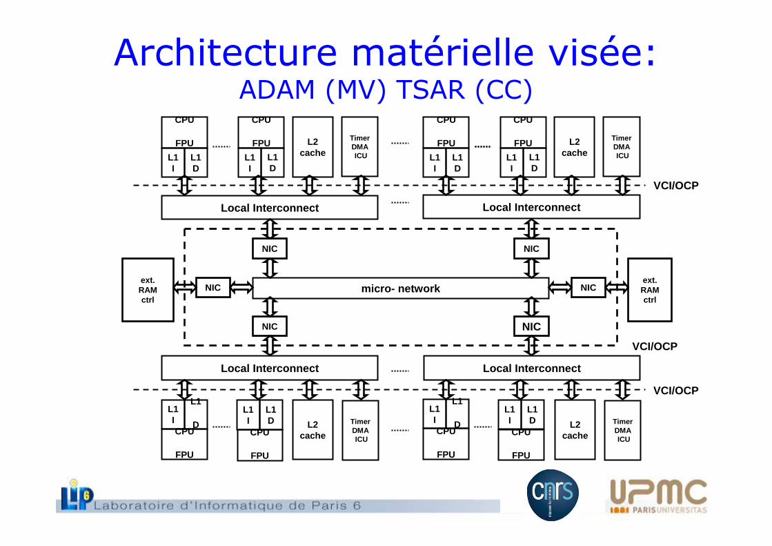
Architecture matérielle visée: ADAM (MV) TSAR (CC)
VCI/OCP
CPU
FPU
Local Interconnect
L2 cache
TimerDMAICU
micro- network
L1I
L1
D
VCI/OCP
Local Interconnect
L2 cache
TimerDMAICU
NIC
Local Interconnect
VCI/OCP
Local Interconnect
TimerDMAICU
L2 cache
CPU
FPU
L1I
L1D
CPU
FPU
L1I
NICext.RAM ctrl
ext.RAM ctrl
NIC
NIC
NIC NIC
TimerDMAICU
L2 cacheL1
D
CPU
FPU
L1I
L1D
CPU
FPU
L1I
L1D
CPU
FPU
L1I
L1D
CPU
FPU
L1I
L1
DCPU
FPU
L1I
L1D
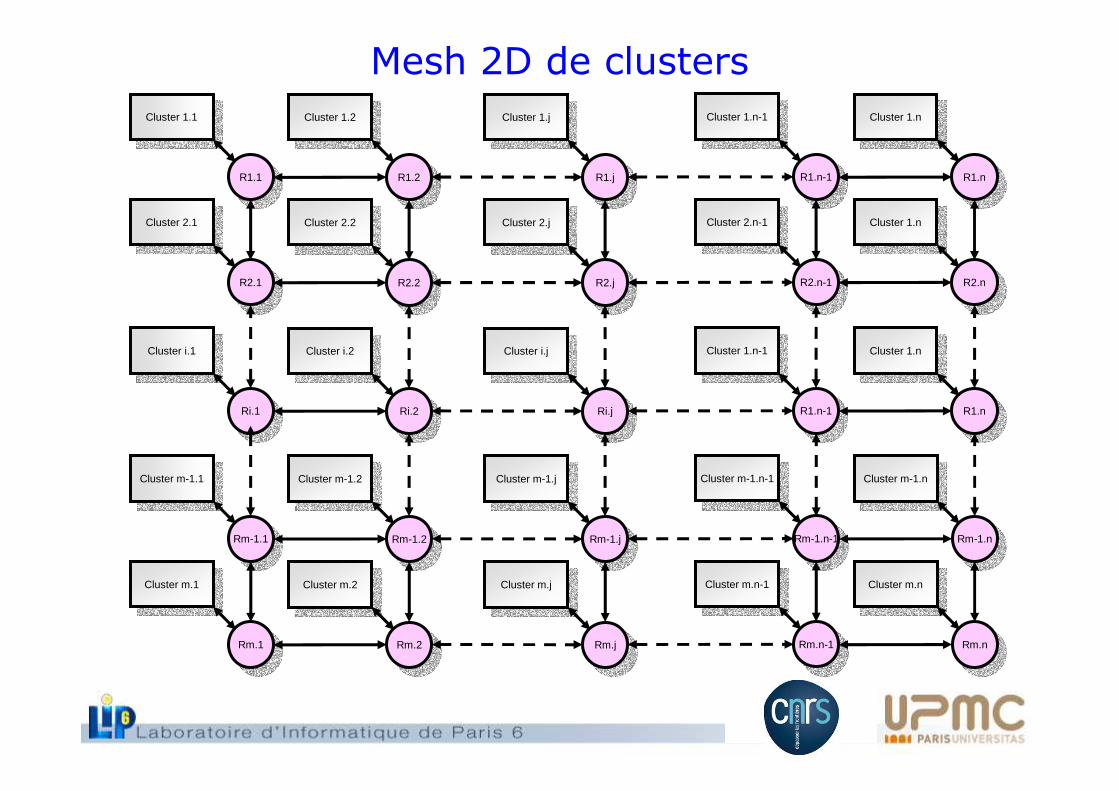
Cluster 1.1Cluster 1.1
R1.1R1.1
Cluster 2.1Cluster 2.1
R2.1R2.1
Cluster 1.2Cluster 1.2
R1.2R1.2
Cluster 2.2Cluster 2.2
R2.2R2.2
Cluster 1.jCluster 1.j
R1.jR1.j
Cluster 2.jCluster 2.j
R2.jR2.j
Cluster 1.n-1Cluster 1.n-1
R1.n-1R1.n-1
Cluster 2.n-1Cluster 2.n-1
R2.n-1R2.n-1
Cluster 1.nCluster 1.n
R1.nR1.n
Cluster 1.nCluster 1.n
R2.nR2.n
Cluster i.1Cluster i.1
Ri.1Ri.1
Cluster i.2Cluster i.2
Ri.2Ri.2
Cluster i.jCluster i.j
Ri.jRi.j
Cluster 1.n-1Cluster 1.n-1
R1.n-1R1.n-1
Cluster 1.nCluster 1.n
R1.nR1.n
Cluster m-1.1Cluster m-1.1
Rm-1.1Rm-1.1
Cluster m-1.2Cluster m-1.2
Rm-1.2Rm-1.2
Cluster m-1.jCluster m-1.j
Rm-1.jRm-1.j
Cluster m-1.n-1Cluster m-1.n-1
Rm-1.n-1Rm-1.n-1
Cluster m-1.nCluster m-1.n
Rm-1.nRm-1.n
Cluster m.1Cluster m.1
Rm.1Rm.1
Cluster m.2Cluster m.2
Rm.2Rm.2
Cluster m.jCluster m.j
Rm.jRm.j
Cluster m.n-1Cluster m.n-1
Rm.n-1Rm.n-1
Cluster m.nCluster m.n
Rm.nRm.n
Mesh 2D de clusters
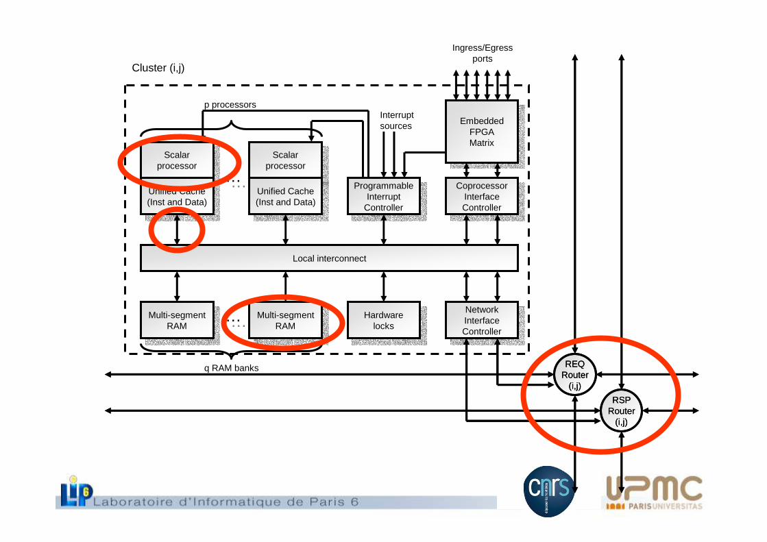
Local interconnect
Scalarprocessor
Scalarprocessor
Unified Cache(Inst and Data)
Unified Cache(Inst and Data)
Scalarprocessor
Scalarprocessor
Unified Cache(Inst and Data)
Unified Cache(Inst and Data)
Multi-segmentRAM
Multi-segmentRAM
Multi-segmentRAM
Multi-segmentRAM
……
…… Hardwarelocks
Hardwarelocks
ProgrammableInterrupt
Controller
ProgrammableInterrupt
Controller
CoprocessorInterfaceController
CoprocessorInterfaceController
NetworkInterfaceController
NetworkInterfaceController
EmbeddedFPGAMatrix
EmbeddedFPGAMatrix
Interruptsources
Cluster (i,j)
Ingress/Egressports
q RAM banks
p processors
REQRouter
(i,j)
RSPRouter
(i,j)
REQRouter
(i,j)
RSPRouter
(i,j)

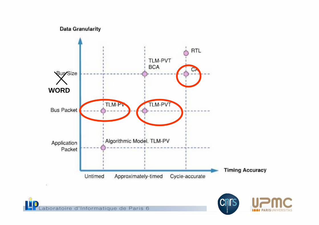
VCI/OCP• Composants écrits
en SystemC OSCI
• Interopérables(standard VCI/OCP)
• 3 niveaux de modélisation dont 2 disponibles
– TLM avec temps, phénomènes dynamiques (comportement fin des caches, gestion de la contention)
– Cycle Accurate Bit Accurate
– RTL synthétisable
Initiateur Cible
CMDVAL
CMDACK
CMD
RSPACK
RSPVAL
RSP
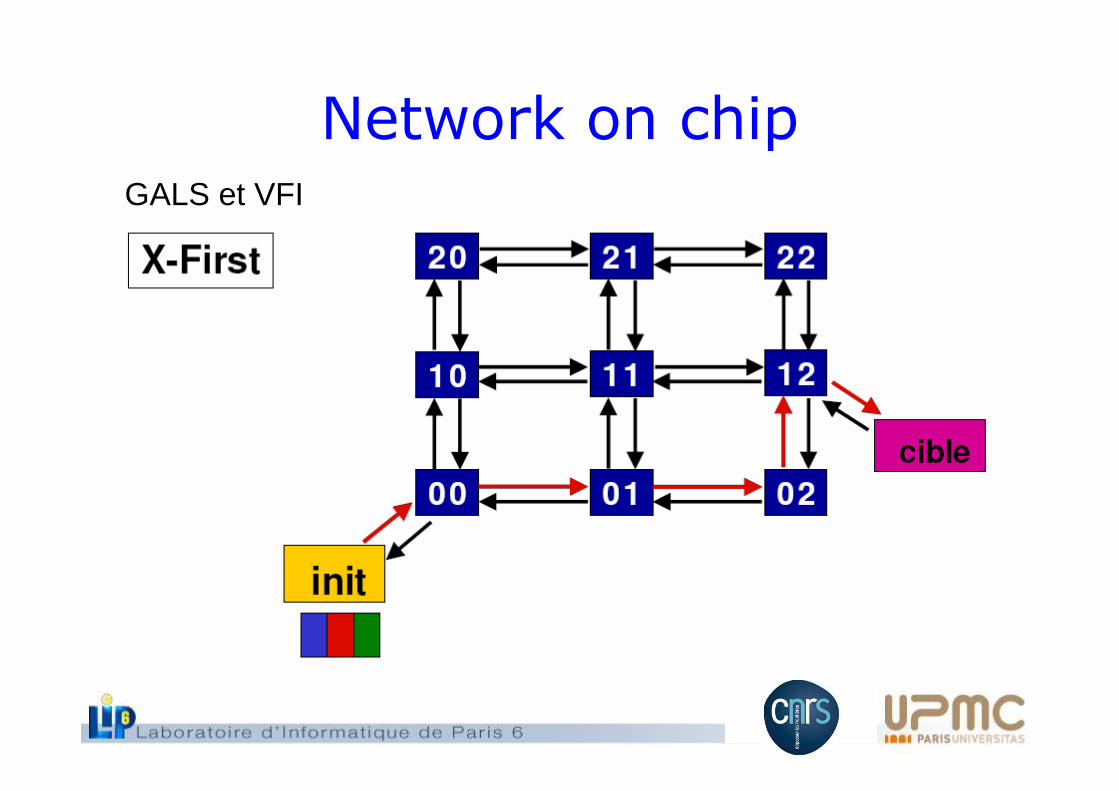
Network on chipGALS et VFI
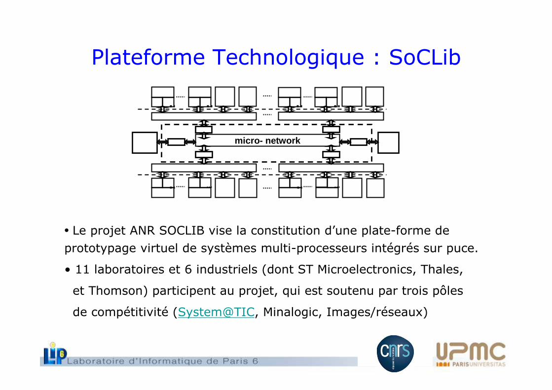
• Le projet ANR SOCLIB vise la constitution d’une plate-forme de
prototypage virtuel de systèmes multi-processeurs intégrés sur puce.
• 11 laboratoires et 6 industriels (dont ST Microelectronics, Thales,
et Thomson) participent au projet, qui est soutenu par trois pôles
de compétitivité (System@TIC, Minalogic, Images/réseaux)
Plateforme Technologique : SoCLib
micro- network
WORD
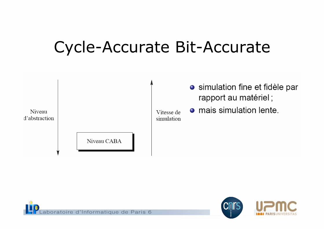
Cycle-Accurate Bit-Accurate
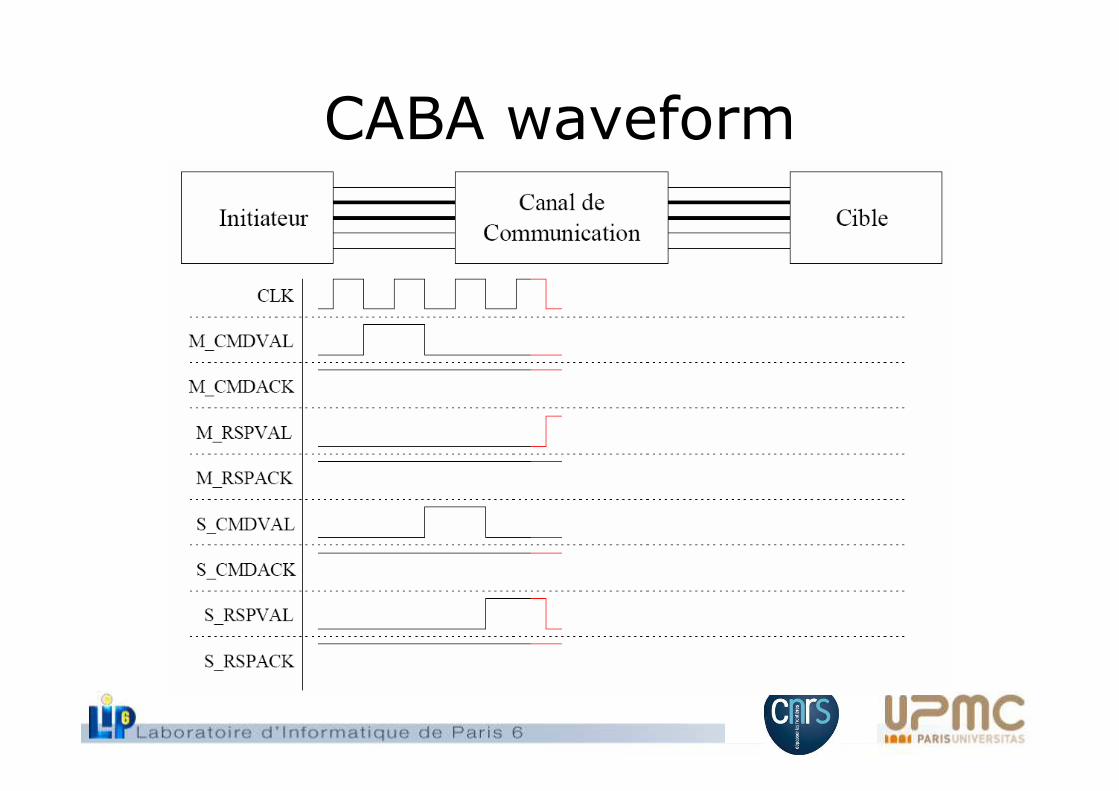
CABA waveform
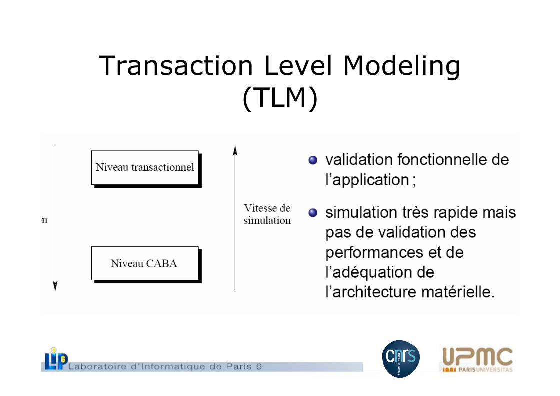
Transaction Level Modeling(TLM)
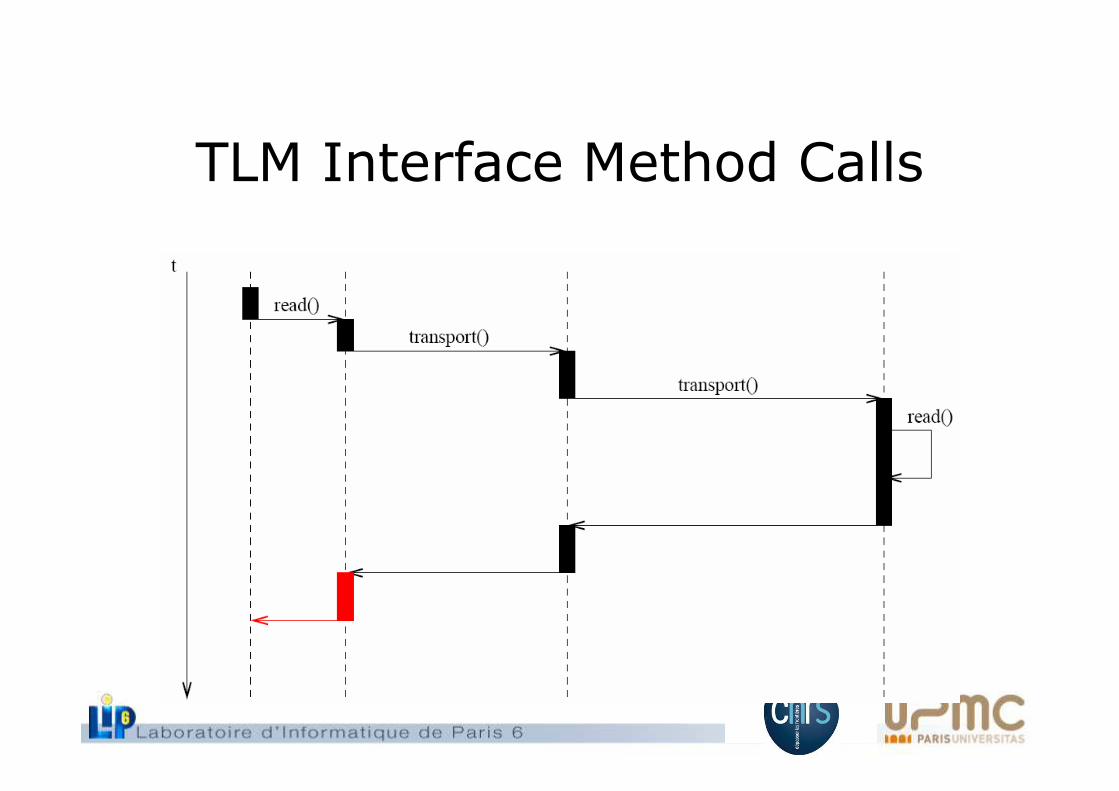
TLM Interface Method Calls
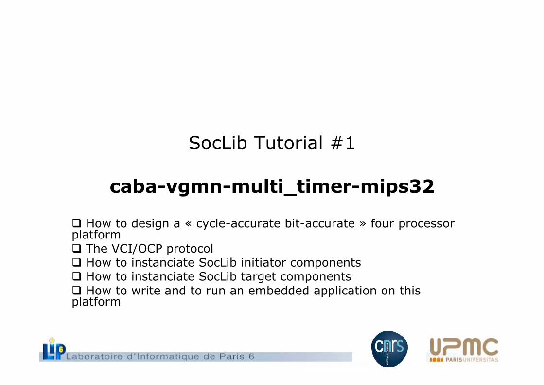
SocLib Tutorial #1
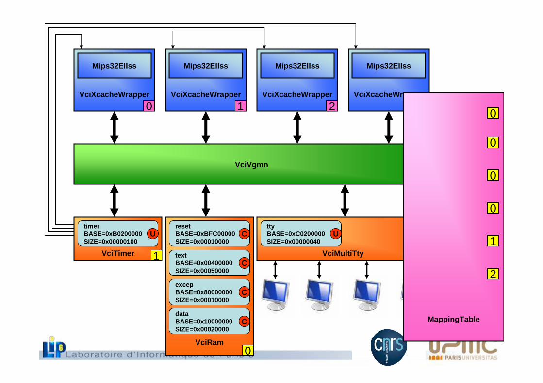
caba-vgmn-multi_timer-mips32
� How to design a « cycle-accurate bit-accurate » four processorplatform� The VCI/OCP protocol� How to instanciate SocLib initiator components� How to instanciate SocLib target components� How to write and to run an embedded application on thisplatform
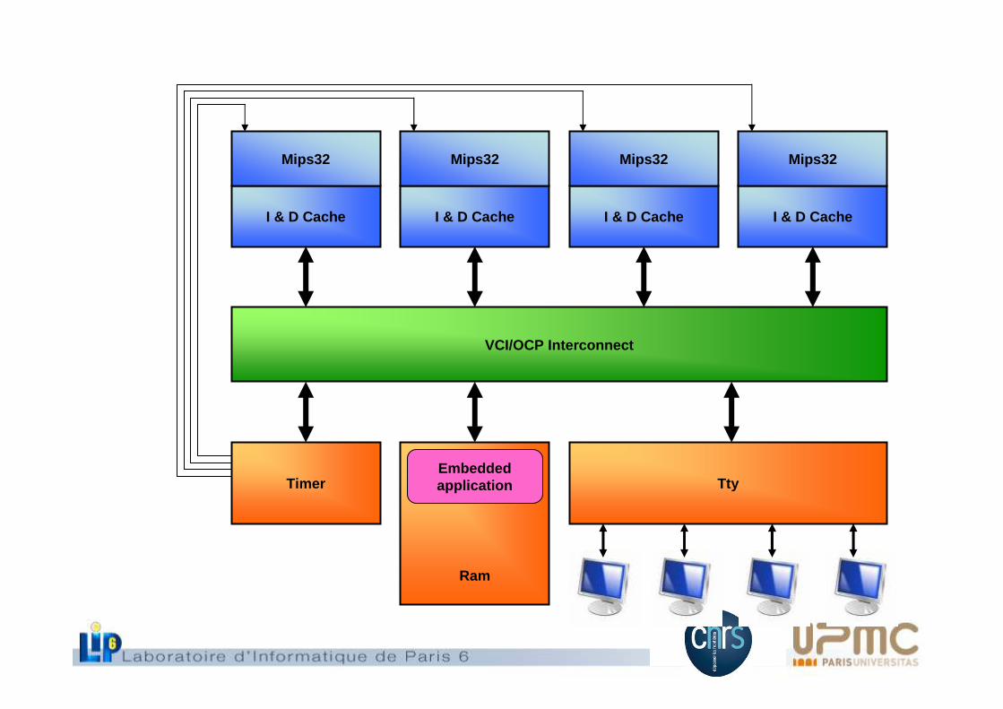
VCI/OCP Interconnect
I & D Cache
Mips32
Timer
Ram
I & D Cache
Mips32
I & D Cache
Mips32
I & D Cache
Mips32
TtyEmbeddedapplication
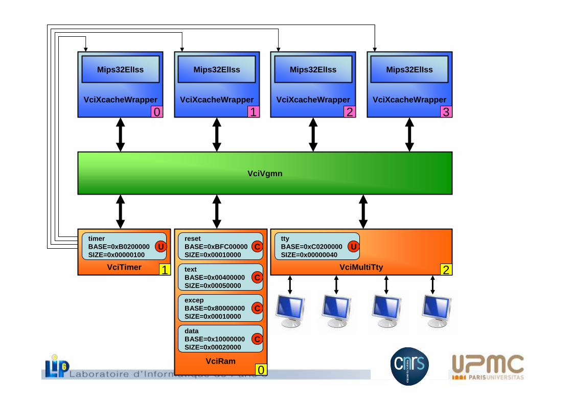
VciMultiTty 2VciTimer 1
VciVgmn
VciXcacheWrapper
Mips32ElIss
VciRam
timerBASE=0xB0200000SIZE=0x00000100
UttyBASE=0xC0200000SIZE=0x00000040
UresetBASE=0xBFC00000SIZE=0x00010000
C
excepBASE=0x80000000SIZE=0x00010000
C
textBASE=0x00400000SIZE=0x00050000
C
dataBASE=0x10000000SIZE=0x00020000
C
0
0VciXcacheWrapper
Mips32ElIss
1VciXcacheWrapper
Mips32ElIss
2VciXcacheWrapper
Mips32ElIss
3
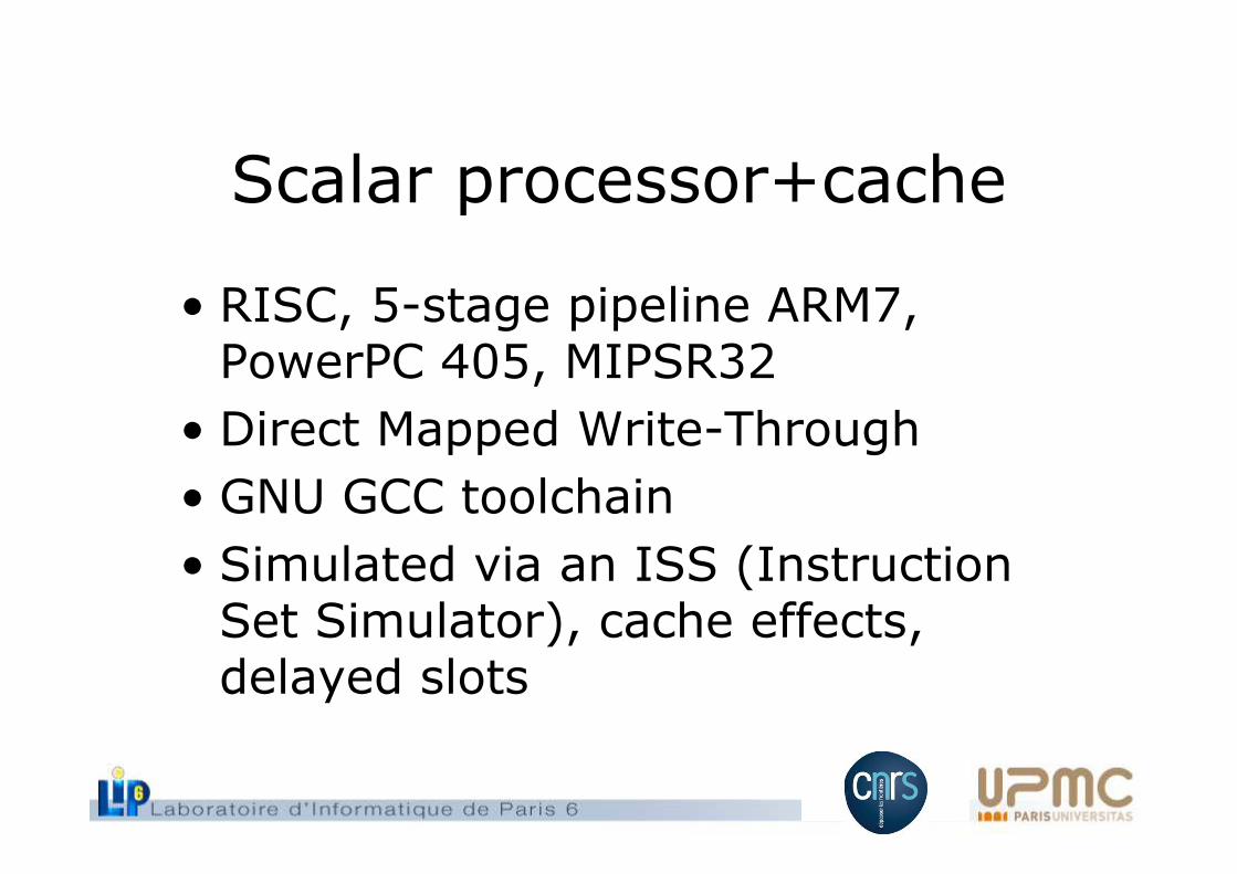
Scalar processor+cache
• RISC, 5-stage pipeline ARM7, PowerPC 405, MIPSR32
• Direct Mapped Write-Through
• GNU GCC toolchain
• Simulated via an ISS (Instruction Set Simulator), cache effects, delayed slots
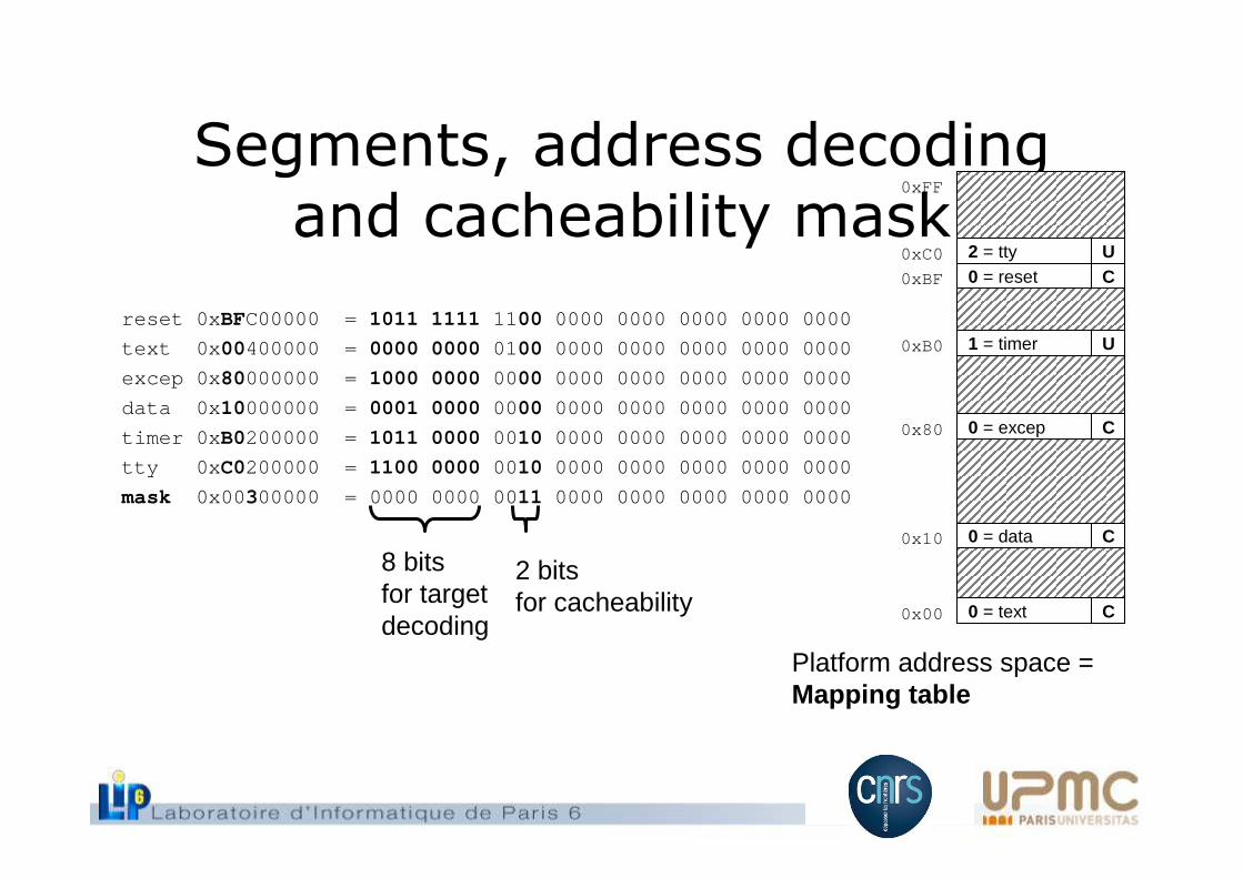
Segments, address decodingand cacheability mask
reset 0xBFC00000 = 1011 1111 1100 0000 0000 0000 0000 0000
text 0x00400000 = 0000 0000 0100 0000 0000 0000 0000 0000
excep 0x80000000 = 1000 0000 0000 0000 0000 0000 0000 0000
data 0x10000000 = 0001 0000 0000 0000 0000 0000 0000 0000
timer 0xB0200000 = 1011 0000 0010 0000 0000 0000 0000 0000
tty 0xC0200000 = 1100 0000 0010 0000 0000 0000 0000 0000
mask 0x00300000 = 0000 0000 0011 0000 0000 0000 0000 0000
8 bitsfor targetdecoding
2 bitsfor cacheability
0 = reset0xBF
1 = timer0xB0
2 = tty0xC0
0 = excep0x80
0 = data0x10
0 = text0x00
0xFF
Platform address space =Mapping table
UC
C
C
C
U
VciRam
VciVgmn
VciXcacheWrapper
Mips32ElIss
VciTimer
VciXcacheWrapper
Mips32ElIss
VciXcacheWrapper
Mips32ElIss
VciXcacheWrapper
Mips32ElIss
VciMultiTty
0
1 2
0 1 2 3
MappingTable
resetBASE=0xBFC00000SIZE=0x00010000
C
textBASE=0x00400000SIZE=0x00050000
C
excepBASE=0x80000000SIZE=0x00010000
C
dataBASE=0x10000000SIZE=0x00020000
C
timerBASE=0xB0200000SIZE=0x00000100
UttyBASE=0xC0200000SIZE=0x00000040
U
0
0
0
0
1
2
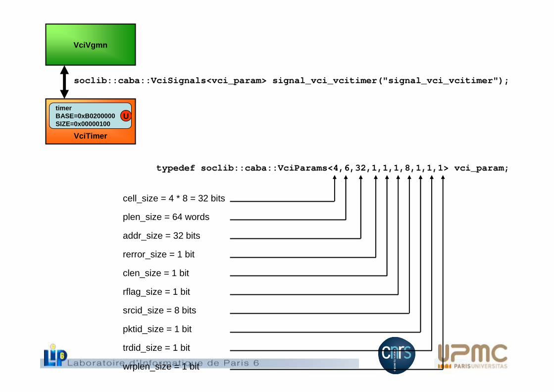
typedef soclib::caba::VciParams<4,6,32,1,1,1,8,1,1,1> vci_param;
cell_size = 4 * 8 = 32 bits
plen_size = 64 words
addr_size = 32 bits
rerror_size = 1 bit
clen_size = 1 bit
rflag_size = 1 bit
srcid_size = 8 bits
pktid_size = 1 bit
trdid_size = 1 bit
wrplen_size = 1 bit
VciTimer
timerBASE=0xB0200000SIZE=0x00000100
U
VciVgmn
soclib::caba::VciSignals<vci_param> signal_vci_vcitimer("signal_vci_vcitimer");
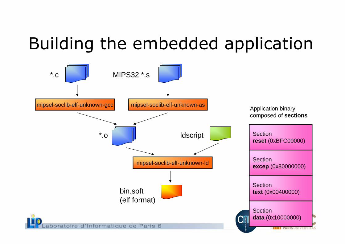
Building the embedded application
*.c MIPS32 *.s
mipsel-soclib-elf-unknown-gcc
*.o ldscript
bin.soft(elf format)
mipsel-soclib-elf-unknown-as
mipsel-soclib-elf-unknown-ld
Sectionreset (0xBFC00000)
Sectionexcep (0x80000000)
Sectiontext (0x00400000)
Sectiondata (0x10000000)
Application binarycomposed of sections
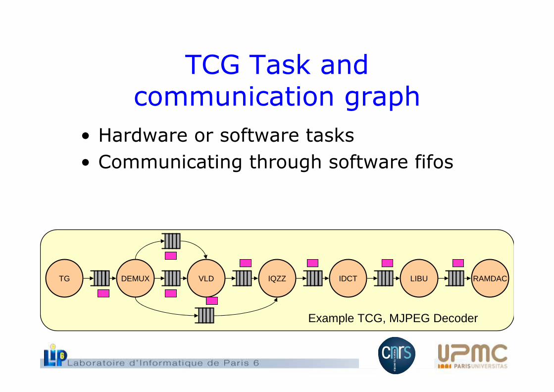
TCG Task andcommunication graph
• Hardware or software tasks
• Communicating through software fifos
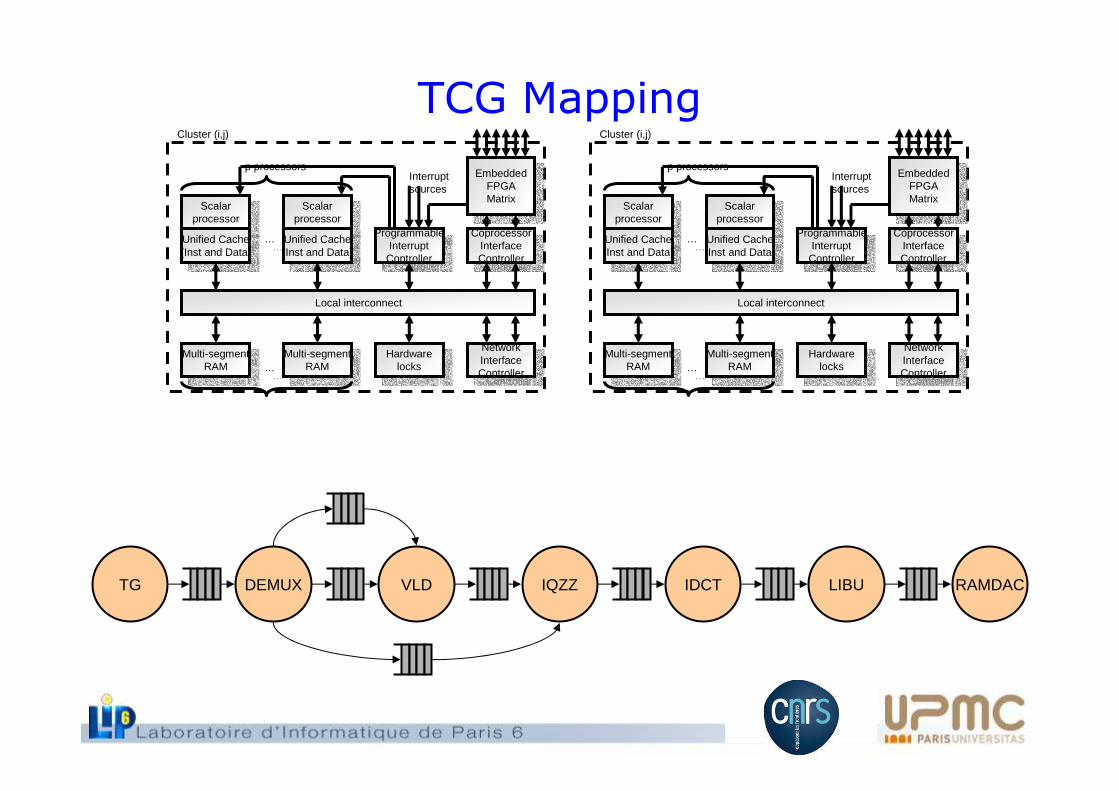
TG DEMUX VLD IQZZ IDCT LIBU RAMDAC
Example TCG, MJPEG Decoder
Local interconnect
Scalarprocessor
Scalarprocessor
Unified Cache(Inst and Data)
Unified Cache(Inst and Data)
Scalarprocessor
Scalarprocessor
Unified Cache(Inst and Data)
Unified Cache(Inst and Data)
Multi-segmentRAM
Multi-segmentRAM Multi-segment
RAM
Multi-segmentRAM
……
…… Hardware
locks
Hardwarelocks
ProgrammableInterrupt
Controller
ProgrammableInterrupt
Controller
CoprocessorInterfaceController
CoprocessorInterfaceController
NetworkInterfaceController
NetworkInterfaceController
EmbeddedFPGAMatrix
EmbeddedFPGAMatrix
Interruptsources
Cluster (i,j)
p processors
TG DEMUX VLD IQZZ IDCT LIBU RAMDAC
TCG Mapping
CABA modeling
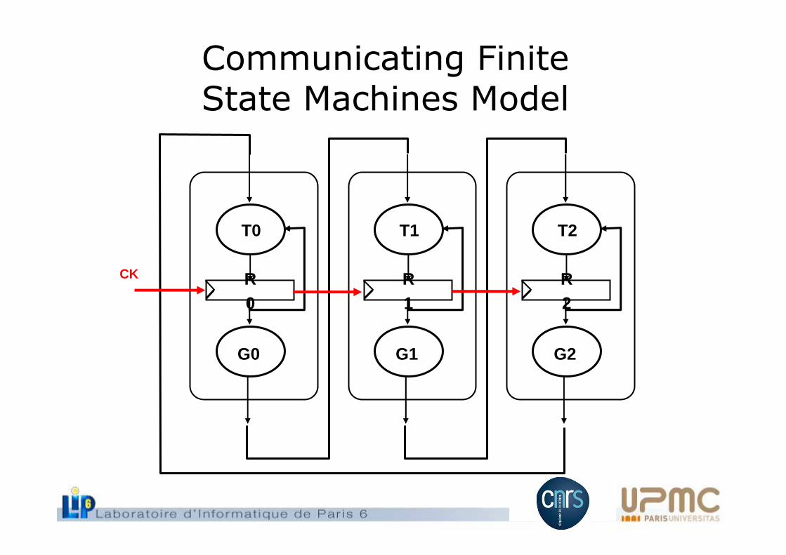
Communicating FiniteState Machines Model
R0
G0
T0
R1
G1
T1
R2
G2
T2
CK
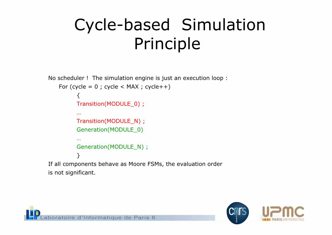
Cycle-based Simulation Principle
No scheduler ! The simulation engine is just an execution loop :
For (cycle = 0 ; cycle < MAX ; cycle++)
{
Transition(MODULE_0) ;
…
Transition(MODULE_N) ;
Generation(MODULE_0)
…
Generation(MODULE_N) ;
}
If all components behave as Moore FSMs, the evaluation order
is not significant.
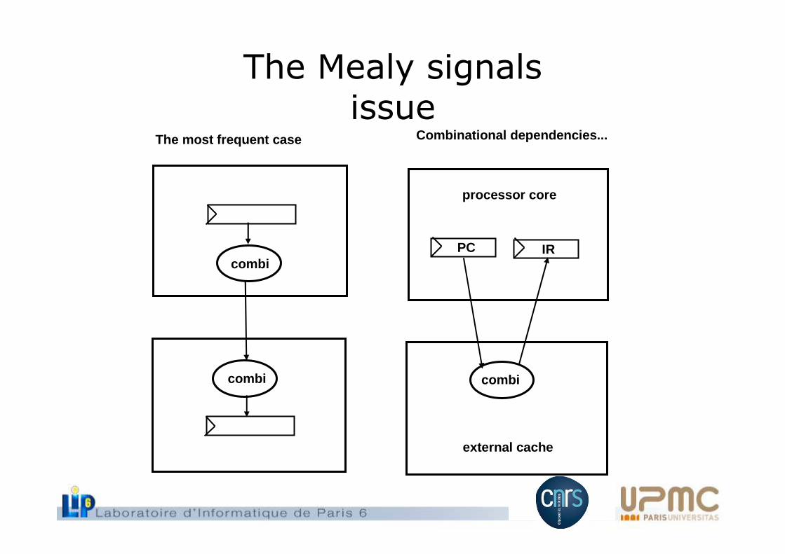
The Mealy signalsissue
combi
combi
The most frequent case
combi
Combinational dependencies...
external cache
processor core
PC IR
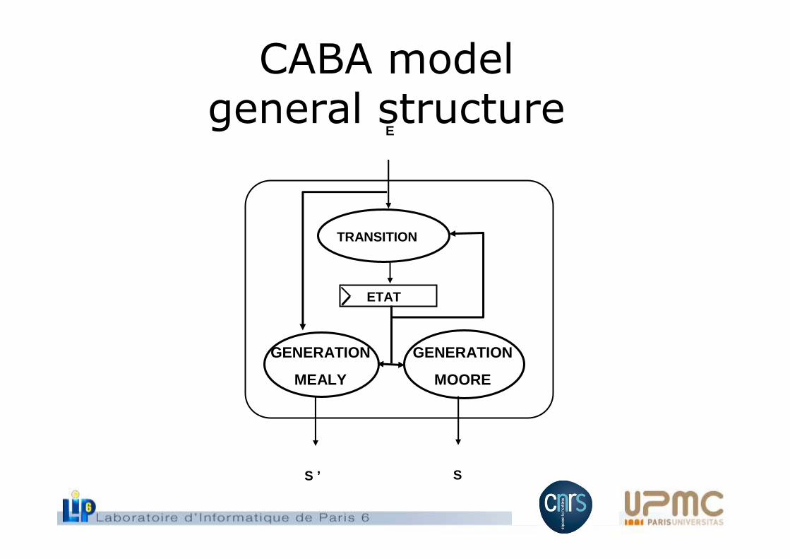
CABA model general structure
GENERATION
MOORE
TRANSITION
GENERATION
MEALY
ETAT
E
S ’ S
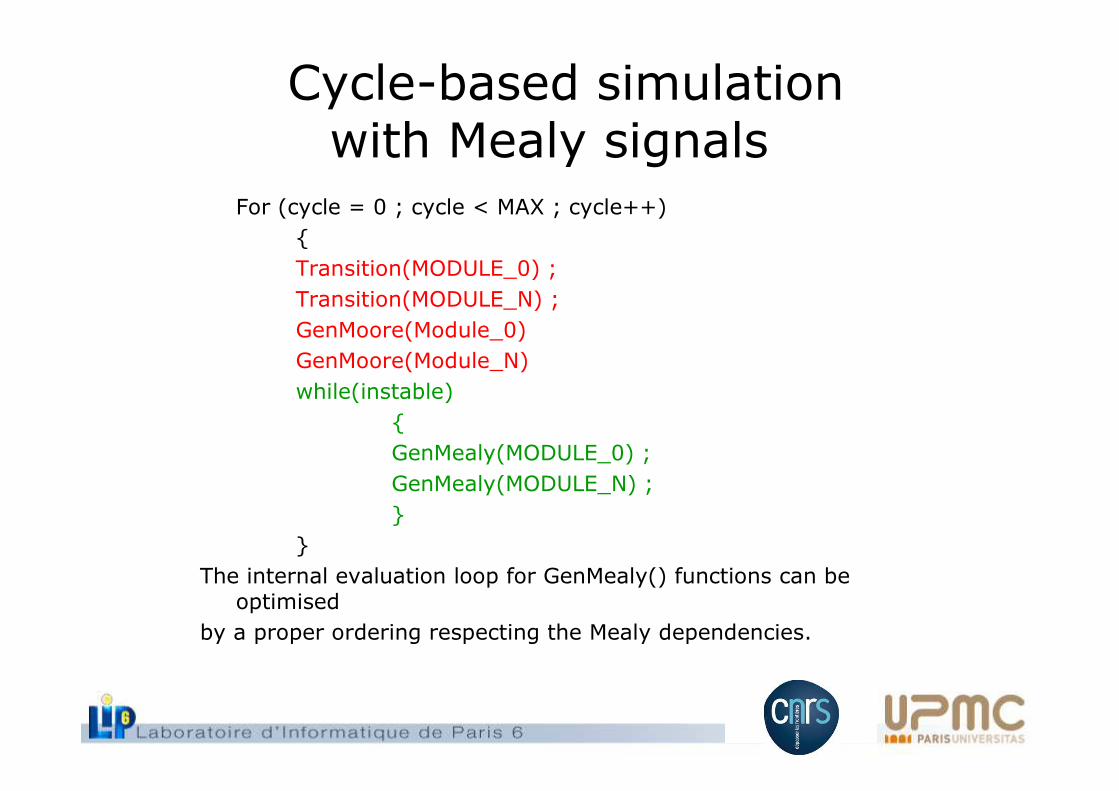
Cycle-based simulation with Mealy signals
For (cycle = 0 ; cycle < MAX ; cycle++)
{
Transition(MODULE_0) ;
Transition(MODULE_N) ;
GenMoore(Module_0)
GenMoore(Module_N)
while(instable)
{
GenMealy(MODULE_0) ;
GenMealy(MODULE_N) ;
}
}
The internal evaluation loop for GenMealy() functions can beoptimised
by a proper ordering respecting the Mealy dependencies.
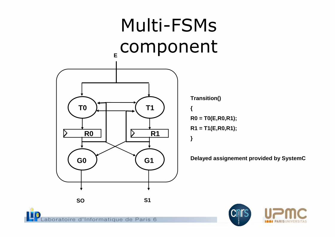
Multi-FSMscomponent
R0
G0
T0
R1
G1
T1Transition()
{
R0 = T0(E,R0,R1);
R1 = T1(E,R0,R1);
}
Delayed assignement provided by SystemC
E
SO S1
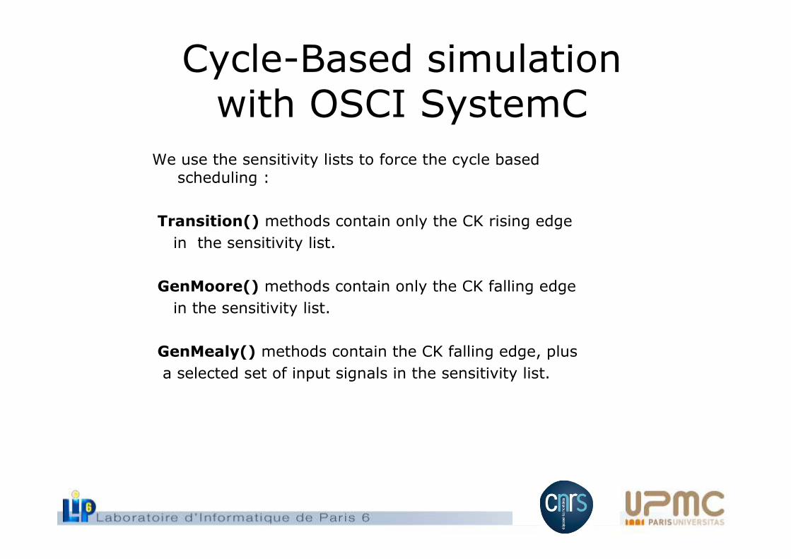
Cycle-Based simulation with OSCI SystemC
We use the sensitivity lists to force the cycle basedscheduling :
Transition() methods contain only the CK rising edge
in the sensitivity list.
GenMoore() methods contain only the CK falling edge
in the sensitivity list.
GenMealy() methods contain the CK falling edge, plus
a selected set of input signals in the sensitivity list.
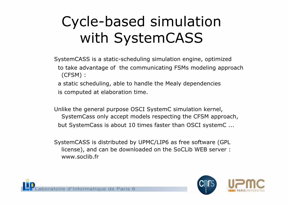
Cycle-based simulation with SystemCASS
SystemCASS is a static-scheduling simulation engine, optimized
to take advantage of the communicating FSMs modeling approach
(CFSM) :
a static scheduling, able to handle the Mealy dependencies
is computed at elaboration time.
Unlike the general purpose OSCI SystemC simulation kernel,
SystemCass only accept models respecting the CFSM approach,
but SystemCass is about 10 times faster than OSCI systemC ...
SystemCASS is distributed by UPMC/LIP6 as free software (GPL
license), and can be downloaded on the SoCLib WEB server :
www.soclib.fr
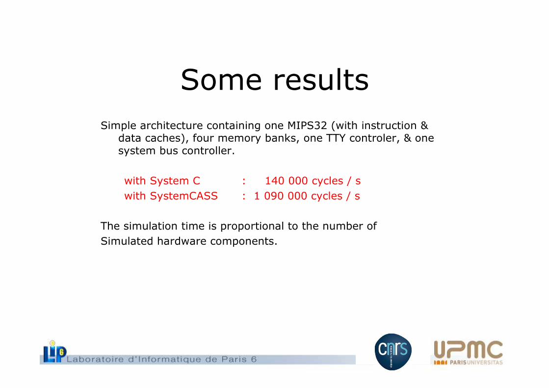
Some results
Simple architecture containing one MIPS32 (with instruction & data caches), four memory banks, one TTY controler, & one system bus controller.
with System C : 140 000 cycles / s
with SystemCASS : 1 090 000 cycles / s
The simulation time is proportional to the number of
Simulated hardware components.
TLM-T over TLM-2.0
[email protected],[email protected],[email protected]
Université Pierre et Marie Curie,Laboratoire LIP6/SoC/ALSoC
Special thanks to Daniel Gracia Pérez, Gilles Mouchard from CEA-LIST
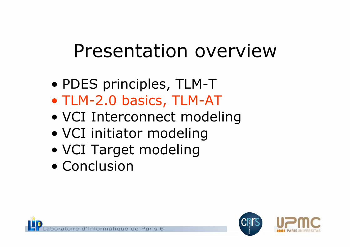
Presentation overview
• PDES principles, TLM-T• TLM-2.0 basics, TLM-AT• VCI Interconnect modeling• VCI initiator modeling• VCI Target modeling
• Conclusion
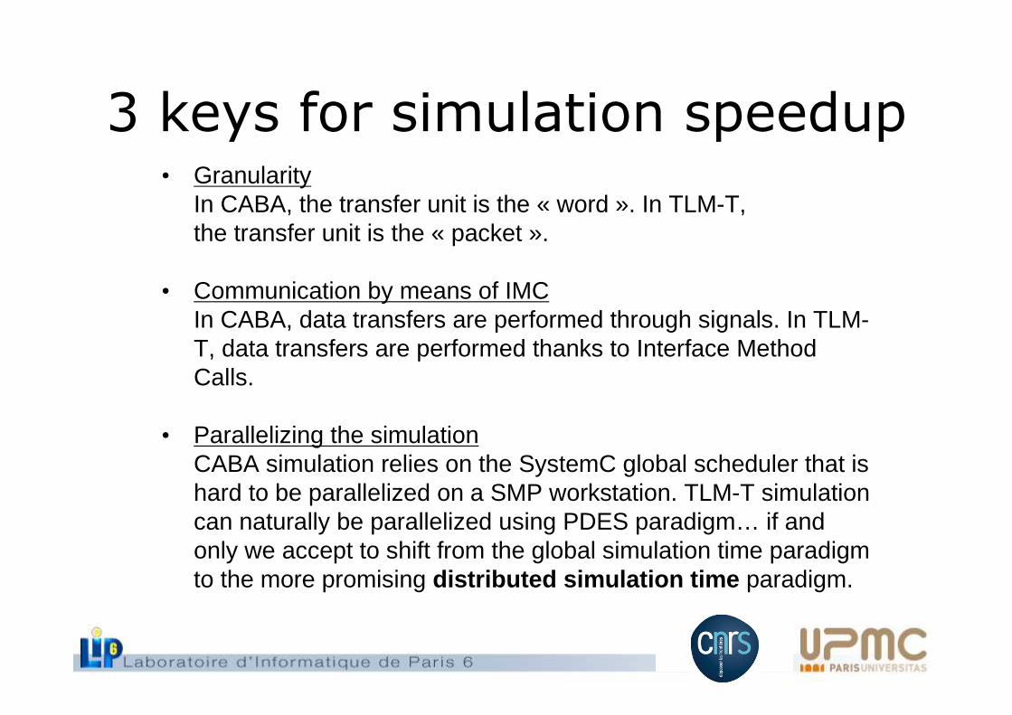
3 keys for simulation speedup• Granularity
In CABA, the transfer unit is the « word ». In TLM-T, the transfer unit is the « packet ».
• Communication by means of IMCIn CABA, data transfers are performed through signals. In TLM-T, data transfers are performed thanks to Interface Method Calls.
• Parallelizing the simulationCABA simulation relies on the SystemC global scheduler that is hard to be parallelized on a SMP workstation. TLM-T simulation can naturally be parallelized using PDES paradigm… if and only we accept to shift from the global simulation time paradigmto the more promising distributed simulation time paradigm.
PDES principles
• The complete simulated system is described as a set of logical processes that execute in parallel and communicate via point-to-point channels.
• There is neither global scheduler nor global clock.
• To each process is associated a local clock with a value, the local time.
• The processes synchronize themselves by embedding timing information in the packets carried along the channels.
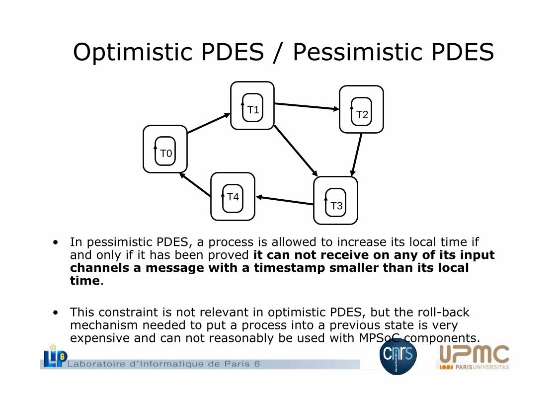
Optimistic PDES / Pessimistic PDES
• In pessimistic PDES, a process is allowed to increase its local time if and only if it has been proved it can not receive on any of its input channels a message with a timestamp smaller than its local time.
• This constraint is not relevant in optimistic PDES, but the roll-back mechanism needed to put a process into a previous state is very expensive and can not reasonably be used with MPSoC components.
T0
T4T3
T2T1
Null-messages• The pessimistic PDES algorithm relies on temporal filtering of
the incoming messages.
• A PDES process that has N input channels is only allowed to process when it has timing information on all its N input ports.
– For example, an interconnect is allowed to let a command packet reach a given target if and only if all the initiators thatcan theorically address this target have sent at least onetimed message.
• To solve this issue, the traditional PDES algorithm uses nullmessage. A null message contains no data, but only a timeinformation. Moreover, all processes can be in two modes : active & non-active. Only processes that are active participate to the temporal filtering.
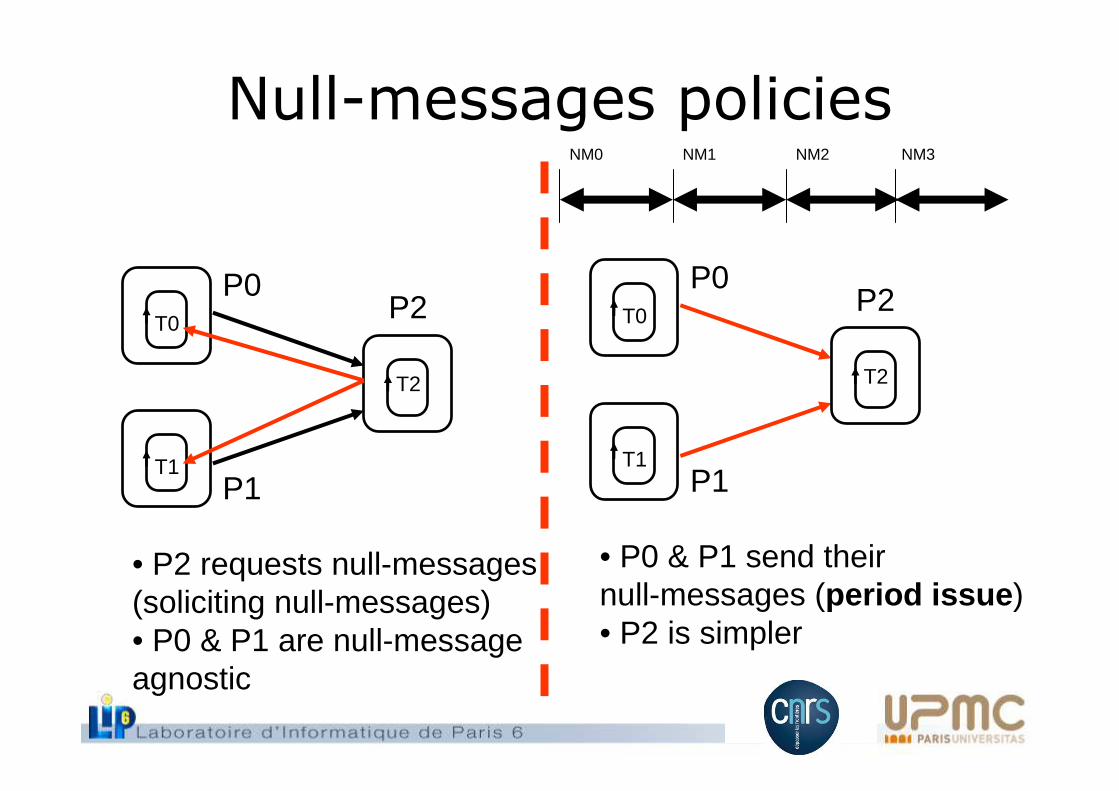
Null-messages policies
T0
T1
T2
• P2 requests null-messages(soliciting null-messages)• P0 & P1 are null-messageagnostic
P2P0
P1
T0
T1
T2
• P0 & P1 send theirnull-messages (period issue )• P2 is simpler
P2P0
P1
NM0 NM1 NM2 NM3
Presentation overview
• PDES principles, TLM-T • TLM-2.0 basics, TLM-AT• VCI Interconnect modeling• VCI initiator modeling• VCI Target modeling• Conclusion
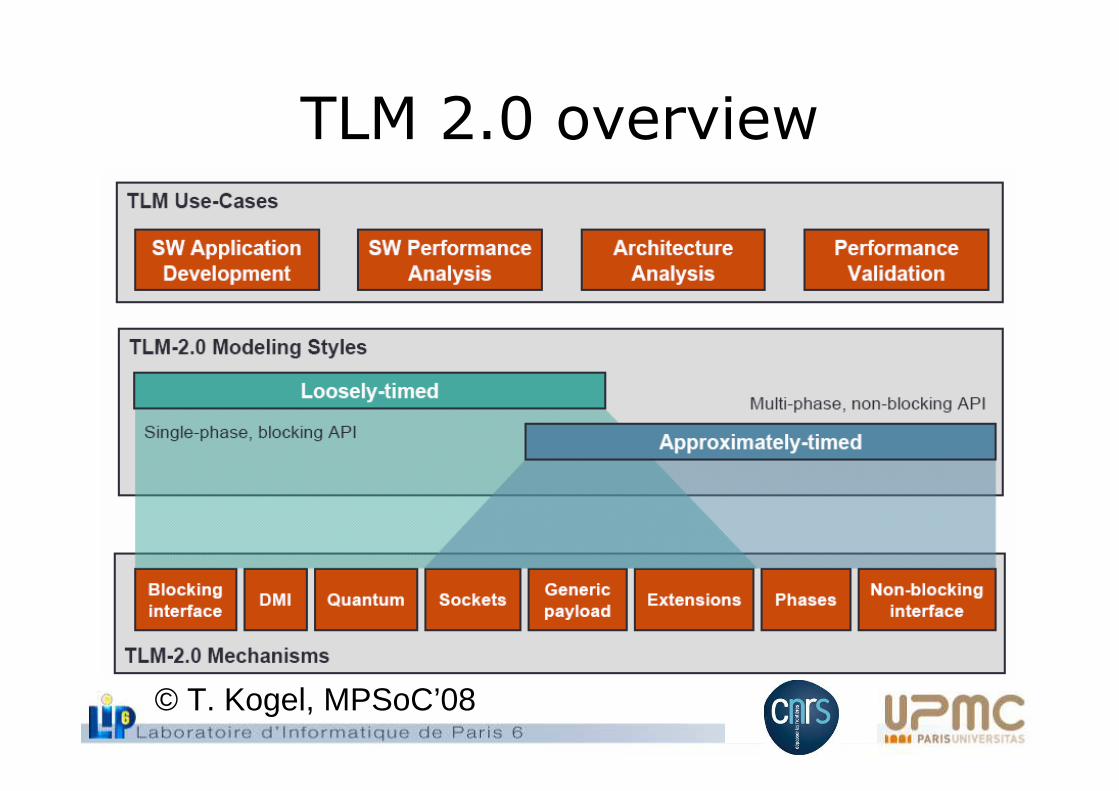
TLM 2.0 overview
© T. Kogel, MPSoC’08
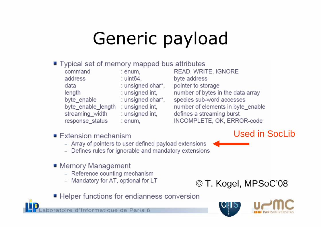
Generic payload
© T. Kogel, MPSoC’08
Used in SocLib
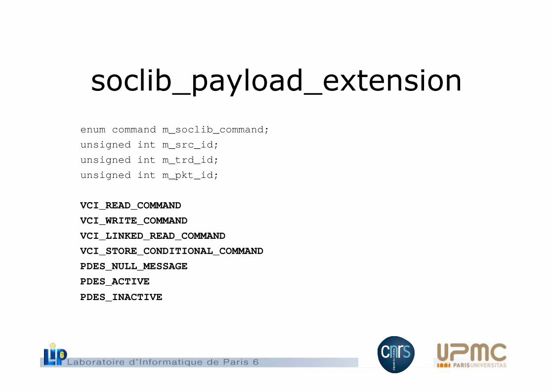
soclib_payload_extension
enum command m_soclib_command;
unsigned int m_src_id;
unsigned int m_trd_id;
unsigned int m_pkt_id;
VCI_READ_COMMAND
VCI_WRITE_COMMAND
VCI_LINKED_READ_COMMAND
VCI_STORE_CONDITIONAL_COMMAND
PDES_NULL_MESSAGE
PDES_ACTIVE
PDES_INACTIVE
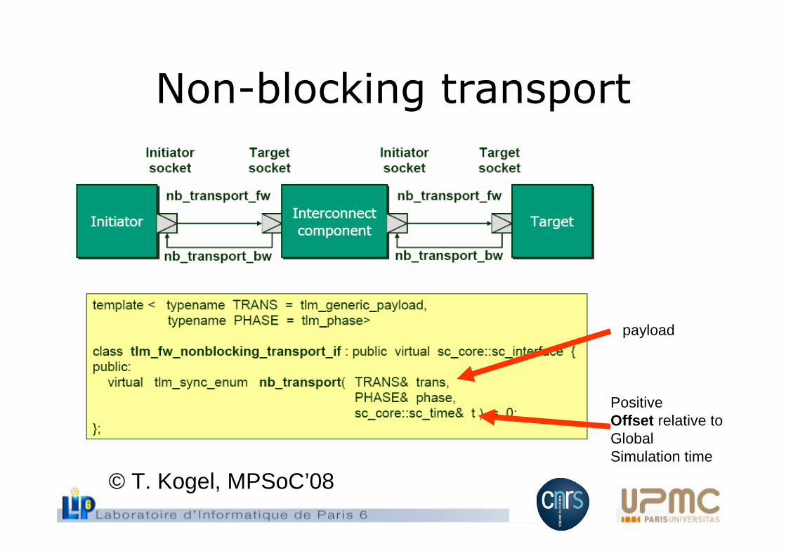
Non-blocking transport
© T. Kogel, MPSoC’08
payload
PositiveOffset relative toGlobalSimulation time
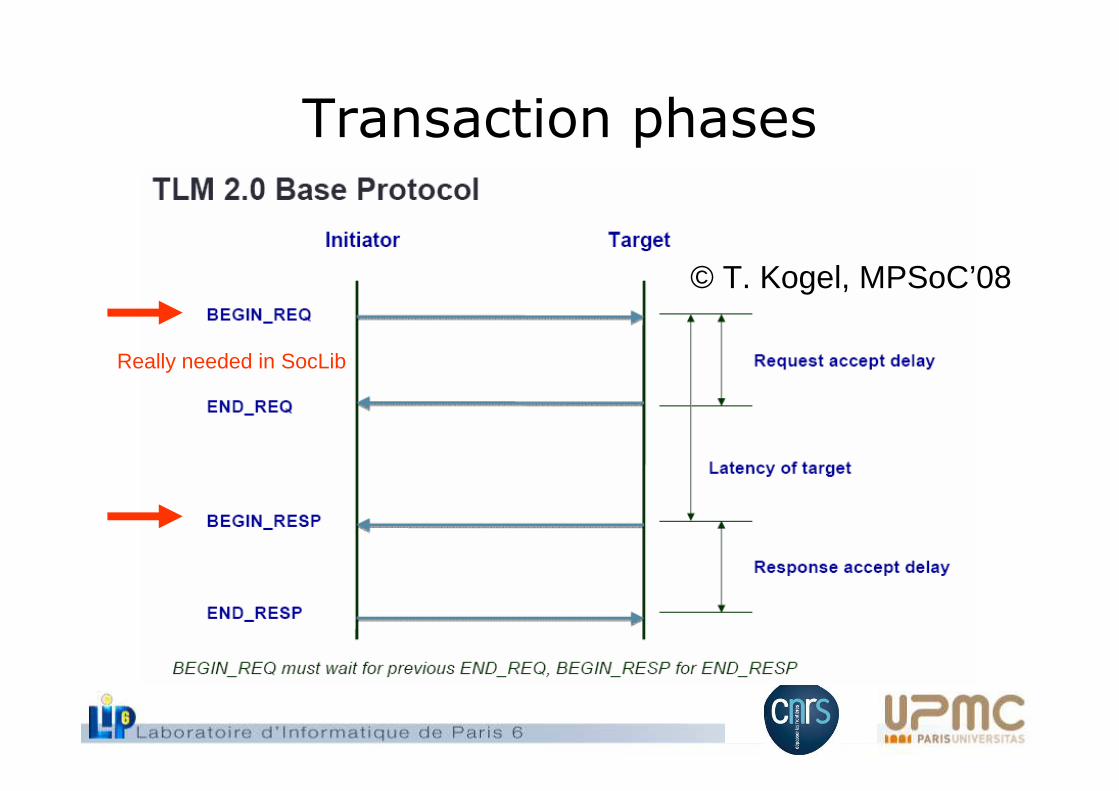
Transaction phases
© T. Kogel, MPSoC’08
Really needed in SocLib
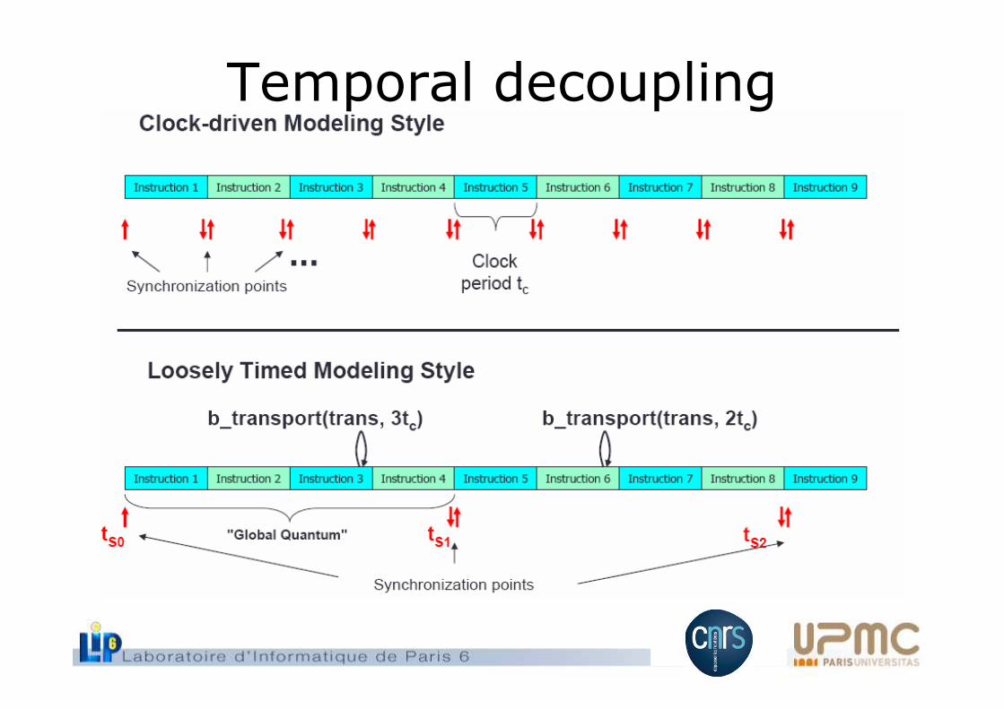
Temporal decoupling
Presentation overview
• PDES principles, TLM-T • TLM-2.0 basics, TLM-AT• VCI Interconnect modeling• VCI initiator modeling• VCI Target modeling• Conclusion
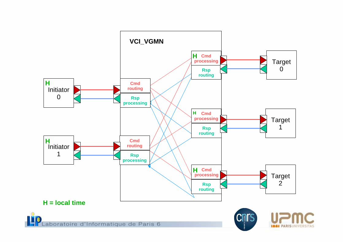
H = local time
VGMNInitiator0
Cmdrouting
Rspprocessing
H
VGMNInitiator1
Cmdrouting
Rspprocessing
H
VCI_VGMN
Cmdprocessing
Rsprouting
HTarget
0
Cmdprocessing
Rsprouting
H
Target1
Cmdprocessing
Rsprouting
HTarget
2
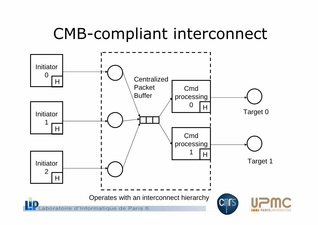
CMB-compliant interconnect
Initiator0
Initiator1
Initiator2
H
H
HCmd
processing0 H
Cmdprocessing
1 H
CentralizedPacketBuffer
Target 0
Target 1
Operates with an interconnect hierarchy
Interconnect behavior
• Temporal filtering operation on incoming messages can be factorizedfor all targets
• These messages are stored in a centralized data structure . This structure stores tree information: the packet, the timestamps and thecurrent initiator activity.
• After elaboration of the simulator, the activity information for eachinitiator is set to true. Only the active initiators are taken into accountduring filtering. A coprocessor initiator not yet programmed will send a message with m_soclib_command set to PDES_INACTIVE.
• Therefore, when all slots of this centralized structure are filled with realor null messages with their associated timestamps, a temporal filteringiteration can occur.
Presentation overview
• PDES principles, TLM-T • TLM-2.0 basics, TLM-AT• VCI Interconnect modeling• VCI initiator modeling• VCI Target modeling• Conclusion
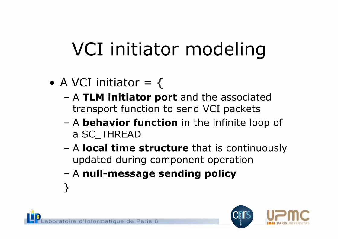
VCI initiator modeling
• A VCI initiator = {– A TLM initiator port and the associatedtransport function to send VCI packets
– A behavior function in the infinite loop ofa SC_THREAD
– A local time structure that is continuouslyupdated during component operation
– A null-message sending policy
}
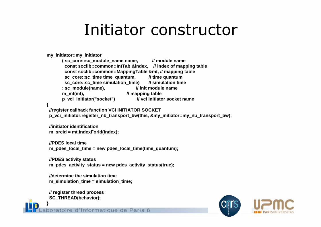
Initiator constructor
my_initiator::my_initiator( sc_core::sc_module_name name, // module name
const soclib::common::IntTab &index, // index of map ping tableconst soclib::common::MappingTable &mt, // mapping tab lesc_core::sc_time time_quantum, // time quant umsc_core::sc_time simulation_time) // simulatio n time
: sc_module(name), // init mo dule namem_mt(mt), // mappin g tablep_vci_initiator("socket") // vci ini tiator socket name
{ //register callback function VCI INITIATOR SOCKETp_vci_initiator.register_nb_transport_bw(this, &my_ initiator::my_nb_transport_bw);
//initiator identificationm_srcid = mt.indexForId(index);
//PDES local timem_pdes_local_time = new pdes_local_time(time_quantum );
//PDES activity statusm_pdes_activity_status = new pdes_activity_status(tr ue);
//determine the simulation timem_simulation_time = simulation_time;
// register thread processSC_THREAD(behavior);
}
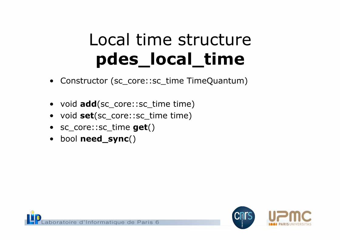
Local time structure pdes_local_time
• Constructor (sc_core::sc_time TimeQuantum)
• void add(sc_core::sc_time time)
• void set(sc_core::sc_time time)
• sc_core::sc_time get()
• bool need_sync()
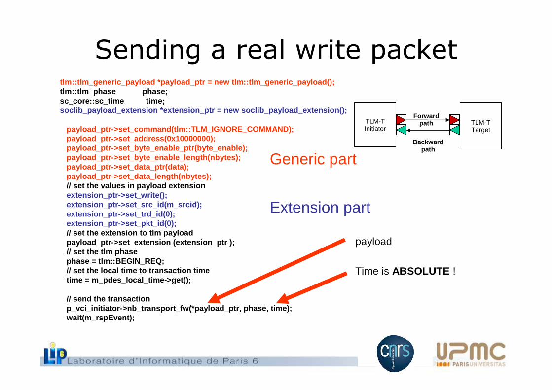
Sending a real write packettlm::tlm_generic_payload *payload_ptr = new tlm::tlm_ generic_payload();tlm::tlm_phase phase;sc_core::sc_time time;soclib_payload_extension *extension_ptr = new soclib_ payload_extension();
payload_ptr->set_command(tlm::TLM_IGNORE_COMMAND);payload_ptr->set_address(0x10000000);payload_ptr->set_byte_enable_ptr(byte_enable);payload_ptr->set_byte_enable_length(nbytes);payload_ptr->set_data_ptr(data);payload_ptr->set_data_length(nbytes);// set the values in payload extensionextension_ptr->set_write();extension_ptr->set_src_id(m_srcid);extension_ptr->set_trd_id(0);extension_ptr->set_pkt_id(0);// set the extension to tlm payloadpayload_ptr->set_extension (extension_ptr );// set the tlm phasephase = tlm::BEGIN_REQ;// set the local time to transaction timetime = m_pdes_local_time->get();
// send the transactionp_vci_initiator->nb_transport_fw(*payload_ptr, phas e, time);wait(m_rspEvent);
Generic part
Extension part
payload
Time is ABSOLUTE !
TLM-TTarget
TLM-TInitiator
Forward path
Backward path
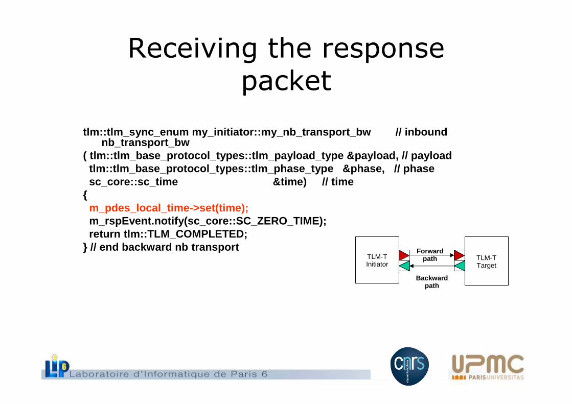
Receiving the responsepacket
tlm::tlm_sync_enum my_initiator::my_nb_transport_bw / / inboundnb_transport_bw
( tlm::tlm_base_protocol_types::tlm_payload_type &pa yload, // payloadtlm::tlm_base_protocol_types::tlm_phase_type &phase, // phasesc_core::sc_time &time) // time
{m_pdes_local_time->set(time);m_rspEvent.notify(sc_core::SC_ZERO_TIME);return tlm::TLM_COMPLETED;
} // end backward nb transportTLM-TTarget
TLM-TInitiator
Forward path
Backward path
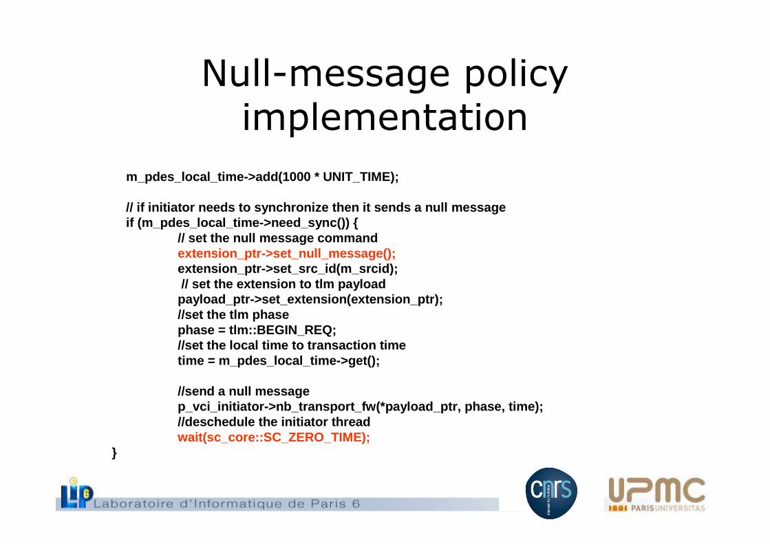
Null-message policyimplementation
m_pdes_local_time->add(1000 * UNIT_TIME);
// if initiator needs to synchronize then it sends a null messageif (m_pdes_local_time->need_sync()) {
// set the null message commandextension_ptr->set_null_message();extension_ptr->set_src_id(m_srcid);// set the extension to tlm payload
payload_ptr->set_extension(extension_ptr);//set the tlm phasephase = tlm::BEGIN_REQ;//set the local time to transaction timetime = m_pdes_local_time->get();
//send a null messagep_vci_initiator->nb_transport_fw(*payload_ptr, phas e, time);//deschedule the initiator threadwait(sc_core::SC_ZERO_TIME);
}
Presentation overview
• PDES principles, TLM-T • TLM-2.0 basics, TLM-AT• VCI Interconnect modeling• VCI initiator modeling• VCI Target modeling• Conclusion
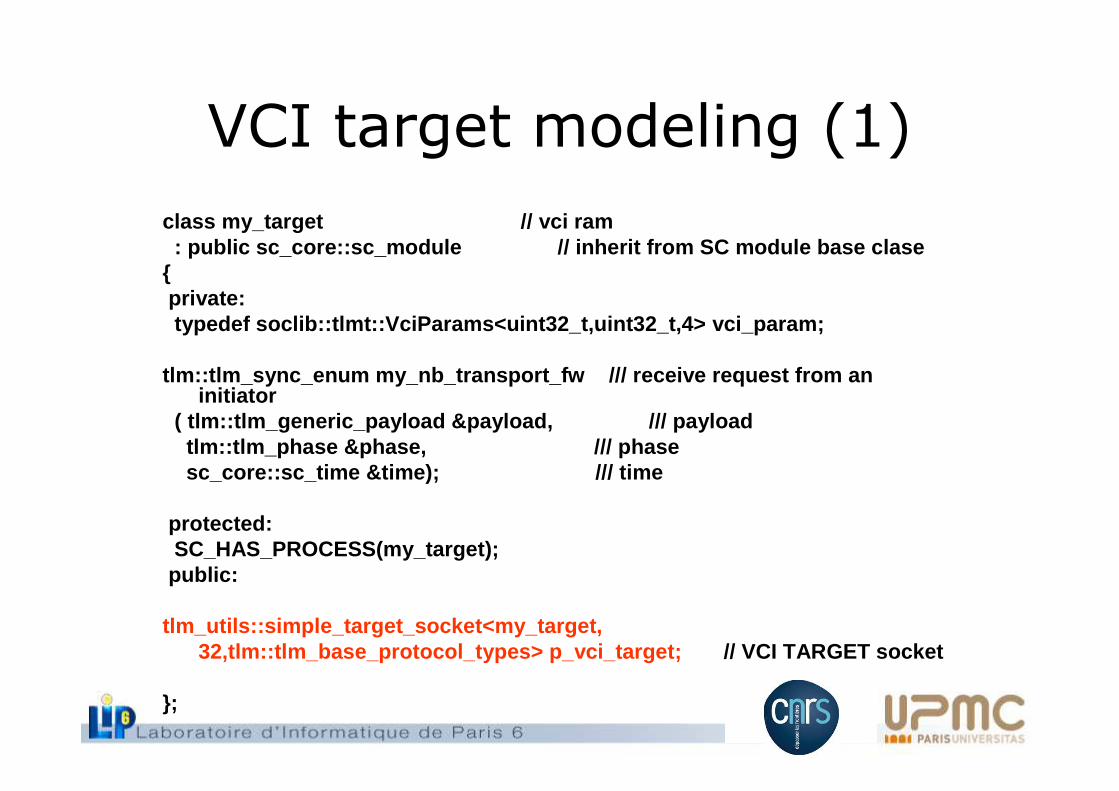
VCI target modeling (1)
class my_target // vci ram: public sc_core::sc_module // inherit from SC module base clase
{private:typedef soclib::tlmt::VciParams<uint32_t,uint32_t,4> vci_param;
tlm::tlm_sync_enum my_nb_transport_fw /// receive requ est from an initiator
( tlm::tlm_generic_payload &payload, /// payloadtlm::tlm_phase &phase, // / phasesc_core::sc_time &time); // / time
protected:SC_HAS_PROCESS(my_target);
public:
tlm_utils::simple_target_socket<my_target,32,tlm::tlm_base_protocol_types> p_vci_target; // VCI TARGET socket
};
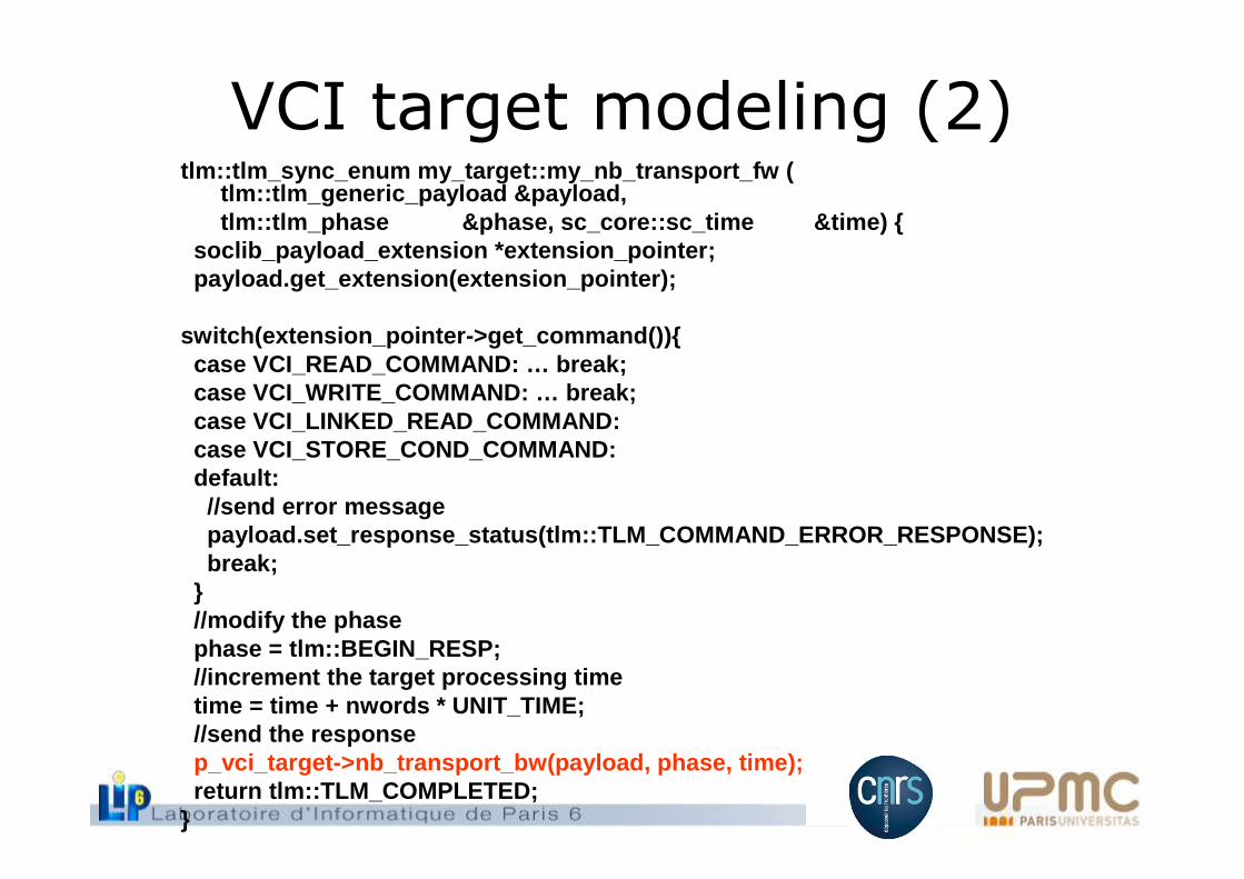
VCI target modeling (2)tlm::tlm_sync_enum my_target::my_nb_transport_fw (
tlm::tlm_generic_payload &payload,tlm::tlm_phase &phase, sc_core::sc_time &time) {
soclib_payload_extension *extension_pointer;payload.get_extension(extension_pointer);
switch(extension_pointer->get_command()){case VCI_READ_COMMAND: … break;case VCI_WRITE_COMMAND: … break;case VCI_LINKED_READ_COMMAND:case VCI_STORE_COND_COMMAND:default:
//send error messagepayload.set_response_status(tlm::TLM_COMMAND_ERROR_ RESPONSE);break;
}//modify the phasephase = tlm::BEGIN_RESP;//increment the target processing timetime = time + nwords * UNIT_TIME;//send the responsep_vci_target->nb_transport_bw(payload, phase, time) ;return tlm::TLM_COMPLETED;
}
Presentation overview
• PDES principles, TLM-T • TLM-2.0 basics, TLM-AT• VCI Interconnect modeling• VCI initiator modeling• VCI Target modeling• Conclusion