e-docs-#4172671-cmd 13-m30.2 submission from - nuclear free
TRANSCRIPT
CMD 13-M30.2
File/dossier : 6.02.04 Date : 2013-07-16 Edocs pdf : 4172671 Written Submission from Sunil Nijhawan In the Matter of
Mémoire de Sunil Nijhawan À l’égard de
CNSC Staff Integrated Safety Assessment of Canadian Nuclear Power Plants for 2012
Évaluation intégrée en matière de sûreté des centrales nucléaires au Canada par le personnel de la CCSN pour 2012
Commission Meeting August 21, 2013
Réunion de la Commission Le 21 août 2013
Public Comments on the CNSC Staff Integrated Safety Assessment of Canadian Nuclear Power Plants for 2012 – July 2013
1
Public Comments on CNSC Staff Integrated Safety Assessment of Canadian Nuclear Power Plants for 2012
Sunil Nijhawan
The CNSC Staff Integrated Safety Assessment of Canadian Nuclear Power Plants for 2012 (the Report), contains in an appendix, a summary chapter on the industry response to Fukushima action items and indicates that all short term action items for 2012 have been ‘closed’. There is no information on the basis on which these action items were closed. From the information available from sources outside the Report, I would submit to the Commission that no sound engineering bases exist for the closure of a number of these items and that this closure is premature, dangerously irresponsible and on many counts puts the safety of Canadians at risk; as if no lessons needed to be learnt from Fukushima.
The manner in which this finding has been published and the information staff may have used in accepting closure of these items is contrary to accepted engineering norms, safety practices and applicable codes. It is also indicative of the low CNSC staff expertise in severe accident related issues that CANDU reactors are especially vulnerable to. It also casts serious doubt on the Satisfactory Rating to all NPPs on all other counts that staff has generously bestowed upon all licensees. It reminds me of the rubber stamp parliaments in certain dictatorial regimes of the past. We all know how that ends.
With a background of longstanding work in the field of CANDU severe accidents and my past development of the Industry Standard Tool Set (MAAP-CANDU) for the analysis of severe accident progression in CANDU plants along with a number of other analytical and investigative tools, I am concerned that these decisions are premature at best. I submit that safety of Canadians continues to be at the same risk level as before Fukushima and the Commission should not accept the staff submission without an independent, qualified external review.
Public participation in CNSC activities cannot happen unless CNSC releases information in a timely manner to the public on its activities. In anticipation of gaining an understanding of the basis on which the Fukushima action items were being dispositioned by the CNSC staff, I made a request to CNSC for information under the Freedom of Information act in early January 2013. The request stated:
Please provide copies of all information submitted by holders of Canadian nuclear power reactor licensees in response to CNSC Staff Action Plan on the CNSC Fukushima Task Force Recommendations (i.e. in INFO 0824) for all short term items that were due for completion on 31 December 2012. For example this includes action item 1.1 (bleed condenser relief capacity), item 1.4 (PARS installation), 1.10 (electrical power for I&C), item 1.11 (emergency equipment), and other task force recommendations . Please also provide all their correspondence with CNSC and CNSC communications on the topics to the licensees during 2011 and 2012.
Over the last six months since I put in the request for information, I received two transmissions, one every 2-3 months, from CNSC but there was very little relevant information forthcoming, in spite of the request being unambiguous. CNSC staff has not been able to identify and disclose relevant information on industry submissions on closure of the short term Fukushima Action Items that were due on December 31, 2012. Or perhaps they are withholding public disclosure.
I still am able to provide sufficient information in this submission to demonstrate that my longstanding concerns about inadequacy of CANDU design are still valid and that Commission is best served by keeping public safety ahead of rubber stamping the staff findings. The Commission definitely seems to need independent technical
Public Comments on the CNSC Staff Integrated Safety Assessment of Canadian Nuclear Power Plants for 2012 – July 2013
2
advice. As an example, I summarize my concerns below on closure of two short term Fukushima Action Items. My concerns are not limited to these two items.
Fukushima Action Items 1.1.1 and 1.1.2
These Fukushima Task Force Action Items are summarized in the report as:
1.1.1 An updated evaluation of the capability of bleed condenser/degasser condenser relief valves providing additional evidence that the valves have sufficient capacity. December 2012.
1.1.2 If required, a plan and schedule either for confirmatory testing of installation or provision for additional relief capacity. December 2012.
Following is a summary of my understanding of the reasons for these action items and I have provided detailed arguments in Appendix A of my submission.
Summary of Concerns
When considerations for overpressure protection for nuclear reactor primary heat transport system include a loss of heat sinks, the certified steam relief capacity of the overpressure protection system safety relief valves must exceed the anticipated steam generation rate from core decay heat with a comfortable margin. Applicable ASME Boiler and Pressure Vessel Code, Section III, Subsection NB requires that the safety relief valves be properly sized and their relief capacity be certified in a prescribed manner that precludes large uncertainties and the legislated certification is solely based on actual testing of the subject valves.
While the PWRs and other reactors sport demonstrably adequate relief capacity (typically 50 times more than in a CANDU) and provide test results in their design submissions, the relief valves that provide overpressure protection on operating CANDU reactors do not meet these requirements even though they are required to adhere to the same ASME standards.
The valves were originally designed properly but were replaced en masse in 1996 after an incident at Pickering where the bleed condenser valves stuck open and chattered. The replacement degasser condenser safety relief valves are in most cases adequate for design basis accidents but not adequate to remove nuclear fuel decay heat after a reactor trip and a loss of heat sinks, a very simple design requirement easy to understand.
Each of the two safety relief valves (installed on the degasser condenser and relieving system pressure from the reactor water through another set of relief valves, an arrangement that is contrary to ASME requirements but accepted by CNSC) has a documented design specification of relief capacity of about 2 kg/s each that is 5 to 10 times less than ~20 kg/s of steam generated in the case of loss of AC power. The design capacity of ~2 kg/s was verified for Bruce valves in tests that would have disqualified the valves even for design basis accidents. With an inability to relieve the heat load when critically required, the reactor heat transport system would pressurize and burst a component that is weakest at that time.
A complete loss of AC power to the currently operating CANDU PHWR reactors thus has the potential to cause an uncontrolled pressurization of the heat transport system and an unplanned rupture. A ‘containment bypass’ is
Public Comments on the CNSC Staff Integrated Safety Assessment of Canadian Nuclear Power Plants for 2012 – July 2013
3
possible due to potential boiler tube ruptures with unacceptable off-site consequences. These consequences get worse especially if ECC does not fire and an ensuing actual severe core damage to the reactor is unmitigated as in Fukushima. Even prior to a widespread and severe damage to the fuel, a bursting of reactor pressure boundary will lead at best to a billion dollar damage to reactor core (if only a fuel channel bursts) and at worst to large off-site releases with unacceptable off-site radiological consequences that can be avoided by replacement of two $40,000 valves, erroneously mis-sized after the 1995 Pickering incident. CNSC asked the utilities to test the valves and the utilities have refused to do so. These reactors should now be shutdown until this is fixed properly.
Given that CNSC has not seen it fit to release all relevant information, I must paraphrase the industry submissions on the topic. My understanding is that Action items 1.1.1 and 1.1.2 related to these valves were closed based on:
1. NB Power submitting that while the subject valves were certainly inadequate to relieve the heat load and an over-pressure would occur, enough margins existed for the boiler tubes to survive.
2. Hydro Quebec admitting that while the subject valves were certainly inadequate to relieve the initial generation of steam but asserting that the pressurization after a loss of heat sinks would be slow and that peak pressure after a loss of capacity to relieve pressure would be capped at a pressure (11.7 MPa) lower than any failure pressure and no failure would occur in the reactor pressure boundary.
3. Bruce Power citing an earlier submission (some action item 021409) and promising to look further into it. 4. Ontario Power Generation submission information not available because CNSC has not made that public,
but given their past submissions on the topic it is not expected to be inconsistent with above positions, all of which defy engineering judgment and demonstrate a callous attitude to public safety and a stubborn response to the issue known to them for over 15 years.
There are two arguments in the above submissions. One says that nothing can fail even though there is no heat sink and the pressure rise is miraculously limited to an acceptable value. This implies that ASME requirements for testing are irrelevant. The other argument implies that there will be a failure due an inadequate over pressure protection by the degasser condenser valves but that a failure – a rupture – a bursting of the pressure boundary is an acceptable outcome even before the ECC has a chance to do its magic – because the failure is not in the boiler tubes.
These arguments are technically erroneous and dangerously irresponsible. Nothing should burst due to an over-pressure – ever. There are direct and unambiguous requirements from the ASME BPV code for certifications of relief capacity of the safety relief valves by testing to ensure that the valves do not allow an overpressure. That is what CNSC staff had asked the utilities to do years ago and that is what all other reactor designers and utilities do. Any analyses prepared to ‘demonstrate’ that the pressure in the reactor is self limiting are at best erroneous and misleading in general. These ‘analyses’ followed 10 years of the industry claiming that the relief capacity was actually way higher than the tested value. Then these claims were withdrawn because I insisted that they were wrong. This could have been easily detected by the CNSC staff with a simple linear equation (see Appendix A) available to all in the ASME BPV code. But CNSC staff were not able to catch that mistake.
It must be understood that a CANDU6 heat transport system with an effective volume of about 120 m3 cannot stop being uncontrollably and quickly pressurized in the absence of an adequate heat sink and in the absence of an adequate steam relief capacity, especially with ~20,000 kW of decay heat being generated and imparted directly to water, enveloping the fuel after the boilers have run dry but the heat transport system is still full of water. Having a steam relief capacity consistent with decay heat equivalent generation of steam is a basic and simple target. All other reactor designs meet that requirement handily. Once boilers are dry and no makeup to boilers can
Public Comments on the CNSC Staff Integrated Safety Assessment of Canadian Nuclear Power Plants for 2012 – July 2013
4
be initiated (the beginning of majority of severe core damage accidents), internal water is the immediate heat sink and its boiloff and inability to relieve the produced steam will cause the pressure to rise until something fails. There is no physical basis for the pressure rise limit to 11.7 MPa as claimed by HQ and NB Power, and AECL simulations have shown that pressure does rise to a higher value. In fact, use of any computer simulations to support that ludicrous argument is wrong and contrary to requirements of the ASME Boiler and Pressure Vessel Code that requires testing of the actual valves. The code requires that valves be tested under controlled conditions. Past tests of these valves for Bruce have confirmed that the relief capacity is woefully low, consistent with the valve specifications, albeit with a 50% scatter that would have normally caused the valves to be rejected.
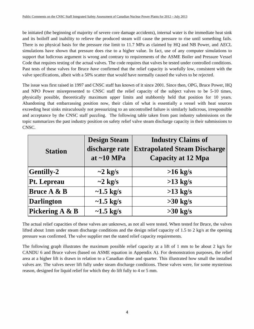
The issue was first raised in 1997 and CNSC staff has known of it since 2001. Since then, OPG, Bruce Power, HQ and NPO Power misrepresented to CNSC staff the relief capacity of the subject valves to be 5-10 times, physically possible, theoretically maximum upper limits and stubbornly held that position for 10 years. Abandoning that embarrassing position now, their claim of what is essentially a vessel with heat sources exceeding heat sinks miraculously not pressurizing to an uncontrolled failure is similarly ludicrous, irresponsible and acceptance by the CNSC staff puzzling. The following table taken from past industry submissions on the topic summarizes the past industry position on safety relief valve steam discharge capacity in their submissions to CNSC.
The actual relief capacities of these valves are unknown, as not all were tested. When tested for Bruce, the valves lifted about 1mm under steam discharge conditions and the design relief capacity of 1.5 to 2 kg/s at the opening pressure was confirmed. The valve supplier met the stated relief capacity requirements.
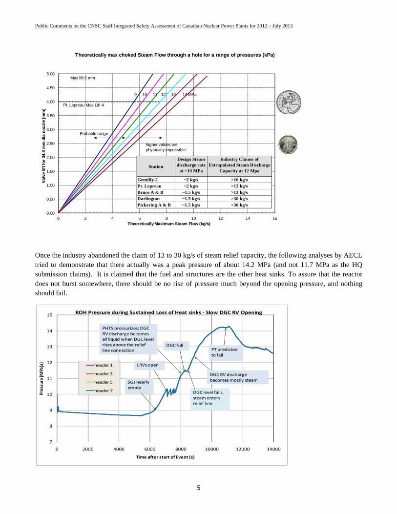
The following graph illustrates the maximum possible relief capacity at a lift of 1 mm to be about 2 kg/s for CANDU 6 and Bruce valves (based on ASME equation in Appendix A). For demonstration purposes, the relief area at a higher lift is drawn in relation to a Canadian dime and quarter. This illustrated how small the installed valves are. The valves never lift fully under steam discharge conditions. These valves were, for some mysterious reason, designed for liquid relief for which they do lift fully to 4 or 5 mm.
StationDesign Steam discharge rate
at ~10 MPa
Industry Claims of Extrapolated Steam Discharge
Capacity at 12 Mpa
Gentilly-2 ~2 kg/s >16 kg/sPt. Lepreau ~2 kg/s >13 kg/s Bruce A & B ~1.5 kg/s >13 kg/sDarlington ~1.5 kg/s >30 kg/sPickering A & B ~1.5 kg/s >30 kg/s
Public Comments on the CNSC Staff Integrated Safety Assessment of Canadian Nuclear Power Plants for 2012 – July 2013
5
Once the industry abandoned the claim of 13 to 30 kg/s of steam relief capacity, the following analyses by AECL tried to demonstrate that there actually was a peak pressure of about 14.2 MPa (and not 11.7 MPa as the HQ submission claims). It is claimed that the fuel and structures are the other heat sinks. To assure that the reactor does not burst somewhere, there should be no rise of pressure much beyond the opening pressure, and nothing should fail.
0.00
0.50
1.00
1.50
2.00
2.50
3.00
3.50
4.00
4.50
5.00
0 2 4 6 8 10 12 14 16
Val
ve li
ft fo
r 34
.8 m
m d
ia n
ozz
le [
mm
]
Theoretically Maximum Steam Flow (kg/s)
Theoretically max choked Steam Flow through a hole for a range of pressures (kPa)
9 10 11 12 13 14 MPa
higher values are physically impossible
Pt. Lepreau Max Lift 4
Max lift 5 mm
Probable range
StationDesign Steam discharge rate
at ~10 MPa
Industry Claims of Extrapolated Steam Discharge
Capacity at 12 Mpa
Gentilly-2 ~2 kg/s >16 kg/sPt. Lepreau ~2 kg/s >13 kg/s Bruce A & B ~1.5 kg/s >13 kg/sDarlington ~1.5 kg/s >30 kg/sPickering A & B ~1.5 kg/s >30 kg/s
7
8
9
10
11
12
13
14
15
0 2000 4000 6000 8000 10000 12000 14000
Pressure (M
Pa(a)
Time after start of Event (s)
ROH Pressure during Sustained Loss of Heat sinks ‐ Slow DGC RV Opening
header 1
header 3
header 5
header 7
DGC full
SGs nearly empty
LRVs open
PHTS pressurizes; DGC RV discharge becomesall liquid when DGC level rises above the relief line connection
DGCRV discharge becomes mostly steam
PT predicted to fail
DGC level falls, steam enters relief line
Public Comments on the CNSC Staff Integrated Safety Assessment of Canadian Nuclear Power Plants for 2012 – July 2013
6
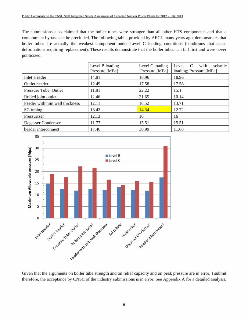
The submissions also claimed that the boiler tubes were stronger than all other HTS components and that a containment bypass can be precluded. The following table, provided by AECL many years ago, demonstrates that boiler tubes are actually the weakest component under Level C loading conditions (conditions that cause deformations requiring replacement). These results demonstrate that the boiler tubes can fail first and were never publicized.
Level B loading Pressure [MPa]
Level C loading Pressure [MPa]
Level C with seismic loading; Pressure [MPa]
Inlet Header 14.81 18.96 18.96 Outlet header 12.49 17.58 17.58 Pressure Tube Outlet 11.81 22.22 15.1 Rolled joint outlet 12.46 21.65 10.14 Feeder with min wall thickness 12.11 16.52 13.71 SG tubing 13.43 14.34 12.72 Pressurizer 12.13 16 16 Degasser Condenser 11.77 15.51 15.51 header interconnect 17.46 30.99 11.68
Given that the arguments on boiler tube strength and on relief capacity and on peak pressure are in error, I submit therefore, the acceptance by CNSC of the industry submissions is in error. See Appendix A for a detailed analysis.
0
5
10
15
20
25
30
35
Maxim
um Allo
wab
le pressure [Mpa]
Level BLevel C
Public Comments on the CNSC Staff Integrated Safety Assessment of Canadian Nuclear Power Plants for 2012 – July 2013
7
Action Item 1.4.1
This Fukushima Task Force Action Item can be summarized as:
A plan and schedule for the installation of PARs as quickly as possible.
Closure of this Action item is based on the utilities installing PARS that are adequate to mitigate deuterium/hydrogen only for design basis accidents and not as a Fukushima Action Item for severe accidents. It is acknowledged in Table C.1 of the Report that “Licensees have committed to installing passive autocatalytic recombiners (PARs) to improve hydrogen control during design basis accidents”. Deuterium/hydrogen production during a severe core damage accident can be orders of magnitude greater than the most challenging limited core damage accident covered under design basis, and threaten the containment integrity more grievously and lead to releases into environment of radio-activity in a manner that can cause severe off-site consequences. Thus, the action item should not be closed unless the utilities demonstrate that severe accident source terms of combustible D2/H2/CO can be mitigated without causing a containment failure. I submit that they are no position to make that claim at this time.
Given that there are no severe accident consequence assessment analyses done by any utility in Canada that consider the appropriate short term sources of deuterium/hydrogen in their severe accident progression simulations (using either MAAP-CANDU computer code that I developed for CANDUs or any other bounding analyses) it is questionable whether the selection of number, type and location of PARS is adequate, and the decision to ‘close’ the action item should be re-examined. The PARS units currently being installed or already installed are inadequate for severe accidents and the first order analysis presented in Appendix B easily demonstrates that. Just having some PARS (less than 30 AECL designed PARS at Pt. Lepreau, for example) is not a complete solution that would help avoid having Fukushima type consequences in Toronto suburbs. Additional information is summarized in Appendix B. Additional concerns about PARS causing a containment failure due to the large amounts of energy release during recombination of deuterium/hydrogen need to be addressed explicitly and the analysis presented in Appendix B shows that these additional heat loads can indeed be significant.
It has not been demonstrated that the number, type and location of PARS is optimal or sufficient. There is a haste to install some PARS without proper evaluations. Fundamental to choosing proper mitigation measures is completion of a full range of supporting analyses to evaluate the hydrogen source term rates. Given that the analyses conducted by the industry are incomplete and based on an outdated tool set that ignores major source terms for hydrogen, the action item should not be closed.
See Appendix B for further discussion on the topic.
Public Comments on the CNSC Staff Integrated Safety Assessment of Canadian Nuclear Power Plants for 2012 – July 2013
8
Additional Action Items
A number of convenient assumptions have been made over the years to project a positive picture of the severe accident mitigation capabilities of the CANDU power plants. For example an ability of the Calandria vessel to retain debris after a loss of core integrity has been a long standing industry position that has not been challenged by CNSC or reflected in its development of CNSC Fukushima action items.
Over 400 tons of water in the reactor vault (shield tank) of a CANDU reactor offers a unique heat sink for the debris if they are successfully contained in the Calandria vessel it envelops. Necessary for that is an adequate steam relief capacity in its overpressure protection system and am adequate heat removal capacity if recovery actions can reinstate that cooling. Reactor vaults in CANDU reactors were not designed to be able to remove the thermal loads from debris and with an inadequate steam relief capacity (except in newly refurbished unit at Pt. Lepreau) can fail once the water starts to boil. Vault water depletion, by failure or boiloff can lead to melt through of the debris through the Calandria shell and as debris heatup and melt onto the thin steel liner, lead to core concrete interactions (and further production of hydrogen and other combustible gases. This has not been addressed at all power plants and should have been a short term Fukushima action item.
It has been demonstrated by analyses that the CANDU Calandria vessel, a three cylinder stepped vessel may fail at it’s welds due to thermal stresses and the fabled capacity to retain debris is highly questionable. This has not been recognized by the industry and has a profound effect on source terms for hydrogen and energy release into the containment.
A public examination of all submissions by the industry on Fukushima action items is essential before CNSC should accept the closure of any action item. That is if it wants to take the safety of CANDU plants for severe accident mitigation seriously and not just rubber stamp any and all submissions on the topic by the industry.
Public Comments on the CNSC Staff Integrated Safety Assessment of Canadian Nuclear Power Plants for 2012 – July 2013
9
APPENDIX A – Fukushima Action Item 1.1.1 - Degasser Condenser Relief Valves
Background
After Fukushima, any Station Blackout capability reviews must be carried out with diligence and integrity beyond any reasonable doubt. This is especially true for nuclear reactors that did not consider a sustained loss of AC power and severe accidents in their original design basis. Integrity of the engineered barriers to release of activity must be demonstrated to showcase the extension of defense in depth to a Station Blackout and reasonable provisions for effective interventions. An important aspect of nuclear reactor heat transport system pressure boundary integrity is the ability of its over-pressure protection system to meet the challenges upon a sustained loss of AC power.
The primary heat transport systems in water cooled nuclear power reactors have at least two passive safety relief valves so that at least one is available to act with the generally mandated consideration of a single failure. Design criteria for these relief valves vary but their steam relief capacity, reliability and performance must conform to the relevant ASME code or equivalent requirements. A typical PWR of about 3000 MW thermal power may usually have 3-5 such valves able to relieve upto ~200 kg/s of steam, which may be about an order of magnitude higher than required. A typical single unit CANDU reactor, on the other hand, has about 30% less thermal power but only 2 such safety relief valves with a combined steam relief capacity of about 4 kg/s or about 4 MW of thermal power equivalent at the relief set-point and a time when the decay power is ~20 MW. Installation of these valves in a CANDU reactor is also atypical; as they do not provide a direct and unobstructed path from the heat transport system but are installed downstream of another series of isolating Liquid Relief Valves emptying into an unpressurized and small degasser condenser vessel downstream of which they are mounted.
These valves become critical when there is a sustained loss/depletion of engineered heat removal systems following multiple failures as in Fukushima. An unmitigated increase in heat transport pressure and a consequential breech in pressure boundary become inevitable if the core decay heat exceeds the safety valve steam relief capacity. If the ensuing failure is in the boiler tubes, a containment bypass and release of activity into atmosphere is possible.
The present design of CANDU reactor Primary Heat Transport system does not seem to allow the anticipated energy relief through the safety relief valves following a sustained loss of all engineered heat sinks. This may result in uncontrolled primary heat transport system pressurization and a potential for boiler tube ruptures such that activity releases bypass the containment and expose the population to dangerously high radiation well before any evacuation. If the valves are to conform to requirements of the ASME codes under early stages of a loss of heat sinks scenario just as they must for design basis accidents (energy relief capacity greater than the heat load), it may seem that many clauses of the applicable ASME code sections for the subject valves are violated in abundance and with impunity.
A containment bypass resulting from boiler tube failure caused by the faulty overpressure protection can cause fatalities that can be high with astronomical economic consequences, especially after the fuel begins to overheat. Such a containment bypass is considered to present the highest risk to public. The probability of a sustained loss of heat sinks is not insignificant and the overall risk is yet to be quantified for all instigators for any CANDU
Public Comments on the CNSC Staff Integrated Safety Assessment of Canadian Nuclear Power Plants for 2012 – July 2013
10
power plant. The national regulators have not required that utilities do so in a timely manner and as a condition of operating license.
INTRODUCTION
Nuclear reactor design and licensing is typically a national issue but their accidents have international implications and affect the nuclear industry at large. The 2011 Fukushima reactor accident has brought to the forefront of our consciousness, questions about preventative and mitigative features of various reactor designs under upset conditions that may lead to a loss of engineered heat sinks and severe damage to the nuclear core. Integrity of the pressure vessels and nuclear reactor cooling systems is an important aspect of the safety reviews that have followed. Challenges to vessel integrity may arise either due to unanticipated thermal hydraulic loads or due to unanticipated challenges to the pressure and inventory control systems. If the engineered over-pressure protection systems design does not offer protection for scenarios that are precursors to a core damage accident, then the defense in depth hallmark of the nuclear reactors is jeopardized.
Operating CANDU reactors, like others that were designed and built between 1960s and early 1980s, were not designed with severe accidents in their design basis and include little additional measures for severe accident mitigation, instigated for example by a sustained loss of on-site AC power, as in Fukushima. Their operational safety is exemplary and the safety evaluations for design basis accidents have satisfied the respective national regulators into licensing over 50 of these reactors in Canada, India, Rumania, Korea, Argentina and China. However, many a design feature that is acceptable for design basis accidents may not be sufficient to mitigate those accidents that may lead to severe core damage. It is only during evaluation of severe accident progression and consequence assessments that some design deficiencies are identified.
Of significant alarm is the fact that the utilities that own and operate the reactors and the national regulators that are supposed to be the wise overview, are unable to accept some of these design deficiencies as real; mired in the perception they create of the universality of the safety of their reactors even under the conditions for which they were not designed. The over pressure protection system is a case in point for CANDU reactors. This simple issue has remained unresolved for over 12 years.
OVER-PRESSURE PROTECTION SYSTEMS
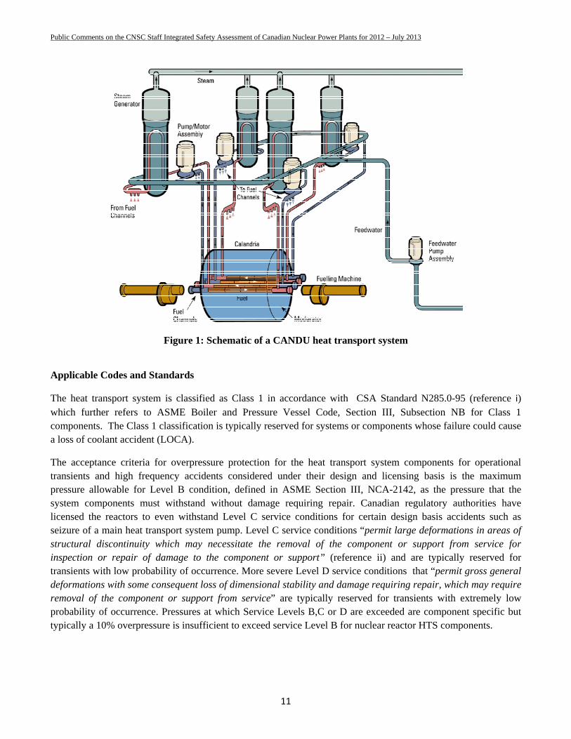
Primary heat transport system (HTS), designed to carry heat from the horizontal fuel channels, is a closed heavy water loop in CANDU pressurized heavy water reactors. It includes the pumps, headers, feeders, the primary side of the steam generators, and a pressurizer. There are two separate, but inter connected and isolable, heat transport loops, with each serving one-half of the reactor and half of the fuel channels (half of 380 channels in a single unit ~700 MWe, 2000 MW thermal CANDU-6 reactor) through two passes each with its own pump and steam generator (Figure 1). The two loops are connected to a common pressurizer, common emergency core cooling, shutdown cooling, pressure and inventory control and purification systems.
Public Comments on the CNSC Staff Integrated Safety Assessment of Canadian Nuclear Power Plants for 2012 – July 2013
11
Figure 1: Schematic of a CANDU heat transport system
Applicable Codes and Standards
The heat transport system is classified as Class 1 in accordance with CSA Standard N285.0-95 (reference i) which further refers to ASME Boiler and Pressure Vessel Code, Section III, Subsection NB for Class 1 components. The Class 1 classification is typically reserved for systems or components whose failure could cause a loss of coolant accident (LOCA).
The acceptance criteria for overpressure protection for the heat transport system components for operational transients and high frequency accidents considered under their design and licensing basis is the maximum pressure allowable for Level B condition, defined in ASME Section III, NCA-2142, as the pressure that the system components must withstand without damage requiring repair. Canadian regulatory authorities have licensed the reactors to even withstand Level C service conditions for certain design basis accidents such as seizure of a main heat transport system pump. Level C service conditions “permit large deformations in areas of structural discontinuity which may necessitate the removal of the component or support from service for inspection or repair of damage to the component or support” (reference ii) and are typically reserved for transients with low probability of occurrence. More severe Level D service conditions that “permit gross general deformations with some consequent loss of dimensional stability and damage requiring repair, which may require removal of the component or support from service” are typically reserved for transients with extremely low probability of occurrence. Pressures at which Service Levels B,C or D are exceeded are component specific but typically a 10% overpressure is insufficient to exceed service Level B for nuclear reactor HTS components.
Public Comments on the CNSC Staff Integrated Safety Assessment of Canadian Nuclear Power Plants for 2012 – July 2013
12
ASME Section III, NB-7000 describes the requirements for the over-pressure relief valves required when the operating conditions in the Overpressure Protection Report would cause the Service limits specified in the Design Specification to be exceeded.
No sections of the ASME Section III (or general engineering principles) allow the over pressure protection system on Class 1 systems to permit an uncontrolled rupture of the nuclear heat transport system under anticipated thermal loading conditions. A loss of all AC power and ensuing boiloff / depletion of the boiler water inventory resulting in an pressurization of the HTS is an anticipated event that can be otherwise mitigated by adding water to the boilers during HTS inventory depletion and before a severe core damage can start.
Overpressure protection in PWRs and PHWRs
Over-pressure protection on a pressurized water reactor is composed of a number of complementing systems including the reactor shutdown systems and pressure and inventory control systems. Passive, spring loaded, self closing safety relief valves are the most important components of the pressure control systems, especially upon a reactor trip.
The Primary Heat Transport Systems in nuclear power reactors have at least two self actuated by direct fluid pressure, spring loaded, reclosing safety relief valves so that at least one is available to act with the generally mandated consideration of a single failure. Design criteria for these safety relief valves vary but their steam (energy) relief capacity, reliability and performance must conform to the relevant ASME Section III or equivalent requirements. Regulatory requirements such as in Reference iii, also ensure that the valves are properly tested. The design relief capacity is chosen to envelope the requirements of a set of credible events that form the design basis (e.g. Loss of electrical load and/or turbine trip, Uncontrolled rod withdrawal at power, Loss of reactor coolant flow, Loss of normal feedwater, Loss of offsite power to the station auxiliaries). These valves are designed, tested and certified using the transients, loading, seismic considerations, and stress limits for Class 1 components.
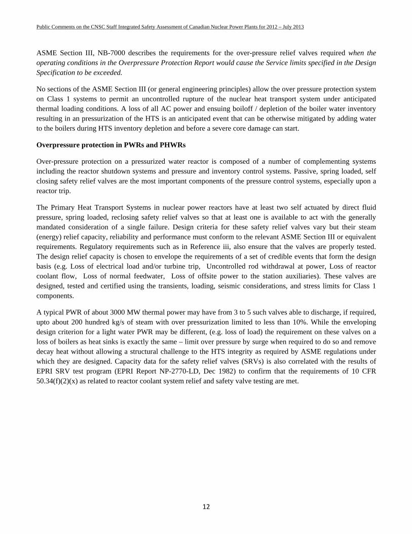
A typical PWR of about 3000 MW thermal power may have from 3 to 5 such valves able to discharge, if required, upto about 200 hundred kg/s of steam with over pressurization limited to less than 10%. While the enveloping design criterion for a light water PWR may be different, (e.g. loss of load) the requirement on these valves on a loss of boilers as heat sinks is exactly the same – limit over pressure by surge when required to do so and remove decay heat without allowing a structural challenge to the HTS integrity as required by ASME regulations under which they are designed. Capacity data for the safety relief valves (SRVs) is also correlated with the results of EPRI SRV test program (EPRI Report NP-2770-LD, Dec 1982) to confirm that the requirements of 10 CFR 50.34(f)(2)(x) as related to reactor coolant system relief and safety valve testing are met.
Public Comments on the CNSC Staff Integrated Safety Assessment of Canadian Nuclear Power Plants for 2012 – July 2013
13
Figure 2 : HTS over protection on a typical PWR (Diablo Canyon)
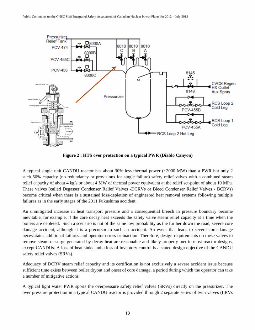
A typical single unit CANDU reactor has about 30% less thermal power (~2000 MW) than a PWR but only 2 such 50% capacity (no redundancy or provisions for single failure) safety relief valves with a combined steam relief capacity of about 4 kg/s or about 4 MW of thermal power equivalent at the relief set-point of about 10 MPa. These valves (called Degasser Condenser Relief Valves -DCRVs or Bleed Condenser Relief Valves - BCRVs) become critical when there is a sustained loss/depletion of engineered heat removal systems following multiple failures as in the early stages of the 2011 Fukushima accident.
An unmitigated increase in heat transport pressure and a consequential breech in pressure boundary become inevitable, for example, if the core decay heat exceeds the safety valve steam relief capacity at a time when the boilers are depleted. Such a scenario is not of the same low probability as the further down the road, severe core damage accident, although it is a precursor to such an accident. An event that leads to severe core damage necessitates additional failures and operator errors or inaction. Therefore, design requirements on these valves to remove steam or surge generated by decay heat are reasonable and likely properly met in most reactor designs, except CANDUs. A loss of heat sinks and a loss of inventory control is a stated design objective of the CANDU safety relief valves (SRVs).
Adequacy of DCRV steam relief capacity and its certification is not exclusively a severe accident issue because sufficient time exists between boiler dryout and onset of core damage, a period during which the operator can take a number of mitigative actions.
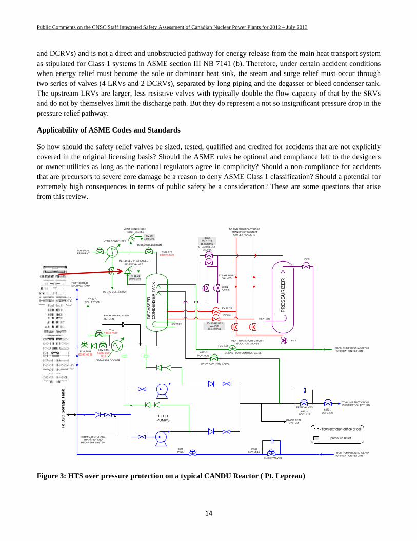
A typical light water PWR sports the overpressure safety relief valves (SRVs) directly on the pressurizer. The over pressure protection in a typical CANDU reactor is provided through 2 separate series of twin valves (LRVs
Public Comments on the CNSC Staff Integrated Safety Assessment of Canadian Nuclear Power Plants for 2012 – July 2013
14
and DCRVs) and is not a direct and unobstructed pathway for energy release from the main heat transport system as stipulated for Class 1 systems in ASME section III NB 7141 (b). Therefore, under certain accident conditions when energy relief must become the sole or dominant heat sink, the steam and surge relief must occur through two series of valves (4 LRVs and 2 DCRVs), separated by long piping and the degasser or bleed condenser tank. The upstream LRVs are larger, less resistive valves with typically double the flow capacity of that by the SRVs and do not by themselves limit the discharge path. But they do represent a not so insignificant pressure drop in the pressure relief pathway.
Applicability of ASME Codes and Standards
So how should the safety relief valves be sized, tested, qualified and credited for accidents that are not explicitly covered in the original licensing basis? Should the ASME rules be optional and compliance left to the designers or owner utilities as long as the national regulators agree in complicity? Should a non-compliance for accidents that are precursors to severe core damage be a reason to deny ASME Class 1 classification? Should a potential for extremely high consequences in terms of public safety be a consideration? These are some questions that arise from this review.
Figure 3: HTS over pressure protection on a typical CANDU Reactor ( Pt. Lepreau)
VENT CONDENSERRELIEF VALVES
VENT CONDENSER
GASEOUS EFFLUENT
DEGASSER CONDENSERRELIEF VALVES
TO D2O COLLECTION
TO D2O COLLECTION
TO AND FROM EAST HEATTRANSPORT SYSTEM
OUTLET HEADERS
LIQUID RELIEFVALVES
10.24 MPag
STEAM RELIEFVALVES
STEAM BLEEDVALVES
PR
ES
SU
RIZ
ER
HEAT TRANSPORT CIRCUITISOLATION VALVES
DEGAS FLOW CONTROL VALVE
SPRAY CONTROL VALVE
FEEDPUMPS
FROM D2O STORAGETRANSFER AND
RECOVERY SYSTEM
FEED VALVES
TO PUMP SUCTION VIAPURIFICATION RETURN
FROM PUMP DISCHARGE VIAPURIFICATION RETURN
FROM PUMP DISCHARGE VIAPURIFICATION RETURN
BLEED VALVES
DEGASSER COOLER
FROM PURIFICATIONRETURN D
EG
AS
SE
RC
ON
DE
NS
ER
TA
NKTO/FROM D2O
STORAGE TANK
HEATERS
HEATERS
RV 291.03 MPa 3332
PV 47,4810.86 MPag
RV 11,2110.06 MPa
63332PCV 5,6
63331LCV 13,22
PV 12,13
PV 3,4
63332PCV 24,25
FCV 8,26
PV 9
PV 7
63331LCV 11,12
63331LCV 14,15
3331PV25
LCV 8,1563332-LCV
8,15
3332 PV1663332-HS 16
- flow restriction orifice or coil
- pressure relief
TO D2OCOLLECTION
PV 1063332-HS10
GLAND SEALSYSTEM
To
D2O
So
rag
e T
ank
3332 P2263332-HS 22
Public Comments on the CNSC Staff Integrated Safety Assessment of Canadian Nuclear Power Plants for 2012 – July 2013
15
SRV sizing and code classification issues
A review of ASME section III and its application to reactors designed and licensed in the US and Europe reveals that the SRVs are sized such that the over pressurization imposed on the pressure boundary does not exceed the limits imposed by service Level B (typically an overpressure of 10%) for almost all foreseeable events, including those later potentially leading to core damage. Given the frequency at which off-site power has been lost to operating nuclear reactors and the past occurrences of simultaneous loss or effectiveness of on-site back up power at TMI, Narora, Fukushima leading to a loss of backup feedwater to the boilers, the event is at least of moderate probability of occurrence. Given that the consequences can be fairly severe, the potential risk is not insignificant.
It can be argued that with regulatory blessing, a utility that owns and operates the reactor can allow itself the luxury of making expensive repairs or writing off a reactor in event of a temporary loss of boilers as a heat sink (which really is a recoverable accident as restoration of water into the boilers within the next hour is a high probability recovery action) by allowing the valves to be such that their design parameters allow service level C loads on the heat transport system (typically an overpressure as low as 20% to 30% but depends upon each component and on seismic loading). However, it would be totally irresponsible to design the valves to cause service level D conditions as it could potentially result in an un-repairable nuclear reactor. Under no circumstances should a design that potentially allows an uncontrolled pressurization and stress levels beyond Service Level D into an uncontrolled rupture of the weakest component of the pressure boundary for a relatively high probability accident such as the ones leading to loss of boilers as a heat sinks, be allowed to stand. Recall that a loss of boilers as a heat sink is not a severe core damage accident by itself but can be a severe activity release accident if the containment is bypassed.
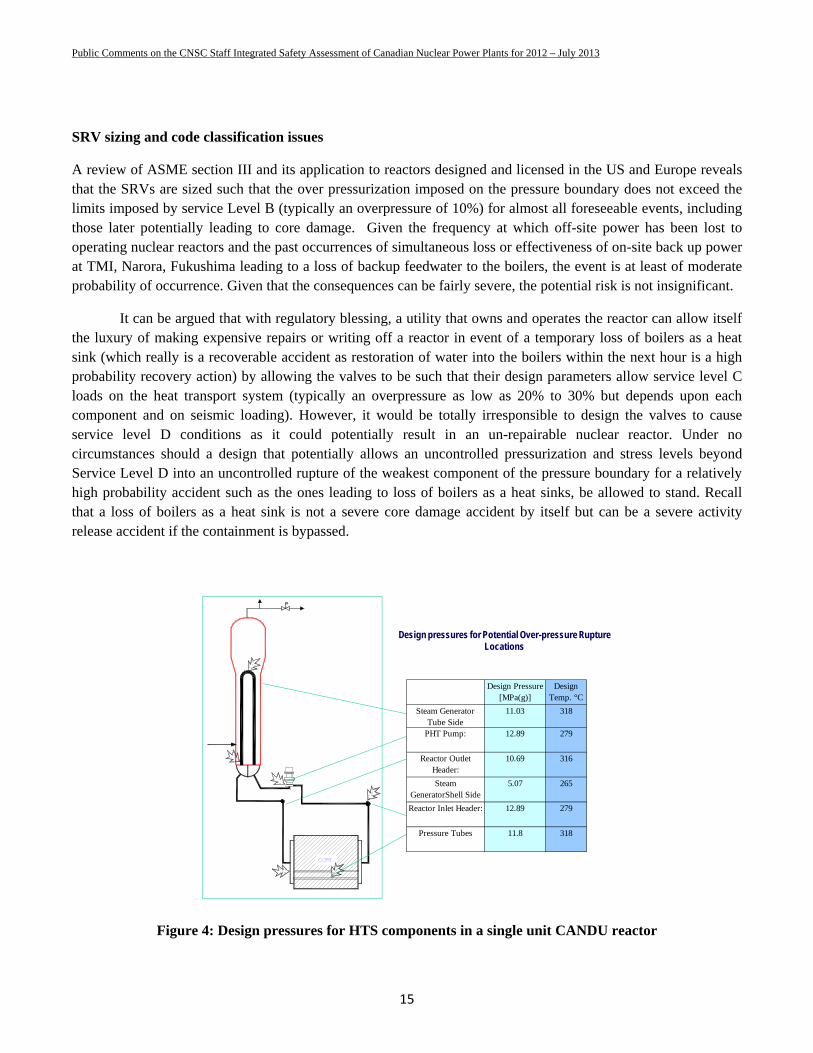
Figure 4: Design pressures for HTS components in a single unit CANDU reactor
Design pressures for Potential Over-pressure Rupture Locations
Design Pressure [MPa(g)]
Design Temp. °C
Steam Generator Tube Side
11.03 318
PHT Pump: 12.89 279
Reactor Outlet Header:
10.69 316
Steam GeneratorShell Side
5.07 265
Reactor Inlet Header: 12.89 279
Pressure Tubes 11.8 318
Public Comments on the CNSC Staff Integrated Safety Assessment of Canadian Nuclear Power Plants for 2012 – July 2013
16
Determination of HTS pressures at which service Level B, C and D conditions are reached should be carried out considering ageing effects and the deteriorated conditions at which the reactors are allowed to operate. For CANDU reactors that includes anticipated, but allowable thinning of the carbon steel feeders and the boiler tubes with consideration of anticipated seismic loading under accident conditions. Examination of pressures at which service level B and C condition are reached in HTS components of a typical CANDU reactor (operating pressure at the inlet of channels of 11.3 MPa and at the outlet 10 MPa) without flaw like defects reveals that the boiler tubes may be susceptible to Level C conditions with less than 30% overpressure. With flaws and geometric deteriorations common in boiler tubes it is possible that failure of boiler tubes under over pressure conditions cannot be ruled out to occur before failure of another component within the reactor building.
There are two issues at hand. First that the safety valves must be properly sized by the designers and second that their pre-installation testing must always be governed by certain engineering principles, (stipulated for Class 1 components by ASME and CSA) that should not be violated. Additional requirements have been imposed by NRC in 10 CFR 50.34(f)(2)(x) to ascertain that any drift in valve characteristics is detected by periodic testing of the subject valves (also mandated by ASME OM code).
SRV testing and qualification
No matter what the limiting design criterion for a safety relief valve is and how ultimately the valves are sized, there are certain rules as to their pre installation operability and capacity certification to determine with high degree of repeatability and confidence:
1. Opening pressure 2. Closing Pressure 3. Relief capacity.
ASME Section III, NB-7000 rules explicitly require that a number of identical valves be tested preoperational under proscribed certification rules in a certified facility and under the supervision of a certified professional. These rules have to be followed if the reactor component is to be ASME Code compliant. The requirements span a number of code subsections and can be summarized in simple words as:
1. The actual safety relief valves must be tested individually in steam at representative conditions in a certified facility. Tests are mandatory and cannot be substituted by a computer models unless verified by test data for the same geometry of valves.
2. Installation geometry must be replicated in tests. 3. Three to four valves are to be tested (number depends upon the method used to certify relief capacity).
Three discharge tests per valve are required. 4. Test data on Opening Pressure or the Set Pressure (pressure at which the valves open to sustain a
discharge) must fall within 3% of the design value. 5. Rated discharge capacity must be attained within 110% of the set pressure. 6. Inlet pressure losses on valves as installed be no more than 3% (non-mandatory) 7. Any valves that give a relief discharge more than 5% from the average must be rejected. 8. Effect of uncertainties in measurement should be considered. 9. Only 90% of the average tested relief capacity is used as certified relief capacity.
Public Comments on the CNSC Staff Integrated Safety Assessment of Canadian Nuclear Power Plants for 2012 – July 2013
17
10. Maximum possible steam discharge can be pre calculated using Napier equations and their corrections for superheat and pressure. A coefficient of discharge equal to the ratio of the actual flow to the maximum flow is developed and used.
11. Extrapolation or proration to a pressure higher than the pressure at which the relief capacity has been certified is permissible by the ratio of pressures. So at a pressure greater by 20% over the certification pressure, the relief capacity can be claimed to be greater by only 20%.
12. Extrapolation to other fluids is according to Section XI of the ASME code. Steam service valves should always be tested in steam.
The HTS overpressure protection against a loss of heat sinks is such an important safety function that competent regulators (e.g. NRC) often require that installed valves be tested on a regular basis and hold the valve performance as a condition of license for the nuclear power plant. In short, broad engineering principles, ASME Code requirements and regulatory vigilance ensure that the valves operate as per the design basis to protect the equipment and provide their function fully and effectively when required.
Valve testing as a mandatory requirement
Neither the competent regulatory oversight, nor ASME rules allow the valve performance to be certified alone by word arguments, correlations, analysis or by stating that the results of an uncontrolled rupture of Class 1 nuclear piping following their actuation when required is an acceptable outcome, in lieu of proper choice and testing of the valves.
CANDU Safety Relief Valve Design Specifics
The HTS over-pressure protection is currently provided through two pairs of liquid relief valves (LRVs) that join the outlet headers from the two loops at one end of the reactor to the degasser condenser tank (Figure 3). These valves form the pressure boundary under normal operating conditions but are not the ultimate pressure relief valves. With the outlet headers at 10 MPA, these liquid relief valves are designed to open at 10.24 MPa and allow a discharge of about 25.2 kg/s of liquid D2O. Their relief setpoint is properly kept lower than the 10% over-pressure protection required by the ASME and CSA standards for operational transients of relatively high frequency. These LRVs discharge into a tank called the Degasser or Bleed condenser which normally operates at pressures that are close to atmospheric pressure. The two (2) safety relief valves on the degasser condenser (DCRVs) are then the ultimate over-pressure protection devices for the HTS and are effective only when the upstream LRVs open and pressurize the degasser condenser tank. These degasser condenser relief valves are also sized, tested and qualified for liquid relief with a discharge capacity of about 26.7 kg/s of liquid D2O at 10.057 MPa and 268C. The setpoint is only slightly higher than the normal outlet header pressure to avoid a loss of HTS inventory through a spurious opening of the upstream LRV. A schematic of the proportional spring loaded liquid relief valves is shown in Figure 3. These valves can also be pneumatically activated; typically at a setpoint of about 11.7 MPa.
The design specifications of the steam relief from the degasser condenser relief valves (DCRVs) is only about 1.9 m3/min. or about 2 kg/s at 10 MPa. Importance of DCRV relief capacity for steam service was perhaps not an issue during capacity qualification tests for these new Bopp and Reuther 2”x3” pressure relief valves that replaced the 4”x6” Cosby valves in mid 1995-96 after the Pickering NGS incident of a stuck open and chattering safety relief valve.
Public Comments on the CNSC Staff Integrated Safety Assessment of Canadian Nuclear Power Plants for 2012 – July 2013
18
As a result, the total steam relief energy equivalence is only about 4 MW from the two DCRVs. This is significantly lower than decay heat of ~20 MW after 2 hours when the boilers run dry and for the rest of the day after a reactor trip (see Figure 6). One stated design basis for the subject valves is ‘loss of inventory control and loss of heat sink’. The stated design objective is not met for a sustained loss of heat sinks.
Estimates of steam relief capacity of the subject valves
Some of the subject valves are made by Bopp and Reuther and their initial capacity certification test confirmed that their design liquid and steam discharge capacity was approximately as specified. The valves performed in tests as specified by the designers and the valve suppliers met the stated design specifications.
The Bopp & Reuther valves installed in CANDU-6 reactors have a throat diameter of 34.8 mm and a maximum lift of 4 or 5 mm, depending upon the reactor unit. Valves lifted fully for water tests as designed but the steam tests resulted in a lower lift as expected for a maximum lift of about 0.8 to 1.5 mm.
An estimate of the maximum possible steam relief capacity of the subject valves can be easily made by using fundamental equations such as the Napier equation, by using NB-7734.2 Establishment of Coefficient of Discharge, excerpts from which are reproduced below:
(a) Tests shall be made on each pressure relief valve to determine its lift, opening, and blowdown pressures, and capacity in terms of the fluid used in the test. A coefficient of discharge KD shall be established for each test run as follows:
FlowlTheoretica
FlowActualKD = Coefficient of Discharge
where Actual Flow is determined quantitatively by test, and the Theoretical Flow is calculated by the following formula For test with dry saturated steam:
Pressures up to 1,500 psig (10 342 kPa gage)
WT = 51.5AP
Pressures over 1,500 psig (10 342 kPa gage) and up to 3,200 psig (22 063 kPa gage) the value of WT calculated by the above equation, shall be corrected by being multiplied by the following factor:
)315.72292.0()895.61906.0(
P
P
The average of the coefficients of discharge KD of the tests required shall be multiplied by 0.90 and their product shall be taken as the coefficient K of that design. The coefficient of the design shall not be greater than 0.876 (the product of 0.9 × 0.975).
Public Comments on the CNSC Staff Integrated Safety Assessment of Canadian Nuclear Power Plants for 2012 – July 2013
19
(b) If any of the experimentally determined coefficients fall outside of a range of ±5% of the average coefficient, the unacceptable valves shall be replaced by two valves of the same size and set pressure. Following the test of these valves, a new average coefficient shall be determined, excluding the replaced valve test results. If any individual coefficient is now outside of the ±5% range, then the test shall be considered unsatisfactory and shall be cause for the ASME designated organization to refuse certification of the particular valve design.
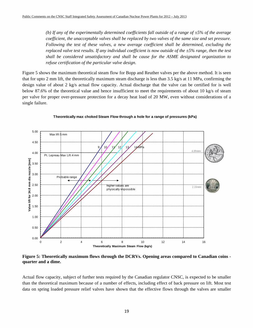
Figure 5 shows the maximum theoretical steam flow for Bopp and Reuther valves per the above method. It is seen that for upto 2 mm lift, the theoretically maximum steam discharge is less than 3.5 kg/s at 11 MPa, confirming the design value of about 2 kg/s actual flow capacity. Actual discharge that the valve can be certified for is well below 87.6% of the theoretical value and hence insufficient to meet the requirements of about 10 kg/s of steam per valve for proper over-pressure protection for a decay heat load of 20 MW, even without considerations of a single failure.
Figure 5: Theoretically maximum flows through the DCRVs. Opening areas compared to Canadian coins - quarter and a dime.
Actual flow capacity, subject of further tests required by the Canadian regulator CNSC, is expected to be smaller than the theoretical maximum because of a number of effects, including effect of back pressure on lift. Most test data on spring loaded pressure relief valves have shown that the effective flows through the valves are smaller
0.00
0.50
1.00
1.50
2.00
2.50
3.00
3.50
4.00
4.50
5.00
0 2 4 6 8 10 12 14 16
Val
ve l
ift
for
34.8
mm
dia
no
zzle
[m
m]
Theoretically Maximum Steam Flow (kg/s)
Theoretically max choked Steam Flow through a hole for a range of pressures (kPa)
9 10 11 12 13 14 MPa
higher values are physically impossible
Pt. Lepreau Max Lif t 4 mm
Max lif t 5 mm
Probable range
2.33mm=
4.09mm=
Public Comments on the CNSC Staff Integrated Safety Assessment of Canadian Nuclear Power Plants for 2012 – July 2013
20
than the theoretical maximum and the effective coefficient of discharge KD significantly smaller than 1. Of particular interest are studies on effect of back pressure on valve lift characteristics.
Utilities, however, claim that heat transport system over-pressure protection system has been designed to meet the requirements of the applicable ASME, CSA and CNSC design requirements. These include the ASME Boiler and Pressure Vessel Code Section III, Section NB, the CSA Standards CAN3-N285.0-95 and CAN3-N285.1-M81 design as well as the Canadian Atomic Energy Control Board (now CNSC) Regulatory Document R-77. All these documents require that the over-pressure protection be sufficient to limit the damage to the HTS consistent with the frequency of the initiating events.
In all cases the applicable codes specify the maximum over-pressure and maximum allowable physical damage to the system. The requirements always implicitly insist that the over-pressure protection be sufficient to prevent an uncontrolled rupture.
A station blackout accident involving a sustained loss of AC power (as in Fukushima) and resulting in a loss of steam generator heat sinks to the HTS is one of the accidents that the over pressure protection system must be designed for. Such a loss can occur if both the main and auxiliary feedwater injections are lost. Once the water level in steam generators drops sufficiently low, the heat removal capacity will fall below heat generation by decay heat. If the shutdown cooling is not brought in a timely manner or fails to initiate in the abnormal mode – the HTS pressure can increase. It is at this time that the LRVs and the DCRVs will open to try to relieve the decay heat. Since their relief capacity is lower than the heat load – an uncontrolled rupture in the HTS will result in one of the various locations identified in Figure 4. If this consequential failure is in the steam generator tubes – a containment bypass will ensue and the doses to the public can be extremely high, especially after fuel failures.
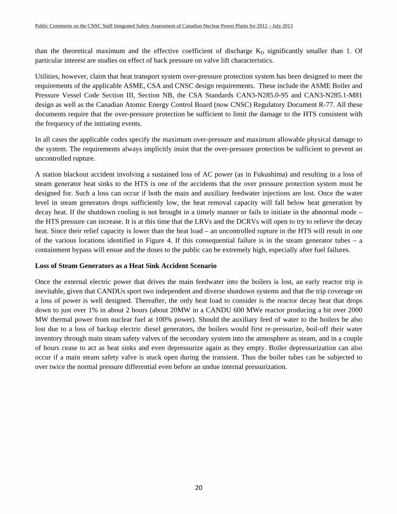
Loss of Steam Generators as a Heat Sink Accident Scenario
Once the external electric power that drives the main feedwater into the boilers is lost, an early reactor trip is inevitable, given that CANDUs sport two independent and diverse shutdown systems and that the trip coverage on a loss of power is well designed. Thereafter, the only heat load to consider is the reactor decay heat that drops down to just over 1% in about 2 hours (about 20MW in a CANDU 600 MWe reactor producing a bit over 2000 MW thermal power from nuclear fuel at 100% power). Should the auxiliary feed of water to the boilers be also lost due to a loss of backup electric diesel generators, the boilers would first re-pressurize, boil-off their water inventory through main steam safety valves of the secondary system into the atmosphere as steam, and in a couple of hours cease to act as heat sinks and even depressurize again as they empty. Boiler depressurization can also occur if a main steam safety valve is stuck open during the transient. Thus the boiler tubes can be subjected to over twice the normal pressure differential even before an undue internal pressurization.
Public Comments on the CNSC Staff Integrated Safety Assessment of Canadian Nuclear Power Plants for 2012 – July 2013
21
Figure 6: Decay heat and water boiloff in the CANDU 6 boilers upon a loss of feedwater injection.
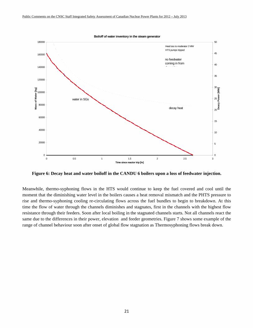
Meanwhile, thermo-syphoning flows in the HTS would continue to keep the fuel covered and cool until the moment that the diminishing water level in the boilers causes a heat removal mismatch and the PHTS pressure to rise and thermo-syphoning cooling re-circulating flows across the fuel bundles to begin to breakdown. At this time the flow of water through the channels diminishes and stagnates, first in the channels with the highest flow resistance through their feeders. Soon after local boiling in the stagnated channels starts. Not all channels react the same due to the differences in their power, elevation and feeder geometries. Figure 7 shows some example of the range of channel behaviour soon after onset of global flow stagnation as Thermosyphoning flows break down.
Boiloff of water inventory in the steam generator
0
20000
40000
60000
80000
100000
120000
140000
160000
180000
0 0.5 1 1.5 2 2.5 3
Time since reactor trip [hr]
Ma
ss
of
Wa
ter
[kg
]
0
5
10
15
20
25
30
35
40
45
50
De
ac
y P
ow
er
[MW
]
decay heat
Heat loss to moderator 2 MW
HTS pumps tripped
no feedwater coming in from deaerator
water in SGs
Public Comments on the CNSC Staff Integrated Safety Assessment of Canadian Nuclear Power Plants for 2012 – July 2013
22
Figure 7: Examples of range of channel conditions after a loss of circulation
The main thrust of operator actions during this period (expected to last 2 hours or so in a single unit 600 MWe CANDU) would be to find means to re-establish power sources and/or find other means to inject water into the boilers. If successful, this would facilitate removal of fuel decay energy through boilers so that the PHTS water does not deplete through the SRVs and the fuel bundles do not uncover, overheat and cause release of radioactivity. A properly designed overpressure system would have a SRV steam relief capacity no smaller than generation by decay heat, kicking in as the boilers cease to support heat removal from the primary coolant system. The SRVs should also be able to relieve liquid surge. With only a small loss of water inventory through the properly designed steam relief valves, the operator is afforded the additional time of about one hour to continue to take corrective actions. That is where SRVs become critical. If the operator is not successful in re-establishing cooling through boilers, the SRVs become the heat sink and only an inability to remove the energy produced by the decay heat of fuel or the liquid surge caused by local vapour generation in stagnated channels would cause the system pressure to rise uncontrollably to rupture.
The expected rate of pressure rise in the heat transport system upon a loss of thermosyphoning flow is difficult to estimate due to break down of flows through the channels. One extreme resulting in the highest rate of pressurization is that caused by a volumetric thrust from local vapour generation in the stagnated channels. The other extreme is that all heat is absorbed by all metal, including the fuel and all fluid in the heat transport system.
Given the large uncertainty in the complex thermo-hydraulic phenomena, avoidance of over pressurization can only be claimed if the relief valves are able to relieve the volumetric expansion. Any analysis or arguments to claim that the heat load is absorbed by the fuel or metal structures or that the core heat is evenly transmitted within the liquid inventory, given the distributed nature of water and heat sources in the CANDU core would be subject to large uncertainties. That is why the valves must be sized for the total anticipated heat load without crediting any heat sinks, a practice followed by all designers except for CANDUs.
Public Comments on the CNSC Staff Integrated Safety Assessment of Canadian Nuclear Power Plants for 2012 – July 2013
23
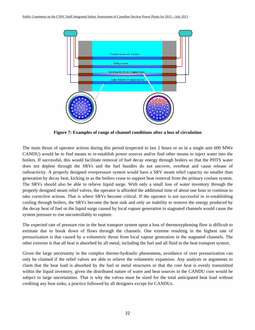
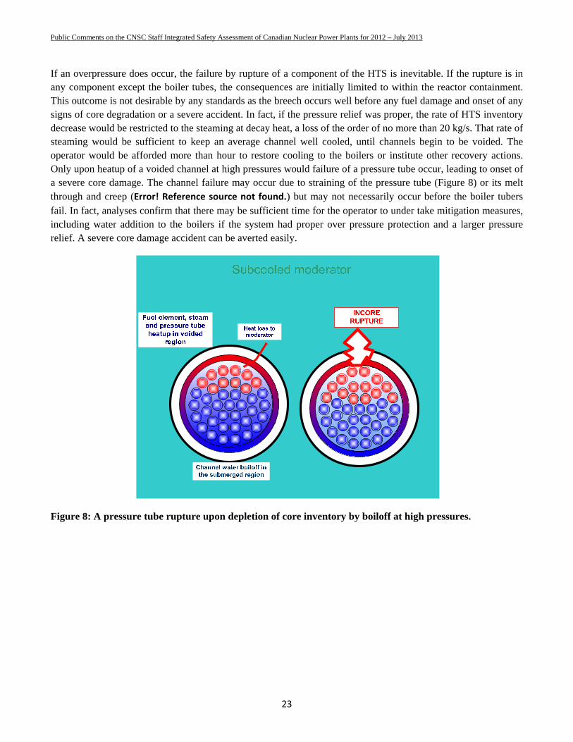
If an overpressure does occur, the failure by rupture of a component of the HTS is inevitable. If the rupture is in any component except the boiler tubes, the consequences are initially limited to within the reactor containment. This outcome is not desirable by any standards as the breech occurs well before any fuel damage and onset of any signs of core degradation or a severe accident. In fact, if the pressure relief was proper, the rate of HTS inventory decrease would be restricted to the steaming at decay heat, a loss of the order of no more than 20 kg/s. That rate of steaming would be sufficient to keep an average channel well cooled, until channels begin to be voided. The operator would be afforded more than hour to restore cooling to the boilers or institute other recovery actions. Only upon heatup of a voided channel at high pressures would failure of a pressure tube occur, leading to onset of a severe core damage. The channel failure may occur due to straining of the pressure tube (Figure 8) or its melt through and creep (Error! Reference source not found.) but may not necessarily occur before the boiler tubers fail. In fact, analyses confirm that there may be sufficient time for the operator to under take mitigation measures, including water addition to the boilers if the system had proper over pressure protection and a larger pressure relief. A severe core damage accident can be averted easily.
Figure 8: A pressure tube rupture upon depletion of core inventory by boiloff at high pressures.
Public Comments on the CNSC Staff Integrated Safety Assessment of Canadian Nuclear Power Plants for 2012 – July 2013
24
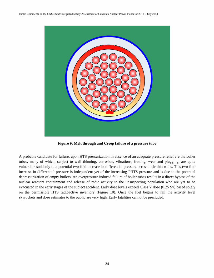
Figure 9: Melt through and Creep failure of a pressure tube
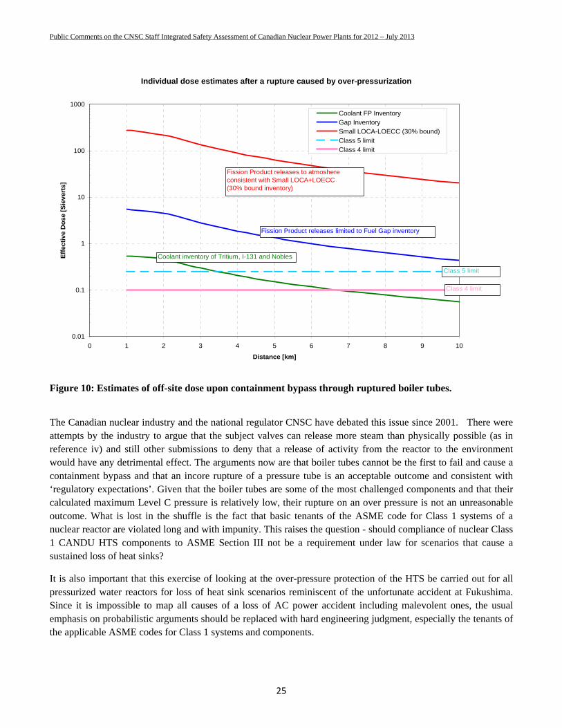
A probable candidate for failure, upon HTS pressurization in absence of an adequate pressure relief are the boiler tubes, many of which, subject to wall thinning, corrosion, vibrations, fretting, wear and plugging, are quite vulnerable suddenly to a potential two-fold increase in differential pressure across their thin walls. This two-fold increase in differential pressure is independent yet of the increasing PHTS pressure and is due to the potential depressurization of empty boilers. An overpressure induced failure of boiler tubes results in a direct bypass of the nuclear reactors containment and release of radio activity to the unsuspecting population who are yet to be evacuated in the early stages of the subject accident. Early dose levels exceed Class V dose (0.25 Sv) based solely on the permissible HTS radioactive inventory (Figure 10). Once the fuel begins to fail the activity level skyrockets and dose estimates to the public are very high. Early fatalities cannot be precluded.
Public Comments on the CNSC Staff Integrated Safety Assessment of Canadian Nuclear Power Plants for 2012 – July 2013
25
Figure 10: Estimates of off-site dose upon containment bypass through ruptured boiler tubes.
The Canadian nuclear industry and the national regulator CNSC have debated this issue since 2001. There were attempts by the industry to argue that the subject valves can release more steam than physically possible (as in reference iv) and still other submissions to deny that a release of activity from the reactor to the environment would have any detrimental effect. The arguments now are that boiler tubes cannot be the first to fail and cause a containment bypass and that an incore rupture of a pressure tube is an acceptable outcome and consistent with ‘regulatory expectations’. Given that the boiler tubes are some of the most challenged components and that their calculated maximum Level C pressure is relatively low, their rupture on an over pressure is not an unreasonable outcome. What is lost in the shuffle is the fact that basic tenants of the ASME code for Class 1 systems of a nuclear reactor are violated long and with impunity. This raises the question - should compliance of nuclear Class 1 CANDU HTS components to ASME Section III not be a requirement under law for scenarios that cause a sustained loss of heat sinks?
It is also important that this exercise of looking at the over-pressure protection of the HTS be carried out for all pressurized water reactors for loss of heat sink scenarios reminiscent of the unfortunate accident at Fukushima. Since it is impossible to map all causes of a loss of AC power accident including malevolent ones, the usual emphasis on probabilistic arguments should be replaced with hard engineering judgment, especially the tenants of the applicable ASME codes for Class 1 systems and components.
Individual dose estimates after a rupture caused by over-pressurization
0.01
0.1
1
10
100
1000
0 1 2 3 4 5 6 7 8 9 10
Distance [km]
Eff
ecti
ve
Do
se [
Sie
ver
ts]
Coolant FP Inventory
Gap InventorySmall LOCA-LOECC (30% bound)
Class 5 limit
Class 4 limit
Fission Product releases to atmoshere consistent with Small LOCA+LOECC(30% bound inventory)
Fission Product releases limited to Fuel Gap inventory
Coolant inventory of Tritium, I-131 and Nobles
Class 5 limit
Class 4 limit
Public Comments on the CNSC Staff Integrated Safety Assessment of Canadian Nuclear Power Plants for 2012 – July 2013
26
APPENDIX B – ADEQUACY OF PARS INSTALLED OR PLANNED IN CANADIAN NUCLEAR POWER PLANTS
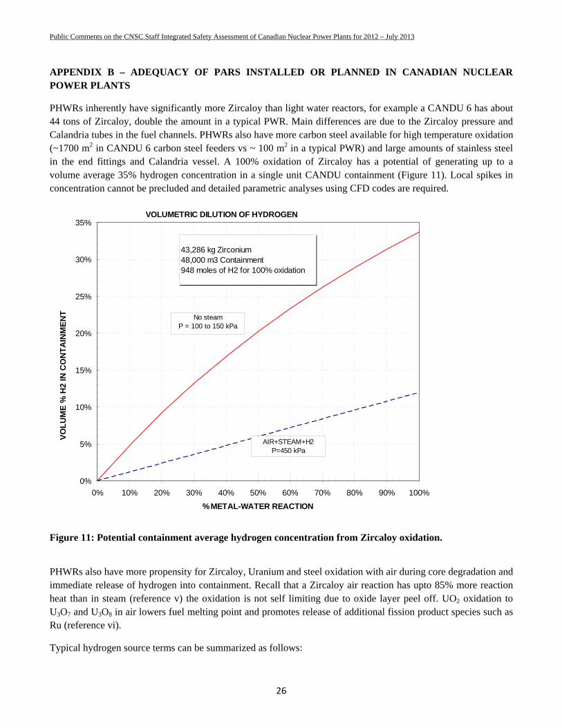
PHWRs inherently have significantly more Zircaloy than light water reactors, for example a CANDU 6 has about 44 tons of Zircaloy, double the amount in a typical PWR. Main differences are due to the Zircaloy pressure and Calandria tubes in the fuel channels. PHWRs also have more carbon steel available for high temperature oxidation (~1700 m2 in CANDU 6 carbon steel feeders vs ~ 100 m2 in a typical PWR) and large amounts of stainless steel in the end fittings and Calandria vessel. A 100% oxidation of Zircaloy has a potential of generating up to a volume average 35% hydrogen concentration in a single unit CANDU containment (Figure 11). Local spikes in concentration cannot be precluded and detailed parametric analyses using CFD codes are required.
Figure 11: Potential containment average hydrogen concentration from Zircaloy oxidation.
PHWRs also have more propensity for Zircaloy, Uranium and steel oxidation with air during core degradation and immediate release of hydrogen into containment. Recall that a Zircaloy air reaction has upto 85% more reaction heat than in steam (reference v) the oxidation is not self limiting due to oxide layer peel off. UO2 oxidation to U3O7 and U3O8 in air lowers fuel melting point and promotes release of additional fission product species such as Ru (reference vi).
Typical hydrogen source terms can be summarized as follows:
VOLUMETRIC DILUTION OF HYDROGEN
0%
5%
10%
15%
20%
25%
30%
35%
0% 10% 20% 30% 40% 50% 60% 70% 80% 90% 100%
% METAL-WATER REACTION
VO
LU
ME
% H
2 IN
CO
NT
AIN
ME
NT
43,286 kg Zirconium48,000 m3 Containment948 moles of H2 for 100% oxidation
No steamP = 100 to 150 kPa
AIR+STEAM+H2P=450 kPa
Public Comments on the CNSC Staff Integrated Safety Assessment of Canadian Nuclear Power Plants for 2012 – July 2013
27
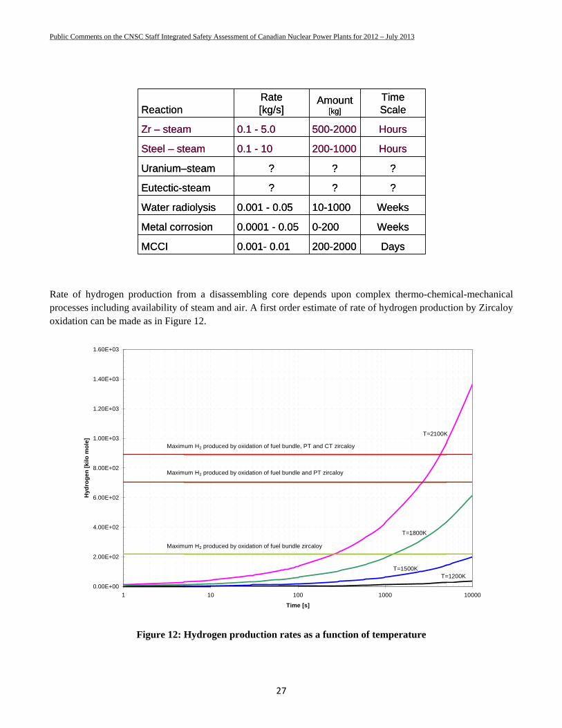
Rate of hydrogen production from a disassembling core depends upon complex thermo-chemical-mechanical processes including availability of steam and air. A first order estimate of rate of hydrogen production by Zircaloy oxidation can be made as in Figure 12.
Figure 12: Hydrogen production rates as a function of temperature
ReactionRate [kg/s]
Amount[kg]
Time Scale
Zr – steam 0.1 - 5.0 500-2000 Hours
Steel – steam 0.1 - 10 200-1000 Hours
Uranium–steam ? ? ?
Eutectic-steam ? ? ?
Water radiolysis 0.001 - 0.05 10-1000 Weeks
Metal corrosion 0.0001 - 0.05 0-200 Weeks
MCCI 0.001- 0.01 200-2000 Days
ReactionRate [kg/s]
Amount[kg]
Time Scale
Zr – steam 0.1 - 5.0 500-2000 Hours
Steel – steam 0.1 - 10 200-1000 Hours
Uranium–steam ? ? ?
Eutectic-steam ? ? ?
Water radiolysis 0.001 - 0.05 10-1000 Weeks
Metal corrosion 0.0001 - 0.05 0-200 Weeks
MCCI 0.001- 0.01 200-2000 Days
0.00E+00
2.00E+02
4.00E+02
6.00E+02
8.00E+02
1.00E+03
1.20E+03
1.40E+03
1.60E+03
1 10 100 1000 10000
Time [s]
Hyd
rog
en [
kilo
mo
le]
T=1800K
T=1500KT=1200K
T=2100K
Maximum H2 produced by oxidation of fuel bundle zircaloy
Maximum H2 produced by oxidation of fuel bundle and PT zircaloy
Maximum H2 produced by oxidation of fuel bundle, PT and CT zircaloy
Public Comments on the CNSC Staff Integrated Safety Assessment of Canadian Nuclear Power Plants for 2012 – July 2013
28
1. Containment hydrogen mitigation systems for avoidance of hydrogen burns and detonations
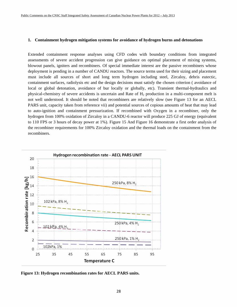
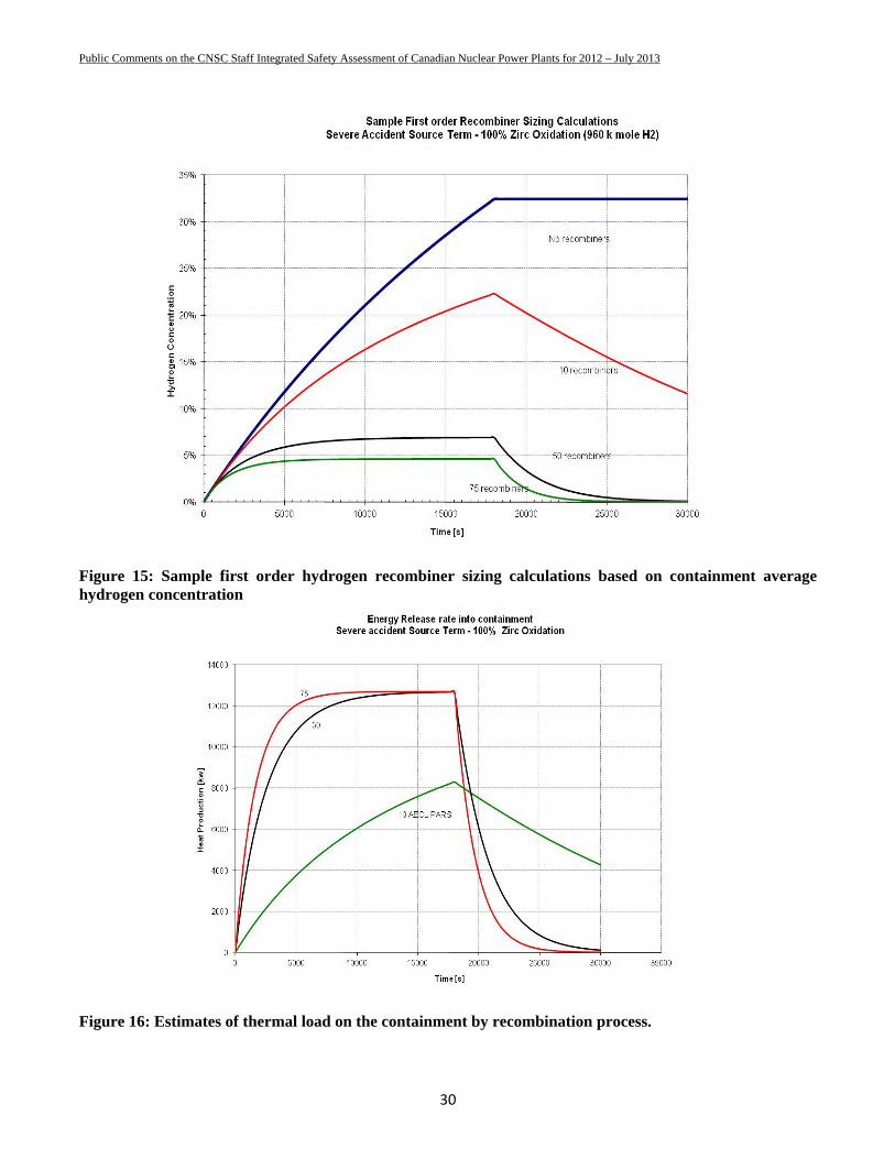
Extended containment response analyses using CFD codes with boundary conditions from integrated assessments of severe accident progression can give guidance on optimal placement of mixing systems, blowout panels, igniters and recombiners. Of special immediate interest are the passive recombiners whose deployment is pending in a number of CANDU reactors. The source terms used for their sizing and placement must include all sources of short and long term hydrogen including steel, Zircaloy, debris eutectic, containment surfaces, radiolysis etc and the design decisions must satisfy the chosen criterion ( avoidance of local or global detonation, avoidance of bur locally or globally, etc). Transient thermal-hydraulics and physical-chemistry of severe accidents is uncertain and Rate of H2 production in a multi-component melt is not well understood. It should be noted that recombiners are relatively slow (see Figure 13 for an AECL PARS unit, capacity taken from reference vii) and potential sources of copious amounts of heat that may lead to auto-ignition and containment pressurization. If recombined with Oxygen in a recombiner, only the hydrogen from 100% oxidation of Zircaloy in a CANDU-6 reactor will produce 225 GJ of energy (equivalent to 110 FPS or 3 hours of decay power at 1%). Figure 15 And Figure 16 demonstrate a first order analysis of the recombiner requirements for 100% Zircaloy oxidation and the thermal loads on the containment from the recombiners.
Figure 13: Hydrogen recombination rates for AECL PARS units.

Public Comments on the CNSC Staff Integrated Safety Assessment of Canadian Nuclear Power Plants for 2012 – July 2013
29
Typical recombiner capacity increases with hydrogen concentration. While this may be advantageous in some regards, an important consideration in choosing a recombiner should be its capacity to limit hydrogen recombination at higher concentration of hydrogen. Such an approach has been proposed in reference viii ( see Figure 14). Novel methods (e.g. reference ix) of deploying PARS need to be further investigated along with consideration of heat generated by PARS by alternate / passive heat sinks that do not thermally load the containment.
Figure 14: Investigation of improved catalytic recombiner plate depositions for controlling hydrogen production.
Public Comments on the CNSC Staff Integrated Safety Assessment of Canadian Nuclear Power Plants for 2012 – July 2013
30
Figure 15: Sample first order hydrogen recombiner sizing calculations based on containment average hydrogen concentration
Figure 16: Estimates of thermal load on the containment by recombination process.
Public Comments on the CNSC Staff Integrated Safety Assessment of Canadian Nuclear Power Plants for 2012 – July 2013
31
Absence of hydrogen sampling and long term hydrogen removal systems in most CANDU containments can lead to challenges to containment integrity.
Above simple analysis demonstrates that the number of PARS installed at Pt. Lepreau (~30) are inadequate to mitigate the hydrogen production from Zircaloy. Other immediate sources of hydrogen have not been considered. These include the carbon steel feeders and the stainless steel Calandria vessel and end fittings.
A large number of other severe accident vulnerabilities have also not been addressed and closure of a number of Fukushima Action Plan items is premature.
Public Comments on the CNSC Staff Integrated Safety Assessment of Canadian Nuclear Power Plants for 2012 – July 2013
32
REFERENCES
i CSA Standard N285.0-95, “General Requirements for Pressure-Retaining Systems and Components in CANDU Nuclear Power Plants”. ii ASME Section III, part NCA 2142 iii NRC Regulations Title 10, Code of Federal Regulations, 10CFR 50.34(f)(2)(x)
iv Development of a Discharge Model for the Bopp & Reuther Degasser/Condenser Relief Valves for Heat Sink Assessment, CNS Sixth International Conference on Simulation Methods in Nuclear Engineering Montreal, Quebec, Canada (2004 October 12-15) v Separate-effect tests on zirconium cladding degradation in air ingress situations, C. Duriez; M. Steinbrück; D. Ohai; T. Meleg; J. Birchley; T. Haste, Nuclear Engineering and Design (February 2009), 239 (2), pg. 244-253 vi Thermodynamic and kinetic aspects of UO 2 fuel oxidation in air at 400–2000 K. Peter Taylor, Journal of Nuclear Materials, ISSN 0022-3115, 2005, Volume 344, Issue 1, pp. 206 - 212 vii. Generic approach for designing and implementing a passive autocatalytic recombiner PAR-system in nuclear power plant containments. E. Bachellerie et al, Nuclear Engineering and Design 221 (2003) 151–165. viii E.-A. Reinecke et al. Nuclear Engineering and Design 230 (2004) 49–59 ix Hydrogen removal from LWR containments by catalytic-coated thermal insulation elements (THINCAT), K. Fischer; P. Broeckerhoff; G. Ahlers; V. Gustavsson; L. Herranz; J. Polo; T. Dominguez; P. Royl ,Nuclear Engineering and Design (April 2003), 221 (1-3), pg. 137-149