underground exploitations inside ... - gsm.min-pan.krakow.pl
TRANSCRIPT
GOSPODARKA SUROWCAMI MINERALNYMI – MINERAL RESOURCES MANAGEMENT
2015 Volume 31 Issue 3 Pages 93–110
DOI 10.1515/gospo-2015-27
* Professor, ** Ph.D. Ing., *** M.Sc. Ing., Strata Mechanics Research Institute of the Polish Academy of Sciences, Krakow, Poland; e-mail: [email protected]; [email protected]; [email protected]
ANTON SROKA*, STANISŁAW KNOTHE*, KRZYSZTOF TAJDUŚ**, RAFAŁ MISA***
Underground exploitations inside safety pillar shafts when considering
the effective use of a coal deposit
Introduction
Underground mining operations, such as for coal deposits, salt, and copper ore, lead to the deformation of the surrounding rock mass and to the surface area as well (Kowalski et al. 2015). These deformations can lead to the damage of facilities found in the subsurface and including objects in the mine itself such as shafts, equipment, and facilities connected with shaft infrastructure (Sroka 1999; Tajduś 2014). The aim of the development of computational methods taking into account effects of mining on rock mass and surface area, for example a method of Bals’ (1931–1932), the Knothe Theory (1951) Kochmański’s Theory (1955) or the Ruhrkohle method (Ehrhardt and Sauer 1961), was not only to create the possibility to calculate the expected values of displacements and deformations, but mainly to provide ca-pabilities for mine exploitations in terms of minimizing its effects on objects located in the subsurface and on the surface.
This is essential, because from the preservation point of view, through the years, many millions of tons of coal were trapped inside the safety pillar shafts. Currently, because the costs of exploitation are continuously increasing (and it is closely connected with increasing
Sroka et al. 2015 / Gospodarka Surowcami Mineralnymi – Mineral Resources Management 31(3), 93–11094
excavation depths), many mining companies are trying to return to partial excavations in-side safety pillar shafts keeping shaft and surface infrastructure functionality. This method combined with suitable mining discipline is leading to an increase in mine life-spans and their profitability.
It is fully possible to plan mining exploitation in terms of the minimisation of its effects on the surface structures and rock mass, moreover the planning requires a suitable appraisal of many parameters and it is aim of this paper. Generally, such exploitations can be carried out when at least the following elements are known:
�� calculation method that relates the cause (i.e. mining exploitation) to its effect (i.e. rock mass deformation);
�� parameters of this theory (determined by identification in the in-situ measure-ments);
�� resistance of the surface structures and the rock mass to the effects of mining explo-itation.
1. Problems of exploitation in pillar shafts
Coming about in the first and second half of the twentieth century, methods of geometric integrals, for example: Keinhorst (Praca zbiorowa 1956), Bals (1931–1932), Beyer (Praca zbiorowa 1956), Knothe (1951) and Kochmański (1955) and the so-called Ruhrkohle method (Ehrhardt and Sauer 1961) allow for the calculation of subsidence at any point in the subsur-face for any geometry of exploited coal deposit.
The first scholar to have proposed the method to describe deformation in mine shafts was Bals (1939). In his theory of surface and rock mass subsidence, Bals assumed the function of subsidence effects per exploitation element in analogy to Newton’s law of universal gra-vitation (Bals 1931/1932).
In the solution for the description of subsidence along a vertical shaft excavation, Bals assumed that the values of subsidence factor a and of the boundary angle ξgr in the rock mass are constant.
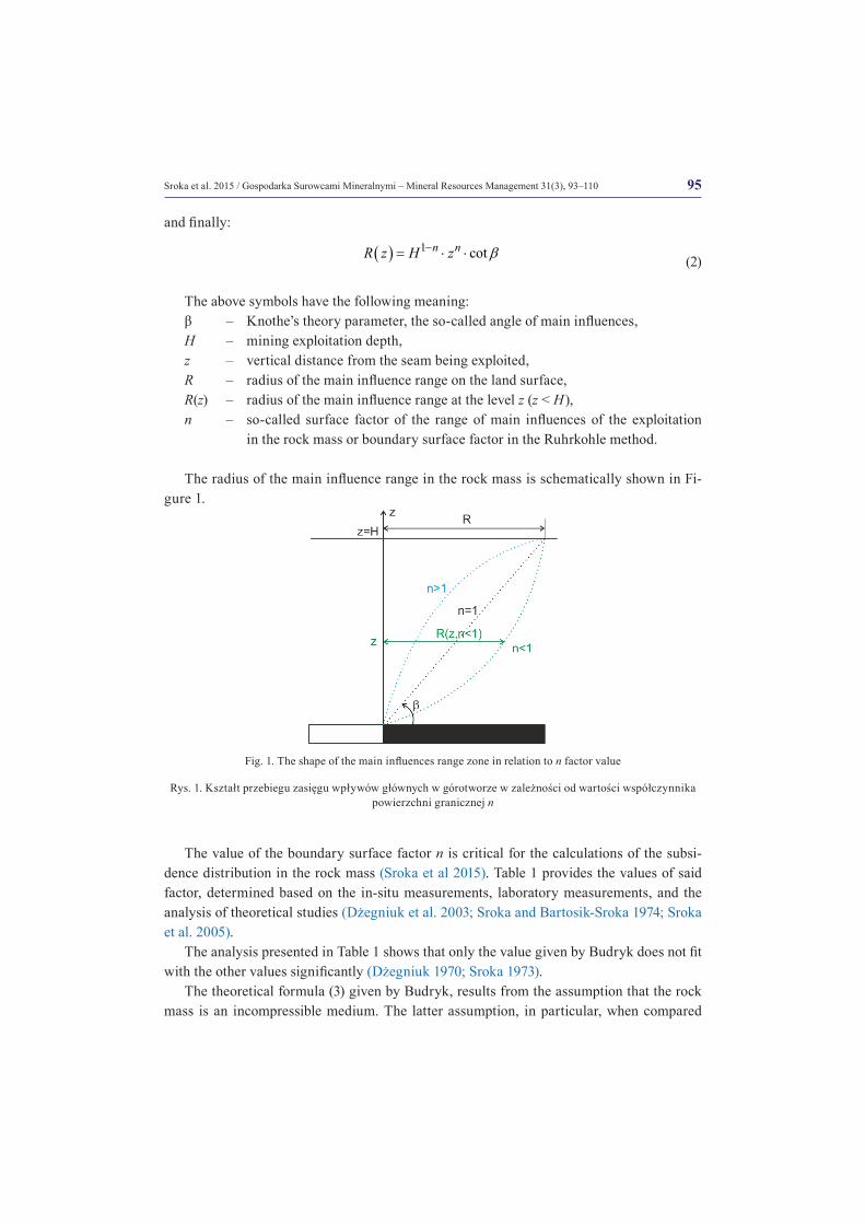
In fact, as shown by in-situ and experimental results, the boundary angle range of mining effects in the ground is not a constant value. The range of mining exploitation influence in the rock mass above the seam being exploited is described in the form proposed by Budryk (1953) as follows:
( ) ( )n nz zR z R H R
H H = ⋅ = ⋅
(1)
where:
( ) cotR H R H β= = ⋅
95Sroka et al. 2015 / Gospodarka Surowcami Mineralnymi – Mineral Resources Management 31(3), 93–110
and finally:
( ) 1 cotn nR z H z β−= ⋅ ⋅ (2)
The above symbols have the following meaning:β – Knothe’s theory parameter, the so-called angle of main influences,H – mining exploitation depth,z – vertical distance from the seam being exploited,R – radius of the main influence range on the land surface,R(z) – radius of the main influence range at the level z (z < H),n – so-called surface factor of the range of main influences of the exploitation
in the rock mass or boundary surface factor in the Ruhrkohle method.
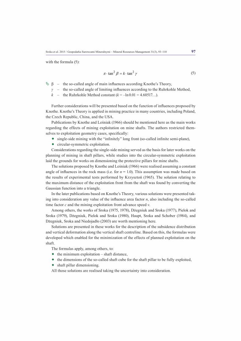
The radius of the main influence range in the rock mass is schematically shown in Fi-gure 1.
The value of the boundary surface factor n is critical for the calculations of the subsi-dence distribution in the rock mass (Sroka et al 2015). Table 1 provides the values of said factor, determined based on the in-situ measurements, laboratory measurements, and the analysis of theoretical studies (Dżegniuk et al. 2003; Sroka and Bartosik-Sroka 1974; Sroka et al. 2005).
The analysis presented in Table 1 shows that only the value given by Budryk does not fit with the other values significantly (Dżegniuk 1970; Sroka 1973).
The theoretical formula (3) given by Budryk, results from the assumption that the rock mass is an incompressible medium. The latter assumption, in particular, when compared
Fig. 1. The shape of the main influences range zone in relation to n factor value
Rys. 1. Kształt przebiegu zasięgu wpływów głównych w górotworze w zależności od wartości współczynnika powierzchni granicznej n
96 Sroka et al. 2015 / Gospodarka Surowcami Mineralnymi – Mineral Resources Management 31(3), 93–110
to the results of subsidence measurements in mine shafts and with in-situ observations, has proven to be completely false.
2 tann π β= ⋅ (3)
Equation (1) does not meet the initial condition for z = 0, so Drzęźla (1989) presented a modified formula (4):
( ) 0
0
nz z
R z RH z
+= ⋅ +
(4)
�ª z0 – constant value.
Since the mid-20th century, the so-called Knothe’s Theory (Knothe 1951) has been used in Poland, particularly for describing the effects of mining exploitation on mine shafts, while in German mining, the Ruhrkohle method (Ehrhardt and Sauer 1961) has been used. Both calculation methods are based on the function of effects in a form of a Gaussian function, while they differ as to the definitions of the angles of main influences.
Both methods, namely Knothe’s Theory and the Ruhrkohle Method, provide identical calculation results for the dependencies between the angles of influences β and γ, described
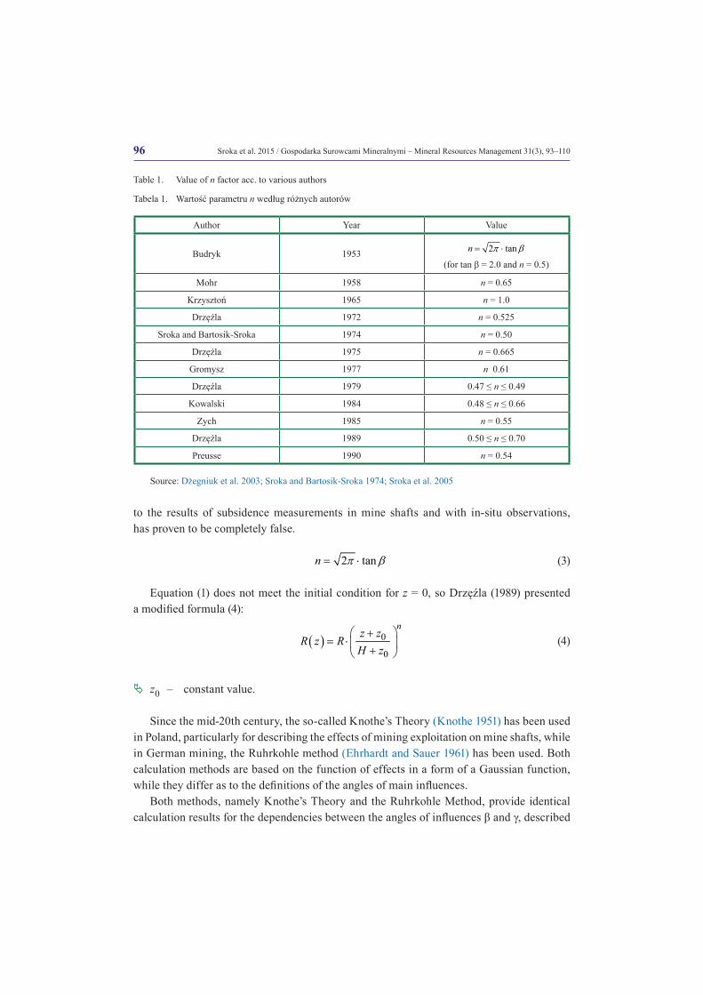
Table 1. Value of n factor acc. to various authors
Tabela 1. Wartość parametru n według różnych autorów
Author Year Value
Budryk 1953 2 tann π β= ⋅ (for tan β = 2.0 and n = 0.5)
Mohr 1958 n = 0.65
Krzysztoń 1965 n = 1.0
Drzęźla 1972 n = 0.525
Sroka and Bartosik-Sroka 1974 n = 0.50
Drzęźla 1975 n = 0.665
Gromysz 1977 n 0.61
Drzęźla 1979 0.47 ≤ n ≤ 0.49
Kowalski 1984 0.48 ≤ n ≤ 0.66
Zych 1985 n = 0.55
Drzęźla 1989 0.50 ≤ n ≤ 0.70
Preusse 1990 n = 0.54
Source: Dżegniuk et al. 2003; Sroka and Bartosik-Sroka 1974; Sroka et al. 2005
97Sroka et al. 2015 / Gospodarka Surowcami Mineralnymi – Mineral Resources Management 31(3), 93–110
with the formula (5):
2 2tan tankπ β γ⋅ = ⋅ (5)
�ª β – the so-called angle of main influences according Knothe’s Theory,γ – the so-called angle of limiting influences according to the Ruhrkohle Method,k – the Ruhrkohle Method constant (k = –ln 0.01 = 4.60517…).
Further considerations will be presented based on the function of influences proposed by Knothe. Knothe’s Theory is applied in mining practice in many countries, including Poland, the Czech Republic, China, and the USA.
Publications by Knothe and Leśniak (1966) should be mentioned here as the main works regarding the effects of mining exploitation on mine shafts. The authors restricted them-selves to exploitation geometry cases, specifically:
�� single-side mining with the “infinitely” long front (so-called infinite semi-plane), �� circular-symmetric exploitation.
Considerations regarding the single-side mining served as the basis for later works on the planning of mining in shaft pillars, while studies into the circular-symmetric exploitation laid the grounds for works on dimensioning the protective pillars for mine shafts.
The solutions proposed by Knothe and Leśniak (1966) were realised assuming a constant angle of influences in the rock mass (i.e. for n = 1.0). This assumption was made based on the results of experimental tests performed by Krzysztoń (1965). The solution relating to the maximum distance of the exploitation front from the shaft was found by converting the Gaussian function into a triangle.
In the later publications based on Knothe’s Theory, various solutions were presented tak-ing into consideration any value of the influence area factor n, also including the so-called time factor c and the mining exploitation front advance speed v.
Among others, the works of Sroka (1975, 1978), Dżegniuk and Sroka (1977), Pielok and Sroka (1979), Dżegniuk, Pielok and Sroka (1980), Haupt, Sroka and Schober (1984), and Dżegniuk, Sroka and Niedojadło (2003) are worth mentioning here.
Solutions are presented in these works for the description of the subsidence distribution and vertical deformation along the vertical shaft centreline. Based on this, the formulas were developed which enabled for the minimization of the effects of planned exploitation on the shaft.
The formulas apply, among others, to:�� the minimum exploitation – shaft distance,�� the dimensions of the so-called shaft cube for the shaft pillar to be fully exploited,�� shaft pillar dimensioning.
All those solutions are realised taking the uncertainty into consideration.
98 Sroka et al. 2015 / Gospodarka Surowcami Mineralnymi – Mineral Resources Management 31(3), 93–110
2. Solution to the plane section problem (2D)
According to the solution given by Knothe for the 2D dimension, the subsidence of any point in the rock in the section perpendicular to the straight edge of exploitation in the form of the so-called infinite half-plane is described by the formula:
( )( ) ( )
( ) ( )( )
22
2( , ) exp expx X z
a z gs x z d a z g d
R z R zλπ λ πµ µ
∞ ∞ ⋅ = − = ⋅ −
∫ ∫ (6)
�ª a – so-called subsidence factor, vertical scale parameter,g – thickness of the seam being exploited,x – horizontal distance of the calculation point from the edge of mining exploitation,z – the vertical distance of the point from the seam,R(z) – radius of the main influence range on the land surface, horizontal scale parameter,X(z) – standardized distance of the calculation point from the edge of exploitation
(X(z) = x/R(z)).
Equation (6) describes the distribution of subsidence for a horizontal seam and horizon-tally layered rock mass. The vertical deformation and subsidence velocity are the indicators of deformations with proper correlation to the observed damages (Dżegniuk et al. 1978, 1980). The vertical deformation distribution along a vertical line (i.e. for x = const., z – va-riable) is defined as a derivative of the vertical displacement distribution relative to z.
( ) ( ),,zz
s x zx y
ze
∂= −
∂ (7)
In formula (6), which describes the distribution of the final subsidence, the dependent parameters of the value z are parameters of horizontal and vertical scale a(z) and R(z).
Bals (1939), Knothe and Leśniak (1966) and Sroka (1978) assumed that the value of pa-rameter a in the rock mass was constant.
This assumption corresponds with a very good approximation of the observed reality. The variability of parameter R(z) is described in formulas (2) and (4). Starting from this equation (6) we get:
( ) ( ) ( )
2
2, expzza g x xx z n
z R z R ze π
⋅ = − ⋅ ⋅ ⋅ −
(8)
Using the above equation, the calculation of the vertical deformation distributions along a horizontal line (z = const., x – variable), or a vertical line (x = const., z – variable) can be performed.
99Sroka et al. 2015 / Gospodarka Surowcami Mineralnymi – Mineral Resources Management 31(3), 93–110
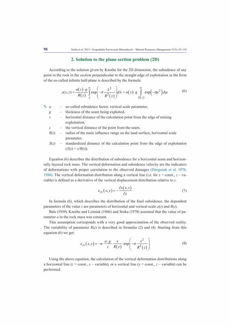
Figure 2 shows schematically the distributions of vertical deformation for a horizontal line and for a vertical line.
Analysing the distribution εzz(x,z) along any horizontal line (for z = const.) yields:
max
0.242min 2
zz
zz
n a g a gnz ze
ee π
⋅ ⋅= ± ⋅ = ± ⋅ ⋅
⋅ (9)
( )( )
( ) ( )1
20.40
2x z R z
R zx z π
= = ⋅ (10)
Analysing the vertical deformation distribution along a vertical line (i.e. for x = const.) yields:
( )1/1/22
1
nn xnz x Hn Reπ ⋅ = ⋅ ⋅ +
(11)
( ) ( )( )
1 1max exp2 2zz
n n a g nxz x ne
eπ
⋅ + ⋅ + = ± ⋅ −
(12)
Fig. 2. Analysis of vertical εzz deformation distribution along a horizontal line and along a vertical line in the subsurface (Sroka 1978)
Rys. 2. Analiza rozkładu deformacji pionowej εzz wzdłuż linii poziomej oraz wzdłuż linii pionowej w górotworze (Sroka 1978)
100 Sroka et al. 2015 / Gospodarka Surowcami Mineralnymi – Mineral Resources Management 31(3), 93–110
The analysis of the in-situ measurement results and the comparative calculation shows that the value of n is in the range specified by (see Table 1):
0.45 < n < 0.70
For the conditions present in the Ruhr Region of Germany, it can be assumed that the value of the factor is 0.5 with good approximation (Preusse 1990). We obtain for the vertical line for this value as follows:
( )2
22 tan3
xz xHe π β= ⋅ ⋅ ⋅ (13)
( ) 22max 0.0368 cotzz
a gx Hx
e β⋅= ± ⋅ ⋅ ⋅ (14)
Equations (11) and (12) are used after transformation to determine the minimum admis-sible distance between the exploitation front and the shaft for a known limit of the vertical deformation
grzze , and data concerning the proposed mining exploitations (formula 15).
( )min ( , ) 0.192 cotgr gr grzz gr
zz
a gx SF He α α βe
⋅= ⋅ ⋅ ⋅ ⋅ (15)
where: SF(αgr) – safety factor depending on the boundary risk value αgr, which depends on the function and importance of the shaft and the natural threats present (αgr- maximum limit value of the the probability of risk, that the assumed value of gr
zze is exceeded). Limit value of gr
zze depends on the lining type of the shafts and its technical condition, and the natural threats present, such as water hazards.
The value of the safety factor combined with the likelihood of risk for exceeding the approved limit of vertical deformation was determined on the basis of the empirical material analysis on the measured and calculated vertical deformation for the mine shafts according to the Ruhrkohle method and using the Knothe Theory.
Salamon and Munro (1967) assumed that the logarithm for variable D (formula 16), is the ratio of the calculated values of the maximum vertical deformation to the measured maximum value, which is a normal distribution (Dżegniuk et al. 2003; Sroka 1991; Sroka et al. 2005).
maxmax
calculatedzzmeasuredzz
De
e= (16)
( )~ ,D N µ σ (17)
�ª µ – the expected value,σ – standard deviation.
101Sroka et al. 2015 / Gospodarka Surowcami Mineralnymi – Mineral Resources Management 31(3), 93–110
As a result of the analysis, the “maximum likelihood estimators” of the following values were obtained:
µ = 0.010 (18)
σ = 0.130 (19)
It can be concluded from the resulting expected value that the Ruhrkohle Method and Knothe’s Theory properly describe the average values for maximum vertical deformation. It is approximately. 2.33% higher than the observed values in formula (20):
10 1.0233D µ= = (20)
The definition of variable D shows that D corresponds to the definition of the safety factor. Between the safety factor and the standard deviation for the required limit for the likelihood of αgr the relations are defined as:
( ) ( )10gr
gr zSF α σα ⋅= (21)
�ª z(αgr) – one-side upper quantile of the normal distribution, whose value depends on the value of αgr.
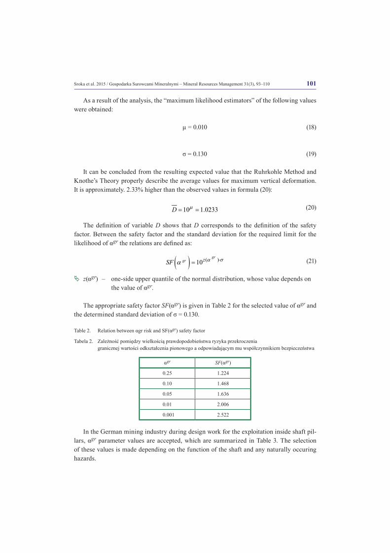
The appropriate safety factor SF(αgr) is given in Table 2 for the selected value of αgr and the determined standard deviation of σ = 0.130.
Table 2. Relation between αgr risk and SF(αgr) safety factor
Tabela 2. Zależność pomiędzy wielkością prawdopodobieństwa ryzyka przekroczenia granicznej wartości odkształcenia pionowego a odpowiadającym mu współczynnikiem bezpieczeństwa
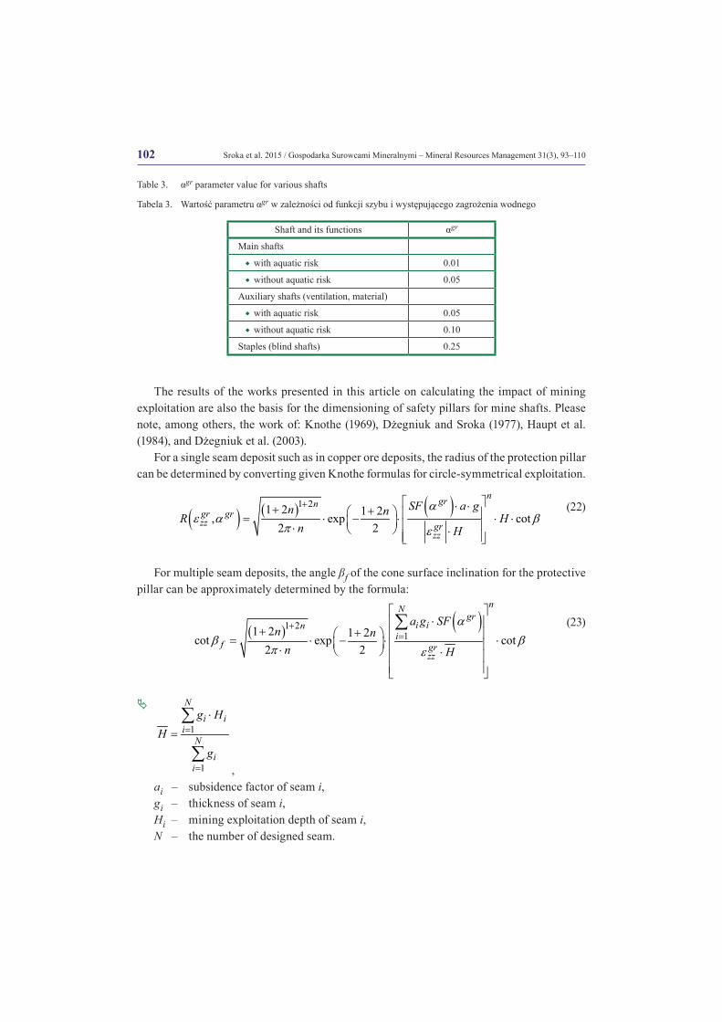
In the German mining industry during design work for the exploitation inside shaft pil-lars, αgr parameter values are accepted, which are summarized in Table 3. The selection of these values is made depending on the function of the shaft and any naturally occuring hazards.
αgr SF(αgr)
0.25 1.224
0.10 1.468
0.05 1.636
0.01 2.006
0.001 2.522
102 Sroka et al. 2015 / Gospodarka Surowcami Mineralnymi – Mineral Resources Management 31(3), 93–110
Table 3. αgr parameter value for various shafts
Tabela 3. Wartość parametru αgr w zależności od funkcji szybu i występującego zagrożenia wodnego
The results of the works presented in this article on calculating the impact of mining exploitation are also the basis for the dimensioning of safety pillars for mine shafts. Please note, among others, the work of: Knothe (1969), Dżegniuk and Sroka (1977), Haupt et al. (1984), and Dżegniuk et al. (2003).
For a single seam deposit such as in copper ore deposits, the radius of the protection pillar can be determined by converting given Knothe formulas for circle-symmetrical exploitation.
( ) ( ) ( )1 21 2 1 2, exp cot2 2
ngrngr grzz gr
zz
SF a gn nR Hn H
αe α β
π e
+ ⋅ ⋅+ + = ⋅ − ⋅ ⋅ ⋅ ⋅ ⋅
(22)
For multiple seam deposits, the angle βf of the cone surface inclination for the protective pillar can be approximately determined by the formula:
( ) ( )1 2
11 2 1 2cot exp cot2 2
nNgr
i ini
f grzz
a g SFn n
n H
αβ β
π e
+=
⋅
+ + = ⋅ − ⋅ ⋅ ⋅ ⋅
∑ (23)
�ª
1
1
N
i ii
N
ii
g HH
g
=
=
⋅
=∑
∑,
ai – subsidence factor of seam i,gi – thickness of seam i,Hi – mining exploitation depth of seam i,N – the number of designed seam.
Shaft and its functions αgr
Main shafts
�� with aquatic risk 0.01
�� without aquatic risk 0.05
Auxiliary shafts (ventilation, material)
�� with aquatic risk 0.05
�� without aquatic risk 0.10
Staples (blind shafts) 0.25
103Sroka et al. 2015 / Gospodarka Surowcami Mineralnymi – Mineral Resources Management 31(3), 93–110
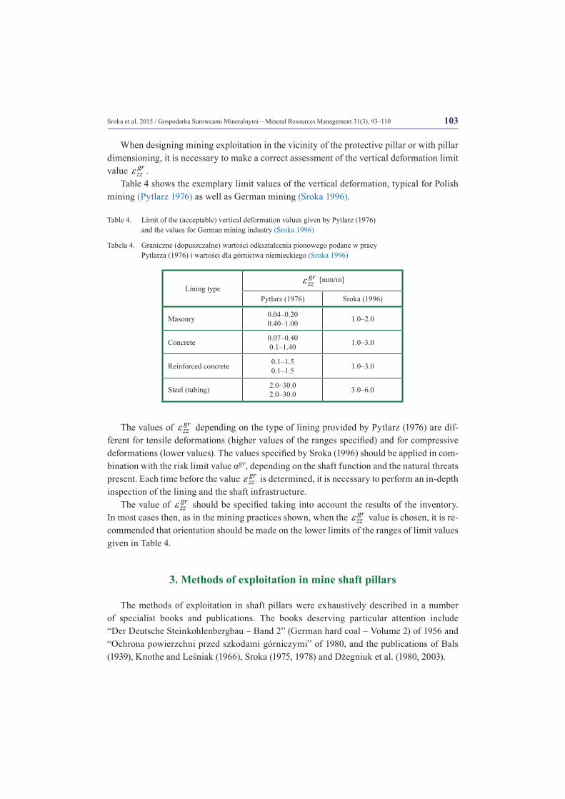
When designing mining exploitation in the vicinity of the protective pillar or with pillar dimensioning, it is necessary to make a correct assessment of the vertical deformation limit value gr
zze .Table 4 shows the exemplary limit values of the vertical deformation, typical for Polish
mining (Pytlarz 1976) as well as German mining (Sroka 1996).
Table 4. Limit of the (acceptable) vertical deformation values given by Pytlarz (1976) and the values for German mining industry (Sroka 1996)
Tabela 4. Graniczne (dopuszczalne) wartości odkształcenia pionowego podane w pracy Pytlarza (1976) i wartości dla górnictwa niemieckiego (Sroka 1996)
The values of grzze depending on the type of lining provided by Pytlarz (1976) are dif-
ferent for tensile deformations (higher values of the ranges specified) and for compressive deformations (lower values). The values specified by Sroka (1996) should be applied in com-bination with the risk limit value αgr, depending on the shaft function and the natural threats present. Each time before the value gr
zze is determined, it is necessary to perform an in-depth inspection of the lining and the shaft infrastructure.
The value of grzze should be specified taking into account the results of the inventory.
In most cases then, as in the mining practices shown, when the grzze value is chosen, it is re-
commended that orientation should be made on the lower limits of the ranges of limit values given in Table 4.
3. Methods of exploitation in mine shaft pillars
The methods of exploitation in shaft pillars were exhaustively described in a number of specialist books and publications. The books deserving particular attention include “Der Deutsche Steinkohlenbergbau – Band 2” (German hard coal – Volume 2) of 1956 and “Ochrona powierzchni przed szkodami górniczymi” of 1980, and the publications of Bals (1939), Knothe and Leśniak (1966), Sroka (1975, 1978) and Dżegniuk et al. (1980, 2003).
Lining typegrzze [mm/m]
Pytlarz (1976) Sroka (1996)
Masonry 0.04–0.20 0.40–1.00 1.0–2.0
Concrete 0.07–0.40 0.1–1.40 1.0–3.0
Reinforced concrete 0.1–1.5 0.1–1.5 1.0–3.0
Steel (tubing) 2.0–30.0 2.0–30.0 3.0–6.0

104 Sroka et al. 2015 / Gospodarka Surowcami Mineralnymi – Mineral Resources Management 31(3), 93–110
The exploitation methods applied currently include the single-side mining (Fig. 3). There are two variants of this method in use:
�� single-side mining including a part of the shaft pillar, without cutting the shaft lining (Fig. 3a);
�� single-side mining covering the entire pillar with or without the so-called shaft cube (Fig. 3b).
In the single-side mining which reaches a part of the shaft pillar, the minimum admissi-ble distance between the exploitation front and the shaft is evaluated. This distance can be determined from the formula (24).
( ) ( )min
,1, cot2
ngr grzzgr gr
zzznX H
n He e α
e α βπ
+ = ⋅ ⋅ ⋅ ⋅
(24)
where:
( ) ( ) ( )1 1, exp2 2
gr gr grzz gr
zz
n n a g nz SFne e α α
π e
⋅ + ⋅ + = ⋅ ⋅ ⋅ −
The detailed solution for the n = 0.5 is described by Formula (15). The formulas for the allowable distances of mining exploitation from the shaft, for the limit values of horizontal deformation factors, horizontal displacement (i.e. shaft centreline deflection) and the sub-sidence velocity, are provided, among others in the publications of Haupt et al. (1984) and Sroka et al. (2005).
In case of single-side mining cutting the shaft lining, the exploitation with prior ex-traction of the so-called shaft cube is performed. The solution for the cube dimension was provided among others by Pytlarz et al. (1972), Sroka (1975) and Dżegniuk, Sroka (1977).
Fig. 3. One-side mining outline
Rys. 3. Schemat eksploatacji jednoskrzydłowej
105Sroka et al. 2015 / Gospodarka Surowcami Mineralnymi – Mineral Resources Management 31(3), 93–110
The minimum vertical distance between the planned mining exploitation and shaft sump should not be less than described by Equation (25).
( ) ( ) ( ) ( ) ( )min 0.2422 z z
gr gr grgr grzz zz
n a g a gZ f u SF n f u SFe e eα α α
π e e
⋅ ⋅= ⋅ ⋅ ⋅ = ⋅ ⋅ ⋅ ⋅
⋅ ⋅ (25)
�ª u – the so-called dynamic variable of mining exploitation
(c Ru
v⋅
= , v – velocity of the mining run), and
( )z
f ue – coefficient with a value in the range from 1.0 to 1.7.
The value of function z
fe > 1 is due to the fact that the vertical deformation (tension) is the only indicator of the maximum value of the deformation for the front progressing mining exploitation, i.e. in the dynamic phase, which is greater than its final value. This is because the ratio of time c is not a constant value in the subsurface (Pielok and Sroka 1979).
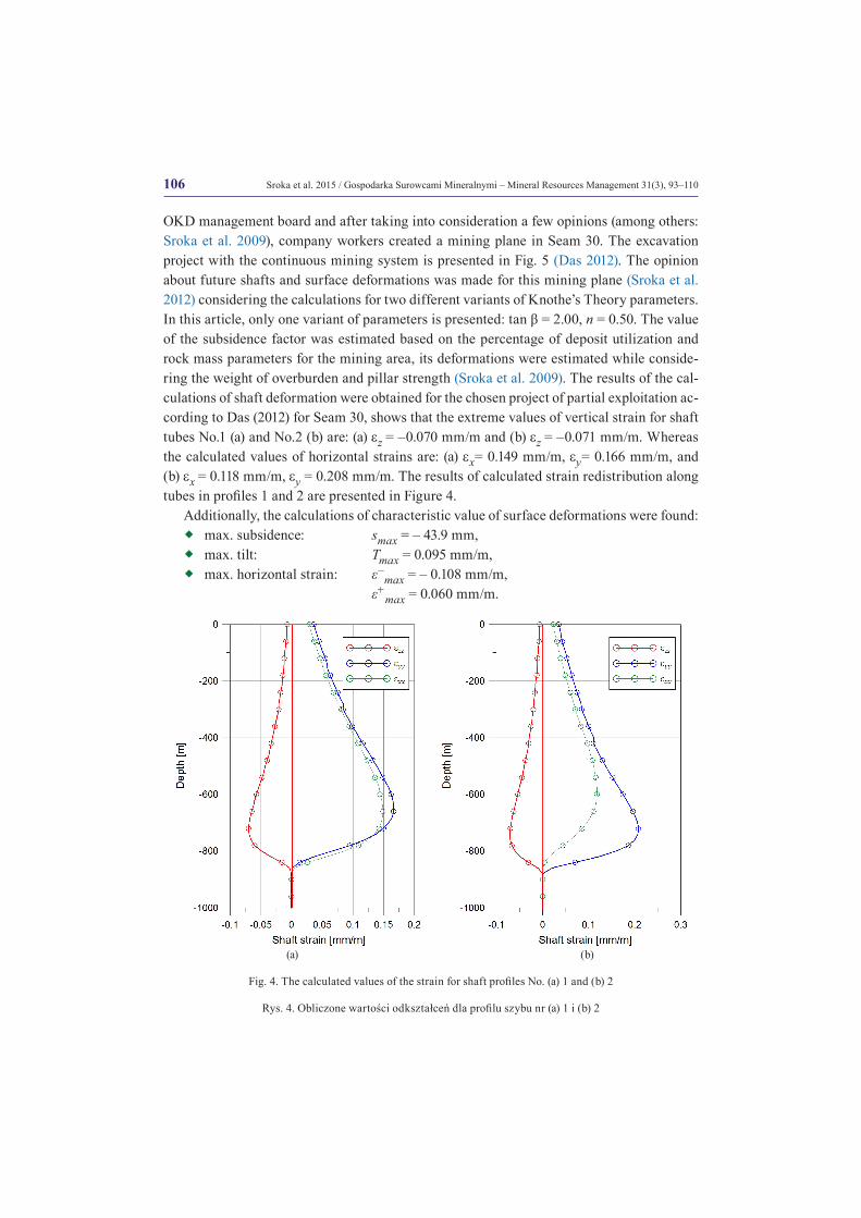
4. Practical example
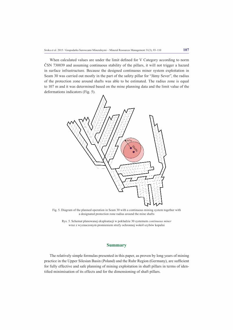
An interesting example of efficient coal management is the exploitation inside safety pil-lar shafts in ČSM mine. The ČSM mine, which belong to mining company OKD in Ostrava was planning a continuous mining excavation system in safety pillar for shafts “Jămy Sever” in following seams: 30, 33a, 39a, 40. Due to the function of the shafts and its importance for the mine, the total mining influence should not exceed the characteristic value of deforma-tion for V Category of Mining Area according to norm ČSN 730039. This norm presents the following limit values of deformations: horizontal strain 1gre ≤ mm/m, curvature radius Rgr ≥ 20 km, and surface tilt Tgr ≥ 2 mm/m. Those values describe the requirements for very sensitive objects on mining induced deformations and meeting these terms provides safe and failure free use of the shaft and shaft infrastructure and buildings. Shaft supports were built using party brick-lined and partly concrete linings. The inspection of one shaft confirmed that it was in good technical condition. There were no visible failures of the lining, created by the previous longwall panel exploitation carried out in the safety pillars’ neighbourhood. Based on this, the authors of the project (Sroka et al. 2009) assumed that the maximum verti-cal strain should not exceed the value of ezz= –0.5 mm/m. For the purpose of this article, only the results of a planned continuous mining system in seam 30 for a shafts was presented. Seam 30 is on the depth of H = 900 m and with thickness g = 4.0 m. In this type of mining system it is very important to determine the suitable size of the coal pillars for every plan-ned seam. The pillars should fulfil both the conditions of surface protection and permanent stability. The authors of the article determined the size of coal pillars for design excavation in ČSM mine based on numerical and analytical analyses, the results of rock mass property tests, and experience (Sroka et al. 2009, 2012). Findings were presented in meetings with the
106 Sroka et al. 2015 / Gospodarka Surowcami Mineralnymi – Mineral Resources Management 31(3), 93–110
OKD management board and after taking into consideration a few opinions (among others: Sroka et al. 2009), company workers created a mining plane in Seam 30. The excavation project with the continuous mining system is presented in Fig. 5 (Das 2012). The opinion about future shafts and surface deformations was made for this mining plane (Sroka et al. 2012) considering the calculations for two different variants of Knothe’s Theory parameters. In this article, only one variant of parameters is presented: tan β = 2.00, n = 0.50. The value of the subsidence factor was estimated based on the percentage of deposit utilization and rock mass parameters for the mining area, its deformations were estimated while conside-ring the weight of overburden and pillar strength (Sroka et al. 2009). The results of the cal-culations of shaft deformation were obtained for the chosen project of partial exploitation ac-cording to Das (2012) for Seam 30, shows that the extreme values of vertical strain for shaft tubes No.1 (a) and No.2 (b) are: (a) ez = –0.070 mm/m and (b) ez = –0.071 mm/m. Whereas the calculated values of horizontal strains are: (a) ex= 0.149 mm/m, ey= 0.166 mm/m, and (b) ex = 0.118 mm/m, ey = 0.208 mm/m. The results of calculated strain redistribution along tubes in profiles 1 and 2 are presented in Figure 4.
Additionally, the calculations of characteristic value of surface deformations were found: �� max. subsidence: smax = – 43.9 mm,�� max. tilt: Tmax = 0.095 mm/m,�� max. horizontal strain: ε–
max = – 0.108 mm/m, ε+
max = 0.060 mm/m.
(a) (b)
Fig. 4. The calculated values of the strain for shaft profiles No. (a) 1 and (b) 2
Rys. 4. Obliczone wartości odkształceń dla profilu szybu nr (a) 1 i (b) 2
107Sroka et al. 2015 / Gospodarka Surowcami Mineralnymi – Mineral Resources Management 31(3), 93–110
When calculated values are under the limit defined for V Category according to norm ČSN 730039 and assuming continuous stability of the pillars, it will not trigger a hazard in surface infrastructure. Because the designed continuous miner system exploitation in Seam 30 was carried out mostly in the part of the safety pillar for “Jămy Sever”, the radius of the protection zone around shafts was able to be estimated. The radius zone is equal to 107 m and it was determined based on the mine planning data and the limit value of the deformations indicators (Fig. 5).
Summary
The relatively simple formulas presented in this paper, as proven by long years of mining practice in the Upper Silesian Basin (Poland) and the Ruhr Region (Germany), are sufficient for fully effective and safe planning of mining exploitation in shaft pillars in terms of iden-tified minimisation of its effects and for the dimensioning of shaft pillars.
Fig. 5. Diagram of the planned operation in Seam 30 with a continuous mining system together with a designated protection zone radius around the mine shafts
Rys. 5. Schemat planowanej eksploatacji w pokładzie 30 systemem continuous miner wraz z wyznaczonym promieniem strefy ochronnej wokół szybów kopalni
108 Sroka et al. 2015 / Gospodarka Surowcami Mineralnymi – Mineral Resources Management 31(3), 93–110
However, two points which should be taken into account are:�� to consider the relatively high uncertainty resulting mainly from stochastic proper-
ties of the rock mass and the uncertainty in the assessment of the shaft structure susceptibility to the effects of mining;
�� to inspect the shaft, before every project, with particular emphasis on its function, lining condition (cracks, water leaks), type and condition of the shaft infrastructure (girders, guides) and the existing protection measures.
When considered, the above points will assist in the individual definition of the limit value of the vertical deformation, horizontal displacement, and subsidence speed, as well as the risk probability values depending on the shaft function and the natural threats pre-sent.
REFERENCES
Bals, R. 1931/32. Beitrag zur Frage der Vorausberechnung bergbaulicher Senkungen. Mitteilungen aus dem Marks-cheidewesen Vol. 42–43, Essen. (in German).
Bals, R. 1939. Abbau von Schachtsicherheitspfeilern. Glückauf Nr 12, 13, Essen. (in German).Budryk, W. 1953. Wyznaczanie wielkości poziomych odkształceń terenu. Archiwum Górnictwa i Hutnictwa t. 1, z. 1.
Warszawa, PWN (in Polish).ČSN 73 0039. Navrhování objektů na poddolovaném území. Czeska norma.Das, T. 2012. Pillar design for Room and Pillar mining method within the shaft pillars of ČSM Mine – Seam 30.
OKD a.s. Ostrava, Czech Republic. Report (in Czech).Drzęźla, B. 1989. Opis programów prognozowania deformacji górotworu pod wpływem eksploatacji górniczej,
Aktualny stan oprogramowania. Zeszyty Naukowe Politechniki Śląskiej, Górnictwo z. 165, Gliwice (in Polish).Dżegniuk, B. 1970. Próba doświadczalnego ustalenia związku między odkształceniami poziomymi i pionowymi
w górotworze. Zeszyty Naukowe Akademii Górniczo-Hutniczej im. Stanisława Staszica, Geodezja nr 263, z. 17, Kraków.
Dżegniuk, B. and Sroka, A. 1977. Prognozowanie skutków eksploatacji w filarach szybowych KGHM. II Międzyna-rodowe Sympozjum Gospodarka Zasobami Miedzi, Referat G13, Lubin 27–28.04.1977.
Dżegniuk et al. 1978 – Dżegniuk, B., Pielok, J. and Sroka, A. 1978. Problematyka eksploatacji w filarach ochron-nych szybów. Filary ochronne szybowe. Zagadnienia postępu technicznego i ekonomiki górnictwa, SITG. Katowice.
Dżegniuk et al. 1980 – Dżegniuk, B., Pielok, J. i Sroka, A. 1980. Erfahrungen beim Abbau von Schachtsicherheitsp-feilern in Polen. Das Markscheidewesen 87, Heft 2, Verlag Glückauf GmbH Essen (in German).
Dżegniuk et al. 2003 – Dżegniuk, B., Niedojadło, Z. and Sroka, A. 2003. Podstawy wymiarowania i eksploatacji szybowych filarów ochronnych. Materiały Szkoły Eksploatacji Podziemnej 2003. Szczyrk, 17–21 lutego 2003. Wydawnictwo IGSMiE PAN, Nr. 58, Kraków (in Polish).
Ehrhardt, W. and Sauer, A. 1961. Die Vorausberechnung von Senkung, Schieflage und Krümmung über dem Abbau in flacher Lagerung. Bergbau-Wissenschaften 8, 415/28 (in German).
Haupt et al. 1984 – Haupt, W., Schober, F. and Sroka, A. 1984. Dimensionierung von Sicherheitspfeilern und Schutzbereichen. Das Markscheidewesen 91 Heft 3, Verlag Glückauf GmbH Essen (in German).
Knothe, S. 1951. Wpływ podziemnej eksploatacji na powierzchnię z punktu widzenia zabezpieczenia położonych na niej obiektów. Praca doktorska, AGH Kraków (in Polish).
Knothe, S. and Leśniak, J. 1966. Wyznaczenie wielkości spodziewanych wpływów eksploatacji w szybowych fila-rach ochronnych. Archives of Mining Science t. 11, z. 4, Kraków (in Polish).
Knothe, S. 1969. Wyznaczanie wpływów eksploatacji w filarach szybowych. Przegląd Górniczy nr 7–8, Katowice (in Polish).
109Sroka et al. 2015 / Gospodarka Surowcami Mineralnymi – Mineral Resources Management 31(3), 93–110
Kochmański, T. 1955. Obliczanie ruchów punktów górotworu pod wpływem eksploatacji górniczej. Polska Akade-mia Nauk, Komitet Geodezji, PWN, Warszawa (in Polish).
Kowalski, A. and Jędrzejec, E. 2015. Influence of Subsidence Fluctuaction in the Determination of Mining Area Curvatures. Archives of Mining Sciences vol. 60, issue 2, Kraków.
Krzysztoń, D. 1965. Parametr zasięgu niecek osiadania w ośrodku sypkim. Archiwum Górnictwa t. 10, z. 1, Kraków (in Polish).
Pielok, J. and Sroka, A. 1979. Verringerung der Deformationsbeträge im Schachtausbau durch entsprechende ze-itlichräumliche Gestaltung des Abbaues in Schachtsicherheitspfeilern. Materiały IV. Międzynarodowego Sym-pozjum Miernictwa Górniczego, Aachen/Niemcy, t. 4, Aachen (in German).
Praca zbiorowa, 1956. Der Deutsche Steinkohlenbergbau. Vermessung- und Risswesen Bergschäden. Technisches Sammelwerk Band 2, Verlag Glückauf GmbH Essen (in German).
Praca zbiorowa, 1980. Ochrona powierzchni przed szkodami górniczymi. Katowice. Wydawnictwo Śląsk (in Polish).Preusse, A. 1990. Markscheiderische Analyse und Prognose der vertikalen Beanspruchung von Schachtsäulen im
Einwirkungsbereich untertägigen Steinkohlenabbaus. TU Clausthal, Dissertation (in German).Pytlarz et al. 1972 – Pytlarz, T., Kowalski, A. and Szukalski, S. 1972. Optymalne wymiary kostki przyszybowej przy
eksploatacji pokładu w filarze szybowym. Komunikat GIG nr 575, Katowice (in Polish).Pytlarz, T. 1976. Podstawy zachowania funkcjonalności szybu przy eksploatacji w jego filarze. Prace Głównego
Instytutu Górnictwa, Katowice (in Polish).Salamon, M.D.G. and Munro, A.H. 1967. A study of strength of coal pillars. I. S. Afr. Inst. Min. Met.Sroka, A. 1973. Związki pomiędzy składowymi stanu odkształcenia na powierzchni. Rudy i Metale Nieżelazne
R. 18, nr 12, Katowice (in Polish).Sroka, A. and Bartosik-Sroka, T. 1974. Zmienność wartości parametrów teorii T. Kochmańskiego i St. Knothe w gó-
rotworze. Rudy i Metale Nieżelazne R. 19, nr 7, Katowice.Sroka, A. 1975. Teoretyczne podstawy wyznaczania wymiarów kostki przy eksploatacji górniczej w filarach szybo-
wych. Zeszyty Naukowe AGH, Geodezja z. 36, Kraków (in Polish).Sroka, A. 1978. Wpływ eksploatacji górniczej na wyrobisko szybowe w fazie dynamicznej i asymptotycznej. Prace
Komisji Górniczo-Geodezyjnej PAN, Geodezja Z. 22, Kraków (in Polish).Sroka, A. 1991. Sicherheitsaussagen in der Gebirgsmechanik. Essen, Feldbau No. 3 (in German).Sroka, A. 1996. 2. Stellungnahme zum geplanten Abbau des BW Friedrich Heinrich im Flöz Girondelle 5/1WS im Si-
cherheitspfeiler des Schachtes Norddeutschland. Deutsche Steinkohle AG, Duisburg, 20.02.1996 (in German).Sroka, A. 1999. Dynamika eksploatacji górniczej z punktu widzenia szkód górniczych. Studia Rozprawy Monografie
Nr 58, Wydawnictwo Instytutu Gospodarki Surowcami Mineralnymi i Energią PAN, Kraków (in Polish).Sroka et al. 2005 – Sroka, A., Preusse, A. and Kateloe, H.-J. 2005. Basics on the Dimensioning and the Extraction
of Shaft Safety Zones, 24th International Conference on Ground Control in Mining, August 2–4, 2005, Mor-gantown, WV, USA.
Sroka et al. 2009 – Sroka, A., Knothe, S. and Tajduś, K. 2009. Exploitation in safety pillar for shafts “Jămy Sever” in mine ČSM part 1 and 2. Strata Mechanics Research Institutes of Polish Academy of Science. Report.
Sroka et al. 2012b – Sroka, A., Tajduś, K. and Misa, R. 2012b. Expert report on the planned Room&Pillar mining at ČSM Mine. Expert report OKD.a.s. not published.
Sroka et al. 2015 – Sroka ,A., Knothe, S., Tajduś, K. and Misa, R. 2015. Point movement trace vs. the range of min-ing exploitation effects in the rock mass. Archives of Mining Sciences vol. 60, issue 3, Kraków.
Tajduś, K. 2014. The nature of mining-induced horizontal displacement of surface on the example of several coal mines. Archives of Mining Sciences vol. 59, issue 4, Kraków. p. 971–986.
110 Sroka et al. 2015 / Gospodarka Surowcami Mineralnymi – Mineral Resources Management 31(3), 93–110
EKSPLOATACJA GÓRNICZA W FILARACH OCHRONNYCH SZYBÓW KOPALNIANYCH W ASPEKCIE RACJONALNEGO WYKORZYSTANIA ZASOBÓW WĘGLA KAMIENNEGO
S ł o w a k l u c z o w e
deformacje powierzchni, szkody górnicze, eksploatacja w filarach szybowych, niepewność prognozy, planowanie eksploatacji górniczej w sensie minimalizacji wpływów
S t r e s z c z e n i e
W artykule przedstawiono metodykę obliczania wpływów eksploatacji górniczej na szyby kopal-niane z zastosowaniem metod geometryczno-całkowych. Przedstawiono założenia pierwszej metody opracowanej przez Balsa (1931–1932) oraz szczegółowo metodę opartą na tzw. teorii prof. Knothego (1951), a także niemiecką metodę Ruhrkohle (Ehrhardt i Sauer 1961). Opierając się na tych metodach podano zasady planowania eksploatacji w filarach ochronnych szybów przy eksploatacji złóż pokłado-wych oraz sposób wymiarowania filarów szybowych. Rozwiązania te zilustrowano przykładem z prak-tyki górniczej.
UNDERGROUND EXPLOITATIONS INSIDE SAFETY PILLAR SHAFTS WHEN CONSIDERING THE EFFECTIVE USE OF A COAL DEPOSIT
K e y w o r d s
surface deformations, mining damage, mining operations in shafts, uncertainty of prediction, planning mine exploitation
A b s t r a c t
Underground mining exploitation creates damage in surface building structure and in underground constructions as well. For this reason, many mining companies gave up carrying out excavations in safety pillar shafts. Currently, the situation on the market is changing. The continuous increase in exca-vation depth combined with an increase in exploitation costs resulted in many mining companies trying to find cheaper solutions. One of the methods is to carry out partial exploitations inside safety pillar shafts. Such exploitation is much cheaper than ordinary, because it decreases the exploitations depth, the length of transportation drifts, etc. The functionality of the shaft and its infrastructure have to be fulfil.
The authors present a methodology for calculating the effects of mining on mine shafts using geometric integral methods. The paper presents the assumption of the first method developed by Bals (1939), a method based on the so-called Professor Knothe Theory (1951) and the German method of Ruhrkohle (Ehrhardt and Sauer 1961). Based on these methods, operational planning rules are given for mining in protective pillars during coal bed exploitation; additionally, the dimensioning method for shaft pillars is specified. Presented solutions are illustrated with examples from mining practice, where the continuous miner system was planned in the direct area of the mining shaft.