earthing systems, lightning ... - sati tunisia s.a.r.l. · infrastructures, la société sati...
TRANSCRIPT
9130
074T
- 0
2 -
2015
- G
B
EARTHING SYSTEMS,LIGHTNING PROTECTION AND
EQUIPOTENTIAL BONDING SYSTEMS EXTERNAL LPS
www.satitunisia.com
Rue de Nabeul, Lot N° 17 - Zone Industrielle MEGHIRA 3.CP 2082 - BEN AROUS - TUNISIE
Tél. +216 71 40 98 92 - Fax: +216 71 40 98 93www.satitunisia.com
La longue expérience du Groupe Carpaneto Sati dans le secteur électrique et sa stratégie d’internationalisation ont rendu possible, en 2006, la constitution d’une nouvelle réalité manufacturière en Tunisie. Le but de SATI TUNISIA est de satisfaire les demandes du marché de l’Afrique du Nord, tournées aux systèmes de chemins de câbles et les passerelles en métal dans les versions sendzimir, galvanisé à chaud par immersion, laqué, et en acier Inox. Bref un savoir faire du produit dérivant de la longue expérience de la marque italienne Sati Italia S.p.A, propriétaire du système de chemins de câbles à encastrement S5.
Parmi les caractéristiques les plus importantes du système de chemins de câbles et des passerelles métalliques, qui en ont fait un “best seller” du marché italien, nous comptons la rapidité et la facilité d’installation grâce aux solutions spéciales de jonctions, la disponibilité d’une vaste gamme d’accessoires et le considérable performance et durée. Résultats obtenus par utilisation de matériels de haute qualité et au moyen des applications technologiques les plus récentes dans les procès de fabrication. A travers SATI TUNISIA, le Groupe Carpaneto Sati entend offrir au marché tunisien des installations électriques de même niveau qualitatif du produit, de choix et de service qui en a fait un leader du marché en Italie.
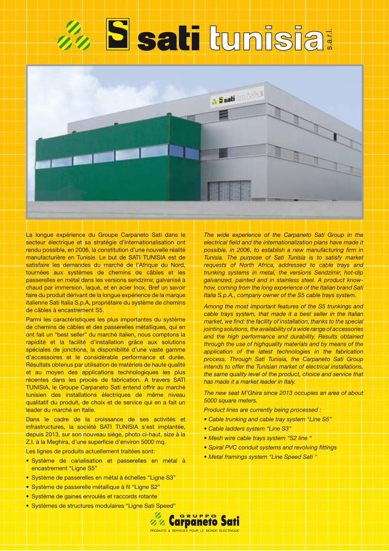
Dans le cadre de la croissance de ses activités et infrastructures, la société SATI TUNISIA s’est implantée, depuis 2013, sur son nouveau siège, photo ci-haut, size à la Z.I. à la Meghira, d’une superficie d’environ 5000 mq.
Les lignes de produits actuellement traitées sont:
• Système de canalisation et passerelles en métal à encastrement “Ligne S5”
• Système de passerelles en métal à échelles “Ligne S3”
• Système de passerelle métallique à fil “Ligne S2”
• Système de gaines enroulés et raccords rotante
• Systèmes de structures modulaires “Ligne Sati Speed“
The wide experience of the Carpaneto Sati Group in the electrical field and the internationalization plans have made it possible, in 2006, to establish a new manufacturing firm in Tunisia. The purpose of Sati Tunisia is to satisfy market requests of North Africa, addressed to cable trays and trunking systems in metal, the versions Sendzimir, hot-dip galvanized, painted and in stainless steel. A product know-how, coming from the long experience of the Italian brand Sati Italia S.p.A., company owner of the S5 cable trays system.
Among the most important features of the S5 trunkings and cable trays system, that made it a best seller in the Italian market, we find: the facility of installation, thanks to the special jointing solutions, the availability of a wide range of accessories and the high performance and durability. Results obtained through the use of highquality materials and by means of the application of the latest technologies in the fabrication process. Through Sati Tunisia, the Carpaneto Sati Group intends to offer the Tunisian market of electrical installations, the same quality level of the product, choice and service that has made it a market leader in Italy.
The new seat M’Ghira since 2013 occupies an area of about 5000 square meters.
Product lines are currently being processed :
• Cable trunking and cable tray system “Line S5”
• Cable ladders system “Line S3”
• Mesh wire cable trays system “S2 line “
• Spiral PVC conduit systems and revolving fittings
• Metal framings system “Line Speed Sati “
2
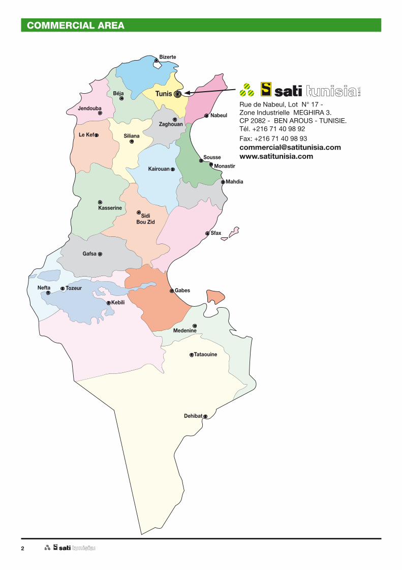
COMMERCIAL AREA
Zaghouan
Rue de Nabeul, Lot N° 17 -Zone Industrielle MEGHIRA 3.CP 2082 - BEN AROUS - TUNISIE.Tél. +216 71 40 98 92Fax: +216 71 40 98 [email protected]

EARTHING SYSTEMS, LIGHTNING PROTECTION AND EQUIPOTENTIAL BONDING SYSTEMS EXTERNAL LPS
TECHNICAL NOTES
Earthing systems - Technical notes ......................................page 4
Lightning protection systems - External LPS ......................page 8
Equipotential bonding systems - Technical notes ..............page 14
4
6
6
2
12
4
32A
1A
1
5
2
3 1
37
Traditional system
Tape or round
page 47
Cross-connector clamps
page 52
Clamps
page 45
Equipotential bonding bar
page 63
Earth electrode
page 45
Earth pits
page 49
Modular earth plates structure
Round section length
page 47
Modular earth plates
page 36
Clamp for equipotential grounding
page 45
Equipotential bonding bar
page 63
Connection to the reinforcement steel of the part of the foundation in contact with the earth
page 33
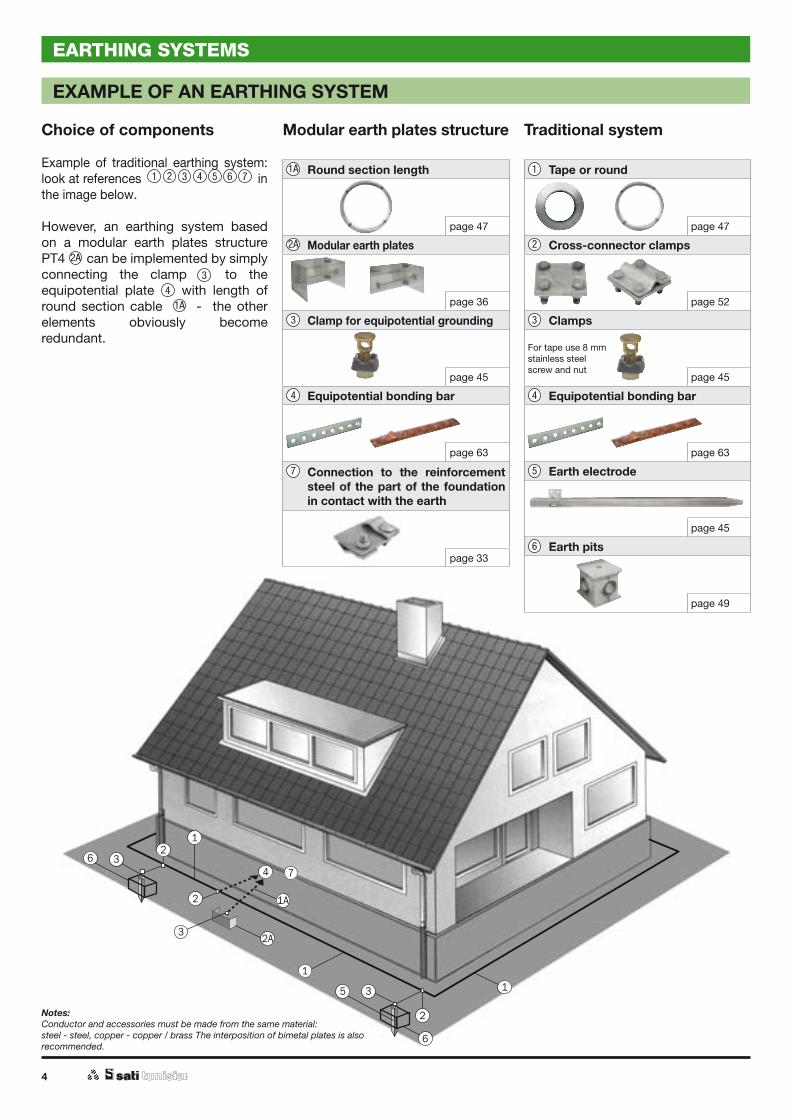
EXAMPLE OF AN EARTHING SYSTEM
Choice of components
Example of traditional earthing system: look at references in the image below.
However, an earthing system based on a modular earth plates structure PT4 2a can be implemented by simply connecting the clamp (3) to the equipotential plate (4) with length of round section cable (1A) - the other elements obviously become redundant.
2A2A 2
1A 11
33
44
4
5
6
7
1A
Notes:Conductor and accessories must be made from the same material:steel - steel, copper - copper / brass The interposition of bimetal plates is also recommended.
For tape use 8 mm stainless steel screw and nut
EARTHING SYSTEMS
2 3
3
4 5 6 7

5
NORMATIVE REFERENCES
The numerous technical standards, developed by the IEC and adopted by the European Committee for Electrotechnical Standardisation (CENELEC), are collectively known as EN 62305. Hundreds of lightning protection specialists from the 28 different member countries that represent CENELEC contributed to the writing of these standards over a period of more than 20 years.
CEI (Comitato Elettrotecnico Italiano) is the Italian Institute in charge of standardization and unification in the electrical, electronic and telecommunications field. Earthing systems, which therefore come under the jurisdiction of CEI, should be regulated according to one set of rules. However, legislation differentiates between low and high voltage circuits and systems for the protection against lightening. Technical notes tables specifywhich components should be used for each purpose. The main Rules and Regulations are:
- CEI 64-8 Electrical systems at a rated voltage not exceeding 1000 V c.a. and 1500 V d.c. (CENELEC-HD 60364-5-54; IEC 60364-1).
- CEI 11-1 Electrical systems at a rated voltage above 1kV c.a. (CENELEC-HD 63751).
- CEI EN 62305-3 Protection Against Lightning; Physical damage to structures and life hazard.
- CEI EN 62305-1 Protection Against Lightning; General Principle.
- CEI 64-12 Guidelines for the construction of earthing systems for residential and commercial buildings.
- CEI 11-37 Guidelines for the construction of earthing systems where consumption is greater than 1 kV (buildings with HV/LV inside).
- CEI 81-5 Equipment for the protection against lightning. Part 1: Phasing out connection components (CEI EN 50164-1).
In general it can be assumed that a system for protecting against lightning is also suitable for other applications. The reverse is not true.
Components for LPSs undergo tests for resistance to environmental corrosion and are also tested with an electrical pulse waveform of 10/350 microseconds.
There are two classes of test:
- Class "H" = 100kA (10/350).
- Class "M" = 50kA (10/350).
Components are chosen according to the desired level of protection and to expected lightning strike charges.
EARTHING SYSTEMS
6
TECHNICAL NOTES
Introduction
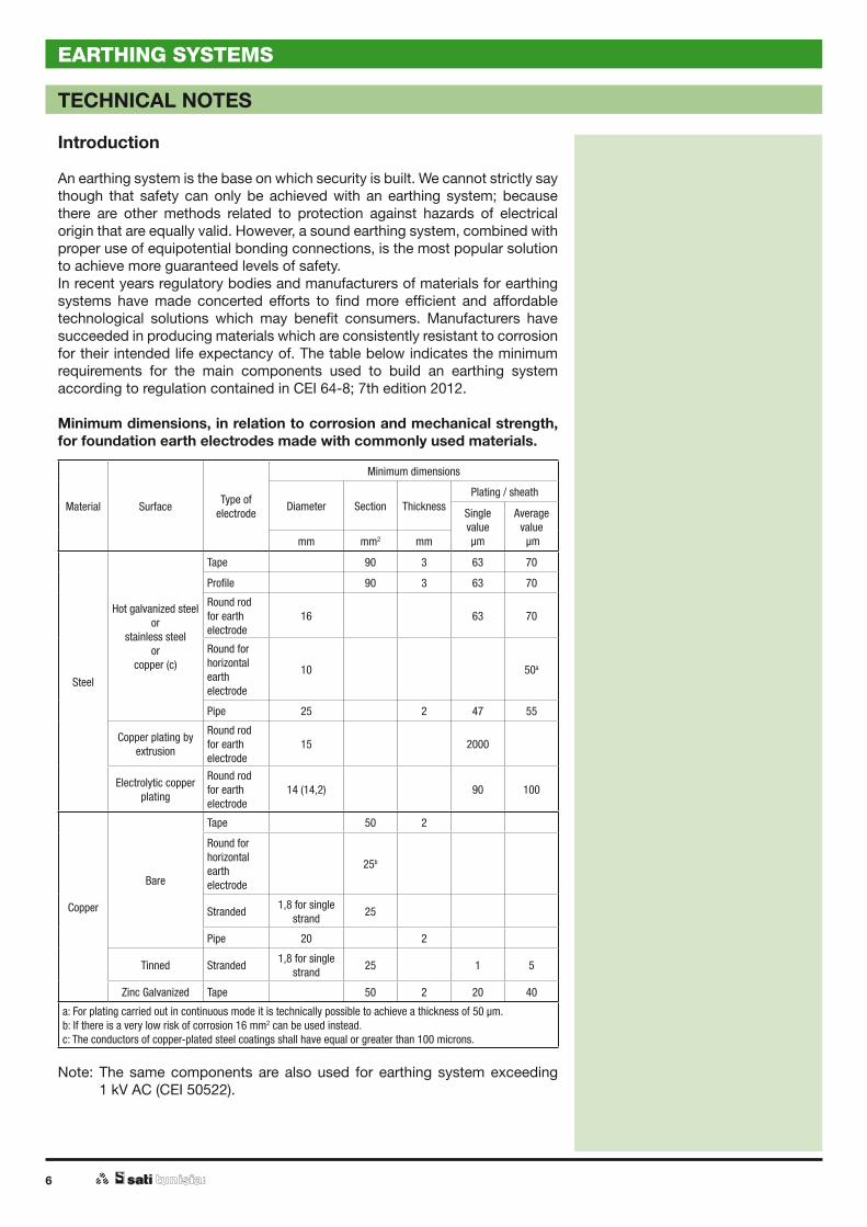
An earthing system is the base on which security is built. We cannot strictly say though that safety can only be achieved with an earthing system; because there are other methods related to protection against hazards of electrical origin that are equally valid. However, a sound earthing system, combined with proper use of equipotential bonding connections, is the most popular solution to achieve more guaranteed levels of safety.In recent years regulatory bodies and manufacturers of materials for earthing systems have made concerted efforts to find more efficient and affordable technological solutions which may benefit consumers. Manufacturers have succeeded in producing materials which are consistently resistant to corrosion for their intended life expectancy of. The table below indicates the minimum requirements for the main components used to build an earthing system according to regulation contained in CEI 64-8; 7th edition 2012.
Minimum dimensions, in relation to corrosion and mechanical strength, for foundation earth electrodes made with commonly used materials.
Material Surface Type of electrode
Minimum dimensions
Diameter Section ThicknessPlating / sheath
Single value µm
Average value µmmm mm2 mm
Steel
Hot galvanized steel or
stainless steelor
copper (c)
Tape 90 3 63 70
Profile 90 3 63 70
Round rod for earth electrode
16 63 70
Round for horizontal earth electrode
10 50a
Pipe 25 2 47 55
Copper plating by extrusion
Round rod for earth electrode
15 2000
Electrolytic copper plating
Round rod for earth electrode
14 (14,2) 90 100
Copper
Bare
Tape 50 2
Round for horizontal earth electrode
25b
Stranded 1,8 for single strand 25
Pipe 20 2
Tinned Stranded 1,8 for single strand 25 1 5
Zinc Galvanized Tape 50 2 20 40
a: For plating carried out in continuous mode it is technically possible to achieve a thickness of 50 µm.b: If there is a very low risk of corrosion 16 mm2 can be used instead.c: The conductors of copper-plated steel coatings shall have equal or greater than 100 microns.
Note: The same components are also used for earthing system exceeding1 kV AC (CEI 50522).
EARTHING SYSTEMS

7
TECHNICAL NOTES
Materials
It is possible to construct earthing systems of all kinds and in accordance with local regulations when using materials supplied by us. In addition to traditional products we also have a wide range of accessories to suit specific purposes: such as deep electrodes, modular extendable plates, equipotential bonding bar, and non-standard fittings. When using items which are designed and manufactured for specific use it is possible to achieve a reduction in installation time and obtain higher reliability for the earthing system.
EARTHING SYSTEMS

8
LIGHTNING PROTECTION SYSTEMS - EXTERNAL LPS
EXAMPLE OF AN EXTERNAL LIGHTNING PROTECTION AND EARTHING SYSTEM
Choice of components
Example: flat roof building with stainless steel roof border.
Note:Page number references help identify products suitable for building lightning protection systems different from the example outlined below.
Notes:Conductor and accessories must be made from the same material:steel - steel, copper - copper / brass The interposition of bimetal plates is also recommended.
Sectioning clamp
page 49
Support for conductor rods
page 54
Tape and round fasteners for conductor rods
page 52
Earth electrodes and accessories
page 43
Tape and round
page 47
Equipotential bonding bar
page 63
Tape or round
page 47
Roof supports
page 59
Cross connector clamps
page 52
Supports for down conductors
page 54
Air termination rods
page 50
Clamp support for air termination rods and down conductors
page 58
82
71
93
104
115
126
9
LIGHTNING PROTECTION SYSTEMS - EXTERNAL LPS
NORMATIVE REFERENCES
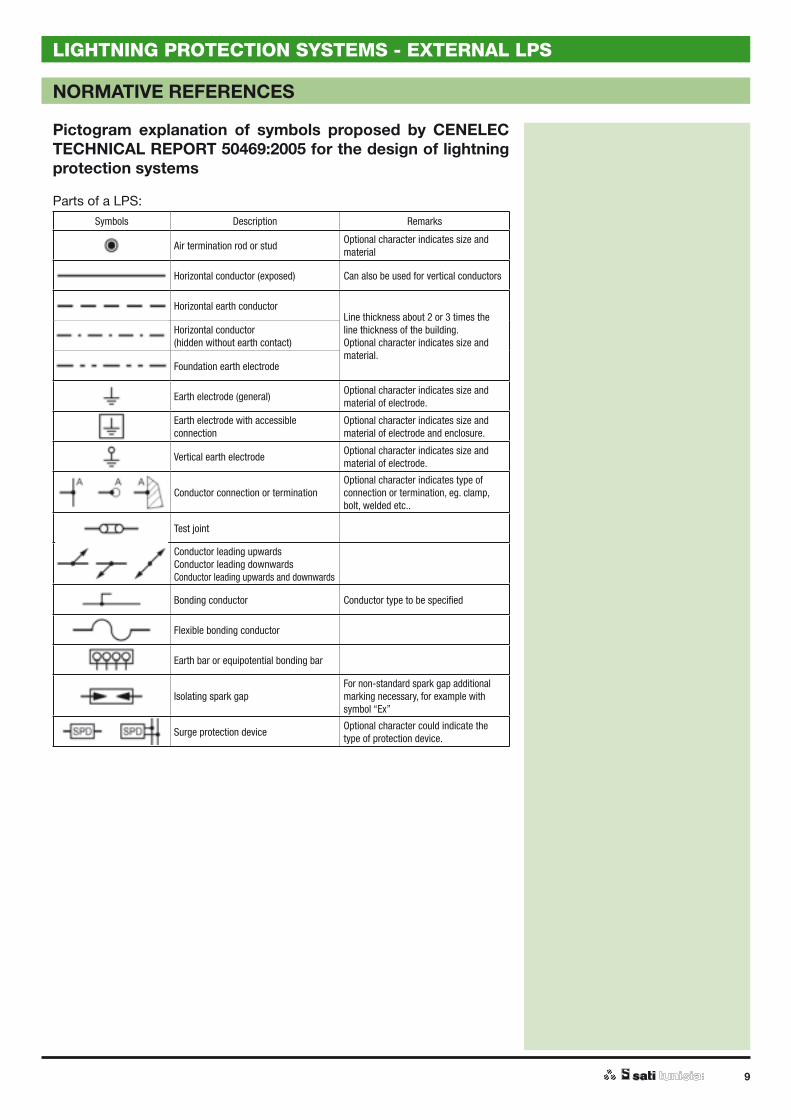
Pictogram explanation of symbols proposed by CENELEC TECHNICAL REPORT 50469:2005 for the design of lightning protection systems
Parts of a LPS:Symbols Description Remarks
Air termination rod or stud Optional character indicates size and material
Horizontal conductor (exposed) Can also be used for vertical conductors
Horizontal earth conductorLine thickness about 2 or 3 times the line thickness of the building.Optional character indicates size and material.
Horizontal conductor(hidden without earth contact)
Foundation earth electrode
Earth electrode (general) Optional character indicates size and material of electrode.
Earth electrode with accessible connection
Optional character indicates size and material of electrode and enclosure.
Vertical earth electrode Optional character indicates size and material of electrode.
Conductor connection or terminationOptional character indicates type of connection or termination, eg. clamp, bolt, welded etc..
Test joint
Conductor leading upwardsConductor leading downwardsConductor leading upwards and downwards
Bonding conductor Conductor type to be specified
Flexible bonding conductor
Earth bar or equipotential bonding bar
Isolating spark gapFor non-standard spark gap additional marking necessary, for example with symbol “Ex”
Surge protection device Optional character could indicate the type of protection device.

10
NORMATIVE REFERENCES
LIGHTNING PROTECTION SYSTEMS - EXTERNAL LPS
Materials employed to design on external LPS
Earthing system materials employed according to standards set out in CEI 64-8; V2 are different from materials used for LPS electrodes as shown in the following tables.Clamps and conductors must comply with standards set out in EN 50164 and their dimensions must be in proportion to the level of protection required against lightning strikes at the point of installation.
Table - Materials, configurations and minimum cross-sectional area of air-terminal conductors, air termination rods, earth lead-in rods and down-conductors (a)
Material Configuration Cross-sectional area mm2
Copper,Tin plated copper
Solid tape 50
Solid round (b) 50
Stranded (b) 50
Solid round (c) 176
Aluminium Solid tape 70
Solid round 50
Stranded 50
Aluminum alloy Solid tape 50
Solid round 50
Stranded 50
Solid round (c) 176
Copper coated Aluminum alloy Solid round 50
Hot dipped galvanized steel Solid tape 50
Solid round 50
Stranded 50
Solid round (c) 176
Copper coated steel Solid round 50
Solid tape 50
Stainless steel Solid tape (d) 50
Solid round (d) 50
Stranded 70
Solid round (c) 176
(a) Mechanical and electrical characteristics as well as corrosion resistance properties shall meet the requirements of the future IEC 62561 series.
(b) 50 mm2 (8 mm diameter) may be reduced to 25 mm2 in certain applications where mechanical strength is not an essential requirement. Consideration should in this case, be given to reducing the spacing of the fasteners.
(c) Applicable for air-terminal rods and earth lead-in rods. For air-terminal rods where mechanical stress such as wind loading is not critical, a 9,5 mm diameter, 1 m long rod may be used.
(8) If thermal and mechanical considerations are important then these values should be increased to 75 mm2.
11
NORMATIVE REFERENCES
LIGHTNING PROTECTION SYSTEMS - EXTERNAL LPS
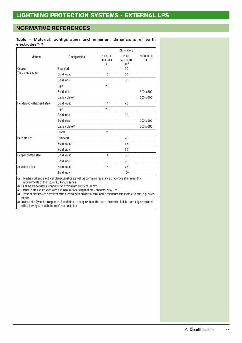
Table - Material, configuration and minimum dimensions of earth electrodes (a, e)
Material Configuration
Dimensions
Earth roddiameter
mm
Earth Conductor
mm2
Earth platemm
CopperTin plated copper
Stranded 50
Solid round 15 50
Solid tape 50
Pipe 20
Solid plate 500 x 500
Lattice plate (c) 600 x 600
Hot dipped galvanized steel Solid round 14 78
Pipe 25
Solid tape 90
Solid plate 500 x 500
Lattice plate (c) 600 x 600
Profile (d)
Bare steel (b) Stranded 70
Solid round 78
Solid tape 75
Copper coated steel Solid round 14 50
Solid tape 90
Stainless steel Solid round 15 78
Solid tape 100
(a) Mechanical and electrical characteristics as well as corrosion resistance properties shall meet the requirements of the future IEC 62561 series.
(b) Shall be embedded in concrete for a minimum depth of 50 mm.(c) Lattice plate constructed with a minimum total lenght of the conductor of 4,8 m.(d) Different profiles are permitted with a cross-section of 290 mm2 and a minimum thickness of 3 mm, e.g. cross
profile.(e) In case of a Type B arrangement foundation earthing system, the earth electrode shall be correctly connected
al least every 5 m with the reinforcement steel.
12
RECOMMENDATIONS FOR IMPLEMENTING AN LPS WITH AN AIR TERMINATION MESH
LIGHTNING PROTECTION SYSTEMS - EXTERNAL LPS
Introduction
When the need arises to install a lightning protection system, according to probabilistic models, the key elements providing protection against lightning are: the air termination mesh, the down conductors and the earth electrode.
Air termination mesh
An appropriate level of protection is calculated according to the type of building and the likelihood of a lightning strike (IEC 62305-2).In this respect CEI rules are also applied to classify systems according to the levels of protection they afford as shown in Table 1 (IEC 62305-1).Once the level of protection, and therefore the efficiency of protection, is calculated the choice of mesh size can be easily derived: see Table 2.
Table 1Level of protection Efficiency (*) Lightning charge (kA)
I 0,99 200
II 0,97 150
III 0,91 100
IV 0,84 100
(*) The efficency of a protection mesure is assumed equal to the probability with which lightning current parameters are insaide such range.
Table 2Level of protection Maximum length of air termination mesh
IV 20
III 15
II 10
I 5
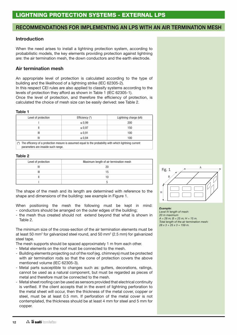
The shape of the mesh and its length are determined with reference to the shape and dimensions of the building: see example in Figure 1.
When positioning the mesh the following must be kept in mind:- conductors should be arranged on the outer edges of the building;- the mesh thus created should not extend beyond that what is shown in
Table 2.
The minimum size of the cross-section of the air termination elements must be at least 50 mm2 for galvanized steel round, and 50 mm2 (2.5 mm) for galvanized steel tape.The mesh supports should be spaced approximately 1 m from each other.- Metal elements on the roof must be connected to the mesh.- Building elements projecting out of the roof (eg. chimneys) must be protected
with air termination rods so that the cone of protection covers the above mentioned volume (IEC 62305-3).
- Metal parts susceptible to changes such as: gutters, decorations, railings, cannot be used as a natural component, but must be regarded as pieces of metal and therefore must be connected to the mesh.
- Metal sheet roofing can be used as sensors provided that electrical continuity is verified. If the client accepts that in the event of lightning perforation to the metal sheet will occur, then the thickness of the metal cover, copper or steel, must be at least 0.5 mm. If perforation of the metal cover is not contemplated, the thickness should be at least 4 mm for steel and 5 mm for copper.
Example:Level IV length of mesh: 20 m maximumA = 28 m; B = 25 m; H = 15 m.Total length of the air termination mesh: 28 x 3 + 25 x 3 = 159 m.
13
RECOMMENDATIONS FOR IMPLEMENTING AN LPS WITH AN AIR TERMINATION MESH
LIGHTNING PROTECTION SYSTEMS - EXTERNAL LPS
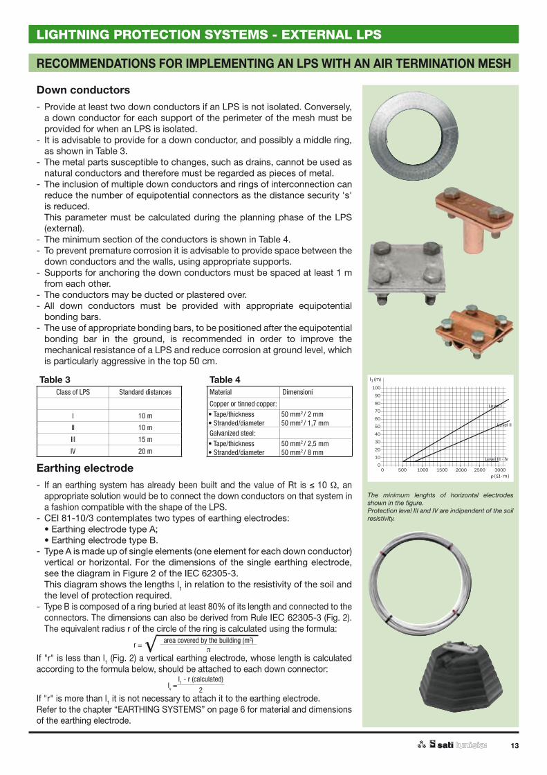
Down conductors- Provide at least two down conductors if an LPS is not isolated. Conversely,
a down conductor for each support of the perimeter of the mesh must be provided for when an LPS is isolated.
- It is advisable to provide for a down conductor, and possibly a middle ring, as shown in Table 3.
- The metal parts susceptible to changes, such as drains, cannot be used as natural conductors and therefore must be regarded as pieces of metal.
- The inclusion of multiple down conductors and rings of interconnection can reduce the number of equipotential connectors as the distance security 's' is reduced.
This parameter must be calculated during the planning phase of the LPS (external).
- The minimum section of the conductors is shown in Table 4.- To prevent premature corrosion it is advisable to provide space between the
down conductors and the walls, using appropriate supports.- Supports for anchoring the down conductors must be spaced at least 1 m
from each other.- The conductors may be ducted or plastered over.- All down conductors must be provided with appropriate equipotential
bonding bars.- The use of appropriate bonding bars, to be positioned after the equipotential
bonding bar in the ground, is recommended in order to improve the mechanical resistance of a LPS and reduce corrosion at ground level, which is particularly aggressive in the top 50 cm.
Table 3 Table 4Class of LPS Standard distances Material Dimensioni
Copper or tinned copper:
I 10 m • Tape/thickness• Stranded/diameter
50 mm2 / 2 mm50 mm2 / 1,7 mm
II 10 mGalvanized steel:
III 15 m • Tape/thickness• Stranded/diameter
50 mm2 / 2,5 mm50 mm2 / 8 mmIV 20 m
Earthing electrode- If an earthing system has already been built and the value of Rt is 10 , an
appropriate solution would be to connect the down conductors on that system in a fashion compatible with the shape of the LPS.
- CEI 81-10/3 contemplates two types of earthing electrodes: • Earthing electrode type A; • Earthing electrode type B.- Type A is made up of single elements (one element for each down conductor)
vertical or horizontal. For the dimensions of the single earthing electrode, see the diagram in Figure 2 of the IEC 62305-3.
This diagram shows the lengths l1 in relation to the resistivity of the soil and the level of protection required.
- Type B is composed of a ring buried at least 80% of its length and connected to the connectors. The dimensions can also be derived from Rule IEC 62305-3 (Fig. 2).
The equivalent radius r of the circle of the ring is calculated using the formula:
r =area covered by the building (m2)
If "r" is less than l1 (Fig. 2) a vertical earthing electrode, whose length is calculated according to the formula below, should be attached to each down connector:
Iv =I1 - r (calculated)
2If "r" is more than l1 it is not necessary to attach it to the earthing electrode.Refer to the chapter “EARTHING SYSTEMS” on page 6 for material and dimensions of the earthing electrode.
The minimum lenghts of horizontal electrodes shown in the figure.Protection level III and IV are indipendent of the soil resistivity.
14
TECHNICAL NOTES
EQUIPOTENTIAL BONDING SYSTEMS
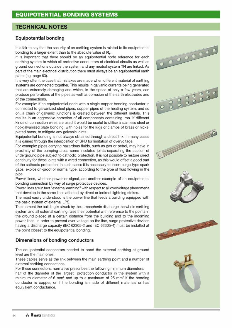
Equipotential bonding
It is fair to say that the security of an earthing system is related to its equipotential bonding to a larger extent than to the absolute value of RE. It is important that there should be an equipotential node reference for each earthing system to which all protective conductors of electrical circuits as well as ground connections outside the system and any neutral system TN are linked. As part of the main electrical distribution there must always be an equipotential earth plate. (eg. page 63). It is very often the case that mistakes are made when different material of earthing systems are connected together. This results in galvanic currents being generated that are extremely damaging and which, in the space of only a few years, can produce perforations of the pipes as well as corrosion of the earth electrodes and of the connections. For example: if an equipotential node with a single copper bonding conductor is connected to galvanized steel pipes, copper pipes of the heating system, and so on, a chain of galvanic junctions is created between the different metals. This results in an aggressive corrosion of all components containing iron. If different kinds of connection wires are used it would be useful to utilise a stainless steel or hot-galvanized plate bonding, with holes for the lugs or clamps of brass or nickel plated brass, to mitigate any galvanic joints. Equipotential bonding is not always obtained through a direct link. In many cases it is gained through the interposition of SPD for limitation of overvoltage. For example: pipes carrying hazardous fluids, such as gas or petrol, may have in proximity of the pumping areas some insulated joints separating the section of underground pipe subject to cathodic protection. It is not possible to restore direct continuity for these joints with a wired connection, as this would offset a good part of the cathodic protection. In such cases it is necessary to insert surge-type spark gaps, explosion-proof or normal type, according to the type of fluid flowing in the pipe. Power lines, whether power or signal, are another example of an equipotential bonding connection by way of surge protective devices.Power lines are in fact "external earthing” with respect to all overvoltage phenomena that develop in the same lines affected by direct or indirect lightning strikes. The most easily understood is the power line that feeds a building equipped with the basic system of external LPS. The moment the building is struck by the atmospheric discharge the whole earthing system and all external earthing raise their potential with reference to the points in the ground placed at a certain distance from the building and to the incoming power lines. In order to prevent over-voltage on the line, surge protective devices having a discharge capacity (IEC 62305-2 and IEC 62305-4) must be installed at the point closest to the equipotential bonding.
Dimensions of bonding conductors
The equipotential connectors needed to bond the external earthing at ground level are the main ones. These cables serve as the link between the main earthing point and a number of external earthing connections. For these connectors, normative prescribes the following minimum diameters: half of the diameter of the largest protection conductor in the system with a minimum diameter of 6 mm2 and up to a maximum of 25 mm2 if the bonding conductor is copper, or if the bonding is made of different materials or has equivalent conductance.
EARTHING SYSTEMS, LIGHTNING PROTECTION AND EQUIPOTENTIAL BONDING SYSTEMS EXTERNAL LPS
APPLICATION EXAMPLES
TT systems for homes and commercial buildings ...............page 16
TN systems for industrial plants, large shopping .................page 18centres and hotels
IT Systems ...............................................................................page 18
Watering towers ......................................................................page 20
Cabins HV / LV equipped with Surge Protective Device ......page 22
Cabins HV / LV on difficult terrain ..........................................page 24

16
EARTHING SYSTEMS, LIGHTNING PROTECTION AND EQUIPOTENTIAL BONDING SYSTEMS
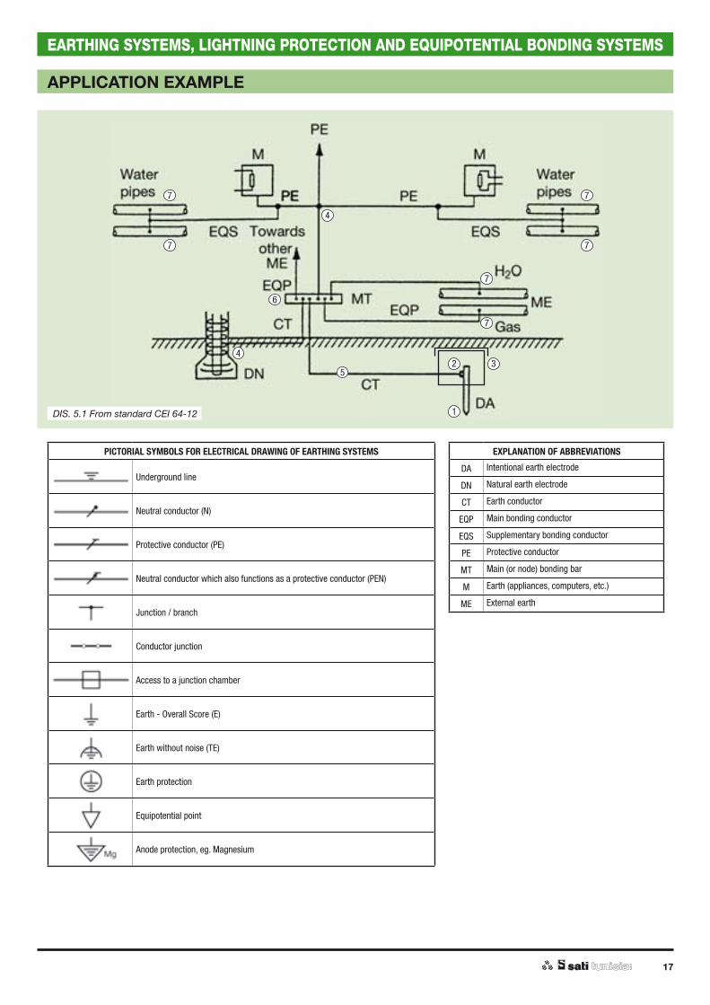
APPLICATION EXAMPLE
A number of examples are provided which describe different types of earthing systems in relation to distribution and requirements of the electrical system. The examples were chosen so as to help solve practical problems in the planning and deploying of earthing systems.Different materials were deliberately chosen in the examples shown. This is intended to facilitate an informed selection of materials by taking into account their compatibility. It is worth remembering that best results, as far as durability of the system is concerned, are obtained with homogeneous materials.
TT systems for homes and commercial buildings
TT systems are certainly the easiest system to implement, as shown in diagram 5.1 because the value of earthing resistance is usually achieved by:
RE UL
Id
where
UL = 50 V for ordinary environments.UL = 25 V for building sites, medical structures, agricultural structures for livestock.RE = total resistance of earth electrodes and conductors of earthing protection in ohm.Id = rated residual current circuit breakers of the protection device upstream of the
distribution system.
The use of residual current circuit breakers in TT has become a common practice and, from a technical and economic point of view, it represents the best solution. The earthing system would certainly be easy to implement because it would be sufficient to build plants with RE between some ten and several hundred ohms. Even in the case of difficult terrain it would be enough to insert some vertical earth electrodes (2 ÷ 4) at least at a distance of 2L (L indicates the length of the single electrode). Alternatively, an earth plate structure of the PT4 type A + B would be sufficient. It is worth remembering that inserting two adjoining vertical earth electrodes in the same earth pit does not have a better effect on the final value of RE. It is also worth remembering that the best technical solution is to use intentional DA electrodes together with DN natural electrodes. This is because while the former are always verifiable and serve the sole purpose of dispersal, the latter can sometimes swing out of control.An often debated topic is whether or not to use earth pits for inspection purposes. From a standards point of view this is not necessary. However, when it comes to maintenance and verification of system efficiency, an earth pit may be useful: it makes visible the state of corrosion of individual components and also allows the integration of extendable vertical earth electrodes.
Product reference
Intentional earth electrodes
3020002
3020052
3010001...
3010005
3060001PT4/A
3060002PT4/B
3050001
Clamps for connection to earth electrodes
3110042
3110251
Earth pit
31119023111922
Product reference
Clamps
3110503
5060151...
5040157
5070054...
5070056
Earth conductor
3120022
3130001
Main (node) bonding bar
3110913
3110851...
3110872
3110912
Pipe clamp
3111651...
3111658
2
1 4
5
6
73
17
EARTHING SYSTEMS, LIGHTNING PROTECTION AND EQUIPOTENTIAL BONDING SYSTEMS
APPLICATION EXAMPLE
2
1
4
4
5
6
7
77
77
7
3
EXPLANATION OF ABBREVIATIONS
DA Intentional earth electrode
DN Natural earth electrode
CT Earth conductor
EQP Main bonding conductor
EQS Supplementary bonding conductor
PE Protective conductor
MT Main (or node) bonding bar
M Earth (appliances, computers, etc.)
ME External earth
PICTORIAL SYMBOLS FOR ELECTRICAL DRAWING OF EARTHING SYSTEMS
Underground line
Neutral conductor (N)
Protective conductor (PE)
Neutral conductor which also functions as a protective conductor (PEN)
Junction / branch
Conductor junction
Access to a junction chamber
Earth - Overall Score (E)
Earth without noise (TE)
Earth protection
Equipotential point
Anode protection, eg. Magnesium
DIS. 5.1 From standard CEI 64-12
18
EARTHING SYSTEMS, LIGHTNING PROTECTION AND EQUIPOTENTIAL BONDING SYSTEMS
APPLICATION EXAMPLE HV / LV TRANSFORMER
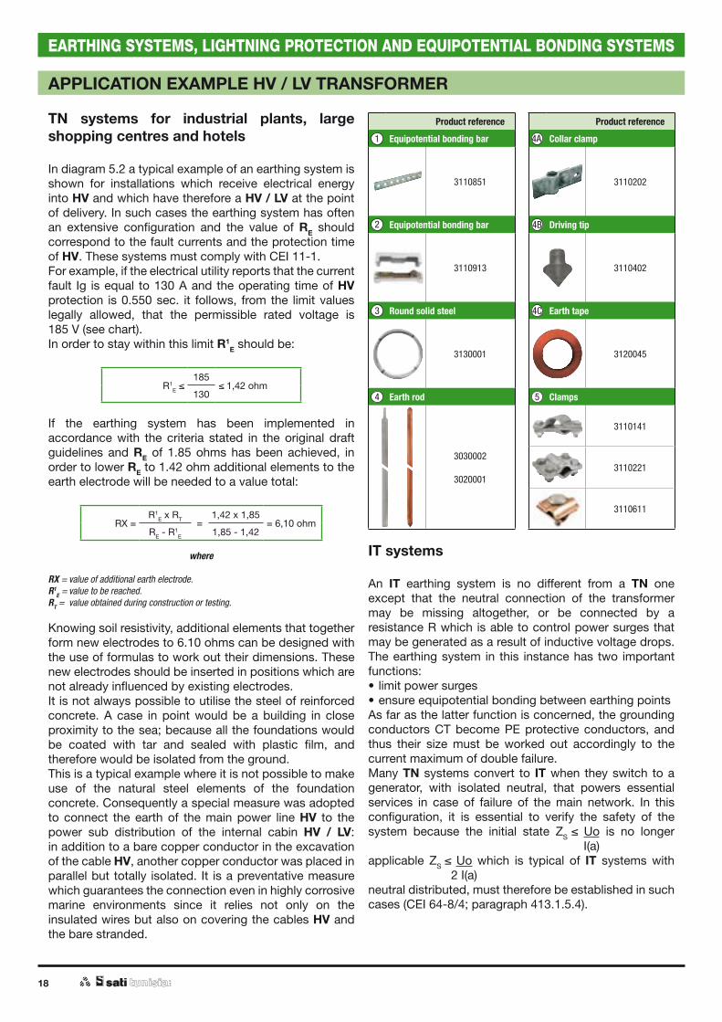
TN systems for industrial plants, large shopping centres and hotels
In diagram 5.2 a typical example of an earthing system is shown for installations which receive electrical energy into HV and which have therefore a HV / LV at the point of delivery. In such cases the earthing system has often an extensive configuration and the value of RE should correspond to the fault currents and the protection time of HV. These systems must comply with CEI 11-1.For example, if the electrical utility reports that the current fault Ig is equal to 130 A and the operating time of HV protection is 0.550 sec. it follows, from the limit values legally allowed, that the permissible rated voltage is185 V (see chart).In order to stay within this limit R1
E should be:
R1E
185!1,42 ohm
130
If the earthing system has been implemented in accordance with the criteria stated in the original draft guidelines and RE of 1.85 ohms has been achieved, in order to lower RE to 1.42 ohm additional elements to the earth electrode will be needed to a value total:
RX "R1
E x RT "1,42 x 1,85
"!6,10 ohmRE - R
1E 1,85 - 1,42
where
RX = value of additional earth electrode.R1
E = value to be reached.RT = value obtained during construction or testing.
Knowing soil resistivity, additional elements that together form new electrodes to 6.10 ohms can be designed with the use of formulas to work out their dimensions. These new electrodes should be inserted in positions which are not already influenced by existing electrodes.It is not always possible to utilise the steel of reinforced concrete. A case in point would be a building in close proximity to the sea; because all the foundations would be coated with tar and sealed with plastic film, and therefore would be isolated from the ground. This is a typical example where it is not possible to make use of the natural steel elements of the foundation concrete. Consequently a special measure was adopted to connect the earth of the main power line HV to the power sub distribution of the internal cabin HV / LV:in addition to a bare copper conductor in the excavation of the cable HV, another copper conductor was placed in parallel but totally isolated. It is a preventative measure which guarantees the connection even in highly corrosive marine environments since it relies not only on the insulated wires but also on covering the cables HV and the bare stranded.
Product reference
Equipotential bonding bar
3110851
Equipotential bonding bar
3110913
Round solid steel
3130001
Earth rod
3030002
3020001
Product reference
Collar clamp
3110202
Driving tip
3110402
Earth tape
3120045
Clamps
3110141
3110221
3110611
2
1
3
4 5
4A
4B
4C
IT systems
An IT earthing system is no different from a TN one except that the neutral connection of the transformer may be missing altogether, or be connected by a resistance R which is able to control power surges that may be generated as a result of inductive voltage drops. The earthing system in this instance has two important functions:• limit power surges• ensure equipotential bonding between earthing pointsAs far as the latter function is concerned, the grounding conductors CT become PE protective conductors, and thus their size must be worked out accordingly to the current maximum of double failure.Many TN systems convert to IT when they switch to a generator, with isolated neutral, that powers essential services in case of failure of the main network. In this configuration, it is essential to verify the safety of the system because the initial state ZS Uo is no longer I(a)applicable ZS Uo which is typical of IT systems with 2 I(a)neutral distributed, must therefore be established in such cases (CEI 64-8/4; paragraph 413.1.5.4).
19
EARTHING SYSTEMS, LIGHTNING PROTECTION AND EQUIPOTENTIAL BONDING SYSTEMS
4
0,05 0,1 0,2 0,3 0,4 0,5 0,55 0,7 1 2 3 4 5 6 7 8 9 10
5
6
789
100
1852
3
4
5
6
7
8
91000
V
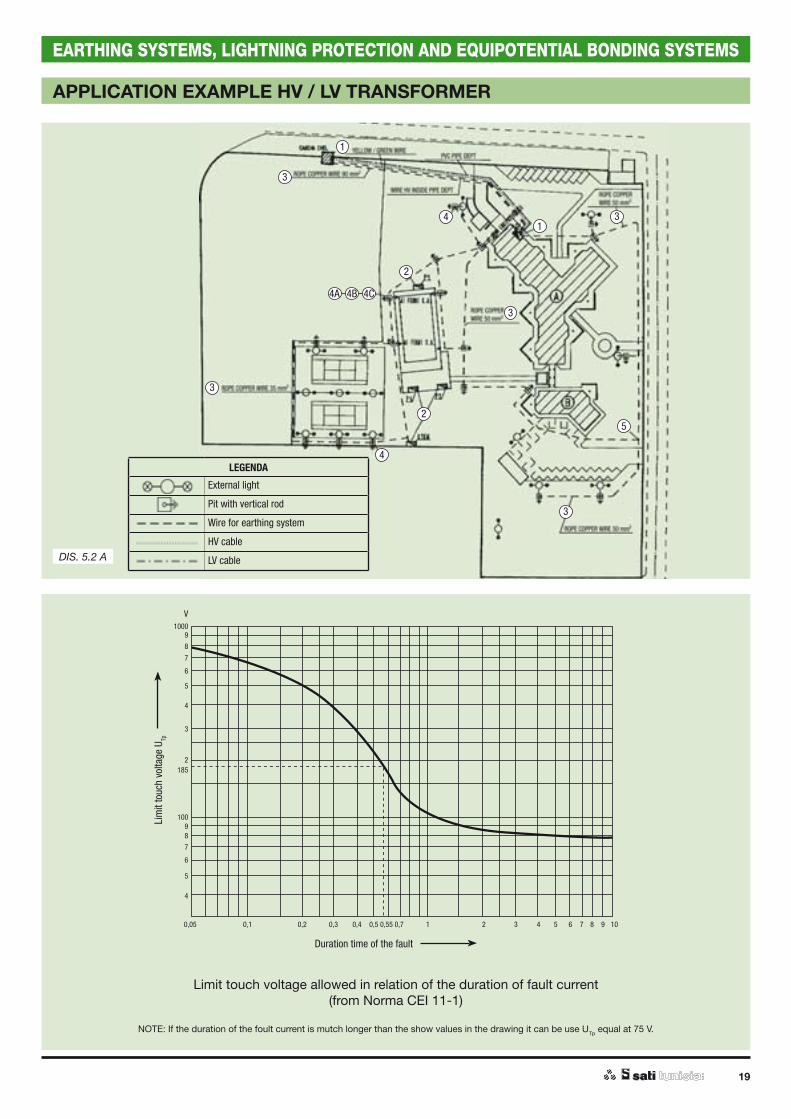
APPLICATION EXAMPLE HV / LV TRANSFORMER
DIS. 5.2 A
LEGENDA
External light
Pit with vertical rod
Wire for earthing system
HV cable
LV cable
Duration time of the fault
Lim
it to
uch
volta
ge U
Tp
Limit touch voltage allowed in relation of the duration of fault current(from Norma CEI 11-1)
NOTE: If the duration of the foult current is mutch longer than the show values in the drawing it can be use UTp equal at 75 V.
2
2
1
1
4
4
5
3
3
3
3
3
4C4B4A
20
EARTHING SYSTEMS, LIGHTNING PROTECTION AND EQUIPOTENTIAL BONDING SYSTEMS
APPLICATION EXAMPLE
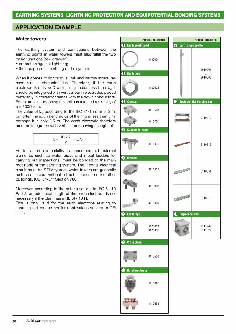
Water towers
The earthing system and connections between the earthing points in water towers must also fulfill the two basic functions (see drawing):• protection against lightning;• the equipotential earthing of the system.
When it comes to lightning, all tall and narrow structures have similar characteristics. Therefore, if the earth electrode is of type C with a ring radius less than L1, it should be integrated with vertical earth electrodes placed preferably in correspondence with the down conductors.For example, supposing the soil has a tested resistivity of = 300 x m.
The value of L1, according to the IEC 81-1 norm is 5 m, but often the equivalent radius of the ring is less than 5 m, perhaps it is only 3.5 m. The earth electrode therefore must be integrated with vertical rods having a length of:
L =5 - 3,5
= 0,75 m2
As far as equipotentiality is concerned, all external elements, such as water pipes and metal ladders for carrying out inspections, must be bonded to the main root node of the earthing system. The internal electrical circuit must be SELV type as water towers are generally restricted areas without direct connection to other buildings. (CEI 64-8/7 Section 706).
Moreover, according to the criteria set out in IEC 81-10 Part 3, an additional length of the earth electrode is not necessary if the plant has a RE of <10 . This is only valid for the earth electrode relating to lightning strikes and not for applications subject to CEI 11-1.
Product reference
Earth solid round
3130001
Earth tape
3120022
Clamps
3110503
3110701
Support for tape
3111011
Clamps
3111410
3110802
3111405
Earth tape
31200223120031
Cross clamp
3110552
Bonding clamps
3110261
3110268
Product reference
Earth cross profile
3010001...
3010005
Equipotential bonding bar
3110913
3110912
3110851
3110872
Inspection well
31119023111922
7
6 11
1
2
3 10
4
5
9
8

21
EARTHING SYSTEMS, LIGHTNING PROTECTION AND EQUIPOTENTIAL BONDING SYSTEMS
APPLICATION EXAMPLE
2
1
8
4
5
67 9
3
3
10
3
11
11
11

22
EARTHING SYSTEMS, LIGHTNING PROTECTION AND EQUIPOTENTIAL BONDING SYSTEMS
APPLICATION EXAMPLE
Power distribution cabins Surge Protective Device HV
The drawing shows a typical example of SPD HV installed on the arrival line.The configuration of the earth will be very similar to that which is necessary for lightning protection systems. It consists, therefore, of at least one ring around the cabin which is supplemented with additional elements at the point of connection with the earth conductor of the SPD. Usually, limitations of surge values of RE lower than 10 !are obtained. It is obvious that the value of RE must correspond with the value of intervention time of HV protection and the typical HV fault currents of the line (see TN system).In practice, these coordinates are difficult to reach due to high soil resistivity. It is necessary therefore to test step voltages and touch as shown in IEC 11-1.
Product reference
Earthing plate
3060001
3060002
3050001
Bonding clamps
3110261
Inspection well
31119223111902
Earthing solid round
3130011
Clamps
3110141
3110221
3110611
Equipotential bonding bar
3110912
3110913
3110851
3110872
Product reference
Earthing rods
30300023020102
Morsetti per picchetti
3110202
3110141
Earthing rope
5070001
Accessories for rope
5070105
5070154
5070054
Cross clamps
3110701
3110503
1
2
3
4
5
6
7
8
9
10
11
23
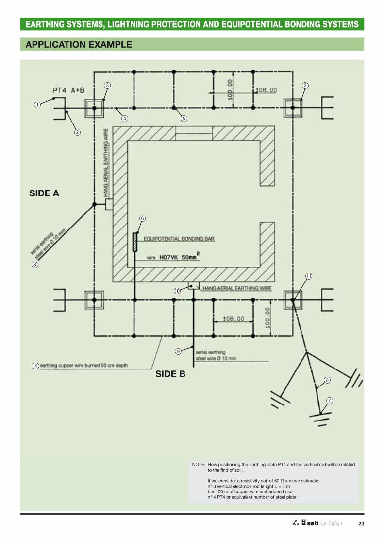
EARTHING SYSTEMS, LIGHTNING PROTECTION AND EQUIPOTENTIAL BONDING SYSTEMS
APPLICATION EXAMPLE
SIDE A
SIDE B
2
4
4
5
6
7
8
9
10
11
8
3 3
1
NOTE: How positioning the earthing plate PT4 and the vertical rod will be related to the find of soil.
If we consider a resistivity soil of 50 x m we estimate: n° 3 vertical electrode rod lenght L = 3 m L = 100 m of copper wire embedded in soil n° 4 PT4 or equivalent number of steel plate

24
EARTHING SYSTEMS, LIGHTNING PROTECTION AND EQUIPOTENTIAL BONDING SYSTEMS
APPLICATION EXAMPLE
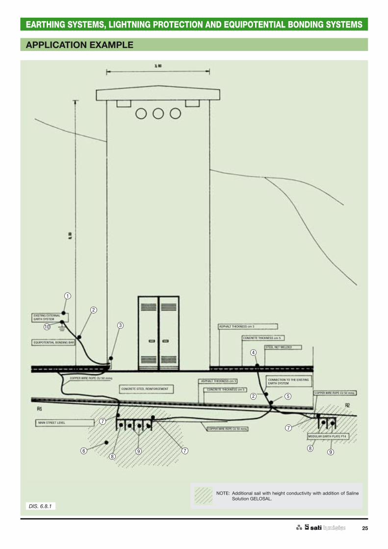
Cabins HV / LV situated on difficult terrain
Difficult terrain typically shows high resistivity: 2000 - 3000 x m and beyond. In these conditions it is impossible to add an earth electrode, working in harmony with the currents of line failure, in the vicinity of the cabin sited on such soil. One solution would be to connect to an earthing system further away where the soil is more conductive.For example, in marble quarries the problem is very difficult to solve. Good technology is represented by the use of electrode plates PT4 A + B + ... laid in modular installation fashion in soil mixed with salt of type GELOSAL. Electrodes that have values in the tens of ohms are used, which are good for working in harmony with differential limit voltage of 25 V. Use of a control step and touch voltages will also be needed.(see drawing 6.8.1.).
Product reference
Clamps
5060153...
5060157
3110611
Earth solid round
3130001
3120022
Equipotential bonding bar
3110912
3110851
3110872
Reinforced steel clamp
3110118
Clamp
5060153...
5060157
Saline solution
3110951
Product reference
Bonding clamp
3110261
Earthing plate
3060001
3060002
3050001
Earth rods
3010001...
3010005
3030002
3020101
3040001
1
2
3 10
4
5
6
7
8 9
25
EARTHING SYSTEMS, LIGHTNING PROTECTION AND EQUIPOTENTIAL BONDING SYSTEMS
APPLICATION EXAMPLE
NOTE: Additional sail with height conductivity with addition of Saline Solution GELOSAL.
2
2
4
5
6
7
7
7
8
899
10 3
1
EXISTING EXTERNALEARTH SYSTEM
EQUIPOTENTIAL BONDING BAR
COPPER WIRE ROPE CU 50 mmq
CONCRETE STEEL REINFORCEMENT
MAIN STREET LEVEL
COPPER WIRE ROPE CU 50 mmq
COPPER WIRE ROPE CU 50 mmq
MODULAR EARTH PLATE PT4
ASPHALT THICKNESS cm 3
ASPHALT THICKNESS cm 3
CONCRETE THICKNESS cm 5
CONCRETE THICKNESS cm 5
STEEL NET WELDED
CONNECTION TO THE EXISTING EARTH SYSTEM
DIS. 6.8.1
26
NOTE

EARTHING SYSTEMS, LIGHTNING PROTECTION AND EQUIPOTENTIAL BONDING SYSTEMS EXTERNAL LPSs
FOUNDATION EARTH ELECTRODE
Foundation earth electrode - Technical notes .....................page 28
Jumpers for rebars electrical continuity ..............................page 32
Clamps - fasteners for earth termination system ................page 33
Wall earthing receptacle .........................................................page 34
Clamp - fastener - bulldog ......................................................page 34
28
EARTHING SYSTEMS, LIGHTNING PROTECTION AND EQUIPOTENTIAL BONDING SYSTEMS
FOUNDATION EARTH ELECTRODE
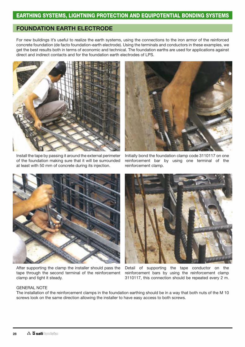
For new buildings it’s useful to realize the earth systems, using the connections to the iron armor of the reinforced concrete foundation (de facto foundation-earth electrode). Using the terminals and conductors in these examples, we get the best results both in terms of economic and technical. The foundation earths are used for applications against direct and indirect contacts and for the foundation earth electrodes of LPS.
Install the tape by passing it around the external perimeter of the foundation making sure that it will be surrounded at least with 50 mm of concrete during its injection.
Detail of supporting the tape conductor on the reinforcement bars by using the reinforcement clamp 3110117, this connection should be repeated every 2 m.
Initially bond the foundation clamp code 3110117 on one reinforcement bar by using one terminal of the reinforcement clamp.
After supporting the clamp the installer should pass the tape through the second terminal of the reinforcement clamp and tight it steady.
GENERAL NOTEThe installation of the reinforcement clamps in the foundation earthing should be in a way that both nuts of the M 10 screws look on the same direction allowing the installer to have easy access to both screws.
29
EARTHING SYSTEMS, LIGHTNING PROTECTION AND EQUIPOTENTIAL BONDING SYSTEMS
FOUNDATION EARTH ELECTRODE
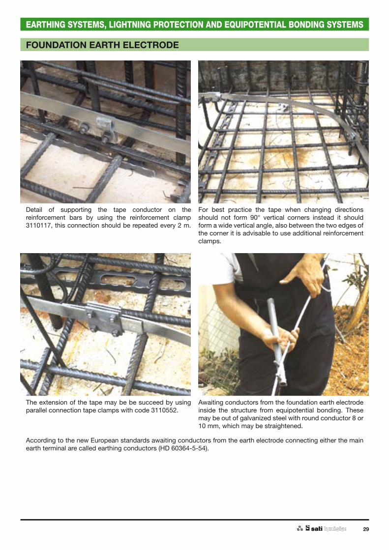
Detail of supporting the tape conductor on the reinforcement bars by using the reinforcement clamp 3110117, this connection should be repeated every 2 m.
Awaiting conductors from the foundation earth electrode inside the structure from equipotential bonding. These may be out of galvanized steel with round conductor 8 or 10 mm, which may be straightened.
For best practice the tape when changing directions should not form 90° vertical corners instead it should form a wide vertical angle, also between the two edges of the corner it is advisable to use additional reinforcement clamps.
The extension of the tape may be be succeed by using parallel connection tape clamps with code 3110552.
According to the new European standards awaiting conductors from the earth electrode connecting either the main earth terminal are called earthing conductors (HD 60364-5-54).

30
EARTHING SYSTEMS, LIGHTNING PROTECTION AND EQUIPOTENTIAL BONDING SYSTEMS
Connection between the earthing conductor (awaiting conductor) with the tape by using a cross clamp with code 3110504.
The copper earth conductors should be bonded with the reinforcement rods by using the reinforcement clamp with code 3110119 at least every 1 m up to the connection point with the earth terminal.
The galvanised earth conductors should be bonded to the reinforcement rods by using the reinforcement clamps 3110117 at least every 2 m until the earth terminal.
Earthing conductors, which are driven to the main distribution board panel are preferable copper conductors. The connection between the tape and the round earth conductors may be done by using a cross clamp with code 3110671, for conductors 1635 mm2 and 3110672 for conductors 5070 mm2.
FOUNDATION EARTH ELECTRODE

31
EARTHING SYSTEMS, LIGHTNING PROTECTION AND EQUIPOTENTIAL BONDING SYSTEMS
Before the connection between the earth conductor and the earth terminal, the terminal should be fixed on the wooded mould by using two nails passing them through the two holes, which are on both sides of the earth terminal (3110114).
Connection between the earth terminal and the earth conductor by using the cross clamp with code 3110672 , for conductors 16 to 35 mm2 and 3110114 for conductors 50 ÷ 70 mm2 or Ø 8 ÷ 10 mm.
FOUNDATION EARTH ELECTRODE

32
EARTHING SYSTEMS, LIGHTNING PROTECTION AND EQUIPOTENTIAL BONDING SYSTEMS
Jumpers for rebars electrical continuityRebars of reinforcing concrete could be used as down conductors if they satisfy the minimum dimensions of the standard, CEI EN 62305-3.The electrical continuity of rebars is achieved by the Rebars Jumpers™.Reproduction of the whole product or part of it, is being prosecuted by the low about the literary property (copyright), etc..Tested according to CEI EN 50164-1 and 2.
Code Class Description Dimensions Pack.Pcs.
3110110 H-100 kA 1 point 1 (60 x 80) + 600 1
3110111 H-100 kA 2 points 2 (60 x 80) + 600 1
3110112 H-100 kA 3 points 3 (60 x 80) + 600 1
3110113 H-100 kA 2 points Clamp, rope wire and wall earthing
receptacle M8
1
JUMPERS FOR REBARS ELECTRICAL CONTINUITY
Air Termination of LPS
Reinforcement
Reinforcement rebar
Jumpers for rebars electrical
continuity
Reinforcement
Reinforcement
Foundation earth electrode
Jumpers for rebars electrical continuity to 2 points.
Jumpers for rebars electrical continuity to 3 points.
Jumpers for rebars electrical continuity to 2 points with clamp,
rope wire and wall earthing receptable M8
H

33
EARTHING SYSTEMS, LIGHTNING PROTECTION AND EQUIPOTENTIAL BONDING SYSTEMS
CLAMPS - FASTENERS FOR EARTH TERMINATION SYSTEM
Clamp - FastenerFor electrical connection-fastening embedded in concrete of Ø 10 mm conductors or tapes up to 40 x 4 mm, to reinforcement rebars up to Ø 24 mm for construction of foundation earthing system or down conductors.Tested according to CEI EN 50164-1.
Equipotential bonding of reinforcementTo be used on connector bars 40 x 4 mm on the reinforcement steel rods of the foundation measuring Ø 10 - 24 mm with conductors measuring 16 - 50 mm2.Tested according to CEI EN 50164-1.
Code Class Dimensions Pack.Pcs.
3110117 H-100 kA 60 x 80 15
Code Class Dimensions Pack.Pcs.
3110118 N-50 kA 60 x 40 25
Code ClassDimensions Pack.
Pcs.Reinforcement Ø Conductor Ø
3110119 H-100 kA 10 ÷ 24 16 ÷ 50 mm2 25
Reinforcement steel
Conductor Ø 10 mm
Plate
H
N
H
Clamp - FastenerFor electrical connection-fastening embedded in concrete tapes up to 40 x 4 mm, to reinforcement rebars up to Ø 17 mm in foundation earthing system.Tested according to CEI EN 50164-1.

34
EARTHING SYSTEMS, LIGHTNING PROTECTION AND EQUIPOTENTIAL BONDING SYSTEMS
ADDITIONAL LPS COMPONENTS
Wall earthing receptacleIn copper alloy.For connecting embedded conductors with air-termination or equipotential bonding bars. In general is used for connecting embedded conductors with external ones. Female thread M 10.Tested according to CEI EN 50164-1.
Clamp - Fastener - BulldogIn black steel.For electrical connection-fastening embedded in concrete tapes up to 30 x 4 mm to reinforcement rebars up to Ø 17 mm in foundation earthing system.Tested according to CEI EN 50164-1.
Straightening machine for solid rounds / barsMotorised straightening machine for solid round Ø 8 ÷ 10 mm and bars 30 x 3 mm.To hire please contact our sales representative.
Code Class Dimensions Internalthread
Pack.Pcs.
3110114 H-100 kA 60 x 80 M 10 10
Code Class Dimensions Pack.Pcs.
3110115 H-100 kA 90 x 36 x 50 25
Code Pack.Pcs.
3110956 1
CLAMP - FASTENER - BULLDOG
STRAIGHTENING MACHINE FOR SOLID ROUNDS / BARS
H
H
Straighten rodsManual straighten rods for round Ø 8 to 10 mm.To hire please contact our sales representative.
Code Pack.Pcs.
3110958 1
STRAIGHTENING RODS

Modular earth plate PT4 ........................................................page 36
Coppercoat earth rod and accessories ................................page 38
Nuova Coppercoat earth rod and accessories .....................page 40
Zincoat earth rod and accessories ........................................page 42
Earth electrodes stainless steel AISI 316 and accessories ....page 44
Earth cross profile and accessories ......................................page 45
Pipe earth electrode and accessories ...................................page 46
Earth plates, tapes, rounds, ropes and accessories ............page 47
Metallic ropes and accessories .............................................page 48
Air terminal rods and accessories .........................................page 50
Protection of Plants with Lps Pv ............................................page 51
Clamps .....................................................................................page 52
Supports ...................................................................................page 54
Supports for flat and corrugated roofs .................................page 57
Clamps .....................................................................................page 60
Plate for equipotential bonding ..............................................page 63
Earth plait ................................................................................page 67
Pipe ties ...................................................................................page 68
Pipe brackets and junction ....................................................page 69
EARTHING SYSTEMS, LIGHTNING PROTECTION AND EQUIPOTENTIAL BONDING SYSTEMS EXTERNAL LPSs

36
EARTHING SYSTEMS, LIGHTNING PROTECTION AND EQUIPOTENTIAL BONDING SYSTEMS
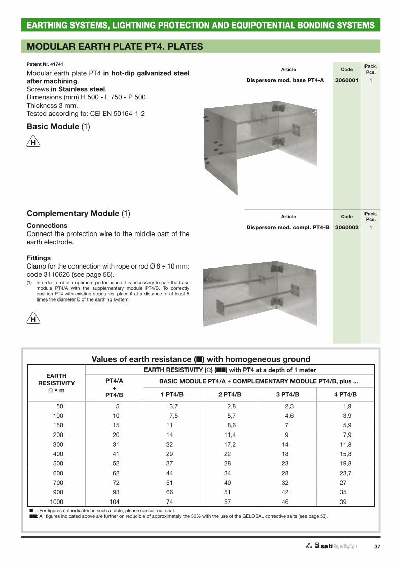
MODULAR EARTH PLATE PT4. PLATES
Patent Nr. 41741Module A
Module B
Characteristics / ApplicationsThe modular earth plate PT4, patent nr. 41741, allows to carry out whichever earthing systems.It is particularly indicated when available areas are limited (for example in the historical centres of the cities and in condominiums).Its modularity and expansibility without limits, enables to carry out earthing systems with particularly low figures. It can be even used to carry out earthing systems for TN systems, in grounds with high resistivity.The geometrical configuration of the earth plate PT4 offers a performance comparable with 5 plates in parallel, therefore its effectiveness is equivalent on the average to 6 earth rods, 1.5 meters length, outdistanced of 4 meters one from the other.
Values under comparison6 earth rods Earth Plate PT4
Digging dimensionsL = 28 m2 (L = length) L ~ 2 m2
P = 02 m2 (P = depht) P ~ 1 m2
S = 32 m2 Required area (S) S = 2 m2
PT4/A + PT4/B1,5 m
2 m (L)
0,5 m
DEPHT = 1 m
37
EARTHING SYSTEMS, LIGHTNING PROTECTION AND EQUIPOTENTIAL BONDING SYSTEMS
Article Code Pack.Pcs.
Dispersore mod. base PT4-A 3060001 1
MODULAR EARTH PLATE PT4. PLATES
Patent Nr. 41741
Values of earth resistance ( ) with homogeneous ground
EARTHRESISTIVITY
• m
EARTH RESISTIVITY ( ) (!!) with PT4 at a depth of 1 meter
PT4/A+
PT4/B
BASIC MODULE PT4/A + COMPLEMENTARY MODULE PT4/B, plus ...
1 PT4/B 2 PT4/B 3 PT4/B 4 PT4/B
0050 005 03,7 02,8 02,3 01,9
0100 010 07,5 05,7 04,6 03,9
0150 015 11,0 08,6 07,0 05,9
0200 020 14,0 11,4 09,0 07,9
0300 031 22,0 17,2 14,0 11,8
0400 041 29,0 22,0 18,0 15,8
0500 052 37,0 28,0 23,0 19,8
0600 062 44,0 34,0 28,0 23,7
0700 072 51,0 40,0 32,0 27,0
0900 093 66,0 51,0 42,0 35,0
1000 104 74,0 57,0 46,0 39,0! : For figures not indicated in such a table, please consult our seat.!!: All figures indicated above are further on reducible of approximately the 30% with the use of the GELOSAL corrective salts (see page 53).
Modular earth plate PT4 in hot-dip galvanized steel after machining.Screws in Stainless steel.Dimensions (mm) H 500 - L 750 - P 500.Thickness 3 mm.Tested according to: CEI EN 50164-1-2
Basic Module (1)
Article Code Pack.Pcs.
Dispersore mod. compl. PT4-B 3060002 1
H
H
Complementary Module (1)ConnectionsConnect the protection wire to the middle part of the earth electrode.
FittingsClamp for the connection with rope or rod Ø 8 ÷ 10 mm:code 3110626 (see page 56).(1) In order to obtain optimum performance it is necessary to pair the base
module PT4/A with the supplementary module PT4/B. To correctly position PT4 with existing structures, place it at a distance of at least 5 times the diameter D of the earthing system.
38
EARTHING SYSTEMS, LIGHTNING PROTECTION AND EQUIPOTENTIAL BONDING SYSTEMS
COPPERCOAT EARTH ROD - TECHNICAL NOTES
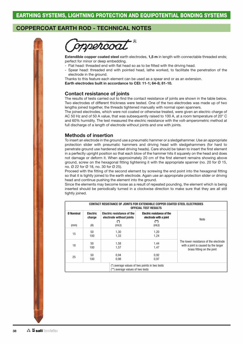
Extendible copper coated steel earth electrodes, 1,5 m in length with connectable threaded ends; perfect for minor or deep embedding.- Flat head: threaded end with flat head so as to be fitted with the driving head.- Spear head: threaded end with pointed head, lathe worked, to facilitate the penetration of the
electrode in the ground.Thanks to this feature each element can be used as a spear end or as an extension.Earth electrodes built in accordance to CEI: 11-1; 64-8; 81-10.
Contact resistance of jointsThe results of tests carried out to find the contact resistance of joints are shown in the table below. Two electrodes of different thickness were tested. One of the two electrodes was made up of two lengths joined together, the threads tightened manually with normal open spanners. The joined electrodes, which were not coated or otherwise treated, were given an electric charge of AC 50 Hz and of 50 A value, that was subsequently raised to 100 A, at a room temperature of 20° C and 60% humidity. The test measured the electric resistance with the volt-amperometric method at full discharge of a length of electrode without joints and one with joints.
Methods of insertionTo insert an electrode in the ground use a pneumatic hammer or a sledgehammer. Use an appropriate protection slider with pneumatic hammers and driving head with sledgehammers (for hard to penetrate ground use hardened steel driving heads). Care should be taken to insert the first element in a perfectly upright position so that each blow of the hammer hits it squarely on the head and does not damage or deform it. When approximately 20 cm of the first element remains showing above ground, screw on the hexagonal fitting tightening it with the appropriate spanner (no. 20 for Ø 15, no. Ø 22 for Ø 18, no. 30 for Ø 25).Proceed with the fitting of the second element by screwing the end point into the hexagonal fitting so that it is tightly joined to the earth electrode. Again use an appropriate protection slider or driving head and continue pushing the element into the ground.Since the elements may become loose as a result of repeated pounding, the element which is being inserted should be periodically turned in a clockwise direction to make sure that they are all still tightly joined.
CONTACT RESISTANCE OF JOINTS FOR EXTENDIBLE COPPER COATED STEEL ELECTRODESOFFICIAL TEST RESULTS
Ø Nominal
(mm)
Electric charge
(A)
Electric resistance of the electrode without joints
(*)(m )
Electric resistance of the electrode with a joint
(**)(m )
Note
15 50100
1,301,33
1,201,24
The lower resistance of the electrode with a joint is caused by the larger
brass fitting on the joint 18 50
1001,581,57
1,441,47
25 50100
0,940,98
0,920,97
(*) average values of two points in two tests(**) average values of two tests

39
EARTHING SYSTEMS, LIGHTNING PROTECTION AND EQUIPOTENTIAL BONDING SYSTEMS
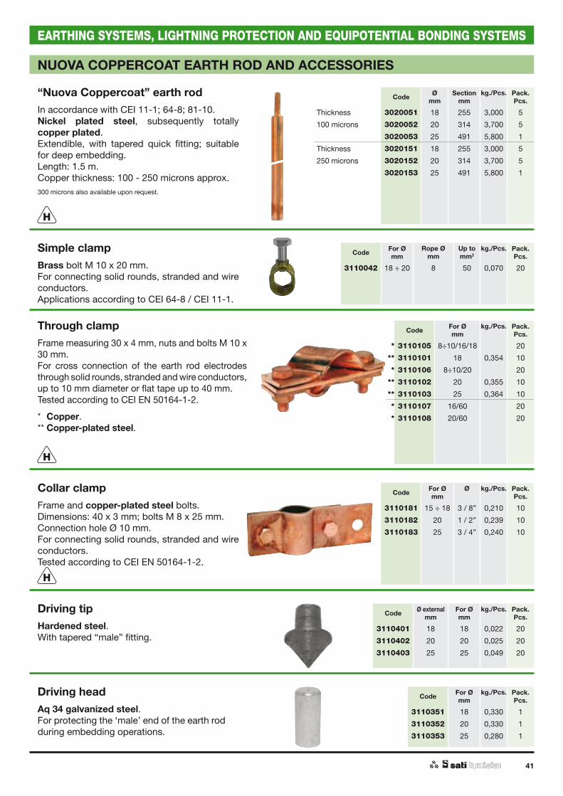
COPPERCOAT EARTH ROD AND ACCESSORIES
“Coppercoat” earth rodIn accordance with CEI 11-1, 64-8, 81-10.Nickel plated steel, subsequently totally copper plated.Threaded ends, 1,5 m in length, extendible.Copper thickness 100 - 250 microns approx.Suitable for minor or deep embedding.Tested according to: CEI EN 50164-1-2.Available upon request: 300 microns.
Extension coupling sleeveIn brass.Internally threaded.
Simple clampBrass bolt M 10 x 20 mm.For connecting solid rounds, stranded and wire conductors.Applications according to CEI 64-8 / CEI 11-1.
Collar clampFrame and copper-plated steel bolts.Dimensions: 40 x 3 mm; bolts M 8 x 25 mm.Connection hole Ø 10 mm. For connecting solid rounds, stranded and wire conductors.Tested according to CEI EN 50164-1-2.
Driving headMild steel - C10 Tempered steel, galvanized - 38NCD4.To protect the thread during piling operations.
Through clampCopper-plated steel frame measuring 30 x 4 mm, nuts and bolts M 10 x 30 mm.For cross connection of the earth rod electrodes through solid rounds, stranded and wire conductors, up to 10 mm diameter or flat tape up to 40 mm.Tested according to CEI EN 50164-1-2.
Code Ømm
Sectionmm
kg./Pcs. Pack.Pcs.
Thickness 3020001 15 177 2,100 10
100 microns 3020002 18 255 3,000 05
3020003 25 491 5,800 01
Thickness 3020101 15 177 2,100 10
250 microns 3020102 18 255 3,000 05
3020103 25 491 5,800 01
Code Sectionmm
kg./Pcs. Pack.Pcs.
3110001 15 0,090 25
3110002 18 0,090 25
3110003 25 0,120 25
Code For Ømm
Rope Ømm
Up tomm2
kg./Pcs. Pack.Pcs.
3110041 15 7 35 0,050 20
3110042 18 ÷ 20 8 50 0,070 20
Code For Ømm
Ø kg./Pcs. Pack.Pcs.
3110181 15 ÷ 18 3 / 8” 0,210 10
3110183 25 3 / 4” 0,240 10
Code For Ømm
Execution kg./Pcs. Pack.Pcs.
3110301 15 Mild steel 0,130 1
3110302 18 Mild steel 0,120 1
3110321 18 Tempered steel 0,220 1
3110322 25 Tempered steel 0,210 1
Code For Ømm
kg./Pcs. Pack.Pcs.
3110105 8÷10/16/18 20
3110101 18 0,354 10
3110106 8÷10/20 20
3110103 25 0,364 10
H
H
H
H

40
EARTHING SYSTEMS, LIGHTNING PROTECTION AND EQUIPOTENTIAL BONDING SYSTEMS
NUOVA COPPERCOAT EARTH ROD - TECHNICAL NOTES
Extendible copper coated steel electrodes 1.5 m in length with tapered ends calibrated for male -female quick coupling, providing excellent electrical conductivity and very low values of electrical resistance. Also suitable for deep piling and hard surfaces. Electrodes meet CEI: 11-1, 64-8, 81-10 requirements.
Benefits– QUICK-COUPLING: nothing else is needed to join the elements; all you need on site are the
electrode elements and the tools for driving them into the ground.– SPEED OF CONNECTION: no special provision required during embedding operations: as soon
as one element is in the ground, add the following and continue to hammer.– PERFECT ADHERENCE OF THE ELECTRODE TO THE SOIL: as there is no coupling sleeve, the
diameter of the penetration hole does not become greater than the diameter of the electrode. This would be likely with the presence of a coupling sleeve, especially with clay soils.
– MECHANICAL RESISTANCE: Nuova Coppercoat electrodes can withstand traction and torsion resulting from ground settling and / or surface modification above ground.
– CORROSION RESISTANCE: both the 'tip' and the 'head' are fully copper coated, as the electrodes are dipped in the electrolytic baths after lathing. In any case, since the quick coupling is perfectly calibrated, the adherence between the 'head' and 'tip' surface guarantees absolute tightness thus excluding the possibility that the joints become corroded.
Contact resistance in joints and mechanical behaviourThe mechanical behaviour of samples of 10 cm in length – taken from the heads of the two most common diameters (18 mm and 25 mm) was tested for:– conjunction, by compression to reach "full closure" (that is until the two ends are joined);– disconnection, by pulling apart to reach "detachment" with progressively increasing force in
measurements of 100 kg / s.The results are shown in Table 1.The electrical behaviour was tested on similar samples made up of elements joined by a force of a 3 kg weight, made to fall 10 times from a height of 1.5 m. The elements were subjected to an alternating current (50 Hz), first of 50 A and then 100 A, at a room temperature of 20° C and 60 % humidity.The results, in terms of average resistance of contact for each joint, based on the difference between the electrical resistance of a 50 cm length of electrode comprising a coupling sleeve and one which does not, are shown in Table 2.For both series of tests, the figures appear overwhelmingly conclusive.The coupling sleeve of the modular earth electrode was also tested for 'electrodynamic' and 'electrotermic' conditions. In this regard, it was found that all the samples subjected to CA 3000 A for a duration of 5 seconds (simulation of full strength, full duration lightning strikes) did not present the slightest alteration whatsoever.Table 1
MECHANICAL MEASUREMENTS TEST RESULTSØ
Nominal(mm)
Necessary force for closingthe coupling sleeve (*)
(kg)
Average necessary force to detachthe coupling sleeve (*)
(kg)18 11.750 3.40025 15.000 3.150
(*) Average values of two tests
Table 2
OFFICIAL TEST RESULTS FOR ELECTRICAL BEHAVIOURØ
Nominal
(mm)
Electric charge
(A)
Electric resistance of the electrode without joints (*)
(m )
Electric resistance of the electrode with a joint (**)
(m )
Contact resistanceof the joint (***)
(m )
15050 1,66 1,78 0,12100 1,77 1,86 0,09
18050 0,97 1,06 0,09100 1,00 1,09 0,09
(*) valori medi su due tronchi di 2 provibi (**) valori medi in due provini (***) differenza tra i valori (**) e i valori (*)
41
EARTHING SYSTEMS, LIGHTNING PROTECTION AND EQUIPOTENTIAL BONDING SYSTEMS
NUOVA COPPERCOAT EARTH ROD AND ACCESSORIES
“Nuova Coppercoat” earth rodIn accordance with CEI 11-1; 64-8; 81-10.Nickel plated steel, subsequently totally copper plated.Extendible, with tapered quick fitting; suitable for deep embedding.Length: 1.5 m.Copper thickness: 100 - 250 microns approx.300 microns also available upon request.
Driving tipHardened steel.With tapered “male” fitting.
Simple clampBrass bolt M 10 x 20 mm.For connecting solid rounds, stranded and wire conductors.Applications according to CEI 64-8 / CEI 11-1.
Collar clampFrame and copper-plated steel bolts.Dimensions: 40 x 3 mm; bolts M 8 x 25 mm.Connection hole Ø 10 mm. For connecting solid rounds, stranded and wire conductors.Tested according to CEI EN 50164-1-2.
Driving headAq 34 galvanized steel.For protecting the ‘male’ end of the earth rod during embedding operations.
Through clampFrame measuring 30 x 4 mm, nuts and bolts M 10 x 30 mm.For cross connection of the earth rod electrodes through solid rounds, stranded and wire conductors, up to 10 mm diameter or flat tape up to 40 mm.Tested according to CEI EN 50164-1-2.
** Copper.** Copper-plated steel.
Code Ømm
Sectionmm
kg./Pcs. Pack.Pcs.
Thickness 3020051 18 255 3,000 5
100 microns 3020052 20 314 3,700 5
3020053 25 491 5,800 1
Thickness 3020151 18 255 3,000 5
250 microns 3020152 20 314 3,700 5
3020153 25 491 5,800 1
Code Ø externalmm
For Ømm
kg./Pcs. Pack.Pcs.
3110401 18 18 0,022 20
3110402 20 20 0,025 20
3110403 25 25 0,049 20
Code For Ømm
Rope Ømm
Up tomm2
kg./Pcs. Pack.Pcs.
3110042 18 ÷ 20 8 50 0,070 20
Code For Ømm
Ø kg./Pcs. Pack.Pcs.
3110181 15 ÷ 18 3 / 8” 0,210 10
3110182 20 1 / 2” 0,239 10
3110183 25 3 / 4” 0,240 10
Code For Ømm
kg./Pcs. Pack.Pcs.
3110351 18 0,330 1
3110352 20 0,330 1
3110353 25 0,280 1
Code For Ømm
kg./Pcs. Pack.Pcs.
* 3110105 8÷10/16/18 20
** 3110101 18 0,354 10
* 3110106 8÷10/20 20
** 3110102 20 0,355 10
** 3110103 25 0,364 10
* 3110107 16/60 20
* 3110108 20/60 20
H
H
H
42
EARTHING SYSTEMS, LIGHTNING PROTECTION AND EQUIPOTENTIAL BONDING SYSTEMS
ZINCOAT EARTH ROD - TECHNICAL NOTES
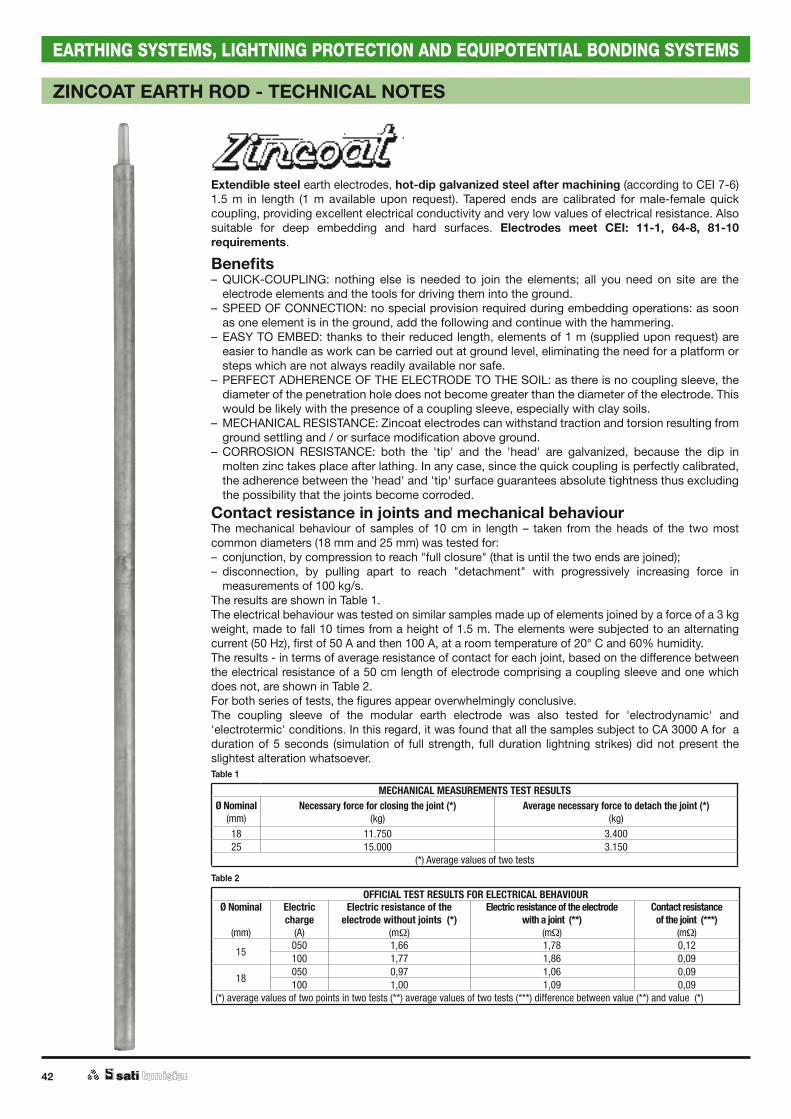
Extendible steel earth electrodes, hot-dip galvanized steel after machining (according to CEI 7-6) 1.5 m in length (1 m available upon request). Tapered ends are calibrated for male-female quick coupling, providing excellent electrical conductivity and very low values of electrical resistance. Also suitable for deep embedding and hard surfaces. Electrodes meet CEI: 11-1, 64-8, 81-10 requirements.
Benefits– QUICK-COUPLING: nothing else is needed to join the elements; all you need on site are the
electrode elements and the tools for driving them into the ground.– SPEED OF CONNECTION: no special provision required during embedding operations: as soon
as one element is in the ground, add the following and continue with the hammering.– EASY TO EMBED: thanks to their reduced length, elements of 1 m (supplied upon request) are
easier to handle as work can be carried out at ground level, eliminating the need for a platform or steps which are not always readily available nor safe.
– PERFECT ADHERENCE OF THE ELECTRODE TO THE SOIL: as there is no coupling sleeve, the diameter of the penetration hole does not become greater than the diameter of the electrode. This would be likely with the presence of a coupling sleeve, especially with clay soils.
– MECHANICAL RESISTANCE: Zincoat electrodes can withstand traction and torsion resulting from ground settling and / or surface modification above ground.
– CORROSION RESISTANCE: both the 'tip' and the 'head' are galvanized, because the dip in molten zinc takes place after lathing. In any case, since the quick coupling is perfectly calibrated, the adherence between the 'head' and 'tip' surface guarantees absolute tightness thus excluding the possibility that the joints become corroded.
Contact resistance in joints and mechanical behaviourThe mechanical behaviour of samples of 10 cm in length – taken from the heads of the two most common diameters (18 mm and 25 mm) was tested for:– conjunction, by compression to reach "full closure" (that is until the two ends are joined);– disconnection, by pulling apart to reach "detachment" with progressively increasing force in
measurements of 100 kg/s.The results are shown in Table 1.The electrical behaviour was tested on similar samples made up of elements joined by a force of a 3 kg weight, made to fall 10 times from a height of 1.5 m. The elements were subjected to an alternating current (50 Hz), first of 50 A and then 100 A, at a room temperature of 20° C and 60% humidity.The results - in terms of average resistance of contact for each joint, based on the difference between the electrical resistance of a 50 cm length of electrode comprising a coupling sleeve and one which does not, are shown in Table 2.For both series of tests, the figures appear overwhelmingly conclusive.The coupling sleeve of the modular earth electrode was also tested for 'electrodynamic' and 'electrotermic' conditions. In this regard, it was found that all the samples subject to CA 3000 A for a duration of 5 seconds (simulation of full strength, full duration lightning strikes) did not present the slightest alteration whatsoever.Table 1
MECHANICAL MEASUREMENTS TEST RESULTSØ Nominal
(mm)Necessary force for closing the joint (*)
(kg)Average necessary force to detach the joint (*)
(kg)18 11.750 3.40025 15.000 3.150
(*) Average values of two tests
Table 2
OFFICIAL TEST RESULTS FOR ELECTRICAL BEHAVIOURØ Nominal
(mm)
Electric charge
(A)
Electric resistance of the electrode without joints (*)
(m )
Electric resistance of the electrodewith a joint (**)
(m )
Contact resistanceof the joint (***)
(m )
15050 1,66 1,78 0,12100 1,77 1,86 0,09
18050 0,97 1,06 0,09100 1,00 1,09 0,09
(*) average values of two points in two tests (**) average values of two tests (***) difference between value (**) and value (*)

43
EARTHING SYSTEMS, LIGHTNING PROTECTION AND EQUIPOTENTIAL BONDING SYSTEMS
ZINCOAT EARTH ROD AND ACCESSORIES
“Zincoat” earth rodIn accordance with CEI 11-1; 64-8; 81-10.Hot-dip galvanized steel after machining.Extendible, with tapered quick coupling, suitable for deep embedding.1.5 m length.Tested according to CEI EN 50164-1-2.
Driving tipHardened steel.Tapered with ‘male’ fitting.
Collar clampHot-dip galvanized steel after machining.Measuring 40 x 3 mm; nuts and bolts M 8 x 25 mm.Connection hole Ø 10 mm.To connect round, stranded and braid conductors.
Driving headAq 34 zinc steel.For protecting the ‘male’ end of the earth rod during the embedding operation.
Through clampHot-dip galvanized steel after machining.Measuring 40 x 4 mm; nuts and bolts M 10 x 30 mm.For cross connection of earth rod electrodes through solid rounds, stranded and wire conductors, up to Ø 10 mm or flat tape up to 40 mm.Surface contact for round 510 mm2, for tape 750 mm2.
Code Ømm
Sectionmm
kg./Pcs. Pack.Pcs.
3030002 20 314 3,700 1
3030003 25 491 5,700 1
Code Ø externalmm
For Ømm
kg./Pcs. Pack.Pcs.
3110402 20 20 0,025 20
3110403 25 25 0,049 20
Code For Ømm
Ø kg./Pcs. Pack.Pcs.
3110202 20 1 / 2” 0,219 10
3110203 25 3 / 4” 0,239 10
Code For Ømm
kg./Pcs. Pack.Pcs.
3110352 20 0,330 1
3110353 25 0,280 1
Code For Ømm
kg./Pcs. Pack.Pcs.
3110141 20 0,340 10
3110142 25 0,340 10
Plate clampHot-dip galvanized steel after machining.Measuring 70 x 5 mm; nuts and bolts M 12 with washer.To connect solid rounds, stranded and wire conductors.
Code For Ømm
kg./Pcs. Pack.Pcs.
3110221 25 0,790 1
H
H
H
H
44
EARTHING SYSTEMS, LIGHTNING PROTECTION AND EQUIPOTENTIAL BONDING SYSTEMS
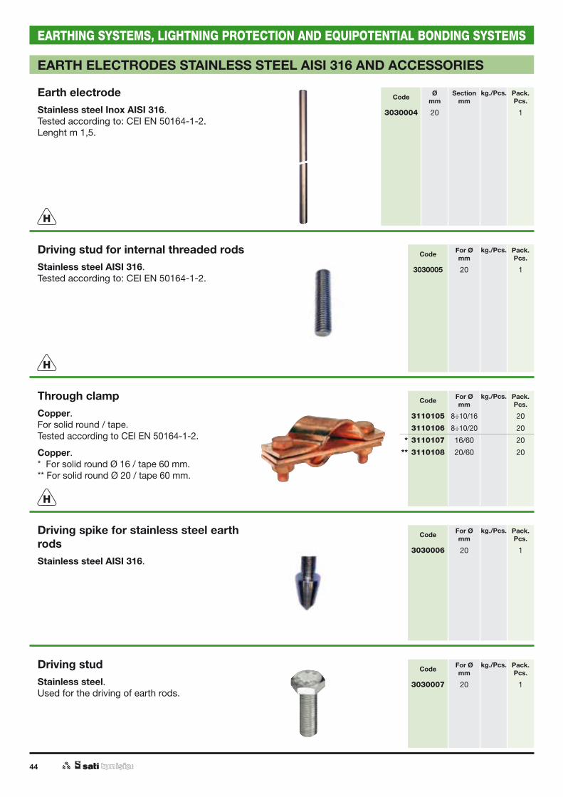
EARTH ELECTRODES STAINLESS STEEL AISI 316 AND ACCESSORIES
Earth electrodeStainless steel Inox AISI 316.Tested according to: CEI EN 50164-1-2.Lenght m 1,5.
Driving spike for stainless steel earth rodsStainless steel AISI 316.
Driving studStainless steel.Used for the driving of earth rods.
Driving stud for internal threaded rodsStainless steel AISI 316.Tested according to: CEI EN 50164-1-2.
Code Ømm
Sectionmm
kg./Pcs. Pack.Pcs.
3030004 20 1
Code For Ømm
kg./Pcs. Pack.Pcs.
3030006 20 1
Code For Ømm
kg./Pcs. Pack.Pcs.
3030007 20 1
Code For Ømm
kg./Pcs. Pack.Pcs.
3030005 20 1
H
H
Through clampCopper.For solid round / tape.Tested according to CEI EN 50164-1-2.
Copper.* For solid round Ø 16 / tape 60 mm.** For solid round Ø 20 / tape 60 mm.
Code For Ømm
kg./Pcs. Pack.Pcs.
3110105 8÷10/16 20
3110106 8÷10/20 20
* 3110107 16/60 20
** 3110108 20/60 20
H

45
EARTHING SYSTEMS, LIGHTNING PROTECTION AND EQUIPOTENTIAL BONDING SYSTEMS
EARTH CROSS PROFILE AND ACCESSORIES
Earth "cross" profileIn accordance with CEI 11-1; 64-8; 81-10.Uniform profile, hot-dip galvanized steel after machining.Measuring 50 x 50 x 5 mm with side plate containing three holes Ø 11 mm to connect solid rounds, stranded and wire conductors.Tested according to CEI EN 50164-1-2.
“T” earth plateIn accordance with CEI 11-1; 64-8; 81-10.Uniform profile, hot-dip galvanized steel after machining.Measuring 50 x 50 x 7 mm with two holesØ 13.5 mm to connect solid rounds, tape, stranded and wire conductors.Tested according to CEI EN 50164-1-2.
Bonding clampIn zamak and in copper alloy.Clamp for solid round Ø 8-10 mm.To be used for fixing collars, earth rods and equipotential clamping.Tested according to: CEI EN 50164-1.
Contact terminal clampContact terminal clamp for use with earthing connectors.With zinc-cromium galvanized screw, cast plate and zinc-cromium galvanized nut M 10. Applications according to CEI; 64-8; / CEI 11-1.
Through clampHot-dip galvanized steel after machining. Measuring 40 x 3 mm.Complete with 2 cup square bolts with hexagon nut M 10.For cross connection of earthing electrodes with solid rounds, stranded and wire conductors up to Ø 10mm and tape conductors up to 40 mm.
Code Lenght cam
kg./Pcs. Pack.Pcs.
Thickness 5 mm 3010001 1,0 03,600 1
3010002 1,5 05,400 1
3010003 2,0 07,200 1
3010004 2,5 09,000 1
3010005 3,0 11,000 1
Thickness 3 mm 3010051 1,0 02,700 1
3010052 1,5 04,000 1
3010053 2,0 05,400 1
3010054 2,5 06,500 1
Code Lenght cam
kg./Pcs. Pack.Pcs.
3010101 1,6 8,000 1
Code Lenght camm
kg./Pcs. Pack.Pcs.
3110161 140 0,270 5
Code Type For conductorsØ mm
kg./Pcs. Pack.Pcs.
Zamak 3110261 Single 8 25
3110262 Single 10 25
Copper alloy 3110263 Single 8 ÷ 50 mm2 10
Zamak 3110266 Double 8 25
3110267 Double 10 25
Copper alloy 3110268 Double 8 ÷ 50 mm2 10
Code Type For conductorsØ mm
kg./Pcs. Pack.Pcs.
3110251 Single 8 ÷ 10 0,070 20
3110252 Double 8 ÷ 10 0,140 25
H
H
H

46
EARTHING SYSTEMS, LIGHTNING PROTECTION AND EQUIPOTENTIAL BONDING SYSTEMS
PIPE EARTH ELECTRODE AND ACCESSORIES
“Edison” pipe earth electrodeIn accordance with CEI 11-1; 64-8; 81-10.Semi-hard carbon steel pipe with R=37/45, approx. 5 mm thickness, hot-dip galvanized steel after machining.Elements approx. 1.5 m in length, extendible to any depth thanks to male and female calibrated threads (avoiding the need for a coupling sleeve) and to the extremely hard forged tips.Tested according to CEI EN 50164-1-2.The surface of all sections of pipe is perforated in order to facilitate the entry of water and thus obtain even better contact.
Code Type Ø externalmm
Ø externalinch
kg./Pcs. Pack.Pcs.
3040001 Extension 48,3 1.1/2” 08,000 1
3040002 Electrode 48,3 1.1/2” 08,000 1
H
Collar clampHot-dip galvanized steel after machining.Measuring: 40 x 3 mm; zinc steel plated nuts and bolts M 8 x 25 mm.Connection hole: Ø 10 mm.To connect tape, solid rounds, stranded and wire conductors.Tested according to CEI EN 50164-1.
Vertical capHot-dip galvanized steel after machining.Internally threaded.Banner plate with four holes Ø 18 mm to connect tape, solid rounds, stranded and wire conductors.
Driving headSteel, internally threaded, to carry out embedding of earth electrodes.
Code For Ømm
kg./Pcs. Pack.Pcs.
3110206 1.1/2” 0,250 10
Code For Ømm
kg./Pcs. Pack.Pcs.
3110451 1.1/4” 1,140 1
Code For Ømm
kg./Pcs. Pack.Pcs.
3110453 1.1/4” 1,120 1
H

47
EARTHING SYSTEMS, LIGHTNING PROTECTION AND EQUIPOTENTIAL BONDING SYSTEMS
EARTH PLATE, TAPES, ROUNDS, ROPES
Earth plateHot-dip galvanized steel after machining. The plate, which is welded to the rod, is 3 mm in thickness and measures 30 x 3 mm.Hot-dip zinc steel plate process carried out after the welding of the plate.
Code Dimensionsmm
kg./Pcs. Pack.Pcs.
3050001 500 x 0500 x 3 08,000 1
3050002 500 x 1000 x 3 14,000 1
H
Earth tapeHot-dip galvanized steel and dragging process carried out after machining.Mild steel copper plated with 70 µm thickness.Other measurements available upon request.Tested according to CEI EN 50164-2.
Code Dimensionsmm
Sectionmm2
Lenght cam
kg./m Pack.Pcs.
Steel 3120001 20 x 3,0 060 77 0,480 1
3120012 25 x 3,0 075 77 0,620 1
3120022 30 x 3,0 090 77 0,740 1
3120023 30 x 3,5 105 77 0,850 1
3120031 40 x 3,0 120 77 1,000 1
3120032 40 x 4,0 160 77 1,300 1
Steel coppered
3120045 25 x 3,0 075 40 0,620 1
3120046 25 x 4,0 100 30 0,820 1
Earth solid round- Hot-dip galvanized steel and
dragging process carried out after machining.
- Electrolytic copper.- Bimetal steel / copper and aluminum / copper.Available in 4 m length reel or linear bar.Reel coiled around disc measuring:- Ø int. 650 mm.- Ø int. 800 mm per i bimetalli.Tested according to: CEI EN 50164-2. CEI EN 62561-2
* Bi-Grounding: for Earthing and Lightning protection systems.
** Bi-Lightning: for Lightning protection system.
Code Ømm
Sectionmm2
Copper thicknessµm
Lenght cam
kg./m Pack.Pcs.
Steel 3130001 08 50 100 0,400 1
3130011 10 78 075 0,600 1
Linear bar 3130021 08 50 004 0,400 1
Linear bar 3130031 10 78 004 0,600 1
Copper 3130041 08 50 100 0,450 1
BimetalSteel / Copper
* 3230101 10 78 150 025 0,560 1
* 3230102 10 78 150 050 0,560 1
* 3230103 10 78 150 100 0,560 1
* 3230111 10 78 380 025 0,560 1
* 3230112 10 78 380 050 0,560 1
* 3230113 10 78 380 100 0,560 1
** 3230121 08 50 300 025 0,400 1
** 3230122 08 50 300 050 0,400 1
** 3230123 08 50 300 100 0,400 1
BimetalAluminum / Copper
** 3230201 08 50 280 025 0,180 1
** 3230202 08 50 280 050 0,180 1
** 3230203 08 50 280 100 0,180 1
NEW
NEW
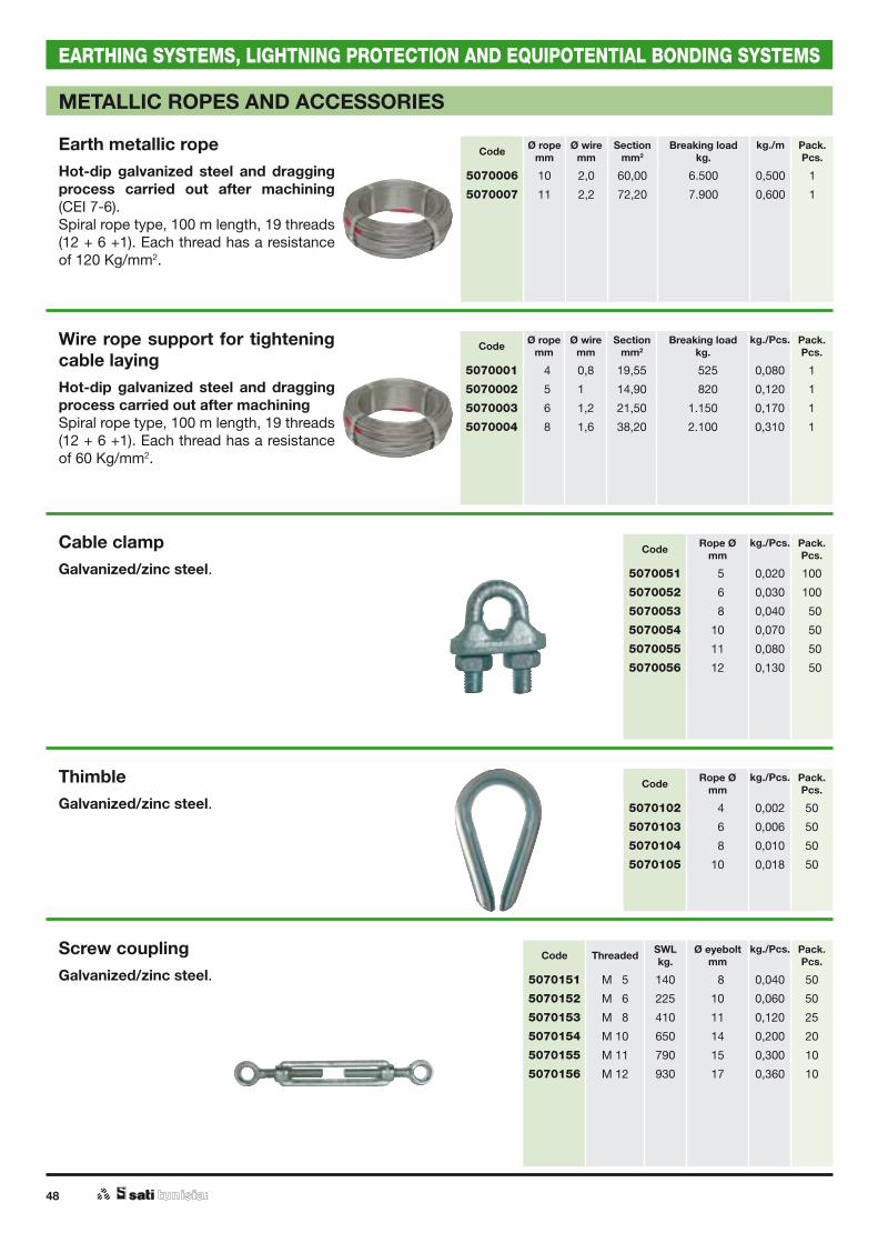
48
EARTHING SYSTEMS, LIGHTNING PROTECTION AND EQUIPOTENTIAL BONDING SYSTEMS
METALLIC ROPES AND ACCESSORIES
Wire rope support for tightening cable layingHot-dip galvanized steel and dragging process carried out after machiningSpiral rope type, 100 m length, 19 threads(12 + 6 +1). Each thread has a resistance of 60 Kg/mm2.
Cable clampGalvanized/zinc steel.
ThimbleGalvanized/zinc steel.
Screw couplingGalvanized/zinc steel.
Code Ø ropemm
Ø wiremm
Sectionmm2
Breaking loadkg.
kg./Pcs. Pack.Pcs.
5070001 04 0,8 19,55 0.525 0,080 1
5070002 05 1,0 14,90 0.820 0,120 1
5070003 06 1,2 21,50 1.150 0,170 1
5070004 08 1,6 38,20 2.100 0,310 1
Code Rope Ø mm
kg./Pcs. Pack.Pcs.
5070051 05 0,020 100
5070052 06 0,030 100
5070053 08 0,040 050
5070054 10 0,070 050
5070055 11 0,080 050
5070056 12 0,130 050
Code Rope Ø mm
kg./Pcs. Pack.Pcs.
5070102 04 0,002 50
5070103 06 0,006 50
5070104 08 0,010 50
5070105 10 0,018 50
Code Threaded SWLkg.
Ø eyeboltmm
kg./Pcs. Pack.Pcs.
5070151 M 05 140 08 0,040 50
5070152 M 06 225 10 0,060 50
5070153 M 08 410 11 0,120 25
5070154 M 10 650 14 0,200 20
5070155 M 11 790 15 0,300 10
5070156 M 12 930 17 0,360 10
Earth metallic ropeHot-dip galvanized steel and dragging process carried out after machining (CEI 7-6).Spiral rope type, 100 m length, 19 threads (12 + 6 +1). Each thread has a resistance of 120 Kg/mm2.
Code Ø ropemm
Ø wiremm
Sectionmm2
Breaking loadkg.
kg./m Pack.Pcs.
5070006 10 2,0 60,00 6.500 0,500 1
5070007 11 2,2 72,20 7.900 0,600 1

49
EARTHING SYSTEMS, LIGHTNING PROTECTION AND EQUIPOTENTIAL BONDING SYSTEMS
ACCESSORIES
Inspection wellPolypropylene PP. The bottom can be removed in order to stack modules and gain height to cover any depth. The top is closed by a manhole which can support the weight of cars (but not with constant traffic). Markings on all four sides facilitate entry/exit of pipes carrying cables. Suitable for earth electrodes and for joining and crossing over cables.
Sectioning clampIn accordance with CEI 11-1; 64-8. Nylon fibre reinforced glass support with passivation treated galvanized steel wall mounting plate 150 x 45 mm.Copper section bar 20 x 2.5 mm for solid round conductors or stranded 6 - 10 mm diameter.Suitable for spacing the earth conductors from the earth electrode in order to measure the ground resistance (with or without plate).
Anticorrosion tapePVC for underground joints.Dimensions: Width 50mmLength 30.5m.
“GELOSAL” saline solutionCalibrated chemical formula, made up of various elements able to produce an irreversible composition of material filaments, which is highly hygroscopic.It is essential that this composition should be in close contact with the metal of the earth electrode.One package contains sufficient solution for one single embedding of up to 4-6 m depth, or for two embeddings of up to 2-3 m depth, or to cover a horizontal / linear distance of 5-6 m. Instructions for use are available inside each package.
Characteristics and effectiveness of "GELOSAL".The new formula of this product, in physical-chemical terms, ensures easy and safe application, as well as complete safety: no danger of toxicity for people, no corrosion of the earth electrode, and no contamination of the environment.As far as its effectiveness is concerned, in terms of electrical/plant benefit , the volume of soil treated with "GELOSAL" (in accordance with the instructions supplied) decreases, after a few hours, to up to one third of natural or local values. It does not revert for a few months or even years provided that climate and soil conditions are stable.Regular application of this product can reduce the relevant RE permanently or at least to acceptable levels.
Code Article Hmm
Dimensionskg.
kg./Pcs. Pack.Pcs.
3111901 Well 200 200x200 1,200 1
3111902 Well 300 300x300 2,225 1
3111903 Well 400 400x400 3,075 1
3111921 Cover - 200x200 0,400 1
3111922 Cover - 300x300 1,000 1
3111923 Cover - 400x400 2,600 1
Code Type kg./Pcs. Pack.Pcs.
3110941 with plate 0,200 10
3110942 without plate 0,120 12
Code Packging.kg.
Pack.Pcs.
3110951 6,5 1
Code Dimensionsmm
Pack.Pcs.
3170000 50 x 30,5 1
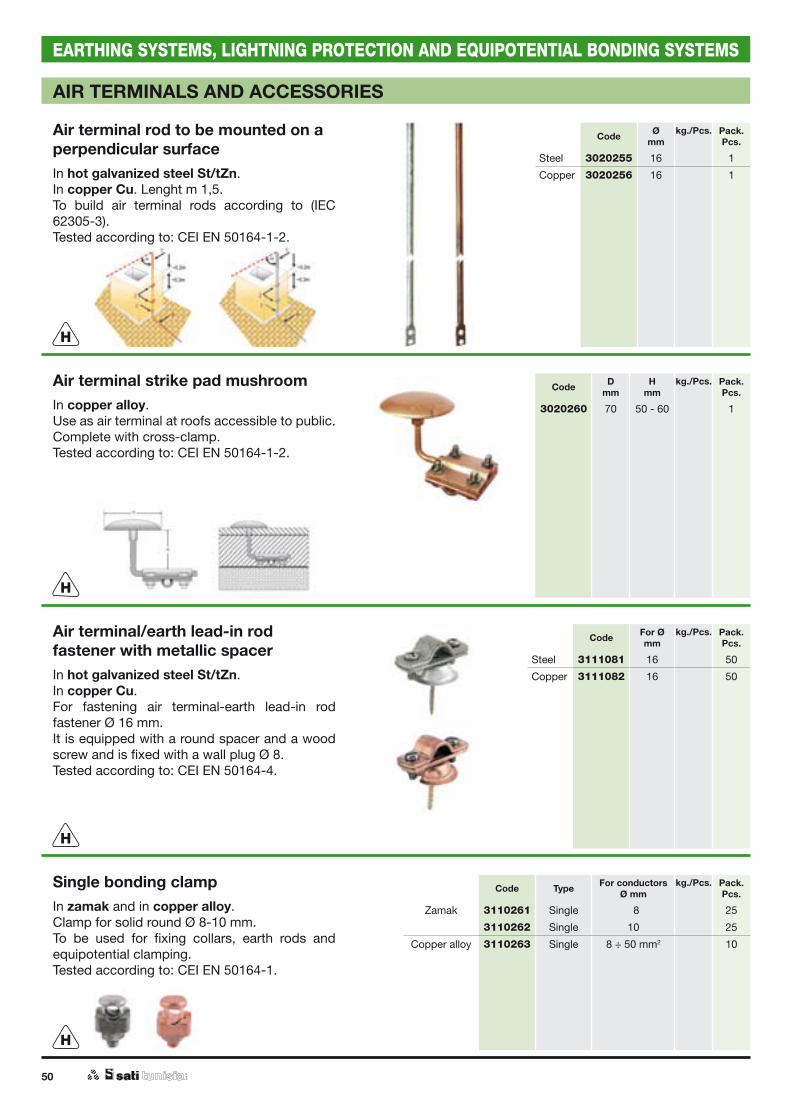
50
EARTHING SYSTEMS, LIGHTNING PROTECTION AND EQUIPOTENTIAL BONDING SYSTEMS
AIR TERMINALS AND ACCESSORIES
Air terminal rod to be mounted on a perpendicular surfaceIn hot galvanized steel St/tZn.In copper Cu. Lenght m 1,5.To build air terminal rods according to (IEC 62305-3).Tested according to: CEI EN 50164-1-2.
Air terminal strike pad mushroomIn copper alloy.Use as air terminal at roofs accessible to public.Complete with cross-clamp.Tested according to: CEI EN 50164-1-2.
Air terminal/earth lead-in rod fastener with metallic spacerIn hot galvanized steel St/tZn.In copper Cu.For fastening air terminal-earth lead-in rod fastener Ø 16 mm.It is equipped with a round spacer and a wood screw and is fixed with a wall plug Ø 8.Tested according to: CEI EN 50164-4.
Code Ømm
kg./Pcs. Pack.Pcs.
Steel 3020255 16 1
Copper 3020256 16 1
Code Dmm
Hmm
kg./Pcs. Pack.Pcs.
3020260 70 50 - 60 1
Code For Ømm
kg./Pcs. Pack.Pcs.
Steel 3111081 16 50
Copper 3111082 16 50
H
H
H
Single bonding clampIn zamak and in copper alloy.Clamp for solid round Ø 8-10 mm.To be used for fixing collars, earth rods and equipotential clamping.Tested according to: CEI EN 50164-1.
Code Type For conductorsØ mm
kg./Pcs. Pack.Pcs.
Zamak 3110261 Single 08 25
3110262 Single 10 25
Copper alloy 3110263 Single 8 ÷ 50 mm2 10
H
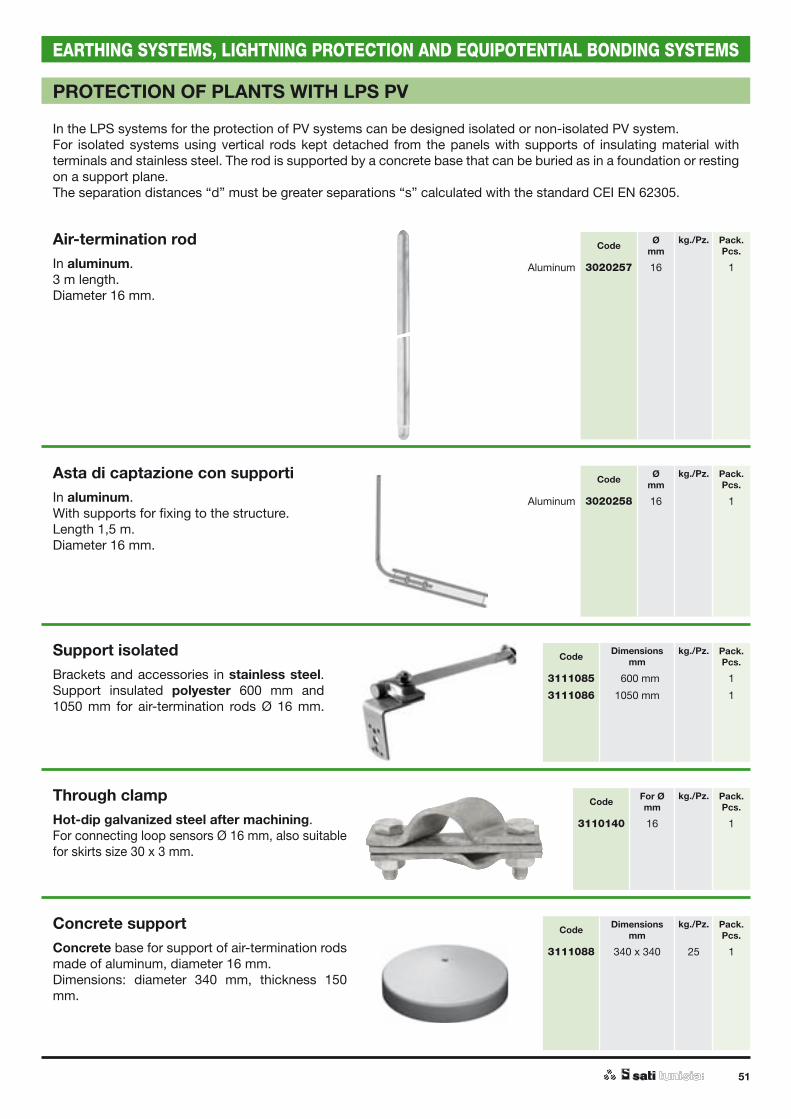
51
EARTHING SYSTEMS, LIGHTNING PROTECTION AND EQUIPOTENTIAL BONDING SYSTEMS
PROTECTION OF PLANTS WITH LPS PV
In the LPS systems for the protection of PV systems can be designed isolated or non-isolated PV system.For isolated systems using vertical rods kept detached from the panels with supports of insulating material with terminals and stainless steel. The rod is supported by a concrete base that can be buried as in a foundation or resting on a support plane.The separation distances “d” must be greater separations “s” calculated with the standard CEI EN 62305.
Air-termination rod In aluminum.3 m length.Diameter 16 mm.
Asta di captazione con supportiIn aluminum.With supports for fixing to the structure.Length 1,5 m.Diameter 16 mm.
Support isolated Brackets and accessories in stainless steel.Support insulated polyester 600 mm and 1050 mm for air-termination rods Ø 16 mm.
Code Ømm
kg./Pz. Pack.Pcs.
Aluminum 3020257 16 1
Code Ømm
kg./Pz. Pack.Pcs.
Aluminum 3020258 16 1
Code Dimensionsmm
kg./Pz. Pack.Pcs.
3111085 0600 mm 1
3111086 1050 mm 1
Through clampHot-dip galvanized steel after machining.For connecting loop sensors Ø 16 mm, also suitable for skirts size 30 x 3 mm.
Concrete supportConcrete base for support of air-termination rods made of aluminum, diameter 16 mm.Dimensions: diameter 340 mm, thickness 150 mm.
Code For Ømm
kg./Pz. Pack.Pcs.
3110140 16 1
Code Dimensionsmm
kg./Pz. Pack.Pcs.
3111088 340 x 340 25 1

52
EARTHING SYSTEMS, LIGHTNING PROTECTION AND EQUIPOTENTIAL BONDING SYSTEMS
H
H
CLAMPS
Cross clamp for earth roundZF type: hot-dip galvanized steel after machining.Nuts and bolts: M 8 x 25 mm.Light duty type: 60 x 60 x 2.5 mm.Heavy duty type: 60 x 60 x 4 mm.
Cu type: copper structure and stainless steel nuts and bolts M 8 x 25 mm. Dimensions: 60 x 60 x 3 mm.Suitable for connecting solid round Ø 8-10 mm, braids and stranded up to 78 mm2.Tested according to CEI EN 50164-1.
Cross clamp for earth tapeZF type: hot-dip galvanized steel after machining.Nuts and bolts: M 8 x 25 mm.Dimensions: 60 x 60 x 2.5 mm.
Cu type: copper structure and stainless steel nuts and bolts M 8 x 25 mm. Dimensions: 60 x 60 x 3 mm.Suitable for connecting tape up to 30 mm.
ZF-CU type: 40/40: to connect tape 40 x 4 mm. With intermediate plate and bolts M 8.Dimensions: 70 x 7 mm.Tested according to CEI EN 50164-1.
Code Type Separator plate
kg./Pcs. Pack.Pcs.
3110501 ZF / Light without 0,210 10
3110502 ZF / Light with 0,270 10
3110503 ZF / Heavy without 0,300 10
3110504 ZF / Heavy with 0,360 10
3110521 Cu without 0,250 10
3110522 Cu with 0,310 10
Flat Code Type Separator plate
kg./Pcs. Pack.Pcs.
30 / 30 3110551 ZF / Light without 0,210 10
30 / 30 3110552 ZF / Light with 0,270 10
30 / 30 3110671 Cu without 0,250 10
30 / 30 3110672 Cu with 0,310 10
40 / 40 3110531 ZF 40 / 40 with 15
40 / 40 3110532 Cu 40 /40 with 15
H
Combination clamp for earth round and tapeZF type: hot-dip galvanized steel after machining.Nuts and bolts: M 8 x 25 mm.
Cu type: copper structure and stainless steel nuts and bolts M 8 x 25 mm. Suitable for connecting solid round Ø 8 ÷ 10 mm, braids and stranded up to 78 mm2 and tape up to 30 mm. With intermediate plate.Dimensions: 60 x 60 x 2.5 mm.Tested according to CEI EN 50164-1.
Code Type kg./Pcs. Pack.Pcs.
3110701 ZF 0,270 10
3110702 Cu 0,250 10

53
EARTHING SYSTEMS, LIGHTNING PROTECTION AND EQUIPOTENTIAL BONDING SYSTEMS
CLAMPS
H
H
H
Combination jointHot-dip galvanized steel after machining.Zinc bolts M 6.Suitable for connecting or adding solid rounds, braids and stranded with zinc tapes. Tested according to CEI EN 50164-1.
Connector for bonding metallic surfacesIn copper CU.Stainless steel AISI 304.Used to connect collars, vertical rods, modular PT4 plates to flat surfaces.Tested according to CEI EN 50164-1.
Universal connector - clampIn hot galvanized steel St/tZn.In copper Cu.For connection of Ø 8 ÷ 10 mm conductors, bonding of metallic structures, etc.For application see below.Tested according to: CEI EN 50164-1.
Code Round Ømm
Flatmm
kg./Pcs. Pack.Pcs.
3110801 06,3 - 00 30 0,100 10
3110802 08,0 ÷ 10 30 0,100 10
3110803 12,5 ÷ 16 30 0,100 10
Code Round Ømm
kg./Pcs. Pack.Pcs.
Copper 3110616 6 ÷ 10 50
Stainless 3110626 6 ÷ 10 50
steel
Code Round Ømm
kg./Pcs. Pack.Pcs.
Steel 3110601 8 ÷ 10 25
Copper 3110611 8 ÷ 10 25
Aluminium 3110612 8 ÷ 10
Bimetallic Al/Cu 3110613 8 ÷ 10
Derivation Parallel "T" derivation

54
EARTHING SYSTEMS, LIGHTNING PROTECTION AND EQUIPOTENTIAL BONDING SYSTEMS
SUPPORTS
H
H
H
H
Support for earth tapeZamak zinc structure; threaded stand 30mm height.Top plate: hot-dip galvanized steel after machining. For tapes 20 - 30 mm width.Tested according to CEI EN 50164-4.
Support for earth tapeCopper galvanized structure; threaded stand 30 mm height.Copper top plate; stainless steel bolts. For tapes 20 - 30 mm width.Tested according to CEI EN 50164-4.
Support for earth roundZamak zinc structure; threaded stand 30 mm height.Top plate: hot-dip galvanized steel after machining. For solid round Ø 8 ÷ 10 mm, for stranded, braids Ø 6.3 - 16 mm.Tested according to CEI EN 50164-4.
Support for earth roundCopper galvanized structure; threaded stand 30 mm height.Copper top plate; stainless steel bolts. For solid round Ø 8 ÷ 10 mm, for stranded, braids Ø 6.3 - 16 mm.Tested according to CEI EN 50164-4.
Code Threaded Flatmm
kg./Pcs. Pack.Pcs.
3111001 M 6 20 - 30 0,080 50
3111011 M 8 20 - 30 0,070 50
Code Threaded Flatmm
kg./Pcs. Pack.Pcs.
3111021 M 6 20 - 30 0,070 50
3111031 M 8 20 - 30 0,070 50
Code Threaded Round/Wire/RopeØ mm
kg./Pcs. Pack.Pcs.
3111052 M 6 08,0 ÷ 10 0,080 50
3111053 M 6 12,5 ÷ 16 0,080 50
3111072 M 8 08,0 ÷ 10 0,070 50
3111073 M 8 12,5 ÷ 16 0,080 50
Code Threaded Round/Wire/RopeØ mm
kg./Pcs. Pack.Pcs.
3111101 M 6 8 ÷ 10 0,080 50
3111111 M 8 8 ÷ 10 0,080 50
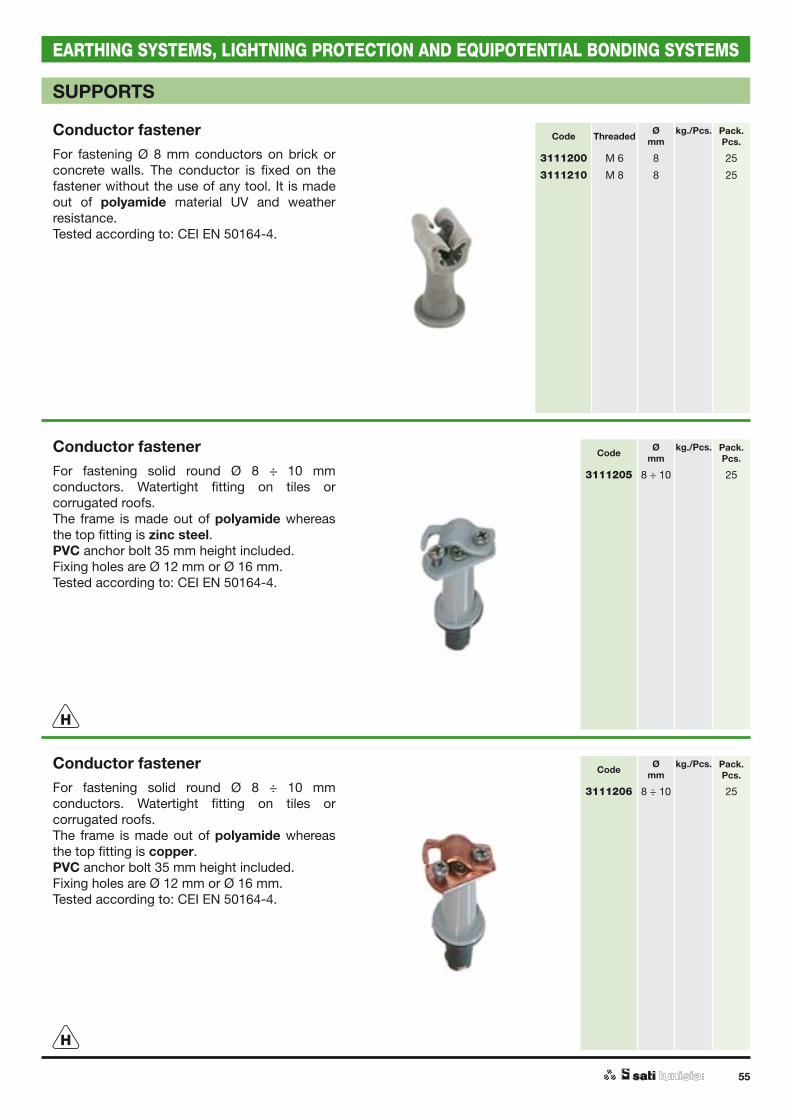
55
EARTHING SYSTEMS, LIGHTNING PROTECTION AND EQUIPOTENTIAL BONDING SYSTEMS
SUPPORTS
H
H
Conductor fastenerFor fastening Ø 8 mm conductors on brick or concrete walls. The conductor is fixed on the fastener without the use of any tool. It is made out of polyamide material UV and weather resistance.Tested according to: CEI EN 50164-4.
Conductor fastenerFor fastening solid round Ø 8 ÷ 10 mm conductors. Watertight fitting on tiles or corrugated roofs.The frame is made out of polyamide whereas the top fitting is zinc steel. PVC anchor bolt 35 mm height included.Fixing holes are Ø 12 mm or Ø 16 mm.Tested according to: CEI EN 50164-4.
Conductor fastenerFor fastening solid round Ø 8 ÷ 10 mm conductors. Watertight fitting on tiles or corrugated roofs.The frame is made out of polyamide whereas the top fitting is copper.PVC anchor bolt 35 mm height included.Fixing holes are Ø 12 mm or Ø 16 mm.Tested according to: CEI EN 50164-4.
Code Threaded Ømm
kg./Pcs. Pack.Pcs.
3111200 M 6 8 25
3111210 M 8 8 25
Code Ømm
kg./Pcs. Pack.Pcs.
3111205 8 ÷ 10 25
Code Ømm
kg./Pcs. Pack.Pcs.
3111206 8 ÷ 10 25

56
EARTHING SYSTEMS, LIGHTNING PROTECTION AND EQUIPOTENTIAL BONDING SYSTEMS
SUPPORTS
H
H
Support with iron anchor bolt for earth round and tapeZamak zinc frame.Top plate: hot-dip galvanized steel after machining. Complete fixing system made up of a steel anchor boltØ 9 x 20 mm.Threaded pin M 6 x 20 mm.Turning the frame tightens the anchor bolt.Tested according to CEI EN 50164-4.
Support with iron anchor bolt for earth round and tapeZamak copper frame. Top plate made out of copper; stainless steel bolts.Complete fixing system made up of a steel anchor bolt Ø 9 x 20 mm.Threaded pin M 6 x 20 mm.Turning the frame tightens the anchor bolt.Tested according to CEI EN 50164-4.
Anchor bolt for supportsNylon.The support can be also fixed to the wall with a double threaded anchor bolt. The support for earth round or tape (not included) is assembled separately.
Code Support Ømm
kg./Pcs. Pack.Pcs.
3111141 Round 08 ÷ 10 0,100 50
3111151 Flat 20 - 30 0,090 50
Code Support Ømm
kg./Pcs. Pack.Pcs.
3111161 Round 08 ÷ 10 0,100 50
3111171 Flat 20 - 30 0,090 50
Code Ømm
kg./Pcs. Pack.Pcs.
11655 M 6 x 30 0,002 200
11679 M 8 x 60 0,118 100

57
EARTHING SYSTEMS, LIGHTNING PROTECTION AND EQUIPOTENTIAL BONDING SYSTEMS
SUPPORTS FOR FLAT AND CORRUGATED ROOFS
Anchor plate for flat roofsHot-dip galvanized steel after machining. Brass threaded pin M 8.Used in conjunction with supports for flat and solid round conductors and, if needed, with additional spacers.Mounting holes: Four Ø 10 mm. Four Ø 4.5 mm.
Support plate for flat roofsHot-dip galvanized steel after machining. Height 100 mm, as required by CEI 81-1, Chapter II, Sec. 1.Anchoring for tape up to 30 mm or solid roundØ 8 ÷ 10 mm (other diameters available upon request).Mounting holes:Four Ø 10 mm.Four Ø 4.5 mm.Tested according to CEI EN 50164-4.
Flat support for tiled roofsGalvanized zinc steel with brass pin thread M 8.Mounting holes Ø 5 mm.Used in conjunction with supports for flat and solid round conductors and, if needed, with additional spacers. Thanks to the threaded pin, the supports can be positioned in the direction required.
Angled support for tiled roofsHot-dip galvanized steel after machining, with brass pin thread M 8.Mounting holes Ø 5 mm.Used in conjunction with supports for flat and solid round conductors and, if needed, with additional spacers. Thanks to the threaded pin, the supports can be positioned in the direction required.
Angled support for tiled roofsHot-dip galvanized steel after machining.Mounting holes Ø 5 mm.Anchoring for tape up to 30 mm or solid roundØ 8 ÷ 10 mm (other diameters available upon request).
Code Base Ømm
Type kg./Pcs. Pack.Pcs.
3111251 100 M 8 0,120 10
Code Base Ømm
Support kg./Pcs. Pack.Pcs.
3111261 100 Solid round 0,250 25
3111271 100 Flatì 0,240 25
Code Dimensionsmm
kg./Pcs. Pack.Pcs.
3111281 265 x 23 x 1,5 0,940 20
Code Dimensionsmm
kg./Pcs. Pack.Pcs.
3111282 420 x 20 x 3 0,250 40
Code Dimensionsmm For kg./Pcs. Pack.
Pcs.
3111301 420 x 20 x 3 Round 0,360 20
3111311 420 x 20 x 3 Flat 0,350 20
H
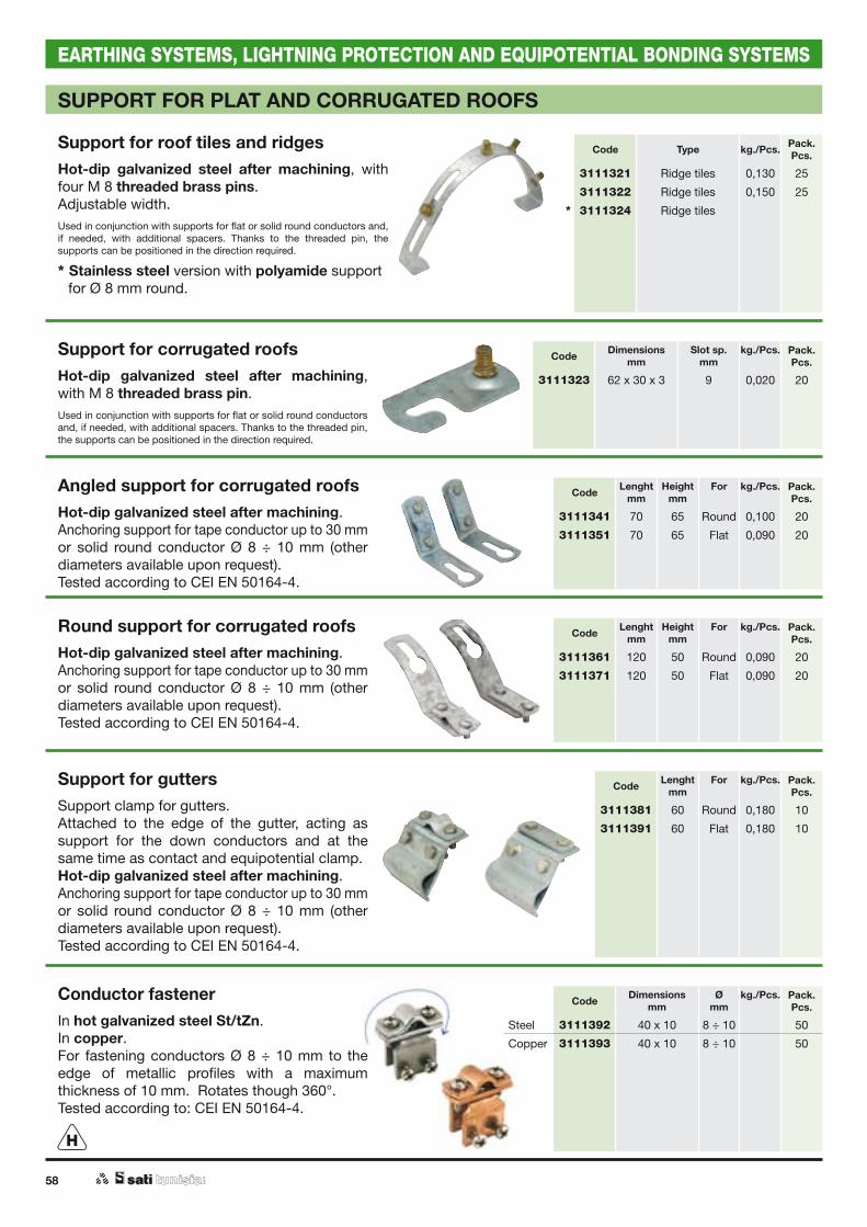
58
EARTHING SYSTEMS, LIGHTNING PROTECTION AND EQUIPOTENTIAL BONDING SYSTEMS
SUPPORT FOR PLAT AND CORRUGATED ROOFS
Support for roof tiles and ridges Hot-dip galvanized steel after machining, with four M 8 threaded brass pins.Adjustable width.Used in conjunction with supports for flat or solid round conductors and, if needed, with additional spacers. Thanks to the threaded pin, the supports can be positioned in the direction required.
* Stainless steel version with polyamide support for Ø 8 mm round.
Support for corrugated roofsHot-dip galvanized steel after machining, with M 8 threaded brass pin.Used in conjunction with supports for flat or solid round conductors and, if needed, with additional spacers. Thanks to the threaded pin, the supports can be positioned in the direction required.
Angled support for corrugated roofsHot-dip galvanized steel after machining.Anchoring support for tape conductor up to 30 mm or solid round conductor Ø 8 ÷ 10 mm (other diameters available upon request).Tested according to CEI EN 50164-4.
Round support for corrugated roofsHot-dip galvanized steel after machining.Anchoring support for tape conductor up to 30 mm or solid round conductor Ø 8 ÷ 10 mm (other diameters available upon request).Tested according to CEI EN 50164-4.
Support for guttersSupport clamp for gutters. Attached to the edge of the gutter, acting as support for the down conductors and at the same time as contact and equipotential clamp.Hot-dip galvanized steel after machining.Anchoring support for tape conductor up to 30 mm or solid round conductor Ø 8 ÷ 10 mm (other diameters available upon request).Tested according to CEI EN 50164-4.
Conductor fastenerIn hot galvanized steel St/tZn.In copper.For fastening conductors Ø 8 ÷ 10 mm to the edge of metallic profiles with a maximum thickness of 10 mm. Rotates though 360°.Tested according to: CEI EN 50164-4.
Code Type kg./Pcs. Pack.Pcs.
3111321 Ridge tiles 0,130 25
3111322 Ridge tiles 0,150 25
* 3111324 Ridge tiles
Code Dimensionsmm
Slot sp.mm
kg./Pcs. Pack.Pcs.
3111323 62 x 30 x 3 9 0,020 20
Code Lenghtmm
Heightmm
For kg./Pcs. Pack.Pcs.
3111341 70 65 Round 0,100 20
3111351 70 65 Flat 0,090 20
Code Lenghtmm
Heightmm
For kg./Pcs. Pack.Pcs.
3111361 120 50 Round 0,090 20
3111371 120 50 Flat 0,090 20
Code Lenghtmm
For kg./Pcs. Pack.Pcs.
3111381 60 Round 0,180 10
3111391 60 Flat 0,180 10
Code Dimensionsmm
Ømm
kg./Pcs. Pack.Pcs.
Steel 3111392 40 x 10 8 ÷ 10 50
Copper 3111393 40 x 10 8 ÷ 10 50
H

59
EARTHING SYSTEMS, LIGHTNING PROTECTION AND EQUIPOTENTIAL BONDING SYSTEMS
SUPPORTS FOR FLAT AND CORRUGATED ROOFS
Concrete support for flat roofsMade from frost proof, vibrated concrete, with an M 8 anchor piece to connect it to fittings for tape connectors or solid round connectors, using double nipple M 8.In accordance with CEI 81-10, the height of the concrete support added to the connector support should be more than 100 mm.
Cement coated support for flat roofsMade from frost proof plastic with cover, and filled with vibrated concrete.For round Ø 8 ÷ 10 mm, with click fittings.For flat 30 x 3 - 3.5 mm.Tested according to CEI EN 50164-4.* Galvanized steel plate to secure the tape conductor
to the concrete support.** Copper plate to secure the tape conductor to the
concrete support.
Contraction-expansion absorbing componentIn hot galvanized steel St/tZn.In electrolytic copper.Installed at 20 m intervals with straight conductors or at the intersection of conductors, to compensate for the contraction-expansion of metal caused by temperature changes. The 3111400 version is suitable for hot galvanized steel, aluminium or stainless steel conductors. For copper conductors, the 3111403 version is used instead.At intersections, different clamps are used depending on the type of the conductor: for steel use id. 3110552, for copper use id 3110672.Tested according to CEI EN 50164-1-2.
End clampIn cast steel hot galvanized St/tZn.In cast copper alloy.For equipotential bonding of metallic surfaces with matching clamps id. 3110261/3110262/3110263.Tested according to CEI EN 50164-1.
Code Basemm
Height kg./Pcs. Pack.Pcs.
3111402 190 x 160 73 2,100 10
Code Basemm
Height For Ømm
kg./Pcs. Pack.Pcs.
3111441 130 75 Round Ø 08 1,200 12
3111442 130 75 Round Ø 10 1,200 12
* 3111443 Steel galanized for flat 30 mm 0,030 12
** 3111444 Copper plate for flat 30 mm 0,030 12
Code Lenghtmm
kg./Pcs. Pack.Pcs.
Steel 3111400 400 1
Copper 3111403 400 1
Code Ømm
kg./Pcs. Pack.Pcs.
Steel 3111405 8 ÷ 10 1
Copper 3111406 8 ÷ 10 1
N
N
H
H

60
EARTHING SYSTEMS, LIGHTNING PROTECTION AND EQUIPOTENTIAL BONDING SYSTEMS
CLAMPS
Cross clamp with plateSteel 60 x 60 x 2.5 mm, hot-dip galvanized steel after machining.Nuts and bolts: M 8 x 25 mm. For flat roofs.Flat base Ø 100 mm, fitted with four fixing holes Ø 10 mm and four Ø 4.5 mm. Simultaneously achieves the intersection and anchoring of solid round connectors up toØ 10 mm, strand and braids up to 78 mm2, tape up to 30 mm. Height 100 mm, as required by CEI 81-10.Tested according to CEI EN 50164-4.Intermediate plate available upon request.
Cross clamp with threaded rodSteel 60 x 60 x 2.5 mm, hot-dip galvanized steel after machining.Nuts and bolts M 8 x 25 mm. Threaded rod M 8 welded to bottom plate, with 3 cm clearance.Simultaneously achieves the intersection and anchoring of solid round connectors up toØ 10 mm, strand and braids up to 78 mm2, tape up to 30 mm. Tested according to CEI EN 50164-4.Intermediate plate available upon request.
Test clampIn cast copper alloy tin-plated.In zamak.In bimetallic zamak and cast copper alloy tin-plated.It can be installed 1,5 - 2 m above ground level at each down conductor. It is used to facilitate the electrical testing and measuement of LPS.
Tested according to: CEI EN 50164-1.
Code Round/Wire/RopeØ mm
Flat kg./Pcs. Pack.Pcs.
3110751 8 ÷ 10 - 0,400 25
3110752 - 20 - 30 0,370 25
Code Round/Wire/RopeØ mm
Flat kg./Pcs. Pack.Pcs.
3110781 8 ÷ 10 - 0,220 10
3110782 - 20 - 30 0,200 10
Code Ømm
kg./Pcs. Pack.Pcs.
Zamak 3111407 8 ÷ 10 25
Bimetallic 3111408 8 ÷ 08 25
Copper alloy tin-plated
3111409 8 - 50 mm2 - 50 mm2 - 8 25
H
H
H
Assembly example
Assembly example
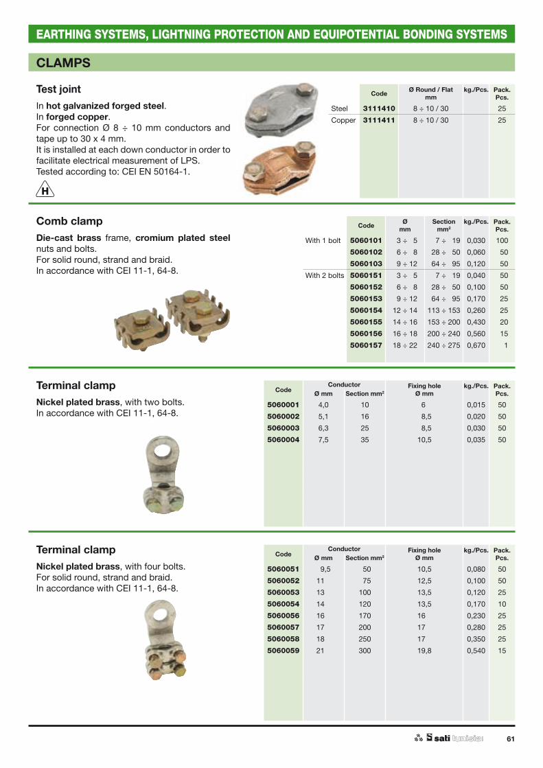
61
EARTHING SYSTEMS, LIGHTNING PROTECTION AND EQUIPOTENTIAL BONDING SYSTEMS
CLAMPS
Test jointIn hot galvanized forged steel.In forged copper.For connection Ø 8 ÷ 10 mm conductors and tape up to 30 x 4 mm.It is installed at each down conductor in order to facilitate electrical measurement of LPS.Tested according to: CEI EN 50164-1.
Comb clampDie-cast brass frame, cromium plated steel nuts and bolts.For solid round, strand and braid.In accordance with CEI 11-1, 64-8.
Terminal clampNickel plated brass, with two bolts.In accordance with CEI 11-1, 64-8.
Terminal clampNickel plated brass, with four bolts.For solid round, strand and braid.In accordance with CEI 11-1, 64-8.
Code Ø Round / Flatmm
kg./Pcs. Pack.Pcs.
Steel 3111410 8 ÷ 10 / 30 25
Copper 3111411 8 ÷ 10 / 30 25
Code Ømm
Sectionmm2
kg./Pcs. Pack.Pcs.
With 1 bolt 5060101 03 ÷ 05 007 ÷ 019 0,030 100
5060102 06 ÷ 08 028 ÷ 050 0,060 150
5060103 09 ÷ 12 064 ÷ 095 0,120 150
With 2 bolts 5060151 03 ÷ 05 007 ÷ 019 0,040 150
5060152 06 ÷ 08 028 ÷ 050 0,100 150
5060153 09 ÷ 12 064 ÷ 095 0,170 125
5060154 12 ÷ 14 113 ÷ 153 0,260 125
5060155 14 ÷ 16 153 ÷ 200 0,430 120
5060156 16 ÷ 18 200 ÷ 240 0,560 115
5060157 18 ÷ 22 240 ÷ 275 0,670 111
CodeConductor Fixing hole
Ø mmkg./Pcs. Pack.
Pcs.Ø mm Section mm2
5060001 4,0 10 06,0 0,015 50
5060002 5,1 16 08,5 0,020 50
5060003 6,3 25 08,5 0,030 50
5060004 7,5 35 10,5 0,035 50
CodeConductor Fixing hole
Ø mmkg./Pcs. Pack.
Pcs.Ø mm Section mm2
5060051 09,5 050 10,5 0,080 50
5060052 11,0 075 12,5 0,100 50
5060053 13,0 100 13,5 0,120 25
5060054 14,0 120 13,5 0,170 10
5060056 16,0 170 16,0 0,230 25
5060057 17,0 200 17,0 0,280 25
5060058 18,0 250 17,0 0,350 25
5060059 21,0 300 19,8 0,540 15
H

62
EARTHING SYSTEMS, LIGHTNING PROTECTION AND EQUIPOTENTIAL BONDING SYSTEMS
CLAMP
Linear joint plateNickel plated copper. For solid round connectors Ø 8 ÷ 10 mm.Tested according to CEI EN 50164-1.
“U” clampBrass.For solid round, strand and braid.In accordance with CEI 11-1, 64-8.
“T” clampChrome plated brass.For solid round, strand and braid.In accordance with CEI 11-1, 64-8.
Parallel clampBrass.For solid round, strand and braid.In accordance with CEI 11-1, 64-8.* While stocks last.
Code Ømm
kg./Pcs. Pack.Pcs.
3110804 8 ÷ 10 0,180 10
Code Ømm
Sectionmm2
kg./Pcs. Pack.Pcs.
5060252 03 ÷ 06 16 ÷ 28 0,050 50
5060253 07 ÷ 08 28 ÷ 50 0,070 25
5060254 09 ÷ 12 50 ÷ 78 0,100 10
Code Ømm
Sectionmm2
kg./Pcs. Pack.Pcs.
5060303 7 ÷ 08 28 ÷ 50 0,110 25
5060304 9 ÷ 10 50 ÷ 78 0,160 10
Code Ømm
Sectionmm2
kg./Pcs. Pack.Pcs.
* 5060356 08 50 0,180 25
* 5060357 09 63 0,250 25
* 5060358 10 78 0,310 10
* 5060359 11 95 0,330 10
H

63
EARTHING SYSTEMS, LIGHTNING PROTECTION AND EQUIPOTENTIAL BONDING SYSTEMS
PLATE FOR EQUIPOTENTIAL BONDING
Plate for equipotential bondingsType BTMStainless steel AISI 304 or ZF hot-dip galvanized steel after machining.Dimensions 280 x 40 x 5 mm.- Anchor holes: two Ø 13 mm; spaced 17.5 mm from
each other and 20 mm from the ends and edges.- Derivation holes: six Ø 13 mm; spaced 35 mm from
each other and 20 mm from the ends and edges.
Type BTHStainless steel AISI 304 or ZF hot-dip galvanized steel after machining.Dimensions: 280 x 50 x 5mm.- Anchor holes: two Ø 13 mm; spaced 17.5 mm
from the ends and 25 mm from the edges.- Derivation holes: six + six Ø 13 mm; spaced 35
mm from each other ; the holes are spaced out in two parallel lines 23 mm from each other and 13.5 mm from the edges.
Code Type Lenghtmm
kg./Pcs. Pack.Pcs.
3110851 BTM - INOX 280 0,410 1
3110852 BTH - INOX 280 0,500 1
3110871 BTM - ZF 280 0,430 1
3110872 BTH - ZF 280 0,500 1
Code Type Dimensionsmm
kg./Pcs. Pack.Pcs.
3110893 ZF 40 x 75 x 50 0,100 1
Code Dimensionsmm
Sectionmm2
kg./Pcs. Pack.Pcs.
3110875 25 x 4 x 1000 100 1
3110876 30 x 5 x 1000 150 1
Code Dimensionsmm
kg./Pcs. Pack.Pcs.
3110880 27 x 30 x 50 1
Anchoring bracketZF hot-dip galvanized steel after machining.Plate thickness: 3 mm.Anchor holes: Ø 13 mm.
Drilled threaded barCopper.M 6 threaded holes.Spacing: 20 mm (25 x 4 mm).Spacing: 25 mm (30 x 5 mm).Note: different sizes and measurements provided upon request.
Spacing pillarsPolyester with fibreglass.Female metal inserts at both ends.
BTM
BTH

64
EARTHING SYSTEMS, LIGHTNING PROTECTION AND EQUIPOTENTIAL BONDING SYSTEMS
PLATE FOR EQUIPOTENTIAL BONDING
Equipotential plate with coverWith shock resistant PVC cover.Nickel-plated brass terminal block:n. 1 conductor terminal Ø 8 ÷ 10 mm or section 50 mm2.n. 7 conductor terminals 6 ÷ 25 mm2.n. 1 tape terminal 30 mm or conductor Ø 8 ÷ 10 mm.Tested according to: CEI EN 50164-1.
Code Dimensionsmm
kg./Pcs. Pack.Pcs.
3110913 170 x 50 x 50 1
H
H
Code Lenghtmm
kg./Pcs. Pack.Pcs.
3110912 200 0,240 1
Plate for equipotential bondingsCopper, stainless steel bolts - Section 30 x 3 mm.For number of conductors: One wire (35 ÷ 50 mm2).Four wire (up to 35 mm2)
Wall earthing receptacleIn copper alloy.For connecting embedded conductors with air-termination or equipotential bonding bars. In general is used for connecting embedded conductors with external ones. Female thread M 10.Tested according to CEI EN 50164-1.
Code Class Dimensions Internalthread
Pack.Pcs.
3110114 H-100 kA 60 x 80 M 10 10

65
EARTHING SYSTEMS, LIGHTNING PROTECTION AND EQUIPOTENTIAL BONDING SYSTEMS
ACCESSORIES
Earth plate signIn aluminium.* While stocks last.
Hexagonal spacerZinc galvanized steel.Internally threaded.no.10 spanner for M 6 spacers.no.13 spanner for M 8 spacers.
Double NiplesZinc galvanized steel.
Threaded rodZinc galvanized steel.
Code Dimensionsmm
kg./Pcs. Pack.Pcs.
3110962 165 x 250 0,120 1
* 3110964 500 x 330 0,325 1
Code Type Lenghtmm
kg./Pcs. Pack.Pcs.
3111481 M 06 x 20 20 0,009 100
3111482 M 06 x 25 25 0,010 100
3111483 M 06 x 30 30 0,015 100
3111484 M 06 x 40 40 0,019 100
2020351 M 06 x 50 50 0,020 100
3111491 M 08 x 20 20 0,010 100
3111492 M 08 x 30 30 0,019 100
3111493 M 08 x 40 40 0,020 100
2020352 M 08 x 50 50 0,030 050
2020353 M 10 x 50 50 0,040 050
2020354 M 12 x 50 50 0,062 050
Code Type Lenghtmm
kg./Pcs. Pack.Pcs.
3111472 M 8 x 17 17 0,006 100
Code Type Lenghtmm
kg./Pcs. Pack.Pcs.
2020301 M 06 1000 0,170 20
2020302 M 08 1000 0,310 20
2020303 M 10 1000 0,400 20
2020304 M 12 1000 0,700 10

66
EARTHING SYSTEMS, LIGHTNING PROTECTION AND EQUIPOTENTIAL BONDING SYSTEMS
ACCESSORIES
Fiberglass channelPultruded fibreglass.To prevent direct contact between down conductors and lightning rods or cables on walls or poles.Length: 3 m. With slots for mounting on poles.
"U" bracketHot-dip galvanized steel after machining.To anchor the fibreglass channel to the wall.
Code Dimensionsmm
kg./Pcs. Pack.Pcs.
3111841 52 x 56 2,700 1
3111842 76 x 80 4,500 1
Code For channelmm
kg./Pcs. Pack.Pcs.
3111861 52 x 56 0,100 1
3111862 76 x 80 0,114 1

67
EARTHING SYSTEMS, LIGHTNING PROTECTION AND EQUIPOTENTIAL BONDING SYSTEMS
CONNECTING AND EXPANSION STRIP
Flexible copper braidTwo holes Ø 9 mm.Flattened tubular braid in rolls, in Ø 0.2 mm strands and in sections up to 200 mm2 may be supplied upon request.Dimensions and sections other than those listed may be also provided upon request.
Flexible tinned copper braidTwo holes Ø 9 mm.Flattened tubular braid in rolls, in Ø 0.2 mm strands and in sections up to 200 mm2 may be supplied upon request.Dimensions and sections other than those listed may be also provided upon request.
Code kg./Pcs. Pack.Pcs.
Section 10 mm2. Fixing space 200 mm. 3150151 0,020 10
Fixing space 250 mm. 3150152 0,020 10
Section 16 mm2. Fixing space 100 mm. 3150161 0,020 10
Fixing space 150 mm. 3150162 0,029 10
Fixing space 200 mm. 3150163 0,039 10
Fixing space 250 mm. 3150164 0,041 10
Fixing space 300 mm. 3150165 0,050 10
Section 25 mm2. Fixing space 100 mm. 3150171 0,034 10
Fixing space 150 mm. 3150172 0,045 10
Fixing space 200 mm. 3150173 0,055 10
Fixing space 250 mm. 3150174 0,062 10
Fixing space 300 mm. 3150175 0,080 10
Section 35 mm2. Fixing space 100 mm. 3150181 0,040 10
Fixing space 150 mm. 3150182 0,060 10
Fixing space 200 mm. 3150183 0,075 10
Fixing space 250 mm. 3150184 0,092 10
Fixing space 300 mm. 3150185 0,110 10
Section 50 mm2. Fixing space 100 mm. 3150196 0,085 10
2 hole Ø 11 mm. Fixing space 150 mm. 3150197 0,100 10
Fixing space 200 mm. 3150198 0,130 10
Fixing space 250 mm. 3150199 0,170 10
Fixing space 300 mm. 3150200 0,176 10
Code kg./Pcs. Pack.Pcs.
Section 10 mm2. Fixing space 200 mm. 3150063 0,020 10
Fixing space 250 mm. 3150064 0,028 10
Section 16 mm2. Fixing space 100 mm. 3150071 0,020 10
Fixing space 150 mm. 3150072 0,029 10
Fixing space 200 mm. 3150073 0,034 10
Fixing space 250 mm. 3150074 0,045 10
Fixing space 300 mm. 3150075 0,048 10
Section 25 mm2. Fixing space 100 mm. 3150081 0,034 10
Fixing space 150 mm. 3150082 0,045 10
Fixing space 200 mm. 3150083 0,050 10
Fixing space 250 mm. 3150084 0,062 10
Fixing space 300 mm. 3150085 0,075 10
Section 35 mm2. Fixing space 100 mm. 3150091 0,040 10
Fixing space 150 mm. 3150092 0,060 10
Fixing space 200 mm. 3150093 0,080 10
Fixing space 250 mm. 3150094 0,092 10
Fixing space 300 mm. 3150095 0,110 10
Section 50 mm2. Fixing space 100 mm. 3150101 0,085 10
2 hole Ø 11 mm. Fixing space 150 mm. 3150102 0,100 10
Fixing space 200 mm. 3150103 0,130 10
Fixing space 250 mm. 3150104 0,151 10
Fixing space 300 mm. 3150105 0,175 10
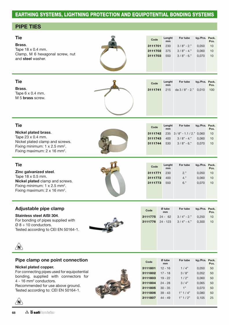
68
EARTHING SYSTEMS, LIGHTNING PROTECTION AND EQUIPOTENTIAL BONDING SYSTEMS
PIPE TIES
TieBrass.Tape 18 x 0.4 mm.Clamp, M 6 hexagonal screw, nut and steel washer.
TieBrass.Tape 6 x 0.4 mm.M 5 brass screw.
TieNickel plated brass.Tape 23 x 0.4 mm.Nickel plated clamp and screws.Fixing minimum: 1 x 2.5 mm2.Fixing maximum: 2 x 16 mm2.
TieZinc galvanized steel.Tape 18 x 0.5 mm.Nickel plated clamp and screws.Fixing minimum: 1 x 2.5 mm2.Fixing maximum: 2 x 16 mm2.
Adjustable pipe clampStainless steel AISI 304.For bonding of pipes supplied withØ 8 ÷ 10 conductors.Tested according to CEI EN 50164-1.
Pipe clamp one point connectionNickel plated copper.For connecting pipes used for equipotential bonding, supplied with connectors for4 - 16 mm2 conductors.Recommended for use above ground.Tested according to: CEI EN 50164-1.
Code Lenghtmm
For tube kg./Pcs. Pack.Pcs.
3111701 230 3 / 8” - 2.” 0,050 10
3111702 375 3 / 8” - 4.” 0,060 10
3111703 550 3 / 8” - 6.” 0,070 10
Code Lenghtmm
For tube kg./Pcs. Pack.Pcs.
3111741 215 da 3 / 8” - 2.” 0,010 100
Code Lenghtmm
For tube kg./Pcs. Pack.Pcs.
3111742 235 3 / 8” - 1.1 / 2.” 0,060 10
3111743 400 3 / 8” - 4.” 0,060 10
3111744 530 3 / 8” - 6.” 0,070 10
Code Lenghtmm
For tube kg./Pcs. Pack.Pcs.
3111771 230 2.” 0,050 10
3111772 400 4.” 0,060 10
3111773 550 6.” 0,070 10
Code Ø tubemm
For tube kg./Pcs. Pack.Pcs.
3111775 24 - 062 3 / 4” - 2.” 0,250 10
3111776 24 - 123 3 / 4” - 4.” 0,300 10
Code Ø tubemm
For tube kg./Pcs. Pack.Pcs.
3111801 12 - 16 1 / 4” 0,050 50
3111802 17 - 18 3 / 8” 0,052 50
3111803 19 - 22 1 / 2” 0,060 50
3111804 24 - 28 3 / 4” 0,065 50
3111805 30 - 35 1” 0,070 50
3111806 39 - 43 1” 1 / 4” 0,080 50
3111807 44 - 49 1” 1 / 2” 0,105 25N
N
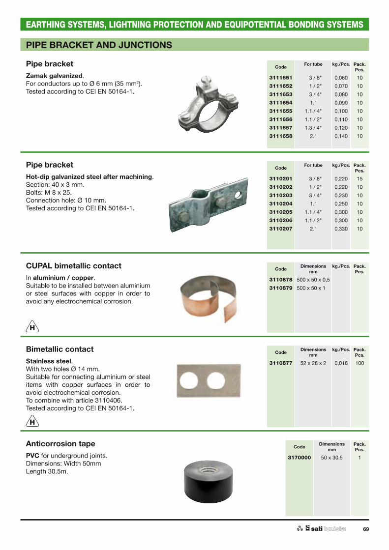
69
EARTHING SYSTEMS, LIGHTNING PROTECTION AND EQUIPOTENTIAL BONDING SYSTEMS
PIPE BRACKET AND JUNCTIONS
Pipe bracketZamak galvanized. For conductors up to Ø 6 mm (35 mm2).Tested according to CEI EN 50164-1.
Pipe bracketHot-dip galvanized steel after machining.Section: 40 x 3 mm. Bolts: M 8 x 25.Connection hole: Ø 10 mm.Tested according to CEI EN 50164-1.
CUPAL bimetallic contactIn aluminium / copper.Suitable to be installed between aluminium or steel surfaces with copper in order to avoid any electrochemical corrosion.
Bimetallic contactStainless steel.With two holes Ø 14 mm.Suitable for connecting aluminium or steel items with copper surfaces in order to avoid electrochemical corrosion.To combine with article 3110406.Tested according to CEI EN 50164-1.
Anticorrosion tapePVC for underground joints.Dimensions: Width 50mmLength 30.5m.
Code For tube kg./Pcs. Pack.Pcs.
3111651 0.3 / 8" 0,060 10
3111652 0.1 / 2" 0,070 10
3111653 0.3 / 4" 0,080 10
3111654 1." 0,090 10
3111655 1.1 / 4" 0,100 10
3111656 1.1 / 2" 0,110 10
3111657 1.3 / 4" 0,120 10
3111658 2." 0,140 10
Code For tube kg./Pcs. Pack.Pcs.
3110201 0.3 / 8" 0,220 15
3110202 0.1 / 2" 0,220 10
3110203 0.3 / 4" 0,230 10
3110204 1." 0,250 10
3110205 1.1 / 4" 0,300 10
3110206 1.1 / 2" 0,300 10
3110207 2." 0,330 10
Code Dimensionsmm
kg./Pcs. Pack.Pcs.
3110878 500 x 50 x 0,5
3110879 500 x 50 x 1,0
Code Dimensionsmm
kg./Pcs. Pack.Pcs.
3110877 52 x 28 x 2 0,016 100
Code Dimensionsmm
Pack.Pcs.
3170000 50 x 30,5 1
H
H
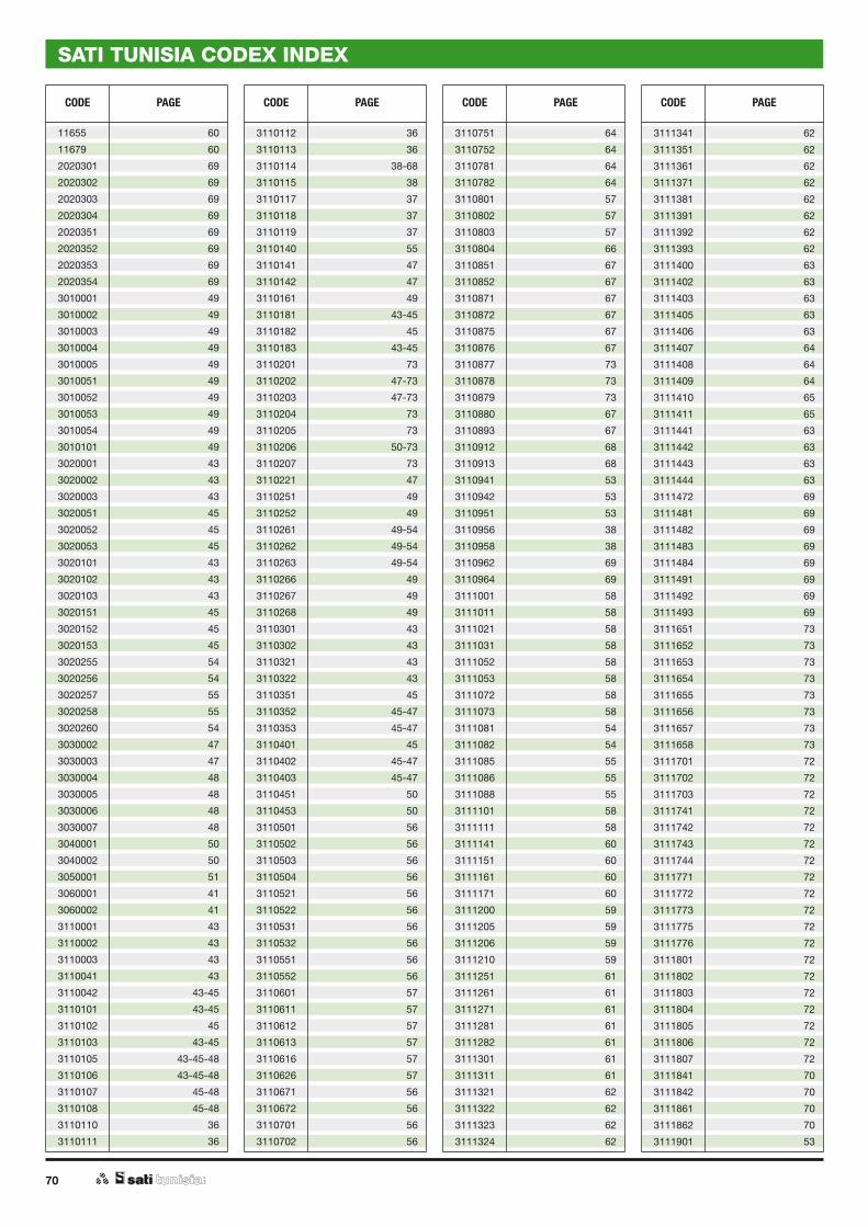
70
SATI TUNISIA CODEX INDEX
CODE PAGE CODE PAGE CODE PAGE CODE PAGE
11655 60
11679 60
2020301 69
2020302 69
2020303 69
2020304 69
2020351 69
2020352 69
2020353 69
2020354 69
3010001 49
3010002 49
3010003 49
3010004 49
3010005 49
3010051 49
3010052 49
3010053 49
3010054 49
3010101 49
3020001 43
3020002 43
3020003 43
3020051 45
3020052 45
3020053 45
3020101 43
3020102 43
3020103 43
3020151 45
3020152 45
3020153 45
3020255 54
3020256 54
3020257 55
3020258 55
3020260 54
3030002 47
3030003 47
3030004 48
3030005 48
3030006 48
3030007 48
3040001 50
3040002 50
3050001 51
3060001 41
3060002 41
3110001 43
3110002 43
3110003 43
3110041 43
3110042 43-45
3110101 43-45
3110102 45
3110103 43-45
3110105 43-45-48
3110106 43-45-48
3110107 45-48
3110108 45-48
3110110 36
3110111 36
3110112 36
3110113 36
3110114 38-68
3110115 38
3110117 37
3110118 37
3110119 37
3110140 55
3110141 47
3110142 47
3110161 49
3110181 43-45
3110182 45
3110183 43-45
3110201 73
3110202 47-73
3110203 47-73
3110204 73
3110205 73
3110206 50-73
3110207 73
3110221 47
3110251 49
3110252 49
3110261 49-54
3110262 49-54
3110263 49-54
3110266 49
3110267 49
3110268 49
3110301 43
3110302 43
3110321 43
3110322 43
3110351 45
3110352 45-47
3110353 45-47
3110401 45
3110402 45-47
3110403 45-47
3110451 50
3110453 50
3110501 56
3110502 56
3110503 56
3110504 56
3110521 56
3110522 56
3110531 56
3110532 56
3110551 56
3110552 56
3110601 57
3110611 57
3110612 57
3110613 57
3110616 57
3110626 57
3110671 56
3110672 56
3110701 56
3110702 56
3110751 64
3110752 64
3110781 64
3110782 64
3110801 57
3110802 57
3110803 57
3110804 66
3110851 67
3110852 67
3110871 67
3110872 67
3110875 67
3110876 67
3110877 73
3110878 73
3110879 73
3110880 67
3110893 67
3110912 68
3110913 68
3110941 53
3110942 53
3110951 53
3110956 38
3110958 38
3110962 69
3110964 69
3111001 58
3111011 58
3111021 58
3111031 58
3111052 58
3111053 58
3111072 58
3111073 58
3111081 54
3111082 54
3111085 55
3111086 55
3111088 55
3111101 58
3111111 58
3111141 60
3111151 60
3111161 60
3111171 60
3111200 59
3111205 59
3111206 59
3111210 59
3111251 61
3111261 61
3111271 61
3111281 61
3111282 61
3111301 61
3111311 61
3111321 62
3111322 62
3111323 62
3111324 62
3111341 62
3111351 62
3111361 62
3111371 62
3111381 62
3111391 62
3111392 62
3111393 62
3111400 63
3111402 63
3111403 63
3111405 63
3111406 63
3111407 64
3111408 64
3111409 64
3111410 65
3111411 65
3111441 63
3111442 63
3111443 63
3111444 63
3111472 69
3111481 69
3111482 69
3111483 69
3111484 69
3111491 69
3111492 69
3111493 69
3111651 73
3111652 73
3111653 73
3111654 73
3111655 73
3111656 73
3111657 73
3111658 73
3111701 72
3111702 72
3111703 72
3111741 72
3111742 72
3111743 72
3111744 72
3111771 72
3111772 72
3111773 72
3111775 72
3111776 72
3111801 72
3111802 72
3111803 72
3111804 72
3111805 72
3111806 72
3111807 72
3111841 70
3111842 70
3111861 70
3111862 70
3111901 53

71
SATI TUNISIA CODEX INDEX
CODE PAGE CODE PAGE CODE PAGE CODE PAGE
3111902 53
3111903 53
3111921 53
3111922 53
3111923 53
3120001 51
3120012 51
3120022 51
3120023 51
3120031 51
3120032 51
3120045 51
3120046 51
3130001 51
3130011 51
3130021 51
3130031 51
3130041 51
3150063 71
3150064 71
3150071 71
3150072 71
3150073 71
3150074 71
3150075 71
3150081 71
3150082 71
3150083 71
3150084 71
3150085 71
3150091 71
3150092 71
3150093 71
3150094 71
3150095 71
3150101 71
3150102 71
3150103 71
3150104 71
3150105 71
3150151 71
3150152 71
3150161 71
3150162 71
3150163 71
3150164 71
3150165 71
3150171 71
3150172 71
3150173 71
3150174 71
3150175 71
3150181 71
3150182 71
3150183 71
3150184 71
3150185 71
3150196 71
3150197 71
3150198 71
3150199 71
3150200 71
3170000 53-73
3230101 51
3230102 51
3230103 51
3230111 51
3230112 51
3230113 51
3230121 51
3230122 51
3230123 51
3230201 51
3230202 51
3230203 51
5060001 65
5060002 65
5060003 65
5060004 65
5060051 65
5060052 65
5060053 65
5060054 65
5060056 65
5060057 65
5060058 65
5060059 65
5060101 65
5060102 65
5060103 65
5060151 65
5060152 65
5060153 65
5060154 65
5060155 65
5060156 65
5060157 65
5060252 66
5060253 66
5060254 66
5060303 66
5060304 66
5060356 66
5060357 66
5060358 66
5060359 66
5070001 52
5070002 52
5070003 52
5070004 52
5070006 52
5070007 52
5070051 52
5070052 52
5070053 52
5070054 52
5070055 52
5070056 52
5070102 52
5070103 52
5070104 52
5070105 52
5070151 52
5070152 52
5070153 52
5070154 52
5070155 52
5070156 52
72
WIT S.A. - Saint Laurent du Var Cedex - FranceSolutions de Télégestion et de Process
Wi-Next S.r.l.Siège de RIVOLI CASCINE VICA (TO) - Italie
Carpaneto & C. S.p.A. (Chef de Groupe)Siège de RIVOLI CASCINE VICA (TO) - Italie
Sati Italia S.p.A. - Filial de PADOVA - Italie
Usine de production - LATINA - Italie
Sati Italia S.p.A. - Filial de LATINA - Italie
Usine de production - SIZIANO - Italie
Sati Italia S.p.A. - Siège de SIZIANO (PV) - Italie
NoField S.r.l.Siège de TURIN - Italie
OTHER ACTIVITIES OF THE CARPANETO SATI GROUP

9130
074T
- 0
2 -
2015
- G
B
EARTHING SYSTEMS,LIGHTNING PROTECTION AND
EQUIPOTENTIAL BONDING SYSTEMS EXTERNAL LPS
www.satitunisia.com
Rue de Nabeul, Lot N° 17 - Zone Industrielle MEGHIRA 3.CP 2082 - BEN AROUS - TUNISIE
Tél. +216 71 40 98 92 - Fax: +216 71 40 98 93www.satitunisia.com