connaître et comprendre circuits logiques ele1300 · l’additionneur “complet” (suite) 3...
TRANSCRIPT
Circuits LogiquesELE1300ELE1300
Représentation des nombreset opérations
JP David
Objectifs
• Connaître et comprendre�La représentation d’un nombre dans une base
quelconque et en particulier dans les formats binaires.
3 novembre 2014 Circuits logiques - JP David 2
binaires.
• Être capable de�Convertir un nombre d’une base à une autre�Réaliser des opérations sur les nombres
• Addition – soustraction – multiplication – division
[ ]( )1 2 1 0 1 2
, n n m b
a a a a a a a− − − − −
� �
partie entière partie fractionnaire base
Forme générale d’un nombre
3 novembre 2014 Circuits logiques - JP David 3
partie entière
n chiffres
partie fractionnaire
m chiffres
base
[ ]( )1 2 1 0 1 2
, n n m b
a a a a a a a− − − − −
� �
1 2 1 0 1 2 n n m
b b b b b b b− − − − −
� �
Forme générale d’un nombre (suite)
3 novembre 2014 Circuits logiques - JP David 4
1 21 2 1 0 n n
n na b a b a b a− −
− −× + × + + × +�
Valeur :
-1 -2 --1 -2 - m
ma b a b a b+ × + × + + ×�
b b b b b b b� �
Exemple 1
51 = 1.25 + 1.24 + 0.23 + 0.22 + 1.21 + 1.20
= 32 + 16 + 0 + 0 +2 + 1
51 = (((((1).2+1).2+0).2+0).2+1).2+1
3 novembre 2014 Circuits logiques - JP David 5
51 = (((((1).2+1).2+0).2+0).2+1).2+1
32 16 8 4 2 1
1 1 0 0 1 1
Exemple 2
64 32 16 8 4 2 1 1/2
1/4
1/8
1/16
1/32
1/64
Base10
0 1 1 0 0 1 1 0 0 0 0 0 0 51
3 novembre 2014 Circuits logiques - JP David 6
0 1 1 0 0 1 1 0 0 0 0 0 0 51
0 0 0 0 1 0 1 0 0 1 0 0 0 5,125
0 0 0 0 0 0 0 0 1 0 1 0 1…
1/3
SYSTÈME BASE CHIFFRES
BINAIRE
OCTAL
DÉCIMAL
HEXADÉCIMAL
2
8
10
16
{ }0,1,2,3,4,5,6,7ia ∈
{ }0,1ia ∈
{ }0,1,2,3,4,5,6,7,8,9ia ∈
{ }0,1,2,3, 4,5,6,7,8,9,A,B,C,D,E,Fa ∈
Quelques bases usitées
3 novembre 2014 Circuits logiques - JP David 7
HEXADÉCIMAL 16 { }0,1,2,3, 4,5,6,7,8,9,A,B,C,D,E,Fia ∈
( ) ( ) ( ) ( ) ( ) ( ) ( ) ( ) ( )2 1 0 1
10 10 10 10 10 10 10 10 10243,6 2 10 4 10 3 10 6 10−= × + × + × + ×
Exemples :
( ) ( ) ( ) ( ) ( ) ( ) ( ) ( ) ( ) ( ) ( ) ( ) ( ) ( ) ( )3 2 1 0 1 2 3
2 2 2 2 2 2 2 2 2 2 2 2 2 2 21011,101 1 10 0 10 1 10 1 10 1 10 0 10 1 10− − −= × + × + × + × + × + × + ×
( ) ( ) ( ) ( ) ( ) ( ) ( ) ( ) ( )2 1 0 1
16 16 16 16 16 16 16 16 1612A, 4 1 10 2 10 A 10 4 10−= × + × + × + ×
( ) ( ) ( ) ( ) ( ) ( ) ( ) ( ) ( )1 0 1 2
8 8 8 8 8 8 8 8 845,36 4 10 5 10 3 10 6 10− −= × + × + × + ×
BINAIRE
0000000100100011010001010110
OCTAL
0123456
HEXADÉCIMAL
0123456
DÉCIMAL
0123456
Quelques bases usitées (suite)
3 novembre 2014 Circuits logiques - JP David 8
0110011110001001101010111100110111101111
10000
67
101112131415161720
6789ABCDEF10
6789
10111213141516
Conversion par multiplication
• Exemples :�110011(2) = (((((1)x2+1)x2)x2)x2+1)x2+1
= 51
�51 = (5) x 10 + 1
3 novembre 2014 Circuits logiques - JP David 9
�51 = (5) x 10 + 1 = 101(2) x 1010(2) + 1 = 110011(2)
Conversion par division
• Exemples :51 / 2 = 25 reste 1 (LSB)25 / 2 = 12 reste 112 / 2 = 6 reste 06 / 2 = 3 reste 0
3 novembre 2014 Circuits logiques - JP David 10
6 / 2 = 3 reste 03 / 2 = 1 reste 11 / 2 = 0 reste 1 (MSB)
110011(2) / 1010(2) = 101(2) reste 1(2) (1)
101(2) / 1010(2) = 0(2) reste 101(2) (5)
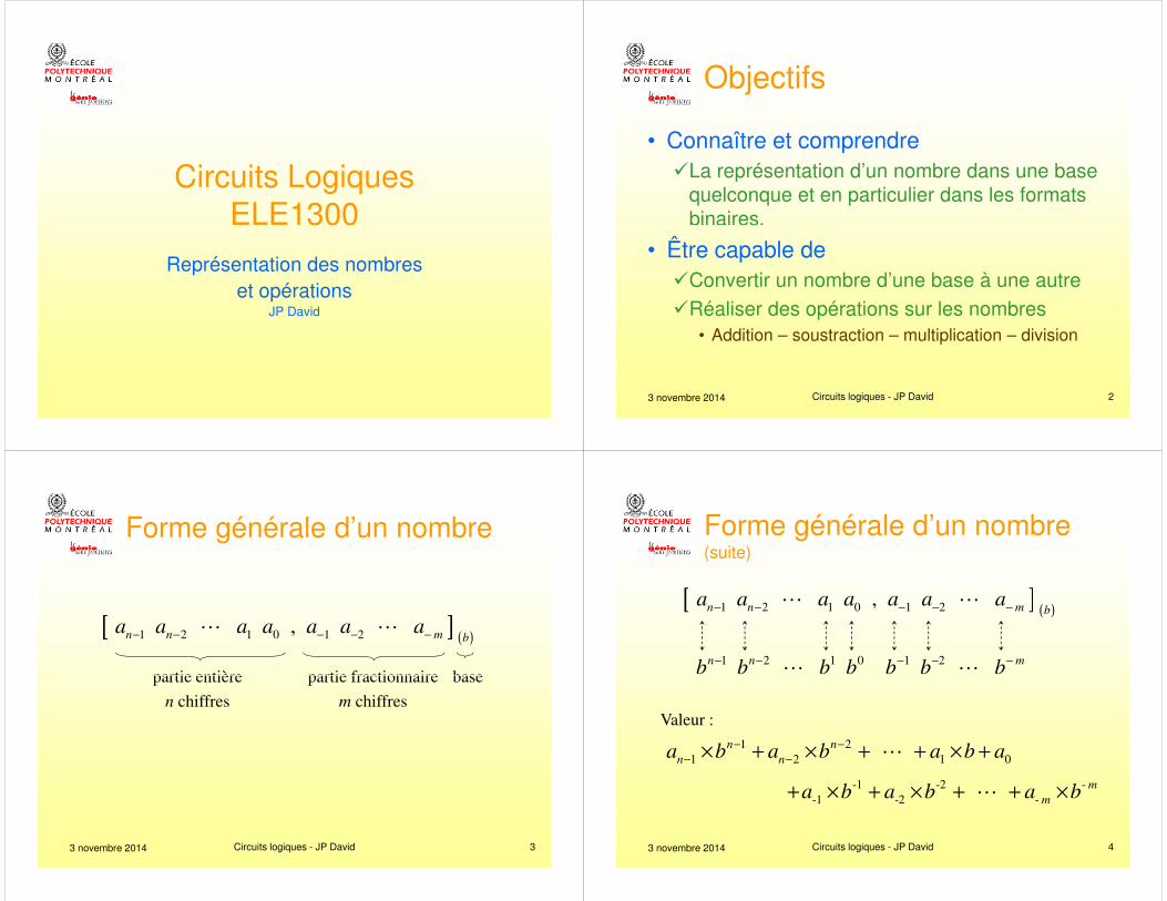
Binaire, octal et hexadécimal
1001010101001111 binaire
1001010101001111
1 1 2 5 1 7 octal
3 novembre 2014 Circuits logiques - JP David 11
1 1 2 5 1 7 octal
1001010101001111
9 5 4 F hexa
Justification ? Conv. de base par division
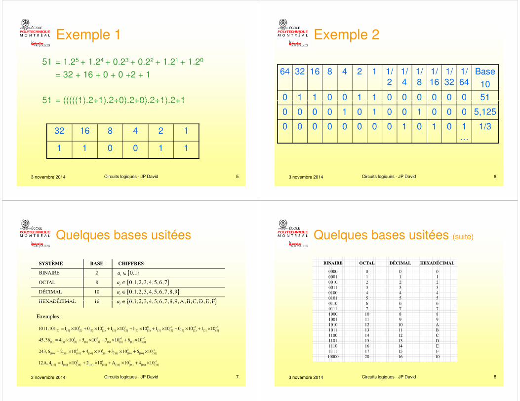
L’addition binaire : 207 + 120
128 64 32 16 8 4 2 1
3 novembre 2014 Circuits logiques - JP David 12
1 0 1 0 0 0 1 1 1
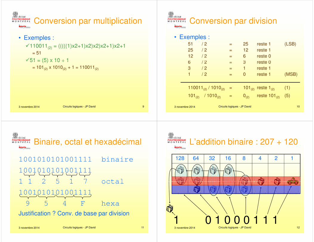
Le décalage
32 16 8 4 2 1 1/2
1/4
1/8
1/16
1/32
1/64
Base10
1 1 0 0 1 1 0 0 0 0 0 0 51
0 1 1 0 0 1 1 0 0 0 0 0 25,5
3 novembre 2014 Circuits logiques - JP David 13
0 1 1 0 0 1 1 0 0 0 0 0 25,5
0 1 1 0 0 1 1 0 0 0 0 12,75
0 1 1 0 0 1 1 0 0 0 6,375
0 1 1 0 0 1 1 0 0 3, …
0 1 1 0 0 1 1 0 1, …
La multiplication
• 123 x 35 = (1 x 100 + 2 x 10 + 3) x 35= 3 x 35 = 0105+ 2 x 35 x 10 = 0700+ 1 x 35 x 100 = 3500
= 4305
3 novembre 2014 Circuits logiques - JP David 14
en base 2:
• 101(2) x 110011(2) = (1 x 100(2) + 0 x 10(2) + 1) x 110011(2)
= 1 x 110011(2) = 00110011(2)
+ 0 x 110011(2) x 10(2) = 00000000(2)
+ 1 x 110011(2) x 100(2) = 11001100(2)
= 11111111(2)
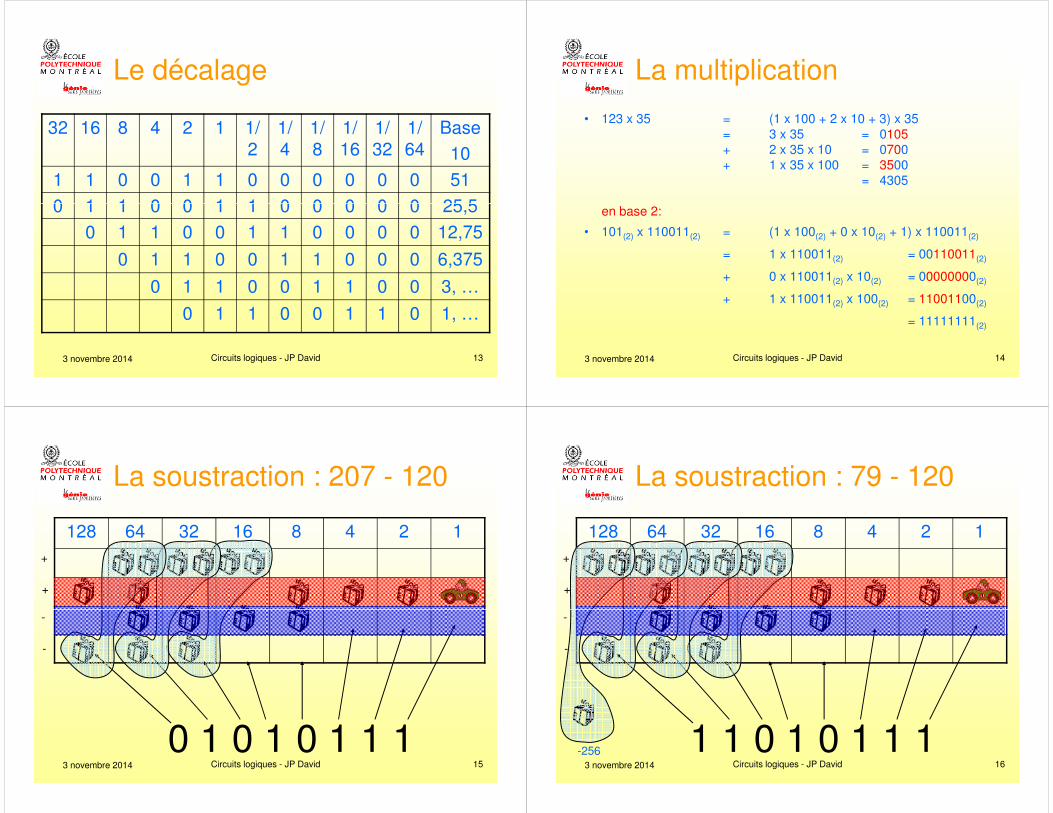
La soustraction : 207 - 120
128 64 32 16 8 4 2 1+
+
3 novembre 2014 Circuits logiques - JP David 15
0 1 0 1 0 1 1 1
-
-
La soustraction : 79 - 120
128 64 32 16 8 4 2 1+
+
3 novembre 2014 Circuits logiques - JP David 16
1 1 0 1 0 1 1 1
-
-
-256
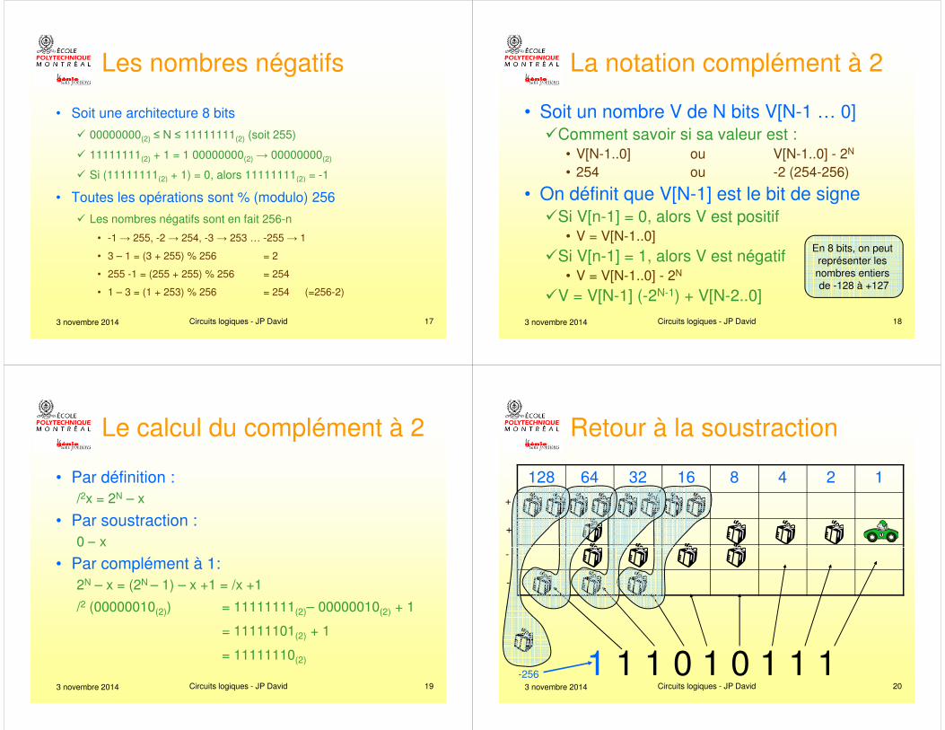
Les nombres négatifs
• Soit une architecture 8 bits
� 00000000(2) ≤ N ≤ 11111111(2) (soit 255)
� 11111111(2) + 1 = 1 00000000(2) → 00000000(2)
� Si (11111111(2) + 1) = 0, alors 11111111(2) = -1
3 novembre 2014 Circuits logiques - JP David 17
(2) (2)
• Toutes les opérations sont % (modulo) 256
� Les nombres négatifs sont en fait 256-n
• -1 → 255, -2 → 254, -3 → 253 … -255 → 1
• 3 – 1 = (3 + 255) % 256 = 2
• 255 -1 = (255 + 255) % 256 = 254
• 1 – 3 = (1 + 253) % 256 = 254 (=256-2)
La notation complément à 2
• Soit un nombre V de N bits V[N-1 … 0]�Comment savoir si sa valeur est :
• V[N-1..0] ou V[N-1..0] - 2N
• 254 ou -2 (254-256)
3 novembre 2014 Circuits logiques - JP David 18
• On définit que V[N-1] est le bit de signe�Si V[n-1] = 0, alors V est positif
• V = V[N-1..0]
�Si V[n-1] = 1, alors V est négatif• V = V[N-1..0] - 2N
�V = V[N-1] (-2N-1) + V[N-2..0]
En 8 bits, on peut représenter les nombres entiers de -128 à +127
Le calcul du complément à 2
• Par définition :/2x = 2N – x
• Par soustraction :0 – x
3 novembre 2014 Circuits logiques - JP David 19
0 – x
• Par complément à 1:2N – x = (2N – 1) – x +1 = /x +1
/2 (00000010(2)) = 11111111(2)– 00000010(2) + 1
= 11111101(2) + 1
= 11111110(2)
Retour à la soustraction
128 64 32 16 8 4 2 1+
+
3 novembre 2014 Circuits logiques - JP David 20
1 1 1 0 1 0 1 1 1
-
-
-256
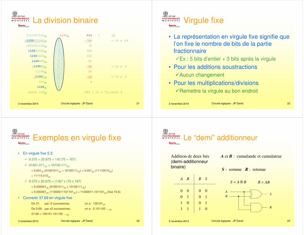
La division binaire
1101001100(2) |1100(2) 844 | 12
-1100000000(2) 1 -768 = 12 x 64
0001001100(2) 76
110000000(2) 0 384
11000000(2) 0 192
3 novembre 2014 Circuits logiques - JP David 21
1100000(2) 0 96
-110000(2) 1 -48 = 12 x 4
11100(2) 28
-11000(2) 1 -24 = 12 x 2
100(2) 4
1100(2) 0
reste 100(2) 844 / 12 = 70,reste 4
Virgule fixe
• La représentation en virgule fixe signifie que l’on fixe le nombre de bits de la partie fractionnaire�Ex : 5 bits d’entier + 3 bits après la virgule
3 novembre 2014 Circuits logiques - JP David 22
�Ex : 5 bits d’entier + 3 bits après la virgule
• Pour les additions soustractions�Aucun changement
• Pour les multiplications/divisions�Remettre la virgule au bon endroit
Exemples en virgule fixe
• En virgule fixe 5.3
� 9.375 + 20.875 = 1/8 (75 + 167)
� 01001.011(2) + 10100.111(2)
= 0.001(2) (01001011(2) + 10100111(2)) = 0.001(2) (11110010(2))
= 11110.010(2)
3 novembre 2014 Circuits logiques - JP David 23
= 11110.010(2)
� 9.375 x 20.875 = (1/8)2 x (75 x 167)
= 0.000001(2) (01001011(2) x 10100111(2))
= 0.000001(2) (11000011101101(2)) = 11000011.101101(2) (fixe 10.6)
• Convertir 37.69 en virgule fixe
De 37, par /2 successives, on a : 100101(2)
De 0.69, par x2 successives, on a : 0.101100 …(2)
37.69 = 100101.101100 …(2)
Addition de deux bits (demi-additionneur binaire)
A et B : cumulande et cumulateur
S : somme R : retenue
Le “demi” additionneur
3 novembre 2014 Circuits logiques - JP David 24
0 0 0 0
0 1 0 1
1 0 0 1
1 1 1 0
A B R SS A B= ⊕ R AB=
S
R
A
B
1 3 2 1
1 3 2 1 0
1 3 2 1 0
1 3 2 1 0
nr r r r
n
n
n n
a a a a a
b b b b b
r s s s s s
−
−
−
−
+
�
�
�
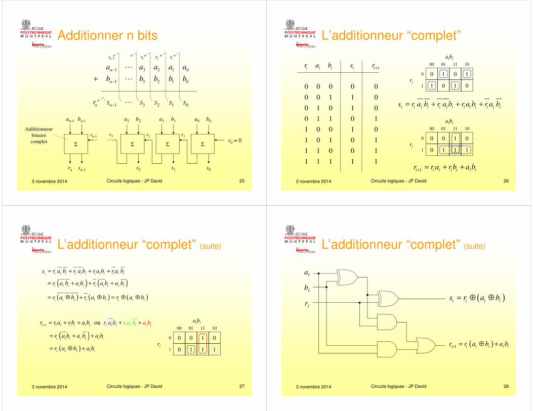
Additionner n bits
3 novembre 2014 Circuits logiques - JP David 25
1 3 2 1 0n nr s s s s s−�
Additionneur binaire complet
ΣΣΣΣ
a0 b0a1 b1a2 b2bn-1an-1
s0s1s2sn-1rn
r0 = 0r2 r1rn-1 r3
1
0 0 0 0 0
0 0 1 1 0
i i i i ir a b s r+
0 1
1 01
0100
0
aibi
ri
0 1
1 0
1011
s r a b r a b r a b r a b= + + +
L’additionneur “complet”
3 novembre 2014 Circuits logiques - JP David 26
0 1 0 1 0
0 1 1 0 1
1 0 0 1 0
1 0 1 0 1
1 1 0 0 1
1 1 1 1 1
i i i i i i i i i i i i is r a b r a b r a b r a b= + + +
0 0
0 11
0100
0
aibi
ri
1 0
1 1
1011
1i i i i i i ir r a r b a b
+= + +
i i i i i i i i i i i i is r a b r a b r a b r a b= + + +
( ) ( )i i i i i i i i i ir a b a b r a b a b= + + +
( ) ( ) ( )i i i i i i i i ir a b r a b r a b= ⊕ + ⊕ = ⊕ ⊕
L’additionneur “complet” (suite)
3 novembre 2014 Circuits logiques - JP David 27
ou ii ii ii i irr bbb a aa + +
0 0
0 11
0100
0
aibi
ri
1 0
1 1
1011
( )i i i i i i ir a b a b a b= + +
( )i i i i ir a b a b= ⊕ +
1i i i i i i ir r a r b a b+
= + +
ai
bi
ri
( )i i i is r a b= ⊕ ⊕
L’additionneur “complet” (suite)
3 novembre 2014 Circuits logiques - JP David 28
( )1i i i i i ir r a b a b
+= ⊕ +
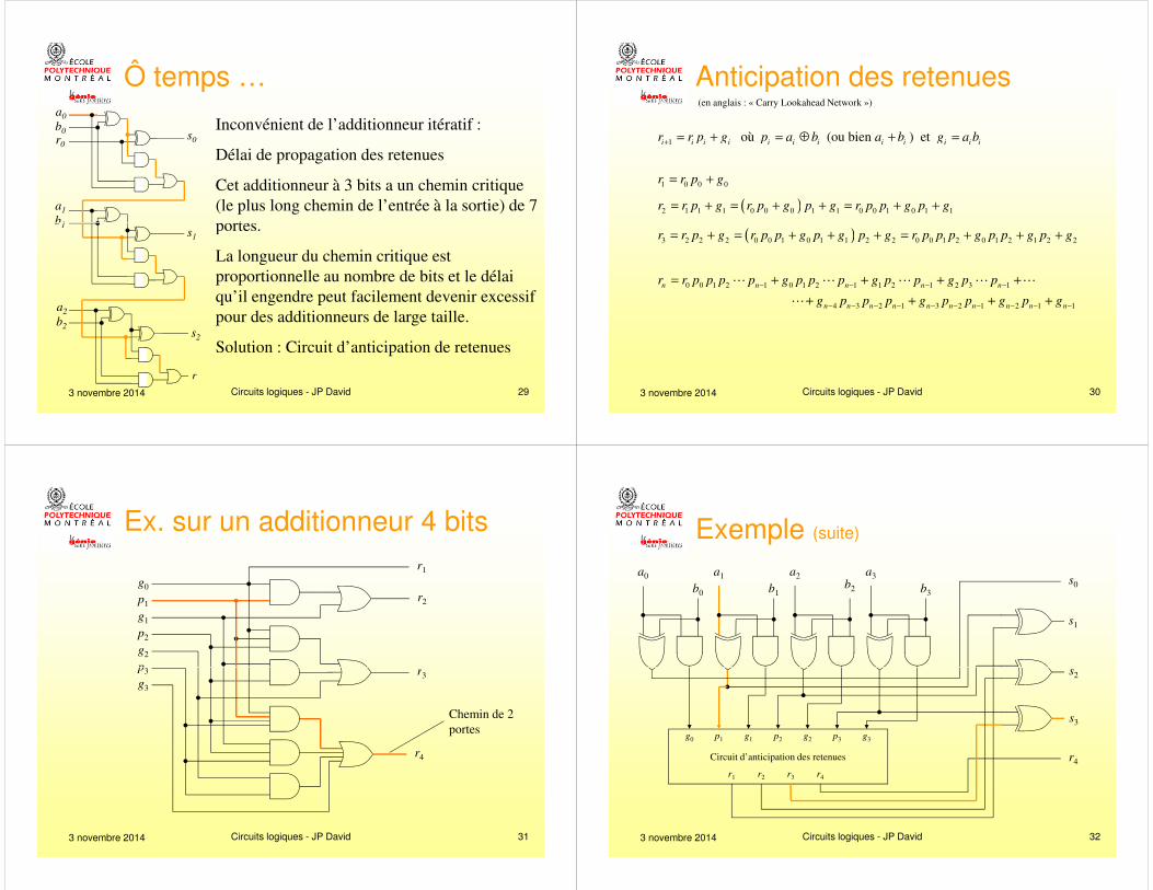
Inconvénient de l’additionneur itératif :
Délai de propagation des retenues
Cet additionneur à 3 bits a un chemin critique (le plus long chemin de l’entrée à la sortie) de 7 portes.
a0
b0
a1
b1
s0r0
Ô temps …
3 novembre 2014 Circuits logiques - JP David 29
portes.
La longueur du chemin critique est proportionnelle au nombre de bits et le délai qu’il engendre peut facilement devenir excessif pour des additionneurs de large taille.
Solution : Circuit d’anticipation de retenues
r
b1
a2
b2
s1
s2
(en anglais : « Carry Lookahead Network »)
1 où (ou bien ) et i i i i i i i i i i i ir r p g p a b a b g a b+
= + = ⊕ + =
1 0 0 0r r p g= +
( )2 1 1 1 0 0 0 1 1 0 0 1 0 1 1r r p g r p g p g r p p g p g= + = + + = + +
Anticipation des retenues
3 novembre 2014 Circuits logiques - JP David 30
( )3 2 2 2 0 0 1 0 1 1 2 2 0 0 1 2 0 1 2 1 2 2r r p g r p p g p g p g r p p p g p p g p g= + = + + + = + + +
0 0 1 2 1 0 1 2 1 1 2 1 2 3 1
4 3 2 1 3 2 1 2 1 1 n n n n n
n n n n n n n n n n
r r p p p p g p p p g p p g p p
g p p p g p p g p g
− − − −
− − − − − − − − − −
= + + + +
+ + + +
� � � � �
�
g0
p1
g1
p2
g2
p3
r1
r2
r
Ex. sur un additionneur 4 bits
3 novembre 2014 Circuits logiques - JP David 31
p3
g3
r3
r4
Chemin de 2 portes
s0
s1
s
a0 a1 a2b2
a3
b3b0 b1
Exemple (suite)
3 novembre 2014 Circuits logiques - JP David 32
s3
r4
s2
Circuit d’anticipation des retenues
r1 r2 r3 r4
g0 p1 g1 p2 g2 p3 g3
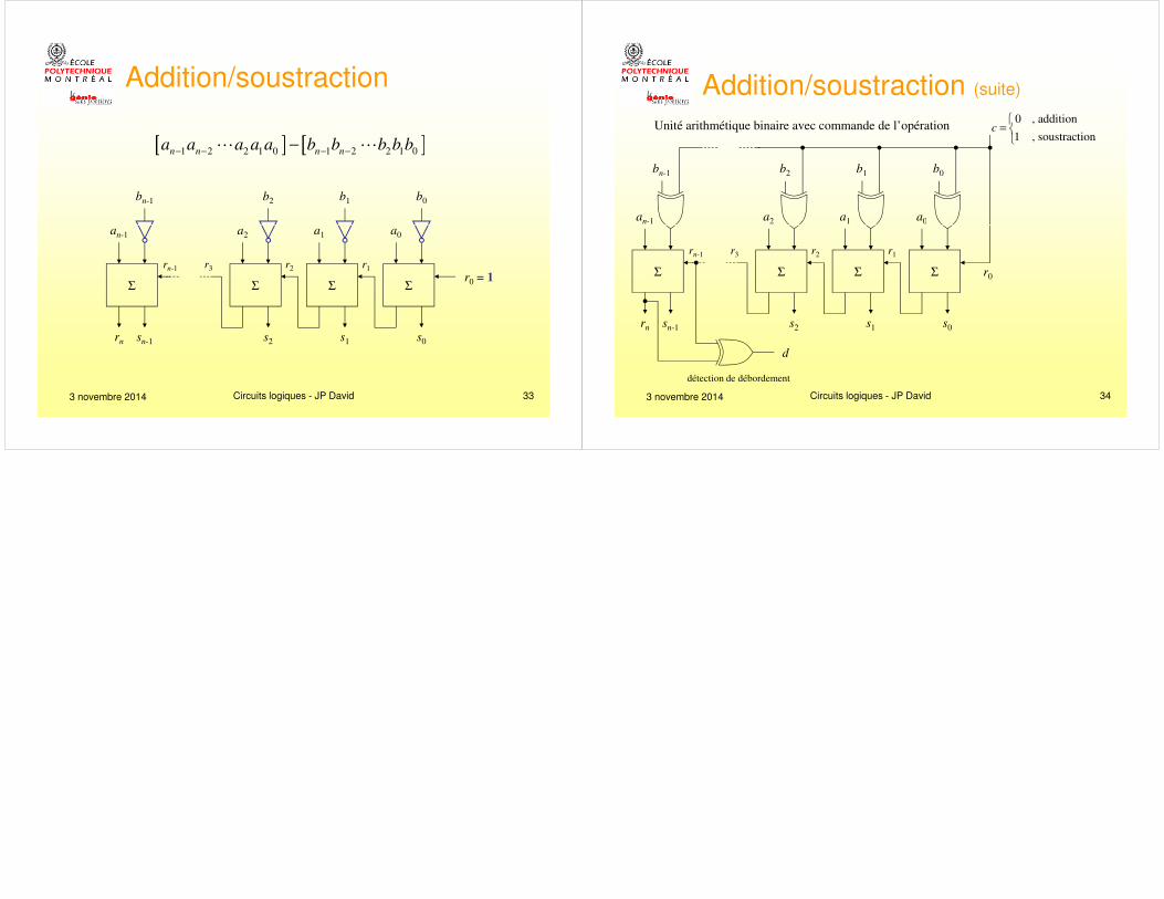
[ ] [ ]1 2 2 1 0 1 2 2 1 0n n n na a a a a b b b b b
− − − −−� �
a
b0
a
b1
a
b2bn-1
a
Addition/soustraction
3 novembre 2014 Circuits logiques - JP David 33
ΣΣΣΣ
a0a1a2an-1
s0s1s2sn-1rn
r0 = 1r2 r1rn-1 r3
Unité arithmétique binaire avec commande de l’opération
a0
b0
a1
b1
a2
b2bn-1
an-1
0 , addition
1 , soustractionc
=
Addition/soustraction (suite)
3 novembre 2014 Circuits logiques - JP David 34
ΣΣΣΣ
s0s1s2sn-1rn
r0
r2 r1rn-1 r3
d
détection de débordement