avk vanne combinÉe À 3 voies 18/80 - static.pumplastiques.fr · • Étanchéité conforme à la...
TRANSCRIPT
DROITS D'AUTEUR © AVK GROUP A/S 2011 / AVK France S.A.S. Version n°
AVK France S.A.S.4 rue de la GarbotièreCS 290441029 Blois CedexFranceTél.: 02 54 74 23 13E-mail : [email protected]
AVK VANNE COMBINÉE À 3 VOIES 18/80
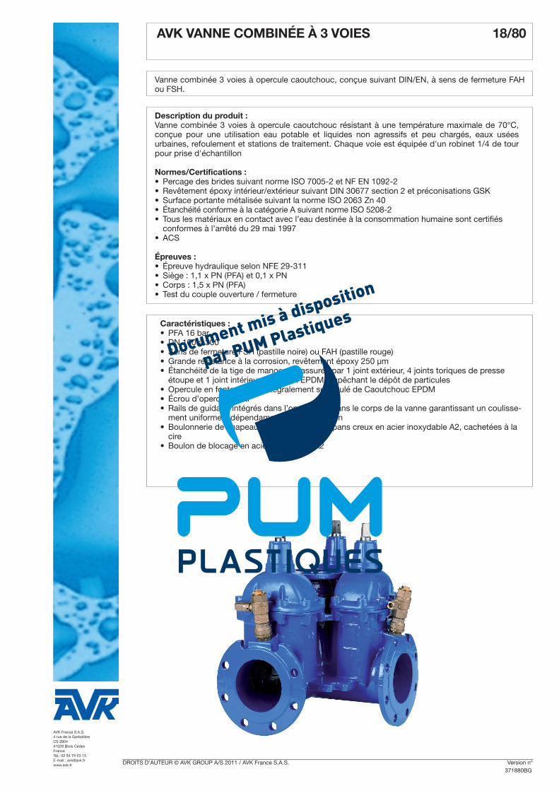
Vanne combinée 3 voies à opercule caoutchouc, conçue suivant DIN/EN, à sens de fermeture FAH ou FSH.
Description du produit :Vanne combinée 3 voies à opercule caoutchouc résistant à une température maximale de 70°C, conçue pour une utilisation eau potable et liquides non agressifs et peu chargés, eaux usées urbaines, refoulement et stations de traitement. Chaque voie est équipée d'un robinet 1/4 de tour pour prise d'échantillon
Normes/Certifications : •Percage des brides suivant norme ISO 7005-2 et NF EN 1092-2• Revêtement époxy intérieur/extérieur suivant DIN 30677 section 2 et préconisations GSK•Surface portante métalisée suivant la norme ISO 2063 Zn 40• Étanchéité conforme à la catégorie A suivant norme ISO 5208-2• Tous les matériaux en contact avec l’eau destinée à la consommation humaine sont certifiés
conformes à l’arrêté du 29 mai 1997•ACS
Épreuves :• Épreuve hydraulique selon NFE 29-311•Siège : 1,1 x PN (PFA) et 0,1 x PN•Corps : 1,5 x PN (PFA) • Test du couple ouverture / fermeture
Caractéristiques :•PFA 16 bar•DN 100 à 300•Sens de fermeture FSH (pastille noire) ou FAH (pastille rouge)•Grande résistance à la corrosion, revêtement époxy 250 µm• Étanchéité de la tige de manoeuvre assurée par 1 joint extérieur, 4 joints toriques de presse
étoupe et 1 joint intérieur à lèvre en EPDM empêchant le dépôt de particules•Opercule en fonte ductile intégralement surmoulé de Caoutchouc EPDM• Écrou d’opercule serti •Rails de guidage intégrés dans l’opercule et dans le corps de la vanne garantissant un coulisse-
ment uniforme indépendamment de la pression •Boulonnerie de chapeau constituée de vis 6 pans creux en acier inoxydable A2, cachetées à la
cire•Boulon de blocage en acier inoxydable A2
371880BG
Se reporter à la section "informations techniques" pour toute information complémentaire.Les designs, matériaux et spécifications présentés peuvent être modifiés sans préavis en fonction des évolutions techniques.
AVK COMBI-CROSS, 3 OUTLETS, PN 10/16, CTC 18/80003
2
L2
L3
L1
ds
1
2
3
4
5
6
7
8
9
10
11
12
13
14
H
H1
L
F
F1
F2
D
A
B
C
Component list1. Stem2. NBR wiper ring3. NBR O-ring4. Plastic bearing5. Bonnet6. Thrust collar7. EPDM rubber manchette8. Bonnet bolts9. Bonnet gasket10. Outlet for service valve11. Wedge nut12. Center outlet gasket13. Wedge14. Valve body
A. Stem sealingThree independent stem seals offering triple safety:• A NBR wiper ring protects against dirt from outside.• A polyamid bearing with 4 NBR O-rings protects
against galvanic corrosion.• An EPDM rubber manchette sealing acts as the
main hydraulic seal to the flow.
B. Body/bonnet connectionThe unique assembly of the valve body and bonnetensures a durable tightness:• A round rubber bonnet gasket fits into a recess in
the valve bonnet preventing it from being blown outby pressure surges.
• The stainless steel bonnet bolts are countersunk inthe valve bonnet, encircled by the bonnet gasketand sealed with hot melt. Thus there is no risk ofcorrosion as the bolts are not exposed to themedium or soil.
C. Wedge nutThe fixed, integral wedge nut reduces the number ofmovable valve parts thus minimizing the risk ofcorrosion and malfunction. The wedge nut is made ofdezincification resistant brass with lubricating abilitiesproviding optimum compatibility with the stainlesssteel stem.
D. Vulcanized wedgeThe ductile iron core is fully vulcanized with drinkingwater approved EPDM rubber internally andexternally. No iron parts are exposed to the mediumand the excellent rubber vulcanization preventscreeping corrosion underneath the rubber. Guides inthe wedge and on the valve body ensure a uniformclosure regardless of high pressure. Safe operation isensured, as the guides prevent overloading of thestem. The wedge has a large through bore and asthere are no hollows in the core, stagnant water orimpurities cannot collect and cause contamination.
L2
P1
L1
27 mm
1
2
3
4
5
6
7
8
9
10
11
12
13
14
H
H1
L
F
F1
F2
D
A
B
C
Reference nos. and dimensions
AVK ref. nos.DN mm
PN drilling bar
Lmm
L1mm
L2mm
Hmm
H1mm
P1mm
Fmm
F1mm
F2mm
Theoreticalweight kg
18-100-80011 #) 100 10/16 580 340 312 305 237 240 19 22 38 9018-150-80011 #) 150 10/16 620 372 360 452 298 263 19 22 38 16518-200-80001 #) 200 10 750 468 445 596 370 331 24 28 42 28018-200-80011 #) 200 16 750 468 445 596 370 331 24 28 42 28018-250-80006 #) 250 10 960 656 617 664 375 464 27 31 47 45018-250-80016 #) 250 16 960 656 617 664 375 464 27 31 47 45018-300-80006 #) 300 10 1050 702 617 740 480 496 27 31 47 62018-300-80016 #) 300 16 1050 702 617 740 480 496 27 31 47 620
# With ball valves and DN 100 center outlet
AVK VANNE À COMBINÉE À 3 VOIES 18/80
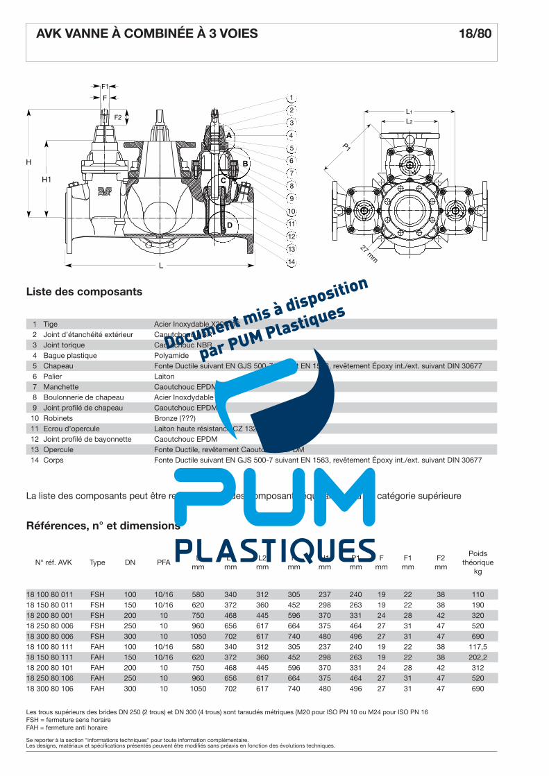
Références, n° et dimensions
Liste des composants
La liste des composants peut être remplacée par des composants équivalents ou de catégorie supérieure
1 Tige Acier Inoxydable X20Cr132 Joint d’étanchéité extérieur Caoutchouc NBR3 Joint torique Caoutchouc NBR4 Bague plastique Polyamide5 Chapeau Fonte Ductile suivant EN GJS 500-7 suivant EN 1563, revêtement Époxy int./ext. suivant DIN 306776 Palier Laiton7 Manchette Caoutchouc EPDM8 Boulonnerie de chapeau Acier Inoxdydable9 Joint profilé de chapeau Caoutchouc EPDM10 Robinets Bronze (???)11 Ecrou d’opercule Laiton haute résistance CZ 132 suivant BS 287412 Joint profilé de bayonnette Caoutchouc EPDM13 Opercule Fonte Ductile, revêtement Caoutchouc EPDM14 Corps Fonte Ductile suivant EN GJS 500-7 suivant EN 1563, revêtement Époxy int./ext. suivant DIN 30677
Les trous supérieurs des brides DN 250 (2 trous) et DN 300 (4 trous) sont taraudés métriques (M20 pour ISO PN 10 ou M24 pour ISO PN 16FSH = fermeture sens horaireFAH = fermeture anti horaire
AVK COMBI-CROSS, 3 OUTLETS, PN 10/16, CTC 18/80003
2
L2
L3
L1
ds
1
2
3
4
5
6
7
8
9
10
11
12
13
14
H
H1
L
F
F1
F2
D
A
B
C
Component list1. Stem2. NBR wiper ring3. NBR O-ring4. Plastic bearing5. Bonnet6. Thrust collar7. EPDM rubber manchette8. Bonnet bolts9. Bonnet gasket10. Outlet for service valve11. Wedge nut12. Center outlet gasket13. Wedge14. Valve body
A. Stem sealingThree independent stem seals offering triple safety:• A NBR wiper ring protects against dirt from outside.• A polyamid bearing with 4 NBR O-rings protects
against galvanic corrosion.• An EPDM rubber manchette sealing acts as the
main hydraulic seal to the flow.
B. Body/bonnet connectionThe unique assembly of the valve body and bonnetensures a durable tightness:• A round rubber bonnet gasket fits into a recess in
the valve bonnet preventing it from being blown outby pressure surges.
• The stainless steel bonnet bolts are countersunk inthe valve bonnet, encircled by the bonnet gasketand sealed with hot melt. Thus there is no risk ofcorrosion as the bolts are not exposed to themedium or soil.
C. Wedge nutThe fixed, integral wedge nut reduces the number ofmovable valve parts thus minimizing the risk ofcorrosion and malfunction. The wedge nut is made ofdezincification resistant brass with lubricating abilitiesproviding optimum compatibility with the stainlesssteel stem.
D. Vulcanized wedgeThe ductile iron core is fully vulcanized with drinkingwater approved EPDM rubber internally andexternally. No iron parts are exposed to the mediumand the excellent rubber vulcanization preventscreeping corrosion underneath the rubber. Guides inthe wedge and on the valve body ensure a uniformclosure regardless of high pressure. Safe operation isensured, as the guides prevent overloading of thestem. The wedge has a large through bore and asthere are no hollows in the core, stagnant water orimpurities cannot collect and cause contamination.
L2
P1
L1
27 mm
1
2
3
4
5
6
7
8
9
10
11
12
13
14
H
H1
L
F
F1
F2
D
A
B
C
Reference nos. and dimensions
AVK ref. nos.DN mm
PN drilling bar
Lmm
L1mm
L2mm
Hmm
H1mm
P1mm
Fmm
F1mm
F2mm
Theoreticalweight kg
18-100-80011 #) 100 10/16 580 340 312 305 237 240 19 22 38 9018-150-80011 #) 150 10/16 620 372 360 452 298 263 19 22 38 16518-200-80001 #) 200 10 750 468 445 596 370 331 24 28 42 28018-200-80011 #) 200 16 750 468 445 596 370 331 24 28 42 28018-250-80006 #) 250 10 960 656 617 664 375 464 27 31 47 45018-250-80016 #) 250 16 960 656 617 664 375 464 27 31 47 45018-300-80006 #) 300 10 1050 702 617 740 480 496 27 31 47 62018-300-80016 #) 300 16 1050 702 617 740 480 496 27 31 47 620
# With ball valves and DN 100 center outlet
N° réf. AVK Type DN PFAL
mmL1
mmL2
mmH
mmH1mm
P1mm
Fmm
F1mm
F2mm
Poids théorique
kg
18 100 80 011 FSH 100 10/16 580 340 312 305 237 240 19 22 38 11018 150 80 011 FSH 150 10/16 620 372 360 452 298 263 19 22 38 19018 200 80 001 FSH 200 10 750 468 445 596 370 331 24 28 42 32018 250 80 006 FSH 250 10 960 656 617 664 375 464 27 31 47 52018 300 80 006 FSH 300 10 1050 702 617 740 480 496 27 31 47 69018 100 80 111 FAH 100 10/16 580 340 312 305 237 240 19 22 38 117,518 150 80 111 FAH 150 10/16 620 372 360 452 298 263 19 22 38 202,218 200 80 101 FAH 200 10 750 468 445 596 370 331 24 28 42 31218 250 80 106 FAH 250 10 960 656 617 664 375 464 27 31 47 52018 300 80 106 FAH 300 10 1050 702 617 740 480 496 27 31 47 690