pm700 trilingual.book page 1 monday, april 12, 2004 9:47 ... aparaty nn/mierniki analizatory...
TRANSCRIPT

Power MeterCentrale de mesureCentral de medidaPM700Retain for future use.À conserver pour une utilisation ultérieureConsérvese para futuras consultas.
Instruction BulletinManuel d’utilisationManual de instrucciones
PM700 Trilingual.book Page 1 Monday, April 12, 2004 9:47 AM

PM700 Trilingual.book Page 2 Monday, April 12, 2004 9:47 AM
ENG
LISH
ESPA
ÑO
LFR
AN
ÇA
IS
EnglishHazard Categories and Special Symbols. . . . . . . . . . . . . . . . . . . . . . . . . . . . . . . . . . . 1Table of Contents . . . . . . . . . . . . . . . . . . . . . . . . . . . . . . . . . . . . . . . . . . . . . . . . . . . . 3
EspañolCategorías de riesgos y símbolos especiales . . . . . . . . . . . . . . . . . . . . . . . . . . . . . . 61Índice . . . . . . . . . . . . . . . . . . . . . . . . . . . . . . . . . . . . . . . . . . . . . . . . . . . . . . . . . . . . . 63
FrançaisCatégories de dangers et symboles spéciaux . . . . . . . . . . . . . . . . . . . . . . . . . . . . . 123Table des matières . . . . . . . . . . . . . . . . . . . . . . . . . . . . . . . . . . . . . . . . . . . . . . . . . 125
PM700 Trilingual.book Page 3 Monday, April 12, 2004 9:47 AM

PM700 Trilingual.book Page 4 Monday, April 12, 2004 9:47 AM
© 2004 Schneider Electric. All Rights Reserved.
ENG
LISH
1
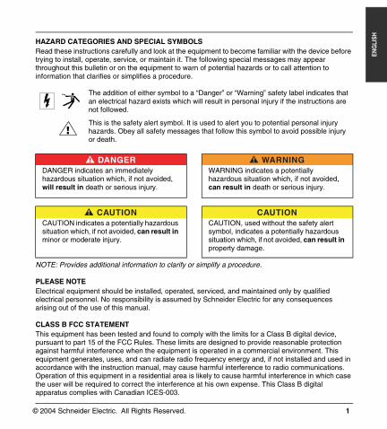
CHAPTER 1 — HAZARD CATEGORIES AND SPECIAL SYMBOLSHAZARD CATEGORIES AND SPECIAL SYMBOLSRead these instructions carefully and look at the equipment to become familiar with the device before trying to install, operate, service, or maintain it. The following special messages may appear throughout this bulletin or on the equipment to warn of potential hazards or to call attention to information that clarifies or simplifies a procedure.
NOTE: Provides additional information to clarify or simplify a procedure.
PLEASE NOTEElectrical equipment should be installed, operated, serviced, and maintained only by qualified electrical personnel. No responsibility is assumed by Schneider Electric for any consequences arising out of the use of this manual.
CLASS B FCC STATEMENTThis equipment has been tested and found to comply with the limits for a Class B digital device, pursuant to part 15 of the FCC Rules. These limits are designed to provide reasonable protection against harmful interference when the equipment is operated in a commercial environment. This equipment generates, uses, and can radiate radio frequency energy and, if not installed and used in accordance with the instruction manual, may cause harmful interference to radio communications. Operation of this equipment in a residential area is likely to cause harmful interference in which case the user will be required to correct the interference at his own expense. This Class B digital apparatus complies with Canadian ICES-003.
The addition of either symbol to a “Danger” or “Warning” safety label indicates that an electrical hazard exists which will result in personal injury if the instructions are not followed.
This is the safety alert symbol. It is used to alert you to potential personal injury hazards. Obey all safety messages that follow this symbol to avoid possible injury or death.
DANGERDANGER indicates an immediately hazardous situation which, if not avoided, will result in death or serious injury.
WARNINGWARNING indicates a potentially hazardous situation which, if not avoided, can result in death or serious injury.
CAUTIONCAUTION indicates a potentially hazardous situation which, if not avoided, can result in minor or moderate injury.
CAUTIONCAUTION, used without the safety alert symbol, indicates a potentially hazardous situation which, if not avoided, can result in property damage.
PM700 Trilingual.book Page 1 Monday, April 12, 2004 9:47 AM

ENG
LISH
© 2004 Schneider Electric. All Rights Reserved.2
PM700 Trilingual.book Page 2 Monday, April 12, 2004 9:47 AM
© 2004 Schneider Electric. All Rights Reserved.
63230-501-201A3 Chapter 1 — Table of Contents4/2004
3
ENG
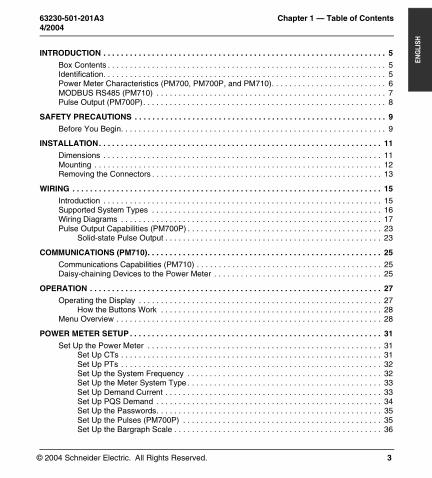
LISHCHAPTER 1 — TABLE OF CONTENTS
INTRODUCTION . . . . . . . . . . . . . . . . . . . . . . . . . . . . . . . . . . . . . . . . . . . . . . . . . . . . . . . . . . . . . . . . 5
Box Contents . . . . . . . . . . . . . . . . . . . . . . . . . . . . . . . . . . . . . . . . . . . . . . . . . . . . . . . . . . . . . . . 5Identification. . . . . . . . . . . . . . . . . . . . . . . . . . . . . . . . . . . . . . . . . . . . . . . . . . . . . . . . . . . . . . . . 5Power Meter Characteristics (PM700, PM700P, and PM710). . . . . . . . . . . . . . . . . . . . . . . . . . 6MODBUS RS485 (PM710) . . . . . . . . . . . . . . . . . . . . . . . . . . . . . . . . . . . . . . . . . . . . . . . . . . . . 7Pulse Output (PM700P). . . . . . . . . . . . . . . . . . . . . . . . . . . . . . . . . . . . . . . . . . . . . . . . . . . . . . . 8
SAFETY PRECAUTIONS . . . . . . . . . . . . . . . . . . . . . . . . . . . . . . . . . . . . . . . . . . . . . . . . . . . . . . . . . 9
Before You Begin. . . . . . . . . . . . . . . . . . . . . . . . . . . . . . . . . . . . . . . . . . . . . . . . . . . . . . . . . . . . 9
INSTALLATION. . . . . . . . . . . . . . . . . . . . . . . . . . . . . . . . . . . . . . . . . . . . . . . . . . . . . . . . . . . . . . . . 11
Dimensions . . . . . . . . . . . . . . . . . . . . . . . . . . . . . . . . . . . . . . . . . . . . . . . . . . . . . . . . . . . . . . . 11Mounting . . . . . . . . . . . . . . . . . . . . . . . . . . . . . . . . . . . . . . . . . . . . . . . . . . . . . . . . . . . . . . . . . 12Removing the Connectors . . . . . . . . . . . . . . . . . . . . . . . . . . . . . . . . . . . . . . . . . . . . . . . . . . . . 13
WIRING . . . . . . . . . . . . . . . . . . . . . . . . . . . . . . . . . . . . . . . . . . . . . . . . . . . . . . . . . . . . . . . . . . . . . . 15
Introduction . . . . . . . . . . . . . . . . . . . . . . . . . . . . . . . . . . . . . . . . . . . . . . . . . . . . . . . . . . . . . . . 15Supported System Types . . . . . . . . . . . . . . . . . . . . . . . . . . . . . . . . . . . . . . . . . . . . . . . . . . . . 16Wiring Diagrams . . . . . . . . . . . . . . . . . . . . . . . . . . . . . . . . . . . . . . . . . . . . . . . . . . . . . . . . . . . 17Pulse Output Capabilities (PM700P) . . . . . . . . . . . . . . . . . . . . . . . . . . . . . . . . . . . . . . . . . . . . 23
Solid-state Pulse Output . . . . . . . . . . . . . . . . . . . . . . . . . . . . . . . . . . . . . . . . . . . . . . . . . 23
COMMUNICATIONS (PM710). . . . . . . . . . . . . . . . . . . . . . . . . . . . . . . . . . . . . . . . . . . . . . . . . . . . . 25
Communications Capabilities (PM710) . . . . . . . . . . . . . . . . . . . . . . . . . . . . . . . . . . . . . . . . . . 25Daisy-chaining Devices to the Power Meter . . . . . . . . . . . . . . . . . . . . . . . . . . . . . . . . . . . . . . 25
OPERATION . . . . . . . . . . . . . . . . . . . . . . . . . . . . . . . . . . . . . . . . . . . . . . . . . . . . . . . . . . . . . . . . . . 27
Operating the Display . . . . . . . . . . . . . . . . . . . . . . . . . . . . . . . . . . . . . . . . . . . . . . . . . . . . . . . 27How the Buttons Work . . . . . . . . . . . . . . . . . . . . . . . . . . . . . . . . . . . . . . . . . . . . . . . . . . 28
Menu Overview . . . . . . . . . . . . . . . . . . . . . . . . . . . . . . . . . . . . . . . . . . . . . . . . . . . . . . . . . . . . 28
POWER METER SETUP . . . . . . . . . . . . . . . . . . . . . . . . . . . . . . . . . . . . . . . . . . . . . . . . . . . . . . . . . 31
Set Up the Power Meter . . . . . . . . . . . . . . . . . . . . . . . . . . . . . . . . . . . . . . . . . . . . . . . . . . . . . 31Set Up CTs . . . . . . . . . . . . . . . . . . . . . . . . . . . . . . . . . . . . . . . . . . . . . . . . . . . . . . . . . . . 31Set Up PTs . . . . . . . . . . . . . . . . . . . . . . . . . . . . . . . . . . . . . . . . . . . . . . . . . . . . . . . . . . . 32Set Up the System Frequency . . . . . . . . . . . . . . . . . . . . . . . . . . . . . . . . . . . . . . . . . . . . 32Set Up the Meter System Type . . . . . . . . . . . . . . . . . . . . . . . . . . . . . . . . . . . . . . . . . . . . 33Set Up Demand Current . . . . . . . . . . . . . . . . . . . . . . . . . . . . . . . . . . . . . . . . . . . . . . . . . 33Set Up PQS Demand . . . . . . . . . . . . . . . . . . . . . . . . . . . . . . . . . . . . . . . . . . . . . . . . . . . 34Set Up the Passwords. . . . . . . . . . . . . . . . . . . . . . . . . . . . . . . . . . . . . . . . . . . . . . . . . . . 35Set Up the Pulses (PM700P) . . . . . . . . . . . . . . . . . . . . . . . . . . . . . . . . . . . . . . . . . . . . . 35Set Up the Bargraph Scale . . . . . . . . . . . . . . . . . . . . . . . . . . . . . . . . . . . . . . . . . . . . . . . 36
PM700 Trilingual.book Page 3 Monday, April 12, 2004 9:47 AM

© 2004 Schneider Electric. All Rights Reserved.
Chapter 1 — Table of Contents 63230-501-201A34/2004
4
ENG
LISH
Set Up Communications (PM710). . . . . . . . . . . . . . . . . . . . . . . . . . . . . . . . . . . . . . . . . . 36Select the Operating Mode . . . . . . . . . . . . . . . . . . . . . . . . . . . . . . . . . . . . . . . . . . . . . . . 37
Power Meter Diagnostics. . . . . . . . . . . . . . . . . . . . . . . . . . . . . . . . . . . . . . . . . . . . . . . . . . . . . 37View the Meter Information . . . . . . . . . . . . . . . . . . . . . . . . . . . . . . . . . . . . . . . . . . . . . . . 37Check the Health Status . . . . . . . . . . . . . . . . . . . . . . . . . . . . . . . . . . . . . . . . . . . . . . . . . 38
Reset the Power Meter . . . . . . . . . . . . . . . . . . . . . . . . . . . . . . . . . . . . . . . . . . . . . . . . . . . . . . 38Restore Power Meter Default Settings . . . . . . . . . . . . . . . . . . . . . . . . . . . . . . . . . . . . . . 38
MAINTENANCE AND TROUBLESHOOTING . . . . . . . . . . . . . . . . . . . . . . . . . . . . . . . . . . . . . . . . 39
Introduction . . . . . . . . . . . . . . . . . . . . . . . . . . . . . . . . . . . . . . . . . . . . . . . . . . . . . . . . . . . . . . . 39Getting Technical Support . . . . . . . . . . . . . . . . . . . . . . . . . . . . . . . . . . . . . . . . . . . . . . . . . . . . 39Troubleshooting . . . . . . . . . . . . . . . . . . . . . . . . . . . . . . . . . . . . . . . . . . . . . . . . . . . . . . . . . . . . 39
SPECIFICATIONS . . . . . . . . . . . . . . . . . . . . . . . . . . . . . . . . . . . . . . . . . . . . . . . . . . . . . . . . . . . . . . 41
Power Meter Specifications . . . . . . . . . . . . . . . . . . . . . . . . . . . . . . . . . . . . . . . . . . . . . . . . . . . 41
GLOSSARY . . . . . . . . . . . . . . . . . . . . . . . . . . . . . . . . . . . . . . . . . . . . . . . . . . . . . . . . . . . . . . . . . . . 45
Glossary. . . . . . . . . . . . . . . . . . . . . . . . . . . . . . . . . . . . . . . . . . . . . . . . . . . . . . . . . . . . . . . . . . 45Abbreviations and Symbols . . . . . . . . . . . . . . . . . . . . . . . . . . . . . . . . . . . . . . . . . . . . . . . . . . . 47
REGISTER LIST . . . . . . . . . . . . . . . . . . . . . . . . . . . . . . . . . . . . . . . . . . . . . . . . . . . . . . . . . . . . . . . 51
Register List. . . . . . . . . . . . . . . . . . . . . . . . . . . . . . . . . . . . . . . . . . . . . . . . . . . . . . . . . . . . . . . 51Supported MODBUS Commands . . . . . . . . . . . . . . . . . . . . . . . . . . . . . . . . . . . . . . . . . . . . . . 58
INDEX . . . . . . . . . . . . . . . . . . . . . . . . . . . . . . . . . . . . . . . . . . . . . . . . . . . . . . . . . . . . . . . . . . . . . . . 59
PM700 Trilingual.book Page 4 Monday, April 12, 2004 9:47 AM
© 2004 Schneider Electric. All Rights Reserved.
63230-501-201A3 Chapter 1 — Introduction4/2004 Box Contents
5
ENG
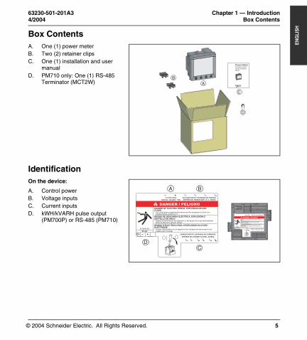
LISHCHAPTER 1 — INTRODUCTIONBox Contents
Identification
A. One (1) power meterB. Two (2) retainer clipsC. One (1) installation and user
manualD. PM710 only: One (1) RS-485
Terminator (MCT2W)
On the device:
A. Control powerB. Voltage inputsC. Current inputsD. kWH/kVARH pulse output
(PM700P) or RS-485 (PM710)
Power Meter Centrale de mesureCentral de medidaPM700
AB
C
D
+
2-
CURRENT INPUTS / ENTRADAS DE CORRIENTE
ENTRÉES DE COURANT 5A NOM. / 6A MAX.
1-I1+ I 2+I I 3-3-3+I I
A B
CD
RISQUE D'ÉLECTROCUTION, D'EXPLOSION OU D'ARC
RIESGO DE DESCARGA ELÉCTRICA, EXPLOSIÓN O
HAZARD OF ELECTRIC SHOCK, EXPLOSION OR ARC
50/60 Hz / 125-250V 3W
ELECTRIQUE
RS 485
DESTELLO DE ARCO
FLASH
115-415V 5VA+ V
ENTRÉES DE TENSION 480V L L 50/60Hz
1V V2 3 VN
Turn off all power supplying this device and the equipment in which it is
Z103904-0A
Apague la alimentación del dispositivo y del equipo en el que está instalado
Coupez l'alimentation de cet appareil et de l'équipement dans lequel il est installé avant travailler.
installed before working on it.
VOLTAGE INPUTS / ENTRADAS DE TENSIÓN
antes de efectuar cualquier trabajo.
RISQUE D'ÉLECTROCUTION, D'EXPLOSION OU D'ARC
RIESGO DE DESCARGA ELÉCTRICA, EXPLOSIÓN O
HAZARD OF ELECTRIC SHOCK, EXPLOSION OR ARC
50/60 Hz / 125-250V 3W
ELECTRIQUE
RS 485
+
DESTELLO DE ARCO
FLASH
115-415V 5VA+
CURRENT INPUTS / ENTRADAS DE CORRIENTE
ENTRÉES DE COURANT 5A NOM. / 6A MAX.
I I I I I I
V
ENTRÉES DE TENSION 480V L L 50/60Hz
1V V2 3 VN
Turn off all power supplying this device and the equipment in which it is
Z103904-0A
Apague la alimentación del dispositivo y del equipo en el que está instalado
Coupez l'alimentation de cet appareil et de l'équipement dans lequel il est installé avant travailler.
installed before working on it.
VOLTAGE INPUTS / ENTRADAS DE TENSIÓN
antes de efectuar cualquier trabajo.
2-1-1+ 2+ 3-3+
PM700 Trilingual.book Page 5 Monday, April 12, 2004 9:47 AM
© 2004 Schneider Electric. All Rights Reserved.
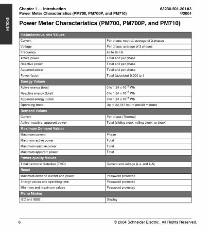
Chapter 1 — Introduction 63230-501-201A3Power Meter Characteristics (PM700, PM700P, and PM710) 4/2004
6
ENG
LISH
Power Meter Characteristics (PM700, PM700P, and PM710)
Instantaneous rms Values
Current Per phase, neutral, average of 3 phases
Voltage Per phase, average of 3 phases
Frequency 45 to 65 Hz
Active power Total and per phase
Reactive power Total and per phase
Apparent power Total and per phase
Power factor Total (absolute) 0.000 to 1
Energy Values
Active energy (total) 0 to 1.84 x 10¹⁸ Wh
Reactive energy (total) 0 to 1.84 x 10¹⁸ Wh
Apparent energy (total) 0 to 1.84 x 10¹⁸ Wh
Operating times Up to 32,767 hours and 59 minutes
Demand Values
Current Per phase (Thermal)
Active, reactive, apparent power Total (sliding block, rolling block, or block)
Maximum Demand Values
Maximum current Phase
Maximum active power Total
Maximum reactive power Total
Maximum apparent power Total
Power-quality Values
Total harmonic distortion (THD) Current and voltage (L-L and L-N)
Reset
Maximum demand current and power Password protected
Energy values and operating time Password protected
Minimum and maximum values Password protected
Menu Modes
IEC and IEEE Display
PM700 Trilingual.book Page 6 Monday, April 12, 2004 9:47 AM
© 2004 Schneider Electric. All Rights Reserved.
63230-501-201A3 Chapter 1 — Introduction4/2004 MODBUS RS485 (PM710)
7
ENG
LISH
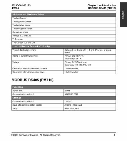
MODBUS RS485 (PM710)
Minimum and Maximum Values
Total real power
Total apparent power
Total reactive power
Total PF (power factor)
Current per phase
Voltage (L-L and L-N)
THD current
THD voltage (L-L and L-N)
Local or Remote Setup (PM710 only)
Type of distribution system 3-phase 3- or 4-wire with 1, 2, or 3 CTs, two- or single-phase
Rating of current transformers Primary 5 to 32,767 ASecondary 5 or 1 A
Voltage Primary 3,276,700 V maxSecondary 100, 110, 115, 120
Calculation interval for demand currents 1 to 60 minutes
Calculation interval for demand power 1 to 60 minutes
Functions
RS485 link 2-wire
Communication protocol MODBUS RTU
Settings
Communication address 1 to 247
Baud rate (communication speed) 2400 to 19200 baud
Parity none, even, odd
PM700 Trilingual.book Page 7 Monday, April 12, 2004 9:47 AM
© 2004 Schneider Electric. All Rights Reserved.
Chapter 1 — Introduction 63230-501-201A3Pulse Output (PM700P) 4/2004
8
ENG
LISH
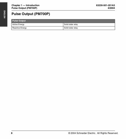
Pulse Output (PM700P)
Pulse Output
Active Energy Solid state relay
Reactive Energy Solid state relay
PM700 Trilingual.book Page 8 Monday, April 12, 2004 9:47 AM
© 2004 Schneider Electric. All Rights Reserved.
63230-501-201A3 Chapter 2 — Safety Precautions4/2004 Before You Begin
9
ENG
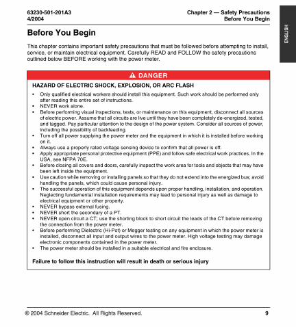
LISHCHAPTER 2 — SAFETY PRECAUTIONSBefore You Begin
This chapter contains important safety precautions that must be followed before attempting to install, service, or maintain electrical equipment. Carefully READ and FOLLOW the safety precautions outlined below BEFORE working with the power meter.
DANGER
HAZARD OF ELECTRIC SHOCK, EXPLOSION, OR ARC FLASH
• Only qualified electrical workers should install this equipment. Such work should be performed only after reading this entire set of instructions.
• NEVER work alone.• Before performing visual inspections, tests, or maintenance on this equipment, disconnect all sources
of electric power. Assume that all circuits are live until they have been completely de-energized, tested, and tagged. Pay particular attention to the design of the power system. Consider all sources of power, including the possibility of backfeeding.
• Turn off all power supplying the power meter and the equipment in which it is installed before working on it.
• Always use a properly rated voltage sensing device to confirm that all power is off.• Apply appropriate personal protective equipment (PPE) and follow safe electrical work practices. In the
USA, see NFPA 70E.• Before closing all covers and doors, carefully inspect the work area for tools and objects that may have
been left inside the equipment. • Use caution while removing or installing panels so that they do not extend into the energized bus; avoid
handling the panels, which could cause personal injury.• The successful operation of this equipment depends upon proper handling, installation, and operation.
Neglecting fundamental installation requirements may lead to personal injury as well as damage to electrical equipment or other property.
• NEVER bypass external fusing.• NEVER short the secondary of a PT.• NEVER open circuit a CT; use the shorting block to short circuit the leads of the CT before removing
the connection from the power meter.• Before performing Dielectric (Hi-Pot) or Megger testing on any equipment in which the power meter is
installed, disconnect all input and output wires to the power meter. High voltage testing may damage electronic components contained in the power meter.
• The power meter should be installed in a suitable electrical and fire enclosure.
Failure to follow this instruction will result in death or serious injury
PM700 Trilingual.book Page 9 Monday, April 12, 2004 9:47 AM

© 2004 Schneider Electric. All Rights Reserved.
Chapter 2 — Safety Precautions 63230-501-201A3Before You Begin 4/2004
10
ENG
LISH
PM700 Trilingual.book Page 10 Monday, April 12, 2004 9:47 AM
© 2004 Schneider Electric. All Rights Reserved.
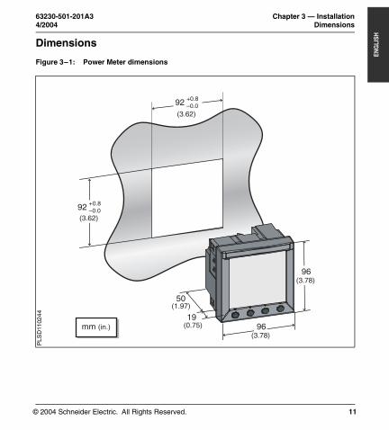
63230-501-201A3 Chapter 3 — Installation4/2004 Dimensions
11
ENG
LISHCHAPTER 3 — INSTALLATIONDimensions
Figure 3–1: Power Meter dimensions
(3.62)
92 +0.8–0.0
92 +0.8–0.0
(3.62)
mm (in.)19
50(1.97)
(0.75)
96(3.78)
96(3.78)
PLS
D11
024
4
PM700 Trilingual.book Page 11 Monday, April 12, 2004 9:47 AM
© 2004 Schneider Electric. All Rights Reserved.
Chapter 3 — Installation 63230-501-201A3Mounting 4/2004
12
ENG
LISH
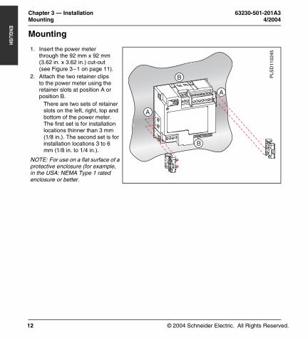
Mounting
1. Insert the power meter through the 92 mm x 92 mm (3.62 in. x 3.62 in.) cut-out (see Figure 3–1 on page 11).
2. Attach the two retainer clips to the power meter using the retainer slots at position A or position B.
There are two sets of retainer slots on the left, right, top and bottom of the power meter. The first set is for installation locations thinner than 3 mm (1/8 in.). The second set is for installation locations 3 to 6 mm (1/8 in. to 1/4 in.).
NOTE: For use on a flat surface of a protective enclosure (for example, in the USA: NEMA Type 1 rated enclosure or better.
B
A
A
B
PLS
D11
024
5
PM700 Trilingual.book Page 12 Monday, April 12, 2004 9:47 AM
© 2004 Schneider Electric. All Rights Reserved.
63230-501-201A3 Chapter 3 — Installation4/2004 Removing the Connectors
13
ENG
LISH
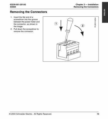
Removing the Connectors
1. Insert the flat end of a screwdriver into the groove between the power meter and the connector, as shown in the image.
2. Pull down the screwdriver to remove the connector.
12 P
LSD
110
254
PM700 Trilingual.book Page 13 Monday, April 12, 2004 9:47 AM
© 2004 Schneider Electric. All Rights Reserved.
Chapter 3 — Installation 63230-501-201A3Removing the Connectors 4/2004
14
ENG
LISH
PM700 Trilingual.book Page 14 Monday, April 12, 2004 9:47 AM
© 2004 Schneider Electric. All Rights Reserved.
63230-501-201A3 Chapter 4 — Wiring4/2004 Introduction
15
ENG
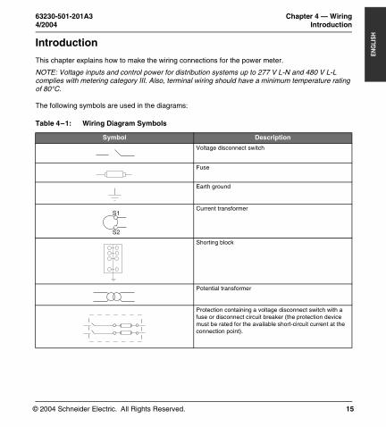
LISHCHAPTER 4 — WIRINGIntroduction
This chapter explains how to make the wiring connections for the power meter.
NOTE: Voltage inputs and control power for distribution systems up to 277 V L-N and 480 V L-L complies with metering category III. Also, terminal wiring should have a minimum temperature rating of 80°C.
The following symbols are used in the diagrams:
Table 4–1: Wiring Diagram Symbols
Symbol Description
Voltage disconnect switch
Fuse
Earth ground
Current transformer
Shorting block
Potential transformer
Protection containing a voltage disconnect switch with a fuse or disconnect circuit breaker (the protection device must be rated for the available short-circuit current at the connection point).
S2
S1
PM700 Trilingual.book Page 15 Monday, April 12, 2004 9:47 AM
© 2004 Schneider Electric. All Rights Reserved.
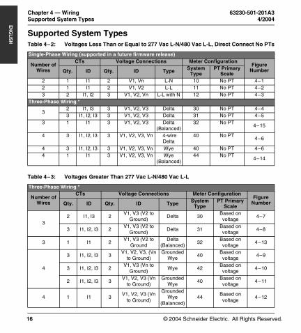
Chapter 4 — Wiring 63230-501-201A3Supported System Types 4/2004
16
ENG
LISH
Supported System TypesTable 4–2: Voltages Less Than or Equal to 277 Vac L-N/480 Vac L-L, Direct Connect No PTs
Single-Phase Wiring (supported in a future firmware release)
Number of Wires
CTs Voltage Connections Meter ConfigurationFigure
NumberQty. ID Qty. ID Type System Type
PT Primary Scale
2 1 I1 2 V1, Vn L-N 10 No PT 4–12 1 I1 2 V1, V2 L-L 11 No PT 4–23 2 I1, I2 3 V1, V2, Vn L-L with N 12 No PT 4–3
Three-Phase Wiring *
32 I1, I3 3 V1, V2, V3 Delta 30 No PT 4–43 I1, I2, I3 3 V1, V2, V3 Delta 31 No PT 4–5
3 1 I1 3 V1, V2, V3 Delta (Balanced)
32 No PT4–15
4 3 I1, I2, I3 3 V1, V2, V3, Vn 4-wire Delta
40 No PT4–6
4 3 I1, I2, I3 3 V1, V2, V3, Vn Wye 40 No PT 4–64 1 I1 3 V1, V2, V3, Vn Wye
(Balanced)44 No PT
4–14
Table 4–3: Voltages Greater Than 277 Vac L-N/480 Vac L-L
Three-Phase Wiring *
Number of Wires
CTs Voltage Connections Meter ConfigurationFigure
NumberQty. ID Qty. ID Type System Type
PT Primary Scale
32 I1, I3 2
V1, V3 (V2 to Ground)
Delta 30Based on voltage
4–7
3 I1, I2, I3 2V1, V3 (V2 to
Ground)Delta 31
Based on voltage
4–8
3 1 I1 2V1, V3 (V2 to
GroundDelta
(Balanced)32
Based on voltage
4–13
4
3 I1, I2, I3 3V1, V2, V3, (Vn
to Ground)Grounded
Wye40
Based on voltage
4–9
3 I1, I2, I3 2V1, V3 (Vn to
Ground)Wye 42
Based on voltage
4–10
2 I1, I2, I3 3V1, V2, V3 (Vn
to Ground)Grounded
Wye40
Based on voltage
4–11
4 1 I1 3V1, V2, V3 (Vn
to Ground)
Grounded Wye
(Balanced)44
Based on voltage
4–12
PM700 Trilingual.book Page 16 Monday, April 12, 2004 9:47 AM

© 2004 Schneider Electric. All Rights Reserved.
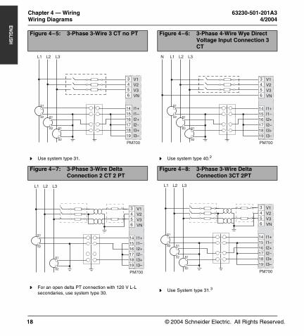
63230-501-201A3 Chapter 4 — Wiring4/2004 Wiring Diagrams
17
ENG
LISH
Wiring DiagramsFigure 4–1: 1-Phase Line-to-Neutral 2-
Wire System 1 CTFigure 4–2: 1-Phase Line-to-Line 2-Wire
System 1 CT
Use system type 10.1 Use system type 11.1
Figure 4–3: 1-Phase Direct Voltage Connection 2 CT
Figure 4–4: 3-Phase 3-Wire 2 CT no PT
Use system type 12.1 Use system type 30.
N L1
S2
S1
V1V2V3VN
I1+I1–I2+I2–I3+I3–
3456
14 15 16 17 18 19
PM700
L1 L2
VL-L <= 480V
S2
S1
PM700
V1V2V3VN
I1+I1–I2+I2–I3+I3–
3456
14 15 16 17 18 19
L1 L2
S2
S1
S2
S1
PM700
V1V2V3VN
I1+I1–I2+I2–I3+I3–
3456
14 15 16 17 18 19
N L2 L3L1
S2
S1
S2
S1
PM700
V1V2V3VN
I1+I1–I2+I2–I3+I3–
3456
14 15 16 17 18 19
PM700 Trilingual.book Page 17 Monday, April 12, 2004 9:47 AM
© 2004 Schneider Electric. All Rights Reserved.
Chapter 4 — Wiring 63230-501-201A3Wiring Diagrams 4/2004
18
ENG
LISH
Figure 4–5: 3-Phase 3-Wire 3 CT no PT Figure 4–6: 3-Phase 4-Wire Wye Direct Voltage Input Connection 3 CT
Use system type 31. Use system type 40.2
Figure 4–7: 3-Phase 3-Wire Delta Connection 2 CT 2 PT
Figure 4–8: 3-Phase 3-Wire Delta Connection 3CT 2PT
For an open delta PT connection with 120 V L-L secondaries, use system type 30.
Use System type 31.3
L2 L3L1
S2
S1
S2
S1S2
S1
PM700
V1V2V3VN
I1+I1–I2+I2–I3+I3–
3456
14 15 16 17 18 19
L2 L3L1N
S2
S1
S2
S1S2
S1
PM700
V1V2V3VN
I1+I1–I2+I2–I3+I3–
3456
14 15 16 17 18 19
L2 L3L1
S2
S1
S2
S1
PM700
V1V2V3VN
I1+I1–I2+I2–I3+I3–
3456
14 15 16 17 18 19
L2 L3L1
S2
S1
S2
S1S2
S1
PM700
V1V2V3VN
I1+I1–I2+I2–I3+I3–
3456
14 15 16 17 18 19
PM700 Trilingual.book Page 18 Monday, April 12, 2004 9:47 AM
© 2004 Schneider Electric. All Rights Reserved.
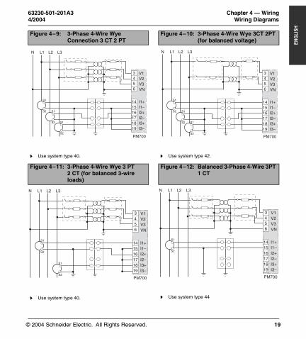
63230-501-201A3 Chapter 4 — Wiring4/2004 Wiring Diagrams
19
ENG
LISH
Figure 4–9: 3-Phase 4-Wire Wye Connection 3 CT 2 PT
Figure 4–10: 3-Phase 4-Wire Wye 3CT 2PT (for balanced voltage)
Use system type 40. Use system type 42.
Figure 4–11: 3-Phase 4-Wire Wye 3 PT 2 CT (for balanced 3-wire loads)
Figure 4–12: Balanced 3-Phase 4-Wire 3PT 1 CT
Use system type 40. Use system type 44
L2 L3L1N
S2
S1
S2
S1S2
S1
PM700
V1V2V3VN
I1+I1–I2+I2–I3+I3–
3456
14 15 16 17 18 19
L2 L3L1N
S2
S1
S2
S1S2
S1
PM700
V1V2V3VN
I1+I1–I2+I2–I3+I3–
3456
14 15 16 17 18 19
L2 L3L1N
S2
S1
S2
S1
PM700
V1V2V3VN
I1+I1–I2+I2–I3+I3–
3456
14 15 16 17 18 19
L2 L3L1N
S2
S1
PM700
V1V2V3VN
I1+I1–I2+I2–I3+I3–
3456
14 15 16 17 18 19
PM700 Trilingual.book Page 19 Monday, April 12, 2004 9:47 AM

© 2004 Schneider Electric. All Rights Reserved.
Chapter 4 — Wiring 63230-501-201A3Wiring Diagrams 4/2004
20
ENG
LISH
Figure 4–13: Balanced 3-Phase 3-Wire 1 CT 2 PT
Figure 4–14: Balanced 3-Phase 4-Wire Direct Voltage Input Connection 1 CT
Use system type 32 Use system type 44
Figure 4–15: Balanced 3-Phase 3-Wire Direct Voltage Input Connection 1 CT
Use system type 32
L2 L3L1
S2
S1
PM700
V1V2V3VN
I1+I1–I2+I2–I3+I3–
3456
14 15 16 17 18 19
L2 L3L1N
S2
S1
PM700
V1V2V3VN
I1+I1–I2+I2–I3+I3–
3456
14 15 16 17 18 19
L2 L3L1
S2
S1
PM700
V1V2V3VN
I1+I1–I2+I2–I3+I3–
3456
14 15 16 17 18 19
PM700 Trilingual.book Page 20 Monday, April 12, 2004 9:47 AM
© 2004 Schneider Electric. All Rights Reserved.
63230-501-201A3 Chapter 4 — Wiring4/2004 Wiring Diagrams
21
ENG
LISH
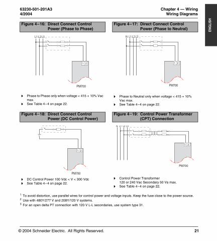
1 To avoid distortion, use parallel wires for control power and voltage inputs. Keep the fuse close to the power source.2 Use with 480Y/277 V and 208Y/120 V systems.3 For an open delta PT connection with 120 V L-L secondaries, use system type 31.
Figure 4–16: Direct Connect Control Power (Phase to Phase)
Figure 4–17: Direct Connect Control Power (Phase to Neutral)
Phase to Phase only when voltage < 415 + 10% Vac max.
See Table 4–4 on page 22.
Phase to Neutral only when voltage < 415 + 10% Vac max.
See Table 4–4 on page 22.
Figure 4–18: Direct Connect Control Power (DC Control Power)
Figure 4–19: Control Power Transformer (CPT) Connection
DC Control Power 100 Vdc < V < 300 Vdc See Table 4–4 on page 22.
Control Power Transformer120 or 240 Vac Secondary 50 Va max.
See Table 4–4 on page 22.
L1 L2 L3
1 2
PM700
L1 L2 L3N
1 2
PM700
PM700
1 2
L1 L2 L3N
PM700
1 2
PM700 Trilingual.book Page 21 Monday, April 12, 2004 9:47 AM
© 2004 Schneider Electric. All Rights Reserved.
Chapter 4 — Wiring 63230-501-201A3Wiring Diagrams 4/2004
22
ENG
LISH
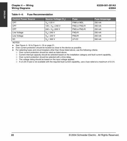
Table 4–4: Fuse Recommendation
Control Power Source Source Voltage (Vs) Fuse Fuse Amperage
CPT Vs ≤125 V FNM or MDL 250 mA
CPT 125 < Vs ≤ 240 V FNQ or FNQ-R 250 mA
CPT 240 < Vs ≤305 V FNQ or FNQ-R 250 mA
Line Voltage Vs ≤ 240 V FNQ-R 250 mA
Line Voltage Vs > 240 V FNQ-R 250 mA
DC Vs ≤ 300 V LP-CC 500 mA
NOTES: See Figure 4–16 to Figure 4–19 on page 21. Over current protection should be located as close to the device as possible. For selecting fuses and circuit breakers other than those listed above, use the following criteria:
Over current protection should be rated as listed above. Current interrupt capacity should be selected based on the installation category and fault current capability. Over current protection should be selected with a time delay. The voltage rating should be based on the input voltage applied. If a 0.25 A fuse is not available with the required fault current capability, use a fuse rated at a maximum of 0.5 A.
PM700 Trilingual.book Page 22 Monday, April 12, 2004 9:47 AM

© 2004 Schneider Electric. All Rights Reserved.
63230-501-201A3 Chapter 4 — Wiring4/2004 Pulse Output Capabilities (PM700P)
23
ENG
LISH
Pulse Output Capabilities (PM700P)
Solid-state Pulse Output
There are two solid-state KY outputs. One is dedicated to kWH and the other is dedicated to kVARH.
Figure 4–1: Solid-state Outputs
*The power source should not be a safety extra low voltage (SELV) circuit. Pulse outputs are not SELV rated.
≤ 100 mA
~=
≤ 100 mA
~=
34
56
KWH KVARH
PM700P
Digital Output / Pulse OutputKY is a solid state pulse output rated for 240 Vac/dc max.
Maximum load current is 100 mA at 25°C. Derate 0.56 mA per °C above 25°C.
NOTE: The overcurrent protective device must be rated for the short circuit current at the connection point.
Overcurrent Protective Device (not supplied)
Power Source *3 - 240 Vdc6 - 240 Vac
Load
Load
Power Source *3 - 240 Vdc6 - 240 Vac
PM700 Trilingual.book Page 23 Monday, April 12, 2004 9:47 AM
© 2004 Schneider Electric. All Rights Reserved.
Chapter 4 — Wiring 63230-501-201A3Pulse Output Capabilities (PM700P) 4/2004
24
ENG
LISH
PM700 Trilingual.book Page 24 Monday, April 12, 2004 9:47 AM
© 2004 Schneider Electric. All Rights Reserved.
63230-501-201A3 Chapter 5 — Communications (PM710)4/2004 Communications Capabilities (PM710)
25
ENG
LISHCHAPTER 5 — COMMUNICATIONS (PM710)Communications Capabilities (PM710)
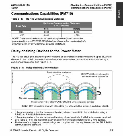
Daisy-chaining Devices to the Power Meter
The RS-485 slave port allows the power meter to be connected in a daisy chain with up to 31, 2-wire devices. In this bulletin, communications link refers to a chain of devices that are connected by a communications cable. See Figure 5–1.
• If the power meter is the first device on the daisy chain, connect it to the host device using a RS-232 to RS-422/RS-485 converter.
• If the power meter is the last device on the daisy chain, terminate it with the terminator provided.• See Table 5–1 for the maximum daisy-chain communications distances for 2-wire devices.• The terminal’s voltage and current ratings are compliant with the requirements of the EIA RS-485
communications standard.
Table 5–1: RS-485 Communications Distances
Baud RateMaximum Communication Distances
1 to 32 Devices
Feet Meters
9600 8,000 2,438
19200 6,000 1,829
NOTE: Distances listed should be used as a guide only and cannot be guaranteed for non-POWERLOGIC devices. Refer to the master device’s documentation for any additional distance limitations.
Figure 5–1: Daisy-chaining 2-wire devices
–+
Power Meter 710 or other POWERLOGIC 2-wire compatible devices
Belden 9841 or equivalent
Belden 9841 wire colors: blue with white stripe (+), white with blue stripe (–), and silver (shield)
MCT2W-485 terminator on the last device of the daisy chain
PLS
D11
0087
Not used
PM700 Trilingual.book Page 25 Monday, April 12, 2004 9:47 AM

© 2004 Schneider Electric. All Rights Reserved.
Chapter 5 — Communications (PM710) 63230-501-201A3Daisy-chaining Devices to the Power Meter 4/2004
26
ENG
LISH
PM700 Trilingual.book Page 26 Monday, April 12, 2004 9:47 AM
© 2004 Schneider Electric. All Rights Reserved.
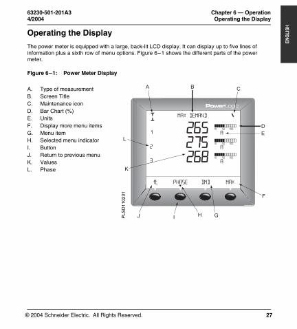
63230-501-201A3 Chapter 6 — Operation4/2004 Operating the Display
27
ENG
LISHCHAPTER 6 — OPERATIONOperating the Display
The power meter is equipped with a large, back-lit LCD display. It can display up to five lines of information plus a sixth row of menu options. Figure 6–1 shows the different parts of the power meter.
Figure 6–1: Power Meter Display
A. Type of measurementB. Screen TitleC. Maintenance iconD. Bar Chart (%) E. UnitsF. Display more menu itemsG. Menu itemH. Selected menu indicatorI. ButtonJ. Return to previous menuK. ValuesL. Phase
PHASE
MAX DEMAND
1
1; DMD MAX
265275268
2.4
A
A
A
! &
2
3
N
I
A
10 50 100
10 50 100
10 50 100
%
A B C
D
F
GHJ
K
L
I
E
PLS
D1
1023
1
PM700 Trilingual.book Page 27 Monday, April 12, 2004 9:47 AM
© 2004 Schneider Electric. All Rights Reserved.
Chapter 6 — Operation 63230-501-201A3Menu Overview 4/2004
28
ENG
LISH
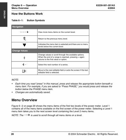
How the Buttons Work
NOTE:
• Each time you read “press” in this manual, press and release the appropriate button beneath a menu item. For example, if you are asked to “Press PHASE,” you would press and release the button below the PHASE menu item.
• Changes are automatically saved.
Menu Overview
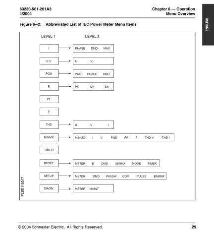
Figure 6–2 on page 29 shows the menu items of the first two levels of the power meter. Level 1 contains all of the menu items available on the first screen of the power meter. Selecting a Level 1 menu item takes you to the next screen level containing the Level 2 menu items.
NOTE: The ###: is used to scroll through all menu items on a level.
Table 6–1: Button Symbols
Navigation
---> View more menu items on the current level.
1; Return to the previous menu level.
^Indicates the menu item is selected and there are no menu levels below the current level.
Change Values
+Change values or scroll through the available options. When the end of a range is reached, pressing + again returns to the first value or option.
<- Select the next number of a series.
OKMove to the next editable field or exits the screen if the last editable field is selected.
PM700 Trilingual.book Page 28 Monday, April 12, 2004 9:47 AM
© 2004 Schneider Electric. All Rights Reserved.
63230-501-201A3 Chapter 6 — Operation4/2004 Menu Overview
29
ENG
LISH
Figure 6–2: Abbreviated List of IEC Power Meter Menu Items
PHASE DMD MAX
U V
Ph Qh Sh
PQS PHASE DMD
U V I
MINMX I V PQS PF F THD V THD I
METER DMD PASSW COM PULSE BARGR
METER MAINT
U-V
PQS
E
PF
F
THD
MINMX
TIMER
RESET
SETUP
DIAGN.
METER E DMD MINMX MODE TIMER
I
LEVEL 1 LEVEL 2
PLS
D11
0247
PM700 Trilingual.book Page 29 Monday, April 12, 2004 9:47 AM

© 2004 Schneider Electric. All Rights Reserved.
Chapter 6 — Operation 63230-501-201A3Menu Overview 4/2004
30
ENG
LISH
PM700 Trilingual.book Page 30 Monday, April 12, 2004 9:47 AM

© 2004 Schneider Electric. All Rights Reserved.
63230-501-201A3 Chapter 7 — Power Meter Setup4/2004 Set Up the Power Meter
31
ENG
LISHCHAPTER 7 — POWER METER SETUPSet Up the Power Meter
To begin power meter setup, do the following:
1. Press ###: until you see SETUP.2. Press SETUP.3. Enter your password.
NOTE: The default password is 00000.
Set Up CTs
1. Press ###: until METER is visible.
2. Press METER.3. Press CT.4. Enter the PRIM CT (primary
CT) number: 1 to 32762.5. Press OK.6. Enter the SECON. CT
(secondary CT) number: 1 or 5.
7. Press OK.8. Press 1; to return to the
SETUP MODE screen.<-
CT RATIO
1; + OK
8005
PRIM
SECON.
C T
C T
PLS
D11
010
6
PM700 Trilingual.book Page 31 Monday, April 12, 2004 9:47 AM
© 2004 Schneider Electric. All Rights Reserved.
Chapter 7 — Power Meter Setup 63230-501-201A3Set Up the Power Meter 4/2004
32
ENG
LISH
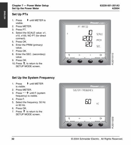
Set Up PTs
Set Up the System Frequency
1. Press ###: until METER is visible.
2. Press METER.3. Press PT.4. Select the SCALE value: x1,
x10, x100, NO PT (for direct connect).
5. Press OK.6. Enter the PRIM (primary)
value.7. Press OK.8. Enter the SEC. (secondary)
value.9. Press OK.10. Press 1; to return to the
SETUP MODE screen.
1. Press ###: until METER is visible.
2. Press METER.3. Press ###: until F (system
frequency) is visible.4. Press F.5. Select the frequency: 50 Hz
or 60 Hz.6. Press OK.7. Press 1; to return to the
SETUP MODE screen.
<-
PT RATIO
1; + OK
1200120
PRIM
SEC.
X SCALE10
PLS
D11
011
2
<-
SYSTEM Frequency
1; + OK
6060
Hz
FREQ.
&
PLS
D11
0232
PM700 Trilingual.book Page 32 Monday, April 12, 2004 9:47 AM
© 2004 Schneider Electric. All Rights Reserved.
63230-501-201A3 Chapter 7 — Power Meter Setup4/2004 Set Up the Power Meter
33
ENG
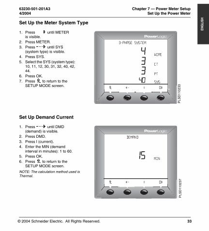
LISHSet Up the Meter System Type
Set Up Demand Current
1. Press ###: until METER is visible.
2. Press METER.3. Press ###: until SYS
(system type) is visible.4. Press SYS.5. Select the SYS (system type):
10, 11, 12, 30, 31, 32, 40, 42, 44.
6. Press OK.7. Press 1; to return to the
SETUP MODE screen.
1. Press ###: until DMD (demand) is visible.
2. Press DMD.3. Press I (current).4. Enter the MIN (demand
interval in minutes): 1 to 60.5. Press OK.6. Press 1; to return to the
SETUP MODE screen.
NOTE: The calculation method used is Thermal.
<-
3-PHASE SYSTEM
1; + OK
&
43340
CT
PT
SYS
Wire
PLS
D11
0233
<-
DEMAND
1; + OK
10015100
0.1
MIN
MSEC
KVARH
&
MSEC
PLS
D11
0237
PM700 Trilingual.book Page 33 Monday, April 12, 2004 9:47 AM
© 2004 Schneider Electric. All Rights Reserved.
Chapter 7 — Power Meter Setup 63230-501-201A3Set Up the Power Meter 4/2004
34
ENG
LISH
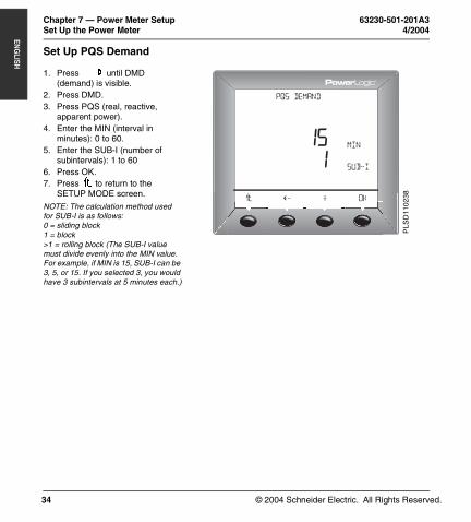
Set Up PQS Demand
1. Press ###: until DMD (demand) is visible.
2. Press DMD.3. Press PQS (real, reactive,
apparent power).4. Enter the MIN (interval in
minutes): 0 to 60.5. Enter the SUB-I (number of
subintervals): 1 to 606. Press OK.7. Press 1; to return to the
SETUP MODE screen.NOTE: The calculation method used for SUB-I is as follows:0 = sliding block1 = block>1 = rolling block (The SUB-I value must divide evenly into the MIN value. For example, if MIN is 15, SUB-I can be 3, 5, or 15. If you selected 3, you would have 3 subintervals at 5 minutes each.)
<-
PQS DEMAND
1; + OK
1001510.1
MIN
SUB-i
KVARH
&
MSEC
I
PLS
D11
0238
PM700 Trilingual.book Page 34 Monday, April 12, 2004 9:47 AM
© 2004 Schneider Electric. All Rights Reserved.
63230-501-201A3 Chapter 7 — Power Meter Setup4/2004 Set Up the Power Meter
35
ENG
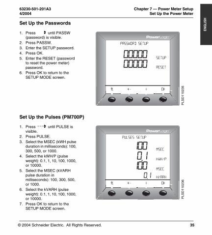
LISHSet Up the Passwords
Set Up the Pulses (PM700P)
1. Press ###: until PASSW (password) is visible.
2. Press PASSW.3. Enter the SETUP password.4. Press OK.5. Enter the RESET (password
to reset the power meter) password.
6. Press OK to return to the SETUP MODE screen.
1. Press ###: until PULSE is visible.
2. Press PULSE.3. Select the MSEC (kWH pulse
duration in milliseconds): 100, 300, 500, or 1000.
4. Select the kWH/P (pulse weight): 0.1, 1, 10, 100, 1000, or 10000.
5. Select the MSEC (kVARH pulse duration in milliseconds): 100, 300, 500, or 1000.
6. Select the kVARH (pulse weight): 0.1, 1, 10, 100, 1000, or 10000.
7. Press OK to return to the SETUP MODE screen.
<-
PASSWORD SETUP
1; + OK
0000000000
00000
DIAG.
RESET
MIN.MX
&
00000 SETUP
PLS
D11
0235
<-
PULSES SETUP
1; + OK
1000.1100
0.1
KWH/P
MSEC
KVARH
&
MSEC
PLS
D11
023
6
PM700 Trilingual.book Page 35 Monday, April 12, 2004 9:47 AM
© 2004 Schneider Electric. All Rights Reserved.
Chapter 7 — Power Meter Setup 63230-501-201A3Set Up the Power Meter 4/2004
36
ENG
LISH
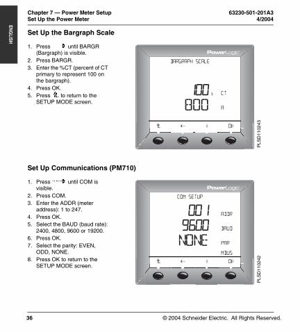
Set Up the Bargraph Scale
Set Up Communications (PM710)
1. Press ###: until BARGR (Bargraph) is visible.
2. Press BARGR.3. Enter the %CT (percent of CT
primary to represent 100 on the bargraph).
4. Press OK.5. Press 1; to return to the
SETUP MODE screen.
1. Press ###: until COM is visible.
2. Press COM.3. Enter the ADDR (meter
address): 1 to 247.4. Press OK.5. Select the BAUD (baud rate):
2400, 4800, 9600 or 19200.6. Press OK.7. Select the parity: EVEN,
ODD, NONE.8. Press OK to return to the
SETUP MODE screen.
<-
BARGRAPH SCALE
1; + OK
100800
CT
A
mbus
ADDR001%
PL
SD
1102
43<-
COM SETUP
1; + OK
9600nOnE
bauD
Par
mbus
ADDR001
PL
SD
1102
42
PM700 Trilingual.book Page 36 Monday, April 12, 2004 9:47 AM
© 2004 Schneider Electric. All Rights Reserved.
63230-501-201A3 Chapter 7 — Power Meter Setup4/2004 Power Meter Diagnostics
37
ENG
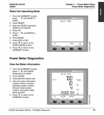
LISHSelect the Operating Mode
Power Meter Diagnostics
View the Meter Information
1. From the SUMMARY screen, press ###: until RESET is visible.
2. Press RESET.3. Enter the RESET password
(00000 is the default).4. Press OK.5. Press ###: until MODE is
visible.6. Press MODE.7. Press IEEE or IEC.8. Press 1; to return to the
RESET MODE screen.9. Press 1; to return to the
SUMMARY screen.
1. From the SUMMARY screen, press ###: until DIAGN (diagnostics) is visible.
2. Press DIAGN.3. Press METER (meter info).4. View the meter information
(model number, firmware operating system version, firmware reset system version, and power meter serial number).
5. Press 1; to return to the SUMMARY screen.
SELECT MODE
1; IEEE IEC
PL
SD
1102
52
METER
METER INFO
P M
1; MAINT
700104
25000193
0.5.
R.S.
S.N.
&
MODEL
^
PL
SD
1102
39
PM700 Trilingual.book Page 37 Monday, April 12, 2004 9:47 AM

© 2004 Schneider Electric. All Rights Reserved.
Chapter 7 — Power Meter Setup 63230-501-201A3Reset the Power Meter 4/2004
38
ENG
LISH
Check the Health Status
Reset the Power Meter
Restore Power Meter Default Settings
1. Press ###: until DIAGN (diagnostics) is visible.
2. Press DIAGN.3. Press MAINT (maintenance).4. View the health status.5. Press 1; to return to the
SUMMARY screen.
NOTE: The wrench icon and the health status code displays when a health problem is detected.
1. From the SUMMARY screen, press ###: until RESET is visible.
2. Press RESET.3. Enter the RESET password
(00000 is the default).4. Press OK.5. Press ###: until METER is
visible.6. Press METER.7. Press NO or YES.8. Press 1; to return to the
SUMMARY screen.
METER
HEALTH STATUS
1; MAINT MAINT
OK
&
PLS
D11
0240
INIT METER?
No Yes
PLS
D11
0253
PM700 Trilingual.book Page 38 Monday, April 12, 2004 9:47 AM
© 2004 Schneider Electric. All Rights Reserved.
63230-501-201A3 Chapter 8 — Maintenance and Troubleshooting4/2004 Introduction
39
ENG
LISHCHAPTER 8 — MAINTENANCE AND TROUBLESHOOTINGIntroduction
The power meter does not contain any user-serviceable parts. If the power meter requires service, contact your local sales representative. Do not open the power meter. Opening the power meter voids the warranty.
Getting Technical Support
Please refer to the Technical Support Contacts provided in the power meter shipping carton for a list of support phone numbers by country.
Troubleshooting
The information in Table 8–1 describes potential problems and their possible causes. It also describes checks you can perform or possible solutions for each. After referring to this table, if you cannot resolve the problem, contact the your local Square D/Schneider Electric sales representative for assistance.
DANGERHAZARD OF ELECTRIC SHOCK, EXPLOSION, OR ARC FLASH
• This equipment must be installed and serviced only by qualified electrical personnel.• Turn off all power supplying this equipment before working on or inside.• Always use a properly rated voltage sensing device to confirm that all power is off.• Apply appropriate personal protective equipment (PPE) and follow safe electrical work practices. See
NFPA 70E.• Carefully inspect the work area for tools and objects that may have been left inside the equipment. • Use caution while removing or installing panels so that they do not extend into the energized bus; avoid
handling the panels, which could cause personal injury.
Failure to follow this instruction will result in death or serious injury
PM700 Trilingual.book Page 39 Monday, April 12, 2004 9:47 AM

© 2004 Schneider Electric. All Rights Reserved.
Chapter 8 — Maintenance and Troubleshooting 63230-501-201A3Troubleshooting 4/2004
40
ENG
LISH
Table 8–1: Troubleshooting
Potential Problem Possible Cause Possible Solution
The maintenance icon is illuminated on the power meter display.
When the maintenance icon is illuminated, it indicates a potential hardware or firmware problem in the power meter.
When the maintenance icon is illuminated, go to DIAGNOSTICS > MAINTENANCE. Error messages display to indicate the reason the icon is illuminated. Note these error messages and call Technical Support or contact your local sales representative for assistance.
The display is blank after applying control power to the power meter.
The power meter may not be receiving the necessary power.
• Verify that the power meter line (L) and neutral (N) terminals (terminals 25 and 27) are receiving the necessary power.
• Verify that the heartbeat LED is blinking.• Check the fuse.
The data being displayed is inaccurate or not what you expect.
Incorrect setup values. Check that the correct values have been entered for power meter setup parameters (CT and PT ratings, System Type, Nominal Frequency, and so on). See “Set Up the Power Meter” on page 31 for setup instructions.
Incorrect voltage inputs. Check power meter voltage input terminals to verify that adequate voltage is present.
Power meter is wired improperly. Check that all CTs and PTs are connected correctly (proper polarity is observed) and that they are energized. Check shorting terminals. See “Wiring Diagrams” on page 17. Initiate a wiring check from the power meter display.
Cannot communicate with power meter from a remote personal computer.
Power meter address is incorrect. Check to see that the power meter is correctly addressed. See “Set Up Communications (PM710)” on page 36 for instructions.
Power meter baud rate is incorrect. Verify that the baud rate of the power meter matches the baud rate of all other devices on its communications link. See “Set Up Communications (PM710)” on page 36 for instructions.
Communications lines are improperly connected.
Verify the power meter communications connections. Refer to the Communications chapter for instructions.
Communications lines are improperly terminated.
Check to see that a multipoint communications terminator is properly installed. See Figure 5–1 on page 25for instructions.
Incorrect route statement to power meter.
Check the route statement. Refer to the SMS online help for instructions on defining route statements.
PM700 Trilingual.book Page 40 Monday, April 12, 2004 9:47 AM
© 2004 Schneider Electric. All Rights Reserved.
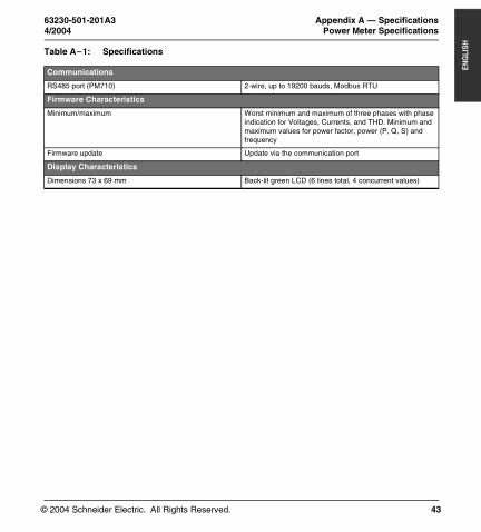
63230-501-201A3 Appendix A — Specifications4/2004 Power Meter Specifications
41
ENG
LISHAPPENDIX A — SPECIFICATIONSPower Meter Specifications
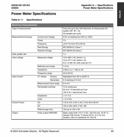
Table A–1: Specifications
Electrical Characteristics
Type of measurement True rms up to the 15th harmonic on three-phase AC system (3P, 3P + N)32 samples per cycle
Measurement Accuracy Current and Voltage 0.5% of reading from 20% to 120%
Power 1%
Frequency ±0.01 Hz from 45 to 65 Hz
Real Energy IEC 62053-21 Class 1
Reactive Energy IEC 62053-23 Class 2
Data update rate 1 s
Input-voltage Measured voltage 10 to 480 V AC (direct L-L)10 to 277 V AC (direct L-N)0 to 1.6 MV AC (with external VT)
Metering over-range 1.2 Un
Impedance 2 MΩ (L-L) / 1 MΩ (L-N)
Frequency range 45 to 65 Hz
Input-current CT ratings Primary Adjustable from 5A to 32767 A
Secondary 5 A starting at 10 mA
Measurement input range 0 to 6 A
Permissible overload 10 A continuous50 A for 10 seconds per hour120 A for 1 second per hour
Impedance < 0.1 2 Ω
Load < 0.15 VA
Control Power AC 115 to 415 ±10% V AC, 5 VA; 50 to 60 Hz
DC 125 to 250 ±20% V DC, 3W
Ride-through time 100 ms at 120 V AC
Output Pulse output (PM700P) Static output 240 ±10 % V AC, 100 mA max. @ 25 °C (derate 0.56 mA per °C above 25°C), 2.41 kV rms isolation, 30Ω on-resistance @ 100 mA
PM700 Trilingual.book Page 41 Monday, April 12, 2004 9:47 AM
© 2004 Schneider Electric. All Rights Reserved.
Appendix A — Specifications 63230-501-201A3Power Meter Specifications 4/2004
42
ENG
LISH
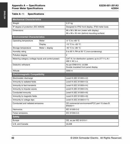
Mechanical Characteristics
Weight 0.37 kg
IP degree of protection (IEC 60529) Designed to IP52 front display, IP30 meter body
Dimensions 96 x 96 x 88 mm (meter with display)96 x 96 x 50 mm (behind mounting surface)
Environmental Characteristics
Operating temperature Meter -0 °C to +60 °C
Display -10 °C to +50 °C
Storage temperature Meter + display -40 °C to +85 °C
Humidity rating 5 to 95 % RH at 50 °C (non-condensing)
Pollution degree 2
Metering category (voltage inputs and control power) CAT III, for distribution systems up to 277 V L-N / 480 V AC L-L
Dielectric withstand As per EN61010, UL508Double insulated front panel display
Altitude 3000 m
Electromagnetic Compatibility
Electrostatic discharge Level III (IEC 61000-4-2)
Immunity to radiated fields Level III (IEC 61000-4-3)
Immunity to fast transients Level III (IEC 61000-4-4)
Immunity to impulse waves Level III (IEC 61000-4-5)
Conducted immunity Level III (IEC 61000-4-6)
Immunity to magnetic fields Level III (IEC 61000-4-8)
Immunity to voltage dips Level III (IEC 61000-4-11)
Conducted and radiated emissions CE commercial environment/FCC part 15 class B EN55011
Harmonics IEC 61000-3-2
Ficker emissions IEC 61000-3-3
Safety
Europe CE, as per IEC 61010-1
U.S. and Canada UL508
Table A–1: Specifications
PM700 Trilingual.book Page 42 Monday, April 12, 2004 9:47 AM
© 2004 Schneider Electric. All Rights Reserved.
63230-501-201A3 Appendix A — Specifications4/2004 Power Meter Specifications
43
ENG
LISH
Communications
RS485 port (PM710) 2-wire, up to 19200 bauds, Modbus RTU
Firmware Characteristics
Minimum/maximum Worst minimum and maximum of three phases with phase indication for Voltages, Currents, and THD. Minimum and maximum values for power factor, power (P, Q, S) and frequency
Firmware update Update via the communication port
Display Characteristics
Dimensions 73 x 69 mm Back-lit green LCD (6 lines total, 4 concurrent values)
Table A–1: Specifications
PM700 Trilingual.book Page 43 Monday, April 12, 2004 9:47 AM

© 2004 Schneider Electric. All Rights Reserved.
Appendix A — Specifications 63230-501-201A3Power Meter Specifications 4/2004
44
ENG
LISH
PM700 Trilingual.book Page 44 Monday, April 12, 2004 9:47 AM

© 2004 Schneider Electric. All Rights Reserved.
63230-501-201A3 Appendix B — Glossary4/2004 Glossary
45
ENG
LISHAPPENDIX B — GLOSSARYGlossary
accumulated energy—energy can accumulates in either signed or unsigned (absolute) mode. In signed mode, the direction of power flow is considered and the accumulated energy magnitude may increase and decrease. In absolute mode, energy accumulates as a positive regardless of the power flow direction.
baud rate—specifies how fast data is transmitted across a network port.
block interval demand— power demand calculation method for a block of time and includes three ways to apply calculating to that block of time using the sliding block, fixed block, or rolling block method.
communications link—a chain of devices connected by a communications cable to a communications port.
current transformer (CT)—current transformer for current inputs.
demand—average value of a quantity, such as power, over a specified interval of time.
device address—defines where the power meter resides in the power monitoring system.
event—the occurrence of an alarm condition, such as Undervoltage Phase A, configured in the power meter.
firmware—operating system within the power meter
fixed block—an interval selected from 1 to 60 minutes (in 1-minute increments). The power meter calculates and updates the demand at the end of each interval.
float—a 32-bit floating point value returned by a register (see Appendix C —Register List on page 51). The upper 16-bits are in the lowest-numbered register pair. For example, in the register 4010/11, 4010 contains the upper 16-bits while 4011 contains the lower 16-bits.
frequency—number of cycles in one second.
line-to-line voltages—measurement of the rms line-to-line voltages of the circuit.
line-to-neutral voltages—measurement of the rms line-to-neutral voltages of the circuit.
maximum demand current—highest demand current measured in amperes since the last reset of demand.
maximum demand real power—highest demand real power measured since the last rest of demand.
maximum demand voltage—highest demand voltage measured since the last reset of demand voltage.
PM700 Trilingual.book Page 45 Monday, April 12, 2004 9:47 AM
© 2004 Schneider Electric. All Rights Reserved.
Appendix B — Glossary 63230-501-201A3Glossary 4/2004
46
ENG
LISH
maximum demand—highest demand measured since the last reset of peak demand.
maximum value—highest value recorded of the instantaneous quantity such as Phase A Current, Phase A Voltage, etc., since the last reset of the minimums and maximums.
minimum value—lowest value recorded of the instantaneous quantity such as Phase A Current, Phase A Voltage, etc., since the last reset of the minimums and maximums.
nominal—typical or average.
parity—refers to binary numbers sent over the communications link. An extra bit is added so that the number of ones in the binary number is either even or odd, depending on your configuration). Used to detect errors in the transmission of data.
partial interval demand—calculation of energy thus far in a present interval. Equal to energy accumulated thus far in the interval divided by the length of the complete interval.
phase currents (rms)—measurement in amperes of the rms current for each of the three phases of the circuit. See also maximum value.
phase rotation—phase rotations refers to the order in which the instantaneous values of the voltages or currents of the system reach their maximum positive values. Two phase rotations are possible: A-B-C or A-C-B.
potential transformer (PT)—also known as a voltage transformer
power factor (PF)—true power factor is the ratio of real power to apparent power using the complete harmonic content of real and apparent power. Calculated by dividing watts by volt amperes. Power factor is the difference between the total power your utility delivers and the portion of total power that does useful work. Power factor is the degree to which voltage and current to a load are out of phase.
real power—calculation of the real power (3-phase total and per-phase real power calculated) to obtain kilowatts.
rms—root mean square. Power meters are true rms sensing devices.
rolling block—a selected interval and subinterval that the power meter uses for demand calculation. The subinterval must divide evenly into the interval. Demand is updated at each subinterval, and the power meter displays the demand value for the last completed interval.
scale factor—multipliers that the power meter uses to make values fit into the register where information is stored.
safety extra low voltage (SELV) circuit—a SELV circuit is expected to always be below a hazardous voltage level.
short integer—a signed 16-bit integer (see Appendix C —Register List on page 51).
PM700 Trilingual.book Page 46 Monday, April 12, 2004 9:47 AM
© 2004 Schneider Electric. All Rights Reserved.
63230-501-201A3 Appendix B — Glossary4/2004 Abbreviations and Symbols
47
ENG
LISH
Abbreviations and Symbols
sliding block—an interval selected from 1 to 60 minutes (in 1-minute increments). If the interval is between 1 and 15 minutes, the demand calculation updates every 15 seconds. If the interval is between 16 and 60 minutes, the demand calculation updates every 60 seconds. The power meter displays the demand value for the last completed interval.
SMS—see System Manager Software.
System Manager Software (SMS)—software designed by POWERLOGIC for use in evaluating power monitoring and control data.
system type—a unique code assigned to each type of system wiring configuration of the power meter.
thermal demand—demand calculation based on thermal response.
Total Harmonic Distortion (THD or thd)—indicates the degree to which the voltage or current signal is distorted in a circuit.
total power factor—see power factor.
true power factor—see power factor.
unsigned integer—an unsigned 16-bit integer (see Appendix C —Register List on page 51).
unsigned long integer—an unsigned 32-bit value returned by a register (see Appendix C —Register List on page 51). The upper 16-bits are in the lowest-numbered register pair. For example, in the register pair 4010 and 4011, 4010 contains the upper 16-bits while 4011 contains the lower 16-bits.
VAR—volt ampere reactive.
A—Ampere
ADDR—Power meter address
BARGR—Bargraph
COM—Communications
CPT—Control Power Transformer
CT—see current transformer on page 45
DMD—Demand
F—Frequency
PM700 Trilingual.book Page 47 Monday, April 12, 2004 9:47 AM

© 2004 Schneider Electric. All Rights Reserved.
Appendix B — Glossary 63230-501-201A3Abbreviations and Symbols 4/2004
48
ENG
LISH
I—Current
IMAX—Current maximum demand
kVA—Kilovolt-Ampere
kVAD—Kilovolt-Ampere demand
kVAR—Kilovolt-Ampere reactive
kVARD—Kilovolt-Ampere reactive demand
kVARH—Kilovolt-Ampere reactive hour
kW—Kilowatt
kWD—Kilowatt demand
kWH/P—Kilowatthours per pulse
KWMAX—Kilowatt maximum demand
MAINT—Maintenance screen
MBUS—MODBUS
MIN—Minimum
MINS—Minutes
MINMX—Minimum and maximum values
MSEC—Milliseconds
MVAh—Megavolt ampere hour
MVARh—Megavolt ampere reactive hour
MWh—Megawatt hour
O.S.—Operating System (firmware version)
P—Real power
PAR—Parity
PASSW—Password
Pd—Real power demand
PF—Power factor
Ph—Real energy
PM—Power meter
PM700 Trilingual.book Page 48 Monday, April 12, 2004 9:47 AM
© 2004 Schneider Electric. All Rights Reserved.
63230-501-201A3 Appendix B — Glossary4/2004 Abbreviations and Symbols
49
ENG
LISH
PQS—Real, reactive, apparent power
PQSd—Real, reactive, apparent power demand
PRIM—Primary
PT—Number of voltage connections (see potential transformer on page 46)
PULSE—Pulse
Q—Reactive power
Qd—Reactive power demand
Qh—Reactive energy
R.S.—Firmware reset system version
S—Apparent power
S.N.—Power meter serial number
SCALE—see scale factor on page 46
Sd—Apparent power demand
SECON—Secondary
SEC—Secondary
Sh—Apparent Energy
SUB-I—Subinterval
SYS—System Manager™ software (SMS) system type (ID)
U—Voltage line to line
V—Voltage
VMAX—Maximum voltage
VMIN—Minimum voltage
PM700 Trilingual.book Page 49 Monday, April 12, 2004 9:47 AM

© 2004 Schneider Electric. All Rights Reserved.
Appendix B — Glossary 63230-501-201A3Abbreviations and Symbols 4/2004
50
ENG
LISH
PM700 Trilingual.book Page 50 Monday, April 12, 2004 9:47 AM
© 2004 Schneider Electric. All Rights Reserved.
63230-501-201A3 Appendix C — Register List4/2004 Register List
51
ENG
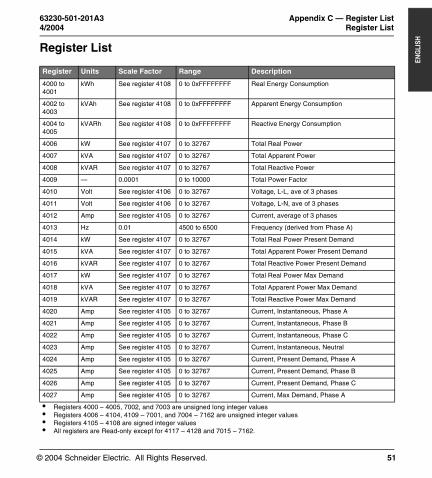
LISHAPPENDIX C — REGISTER LISTRegister List
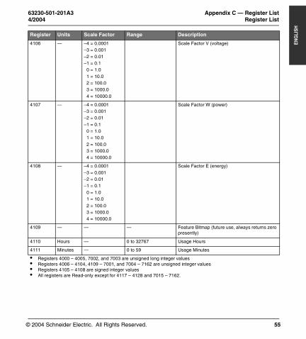
Register Units Scale Factor Range Description
4000 to 4001
kWh See register 4108 0 to 0xFFFFFFFF Real Energy Consumption
4002 to 4003
kVAh See register 4108 0 to 0xFFFFFFFF Apparent Energy Consumption
4004 to 4005
kVARh See register 4108 0 to 0xFFFFFFFF Reactive Energy Consumption
4006 kW See register 4107 0 to 32767 Total Real Power
4007 kVA See register 4107 0 to 32767 Total Apparent Power
4008 kVAR See register 4107 0 to 32767 Total Reactive Power
4009 — 0.0001 0 to 10000 Total Power Factor
4010 Volt See register 4106 0 to 32767 Voltage, L-L, ave of 3 phases
4011 Volt See register 4106 0 to 32767 Voltage, L-N, ave of 3 phases
4012 Amp See register 4105 0 to 32767 Current, average of 3 phases
4013 Hz 0.01 4500 to 6500 Frequency (derived from Phase A)
4014 kW See register 4107 0 to 32767 Total Real Power Present Demand
4015 kVA See register 4107 0 to 32767 Total Apparent Power Present Demand
4016 kVAR See register 4107 0 to 32767 Total Reactive Power Present Demand
4017 kW See register 4107 0 to 32767 Total Real Power Max Demand
4018 kVA See register 4107 0 to 32767 Total Apparent Power Max Demand
4019 kVAR See register 4107 0 to 32767 Total Reactive Power Max Demand
4020 Amp See register 4105 0 to 32767 Current, Instantaneous, Phase A
4021 Amp See register 4105 0 to 32767 Current, Instantaneous, Phase B
4022 Amp See register 4105 0 to 32767 Current, Instantaneous, Phase C
4023 Amp See register 4105 0 to 32767 Current, Instantaneous, Neutral
4024 Amp See register 4105 0 to 32767 Current, Present Demand, Phase A
4025 Amp See register 4105 0 to 32767 Current, Present Demand, Phase B
4026 Amp See register 4105 0 to 32767 Current, Present Demand, Phase C
4027 Amp See register 4105 0 to 32767 Current, Max Demand, Phase A
• Registers 4000 – 4005, 7002, and 7003 are unsigned long integer values• Registers 4006 – 4104, 4109 – 7001, and 7004 – 7162 are unsigned integer values• Registers 4105 – 4108 are signed integer values• All registers are Read-only except for 4117 – 4128 and 7015 – 7162.
PM700 Trilingual.book Page 51 Monday, April 12, 2004 9:47 AM
© 2004 Schneider Electric. All Rights Reserved.
Appendix C — Register List 63230-501-201A3Register List 4/2004
52
ENG
LISH
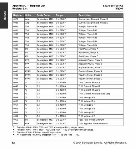
4028 Amp See register 4105 0 to 32767 Current, Max Demand, Phase B
4029 Amp See register 4105 0 to 32767 Current, Max Demand, Phase C
4030 Volt See register 4106 0 to 32767 Voltage, Phase A-B
4031 Volt See register 4106 0 to 32767 Voltage, Phase B-C
4032 Volt See register 4106 0 to 32767 Voltage, Phase A-C
4033 Volt See register 4106 0 to 32767 Voltage, Phase A-N
4034 Volt See register 4106 0 to 32767 Voltage, Phase B-N
4035 Volt See register 4106 0 to 32767 Voltage, Phase C-N
4036 kW See register 4107 0 to 32767 Real Power, Phase A
4037 kW See register 4107 0 to 32767 Real Power, Phase B
4038 kW See register 4107 0 to 32767 Real Power, Phase C
4039 kVA See register 4107 0 to 32767 Apparent Power, Phase A
4040 kVA See register 4107 0 to 32767 Apparent Power, Phase B
4041 kVA See register 4107 0 to 32767 Apparent Power, Phase C
4042 kVAR See register 4107 0 to 32767 Reactive Power, Phase A
4043 kVAR See register 4107 0 to 32767 Reactive Power, Phase B
4044 kVAR See register 4107 0 to 32767 Reactive Power, Phase C
4045 % 0.1 0 to 10000 THD, Current, Phase A
4046 % 0.1 0 to 10000 THD, Current, Phase B
4047 % 0.1 0 to 10000 THD, Current, Phase C
4048 % 0.1 0 to 10000 THD, Current, Neutral (future use)
4049 % 0.1 0 to 10000 THD, Voltage A-N
4050 % 0.1 0 to 10000 THD, Voltage B-N
4051 % 0.1 0 to 10000 THD, Voltage C-N
4052 % 0.1 0 to 10000 THD, Voltage A-B
4053 % 0.1 0 to 10000 THD, Voltage B-C
4054 % 0.1 0 to 10000 THD, Voltage A-C
4055 kW See register 4107 0 to 32767 Total Real Power Minimum
4056 kVA See register 4107 0 to 32767 Total Apparent Power Minimum
Register Units Scale Factor Range Description
• Registers 4000 – 4005, 7002, and 7003 are unsigned long integer values• Registers 4006 – 4104, 4109 – 7001, and 7004 – 7162 are unsigned integer values• Registers 4105 – 4108 are signed integer values• All registers are Read-only except for 4117 – 4128 and 7015 – 7162.
PM700 Trilingual.book Page 52 Monday, April 12, 2004 9:47 AM
© 2004 Schneider Electric. All Rights Reserved.
63230-501-201A3 Appendix C — Register List4/2004 Register List
53
ENG
LISH
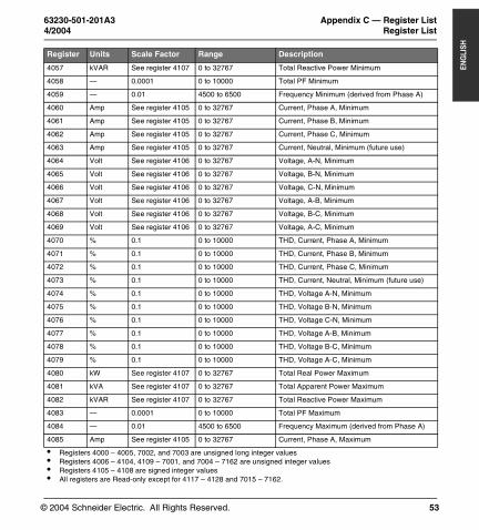
4057 kVAR See register 4107 0 to 32767 Total Reactive Power Minimum
4058 — 0.0001 0 to 10000 Total PF Minimum
4059 — 0.01 4500 to 6500 Frequency Minimum (derived from Phase A)
4060 Amp See register 4105 0 to 32767 Current, Phase A, Minimum
4061 Amp See register 4105 0 to 32767 Current, Phase B, Minimum
4062 Amp See register 4105 0 to 32767 Current, Phase C, Minimum
4063 Amp See register 4105 0 to 32767 Current, Neutral, Minimum (future use)
4064 Volt See register 4106 0 to 32767 Voltage, A-N, Minimum
4065 Volt See register 4106 0 to 32767 Voltage, B-N, Minimum
4066 Volt See register 4106 0 to 32767 Voltage, C-N, Minimum
4067 Volt See register 4106 0 to 32767 Voltage, A-B, Minimum
4068 Volt See register 4106 0 to 32767 Voltage, B-C, Minimum
4069 Volt See register 4106 0 to 32767 Voltage, A-C, Minimum
4070 % 0.1 0 to 10000 THD, Current, Phase A, Minimum
4071 % 0.1 0 to 10000 THD, Current, Phase B, Minimum
4072 % 0.1 0 to 10000 THD, Current, Phase C, Minimum
4073 % 0.1 0 to 10000 THD, Current, Neutral, Minimum (future use)
4074 % 0.1 0 to 10000 THD, Voltage A-N, Minimum
4075 % 0.1 0 to 10000 THD, Voltage B-N, Minimum
4076 % 0.1 0 to 10000 THD, Voltage C-N, Minimum
4077 % 0.1 0 to 10000 THD, Voltage A-B, Minimum
4078 % 0.1 0 to 10000 THD, Voltage B-C, Minimum
4079 % 0.1 0 to 10000 THD, Voltage A-C, Minimum
4080 kW See register 4107 0 to 32767 Total Real Power Maximum
4081 kVA See register 4107 0 to 32767 Total Apparent Power Maximum
4082 kVAR See register 4107 0 to 32767 Total Reactive Power Maximum
4083 — 0.0001 0 to 10000 Total PF Maximum
4084 — 0.01 4500 to 6500 Frequency Maximum (derived from Phase A)
4085 Amp See register 4105 0 to 32767 Current, Phase A, Maximum
Register Units Scale Factor Range Description
• Registers 4000 – 4005, 7002, and 7003 are unsigned long integer values• Registers 4006 – 4104, 4109 – 7001, and 7004 – 7162 are unsigned integer values• Registers 4105 – 4108 are signed integer values• All registers are Read-only except for 4117 – 4128 and 7015 – 7162.
PM700 Trilingual.book Page 53 Monday, April 12, 2004 9:47 AM
© 2004 Schneider Electric. All Rights Reserved.
Appendix C — Register List 63230-501-201A3Register List 4/2004
54
ENG
LISH
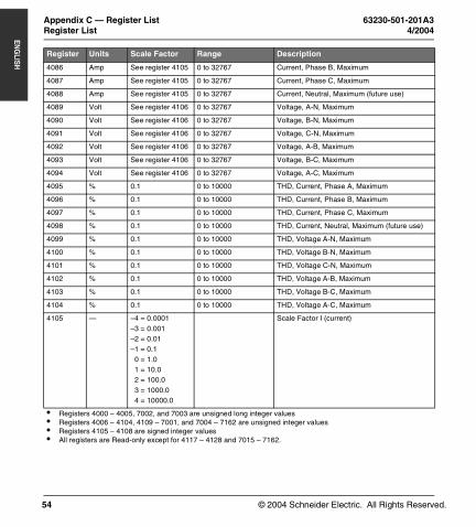
4086 Amp See register 4105 0 to 32767 Current, Phase B, Maximum
4087 Amp See register 4105 0 to 32767 Current, Phase C, Maximum
4088 Amp See register 4105 0 to 32767 Current, Neutral, Maximum (future use)
4089 Volt See register 4106 0 to 32767 Voltage, A-N, Maximum
4090 Volt See register 4106 0 to 32767 Voltage, B-N, Maximum
4091 Volt See register 4106 0 to 32767 Voltage, C-N, Maximum
4092 Volt See register 4106 0 to 32767 Voltage, A-B, Maximum
4093 Volt See register 4106 0 to 32767 Voltage, B-C, Maximum
4094 Volt See register 4106 0 to 32767 Voltage, A-C, Maximum
4095 % 0.1 0 to 10000 THD, Current, Phase A, Maximum
4096 % 0.1 0 to 10000 THD, Current, Phase B, Maximum
4097 % 0.1 0 to 10000 THD, Current, Phase C, Maximum
4098 % 0.1 0 to 10000 THD, Current, Neutral, Maximum (future use)
4099 % 0.1 0 to 10000 THD, Voltage A-N, Maximum
4100 % 0.1 0 to 10000 THD, Voltage B-N, Maximum
4101 % 0.1 0 to 10000 THD, Voltage C-N, Maximum
4102 % 0.1 0 to 10000 THD, Voltage A-B, Maximum
4103 % 0.1 0 to 10000 THD, Voltage B-C, Maximum
4104 % 0.1 0 to 10000 THD, Voltage A-C, Maximum
4105 — –4 = 0.0001–3 = 0.001–2 = 0.01–1 = 0.1
0 = 1.01 = 10.02 = 100.03 = 1000.04 = 10000.0
Scale Factor I (current)
Register Units Scale Factor Range Description
• Registers 4000 – 4005, 7002, and 7003 are unsigned long integer values• Registers 4006 – 4104, 4109 – 7001, and 7004 – 7162 are unsigned integer values• Registers 4105 – 4108 are signed integer values• All registers are Read-only except for 4117 – 4128 and 7015 – 7162.
PM700 Trilingual.book Page 54 Monday, April 12, 2004 9:47 AM
© 2004 Schneider Electric. All Rights Reserved.
63230-501-201A3 Appendix C — Register List4/2004 Register List
55
ENG
LISH
4106 — –4 = 0.0001–3 = 0.001–2 = 0.01–1 = 0.1
0 = 1.01 = 10.02 = 100.03 = 1000.04 = 10000.0
Scale Factor V (voltage)
4107 — –4 = 0.0001–3 = 0.001–2 = 0.01–1 = 0.1
0 = 1.01 = 10.02 = 100.03 = 1000.04 = 10000.0
Scale Factor W (power)
4108 — –4 = 0.0001–3 = 0.001–2 = 0.01–1 = 0.1
0 = 1.01 = 10.02 = 100.03 = 1000.04 = 10000.0
Scale Factor E (energy)
4109 — — — Feature Bitmap (future use, always returns zero presently)
4110 Hours — 0 to 32767 Usage Hours
4111 Minutes — 0 to 59 Usage Minutes
Register Units Scale Factor Range Description
• Registers 4000 – 4005, 7002, and 7003 are unsigned long integer values• Registers 4006 – 4104, 4109 – 7001, and 7004 – 7162 are unsigned integer values• Registers 4105 – 4108 are signed integer values• All registers are Read-only except for 4117 – 4128 and 7015 – 7162.
PM700 Trilingual.book Page 55 Monday, April 12, 2004 9:47 AM
© 2004 Schneider Electric. All Rights Reserved.
Appendix C — Register List 63230-501-201A3Register List 4/2004
56
ENG
LISH
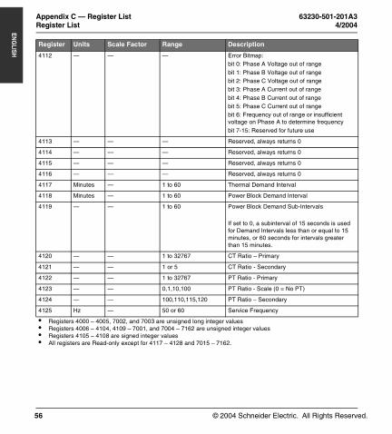
4112 — — — Error Bitmap:bit 0: Phase A Voltage out of rangebit 1: Phase B Voltage out of rangebit 2: Phase C Voltage out of rangebit 3: Phase A Current out of rangebit 4: Phase B Current out of rangebit 5: Phase C Current out of rangebit 6: Frequency out of range or insufficient voltage on Phase A to determine frequencybit 7-15: Reserved for future use
4113 — — — Reserved, always returns 0
4114 — — — Reserved, always returns 0
4115 — — — Reserved, always returns 0
4116 — — — Reserved, always returns 0
4117 Minutes — 1 to 60 Thermal Demand Interval
4118 Minutes — 1 to 60 Power Block Demand Interval
4119 — — 1 to 60 Power Block Demand Sub-Intervals
If set to 0, a subinterval of 15 seconds is used for Demand Intervals less than or equal to 15 minutes, or 60 seconds for intervals greater than 15 minutes.
4120 — — 1 to 32767 CT Ratio – Primary
4121 — — 1 or 5 CT Ratio - Secondary
4122 — — 1 to 32767 PT Ratio - Primary
4123 — — 0,1,10,100 PT Ratio - Scale (0 = No PT)
4124 — — 100,110,115,120 PT Ratio – Secondary
4125 Hz — 50 or 60 Service Frequency
Register Units Scale Factor Range Description
• Registers 4000 – 4005, 7002, and 7003 are unsigned long integer values• Registers 4006 – 4104, 4109 – 7001, and 7004 – 7162 are unsigned integer values• Registers 4105 – 4108 are signed integer values• All registers are Read-only except for 4117 – 4128 and 7015 – 7162.
PM700 Trilingual.book Page 56 Monday, April 12, 2004 9:47 AM
© 2004 Schneider Electric. All Rights Reserved.
63230-501-201A3 Appendix C — Register List4/2004 Register List
57
ENG
LISH
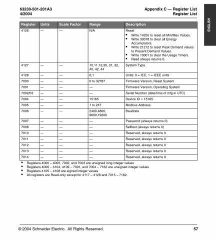
4126 — — N/A Reset• Write 14255 to reset all Min/Max Values.• Write 30078 to clear all Energy
Accumulators.• Write 21212 to reset Peak Demand values
to Present Demand Values.• Write 10001 to clear the Usage Timers.• Read always returns 0.
4127 — — 10,11,12,30, 31, 32, 40, 42, 44
System Type
4128 — — 0,1 Units: 0 = IEC, 1 = IEEE units
7000 — — 0 to 32767 Firmware Version, Reset System
7001 — — — Firmware Version, Operating System
7002/03 — — — Serial Number (date/time of mfg in UTC)
7004 — — 15165 Device ID = 15165
7005 — — 1 to 247 Modbus Address
7006 — — 2400,4800, 9600,19200
Baudrate
7007 — — — Password (always returns 0)
7008 — — — Selftest (always returns 0)
7010 — — — Reserved, always returns 0
7011 — — — Reserved, always returns 0
7012 — — — Reserved, always returns 0
7013 — — — Reserved, always returns 0
7014 — — — Reserved, always returns 0
Register Units Scale Factor Range Description
• Registers 4000 – 4005, 7002, and 7003 are unsigned long integer values• Registers 4006 – 4104, 4109 – 7001, and 7004 – 7162 are unsigned integer values• Registers 4105 – 4108 are signed integer values• All registers are Read-only except for 4117 – 4128 and 7015 – 7162.
PM700 Trilingual.book Page 57 Monday, April 12, 2004 9:47 AM
© 2004 Schneider Electric. All Rights Reserved.
Appendix C — Register List 63230-501-201A3Supported MODBUS Commands 4/2004
58
ENG
LISH
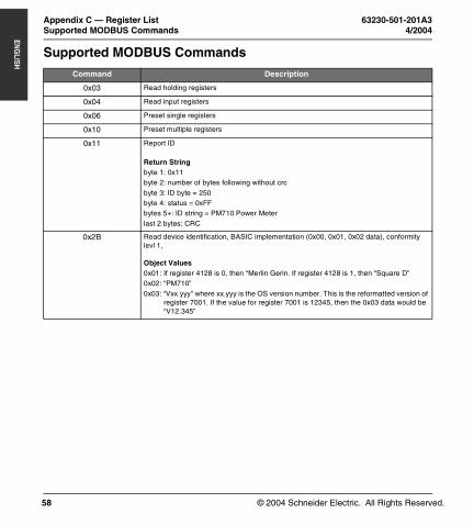
Supported MODBUS Commands
Command Description
0x03 Read holding registers
0x04 Read input registers
0x06 Preset single registers
0x10 Preset multiple registers
0x11 Report ID
Return Stringbyte 1: 0x11byte 2: number of bytes following without crcbyte 3: ID byte = 250byte 4: status = 0xFFbytes 5+: ID string = PM710 Power Meterlast 2 bytes: CRC
0x2B Read device identification, BASIC implementation (0x00, 0x01, 0x02 data), conformity levl 1,
Object Values0x01: If register 4128 is 0, then “Merlin Gerin. If register 4128 is 1, then “Square D”0x02: “PM710”0x03: “Vxx.yyy” where xx.yyy is the OS version number. This is the reformatted version of
register 7001. If the value for register 7001 is 12345, then the 0x03 data would be “V12.345”
PM700 Trilingual.book Page 58 Monday, April 12, 2004 9:47 AM
© 2004 Schneider Electric. All Rights Reserved.
63230-501-201A3 Chapter 1 — Index4/2004
59
ENG
LISHCHAPTER 1 — INDEXA
addressdevice address 40
Bbargraph scale
setup 36baud rate 40button
symbols 28buttons
how to use 28Ccommunication
characteristics 7communications
capabilities 25daisy-chaining devices 25functions 7problems with PC communi-
cation 40settings 7setup 36
communications distances 25connections
wiring 15contacting technical support 39CT
setup 31Ddemand
setup 33values 6
dimensionspower meter 11
displayoperation 27
Eenergy
values 6Ffuse recommendations 22
Ggetting technical support 39Hhealth status 38IIEC 37IEEE 37instantaneous rms
values 6Mmaintenance
maintenance icon 40of power meter 39
maximum demandvalues 6
maximum values 7menu
list of menu items 29overview 28
menu modes 6meter information 37minimum values 7MODBUS 7mounting
dimensions 11Ooperating mode
IEC 37IEEE 37
operationdisplay 27problems with the power
meter 40Ppassword
setup 35power meter
box contents 5characteristics 6dimensions 11setup 31
power-quality
values 6PQS demand
setup 34problems
see troubleshooting 39PT
setup 32pulse output 8pulse setup 35Rreset
characteristics 6password 35
route statement 40RS485 7
communications distances25
Ssafety precautions 9setup 31
bargraph scale 36communications 36CT 31demand 33password 35PQS demand 34PT 32pulse 35system frequency 32system type 32, 33
symbolsabove buttons 28wiring 15
system frequencysetup 32
system typesetup 32, 33
system types 16Ttechnical support 39thermal demand
values 6
PM700 Trilingual.book Page 59 Monday, April 12, 2004 9:47 AM

© 2004 Schneider Electric. All Rights Reserved.
Chapter 1 — Index 63230-501-201A34/2004
60
ENG
LISH
Vviewing meter information 37
Wwiring
fuse recommendations 22
troubleshooting 40wiring symbols 15
PM700 Trilingual.book Page 60 Monday, April 12, 2004 9:47 AM

PM700 Trilingual.book Page 187 Monday, April 12, 2004 9:47 AM

Power Meter PM700Instruction Bulletin / Manuel d’utilisation / Manual de instrucciones
4/2004 © 2004 Schneider Electric. All Rights Reserved.
Schneider ElectricPower Management Operations295 Tech Park Drive, Suite 100LaVergne, TN 37086Tel: +1 (615) 287-3400www.powerlogic.com
63230-501-201A3Z103730-0C
This product must be installed, connected, and used in compliance with prevailing standards and/or installation regulations.
As standards, specifications, and designs change from time to time, please ask for confirmation of the information given in this publication.
Ce produit doit être installé, raccordé et utilisé en repectant les normes et/ou les règlements d’installation en vigueur.
En raison de l’évolution des normes et du matériel, les caractéristiques et cotes d’encombrement données ne nous engagent qu’après confirmation par nos services.
Este producto debera instalarse, conectarse y utilizarse en conformidad conlas normas y/o los reglementos de instalación vigentes.
Debido a la evolución constante de las normas ydes material, nos comprometemos únicamente con las característics y cotas de volumen previa confirmación de nuestros servicios.
Publishing: Square D Company PMO
Production: Square D Company PMO
Édition : Square D Company PMO
Production : Square D Company PMO
Editado por: Square D Company PMO
Producción: Square D Company PMO
PM700 Trilingual.book Page 188 Monday, April 12, 2004 9:47 AM