norme cei internationale iec international …maxwell.sze.hu/~kovacsg/erzekelok es...
TRANSCRIPT
NORME INTERNATIONALE
CEIIEC
INTERNATIONAL STANDARD
61000-4-4Deuxième édition
Second edition2004-07
Compatibilité électromagnétique (CEM) –
Partie 4-4: Techniques d'essai et de mesure – Essais d'immunité aux transitoires électriques rapides en salves
Electromagnetic compatibility (EMC) –
Part 4-4: Testing and measurement techniques – Electrical fast transient/burst immunity test
Numéro de référence
Reference number
CEI/IEC 61000-4-4:2004
PUBLICATION FONDAMENTALE EN CEM BASIC EMC PUBLICATION
NORME INTERNATIONALE
CEIIEC
INTERNATIONAL STANDARD
61000-4-4Deuxième édition
Second edition2004-07
Compatibilité électromagnétique (CEM) –
Partie 4-4: Techniques d'essai et de mesure – Essais d'immunité aux transitoires électriques rapides en salves
Electromagnetic compatibility (EMC) –
Part 4-4: Testing and measurement techniques – Electrical fast transient/burst immunity test
Pour prix, voir catalogue en vigueur
For price, see current catalogue
IEC 2004 Droits de reproduction réservés Copyright - all rights reserved
Aucune partie de cette publication ne peut être reproduite ni utilisée sous quelque forme que ce soit et par aucun procédé, électronique ou mécanique, y compris la photo-copie et les microfilms, sans l'accord écrit de l'éditeur.
No part of this publication may be reproduced or utilized in any form or by any means, electronic or mechanical, including photocopying and microfilm, without permission in writing from the publisher.
International Electrotechnical Commission, 3, rue de Varembé, PO Box 131, CH-1211 Geneva 20, Switzerland
Telephone: +41 22 919 02 11 Telefax: +41 22 919 03 00 E-mail: [email protected] Web: www.iec.ch
Commission Electrotechnique InternationaleInternational Electrotechnical Commission !"#$%&'(#%&) *+!,-'(-!.%/0!1,&) 2(3/11/)
V CODE PRIX
PRICE CODE
PUBLICATION FONDAMENTALE EN CEM BASIC EMC PUBLICATION
61000-4-4 IEC:2004 – 3 –
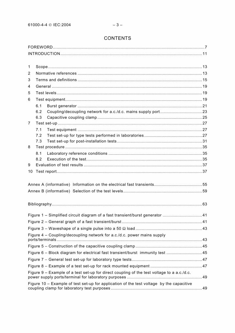
CONTENTS
FOREWORD...........................................................................................................................7
INTRODUCTION...................................................................................................................11
1 Scope............................................................................................................................. 13
2 Normative references ..................................................................................................... 13
3 Terms and definitions ..................................................................................................... 15
4 General .......................................................................................................................... 19
5 Test levels ...................................................................................................................... 19
6 Test equipment...............................................................................................................19
6.1 Burst generator ..................................................................................................... 21
6.2 Coupling/decoupling network for a.c./d.c. mains supply port .................................. 23
6.3 Capacitive coupling clamp ..................................................................................... 25
7 Test set-up ..................................................................................................................... 27
7.1 Test equipment ..................................................................................................... 27
7.2 Test set-up for type tests performed in laboratories ............................................... 27
7.3 Test set-up for post-installation tests ..................................................................... 31
8 Test procedure ...............................................................................................................35
8.1 Laboratory reference conditions ............................................................................ 35
8.2 Execution of the test.............................................................................................. 35
9 Evaluation of test results ................................................................................................ 37
10 Test report...................................................................................................................... 37
Annex A (informative) Information on the electrical fast transients....................................... 55
Annex B (informative) Selection of the test levels................................................................ 59
Bibliography.......................................................................................................................... 63
Figure 1 – Simplified circuit diagram of a fast transient/burst generator ................................ 41
Figure 2 – General graph of a fast transient/burst ................................................................. 41
Figure 3 – Waveshape of a single pulse into a 50 Ω load ...................................................... 43
Figure 4 – Coupling/decoupling network for a.c./d.c. power mains supply ports/terminals ...................................................................................................................... 43
Figure 5 – Construction of the capacitive coupling clamp ...................................................... 45
Figure 6 – Block diagram for electrical fast transient/burst immunity test ............................. 45
Figure 7 − General test set-up for laboratory type tests......................................................... 47
Figure 8 – Example of a test set-up for rack mounted equipment .......................................... 47
Figure 9 – Example of a test set-up for direct coupling of the test voltage to a a.c./d.c. power supply ports/terminal for laboratory purposes ............................................................. 49
Figure 10 – Example of test set-up for application of the test voltage by the capacitive coupling clamp for laboratory test purposes .......................................................................... 49

61000-4-4 IEC:2004 – 5 –
Figure 11 – Example for post-installation test on a.c./d.c. power supply ports and protective earth terminals for stationary, floor-mounted EUT ................................................. 51
Figure 12 – Example for post-installation test on a.c. mains supply port and protective earth terminals for non-stationary mounted EUT ................................................................... 53
Figure 13 – Example of post-installation test on communications and I/O ports without the capacitive coupling clamp ............................................................................................... 53
Table 1 – Test levels............................................................................................................. 19
Table 2 – Output voltage peak values and repetition rates .................................................... 23
61000-4-4 IEC:2004 – 7 –
INTERNATIONAL ELECTROTECHNICAL COMMISSION ___________
ELECTROMAGNETIC COMPATIBILITY (EMC) –
Part 4-4: Testing and measurement techniques –
Electrical fast transient/burst immunity test
FOREWORD
1) The International Electrotechnical Commission (IEC) is a worldwide organization for standardization comprising all national electrotechnical committees (IEC National Committees). The object of IEC is to promote international co-operation on all questions concerning standardization in the electrical and electronic fields. To this end and in addition to other activities, IEC publishes International Standards, Technical Specifications, Technical Reports, Publicly Available Specifications (PAS) and Guides (hereafter referred to as “IEC Publication(s)”). Their preparation is entrusted to technical committees; any IEC National Committee interested in the subject dealt with may participate in this preparatory work. International, governmental and non-governmental organizations liaising with the IEC also participate in this preparation. IEC collaborates closely with the International Organization for Standardization (ISO) in accordance with conditions determined by agreement between the two organizations.
2) The formal decisions or agreements of IEC on technical matters express, as nearly as possible, an international consensus of opinion on the relevant subjects since each technical committee has representation from all interested IEC National Committees.
3) IEC Publications have the form of recommendations for international use and are accepted by IEC National Committees in that sense. While all reasonable efforts are made to ensure that the technical content of IEC Publications is accurate, IEC cannot be held responsible for the way in which they are used or for any misinterpretation by any end user.
4) In order to promote international uniformity, IEC National Committees undertake to apply IEC Publications transparently to the maximum extent possible in their national and regional publications. Any divergence between any IEC Publication and the corresponding national or regional publication shall be clearly indicated in the latter.
5) IEC provides no marking procedure to indicate its approval and cannot be rendered responsible for any equipment declared to be in conformity with an IEC Publication.
6) All users should ensure that they have the latest edition of this publication.
7) No liability shall attach to IEC or its directors, employees, servants or agents including individual experts and members of its technical committees and IEC National Committees for any personal injury, property damage or other damage of any nature whatsoever, whether direct or indirect, or for costs (including legal fees) and expenses arising out of the publication, use of, or reliance upon, this IEC Publication or any other IEC Publications.
8) Attention is drawn to the Normative references cited in this publication. Use of the referenced publications is indispensable for the correct application of this publication.
9) Attention is drawn to the possibility that some of the elements of this IEC Publication may be the subject of patent rights. IEC shall not be held responsible for identifying any or all such patent rights.
International Standard IEC 61000-4-4 has been prepared by sub-committee 77B: High frequency phenomena, of IEC technical committee 77: Electromagnetic compatibility.
It forms Part 4-4 of IEC 61000. It has the status of a basic EMC publication in accordance with IEC Guide 107, Electromagnetic compatibility – Guide to the drafting of electromagnetic compatibility publications.
This second edition cancels and replaces the first edition published in 1995 and its amend-ments 1 (2000) and 2 (2001) and constitutes a technical revision.
This second edition improves and clarifies simulator specifications, test criteria and test set-ups. Only common mode injection is required.
61000-4-4 IEC:2004 – 9 –
The text of this standard is based on the following documents:
FDIS Report on voting
77B/419/FDIS 77B/424/RVD
Full information on the voting for the approval of this standard can be found in the report on voting indicated in the above table.
This publication has been drafted in accordance with the ISO/IEC Directives, Part 2.
The committee has decided that the contents of this publication will remain unchanged until the maintenance result date indicated on the IEC web site under "http://webstore.iec.ch" in the data related to the specific publication. At this date, the publication will be
• reconfirmed;
• withdrawn;
• replaced by a revised edition, or
• amended.
61000-4-4 IEC:2004 – 11 –
INTRODUCTION
IEC 61000 is published in separate parts, according to the following structure:
Part 1: General
General considerations (introduction, fundamental principles)
Definitions, terminology
Part 2: Environment
Description of the environment
Classification of the environment
Compatibility levels
Part 3: Limits
Emission limits
Immunity limits (in so far as they do not fall under the responsibility of the product committees)
Part 4: Testing and measurement techniques
Measurement techniques
Testing techniques
Part 5: Installation and mitigation guidelines
Installation guidelines
Mitigation methods and devices
Part 6: Generic standards
Part 9: Miscellaneous
Each part is further subdivided into several parts, published either as international standards or as technical specifications or technical reports, some of which have already been published as sections. Others will be published with the part number followed by a dash and a second number identifying the subdivision (example: 61000-6-1).
This part is an international standard which gives immunity requirements and test procedures related to electrical fast transients/bursts.
61000-4-4 IEC:2004 – 13 –
ELECTROMAGNETIC COMPATIBILITY (EMC) –
Part 4-4: Testing and measurement techniques – Electrical fast transient/burst immunity test
1 Scope
This part of IEC 61000-4 relates to the immunity of electrical and electronic equipment to repetitive electrical fast transients. It gives immunity requirements and test procedures related to electrical fast transients/bursts. It additionally defines ranges of test levels and establishes test procedures.
The object of this standard is to establish a common and reproducible reference for evaluating the immunity of electrical and electronic equipment when subjected to electrical fast transient/bursts on supply, signal, control and earth ports. The test method documented in this part of IEC 61000-4 describes a consistent method to assess the immunity of an equipment or system against a defined phenomenon.
NOTE As described in IEC Guide 107, this is a basic EMC publication for use by product committees of the IEC. As also stated in Guide 107, the IEC product committees are responsible for determining whether this immunity test standard should be applied or not, and if applied, they are responsible for determining the appropriate test levels and performance criteria. TC 77 and its sub-committees are prepared to co-operate with product committees in the evaluation of the value of particular immunity tests for their products.
The standard defines:
– test voltage waveform;
– range of test levels;
– test equipment;
– verification procedures of test equipment;
– test set-up;
– test procedure.
The standard gives specifications for laboratory and post-installation tests.
2 Normative references
The following referenced documents are indispensable for the application of this document. For dated references, only the edition cited applies. For undated references, the latest edition of the referenced document (including any amendments) applies.
IEC 60050-161:1990, International Electrotechnical Vocabulary (IEV) – Chapter 161: Electro-magnetic compatibility
61000-4-4 IEC:2004 – 15 –
3 Terms and definitions
For the purposes of this document, the following terms and definitions, together with those in IEC 60050-161 apply.
NOTE Several of the most relevant terms and definitions from IEC 60050-161 are presented among the definitions below.
3.1 burst
sequence of a limited number of distinct pulses or an oscillation of limited duration
[IEV 161-02-07]
3.2 calibration set of operations which establishes, by reference to standards, the relationship which exists, under specified conditions, between an indication and a result of a measurement
NOTE 1 This term is based on the "uncertainty" approach.
NOTE 2 The relationship between the indications and the results of measurement can be expressed, in principle, by a calibration diagram.
[IEV 311-01-09]
3.3 coupling
interaction between circuits, transferring energy from one circuit to another
3.4 common mode (coupling)
simultaneous coupling to all lines versus the ground reference plane
3.5 coupling clamp device of defined dimensions and characteristics for common mode coupling of the disturbance signal to the circuit under test without any galvanic connection to it
3.6 coupling network electrical circuit for the purpose of transferring energy from one circuit to another
3.7 decoupling network electrical circuit for the purpose of preventing EFT voltage applied to the EUT from affecting other devices, equipment or systems which are not under test
3.8 degradation (of performance) undesired departure in the operational performance of any device, equipment or system from its intended performance
NOTE The term "degradation" can apply to temporary or permanent failure.
[IEV 161-01-19]
61000-4-4 IEC:2004 – 17 –
3.9 EFT/B
electrical fast transient/burst
3.10 electromagnetic compatibility (EMC) ability of an equipment or system to function satisfactorily in its electromagnetic environment without introducing intolerable electromagnetic disturbances to anything in that environment
[IEV 161-01-07]
3.11 EUT
equipment under test
3.12 ground reference plane flat conductive surface whose potential is used as a common reference
[IEV 161-04-36]
3.13 immunity (to a disturbance) ability of a device, equipment or system to perform without degradation in the presence of an electromagnetic disturbance
[IEV 161-01-20]
3.14 port
particular interface of the EUT with the external electromagnetic environment
3.15 rise time interval of time between the instants at which the instantaneous value of a pulse first reaches 10 % value and then the 90 % value
[IEV 161-02-05, modified]
3.16 transient pertaining to or designating a phenomenon or a quantity which varies between two consecutive steady states during a time interval which is short compared with the time-scale of interest
[IEV 161-02-01]
3.17 verification set of operations which is used to check the test equipment system (e.g. the test generator and the interconnecting cables) and to demonstrate that the test system is functioning within the specifications given in Clause 6
NOTE 1 The methods used for verification may be different from those used for calibration.
NOTE 2 The procedure of 6.1.2 and 6.2.2 is meant as a guide to insure the correct operation of the test generator, and other items making up the test set-up so that the intended waveform is delivered to the EUT.
NOTE 3 For the purpose of this basic EMC standard this definition is different from the definition given in IEV 311-01-13.
61000-4-4 IEC:2004 – 19 –
4 General
The repetitive fast transient test is a test with bursts consisting of a number of fast transients, coupled into power supply, control, signal and earth ports of electrical and electronic equipment. Significant for the test are the high amplitude, the short rise time, the high repetition rate, and the low energy of the transients.
The test is intended to demonstrate the immunity of electrical and electronic equipment when subjected to types of transient disturbances such as those originating from switching transients (interruption of inductive loads, relay contact bounce, etc.).
5 Test levels
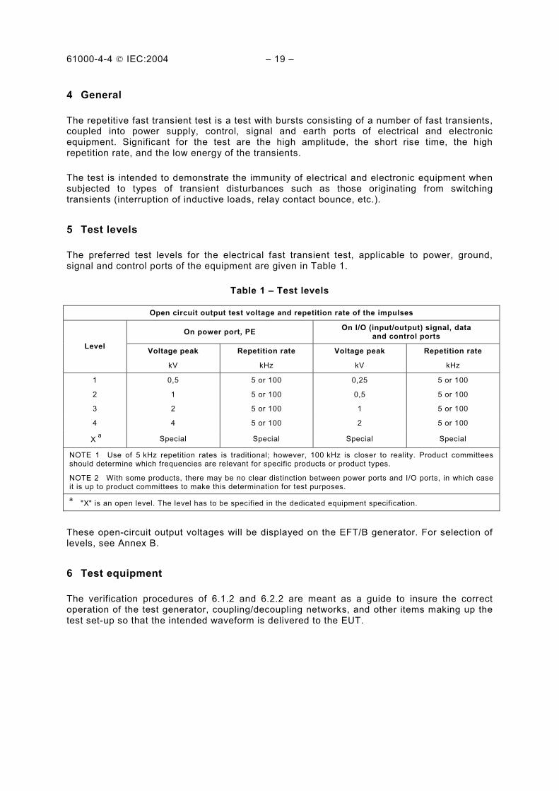
The preferred test levels for the electrical fast transient test, applicable to power, ground, signal and control ports of the equipment are given in Table 1.
Table 1 – Test levels
Open circuit output test voltage and repetition rate of the impulses
On power port, PE On I/O (input/output) signal, data
and control ports
Level Voltage peak
kV
Repetition rate
kHz
Voltage peak
kV
Repetition rate
kHz
1 0,5 5 or 100 0,25 5 or 100
2 1 5 or 100 0,5 5 or 100
3 2 5 or 100 1 5 or 100
4 4 5 or 100 2 5 or 100
X a
Special Special Special Special
NOTE 1 Use of 5 kHz repetition rates is traditional; however, 100 kHz is closer to reality. Product committees should determine which frequencies are relevant for specific products or product types.
NOTE 2 With some products, there may be no clear distinction between power ports and I/O ports, in which case it is up to product committees to make this determination for test purposes.
a "X" is an open level. The level has to be specified in the dedicated equipment specification.
These open-circuit output voltages will be displayed on the EFT/B generator. For selection of levels, see Annex B.
6 Test equipment
The verification procedures of 6.1.2 and 6.2.2 are meant as a guide to insure the correct operation of the test generator, coupling/decoupling networks, and other items making up the test set-up so that the intended waveform is delivered to the EUT.
61000-4-4 IEC:2004 – 21 –
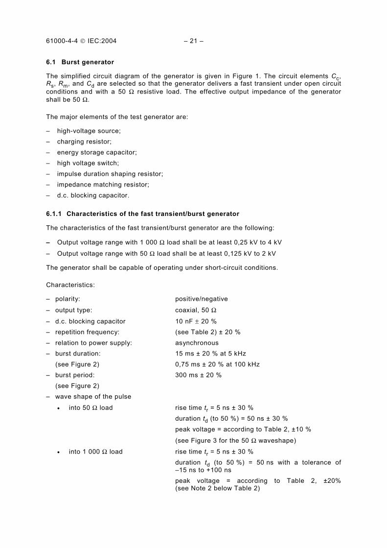
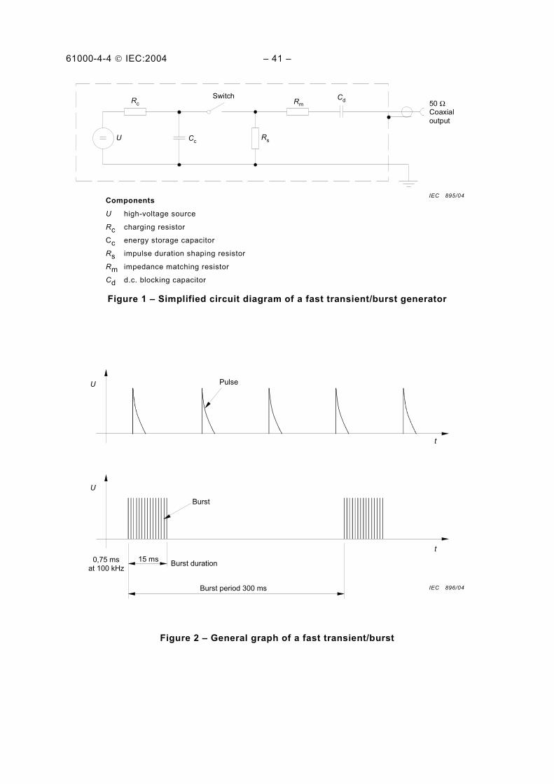
6.1 Burst generator
The simplified circuit diagram of the generator is given in Figure 1. The circuit elements Cc, Rs, Rm, and Cd are selected so that the generator delivers a fast transient under open circuit
conditions and with a 50 Ω resistive load. The effective output impedance of the generator
shall be 50 Ω.
The major elements of the test generator are:
– high-voltage source;
– charging resistor;
– energy storage capacitor;
– high voltage switch;
– impulse duration shaping resistor;
– impedance matching resistor;
– d.c. blocking capacitor.
6.1.1 Characteristics of the fast transient/burst generator
The characteristics of the fast transient/burst generator are the following:
– Output voltage range with 1 000 Ω load shall be at least 0,25 kV to 4 kV
– Output voltage range with 50 Ω load shall be at least 0,125 kV to 2 kV
The generator shall be capable of operating under short-circuit conditions.
Characteristics:
– polarity: positive/negative
– output type: coaxial, 50 Ω
– d.c. blocking capacitor 10 nF ± 20 %
– repetition frequency: (see Table 2) ± 20 %
– relation to power supply: asynchronous
– burst duration: 15 ms ± 20 % at 5 kHz
(see Figure 2) 0,75 ms ± 20 % at 100 kHz
– burst period: 300 ms ± 20 %
(see Figure 2)
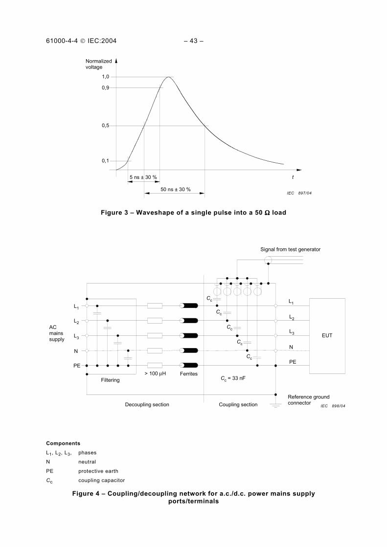
– wave shape of the pulse
• into 50 Ω load rise time tr = 5 ns ± 30 %
duration td (to 50 %) = 50 ns ± 30 %
peak voltage = according to Table 2, ±10 %
(see Figure 3 for the 50 Ω waveshape)
• into 1 000 Ω load rise time tr = 5 ns ± 30 %
duration td (to 50 %) = 50 ns with a tolerance of –15 ns to +100 ns
peak voltage = according to Table 2, ±20% (see Note 2 below Table 2)
61000-4-4 IEC:2004 – 23 –
– test load impedance 50 Ω ± 2 %
1 000 Ω ± 2 % in parallel with ≤ 6 pF. The resistance measurement is made at d.c. and the capacitance measurement is made using a commercially available capacitance meter that operates at low frequencies.
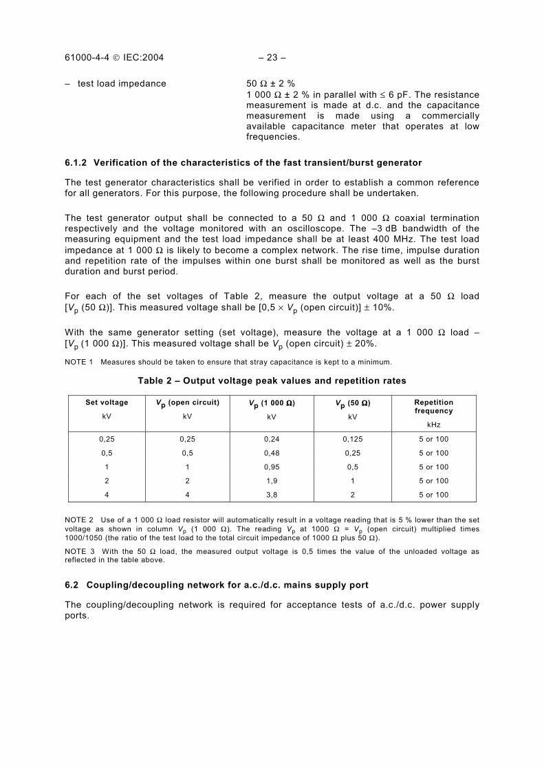
6.1.2 Verification of the characteristics of the fast transient/burst generator
The test generator characteristics shall be verified in order to establish a common reference for all generators. For this purpose, the following procedure shall be undertaken.
The test generator output shall be connected to a 50 Ω and 1 000 Ω coaxial termination respectively and the voltage monitored with an oscilloscope. The –3 dB bandwidth of the measuring equipment and the test load impedance shall be at least 400 MHz. The test load
impedance at 1 000 Ω is likely to become a complex network. The rise time, impulse duration and repetition rate of the impulses within one burst shall be monitored as well as the burst duration and burst period.
For each of the set voltages of Table 2, measure the output voltage at a 50 Ω load
[Vp (50 Ω)]. This measured voltage shall be [0,5 × Vp (open circuit)] ± 10%.
With the same generator setting (set voltage), measure the voltage at a 1 000 Ω load –
[Vp (1 000 Ω)]. This measured voltage shall be Vp (open circuit) ± 20%.
NOTE 1 Measures should be taken to ensure that stray capacitance is kept to a minimum.
Table 2 – Output voltage peak values and repetition rates
Set voltage
kV
Vp (open circuit)
kV
Vp (1 000 ΩΩΩΩ)
kV
Vp (50 ΩΩΩΩ)
kV
Repetition frequency
kHz
0,25 0,25 0,24 0,125 5 or 100
0,5 0,5 0,48 0,25 5 or 100
1 1 0,95 0,5 5 or 100
2 2 1,9 1 5 or 100
4 4 3,8 2 5 or 100
NOTE 2 Use of a 1 000 Ω load resistor will automatically result in a voltage reading that is 5 % lower than the set
voltage as shown in column Vp (1 000 Ω). The reading Vp at 1000 Ω = Vp (open circuit) multiplied times
1000/1050 (the ratio of the test load to the total circuit impedance of 1000 Ω plus 50 Ω).
NOTE 3 With the 50 Ω load, the measured output voltage is 0,5 times the value of the unloaded voltage as reflected in the table above.
6.2 Coupling/decoupling network for a.c./d.c. mains supply port
The coupling/decoupling network is required for acceptance tests of a.c./d.c. power supply ports.
61000-4-4 IEC:2004 – 25 –
The circuit diagram (example for a three-phase power mains supply) is given in Figure 4.
The waveform of the EFT/B generator shall be verified at the output of the coupling network according to 6.2.2.
6.2.1 Characteristics of the coupling/decoupling network
The characteristics of the coupling/decoupling network are the following:
– coupling capacitors: 33 nF;
– coupling mode: common mode.
6.2.2 Verification of the characteristics of the coupling/decoupling network
The requirements given in 6.1.2 also apply to the measurement equipment that is used for the verification of the characteristics of the coupling/decoupling network.
The waveform shall be verified at the common mode output of the coupling/decoupling
network with a single 50 Ω termination.
The verification is performed with the generator output voltage set to a nominal voltage of 4 kV. The generator is connected to input of the coupling/decoupling network. The output of
the CDN (normally connected to the EUT) is terminated with a 50 Ω load. The peak voltage and waveform are recorded.
The functionality verification of each single coupling/decoupling path is recommended.
Rise time of the pulses (10 % to 90 % value) shall be 5 ns ± 30 %.
Impulse duration (50 % value) shall be 50 ns ± 30 % with the 50 Ω load.
Peak voltage ±10 % according to Table 2.
The residual test pulse voltage on the inputs of the coupling/decoupling network when the EUT and the power network are disconnected shall not exceed 10 % of applied test voltage.
NOTE Coupling/decoupling networks designed in accordance with Edition 1 of IEC 61000-4-4 (1995) may need minor modifications to meet the common mode requirements of this document.
6.3 Capacitive coupling clamp
The clamp provides the ability of coupling the fast transients/bursts to the circuit under test without any galvanic connection to the terminals of the EUT's ports, shielding of the cables or any other part of the EUT.
The coupling capacitance of the clamp depends on the cable diameter, material of the cables, and cable shielding (if any).
The device is composed of a clamp unit (made, for example, of galvanized steel, brass, copper or aluminium) for housing the cables (flat or round) of the circuits under test and shall be placed on a ground reference plane of minimum area of 1 m2. The ground (reference) plane shall extend beyond the clamp by a least 0,1 m on all sides.
61000-4-4 IEC:2004 – 27 –
The clamp shall be provided at both ends with a high-voltage coaxial connector for the connection of the test generator at either end. The generator shall be connected to that end of the clamp which is nearest to the EUT.
The clamp itself shall be closed as much as possible to provide maximum coupling capacitance between the cable and the clamp.
The mechanical arrangement of the coupling clamp is given in Figure 5 and determines its characteristics, such as frequency response, impedance, etc.
Characteristics:
− typical coupling capacitance between cable and clamp: 100 pF to 1 000 pF;
− usable diameter range of round cables: 4 mm to 40 mm;
− insulation withstand capability: 5 kV (test pulse: 1,2/50 µs).
The coupling method using the clamp is required for acceptance tests on lines connected to I/O and communication ports. It may also be used on ac/dc power supply ports only if the coupling/decoupling network defined in 6.2 cannot be used.
7 Test set-up
Different types of tests are defined based on test environments. These are:
– type (conformance) tests performed in laboratories;
– post-installation tests performed on equipment in its final installed conditions.
The preferred test method is that of type tests performed in laboratories.
The EUT shall be arranged in accordance with the manufacturer's instructions for installation (if any).
7.1 Test equipment
The test set-up includes the following equipment (see Figure 6):
– ground reference plane;
– coupling device (network or clamp);
– decoupling network;
– test generator.
7.2 Test set-up for type tests performed in laboratories
7.2.1 Test conditions
The following requirements apply to tests performed in laboratories with the environmental reference conditions specified in 8.1.
EUTs, whether stationary floor-mounted or table top, and equipment designed to be mounted in other configurations, shall be placed on a ground reference plane and shall be insulated from it by an insulating support 0,1 m ± 0,01 m thick (see Figure 7).

61000-4-4 IEC:2004 – 29 –
In the case of table-top equipment, the EUT should be located 0,1 m ± 0,01 m above the ground reference plane (see Figure 7). Equipment normally mounted on ceilings or walls shall
be tested as table-top equipment with the EUT located 0,1m ± 0,01 m above the ground reference plane.
The test generator and the coupling/decoupling network shall be placed directly on, and bonded to, the ground reference plane.
The ground reference plane shall be a metallic sheet (copper or aluminium) of 0,25 mm minimum thickness; other metallic materials may be used but they shall have 0,65 mm minimum thickness.
The minimum area of the ground reference plane is 1 m × 1 m. The actual size depends on the dimensions of the EUT.
The ground reference plane shall project beyond the EUT by at least 0,1 m on all sides.
The ground reference plane shall be connected to the protective earth.
The EUT shall be arranged and connected to satisfy its functional requirements, according to the equipment installation specifications.
The minimum distance between the EUT and all other conductive structures (e.g. the walls of a shielded room), except the ground reference plane shall be more than 0,5 m.
All cables to the EUT shall be placed on the insulation support 0,1 m above the ground reference plane. Cables not subject to electrical fast transients shall be routed as far as possible from the cable under test to minimize the coupling between the cables.
The EUT shall be connected to the earthing system in accordance with the manufacturer's installation specifications; no additional earthing connections are allowed.
The connection impedance of the coupling/decoupling network earth cables to the ground reference plane and all bondings shall provide a low inductance.
Either a direct coupling network or a capacitive clamp shall be used for the application of the test voltages. The test voltages shall be coupled to all of the EUT ports including those between two units of equipment involved in the test, unless the length of the interconnecting cable makes it impossible to test.
Decoupling networks shall be used to protect auxiliary equipment and public networks.
When using the coupling clamp, the minimum distance between the coupling plates and all other conductive surfaces, except the ground reference plane beneath the coupling clamp, shall be 0,5 m.
Unless otherwise specified in the product standard or the product family standard, the length of the signal and power lines between the coupling device and the EUT shall be 0,5 m ± 0,05 m.
If the manufacturer provides a non-detachable supply cable more than 0,5 m ± 0,05 m long with the equipment, the excess length of this cable shall be folded to avoid a flat coil and situated at a distance of 0,1 m above the ground reference plane.
61000-4-4 IEC:2004 – 31 –
Examples of the test set-up for laboratory tests are given in Figures 7 and 8.
In Figure 8, an additional ground plane, connected to the chassis of the EUT is used.
7.2.2 Methods of coupling the test voltage to the EUT
The method of coupling the test voltage to the EUT is dependent on the type of EUT port (as indicated below).
7.2.2.1 Power supply ports
An example for the test set-up for direct coupling of the EFT/B disturbance voltage via a coupling/decoupling network is given in Figure 9. This is the preferred method of coupling to power supply ports.
If a suitable coupler/decoupler cannot be obtained, i.e. for a.c. mains currents >100 A, alternative methods can be employed; however, use of the capacitive clamp is discouraged since its efficiency in coupling the bursts is considerably less than direct injection using the 33 nF capacitors.
7.2.2.2 I/O and communication ports
The examples in Figures 7 and 10 show how to use the capacitive coupling clamp for application of the disturbance test voltage to I/O and communication ports. When using the capacitive coupling clamp, non-tested or auxiliary equipment connected should be appropriately decoupled.
7.2.2.3 Cabinet earth port
The test point on the cabinet shall be the terminal for the protective earth conductor.
The test voltage shall be applied to the protective earth (PE) connection through a 33 nF coupling capacitor according to Figure 11.
7.3 Test set-up for post-installation tests
These tests are optional. They may be applied only when agreed between manufacturer and customer. It has to be considered that the test itself may be destructive to the EUT and other co-located equipment may be damaged or otherwise unacceptably affected.
The equipment or system shall be tested in the final installed conditions. Post-installation tests shall be performed without coupling/decoupling networks in order to simulate the actual electromagnetic environment as closely as possible.
If equipment or system other than the EUT are unduly affected during the test procedure, decoupling networks shall be used by agreement between the user and the manufacturer.
7.3.1 Test on power supply ports and earth ports
7.3.1.1 Stationary, floor-mounted equipment
The test voltage shall be applied simultaneously between a ground reference plane and all of the power supply terminals, a.c. or d.c., and the protective or functional earth port on the EUT cabinet.
61000-4-4 IEC:2004 – 33 –
For the test set-up, see Figure 11.
A ground reference plane of minimum area of 1 m2 (as described in 7.2.1) shall be mounted
near the EUT and connected to the protective earth conductor at the power supply mains outlet.
The EFT/B generator shall be located on the ground reference plane. The length of the "hot wire" from the coaxial output of the EFT/B-coupling device to the ports on the EUT shall be
0,5 m ± 0,05 m. This connection shall be unshielded but well insulated. If a.c./d.c. blocking capacitors are necessary, their capacitance shall be 33 nF. All other connections of the EUT should be in accordance with its functional requirements.
7.3.1.2 Non-stationary mounted EUT, connected to the mains supply by flexible cord and plugs
The test voltage shall be applied simultaneously between each of the power supply conductors and the protective earth at the power supply (see Figure 12).
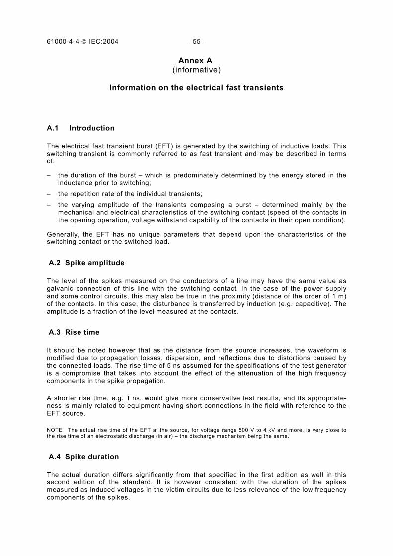
7.3.2 Test on I/O and communication ports
The capacitive coupling clamp is the preferred method for coupling the test voltage into I/O and communication ports. However, if the clamp cannot be used due to mechanical problems (size, cable routing) in the cabling, it shall be replaced by a tape or a conductive foil enveloping the lines under test. The capacitance of this coupling arrangement with foil or tape should be equivalent to that of the standard coupling clamp.
An alternative method is to couple the EFT/B generator to the terminals of the lines via discrete 100 pF capacitors instead of the distributed capacitance of the clamp or of the foil or tape arrangement.
If an EUT contains many similar ports, the manufacturer can elect to test a representative number of cables as long as those are clearly identified.
Earthing of the coaxial cable from the test generator shall be made in the vicinity of the coupling point. Application of the test voltage to the connectors (hot wires) of coaxial or shielded communication lines is not permitted.
The test voltage should be applied in a way that the shielding protection of the equipment will not be reduced. See Figure 13 for the test configuration.
The test results obtained with the discrete capacitor coupling arrangement are likely to be different from those obtained with the coupling clamp or the foil coupling. Therefore, the test levels specified in Clause 5 may be amended by a product committee in a product standard in order to take significant installation characteristics into consideration.
In the post installation test it can be agreed between manufacturer and user that external cables can be tested by routing all cables simultaneously in the coupling clamp.
61000-4-4 IEC:2004 – 35 –
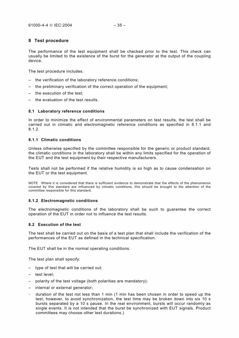
8 Test procedure
The performance of the test equipment shall be checked prior to the test. This check can usually be limited to the existence of the burst for the generator at the output of the coupling device.
The test procedure includes:
– the verification of the laboratory reference conditions;
– the preliminary verification of the correct operation of the equipment;
– the execution of the test;
– the evaluation of the test results.
8.1 Laboratory reference conditions
In order to minimize the effect of environmental parameters on test results, the test shall be carried out in climatic and electromagnetic reference conditions as specified in 8.1.1 and 8.1.2.
8.1.1 Climatic conditions
Unless otherwise specified by the committee responsible for the generic or product standard, the climatic conditions in the laboratory shall be within any limits specified for the operation of the EUT and the test equipment by their respective manufacturers.
Tests shall not be performed if the relative humidity is so high as to cause condensation on the EUT or the test equipment.
NOTE Where it is considered that there is sufficient evidence to demonstrate that the effects of the phenomenon covered by this standard are influenced by climatic conditions, this should be brought to the attention of the committee responsible for this standard.
8.1.2 Electromagnetic conditions
The electromagnetic conditions of the laboratory shall be such to guarantee the correct operation of the EUT in order not to influence the test results.
8.2 Execution of the test
The test shall be carried out on the basis of a test plan that shall include the verification of the performances of the EUT as defined in the technical specification.
The EUT shall be in the normal operating conditions.
The test plan shall specify:
– type of test that will be carried out;
– test level;
– polarity of the test voltage (both polarities are mandatory);
– internal or external generator;
– duration of the test not less than 1 min (1 min has been chosen in order to speed up the test; however, to avoid synchronization, the test time may be broken down into six 10 s bursts separated by a 10 s pause. In the real environment, bursts will occur randomly as single events. It is not intended that the burst be synchronized with EUT signals. Product committees may choose other test durations.)
61000-4-4 IEC:2004 – 37 –
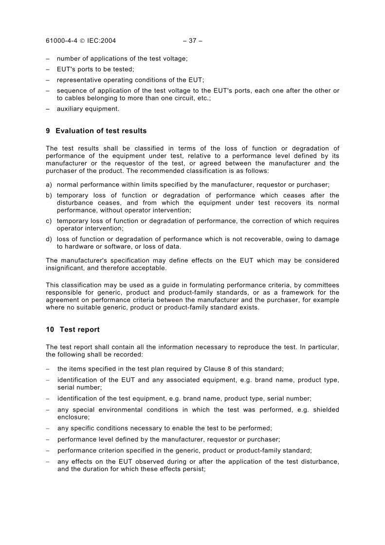
– number of applications of the test voltage;
– EUT's ports to be tested;
– representative operating conditions of the EUT;
– sequence of application of the test voltage to the EUT's ports, each one after the other or to cables belonging to more than one circuit, etc.;
– auxiliary equipment.
9 Evaluation of test results
The test results shall be classified in terms of the loss of function or degradation of performance of the equipment under test, relative to a performance level defined by its manufacturer or the requestor of the test, or agreed between the manufacturer and the purchaser of the product. The recommended classification is as follows:
a) normal performance within limits specified by the manufacturer, requestor or purchaser;
b) temporary loss of function or degradation of performance which ceases after the disturbance ceases, and from which the equipment under test recovers its normal performance, without operator intervention;
c) temporary loss of function or degradation of performance, the correction of which requires operator intervention;
d) loss of function or degradation of performance which is not recoverable, owing to damage to hardware or software, or loss of data.
The manufacturer's specification may define effects on the EUT which may be considered insignificant, and therefore acceptable.
This classification may be used as a guide in formulating performance criteria, by committees responsible for generic, product and product-family standards, or as a framework for the agreement on performance criteria between the manufacturer and the purchaser, for example where no suitable generic, product or product-family standard exists.
10 Test report
The test report shall contain all the information necessary to reproduce the test. In particular, the following shall be recorded:
− the items specified in the test plan required by Clause 8 of this standard;
− identification of the EUT and any associated equipment, e.g. brand name, product type, serial number;
− identification of the test equipment, e.g. brand name, product type, serial number;
− any special environmental conditions in which the test was performed, e.g. shielded enclosure;
− any specific conditions necessary to enable the test to be performed;
− performance level defined by the manufacturer, requestor or purchaser;
− performance criterion specified in the generic, product or product-family standard;
− any effects on the EUT observed during or after the application of the test disturbance, and the duration for which these effects persist;

61000-4-4 IEC:2004 – 39 –
− the rationale for the pass/fail decision (based on the performance criterion specified in the generic, product or product-family standard, or agreed between the manufacturer and the purchaser);
− any specific conditions of use, for example cable length or type, shielding or grounding, or EUT operating conditions, which are required to achieve compliance.
Concerning measurement uncertainty, it is sufficient to state that the test equipment meets the tolerance requirements of IEC 61000-4-4; however, when checking for compliance with the specified tolerances, the calibration uncertainty is to be taken into account.
61000-4-4 IEC:2004 – 41 –
Rc
U CcRs
Rm
Cd50 ΩCoaxial
output
Switch
Components
U high-voltage source
Rc charging resistor
Cc energy storage capacitor
Rs impulse duration shaping resistor
Rm impedance matching resistor
Cd d.c. blocking capacitor
Figure 1 – Simplified circuit diagram of a fast transient/burst generator
Pulse
Burst
Burst duration 15 ms t
t
Burst period 300 ms
0,75 ms at 100 kHz
U
U
Figure 2 – General graph of a fast transient/burst
IEC 895/04
IEC 896/04
61000-4-4 IEC:2004 – 43 –
1,0
0,9
0,5
0,1
5 ns ± 30 %
50 ns ± 30 %
t
Normalizedvoltage
Figure 3 – Waveshape of a single pulse into a 50 ΩΩΩΩ load
L 1
L 2
L 3
N
PE > 100 µH Ferrites
Cc
Cc
Cc
Cc
Cc
L 1
L 2
L 3
N
PE
EUT
Signal from test generator
Cc = 33 nFFiltering
Decoupling section Coupling section
Reference groundconnector
AC mains supply
Components
L1, L2, L3, phases
N neutral
PE protective earth
Cc coupling capacitor
Figure 4 – Coupling/decoupling network for a.c./d.c. power mains supply ports/terminals
IEC 897/04
IEC 898/04
61000-4-4 IEC:2004 – 45 –
Dimensions in millimetres
70
70
100
1 050
Insulating supports
High-voltagecoaxial connector
140
Coupling plates
1 000
High-voltagecoaxial connector
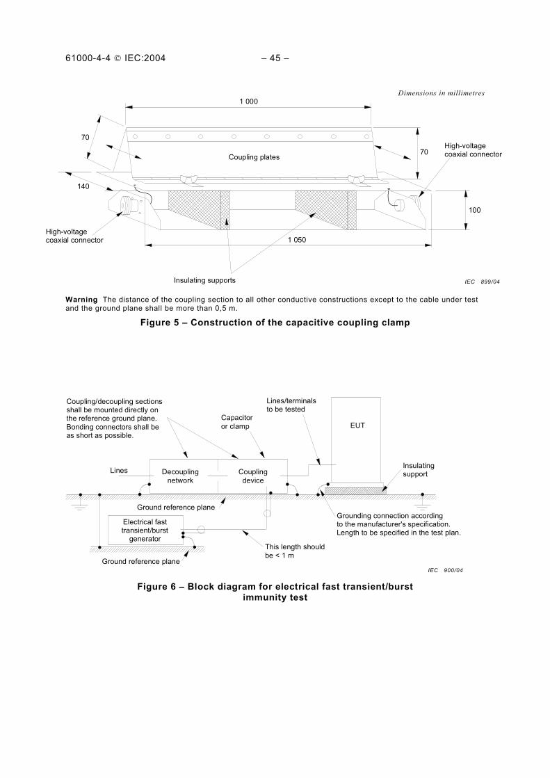
Warning The distance of the coupling section to all other conductive constructions except to the cable under test and the ground plane shall be more than 0,5 m.
Figure 5 – Construction of the capacitive coupling clamp
EUTCapacitor
or clamp
Coupling/decoupling sectionsshall be mounted directly onthe reference ground plane.
Bonding connectors shall beas short as possible.
Decoupling
network
Coupling
device
Lines/terminalsto be tested
Ground reference plane
Electrical fasttransient/burst
generatorThis length should
be < 1 m
Grounding connection accordingto the manufacturer's specification.Length to be specified in the test plan.
LinesInsulatingsupport
Ground reference plane
Figure 6 – Block diagram for electrical fast transient/burst immunity test
IEC 899/04
IEC 900/04
61000-4-4 IEC:2004 – 47 –
EUT
EUT
EUT
EUT
EUT
ACmainssupply
EFT/B-generator
Coupling/decouplingnetwork (A)
Groundingcable
0,1 m
Groundreferenceplane
Insulatingsupport
0,1 mI
I
0,1 m
ACmainssupply
Insulatingsupport
Grounding connection according tothe manufacturer's specification.Length to be specified in the test plan.
EFT/B-generator
Capacitive couplingclamp
> 0,5 m> 0,5 m
> 0,5 m> 0,5 m
Contact to the groundreference plane
Ground reference plane
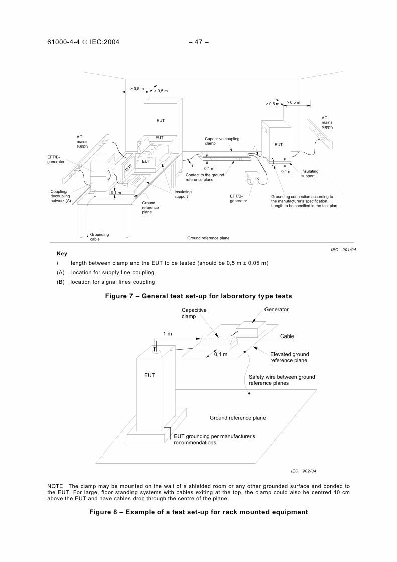
Key
l length between clamp and the EUT to be tested (should be 0,5 m ± 0,05 m)
(A) location for supply line coupling
(B) location for signal lines coupling
Figure 7 −−−− General test set-up for laboratory type tests
EUT
EUT grounding per manufacturer's
recommendations
Ground reference plane
Safety wire between groundreference planes
Elevated groundreference plane
Cable
GeneratorCapacitive
clamp
1 m
0,1 m
NOTE The clamp may be mounted on the wall of a shielded room or any other grounded surface and bonded to the EUT. For large, floor standing systems with cables exiting at the top, the clamp could also be centred 10 cm above the EUT and have cables drop through the centre of the plane.
Figure 8 – Example of a test set-up for rack mounted equipment
IEC 901/04
IEC 902/04
61000-4-4 IEC:2004 – 49 –
EFT/B-generator
L
N
PE
Cable
L = 0,5 m ± 0,05 m
Cc Z1
Coupling/decoupling
networkFiltering
AC/DC
mains supply
0,1 m
Grounding connection according tothe manufacturer's specification.Length to be specified in the test plan.
Insulatingsupport Ground reference plane
EUT
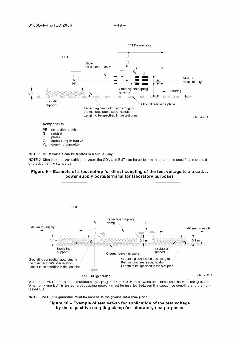
Components
PE protective earth N neutral L phase Z1 decoupling inductive Cc coupling capacitor
NOTE 1 DC terminals can be treated in a similar way.
NOTE 2 Signal and power cables between the CDN and EUT can be up to 1 m in length if so specified in product or product family standards.
Figure 9 – Example of a test set-up for direct coupling of the test voltage to a a.c./d.c. power supply ports/terminal for laboratory purposes
0,1 m 0,1 m 0,1 m
Grounding connection according to
the manufacturer's specification.Length to be specified in the test plan.
Grounding connection according tothe manufacturer's specification.
Length to be specified in the test plan.
Insulatingsupport
Ground reference plane
To EFT/B-generator
EUT
Capacitive coupling
clampI1 I2
AC mains supply AC mains supply
Insulatingsupport
When both EUTs are tested simultaneously: l1= l2 = 0,5 m ± 0,05 m between the clamp and the EUT being tested. When only one EUT is tested, a decoupling network must be inserted between the capacitive coupling and the non-tested EUT.
NOTE The EFT/B generator must be bonded to the ground reference plane.
Figure 10 – Example of test set-up for application of the test voltage by the capacitive coupling clamp for laboratory test purposes
IEC 903/04
IEC 904/04
61000-4-4 IEC:2004 – 51 –
EUT EFT/Btest generator
Protectiveearth
AC mains supply
Test point PE
terminal onthe cabinet
** 33 nF
L 1, L 2
, L 3
N
PE
FloorFloor
To peripherals
Grounding connection according to
the manufacturer's specification.Length to be specified in the test plan.
Ground reference plane
Cable
L = 0,5 m ± 0,05 m
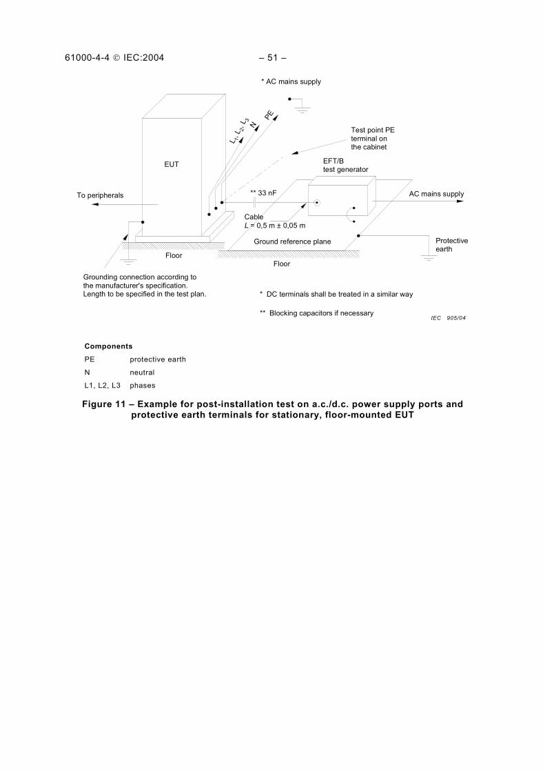
* DC terminals shall be treated in a similar way
** Blocking capacitors if necessary
* AC mains supply
Components
PE protective earth
N neutral
L1, L2, L3 phases
Figure 11 – Example for post-installation test on a.c./d.c. power supply ports and protective earth terminals for stationary, floor-mounted EUT
IEC 905/04
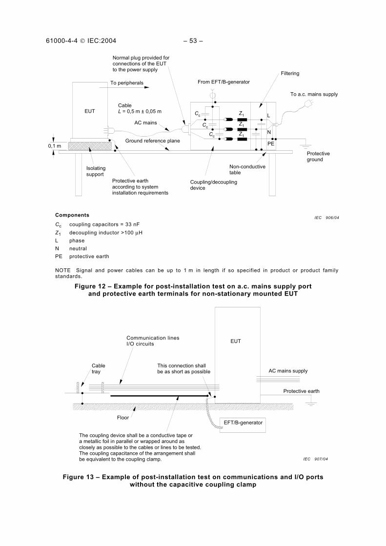
61000-4-4 IEC:2004 – 53 –
0,1 m
Isolating
support
EUT
To peripherals
AC mains
CableL = 0,5 m ± 0,05 m
Normal plug provided forconnections of the EUTto the power supply
Protective earth
according to systeminstallation requirements
Ground reference plane
Coupling/decouplingdevice
Protectiveground
To a.c. mains supply
From EFT/B-generator
Filtering
Non-conductivetable
L
N
PE
CcZ1
Z1
Z1
Cc
Cc
Components
Cc coupling capacitors = 33 nF
Z1 decoupling inductor >100 µH
L phase
N neutral
PE protective earth
NOTE Signal and power cables can be up to 1 m in length if so specified in product or product family standards.
Figure 12 – Example for post-installation test on a.c. mains supply port and protective earth terminals for non-stationary mounted EUT
AC mains supply
EFT/B-generator
The coupling device shall be a conductive tape ora metallic foil in parallel or wrapped around as
closely as possible to the cables or lines to be tested.The coupling capacitance of the arrangement shallbe equivalent to the coupling clamp.
Floor
Cabletray
Communication linesI/O cicuits
This connection shallbe as short as possible
EUT
Protective earth
Figure 13 – Example of post-installation test on communications and I/O ports without the capacitive coupling clamp
IEC 906/04
IEC 907/04
Communication lines I/O circuits
61000-4-4 IEC:2004 – 55 –
Annex A (informative)
Information on the electrical fast transients
A.1 Introduction
The electrical fast transient burst (EFT) is generated by the switching of inductive loads. This switching transient is commonly referred to as fast transient and may be described in terms of:
– the duration of the burst – which is predominately determined by the energy stored in the inductance prior to switching;
– the repetition rate of the individual transients;
– the varying amplitude of the transients composing a burst – determined mainly by the mechanical and electrical characteristics of the switching contact (speed of the contacts in the opening operation, voltage withstand capability of the contacts in their open condition).
Generally, the EFT has no unique parameters that depend upon the characteristics of the switching contact or the switched load.
A.2 Spike amplitude
The level of the spikes measured on the conductors of a line may have the same value as galvanic connection of this line with the switching contact. In the case of the power supply and some control circuits, this may also be true in the proximity (distance of the order of 1 m) of the contacts. In this case, the disturbance is transferred by induction (e.g. capacitive). The amplitude is a fraction of the level measured at the contacts.
A.3 Rise time
It should be noted however that as the distance from the source increases, the waveform is modified due to propagation losses, dispersion, and reflections due to distortions caused by the connected loads. The rise time of 5 ns assumed for the specifications of the test generator is a compromise that takes into account the effect of the attenuation of the high frequency components in the spike propagation.
A shorter rise time, e.g. 1 ns, would give more conservative test results, and its appropriate-ness is mainly related to equipment having short connections in the field with reference to the EFT source.
NOTE The actual rise time of the EFT at the source, for voltage range 500 V to 4 kV and more, is very close to the rise time of an electrostatic discharge (in air) – the discharge mechanism being the same.
A.4 Spike duration
The actual duration differs significantly from that specified in the first edition as well in this second edition of the standard. It is however consistent with the duration of the spikes measured as induced voltages in the victim circuits due to less relevance of the low frequency components of the spikes.
61000-4-4 IEC:2004 – 57 –
A.5 Spike repetition rate
The repetition rate depends on many parameters. For example:
– time constant of the charging circuit (resistance, inductance and distributed capacity of the switched inductive load);
– time constant of the switching circuit, including the impedance of the line connecting this load to the switching contact;
– speed of the contact in the opening action;
– withstanding voltage of the switching contact.
The repetition rate is therefore variable, and the range of one decade or more is quite common.
NOTE In practice, the repetition rate of 100 kHz could have been selected for testing as the compromise repetition rate because of the need to include in one test the range of the most significant parameters of the EFT/B.
A.6 Number of spikes/burst and burst duration
This (these) parameter(s) depends on the energy stored by the switched inductive load as well as the withstand voltage of the switching contact.
The number of spikes/burst is directly related to the spike repetition rate and burst duration. From measured results, most of the duration of bursts are very near to 2 ms, with the exception of the mercury wetted relay, the use of which is not as common as for the other types considered here.
NOTE The 0,75 ms duration was chosen as the reference time for testing at 100 kHz. Accordingly, 75 is the resultant number of spikes/burst.
61000-4-4 IEC:2004 – 59 –
Annex B (informative)
Selection of the test levels
The test levels should be selected in accordance with the most realistic installation and environmental conditions. These levels are outlined in Clause 5 of this standard.
The immunity tests are correlated with these levels in order to establish a performance level for the environment in which the equipment is expected to operate.
For testing I/O, control, signal and data EUT ports, use half the test voltage values applied on power supply.
Based on common installation practices, the recommended selection of test levels for EFT/B testing according to the requirements of the electromagnetic environment, is the following:
a) Level 1: Well-protected environment
The installation is characterized by the following attributes:
– suppression of all EFT/B in the switched power supply and control circuits;
– separation between power supply lines (a.c. and d.c.) and control and measurement circuits coming from other environments belonging to higher severity levels:
– shielded power supply cables with the screens earthed at both ends on the reference ground of the installation, and power supply protection by filtering.
The computer room may be representative of this environment.
The applicability of this level to testing of equipment is limited to the power supply circuits for type tests, and to the earthing circuits and equipment cabinets for post-installation tests.
b) Level 2: Protected environment
The installation is characterized by the following attributes:
– partial suppression of EFT/B in the power supply and control circuits which are switched only by relays (no contactors);
– poor separation of the industrial circuits belonging to the industrial environment from other circuits associated with environments of higher severity levels;
– physical separation of unshielded power supply and control cables from signal and communication cables.
The control room or terminal room of industrial and electrical plants may be representative of this environment.
61000-4-4 IEC:2004 – 61 –
c) Level 3: Typical industrial environment
The installation is characterized by the following attributes:
– no suppression of EFT/B in the power supply and control circuits which are switched only by relays (no contactors);
– poor separation of the industrial circuits from other circuits associated with environments of higher severity levels;
– dedicated cables for power supply, control, signal and communication lines;
– poor separation between power supply, control, signal and communication cables;
– availability of earthing system represented by conductive pipes, earth conductors in the cable trays (connected to the protective earth system) and by a ground mesh.
The area of industrial process equipment may be representative of this environment.
d) Level 4: Severe industrial environment
The installation is characterized by the following attributes:
– no suppression of EFT/B in the power supply and control and power circuits which are switched by relays and contactors;
– no separation of the industrial circuits belonging to the severe industrial environment from other circuits associated with environments of higher severity levels;
– no separation between power supply, control, signal and communication cables;
– use of multicore cables in common for control and signal lines.
The outdoor area of industrial process equipment where no specific installation practice has been adopted, power plants, the relay rooms of open-air H.V. substations and gas insulated substations of up to 500 kV operating voltage (with typical installation practice) may be representative of this environment.
e) Level 5: Special situations to be analysed
The minor or major electromagnetic separation of disturbance sources from equipment circuits, cables, lines etc., and the quality of the installations may require the use of a higher or lower environmental level than those described above. It should be noted that equipment lines of a higher environmental level can penetrate a lower severity environment.

61000-4-4 IEC:2004 – 63 –
Bibliography
IEC 60050-300:2001, International Electrotechnical Vocabulary (IEV) – Electrical and electronic measurements and measuring instruments – Part 311: General terms relating to measurements – Part 312: General terms relating to electrical measurements – Part 313: Types of electrical measuring instruments – Part 314: Specific terms according to the type of instrument
IEC 61000-4-4:1995, Electromagnetic compatibility (EMC) – Part 4: Testing and measurement techniques – Section 4: Electrical fast transient/burst immunity test
___________
Standards Survey
The IEC would like to offer you the best quality standards possible. To make sure that wecontinue to meet your needs, your feedback is essential. Would you please take a minuteto answer the questions overleaf and fax them to us at +41 22 919 03 00 or mail them tothe address below. Thank you!
Customer Service Centre (CSC)
International Electrotechnical Commission3, rue de Varembé1211 Genève 20Switzerland
or
Fax to: IEC/CSC at +41 22 919 03 00
Thank you for your contribution to the standards-making process.
Non affrancareNo stamp required
Nicht frankierenNe pas affranchir
A Prioritaire
RÉPONSE PAYÉE
SUISSE
Customer Service Centre (CSC)International Electrotechnical Commission3, rue de Varembé1211 GENEVA 20Switzerland
Enquête sur les normes
La CEI ambitionne de vous offrir les meilleures normes possibles. Pour nous assurerque nous continuons à répondre à votre attente, nous avons besoin de quelquesrenseignements de votre part. Nous vous demandons simplement de consacrer un instantpour répondre au questionnaire ci-après et de nous le retourner par fax au+41 22 919 03 00 ou par courrier à l’adresse ci-dessous. Merci !
Centre du Service Clientèle (CSC)
Commission Electrotechnique Internationale3, rue de Varembé1211 Genève 20Suisse
ou
Télécopie: CEI/CSC +41 22 919 03 00
Nous vous remercions de la contribution que vous voudrez bien apporter ainsià la Normalisation Internationale.
Non affrancareNo stamp required
Nicht frankierenNe pas affranchir
A Prioritaire
RÉPONSE PAYÉE
SUISSE
Centre du Service Clientèle (CSC)Commission Electrotechnique Internationale3, rue de Varembé1211 GENÈVE 20Suisse
