norme cei internationale iec - polier.fr · norme internationale international standard cei iec...
TRANSCRIPT
NORMEINTERNATIONALE
INTERNATIONALSTANDARD
CEIIEC
62056-21Premiere edition
First edition2002-05
Equipements de mesure de I'energie electrique -Echange des donnees pour la lecture descompteurs, le controle des tarifs et de la charge
Partie 21:Echange des donnees directes en local
Electricity metering -Data exchange for meter reading,tariff and load control -
Part 21:Direct local data exchange
Numero de referenceReference number
CEI/IEC 62056-21:2002
Numerotation des publications Publication numbering
Depuis le 1er Janvier 1997. les publications de la CEIsont numerotees a partir de 60000. Ainsi. la CEI 34-1devient la CEI 60034-1.
As from 1 January 1997 all IEC publications areissued with a designation in the 60000 series. Forexample. IEC 34-1 is now referred to as IEC 60034-1.
Editions consolidees Consolidated editions
Les versions consolidees de certaines publications de laCEI incorporant les amendements sont disponibles. Parexemple, les numeros d'edition 1.0, 1.1 et 1.2 indiquentrespectivement la publication de base, la publication debase incorporant I'amendement 1, et la publication debase incorporant les amendements 1 et 2.
The IEC is now publishing consolidated versions of itspublications. For example, edition numbers 1.0, 1.1and 1.2 refer, respectively, to the base publication,the base publication incorporating amendment 1 andthe base publication incorporating amendments 1and 2.
Informations supplementairessur les publications de la CEI
Le contenu technique des publications de la CEI estconstamment revu par la CEI afin qu'il reflete I'etatactuel de la technique. Des renseignements relatifs acette publication, y compns sa validite, sont dispo-nibles dans le Catalogue des publications de la CEI(voir ci-dessous) en plus des nouvelles editions,amendements et corrigenda. Des informations sur lessujets a I'etude et I'avancement des travaux entreprispar le comite d'etudes qui a elabore cette publication,ainsi que la liste des publications parues, sontegalement disponibles par I'intermediaire de:
• Site web de la CEI (www.iec.chl
• Catalogue des publications de la CEI
Le catalogue en ligne sur le site web de la CEI(www.iec.ch/callq-f htm) vous permet de faire desrecherches en utilisant de nombreux criteres,comprenant des recherches textuelles, par comited'etudes ou date de publication. Des informationsen ligne sont egalement disponibles sur lesnouvelles publications, les publications rempla-cees ou retirees, ainsi que sur les corrigenda.
IEC Just Published
Ce resume des dernieres publications parues(www.iec.ch/JP.htm) est aussi disponible parcourrier electronique. Veuillez prendre contactavec le Service client (voir ci-dessous) pour plusd'informations.
• Service clients
Si vous avez des questions au sujet de cettepublication ou avez besoin de renseignementssupplementaires, prenez contact avec le Serviceclients:
Email: custserv(g)iec.chTel: +41 22 919 02 11Fax: +41 22 919 03 00
Further information on IEC publications
The technical content of IEC publications is keptunder constant review by the IEC. thus ensuring thatthe content reflects current technology. Informationrelating to this publication, including its validity, isavailable in the IEC Catalogue of publications(see below) in addition to new editions, amendmentsand corrigenda. Information on the subjects underconsideration and work in progress undertaken by thetechnical committee which has prepared thispublication, as well as the list of publications issued,is also available from the following:
• IEC Web Site (www.iec.ch)
• Catalogue of IEC publications
The on-line catalogue on the IEC web site(www.iec.ch/catlq-e.htm) enables you to searchby a variety of criteria including text searches,technical committees and date of publication. On-line information Is also available on recentlyissued publications, withdrawn and replacedpublications, as well as corrigenda.
IEC Just Published
This summary of recently issued publications(www.iec.ch/JP.htm) is also available by email.Please contact the Customer Service Centre (seebelow) for further information.
• Customer Service Centre
If you have any questions regarding thispublication or need further assistance, pleasecontact the Customer Service Centre:
Email: custserv(S)iec.chTel: + 4 1 2 2 9 1 9 0 2 1 1Fax: +41 22 919 03 00
62056-21 © IEC:2002 -3-
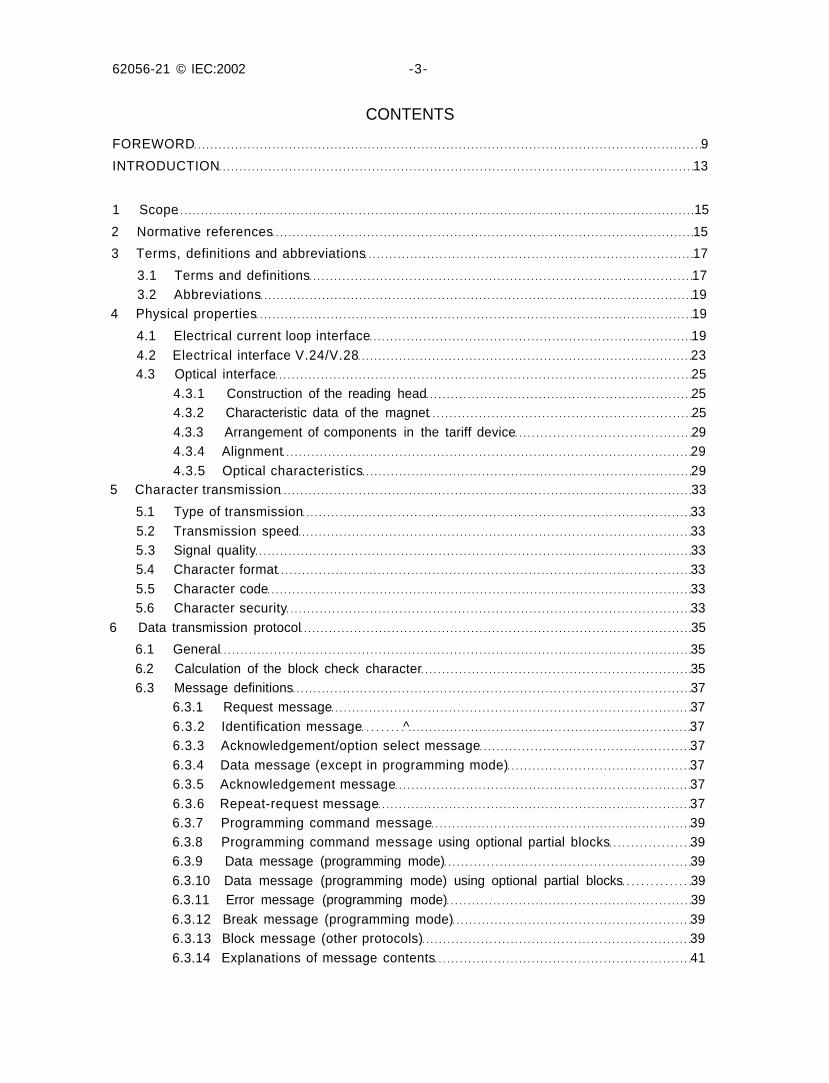
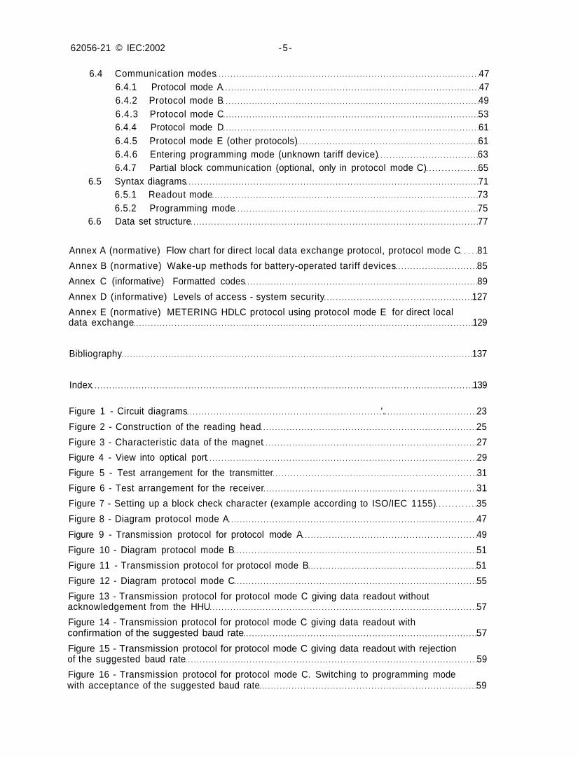
CONTENTS
FOREWORD 9
INTRODUCTION 13
1 Scope 15
2 Normative references 15
3 Terms, definitions and abbreviations 17
3.1 Terms and definitions 173.2 Abbreviations 19
4 Physical properties 19
4.1 Electrical current loop interface 194.2 Electrical interface V.24/V.28 234.3 Optical interface 25
4.3.1 Construction of the reading head 254.3.2 Characteristic data of the magnet 254.3.3 Arrangement of components in the tariff device 294.3.4 Alignment 294.3.5 Optical characteristics 29
5 Character transmission 33
5.1 Type of transmission 335.2 Transmission speed 335.3 Signal quality 335.4 Character format 335.5 Character code 335.6 Character security 33
6 Data transmission protocol 35
6.1 General 356.2 Calculation of the block check character 356.3 Message definitions 37
6.3.1 Request message 376.3.2 Identification message ^ 376.3.3 Acknowledgement/option select message 376.3.4 Data message (except in programming mode) 376.3.5 Acknowledgement message 376.3.6 Repeat-request message 376.3.7 Programming command message 396.3.8 Programming command message using optional partial blocks 396.3.9 Data message (programming mode) 396.3.10 Data message (programming mode) using optional partial blocks 396.3.11 Error message (programming mode) 396.3.12 Break message (programming mode) 396.3.13 Block message (other protocols) 396.3.14 Explanations of message contents 41
62056-21 © IEC:2002 -5 -
6.4 Communication modes 476.4.1 Protocol mode A 476.4.2 Protocol mode B 496.4.3 Protocol mode C 536.4.4 Protocol mode D 616.4.5 Protocol mode E (other protocols) 616.4.6 Entering programming mode (unknown tariff device) 636.4.7 Partial block communication (optional, only in protocol mode C) 65
6.5 Syntax diagrams 716.5.1 Readout mode 736.5.2 Programming mode 75
6.6 Data set structure 77
Annex A (normative) Flow chart for direct local data exchange protocol, protocol mode C 81
Annex B (normative) Wake-up methods for battery-operated tariff devices 85
Annex C (informative) Formatted codes 89
Annex D (informative) Levels of access - system security 127
Annex E (normative) METERING HDLC protocol using protocol mode E for direct localdata exchange 129
Bibliography 137
Index 139
Figure 1 - Circuit diagrams '. 23
Figure 2 - Construction of the reading head 25
Figure 3 - Characteristic data of the magnet 27
Figure 4 - View into optical port 29
Figure 5 - Test arrangement for the transmitter 31
Figure 6 - Test arrangement for the receiver 31
Figure 7 - Setting up a block check character (example according to ISO/IEC 1155) 35
Figure 8 - Diagram protocol mode A 47
Figure 9 - Transmission protocol for protocol mode A 49
Figure 10 - Diagram protocol mode B 51
Figure 11 - Transmission protocol for protocol mode B 51
Figure 12 - Diagram protocol mode C 55
Figure 13 - Transmission protocol for protocol mode C giving data readout withoutacknowledgement from the HHU 57
Figure 14 - Transmission protocol for protocol mode C giving data readout withconfirmation of the suggested baud rate 57
Figure 15 - Transmission protocol for protocol mode C giving data readout with rejectionof the suggested baud rate 59
Figure 16 - Transmission protocol for protocol mode C. Switching to programming modewith acceptance of the suggested baud rate 59
62056-21 © IEC:2002 -7-
Figure 17 - Transmission protocol for protocol mode C. Switching to programming modewith rejection of the suggested baud rate 59
Figure 18 - Diagram protocol mode D 61
Figure 19 - Transmission protocol for protocol mode D 61
Figure 20 - Diagram for entering programming mode 63
Figure 21 - Example of a partial block unformatted read 67
Figure 22 - Example of a partial block formatted write 69
Figure 23 - Example of a partial block formatted write (with errors) 71
Figure 24 - Syntax diagrams - readout mode 73
Figure 25 - Syntax diagrams - programming mode - command 75
Figure 26 - Syntax diagram - programming mode - answer 77
Figure 27 - Data set structure 77
Figure A.1 - Flow chart for direct local data exchange protocol, protocol mode C 81
Figure B.1 - The start sequence for battery-operated devices 85
Figure B.2 - Diagram for the start sequence of battery-operated devices by fastwake-up mode 87
Figure C.1 - Example of channel types 91
Figure C.2 - Register coding diagram 97
Figure C.3 - Bit assignment for group data 111
Figure C.4 - Vector diagrams for quadrants I to IV 125
Figure E.1 - Entering protocol mode E (HDLC) 129
Figure E.2 - Flow chart and switchover to METERING HDLC in protocol mode E 131
Figure E.3 - Physical layer primitives 133
Figure E.4 - Physical layer primitives, simplified example with one mode change only 133
Table 1 - Electrical interface 19
Table 2 - Read, Write and Execute commands .. ...65
62056-21 © IEC:2002 -9-
INTERNATIONAL ELECTROTECHNICAL COMMISSION
ELECTRICITY METERING -DATA EXCHANGE FOR METER READING,
TARIFF AND LOAD CONTROL -
Part 21: Direct local data exchange
FOREWORD
1) The IEC (International Electrotechnical Commission) is a worldwide organization for standardization comprisingall national electrotechmcal committees (IEC National Committees). The object of the IEC is to promoteinternational co-operation on all questions concerning standardization in the electrical and electronic fields. Tothis end and in addition to other activities, the IEC publishes International Standards. Their preparation isentrusted to technical committees; any IEC National Committee interested in the subject dealt with mayparticipate in this preparatory work. International, governmental and non-governmental organizations liaisingwith the IEC also participate in this preparation. The IEC collaborates closely with the International Organizationfor Standardization (ISO) in accordance with conditions determined by agreement between the twoorganizations.
2) The formal decisions or agreements of the IEC on technical matters express, as nearly as possible, aninternational consensus of opinion on the relevant subjects since each technical committee has representationfrom all interested National Committees.
3) The documents produced have the form of recommendations for international use and are published in the formof standards, technical specifications, technical reports or guides and they are accepted by the NationalCommittees in that sense.
4) In order to promote international unification, IEC National Committees undertake to apply IEC InternationalStandards transparently to the maximum extent possible in their national and regional standards. Anydivergence between the IEC Standard and the corresponding national or regional standard shall be clearlyindicated in the latter.
5) The IEC provides no marking procedure to indicate its approval and cannot be rendered responsible for anyequipment declared to be in conformity with one of its standards.
The International Electrotechnical Commission (IEC) draws attention to the fact that it isclaimed that compliance with this International Standard may involve the use of a maintenanceservice concerning the stack of protocols on which the-present standard IEC 62056-21 isbased.
The IEC takes no position concerning the evidence, validity and scope of this maintenanceservice.
The provider of the maintenance service has assured the IEC that he is willing to provideservices under reasonable and non-discriminatory terms and conditions with applicantsthroughout the world. In this respect, the statement of the provider of the maintenance serviceis registered with the IEC. Information may be obtained:
Manufacturer's identification, item 12) of 6.3.2: from
The FLAG Association, UKwww.dlms.com/fiag
Enhanced identification character, item 24) of 6.3.2: from
DIMS User AssociationGeneva / Switzerland
www.dlms.ch
62056-21 © IEC:2002 -11 -
International Standard IEC 62056-21 has been prepared by IEC Technical Committee 13:Equipment for electrical energy measurement and load control.
This first edition IEC 62056-21 cancels and replaces the second edition of IEC 61107published in 1996 and constitutes a technical revision.
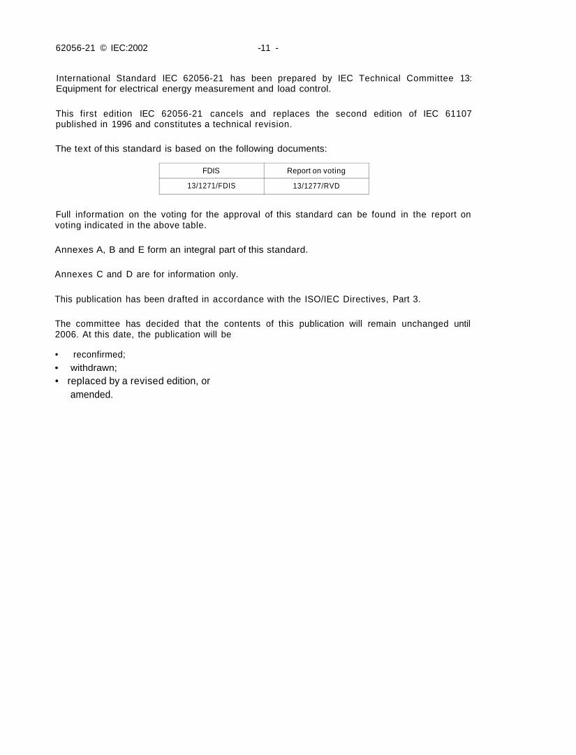
The text of this standard is based on the following documents:
FDIS
13/1271/FDIS
Report on voting
13/1277/RVD
Full information on the voting for the approval of this standard can be found in the report onvoting indicated in the above table.
Annexes A, B and E form an integral part of this standard.
Annexes C and D are for information only.
This publication has been drafted in accordance with the ISO/IEC Directives, Part 3.
The committee has decided that the contents of this publication will remain unchanged until2006. At this date, the publication will be
• reconfirmed;• withdrawn;• replaced by a revised edition, or
amended.

62056-21 © IEC:2002 -13-
INTRODUCTiON
IEC TC 13 has the task of preparing standards for data exchange for the purposes of meterreading, tariff and load control, and consumer information using various alternativecommunication media, with reference to ISO and ITU standards.
Meter data exchange can be local or remote. This part of IEC 62056 is restricted to local dataexchange, whereas remote data exchange is covered by other standards of the IEC 62056series.
62056-21 © IEC:2002 - 15-
ELECTRICITY METERING -DATA EXCHANGE FOR METER READING,
TARIFF AND LOAD CONTROL -
Part 21: Direct local data exchange
1 Scope
This part of IEC 62056 describes hardware and protocol specifications for local meter dataexchange. In such systems, a hand-held unit (HHU) or a unit with equivalent functions isconnected to a tariff device or a group of devices.
The connection can be permanent or disconnectable using an optical or electrical coupling. Anelectrical interface is proposed for use with a permanent connection, or when more than onetariff device needs to be read at one site. The optical coupler should be easily disconnectableto enable data collection via an HHU.
The protocol permits reading and programming of tariff devices. It is designed to be particularlysuitable for the environment of electricity metering, especially as regards electrical isolationand data security. While the protocol is well-defined, its use and application are left to the user.
This standard is based on the reference model for communication in open systems. It isenhanced by further elements such as an optical interface, protocol controlled baud rateswitchover, data transmission without acknowledgement of receipt. The protocol offers severalmodes for implementation in the tariff device. The HHU or equivalent unit acts as a masterwhile the tariff device acts as a slave in protocol modes A to D. In protocol mode E, the HHUacts as a client and the tariff device acts as a server.
As several systems are in practical use already, particular care was taken to maintaincompatibility with existing systems and/or system components and their relevant protocols
2 Normative references
The following normative documents contain provisions which, through reference in this text,constitute provisions of this International Standard. At the time of publication, the editionsindicated were valid. All normative documents are subject to revision, and parties toagreements based on this International Standard are encouraged to investigate the possibilityof applying the most recent editions of the normative documents indicated below. Members ofIEC and ISO maintain registers of currently valid International Standards.
IEC 60050-300:2001, International Electrotechnical Vocabulary (IEV) - Electrical and electronicmeasurements and measuring instruments - Part 311: General terms relating to measurements- Part 312: General terms relating to electrical measurements - Part 313: Types of electricalmeasuring instruments - Part 314: Specific terms according to the type of instrument
62056-21 © IEC:2002 -17-
IEC 62051:1999, Electricity metering - Glossary of terms
IEC 62056-42:2002. Electricity metering - Data exchange for meter reading, tariff and loadcontrol Part 42: Physical layer services and procedures for connection orientedasynchronous data exchange
IEC 62056-46:2002, Electricity metering - Data exchange for meter reading, tariff and loadcontrol - Part 46: Data link layer using HDLC-protocol
IEC 62056-53:2002. Electricity metering - Data exchange for meter reading, tariff and loadcontrol - Part 53: COSEM application layer
ISO/IEC 646:1991, Information technology - ISO 7-bit coded character set for informationinterchange
ISO/IEC 1155:1978, Information processing - Use of longitudinal parity to detect errors ininformation messages
ISO/IEC 1177:1985, Information processing - Character structure for start/stop andsynchronous character-oriented transmission
ISO/IEC 1745:1975, Information processing - Basic mode control procedures for datacommunication systems
ISO/IEC 7480:1991, Information technology- Telecommunications and information exchangebetween systems - Start-stop transmission signal Quality at DTE/DCE interfaces
ITU-T Recommendation V.24 (2000), List of definitions for interchange circuits between dataterminal equipment (DTE) and data circuit-terminating equipment (DCE)
ITU-T Recommendation V.28 (1993), Electrical characteristics for unbalanced double-currentinterchange circuits
3 Terms, definitions and abbreviations
3.1 Terms and definitions
For the purpose of this part of IEC 62056 the terms and definitions given in IEC 60050-300 andIEC 62051, as well as the following apply:
3.1.1tariff devicefixed data collection unit, normally linked or combined with an electricity meter, actingas a server
3.1.2mastercentral station. Station which takes the initiative and controls the data flow
62056-21 © IEC:2002 -19-
3.1.3slavestation responding to requests of a master station. The tariff device is normally a slave station
3.1.4clienta station, asking for services, normally the master station
3.1.5servera station, delivering services. The tariff device (e.g. the meter) is normally the server,delivering the requested values or executing the requested tasks
3.2 Abbreviations
HHU hand-held unit
4 Physical properties
4.1 Electrical current loop interface
a) Type of signal
20 mA current loop
•Absolute limits:
Current
Zero, no loop current, SPACE
One, 20 mA loop current, MARK
Send (TX)
<=2,5 mA
>=11 mA
Receive (RX)
<=3 mA
>=9 mA
Voltage drop
One. 20 mA loop current, MARK
Send (TX)
<=2 V
Receive (RX)
<=3 V
j
Maximum open-circuit voltage during operation 3 0 V d . c .
b) Power supply
On the tariff device side the interface is passive. The HHU supplies the necessary power.
c) Connections
Via terminals or suitable connectors. Polarity errors can prevent communication, but shallnot harm the devices.
Open-circuit voltage: max. 30 V d.c.
Loop current: max. 30 mA
Table 1 - Electrical interface
62056-21 © IEC:2002 -21 -
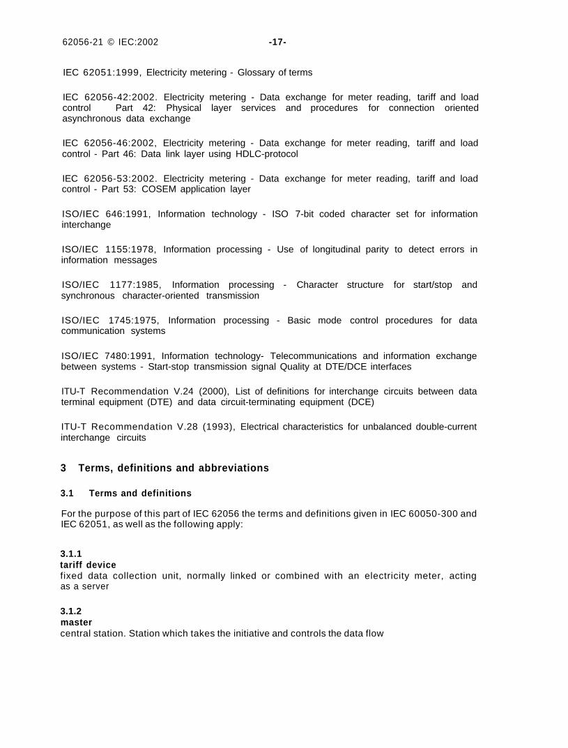
d) Circuit arrangements in two-wire configuration (one slave station)
Figure 1a - Circuit diagram of a two-wire single slave configuration
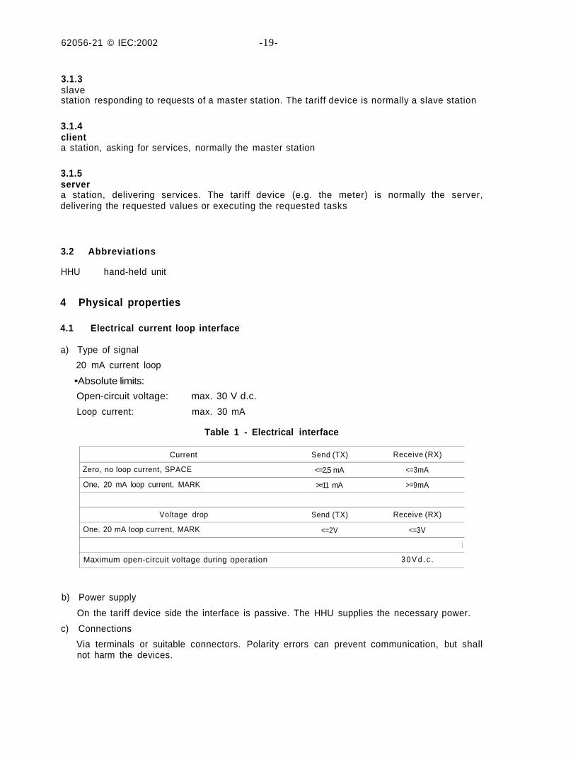
e) Circuit arrangements in two-wire configuration (multiple slave stations)
/EC 723/02
Figure 1b - Circuit diagram of a two-wire multiple slave configuration
f) Circuit arrangements in four-wire configuration (one slave station)
IEC 724/02
Figure 1c - Circuit diagram of a four-wire single slave configuration
IEC 722/02
62056-21 © |EC:2002 -23-
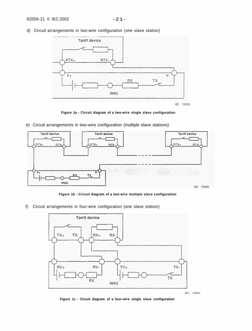
g) Circuit arrangements in four-wire configuration (multiple slave stations)
/EC 725/02
Figure 1d - Circuit diagram of a four-wire multiple slave configuration
Figure 1 - Circuit diagrams
If a nominal voltage of the master station (HHU) of 26 V is assumed, eight slave stations (tariffdevices) can be connected in series.
4.2 Electrical interface V.24/V.28
Relevant ITU-T recommendations apply:
ITU-T Recommendation V.24: only circuits No. 102 (Signal ground), 103 (Transmitted data)and 104 (Received data) are used.
ITU-T Recommendation V.28: The electrical characteristics of the interchange circuits shall beaccording to the ITU-T V.28 Recommendation. These enable signalling rates up to 20 kbit/s.
62056-21 © IEC:2002 -25-
4.3 Optical interface
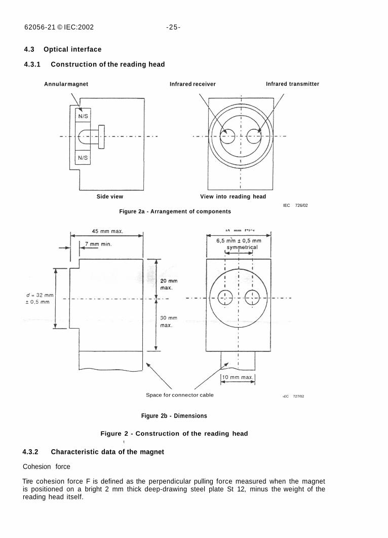
4.3.1 Construction of the reading head
Annular magnet Infrared receiver Infrared transmitter
Side view View into reading head
Figure 2a - Arrangement of componentsIEC 726/02
tA mm f*i^v
Space for connector cable ,£C 727/02
Figure 2b - Dimensions
Figure 2 - Construction of the reading headt
4.3.2 Characteristic data of the magnet
Cohesion force
Tire cohesion force F is defined as the perpendicular pulling force measured when the magnetis positioned on a bright 2 mm thick deep-drawing steel plate St 12, minus the weight of thereading head itself.
62056-21 © IEC:2002 -27
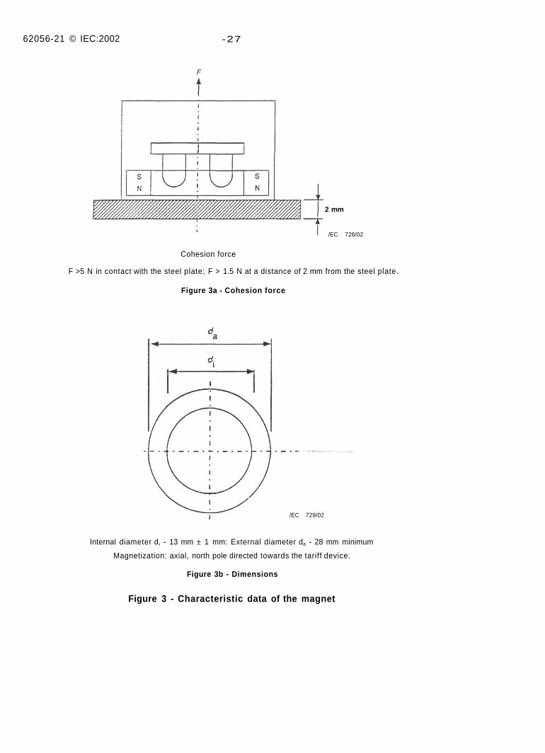
2 mm
/EC 728/02
Cohesion force
F >5 N in contact with the steel plate; F > 1.5 N at a distance of 2 mm from the steel plate.
Figure 3a - Cohesion force
/EC 729/02
Internal diameter d, - 13 mm ± 1 mm: External diameter da - 28 mm minimum
Magnetization: axial, north pole directed towards the tariff device.
Figure 3b - Dimensions
Figure 3 - Characteristic data of the magnet
62056-21 © IEC:2002 -29-
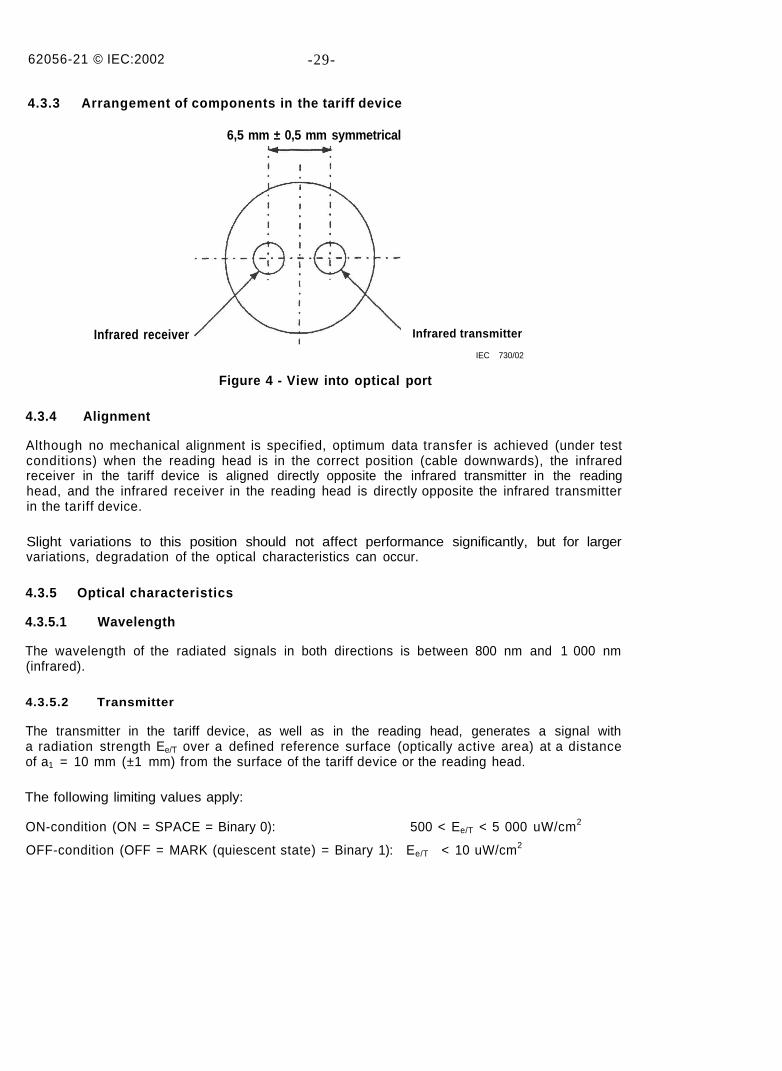
4.3.3 Arrangement of components in the tariff device
6,5 mm ± 0,5 mm symmetrical
Infrared receiver Infrared transmitter
IEC 730/02
Figure 4 - View into optical port
4.3.4 Alignment
Although no mechanical alignment is specified, optimum data transfer is achieved (under testconditions) when the reading head is in the correct position (cable downwards), the infraredreceiver in the tariff device is aligned directly opposite the infrared transmitter in the readinghead, and the infrared receiver in the reading head is directly opposite the infrared transmitterin the tariff device.
Slight variations to this position should not affect performance significantly, but for largervariations, degradation of the optical characteristics can occur.
4.3.5 Optical characteristics
4.3.5.1 Wavelength
The wavelength of the radiated signals in both directions is between 800 nm and 1 000 nm(infrared).
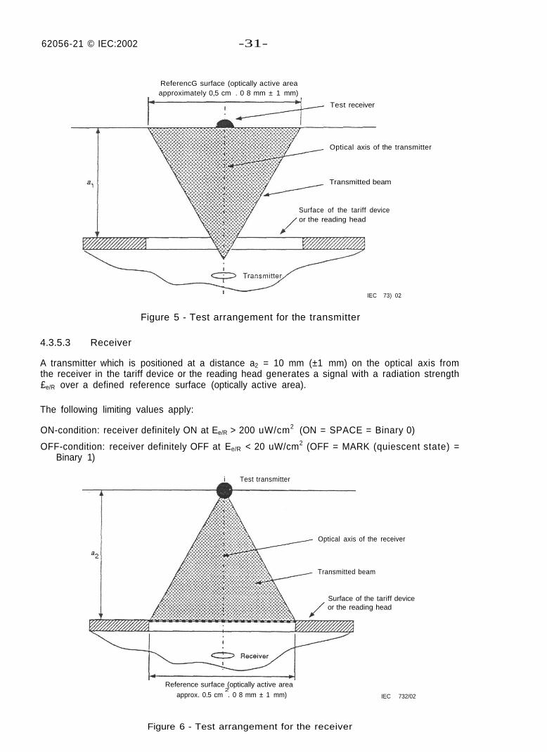
4.3.5.2 Transmitter
The transmitter in the tariff device, as well as in the reading head, generates a signal witha radiation strength Ee/T over a defined reference surface (optically active area) at a distanceof a1 = 10 mm (±1 mm) from the surface of the tariff device or the reading head.
The following limiting values apply:
ON-condition (ON = SPACE = Binary 0): 500 < Ee/T < 5 000 uW/cm2
OFF-condition (OFF = MARK (quiescent state) = Binary 1): Ee/T < 10 uW/cm2
62056-21 © IEC:2002 -31 -
ReferencG surface (optically active areaapproximately 0,5 cm . 0 8 mm ± 1 mm)
'Test receiver
Optical axis of the transmitter
Transmitted beam
Surface of the tariff deviceor the reading head
IEC 73) 02
Figure 5 - Test arrangement for the transmitter
4.3.5.3 Receiver
A transmitter which is positioned at a distance a2 = 10 mm (±1 mm) on the optical axis fromthe receiver in the tariff device or the reading head generates a signal with a radiation strength£e/R over a defined reference surface (optically active area).
The following limiting values apply:
ON-condition: receiver definitely ON at Ee/R > 200 uW/cm2 (ON = SPACE = Binary 0)
OFF-condition: receiver definitely OFF at Ee/R < 20 uW/cm2 (OFF = MARK (quiescent state) =Binary 1)
i Test transmitter
Optical axis of the receiver
Transmitted beam
Surface of the tariff deviceor the reading head
Reference surface (optically active area2
approx. 0.5 cm . 0 8 mm ± 1 mm) IEC 732/02
Figure 6 - Test arrangement for the receiver
62056-21 © IEC:2002 -33-
4.3.5.4 Environmental lighting condition
The optical path (data transmission) shall not be affected by surrounding light with an intensityof up to 16 000 lux (light composition comparable with daylight, including fluorescent light).
4.3.5.5 Environmental temperature condition
The reference temperature is 23 °C ± 2 °C.
5 Character transmission
5.1 Type of transmission
Asynchronous serial bit (Start - Stop) transmission according to ISO/IEC 1177:1985. half-duplex.
5.2 Transmission speed
Initial baud rate - 300
Standard baud rates - 300, 600, 1 200. 2 400, 4 800, 9 600, 19 200
Special baud rate - as desired.
NOTE The maximum speed may be limited by the reading head or the optical port or the ITU-T RecommendationV.28 limitations in the tariff device.
5.3 Signal quality,
According to ISO/IEC 7480:1991:
category 1 for the transmitter;
- category A for the receiver.
5.4 Character format
Character format according to ISO/IEC 1177:1985.
(1 start bit, 7 data bits, 1 parity bit, 1 stop bit).
NOTE Protocol mode E (see 6.4.5) may use byte transparency, 1 start bit. 8 data bits. 1 stop bit (e.g. see Annex E).
5.5 Character code
Character code according to ISO/IEC 646:1991, international reference version. For local use.a national replacement code can be used.
NOTE Protocol mode E (see 6.4.5) may use byte transparency.
5.6 Character security
With parity bit, even parity according to ISO/IEC 1177:1985.
NOTE Protocol mode E (see 6.4.5) may use byte transparency, specific security may be used.
62056-21 © IEC:2002 -35-
6 Data transmission protocol
6.1 General
The protocol offers five alternative protocol modes, which can be used by the tariff device: A,B, C, D and E. Mode selection is a subset of ISO/IEC 1745, basic mode control procedures.
Data exchange is bi-directional in protocol modes A, B, C and E and is always initiated by theHHU with a transmission of a request message. In protocol modes A to C, the HHU acts as amaster and the tariff device acts as a slave. In protocol mode E, the HHU acts as a client andthe tariff device acts as a server. These protocol modes permit meter reading andprogramming. Protocol mode E may be a transparent binary mode.
Data exchange is unidirectional in protocol mode D and permits readout only. The informationflows from the tariff device to the HHU. Data transmission is initiated, for example by operatinga push button or other sensor on the tariff device.
The protocol mode used by the tariff device is indicated to the HHU by the identificationmessage. Protocol modes A to D are identified by the baud rate identification character (seeitem 13 in 6.3.3) while protocol mode E is identified by an escape sequence (see items 23 and24 in 6.3.2). Protocol mode E enables to use various protocols, one of them being theMETERING HDLC protocol as described in Annex E.
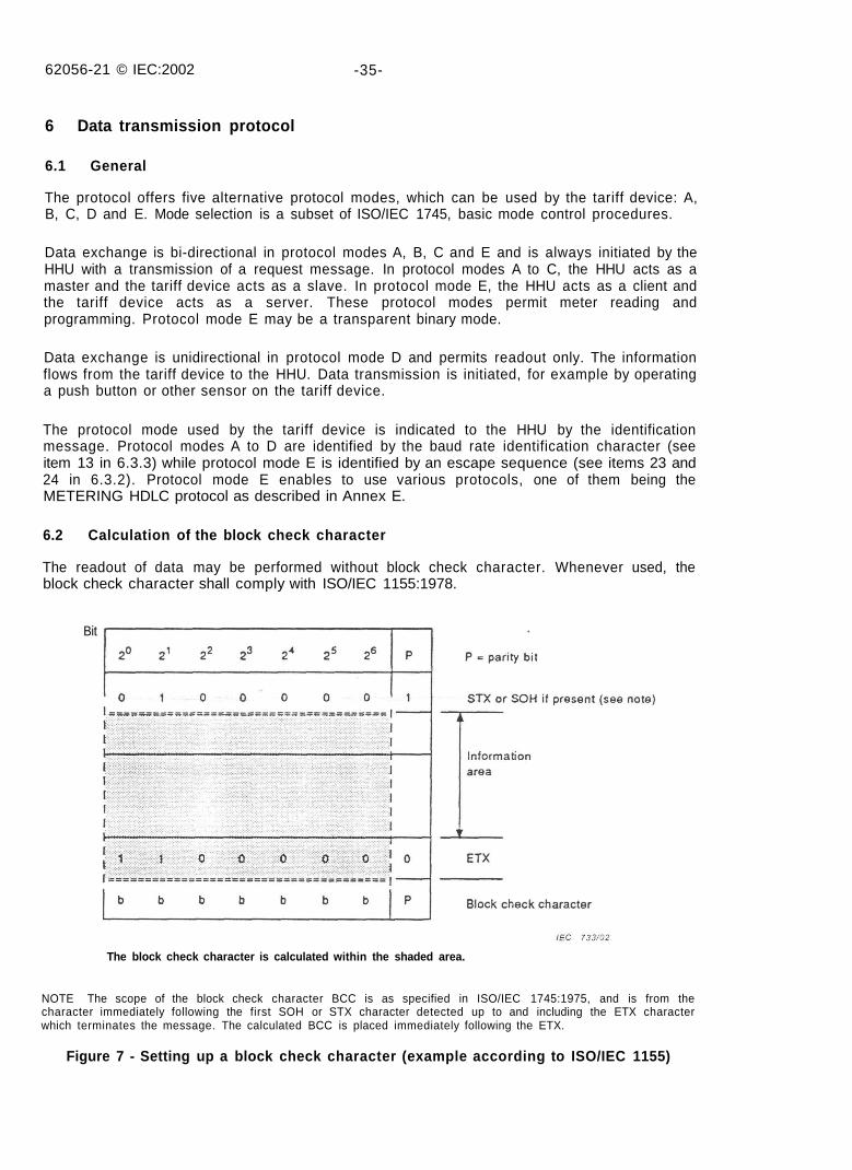
6.2 Calculation of the block check character
The readout of data may be performed without block check character. Whenever used, theblock check character shall comply with ISO/IEC 1155:1978.
Bit
The block check character is calculated within the shaded area.
NOTE The scope of the block check character BCC is as specified in ISO/IEC 1745:1975, and is from thecharacter immediately following the first SOH or STX character detected up to and including the ETX characterwhich terminates the message. The calculated BCC is placed immediately following the ETX.
Figure 7 - Setting up a block check character (example according to ISO/IEC 1155)
62056-21 © IEC:2002 -37-
6.3 Message definitions
Explanations of message contents see 6.3.14.
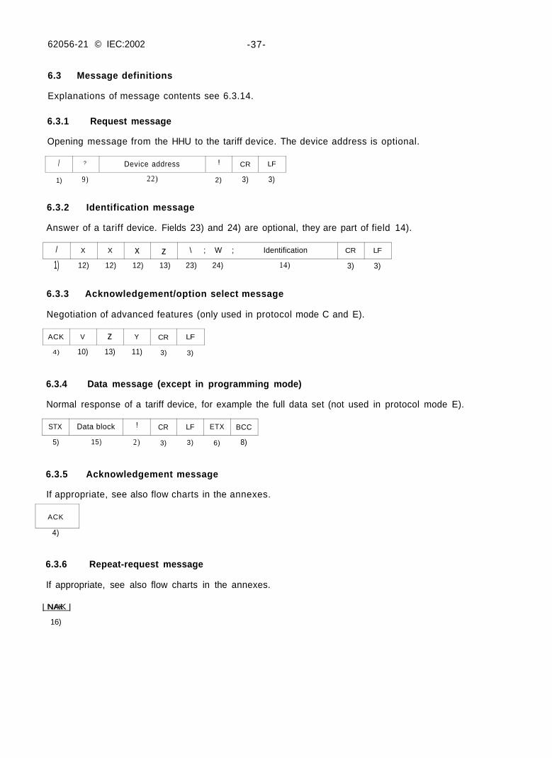
6.3.1 Request message
Opening message from the HHU to the tariff device. The device address is optional.
1) 9) 22) 2) 3) 3)
6.3.2 Identification message
Answer of a tariff device. Fields 23) and 24) are optional, they are part of field 14).
6.3.3 Acknowledgement/option select message
Negotiation of advanced features (only used in protocol mode C and E).
4) 10) 13) 11) 3) 3)
6.3.4 Data message (except in programming mode)
Normal response of a tariff device, for example the full data set (not used in protocol mode E).
5) 15) 2) 3) 3) 6) 8)
6.3.5 Acknowledgement message
If appropriate, see also flow charts in the annexes.
4)
6.3.6 Repeat-request message
If appropriate, see also flow charts in the annexes.
| NAK |
16)
1) 12) 12) 12) 13) 23) 24) 14) 3) 3)
/ ? Device address ! CR LF
/ X X x z \ ; W ; Identification CR LF
ACK V z Y CR LF
STX Data block ! CR LF ETX BCC
ACK
NAK
62056-21 © IEC:2002 -39-
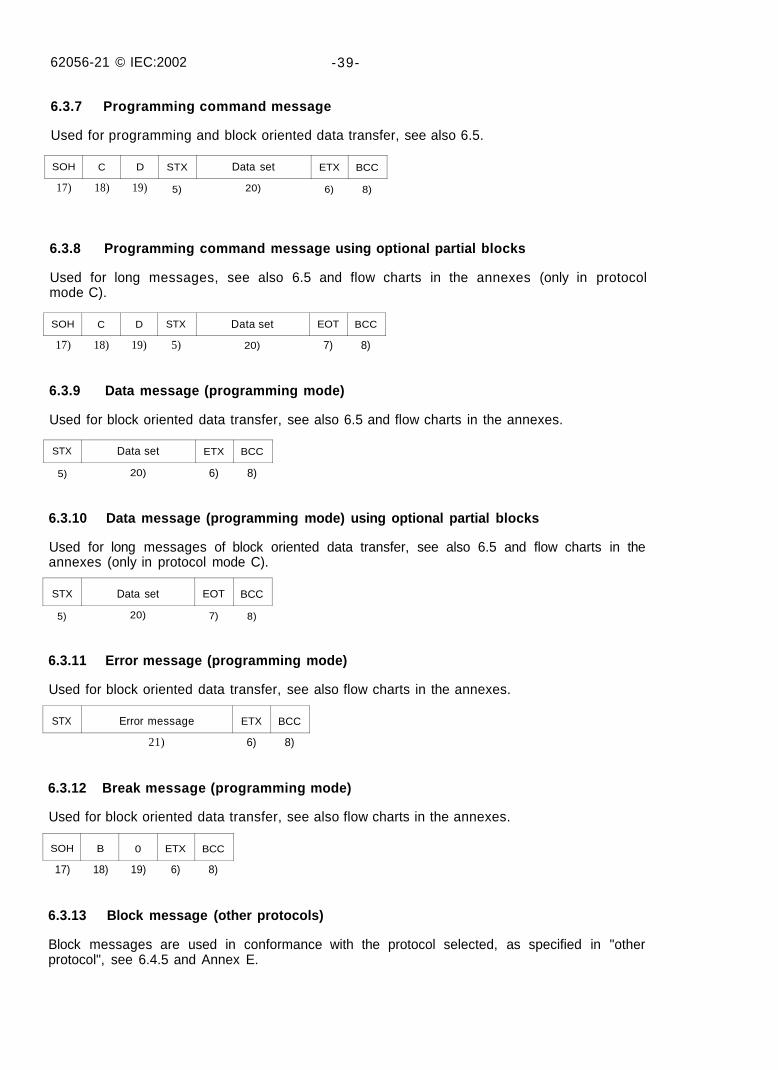
6.3.7 Programming command message
Used for programming and block oriented data transfer, see also 6.5.
17) 18) 19) 5) 20) 6) 8)
6.3.8 Programming command message using optional partial blocks
Used for long messages, see also 6.5 and flow charts in the annexes (only in protocolmode C).
17) 18) 19) 5) 20) 7) 8)
6.3.9 Data message (programming mode)
Used for block oriented data transfer, see also 6.5 and flow charts in the annexes.
5) 20) 6) 8)
6.3.10 Data message (programming mode) using optional partial blocks
Used for long messages of block oriented data transfer, see also 6.5 and flow charts in theannexes (only in protocol mode C).
5) 20) 7) 8)
6.3.11 Error message (programming mode)
Used for block oriented data transfer, see also flow charts in the annexes.
21) 6) 8)
6.3.12 Break message (programming mode)
Used for block oriented data transfer, see also flow charts in the annexes.
17) 18) 19) 6) 8)
6.3.13 Block message (other protocols)
Block messages are used in conformance with the protocol selected, as specified in "otherprotocol", see 6.4.5 and Annex E.
SOH C D STX Data set ETX BCC
SOH C D STX Data set EOT BCC
STX Data set ETX BCC
STX Data set EOT BCC
STX Error message ETX BCC
SOH B 0 ETX BCC
62056-21 © IEC 2002 -41 -
6.3.14 Explanations of message contents
1) Start character "/" (forward oblique, code 2FH)
2) End character"!" (exclamation mark, code 21H)
3) Completion character (CR, carriage return, code ODH, LF, line feed, code OAH)
4) Acknowledge character (ACK, acknowledge, code 06H)
5) Frame start character (STX, start of text code 02H) indicating where the calculation of BCCshall start from This character is not required if there is no data set to follow
6) End character in the block (ETX, end of text, code 03H)
7) End character in a partial block (EOT, end of text block, code 04H)
8) Block check character (BCC), if required, in accordance with the characters 5) and 6)Items 5) and 6) do not apply when the data block is transmitted without check characters
9) Transmission request command '"?" (question mark, code 3FH)
10) Protocol control character (see 6 4 5 2 )
11) Mode control character (see 6 4 5 3 )
12) Manufacturer's identification comprising three upper case letters except as noted below
If a tariff device transmits the third letter in lower case, the minimum reaction time tr for thedevice is 20 ms instead of 200 ms Even though a tariff device transmits an upper casethird letter, this does not preclude supporting a 20 ms reaction time
These letters shall be registered with the administrator The FLAG Association (see theforeword)
13) Baud rate identification (for baud rate changeover)
The request message, the identification message and the acknowledgement/option selectmessage are transmitted at the initial rate of 300 Bd (except protocol mode D) The baudrate of the data message depends on the baud rate determined by the protocol
a) Protocol mode A (without baud rate changeover)
Any desired printable characters except "/", "!" and as long as they are not specified forprotocol mode B or protocol mode C
b) Protocol mode B (with baud rate changeover, without acknowledgement/option selectmessage)
A - 600 Bd
B - 1 200 Bd
C - 2 400 Bd
D - 4 800 Bd
E - 9 600 Bd
F - 19200Bd
G, H, I - reserved for later extensions
c) Protocol mode C and protocol mode E (with baud rate changeover, withacknowledgement / option select message or other protocols)
0 - 300 Bd
1 - 600 Bd
2 - 1 200 Bd
3 - 2 400 Bd
62056-21 © IEC:2002 -43-
4 - 4 800 Bd5 - 9 600 Bd6 - 19200Bd7, 8, 9 - reserved for later extensions.
d) Protocol mode D (data transmission at 2 400 Bd)Baud rate character is always 3.
14) Identification, manufacturer-specific, 16 printable characters maximum except for "/" and"!". "\" is only allowed as an escape character, see 23) and 24).
15) Data block with the measured values (see syntax diagram for normal reading). All printablecharacters may be used in the data block, as well as line feed and carriage return, exceptfor"/" and "!".
16) Repeat request character (NAK, negative acknowledge, code 15H).
17) Start-of-header character (SOH, start-of-header, code 01H).
18) Command message identifier
P - Password commandW - Write commandR - Read commandE - Execute commandB - Exit command (break)
Other characters are reserved for future use.
19) Command type identifier (signifies the variant of the command)
Values:
a) for password P command
0 - data is operand for secure algorithm1 - data is operand for comparison with internally held password2 - data is result of secure algorithm (manufacturer-specific)3-9 - reserved for future use.
b) for write W command
0 - reserved for future use1 - write ASCII-coded data2 - formatted communication coding method write (optional, see Annex C) •3 - write ASCII-coded with partial block (optional)4 - formatted communication coding method write (optional, see Annex C)
with partial block5 - reserved for national use6-9 - reserved for future use.
c) for read R command
0 - reserved for future use1 - read ASCII-coded data2 - formatted communication coding method read (optional, see Annex C)3 - read ASCII-coded with partial block (optional)4 - formatted communication coding method read (optional, see Annex C)
with partial block5,6 - reserved for national use7-9 - reserved for future use.
62056-21 © IEC:2002 - 45 -
d) for execute E command
0-1 - reserved for future use
2 - formatted communication coding method execute (optional, see Annex C)
3-9 - reserved for future use.
e) for exit B command
0 - complete sign-off
1 - complete sign-off for battery operated devices using the fast wake-up method
2-9 - reserved for future use.
20) Data set
This provides the address and data for the message (see 6.5).
The following applies to command messages:
a) The password command
The address and unit fields are empty (devoid of any characters).
b) The write command
Where the value represents a data string, the address is the start location to which thedata is to be written. The unit field is left empty.
c) The read command
Where a data string is to be read, the address is the start location from which data isread.
The value represents the number of locations to be read including the start location.The unit field is left empty.
• d) The execute command
It requests that a device executes a predefined function.
e) The exit command
No data set is required when the command type identifier is 0.
21) Error message
This consists of 32 printable characters maximum with exception of (, ), *, / and !. It isbounded by front and rear boundary characters, as in the data set structure. This ismanufacturer-specific and should be chosen so that it cannot be confused with data, forexample starting all error messages with ER.
22) Device address, optional field, manufacturer-specific, 32 characters maximum. The charac-ters can be digits (0...9), upper-case letters (A...Z), or lower case letters (a...z), or a space( ). Upper and lower case letters, and the space character are unique*. Leading zeros shallnot be evaluated. This means that all leading zeros in the transmitted address are ignoredand all leading zeros in the tariff device address are ignored (i.e. 10203 = 010203 =000010203). When both the transmitted address and the tariff device address contain onlyzeros, regardless of their respective lengths, the addresses are considered equivalent. Asa missing address field is considered as a general address (/ ? ! CR LF), the tariff deviceshall respond. The tariff device shall be able to evaluate the complete address as sent byan external device, even if the internal programmed address is shorter or longer in length.NOTE 1 * Upper and lower case letters, and the space character must match and their combination may beused only once.
NOTE 2 The device identification number can be used as an address to avoid reading of, or writing to, wrongdevices.
62056-21 © IEC:2002 -47-
23) Sequence delimiter (backslash code 5CH), optional field. This character is always followedby a one character field 24). This field is part of the maximum 16 character wideidentification field 14). Multiple pairs 23)/24) are allowed.
24) Enhanced baud rate and mode identification character (optional field). This field is part ofthe 16 character wide identification field 14). W must be registered with the administrator:The DLMS User Association (see the foreword). For details see 6.4.5.1.
6.4 Communication modes
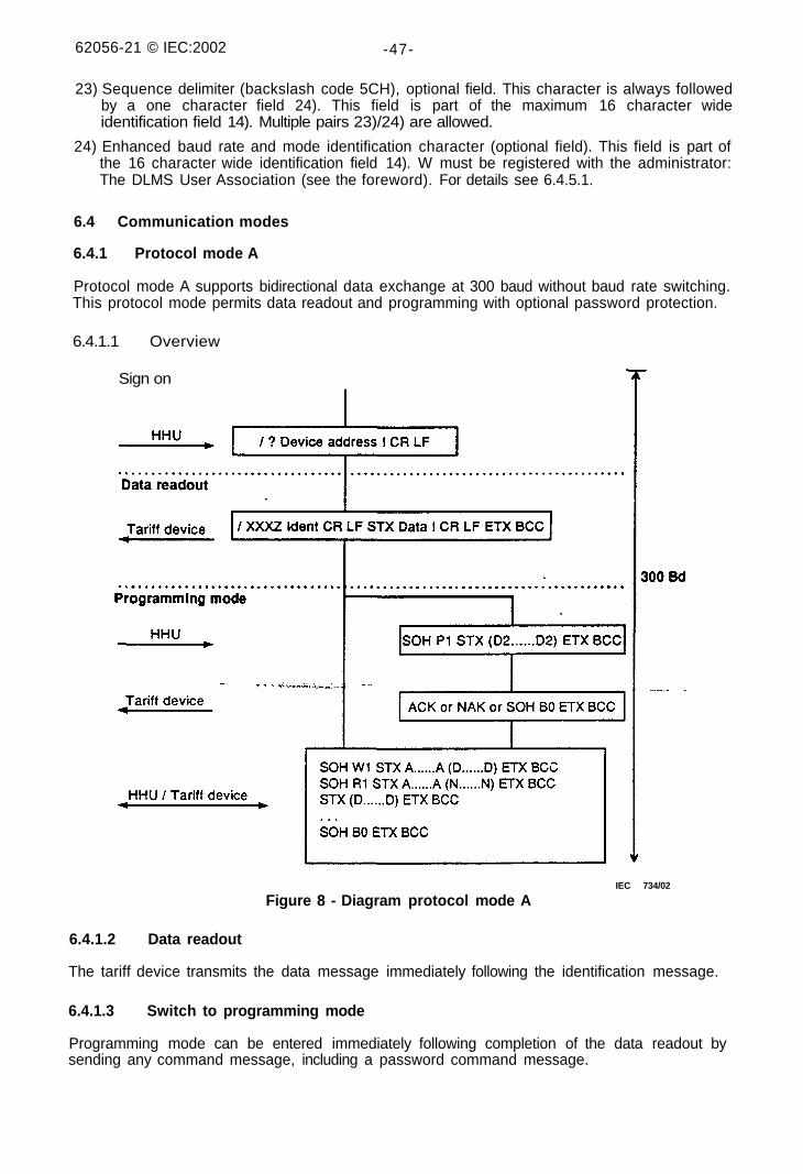
6.4.1 Protocol mode A
Protocol mode A supports bidirectional data exchange at 300 baud without baud rate switching.This protocol mode permits data readout and programming with optional password protection.
6.4.1.1 Overview
Sign on
IEC 734/02
Figure 8 - Diagram protocol mode A
6.4.1.2 Data readout
The tariff device transmits the data message immediately following the identification message.
6.4.1.3 Switch to programming mode
Programming mode can be entered immediately following completion of the data readout bysending any command message, including a password command message.
62056-21 © IEC:2002 -49-
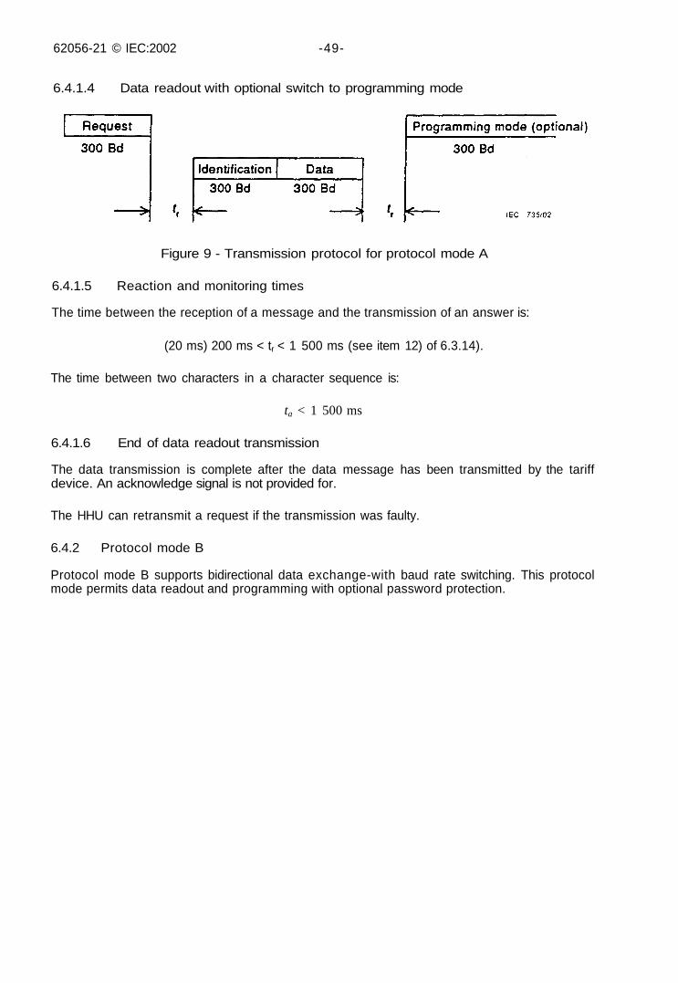
6.4.1.4 Data readout with optional switch to programming mode
Figure 9 - Transmission protocol for protocol mode A
6.4.1.5 Reaction and monitoring times
The time between the reception of a message and the transmission of an answer is:
(20 ms) 200 ms < tr < 1 500 ms (see item 12) of 6.3.14).
The time between two characters in a character sequence is:
ta < 1 500 ms
6.4.1.6 End of data readout transmission
The data transmission is complete after the data message has been transmitted by the tariffdevice. An acknowledge signal is not provided for.
The HHU can retransmit a request if the transmission was faulty.
6.4.2 Protocol mode B
Protocol mode B supports bidirectional data exchange-with baud rate switching. This protocolmode permits data readout and programming with optional password protection.
62056-21 © IEC:2002 -51 -
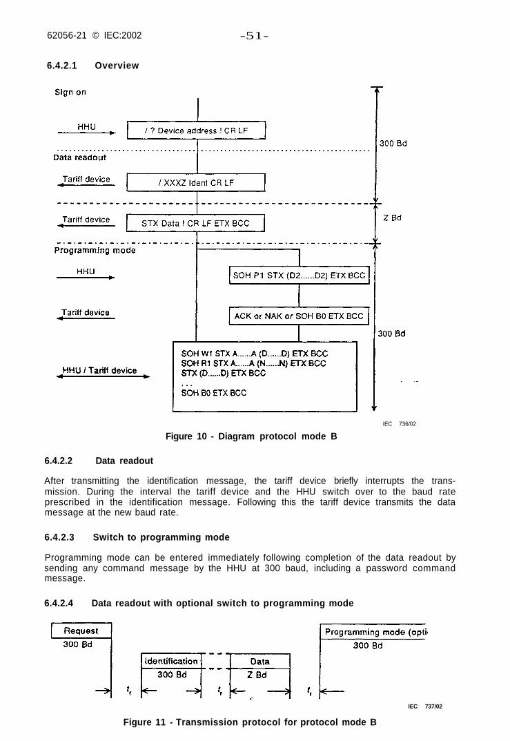
6.4.2.1 Overview
IEC 736/02
Figure 10 - Diagram protocol mode B
6.4.2.2 Data readout
After transmitting the identification message, the tariff device briefly interrupts the trans-mission. During the interval the tariff device and the HHU switch over to the baud rateprescribed in the identification message. Following this the tariff device transmits the datamessage at the new baud rate.
6.4.2.3 Switch to programming mode
Programming mode can be entered immediately following completion of the data readout bysending any command message by the HHU at 300 baud, including a password commandmessage.
6.4.2.4 Data readout with optional switch to programming mode
IEC 737/02
Figure 11 - Transmission protocol for protocol mode B
62056-21 © IEC:2002 -53-
6.4.2.5 Reaction and monitoring times
The time between the reception of a message and the transmission of an answer is:
(20 ms) 200 ms < tr < 1 500 ms (see item 12) of 6.3.14.
The time between two characters in a character sequence is:
ta < 1 500 ms
6.4.2.6 End of data readout transmission
The data transmission is complete after the data message has been transmitted by the tariffdevice. An acknowledge signal is not provided for.
The HHU can retransmit a request if the transmission was faulty.
6.4.3 Protocol mode C
Protocol mode C supports bidirectional data exchange with baud rate switching and permitsdata readout, programming with enhanced security and manufacturer-specific modes.
62056-21 D IEC.2002 -55-
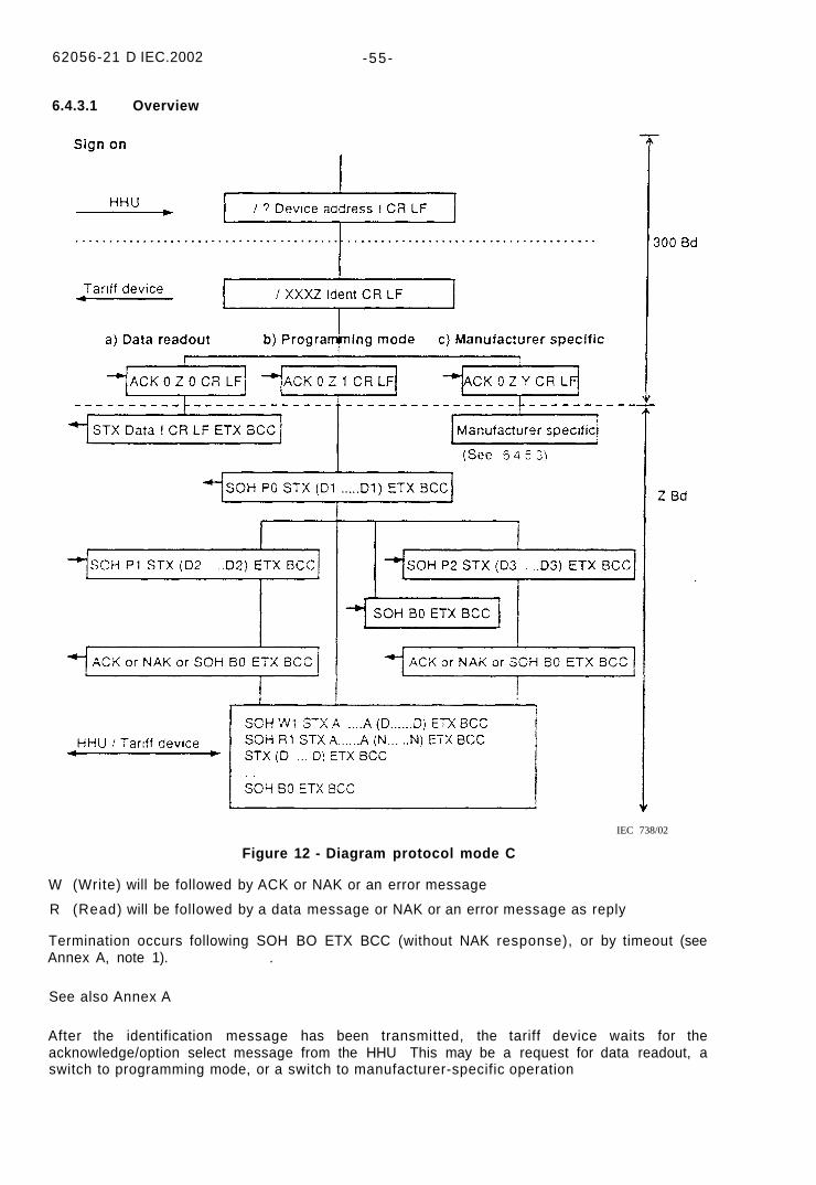
6.4.3.1 Overview
Figure 12 - Diagram protocol mode C
W (Write) will be followed by ACK or NAK or an error message
R (Read) will be followed by a data message or NAK or an error message as reply
Termination occurs following SOH BO ETX BCC (without NAK response), or by timeout (seeAnnex A, note 1). .
See also Annex A
After the identification message has been transmitted, the tariff device waits for theacknowledge/option select message from the HHU This may be a request for data readout, aswitch to programming mode, or a switch to manufacturer-specific operation
IEC 738/02
62056-21 e IEC.2002 -57-
6.4.3.2 Data readout mode
In the case of ACK 0 Z 0 CR LF the tariff device will respond with a predefined data set in theformat defined in 6 5 ("Syntax diagrams - Readout mode - Data message"). The data set maybe empty for those tariff devices not designed to read data in this manner
The communication will proceed at 300 Bd (initial baud rate) if:
- the "Z" character in the acknowledgement/option select message is 0; or
- an incorrect or unsupported acknowledgement/option select message is sent or received: or
- no acknowledgement/option select message is sent or received
The communication will only switch to Z baud if the Z characters m the identification responseand the acknowledgement/option select message are identical
6.4.3.3 Switch to programming mode
In the case of ACK 0 Z 1 CR LF the tariff device will switch to programming mode Furthercommunication will proceed at 300 Bd (the initial baud rate) if'
- the Z character in the acknowledgement/option select message is 0
The communication will switch to Z baud if the Z character m the identification response andthe acknowledgement/option select message are identical If the acknowlecgement/optionselect message is inconsistent or determined to be in error by the tariff device, thencommunication will proceed at 300 Bd in the data readout mode Programming will not beentered.
6.4.3.4 Switch to manufacturer-specific operation
Manufacturer's own options may be obtained by selecting Y to take values between 6 and 9 inthe seduence ACK 0 Z Y CR LF
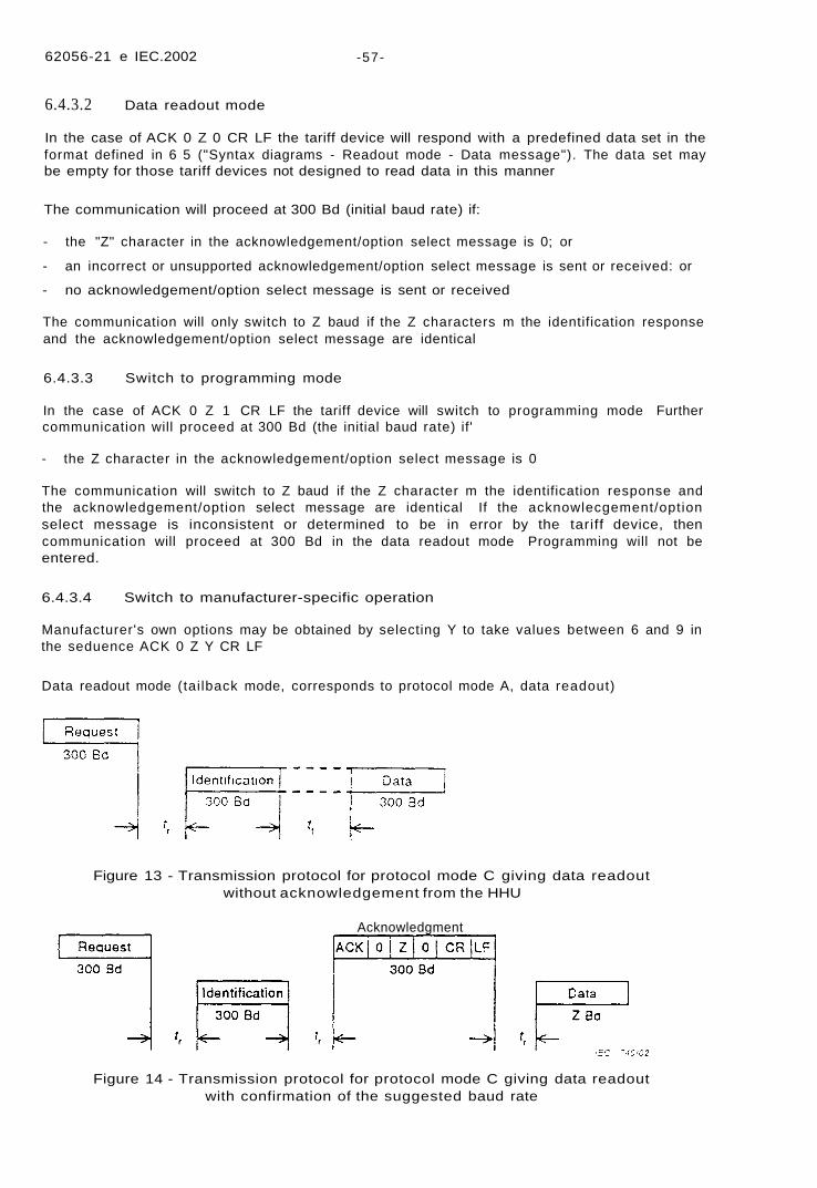
Data readout mode (tai lback mode, corresponds to protocol mode A, data readout)
Figure 13 - Transmission protocol for protocol mode C giving data readoutwithout acknowledgement from the HHU
Acknowledgment
Figure 14 - Transmission protocol for protocol mode C giving data readoutwith confirmation of the suggested baud rate
62056-21 © IEC:2002 -59-
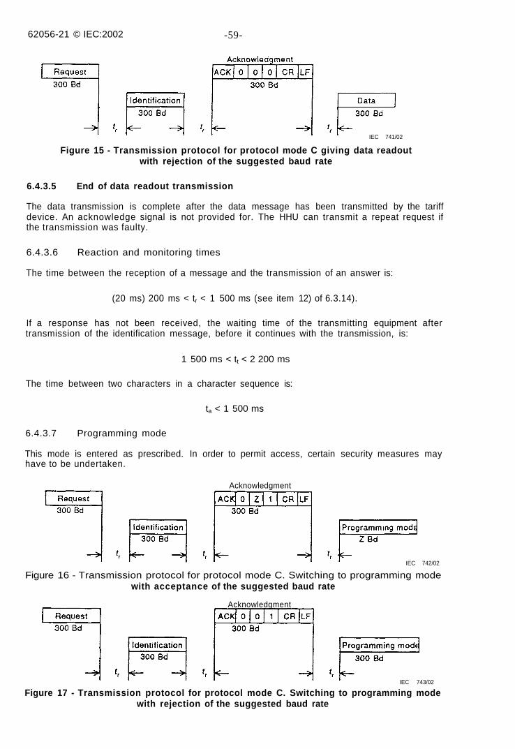
IEC 741/02
Figure 15 - Transmission protocol for protocol mode C giving data readoutwith rejection of the suggested baud rate
6.4.3.5 End of data readout transmission
The data transmission is complete after the data message has been transmitted by the tariffdevice. An acknowledge signal is not provided for. The HHU can transmit a repeat request ifthe transmission was faulty.
6.4.3.6 Reaction and monitoring times
The time between the reception of a message and the transmission of an answer is:
(20 ms) 200 ms < tr < 1 500 ms (see item 12) of 6.3.14).
If a response has not been received, the waiting time of the transmitting equipment aftertransmission of the identification message, before it continues with the transmission, is:
1 500 ms < tt < 2 200 ms
The time between two characters in a character sequence is:
ta < 1 500 ms
6.4.3.7 Programming mode
This mode is entered as prescribed. In order to permit access, certain security measures mayhave to be undertaken.
Acknowledgment
IEC 742/02
Figure 16 - Transmission protocol for protocol mode C. Switching to programming modewith acceptance of the suggested baud rate
Acknowledgment
IEC 743/02
Figure 17 - Transmission protocol for protocol mode C. Switching to programming modewith rejection of the suggested baud rate
62056-21 © IEC:2002 -61
6.4.3.8 Levels of access - system security
See Annex D.
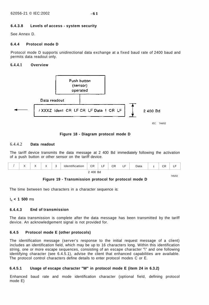
6.4.4 Protocol mode D
Protocol mode D supports unidirectional data exchange at a fixed baud rate of 2400 baud andpermits data readout only.
6.4.4.1 Overview
IEC 744/02
Figure 18 - Diagram protocol mode D
6.4.4.2 Data readout
The tariff device transmits the data message at 2 400 Bd immediately following the activationof a push button or other sensor on the tariff device.
/ X X X 3 Identification CR LF CR LF Data ! CR LF
2 400 Bd
Figure 19 - Transmission protocol for protocol mode D745/02
The time between two characters in a character sequence is:
ta < 1 500 ms
6.4.4.3 End of transmission
The data transmission is complete after the data message has been transmitted by the tariffdevice. An acknowledgement signal is not provided for.
6.4.5 Protocol mode E (other protocols)
The identification message (server's response to the initial request message of a client)includes an identification field, which may be up to 16 characters long. Within this identificationstring, one or more escape sequences, consisting of an escape character "\" and one followingidentifying character (see 6.4.5.1), advise the client that enhanced capabilities are available.The protocol control characters define details to enter protocol modes C or E.
6.4.5.1 Usage of escape character "W" in protocol mode E (item 24 in 6.3.2)
Enhanced baud rate and mode identification character (optional field, defining protocolmode E)
62056-21 © lEC 2002 -63 -
0-1 - reserved for future applications
2 - binary mode (HDLC) see Annex E
3-9 - reserved for future applications
Other printable characters with exception of /, \ and ! manufacturer-specific use
6.4.5.2 Usage of protocol control character "V" in protocolmode C and E (item 10 in 6.3.3)
0 - normal protocol procedure
1 - secondary protocol procedure
2 - HDLC protocol procedure, see Annex E
3-9 - reserved for future applications
6.4.5.3 Usage of mode control character "Y" in protocolmodes C and E (item 11 in 6.3.3)
0 - data readout
1 - programming mode
2 - binary mode (HDLC), see Annex E
3-5 and A-Z - reserved for future applications
6-9 - manufacturer-specific use
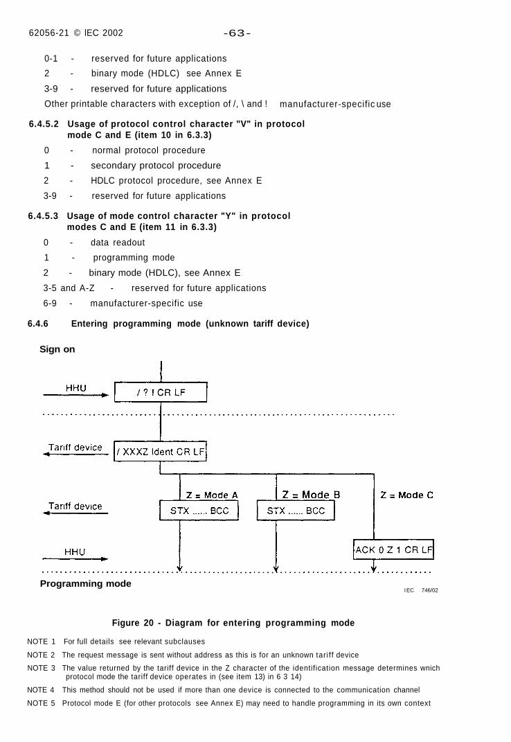
6.4.6 Entering programming mode (unknown tariff device)
Sign on
Programming modeI EC 746/02
Figure 20 - Diagram for entering programming mode
NOTE 1 For full details see relevant subclauses
NOTE 2 The request message is sent without address as this is for an unknown tar i f f device
NOTE 3 The value returned by the tariff device in the Z character of the identification message determines wnichprotocol mode the tariff device operates in (see item 13) in 6 3 14)
NOTE 4 This method should not be used if more than one device is connected to the communication channel
NOTE 5 Protocol mode E (for other protocols see Annex E) may need to handle programming in its own context
62056-21 © IEC2002 -65-
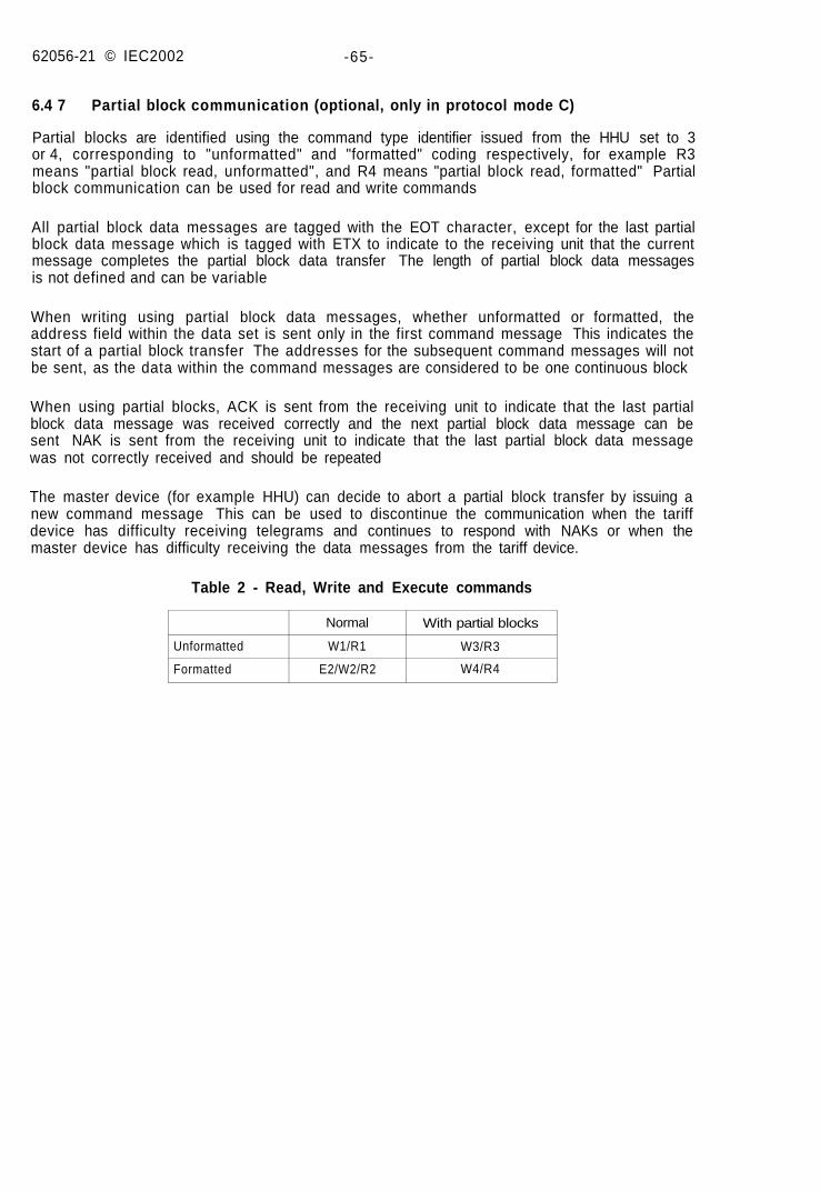
6.4 7 Partial block communication (optional, only in protocol mode C)
Partial blocks are identified using the command type identifier issued from the HHU set to 3or 4, corresponding to "unformatted" and "formatted" coding respectively, for example R3means "partial block read, unformatted", and R4 means "partial block read, formatted" Partialblock communication can be used for read and write commands
All partial block data messages are tagged with the EOT character, except for the last partialblock data message which is tagged with ETX to indicate to the receiving unit that the currentmessage completes the partial block data transfer The length of partial block data messagesis not defined and can be variable
When writing using partial block data messages, whether unformatted or formatted, theaddress field within the data set is sent only in the first command message This indicates thestart of a partial block transfer The addresses for the subsequent command messages will notbe sent, as the data within the command messages are considered to be one continuous block
When using partial blocks, ACK is sent from the receiving unit to indicate that the last partialblock data message was received correctly and the next partial block data message can besent NAK is sent from the receiving unit to indicate that the last partial block data messagewas not correctly received and should be repeated
The master device (for example HHU) can decide to abort a partial block transfer by issuing anew command message This can be used to discontinue the communication when the tariffdevice has difficulty receiving telegrams and continues to respond with NAKs or when themaster device has difficulty receiving the data messages from the tariff device.
Table 2 - Read, Write and Execute commands
Unformatted
Formatted
Normal
W1/R1
E2/W2/R2
With partial blocks
W3/R3
W4/R4
62056-21 © IEC:2002 -67-
HHU
Tariff device
HHU
Tariff device
HHU
Tariff device
HHU
Tariff device
HHU
Tariff device
SOH R3 STX 0000(93) ETX BCC
STX 0000(0123456789ABCDEF0123456789ABCDEF) CR LF0010(0123456789ABCDEF0123456789ABCDEF) CR LF0020(0123456789ABCDEF0123456789ABCDEF) CR LF0030(0123456789ABCDEF0123456789ABCDEF) EOT BCC
STX 0000(0123456789ABCDEF0123456789ABCDEF) CR LF0010(0123456789ABCDEF0123456789ABCDEF) CR LF0020(0123456789ABCDEF0123456789ABCDEF) CR LF0030(0123456789ABCDEF0123456789ABCDEF) EOT BCC
STX 0040(0123456789ABCDEF0123456789ABCDEF) CR LF0050(0123456789ABCDEF0123456789ABCDEF) CR LF0060(0123456789ABCDEF0123456789ABCDEF) CR LF0070(0123456789ABCDEF0123456789ABCDEF) EOT BCC
STX 0080(0123456789ABCDEF0123456789ABCDEF) CR LF0090(012345) ETX BCC
STX 0080(0123456789ABCDEF0123456789ABCDEF) CR LF0090(012345) ETX BCC
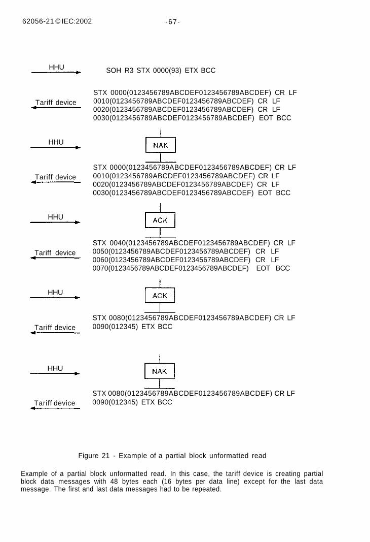
Figure 21 - Example of a partial block unformatted read
Example of a partial block unformatted read. In this case, the tariff device is creating partialblock data messages with 48 bytes each (16 bytes per data line) except for the last datamessage. The first and last data messages had to be repeated.
62056-21 © IEC:2002 -69-
HHU
Tariff device
HHU
Tariff device
HHU
Tariff device
HHU
Tariff device
SOH W4 STX FFFF(012345) EOT BCC
ACK
SOH W4 STX (6789ABCDE) EOT BCC
ACK
SOH W4 STX (F01234) ETX BCC
NAK
SOH W4 STX (F01234) ETX BCC
ACK
/EC 748/02
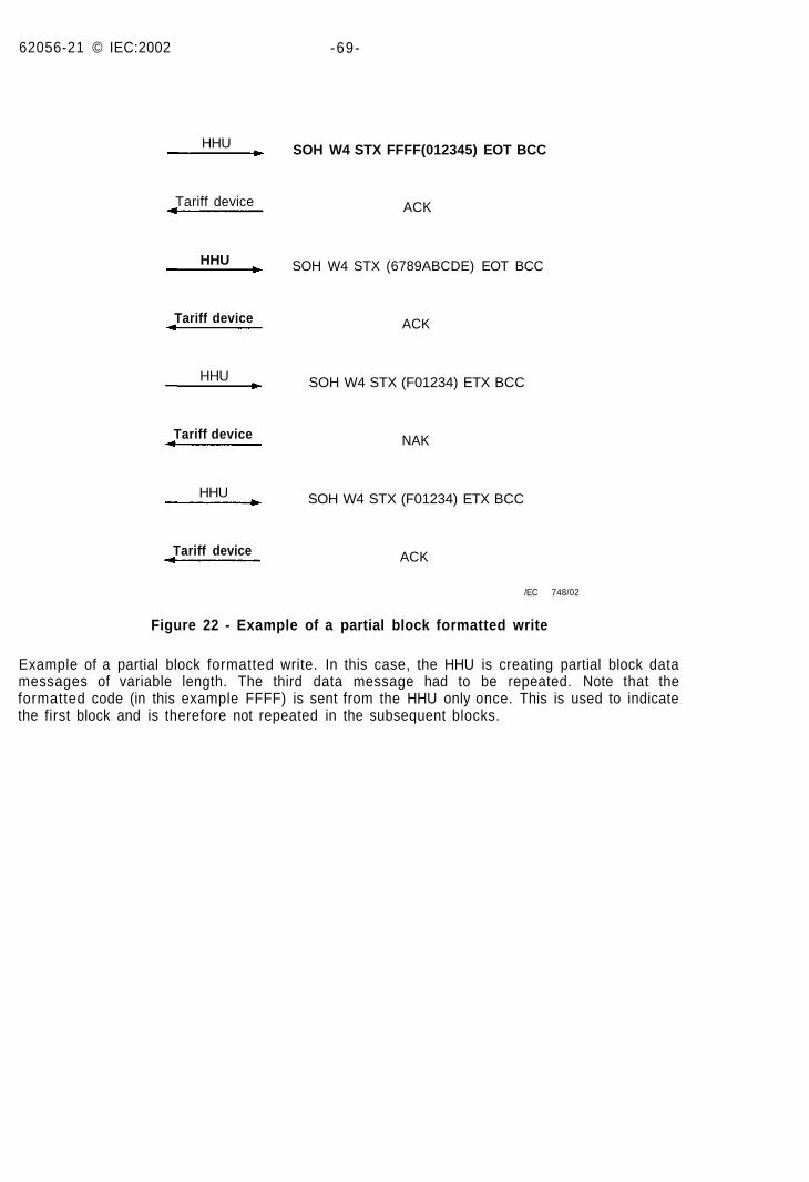
Figure 22 - Example of a partial block formatted write
Example of a partial block formatted write. In this case, the HHU is creating partial block datamessages of variable length. The third data message had to be repeated. Note that theformatted code (in this example FFFF) is sent from the HHU only once. This is used to indicatethe first block and is therefore not repeated in the subsequent blocks.
62056-21 © IEC 2002 -71 -
HHU
Tariff device
HHU
Tariff device
HHU
Tariff device
HHU
Tariff device
HHU
Tariff device
HHU
SOH W4 STX FFFF(012345) EOT BCC
SOH W4 STX (6789ABCDE) EOT BCC
SOH W4 STX (F01234) ETX BCC
SOH W4 STX (F01234) ETX BCC
ACK
SOH W4 STX (6789ABCDE) EOT BCC
ACK
SOH W4 STX (F01234) ETX BCC
NAK
SOH W4 STX (F01234) ETX BCC
NAK
SOH W4 STX (F01234) ETX BCC
NAK
SOH BO ETX BCC
IEC 749/02
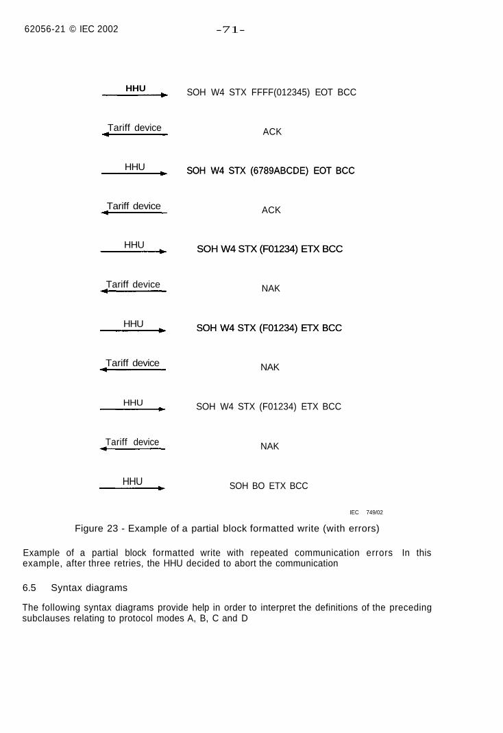
Figure 23 - Example of a partial block formatted write (with errors)
Example of a partial block formatted write with repeated communication errors In thisexample, after three retries, the HHU decided to abort the communication
6.5 Syntax diagrams
The following syntax diagrams provide help in order to interpret the definitions of the precedingsubclauses relating to protocol modes A, B, C and D
62056-21 © IEC:2002 -73 -
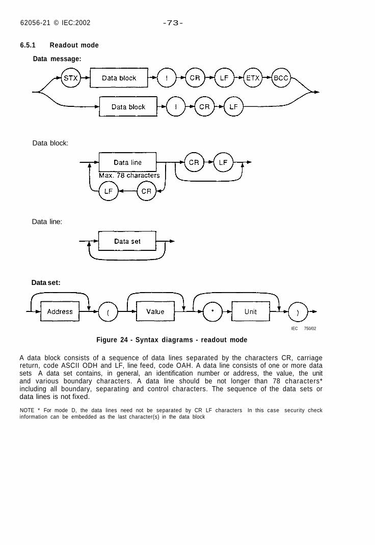
6.5.1 Readout mode
Data message:
Data block:
Data line:
Data set:
IEC 750/02
Figure 24 - Syntax diagrams - readout mode
A data block consists of a sequence of data lines separated by the characters CR, carriagereturn, code ASCII ODH and LF, line feed, code OAH. A data line consists of one or more datasets A data set contains, in general, an identification number or address, the value, the unitand various boundary characters. A data line should be not longer than 78 characters*including all boundary, separating and control characters. The sequence of the data sets ordata lines is not fixed.
NOTE * For mode D, the data lines need not be separated by CR LF characters In this case security checkinformation can be embedded as the last character(s) in the data block
52056-21 © IEC 2002 -75-
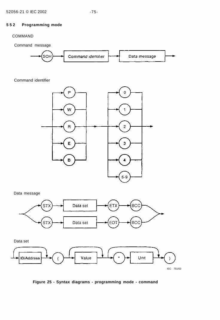
5 5 2 Programming mode
COMMAND
Command message
Command identifier
Data message
Data set
IEC 751/02
Figure 25 - Syntax diagrams - programming mode - command
62056-21 © IEC:2002 -77-
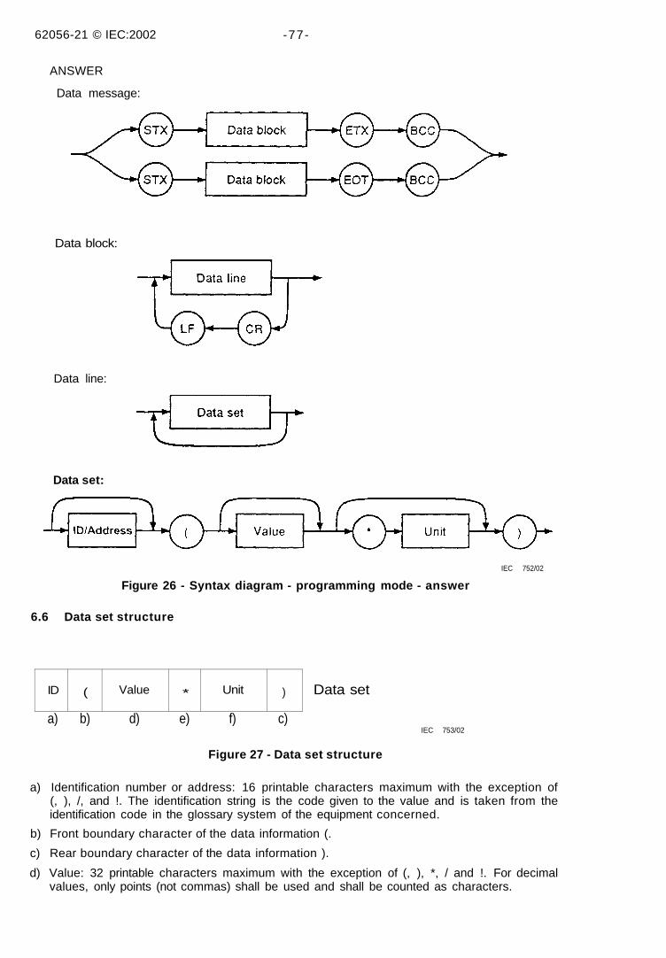
ANSWER
Data message:
Data block:
Data line:
Data set:
IEC 752/02
Figure 26 - Syntax diagram - programming mode - answer
6.6 Data set structure
ID ( Value * Unit ) Data set
a) b) d) e) f) c)IEC 753/02
Figure 27 - Data set structure
a) Identification number or address: 16 printable characters maximum with the exception of(, ), /, and !. The identification string is the code given to the value and is taken from theidentification code in the glossary system of the equipment concerned.
b) Front boundary character of the data information (.
c) Rear boundary character of the data information ).
d) Value: 32 printable characters maximum with the exception of (, ), *, / and !. For decimalvalues, only points (not commas) shall be used and shall be counted as characters.
52056-21 © IEC:2002 -79-
5) The separator character "*" between value and unit is not needed if there are no units.
) Unit: 16 printable characters maximum except for (, ), / and !.\IOTE 1 Remarks regarding items a), e) and f) to reduce the quantity of data, the identification code a) and/or thenit information e) and f) can be dispensed with, provided that an unambiguous correlation exists For example, the
dentification code or the unit information is not necessary for a sequence of similar values (sequence of historicalalues) on condition that the evaluation unit can clearly establish the identification code and unit of the succeedingalues from the first value of a sequence
MOTE 2 Remarks regarding programming mode, protocol mode C item a), the identification number may be usedjs an address, item d), the value portion may contain up to 128 characters.
62056-21 © IEC:2002 -81
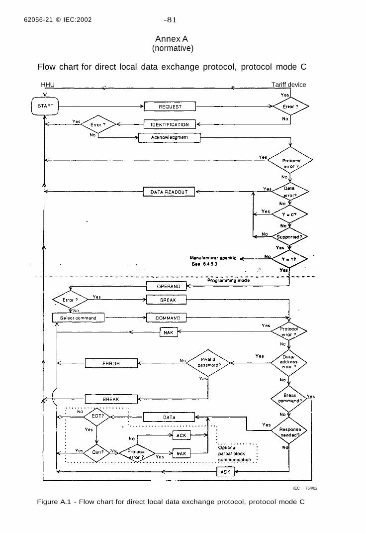
Annex A(normative)
Flow chart for direct local data exchange protocol, protocol mode C
HHU .. „ Tariff device
IEC 754/02
Figure A.1 - Flow chart for direct local data exchange protocol, protocol mode C
62056-21 © IEC.2002 -83-
Key to protocol mode C flow diagram
Message formats
For a complete message format definition, see 6.3.
REQUEST /? Device Address ! CR LF
IDENTIFICATION / XXX Z Ident CR LF
ACKNOWLEDGEMENT ACK0 Z Y CRLF
DATA READOUT STX DATA i CR LF ETX BCC
OPERAND SOH P 0 STX (d . d) ETX BCC
SOH P 0 STX (d . . d) EOT BCC
COMMAND SOH C D STX a a (d d) ETX BCC
optionally: SOH C D STX a . a (d d) EOT BCC
DATA STX (d . . d) ETX BCC
optionally STX (d . d) EOT BCC
ERROR STX (e . . e) ETX BCC
BREAK SOH B 0 ETX BCC
NOTE 1 The inactivity time-out period for the tariff device is 60 s to 120 s after which the operation moves fromany point to the start
NOTE 2 A break message can be issued at any point Operation then moves to the start after finishing the currentoperation
NOTE 3 ACK and NAK are used for error diagnosis at the command protocol level, with the following definition
ACK is returned from a tariff device, if the command meets protocol requirements, and a successful operation isperformed within the tariff device (e g memory write)
NAK is returned from a tariff device, if the command does not meet protocol requirements.
If the command meets protocol requirements but is not executed due to tariff device functionality (e g memory writeprotect, illegal command, etc ) an error message is returned
ACK and NAK are also used as "continue" and "repeat last partial block" commands issued by the receiving devicewhen in partial block mode (command type = 3 or 4)
NOTE 4 All other error diagnosis is done by time-out, i e if the tariff device does not respond within 1 500 ms of acommand, there has been an error and the HHU should take appropriate action
NOTE 5 A protocol error occurs when a parity, or the BCC, or the message syntax is incorrect
NOTE 6 An address/data error occurs when the received address or command is unknown or the data setstructure or content is incorrect In this case, the command cannot be earned out
NOTE 7 An error refers to any type of error (protocol, address/data, etc )
NOTE 8 The diagram does not explicitly indicate the partial block write method See 6 4 7 for further details
62056-21 © IEC:2002 -85-
Annex B(normative)
Wake-up methods for battery-operated tariff devices
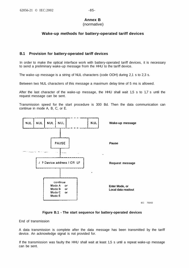
B.1 Provision for battery-operated tariff devices
In order to make the optical interface work with battery-operated tariff devices, it is necessaryto send a preliminary wake-up message from the HHU to the tariff device.
The wake-up message is a string of NUL characters (code OOH) during 2,1 s to 2,3 s.
Between two NUL characters of this message a maximum delay time of 5 ms is allowed.
After the last character of the wake-up message, the HHU shall wait 1,5 s to 1,7 s until therequest message can be sent.
Transmission speed for the start procedure is 300 Bd. Then the data communication cancontinue in mode A, B, C, or E.
Wake-up message
Pause
Request message
Enter Mode, orLocal data readout
IEC 755/02
Figure B.1 - The start sequence for battery-operated devices
End of transmission
A data transmission is complete after the data message has been transmitted by the tariffdevice. An acknowledge signal is not provided for.
If the transmission was faulty the HHU shall wait at least 1,5 s until a repeat wake-up messagecan be sent.
62056-21 © IEC:2002 -87-
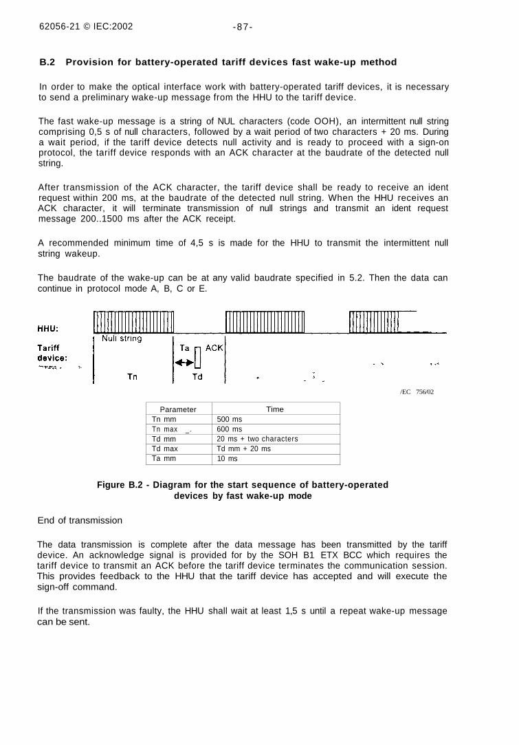
B.2 Provision for battery-operated tariff devices fast wake-up method
In order to make the optical interface work with battery-operated tariff devices, it is necessaryto send a preliminary wake-up message from the HHU to the tariff device.
The fast wake-up message is a string of NUL characters (code OOH), an intermittent null stringcomprising 0,5 s of null characters, followed by a wait period of two characters + 20 ms. Duringa wait period, if the tariff device detects null activity and is ready to proceed with a sign-onprotocol, the tariff device responds with an ACK character at the baudrate of the detected nullstring.
After transmission of the ACK character, the tariff device shall be ready to receive an identrequest within 200 ms, at the baudrate of the detected null string. When the HHU receives anACK character, it will terminate transmission of null strings and transmit an ident requestmessage 200..1500 ms after the ACK receipt.
A recommended minimum time of 4,5 s is made for the HHU to transmit the intermittent nullstring wakeup.
The baudrate of the wake-up can be at any valid baudrate specified in 5.2. Then the data cancontinue in protocol mode A, B, C or E.
/EC 756/02
ParameterTn mmTn max _.Td mmTd maxTa mm
Time500 ms600 ms20 ms + two charactersTd mm + 20 ms10 ms
Figure B.2 - Diagram for the start sequence of battery-operateddevices by fast wake-up mode
End of transmission
The data transmission is complete after the data message has been transmitted by the tariffdevice. An acknowledge signal is provided for by the SOH B1 ETX BCC which requires thetariff device to transmit an ACK before the tariff device terminates the communication session.This provides feedback to the HHU that the tariff device has accepted and will execute thesign-off command.
If the transmission was faulty, the HHU shall wait at least 1,5 s until a repeat wake-up messagecan be sent.
62056-21 © IEC 2002 -89-
Annex C(informative)
Formatted codes
C.1 General
This annex defines a data protocol for accessing metering devices within the framework of thisstandard (protocol mode E is excluded) The protocol is designed to allow access to allinformation within a given metering device The protocol can be viewed on two levels The firstlevel defines a data structure that can be applied to various metering applications Thisrequires the decomposition of data into items such as channels data types registers andtariffs The second level defines the content of these categories, that is the unit ofmeasurement recorded in register 0, whether it is kilowatt-hours or cubic meters of water Eightdifferent data categories have been defined in which to organise metering data These areRegister, Seasonal, Load profile, Group, Variable, Parameter, Extended function andManufacturer-specific An additional category has been reserved for future applications
Reading and writing are supported using the R2/R4 and W2/W4 commands in programmingmode in the form of programming command messages Additionally, execute commands, suchas trigger a seasonal cumulation, are supported using the E2 programming commandmessages All formatted commands have the syntax of command messages In order tosimplify processing within the metering unit, the coding method uses a four digit hex code, anassociated mnemonic, and a data field Within the command message, the code fieldcorresponds to the data set "address field", and the data field corresponds to the data set"value field" The mnemonic is a general purpose one, in that it does not refer to any particularapplication, electrical metering, gas metering, etc A set of mnemonics could be generated fora specific application for clarity as the need arises The data field follows the syntax for dataset structure Some codes require a predefined data field format These are listed explicitlyThe last section defines how the coding scheme is applied to electricity metering applicationsIn the rest of this annex, reference will only be made to R2 and W2, although in most cases anR4 or W4 command could be used
C.2 Channels
Channels play a specific part in coding They are the link between the first and second levels ofcoding This is accomplished by defining channel types of which there can be a limitlessnumber A type is assigned to each channel used in a metering unit, be it water, gas, heat orelectricity This depends on the data being stored within that channel When assigningchannels within a metering unit, the designation may or may not refer to physical channels Inthe case of a metering unit that registers the electrical energy, water and gas usage at aparticular installation, the channel designation could logically be applied to each item resultingin three channels But in a single electricity meter, where the device may measure variouskinds of information, such as kWh, kW and kVA, the data may all be accessed as one logicalchannel, even though the information is delivered to the metering device on different physicalchannels The channel type only plays a role in the following data categories Register,Season, Load profile and Group The other data categories, Extended function, Variable,Parameter, and Manufacturer-specific, do not require the channel to be specified, and aretherefore not defined by the channel type, but are available independent of channel type Thefollowing diagram is an example of the use of channel types
62056-21 © IEC:2002 -91 -
IEC 757/0}
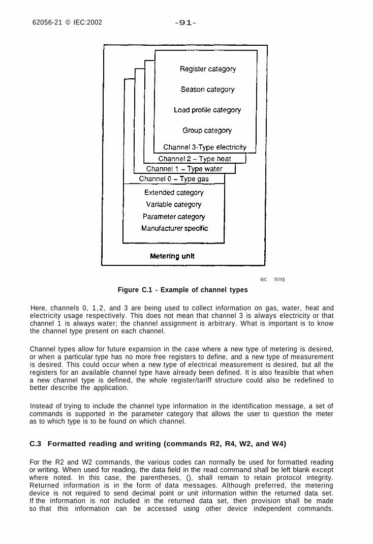
Figure C.1 - Example of channel types
Here, channels 0, 1 ,2 , and 3 are being used to collect information on gas, water, heat andelectricity usage respectively. This does not mean that channel 3 is always electricity or thatchannel 1 is always water; the channel assignment is arbitrary. What is important is to knowthe channel type present on each channel.
Channel types allow for future expansion in the case where a new type of metering is desired,or when a particular type has no more free registers to define, and a new type of measurementis desired. This could occur when a new type of electrical measurement is desired, but all theregisters for an available channel type have already been defined. It is also feasible that whena new channel type is defined, the whole register/tariff structure could also be redefined tobetter describe the application.
Instead of trying to include the channel type information in the identification message, a set ofcommands is supported in the parameter category that allows the user to question the meteras to which type is to be found on which channel.
C.3 Formatted reading and writing (commands R2, R4, W2, and W4)
For the R2 and W2 commands, the various codes can normally be used for formatted readingor writing. When used for reading, the data field in the read command shall be left blank exceptwhere noted. In this case, the parentheses, (), shall remain to retain protocol integrity.Returned information is in the form of data messages. Although preferred, the meteringdevice is not required to send decimal point or unit information within the returned data set.If the information is not included in the returned data set, then provision shall be madeso that this information can be accessed using other device independent commands.
62056-21 © IEC:2002 -93-
Time/date stamps are considered an integral part of a single data record and are included whenaccessing data records that have associated with them such information. They have the form(YY-MM-DD) or (YY-MM-DD hh:mm). In this case, the time and date stamp will be included asa new data set within the same data line as follows:
STX 0401 (0000.00*kW)(93-12-31 12:53) ETX BCC
When writing data, only available in the Register, Variable, and Parameter categories, the formof the data shall be compatible with the data set structure. When information is not explicitlysent by the programming device, the receiving unit may assume certain items, like units ordecimal points or leading zeros. Writing the value 0 to a particular data record is the same aserasing or resetting the record. The preferred method in this case is to send a write commandwith an empty data field () which is defined as resetting the addressed information. Becauseprogramming historical data is not considered a desired feature, write commands used in theSeason, Group or Load profile data categories are defined as erase commands.
C.4 Coding capabilities
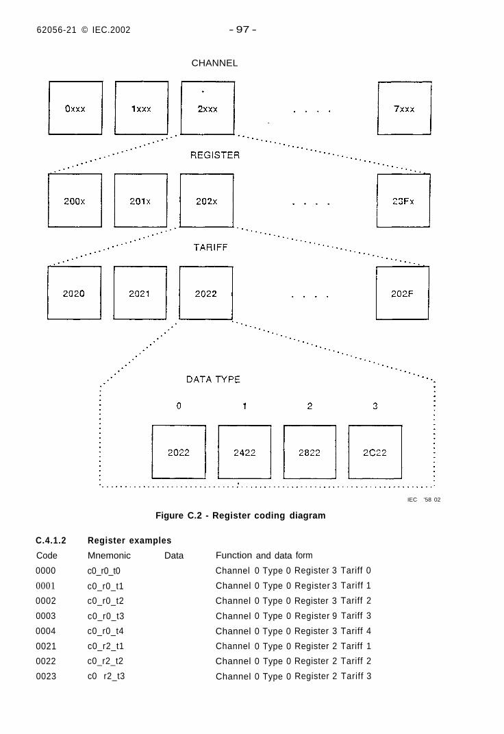
The coding scheme allows up to eight CHANNELS of data (each can have a different channeltype), 64 REGISTERS per channel, each with four DATA TYPES and 16 TARIFFS per type.See clause C.2 for expansion capabilities. Throughout the rest of this annex, words inCAPITALS will have specific meanings as defined in the various subclauses.
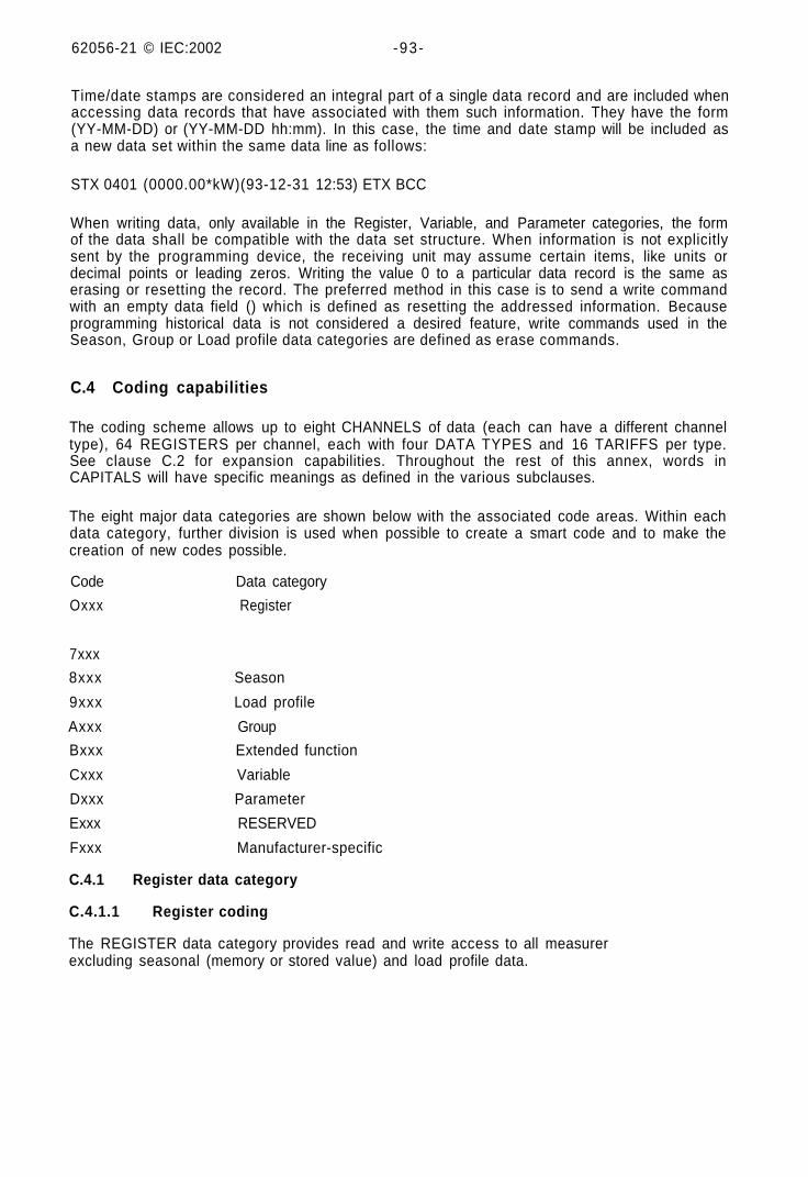
The eight major data categories are shown below with the associated code areas. Within eachdata category, further division is used when possible to create a smart code and to make thecreation of new codes possible.
Code Data category
Oxxx Register
7xxx
8xxx Season
9xxx Load profile
Axxx Group
Bxxx Extended function
Cxxx Variable
Dxxx Parameter
Exxx RESERVED
Fxxx Manufacturer-specific
C.4.1 Register data category
C.4.1.1 Register coding
The REGISTER data category provides read and write access to all measurerexcluding seasonal (memory or stored value) and load profile data.
62056-21 © IEC 2002 -95-
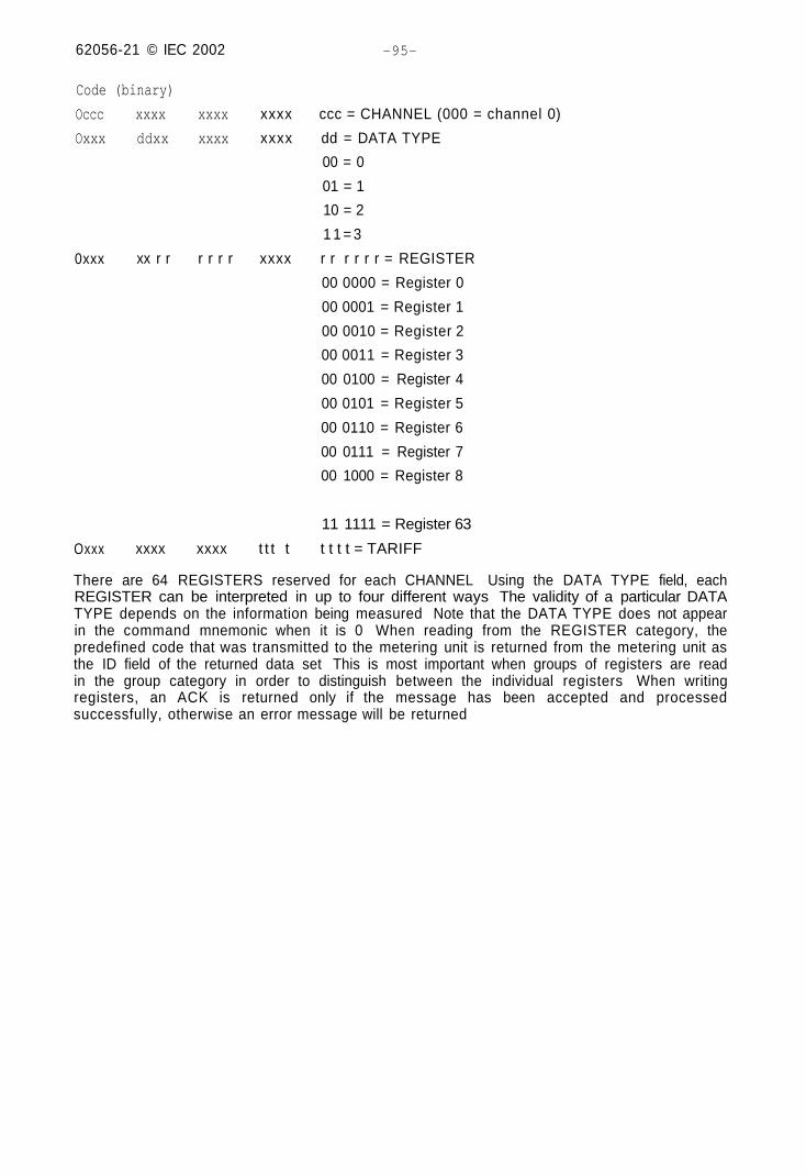
Code (binary)
Occc xxxx xxxx
Oxxx ddxx xxxx
0xxx xx r r r r r r
xxxx ccc = CHANNEL (000 = channel 0)
xxxx dd = DATA TYPE
00 = 0
01 = 1
10 = 2
1 1 = 3
xxxx r r r r r r = REGISTER
00 0000 = Register 0
00 0001 = Register 1
00 0010 = Register 2
00 0011 = Register 3
00 0100 = Register 4
00 0101 = Register 5
00 0110 = Register 6
00 0111 = Register 7
00 1000 = Register 8
Oxxx xxxx xxxx t t t t
11 1111 = Register 63
t t t t = TARIFF
There are 64 REGISTERS reserved for each CHANNEL Using the DATA TYPE field, eachREGISTER can be interpreted in up to four different ways The validity of a particular DATATYPE depends on the information being measured Note that the DATA TYPE does not appearin the command mnemonic when it is 0 When reading from the REGISTER category, thepredefined code that was transmitted to the metering unit is returned from the metering unit asthe ID field of the returned data set This is most important when groups of registers are readin the group category in order to distinguish between the individual registers When writingregisters, an ACK is returned only if the message has been accepted and processedsuccessfully, otherwise an error message will be returned
62056-21 © IEC.2002 - 97 -
CHANNEL
C.4.1.2
Code
0000
0001
0002
0003
0004
0021
0022
0023
Figure C.2 - Register coding diagram
Register examples
Mnemonic
c0_r0_t0
c0_r0_t1
c0_r0_t2
c0_r0_t3
c0_r0_t4
c0_r2_t1
c0_r2_t2
c0 r2_t3
Data Function
Channel
Channel
Channel
Channel
Channel
Channel
Channel
Channel
and data
0 Type 0
0 Type 0
0 Type 0
0 Type 0
0 Type 0
0 Type 0
0 Type 0
0 Type 0
form
Register 3
Register 3
Register 3
Register 9
Register 3
Register 2
Register 2
Register 2
Tariff 0
Tariff 1
Tariff 2
Tariff 3
Tariff 4
Tariff 1
Tariff 2
Tariff 3
IEC '58 02
62056-21 5 IEC.2002 -99 -
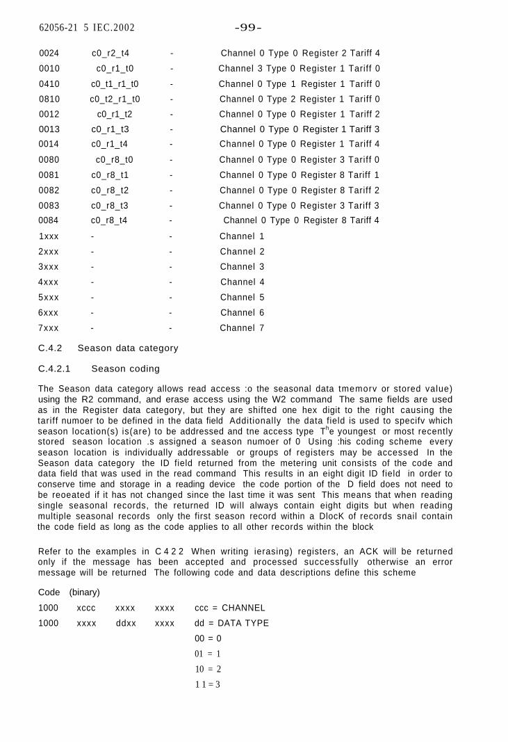
0024 c0_r2_t4 - Channel 0 Type 0 Register 2 Tariff 4
0010 c0_r1_t0 - Channel 3 Type 0 Register 1 Tariff 0
0410 c0_t1_r1_t0 - Channel 0 Type 1 Register 1 Tariff 0
0810 c0_t2_r1_t0 - Channel 0 Type 2 Register 1 Tariff 0
0012 c0_r1_t2 - Channel 0 Type 0 Register 1 Tariff 2
0013 c0_r1_t3 - Channel 0 Type 0 Register 1 Tariff 3
0014 c0_r1_t4 - Channel 0 Type 0 Register 1 Tariff 4
0080 c0_r8_t0 - Channel 0 Type 0 Register 3 Tariff 0
0081 c0_r8_t1 - Channel 0 Type 0 Register 8 Tariff 1
0082 c0_r8_t2 - Channel 0 Type 0 Register 8 Tariff 2
0083 c0_r8_t3 - Channel 0 Type 0 Register 3 Tariff 3
0084 c0_r8_t4 - Channel 0 Type 0 Register 8 Tariff 4
1xxx - - Channel 1
2xxx - - Channel 2
3xxx - - Channel 3
4xxx - - Channel 4
5xxx - - Channel 5
6xxx - - Channel 6
7xxx - - Channel 7
C.4.2 Season data category
C.4.2.1 Season coding
The Season data category allows read access :o the seasonal data tmemorv or stored value)using the R2 command, and erase access using the W2 command The same fields are usedas in the Register data category, but they are shifted one hex digit to the right causing thetariff numoer to be defined in the data field Additionally the data field is used to specifv whichseason location(s) is(are) to be addressed and tne access type The youngest or most recentlystored season location .s assigned a season numoer of 0 Using :his coding scheme everyseason location is individually addressable or groups of registers may be accessed In theSeason data category the ID field returned from the metering unit consists of the code anddata field that was used in the read command This results in an eight digit ID field in order toconserve time and storage in a reading device the code portion of the D field does not need tobe reoeated if it has not changed since the last time it was sent This means that when readingsingle seasonal records, the returned ID will always contain eight digits but when readingmultiple seasonal records only the first season record within a DlocK of records snail containthe code field as long as the code applies to all other records within the block
Refer to the examples in C 4 2 2 When writing ierasing) registers, an ACK will be returnedonly if the message has been accepted and processed successful ly otherwise an errormessage will be returned The following code and data descriptions define this scheme
Code (binary)
1000 xccc xxxx xxxx
1000 xxxx ddxx xxxx
ccc = CHANNEL
dd = DATA TYPE
00 = 0
01 = 1
10 = 2
1 1 = 3
62056-21 © IEC:2002 - 101 -
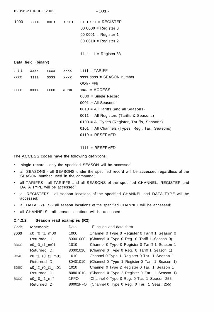
1000 xxxx xxr r r r r r r r r r r r = REGISTER
00 0000 = Register 0
00 0001 = Register 1
00 0010 = Register 2
Data field (binary)
t t t t
xxxx
xxxx
xxxx
ssss
xxxx
xxxx
ssss
xxxx
11 1111 = Register 63
xxxx t t t t = TARIFF
xxxx ssss ssss = SEASON number
OOh - FFh
aaaa aaaa = ACCESS
0000 = Single Record
0001 = All Seasons
0010 = All Tariffs (and all Seasons)
0011 = All Registers (Tariffs & Seasons)
0100 = All Types (Register, Tariffs, Seasons)
0101 = All Channels (Types, Reg., Tar., Seasons)
0110 = RESERVED
1111 = RESERVED
The ACCESS codes have the following definitions:
• single record - only the specified SEASON will be accessed;
• all SEASONS - all SEASONS under the specified record will be accessed regardless of theSEASON number used in the command;
• all TARIFFS - all TARIFFS and all SEASONS of the specified CHANNEL, REGISTER andDATA TYPE will be accessed;
• all REGISTERS - all season locations of the specified CHANNEL and DATA TYPE will beaccessed;
• all DATA TYPES - all season locations of the specified CHANNEL will be accessed;
• all CHANNELS - all season locations will be accessed.
C.4.2.2
Code
8000
8000
8040
8080
8000
Season read examples (R2)
Mnemonic
c0_r0_t1_m00
Returned ID:
c0_r0_t1_m01
Returned ID:
c0_t1_r0_t1_m01
Returned ID:
c0_t2_r0_t1_m01Returned ID:
c0_r0_t1_mff
Returned ID:
Data Function and data form
1000 Channel 0 Type 0 Register 0 Tariff 1 Season 0
80001000 (Channel 0 Type 0 Reg. 0 Tariff 1 Season 0)
1010 Channel 0 Type 0 Register 0 Tariff 1 Season 1
80001010 (Channel 0 Type 0 Reg. 0 Tariff 1 Season 1)
1010 Channel 0 Type 1 Register 0 Tar. 1 Season 1
80401010 (Channel 0 Type 1 Register 0 Tar. 1 Season 1)
1010 Channel 0 Type 2 Register 0 Tar. 1 Season 1
80801010 (Channel 0 Type 2 Register 0 Tar. 1 Season 1)
1FFO Channel 0 Type 0 Reg. 0 Tar. 1 Season 255
80001FFO (Channel 0 Type 0 Reg. 0 Tar. 1 Seas. 255)
62056-21 © IEC:2002 - 103 -
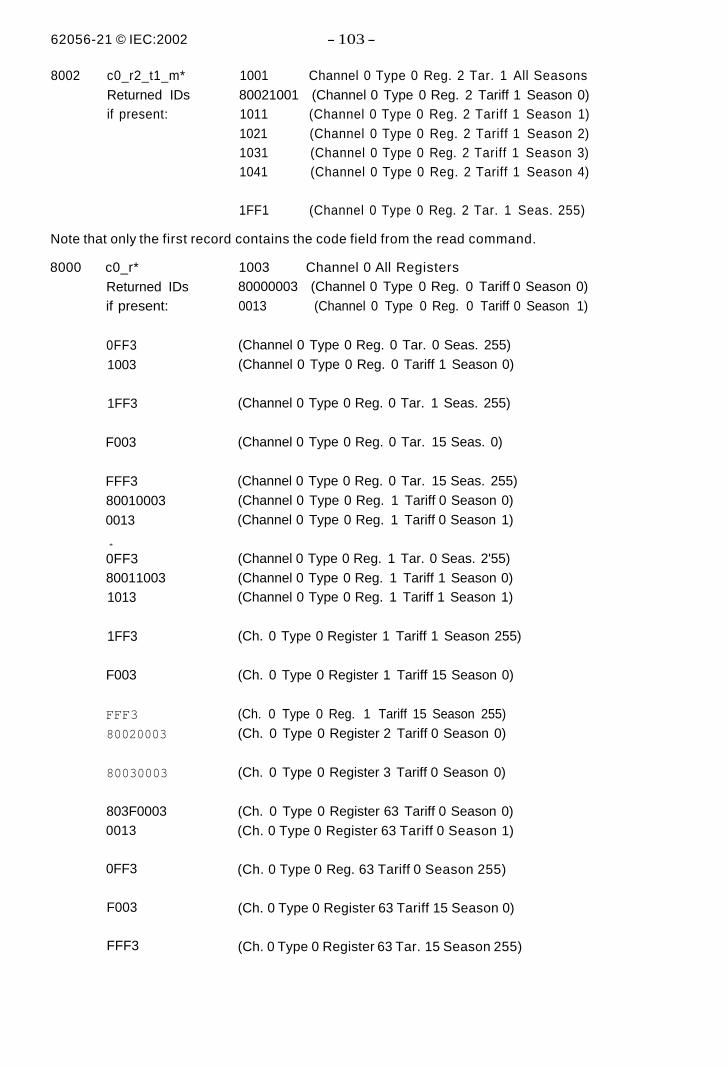
8002 c0_r2_t1_m* 1001 Channel 0 Type 0 Reg. 2 Tar. 1 All SeasonsReturned IDs 80021001 (Channel 0 Type 0 Reg. 2 Tariff 1 Season 0)if present: 1011 (Channel 0 Type 0 Reg. 2 Tariff 1 Season 1)
1021 (Channel 0 Type 0 Reg. 2 Tariff 1 Season 2)1031 (Channel 0 Type 0 Reg. 2 Tariff 1 Season 3)1041 (Channel 0 Type 0 Reg. 2 Tariff 1 Season 4)
1FF1 (Channel 0 Type 0 Reg. 2 Tar. 1 Seas. 255)
Note that only the first record contains the code field from the read command.
8000 c0_r*Returned IDsif present:
0FF31003
1FF3
F003
FFF3800100030013
*
0FF3800110031013
1FF3
F003
FFF3
80020003
80030003
803F00030013
0FF3
F003
FFF3
1003 Channel 0 All Registers80000003 (Channel 0 Type 0 Reg. 0 Tariff 0 Season 0)0013 (Channel 0 Type 0 Reg. 0 Tariff 0 Season 1)
(Channel 0 Type 0 Reg. 0 Tar. 0 Seas. 255)(Channel 0 Type 0 Reg. 0 Tariff 1 Season 0)
(Channel 0 Type 0 Reg. 0 Tar. 1 Seas. 255)
(Channel 0 Type 0 Reg. 0 Tar. 15 Seas. 0)
(Channel 0 Type 0 Reg. 0 Tar. 15 Seas. 255)(Channel 0 Type 0 Reg. 1 Tariff 0 Season 0)(Channel 0 Type 0 Reg. 1 Tariff 0 Season 1)
(Channel 0 Type 0 Reg. 1 Tar. 0 Seas. 2'55)(Channel 0 Type 0 Reg. 1 Tariff 1 Season 0)(Channel 0 Type 0 Reg. 1 Tariff 1 Season 1)
(Ch. 0 Type 0 Register 1 Tariff 1 Season 255)
(Ch. 0 Type 0 Register 1 Tariff 15 Season 0)
(Ch. 0 Type 0 Reg. 1 Tariff 15 Season 255)(Ch. 0 Type 0 Register 2 Tariff 0 Season 0)
(Ch. 0 Type 0 Register 3 Tariff 0 Season 0)
(Ch. 0 Type 0 Register 63 Tariff 0 Season 0)(Ch. 0 Type 0 Register 63 Tariff 0 Season 1)
(Ch. 0 Type 0 Reg. 63 Tariff 0 Season 255)
(Ch. 0 Type 0 Register 63 Tariff 15 Season 0)
(Ch. 0 Type 0 Register 63 Tar. 15 Season 255)
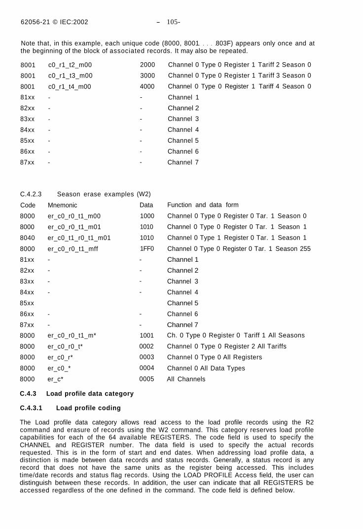
62056-21 © IEC:2002 - 105-
Note that, in this example, each unique code (8000, 8001 803F) appears only once and atthe beginning of the block of associated records. It may also be repeated.
C.4.3 Load profile data category
C.4.3.1 Load profile coding
The Load profile data category allows read access to the load profile records using the R2command and erasure of records using the W2 command. This category reserves load profilecapabilities for each of the 64 available REGISTERS. The code field is used to specify theCHANNEL and REGISTER number. The data field is used to specify the actual recordsrequested. This is in the form of start and end dates. When addressing load profile data, adistinction is made between data records and status records. Generally, a status record is anyrecord that does not have the same units as the register being accessed. This includestime/date records and status flag records. Using the LOAD PROFILE Access field, the user candistinguish between these records. In addition, the user can indicate that all REGISTERS beaccessed regardless of the one defined in the command. The code field is defined below.
8001
8001
8001
81xx
82xx
83xx
84xx
85xx
86xx
87xx
C.4.2.3
Code
8000
8000
8040
8000
81xx
82xx
83xx
84xx
85xx
86xx
87xx
8000
8000
8000
8000
8000
c0_r1_t2_m00
c0_r1_t3_m00
c0_r1_t4_m00
-
-
-
-
-
-
-
Season erase examples
Mnemonic
er_c0_r0_t1_m00
er_c0_r0_t1_m01
er_c0_t1_r0_t1_m01
er_c0_r0_t1_mff
-
-
-
-
-
-
er_c0_r0_t1_m*
er_c0_r0_t*
er_c0_r*
er_c0_*
er_c*
2000
3000
4000
-
-
-
-
-
-
-
(W2)
Data
1000
1010
1010
1FF0
-
-
-
-
-
-
1001
0002
0003
0004
0005
Channel 0 Type 0 Register 1 Tariff 2 Season 0
Channel 0 Type 0 Register 1 Tariff 3 Season 0
Channel 0 Type 0 Register 1 Tariff 4 Season 0
Channel 1
Channel 2
Channel 3
Channel 4
Channel 5
Channel 6
Channel 7
Function and data form
Channel 0 Type 0 Register 0 Tar. 1 Season 0
Channel 0 Type 0 Register 0 Tar. 1 Season 1
Channel 0 Type 1 Register 0 Tar. 1 Season 1
Channel 0 Type 0 Register 0 Tar. 1 Season 255
Channel 1
Channel 2
Channel 3
Channel 4
Channel 5
Channel 6
Channel 7
Ch. 0 Type 0 Register 0 Tariff 1 All Seasons
Channel 0 Type 0 Register 2 All Tariffs
Channel 0 Type 0 All Registers
Channel 0 All Data Types
All Channels
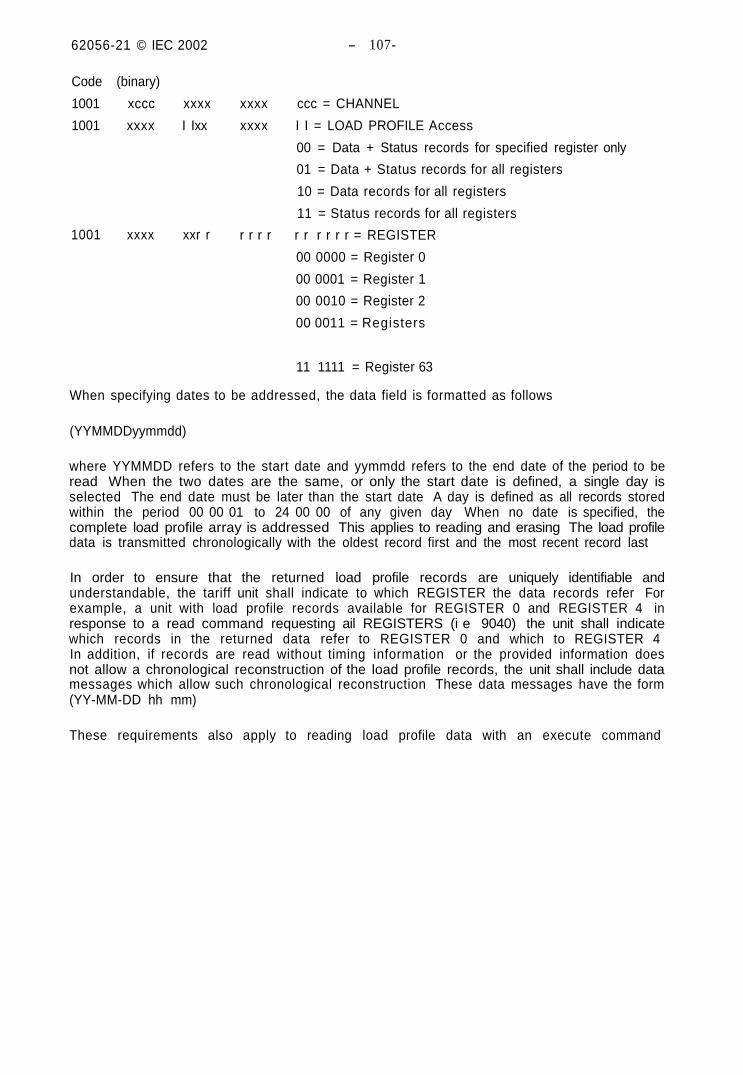
62056-21 © IEC 2002 - 107-
Code (binary)
1001 xccc xxxx
1001 xxxx I Ixx
1001 xxxx xxr r
xxxx ccc = CHANNEL
xxxx I I = LOAD PROFILE Access
00 = Data + Status records for specified register only
01 = Data + Status records for all registers
10 = Data records for all registers
11 = Status records for all registers
r r r r r r r r r r = REGISTER
00 0000 = Register 0
00 0001 = Register 1
00 0010 = Register 2
00 0011 = Registers
11 1111 = Register 63
When specifying dates to be addressed, the data field is formatted as follows
(YYMMDDyymmdd)
where YYMMDD refers to the start date and yymmdd refers to the end date of the period to beread When the two dates are the same, or only the start date is defined, a single day isselected The end date must be later than the start date A day is defined as all records storedwithin the period 00 00 01 to 24 00 00 of any given day When no date is specified, thecomplete load profile array is addressed This applies to reading and erasing The load profiledata is transmitted chronologically with the oldest record first and the most recent record last
In order to ensure that the returned load profile records are uniquely identifiable andunderstandable, the tariff unit shall indicate to which REGISTER the data records refer Forexample, a unit with load profile records available for REGISTER 0 and REGISTER 4 inresponse to a read command requesting ail REGISTERS (i e 9040) the unit shall indicatewhich records in the returned data refer to REGISTER 0 and which to REGISTER 4In addition, if records are read without timing information or the provided information doesnot allow a chronological reconstruction of the load profile records, the unit shall include datamessages which allow such chronological reconstruction These data messages have the form(YY-MM-DD hh mm)
These requirements also apply to reading load profile data with an execute command
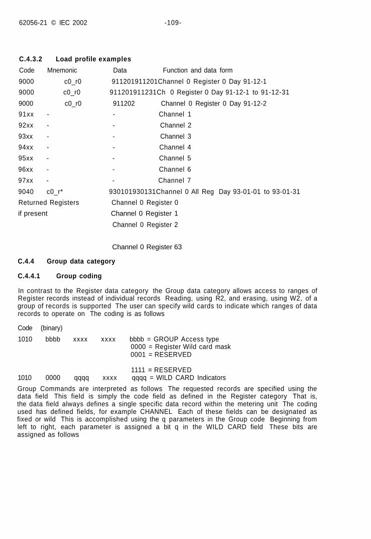
62056-21 © IEC 2002 -109-
C.4.3.2 Load profile examples
Code Mnemonic Data Function and data form
9000 c0_r0 911201911201Channel 0 Register 0 Day 91-12-1
9000 c0_r0 911201911231Ch 0 Register 0 Day 91-12-1 to 91-12-31
9000 c0_r0 911202 Channel 0 Register 0 Day 91-12-2
91xx - - Channel 1
92xx - - Channel 2
93xx - - Channel 3
94xx - - Channel 4
95xx - - Channel 5
96xx - - Channel 6
97xx - - Channel 7
9040 c0_r* 930101930131Channel 0 All Reg Day 93-01-01 to 93-01-31
Returned Registers Channel 0 Register 0
if present Channel 0 Register 1
Channel 0 Register 2
Channel 0 Register 63
C.4.4 Group data category
C.4.4.1 Group coding
In contrast to the Register data category the Group data category allows access to ranges ofRegister records instead of individual records Reading, using R2, and erasing, using W2, of agroup of records is supported The user can specify wild cards to indicate which ranges of datarecords to operate on The coding is as follows
Code (binary)
1010 bbbb xxxx xxxx bbbb = GROUP Access type0000 = Register Wild card mask0001 = RESERVED
1111 = RESERVED1010 0000 qqqq xxxx qqqq = WILD CARD Indicators
Group Commands are interpreted as follows The requested records are specified using thedata field This field is simply the code field as defined in the Register category That is,the data field always defines a single specific data record within the metering unit The codingused has defined fields, for example CHANNEL Each of these fields can be designated asfixed or wild This is accomplished using the q parameters in the Group code Beginning fromleft to right, each parameter is assigned a bit q in the WILD CARD field These bits areassigned as follows
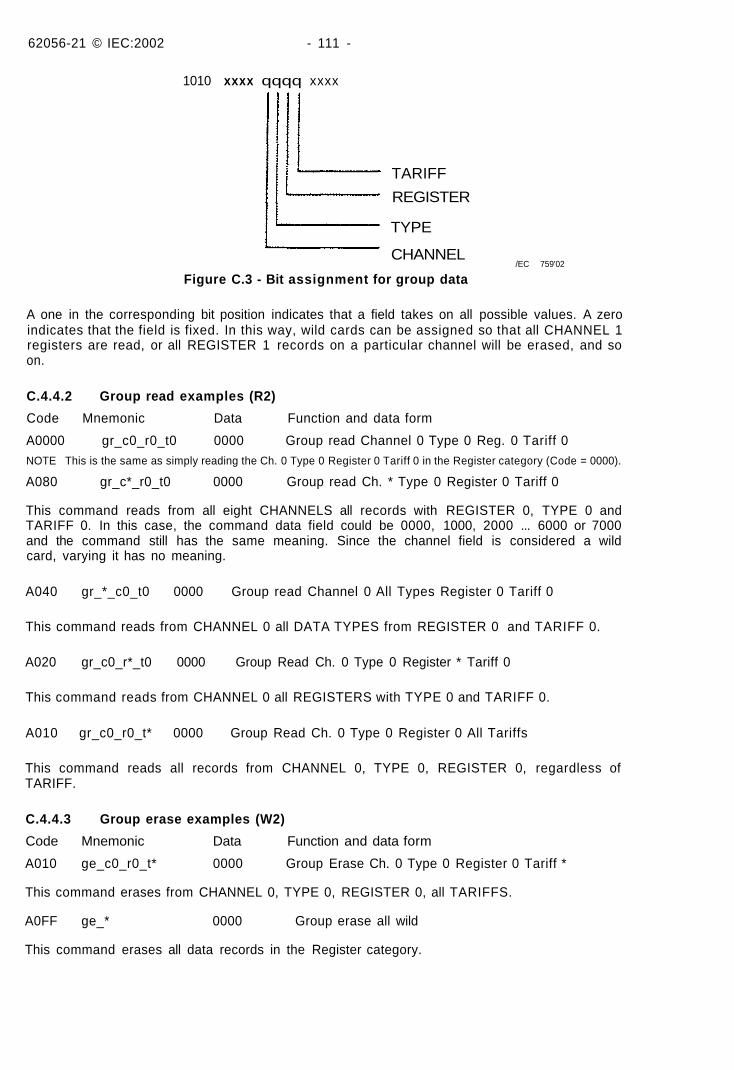
62056-21 © IEC:2002 - 111 -
1010 xxxx qqqq xxxx
TARIFF
REGISTER
TYPE
CHANNEL/EC 759'02
Figure C.3 - Bit assignment for group data
A one in the corresponding bit position indicates that a field takes on all possible values. A zeroindicates that the field is fixed. In this way, wild cards can be assigned so that all CHANNEL 1registers are read, or all REGISTER 1 records on a particular channel will be erased, and soon.
C.4.4.2 Group read examples (R2)
Code Mnemonic Data Function and data form
A0000 gr_c0_r0_t0 0000 Group read Channel 0 Type 0 Reg. 0 Tariff 0NOTE This is the same as simply reading the Ch. 0 Type 0 Register 0 Tariff 0 in the Register category (Code = 0000).
A080 gr_c*_r0_t0 0000 Group read Ch. * Type 0 Register 0 Tariff 0
This command reads from all eight CHANNELS all records with REGISTER 0, TYPE 0 andTARIFF 0. In this case, the command data field could be 0000, 1000, 2000 ... 6000 or 7000and the command still has the same meaning. Since the channel field is considered a wildcard, varying it has no meaning.
A040 gr_*_c0_t0 0000 Group read Channel 0 All Types Register 0 Tariff 0
This command reads from CHANNEL 0 all DATA TYPES from REGISTER 0 and TARIFF 0.
A020 gr_c0_r*_t0 0000 Group Read Ch. 0 Type 0 Register * Tariff 0
This command reads from CHANNEL 0 all REGISTERS with TYPE 0 and TARIFF 0.
A010 gr_c0_r0_t* 0000 Group Read Ch. 0 Type 0 Register 0 All Tariffs
This command reads all records from CHANNEL 0, TYPE 0, REGISTER 0, regardless ofTARIFF.
C.4.4.3 Group erase examples (W2)
Code Mnemonic Data Function and data form
A010 ge_c0_r0_t* 0000 Group Erase Ch. 0 Type 0 Register 0 Tariff *
This command erases from CHANNEL 0, TYPE 0, REGISTER 0, all TARIFFS.
A0FF ge_* 0000 Group erase all wild
This command erases all data records in the Register category.
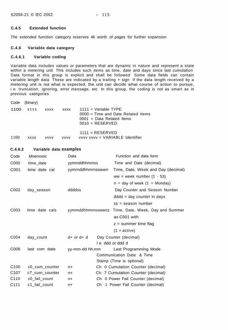
62056-21 © IEC 2002 - 113-
C.4.5 Extended function
The extended function category reserves 4k worth of pages for further expansion
C.4.6 Variable data category
C.4.6.1 Variable coding
Variable data includes values or parameters that are dynamic in nature and represent a statewithin a metering unit This includes such items as time, date and days since last cumulationData format in this group is explicit and shall be followed Some data fields can containvariable length data These are indicated by a trailing + sign If the data length received by ametering unit is not what is expected, the unit can decide what course of action to pursue,i e truncation, ignoring, error message, etc In this group, the coding is not as smart as inprevious categories
Code (binary)
1100 t t t t
1100 xxxx
xxxx xxxx 1111 = Variable TYPE0000 = Time and Date Related Items0001 = Data Related Items0010 = RESERVED
1111 = RESERVEDvvvv vvvv vvvv vvvv = VARIABLE Identifier
C.4.6.2 Variable data
Code Mnemonic
C000 time_date
C001 time date cal
C002 day_season
C003 time date cals
C004 day_count
C006 last com date
C100 c0_cum_counter
C107 c7_cum_counter
C110 c0_fail_count
C111 c1_fail_count
examples
Data Function and data form
yymmddhhmmss Time and Date (decimal)
yymrnddhhmmsswwn Time, Date, Week and Day (decimal)
ww = week number (1 - 53)
n = day of week (1 = Monday)
ddddss Day Counter and Season Number
dddd = day counter in days
ss = season number
yymmddhhmmsswwnz Time, Date, Week, Day and Summer
as C001 with
z = summer time flag
(1 = active)
d+ or d+ d Day Counter (decimal)
i e ddd or ddd d
yy-mm-dd hh.mm Last Programming Mode
Communication Date & Time
Stamp (Time is optional)
n+ Ch 0 Cumulation Counter (decimal)
n+ Ch 7 Cumulation Counter (decimal)
n+ Ch 0 Power Fail Counter (decimal)
n+ Ch 1 Power Fail Counter (decimal)
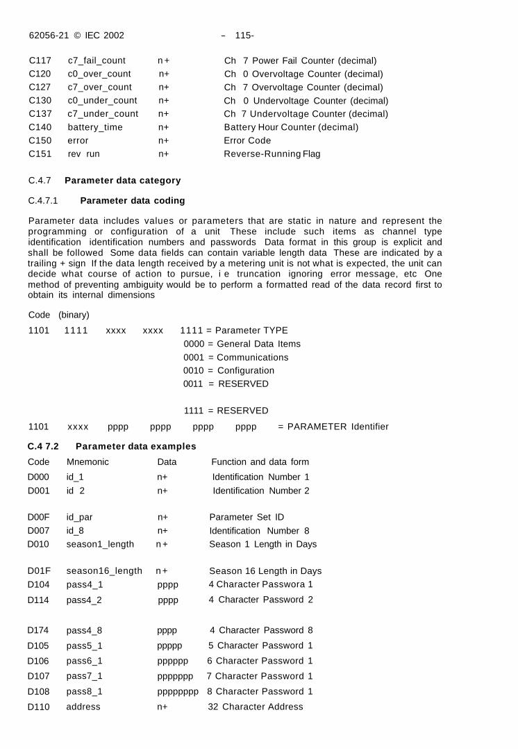
62056-21 © IEC 2002 - 115-
C117 c7_fail_count n +C120 c0_over_count n+C127 c7_over_count n+C130 c0_under_count n+C137 c7_under_count n+
C140 battery_time n+C150 error n+C151 rev run n+
Ch 7 Power Fail Counter (decimal)Ch 0 Overvoltage Counter (decimal)Ch 7 Overvoltage Counter (decimal)
Ch 0 Undervoltage Counter (decimal)Ch 7 Undervoltage Counter (decimal)Battery Hour Counter (decimal)Error CodeReverse-Running Flag
C.4.7 Parameter data category
C.4.7.1 Parameter data coding
Parameter data includes values or parameters that are static in nature and represent theprogramming or configuration of a unit These include such items as channel typeidentification identification numbers and passwords Data format in this group is explicit andshall be followed Some data fields can contain variable length data These are indicated by atrailing + sign If the data length received by a metering unit is not what is expected, the unit candecide what course of action to pursue, i e truncation ignoring error message, etc Onemethod of preventing ambiguity would be to perform a formatted read of the data record first toobtain its internal dimensions
Code (binary)
1101 1111 xxxx xxxx 1111 = Parameter TYPE
0000 = General Data Items
0001 = Communications0010 = Configuration0011 = RESERVED
1111 = RESERVED
1101 xxxx pppp pppp pppp pppp = PARAMETER Identifier
C.4 7.2 Parameter data examples
Code Mnemonic Data Function and data form
D000 id_1 n+ Identification Number 1
D001 id 2 n+ Identification Number 2
D00F id_par n+
D007 id_8 n+
D010 season1_length n +
D01F season16_length n +
D104 pass4_1 pppp
D114 pass4_2 pppp
Parameter Set ID
Identification Number 8Season 1 Length in Days
Season 16 Length in Days4 Character Passwora 1
4 Character Password 2
D174
D105
D106
D107
D108
D110
pass4_8
pass5_1
pass6_1
pass7_1
pass8_1
address
pppp 4 Character Password 8
ppppp 5 Character Password 1
pppppp 6 Character Password 1
ppppppp 7 Character Password 1
pppppppp 8 Character Password 1
n+ 32 Character Address
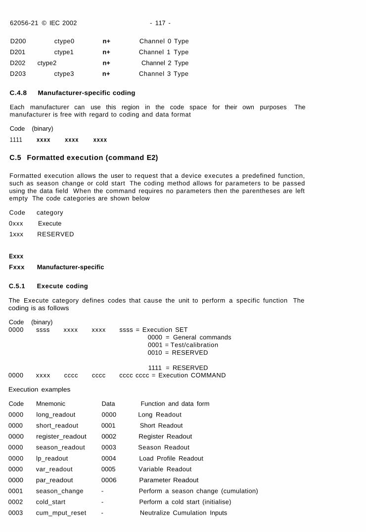
62056-21 © IEC 2002 - 117 -
D200 ctype0 n+ Channel 0 Type
D201 ctype1 n+ Channel 1 Type
D202 ctype2 n+ Channel 2 Type
D203 ctype3 n+ Channel 3 Type
C.4.8 Manufacturer-specific coding
Each manufacturer can use this region in the code space for their own purposes Themanufacturer is free with regard to coding and data format
Code (binary)
1111 xxxx xxxx xxxx
C.5 Formatted execution (command E2)
Formatted execution allows the user to request that a device executes a predefined function,such as season change or cold start The coding method allows for parameters to be passedusing the data field When the command requires no parameters then the parentheses are leftempty The code categories are shown below
Code category
0xxx Execute
1xxx RESERVED
Exxx
Fxxx Manufacturer-specific
C.5.1 Execute coding
The Execute category defines codes that cause the unit to perform a specific function Thecoding is as follows
Code (binary)0000 ssss xxxx xxxx ssss = Execution SET
0000 = General commands0001 = Test/calibration0010 = RESERVED
1111 = RESERVED0000 xxxx cccc cccc cccc cccc = Execution COMMAND
Execution examples
Code Mnemonic Data Function and data form
0000 long_readout 0000 Long Readout
0000 short_readout 0001 Short Readout
0000 register_readout 0002 Register Readout
0000 season_readout 0003 Season Readout
0000 lp_readout 0004 Load Profile Readout
0000 var_readout 0005 Variable Readout
0000 par_readout 0006 Parameter Readout
0001 season_change - Perform a season change (cumulation)
0002 cold_start - Perform a cold start (initialise)
0003 cum_mput_reset - Neutralize Cumulation Inputs
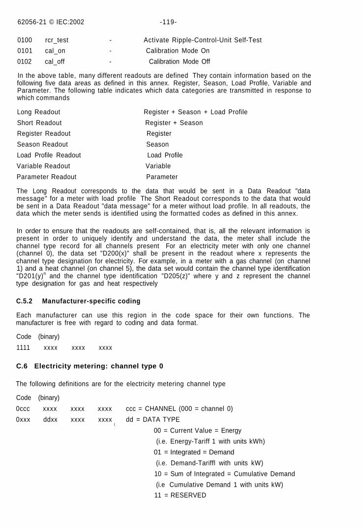
62056-21 © IEC:2002 -119-
0100 rcr_test - Activate Ripple-Control-Unit Self-Test
0101 cal_on - Calibration Mode On
0102 cal_off - Calibration Mode Off
In the above table, many different readouts are defined They contain information based on thefollowing five data areas as defined in this annex. Register, Season, Load Profile, Variable andParameter. The following table indicates which data categories are transmitted in response towhich commands
Long Readout Register + Season + Load Profile
Short Readout Register + Season
Register Readout Register
Season Readout Season
Load Profile Readout Load Profile
Variable Readout Variable
Parameter Readout Parameter
The Long Readout corresponds to the data that would be sent in a Data Readout "datamessage" for a meter with load profile The Short Readout corresponds to the data that wouldbe sent in a Data Readout "data message" for a meter without load profile. In all readouts, thedata which the meter sends is identified using the formatted codes as defined in this annex.
In order to ensure that the readouts are self-contained, that is, all the relevant information ispresent in order to uniquely identify and understand the data, the meter shall include thechannel type record for all channels present For an electricity meter with only one channel(channel 0), the data set "D200(x)" shall be present in the readout where x represents thechannel type designation for electricity. For example, in a meter with a gas channel (on channel1) and a heat channel (on channel 5), the data set would contain the channel type identification"D201(y)n and the channel type identification "D205(z)" where y and z represent the channeltype designation for gas and heat respectively
C.5.2 Manufacturer-specific coding
Each manufacturer can use this region in the code space for their own functions. Themanufacturer is free with regard to coding and data format.
Code (binary)
1111 xxxx xxxx xxxx
C.6 Electricity metering: channel type 0
The following definitions are for the electricity metering channel type
Code (binary)
0ccc xxxx xxxx xxxx ccc = CHANNEL (000 = channel 0)
0xxx ddxx xxxx xxxx dd = DATA TYPE(
00 = Current Value = Energy
(i.e. Energy-Tariff 1 with units kWh)
01 = Integrated = Demand
(i.e. Demand-Tariffl with units kW)
10 = Sum of Integrated = Cumulative Demand
(i.e Cumulative Demand 1 with units kW)
11 = RESERVED
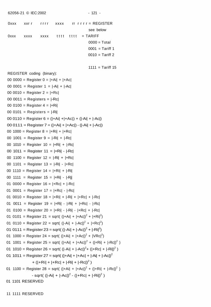
62056-21 © IEC:2002 - 121 -
0xxx xxr r r r r r xxxx rr r r r r = REGISTER
see below
0xxx xxxx xxxx t t t t t t t t = TARIFF
0000 = Total
0001 = Tariff 1
0010 = Tariff 2
1111 = Tariff 15
REGISTER coding (binary):
00 0000 = Register 0 = |+Ai| + |+Ac|
00 0001 = Register 1 = |-Ai| + |-Ac|
00 0010 = Register 2 = |+Rc|
00 0011 = Registers = |-Rc|
00 0100 = Register 4 = |+Ri|
00 0101 = Registers = |-Ri|
00 0110 = Register 6 = (|+Ai| +|+Ac|) + (|-Ai| + |-Ac|)
00 0111 = Register 7 = (|+Ai| + |+Ac|) - (|-Ai| + |-Ac|)
00 1000 = Register 8 = |+Ri| + |+Rc|
00 1001 = Register 9 = |-Ri| + |-Rc|
00 1010 = Register 10 = |+Ri| + |-Rc|
00 1011 = Register 11 = |+Ri| - |-Rc|
00 1100 = Register 12 = |-Ri| + |+Rc|
00 1101 = Register 13 = |-Ri| - |+Rc|
00 1110 = Register 14 = |+Ri| + |-Ri|
00 1111 = Register 15 = |+Ri| - |-Rj|
01 0000 = Register 16 = |+Rc| + |-Rc|
01 0001 = Register 17 = |+Rc| - |-Rc|
01 0010 = Register 18 = |+Ri| + |-Ri| + |+Rc| + |-Rc|
01 0011 = Register 19 = |+Ri| - |-Ri| + |+Rc| - |-Rc|
01 0100 = Register 20 = |+Ri| - |-Ri| - |+Rc| + |-Rc|
01 0101 = Register 21 = sqrt( (|+Ai| + |+Ac|)2 + |+Ri|2)
01 0110 = Register 22 = sqrt( (|-Ai| + |-Ac|)2 + |+Rc|2)
01 0111 = Register 23 = sqrt( (|-Ai| + |-Ac|)2 + |-Ri|2)
01 1000 = Register 24 = sqrt( (|+Ai| + |+Ac|)2 + |VRc|2)
01 1001 = Register 25 = sqrt( (|+Ai| + |+Ac|)2 + (|+Ri| + |-Rc|)2 )
01 1010 = Register 26 = sqrt( (|-Ai| + |-Ac|)2+ (|+Rc| + |-Ri|)2 )
01 1011 = Register 27 = sqrt( (|+Ai| + |+Ac| + |-Ai| + |-Ac|)2
+ (|+Ri| + |+Rc| + |-Ri| + |-Rc|)2 )
01 1100 = Register 28 = sqrt( (|+Ai| + |+Ac|)2 + (|+Ri| + |-Rc|)2 )
- sqrt( (|-Ai| + |-Ac|)2 - (|+Rc| + |-Ri|)2 )
01 1101 RESERVED
11 1111 RESERVED
62056-21 © IEC.-2002 - 123 -
For the description in this clause, the measurement plane is considered to have two axes, realand imaginary. The real axis is denoted A and the imaginary axis R. Positive (+) is consideredto the right or up and negative (-) considered to the left or down. The reference for themeasurement plane is considered the current vector which is fixed on the +A half axis. Themomentary voltage vector is used to designate the current energy transfer and has phaseangle FI in relation to the current vector. Phase angle FI is zero when the current and voltage arecoincident, and is positive in the counter clockwise direction. The four quadrants are numbered1 to 4 counterclockwise from the positive real axis.
When the vector denoting the momentary voltage in relation to the momentary current is in thefirst quadrant, +Ai represents the real component of energy consumption and +Ri the imaginaryor reactive component of energy consumption.
When the voltage vector is in the second quadrant, -Ac represents the real component ofenergy consumption and +Rc the imaginary or reactive component of energy consumption.
When the voltage vector is in the third quadrant, -Ai represents the real component of energyconsumption and -Ri the imaginary or reactive component of energy consumption.
When the voltage vector is in the fourth quadrant, +Ac represents the real component ofenergy consumption and -Rc the imaginary or reactive component of energy consumption.
When the voltage vector is coincident with the +R or -R half-axes, then no real component ispresent, and the imaginary or reactive component of the energy consumption is considered tobe of the same type as the last measured reactive component. Note that all measurementcomponents are functions of time and could therefore be designated as such, i.e. +Ai(t). Assuch, the equations for the vector sums are only correct for instantaneous values. Theindividual register values cannot be used at a later point in time to calculate other registertotals, i.e. Register-X <> sqrt(Register-Y2 + Register-Z2).
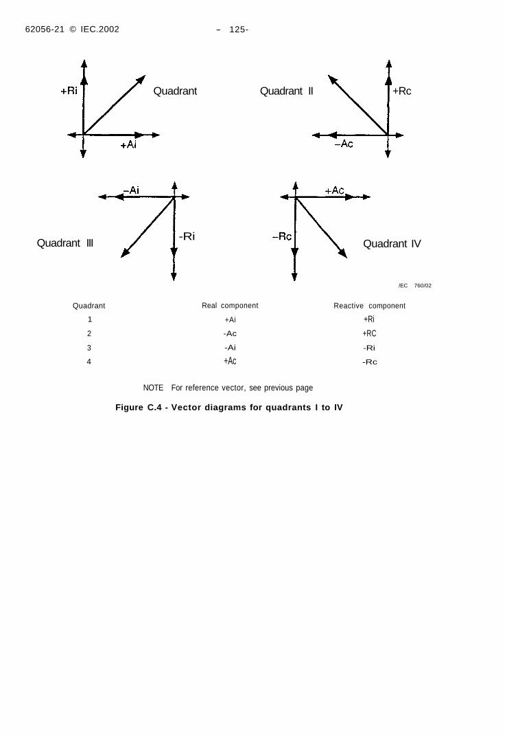
62056-21 © IEC.2002 - 125-
Quadrant Quadrant II +Rc
Quadrant III
Quadrant
1
2
3
4
-RiQuadrant IV
/EC 760/02
Real component
+Ai
-Ac
-Ai
+Ac
NOTE For reference vector, see previous page
Figure C.4 - Vector diagrams for quadrants I to IV
Reactive component
+Ri
+RC
-Ri
-Rc
62056-21 © IEC:2002 -127-
Annex D(informative)
Levels of access - system security
In order to restrict access to the tariff device, different levels of security are defined. Any or allof these may be used by a tariff device.
Access level 1
Requires only a knowledge of this protocol to gain access.
Access level 2
Requires one or more passwords to be correctly entered.
Access level 3
Requires operation of a sealable button or manipulation of certain data with a secret algorithmto gain access.
Access level 4
Requires physical entry into the case of the tariff device and effecting a physical change,such as making/breaking a link or operation of a switch, before further communications accessis allowed.
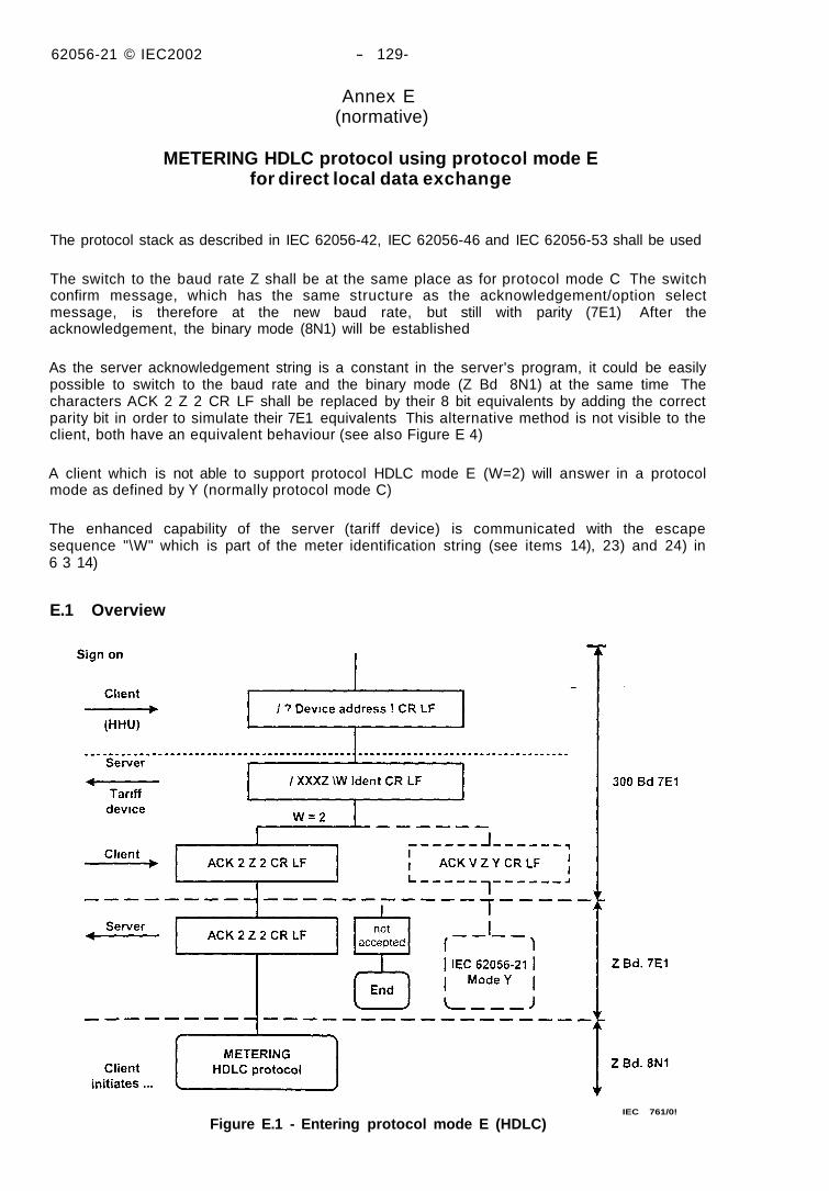
62056-21 © IEC2002 - 129-
Annex E(normative)
METERING HDLC protocol using protocol mode Efor direct local data exchange
The protocol stack as described in IEC 62056-42, IEC 62056-46 and IEC 62056-53 shall be used
The switch to the baud rate Z shall be at the same place as for protocol mode C The switchconfirm message, which has the same structure as the acknowledgement/option selectmessage, is therefore at the new baud rate, but still with parity (7E1) After theacknowledgement, the binary mode (8N1) will be established
As the server acknowledgement string is a constant in the server's program, it could be easilypossible to switch to the baud rate and the binary mode (Z Bd 8N1) at the same time Thecharacters ACK 2 Z 2 CR LF shall be replaced by their 8 bit equivalents by adding the correctparity bit in order to simulate their 7E1 equivalents This alternative method is not visible to theclient, both have an equivalent behaviour (see also Figure E 4)
A client which is not able to support protocol HDLC mode E (W=2) will answer in a protocolmode as defined by Y (normally protocol mode C)
The enhanced capability of the server (tariff device) is communicated with the escapesequence "\W" which is part of the meter identification string (see items 14), 23) and 24) in6 3 14)
E.1 Overview
Figure E.1 - Entering protocol mode E (HDLC)IEC 761/0!
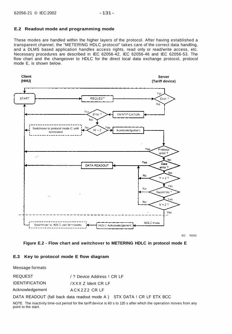
62056-21 © IEC:2002 - 131 -
E.2 Readout mode and programming mode
These modes are handled within the higher layers of the protocol. After having established atransparent channel, the "METERING HDLC protocol" takes care of the correct data handling,and a DLMS based application handles access rights, read only or read/write access, etc.Necessary procedures are described in IEC 62056-42, IEC 62056-46 and IEC 62056-53. Theflow chart and the changeover to HDLC for the direct local data exchange protocol, protocolmode E, is shown below.
Client(HHU)
Server(Tariff device)
Switchover to protocol mode C untilterminated
IEC 762/02
Figure E.2 - Flow chart and switchover to METERING HDLC in protocol mode E
E.3 Key to protocol mode E flow diagram
Message formats
REQUEST
IDENTIFICATION
Acknowledgement
/ ? Device Address ! CR LF
/XXX Z Ident CR LF
A C K 2 Z 2 CR LF
DATA READOUT (fall back data readout mode A ) STX DATA ! CR LF ETX BCC
NOTE The inactivity time-out period for the tariff device is 60 s to 120 s after which the operation moves from anypoint to the start.
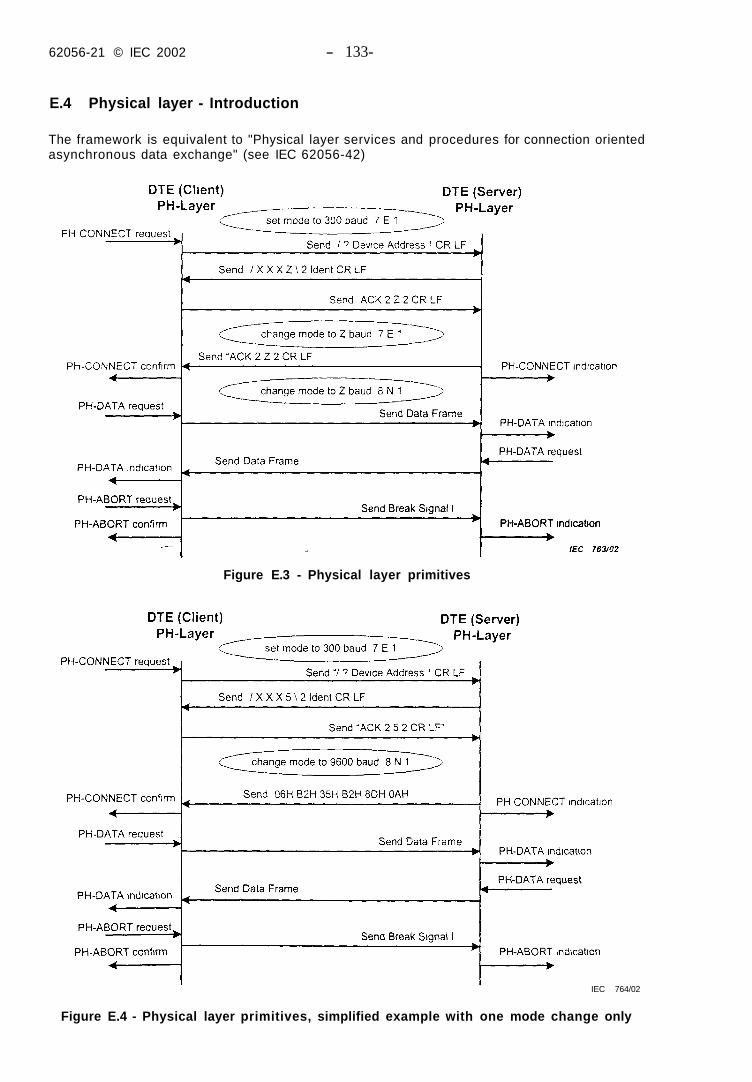
62056-21 © IEC 2002 - 133-
E.4 Physical layer - Introduction
The framework is equivalent to "Physical layer services and procedures for connection orientedasynchronous data exchange" (see IEC 62056-42)
Figure E.3 - Physical layer primitives
IEC 764/02
Figure E.4 - Physical layer primitives, simplified example with one mode change only
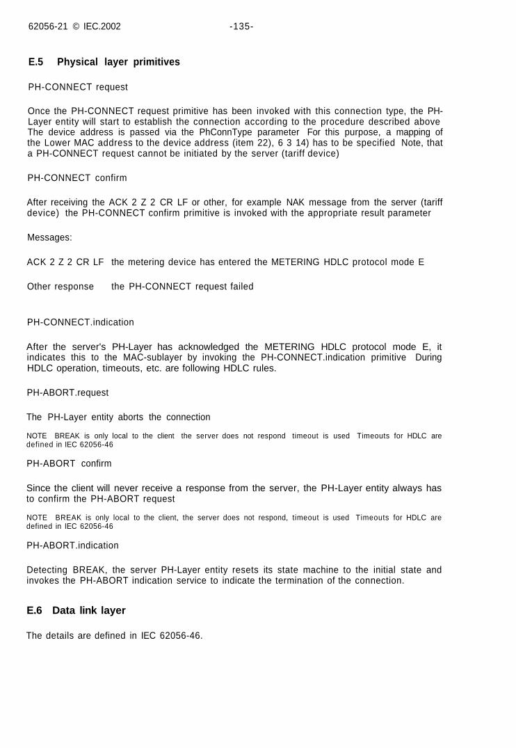
62056-21 © IEC.2002 -135-
E.5 Physical layer primitives
PH-CONNECT request
Once the PH-CONNECT request primitive has been invoked with this connection type, the PH-Layer entity will start to establish the connection according to the procedure described aboveThe device address is passed via the PhConnType parameter For this purpose, a mapping ofthe Lower MAC address to the device address (item 22), 6 3 14) has to be specified Note, thata PH-CONNECT request cannot be initiated by the server (tariff device)
PH-CONNECT confirm
After receiving the ACK 2 Z 2 CR LF or other, for example NAK message from the server (tariffdevice) the PH-CONNECT confirm primitive is invoked with the appropriate result parameter
Messages:
ACK 2 Z 2 CR LF the metering device has entered the METERING HDLC protocol mode E
Other response the PH-CONNECT request failed
PH-CONNECT.indication
After the server's PH-Layer has acknowledged the METERING HDLC protocol mode E, itindicates this to the MAC-sublayer by invoking the PH-CONNECT.indication primitive DuringHDLC operation, timeouts, etc. are following HDLC rules.
PH-ABORT.request
The PH-Layer entity aborts the connection
NOTE BREAK is only local to the client the server does not respond timeout is used Timeouts for HDLC aredefined in IEC 62056-46
PH-ABORT confirm
Since the client will never receive a response from the server, the PH-Layer entity always hasto confirm the PH-ABORT request
NOTE BREAK is only local to the client, the server does not respond, timeout is used Timeouts for HDLC aredefined in IEC 62056-46
PH-ABORT.indication
Detecting BREAK, the server PH-Layer entity resets its state machine to the initial state andinvokes the PH-ABORT indication service to indicate the termination of the connection.
E.6 Data link layer
The details are defined in IEC 62056-46.
62056-21 © IEC:2002 - 137 -
Bibliography
IEC 62056-61:2002 Electricity metering - Data exchange for meter reading, tariff and loadcontrol - Part 61: Object Identification System (OBIS)
IEC 62056-62:2002 Electricity metering - Data exchange for meter reading, tariff and loadcontrol - Part 62: Interface classes
ISO/IEC 7498-1:1994, Information technology - Open systems interconnection - Basicreference model: The basic model
ISO/IEC 7498-2:1989, Information processing systems - Open systems interconnection -Basic reference model - Part 2: Security architecture
ISO/IEC 7498-3:1997, Information technology - Open systems interconnection - Basicreference model - Part 3: Naming and addressing
ISO/IEC 7498-4:1989, Information processing systems - Open systems interconnection -Basic reference model - Part 4: Management framework
ISO/IEC 13239:2000, Information technology - Telecommunications and information exchangebetween systems - High-level data link control (HDLC) procedures
62056-21 IEC 2002
Index
Abbreviations 17Access level 127Acknowledgement 37Acknowledgement message 37Alignment 29Arrangement of components 29battery-operated tariff devices, 85Bibliography, 137block check character 35Block message, 39Break message, 39Channels 89Character code. 33Character format, 33Character transmission 33client. 19Coding capabilities, 93commands R2. R4, W2 and W4, 91Communication modes 47control character, 63current loop 19Data link layer, 135Data message, 37Data readout 47, 51 61Data transmission protocol 35Definitions 17Electrical interface 19 23End of data readout. 49 53 59End of transmission 61Entering programming mode 63Environmental 33Error message 39escape character 61Execute coding 117Extended function 113Flow chart 31Formatted codes 89Formatted execution 117Formatted reading and anting, 91Group coding, 109Group data category 109Group erase examples (W2), 111Group read examples CR2), 111HDLC protocol 129HHU 19Identification message 37Levels of access 61 127lighting condition 33Load profile coding, 105Load profile data category, 105Load profile examples, 109magnet, 25Manufacturer specific coding, 117 119manufacturer-specific operation 57master, 17message contents. 41
Message definitions 37METERING HDLC protocol, 129Normative references 15Optical characteristics 29Optical interface 25option select message 37Parameter data category, 115Parameter data coding, 115Parameter data examples 115Partial block communication 65partial blocks 39PH-Layer Primitives 135Physical Layer 133Physical properties 19Programmmg command message 39programming mode 37 39Programmmg mode 59 75, 131Protocol mode A -17Protocol mode B 49protocol mode C 81Protocol mode C 53Protocol mode D 61
Protocol mode E (Other protocols) 6"quality 33Reaction and monitoring times 49 53 59reading head 25Readout mode 73 131Receiver 31Register coding 93Register data category 93Register examples 97Repeat-request message 37Reduest message 27Season coding, 99Season data categcrv 99Season erase examples (W2) 1C5Season read examples (R2), 101security 33server 19Signal quality, 33slave 19Switch to orogrammmg mode 47 51Syntax diagrams 71system security, 61,127tariff device 17 29temperature condition 33Terms 17transmission 33Transmission speed 33Transmitter 29Variable coding, 113Variable data category 113Variable data examples 113wake UD method 87Wavelength. 29