jsas 004 07_7_sadeghi
TRANSCRIPT
K. Sadeghi, GAU J. Soc. & Appl. Sci., 4(7), 67-92, 2008
67
Significant Guidance for Design and Construction
of Marine and Offshore Structures
Kabir Sadeghi1
Girne American University, Faculty of Engineering and Architecture, TRNC
Abstract
Marine and offshore structures are constructed worldwide for a variety of functions and in a variety of water depths, and environmental conditions. Shore protection facilities, ports, harbors and offshore petroleum platforms are important infrastructures which have big impacts on the economy level and industrial progress of countries.
Selection of type of platform and also right planning, design, fabrication, transportation and installation of marine and offshore structures, considering the water depth and environment conditions are very important. In this paper an overview of coast, ports and offshore structures engineering is presented. The paper covers mainly design and construction of jetties, harbor and fixed template offshore platforms. The overall objective of this paper is to provide a general understanding of different stages of design, construction, load-out, transportation and installation of marine and offshore structures.
Keywords: Wave Mechanics, Template Platform, Jacket, Harbor, Breakwater,
Petroleum, Oil/Gas.
1. Introduction
The marine and offshore structures must function safely for their design lifetimes (50 to 75 years for harbors and 25 years or more for offshore petroleum platforms) against very harsh marine environments. Some important design considerations are peak loads created by storm winds and waves, fatigue loads generated by waves over the platform lifetime and the motion of the platform.
Offshore structures are designed for installation in the open sea, lakes, and gulfs many kilometers from shorelines. These structures are mainly made of various grades of steel, from mild steel to high strength steel. Offshore platforms are very heavy and they are among the tallest manmade structures on the earth.
This paper covers mainly design and construction of jetties, breakwaters, harbors and fixed template offshore platforms. For more information about environmental
Significant Guidance for Design and Construction of Marine and Offshore Structures
68
data for Persian Gulf and Caspian Sea, different types of coastal, ports and offshore structures along with necessary formulae, equations and data needed for design and analysis of such structures references 1, 2 (Sadeghi 2001, 1989) and 3 (U.S. Army Coastal Engineering Center) may be used which are submitted briefly in this paper.
2. Different Types of Marine and Offshore Structures
2.1. Marine Structure Types
Main types of marine structures are breakwaters, shore protection structures, groins, jetties, dry ducks, which are classified and described for different water depths and environment conditions in the book reference 1 that can be used in the design and construction phases.
2.2. Offshore Petroleum Platform Types
Depending upon the water depth, environmental and geotechnical conditions, different types of offshore petroleum platforms such as template, tower, guyed tower, gravity, tension leg, jack up, semi submersible and ship type platforms are used.
There are two main groups of offshore platforms/rigs; the first group includes moveable offshore drilling rigs that can be moved from one place to another and the second group covers the fixed platforms.
Main types of offshore platforms are briefly explained below.
2.2.1. Moveable Offshore Drilling Platforms/Rigs
Jackup rigs are suitable for shallower waters and can be moved from one place to another.
Submersible rigs, also suitable for shallow waters, are like jack-up rigs in that they come in contact with the sea floor.
Semisubmersible platform/rig is an offshore oil rig that has a floating drill unit that includes columns and pontoons that if flooded with water will cause the pontoons to submerge to a depth that is predetermined. Semisubmersible rigs are the most common type of offshore drilling rigs, combining the advantages of submersible rigs with the ability to drill in deep water. The rig is partially submerged, but still floats above the drill site. When drilling, the lower hull, filled with water, provides stability to the rig. Semisubmersible rigs are generally held in place by huge anchors, each weighing upwards of ten tons. These anchors, combined with the submerged portion of the rig, ensure that the platform is stable and safe enough to be used in turbulent offshore waters.
K. Sadeghi, GAU J. Soc. & Appl. Sci., 4(7), 67-92, 2008
69
Semisubmersible rigs can also be kept in place by the use of dynamic positioning system.
Semisubmersible rigs can be used to drill in deep waters. Now with a leap in technology depths of up to 6,000 feet can be achieved safely and easily. This type of rig platform will drill a hole in the seabed and can be quickly moved to new locations.
Drillships use 'dynamic positioning' systems. Drillships are equipped with electric motors on the underside of the ships hull, capable of propelling the ship in any direction. These motors are integrated into the ships computer system, which uses satellite positioning technology, in conjunction with sensors located on the drilling template, to ensure that the ship is directly above the drill site at all times.
2.2.2. Fixed Platforms
In shallow water, it is possible to attach physically a platform to the sea floor. The 'legs' are mainly constructed with steel, extending down from the platform, and fixed to the seafloor with piles.
There are many possible designs for these fixed permanent platforms. The main advantages of these types of platforms are their stability, as they are attached to the sea floor there is limited exposure to movement due to wind, current and wave forces. However, these platforms cannot be used in extremely deep water; it simply is not economical to build legs that are long.
Template (jacket) platforms are usually installed in Persian Gulf, Gulf of Mexico, Nigeria, California shorelines and are made of steel. Template platforms mainly consist of jacket, decks and piles. All of the petroleum platforms installed in Persian Gulf are Template (Jacket) type. So far about 160 template platforms belonging to Iran and about 150 template platforms belonging to Arabian countries are installed in The Persian Gulf.
Tower platforms consist of a narrow tower, attached to a foundation on the seafloor and extending up to the platform. This tower is flexible, as opposed to the relatively rigid legs of a fixed platform.
Tension Leg Platforms (TPL) are used in deep waters. The long, flexible tension legs (cables) are attached to the seafloor, and run up to the platform itself. These legs allow for significant side to side movement (up to 20 feet), with little vertical movement. Tension leg platforms can operate as deep as 7,000 feet.
Gravity Platforms are fixed platforms which are made of concrete. The weight of the legs and seafloor platform is so great, that they do not have to be physically attached to the seafloor, but instead simply rest on their own mass.
Significant Guidance for Design and Construction of Marine and Offshore Structures
70
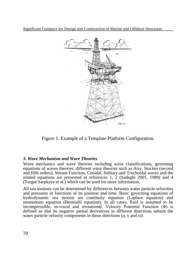
Figure 1. Example of a Template Platform Configuration.
3. Wave Mechanism and Wave Theories
Wave mechanics and wave theories including wave classifications, governing equations of waves theories, different wave theories such as Airy, Stockes (second and fifth orders), Stream Function, Cnoidal, Solitary and Trochoidal waves and the related equations are presented in references 1, 2 (Sadeghi 2001, 1989) and 4 (Turgut Sarpkaya et al.) which can be used for more information.
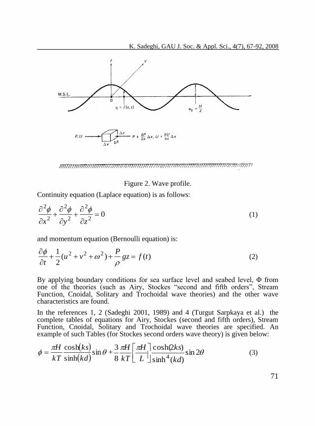
All sea motions can be determined by differences between water particle velocities and pressures in functions of its position and time. Basic governing equations of hydrodynamic sea motion are continuity equation (Laplace equation) and momentum equation (Bernoulli equation). In all cases, fluid is assumed to be incompressible, in-viscid and irrotational. Velocity Potential Function (Φ) is defined so that its negative partial derivatives in different directions submit the water particle velocity components in those directions (u, v and ):
K. Sadeghi, GAU J. Soc. & Appl. Sci., 4(7), 67-92, 2008
71
Figure 2. Wave profile.
Continuity equation (Laplace equation) is as follows:
02
2
2
2
2
2
zyx
(1)
and momentum equation (Bernoulli equation) is:
)()(2
1 222 tfgzP
vut
(2)
By applying boundary conditions for sea surface level and seabed level, Φ from one of the theories (such as Airy, Stockes “second and fifth orders”, Stream Function, Cnoidal, Solitary and Trochoidal wave theories) and the other wave characteristics are found.
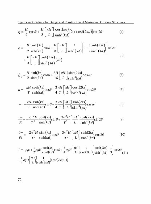
In the references 1, 2 (Sadeghi 2001, 1989) and 4 (Turgut Sarpkaya et al.) the complete tables of equations for Airy, Stockes (second and fifth orders), Stream Function, Cnoidal, Solitary and Trochoidal wave theories are specified. An example of such Tables (for Stockes second orders wave theory) is given below:
sinsinh
cosh
kd
ks
kT
H +
2sin
)(sinh
)2cosh(
8
34 kd
ks
L
H
kT
H
(3)
Significant Guidance for Design and Construction of Marine and Offshore Structures
72
2cos2cosh2
sinh
cosh
8cos
2 3kd
kd
kd
L
HHH
(4)
2 2
2
cosh 1 3cosh 2sin 1 sin 2
2 sinh 8 sinh 2 sinh
cosh 2
4 sinh
H ks H H ks
kd L kd kd
H H kst
L kd
(5)
2cos
sinh
2sinh
16
3cos
sinh
sinh
2 4 kd
ks
L
HH
kd
ksHV
(6)
2cos
sinh
2cosh
4
3cos
sinh
cosh4 kd
ks
L
H
T
H
kd
ks
T
Hu
(7)
2sin
sinh
2sinh
4
3sin
sinh
sinh4 kd
ks
L
H
T
H
kd
ks
T
Hw
(8)
2sin
sinh
2cosh3sin
sinh
cosh242
2
2
2
kd
ks
L
H
T
H
kd
ks
T
H
t
u
(9)
2cos
sinh
2sinh3cos
sinh
sinh242
2
2
2
kd
ks
L
H
T
H
kd
ks
T
H
t
w
(10)
12cosh
2sinh
1
4
1
2cos3
1
sinh
2cosh
2sinh
1
4
3cos
cosh
cosh
2
12
kskdL
HgH
kd
ks
kdL
HgH
kd
ksgHgzP
(11)
K. Sadeghi, GAU J. Soc. & Appl. Sci., 4(7), 67-92, 2008
73
42 08
1 gHE (12)
42 0
2sinh
21
16
1
kd
kdcgHp (13)
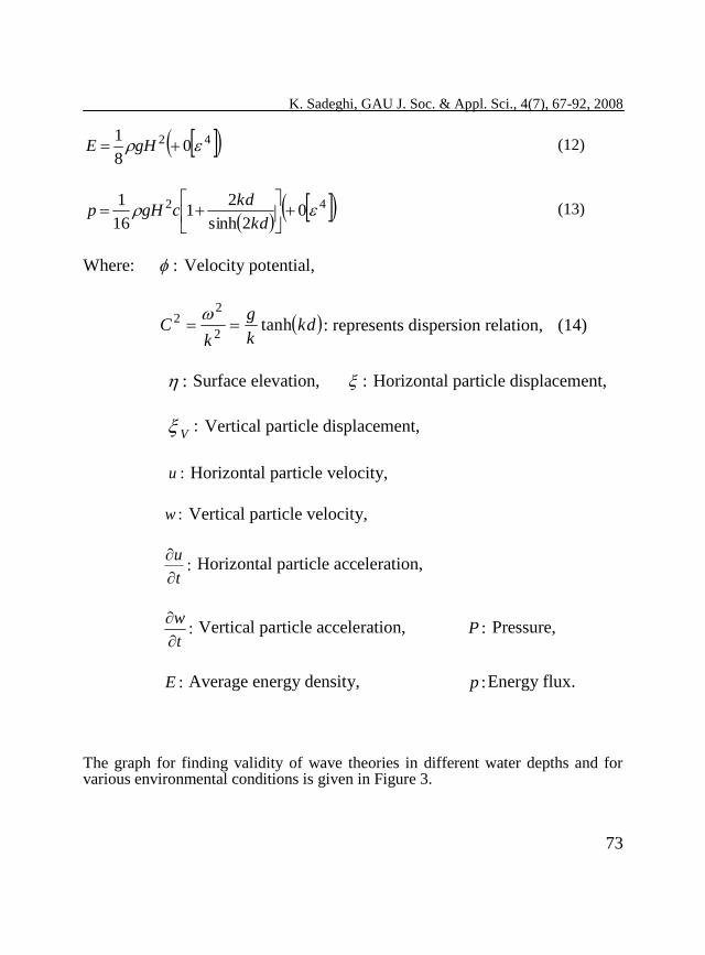
Where: : Velocity potential,
kdk
g
kC tanh
2
22
: represents dispersion relation, (14)
: Surface elevation, : Horizontal particle displacement,
: V Vertical particle displacement,
:u Horizontal particle velocity,
:w Vertical particle velocity,
:t
u
Horizontal particle acceleration,
:t
w
Vertical particle acceleration, :P Pressure,
:E Average energy density, :p Energy flux.
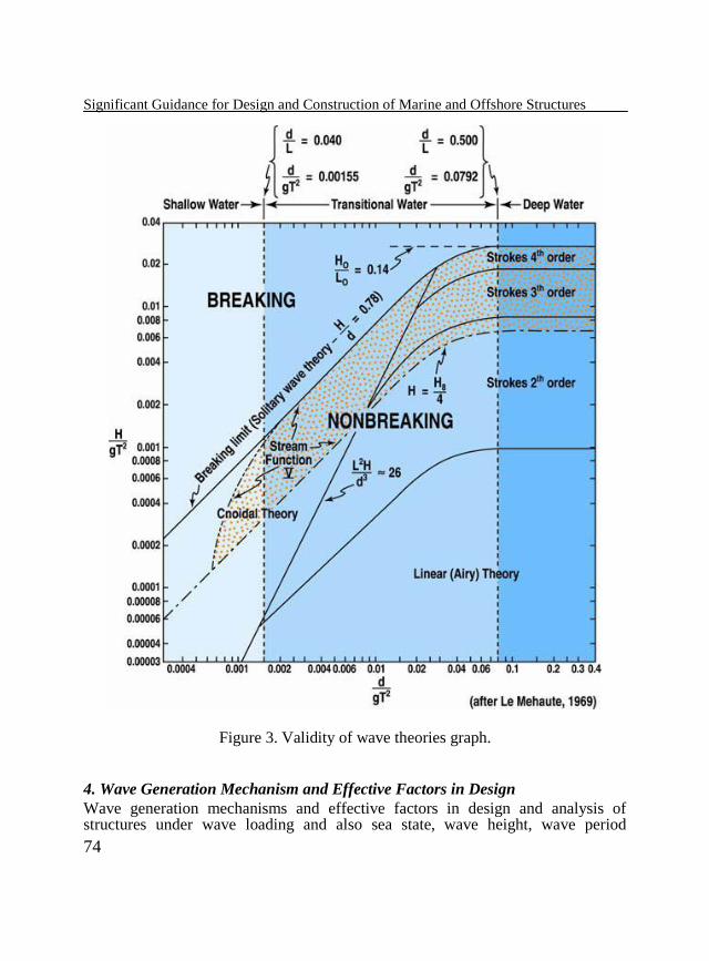
The graph for finding validity of wave theories in different water depths and for various environmental conditions is given in Figure 3.
Significant Guidance for Design and Construction of Marine and Offshore Structures
74
Figure 3. Validity of wave theories graph.
4. Wave Generation Mechanism and Effective Factors in Design
Wave generation mechanisms and effective factors in design and analysis of structures under wave loading and also sea state, wave height, wave period
K. Sadeghi, GAU J. Soc. & Appl. Sci., 4(7), 67-92, 2008
75
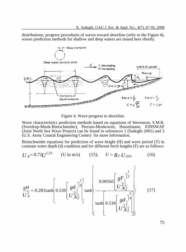
distributions, progress procedures of waves toward shoreline (refer to the Figure 4), waves prediction methods for shallow and deep waters are issued here shortly.
Figure 4. Wave progress to shoreline.
Wave characteristics prediction methods based on equations of Stevenson, S.M.B. (Sverdrup-Munk-Bretschneider), Pierson-Moskowitz, Hasselmann, JONSWAP (Joint North Sea Wave Project) can be found in references 1 (Sadeghi 2001) and 3 (U.S. Army Coastal Engineering Center) for more information.
Bretschneider equations for prediction of wave height (H) and wave period (T) in constant water depth (d) condition and for different fetch lengths (F) are as follows:
UU A23.171.0 (U in m/s) (15), URTU )10(. (16)
U
gd
U
gF
U
gd
U
A
A
A
gH
A
2530.0tanh
200565.0
tanh2
530.0tanh283.0
4
3
2
1
4
3
2 (17)
Significant Guidance for Design and Construction of Marine and Offshore Structures
76
U
gd
U
gF
U
gd
U
A
A
A
gT
A
2833.0tanh
20379.0
tanh2
833.0tanh54.7
8
3
3
1
8
3
(18)
U
gT
U A
gt
A
3
7
21037.5 x (19)
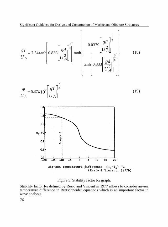
Figure 5. Stability factor RT graph.
Stability factor RT defined by Resio and Vincent in 1977 allows to consider air-sea temperature difference in Bretschneider equations which is an important factor in wave analysis.
K. Sadeghi, GAU J. Soc. & Appl. Sci., 4(7), 67-92, 2008
77
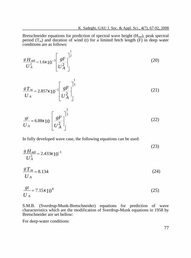
Bretschneider equations for prediction of spectral wave height (Hm0), peak spectral period (Tm) and duration of wind (t) for a limited fetch length (F) in deep water conditions are as follows:
U
gF
U
H
A
g
A
m
26.1
2
1
3
20
10x (20)
U
gF
U
T
A
g
A
m
2857.2
3
1
110x (21)
U
gF
U A
gt
A2
88.6
3
2
10x (22)
In fully developed wave case, the following equations can be used:
(23)
134.8U
T
A
mg (24)
10415.7 x
U A
gt (25)
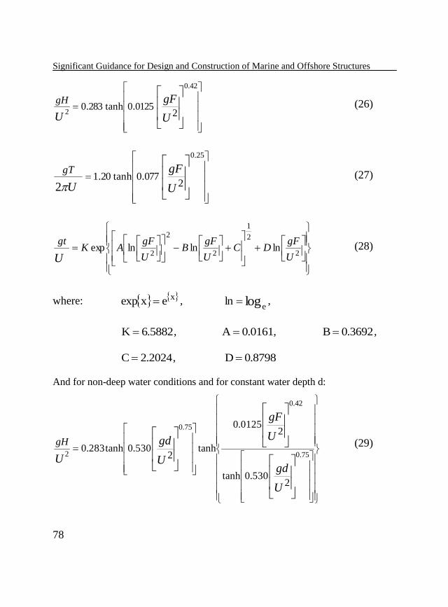
S.M.B. (Sverdrup-Munk-Bretschneider) equations for prediction of wave characteristics which are the modification of Sverdrup-Munk equations in 1958 by Bretschneider are set bellow:
For deep-water conditions:
101
20 433.2 x
U
H
A
mg
Significant Guidance for Design and Construction of Marine and Offshore Structures
78
U
gF
U
gH
20125.0tanh283.0
42.0
2 (26)
U
gF
U
gT
2077.0tanh20.1
25.0
2 (27)
2
2
1
2
2
2lnlnlnexp
U
gFDC
U
gFB
U
gFAK
gt
U (28)
where: xexexp , loge
ln ,
5882.6K , 0161.0A , 3692.0B ,
2024.2C , 8798.0D
And for non-deep water conditions and for constant water depth d:
U
gd
U
gF
U
gd
U
gH
2530.0tanh
20125.0
tanh2
530.0tanh283.075.0
42.0
75.0
2
(29)
K. Sadeghi, GAU J. Soc. & Appl. Sci., 4(7), 67-92, 2008
79
U
gd
U
gF
U
gd
U
gT
2833.0tanh
2077.0
tanh2
833.0tanh20.1375.0
25.0
375.0
2
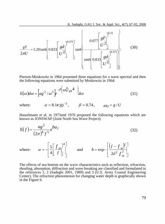
(30)
Pierson-Moskowitz in 1964 presented three equations for a wave spectral and then the following equations were submitted by Moskowitz in 1964:
deagd
4
/E/4
052 (31)
where: 1031.8 x , 74.0 , Ug /0
Hasselmann et al. in 1973and 1976 proposed the following equations which are known as JONSWAP (Joint North Sea Wave Project):
bae
f
agf
54
2
2E (32)
where:
4
4
5
f
fm and
f
f
m
mf
b22
2
2exp
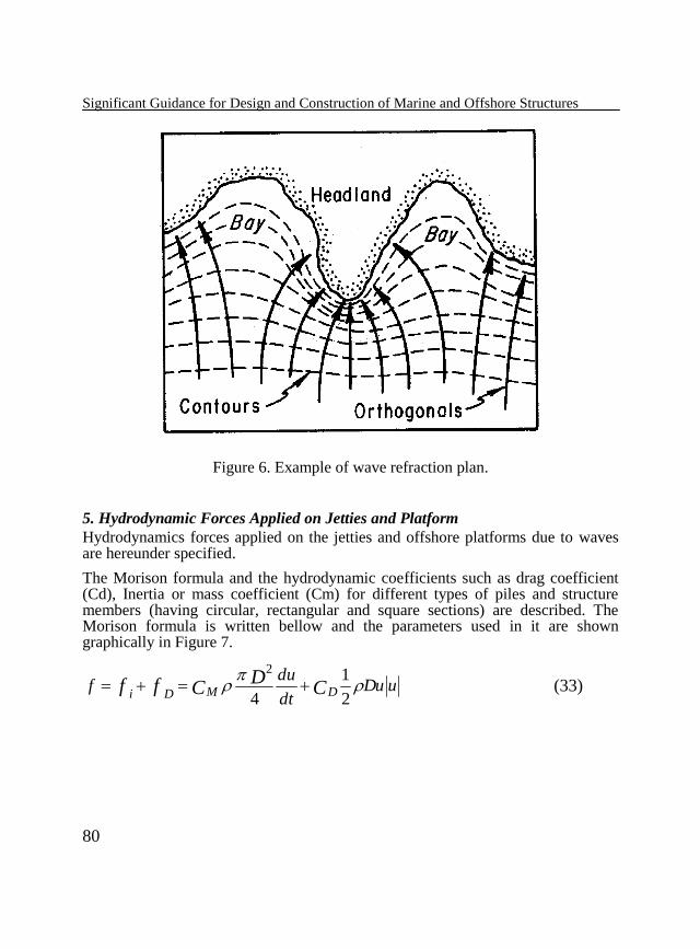
The effects of sea bottom on the wave characteristics such as reflection, refraction, shoaling, absorption, diffraction and wave breaking are classified and formulated in the references 1, 2 (Sadeghi 2001, 1989) and 3 (U.S. Army Coastal Engineering Center). The refraction phenomenon for changing water depth is graphically shown in the Figure 6.
Significant Guidance for Design and Construction of Marine and Offshore Structures
80
Figure 6. Example of wave refraction plan.
5. Hydrodynamic Forces Applied on Jetties and Platform
Hydrodynamics forces applied on the jetties and offshore platforms due to waves are hereunder specified.
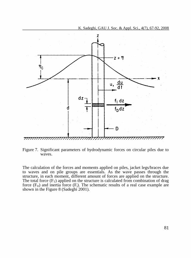
The Morison formula and the hydrodynamic coefficients such as drag coefficient (Cd), Inertia or mass coefficient (Cm) for different types of piles and structure members (having circular, rectangular and square sections) are described. The Morison formula is written bellow and the parameters used in it are shown graphically in Figure 7.
uDudt
duf C
DCff DMDi
2
1
4
2
(33)
K. Sadeghi, GAU J. Soc. & Appl. Sci., 4(7), 67-92, 2008
81
Figure 7. Significant parameters of hydrodynamic forces on circular piles due to waves.
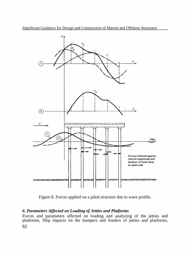
The calculation of the forces and moments applied on piles, jacket legs/braces due to waves and on pile groups are essentials. As the wave passes through the structure, in each moment, different amount of forces are applied on the structure. The total force (FT) applied on the structure is calculated from combination of drag force (FD) and inertia force (Fi). The schematic results of a real case example are shown in the Figure 8 (Sadeghi 2001).
Significant Guidance for Design and Construction of Marine and Offshore Structures
82
Figure 8. Forces applied on a piled structure due to wave profile.
6. Parameters Affected on Loading of Jetties and Platforms
Forces and parameters affected on loading and analyzing of the jetties and platforms, Ship impacts on the bumpers and fenders of jetties and platforms,
K. Sadeghi, GAU J. Soc. & Appl. Sci., 4(7), 67-92, 2008
83
different types of fenders, specifications of berths in ports, mooring forces, dead and live loads, load combinations, current force, wind force, earthquake force and the needed formulae are items that are to be considered in the design phase which for further information references 1 and 2 (Sadeghi 2001, 1989) can be used.
7. Design and Analysis of Template Platform and Jetties Piles
Different methods used for design of template fixed platforms and jetties piles are issued in the references 1 and 2 (Sadeghi 2001, 1989).
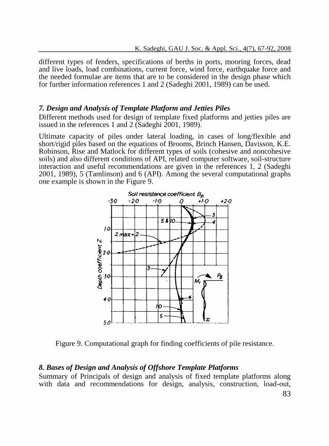
Ultimate capacity of piles under lateral loading, in cases of long/flexible and short/rigid piles based on the equations of Brooms, Brinch Hansen, Davisson, K.E. Robinson, Rise and Matlock for different types of soils (cohesive and noncohesive soils) and also different conditions of API, related computer software, soil-structure interaction and useful recommendations are given in the references 1, 2 (Sadeghi 2001, 1989), 5 (Tamlinson) and 6 (API). Among the several computational graphs one example is shown in the Figure 9.
Figure 9. Computational graph for finding coefficients of pile resistance.
8. Bases of Design and Analysis of Offshore Template Platforms
Summary of Principals of design and analysis of fixed template platforms along with data and recommendations for design, analysis, construction, load-out,
Significant Guidance for Design and Construction of Marine and Offshore Structures
84
transportation and installation of platforms in Persian Gulf submitted in the references 1 (Sadeghi 2001) and 6 (API) are presented hereunder.
8.1. Summary of Offshore Construction Project Stages
Basically an offshore platform construction project includes the following phases:
Design
Procurement
Fabrication of steel structures
Load-out, transportation and installation operations
Commissioning Usually, fabrication of steel structures of offshore platforms is carried out at the construction yard, located significantly remote from the installation site. Load-out, transportation and installation of such big-sized elements are complicated operations requiring special designs, structural strength calculations for the related conditions.
8.2. Design of Offshore Fixed Platforms
8.2.1. General
The most commonly used offshore platforms in the Gulf of Mexico, Nigeria, California shorelines and Persian Gulf are template type platforms and are made of steel, and are used for oil/gas exploration and production (Sadeghi, 2001). The design and analyses of these offshore structures are carried out in accordance with recommendations published by the American Petroleum Institute (API), American Institute of Steel Construction (AISC) codes and the like.
8.2.2. Different Analyses Needed for Template Platforms
Main analyses required for design of a template (jacket) type platform are as follows:
In- place analysis
Earthquake analysis
Fatigue analysis
Impact analysis
Temporary analysis
Load-out analysis
K. Sadeghi, GAU J. Soc. & Appl. Sci., 4(7), 67-92, 2008
85
Transportation analysis
Appurtenances analysis
Lift or Launch analysis
Upending analysis
Up-righting analysis
Un-piled stability analysis
Pile and conductor pipe drivability analysis
Cathodic protection analysis
Transportation analysis
Installation analysis.
8.2.3. Environmental Parameters
The design and analysis of fixed offshore platforms may be conducted in accordance with the API’s “Recommended Practice for Planning, Designing, and Constructing Fixed Offshore Platforms – Working Stress Design (API-RP-2A-WSD)”.
The API specifies minimum design criteria for a 100-year design storm.
Helicopter landing pad (helipad or helideck) on offshore platforms must conform to API RP-2L (latest edition).
Normally, for the analysis of offshore platforms, the environmental parameters include wave heights of as much as 21 meters (depending on the water depth) and wind velocities of 170 km/hr for Gulf of Mexico, coupled with tides up to 4 m in shallow waters. The wave heights up to 12.2 meters and wind velocities up to 130 km/hr for Persian Gulf, coupled with tides up to 3 m are considered in design of platforms.
The design wave height in Southern Caspian Sea is about 20 m for a return period of 100 years, and for North Sea it is over 32 m depending on the location.
The API RP-2A also specifies that the lowest deck must maintain a minimum of 1.5 m air gap between the bottom of the deck beams and the wave crest during the maximum expected level of water considering combination of wave height and tides.
The platform should resist against the loads generated by the environmental conditions, construction, load-out, transportation and installation plus other loads generated by onboard equipments.
Significant Guidance for Design and Construction of Marine and Offshore Structures
86
8.2.4. Geotechnical Data and Pile Design Consideration
Another essential part of the design of offshore structures is the soil investigation and pile design. The soil investigation is vital to the design of offshore structures, because it is the soil that ultimately resists the enormous forces and moments present in the piling, at the bottom of the ocean, created by the presence of the platform in the storm conations.
The under seabed soil normally can be clay, sand, silt, or a mixture of these.
Each project must acquire a site-specific soil report showing the soil stratification and its characteristics for load bearing in tension and compression, shear resistance, and load-deflection characteristics of axially and laterally loaded piles. The soil borings at the desired location and then performing in-situ and laboratory tests are necessary for developing data usable to the platform design. The soil report should show the calculated minimum axial capacities for piles of the same diameter as the platform design piles, SRD curves, different types of mudmat bearing capacity, pile group action curves, shear resistance values and pile tip end bearing values, lateral pile axial capacity values.
These values will be input into the structural analysis model (normally in StruCad, FASTRUDL or SACS software), and will determine minimum pile penetrations and sizes, considering a factor of safety of 1.5. For operating loads, the F.S. must be 2.0 for piles. The unity check ratios must not exceed 1.0, in the piles or anywhere else in the platform in normal conditions.
Pile penetrations will vary depending on platform size and loads, and soil characteristics, but normally range from about 30 meters to about 100 meters. For heavy platforms in Persian Gulf, pile diameter is about 2 m and pile penetration is about 70 m under seabed.
The soil characteristics are also used for a pile drivability analysis. Sandy soils are very desirable for axial end bearing, but can be detrimental to pile driving when encountered near the surface.
8.2.5. Software Used in the Platforms Design
To perform the structural analysis of platforms the following software may be used:
SACS, FASTRUDL, MARCS, OSCAR, StruCad or SESAM for
structural analysis.
Maxsurf, Hydromax, Seamoor for hydrodynamics calculations of
barges.
GRLWEAP, PDA, CAPWAP for pile analyses.
K. Sadeghi, GAU J. Soc. & Appl. Sci., 4(7), 67-92, 2008
87
8.2.6. Structural Analysis
To perform structural analysis of a platform, structural model is developed using normally one of the following common software packages developed for the offshore engineering: SACS, FASTRUDL, MARCS, SESEM, OSCAR or StruCad. A model of the structure should include all principal members of the structure, appurtenances and major equipments.
A typical offshore structure supported by piles has normally a topside structure containing a Main Deck, a Cellar Deck, Sub-Cellar Deck and a Helideck. The topside structure is supported by deck legs connected to the top of the piles. The piles extend from above the top level of jacket through the mudline and into the soil. Underwater, the piles are contained inside the legs of a “jacket” structure which serves as bracing for the piles against lateral loads. The jacket may also serve as a template for the initial driving of the through-leg piles (The piles are driven through the inside of the legs of the jacket structure). The piles may be driven from outside the legs of the jacket structure in the case of using skirt piles and using underwater hammer.
The structural model file consists of:
The type of analysis, the mudline elevation and water depth,
Member sizes,
Joints definition,
Soil data (i.e. mudmat bearing capacity, pile groups, T-Z, P-Y, Q-Z
curve data),
Joint coordinates,
Marine growth input,
Inertia and mass coefficients (CD and CM) input,
Distributed load surface areas,
Wind areas,
Anode weights and locations,
Appurtenances weights and locations,
Conductors and piles weight and locations,
Grouting weight and locations,
Load cases include dead, live and environmental loading, crane loads,
etc. Any analysis of offshore platforms must also include the equipment weights and a maximum deck live loading (distributed area loading), dead loads in addition to the environmental loads mentioned above, and wind loads. Underwater, the analysis
Significant Guidance for Design and Construction of Marine and Offshore Structures
88
must also include marine growth as a natural means of enlargement of weight, in addition to the underwater projected areas subject to wave and current forces.
The structural analysis will be a static linear analysis of the structure above the mudline combined with a static non-linear analysis of the soil with the piles.
Additionally, checks will be made for all tubular joint connections to analyze the strength of tubular joints against punching. The punching shear analysis is referred to as “joint can analysis”. The Unity Checks must not exceed 1.0 in normal condition.
All structural members will be chosen based on the results of the computer-aided in-place and the other above-mentioned analyses.
Concurrently with the structural analysis the design team will start the development of construction drawings, which will incorporate all the dimensions and sizes optimized by the analyses and will also add construction details for the field erection, load-out, transportation, and installation of the structure.
The platforms must be capable of withstanding the most severe design loads and also of surviving a design lifetime of fatigue loading.
The fatigue analysis is developed with input from a wave scatter diagram and from the natural dynamic response of the platform, and the stiffness of the pile caps at the mudline by applying Palmgeren-Miner formula. A detailed fatigue analysis should be performed to assess cumulative fatigue damage. The analysis required is a “spectral fatigue analysis” or simplified fatigue analysis according to API.
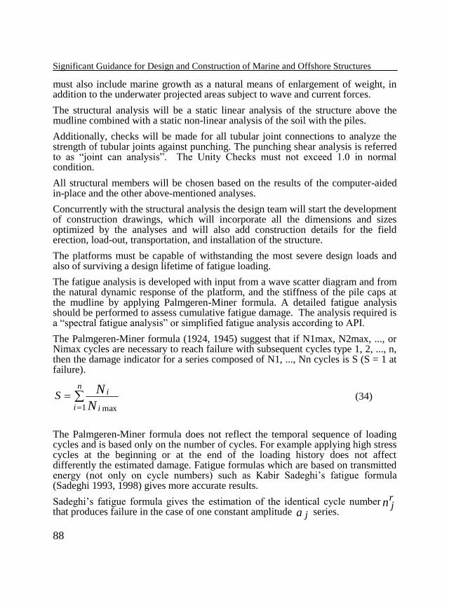
The Palmgeren-Miner formula (1924, 1945) suggest that if N1max, N2max, ..., or Nimax cycles are necessary to reach failure with subsequent cycles type 1, 2, ..., n, then the damage indicator for a series composed of N1, ..., Nn cycles is S (S = 1 at failure).
n
i i
i
N
NS
1 max
(34)
The Palmgeren-Miner formula does not reflect the temporal sequence of loading cycles and is based only on the number of cycles. For example applying high stress cycles at the beginning or at the end of the loading history does not affect differently the estimated damage. Fatigue formulas which are based on transmitted energy (not only on cycle numbers) such as Kabir Sadeghi’s fatigue formula (Sadeghi 1993, 1998) gives more accurate results.
Sadeghi’s fatigue formula gives the estimation of the identical cycle number nrj
that produces failure in the case of one constant amplitude a j series.
K. Sadeghi, GAU J. Soc. & Appl. Sci., 4(7), 67-92, 2008
89
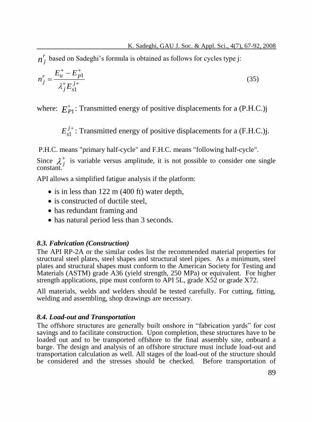
nrj based on Sadeghi’s formula is obtained as follows for cycles type j:
jsj
purj
E
EEn
1
1
(35)
where: EP
1 : Transmitted energy of positive displacements for a (P.H.C.)j
jsE 1 : Transmitted energy of positive displacements for a (F.H.C.)j.
P.H.C. means "primary half-cycle" and F.H.C. means "following half-cycle".
Since j is variable versus amplitude, it is not possible to consider one single
constant.
API allows a simplified fatigue analysis if the platform:
is in less than 122 m (400 ft) water depth,
is constructed of ductile steel,
has redundant framing and
has natural period less than 3 seconds.
8.3. Fabrication (Construction)
The API RP-2A or the similar codes list the recommended material properties for structural steel plates, steel shapes and structural steel pipes. As a minimum, steel plates and structural shapes must conform to the American Society for Testing and Materials (ASTM) grade A36 (yield strength, 250 MPa) or equivalent. For higher strength applications, pipe must conform to API 5L, grade X52 or grade X72.
All materials, welds and welders should be tested carefully. For cutting, fitting, welding and assembling, shop drawings are necessary.
8.4. Load-out and Transportation
The offshore structures are generally built onshore in “fabrication yards” for cost savings and to facilitate construction. Upon completion, these structures have to be loaded out and to be transported offshore to the final assembly site, onboard a barge. The design and analysis of an offshore structure must include load-out and transportation calculation as well. All stages of the load-out of the structure should be considered and the stresses should be checked. Before transportation of
Significant Guidance for Design and Construction of Marine and Offshore Structures
90
platform, sea-fastening analysis is performed and the platform parts (jacket, decks, and appurtenances) are fastened to the barge. In the transportation analysis, the motions of roll, pitch, heave and yaw should be considered.
To perform a transportation analysis, an environmental report showing the worst sea-state conditions during that time of the year throughout the course of the intended route should be available for design. Generally, based on Noble Denton criteria for transportation, it may assume a 20 degree angle of roll with a 10 second roll period, and a 12.5 degree angle of pitch with a 10 second period, plus a heave acceleration of 0.2 g.
8.5. Installation
All the structural sections of an offshore platform must also be designed to withstand the lifting/launching, upending, up-righting, and other installation stresses.
The jackets must be designed to be self supporting during pile driving and installation period. Mudmats are used at the bottom horizontal brace level which transfer the temporary loads to the seabed surface and soil before completion of pile driving operation. The mudmats are made of stiffened steel plates and are generally located adjacent to the jacket leg connections near the mudline level.
The piles must be designed to withstand the stresses during pile driving operation. The piles are installed in sections. The first section must be long enough to go from a few meters above the top of the jacket leg to the mudline (additionally pile setup and self-weight penetration of pile should be taken into account). The other sections (add-ons) must be field welded to the first section (main piece) and the following add-ons at an elevation slightly higher than the top of the jacket legs.
When all the piles have been driven to the required design target penetrations, they will be trimmed at the design “top of pile” elevation. The jacket will then be welded to the piles about 1.0 meters or less below the top of the piles around scheme plate.
8.6. Data Used for the Tallest Platform Installed in Persian Gulf
Data used for the tallest platform installed in Persian Gulf along with different steps of analyses of the platform are given in the reference 1(Sadeghi 2001) as an example.
9. Breakwaters
Ports and harbors design, and the different types of breakwaters, details of breakwater design and construction with special stress on rubble mound structures
K. Sadeghi, GAU J. Soc. & Appl. Sci., 4(7), 67-92, 2008
91
are presented in references 1 (Sadeghi 2001) and 3 (U.S. Army Coastal Engineering Center).
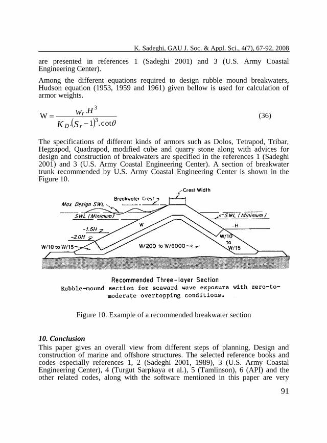
Among the different equations required to design rubble mound breakwaters, Hudson equation (1953, 1959 and 1961) given bellow is used for calculation of armor weights.
cot.1.
.W
3
3
SK
w
rD
r H (36)
The specifications of different kinds of armors such as Dolos, Tetrapod, Tribar, Hegzapod, Quadrapod, modified cube and quarry stone along with advices for design and construction of breakwaters are specified in the references 1 (Sadeghi 2001) and 3 (U.S. Army Coastal Engineering Center). A section of breakwater trunk recommended by U.S. Army Coastal Engineering Center is shown in the Figure 10.
Figure 10. Example of a recommended breakwater section
10. Conclusion
This paper gives an overall view from different steps of planning, Design and construction of marine and offshore structures. The selected reference books and codes especially references 1, 2 (Sadeghi 2001, 1989), 3 (U.S. Army Coastal Engineering Center), 4 (Turgut Sarpkaya et al.), 5 (Tamlinson), 6 (API) and the other related codes, along with the software mentioned in this paper are very
Significant Guidance for Design and Construction of Marine and Offshore Structures
92
helpful for designing marine and offshore structures. These documents cover a wide range of information, technical specifications, technical data, applicable equations and graphs, useful recommendations, addressing most used international codes and standards and can be considered as reliable guides for designing and construction of marine and offshore structures.
References
Kabir Sadeghi, 2001, "Coasts, Ports and Offshore Structures Engineering Book",
Rev. 1, Published by Power and Water University of Technology, 501 pages,
ISBN: 964-93442-0-9.
Kabir Sadeghi, 2001, “Design of Marine and Offshore Structures”, Published by K.
N. T. University of Technology, 1989, 456 pages.
U.S. Army Coastal Engineering Center, Shore Protection Manual, Vol. I & II,
Fourth edition, Second printing, 1980.
Turgut Sarpkaya/Michael Isacicson, “Mechanics of Wave Forces on Offshore
Structures”, Published by Van Nostrand Reinhold Co.
Tamlinson M. J., Pile Design &Construction Practice, Published by Viewpoint
Publication.
API, Recommended Practice for Planning, Designing & Constructing Fixed
Offshore Platforms, API-RP.2A-WSD, 21st edition.
Sadeghi K., “Proposition of a Damage Indicator Applied on R/C Structures
Subjected to Cyclic Loading”, Fracture Mechanics of Concrete Structures, Vol.
1, edited by J. Mihashi & K. Rokugo, AEDIFICATIO Publishers
(Netherlands/Germany), 1998, p. 707-717.
Sadeghi K., Lamirault J. and Sieffert J.G., “Damage Indicator Improvement
Applied on R/C Structures Subjected to cyclic Loading”, EURODYN93,
Norway, Structural Dynamics, vol. 1, p. 129-136, Balkema, T. Moan et al.
Editors, ISBN 90 5410336 1, 1993.
Sadeghi K., Lamirault Jacques, & Sieffert Jean Georges, “proposition de
définition d’un indicateur de dommage”, Troisième Colloque National de
Génie parasismique “Génie parasismique et Aspects vibratoires dans le
Génie civil”, AFPS, Paris, 1993, vol. 2, Techniques Avancées, p. TA47 -
TA 56.