de montage et de fonctionnement installateur atc tecniche per... · i/t teletherm k línea...
TRANSCRIPT

1
LAIA GTA
Heating UnitsInstallation, Assemblyand Operating Instructionsfor the INSTALLER
GB
HeizkesselInstallations-, Montage-und Betriebsanleitungfür den INSTALLATEUR
D
GruppoTermicoIstruzioni per l’Installazione,il Montaggio e il Funzionamentoper l’INSTALLATORE
I
Grupos TérmicosInstruções de Instalação,Montagem e Funcionamentopara o INSTALADOR
P
Groupes ThermiquesInstructions d’Installation,de Montage et de Fonctionnementpour l’INSTALLATEUR
F
Grupos TérmicosInstrucciones de Instalación,Montaje y Funcionamientopara el INSTALADOR
E
ATC ROC
2
Fig. 1
Fig. 4
Fig. 5
Fig. 7
Fig. 2 Fig. 3
Fig. 6 Fig. 8
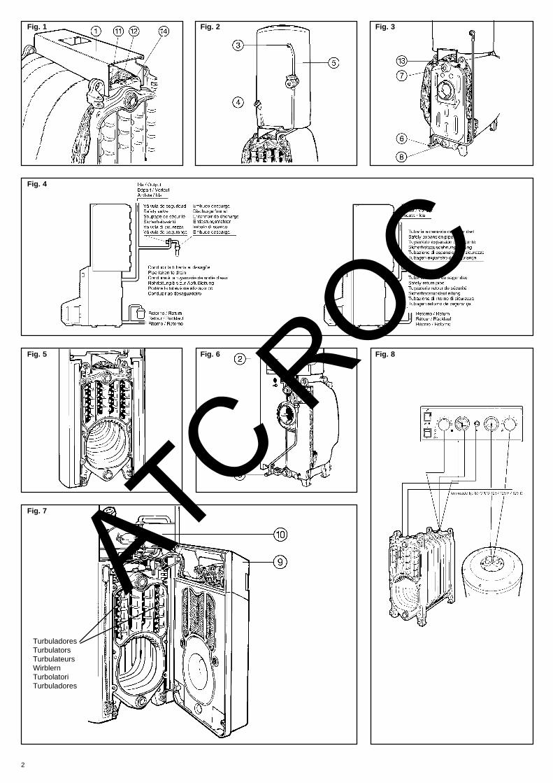
TurbuladoresTurbulatorsTurbulateursWirblernTurbolatoriTurbuladores
ATC ROC

3
Fig. 9
CC-129 CC-129 R
CC-129 T
ATC ROC

4
A CirculadorA(*) Circulador segundo circuito de CalefacciónB QuemadorD Termostato de seguridadE Termostato de regulaciónF Señalización tensiónG Señalización bloqueo quemadorH Interruptor generalI/T TelethermK Línea telefónicaM Reloj programadorO Central regulaciónQ Termostato de ambiente opcionalR Circulador Agua Caliente SanitariaS Termostato regulación Agua Caliente SanitariaT Interruptor Invierno/VeranoU Termostato mantenimiento 80°CV ReléW Resistencia eléctrica opcionalY Servomotor válvula 3 víasZ Zócalo central regulación
A CirculateurA(*) Circulateur du second circuit de ChauffageB BrûleurD Thermostat de sécuritéE Thermostat de régulationF Voyant de tensionG Voyant de blocage brûleurH Interrupteur généralI/T TéléthermK Ligne téléphoniqueM Horloge programmableO Centrale de régulationQ Thermostat d’ambianceR Circulateur Eau Chaude SanitaireS Thermostat de régulation Eau Chaude SanitaireT Interrupteur Hiver/EtéU Thermostat fixe à 80°CV RelaisW Résistance électrique (Option)Y Servomoteur vanne 3 voiesZ Socle centrale de régulation
A UmwälzpumpeA(*) Umwälzpumpe für den zweiten HeizhreislaufB BrennerD SicherheitsthermostatE RegelthermostatF Anzeige SpannungG Anzeige BrennerblockierungH HauptschalterI/T TelethermK TelefonleitungM SchaltuhrO RegelwarteQ (Auf Wunsch geliefertes) RaumthermostatR Umwälzpumpe HeißwasserS Regelthermostat HeißwasserT Wählschalter Sommer/WinterU Auf 80°C eingestellter WartungsthermostatV RelaisW (Auf Wunsch gelieferter) HeizwiderstandY Servomotor 3-Wege-VentilZ Sockel Regelwarte
A Circolatore impiantoA(*) Circolatore secondo circuito di RiscaldamentoB BruciatoreD Termostato di sicurezzaE Termostato di regolazioneF Led sotto tensioneG Led blocco bruciatoreH Interruttore generaleI/T Teletherm (comando telefonico)K Linea telefonicaM Orologio programmatoreO Centralina di termoregolazioneQ Termostato ambiente (optional)R Circolatore circuito sanitarioS Termostato regolazione Acqua Calda SanitariaT Interruttore Inverno/EstateU Termostato di mantenimento 80°CV ReléW Resistenza elettrica (optional)Y Servomotore valvola a tre vieZ Zoccolo centralina di termoregolazione
A CirculadorA(*) Circulador segundo circuito Aquecimento centralB QueimadorD Termostato de segurançaE Termostato de regulaçãoF Sinalização de tensãoG Sinalização de bloqueio do queimadorH Interruptor geralI/T TelethermK Linha telefónicaM Relógio programadorO Central de regulaçãoQ Termostato ambiente (opcional)R Circulador Água Quente SanitáriaS Termostato regulação Água Quente SanitáriaT Interruptor Verão/InvernoU Termostato manutenção 80°CV ReléW Resistência eléctrica (opcional)Y Servomotor Válvula de 3 viasZ Base central regulação
Fig. 9
CC-129 C CCE-130 T
C ROC
A Circulating pumpA(*) Pump for Heating Circuit 2B BurnerD Safety limit thermostatE Control thermostatF Power ”on” indicator lampG Burner lockout indicator lampH Main switchI/T TelethermK Telephone lineM TimerO Control CentreQ Ambient thermostat (optional)R DHW pumpS DHW control thermostatT Winter/Summer SwitchU Fixed thermostat 80°CV RelayW Electric heater (optional)Y Motorized 3-way valveZ Control centre base
Para conectar termostato de ambiente retirar puente entre bornes: - 8 y 9 en cuadro CC-129 - 15 y 16 en cuadro CC-129R - 10 y 11en cuadro CC-129T - 9 y 10 en cuadro CCE-130TPara conectar resistencia retirar puente entre bornes:- 4 y 5 en cuadros CC-129 y CC-129T, y conectarla entre 3 y 4 - 10y 11 en cuadro CC-129R, y conectarla entre 9 y 10.El reloj M está preparado de origen para el control de Calefacción.Para el control de Calefacción y Agua Caliente Sanitaria, retirarpuentes 3-4, 5-6 y 7-8 y realizar puentes entre 3-6, 4-7 y 5-8.El trazado grueso corresponde a cables de 2,5 mm de sección,mientras que el fino corresponde a cables de 1 mm de sección.
Pour connecter un thermostat d’ambiance, retirer le pont entre lesbornes:-8 et 9 du tableau CC-129 - 15 et 16 du tableau C-129R - 10 et 11du tableau CC-129T - 9 et 10 du tableau CCE-130TPour connecter une résistance, retirer le pont entre les bornes:-4 et 5 des tableaux CC-129 et CC-129T, et connecter la entre 3 et4 - 10 et 11 du tableau CC-129R, et connecter la entre 9 et 10.L’horloge M est préparée d’origine pour le contrôle du Chauffage.Pour le contrôle du Chauffage et de l’Eau Chaude Sanitaire, retirerles ponts 3-4, 5-6 et 7-8 et faire les ponts entre 3-6, 4-7 et 5-8.Le trait gras correspond a des câbles de 2,5 mm de section, tandisque le fin correspond a des câbles de 1 mm section.
Entfernen Sie für den Anschluß des Raumthermostats die Brückezwischen den Klemmen:-8 und 9 bei Schalttafel CC-129 - 15 und 16 bei SchalttafelCC-129R - 10 und 11 bei Schalttafel CC-129T - 9 und 10 beiSchalttafel CCE-130TEntfernen Sie für den Anschluß des Heizwiderstands die Brückezwischen den Klemmen:- 4 und 5 bei den Schalttafeln CC-129 und CC-129T. Bringen Siedie Brücke zwischen Klemme 3 und 4 an. - 10 und 11 bei SchalttafelCC-129R. Bringen Sie die Brücke zwischen Klemme 9 und 10 an.Die Schaltuhr M ist ab Werk auf Heizbetrieb eingestellt. EntfernenSie für Heiz- und Warmwasserbetrieb die Brücken 3-4, 5-6 und7-8 und verlegen Sie diese auf 3-6, 4-7 und 5-8.Die dicke Strichführung entspricht Kabeln mit einem Durchmesser
Per collegare il termostato ambiente rimuovere i ponti tra i morsetti:-8 e 9 nel Quadro CC-129 - 15 e 16 nel Quadro CC-129R - 10 e 11nel Quadro CC-129T - 9 e 10 nel Quadro CCE-130TPer collegare la resistenza elettrica rimuovere i ponti tra i morsetti:-4 e 5 nel Quadro CC-129 e CC-129T e spostarlo tra 3 e 4 - 10 e 11nel Quadro CC-129R e spostarlo tra 9 e 10L’orologio programmatore M è in origine preparato per il controllodel Riscaldamento.Per il controllo del Riscaldamento e Acqua Calda Sanitaria,rimuovere i ponti 3-4, 5-6 e 7-8 e spostarli tra 3-6, 4-7 e 5-8.Lo schema elettrico é rappresentato con le linee in grassetto percavi da 2,5 mm di sezione, mentre le linee normali corrispondonoa cavi da 1 mm di sezione.
Para fazer a ligação do termostato ambiente eliminar a ponte entreos bornes:- 8 e 9 no quadro CC-129 - 15 e 16 no quadro CC-129R -10 e 11no quadro CC-129T - 9 e 10 no quadro CCE-130TPara ligar a resistência retirar a ponte entre os bornes:- 4 e 5 nos quadros CC-129 e CC-129T, e ligá-los entre 3 e 4- 10 e 11 no quadro CC-129R, e ligá-lo entre 9 e 10O relógio M está preparado de origem para o controlo doAquecimento.Para o controlo de Aquecimento e Água Quente Sanitária, retiraras pontes 3-4, 5-6 e 7-8 e fazer pontes entre 3-6, 4-7 e 5-8. Otraço grosso corresponde a cabos de 2.5 mm de secção e o fino acabos de 1 mm de secção.
AT
To connect the ambient thermostat, remove the jumper plugbetween terminals:-8 and 9 in Control Panel CC-129 - 15 and 16 in Control PanelCC-129R - 10 and 11 in Control Panel CC-129T - 9 and 10 inControl Panel 130TTo connect the electric heater, remove the jumper plug betweenterminals:-4 and 5 in Control Panels CC-129 and CC-129T and wire it acrossterminals 3 and 4 - 10 and 11 in Control Panel CC-129R and wireit across terminals 9 and 10Timer ’M’ is factory-set for Heating control. For both Heating anddomestic Hot Water Control, remove jumpers 3-4, 5-6 and 7-8 andput a jumper wire across terminals 3-6, 4-7 and 5-8.The thick line refers to 2.5 mm cross-section wires, while the thinline refers to 1 mm cross-section wires.von 2,5 mm, die dünne Strichführung entspricht Kabeln einesDurchmessers von 1 mm.

5
Fig. 11 CC-129 CC-129 R
CC-129 C
CC-129 T ATC ROC
6
Fig. 10
Fig. 12
Fig. 13
Fig. 14 Fig. 16
Fig. 21
Fig. 15
Fig. 19
Fig. 20
Fig. 17
Tem
pera
tura
cal
dera
Boi
ler T
empe
ratu
reT
empé
ratu
ra c
haud
ière
Tem
pera
tura
bfal
lT
empe
ratu
ra c
alda
iaT
empe
ratu
ra c
alde
ira
Pendiente / Slope
Courbe / Auss
entemperatur
Pendenza / I
nclinaçã
o
Pte. Regulació
n/Adjustment s
lope
Courbe Réglage/Regulie
rung temp.
Pza. re
golazione/In
clinaçã
o regulaçã
o
Tª mínima / 1st minimumT minimale / MindesttemperaturTª minima / Tª mínima
Temperatura exteriorExternal temperatureTempérature extérieureHeizkesseltemperaturTemperatura esternaTemperatura exterior
Fig. 18
Temperatura exteriorExternal temperatureTempérature extérieureHeizkesseltemperaturTemperatura esternaTemperatura exteriorT
empe
ratu
ra c
alde
raB
oile
r Tem
pera
ture
Tem
péra
tura
cha
udiè
re
Tem
pera
tura
bfal
lT
empe
ratu
ra c
alda
iaT
empe
ratu
ra c
alde
ira
Pendiente / Slope
Courbe / Auss
entemperatur
Pendenza / In
clinaçã
o
ATC ROC

7
Características principales / Main Feature / Caractéristiques principales / HauptmerkmaleCaratteristiche principale / Características principais
Características eléctricas:Electrical characteristics:Caractéristiques électriques: 220-230V ∼ 50 HzElektrische Daten:Caratteristiche elettriche:Características eléctricas:
Potencia nominal máxima / Maximum nominal output / Puissance nominale maximale
Maximale Nennleistung / Potenza massima nominale / Potência nominal máxima
(W)Caldera
Boiler
Chaudière
Kessel
Caldaia
Caldeira
Quemador
Burner
Brûleur
Brenner
Bruciatore
Queimador
Circulador
Pump
Circulateur
Umwälzpumpe
Circolatore impianto
Circulador
Circulador Agua Caliente Sanitaria
DHW Pump
Circulateur Eau Chaude Sanitaire
Heißwasser-Umwälzpumpe
Circolatore Acqua Calda Sanitaria
Circulador Água Quente Sanitária
LAIA 25 GT 460 290 85 85
LAIA 30 GT 460 290 85 85
LAIA 45 GT 485 290 115 85
Grupo Térmico Nº. de elementos Potencia útil Rendimiento útil Capacidad agua
Heating Unit Model Nº of sections Heat output Net Efficiency Water content
Groupe Thermique Nº d'éléments Puissance utile Rendement utile Capacité en eau
Heizkessel Anzahl der Heizelemente Nutzleistung Nutzungsgrad Wasserinhalt
Gruppo Termico N. di elementi Potenza utile Rendimento utile Contenuto acqua
Grupo Térmico Nº de elementos Potência útil Rendimento útil Capacidade água
kcal/h kW (%) (l)
LAIA 25 GT 3 24.000 27,9 90,4 19
LAIA 30 GT 4 28.000 32,6 90,5 26
LAIA 45 GT 6 43.000 50,0 90,9 39
Temperatura máxima de trabajo: 100 °C Presión máxima de trabajo caldera: 3 barMax. working temperature: 100 °C Boiler max. working pressure: 3 barTempérature max. de travail: 100 °C Pressión max. de travail chaudière: 3 barMaximale Betriebstemperatur: 100 °C Maximaler Betriebsdruck Kessel: 3 barTemperatura massima di lavoro: 100 °C Pressione massima lato impianto: 3 barTemperatura máxima de trablho: 100 °C Pressão máxima de trabalho da caldeira: 3 bar
Grupo Térmico Modelo Peso aprox. Perdida carga circuito agua (mm.c.a.)
Thermal Unit Model Approx. weigt Waterside Pressure Drop (mm.w.g.)
Groupe Thermique Modèle Poids approx. Pertes de charge circuit eau (mm.c.e.)
Heizkessel Modell Gewicht Ladeverlust Wasserkreislauf (mm WS)
Gruppo Termico Modello Peso appross. Perdita di carico lato acqua circuito Riscald. (mm.c.a.)
Grupo Térmico Modelo Peso aprox. Perda de carga circuito água (mm.c.a.)
(kg) ∆ t = 10 °C ∆ t = 20 °C
LAIA 25 GT 245 35 8
LAIA 30 GT 310 75 15
LAIA 45 GT 402 145 38
* Con turbuladores y selenciador. / With turbulators and silencer. / * Avec turbulateurs et piège à son. / * Mit Wirblern und Schalldämpfer* Con turbulatori e silenziatore. / * Com turbuladores e silenciador.
ATC ROC

8
Grupo Térmico Circulador Quemador de gasóleo Grupo hidráulico Pérdida de carga (mm.c.a.)Modelo Potencia
absorbida (W)Modelo Potencia absorbida
máx. (W)Modelo Circuito de humos*
Heating Unit Pump Oill burner Hydraulic Unit Smoke Circuit* PressureModel Power
input (W)Model Power
input (W)Model Drop (mm.w.g)*
Groupe Thermique Circulateur Brûleur au gazole Groupe hydraulique, Pertes de charge (mm.c.e.)Modèle Puissance
absorbée, (W)Modèle Puissance
absorbée (W)Modèle Circuit des fummées.*
Heizkessel Umwälzpumpe Dieselbrenner Hydraulik-Aggregat, Ladeverlust (mm WS)Modell Leistungsauf-
nahme (W)Modell Leistungsaufnahme
(W)Modell Rauchkreislauf*
Gruppo Termico Circolatore Bruciatore a gasolio Gruppo idraulico, Perdita di carico (mm.c.a.)Modello Potenza
assorbita (W)Modello Potenza
assorbita (W)Modello Circuito fumi*
Grupo Térmico Circulador Queimador gasóleo Grupo hidráulico Perda de carga (mm.c.a.)Modelo Potência
absorvida (W)Modelo Potência
absorvida (W)Modelo Circuito de fumos*
LAIA 25 GTA MYL-30-15 94 CRONO-3L 290 GH-16 1,5
LAIA 30 GTA PC-1025 94 CRONO-3L 290 GH-17 0,7
LAIA 45 GTA PC-1035 117 CRONO-5L 290 GH-15 2,5
* A potencia nominal y CO2 = 13% / * Nominal Output and CO2 = 13% / * A puissance nominale et CO2 = 13%* Bei Nennleistung und CO2 = 13% / * A potenza nominale e CO2 = 13% / * A potência Nominal e CO2 = 13%
Grupo Térmico Capacidad Depósito acumulador*Presión máxima (bar)
Resistenciaopcional
Circulador Agua Caliente SanitariaPotencia absorbida
Primario SecundarioHeating Unit
ModelCapacity Storage Tank*
Max. Pressure (bar)Optional Elec.
HeatDWH PumpPower Input
Primary SecondaryGroupe Thermique Capacité Préparateur*
Pression max. (bar)Résistance
OptionCirculateur Eau Chaude Sanitaire
Puissance absorbéePrimaire Secundaire
Heizkessell Fassungsvermögen Speicherbehälter*Maximaler Druck (bar)
Heizwiderstand(Auf Wunsch)
Heißwasser-UmwälzpumpeLeistungsaufnahme
Primär SecundärGruppo Termico Capacitá Depósito Accumulatore*
Pressione massima (bar)Resistenza elettrica
optionalCircolatore Acqua Calda Sanitaria
Potenza assorbitaPrimario Secondario
Grupo Térmico Capacidade Depósito acumulador*Pressão Maxima (bar)
Resistênciaopcional
Circulador Água Quente SanitáriaPotência absorvida
Primário Secundário(l) (W) (W)
LAIA 25 GTA 100 3 7 2.000 94
LAIA 30 GTA 150 3 7 2.500 94
LAIA 45 GTA 150 3 7 2.500 94
* Equipo de protección catódica EPC GM-1-2 para cada capacidad. / * Cathodic protection unit EPC GM-1-2 for each capacity.* Equipement de protection cathodique EPC GM-1-2 pour chaque capacité. / * Kathodenschutz EPC GM-1-2 für jedes Fassungsvermögen.* Gruppo di protezione catodica EPC GM-1-2 seconda capacità. / * Equipamento de proteccão catódica EPC GM-1-2 para cada capacidade.
Características hidráulicas circuladores / Pump Hydraulic FeaturesCaractéristiques hydrauliques circulateur / Hydraulische Daten der UmwälzpumpenCaratteristiche idrauliche dei circolatori / Características Hidráulicas dos circuladores
Caudal en m3/h Caudal en m3/h Caudal en m3/h
Pre
sión
en
m.c
.a.
Pre
sión
en
m.c
.a.
Pre
sión
en
m.c
.a.
ATC ROC
9
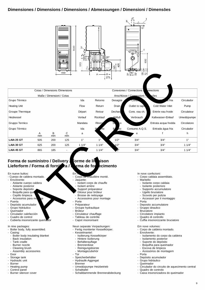
Dimensiones / Dimensions / Dimensions / Abmessungen / Dimensioni / Dimens ões
Cotas / Dimensions /Dimensions
Maße / Dimensioni / Cotas
Conexiones / Connections / Connections
Anschlüsse / Connessioni / Ligações
Grupo Térmico Ida Retorno Desagüe Consumo Entrada agua fria Circulador
Heating Unit Flow Return Drain Outlet to taps Cold Water Inlet Pump
Groupe Thermique Départ Retour Decharge Cons. eau ch. Entrée eau froide Circulateur
Heizkessel Vorlauf Rücklauf Abfluß Verbrauch Kaltwasser-Einlauf Umwälzpumpe
Gruppo Termico Mandata Ritorno Scarico Uscita A.C.S. Entrata acqua fredda Circolatore
Grupo Térmico Ida Retorno Esgoto Consumo A.Q.S. Entrada água fria Circulador
Amm
Bmm
Cmm
a b c e f h
LAIA 25 GT 505 200 125 1" 1" 1/2" 3/4" 3/4" 1"
LAIA 30 GT 625 200 125 1 1/4" 1 1/4" 1/2" 3/4" 3/4" 1 1/4"
LAIA 45 GT 865 185 - 1 1/4" 1 1/4" 1/2" 3/4" 3/4" 1 1/4"
Forma de suministro / Delivery / Forme de livraisonLieferform / Forma di fornitura / Forma de fornecimento
En nueve bultos:- Cuerpo de caldera montado.- Envolvente:
- Aislante cuerpo caldera- Aislante posterior- Soporte depósito- Boquilla para quemador- Cepillo limpieza- Accesorios para montaje
- Puerta- Depósito acumulador- Grupo hidráulico- Quemador- Circulador calefacción- Cuadro de control- Cubierta insonorizante quemador
In nine packages:- Boiler body, fully assembled.- Casing:
- Boiler body insulating blanket- Back insulation- Tank cradle- Burner nozzle- Cleaning brush- Assembly accessories
- Door- Storage tank- Hydraulic unit- Burner- Heating pump- Control panel- Burner silencer cover
En neuf colis:- Corps de chaudière monté.- Jaquette:
- Isolant corps de chauffe- Isolant arrière- Support préparateur- Gliceur pour brûleur- Brosse de nettoyage- Accessoires pour montage
- Porte- Préparateur- Groupe hydraulique- Brûleur- Circulateur chauffage- Tableau de contrôle- Capot insonorisant
Neun separate Verpackungen:- Fertig montierter Kesselkörper.- Kesselmantel:
- Isolierung Kesselkörper- Hintere Isolierung- Behälterauflage- Brennerdüse- Reinigungsbürste- Montagezubehör
- Tür- Speicherbehälter- Hydraulik-Aggregat- Brenner- Umwälzpumpe Heizbetrieb- Schalttafel- Schalldammende Brennerabdeckung
In nove confezioni:- Corpo caldaia assemblato.- Mantello:
- Isolante corpo caldaia- Isolante posteriore- Supporto accumulatore- Ugello bruciatore- Scovolo per pulizia- Accessori per il montaggio
- Porta- Deposito accumulatore- Gruppo idraulico- Bruciatore- Circolatore impianto- Quadro di controllo- Cuffia insonorizzante bruciatore
Em nove volumes:- Corpo de caldeira montado.- Envolvente:
- Isolamento do corpo da caldeira- Isolamento posterior- Suporte do depósito- Boquilha para queimador- Escova de limpeza- Acessórios de montagem
- Porta- Depósito acumulador- Grupo hidráulico- Queimador- Circulador do circuito de aquecimento central- Quadro de controlo- Caixa insonorizadora do queimador
ATC ROC

Installation- Observe current Regulations.- Check that there is sufficient clearance between
the back section and the wall to permit futuremaintenance operations.
- The minimum clearance between the side panel,on the hinge side of the door, and the wall shouldbe 30 cm, and 10 cm on the opposite.
- Ensure there is a 220V-50Hz single-phase,earthed power point as well as a water supplyand drain near the installation site of the unit.
- To obtain the output shown on the datanameplate, please note that the size of thechimney should conform with the graph.
N.B:- When approved chimneys are being fitted, the
maker’s dimensions should be adhered to.- To remove possible residue deposited in the
chimney, it is advisable to have a handhole inthe base for this purpose.
Assembly- To facilitate transporting the boiler to its final
position, the front and back sections have liftingrings which allow for pipes of up to 3/4” to beinserted through them.
- Check that the boiler is level on its futureoperating plinth.
Outdoor AFS sensor, VFAS FlowSensor, Remote Control FB5 orAmbient Sensor RFS5 (with ControlPanel CC-129C only)The last two devices are optional and so they arenot supplied as standard unless otherwise stated.– Proceed as described in the Instructions that
come with the Control Centre.
LAIA GTA Heating Units- In the top left-hand tapping in the front section
screw in the temp./altitude gauge check valveof the Control Panel (except where a CCE-130Tmodel is being installed).
- Cover the boiler body with the insulating blanket,passing it between the lower tie-rods and theboiler body itself.
- Rest the tank cradle (1) on the front and backsections. The notched end should rest on thefront section. Figure 1.
- Where LAIA 25 GTA and LAIA 30 GTA unitsare being installed, fit the back plastic cover (2)on the tank and secure it in place by means ofthe 4 Fischer plugs supplied, introducing themin the tank insulating material. Figure 6.
- Fit the FLEXVENT-H automatic floatventsupplied with the hydraulic unit in the tappingfor this purpose located at the top back side ofthe tank.
GB
No. of sections
Chimney height (m)
Dia
met
er ∅
. Sid
e of
squ
are
(cm
)
AT
10
- Rest the tank on the cradle in such a way thatthe tapping (3) for connecting the ”tank flow” issituated on the upper right-hand side. The loweredge of the insulation will fit into the cradle.Figure 2.
- In tanks designed to accept an electric heater,this will be screwed into the tapping (4) with anut and locking plate. Please refer to the”Electrical connections” section with regard tothe safety limit thermostat supplied with it.
- Make the connection between the tank and theboiler through the hydraulic unit provided in theway shown in figures 2 and 3.
Note:The hydraulic unit shown in figures 2 and 3 belongsto LAIA 45 GTA. For LAIA 25 GTA (Fig. 6) andLAIA 30 GTA (Fig. 10), the pump is fitted betweenthe top return connecting pipe and the bottom one.The pipe lagging (insulation) has not been drawnin the above-mentioned figures so as to get aclearer view of components.Put gaskets on all the joints.The check valve is located inside the ”boiler flowconnection” (5), at the top.The arrow on the pump body at the back of LAIA25 GTA and LAIA 30 GTA units must point down,while that on the pump at the front of LAIA 45 GTAunits must point up. However, the terminal boxhas to be at the top.If no drain cock (optional) has been installed inthe tapping (6), screw in a 1/2” gasketed plug.- Connect the tank to the water mains and to the
installation through the upper tappings,observing their destination; cold water inlet = blueprotection; consumption = red protection.
- Make the flow and return connections of theinstallation at m and (8), respectively. Figure 3.
- In the ”mains water inlet” connection before thetank, install the FLEXBRANE safety unit inaccordance with the instructions that come withit. Route the discharge to the general drain.
- The safety valve must be installed in such a waythat it is directly connected to the boiler, as closeas possible and without any obstacles or closingelements between them.
- Fit the specific safety devices for sealed or openvented system installations in accordance withthe respective diagram (Figure 4). In any case,the diameters of the safety conduits shallconform to the dimensions given for them in thecurrent Regulations.
- Put the insulating material on the back of theboiler.
- Connect the chimney and carefully pack roundthe joint.
- Fill the tank and heating circuit with water,necessarily in this order, and check the hydrauliccircuit for leaks.
- Secure the side casing panels to the boiler: tothe front section by means of 4 screws M8x12and 4 washers A8.4 and to the tie- rods backend, inserting the spreaders of 25 (top) and 13(bottom) with 4 washers B 13 and 4 hex nutsM12. Figures 5 and 6.
- Place the top casing cover on the tank, so thatthe round shape coincides with the flange andthe opening facing the back side. Secure it tothe sides by means of M6 screws and A 6.4washers.
- Raise the door together with the pivots and insertthem in the right or left hand hinge-holes of thefront section, according to the direction of dooropening chosen.
- Hang the cleaning brush on the front sideopposite the direction of door opening.
- Lower the control panel cover (9) of the door.Figure 7.
- Introduce the terminal strip holder bracket (10),the cables and capillaries of the control panelthrough the rectangular opening in the door.
C RO
- Fix the control panel fascia to the door using 4blued self-tapping screws B3.5 x 13.
- Rest the terminal strip holder bracket onto thecasing side panel brackets and fasten it with thetwo nuts and bolts provided for this purpose.Figure 7.
- Pass the wiring harness for connection betweenthe control panel and terminal strip up the backside of the terminal strip holder bracket andfasten it with the accessories provided for thispurpose.
Position of valves, bulbs and sensorsControl Panels CC-129 range- In the check valve (11) of the front section, screw
the temp./altitude gauge pressure test sensor.Figure 1.
- In the front section centre pocket (12) insert thebulb of the 80°C fixed thermostat (Control PanelsCC-129, CC-129R and CC-129T)
- Insert the bulbs of the thermometer and DHWcontrol thermostat in the tank pocket. Thecapillaries will go through the grommet in thecasing top cover.
- In the back section centre pocket (13, figure 3)insert the bulbs of the control and limitthermostats and that of the heating servicethermostat (figure 8). The capillaries will passunder the tank cradle.
- Fasten the capillaries with the pocket clips.
Control Panel CC-130T- Screw the pressure transducer in the top right-
hand tapping (14) in the front section afterremoving the respective metal plug. Figure 1.
- Connect the transducer cable connector to theconnector marked ”S. Pres” on the top left endof the plate.
- In the back section centre pocket (13, figure 3)insert the two labelled temperature sensors.
- Insert the labelled sensor into the tank pocket.- Fasten the capillaries with the pocket clips.
Electrical connectionsThe installation should include a switch, a circuitbreaker or other omnipolar disconnect switch toisolate all power supply lines to the unit.The maximum power (W) that the components notsupplied with the boiler can consume is as follows:
CC-129 CC-129R CC-129C CC-129T
Burner 850 850 350 850
Heatingpump
1750 1750 350 1750
DHWPUMP
1750 1750 350 1750
3-way valve - - 350 -
Storage tank 2800 2800 - 2800
The connection of external appliances not suppliedwith the boiler should be done through approvedwiring harness type ES- N05VV5-F, with thenumber of conductors and size indicated on theelectrical wiring diagrams, figures 9.- Connect the mains and the different components
at the terminal strip provided for this purpose,as shown in the relevant diagrams of figures 9(CC-129), (CC-129R), (CC-129T), (CC-129C)and (CCE-130T) and in accordance with thecontrol panel installed. Insert their respectiveleads through the cable entries in the lowerprofile of the terminal strip holder bracket andpass those from the Heating Unit through theholes in the cable outlet cover (15). Figure10.Where the tank incorporates an electric heater,the limit thermostat provided should be fitted onthe terminal strip holder bracket. The HeatingUnit incorporates the wiring for connection of theburner, pumps and telephone line (the telephoneline only where a CC-129T or CC-130T controlpanel has been installed).
C

- Secure the cable outlet cover (15) to the casingby means of 2 M6 screws and washers ∅6.3.Figure 10.
- Fit the front casing cover introducing the lowerlugs into their housings in the side panels profileand screw it through the top.
- Bring the door near the front section, parallel toit, until the sealing strip comes into contact withthe section rib.
- Hold the door fast by tightening the screwnearest the hinge first and then the opposite one.
- Remove the protector from the burner openingand fix the flange supplied with it to the door.
- Fit the nozzle on to the burner.- Secure the burner to the flange in accordance
with the instructions that come with it, andconnect the fuel supply.
- Make the electrical connection of the burner tothe control panel by means of the fittedconnector.
- Alternatively, secure the respective bracket ontothe door by means of two B3.5 x 13 screws andhang the burner silencer cover on it.
Changing the direction of dooropening (optional)- Remove the bolts that fix the front cover to the
sides of the casing, using the Allen key housedinside the cover of the control panel.
- Detach the front cover from the boiler.- With the Allen key, loosen the two bolts that hold
the door to the front section and open it.- Raise the door together with the pivots and insert
them in the left hand hinge-holes of the frontsection in order to hang it.
- Replace the front cover and bolt it in place.- Hang the cleaning brush on the right-hand front
panel.- Bring the door near the front section, parallel to
it, until the sealing strip comes into contact withthe section rib.
- Hold the door fast by tightening the screwnearest the hinge first and then the opposite one.
Operation
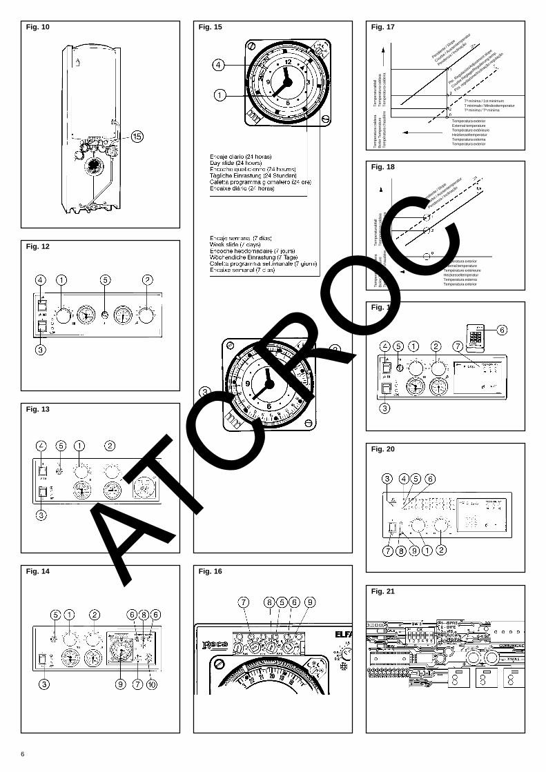
Please refer to the schematic diagrams infigures 11 (CC-129), (CC-129R), (CC-129T),(CC-129C).
Operations prior to the first lighting- Check that the installation is full of water and
put the fixed pointer of the combined temp./altitude gauge (control panels CC-129) in theposition that corresponds to the static head ofthe installation.
- Check that the plug on the Flexvent-H automaticfloatvent is not tight.
- Check that the cold water inlet cock (black wheel)in the Flexbrane safety unit is open.
- Open a hot water tap in order to bleed the air inthe circuit.
- Bleed the air from the installation and radiators.- In installations with a closed expansion vessel,
top up with water, if necessary, until the mobilepointer of the temp./altitude gauge is slightlyhigher than the fixed one. Where there is an openexpansion vessel, top up until the mobile pointerlevels off with the fixed one.
First lighting with Control PanelCC-129- Set the boiler control thermostat (1) to about
80°C. Figure 12.- Set the ambient thermostat (optional) to the
required temperature.- Set the DHW control thermostat (2) to about
55°C.- Turn on the main On/off switch (3). The green
pilot lamp will light up.- Use switch (4) to select either ”Heating/DHW”
or ”Domestic Hot Water”.
AT
Heating / Domestic Hot Water Service- Put the service switch (4) in position A - With no demand for Domestic Hot Water
- Burner operation is governed by the boilercontrol thermostat and the ambientthermostat, if any.
- The heating pump runs continuously.- Check for correct operation of both. If it were
necessary, unlock the pump by pressing ascrewdriver into the slot on the shaft-endand, at the same time, turn it.
- Should the burner lock out, the red pilot lampwill light up.
- Adjust the burner in accordance with theinstructions enclosed with it and check itssafety devices.
- When the safety limit thermostat (5) hasbeen triggered, remove its guard and pressthe button.
- Under normal operating conditions, vent thesystem and check that all radiators reachthe required temperature.
- Ensure that there are no leaks of flue gasesB - With demand for Domestic Hot Water
Even if the tank incorporates an electric heater,it will not come into operation.- Burner operation is governed by the 80°C
set thermostat.- The HWS pump is governed by the DHW
control thermostat.- The heating pump does not operate.
Domestic Hot Water Service(without electric heater)- Put the service switch (4) in position A - With no demand for Domestic Hot Water
- Neither the burner nor the pumps operate.B - With demand for Domestic Hot Water
- Burner operation is governed by the 80°Cset thermostat.
- The HWS pump is governed by the DHWcontrol thermostat.
- The heating pump does not operate.
Domestic Hot Water Service(with electric heater)- Put the service switch (4) in position
The electric heater comes into operation,governed by the DHW control thermostat.
Note:In any case, the limit thermostat will switch off theburner whenever the temperature of the water inthe boiler becomes too high. It must be resetmanually.
First lighting with Control PanelCC-129RFigure 13. Carry out the same operationsdescribed for control panel CC-129R.
TimerThe timer comes into operation when the main On/off switch (3) is turned ”on”.- Please refer to the instructions that come with
the control panel.
First lighting with Control PanelCC-129CFigure 14. Carry out the same operationsdescribed for control panel CC-129; with regardto the control centre, please proceed as describedbelow:
Control Centre 6 - Slope selector 7 - Sun selector 8 - Moon selector 9 - Timer10 - Program selector
C RO
Slope SelectorPlace it on the resultant value for the installationin question, based on design temperatures.
Max. flow temp. - 30ºCSlope =
Ambient temp. - Outside temp.
Evaluation exampleCalculate the slope of an installation for:- Max. water flow temperature = 80ºC- Room temperature = 20ºC- Outside temperature = -5ºC
80 - 30 50Slope = = = 2
20 - (-5) 25
Sun SelectorPut it in the position corresponding to the requiredambient temperature, according to the Table.
Position SUNReduction/Increase
in ambient temp.-4 -8 °C-2 -4 °C0 0 °C
+2 +4 °C+4 +8 °C
Moon SelectorPut it in the position corresponding to the requiredreduction in ambient temperature with respect tothat selected on the Sun Selector, according tothe Table.
Position MOONReduction in
ambient temp.0 0 °C-2 4 °C-4 8 °C-6 12 °C-8 16 °C
With the incorporation of an ambient sensor, therelationship between the position of your MoonSelector and the reduction in ambient temperatureis shown in the Table.
Position MOONReduction in
ambient temp.0 0 °C-2 2,5 °C-4 5 °C-6 7,5 °C-8 10 °C
TimerFigure 15. It has a power backup of about 50 hours.1 - Daily Programme
- It is factory-set. The red and blue camsshould be moved on the rotary ring to thetimes chosen for the start of the Sun andMoon programs.
- To set the time on the clock, turn the hand(1) until the symbol coincides with thepresent time.The rotary indicator (2) should show theprogramme that has been set.
2 - Weekly programme- Remove the rotary ring (3), press-fitted to
the dial.- Turn the hand (1) until the pin (4) on the
green ring can moves to a groove on theyellow one.
- Turn the rotary ring and snap it on the dialso that the symbol coincides with thepresent day of the week (1 = Monday) andthe time of day (turn the minute hand ifnecessary).
- Set the weekly program with the camsprovided.
Changing from weekly program to daily.- Remove the rotary ring from the dial.
C
11

- Turn the minute hand until the pin (4) on theyellow ring moves to fit the notch on the greenone.
- Turn the rotary ring and snap it on the dial.- Set the clock at the correct time and establish
the daily programme.
Programme selectorThe Control Centre does not regulate but thetimer is working. For outside temperaturesbelow 0ºC, the Moon programme startsautomatically to protect the installation fromthe risk of freezing.
Regulation according to the alternate Sun-Moon programmes established
Permanent Sun regulation.
Permanent Moon regulation
Position prior to combustion analysis.Adjust the boiler thermostat to 90ºC.The pump is “on” and the burner is working atfull capacity.
In case of malfuntion of the regulatingequipment, adjust the boiler temperturethrough the thermostat; pump ”on”
Service indicator lamps andregulatorsFigure 16. When indicator lamps (5) and (6) arelit, it means that both the pump and the burner arerunning.With the control ”min” (7) you can set the minimumtemperature of the water in the boiler for switchingoff the burner during a Moon program. Adjustablefrom 10°C to 60°C; it is factory-set at 50°C.Figure 17.0 - Outside temperature considered.
Burner start.1 - Boiler temperature regulation
Burner ’off’.2 - Boiler temperature regulation
Burner ’on’.3 - Minimum boiler temperature selected.
Burner ’off’.2-3 - Boiler temperature differential between
burner ’on’ and ’off’ during the Moonregulation.
With the ”KAE” control (8), full running of theinstallation is optimized on starting up or onpassing from a Moon program to a Sun program.Whilst the boiler temperature does not reach therequired value, the burner keeps running but notthe pump.Adjustable from 10°C to 60°C; it is factory-set at10°C. It should be set 5°C below the minimumtemperature selected on fitting the KSF sensor.With the ”Hys” control (9) you can set the value ofthe difference that will exist, with the installationunder normal working conditions, between thetemperatures of the water in the boiler when theburner is switched ’on’ or ’off’. Adjustable from 4°Cto 10°C; it is factory-set at 5°C. Figure 18.0 - Burner start-up1 - Disconnection (’off’)2 - Connection (’on’)
Note:The adjustments made with ”min” and ”KAE” havepriority over the ”Hys” differential.
First lighting with Control PanelCC-129TFigure 19. Carry out the same operationsdescribed for control panel CC-129.With regard to the telephone module, pleaseproceed as described below:
Telephone moduleIt is made up of two parts: a portable transmitter(6) with service switch, keypad and loudspeakerand a separate receiver (7) mounted on the controlpanel for connecting to the telephone line.
AT
12
Country selectionTo select the country where the telephone modulehas been installed, proceed as follows:- Place the transmitter on the receiver’s
microphone, key in the sequence ” 0 ”and then the digit of the required country, inaccordance with the table below:
Digit Country where installed Language
1 Spain Spanish
2 France French
3 Italy Italian
4 Belgium French
5 Portugal Portuguese
6 Germany German
7 United Kingdom English
8 Other countries Tone Code
The receiver will give message 10 ”SelectFunction” in the language of the country that hasbeen selected. In the case of ”other countries”,the message will be: two short tones (the first, high-pitched).From this moment, synthesized messages will begiven in the language of the selected country, orthrough a Tone Code ( ) for ”other countries”, andthe electrical operation will be adapted to therequirements of the country’s current regulations.The original configuration of the module is for itsinstallation in Spain.The selected country holds until a new one isselected, regardless of power cuts.
( ) List of messages transmitted as Tone Codes.A) Long tone (half a second) = ”Dial the Code”,
”Dial New Code” or ”Right Code”.B) A very low tone = ”Wrong Code” or ”Blocked
Boiler”.C) A low tone = ”Out of Work”D) A medium-pitched tone = ”Heating”E) Two medium-pitched tones (D + D) ”Domestic
Hot Water”F) A high-pitched tone = ”In Service”G) Tow short tones (the first, higher-pitched)
”Select Function”The combination of tones is equivalent tonumbered messages, according to the followinglist:
Message 1 = ”Roca” + AMessage 2 = A+ GMessage 3 = B + AMessage 4 = AMessage 5 = AMessage 6 = D + FMessage 7 = D + CMessage 8 = E + FMessage 9 = E+ CMessage 10 = GMessage 11 = Scale of three short tones,
gradually lowerMessage 12 = Scale of three short tones,
higher-pitchedMessage 13 = B + D + CMessage 14 = B + E + C
Remote control operationThe maximum length of a telephone call is fourminutes; after this time the call is interrupted. Ifthe receiver does not receive any tone from thetransmitter within 30 seconds, the call will also beinterrupted.- Dial the telephone number where the receiver is
installed; at the eighth signal this will transmitmessage 1 ”Roca Heating; Dial the Code”, whichwill be audible in the telephone ear-piece.
C RO
- Bring the transmitter near to the mouthpiece ofthe telephone and key in the four digits of theAccess Code. The factory-set Access Code is0000.
a) If the keyed in code is not correct, the receivergives message 3 ”Wrong Code; Dial the code”.After five failed attempts, communication willbe interrupted. If less than four digits are keyedin, the communication will be broken; and ifmore digits are keyed in, depending on whatthey are, it is possible that some function willbe started (when the first four numbers coincidewith the correct code and the others with somefunction).
b) If the keyed in code is correct, the receiver givesmessage 2 ”Right code; Select Function” andwaits to receive digits 1, 2 or , according tothe required mode.
Changing the codePress ” ” and 1 in that order. The receiver givesmessage 5 ”Dial New Code”.- Key in the four digits of the new code and then
” ”. The receiver says again: ”Dial New Code”.- Again key in the four digits of the new code.
a) If the two series of digits are not the same,the receiver gives message 4: ”Dial the Code”and the procedure for changing the code mustbe repeated from the start.
b) If the two series of digits were the same, thereceiver says: ”Right Code. Select Function”and waits to receive one of these digits: 1, 2or ” ”, according to the required mode.
Consulting or changing the ”Heating”serviceOn pressing key No. 1 on the transmitter, thereceiver gives out message 6 ”Heating Working”or message 7 ”Heating out of Work”. To changethe service status, press key No. 1 again.
Consulting or changing the”Domestic Hot Water” serviceWhen key No. 2 is pressed on the transmitter, thereceiver gives message 8 ”Hot Water Available”,or message 9 ”Hot Water Unavailable”.To change the status, press key No. 2 again
Receiver configurationThe ”standard” configuration is for a storage tankwith no electric heater. The ”alternative”configuration is for a storage tank with electricheater, in which case, should the boiler fail tooperate because of some fault, it will still bepossible to get hot water with the electric heateron.When key No. 1 is pressed on the transmitter, thereceiver gives message 13 ”Blocked Boiler;Heating out of Work”. On pressing No. 2, thereceiver says: ”Hot Water Available” or ”Hot WaterUnavailable”. To switch back to the Hot WaterService, press 2 again.With the ”standard” configuration, should the boilerfail to operate because of some fault, when No. 1is pressed on the transmitter, the receiver givesmessage 13 ”Blocked Boiler; Heating Out of Work”.On pressing No. 2, the receiver gives message14 ”Blocked Boiler; Hot Water Out of Work”.- Key in , =, 3 and in that order. The
receiver gives message 11 ”StandardConfiguration” (factory-set) or message 12”Alternative Configuration”. The configurationnow selected will hold until the above series iskeyed in again, when the receiver will changeand will give the message which corresponds tothe new configuration.
Receiver OperationWhen the receiver is connected to the mains, thegreen LED lights up and the LED remainsunlit. The receiver will not admit tones from thetransmitter through the mouthpiece nor sendmessages through the loudspeaker.
C

The receiver has three buttons: ”Heating”, ”Domestic Hot Water” and ”Loudspeaker”.
”Heating” selectionPress . The LED :- Lights up = Heating Service operating normally.- Does not light up = Heating Service ”off”.
”Domestic Hot Water” ServicePress . The LED :- Lights up = DHW Service operating normally- Does not light up = DHW Service ”off”.
”Loudspeaker” selection1 - Position ”OFF”.
Press (except when connecting the receiverto the mains for the first time).The LED is unlit and the receiver:- Does not admit incoming tones from the
transmitter through its loudspeaker.- Does not send out messages through its
loudspeaker.- Admits telephone messages at the eighth
signal.- Gives messages through the telephone line.
2 - Position ”ON”Press . The LED lights up and thereceiver:- Admits incoming tones from the transmitter
through its mouthpiece- Sends out messages through its
loudspeaker- Admits telephone messages at the eighth
signal.- The ”loudspeaker” LED flashes slowly while
there is a call which is being answered bythe receiver.
3 - Position ”OFF”Press for three seconds. The LEDflashes rapidly and the receiver:- Is disconnected from the telephone line.- Does not answer any call.Press to return to the ”ON” position.
LockoutThe red LED lit up means that the boiler has”locked out”.
Direct operation on the receivermicrophoneAll the functions that can be done by telephonecan also be done by resting the transmitter’sloudspeaker on the receiver’s microphone.- Put the key in the ”ON” position. The LED
lights up.- Bring the loudspeaker on the back of the
transmitter close to the receiver’s microphone .
- Follow the steps described in the ”RemoteControl Operation” section, keeping in mind that:- It is not necessary to key in the digits of the
access code.- Press 0. The message ”Roca Heating”; Select
Function” is given.If, during these operations, a telephone call isreceived, it is given priority, cancelling the ordersgiven through the receiver’s microphone.
First lighting with Control PanelCCE-130TFigure 20. The Control Panel CCE-130Tincorporates a telephone module whosecharacteristics and operation are similar to thoseof Control Panel CC-129T.
Control thermostatsTwo controls (1) and (2) to set the setpointtemperature of the water in the boiler, i.e. from50°C to 90°C, and the water in the tank, i.e. from30°C to 60°C (factory-set limitation), respectively.
AT
Anti-freeze modeIt protects the installation from the effects of lowtemperatures.Set the knob of the control thermostat at itsminimum value; the 30°C LED flashes slowlyindicating that the service in question has beeninterrupted.By selecting the anti-freeze mode on the heatingthermostat, the operation of an optional ambientthermostat is overridden.The anti-freeze mode process is as follows:1 - Initial stand-by position
- The temperature of the water in the boilerand storage tank are continuouslymeasured. When the water temperaturedrops below 8°C a ”pump cycle” is initiated.
2 - Pump cycle- Pumps run for 30-minute cycles, which are
repeated until:All temperatures measured during a cycleexceed 8°C, in which case the stand-byposition is resumed.A temperature below 4°C is sensed, in whichcase a ”burner cycle” is initiated.
3 - Burner cycleThe burner runs for 30-minute cycles, with awater temperature differential of 8°C between”on” and ”off” and 50°C setpoint temperature.The pumps run simultaneously.These cycles are repeated until all measuredtemperatures exceed 4°C at any one cycle,and then a pump cycle is initiated.
Ambient thermostat (optional)If an ambient thermostat were to be installed, itshould be wired across terminals 9 and 10 afterremoving the existing jumper. Please refer to thewiring diagram in figures 9.
Note: At the beginning of a burner stop, caused by theambient thermostat, a 30-minute timedelay isinitiated, at the end of which the heating pump willstop.
Anti-Legionella ModeEvery 20 damands for heat in the DHW system,the temperature of hot water rises to 70°C, whicheliminates possible bacteria in the installation.
Maintenance of pumpsPumps run one minute every 24 hours from thetime the boiler starts operating. The DHW pumpstarts first and then the heating pump.
Safety circuitElectronic safety circuit that operates automaticallywhen a fault which may lead to a hazardousoperating condition for the boiler is detected, eitherbecause of overheating or because of some faultin the control board.
Unlocking button(3). It must be pressed once the normal operatingconditions have been restored, when a manualreset lockout condition has occurred. Please referto the ”Troubleshooting Table”.
Temperature displayDuring operation, the temperature of the water inthe boiler and in the tank is shown by the lightingof specific LEDs (4) and (5) every 5°C. The 30°CLEDs are lit all the time.
Pressure displayDuring operation, the lighting of specific LEDs (6)shows the relative pressure in the boiler in relationto the atmospheric pressure, every 0.5 bar, from0 bar to 4 bar. The 0-bar LED is lit all the time.
C RO
Combined operation of controlthermostatsDepending on whether the position of controls forgoverning the temperature of water in the boiler(1) or in the tank (2) is on anti-freeze mode (OFF)or temperature selection (ON), operation can beas follows:A - Thermostat (1) OFF and thermostat (2) OFF
- No Heating service available- No Domestic Hot Water service available- Anti-freeze mode on stand-by.
B - Thermostat (1) ON and thermostat (2) OFF- Heating service available- No Domestic Hot Water service available- Tank anti-freeze mode on stand-by.
C - Thermostat (1) OFF and thermostat (2) ON- No Heating service available- Domestic Hot Water service available
through the burner or electric heat operation,according to the position of selector switch6 ”RCAL” (see ”Selector Switches”).
- Anti-freeze mode on stand-by.D - Thermostat (1) ON and thermostat (2) ON
- Heating service available and domestic hotwater through burner operation. Duringdemand for Domestic Hot Water, the boilertemperature is automatically set at 80°C.
- When the DHW control thermostat activatesthe DHW pump, the Heating pump will eitherstop or keep on running, according to theposition of switch 5 ”PRI/PAL” (see ”SelectorSwitches”).
Selector Switches for operatingoptionsFig. 21. Located at the back of the control panel.It is factory-set at ”ON”.
Switch 1 (BPRES)The original setting limits the operating pressuresbetween 0.3 bar and 3.8 bar. For pressure valuesother than these, the boiler will ”lock out”.Changing the position of the switch overrides thislimitation (safety for pressure).
Switch 2 (DIFE)The factory setting fixes at 8°C the energizing/de-energizing differential of the boiler and tank controlthermostats. The change of position sets the samedifferential at 4°C.
Switch 3 (VIS)The factory setting belongs to the fault signallingfor the User. The change of position offerssignalling for the Installer; in this case, the faultLED flashes slowly even if there are no faults.Please refer to the ”Troubleshooting Table”.
Switch 4 (RJCA)In their factory setting, the timers (optional) forheating and domestic hot water control theirservices only. Changing the position, the heatingtimer controls both services
Switch 5 (PRI/PAL)Its factory setting establishes priority for thedomestic hot water over heating. The change ofposition overrides this priority.
Switch 6 (RCAL)Keep it in its original setting when the tank is notfitted with an electric heater. The change of positionwill be necessary when the tank is fitted with anelectric heater.
C
13

Troubleshooting Table
Cause Stoppage of User's signal Installer's signal To restore serviceBoiler water overheating(>100°C)
Burner andelectric heater.
!
!
Fault LED flashes rapidly.90°C boiler LED flashes.
!
!
Fault LED flashes slowly.Only 90 °C boiler LED flashes.
!
!
Press unlocking button when boiler temp.≤ 80°C.Change position of switch 3 if necessary.
Control / safety sensorfailure.
Burner, pumpsand electric
heater.
!
!
Fault LED lit permanently.All temp. LEDs off.
!
!
!
!
Fault LED flashes slowly.Only 60, 70, 80 y 90°C boilerLEDs flashing = Safety sensorfault.Only 30, 40 and 50°C boilerLEDs flashing = Control sensorfault.All boiler temp. LEDs flashing =diff. between sensors > 10°C .
!
!
Press unlocking button when readings in bothsensors are correct (see ohmic resistancevalues).Change position of switch 3 if necessary.
Overpressure. Burner andelectric heater.
!
!
Fault LED flashes rapidly.4-bar LED flashes.
!
!
Fault LED flashes slowly.4-bar LED flashes.
!
!
Press unlocking button as pressure droppeddown to 3 bar or move switch 1 to OFF.Change position of switch 3 if necessary.
Lack of pressure. Burner, pumpsand electric
heater.
!
!
Fault LED flashes rapidly.0-bar LED flashes.
!
!
Fault LED flashes slowly.0-bar LED flashes.
!
!
Press unlocking button as pressure increasesup to 0.7 bar or move switch 3 to OFF.Change position of switch 3 if necessary.
Pressure sensor failure. Burner, pumpsand electric
heater.
!
!
Fault LED lit permanently.Pressure LEDs off.
!
!
Fault LED flashes slowly.All pressure LEDs flashing.
!
!
Press unlocking button to obtain the correctpressure in the pressure sensor (see ohmicresistance values).Change position of switch 3 if necessary.
Fault during self-check ofburner lockout circuit.
Burner, pumpsand electric
heater.
!
!
Fault LED lit permanently.Temp. and pressure LEDs off.
!
!
Fault LED flashes slowly.Temp. and pressure LEDsflashing.
!
!
Press unlocking button as internal faultcondition which caused the lockout was notdetected.Change position of switch 3 if necessary.
Burner internally locked. Temp. control(unchanged).
! Fault LED flashes rapidly. ! Fault LED flashes slowly. !
!
Press burner unlock button.Change position of switch 3 if necessary.
DHW sensor failure. DHW serviceburner, DHWpump, and
electric heater.
!
!
Fault LED lit permanently.DHW temp. LEDs off.
!
!
Fault LED flashes slowly.DHW temp. LEDs flashing.
!
!
Press unlocking button when the correctreading in the DHW sensor is obtained.Change position of switch 3 if necessary.
DHW overheating. DHW serviceburner, DHWpump, and
electric heater.
!
!
Fault LED flashes rapidly.90°C DHW LED flashes.
!
!
Fault LED flashes slowly.90°C DHW LED flashes.
!
!
Press unlocking button as DHW temperaturedropped.Change position of switch 3 if necessary.
OC
Carry out the following operations:- Set the controls on the panel to the value thatcorresponds to the installation and requiredoperation.Set the ambient thermostat (optional) to therequired temperature.
- Turn on the main switch (7). The green LED (8)lights up.
- Check that the pumps and burner are runningcorrectly. Adjust the burner in accordance withthe instructions that come with it.
- Bleed the air, and with the system running undernormal conditions, check that the radiators reachthe required temperature.
- Check that there are no leaks of flue gases.- Check the burner safety devices. The red LED
(9) ”on” means that the burner has ”locked out”.
T
14
A
Appox. Ohmic resistance valuesTemperature sensor Pressure sensor-20 °C 123,5Ω 0 bar 320Ω-10 °C 73,5Ω 0,5 bar 276Ω0 °C 45,1Ω 4 bar 86Ω10 °C 28,5Ω20 °C 14,9Ω30 °C 12,3Ω40 °C 8,3Ω50 °C 5,8Ω60 °C 4,1Ω70 °C 2,9Ω80 °C 2,1Ω90 °C 1,6Ω100 °C 1,2Ω110 °C 0,9Ω120 °C 0,7Ω125 °C 0,6Ω
Resistance values >123,5 kΩ and <0,6 kΩ are indicativeof fault in sensor
Resistance values ≤276 Ω and ≥86 Ω mean lockout forlack of or excess pressure, respectively
C R
Important recommendations- If the installation is located in an area with riskof freezing, some anti-freeze product should beadded to the water in proportion to the minimumoutside temperature of the place.
- We recommend that the properties of the waterin the system be:pH: 7,5 ÷ 8,5Hardness: 8 ÷ 12 French degrees (*)
(*) One French degree is equivalent to 1 gram ofCalcium Carbonate per 100 litres of water.
- If it were absolutely necessary to add water tothe system, wait until the boiler is completelycold before doing so.
Note:Characteristics and performance qualities subjectto change without notice.
CE MarkedThe LAIA/GTA Heating Units comply withthe European Directives 89/336/CEE onElectromagnetic Compatibility and73/23/CEE on Low Voltage.