comitÉ europÉen des assurances - apsei · 5 foreword these cea specifications have been drawn up...
TRANSCRIPT
1
COMITÉ EUROPÉEN DES ASSURANCES
SECRETARIAT GENERAL 3bis, rue de la Chaussée d'Antin F 75009 Paris
Tél. : +33 1 44 83 11 73 Fax : +33 1 44 83 11 85 Web : cea.assur.org
DELEGATION A BRUXELLES
Square de Meeûs, 29 B 1000 Bruxelles Tél. : +32 2 547 58 11 Fax : +32 2 547 58 19
Web : cea.assur.org
PROPERTY INSURANCE COMMITTEE Prevention Specifications
Planning and Installation for Automatic Fire Detection and Fire Alarm Systems
CEA 4040: July 2003 (en)
Copyright by CEA – 3 bis, rue de la Chaussée d’Antin – 75009 PARIS
2
Contents
FOREWORD..................................................................................................................................................................5
0 - INTRODUCTION.....................................................................................................................................................5
1 - SCOPE .......................................................................................................................................................................5
2 - REFERENCES AND DEFINITIONS .....................................................................................................................6
3 - GENERAL...............................................................................................................................................................11 3.1 USAGE OF THE GUIDELINES ...................................................................................................................................11 3.2 FORMAT OF THE GUIDELINES.................................................................................................................................12 3.3 NATIONAL INSURANCE DOCUMENTS .....................................................................................................................14 3.4 OTHER SYSTEMS....................................................................................................................................................14 3.5 SAFETY REQUIREMENTS ........................................................................................................................................14 3.6 FALSE ALARMS......................................................................................................................................................14 3.7 NEW DEVELOPMENTS ............................................................................................................................................14 3.8 WARRANTIES AND GUARANTEES...........................................................................................................................14 3.9 DOCUMENTATION .................................................................................................................................................15 3.10 RESPONSIBILITY..................................................................................................................................................15 3.11 QUALIFICATIONS.................................................................................................................................................15
4 - ASSESSMENT OF NEEDS....................................................................................................................................16 4.1 PURPOSE ...............................................................................................................................................................16 4.2 CONSULTATION.....................................................................................................................................................16 4.3 PARTS OF THE BUILDING NEEDING COVER .............................................................................................................16 4.4 FIRE BRIGADE ATTENDANCE..................................................................................................................................18 4.5 FIRE ALARM RESPONSE STRATEGY ........................................................................................................................18 4.6 DOCUMENTATION .................................................................................................................................................20 4.7 RESPONSIBILITY....................................................................................................................................................20 4.8 QUALIFICATIONS...................................................................................................................................................20
5 – PLANNING AND DESIGN...................................................................................................................................21 5.1 DEVICES CONNECTED TO THE SYSTEM...................................................................................................................22 5.2 SYSTEM DESIGN ....................................................................................................................................................22 5.3 ZONES ...................................................................................................................................................................26 5.4 SELECTION OF DETECTORS AND MANUAL CALL POINTS .........................................................................................29 5.5 SITING AND SPACING OF AUTOMATIC DETECTORS AND MANUAL CALL POINTS ......................................................32 5.6 ALARM SYSTEMS AND DEVICES .............................................................................................................................58 5.7 CONTROL AND INDICATION ...................................................................................................................................60 5.8 POWER SUPPLIES ..................................................................................................................................................61 5.9 SIGNALS TO A FIRE ALARM RECEIVING STATION....................................................................................................63 5.10 DOCUMENTATION ...............................................................................................................................................63 5.11 RESPONSIBILITY..................................................................................................................................................63 5.12 QUALIFICATIONS.................................................................................................................................................64
6 - INSTALLATION ....................................................................................................................................................64 6.1 GENERAL ..............................................................................................................................................................64 6.2 SITING AND ACCOMMODATION OF EQUIPMENT......................................................................................................64
3
6.3 INSTALLATION OF CABLES AND INTERCONNECTIONS............................................................................................65 6.4 CABLE JOINTS AND TERMINATIONS .......................................................................................................................67 6.5 RADIOACTIVITY ....................................................................................................................................................67 6.6 DOCUMENTATION .................................................................................................................................................67 6.7 RESPONSIBILITY....................................................................................................................................................67 6.8 QUALIFICATIONS (REFER TO §3.11) .....................................................................................................................67
7 - COMMISSIONING AND VERIFICATION........................................................................................................68 7.1 GENERAL ..............................................................................................................................................................68 7.2 COMMISSIONING ...................................................................................................................................................68 7.3 VERIFICATION .......................................................................................................................................................69 7.4 DOCUMENTATION .................................................................................................................................................70 7.5 RESPONSIBILITY....................................................................................................................................................70 7.6 QUALIFICATIONS...................................................................................................................................................70
8 - THIRD PARTY APPROVAL................................................................................................................................70 8.1 GENERAL ..............................................................................................................................................................70 8.2 PROCEDURES.........................................................................................................................................................71 8.3.INSPECTION AND TESTING .....................................................................................................................................72 8.4 PERIODIC INSPECTION BY AN APPROVING BODY ....................................................................................................73 8.5 DOCUMENTATION .................................................................................................................................................73 8.6 QUALIFICATIONS..................................................................................................................................................73
9 - FIRE TESTS............................................................................................................................................................73 9.1 PROCEDURE ..........................................................................................................................................................74 9.2. FIRE TESTS ...........................................................................................................................................................74 9.3 TYPES OF FIRE TESTS ACCORDING TO DETECTORS .................................................................................................78
10 - USE OF THE SYSTEM.......................................................................................................................................79 10.1 RESPONSIBILITY................................................................................................................................................79 10.2 DOCUMENTATION .............................................................................................................................................81
11 - MAINTENANCE .................................................................................................................................................81 11.1 GENERAL ............................................................................................................................................................81 11.2 INSPECTION AND SERVICING................................................................................................................................81 11.3 SPECIAL SERVICING.............................................................................................................................................82 11.4 REPAIR ................................................................................................................................................................83 11.5 SPARES................................................................................................................................................................83 11.6 DOCUMENTATION ...............................................................................................................................................83 11.7 RESPONSIBILITY..................................................................................................................................................83 11.8 QUALIFICATIONS (REFER TO §3.11)....................................................................................................................83
12 - MODIFICATION OR EXTENSION OF AN INSTALLED SYSTEM............................................................83 12.1 GENERAL ............................................................................................................................................................83 12.2 THIRD PARTY APPROVAL .....................................................................................................................................84 12.3 DOCUMENTATION ...............................................................................................................................................84
13 - OPERATION OF OTHER FIRE PROTECTION SYSTEMS - ANCILLARY SYSTEMS .........................84 13.1 GENERAL ............................................................................................................................................................84 13.2 RESPONSIBILITY..................................................................................................................................................85
14 - APPLICATIONS IN SPECIAL RISKS ..............................................................................................................85 14.1 GENERAL ............................................................................................................................................................85 14.2 ROOMS WITH HIGH CONCENTRATION OF ELECTRONIC EQUIPMENT ......................................................................86 14.3 HIGH-RACK WAREHOUSES..................................................................................................................................91 14.4 ATRIUM BUILDINGS.............................................................................................................................................93 14.5 HAZARDOUS AREAS.............................................................................................................................................93 14.6 OUTDOOR AREAS.................................................................................................................................................93 14.7 RESPONSIBILITY..................................................................................................................................................93

4
15 - INTEGRATED SYSTEMS ..................................................................................................................................93
16 - HIERARCHICAL SYSTEMS .............................................................................................................................95
5
FOREWORD These CEA specifications have been drawn up by the GEI 2 - Fire Expert Group n° 2 - of the CEA Property Committee, in collaboration with EURALARM. 0 - INTRODUCTION The intention of these specifications is to provide insurers with a European standard of planning, design, installation, commissioning, use and maintenance for fire detection and fire alarm systems throughout Europe. At present, many different guidelines, codes and rules are in use in different national insurance associations. On some subjects, existing guidelines show much similarity, while on other subjects there is considerable disagreement. These specifications are therefore drafted to separate fully agreed topics from those on which there is some dissension. For example, in all those European countries having insurer installation guidelines, those guidelines place some restriction on the area allowed to be covered by a single detector. But although there is general agreement on the principle that coverage should be restricted, the methods and extent of restriction varies in different countries. If there are no insurance guidelines covering the restriction of detector coverage, these specifications give a set of restrictions on spacing which should be used. CEA specifications bring additional requirements to the EN 54-14 standard. Persons involved with fire detection and fire alarm systems must be qualified in accordance with CEA specifications. 1 - SCOPE These specifications provide guidelines for the application of automatic fire detection and/or fire alarm systems in and around buildings. They cover planning, design, installation, commissioning, use and maintenance of the systems. The guidelines cover systems intended for the protection of life and/or the protection of property. The guidelines cover systems ranging from simple systems, for example those with one or two manual call points, up to complex systems with automatic fire detectors, manual call points, connection to the public fire service, etc. The systems may be capable of providing signals to initiate, in the event of a fire, the operation of ancillary equipment (such as fixed fire extinguishing systems) and other precautions and actions (such as machinery shutdown), but the guidelines do not cover the ancillary services themselves. The guidelines do not cover systems combining fire alarm functions with other non-fire related functions. The guidelines do not recommend whether or not an automatic fire detection and/or fire alarm system should be installed in any given premises. It has been assumed in the drafting of this specification that the execution of its provisions will be entrusted to appropriately competent persons. However, guidance is also given to other persons who may be required to purchase or use a fire detection or fire alarm system
6
Where automatic fire detection and fire alarm systems are intended to activate fixed extinguishing devices or other fire protection systems, the additional CEA rules in force will also have to be taken into consideration. 2 - REFERENCES AND DEFINITIONS • Specifications for installing firms of security systems against fire and/or theft
(CEA 4002) – April 1996.
• Specifications for electrical installers of security systems against fire and/or theft (CEA 4003) - April 1996 .
• Specifications for CO2 Systems – Planning and installation (CEA 4007) – August 1997
Specification for sprinklers systems planning and installation (CEA 4001) Specification for inert and halocarbon gases planning and installation (CEA ….)
• Specifications for centralized technical management systems
(CEA 4018) – February 1998
• CEA Specification for CO2 Systems /"Equipment Protection for Electric and Electronic System" document SC 92/08.
• CEA specifications for Remote Control Station - November 1991 • CEI 839-1-2 1987 • EN 608 9 “Sound system for emergency purposes” • EN 54, Fire detection and fire alarm systems
Part 1: Introduction Part 2: Control and indicating equipment Part 3: Audible fire alarm devices Part 4: Power supplies Part 5: Heat detectors — Point detectors Part 7: Smoke detectors — Point detectors using scattered light; transmitted light or ionisation Part 10: Flame detectors Part 11: Manual call points Part 12: Smoke detectors — Line detectors using a transmitted light beam Part 13: System requirements Part: Fire alarm routing devices
• EC-TC 81 • IEC 1000-5 “Classification of the installation” • EN 45000 series (EN 45001, EN 45002, EN 45003, EN 45004….) • IEC 651
7
• EN 29000 For the purposes of this guideline, the definitions given issue from EN 54- part 1 standard published by CEN TC 72. 2.1 Acceptance : The decision that the installed system meets the requirements of a previously agreed specification. 2.2 Alarm load: The maximum power (normally electrical) that might be required under the fire condition. 2.3 Ancillary equipment: Equipment which can initiate or be initiated by the fire detection and alarm system. 2.4 Approval: Agreement by a third party that the installed system satisfies the requirements of the third party. 2.5 Approval body: A body accepted by an authority having jurisdiction or other competent organisation as having the expertise necessary to assess the compliance of the installed system with this standard. 2.6 Aspirating detection device: Aspirating detection devices comprise detectors in measuring chambers fitted with suction devices. Either a part of the air flow from the outlet vents of the protected equipment is drawn through these chambers, or other parameters indicative of a fire are routed directly to these detectors. 2.7 Authority having jurisdiction: A body having powers provided under local, regional, national or European legislation. 2.8 Automatic smoke curtain: A smoke curtain capable of moving without human intervention from its retracted position to its operational position when actuated. 2.9 Beam detector: The more commonly used term for smoke detector - line detector using a transmitted light beam 2.10 Control & Indicating Equipment: A component of a fire detection and fire alarm system by which detectors are powered and which is:
a) Used: 1. To receive signals from detectors linked; 2. To define if these signals correspond to a fire condition; 3. To signal audibly and visibly this fire condition; 4. To localise the place of the danger; 5. To record all these information
b) Used to survey the correct functioning of the system and to signal audibly and visibly all faults (by example short-circuit, cut the line, fault of power supply);
c) Capable, if necessary, to transmit fire alarm signal, by example: - To audibly and visibly fire alarm devices - By an alarm transmission device to fire rescue.
2.11 Circuit (transmission path): An interconnected assembly of cables, components and elements, terminated at the control and indicating equipment in such a way that its only connection to other parts of the fire detection and alarm system is through the control and
8
indicating equipment and controlled by the control and indicating equipment. NOTE 1 - A circuit may have more than one link to the control and indicating equipment (as in a loop circuit, connected to the control and indicating equipment at both ends). NOTE 2 - If two or more cables are directly linked together inside the control and indicating equipment, without the possibility of control by the link, then they are part of one circuit. 2.12 Coincidence: A system in which no alarm is given until fire signals are being received from at least two sources. 2.13 Commissioning: The process by which it is verified that the installed system meets the defined requirements. 2.14 Commissioning engineer: The person who carries out the process of commissioning. 2.15 Competent person: A person who, in relation to the work undertaken, has the necessary knowledge, skill and experience to complete the work satisfactorily and without danger or injury to any person. 2.16 Component: A device which is defined as a component type I or component type II in EN54-13. 2.17 Delayed alarm system: A system in which an alarm may be delayed for a sufficient time to allow the cause to be investigated. 2.18 Designer: A person or organisation taking responsibility for the work outlined in clause 5. 2.19 False alarm: A fire alarm caused by reasons other than fire.
NOTE - Information on false alarms is given in Annex A 2.20 Fault: A failure within the system or its power supply in such a way as to jeopardise the correct functioning of the system. 2.21 Fault signal: A signal intended to indicate the occurrence of a fault. 2.22 Fault warning: A fault signal perceptible to a person. 2.23 Fire: Pyrolysis or combustion needing investigation and/or corrective action in order to prevent danger to life or property. 2.24 Fire alarm: A visual, audible or tactile indication of fire. 2.25 Fire compartment: A compartment whose boundary components are required by regulations to have a defined fire resistance. 2.26 Fire routine: The pre-planned procedures which are expected to be followed when a fire alarm occurs. 2.27 Fire signal: A signal intended to indicate the occurrence of a fire. 2.28 Fire tests: Tests to check on site, level of performance of a fire detection installation.
9
2.29 Flooding zone: A zone, comprising all calculation zones, to be flooded simultaneously by the extinguishing medium. 2.30 Hierarchical system: A networked system in which one control and indicating equipment is designated as the main control and indicating equipment, and in which the main control and indicating equipment is able to:
- receive signals from and/or transmit signals to subsidiary control and indicating equipment;
- indicate the status of the subsidiary control and indicating equipment. 2.31 Hierarchical networked system: A fire detection and fire alarm system, consisting of more than one control and indicating equipment, which are interconnected and able to exchange information and where at least one of the control and indicating equipment (main C.I.E) carries out at least one mandatory function on behalf of and/or in conjunction with other control and indicating equipment (sub C.I.E.). 2.32 Inspection: The routine processes by which the system, its functioning and its indications are manually checked at pre-determined intervals. 2.33 Installation: The work of fixing and interconnecting the components and elements of a system. Installation may be carried out by one or more parties. 2.34 Installed system: The system after installation has been completed. 2.35 Installer: A person or organisation having responsibility for all or part of the process of installation. 2.36 Integrated system: A system in which the fire detection and alarm functions are integrated with other non-fire functions. 2.37 Maintenance: The work of inspection, servicing and repair necessary in order to maintain the efficient operation of the installed system. 2.38 Main Power supply: The primary power source shall be designed to operate from the public electricity supply or an equivalent system.
10
2.39 Mimic diagram: A diagrammatic representation of the building, carrying active indications which are directly related to the building layout. 2.40 National insurance document: A document, published by a national insurance association giving recommendations or requirements for installed systems, but not having general application within all European countries. 2.41 Networked system: A fire detection and/or fire alarm system in which several control and indicating equipments are interconnected and able to exchange information. 2.42 Periodic inspection: The inspection of the fire alarm system for continued compliance with the specification. 2.43 Pre-warning: A warning given when the signal from a sensor exceeds the normal level but has not yet reached the fire level. 2.44 Purchaser: The person or organisation taking primary responsibility for payment for the installed system. 2.45 Qualified: Satisfying any relevant national, regional or local standards for competence. 2.46 Quiescent condition: The condition of the installed system when it is supplied by power from its main power source, and has no indicated fire alarms, fault warnings or disablements 2.47 Repair: Non-routine work necessary to restore the efficient operation of the installed system. 2.48 Repeat indicating panel: A panel which replicates all or some of the indications of the control and indicating equipment, without providing any control facilities for other devices. 2.49 Remote Control Panel: The remote control panel reports information from CIE. 2.50 Search distance: The distance that a person has to travel within the affected zone in order to visually determine the position of the fire 2.51 Servicing: The routine processes of work on the system (including cleaning, re-alignment, adjustment and replacement) carried out at pre-determined intervals. 2.52 Smoke reservoir: Area within a building bordered by an automatic smoke curtain or structural elements so as to retain a thermally buoyant smoke layer in the event of fire. 2.53 Standby load: The power taken by the system under failure of the main power source but otherwise quiescent condition. 2.54 Standby power supply: The secondary power source shall be a rechargeable battery. 2.55 Supplier: An organisation from which all or part of the hardware and/or software for the installed system is purchased.
NOTE - If all the hardware and/or software for an installed system is purchased from a single organisation, then that organisation is called the system supplier.
2.56 Suppressed reaction (double knock): A system in which no alarm is given until the fire
11
products reaching the detector have exceeded the fire threshold level for at least a specified time. 2.57 Surveillance area: Depending on configurations below, surveillance area applies to following definitions
A max - Maximum surveillance area: A maximum surveillance area is affected for each kind of detector, corresponding at reasonable efficiency limit conditions. A max assessment takes into account observed measures depending on the actual technology. A n - Nominal area: Area normally surveyed by detector. It is determined from risk factor K related to the surveyed room activity.
A n = K x A max 2.58 System: The system, including certified components, shall be approved by the authorities. 2.59 Third party: A body or organisation other than the installer, supplier or customer. 2.60 Third Party Approval: Approval of the system by a body or an organization accepted by the insurers. 2.61 User: Person or organisation having control of the building (or part of the building) in which the fire detection and alarm system is installed. 2.62 Verification: The process by which the installer or other contractor satisfies the customer that the installed system meets the defined requirements. 2.63 Zone: A geographical sub-division of the protected premises in which a function may be carried out separately from any other sub-division.
NOTE 1: The function may, for instance, be :- the indication of the occurrence of a fire (detection zone); - the giving of a fire alarm (alarm zone): - the control of ancillary systems (control zones).
NOTE 2: Zoning for different functions need not be identical. NOTE 3: A zone cannot exceed more than one fire compartment.
2.64 Zone card: A portable zone map, covering one or more individual zones. 2.65 Zone map: A diagram showing the geographic boundaries of zones and access routes to zones. 3 - GENERAL 3.1 Usage of the guidelines These guidelines provide recommendations for planning, design, installation, commissioning, use and maintenance of fire detection and alarm systems. However, the recommendations may be made mandatory (completely or in part) when they are called up by other documents. For instance:
- national law or regulations may require that in specific types of premises some or all of the recommendations shall be complied with;
- an authority having jurisdiction may specify that in specific premises some or all of the
12
recommendations shall be complied with; - the contract between a purchaser and a contractor may specify that some or all of the
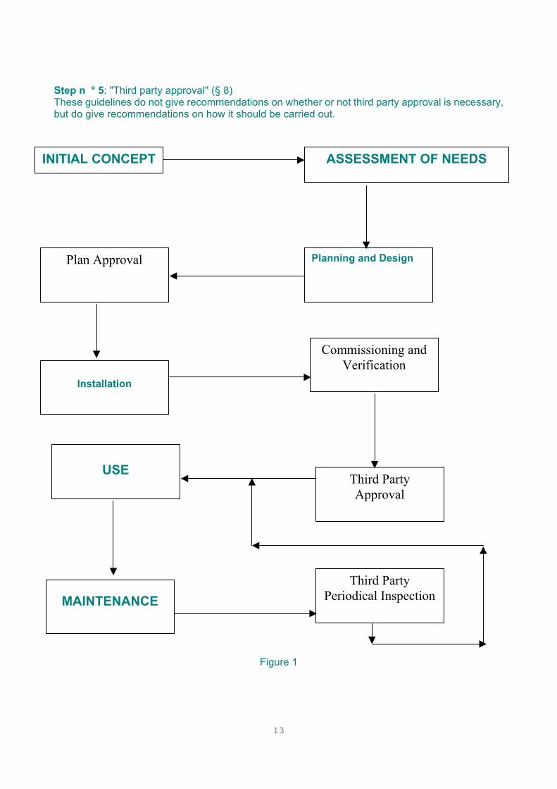
recommendations shall be complied with. It is appreciated that the guidelines cannot cover every possible case that might arise. For this reason, departures from the recommendations are permitted, provided that they have been discussed and agreed between all interested parties (§ 4.2). Unless prohibited by other documents, such agreed departures may be considered as complying with the recommendations of this standard. 3.2 Format of the guidelines These guidelines have been drawn up as if the provision and use of an installed system will follow the pattern shown in Figure 1. Step n ° 1: "Initial concept" and "Assessment of needs" of the building for fire detection and fire alarm (§ 4). This may include an assessment of:
- whether part or all of the building is to be protected; - the type of system to be installed; - the interaction of the system with other fire protection measures; - the description of each kind of zones.
Step n ° 2: "Planning and design" of the system (§ 5). This may include:
- the selection of detector type and siting for the various parts of the building; - the subdivision of the building into detection and/or alarm zones; - the provision for control of the system and for the display of its indications; - the provision of power supplies; - the plan approval.
Step n ° 3: "Installation" ( process of mounting and interconnecting the equipment (§ 6). Step n ° 4: "Commissioning and verification" of the installed system and verification of correct operation (§ 7).
13
Step n ° 5: "Third party approval" (§ 8) These guidelines do not give recommendations on whether or not third party approval is necessary, but do give recommendations on how it should be carried out.
Figure 1
Plan Approval
ASSESSMENT OF NEEDS INITIAL CONCEPT
Planning and Design
Installation
Commissioning and Verification
Third Party Approval
USE
MAINTENANCE Third Party
Periodical Inspection

14
Once the system has been handed over to the purchaser, responsibility for correct operation will generally lie with the system's user and/or owner (§ 10, 11). Included in this responsibility will be that of ensuring that the system is properly maintained and serviced (§ 11). The guidelines are written on the assumption that each of these processes is carried out by a different organisation. For each process the guidelines give recommendations on qualifications of personnel or organisations, responsibility for the work, and the documentation to be carried on from one stage to the next. 3.3 National insurance documents The recommendations of the guidelines should be read in conjunction with national insurance documents. If there are no national insurance documents, or if national insurance documents have no recommendations relevant to a specific subject, then the recommendations of these guidelines should be accepted. If there is a recommendation in the national insurance document, then that recommendation should be taken.
NOTE: This clause is drafted to allow national insurance recommendations and requirements to override those of this document.
3.4 Other systems Other systems connected to the fire detection and alarm system shall be authorised and approved by the insurance company in accordance with CEA specifications. 3.5 Safety requirements Electrical safety requirements are not covered in these guidelines, and reference should be made to national documents. 3.6 False alarms False alarms can be expensive in disruption of the building operations, and may lead to a real alarm being ignored. It is essential that the utmost care should be taken by system designers, installers and user and/or owners to avoid false alarms. Guidance on the causes and prevention of false alarms is given in Annex A. As an objective, not more than one false alarm per one hundred detectors within 3 years should occur. 3.7 New developments These guidelines are written to cover the types of system currently in common use in Europe. It is not the intention of these guidelines to prevent technical advance; if new apparatus or new systems are produced then their use may be permitted but will require special consideration (often as part of the consultations under § 4.2). The consideration should cover the reliability of the system; systems with reliabilities or availabilities lower than current systems should not be used. 3.8 Warranties and guarantees In addition to any warranties required by legislation, the equipment for installed systems will usually be guaranteed by manufacturers or suppliers, and the performance of the installed system may be guaranteed by one of the organisations responsible for supply, design or installation. Any warranty should be in written form, and should at least specify:
15
1) the organisation responsible for fulfilling the warranty; 2) the date(s) from which the warranty will operate;
3) the duration of the warranty;
4) the extent of responsibility under the warranty.
Where possible, arrangements should be made so that all warranties (including those for equipment purchased from suppliers not directly concerned with the installation) should operate from the same date. 3.9 Documentation In many cases one organisation may carry out more than one of the processes; for example, one organisation may take responsibility for planning, design, installation and commissioning of the system, and may also be contracted to carry out the maintenance. In such cases the internal documentation of the organisation may replace that shown in these guidelines, but when responsibility moves from one organisation to another then at least the documentation recommended by the relevant clause should be provided. The person or organisation taking responsibility for that stage should certify proper performance of each stage of the work. Model certificates are shown in Annex C. 3.10 Responsibility In general, the responsibilities for the individual stages of the work are specified under the clauses dealing with those stages. However, it should be remembered that, whether or not these responsibilities are specified, normal contractual responsibilities might also apply. The installer certified in accordance with the "CEA specifications for installing firms of security systems against fire and/or theft (CEA 4002: 1996-04)" is responsible for planning, design and installation of the fire detection and fire alarm system. The installer is responsible for commissioning and verification. Particular care should be taken to establish responsibility for the documentation covering instructions for use, routine attention and test procedures which is required under § 9.1 to be supplied to the person responsible for the use of the premises. After handover of the system, the user and/or owner of the system will normally take responsibility for the continued performance. 3.11 Qualifications Persons or organisations carrying out any work referred to in these CEA specifications shall be appropriately competent, experienced and qualified in accordance with CEA requirements, attested by a certificate from insurance association. They must be qualified for all parts covered by these specifications (assessment of needs, planning and design, installation and maintenance).
16
4 - ASSESSMENT OF NEEDS 4.1 Purpose Fire detection and fire alarm systems may be installed for the protection of life, property, environment or all three. 4.2 Consultation The requirements for the system to be installed should be decided by the insurer or by the purchaser of the system after consultation with other interested parties. Where the installed system is subject to legislation, the authority having jurisdiction should be consulted and their requirements established. NOTE: Other interested parties may include organisations such as:
- the system supplier(s) - the installer of the system; - designers and installers of other fire protection systems in the protected premises.
These requirements should include any need for third party approval. Since the design of the system may depend on the requirements of the approval body it is important that this body is identified at as early a stage as possible, and its requirements established. If approval is required from more than one body, and these bodies have different requirements for the installed system, then the installed system should be designed to meet the most stringent of the requirements. In the unlikely event that the requirements of two approval bodies are incompatible, then the incompatibility should be resolved by discussion. Points that may need to be covered include:
- any deviations from the recommendations of these guidelines (§ 3.1); - the use of new developments in fire detection (§ 3.7); - the fire alarm response strategy (§ 4.5); - differing requirements of approval bodies (§ 8.1); - the use of hierarchical systems (§16).
In any case, the insurance company shall be consulted about the kind of fire protection system (e.g. fire detection or extinguishing). 4.3 Parts of the building needing cover 4.3.1 Extent of cover The parts of the building to be covered or the types of system to be installed may be specified by a third party, such as by an authority having jurisdiction or by an insurance company. Where a third party where there is a desire to install a more extensive system does not specify the extent of the system, the following items should be considered in assessing the risk in each area:
- probability of ignition; - probability of spread inside the room of origin;
- probability of spread beyond the room of origin;
17
- the consequences of a fire (including probability of death, injury, loss of property and environmental damage);
- the existence of other methods of fire protection.
The parts of the building to be monitored shall be specified and/or agreed by the insurance company. The monitoring must extend over at least an area, which is determined by the national associations (for example a fire compartment). The areas classed as separate fire risks must be monitored throughout. The following are examples of partial areas, which need specific protection
• lift, conveyor and transmission shafts and light wells, • cable ducts and shafts, • air conditioning plant, ventilation and air extraction installations, • chutes for supplies and refuse and their containers, • each storage area, cubicles and built-in units, • voids above false ceilings and below false floors, • compartments in rooms created by general storage raised to within less than 500 mm of the
ceilings, or by other arrangements. 4.3.2 Description of extent The following types of installation are possible:
Total cover (Type 1): cover of all parts of the building.
Partial cover: Fire compartment cover (Type 2): cover of one or more specified fire compartments within the building.
Local cover ( Type 4): cover of a specific device or function within the building, not necessarily forming the whole of a fire compartment
NOTE: The type numbering is not intended to be hierarchical. 4.3.2.1 Total cover: Type 1 A total cover system is an automatic fire detection system covering all spaces in the building other than those specifically exempted by these guidelines. (§ 4.3.3) 4.3.2.2 Partial cover: Fire Compartment cover / Type 2 A fire compartment cover system is an automatic fire detection system covering only some parts (usually the most vulnerable areas) of the building. The boundaries of a fire compartment cover system should be fire compartment boundaries; within those boundaries the cover should be the same as that of a total cover system. If a partial cover system is to be used, then the parts of the building to be protected should be specified in the documentation of § 5.10. 4.3.2.3 Local cover: Type 4 Local cover may be provided to protect particular functions, special equipment or areas of particularly
18
high risk. The area of local cover may be within an area of total or partial cover. Such a case could be, for example, where an object or a piece of equipment is provided with detectors inside its housing or where a particularly hazardous process is carried out within an otherwise low hazard area. Local cover on its own can provide good surveillance against fires starting within the surveyed area, but can give little or no surveillance against fires starting outside that area. 4.3.3. Areas not needing cover Unless there are special requirements, some areas may be considered to have a sufficiently low risk of fire that they need not be surveyed:
rooms used for sanitary purposes (e.g. bathrooms, toilets), provided that they are not used for the storage of combustible materials or rubbish; but not common lobbies giving access to these rooms;
unroofed loading bays; rooms protected by an automatic extinguishing installation in accordance with insurance
regulations, and separated from adjacent areas by fire resistant partitions, unless a fire detection system is necessary to trigger the extinguishing installation or is especially required for another reason;
Cable ducts and shafts less than 2 m² (cross-section) and without access; other small areas provided no doubt exists on their fire safety. These areas shall be
mentioned in the appropriate documents (§ 5.10) together with the relevant justification. voids which
♦ are less than 0,80 m in height, and ♦ are less than 10 m in length, and ♦ are less than 10 m in width, and ♦ are wholly enclosed by incombustible material, and ♦ the fire load is less than 25 MJ referred to 1m x 1m (such as for example 15 mains cable
3x1,5 mm² on 1 m length – PVC drainpipe 100 mm diameter) ♦ do not contain cables concerned with emergency systems (unless the cable can resist fire
for at least 30 minutes.) 4.4 Fire brigade attendance 4.4.1 Communications The alarm signal shall automatically alert the public and/or private fire brigade and/or shall be sent to a remote control station approved by the insurance organisation in accordance with the CEA document "Remote Control Station - November 1991", via a link which is in accordance with the insurance requirements, or to an internal company surveillance 4.4.2 Attendance time The insurance company should assess the delay between initial detection and the arrival of trained fire fighters. If the fire spread in this time is likely to be excessive, then the use of other appropriate methods, such as automatic fire extinction, should be considered. 4.5 Fire alarm response strategy The design of the fire detection and alarm system may depend on the actions required after the fire has been detected. It is thus essential that these actions are pre-planned and the subject of early discussion (§ 4.2). The protection offered by a fire detection and fire alarm system is severely diminished unless steps
19
are taken to ensure that the fire alarm can at all times be heard by people, and that fire-fighting measures are initiated without delay. Consequently, every user of the system shall draw up its own fire routine organization plan suited to its operational conditions. At least the following points should be considered in the planning of the fire alarm response strategy, and should be included in the documentation of § 5.10:
• The training of persons in case of an alarm situation; • The method by which occupants are to be informed of the fire condition (internal alarms); • The expected pattern of evacuation in case of fire; • The expected occupancy of the building (working and rest times); • Any change in the fire routine between night and day, or between working days and holidays; • The method of calling for the fire brigade, unless this is done automatically, and the
information to be passed; • Any requirements for providing access by the fire brigade, including the provision of keys; • The expected attendance time of the fire brigade; • The duties and responsibilities of staff, including any provision for organised fire-fighting; • Locate detector zone from fire alarm control unit and have keys for any doors which may be
locked, ready for the fire brigade; • The necessary division of the building into detection and alarm zones; • In hierarchical systems or systems with remote control equipment, the arrangements for
transfer of control between control stations; • Any provision for reducing the effects of false alarms; • Other types of active fire protection measures, including special requirements for the
operation and zoning of ancillary equipment; • Provision for emergency power supplies; • Servicing provisions; • Any requirements for disablement, disconnection or isolation, and the responsibilities for
restoration or reconnection; • Measures to protect property and reduce damages in case of fire; • Existence of fire resistance data cabinets.
20
4.6 Documentation Documents should include all requirements made by insurers and be prepared covering the fire routine for the building and the general requirements for the installed system. The amount of detail given in these documents should allow designs to be prepared on a common basis. The documents should include:
- any requirements for third party approval or acceptance;
- information on any areas of the building which might form hazardous areas (§ 14.5). In some countries there are national requirements which may affect the equipment to be provided for the system. These requirements could, for instance, be for specific options or for the installation of a specific fire brigade panel. Any such requirements should be included in the documentation prepared under this clause. 4.7 Responsibility No extra requirements; refer to § 3.10 4.8 Qualifications No extra requirements; refer to § 3.11
21
5 – PLANNING AND DESIGN 5.0 General In addition to the following requirements, the national regulations of the country in which the system is installed may be applied to the installation. 5.0.1 Transmission paths A maximum of 128 detectors and devices may be connected to a transmission path. The maximum area, covered by one transmission path, shall not exceed 6000 m². Transmission paths, used for control functions, shall meet the above mentioned requirements also. If transmission paths are installed as loops, separate cables shall be used for incoming and outgoing transmission paths. In addition to automatic fire detectors and/or manual call points the following devices to carry out the functions "Alarm", "Control", "Indication" and "Receipt and/or Transmission of information" may be connected directly or via an interface-module to the transmission path. Transmission paths between CIE and other devices of the automatic fire detection and alarm system and transmission paths to controls for fire protection equipment (e.g. fire extinguishing systems, smoke exhaust systems as well as fire alarm and fault warning routine equipment) shall be monitored.
a) Alarm devices: One or more groups of alarm devices shall be related to one fire alarm
zone. b) Controls (control zones) for ancillary equipment: One or more groups of control
equipment (control modules) shall be assigned to the following control functions of one fire protection zone (maximum one fire compartment / smoke reservoir/automatic smoke curtain): control of door closing equipment control of smoke and heat ventilating systems control of extinguishing systems control of other ancillary equipment.
c) Indicating equipment: Indicating equipment may be assigned to single detectors or may
be used for the indication of information related to groups or zones. d) Input/output interfaces (receipt and / or transmission of information): Input/output
interface modules may receive or transmit signals and information related to single detectors and/or devices or groups of detectors as well as control and indicating equipment (CIE)
5.0.2 Assignment of flooding zones to a transmission path If control equipment or interfaces for triggering fire extinguishing systems are connected to a transmission path it shall be ensured that: in case of defects or functional faults of a component, no more than one flooding zone will be lost
or an unwanted release may not occur in more than one flooding zone. when the activation of fire extinguishing systems is likely to endanger persons within the protected
area, prevention measures shall be provided not only in case of release following a fire, but also in case of a false alarm.
22
For the protection of EDP (Electronic Data Processing) units it shall be considered that 5 units with similar or related functions may be assigned to one flooding zone. They shall be assigned to separate flooding zones if their spacing is more than 5 m or if their functions are separate from each other. 5.1 Devices connected to the system 5.1.1 Components All devices (components and elements) used in a fire detection and fire alarm system shall be tested in accordance e.g. with EN 54 parts or CEA requirements EFSAC (1) endorsed and approved by an organisation accepted by insurers. 5.2 System design 5.2.1 Compatibility Care should be taken that all devices connected to the system have been assessed or tested in accordance with EN54-13. Restrictions on system design and layout given in the documentation provided with the devices should be followed.
NOTE: The documentation provided should reflect any limitations observed during the assessments or testing required under EN54-13.
5.2.2 Effects of faults 5.2.2.1 Limitation of effects of faults The design of the system should be such that the effects of faults in transmission paths or connections are restricted
5.2.2.1.1. Fault on a transmission path It shall be ensured that 1 fault (short-circuit or open circuit of a transmission path or failure of a detector or manual call point or devices) shall not cause the loss of more than one detection zone with a maximum of 1600 m² or 32 automatic detectors or 10 manual call points or one flooding zone. The system should be such that 2 faults in any individual circuit cannot remove protection from a floor area exceeding 6000 m², or from more than 5 fire compartments, whichever is the smaller. Faults on the outputs of control modules or output-interfaces and inputs of input-interfaces to devices other than detectors shall not affect the transmission path.
1 EFSAC: European Fire and Security Advisory Committee
23
5.2.2.1.2 Fault on a central processing unit (system fault) In case of a fault of a central processing unit, a concentrator or a sub-control and indicating equipment, with more than 512 detectors connected in detection zones with a total area of more than 6000 m², the signal processing for the detection zones shall function correctly. A visual indication of the general alarm indicator and an audible indication shall indicate the alarm condition. If provided, it shall be possible in case of an alarm to operate the transmission paths to fire alarm devices (C of EN 54-1) and to fire alarm routing equipment (E of EN 54-1). The operation of the fire alarm routing equipment shall be indicated. In case of networked control and indicating units, the unit initiating the alarm shall be identifiable at the main control and indicating equipment. 5.2.2.1.4. Fault on an alphanumeric display (equipment for concentrated indication) The fault of an alphanumeric display may affect detection zones with a max. area of 6000 m² , but not more than 512 detectors. If the number of detectors assigned to an alphanumeric display is greater than 512, then at least:
- a second alphanumeric display inclusive electronic interface, ready for operation, or - an immediately readable registration equipment (like a printer) shall be operational. 5.2.2.2 Indication of faults The system should be so arranged that a fault indication is given in the event of open circuit or short-circuit of any cable feeding:
- detectors or manual call points
- alarm devices
- any ancillary equipment requiring fault indication. There may be national recommendations for the indication of other faults. 5.2.3 Hazardous atmospheres Where it is necessary to install fire alarm equipment in areas having a potential danger from explosion of combustible gas, dust or vapour, equipment certified as suitable for the purpose and satisfying any national regulations should be used. Special cabling rules apply to areas with hazardous atmospheres in according with national regulations. 5.2.4 False alarms All possible precautions should be taken to prevent false alarms. Guidance on the causes and prevention of false alarms is given in Annex A. With regard to sensors, it is possible that monitored parameters e.g. heat, smoke, carbon monoxide, UV-and IR-radiation may cause unwanted alarms. All possibilities of avoiding a false alarm shall be considered. It is necessary to take into account e.g. environmental conditions, use of the premises, possible fire risk and its probable spread. before the
24
setting of the final sensitive levels mentioned above the real background disturbance levels should be measured if necessary At least one of the following methods shall be applied:
The correct choice of the detector; The choice of the appropriate sensitivity of the detectors (if possible); The incorporation of more than one threshold value. This allows separate stages of no-
alarm, pre-alarm and alarm; In software controlled systems, to choose suitable algorithms for the decision-making
process; Two or more fire parameters are utilised in the same detection device (multi-sensor). The
use of a multi-sensor detector may result in the lowering of the sensitivity for each sensor Design of the installation with co()incidence detection (double-group or double-detector
dependency) Installation of a double knocks circuit (a fire alarm is indicated, when after a maximum of
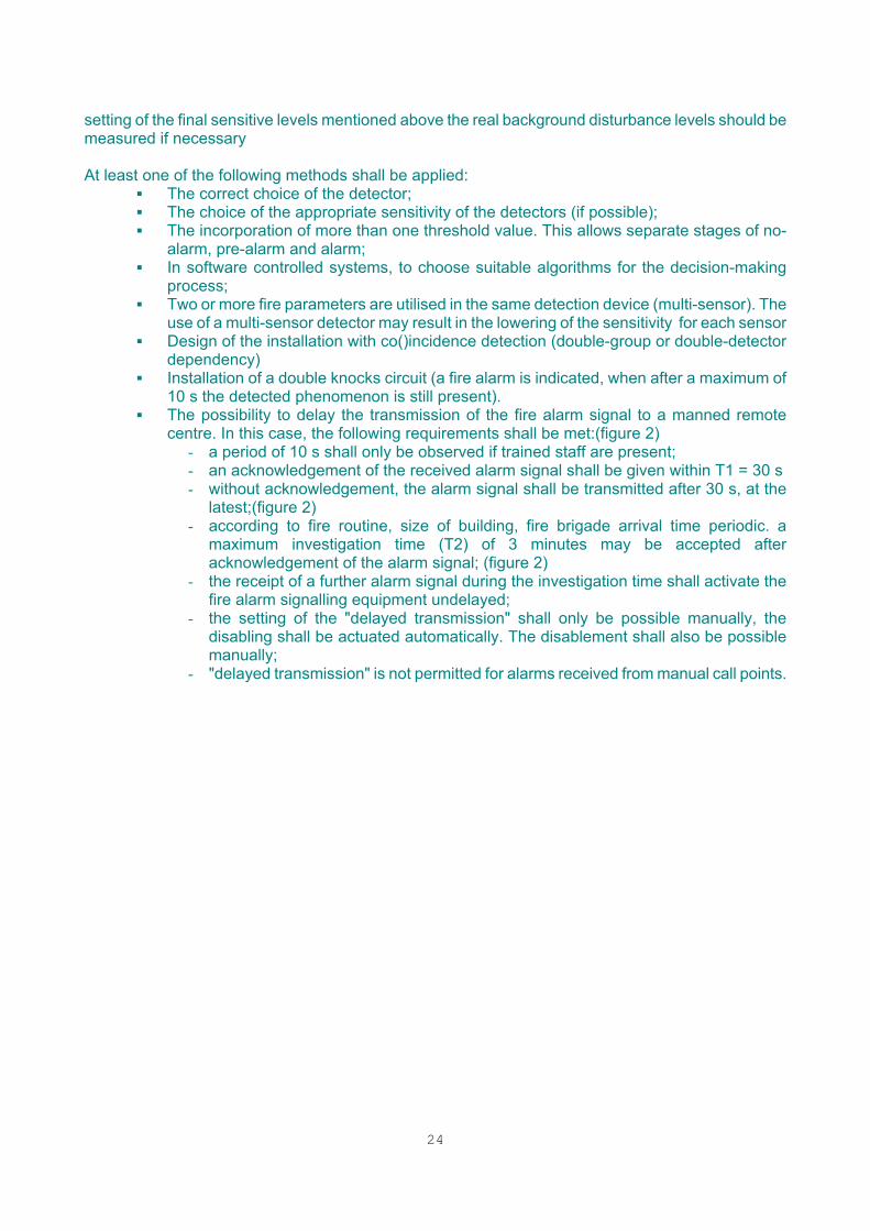
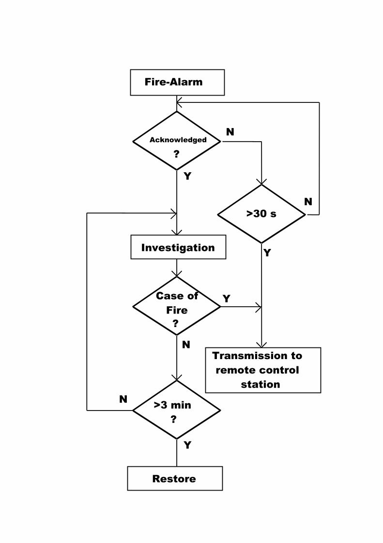
10 s the detected phenomenon is still present). The possibility to delay the transmission of the fire alarm signal to a manned remote
centre. In this case, the following requirements shall be met:(figure 2) - a period of 10 s shall only be observed if trained staff are present; - an acknowledgement of the received alarm signal shall be given within T1 = 30 s - without acknowledgement, the alarm signal shall be transmitted after 30 s, at the
latest;(figure 2) - according to fire routine, size of building, fire brigade arrival time periodic. a
maximum investigation time (T2) of 3 minutes may be accepted after acknowledgement of the alarm signal; (figure 2)
- the receipt of a further alarm signal during the investigation time shall activate the fire alarm signalling equipment undelayed;
- the setting of the "delayed transmission" shall only be possible manually, the disabling shall be actuated automatically. The disablement shall also be possible manually;
- "delayed transmission" is not permitted for alarms received from manual call points.
25
Fire-Alarm
Acknowledged
?
>30 s
N
Y
N
YInvestigation
Case ofFire?
Y
N
Restore
>3 min?
Y
N
Transmission toremote control
station
26
Heat detectors shall not be installed where the ambient temperature, because of natural or operational heat sources, can reach such levels that there is a risk of unintentional actuation of the detectors. When smoke detectors are installed in low rooms (height less than 3 m) measures should be taken to prevent the actuation of detectors by smoke produced by e.g. cigarettes, working processes etc. The following measures could, for example, be introduced:
avoid siting detectors near the likely source of smoke, smoking ban, replacement of smoke detectors by heat detectors.
In rooms with a strong air flow, there is a risk that dust will deposit on the detectors and cause a false alarm. In such cases, installing, for example, special protective shields shall protect the detectors. All devices used in a fire detection system shall have suitable EMC protection to avoid false alarms caused by EM interference. 5.2.5 Other fire protection systems Recommendations for connection to other fire protection systems are given in § 3.4 and § 13. 5.2.6 Special risks Recommendations for systems covering special risks are given in § 14. 5.3 Zones 5.3.1 General The division of the building into detection and alarm zones (Figure 3) should satisfy the requirements of the fire routine (see the documentation prepared under § 5.10). 5.3.2 Detection zones The building should be divided into detection zones so that the place of origin of the alarm can be quickly determined from the indications given by the indicating equipment. Provision should be made for identifying manual call point signals, so that misleading indications can be prevented. Other configurations, complying only with national codes of practice, may be included within the documentation of the system, but shall be clearly identified as not complying with EN 54-14. The zoning should take into account the internal layout of the building, any possible difficulties of search or movement, the provision of alarm zones and the presence of any special hazards. Particular care should be taken in zoning where the fire detection system is used to initiate other fire protection systems (§ 3.4). Restrictions on the extent of detection zones.
• The area of a single detection zone in an open or undivided compartment shall not exceed 1600 m²;
• If the area to be monitored exceeds 1600 m², it has to be divided into detection zones. The operation of a detector shall allow clear location of the affected detection zone;
• The detection zones are to be defined in a manner which allows the origin of the outbreak to be ascertained quickly and clearly;
• If the area to be surveyed consists of offices or compartments and the area of these does
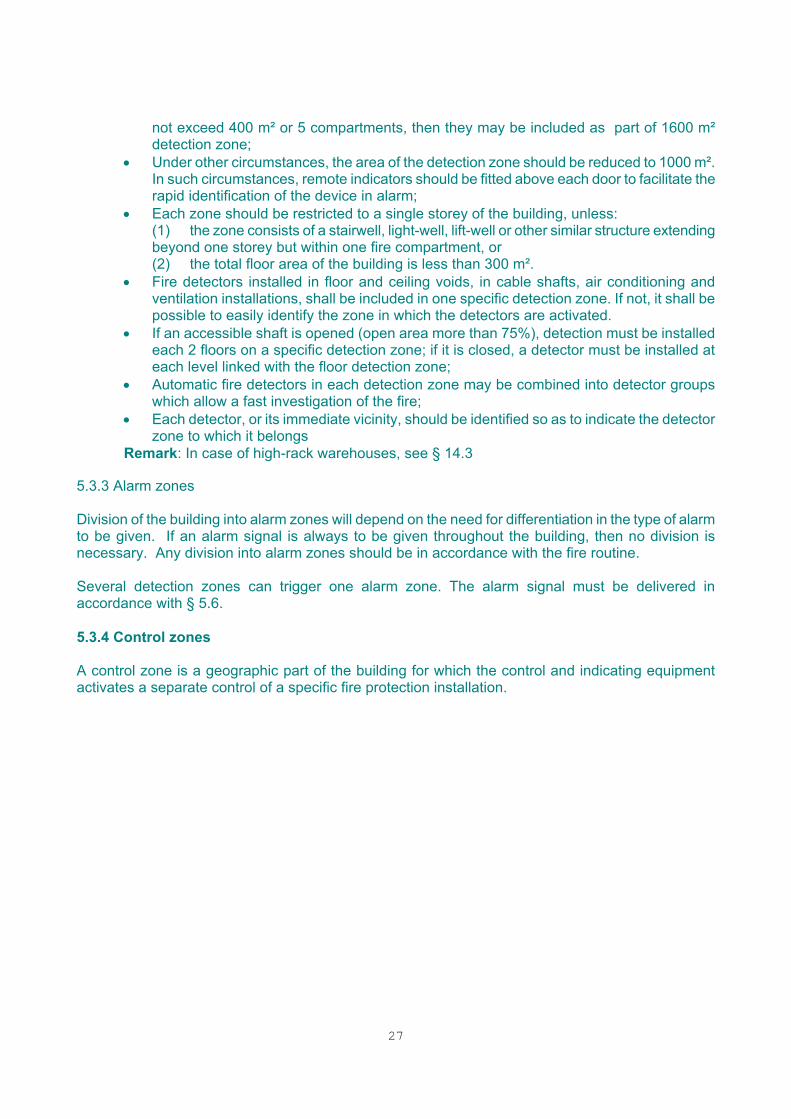
27
not exceed 400 m² or 5 compartments, then they may be included as part of 1600 m² detection zone;
• Under other circumstances, the area of the detection zone should be reduced to 1000 m². In such circumstances, remote indicators should be fitted above each door to facilitate the rapid identification of the device in alarm;
• Each zone should be restricted to a single storey of the building, unless: (1) the zone consists of a stairwell, light-well, lift-well or other similar structure extending
beyond one storey but within one fire compartment, or (2) the total floor area of the building is less than 300 m². • Fire detectors installed in floor and ceiling voids, in cable shafts, air conditioning and
ventilation installations, shall be included in one specific detection zone. If not, it shall be possible to easily identify the zone in which the detectors are activated.
• If an accessible shaft is opened (open area more than 75%), detection must be installed each 2 floors on a specific detection zone; if it is closed, a detector must be installed at each level linked with the floor detection zone;
• Automatic fire detectors in each detection zone may be combined into detector groups which allow a fast investigation of the fire;
• Each detector, or its immediate vicinity, should be identified so as to indicate the detector zone to which it belongs
Remark: In case of high-rack warehouses, see § 14.3
5.3.3 Alarm zones Division of the building into alarm zones will depend on the need for differentiation in the type of alarm to be given. If an alarm signal is always to be given throughout the building, then no division is necessary. Any division into alarm zones should be in accordance with the fire routine. Several detection zones can trigger one alarm zone. The alarm signal must be delivered in accordance with § 5.6. 5.3.4 Control zones A control zone is a geographic part of the building for which the control and indicating equipment activates a separate control of a specific fire protection installation.
28
Figure 3: Area / Zone / Group; Short Circuit Isolators included
29
5.4 Selection of detectors and manual call points 5.4.1 Detectors - general Factors affecting the choice of detector type include the following:
- the materials in the area and the way in which they would burn;
- the configuration of the area (particularly ceiling height);
- the effects of ventilation and heating;
- the ambient conditions within the surveyed rooms;
- the possibilities of false alarms;
- legislative requirements. The detectors selected should generally be those that will provide the earliest reliable warning under the environmental conditions of the areas in which they are to be sited. No one type of detector is the most suitable for all applications and the final choice will depend on individual circumstances. It will often be useful to employ a mixture of different types of detector. Fire detectors are usually designed to detect one or more characteristics of a fire: smoke, heat, radiation (flame) and other products of combustion. Each type of detector responds at a different rate to different kinds of fire. In general, a heat detector gives the slowest response, but a fire that evolves heat rapidly and with very little smoke might operate a heat detector before a smoke detector. In a slowly smouldering fire, such as the initial stages of a fire involving cardboard, a smoke detector would generally operate first. With a combustible liquid fire, a flame detector would generally give the earliest detection. The products of combustion sensed by point-type heat and smoke detectors are transported from the fire to the detector by convection. These detectors rely on the presence of a ceiling (or other similar surface) to direct the products outward from the plume to the detector. They are therefore suitable for use in most buildings, but are generally unsuitable for outside use. The radiation sensed by flame detectors travels in straight lines and requires no ceiling to direct the products outwards. Flame detectors can therefore be used outside or in rooms with very high ceilings where heat and smoke detectors are unsuitable. 5.4.2 Smoke detectors Both ionisation chamber and optical types of smoke detector have a sufficiently wide range of response to be of general use. There are, however, specific risks for which each type is particularly suitable (or particularly unsuitable). Ionisation chamber smoke detectors are particularly sensitive to smoke containing small particles such as are produced in rapidly burning flaming fires, but are less sensitive to the larger particles found in optically dense smoke which may be produced by smouldering materials. Smoke detectors operating on the scattered light principle are sensitive to the larger, optically active, particles found in optically dense smoke, but are less sensitive to the small particles found in clean burning fires. Certain materials when overheated (e.g. PVC) or when smouldering (e.g. polyurethane foam) produce smoke having mainly large particles to which optical smoke detectors are particularly
30
sensitive. Aspirating smoke detectors use a tube system to sample the atmosphere of the protected area, and to carry the sample to a sensor, which may be remote from the protected area. A sampling tube will usually have several sampling orifices, and the smoke density at the sensor will be the average value of smoke density over all the orifices on the sampling tube. Aspirating detectors are often used in the protection of electronic equipment. Beam detectors generally sense obstruction of a light beam, and are therefore sensitive to the smoke density over the length of the beam. They are particularly suitable for use where the smoke may have dispersed over a large area before detection, and may be the only form of smoke detector permissible below high ceilings where points detectors are not suitable (see Table 2 § 5.5.2.1). In general, smoke detectors give appreciably faster responses than heat detectors, but may be more liable to give false alarms if not correctly installed. Smoke detectors cannot detect the products from clean burning liquids (such as alcohol). If the fire is likely to be restricted to such materials, and not involve other combustible materials, then heat or flame detectors should be used in the area. Where there is production or other processes producing smoke, fumes, dust etc. which might operate smoke detectors, an alternative type of detector should be considered, e.g. heat or flame. 5.4.3 Optical beam detectors Optical beam detectors are suitable for the surveillance of e.g. extensive halls, high rooms, cable tunnels or rooms with ceilings having art-historical value, where no other detectors, (e.g. point detectors) can be installed given the characteristics of the premises. 5.4.4 Heat detectors Heat detectors are generally considered to be the least sensitive of the available forms of detector. As a simple guide, a heat detector will operate when the flames from the fire reach about one third of the way from the base of the fire to the ceiling. Heat detectors with rate-of-rise elements are more suitable where ambient temperatures are low or vary only slowly, while fixed temperature detectors are more suitable where the ambient temperature is likely to fluctuate rapidly over short periods. In general, heat detectors have a greater resistance to adverse environmental conditions than have other types.
5.4.5 Flame detectors Flame detectors detect radiation from fires. Ultraviolet radiation, infra-red radiation, or a combination of the two may be used. The radiation spectrum from most flaming materials is sufficiently wide-band to be detected by any flame detector, but with some materials (such as inorganic materials) it may be necessary to choose flame detectors capable of responding to specific parts of the wavelength spectrum. Flame detectors can respond to a flaming fire more quickly than can heat or smoke detectors. Because of their inability to detect smouldering fires, flame detectors should not be considered as general purpose detectors. Because of the radiate transmission it is not necessary to mount flame detectors on a ceiling.
31
Flame detectors are particularly suitable for use in applications such as the general surveillance of large open areas in warehouses or timber yards, or the local surveillance of critical areas where flaming fire may spread very rapidly, e.g. at pumps, valves or pipe work containing combustible liquids or areas of thin vertically-oriented combustible material such as panelling or oil paintings. Flame detectors should only be used if there is a clear line-of-sight to the area being protected. Ultra-violet and infrared radiation differs in its abilities to pass through various materials. Ultraviolet radiation in the wavelength range used for fire detection can be absorbed by oil, grease, and most common glasses and by many smokes. Infrared radiation is much less affected. UV-flame detectors should not be installed in areas with dusty, misty or smoky environments. Precautions should be taken against deposition of oil, grease or dust. Ultraviolet radiation from a fire can be prevented from reaching a detector if the fire produces significant smoke before flames appear. If ultraviolet detectors are to be used in premises where materials are likely to smoulder, then detectors of other types should back them up. Care should be taken in the use of flame detectors where production or other processes produce radiation. If flame detectors are likely to be exposed to sunlight, then solar-blind types of detectors should be chosen. The spreading of flame-radiation depends on the ratio of the radiated wavelengths to the size of particles (smoke particles) in the monitored room. If a smouldering fire is considered likely to occur in the monitored area, which will fill up the room with smoke, IR-flame detectors shall preferably be installed. Smoke can be penetrated by infrared radiation, ultraviolet radiation may be absorbed; UV-flame detectors shall not be installed, or only if they are backed up with smoke detectors. 5.4.6 Manual call points Manual call points shall normally have the same method of operation, and preferably be of the same type, throughout the premises. There may be national requirements on the type of operation. Care should be taken that manual call points intended to initiate a fire signal are clearly differentiated from devices intended for other purposes.
32
5.5 Siting and spacing of automatic detectors and manual call points 5.5.1 General The number of detectors (heat, smoke, beam, flame, manual call points) is defined in the relevant sub chapters below:
for heat and smoke detectors, § 5.5.2 for flame detectors, § 5.5.3 for optical beam type detectors, § 5.5.4 for special detectors, § 5.5.5. for manual call points, § 5.5.6
The siting and spacing of automatic detectors may be determined after fire tests (§ 9) in case of doubt Before the fire detection system is installed, fire test(s) may be carried out, as soon as possible, in combination with all other devices in the specified area which might influence the performance of the fire detection system (e.g. HVAC systems); the test carried out by the responsible people will evaluate the spread of smoke or heat when such devices are alternatively active or inactive. The smoke should be preferably produced by a source with low thermal buoyancy force (e.g. a smoke generator may be used for this purpose). Automatic fire detectors should be sited so that the relevant products of combustion from any fire within the protected area can reach the detectors without undue dilution, attenuation or delay. Care should be taken to ensure that detectors are sited in hidden areas where fire might start or spread. Such areas may include voids under floors or above false ceilings. Manual call points should be sited so that any person discovering a fire is able quickly and easily to alert the necessary people. Attention should be given to any special instructions in the manufacturer's data. Provision should be made for access to manual call points and detectors for maintenance purposes. Each protected room or enclosed space should contain at least one automatic fire detector. 5.5.1.1 Distance of automatic fire detectors to walls The distance between detectors and walls shall not be less than 0,5 m except in the cases of passages, ducts and similar structural features less than 1 m wide; where there are girders, beams, or e.g. air conditioning ducts running below the ceiling, which are closer to it than 15 cm, the lateral distance to this structural feature shall then also be at least 0,5 m.
33
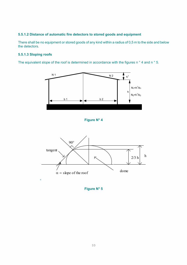
5.5.1.2 Distance of automatic fire detectors to stored goods and equipment There shall be no equipment or stored goods of any kind within a radius of 0,5 m to the side and below the detectors. 5.5.1.3 Sloping roofs The equivalent slope of the roof is determined in accordance with the figures n ° 4 and n ° 5.
N 1
b 2
N 2 h1
N1=h1/b1
N2=h1/b2
b 1
h
Figure N° 4
°
h 2/3 h
tangent
α = slope of the roof
90°
dome
Figure N° 5
34
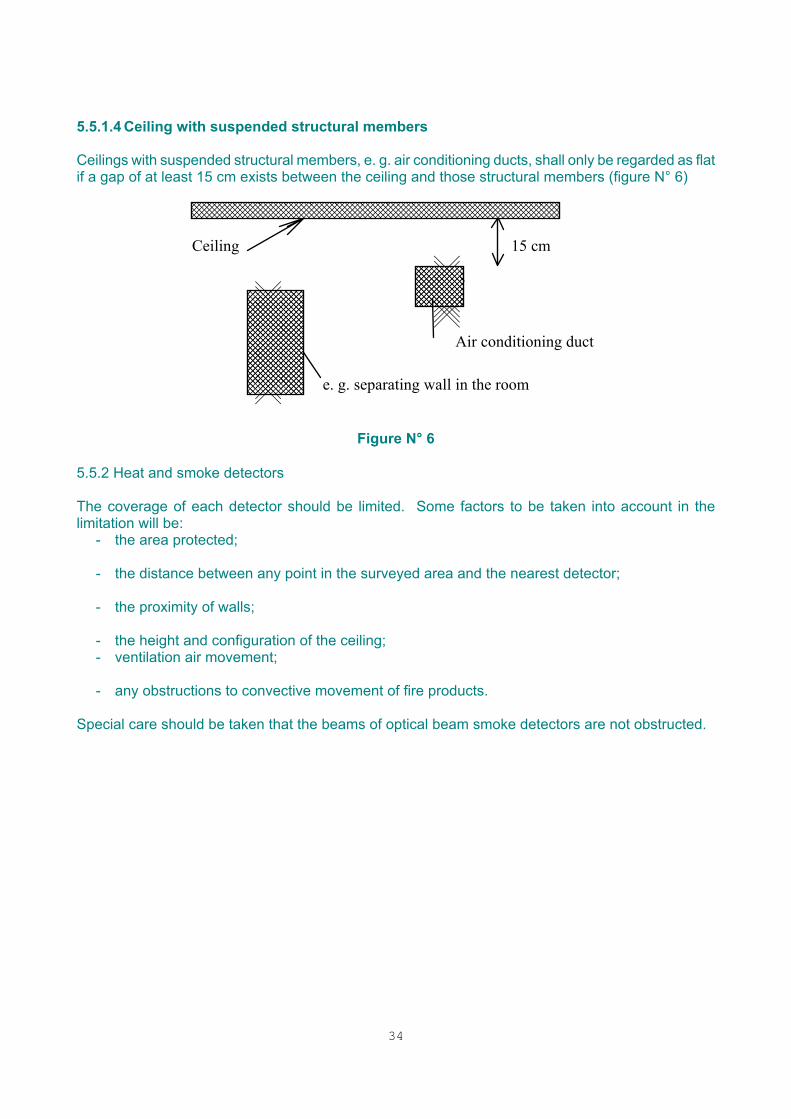
5.5.1.4 Ceiling with suspended structural members Ceilings with suspended structural members, e. g. air conditioning ducts, shall only be regarded as flat if a gap of at least 15 cm exists between the ceiling and those structural members (figure N° 6)
���������
e. g. separating wall in the room
���������������
���������������
15 cmCeiling
Air conditioning duct
Figure N° 6
5.5.2 Heat and smoke detectors The coverage of each detector should be limited. Some factors to be taken into account in the limitation will be:
- the area protected;
- the distance between any point in the surveyed area and the nearest detector;
- the proximity of walls;
- the height and configuration of the ceiling; - ventilation air movement;
- any obstructions to convective movement of fire products.
Special care should be taken that the beams of optical beam smoke detectors are not obstructed.
35
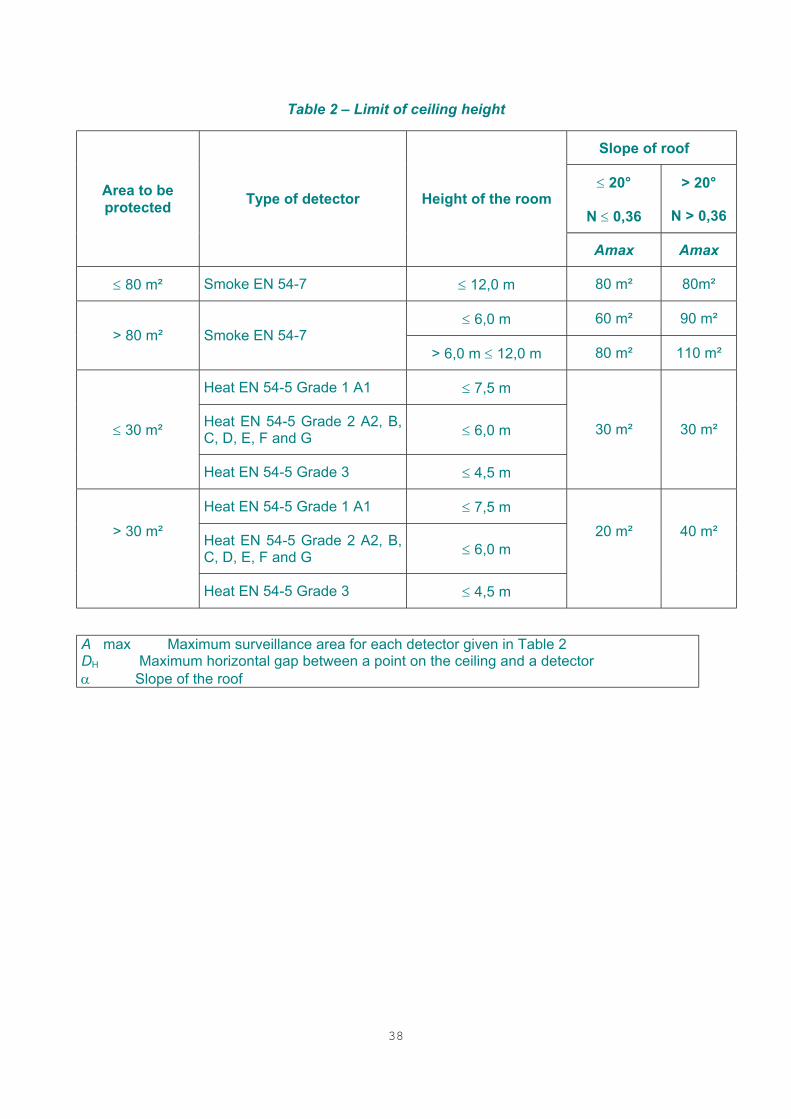
5.5.2.1 Limits of ceiling heights and maximum horizontal distance between detectors In general, the performance of heat or smoke detectors depends on the presence of a ceiling close above the detectors. Detectors should be sited so that their sensitive elements are within the limits given in Table 3 (§ 5.5.2.3). Because of the possible existence of a cold boundary layer of air, detectors should not be recessed into the ceiling. If adverse temperature gradients exist in the protected area then the rising plume from the fire may flatten and form a layer before reaching the ceiling. If the height of this layer is predictable, then, in addition to the detectors installed close to the ceiling, further detectors may be mounted at the expected stratification height. The number of detectors is to be calculated in such a way that the maximum floor area per detector, indicted in Table 2 below is not exceeded. For point type detectors (smoke and heat), the horizontal distance from any place in a protected area to the detector nearest to that place should not exceed a value given by figures 7 and 8 which follows.

36
A max shall be weighted by K coefficient below, according to formula A n = K x A max.
Table 1 - Risk factors k
Surveyed room Coefficient K
A Attic storey 0,6 Archives 1 B Battery room 1 Boiler room 1 C Cable track 0,6 Awing 1 Cloakroom 1 Common warehouse 0,6 Computer room 0,3 Cold room 0,6 Core oven 1 Corridors 1 E Electrical risk 0,6 Electrical workshop 1 Engine test bench 0,6 H Hangar 0,3 Hospital room 0,3 Hotel room 0,6 J Joiner’s shop 0,6 K Kitchen 1 L Laboratory (clean room) 0,3
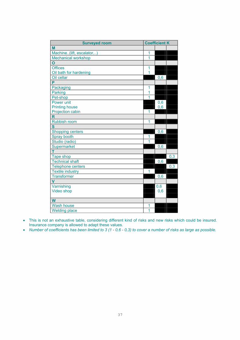
37
Surveyed room Coefficient K
M Machine..(lift, escalator,..) 1 Mechanical workshop 1 O Offices 1 Oil bath for hardening 1 Oil cellar 0,6 P Packaging 1 Parking 1 Pet-shop 1 Power unit 0,6 Printing house 0,6 Projection cabin 1 R Rubbish room 1 S Shopping centers 0,6 Spray booth 1 Studio (radio) 1 Supermarket 0,6 T Tape shop 0,3 Technical shaft 0,6 Telephone centers 0,3 Textile industry 1 Transformer 0,6 V Varnishing 0,6 Video shop 0,6 W Wash house 1 Welding place 1
• This is not an exhaustive table, considering different kind of risks and new risks which could be insured. Insurance company is allowed to adapt these values. • Number of coefficients has been limited to 3 (1 - 0,6 - 0,3) to cover a number of risks as large as possible.
38
Table 2 – Limit of ceiling height
Slope of roof �
≤ 20°
N ≤ 0,36
> 20°
N > 0,36 Area to be protected Type of detector Height of the room
Amax Amax
≤ 80 m² Smoke EN 54-7 ≤ 12,0 m 80 m² 80m²
≤ 6,0 m 60 m² 90 m² > 80 m² Smoke EN 54-7
> 6,0 m ≤ 12,0 m 80 m² 110 m²
Heat EN 54-5 Grade 1 A1 ≤ 7,5 m
Heat EN 54-5 Grade 2 A2, B, C, D, E, F and G ≤ 6,0 m ≤ 30 m²
Heat EN 54-5 Grade 3 ≤ 4,5 m
30 m² 30 m²
Heat EN 54-5 Grade 1 A1 ≤ 7,5 m > 30 m² Heat EN 54-5 Grade 2 A2, B,
C, D, E, F and G ≤ 6,0 m 20 m² 40 m²
Heat EN 54-5 Grade 3 ≤ 4,5 m A max Maximum surveillance area for each detector given in Table 2 DH Maximum horizontal gap between a point on the ceiling and a detector α Slope of the roof
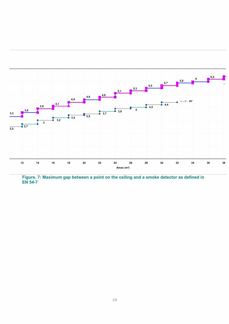
39
Figure. 7: Maximum gap between a point on the ceiling and a smoke detector as defined in EN 54-7
4,44,2
43,9
3,53,43,2
32,7
2,5
3,73,33,6
3,94,1
4,44,6 4,8
5,15,3
5,55,7
5,96 6,2
12 14 16 18 20 22 24 26 28 30 32 34 36 38
Amax (m²)
°
α = 0°− 20°
40
Figure 8: Maximum gap between a point on the ceiling and a heat detector as defined in EN 54-5 Detectors intended to be used in coincidence detection mode The area to be protected in Table 2 is reduced for at least 30 % (only for smoke detectors). The distance between these two detectors must be at least 2,5 m. Detectors intended to be used for fixed fire extinguishing system The area to be protected in Table 2 is reduced for at least 50 %. 5.5.2.2 Detectors under ceilings and roofs Heat detectors shall be fitted directly under the ceiling. For smoke detectors, the necessary spacing between the detector and the ceiling/roof depends on the type of ceiling or roof involved and on the room height. The spacing values are given in table 3. In case of open false ceiling (openings, grids, for example,…) if open area is more than 75%, no additional detectors are necessary under the false ceiling. 5.5.2.3 Detectors on ceilings and roofs with special shapes. In the case of rooms with high-pitched roofs, e.g. lean-to roofs, ridged roofs, hipped roofs, with a slope angle > 20 °, a row of detectors shall be fitted at the vertical level of the ridge to the highest part of the room.
4,44,243,93,53,43,23
2,72,5
3,73,3 3,63,9 4,1
4,4 4,6 4,85,1 5,3 5,5 5,7 5,9 6 6,2
0
1
2
3
4
5
6
7
10 12 14 16 18 20 22 24 26 28 30 32 34 36 38 40Amax(m²)
DH
/m
α > 20°
α = 0°- 20°
41
In the case of rooms with north light roofs, a row of detectors shall be fitted to each apex, as given in figure 9 below. The detectors shall be fitted to the roof surface having the lower degree of slope to a (Dv) spacing. In case of the installation of a second row of detectors in the north light roof, the spacing (Dv) shall be chosen as for roof slopes < 20 °. Table 3: Spacing between smoke sensing elements and ceilings /roofs
Slope of roof � ≤ 20° (N ≤ 0,36) > 20° (N < 0,36) Room height RH[m]
Dv Dv ≤ 6 m 0 - 0,25 m 0,20 m - 0,5 m > 6 m 0 - 0,4 m 0,35 m - 1,0 m
Dv Spacing between smoke sensing elements and ceilings / roofs � slope of roof
*1) if HS > 0,6m *2) if WS > 7,5 m or if HS ≤ 0,6m PH in accordance to Table 3 (DL) Rh: Height of the room
Figure 9: Siting and spacing of detectors in case of special roof shapes
5.5.2.4 Detectors below platforms, grids or similar equipment. If a room is subdivided horizontally by closed platforms or by grids, the installation of additional detectors below this equipment is necessary. Note: Grids are considered as closed platforms because of possible storage of goods on them. Detectors can be installed under platforms if the conditions defined in Table 4 below can be satisfied. In the case of more than one platform level, only the lower level shall be fitted with detectors if there is no fire load between the other levels. Table 4: Detectors below platforms
42
Kind of detector
Platform height h (m)
Platform length l (m)
Platform width b (m)
Platform area f (m²)
Heat EN 54-5
Up to 7,5 m (Grade 1)
More than 2 m
More than 2 m
More than 9 m²
Up to 6 m More than 2 m
More than 2 m
More than 16 m²
Smoke EN 54-7 More than
6 m up to 12 m
More than 3,5 m
More than 3,5 m
More than 31,5 m²
43
5.5.2.5 Detectors on ceilings with girders Depending on the room height and the girder's depth, girders shall be taken into account as defined in figure 10 below. If they are not taken into account, detectors have to be installed on the underside of the girder.
Figure 10: Curve determining the installation of detectors on ceilings with girders Where the distance DH between the upper edges of the girder and the bottom edges of the roof or ceiling is more than 250 mm, girders of any height can be ignored (figure 11 below)..
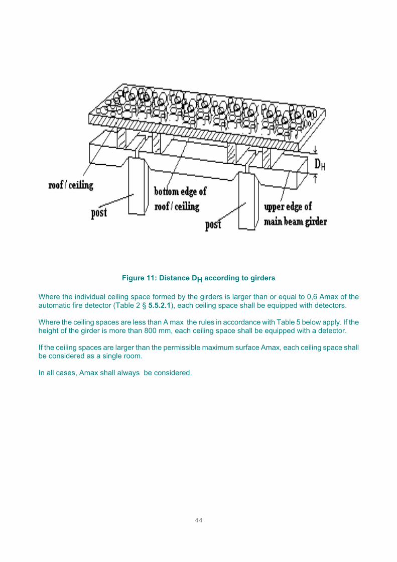
44
Figure 11: Distance DH according to girders
Where the individual ceiling space formed by the girders is larger than or equal to 0,6 Amax of the automatic fire detector (Table 2 § 5.5.2.1), each ceiling space shall be equipped with detectors. Where the ceiling spaces are less than A max the rules in accordance with Table 5 below apply. If the height of the girder is more than 800 mm, each ceiling space shall be equipped with a detector. If the ceiling spaces are larger than the permissible maximum surface Amax, each ceiling space shall be considered as a single room. In all cases, Amax shall always be considered.
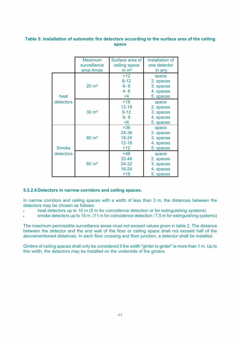
45
Table 5: Installation of automatic fire detectors according to the surface area of the ceiling space
Maximum surveillance
Surface area of ceiling space
Installation of one detector
area Amax in m² in any >12 space 8-12 2. spaces 20 m² 6- 8 3. spaces 4- 6 4. spaces
heat <4 5. spaces detectors >18 space
12-18 2. spaces 30 m² 9-12 3. spaces 6- 9 4. spaces <6 5. spaces >36 space 24-36 2. spaces 60 m² 18-24 3. spaces 12-18 4. spaces
Smoke <12 5. spaces detectors >48 space
32-48 2. spaces 80 m² 24-32 3. spaces 16-24 4. spaces <16 5. spaces
5.5.2.6 Detectors in narrow corridors and ceiling spaces. In narrow corridors and ceiling spaces with a width of less than 3 m, the distances between the detectors may be chosen as follows: ♦ heat detectors up to 10 m (5 m for coincidence detection or for extinguishing systems) ♦ smoke detectors up to 15 m. (11 m for coincidence detection / 7,5 m for extinguishing systems) The maximum permissible surveillance areas must not exceed values given in table 2. The distance between the detector and the end wall of the floor or ceiling space shall not exceed half of the abovementioned distances. In each floor crossing and floor junction, a detector shall be installed. Girders of ceiling spaces shall only be considered if the width "girder to girder" is more than 1 m. Up to this width, the detectors may be installed on the underside of the girders.
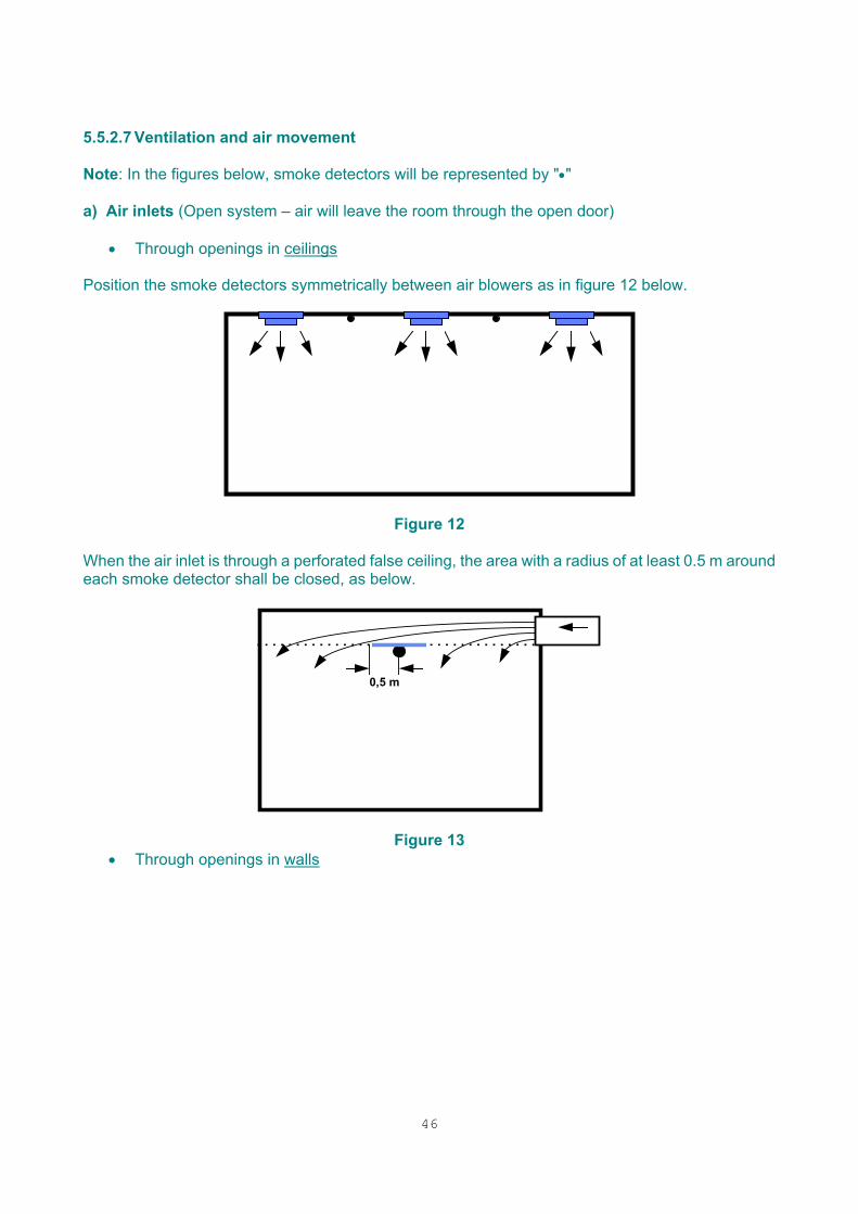
46
5.5.2.7 Ventilation and air movement Note: In the figures below, smoke detectors will be represented by "•" a) Air inlets (Open system – air will leave the room through the open door)
• Through openings in ceilings Position the smoke detectors symmetrically between air blowers as in figure 12 below.
Figure 12
When the air inlet is through a perforated false ceiling, the area with a radius of at least 0.5 m around each smoke detector shall be closed, as below.
0,5 m
Figure 13 • Through openings in walls
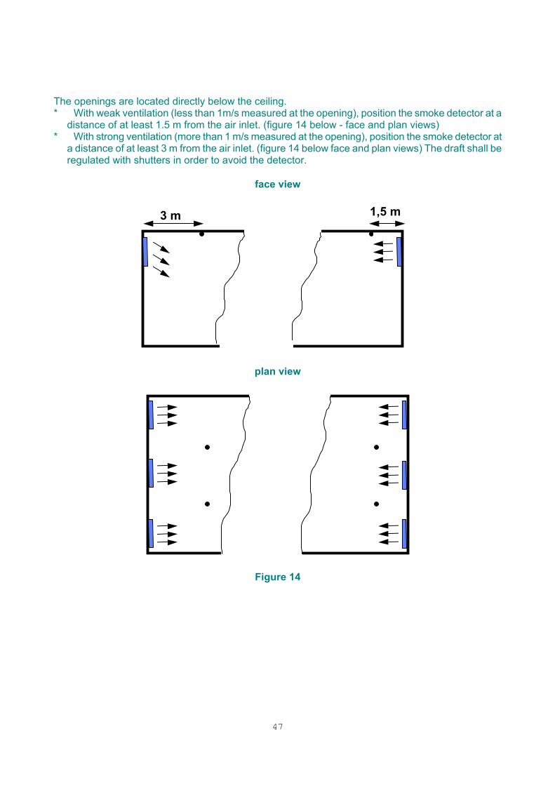
47
The openings are located directly below the ceiling. * With weak ventilation (less than 1m/s measured at the opening), position the smoke detector at a
distance of at least 1.5 m from the air inlet. (figure 14 below - face and plan views) * With strong ventilation (more than 1 m/s measured at the opening), position the smoke detector at
a distance of at least 3 m from the air inlet. (figure 14 below face and plan views) The draft shall be regulated with shutters in order to avoid the detector.
face view
plan view
Figure 14
1,5 m3 m
48
b) Air outlets ♦ Through openings in ceilings The smoke detectors shall be located in the air turbulence zones between the air outlets, not in front of the outlet openings as below
Figure 15
If the air outlet takes place by ventilation ducts (eventually installed above the false ceiling) each duct shall be equipped with a detector following figures 16 and 17 below. Note: In figures 16 and 17, detectors installed in the false ceiling depend on § 4.3.3
Figure 16 - face view
49
Figure 17 - plan view ♦ Through opening in walls The openings are located directly below the ceiling. Position the smoke detector in front of each opening but not directly in the air stream following figure 18 below.
Figure 18
The openings are not located directly below the ceiling. Special precautions shall be taken for the positioning of the smoke detector. c) In false ceilings and floors The detectors shall be positioned according to a symmetrical distribution over the covered area. The concentration of detectors shall always be higher near the air outlet. The support for the detector in the false floor should permit easy accessibility for the purposes of maintenance and testing. Note: False ceilings and false floors used as plenum shall always be monitored. If these spaces are not used as plenum, see § 4.3
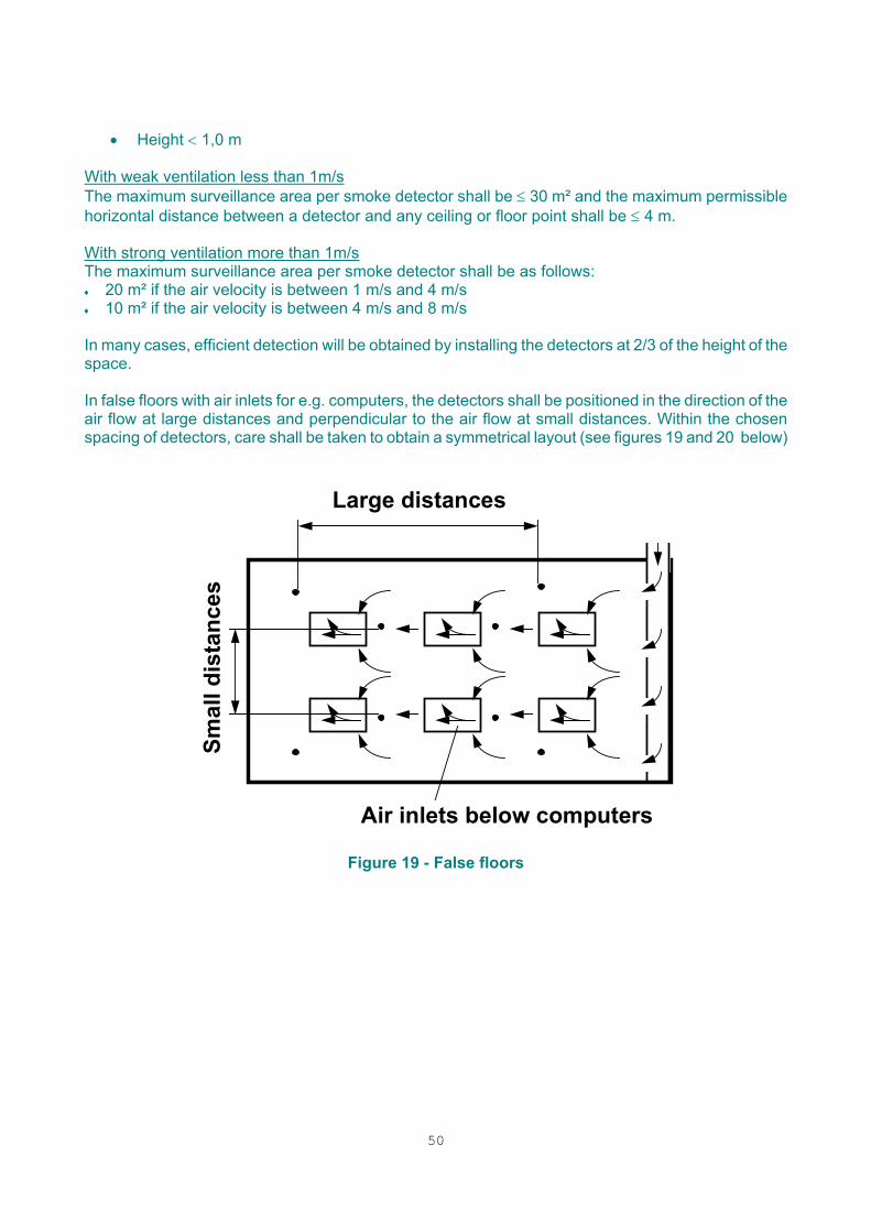
50
• Height < 1,0 m
With weak ventilation less than 1m/s The maximum surveillance area per smoke detector shall be ≤ 30 m² and the maximum permissible horizontal distance between a detector and any ceiling or floor point shall be ≤ 4 m. With strong ventilation more than 1m/s The maximum surveillance area per smoke detector shall be as follows: ♦ 20 m² if the air velocity is between 1 m/s and 4 m/s ♦ 10 m² if the air velocity is between 4 m/s and 8 m/s In many cases, efficient detection will be obtained by installing the detectors at 2/3 of the height of the space. In false floors with air inlets for e.g. computers, the detectors shall be positioned in the direction of the air flow at large distances and perpendicular to the air flow at small distances. Within the chosen spacing of detectors, care shall be taken to obtain a symmetrical layout (see figures 19 and 20 below)
Air inlets below computers
Smal
l dis
tanc
es
Large distances
Figure 19 - False floors
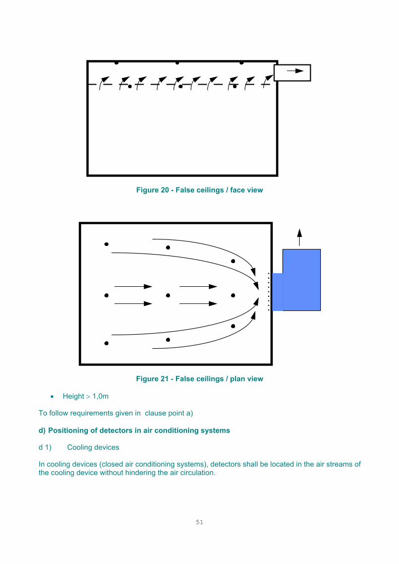
51
Figure 20 - False ceilings / face view
Figure 21 - False ceilings / plan view
• Height > 1,0m To follow requirements given in clause point a) d) Positioning of detectors in air conditioning systems d 1) Cooling devices In cooling devices (closed air conditioning systems), detectors shall be located in the air streams of the cooling device without hindering the air circulation.
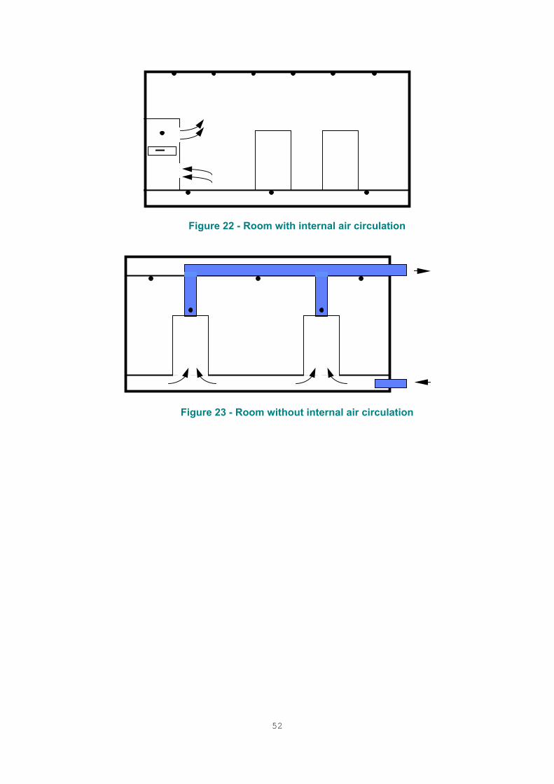
52
Figure 22 - Room with internal air circulation
Figure 23 - Room without internal air circulation
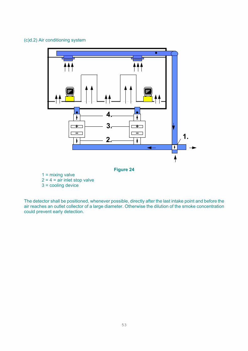
53
(c)d.2) Air conditioning system
3.1.2.
4.
Figure 24
1 = mixing valve 2 = 4 = air inlet stop valve 3 = cooling device
The detector shall be positioned, whenever possible, directly after the last intake point and before the air reaches an outlet collector of a large diameter. Otherwise the dilution of the smoke concentration could prevent early detection.
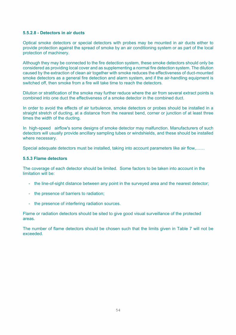
54
5.5.2.8 - Detectors in air ducts Optical smoke detectors or special detectors with probes may be mounted in air ducts either to provide protection against the spread of smoke by an air conditioning system or as part of the local protection of machinery. Although they may be connected to the fire detection system, these smoke detectors should only be considered as providing local cover and as supplementing a normal fire detection system. The dilution caused by the extraction of clean air together with smoke reduces the effectiveness of duct-mounted smoke detectors as a general fire detection and alarm system, and if the air-handling equipment is switched off, then smoke from a fire will take time to reach the detectors. Dilution or stratification of the smoke may further reduce where the air from several extract points is combined into one duct the effectiveness of a smoke detector in the combined duct. In order to avoid the effects of air turbulence, smoke detectors or probes should be installed in a straight stretch of ducting, at a distance from the nearest bend, corner or junction of at least three times the width of the ducting. In high-speed airflow's some designs of smoke detector may malfunction. Manufacturers of such detectors will usually provide ancillary sampling tubes or windshields, and these should be installed where necessary. Special adequate detectors must be installed, taking into account parameters like air flow,…… 5.5.3 Flame detectors The coverage of each detector should be limited. Some factors to be taken into account in the limitation will be:
- the line-of-sight distance between any point in the surveyed area and the nearest detector; - the presence of barriers to radiation;
- the presence of interfering radiation sources.
Flame or radiation detectors should be sited to give good visual surveillance of the protected areas. The number of flame detectors should be chosen such that the limits given in Table 7 will not be exceeded.
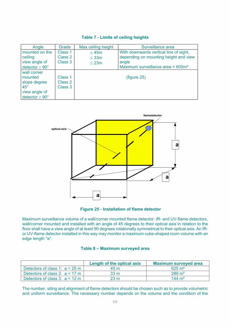
55
Table 7 - Limits of ceiling heights
Angle Grade Max ceiling height Surveillance area mounted on the ceiling view angle of detector ≥ 90°
Class 1 Class 2 Class 3
≤ 45m ≤ 33m ≤ 23m
With downwards vertical line of sight, depending on mounting height and view angle Maximum surveillance area = 600m²
wall corner mounted slope degree 45° view angle of detector ≥ 90°
Class 1 Class 2 Class 3
(figure 25)
a
a
a
optical axis
flamedetector
Figure 25 - Installation of flame detector
Maximum surveillance volume of a wall/corner mounted flame detector: IR- and UV-flame detectors, wall/corner mounted and installed with an angle of 45 degrees to their optical axis in relation to the floor shall have a view angle of at least 90 degrees rotationally symmetrical to their optical axis. An IR- or UV-flame detector installed in this way may monitor a maximum cube-shaped room volume with an edge length "a".
Table 8 – Maximum surveyed area
Length of the optical axis Maximum surveyed area Detectors of class 1: a = 25 m 45 m 625 m² Detectors of class 2: a = 17 m 33 m 289 m² Detectors of class 3: a = 12 m 23 m 144 m²
The number, siting and alignment of flame detectors should be chosen such as to provide volumetric and uniform surveillance. The necessary number depends on the volume and the condition of the
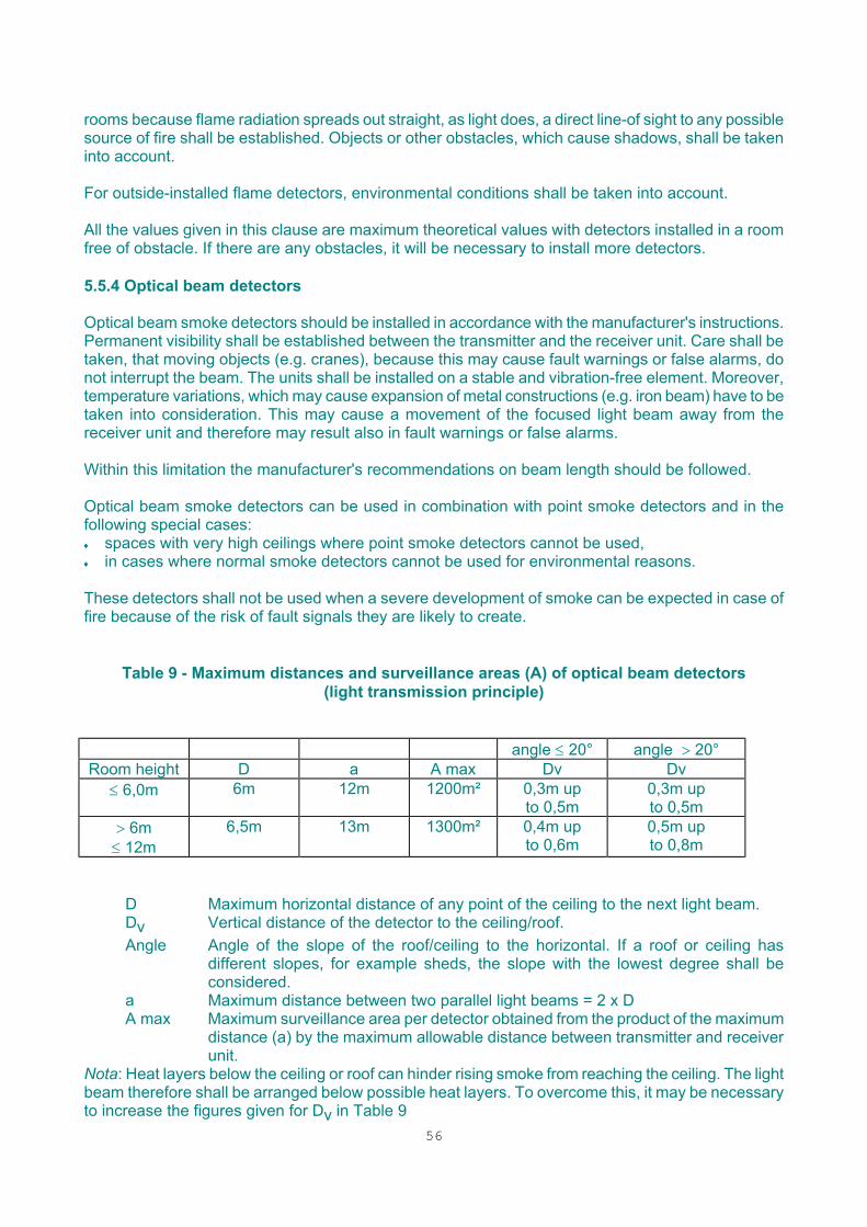
56
rooms because flame radiation spreads out straight, as light does, a direct line-of sight to any possible source of fire shall be established. Objects or other obstacles, which cause shadows, shall be taken into account. For outside-installed flame detectors, environmental conditions shall be taken into account. All the values given in this clause are maximum theoretical values with detectors installed in a room free of obstacle. If there are any obstacles, it will be necessary to install more detectors. 5.5.4 Optical beam detectors Optical beam smoke detectors should be installed in accordance with the manufacturer's instructions. Permanent visibility shall be established between the transmitter and the receiver unit. Care shall be taken, that moving objects (e.g. cranes), because this may cause fault warnings or false alarms, do not interrupt the beam. The units shall be installed on a stable and vibration-free element. Moreover, temperature variations, which may cause expansion of metal constructions (e.g. iron beam) have to be taken into consideration. This may cause a movement of the focused light beam away from the receiver unit and therefore may result also in fault warnings or false alarms. Within this limitation the manufacturer's recommendations on beam length should be followed. Optical beam smoke detectors can be used in combination with point smoke detectors and in the following special cases: ♦ spaces with very high ceilings where point smoke detectors cannot be used, ♦ in cases where normal smoke detectors cannot be used for environmental reasons. These detectors shall not be used when a severe development of smoke can be expected in case of fire because of the risk of fault signals they are likely to create.
Table 9 - Maximum distances and surveillance areas (A) of optical beam detectors (light transmission principle)
angle ≤ 20° angle > 20° Room height D a A max Dv Dv
≤ 6,0m 6m 12m 1200m² 0,3m up to 0,5m
0,3m up to 0,5m
> 6m ≤ 12m
6,5m 13m 1300m² 0,4m up to 0,6m
0,5m up to 0,8m
D Maximum horizontal distance of any point of the ceiling to the next light beam. Dv Vertical distance of the detector to the ceiling/roof. Angle Angle of the slope of the roof/ceiling to the horizontal. If a roof or ceiling has
different slopes, for example sheds, the slope with the lowest degree shall be considered.
a Maximum distance between two parallel light beams = 2 x D A max Maximum surveillance area per detector obtained from the product of the maximum
distance (a) by the maximum allowable distance between transmitter and receiver unit.
Nota: Heat layers below the ceiling or roof can hinder rising smoke from reaching the ceiling. The light beam therefore shall be arranged below possible heat layers. To overcome this, it may be necessary to increase the figures given for Dv in Table 9
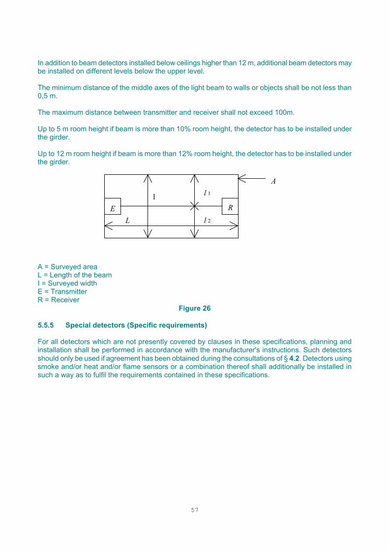
57
In addition to beam detectors installed below ceilings higher than 12 m, additional beam detectors may be installed on different levels below the upper level.
The minimum distance of the middle axes of the light beam to walls or objects shall be not less than 0,5 m. The maximum distance between transmitter and receiver shall not exceed 100m. Up to 5 m room height if beam is more than 10% room height, the detector has to be installed under the girder. Up to 12 m room height if beam is more than 12% room height, the detector has to be installed under the girder.
E R L
l
A l 1
l 2
A = Surveyed area L = Length of the beam I = Surveyed width E = Transmitter R = Receiver
Figure 26
5.5.5 Special detectors (Specific requirements) For all detectors which are not presently covered by clauses in these specifications, planning and installation shall be performed in accordance with the manufacturer's instructions. Such detectors should only be used if agreement has been obtained during the consultations of § 4.2. Detectors using smoke and/or heat and/or flame sensors or a combination thereof shall additionally be installed in such a way as to fulfil the requirements contained in these specifications.
58
5.5.6 Manual call points Manual call points shall be sited on escape routes, at (inside or outside) each door to escape stairs and at each exit to the open air, so that no person in the premises need cover a distance of more than 30 m to reach a manual call point. They may also be sited near special hazards. Additional care in siting manual call points may be necessary where there are people who are handicapped in movement. Manual call points should be clearly visible, identifiable and shall be easily accessible. In general, call points should be fixed at a height between 1,2 m and 1,5 m above the floor. They should be installed in accordance with national regulations. 5.6 Alarm systems and devices 5.6.1 General The method of giving the alarm to the occupants of the building should comply with the requirements of the fire routine. In some cases, the fire routine may require the alarm to be given initially to trained staff, who may then take charge of the resulting operations in the building. In such cases, a general fire alarm need not be given immediately, but a facility for giving a general alarm should be provided. Any alarm intended to be perceived by untrained persons (such as the general public) should be at least by audible means. These may be alarm devices or a voice alarm system (such as the public address system). In the case of additional fire microphones the system should be so designed that it is not possible for more than one microphone, speech module or message generator to be broadcast simultaneously. Access to the fire microphones should be limited to authorised persons. In areas where sound signals may be ineffective, e.g. where the background noise is excessive, where the occupants are deaf or where hearing protection is likely to be worn, visual and/or tactile signals should be used to supplement sound signals. The requirements specified may deviate in regard to national regulations. 5.6.2 Sound signals Limitations on the siting of alarm device sound levels to be achieved, and intelligibility and form of voice messages are given below. 5.6.2.1 Sound level The sound level provided shall be such that the fire alarm signal is immediately audible above any ambient noise. The fire alarm sound shall have a minimum level of either 65 dB(A), or 5 dB(A) above any other noise likely to persist for a period longer than 30 s, whichever is the greater. If the alarm is intended to wake sleeping persons then the minimum sound level should be 75 dB(A). These minimum levels shall be reached at any point at which the alarm sound is required to be heard.
59
The sound level shall not exceed 120 dB(A) at any point more than 1 m from an alarm sounder. 5.6.2.2 Measurement Sound levels shall be measured using an instrument complying with IEC 651, type 2, with slow response and "A" weighting. 5.6.2.3 Alarm devices The number and type of fire alarm devices used shall be sufficient to produce the sound level recommended in § 5.6.2.1. A minimum of two sounders shall be provided in the building even if the recommended sound level could be achieved with a single sounder. At least one sounder shall be provided in each fire compartment. It is unlikely that sound levels in a room will be satisfactory if it is separated from the nearest sounder by more than one door. A larger number of quieter sounders rather than a few very loud sounders may be preferable in order to prevent excessive sound levels in some areas. 5.6.2.4 Sound characteristics The sound characteristics used for fire alarm purposes shall be the same in all parts of the building. The sound of the fire alarm should be adapted to national regulations, if required. 5.6.2.5 Voice systems Where the transmitted alarm is a voice message it shall be ensured that: (a) a suitable alarm (either pre-recorded or synthesised) is provided which can be automatically
transmitted in response to a fire alarm, either immediately or after an agreed delay; this transmission should not depend on the presence of an operator.
(b) all voice messages are clear, short, unambiguous and, as far as practical, preplanned (c) the level of the voice systems should be such that it is audible above any ambience noises in the building.
(d) the received sound is understandable. (e) other signals, e.g. meal break, work start and stop , cannot be confused with the fire alarm
signals and cannot be broadcast at the same time as fire alarm signals. (f) the time interval between successive messages does not exceed 30 s, and that "fill-in" signals
similar to those of conventional sounders are used wherever periods of silence might otherwise exceed 10s.
(g) during fire alarm conditions all audio input sources are automatically disconnected except the speech modules (or equivalent message generators) which give the warning, or those microphones designated as fire microphones. These should be retained in circuit so that announcements and instructions relating to the emergency can be given.
At least one fire microphone shall normally be sited near to the control and indicating equipment (CIE). It may be necessary to consider additional fire microphone positioning at places well separated from the first one. In such a case the system should be so designed that it is not possible for more than one microphone, speech module or message generator to be operated simultaneously. 5.6.3 Visual fire alarm devices Visual fire alarm devices should only be provided in areas where ambient noise level exceed 90 dB (A) and in other areas where hearing protection is likely to be used under normal circumstances. Any visual fire alarm should be clearly visible and distinguishable from other visual signals used in the
60
premises. 5.7 Control and indication 5.7.1 Location of control and indicating equipment To consider location, all configurations have to be taken into account: 1 – The control and indicating equipment (CIE) can be alone 2 – The CIE can be completed with a remote "front face" which has to fulfil EN54-2 3 – The CIE with a remote control panel used for comfort 4 – The CIE can be completed with a remote control panel (exploitation) For other configurations (e.g. remote panels) specifications have to be defined.
(a) The control and indicating equipment should be located in a room: ♦ which is sited preferably on the ground floor and in the immediate vicinity of the main
entrance to the monitored premises or the entrance normally used by the fire brigade and which should permit free access at all time; if there are difficulties in fulfilling this requirement, it shall be possible to duplicate signalling
♦ which is in a clean place, at the appropriate temperature (0° to 40°C) and humidity (10 %
to 80 %) to ensure that the control unit functions correctly. The alarm location aids (§ 5.7.5) shall be kept close to the CIE:
( b) the lighting is such that the labels and visual indications can be easily seen and read; (c) the background noise level allows audible indications to be heard;
(d) the risk of mechanical damage to the equipment is low;
(e) the risk of fire is low, and the location is covered by the fire detection system.
If the control and indicating equipment is in more than one enclosure, then the location of each enclosure should satisfy the recommendations
The connection between the enclosures must be achieved by a physical separation of interconnecting cables or the use of the cable that would maintain integrity in the event of the fire.
Control and indicating equipment or a remote signalisation panel shall be installed in a permanently manned area; if it is not fulfilled, it has to be connected to an approved CEA remote control station. If it is necessary for practical reasons to mount the control and indicating equipment in environments which do not satisfy the recommendations of (a), d) and (e) above, then special precautions should be taken to protect the equipment. 5.7.2 Detector identification It is frequently convenient for the competent person, via the control and indicating equipment to be able to identify the individual detector or manual call point from which an alarm has been raised. In such cases, a method should be provided by which the control and indicating equipment indication can be easily related to the relevant detector. 5.7.3 Repeat indications
61
Repeat indicating panels may be necessary where the control and indicating equipment is remote from the fire brigade entrance, where a building has several fire brigade entrances, or where the control and indicating equipment is not in a permanently manned area.. Repeat indicating panels should be in locations complying with 5.7.1 a) to e). Visual indications such as a flashing beacon may be provided at the fire brigade entrance to the building.
5.7.4 Repeat controls Where multiple control panels are provided, allowing control to be taken at several locations, provision should be made to prevent contradictory operation of controls from different positions 5.7.5 Alarm location aids It should be possible quickly, easily and unambiguously to relate the indications of the control and indicating equipment to the geographical position of any detector or manual call point in alarm. At least one of the following should be provided:
• zone cards;
• zone maps;
• mimic diagrams;
• remote indicator lamps. In some cases (particularly when dealing with false alarms), it may be convenient to be able to identify the individual detector or manual call point from which the alarm has been raised. 5.7.6 Fire brigade panel In some countries, a standardised panel is required for fire brigade use. The requirements for fire brigade panels are given in national documents. 5.8 Power supplies 5.8.1 Power supply equipment The output of the power supply equipment should be sufficient to satisfy the maximum demands of the system. In some fire detection and fire alarm systems, the power supply for remote items of equipment is provided locally and not from the power supply of the CIE (e.g. Aspirating smoke detectors or sounders). The power supplies for remote items of equipment shall be monitored to enable fault conditions and the remote equipment to be displayed at the main Control and Indicating Equipment. If remote items are supplied from a central power supply equipment, then, a single fault on the supply to the remote item shall not remove detection coverage from an area greater than 1600 m². 5.8.2 Main power source
62
In general, the main power source for the system should be the public supply system. Privately generated power may be used where it has at least the same reliability as the public supply or where no public supply system is available The main power supply to the fire detection system should be provided with a suitable dedicated isolating protective device at a position as close as possible to the point of entry of the supply into the building (before differential protection if authorised by national regulation). Care should be taken to minimise the number of fuses. For easy access, the location of the isolating protective device has to be identified and its place described at a suitable place on/in the control and indicating equipment. The reloading of the battery at 80 % of normal capacity has to be done within 24 h continuously with the normal functioning of the installation. Provision should be made (by, for instance, labelling or the restriction of access) to prevent unauthorised disconnection of the main power source. Where more than one power supply equipment is used, the power source for each equipment should comply with these recommendations. 5.8.3 Standby supply In the event of failure of the main power source, standby power should be available from a battery. The capacity of this battery should be sufficient to supply the system during all likely breaks in the main power source or to allow other corrective action to be taken. In some cases, power may also be available from standby generators or no-break power supplies. When such power is provided, the capacity of the standby battery may be reduced but a dedicated battery should always be provided. Where standby generators are used, arrangements should be made for refuelling within 24h of the restoration of the main power source Batteries have to be replaced at least 4 years after their production date, unless otherwise stated in the certificate of approval, if it exists. Only batteries of the same type (same manufacturer, capacity, voltage, production date), may be connected in parallel or series. Only if the capacity of a single battery is at least 36 Ah, or if the batteries are monitored separately and decoupled from each other (e.g. by fuses), may more than 2 batteries be connected to chargers. Generally, not more than 3 batteries may be connected in parallel. If batteries are connected in series, a maximum of 2 series connections may be connected in parallel. Batteries up to a cell quantity of max. 12 cells may be connected in parallel. A series connection of more than 12 cells is possible, if a well-balanced voltage distribution takes place by suitable measures. To compensate for any possible failures of equipment or of the incoming main supply, the standby supply should be capable of maintaining the system in operation for at least 72 h,( after which sufficient capacity should remain to provide the alarm load for at least 30 min.) Where there will be immediate notification of fault, either by local (permanently manned area) or remote supervision of the system, and when a repair contract is in force, giving a maximum repair period of less than 24 h, then the minimum standby capacity may be reduced from 72 h to 30 h.

63
If there is a repair contract in force, giving a maximum repair period of less than 8 hours, the minimum standby capacity may be reduced from 30 to 12 h. The period may be further reduced to 4 h if spares, repair personnel and a standby generator are available on-site at all times. For this duration, the capacity shall be 0.75 considering the characteristics of the batteries. In all cases, sufficient capacity should remain to provide the alarm load for at least 30 min. The rated capacity “C” of the new battery shall be “1,25 x C” considering that ageing will result in a loss of capacity. C nom (Ah) =1,25 x ((A1 x t1) + (A2 x t2)) t1: standby time t2: alarm time A1: Standby current (I nom) A2: Alarm current (I nom) 5.9 Signals to a fire alarm receiving station To obtain the maximum benefit from a fire detection and alarm system, alarms should be passed to the fire brigade with the minimum of delay. This can best be achieved by the use of an automatic link preferably directly to the fire brigade but alternatively via another remote manned centre. Where a remote manned centre is used, it should comply with "CEA specifications for Remote Control Stations - November 1991 " If the premises are constantly manned, the call may be made manually by telephone, either to a number previously agreed by the fire brigade or to the national emergency number. Care should be taken that the provision of telephones within the building is sufficient to avoid delay in calling the fire brigade. Automatic links should preferably be monitored so that any fault on the link is indicated either at the remote manned station or at the control and indicating equipment. Where the remote manned centre agrees, it is recommended that at least general fire and fault signals are transmitted and consideration should be given to transmission faults. 5.10 Documentation The designer should provide sufficient documentation to enable the installer satisfactorily to carry out the installation. As a minimum, this should be layout drawings showing the intended type and location of all devices and a schematic diagram showing their interconnections. The designer should provide and sign a certificate of design. A model certificate is given in Annex B. If changes are made subsequent to the supply of the initial documentation, then these amendments and any new documentation should be similarly certified. 5.11 Responsibility Responsibility for planning, design, and the completeness and accuracy of the documentation of § 5.10 should be clearly defined as in § 3.10.
64
5.12 Qualifications The person or organisation carrying out the design and preparing the documentation of § 5.10. shall be certified by an insurance company. 6 - INSTALLATION 6.1 General The system should be installed in accordance with the documentation prepared under § 5.10. If for any reason the design prepared under § 5 is found unsuitable during installation, then any changes found necessary should be agreed by the designer and agreed amendments made to the documentation, including the certificate of design. In addition to the following requirements, the national regulations of the country in which the system is installed apply to the installation. 6.2 Siting and accommodation of equipment 6.2.1 Siting The positioning of the equipment should be checked against the documentation. Any conflict should be resolved by consultation. The insurance company shall be consulted. 6.2.2. Protection against lightning (over-voltage) If there are national insurer regulations, they have to be fulfilled. Protection against over-voltage shall be realised by suitable measures (equipment) in the components of a fire detection alarm system (basic protection) on one side and additional measures or requirements for the installation on the other. The necessary measures are mainly dependent on the localisation of the components forming part of the installation and on the equipment connected to the fire detection alarm system. A comprehensive protection against damage caused by lightning strikes and over-voltage can be reached by outer and inner lightning protection. Based on a standard building, the installation classification is fixed following the lightning-protection concept of EC-TC 81 and IEC-publication 1000-5 "Classification of the installation". 6.2.3 Hazardous areas Siting of equipment should take account of any special hazards which might exist. In locations having a potentially explosive atmosphere, adequate measures shall be taken in accordance with national or European recommendations. 6.2.4 Installation of detectors and control units Detectors and control units shall be installed in a manner so as to aid maintenance. Due consideration should be given to ease of access for the purposes of servicing.
65
Detectors shall be installed in such a way that their state indication must be visible when entering the room. Detectors and control units shall be sited in a position where they are not exposed to the risk of physical damage. Detectors, in certain circumstances, may be suspended in accordance with an approved method, so as to facilitate their maintenance. 6.3 Installation of cables and interconnections 6.3.1 Cable types Cables should satisfy any requirements specified by the manufacturer or supplier of the equipment. The recommendations of national documents on the types of cable and their installation should be followed. Where necessary, fire detection and alarm system cables may be segregated from other cables by the use of insulating or earthen conducting partitions or by separation by an adequate distance. The cross-section of cables must be in accordance with the current carrying capacity to avoid undue voltage drops. To ensure adequate mechanical resistance, the diameter of leads shall not be less than 0,6 mm. Distribution boxes and cables shall be easily identifiable as part of the fire alarm system. 6.3.2 Protection against fire and mechanical damage Cables should be adequately protected. Cables should be installed in suitably protected locations (cable trays, trunking, ducts); alternatively, the cable should have sufficient mechanical strength for its location or additional mechanical protection should be provided. Where loop connected circuits are used, consideration should be given to the effects of simultaneous damage to both sides by a single incident (for example, damage to both cables by collision with a vehicle) or by a fire. Where susceptibility to such damage could occur, either mechanical or fire protection should be provided or the sides of the loop should be sufficiently separated as to prevent simultaneous damage. Where possible, cables should be run in areas of low fire risk. If it is necessary to run cables through other areas and failure of those cables will prevent:
- the operation of alarm devices; - the reception of signals from the fire detection system by any control for fire protection
equipment; - the reception of signals from the fire detection system by any fire alarm routing equipment;
then either fire resistant cables, in accordance with national or European regulations, should be used or the cables should be given protection against fire. For detection circuits, if they are not in an area covered by fire detection, cables must be fire resistant.

66
Cables which may need to function for more than 1 minute after detection of a fire shall either be able to withstand the effects of fire for at least 30 minutes or be protected against fire for the same period. It applies to all cables between: ♦ a CIE and alarm devices; ♦ a CIE and a separate power supply equipment; ♦ different component parts of a CIE; ♦ a main CIE and any repeat indicator panel; ♦ a main CIE and any repeat control panel: ♦ and any other cable required to operate after the fire has started. with the exception of fail-safe of ancillary equipment or ring configuration for which equipment is powered from both sides. Cables must be physically separate and installed in different ways:
67
6.3.3 Protection against electromagnetic interference In order to prevent damage and false alarms, equipment (including cabling) should not be sited in places likely to have high levels of electromagnetic interference. Where this cannot be arranged, then adequate electromagnetic protection should be provided. 6.3.4 Precautions against spread of fire Where cables, etc., penetrate the wall, floor or ceiling of a fire compartment, the penetration should be fire-stopped so that the fire resistance of the penetrated component is not reduced. 6.4 Cable joints and terminations Joints in cables, other than those contained within enclosures of equipment, should be avoided wherever possible. Where a joint in a cable is unavoidable, it should be enclosed in a suitable, accessible and clearly identified junction box to avoid confusion with other services. Jointing and termination methods should be chosen to minimise any reduction in reliability and resistance to fire below that of the enjoined cable. Conduit and ducting sizes should be such as to permit easy drawing in and out of the cables concerned. Access should be provided by means of removable or hinged covers. Cabling must be installed in accordance with § 6.3. 6.5 Radioactivity Handling, storage and use of detectors containing radioactive material may be subject to requirements of national legislation. It is essential that these requirements are met. 6.6 Documentation For maintenance and record purposes, scale drawings, block diagrams and in case of hierarchical system structure, should be provided by the installer to the purchaser showing the position of the various items of equipment, junction boxes, etc. Wiring diagrams of junction boxes and distribution cases should be included. The records should be permanent and suitable for convenient reference. In the block diagram, isolators shall be located on the drawings Fire compartments and details of construction (false floor, false ceiling, hidden places…) must be defined on the drawings in a suitable scale. The installer should supply the purchaser with a certificate of installation and a log book. (A model certificate and logbook are given in Annex B). 6.7 Responsibility Responsibility for compliance of the installed system with the documentation of § 6.6 and § 7.4 rests with the person or organization signing the certificate of installation. 6.8 Qualifications (Refer to §3.11)

68
7 - COMMISSIONING AND VERIFICATION 7.1 General The aim of the commissioning process is to determine that the system as installed meets the requirements of these specifications and, for the safety of life and/or the protection of property, that the assessment of needs has been correctly carried out. 7.2 Commissioning The commissioning shall be applied in the case of newly completed installations and where existing installations have undergone substantial modification which can have an influence on performance. The installer's representative and the user (purchaser) or his agent will normally carry out the commissioning. Where there are requirements for third party approval, the recommendations of § 8 shall be followed. The commissioning engineer should make a thorough visual inspection to ensure that the work has been carried out in a satisfactory manner, that the methods, materials and components used comply with these guidelines and that record drawings and operating instructions are true to the installed system. The commissioning engineer should test and verify that the installed system operates correctly, and in particular should check that:
- all detectors and manual call points are functioning;
- the information given by the control and indicating equipment is correct and meets the requirements documented under § 5.10;
- any connection to a fire alarm receiving station or fault warning receiving station is in operation
and that the messages are correct and clear;
- the alarm devices operate as indicated in these guidelines;
- all ancillary functions can be activated;
- the documents and instructions required under § 7.4 have been provided. Where possible, the commissioning should be carried out under the normally expected environment of the system, including the operation of air conditioning systems. When work on the installation is completed, and before it is taken over by the user (purchaser), the installer shall perform the acceptance test against approved EN 29000 procedures.
69
7.3 Verification The installer's technical representative and the purchaser or his agent will normally carry out verification and acceptance of the detection and alarm system. In all cases, it is recommended that the acceptance should proceed only after a preliminary operating period of 6 weeks, during which the stability of the installed system in normal operating conditions will be observed and recorded in the logbook. The acceptance test consists of:
- verification that the documents required by these guidelines have been supplied;
- visual checks, including all assessments which can be done by visual inspection to check that the system complies with the specification;
- functional tests of the correct working of the system, including interfaces with ancillaries and the
transmission network, carried out by operation of an agreed number of the detection devices in the system.
The verification and acceptance test may include visual inspection and functional tests and could include fire tests.
7.3.1 Visual inspection After installation, a thorough visual inspection by the installer's representative is required to ensure that the work has been carried out in a satisfactory manner, that the methods, materials and components used comply with these specifications and that record drawings and operating instructions are true to the installed system. 7.3.2 Functional tests Arrangements may be specified in the contract for pre-delivery inspection of the equipment, including operational tests to be carried out on the supplier's premises in the presence of the purchaser or his representative. 7.3.3 Fire tests Fire tests conducted on site (§ 9) shall be carried out if:
• deviations from the specifications or environmental conditions are subject to reduce the fire detection time response
or • if it is required by the authorities or insurers.
At the approval or acceptance stage of an installed system (approval or a periodic inspection by an approving body). If doubt still remains after installation has been realised, either for the fire insurance company or for its third party approval body, the third party approval body shall carry out fire test(s). The doubt can concern: • siting and spacing of the detectors; • performance of the fire detection installation (e.g.; strong ventilation, air flows, etc.)
70
First of all, the fire detection installation shall be submitted to all functional tests as described in § 8.31. All the detectors shall especially be tested positively with appropriate test equipment accepted by the manufacturer of the detectors. The smoke and heat generated by the fire test will activate the detector(s). In the case of negative results of the fire test, the installation shall be adapted and new fire tests made until they are positive. 7.4 Documentation Adequate instructions on use, routine attention and testing of the installed system should be supplied to the person responsible for the use of the premises. Advice on routine attention is given in § 11.2.1 The commissioning engineer should supply the purchaser with a signed certificate of commissioning. A model certificate is given in Annex B. On completion of the work, the purchaser should sign a certificate of completion and acceptance. A model certificate is given in Annex B. 7.5 Responsibility When verification has been completed to the satisfaction of the purchaser, the system should be formally handed over. The point of handover marks the point at which the purchaser takes on responsibility for the system (§ 10.1). 7.6 Qualifications The persons carrying out the commissioning and preparing the documents of § 6.6 should have adequate theoretical and practical knowledge and be trained to carry out the necessary work against approved EN 29000 procedures. This knowledge should include: • the recommendations of these specifications, and an understanding of the reasons for the
requirements, • any special requirements of any authority having jurisdiction, • any special requirements under legislation, • fire behaviour including any special behaviour related to special building contents or building
construction, • the requirements of the owner of the system, • the assessment of needs and the organisation of the fire fighting team. Note: there may be national requirements for qualification or experience. 8 - THIRD PARTY APPROVAL 8.1 General The aim of the third party approval process is to examine, by order of the Insurance Organisations and/or the Fire authorities, that the system, as installed, meets their proper requirements for the safety of life and/or the protection of property. Approval of an installed system will usually be based on an initial acceptance examination, together with continuing periodic examination to ensure that the system, as installed, has been correctly used, maintained and, where necessary, modified.
71
This task shall be carried out by a certification body approved in accordance with EN 45004 and agreed by the national insurance association. The examination and tests to be made during this third party approval will be carried out at the discretion of the certification body. The approval procedures of the national insurance associations may vary. This should apply in the case of a newly completed installation and where existing installations have undergone substantial modification, which can have an influence on performance. Approval by a third party does not necessarily imply any acceptance by the third party of responsibility for the correct operation of the system Depending on the national insurance association, plan approval may be required by the third party approval body.
Prior to the initial acceptance examination, the certification body shall receive the documents which are necessary to assess the installation. The pre-commissioning test records shall be signed by the installer and the customer and shall be added to the documents provided to the certification body. A report of the initial acceptance examination shall be given in writing. The approval body shall specify the approval requirements. Information must be given to the third party approval or to the insurer, if the fire detection installation is out of order. Fire authorities: Different legislative requirements exist under various national, regional or local bodies. In general, systems complying with these guidelines and approved by third parties will meet requirements of authorities having jurisdiction, but an authority may require its own inspection.
Insurance organisations: The requirements of fire insurance organisations have national or local variations, and are usually laid down in their own documents. These requirements will specify any needs for direct involvement by insurance organisations in the inspection of the installed system.
8.2 Procedures This examination is not intended as an additional or repeated system or components test, but rather as a validation of the installation as a whole. It is the responsibility of the certification body to determine the appropriate measures required for functional tests and to inform the installer's representative and/or the purchaser (or the purchaser's representative) of the various stages at which inspection will be required. It is then the responsibility of the installer's representative to inform the body when each of these stages is reached. The approval body may require fire tests to be carried out in order to demonstrate correct choice and siting of the detectors (§ 9) If the tests could lead to damage to the system or to the building then prior agreement should be obtained on responsibility for any damage that might be caused.
72
Representatives of insurance organisations and/or fire authorities and the insurers may wish to attend this examination. 8.3. Inspection and testing The inspection may be carried out by the approval body or by another organisation acceptable to the approval body. The approval body should specify the proportion of the installed system to be inspected or tested prior to approval. 8.3.1 Testing of operation The test schedule required for approval should be agreed between the user and/or owner, the installer, and the approving body. Where the testing involves signals being sent to ancillary services or equipment, precautions should be taken so that those test signals do not result in unforeseen or damaging operations (such as the unwanted release of extinguishing agent). 8.3.2 Documentation The approving body should give a written certificate of approval of the installed system. This certificate should cover planning, design, installation and the equipment installed. Where deviations from these guidelines have been agreed, the certificate should contain a list of the agreed deviations. A reference to this certificate should be given in the system logbook. If the approving body decides that approval cannot be given then a written notice of the deficiencies of the system should be given.
73
8.4 Periodic inspection by an approving body After the initial approval examination, the fire authorities and/or the insurance organisations may require periodic inspections to be made as a condition of renewing the approval. Note: An installed system should normally be inspected once a year, although this interval may be further defined in national standards. In special circumstances, the approving body may reduce or increase the frequency of inspection. During the inspection it shall be checked that: • the installation is fully functional and still operates correctly; • the prescribed servicing and repairs have been carried out; • the system logbook has been kept correctly; • the installed system needs to be modified following an alteration in the use or in the interior
fittings of the building or within the area monitored by the installation. • the installed system still meets the initial requirements for the safety of life and/or the
protection of property and fulfils the assessments of needs. Where changes or deficiencies are noted, the certification body may reserve the right to re-inspection after completion. 8.5 Documentation A report of the periodic inspection shall be given in writing. The inspection should be recorded in the system logbook (Annex B). The inspection shall be carried out according to the "Check List" enclosed (Annex C). The approval body shall specify the approval requirements. 8.6 Qualifications The approval body shall have adequate theoretical and practical knowledge and be trained to carry out the necessary work against approved procedures irrespective of the sector involved, in compliance with EN 45000 series. Note: recommendations may be specified in national documents. 9 - FIRE TESTS The fire test(s) shall prove the correct siting and operation of detectors within the installation. Fire tests are neither intended to determine the sensitivity of the fire detectors installed nor to draw up a comparative evaluation of the different types of detectors, but to check that the combustion products generated by the fire test(s) reach and activate the detector(s). The existing fire tests are the following:
• Fire test n°1: Electrical coils • Fire test n°2: Polyurethane foam mat(s) • Fire test n°3: Alcohol • Fire test n °4: Hot plate • Aerosol generators
74
9.1 Procedure The fire test type and the quantity of burning material shall be agreed by all parties involved. The choice of the type of fire test(s) depends on the degree of detection performance defined at the consultation stage (§ 4.2.) The fire test(s) will be carried out after agreement with the user of the fire detection installation (to avoid a claim afterwards for damage of the goods/equipment and misunderstanding). They shall not be carried out in an area with an explosion risk. When permission for the test(s) is refused or fire test(s) are impossible it will be noted in the different documents (§ 4.6,.§ 7.4 and § 8.5) The users of the building shall be informed about the planned date of the test(s). It is recommended that the test is performed in the absence of the people not directly involved/concerned. The fire test(s) shall be performed under worst case conditions (e.g. the room ventilation system operating with max. performance). Ancillary equipment that does not interfere with the test results (e.g.; closing of the dampers, shut-down of the ventilation) and the transmission system shall be switched off before the test. Care shall be taken to isolate any linked extinguishing systems prior to testing. It will, in most instances, be necessary to test the fire detection installation with the air-conditioning system being in both on/off positions. It may be necessary to carry out several tests in different locations. Adequate additional fire protection measures shall be taken before the test starts. It is required that the detection system shall detect the fire test(s) as specified before the test material is completely burnt. In the case of a detection installation following the coincidence principle, fire test n°2 has to be carried out. If detection occurs before the test material is completely burnt, the operator (safety precaution) may extinguish the fire. In case of failure, the cause shall be identified and, after modification of the fire detection installation, a new fire test shall be carried out. The detection installation shall be reset only after the test aerosols/products have disappeared (back to normal condition). A report shall be made by the installer or by the third-party approval body, stating the arrangements and procedures for the test(s) (room, location of the fire, type of test, quantity of burning material) and the result (identification of activated detectors, technology and detection time)
9.2. Fire tests

75
9.2. 1 Fire test n°1: Electrical coils (production of smoke) The fire test consists of smouldering electrical coils positioned in the worst case scenario in the direction of the air stream according to the siting and spacing of the smoke detectors. Past test-fire experience has shown that, in most cases, 2 coils are sufficient. The coils, as described below, are connected (in parallel) to a current limited output supply of 2 A. The ignition suppression equipment is powered by a 240 VAC main supply. This ignition suppression equipment is used for automatically holding the current at max A and breaking the circuit in the event of the current becoming excessive (short circuit), in order to prevent the coils from igniting. For the test fire, the coils are put in a metal box, (see figure below) with dimensions of 210 x 200 x 120 mm and a thickness of 10/10 mm. A screen is hinged on the cover of the metal box. The cover, which is removable, is perforated with 220 holes with a diameter of 8 mm. The metal box is equipped with electrical connectors for the connection of the ignition suppression equipment (outside) and the coils (inside) and is provided with the necessary switches and ammeters. The coils must be visible (e.g. through a transparent tile) throughout the test and, if possible, also the detectors sited in the concealed spaces (in the vicinity of the metal box). The test is assumed to be finished if the main supply, via the double pole switch, is switched off automatically. Specifications for the test coil: Coil housing
♦ material: laminated paper ♦ dimension: 33 x 30 and 47.5 (height) ♦ overall dimension: 62 x 72 x 47.5 mm Coil
♦ material enamelled copper wire ♦ wire diameter: O.24 mm ♦ number of turns: 800 ♦ electrical resistant: 50 ± 5 ohms ♦ wire ends: the connections shall be protected with insulation (diameter about 1
mm, length about 50 mm) Insulation
♦ material: oiled linen ♦ dimension: 49 mm wide and 0.12 mm thick Note
♦ The winding tension shall be 300 gf (0.03 N) ♦ Exclude any PVC based insulating component
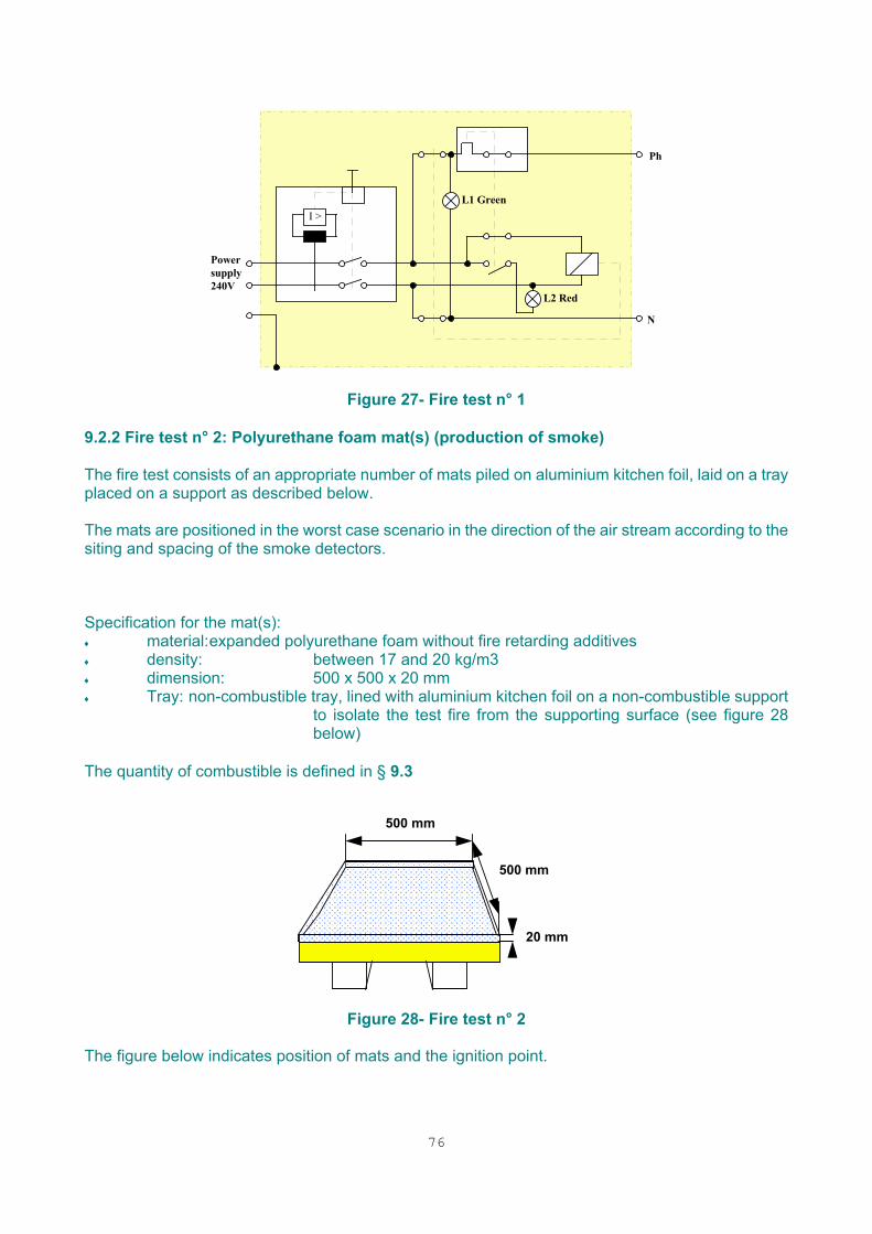
76
Ph
I >
N
L2 Red
L1 Green
Powersupply240V
Figure 27- Fire test n° 1 9.2.2 Fire test n° 2: Polyurethane foam mat(s) (production of smoke) The fire test consists of an appropriate number of mats piled on aluminium kitchen foil, laid on a tray placed on a support as described below. The mats are positioned in the worst case scenario in the direction of the air stream according to the siting and spacing of the smoke detectors. Specification for the mat(s): ♦ material: expanded polyurethane foam without fire retarding additives ♦ density: between 17 and 20 kg/m3 ♦ dimension: 500 x 500 x 20 mm ♦ Tray: non-combustible tray, lined with aluminium kitchen foil on a non-combustible support
to isolate the test fire from the supporting surface (see figure 28 below)
The quantity of combustible is defined in § 9.3
����������������������������������������������������������������������������������������������������������������������������������������������������������������������
������������������������������������������������������������������������������������������������������������������������������������������������������������������������������������������������������������������������������������������������������������������������������������������������
������������������������������������������������������������������������������������������������������������������������������������������������������������������������������
500 mm
500 mm
20 mm
Figure 28- Fire test n° 2 The figure below indicates position of mats and the ignition point.

77
�
��
��
�
Figure 29 End of combustion corresponds to the total disappearance of the mat. When the alarm has been activated before the end of combustion, the fire test can be extinguished. 9.2.3. Fire test n° 3: Alcohol (production of flames) The fire test consists of an appropriate quantity of alcohol spilled in a container as described below. The container is positioned under the heat detector. Past fire tests experience has shown that in most cases 2 litres are sufficient and 4 litres shall be used as a maximum. The alcohol is ignited with a match. Specifications for the alcohol: ♦ material: ethyl alcohol, denatured alcohol or methylated spirit. Container
♦ material: metal plating on a non-combustible support to isolate the test fire from the supporting surface (see figure 30 below)
♦ dimension: 500 x 500 x 50 (height) The quantity of combustible is defined in § 9.3
500 mm
500 mm
50 mm����������������������������������������������������������������������������������������������������������������������������������������������
Figure 30 - Fire test n° 3
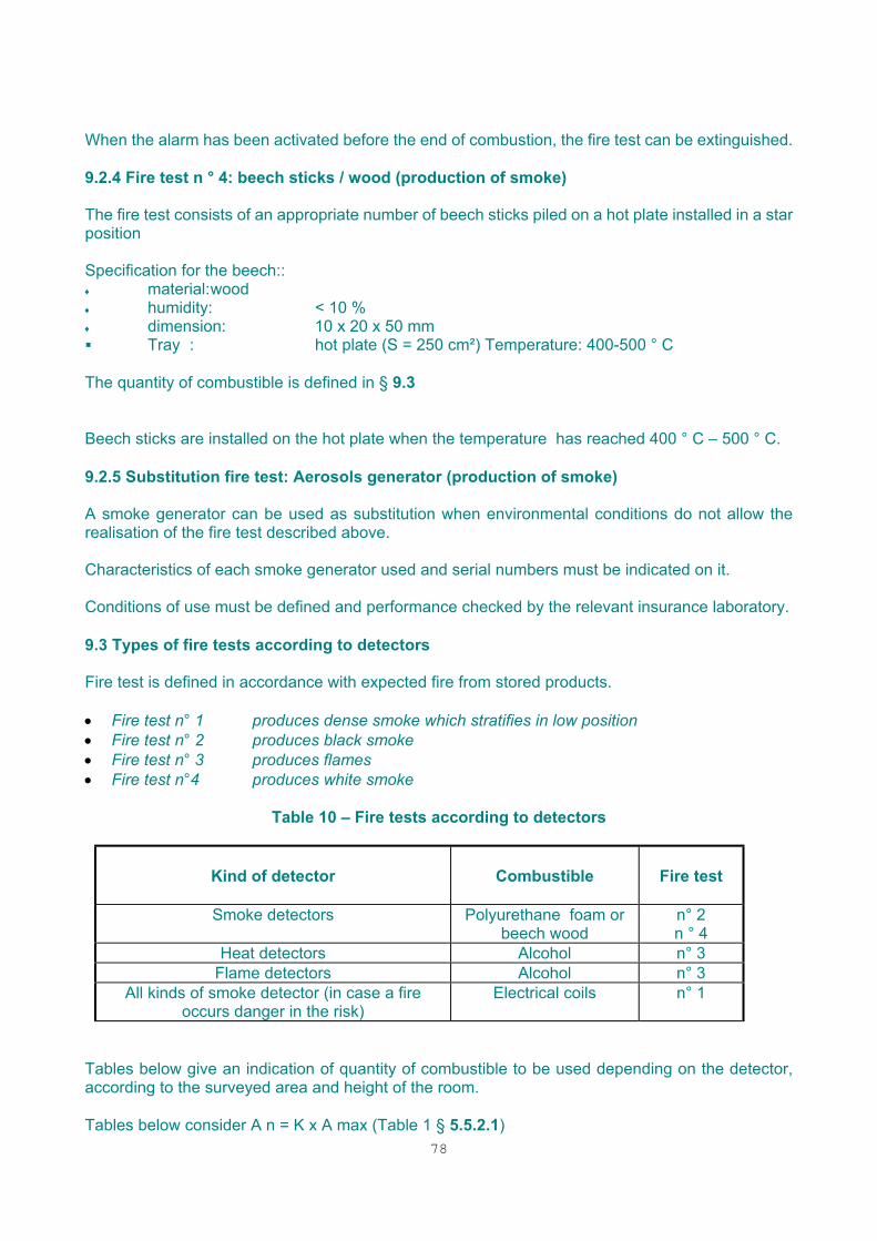
78
When the alarm has been activated before the end of combustion, the fire test can be extinguished. 9.2.4 Fire test n ° 4: beech sticks / wood (production of smoke) The fire test consists of an appropriate number of beech sticks piled on a hot plate installed in a star position Specification for the beech:: ♦ material: wood ♦ humidity: < 10 % ♦ dimension: 10 x 20 x 50 mm Tray : hot plate (S = 250 cm²) Temperature: 400-500 ° C
The quantity of combustible is defined in § 9.3 Beech sticks are installed on the hot plate when the temperature has reached 400 ° C – 500 ° C. 9.2.5 Substitution fire test: Aerosols generator (production of smoke) A smoke generator can be used as substitution when environmental conditions do not allow the realisation of the fire test described above. Characteristics of each smoke generator used and serial numbers must be indicated on it. Conditions of use must be defined and performance checked by the relevant insurance laboratory. 9.3 Types of fire tests according to detectors Fire test is defined in accordance with expected fire from stored products. • Fire test n° 1 produces dense smoke which stratifies in low position • Fire test n° 2 produces black smoke • Fire test n° 3 produces flames • Fire test n°4 produces white smoke
Table 10 – Fire tests according to detectors
Kind of detector
Combustible
Fire test
Smoke detectors Polyurethane foam or beech wood
n° 2 n ° 4
Heat detectors Alcohol n° 3 Flame detectors Alcohol n° 3
All kinds of smoke detector (in case a fire occurs danger in the risk)
Electrical coils
n° 1
Tables below give an indication of quantity of combustible to be used depending on the detector, according to the surveyed area and height of the room. Tables below consider A n = K x A max (Table 1 § 5.5.2.1)
79
Table 11 - Smoke detectors – (Fire test n°2 / Number of mats)
An (m²)
h (m) An ≤ 15 15 < An ≤ 30 30 < An ≤ 40 40 < An ≤ 80 h ≤ 3 ½ 1 1 + 1/2 2
3 < h ≤ 5 1 1 + ½ 2 2 + 1/2 5 < h ≤ 7 1 2 2 + 1/2 3 7 < h ≤ 9 1 + 1/2 2 + ½ 3 4
9 < h ≤ 12 2 3 4 5
Table 12 - Smoke detectors - ( Fire test n°4 / Number of beech sticks)
An (m²)
h (m) An ≤ 15 15 < An ≤ 30 30 < An ≤ 40 40 < An ≤ 80 h ≤ 3 3 4 6 8
3 < h ≤ 5 4 6 8 11 5 < h ≤ 7 5 7 10 14
7 < h ≤ 12 Use Fire test n ° 2
Table 13 - Heat detectors - ( Fire test n°3 / Quantity of litres (alcohol)
An (m²) h (m) An ≤ 15 15 < An ≤ 40 h ≤ 3 0,5 1
3 < h ≤ 5 0,75 1,5 5 < h ≤ 7,5 1 2
Table 14 - Flame detectors - (Fire test n°3 / Quantity of litres (alcohol)
An (m²) h (m) An ≤ 144 144 < An ≤ 289 289 < An ≤ 625 h ≤ 23 0,5 1 1,5
23 < h ≤ 33 1 1,5 2 33 < h ≤ 45 1,5 2 2,5
When An is bigger than value given in the tables 11, 12, 13 and 14, as the aim is to detect a fire which represents the risk, no more combustible than the higher amount will be implemented. 10 - USE OF THE SYSTEM 10.1 Responsibility The person having control of that part of the building containing the installed system should appoint one or more identifiable persons to be responsible for carrying out the following functions:
- ensuring the initial and continuing compliance of the system under normal circumstances; with the recommendations of these guidelines and with the requirements of any approving body;
- laying down procedures for dealing with the various alarms, warnings and other events

80
originating from the system; - training of occupants; - keeping the system in good functioning order;
- maintaining a clear space of at least 0.5m below the detectors - ensuring that there are no obstructions which might hinder the movement of fire products
towards the detectors; - ensuring that access to manual call points is not obstructed; - preventing false alarms, by taking adequate measures to prevent activation of the detectors
by cutting, welding, sawing, smoking, heating, cooking, exhaust fumes, etc.; - ensuring that the system is suitably modified if any significant changes of use or
configuration of the building occur; - keeping a logbook, and recording all events resulting from or affecting the system; - ensuring that maintenance (§ 11) is carried out at the correct intervals; - ensuring that the system is properly serviced after the occurrence of a fault, fire, or other
event which might adversely affect the system. The name(s) of the responsible person(s) should be recorded in the logbook, and kept up to date. If the person having control of that part of the building does not appoint a responsible person then that person should be deemed to be the responsible person.
Some or all of these functions may be delegated by contract with another organisation (such as an installer or servicing organisation). These guidelines do not specify the division of responsibilities for the delegated functions. The documentation mentioned in § 8.4 shall be kept in the vicinity of the CIE

81
10.2 Documentation The logbook should be kept in a place accessible to authorised persons (preferably at or near the control and indicating equipment). A record should be kept in this logbook of all events concerning the installed system. A suggested form of logbook is given in Annex B. 11 - MAINTENANCE 11.1 General To ensure the continued correct functioning of the system, the system should be regularly inspected and serviced. Arrangements for this should be made immediately on completion of the system whether the premises are occupied or not. In general, an arrangement should be made between the user and/or owner and the manufacturer, supplier or other competent organisation for inspection, servicing and repair. The arrangement should specify the method of liaison to provide access to the premises, and the time within which the equipment should be restored to operation following a fault. The name and telephone number of the servicing organisation should be prominently displayed at the control and indicating equipment.
11.2 Inspection and servicing 11.2.1 Maintenance routine A service and maintenance contract shall be concluded with a certified installer or a certified servicing company (Installing firms of security systems against fire and/or theft (CEA 4002) – April 1996). An inspection (by the user) and servicing routine (by the installer) shall be adopted. This routine is intended to ensure the continuing correct functioning of the system under normal circumstances. For the insurance company; at least once a year the user shall ensure that the certified installer or certified servicing company shall:
a) carry out a general check and perform necessary adjustments; b) check each detector and manual call points for correct operation which may be checked without
destruction and each transmission path with detectors, which cannot be checked without destruction in accordance with the manufacturer's recommendations;
c) check the alarm signalling devices; d) check the control and indicating equipment inside or outside; e) check the power supply equipment; f) battery shall be replaced in accordance with § 5.8.3; g) start any standby generator, and check its fuel levels; h) make a visual inspection to check whether structural or occupancy changes have affected the
requirements for the siting of manual call points, detectors and sounders; i) make a visual inspection to confirm that a clear space of at least 500 mm is preserved in all
directions below (every) detector and that all manual call points remain unobstructed and conspicuous;
j) make a visual inspection to confirm that all cable fittings and equipment are secure, undamaged and adequately protected;
k) change components with limited lifetime (e.g. battery…..); l) that any fault warning recorded the in the logbook has been taken into account;
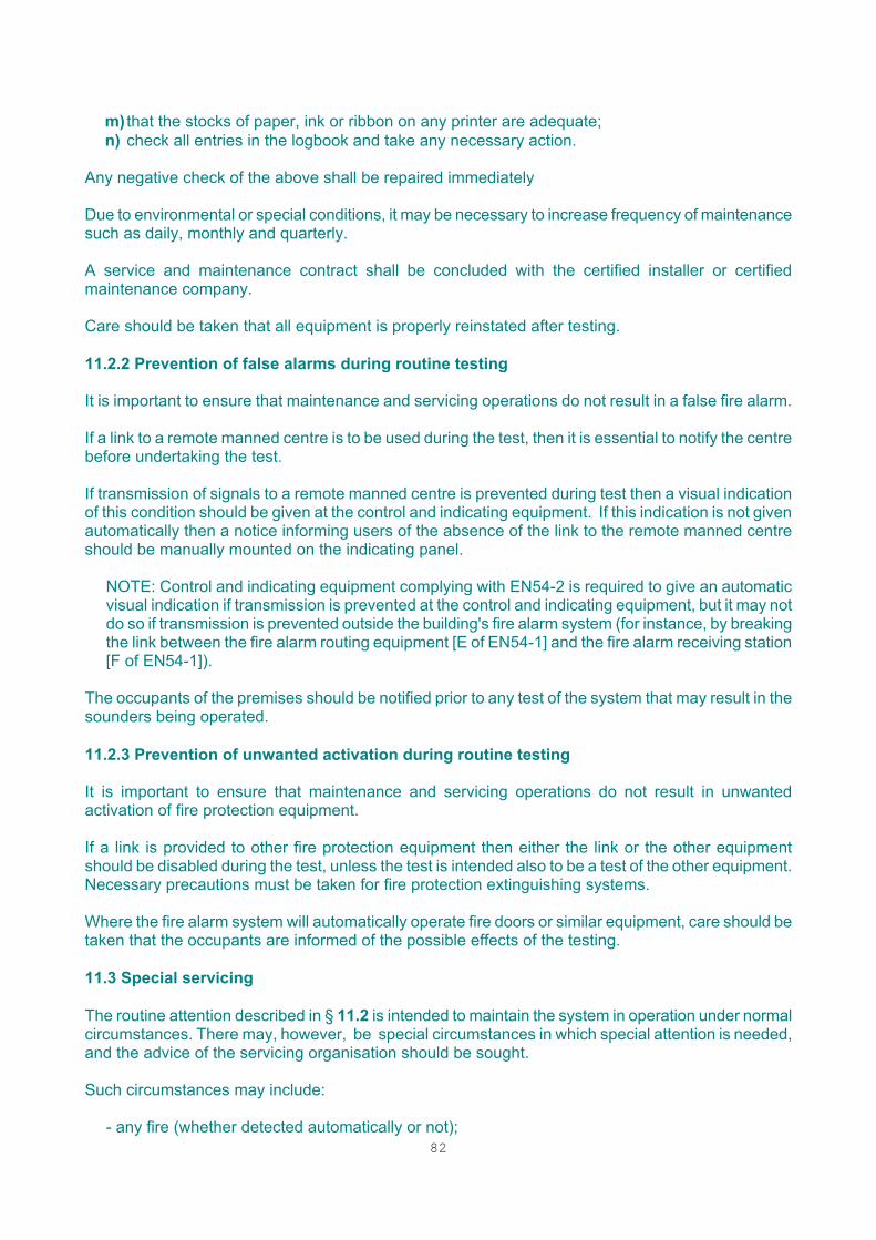
82
m) that the stocks of paper, ink or ribbon on any printer are adequate; n) check all entries in the logbook and take any necessary action.
Any negative check of the above shall be repaired immediately Due to environmental or special conditions, it may be necessary to increase frequency of maintenance such as daily, monthly and quarterly. A service and maintenance contract shall be concluded with the certified installer or certified maintenance company. Care should be taken that all equipment is properly reinstated after testing. 11.2.2 Prevention of false alarms during routine testing It is important to ensure that maintenance and servicing operations do not result in a false fire alarm. If a link to a remote manned centre is to be used during the test, then it is essential to notify the centre before undertaking the test. If transmission of signals to a remote manned centre is prevented during test then a visual indication of this condition should be given at the control and indicating equipment. If this indication is not given automatically then a notice informing users of the absence of the link to the remote manned centre should be manually mounted on the indicating panel.
NOTE: Control and indicating equipment complying with EN54-2 is required to give an automatic visual indication if transmission is prevented at the control and indicating equipment, but it may not do so if transmission is prevented outside the building's fire alarm system (for instance, by breaking the link between the fire alarm routing equipment [E of EN54-1] and the fire alarm receiving station [F of EN54-1]).
The occupants of the premises should be notified prior to any test of the system that may result in the sounders being operated. 11.2.3 Prevention of unwanted activation during routine testing It is important to ensure that maintenance and servicing operations do not result in unwanted activation of fire protection equipment. If a link is provided to other fire protection equipment then either the link or the other equipment should be disabled during the test, unless the test is intended also to be a test of the other equipment. Necessary precautions must be taken for fire protection extinguishing systems. Where the fire alarm system will automatically operate fire doors or similar equipment, care should be taken that the occupants are informed of the possible effects of the testing. 11.3 Special servicing The routine attention described in § 11.2 is intended to maintain the system in operation under normal circumstances. There may, however, be special circumstances in which special attention is needed, and the advice of the servicing organisation should be sought. Such circumstances may include:
- any fire (whether detected automatically or not);
83
- any unusual incidence of false alarms;
- extension, alteration or decoration of the premises;
- changes in occupancy or activities in the area covered by the system;
- changes in the ambient noise level or sound attenuation such as to change the sounder requirements;
- damage to the system, even though no fault may be immediately apparent;
- any change to ancillary equipment.
11.4 Repair In the event of: • Negative results during the maintenance servicing • Any indication of malfunction of the system • Damage to any part of the system. The certified installer or certified servicing company will repair immediately or as soon as possible. 11.5 Spares It may be convenient for a supply of spares (such as spare glasses for manual call points) to be held on site. 11.6 Documentation Work carried out on the system should be noted in the logbook. Details of the work should either be recorded in the logbook or recorded separately and held with the system documentation. Evidence of servicing must be available to interested parties. 11.7 Responsibility Responsibility for maintenance of the fire detection and alarm system should be defined. It will normally rest with the user and/or owner of the installed system. 11.8 Qualifications (Refer to §3.11) 12 - MODIFICATION OR EXTENSION OF AN INSTALLED SYSTEM 12.1 General In the event of: - any change in the structure or occupancy of the premises; - any change in the activities within the protected area that might change the fire risk;
84
the user and/or owner shall immediately inform the installer so that any necessary remedial action may be taken. It is desirable that any modification or extension to a system should be such that the modified or extended system complies completely with these guidelines. However, where the initial system (before extension or modification) does not comply with the guidelines because the design process started before the guidelines were brought into effect, then it may not be practical to modify the whole of the installed system to bring it into compliance. In such cases:
- modification should not increase the degree of non-compliance within the area initially covered;
- in an extension of the system, the extended part of the system should comply completely with the guidelines.
In particular, care should be taken that:
- the power supply is adequate for the modified or extended system;
- the control and indicating equipment, the detectors, alarm devices, etc. used in the modified or extended system are compatible with devices already installed.
If the extended system forms a hierarchical or networked system, then reference should be made to § 16. A certified installer according to CEA rules with approved devices whose compatibility has been checked shall do extensions and alterations to existing systems. Drawings have to be updated. A commissioning could be initiated by the insurer, depending on risk assessment, after the extension or alteration. 12.2 Third party approval Where the installed system is the subject of approval by a third party, any extension or modification should be reported in writing to the third party, which decides subsequent procedure. 12.3 Documentation If changes in documentation are necessary (for example, if the installed system is extended, detector types are changed or new alarm devices are added) efforts should be made to obtain the agreement of the person or organisation concerned. 13 - OPERATION OF OTHER FIRE PROTECTION SYSTEMS - ANCILLARY SYSTEMS 13.1 General The fire detection and alarm system may be used to provide initiating signals to other fire protection systems, such as: - fire extinguishing systems;
- smoke venting or heat venting systems;
85
- systems for triggering the release and closing of fire doors. - voice communicating system
- smoke or fire dampers; - ventilation shut-down; - lift control; - security doors. Operation or malfunction of another fire protection system should not jeopardise the correct functioning of the fire detection system, or prevent the giving of a signal to any other system. There may be national requirements on the connection to other systems. The recommendations of these guidelines are not intended to cover any requirements, which these systems may impose on the fire detection and alarm system The recommendations or requirements given in the documentation of the other fire protection system should be followed.
These ancillary systems have to be installed in accordance with the relevant CEA specifications if available. 13.2 Responsibility In addition to the responsibilities laid down under § 6.7, § 7.5 and § 11.7, the designer, installer and maintainer shall ensure that the fire detection and alarm system neither impairs nor is impaired by the system to be triggered. Close liaison should be maintained between the designers of the fire detection system and the other fire protection system and the boundaries of their respective responsibilities should be defined. The requirements of both systems should be specified in sufficient detail to allow correct design of the interface between the two systems. 14 - APPLICATIONS IN SPECIAL RISKS 14.1 General Special risks are those requiring particular attention and knowledge in the design and choice of equipment, the siting and spacing of detectors, or the arrangement of circuits. Such risks may include, for example:
- rooms with high concentration of electronic equipment; - high-racked warehouses; - atrium buildings; - hazardous areas; - outdoor risks.

86
14.2 Rooms with high concentration of electronic equipment A specific initial study will have to be done with all people involved. 14.2.1 General For the surveillance of rooms with electric and electronic installations or equipment, additional requirements described below for the fire detection installation are necessary, because of the high concentration of values and the risk of business interruption. It applies in particular to the following types of rooms:
electronic data processing systems (EDP) • energy supply packs and line power distribution points including non-interruptible power
supply • instrumentation and control systems • telecommunication exchanges and PABX equipment • climatic control systems and equipment • CNC machines and/or industrial robots • CAD/CAM systems • printer systems • etc... The following items should be given special attention in the design of fire detection systems for rooms containing electronic equipment such as computers or telephone exchange equipment:
- arrangements for controlling ventilation and air conditioning;
- the effects of high ventilation rates and high air speeds;
- the closing of fire shutters and dampers in response to signals from the fire detection system;
- arrangements for close-down of the equipment or its power supply in the event of a fire;
- arrangements for close-down of air handling equipment in the event of a fire;
- the needs for fire detection in concealed spaces such as above false ceilings and below false floors.
14.2.2 Room detection The type and use of the rooms determine the design of a fire detection installation. Differentiation is made between: • rooms with electrical equipments and installations. The planning and design shall be performed in accordance with chapter 5 , but with additional local detection. • rooms with electronic data processing installations (EDP-rooms). The planning and design shall be performed in accordance with § 5, but with additional requirements and additional local detection (Table 7). Rooms qualified as EDP-rooms are e.g. rooms containing EDP-machines like: • rooms for the main power- and standby power supplies • rooms for the climatic controls • rooms of the data archives. The monitoring of such rooms requires special planning and design of fire detection installations. Therefore, in addition to chapter 5, the following requirements are given:
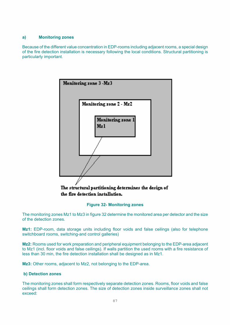
87
a) Monitoring zones Because of the different value concentration in EDP-rooms including adjacent rooms, a special design of the fire detection installation is necessary following the local conditions. Structural partitioning is particularly important.
Figure 32- Monitoring zones
The monitoring zones Mz1 to Mz3 in figure 32 determine the monitored area per detector and the size of the detection zones. Mz1: EDP-room, data storage units including floor voids and false ceilings (also for telephone switchboard rooms, switching-and control galleries) Mz2: Rooms used for work preparation and peripheral equipment belonging to the EDP-area adjacent to Mz1 (incl. floor voids and false ceilings). If walls partition the used rooms with a fire resistance of less than 30 min, the fire detection installation shall be designed as in Mz1. Mz3: Other rooms, adjacent to Mz2, not belonging to the EDP-area. b) Detection zones The monitoring zones shall form respectively separate detection zones. Rooms, floor voids and false ceilings shall form detection zones. The size of detection zones inside surveillance zones shall not exceed:
88
• Mz1: 500 m²; • Mz 2: 800 m² • Mz 3: 1600 m² . c) Choice of detectors Since in surveillance zone 1 (Mz1) mainly smouldering fires have to be considered, only smoke detectors shall be used. If possible, optical and ionisation types of smoke detectors should be mixed 1:1. In Mz2 and Mz3 preferably, smoke detectors should also be installed. d) Number and positioning of fire detectors Fire detectors shall be installed inside the casing of machines or cabinets. The number of detectors shall be chosen in such a way that the maximum monitored areas (A) given in table 15 are not exceeded. The detectors shall be sited in such a way that the horizontal distance from any point on the ceiling does not exceed the range given in figures 8 and 9
Table 15 - Maximum monitored area A for special risks
Maximum monitored area (A)
Mz 1 Mz 2(1) Mz 3(2) False ceiling 40 m2 60 m2 Room 25 m2 40 m2 Floor void 40 m2 60 m2
Surveillance in accordance with Chapter 5
Mz Monitoring zone (1): Structural partition between Mz 1 and Mz 2 at least 30 minutes' fire resistance as Mz 1 (2): Structural partition between Mz 2 and Mz 3 at least 90 minutes' fire resistance
e) Ventilation system Refer to § 5.5.2.7 f) Individual alarm indication For activated detectors, which cannot be seen, e.g. detectors in air ducts, an indication shall be given on an indication panel at the entrance or on control and indicating equipment. 14.2.3 Local detection 14.2.3.1 General Local surveillance, only possible in combination with room surveillance, is restricted to direct surveillance into the machinery. Fires inside the machinery can be detected and indicated earlier - (see also CEA Doc. SC - 92/08). 14.2.3.2 Planning Planning, installation and maintenance of the local protection - and local surveillance system - shall be co-ordinated between the machinery manufacturer, the user, the insurer and the installers of fire detection and extinguishing systems. The overall fire protection concept, incorporating the local

89
protection system, depends on influence factors, which shall be identified by risk analysis. The major influence factors are: ♦ Internal and external fire hazards ♦ Personnel safety ♦ Significance of the machinery in operation ♦ Interruptions of operation ♦ Time required for replacement ♦ Size and location of the building, partitioning and technical equipment ♦ Size and arrangement of the equipment ♦ Existing protection measures. The results of the risk analysis and the personal safety and protection needs will determine the degree of protection. In order to ensure complete fire protection, all the machinery which is forced-ventilated by climatic control systems shall be protected. The design of the system shall take into account the conditions under which the machinery operates. The following criteria shall be observed when doing so: ♦ Operational and environmental influences (e.g. temperature, humidity, dust, aerosols, vapours, radiation) ♦ Operating mode (e.g. manned and unmanned areas, clarity and accessibility of the devices, intermittent or continuous operation) ♦ Type of cooling (natural draught, forced ventilation, liquid-cooled equipment) ♦ Electromagnetic interference. ♦ Smoke detectors shall generally be used, because of smoke produced in most cases of fire. ♦ Aspirating detection systems installed outside the unit itself shall monitor units with forced ventilation. ♦ Naturally ventilated units (convection) can also be monitored with point detectors. When liquid media are used for cooling, special adaptations of the above-mentioned detection systems may be required, depending on the exact design of the unit. 14.2.3.3 Application areas Application areas for equipment detection and protection systems include EDP- systems and similar electronic configurations as mentioned under § 13.2.1 The primary devices of the EDP-systems include those listed below: ♦ Central processing units ♦ Disk controllers and disk storage units ♦ Processors for data teleprocessing/network-submaster station (nodal) computers ♦ Modem cabinets ♦ Tape recording systems, robot systems ♦ Laser printing systems. Depending on the degree of fire safety required, additional units may be protected; e.g.: ♦ Magnetic tape controllers and drivers ♦ High-speed printers. Devices, which are a part of the infrastructure, shall be included in the scope of protection, such as: ♦ Line power distribution points, energy supply packs (including non-interruptible power supply) ♦ Air conditioning systems and climatic-control cubicles.
90
14.2.3.4 Detector arrangement The detectors shall be so arranged as to respond to fire parameters. Aspirating detection devices Aspirating detection devices shall sense the air in the main cooling air stream. This requirement will usually be satisfied when the inlet openings are positioned as close as possible to the air outlet vent of the unit being monitored. The aspirating detection device shall not adversely affect the flow of cooling air to the unit. Any reduction of the operating safety of the protected units shall be avoided; it shall be possible to carry out maintenance work with minimum hindrance. The arrangement of the aspirating detection devices shall be co-ordinated with the manufacturer of the equipment. Note: The nominal electric operating data for the fan in the extraction system shall be monitored. Changes in the air stream in the suction system (e.g. clogging or breaks) which affect the function shall be indicated. Point detectors If point detectors, primarily smoke detectors, are installed in units, the volume being monitored shall not exceed 2.5 m3 per detector. At least one detector shall be installed per unit. If structures inside the units being monitored are likely to hinder the response of the detector, then additional detectors shall be provided. It is also permissible to install ceiling-mounted point detectors to monitor individual units, taking into account the air flow situation in the room and provided that: ♦ the distance between the detector and the unit's air discharge opening is small (guideline value < 1 m) ♦ the air exchange rates and/or velocities in the room are neglectable. ♦ the detector can be positioned in the air stream. 14.2.3.5 Detection zones The room and local detectors shall be connected to separate detection zones. Multiple detectors protecting a unit or group of units with similar functions can be combined into one detection zone. A maximum of five adjacent units of similar function may be monitored with a single aspirating detection system to achieve dependable and selective fire detection in its incipient stage. Further reduction may be necessary ♦ as a consequence of the number and type of air discharge openings at the units; ♦ where units are not positioned immediately adjacent to each other. Where the distance between units is greater than 5 m or where the units are dissimilar in function, then separate aspirating detection systems shall be installed. 14.2.3.6 Alarms and controls If a fire signal does not only trigger an alarm but also activates control functions, then the following rules shall be observed: Control procedures, which are simple by nature, such as sounding a local alarm or closing doors, may be initiated by a single detector or a single group. Control procedures which are more important by nature, such as: ♦ sounding an external alarm; ♦ machinery shut-down; ♦ activation of an extinguishing system; ♦ shut-down with loss of data or suspension of operations; shall be activated only when two detectors or two groups have responded.
91
Pre-warning In the case of pre-warning, i.e. if a single group of detectors in the equipment surveillance system has responded, then ♦ an internal alarm (audible and, if necessary, visual) shall be initiated; ♦ response by a further group of detectors in the room surveillance system and/or in the cable
gallery can trigger the main alarm for the room or cable gallery. Main alarm In the case of a main alarm, i.e. if a second group or a further detector in the equipment surveillance system has responded, then: ♦ an alarm (audible and, if necessary, visual) shall be initiated inside the hazard area and the alarm shall be transmitted to a continuously manned location; ♦ response by a further group or detector in the room fire detection system and/or in the cable gallery should initiate the main alarm for the room or the cable gallery; ♦ all power to the unit or group of units shall be switched off; ♦ the climate control system and climate control cubicles shall be switched off; ♦ fire isolation barriers and other operating equipment may be activated;
♦ interlock circuits may be necessary when a second detection zone responds; ♦ the equipment-centred extinguishing system, if present, shall be activated; ♦ the units or groups of units in the flooding zone shall be isolated from all power sources. An alarm plan considering all the details of the project shall be prepared, incorporating the measures listed above and any additional measures.
14.2.3.7 Power supply In the case of equipment protection systems, an uninterrupted supply of power for the fire detection equipment and control components, including the fan, shall be provided for a period of at least four hours; it shall be possible, following a four-hour period, to operate the alarm devices of the area containing the local protection system with the maximum energy load for a period of at least 30 minutes. If emergency power sources (substituting for the mains supply) are provided, then the mains feed to the fire detection and control devices for the equipment protection system shall be connected to these sources. 14.3 High-rack warehouses Because of the wide range of types of high-rack storage and of possible contents, early consultation with the user and/or owner and other interested parties (insurers, architects, authorities, etc.) is essential. Special care should be taken in the planning of the fire routine to ensure that the possible effects of high fire-spread rate are taken into account. Some form of automatic extinguishing system (such as sprinklers) usually protects high-rack storage. It may therefore be necessary to consider interconnection between the detection and extinguishing systems. 14.3.1 General High-rack warehouses or high-bay storage, according to these specifications, are storage where the stacking height (ground floor to upper limit of the stored goods), exceeds 7.5 m.
92
Manual fire-fighting inside a high-bay storage will be successful only if the fire has not spread into a volume of several cubimeters. The height and concentration of stored goods and the narrowness of the corridors will hinder fire-fighting. Therefore, an automatic fire extinguishing system is the only suitable form of fire protection. A fire extinguishing system may be supplemented by a fire detection and alarm system, intended to react during the smouldering phase and to protect the stored goods from smoke damage. If the stored goods, their packaging and storage equipment have together a light fire load with a small rate of fire spread, a fire detection and alarm system associated with manual fire-fighting measures may represent an adequate fire protection plan. 14.3.2 Choice of detectors Smoke detectors shall be preferred additionally, flame detectors may be useful. For special risks, other appropriate types of detectors may be used. 14.3.3 Siting of detectors 14.3.4 Detectors on the ceiling Smoke detectors (Point or Optical beam detectors) or the section holes of aspirating detectors shall be sited above each rack aisle and at a maximum distance of 6 m. 14.3.5 Detectors for rack surveillance Point detectors Point detectors shall be installed inside the racks on intermediate levels. Different types of rack storage and the supporting structure will mainly determine the siting of the detectors. Independently from the construction of the racks the following distances between the detectors shall not be exceeded: ♦ horizontally max. 6 m ♦ vertically (distance between detector levels) max. 6 m Detectors on the different levels shall be staggered. Preferably the detectors shall be installed outside the racks. The detectors shall be sited or protected in such a way as to avoid mechanical damage caused by the conveying system and the goods and that their maintenance does not affect the normal operation of the high-bay storage. Aspirating detectors If aspirating detectors are used, the suction tubes shall be installed vertically outside the racks or, with double racks, preferably in the transverse or longitudinal flue. With a vertical distance of max. 6 m, a suction hole shall be provided at each detection level. The horizontal distance between the suction tubes shall not exceed 6 m. Each aspirating detector shall be assigned to a detection zone. Information from the manufacturer as well as restrictions given in the approval certificate shall be considered. Remote detector indication
93
If detectors or aspirating detectors are installed inside the racks, a visible individual lamp shall indicate the alarm condition of the detector. 14..3.6 Detection zones The whole high-bay storage including the I-point (information point) and the loading zones shall be split up into detection zones. The detection zones shall be vertically formed and delimited by aisles to allow a quick and clear identification of the fire origin. Ceiling detectors shall form separate detection zones. A detection zone shall not contain more than 20 point detectors and, in case of aspirating detectors, not more than 20 suction holes. 14.4 Atrium buildings In atrium buildings it is important that all fire protection measures (including fire compartmentation, smoke control, fire extinction, etc., as well as the fire detection and alarm system) are co-ordinated, and that their interactions are properly controlled. The guidance given in these guidelines should be taken only as a starting point; further detection (or unusual configurations of detectors) may be found necessary in the planning of the building. Where fire protection measures are being supplied or installed by several different organisations, it will usually be necessary for these organisations to liase together to provide the necessary co-ordination (see also 5.2). 14.5 Hazardous areas In some buildings, there may be hazards (explosive, chemical, biological or nuclear, for instance) which may have significant effects on the design of the system. In such cases, very close co-operation is necessary between the purchaser (who should be aware of the hazard) and the designers and installers of fire detection and alarm systems. Recommendations of national documents should be followed. 14.6 Outdoor areas Where all or part of a fire alarm system is installed in an outdoor area, special attention should be paid to:
- the environmental conditions;
- the choice and siting of detectors;
- the avoidance of false alarms.
14.7 Responsibility In addition to the purchaser's responsibility under § 4.7 and § 5.11, the designer and user and/or owner should ensure that all necessary information needed for the assessment of the special risk is made available. This information will usually include the fire routine for the risk. 15 - INTEGRATED SYSTEMS

94
Although these guidelines do not cover integrated systems, the fire detection and alarm functions of such systems should generally comply with these recommendations.
95
16 - HIERARCHICAL SYSTEMS Hierarchical systems are frequently used in places where a main site is sub-divided into a number of smaller parts; for instance in shopping centres, large hospitals or petrochemical plants. Where there are several separate buildings on a common site, each may require its own system for fire detection and alarm, but with the facility to provide status information to a centre on the site. In large buildings, economy of cabling may be achieved by the use of a number of subsidiary control and indicating equipment, each providing fire detection and/or alarm functions for a defined part of the building but additionally communicating with a centre within the building and/or with each other. Where such systems are to be installed, particular care should be taken:
- to ensure mutual compatibility;
- in arranging suitable working procedures (including procedures for resetting, silencing, isolation, etc);
- in arranging any remote links;
- in defining system responsibilities.
The equipment used and the circuit design should be such that indications are given at the manned centre at least:
- identifying any subsidiary control and indicating equipment in its fire alarm condition;
- identifying any condition of a subsidiary control and indicating equipment in which a fire alarm could be prevented (such as fault or disabled conditions);
- identifying any failure of a link to a subsidiary control and indicating equipment which might
prevent the reception of a fire alarm at the manned centre. Requirements for other control and indication facilities should be determined in the consultations of § 4.2. Where networked systems are used without a hierarchical structure, care should be taken that only information can be passed between systems. Control of one control and indicating equipment from another should only be allowed where the controlling equipment has been designated the main control and indicating equipment in a hierarchical system. 16.1 Hierarchical networked system Networked systems can be configured in different ways but the following regulations are for installations where at least one control and indicating equipment C.I.E. (Main C.I.E.) performs mandatory functions in a hierarchical way (§.2). Such installation may be subdivided into a main system (with a main C.I.E) and one or more sub-systems (with sub C.I.E (s)). 16.2 General Only C.I.E`s of an approved system (§ 5.1.) may be used, unless they are connected via a standardised input/output interface, which is part of the system.
96
Faults in a C.I.E, in a sub-system or in a remote indicating and control panel shall not adversely affect the function of another C.I.E., a sub-system or another remote indicating and control panel. If a detector connected to a processing unit of a CIE, regarded as a sub-system of a main CIE process unit, triggers a fire alarm and when a fault occurs simultaneously on the main CIE, the fire alarm signal shall be identifiable. The processing times specified in the appropriate standards (e.g. for control and indicating equipment) for the indication and transmission of information shall be kept. 16.3 Transmission paths between C.I.Es The transmission paths between the C.I.Es shall be monitored. Faults (e.g. short-circuit or interruption) occurring in a transmission path or in a section of a transmission path interconnecting one or more C.I.Es and transmission paths to the main C.I.E shall not adversely affect the operation of the installation. Note: A section of a transmission path is that part which, in the case of a fault, can be isolated. 16.4 Indications All states of the system shall be indicated on the main C.I.E. at least as general information in such a way, that the C.I.E or sub-system, which originated the information, can be identified. Faults in a transmission path between the C.I.E. and the main C.I.E shall be indicated on the main equipment. If the same conditions are indicated on more than one C.I.E, the indications shall be clearly related to their origin. All indications shall be coherent. 16.5 Operation of controls Concerning the operation of controls in the installation, competence and responsibilities shall be clearly defined. If the operation of controls is possible not only on the main C.I.E. but also on other C.I.Es of the installation, the operation procedures shall be clearly co-ordinated. This may require that operating controls on a sub-system is only possible when permitted by the main system.
97
Annex A (Informative)
False alarms 1 Prevention of false alarms It is essential that the utmost care should be taken by system designers, installers and users to reduce the incidence of false alarms. False alarms may be the result of poor equipment, poor system design, poor installation, poor usage or poor maintenance. They may also result from adverse environmental conditions not taken into account in the system design. Common causes of false alarms include the following (not necessarily given in order of importance):
(a) work being carried out in a protected area without knowledge of, or in neglect of, the necessary precautions;
(b) ambient conditions such as heat, smoke or flame from cooking or work processes, fumes from
engine exhausts, or high air velocities; (c) mechanical and electrical faults, often resulting from the effects of vibration, impact or
corrosion; (d) servicing or testing work carried out without prior notification to the fire brigade or central
alarm station; (e) electrical transients (such as from lightning or switch-on surges) or radio interference (such as
from cellular phones); (f) inadequate servicing; (g) the build-up of dust or dirt within a detector, or the entry of insects; (h) change of use or changes within the building; (i) accidental or malicious operation of manual call points or detectors.
2 Smoke detectors False alarms signalled by smoke detectors may be caused by smoke and other fumes, dusts (including slow accumulations of dust and disturbed burial dusts), fires, steam or condensation; all these may be due to normal processes or activities or to unusual extremes of the environment. Insect infestation may be a significant problem, particularly in the late summer period. Optical beam smoke detectors will often give false alarms if the beam is accidentally partially obstructed; apart from those obstructions due to human activities, obstructions due to perching by birds or by cats has been reported. Some types of beam detectors may give false alarms when subjected to bright sunlight or intense light sources such as photographic flash-guns. Ionisation chamber smoke detectors are highly sensitive to smoke made up of very small particles, including diesel exhausts and fumes from self-cleaning ovens. Some types are sensitive to high air
98
speeds and may give false alarms if mounted in windy situations. Because of the very low currents used in the ionisation chambers, high humidity may cause problems, particularly if the detectors have previously been contaminated by materials which can absorb water. 3 Heat detectors False alarms may be caused by abnormal increases in temperature due to space heating equipment, industrial processes or sunshine. They may be prevented by installing detectors with appropriate higher temperature settings, or, in the case of direct sunlight, by introducing an appropriate shade. NOTE: reference will be made to the classes of EN 54-5 when it is published. False alarms from rate-of-rise heat detectors may also be caused by a rapid temperature increase to normal room conditions following exposure to low temperatures. Such a sequence may occur, for instance, in a loading bay with large doors to the outside; while the doors are open the detector may be exposed to winter conditions, followed by rapid heating when the doors are closed. If such conditions are likely, then detectors without a rate-of-rise response should be used. 4 Flame detectors Ultraviolet flame detectors sense the ultraviolet radiation emitted by flames. They are liable to respond to sources such as lightning, ionising radiation, ultraviolet lamps and quartz-halogen lamps unless the detection system can discriminate between various sources, but they do not respond to sunlight. (The component of solar ultraviolet to which detectors would respond is filtered out by the high-altitude ozone layer of the earth's atmosphere.) Known sources of ultraviolet light should be screened from the detector, taking care that the screen does not also obscure likely sites for fire. Ordinary window glass will screen ultraviolet radiation. Most infrared flame detectors operate by detecting the flickering component of the infrared radiation from a fire. This type of detector should be insensitive to steady infrared sources such as very hot objects or sunlight, but may be operated if this steady light becomes modulated by, for example, moving tree branches or the blades of a fan. Infrared flame detectors may be made solar blind. Alarm signals from flame detectors, which respond to only one specific wavelength range, shall not cause the activation of external alarm devices (audible public alarms). If such a risk exists, fire alarm routing equipment shall be installed according to other criteria. Flame detectors with two or more sensors, where the alarm signalling is not dependent on the combination "OR" of the signals from the sensors and where the overall response depends on at least two or more wavelength ranges, may cause a general fire alarm.
99
5 Multi-phenomena systems Systems in which more than one operating principle is used to detect fire, with the objective of obtaining a better differentiation between fire and non-fire conditions. Such systems may have more than one sensor in a single detector housing or may combine the readings from several different detectors. Typical combinations may include smoke and heat sensors, ionisation chamber and optical scattering sensors, or infrared and ultraviolet flame sensors. The benefits of these systems depend on the algorithm used to make the fire decision. The increased amount of information coming from the combination can significantly reduce the number of false alarms caused by environmental conditions. 6 Pre-alarm warnings In some types of system, an early warning can be given of conditions which might (or might not) represent a fire. Such pre-warnings should not initiate a full fire alarm, but may be used to alert personnel to the need for an inspection, thus reducing the number of false alarms and possibly giving earlier fire action. 7 Activity-related systems Where human or industrial activity during working or waking hours could result in false alarms, particularly where the presence and behaviour patterns of people make it unlikely that a fire would go undetected by human agency, it may be useful to consider an activity-related system. Various options are available and each should be considered in the light of the fire risk and type of occupancy. No such options, for either new or existing systems, should be implemented until agreement has been reached under the procedures outlined in § 4.2. Instances of where activity-related systems might be employed include the following:
(a) schools;
(b) hotels, boarding houses and other residential premises;
(c) factory and commercial premises that are active for only part of the day. A few examples of activity-related systems are listed below.
(1) The simplest application could be for a system that switched from manual detection during working hours to automatic detection in silent hours (i.e. outside working hours).
(2) In a system which allows variable detection algorithms, it may be possible to use different algorithms (or change the recognition patterns) during working hours so that the system is less likely to give false operation in response to conditions which may commonly arise during working hours.
(3) Protection by smoke detectors in silent hours could be changed to heat detectors during working hours.
(4) As a last resort, a system of pre-transmission confirmation may be used during working hours.
100
Any condition likely to result in an increased size of fire at detection should be used only when trained staff are present on the premises and a risk assessment has been carried out. Switching to the silent hours condition should not rely on human action or discretion; it should be an entirely automatic procedure at a predetermined time. The risk of false alarms should be subordinate to the need to guarantee the required level of protection during silent hours. No automatic switching devices should be readily accessible to the system user, except that in places like a hotel bar it is permissible to delay the change to the more sensitive state by a manual switch operation at access level 2. Repeated switch operations may be used to extend the delay but the delay should not extend more than 45 min after the last operation of the switch. In commercial premises, it may sometimes be acceptable for the automatic changeover to occur when the main access door is closed and locked for the night. Weekends should be pre-programmed into the system time switch. The procedures for dealing with public and works holidays and with time changes to and from summer time should be clearly understood by the user, so that the correct degree of cover is available at all times. A manual override switch, on or adjacent to the control equipment, should be available to allow full cover to be provided during periods when the building is unexpectedly unoccupied. The override switch should not be capable of switching the full cover to the restricted cover, and the system design should not permit the action of this switch to be temporarily or permanently cancelled by any automatic function. An indicator light on, or adjacent to, the control and indicating equipment should show whether the system is switched to the working or silent hours state. 8 Pre-transmission confirmation In some (but not all) circumstances where there is a high incidence of false alarms which cannot be reduced by other measures, it may be desirable to delay the automatic transmission of an alarm to the fire brigade for a sufficient time to allow the alarm to be investigated. For this purpose, the inclusion in the control and indicating equipment of an output delay (allowed as an option under EN54-2) or the provision of a separate alarm transmission delay unit may be considered. An alarm transmission delay unit should not be incorporated into a fire alarm system unless the person responsible is satisfied that all other reasonable measures have been taken to prevent false fire alarms, that the unit would not prejudice the level of fire precautions within the protected premises, that the delay will only be used when staff are available to investigate the cause of the alarm, and that both the proposed unit and the arrangements for its use are acceptable to the fire insurer and the fire brigade. In many applications, rapid attendance by the fire brigade is essential, and in such cases the use of transmission delay units will not be acceptable. Even where rapid attendance by the fire brigade is not essential, the total possible delay should be related to the expected attendance time. If an alarm transmission delay unit is used then the normal sequence of events in the event of an alarm should be as follows:
a) If the alarm is raised by a manual call point then the normal functions of the system in both sounding the internal alarm and transmitting the alarm to the remote centre should continue without delay (i.e. the alarm transmission delay should not operate).
b) If the alarm is initiated by an automatic detector then the call to the fire brigade or central alarm station may be delayed for a search period not exceeding 10 min. During this period the sounding of the internal alarms will depend on decisions made in defining the fire alarm response strategy (§ 4.5).

101
c) If during the delay period the alarm is found to be a real fire then a manual operation at the control panel or the operation of any manual call point should cause an immediate transmission of the alarm.
d) If the alarm can be shown to be false, with no actual fire, then the internal alarms should be silenced, a note made of any indication which might throw light on the origin of the alarm and the system should be reset. Resetting of the system should inhibit transmission of the alarm unless the system again goes into the alarm state. The system outlined under a) to d) above has a possibility that (if no one starts a search) a delay of up to 10 min. might be experienced with no action being taken, but with the fire able to grow and spread. To reduce the risk of this occurring, the search period may start with an acknowledgement period not exceeding 2 min. During this period, the existence of an alarm should be acknowledged by a manual action at the control panel. If no acknowledgement action is made then at the end of the acknowledgement period all delayed outputs should be activated. An alarm transmission delay should not delay or otherwise affect the operation of audible or visual alarms or any other part of the fire alarm system. The period of delay should only be alterable by properly authorised and trained persons. A simple, accessible alarm transmission switch should also be provided so that a call to the fire brigade can be made without delay if necessary. Satisfactory arrangements (such as a time switch) should be made to disconnect the device during periods when the internal investigation of alarms cannot be undertaken immediately. If investigations show that the transmission system may have significant delays between the sending of the alarm from the protected premises and its reception by the fire brigade then these delays should be taken into account in assessing the desirability of an alarm transmission delay unit. 9 Investigation of false alarms Installed systems, which are the subject of a series of false alarms, should be referred to an organisation having specialist knowledge such as the system designer, installer, maintainer or inspection organisation.
102
Annex B (Informative)
Models of certificates
This annex gives models for certificates of:
- design, - installation, - commissioning and testing , - completion and user acceptance,
and for the system logbook. Although the various certificates are here shown separately, it is permissible (and may be desirable) for them to be combined into one document or to be included in the system logbook.
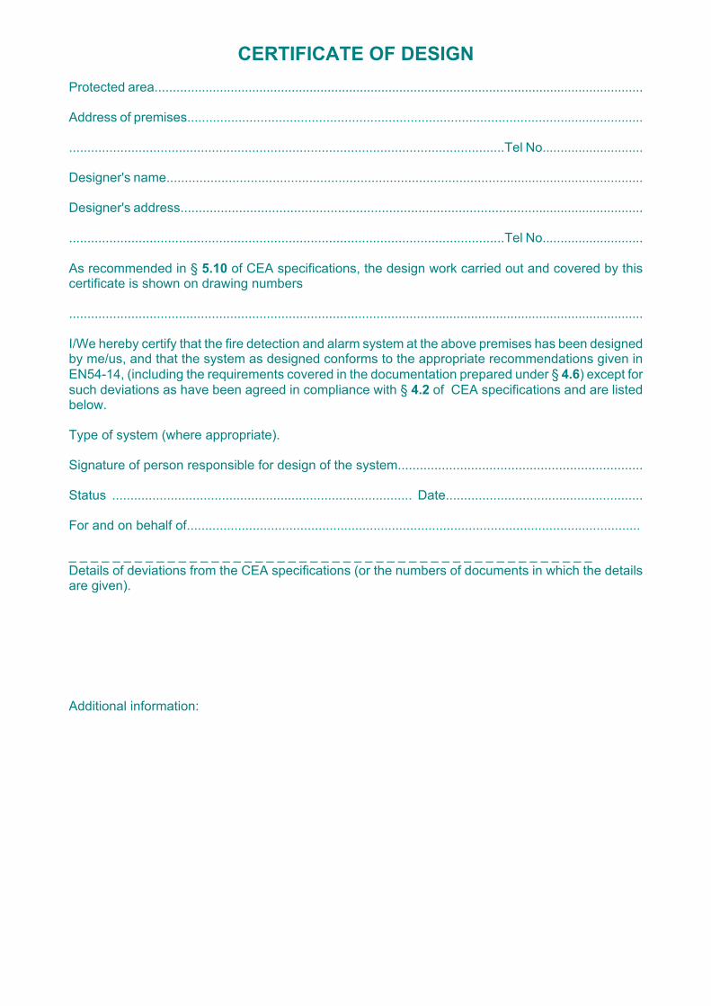
CERTIFICATE OF DESIGN Protected area........................................................................................................................................ Address of premises............................................................................................................................. .......................................................................................................................Tel No............................ Designer's name................................................................................................................................... Designer's address............................................................................................................................... .......................................................................................................................Tel No............................ As recommended in § 5.10 of CEA specifications, the design work carried out and covered by this certificate is shown on drawing numbers .............................................................................................................................................................. I/We hereby certify that the fire detection and alarm system at the above premises has been designed by me/us, and that the system as designed conforms to the appropriate recommendations given in EN54-14, (including the requirements covered in the documentation prepared under § 4.6) except for such deviations as have been agreed in compliance with § 4.2 of CEA specifications and are listed below. Type of system (where appropriate). Signature of person responsible for design of the system................................................................... Status .................................................................................. Date...................................................... For and on behalf of............................................................................................................................ _ _ _ _ _ _ _ _ _ _ _ _ _ _ _ _ _ _ _ _ _ _ _ _ _ _ _ _ _ _ _ _ _ _ _ _ _ _ _ _ _ _ _ _ _ _ _ _ Details of deviations from the CEA specifications (or the numbers of documents in which the details are given). Additional information:
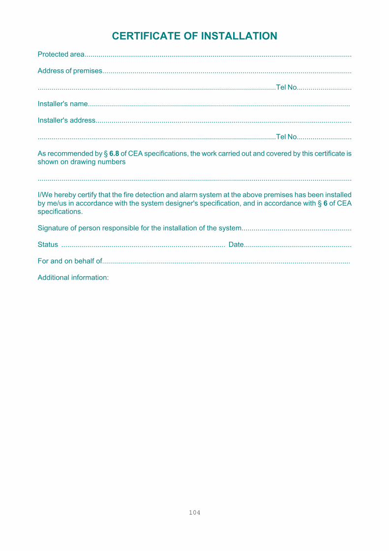
104
CERTIFICATE OF INSTALLATION Protected area........................................................................................................................................ Address of premises............................................................................................................................. .......................................................................................................................Tel No............................ Installer's name................................................................................................................................... Installer's address................................................................................................................................ .......................................................................................................................Tel No............................ As recommended by § 6.8 of CEA specifications, the work carried out and covered by this certificate is shown on drawing numbers .............................................................................................................................................................. I/We hereby certify that the fire detection and alarm system at the above premises has been installed by me/us in accordance with the system designer's specification, and in accordance with § 6 of CEA specifications. Signature of person responsible for the installation of the system....................................................... Status .................................................................................. Date...................................................... For and on behalf of............................................................................................................................ Additional information:

105
CERTIFICATE OF COMMISSIONING AND VERIFICATION Protected area........................................................................................................................................ Address of premises............................................................................................................................. .......................................................................................................................Tel No............................ System commissioned and tested by (Company)................................................................................. Address................................................................................................................................................ .......................................................................................................................Tel No............................ I/We hereby certify that the fire detection and alarm system at the above premises has been inspected by me/us in accordance with the system designers' specification, and that the system as inspected conforms to the appropriate recommendations given in CEA specifications except for such deviations as are listed below. Signature of person responsible for commissioning and testing the system ........................................................................... Status .................................................................................. Date...................................................... For and on behalf of............................................................................................................................ _ _ _ _ _ _ _ _ _ _ _ _ _ _ _ _ _ _ _ _ _ _ _ _ _ _ _ _ _ _ _ _ _ _ _ _ _ _ _ _ _ _ _ _ _ _ _ _ Details of deviations from the CEA specifications (or the numbers of documents in which the details are given). Additional information:

106
CERTIFICATE OF COMPLETION AND ACCEPTANCE Following the certification of the installation, commissioning and testing of the fire detection and alarm system at: Protected area........................................................................................................................................ Address of premises............................................................................................................................. .................................................................................................. Tel. No. ............................................. my attention has been drawn to the CEA specifications; in particular § 10 (Use of the system), § 11 (Maintenance) and Annex A (False alarms). In accordance with § 6.8 and 7.4, logbook, record drawings and instructions for use, routine attention and maintenance of the system have been supplied and received by: Signed................................................................................... Status .................................................................................. Date..................................................................................... For and on behalf of (purchaser)................................ Additional information:
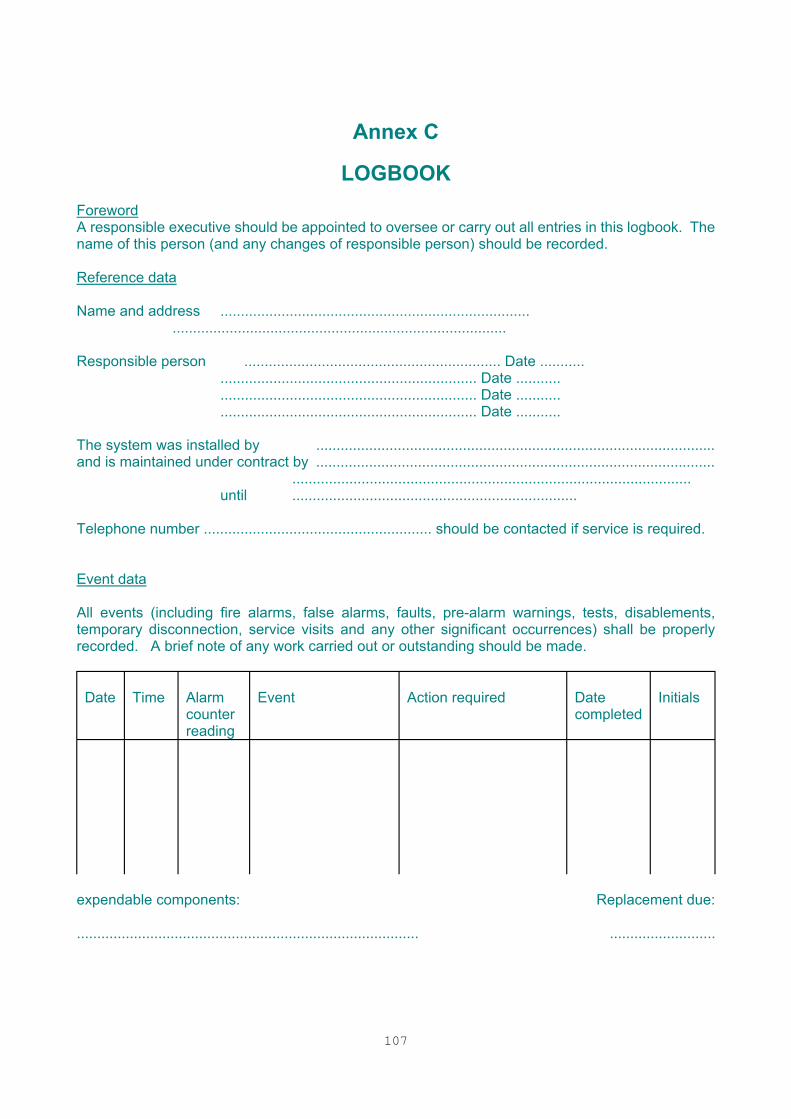
107
Annex C
LOGBOOK Foreword A responsible executive should be appointed to oversee or carry out all entries in this logbook. The name of this person (and any changes of responsible person) should be recorded. Reference data Name and address ............................................................................
.................................................................................. Responsible person ............................................................... Date ...........
............................................................... Date ...........
............................................................... Date ...........
............................................................... Date ........... The system was installed by .................................................................................................. and is maintained under contract by ..................................................................................................
.................................................................................................. until ......................................................................
Telephone number ........................................................ should be contacted if service is required. Event data All events (including fire alarms, false alarms, faults, pre-alarm warnings, tests, disablements, temporary disconnection, service visits and any other significant occurrences) shall be properly recorded. A brief note of any work carried out or outstanding should be made.
Date
Time
Alarm counter reading
Event
Action required
Date completed
Initials
expendable components: Replacement due: .................................................................................... ..........................
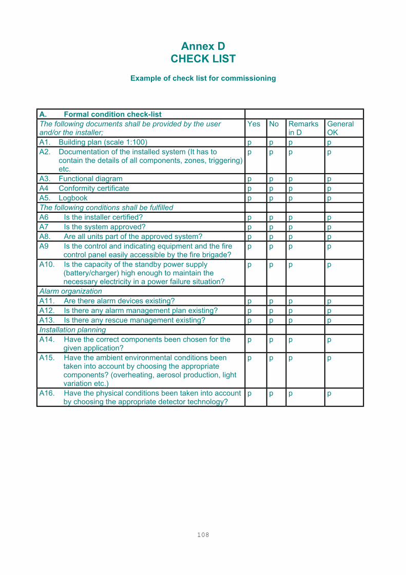
108
Annex D
CHECK LIST
Example of check list for commissioning
A. Formal condition check-list The following documents shall be provided by the user and/or the installer;
Yes No Remarks in D
General OK
A1. Building plan (scale 1:100) p p p p A2. Documentation of the installed system (It has to
contain the details of all components, zones, triggering) etc.
p p p p
A3. Functional diagram p p p p A4 Conformity certificate p p p p A5. Logbook p p p p The following conditions shall be fulfilled A6 Is the installer certified? p p p p A7 Is the system approved? p p p p A8. Are all units part of the approved system? p p p p A9 Is the control and indicating equipment and the fire
control panel easily accessible by the fire brigade? p p p p
A10. Is the capacity of the standby power supply (battery/charger) high enough to maintain the necessary electricity in a power failure situation?
p p p p
Alarm organization A11. Are there alarm devices existing? p p p p A12. Is there any alarm management plan existing? p p p p A13. Is there any rescue management existing? p p p p Installation planning A14. Have the correct components been chosen for the
given application? p p p p
A15. Have the ambient environmental conditions been taken into account by choosing the appropriate components? (overheating, aerosol production, light variation etc.)
p p p p
A16. Have the physical conditions been taken into account by choosing the appropriate detector technology?
p p p p
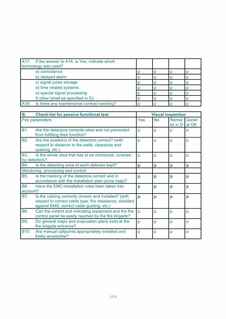
109
A17. If the answer to A16. is Yes, indicate which technology was used?
a) coincidence p p p p b) delayed alarm p p p p c) signal pulse storage p p p p d) time related systems p p p p e) special signal processing p p p p f) other (shall be specified in D) p p p p A18. Is there any maintenance contract existing? p p p p B. Check-list for passive functional test Visual inspection Fire parameters Yes No Remar
ks in D General OK
B1. Are the detectors correctly sited and not prevented from fulfilling their function?
p p p p
B2. Are the positions of the detectors correct? (with respect to distance to the walls, clearance and spacing, etc.)
p p p p
B3. Is the whole area that has to be monitored, covered by detectors?
p p p p
B4. Is the detecting zone of each detector kept? p p p p Monitoring processing and control B5. Is the marking of the detectors correct and in
accordance with the installation plan (zone map)? p p p p
B6. Have the EMC-installation rules been taken into account?
p p p p
B7. Is the cabling correctly chosen and installed? (with respect to correct cable type; fire resistance, shielded against EMS; correct cable guiding, etc.)
p p p p
B8. Can the control and indicating equipment and the fire control panel be easily reached by the fire brigade?
p p p p
B9. Do general maps and evacuation plans exist at the fire brigade entrance?
p p p p
B10. Are manual callpoints appropriately installed and freely accessible?
p p p p
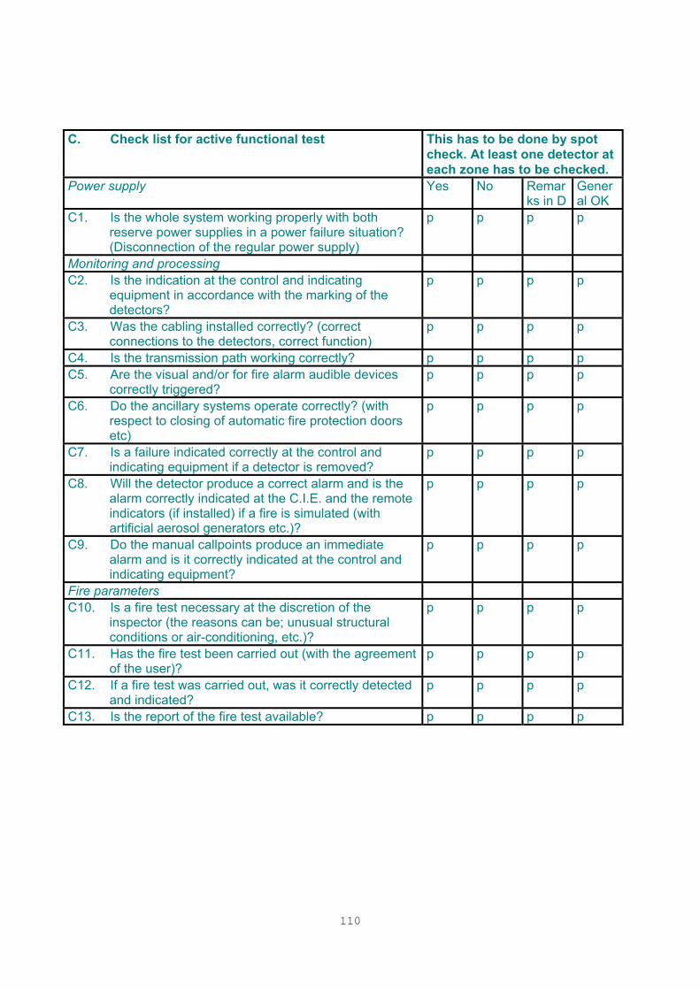
110
C. Check list for active functional test This has to be done by spot
check. At least one detector at each zone has to be checked.
Power supply Yes No Remarks in D
General OK
C1. Is the whole system working properly with both reserve power supplies in a power failure situation? (Disconnection of the regular power supply)
p p p p
Monitoring and processing C2. Is the indication at the control and indicating
equipment in accordance with the marking of the detectors?
p p p p
C3. Was the cabling installed correctly? (correct connections to the detectors, correct function)
p p p p
C4. Is the transmission path working correctly? p p p p C5. Are the visual and/or for fire alarm audible devices
correctly triggered? p p p p
C6. Do the ancillary systems operate correctly? (with respect to closing of automatic fire protection doors etc)
p p p p
C7. Is a failure indicated correctly at the control and indicating equipment if a detector is removed?
p p p p
C8. Will the detector produce a correct alarm and is the alarm correctly indicated at the C.I.E. and the remote indicators (if installed) if a fire is simulated (with artificial aerosol generators etc.)?
p p p p
C9. Do the manual callpoints produce an immediate alarm and is it correctly indicated at the control and indicating equipment?
p p p p
Fire parameters C10. Is a fire test necessary at the discretion of the
inspector (the reasons can be; unusual structural conditions or air-conditioning, etc.)?
p p p p
C11. Has the fire test been carried out (with the agreement of the user)?
p p p p
C12. If a fire test was carried out, was it correctly detected and indicated?
p p p p
C13. Is the report of the fire test available? p p p p

111
D. REMARKS
QUESTION