assemblaggio della rapida - seipdoors
TRANSCRIPT
I
1
RA - HIGH SPEED
ROLL-UP DOOR
ASSEMBLY HANDBOOK
DOOR MODEL
SERIAL No.
YEAR OF CONSTRUCTION
RA
I
2
GENERAL INFORMATION SCOPE & PURPOSE
This handbook, written by the company in accordance with the requirements of Directive 89/392/EEC, Annex I, 1.7.4, is an integral part of the industrial doors made by the producer and indicated by the following trade names:
• ROLL-UP RAPID DOOR This handbook was devised and implemented for the purpose of providing users and maintenance technicians all the information they may need for the correct installation and use of our industrial doors, in compliance with the design, together with the main technical features that all users must be aware of in order to be able to work under safe conditions. Therefore, this Handbook aims to provide users with all data, information and instructions deemed necessary with regard to:
• foreseen conditions of use; • controls; • start-up; • use; • maintenance and allowed repairs; • disassembly and reassembly of some components; • allowed adjustments.
When this handbook was drafted, special attention was paid both to safety and health protection issues, as well as the protection and respect of the working environment as set forth by the regulations in force. Pictures and drawings are provided only as examples.
CONFIDENTIALITY
Since the information contained in this handbook is the property of the producer, it must be considered strictly confidential: Any disclosures or even partial reproductions of said information shall be prohibited without the producer’s permission. It is also forbidden to use this handbook for uses other than those strictly described in the chapters contained herein.
I
3
1. DOOR INSTALLATION
The following points provide information about the conditions, measures and procedures to be taken for the proper
installation of the door.
The door MUST be installed only by skilled technicians with proven experience, who have been suitably trained and have read and fully understood this handbook.
• Throughout the installation, all the employer's safety regulations must be complied with, as concerns the characteristics of the workplace where the door is installed. Delimit the opening by placing adequate no-trespassing signs. • Wear suitable personal protective equipment (PPE) throughout all the installation stages. • Do not dispose of packaging materials in the environment but be sure to collect, separate and dispose of them properly. Before assembling the industrial door, be sure to read and understand all that which is stated in this handbook The manufacturer accepts no responsibility for damage caused by installations that do not comply with that explicitly stated in this handbook
1.1 Preliminary Operations
The door is inspected at the manufacturer's facility before delivery. In the event it was damaged during transport, said
damage must be identified to prevent the door from being operated in these conditions. Each time the door is transported
or handled, its condition must be checked through a visual inspection to make sure both the doors and its parts have not
undergone any damage.
• Check for the integrity of every part of the door before assembling and installing it. • If any parts are deformed, this means the door was subjected to impacts during transport,. event which could compromise its normal and safe operation; as such, please contact your supplier
ANY DAMAGE CAUSED BY TRANSPORT MUST BE CONTESTED TO THE CARRIER AND REPORTED IMMEDIATELY TO THE MANUFACTURER.
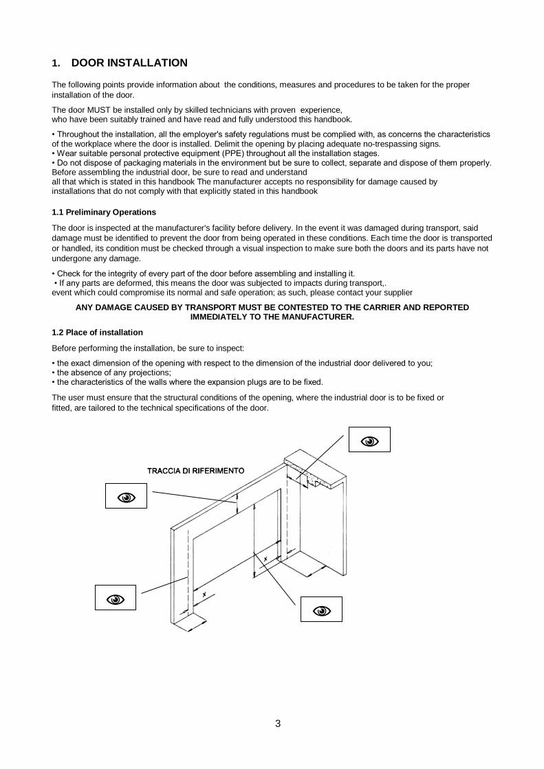
1.2 Place of installation
Before performing the installation, be sure to inspect:
• the exact dimension of the opening with respect to the dimension of the industrial door delivered to you; • the absence of any projections; • the characteristics of the walls where the expansion plugs are to be fixed.
The user must ensure that the structural conditions of the opening, where the industrial door is to be fixed or
fitted, are tailored to the technical specifications of the door.
I
4
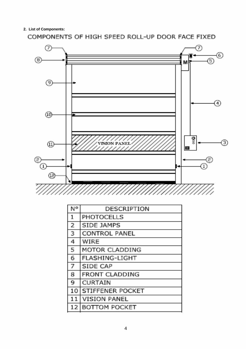
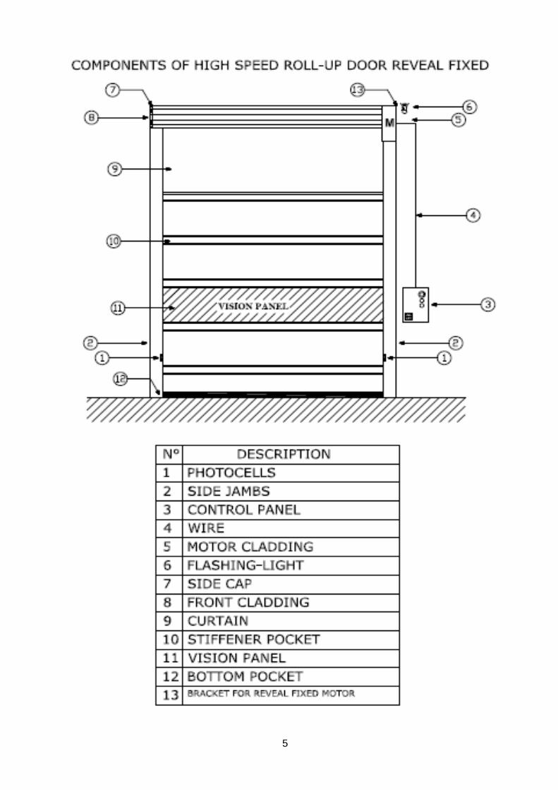
2. List of Components:
I
5
I
6
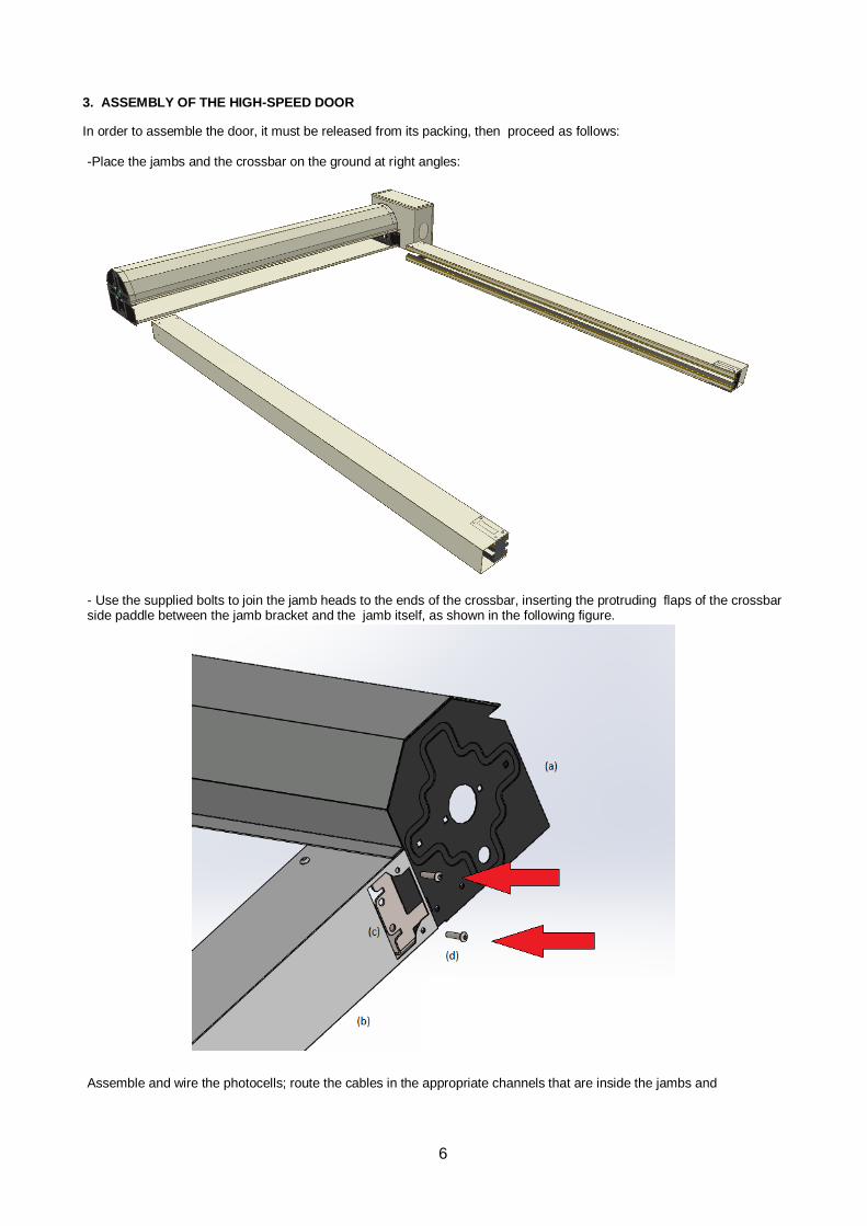
3. ASSEMBLY OF THE HIGH-SPEED DOOR
In order to assemble the door, it must be released from its packing, then proceed as follows: -Place the jambs and the crossbar on the ground at right angles:
- Use the supplied bolts to join the jamb heads to the ends of the crossbar, inserting the protruding flaps of the crossbar side paddle between the jamb bracket and the jamb itself, as shown in the following figure.
Assemble and wire the photocells; route the cables in the appropriate channels that are inside the jambs and
I
7
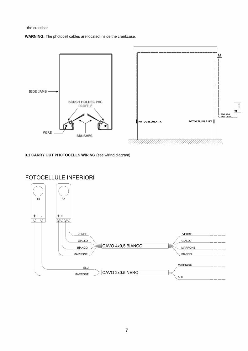
the crossbar WARNING: The photocell cables are located inside the crankcase.
3.1 CARRY OUT PHOTOCELLS WIRING (see wiring diagram)
I
8
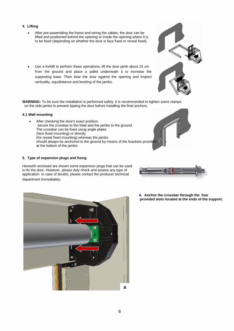
4. Lifting
• After pre-assembling the frame and wiring the cables, the door can be lifted and positioned behind the opening or inside the opening where it is to be fixed (depending on whether the door is face fixed or reveal fixed).
• Use a forklift to perform these operations, lift the door jamb about 15 cm
from the ground and place a pallet underneath it to increase the
supporting base. Then bear the door against the opening and inspect
verticality, equidistance and leveling of the jambs.
WARNING: To be sure the installation is performed safely, it is recommended to tighten some clamps on the side jambs to prevent tipping the door before installing the final anchors.
4.1 Wall mounting
• After checking the door's exact position, secure the crossbar to the lintel and the jambs to the ground. The crossbar can be fixed using angle plates (face fixed mounting) or directly (for reveal fixed mounting) whereas the jambs should always be anchored to the ground by means of the brackets provided at the bottom of the jambs.
5. Type of expansion plugs and fixing
Herewith enclosed are shown some expansion plugs that can be used to fix the door. However, please duly check and assess any type of application. In case of doubts, please contact the producer technical
department immediately.
A. Anchor the crossbar through the four provided slots located at the ends of the support.
A
I
9
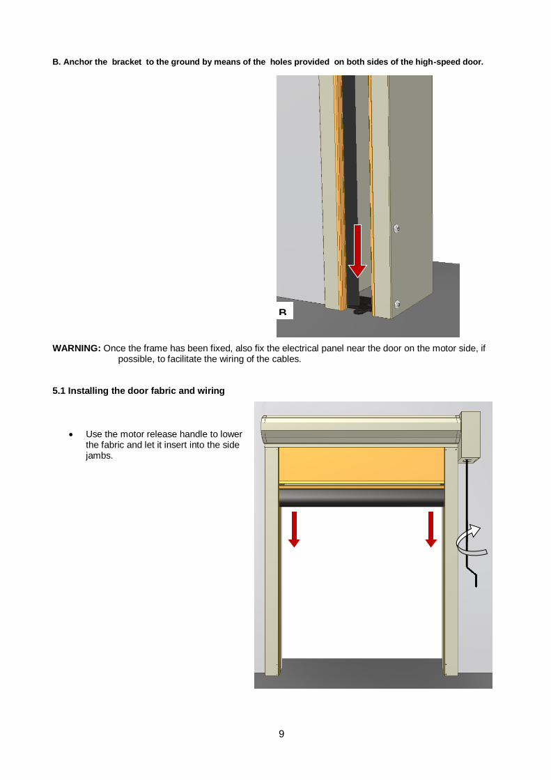
B. Anchor the bracket to the ground by means of the holes provided on both sides of the high-speed door.
WARNING: Once the frame has been fixed, also fix the electrical panel near the door on the motor side, if
possible, to facilitate the wiring of the cables. 5.1 Installing the door fabric and wiring
• Use the motor release handle to lower the fabric and let it insert into the side jambs.
B
I
10
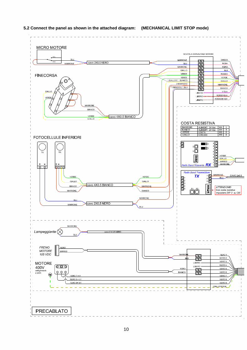
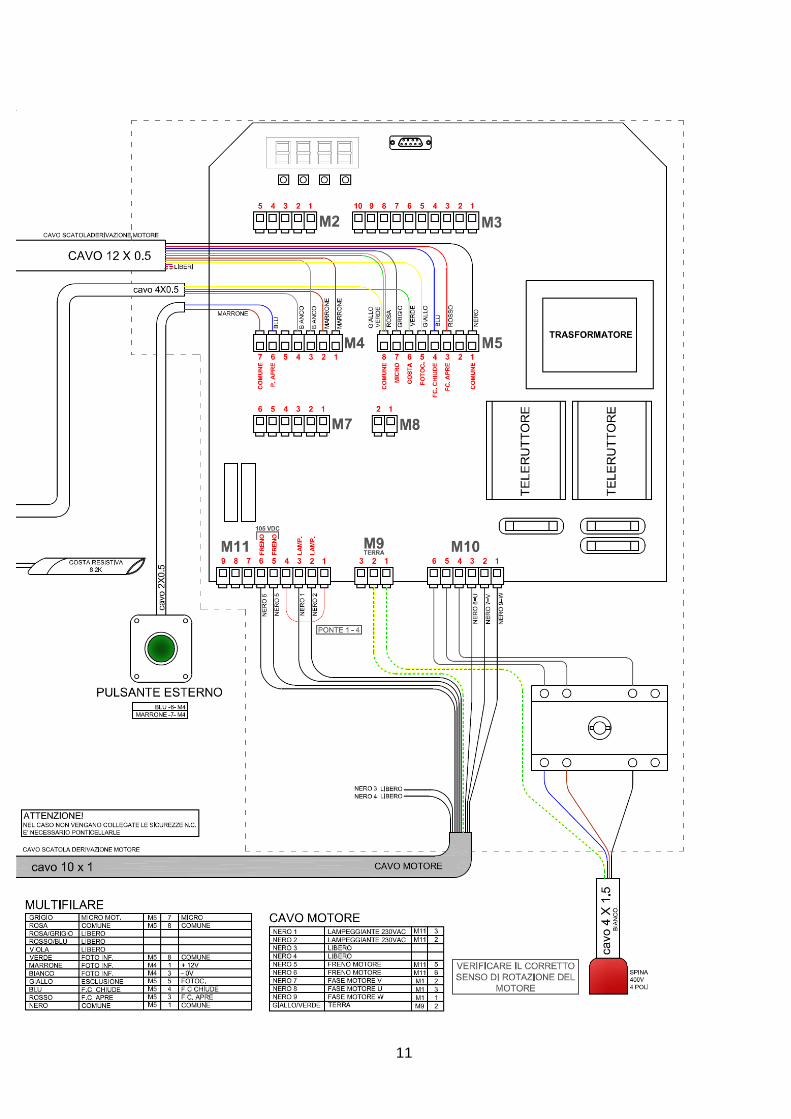
5.2 Connect the panel as shown in the attached diagram: (MECHANICAL LIMIT STOP mode)
I
11

I
12
6. Checks to be carried out before start-up
• Turn on the panel and wait until the following screens are displayed:
→ → . Based on the charged state of the capacitors, when you power-on the inverter, it usually takes a few seconds before it is ready for use.
• Check the correct operation of the NC safeties (their matching green LEDs should be ON in the panel)
• Use the cursors and press to select the preset table mode:
. MECHANICAL LIMIT STOP MODE
Depending on which table you selected, pressing button will bring up the door setting procedure. Press ENTER again to start this procedure.
Select table 0 to display SETTING FOR LIMIT STOP ON NEXT PAGE)
6.1 SETTINGS
ADJUSTING AND CHECKING THE MECHANICS - LIMIT STOP For the ENCODER-based version, first of all carry out setting 5.
When using this setting, you can move the high-speed door, adjust the limit stops and check the motor's running direction at reduced speed. Active inputs: Limit stop, Emergency, Motor micro.
Description: The only active keys are and , which work only in man-in-attendance mode (the door stops once they are released).
FOLLOWING ADJUSTMENTS CAN BE MADE BOTH THROUGH THE EXTERNAL
KEYBOARD AND KEYS LOCATED UNDER THE DISPLAY INSIDE THE PANEL
I
13
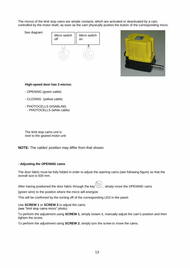
The micros of the limit stop cams are simple contacts, which are activated or deactivated by a cam, controlled by the motor shaft, as soon as the cam physically pushes the button of the corresponding micro. See diagram:
High-speed door has 3 micros: - OPENING (green cable) - CLOSING (yellow cable) - PHOTOCELLS DISABLING
- PHOTOCELLS (white cable)
The limit stop cams unit is next to the geared motor unit
NOTE: The cables' position may differ from that shown.
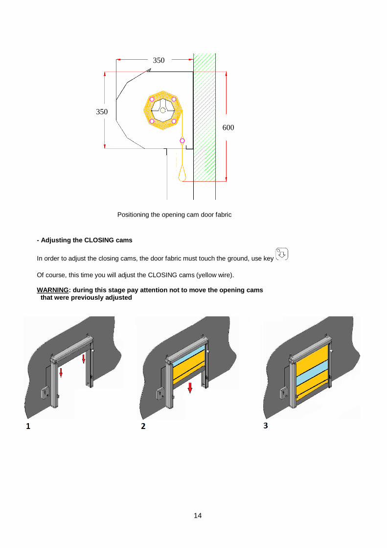
- Adjusting the OPENING cams
The door fabric must be fully folded in order to adjust the opening cams (see following figure) so that the overall size is 500 mm.
After having positioned the door fabric through the key , simply move the OPENING cams
(green wire) to the position where the micro will energize.
This will be confirmed by the turning off of the corresponding LED in the panel. Use SCREW 1 or SCREW 2 to adjust the cams. (see “limit stop cams micro” photo)
To perform the adjustment using SCREW 1, simply loosen it, manually adjust the cam's position and then tighten the screw.
To perform the adjustment using SCREW 2, simply turn the screw to move the cams.
Micro switch off
Micro switch on
I
14
Positioning the opening cam door fabric
- Adjusting the CLOSING cams
In order to adjust the closing cams, the door fabric must touch the ground, use key
Of course, this time you will adjust the CLOSING cams (yellow wire). WARNING: during this stage pay attention not to move the opening cams that were previously adjusted
600
350
350
I
15
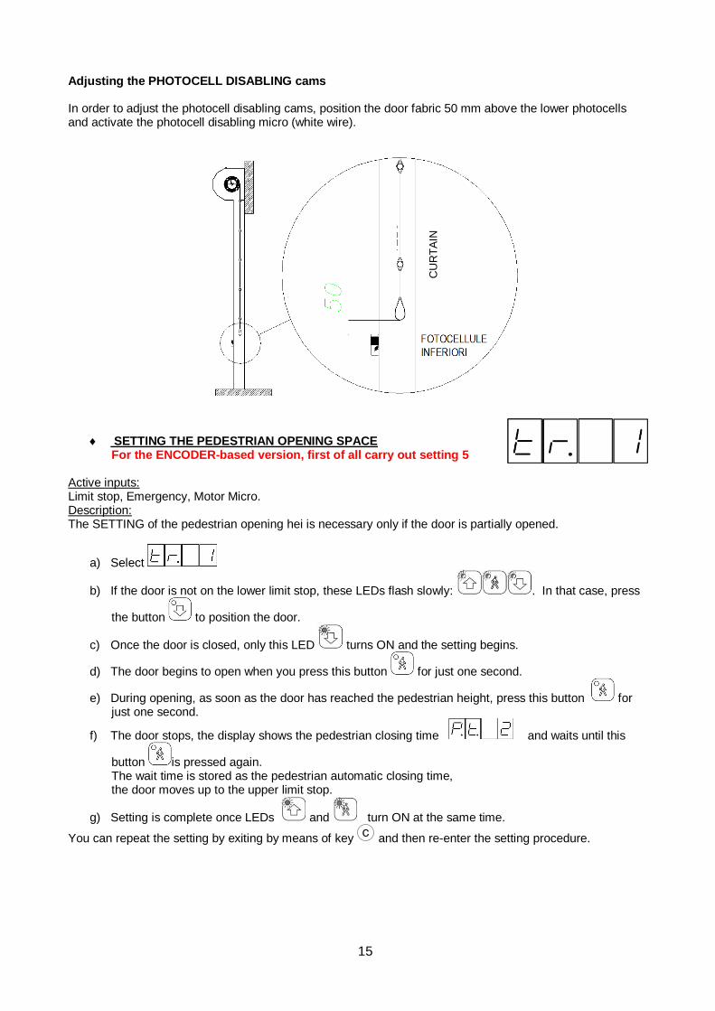
Adjusting the PHOTOCELL DISABLING cams In order to adjust the photocell disabling cams, position the door fabric 50 mm above the lower photocells and activate the photocell disabling micro (white wire).
SETTING THE PEDESTRIAN OPENING SPACE For the ENCODER-based version, first of all carry out setting 5
Active inputs: Limit stop, Emergency, Motor Micro. Description: The SETTING of the pedestrian opening hei is necessary only if the door is partially opened.
a) Select
b) If the door is not on the lower limit stop, these LEDs flash slowly: . In that case, press
the button to position the door.
c) Once the door is closed, only this LED turns ON and the setting begins.
d) The door begins to open when you press this button for just one second.
e) During opening, as soon as the door has reached the pedestrian height, press this button for just one second.
f) The door stops, the display shows the pedestrian closing time and waits until this
button is pressed again. The wait time is stored as the pedestrian automatic closing time, the door moves up to the upper limit stop.
g) Setting is complete once LEDs and turn ON at the same time.
You can repeat the setting by exiting by means of key and then re-enter the setting procedure.
CU
RT
AIN
I
16
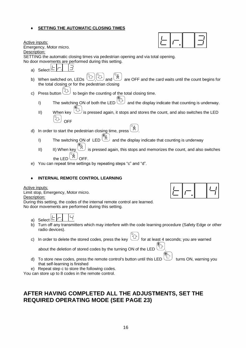
SETTING THE AUTOMATIC CLOSING TIMES
Active inputs: Emergency, Motor micro. Description: SETTING the automatic closing times via pedestrian opening and via total opening. No door movements are performed during this setting.
a) Select
b) When switched on, LEDs , and are OFF and the card waits until the count begins for the total closing or for the pedestrian closing
c) Press button to begin the counting of the total closing time.
I) The switching ON of both the LED and the display indicate that counting is underway.
II) When key is pressed again, it stops and stores the count, and also switches the LED
OFF
d) In order to start the pedestrian closing time, press .
I) The switching ON of LED and the display indicate that counting is underway
II) II) When key is pressed again, this stops and memorizes the count, and also switches
the LED OFF. e) You can repeat time settings by repeating steps “c” and “d”.
INTERNAL REMOTE CONTROL LEARNING
Active inputs: Limit stop, Emergency, Motor micro. Description: During this setting, the codes of the internal remote control are learned. No door movements are performed during this setting.
a) Select b) Turn off any transmitters which may interfere with the code learning procedure (Safety Edge or other
radio devices).
c) In order to delete the stored codes, press the key for at least 4 seconds; you are warned
about the deletion of stored codes by the turning ON of the LED .
d) To store new codes, press the remote control's button until this LED turns ON, warning you that self-learning is finished
e) Repeat step c to store the following codes. You can store up to 8 codes in the remote control.
AFTER HAVING COMPLETED ALL THE ADJUSTMENTS, SET THE REQUIRED OPERATING MODE (SEE PAGE 23)
I
17
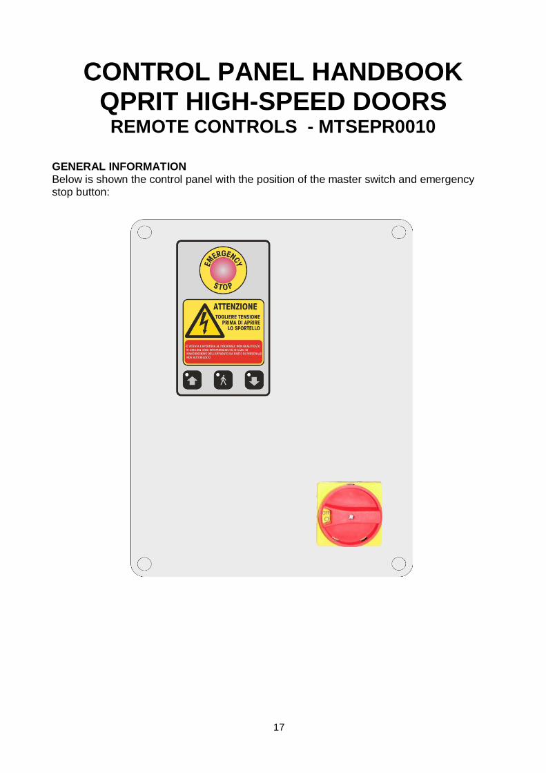
CONTROL PANEL HANDBOOK QPRIT HIGH-SPEED DOORS
REMOTE CONTROLS - MTSEPR0010
GENERAL INFORMATION Below is shown the control panel with the position of the master switch and emergency stop button:
I
18
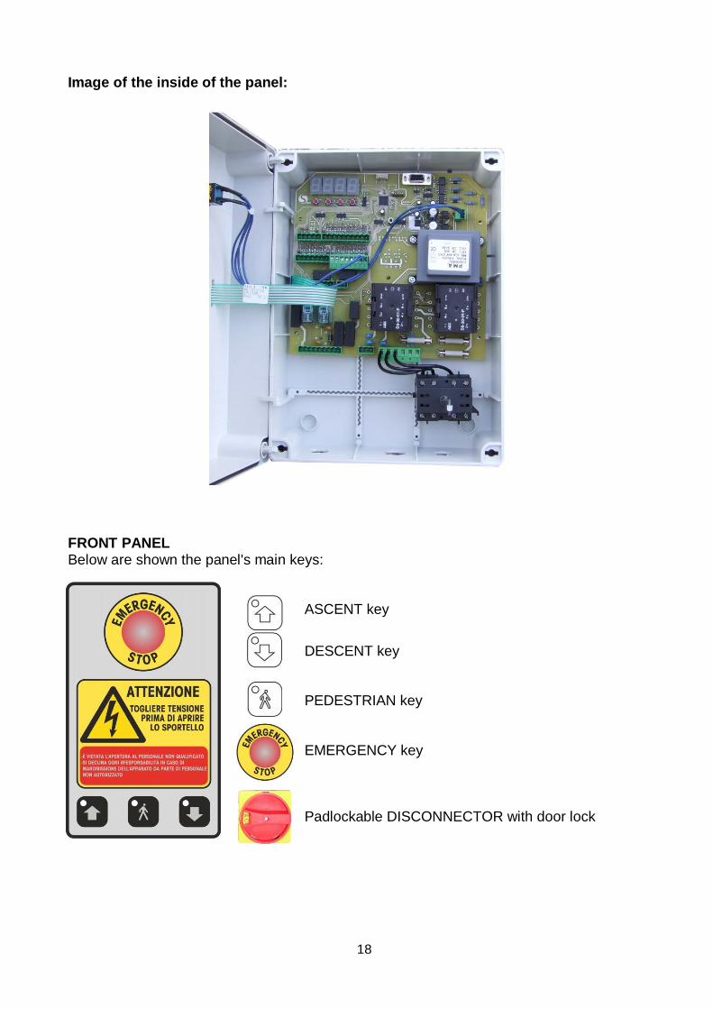
Image of the inside of the panel:
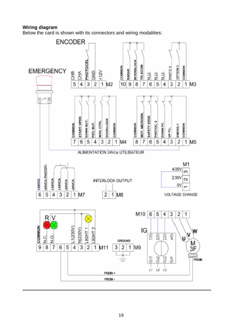
FRONT PANEL Below are shown the panel's main keys:
ASCENT key
DESCENT key
PEDESTRIAN key EMERGENCY key Padlockable DISCONNECTOR with door lock
I
19
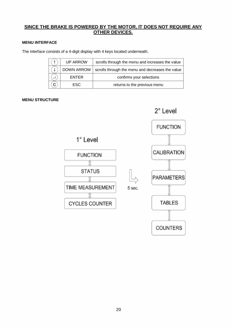
Wiring diagram Below the card is shown with its connectors and wiring modalities:
I
20
SINCE THE BRAKE IS POWERED BY THE MOTOR, IT DOES NOT REQUIRE ANY OTHER DEVICES.
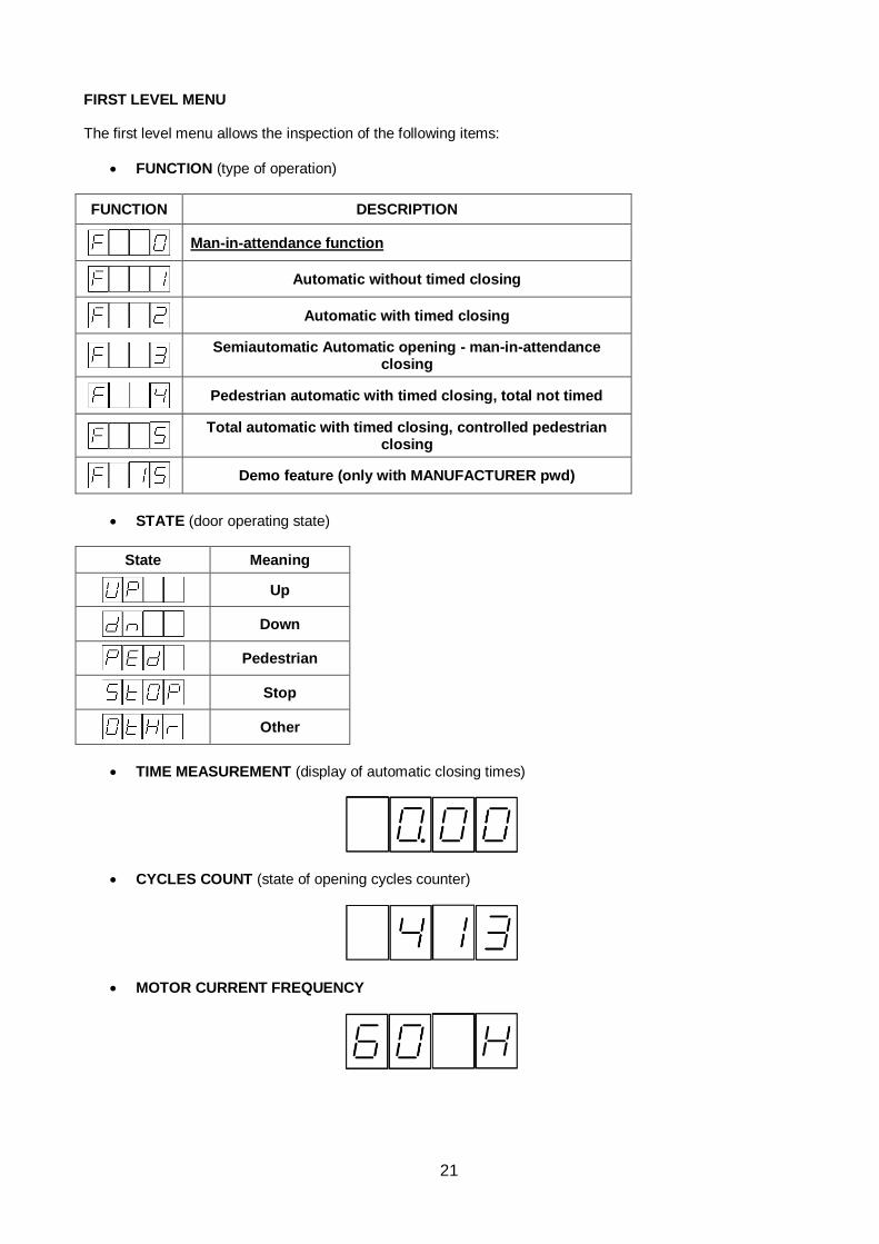
MENU INTERFACE The interface consists of a 4-digit display with 4 keys located underneath.
MENU STRUCTURE
UP ARROW scrolls through the menu and increases the value
DOWN ARROW scrolls through the menu and decreases the value
ENTER confirms your selections
ESC returns to the previous menu
I
21
FIRST LEVEL MENU The first level menu allows the inspection of the following items:
• FUNCTION (type of operation)
FUNCTION DESCRIPTION
Man-in-attendance function
Automatic without timed closing
Automatic with timed closing
Semiautomatic Automatic opening - man-in-attendance
closing
Pedestrian automatic with timed closing, total not timed
Total automatic with timed closing, controlled pedestrian
closing
Demo feature (only with MANUFACTURER pwd)
• STATE (door operating state)
State Meaning
Up
Down
Pedestrian
Stop
Other
• TIME MEASUREMENT (display of automatic closing times)
• CYCLES COUNT (state of opening cycles counter)
• MOTOR CURRENT FREQUENCY
I
22
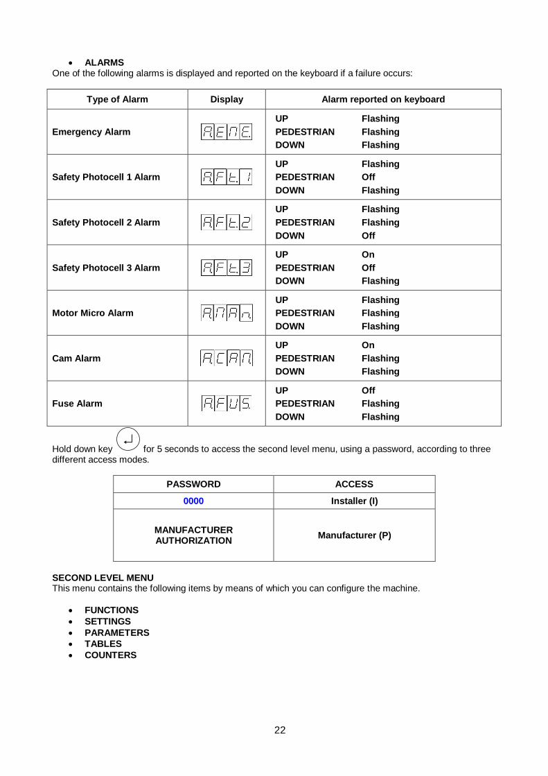
• ALARMS One of the following alarms is displayed and reported on the keyboard if a failure occurs:
Type of Alarm Display Alarm reported on keyboard
Emergency Alarm
UP Flashing
PEDESTRIAN Flashing
DOWN Flashing
Safety Photocell 1 Alarm
UP Flashing
PEDESTRIAN Off
DOWN Flashing
Safety Photocell 2 Alarm
UP Flashing
PEDESTRIAN Flashing
DOWN Off
Safety Photocell 3 Alarm
UP On
PEDESTRIAN Off
DOWN Flashing
Motor Micro Alarm
UP Flashing
PEDESTRIAN Flashing
DOWN Flashing
Cam Alarm
UP On
PEDESTRIAN Flashing
DOWN Flashing
Fuse Alarm
UP Off
PEDESTRIAN Flashing
DOWN Flashing
Hold down key for 5 seconds to access the second level menu, using a password, according to three different access modes.
PASSWORD ACCESS
0000 Installer (I)
MANUFACTURER AUTHORIZATION
Manufacturer (P)
SECOND LEVEL MENU This menu contains the following items by means of which you can configure the machine.
• FUNCTIONS
• SETTINGS
• PARAMETERS
• TABLES
• COUNTERS
I
23
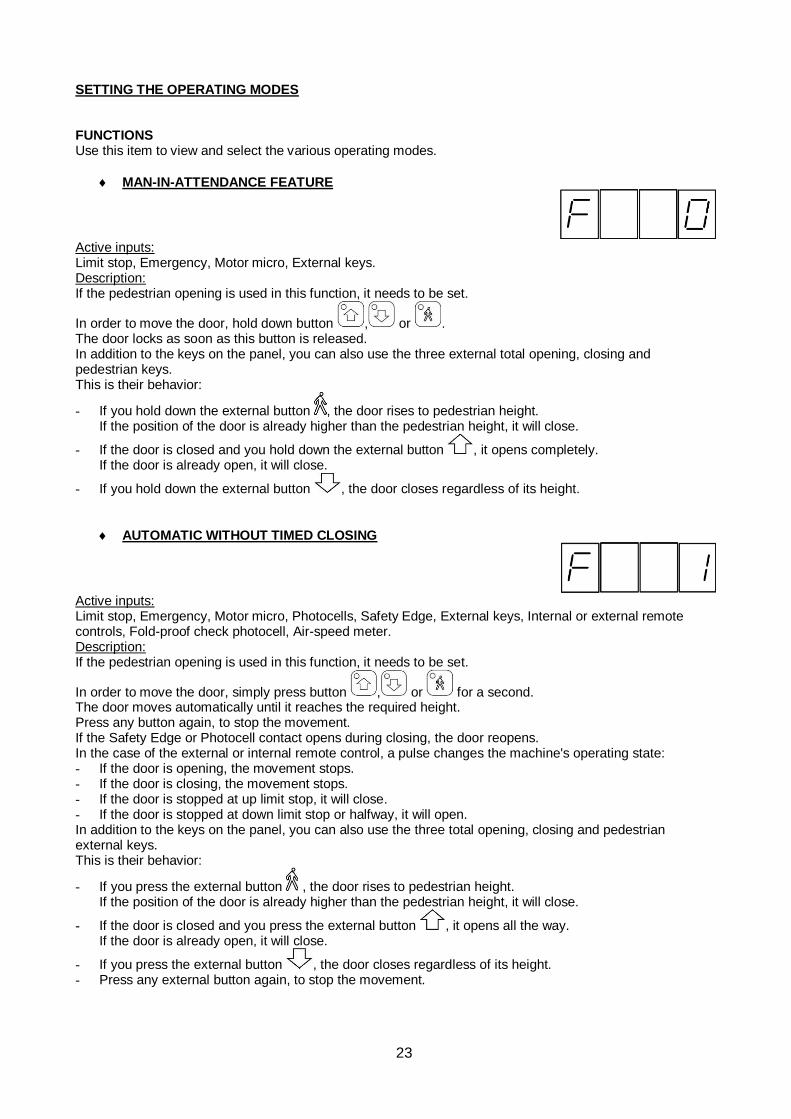
SETTING THE OPERATING MODES FUNCTIONS Use this item to view and select the various operating modes.
MAN-IN-ATTENDANCE FEATURE
Active inputs: Limit stop, Emergency, Motor micro, External keys. Description: If the pedestrian opening is used in this function, it needs to be set.
In order to move the door, hold down button , or . The door locks as soon as this button is released. In addition to the keys on the panel, you can also use the three external total opening, closing and pedestrian keys. This is their behavior:
- If you hold down the external button , the door rises to pedestrian height. If the position of the door is already higher than the pedestrian height, it will close.
- If the door is closed and you hold down the external button , it opens completely. If the door is already open, it will close.
- If you hold down the external button , the door closes regardless of its height.
AUTOMATIC WITHOUT TIMED CLOSING
Active inputs: Limit stop, Emergency, Motor micro, Photocells, Safety Edge, External keys, Internal or external remote controls, Fold-proof check photocell, Air-speed meter. Description: If the pedestrian opening is used in this function, it needs to be set.
In order to move the door, simply press button , or for a second. The door moves automatically until it reaches the required height. Press any button again, to stop the movement. If the Safety Edge or Photocell contact opens during closing, the door reopens. In the case of the external or internal remote control, a pulse changes the machine's operating state: - If the door is opening, the movement stops. - If the door is closing, the movement stops. - If the door is stopped at up limit stop, it will close. - If the door is stopped at down limit stop or halfway, it will open. In addition to the keys on the panel, you can also use the three total opening, closing and pedestrian external keys. This is their behavior:
- If you press the external button , the door rises to pedestrian height. If the position of the door is already higher than the pedestrian height, it will close.
- If the door is closed and you press the external button , it opens all the way. If the door is already open, it will close.
- If you press the external button , the door closes regardless of its height. - Press any external button again, to stop the movement.
I
24
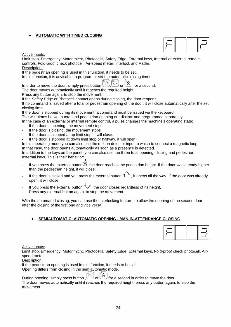
AUTOMATIC WITH TIMED CLOSING
Active inputs: Limit stop, Emergency, Motor micro, Photocells, Safety Edge, External keys, Internal or external remote controls, Fold-proof check photocell, Air-speed meter, Interlock and Radar. Description: If the pedestrian opening is used in this function, it needs to be set. In this function, it is advisable to program or set the automatic closing times.
In order to move the door, simply press button , or for a second. The door moves automatically until it reaches the required height. Press any button again, to stop the movement. If the Safety Edge or Photocell contact opens during closing, the door reopens. If no command is issued after a total or pedestrian opening of the door, it will close automatically after the set closing time. If the door is stopped during its movement, a command must be issued via the keyboard. The wait times between total and pedestrian opening are distinct and programmed separately. In the case of an external or internal remote control, a pulse changes the machine's operating state: - If the door is opening, the movement stops. - If the door is closing, the movement stops. - If the door is stopped at up limit stop, it will close. - If the door is stopped at down limit stop or halfway, it will open. In this operating mode you can also use the motion detector input to which to connect a magnetic loop. In that case, the door opens automatically as soon as a presence is detected. In addition to the keys on the panel, you can also use the three total opening, closing and pedestrian external keys. This is their behavior:
- If you press the external button , the door reaches the pedestrian height. If the door was already higher than the pedestrian height, it will close.
- If the door is closed and you press the external button , it opens all the way. If the door was already open, it will close.
- If you press the external button , the door closes regardless of its height. - Press any external button again, to stop the movement. With the automated closing, you can use the interlocking feature, to allow the opening of the second door after the closing of the first one and vice versa.
SEMIAUTOMATIC: AUTOMATIC OPENING - MAN-IN-ATTENDANCE CLOSING
Active inputs: Limit stop, Emergency, Motor micro, Photocells, Safety Edge, External keys, Fold-proof check photocell, Air-speed meter. Description: If the pedestrian opening is used in this function, it needs to be set. Opening differs from closing in the semiautomatic mode.
During opening, simply press button , or for a second in order to move the door. The door moves automatically until it reaches the required height; press any button again, to stop the movement.
I
25
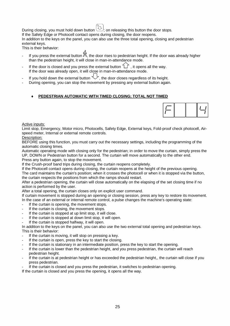
During closing, you must hold down button ; on releasing this button the door stops. If the Safety Edge or Photocell contact opens during closing, the door reopens. In addition to the keys on the panel, you can also use the three total opening, closing and pedestrian external keys. This is their behavior:
- If you press the external button , the door rises to pedestrian height. If the door was already higher than the pedestrian height, it will close in man-in-attendance mode.
- If the door is closed and you press the external button , it opens all the way. If the door was already open, it will close in man-in-attendance mode.
- If you hold down the external button , the door closes regardless of its height. - During opening, you can stop the movement by pressing any external button again.
PEDESTRIAN AUTOMATIC WITH TIMED CLOSING; TOTAL NOT TIMED
Active inputs: Limit stop, Emergency, Motor micro, Photocells, Safety Edge, External keys, Fold-proof check photocell, Air-speed meter, Internal or external remote controls. Description: BEFORE using this function, you must carry out the necessary settings, including the programming of the automatic closing times. Automatic operating mode with closing only for the pedestrian; in order to move the curtain, simply press the UP, DOWN or Pedestrian button for a second. The curtain will move automatically to the other end. Press any button again, to stop the movement. If the Crush-proof band trips during closing, the curtain reopens completely. If the Photocell contact opens during closing, the curtain reopens at the height of the previous opening. The card maintains the curtain's position; when it crosses the photocell or when it is stopped via the button, the curtain respects the positions from which the ramps should restart. After a pedestrian opening, the curtain will close automatically on the elapsing of the set closing time if no action is performed by the user. After a total opening, the curtain closes only on explicit user command. If curtain movement is stopped during an opening or closing session, press any key to restore its movement. In the case of an external or internal remote control, a pulse changes the machine's operating state: - If the curtain is opening, the movement stops. - If the curtain is closing, the movement stops. - If the curtain is stopped at up limit stop, it will close. - If the curtain is stopped at down limit stop, it will open. - If the curtain is stopped halfway, it will open. In addition to the keys on the panel, you can also use the two external total opening and pedestrian keys. This is their behavior: - If the curtain is moving, it will stop on pressing a key. - If the curtain is open, press the key to start the closing. - If the curtain is stationary in an intermediate position, press the key to start the opening. - If the curtain is lower than the pedestrian height, and you press pedestrian, the curtain will reach
pedestrian height. - If the curtain is at pedestrian height or has exceeded the pedestrian height,, the curtain will close if you
press pedestrian. - If the curtain is closed and you press the pedestrian, it switches to pedestrian opening. If the curtain is closed and you press the opening, it opens all the way.
I
26
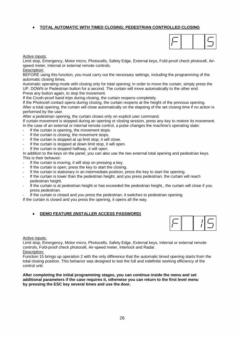
TOTAL AUTOMATIC WITH TIMED CLOSING; PEDESTRIAN CONTROLLED CLOSING
Active inputs: Limit stop, Emergency, Motor micro, Photocells, Safety Edge, External keys, Fold-proof check photocell, Air-speed meter, Internal or external remote controls. Description: BEFORE using this function, you must carry out the necessary settings, including the programming of the automatic closing times. Automatic operating mode with closing only for total opening; in order to move the curtain, simply press the UP, DOWN or Pedestrian button for a second. The curtain will move automatically to the other end. Press any button again, to stop the movement. If the Crush-proof band trips during closing, the curtain reopens completely. If the Photocell contact opens during closing, the curtain reopens at the height of the previous opening. After a total opening, the curtain will close automatically on the elapsing of the set closing time if no action is performed by the user. After a pedestrian opening, the curtain closes only on explicit user command. If curtain movement is stopped during an opening or closing session, press any key to restore its movement. In the case of an external or internal remote control, a pulse changes the machine's operating state: - If the curtain is opening, the movement stops. - If the curtain is closing, the movement stops. - If the curtain is stopped at up limit stop, it will close. - If the curtain is stopped at down limit stop, it will open. - If the curtain is stopped halfway, it will open. In addition to the keys on the panel, you can also use the two external total opening and pedestrian keys. This is their behavior: - If the curtain is moving, it will stop on pressing a key. - If the curtain is open, press the key to start the closing. - If the curtain is stationary in an intermediate position, press the key to start the opening. - If the curtain is lower than the pedestrian height, and you press pedestrian, the curtain will reach
pedestrian height. - If the curtain is at pedestrian height or has exceeded the pedestrian height,, the curtain will close if you
press pedestrian. - If the curtain is closed and you press the pedestrian, it switches to pedestrian opening. If the curtain is closed and you press the opening, it opens all the way.
DEMO FEATURE (INSTALLER ACCESS PASSWORD)
Active inputs: Limit stop, Emergency, Motor micro, Photocells, Safety Edge, External keys, Internal or external remote controls, Fold-proof check photocell, Air-speed meter, Interlock and Radar. Description: Function 15 brings up operation 2 with the only difference that the automatic timed opening starts from the total closing position. This behavior was designed to test the full and indefinite working efficiency of the control unit. After completing the initial programming stages, you can continue inside the menu and set additional parameters if the case requires it, otherwise you can return to the first level menu by pressing the ESC key several times and use the door.
I
27
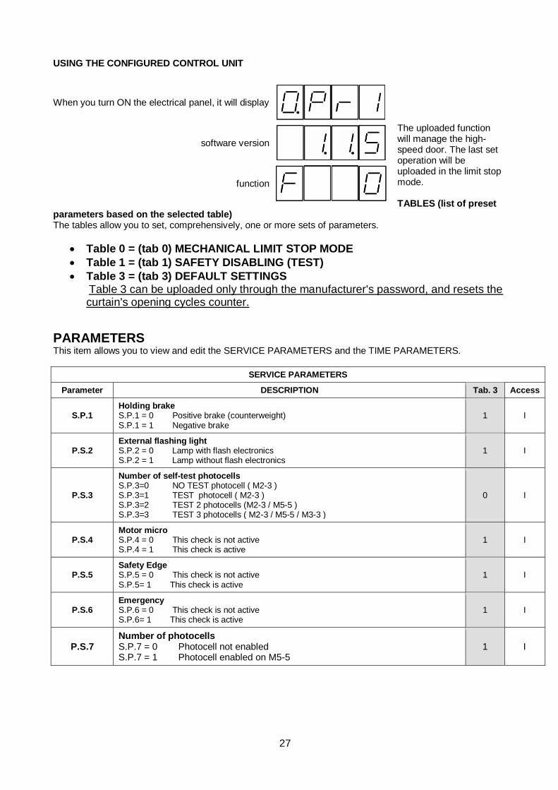
USING THE CONFIGURED CONTROL UNIT
The uploaded function will manage the high-speed door. The last set operation will be uploaded in the limit stop mode. TABLES (list of preset
parameters based on the selected table) The tables allow you to set, comprehensively, one or more sets of parameters.
• Table 0 = (tab 0) MECHANICAL LIMIT STOP MODE
• Table 1 = (tab 1) SAFETY DISABLING (TEST)
• Table 3 = (tab 3) DEFAULT SETTINGS Table 3 can be uploaded only through the manufacturer's password, and resets the curtain's opening cycles counter.
PARAMETERS This item allows you to view and edit the SERVICE PARAMETERS and the TIME PARAMETERS.
SERVICE PARAMETERS
Parameter DESCRIPTION Tab. 3 Access
S.P.1 Holding brake S.P.1 = 0 Positive brake (counterweight) S.P.1 = 1 Negative brake
1 I
P.S.2 External flashing light S.P.2 = 0 Lamp with flash electronics S.P.2 = 1 Lamp without flash electronics
1 I
P.S.3
Number of self-test photocells S.P.3=0 NO TEST photocell ( M2-3 ) S.P.3=1 TEST photocell ( M2-3 ) S.P.3=2 TEST 2 photocells (M2-3 / M5-5 ) S.P.3=3 TEST 3 photocells ( M2-3 / M5-5 / M3-3 )
0 I
P.S.4 Motor micro S.P.4 = 0 This check is not active S.P.4 = 1 This check is active
1 I
P.S.5 Safety Edge S.P.5 = 0 This check is not active S.P.5= 1 This check is active
1 I
P.S.6 Emergency S.P.6 = 0 This check is not active S.P.6= 1 This check is active
1 I
P.S.7 Number of photocells S.P.7 = 0 Photocell not enabled S.P.7 = 1 Photocell enabled on M5-5
1 I
When you turn ON the electrical panel, it will display
software version
function
I
28
TIME PARAMETERS
Parameter Description Min. Max. Tab. 3 Access
P.t.0 SAFETY OPENING PAUSE 0 2.00 0.50 I
P.t.1 AUTOMATIC RE-CLOSING TIME 0 99.99 3.00 I
P.t.2 PEDESTRIAN RE-CLOSING TIME 0 99.99 3.00 I
P.t.3 BRAKE DELAY TIME 0 0.40 0.04 I
P.t.4 LAMP DELAY TIME 0 2.00 0.76 I
P.t.5 SAFETY OPENING TIME 0 99.99 15.00 I
P.t.6 PEDESTRIAN OPENING TIME 0 99.99 5.00 I
P.t.7 TOTAL OPENING TIME 0 99.99 12.00 I
P.t.9 BRAKE RELEASE DELAY 0.00 0.60 0.00 I
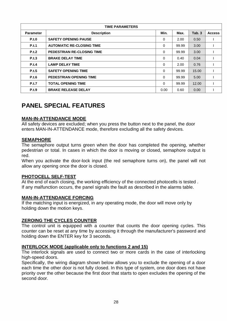
PANEL SPECIAL FEATURES MAN-IN-ATTENDANCE MODE All safety devices are excluded; when you press the button next to the panel, the door enters MAN-IN-ATTENDANCE mode, therefore excluding all the safety devices. SEMAPHORE The semaphore output turns green when the door has completed the opening, whether pedestrian or total. In cases in which the door is moving or closed, semaphore output is red. When you activate the door-lock input (the red semaphore turns on), the panel will not allow any opening once the door is closed. PHOTOCELL SELF-TEST At the end of each closing, the working efficiency of the connected photocells is tested . If any malfunction occurs, the panel signals the fault as described in the alarms table. MAN-IN-ATTENDANCE FORCING If the matching input is energized, in any operating mode, the door will move only by holding down the motion keys. ZEROING THE CYCLES COUNTER The control unit is equipped with a counter that counts the door opening cycles. This counter can be reset at any time by accessing it through the manufacturer's password and holding down the ENTER key for 3 seconds. INTERLOCK MODE (applicable only to functions 2 and 15) The interlock signals are used to connect two or more cards in the case of interlocking high-speed doors. Specifically, the wiring diagram shown below allows you to exclude the opening of a door each time the other door is not fully closed. In this type of system, one door does not have priority over the other because the first door that starts to open excludes the opening of the second door.
I
29
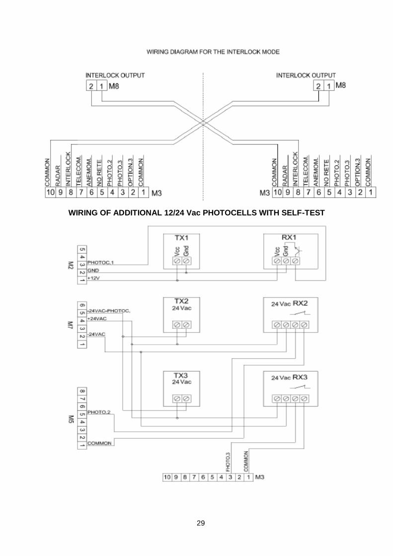
WIRING OF ADDITIONAL 12/24 Vac PHOTOCELLS WITH SELF-TEST
I
30
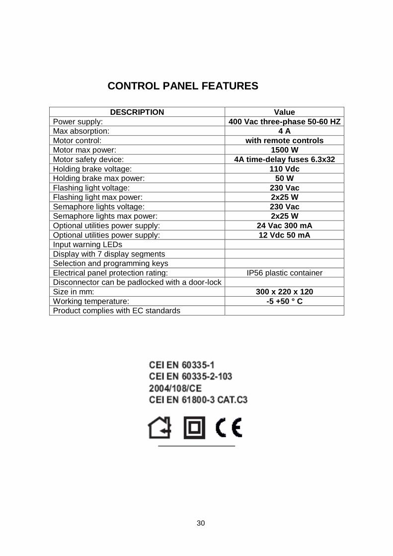
CONTROL PANEL FEATURES
DESCRIPTION Value
Power supply: 400 Vac three-phase 50-60 HZ
Max absorption: 4 A
Motor control: with remote controls
Motor max power: 1500 W
Motor safety device: 4A time-delay fuses 6.3x32
Holding brake voltage: 110 Vdc
Holding brake max power: 50 W
Flashing light voltage: 230 Vac
Flashing light max power: 2x25 W
Semaphore lights voltage: 230 Vac
Semaphore lights max power: 2x25 W
Optional utilities power supply: 24 Vac 300 mA
Optional utilities power supply: 12 Vdc 50 mA
Input warning LEDs
Display with 7 display segments
Selection and programming keys
Electrical panel protection rating: IP56 plastic container
Disconnector can be padlocked with a door-lock
Size in mm: 300 x 220 x 120
Working temperature: -5 +50 ° C
Product complies with EC standards
ACCESSORIES
I
31
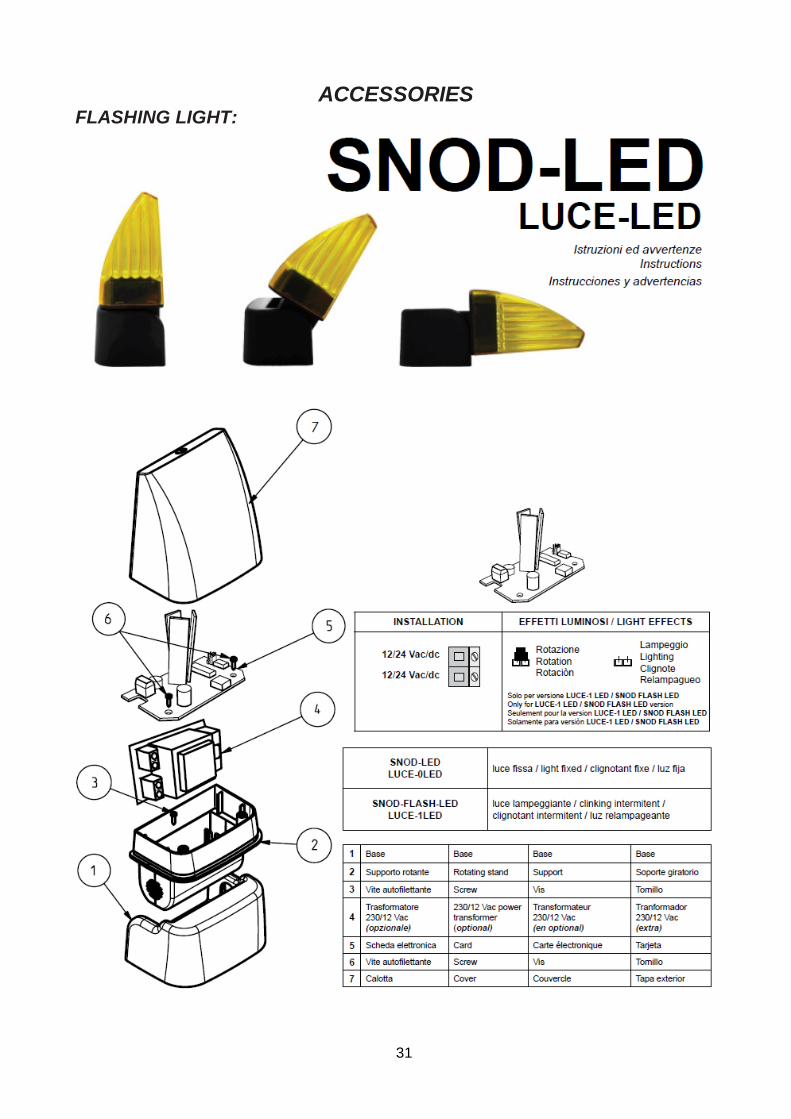
ACCESSORIES FLASHING LIGHT:
I
32
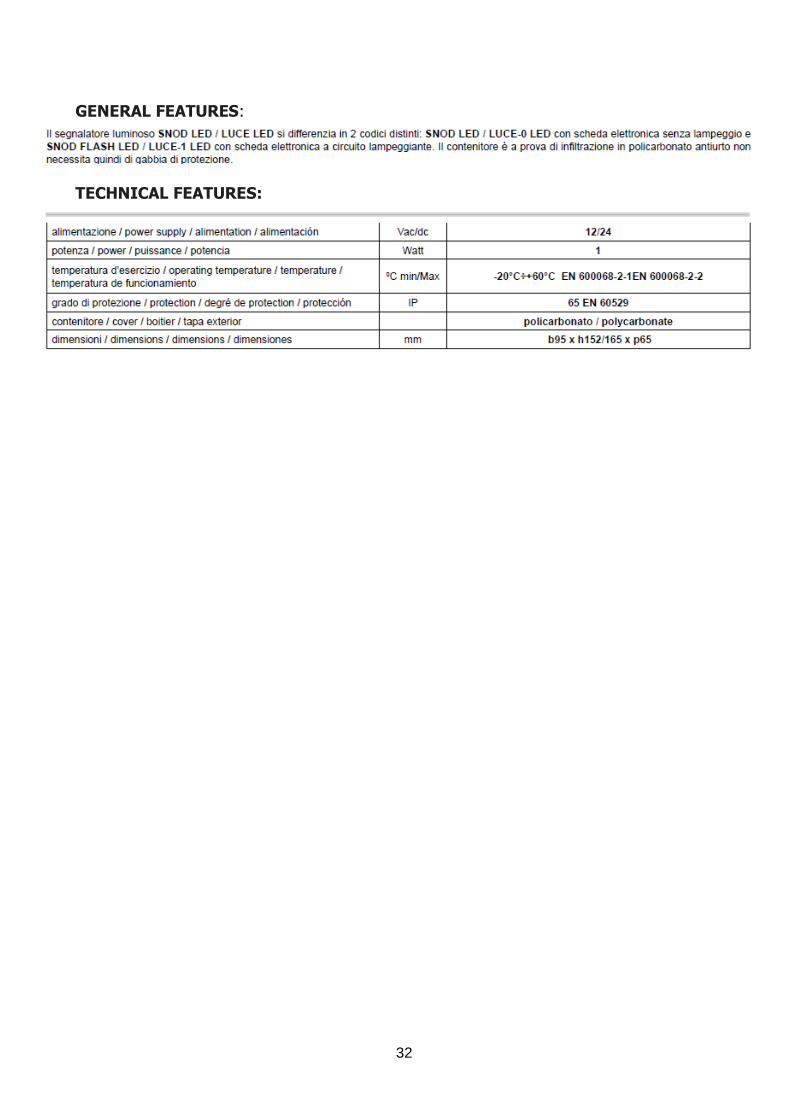
GENERAL FEATURES:
TECHNICAL FEATURES:
I
33
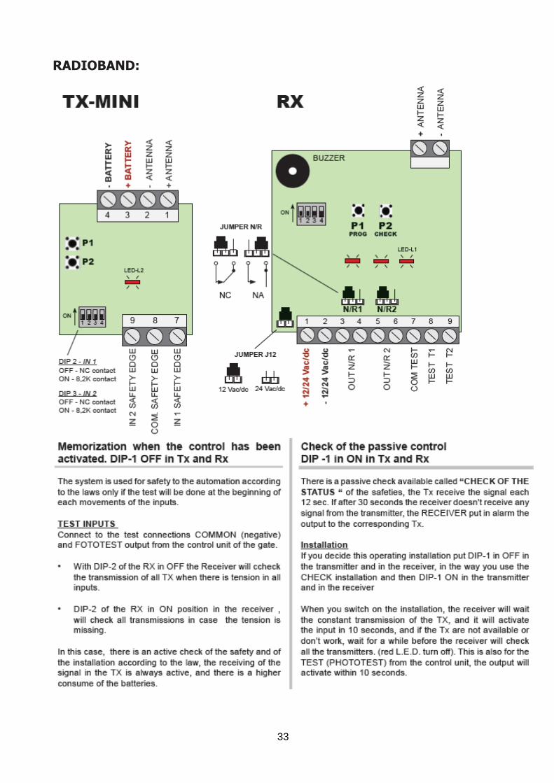
RADIOBAND:
I
34
I
35
I
36
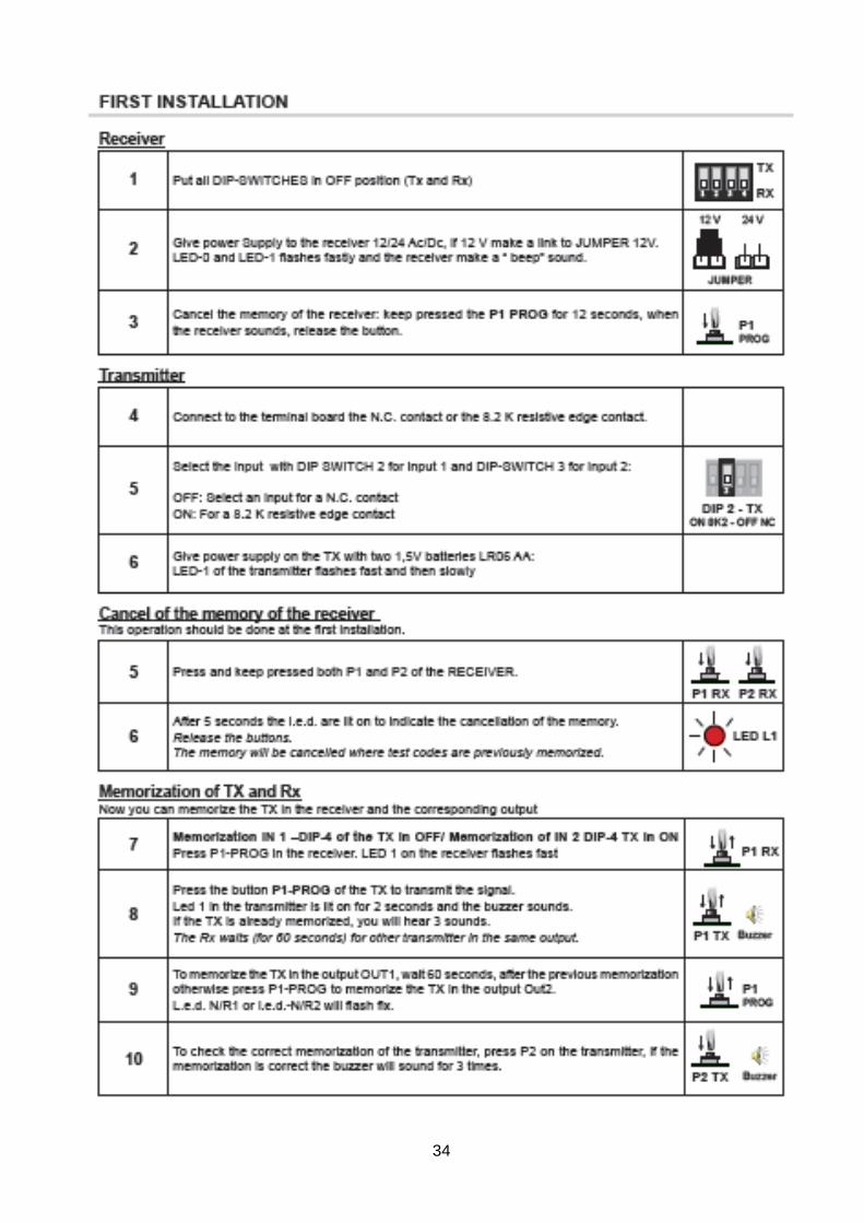
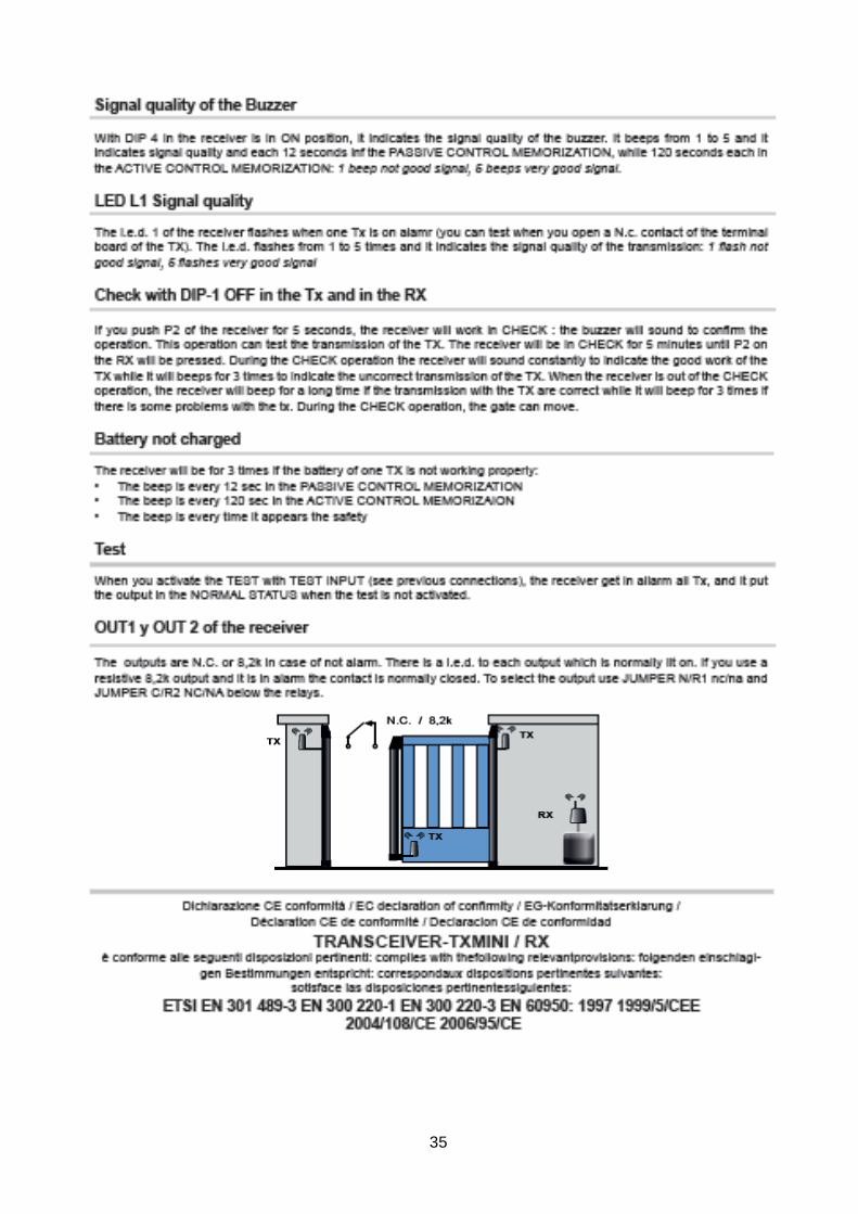
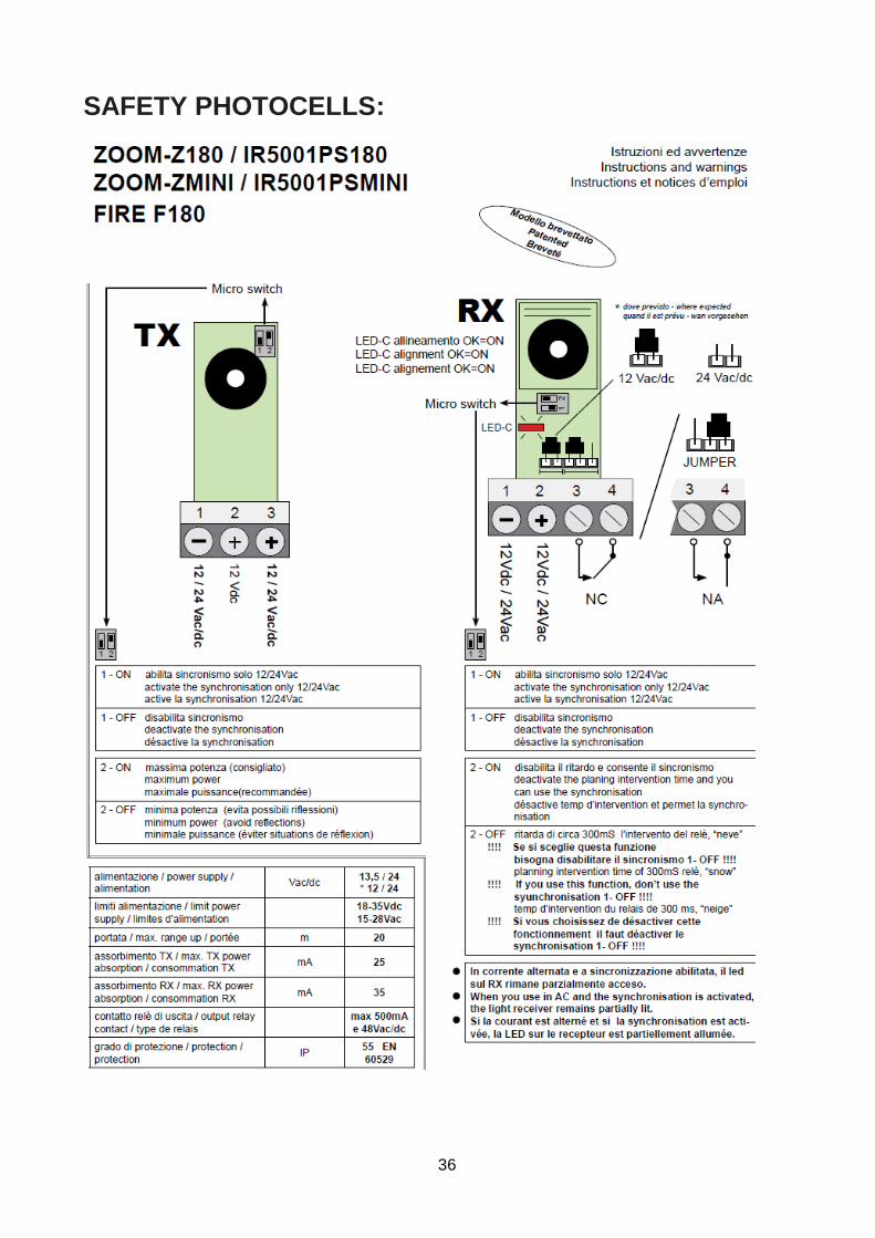
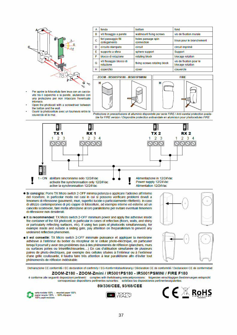
SAFETY PHOTOCELLS:
I
37

I
38
NOTES: _____________________________________________________________________________________________
_____________________________________________________________________________________________
_____________________________________________________________________________________________
_____________________________________________________________________________________________
_____________________________________________________________________________________________
_____________________________________________________________________________________________
_____________________________________________________________________________________________
_____________________________________________________________________________________________
_____________________________________________________________________________________________
_____________________________________________________________________________________________
_____________________________________________________________________________________________
_____________________________________________________________________________________________
_____________________________________________________________________________________________
_____________________________________________________________________________________________
_____________________________________________________________________________________________
_____________________________________________________________________________________________
_____________________________________________________________________________________________
_____________________________________________________________________________________________
_____________________________________________________________________________________________
_____________________________________________________________________________________________
_____________________________________________________________________________________________
I
39
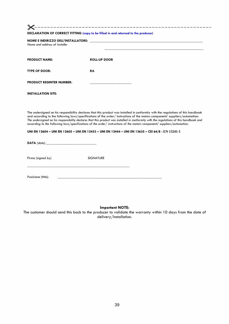
DECLARATION OF CORRECT FITTING (copy to be filled in and returned to the producer) NOME E INDIRIZZO DELL’INSTALLATORE: _________________________________________________________________ Name and address of Installer
_________________________________________________________ PRODUCT NAME: ROLL-UP DOOR TYPE OF DOOR: RA PRODUCT REGINTER NUMBER: ________________________ INSTALLATION SITE: The undersigned on his responsibility declares that this product was installed in conformity with the regulations of this handbook and according to the following laws/specifications of the order/ instructions of the motors components’ suppliers/automation: The undersigned on his responsibility declares that this product was installed in conformity with the regulations of this handbook and according to the following laws/specifications of the order/ instructions of the motors components’ suppliers/automation.
UNI EN 12604 – UNI EN 12605 – UNI EN 12453 – UNI EN 12444 – UNI EN 13635 – CEI 64/8 - EN 13241-1 DATA (date):_____________________________ Firma (signed by) SIGNATURE ___________________________________________________________ Posizione (title): ____________________________________________________________
Important NOTE: The customer should send this back to the producer to validate the warranty within 10 days from the date of
delivery/installation.

I
40
NOTES: _____________________________________________________________________________________________
_____________________________________________________________________________________________
_____________________________________________________________________________________________
_____________________________________________________________________________________________
_____________________________________________________________________________________________
_____________________________________________________________________________________________
_____________________________________________________________________________________________
_____________________________________________________________________________________________
_____________________________________________________________________________________________
_____________________________________________________________________________________________
_____________________________________________________________________________________________
_____________________________________________________________________________________________
_____________________________________________________________________________________________
_____________________________________________________________________________________________
_____________________________________________________________________________________________
_____________________________________________________________________________________________
_____________________________________________________________________________________________
_____________________________________________________________________________________________
_____________________________________________________________________________________________
_____________________________________________________________________________________________
_____________________________________________________________________________________________
I
41
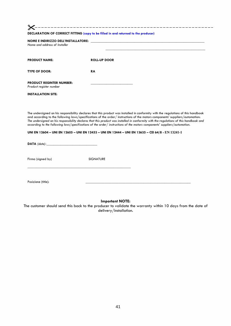
DECLARATION OF CORRECT FITTING (copy to be filled in and returned to the producer) NOME E INDIRIZZO DELL’INSTALLATORE: _________________________________________________________________ Name and address of Installer
_________________________________________________________ PRODUCT NAME: ROLL-UP DOOR TYPE OF DOOR: RA PRODUCT REGINTER NUMBER: ________________________ Product register number INSTALLATION SITE: The undersigned on his responsibility declares that this product was installed in conformity with the regulations of this handbook and according to the following laws/specifications of the order/ instructions of the motors components’ suppliers/automation: The undersigned on his responsibility declares that this product was installed in conformity with the regulations of this handbook and according to the following laws/specifications of the order/ instructions of the motors components’ suppliers/automation.
UNI EN 12604 – UNI EN 12605 – UNI EN 12453 – UNI EN 12444 – UNI EN 13635 – CEI 64/8 - EN 13241-1 DATA (date):_____________________________ Firma (signed by) SIGNATURE ___________________________________________________________ Posizione (title): ____________________________________________________________
Important NOTE: The customer should send this back to the producer to validate the warranty within 10 days from the date of
delivery/installation.