ta100-200-250 installation instructions › lib › focusedtechnology › ta100-200-250-i.pdf203.2...
TRANSCRIPT
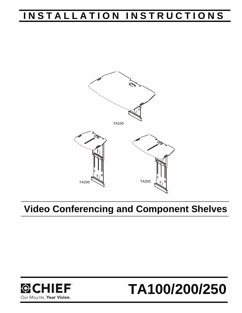
I N S T A L L A T I O N I N S T R U C T I O N S
Instrucciones de instalaciónInstallationsanleitungInstruções de Instalação
Istruzioni di installazioneInstallatie-instructiesInstructions d´installation
TA100
TA200 TA250
Video Conferencing and Component ShelvesSpanish Product DescriptionGerman Product Description
Portuguese Product Description Italian Product DescriptionDutch Product Description
French Product Description
TA100/200/250
TA100/200/250 Installation Instructions
2
DISCLAIMERMilestone AV Technologies and its affiliated corporations andsubsidiaries (collectively "Milestone"), intend to make thismanual accurate and complete. However, Milestone makes noclaim that the information contained herein covers all details,conditions or variations, nor does it provide for every possiblecontingency in connection with the installation or use of thisproduct. The information contained in this document is subjectto change without notice or obligation of any kind. Milestonemakes no representation of warranty, expressed or implied,regarding the information contained herein. Milestone assumesno responsibility for accuracy, completeness or sufficiency ofthe information contained in this document.
Chief® is a registered trademark of Milestone AV Technologies.All rights reserved.
IMPORTANT WARNINGS ANDCAUTIONS!
WARNING: A WARNING alerts you to the possibility ofserious injury or death if you do not follow the instructions.
CAUTION: A CAUTION alerts you to the possibility ofdamage or destruction of equipment if you do not follow thecorresponding instructions.
WARNING: Failure to read, thoroughly understand, andfollow all instructions can result in serious personal injury,damage to equipment, or voiding of factory warranty! It is theinstaller’s responsibility to make sure all components areproperly assembled and installed using the instructionsprovided.
WARNING: Failure to provide adequate structural strengthfor this component can result in serious personal injury ordamage to equipment! It is the installer’s responsibility tomake sure the structure to which this component is attachedcan support five times the combined weight of all equipment.Reinforce the structure as required before installing thecomponent.
WARNING: Exceeding the weight capacity can result inserious personal injury or damage to equipment! It is theinstaller’s responsibility to make sure the combined weight ofall equipment and accessories mounted on each TA100/200/250 shelf does not exceed 10 lbs (4.54 kg) per shelf.
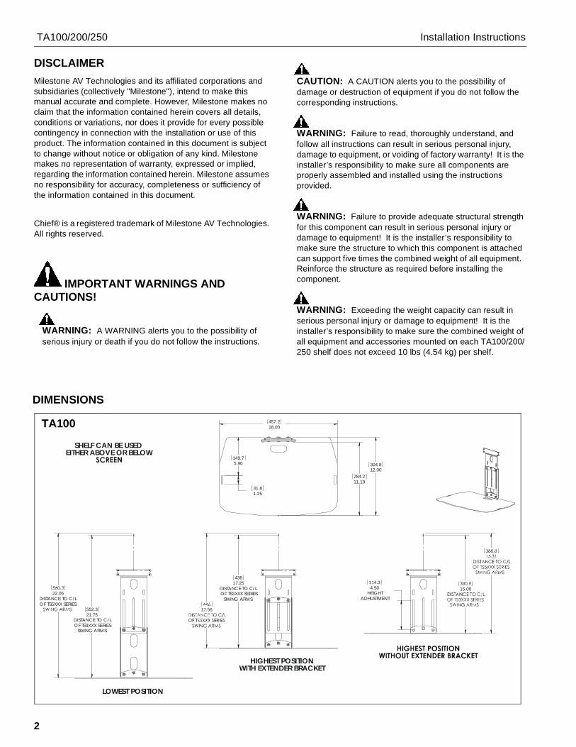
DIMENSIONS
17.25DISTANCE TO C/LOF TS3XXX SERIES
SWING ARMS
438
17.56
HIGHEST POSITIONWITH EXTENDER BRACKET
18.00457.2
5.90149.7
1.2531.8
12.00304.8
11.19284.2
21.75DISTANCE TO C/LOF TS3XXX SERIES
SWING ARMS
552.3
22.06DISTANCE TO C/LOF TS5XXX SERIES
LOWEST POSITION
4.50HEIGHT
ADHUSTMENT
114.315.00
SHELF CAN BE USEDEITHER ABOVE OR BELOW
TA100
Installation Instructions TA100/200/250
3
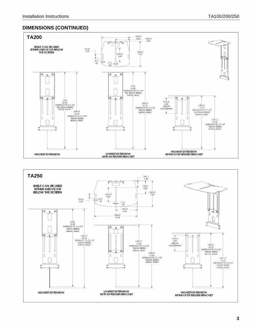
DIMENSIONS (CONTINUED)
22.16DISTANCE TO C/L OF
TS5XXX SERIESSWING ARMS
562.9
21.85DISTANCE TO C/L OF
THE TS3XXX SERIES
HIGHEST EXTENSION
22.16DISTANCE TO C/L OF
TS5XXX SERIESSWING ARMS
562.9
21.85DISTANCE TO C/L OF
THE TS3XXX SERIES
LOWEST EXTENSIONWITH EXTENDER BRACKET
4.50HEIGHT
ADJUSTMENT
114.3
15.41DISTANCE TO C/L OF
TS5XXX SERIES
HIGHEST EXTENSIONWITHOUT EXTENDER BRACKET
8.00203.2
4.00101.6
.287.1
4.00101.6
1.2531.8
.256.4
7.25184.2
SHELF CAN BE USEDEITHER ABOVE OR BELOW
TA200
21.85DISTANCE TO C/L OF
TS3XXX SERIESSWING ARMS
555
22.16
HIGHEST EXTENSION
17.66DISTANCE TO C/L OF
TS5XXX SERIESSWING ARMS
448.6
17.35DISTANCE TO C/L OF
TS3XXX SERIES
LOWEST EXTENSIONWITH EXTENDER BRACKET
4.50HEIGHT
ADJUSTMENT
114.3
15.10DISTANCE TO C/L OF
TS3XXX SERIES
HIGHEST EXTENSIONWITHOUT EXTENDER BRACKET
12.00304.8
6.00152.4
1.9048.1
4.00101.6
.287.11.25
31.8.256.4
3.6592.6
7.25184.2
SHELF CAN BE USEDEITHER ABOVE OR
BELOW THE SCREEN
TA250
TA100/200/250 Installation Instructions
4
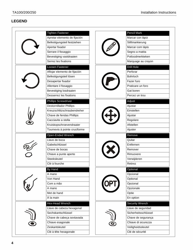
LEGEND
Tighten Fastener
Apretar elemento de fijación
Befestigungsteil festziehen
Apertar fixador
Serrare il fissaggio
Bevestiging vastdraaien
Serrez les fixations
Loosen Fastener
Aflojar elemento de fijación
Befestigungsteil lösen
Desapertar fixador
Allentare il fissaggio
Bevestiging losdraaien
Desserrez les fixations
Phillips Screwdriver
Destornillador Phillips
Kreuzschlitzschraubendreher
Chave de fendas Phillips
Cacciavite a stella
Kruiskopschroevendraaier
Tournevis à pointe cruciforme
Open-Ended Wrench
Llave de boca
Gabelschlüssel
Chave de bocas
Chiave a punte aperte
Steeksleutel
Clé à fourche
By Hand
A mano
Von Hand
Com a mão
A mano
Met de hand
À la main
Hex-Head Wrench
Llave de cabeza hexagonal
Sechskantschlüssel
Chave de cabeça sextavada
Chiave esagonale
Zeskantsleutel
Clé à tête hexagonale
Pencil Mark
Marcar con lápiz
Stiftmarkierung
Marcar com lápis
Segno a matita
Potloodmerkteken
Marquage au crayon
Drill Hole
Perforar
Bohrloch
Fazer furo
Praticare un foro
Gat boren
Percez un trou
Adjust
Ajustar
Einstellen
Ajustar
Regolare
Afstellen
Ajuster
Remove
Quitar
Entfernen
Remover
Rimuovere
Verwijderen
Retirez
Optional
Opcional
Optional
Opcional
Opzionale
Optie
En option
Security Wrench
Llave de seguridad
Sicherheitsschlüssel
Chave de segurança
Chiave di sicurezza
Veiligheidssleutel
Clé de sécurité
TA100/200/250 Installation Instructions
5
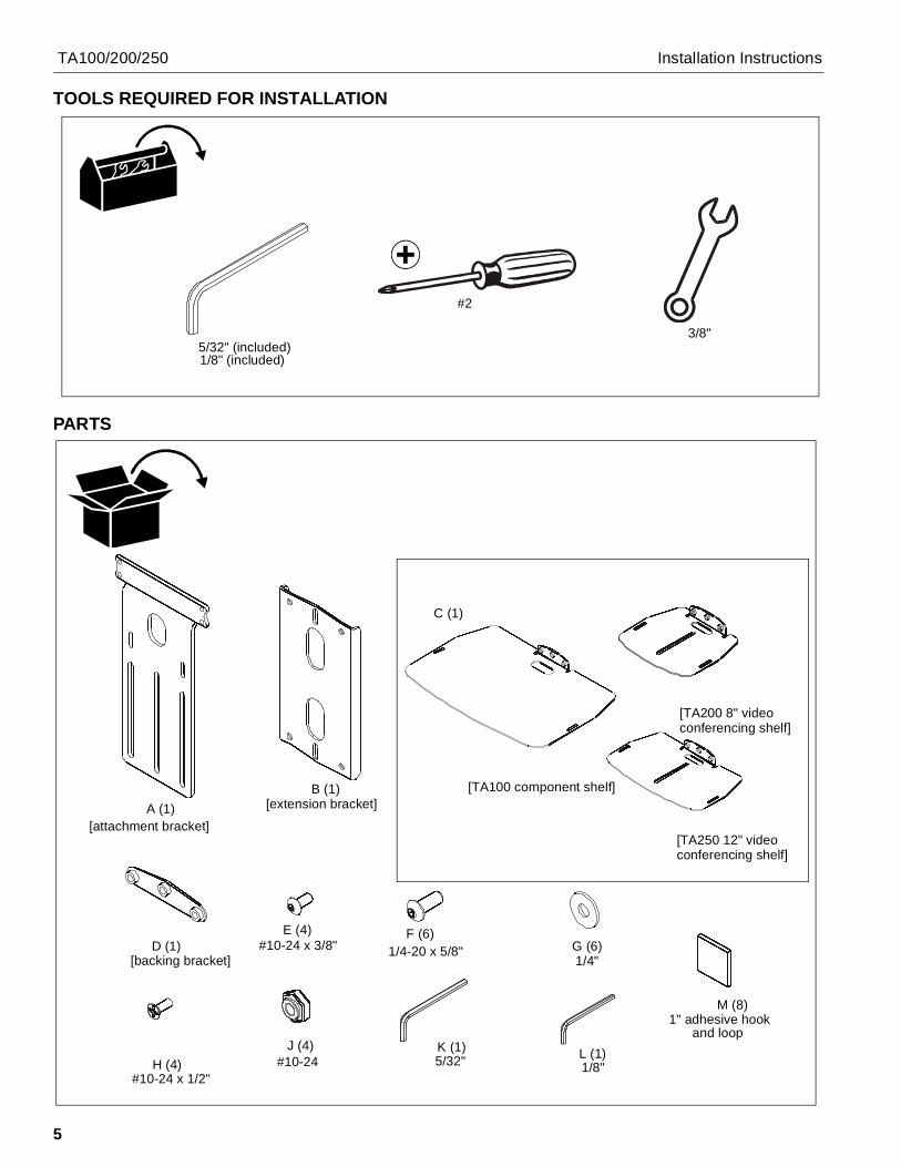
TOOLS REQUIRED FOR INSTALLATION
PARTS
5/32" (included)1/8" (included)
#2
3/8"
A (1)B (1)
C (1)
[attachment bracket]
[extension bracket][TA100 component shelf]
[TA200 8" videoconferencing shelf]
[TA250 12" videoconferencing shelf]
D (1)[backing bracket]
E (4)#10-24 x 3/8"
F (6)1/4-20 x 5/8" G (6)
1/4"
H (4) 5/32"J (4)
1/8"K (1) L (1)
#10-24 x 1/2"#10-24
M (8)1" adhesive hook
and loop

TA100/200/250 Installation Instructions
6
InstallationShelf Assembly1. Use three 1/4-20 x 5/8" button head cap screws (F) and
three 1/4" washers (G) to connect shelf (C) to eitherextension bracket (B) or attachment bracket (A). (SeeFigure 1)
NOTE: Use extension bracket (B) for larger displays or ifcomponent needs to be mounted further from thedisplay.
Figure 1
2. If using extension bracket, use three 1/4-20 x 5/8" buttonhead cap screws (F) and three 1/4" washers (G) to attachextension bracket (B) to attachment bracket (A). (SeeFigure 2)
Figure 2
Installation to FaceplateTS525 or iCF50 InstallationNOTE: Display does NOT have to be removed for shelf
installation.
1. Use four #10-24 x 3/8" button head cap screws (E) toconnect attachment bracket (A) to swing arm faceplate.(See Figure 3) and (See Figure 4)
Figure 3
1 (F) x 3
(G) x 3
(B)
(C)
(TA200 shown)
1 (F) x 3
(G) x 3
(A)
(C)
With extension bracket
Without extension bracket
2 (F) x 3
(G) x 3
(A)
(D)
(B)
(TA200 shown)
(display not shown for clarity)(upper installation)
(A)
(E) x 41
Installation Instructions TA100/200/250
7
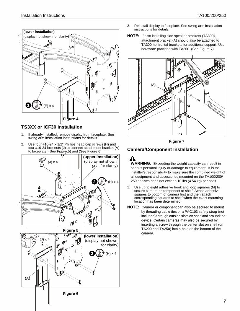
Figure 4
TS3XX or iCF30 Installation1. If already installed, remove display from faceplate. See
swing arm installation instructions for details.
2. Use four #10-24 x 1/2" Phillips head cap screws (H) andfour #10-24 lock nuts (J) to connect attachment bracket (A)to faceplate. (See Figure 5) and (See Figure 6)
Figure 5
Figure 6
3. Reinstall display to faceplate. See swing arm installationinstructions for details.
NOTE: If also installing side speaker brackets (TA300),attachment bracket (A) should also be attached toTA300 horizontal brackets for additional support. Usehardware provided with TA300. (See Figure 7)
Figure 7
Camera/Component Installation
WARNING: Exceeding the weight capacity can result inserious personal injury or damage to equipment! It is theinstaller’s responsibility to make sure the combined weight ofall equipment and accessories mounted on the TA100/200/250 shelves does not exceed 10 lbs (4.54 kg) per shelf.
1. Use up to eight adhesive hook and loop squares (M) tosecure camera or component to shelf. Attach adhesivesquares to bottom of camera first and then attachcorresponding squares to shelf when the exact mountinglocation has been determined.
NOTE: Camera or component can also be secured to mountby threading cable ties or a PAC103 safety strap (notincluded) through outside slots on shelf and around thedevice. Certain cameras may also be secured byinserting a screw through the center slot on shelf (onTA200 and TA250) into a hole on the bottom of thecamera.
(display not shown for clarity)(lower installation)
(E) x 41
(A)(J) x 4
2 (H) x 4
(upper installation)(display not shown for clarity)
(lower installation)(display not shown for clarity)
2 (H) x 4
(J) x 4
(A)
(A)
TA100/200/250 Installation Instructions
8
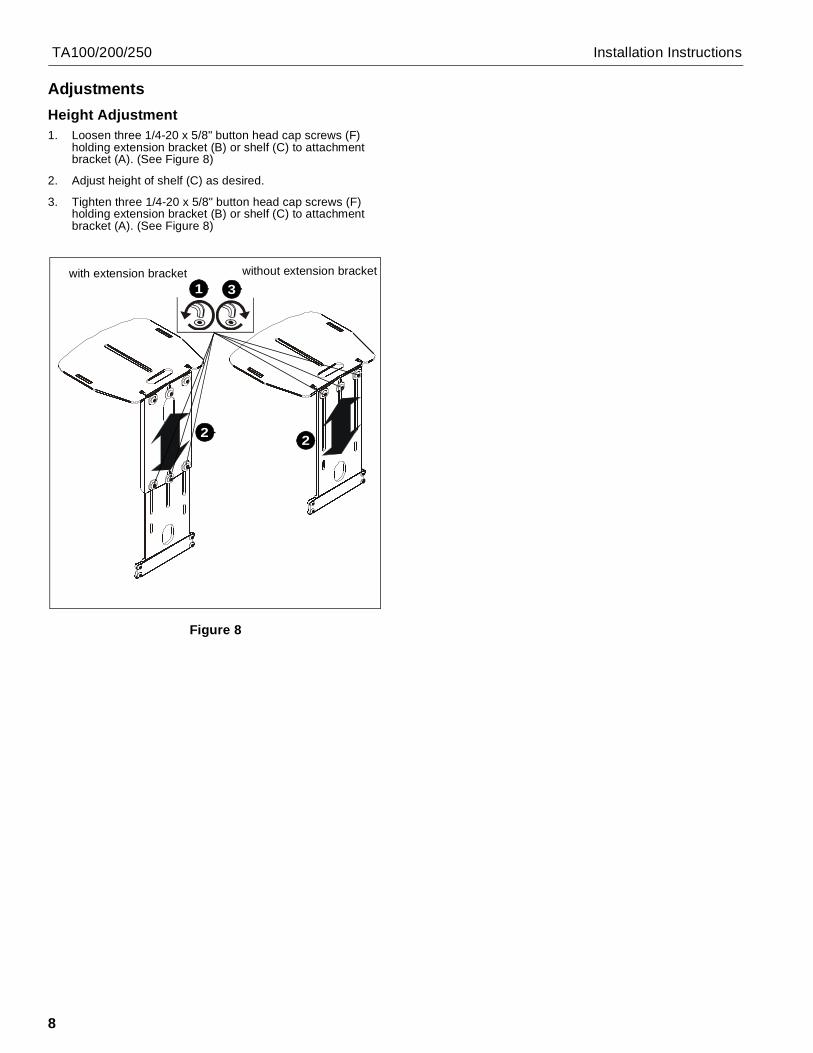
AdjustmentsHeight Adjustment1. Loosen three 1/4-20 x 5/8" button head cap screws (F)
holding extension bracket (B) or shelf (C) to attachmentbracket (A). (See Figure 8)
2. Adjust height of shelf (C) as desired.
3. Tighten three 1/4-20 x 5/8" button head cap screws (F)holding extension bracket (B) or shelf (C) to attachmentbracket (A). (See Figure 8)
Figure 8
2
1 3with extension bracket without extension bracket
2

Installation Instructions TA100/200/250
9

TA100/200/250 Installation Instructions
10

Installation Instructions TA100/200/250
11
TA100/200/250 Installation Instructions
USA/International A 8401 Eagle Creek Parkway, Savage, MN 55378P 800.582.6480 / 952.894.6280F 877.894.6918 / 952.894.6918
Europe A Fellenoord 130 5611 ZB EINDHOVEN, The NetherlandsP +31 (0)40 2668620F +31 (0)40 2668615
Asia Pacific A Office No. 1 on 12/F, Shatin Galleria18-24 Shan Mei StreetFotan, Shatin, Hong Kong
P 852 2145 4099F 852 2145 4477
Chief Manufacturing, a products divisionof Milestone AV Technologies
8805-002018 Rev012011 Milestone AV Technologies, a
Duchossois Group Companywww.chiefmfg.com08/11