scrubi 700 b - kraenzle.ch
TRANSCRIPT
IT
Uso e ManutenzioneEN
Use and MaintenanceFR
Utilisation et EntretienDE
Gebrauch und wartung
49.0217.48ed. 10-2017
SCRUBI 700 B

2
IPX3 GVW: .... KgYear: ........
Art.: .................Mod: .......................Scrubber Dryer
........ V Tot:...... W
Sn . ...........................MADE IN ITALY
.............................. V ....Hz .....W
...
1
82
3 4
5
67
3
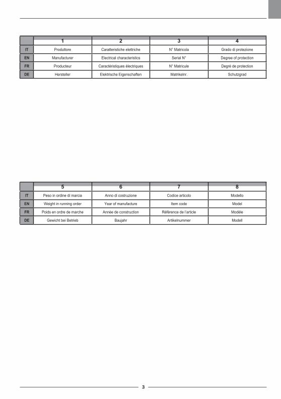
1 2 3 4IT Produttore Caratteristiche elettriche N° Matricola Grado di protezione
EN Manufacturer Electrical characteristics Serial N° Degree of protection
FR Producteur Caractéristiques électriques N° Matricule Degré de protection
DE Hersteller Elektrische Eigenschaften Matrikelnr. Schutzgrad
5 6 7 8IT Peso in ordine di marcia Anno di costruzione Codice articolo Modello
EN Weight in running order Year of manufacture Item code Model
FR Poids en ordre de marche Année de construction Référence de l’article Modèle
DE Gewicht bei Betrieb Baujahr Artikelnummer Modell

5
IT Italiano ................................................................................................... ITALIANO -1 (Istruzioni originali)EN English ...................................................................................................ENGLISH -1
(Translation of original instructions)FR Français .............................................................................................. FRANÇAIS -1
(Traduction des instructions d’origine)DE Deutsch ................................................................................................ DEUTSCH -1
(Übersetzung der Originalanleitung)
ITALIANO - 1
Gentile cliente,La ringraziamo per aver scelto un nostro prodotto per la pulizia dei suoi ambienti.
La lavasciuga pavimenti da lei acquistata è stata progettata per soddisfare l’utilizzatore in termini di semplicità di utilizzo e affidabilità nel tempo.
Noi siamo coscienti che un buon prodotto per restare tale, nel tempo, necessita di con-tinui aggiornamenti mirati a soddisfare le aspettative di chi, quotidianamente, ne fa uso. In tal senso, noi ci auguriamo di avere in lei non solo un cliente soddisfatto ma anche un partner che non esita a trasmetterci opinioni e idee derivanti dalla personale quotidiana esperienza.
ITALIANO - 2
Indice Dati tecnici ........................................................................................................ 3
1.1 Introduzione ..................................................................................................... 5
2.1 Conoscenza della macchina ........................................................................... 5
3.1 Disimballo ......................................................................................................... 5 3.1.a Dotazione macchina (versione batteria) ................................................. 5 3.1.b Dotazione macchina (versione con alimentatore) .................................. 5 3.1.c Caricabatterie da auto (opzionale) ......................................................... 5 3.1.d Sollevamento macchina ......................................................................... 5
4.1 Assemblaggio componenti ............................................................................. 6 4.1.a Montaggio spazzola ............................................................................... 6 4.1.b Posizionamento maniglione ................................................................... 6 4.1.c Montaggio batteria solo per versione batteria ........................................ 6 4.1.d Montaggio alimentatore solo per versione elettrica ................................ 6
5.1 Carica della batteria (se presente) ................................................................. 6 5.1.a Carica della batteria tramite presa 12V .................................................. 7
6.1 Pannello di controllo e comando ................................................................... 76.2 Leva regolazione inclinazione maniglione / Funzionamento ciclo macchina ...................................................................... 86.3 Leve funzionamento ciclo macchina ............................................................. 86.4 Pedale sollevamento/discesa spazzola ......................................................... 86.5 Selettore regolazione pressione a terra spazzola......................................... 9
7.1 Movimentazione della macchina .................................................................... 9
8.1 Riempimento serbatoio acqua pulita ............................................................. 9 8.1.a Riempimento serbatoio in macchina ...................................................... 9 8.1.b Riempimento con serbatoio rimosso .................................................... 10
9.1 Funzionamento ............................................................................................. 10 9.1.a Controlli prima dell’uso ......................................................................... 10 9.1.b Preparazione macchina e scelta ciclo .................................................. 10 9.1.c Uso della macchina .............................................................................. 11 9.1.d Fine uso e spegnimento ....................................................................... 11 9.1.e Parcheggio della macchina. ................................................................. 11
10.1 Scarico acqua di recupero ........................................................................... 11
11.1 Manutenzione e pulizia ................................................................................. 12 11.1.a Svuotamento e pulizia serbatoio acqua pulita ...................................... 12 11.1.b Pulizia serbatoio acqua di recupero ..................................................... 12 11.1.c Rimozione gruppo tergitore .................................................................. 12 11.1.d Pulizia gruppo tergitore ...................................................................... 12 11.1.e Pulizia spazzola................................................................................... 13 11.1.f Sostituzione spazzola........................................................................... 13 11.1.g Sostituzione gomme tergitore............................................................... 13
Problemi - Cause - Rimedi .................................................................................... 14
Accessori opzionali ............................................................................................... 15
Schema elettrico .................................................................................................... 16
ITALIANO - 3
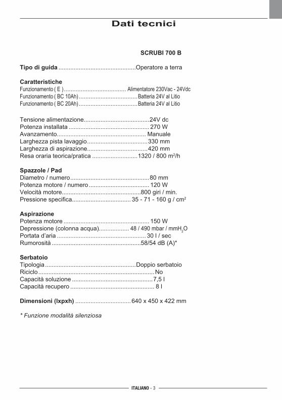
Dati tecnici
SCRUBI 700 B
Tipo di guida ..............................................Operatore a terra
CaratteristicheFunzionamento ( E ) ..................................... Alimentatore 230Vac - 24Vdc Funzionamento ( BC 10Ah) ...................................Batteria 24V al Litio Funzionamento ( BC 20Ah) ...................................Batteria 24V al Litio
Tensione alimentazione.......................................24V dc
Potenza installata
................................................ 270 W
Avanzamento..................................................... Manuale
Larghezza pista lavaggio
....................................330 mm
Larghezza di aspirazione....................................420 mm
Resa oraria teorica/pratica
...........................1320 / 800 m2/h
Spazzole / PadDiametro / numero
...............................................80 mm
Potenza motore / numero
.................................... 120 W
Velocità motore...............................................800 giri / min.
Pressione specifica................................... 35 - 71 - 160 g / cm2
AspirazionePotenza motore
................................................... 150 W
Depressione (colonna acqua).................. 48 / 490 mbar / mmH2O
Portata d’aria
..................................................... 30 l / sec
Rumorosità
.....................................................58/54 dB (A)*
SerbatoioTipologia
......................................................Doppio serbatoio
Riciclo
.....................................................................No
Capacità soluzione
................................................7,5 l
Capacità recupero
.................................................. 8 l
Dimensioni (lxpxh)
................................. 640 x 450 x 422 mm
* Funzione modalità silenziosa
ITALIANO - 4
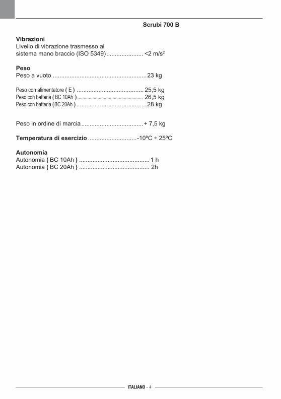
Scrubi 700 B
VibrazioniLivello di vibrazione trasmesso al sistema mano braccio (ISO 5349) ...................... <2 m/s2
PesoPeso a vuoto ........................................................23 kg
Peso con alimentatore ( E ) ........................................ 25,5 kg Peso con batteria ( BC 10Ah ) .................................................... 26,5 kg Peso con batteria (BC 20Ah ) ..........................................28 kg
Peso in ordine di marcia
.....................................+ 7,5 kg
Temperatura di esercizio
.............................-10ºC ÷ 25ºC
AutonomiaAutonomia ( BC 10Ah ) .......................................... 1 h
Autonomia ( BC 20Ah ) .......................................... 2h
ITALIANO - 5
1.1 INTRODUZIONE
PERICOLO:Prima di utilizzare la macchina leggere atten-tamente il libretto “AVVERTENZE DI SICU-REZZA PER LAVASCIUGA PAVIMENTI” allegato al presente.
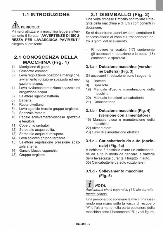
2.1 CONOSCENZA DELLA MACCHINA (Fig. 1)
1) Maniglione di guida.2) Cruscotto comandi.3) Leva regolazione posizione maniglione,
avviamento rotazione spazzola ed ero-gazione acqua.
4) Leva avviamento rotazione spazzola ed erogazione acqua.
5) Selettore sgancio batteria.6) Batteria.7) Ruote pivottanti.8) Leva sgancio braccio gruppo tergitore.9) Spazzola rotante.10) Pedale sollevamento/discesa spazzola
e tergitori.11) Coperchio serbatoi.12) Serbatoio acqua pulita.13) Serbatoio acqua di recupero.14) Leva sblocco gruppo tergitore.15) Selettore regolazione pressione spaz-
zola a terra.16) Gancio blocco coperchio.48) Gruppo tergitore.
3.1 DISIMBALLO (Fig. 2)Una volta rimosso l’imballo controllare l’inte-grità della macchina e di tutti i componenti in dotazione.Se si riscontrano danni evidenti contattare il concessionario di zona e il trasportatore en-tro 3 giorni dal ricevimento.
- Rimuovere la scatola (17) contenente gli accessori in dotazione e la busta (18) contenete la spazzola.
3.1.a - Dotazione macchina (versio-ne batteria) (Fig. 3)
Gli accessori in dotazione sono i seguenti:6) Batteria.9) Spazzola.19) Manuale d’uso e manutenzione della
macchina.20) Manuale istruzioni caricabatterie.21) Caricabatterie.
3.1.b - Dotazione macchina (Fig. 4) (versione con alimentatore)19) Manuale d’uso e manutenzione della
macchina.22) Alimentatore.23) Cavo di alimentazione elettrica.
3.1.c - Caricabatterie da auto (opzio-nale) (Fig. 4a)
A richiesta è possibile avere un caricabatte-rie da auto in modo da caricare la batteria della lavasciuga durante il tragitto in auto.35) Caricabatterie da auto (opzionale). 3.1.d - Sollevamento macchina (Fig. 5)
NOTA:Assicurarsi che il coperchio (11) sia corretta-mente chiuso.Una persona può sollevare la macchina inse-rendo una mano sotto la vasca di recupero “A” e l’altra mano nella parte posteriore della macchina sotto il basamento “B” ; vedi figura.
ITALIANO - 6
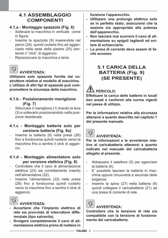
4.1 ASSEMBLAGGIOCOMPONENTI
4.1.a - Montaggio spazzola (Fig. 6)- Sollevare la macchina in verticale come
in figura.- Inserire la spazzola (9) inserendola nel
perno (24), quindi ruotarla fino ad aggan-ciarla nella sede della piastra (25) sen-tendo il “click” di aggancio.
- Riposizionare la macchina a terra.
AVVERTENZA:Utilizzare solo spazzole fornite dal co-struttore relative al modello di macchina.L’utilizzo di altri tipi di spazzole può com-promettere la sicurezza della macchina.
4.1.b - Posizionamento maniglione (Fig. 7)
- Sbloccare il maniglione (1) tirando la leva (3) e sollevarlo posizionandolo nella posi-zione desiderata.
4.1.c - Montaggio batteria solo per versione batteria (Fig. 8a)
- Inserire la batteria (6) nella presa (26) fino a fondocorsa quindi ruotarla verso la macchina fino a sentire il click di aggan-cio.
4.1.d - Montaggio alimentatore solo per versione elettrica (Fig. 8)
- Controllare che il cavo di alimentazione elettrica (23) sia correttamente inserito nell’alimentatore (22).
- Inserire l’alimentatore (22) nella presa (26) fino a fondocorsa quindi ruotarlo verso la macchina fino a sentire il click di aggancio.
AVVERTENZA:- Accertarsi che l’impianto elettrico di
rete sia provvisto di interruttore diffe-renziale (tipo salvavita).
- Svolgere completamente il cavo di ali-mentazione elettrica prima di mettere in
funzione l’apparecchio.- Utilizzare una prolunga elettrica solo
se in perfetto stato; assicurarsi che la sezione sia appropriata alla potenza dell’apparecchio.
- Non lasciare mai scorrere il cavo di ali-mentazione su spigoli taglienti ed evi-tare di schiacciarlo.
- La presa di corrente deve essere di fa-cile accesso.
5.1 CARICA DELLA BATTERIA (Fig. 9) (SE PRESENTE)
PERICOLO:Effettuare la carica delle batterie in locali ben areati e conformi alle norme vigenti nel paese di utilizzo.
Per le informazioni relative alla sicurezza attenersi a quanto descritto nel capitolo 1 del presente manuale.
AVVERTENZA:Per le informazioni e le avvertenze rela-tive al caricabatteria attenersi a quanto indicato nel manuale del caricabatteria allegato al presente.
- Abbassare il selettore (5) per sganciare la batteria (6).
- E’ possibile lasciare la batteria in mac-china oppure rimuoverla a seconda delle esigenze.
- Inserire la spina (27) nella batteria (6) quindi collegare il caricabatterie (21) ad una presa di corrente di rete.
AVVERTENZA:Controllare che la tensione di rete sia compatibile con la tensione di funziona-mento del caricabatteria.
ITALIANO - 7
- Lasciare in carica la batteria fino all’illu-minazione del led (28) “Verde”, quindi staccare il cavo (29) di alimentazione dalla presa di rete, ed il cavo (27) dalla batteria.
NOTA: Per la ricarica completa della batteria sono necessarie 2 ore per la batteria da 10A e 4 ore per la batteria da 20A.E’ possibile effettuare ricariche parziali.
5.1.a - Carica della batteria tramite presa 12V (Fig. 4a - 9)
- Posizionare la macchina nel baule dell’autovettura o furgone.
- Abbassare il selettore (5) per sganciare la batteria (6).
- E’ possibile lasciare la batteria in mac-china oppure rimuoverla a secondo delle esigenze.
- Inserire la spina (27a Fig. 4a) nella bat-teria (6) quindi collegare il caricabatterie (35) ad una presa di corrente da 12V dell’autovettura o furgone.
AVVERTENZA:La macchina è dotata di una sicurezza che evita il suo funzionamento con il vano batteria aperto.
6.1 PANNELLO DI CONTROLLO E COMANDO
(Fig. 10)
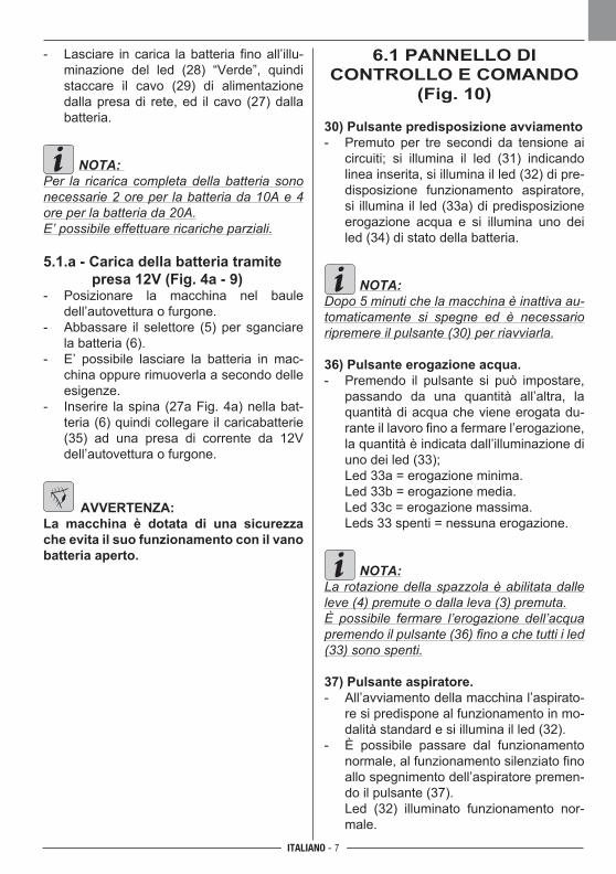
30) Pulsante predisposizione avviamento- Premuto per tre secondi da tensione ai
circuiti; si illumina il led (31) indicando linea inserita, si illumina il led (32) di pre-disposizione funzionamento aspiratore, si illumina il led (33a) di predisposizione erogazione acqua e si illumina uno dei led (34) di stato della batteria.
NOTA:Dopo 5 minuti che la macchina è inattiva au-tomaticamente si spegne ed è necessario ripremere il pulsante (30) per riavviarla.
36) Pulsante erogazione acqua.- Premendo il pulsante si può impostare,
passando da una quantità all’altra, la quantità di acqua che viene erogata du-rante il lavoro fino a fermare l’erogazione, la quantità è indicata dall’illuminazione di uno dei led (33);
Led 33a = erogazione minima. Led 33b = erogazione media. Led 33c = erogazione massima. Leds 33 spenti = nessuna erogazione.
NOTA:La rotazione della spazzola è abilitata dalle leve (4) premute o dalla leva (3) premuta.È possibile fermare l’erogazione dell’acqua premendo il pulsante (36) fino a che tutti i led (33) sono spenti.
37) Pulsante aspiratore.- All’avviamento della macchina l’aspirato-
re si predispone al funzionamento in mo-dalità standard e si illumina il led (32).
- È possibile passare dal funzionamento normale, al funzionamento silenziato fino allo spegnimento dell’aspiratore premen-do il pulsante (37).
Led (32) illuminato funzionamento nor-male.
ITALIANO - 8
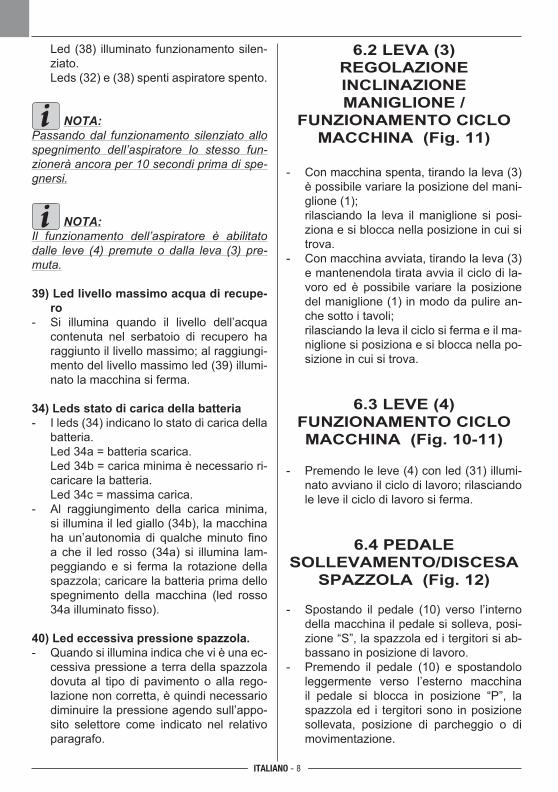
Led (38) illuminato funzionamento silen-ziato.
Leds (32) e (38) spenti aspiratore spento.
NOTA:Passando dal funzionamento silenziato allo spegnimento dell’aspiratore lo stesso fun-zionerà ancora per 10 secondi prima di spe-gnersi.
NOTA:Il funzionamento dell’aspiratore è abilitato dalle leve (4) premute o dalla leva (3) pre-muta.
39) Led livello massimo acqua di recupe-ro
- Si illumina quando il livello dell’acqua contenuta nel serbatoio di recupero ha raggiunto il livello massimo; al raggiungi-mento del livello massimo led (39) illumi-nato la macchina si ferma.
34) Leds stato di carica della batteria- I leds (34) indicano lo stato di carica della
batteria. Led 34a = batteria scarica. Led 34b = carica minima è necessario ri-
caricare la batteria. Led 34c = massima carica.- Al raggiungimento della carica minima,
si illumina il led giallo (34b), la macchina ha un’autonomia di qualche minuto fino a che il led rosso (34a) si illumina lam-peggiando e si ferma la rotazione della spazzola; caricare la batteria prima dello spegnimento della macchina (led rosso 34a illuminato fisso).
40) Led eccessiva pressione spazzola.- Quando si illumina indica che vi è una ec-
cessiva pressione a terra della spazzola dovuta al tipo di pavimento o alla rego-lazione non corretta, è quindi necessario diminuire la pressione agendo sull’appo-sito selettore come indicato nel relativo paragrafo.
6.2 LEVA (3) REGOLAZIONE INCLINAZIONE MANIGLIONE /
FUNZIONAMENTO CICLO MACCHINA (Fig. 11)
- Con macchina spenta, tirando la leva (3) è possibile variare la posizione del mani-glione (1);
rilasciando la leva il maniglione si posi-ziona e si blocca nella posizione in cui si trova.
- Con macchina avviata, tirando la leva (3) e mantenendola tirata avvia il ciclo di la-voro ed è possibile variare la posizione del maniglione (1) in modo da pulire an-che sotto i tavoli;
rilasciando la leva il ciclo si ferma e il ma-niglione si posiziona e si blocca nella po-sizione in cui si trova.
6.3 LEVE (4) FUNZIONAMENTO CICLO MACCHINA (Fig. 10-11)
- Premendo le leve (4) con led (31) illumi-nato avviano il ciclo di lavoro; rilasciando le leve il ciclo di lavoro si ferma.
6.4 PEDALE SOLLEVAMENTO/DISCESA
SPAZZOLA (Fig. 12)
- Spostando il pedale (10) verso l’interno della macchina il pedale si solleva, posi-zione “S”, la spazzola ed i tergitori si ab-bassano in posizione di lavoro.
- Premendo il pedale (10) e spostandolo leggermente verso l’esterno macchina il pedale si blocca in posizione “P”, la spazzola ed i tergitori sono in posizione sollevata, posizione di parcheggio o di movimentazione.
ITALIANO - 9
6.5 SELETTORE REGOLAZIONE
PRESSIONE A TERRA SPAZZOLA (Fig. 1)
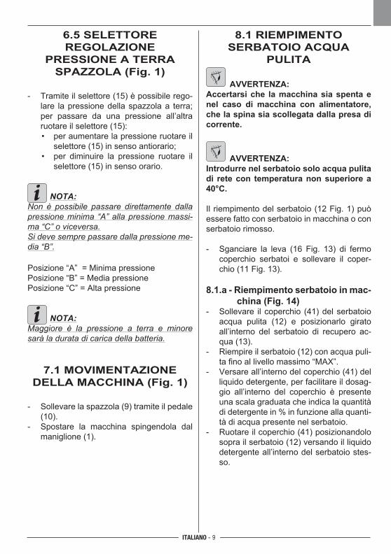
- Tramite il selettore (15) è possibile rego-lare la pressione della spazzola a terra; per passare da una pressione all’altra ruotare il selettore (15):
• per aumentare la pressione ruotare il selettore (15) in senso antiorario;
• per diminuire la pressione ruotare il selettore (15) in senso orario.
NOTA:Non è possibile passare direttamente dalla pressione minima “A” alla pressione massi-ma “C” o viceversa.Si deve sempre passare dalla pressione me-dia “B”.
Posizione “A” = Minima pressionePosizione “B” = Media pressionePosizione “C” = Alta pressione
NOTA:Maggiore è la pressione a terra e minore sarà la durata di carica della batteria.
7.1 MOVIMENTAZIONE DELLA MACCHINA (Fig. 1)
- Sollevare la spazzola (9) tramite il pedale (10).
- Spostare la macchina spingendola dal maniglione (1).
8.1 RIEMPIMENTO SERBATOIO ACQUA
PULITA
AVVERTENZA:Accertarsi che la macchina sia spenta e nel caso di macchina con alimentatore, che la spina sia scollegata dalla presa di corrente.
AVVERTENZA:Introdurre nel serbatoio solo acqua pulita di rete con temperatura non superiore a 40°C.
Il riempimento del serbatoio (12 Fig. 1) può essere fatto con serbatoio in macchina o con serbatoio rimosso.
- Sganciare la leva (16 Fig. 13) di fermo coperchio serbatoi e sollevare il coper-chio (11 Fig. 13).
8.1.a - Riempimento serbatoio in mac-china (Fig. 14)
- Sollevare il coperchio (41) del serbatoio acqua pulita (12) e posizionarlo girato all’interno del serbatoio di recupero ac-qua (13).
- Riempire il serbatoio (12) con acqua puli-ta fino al livello massimo “MAX”.
- Versare all’interno del coperchio (41) del liquido detergente, per facilitare il dosag-gio all’interno del coperchio è presente una scala graduata che indica la quantità di detergente in % in funzione alla quanti-tà di acqua presente nel serbatoio.
- Ruotare il coperchio (41) posizionandolo sopra il serbatoio (12) versando il liquido detergente all’interno del serbatoio stes-so.
ITALIANO - 10
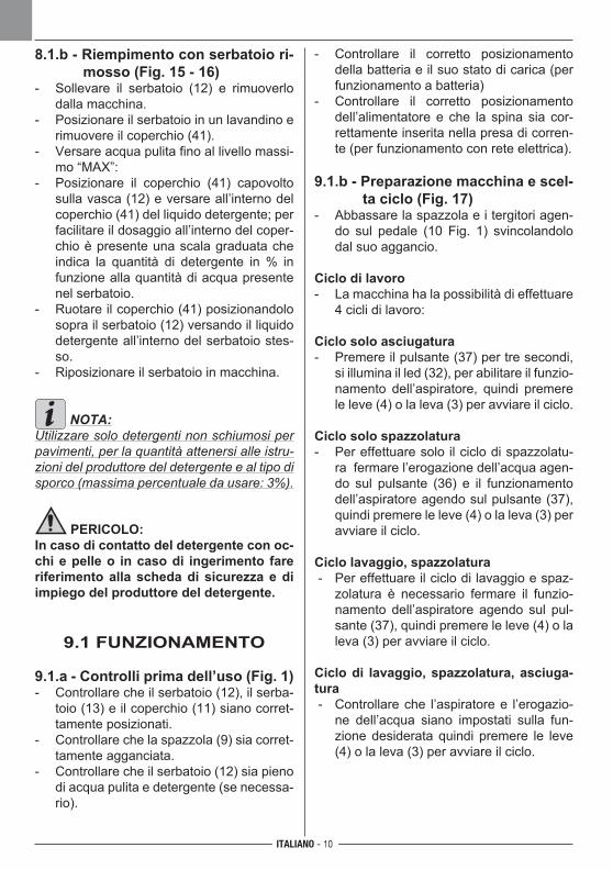
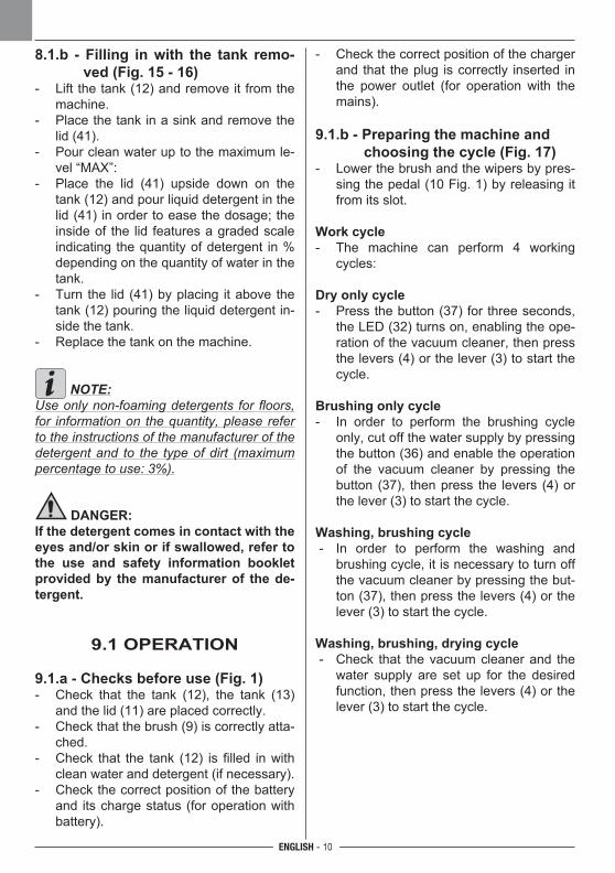
8.1.b - Riempimento con serbatoio ri-mosso (Fig. 15 - 16)
- Sollevare il serbatoio (12) e rimuoverlo dalla macchina.
- Posizionare il serbatoio in un lavandino e rimuovere il coperchio (41).
- Versare acqua pulita fino al livello massi-mo “MAX”:
- Posizionare il coperchio (41) capovolto sulla vasca (12) e versare all’interno del coperchio (41) del liquido detergente; per facilitare il dosaggio all’interno del coper-chio è presente una scala graduata che indica la quantità di detergente in % in funzione alla quantità di acqua presente nel serbatoio.
- Ruotare il coperchio (41) posizionandolo sopra il serbatoio (12) versando il liquido detergente all’interno del serbatoio stes-so.
- Riposizionare il serbatoio in macchina.
NOTA:Utilizzare solo detergenti non schiumosi per pavimenti, per la quantità attenersi alle istru-zioni del produttore del detergente e al tipo di sporco (massima percentuale da usare: 3%).
PERICOLO:In caso di contatto del detergente con oc-chi e pelle o in caso di ingerimento fare riferimento alla scheda di sicurezza e di impiego del produttore del detergente.
9.1 FUNZIONAMENTO
9.1.a - Controlli prima dell’uso (Fig. 1)- Controllare che il serbatoio (12), il serba-
toio (13) e il coperchio (11) siano corret-tamente posizionati.
- Controllare che la spazzola (9) sia corret-tamente agganciata.
- Controllare che il serbatoio (12) sia pieno di acqua pulita e detergente (se necessa-rio).
- Controllare il corretto posizionamento della batteria e il suo stato di carica (per funzionamento a batteria)
- Controllare il corretto posizionamento dell’alimentatore e che la spina sia cor-rettamente inserita nella presa di corren-te (per funzionamento con rete elettrica).
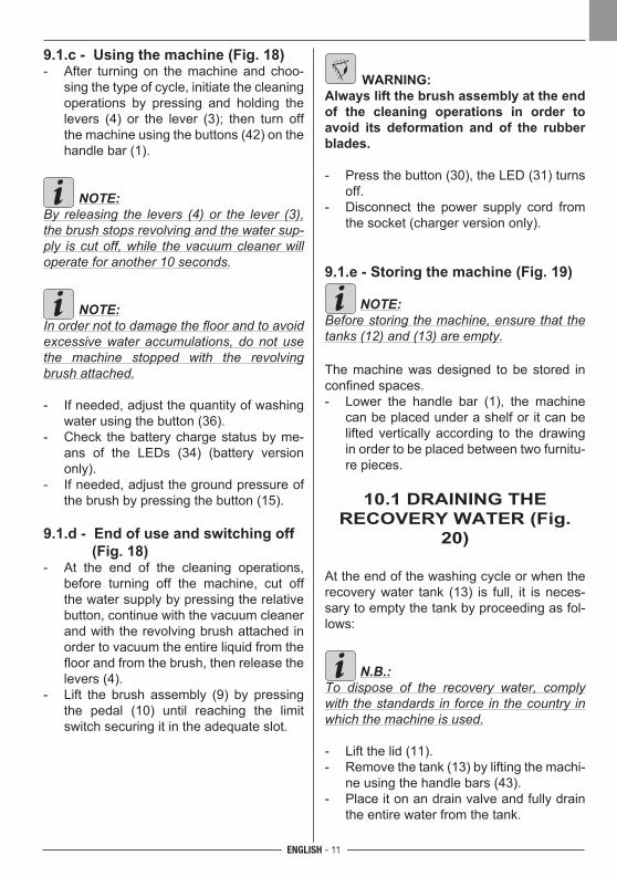
9.1.b - Preparazione macchina e scel-ta ciclo (Fig. 17)
- Abbassare la spazzola e i tergitori agen-do sul pedale (10 Fig. 1) svincolandolo dal suo aggancio.
Ciclo di lavoro- La macchina ha la possibilità di effettuare
4 cicli di lavoro:
Ciclo solo asciugatura- Premere il pulsante (37) per tre secondi,
si illumina il led (32), per abilitare il funzio-namento dell’aspiratore, quindi premere le leve (4) o la leva (3) per avviare il ciclo.
Ciclo solo spazzolatura- Per effettuare solo il ciclo di spazzolatu-
ra fermare l’erogazione dell’acqua agen-do sul pulsante (36) e il funzionamento dell’aspiratore agendo sul pulsante (37), quindi premere le leve (4) o la leva (3) per avviare il ciclo.
Ciclo lavaggio, spazzolatura - Per effettuare il ciclo di lavaggio e spaz-
zolatura è necessario fermare il funzio-namento dell’aspiratore agendo sul pul-sante (37), quindi premere le leve (4) o la leva (3) per avviare il ciclo.
Ciclo di lavaggio, spazzolatura, asciuga-tura - Controllare che l’aspiratore e l’erogazio-
ne dell’acqua siano impostati sulla fun-zione desiderata quindi premere le leve (4) o la leva (3) per avviare il ciclo.
ITALIANO - 11
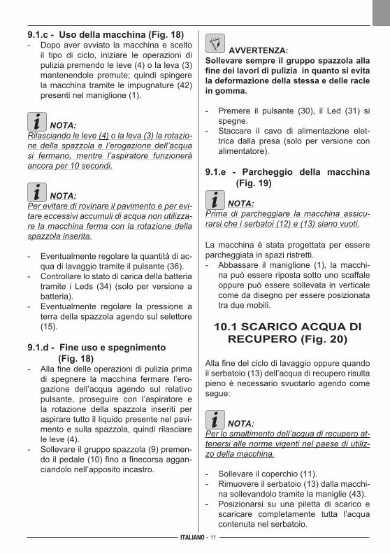
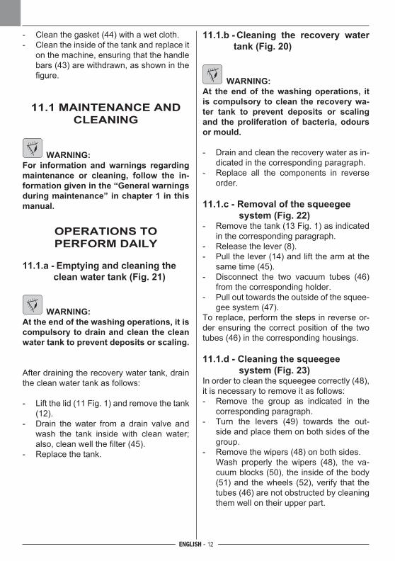
9.1.c - Uso della macchina (Fig. 18)- Dopo aver avviato la macchina e scelto
il tipo di ciclo, iniziare le operazioni di pulizia premendo le leve (4) o la leva (3) mantenendole premute; quindi spingere la macchina tramite le impugnature (42) presenti nel maniglione (1).
NOTA:Rilasciando le leve (4) o la leva (3) la rotazio-ne della spazzola e l’erogazione dell’acqua si fermano, mentre l’aspiratore funzionerà ancora per 10 secondi.
NOTA:Per evitare di rovinare il pavimento e per evi-tare eccessivi accumuli di acqua non utilizza-re la macchina ferma con la rotazione della spazzola inserita.
- Eventualmente regolare la quantità di ac-qua di lavaggio tramite il pulsante (36).
- Controllare lo stato di carica della batteria tramite i Leds (34) (solo per versione a batteria).
- Eventualmente regolare la pressione a terra della spazzola agendo sul selettore (15).
9.1.d - Fine uso e spegnimento (Fig. 18)- Alla fine delle operazioni di pulizia prima
di spegnere la macchina fermare l’ero-gazione dell’acqua agendo sul relativo pulsante, proseguire con l’aspiratore e la rotazione della spazzola inseriti per aspirare tutto il liquido presente nel pavi-mento e sulla spazzola, quindi rilasciare le leve (4).
- Sollevare il gruppo spazzola (9) premen-do il pedale (10) fino a finecorsa aggan-ciandolo nell’apposito incastro.
AVVERTENZA:Sollevare sempre il gruppo spazzola alla fine dei lavori di pulizia in quanto si evita la deformazione della stessa e delle racle in gomma.
- Premere il pulsante (30), il Led (31) si spegne.
- Staccare il cavo di alimentazione elet-trica dalla presa (solo per versione con alimentatore).
9.1.e - Parcheggio della macchina (Fig. 19)
NOTA:Prima di parcheggiare la macchina assicu-rarsi che i serbatoi (12) e (13) siano vuoti.
La macchina è stata progettata per essere parcheggiata in spazi ristretti.- Abbassare il maniglione (1), la macchi-
na può essere riposta sotto uno scaffale oppure può essere sollevata in verticale come da disegno per essere posizionata tra due mobili.
10.1 SCARICO ACQUA DI RECUPERO (Fig. 20)
Alla fine del ciclo di lavaggio oppure quando il serbatoio (13) dell’acqua di recupero risulta pieno è necessario svuotarlo agendo come segue:
NOTA:Per lo smaltimento dell’acqua di recupero at-tenersi alle norme vigenti nel paese di utiliz-zo della macchina.
- Sollevare il coperchio (11).- Rimuovere il serbatoio (13) dalla macchi-
na sollevandolo tramite la maniglie (43).- Posizionarsi su una piletta di scarico e
scaricare completamente tutta l’acqua contenuta nel serbatoio.
ITALIANO - 12
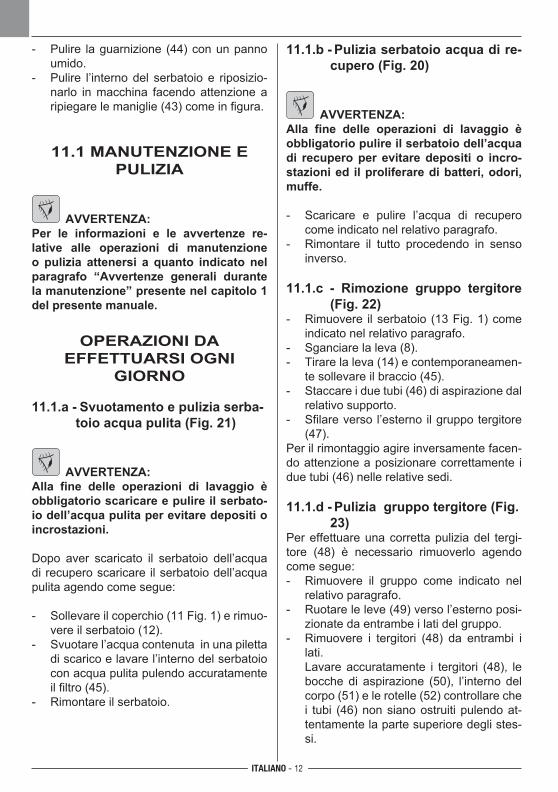
- Pulire la guarnizione (44) con un panno umido.
- Pulire l’interno del serbatoio e riposizio-narlo in macchina facendo attenzione a ripiegare le maniglie (43) come in figura.
11.1 MANUTENZIONE E PULIZIA
AVVERTENZA:Per le informazioni e le avvertenze re-lative alle operazioni di manutenzione o pulizia attenersi a quanto indicato nel paragrafo “Avvertenze generali durante la manutenzione” presente nel capitolo 1 del presente manuale.
OPERAZIONI DAEFFETTUARSI OGNI
GIORNO
11.1.a - Svuotamento e pulizia serba-toio acqua pulita (Fig. 21)
AVVERTENZA:Alla fine delle operazioni di lavaggio è obbligatorio scaricare e pulire il serbato-io dell’acqua pulita per evitare depositi o incrostazioni.
Dopo aver scaricato il serbatoio dell’acqua di recupero scaricare il serbatoio dell’acqua pulita agendo come segue:
- Sollevare il coperchio (11 Fig. 1) e rimuo-vere il serbatoio (12).
- Svuotare l’acqua contenuta in una piletta di scarico e lavare l’interno del serbatoio con acqua pulita pulendo accuratamente il filtro (45).
- Rimontare il serbatoio.
11.1.b - Pulizia serbatoio acqua di re-cupero (Fig. 20)
AVVERTENZA:Alla fine delle operazioni di lavaggio è obbligatorio pulire il serbatoio dell’acqua di recupero per evitare depositi o incro-stazioni ed il proliferare di batteri, odori, muffe.
- Scaricare e pulire l’acqua di recupero come indicato nel relativo paragrafo.
- Rimontare il tutto procedendo in senso inverso.
11.1.c - Rimozione gruppo tergitore (Fig. 22)
- Rimuovere il serbatoio (13 Fig. 1) come indicato nel relativo paragrafo.
- Sganciare la leva (8).- Tirare la leva (14) e contemporaneamen-
te sollevare il braccio (45).- Staccare i due tubi (46) di aspirazione dal
relativo supporto.- Sfilare verso l’esterno il gruppo tergitore
(47).Per il rimontaggio agire inversamente facen-do attenzione a posizionare correttamente i due tubi (46) nelle relative sedi.
11.1.d - Pulizia gruppo tergitore (Fig. 23)
Per effettuare una corretta pulizia del tergi-tore (48) è necessario rimuoverlo agendo come segue:- Rimuovere il gruppo come indicato nel
relativo paragrafo.- Ruotare le leve (49) verso l’esterno posi-
zionate da entrambe i lati del gruppo.- Rimuovere i tergitori (48) da entrambi i
lati. Lavare accuratamente i tergitori (48), le
bocche di aspirazione (50), l’interno del corpo (51) e le rotelle (52) controllare che i tubi (46) non siano ostruiti pulendo at-tentamente la parte superiore degli stes-si.
ITALIANO - 13
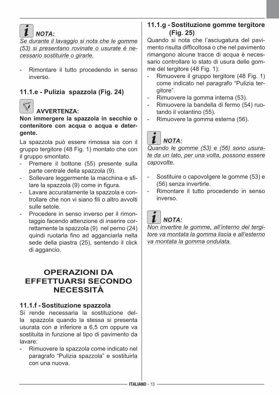
NOTA: Se durante il lavaggio si nota che le gomme (53) si presentano rovinate o usurate è ne-cessario sostituirle o girarle. - Rimontare il tutto procedendo in senso
inverso.
11.1.e - Pulizia spazzola (Fig. 24)
AVVERTENZA:Non immergere la spazzola in secchio o contenitore con acqua o acqua e deter-gente.La spazzola può essere rimossa sia con il gruppo tergitore (48 Fig. 1) montato che con il gruppo smontato.- Premere il bottone (55) presente sulla
parte centrale della spazzola (9).- Sollevare leggermente la macchina e sfi-
lare la spazzola (9) come in figura.- Lavare accuratamente la spazzola e con-
trollare che non vi siano fili o altro avvolti sulle setole.
- Procedere in senso inverso per il rimon-taggio facendo attenzione di inserire cor-rettamente la spazzola (9) nel perno (24) quindi ruotarla fino ad agganciarla nella sede della piastra (25), sentendo il click di aggancio.
OPERAZIONI DAEFFETTUARSI SECONDO
NECESSITÀ
11.1.f - Sostituzione spazzolaSi rende necessaria la sostituzione del-la spazzola quando la stessa si presenta usurata con ø inferiore a 6,5 cm oppure va sostituita in funzione al tipo di pavimento da lavare:- Rimuovere la spazzola come indicato nel
paragrafo “Pulizia spazzola” e sostituirla con una nuova.
11.1.g - Sostituzione gomme tergitore (Fig. 25)
Quando si nota che l’asciugatura del pavi-mento risulta difficoltosa o che nel pavimento rimangono alcune tracce di acqua è neces-sario controllare lo stato di usura delle gom-me del tergitore (48 Fig. 1):- Rimuovere il gruppo tergitore (48 Fig. 1)
come indicato nel paragrafo “Pulizia ter-gitore”.
- Rimuovere la gomma interna (53).- Rimuovere la bandella di fermo (54) ruo-
tando il volantino (55).- Rimuovere la gomma esterna (56).
NOTA:Quando le gomme (53) e (56) sono usura-te da un lato, per una volta, possono essere capovolte.
- Sostituire o capovolgere le gomme (53) e (56) senza invertirle.
- Rimontare il tutto procedendo in senso inverso.
NOTA:Non invertire le gomme, all’interno del tergi-tore va montata la gomma liscia e all’esterno va montata la gomma ondulata.
ITALIANO - 14
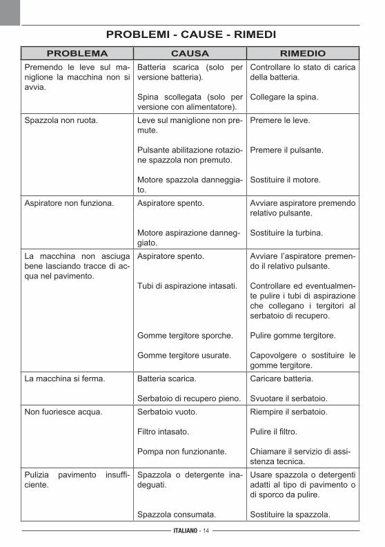
PROBLEMI - CAUSE - RIMEDI
PROBLEMA CAUSA RIMEDIOPremendo le leve sul ma-niglione la macchina non si avvia.
Batteria scarica (solo per versione batteria).
Spina scollegata (solo per versione con alimentatore).
Controllare lo stato di carica della batteria.
Collegare la spina.
Spazzola non ruota. Leve sul maniglione non pre-mute.
Pulsante abilitazione rotazio-ne spazzola non premuto.
Motore spazzola danneggia-to.
Premere le leve.
Premere il pulsante.
Sostituire il motore.
Aspiratore non funziona. Aspiratore spento.
Motore aspirazione danneg-giato.
Avviare aspiratore premendo relativo pulsante.
Sostituire la turbina.
La macchina non asciuga bene lasciando tracce di ac-qua nel pavimento.
Aspiratore spento.
Tubi di aspirazione intasati.
Gomme tergitore sporche.
Gomme tergitore usurate.
Avviare l’aspiratore premen-do il relativo pulsante.
Controllare ed eventualmen-te pulire i tubi di aspirazione che collegano i tergitori al serbatoio di recupero.
Pulire gomme tergitore.
Capovolgere o sostituire le gomme tergitore.
La macchina si ferma. Batteria scarica.
Serbatoio di recupero pieno.
Caricare batteria.
Svuotare il serbatoio.Non fuoriesce acqua. Serbatoio vuoto.
Filtro intasato.
Pompa non funzionante.
Riempire il serbatoio.
Pulire il filtro.
Chiamare il servizio di assi-stenza tecnica.
Pulizia pavimento insuffi-ciente.
Spazzola o detergente ina-deguati.
Spazzola consumata.
Usare spazzola o detergenti adatti al tipo di pavimento o di sporco da pulire.
Sostituire la spazzola.
ITALIANO - 15
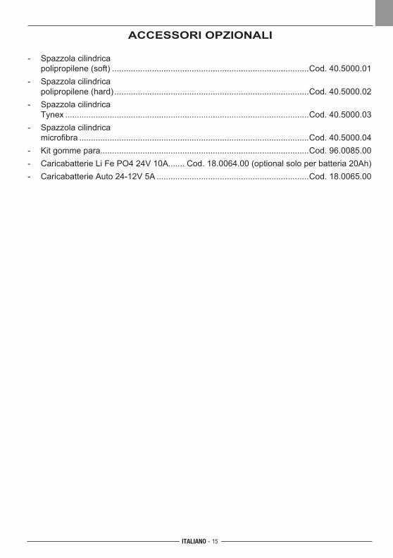
ACCESSORI OPZIONALI
- Spazzola cilindrica polipropilene (soft) ....................................................................................Cod. 40.5000.01- Spazzola cilindrica polipropilene (hard) ...................................................................................Cod. 40.5000.02- Spazzola cilindrica Tynex ........................................................................................................Cod. 40.5000.03- Spazzola cilindrica microfibra ..................................................................................................Cod. 40.5000.04- Kit gomme para.........................................................................................Cod. 96.0085.00 - Caricabatterie Li Fe PO4 24V 10A....... Cod. 18.0064.00 (optional solo per batteria 20Ah)- Caricabatterie Auto 24-12V 5A .................................................................Cod. 18.0065.00
M1
M2
M3
M1.
1M
1.2
M2.
1M
2.2
M3.
1M
3.2
B+
B -
16
T1
SW1a
SW1a.1SW1b.2SW1.3
SW3
SW
3.1
SW
3.2
SW2
SW
2.1
SW
2.2
SW4
SW
4.1
SW
4.2
T1
S5S
5.1
S5.
2
a
b
c
11
10
9
8
7
6
5
4
3
2
1
12 (C) +
13
14
15
16 (C)
F2
SW1b
24V 0
ITALIANO - 16
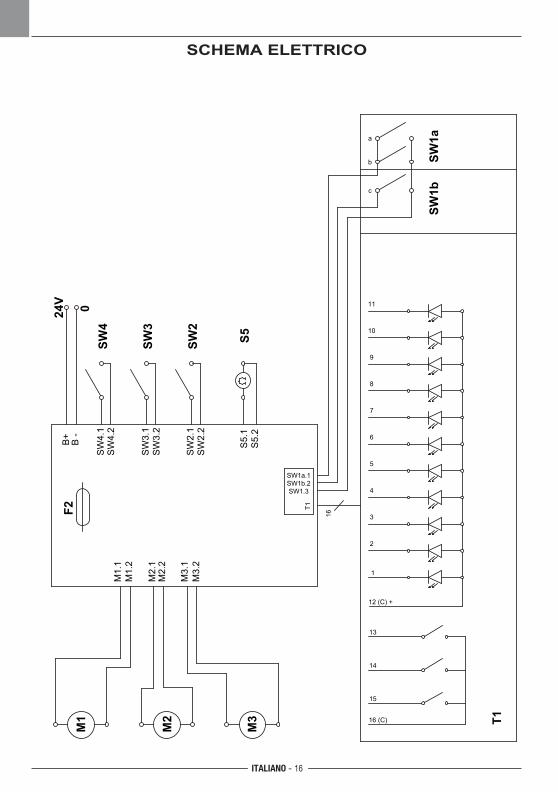
SCHEMA ELETTRICO
ITALIANO - 17
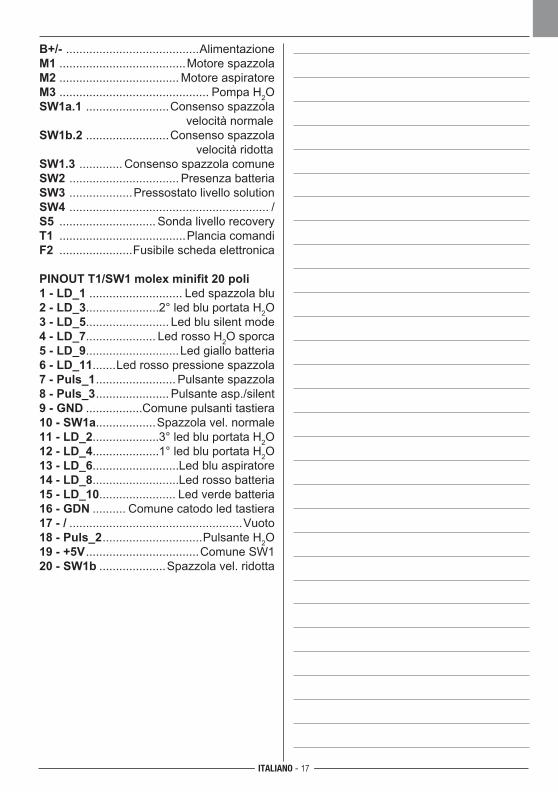
B+/- ........................................AlimentazioneM1 ......................................Motore spazzolaM2 .................................... Motore aspiratoreM3 ............................................. Pompa H2OSW1a.1 .........................Consenso spazzola velocità normaleSW1b.2 .........................Consenso spazzola velocità ridottaSW1.3 ............. Consenso spazzola comuneSW2 ................................. Presenza batteriaSW3 ...................Pressostato livello solutionSW4 ............................................................ /S5 ............................. Sonda livello recoveryT1 ......................................Plancia comandiF2 ......................Fusibile scheda elettronica
PINOUT T1/SW1 molex minifit 20 poli1 - LD_1 ............................ Led spazzola blu2 - LD_3......................2° led blu portata H2O3 - LD_5......................... Led blu silent mode4 - LD_7..................... Led rosso H2O sporca5 - LD_9............................Led giallo batteria6 - LD_11.......Led rosso pressione spazzola7 - Puls_1 ........................ Pulsante spazzola8 - Puls_3 ...................... Pulsante asp./silent9 - GND .................Comune pulsanti tastiera10 - SW1a..................Spazzola vel. normale11 - LD_2....................3° led blu portata H2O12 - LD_4....................1° led blu portata H2O13 - LD_6..........................Led blu aspiratore14 - LD_8..........................Led rosso batteria15 - LD_10....................... Led verde batteria16 - GDN .......... Comune catodo led tastiera17 - / ....................................................Vuoto18 - Puls_2 ..............................Pulsante H2O19 - +5V ..................................Comune SW120 - SW1b ....................Spazzola vel. ridotta

18
ENGLISH - 1
Dear Customer,Thank you for choosing one of our cleaning products.
The floor scrubber dryer that you have purchased has been designed to satisfy the user in terms of ease of use and reliability over time.
We are aware that in order for a good product to stay that way, over time, it requires continuous updates aimed at meeting the expectations of those who use it on a daily basis. For this reason, we hope that you will not only be a satisfied customer but also a partner who does not hesitate to give us your opinions and ideas originating from your personal day-to-day experience.
ENGLISH - 2
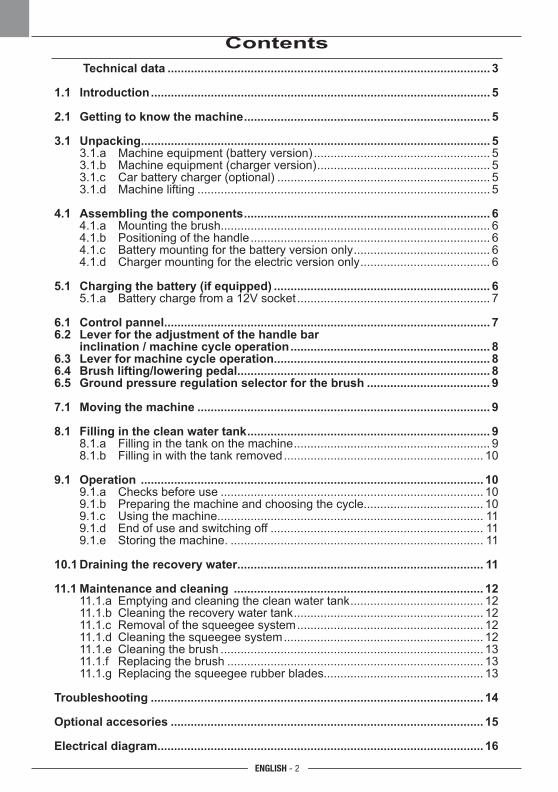
Contents Technical data ................................................................................................. 3
1.1 Introduction ...................................................................................................... 5
2.1 Getting to know the machine .......................................................................... 5
3.1 Unpacking ......................................................................................................... 5 3.1.a Machine equipment (battery version) ..................................................... 5 3.1.b Machine equipment (charger version) .................................................... 5 3.1.c Car battery charger (optional) ................................................................ 5 3.1.d Machine lifting ........................................................................................ 5
4.1 Assembling the components .......................................................................... 6 4.1.a Mounting the brush................................................................................. 6 4.1.b Positioning of the handle ........................................................................ 6 4.1.c Battery mounting for the battery version only ......................................... 6 4.1.d Charger mounting for the electric version only ....................................... 6
5.1 Charging the battery (if equipped) ................................................................. 6 5.1.a Battery charge from a 12V socket .......................................................... 7
6.1 Control pannel .................................................................................................. 76.2 Lever for the adjustment of the handle bar inclination / machine cycle operation ............................................................ 86.3 Lever for machine cycle operation................................................................. 86.4 Brush lifting/lowering pedal ............................................................................ 86.5 Ground pressure regulation selector for the brush ..................................... 9
7.1 Moving the machine ........................................................................................ 9
8.1 Filling in the clean water tank ......................................................................... 9 8.1.a Filling in the tank on the machine ........................................................... 9 8.1.b Filling in with the tank removed ............................................................ 10
9.1 Operation ....................................................................................................... 10 9.1.a Checks before use ............................................................................... 10 9.1.b Preparing the machine and choosing the cycle.................................... 10 9.1.c Using the machine................................................................................ 11 9.1.d End of use and switching off ................................................................ 11 9.1.e Storing the machine. ............................................................................ 11
10.1 Draining the recovery water.......................................................................... 11
11.1 Maintenance and cleaning ........................................................................... 12 11.1.a Emptying and cleaning the clean water tank ........................................ 12 11.1.b Cleaning the recovery water tank ......................................................... 12 11.1.c Removal of the squeegee system ........................................................ 12 11.1.d Cleaning the squeegee system ............................................................ 12 11.1.e Cleaning the brush ............................................................................... 13 11.1.f Replacing the brush ............................................................................. 13 11.1.g Replacing the squeegee rubber blades................................................ 13
Troubleshooting .................................................................................................... 14
Optional accesories .............................................................................................. 15
Electrical diagram.................................................................................................. 16
ENGLISH - 3
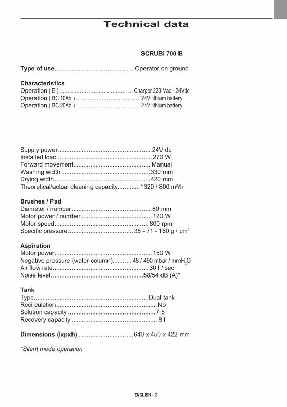
Technical data
SCRUBI 700 B
Type of use...............................................Operator on ground
CharacteristicsOperation ( E ) ........................................... Charger 230 Vac - 24VdcOperation ( BC 10Ah ) ..................................... 24V lithium battery Operation ( BC 20Ah ) ..................................... 24V lithium battery
Supply power .......................................................24V dc Installed load ....................................................... 270 W Forward movement............................................. Manual Washing width ....................................................330 mm Drying width ........................................................420 mm Theoretical/actual cleaning capacity.............1320 / 800 m2/h
Brushes / PadDiameter / number ...............................................80 mm Motor power / number ......................................... 120 W Motor speed....................................................... 800 rpm Specific pressure ...................................... 35 - 71 - 160 g / cm2
AspirationMotor power......................................................... 150 W Negative pressure (water column)........... 48 / 490 mbar / mmH2O Air flow rate........................................................ 30 l / sec Noise level ......................................................58/54 dB (A)*
TankType...................................................................Dual tank Recirculation ...........................................................No Solution capacity ...................................................7,5 l Recovery capacity .................................................. 8 l
Dimensions (lxpxh) ................................ 640 x 450 x 422 mm
*Silent mode operation
ENGLISH - 4
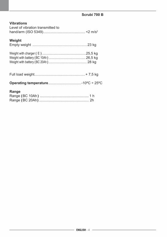
Scrubi 700 B
VibrationsLevel of vibration transmitted tohand/arm (ISO 5349) .......................................... <2 m/s2
WeightEmpty weight .......................................................23 kg
Weight with charger ( E ) ............................................25,5 kg Weight with battery ( BC 10Ah ) ................................................. 26,5 kg Weight with battery ( BC 20Ah ) ...................................... 28 kg
Full load weight...................................................+ 7,5 kg
Operating temperature
.................................-10ºC ÷ 25ºC
RangeRange (BC 10Ah )
................................................. 1 h
Range (BC 20Ah)
.................................................. 2h
ENGLISH - 5
1.1 INTRODUCTION
HAZARD:Before using the machine, carefully read the attached “SAFETY WARNINGS FOR THE FLOOR SCRUBBER DRYER” manual.
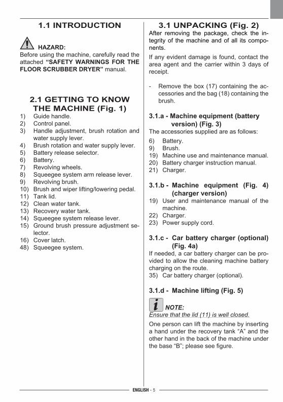
2.1 GETTING TO KNOW THE MACHINE (Fig. 1)
1) Guide handle.2) Control panel.3) Handle adjustment, brush rotation and
water supply lever.4) Brush rotation and water supply lever.5) Battery release selector.6) Battery.7) Revolving wheels.8) Squeegee system arm release lever.9) Revolving brush.10) Brush and wiper lifting/lowering pedal.11) Tank lid.12) Clean water tank.13) Recovery water tank.14) Squeegee system release lever.15) Ground brush pressure adjustment se-
lector.16) Cover latch.48) Squeegee system.
3.1 UNPACKING (Fig. 2)After removing the package, check the in-tegrity of the machine and of all its compo-nents.If any evident damage is found, contact the area agent and the carrier within 3 days of receipt.
- Remove the box (17) containing the ac-cessories and the bag (18) containing the brush.
3.1.a - Machine equipment (battery version) (Fig. 3)
The accessories supplied are as follows:6) Battery.9) Brush.19) Machine use and maintenance manual.20) Battery charger instruction manual.21) Charger.
3.1.b - Machine equipment (Fig. 4) (charger version)
19) User and maintenance manual of the machine.
22) Charger.23) Power supply cord.
3.1.c - Car battery charger (optional) (Fig. 4a)
If needed, a car battery charger can be pro-vided to allow the cleaning machine battery charging on the route.35) Car battery charger (optional). 3.1.d - Machine lifting (Fig. 5)
NOTE:Ensure that the lid (11) is well closed.One person can lift the machine by inserting a hand under the recovery tank “A” and the other hand in the back of the machine under the base “B”; please see figure.
ENGLISH - 6
4.1 ASSEMBLING THECOMPONENTS
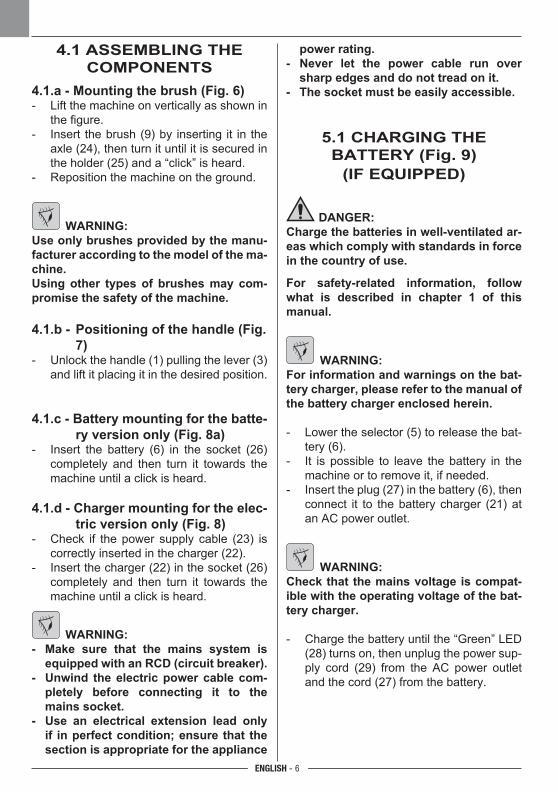
4.1.a - Mounting the brush (Fig. 6)- Lift the machine on vertically as shown in
the figure.- Insert the brush (9) by inserting it in the
axle (24), then turn it until it is secured in the holder (25) and a “click” is heard.
- Reposition the machine on the ground.
WARNING:Use only brushes provided by the manu-facturer according to the model of the ma-chine.Using other types of brushes may com-promise the safety of the machine.
4.1.b - Positioning of the handle (Fig. 7)
- Unlock the handle (1) pulling the lever (3) and lift it placing it in the desired position.
4.1.c - Battery mounting for the batte-ry version only (Fig. 8a)
- Insert the battery (6) in the socket (26) completely and then turn it towards the machine until a click is heard.
4.1.d - Charger mounting for the elec-tric version only (Fig. 8)
- Check if the power supply cable (23) is correctly inserted in the charger (22).
- Insert the charger (22) in the socket (26) completely and then turn it towards the machine until a click is heard.
WARNING:- Make sure that the mains system is
equipped with an RCD (circuit breaker).- Unwind the electric power cable com-
pletely before connecting it to the mains socket.
- Use an electrical extension lead only if in perfect condition; ensure that the section is appropriate for the appliance
power rating.- Never let the power cable run over
sharp edges and do not tread on it.- The socket must be easily accessible.
5.1 CHARGING THE BATTERY (Fig. 9)
(IF EQUIPPED)
DANGER:Charge the batteries in well-ventilated ar-eas which comply with standards in force in the country of use.
For safety-related information, follow what is described in chapter 1 of this manual.
WARNING:For information and warnings on the bat-tery charger, please refer to the manual of the battery charger enclosed herein.
- Lower the selector (5) to release the bat-tery (6).
- It is possible to leave the battery in the machine or to remove it, if needed.
- Insert the plug (27) in the battery (6), then connect it to the battery charger (21) at an AC power outlet.
WARNING:Check that the mains voltage is compat-ible with the operating voltage of the bat-tery charger.
- Charge the battery until the “Green” LED (28) turns on, then unplug the power sup-ply cord (29) from the AC power outlet and the cord (27) from the battery.
ENGLISH - 7
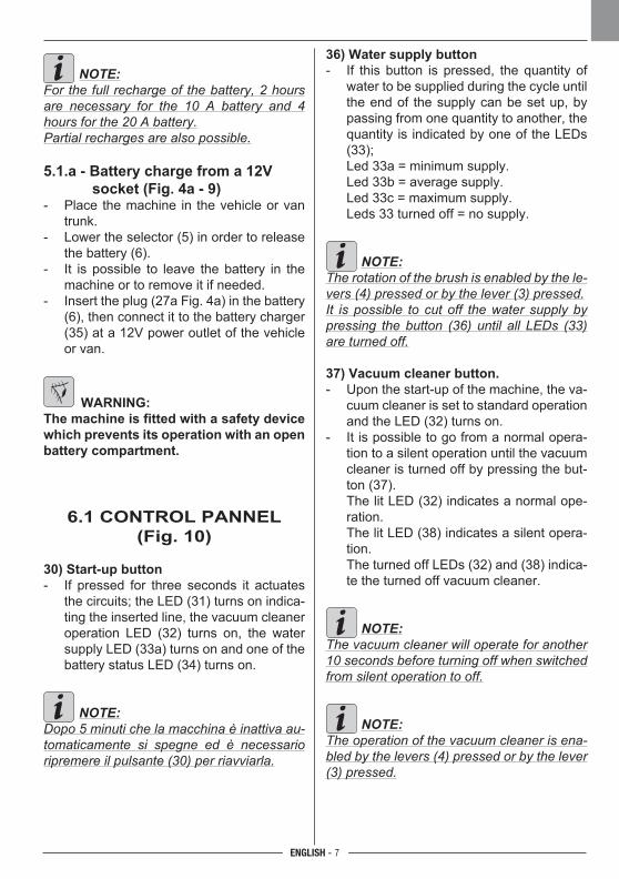
36) Water supply button- If this button is pressed, the quantity of
water to be supplied during the cycle until the end of the supply can be set up, by passing from one quantity to another, the quantity is indicated by one of the LEDs (33);
Led 33a = minimum supply. Led 33b = average supply. Led 33c = maximum supply. Leds 33 turned off = no supply.
NOTE:The rotation of the brush is enabled by the le-vers (4) pressed or by the lever (3) pressed.It is possible to cut off the water supply by pressing the button (36) until all LEDs (33) are turned off.
37) Vacuum cleaner button.- Upon the start-up of the machine, the va-
cuum cleaner is set to standard operation and the LED (32) turns on.
- It is possible to go from a normal opera-tion to a silent operation until the vacuum cleaner is turned off by pressing the but-ton (37).
The lit LED (32) indicates a normal ope-ration.
The lit LED (38) indicates a silent opera-tion.
The turned off LEDs (32) and (38) indica-te the turned off vacuum cleaner.
NOTE:The vacuum cleaner will operate for another 10 seconds before turning off when switched from silent operation to off.
NOTE:The operation of the vacuum cleaner is ena-bled by the levers (4) pressed or by the lever (3) pressed.
NOTE:For the full recharge of the battery, 2 hours are necessary for the 10 A battery and 4 hours for the 20 A battery.Partial recharges are also possible.
5.1.a - Battery charge from a 12V socket (Fig. 4a - 9)
- Place the machine in the vehicle or van trunk.
- Lower the selector (5) in order to release the battery (6).
- It is possible to leave the battery in the machine or to remove it if needed.
- Insert the plug (27a Fig. 4a) in the battery (6), then connect it to the battery charger (35) at a 12V power outlet of the vehicle or van.
WARNING:The machine is fitted with a safety device which prevents its operation with an open battery compartment.
6.1 CONTROL PANNEL(Fig. 10)
30) Start-up button- If pressed for three seconds it actuates
the circuits; the LED (31) turns on indica-ting the inserted line, the vacuum cleaner operation LED (32) turns on, the water supply LED (33a) turns on and one of the battery status LED (34) turns on.
NOTE:Dopo 5 minuti che la macchina è inattiva au-tomaticamente si spegne ed è necessario ripremere il pulsante (30) per riavviarla.
ENGLISH - 8
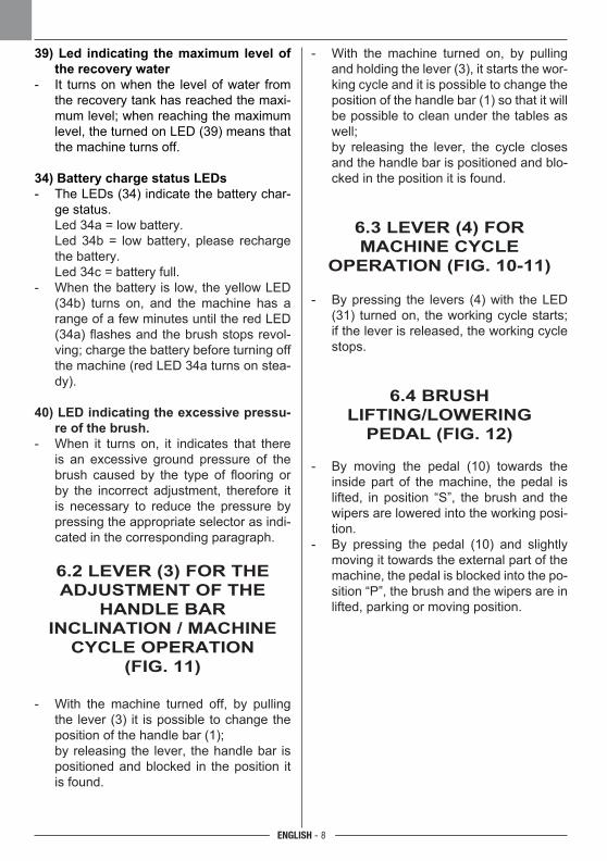
39) Led indicating the maximum level of the recovery water
- It turns on when the level of water from the recovery tank has reached the maxi-mum level; when reaching the maximum level, the turned on LED (39) means that the machine turns off.
34) Battery charge status LEDs- The LEDs (34) indicate the battery char-
ge status. Led 34a = low battery. Led 34b = low battery, please recharge
the battery. Led 34c = battery full.- When the battery is low, the yellow LED
(34b) turns on, and the machine has a range of a few minutes until the red LED (34a) flashes and the brush stops revol-ving; charge the battery before turning off the machine (red LED 34a turns on stea-dy).
40) LED indicating the excessive pressu-re of the brush.
- When it turns on, it indicates that there is an excessive ground pressure of the brush caused by the type of flooring or by the incorrect adjustment, therefore it is necessary to reduce the pressure by pressing the appropriate selector as indi-cated in the corresponding paragraph.
6.2 LEVER (3) FOR THE ADjUSTMENT OF THE
HANDLE BAR INCLINATION / MACHINE
CYCLE OPERATION (FIG. 11)
- With the machine turned off, by pulling the lever (3) it is possible to change the position of the handle bar (1);
by releasing the lever, the handle bar is positioned and blocked in the position it is found.
- With the machine turned on, by pulling and holding the lever (3), it starts the wor-king cycle and it is possible to change the position of the handle bar (1) so that it will be possible to clean under the tables as well;
by releasing the lever, the cycle closes and the handle bar is positioned and blo-cked in the position it is found.
6.3 LEVER (4) FOR MACHINE CYCLE
OPERATION (FIG. 10-11)
- By pressing the levers (4) with the LED (31) turned on, the working cycle starts; if the lever is released, the working cycle stops.
6.4 BRUSH LIFTING/LOWERING
PEDAL (FIG. 12)
- By moving the pedal (10) towards the inside part of the machine, the pedal is lifted, in position “S”, the brush and the wipers are lowered into the working posi-tion.
- By pressing the pedal (10) and slightly moving it towards the external part of the machine, the pedal is blocked into the po-sition “P”, the brush and the wipers are in lifted, parking or moving position.
ENGLISH - 9
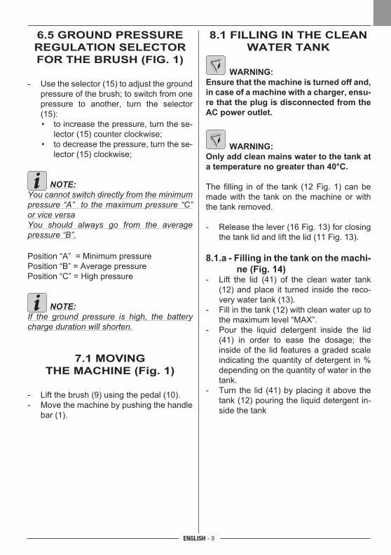
6.5 GROUND PRESSURE REGULATION SELECTOR FOR THE BRUSH (FIG. 1)
- Use the selector (15) to adjust the ground pressure of the brush; to switch from one pressure to another, turn the selector (15):
• to increase the pressure, turn the se-lector (15) counter clockwise;
• to decrease the pressure, turn the se-lector (15) clockwise;
NOTE:You cannot switch directly from the minimum pressure “A” to the maximum pressure “C” or vice versaYou should always go from the average pressure “B”.
Position “A” = Minimum pressurePosition “B” = Average pressurePosition “C” = High pressure
NOTE:If the ground pressure is high, the battery charge duration will shorten.
7.1 MOVING THE MACHINE (Fig. 1)
- Lift the brush (9) using the pedal (10).- Move the machine by pushing the handle
bar (1).
8.1 FILLING IN THE CLEAN WATER TANK
WARNING:Ensure that the machine is turned off and, in case of a machine with a charger, ensu-re that the plug is disconnected from the AC power outlet.
WARNING:Only add clean mains water to the tank at a temperature no greater than 40°C.
The filling in of the tank (12 Fig. 1) can be made with the tank on the machine or with the tank removed.
- Release the lever (16 Fig. 13) for closing the tank lid and lift the lid (11 Fig. 13).
8.1.a - Filling in the tank on the machi-ne (Fig. 14)
- Lift the lid (41) of the clean water tank (12) and place it turned inside the reco-very water tank (13).
- Fill in the tank (12) with clean water up to the maximum level “MAX”.
- Pour the liquid detergent inside the lid (41) in order to ease the dosage; the inside of the lid features a graded scale indicating the quantity of detergent in % depending on the quantity of water in the tank.
- Turn the lid (41) by placing it above the tank (12) pouring the liquid detergent in-side the tank
ENGLISH - 10
8.1.b - Filling in with the tank remo-ved (Fig. 15 - 16)
- Lift the tank (12) and remove it from the machine.
- Place the tank in a sink and remove the lid (41).
- Pour clean water up to the maximum le-vel “MAX”:
- Place the lid (41) upside down on the tank (12) and pour liquid detergent in the lid (41) in order to ease the dosage; the inside of the lid features a graded scale indicating the quantity of detergent in % depending on the quantity of water in the tank.
- Turn the lid (41) by placing it above the tank (12) pouring the liquid detergent in-side the tank.
- Replace the tank on the machine.
NOTE:Use only non-foaming detergents for floors, for information on the quantity, please refer to the instructions of the manufacturer of the detergent and to the type of dirt (maximum percentage to use: 3%).
DANGER:If the detergent comes in contact with the eyes and/or skin or if swallowed, refer to the use and safety information booklet provided by the manufacturer of the de-tergent.
9.1 OPERATION
9.1.a - Checks before use (Fig. 1) - Check that the tank (12), the tank (13)
and the lid (11) are placed correctly.- Check that the brush (9) is correctly atta-
ched.- Check that the tank (12) is filled in with
clean water and detergent (if necessary).- Check the correct position of the battery
and its charge status (for operation with battery).
- Check the correct position of the charger and that the plug is correctly inserted in the power outlet (for operation with the mains).
9.1.b - Preparing the machine and choosing the cycle (Fig. 17)
- Lower the brush and the wipers by pres-sing the pedal (10 Fig. 1) by releasing it from its slot.
Work cycle- The machine can perform 4 working
cycles:
Dry only cycle- Press the button (37) for three seconds,
the LED (32) turns on, enabling the ope-ration of the vacuum cleaner, then press the levers (4) or the lever (3) to start the cycle.
Brushing only cycle- In order to perform the brushing cycle
only, cut off the water supply by pressing the button (36) and enable the operation of the vacuum cleaner by pressing the button (37), then press the levers (4) or the lever (3) to start the cycle.
Washing, brushing cycle - In order to perform the washing and
brushing cycle, it is necessary to turn off the vacuum cleaner by pressing the but-ton (37), then press the levers (4) or the lever (3) to start the cycle.
Washing, brushing, drying cycle - Check that the vacuum cleaner and the
water supply are set up for the desired function, then press the levers (4) or the lever (3) to start the cycle.
ENGLISH - 11
9.1.c - Using the machine (Fig. 18)- After turning on the machine and choo-
sing the type of cycle, initiate the cleaning operations by pressing and holding the levers (4) or the lever (3); then turn off the machine using the buttons (42) on the handle bar (1).
NOTE:By releasing the levers (4) or the lever (3), the brush stops revolving and the water sup-ply is cut off, while the vacuum cleaner will operate for another 10 seconds.
NOTE:In order not to damage the floor and to avoid excessive water accumulations, do not use the machine stopped with the revolving brush attached.
- If needed, adjust the quantity of washing water using the button (36).
- Check the battery charge status by me-ans of the LEDs (34) (battery version only).
- If needed, adjust the ground pressure of the brush by pressing the button (15).
9.1.d - End of use and switching off (Fig. 18)- At the end of the cleaning operations,
before turning off the machine, cut off the water supply by pressing the relative button, continue with the vacuum cleaner and with the revolving brush attached in order to vacuum the entire liquid from the floor and from the brush, then release the levers (4).
- Lift the brush assembly (9) by pressing the pedal (10) until reaching the limit switch securing it in the adequate slot.
WARNING:Always lift the brush assembly at the end of the cleaning operations in order to avoid its deformation and of the rubber blades.
- Press the button (30), the LED (31) turns off.
- Disconnect the power supply cord from the socket (charger version only).
9.1.e - Storing the machine (Fig. 19)
NOTE:Before storing the machine, ensure that the tanks (12) and (13) are empty.
The machine was designed to be stored in confined spaces.- Lower the handle bar (1), the machine
can be placed under a shelf or it can be lifted vertically according to the drawing in order to be placed between two furnitu-re pieces.
10.1 DRAINING THE RECOVERY WATER (Fig.
20)
At the end of the washing cycle or when the recovery water tank (13) is full, it is neces-sary to empty the tank by proceeding as fol-lows:
N.B.:To dispose of the recovery water, comply with the standards in force in the country in which the machine is used.
- Lift the lid (11).- Remove the tank (13) by lifting the machi-
ne using the handle bars (43).- Place it on an drain valve and fully drain
the entire water from the tank.
ENGLISH - 12
- Clean the gasket (44) with a wet cloth.- Clean the inside of the tank and replace it
on the machine, ensuring that the handle bars (43) are withdrawn, as shown in the figure.
11.1 MAINTENANCE AND CLEANING
WARNING:For information and warnings regarding maintenance or cleaning, follow the in-formation given in the “General warnings during maintenance” in chapter 1 in this manual.
OPERATIONS TO PERFORM DAILY
11.1.a - Emptying and cleaning the clean water tank (Fig. 21)
WARNING:At the end of the washing operations, it is compulsory to drain and clean the clean water tank to prevent deposits or scaling.
After draining the recovery water tank, drain the clean water tank as follows:
- Lift the lid (11 Fig. 1) and remove the tank (12).
- Drain the water from a drain valve and wash the tank inside with clean water; also, clean well the filter (45).
- Replace the tank.
11.1.b - Cleaning the recovery water tank (Fig. 20)
WARNING:At the end of the washing operations, it is compulsory to clean the recovery wa-ter tank to prevent deposits or scaling and the proliferation of bacteria, odours or mould.
- Drain and clean the recovery water as in-dicated in the corresponding paragraph.
- Replace all the components in reverse order.
11.1.c - Removal of the squeegee system (Fig. 22) - Remove the tank (13 Fig. 1) as indicated
in the corresponding paragraph.- Release the lever (8).- Pull the lever (14) and lift the arm at the
same time (45).- Disconnect the two vacuum tubes (46)
from the corresponding holder.- Pull out towards the outside of the squee-
gee system (47).To replace, perform the steps in reverse or-der ensuring the correct position of the two tubes (46) in the corresponding housings.
11.1.d - Cleaning the squeegee system (Fig. 23)In order to clean the squeegee correctly (48), it is necessary to remove it as follows:- Remove the group as indicated in the
corresponding paragraph.- Turn the levers (49) towards the out-
side and place them on both sides of the group.
- Remove the wipers (48) on both sides. Wash properly the wipers (48), the va-
cuum blocks (50), the inside of the body (51) and the wheels (52), verify that the tubes (46) are not obstructed by cleaning them well on their upper part.
ENGLISH - 13
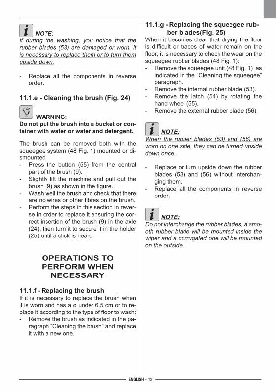
NOTE: If during the washing, you notice that the rubber blades (53) are damaged or worn, it is necessary to replace them or to turn them upside down. - Replace all the components in reverse
order.
11.1.e - Cleaning the brush (Fig. 24)
WARNING:Do not put the brush into a bucket or con-tainer with water or water and detergent.
The brush can be removed both with the squeegee system (48 Fig. 1) mounted or di-smounted.- Press the button (55) from the central
part of the brush (9).- Slightly lift the machine and pull out the
brush (9) as shown in the figure.- Wash well the brush and check that there
are no wires or other fibres on the brush.- Perform the steps in this section in rever-
se in order to replace it ensuring the cor-rect insertion of the brush (9) in the axle (24), then turn it to secure it in the holder (25) until a click is heard.
OPERATIONS TO PERFORM WHEN
NECESSARY
11.1.f - Replacing the brushIf it is necessary to replace the brush when it is worn and has a ø under 6.5 cm or to re-place it according to the type of floor to wash:- Remove the brush as indicated in the pa-
ragraph “Cleaning the brush” and replace it with a new one.
11.1.g - Replacing the squeegee rub-ber blades(Fig. 25)
When it becomes clear that drying the floor is difficult or traces of water remain on the floor, it is necessary to check the wear on the squeegee rubber blades (48 Fig. 1):- Remove the squeegee unit (48 Fig. 1) as
indicated in the “Cleaning the squeegee” paragraph.
- Remove the internal rubber blade (53).- Remove the latch (54) by rotating the
hand wheel (55).- Remove the external rubber blade (56).
NOTE:When the rubber blades (53) and (56) are worn on one side, they can be turned upside down once.
- Replace or turn upside down the rubber blades (53) and (56) without interchan-ging them.
- Replace all the components in reverse order.
NOTE:Do not interchange the rubber blades, a smo-oth rubber blade will be mounted inside the wiper and a corrugated one will be mounted on the outside.
ENGLISH - 14
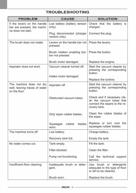
TROUBLESHOOTING
PROBLEM CAUSE SOLUTIONIf the levers on the handle bar are pressed, the machi-ne does not start.
Low battery (battery version only).
Plug disconnected (charger version only).
Check that the battery is charged.
Connect the plug.
The brush does not rotate. Levers on the handle bar not pressed.
Brush rotation enabling but-ton not pressed.
Brush motor damaged.
Press the levers.
Press the button.
Replace the engine.Aspirator does not work. Vacuum cleaner turned off.
Intake motor damaged
Start the vacuum cleaner by pressing the corresponding button.
Replace the turbine.The machine does not dry well, leaving traces of water on the floor.
Aspirator off.
Obstructed vacuum tubes.
Dirty wiper rubber blades.
Squeegee rubber blades worn.
Start the vacuum cleaner by pressing the corresponding button.
Check and if necessary cle-an the vacuum tubes that connect the wipers to the re-covery tank.
Clean the rubber blades of the wiper.
Replace or turn over the squeegee rubber blades.
The machine turns off. Low battery.
Recovery tank full.
Charge battery.
Empty the tank.
No water comes out. Tank empty.
Filter blocked.
Pump not functioning.
Fill the tank.
Clean the filter.
Call the technical support service.
Insufficient floor cleaning. Inadequate brush or deter-gent.
Brush worn.
Use brush or detergents adequate to the type of floor or dirt to be cleaned.
Replace the brush.

ENGLISH - 15
PROBLEM CAUSE SOLUTIONIf the levers on the handle bar are pressed, the machi-ne does not start.
Low battery (battery version only).
Plug disconnected (charger version only).
Check that the battery is charged.
Connect the plug.
The brush does not rotate. Levers on the handle bar not pressed.
Brush rotation enabling but-ton not pressed.
Brush motor damaged.
Press the levers.
Press the button.
Replace the engine.Aspirator does not work. Vacuum cleaner turned off.
Intake motor damaged
Start the vacuum cleaner by pressing the corresponding button.
Replace the turbine.The machine does not dry well, leaving traces of water on the floor.
Aspirator off.
Obstructed vacuum tubes.
Dirty wiper rubber blades.
Squeegee rubber blades worn.
Start the vacuum cleaner by pressing the corresponding button.
Check and if necessary cle-an the vacuum tubes that connect the wipers to the re-covery tank.
Clean the rubber blades of the wiper.
Replace or turn over the squeegee rubber blades.
The machine turns off. Low battery.
Recovery tank full.
Charge battery.
Empty the tank.
No water comes out. Tank empty.
Filter blocked.
Pump not functioning.
Fill the tank.
Clean the filter.
Call the technical support service.
Insufficient floor cleaning. Inadequate brush or deter-gent.
Brush worn.
Use brush or detergents adequate to the type of floor or dirt to be cleaned.
Replace the brush.
OPTIONAL ACCESORIES
- Polypropylene cylindrical brush (soft) ..............................................................................Code 40.5000.01- Polypropylene cylindrical brush (hard).............................................................................Code 40.5000.02- Tynex cylindrical brush .......................................................................................Code 40.5000.03- Microfibre cylindrical brush .......................................................................................Code 40.5000.04- Natural rubber blade kit ...........................................................................Code 96.0085.00 - Battery charger Li Fe PO4 24V 10A ..... Code 18.0064.00 (optional only for 20Ah battery)- Car battery charger 24-12V 5A ................................................................Code 18.0065.00
M1
M2
M3
M1.
1M
1.2
M2.
1M
2.2
M3.
1M
3.2
B+
B -
16
T1
SW1a
SW1a.1SW1b.2SW1.3
SW3
SW
3.1
SW
3.2
SW2
SW
2.1
SW
2.2
SW4
SW
4.1
SW
4.2
T1
S5S
5.1
S5.
2
a
b
c
11
10
9
8
7
6
5
4
3
2
1
12 (C) +
13
14
15
16 (C)
F2
SW1b
24V 0
ENGLISH - 16
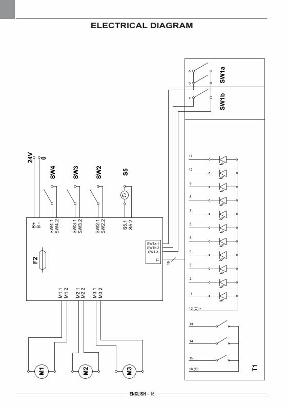
ELECTRICAL DIAGRAM
ENGLISH - 17
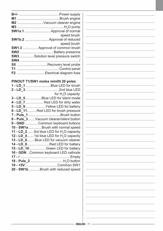
B+/- .........................................Power supplyM1 ........................................... Brush engineM2 ...........................Vacuum cleaner engineM3 ................................................H2O pumpSW1a.1 .......................... Approval of normal speed brushSW1b.2 ........................ Approval of reduced speed brushSW1.3 ............... Approval of common brushSW2 .................................. Battery presenceSW3 ..............Solution level pressure switchSW4 ............................................................ /S5 ...............................Recovery level probeT1 ...........................................Control panelF2 ............................Electrical diagram fuse
PINOUT T1/SW1 molex minifit 20 poles1 - LD_1 .........................Blue LED for brush2 - LD_3...................................2nd blue LED for H2O capacity3 - LD_5.................Blue LED for silent mode4 - LD_7...................Red LED for dirty water5 - LD_9.....................Yellow LED for battery6 - LD_11..........Red LED for brush pressure7 - Puls_1 .................................Brush button8 - Puls_3 .......Vacuum cleaner/silent button9 - GND ............. Common keyboard buttons10 - SW1a..............Brush with normal speed11 - LD_2...... 3rd blue LED for H2O capacity12 - LD_4.......1st blue LED for H2O capacity13 - LD_6........Blue LED for vacuum cleaner14 - LD_8.......................Red LED for battery15 - LD_10................. Green LED for battery16 - GDN .. Common keyboard LED cathode17 - / ................................................... Empty18 - Puls_2 ..................................H2O button19 - +5V .................................Common SW120 - SW1b ...........Brush with reduced speed

18
FRANÇAIS - 1
Cher client,Nous vous remercions pour avoir choisi un de nos produits pour le nettoyage de vos locaux.
L’autolaveuse accompagnée que vous venez d’acquérir a été conçue pour satisfaire l’utilisateur en termes de simplicité d’utilisation et de fiabilité dans le temps.
Nous sommes conscients que, pour qu’un produit reste tel quel dans le temps, il faut constamment le renouveler afin de satisfaire les attentes de ceux l’utilisent quotidienne-ment. Nous espérons donc que vous serez un client satisfait mais aussi un collaborateur qui n’hésite pas à nous faire partager les opinions et les idées de ceux qui l’utilisent au quotidien.
FRANÇAIS - 2
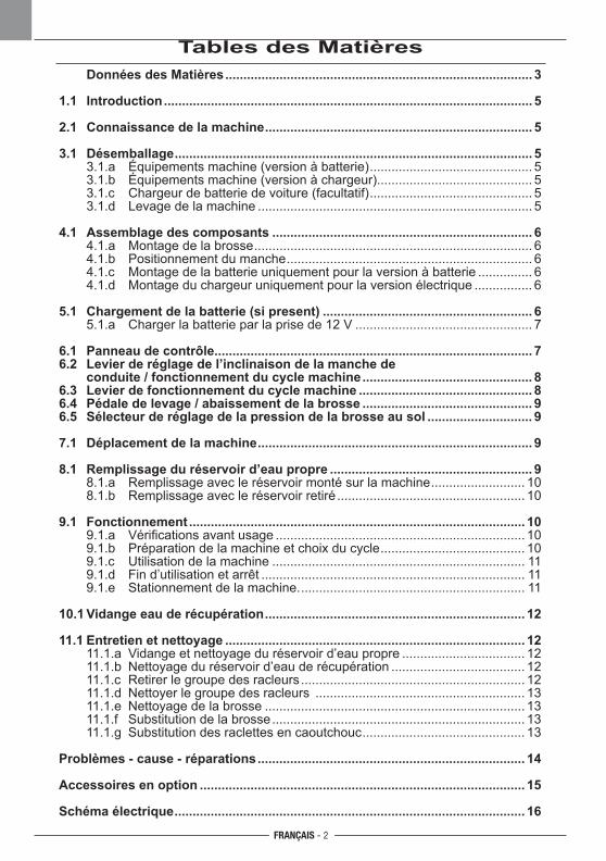
Tables des Matières Données des Matières ..................................................................................... 3
1.1 Introduction ...................................................................................................... 5
2.1 Connaissance de la machine .......................................................................... 5
3.1 Désemballage ................................................................................................... 5 3.1.a Équipements machine (version à batterie) ............................................. 5 3.1.b Équipements machine (version à chargeur)........................................... 5 3.1.c Chargeur de batterie de voiture (facultatif) ............................................. 5 3.1.d Levage de la machine ............................................................................ 5
4.1 Assemblage des composants ........................................................................ 6 4.1.a Montage de la brosse ............................................................................. 6 4.1.b Positionnement du manche .................................................................... 6 4.1.c Montage de la batterie uniquement pour la version à batterie ............... 6 4.1.d Montage du chargeur uniquement pour la version électrique ................ 6
5.1 Chargement de la batterie (si present) .......................................................... 6 5.1.a Charger la batterie par la prise de 12 V ................................................. 7
6.1 Panneau de contrôle ........................................................................................ 76.2 Levier de réglage de l’inclinaison de la manche de conduite / fonctionnement du cycle machine ............................................... 86.3 Levier de fonctionnement du cycle machine ................................................ 86.4 Pédale de levage / abaissement de la brosse ............................................... 96.5 Sélecteur de réglage de la pression de la brosse au sol ............................. 9
7.1 Déplacement de la machine ............................................................................ 9
8.1 Remplissage du réservoir d’eau propre ........................................................ 9 8.1.a Remplissage avec le réservoir monté sur la machine .......................... 10 8.1.b Remplissage avec le réservoir retiré .................................................... 10
9.1 Fonctionnement ............................................................................................. 10 9.1.a Vérificationsavantusage ..................................................................... 10 9.1.b Préparation de la machine et choix du cycle ........................................ 10 9.1.c Utilisation de la machine ...................................................................... 11 9.1.d Fin d’utilisation et arrêt ......................................................................... 11 9.1.e Stationnement de la machine. .............................................................. 11
10.1 Vidange eau de récupération ........................................................................ 12
11.1 Entretien et nettoyage ................................................................................... 12 11.1.a Vidange et nettoyage du réservoir d’eau propre .................................. 12 11.1.b Nettoyage du réservoir d’eau de récupération ..................................... 12 11.1.c Retirer le groupe des racleurs .............................................................. 12 11.1.d Nettoyer le groupe des racleurs .......................................................... 13 11.1.e Nettoyage de la brosse ........................................................................ 13 11.1.f Substitution de la brosse ...................................................................... 13 11.1.g Substitution des raclettes en caoutchouc ............................................. 13
Problèmes - cause - réparations .......................................................................... 14
Accessoires en option .......................................................................................... 15
Schéma électrique ................................................................................................. 16
FRANÇAIS - 3
Données des Matières
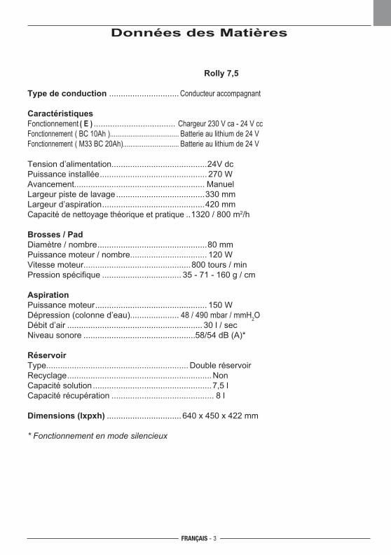
Rolly 7,5
Type de conduction .............................. Conducteur accompagnant
CaractéristiquesFonctionnement ( E ) ................................... Chargeur 230 V ca - 24 V cc Fonctionnement ( BC 10Ah )..................................... Batterie au lithium de 24 V Fonctionnement ( M33 BC 20Ah).............................. Batterie au lithium de 24 V
Tension d’alimentation.........................................24V dc
Puissance installée
.............................................. 270 W
Avancement........................................................ Manuel
Largeur piste de lavage
......................................330 mm
Largeur d’aspiration
............................................420 mm
Capacité de nettoyage théorique et pratique
..1320 / 800 m2/h
Brosses / PadDiamètre / nombre
...............................................80 mm
Puissance moteur / nombre................................. 120 W
Vitesse moteur..............................................800 tours / min
Pression spécifique
.................................. 35 - 71 - 160 g / cm
AspirationPuissance moteur
................................................ 150 W
Dépression (colonne d’eau)..................... 48 / 490 mbar / mmH2O
Débit d’air
.......................................................... 30 l / sec
Niveau sonore
................................................58/54 dB (A)*
RéservoirType............................................................. Double réservoir
Recyclage
..............................................................Non
Capacité solution
...................................................7,5 l
Capacité récupération
............................................ 8 l
Dimensions (lxpxh)
................................ 640 x 450 x 422 mm
* Fonctionnement en mode silencieux
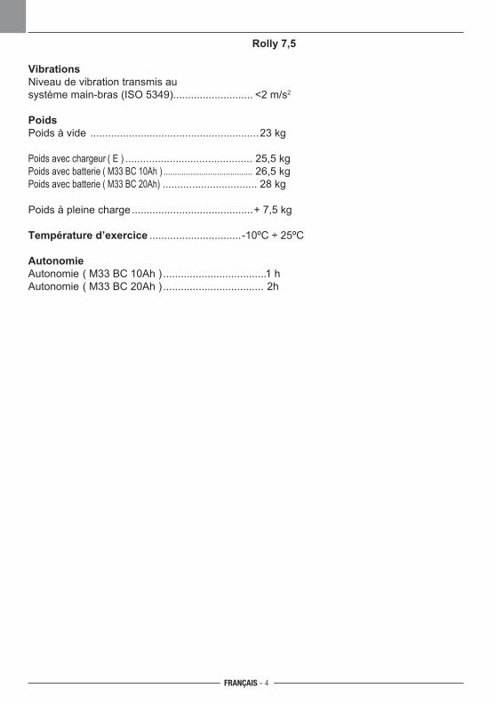
FRANÇAIS - 4
Rolly 7,5
VibrationsNiveau de vibration transmis au système main-bras (ISO 5349)........................... <2 m/s2
PoidsPoids à vide .........................................................23 kg
Poids avec chargeur ( E ) ........................................... 25,5 kg Poids avec batterie ( M33 BC 10Ah ) ........................................ 26,5 kg Poids avec batterie ( M33 BC 20Ah) ................................ 28 kg
Poids à pleine charge
.........................................+ 7,5 kg
Température d’exercice
...............................-10ºC ÷ 25ºC
AutonomieAutonomie ( M33 BC 10Ah ) ...................................1 h
Autonomie ( M33 BC 20Ah ) .................................. 2h
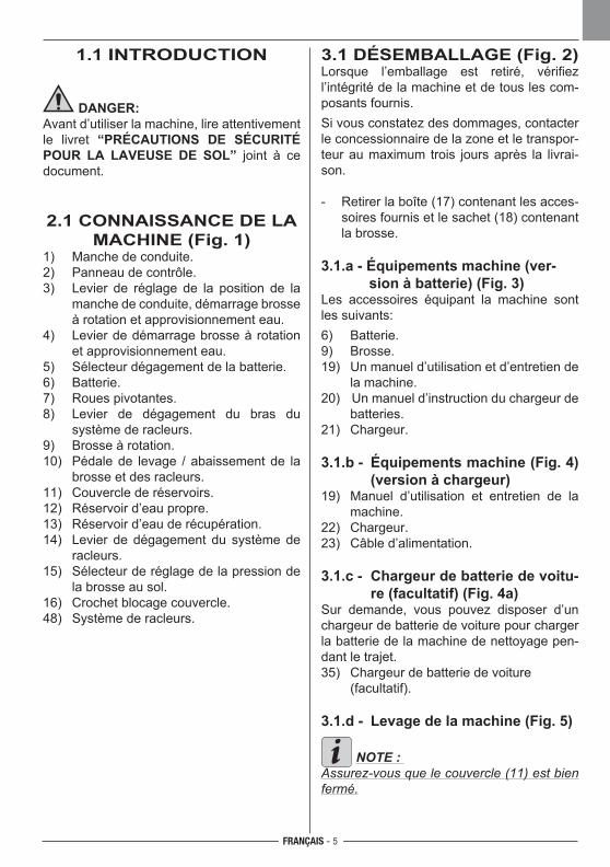
FRANÇAIS - 5
1.1 INTRODUCTION
DANGER:Avant d’utiliser la machine, lire attentivement le livret “PRÉCAUTIONS DE SÉCURITÉ POUR LA LAVEUSE DE SOL” joint à ce document.
2.1 CONNAISSANCE DE LA MACHINE (Fig. 1)
1) Manche de conduite.2) Panneau de contrôle.3) Levier de réglage de la position de la
manche de conduite, démarrage brosse à rotation et approvisionnement eau.
4) Levier de démarrage brosse à rotation et approvisionnement eau.
5) Sélecteur dégagement de la batterie.6) Batterie.7) Roues pivotantes.8) Levier de dégagement du bras du
système de racleurs.9) Brosse à rotation.10) Pédale de levage / abaissement de la
brosse et des racleurs.11) Couvercle de réservoirs.12) Réservoir d’eau propre.13) Réservoir d’eau de récupération.14) Levier de dégagement du système de
racleurs.15) Sélecteur de réglage de la pression de
la brosse au sol.16) Crochet blocage couvercle.48) Système de racleurs.
3.1 DÉSEMBALLAGE (Fig. 2)Lorsque l’emballage est retiré, vérifiez l’intégrité de la machine et de tous les com-posants fournis.Si vous constatez des dommages, contacter le concessionnaire de la zone et le transpor-teur au maximum trois jours après la livrai-son.
- Retirer la boîte (17) contenant les acces-soires fournis et le sachet (18) contenant la brosse.
3.1.a - Équipements machine (ver-sion à batterie) (Fig. 3)
Les accessoires équipant la machine sont les suivants:6) Batterie.9) Brosse.19) Un manuel d’utilisation et d’entretien de
la machine.20) Un manuel d’instruction du chargeur de
batteries.21) Chargeur.
3.1.b - Équipements machine (Fig. 4) (version à chargeur)
19) Manuel d’utilisation et entretien de la machine.
22) Chargeur.23) Câble d’alimentation.
3.1.c - Chargeur de batterie de voitu-re (facultatif) (Fig. 4a)
Sur demande, vous pouvez disposer d’un chargeur de batterie de voiture pour charger la batterie de la machine de nettoyage pen-dant le trajet.35) Chargeur de batterie de voiture (facultatif). 3.1.d - Levage de la machine (Fig. 5)
NOTE : Assurez-vous que le couvercle (11) est bien fermé.
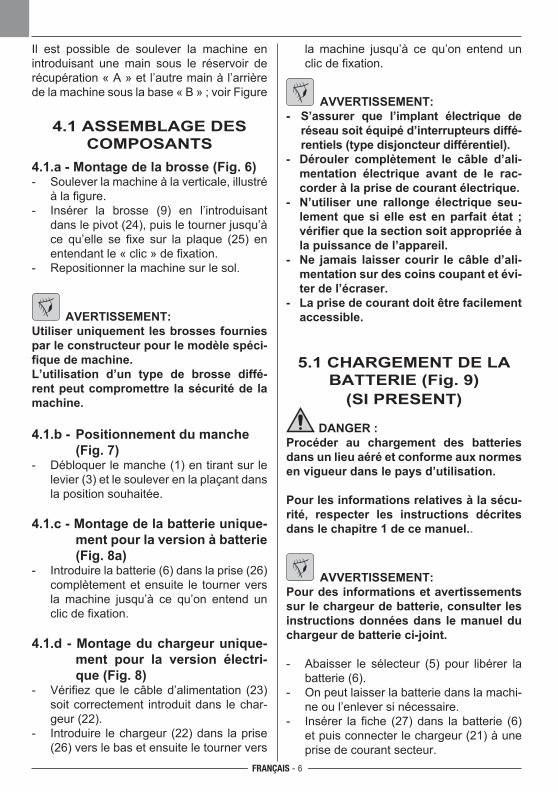
FRANÇAIS - 6
Il est possible de soulever la machine en introduisant une main sous le réservoir de récupération « A » et l’autre main à l’arrière de la machine sous la base « B » ; voir Figure
4.1 ASSEMBLAGE DES COMPOSANTS
4.1.a - Montage de la brosse (Fig. 6)- Soulever la machine à la verticale, illustré
à la figure.- Insérer la brosse (9) en l’introduisant
dans le pivot (24), puis le tourner jusqu’à ce qu’elle se fixe sur la plaque (25) en entendant le « clic » de fixation.
- Repositionner la machine sur le sol.
AVERTISSEMENT:Utiliser uniquement les brosses fournies par le constructeur pour le modèle spéci-fique de machine.L’utilisation d’un type de brosse diffé-rent peut compromettre la sécurité de la machine.
4.1.b - Positionnement du manche (Fig. 7)
- Débloquer le manche (1) en tirant sur le levier (3) et le soulever en la plaçant dans la position souhaitée.
4.1.c - Montage de la batterie unique-ment pour la version à batterie (Fig. 8a)
- Introduire la batterie (6) dans la prise (26) complètement et ensuite le tourner vers la machine jusqu’à ce qu’on entend un clic de fixation.
4.1.d - Montage du chargeur unique-ment pour la version électri-que (Fig. 8)
- Vérifiez que le câble d’alimentation (23) soit correctement introduit dans le char-geur (22).
- Introduire le chargeur (22) dans la prise (26) vers le bas et ensuite le tourner vers
la machine jusqu’à ce qu’on entend un clic de fixation.
AVVERTISSEMENT: - S’assurer que l’implant électrique de
réseau soit équipé d’interrupteurs diffé-rentiels (type disjoncteur différentiel).
- Dérouler complètement le câble d’ali-mentation électrique avant de le rac-corder à la prise de courant électrique.
- N’utiliser une rallonge électrique seu-lement que si elle est en parfait état ; vérifier que la section soit appropriée à la puissance de l’appareil.
- Ne jamais laisser courir le câble d’ali-mentation sur des coins coupant et évi-ter de l’écraser.
- La prise de courant doit être facilement accessible.
5.1 CHARGEMENT DE LA BATTERIE (Fig. 9)
(SI PRESENT)
DANGER :Procéder au chargement des batteries dans un lieu aéré et conforme aux normes en vigueur dans le pays d’utilisation.
Pour les informations relatives à la sécu-rité, respecter les instructions décrites dans le chapitre 1 de ce manuel..
AVVERTISSEMENT: Pour des informations et avertissements sur le chargeur de batterie, consulter les instructions données dans le manuel du chargeur de batterie ci-joint.
- Abaisser le sélecteur (5) pour libérer la batterie (6).
- On peut laisser la batterie dans la machi-ne ou l’enlever si nécessaire.
- Insérer la fiche (27) dans la batterie (6) et puis connecter le chargeur (21) à une prise de courant secteur.
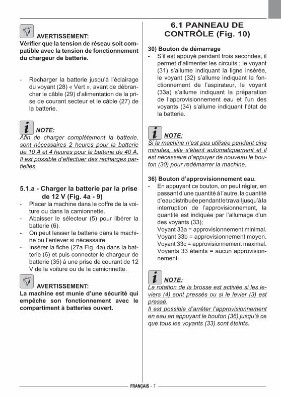
FRANÇAIS - 7
6.1 PANNEAU DE CONTRÔLE (Fig. 10)
30) Bouton de démarrage- S’il est appuyé pendant trois secondes, il
permet d’alimenter les circuits ; le voyant (31) s’allume indiquant la ligne insérée, le voyant (32) s’allume indiquant le fon-ctionnement de l’aspirateur, le voyant (33a) s’allume indiquant la préparation de l’approvisionnement eau et l’un des voyants (34) s’allume indiquant l’état de la batterie.
NOTE:Si la machine n’est pas utilisée pendant cinq minutes, elle s’éteint automatiquement et il est nécessaire d’appuyer de nouveau le bou-ton (30) pour redémarrer la machine.
36) Bouton d’approvisionnement eau.- En appuyant ce bouton, on peut régler, en
passant d’une quantité à l’autre, la quantité d’eau distribuée pendant le travail jusqu’à la interruption de l’approvisionnement, la quantité est indiquée par l’allumage d’un des voyants (33);
Voyant 33a = approvisionnement minimal. Voyant 33b = approvisionnement moyen. Voyant 33c = approvisionnement maximal. Voyants 33 éteints = aucun approvision-
nement.
NOTE:La rotation de la brosse est activée si les le-viers (4) sont pressés ou si le levier (3) est pressé.Il est possible d’arrêter l’approvisionnement en eau en appuyant le bouton (36) jusqu’à ce que tous les voyants (33) sont éteints.
AVERTISSEMENT: Vérifier que la tension de réseau soit com-patible avec la tension de fonctionnement du chargeur de batterie.
- Recharger la batterie jusqu’à l’éclairage du voyant (28) « Vert », avant de débran-cher le câble (29) d’alimentation de la pri-se de courant secteur et le câble (27) de la batterie.
NOTE: Afin de charger complètement la batterie, sont nécessaires 2 heures pour la batterie de 10 A et 4 heures pour la batterie de 40 A.Il est possible d’effectuer des recharges par-tielles.
5.1.a - Charger la batterie par la prise de 12 V (Fig. 4a - 9)
- Placer la machine dans le coffre de la voi-ture ou dans la camionnette.
- Abaisser le sélecteur (5) pour libérer la batterie (6).
- On peut laisser la batterie dans la machi-ne ou l’enlever si nécessaire.
- Insérer la fiche (27a Fig. 4a) dans la bat-terie (6) et puis connecter le chargeur de batterie (35) à une prise de courant de 12 V de la voiture ou de la camionnette.
AVERTISSEMENT:La machine est munie d’une sécurité qui empêche son fonctionnement avec le compartiment à batteries ouvert.
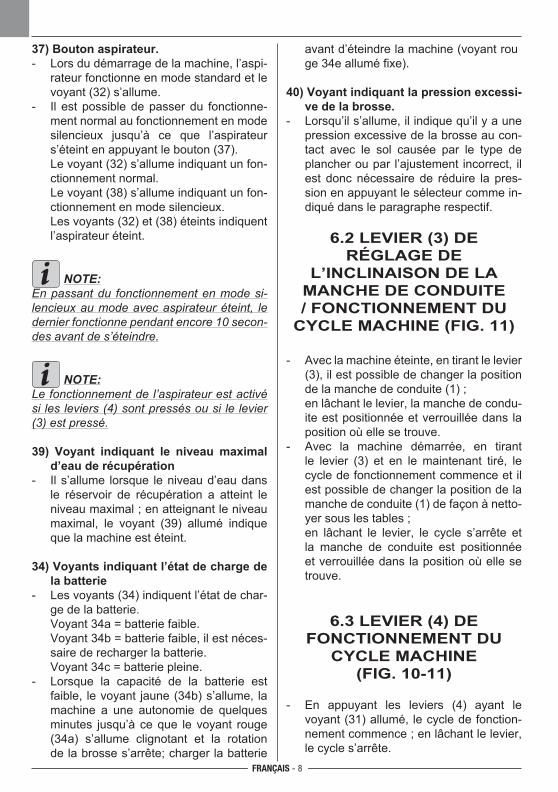
FRANÇAIS - 8
37) Bouton aspirateur.- Lors du démarrage de la machine, l’aspi-
rateur fonctionne en mode standard et le voyant (32) s’allume.
- Il est possible de passer du fonctionne-ment normal au fonctionnement en mode silencieux jusqu’à ce que l’aspirateur s’éteint en appuyant le bouton (37).
Le voyant (32) s’allume indiquant un fon-ctionnement normal.
Le voyant (38) s’allume indiquant un fon-ctionnement en mode silencieux.
Les voyants (32) et (38) éteints indiquent l’aspirateur éteint.
NOTE:En passant du fonctionnement en mode si-lencieux au mode avec aspirateur éteint, le dernier fonctionne pendant encore 10 secon-des avant de s’éteindre.
NOTE:Le fonctionnement de l’aspirateur est activé si les leviers (4) sont pressés ou si le levier (3) est pressé.
39) Voyant indiquant le niveau maximal d’eau de récupération
- Il s’allume lorsque le niveau d’eau dans le réservoir de récupération a atteint le niveau maximal ; en atteignant le niveau maximal, le voyant (39) allumé indique que la machine est éteint.
34) Voyants indiquant l’état de charge de la batterie
- Les voyants (34) indiquent l’état de char-ge de la batterie.
Voyant 34a = batterie faible. Voyant 34b = batterie faible, il est néces-
saire de recharger la batterie. Voyant 34c = batterie pleine.- Lorsque la capacité de la batterie est
faible, le voyant jaune (34b) s’allume, la machine a une autonomie de quelques minutes jusqu’à ce que le voyant rouge (34a) s’allume clignotant et la rotation de la brosse s’arrête; charger la batterie
avant d’éteindre la machine (voyant rouge 34e allumé fixe).
40) Voyant indiquant la pression excessi-ve de la brosse.
- Lorsqu’il s’allume, il indique qu’il y a une pression excessive de la brosse au con-tact avec le sol causée par le type de plancher ou par l’ajustement incorrect, il est donc nécessaire de réduire la pres-sion en appuyant le sélecteur comme in-diqué dans le paragraphe respectif.
6.2 LEVIER (3) DE RÉGLAGE DE
L’INCLINAISON DE LA MANCHE DE CONDUITE / FONCTIONNEMENT DU
CYCLE MACHINE (FIG. 11)
- Avec la machine éteinte, en tirant le levier (3), il est possible de changer la position de la manche de conduite (1) ;
en lâchant le levier, la manche de condu-ite est positionnée et verrouillée dans la position où elle se trouve.
- Avec la machine démarrée, en tirant le levier (3) et en le maintenant tiré, le cycle de fonctionnement commence et il est possible de changer la position de la manche de conduite (1) de façon à netto-yer sous les tables ;
en lâchant le levier, le cycle s’arrête et la manche de conduite est positionnée et verrouillée dans la position où elle se trouve.
6.3 LEVIER (4) DE FONCTIONNEMENT DU
CYCLE MACHINE (FIG. 10-11)
- En appuyant les leviers (4) ayant le voyant (31) allumé, le cycle de fonction-nement commence ; en lâchant le levier, le cycle s’arrête.
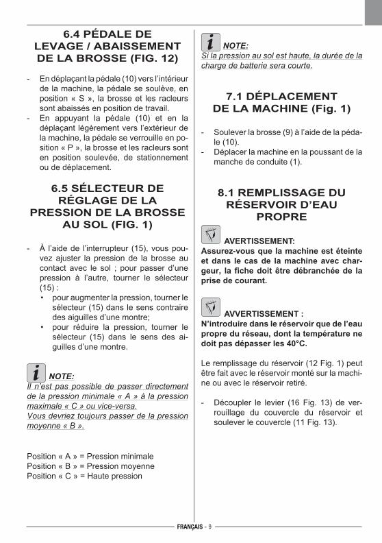
FRANÇAIS - 9
6.4 PÉDALE DE LEVAGE / ABAISSEMENT DE LA BROSSE (FIG. 12)
- En déplaçant la pédale (10) vers l’intérieur de la machine, la pédale se soulève, en position « S », la brosse et les racleurs sont abaissés en position de travail.
- En appuyant la pédale (10) et en la déplaçant légèrement vers l’extérieur de la machine, la pédale se verrouille en po-sition « P », la brosse et les racleurs sont en position soulevée, de stationnement ou de déplacement.
6.5 SÉLECTEUR DE RÉGLAGE DE LA
PRESSION DE LA BROSSE AU SOL (FIG. 1)
- À l’aide de l’interrupteur (15), vous pou-vez ajuster la pression de la brosse au contact avec le sol ; pour passer d’une pression à l’autre, tourner le sélecteur (15) :
• pour augmenter la pression, tourner le sélecteur (15) dans le sens contraire des aiguilles d’une montre;
• pour réduire la pression, tourner le sélecteur (15) dans le sens des ai-guilles d’une montre.
NOTE:Il n’est pas possible de passer directement de la pression minimale « A » à la pression maximale « C » ou vice-versa.Vous devriez toujours passer de la pression moyenne « B ».
Position « A » = Pression minimalePosition « B » = Pression moyennePosition « C » = Haute pression
NOTE:Si la pression au sol est haute, la durée de la charge de batterie sera courte.
7.1 DÉPLACEMENT DE LA MACHINE (Fig. 1)
- Soulever la brosse (9) à l’aide de la péda-le (10).
- Déplacer la machine en la poussant de la manche de conduite (1).
8.1 REMPLISSAGE DU RÉSERVOIR D’EAU
PROPRE
AVERTISSEMENT: Assurez-vous que la machine est éteinte et dans le cas de la machine avec char-geur, la fiche doit être débranchée de la prise de courant.
AVVERTISSEMENT : N’introduire dans le réservoir que de l’eau propre du réseau, dont la température ne doit pas dépasser les 40°C.
Le remplissage du réservoir (12 Fig. 1) peut être fait avec le réservoir monté sur la machi-ne ou avec le réservoir retiré.
- Découpler le levier (16 Fig. 13) de ver-rouillage du couvercle du réservoir et soulever le couvercle (11 Fig. 13).
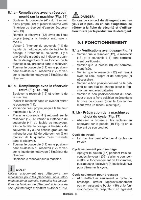
FRANÇAIS - 10
8.1.a - Remplissage avec le réservoir monté sur la machine (Fig. 14)
- Soulever le couvercle (41) du réservoir d’eau propre (12) et placer le tourné vers l’intérieur du réservoir d’eau de récupéra-tion (13).
- Remplir le réservoir (12) avec de l’eau propre jusqu’à la hauteur maximale « MAX ».
- Verser à l’intérieur du couvercle (41) du liquide de nettoyage, afin de faciliter le dosage, à l’intérieur du couvercle, il y a une échelle graduée qui indique la quan-tité de détergent en % en fonction de la quantité d’eau présente dans le réservoir.
- Tourner le couvercle (41) en le position-nant au-dessus du réservoir (12) et ver-ser le liquide de nettoyage à l’intérieur du réservoir.
8.1.b - Remplissage avec le réservoir retiré (Fig. 15 - 16)
- Soulever le réservoir (12) et retirer le de la machine.
- Placer le réservoir dans un évier et retirer le couvercle (41).
- Verser de l’eau propre jusqu’à la hauteur maximale « MAX » :
- Placer le couvercle (41) retourné sur le réservoir (12) et verser à l’intérieur du couvercle (41) du liquide de nettoyage, afin de faciliter le dosage, à l’intérieur du couvercle, il y a une échelle graduée qui indique la quantité de détergent en % en fonction de la quantité d’eau présente dans le réservoir.
- Tourner le couvercle (41) en le position-nant au-dessus du réservoir (12) et ver-ser le liquide de nettoyage à l’intérieur du réservoir.
- Replacer le réservoir sur la machine.
NOTE:Utiliser uniquement des détergents non moussants pour les planchers, pour infor-mations sur la quantité, consulter les instruc-tions du fabricant du détergent et le type de sale (pourcentage maximum à utiliser : 3 %).
DANGER:En cas de contact du détergent avec les yeux et la peau ou en cas d’ingestion, se référer à la fiche de sécurité et d’utilisa-tion fourni par le producteur du détergent.
9.1 FONCTIONNEMENT
9.1.a - Vérifications avant usage (Fig. 1)- Vérifier que le réservoir (12), le réservoir
(13) et le couvercle (11) sont correcte-ment positionnés.
- Vérifier que la brosse (9) est correcte-ment fixée.
- Vérifier que le réservoir (12) est rempli avec de l’eau propre et de détergent (si nécessaire).
- Vérifier le bon positionnement de la bat-terie et son état de charge (pour le fon-ctionnement avec batterie)
- Vérifier le bon positionnement du char-geur et que la fiche soit bien insérée dans la prise de courant (pour le fonctionne-ment avec un réseau électrique).
9.1.b - Préparation de la machine et choix du cycle (Fig. 17)
- Abaisser la brosse et les racleurs en appuyant sur la pédale (10 Fig. 1) en le libérant de son crochet.
Cycle de travail- La machine peut effectuer 4 cycles de
travail:
Cycle seulement pour séchage- Appuyer le bouton (37) pendant trois se-
condes, le voyant (32), s’allume pour per-mettre le fonctionnement de l’aspirateur, puis appuyer les leviers (4) ou le levier (3) pour démarrer le cycle.
Cycle seulement pour brossage- Afin d’effectuer seulement le cycle de
brossage, arrêter l’approvisionnement eau en agissant le bouton (36) et le fon-ctionnement de l’aspirateur en agissant
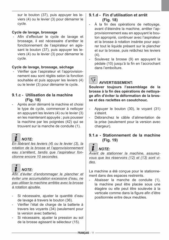
FRANÇAIS - 11
sur le bouton (37), puis appuyer les le-viers (4) ou le levier (3) pour démarrer le cycle.
Cycle de lavage, brossage - Afin d’effectuer le cycle de lavage et
brossage, il est nécessaire d’arrêter le fonctionnement de l’aspirateur en agis-sant le bouton (37), puis appuyer les le-viers (4) ou le levier (3) pour démarrer le cycle.
Cycle de lavage, brossage, séchage - Vérifier que l’aspirateur et l’approvision-
nement eau sont réglés selon la fonction souhaitée et puis appuyer les leviers (4) ou le levier (3) pour démarrer le cycle.
9.1.c - Utilisation de la machine (Fig. 18)- Après avoir démarré la machine et choisi
le type de cycle, commencer à nettoyer en appuyant les leviers (4) ou le levier (3) en les maintenant appuyés ; puis pousser la machine par les poignées (42) qui se trouvent sur la manche de conduite (1).
NOTE:En libérant les leviers (4) ou le levier (3), la rotation de la brosse et l’approvisionnement eau s’arrêtent, tandis que l’aspirateur fon-ctionne encore 10 secondes.
NOTE:Afin d’éviter d’endommager le plancher et éviter une accumulation excessive d’eau, ne pas utiliser la machine arrêtée avec la brosse à rotation ajoutée.
- Si nécessaire, ajuster la quantité d’eau de lavage à travers le bouton (36).
- Vérifier l’état de charge de la batterie à travers les voyants (34) (seulement pour la version avec batterie).
- Si nécessaire, ajuster la pression au sol de la brosse agissant le sélecteur (15).
9.1.d - Fin d’utilisation et arrêt (Fig. 18)- À la fin des opérations de nettoyage,
avant d’éteindre la machine, arrêter l’ap-provisionnement eau en appuyant le bou-ton approprié, continuer avec l’aspirateur et la brosse à rotation insérée pour aspi-rer tout le liquide présent sur le plancher et sur la brosse, puis relâchez les leviers (4).
- Soulevez la brosse (9) en appuyant la pédale (10) jusqu’à la fin en l’accrochant dans l’emboîture.
AVVERTISSEMENT:RTISSEMENT:Soulever toujours l’assemblage de la brosse à la fin des opérations de nettoya-ge afin d’éviter la déformation de la bros-se et des raclettes en caoutchouc.
- Appuyer le bouton (30), le voyant (31) s’éteint.
- Débranchez le câble d’alimentation de la prise (seulement pour la version avec chargeur).
9.1.e - Stationnement de la machine (Fig. 19)
NOTE:Avant de stationner la machine, assurez-vous que les réservoirs (12) et (13) sont vi-des.
La machine a été conçue pour le stationne-ment dans des espaces restreints.- Abaisser la manche de conduite (1),
la machine peut être placée sous une étagère ou elle peut être soulevée à la verticale comme dans la figure afin d’être positionnée entre deux meubles.
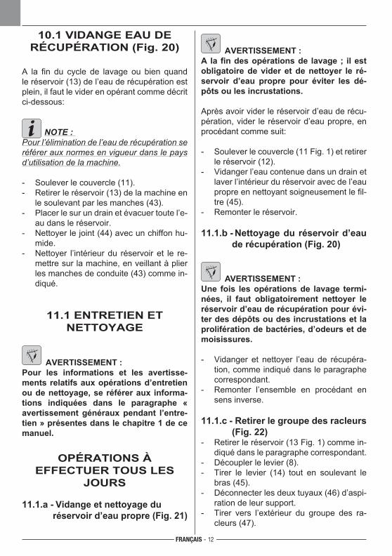
FRANÇAIS - 12
10.1 VIDANGE EAU DE RÉCUPÉRATION (Fig. 20)
A la fin du cycle de lavage ou bien quand le réservoir (13) de l’eau de récupération est plein, il faut le vider en opérant comme décrit ci-dessous:
NOTE : Pour l’élimination de l’eau de récupération se référer aux normes en vigueur dans le pays d’utilisation de la machine.
- Soulever le couvercle (11).- Retirer le réservoir (13) de la machine en
le soulevant par les manches (43).- Placer le sur un drain et évacuer toute l’e-
au dans le réservoir.- Nettoyer le joint (44) avec un chiffon hu-
mide.- Nettoyer l’intérieur du réservoir et le re-
mettre sur la machine, en veillant à plier les manches de conduite (43) comme in-diqué.
11.1 ENTRETIEN ET NETTOYAGE
AVERTISSEMENT : Pour les informations et les avertisse-ments relatifs aux opérations d’entretien ou de nettoyage, se référer aux informa-tions indiquées dans le paragraphe « avertissement généraux pendant l’entre-tien » présentes dans le chapitre 1 de ce manuel.
OPÉRATIONS À EFFECTUER TOUS LES
JOURS
11.1.a - Vidange et nettoyage du réservoir d’eau propre (Fig. 21)
AVERTISSEMENT : A la fin des opérations de lavage ; il est obligatoire de vider et de nettoyer le ré-servoir d’eau propre pour éviter les dé-pôts ou les incrustations.
Après avoir vider le réservoir d’eau de récu-pération, vider le réservoir d’eau propre, en procédant comme suit:
- Soulever le couvercle (11 Fig. 1) et retirer le réservoir (12).
- Vidanger l’eau contenue dans un drain et laver l’intérieur du réservoir avec de l’eau propre en nettoyant soigneusement le fil-tre (45).
- Remonter le réservoir.
11.1.b - Nettoyage du réservoir d’eau de récupération (Fig. 20)
AVERTISSEMENT :Une fois les opérations de lavage termi-nées, il faut obligatoirement nettoyer le réservoir d’eau de récupération pour évi-ter des dépôts ou des incrustations et la prolifération de bactéries, d’odeurs et de moisissures.
- Vidanger et nettoyer l’eau de récupéra-tion, comme indiqué dans le paragraphe correspondant.
- Remonter l’ensemble en procédant en sens inverse.
11.1.c - Retirer le groupe des racleurs (Fig. 22)
- Retirer le réservoir (13 Fig. 1) comme in-diqué dans le paragraphe correspondant.
- Découpler le levier (8).- Tirer le levier (14) tout en soulevant le
bras (45).- Déconnecter les deux tuyaux (46) d’aspi-
ration de leur support.- Tirer vers l’extérieur du groupe des ra-
cleurs (47).
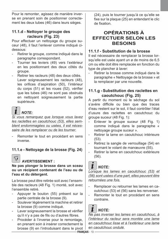
FRANÇAIS - 13
Pour le remonter, agissez de manière inver-se en prenant soin de positionner correcte-ment les deux tubes (46) dans leurs sièges.
11.1.d - Nettoyer le groupe des racleurs (Fig. 23)Pour effectuer un nettoyage du groupe su-ceur (48), il faut l’enlever comme indiqué ci-dessous:- Retirer le groupe, comme indiqué dans le
paragraphe correspondant.- Tourner les leviers (49) vers l’extérieur
en les positionnant des deux côtés du groupe.
- Retirer les racleurs (48) des deux côtés. Laver soigneusement les racleurs (48),
les orifices d’aspiration (50), l’intérieur du corps (51) et les roues (52), vérifier que les tubes (46) ne sont pas obstrués en nettoyant soigneusement la partie supérieure.
NOTE: Si vous remarquez que lorsque vous lavez les raclettes en caoutchouc (53), elles sem-blent endommagées ou usées, il est néces-saire de les remplacer ou de les tourner. - Remonter le tout en procédant en sens
inverse.
11.1.e - Nettoyage de la brosse (Fig. 24)
AVERTISSEMENT : Ne pas plonger la brosse dans un sceau ou un récipient contenant de l’eau ou de l’eau et du détergent.
La brosse peut être retirée soit avec l’ensem-ble des racleurs (48 Fig. 1) monté, soit avec l’ensemble retiré.- Appuyer le bouton (55) présent sur la
partie centrale de la brosse (9).- Soulever légèrement la machine et retirer
la brosse (9) comme indiqué.- Laver soigneusement la brosse et vérifier
qu’il n’y a pas de fils ou d’autres fibres.- Procéder à l’inverse pour le remontage,
en prenant soin à insérer correctement la brosse (9) en l’introduisant dans le pivot
(24), puis le tourner jusqu’à ce qu’elle se fixe sur la plaque (25) en entendant le clic de fixation.
OPÉRATIONS À EFFECTUER SELON LES
BESOINS11.1.f - Substitution de la brosseIl est nécessaire de remplacer la brosse lor-squ’elle est usée ayant un ø de moins de 6,5 cm ou elle doit être remplacée en fonction du type de plancher à laver:- Retirer la brosse comme indiqué dans le
paragraphe « Nettoyage de la brosse » et la remplacer par une nouvelle.
11.1.g - Substitution des raclettes en caoutchouc (Fig. 25)
A partir du moment où le séchage du sol s’avère difficile ou bien que des traces d’eau restent sur le sol, il faut contrôler l’état d’usure des raclettes en caoutchouc du groupe suceur (48 Fig. 1):- Enlever le groupe suceur (48 Fig. 1)
comme indiqué dans le paragraphe « nettoyage groupe suceur ».
- Retirer la lame en caoutchouc intérieure (53).
- Retirez la sangle de verrouillage (54) en tournant le volant de manœuvre (55).
- Retirer la lame en caoutchouc extérieure (56).
NOTE:Lorsque les lames en caoutchouc (53) et (56) sont usées d’une part, elles peuvent être retournées une fois.
- Remplacer ou retourner les lames en ca-outchouc (53) et (56) sans les renverser.
- Remonter le tout en procédant en sens contraire.
NOTE:Ne pas inverser les lames en caoutchouc, à l’intérieur du racleur sera montée une lame en caoutchouc lisse et à l’extérieur une lame en caoutchouc ondulé.
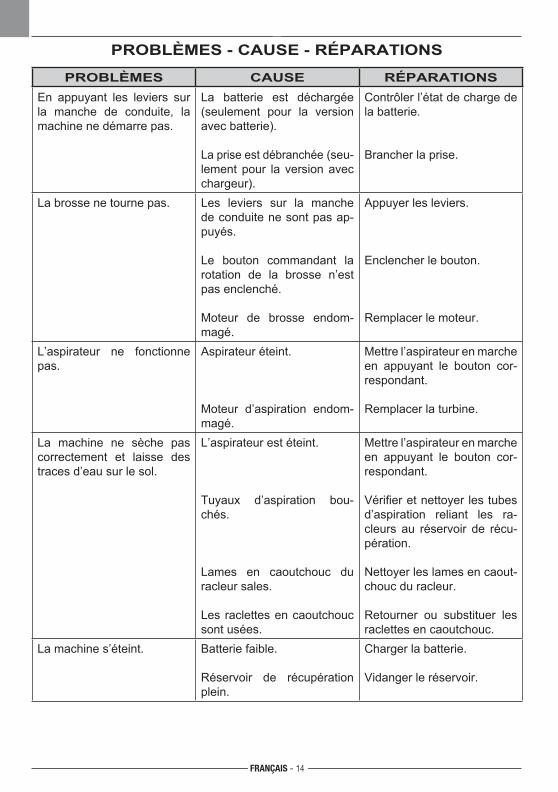
FRANÇAIS - 14
PROBLÈMES - CAUSE - RÉPARATIONS
PROBLÈMES CAUSE RÉPARATIONSEn appuyant les leviers sur la manche de conduite, la machine ne démarre pas.
La batterie est déchargée (seulement pour la version avec batterie).
La prise est débranchée (seu-lement pour la version avec chargeur).
Contrôler l’état de charge de la batterie.
Brancher la prise.
La brosse ne tourne pas. Les leviers sur la manche de conduite ne sont pas ap-puyés.
Le bouton commandant la rotation de la brosse n’est pas enclenché.
Moteur de brosse endom-magé.
Appuyer les leviers.
Enclencher le bouton.
Remplacer le moteur.
L’aspirateur ne fonctionne pas.
Aspirateur éteint.
Moteur d’aspiration endom-magé.
Mettre l’aspirateur en marche en appuyant le bouton cor-respondant.
Remplacer la turbine.
La machine ne sèche pas correctement et laisse des traces d’eau sur le sol.
L’aspirateur est éteint.
Tuyaux d’aspiration bou-chés.
Lames en caoutchouc du racleur sales.
Les raclettes en caoutchouc sont usées.
Mettre l’aspirateur en marche en appuyant le bouton cor-respondant.
Vérifier et nettoyer les tubes d’aspiration reliant les ra-cleurs au réservoir de récu-pération.
Nettoyer les lames en caout-chouc du racleur.
Retourner ou substituer les raclettes en caoutchouc.
La machine s’éteint. Batterie faible.
Réservoir de récupération plein.
Charger la batterie.
Vidanger le réservoir.
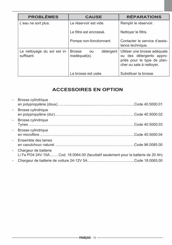
FRANÇAIS - 15
PROBLÈMES CAUSE RÉPARATIONSL’eau ne sort plus. Le réservoir est vide.
Le filtre est encrassé.
Pompe non-fonctionnant.
Remplir le réservoir.
Nettoyer le filtre.
Contacter le service d’assis-tance technique.
Le nettoyage du sol est in-suffisant.
Brosse ou détergent inadéquat(e).
La brosse est usée.
Utiliser une brosse adéquate ou des détergents appro-priés pour le type de plan-cher ou sale à nettoyer.
Substituer la brosse.
ACCESSOIRES EN OPTION
- Brosse cylindrique en polypropylène (doux) ..........................................................................Code 40.5000.01- Brosse cylindrique en polypropylène (dur) .............................................................................Code 40.5000.02- Brosse cylindrique Tynex .......................................................................................................Code 40.5000.03- Brosse cylindrique en microfibre ............................................................................................Code 40.5000.04- Ensemble des lames en caoutchouc naturel .............................................................................Code 96.0085.00 - Chargeur de batterie Li Fe PO4 24V 10A ........Cod. 18.0064.00 (facultatif seulement pour la batterie de 20 Ah)- Chargeur de batterie de voiture 24-12V 5A .............................................Code 18.0065.00

M1
M2
M3
M1.
1M
1.2
M2.
1M
2.2
M3.
1M
3.2
B+
B -
16
T1
SW1a
SW1a.1SW1b.2SW1.3
SW3
SW
3.1
SW
3.2
SW2
SW
2.1
SW
2.2
SW4
SW
4.1
SW
4.2
T1
S5S
5.1
S5.
2
a
b
c
11
10
9
8
7
6
5
4
3
2
1
12 (C) +
13
14
15
16 (C)
F2
SW1b
24V 0
FRANÇAIS - 16
SCHÉMA ÉLECTRIQUE
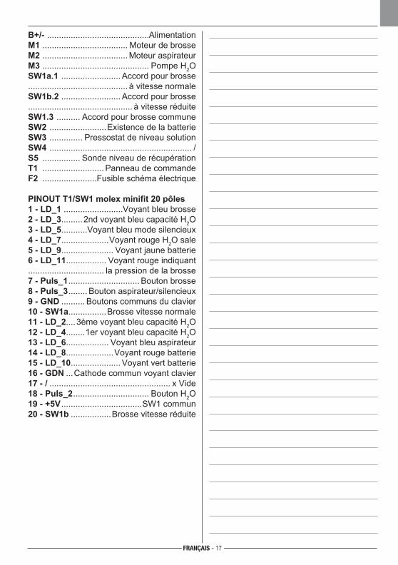
FRANÇAIS - 17
B+/- ...........................................AlimentationM1 .................................... Moteur de brosseM2 .................................... Moteur aspirateurM3 ............................................. Pompe H2OSW1a.1 ......................... Accord pour brosse .......................................... à vitesse normaleSW1b.2 ......................... Accord pour brosse............................................ à vitesse réduiteSW1.3 .......... Accord pour brosse communeSW2 ........................Existence de la batterieSW3 .............. Pressostat de niveau solutionSW4 ............................................................ /S5 ................ Sonde niveau de récupérationT1 .......................... Panneau de commandeF2 .......................Fusible schéma électrique
PINOUT T1/SW1 molex minifit 20 pôles1 - LD_1 .........................Voyant bleu brosse2 - LD_3.........2nd voyant bleu capacité H2O3 - LD_5...........Voyant bleu mode silencieux4 - LD_7....................Voyant rouge H2O sale5 - LD_9...................... Voyant jaune batterie6 - LD_11................. Voyant rouge indiquant ................................ la pression de la brosse7 - Puls_1 .............................. Bouton brosse8 - Puls_3 ........ Bouton aspirateur/silencieux9 - GND .......... Boutons communs du clavier10 - SW1a................Brosse vitesse normale11 - LD_2....3ème voyant bleu capacité H2O12 - LD_4........1er voyant bleu capacité H2O13 - LD_6.................. Voyant bleu aspirateur14 - LD_8....................Voyant rouge batterie15 - LD_10..................... Voyant vert batterie16 - GDN ...Cathode commun voyant clavier17 - / ................................................... x Vide 18 - Puls_2 ................................ Bouton H2O19 - +5V ..................................SW1 commun20 - SW1b .................Brosse vitesse réduite

18
DEUTSCH - 1
Sehr verehrter Kunde,Wir bedanken uns bei Ihnen dafür, dass Sie eines unserer Produkte zur Reinigung Ihrer Räume gekauft haben.
Der von Ihnen erworbene Wasch-Trockenfußbodenreiniger wurde für eine unkompli-zierte Handhabung und für eine lange Lebensdauer entwickelt.
Uns ist bewusst, dass ein gutes Produkt, um im Laufe der Zeit gut zu bleiben, ständig verbessert werden muss, um die jene zufrieden zu stellen, die tagtäglich mit ihm umge-hen. Daher wünschen wir uns, dass Sie nicht nur ein zufriedener Kunde sind, sondern auch ein Partner, der sich nicht davor scheut, uns seine Meinungen und seine jeden Tag mit dem Gerät gemachten Erfahrungen mitteilt.
DEUTSCH - 2
Inhaltsangabe Technische Daten ............................................................................................ 3
1.1 Einleitung .......................................................................................................... 5
2.1 Maschinenkenntnisse...................................................................................... 5
3.1 Entpackung ...................................................................................................... 5 3.1.a Maschinenausstattungen (Version mit Batterie) ..................................... 5 3.1.b Maschinenausstattungen(Version mit Ladegerät) .................................. 5 3.1.c Kfz-Batterieladegerät (optional).............................................................. 5 3.1.d Anheben der Maschine .......................................................................... 5
4.1 Zusammenbau der Einzelteile ........................................................................ 6 4.1.a Montage der Bürste ................................................................................ 6 4.1.b Positionierung der Handstange .............................................................. 6 4.1.c Einbau der Batterie nur für die batteriebetriebene Version .................... 6 4.1.d Einbau des Ladegeräts nur für die elektrische Version .......................... 6
5.1 Laden der Batterie (falls vorhanden) ............................................................. 6 5.1.a AufladenderBatterievoneiner12V-Steckdose.................................... 7
6.1 Bedienfeld ......................................................................................................... 76.2 Hebel für die Einstellung der Griffneigung / des Zyklusbetriebs der Maschine .................................................................. 86.3 Hebel für den Zyklusbetrieb der Maschine.................................................... 86.4 Pedale für das Anheben/Absenken der Bürste ............................................. 86.5 Schalter für die Einstellung des bürstendrucks bei bodenkontakt ............ 9
7.1 Verlegen der Maschine .................................................................................... 9
8.1 Befüllen des Tanks mit sauberem Wasser .................................................... 9 8.1.a Befüllen des Tanks auf der Maschine ..................................................... 9 8.1.b Befüllen des abmontierten Tanks ......................................................... 10
9.1 Betrieb .......................................................................................................... 10 9.1.a ÜberprüfungenvorderBenutzung ....................................................... 10 9.1.b Vorbereiten der Maschine und Zykluswahl........................................... 10 9.1.c Gebrauch der Maschine ....................................................................... 11 9.1.d Nach Gebrauch der Maschine und Ausschalten .................................. 11 9.1.e Lagerung der Maschine........................................................................ 11
10.1 Entsorgung des Schmutzwassers .............................................................. 12
11.1 Wartung und Reinigung ............................................................................... 12 11.1.a Leeren und Reinigen des Frischwassertanks ......................................12 11.1.b ReinigungdesSchmutzwassertanks ...................................................12 11.1.c Ausbau der Wischergruppe ..................................................................12 11.1.d Reinigung der Wischergruppe .............................................................. 13 11.1.e Reinigung der Bürste............................................................................ 13 11.1.f Auswechseln der Bürste....................................................................... 13 11.1.g Auswechseln des Wischergummis ....................................................... 13
Problem - Ursache - Behebung ............................................................................ 14
Optionales Zubehör ............................................................................................... 15
Schaltplan ............................................................................................................. 16
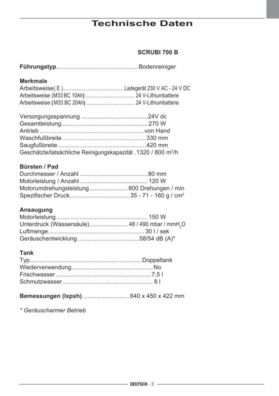
DEUTSCH - 3
Technische Daten
SCRUBI 700 B
Führungstyp ................................................. Bodenreiniger
MerkmaleArbeitsweise ( E ) .................................... Ladegerät230VAC-24VDC Arbeitsweise (M33 BC10Ah) ............................. 24V-Lithiumbatterie Arbeitsweise (M33BC20Ah) ............................. 24V-Lithiumbatterie
Versorgungsspannung
........................................24Vdc
Gesamtleistung....................................................270W
Antrieb
...............................................................vonHand
Waschfußbreite
..................................................330 mm
Saugfußbreite
.....................................................420mm
Geschätzte/tatsächliche Reinigungskapazität
.1320/800m2/h
Bürsten / PadDurchmesser/Anzahl
.........................................80 mm
Motorleistung / Anzahl
.........................................120W
Motorumdrehungsleistung
....................... 800 Drehungen/min
SpezifischerDruck.................................... 35 - 71 - 160 g / cm2
AnsaugungMotorleistung
....................................................... 150 W
Unterdruck (Wassersäule)
....................... 48 / 490 mbar / mmH2O
Luftmenge.......................................................... 30 l / sek
Geräuschentwicklung
.....................................58/54 dB (A)*
TankTyp...................................................................Doppeltank
Wiederverwendung.................................................No
Frischwasser
.........................................................7,5 l
Schmutzwasser
...................................................... 8 l
Bemessungen (lxpxh)
............................640x450x422mm
* Geräuscharmer Betrieb
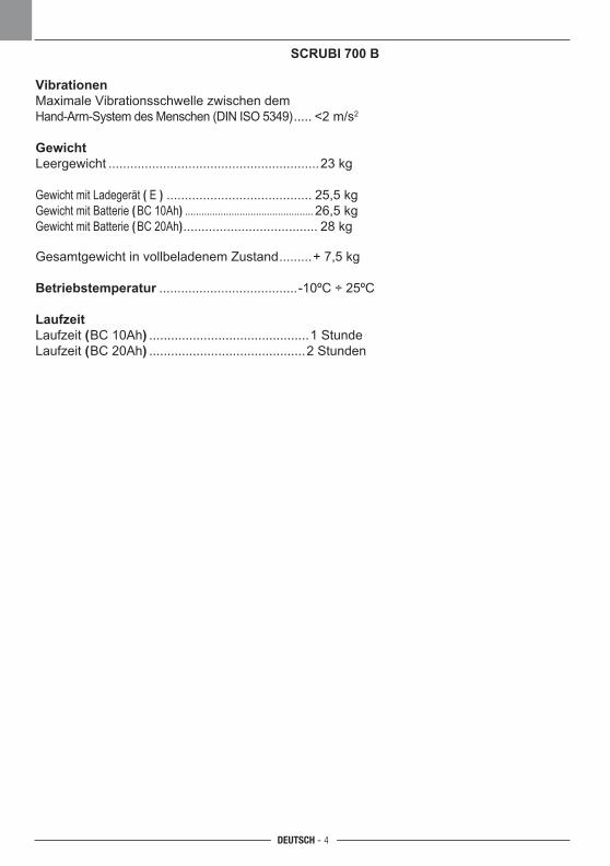
DEUTSCH - 4
SCRUBI 700 B
VibrationenMaximale Vibrationsschwelle zwischen dem Hand-Arm-SystemdesMenschen(DINISO5349) ..... <2m/s2
GewichtLeergewicht ..........................................................23kg
Gewicht mit Ladegerät ( E ) ........................................ 25,5kg Gewicht mit Batterie (BC10Ah) ...............................................26,5kg Gewicht mit Batterie (BC20Ah) ..................................... 28kg
GesamtgewichtinvollbeladenemZustand
.........+ 7,5 kg
Betriebstemperatur
......................................-10ºC÷25ºC
LaufzeitLaufzeit (BC10Ah)
............................................1Stunde
Laufzeit ( BC20Ah)
...........................................2Stunden
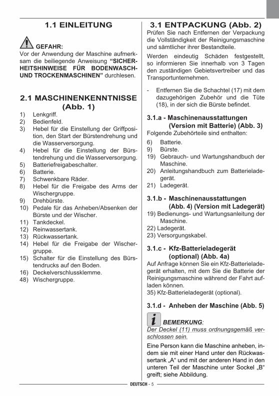
DEUTSCH - 5
1.1 EINLEITUNG
GEFAHR:Vor der Anwendung der Maschine aufmerk-sam die beiliegende Anweisung “SICHER-HEITSHINWEISE FÜR BODENWASCH- UND TROCKENMASCHINEN” durchlesen.
2.1 MASCHINENKENNTNISSE (Abb. 1)
1) Lenkgriff.2) Bedienfeld.3) Hebel für die Einstellung der Griffposi-
tion,denStartderBürstendrehungunddieWasserversorgung.
4) Hebel für die Einstellung der Bürs-tendrehungunddieWasserversorgung.
5) Batteriefreigabeschalter.6) Batterie.7) SchwenkbareRäder.8) Hebel für die Freigabe des Arms der
Wischergruppe.9) Drehbürste.10) Pedale für das Anheben/Absenken der
Bürste und der Wischer.11) Tankdeckel.12) Reinwassertank.13) Rückwassertank.14) Hebel für die Freigabe der Wischer-
gruppe.15) Schalter für die Einstellung des Bürs-
tendrucks auf den Boden.16) Deckelverschlussklemme.48) Wischergruppe.
3.1 ENTPACKUNG (Abb. 2)PrüfenSienachEntfernenderVerpackungdie Vollständigkeit der Reinigungsmaschine und sämtlicher ihrer Bestandteile.Werden eindeutig Schäden festgestellt,so informieren Sie innerhalb von 3 Tagenden zuständigenGebietsvertreiber unddasTransportunternehmen.
- EntfernenSiedieSchachtel(17)mitdemdazugehörigen Zubehör und die Tüte (18), in der sich die Bürste befindet.
3.1.a - Maschinenausstattungen (Version mit Batterie) (Abb. 3)Folgende Zubehörteile sind enthalten:6) Batterie.9) Bürste.19) Gebrauch- und Wartungshandbuch der
Maschine.20) Anleitungshandbuch zum Batterielade-
gerät.21) Ladegerät.
3.1.b - Maschinenausstattungen (Abb. 4) (Version mit Ladegerät)19) Bedienungs- und Wartungsanleitung der
Maschine.22)Ladegerät.23)Versorgungskabel.
3.1.c - Kfz-Batterieladegerät (optional) (Abb. 4a)AufAnfragekönnenSieeinKfz-Batterielade-geräterhalten,mitdemSiedieBatteriederReinigungsmaschine während der Fahrt auf-laden können.35) Kfz-Batterieladegerät (optional). 3.1.d - Anheben der Maschine (Abb. 5)
BEMERKUNG:Der Deckel (11) muss ordnungsgemäß ver-schlossen sein.Eine Person kann die Maschine anheben, in-dem sie mit einer Hand unter den Rückwas-sertank „A“ und mit der anderen Hand in den unterenTeilderMaschineunterSockel „B“greift; siehe Abbildung.
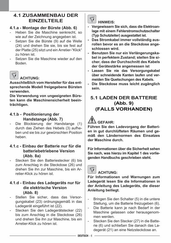
DEUTSCH - 6
4.1 ZUSAMMENBAU DER EINZELTEILE
4.1.a - Montage der Bürste (Abb. 6)- Heben Sie die Maschine senkrecht, so
wie auf der Zeichnung angegeben ist.- SetzenSiedieBürste (9) auf dieWelle
(24)unddrehenSiesie,bissie festaufderPlatte(25)sitztundeinArretier-“Klick“zu hören ist.
- SetzenSiedieMaschinewiederaufdenBoden.
ACHTUNG:Ausschließlich vom Hersteller für das ent-sprechende Modell freigegebene Bürsten verwenden.Die Verwendung von ungeeigneten Bürs-ten kann die Maschinensicherheit beein-trächtigen.
4.1.b - Positionierung der Handstange (Abb. 7)- Die Blockierung der Handstange (1)
durch das Ziehen des Hebels (3) aufhe-ben und sie bis zur gewünschten Position heben.
4.1.c - Einbau der Batterie nur für die batteriebetriebene Version (Abb. 8a)
- Stecken Sie den Batteriestecker (6) biszumAnschlagindieSteckdose(26)unddrehenSieihnzurMaschine,biseinAr-retier-Klick zu hören ist.
4.1.d - Einbau des Ladegeräts nur für die elektrische Version
(Abb. 8)- Stellen Sie sicher, dass das Versor-
gungskabel (23)ordnungsgemäß indasLadegeräteingeführtist(22).
- Stecken Sie den Ladegerätstecker (22)biszumAnschlag indieSteckdose(26)unddrehenSieihnzurMaschine,biseinArretier-Klick zu hören ist.
HINWEIS:- Vergewissern Sie sich, dass die Elektroan-
lage mit einem Fehlerstromschutzschalter (Typ Schutzleiter) ausgestattet ist.
- Das Stromkabel immer vollständig aus-rollen bevor es an die Steckdose ange-schlossen wird.
- Benutzen Sie nur ein Verlängerungska-bel in perfektem Zustand; stellen Sie si-cher, dass der Durchschnitt des Kabels der Gerätestärke angemessen ist
- Lassen Sie nie das Versorgungskabel über schneidende Kanten laufen und ver-meiden Sie Quetschungen des Kabels.
- Die Steckdose muss leicht zugänglich sein.
5.1 LADEN DER BATTERIE (Abb. 9)
(FALLS VORHANDEN)
GEFAHR:Führen Sie den Ladevorgang der Batteri-en in gut durchlüfteten Räumen und ge-mäß den Ländernormen des Einsatzes der Maschine durch.
Für Informationen über die Sicherheit sehen Sie nach, was hierzu im Kapitel 1 des vorlie-genden Handbuchs geschrieben steht.
ACHTUNG:Für Informationen und Warnungen zum Ladegerät lesen Sie die Informationen in der Anleitung des Ladegeräts, die dieser Anleitung beiliegt.
- BringenSiedenSchalter(5)indieuntereStellung,umdieBatteriefreizugeben(6).
- DieBatterie kann jenachBedarf in derMaschine gelassen oder herausgenom-men werden.
- SteckenSiedenStecker(27)indieBatte-rie(6)undschließenSiedanachdasLa-degerät(21)aneineNetzsteckdosean.
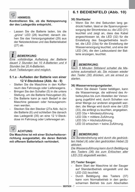
DEUTSCH - 7
6.1 BEDIENFELD (Abb. 10)
30) Starttaster- Wenn Sie ihn drei Sekunden lang ge-
drückthalten,lässterdieSpannungsver-sorgungderStromkreisezu;dieLED(31)leuchtet und zeigt an, dass das Kabel angeschlossen ist, die LED (32) für dieEinstellung des Saugerbetriebs leuch-tet,dieLED(33a)fürdieEinstellungderWasserversorgungleuchtet,undeinederLED(34),diedenLadezustandderBat-terie anzeigen, leuchtet.
BEMERKUNG:Nach 5 Minuten Stillstand schaltet die Ma-schine automatisch ab; Sie müssen wieder den Taster (30) drücken, um sie erneut zu starten.
36) Wasserversorgungstaster.- WennSiediesenTasterbetätigen,kann
die Wassermenge, die während des Ar-beitszyklus bis zum Abstellen der Versor-gungzugeführtwird,durchSchaltenvoneiner Menge zur anderen eingestellt wer-den;dieMengewirddurcheinederLED(33), die anfängt zu leuchten, angegeben.
LED33a=Mindestzuführung. LED33b=mittlereZuführung. LED33c=Höchstzuführung. LED33erloschen=keineZuführung.
BEMERKUNG:Die Bürstendrehung wird durch die gedrück-ten Hebel (4) oder den gedrückten Hebel (3) aktiviert.Die Wasserzuführung kann durch Betätigung des Tasters (36) bis zum Erlöschen aller LED (33) abgestellt werden.
37) Taster Sauger.- BeimStartderMaschine istderSauger
auf Standardbetrieb eingestellt und dieLED(32)leuchtet.
- Durch Betätigung des Tasters (37)kann vom Normalbetrieb in den geräu-scharmen Betrieb bis zum Abschalten
HINWEIS:Kontrollieren Sie, ob die Netzspannung der des Ladegeräts entspricht..
- Lassen Sie die Batterie laden, bis die„grüne“ LED (28) leuchtet; danach zie-henSiedasVersorgungskabel (29)ausder Netzsteckdose und das Batteriekabel (27)ab.
BEMERKUNG:Eine vollständige Aufladung der Batterie dauert 2 Stunden bei 10 A-Batterien und 4 Stunden bei 20 A-Batterien.Auch Teilladungen sind möglich.
5.1.a - Aufladen der Batterie von einer 12 V-Steckdose (Abb. 4a - 9)
- StellenSie dieMaschine in denKoffer-raum des Fahrzeugs oder Lieferwagens.
- BringenSiedenSchalter(5)indieuntereStellung,umdieBatteriefreizugeben(6).
- DieBatterie kann jenachBedarf in derMaschine gelassen oder herausgenom-men werden.
- SteckenSiedenStecker(27aAbb.4a)indieBatterie(6)undschließenSiedanachdasLadegerät (35)aneine12V-Steck-dose im Fahrzeug oder Lieferwagen an.
ACHTUNG:Die Maschine ist mit einer Sicherheitsvor-richtung ausgestattet, die deren Betrieb mit offenem Batteriefach verhindert.
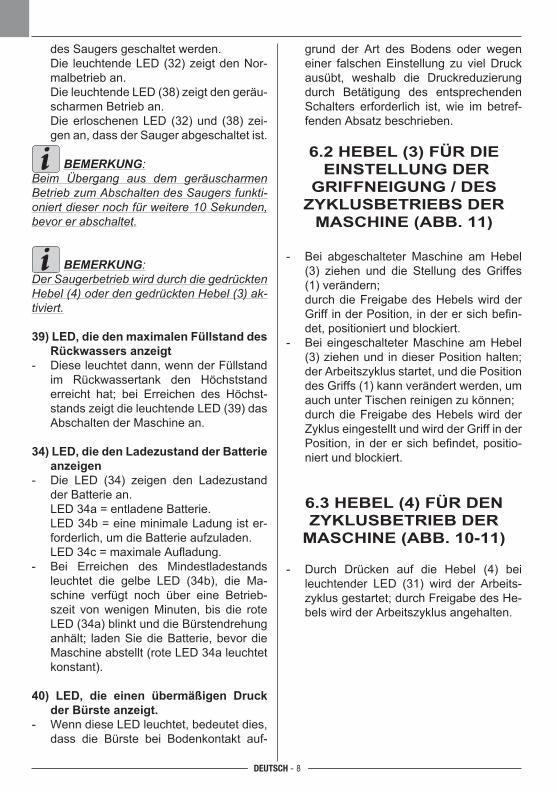
DEUTSCH - 8
desSaugersgeschaltetwerden. Die leuchtendeLED(32)zeigtdenNor-
malbetrieb an. DieleuchtendeLED(38)zeigtdengeräu-
scharmen Betrieb an. DieerloschenenLED (32)und (38)zei-
genan,dassderSaugerabgeschaltetist.
BEMERKUNG:Beim Übergang aus dem geräuscharmen Betrieb zum Abschalten des Saugers funkti-oniert dieser noch für weitere 10 Sekunden, bevor er abschaltet.
BEMERKUNG:Der Saugerbetrieb wird durch die gedrückten Hebel (4) oder den gedrückten Hebel (3) ak-tiviert.
39) LED, die den maximalen Füllstand des Rückwassers anzeigt
- Dieseleuchtetdann,wennderFüllstandim Rückwassertank den Höchststand erreicht hat; bei Erreichen des Höchst-standszeigtdieleuchtendeLED(39)dasAbschalten der Maschine an.
34) LED, die den Ladezustand der Batterie anzeigen
- Die LED (34) zeigen den Ladezustandder Batterie an.
LED34a=entladeneBatterie. LED34b=eineminimaleLadungister-
forderlich, um die Batterie aufzuladen. LED34c=maximaleAufladung.- Bei Erreichen des Mindestladestands
leuchtet die gelbe LED (34b), die Ma-schine verfügt noch über eine Betrieb-szeit vonwenigenMinuten, bis die roteLED(34a)blinktunddieBürstendrehunganhält; ladenSiedieBatterie,bevordieMaschineabstellt(roteLED34aleuchtetkonstant).
40) LED, die einen übermäßigen Druck der Bürste anzeigt.
- WenndieseLEDleuchtet,bedeutetdies,dass die Bürste bei Bodenkontakt auf-
grund der Art des Bodens oder wegen einer falschenEinstellung zu vielDruckausübt, weshalb die Druckreduzierungdurch Betätigung des entsprechenden Schalters erforderlich ist, wie im betref-fenden Absatz beschrieben.
6.2 HEBEL (3) FÜR DIE EINSTELLUNG DER
GRIFFNEIGUNG / DES ZYKLUSBETRIEBS DER
MASCHINE (ABB. 11)
- Bei abgeschalteter Maschine am Hebel (3) ziehen und die Stellung des Griffes(1)verändern;
durch die Freigabe des Hebels wird der Griff in der Position, in der er sich befin-det, positioniert und blockiert.
- Bei eingeschalteter Maschine am Hebel (3) ziehen und in dieser Position halten; der Arbeitszyklus startet, und die Position desGriffs(1)kannverändertwerden,umauch unter Tischen reinigen zu können;
durch die Freigabe des Hebels wird der Zyklus eingestellt und wird der Griff in der Position, in der er sich befindet, positio-niert und blockiert.
6.3 HEBEL (4) FÜR DEN ZYKLUSBETRIEB DER
MASCHINE (ABB. 10-11)
- Durch Drücken auf die Hebel (4) beileuchtender LED (31) wird der Arbeits-zyklus gestartet; durch Freigabe des He-bels wird der Arbeitszyklus angehalten.
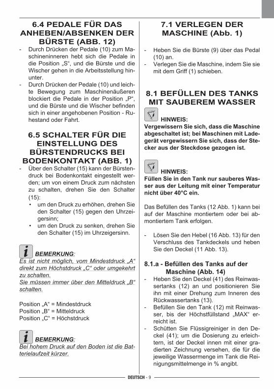
DEUTSCH - 9
6.4 PEDALE FÜR DAS ANHEBEN/ABSENKEN DER
BÜRSTE (ABB. 12)- DurchDrückenderPedale(10)zumMa-
schineninneren hebt sich die Pedale in diePosition „S“,unddieBürsteunddieWischer gehen in die Arbeitsstellung hin-unter.
- DurchDrückenderPedale(10)undleich-te Bewegung zum Maschinenäußeren blockiert die Pedale in der Position „P“, und die Bürste und die Wischer befinden sich in einer angehobenen Position - Ru-hestand oder Fahrt.
6.5 SCHALTER FÜR DIE EINSTELLUNG DES
BÜRSTENDRUCKS BEI BODENKONTAKT (ABB. 1)- ÜberdenSchalter(15)kannderBürsten-
druck bei Bodenkontakt eingestellt wer-den;umvoneinemDruckzumnächstenzu schalten, drehen Sie den Schalter(15):
• umdenDruckzuerhöhen,drehenSiedenSchalter(15)gegendenUhrzei-gersinn;
• umdenDruckzusenken,drehenSiedenSchalter(15)imUhrzeigersinn.
BEMERKUNG:Es ist nicht möglich, vom Mindestdruck „A“ direkt zum Höchstdruck „C“ oder umgekehrt zu schalten.Sie müssen immer über den Mitteldruck „B“ schalten.
Position„A“=MindestdruckPosition„B“=MitteldruckPosition„C“=Höchstdruck
BEMERKUNG:Bei hohem Druck auf den Boden ist die Bat-terielaufzeit kürzer.
7.1 VERLEGEN DER MASCHINE (Abb. 1)
- HebenSiedieBürste(9)überdasPedal(10) an.
- VerlegenSiedieMaschine,indemSiesiemit dem Griff (1) schieben.
8.1 BEFÜLLEN DES TANKS MIT SAUBEREM WASSER
HINWEIS:Vergewissern Sie sich, dass die Maschine abgeschaltet ist; bei Maschinen mit Lade-gerät vergewissern Sie sich, dass der Ste-cker aus der Steckdose gezogen ist.
HINWEIS:Füllen Sie in den Tank nur sauberes Was-ser aus der Leitung mit einer Temperatur nicht über 40°C ein.
DasBefüllendesTanks(12Abb.1)kannbeiauf der Maschine montiertem oder bei ab-montiertem Tank erfolgen.
- LösenSiedenHebel(16Abb.13)fürdenVerschluss des Tankdeckels und heben SiedenDeckel(11Abb.13).
8.1.a - Befüllen des Tanks auf der Maschine (Abb. 14)
- HebenSiedenDeckel(41)desReinwas-sertanks (12) an und positionieren Sieihnmit einerDrehung zum InnerendesRückwassertanks (13).
- BefüllenSiedenTank(12)mitReinwas-ser, bis der Höchstfüllstand „MAX“ er-reicht ist.
- SchüttenSie Flüssigreiniger in denDe-ckel (41); um die Dosierung zu erleich-tern, istderDeckel innenmiteinergra-dierten Zeichnung versehen, die für diejeweiligeWassermengeimTankdieRei-nigungsmittelmenge in % angibt.
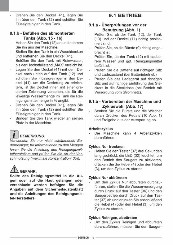
DEUTSCH - 10
- Drehen Sie den Deckel (41), legen SieihnüberdenTank(12)undschüttenSieFlüssigreiniger in den Tank.
8.1.b - Befüllen des abmontierten Tanks (Abb. 15 - 16)
- HebenSiedenTank(12)anundnehmenSieihnausderMaschine.
- StellenSiedenTankineinWaschbeckenundentfernenSiedenDeckel(41).
- Befüllen Sie den Tank mit Reinwasser,bis der Höchstfüllstand „MAX“ erreicht ist.
- LegenSiedenDeckel(41)mitdemDe-ckel nach unten auf denTank (12) undschütten Sie Flüssigreiniger in den De-ckel (41); um die Dosierung zu erleich-tern, istderDeckel innenmiteinergra-dierten Zeichnung versehen, die für diejeweiligeWassermengeimTankdieRei-nigungsmittelmenge in % angibt.
- Drehen Sie den Deckel (41), legen SieihnüberdenTank(12)undschüttenSieFlüssigreiniger in den Tank.
- BringenSiedenTankwiederanseinenPlatz in der Maschine.
BEMERKUNG:Verwenden Sie nur nicht schäumende Bo-denreiniger; für Informationen zu den Mengen lesen Sie die Anleitung des Reinigungsmit-telherstellers und prüfen Sie die Art der Ver-schmutzung (maximale Konzentration: 3%).
GEFAHR:Sollte das Reinigungsmittel in die Au-gen oder auf die Haut gelangen oder verschluckt werden befolgen Sie die Angaben auf dem Sicherheitsdatenblatt und die Anleitungen des Reinigungsmit-tel-Herstellers.
9.1 BETRIEB
9.1.a - Überprüfungen vor der Benutzung (Abb. 1)- PrüfenSie, ob derTank (12), der Tank
(13) undderDeckel (11) richtig positio-niert sind.
- PrüfenSie,obdieBürste(9)richtigange-bracht ist.
- PrüfenSie,obderTank(12)mitsaube-rem Wasser und ggf. Reinigungsmittel befüllt ist.
- PrüfenSiedieBatterieaufrichtigenSitzund Ladezustand (bei Batteriebetrieb)
- Prüfen Sie das Ladegerät auf richtigenSitzundaufrichtigeEinführungdesSte-ckers in die Steckdose (bei Betrieb mitVersorgungvomStromnetz).
9.1.b - Vorbereiten der Maschine und Zykluswahl (Abb. 17)
- SenkenSiedieBürsteunddieWischerdurch Drücken des Pedals (10 Abb. 1)und Freigabe aus der Aussparung ab.
Arbeitszyklus- Die Maschine kann 4 Arbeitszyklen
durchführen:
Zyklus Nur trocknen- HaltenSiedenTaster(37)dreiSekunden
langgedrückt,dieLED(32)leuchtet;umden Betrieb des Saugers zu aktivieren,drückenSiedieHebel(4)oderdenHebel(3), um den Zyklus zu starten.
Zyklus Nur abbürsten- Um den Zyklus Nur abbürsten durchzu-
führen,stellenSiedieWasserversorgungdurchDruckaufdenTaster(36)unddenSaugerbetriebdurchDruckaufdenTas-ter(37)abunddrückenSieanschließenddie Hebel (4) oder den Hebel (3), um den Zyklus zu starten.
Zyklus Reinigen, abbürsten - Um den Zyklus Reinigen und abbürsten
durchzuführen,müssenSiedenSauger-
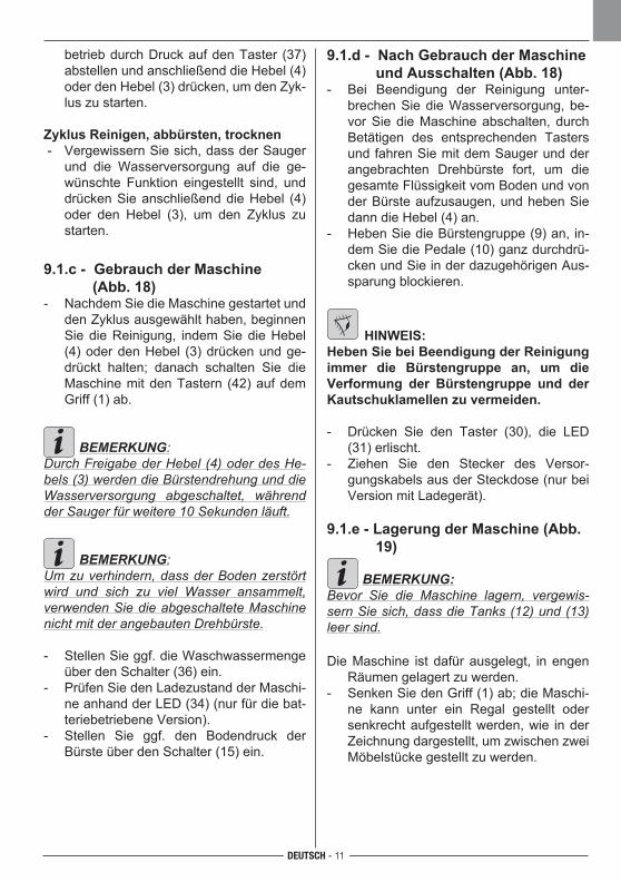
DEUTSCH - 11
betriebdurchDruckaufdenTaster (37)abstellen und anschließend die Hebel (4) oder den Hebel (3) drücken, um den Zyk-lus zu starten.
Zyklus Reinigen, abbürsten, trocknen- VergewissernSiesich,dassderSauger
und die Wasserversorgung auf die ge-wünschte Funktion eingestellt sind, und drückenSieanschließenddieHebel (4)oder den Hebel (3), um den Zyklus zu starten.
9.1.c - Gebrauch der Maschine (Abb. 18)- NachdemSiedieMaschinegestartetund
den Zyklus ausgewählt haben, beginnen SiedieReinigung, indemSiedieHebel(4) oder den Hebel (3) drücken und ge-drückt halten; danach schalten Sie dieMaschinemitdenTastern (42)aufdemGriff (1) ab.
BEMERKUNG:Durch Freigabe der Hebel (4) oder des He-bels (3) werden die Bürstendrehung und die Wasserversorgung abgeschaltet, während der Sauger für weitere 10 Sekunden läuft.
BEMERKUNG:Um zu verhindern, dass der Boden zerstört wird und sich zu viel Wasser ansammelt, verwenden Sie die abgeschaltete Maschine nicht mit der angebauten Drehbürste.
- StellenSieggf.dieWaschwassermengeüberdenSchalter(36)ein.
- PrüfenSiedenLadezustandderMaschi-neanhandderLED(34)(nurfürdiebat-teriebetriebene Version).
- Stellen Sie ggf. den Bodendruck derBürsteüberdenSchalter(15)ein.
9.1.d - Nach Gebrauch der Maschine und Ausschalten (Abb. 18)
- Bei Beendigung der Reinigung unter-brechenSiedieWasserversorgung,be-vorSiedieMaschineabschalten, durchBetätigen des entsprechenden Tasters undfahrenSiemitdemSaugerundderangebrachten Drehbürste fort, um diegesamteFlüssigkeitvomBodenundvonderBürsteaufzusaugen,undhebenSiedann die Hebel (4) an.
- HebenSiedieBürstengruppe(9)an,in-demSiediePedale(10)ganzdurchdrü-ckenundSieinderdazugehörigenAus-sparung blockieren.
HINWEIS:Heben Sie bei Beendigung der Reinigung immer die Bürstengruppe an, um die Verformung der Bürstengruppe und der Kautschuklamellen zu vermeiden.
- Drücken Sie den Taster (30), die LED(31) erlischt.
- Ziehen Sie den Stecker des Versor-gungskabelsausderSteckdose(nurbeiVersion mit Ladegerät).
9.1.e - Lagerung der Maschine (Abb. 19)
BEMERKUNG:Bevor Sie die Maschine lagern, vergewis-sern Sie sich, dass die Tanks (12) und (13) leer sind.
DieMaschine ist dafürausgelegt, inengenRäumen gelagert zu werden.
- SenkenSiedenGriff(1)ab;dieMaschi-ne kann unter ein Regal gestellt oder senkrecht aufgestellt werden, wie in der Zeichnung dargestellt, um zwischen zwei Möbelstücke gestellt zu werden.
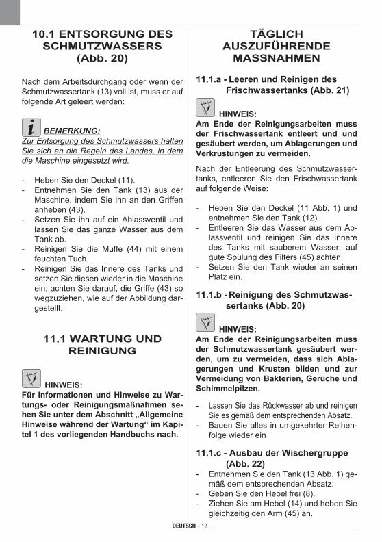
DEUTSCH - 12
10.1 ENTSORGUNG DES SCHMUTZWASSERS
(Abb. 20)
Nach dem Arbeitsdurchgang oder wenn der Schmutzwassertank(13)vollist,musserauffolgende Art geleert werden:
BEMERKUNG:Zur Entsorgung des Schmutzwassers halten Sie sich an die Regeln des Landes, in dem die Maschine eingesetzt wird.
- HebenSiedenDeckel(11).- Entnehmen Sie den Tank (13) aus der
Maschine, indemSie ihnandenGriffenanheben (43).
- SetzenSie ihnauf einAblassventil undlassenSie dasganzeWasser ausdemTank ab.
- Reinigen Sie die Muffe (44) mit einemfeuchten Tuch.
- ReinigenSiedas InneredesTanksundsetzenSiediesenwiederindieMaschineein;achtenSiedarauf,dieGriffe(43)sowegzuziehen, wie auf der Abbildung dar-gestellt.
11.1 WARTUNG UND REINIGUNG
HINWEIS:Für Informationen und Hinweise zu War-tungs- oder Reinigungsmaßnahmen se-hen Sie unter dem Abschnitt „Allgemeine Hinweise während der Wartung“ im Kapi-tel 1 des vorliegenden Handbuchs nach.
TÄGLICH AUSZUFÜHRENDE
MASSNAHMEN
11.1.a - Leeren und Reinigen des Frischwassertanks (Abb. 21)
HINWEIS:Am Ende der Reinigungsarbeiten muss der Frischwassertank entleert und und gesäubert werden, um Ablagerungen und Verkrustungen zu vermeiden.
Nach der Entleerung des Schmutzwasser-tanks, entleeren Sie den Frischwassertankauf folgende Weise:
- HebenSie denDeckel (11Abb. 1) undentnehmenSiedenTank(12).
- EntleerenSiedasWasserausdemAb-lassventil und reinigen Sie das Inneredes Tanks mit sauberem Wasser; auf guteSpülungdesFilters(45)achten.
- Setzen Sie den Tankwieder an seinenPlatz ein.
11.1.b - Reinigung des Schmutzwas-sertanks (Abb. 20)
HINWEIS:Am Ende der Reinigungsarbeiten muss der Schmutzwassertank gesäubert wer-den, um zu vermeiden, dass sich Abla-gerungen und Krusten bilden und zur Vermeidung von Bakterien, Gerüche und Schimmelpilzen.
- LassenSiedasRückwasserabundreinigenSieesgemäßdementsprechendenAbsatz.
- BauenSiealles inumgekehrterReihen-folge wieder ein
11.1.c - Ausbau der Wischergruppe (Abb. 22)
- EntnehmenSiedenTank(13Abb.1)ge-mäß dem entsprechenden Absatz.
- GebenSiedenHebelfrei(8).- ZiehenSieamHebel(14)undhebenSie
gleichzeitig den Arm (45) an.
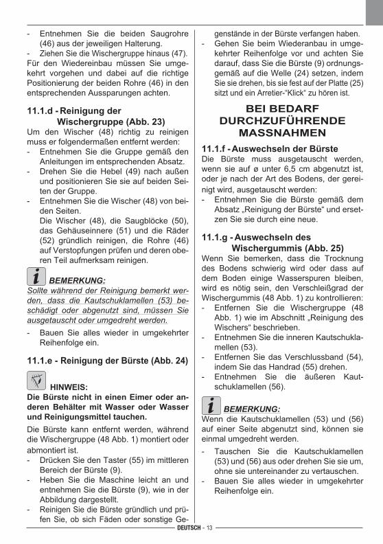
DEUTSCH - 13
- Entnehmen Sie die beiden Saugrohre(46)ausderjeweiligenHalterung.
- ZiehenSiedieWischergruppehinaus(47).Für den Wiedereinbau müssen Sie umge-kehrt vorgehen und dabei auf die richtigePositionierung der beiden Rohre (46) in den entsprechenden Aussparungen achten.
11.1.d - Reinigung der Wischergruppe (Abb. 23)Um den Wischer (48) richtig zu reinigen muss er folgendermaßen entfernt werden:- EntnehmenSie dieGruppe gemäßden
Anleitungen im entsprechenden Absatz.- Drehen Sie die Hebel (49) nach außen
undpositionierenSiesieaufbeidenSei-ten der Gruppe.
- EntnehmenSiedieWischer(48)vonbei-denSeiten.
DieWischer (48), die Saugblöcke (50),das Gehäuseinnere (51) und die Räder (52) gründlich reinigen, die Rohre (46)auf Verstopfungen prüfen und deren obe-ren Teil aufmerksam reinigen.
BEMERKUNG:Sollte während der Reinigung bemerkt wer-den, dass die Kautschuklamellen (53) be-schädigt oder abgenutzt sind, müssen Sie ausgetauscht oder umgedreht werden. - Bauen Sie alles wieder in umgekehrter
Reihenfolge ein.
11.1.e - Reinigung der Bürste (Abb. 24)
HINWEIS:Die Bürste nicht in einen Eimer oder an-deren Behälter mit Wasser oder Wasser und Reinigungsmittel tauchen.Die Bürste kann entfernt werden, währenddie Wischergruppe (48 Abb. 1) montiert oder abmontiert ist.- DrückenSiedenTaster(55)immittleren
Bereich der Bürste (9).- Heben Sie die Maschine leicht an und
entnehmenSiedieBürste(9),wieinderAbbildung dargestellt.
- ReinigenSiedieBürstegründlichundprü-fenSie,obsichFädenoder sonstigeGe-
genständeinderBürsteverfangenhaben.- GehenSiebeimWiederanbau inumge-
kehrterReihenfolge vor und achtenSiedarauf,dassSiedieBürste(9)ordnungs-gemäßaufdieWelle(24)setzen,indemSiesiedrehen,bissiefestaufderPlatte(25)sitzt und ein Arretier-“Klick“ zu hören ist.
BEI BEDARF DURCHZUFÜHRENDE
MASSNAHMEN11.1.f - Auswechseln der BürsteDie Bürste muss ausgetauscht werden,wenn sie auf ø unter 6,5 cm abgenutzt ist, oderjenachderArtdesBodens,dergerei-nigt wird, ausgetauscht werden:- Entnehmen Sie die Bürste gemäß dem
Absatz „Reinigung der Bürste“ und erset-zenSiesiedurcheineneue.
11.1.g - Auswechseln des Wischergummis (Abb. 25)Wenn Sie bemerken, dass die Trocknungdes Bodens schwierig wird oder dass auf dem Boden einige Wasserspuren bleiben, wird es nötig sein, den Verschleißgrad der Wischergummis (48 Abb. 1) zu kontrollieren:- Entfernen Sie die Wischergruppe (48
Abb. 1) wie im Abschnitt „Reinigung des Wischers“ beschrieben.
- EntnehmenSiedieinnerenKautschukla-mellen (53).
- EntfernenSiedasVerschlussband (54),indemSiedasHandrad(55)drehen.
- Entnehmen Sie die äußeren Kaut-schuklamellen (56).
BEMERKUNG:Wenn die Kautschuklamellen (53) und (56) auf einer Seite abgenutzt sind, können sieeinmal umgedreht werden.- Tauschen Sie die Kautschuklamellen
(53)und(56)ausoderdrehenSiesieum,ohnesieuntereinanderzuvertauschen.
- Bauen Sie alles wieder in umgekehrterReihenfolge ein.
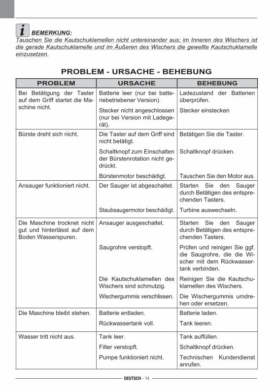
DEUTSCH - 14
BEMERKUNG:Tauschen Sie die Kautschuklamellen nicht untereinander aus; im Inneren des Wischers ist die gerade Kautschuklamelle und im Äußeren des Wischers die gewellte Kautschuklamelle einzusetzen.
PROBLEM - URSACHE - BEHEBUNGPROBLEM URSACHE BEHEBUNG
Bei Betätigung der Taster auf dem Griff startet die Ma-schine nicht.
Batterie leer (nur bei batte-riebetriebener Version).
Steckernichtangeschlossen (nur bei Version mit Ladege-rät).
Ladezustand der Batterien überprüfen.
Steckereinstecken
Bürste dreht sich nicht. DieTasteraufdemGriffsindnicht betätigt.
SchaltknopfzumEinschaltender Bürstenrotation nicht ge-drückt.
Bürstenmotor beschädigt.
BetätigenSiedieTaster.
Schaltknopfdrücken.
TauschenSiedenMotoraus.Ansauger funktioniert nicht. DerSaugeristabgeschaltet.
Staubsaugermotorbeschädigt.
Starten Sie den Saugerdurch Betätigen des entspre-chenden Tasters.
Turbine auswechseln.
DieMaschine trocknet nichtgut und hinterlässt auf dem Boden Wasserspuren.
Ansauger ausgeschaltet.
Saugrohreverstopft.
Die Kautschuklamellen desWischers sind schmutzig.
Wischergummisverschlissen.
Starten Sie den Saugerdurch Betätigen des entspre-chenden Tasters.
PrüfenundreinigenSieggf.die Saugrohre, die die Wi-scher mit dem Rückwasser-tankverbinden.
Reinigen Sie die Kautschu-klamellen des Wischers.
Die Wischergummis umdre-hen oder ersetzen.
DieMaschinebleibtstehen. Batterie entladen.
Rückwassertankvoll.
Batterie laden.
Tank leeren.
Wasser tritt nicht aus. Tank leer.
Filterverstopft.
Pumpe funktioniert nicht.
Tank auffüllen.
Schaltknopfdrücken.
Technischen Kundendienst anrufen.
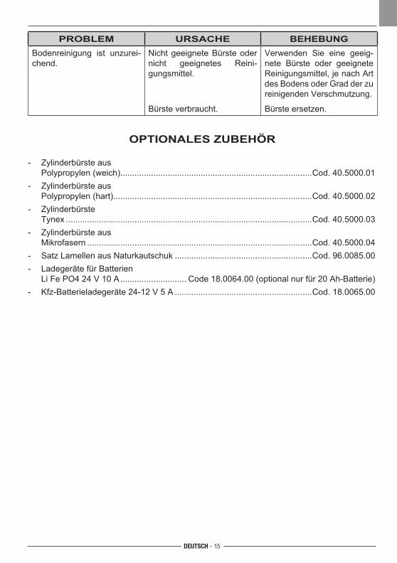
DEUTSCH - 15
PROBLEM URSACHE BEHEBUNGBodenreinigung ist unzurei-chend.
Nicht geeignete Bürste oder nicht geeignetes Reini-gungsmittel.
Bürsteverbraucht.
Verwenden Sie eine geeig-nete Bürste oder geeignete Reinigungsmittel,jenachArtdes Bodens oder Grad der zu reinigenden Verschmutzung.
Bürste ersetzen.
OPTIONALES ZUBEHÖR
- Zylinderbürste aus Polypropylen (weich).................................................................................Cod.40.5000.01- Zylinderbürste aus Polypropylen (hart)....................................................................................Cod.40.5000.02- Zylinderbürste Tynex ........................................................................................................Cod.40.5000.03- Zylinderbürste aus Mikrofasern ...............................................................................................Cod.40.5000.04- SatzLamellenausNaturkautschuk ..........................................................Cod.96.0085.00- Ladegeräte für Batterien LiFePO424V10A ............................Code18.0064.00(optionalnurfür20Ah-Batterie)- Kfz-Batterieladegeräte24-12V5A ..........................................................Cod.18.0065.00
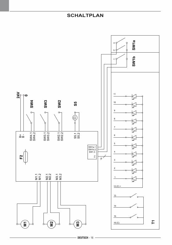
M1
M2
M3
M1.
1M
1.2
M2.
1M
2.2
M3.
1M
3.2
B+
B -
16
T1
SW1a
SW1a.1SW1b.2SW1.3
SW3
SW
3.1
SW
3.2
SW2
SW
2.1
SW
2.2
SW4
SW
4.1
SW
4.2
T1
S5S
5.1
S5.
2
a
b
c
11
10
9
8
7
6
5
4
3
2
1
12 (C) +
13
14
15
16 (C)
F2
SW1b
24V 0
DEUTSCH - 16
SCHALTPLAN
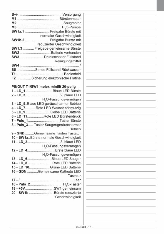
DEUTSCH - 17
B+/- ............................................VersorgungM1 ...........................................BürstenmotorM2 ...............................................SaugmotorM3 ............................................. H2O-PumpeSW1a.1 .........................Freigabe Bürste mit
normaler GeschwindigkeitSW1b.2 .........................Freigabe Bürste mit
reduzierter GeschwindigkeitSW1.3 ........... Freigabe gemeinsame BürsteSW2 ...............................BatterievorhandenSW3 ........................DruckschalterFüllstand
ReinigungsmittelSW4 ............................................................ /S5 ..................SondeFüllstandRückwasserT1 ............................................... BedienfeldF2 ..............SicherungelektronischePlatine
PINOUT T1/SW1 molex minifit 20-polig1 - LD_1 ...........................BlaueLEDBürste2 - LD_3....................................2.blaueLED
H2O-Fassungsvermögen3 - LD_5..BlaueLEDgeräuscharmerBetrieb4 - LD_7..........RoteLEDWasserschmutzig5 - LD_9.........................GelbeLEDBatterie6 - LD_11.................RoteLEDBürstendruck7 - Puls_1 ................................Taster Bürste8 - Puls_3 ..... TasterSauger/geräuscharmer
Betrieb9 - GND .........Gemeinsame Tasten Tastatur10 - SW1a..Bürste normale Geschwindigkeit11 - LD_2..................................3.blaueLED
H2O-Fassungsvermögen12 - LD_4............................ErsteblaueLED
H2O-Fassungsvermögen13 - LD_6.........................BlaueLEDSauger14 - LD_8.........................RoteLEDBatterie15 - LD_10.....................GrüneLEDBatterie16 - GDN ...........GemeinsameKathodeLED
Tastatur17 - / ...................................................... Leer18 - Puls_2 ................................. H2O-Taster19 - +5V .............................SW1gemeinsam20 - SW1b .........................Bürste reduzierte
Geschwindigkeit
4
ENIT Dichiarazione di conformità
Con la presente si dichiara che la macchina qui di seguito indicata, in base alla sua concezione, al tipo di costruzione e nella versione da noi introdot-ta sul mercato, è conforme ai requisiti fondamenta-li di sicurezza e di sanità delle direttive CE.In caso di modifiche apportate alla macchina sen-za il nostro consenso, la presente dichiarazione perde ogni validità.
Prodotto Lavasciugapavimenti
MODELLO SCRUBI 700 B
CODICE13.0075.48
Direttive CE pertinenti
2006/42/CE (+2009/127/CE)2014/30/UE2011/65/UENorme armonizzate applicate EN 60335-1EN 60335-2-72
Norme nazionali applicate-
Nome e posizione della persona autorizzata a fir-mare la Dichiarazione Walter KradolferAmministratore Delegato Kranzle
Firma ________________ Walter Kradolfer
Nome e indirizzo della persona autorizzata a forni-re il fascicolo tecnico:Walter Kardolfer, presso KranzleOberebenestrasse 21- 5620 Bremgarten,Schweiz
Firma ________________
Bremgarten, 10/2017
Declaration of EC conformity
We hereby declare that the machine de-scribed below complies with the relevant basic safety and health requirements of the EU Directives, both in its basic design and construction as well as in the version put into circulation by us. This declaration shall cease to be valid if the machine is modified without our prior approval.
Product Scrubber drier
MODEL
CODE13.0075.48
Relevant EU Directives 2006/42/CE (+2009/127/CE)2014/30/UE2011/65/UE
Applied harmonized standards EN 60335-1EN 60335-2-72
Applied national standards-
Name and position of the person authorised to sign the Declaration Walter KradolferChief Executive Officer of Kranzle
Signature ________________
Name and address of the person authorised to supply the technical manual
Signature ________________
Bremgarten, 10/2017
SCRUBI 700 B
Walter Kradolfer
Walter KradolferWalter Kradolfer
Walter Kardolfer, at KranzleOberebenestrasse 21- 5620 Bremgarten,Schweiz
5
DEFR Déclaration de conformité
Nous certifions par la présente que la machine spé-cifiée ci-après répond de par sa conception et son type de construction ain-si que de par la version que nous avons mise sur le marché aux prescriptions fondamentales stipulées en matière de sécurité et d’hygiène par les directives européennes en vigueur. Toute modification apportée à la machine sans notre ac-cord rend cette déclaration invalide.Produit
Autolaveuses
MODÈLE
CODE
Directives européennes en vigueur
2006/42/CE (+2009/127/CE)2014/30/UE2011/65/UENormes harmonisées appliquées EN 60335-1EN 60335-2-72
Normes nationales appliquées-
Nom et position de la personne autorisée à signer la DéclarationWalter Kradolfer, Directeur Général Kranzle
Signature ________________
Nom et adresse de la personne autorisée à fournir le fascicule technique:Walter Kradolfer, auprès de Kranzle,Oberebenestrasse 21- 5620 Bremgarten,Schweiz.
Signature ________________
Bremgarten, 10/2017
EG- Konformitätserklärung
Hiermit erklären wir, dass die nachfolgend be-zeichnete Maschine aufgrund ihrer Kon-zipierung und Bauart sowie in der von uns in Verkehr ge-brachten Ausführung den ein-schlägigen grundle-genden Sicherheits- und Gesundheitsanforderun-gen der EG-Richtlinien entspricht. Bei einer nicht mit uns abgestimmten Änderung der Maschine verliert diese Erklärung ihre Gültigkeit.
Produkt Boden-Waschtrockner
MODELL
KENNNR.
Einschlägige EG-Richtlinien
2006/42/CE (+2009/127/CE)2014/30/UE2011/65/UEAngewandte harmonisierte Normen EN 60335-1EN 60335-2-72
Angewandte nationale Normen-
Name und Beruf der autorisierten Person, welche die Erklärung unterzeichnet.Walter Kradolfer, Vorstandsvorsitzender Kranzle
Unterschrift ________________
Name und Anschrift der zuständigen Person für den Versandt technischer Unterlagen:Walter Kradolfer, bei Kranzle , Oberebenestrasse 21- 5620 Bremgarten,Schweiz.
Unterschrift ________________
Bremgarten, 10/2017
SCRUBI 700 B SCRUBI 700 B
13.0075.4813.0075.48
Walter Kradolfer Walter Kradolfer
Walter Kradolfer Walter Kradolfer

18

DEALER
Cod
. 49.
0217
.48
- 1^
ed. -
10/
2017
Kränzle AG
Tel. +41 ( 0) 56 201 44 88 - Fax +41 ( 0) 56 201 44 89 http://www.kraenzle.ch - e-mail: [email protected]
Oberebenestrasse 21 - 5620 Bremgarten,Schweiz