saba 50 - lamischief.files.wordpress.com
TRANSCRIPT

Saba 50
USER GUIDE
CONTENTS
TECHNICAL INFORMATION
A) Identity file .......................................................................................................................... 4
B) Characteristics ..................................................................................................................... 5
C) Rigging and fitting ropes ................................................................................................... 6
SAILING
A) Leaving harbour ................................................................................................................. 8
Starting the engines ................................................................................................................... 11
Manoeuvres common to the different engine types .................................................................. 12
B) Sailing .................................................................................................................................. 14
B1) Sail reduction table according to apparent wind ............................................................... 14
B2) Main sail............................................................................................................................. 15
B3) Helm system ...................................................................................................................... 16
C) Anchoring ........................................................................................................................... 17
C1) Setting the anchor .............................................................................................................. 17
C2) Lifting the anchor ............................................................................................................... 18
D) Arrival at harbour ............................................................................................................ 20
Volvo engines: EVC system ..................................................................................................... 20
COMFORT
A) Electricity............................................................................................................................ 22
A1) Electrical installations ...................................................................................................... 22
A2) 220V circuit (optional ........................................................................................................ 23
A3) Power generator (optional) ............................................................................................... 24
A4) Sockets on inverter (optional) ............................................................................................ 24
B) Cold ..................................................................................................................................... 25
B1) 2-drawer galley fridge ....................................................................................................... 25
B2) Additional galley freezer or fridge (optional) ................................................................... 26
B3) Additional cockpit fridge (optional) ............................................................................... 26
C) Gas ....................................................................................................................................... 27
D) Water .................................................................................................................................. 28
D1) Fresh water circuit ............................................................................................................. 28
Deck shower (mixer tap optional)............................................................................................. 29
D2) Sea water circuit (optional) .............................................................................................. 29
D3) Using the toilets ................................................................................................................. 30
D4) Using the holding tanks ..................................................................................................... 32
D5) Shower evacuation ......................................................................................................... 33
D6) Sink evacuation ................................................................................................................. 33
D7) Bilge pumping .................................................................................................................. 34
MAN OVER BOARD AND RECOVERY .......................................................................... 35
FIRE PROTECTION ............................................................................................................ 36
A) Recommandations ............................................................................................................... 37
B) Installation .......................................................................................................................... 37
MAINTENANCE .................................................................................................................... 38
Drainage .................................................................................................................................. 38

A) IDENTITY FILE
Catégory A : « Ocean-going »
The ship is designed for long journeys during which the wind may exceed force 8 (on the Beaufort scale) and the waves of
significant height of 4 metres, for which these ships are broadly self-sufficient.
HIN NUMBER :
055
BUILDER : FOUNTAINE PAJOT
Zone industrielle - 17290 AIGREFEUILLE
TYPE OF CRAFT:
CATAMARAN
SERIE :
SABA 50
TECHNICAL INFORMATION
4 DAD_MDP_055_001 — 15/05/16
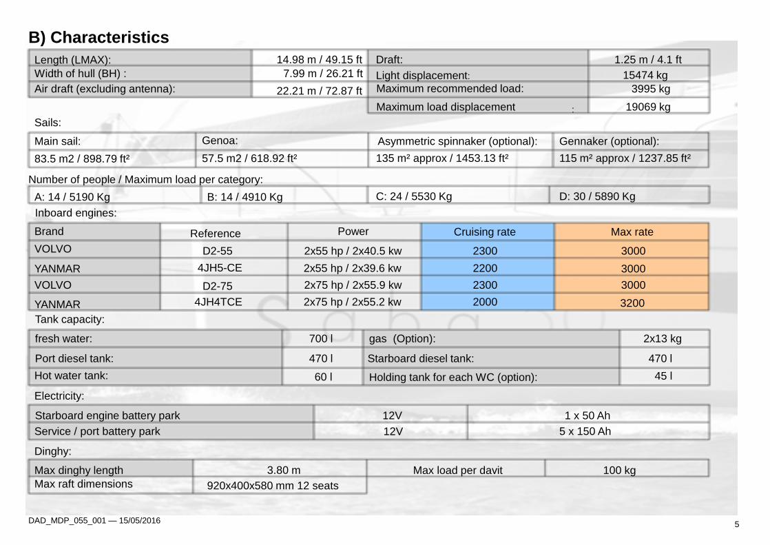
B) Characteristics
Length (LMAX): 14.98 m / 49.15 ft Draft: 1.25 m / 4.1 ft
Width of hull (BH) : 7.99 m / 26.21 ft Light displacement: 15474 kg
Air draft (excluding antenna): 22.21 m / 72.87 ft Maximum recommended load: 3995 kg
Maximum load displacement : 19069 kg
Sails:
Main sail: Genoa: Asymmetric spinnaker (optional): Gennaker (optional):
83.5 m2 / 898.79 ft² 57.5 m2 / 618.92 ft² 135 m² approx / 1453.13 ft² 115 m² approx / 1237.85 ft²
Number of people / Maximum load per category:
A: 14 / 5190 Kg B: 14 / 4910 Kg C: 24 / 5530 Kg D: 30 / 5890 Kg
Inboard engines:
Brand Reference Power Cruising rate Max rate
VOLVO D2-55 2x55 hp / 2x40.5 kw 2300 3000
YANMAR 4JH5-CE 2x55 hp / 2x39.6 kw 2200 3000
VOLVO D2-75 2x75 hp / 2x55.9 kw 2300 3000
YANMAR 4JH4TCE 2x75 hp / 2x55.2 kw 2000 3200
Tank capacity:
fresh water: 700 l gas (Option): 2x13 kg
Port diesel tank: 470 l Starboard diesel tank: 470 l
Hot water tank: 60 l Holding tank for each WC (option): 45 l
Electricity:
Starboard engine battery park 12V 1 x 50 Ah
Service / port battery park 12V 5 x 150 Ah
Dinghy:
Max dinghy length 3.80 m Max load per davit 100 kg
Max raft dimensions 920x400x580 mm 12 seats
DAD_MDP_055_001 — 15/05/2016 5
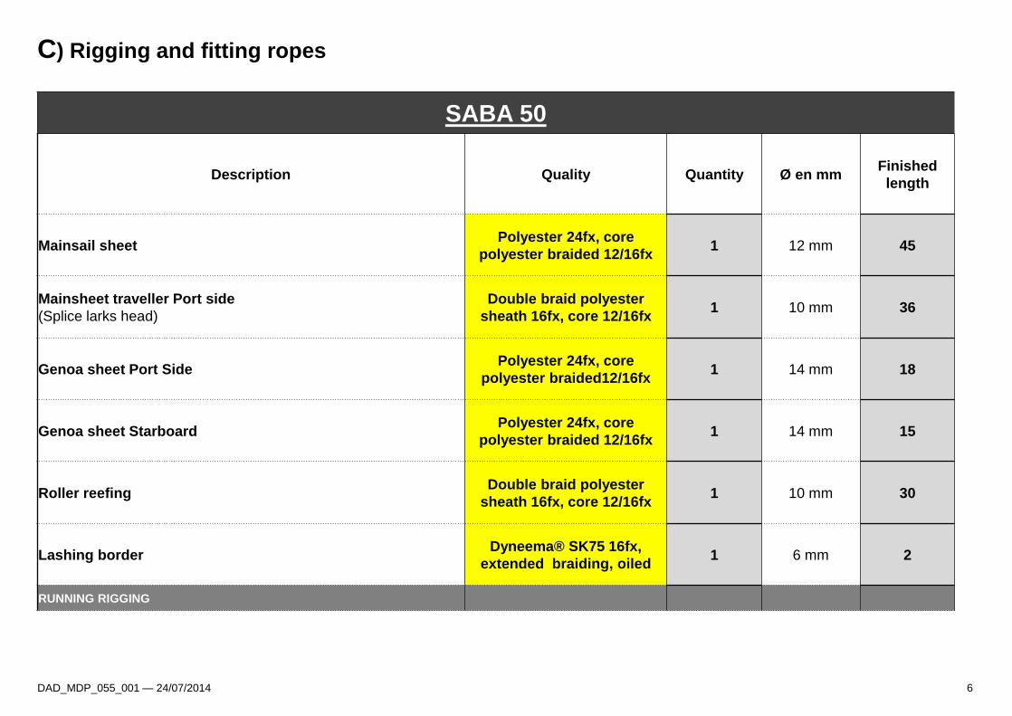
C) Rigging and fitting ropes
DAD_MDP_055_001 — 24/07/2014 6
SABA 50
Description Quality Quantity Ø en mm Finished
length
Mainsail sheet Polyester 24fx, core
polyester braided 12/16fx 1 12 mm 45
Mainsheet traveller Port side
(Splice larks head)
Double braid polyester
sheath 16fx, core 12/16fx 1 10 mm 36
Genoa sheet Port Side Polyester 24fx, core
polyester braided12/16fx 1 14 mm 18
Genoa sheet Starboard Polyester 24fx, core
polyester braided 12/16fx 1 14 mm 15
Roller reefing Double braid polyester
sheath 16fx, core 12/16fx 1 10 mm 30
Lashing border Dyneema® SK75 16fx,
extended braiding, oiled 1 6 mm 2
RUNNING RIGGING
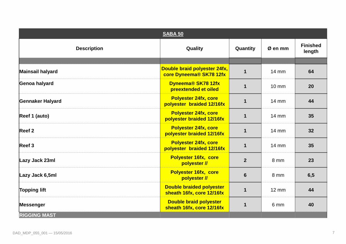
SABA 50
Description Quality Quantity Ø en mm Finished
length
Mainsail halyard Double braid polyester 24fx,
core Dyneema® SK78 12fx 1 14 mm 64
Genoa halyard
Dyneema® SK78 12fx
preextended et oiled 1 10 mm 20
Gennaker Halyard Polyester 24fx, core
polyester braided 12/16fx 1 14 mm 44
Reef 1 (auto) Polyester 24fx, core
polyester braided 12/16fx 1 14 mm 35
Reef 2 Polyester 24fx, core
polyester braided 12/16fx 1 14 mm 32
Reef 3 Polyester 24fx, core
polyester braided 12/16fx 1 14 mm 35
Lazy Jack 23ml Polyester 16fx, core
polyester // 2 8 mm 23
Lazy Jack 6,5ml Polyester 16fx, core
polyester // 6 8 mm 6,5
Topping lift Double braided polyester
sheath 16fx, core 12/16fx 1 12 mm 44
Messenger Double braid polyester
sheath 16fx, core 12/16fx 1 6 mm 40
RIGGING MAST
7 DAD_MDP_055_001 — 15/05/2016

A) Leaving terminal
Close all the hull portholes, the covers, and the deck and
windscreen panels.
Unlock all the doors and chests then check that the water
has been emptied from the bilges.
Open the diesel valves and the "sea water" inlets
Fill:
• The fresh water tanks from the front port deck
plug.
• The diesel tanks from the plugs on the flats
Interior rear port and starboard cockpit descents.
DAD_MDP_055_001 — 15/05/2016
SAILING
,
8

Caution - Battery coupling principle:
• The coupling between the service battery pack and the engine battery
is triggered when the voltage on one of the parks exceeds 13.2 V.
• The coupling is maintained until the park voltage falls below 12.8 V.
• When the voltage is below 12.8 V, the coupling is interrupted and the
engine battery is then isolated from the service park
• The BACKUP/START-UP circuit breaker enables the
battery parks to be coupled IF ONE PARK IS INSUFFICIENT.
It must always be disconnected as soon as the engine is running.
Fuse panels:
The 3 fuse panels are positioned as follows:
1 under the chart table in the saloon,
1 in the rear port engine compartment
1 in the starboard passage hanging closet.
The content of each box is detailed on the lid
.
DAD_MDP_055_001 — 15/05/2016 9
In contact
Connect the circuit breakers (port and port engine compartments) and check that
the windlass circuit breaker is triggered.

Check the water and diesel levels on the dashboard
("Navigation instruments" switch on the electrical panel).
Place the safety equipment outside (life belts, life rafts, etc.).
Check that there is no fuel and gas vapour inside the compartments.
DAD_MDP_055_001 — 15/05/2015 10
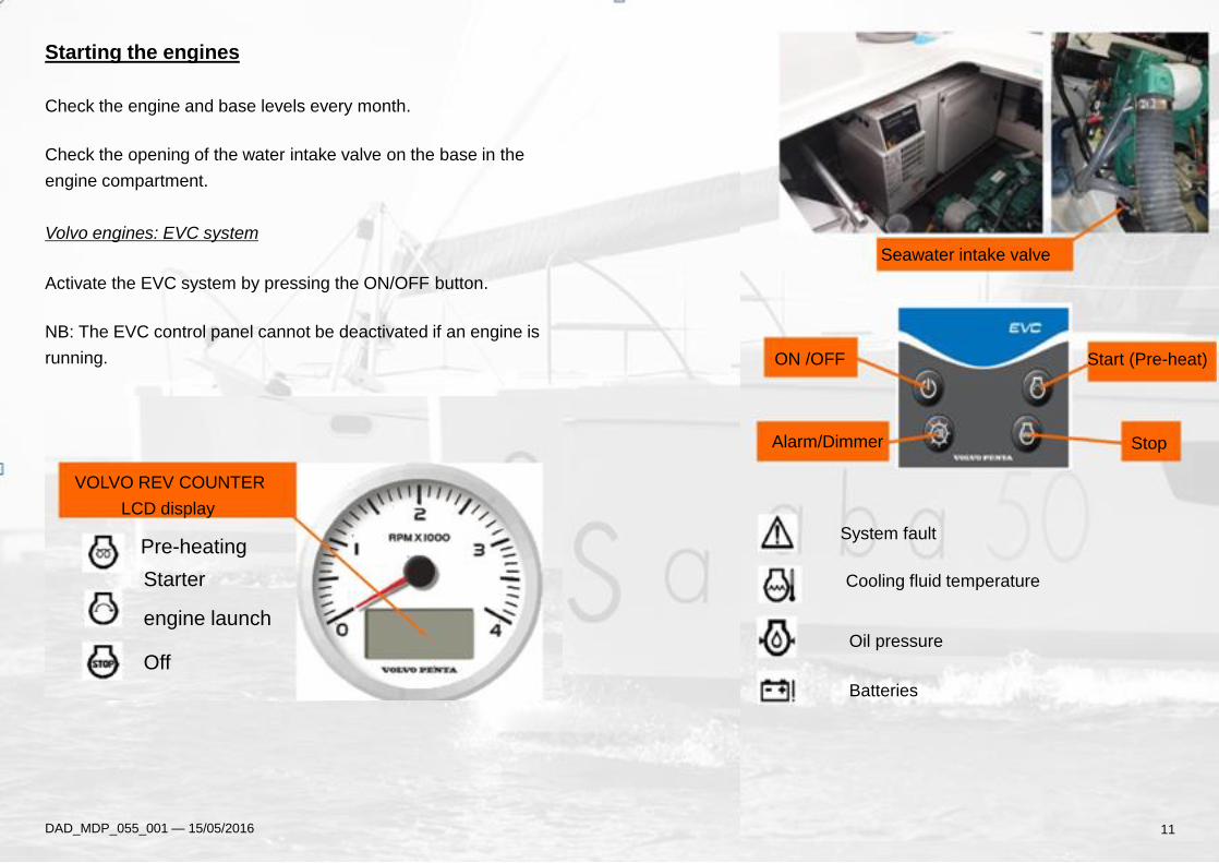
Starting the engines
Check the engine and base levels every month.
Check the opening of the water intake valve on the base in the
engine compartment.
Volvo engines: EVC system
Activate the EVC system by pressing the ON/OFF button.
NB: The EVC control panel cannot be deactivated if an engine is
running.
DAD_MDP_055_001 — 15/05/2016
9
Alarm/Dimmer
ON /OFF
Seawater intake valve
Start (Pre-heat)
Stop
System fault
Cooling fluid temperature
Oil pressure
Batteries
VOLVO REV COUNTER
LCD display
Pre-heating
Starter
engine launch
Off
11
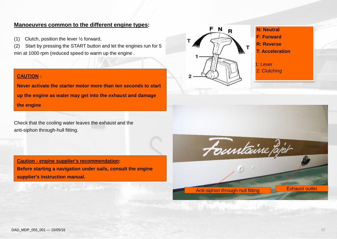
Manoeuvres common to the different engine types:
(1) Clutch, position the lever ½ forward,
(2) Start by pressing the START button and let the engines run for 5
min at 1000 rpm (reduced speed to warm up the engine .
Check that the cooling water leaves the exhaust and the
anti-siphon through-hull fitting.
N: Neutral
F: Forward
R: Reverse
T: Acceleration
1: Lever
2: Clutching
Caution - engine supplier's recommendation:
Before starting a navigation under sails, consult the engine
supplier's instruction manual.
CAUTION :
Never activate the starter motor more than ten seconds to start
up the engine as water may get into the exhaust and damage
the engine
12 DAD_MDP_055_001 — 15/05/16
Anti-siphon through-hull fitting Exhaust outlet
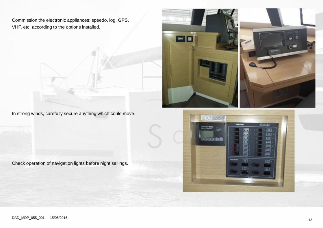
Commission the electronic appliances: speedo, log, GPS,
VHF, etc. according to the options installed.
In strong winds, carefully secure anything which could move.
Check operation of navigation lights before night sailings.
DAD_MDP_055_001 — 15/05/2016 13

B) Sailing
B1) Sail reduction table according to apparent wind
Beat and close reaching Downwind and broad reaching
Maximum sail area
0-18 knots
0-15 knots
Main sail 1 reef
Genoa 2/3
18-25 knots
15-20 knots
Main sail 2 reef
Genoa ½
25-30 knots
20-25 knots
Main sail 3 reef
Genoa 1/3
30-35 knots
25-30 knots
Main sail 3 reef
Genoa 1/5
35-40 knots
30-35 knots
Main sail down
Genoa 1/10
> 40 knots
> 35 knots
Using the asymmetric spinnaker or gennaker (optional)
The asymmetric spinnaker and the gennaker are sails that are
designed to be used in high speeds and relative wind below 15
knots.
-They must be stored:
-In winds over 15 knots
- When anchored
-In dock
- When not used in sailing
0201052322212019DWL 18171624 0810091312111415 0607 090403
0712 0506 010203DWL
20212324 22 1718 14151619 08 0413 091011
07081213 1011 03040506091718 141920212223 151624DWL
0102 09
0110 0913 09021112 08 07 06 05 0421 20 19 1423 22 0318 17 16 15DWL
24
13 091011 02 090112 07192021 040508 0314 06222324 15161718DWL
02 0111 10 0913 12 0907 0423 08 0521 20 0618 17 1622 19 1415DWL
24 03
14 DAD_MDP_055_001 — 15/05/16
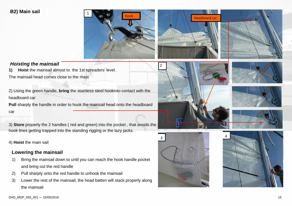
B2) Main sail 1
Hoisting the mainsail
1) Hoist the mainsail almost to the 1st spreaders’ level.
The mainsail head comes close to the mast
2) Using the green handle, bring the stainless steel hookinto contact with the
headboard car
Pull sharply the handle in order to hook the mainsail head onto the headboard
car
3) Store properly the 2 handles ( red and green) into the pocket , that avoids the
hook lines getting trapped into the standing rigging or the lazy jacks.
4) Hoist the main sail
2
4
DAD_MDP_055_001 — 15/05/2016 15
Headboard car Hook
Lowering the mainsail
1) Bring the mainsail down to until you can reach the hook handle pocket
and bring out the red handle
2) Pull sharply onto the red handle to unhook the mainsail
3) Lower the rest of the mainsail, the head batten will stack properly along
the mainsail
4 3 3
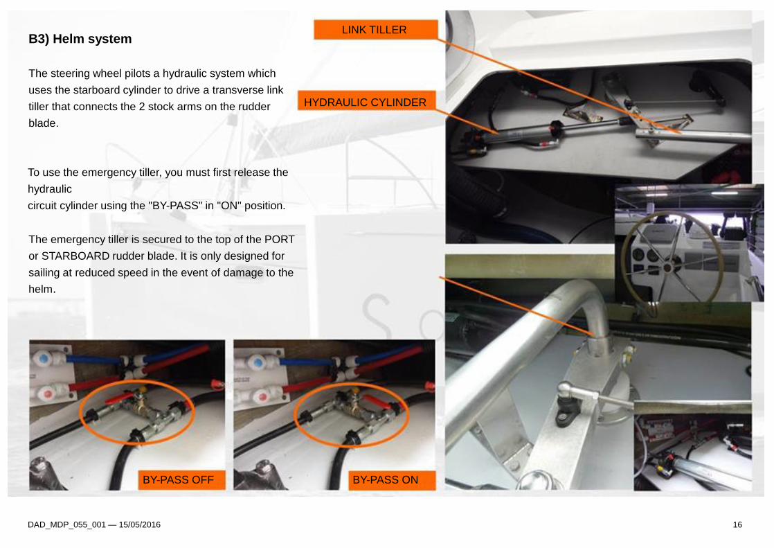
B3) Helm system
LINK TILLER
The steering wheel pilots a hydraulic system which
uses the starboard cylinder to drive a transverse link
tiller that connects the 2 stock arms on the rudder
blade.
HYDRAULIC CYLINDER
To use the emergency tiller, you must first release the
hydraulic
circuit cylinder using the "BY-PASS" in "ON" position.
The emergency tiller is secured to the top of the PORT
or STARBOARD rudder blade. It is only designed for
sailing at reduced speed in the event of damage to the
helm.
BY-PASS OFF BY-PASS ON
DAD_MDP_055_001 — 15/05/2016 16
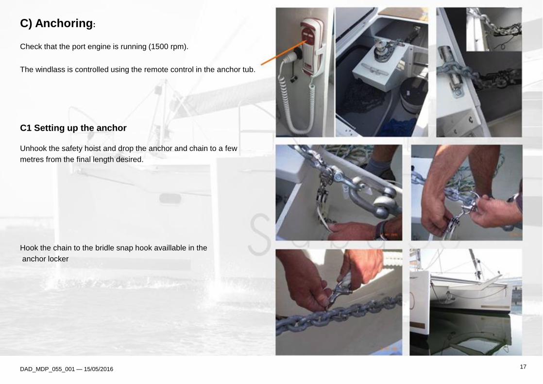
C) Anchoring:
Check that the port engine is running (1500 rpm).
The windlass is controlled using the remote control in the anchor tub.
C1 Setting up the anchor
Unhook the safety hoist and drop the anchor and chain to a few
metres from the final length desired.
Hook the chain to the bridle snap hook availlable in the
anchor locker
DAD_MDP_055_001 — 15/05/2016 17
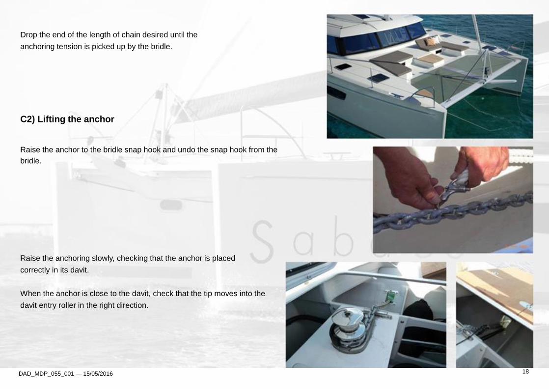
Drop the end of the length of chain desired until the
anchoring tension is picked up by the bridle.
C2) Lifting the anchor
Raise the anchor to the bridle snap hook and undo the snap hook from the
bridle.
Raise the anchoring slowly, checking that the anchor is placed
correctly in its davit.
When the anchor is close to the davit, check that the tip moves into the
davit entry roller in the right direction.
DAD_MDP_055_001 — 15/05/2016 18
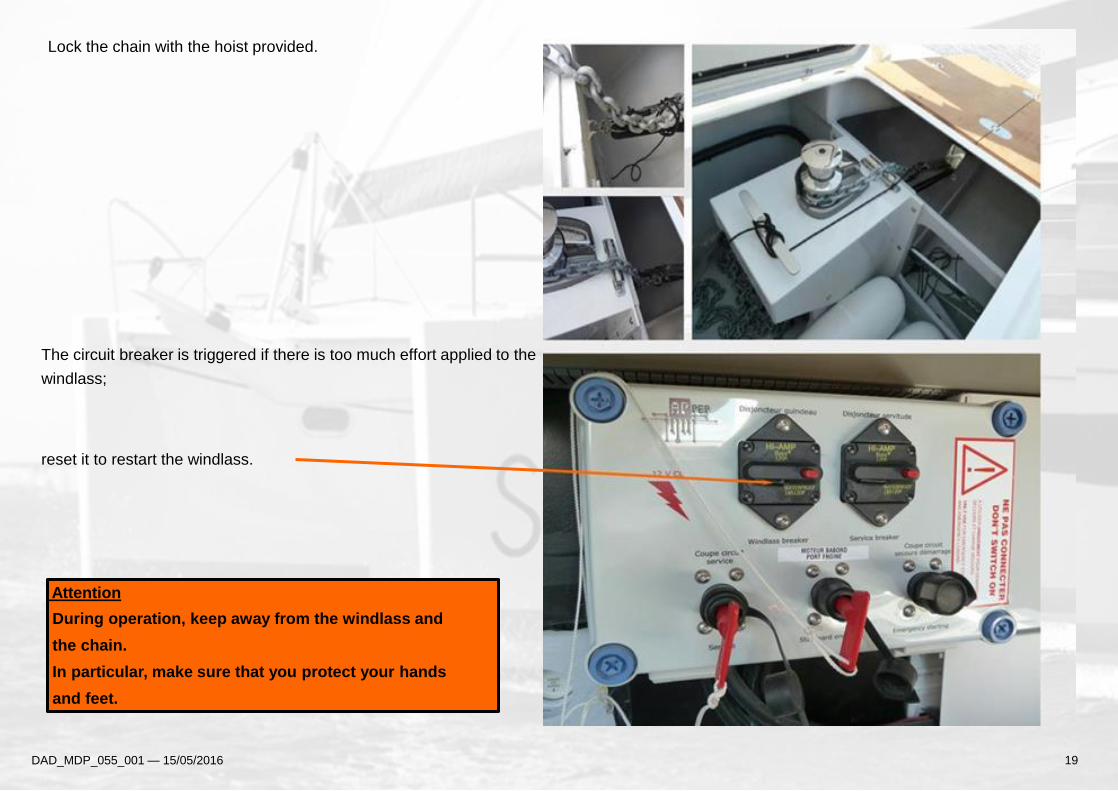
Lock the chain with the hoist provided.
The circuit breaker is triggered if there is too much effort applied to the
windlass;
reset it to restart the windlass.
Attention
During operation, keep away from the windlass and
the chain.
In particular, make sure that you protect your hands
and feet.
DAD_MDP_055_001 — 15/05/2016 19
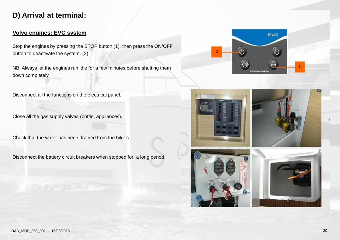
D) Arrival at terminal:
Volvo engines: EVC system
Stop the engines by pressing the STOP button (1), then press the ON/OFF
button to deactivate the system. (2)
NB: Always let the engines run idle for a few minutes before shutting them
down completely.
Disconnect all the functions on the electrical panel.
Close all the gas supply valves (bottle, appliances).
Check that the water has been drained from the bilges.
Disconnect the battery circuit breakers when stopped for a long period.
DAD_MDP_055_001 — 15/05/2016 20
2
1
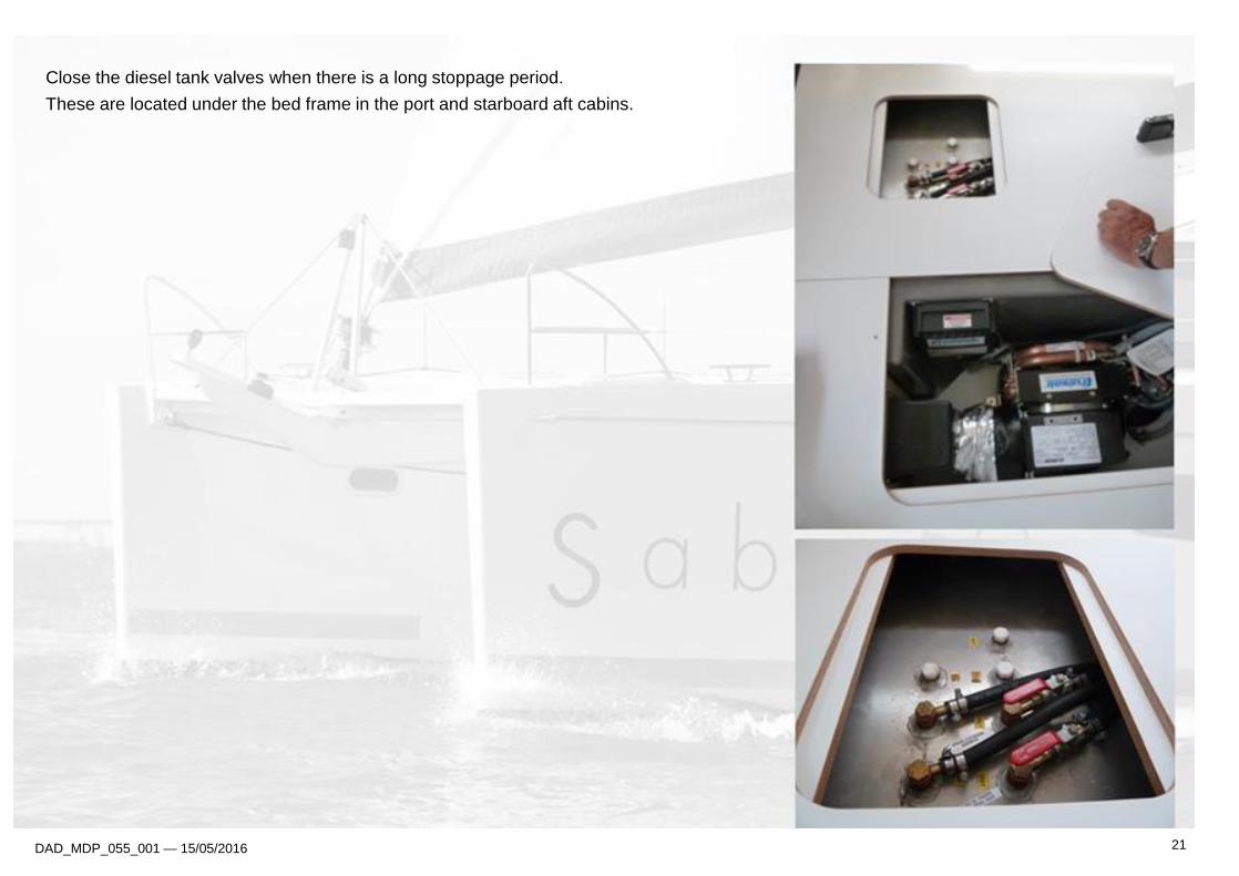
Close the diesel tank valves when there is a long stoppage period.
These are located under the bed frame in the port and starboard aft cabins.
DAD_MDP_055_001 — 15/05/2016 21
A) Electricity:
A1) Electrical installations
Engine 12 V DC network
The onboard power is produced by the engine alternators
(130 Ah) and stored by 12V DC batteries.
The batteries are separated into 2 separate parks:
Engine battery / port service park = 5 x150 Ah
Starboard engine battery park = 1 x 50 Ah
The starboard engine battery park powers:
the starboard engine only
The port engine battery powers
the port engine
All the 12v functions on the electrical distribution panel.
Caution - Battery coupling principle:
The coupling between the service battery park and the engine battery is triggered when the voltage on one of the parks exceeds 13.2 V.
The coupling is maintained until the park voltage falls below 12.8 V.
When the voltage is below 12.8 V, the coupling is interrupted and the engine battery is then isolated from the service park.
The BACKUP/START-UP circuit breaker enables the battery parks to be coupled IF ONE PARK IS INSUFFICIENT.
It must always be disconnected as soon as the engine is running.
DAD_MDP_055_001 — 15/05/2016
220 V AC alternating network: (optional)
The 220 V AC alternating network is powered:
- Either by a dock extension
- Or by a power generator (optional)
The whole network is protected by a 30 mA differential
circuit breaker.
- Each function is protected by a circuit breaker
.
22
COMFORT

A2) 220 V AC circuit: (optional)
Connect the dock extension by rolling it out fully or start the power generator.
Check the cable's condition,
If the cable is damaged, replace it with an identical cable.
.
Attention
Never connect an extension whose plug is damp.
Check that the current is flowing using the light indicator on the 220V unit.
Push in the differential circuit breaker and the circuit breakers for the function
required (starboard engine compartment).
Light indicator
DAD_MDP_055_001 — 15/05/2016 23
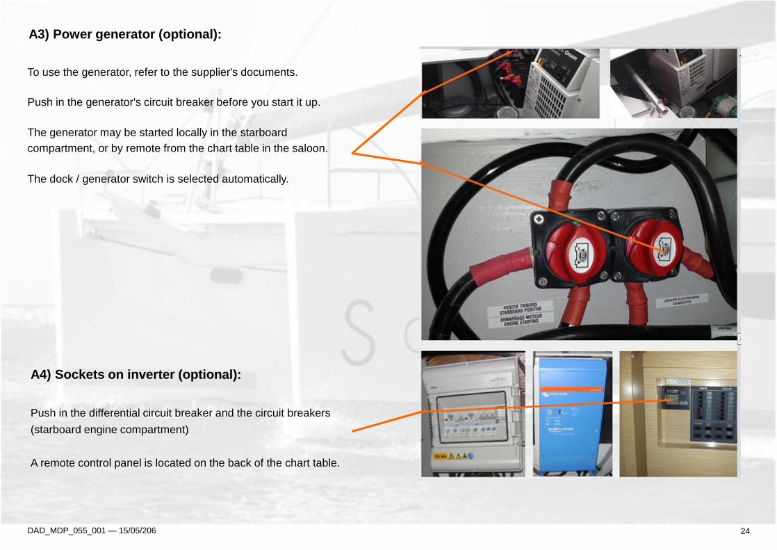
A3) Power generator (optional):
To use the generator, refer to the supplier's documents.
Push in the generator's circuit breaker before you start it up.
The generator may be started locally in the starboard
compartment, or by remote from the chart table in the saloon.
The dock / generator switch is selected automatically.
A4) Sockets on inverter (optional):
Push in the differential circuit breaker and the circuit breakers
(starboard engine compartment)
A remote control panel is located on the back of the chart table.
DAD_MDP_055_001 — 15/05/206 24

B) Cold:
Check the service battery park charge status (aft port
compartment) on the battery controller on the chart table.
Attention
If the service battery park charge level is ≤ 11.7V,
the refrigeration unit switches to safety.
B1) 2-drawer galley fridge
This is started up using the "Refrigerator" switch on the
electrical panel.
Set the cooling thermostat to the temperature required.
(For maintenance, see the manufacturer's manual)
DAD_MDP_055_001 — 15/05/2015
25
Attention
Respect the following instructions to limit the 12V energy consumption:
• Set the refrigerator thermostat to the minimum necessary
Limit door opening.
• Keep the refrigerator well filled,
• Defrost the refrigerator regularly.

B2) Additional galley 12V 90L freezer/
or 130L refrigerator (OPTIONAL)
This is started up using the "Refrigerator" switch
on the electrical panel.
Set the freezer thermostat to the temperature required.
(For maintenance, see the manufacturer's manual)
B3) Additional 12V cockpit freezer
(OPTIONAL)
This is started up via the thermostat.
Set the freezer thermostat to the temperature required.
(For maintenance, see the manufacturer's manual)
DAD_MDP_055_001 — 15/05/2016 26

C) Gas:
Open the general shut-off valve and the shut-off valve for the
appliance to be used (kitchen cupboard).
(valves open in the direction of the pipe)
Each gas appliance has a safety system.
To switch it on, hold the button down.
Attention
Ventilate fully when using the cooking surface.
DAD_MDP_055_001 — 15/05/2016 27
Open the regulator shut-off valve attached directly to the bottle
(gas unit in the cockpit).

D) Water: D1) Fresh water circuit
Open the main valve on the circuit to power the circuit from
the tanks (accessible under the chart table).
Check that the hot water tank supply valve (aft port cabin)
is in open position at all times.
Trigger the fresh water pump function on the electrical panel
DAD_MDP_055_001 — 15/05/2016 28
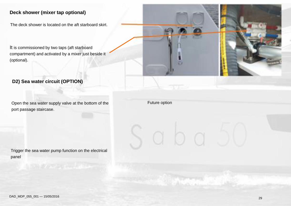
Deck shower (mixer tap optional)
The deck shower is located on the aft starboard skirt.
It is commissioned by two taps (aft starboard
compartment) and activated by a mixer just beside it
(optional).
D2) Sea water circuit (OPTION)
Open the sea water supply valve at the bottom of the
port passage staircase.
Trigger the sea water pump function on the electrical
panel
DAD_MDP_055_001 — 15/05/2016
Future option
29

D3) Using the toilets
Check that the sea water intake valves and the W.C.
evacuation valves are open.
The floor hatches open using suckers (stored in the
chart table).
Supply:
2 valves in each hull located under the forward
port/starboard and aft port/starboard cabins.
Evacuation:
1 evacuation valve per bathroom, accessible via the hatch
located in each shower.
DAD_MDP_055_001 — 15/05/2016 30
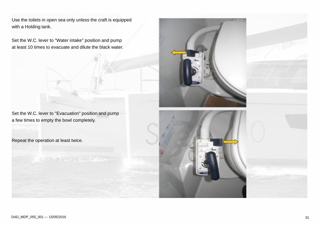
Use the toilets in open sea only unless the craft is equipped
with a Holding tank.
Set the W.C. lever to "Water intake" position and pump
at least 10 times to evacuate and dilute the black water.
Set the W.C. lever to "Evacuation" position and pump
a few times to empty the bowl completely.
Repeat the operation at least twice.
DAD_MDP_055_001 — 15/05/2016 31

D4) Using the holding tanks
To store the black water in the holding tanks:
• Close the evacuation valve (accessible via the hatch in
each shower)
Attention :
Never force the pump.
Storage capacity: 45 litres.
Drain the holding tank regularly :
• By evacuating the black water directly into the sea
(Open the evacuation valve when out at sea only)
• At the dock by pumping in the "Waste" deck plug.
DAD_MDP_055_001 — 15/05/2016 32
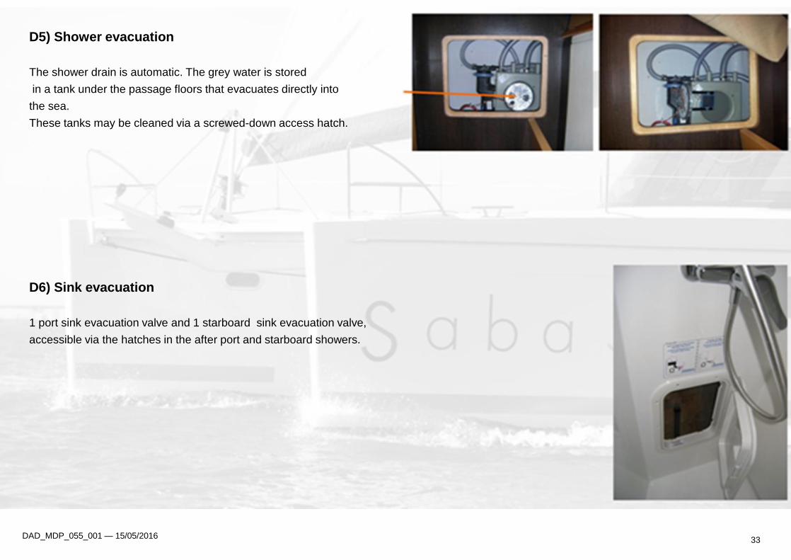
D5) Shower evacuation
The shower drain is automatic. The grey water is stored
in a tank under the passage floors that evacuates directly into
the sea.
These tanks may be cleaned via a screwed-down access hatch.
D6) Sink evacuation
1 port sink evacuation valve and 1 starboard sink evacuation valve,
accessible via the hatches in the after port and starboard showers.
DAD_MDP_055_001 — 15/05/2016 33

D7) Bilge pumping
: Manual bilge pump ( in cockpit locker)
Open and unfold the manual pump on the aft port front panel
in the aft bench. A pipe stored inside the locker must unrolled
to drain the desired zones.
Electric bilge pumping
The craft is fitted with 6 electric bilge pumps :
1 per engine compartment,
2 per hull.
Push in the switch on the electrical panel: 2 positions possible
1) AUTO position (optional):
The bilge pump is triggered automatically if any water gets
in and its operation is indicated by an alarm.
1) MANUAL position:
The bilge pump is triggered manually by activating
the switch on the electrical panel.
Set the switch back to OFF position when drainage is
complete.
DAD_MDP_055_001 — 15/05/2016 34

IV- MANOVERBOARD AND RECOVERY
During a passage at sea, it is recommended to remains in the areas of the deck that are designed for it.
These areas (sidewalks, cockpit, coachroof, mast step etc..…) are covered with an antiskid surface or teak covering that allow the crew
to move on the boat in a secure way.
It is also recommended, according to sea or wind conditions, to wear safety harnesses and use the various securing points on the deck
that are mentionned in the deck plan.
SABA is equipped with sternladder (starboard transom) that is designed to allow a crew to climb back on board in a manoverboard
situation
35 DAD_MDP_055_001 — 15/05/16
V – FIRE PROTECTION
A) Installation
Fire extinguishers are subject to national rules, thus they are not supplied with the boat.
However, while being used, the boat must be equipped with portable extinguishers with the following fire fighting capacities and
these must be stored in specific areas of the boat.
• 1 kg powder extinguisher : entrance of saloon (galley cabinet)
• 1 kg powder extinguisher : port fore cabin
• 4 kg powder extinguisher + flexible : port aft cabin
• 4 kg powder extinguisher + flexible : starboard aft cabin
If you choose to install a carbon dioxyde extinguisher, it can not be installed in any living space holding any electrical equipments
under tension (for example electrical motors, battery compartment, powered hatches..) or inflammable liquids ( in galley for
example).
A fire blanket should also be stored near the galley, that is useful in case of gas stove fire (cause by oil for example)
36 DAD_MDP_055_001 — 15/05/16
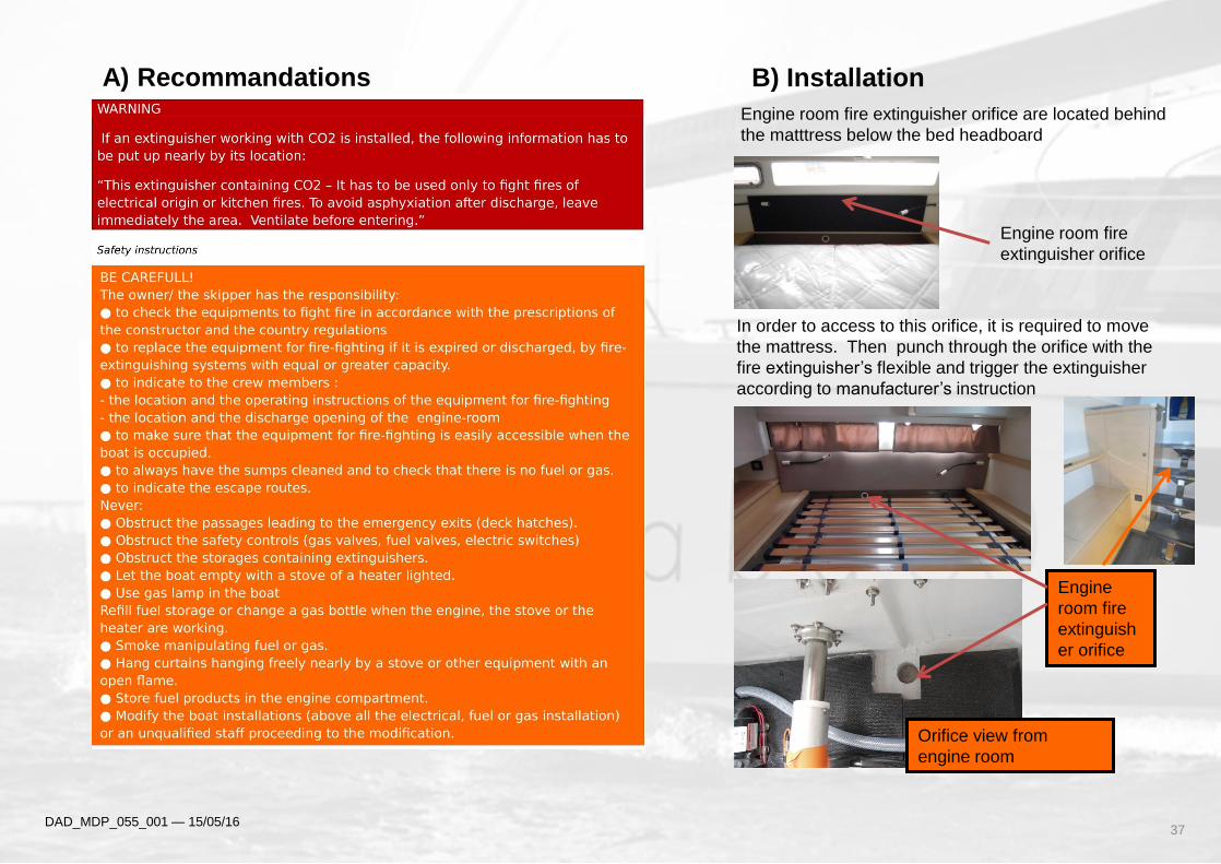
Engine room fire
extinguisher orifice
Engine
room fire
extinguish
er orifice
In order to access to this orifice, it is required to move
the mattress. Then punch through the orifice with the
fire extinguisher’s flexible and trigger the extinguisher
according to manufacturer’s instruction
Orifice view from
engine room
Engine room fire extinguisher orifice are located behind
the matttress below the bed headboard
DAD_MDP_055_001 — 15/05/16 37
A) Recommandations B) Installation
Drainage
DATE SAILING TIMES FILTER CHANGE
DAD_MDP_055_001 — 15/05/2016 38
MAINTENANCE
DATE SAILING TIMES FILTER CHANGE
DAD_MDP_055_001 — 15/05/2016 39