quick reference guidemanuals.repeater-builder.com/te-files/miscellaneous/zebra... · 2017. 6....
TRANSCRIPT

Zebra® XiIIIPlus™Industrial/Commercial Printer
Quick Reference GuideDA Kort Funktionsoversigt Guida Rapida IT DE Kurzanleitung Naslaggids NLEL Οδηγός γρήγορης αναφοράς Hurtiganvisning NO ES Guía de Referencia Rápida Skrócony Opis PLFI Pikaopas Guia de Referência Rápida PT FR Guide de Référence Rapide Краткое руководство RUHR Kratki Vodic Snabbanvändarguide SV

©2004 ZIH Corp. All product names and numbers are Zebra trademarks, and Zebra, the Zebra logo, ZebraNet, ZPL, and ZPL II are registered trademarks of ZIH Corp. All rights reserved. Adobe® and Acrobat® are registered trademarks of Adobe Systems Incorporated. All other trademarks are the property of their respective owners.This copyrighted guide and the label printers described herein are owned by Zebra Technologies Corporation. All rights are reserved. Unauthorized reproduction of the guide or the software in the label printer may result in imprisonment of up to one year and fines of up to $10,000 (17 U.S.C.506). Copyright violators may be subject to civil liability.
Customer Order # 11347LB
Manufacturer Part # 11347LB R4
Zebra XiIIIPlusQuick Reference Guide
This Quick Reference Guide contains basic information on how to install and operate the printer as well as some simple adjustments that can be performed by the operator; however, it is not comprehensive.
Contact your distributor for additional information covering the Zebra XiIIIPlus printers:• User Guide (part # 13371/ 13383L)• ZPL II Programming Guide (part # 45541L / 45542L)• Maintenance Manual (part # 13185L / 48152L)
ContentsSpecifications. . . . . . . . . . . . . . . . . . . . . . . . . . . . . . . . . . . . . . . . . . . . . . . . . 2Media and Ribbon Loading . . . . . . . . . . . . . . . . . . . . . . . . . . . . . . . . . . . . . . 3Operator Controls . . . . . . . . . . . . . . . . . . . . . . . . . . . . . . . . . . . . . . . . . . . . . 8Calibration . . . . . . . . . . . . . . . . . . . . . . . . . . . . . . . . . . . . . . . . . . . . . . . . . . . 9Configuration . . . . . . . . . . . . . . . . . . . . . . . . . . . . . . . . . . . . . . . . . . . . . . . . 10Preventive Maintenance . . . . . . . . . . . . . . . . . . . . . . . . . . . . . . . . . . . . . . . 12Adjustments. . . . . . . . . . . . . . . . . . . . . . . . . . . . . . . . . . . . . . . . . . . . . . . . . 14
English 11347LB R4 6/4/04 EN-1
Specifications
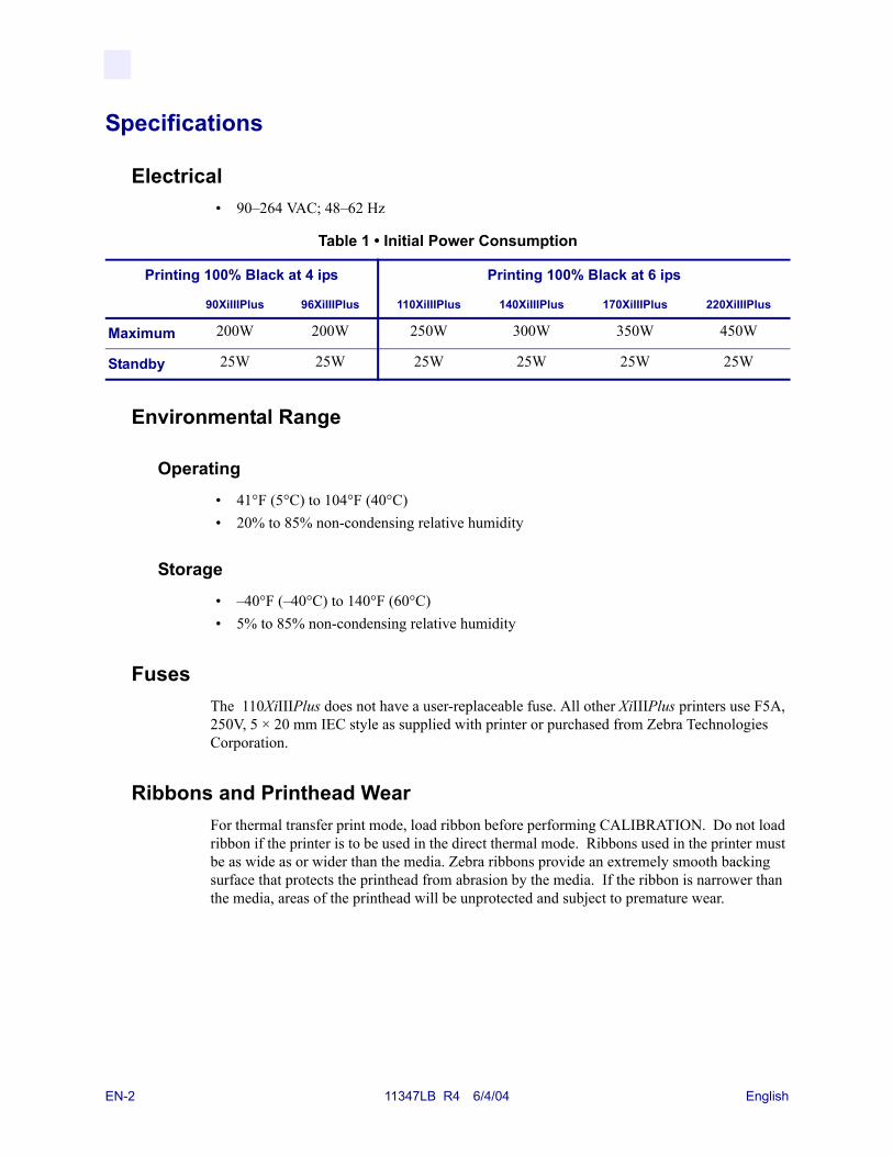
Electrical• 90–264 VAC; 48–62 Hz
Environmental Range
Operating• 41°F (5°C) to 104°F (40°C)• 20% to 85% non-condensing relative humidity
Storage• –40°F (–40°C) to 140°F (60°C)• 5% to 85% non-condensing relative humidity
FusesThe 110XiIIIPlus does not have a user-replaceable fuse. All other XiIIIPlus printers use F5A, 250V, 5 × 20 mm IEC style as supplied with printer or purchased from Zebra Technologies Corporation.
Ribbons and Printhead WearFor thermal transfer print mode, load ribbon before performing CALIBRATION. Do not load ribbon if the printer is to be used in the direct thermal mode. Ribbons used in the printer must be as wide as or wider than the media. Zebra ribbons provide an extremely smooth backing surface that protects the printhead from abrasion by the media. If the ribbon is narrower than the media, areas of the printhead will be unprotected and subject to premature wear.
Table 1 • Initial Power Consumption
Printing 100% Black at 4 ips Printing 100% Black at 6 ips
90XiIIIPlus 96XiIIIPlus 110XiIIIPlus 140XiIIIPlus 170XiIIIPlus 220XiIIIPlus
Maximum 200W 200W 250W 300W 350W 450W
Standby 25W 25W 25W 25W 25W 25W
EN-2 11347LB R4 6/4/04 English

Media and Ribbon Loading
Media Loading
Figure 1 • Media Loading—Printer Components
Figure 2 • Media Loading Modes
English 11347LB R4 6/4/04 EN-3

Roll Media Loading in Tear-Off Mode (Figure 2-A)1. From the front panel, select the appropriate print mode.
2. Place the media roll (Figure 1-E) on the media supply hanger (Figure 1-F) or optional supply spindle.
3. Open the printhead by moving the lever located on the upper printhead assembly to the open (Figure 1-A) position.
4. Loosen the media guide (Figure 1-M) thumbscrew and position the media guide as far out from the printer frame as possible.
5. Thread the media under the dancer arm assembly (Figure 1-P), under the lower roller (Figure 1-L), between the upper media guide plate and main media guide, under the printhead, and over the platen (Figure 1-J).
6. Adjust the media guide (Figure 1-M) position until it just touches the outer edge of the media without causing it to buckle. Make sure it is parallel to the edge of the media, then tighten the thumbscrew.
7. Close the printhead by moving the lever located on the upper printhead assembly to the closed (Figure 1-B) position.
8. IMPORTANT: Perform the Media Sensor Position Adjustments found on page 15.
Peel-Off Mode (Figure 2-B)
1. From the front panel, select the appropriate print mode.
2. If the rewind plate is installed in the printer, remove and store it on the two mounting screws on the inside of the front panel. The notch in the rewind plate must face upward so that the take label sensor can sense a peeled label.
3. Load media according to the directions for Tear-Off Mode. When loading the media, allow about 1 yd. or 1 m of media to extend past the tear-off bar. If using label stock, remove all labels from this portion of the media to create a leader.
4. Remove the hook (Figure 1-G) from the take-up spindle shaft (Figure 1-H). If you are using a core, remove all tape from the core and slide it onto the rewind spindle until it is flush against the guide plate.
5. Wind the backing 1 to 2 times around the media take-up spindle and reinstall the spindle hook (if necessary). Make sure that the media backing is against the backing guide plate. (With some types of media, especially tag stock, you may need to tape the end of the media to the core if it does not otherwise tighten onto the core. DO NOT tape the label stock unless absolutely necessary.)
Note • For best results, install the printer on a level surface. This is especially helpful with wider printers using wide media. If the surface is not level, the media may “telescope” off of the rewind spindle, causing unsatisfactory results.
Note • Before closing the printhead open lever, make sure that throughout the media pathway (1) the media is positioned against the inside guides, and the outer guide and media supply guide barely touch the media, (2) the media is taut, and (3) the media is parallel with itself and with the pathway when wound on the rewind spindle/core.
EN-4 11347LB R4 6/4/04 English
6. After all of the above steps have been completed, close the printhead open lever to lock the media in place. If not aligned correctly, the material may not rewind properly on the rewind spindle/core; that may, in turn, affect media movement and/or printing.
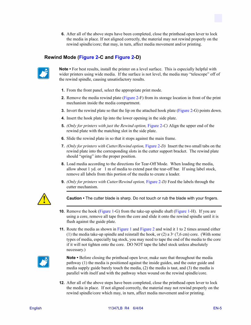
Rewind Mode (Figure 2-C and Figure 2-D)
1. From the front panel, select the appropriate print mode.
2. Remove the media rewind plate (Figure 2-F) from its storage location in front of the print mechanism inside the media compartment.
3. Invert the rewind plate so that the lip on the attached hook plate (Figure 2-G) points down.
4. Insert the hook plate lip into the lower opening in the side plate.
5. (Only for printers with just the Rewind option, Figure 2-C) Align the upper end of the rewind plate with the matching slot in the side plate.
6. Slide the rewind plate in so that it stops against the main frame.
7. (Only for printers with Cutter/Rewind option, Figure 2-D) Insert the two small tabs on the rewind plate into the corresponding slots in the cutter support bracket. The rewind plate should “spring” into the proper position.
8. Load media according to the directions for Tear-Off Mode. When loading the media, allow about 1 yd. or 1 m of media to extend past the tear-off bar. If using label stock, remove all labels from this portion of the media to create a leader.
9. (Only for printers with Cutter/Rewind option, Figure 2-D) Feed the labels through the cutter mechanism.
10. Remove the hook (Figure 1-G) from the take-up spindle shaft (Figure 1-H). If you are using a core, remove all tape from the core and slide it onto the rewind spindle until it is flush against the guide plate.
11. Route the media as shown in Figure 1 and Figure 2 and wind it 1 to 2 times around either (1) the media take-up spindle and reinstall the hook, or (2) a 3″ (7,6 cm) core. (With some types of media, especially tag stock, you may need to tape the end of the media to the core if it will not tighten onto the core. DO NOT tape the label stock unless absolutely necessary.)
12. After all of the above steps have been completed, close the printhead open lever to lock the media in place. If not aligned correctly, the material may not rewind properly on the rewind spindle/core which may, in turn, affect media movement and/or printing.
Note • For best results, install the printer on a level surface. This is especially helpful with wider printers using wide media. If the surface is not level, the media may “telescope” off of the rewind spindle, causing unsatisfactory results.
Caution • The cutter blade is sharp. Do not touch or rub the blade with your fingers.
Note • Before closing the printhead open lever, make sure that throughout the media pathway (1) the media is positioned against the inside guides, and the outer guide and media supply guide barely touch the media, (2) the media is taut, and (3) the media is parallel with itself and with the pathway when wound on the rewind spindle/core.
English 11347LB R4 6/4/04 EN-5

Cutter Mode (Figure 2-E)1. Make sure that the Cutter option is available and installed on the printer.
2. From the front panel, select the appropriate print mode.
3. Load media according to the directions above for Tear-Off Mode, except feed the media through the cutter module as shown in Figure 2-E.
Fanfold Media Loading (Figure 3)Fanfold media can be placed in the bottom of the media compartment, in the fanfold supply bin, or outside of the printer with access through the bottom or the rear.
Adjust the media guide (Figure 1-M) thumbscrew to keep the media from drifting; make sure it is parallel to the edge of the media.
Figure 3 • Fanfold Media Loading
Ribbon LoadingRefer to Figure 4. When loading ribbon, make sure that the ribbon core is pushed up against the stop on the ribbon supply spindle (Figure 4-D). Do not use ribbon narrower than the media.
1. Align the segments of the ribbon supply spindle (Figure 4).
2. Place the ribbon roll on the ribbon supply spindle (Figure 4-D).
3. Make a leader for your ribbon. Tear off a strip of media (labels and backing) about 6 in. to 12 in. (15 cm to 30 cm) long. Peel off a label from this strip. Apply half of this label to the end of the strip and the other half to the end of the ribbon. This acts as a ribbon leader.
4. Open the printhead (Figure 4-A) and thread the leader and attached ribbon through the print mechanism, under the upper roller (Figure 4-K), and past the platen roller (Figure 4-J).
5. Before wrapping the ribbon around the ribbon take-up spindle, ensure that the arrow on the knob aligns with the indented notch (see inset, Figure 5).
Caution • The cutter blade is sharp. Do not touch or rub the blade with your fingers.
Note • For the 170XiIIIPlus and 220XiIIIPlus, thread the leader first through the dancer roller assembly (Figure 4-R).
EN-6 11347LB R4 6/4/04 English

6. Place the ribbon with leader around the ribbon take-up spindle (Figure 4-C) and wind counterclockwise for several turns.
7. Close the printhead (Figure 4-B).
Figure 4 • Ribbon Loading
Removing Used RibbonRefer to Figure 5.
1. Break the ribbon close to the ribbon take-up spindle (Figure 5-A).
2. While holding the ribbon take-up spindle, turn the knob (Figure 5-B) clockwise until it stops. This causes the ribbon release bars (Figure 5-C) to pivot down, easing the spindle’s “grip” on the wound ribbon.
3. Slide the ribbon off of the ribbon take-up spindle. Once the used ribbon has been removed, ensure that the arrow on the knob aligns with the indented notch in the ribbon take-up spindle (see inset).
4. Remove the empty core from the ribbon supply spindle.
Figure 5 • Ribbon Removal
English 11347LB R4 6/4/04 EN-7
Operator Controls
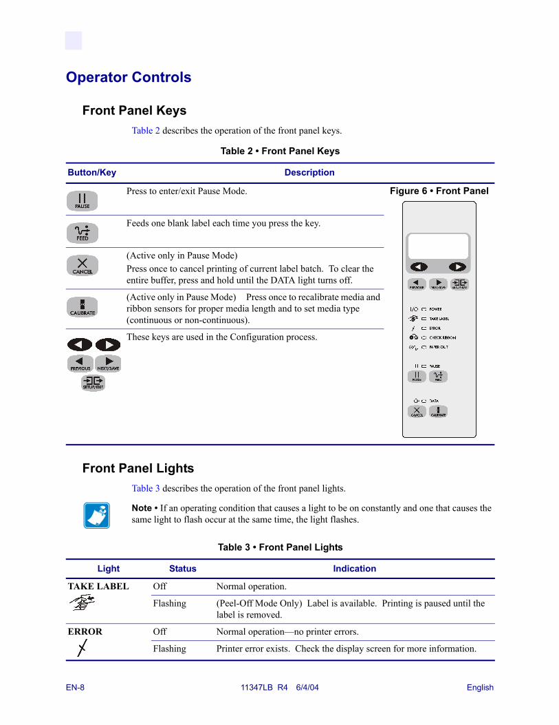
Front Panel KeysTable 2 describes the operation of the front panel keys.
Front Panel LightsTable 3 describes the operation of the front panel lights.
Table 2 • Front Panel Keys
Button/Key Description
Press to enter/exit Pause Mode. Figure 6 • Front Panel
Feeds one blank label each time you press the key.
(Active only in Pause Mode) Press once to cancel printing of current label batch. To clear the entire buffer, press and hold until the DATA light turns off.
(Active only in Pause Mode) Press once to recalibrate media and ribbon sensors for proper media length and to set media type (continuous or non-continuous).
These keys are used in the Configuration process.
Note • If an operating condition that causes a light to be on constantly and one that causes the same light to flash occur at the same time, the light flashes.
Table 3 • Front Panel Lights
Light Status Indication
TAKE LABEL Off Normal operation.
Flashing (Peel-Off Mode Only) Label is available. Printing is paused until the label is removed.
ERROR Off Normal operation—no printer errors.
Flashing Printer error exists. Check the display screen for more information.
EN-8 11347LB R4 6/4/04 English
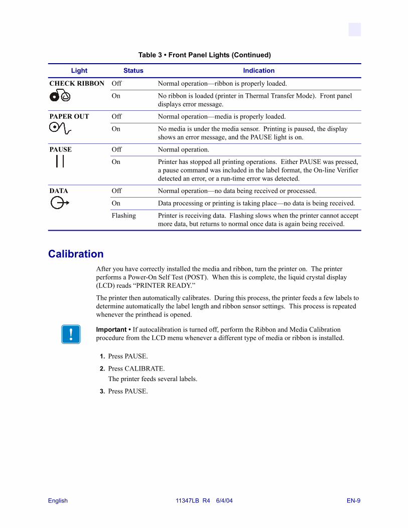
CalibrationAfter you have correctly installed the media and ribbon, turn the printer on. The printer performs a Power-On Self Test (POST). When this is complete, the liquid crystal display (LCD) reads “PRINTER READY.”
The printer then automatically calibrates. During this process, the printer feeds a few labels to determine automatically the label length and ribbon sensor settings. This process is repeated whenever the printhead is opened.
1. Press PAUSE.
2. Press CALIBRATE.The printer feeds several labels.
3. Press PAUSE.
CHECK RIBBON Off Normal operation—ribbon is properly loaded.
On No ribbon is loaded (printer in Thermal Transfer Mode). Front panel displays error message.
PAPER OUT Off Normal operation—media is properly loaded.
On No media is under the media sensor. Printing is paused, the display shows an error message, and the PAUSE light is on.
PAUSE Off Normal operation.
On Printer has stopped all printing operations. Either PAUSE was pressed, a pause command was included in the label format, the On-line Verifier detected an error, or a run-time error was detected.
DATA Off Normal operation—no data being received or processed.
On Data processing or printing is taking place—no data is being received.
Flashing Printer is receiving data. Flashing slows when the printer cannot accept more data, but returns to normal once data is again being received.
Table 3 • Front Panel Lights (Continued)
Light Status Indication
Important • If autocalibration is turned off, perform the Ribbon and Media Calibration procedure from the LCD menu whenever a different type of media or ribbon is installed.
English 11347LB R4 6/4/04 EN-9
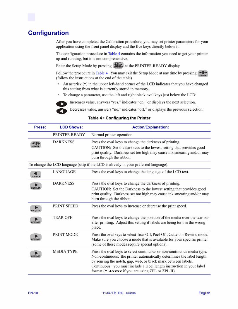
ConfigurationAfter you have completed the Calibration procedure, you may set printer parameters for your application using the front panel display and the five keys directly below it.
The configuration procedure in Table 4 contains the information you need to get your printer up and running, but it is not comprehensive.
Enter the Setup Mode by pressing at the PRINTER READY display.
Follow the procedure in Table 4. You may exit the Setup Mode at any time by pressing (follow the instructions at the end of the table).• An asterisk (*) in the upper left-hand corner of the LCD indicates that you have changed
this setting from what is currently stored in memory.• To change a parameter, use the left and right black oval keys just below the LCD:
Increases value, answers “yes,” indicates “on,” or displays the next selection.
Decreases value, answers “no,” indicates “off,” or displays the previous selection.
Table 4 • Configuring the Printer
Press: LCD Shows: Action/Explanation:
— PRINTER READY Normal printer operation.
DARKNESS Press the oval keys to change the darkness of printing.CAUTION: Set the darkness to the lowest setting that provides good print quality. Darkness set too high may cause ink smearing and/or may burn through the ribbon.
To change the LCD language (skip if the LCD is already in your preferred language):
LANGUAGE Press the oval keys to change the language of the LCD text.
DARKNESS Press the oval keys to change the darkness of printing.CAUTION: Set the Darkness to the lowest setting that provides good print quality. Darkness set too high may cause ink smearing and/or may burn through the ribbon.
PRINT SPEED Press the oval keys to increase or decrease the print speed.
TEAR OFF Press the oval keys to change the position of the media over the tear bar after printing. Adjust this setting if labels are being torn in the wrong place.
PRINT MODE Press the oval keys to select Tear-Off, Peel-Off, Cutter, or Rewind mode. Make sure you choose a mode that is available for your specific printer (some of these modes require special options).
MEDIA TYPE Press the oval keys to select continuous or non-continuous media type. Non-continuous: the printer automatically determines the label length by sensing the notch, gap, web, or black mark between labels. Continuous: you must include a label length instruction in your label format (^LLxxxx if you are using ZPL or ZPL II).
EN-10 11347LB R4 6/4/04 English

SENSOR TYPE Press the oval keys to select web or mark sensing mode. If your media does not have black marks on the back, leave your printer at the default (web) setting.
PRINT METHOD Press the oval keys to select the method of printing you want to use: direct thermal (no ribbon) or thermal transfer (using thermal transfer media and ribbon).
PRINT WIDTH Press the oval keys to set the printer to the width of your media.
MAXIMUM LENGTH
Press the oval keys to set the maximum print length. Select the value closest to but not less than the length of label you are using.
LIST FONTS Press the right oval key to print a list of available fonts.
LIST BAR CODES Press the right oval key to print a list of available bar codes.
LIST IMAGES Press the right oval key to print a list of available images.
LIST FORMATS Press the right oval key to print a list of all formats currently stored in the printer’s DRAM, optional EPROM, or on an optional memory card.
LIST SETUP Press the right oval key to print a list of the current printer configuration settings.
LIST ALL Press the right oval key to print a list of fonts, bar codes, images, formats, and the current print engine configuration settings.
SAVE CHANGES Press the oval keys to select:PERMANENT: saves the changes when the power is turned off.TEMPORARY: saves the changes until changed again or until power is turned off.CANCEL: cancels all changes since entering the Setup Mode.LOAD DEFAULTS: loads factory default values for all parameters. Note: Refer to the User Guide! This requires Calibration and resetting of the Head Resistance.LOAD LAST SAVE: loads values from the last permanent save.Press to accept a selection.
— PRINTER READY You have exited the Setup Mode and are now ready for normal printer operation.
Table 4 • Configuring the Printer
Press: LCD Shows: Action/Explanation:
English 11347LB R4 6/4/04 EN-11
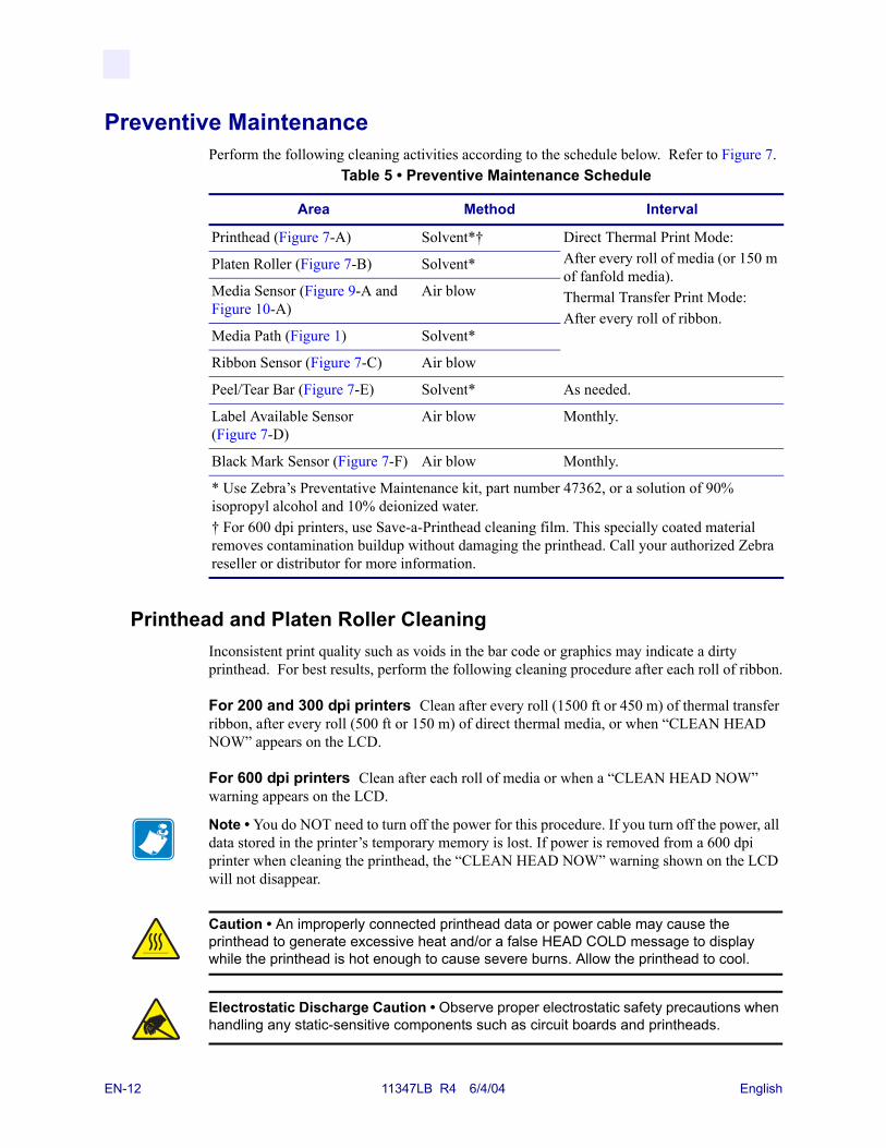
Preventive MaintenancePerform the following cleaning activities according to the schedule below. Refer to Figure 7.
Printhead and Platen Roller CleaningInconsistent print quality such as voids in the bar code or graphics may indicate a dirty printhead. For best results, perform the following cleaning procedure after each roll of ribbon.
For 200 and 300 dpi printers Clean after every roll (1500 ft or 450 m) of thermal transfer ribbon, after every roll (500 ft or 150 m) of direct thermal media, or when “CLEAN HEAD NOW” appears on the LCD.
For 600 dpi printers Clean after each roll of media or when a “CLEAN HEAD NOW” warning appears on the LCD.
Table 5 • Preventive Maintenance Schedule
Area Method Interval
Printhead (Figure 7-A) Solvent*† Direct Thermal Print Mode:After every roll of media (or 150 m of fanfold media).Thermal Transfer Print Mode:After every roll of ribbon.
Platen Roller (Figure 7-B) Solvent*
Media Sensor (Figure 9-A and Figure 10-A)
Air blow
Media Path (Figure 1) Solvent*
Ribbon Sensor (Figure 7-C) Air blow
Peel/Tear Bar (Figure 7-E) Solvent* As needed.
Label Available Sensor (Figure 7-D)
Air blow Monthly.
Black Mark Sensor (Figure 7-F) Air blow Monthly.
* Use Zebra’s Preventative Maintenance kit, part number 47362, or a solution of 90% isopropyl alcohol and 10% deionized water.† For 600 dpi printers, use Save-a-Printhead cleaning film. This specially coated material removes contamination buildup without damaging the printhead. Call your authorized Zebra reseller or distributor for more information.
Note • You do NOT need to turn off the power for this procedure. If you turn off the power, all data stored in the printer’s temporary memory is lost. If power is removed from a 600 dpi printer when cleaning the printhead, the “CLEAN HEAD NOW” warning shown on the LCD will not disappear.
Caution • An improperly connected printhead data or power cable may cause the printhead to generate excessive heat and/or a false HEAD COLD message to display while the printhead is hot enough to cause severe burns. Allow the printhead to cool.
Electrostatic Discharge Caution • Observe proper electrostatic safety precautions when handling any static-sensitive components such as circuit boards and printheads.
EN-12 11347LB R4 6/4/04 English
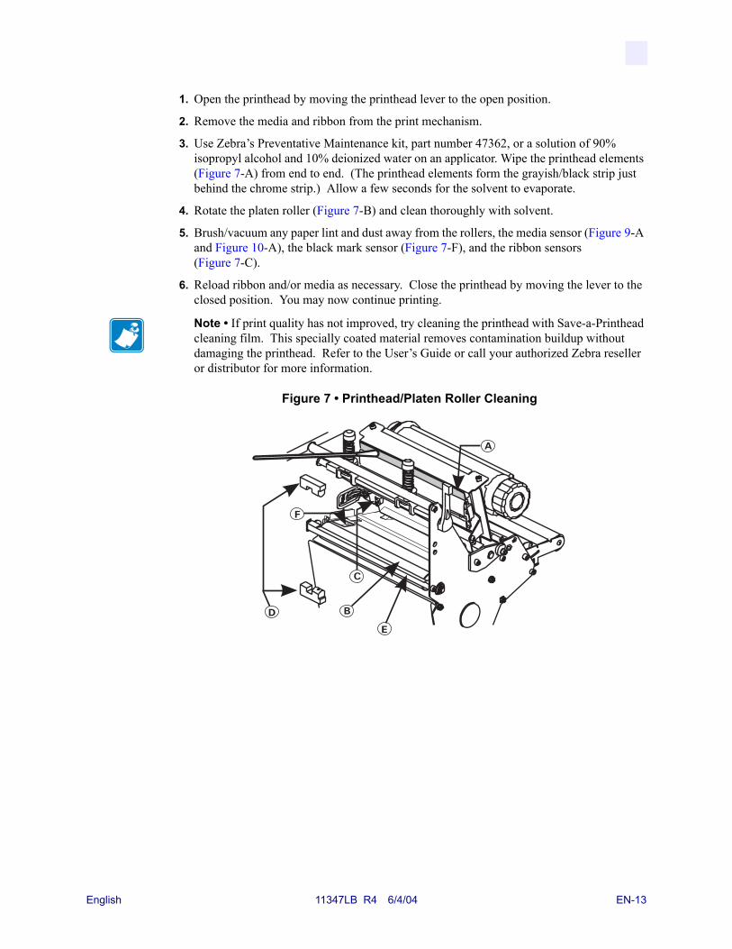
1. Open the printhead by moving the printhead lever to the open position.
2. Remove the media and ribbon from the print mechanism.
3. Use Zebra’s Preventative Maintenance kit, part number 47362, or a solution of 90% isopropyl alcohol and 10% deionized water on an applicator. Wipe the printhead elements (Figure 7-A) from end to end. (The printhead elements form the grayish/black strip just behind the chrome strip.) Allow a few seconds for the solvent to evaporate.
4. Rotate the platen roller (Figure 7-B) and clean thoroughly with solvent.
5. Brush/vacuum any paper lint and dust away from the rollers, the media sensor (Figure 9-A and Figure 10-A), the black mark sensor (Figure 7-F), and the ribbon sensors (Figure 7-C).
6. Reload ribbon and/or media as necessary. Close the printhead by moving the lever to the closed position. You may now continue printing.
Figure 7 • Printhead/Platen Roller Cleaning
Note • If print quality has not improved, try cleaning the printhead with Save-a-Printhead cleaning film. This specially coated material removes contamination buildup without damaging the printhead. Refer to the User’s Guide or call your authorized Zebra reseller or distributor for more information.
English 11347LB R4 6/4/04 EN-13
Adjustments
Toggle PositioningPosition the toggle(s) to provide even pressure on the media by sliding them to the desired location. If you are using narrow media and your printer has two toggles, you may position one toggle over the center of the media and slide the other toggle out of the way (decrease the pressure on the unused toggle).
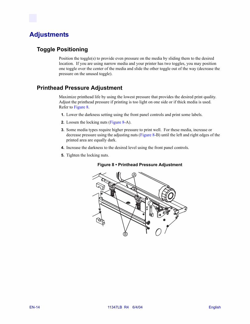
Printhead Pressure AdjustmentMaximize printhead life by using the lowest pressure that provides the desired print quality. Adjust the printhead pressure if printing is too light on one side or if thick media is used. Refer to Figure 8.
1. Lower the darkness setting using the front panel controls and print some labels.
2. Loosen the locking nuts (Figure 8-A).
3. Some media types require higher pressure to print well. For these media, increase or decrease pressure using the adjusting nuts (Figure 8-B) until the left and right edges of the printed area are equally dark.
4. Increase the darkness to the desired level using the front panel controls.
5. Tighten the locking nuts.
Figure 8 • Printhead Pressure Adjustment
EN-14 11347LB R4 6/4/04 English
Media Sensor Position AdjustmentsThe media sensor must be positioned so that it can detect the “web” between labels or a hole or notch in the media.
The factory-set position should be sufficient for most applications. If not, perform the appropriate adjustments.
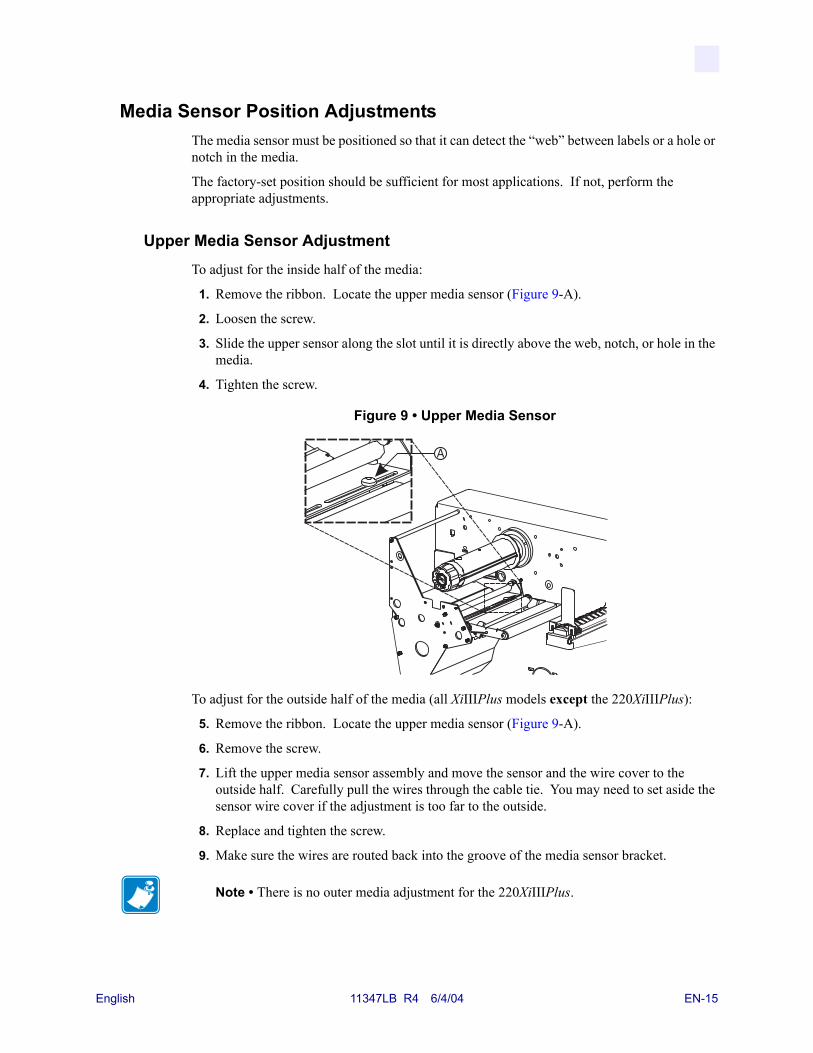
Upper Media Sensor AdjustmentTo adjust for the inside half of the media:
1. Remove the ribbon. Locate the upper media sensor (Figure 9-A).
2. Loosen the screw.
3. Slide the upper sensor along the slot until it is directly above the web, notch, or hole in the media.
4. Tighten the screw.
Figure 9 • Upper Media Sensor
To adjust for the outside half of the media (all XiIIIPlus models except the 220XiIIIPlus):
5. Remove the ribbon. Locate the upper media sensor (Figure 9-A).
6. Remove the screw.
7. Lift the upper media sensor assembly and move the sensor and the wire cover to the outside half. Carefully pull the wires through the cable tie. You may need to set aside the sensor wire cover if the adjustment is too far to the outside.
8. Replace and tighten the screw.
9. Make sure the wires are routed back into the groove of the media sensor bracket.
Note • There is no outer media adjustment for the 220XiIIIPlus.
English 11347LB R4 6/4/04 EN-15
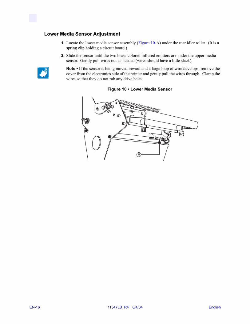
Lower Media Sensor Adjustment1. Locate the lower media sensor assembly (Figure 10-A) under the rear idler roller. (It is a
spring clip holding a circuit board.)
2. Slide the sensor until the two brass-colored infrared emitters are under the upper media sensor. Gently pull wires out as needed (wires should have a little slack).
Figure 10 • Lower Media Sensor
Note • If the sensor is being moved inward and a large loop of wire develops, remove the cover from the electronics side of the printer and gently pull the wires through. Clamp the wires so that they do not rub any drive belts.
EN-16 11347LB R4 6/4/04 English


Zebra Technologies Corporation333 Corporate Woods ParkwayVernon Hills, Illinois 60061.3109 U.S.A.Telephone: +1 847.634.6700Facsimile: +1 847.913.8766
Zebra Technologies Europe LimitedZebra HouseThe Valley Centre, Gordon RoadHigh WycombeBuckinghamshire HP13 6EQ, UKTelephone: +44 (0) 1494 472872Facsimile: +44 (0) 1494 450103
Customer Order # 11347LBManufacturer Part # 11347LB R4
© 2004 ZIH Corp.