mp - wt-thielemann.de · droit d’apporter à tout moment les modifications qu’elle jugera...
TRANSCRIPT
CER
MET
AZIENDA
CE
RT
IF IC A T A
UN
I EN
ISO
9001-085
550 &
550
MP
para la naturaleza100% papel reciclado
ist umweltfreundlich100% Altpapier
pour la naturepapier recyclé 100%
for naturerecycled paper 100%carta riciclata 100%
per la natura
550 &
550
MP
Timbro del Rivenditore:/Distributor’s Stamp:/Timbre de l’Agent:/ Fachhändlerstempel:/Sello del Revendedor:
Le descrizioni e le illustrazioni del presente manuale non sono impegnative. La FAAC si riserva il diritto,lasciando inalterate le caratteristiche essenziali dell’apparecchiatura, di apportare in qualunquemomento e senza impegnarsi ad aggiornare la presente pubblicazione, le modifiche che essa ritieneconvenienti per miglioramenti tecnici o per qualsiasi altra esigenza di carattere costruttivo ocommerciale.
The descriptions and illustrations contained in the present manual are not binding. FAAC reserves theright, whilst leaving the main features of the equipments unaltered, to undertake any modificationsit holds necessary for either technical or commercial reasons, at any time and without revising thepresent publication.
Les descriptions et les illustrations du présent manuel sont fournies à titre indicatif. FAAC se réserve ledroit d’apporter à tout moment les modifications qu’elle jugera utiles sur ce produit tout en conservantles caractéristiques essentielles, sans devoir pour autant mettre à jour cette publication.
Die Beschreibungen und Abbildungen in vorliegendem Handbuch sind unverbindlich. FAAC behältsich das Recht vor, ohne die wesentlichen Eigenschaften dieses Gerätes zu verändern und ohneVerbindlichkeiten in Bezug auf die Neufassung der vorliegenden Anleitungen, technisch bzw.konstruktiv/kommerziell bedingte Verbesserungen vorzunehmen.
Las descripciones y las ilustraciones de este manual no comportan compromiso alguno. FAAC sereserva el derecho, dejando inmutadas las características esenciales de los aparatos, de aportar, encualquier momento y sin comprometerse a poner al día la presente publicación, todas lasmodificaciones que considere oportunas para el perfeccionamiento técnico o para cualquier otrotipo de exigencia de carácter constructivo o comercial.
FAAC S.p.A.Via Benini, 140069 Zola Predosa (BO) - ITALIATel.: 051/6172411 - Tlx.: 521087Fax: 051/758518
FAAC per la natura• La presente istruzione è realizzata al 100% in carta riciclata.• Non disperdete nell'ambiente gli imballaggi dei componenti dell'automazione bensì selezionate
i vari materiali (es. cartone, polistirolo) secondo prescrizioni locali per lo smaltimento rifiuti e lenorme vigenti.
FAAC for the environment• The present manual is produced in 100% recycled paper• Respect the environment. Dispose of each type of product packaging material (card, polystyrene)
in accordance with the provisions for waste disposal as specified in the country of installation.
FAAC der Umwelt zuliebe• Vorliegende Anleitungen sind auf 100% Altpapier gedruckt.• Verpackungsstoffe der Antriebskomponenten (z.B. Pappe, Styropor) nach den einschlägigen
Normen der Abfallwirtschaft sortenrein sammeln.FAAC écologique• La présente notice a été réalisée 100% avec du papier recyclé.• Ne pas jeter dans la nature les emballages des composants de l’automatisme, mais sélectionner
les différents matériaux (ex.: carton, polystyrène) selon la législation locale pour l’élimination desdéchets et les normes en vigueur.
FAAC por la naturaleza.• El presente manual de instrucciones se ha realizado, al 100%, en papel reciclado.• Los materiales utilizados para el embalaje de las distintas partes del sistema automático (cartón,
poliestireno) no deben tirarse al medio ambiente, sino seleccionarse conforme a las prescripcioneslocales y las normas vigentes para el desecho de residuos sólidos.
7323
11 -
Re
v.A
para
la n
atur
alez
a10
0% p
apel
rec
icla
dois
t um
wel
tfreu
ndlic
h10
0% A
ltpap
ier
pour
la n
atur
epa
pier
rec
yclé
100
%fo
r na
ture
recy
cled
pap
er 1
00%
cart
a ric
icla
ta 1
00%
per
la n
atur
a
1
ITALIANOITALIANO
1) ATTENZIONE! È importante per la sicurezza delle persone seguire atten-tamente tutta l’istruzione. Una errata installazione o un errato uso delprodotto può portare a gravi danni alle persone.
2) Leggere attentamente le istruzioni prima di iniziare l’installazione delprodotto.
3) I materiali dell’imballaggio (plastica,polistirolo,ecc.) non devono es-sere lasciati alla portata dei bambini in quanto potenziali fonti dipericolo.
4) Conservare le istruzioni per riferimenti futuri.
5) Questo prodotto è stato progettato e costruito esclusivamente perl’utilizzo indicato in questa documentazione. Qualsiasi altro utilizzo nonespressamente indicato potrebbe pregiudicare l’integrità del prodot-to e/o rappresentare fonte di pericolo.
6) FAAC declina qualsiasi responsabilità derivata dall’uso improprio odiverso da quello per cui l’automatismo è destinato.
7) Non installare l’apparecchio in atmosfera esplosiva: la presenza di gaso fumi infiammabili costituisce un grave pericolo per la sicurezza.
8) Gli elementi costruttivi meccanici devono essere in accordo conquanto stabilito dalle Normative UNI8612, CEN pr EN 12604 e CEN prEN 12605.
Per i Paesi extra-CEE, oltre ai riferimenti normativi nazionali, per ottene-re un livello di sicurezza adeguato, devono essere seguite le Normesopra riportate.
9) FAAC non è responsabile dell’inosservanza della Buona Tecnica nellacostruzione delle chiusure da motorizzare, nonchè delle deformazioniche dovessero intervenire nell’utilizzo.
10) L’installazione deve essere effettuata nell’osservanza delle NormeUNI8612, CEN pr EN 12453 e CEN pr EN 12635.Il livello di sicurezza dell’automazione deve essere C+D.
11) Prima di effettuare qualsiasi intervento sull’impianto, togliere l’alimen-tazione elettrica.
12) Prevedere sulla rete di alimentazione dell’automazione un interruttoreonnipolare con distanza d’apertura dei contatti uguale o superiore a3 mm. È consigliabile l’uso di un magnetotermico da 6A con interruzio-ne onnipolare.
DICHIARAZIONE CE DI CONFORMITÁ PER MACCHINE(DIRETTIVA 89/392/CEE, ALLEGATO II, PARTE B)
Fabbricante: FAAC S.p.A.
Indirizzo: Via Benini, 1 - 40069 Zola Predosa BOLOGNA - ITALIA
Dichiara che: L'operatore mod. 550,
• è costruito per essere incorporato in una macchina o per essere assemblato con altri macchinari per costituireuna macchina ai sensi della Direttiva 89/392/CEE, e successive modifiche 91/368/CEE, 93/44/CEE, 93/68/CEE;
• è conforme ai requisiti essenziali di sicurezza delle seguenti altre direttive CEE:
73/23/CEE e successiva modifica 93/68/CEE.89/336/CEE e successiva modifica 92/31/CEE e 93/68/CEE
e inoltre dichiara che non è consentito mettere in servizio il macchinario fino a che la macchina in cui saràincorporato o di cui diverrà componente sia stata identificata e ne sia stata dichiarata la conformità allecondizioni della Direttiva 89/392/CEE e successive modifiche trasposta nella legislazione nazionale dal DPR n°459 del 24 luglio 1996.
Bologna, 01,gennaio,1999L’Amministratore Delegato
A. Bassi
13) Verificare che a monte dell’impianto vi sia un interruttore differenzialecon soglia da 0,03 A.
14) Verificare che l’impianto di terra sia realizzato a regola d’arte ecollegarvi le parti metalliche della chiusura. Collegare inoltre a terrail filo Giallo/Verde dell’automatismo.
15) L’automazione dispone di una sicurezza intrinseca antischiacciamentocostituita da un controllo di coppia che deve comunque esseresempre accompagnato ad altri dispositivi di sicurezza.
16) I dispositivi di sicurezza (Es.: fotocellule,coste sensibili,ecc...) permet-tono di proteggere eventuali aree di pericolo da Rischi meccanici dimovimento, come ad Es. schiacciamento, convogliamento,cesoiamento.
17) Per ogni impianto è consigliabile l’utilizzo di almeno una segnalazioneluminosa (es: FAAC LAMP MINILAMP, ecc.) nonchè di un cartello disegnalazione fissato adeguatamente sulla struttura dell’infisso, oltreai dispositivi citati al punto “16”.
18) FAAC declina ogni responsabilità ai fini della sicurezza e del buonfunzionamento dell’automazione, in caso vengano utilizzati compo-nenti dell’impianto non di produzione FAAC.
19) Per la manutenzione utilizzare esclusivamente parti originali FAAC.
20) Non eseguire alcuna modifica sui componenti facenti parte il sistemad’automazione.
21) L’installatore deve fornire tutte le informazioni relative al funziona-mento manuale del sistema in caso di emergenza e consegnareall’Utente utilizzatore dell’impianto il libretto d’avvertenze allegato alprodotto.
22) Non permettere ai bambini o persone di sostare nelle vicinanze delprodotto durante il funzionamento.
23) Tenere fuori dalla portata dei bambini radiocomandi o qualsiasi altrodatore di impulso, per evitare che l’automazione possa essereazionata involontariamente.
24) L’Utente utilizzatore deve astenersi da qualsiasi tentativo di riparazio-ne o d’intervento diretto e rivolgersi solo a personale qualificato.
25) Tutto quello che non è previsto espressamente in queste istruzioni nonè permesso
AVVERTENZE PER L’INSTALLATOREOBBLIGHI GENERALI PER LA SICUREZZA
2
ITALIANO ITALIANO
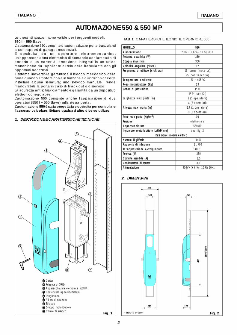
AUTOMAZIONE 550 & 550 MPLe presenti istruzioni sono valide per i seguenti modelli:550 I - 550 SlaveL’automazione 550 consente di automatizzare porte basculantia contrappesi di garages residenziali.È costituita da un operatore elettromeccanico,un'apparecchiatura elettronica di comando con lampada dicortesia e un carter di protezione integrati in un unicomonoblocco da applicare al telo della basculante con gliopportuni accessori.Il sistema irreversibile garantisce il blocco meccanico dellaporta quando il motore non è in funzione e quindi non occorreinstallare alcuna serratura; uno sblocco manuale rendemanovrabile la porta in caso di black-out o disservizio.La sicurezza antischiacciamento è garantita da un dispositivoelettronico regolabile.L'automazione 550 consente anche l'applicazione di dueoperatori (550 I + 550 Slave) sulla stessa porta.L'automazione 550 è stata progettata e costruita per controllarel’accesso veicolare. Evitare qualsiasi altro diverso utilizzo.
1. DESCRIZIONE E CARATTERISTICHE TECNICHE
Fig. 1
aaaaa Carterbbbbb Pulsante di OPENccccc Apparecchiatura elettronica 550MPddddd Contenitore apparecchiaturaeeeee Longheronefffff Albero di rotazioneggggg Sbloccohhhhh Gruppo motoriduttoreiiiii Chiave di sblocco
TAB. 1 CARATTERISTICHE TECNICHE OPERATORE 550
MODELLO 550Al imentazione 230V~ (+ 6 % - 10 %) 50HzPotenza assorbita (W) 360Coppia max (Nm) 300Velocità angolare (°/sec) 12Frequenza di uti l izzo (cicli/ora) 15 (senza f inecorsa)
25 (con f inecorsa)Temperatura ambiente -20 ÷ +55 °CPeso motoriduttore (Kg) 13Grado di protezione IP 31
IP 44 (con Kit)Larghezza max porta (m) 3 (1 operatore)
4 (2 operatori)Altezza max porta (m) 2.7 (1 operatore)
3 (2 operatori)Peso max porta (Kg/m2) 10Fr iz ione elett ronicaApparecchiatura 550MPIngombro motoriduttore LxHxP(mm) vedi f ig. 2
Dati tecnici motore elettricoNumero di giri/min 1400Rapporto di r iduzione 1 : 700Termoprotezione avvolgimento 140 °CPotenza (W) 350Corrente assorbita (A) 1.5Condensatore di spunto 8µFAlimentazione 230V~ (+ 6 % - 10 %) 50Hz
2. DIMENSI0NI
Fig. 2
175
100
160 120
5067
0
1500
/200
0
• quote in mm
a
b
d
c
e
gh
i
f
3
ITALIANOITALIANO
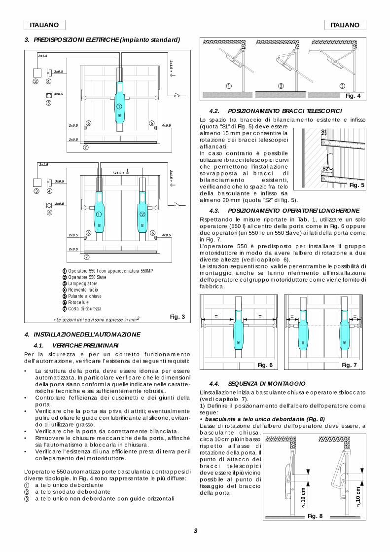
3. PREDISPOSIZIONI ELETTRICHE (impianto standard)
aaaaa Operatore 550 I con apparecchiatura 550MPbbbbb Operatore 550 Slaveccccc Lampeggiatoreddddd Ricevente radioeeeee Pulsante a chiavefffff Fotocelluleggggg Costa di sicurezza
a b
c d
e
f
g
f
a
c d
e
f
g
f
4. INSTALLAZIONE DELL'AUTOMAZIONE
4.1. VERIFICHE PRELIMINARIPer la sicurezza e per un corretto funzionamentodell’automazione, verificare l’esistenza dei seguenti requisiti:
• La struttura della porta deve essere idonea per essereautomatizzata. In particolare verificare che le dimensionidella porta siano conformi a quelle indicate nelle caratte-ristiche tecniche e sia sufficientemente robusta.
• Controllare l'efficienza dei cuscinetti e dei giunti dellaporta.
• Verificare che la porta sia priva di attriti; eventualmentepulire ed oliare le guide con lubrificante al silicone, evitan-do di utilizzare grasso.
• Verificare che la porta sia correttamente bilanciata.• Rimuovere le chiusure meccaniche della porta, affinchè
sia l'automatismo a bloccarla in chiusura.• Verificare l’esistenza di una efficiente presa di terra per il
collegamento del motoriduttore.
L'operatore 550 automatizza porte basculanti a contrappesi didiverse tipologie. In Fig. 4 sono rappresentate le più diffuse:a a telo unico debordanteb a telo snodato debordantec a telo unico non debordante con guide orizzontali
4.2. POSIZIONAMENTO BRACCI TELESCOPICILo spazio tra braccio di bilanciamento esistente e infisso(quota "S1" di Fig. 5) deve esserealmeno 15 mm per consentire larotazione dei bracci telescopiciaffiancati.In caso contrario è possibileutilizzare i bracci telescopici curviche permettono l'installazionesovrapposta ai bracci dibilanciamento esistenti,verificando che lo spazio fra telodella basculante e infisso siaalmeno 20 mm (quota "S2" di fig. 5).
4.3. POSIZIONAMENTO OPERATORE/LONGHERONERispettando le misure riportate in Tab. 1, utilizzare un solooperatore (550 I) al centro della porta come in Fig. 6 oppuredue operatori (un 550 I e un 550 Slave) ai lati della porta comein Fig. 7.L'operatore 550 è predisposto per installare il gruppomotoriduttore in modo da avere l'albero di rotazione a duediverse altezze (vedi capitolo 6).Le istruzioni seguenti sono valide per entrambe le possibilità dimontaggio anche se fanno riferimento all'installazionedell'operatore col gruppo motoriduttore come viene fornito difabbrica.
Fig. 3
4.4. SEQUENZA DI MONTAGGIOL'installazione inizia a basculante chiusa e operatore sbloccato(vedi capitolo 7).1) Definire il posizionamento dell'albero dell'operatore comesegue:• basculante a telo unico debordante (Fig. 8)L'asse di rotazione dell'albero dell'operatore deve essere, abasculante chiusa,circa 10 cm più in bassorispetto all 'asse dirotazione della porta. Ilpunto di attacco deibracci telescopicideve essere il più vicinopossibile al punto difissaggio del bracciodella porta.
10 c
m
10 c
m
Fig. 8
= = = =
Fig. 6 Fig. 7
a cb
Fig. 4
S1
S2
2x0.5 4x0.5
2x0.5
3x0.5
3x0.5
2x1.5
2x1.5 + W
5x1.5 + W
2x1.5
3x0.5
3x0.5
2x0.5
2x0.5
4x0.5
•Le sezioni dei cavi sono espresse in mm2
Fig. 5
2x1.5 + W
4
ITALIANO ITALIANO
• basculante a telo snodato(Fig. 9)
L'asse di rotazione dell'alberodell'operatore deve essere, abasculante chiusa, circa 10cm più in basso rispettoall'asse di rotazione dellecerniere di articolazione dellaporta (rif. A). Il punto di attacco dei braccitelescopici deve essere il piùvicino possibile al punto difissaggio delle cerniere dellaporta (rif. B).
• basculante con guideorizzontali (Fig. 10)
L'asse di rotazione dell'alberodell 'operatore devecoincidere con la linea dimezzeria tra i due cuscinetti. Il punto di attacco dei braccitelescopici deve essere il piùvicino possibile al punto dicongiunzione delle guidesuperiore e verticale.
2) Fissare verticalmente illongherone sui rinforzi del telo basculante con viti adeguatealla struttura della porta; è consigliabile l'utilizzo di inserti filettati.ÜPosizionare il longherone in modo che la parte in cui è
stampata una "E" (che indica dove verrà a trovarsi la sche-da), sia rivolta verso l'alto.
ÜIl longherone ha una serie di fori Ø 8mm che consentono,una volta fissato, di installare l'operatore a varie altezze.Verificare che la posizione di fissaggio del longheroneconsenta il montaggio dell'operatore rispettando la posizionedell'albero precedentemente determinata.
Nel caso di installazione di due operatori sulla stessa porta,entrambi gli alberi devono essere allineati alla stessa altezza.
10 cm
Fig. 9
AB
=
=
Fig. 10
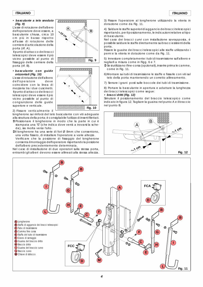
3) Fissare l'operatore al longherone utilizzando la viteria indotazione come da Fig. 11.
4) Saldare le staffe superiori di aggancio dei bracci telescopicirispettando, per il posizionamento, le indicazioni relative al tipodi basculante.Nel caso dei bracci curvi con installazione sovrapposta, èpossibile saldare le staffe direttamente sui bracci esistenti dellaporta.Fissare le guaine dei bracci telescopici alle staffe utilizzando iperni e la viteria in dotazione come da Fig. 11.
5) Innestare completamente i tubi di trasmissione sull'albero etagliarli a misura come in Figg. 6 e 7.ÜSe si utilizzano i fine-corsa (opzionali), inserire prima le camme,
come in Fig. 11.
6)Montare sui tubi di trasmissione le staffe e fissarle con viti sultelo della porta mantenendo un corretto allineamento.
7) Serrare i grani posti sulle boccole dei tubi di trasmissione.
8) Portare la basculante in apertura e adattare la lunghezzadei bracci telescopici come segue:• bracci dritti (Fig. 12)Simulare il posizionamento del braccio telescopico comeindicato in figura 12. Tagliare la guaina nel punto A e il braccionel punto B.
Fig. 11
AB
Fig. 12
FCC
FCAA
B
B
B
BC
C
D
D
E
E
F
F
G
G
H
H
I
I
L
M
A LongheroneB Staffa di aggancio dei bracci telescopiciC Tubo di trasmissioneD Camma fine corsaE Staffa del tubo di trasmissioneF Grano di serraggioG Guaina del braccio drittoH Braccio dritto I Guaina del braccio curvo L Braccio curvoM Chiave di sblocco
L
5
ITALIANOITALIANO
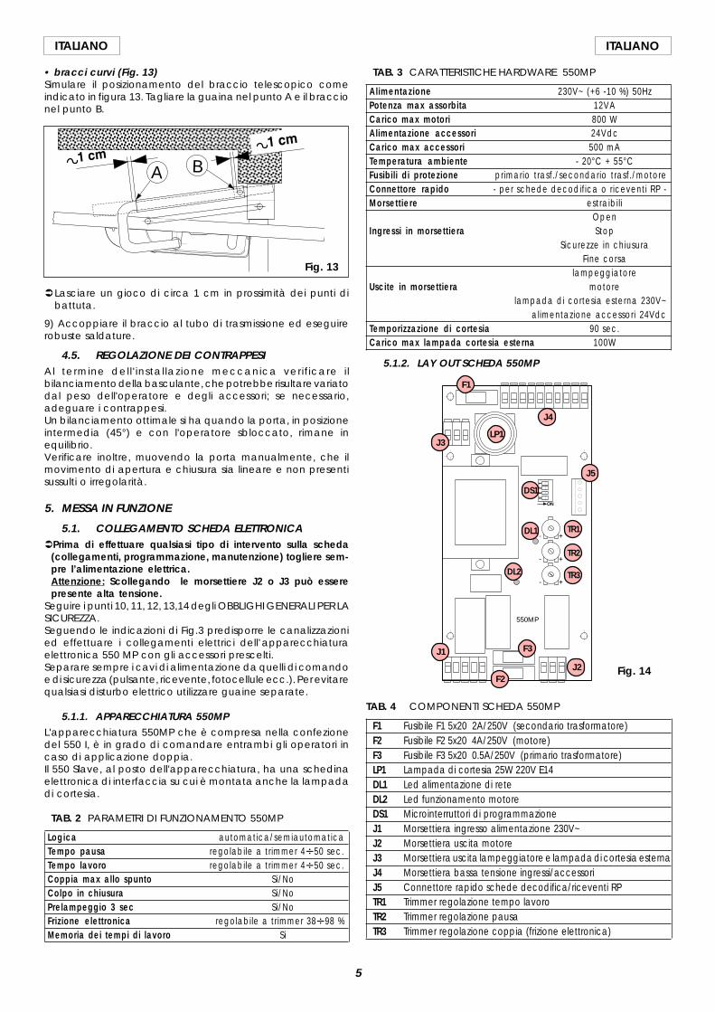
• bracci curvi (Fig. 13)Simulare il posizionamento del braccio telescopico comeindicato in figura 13. Tagliare la guaina nel punto A e il braccionel punto B.
ÜLasciare un gioco di circa 1 cm in prossimità dei punti dibattuta.
9) Accoppiare il braccio al tubo di trasmissione ed eseguirerobuste saldature.
4.5. REGOLAZIONE DEI CONTRAPPESIAl termine dell ' installazione meccanica verif icare i lbilanciamento della basculante, che potrebbe risultare variatodal peso dell'operatore e degli accessori; se necessario,adeguare i contrappesi.Un bilanciamento ottimale si ha quando la porta, in posizioneintermedia (45°) e con l'operatore sbloccato, rimane inequilibrio.Verificare inoltre, muovendo la porta manualmente, che ilmovimento di apertura e chiusura sia lineare e non presentisussulti o irregolarità.
5. MESSA IN FUNZIONE
5.1. COLLEGAMENTO SCHEDA ELETTRONICAÜPrima di effettuare qualsiasi tipo di intervento sulla scheda
(collegamenti, programmazione, manutenzione) togliere sem-pre l’alimentazione elettrica.Attenzione: Scollegando le morsettiere J2 o J3 può esserepresente alta tensione.
Seguire i punti 10, 11, 12, 13,14 degli OBBLIGHI GENERALI PER LASICUREZZA.Seguendo le indicazioni di Fig.3 predisporre le canalizzazionied effettuare i collegamenti elettrici dell’apparecchiaturaelettronica 550 MP con gli accessori prescelti.Separare sempre i cavi di alimentazione da quelli di comandoe di sicurezza (pulsante, ricevente, fotocellule ecc.). Per evitarequalsiasi disturbo elettrico utilizzare guaine separate.
5.1.1. APPARECCHIATURA 550MPL'apparecchiatura 550MP che è compresa nella confezionedel 550 I, è in grado di comandare entrambi gli operatori incaso di applicazione doppia.Il 550 Slave, al posto dell'apparecchiatura, ha una schedinaelettronica di interfaccia su cui è montata anche la lampadadi cortesia.
TAB. 2 PARAMETRI DI FUNZIONAMENTO 550MP
Logica automatica/semiautomaticaTempo pausa regolabile a trimmer 4V50 sec.Tempo lavoro regolabile a trimmer 4V50 sec.Coppia max allo spunto Si/NoColpo in chiusura Si/NoPrelampeggio 3 sec Si/NoFrizione elettronica regolabile a trimmer 38V98 %Memoria dei tempi di lavoro Si
TAB. 4 COMPONENTI SCHEDA 550MP
F1 Fusibile F1 5x20 2A/250V (secondario trasformatore)F2 Fusibile F2 5x20 4A/250V (motore)F3 Fusibile F3 5x20 0.5A/250V (primario trasformatore)LP1 Lampada di cortesia 25W 220V E14DL1 Led alimentazione di reteDL2 Led funzionamento motoreDS1 Microinterruttori di programmazioneJ1 Morsettiera ingresso alimentazione 230V~J2 Morsettiera uscita motoreJ3 Morsettiera uscita lampeggiatore e lampada di cortesia esternaJ4 Morsettiera bassa tensione ingressi/accessoriJ5 Connettore rapido schede decodifica/riceventi RPTR1 Trimmer regolazione tempo lavoroTR2 Trimmer regolazione pausaTR3 Trimmer regolazione coppia (frizione elettronica)
TAB. 3 CARATTERISTICHE HARDWARE 550MP
Alimentazione 230V~ (+6 -10 %) 50HzPotenza max assorbita 12VACarico max motori 800 WAlimentazione accessori 24VdcCarico max accessori 500 mATemperatura ambiente - 20°C + 55°CFusibili di protezione primario trasf./secondario trasf./motoreConnettore rapido - per schede decodifica o riceventi RP -Morsettiere estraibil i
OpenIngressi in morsettiera Stop
Sicurezze in chiusuraFine corsa
lampeggiatoreUscite in morsettiera motore
lampada di cortesia esterna 230V~alimentazione accessori 24Vdc
Temporizzazione di cortesia 90 sec.Carico max lampada cortesia esterna 100W
5.1.2. LAY OUT SCHEDA 550MP
A B
Fig. 13
ON
+
+
+
-
-
-
14
32
550MP
F1
J4
LP1J3
J5
DS1
DL1 TR1
TR2
TR3
J1
J2
F3
F2
DL2
Fig. 14
6
ITALIANO ITALIANO
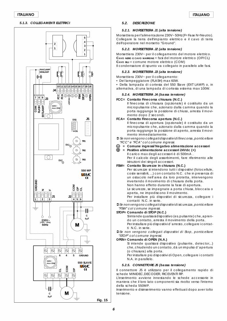
5.1.3. COLLEGAMENTI ELETTRICI
ON
+
+
+
-
-
-
14
32
1 32 4 5 6
7 8 9
10 11 12 13 14 15 16 17 18 19J4
J3
J1 J2
GROUND
N F CO
MO
PC
L
CO
MFL
ASH
EXT.L
AM
P
FCC
FCA
FSW
STO
P
OPE
N
M230V~
C8µF
5
43
2
1
1
2
(+6% -10%)
550 SLAVE
550 MP
M
C8µF
50Hz
CO
M
OP
CL
4 56
FAACLAMPMINILAMP
230V~max 25W
230V~max 25W
J5
TR1
TR2
TR3
DS1
DL1
DL2
GRO
UND
Fig. 15
5.2. DESCRIZIONE
5.2.1. MORSETTIERA J1 (alta tensione)Morsettiera per l'alimentazione 230V~ 50Hz (F= Fase N=Neutro).Collegare la terra dell'impianto elettrico e il cavo di terradell'operatore nel morsetto "Ground".
5.2.2. MORSETTIERA J2 (alta tensione)Morsettiera 230V~ per il collegamento del motore elettrico.CAVO NERO E CAVO MARRONE = fasi del motore elettrico (OP/CL)CAVO BLU = comune motore elettrico (COM)Il condensatore di spunto va collegato in parallelo alle fasi.
5.2.3. MORSETTIERA J3 (alta tensione)Morsettiera 230V~ per il collegamento:• Del lampeggiatore (FLASH) max 60W.• Della lampada di cortesia del 550 Slave (EXT LAMP) o, inalternativa, di una lampada di cortesia esterna max 100W.
5.2.4. MORSETTIERA J4 (bassa tensione)FCC= Contatto Finecorsa chiusura (N.C.)
Il finecorsa di chiusura (opzionale) è costituito da unmicropulsante che, azionato dalla camma quando laporta raggiunge la posizione di chiuso, arresta il movi-mento dopo 2 secondi.
FCA= Contatto Finecorsa apertura (N.C.)Il finecorsa di apertura (opzionale) è costituito da unmicropulsante che, azionato dalla camma quando laporta raggiunge la posizione di aperto, arresta il movi-mento immediatamente.
Ü Se non vengono collegati dispositivi di finecorsa, ponticellare"FCC" e "FCA" col comune ingressi.
= Comune ingressi/Negativo alimentazione accessori= Positivo alimentazione accessori 24Vdc (+)
Il carico max degli accessori è di 500mA .Per il calcolo degli assorbimenti, fare riferimento alleistruzioni dei singoli accessori.
FSW= Contatto Sicurezze in chiusura (N.C.)Per sicurezze si intendono tutti i dispositivi (fotocellule,coste sensibili, ...) con contatto N.C. che in presenza diun ostacolo nell’area da loro protetta, intervengonoinvertendo il movimento di chiusura della porta.Non hanno effetto durante la fase di apertura.Le sicurezze, se impegnate a porta chiusa, bloccata oaperta, ne impediscono il movimento.Per installare più dispositivi di sicurezza, collegare icontatti N.C. in serie.
ÜSe non vengono collegati dispositivi di sicurezza, ponticellare"FSW" col comune ingressi.
STOP= Comando di STOP (N.C.)Si intende qualsiasi dispositivo (es. pulsante) che, apren-do un contatto, arresta il movimento della porta.Per installare più dispositivi d’arresto, collegare i contat-ti N.C. in serie.
ÜSe non vengono collegati dispositivi di Stop, ponticellare"STOP" col comune ingressi.
OPEN= Comando di OPEN (N.A.)Si intende qualsiasi dispositivo (pulsante, detector,..)che, chiudendo un contatto, dà un impulso d’apertura(o chiusura) alla porta.Per installare più dispositivi di Open, collegare i contattiN.A. in parallelo.
5.2.5. CONNETTORE J5 (bassa tensione)Il connettore J5 è utilizzato per il collegamento rapido dischede MINIDEC,DECODER, RICEVENTI RP.L'inserimento avviene innestando le schede accessorie inmaniera che il loro lato componenti sia rivolto verso l'internodella scheda 550MP.Inserimento e disinserimento vanno effettuati dopo aver toltotensione.
7
ITALIANOITALIANO
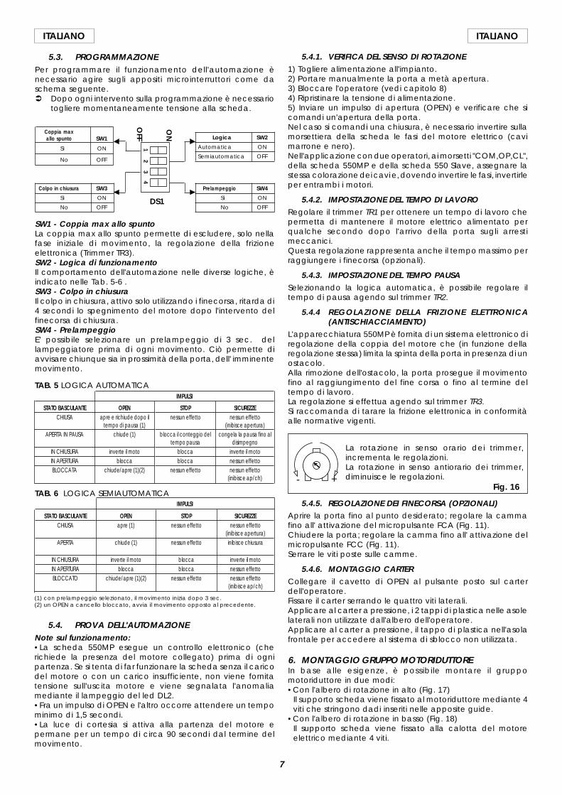
5.3. PROGRAMMAZIONEPer programmare il funzionamento dell'automazione ènecessario agire sugli appositi microinterruttori come daschema seguente.Ü Dopo ogni intervento sulla programmazione è necessario
togliere momentaneamente tensione alla scheda.
SW1 - Coppia max allo spuntoLa coppia max allo spunto permette di escludere, solo nellafase iniziale di movimento, la regolazione della frizioneelettronica (Trimmer TR3).SW2 - Logica di funzionamentoIl comportamento dell'automazione nelle diverse logiche, èindicato nelle Tab. 5-6 .SW3 - Colpo in chiusuraIl colpo in chiusura, attivo solo utilizzando i finecorsa, ritarda di4 secondi lo spegnimento del motore dopo l'intervento delfinecorsa di chiusura.SW4 - PrelampeggioE' possibile selezionare un prelampeggio di 3 sec. dellampeggiatore prima di ogni movimento. Ciò permette diavvisare chiunque sia in prossimità della porta, dell' imminentemovimento.
Logica SW2
Automatica ON
Semiautomatica OFF
Coppia maxallo spunto SW1
Si ON
No OFF
Colpo in chiusura SW3
Si ON
No OFF
Prelampeggio SW4
Si ON
No OFF
12
34
ON
OFF
TAB. 6 LOGICA SEMIAUTOMATICA
SICUREZZEnessun effetto
(inibisce apertura)inibisce chiusura
inverte il motonessun effettonessun effetto
(inibisce ap/ch)
STATO BASCULANTECHIUSA
APERTA
IN CHIUSURAIN APERTURABLOCCATO
OPENapre (1)
chiude (1)
inverte il motoblocca
chiude/apre (1)(2)
STOPnessun effetto
nessun effetto
bloccablocca
nessun effetto
IMPULSI
IMPULSI
SICUREZZEnessun effetto
(inibisce apertura)congela la pausa fino al
disimpegnoinverte il motonessun effettonessun effetto
(inibisce ap/ch)
STOPnessun effetto
blocca il conteggio deltempo pausa
bloccablocca
nessun effetto
STATO BASCULANTECHIUSA
APERTA IN PAUSA
IN CHIUSURAIN APERTURABLOCCATA
OPENapre e richiude dopo il
tempo di pausa (1)chiude (1)
inverte il motoblocca
chiude/apre (1)(2)
TAB. 5 LOGICA AUTOMATICA
(1) con prelampeggio selezionato, il movimento inizia dopo 3 sec.(2) un OPEN a cancello bloccato, avvia il movimento opposto al precedente.
5.4. PROVA DELL'AUTOMAZIONENote sul funzionamento:•La scheda 550MP esegue un controllo elettronico (cherichiede la presenza del motore collegato) prima di ognipartenza. Se si tenta di far funzionare la scheda senza il caricodel motore o con un carico insufficiente, non viene fornitatensione sull'uscita motore e viene segnalata l'anomaliamediante il lampeggio del led DL2.•Fra un impulso di OPEN e l'altro occorre attendere un tempominimo di 1,5 secondi.•La luce di cortesia si attiva alla partenza del motore epermane per un tempo di circa 90 secondi dal termine delmovimento.
5.4.1. VERIFICA DEL SENSO DI ROTAZIONE1) Togliere alimentazione all'impianto.2) Portare manualmente la porta a metà apertura.3) Bloccare l'operatore (vedi capitolo 8)4) Ripristinare la tensione di alimentazione.5) Inviare un impulso di apertura (OPEN) e verificare che sicomandi un'apertura della porta.Nel caso si comandi una chiusura, è necessario invertire sullamorsettiera della scheda le fasi del motore elettrico (cavimarrone e nero).Nell'applicazione con due operatori, ai morsetti "COM,OP,CL",della scheda 550MP e della scheda 550 Slave, assegnare lastessa colorazione dei cavi e, dovendo invertire le fasi, invertirleper entrambi i motori.
5.4.2. IMPOSTAZIONE DEL TEMPO DI LAVORORegolare il trimmer TR1 per ottenere un tempo di lavoro chepermetta di mantenere il motore elettrico alimentato perqualche secondo dopo l'arrivo della porta sugli arrestimeccanici.Questa regolazione rappresenta anche il tempo massimo perraggiungere i finecorsa (opzionali).
5.4.3. IMPOSTAZIONE DEL TEMPO PAUSASelezionando la logica automatica, è possibile regolare iltempo di pausa agendo sul trimmer TR2.
5.4.4 REGOLAZIONE DELLA FRIZIONE ELETTRONICA(ANTISCHIACCIAMENTO)
L'apparecchiatura 550MP è fornita di un sistema elettronico diregolazione della coppia del motore che (in funzione dellaregolazione stessa) limita la spinta della porta in presenza di unostacolo.Alla rimozione dell'ostacolo, la porta prosegue il movimentofino al raggiungimento del fine corsa o fino al termine deltempo di lavoro.La regolazione si effettua agendo sul trimmer TR3.Si raccomanda di tarare la frizione elettronica in conformitàalle normative vigenti.
5.4.5. REGOLAZIONE DEI FINECORSA (OPZIONALI)Aprire la porta fino al punto desiderato; regolare la cammafino all' attivazione del micropulsante FCA (Fig. 11).Chiudere la porta; regolare la camma fino all' attivazione delmicropulsante FCC (Fig. 11).Serrare le viti poste sulle camme.
5.4.6. MONTAGGIO CARTERCollegare il cavetto di OPEN al pulsante posto sul carterdell'operatore.Fissare il carter serrando le quattro viti laterali.Applicare al carter a pressione, i 2 tappi di plastica nelle asolelaterali non utilizzate dall'albero dell'operatore.Applicare al carter a pressione, il tappo di plastica nell'asolafrontale per accedere al sistema di sblocco non utilizzata.
6. MONTAGGIO GRUPPO MOTORIDUTTOREIn base alle esigenze, è possibile montare il gruppomotoriduttore in due modi:•Con l'albero di rotazione in alto (Fig. 17)
Il supporto scheda viene fissato al motoriduttore mediante 4viti che stringono dadi inseriti nelle apposite guide.
•Con l'albero di rotazione in basso (Fig. 18)Il supporto scheda viene fissato alla calotta del motoreelettrico mediante 4 viti.
DS1
+-Fig. 16
La rotazione in senso orario dei trimmer,incrementa le regolazioni.La rotazione in senso antiorario dei trimmer,diminuisce le regolazioni.
8
ITALIANO ITALIANO
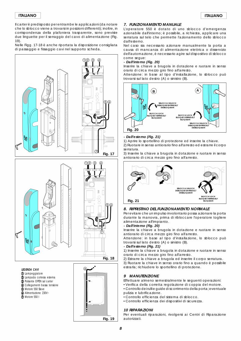
Il carter è predisposto per entrambe le applicazioni (da notareche lo sblocco viene a trovarsi in posizioni differenti); inoltre, incorrispondenza della plafoniera trasparente, sono previstedue linguette per il serraggio del cavo di alimentazione (Fig.19).Nelle Figg. 17-18 è anche riportata la disposizione consigliatadi passaggio e fissaggio cavi nel supporto scheda.
LEGENDA CAVIaaaaa Lampeggiatorebbbbb Lampada cortesia esternaccccc Pulsante OPEN sul carterddddd Collegamenti bassa tensioneeeeee Motore 550 Slavefffff Alimentazione 230V~ggggg Motore 550 I
ab c d
ef
ab c d
ef
g
Fig. 18
Fig. 19
g
Fig. 17
- Dall'esterno (Fig. 21)1) Aprire lo sportellino di protezione ed inserire la chiave.2) Ruotare in senso antiorario fino all'arresto ed estrarre il corposerratura.3) Inserire la chiave a brugola in dotazione e ruotare in sensoantiorario di circa mezzo giro fino all'arresto.
Fig. 21
SBLOCCA/UNLOCKDEBLOQUE/ENTRIEGELT
DESBLOQUEAR
BLOCCA/LOCKBLOQUE/VERRIEGELT
BLOQUEAR
8. RIPRISTINO DEL FUNZIONAMENTO NORMALEPer evitare che un impulso involontario possa azionare la portadurante la manovra, prima di ribloccare l'operatore toglierealimentazione all'impianto.- Dall'interno (Fig. 20)Inserire la chiave a brugola in dotazione e ruotare in sensoantiorario di circa mezzo giro fino all'arresto.Attenzione: in base al tipo d'installazione, lo sblocco puòtrovarsi sul lato destro (A) o sinistro (B).- Dall'esterno (Fig. 21)1) Inserire la chiave a brugola in dotazione e ruotare in sensoorario di circa mezzo giro fino all'arresto.2) Estrarre la chiave a brugola ed inserire il corpo serratura.3) Ruotare la chiave in senso orario fino a quando è possibileestrarla; richiudere lo sportellino di protezione.
9 MANUTENZIONEEffettuare almeno semestralmente le seguenti operazioni:•Verifica della corretta regolazione di coppia del motore.•Controllo dei rulli e guide di scorrimento della porta; eventualepulizia e lubrificazione.•Controllo efficienza del sistema di sblocco.•Controllo efficienza dei dispositivi di sicurezza.
10 RIPARAZIONIPer eventuali riparazioni, rivolgersi ai Centri di Riparazioneautorizzati.
Fig. 20
BLOCCA/LOCKBLOQUE/VERRIEGELT
BLOQUEAR
SBLOCCA/UNLOCKDEBLOQUE/ENTRIEGELT
DESBLOQUEAR
SBLOCCA/UNLOCKDEBLOQUE/ENTRIEGELT
DESBLOQUEAR
BLOCCA/LOCKBLOQUE/VERRIEGELT
BLOQUEAR
AB
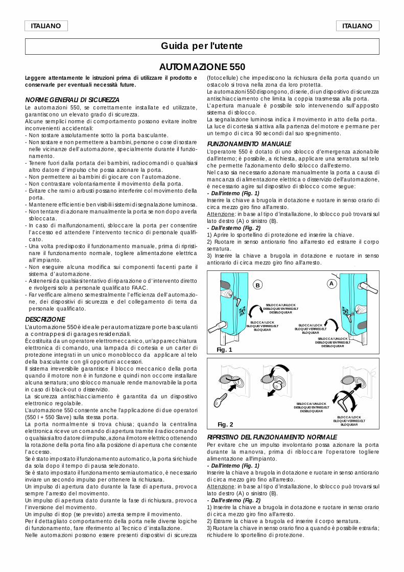
7. FUNZIONAMENTO MANUALEL'operatore 550 è dotato di uno sblocco d'emergenzaazionabile dall'interno; è possibile, a richiesta, applicare unaserratura sul telo che permette l'azionamento dello sbloccodall'esterno.Nel caso sia necessario azionare manualmente la porta acausa di mancanza di alimentazione elettrica o disserviziodell'automazione, è necessario agire sul dispositivo di sbloccocome segue:- Dall'interno (Fig. 20)Inserire la chiave a brugola in dotazione e ruotare in sensoorario di circa mezzo giro fino all'arresto.Attenzione: in base al tipo d'installazione, lo sblocco puòtrovarsi sul lato destro (A) o sinistro (B).
f
9
ITALIANOITALIANO
Guida per l'utente
AUTOMAZIONE 550Leggere attentamente le istruzioni prima di utilizzare il prodotto econservarle per eventuali necessità future.
NORME GENERALI DI SICUREZZALe automazioni 550, se correttamente installate ed utilizzate,garantiscono un elevato grado di sicurezza.Alcune semplici norme di comportamento possono evitare inoltreinconvenienti accidentali:- Non sostare assolutamente sotto la porta basculante.- Non sostare e non permettere a bambini, persone o cose di sostare
nelle vicinanze dell’automazione, specialmente durante il funzio-namento.
- Tenere fuori dalla portata dei bambini, radiocomandi o qualsiasialtro datore d’impulso che possa azionare la porta.
- Non permettere ai bambini di giocare con l’automazione.- Non contrastare volontariamente il movimento della porta.- Evitare che rami o arbusti possano interferire col movimento della
porta.- Mantenere efficienti e ben visibili i sistemi di segnalazione luminosa.- Non tentare di azionare manualmente la porta se non dopo averla
sbloccata.- In caso di malfunzionamenti, sbloccare la porta per consentire
l’accesso ed attendere l’intervento tecnico di personale qualifi-cato.
- Una volta predisposto il funzionamento manuale, prima di ripristi-nare il funzionamento normale, togliere alimentazione elettricaall’impianto.
- Non eseguire alcuna modifica sui componenti facenti parte ilsistema d’automazione.
- Astenersi da qualsiasi tentativo di riparazione o d’intervento direttoe rivolgersi solo a personale qualificato FAAC.
- Far verificare almeno semestralmente l’efficienza dell’automazio-ne, dei dispositivi di sicurezza e del collegamento di terra dapersonale qualificato.
DESCRIZIONEL'automazione 550 è ideale per automatizzare porte basculantia contrappesi di garages residenziali.È costituita da un operatore elettromeccanico, un'apparecchiaturaelettronica di comando, una lampada di cortesia e un carter diprotezione integrati in un unico monoblocco da applicare al telodella basculante con gli opportuni accessori.Il sistema irreversibile garantisce il blocco meccanico della portaquando il motore non è in funzione e quindi non occorre installarealcuna serratura; uno sblocco manuale rende manovrabile la portain caso di black-out o disservizio.La sicurezza antischiacciamento è garantita da un dispositivoelettronico regolabile.L'automazione 550 consente anche l'applicazione di due operatori(550 I + 550 Slave) sulla stessa porta.La porta normalmente si trova chiusa; quando la centralinaelettronica riceve un comando di apertura tramite il radiocomandoo qualsiasi altro datore di impulso, aziona il motore elettrico ottenendola rotazione della porta fino alla posizione di apertura che consentel’accesso.Se è stato impostato il funzionamento automatico, la porta si richiudeda sola dopo il tempo di pausa selezionato.Se è stato impostato il funzionamento semiautomatico, è necessarioinviare un secondo impulso per ottenere la richiusura.Un impulso di apertura dato durante la fase di apertura, provocasempre l’arresto del movimento.Un impulso di apertura dato durante la fase di richiusura, provocal’inversione del movimento.Un impulso di stop (se previsto) arresta sempre il movimento.Per il dettagliato comportamento della porta nelle diverse logichedi funzionamento, fare riferimento al Tecnico d’installazione.Nelle automazioni possono essere presenti dispositivi di sicurezza
Fig. 2
SBLOCCA/UNLOCKDEBLOQUE/ENTRIEGELT
DESBLOQUEAR
BLOCCA/LOCKBLOQUE/VERRIEGELT
BLOQUEAR
RIPRISTINO DEL FUNZIONAMENTO NORMALEPer evitare che un impulso involontario possa azionare la portadurante la manovra, prima di ribloccare l'operatore toglierealimentazione all'impianto.- Dall'interno (Fig. 1)Inserire la chiave a brugola in dotazione e ruotare in senso antiorariodi circa mezzo giro fino all'arresto.Attenzione: in base al tipo d'installazione, lo sblocco può trovarsi sullato destro (A) o sinistro (B).- Dall'esterno (Fig. 2)1) Inserire la chiave a brugola in dotazione e ruotare in senso orariodi circa mezzo giro fino all'arresto.2) Estrarre la chiave a brugola ed inserire il corpo serratura.3) Ruotare la chiave in senso orario fino a quando è possibile estrarla;richiudere lo sportellino di protezione.
Fig. 1
BLOCCA/LOCKBLOQUE/VERRIEGELT
BLOQUEAR
SBLOCCA/UNLOCKDEBLOQUE/ENTRIEGELT
DESBLOQUEAR
SBLOCCA/UNLOCKDEBLOQUE/ENTRIEGELT
DESBLOQUEAR
BLOCCA/LOCKBLOQUE/VERRIEGELT
BLOQUEAR
AB
(fotocellule) che impediscono la richiusura della porta quando unostacolo si trova nella zona da loro protetta.Le automazioni 550 dispongono, di serie, di un dispositivo di sicurezzaantischiacciamento che limita la coppia trasmessa alla porta.L’apertura manuale è possibile solo intervenendo sull’appositosistema di sblocco.La segnalazione luminosa indica il movimento in atto della porta.La luce di cortesia si attiva alla partenza del motore e permane perun tempo di circa 90 secondi dal suo spegnimento.
FUNZIONAMENTO MANUALEL'operatore 550 è dotato di uno sblocco d'emergenza azionabiledall'interno; è possibile, a richiesta, applicare una serratura sul teloche permette l'azionamento dello sblocco dall'esterno.Nel caso sia necessario azionare manualmente la porta a causa dimancanza di alimentazione elettrica o disservizio dell'automazione,è necessario agire sul dispositivo di sblocco come segue:- Dall'interno (Fig. 1)Inserire la chiave a brugola in dotazione e ruotare in senso orario dicirca mezzo giro fino all'arresto.Attenzione: in base al tipo d'installazione, lo sblocco può trovarsi sullato destro (A) o sinistro (B).- Dall'esterno (Fig. 2)1) Aprire lo sportellino di protezione ed inserire la chiave.2) Ruotare in senso antiorario fino all'arresto ed estrarre il corposerratura.3) Inserire la chiave a brugola in dotazione e ruotare in sensoantiorario di circa mezzo giro fino all'arresto.
9
ENGLISHENGLISH
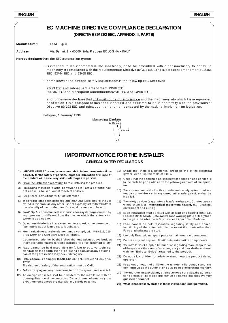
1) IMPORTANT! FAAC strongly recommends to follow these instructionscarefully for the safety of persons. Improper installation or misuse ofthe product will cause very serious damages to persons.
2) Read the instructions carefully before installing the product.
3) Packaging materials (plastic, polystyrene etc.) are a potential haz-ard and must be kept out of reach of children.
4) Keep these instructions for future reference.
5) This product has been designed and manufactured only for the usestated in this manual. Any other use not expressly set forth will affectthe reliability of the product and/or could be source of hazard.
6) FAAC S.p.A. cannot be held responsible for any damage caused byimproper use or different from the use for which the automationsystem is destined to.
7) Do not use this device in areas subject to explosion: the presence offlammable gas or fumes is a serious hazard.
8) Mechanical constructive elements must comply with UNI 8612, CENprEN 12604 and CEN prEN 12605 standards.
Countries outside the EC shall follow the regulations above besidestheir national normative references in order to offer the utmost safety.
9) Faac cannot be held responsible for failure to observe technicalstandards in the construction of gates and doors, or for any deforma-tion of the gates which may occur during use.
10) Installation must comply with UNI8612, CEN pr EN 12453 and CEN pr EN12635.The degree of safety of the automation must be C+D.
11) Before carrying out any operations, turn off the system’s main switch.
12) An omnipower switch shall be provided for the installation with anopening distance of the contacts of 3 mm of more. Alternatively, usea 6A thermomagnetic breaker with multi-pole switching.
EC MACHINE DIRECTIVE COMPLIANCE DECLARATION(DIRECTIVE 89/392 EEC, APPENDIX II, PART B)
Manufacturer: FAAC S.p.A.
Address: Via Benini, 1 - 40069 Zola Predosa BOLOGNA - ITALY
Hereby declares that: the 550 automation system
• is intended to be incorporated into machinery, or to be assembled with other machinery to constitutemachinery in compliance with the requirements of Directive 89/392 EEC, and subsequent amendments 91/368EEC, 93/44 EEC and 93/68 EEC;
• complies with the essential safety requirements in the following EEC Directives:
73/23 EEC and subsequent amendment 93/68 EEC.89/336 EEC and subsequent amendments 92/31 EEC and 93/68 EEC.
and furthermore declares that unit must not be put into service until the machinery into which it is incorporatedor of which it is a component has been identified and declared to be in conformity with the provisions ofDirective 89/392 EEC and subsequent amendments enacted by the national implementing legislation.
Bologna, 1 January 1999Managing Director
A.Bassi
13) Ensure that there is a differential switch up-line of the electricalsystem, with a trip threshold of 0.03 A.
14) Check that the earthing plant is in perfect condition and connect itto the metallic parts. Also earth the yellow/green wire of the opera-tor.
15) The automation is fitted with an anti-crush safety system that is atorque control device. In any case, further safety devices shall beinstalled.
16) The safety devices (e.g.photocells, safety edges, etc.) protect areaswhere there is a mechanical movement hazard, e.g. crushing,entrapment and cutting.
17) Each installation must be fitted with at least one flashing light (e.g.FAAC LAMP, MINILAMP, etc.) as well as a warning plate suitably fixedto the gate, besides the safety devices as per point 16 above.
18) Faac cannot be held responsible regarding safety and correctfunctioning of the automation in the event that parts other thanFaac original parts are used.
19) Use only Faac original spare parts for maintenance operations.
20) Do not carry out any modifications to automation components.
21) The installer must supply all information regarding manual operationof the system in the event of an emergency and provide the end-userwith the ”End-user Guide” attached to the product.
22) Do not allow children or adults to stand near the product duringoperation.
23) Keep out of reach of children the remote radio controls and anycontrol devices. The automation could be operated unintentionally.
24) The end-user must avoid any attempt to repair or adjust the automa-tion personally. These operations must be carried out exclusively byqualified personnel.
25) What is not explicitly stated in these instructions is not permitted.
IMPORTANT NOTICE FOR THE INSTALLERGENERAL SAFETY REGULATIONS
10
ENGLISH ENGLISH
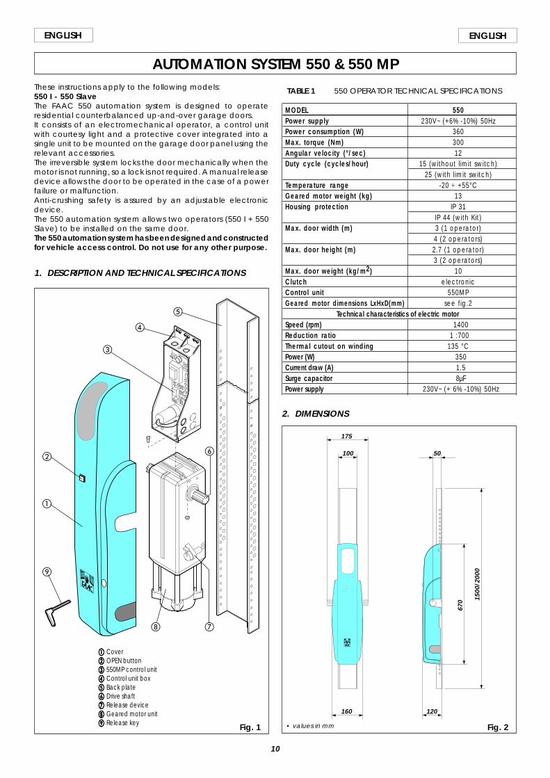
AUTOMATION SYSTEM 550 & 550 MPThese instructions apply to the following models:550 I - 550 SlaveThe FAAC 550 automation system is designed to operateresidential counterbalanced up-and-over garage doors.It consists of an electromechanical operator, a control unitwith courtesy light and a protective cover integrated into asingle unit to be mounted on the garage door panel using therelevant accessories.The irreversible system locks the door mechanically when themotor is not running, so a lock is not required. A manual releasedevice allows the door to be operated in the case of a powerfailure or malfunction.Anti-crushing safety is assured by an adjustable electronicdevice.The 550 automation system allows two operators (550 I + 550Slave) to be installed on the same door.The 550 automation system has been designed and constructedfor vehicle access control. Do not use for any other purpose.
1. DESCRIPTION AND TECHNICAL SPECIFICATIONS
Fig. 1
aaaaa Coverbbbbb OPEN buttonccccc 550MP control unitddddd Control unit boxeeeee Back platefffff Drive shaftggggg Release devicehhhhh Geared motor unitiiiii Release key
TABLE 1 550 OPERATOR TECHNICAL SPECIFICATIONS
MODEL 550Power supply 230V~ (+6% -10%) 50HzPower consumption (W) 360Max. torque (Nm) 300Angular velocity (°/sec) 12Duty cycle (cycles/hour) 15 (without l imit switch)
25 (with l imit switch)Temperature range -20 ÷ +55°CGeared motor weight (kg) 13Housing protection IP 31
IP 44 (with Kit)Max. door width (m) 3 (1 operator)
4 (2 operators)Max. door height (m) 2.7 (1 operator)
3 (2 operators)Max. door weight (kg/m2) 10Clutch electronicControl unit 550MPGeared motor dimensions LxHxD(mm) see fig.2
Technical characteristics of electric motorSpeed (rpm) 1400Reduction ratio 1 :700Thermal cutout on winding 135 °CPower (W) 350Current draw (A) 1.5Surge capacitor 8µFPower supply 230V~ (+ 6% -10%) 50Hz
2. DIMENSIONS
Fig. 2
175
100
160 120
5067
0 1500
/200
0
• values in mm
a
b
d
c
e
gh
i
f
11
ENGLISHENGLISH
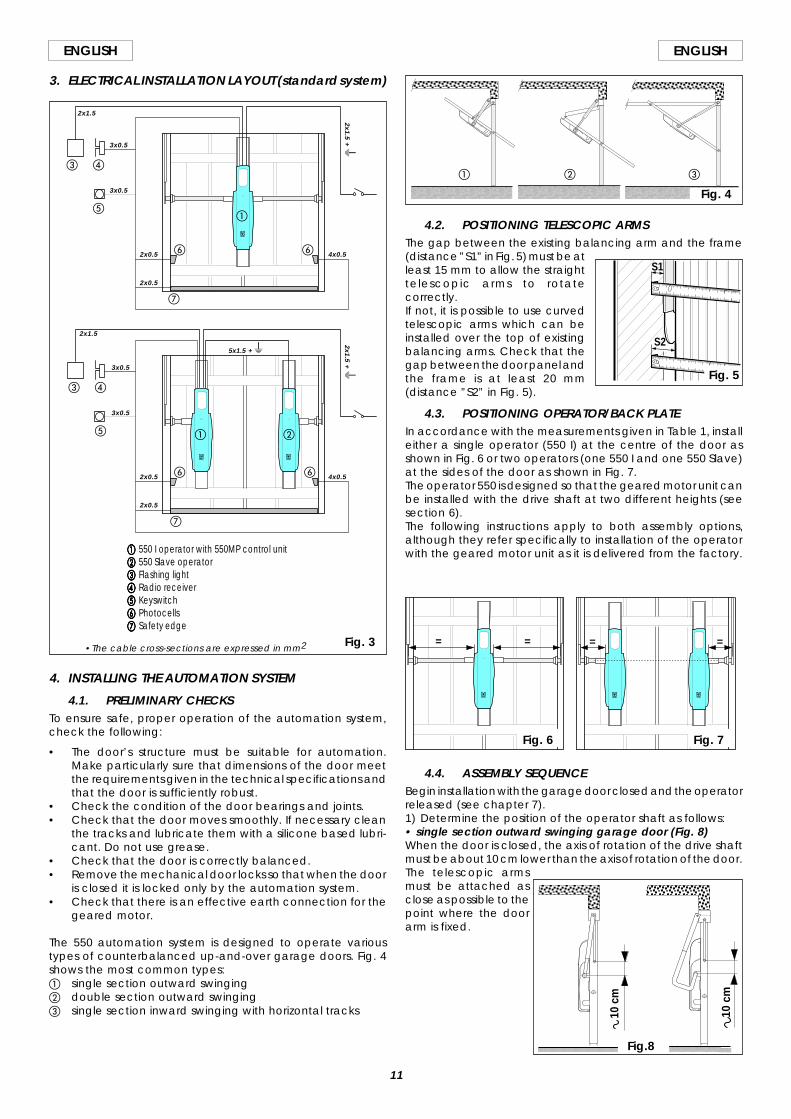
3. ELECTRICAL INSTALLATION LAYOUT (standard system)
aaaaa 550 I operator with 550MP control unitbbbbb 550 Slave operatorccccc Flashing lightddddd Radio receivereeeee Keyswitchfffff Photocellsggggg Safety edge
a b
c d
e
f
g
f
a
c d
e
f
g
f
4. INSTALLING THE AUTOMATION SYSTEM
4.1. PRELIMINARY CHECKSTo ensure safe, proper operation of the automation system,check the following:
• The door’s structure must be suitable for automation.Make particularly sure that dimensions of the door meetthe requirements given in the technical specifications andthat the door is sufficiently robust.
• Check the condition of the door bearings and joints.• Check that the door moves smoothly. If necessary clean
the tracks and lubricate them with a silicone based lubri-cant. Do not use grease.
• Check that the door is correctly balanced.• Remove the mechanical door locks so that when the door
is closed it is locked only by the automation system.• Check that there is an effective earth connection for the
geared motor.
The 550 automation system is designed to operate varioustypes of counterbalanced up-and-over garage doors. Fig. 4shows the most common types:a single section outward swingingb double section outward swingingc single section inward swinging with horizontal tracks
4.2. POSITIONING TELESCOPIC ARMSThe gap between the existing balancing arm and the frame(distance ”S1” in Fig. 5) must be atleast 15 mm to allow the straighttelescopic arms to rotatecorrectly.If not, it is possible to use curvedtelescopic arms which can beinstalled over the top of existingbalancing arms. Check that thegap between the door panel andthe frame is at least 20 mm(distance ”S2” in Fig. 5).
4.3. POSITIONING OPERATOR/BACK PLATEIn accordance with the measurements given in Table 1, installeither a single operator (550 I) at the centre of the door asshown in Fig. 6 or two operators (one 550 I and one 550 Slave)at the sides of the door as shown in Fig. 7.The operator 550 is designed so that the geared motor unit canbe installed with the drive shaft at two different heights (seesection 6).The following instructions apply to both assembly options,although they refer specifically to installation of the operatorwith the geared motor unit as it is delivered from the factory.
Fig. 3
4.4. ASSEMBLY SEQUENCEBegin installation with the garage door closed and the operatorreleased (see chapter 7).1) Determine the position of the operator shaft as follows:• single section outward swinging garage door (Fig. 8)When the door is closed, the axis of rotation of the drive shaftmust be about 10 cm lower than the axis of rotation of the door.The telescopic armsmust be attached asclose as possible to thepoint where the doorarm is fixed.
10 c
m
10 c
m
Fig.8
= = = =
Fig. 6 Fig. 7
a cb
Fig. 4
S1
S2
2x0.5 4x0.5
2x0.5
3x0.5
3x0.5
2x1.5
2x1.5 + W
5x1.5 + W
2x1.5
3x0.5
3x0.5
2x0.5
2x0.5
4x0.5
•The cable cross-sections are expressed in mm2
Fig. 5
2x1.5 + W
12
ENGLISH ENGLISH
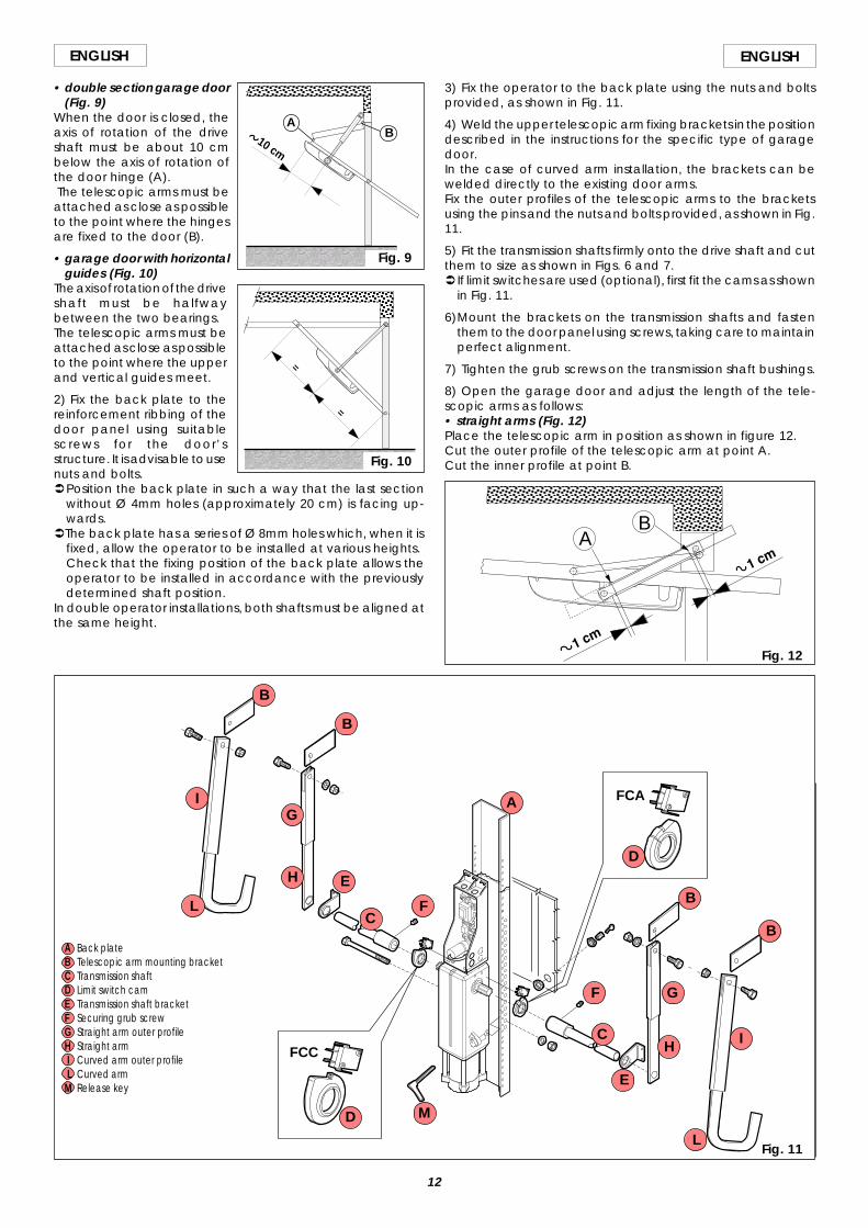
• double section garage door(Fig. 9)
When the door is closed, theaxis of rotation of the driveshaft must be about 10 cmbelow the axis of rotation ofthe door hinge (A). The telescopic arms must beattached as close as possibleto the point where the hingesare fixed to the door (B).
• garage door with horizontalguides (Fig. 10)
The axis of rotation of the driveshaft must be halfwaybetween the two bearings.The telescopic arms must beattached as close as possibleto the point where the upperand vertical guides meet.
2) Fix the back plate to thereinforcement ribbing of thedoor panel using suitablescrews for the door’sstructure. It is advisable to usenuts and bolts.ÜPosition the back plate in such a way that the last section
without Ø 4mm holes (approximately 20 cm) is facing up-wards.
ÜThe back plate has a series of Ø 8mm holes which, when it isfixed, allow the operator to be installed at various heights.Check that the fixing position of the back plate allows theoperator to be installed in accordance with the previouslydetermined shaft position.
In double operator installations, both shafts must be aligned atthe same height.
10 cm
Fig. 9
AB
=
=
Fig. 10
3) Fix the operator to the back plate using the nuts and boltsprovided, as shown in Fig. 11.
4) Weld the upper telescopic arm fixing brackets in the positiondescribed in the instructions for the specific type of garagedoor.In the case of curved arm installation, the brackets can bewelded directly to the existing door arms.Fix the outer profiles of the telescopic arms to the bracketsusing the pins and the nuts and bolts provided, as shown in Fig.11.
5) Fit the transmission shafts firmly onto the drive shaft and cutthem to size as shown in Figs. 6 and 7.Ü If limit switches are used (optional), first fit the cams as shown
in Fig. 11.
6)Mount the brackets on the transmission shafts and fastenthem to the door panel using screws, taking care to maintainperfect alignment.
7) Tighten the grub screws on the transmission shaft bushings.
8) Open the garage door and adjust the length of the tele-scopic arms as follows:• straight arms (Fig. 12)Place the telescopic arm in position as shown in figure 12.Cut the outer profile of the telescopic arm at point A.Cut the inner profile at point B.
Fig. 11
AB
Fig. 12
FCC
FCAA
B
B
B
BC
C
D
D
E
E
F
F
G
G
H
H
I
I
L
M
A Back plateB Telescopic arm mounting bracketC Transmission shaftD Limit switch camE Transmission shaft bracketF Securing grub screwG Straight arm outer profileH Straight arm I Curved arm outer profile L Curved armM Release key
L
13
ENGLISHENGLISH
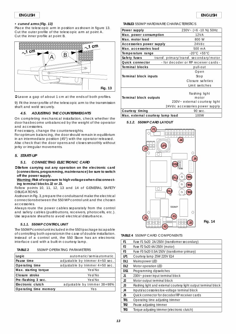
• curved arms (Fig. 13)Place the telescopic arm in position as shown in figure 13.Cut the outer profile of the telescopic arm at point A.Cut the inner profile at point B.
ÜLeave a gap of about 1 cm at the ends of both profiles.
9) Fit the inner profile of the telescopic arm to the transmissionshaft and weld securely.
4.5. ADJUSTING THE COUNTERWEIGHTSOn completing mechanical installation, check whether thedoor has become unbalanced by the weight of the operatorand accessories.If necessary, change the counterweights.For optimum balancing, the door should remain in equilibriumin an intermediate position (45°) with the operator released.Also check that the door opens and closes smoothly withoutjerky or irregular movements.
5. START-UP
5.1. CONNECTING ELECTRONIC CARDÜBefore carrying out any operation on the electronic card
(connections, programming, maintenance) be sure to switchoff the power supply.Warning: Risk of exposure to high voltages when disconnect-ing terminal blocks J2 or J3.
Follow points 10, 11, 12, 13 and 14 of GENERAL SAFETYOBLIGATIONS.As shown in Fig. 3, prepare the conduits and make the electricalconnections between the 550 MP control unit and the chosenaccessories.Always route the power cables separately from the controland safety cables (pushbuttons, receivers, photocells, etc.).Use separate sheaths to avoid electrical disturbance.
5.1.1. 550MP CONTROL UNITThe 550MP control unit included in the 550 I package is capableof controlling both operators in the case of double installation.Instead of a control unit, the 550 Slave has an electronicinterface card with a built-in courtesy lamp.
TABLE 2 550MP OPERATING PARAMETERS
Logic automatic/semiautomaticPause time adjustable by trimmer 4V50 sec.Operating time adjustable by trimmer 4V50 sec.Max. starting torque Yes/No
Closure stroke Yes/NoPre-flashing 3 sec. Yes/NoElectronic clutch adjustable by trimmer 38V98%Operating time memory Yes
TABLE 4 550MP CARD COMPONENTS
F1 Fuse F1 5x20 2A/250V (transformer secondary)F2 Fuse F2 5x20 4A/250V (motor)F3 Fuse F3 5x20 0.5A/250V (transformer primary)LP1 Courtesy lamp 25W 220V E14DL1 Mains power LEDDL2 Motor operation LEDDS1 Programming dipswitchesJ1 230V~ power input terminal blockJ2 Motor output terminal blockJ3 Flashing light and external courtesy light output terminal blockJ4 Inputs/accessories low-voltage terminal blockJ5 Quick connector for decoder/RP receiver cardsTR1 Operating time adjusting trimmerTR2 Pause adjusting trimmerTR3 Torque adjusting trimmer (electronic clutch)
TABLE3 550MP HARDWARE CHARACTERISTICS
Power supply 230V~ (+6 -10 %) 50HzMax. power consumption 12VAMax. motor load 800 WAccessories power supply 24VdcMax. accessories load 500 mATemperature range -20°C +55°CSafety fuses transf. primary/transf. secondary/motorQuick connector - for decoder or RP receiver cards -Terminal blocks pull-out
OpenTerminal block inputs Stop
Closure safetiesLimit switches
flashing lightTerminal block outputs motor
230V~ external courtesy light24Vdc accessories power supply
Courtesy timing 90 sec.Max. external courtesy lamp load 100W
5.1.2. 550MP CARD LAYOUT
A B
Fig. 13
ON
+
+
+
-
-
-
14
32
550MP
F1
J4
LP1J3
J5
DS1
DL1 TR1
TR2
TR3
J1
J2
F3
F2
DL2
Fig. 14
14
ENGLISH ENGLISH
5.1.3. ELECTRICAL CONNECTIONS
ON
+
+
+
-
-
-
14
32
1 32 4 5 6
7 8 9
10 11 12 13 14 15 16 17 18 19J4
J3
J1 J2
GROUND
N F CO
MO
PC
L
CO
MFL
ASH
EXT.L
AM
P
FCC
FCA
FSW
STO
P
OPE
N
M230V~
C8µF
5
43
2
1
1
2
(+6% -10%)
550 SLAVE
550 MP
M
C8µF
50Hz
CO
M
OP
CL
4 56
FAACLAMPMINILAMP
230V~max 25W
230V~max 25W
J5
TR1
TR2
TR3
DS1
DL1
DL2
GRO
UND
Fig. 15
5.2. DESCRIPTION
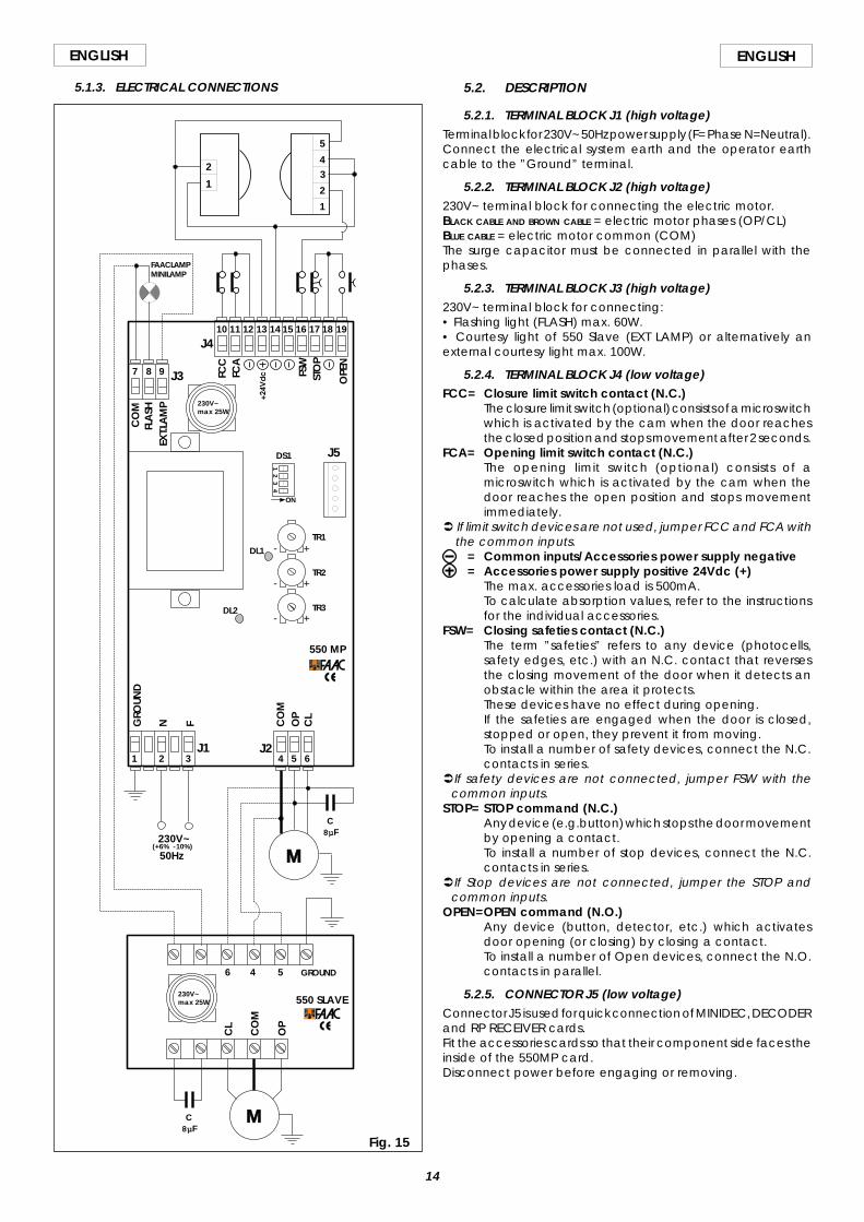
5.2.1. TERMINAL BLOCK J1 (high voltage)Terminal block for 230V~ 50Hz power supply (F= Phase N=Neutral).Connect the electrical system earth and the operator earthcable to the ”Ground” terminal.
5.2.2. TERMINAL BLOCK J2 (high voltage)230V~ terminal block for connecting the electric motor.BLACK CABLE AND BROWN CABLE = electric motor phases (OP/CL)BLUE CABLE = electric motor common (COM)The surge capacitor must be connected in parallel with thephases.
5.2.3. TERMINAL BLOCK J3 (high voltage)230V~ terminal block for connecting:• Flashing light (FLASH) max. 60W.• Courtesy light of 550 Slave (EXT LAMP) or alternatively anexternal courtesy light max. 100W.
5.2.4. TERMINAL BLOCK J4 (low voltage)FCC= Closure limit switch contact (N.C.)
The closure limit switch (optional) consists of a microswitchwhich is activated by the cam when the door reachesthe closed position and stops movement after 2 seconds.
FCA= Opening limit switch contact (N.C.)The opening limit switch (optional) consists of amicroswitch which is activated by the cam when thedoor reaches the open position and stops movementimmediately.
Ü If limit switch devices are not used, jumper FCC and FCA withthe common inputs.
= Common inputs/Accessories power supply negative= Accessories power supply positive 24Vdc (+)
The max. accessories load is 500mA.To calculate absorption values, refer to the instructionsfor the individual accessories.
FSW= Closing safeties contact (N.C.)The term ”safeties” refers to any device (photocells,safety edges, etc.) with an N.C. contact that reversesthe closing movement of the door when it detects anobstacle within the area it protects.These devices have no effect during opening.If the safeties are engaged when the door is closed,stopped or open, they prevent it from moving.To install a number of safety devices, connect the N.C.contacts in series.
ÜIf safety devices are not connected, jumper FSW with thecommon inputs.
STOP= STOP command (N.C.)Any device (e.g.button) which stops the door movementby opening a contact.To install a number of stop devices, connect the N.C.contacts in series.
ÜIf Stop devices are not connected, jumper the STOP andcommon inputs.
OPEN=OPEN command (N.O.)Any device (button, detector, etc.) which activatesdoor opening (or closing) by closing a contact.To install a number of Open devices, connect the N.O.contacts in parallel.
5.2.5. CONNECTOR J5 (low voltage)Connector J5 is used for quick connection of MINIDEC, DECODERand RP RECEIVER cards.Fit the accessories cards so that their component side faces theinside of the 550MP card.Disconnect power before engaging or removing.

15
ENGLISHENGLISH
5.3. PROGRAMMINGTo program operation of the automation, set the dipswitches asshown in the following diagram.Ü Disconnect the power supply momentarily from the card
after every programming operation.
SW1 - Max. starting torqueThe maximum starting torque allows the electronic clutch setting(Trimmer TR3) to be disabled in the initial movement phase.SW2 - Operating logicThe operation of the automation in the various logics is shown inTables 5-6.SW3 - Closure strokeThe closure stroke is enabled only if the limit switches are used.It delays cut-out of the motor by 4 seconds after activation ofthe closing limit switch.SW4 - Pre-flashingIt is possible to select 3 sec. pre-flashing of the flashing light priorto every movement. This warns anyone in the vicinity of the doorthat it is about to move.
Logic SW2
Automatic ON
Semiautomatic OFF
Max. startingtorque SW1
Yes ON
No OFF
Closure stroke SW3
Yes ON
No OFF
Pre-flashing SW4
Yes ON
No OFF
12
34
ON
OFF
TABLE 6 SEMIAUTOMATIC LOGIC
SAFETIESno effect
(prevents opening)prevents closure
reverses movementno effectno effect
(prevents op/cl)
DOOR STATUSCLOSED
OPEN
CLOSINGOPENINGSTOPPED
OPENopens (1)
closes (1)
reverses movementstops
closes/opens (1)(2)
STOPno effect
no effect
stopsstops
no effect
PULSES
PULSES
SAFETIESno effect
(prevents opening)freezes pause untildisengagement
reverses movementno effectno effect
(prevents op/cl)
STOPnbo effect
stops counting of pausetimestopsstops
no effect
DOOR STATUSCLOSED
OPEN ON PAUSE
CLOSINGOPENINGSTOPPED
OPENopens the door and recloses
after pause time (1)closes (1)
reverses movementstops
closes/opens (1)(2)
TABLE 5 AUTOMATIC LOGIC
(1) with pre-flashing selected, the movement begins after 3 sec.(2) giving an OPEN signal with the door stopped starts the opposite movement to theprevious one.
5.4. TESTING THE AUTOMATION SYSTEMNotes on operation:•The 550MP card performs an electronic check (for which themotor must be connected) prior to every start-up. If any attemptis made to operate the card without the motor load or with aninsufficient load, voltage is not supplied to the motor output andLED DL2 flashes to signal the fault.•There must be a delay of at least 1.5 seconds between oneOPEN signal and the next.•The courtesy light comes on when the motor starts and stays onfor about 90 seconds after the end of the movement.
5.4.1. CHECKING DIRECTION OF ROTATION1) Turn off the power supply to the system.2) Move the door manually to its half open position.3) Lock the operator (see chapter 8)4) Turn the power supply back on.5) Send an open signal (OPEN) and check that this causes thedoor to open.If the door closes, invert the electric motor phase wires on thecard terminal block (brown and black wires).In the double operator installation, connect the same colourwires to the COM, OP and CL terminals on the 550MP card andthe 550 Slave card. If you have to invert the wires, invert them onboth motors.
5.4.2. SETTING THE OPERATING TIMESet trimmer TR1 to obtain an operating time such that theelectric motor remains powered up for a few seconds after thedoor has reached the mechanical stops.This setting also represents the maximum time for reaching thelimit switches (optional).
5.4.3. SETTING PAUSE TIMEBy selecting automatic logic it is possible to set the pause timeby means of the trimmer TR2.
5.4.4 SETTING ELECTRONIC CLUTCH (ANTI-CRUSHING SAFETYSYSTEM)
The 550MP control unit is equipped with an electronic system forregulating the motor torque which limits the thrust of the doorwhen obstructed by an obstacle (depending on the setting).When the obstacle is removed, the door continues its movementuntil it reaches the limit switch or until the end of the operatingtime.The setting is made by means of trimmer TR3.Make sure that the electronic clutch is calibrated in accordancewith current applicable legislation.
5.4.5. ADJUSTMENT OF LIMIT SWITCHES (OPTIONAL)Open the door as far as required, then turn the cam until it justtrips microswitch FCA (Fig.11).Close the door, then turn the cam until it just trips microswitchFCC (Fig.11).Tighten the screws on the cams.
5.4.6. MOUNTING COVERConnect the OPEN cable to the button on the operator cover.Fasten the cover in place by tightening the four screws at thesides.Push the 2 plastic caps onto the side slots on the cover not usedby the operator shaft.Push the plastic cap onto the unused front slot on the cover forgaining access to the release system.
6. MOUNTING GEARED MOTOR UNITDepending on requirements, the geared motor unit can bemounted in two different ways:•With the drive shaft at the top (Fig. 17)
The card support is fixed to the geared motor by means of 4bolts which engage with nuts inserted in the guides.
•With the drive shaft at the bottom (Fig. 18)The card support is fixed to the electric motor cap by meansof 4 screws.
DS1
+-Fig. 16
Turning the trimmer clockwise increases the setvalues.Turning the trimmer anticlockwise reduces theset values.
16
ENGLISH ENGLISH
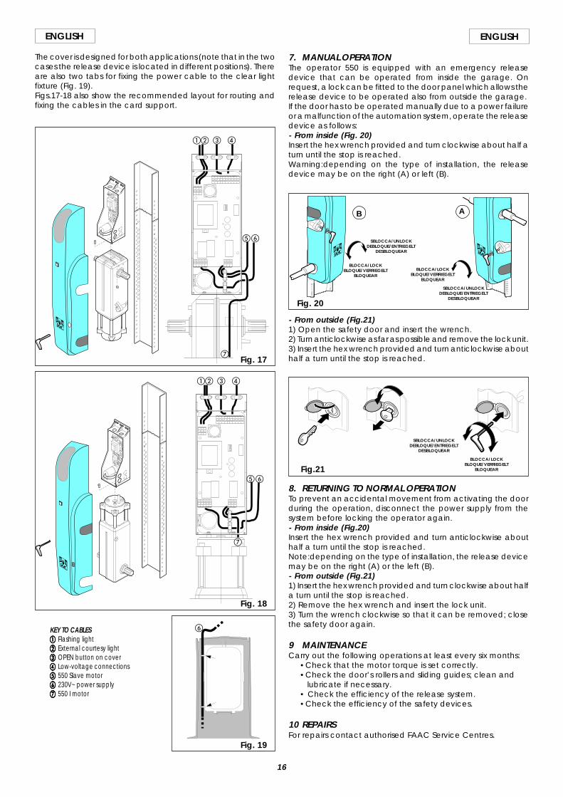
The cover is designed for both applications (note that in the twocases the release device is located in different positions). Thereare also two tabs for fixing the power cable to the clear lightfixture (Fig. 19).Figs.17-18 also show the recommended layout for routing andfixing the cables in the card support.
KEY TO CABLESaaaaa Flashing lightbbbbb External courtesy lightccccc OPEN button on coverddddd Low-voltage connectionseeeee 550 Slave motorfffff 230V~ power supplyggggg 550 I motor
ab c d
ef
ab c d
ef
g
Fig. 18
Fig. 19
g
Fig. 17
- From outside (Fig.21)1) Open the safety door and insert the wrench.2) Turn anticlockwise as far as possible and remove the lock unit.3) Insert the hex wrench provided and turn anticlockwise abouthalf a turn until the stop is reached.
Fig.21
SBLOCCA/UNLOCKDEBLOQUE/ENTRIEGELT
DESBLOQUEAR
BLOCCA/LOCKBLOQUE/VERRIEGELT
BLOQUEAR
8. RETURNING TO NORMAL OPERATIONTo prevent an accidental movement from activating the doorduring the operation, disconnect the power supply from thesystem before locking the operator again.- From inside (Fig.20)Insert the hex wrench provided and turn anticlockwise abouthalf a turn until the stop is reached.Note:depending on the type of installation, the release devicemay be on the right (A) or the left (B).- From outside (Fig.21)1) Insert the hex wrench provided and turn clockwise about halfa turn until the stop is reached.2) Remove the hex wrench and insert the lock unit.3) Turn the wrench clockwise so that it can be removed; closethe safety door again.
9 MAINTENANCECarry out the following operations at least every six months:
•Check that the motor torque is set correctly.•Check the door’s rollers and sliding guides; clean and lubricate if necessary.• Check the efficiency of the release system.•Check the efficiency of the safety devices.
10 REPAIRSFor repairs contact authorised FAAC Service Centres.
Fig. 20
BLOCCA/LOCKBLOQUE/VERRIEGELT
BLOQUEAR
SBLOCCA/UNLOCKDEBLOQUE/ENTRIEGELT
DESBLOQUEAR
SBLOCCA/UNLOCKDEBLOQUE/ENTRIEGELT
DESBLOQUEAR
BLOCCA/LOCKBLOQUE/VERRIEGELT
BLOQUEAR
AB
7. MANUAL OPERATIONThe operator 550 is equipped with an emergency releasedevice that can be operated from inside the garage. Onrequest, a lock can be fitted to the door panel which allows therelease device to be operated also from outside the garage.If the door has to be operated manually due to a power failureor a malfunction of the automation system, operate the releasedevice as follows:- From inside (Fig. 20)Insert the hex wrench provided and turn clockwise about half aturn until the stop is reached.Warning:depending on the type of installation, the releasedevice may be on the right (A) or left (B).
f
17
ENGLISHENGLISH
User’s guide
550 AUTOMATION SYSTEMRead the instructions carefully before using the product andkeep for future reference.
GENERAL SAFETY RULESIf correctly installed and operated, the 550 automation systemsensure a high level of safety.However, some simple rules should be followed to avoidaccidents:- Do not stand underneath the garage door.- Do not stand in the vicinity of the automation or allow anyone
else, especially children, to do so and do not place objects inthe vicinity of the automation. This is particularly importantduring operation.
- Keep remote controls and other control devices out of thereach of children to prevent them from accidentally operatingthe door.
- Do not allow children to play with the automation.- Do not deliberately obstruct the movement of the door.- Make sure that branches or bushes do not interfere with the
movement of the door.- Keep the luminous signalling systems efficient and clearly visible.- Do not attempt to operate the door manually without first
releasing it.- In the event of a malfunction, release the gate to allow access
and call a qualified technician for service.- After setting manual operation, disconnect the electricity supply
from the system before returning to normal operation.- Do not make any modifications to components belonging to
the automation system.- Do not attempt to perform any repair work or tamper with the
automation. Call FAAC qualified personnel for repairs.- At least once every six months have the automation, the safety
devices and the earth connection checked by a qualifiedtechnician.
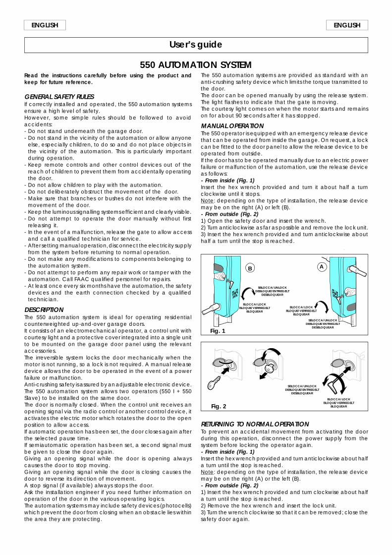
DESCRIPTIONThe 550 automation system is ideal for operating residentialcounterweighted up-and-over garage doors.It consists of an electromechanical operator, a control unit withcourtesy light and a protective cover integrated into a single unitto be mounted on the garage door panel using the relevantaccessories.The irreversible system locks the door mechanically when themotor is not running, so a lock is not required. A manual releasedevice allows the door to be operated in the event of a powerfailure or malfunction.Anti-crushing safety is assured by an adjustable electronic device.The 550 automation system allows two operators (550 I + 550Slave) to be installed on the same door.The door is normally closed. When the control unit receives anopening signal via the radio control or another control device, itactivates the electric motor which rotates the door to the openposition to allow access.If automatic operation has been set, the door closes again afterthe selected pause time.If semiautomatic operation has been set, a second signal mustbe given to close the door again.Giving an opening signal while the door is opening alwayscauses the door to stop moving.Giving an opening signal while the door is closing causes thedoor to reverse its direction of movement.A stop signal (if available) always stops the door.Ask the installation engineer if you need further information onoperation of the door in the various operating logics.The automation systems may include safety devices (photocells)which prevent the door from closing when an obstacle lies withinthe area they are protecting.
Fig. 2
SBLOCCA/UNLOCKDEBLOQUE/ENTRIEGELT
DESBLOQUEAR
BLOCCA/LOCKBLOQUE/VERRIEGELT
BLOQUEAR
RETURNING TO NORMAL OPERATIONTo prevent an accidental movement from activating the doorduring this operation, disconnect the power supply from thesystem before locking the operator again.- From inside (Fig. 1)Insert the hex wrench provided and turn anticlockwise about halfa turn until the stop is reached.Note: depending on the type of installation, the release devicemay be on the right (A) or the left (B).- From outside (Fig. 2)1) Insert the hex wrench provided and turn clockwise about halfa turn until the stop is reached.2) Remove the hex wrench and insert the lock unit.3) Turn the wrench clockwise so that it can be removed; close thesafety door again.
Fig. 1
BLOCCA/LOCKBLOQUE/VERRIEGELT
BLOQUEAR
SBLOCCA/UNLOCKDEBLOQUE/ENTRIEGELT
DESBLOQUEAR
SBLOCCA/UNLOCKDEBLOQUE/ENTRIEGELT
DESBLOQUEAR
BLOCCA/LOCKBLOQUE/VERRIEGELT
BLOQUEAR
AB
The 550 automation systems are provided as standard with ananti-crushing safety device which limits the torque transmitted tothe door.The door can be opened manually by using the release system.The light flashes to indicate that the gate is moving.The courtesy light comes on when the motor starts and remainson for about 90 seconds after it has stopped.
MANUAL OPERATIONThe 550 operator is equipped with an emergency release devicethat can be operated from inside the garage. On request, a lockcan be fitted to the door panel to allow the release device to beoperated from outside.If the door has to be operated manually due to an electric powerfailure or malfunction of the automation, use the release deviceas follows:- From inside (Fig. 1)Insert the hex wrench provided and turn it about half a turnclockwise until it stops.Note: depending on the type of installation, the release devicemay be on the right (A) or left (B).- From outside (Fig. 2)1) Open the safety door and insert the wrench.2) Turn anticlockwise as far as possible and remove the lock unit.3) Insert the hex wrench provided and turn anticlockwise abouthalf a turn until the stop is reached.
17
FRANÇAISFRANÇAIS
1) ATTENTION! Il est très important pour la sécurité des personnes de liretoute la notice d’instructions. Une mauvaise installation et/ou utilisa-tion du produit peut faire courir de graves risques aux personnes.
2) Lire attentivement les instructions avant de commencer le montagede l’automatisme.
3) Tenir à l’écart des enfants tous les matériaux d’emballage (plastique,polystyrène, etc.), car ils constituent une source de risque potentiel.
4) Toujours conserver en un lieu sûr les instructions pour toute consultationfuture.
5) Cet automatisme a été conçu exclusivement pour l’utilisation indi-quée sur la présente notice. Toute autre utilisation pourrait compro-mettre l’efficacité de l’automatisme et/ou représenter une source dedanger.
6) FAAC décline toute responsabilité en cas d’utilisation impropre ouautre que celle pour laquelle l’automatisme est destiné.
7) Ne pas utiliser l’automatisme en atmosphère explosive: la présence degaz ou de fumées inflammables représente un grave risque pour lasécurité.
8) Les parties, ou éléments, mécaniques de construction de l’automa-tisme doivent satisfaire les exigences essentielles des normes UNI8612,CEN pr EN 12604 et CEN pr EN 12605.
Dans les pays ne faisant pas partie de la CEE, outre le respect à lalégislation nationale, l’installateur doit se conformer aux normes ci-dessus pour garantir un niveau de sécurité adéquat.
9) FAAC ne saurait être tenu pour responsable de l’inobservation desrègles de l’art dans la construction des fermetures à motoriser ni deleurs détériorations pendant leur durée de fonctionnement.
10) L’installation doit être réalisée conformément aux normes UNI8612,CEN pr EN 12453 et CEN pr EN 12635.Le niveau de sécurité de l’automatisme doit être C+D.
11) Avant toute intervention sur l’installation, couper l’alimentation enénergie électrique.
12) Prévoir sur le réseau d’alimentation de l’automatisme un interrupteuromnipolaire avec distance d’ouverture des contacts égale ou supé-rieure à 3 mm. Il est recommandé l’emploi d’un interrupteur magnéto-thermique de 6 A avec coupure omnipolaire.
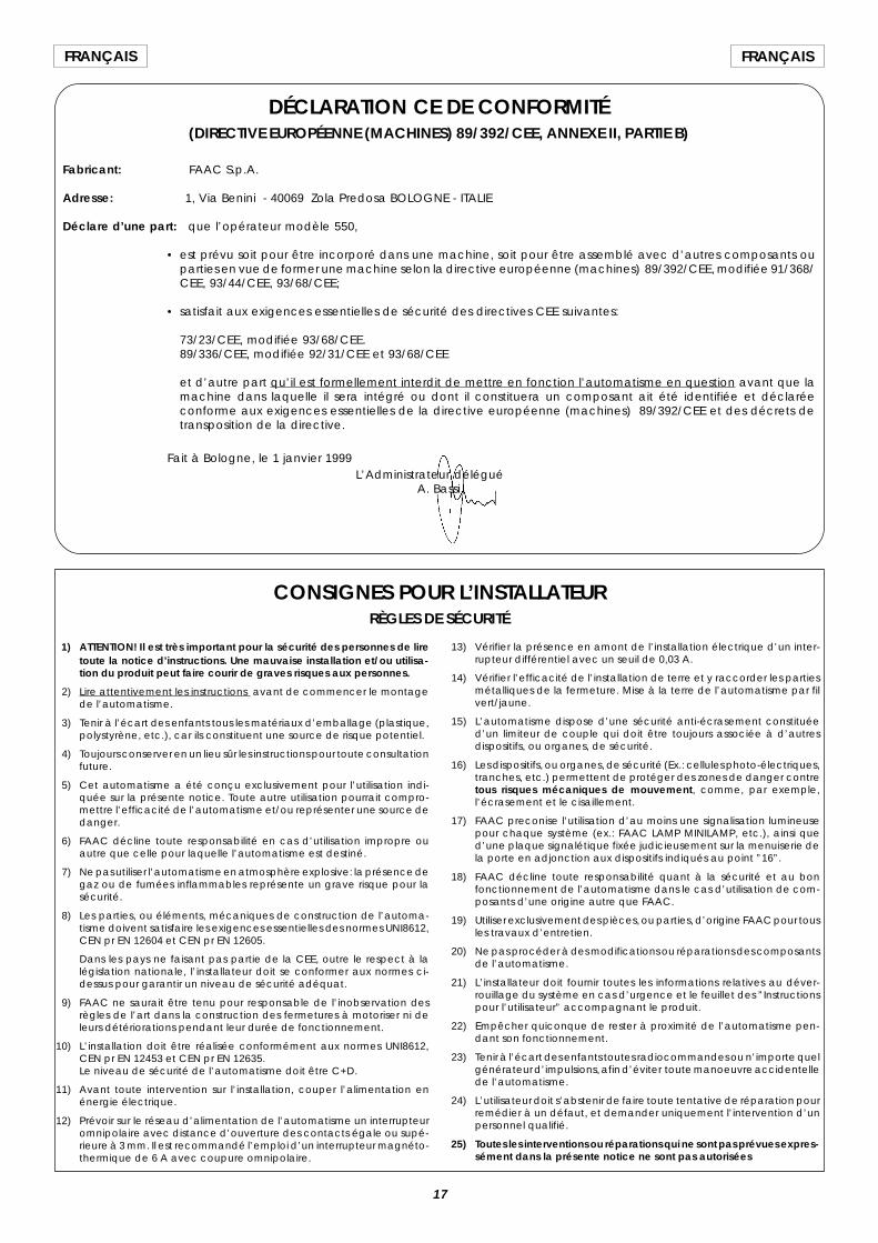
DÉCLARATION CE DE CONFORMITÉ(DIRECTIVE EUROPÉENNE (MACHINES) 89/392/CEE, ANNEXE II, PARTIE B)
Fabricant: FAAC S.p.A.
Adresse: 1, Via Benini - 40069 Zola Predosa BOLOGNE - ITALIE
Déclare d’une part: que l’opérateur modèle 550,
• est prévu soit pour être incorporé dans une machine, soit pour être assemblé avec d’autres composants ouparties en vue de former une machine selon la directive européenne (machines) 89/392/CEE, modifiée 91/368/CEE, 93/44/CEE, 93/68/CEE;
• satisfait aux exigences essentielles de sécurité des directives CEE suivantes:
73/23/CEE, modifiée 93/68/CEE.89/336/CEE, modifiée 92/31/CEE et 93/68/CEE
et d’autre part qu’il est formellement interdit de mettre en fonction l’automatisme en question avant que lamachine dans laquelle il sera intégré ou dont il constituera un composant ait été identifiée et déclaréeconforme aux exigences essentielles de la directive européenne (machines) 89/392/CEE et des décrets detransposition de la directive.
Fait à Bologne, le 1 janvier 1999L’Administrateur délégué
A. Bassi
13) Vérifier la présence en amont de l’installation électrique d’un inter-rupteur différentiel avec un seuil de 0,03 A.
14) Vérifier l’efficacité de l’installation de terre et y raccorder les partiesmétalliques de la fermeture. Mise à la terre de l’automatisme par filvert/jaune.
15) L’automatisme dispose d’une sécurité anti-écrasement constituéed’un limiteur de couple qui doit être toujours associée à d’autresdispositifs, ou organes, de sécurité.
16) Les dispositifs, ou organes, de sécurité (Ex.: cellules photo-électriques,tranches, etc.) permettent de protéger des zones de danger contretous risques mécaniques de mouvement, comme, par exemple,l’écrasement et le cisaillement.
17) FAAC preconise l’utilisation d’au moins une signalisation lumineusepour chaque système (ex.: FAAC LAMP MINILAMP, etc.), ainsi qued’une plaque signalétique fixée judicieusement sur la menuiserie dela porte en adjonction aux dispositifs indiqués au point ”16”.
18) FAAC décline toute responsabilité quant à la sécurité et au bonfonctionnement de l’automatisme dans le cas d’utilisation de com-posants d’une origine autre que FAAC.
19) Utiliser exclusivement des pièces, ou parties, d’origine FAAC pour tousles travaux d’entretien.
20) Ne pas procéder à des modifications ou réparations des composantsde l’automatisme.
21) L’installateur doit fournir toutes les informations relatives au déver-rouillage du système en cas d’urgence et le feuillet des ”Instructionspour l’utilisateur” accompagnant le produit.
22) Empêcher quiconque de rester à proximité de l’automatisme pen-dant son fonctionnement.
23) Tenir à l’écart des enfants toutes radiocommandes ou n’importe quelgénérateur d’impulsions, afin d’éviter toute manoeuvre accidentellede l’automatisme.
24) L’utilisateur doit s’abstenir de faire toute tentative de réparation pourremédier à un défaut, et demander uniquement l’intervention d’unpersonnel qualifié.
25) Toutes les interventions ou réparations qui ne sont pas prévues expres-sément dans la présente notice ne sont pas autorisées
CONSIGNES POUR L’INSTALLATEURRÈGLES DE SÉCURITÉ
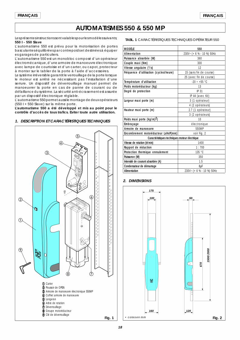
18
FRANÇAIS FRANÇAIS
AUTOMATISMES 550 & 550 MPLes présentes instructions sont valables pour les modèles suivants;550 I - 550 SlaveL’automatisme 550 est prévu pour la motorisation de portesbasculantes équilibrées par contrepoids et destinées à équiperes garages de particuliers.L’automatisme 550 est un monobloc composé d’un opérateurélectromécanique, d’une armoire de manoeuvre électroniqueavec lampe de courtoisie et d’un carter, ou capot, protecteurà monter sur le tablier de la porte à l’aide d’accessoires.Le système irréversible garantit le verrouillage de la porte lorsquele moteur est arrêté ne nécessitant pas l’installation d’uneserrure. Un dispositif de déverrouillage manuel permet demanoeuvrer la porte en cas de panne de courant ou dedéfaillance du système. La sécurité anti-écrasement est assuréepar un dispositif électronique réglable.L’automatisme 550 permet aussi le montage de deux opérateurs(550 I + 550 Slave) sur la même porte.L’automatisme 550 a été développé et mis au point pour lecontrôle d’accès de tous trafics. Eviter toute autre utilisation.
1. DESCRIPTION ET CARACTÉRISTIQUES TECHNIQUES
Fig. 1
aaaaa Carterbbbbb Poussoir de OPENccccc Armoire de manoeuvre électronique 550MPddddd Coffret armoire de manoeuvreeeeee Longeronfffff Arbre de rotationggggg Déverrouillagehhhhh Groupe motoréducteuriiiii Clé de déverrouillage
TABL. 1 CARACTÉRISTIQUES TECHNIQUES OPÉRATEUR 550
MODÈLE 550Al imentat ion 230V~ (+ 6 % - 10 %) 50HzPuissance absorbée (W) 360Couple maxi (Nm) 300Vitesse angulaire (°/s) 12Fréquence d’uti l isation (cycles/heure) 15 (sans f in de course)
25 (avec f in de course)Température d’uti l isation -20 ÷ +55 °CPoids motoréducteur (kg) 13Degré de protection IP 31
IP 44 (avec Kit)Largeur maxi porte (m) 3 (1 opérateur)
4 (2 opérateurs)Hauteur maxi porte (m) 2.7 (1 opérateur)
3 (2 opérateurs)Poids maxi porte (kg/m)2) 10Embrayage électroniqueArmoire de manoeuvre 550MPEncombrement motoréducteur LxHxP(mm) voir F ig. 2
Caractéristiques techniques moteur électriqueVitesse de rotation (tr/min) 1400Rapport de réduction 1 : 700Protection thermique enroulement 135 °CPuissance (W) 350Intensité de courant absorbée (A) 1.5Condensateur de démarrage 8µFAlimentation 230V~ (+ 6 % - 10 %) 50Hz
2. DIMENSI0NS
Fig. 2
175
100
160 120
5067
0 1500
/200
0
• cotes en mm
a
b
d
c
e
gh
i
f
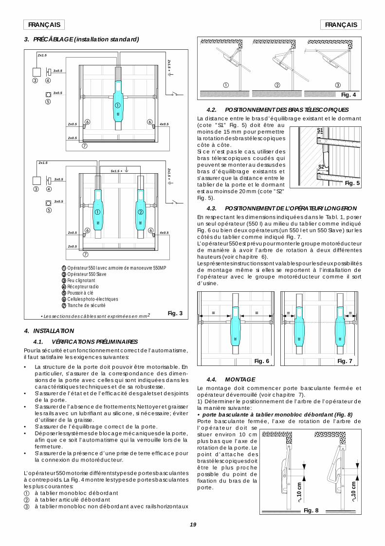
19
FRANÇAISFRANÇAIS
3. PRÉCÂBLAGE (installation standard)
aaaaa Opérateur 550 I avec armoire de manoeuvre 550MPbbbbb Opérateur 550 Slaveccccc Feu clignotantddddd Récepteur radioeeeee Poussoir à cléfffff Cellules photo-électriquesggggg Tranche de sécurité
a b
c d
e
f
g
f
a
c d
e
f
g
f
4. INSTALLATION
4.1. VÉRIFICATIONS PRÉLIMINAIRESPour la sécurité et un fonctionnement correct de l’automatisme,il faut satisfaire les exigences suivantes:
• La structure de la porte doit pouvoir être motorisable. Enparticulier, s’assurer de la correspondance des dimen-sions de la porte avec celles qui sont indiquées dans lescaractéristiques techniques et de sa robustesse.
• S’assurer de l’état et de l’efficacité des galets et des jointsde la porte.
• S’assurer de l’absence de frottements; Nettoyer et graisserles rails avec un lubrifiant au silicone, si nécessaire; éviterd’utiliser de la graisse.
• S’assurer de l’équilibrage correct de la porte.• Déposer les systèmes de blocage mécaniques de la porte,
afin que ce soit l’automatisme qui la verrouille lors de lafermeture.
• S’assurer de la présence d’une prise de terre efficace pourla connexion du motoréducteur.
L’opérateur 550 motorise différents types de portes basculantesà contrepoids. La Fig. 4 montre les types de portes basculantesles plus courantes:a à tablier monobloc débordantb à tablier articulé débordantc à tablier monobloc non débordant avec rails horizontaux
4.2. POSITIONNEMENT DES BRAS TÉLESCOPIQUESLa distance entre le bras d’équilibrage existant et le dormant(cote ”S1” Fig. 5) doit être aumoins de 15 mm pour permettrela rotation des bras télescopiquescôte à côte.Si ce n’est pas le cas, utiliser desbras télescopiques coudés quipeuvent se monter au dessus desbras d’équilibrage existants ets’assurer que la distance entre letablier de la porte et le dormantest au moins de 20 mm (cote ”S2”Fig. 5).
4.3. POSITIONNEMENT DE L’OPÉRATEUR/LONGERONEn respectant les dimensions indiquées dans le Tabl. 1, poserun seul opérateur (550 I) au milieu du tablier comme indiquéFig. 6 ou bien deux opérateurs (un 550 I et un 550 Slave) sur lescôtés du tablier comme indiqué Fig. 7.L’opérateur 550 est prévu pour monter le groupe motoréducteurde manière à avoir l’arbre de rotation à deux différenteshauteurs (voir chapitre 6).Les présentes instructions sont valables pour les deux possibilitésde montage même si elles se reportent à l’installation del’opérateur avec le groupe motoréducteur comme il sortd’usine.
Fig. 3
4.4. MONTAGELe montage doit commencer porte basculante fermée etopérateur déverrouillé (voir chapitre 7).1) Déterminer le positionnement de l’arbre de l’opérateur dela manière suivante:• porte basculante à tablier monobloc débordant (Fig. 8)Porte basculante fermée, l’axe de rotation de l’arbre del’opérateur doit sesituer environ 10 cmplus bas que l’axe derotation de la porte. Lepoint d’attache desbras télescopiques doitêtre le plus prochepossible du point defixation du bras de laporte.
10 c
m
10 c
m
Fig. 8
= = = =
Fig. 6 Fig. 7
a cb
Fig. 4
S1
S2
2x0.5 4x0.5
2x0.5
3x0.5
3x0.5
2x1.5
2x1.5 + W
5x1.5 + W
2x1.5
3x0.5
3x0.5
2x0.5
2x0.5
4x0.5
•Les sections des câbles sont exprimées en mm2
Fig. 5
2x1.5 + W
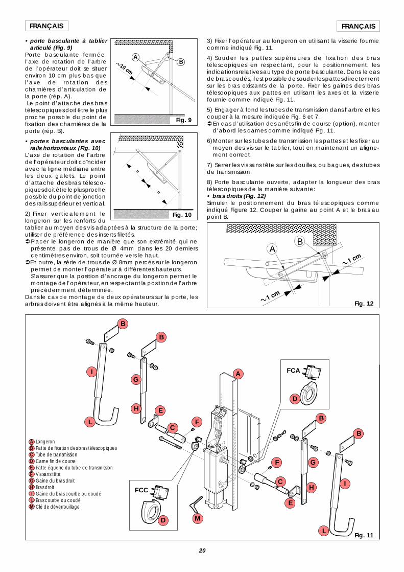
20
FRANÇAIS FRANÇAIS
• porte basculante à tablierarticulé (Fig. 9)
Porte basculante fermée,l’axe de rotation de l’arbrede l’opérateur doit se situerenviron 10 cm plus bas quel’axe de rotation descharnières d’articulation dela porte (rép. A). Le point d’attache des brastélescopiques doit être le plusproche possible du point defixation des charnières de laporte (rép. B).
• portes basculantes avecrails horizontaux (Fig. 10)
L’axe de rotation de l’arbrede l’opérateur doit coïncideravec la ligne médiane entreles deux galets. Le pointd’attache des bras télesco-piques doit être le plus prochepossible du point de jonctiondes rails supérieur et vertical.
2) Fixer verticalement lelongeron sur les renforts dutablier au moyen des vis adaptées à la structure de la porte;utiliser de préférence des inserts filetés.ÜPlacer le longeron de manière que son extrémité qui ne
présente pas de trous de Ø 4mm dans les 20 dernierscentimètres environ, soit tournée vers le haut.
ÜEn outre, la série de trous de Ø 8mm percés sur le longeronpermet de monter l’opérateur à différentes hauteurs.S’assurer que la position d’ancrage du longeron permet lemontage de l’opérateur, en respectant la position de l’arbreprécédemment déterminée.
Dans le cas de montage de deux opérateurs sur la porte, lesarbres doivent être alignés à la même hauteur.
10 cm
Fig. 9
AB
=
=
Fig. 10
3) Fixer l’opérateur au longeron en utilisant la visserie fourniecomme indiqué Fig. 11.
4) Souder les pattes supérieures de fixation des brastélescopiques en respectant, pour le positionnement, lesindications relatives au type de porte basculante. Dans le casde bras coudés, il est possible de souder les pattes directementsur les bras existants de la porte. Fixer les gaines des brastélescopiques aux pattes en utilisant les axes et la visseriefournie comme indiqué Fig. 11.
5) Engager à fond les tubes de transmission dans l’arbre et lescouper à la mesure indiquée Fig. 6 et 7.ÜEn cas d’utilisation des arrêts fin de course (option), monter
d’abord les cames comme indiqué Fig. 11.
6)Monter sur les tubes de transmission les pattes et les fixer aumoyen des vis sur le tablier, tout en maintenant un aligne-ment correct.
7) Serrer les vis sans tête sur les douilles, ou bagues, des tubesde transmission.
8) Porte basculante ouverte, adapter la longueur des brastélescopiques de la manière suivante:• bras droits (Fig. 12)Simuler le positionnement du bras télescopiques commeindiqué Figure 12. Couper la gaine au point A et le bras aupoint B.
Fig. 11
AB
Fig. 12
FCC
FCAA
B
B
B
BC
C
D
D
E
E
F
F
G
G
H
H
I
I
L
M
A LongeronB Patte de fixation des bras télescopiquesC Tube de transmissionD Came fin de courseE Patte équerre du tube de transmissionF Vis sans têteG Gaine du bras droitH Bras droit I Gaine du bras courbe ou coudé L Bras courbe ou coudéM Clé de déverrouillage
L
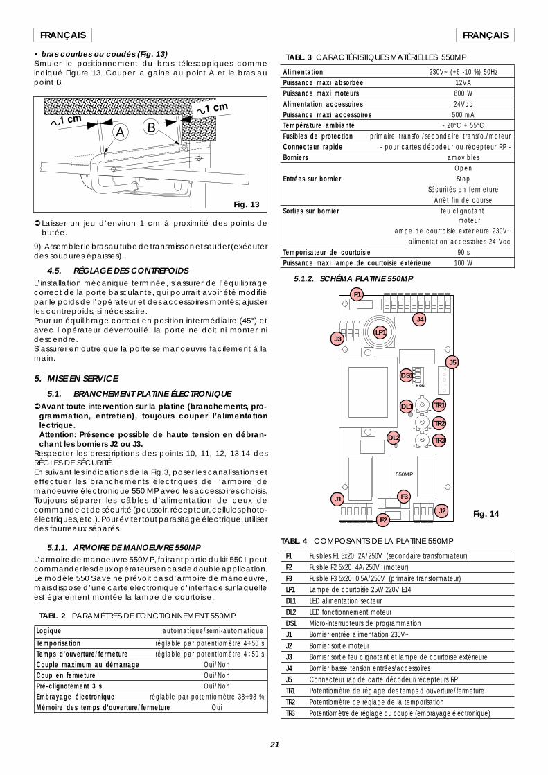
21
FRANÇAISFRANÇAIS
• bras courbes ou coudés (Fig. 13)Simuler le positionnement du bras télescopiques commeindiqué Figure 13. Couper la gaine au point A et le bras aupoint B.
ÜLaisser un jeu d’environ 1 cm à proximité des points debutée.
9) Assembler le bras au tube de transmission et souder (exécuterdes soudures épaisses).
4.5. RÉGLAGE DES CONTREPOIDSL’installation mécanique terminée, s’assurer de l’équilibragecorrect de la porte basculante, qui pourrait avoir été modifiépar le poids de l’opérateur et des accessoires montés; ajusterles contrepoids, si nécessaire.Pour un équilibrage correct en position intermédiaire (45°) etavec l’opérateur déverrouillé, la porte ne doit ni monter nidescendre.S’assurer en outre que la porte se manoeuvre facilement à lamain.
5. MISE EN SERVICE
5.1. BRANCHEMENT PLATINE ÉLECTRONIQUEÜAvant toute intervention sur la platine (branchements, pro-
grammation, entretien), toujours couper l’alimentationlectrique.Attention: Présence possible de haute tension en débran-chant les borniers J2 ou J3.
Respecter les prescriptions des points 10, 11, 12, 13,14 desRÈGLES DE SÉCURITÉ.En suivant les indications de la Fig.3, poser les canalisations eteffectuer les branchements électriques de l’armoire demanoeuvre électronique 550 MP avec les accessoires choisis.Toujours séparer les câbles d’alimentation de ceux decommande et de sécurité (poussoir, récepteur, cellules photo-électriques, etc.). Pour éviter tout parasitage électrique, utiliserdes fourreaux séparés.
5.1.1. ARMOIRE DE MANOEUVRE 550MPL’armoire de manoeuvre 550MP, faisant partie du kit 550 I, peutcommander les deux opérateurs en cas de double application.Le modèle 550 Slave ne prévoit pas d’armoire de manoeuvre,mais dispose d’une carte électronique d’interface sur laquelleest également montée la lampe de courtoisie.
TABL. 2 PARAMÈTRES DE FONCTIONNEMENT 550MP
Logique automatique/semi-automatique
Temporisat ion réglable par potentiomètre 4V50 sTemps d’ouverture/fermeture réglable par potentiomètre 4V50 sCouple maximum au démarrage Oui/NonCoup en fermeture Oui/NonPré-clignotement 3 s Oui/NonEmbrayage électronique réglable par potentiomètre 38V98 %Mémoire des temps d’ouverture/fermeture Oui
TABL. 4 COMPOSANTS DE LA PLATINE 550MP
F1 Fusibles F1 5x20 2A/250V (secondaire transformateur)F2 Fusible F2 5x20 4A/250V (moteur)F3 Fusible F3 5x20 0.5A/250V (primaire transformateur)LP1 Lampe de courtoisie 25W 220V E14DL1 LED alimentation secteurDL2 LED fonctionnement moteurDS1 Micro-interrupteurs de programmationJ1 Bornier entrée alimentation 230V~J2 Bornier sortie moteurJ3 Bornier sortie feu clignotant et lampe de courtoisie extérieureJ4 Bornier basse tension entrées/accessoiresJ5 Connecteur rapide carte décodeur/récepteurs RPTR1 Potentiomètre de réglage des temps d’ouverture/fermetureTR2 Potentiomètre de réglage de la temporisationTR3 Potentiomètre de réglage du couple (embrayage électronique)
TABL. 3 CARACTÉRISTIQUES MATÉRIELLES 550MP
Alimentation 230V~ (+6 -10 %) 50HzPuissance maxi absorbée 12VAPuissance maxi moteurs 800 WAlimentation accessoires 24VccPuissance maxi accessoires 500 mATempérature ambiante - 20°C + 55°CFusibles de protection primaire transfo./secondaire transfo./moteurConnecteur rapide - pour cartes décodeur ou récepteur RP -Borniers amovibles
OpenEntrées sur bornier Stop
Sécurités en fermetureArrêt f in de course
Sorties sur bornier feu clignotant moteur
lampe de courtoisie extérieure 230V~alimentation accessoires 24 Vcc
Temporisateur de courtoisie 90 sPuissance maxi lampe de courtoisie extérieure 100 W
5.1.2. SCHÉMA PLATINE 550MP
A B
Fig. 13
ON
+
+
+
-
-
-
14
32
550MP
F1
J4
LP1J3
J5
DS1
DL1 TR1
TR2
TR3
J1
J2
F3
F2
DL2
Fig. 14
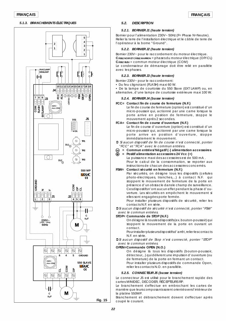
22
FRANÇAIS FRANÇAIS
5.1.3. BRANCHEMENTS ÉLECTRIQUES
ON
+
+
+
-
-
-
14
32
1 32 4 5 6
7 8 9
10 11 12 13 14 15 16 17 18 19J4
J3
J1 J2
GROUND
N F CO
MO
PC
L
CO
MFL
ASH
EXT.L
AM
P
FCC
FCA
FSW
STO
P
OPE
N
M230V~
C8µF
5
43
2
1
1
2
(+6% -10%)
550 SLAVE
550 MP
M
C8µF
50Hz
CO
M
OP
CL
4 56
FAACLAMPMINILAMP
230V~max 25W
230V~max 25W
J5
TR1
TR2
TR3
DS1
DL1
DL2
GRO
UND
Fig. 15
5.2. DESCRIPTION
5.2.1. BORNIER J1 (haute tension)Bornier pour l’alimentation 230V~ 50Hz (F= Phase N=Neutre).Relier la terre de l’installation électrique et le câble de terre del’opérateur à la borne ”Ground”.
5.2.2. BORNIER J2 (haute tension)Bornier 230V~ pour le raccordement du moteur électrique.CÂBLE NOIR ET CÂBLE MARRON = phases du moteur électrique (OP/CL)CÂBLE BLEU = commun moteur électrique (COM)Le condensateur de démarrage doit être relié en parallèleavec les phases.
5.2.3. BORNIER J3 (haute tension)Bornier 230V~ pour le raccordement:• Du feu clignotant (FLASH) maxi 60 W.• De la lampe de courtoisie du 550 Slave (EXT LAMP) ou, enalternative, d’une lampe de courtoisie extérieure maxi 100 W.
5.2.4. BORNIER J4 (basse tension)FCC= Contact fin de course de fermeture (N.F.)
Le fin de course de fermeture (option) est constitué d’unmicro-poussoir qui, actionné par une came lorsque laporte arrive en position de fermeture, stoppe lemouvement après 2 secondes.
FCA= Contact fin de course d’ouverture (N.F.)Le fin de course d’ouverture (option) est constitué d’unmicro-poussoir qui, actionné par une came lorsque laporte arrive en position d’ouverture, stoppeimmédiatement le mouvement.
Ü Si aucun dispositif de fin de course n’est connecté, ponter”FCC” et ”FCA” avec le commun entrées.
= Commun entrées/Négatif (-) alimentation accessoires= Positif alimentation accessoires 24 Vcc (+)
La puissance maxi des accessoires est de 500 mA .Pour le calcul de la consommation, se reporter auxinstructions de chacun des accessoires concernés.
FSW= Contact sécurité en fermeture (N.F.)Par sécurités, on désigne tous les dispositifs (cellulesphoto-électriques, tranches,...) à contact N.F. quistoppent le mouvement de fermeture de la porte enprésence d’un obstacle dans le champ de surveillance.Ces dispositifs n’ont aucun effet pendant la phase d’ou-verture. Les sécurités en empêchent le mouvement sielles sont engagées porte fermée.Pour installer plusieurs dispositifs de sécurité, relier lescontacts N.F. en série.
ÜSi aucun dispositif de sécurité n’est connecté, ponter ”FSW”avec le commun entrées.
STOP= Commande de STOP (N.F.)On désigne là tous les dispositifs (ex. bouton-poussoir) quistoppent le mouvement de la porte en ouvrant uncontact.Pour installer plusieurs dispositifs d’arrêt, relier les contactsN.F. en série.
ÜSi aucun dispositif de Stop n’est connecté, ponter ”STOP”avec le commun entrées.
OPEN=Commande OPEN (N.O.)On désigne là tous les dispositifs (bouton-poussoir,détecteur,..) qui délivrent une impulsion d’ouverture (oude fermeture) de la porte en fermant un contact.Pour installer plusieurs dispositifs de commande Open,relier les contacts N.O. en parallèle.
5.2.5. CONNECTEUR J5 (basse tension)Le connecteur J5 est utilisé pour le branchement rapide descartes MINIDEC, DECODER, RÉCEPTEURS RP.Le branchement s’effectue en embrochant les cartes demanière que leurs composants soient orientés vers l’intérieur dela platine 550MP.Branchement et débranchement doivent s’effectuer aprèscoupé le courant.
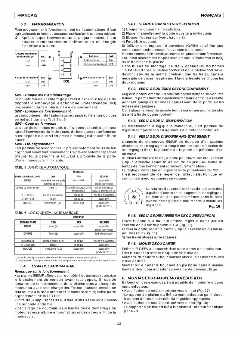
23
FRANÇAISFRANÇAIS
5.3. PROGRAMMATIONPour programmer le fonctionnement de l’automatisme, il fautagir sur les micro-interrupteurs respectifs selon le schema suivant.Ü Après chaque intervention sur la programmation, il faut
couper momentanément l’alimentation en énergieélectrique à la carte.
SW1 - Couple maxi au démarrageLe couple maxi au démarrage permet d’exclure le réglage dudispositif d’embrayage électronique (Potentiomètre TR3)uniquement dans la phase initiale de mouvement.SW2 - Logique de fonctionnementLe comportement de l’automatisme dans les différentes logiquesest indiqué dans les Tabl. 5 et 6 .SW3 - Coup de fermetureLe coup de fermeture retarde de 4 secondes l’arrêt du moteuraprès l’intervention du fin de course de fermeture; cette fonctionn’est disponible que s’il est prévu le montage des arrêts fin decourse.SW4 - Pré-clignotementIl est possible de sélectionner un pré-clignotement de 3 s du feuclignotant avant tout mouvement. Ce pré-clignotement permetd’aviser toute personne se trouvant à proximité de la ported’une manoeuvre imminente.
TABL. 6 LOGIQUE SEMI-AUTOMATIQUE
SÉCURITÉSaucun effet
(inhibe l’ouverture)inhibe la fermeture
inverse le mouvementaucun effetaucun effet
(inhibe ouv./fer.)
ÉTAT DE LA PORTEFERMÉE
OUVERTE
EN FERMETUREEN OUVERTURE
BLOQUÉE
OPENouvre (1)
ferme (1)
inverse le mouvementbloque
ferme/ouvre (1)(2)
STOPaucun effet
aucun effet
se bloquese bloque
aucun effet
IMPULSIONS
IMPULSIONS
SÉCURITÉS
aucun effet(inhibe l’ouverture)
gèle la temporisationjusqu’au désengagement
inverse le mouvementaucun effetaucun effet
(inhibe ouv./fer.)
STOP
aucun effet
bloque le comptage de latemporisation
se bloquese bloque
aucun effet
ÉTAT DE LA PORTE BASCULANTE
FERMÉE
OUVERTE EN TEMPORISATION
EN FERMETUREEN OUVERTURE
BLOQUÉE
OPEN
ouvre et se referme aprèsla temporisation (1)
ferme (1)
inverse le mouvementbloque
ferme/ouvre (1)(2)
TABL. 5 LOGIQUE AUTOMATIQUE
(1) avec le pré-clignotement sélectionné, le mouvement commence après 3 s(2) Une impulsion Open porte basculante bloquée procure un mouvement opposé au précédent.
5.4. ESSAI DE L’AUTOMATISMERemarque sur le fonctionnement:•La platine 550MP effectue un contrôle électronique (qui exigele branchement du moteur) avant tout départ. En cas detentative de fonctionnement de la platine sans la charge dumoteur ou avec une charge insuffisante, aucune tension nesera fournie à la sortie moteur et l’anomalie sera signalée par leclignotement de la LED DL2.•Entre deux impulsions OPEN, il faut laisser s’écouler au moinsune seconde et demie.•L’éclairage de courtoisie s’enclenche dès le démarrage dumoteur et reste allumé environ 90 secondes après la fin de lamanoeuvre.
5.4.1. VÉRIFICATION DU SENS DE ROTATION1) Couper le courant à l’installation.2) Placer manuellement la porte ouverte à mi-hauteur.3) Bloquer l’opérateur (voir chapitre 8)4) Rétablir le courant.5) Délivrer une impulsion d’ouverture (OPEN) et vérifier quecette commande procure l’ouverture de la porte.Si cette commande devait, au contraire, procurer une fermeture,il faudrait alors croiser les phases du moteur (fils marron et noir)sur le bornier de la platine.Dans le cas de montage de deux opérateurs, les bornes”COM,OP,CL”, de la platine 550MP et de la platine 550 Slave,devront être de la même couleur que les fils et, dans lanécessité de croiser les phases, il faudra les intervertir pour lesdeux moteurs.
5.4.2. RÉGLAGE DU TEMPS DE FONCTIONNEMENTRégler le potentiomètre TR1 pour obtenir un temps d’ouverture/fermeture permettant de maintenir le moteur électrique alimentépendant quelques secondes après l’arrêt de la porte sur lesbutées mécaniques.Ce réglage représente aussi le temps maximum pour atteindreles arrêts fin de course (option).
5.4.3. RÉGLAGE DE LA TEMPORISATIONEn sélectionnant la logique automatique, il est possible derégler la temporisation en agissant sur le potentiomètre TR2.
5.4.4 REGLAGE DU DISPOSITIF ANTI-ÉCRASEMENTL’armoire de manoeuvre 550MP est équipée d’un systèmeélectronique de réglage du couple moteur qui (en fonction deson réglage) limite la poussée de la porte en présence d’unobstacle.Aussitôt l’obstacle éliminé, la porte poursuivra son mouvementjusqu’à atteindre l’arrêt fin de course ou jusqu’au terme dutemps de fonctionnement (d’ouverture/fermeture).Le réglage s’effectue en agissant sur le potentiomètre TR3.Il est recommandé de régler ce limiteur électronique enconformité avec les normes en vigueur.
5.4.5. RÉGLAGE DES ARRÊTS FIN DE COURSE (OPTION)Ouvrir la porte à la hauteur désirée; régler la came jusqu’àl’activation du micro-poussoir FCA (Fig. 11).Fermer la porte; régler la came jusqu’à l’activation du micro-poussoir FCC (Fig. 11).Serrer les vis situées sur les cames.
5.4.6. MONTAGE DU CARTERRelier le fil OPEN au poussoir situé sur le carter de l’opérateur.Fixer le carter en serrant les quatre vis latérales.Monter sur le carter les 2 bouchons en plastique dans les rainureslatérales libres.Monter sur le carter le bouchon en plastique dans la rainurefrontale libre, pour accéder au système de déverrouillage.
6. MONTAGE DU GROUPE MOTORÉDUCTEUREn fonction des exigences, il est possible de monter le groupemotoréducteur:•Avec l’arbre de rotation orienté vers le haut (Fig. 17)
Le support de platine est fixé au motoréducteur par 4 vis quibloquent des écrous insérés dans guides appropriés.
•Avec l’arbre de rotation orienté vers le bas (Fig. 18)Le support de platine est fixé à la calotte du moteur électriquepar 4 vis .
DS1
+-Fig. 16
La rotation des potentiomètres dans le sens desaiguilles d’une montre augmente les réglages.La rotation des potentiomètres dans le sensinverse des aiguilles d’une montre diminue lesréglages.
Logique SW2
Automatique True
Semi-automatique OFF
Couple maximumau démarrage SW1
Oui True
Non OFF
Coup de fermeture SW3
Oui True
Non OFF
Pré-clignotement SW4
Oui True
Non OFF
12
34
True
OFF
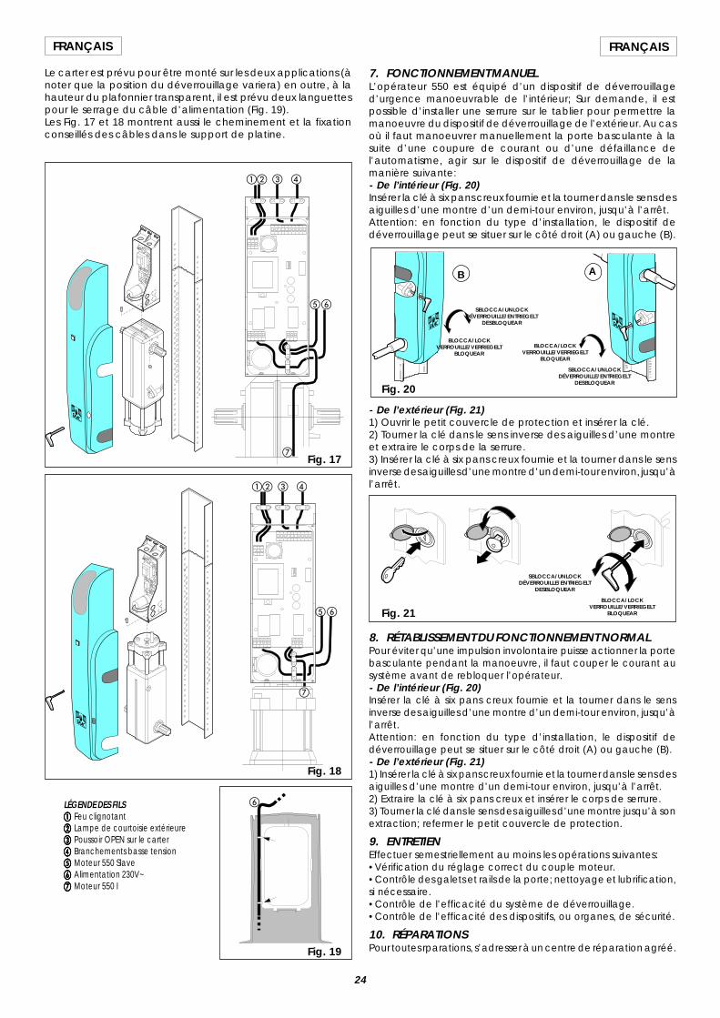
24
FRANÇAIS FRANÇAIS
Le carter est prévu pour être monté sur les deux applications (ànoter que la position du déverrouillage variera) en outre, à lahauteur du plafonnier transparent, il est prévu deux languettespour le serrage du câble d’alimentation (Fig. 19).Les Fig. 17 et 18 montrent aussi le cheminement et la fixationconseillés des câbles dans le support de platine.
LÉGENDE DES FILSaaaaa Feu clignotantbbbbb Lampe de courtoisie extérieureccccc Poussoir OPEN sur le carterddddd Branchements basse tensioneeeee Moteur 550 Slavefffff Alimentation 230V~ggggg Moteur 550 I
ab c d
ef
ab c d
ef
g
Fig. 18
Fig. 19
g
Fig. 17
- De l’extérieur (Fig. 21)1) Ouvrir le petit couvercle de protection et insérer la clé.2) Tourner la clé dans le sens inverse des aiguilles d’une montreet extraire le corps de la serrure.3) Insérer la clé à six pans creux fournie et la tourner dans le sensinverse des aiguilles d’une montre d’un demi-tour environ, jusqu’àl’arrêt.
Fig. 21
SBLOCCA/UNLOCKDÉVERROUILLE/ENTRIEGELT
DESBLOQUEAR
BLOCCA/LOCKVERROUILLE/VERRIEGELT
BLOQUEAR
8. RÉTABLISSEMENT DU FONCTIONNEMENT NORMALPour éviter qu’une impulsion involontaire puisse actionner la portebasculante pendant la manoeuvre, il faut couper le courant ausystème avant de rebloquer l’opérateur.- De l’intérieur (Fig. 20)Insérer la clé à six pans creux fournie et la tourner dans le sensinverse des aiguilles d’une montre d’un demi-tour environ, jusqu’àl’arrêt.Attention: en fonction du type d’installation, le dispositif dedéverrouillage peut se situer sur le côté droit (A) ou gauche (B).- De l’extérieur (Fig. 21)1) Insérer la clé à six pans creux fournie et la tourner dans le sens desaiguilles d’une montre d’un demi-tour environ, jusqu’à l’arrêt.2) Extraire la clé à six pans creux et insérer le corps de serrure.3) Tourner la clé dans le sens des aiguilles d’une montre jusqu’à sonextraction; refermer le petit couvercle de protection.
9. ENTRETIENEffectuer semestriellement au moins les opérations suivantes:•Vérification du réglage correct du couple moteur.•Contrôle des galets et rails de la porte; nettoyage et lubrification,si nécessaire.•Contrôle de l’efficacité du système de déverrouillage.•Contrôle de l’efficacité des dispositifs, ou organes, de sécurité.
10. RÉPARATIONSPour toutes rparations, s’adresser à un centre de réparation agréé.
Fig. 20
BLOCCA/LOCKVERROUILLE/VERRIEGELT
BLOQUEAR
SBLOCCA/UNLOCKDÉVERROUILLE/ENTRIEGELT
DESBLOQUEAR
SBLOCCA/UNLOCKDÉVERROUILLE/ENTRIEGELT
DESBLOQUEAR
BLOCCA/LOCKVERROUILLE/VERRIEGELT
BLOQUEAR
AB
7. FONCTIONNEMENT MANUELL’opérateur 550 est équipé d’un dispositif de déverrouillaged’urgence manoeuvrable de l’intérieur; Sur demande, il estpossible d’installer une serrure sur le tablier pour permettre lamanoeuvre du dispositif de déverrouillage de l’extérieur. Au casoù il faut manoeuvrer manuellement la porte basculante à lasuite d’une coupure de courant ou d’une défaillance del’automatisme, agir sur le dispositif de déverrouillage de lamanière suivante:- De l’intérieur (Fig. 20)Insérer la clé à six pans creux fournie et la tourner dans le sens desaiguilles d’une montre d’un demi-tour environ, jusqu’à l’arrêt.Attention: en fonction du type d’installation, le dispositif dedéverrouillage peut se situer sur le côté droit (A) ou gauche (B).
f
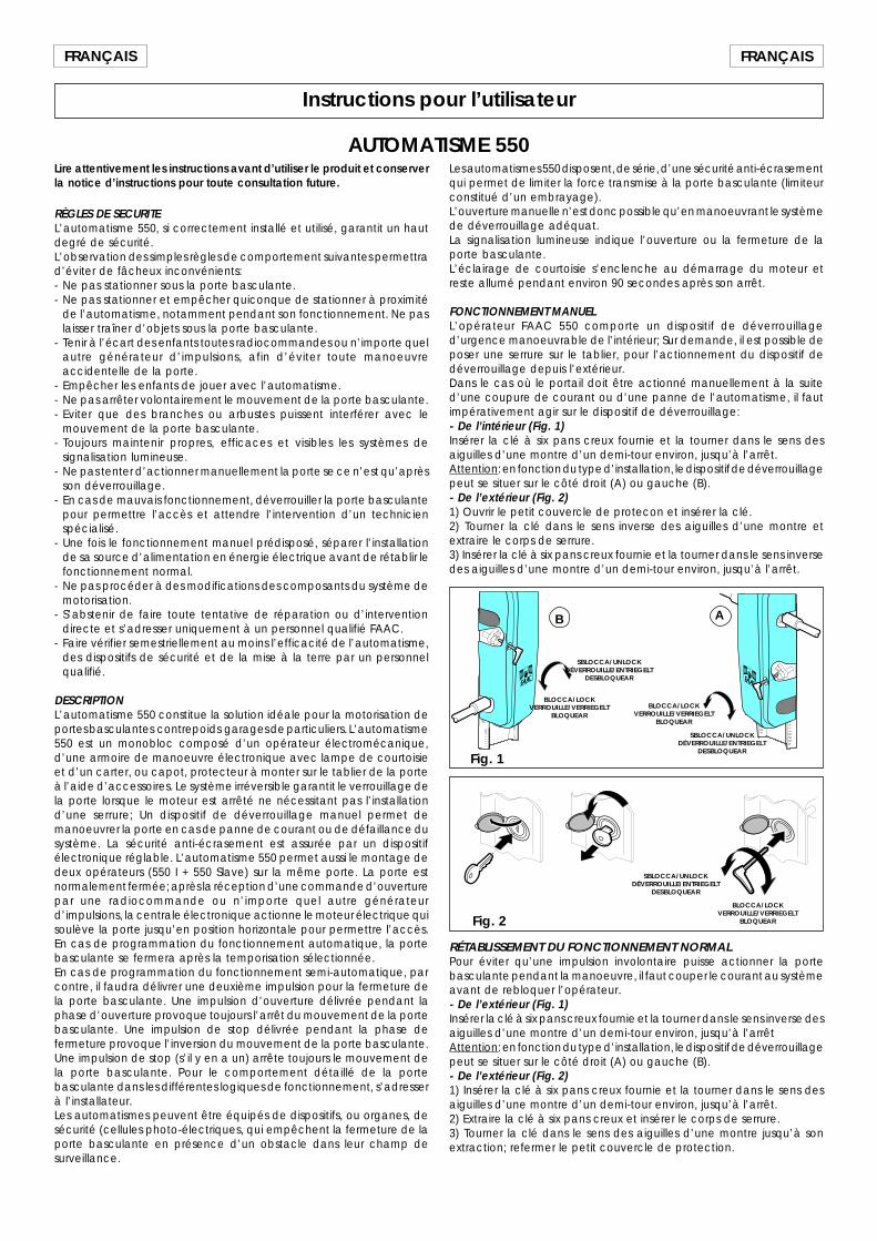
25
FRANÇAISFRANÇAIS
Instructions pour l’utilisateur
AUTOMATISME 550Lire attentivement les instructions avant d’utiliser le produit et conserverla notice d’instructions pour toute consultation future.
RÈGLES DE SECURITEL’automatisme 550, si correctement installé et utilisé, garantit un hautdegré de sécurité.L’observation des simples règles de comportement suivantes permettrad’éviter de fâcheux inconvénients:- Ne pas stationner sous la porte basculante.- Ne pas stationner et empêcher quiconque de stationner à proximité
de l’automatisme, notamment pendant son fonctionnement. Ne paslaisser traîner d’objets sous la porte basculante.
- Tenir à l’écart des enfants toutes radiocommandes ou n’importe quelautre générateur d’impulsions, afin d’éviter toute manoeuvreaccidentelle de la porte.
- Empêcher les enfants de jouer avec l’automatisme.- Ne pas arrêter volontairement le mouvement de la porte basculante.- Eviter que des branches ou arbustes puissent interférer avec le
mouvement de la porte basculante.- Toujours maintenir propres, efficaces et visibles les systèmes de
signalisation lumineuse.- Ne pas tenter d’actionner manuellement la porte se ce n’est qu’après
son déverrouillage.- En cas de mauvais fonctionnement, déverrouiller la porte basculante
pour permettre l’accès et attendre l’intervention d’un technicienspécialisé.
- Une fois le fonctionnement manuel prédisposé, séparer l’installationde sa source d’alimentation en énergie électrique avant de rétablir lefonctionnement normal.
- Ne pas procéder à des modifications des composants du système demotorisation.
- S’abstenir de faire toute tentative de réparation ou d’interventiondirecte et s’adresser uniquement à un personnel qualifié FAAC.
- Faire vérifier semestriellement au moins l’efficacité de l’automatisme,des dispositifs de sécurité et de la mise à la terre par un personnelqualifié.
DESCRIPTIONL’automatisme 550 constitue la solution idéale pour la motorisation deportes basculantes contrepoids garages de particuliers. L’automatisme550 est un monobloc composé d’un opérateur électromécanique,d’une armoire de manoeuvre électronique avec lampe de courtoisieet d’un carter, ou capot, protecteur à monter sur le tablier de la porteà l’aide d’accessoires. Le système irréversible garantit le verrouillage dela porte lorsque le moteur est arrêté ne nécessitant pas l’installationd’une serrure; Un dispositif de déverrouillage manuel permet demanoeuvrer la porte en cas de panne de courant ou de défaillance dusystème. La sécurité anti-écrasement est assurée par un dispositifélectronique réglable. L’automatisme 550 permet aussi le montage dedeux opérateurs (550 I + 550 Slave) sur la même porte. La porte estnormalement fermée; après la réception d’une commande d’ouverturepar une radiocommande ou n’importe quel autre générateurd’impulsions, la centrale électronique actionne le moteur électrique quisoulève la porte jusqu’en position horizontale pour permettre l’accès.En cas de programmation du fonctionnement automatique, la portebasculante se fermera après la temporisation sélectionnée.En cas de programmation du fonctionnement semi-automatique, parcontre, il faudra délivrer une deuxième impulsion pour la fermeture dela porte basculante. Une impulsion d’ouverture délivrée pendant laphase d’ouverture provoque toujours l’arrêt du mouvement de la portebasculante. Une impulsion de stop délivrée pendant la phase defermeture provoque l’inversion du mouvement de la porte basculante.Une impulsion de stop (s’il y en a un) arrête toujours le mouvement dela porte basculante. Pour le comportement détaillé de la portebasculante dans les différentes logiques de fonctionnement, s’adresserà l’installateur.Les automatismes peuvent être équipés de dispositifs, ou organes, desécurité (cellules photo-électriques, qui empêchent la fermeture de laporte basculante en présence d’un obstacle dans leur champ desurveillance.
Fig. 2
SBLOCCA/UNLOCKDÉVERROUILLE/ENTRIEGELT
DESBLOQUEAR
BLOCCA/LOCKVERROUILLE/VERRIEGELT
BLOQUEAR
RÉTABLISSEMENT DU FONCTIONNEMENT NORMALPour éviter qu’une impulsion involontaire puisse actionner la portebasculante pendant la manoeuvre, il faut couper le courant au systèmeavant de rebloquer l’opérateur.- De l’extérieur (Fig. 1)Insérer la clé à six pans creux fournie et la tourner dans le sens inverse desaiguilles d’une montre d’un demi-tour environ, jusqu’à l’arrêtAttention: en fonction du type d’installation, le dispositif de déverrouillagepeut se situer sur le côté droit (A) ou gauche (B).- De l’extérieur (Fig. 2)1) Insérer la clé à six pans creux fournie et la tourner dans le sens desaiguilles d’une montre d’un demi-tour environ, jusqu’à l’arrêt.2) Extraire la clé à six pans creux et insérer le corps de serrure.3) Tourner la clé dans le sens des aiguilles d’une montre jusqu’à sonextraction; refermer le petit couvercle de protection.
Fig. 1
BLOCCA/LOCKVERROUILLE/VERRIEGELT
BLOQUEAR
SBLOCCA/UNLOCKDÉVERROUILLE/ENTRIEGELT
DESBLOQUEAR
SBLOCCA/UNLOCKDÉVERROUILLE/ENTRIEGELT
DESBLOQUEAR
BLOCCA/LOCKVERROUILLE/VERRIEGELT
BLOQUEAR
AB
Les automatismes 550 disposent, de série, d’une sécurité anti-écrasementqui permet de limiter la force transmise à la porte basculante (limiteurconstitué d’un embrayage).L’ouverture manuelle n’est donc possible qu’en manoeuvrant le systèmede déverrouillage adéquat.La signalisation lumineuse indique l’ouverture ou la fermeture de laporte basculante.L’éclairage de courtoisie s’enclenche au démarrage du moteur etreste allumé pendant environ 90 secondes après son arrêt.
FONCTIONNEMENT MANUELL’opérateur FAAC 550 comporte un dispositif de déverrouillaged’urgence manoeuvrable de l’intérieur; Sur demande, il est possible deposer une serrure sur le tablier, pour l’actionnement du dispositif dedéverrouillage depuis l’extérieur.Dans le cas où le portail doit être actionné manuellement à la suited’une coupure de courant ou d’une panne de l’automatisme, il fautimpérativement agir sur le dispositif de déverrouillage:- De l’intérieur (Fig. 1)Insérer la clé à six pans creux fournie et la tourner dans le sens desaiguilles d’une montre d’un demi-tour environ, jusqu’à l’arrêt.Attention: en fonction du type d’installation, le dispositif de déverrouillagepeut se situer sur le côté droit (A) ou gauche (B).- De l’extérieur (Fig. 2)1) Ouvrir le petit couvercle de protecon et insérer la clé.2) Tourner la clé dans le sens inverse des aiguilles d’une montre etextraire le corps de serrure.3) Insérer la clé à six pans creux fournie et la tourner dans le sens inversedes aiguilles d’une montre d’un demi-tour environ, jusqu’à l’arrêt.
25
DEUTSCHDEUTSCH
1) ACHTUNG! Zur persönlichen Sicherheit sollte die Anleitung in allenTeilen befolgt werden. Eine fehlerhafte Installation bzw. Verwendungdes Produkts kann zu schweren Verletzungen führen.
2) Vor Installation des hierin beschriebenen Produkts die Anleitungaufmerksam durchlesen.
3) Verpackungsstoffe (Kunststoff, Styropor usw.) stellen eine Gefahren-quelle für Kinder dar und sind daher außerhalb ihrer Reichweite zuverwahren.
4) Anleitung für künftigen Bedarf aufbewahren.
5) Das vorliegende Produkt ist ausschließlich für den in dieser Dokumen-tation angegebenen Zweck entwickelt und gefertigt worden. Nichtausdrücklich erwähnte Einsätze können die Fehlerfreiheit des Pro-duktes beeinträchtigen bzw. eine Gefahrenquelle darstellen.
6) FAAC lehnt jedwede Haftung bei unsachgemäßem undbestimmungsfremdem Gebrauch des Antriebs ab.
7) Das Produkt nicht in Ex-Bereichen anwenden: Brennbare Gase oderRauchemissionen sind ein schwerwiegendes Sicherheitsrisiko.
8) Die mechanischen Bauelemente haben den Bestimmungen derNormen UNI8612, CEN pr EN 12604 und CEN pr EN 12605 zu entspre-chen.
Im Hinblick auf das EG-Ausland müssen zur Gewährleistung einesangemessenen Sicherheitsstands außer den landeseigenen Bestim-mungen ebenfalls die oben genannten Normen zur Anwendungkommen.
9) FAAC kann nicht für die Mißachtung des technischen Stands bei derHerstellung der anzutreibenden Tore haftbar gemacht werden, desto-weniger für die während der Nutzung auftretenden Struktur-verformungen.
10) Bei der Installation müssen die Normen UNI8612, CEN pr EN 12453 undCEN pr EN 12635 erfüllt werden.Der Sicherheitsstand des Antriebs soll C + D betragen.
11) Vor jeglichen Arbeiten an der Anlage unbedingt die Stromversor-gung unterbrechen.
12) Das Versorgungsnetz des Antriebs ist durch einen allpoligen Schaltermit Kontaktöffnungsabstand von mindestens 3 mm zu schützen.
EG-KONFORMITÄTSERKLÄRUNG ZU MASCHINEN(gemäß EG-RICHTLINIE 89/392/EWG, Anhang II, Teil B)
Hersteller: FAAC S.p.A.
Adresse: Via Benini, 1 - 40069 Zola Predosa BOLOGNA - ITALIEN
erklärt hiermit, daß: der Antrieb Mod. 550
• zum Einbau in eine Maschine oder mit anderen Maschinen zu einer Maschine im Sinne der Richtlinie 89/392/EWGund deren Änderungen 91/368/EWG, 93/44/EWG, 93/68/EWG vorgesehen ist.
• den wesentlichen Sicherheitsbestimmungen folgender anderer EG-Richtlinien entspricht:
73/23/EWG und nachträgliche Änderung 93/68/EWG.89/336/EWG und nachträgliche Änderung 92/31/EWG sowie 93/68/EWG
und erklärt außerdem, daß die Inbetriebnahme solange untersagt ist, bis die Maschine, in welche dieseMaschine eingebaut wird oder von der sie ein Bestandteil ist, den Bestimmungen der Richtlinie 89/392/EWGsowie deren nachträglichen Änderungen entspricht.
Bologna, den 01. Januar 1999 Der Geschäftsführer
A. Bassi
Empfehlenswert ist der Einsatz eines 6A Schutzschalters mit allpoligerUnterbrechung.
13) Der Anlage einen Fehlerstromschutzschalter mit 0,03A Auslöse-schwelle vorschalten.
14) Den Erdschluß auf Wirksamkeit überprüfen und anschließend mit denMetallelementen des Tors verbinden. Grün/gelbes Antriebskabelebenfalls erden.
15) Der Antrieb verfügt über eine integrierte Einklemmsicherheit mitDrehmomentüberwachung, die stets durch weitere Sicherheitsvor-richtungen ergänzt werden muß.
16) Mit den Sicherheiten (z.B. Lichtschranken, Kontaktleisten usw.) wer-den Quetsch- und Scherstellen- und allgemeine Gefahrenbereichewährend der Torbewegung geschützt.
17) Bei jeder Anlage sollten außerdem mindestens eine Leuchtmeldung(z.B. FAAC LAMP, MINILAMP usw.) sowie ein entsprechendes Warn-schild an der Torkonstruktion und die Vorrichtungen aus Punkt “16”eingesetzt werden.
18) FAAC lehnt jegliche Haftung in punkto Sicherheit und korrekte An-triebsfunktion ab, falls die Anlage mit Fremdkomponenten ausgerü-stet ist.
19) Zur Wartung ausschließlich FAAC-Originalteile verwenden.
20) Änderungen an Komponenten des Antriebssystems sind untersagt.
21) Der Installateur soll sämtliche Informationen zur Notentriegelung desSystems erteilen und dem Anwender die dem Produkt beigestelltenAnleitungen aushändigen.
22) Kinder oder Erwachsene sind während des Betriebs vom Produktfernzuhalten.
23) Funksteuerungen oder andere Impulsgeber dürfen nicht von Kinderngehandhabt werden, damit keine unbeabsichtigte Bedienung desAntriebs erfolgt.
24) Der Anwender darf keine eigenmächtigen Reparaturen oder Eingrif-fe vornehmen, sondern ausschließlich Fachpersonal damit beauftra-gen.
25) Alle weiteren, nicht ausdrücklich in dieser Anleitung vergesehenenMaßnahmen sind untersagt.
HINWEISE FÜR DEN INSTALLATIONSTECHNIKERALLGEMEINE SICHERHEITSVORSCHRIFTEN
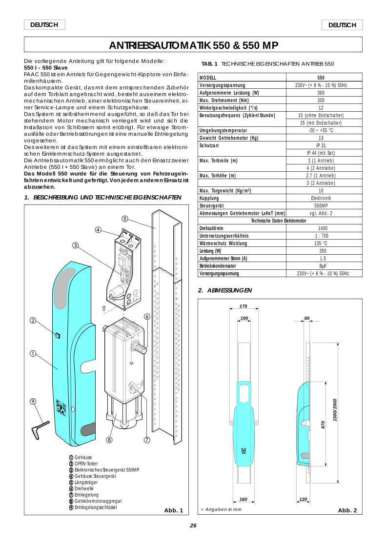
26
DEUTSCH DEUTSCH
ANTRIEBSAUTOMATIK 550 & 550 MPDie vorliegende Anleitung gilt für folgende Modelle:550 I - 550 SlaveFAAC 550 ist ein Antrieb für Gegengewicht-Kipptore von Einfa-milienhäusern.Das kompakte Gerät, das mit dem entsprechenden Zubehörauf dem Torblatt angebracht wird, besteht aus einem elektro-mechanischen Antrieb, einer elektronischen Steuereinheit, ei-ner Service-Lampe und einem Schutzgehäuse.Das System ist selbsthemmend ausgeführt, so daß das Tor beistehendem Motor mechanisch verriegelt wird und sich dieInstallation von Schlössern somit erübrigt. Für etwaige Strom-ausfälle oder Betriebsstörungen ist eine manuelle Entriegelungvorgesehen.Des weiteren ist das System mit einem einstellbaren elektroni-schen Einklemmschutz-System ausgestattet.Die Antriebsautomatik 550 ermöglicht auch den Einsatz zweierAntriebe (550 I + 550 Slave) an einem Tor.Das Modell 550 wurde für die Steuerung von Fahrzeugein-fahrten entwickelt und gefertigt. Von jedem anderen Einsatz istabzusehen.
1. BESCHREIBUNG UND TECHNISCHE EIGENSCHAFTEN
Abb. 1
aaaaa Gehäusebbbbb OPEN-Tasterccccc Elektronisches Steuergerät 550MPddddd Gehäuse Steuergeräteeeee Längsträgerfffff Drehwelleggggg Entriegelunghhhhh Getriebemotoraggregatiiiii Entriegelungsschlüssel
TAB. 1 TECHNISCHE EIGENSCHAFTEN ANTRIEB 550
MODELL 550Versorgungsspannung 230V~ (+ 6 % - 10 %) 50HzAufgenommene Leistung (W) 360Max. Drehmoment (Nm) 300Winkelgeschwindigkeit (°/s) 12Benutzungsfrequenz (Zyklen/Stunde) 15 (ohne Endschalter)
25 (mit Endschalter)Umgebungstemperatur -20 ÷ +55 °CGewicht Getriebemotor (Kg) 13Schutzart IP 31
IP 44 (mit Set)Max. Torbreite (m) 3 (1 Antr ieb)
4 (2 Antr iebe)Max. Torhöhe (m) 2.7 (1 Antr ieb)
3 (2 Antr iebe)Max. Torgewicht (Kg/m2) 10Kupplung Elekt ronikSteuergerät 550MPAbmessungen Getriebemotor LxHxT (mm) vgl. Abb. 2
Technische Daten ElektromotorDrehzahl/min 1400Untersetzungsverhältnis 1 : 700Wärmeschutz Wicklung 135 °CLeistung (W) 350Aufgenommener Strom (A) 1.5Betriebskondensator 8µFVersorgungsspannung 230V~ (+ 6 % - 10 %) 50Hz
2. ABMESSUNGEN
Abb. 2
175
100
160 120
5067
0 1500
/200
0
• Angaben in mm
a
b
d
c
e
gh
i
f
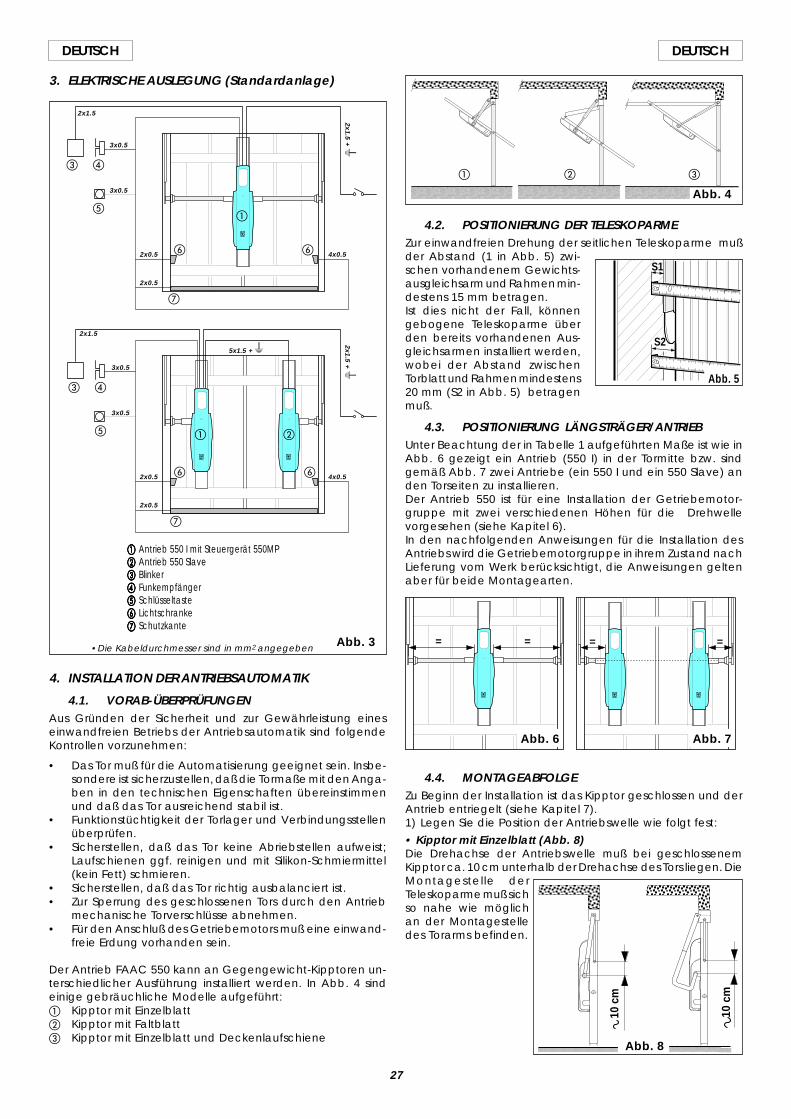
27
DEUTSCHDEUTSCH
3. ELEKTRISCHE AUSLEGUNG (Standardanlage)
aaaaa Antrieb 550 I mit Steuergerät 550MPbbbbb Antrieb 550 Slaveccccc Blinkerddddd Funkempfängereeeee Schlüsseltastefffff Lichtschrankeggggg Schutzkante
a b
c d
e
f
g
f
a
c d
e
f
g
f
4. INSTALLATION DER ANTRIEBSAUTOMATIK
4.1. VORAB-ÜBERPRÜFUNGENAus Gründen der Sicherheit und zur Gewährleistung eineseinwandfreien Betriebs der Antriebsautomatik sind folgendeKontrollen vorzunehmen:
• Das Tor muß für die Automatisierung geeignet sein. Insbe-sondere ist sicherzustellen, daß die Tormaße mit den Anga-ben in den technischen Eigenschaften übereinstimmenund daß das Tor ausreichend stabil ist.
• Funktionstüchtigkeit der Torlager und Verbindungsstellenüberprüfen.
• Sicherstellen, daß das Tor keine Abriebstellen aufweist;Laufschienen ggf. reinigen und mit Silikon-Schmiermittel(kein Fett) schmieren.
• Sicherstellen, daß das Tor richtig ausbalanciert ist.• Zur Sperrung des geschlossenen Tors durch den Antrieb
mechanische Torverschlüsse abnehmen.• Für den Anschluß des Getriebemotors muß eine einwand-
freie Erdung vorhanden sein.
Der Antrieb FAAC 550 kann an Gegengewicht-Kipptoren un-terschiedlicher Ausführung installiert werden. In Abb. 4 sindeinige gebräuchliche Modelle aufgeführt:a Kipptor mit Einzelblattb Kipptor mit Faltblattc Kipptor mit Einzelblatt und Deckenlaufschiene
4.2. POSITIONIERUNG DER TELESKOPARMEZur einwandfreien Drehung der seitlichen Teleskoparme mußder Abstand (1 in Abb. 5) zwi-schen vorhandenem Gewichts-ausgleichsarm und Rahmen min-destens 15 mm betragen.Ist dies nicht der Fall, könnengebogene Teleskoparme überden bereits vorhandenen Aus-gleichsarmen installiert werden,wobei der Abstand zwischenTorblatt und Rahmen mindestens20 mm (S2 in Abb. 5) betragenmuß.
4.3. POSITIONIERUNG LÄNGSTRÄGER/ANTRIEBUnter Beachtung der in Tabelle 1 aufgeführten Maße ist wie inAbb. 6 gezeigt ein Antrieb (550 I) in der Tormitte bzw. sindgemäß Abb. 7 zwei Antriebe (ein 550 I und ein 550 Slave) anden Torseiten zu installieren.Der Antrieb 550 ist für eine Installation der Getriebemotor-gruppe mit zwei verschiedenen Höhen für die Drehwellevorgesehen (siehe Kapitel 6).In den nachfolgenden Anweisungen für die Installation desAntriebs wird die Getriebemotorgruppe in ihrem Zustand nachLieferung vom Werk berücksichtigt, die Anweisungen geltenaber für beide Montagearten.
Abb. 3
4.4. MONTAGEABFOLGEZu Beginn der Installation ist das Kipptor geschlossen und derAntrieb entriegelt (siehe Kapitel 7).1) Legen Sie die Position der Antriebswelle wie folgt fest:
• Kipptor mit Einzelblatt (Abb. 8)Die Drehachse der Antriebswelle muß bei geschlossenemKipptor ca. 10 cm unterhalb der Drehachse des Tors liegen. DieMontagestelle derTeleskoparme muß sichso nahe wie möglichan der Montagestelledes Torarms befinden.
10 c
m
10 c
m
Abb. 8
= = = =
Abb. 6 Abb. 7
a cb
Abb. 4
S1
S2
2x0.5 4x0.5
2x0.5
3x0.5
3x0.5
2x1.5
2x1.5 + W
5x1.5 + W
2x1.5
3x0.5
3x0.5
2x0.5
2x0.5
4x0.5
•Die Kabeldurchmesser sind in mm2 angegeben
Abb. 5
2x1.5 + W
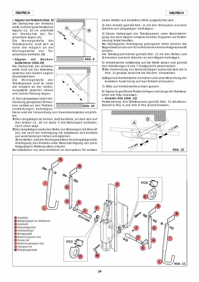
28
DEUTSCH DEUTSCH
• Kipptor mit Faltblatt (Abb. 9)Die Drehachse der Antriebs-welle muß bei geschlossenemKipptor ca. 10 cm unterhalbder Drehachse der Tor-scharniere liegen (A).Die Montagestelle derTeleskoparme muß sich sonahe wie möglich an derMontagestelle der Tor-scharniere befinden (B).
• Kipptor mit Decken-laufschiene (Abb.10)
Die Drehachse der Antriebs-welle muß mit der Mittelliniezwischen den beiden Lagernübereinstimmen.Die Montagestelle derTeleskoparme muß so nahewie möglich an der Verbin-dungsstelle zwischen obererund unterer Führung liegen.
2) Den Längsträger unter Ver-wendung geeigneter Schrau-ben vertikal an den Torblatt-verstärkungen befestigen;hierzu wird die Verwendung von Gewindeeinsätzen empfoh-len.ÜDen Längsträger so drehen, daß das Ende, an dem sich auf
den letzten ca. 20 cm keine 4 mm-Bohrungen befinden,nach oben zeigt.
ÜDer Längsträger weist eine Reihe von Bohrungen mit 8mm Øauf, die nach der Anbringung die Installation des Antriebsauf verschiedenen Höhen ermöglichen.Sicherstellen, daß die Montageposition des Längsträgers dieAnbringung des Antriebs unter Berücksichtigung der zuvorfestgelegten Wellenposition erlaubt.
Bei Installation von zwei Antrieben an demselben Tor müssen
10 cm
Abb. 9
AB
=
=
Abb. 10
beide Wellen auf derselben Höhe ausgerichtet sein.
3) Den Antrieb gemäß Abb. 11 mit den Schrauben aus demZubehör am Längsträger befestigen.
4) Obere Haltebügel der Teleskoparme unter Berücksichti-gung der dem Kipptor entsprechenden Angaben zur Positio-nierung festschweißen.Bei überlagerter Anbringung gebogener Arme können dieBügel direkt an den am Tor vorhandenen Armen festgeschweißtwerden.Die Teleskoparmmäntel gemäß Abb. 11 mit den Bolzen undSchrauben aus dem Zubehör an den Bügeln befestigen.
5) Antriebsrohre vollständig auf die Welle setzen und gemäßden Abbildungen 6 und 7 maßgerecht abschneiden.ÜBei Verwendung von Endanschlägen (optional) sind wie in
Abb. 11 gezeigt zunächst die Nocken einzusetzen.
6)Bügel auf Antriebsrohre montieren und unter Beachtung derkorrekten Ausrichtung auf das Torblatt schrauben.
7) Stifte auf Antriebsrohrbuchsen sperren.
8) Kipptor in geöffnete Position bringen und Länge der Teleskop-arme wie folgt anpassen:• Gerader Arm (Abb. 12)Positionierung des Teleskoparms gemäß Abb. 12 simulieren.Mantel in Pos. A und Arm in Pos. B abschneiden.
Abb. 11
AB
Abb. 12
FCC
FCAA
B
B
B
BC
C
D
D
E
E
F
F
G
G
H
H
I
I
L
M
A LängsträgerB Befestigungsbügel der TeleskoparmeC AntriebsrohrD EndanschlagnockenE AntriebsrohrbügelF BefestigungsstiftG Mantel des geraden ArmsH Gerader Arm I Mantel des gebogenen Arms L Gebogener ArmM Entriegelungsschlüssel
L
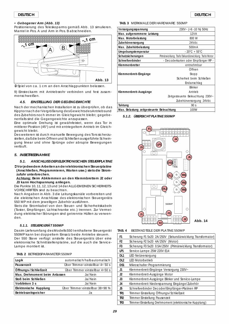
29
DEUTSCHDEUTSCH
• Gebogener Arm (Abb. 13)Positionierung des Teleskoparms gemäß Abb. 13 simulieren.Mantel in Pos. A und Arm in Pos. B abschneiden.
ÜSpiel von ca. 1 cm an den Anschlagpunkten belassen.
9) Einsteckarm mit Antriebsrohr verbinden und fest zusam-menschweißen.
4.5. EINSTELLUNG DER GEGENGEWICHTENach der mechanischen Installation ist zu überprüfen, ob dasKipptor nach der Vergrößerung des Gewichts des Antriebs unddes Zubehörs noch immer im Gleichgewicht bleibt; gegebe-nenfalls sind die Gegengewichte anzupassen.Eine optimale Drehung ist gewährleistet, wenn das Tor inmittlerer Position (45°) und mit entriegeltem Antrieb im Gleich-gewicht bleibt.Des weiteren ist durch manuelle Bewegung des Tors sicherzu-stellen, daß die beim Öffnen und Schließen ausgeführte Schwin-gung linear und ohne Sprünge oder abrupte Bewegungenverläuft.
5. INBETRIEBNAHME
5.1. ANSCHLUSS DER ELEKTRONISCHEN STEUERPLATINEÜVor jedwedem Arbeiten an der elektronischen Steuerplatine
(Anschließen, Programmieren, Warten usw.) stets die Strom-zufuhr unterbrechen.Achtung: Beim Abklemmen an den Klemmbrettern J2 oderJ3 kann Hochspannung anliegen.
Die Punkte 10, 11, 12, 13 und 14 der ALLGEMEINEN SICHERHEITS-VORSCHRIFTEN sind zu beachten.Nach Angaben in Abb. 3 die Leitungskanäle vorbereiten unddie elektrischen Anschlüsse des elektronischen Steuergeräts550 MP mit dem jeweiligen Zubehör ausführen.Stets die Stromkabel von den Steuer- und Sicherheitskabeln(Taster, Empfänger, Lichtschranke etc.) trennen. Zur Vermei-dung elektrischer Störungen sind getrennte Hüllen zu verwen-den.
5.1.1. STEUERGERÄT 550MPDas im Lieferumfang des Modells 550 I enthaltene Steuergerät550MP kann bei doppeltem Einsatz beide Antriebe steuern.Der 550 Slave verfügt anstelle des Steuergeräts über eineelektronische Schnittstellenplatine, auf die auch die Service-Lampe montiert ist.
TAB. 2 BETRIEBSPARAMETER 550MP
Logik automatisch/halbautomatischPausenzeit Über Trimmer einstellbar 4÷ 50 s
Öffnungs-/Schließzeit Über Trimmer einstellbar 4÷50 sMax. Drehmoment beim Anlassen Ja/NeinStoß beim Schließen Ja/NeinVorblinken 3 s Ja/NeinElektronische Kupplung Über Trimmer einstellbar 38÷98 %Betriebszeitspeicher Ja
TAB. 4 BESTANDTEILE DER PLATINE 550MP
F1 Sicherung F1 5x20 2A/250V (Sekundärwicklung Transformator)F2 Sicherung F2 5x20 4A/250V (Motor)F3 Sicherung F3 5x20 0.5A/250V (Primärwicklung Transformator)LP1 Service-Lampe 25W 220V E14DL1 LED NetzversorgungDL2 LED MotorbetriebDS1 Mikroschalter ProgrammierungJ1 Klemmenbrett-Eingänge Versorgung 230V~J2 Klemmenbrett-Ausgänge MotorJ3 Klemmenbrett-Ausgänge Blinker und Service-LampeJ4 Klemmenbrett Niederspannung Eingänge/ZubehörJ5 Schnellverbinder Decoder/Empfänger-Platinen RPTR1 Trimmer Einstellung Öffnungs-/SchließzeitTR2 Trimmer Einstellung PausenzeitTR3 Trimmer Einstellung Drehmoment (elektronische Kupplung)
TAB. 3 MERKMALE DER HARDWARE 550MP
Versorgungsspannung 230V~ (+6 -10 %) 50HzMax. aufgenommene Leistung 12VAMax. Motorbelastung 800 WZubehörversorgung 24VdcMax. Zubehörbelastung 500mAUmgebungstemperatur - 20°C + 55°CSchutzsicherungen Primärwicklung Trafo/Sekundärwicklung Trafo/MotorSchnellverbinder - Decoderkarten oder Empfänger RP -Klemmenbretter entnehmbar
ÖffnenKlemmenbrett-Eingänge Stopp
Sicherheit beim SchließenEndanschlag
BlinkerKlemmenbrett-Ausgänge Antrieb
Zeitgesteuerte Beleuchtung 230V~Zubehörversorgung 24Vdc
Taktung 90 sMax. Belastung zeitgesteuerte Beleuchtung 100W
5.1.2. ÜBERSICHT PLATINE 550MP
A B
Abb. 13
ON
+
+
+
-
-
-
14
32
550MP
F1
J4
LP1J3
J5
DS1
DL1 TR1
TR2
TR3
J1
J2
F3
F2
DL2
Abb. 14
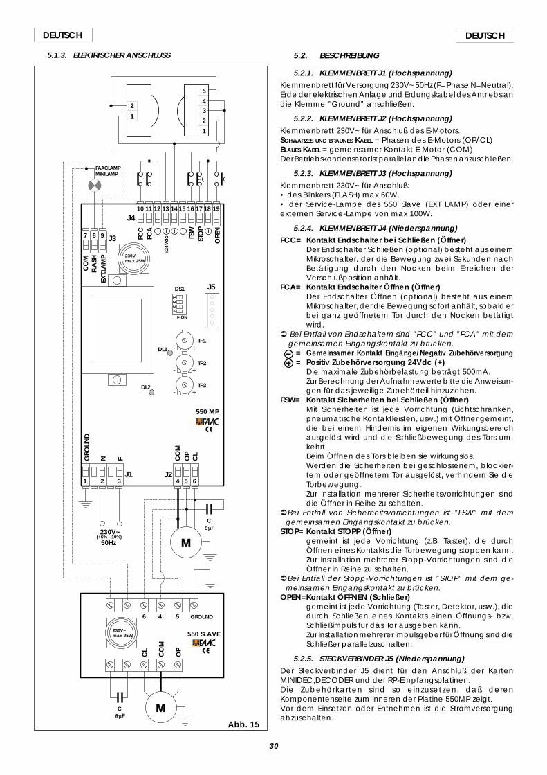
30
DEUTSCH DEUTSCH
5.1.3. ELEKTRISCHER ANSCHLUSS
ON
+
+
+
-
-
-
14
32
1 32 4 5 6
7 8 9
10 11 12 13 14 15 16 17 18 19J4
J3
J1 J2
GROUND
N F CO
MO
PC
L
CO
MFL
ASH
EXT.L
AM
P
FCC
FCA
FSW
STO
P
OPE
N
M230V~
C8µF
5
43
2
1
1
2
(+6% -10%)
550 SLAVE
550 MP
M
C8µF
50Hz
CO
M
OP
CL
4 56
FAACLAMPMINILAMP
230V~max 25W
230V~max 25W
J5
TR1
TR2
TR3
DS1
DL1
DL2
GRO
UND
Abb. 15
5.2. BESCHREIBUNG
5.2.1. KLEMMENBRETT J1 (Hochspannung)Klemmenbrett für Versorgung 230V~ 50Hz (F= Phase N=Neutral).Erde der elektrischen Anlage und Erdungskabel des Antriebs andie Klemme ”Ground” anschließen.
5.2.2. KLEMMENBRETT J2 (Hochspannung)Klemmenbrett 230V~ für Anschluß des E-Motors.SCHWARZES UND BRAUNES KABEL = Phasen des E-Motors (OP/CL)BLAUES KABEL = gemeinsamer Kontakt E-Motor (COM)Der Betriebskondensator ist parallel an die Phasen anzuschließen.
5.2.3. KLEMMENBRETT J3 (Hochspannung)Klemmenbrett 230V~ für Anschluß:• des Blinkers (FLASH) max 60W.• der Service-Lampe des 550 Slave (EXT LAMP) oder einerexternen Service-Lampe von max 100W.
5.2.4. KLEMMENBRETT J4 (Niederspannung)FCC= Kontakt Endschalter bei Schließen (Öffner)
Der Endschalter Schließen (optional) besteht aus einemMikroschalter, der die Bewegung zwei Sekunden nachBetätigung durch den Nocken beim Erreichen derVerschlußposition anhält.
FCA= Kontakt Endschalter Öffnen (Öffner)Der Endschalter Öffnen (optional) besteht aus einemMikroschalter, der die Bewegung sofort anhält, sobald erbei ganz geöffnetem Tor durch den Nocken betätigtwird.
Ü Bei Entfall von Endschaltern sind ”FCC” und ”FCA” mit demgemeinsamen Eingangskontakt zu brücken.
= Gemeinsamer Kontakt Eingänge/Negativ Zubehörversorgung= Positiv Zubehörversorgung 24Vdc (+)
Die maximale Zubehörbelastung beträgt 500mA.Zur Berechnung der Aufnahmewerte bitte die Anweisun-gen für das jeweilige Zubehörteil hinzuziehen.
FSW= Kontakt Sicherheiten bei Schließen (Öffner)Mit Sicherheiten ist jede Vorrichtung (Lichtschranken,pneumatische Kontaktleisten, usw.) mit Öffner gemeint,die bei einem Hindernis im eigenen Wirkungsbereichausgelöst wird und die Schließbewegung des Tors um-kehrt.Beim Öffnen des Tors bleiben sie wirkungslos.Werden die Sicherheiten bei geschlossenem, blockier-tem oder geöffnetem Tor ausgelöst, verhindern Sie dieTorbewegung.Zur Installation mehrerer Sicherheitsvorrichtungen sinddie Öffner in Reihe zu schalten.
ÜBei Entfall von Sicherheitsvorrichtungen ist ”FSW” mit demgemeinsamen Eingangskontakt zu brücken.
STOP= Kontakt STOPP (Öffner)gemeint ist jede Vorrichtung (z.B. Taster), die durchÖffnen eines Kontakts die Torbewegung stoppen kann.Zur Installation mehrerer Stopp-Vorrichtungen sind dieÖffner in Reihe zu schalten.
ÜBei Entfall der Stopp-Vorrichtungen ist ”STOP” mit dem ge-meinsamen Eingangskontakt zu brücken.
OPEN=Kontakt ÖFFNEN (Schließer)gemeint ist jede Vorrichtung (Taster, Detektor, usw.), diedurch Schließen eines Kontakts einen Öffnungs- bzw.Schließimpuls für das Tor ausgeben kann.Zur Installation mehrerer Impulsgeber für Öffnung sind dieSchließer parallelzuschalten.
5.2.5. STECKVERBINDER J5 (Niederspannung)Der Steckverbinder J5 dient für den Anschluß der KartenMINIDEC,DECODER und der RP-Empfangsplatinen.Die Zubehörkarten sind so einzusetzen, daß derenKomponentenseite zum Inneren der Platine 550MP zeigt.Vor dem Einsetzen oder Entnehmen ist die Stromversorgungabzuschalten.
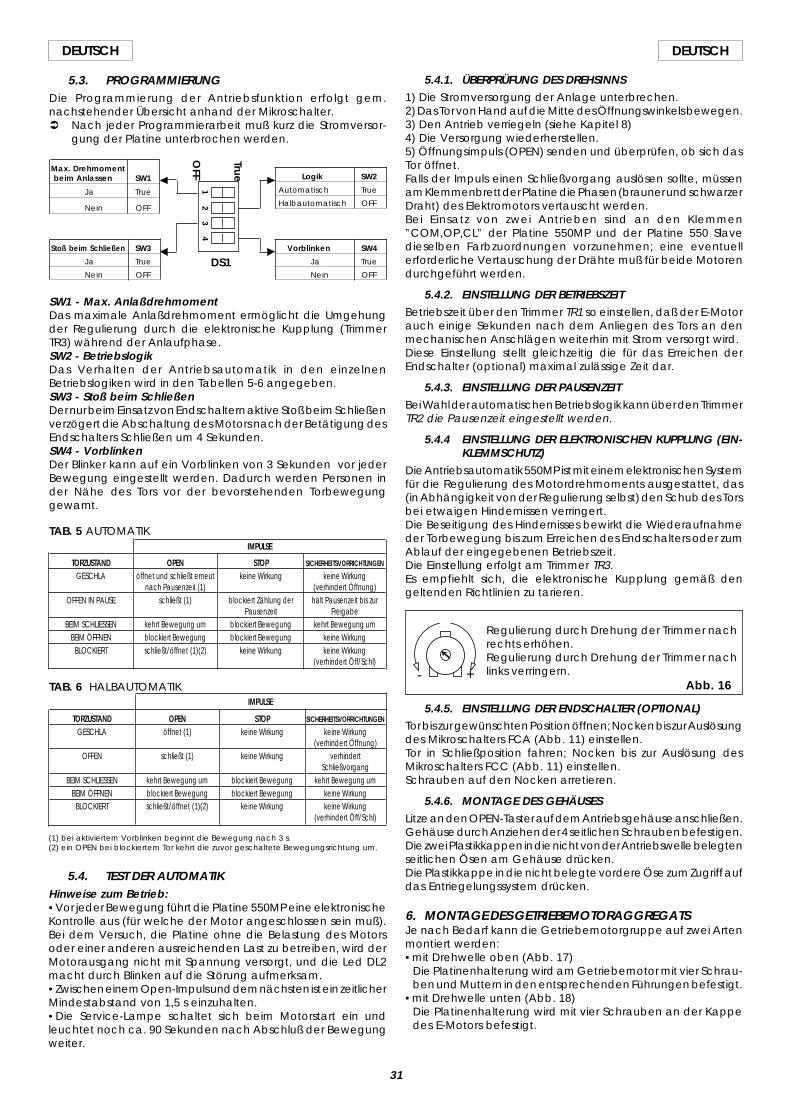
31
DEUTSCHDEUTSCH
5.3. PROGRAMMIERUNGDie Programmierung der Antriebsfunktion erfolgt gem.nachstehender Übersicht anhand der Mikroschalter.Ü Nach jeder Programmierarbeit muß kurz die Stromversor-
gung der Platine unterbrochen werden.
SW1 - Max. AnlaßdrehmomentDas maximale Anlaßdrehmoment ermöglicht die Umgehungder Regulierung durch die elektronische Kupplung (TrimmerTR3) während der Anlaufphase.SW2 - BetriebslogikDas Verhalten der Antriebsautomatik in den einzelnenBetriebslogiken wird in den Tabellen 5-6 angegeben.SW3 - Stoß beim SchließenDer nur beim Einsatz von Endschaltern aktive Stoß beim Schließenverzögert die Abschaltung des Motors nach der Betätigung desEndschalters Schließen um 4 Sekunden.SW4 - VorblinkenDer Blinker kann auf ein Vorblinken von 3 Sekunden vor jederBewegung eingestellt werden. Dadurch werden Personen inder Nähe des Tors vor der bevorstehenden Torbewegunggewarnt.
Logik SW2
Automatisch True
Halbautomatisch OFF
Max. Drehmomentbeim Anlassen SW1
Ja True
Nein OFF
Stoß beim Schließen SW3
Ja True
Nein OFF
Vorblinken SW4
Ja True
Nein OFF
12
34
True
OFF
TAB. 6 HALBAUTOMATIK
SICHERHEITSVORRICHTUNGEN
keine Wirkung(verhindert Öffnung)
verhindertSchließvorgang
kehrt Bewegung umkeine Wirkungkeine Wirkung
(verhindert Öff/Schl)
TORZUSTANDGESCHLA
OFFEN
BEIM SCHLIESSENBEIM ÖFFNEN
BLOCKIERT
OPENöffnet (1)
schließt (1)
kehrt Bewegung umblockiert Bewegungschließt/öffnet (1)(2)
STOPkeine Wirkung
keine Wirkung
blockiert Bewegungblockiert Bewegung
keine Wirkung
IMPULSE
IMPULSE
SICHERHEITSVORRICHTUNGEN
keine Wirkung(verhindert Öffnung)hält Pausenzeit bis zur
Freigabekehrt Bewegung um
keine Wirkungkeine Wirkung
(verhindert Öff/Schl)
STOPkeine Wirkung
blockiert Zählung derPausenzeit
blockiert Bewegungblockiert Bewegung
keine Wirkung
TORZUSTANDGESCHLA
OFFEN IN PAUSE
BEIM SCHLIESSENBEIM ÖFFNEN
BLOCKIERT
OPENöffnet und schließt erneut
nach Pausenzeit (1)schließt (1)
kehrt Bewegung umblockiert Bewegungschließt/öffnet (1)(2)
TAB. 5 AUTOMATIK
(1) bei aktiviertem Vorblinken beginnt die Bewegung nach 3 s.(2) ein OPEN bei blockiertem Tor kehrt die zuvor geschaltete Bewegungsrichtung um.
5.4. TEST DER AUTOMATIKHinweise zum Betrieb:•Vor jeder Bewegung führt die Platine 550MP eine elektronischeKontrolle aus (für welche der Motor angeschlossen sein muß).Bei dem Versuch, die Platine ohne die Belastung des Motorsoder einer anderen ausreichenden Last zu betreiben, wird derMotorausgang nicht mit Spannung versorgt, und die Led DL2macht durch Blinken auf die Störung aufmerksam.•Zwischen einem Open-Impuls und dem nächsten ist ein zeitlicherMindestabstand von 1,5 s einzuhalten.•Die Service-Lampe schaltet sich beim Motorstart ein undleuchtet noch ca. 90 Sekunden nach Abschluß der Bewegungweiter.
5.4.1. ÜBERPRÜFUNG DES DREHSINNS1) Die Stromversorgung der Anlage unterbrechen.2) Das Tor von Hand auf die Mitte des Öffnungswinkels bewegen.3) Den Antrieb verriegeln (siehe Kapitel 8)4) Die Versorgung wiederherstellen.5) Öffnungsimpuls (OPEN) senden und überprüfen, ob sich dasTor öffnet.Falls der Impuls einen Schließvorgang auslösen sollte, müssenam Klemmenbrett der Platine die Phasen (brauner und schwarzerDraht) des Elektromotors vertauscht werden.Bei Einsatz von zwei Antrieben sind an den Klemmen”COM,OP,CL” der Platine 550MP und der Platine 550 Slavedieselben Farbzuordnungen vorzunehmen; eine eventuellerforderliche Vertauschung der Drähte muß für beide Motorendurchgeführt werden.
5.4.2. EINSTELLUNG DER BETRIEBSZEITBetriebszeit über den Trimmer TR1 so einstellen, daß der E-Motorauch einige Sekunden nach dem Anliegen des Tors an denmechanischen Anschlägen weiterhin mit Strom versorgt wird.Diese Einstellung stellt gleichzeitig die für das Erreichen derEndschalter (optional) maximal zulässige Zeit dar.
5.4.3. EINSTELLUNG DER PAUSENZEITBei Wahl der automatischen Betriebslogik kann über den TrimmerTR2 die Pausenzeit eingestellt werden.
5.4.4 EINSTELLUNG DER ELEKTRONISCHEN KUPPLUNG (EIN-KLEMMSCHUTZ)
Die Antriebsautomatik 550MP ist mit einem elektronischen Systemfür die Regulierung des Motordrehmoments ausgestattet, das(in Abhängigkeit von der Regulierung selbst) den Schub des Torsbei etwaigen Hindernissen verringert.Die Beseitigung des Hindernisses bewirkt die Wiederaufnahmeder Torbewegung bis zum Erreichen des Endschalters oder zumAblauf der eingegebenen Betriebszeit.Die Einstellung erfolgt am Trimmer TR3.Es empfiehlt sich, die elektronische Kupplung gemäß dengeltenden Richtlinien zu tarieren.
5.4.5. EINSTELLUNG DER ENDSCHALTER (OPTIONAL)Tor bis zur gewünschten Position öffnen; Nocken bis zur Auslösungdes Mikroschalters FCA (Abb. 11) einstellen.Tor in Schließposition fahren; Nocken bis zur Auslösung desMikroschalters FCC (Abb. 11) einstellen.Schrauben auf den Nocken arretieren.
5.4.6. MONTAGE DES GEHÄUSESLitze an den OPEN-Taster auf dem Antriebsgehäuse anschließen.Gehäuse durch Anziehen der 4 seitlichen Schrauben befestigen.Die zwei Plastikkappen in die nicht von der Antriebswelle belegtenseitlichen Ösen am Gehäuse drücken.Die Plastikkappe in die nicht belegte vordere Öse zum Zugriff aufdas Entriegelungssystem drücken.
6. MONTAGE DES GETRIEBEMOTORAGGREGATSJe nach Bedarf kann die Getriebemotorgruppe auf zwei Artenmontiert werden:•mit Drehwelle oben (Abb. 17)
Die Platinenhalterung wird am Getriebemotor mit vier Schrau-ben und Muttern in den entsprechenden Führungen befestigt.
•mit Drehwelle unten (Abb. 18)Die Platinenhalterung wird mit vier Schrauben an der Kappedes E-Motors befestigt.
DS1
+-Abb. 16
Regulierung durch Drehung der Trimmer nachrechts erhöhen.Regulierung durch Drehung der Trimmer nachlinks verringern.
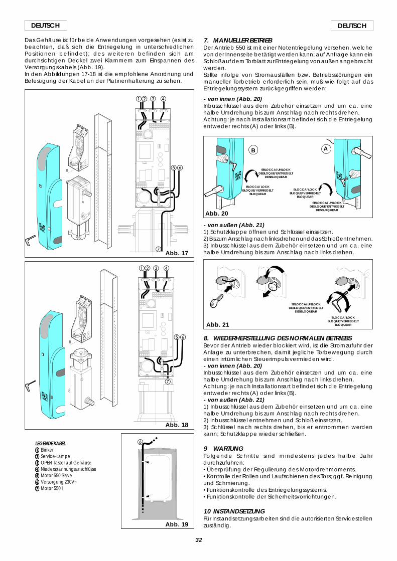
32
DEUTSCH DEUTSCH
Das Gehäuse ist für beide Anwendungen vorgesehen (es ist zubeachten, daß sich die Entriegelung in unterschiedlichenPositionen befindet); des weiteren befinden sich amdurchsichtigen Deckel zwei Klammern zum Einspannen desVersorgungskabels (Abb. 19).In den Abbildungen 17-18 ist die empfohlene Anordnung undBefestigung der Kabel an der Platinenhalterung zu sehen.
LEGENDE KABELaaaaa Blinkerbbbbb Service-Lampeccccc OPEN-Taster auf Gehäuseddddd Niederspannungsanschlüsseeeeee Motor 550 Slavefffff Versorgung 230V~ggggg Motor 550 I
ab c d
ef
ab c d
ef
g
Abb. 18
Abb. 19
g
Abb. 17
- von außen (Abb. 21)1) Schutzklappe öffnen und Schlüssel einsetzen.2) Bis zum Anschlag nach links drehen und das Schloß entnehmen.3) Inbusschlüssel aus dem Zubehör einsetzen und um ca. einehalbe Umdrehung bis zum Anschlag nach links drehen.
Abb. 21
SBLOCCA/UNLOCKDEBLOQUE/ENTRIEGELT
DESBLOQUEAR
BLOCCA/LOCKBLOQUE/VERRIEGELT
BLOQUEAR
8. WIEDERHERSTELLUNG DES NORMALEN BETRIEBSBevor der Antrieb wieder blockiert wird, ist die Stromzufuhr derAnlage zu unterbrechen, damit jegliche Torbewegung durcheinen irrtümlichen Steuerimpuls vermieden wird.- von innen (Abb. 20)Inbusschlüssel aus dem Zubehör einsetzen und um ca. einehalbe Umdrehung bis zum Anschlag nach links drehen.Achtung: je nach Installationsart befindet sich die Entriegelungentweder rechts (A) oder links (B).- von außen (Abb. 21)1) Inbusschlüssel aus dem Zubehör einsetzen und um ca. einehalbe Umdrehung bis zum Anschlag nach rechts drehen.2) Inbusschlüssel entnehmen und Schloß einsetzen.3) Schlüssel nach rechts drehen, bis er entnommen werdenkann; Schutzklappe wieder schließen.
9 WARTUNGFolgende Schritte sind mindestens jedes halbe Jahrdurchzuführen:•Überprüfung der Regulierung des Motordrehmoments.•Kontrolle der Rollen und Laufschienen des Tors; ggf. Reinigungund Schmierung.•Funktionskontrolle des Entriegelungssystems.•Funktionskontrolle der Sicherheitsvorrichtungen.
10 INSTANDSETZUNGFür Instandsetzungsarbeiten sind die autorisierten Servicestellenzuständig.
Abb. 20
BLOCCA/LOCKBLOQUE/VERRIEGELT
BLOQUEAR
SBLOCCA/UNLOCKDEBLOQUE/ENTRIEGELT
DESBLOQUEAR
SBLOCCA/UNLOCKDEBLOQUE/ENTRIEGELT
DESBLOQUEAR
BLOCCA/LOCKBLOQUE/VERRIEGELT
BLOQUEAR
AB
7. MANUELLER BETRIEBDer Antrieb 550 ist mit einer Notentriegelung versehen, welchevon der Innenseite betätigt werden kann; auf Anfrage kann einSchloß auf dem Torblatt zur Entriegelung von außen angebrachtwerden.Sollte infolge von Stromausfällen bzw. Betriebsstörungen einmanueller Torbetrieb erforderlich sein, muß wie folgt auf dasEntriegelungssystem zurückgegriffen werden:
- von innen (Abb. 20)Inbusschlüssel aus dem Zubehör einsetzen und um ca. einehalbe Umdrehung bis zum Anschlag nach rechts drehen.Achtung: je nach Installationsart befindet sich die Entriegelungentweder rechts (A) oder links (B).
f
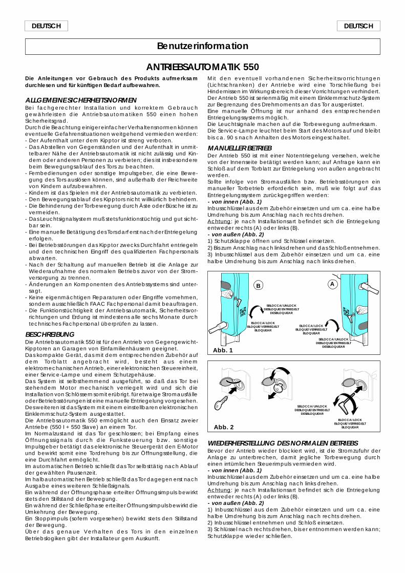
33
DEUTSCHDEUTSCH
Benutzerinformation
ANTRIEBSAUTOMATIK 550Die Anleitungen vor Gebrauch des Produkts aufmerksamdurchlesen und für künftigen Bedarf aufbewahren.
ALLGEMEINE SICHERHEITSNORMENBei fachgerechter Installation und korrektem Gebrauchgewährleisten die Antriebsautomatiken 550 einen hohenSicherheitsgrad.Durch die Beachtung einiger einfacher Verhaltensnormen könneneventuelle Gefahrensituationen weitgehend vermieden werden:- Der Aufenthalt unter dem Kipptor ist streng verboten.- Das Abstellen von Gegenständen und der Aufenthalt in unmit-
telbarer Nähe der Antriebsautomatik ist nicht zulässig und Kin-dern oder anderen Personen zu verbieten; dies ist insbesonderebeim Bewegungsablauf des Tors zu beachten.
- Fernbedienungen oder sonstige Impulsgeber, die eine Bewe-gung des Tors auslösen können, sind außerhalb der Reichweitevon Kindern aufzubewahren.
- Kindern ist das Spielen mit der Antriebsautomatik zu verbieten.- Den Bewegungsablauf des Kipptors nicht willkürlich behindern.- Die Behinderung der Torbewegung durch Äste oder Büsche ist zu
vermeiden.- Das Leuchtsignalsystem muß stets funktionstüchtig und gut sicht-
bar sein.- Eine manuelle Betätigung des Tors darf erst nach der Entriegelung
erfolgen.- Bei Betriebsstörungen das Kipptor zwecks Durchfahrt entriegeln
und den technischen Eingriff des qualifizierten Fachpersonalsabwarten.
- Nach der Schaltung auf manuellen Betrieb ist die Anlage zurWiederaufnahme des normalen Betriebs zuvor von der Strom-versorgung zu trennen.
- Änderungen an Komponenten des Antriebssystems sind unter-sagt.
- Keine eigenmächtigen Reparaturen oder Eingriffe vornehmen,sondern ausschließlich FAAC Fachpersonal damit beauftragen.
- Die Funktionstüchtigkeit der Antriebsautomatik, Sicherheitsvor-richtungen und Erdung ist mindestens alle sechs Monate durchtechnisches Fachpersonal überprüfen zu lassen.
BESCHREIBUNGDie Antriebsautomatik 550 ist für den Antrieb von Gegengewicht-Kipptoren an Garagen von Einfamilienhäusern geeignet.Das kompakte Gerät, das mit dem entsprechenden Zubehör aufdem Torblatt angebracht wird, besteht aus einemelektromechanischen Antrieb, einer elektronischen Steuereinheit,einer Service-Lampe und einem Schutzgehäuse.Das System ist selbsthemmend ausgeführt, so daß das Tor beistehendem Motor mechanisch verriegelt wird und sich dieInstallation von Schlössern somit erübrigt. für etwaige Stromausfälleoder Betriebsstörungen ist eine manuelle Entriegelung vorgesehen.Des weiteren ist das System mit einem einstellbaren elektronischenEinklemmschutz-System ausgestattet.Die Antriebsautomatik 550 ermöglicht auch den Einsatz zweierAntriebe (550 I + 550 Slave) an einem Tor.Im Normalzustand ist das Tor geschlossen; bei Empfang einesÖffnungssignals durch die Funksteuerung bzw. sonstigeImpulsgeber betätigt das elektronische Steuergerät den E-Motorund bewirkt somit eine Tordrehung bis zur Öffnungsstellung, dieeine Durchfahrt ermöglicht.Im automatischen Betrieb schließt das Tor selbsttätig nach Ablaufder gewählten Pausenzeit.Im halbautomatischen Betrieb schließt das Tor dagegen erst nachAusgabe eines weiteren Schließsignals.Ein während der Öffnungsphase erteilter Öffnungsimpuls bewirktstets den Stillstand der Bewegung.Ein während der Schließphase erteilter Öffnungsimpuls bewirkt dieUmkehrung der Bewegung.Ein Stoppimpuls (sofern vorgesehen) bewirkt stets den Stillstandder Bewegung.Über das genaue Verhalten des Tors in den einzelnenBetriebslogiken gibt der Installateur gern Auskunft.
Abb. 2
SBLOCCA/UNLOCKDEBLOQUE/ENTRIEGELT
DESBLOQUEAR
BLOCCA/LOCKBLOQUE/VERRIEGELT
BLOQUEAR
WIEDERHERSTELLUNG DES NORMALEN BETRIEBSBevor der Antrieb wieder blockiert wird, ist die Stromzufuhr derAnlage zu unterbrechen, damit jegliche Torbewegung durcheinen irrtümlichen Steuerimpuls vermieden wird.- von innen (Abb. 1)Inbusschlüssel aus dem Zubehör einsetzen und um ca. eine halbeUmdrehung bis zum Anschlag nach links drehen.Achtung: je nach Installationsart befindet sich die Entriegelungentweder rechts (A) oder links (B).- von außen (Abb. 2)1) Inbusschlüssel aus dem Zubehör einsetzen und um ca. einehalbe Umdrehung bis zum Anschlag nach rechts drehen.2) Inbusschlüssel entnehmen und Schloß einsetzen.3) Schlüssel nach rechts drehen, bis er entnommen werden kann;Schutzklappe wieder schließen.
Abb. 1
BLOCCA/LOCKBLOQUE/VERRIEGELT
BLOQUEAR
SBLOCCA/UNLOCKDEBLOQUE/ENTRIEGELT
DESBLOQUEAR
SBLOCCA/UNLOCKDEBLOQUE/ENTRIEGELT
DESBLOQUEAR
BLOCCA/LOCKBLOQUE/VERRIEGELT
BLOQUEAR
AB
Mit den eventuell vorhandenen Sicherheitsvorrichtungen(Lichtschranken) der Antriebe wird eine Torschließung beiHindernissen im Wirkungsbereich dieser Vorrichtungen verhindert.Der Antrieb 550 ist serienmäßig mit einem Einklemmschutz-Systemzur Begrenzung des Drehmoments an das Tor ausgerüstet.Eine manuelle Öffnung ist nur anhand des entsprechendenEntriegelungssystems möglich.Die Leuchtsignale machen auf die Torbewegung aufmerksam.Die Service-Lampe leuchtet beim Start des Motors auf und bleibtbis ca. 90 s nach Anhalten des Motors eingeschaltet.
MANUELLER BETRIEBDer Antrieb 550 ist mit einer Notentriegelung versehen, welchevon der Innenseite betätigt werden kann; auf Anfrage kann einSchloß auf dem Torblatt zur Entriegelung von außen angebrachtwerden.Sollte infolge von Stromausfällen bzw. Betriebsstörungen einmanueller Torbetrieb erforderlich sein, muß wie folgt auf dasEntriegelungssystem zurückgegriffen werden:- von innen (Abb. 1)Inbusschlüssel aus dem Zubehör einsetzen und um ca. eine halbeUmdrehung bis zum Anschlag nach rechts drehen.Achtung: je nach Installationsart befindet sich die Entriegelungentweder rechts (A) oder links (B).- von außen (Abb. 2)1) Schutzklappe öffnen und Schlüssel einsetzen.2) Bis zum Anschlag nach links drehen und das Schloß entnehmen.3) Inbusschlüssel aus dem Zubehör einsetzen und um ca. einehalbe Umdrehung bis zum Anschlag nach links drehen.
33
ESPAÑOLESPAÑOL
1) ATENCIÓN! Para poder garantizar la seguridad personal, es importanteseguir atentamente todas las instrucciones. La instalación incorrectao el uso inapropiado del producto pueden provocar graves dañospersonales.
2) Leer detenidamente las instrucciones antes de empezar a instalar elequipo.
3) No dejar los materiales de embalaje (plástico, poliestireno, etc.) alalcance de los niños, ya que constituyen fuentes potenciales depeligro.
4) Conservar las instrucciones para futuras consultas.
5) Este producto ha sido proyectado y construido exclusivamente parael uso indicado en el presente manual. Cualquier aplicación noexpresamente indicada podría resultar perjudicial para el equipo opara las personas circunstantes.
6) FAAC SpA declina toda responsabilidad ante inconvenientes deriva-dos del uso impropio del equipo o de aplicaciones distintas de aquéllapara la cual el mismo fue creado.
7) No instalar el aparato en una atmósfera explosiva: la presencia degases o humos inflamables implica un grave peligro para la seguridad.
8) Los elementos mecánicos de construcción deben ser conformes a loestablecido en las Normativas UNI8612, CEN pr EN 12604 y CEN pr EN12605.
En los países no pertenecientes a la CEE, además de respetarse lasnormativas nacionales, para obtener un nivel de seguridad adecua-do deben cumplirse las normas arriba mencionadas.
9) FAAC SpA no es responsable por la inobservancia de los adecuadoscriterios técnicos en la construcción de los cierres que se van amotorizar, ni por las deformaciones que puedan verificarse con el uso.
10) La instalación debe efectuarse de conformidad con las NormasUNI8612, CEN pr EN 12453 y CEN pr EN 12635.El nivel de seguridad del equipo automático debe ser C+D.
11) Antes de efectuar cualquier operación en el equipo, desconéctelode la alimentación eléctrica.
12) La red del equipo automático debe estar dotada de un interruptoromnipolar con una distancia de apertura de los contactos igual osuperior a 3 mm. Como alternativa, se aconseja utilizar un interruptormagnetotérmico de 6 A con interrupción omnipolar.
DECLARACIÓN DE CONFORMIDAD CE PARA MÁQUINAS(DIRECTIVA 89/392/CEE, ANEXO II, PARTE B)
Fabricante: FAAC S.p.A.
Dirección: Via Benini, 1 - 40069 Zola Predosa BOLOGNA - ITALIA
Declara que: El equipo automático modelo 550,
• Ha sido construido para ser incorporado en una máquina, o para ser ensamblado con otros mecanismos a finde constituir una máquina con arreglo a la Directiva 89/392/CEE, y a sus sucesivas modificaciones 91/368/CEE,93/44/CEE, 93/68/CEE.
• Cumple los requisitos esenciales de seguridad establecidos por las siguientes directivas CEE:
73/23/CEE y sucesiva modificación 93/68/CEE,89/336/CEE y sucesivas modificaciones 92/31/CEE y 93/68/CEE
Asimismo, declara que no está permitido poner en marcha el equipo si la máquina en la cual será incorporado,o de la cual se convertirá en un componente, no ha sido identificado o no ha sido declarada su conformidada lo establecido por la Directiva 89/392 CEE y sus sucesivas modificaciones, y a la ley que la incorpora en lalegislación nacional del DPR n° 459 del 24 de julio de 1996.
Bologna, 1º de enero de 1999El Administrador Delegado
A. Bassi
13) Comprobar que antes de la instalación eléctrica haya un interruptordiferencial con umbral de 0,03 A.
14) Cerciorarse de que la conexión a tierra está correctamente realiza-da. Conectar a ella las partes metálicas del cierre y el cable amarillo/verde del equipo automático.
15) El equipo automático cuenta con un dispositivo de seguridadantiaplastamiento, constituido por un control de par, no obstante,también deben instalarse otros dispositivos de seguridad.
16) Los dispositivos de seguridad (por ej.: fotocélulas, bandas sensibles,etc.) permiten evitar peligros derivados de acciones mecánicas demovimiento, como es el caso de aplastamiento, arrastre, cercena-miento.
17) Para cada equipo es indispensable utilizar por lo menos una señaliza-ción luminosa (por ej.: FAAC LAMP MINILAMP, etc.), así como tambiénun letrero de señalización correctamente fijado a la estructura de lacancela, además de los dispositivos citados en el punto 16.
18) FAAC SpA declina toda responsabilidad respecto a la seguridad y alcorrecto funcionamiento del equipo automático en el caso de quese utilicen otros componentes del sistema que no hayan sido produ-cidos por dicha empresa.
19) Para el mantenimiento, utilizar exclusivamente recambios originalesFAAC.
20) No efectuar ninguna modificación de los elementos que componenel sistema de automatización.
21) El técnico instalador debe facilitar toda la información relativa alfuncionamiento manual de sistema en casos de emergencia, yentregar al usuario del sistema las ”Instrucciones para el usuario” quese anexa al producto.
22) No permitir que los niños, ni ninguna otra persona, permanezcan enproximidad del equipo durante el funcionamiento.
23) No dejar al alcance de los niños mandos a distancia ni otros genera-dores de impulsos, para evitar que el equipo automático sea ac-cionado involuntariamente.
24) El usuario debe abstenerse de todo intento de reparación o deintervención directa; es preciso consultar siempre con personal espe-cializado.
25) Todo aquello que no esté expresamente especificado en estas ins-trucciones habrá de considerarse no permitido.
ADVERTENCIAS PARA EL INSTALADORREGLAS GENERALES PARA LA SEGURIDAD
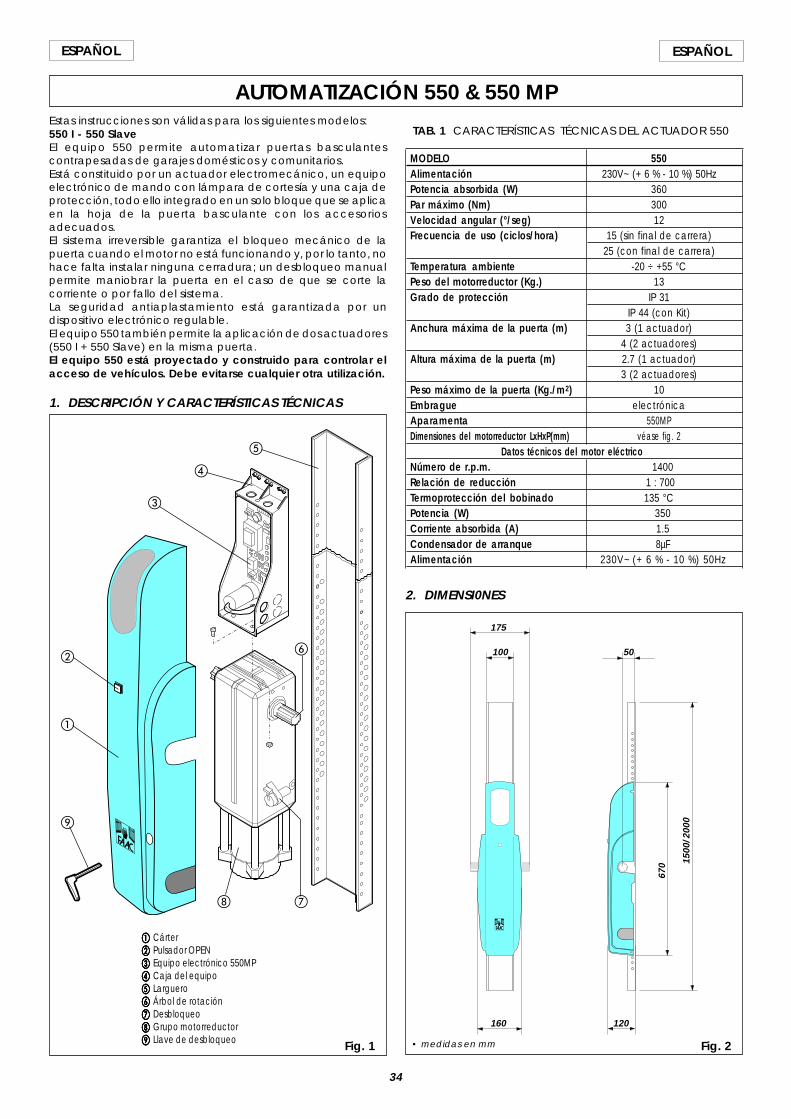
34
ESPAÑOL ESPAÑOL
AUTOMATIZACIÓN 550 & 550 MPEstas instrucciones son válidas para los siguientes modelos:550 I - 550 SlaveEl equipo 550 permite automatizar puertas basculantescontrapesadas de garajes domésticos y comunitarios.Está constituido por un actuador electromecánico, un equipoelectrónico de mando con lámpara de cortesía y una caja deprotección, todo ello integrado en un solo bloque que se aplicaen la hoja de la puerta basculante con los accesoriosadecuados.El sistema irreversible garantiza el bloqueo mecánico de lapuerta cuando el motor no está funcionando y, por lo tanto, nohace falta instalar ninguna cerradura; un desbloqueo manualpermite maniobrar la puerta en el caso de que se corte lacorriente o por fallo del sistema.La seguridad antiaplastamiento está garantizada por undispositivo electrónico regulable.El equipo 550 también permite la aplicación de dos actuadores(550 I + 550 Slave) en la misma puerta.El equipo 550 está proyectado y construido para controlar elacceso de vehículos. Debe evitarse cualquier otra utilización.
1. DESCRIPCIÓN Y CARACTERÍSTICAS TÉCNICAS
Fig. 1
aaaaa Cárterbbbbb Pulsador OPENccccc Equipo electrónico 550MPddddd Caja del equipoeeeee Larguerofffff Árbol de rotaciónggggg Desbloqueohhhhh Grupo motorreductoriiiii Llave de desbloqueo
TAB. 1 CARACTERÍSTICAS TÉCNICAS DEL ACTUADOR 550
MODELO 550Alimentación 230V~ (+ 6 % - 10 %) 50HzPotencia absorbida (W) 360Par máximo (Nm) 300Velocidad angular (°/seg) 12Frecuencia de uso (ciclos/hora) 15 (sin final de carrera)
25 (con final de carrera)Temperatura ambiente -20 ÷ +55 °CPeso del motorreductor (Kg.) 13Grado de protección IP 31
IP 44 (con Kit)Anchura máxima de la puerta (m) 3 (1 actuador)
4 (2 actuadores)Altura máxima de la puerta (m) 2.7 (1 actuador)
3 (2 actuadores)Peso máximo de la puerta (Kg./m2) 10Embrague electrónicaAparamenta 550MPDimensiones del motorreductor LxHxP(mm) véase fig. 2
Datos técnicos del motor eléctricoNúmero de r.p.m. 1400Relación de reducción 1 : 700Termoprotección del bobinado 135 °CPotencia (W) 350Corriente absorbida (A) 1.5Condensador de arranque 8µFAlimentación 230V~ (+ 6 % - 10 %) 50Hz
2. DIMENSI0NES
Fig. 2
175
100
160 120
5067
0 1500
/200
0
• medidas en mm
a
b
d
c
e
gh
i
f
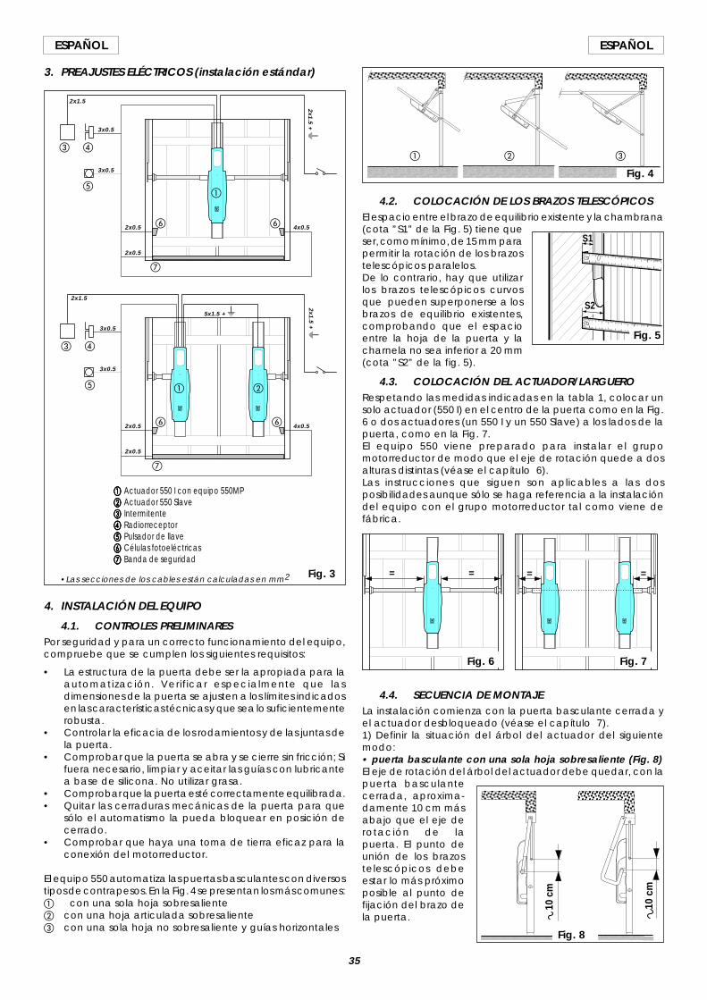
35
ESPAÑOLESPAÑOL
3. PREAJUSTES ELÉCTRICOS (instalación estándar)
aaaaa Actuador 550 I con equipo 550MPbbbbb Actuador 550 Slaveccccc Intermitenteddddd Radiorreceptoreeeee Pulsador de llavefffff Células fotoeléctricasggggg Banda de seguridad
a b
c d
e
f
g
f
a
c d
e
f
g
f
4. INSTALACIÓN DEL EQUIPO
4.1. CONTROLES PRELIMINARESPor seguridad y para un correcto funcionamiento del equipo,compruebe que se cumplen los siguientes requisitos:
• La estructura de la puerta debe ser la apropiada para laautomatización. Verificar especialmente que lasdimensiones de la puerta se ajusten a los límites indicadosen las características técnicas y que sea lo suficientementerobusta.
• Controlar la eficacia de los rodamientos y de las juntas dela puerta.
• Comprobar que la puerta se abra y se cierre sin fricción; Sifuera necesario, limpiar y aceitar las guías con lubricantea base de silicona. No utilizar grasa.
• Comprobar que la puerta esté correctamente equilibrada.• Quitar las cerraduras mecánicas de la puerta para que
sólo el automatismo la pueda bloquear en posición decerrado.
• Comprobar que haya una toma de tierra eficaz para laconexión del motorreductor.
El equipo 550 automatiza las puertas basculantes con diversostipos de contrapesos. En la Fig. 4 se presentan los más comunes:a con una sola hoja sobresalienteb con una hoja articulada sobresalientec con una sola hoja no sobresaliente y guías horizontales
4.2. COLOCACIÓN DE LOS BRAZOS TELESCÓPICOSEl espacio entre el brazo de equilibrio existente y la chambrana(cota ”S1” de la Fig. 5) tiene queser, como mínimo, de 15 mm parapermitir la rotación de los brazostelescópicos paralelos.De lo contrario, hay que utilizarlos brazos telescópicos curvosque pueden superponerse a losbrazos de equilibrio existentes,comprobando que el espacioentre la hoja de la puerta y lacharnela no sea inferior a 20 mm(cota ”S2” de la fig. 5).
4.3. COLOCACIÓN DEL ACTUADOR/LARGUERORespetando las medidas indicadas en la tabla 1, colocar unsolo actuador (550 I) en el centro de la puerta como en la Fig.6 o dos actuadores (un 550 I y un 550 Slave) a los lados de lapuerta, como en la Fig. 7.El equipo 550 viene preparado para instalar el grupomotorreductor de modo que el eje de rotación quede a dosalturas distintas (véase el capítulo 6).Las instrucciones que siguen son aplicables a las dosposibilidades aunque sólo se haga referencia a la instalacióndel equipo con el grupo motorreductor tal como viene defábrica.
Fig. 3
4.4. SECUENCIA DE MONTAJELa instalación comienza con la puerta basculante cerrada yel actuador desbloqueado (véase el capítulo 7).1) Definir la situación del árbol del actuador del siguientemodo:• puerta basculante con una sola hoja sobresaliente (Fig. 8)El eje de rotación del árbol del actuador debe quedar, con lapuerta basculantecerrada, aproxima-damente 10 cm másabajo que el eje derotación de lapuerta. El punto deunión de los brazostelescópicos debeestar lo más próximoposible al punto defijación del brazo dela puerta.
10 c
m
10 c
m
Fig. 8
= = = =
Fig. 6 Fig. 7
a cb
Fig. 4
S1
S2
2x0.5 4x0.5
2x0.5
3x0.5
3x0.5
2x1.5
2x1.5 + W
5x1.5 + W
2x1.5
3x0.5
3x0.5
2x0.5
2x0.5
4x0.5
•Las secciones de los cables están calculadas en mm2
Fig. 5
2x1.5 + W
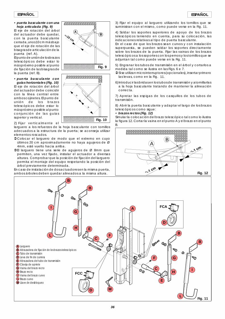
36
ESPAÑOL ESPAÑOL
• puerta basculante con unahoja articulada (Fig. 9)
El eje de rotación del árboldel actuador debe quedar,con la puerta basculantecerrada, unos 10 cm más bajoque el eje de rotación de lasbisagras de articulación de lapuerta (ref. A).El punto de unión de los brazostelescópicos debe estar lomás próximo posible al puntode fijación de las bisagras dela puerta (ref. B).
• puerta basculante conguías horizontales (Fig. 10)
El eje de rotación del árboldel actuador debe coincidircon la línea central entreambos cojinetes. El punto deunión de los brazostelescópicos debe estar lomás próximo posible al puntoconjunción de las guíassuperior y vertical.
2) Fijar verticalmente ellarguero a los refuerzos de la hoja basculante con tornillosadecuados a la estructura de la puerta; se aconseja utilizarelementos roscados.ÜColocar el larguero de modo que el extremo en cuyo
últimos 20 cm aproximadamente no haya agujeros de Ø4mm, esté vuelto hacia arriba.
ÜEl larguero tiene una serie de agujeros de Ø 8mm quepermiten, una vez fijado, instalar el actuador a diversasalturas. Comprobar que la posición de fijación del largueropermita el montaje del equipo respetando la posición delárbol previamente determinada.
En caso de instalación de dos actuadores en la misma puerta,ambos árboles deben quedar alineados a la misma altura.
10 cm
Fig. 9
AB
=
=
Fig. 10
3) Fijar el equipo al larguero utilizando los tornillos que sesuministran con el mismo, como puede verse en la Fig. 11.
4) Soldar los soportes superiores de apoyo de los brazostelescópicos teniendo en cuenta, para su colocación, lasindicaciones relativas al tipo de puerta basculante.En el caso de que los brazos sean curvos y con instalaciónsuperpuesta, se pueden soldar los soportes directamentesobre los brazos de la puerta. Fijar las vainas de los brazostelescópicos a los soportes con los pernos y los tornillos que seadjuntan tal como puede verse en la Fig. 11.
5) Engranar los tubos de transmisión en el árbol y cortarlos amedida tal como se ilustra en las Figs. 6 e 7.ÜSi se utilizan microinterruptores (opcionales), insertar primero
las levas, como en la Fig. 11.
6)Introducir las bridas en los tubos de transmisión y atornillarlasa la hoja basculante tratando de mantener la alineacióncorrecta.
7) Apretar las espigas de los casquillos de los tubos detransmisión.
8) Abrir la puerta basculante y adaptar el largo de los brazostelescópicos como sigue:• brazos rectos (Fig. 12)Simular la colocación del brazo telescópico tal como lo ilustrala figura 12. Cortar la vaina en el punto A y el brazo en el puntoB.
Fig. 11
AB
Fig. 12
FCC
FCAA
B
B
B
BC
C
D
D
E
E
F
F
G
G
H
H
I
I
L
M
A LargueroB Abrazadera de fijación de los brazos telescópicosC Tubo de transmisiónD Leva de fin de carreraE Abrazadera del tubo de transmisiónF Clavija de aprieteG Vaina del brazo rectoH Brazo recto I Vaina del brazo curvo L Brazo curvoM Llave de desbloqueo
L
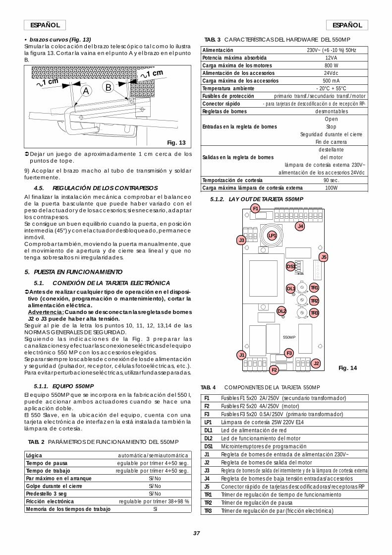
37
ESPAÑOLESPAÑOL
• brazos curvos (Fig. 13)Simular la colocación del brazo telescópico tal como lo ilustrala figura 13. Cortar la vaina en el punto A y el brazo en el puntoB.
ÜDejar un juego de aproximadamente 1 cm cerca de lospuntos de tope.
9) Acoplar el brazo macho al tubo de transmisión y soldarfuertemente.
4.5. REGULACIÓN DE LOS CONTRAPESOSAl finalizar la instalación mecánica comprobar el balanceode la puerta basculante que puede haber variado con elpeso del actuador y de los accesorios; si es necesario, adaptarlos contrapesos.Se consigue un buen equilibrio cuando la puerta, en posiciónintermedia (45°) y con el actuador desbloqueado, permaneceinmóvil.Comprobar también, moviendo la puerta manualmente, queel movimiento de apertura y de cierre sea lineal y que notenga sobresaltos ni irregularidades.
5. PUESTA EN FUNCIONAMIENTO
5.1. CONEXIÓN DE LA TARJETA ELECTRÓNICAÜAntes de realizar cualquier tipo de operación en el disposi-
tivo (conexión, programación o mantenimiento), cortar laalimentación eléctrica.Advertencia: Cuando se desconectan las regletas de bornesJ2 o J3 puede haber alta tensión.
Seguir al pie de la letra los puntos 10, 11, 12, 13,14 de lasNORMAS GENERALES DE SEGURIDAD.Siguiendo las indicaciones de la Fig. 3 preparar lascanalizaciones y efectuar las conexiones eléctricas del equipoelectrónico 550 MP con los accesorios elegidos.Separar siempre los cables de conexión de los de alimentacióny seguridad (pulsador, receptor, células fotoeléctricas, etc.).Para evitar perturbaciones eléctricas, utilizar fundas separadas.
5.1.1. EQUIPO 550MPEl equipo 550MP que se incorpora en la fabricación del 550 I,puede accionar ambos actuadores cuando se hace unaaplicación doble.El 550 Slave, en la ubicación del equipo, cuenta con unatarjeta electrónica de interfaz en la está instalada también lalámpara de cortesía.
TAB. 2 PARÁMETROS DE FUNCIONAMIENTO DEL 550MP
Lógica automática/semiautomáticaTiempo de pausa egulable por trímer 4V50 seg.Tiempo de trabajo regulable por trímer 4V50 seg.Par máximo en el arranque Sí/NoGolpe durante el cierre Sí/NoPredestello 3 seg Sí/NoFricción electrónica regulable por trímer 38V98 %Memoria de los tiempos de trabajo Sí
TAB. 4 COMPONENTES DE LA TARJETA 550MP
F1 Fusibles F1 5x20 2A/250V (secundario transformador)F2 Fusibles F2 5x20 4A/250V (motor)F3 Fusibles F3 5x20 0.5A/250V (primario transformador)LP1 Lámpara de cortesía 25W 220V E14DL1 Led de alimentación de redDL2 Led de funcionamiento del motorDS1 Microinterruptores de programaciónJ1 Regleta de bornes de entrada de alimentación 230V~J2 Regleta de bornes de salida del motorJ3 Regleta de bornes de salida del intermitente y de la lámpara de cortesía externaJ4 Regleta de bornes de baja tensión entradas/accesoriosJ5 Conector rápido de tarjetas descodificadoras/receptoras RPTR1 Trímer de regulación de tiempo de funcionamientoTR2 Trímer de regulación de pausaTR3 Trímer de regulación de par (fricción electrónica)
TAB. 3 CARACTERÍSTICAS DEL HARDWARE DEL 550MP
Alimentación 230V~ (+6 -10 %) 50HzPotencia máxima absorbida 12VACarga máxima de los motores 800 WAlimentación de los accesorios 24VdcCarga máxima de los accesorios 500 mATemperatura ambiente - 20°C + 55°CFusibles de protección primario transf./secundario transf./motorConector rápido - para tarjetas de descodificación o de recepción RP-Regletas de bornes desmontables
OpenEntradas en la regleta de bornes Stop
Seguridad durante el cierreFin de carrera
destellanteSalidas en la regleta de bornes del motor
lámpara de cortesía externa 230V~alimentación de los accesorios 24Vdc
Temporización de cortesía 90 sec.Carga máxima lámpara de cortesía externa 100W
5.1.2. LAY OUT DE TARJETA 550MP
A B
Fig. 13
ON
+
+
+
-
-
-
14
32
550MP
F1
J4
LP1J3
J5
DS1
DL1 TR1
TR2
TR3
J1
J2
F3
F2
DL2
Fig. 14
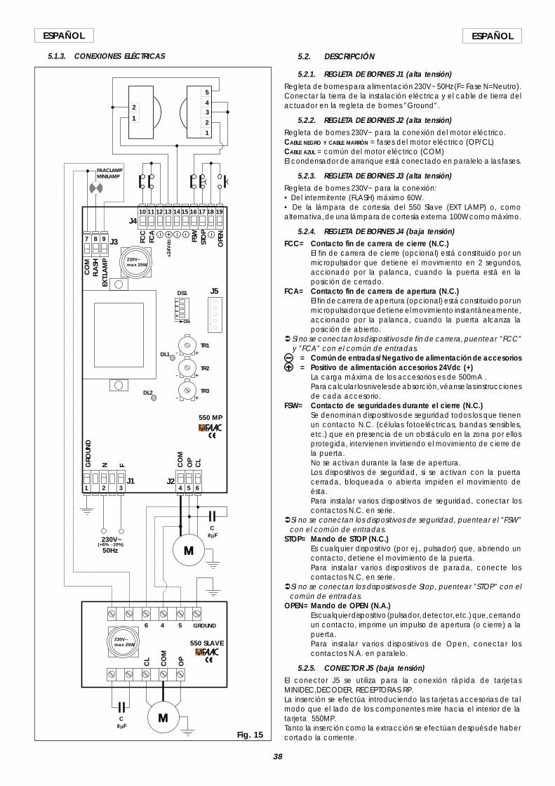
38
ESPAÑOL ESPAÑOL
5.1.3. CONEXIONES ELÉCTRICAS
ON
+
+
+
-
-
-
14
32
1 32 4 5 6
7 8 9
10 11 12 13 14 15 16 17 18 19J4
J3
J1 J2
GROUND
N F CO
MO
PC
L
CO
MFL
ASH
EXT.L
AM
P
FCC
FCA
FSW
STO
P
OPE
N
M230V~
C8µF
5
43
2
1
1
2
(+6% -10%)
550 SLAVE
550 MP
M
C8µF
50Hz
CO
M
OP
CL
4 56
FAACLAMPMINILAMP
230V~max 25W
230V~max 25W
J5
TR1
TR2
TR3
DS1
DL1
DL2
GRO
UND
Fig. 15
5.2. DESCRIPCIÓN
5.2.1. REGLETA DE BORNES J1 (alta tensión)Regleta de bornes para alimentación 230V~ 50Hz (F= Fase N=Neutro).Conectar la tierra de la instalación eléctrica y el cable de tierra delactuador en la regleta de bornes ”Ground”.
5.2.2. REGLETA DE BORNES J2 (alta tensión)Regleta de bornes 230V~ para la conexión del motor eléctrico.CABLE NEGRO Y CABLE MARRÓN = fases del motor eléctrico (OP/CL)CABLE AZUL = común del motor eléctrico (COM)El condensador de arranque está conectado en paralelo a las fases.
5.2.3. REGLETA DE BORNES J3 (alta tensión)Regleta de bornes 230V~ para la conexión:• Del intermitente (FLASH) máximo 60W.• De la lámpara de cortesía del 550 Slave (EXT LAMP) o, comoalternativa, de una lámpara de cortesía externa 100W como máximo.
5.2.4. REGLETA DE BORNES J4 (baja tensión)FCC= Contacto fin de carrera de cierre (N.C.)
El fin de carrera de cierre (opcional) está constituido por unmicropulsador que detiene el movimiento en 2 segundos,accionado por la palanca, cuando la puerta está en laposición de cerrado.
FCA= Contacto fin de carrera de apertura (N.C.)El fin de carrera de apertura (opcional) está constituido por unmicropulsador que detiene el movimiento instantáneamente,accionado por la palanca, cuando la puerta alcanza laposición de abierto.
Ü Si no se conectan los dispositivos de fin de carrera, puentear ”FCC”y ”FCA” con el común de entradas.
= Común de entradas/Negativo de alimentación de accesorios= Positivo de alimentación accesorios 24Vdc (+)
La carga máxima de los accesorios es de 500mA .Para calcular los niveles de absorción, véanse las instruccionesde cada accesorio.
FSW= Contacto de seguridades durante el cierre (N.C.)Se denominan dispositivos de seguridad todos los que tienenun contacto N.C. (células fotoeléctricas, bandas sensibles,etc.) que en presencia de un obstáculo en la zona por ellosprotegida, intervienen invirtiendo el movimiento de cierre dela puerta.No se activan durante la fase de apertura.Los dispositivos de seguridad, si se activan con la puertacerrada, bloqueada o abierta impiden el movimiento deésta.Para instalar varios dispositivos de seguridad, conectar loscontactos N.C. en serie.
ÜSi no se conectan los dispositivos de seguridad, puentear el ”FSW”con el común de entradas.
STOP= Mando de STOP (N.C.)Es cualquier dispositivo (por ej., pulsador) que, abriendo uncontacto, detiene el movimiento de la puerta.Para instalar varios dispositivos de parada, conecte loscontactos N.C. en serie.
ÜSi no se conectan los dispositivos de Stop, puentear ”STOP” con elcomún de entradas.
OPEN= Mando de OPEN (N.A.)Es cualquier dispositivo (pulsador, detector, etc.) que, cerrandoun contacto, imprime un impulso de apertura (o cierre) a lapuerta.Para instalar varios dispositivos de Open, conectar loscontactos N.A. en paralelo.
5.2.5. CONECTOR J5 (baja tensión)El conector J5 se utiliza para la conexión rápida de tarjetasMINIDEC,DECODER, RECEPTORAS RP.La inserción se efectúa introduciendo las tarjetas accesorias de talmodo que el lado de los componentes mire hacia el interior de latarjeta 550MP.Tanto la inserción como la extracción se efectúan después de habercortado la corriente.
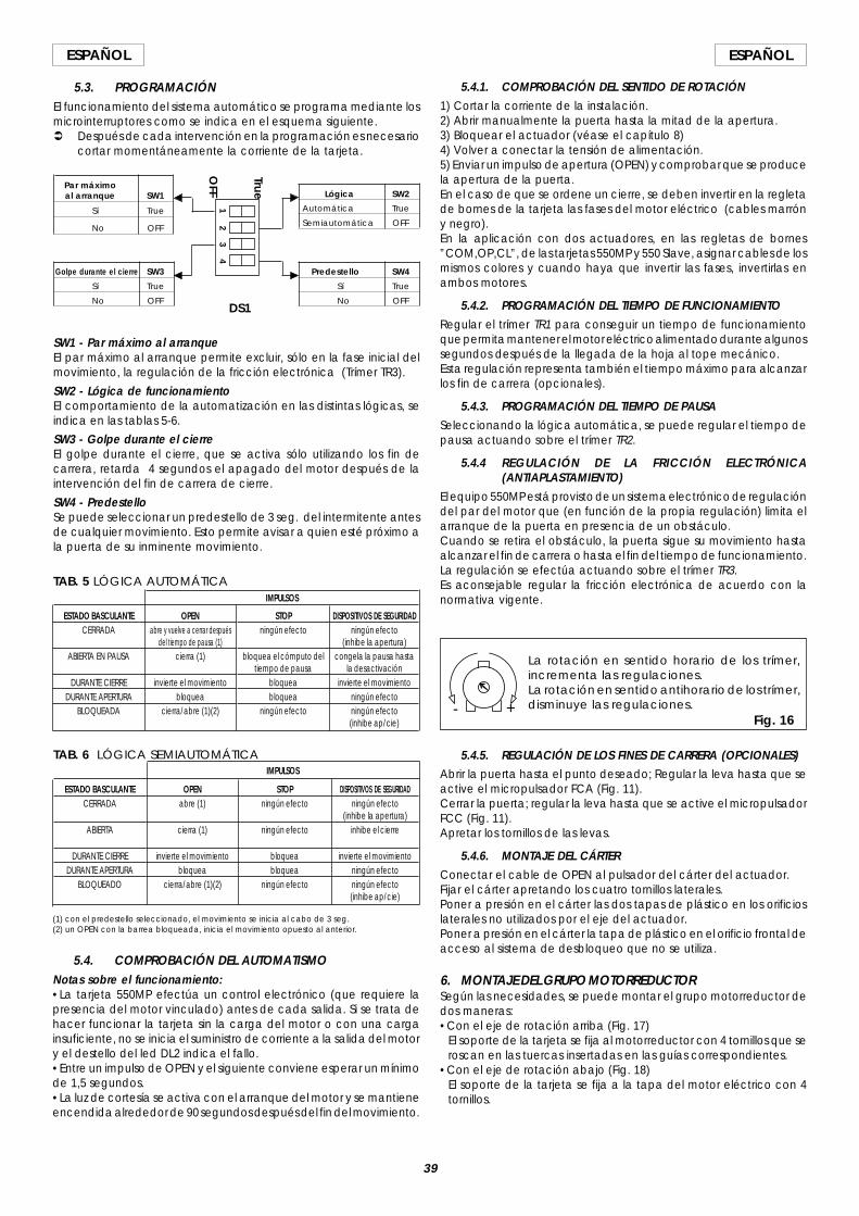
39
ESPAÑOLESPAÑOL
5.3. PROGRAMACIÓNEl funcionamiento del sistema automático se programa mediante losmicrointerruptores como se indica en el esquema siguiente.Ü Después de cada intervención en la programación es necesario
cortar momentáneamente la corriente de la tarjeta.
SW1 - Par máximo al arranqueEl par máximo al arranque permite excluir, sólo en la fase inicial delmovimiento, la regulación de la fricción electrónica (Trímer TR3).
SW2 - Lógica de funcionamientoEl comportamiento de la automatización en las distintas lógicas, seindica en las tablas 5-6.
SW3 - Golpe durante el cierreEl golpe durante el cierre, que se activa sólo utilizando los fin decarrera, retarda 4 segundos el apagado del motor después de laintervención del fin de carrera de cierre.
SW4 - PredestelloSe puede seleccionar un predestello de 3 seg. del intermitente antesde cualquier movimiento. Esto permite avisar a quien esté próximo ala puerta de su inminente movimiento.
Lógica SW2
Automática True
Semiautomática OFF
Par máximoal arranque SW1
Sí True
No OFF
Golpe durante el cierre SW3
Sí True
No OFF
Predestello SW4
Sí True
No OFF
12
34
True
OFF
TAB. 6 LÓGICA SEMIAUTOMÁTICA
DISPOSITIVOS DE SEGURIDADningún efecto
(inhibe la apertura)inhibe el cierre
invierte el movimientoningún efectoningún efecto(inhibe ap/cie)
ESTADO BASCULANTECERRADA
ABIERTA
DURANTE CIERREDURANTE APERTURA
BLOQUEADO
OPENabre (1)
cierra (1)
invierte el movimientobloquea
cierra/abre (1)(2)
STOPningún efecto
ningún efecto
bloqueabloquea
ningún efecto
IMPULSOS
IMPULSOS
DISPOSITIVOS DE SEGURIDADningún efecto
(inhibe la apertura)congela la pausa hasta
la desactivacióninvierte el movimiento
ningún efectoningún efecto(inhibe ap/cie)
STOPningún efecto
bloquea el cómputo deltiempo de pausa
bloqueabloquea
ningún efecto
ESTADO BASCULANTECERRADA
ABIERTA EN PAUSA
DURANTE CIERREDURANTE APERTURA
BLOQUEADA
OPENabre y vuelve a cerrar después
del tiempo de pausa (1)cierra (1)
invierte el movimientobloquea
cierra/abre (1)(2)
TAB. 5 LÓGICA AUTOMÁTICA
(1) con el predestello seleccionado, el movimiento se inicia al cabo de 3 seg.(2) un OPEN con la barrea bloqueada, inicia el movimiento opuesto al anterior.
5.4. COMPROBACIÓN DEL AUTOMATISMONotas sobre el funcionamiento:•La tarjeta 550MP efectúa un control electrónico (que requiere lapresencia del motor vinculado) antes de cada salida. Si se trata dehacer funcionar la tarjeta sin la carga del motor o con una cargainsuficiente, no se inicia el suministro de corriente a la salida del motory el destello del led DL2 indica el fallo.•Entre un impulso de OPEN y el siguiente conviene esperar un mínimode 1,5 segundos.•La luz de cortesía se activa con el arranque del motor y se mantieneencendida alrededor de 90 segundos después del fin del movimiento.
5.4.1. COMPROBACIÓN DEL SENTIDO DE ROTACIÓN1) Cortar la corriente de la instalación.2) Abrir manualmente la puerta hasta la mitad de la apertura.3) Bloquear el actuador (véase el capítulo 8)4) Volver a conectar la tensión de alimentación.5) Enviar un impulso de apertura (OPEN) y comprobar que se producela apertura de la puerta.En el caso de que se ordene un cierre, se deben invertir en la regletade bornes de la tarjeta las fases del motor eléctrico (cables marróny negro).En la aplicación con dos actuadores, en las regletas de bornes”COM,OP,CL”, de las tarjetas 550MP y 550 Slave, asignar cables de losmismos colores y cuando haya que invertir las fases, invertirlas enambos motores.
5.4.2. PROGRAMACIÓN DEL TIEMPO DE FUNCIONAMIENTORegular el trímer TR1 para conseguir un tiempo de funcionamientoque permita mantener el motor eléctrico alimentado durante algunossegundos después de la llegada de la hoja al tope mecánico.Esta regulación representa también el tiempo máximo para alcanzarlos fin de carrera (opcionales).
5.4.3. PROGRAMACIÓN DEL TIEMPO DE PAUSASeleccionando la lógica automática, se puede regular el tiempo depausa actuando sobre el trímer TR2.
5.4.4 REGULACIÓN DE LA FRICCIÓN ELECTRÓNICA(ANTIAPLASTAMIENTO)
El equipo 550MP está provisto de un sistema electrónico de regulacióndel par del motor que (en función de la propia regulación) limita elarranque de la puerta en presencia de un obstáculo.Cuando se retira el obstáculo, la puerta sigue su movimiento hastaalcanzar el fin de carrera o hasta el fin del tiempo de funcionamiento.La regulación se efectúa actuando sobre el trímer TR3.Es aconsejable regular la fricción electrónica de acuerdo con lanormativa vigente.
5.4.5. REGULACIÓN DE LOS FINES DE CARRERA (OPCIONALES)Abrir la puerta hasta el punto deseado; Regular la leva hasta que seactive el micropulsador FCA (Fig. 11).Cerrar la puerta; regular la leva hasta que se active el micropulsadorFCC (Fig. 11).Apretar los tornillos de las levas.
5.4.6. MONTAJE DEL CÁRTERConectar el cable de OPEN al pulsador del cárter del actuador.Fijar el cárter apretando los cuatro tornillos laterales.Poner a presión en el cárter las dos tapas de plástico en los orificioslaterales no utilizados por el eje del actuador.Poner a presión en el cárter la tapa de plástico en el orificio frontal deacceso al sistema de desbloqueo que no se utiliza.
6. MONTAJE DEL GRUPO MOTORREDUCTORSegún las necesidades, se puede montar el grupo motorreductor dedos maneras:•Con el eje de rotación arriba (Fig. 17)
El soporte de la tarjeta se fija al motorreductor con 4 tornillos que seroscan en las tuercas insertadas en las guías correspondientes.
•Con el eje de rotación abajo (Fig. 18)El soporte de la tarjeta se fija a la tapa del motor eléctrico con 4tornillos.
DS1
+-Fig. 16
La rotación en sentido horario de los trímer,incrementa las regulaciones.La rotación en sentido antihorario de los trímer,disminuye las regulaciones.

40
ESPAÑOL ESPAÑOL
El cárter está preparado para ambas aplicaciones (téngase encuenta que el desbloqueo se encuentra en posiciones diferentes);además se han previsto, en correspondencia con la lámpara detecho transparente, dos chavetas para el apriete del cable dealimentación eléctrica. (Fig. 19).En las Figs. 17-18 también se indica la disposición aconsejada de pasoy fijación de los cables en el soporte de la tarjeta.
LEYENDA DE LOS CABLESaaaaa Intermitentebbbbb Lámpara de cortesía externaccccc Pulsador OPEN en la cajaddddd Conexiones de baja tensióneeeee Motor 550 Slavefffff Alimentación 230V~ggggg Motor 550 I
ab c d
ef
ab c d
ef
g
Fig. 18
Fig. 19
g
Fig. 17
- Desde el exterior (Fig. 21)1) Abrir la portezuela de protección e insertar la llave.2) Girar en sentido antihorario hasta que se detenga y sacar el cuerpode la cerradura.3) Insertar la llave hueca hexagonal y girar en sentido antihorarioalrededor de medio giro hasta que se detenga.
Fig. 21
SBLOCCA/UNLOCKDEBLOQUE/ENTRIEGELT
DESBLOQUEAR
BLOCCA/LOCKBLOQUE/VERRIEGELT
BLOQUEAR
8. REANUDACIÓN DEL FUNCIONAMIENTO NORMALPara evitar que un impulso involuntario pueda activar la puertadurante la maniobra, cortar la corriente de la instalación antes devolver a bloquear el actuador.- Desde el interior (Fig. 20)Insertar la llave hueca hexagonal y girarla en sentido antihorarioalrededor de medio giro hasta que se detenga.Advertencia: según el tipo de instalación, el desbloqueo puede estaren el lado derecho (A) o izquierdo (B).- Desde el exterior (Fig. 21)1) Insertar la llave hueca hexagonal y girar en sentido horario alrededorde medio giro hasta que se detenga.2) Sacar la llave hueca hexagonal e insertar el cuerpo de la cerradura.3) Girar la llave en sentido horario hasta que se pueda extraer; cerrarla portezuela de protección.
9 MANTENIMIENTOEfectuar, al menos con frecuencia semestral, las siguientesoperaciones:•Comprobación del correcto ajuste del par del motor.•Control de los rodillos y guías de deslizamiento de la puerta; limpiezay lubricación cuando sea necesario.•Control de la eficacia del sistema de desbloqueo.•Control de la eficacia de los dispositivos de seguridad.
10 REPARACIONESPara cualquier reparación necesaria, diríjase al Servicio TécnicoAutorizado de FAAC.
Fig. 20
BLOCCA/LOCKBLOQUE/VERRIEGELT
BLOQUEAR
SBLOCCA/UNLOCKDEBLOQUE/ENTRIEGELT
DESBLOQUEAR
SBLOCCA/UNLOCKDEBLOQUE/ENTRIEGELT
DESBLOQUEAR
BLOCCA/LOCKBLOQUE/VERRIEGELT
BLOQUEAR
AB
7. FUNCIONAMIENTO MANUALEl actuador 550 está provisto de un desbloqueo de emergenciaaccionable desde el interior; sobre pedido, se puede poner unacerradura en la puerta para accionar el desbloqueo desde elexterior.En el caso de que se deba accionar manualmente la puerta a causade un corte de energía o de un fallo del actuador, se deberá utilizarel dispositivo de desbloqueo tal como se indica:- Desde el interior (Fig. 20)Introducir la llave hueca hexagonal y girarla en la dirección de lasagujas del reloj alrededor de medio giro hasta que se pare.Advertencia: según el tipo de instalación, el desbloqueo puede estaren el lado derecho (A) o izquierdo (B).
f
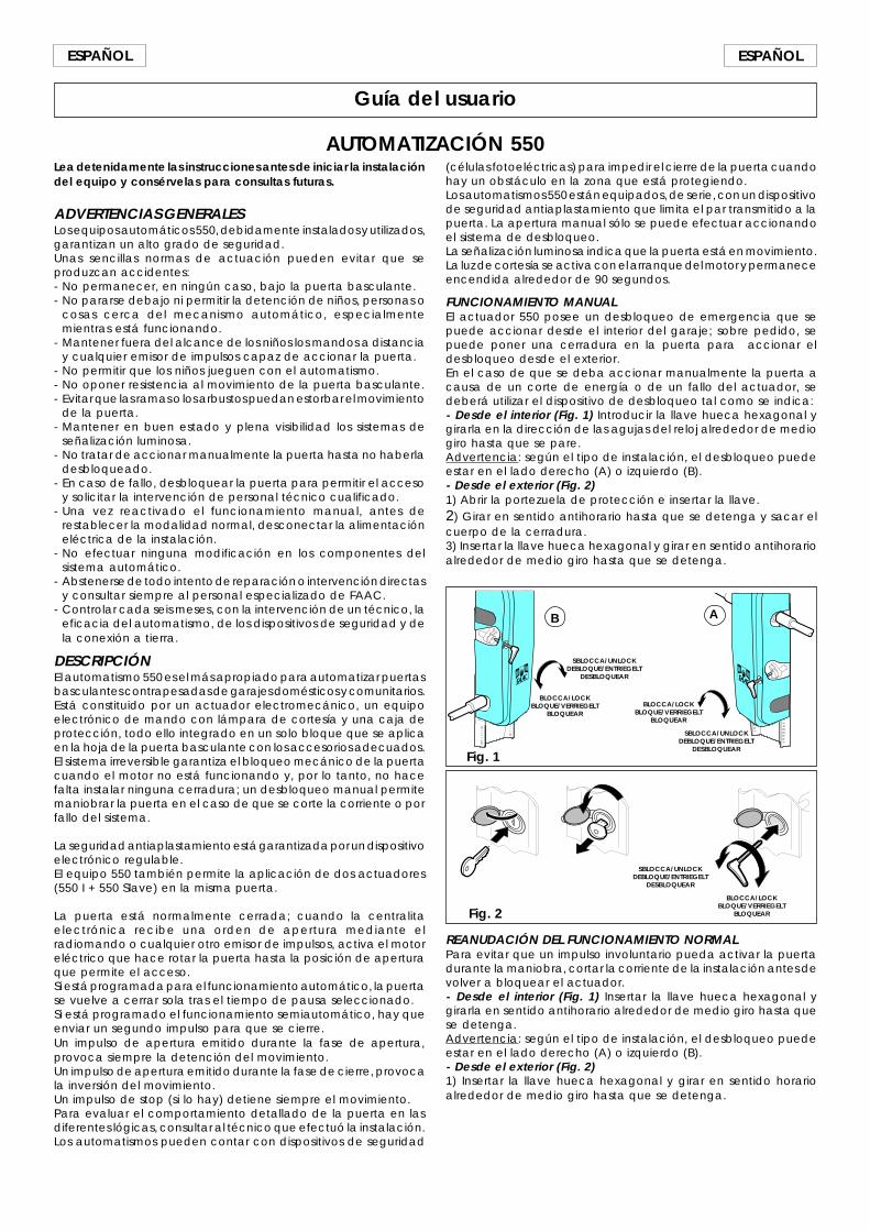
41
ESPAÑOLESPAÑOL
Guía del usuario
AUTOMATIZACIÓN 550Lea detenidamente las instrucciones antes de iniciar la instalacióndel equipo y consérvelas para consultas futuras.
ADVERTENCIAS GENERALESLos equipos automáticos 550, debidamente instalados y utilizados,garantizan un alto grado de seguridad.Unas sencillas normas de actuación pueden evitar que seproduzcan accidentes:- No permanecer, en ningún caso, bajo la puerta basculante.- No pararse debajo ni permitir la detención de niños, personas o
cosas cerca del mecanismo automático, especialmentemientras está funcionando.
- Mantener fuera del alcance de los niños los mandos a distanciay cualquier emisor de impulsos capaz de accionar la puerta.
- No permitir que los niños jueguen con el automatismo.- No oponer resistencia al movimiento de la puerta basculante.- Evitar que las ramas o los arbustos puedan estorbar el movimiento
de la puerta.- Mantener en buen estado y plena visibilidad los sistemas de
señalización luminosa.- No tratar de accionar manualmente la puerta hasta no haberla
desbloqueado.- En caso de fallo, desbloquear la puerta para permitir el acceso
y solicitar la intervención de personal técnico cualificado.- Una vez reactivado el funcionamiento manual, antes de
restablecer la modalidad normal, desconectar la alimentacióneléctrica de la instalación.
- No efectuar ninguna modificación en los componentes delsistema automático.
- Abstenerse de todo intento de reparación o intervención directasy consultar siempre al personal especializado de FAAC.
- Controlar cada seis meses, con la intervención de un técnico, laeficacia del automatismo, de los dispositivos de seguridad y dela conexión a tierra.
DESCRIPCIÓNEl automatismo 550 es el más apropiado para automatizar puertasbasculantes contrapesadas de garajes domésticos y comunitarios.Está constituido por un actuador electromecánico, un equipoelectrónico de mando con lámpara de cortesía y una caja deprotección, todo ello integrado en un solo bloque que se aplicaen la hoja de la puerta basculante con los accesorios adecuados.El sistema irreversible garantiza el bloqueo mecánico de la puertacuando el motor no está funcionando y, por lo tanto, no hacefalta instalar ninguna cerradura; un desbloqueo manual permitemaniobrar la puerta en el caso de que se corte la corriente o porfallo del sistema.
La seguridad antiaplastamiento está garantizada por un dispositivoelectrónico regulable.El equipo 550 también permite la aplicación de dos actuadores(550 I + 550 Slave) en la misma puerta.
La puerta está normalmente cerrada; cuando la centralitaelectrónica recibe una orden de apertura mediante elradiomando o cualquier otro emisor de impulsos, activa el motoreléctrico que hace rotar la puerta hasta la posición de aperturaque permite el acceso.Si está programada para el funcionamiento automático, la puertase vuelve a cerrar sola tras el tiempo de pausa seleccionado.Si está programado el funcionamiento semiautomático, hay queenviar un segundo impulso para que se cierre.Un impulso de apertura emitido durante la fase de apertura,provoca siempre la detención del movimiento.Un impulso de apertura emitido durante la fase de cierre, provocala inversión del movimiento.Un impulso de stop (si lo hay) detiene siempre el movimiento.Para evaluar el comportamiento detallado de la puerta en lasdiferentes lógicas, consultar al técnico que efectuó la instalación.Los automatismos pueden contar con dispositivos de seguridad
Fig. 2
SBLOCCA/UNLOCKDEBLOQUE/ENTRIEGELT
DESBLOQUEAR
BLOCCA/LOCKBLOQUE/VERRIEGELT
BLOQUEAR
REANUDACIÓN DEL FUNCIONAMIENTO NORMALPara evitar que un impulso involuntario pueda activar la puertadurante la maniobra, cortar la corriente de la instalación antes devolver a bloquear el actuador.- Desde el interior (Fig. 1) Insertar la llave hueca hexagonal ygirarla en sentido antihorario alrededor de medio giro hasta quese detenga.Advertencia: según el tipo de instalación, el desbloqueo puedeestar en el lado derecho (A) o izquierdo (B).- Desde el exterior (Fig. 2)1) Insertar la llave hueca hexagonal y girar en sentido horarioalrededor de medio giro hasta que se detenga.
Fig. 1
BLOCCA/LOCKBLOQUE/VERRIEGELT
BLOQUEAR
SBLOCCA/UNLOCKDEBLOQUE/ENTRIEGELT
DESBLOQUEAR
SBLOCCA/UNLOCKDEBLOQUE/ENTRIEGELT
DESBLOQUEAR
BLOCCA/LOCKBLOQUE/VERRIEGELT
BLOQUEAR
AB
(células fotoeléctricas) para impedir el cierre de la puerta cuandohay un obstáculo en la zona que está protegiendo.Los automatismos 550 están equipados, de serie, con un dispositivode seguridad antiaplastamiento que limita el par transmitido a lapuerta. La apertura manual sólo se puede efectuar accionandoel sistema de desbloqueo.La señalización luminosa indica que la puerta está en movimiento.La luz de cortesía se activa con el arranque del motor y permaneceencendida alrededor de 90 segundos.
FUNCIONAMIENTO MANUALEl actuador 550 posee un desbloqueo de emergencia que sepuede accionar desde el interior del garaje; sobre pedido, sepuede poner una cerradura en la puerta para accionar eldesbloqueo desde el exterior.En el caso de que se deba accionar manualmente la puerta acausa de un corte de energía o de un fallo del actuador, sedeberá utilizar el dispositivo de desbloqueo tal como se indica:- Desde el interior (Fig. 1) Introducir la llave hueca hexagonal ygirarla en la dirección de las agujas del reloj alrededor de mediogiro hasta que se pare.Advertencia: según el tipo de instalación, el desbloqueo puedeestar en el lado derecho (A) o izquierdo (B).- Desde el exterior (Fig. 2)1) Abrir la portezuela de protección e insertar la llave.2) Girar en sentido antihorario hasta que se detenga y sacar elcuerpo de la cerradura.3) Insertar la llave hueca hexagonal y girar en sentido antihorarioalrededor de medio giro hasta que se detenga.