load distribution influence on the mechanical state of
TRANSCRIPT
470
ISSN 1392–1207. MECHANIKA. 2020 Volume 26(6): 470–477
Load Distribution Influence on the Mechanical State of Reinforcement
Concrete Structures of a Port Storage Facility
Michail SAMOFALOV*, Leonas USTINOVIČIUS**, Artūras ŠLAUTERIS*** *Klaipėda University, Bijūnų 17, LT–91225 Klaipėda, Lithuania, E-mail: [email protected]
**Bialystok University of Technology, Wiejska 45A, PL–15351 Bialystok, Poland, E-mail: [email protected]
***Klaipėda University, Bijūnų 17, LT–91225 Klaipėda, Lithuania, E-mail: [email protected]
http://dx.doi.org/10.5755/j01.mech.26.6.25239
1. Introduction
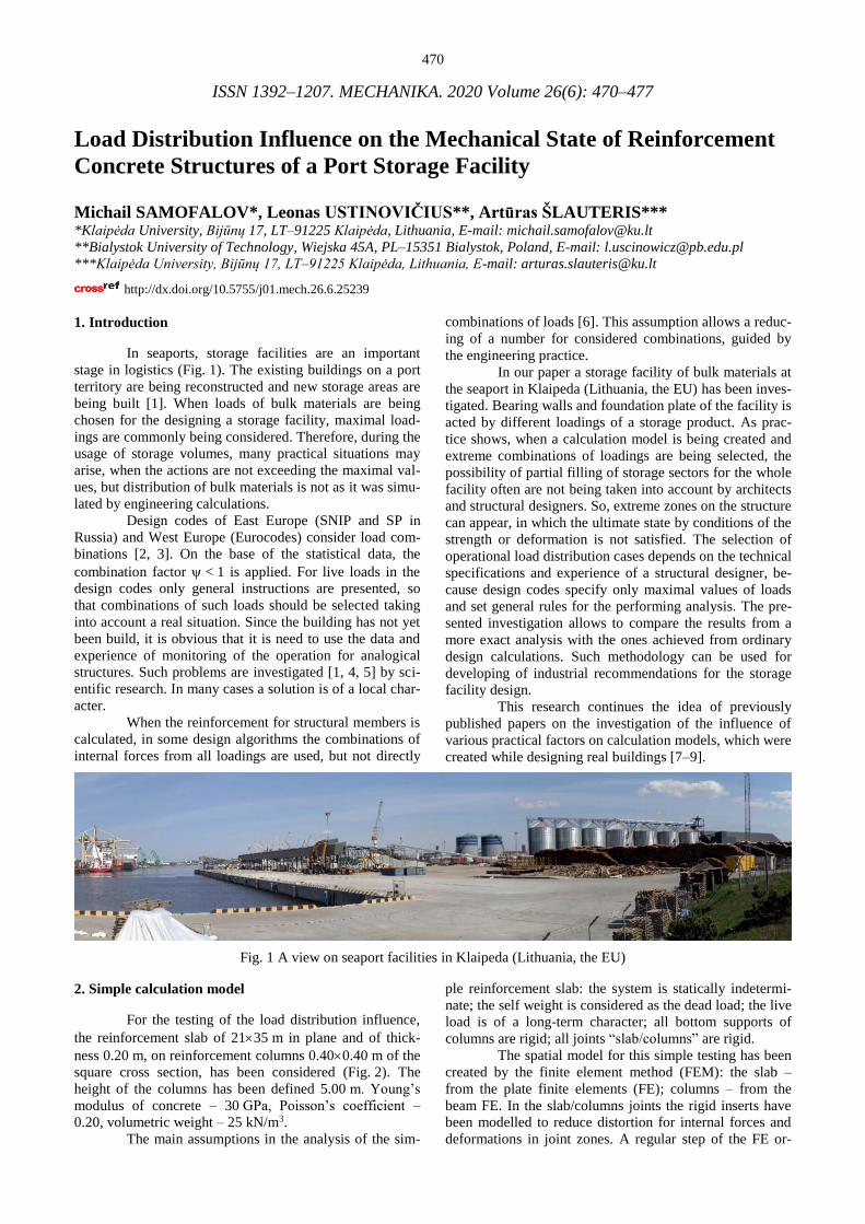
In seaports, storage facilities are an important
stage in logistics (Fig. 1). The existing buildings on a port
territory are being reconstructed and new storage areas are
being built [1]. When loads of bulk materials are being
chosen for the designing a storage facility, maximal load-
ings are commonly being considered. Therefore, during the
usage of storage volumes, many practical situations may
arise, when the actions are not exceeding the maximal val-
ues, but distribution of bulk materials is not as it was simu-
lated by engineering calculations.
Design codes of East Europe (SNIP and SP in
Russia) and West Europe (Eurocodes) consider load com-
binations [2, 3]. On the base of the statistical data, the
combination factor < 1 is applied. For live loads in the
design codes only general instructions are presented, so
that combinations of such loads should be selected taking
into account a real situation. Since the building has not yet
been build, it is obvious that it is need to use the data and
experience of monitoring of the operation for analogical
structures. Such problems are investigated [1, 4, 5] by sci-
entific research. In many cases a solution is of a local char-
acter.
When the reinforcement for structural members is
calculated, in some design algorithms the combinations of
internal forces from all loadings are used, but not directly
combinations of loads [6]. This assumption allows a reduc-
ing of a number for considered combinations, guided by
the engineering practice.
In our paper a storage facility of bulk materials at
the seaport in Klaipeda (Lithuania, the EU) has been inves-
tigated. Bearing walls and foundation plate of the facility is
acted by different loadings of a storage product. As prac-
tice shows, when a calculation model is being created and
extreme combinations of loadings are being selected, the
possibility of partial filling of storage sectors for the whole
facility often are not being taken into account by architects
and structural designers. So, extreme zones on the structure
can appear, in which the ultimate state by conditions of the
strength or deformation is not satisfied. The selection of
operational load distribution cases depends on the technical
specifications and experience of a structural designer, be-
cause design codes specify only maximal values of loads
and set general rules for the performing analysis. The pre-
sented investigation allows to compare the results from a
more exact analysis with the ones achieved from ordinary
design calculations. Such methodology can be used for
developing of industrial recommendations for the storage
facility design.
This research continues the idea of previously
published papers on the investigation of the influence of
various practical factors on calculation models, which were
created while designing real buildings [7–9].
Fig. 1 A view on seaport facilities in Klaipeda (Lithuania, the EU)
2. Simple calculation model
For the testing of the load distribution influence,
the reinforcement slab of 2135 m in plane and of thick-
ness 0.20 m, on reinforcement columns 0.400.40 m of the
square cross section, has been considered (Fig. 2). The
height of the columns has been defined 5.00 m. Young’s
modulus of concrete – 30 GPa, Poisson’s coefficient –
0.20, volumetric weight – 25 kN/m3.
The main assumptions in the analysis of the sim-
ple reinforcement slab: the system is statically indetermi-
nate; the self weight is considered as the dead load; the live
load is of a long-term character; all bottom supports of
columns are rigid; all joints “slab/columns” are rigid.
The spatial model for this simple testing has been
created by the finite element method (FEM): the slab –
from the plate finite elements (FE); columns – from the
beam FE. In the slab/columns joints the rigid inserts have
been modelled to reduce distortion for internal forces and
deformations in joint zones. A regular step of the FE or-
471
thogonal grid for the slab in both directions is set 0.200 m.
The model is consisted of 18783 FE and 18680 nodes, in
total – 111936 degrees of freedom. The accuracy of this
model is sufficient for our purposes of the testing.
1.001.00 6.00 7.00 7.00 7.00 6.00
1.0
01.0
06.0
07.0
06.0
0
1
2
3
4 7 10 13
5 8 11 14
6 9 12 15
5.00 kPa
5.0
0
a
1.001.00 6.00 7.00 7.00 7.00 6.00
1.0
01.0
06.0
07.0
06.0
0
1
2
3
4 7 10 13
5 8 11 14
6 9 12 15
5.00 kPa
5.0
0
b
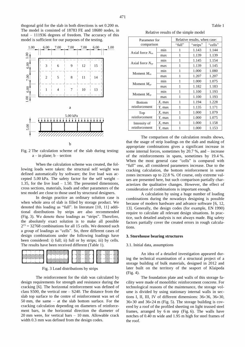
Fig. 2 The calculation scheme of the slab during testing:
a – in plane; b – section
When the calculation scheme was created, the fol-
lowing loads were taken: the structural self weight was
defined automatically by software; the live load was ac-
cepted 5.00 kPa. The safety factor for the self weight –
1.35, for the live load – 1.50. The presented dimensions,
cross sections, materials, loads and other parameters of the
test model are close to those used by structural designers.
In design practice an ordinary solution case is
when whole area of slab is filled by storage product. We
denoted this loading as “full”. In literature [10, 11] addi-
tional distributions by strips are also recommended
(Fig. 3). We denote these loadings as “strips”. Therefore,
the absolutely exact solution is to make all possible
215 = 32768 combinations for all 15 cells. We denoted such
a group of loadings as “cells”. So, three different cases of
design combinations under the following loadings have
been considered: i) full; ii) full or by strips; iii) by cells.
The results have been received different (Table 1).
Fig. 3 Load distributions by strips
The reinforcement for the slab was calculated by
design requirements for strength and resistance during the
cracking [6]. The horizontal reinforcement was defined of
class S500, the vertical one – S240. The distance from the
slab top surface to the centre of reinforcement was set of
50 mm, the same – at the slab bottom surface. For the
cracking calculation depending on diameters of reinforce-
ment bars, in the horizontal direction the diameter of
20 mm were, for vertical bars – 10 mm. Allowable crack
width 0.3 mm was defined from the design codes.
Table 1
Relative results of the simple model
Parameter for
comparison
Relative results, when case:
“full” “strips” “cells”
Axial force Nxx min 1 1.143 1.144
max 1 1.139 1.139
Axial force Nyy min 1 1.145 1.154
max 1 1.139 1.145
Moment Mxx min 1 1.000 1.080
max 1 1.207 1.207
Moment Myy min 1 1.000 1.075
max 1 1.182 1.183
Moment Mxy min 1 1.100 1.193
max 1 1.100 1.193
Bottom
reinforcement
X, max 1 1.194 1.228
Y, max 1 1.135 1.171
Top
reinforcement
X, max 1 1.000 1.079
Y, max 1 1.000 1.075
Intensity of
reinforcement
X, max 1 1.000 1.158
Y, max 1 1.000 1.153
The comparison of the calculation results shows,
that the usage of strip loadings on the slab and making of
appropriate combinations gives a significant increase in
some internal forces, sometimes by 20.7 %, and – increase
of the reinforcements in spans, sometimes by 19.4 %.
When the most general case “cells” is compared with
“full” one, all considered parameters increase. Due to the
cracking calculation, the bottom reinforcement in some
zones increases up to 22.8 %. Of course, only extreme val-
ues are presented here, but such comparison partially char-
acterizes the qualitative changes. However, the effect of
consideration of combinations is important enough.
A calculation by using a huge number of loading
combinations during the nowadays designing is possible
because of modern hardware and advance software [6, 12,
13]. Generally, the design codes (for example, EN 1990)
require to calculate all relevant design situations. In prac-
tice, such detailed analysis is not always made. Big safety
factors partially cover the created errors in rough calcula-
tions.
3. Storehouse bearing structures
3.1. Initial data, assumptions
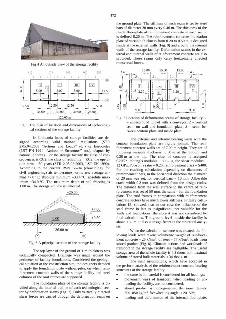
An idea of a detailed investigation appeared dur-
ing the technical examination of a structural project of a
storage building of bulk materials, designed in 2012 and
later built on the territory of the seaport of Klaipeda
(Fig. 4).
The foundation plate and walls of this storage fa-
cility were made of monolithic reinforcement concrete. For
technological reasons of the maintenance, the storage vol-
ume is divided by using stationary internal walls in sec-
tions I, II, III, IV of different dimensions: 3636, 3630,
3630 and 3624 m (Fig. 5). The storage building is cov-
ered by a roof of the profiled sheeting on light trussed steel
frames, arranged by 6 m step (Fig. 6). The walls have
notches of 0.40 m wide and 1.95 m high for steel frames of
the roof.
472
Fig 4 An outside view of the storage facility
120.00 m
36.00 30.00 30.00 24.00
36
.00 I II III IV
5.00 5.00 5.00
5.00
12.50
12.50 12.50 12.50
1 7 12 17 21
A
B
1.5
5
Fig. 5 The plan of location and dimensions of technologi-
cal sections of the storage facility
In Lithuania loads of storage facilities are de-
signed according valid national regulations (STR
2.05.04:2003 “Actions and Loads” etc.) or Eurocodes
(LST EN 1991 “Actions on Structures” etc.), adapted by
national annexes. For the storage facility the class of con-
sequences is CC2, the class of reliability – RC2, the opera-
tion term – 50 years (STR 2.05.03:2003, LST EN 1990).
According to the current RSN 156-94 (climatology for
civil engineering) air temperature norms are: average an-
nual +7.0 C; absolute minimum 33.4 C; absolute max-
imum +34.0 C. The maximum depth of soil freezing is
1.08 m. The storage volume is unheated.
36.00 m
A B
+7.00
+20.00
0.00 +0.50
Fig. 6 A principal section of the storage facility
The top layer of the ground of 1 m thickness was
technically compacted. Drainage was made around the
perimeter of facility foundations. Considered the geologi-
cal situation at the construction site, the designers decided
to apply the foundation plate without piles, on which rein-
forcement concrete walls of the storage facility and steel
columns of the roof frames are supported.
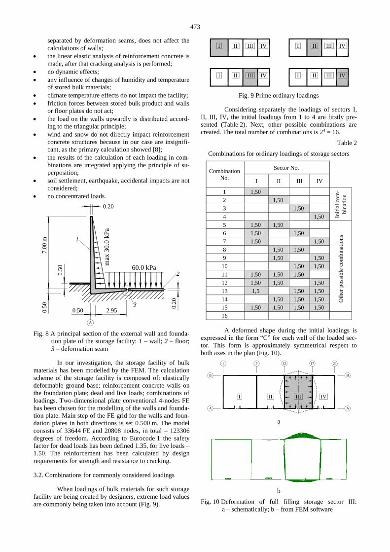
The foundation plate of the storage facility is di-
vided along the internal outline of each technological sec-
tor by deformation seams (Fig. 7). Only vertically directed
shear forces are carried through the deformation seam on
the ground plate. The stiffness of such seam is set by steel
bars of diameter 20 mm every 0.40 m. The thickness of the
inside floor-plate of reinforcement concrete in each sector
is defined 0.20 m. The reinforcement concrete foundation
plate of variable thickness from 0.20 to 0.50 m is designed
inside at the external walls (Fig. 8) and around the internal
walls of the storage facility. Deformation seams in the ex-
ternal and internal walls of reinforcement concrete are also
provided. These seams only carry horizontally directed
transversal forces.
3.4
5 I III IV
3.4
5
3.0
0
3.4515.00 15.00 15.00
3.45
3.20
3.20
3.20
9.009.009.00
1
2222
22
2
3 3
4.9
5
2II
Fig. 7 Location of deformation seams of storage facility: 1
– underground tunnel with a conveyor; 2 – vertical
seam on wall and foundation plate; 3 – seam be-
tween contour plate and inside plate
The external and internal bearing walls with the
contour foundation plate are rigidly jointed. The rein-
forcement concrete walls are of 7.00 m height. They are of
following variable thickness: 0.50 m at the bottom and
0.20 m at the top. The class of concrete is accepted
C20/25, Young’s modulus – 30 GPa, the shear modulus –
12 GPa, Poisson’s ratio – 0.20, reinforcement class – S400.
For the cracking calculation depending on diameters of
reinforcement bars, in the horizontal direction the diameter
of 20 mm was set, for vertical bars – 10 mm. Allowable
crack width 0.3 mm was defined from the design codes.
The distance from the wall surface to the centre of rein-
forcement was set of 50 mm, the same – for the foundation
plate. The roof frames in comparison with reinforcement
concrete sectors have much lower stiffness. Primary calcu-
lations [8] showed, that in our case the influence of the
steel frame in fact is insignificant, not valuable for the
walls and foundations, therefore it was not considered by
final calculations. The ground level outside the facility is
about 0.50 m. It also is insignificant in the structural analy-
sis.
When the calculation scheme was created, the fol-
lowing loads were taken: volumetric weight of reinforce-
ment concrete – 25 kN/m3; of steel – 77 kN/m3; loads from
stored product (Fig. 8). Climatic actions and workloads of
transport in the storage facility are negligible. The useful
storage area of the whole facility is 4.3 thous. m2, maximal
volume of stored bulk materials is 34 thous. m3.
The main assumptions, which have accepted in
the perform analysis of the reinforcement concrete bearing
structures of the storage facility:
the same bulk material is considered for all loadings;
movement ways of transport, when loading or un-
loading the facility, are not considered;
stored product is homogeneous, the same density
500–850 kg/m3, freewheeling angle is 20–50;
loading and deformation of the internal floor plate,
473
separated by deformation seams, does not affect the
calculations of walls;
the linear elastic analysis of reinforcement concrete is
made, after that cracking analysis is performed;
no dynamic effects;
any influence of changes of humidity and temperature
of stored bulk materials;
climate temperature effects do not impact the facility;
friction forces between stored bulk product and walls
or floor plates do not act;
the load on the walls upwardly is distributed accord-
ing to the triangular principle;
wind and snow do not directly impact reinforcement
concrete structures because in our case are insignifi-
cant, as the primary calculation showed [8];
the results of the calculation of each loading in com-
binations are integrated applying the principle of su-
perposition;
soil settlement, earthquake, accidental impacts are not
considered;
no concentrated loads.
60.0 kPa
0.2
0
0.20
0.50 2.95
A
7.0
0 m
0.5
0
0.5
0
1
2
3
max
30
.0 k
Pa
Fig. 8 A principal section of the external wall and founda-
tion plate of the storage facility: 1 – wall; 2 – floor;
3 – deformation seam
In our investigation, the storage facility of bulk
materials has been modelled by the FEM. The calculation
scheme of the storage facility is composed of: elastically
deformable ground base; reinforcement concrete walls on
the foundation plate; dead and live loads; combinations of
loadings. Two-dimensional plate conventional 4-nodes FE
has been chosen for the modelling of the walls and founda-
tion plate. Main step of the FE grid for the walls and foun-
dation plates in both directions is set 0.500 m. The model
consists of 33644 FE and 20808 nodes, in total – 123306
degrees of freedom. According to Eurocode 1 the safety
factor for dead loads has been defined 1.35, for live loads –
1.50. The reinforcement has been calculated by design
requirements for strength and resistance to cracking.
3.2. Combinations for commonly considered loadings
When loadings of bulk materials for such storage
facility are being created by designers, extreme load values
are commonly being taken into account (Fig. 9).
I II III IV I II III IV
I II III IV I II III IV
Fig. 9 Prime ordinary loadings
Considering separately the loadings of sectors I,
II, III, IV, the initial loadings from 1 to 4 are firstly pre-
sented (Table 2). Next, other possible combinations are
created. The total number of combinations is 24 = 16.
Table 2
Combinations for ordinary loadings of storage sectors
Combination
No.
Sector No.
I II III IV
1 1,50
Init
ial
com
-
bin
atio
n
2 1,50
3 1,50
4 1,50
5 1,50 1,50
Oth
er p
oss
ible
co
mb
inat
ion
s 6 1,50 1,50
7 1,50 1,50
8 1,50 1,50
9 1,50 1,50
10 1,50 1,50
11 1,50 1,50 1,50
12 1,50 1,50 1,50
13 1,5 1,50 1,50
14 1,50 1,50 1,50
15 1,50 1,50 1,50 1,50
16
A deformed shape during the initial loadings is
expressed in the form “C” for each wall of the loaded sec-
tor. This form is approximately symmetrical respect to
both axes in the plan (Fig. 10).
1 7 12 17 21
A
B
A
B
I II IVIII
a
b
Fig. 10 Deformation of full filling storage sector III:
a – schematically; b – from FEM software
474
Deformation seams and the tunnel under the stor-
age facility are concentrators, which exacerbate the influ-
ence of various combinations of loadings on the walls. The
influence of openings for gates in the bearing walls and
notches for steel frames are also significant.
When the storage facility is operating in market
conditions, sometimes it is necessary to place a bulk prod-
uct of different customers in one sector. In case of dimen-
sions about 30 m in plan and height of 7 m, such decision
is technologically possible. Additional mobile internal
walls are used for the separating one bulk material from
other (Fig. 11). Certainly, the efficiently of such sector
usage is decreases, nevertheless in practice such cases are
quite frequent.
Fig. 11 An internal mobile wall inside a sector
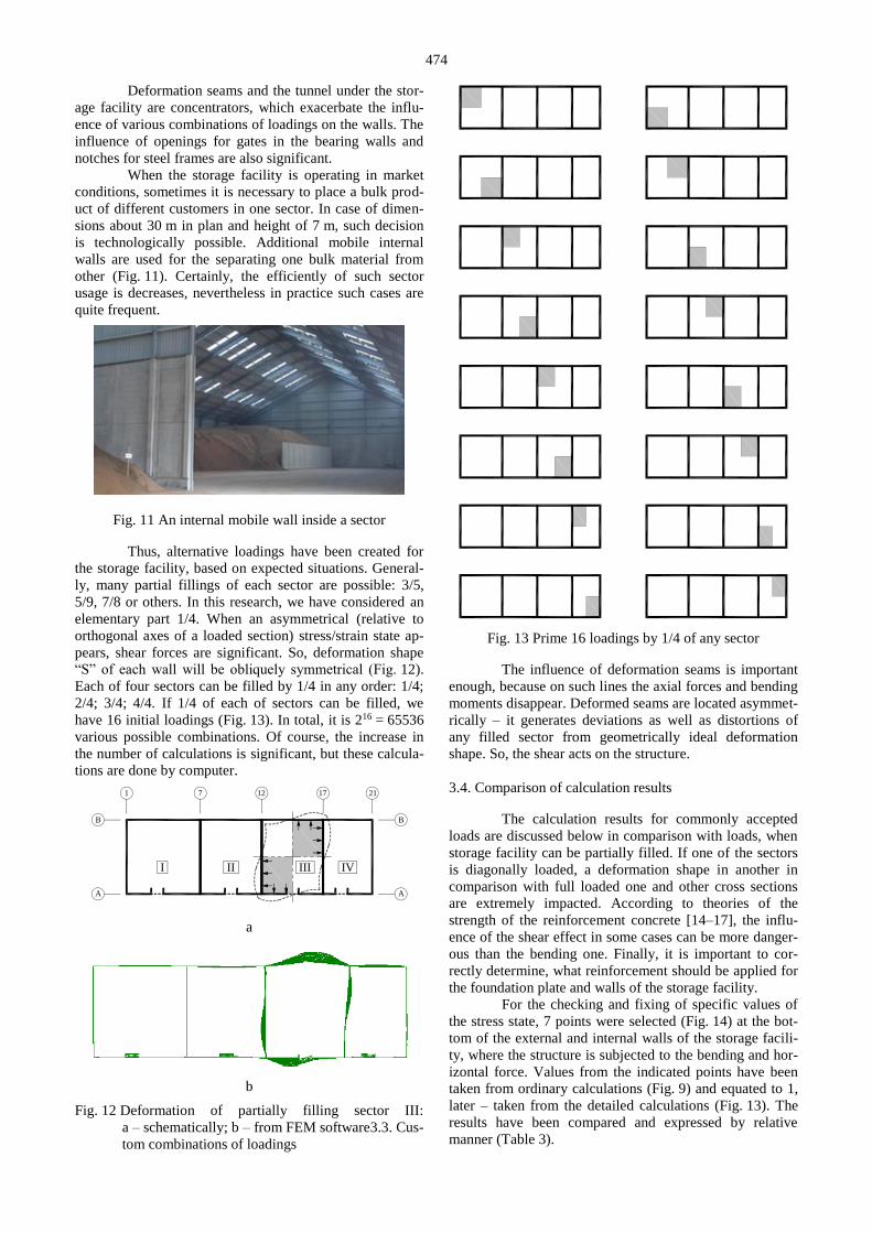
Thus, alternative loadings have been created for
the storage facility, based on expected situations. General-
ly, many partial fillings of each sector are possible: 3/5,
5/9, 7/8 or others. In this research, we have considered an
elementary part 1/4. When an asymmetrical (relative to
orthogonal axes of a loaded section) stress/strain state ap-
pears, shear forces are significant. So, deformation shape
“S” of each wall will be obliquely symmetrical (Fig. 12).
Each of four sectors can be filled by 1/4 in any order: 1/4;
2/4; 3/4; 4/4. If 1/4 of each of sectors can be filled, we
have 16 initial loadings (Fig. 13). In total, it is 216 = 65536
various possible combinations. Of course, the increase in
the number of calculations is significant, but these calcula-
tions are done by computer.
1 7 12 17 21
A
B
A
B
I II IVIII
a
b
Fig. 12 Deformation of partially filling sector III:
a – schematically; b – from FEM software3.3. Cus-
tom combinations of loadings
Fig. 13 Prime 16 loadings by 1/4 of any sector
The influence of deformation seams is important
enough, because on such lines the axial forces and bending
moments disappear. Deformed seams are located asymmet-
rically – it generates deviations as well as distortions of
any filled sector from geometrically ideal deformation
shape. So, the shear acts on the structure.
3.4. Comparison of calculation results
The calculation results for commonly accepted
loads are discussed below in comparison with loads, when
storage facility can be partially filled. If one of the sectors
is diagonally loaded, a deformation shape in another in
comparison with full loaded one and other cross sections
are extremely impacted. According to theories of the
strength of the reinforcement concrete [14–17], the influ-
ence of the shear effect in some cases can be more danger-
ous than the bending one. Finally, it is important to cor-
rectly determine, what reinforcement should be applied for
the foundation plate and walls of the storage facility.
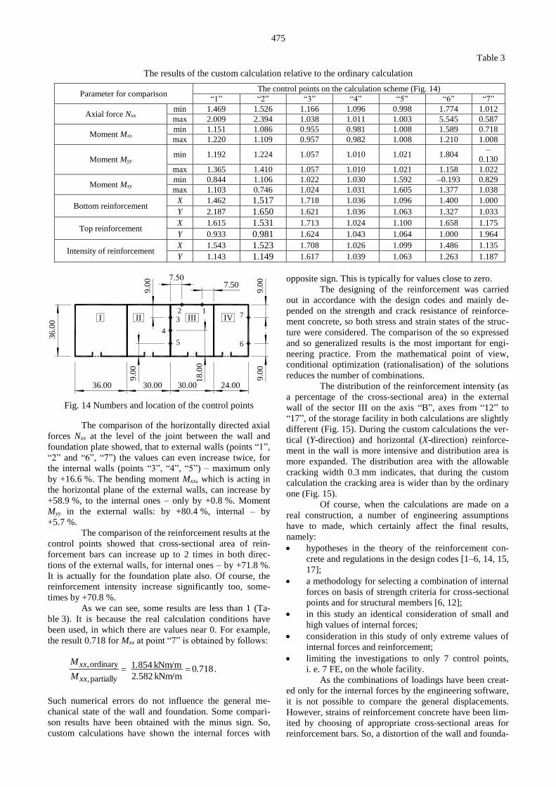
For the checking and fixing of specific values of
the stress state, 7 points were selected (Fig. 14) at the bot-
tom of the external and internal walls of the storage facili-
ty, where the structure is subjected to the bending and hor-
izontal force. Values from the indicated points have been
taken from ordinary calculations (Fig. 9) and equated to 1,
later – taken from the detailed calculations (Fig. 13). The
results have been compared and expressed by relative
manner (Table 3).
475
Table 3
The results of the custom calculation relative to the ordinary calculation
Parameter for comparison The control points on the calculation scheme (Fig. 14)
“1” “2” “3” “4” “5” “6” “7”
Axial force Nxx min 1.469 1.526 1.166 1.096 0.998 1.774 1.012
max 2.009 2.394 1.038 1.011 1.003 5.545 0.587
Moment Mxx min 1.151 1.086 0.955 0.981 1.008 1.589 0.718
max 1.220 1.109 0.957 0.982 1.008 1.210 1.008
Moment Myy min 1.192 1.224 1.057 1.010 1.021 1.804
–
0.130
max 1.365 1.410 1.057 1.010 1.021 1.158 1.022
Moment Mxy min 0.844 1.106 1.022 1.030 1.592 –0.193 0.829
max 1.103 0.746 1.024 1.031 1.605 1.377 1.038
Bottom reinforcement X 1.462 1.517 1.718 1.036 1.096 1.400 1.000
Y 2.187 1.650 1.621 1.036 1.063 1.327 1.033
Top reinforcement X 1.615 1.531 1.713 1.024 1.100 1.658 1.175
Y 0.933 0.981 1.624 1.043 1.064 1.000 1.964
Intensity of reinforcement X 1.543 1.523 1.708 1.026 1.099 1.486 1.135
Y 1.143 1.149 1.617 1.039 1.063 1.263 1.187
36.00 30.00 30.00 24.00
36
.00 I II III IV
7.50
9.0
09
.00
7
6
123
5
4
9.0
0
9.0
0
18
.00
Fig. 14 Numbers and location of the control points
The comparison of the horizontally directed axial
forces Nxx at the level of the joint between the wall and
foundation plate showed, that to external walls (points “1”,
“2” and “6”, “7”) the values can even increase twice, for
the internal walls (points “3”, “4”, “5”) – maximum only
by +16.6 %. The bending moment Mxx, which is acting in
the horizontal plane of the external walls, can increase by
+58.9 %, to the internal ones – only by +0.8 %. Moment
Myy in the external walls: by +80.4 %, internal – by
+5.7 %.
The comparison of the reinforcement results at the
control points showed that cross-sectional area of rein-
forcement bars can increase up to 2 times in both direc-
tions of the external walls, for internal ones – by +71.8 %.
It is actually for the foundation plate also. Of course, the
reinforcement intensity increase significantly too, some-
times by +70.8 %.
As we can see, some results are less than 1 (Ta-
ble 3). It is because the real calculation conditions have
been used, in which there are values near 0. For example,
the result 0.718 for Mxx at point “7” is obtained by follows:
7180kNm/m 5822
kNm/m 8541 partially
ordinary .
.
.
M
M
,xx
,xx .
Such numerical errors do not influence the general me-
chanical state of the wall and foundation. Some compari-
son results have been obtained with the minus sign. So,
custom calculations have shown the internal forces with
opposite sign. This is typically for values close to zero.
The designing of the reinforcement was carried
out in accordance with the design codes and mainly de-
pended on the strength and crack resistance of reinforce-
ment concrete, so both stress and strain states of the struc-
ture were considered. The comparison of the so expressed
and so generalized results is the most important for engi-
neering practice. From the mathematical point of view,
conditional optimization (rationalisation) of the solutions
reduces the number of combinations.
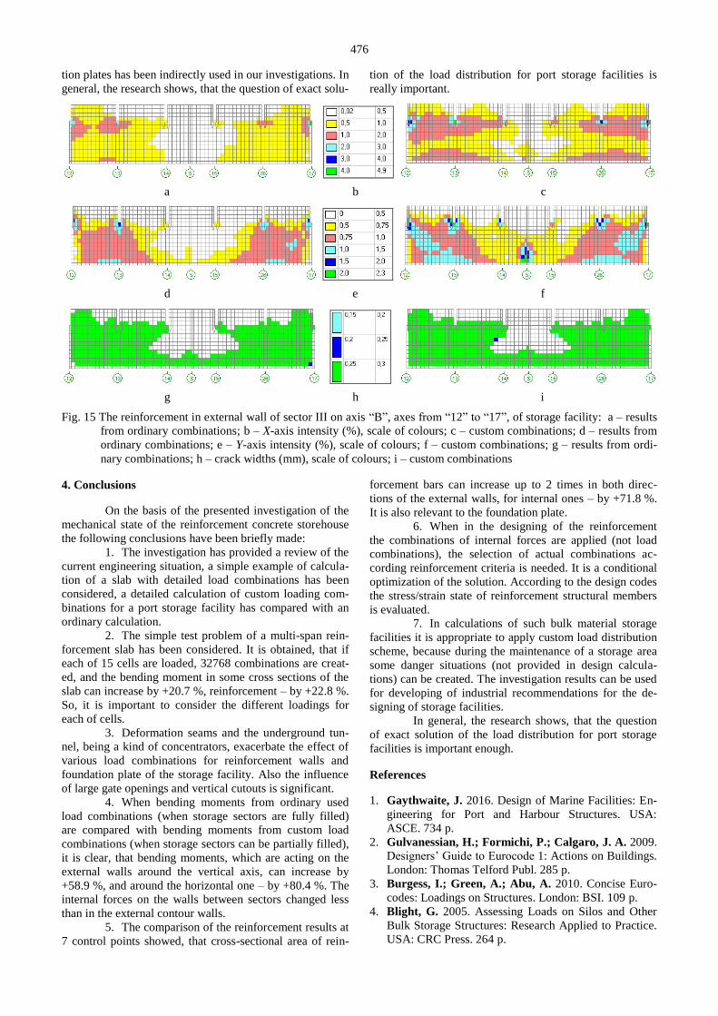
The distribution of the reinforcement intensity (as
a percentage of the cross-sectional area) in the external
wall of the sector III on the axis “B”, axes from “12” to
“17”, of the storage facility in both calculations are slightly
different (Fig. 15). During the custom calculations the ver-
tical (Y-direction) and horizontal (X-direction) reinforce-
ment in the wall is more intensive and distribution area is
more expanded. The distribution area with the allowable
cracking width 0.3 mm indicates, that during the custom
calculation the cracking area is wider than by the ordinary
one (Fig. 15).
Of course, when the calculations are made on a
real construction, a number of engineering assumptions
have to made, which certainly affect the final results,
namely:
hypotheses in the theory of the reinforcement con-
crete and regulations in the design codes [1–6, 14, 15,
17];
a methodology for selecting a combination of internal
forces on basis of strength criteria for cross-sectional
points and for structural members [6, 12];
in this study an identical consideration of small and
high values of internal forces;
consideration in this study of only extreme values of
internal forces and reinforcement;
limiting the investigations to only 7 control points,
i. e. 7 FE, on the whole facility.
As the combinations of loadings have been creat-
ed only for the internal forces by the engineering software,
it is not possible to compare the general displacements.
However, strains of reinforcement concrete have been lim-
ited by choosing of appropriate cross-sectional areas for
reinforcement bars. So, a distortion of the wall and founda-
476
tion plates has been indirectly used in our investigations. In
general, the research shows, that the question of exact solu-
tion of the load distribution for port storage facilities is
really important.
a b c
d e f
g h i
Fig. 15 The reinforcement in external wall of sector III on axis “B”, axes from “12” to “17”, of storage facility: a – results
from ordinary combinations; b – X-axis intensity (%), scale of colours; c – custom combinations; d – results from
ordinary combinations; e – Y-axis intensity (%), scale of colours; f – custom combinations; g – results from ordi-
nary combinations; h – crack widths (mm), scale of colours; i – custom combinations
4. Conclusions
On the basis of the presented investigation of the
mechanical state of the reinforcement concrete storehouse
the following conclusions have been briefly made:
1. The investigation has provided a review of the
current engineering situation, a simple example of calcula-
tion of a slab with detailed load combinations has been
considered, a detailed calculation of custom loading com-
binations for a port storage facility has compared with an
ordinary calculation.
2. The simple test problem of a multi-span rein-
forcement slab has been considered. It is obtained, that if
each of 15 cells are loaded, 32768 combinations are creat-
ed, and the bending moment in some cross sections of the
slab can increase by +20.7 %, reinforcement – by +22.8 %.
So, it is important to consider the different loadings for
each of cells.
3. Deformation seams and the underground tun-
nel, being a kind of concentrators, exacerbate the effect of
various load combinations for reinforcement walls and
foundation plate of the storage facility. Also the influence
of large gate openings and vertical cutouts is significant.
4. When bending moments from ordinary used
load combinations (when storage sectors are fully filled)
are compared with bending moments from custom load
combinations (when storage sectors can be partially filled),
it is clear, that bending moments, which are acting on the
external walls around the vertical axis, can increase by
+58.9 %, and around the horizontal one – by +80.4 %. The
internal forces on the walls between sectors changed less
than in the external contour walls.
5. The comparison of the reinforcement results at
7 control points showed, that cross-sectional area of rein-
forcement bars can increase up to 2 times in both direc-
tions of the external walls, for internal ones – by +71.8 %.
It is also relevant to the foundation plate.
6. When in the designing of the reinforcement
the combinations of internal forces are applied (not load
combinations), the selection of actual combinations ac-
cording reinforcement criteria is needed. It is a conditional
optimization of the solution. According to the design codes
the stress/strain state of reinforcement structural members
is evaluated.
7. In calculations of such bulk material storage
facilities it is appropriate to apply custom load distribution
scheme, because during the maintenance of a storage area
some danger situations (not provided in design calcula-
tions) can be created. The investigation results can be used
for developing of industrial recommendations for the de-
signing of storage facilities.
In general, the research shows, that the question
of exact solution of the load distribution for port storage
facilities is important enough.
References
1. Gaythwaite, J. 2016. Design of Marine Facilities: En-
gineering for Port and Harbour Structures. USA:
ASCE. 734 p.
2. Gulvanessian, H.; Formichi, P.; Calgaro, J. A. 2009.
Designers’ Guide to Eurocode 1: Actions on Buildings.
London: Thomas Telford Publ. 285 p.
3. Burgess, I.; Green, A.; Abu, A. 2010. Concise Euro-
codes: Loadings on Structures. London: BSI. 109 p.
4. Blight, G. 2005. Assessing Loads on Silos and Other
Bulk Storage Structures: Research Applied to Practice.
USA: CRC Press. 264 p.
477
5. Goodchild, C. H.; Webster, R. M.; Elliott, K. S. 2009. Economic Concrete Frame Elements to Euro-
code 2. UK: The Concrete Centre. 181 p.
6. SCAD: an integrated system for finite element structur-
al analysis. [Online]. 2019. [Viewed 31 October 2019].
Available from internet:
https://scadsoft.com/en/products/scad
7. Samofalov, M.; Žiūkas, A. 2015. Investigation of me-
chanical state of spatial roof from steel trusses on
asymmetric building, Mechanika 21(1): 11–18.
http://dx.doi.org/10.5755/j01.mech.21.1.10129.
8. Norvilas, J. 2016. Investigation of Structural Mechani-
cal State of the Port Storage Facility Depending on
Load Distribution of Bulk Materials. MSc thesis.
Klaipėda University. 50 p. (in Lithuanian)
9. Norvilas, J.; Samofalov, M. 2016. The influence of
loos materials load arrangement for mechanical behav-
iour of port warehouse constructions. XVIII Conf. of
Young Scientists of Lithuania “Fundamental Research
and Innovations”, Lithuania, Klaipėda, 12 May 2016:
79–89. (in Lithuanian)
10. Punmia, B. C.; Jain, As. K.; Jain, Ar. K. 2004. Theo-
ry of Structures. New Delhi: Laxmi Publ. Ltd. 648 p.
11. Marti, P. 2013. Theory of Structures: Fundamentals,
Framed Structures, Plates and Shells. USA: John Wiley
& Sons. 695 p.
12. Semenov, S. The influence of load locations on the
stress/strain state of slabs. [Online]. 2015. [Viewed
5 November 2019]. Available from internet:
http://www.myshared.ru/slide/830152/ (in Russian)
13. Reizgevičius, M.; Ustinovičius, L.; Cibulskienė, D.;
Kutut, V.; Nazarko, L. 2018. Promoting sustainability
through investment in Building Information Modeling
(BIM) technologies: a design company perspective.
Sustainability. Basel: MDPI AG 10(3): 2–22.
http://dx.doi.org/10.3390/su10030600.
14. Punmia, B.C.; Jain, As. K.; Jain, Ar. K. 2007. Limit
State Design of Reinforced Concrete. New Delhi:
Laxmi Publ. 935 p.
15. Gulvanessian, H.; Beeby, A. W.; Narayanan, R. S. 2009. Designers’ Guide to Eurocode 2: Design of Con-
crete Structures. London: Thomas Telford Publ. 230 p.
16. Gholipour, G.; Zhang, Ch.; Mousavi, A. A. 2019.
Loading rate effects on the responses of simply sup-
ported RC beams subjected to the combination of im-
pact and blast loads. Engineering Structures 201:
109837.
https://doi.org/10.1016/j.engstruct.2019.109837.
17. Židonis, I. 2019. Curvilinear stress-strain relationship
for concrete of EN-2 regulation in the ZI method and
the calculation of beam strength, Mechanika 25(5):
341–349.
https://doi.org/10.5755/j01.mech.25.5.24453.
M. Samofalov, L. Ustinovičius, A. Šlauteris
LOAD DISTRIBUTION INFLUENCE ON THE
MECHANICAL STATE OF REINFORCEMENT
CONCRETE STRUCTURES OF A PORT STORAGE
FACILITY
S u m m a r y
The stress/strain state of reinforcement concrete
walls and foundation plate of a storage facility in the sea-
port of Klaipeda (Lithuania, the EU) is investigated, con-
sidering the distribution of loads from stored bulk materi-
als. At the first, a simple test problem has been calculated:
reinforcement slab 2135 m in plane on 24 columns,
which are located by a regular step. During creating the
combinations of all 15 possible loadings of each „cell“,
increased internal forces and reinforcement results to
+20 % have been obtained. Next, a storage facility of bulk
materials with dimensions 36120 m in plane has been
considered, when expected 16 loadings, 1/4 for each of
four storage sectors, has been used in the FEM model. The
results of the comparison with the ordinary calculation, in
which each of sectors could be fully filled or be empty,
have presented. The investigation results can be used for
developing of industrial recommendations for the design-
ing of storage facilities.
Keywords: load combinations, load of bulk materials,
reinforcement walls, storage facilities, stress/strain state.
Received January 06, 2020
Accepted December 01, 2020
This article is an Open Access article distributed under the terms and conditions of the Creative Commons At-
tribution 4.0 (CC BY 4.0) License (http://creativecommons.org/licenses/by/4.0/).