iec61462{ed1.0}b (2)
TRANSCRIPT
RAPPORTTECHNIQUE
CEIIEC
TECHNICALREPORT
61462Première édition
First edition1998-11
Isolateurs composites –
Isolateurs creux pour appareillage électriqueutilisé à l’intérieur ou à l’extérieur –
Définitions, méthodes d’essais, critèresd’acceptation et recommandations de conception
Composite insulators –
Hollow insulators for use in outdoorand indoor electrical equipment –
Definitions, test methods, acceptance criteriaand design recommendations
Numéro de référenceReference number
CEI / IEC 61462:1998
Copyrighted m
aterial licensed to Electricity of V
ietnam by T
homson S
cientific, Inc. (ww
w.techstreet.com
). This copy dow
nloaded on 2015-01-10 08:33:51 -0600 by authorized user Tong cong ty T
ruyen tai Dien Q
uoc Gia P
ham V
an Chi.
No further reproduction or distribution is perm
itted.
Numéros des publications
Depuis le 1er janvier 1997, les publications de la CEIsont numérotées à partir de 60000.
Publications consolidées
Les versions consolidées de certaines publications dela CEI incorporant les amendements sont disponibles.Par exemple, les numéros d’édition 1.0, 1.1 et 1.2indiquent respectivement la publication de base, lapublication de base incorporant l’amendement 1, etla publication de base incorporant les amendements 1et 2.
Validité de la présente publication
Le contenu technique des publications de la CEI estconstamment revu par la CEI afin qu'il reflète l'étatactuel de la technique.
Des renseignements relatifs à la date de re-confirmation de la publication sont disponibles dans leCatalogue de la CEI.
Les renseignements relatifs à des questions à l’étude etdes travaux en cours entrepris par le comité techniquequi a établi cette publication, ainsi que la liste despublications établies, se trouvent dans les documents ci-dessous:
• «Site web» de la CEI*
• Catalogue des publications de la CEIPublié annuellement et mis à jour régulièrement(Catalogue en ligne)*
• Bulletin de la CEIDisponible à la fois au «site web» de la CEI*et comme périodique imprimé
Terminologie, symboles graphiqueset littéraux
En ce qui concerne la terminologie générale, le lecteurse reportera à la CEI 60050: Vocabulaire Electro-technique International (VEI).
Pour les symboles graphiques, les symboles littérauxet les signes d'usage général approuvés par la CEI, lelecteur consultera la CEI 60027: Symboles littéraux àutiliser en électrotechnique, la CEI 60417: Symbolesgraphiques utilisables sur le matériel. Index, relevé etcompilation des feuilles individuelles, et la CEI 60617:Symboles graphiques pour schémas.
* Voir adresse «site web» sur la page de titre.
Numbering
As from 1 January 1997 all IEC publications are issuedwith a designation in the 60000 series.
Consolidated publications
Consolidated versions of some IEC publicationsincluding amendments are available. For example,edition numbers 1.0, 1.1 and 1.2 refer, respectively, tothe base publication, the base publication incor-porating amendment 1 and the base publicationincorporating amendments 1 and 2.
Validity of this publication
The technical content of IEC publications is kept underconstant review by the IEC, thus ensuring that thecontent reflects current technology.
Information relating to the date of the reconfirmation ofthe publication is available in the IEC catalogue.
Information on the subjects under consideration andwork in progress undertaken by the technicalcommittee which has prepared this publication, as wellas the list of publications issued, is to be found at thefollowing IEC sources:
• IEC web site*
• Catalogue of IEC publicationsPublished yearly with regular updates(On-line catalogue)*
• IEC BulletinAvailable both at the IEC web site* andas a printed periodical
Terminology, graphical and lettersymbols
For general terminology, readers are referred toIEC 60050: International Electrotechnical Vocabulary(IEV).
For graphical symbols, and letter symbols and signsapproved by the IEC for general use, readers arereferred to publications IEC 60027: Letter symbols tobe used in electrical technology, IEC 60417: Graphicalsymbols for use on equipment. Index, survey andcompilation of the single sheets and IEC 60617:Graphical symbols for diagrams.
* See web site address on title page.
Copyrighted m
aterial licensed to Electricity of V
ietnam by T
homson S
cientific, Inc. (ww
w.techstreet.com
). This copy dow
nloaded on 2015-01-10 08:33:51 -0600 by authorized user Tong cong ty T
ruyen tai Dien Q
uoc Gia P
ham V
an Chi.
No further reproduction or distribution is perm
itted.
RAPPORTTECHNIQUE – TYPE 2
CEIIEC
TECHNICALREPORT – TYPE 2
61462Première édition
First edition1998-11
Isolateurs composites –
Isolateurs creux pour appareillage électriqueutilisé à l’intérieur ou à l’extérieur –
Définitions, méthodes d’essais, critèresd’acceptation et recommandations de conception
Composite insulators –
Hollow insulators for use in outdoorand indoor electrical equipment –
Definitions, test methods, acceptance criteriaand design recommendations
Commission Electrotechnique Internationale International Electrotechnical Commission
Pour prix, voir catalogue en vigueurFor price, see current catalogue
IEC 1998 Droits de reproduction réservés Copyright - all rights reserved
Aucune partie de cette publication ne peut être reproduite niutilisée sous quelque forme que ce soit et par aucunprocédé, électronique ou mécanique, y compris la photo-copie et les microfilms, sans l'accord écrit de l'éditeur.
No part of this publication may be reproduced or utilized inany form or by any means, electronic or mechanical,including photocopying and microfilm, without permission inwriting from the publisher.
International Electrotechnical Commission 3, rue de Varembé Geneva, SwitzerlandTelefax: +41 22 919 0300 e-mail: [email protected] IEC web site http: //www.iec.ch
CODE PRIXPRICE CODE X
Copyrighted m
aterial licensed to Electricity of V
ietnam by T
homson S
cientific, Inc. (ww
w.techstreet.com
). This copy dow
nloaded on 2015-01-10 08:33:51 -0600 by authorized user Tong cong ty T
ruyen tai Dien Q
uoc Gia P
ham V
an Chi.
No further reproduction or distribution is perm
itted.
– 2 – 61462 TR2 © CEI:1998
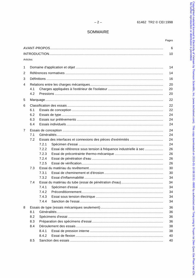
SOMMAIRE
Pages
AVANT-PROPOS....................................................................................................................... 6
INTRODUCTION........................................................................................................................ 10
Articles
1 Domaine d'application et objet ............................................................................................ 14
2 Références normatives ....................................................................................................... 14
3 Définitions ........................................................................................................................... 16
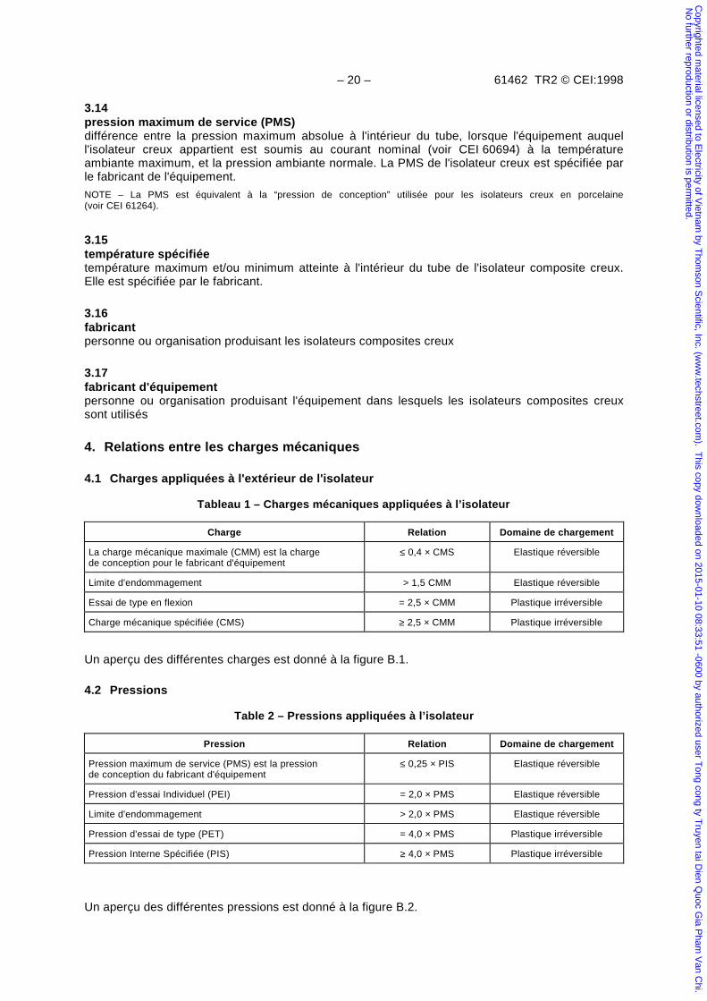
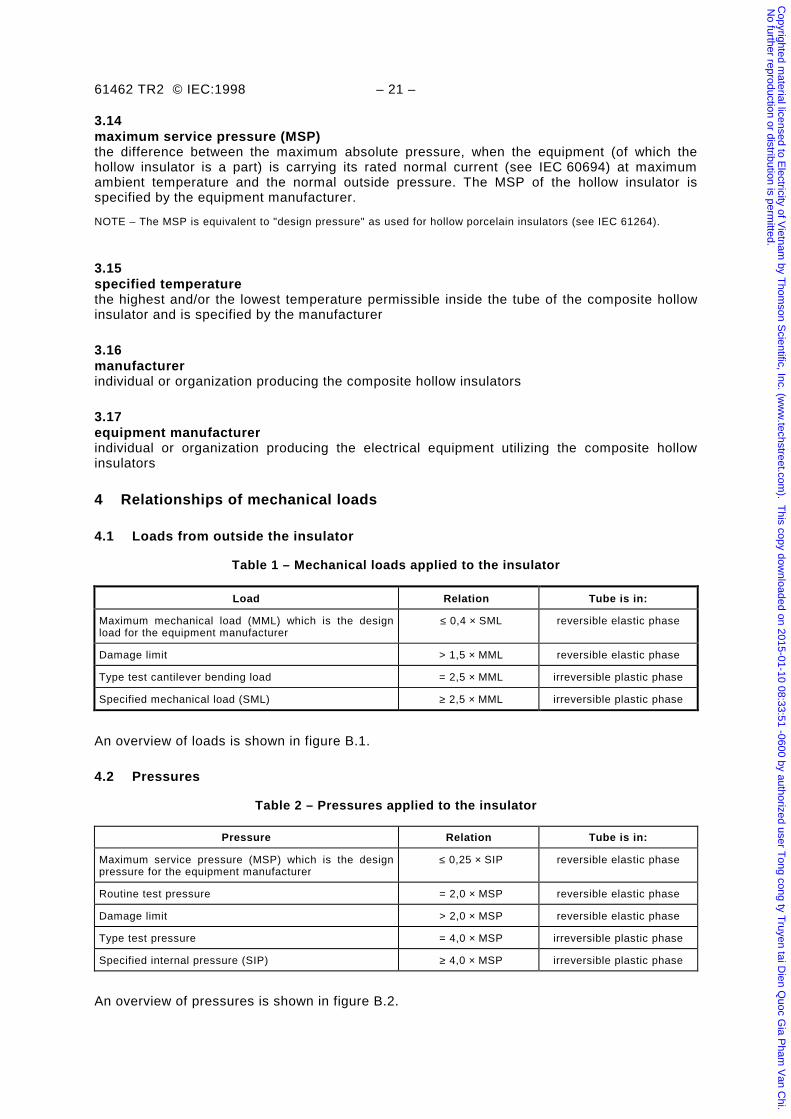
4 Relations entre les charges mécaniques............................................................................. 204.1 Charges appliquées à l'extérieur de l'isolateur .......................................................... 20
4.2 Pressions .................................................................................................................. 20
5 Marquage ............................................................................................................................ 22
6 Classification des essais ..................................................................................................... 226.1 Essais de conception ................................................................................................ 22
6.2 Essais de type ........................................................................................................... 24
6.3 Essais sur prélèvements ........................................................................................... 24
6.4 Essais individuels ...................................................................................................... 24
7 Essais de conception .......................................................................................................... 247.1 Généralités ................................................................................................................ 24
7.2 Essais des interfaces et connexions des pièces d'extrémités ................................... 24
7.2.1 Spécimen d'essai ......................................................................................... 24
7.2.2 Essai de référence sous tension à fréquence industrielle à sec ................... 26
7.2.3 Essai de précontrainte thermo-mécanique ................................................... 26
7.2.4 Essai de pénétration d'eau ........................................................................... 26
7.2.5 Essai de vérification...................................................................................... 26
7.3 Essai du matériau du revêtement .............................................................................. 30
7.3.1 Essai de cheminement et d'érosion .............................................................. 30
7.3.2 Essai d'inflammabilité ................................................................................... 34
7.4 Essai du matériau du tube (essai de pénétration d'eau) ............................................ 34
7.4.1 Spécimen d'essai ......................................................................................... 34
7.4.2 Préconditionnement...................................................................................... 34
7.4.3 Essai sous tension électrique ....................................................................... 34
7.4.4 Sanction de l'essai........................................................................................ 34
8 Essais de type (essais mécaniques seulement) .................................................................. 368.1 Généralités ................................................................................................................ 36
8.2 Spécimens d'essai .................................................................................................... 36
8.3 Préparation des spécimens d'essai ........................................................................... 36
8.4 Déroulement des essais ............................................................................................ 38
8.4.1 Essai de pression interne ............................................................................. 38
8.4.2 Essai de flexion ............................................................................................ 40
8.5 Sanction des essais .................................................................................................. 40
Copyrighted m
aterial licensed to Electricity of V
ietnam by T
homson S
cientific, Inc. (ww
w.techstreet.com
). This copy dow
nloaded on 2015-01-10 08:33:51 -0600 by authorized user Tong cong ty T
ruyen tai Dien Q
uoc Gia P
ham V
an Chi.
No further reproduction or distribution is perm
itted.
61462 TR2 © IEC:1998 – 3 –
CONTENTS
Page
FOREWORD ....................................................................................................................... ... 7
INTRODUCTION .................................................................................................................. 11
Clause
1 Scope and object ........................................................................................................... 15
2 Normative references ..................................................................................................... 15
3 Definitions...................................................................................................................... 17
4 Relationships of mechanical loads .................................................................................. 21
4.1 Loads from outside the insulator............................................................................ 21
4.2 Pressures ............................................................................................................. 21
5 Marking....................................................................................................................... ... 23
6 Classification of tests ..................................................................................................... 23
6.1 Design tests .......................................................................................................... 23
6.2 Type tests ............................................................................................................. 25
6.3 Sample tests ......................................................................................................... 25
6.4 Routine tests......................................................................................................... 25
7 Design tests ................................................................................................................... 25
7.1 General................................................................................................................. 25
7.2 Tests on interfaces and connections of end fittings ................................................ 25
7.2.1 Test specimen........................................................................................... 25
7.2.2 Reference dry power frequency flashover test............................................ 27
7.2.3 Thermal mechanical pre-stress test ........................................................... 27
7.2.4 Water immersion pre-stress test ................................................................ 27
7.2.5 Verification tests ....................................................................................... 27
7.3 Tests of housing material ...................................................................................... 31
7.3.1 Tracking and erosion test .......................................................................... 31
7.3.2 Flammability test ....................................................................................... 35
7.4 Tests for the tube material (water diffusion test) .................................................... 35
7.4.1 Test specimen........................................................................................... 35
7.4.2 Pre-stressing............................................................................................. 35
7.4.3 Voltage test ............................................................................................... 35
7.4.4 Evaluation of the test................................................................................. 35
8 Type tests (only mechanical tests) .................................................................................. 37
8.1 General................................................................................................................. 37
8.2 Test specimens..................................................................................................... 37
8.3 Preparation of the test specimen ........................................................................... 37
8.4 Performance of the tests ....................................................................................... 39
8.4.1 Internal pressure test ................................................................................ 39
8.4.2 Cantilever bending test .............................................................................. 41
8.5 Acceptance criteria ............................................................................................... 41
Copyrighted m
aterial licensed to Electricity of V
ietnam by T
homson S
cientific, Inc. (ww
w.techstreet.com
). This copy dow
nloaded on 2015-01-10 08:33:51 -0600 by authorized user Tong cong ty T
ruyen tai Dien Q
uoc Gia P
ham V
an Chi.
No further reproduction or distribution is perm
itted.
– 4 – 61462 TR2 © CEI:1998
Articles Pages
9 Essais sur prélèvements ..................................................................................................... 429.1 Choix et nombre de pièces à essayer ....................................................................... 42
9.2 Essais........................................................................................................................ 42
9.3 Vérification des dimensions....................................................................................... 42
9.4 Essais mécaniques ................................................................................................... 44
9.5 Vérification de l'interface entre les pièces d'extrémités et l'enveloppe....................... 44
9.6 Sanction de l'essai..................................................................................................... 44
9.7 Contre-épreuve ......................................................................................................... 46
10 Essais individuels ................................................................................................................ 4610.1 Généralités ................................................................................................................ 46
10.2 Examen visuel ........................................................................................................... 46
10.3 Essai individuel de pression ...................................................................................... 48
10.4 Essai individuel mécanique ....................................................................................... 48
10.5 Essai individuel d'étanchéité...................................................................................... 48
10.6 Essai du matériau du tube......................................................................................... 48
11 Documentation .................................................................................................................... 48
Figures
1 Essai de précontrainte thermo-mécanique – Cycles typiques ............................................ 502 Essai de précontrainte thermo-mécanique – Montage typique ........................................... 523 Montage pour l'essai de taux de fuite ................................................................................. 544 Exemples de systèmes d'étanchéité des isolateurs creux composite................................. 565 Exemple de cuve pour l'essai de pénétration d'eau............................................................ 586 Electrodes pour l'essai sous tension .................................................................................. 607 Circuit pour l'essai sous tension ......................................................................................... 60A.1 Parallélisme, coaxialité et excentricité................................................................................ 62A.2 Déviation angulaire des trous de fixation: exemple 1 ......................................................... 64A.3 Déviation angulaire des trous de fixation: exemple 2 ......................................................... 64A.4 Tolérances selon la pratique normalisée de dessin............................................................ 66B.1 Relation entre les charges de flexion ................................................................................. 74B.2 Relation entre les pressions ............................................................................................... 74C.1 Position des jauges de contrainte pour les essais de pression et de flexion ...................... 80C.2 Courbe allongement/temps, phase élastique, réversible .................................................... 82
C.3 Courbe allongement/temps, phase plastique, irréversible, limite d'endommagement ..... 82
Annexe A (normative) – Tolérances de forme et de position...................................................... 62
Annexe B (informative) – Recommandations générales pour la conception et la construction ...... 68B.1 Guide de conception.................................................................................................. 68B.2 Guide concernant la pression maximum de service .................................................. 68B.3 Guide concernant la température requise par le fabricant de l'équipement ............... 68B.4 Guide concernant les charges mécaniques requises par le fabricant
de l'équipement ......................................................................................................... 68B.5 Sommaire des essais ................................................................................................ 70
B.6 Bibliographie.............................................................................................................. 76
Annexe C (informative) – Limite entre les allongements réversibles et irréversibles de tubes d'isolateurs composites creux dus aux pressions internes et forces de flexion ......... 78C.1 Définition ................................................................................................................... 78C.2 Exemple d'évaluation de la tolérance d'élongation .................................................... 78
Copyrighted m
aterial licensed to Electricity of V
ietnam by T
homson S
cientific, Inc. (ww
w.techstreet.com
). This copy dow
nloaded on 2015-01-10 08:33:51 -0600 by authorized user Tong cong ty T
ruyen tai Dien Q
uoc Gia P
ham V
an Chi.
No further reproduction or distribution is perm
itted.
61462 TR2 © IEC:1998 – 5 –
Clause Page
9 Sample tests .................................................................................................................. 43
9.1 Selection and number of insulators........................................................................ 43
9.2 Testing ................................................................................................................. 43
9.3 Verification of dimensions ..................................................................................... 43
9.4 Mechanical tests ................................................................................................... 45
9.5 Check of the interface between end fittings and the housing .................................. 45
9.6 Acceptance criteria ............................................................................................... 45
9.7 Re-test procedure ................................................................................................. 47
10 Routine tests .................................................................................................................. 47
10.1 General................................................................................................................. 47
10.2 Visual examination ................................................................................................ 47
10.3 Routine pressure test ............................................................................................ 49
10.4 Routine mechanical test ........................................................................................ 49
10.5 Routine tightness test............................................................................................ 49
10.6 Test for the tube material ...................................................................................... 49
11 Documentation ............................................................................................................... 49
Figures
1 Thermal mechanical pre-stress test – Typical cycles....................................................... 51
2 Thermal mechanical pre-stress test – Typical test arrangement ...................................... 53
3 Test arrangement for the leakage rate test ..................................................................... 55
4 Examples of sealing systems for composite hollow insulators ......................................... 57
5 Example of boiling container for the water diffusion test .................................................. 59
6 Electrodes for the voltage test ........................................................................................ 61
7 Voltage test circuit.......................................................................................................... 61
A.1 Parallelism, coaxiality and concentricity .......................................................................... 63
A.2 Angular deviation of fixing holes: Example 1 ................................................................... 65
A.3 Angular deviation of fixing holes: Example 2 ................................................................... 65
A.4 Tolerances according to standard drawing practice......................................................... 67
B.1 Relationship of bending loads ......................................................................................... 75
B.2 Relationship of pressures ............................................................................................... 75
C.1 Position of strain gauges for pressure load and bending load .......................................... 81
C.2 Strain/time curve, reversible elastic phase ...................................................................... 83
C.3 Strain/time curve, irreversible plastic phase, damage limit .............................................. 83
Annex A (normative) – Tolerances of form and position......................................................... 63
Annex B (informative) – General recommendations for design and construction .................... 69
B.1 Guidance for design .............................................................................................. 69B.2 Guidance for the maximum service pressure ......................................................... 69B.3 Guidance for the temperature required by the equipment manufacturer.................. 69B.4 Guidance for the mechanical loads required by the equipment manufacturer.......... 69B.5 Summary of the tests ............................................................................................ 71B.6 Bibliography .......................................................................................................... 77
Annex C (informative) – Limits defining reversible and irreversible strain due to internal pressure and/or bending loads on tubes used in composite hollow insulators ............ 79
C.1 Definition .............................................................................................................. 79C.2 Example of determining the strain tolerance .......................................................... 79
Copyrighted m
aterial licensed to Electricity of V
ietnam by T
homson S
cientific, Inc. (ww
w.techstreet.com
). This copy dow
nloaded on 2015-01-10 08:33:51 -0600 by authorized user Tong cong ty T
ruyen tai Dien Q
uoc Gia P
ham V
an Chi.
No further reproduction or distribution is perm
itted.
– 6 – 61462 TR2 © CEI:1998
COMMISSION ÉLECTROTECHNIQUE INTERNATIONALE_________
ISOLATEURS COMPOSITES –
ISOLATEURS CREUX POUR APPAREILLAGE ÉLECTRIQUEUTILISÉ À L'INTÉRIEUR OU À L'EXTÉRIEUR –
Définitions, méthodes d'essais, critères d'acceptationet recommandations de conception
AVANT-PROPOS
1) La CEI (Commission Electrotechnique Internationale) est une organisation mondiale de normalisation composée del'ensemble des comités électrotechniques nationaux (Comités nationaux de la CEI). La CEI a pour objet de favoriser lacoopération internationale pour toutes les questions de normalisation dans les domaines de l'électricité et del'électronique. A cet effet, la CEI, entre autres activités, publie des Normes Internationales. Leur élaboration est confiéeà des comités d'études, aux travaux desquels tout Comité national intéressé par le sujet traité peut participer. Lesorganisations internationales, gouvernementales et non gouvernementales, en liaison avec la CEI, participentégalement aux travaux. La CEI collabore étroitement avec l'Organisation Internationale de Normalisation (ISO), selondes conditions fixées par accord entre les deux organisations.
2) Les décisions ou accords officiels de la CEI concernant les questions techniques, représentent, dans la mesure dupossible un accord international sur les sujets étudiés, étant donné que les Comités nationaux intéressés sontreprésentés dans chaque comité d’études.
3) Les documents produits se présentent sous la forme de recommandations internationales. Ils sont publiés commenormes, rapports techniques ou guides et agréés comme tels par les Comités nationaux.
4) Dans le but d'encourager l'unification internationale, les Comités nationaux de la CEI s'engagent à appliquer de façontransparente, dans toute la mesure possible, les Normes Internationales de la CEI dans leurs normes nationales etrégionales. Toute divergence entre la recommandation de la CEI et la norme nationale correspondante doit êtreindiquée en termes clairs dans cette dernière.
5) La CEI n’a fixé aucune procédure concernant le marquage comme indication d’approbation et sa responsabilité n’estpas engagée quand un matériel est déclaré conforme à l’une de ses normes.
6) L’attention est attirée sur le fait que certains des éléments de la présente Norme internationale peuvent faire l’objet dedroits de propriété intellectuelle ou de droits analogues. La CEI ne saurait être tenue pour responsable de ne pas avoiridentifié de tels droits de propriété et de ne pas avoir signalé leur existence.
La tâche principale des comités d’études de la CEI est l’élaborer des Normes internationales.Exceptionnellement, un comité d’études peut proposer la publication d’un rapport technique de l’undes types suivants:
• type 1, lorsque, en dépit de maints efforts, l’accord requis ne peut être réalisé en faveurde la publication d’une Norme internationale;
• type 2, lorsque le sujet en question est encore en cours de développement techniqueou lorsque, pour une raison quelconque, la possibilité d’un accord pour la publicationd’une Norme internationale peut être envisagée pour l’avenir mais pas dans l’immédiat;
• type 3, lorsqu’un comité d’études a réuni des données de nature différente de celles quisont normalement publiées comme Normes internationales, cela pouvant comprendre, parexemple, des informations sur l’état de la technique.
Les rapports techniques des types 1 et 2 font l’objet d’un nouvel examen trois ans au plus tardaprès leur publication afin de décider éventuellement de leur transformation en Normesinternationales. Les rapports techniques du type 3 ne doivent pas nécessairement être révisés avantque les données qu’ils contiennent ne soient plus jugées valables ou utiles.
Copyrighted m
aterial licensed to Electricity of V
ietnam by T
homson S
cientific, Inc. (ww
w.techstreet.com
). This copy dow
nloaded on 2015-01-10 08:33:51 -0600 by authorized user Tong cong ty T
ruyen tai Dien Q
uoc Gia P
ham V
an Chi.
No further reproduction or distribution is perm
itted.
61462 TR2 © IEC:1998 – 7 –
INTERNATIONAL ELECTROTECHNICAL COMMISSION_________
COMPOSITE INSULATORS –
HOLLOW INSULATORS FOR USE IN OUTDOOR ANDINDOOR ELECTRICAL EQUIPMENT –
Definitions, test methods, acceptance criteria anddesign recommendations
FOREWORD
1) The IEC (International Electrotechnical Commission) is a worldwide organization for standardization comprisingall national electrotechnical committees (IEC National Committees). The object of the IEC is to promoteinternational co-operation on all questions concerning standardization in the electrical and electronic fields. Tothis end and in addition to other activities, the IEC publishes International Standards. Their preparation isentrusted to technical committees; any IEC National Committee interested in the subject dealt with mayparticipate in this preparatory work. International, governmental and non-governmental organizations liaisingwith the IEC also participate in this preparation. The IEC collaborates closely with the International Organizationfor Standardization (ISO) in accordance with conditions determined by agreement between the twoorganizations.
2) The formal decisions or agreements of the IEC on technical matters express, as nearly as possible, aninternational consensus of opinion on the relevant subjects since each technical committee has representationfrom all interested National Committees.
3) The documents produced have the form of recommendations for international use and are published in the formof standards, technical reports or guides and they are accepted by the National Committees in that sense.
4) In order to promote international unification, IEC National Committees undertake to apply IEC InternationalStandards transparently to the maximum extent possible in their national and regional standards. Anydivergence between the IEC Standard and the corresponding national or regional standard shall be clearlyindicated in the latter.
5) The IEC provides no marking procedure to indicate its approval and cannot be rendered responsible for anyequipment declared to be in conformity with one of its standards.
6) Attention is drawn to the possibility that some of the elements of this International Standard may be the subjectof patent rights. The IEC shall not be held responsible for identifying any or all such patent rights.
The main task of IEC technical committees is to prepare International Standards. Inexceptional circumstances, a technical committee may propose the publication of a technicalreport of one of the following types:
• type 1, when the required support cannot be obtained for the publication of anInternational Standard, despite repeated efforts;
• type 2, when the subject is still under technical development or where for any otherreason there is the future but no immediate possibility of an agreement on an InternationalStandard;
• type 3, when a technical committee has collected data of a different kind from thatwhich is normally published as an International Standard, for example "state of the art".
Technical reports of types 1 and 2 are subject to review within three years of publication todecide whether they can be transformed into International Standards. Technical reports oftype 3 do not necessarily have to be reviewed until the data they provide are considered to beno longer valid or useful.
Copyrighted m
aterial licensed to Electricity of V
ietnam by T
homson S
cientific, Inc. (ww
w.techstreet.com
). This copy dow
nloaded on 2015-01-10 08:33:51 -0600 by authorized user Tong cong ty T
ruyen tai Dien Q
uoc Gia P
ham V
an Chi.
No further reproduction or distribution is perm
itted.
– 8 – 61462 TR2 © CEI:1998
La CEI 61462, rapport technique de type 2, a été établie par le comité d’études 36 de la CEI:Isolateurs.
Le texte de ce rapport technique est issu des documents suivants:
Projet de comité Rapport de vote
36/132/CDV 36/149/RVC
Le rapport de vote indiqué dans le tableau ci-dessus donne toute information sur le vote ayantabouti à l'approbation de ce rapport technique.
Le présent document est publié dans la série des rapports techniques de type 2 (conformément auparagraphe G.3.2.2 de la partie 1 des Directives ISO/CEI) comme “norme prospective d'applicationprovisoire” dans le domaine des isolateurs composites creux pour appareillage électrique utilisé àl'intérieur ou à l'extérieur, car il est urgent d'avoir des indications sur la meilleure façon d'utiliser lesnormes dans ce domaine afin de répondre à un besoin déterminé.
Ce document ne doit pas être considéré comme une “Norme internationale”. Il est proposé pour unemise en œuvre provisoire, dans le but de recueillir des informations et d'acquérir de l'expériencequant à son application dans la pratique. Il est de règle d'envoyer les observations éventuellesrelatives au contenu de ce document au Bureau Central de la CEI.
Il sera procédé à un nouvel examen de ce rapport technique de type 2 trois ans au plus tard aprèssa publication, avec la faculté d'en prolonger la validité pendant trois autres années, de letransformer en Norme internationale ou de l'annuler.
L'annexe A fait partie intégrante de ce rapport technique.
Les annexes B et C sont données uniquement à titre d'information.
Copyrighted m
aterial licensed to Electricity of V
ietnam by T
homson S
cientific, Inc. (ww
w.techstreet.com
). This copy dow
nloaded on 2015-01-10 08:33:51 -0600 by authorized user Tong cong ty T
ruyen tai Dien Q
uoc Gia P
ham V
an Chi.
No further reproduction or distribution is perm
itted.
61462 TR2 © IEC:1998 – 9 –
IEC 61462, which is a technical report of type 2, has been prepared by IEC technicalcommittee 36: Isolators.
The text of this technical report is based on the following documents:
Committee draft Report on voting
36/132/CDV 36/149/RVC
Full information on the voting for the approval of this technical report can be found in the reporton voting indicated in the above table.
This document is issued in the type 2 technical report series of publications (according toG.3.2.2 of part 1 of the ISO/IEC Directives) as a "prospective standard for provisionalapplication" in the field of composite follow insulators for use in cutdoor and indoor electricalequipment because there is an urgent requirement for guidance on from standards in this fieldshould be used to meet an identified need.
This document is not to be regarded as an "International Standard". It is proposed forprovisional application so that information and experience of its use in practice may begathered. Comments on the content of this document should be sent to the IEC Central Office.
A review of this type 2 technical report will be carried out not later than three years after itspublication, with the options of either extension for another three years or conversion into anInternational Standard or withdrawal.
Annex A forms an integral part of this technical report.
Annexes B and C are for information only.
Copyrighted m
aterial licensed to Electricity of V
ietnam by T
homson S
cientific, Inc. (ww
w.techstreet.com
). This copy dow
nloaded on 2015-01-10 08:33:51 -0600 by authorized user Tong cong ty T
ruyen tai Dien Q
uoc Gia P
ham V
an Chi.
No further reproduction or distribution is perm
itted.
– 10 – 61462 TR2 © CEI:1998
INTRODUCTION
Les isolateurs composites creux sont constitués d'un tube isolant supportant la charge mécaniqueprotégé par un revêtement en élastomère; la charge mécanique est transmise au tube parl'intermédiaire de pièces d'extrémité métalliques. Malgré ces caractéristiques communes, lesmatériaux utilisés et les procédés de fabrication peuvent différer d'un constructeur à l'autre.
Bien que les isolateurs composites creux soit utilisés dans diverses applications, un manque deconnaissance subsiste en matière de dimensionnement et d'essais.
Des essais regroupés sous la dénomination “essais de conception” sont réalisés une fois seulementpour les isolateurs de même conception et matériau. Les essais de conception sont réalisés de façonà éliminer des matériaux et des conceptions qui ne seraient pas adaptés aux applications à hautetension. L'influence du temps sur les propriétés électriques et mécaniques de l'isolateur compositecreux complet et ses constituants (matériaux du tube, du revêtement, interfaces etc.) est prise encompte lors de la spécification des essais de conception de façon à garantir une durée de vieacceptable sous les conditions de service. Ces conditions peuvent dépendre également del'équipement situé à l'intérieur ou à l'extérieur des isolateurs composites creux; cependant cet aspectn'est pas considéré dans ce rapport. En conséquence, aucune directive ne peut actuellement êtredonnée en ce qui concerne les exigences minimales relatives à l'épaisseur du tube et du revêtement,et relatives aux interactions entre la paroi interne du tube et les diélectriques liquides ou gazeux et àleurs produits de décomposition. Des méthodes d'essai, non spécifiées dans ce rapport, peuvent êtreconsidérées pour des combinaisons particulières de matériaux ou des applications spécifiques et fairel'objet d'un accord entre les fabricants d'isolateurs et les utilisateurs.
En pratique les isolateurs composites creux sont utilisés aussi bien en courant alternatif qu'encourant continu. Malgré cela, aucune procédure d'essai de résistance au cheminement et àl'érosion, en termes d'essai de conception, n'a été définie et acceptée pour les applications encourant continu. L'essai de 1 000 h de la CEI 61109, pour les applications en courant alternatif, aété adopté comme exigence minimale pour vérifier la résistance au cheminement et à l'érosion dumatériau de revêtement. D'autres essais qui peuvent être appropriés pour simuler ou accélérer leseffets d'un environnement sévère, sont en cours d'évaluation.
Des exigences minimales concernant les dimensions du spécimen d'essai sont données pour lesessais de conception, bien qu'il ne soit pas actuellement connu dans quelle mesure les résultatsobtenus sont applicables à des isolateurs de même conception mais comportant des différencesdimensionnelles importantes.
Ce rapport fait la distinction entre les essais de conception et les essais de type puisqu'uneconception et une combinaison de matériaux données peuvent être utilisées pour différents typesd'isolateurs. Dans ce cas, les résultats des essais de conception sont valables pour les différentstypes.
Les essais de tenue à la pollution, conformément à la CEI 60507, ne sont pas considérés dans cerapport dans la mesure où ils ne sont généralement pas applicables. Ces essais réalisés sur desisolateurs en matériau synthétique ne donnent pas de résultats conformes à l'expérience en service.Des essais de tenue à la pollution spécifiques aux isolateurs synthétiques sont en coursd'évaluation.
NOTE – Afin d'obtenir plus d'expérience dans ce domaine, le comité technique 36 a décidé lors de la réunion d'Helsinki(RM 3750 TC 36, juillet 1994) d'éditer ce document sous la forme d'un rapport de type 2.
Copyrighted m
aterial licensed to Electricity of V
ietnam by T
homson S
cientific, Inc. (ww
w.techstreet.com
). This copy dow
nloaded on 2015-01-10 08:33:51 -0600 by authorized user Tong cong ty T
ruyen tai Dien Q
uoc Gia P
ham V
an Chi.
No further reproduction or distribution is perm
itted.
61462 TR2 © IEC:1998 – 11 –
INTRODUCTION
Composite hollow insulators consist of an insulating tube bearing the mechanical loadprotected by an elastomeric housing, the loads being transmitted to the tube by metal fittings.Despite these common features, the materials used and the construction details employed bydifferent manufacturers may be different.
In spite of the fact that composite hollow insulators are in use for different applications, there isa lack of experience concerning dimensioning and testing of these insulators.
Some tests have been grouped together as "design tests" to be performed only once forinsulators of the same design and material. The design tests are performed in order toeliminate designs and materials not suitable for high voltage applications. The influence of timeon the electrical and mechanical properties of the complete composite hollow insulator and itscomponents (tube material, housing material, interfaces etc.) has been considered inspecifying the design tests in order to ensure a satisfactory lifetime under normal serviceconditions. These conditions may also depend on the equipment inside or outside thecomposite hollow insulators; however, this matter has not been covered. Therefore at present,guidance cannot be given concerning minimum requirements for the wall thickness of thehousing and the tube, interactions between the interior of the tube and gaseous or liquidinsulation materials and their decomposition products. Test methods not specified here may beconsidered for specific combinations of materials and specific applications and are a matter ofagreement between manufacturers and users.
The practical use of composite hollow insulators covers both a.c. and d.c. applications. In spiteof this fact a specific tracking and erosion test procedure for d.c. applications as a design testhas not yet been defined and accepted. The 1 000 h a.c. tracking and erosion test has beenadopted from IEC 61109 in order to establish a minimum requirement for the trackingresistance of the housing material. Other tests which may be appropriate to simulate oraccelerate the effects of severe environmental conditions are under consideration.
Minimum requirements for the test specimen dimensions for the design tests are given,although it is not known at present to which extent the results can be transferred to insulatorsof the same design with major dimensional differences.
This report distinguishes between design tests and type tests because several generalcharacteristics of a specific design and specific combinations of materials do not vary fordifferent insulator types. In these cases results from design tests can be adopted for differentinsulator types.
Pollution tests according to IEC 60507 are not included in this report as they are generally notapplicable. Such pollution tests performed on insulators made of non-ceramic materials do notcorrelate with experience obtained from service. Specific pollution tests for non-ceramicinsulators are under consideration.
NOTE – In order to obtain more experience TC 36 decided at the Helsinki meeting (RM 3750/TC 36, July 1994) toissue this document as a type 2 report.
Copyrighted m
aterial licensed to Electricity of V
ietnam by T
homson S
cientific, Inc. (ww
w.techstreet.com
). This copy dow
nloaded on 2015-01-10 08:33:51 -0600 by authorized user Tong cong ty T
ruyen tai Dien Q
uoc Gia P
ham V
an Chi.
No further reproduction or distribution is perm
itted.
– 12 – 61462 TR2 © CEI:1998
Les caractéristiques mécaniques des isolateurs composites creux sont très différentes de celles desisolateurs creux en porcelaine. Afin de déterminer les seuils de détérioration des isolateurscomposites creux sous l'influence des contraintes mécaniques, des mesures à l'aide de jauges decontrainte ont été introduites dans ce rapport. D'autres méthodes de détermination du seuil dedétérioration sont à l'étude (par exemple l'émission acoustique); cependant aucune méthode fiablene peut actuellement être proposée.
Ce rapport fait référence à différentes pressions caractéristiques qui sont utilisées pour laconception et les essais des isolateurs composites creux. Le terme “pression maximale de service”est équivalent au terme “pression de conception” qui est utilisé dans d'autres normes pour lesisolateurs creux en porcelaine; cependant ce dernier terme n'est pas utilisé dans ce qui suit pouréviter la confusion avec le mot “conception” utilisé pour les essais de conception. Une positioncommune de la Commission Européenne est en cours de préparation qui définira des termesgénéraux pour les pressions et températures. Quand ce travail sera terminé, l'harmonisation destermes et définitions pour les pressions et températures dans ce rapport sera prise enconsidération.
Des recommandations générales relatives à la conception et à la construction des isolateurscomposites creux sont présentées à l'annexe B.
Copyrighted m
aterial licensed to Electricity of V
ietnam by T
homson S
cientific, Inc. (ww
w.techstreet.com
). This copy dow
nloaded on 2015-01-10 08:33:51 -0600 by authorized user Tong cong ty T
ruyen tai Dien Q
uoc Gia P
ham V
an Chi.
No further reproduction or distribution is perm
itted.
61462 TR2 © IEC:1998 – 13 –
The mechanical characteristics of composite hollow insulators are quite different compared tothose of hollow insulators made of porcelain. In order to determine the onset of mechanicaldeterioration of composite hollow insulators under the influence of mechanical stress, straingauge measurements have been introduced in this report. Other methods to determine theonset of deterioration are under investigation (for example acoustic emission measurement),but at this stage no other reliable method could be adopted.
This report refers to different characteristic pressures which are used for design and testing ofcomposite hollow insulators. the term "maximum service pressure" MSP is equivalent to theterm "design pressure" which is used in other standards for porcelain hollow insulators,however this latter term is not used in the following to avoid confusion with "design" as used in"design tests". An EC common position on pressure equipment is currently under preparationwhich will define general terms for pressures and temperatures. When this work has beencompleted, harmonization of the terms and definitions for pressures and temperatures in thisreport will be considered.
General recommendations for the design and construction of composite hollow insulators arepresented in annex B.
Copyrighted m
aterial licensed to Electricity of V
ietnam by T
homson S
cientific, Inc. (ww
w.techstreet.com
). This copy dow
nloaded on 2015-01-10 08:33:51 -0600 by authorized user Tong cong ty T
ruyen tai Dien Q
uoc Gia P
ham V
an Chi.
No further reproduction or distribution is perm
itted.
– 14 – 61462 TR2 © CEI:1998
ISOLATEURS COMPOSITES –
ISOLATEURS CREUX POUR APPAREILLAGE ÉLECTRIQUE UTILISÉÀ L'INTÉRIEUR OU À L'EXTÉRIEUR –
Définitions, méthodes d'essais, critères d'acceptationet recommandations de conception
1. Domaine d'application et objet
Le présent rapport technique est applicable aux isolateurs composites creux qui sont constituésd'un tube isolant supportant la charge mécanique constitué de fibres imprégnées de résine, protégépar un revêtement en élastomère (par exemple : silicone ou éthylène-propylène) et de piècesmétalliques fixées à ses extrémités. L'isolateur composite creux tel qu’il est décrit dans ce rapportpeut être sollicité par une pression interne ou peut être sans pression interne. Il peut être utilisé àl'intérieur ou à l'extérieur dans des équipements électriques mettant en œuvre des courantsalternatifs à une tension de service supérieure à 1 000 V et à une fréquence ne dépassant pas100 Hz ou des courants continus à une tension de service supérieure à 1 500 V.
L'objet de ce rapport est de
– définir les termes utilisés;– prescrire les méthodes d'essais;– prescrire les critères d'acceptation.
Ce rapport ne prescrit pas d'essais de type de tension de choc de foudre ou de tension à fréquenceindustrielle ou d'essais de pollution parce que les résultats de ces essais sous tension électrique nesont pas caractéristiques de l'isolateur seul mais dépendent aussi de l'appareil dont il fait partie.
NOTE 1 – “Pression interne” signifie une pression permanente de gaz supérieure à 0,05 MPa (0,5 bar) relatif. Le gaz peutêtre de l'air sec ou un gaz inerte, par exemple de l’hexafluorure de soufre du (SF6), du nitrogène (N2), ou un mélange detels gaz.
NOTE 2 – “Sans pression interne” signifie une pression due à un gaz ou à un liquide inférieure ou égale à 0,05 MPa(0,5 bar) relatif. Quand la pression hydrostatique dépasse 0,05 MPa, des procédures d’essai différentes peuvent fairel’objet d’un accord.
NOTE 3 – Les isolateurs creux sont utilisés dans des équipements électriques tels que, mais pas limités aux
• disjoncteurs;• interrupteurs;• sectionneurs;• sectionneurs de terre;• transformateurs de mesures et de puissance;• traversées.
Des essais complémentaires définis par les comités CEI relatifs à ces matériels peuvent être spécifiés.
2. Références normatives
Les normes suivantes contiennent des dispositions qui, par suite de la référence qui y est faite,constituent des dispositions valables pour le présent rapport technique. Tout document normatif estsujet à révision et les parties prenantes aux accords fondés sur le présent rapport technique sontinvitées à rechercher la possibilité d'appliquer les éditions les plus récentes des documentsnormatifs indiqués ci-après. Les membres de la CEI et de l'ISO possèdent le registre des Normesinternationales en vigueur.
CEI 60060-1:1991, Techniques des essais à haute tension – Première partie: Définitions etprescriptions générales relatives aux essais
CEI 60068-2-17:1994, Essais fondamentaux climatiques et de robustesse mécanique – Partie 2:Essais – Essai Q: Etanchéité
Copyrighted m
aterial licensed to Electricity of V
ietnam by T
homson S
cientific, Inc. (ww
w.techstreet.com
). This copy dow
nloaded on 2015-01-10 08:33:51 -0600 by authorized user Tong cong ty T
ruyen tai Dien Q
uoc Gia P
ham V
an Chi.
No further reproduction or distribution is perm
itted.
61462 TR2 © IEC:1998 – 15 –
COMPOSITE INSULATORS –
HOLLOW INSULATORS FOR USE IN OUTDOOR ANDINDOOR ELECTRICAL EQUIPMENT –
Definitions, test methods, acceptance criteria anddesign recommendations
1 Scope and object
This technical report applies to composite hollow insulators consisting of a load bearinginsulating tube made of resin impregnated fibres, a housing (outside the insulating tube) madeof elastomeric material (for example silicone or ethylene-propylene) and metal fixing devices atthe ends of the insulating tube. Composite hollow insulators as defined in this report areintended to be used under conditions involving internal pressure or free of pressure. They areintended for use in outdoor or indoor electrical equipment operating on alternating current witha rated voltage greater than 1 000 V and a frequency not greater than 100 Hz or for use indirect current equipment with a rated voltage greater than 1 500 V.
The object of this report is:
– to define the terms used;– to prescribe test methods;– to prescribe acceptance criteria.
This report does not prescribe impulse voltage or power frequency voltage type tests orpollution tests because the withstand voltages are not characteristics of the hollow insulatoritself, but of the apparatus of which it ultimately forms a part.
NOTE 1 – "Internal pressure" means a permanent gas pressure greater than 0,05 MPa (0,5 bar) gauge. The gascan be dry air or inert gases, for example sulphur hexafluoride, nitrogen, or a mixture of such gases.
NOTE 2 – "No internal pressure" means a gas or liquid pressure smaller than or equal to 0,05 MPa (0,5 bar) gauge.Where hydrostatic pressure exceeds 0,05 MPa different test procedures may be agreed.
NOTE 3 – Composite hollow insulators are intended for use in electrical equipment, such as, but not limited to
• circuit breakers;• switch-disconnectors;• disconnectors;• earthing switches;• instrument- and power transformers;• bushings.
Additional testing defined by the relevant IEC equipment committee may be required.
2 Normative references
The following normative documents contain provisions which, through references in the text,constitute provisions of this technical report. At the time of publication, the editions indicatedwere valid. All normative documents are subjected to revision, and parties to agreementsbased on this technical report are encouraged to investigate the possibility of applying the mostrecent edition of the normative documents indicated below. Members of IEC and ISO maintainregisters of currently valid International Standards.
IEC 60060-1:1989, High-voltage test techniques – Part 1: General definitions and testrequirements
IEC 60068-2-17:1994, Basic environmental testing procedures – Part 2: Tests – Test Q:Sealing
Copyrighted m
aterial licensed to Electricity of V
ietnam by T
homson S
cientific, Inc. (ww
w.techstreet.com
). This copy dow
nloaded on 2015-01-10 08:33:51 -0600 by authorized user Tong cong ty T
ruyen tai Dien Q
uoc Gia P
ham V
an Chi.
No further reproduction or distribution is perm
itted.

– 16 – 61462 TR2 © CEI:1998
CEI 60168:1994, Essais des supports isolants d'intérieur et d'extérieur, en matière céramique ou enverre, destinés à des installations de tension nominale supérieure à 1 000 V
CEI 60660:1979, Essais des supports isolants d'intérieur en matière organiques destinés à desinstallations de tension nominale supérieure à 1 000 V jusqu'à 300 kV non compris
CEI 60707:1981, Méthodes d'essai pour évaluer l'inflammabilité des matériaux isolants électriquessolides soumis à une source d'allumage
CEI 60932:1988, Spécifications complémentaires pour l'appareillage sous enveloppe de 1 kV à 72,5kV destiné à être utilisé dans des conditions climatiques sévères
CEI 61109:1992, Isolateurs composites destinés aux lignes aériennes à courant alternatif de tensionnominale supérieure à 1 000 V – Définitions, méthodes d'essai et critères d'acceptation
ISO 1101:1983, Dessins techniques – Tolérancement géométrique – Tolérancement de forme,orientation, position et battement – Généralités, définitions, symboles, indications sur les dessins
ISO 3452:1984, Essais non destructifs – Contrôle par ressuage – Principes généraux
3. Définitions
Pour les besoins du présent rapport technique, les définitions suivantes s'appliquent:
3.1isolateur composite creuxun isolateur composite creux est constitué d'au moins deux parties isolantes, à savoir un tube et sonrevêtement extérieur. Le revêtement peut être constitué d'ailettes individuelles fixées sur le tubeavec ou sans gaine intermédiaire, ou peut être directement appliqué en une seule ou plusieurspièces sur le tube. Un isolateur creux est équipé en permanence de deux pièces d'extrémité. Il estouvert de part en part.
3.2tubepartie interne isolante d'un isolateur composite creux étudiée pour en assurer les caractéristiquesde résistance mécanique. Le tube est en général cylindrique ou conique mais peut avoir d'autresformes (par exemple : en tonneau). Le tube est en fibres imprégnées de résine disposées de façonà obtenir la résistance mécanique nécessaire. Différents types de fibres peuvent être utilisés poursatisfaire à des exigences particulières.
3.3pièces d'extrémitéspièces métalliques qui font partie intégrante de l'isolateur composite creux. Elles sont fixées au tubepour transmettre les efforts mécaniques.
3.4zone de couplagepartie des pièces d'extrémités qui transmet la charge aux pièces adjacentes (par exemple à unestructure de support mise à la terre, ou un autre isolateur). Le couplage ne concerne pas l'interfaceentre le tube et les pièces d'extrémités.
3.5zone de connexionpartie du tube et partie de la pièce d'extrémité entre lesquelles la charge est transmise
Copyrighted m
aterial licensed to Electricity of V
ietnam by T
homson S
cientific, Inc. (ww
w.techstreet.com
). This copy dow
nloaded on 2015-01-10 08:33:51 -0600 by authorized user Tong cong ty T
ruyen tai Dien Q
uoc Gia P
ham V
an Chi.
No further reproduction or distribution is perm
itted.
61462 TR2 © IEC:1998 – 17 –
IEC 60168:1994, Tests on indoor and outdoor post insulators of ceramic material or glass forsystems with nominal voltages greater than 1 000 V
IEC 60660:1979, Tests on indoor post insulators of organic materials for systems with nominalvoltages greater than 1 000 V up to but not including 300 kV
IEC 60707:1981, Methods of test for the determination of the flammability of solid electricalinsulating materials when exposed to an igniting source
IEC 60932:1988, Additional requirements for enclosed switchgear and controlgear from 1 kVto 72,5 kV to be used in severe climatic conditions
IEC 61109:1992, Composite insulators for a.c. overhead lines with a nominal voltage greaterthan 1 000 V – Definitions, test methods and acceptance criteria
ISO 1101:1983, Technical drawings – Geometrical tolerancing – Tolerancing of form,orientation, location and run out – Generalities, definitions, symbols on drawings
ISO 3452:1984, Non-destructive testing – Penetrant inspection – General principles
3 Definitions
For the purpose of this technical report the following definitions apply.
3.1composite hollow insulatorconsists of at least two insulating parts, namely a tube and a housing. The housing, mayconsist either of individual sheds mounted on the tube, with or without an intermediate sheath,or directly applied in one or several pieces onto the tube. A composite hollow insulator unit ispermanently equipped with fixing devices or end fittings and is open from end to end.
3.2tubethe internal insulating part of a composite hollow insulator and is designed to ensure themechanical characteristics. The tube is generally cylindrical or conical, but may have othershapes (for example barrel). The tube is made of resin impregnated fibres. These fibres arestructured in such a manner as to achieve sufficient mechanical strength. Layers of differentfibres may be used to fulfil special requirements.
3.3fixing device or end fittingpart of a composite hollow insulator. It is attached to the tube to transmit the mechanical load.
3.4coupling zonethat part of the end fitting which transmits the load to adjacent equipment, for example to anearthed support structure or to another insulator. It does not include the interface between thetube and the end fitting
3.5connection zonethat part of the tube and that part of the fixing devices which transmit the load between them
Copyrighted m
aterial licensed to Electricity of V
ietnam by T
homson S
cientific, Inc. (ww
w.techstreet.com
). This copy dow
nloaded on 2015-01-10 08:33:51 -0600 by authorized user Tong cong ty T
ruyen tai Dien Q
uoc Gia P
ham V
an Chi.
No further reproduction or distribution is perm
itted.
– 18 – 61462 TR2 © CEI:1998
3.6revêtement et ailettesle revêtement est la partie extérieure isolante de l'isolateur composite creux qui assure la ligne defuite nécessaire et protège le noyau des intempéries. Une éventuelle gaine intermédiaire réalisée enun matériau isolant, placée entre le tube et les ailettes, peut faire partie du revêtement. La gaineintermédiaire fait partie intégrante du revêtement.
Une ailette est une partie du revêtement en projection qui a pour but d'augmenter la ligne de fuite.
3.7interfacesurface de contact entre les divers matériaux et entre différentes parties d'un même matériau. Il y aplusieurs interfaces dans les isolateurs composites, par exemple
– entre fibres de verre et résine d'imprégnation;– entre tube et revêtement;– entre différentes parties du revêtement: entre ailettes ou entre ailettes et gaine;– entre revêtement, tube et pièces d'extrémités.
3.8limite d'endommagement du tube sous contrainte mécaniquelimite au-dessous de laquelle la charge mécanique (pression interne, effort de flexion) peut êtreappliquée à température ambiante, sans microfissuration du tube composite. Au-dessous de lalimite d'endommagement, le tube est sollicité dans le domaine élastique réversible. Lorsque lalimite d'endommagement est franchie, le tube est sollicité dans le domaine plastique irréversible,ce qui se traduit par un endommagement permanent du tube qui peut ne pas être visible à unniveau macroscopique (une définition plus précise est donnée à l'annexe C).
3.9charge mécanique spécifiée (CMS)charge, spécifiée par le fabricant, qui est utilisée pour les essais mécaniques Cette charge estgénéralement une charge de flexion appliquée aux conditions atmosphériques ambiantes normales.La CMS constitue la base du choix de l'isolateur composite creux par rapport aux efforts externes.
3.10charge mécanique maximum (CMM)charge mécanique la plus élevée qui peut être appliquée à l'isolateur creux dans les conditions deservice de l'appareil dont il fait partie. La CMM est spécifiée par le fabricant de l'appareil.
3.11déflexion sous des charges de flexionla déflexion de l'isolateur creux sous effort de flexion est la déflexion maximale mesurée sur lapartie libre de l'isolateur durant un essai de flexion. Les caractéristiques de déflexion/effort sontdéterminées par le fabricant.
3.12déflexion résiduelledifférence entre la déflexion initiale d'un isolateur creux avant l'application de l'effort de flexion, et ladéflexion finale obtenue après le relâchement de l'effort appliqué. La mesure de la déflexionrésiduelle est utilisée pour comparaison avec les mesures réalisées avec les jauges de contraintes.
3.13pression interne spécifiée (PIS)pression spécifiée par le fabricant qui est contrôlée par l'essai de pression de type, à températureambiante. La PIS constitue la base du choix de l'isolateur composite creux par rapport à la pressioninterne.
Copyrighted m
aterial licensed to Electricity of V
ietnam by T
homson S
cientific, Inc. (ww
w.techstreet.com
). This copy dow
nloaded on 2015-01-10 08:33:51 -0600 by authorized user Tong cong ty T
ruyen tai Dien Q
uoc Gia P
ham V
an Chi.
No further reproduction or distribution is perm
itted.
61462 TR2 © IEC:1998 – 19 –
3.6housing and shedsthe housing is the external insulating part of a composite hollow insulator which provides thenecessary creepage distance and protects the tube from the environment. Some designs ofcomposite hollow insulators may employ a sheath made of insulating material between the tubeand the sheds. This sheath is treated as a part of the housing.
A shed is an insulating part projecting from the housing, intended to increase the creepagedistance.
3.7interfacethe surface between different materials or between different parts of the same material.Various interfaces occur in most composite hollow insulators, for example:
– between glass fibres and impregnating resin;– between tube and housing;– between various parts of the housing: between sheds or between sheds and sheath;– between housing, tube and end fittings.
3.8damage limit of the tube under mechanical stressthe damage limit is the limit below which mechanical loads (pressure, bending load) can beapplied, at room temperature, without micro damage to the composite tube. Applying suchloads means that the tube is in a reversible elastic phase. If the damage limit of the tube isexceeded the tube is in an irreversible plastic phase, which means permanent damage to thetube which may not be visible at a macroscopic level (for a quantitative definition see annex C).
3.9specified mechanical load (SML)a load specified by the manufacturer that is used in the mechanical tests. The load is normallyapplied in bending at room temperature. It forms the basis of the selection of composite hollowinsulators with regard to external loads.
3.10maximum mechanical load (MML)the highest mechanical load which is expected to be applied to the hollow insulator in serviceand in the equipment in which it is used. This load is specified by the equipment manufacturer.
3.11deflection under bending loadsthe deflection of a hollow insulator under bending load is the maximum deflection of theinsulator measured at the free end during a cantilever test. Deflection/load relationships aredetermined by the manufacturer.
3.12residual deflectionthe difference between the initial deflection of a hollow insulator prior to load application, andthe final deflection after release of the load. The measurement of residual deflection serves forcomparison with strain gauge measurements.
3.13specified internal pressure (SIP)a internal pressure specified by the manufacturer which is verified during a type test at roomtemperature. The SIP forms the basis of the selection of composite hollow insulators withrespect to internal pressure.
Copyrighted m
aterial licensed to Electricity of V
ietnam by T
homson S
cientific, Inc. (ww
w.techstreet.com
). This copy dow
nloaded on 2015-01-10 08:33:51 -0600 by authorized user Tong cong ty T
ruyen tai Dien Q
uoc Gia P
ham V
an Chi.
No further reproduction or distribution is perm
itted.
– 20 – 61462 TR2 © CEI:1998
3.14pression maximum de service (PMS)différence entre la pression maximum absolue à l'intérieur du tube, lorsque l'équipement auquell'isolateur creux appartient est soumis au courant nominal (voir CEI 60694) à la températureambiante maximum, et la pression ambiante normale. La PMS de l'isolateur creux est spécifiée parle fabricant de l'équipement.
NOTE – La PMS est équivalent à la “pression de conception” utilisée pour les isolateurs creux en porcelaine(voir CEI 61264).
3.15température spécifiéetempérature maximum et/ou minimum atteinte à l'intérieur du tube de l'isolateur composite creux.Elle est spécifiée par le fabricant.
3.16fabricantpersonne ou organisation produisant les isolateurs composites creux
3.17fabricant d'équipementpersonne ou organisation produisant l'équipement dans lesquels les isolateurs composites creuxsont utilisés
4. Relations entre les charges mécaniques
4.1 Charges appliquées à l'extérieur de l'isolateur
Tableau 1 – Charges mécaniques appliquées à l’isolateur
Charge Relation Domaine de chargement
La charge mécanique maximale (CMM) est la chargede conception pour le fabricant d'équipement
≤ 0,4 × CMS Elastique réversible
Limite d'endommagement > 1,5 CMM Elastique réversible
Essai de type en flexion = 2,5 × CMM Plastique irréversible
Charge mécanique spécifiée (CMS) ≥ 2,5 × CMM Plastique irréversible
Un aperçu des différentes charges est donné à la figure B.1.
4.2 Pressions
Table 2 – Pressions appliquées à l’isolateur
Pression Relation Domaine de chargement
Pression maximum de service (PMS) est la pressionde conception du fabricant d'équipement
≤ 0,25 × PIS Elastique réversible
Pression d'essai Individuel (PEI) = 2,0 × PMS Elastique réversible
Limite d'endommagement > 2,0 × PMS Elastique réversible
Pression d'essai de type (PET) = 4,0 × PMS Plastique irréversible
Pression Interne Spécifiée (PIS) ≥ 4,0 × PMS Plastique irréversible
Un aperçu des différentes pressions est donné à la figure B.2.
Copyrighted m
aterial licensed to Electricity of V
ietnam by T
homson S
cientific, Inc. (ww
w.techstreet.com
). This copy dow
nloaded on 2015-01-10 08:33:51 -0600 by authorized user Tong cong ty T
ruyen tai Dien Q
uoc Gia P
ham V
an Chi.
No further reproduction or distribution is perm
itted.
61462 TR2 © IEC:1998 – 21 –
3.14maximum service pressure (MSP)the difference between the maximum absolute pressure, when the equipment (of which thehollow insulator is a part) is carrying its rated normal current (see IEC 60694) at maximumambient temperature and the normal outside pressure. The MSP of the hollow insulator isspecified by the equipment manufacturer.
NOTE – The MSP is equivalent to "design pressure" as used for hollow porcelain insulators (see IEC 61264).
3.15specified temperaturethe highest and/or the lowest temperature permissible inside the tube of the composite hollowinsulator and is specified by the manufacturer
3.16manufacturerindividual or organization producing the composite hollow insulators
3.17equipment manufacturerindividual or organization producing the electrical equipment utilizing the composite hollowinsulators
4 Relationships of mechanical loads
4.1 Loads from outside the insulator
Table 1 – Mechanical loads applied to the insulator
Load Relation Tube is in:
Maximum mechanical load (MML) which is the designload for the equipment manufacturer
≤ 0,4 × SML reversible elastic phase
Damage limit > 1,5 × MML reversible elastic phase
Type test cantilever bending load = 2,5 × MML irreversible plastic phase
Specified mechanical load (SML) ≥ 2,5 × MML irreversible plastic phase
An overview of loads is shown in figure B.1.
4.2 Pressures
Table 2 – Pressures applied to the insulator
Pressure Relation Tube is in:
Maximum service pressure (MSP) which is the designpressure for the equipment manufacturer
≤ 0,25 × SIP reversible elastic phase
Routine test pressure = 2,0 × MSP reversible elastic phase
Damage limit > 2,0 × MSP reversible elastic phase
Type test pressure = 4,0 × MSP irreversible plastic phase
Specified internal pressure (SIP) ≥ 4,0 × MSP irreversible plastic phase
An overview of pressures is shown in figure B.2.
Copyrighted m
aterial licensed to Electricity of V
ietnam by T
homson S
cientific, Inc. (ww
w.techstreet.com
). This copy dow
nloaded on 2015-01-10 08:33:51 -0600 by authorized user Tong cong ty T
ruyen tai Dien Q
uoc Gia P
ham V
an Chi.
No further reproduction or distribution is perm
itted.
– 22 – 61462 TR2 © CEI:1998
5. Marquage
Chaque isolateur creux doit être marqué avec le nom ou la marque commerciale du fabricant etl'année de fabrication. De plus, chaque isolateur porté la marque du type et le numéro de série pouren permettre l'identification. Ces marques doivent être lisibles et indélébiles.
6. Classification des essais
Les essais sont classés dans les quatre groupes suivants:
6.1 Essais de conception
Le but des essais de conception est de démontrer l'adéquation de la conception, des matériaux etde la méthode de construction (technologie). Lorsqu'un isolateur composite creux est soumis auxessais de conception, les résultats doivent être considérés comme valables pour la classe entièred'isolateurs qui sont représentés par celui qui a été essayé, et qui a les caractéristiques suivantes:
– mêmes matériaux et même conception du tube et du revêtement;
– même méthode de fabrication;
– même matériau, même conception et même méthode d'attache pour les pièces d'extrémités;
– épaisseur égale ou supérieure du revêtement protecteur du tube (gaine intermédiaire comprise,s'il y a lieu).
Les isolateurs essayés doivent être identifiés par un dessin donnant toutes les dimensions et lestolérances de fabrication.
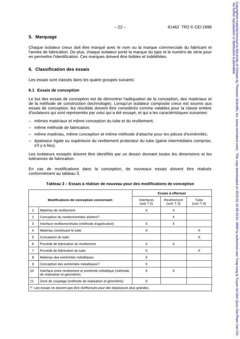
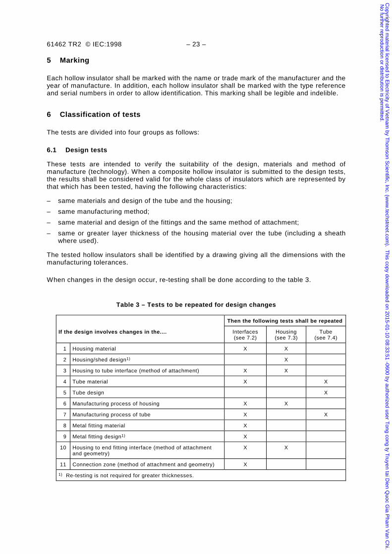
En cas de modifications dans la conception, de nouveaux essais doivent être réalisésconformément au tableau 3.
Tableau 3 – Essais à réaliser de nouveau pour des modifications de conception
Essais à effectuer
Modifications de conception concernant: Interfaces(voir 7.2)
Revêtement(voir 7.3)
Tube(voir 7.4)
1 Matériau de revêtement X X
2 Conception du revêtement/des ailettes1) X
3 Interface revêtement/tube (méthode d'application) X X
4 Matériau constituant le tube X X
5 Conception du tube X
6 Procédé de fabrication du revêtement X X
7 Procédé de fabrication du tube X X
8 Matériau des extrémités métalliques X
9 Conception des extrémités métalliques1) X
10 Interface entre revêtement et extrémité métallique (méthodede réalisation et géométrie)
X X
11 Zone de couplage (méthode de réalisation et géométrie) X
1) Les essais ne doivent pas être réeffectués pour des épaisseurs plus grandes.
Copyrighted m
aterial licensed to Electricity of V
ietnam by T
homson S
cientific, Inc. (ww
w.techstreet.com
). This copy dow
nloaded on 2015-01-10 08:33:51 -0600 by authorized user Tong cong ty T
ruyen tai Dien Q
uoc Gia P
ham V
an Chi.
No further reproduction or distribution is perm
itted.
61462 TR2 © IEC:1998 – 23 –
5 Marking
Each hollow insulator shall be marked with the name or trade mark of the manufacturer and theyear of manufacture. In addition, each hollow insulator shall be marked with the type referenceand serial numbers in order to allow identification. This marking shall be legible and indelible.
6 Classification of tests
The tests are divided into four groups as follows:
6.1 Design tests
These tests are intended to verify the suitability of the design, materials and method ofmanufacture (technology). When a composite hollow insulator is submitted to the design tests,the results shall be considered valid for the whole class of insulators which are represented bythat which has been tested, having the following characteristics:
– same materials and design of the tube and the housing;
– same manufacturing method;
– same material and design of the fittings and the same method of attachment;
– same or greater layer thickness of the housing material over the tube (including a sheathwhere used).
The tested hollow insulators shall be identified by a drawing giving all the dimensions with themanufacturing tolerances.
When changes in the design occur, re-testing shall be done according to the table 3.
Table 3 – Tests to be repeated for design changes
Then the following tests shall be repeated
If the design involves changes in the.... Interfaces(see 7.2)
Housing(see 7.3)
Tube(see 7.4)
1 Housing material X X
2 Housing/shed design1) X
3 Housing to tube interface (method of attachment) X X
4 Tube material X X
5 Tube design X
6 Manufacturing process of housing X X
7 Manufacturing process of tube X X
8 Metal fitting material X
9 Metal fitting design1) X
10 Housing to end fitting interface (method of attachmentand geometry)
X X
11 Connection zone (method of attachment and geometry) X
1) Re-testing is not required for greater thicknesses.
Copyrighted m
aterial licensed to Electricity of V
ietnam by T
homson S
cientific, Inc. (ww
w.techstreet.com
). This copy dow
nloaded on 2015-01-10 08:33:51 -0600 by authorized user Tong cong ty T
ruyen tai Dien Q
uoc Gia P
ham V
an Chi.
No further reproduction or distribution is perm
itted.
– 24 – 61462 TR2 © CEI:1998
6.2 Essais de type
Les essais de type ont pour but de vérifier les caractéristiques mécaniques d'un isolateur compositecreux, caractéristiques qui dépendent principalement du tube et des pièces d'extrémités. Les essaisde type doivent être appliqués aux isolateurs dont la classe a satisfait aux essais de conception. Lesessais de type ne doivent être refaits que lorsque le type, le matériau ou le procédé de fabricationde l'isolateur composite creux est changé.
6.3 Essais sur prélèvements
Les essais sur prélèvements ont pour but de vérifier les caractéristiques de l'isolateur compositecreux qui dépendent de la qualité de fabrication et des matériaux mis en œuvre. Ils doivent être faitssur des isolateurs pris au hasard dans les lots présentés en réception.
6.4 Essais individuels
Les essais individuels ont pour but d'éliminer les isolateurs composites ayant des défauts defabrication. Ils doivent être faits sur tout isolateur présenté en réception.
7. Essais de conception
7.1 Généralités
Ces essais se décomposent de trois parties décrites en 7.2, 7.3 et 7.4. Les essais de conceptiondoivent être effectués une seule fois et leurs résultats sont consignés dans un rapport d'essai.Chaque essai peut être effectué indépendamment, sur de nouveaux spécimens, suivant lescirconstances. L'isolateur composite creux d'une certaine conception ne doit être considéré commequalifié que lorsque tous les isolateurs ou spécimens d'essais ont satisfait, dans la séquenceprévue, aux essais de conception définis en 7.2, 7.3 et 7.4.
7.2 Essais des interfaces et connexions des pièces d'extrémités
Ces essais doivent se dérouler sur le même échantillon, selon la séquence prescrite.
7.2.1 Spécimen d'essai
Le spécimen d'essai doit être un isolateur creux assemblé sur la chaîne de production. Le diamètreintérieur du tube sera d'au moins 100 mm et l'épaisseur de sa paroi doit d'au moins 3 mm. Lalongueur d'isolement (espacement entre pièces métalliques) doit être trois fois le diamètre intérieurdu tube et au moins de 800 mm. Les méthodes d'application et de scellement des deux piècesd'extrémités doivent être les mêmes que sur les isolateurs standards de production. L'isolateurcreux doit être soumis aux essais individuels (voir article 10).
Le fabricant doit définir la CMS et la PIS prévue pour le spécimen.
Si le fabricant ne peut produire que des isolateurs avec une ou des dimensions plus petites quecelles prescrites ci-dessus, les essais de conception peuvent être effectués sur les isolateurs ayantles dimensions disponibles si, d'un commun accord, des calculs peuvent montrer que, pour un tubede dimensions différentes, la contrainte maximum dans le tube est égale ou inférieure à celle dutube à l'essai. Les essais des interfaces et connexions des pièces d'extrémités sont valables pourcette conception.
Copyrighted m
aterial licensed to Electricity of V
ietnam by T
homson S
cientific, Inc. (ww
w.techstreet.com
). This copy dow
nloaded on 2015-01-10 08:33:51 -0600 by authorized user Tong cong ty T
ruyen tai Dien Q
uoc Gia P
ham V
an Chi.
No further reproduction or distribution is perm
itted.
61462 TR2 © IEC:1998 – 25 –
6.2 Type tests
These tests are intended to verify the mechanical characteristics of a composite hollowinsulator which depends mainly on its tube and end fittings. Type tests shall be applied to theclass of composite hollow insulators which have passed the design tests. The type test shall berepeated only when the type or the material or the manufacturing process of the compositehollow insulator is changed.
6.3 Sample tests
These tests are for the purpose of verifying the characteristics of composite hollow insulatorswhich depend on the manufacturing quality and the material used. They shall be made oninsulators taken at random from batches offered for acceptance.
6.4 Routine tests
These tests are for the purpose of eliminating composite hollow insulators with manufacturingdefects. They shall be made on each composite hollow insulator.
7 Design tests
7.1 General
These tests consist of three parts as described in 7.2, 7.3 and 7.4. The design tests shall beperformed only once and the results are recorded in a test report. Each part can be performedindependently on new test specimens where appropriate. The composite hollow insulator of aparticular design shall be deemed accepted only when all insulators or test specimens pass thedesign tests in the given sequence within 7.2, 7.3 and 7.4.
7.2 Tests on interfaces and connections of end fittings
These tests shall be performed in the given sequence on the same specimen.
7.2.1 Test specimen
One hollow insulator assembled on the production line shall be tested. The tube's internaldiameter shall be at least 100 mm and the wall thickness at least 3 mm. The insulation length(metal-to-metal spacing) shall be at least three times the tube's internal diameter but not lessthan 800 mm. Both end fittings shall have the same method of attachment and sealing as onstandard production insulators. The hollow insulator shall be submitted to the routine tests(clause 10).
The manufacturer shall define the expected SML and SIP for the test specimen.
If the manufacturer has only facilities to make insulators with one or more dimensions smallerthan the above-mentioned values, the design tests may be performed on insulators of thosedimensions which are available, if by agreement it can be shown by calculation that for a tubeof different dimensions the maximum stress in the tube is the same or less than in the onetested. The tests on interfaces and connection of end fittings are valid for this design.
Copyrighted m
aterial licensed to Electricity of V
ietnam by T
homson S
cientific, Inc. (ww
w.techstreet.com
). This copy dow
nloaded on 2015-01-10 08:33:51 -0600 by authorized user Tong cong ty T
ruyen tai Dien Q
uoc Gia P
ham V
an Chi.
No further reproduction or distribution is perm
itted.
– 26 – 61462 TR2 © CEI:1998
7.2.2 Essai de référence sous tension à fréquence industrielle à sec
La tension de contournement de référence à fréquence industrielle à sec (Uréf) doit être déterminéeen faisant la moyenne de cinq mesures de tension de contournement conformément à la normeCEI 60060-1. La valeur moyenne de la tension de contournement doit être ramenée aux conditionsatmosphériques normales telles qu'elles sont décrites dans la CEI 60060-1. La tension decontournement doit être obtenue en augmentant linéairement la tension depuis zéro, en moins de1 min.
On doit prendre les précautions nécessaires pour éviter les claquages internes, par exemple enremplissant l'isolateur avec un gaz isolant. La tension de contournement peut aussi être mesurée endivisant la longueur d'isolement en deux parties aussi égales que possible à l'aide d'une électrodeextérieure supplémentaire.
7.2.3 Essai de précontrainte thermo-mécanique
Le spécimen est soumis séquentiellement à une charge mécanique permanente dans quatredirections accompagnée des variations de température.
Les variations thermiques comportent deux cycles de chauffage et de refroidissement; la durée ducycle ne doit pas être inférieure à 24 h ou supérieure à 48 h. La température de la période froidedoit être au moins de 85 K plus basse que celle de la période chaude; cependant, la température laplus basse de la période froide ne doit pas être inférieure à –50 °C. Les températures des périodeschaudes et froides doivent être maintenues durant au moins 33 % du temps choisi pour le cycle.
La charge appliquée au spécimen correspond à 0,5 × CMS ± 5 %.
La charge doit être appliquée perpendiculairement à l'axe de l'isolateur, soit à l'extrémité libre del'isolateur (voir figure 2), soit à une certaine distance de l'extrémité libre si des raisons particulièresl'exigent. Dans ce dernier cas, la charge appliquée doit être ajustée pour créer le même couple à labase de l'isolateur.
La direction de la charge de flexion appliquée au spécimen est changée quatre fois en accord avecla durée des niveaux de température et l’intervalle de temps décrits dans les figures 1 et 2.
L'essai peut être interrompu pour entretien pour une durée totale de 4 h. Le point de départ aprèsune interruption est le début du cycle interrompu.
NOTE – Les valeurs de température et charge ne sont pas choisies pour représenter les conditions de service mais pourobtenir des contraintes spécifiques et reproductibles dans les interfaces de l'isolateur.
7.2.4 Essai de pénétration d'eau
Le spécimen d'essai doit être maintenu immergé dans un récipient d'eau désionisée, bouillante,additionnée de 0,1 % en poids de NaCl, pendant 42 h (voir 5.1.3.3, CEI 61109). Les extrémités duspécimen peuvent être fermées et reliées à l'atmosphère.
A la fin de la période d'ébullition le spécimen doit rester dans le récipient jusqu'à ce que l'eau serefroidisse jusqu'à environ 50 °C; puis il doit être maintenu dans le récipient à cette températurejusqu'au début des essais de vérification, faits selon la séquence donnée ci-dessous.
7.2.5 Essai de vérification
L'intervalle de temps entre les essais individuels de 7.2.5.1, 7.2.5.2 et 7.2.5.3 doit être tel que lesessais de vérification soient terminés dans les 48 h.
Copyrighted m
aterial licensed to Electricity of V
ietnam by T
homson S
cientific, Inc. (ww
w.techstreet.com
). This copy dow
nloaded on 2015-01-10 08:33:51 -0600 by authorized user Tong cong ty T
ruyen tai Dien Q
uoc Gia P
ham V
an Chi.
No further reproduction or distribution is perm
itted.
61462 TR2 © IEC:1998 – 27 –
7.2.2 Reference dry power frequency flashover test
The reference dry power frequency external flashover voltage (Uref) shall be determined inaccordance with IEC 60060-1 by averaging five flashover voltages determined according toIEC 60060-1. This average flashover voltage shall be corrected to normal standard conditionsas mentioned in IEC 60060-1. The flashover voltage shall be obtained by increasing the voltagelinearly from zero to flashover within 1 min.
Means shall be employed to avoid internal flashover, for example by filling with insulating gas.Alternatively, the flashover voltage may be determined by splitting the arcing distance into twosections, as equal as possible, by the use of an additional external electrode.
7.2.3 Thermal mechanical pre-stress test
The specimen is sequentially submitted to a mechanical load in four directions and thermalvariations.
The thermal variations consist of two cycles of heating and cooling, the duration of the cycleshall be taken not shorter than 24 and not longer than 48 h. The cold period shall be at atemperature at least 85 K below the value actually applied in the hot period; however, thelowest temperature in the cold period shall not be lower than –50 °C. Each of the twotemperatures of the hot and cold periods respectively shall be maintained for at least 33 % ofthe chosen cycle time.
The load applied to the test specimen corresponds to 0,5 × SML ± 5 %.
The load shall be applied perpendicularly to the insulator's axis either directly to the free end ofthe insulators (see figure 2) or at a distance from the free end of the insulator if specialreasons exist. When the load is not applied directly to the end fitting, the applied load shall becorrected to give the same bending moment at the base of the insulator.
The direction of the cantilever test load applied to the test specimen is changed four timescorresponding to the duration of the temperature level and the corresponding time intervaldescribed in figure 1 and figure 2.
The test may be interrupted for maintenance of the test equipment for a total duration of 4 h.The starting point after any interruption is the beginning of the interrupted cycle.
NOTE – The temperatures and loads in this test are not intended to represent service conditions, they are designedto produce specific reproducible stresses in the interfaces of the insulator.
7.2.4 Water immersion pre-stress test
The test specimen shall be kept immersed in boiling distilled water with 0,1 % by weight ofNaCl for 42 h (see 5.1.3.3 in IEC 61109). The ends of the specimen may be sealed and ventedto atmospheric pressure.
At the end of the boiling period, the specimen shall remain in the vessel until the water coolsdown to approximately 50 °C. The specimen shall be kept at this temperature in the vessel untilverification tests start in the following sequence.
7.2.5 Verification tests
The time interval between the tests of 7.2.5.1, 7.2.5.2 and 7.2.5.3, shall be such that thesetests are completed within 48 h.
Copyrighted m
aterial licensed to Electricity of V
ietnam by T
homson S
cientific, Inc. (ww
w.techstreet.com
). This copy dow
nloaded on 2015-01-10 08:33:51 -0600 by authorized user Tong cong ty T
ruyen tai Dien Q
uoc Gia P
ham V
an Chi.
No further reproduction or distribution is perm
itted.

– 28 – 61462 TR2 © CEI:1998
7.2.5.1 Examen visuel
Le spécimen doit être inspecté visuellement. Aucune craquelure n'est admise.
7.2.5.2 Essais sous onde de choc à front raide
Le spécimen d'essai doit être muni d'électrodes à arêtes vives (consistant par exemple de bandesdécoupées dans un ruban de cuivre large de 20 mm environ et épais de moins de 0,3 mm) de façonà créer des sections d'environ 500 mm ou moins entre les pièces d'extrémités. Ces électrodes sontfixées solidement au revêtement entre les ailettes. On doit prendre les mesures nécessaires pourqu'il n'y ait pas de claquage à l'intérieur du tube.
Une onde de choc, à raideur de front d'au moins 1 000 kV/µs, doit être appliquée respectivement àdeux électrodes voisines ou entre une pièce d'extrémité et l'électrode voisine. Chaque section doitêtre soumise à 25 chocs de polarité positive et 25 chocs de polarité négative.
Chaque onde de choc doit causer un contournement externe de l'intervalle essayé entre lesélectrodes. Aucune perforation ne doit se produire. Les électrodes formant les sections doiventensuite être enlevées.
7.2.5.3 Essai sous tension à fréquence industrielle à sec
La tension de contournement à fréquence industrielle à sec doit être déterminée suivant la méthodedécrite en 7.2.2. La moyenne des tensions de contournement ne doit pas être inférieure à 90 %de la valeur de référence déterminée pour ce spécimen en 7.2.2. Le spécimen doit être soumispendant 30 min à 80 % de Uréf déterminée en 7.2.2.
Aucune perforation ne doit se produire et l'élévation de température du corps du spécimen,mesurée immédiatement après l'essai, ne doit pas dépasser 20 K.
7.2.5.4 Essai de pression interne
Cet essai n'est pas applicable pour des isolateurs composites creux conçus pour des conditions deservice sans pression.
Le spécimen doit être soumis à la pression interne en deux paliers. Le spécimen ne doit pasprésenter de fuite.
Pour des raisons de sécurité, le spécimen doit être soumis, avant de démarrer l'essai, à unepression interne de 0,5 × PIS pendant 5 min. à la température ambiante, conformément à laprocédure définie en 10.3 (essai de pression individuel).
a) Première étape: essai d'étanchéité sous pression de gaz
L'essai doit être réalisé en disposant le spécimen dans une enceinte de volume le plus petitpossible (voir figure 3). Une pression de gaz de 0,25 × PIS doit être appliquée en utilisant del'hexafluorure de soufre: (SF6).
Le taux de fuite de gaz du spécimen vers l'enceinte doit être mesuré à l'aide d'un mesureur defuite (précision 10–1 × 10⁻⁶) pendant au moins 1 h après une stabilisation du taux de fuite d'aumoins 4 h. Le taux de fuite doit être donné en fraction volumique pour-cent par an.
L'essai est satisfaisant si le taux de fuite n'est pas supérieur à la fraction volumique de 0,75 %par an.
NOTE – Des lignes directrices sur les mesures de taux de fuite peuvent être trouvées dans la CEI 60068-2-17, essaiQm, méthode d'essai 1.
Copyrighted m
aterial licensed to Electricity of V
ietnam by T
homson S
cientific, Inc. (ww
w.techstreet.com
). This copy dow
nloaded on 2015-01-10 08:33:51 -0600 by authorized user Tong cong ty T
ruyen tai Dien Q
uoc Gia P
ham V
an Chi.
No further reproduction or distribution is perm
itted.
61462 TR2 © IEC:1998 – 29 –
7.2.5.1 Visual verification
The specimen shall be inspected visually. No cracks are permissible.
7.2.5.2 Steep-front impulse high voltage test
The test specimen shall be fitted with sharp edged electrodes (consisting of clips, for examplemade of copper strip approximately 20 mm wide and less than 0,3 mm thick) between the endfittings to form sections of about 500 mm or smaller. These electrodes shall lie firmly on thehousing between sheds. Means shall be employed to prevent internal flashover.
An impulse voltage with a steepness of at least 1 000 kV/ms shall be applied to twoneighbouring electrodes and between the insulator end fitting and the neighbouring electrode,respectively. Each section shall be stressed with 25 impulses of positive and 25 impulses ofnegative polarity.
Each impulse shall cause an external flashover of the test distance between the electrodes.No puncture shall occur. The electrodes used to form sections shall be removed.
7.2.5.3 Dry power frequency voltage test
The dry power frequency flashover voltage shall be determined for the specimen using thesame procedure as used in 7.2.2. The average value of the flashover voltages shall not besmaller than 90 % of the Uref determined in 7.2.2 for the specimen. The test specimen shall besubjected for 30 min to 80 % of the Uref determined in 7.2.2.
No puncture shall occur and the temperature rise of the housing between the sheds measuredimmediately after the test shall be not more than 20 K.
7.2.5.4 Internal pressure test
This test is not applicable for composite hollow insulators designed for unpressurized serviceconditions.
The test specimen shall be subjected to an internal pressure in two stages. The specimen shallremain tight.
For safety reasons, before starting the tests, the test specimen shall be subjected to 0,5 × SIPfor 5 min at ambient temperature using the procedure in 10.3 (routine pressure test).
a) Stage one: gas leakage test
The test shall be performed by placing the test specimen in an enclosure with a volume assmall as possible, see figure 3. A pressure of 0,25 × SIP shall be applied using SF6 as thepressure medium.
The leakage of gas from the test specimen into the surrounding enclosure shall bemeasured with a leakage meter (accuracy about 10–1 × 10⁻⁶) for at least 1 h after a leakrate stabilization period of at least 4 h. The leakage rate shall be given in a volume fractionin percent per year.
The test is passed if the leakage rate is not more than the volume fraction of 0,75 % peryear.
NOTE – Guidance on leakage rate measurements can be found in IEC 60068-2-17, test Qm, test method 1.
Copyrighted m
aterial licensed to Electricity of V
ietnam by T
homson S
cientific, Inc. (ww
w.techstreet.com
). This copy dow
nloaded on 2015-01-10 08:33:51 -0600 by authorized user Tong cong ty T
ruyen tai Dien Q
uoc Gia P
ham V
an Chi.
No further reproduction or distribution is perm
itted.
– 30 – 61462 TR2 © CEI:1998
b) Deuxième étape: essai d'étanchéité sous pression d'eau
La pression interne doit être augmentée rapidement, mais sans à-coups de zéro à la PIS etmaintenue pendant 5 min. La pression interne doit être obtenue en utilisant de l'eau. L'essai estconsidéré comme passé avec succès si après 5 min. il n'y a pas rupture du spécimen ou de fuiteaux interstices A et B repérés à la figure 4, et au tube lui-même. Des consignes de sécuritéparticulières doivent être appliquées pour effectuer cette inspection.
7.3 Essai du matériau du revêtement
7.3.1 Essai de cheminement et d'érosion
Cet essai n'est requis que pour les isolateurs composites creux qui sont utilisés à l'extérieur. Pourdes utilisations à l'intérieur, des essais de vieillissement appropriés peuvent être faits après ententeentre le fabricant et l'utilisateur (voir par exemple la CEI 60660 et la CEI 60932).
Le but de l’essai est de contraindre le revêtement et les interfaces par des décharges sousbrouillard salin. Un degré de salinité trop fort peut provoquer des contournements qui n’affectentpas la surface ; ainsi la procédure d’essai prévoit de mesures pour réduire les contournements enbaissant la salinité.
7.3.1.1 Spécimens d'essai
Deux spécimens avec une ligne de fuite entre 500 mm et 700 mm doivent être utilisés, l'un desspécimens subissant l'essai en position horizontale et l'autre en position verticale. Le diamètreextérieur du fût des spécimens doit être d'au moins 100 mm. La conception des pièces d'extrémitéset la transition entre celles-ci et le revêtement seront identiques à celles des isolateurs devant êtrequalifiés. Les spécimens doivent être scellés pour empêcher le brouillard de pénétrer à l'intérieur dutube.
On doit noter qu'il peut devenir impossible de réaliser l'essai avec des tubes de grand diamètre sansque les courants soient trop importants ou qu'il y ait trop de contournements. Il est doncrecommandé d'utiliser si possible des spécimens dont le diamètre du fût est inférieur à 200 mm.
7.3.1.2 Procédure d'essai
Cet essai continu, limité dans le temps, est fait sous brouillard salin et sous tension constante àfréquence industrielle entre 14 kV et 20 kV. La tension d'essai en kilovolts est déterminée endivisant la ligne de fuite en millimètres par 34,6 (ceci équivaut à une ligne de fuite spécifique de20 mm/kV). Le circuit sous une charge résistive de 250 mA (efficace) du côté haute tension ne doitpas voir sa tension baisser de plus de 5 %.
L'essai est fait dans une chambre imperméable et non sujette à la corrosion, dont le volume ne doitpas être supérieur à 10 m3. Une ouverture n'excédant pas 80 cm2 doit permettre l'aération. Uneturbine ou un humidificateur domestique de capacité constante doit être utilisée pour atomiser lasolution saline.
Les spécimens d'essai doivent être lavés avec de l'eau déminéralisée avant de commencer l'essai.
Un spécimen doit être monté horizontalement (à environ mi-hauteur de la chambre) et le secondverticalement. La distance entre le plafond de la chambre et les spécimens d'essai doit être d'aumoins 200 mm et celle avec les parois d'au moins 100 mm.
Le brouillard remplira la chambre mais ne sera pas dirigé contre les spécimens d'essai. La solutionsaline de NaCl et d'eau déminéralisée doit alimenter l'atomiseur.
Copyrighted m
aterial licensed to Electricity of V
ietnam by T
homson S
cientific, Inc. (ww
w.techstreet.com
). This copy dow
nloaded on 2015-01-10 08:33:51 -0600 by authorized user Tong cong ty T
ruyen tai Dien Q
uoc Gia P
ham V
an Chi.
No further reproduction or distribution is perm
itted.
61462 TR2 © IEC:1998 – 31 –
b) Stage two: water leakage test
An internal pressure shall be applied and increased from zero to SIP at ambienttemperature and maintained for 5 min. The inner pressure medium shall be water. The testis passed if after 5 min there is no failure and no water leakage at the joints A and B asshown in figure 4 or on the tube itself. Adequate safety precautions have to be taken forthis inspection.
7.3 Tests of housing material
7.3.1 Tracking and erosion test
This test is required only for composite hollow insulators intended for outdoor use. For indoorapplications appropriate surface ageing tests may be requested, by agreement betweenpurchaser and manufacturer (see for instance IEC 60660 and IEC 60932).
The aim of the test is to stress the housing and interfaces by discharge activity under salt fog.Since too high a degree of salinity can lead to flashovers, which do not affect the surface,measures are allowed in the test procedure to reduce flashovers by reducing salinity.
7.3.1.1 Test specimens
Two test specimens with a creepage distance between 500 mm and 700 mm shall be used,one for horizontal and one for vertical arrangement. The shank diameter of the specimens shallbe at least 100 mm. The design of the end fittings and the transition between end fittings andhousing shall be identical to those used on standard production insulators. The test specimensshall be sealed to prevent fog from penetrating into the inner space of the test specimen.
It shall be noted that the test may become impossible to perform for larger diameter specimensdue to higher current levels or flashovers. It is therefore recommended that the shank diameterof the specimens be less than 200 mm if possible.
7.3.1.2 Test procedure
The test is a time-limited continuous test under salt fog at constant power frequency voltage inthe range of 14 kV to 20 kV. The test voltage in kilovolts is determined by dividing the creepagedistance in millimetres by 34,6 (equal to a specific creepage distance of 20 mm/kV). The testcircuit when loaded with a resistive current of 250 mA (r.m.s) on the high voltage side shallexperience a maximum voltage drop of 5 %.
The test is carried out in a moisture-sealed corrosion-proof chamber, the volume of which shallnot exceed 10 m3. An aperture of not more than 80 cm2 shall be provided for the naturalexhaust air. A turbo sprayer or room humidifier of constant spraying capacity shall be used aswater atomizer.
The test specimens shall be cleaned with deionized water before starting the test.
One test specimen shall be tested when mounted horizontally (at approximately half the heightof the chamber) and the second mounted vertically. There shall be a clearance of at least200 mm between the roof of the chamber and test specimens and a clearance of 100 mm fromthe walls.
The fog will fill up the chamber and not be directly sprayed onto the test specimen. The saltwater prepared with NaCl and deionized water shall be supplied to the sprayer.
Copyrighted m
aterial licensed to Electricity of V
ietnam by T
homson S
cientific, Inc. (ww
w.techstreet.com
). This copy dow
nloaded on 2015-01-10 08:33:51 -0600 by authorized user Tong cong ty T
ruyen tai Dien Q
uoc Gia P
ham V
an Chi.
No further reproduction or distribution is perm
itted.
– 32 – 61462 TR2 © CEI:1998
La protection de surintensité doit être ajustée à 1 A (efficace). S'il y a trop de déclenchements parsurintensité sans contournement, le niveau de déclenchement peut être augmenté. Toutchangement du niveau de déclenchement doit être noté afin d'accumuler des données et del'expérience qui pourront être utilisées ultérieurement pour définir le niveau de déclenchement parsurintensité en fonction du diamètre des isolateurs.
Des interruptions, causées par des déclenchements, de longues durées, jusqu'à 60 h (par exemplependant un week-end) sont acceptables pour autant que la production de brouillard n'ait pas étéinterrompue. Dans ce cas la tension peut être restaurée graduellement (sur une période parexemple du 15 min.) pour éviter les contournements. Ces interruptions doivent être notées et nedoivent pas être considérées pour la durée de l'essai.
Si le nombre des contournements rend impossible la poursuite de l'essai sur des spécimens degrand diamètre, on doit s’assurer que l’installation d’essai ne présente pas des facteurs donnant lieuà l'amorçage de tels contournements. Les problèmes sont les suivants:
– produits de corrosion diffusant des pièces métalliques vers l’isolation;
– nettoyage et/ou vidange trop peu fréquente de la solution saline favorisant la formation d’algues,moisissure et/ou de bactéries dans la chambre d’essai et dans les containers;
– position de l’humidificateur à turbine trop proche des spécimens donnant lieu à une distributionirrégulière de l’humidité;
– utilisation de buses selon la CEI 60507 au lieu de l’humidificateur à turbine spécifié;
– gouttes tombant de l’isolateur ou de la chambre.
Si cinq interruptions (contournements ou déclenchements) apparaissent, l'essai est interrompu et lecontenu de sel dans la solution est réduit de moitié. Les isolateurs sont lavés avec de l’eau derobinet et l'essai repris dans les 8 h. Tout cela peut être répété jusqu’à l’arrêt des interruptions.L’exécution de chaque mesure prise doit être notifiée.
NOTE – Le déclenchement pendant cet essai ne peut pas être considéré comme une indication de mauvais comportementde l’isolateur creux complet par rapport à la pollution. Les concentrations de contraintes dues à la longueur limitée, àl’arrosage continu et aux insuffisances de l’équipement interne sont quelques-uns des facteurs qui rendent une corrélationavec un essai en grandeur réelle presque impossible.
7.3.1.3 Conditions d'essai
Durée de l'essai 1 000 h de tension et brouillard
Débit de l'eau (0,4 ± 0,1) l/(h × m3)
Taille des gouttelettes 5 µm à 10 µm
Température 20 °C ± 5 K
Teneur de l'eau en NaCl (5 ± 0,25) kg/ m3
Le débit d'eau est mesuré en litre par heure par mètre cube de la chambre d'essai. On ne peut pasrecirculer l'eau.
Plusieurs interruptions de l'essai sont admissibles à des fins d'inspection, chacune d'elles nedépassant pas 1 h. Les périodes d'interruption ne seront pas comptées dans la durée de l'essai.
7.3.1.4 Sanction de l'essai
L'essai est considéré comme passé avec succès s'il n'y a pas de cheminement, si l'érosion n'atteintpas le tube de fibre de verre et s'il n'y a pas de perforation. Le tube ne doit pas être visible.
A ce moment, il n'est pas encore possible de donner des critères quantitatifs sûrs quant au nombrede criques d'érosion admissibles. L'expérience acquise avec cet essai devra être comparée avecles retours du service.
Copyrighted m
aterial licensed to Electricity of V
ietnam by T
homson S
cientific, Inc. (ww
w.techstreet.com
). This copy dow
nloaded on 2015-01-10 08:33:51 -0600 by authorized user Tong cong ty T
ruyen tai Dien Q
uoc Gia P
ham V
an Chi.
No further reproduction or distribution is perm
itted.
61462 TR2 © IEC:1998 – 33 –
The protection level shall initially be set at 1 A (r.m.s.). If overcurrent tripouts occur withoutflashover, the tripout level may be increased. Any changes in tripout level shall be noted inorder to collect data and experience useful to define in due time the overcurrent tripout levelversus the diameter of the insulators.
Long interruptions due to tripouts of up to 60 h (for example during the weekend) are allowedunder the provision that the fog generation continues during the unenergized period. In thiscase, the voltage may be reapplied gradually to avoid flashover (for example over 15 min). Anysuch interruptions shall be recorded and shall not count in the test duration.
If repeated tripouts or flashovers make continuation of the test impossible on larger diameterspecimens, the test set-up shall be investigated to ensure that there are no factors which couldbe initiating these events. Typical problems are:
– corrosion products running from alloy end fittings onto the dielectric;
– infrequent cleaning and/or solution renewal leading to algae, fungus or bacterial growth inthe test chamber and water containers;
– turbo sprayer too close to the test objects causing heavy or uneven wetting;
– use of IEC 60507 nozzles instead of the specified turbo sprayer;
– dripping from insulator or test chamber fittings.
If five interruptions (tripouts or flashovers) occur, the test is interrupted and the salt contentof the water is halved. The insulators are washed under tap water and the test re-startedwithin 8 h. This may be repeated until interruptions no longer occur. The application of any ofthe above measures shall be noted.
NOTE – Flashover in this test cannot be taken as an indication of poor pollution performance of the complete hollowcore insulator. Stress concentration due to the reduced length, continuous wetting and lack of internal equipmentare some of the many factors which negate any possible correlation with a full-scale pollution withstand test.
7.3.1.3 Test conditions
Duration of the test 1 000 h of voltage and fog
Water flow rate (0,4 ± 0,1) l / (m 3 × h)
Size of droplets 5 µm à 10 µm
Temperature 20 °C ± 5 K
NaCl content of water (5 ± 0,25) kg/ m3
The water flow rate is defined in litres per hour and per cubic meter of the test chambervolume. It is not permitted to recirculate the water.
Several interruptions of the test for inspection purposes, each of these not exceeding 1 h, arepermissible. Interruption periods will not be counted in the test duration.
7.3.1.4 Evaluation of the test
The test is passed if no tracking occurs, if erosion does not reach the glass fibre tube and if nopuncture occurs. The tube shall not be visible.
At present, it is not possible to indicate reliable criteria quantifying the permissible number oferosion cracks. Further experience with this test will have to be correlated with serviceperformance.
Copyrighted m
aterial licensed to Electricity of V
ietnam by T
homson S
cientific, Inc. (ww
w.techstreet.com
). This copy dow
nloaded on 2015-01-10 08:33:51 -0600 by authorized user Tong cong ty T
ruyen tai Dien Q
uoc Gia P
ham V
an Chi.
No further reproduction or distribution is perm
itted.
– 34 – 61462 TR2 © CEI:1998
7.3.2 Essai d'inflammabilité
Cet essai vise à vérifier les propriétés de combustion du matériau de revêtement.
7.3.2.1 Méthode d'essai
La procédure d'essai doit être celle décrite dans la CEI 60707, article 9, méthode FV.
7.3.2.2 Sanction de l'essai
L'essai est considéré comme passé avec succès si le spécimen appartient à la catégorie FV 0définie en 9.4 de la CEI 60707.
7.4 Essai du matériau du tube (essai de pénétration d'eau)
L'essai de pénétration d'eau décrit plus bas vise à vérifier que l'eau ne pénètre pas dans la paroi dutube.
7.4.1 Spécimen d'essai
Six échantillons doivent être découpés dans un tube venant de la chaîne de production avec unescie circulaire diamantée préférablement sous eau courante froide. La longueur des échantillonsdans le sens parallèle à l'axe du tube doit être de (30 ± 0,5) mm. La largeur des échantillons doitêtre de (15 ± 0,5) mm. Le matériau de revêtement doit être retiré de la surface des échantillons. Lessurfaces de coupe doivent être poncées au moyen d'un tissu abrasif fin (taille des grains 180). Lesextrémités de coupe doivent être propres et parallèles.
7.4.2 Préconditionnement
Les surfaces des spécimens doivent être nettoyées à l'alcool isopropylique et au papierfiltre immédiatement avant l'ébullition. Les échantillons doivent être mis à bouillir pendant (100 ±0,5) h dans une cuve de verre remplie d'eau désionisée, additionnée de 0,1 % en poids de NaCl. Onne doit faire bouillir ensemble que des échantillons d'un même matériau de tube. Un exemple decuve à ébullition est donné à la figure 5.
Après cette ébullition, les échantillons doivent être enlevés de la cuve et placés dans une autre cuvede verre, remplie d'eau du robinet à température ambiante, pendant au moins 15 min. L'essai soustension décrit dans le paragraphe suivant doit être effectué dans les 3 h après le retrait deséchantillons de la cuve d'eau bouillante.
7.4.3 Essai sous tension électrique
L'essai de tension électrique doit être effectué avec le dispositif indiqué aux figures 6 et 7.
Immédiatement avant cet essai, les échantillons sont retirés de la cuve remplie d'eau du robinet etleur surface est séchée avec du papier filtre. Les échantillons sont ensuite placés entre lesélectrodes. La tension électrique est augmentée d'environ 1 kV par seconde, jusqu'à 12 kV. A 12 kVla tension doit être maintenue constante pendant 1 min., puis on la fait décroître.
7.4.4 Sanction de l'essai
Pendant l'essai, il ne doit se produire aucune perforation ni aucun contournement. Pendant toute ladurée de l'essai, l'intensité du courant ne doit pas dépasser 1 mA (valeur efficace).
Copyrighted m
aterial licensed to Electricity of V
ietnam by T
homson S
cientific, Inc. (ww
w.techstreet.com
). This copy dow
nloaded on 2015-01-10 08:33:51 -0600 by authorized user Tong cong ty T
ruyen tai Dien Q
uoc Gia P
ham V
an Chi.
No further reproduction or distribution is perm
itted.
61462 TR2 © IEC:1998 – 35 –
7.3.2 Flammability test
This test is intended to check the housing material for ignition and self-extinguishingproperties.
7.3.2.1 Test method
The test shall be performed according to IEC 60707, clause 9, method FV.
7.3.2.2 Evaluation of the test
The test is passed if the specimen belongs to category FV 0 defined in 9.4, IEC 60707.
7.4 Tests for the tube material (water diffusion test)
A water diffusion test shall be carried out as follows to check the performance of the tubematerial against water penetration.
7.4.1 Test specimen
Six samples shall be cut from a production line insulator tube with a diamond-coated circularsaw blade preferably under running cool water. The length of the samples taken parallel to theaxis of the tube shall be (30 ± 0,5) mm, the width of the samples shall be (15 ± 0,5) mm. Theexternal housing material covering the samples shall be removed. The cut surfaces shall besmoothed by means of fine abrasive cloth (grain size 180). The cut ends shall be clean andparallel.
7.4.2 Pre-stressing
The surfaces of the samples shall be cleaned with isopropyl-alcohol and filter-paperimmediately before boiling. The samples shall be boiled in a glass container for (100 ± 0,5) h inde-ionized water with 0,1 % by weight of NaCl. Only samples of one tube material shall beboiled together in the same container. An example of the boiling container is shown in figure 5.
After boiling, the samples shall be removed from the container and placed in a glass containerwith tap water at room temperature for at least 15 min. The test described below shall becarried out within the next 3 h after the removal of the samples from the boiling container.
7.4.3 Voltage test
The voltage test shall be carried out in the assembly shown in figure 6 and figure 7.
Immediately before the voltage test the samples shall be removed from the tap water and theirsurface dried with filter-paper. The samples shall then be put between the electrodes. The testvoltage shall be increased at approximately 1 kV per second up to 12 kV. At 12 kV the voltageshall be kept constant for one minute and then decreased.
7.4.4 Evaluation of the test
During the voltage test, no puncture or surface flashover shall occur. The current during thewhole test shall not exceed 1 mA (r.m.s.).
Copyrighted m
aterial licensed to Electricity of V
ietnam by T
homson S
cientific, Inc. (ww
w.techstreet.com
). This copy dow
nloaded on 2015-01-10 08:33:51 -0600 by authorized user Tong cong ty T
ruyen tai Dien Q
uoc Gia P
ham V
an Chi.
No further reproduction or distribution is perm
itted.
– 36 – 61462 TR2 © CEI:1998
8. Essais de type (essais mécaniques seulement)
Les essais de type comportent un essai de pression, pour les isolateurs fonctionnant sous pressionseulement, et un essai de flexion.
8.1 Généralités
Un type d'isolateur est défini mécaniquement par le diamètre intérieur et la longueur du tube,l'épaisseur de la paroi du tube, le type de métal et la méthode de fixation des pièces d'extrémités etle procédé de fabrication. La longueur de l'isolateur définit le type seulement pour des rapports delongueur entre ferrures sur diamètre inférieur à 2.
Pour établir la capacité mécanique du tube, ses limites d'élongation réversible et irréversible (voirannexe C) doivent être vérifiées avec des essais effectués à la température ambiante.
Les isolateurs composites creux utilisés pour les essais de type ne doivent pas être utilisés enservice.
Les charges de flexion doivent être appliquées perpendiculairement à l'axe de l'isolateur oudirectement au niveau du plan extrême de la ferrure d'extrémité (voir figure 2) ou à une certainedistance de ce plan si les circonstances l'exigent. Lorsque la charge n'est pas appliquéedirectement à l'extrémité de la ferrure, cette charge doit être ajustée pour créer le même couple à labase de l'isolateur.
8.2 Spécimens d'essai
Deux isolateurs ou deux spécimens d'essais plus courts mais en dehors de cela identiques prisdans la chaîne de production doivent être utilisés. La longueur des spécimens (espacement demétal à métal) ne doit pas être inférieur à 800 mm. Les deux pièces d'extrémités doivent être lesmêmes que sur les isolateurs de la chaîne de production. Les essais devront être faits sur desspécimens avec revêtement extérieur ou ailettes.
8.3 Préparation des spécimens d'essai
Un spécimen doit être soumis à un essai de pression interne, l'autre à un essai de flexion selonrespectivement 8.4.1 et 8.4.2 (voir figure C.1). Chaque spécimen doit être muni de deux jaugesd'élongation (allongement final supérieur ou égal à 2 %, résistance supérieure ou égale à 120 Ω etlongueur inférieure ou égale à 12 mm). Le revêtement doit être retiré localement pour permettre defixer les jauges sur la surface extérieure du tube.
a) Essai de pression interne
Pour cet essai les jauges de contrainte doivent être placées:
– sur la surface interne ou externe du tube;
– avec une jauge parallèle et l'autre perpendiculaire à l'axe du tube;
– à mi-distance entre les pièces d'extrémités.
Le spécimen doit être placé en position verticale. Les extrémités du spécimen seront munies decouvercles étanches. Ces couvercles doivent être munis d'un dispositif pour introduire et retirerl'agent de pressurisation. Celui-ci, un gaz ou un liquide, ne doit affecter le tube d'aucune manièreautre que mécanique.
Copyrighted m
aterial licensed to Electricity of V
ietnam by T
homson S
cientific, Inc. (ww
w.techstreet.com
). This copy dow
nloaded on 2015-01-10 08:33:51 -0600 by authorized user Tong cong ty T
ruyen tai Dien Q
uoc Gia P
ham V
an Chi.
No further reproduction or distribution is perm
itted.
61462 TR2 © IEC:1998 – 37 –
8 Type tests (only mechanical tests)
The type tests consist of a pressure test, for pressurized insulators only, and a bending test.
8.1 General
An insulator type is mechanically defined by the tube inner diameters, the wall thickness of thetube, the tube lamination parameters, the method of attachment and material of the metal endfittings and the manufacturing process. The length of the insulator defines the type only forratios of length between fittings to diameters of less than 2.
The tests shall be performed at room temperature to confirm the mechanical strength ofthe insulator by verifying the limit between reversible and irreversible phase in the tube (seeannex C).
Composite hollow insulators which have been subjected to the type tests shall not be used inservice.
Bending forces shall be applied perpendicularly to the insulator's axis either directly to the frontplane of the insulator (see figure 2) or in a distance to the front plane of the top end fitting ofthe insulator if special reasons exist. When the load is not applied directly to the end fitting, theapplied load shall be corrected to give the same bending moment at the base of the insulator.
8.2 Test specimens
The test specimens shall be either two full length insulators or two shorter, but otherwiseidentical, insulators made on the production line. The length of the latter specimens (metal-to-metal spacing) shall be not less than 800 mm. Both end fittings shall be the same as used onproduction line insulators. The insulator specimens used for these tests shall be equipped withhousing and sheds.
8.3 Preparation of the test specimen
One specimen shall be subjected to an internal pressure test, the other to a cantilever bendingtest in accordance with 8.4.1 and 8.4.2, respectively (see figure C.1). Each of the testspecimens shall be equipped with two strain gauges (for example final elongation greater thanor equal to 2 %, resistance greater than or equal to 120 Ω, length less than or equal to 12 mm).The housing shall be removed locally to allow fixing of the gauges to the outside of the tube.
a) For the internal pressure test
The position of the strain gauges shall be
– inside or outside on the tube;
– one gauge parallel, one gauge perpendicular to the axis of the tube;
– in the middle of the tube between the end fittings.
The internal pressure test specimen shall be mounted in an upright position. The ends ofthe test specimens shall be fitted with end covers and sealed. The covers shall be equippedwith devices for getting the inner pressure medium in and out. The inner pressure mediumshall be a gas or a liquid and shall not affect the tube in any way, other than mechanically.
Copyrighted m
aterial licensed to Electricity of V
ietnam by T
homson S
cientific, Inc. (ww
w.techstreet.com
). This copy dow
nloaded on 2015-01-10 08:33:51 -0600 by authorized user Tong cong ty T
ruyen tai Dien Q
uoc Gia P
ham V
an Chi.
No further reproduction or distribution is perm
itted.
– 38 – 61462 TR2 © CEI:1998
b) Essai de flexion
Pour cet essai les jauges de contrainte doivent être placées
– sur la surface interne ou externe du tube;
– parallèlement à l'axe du tube;
– près du haut de la pièce d'extrémité tenue rigidement, en général avec son centre à 30 mmdu col de la pièce d'extrémité afin d'éliminer l'influence de cette dernière;
– dans le plan de la force de flexion, l'une diamétralement opposée à l'autre.
NOTE – Une simulation des contraintes ou une détermination expérimentale peut être utilisée pour trouver l'endroit où lacontrainte est maximale afin de fixer les jauges de façon optimale. Il convient cependant de noter qu'un simple calculanalytique peut conduire à des résultats erronés.
Une des pièces d'extrémités du spécimen d'essai doit être maintenue rigidement. La direction de laforce de flexion, appliquée à l'autre pièce d'extrémité, doit être approximativement perpendiculaire àl'axe du tube. La force de flexion doit être appliquée à, ou aussi près que possible de, l'armature defaçon à ce que le point d'application ne change pas.
8.4 Déroulement des essais
Un spécimen est soumis à un essai de pression interne, l'autre à un essai de flexion selon 8.4.1 et8.4.2.
8.4.1 Essai de pression interne
Cet essai fait en deux voire en trois étapes n'est pas requis pour les isolateurs composites creux quisont en service sans pression interne.
a) Première étape: essai à 2,0 × la pression maximum de service
La pression interne doit être augmentée rapidement mais sans à-coups de zéro à 2,0 × PMS à latempérature ambiante. Quand 2,0 × PMS est atteint, cette pression doit être maintenue pendant5 min. La pression est ensuite diminuée graduellement. Si l'état de contrainte du tube est, selonl'indication des jauges de contraintes, le même ±5 % de la contrainte maximum (phase élastiqueréversible) avant et après l'essai de pression, on doit inférer que le spécimen n'a pas étéendommagé (voir annexe C).
NOTE – La valeur de ±5 % est donnée à titre d'information. Elle peut être modifiée à la lumière de l'expérienceultérieure.
b) Deuxième étape: essai à 4,0 × la pression maximum de service
Après l'essai précédent, on doit appliquer une pression de 4,0 × PMS pendant au moins 5 min.La pression doit être ensuite diminuée graduellement. Après cet essai, on admet que l'état dedéformation finale du tube diffère, selon l'indication des jauges de contraintes, de plus de ±5 %de la contrainte maximum (phase plastique irréversible, voir annexe C), mais on doit s'assurervisuellement qu'il n'y a pas eu de dégradation.
NOTE – La valeur de ±5 % est donnée à titre d'information. Elle peut être modifiée à la lumière de l'expérienceultérieure.
c) Troisième étape: essai à la pression SIP
Si on le demande comme information supplémentaire, la méthode de la deuxième étape doit êtreutilisée et la PIS doit être appliquée pendant 5 min. Tous les résultats doivent être noter. Il estpossible que des dommages soient observés visuellement (phase plastique irréversible).
Copyrighted m
aterial licensed to Electricity of V
ietnam by T
homson S
cientific, Inc. (ww
w.techstreet.com
). This copy dow
nloaded on 2015-01-10 08:33:51 -0600 by authorized user Tong cong ty T
ruyen tai Dien Q
uoc Gia P
ham V
an Chi.
No further reproduction or distribution is perm
itted.
61462 TR2 © IEC:1998 – 39 –
b) For the cantilever bending test
The position of the strain gauges shall be
– inside or outside on the tube;
– parallel to the axis of the tube;
– positioned near the fixed end of the insulator, generally with its centre 30 mm from themouth of the end fitting in order to eliminate the influence of the end fitting;
– in the plane of the cantilever force and diametrically opposite from each other.
NOTE – Stress simulation or experimental investigation can be used to determine the area of maximum strain foroptimum positioning of the strain gauges. However, it should be noted that simple analytical calculation methodscan give misleading results.
One end fitting of the cantilever test specimen shall be securely fixed. The cantilever forceshall be applied at approximately 90° to the axis of the test specimen on the other fitting. Thecantilever force shall be applied on or close to this end fitting taking care that the point at whichthe force acts remains fixed.
8.4 Performance of the tests
One specimen is subjected to an internal pressure test and one specimen to a cantileverbending test as mentioned under 8.4.1 and 8.4.2.
8.4.1 Internal pressure test
This test is performed in two or possibly three stages. It is not necessary to perform this testfor composite hollow insulators designed for unpressurized service conditions.
a) Stage one: test at 2,0 × maximum service pressure
The internal pressure shall be increased rapidly but smoothly from zero to 2,0 × MSP atambient temperature. When the 2,0 × MSP is reached, the pressure shall be maintained for5 min. Then the pressure shall be released smoothly. If the tube before and after pressureapplication is in the same strain condition within ±5 % of the maximum strain (reversibleelastic phase) indicated by strain gauges, it shall be inferred that no damage has occurred(see annex C).
NOTE – The value of ±5 % is given for guidance. It may be modified in the future after experience has beengained.
b) Stage two: test at 4,0 × maximum service pressure
After this initial pressure application, a pressure test at 4,0 × MSP shall be applied for atleast 5 min. Then the pressure shall be released smoothly. After pressure application it isallowed that the residual strain be greater than ±5 % of the maximum strain (irreversibleplastic phase, see annex C) but it shall be determined that no visible damage has occurred.
NOTE – The value of ±5% is given for guidance. It may be modified in the future after experience has beengained.
c) Stage three: at specified internal pressure level
If required for additional information, the procedure of stage two shall be used and SIP isapplied for 5 min. Any findings shall be noted. Visible damage may arise and is allowed(irreversible plastic phase).
Copyrighted m
aterial licensed to Electricity of V
ietnam by T
homson S
cientific, Inc. (ww
w.techstreet.com
). This copy dow
nloaded on 2015-01-10 08:33:51 -0600 by authorized user Tong cong ty T
ruyen tai Dien Q
uoc Gia P
ham V
an Chi.
No further reproduction or distribution is perm
itted.
– 40 – 61462 TR2 © CEI:1998
8.4.2 Essai de flexion
Un spécimen est soumis à un essai de flexion qui est fait en trois voire en quatre étapes.
a) Première étape: essai à la charge CMM
La charge de flexion doit être augmentée graduellement de zéro à la CMM en 30 s. Une foisatteinte, on doit maintenir la CMM pendant 30 s. Pendant ce temps, la déflexion de la pièced'extrémité mobile doit être mesurée. La charge de flexion doit être retirée et la déflexionrésiduelle mesurée.
b) Deuxième étape: essai à 1,5 × CMM
La charge de flexion doit de nouveau être augmentée graduellement jusqu'à 1,5 × CMM au plusen 30 s. La charge de 1,5 × CMM doit être maintenue à cette valeur de façon pour au moins60 s. Pendant ce temps la déflexion de la pièce d'extrémité doit être mesurée. La charge doitensuite être diminuée graduellement et la déflexion résiduelle mesurée. Si l'état de contrainte dutube est, selon l'indication des jauges, le même ±5 % de la contrainte maximum (phase élastiqueréversible) avant et après l'essai de flexion, on doit inférer que le spécimen n'a pas étéendommagé (voir annexe C).
Une fois la charge retirée, on doit examiner les pièces d'extrémités pour trouver des fissures oudes dommages.
NOTE – La valeur de ±5 % est donnée à titre d'information. Elle peut être modifiée à la lumière de l'expérienceultérieure.
c) Troisième étape: essai à 2,5 × CMM
La charge de flexion doit de nouveau être augmentée graduellement de zéro à 2,5 × CMM enpas plus de 90 s et maintenue à ce niveau pendant 60 s. La charge doit ensuite être diminuéegraduellement.
Après cet essai on admet que l'état de déformation finale du tube diffère, selon l'indication desjauges de contraintes, de plus de ±5 % de la contrainte maximum (phase plastique irréversible),mais on doit vérifier qu'il n'y a eu pas de dégradation visible (voir annexe C).
NOTE – La valeur de ±5 % est donnée à titre d'information. Elle peut être modifiée à la lumière de l'expérienceultérieure.
d) Quatrième étape: essai à CMS
Pour obtenir plus de renseignements, la méthode décrite à la troisième étape doit être utilisée etCMS appliquée pendant au moins 60 s. Tous les résultats doivent être notés. Il est possible quedes dommages soient observés visuellement (phase plastique irréversible).
8.5 Sanction des essais
Les essais sont considérés comme passés avec succès si
– aucune fracture ou arrachement complet du tube ou fracture d'une armature métallique ne seproduit;
– aucune déformation irréversible des tubes indiquée par les jauges de contrainte n'est observéeaprès l'application de 2,0 × PMS pendant l'essai de pression interne, et de 1,5 × CMM pendantl'essai de flexion;
– La déflexion mesurée pendant l'essai de flexion à CMM et à 1,5 × CMM est en accord avec lavaleur prescrite, définie par le fabricant.
Copyrighted m
aterial licensed to Electricity of V
ietnam by T
homson S
cientific, Inc. (ww
w.techstreet.com
). This copy dow
nloaded on 2015-01-10 08:33:51 -0600 by authorized user Tong cong ty T
ruyen tai Dien Q
uoc Gia P
ham V
an Chi.
No further reproduction or distribution is perm
itted.
61462 TR2 © IEC:1998 – 41 –
8.4.2 Cantilever bending test
One specimen is subjected to a cantilever bending test which is performed in three, or possiblyfour, stages.
a) Stage one: test at maximum mechanical load
The bending load shall be increased smoothly from zero to MML within 30 s. When theMML is reached, it shall be maintained for at least 30 s. During this time the deflection shallbe measured. The bending load shall be completely released and the residual deflectionshall be recorded.
b) Stage two: test at 1,5 × maximum mechanical load
The bending load shall be increased smoothly to 1,5 × MML within 30 s and shall bemaintained at this value for at least 60 s. During this time the deflection shall be measured.Then the load shall be released smoothly and the residual deflection shall be recorded.If the tube before and after load application is in the same strain condition within ±5% of themaximum strain (reversible elastic phase), as indicated by the strain gauges, it shall beinferred that no damage has occurred (see annex C).
After releasing the load to zero the end fittings shall be examined for cracks or failures.
NOTE – The value of ±5 % is given for guidance. It may be modified in the future after experience has beengained.
c) Stage three: test at 2,5 × maximum mechanical load
Following completion of stage two, a bending load shall be reapplied. It shall be increasedsmoothly from zero to 2,5 × MML within 90 s and shall be maintained at this value for atleast 60 s. Then the load shall be released smoothly.
After this load application it is allowed that the residual strain be greater than ±5 % of themaximum strain (irreversible plastic phase), but it shall be determined that no visibledamage has occurred (see annex C).
NOTE – The value of ±5 % is given for guidance. It may be modified in the future after experience has beengained.
d) Stage four: test at specified mechanical load
If required for additional information, the procedure of stage three shall be used and SML isapplied for at least 60 s. Any findings shall be noted. Visible damage may arise and isallowed (irreversible plastic phase).
8.5 Acceptance criteria
The tests are passed if
– no fracture or pull out of the tubes or fracture of the end fittings occur;
– no irreversible deformation of the tube as indicated by strain gauges is found afterapplication of 2,0 × MSP during the internal pressure test and after 1,5 × MML during thebending test;
– the measured deflections during the cantilever bending test at MML and 1,5 × MML meetthe predetermined value, as defined by the manufacturer.
Copyrighted m
aterial licensed to Electricity of V
ietnam by T
homson S
cientific, Inc. (ww
w.techstreet.com
). This copy dow
nloaded on 2015-01-10 08:33:51 -0600 by authorized user Tong cong ty T
ruyen tai Dien Q
uoc Gia P
ham V
an Chi.
No further reproduction or distribution is perm
itted.
– 42 – 61462 TR2 © CEI:1998
9. Essais sur prélèvements
9.1 Choix et nombre de pièces à essayer
Les essais sont faits sur un petit nombre d'isolateurs composites creux pris au hasard dans un lotde pièces ayant passé les essais individuels décrits en 10.1. Sauf spécification contraire, le nombred'échantillons doit être conforme au tableau 4.
Tableau 4 – Tailles d’échantillons
Nombre (n) d'isolateurs creuxformant le lot
Nombre d'isolateurs creux à prendre pour l'essaisur prélèvements
12 ou moins Aucun, pour autant que des essais aient déjà été faits sur desisolateurs du même type et que le rapport d'essai soitapprouvé par l'acheteur,
Un, si un rapport d'essai n'est pas disponible.
13 à 24 Un
25 à 100 Deux
101 à 300 Trois
301 à 500 Quatre
501 ou plus Le nombre entier égal ou immédiatement supérieur à
41,5
1 000+
n
Ces essais sont non destructifs si la méthode magnétique est utilisée pour l'essai de galvanisation,si le revêtement n'est pas taché de manière permanente par l'essai de pénétration d'eau et si ungaz est utilisé pour l'essai de pression. Dans ce cas, l'isolateur ou les isolateurs qui ont subi lesessais de prélèvement peuvent être remis dans le lot et utilisés en service.
9.2 Essais
Les échantillons doivent subir les essais suivants:
– vérification des dimensions (9.3),
– essai de galvanisation pour les pièces d'extrémités en acier doux ou en acier couléconformément à CEI 60168,
– essais mécaniques (9.4),
– vérification de l'interface (9.5).
9.3 Vérification des dimensions
Sur chaque isolateur sélectionné, toutes les dimensions indiquées sur les plans seront vérifiées ycompris les tolérances de forme, de géométrie et de position. Sauf prescriptions contraires, lestolérances donnés à l'annexe A doivent être utilisées. Les plans peuvent indiquer les points entrelesquels la ligne de fuite est spécifiée.
La mesure de la ligne de fuite doit être comparée à celle indiquée sur le dessin même si cettedimension est supérieure à celle demandée à l'origine par l'acheteur. Lorsqu'on spécifie la ligne defuite minimum, la tolérance négative est zéro.
Copyrighted m
aterial licensed to Electricity of V
ietnam by T
homson S
cientific, Inc. (ww
w.techstreet.com
). This copy dow
nloaded on 2015-01-10 08:33:51 -0600 by authorized user Tong cong ty T
ruyen tai Dien Q
uoc Gia P
ham V
an Chi.
No further reproduction or distribution is perm
itted.
61462 TR2 © IEC:1998 – 43 –
9 Sample tests
9.1 Selection and number of insulators
The tests are made on a number of composite hollow insulators taken at random from thebatch after passing the routine tests mentioned in 10.1. Unless otherwise specified, the numberof samples shall be in accordance with the table 4.
Table 4 – Sample sizes
Number ( n) of hollow insulatorsforming the batch
Number of hollow insulators to be taken forsample tests
12 or less None, provided that tests have already been made onhollow insulators of the same type and the testreport is approved by the purchaser.
One, if an approved test report is not available
13 to 24 One
25 to 100 Two
101 to 300 Three
301 to 500 Four
501 or more The whole number equal to or next greater than
41,5
1 000+
n
These tests are non-destructive if the magnetic method is used for the galvanizing test, if thehousing is not permanently stained by the dye penetration test and if gas is used for thepressure test. In this case, the insulator(s) submitted to the tests may be returned to the batchand used in service.
9.2 Testing
The selected insulator shall be subjected to the following tests:
– verification of dimensions (9.3);
– galvanizing test for malleable and ductile cast iron, and steel fittings in accordancewith IEC 60168;
– mechanical tests (9.4);
– check of the interface (9.5).
9.3 Verification of dimensions
On all selected insulators, the dimensions of the composite hollow insulator shall comply withthe values shown on the drawing, within specified tolerances for geometry, form and position.Unless otherwise specified, the tolerances given in annex A shall be used. The drawing canshow the points between which the creepage distance is specified.
The measurement of creepage distance shall be related to the design dimensions asdetermined from the insulator drawing, even though this dimension may be greater than thevalue originally specified by the purchaser. When the creepage distance is specified as aminimum value, the negative tolerance is zero.
Copyrighted m
aterial licensed to Electricity of V
ietnam by T
homson S
cientific, Inc. (ww
w.techstreet.com
). This copy dow
nloaded on 2015-01-10 08:33:51 -0600 by authorized user Tong cong ty T
ruyen tai Dien Q
uoc Gia P
ham V
an Chi.
No further reproduction or distribution is perm
itted.
– 44 – 61462 TR2 © CEI:1998
9.4 Essais mécaniques
La totalité des isolateurs du prélèvement doit subir, en trois étapes, les essais suivants à latempérature ambiante:
a) Première étape: essai à 2,0 × PMSL'isolateur est soumis à une pression interne. On doit monter rapidement mais sans à-coups lapression interne de la pression ambiante à 2,0 × PMS. Cette pression est maintenue pendant aumoins 5 min.
Il n'est pas nécessaire de faire cet essai sur des isolateurs composites creux conçus pour unservice sans pression.
b) Deuxième étape: essai à la charge mécanique maximumLe même isolateur est soumis à l'essai de flexion où la contrainte de flexion est appliquéeséquentiellement, à température ambiante, dans les directions décrites à la figure 2. La chargede flexion doit être appliquée rapidement mais sans à-coups de zéro à la CMM. Si la CMM estatteinte en moins de 90 s, l'isolateur doit rester sous contrainte afin que l'essai dure 90 s.Pendant ce temps le déflexion de le pièce d'extrémité doit être notée. Ensuite la charge estrelâchée et la déflexion résiduelle notée.
c) Troisième étape: essai à 1,5 × CMMAprès avoir terminé l'essai de la deuxième étape, on utilise la même procédure pour chargerl'isolateur à 1,5 × CMM.
9.5 Vérification de l'interface entre les pièces d'extrémités et l'enveloppe
A la fin des essais, les deux extrémités d'un des isolateurs doivent être soumises à un essai depénétration d'un indicateur de fissure près des pièces d'extrémités selon l'ISO 3452. L'essai doitêtre fait de la façon suivante:
– la surface doit être soigneusement nettoyée avec l'agent de nettoyage;
– l'agent de pénétration doit être en contact avec la surface nettoyée pendant 20 min;
– la surface doit être nettoyée à nouveau avec un agent approprié et ensuite séchée;
– si la méthode le demande on doit appliquer le révélateur;
– la surface doit être examinée.
Il peut exister des matériaux d'enveloppe dans la masse desquels l'agent de pénétration peutpénétrer en l'absence de fissure. Dans ce cas, on doit pouvoir interpréter les résultats correctement.
Après l'essai de pénétration l'isolateur doit être inspecté pour détecter la présence de fissures et depénétration de colorant à l'interface entre l'enveloppe et les pièces d'extrémités.
9.6 Sanction de l'essai
Les isolateurs ont passé les essais si
– les dimensions de l'isolateur sont conformes aux dessins;
– l'essai de galvanisation fait sur les pièces d'extrémité, si requis, est passé avec succès;
– le tube ne présente pas de fracture ou il ne s'est pas séparé de ses pièces d'extrémités et lespièces d'extrémités n'ont pas de fracture;
– les déflexions ne dépassent pas les valeurs prescrites, définies par le fabricant;
– aucune fissure de l'enveloppe ou des interfaces n'est détectée par l'essai de pénétration decolorant.
Copyrighted m
aterial licensed to Electricity of V
ietnam by T
homson S
cientific, Inc. (ww
w.techstreet.com
). This copy dow
nloaded on 2015-01-10 08:33:51 -0600 by authorized user Tong cong ty T
ruyen tai Dien Q
uoc Gia P
ham V
an Chi.
No further reproduction or distribution is perm
itted.
61462 TR2 © IEC:1998 – 45 –
9.4 Mechanical tests
All the selected insulators shall be subjected to the following test in three stages at ambienttemperature:
a) Stage one: test at 2,0 × maximum service pressure
The insulator is subjected to an internal pressure. The internal pressure shall be increasedrapidly but smoothly from ambient atmosphere pressure to 2,0 × MSP. The internalpressure shall be maintained for at least 5 min.
It is not necessary to perform this test on composite hollow insulators designed forunpressurized conditions.
b) Stage two: test at maximum mechanical load
The same insulator is then subjected to a sequential cantilever bending load according tothe directions given in figure 2 at ambient temperature. The bending load shall be increasedrapidly but smoothly, from zero to MML. If MML is reached in less than 90 s, the load shallbe maintained for the remainder of at least 90 s. During this time, the deflection shall bemeasured. The load is then completely released and the residual deflection recorded.
c) Stage three: test at 1,5 × maximum mechanical load
Following completion of the test of stage two the same procedure is then repeated for theinsulator at a load of 1,5 × MML.
9.5 Check of the interface between end fittings and the housing
Both ends of one of the selected insulators shall, at the end of the tests, be subjected to acrack indication test, by dye penetration in accordance with ISO 3452 on the housing in thevicinity of the metal fittings. The test shall be performed in the following way:
– the surface shall be properly pre-cleaned with the cleaner;
– the penetrant which shall act during 20 min shall be applied on the cleaned surface;
– the surface shall be cleaned with the excess penetrant remover and dried;
– the developer shall be applied, if necessary;
– the surface shall be inspected.
Some housing materials may absorb the penetrant resulting in permanent staining. In such acase, evidence shall be provided to validate the interpretation of the results.
After the penetration test, the selected insulator shall be inspected for cracks and dyepenetration of the housing to fitting interface.
9.6 Acceptance criteria
The samples have passed these tests if
– the dimensions of the insulators conform with the drawing;
– the galvanizing test (if applicable) is passed;
– if no fracture or pull out of the tube or fracture of the end fittings occur;
– if the deflections meet the predetermined level, as defined by the manufacturer;
– if no cracks on the housing or interfaces occur, indicated by the dye penetration.
Copyrighted m
aterial licensed to Electricity of V
ietnam by T
homson S
cientific, Inc. (ww
w.techstreet.com
). This copy dow
nloaded on 2015-01-10 08:33:51 -0600 by authorized user Tong cong ty T
ruyen tai Dien Q
uoc Gia P
ham V
an Chi.
No further reproduction or distribution is perm
itted.
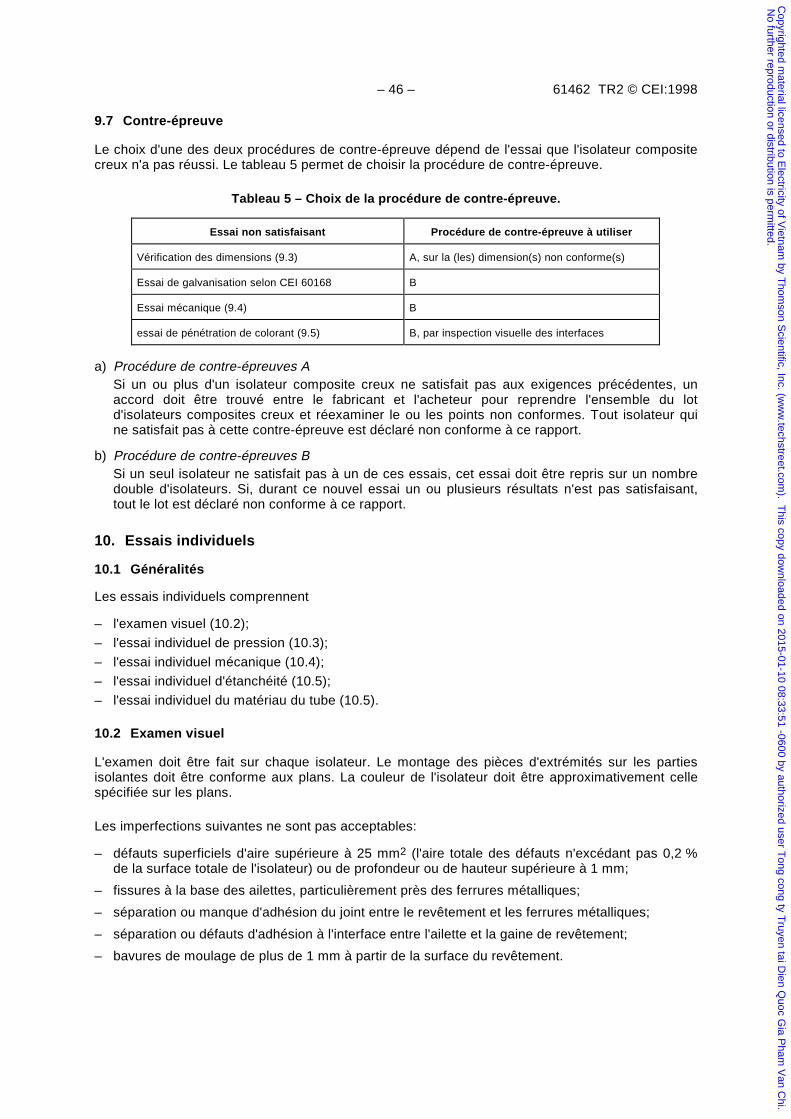
– 46 – 61462 TR2 © CEI:1998
9.7 Contre-épreuve
Le choix d'une des deux procédures de contre-épreuve dépend de l'essai que l'isolateur compositecreux n'a pas réussi. Le tableau 5 permet de choisir la procédure de contre-épreuve.
Tableau 5 – Choix de la procédure de contre-épreuve.
Essai non satisfaisant Procédure de contre-épreuve à utiliser
Vérification des dimensions (9.3) A, sur la (les) dimension(s) non conforme(s)
Essai de galvanisation selon CEI 60168 B
Essai mécanique (9.4) B
essai de pénétration de colorant (9.5) B, par inspection visuelle des interfaces
a) Procédure de contre-épreuves ASi un ou plus d'un isolateur composite creux ne satisfait pas aux exigences précédentes, unaccord doit être trouvé entre le fabricant et l'acheteur pour reprendre l'ensemble du lotd'isolateurs composites creux et réexaminer le ou les points non conformes. Tout isolateur quine satisfait pas à cette contre-épreuve est déclaré non conforme à ce rapport.
b) Procédure de contre-épreuves BSi un seul isolateur ne satisfait pas à un de ces essais, cet essai doit être repris sur un nombredouble d'isolateurs. Si, durant ce nouvel essai un ou plusieurs résultats n'est pas satisfaisant,tout le lot est déclaré non conforme à ce rapport.
10. Essais individuels
10.1 Généralités
Les essais individuels comprennent
– l'examen visuel (10.2);
– l'essai individuel de pression (10.3);
– l'essai individuel mécanique (10.4);
– l'essai individuel d'étanchéité (10.5);
– l'essai individuel du matériau du tube (10.5).
10.2 Examen visuel
L'examen doit être fait sur chaque isolateur. Le montage des pièces d'extrémités sur les partiesisolantes doit être conforme aux plans. La couleur de l'isolateur doit être approximativement cellespécifiée sur les plans.
Les imperfections suivantes ne sont pas acceptables:
– défauts superficiels d'aire supérieure à 25 mm2 (l'aire totale des défauts n'excédant pas 0,2 %de la surface totale de l'isolateur) ou de profondeur ou de hauteur supérieure à 1 mm;
– fissures à la base des ailettes, particulièrement près des ferrures métalliques;
– séparation ou manque d'adhésion du joint entre le revêtement et les ferrures métalliques;
– séparation ou défauts d'adhésion à l'interface entre l'ailette et la gaine de revêtement;
– bavures de moulage de plus de 1 mm à partir de la surface du revêtement.
Copyrighted m
aterial licensed to Electricity of V
ietnam by T
homson S
cientific, Inc. (ww
w.techstreet.com
). This copy dow
nloaded on 2015-01-10 08:33:51 -0600 by authorized user Tong cong ty T
ruyen tai Dien Q
uoc Gia P
ham V
an Chi.
No further reproduction or distribution is perm
itted.
61462 TR2 © IEC:1998 – 47 –
9.7 Re-test procedure
Two re-test procedures are possible according to the type of the test in which the compositehollow insulator failed to meet the requirements. The table 5 shows the re-test procedure to beapplied.
Table 5 – Choice of re-test procedure
Requirements not met in: Re-test procedure to be applied
Verification of dimensions (9.3) A, on the non-conforming dimension(s)
Galvanizing test according to IEC 60168 B
Mechanical test (9.4) B
Dye penetration (9.5) B, by visual inspection of interfaces
a) Re-test procedure A
If one or more composite hollow insulators fail to meet the requirements, agreement shallbe reached between the manufacturer and the purchaser that every composite hollowinsulator in the batch is to be re-examined for the non-conforming requirement(s). Any unitswhich do not satisfy these requirements are not in accordance with this report.
b) Re-test procedure B
If a single hollow insulator fails to satisfy one of these tests, the test in question shall berepeated on a sample twice the size of the first sample. If, during this new test, one or moreof the results are unsatisfactory, the entire batch is not in accordance with this report.
10 Routine tests
10.1 General
The routine tests comprise
– visual examination (10.2);
– routine pressure test (10.3);
– routine mechanical test (10.4);
– routine tightness test (10.5);
– routine test for the tube material (10.6).
10.2 Visual examination
Each insulator shall be examined. The mounting of metallic parts on the insulator assemblyshall be in accordance with the drawings. The colour of the insulator shall approximately be asspecified in the drawing.
The following defects are not permitted:
– superficial defects of an area greater than 25 mm2 (the total defective area not to exceed0,2 % of the total insulator surface) or depth or height greater than 1 mm;
– crack at the root of the shed notably next to the metal fittings;
– separation or lack of bonding at the housing to metal fitting joint (if applicable);
– separation or bonding defects at the shed to sheath interface;
– moulding flashes protruding more than 1 mm above the housing surface.
Copyrighted m
aterial licensed to Electricity of V
ietnam by T
homson S
cientific, Inc. (ww
w.techstreet.com
). This copy dow
nloaded on 2015-01-10 08:33:51 -0600 by authorized user Tong cong ty T
ruyen tai Dien Q
uoc Gia P
ham V
an Chi.
No further reproduction or distribution is perm
itted.
– 48 – 61462 TR2 © CEI:1998
10.3 Essai individuel de pression
Il est nécessaire de faire cet essai sur les isolateurs composites creux conçus pour un service souspression.
Chaque isolateur composite creux doit subir, à pression atmosphérique normale et à températureambiante, un essai individuel de pression hydraulique ou de gaz (air) de 2,0 × PMS pendant 1 min.
Les isolateurs qui n'auront pas passé l'essai doivent être rejetés.
NOTE – D'autres essais individuels peuvent faire l'objet d’un accord entre le fabricant de l’isolateur et le fabricantd'équipement.
10.4 Essai individuel mécanique
Un essai mécanique est fait sur les isolateurs fonctionnant principalement sous contrainte de flexionou autres charges mécaniques en service. Il est aussi fait sur des isolateurs fonctionnant sanspression.
L'essai mécanique est fait pour vérifier l'intégrité des ferrures métalliques et des connexions. Laprocédure d'essai doit reproduire la contrante maximum prévue en service.
NOTE – Les charges, les méthodes d'essais et les critères d'acceptation peuvent faire l'objet d'accord entre le fabricant del’isolateur et le fabricant d'équipement.
10.5 Essai individuel d'étanchéité
Il n'est pas nécessaire de faire cet essai sur des isolateurs composites creux conçus pour unservice sans pression. Cet essai peut également ne pas être fait si en service normal l'interfacen'est pas utilisée pour le scellement ainsi que pour les isolateurs composites creux dont laconception ou le procédé de fabrication sont tels qu'ils excluent tout scellement par l'interface (voirfigures 4c et 4d).
On doit prouver l'étanchéité de la jonction du tube et des pièces d'extrémités à la PMS en utilisantune pression de gaz (air). La pression interne doit être maintenue pendant 5 min.
NOTE – La définition de l'étanchéité, les méthodes d'essais et les critères d'acceptation peuvent faire l'objet d'un accordentre le fabricant de l’isolateur et le fabricant d'équipement..
10.6 Essai du matériau du tube
Un essai de diffusion d'eau doit être fait afin de vérifier l'efficacité du matériau du tube contre lapénétration d'eau.
Un spécimen doit être prélevé pour chaque isolateur composite creux. Le spécimen d'essai doit êtreprélevé dans les chutes de la fabrication du tube de l'isolateur composite creux. Le spécimend'essai doit être préparé selon la méthode décrite en 7.4.1.
Le préconditionnement, l'essai sous tension électrique et la sanction doivent être faits selon 7.4.2,7.4.3 et 7.4.4.
11. Documentation
Le fabricant doit conserver l'enregistrement de toute production conforme à ce rapport pendant unedurée d'au moins 10 ans. Cet enregistrement doit comprendre
– le numéro du type;– le numéro de série;– la date de fabrication;– la date et les résultats des essais individuels.
Sur demande, le fabricant d’équipement peut obtenir des extraits de ces enregistrements.
Copyrighted m
aterial licensed to Electricity of V
ietnam by T
homson S
cientific, Inc. (ww
w.techstreet.com
). This copy dow
nloaded on 2015-01-10 08:33:51 -0600 by authorized user Tong cong ty T
ruyen tai Dien Q
uoc Gia P
ham V
an Chi.
No further reproduction or distribution is perm
itted.
61462 TR2 © IEC:1998 – 49 –
10.3 Routine pressure test
This test is applicable to composite hollow insulators which are stressed by pressure in service.
Every hollow insulator shall be subjected at normal atmospheric pressure and ambienttemperature to a routine hydraulic or gas (air) test pressure corresponding to 2,0 × MSP for1 min.
Failed insulators shall be rejected.
NOTE – Other routine tests are subject to agreement between the manufacturer of the insulator and themanufacturer of equipment.
10.4 Routine mechanical test
This test is applicable to composite hollow insulators which are stressed principally by bendingor by other mechanical loads in service. It is also applicable to unpressurized composite hollowinsulators.
A mechanical test is performed to verify the integrity of the end fittings and connections. Thetest method shall reproduce the maximum stress expected from service.
NOTE – Loads, methods of testing and acceptance criteria are subject to agreement between the manufacturer ofthe insulator and the manufacturer of equipment.
10.5 Routine tightness test
This test is not applicable for composite hollow insulators designed for unpressurized serviceconditions. This test may also be omitted if under normal service conditions the interface is notused for sealing and also for composite hollow insulators whose design and manufacturingprocess are such to exclude any sealing action and untightness of the interface (see figures 4cand 4d).
The tightness of the interface between tube and end fitting shall be checked at MSP using gas(air) pressure. The internal pressure shall be maintained for 5 min.
NOTE – Definition of tightness, methods of testing and acceptance criteria are subject to agreement between themanufacturer of the insulator and the manufacturer of equipment.
10.6 Test for the tube material
A water diffusion test shall be carried out as follows to check the resistance of the tubematerial to water penetration.
One specimen is required for each composite hollow insulator. A test specimen shall be takenfrom the surplus of the tube from which the composite hollow insulators are manufactured. Thetest specimen shall be prepared in accordance with 7.4.1.
Prestressing, voltage testing and evaluation shall be carried out in accordance with 7.4.2, 7.4.3and 7.4.4.
11 Documentation
The manufacturer shall maintain records of all serially produced insulating enclosures inaccordance with this report for a minimum of 10 years. These records shall contain thefollowing information:
– type reference number;– serial number;– date of manufacture;– Routine tests, date and results.
The manufacturer of equipment shall be provided with extracts of the records upon request.
Copyrighted m
aterial licensed to Electricity of V
ietnam by T
homson S
cientific, Inc. (ww
w.techstreet.com
). This copy dow
nloaded on 2015-01-10 08:33:51 -0600 by authorized user Tong cong ty T
ruyen tai Dien Q
uoc Gia P
ham V
an Chi.
No further reproduction or distribution is perm
itted.
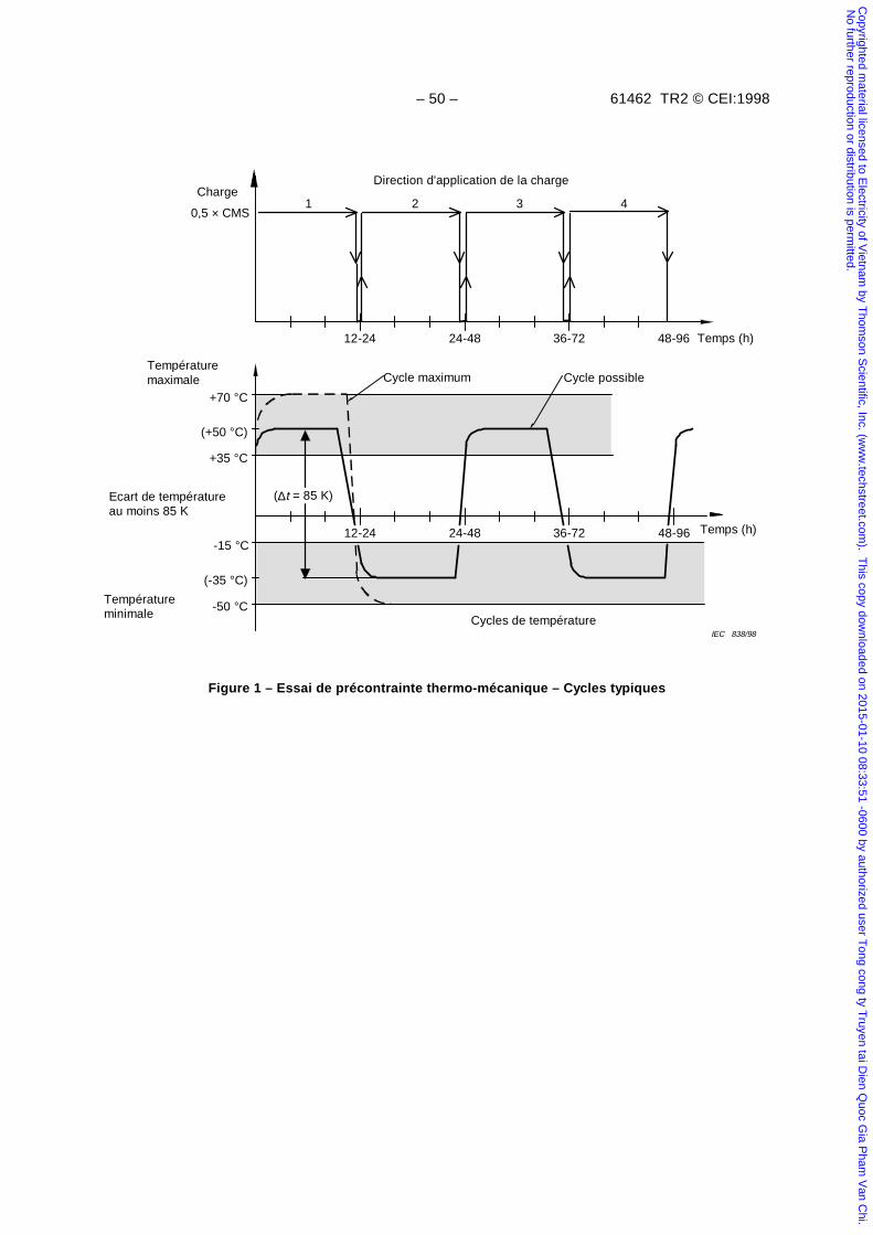
– 50 – 61462 TR2 © CEI:1998
12-24 36-7224-48 48-96
+70 °C
(+50 °C)
(-35 °C)
-50 °C
12-24
0,5 × CMS1
24-48 36-72
Direction d'application de la charge
2 3 4
48-96
+35 °C
-15 °C
Températuremaximale
Ecart de températureau moins 85 K
IEC 838/98
Cycles de température
Temps (h)
Temps (h)
Cycle maximum Cycle possible
Charge
Températureminimale
(∆t = 85 K)
Figure 1 – Essai de précontrainte thermo-mécanique – Cycles typiques
Copyrighted m
aterial licensed to Electricity of V
ietnam by T
homson S
cientific, Inc. (ww
w.techstreet.com
). This copy dow
nloaded on 2015-01-10 08:33:51 -0600 by authorized user Tong cong ty T
ruyen tai Dien Q
uoc Gia P
ham V
an Chi.
No further reproduction or distribution is perm
itted.
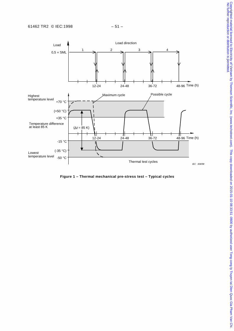
61462 TR2 © IEC:1998 – 51 –
12-24 36-7224-48 48-96
+70 °C
(+50 °C)
(-35 °C)
-50 °C
IEC 838/98Thermal test cycles
temperature levelHighest
at least 85 KTemperature difference
12-24
0,5 × SML1
24-48 36-72
Load direction
2 3 4
48-96
+35 °C
-15 °CTime (h)
Time (h)
Maximum cycle Possible cycle
Load
temperature levelLowest
(∆t = 85 K)
Figure 1 – Thermal mechanical pre-stress test – Typical cycles
Copyrighted m
aterial licensed to Electricity of V
ietnam by T
homson S
cientific, Inc. (ww
w.techstreet.com
). This copy dow
nloaded on 2015-01-10 08:33:51 -0600 by authorized user Tong cong ty T
ruyen tai Dien Q
uoc Gia P
ham V
an Chi.
No further reproduction or distribution is perm
itted.
– 52 – 61462 TR2 © CEI:1998
Air chauffé/refroidi
Charge d'essai
2ème direction de la charge
12 h à 24 h à bassetempérature
12 h à 24 h à hautetempérature
1ère direction de la charge
4ème direction de la charge12 h à 24 h à bassetempérature
3ème direction de la charge
IEC 839/98
12 h à 24 h à hautetempérature
Figure 2 – Essai de précontrainte thermo-mécanique – Montage typique
Copyrighted m
aterial licensed to Electricity of V
ietnam by T
homson S
cientific, Inc. (ww
w.techstreet.com
). This copy dow
nloaded on 2015-01-10 08:33:51 -0600 by authorized user Tong cong ty T
ruyen tai Dien Q
uoc Gia P
ham V
an Chi.
No further reproduction or distribution is perm
itted.
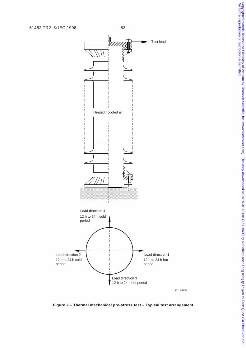
61462 TR2 © IEC:1998 – 53 –
Test load
Heated / cooled air
12 h to 24 h hotperiod
Load direction 1
Load direction 4
12 h to 24 h coldperiod
Load direction 2
12 h to 24 h coldperiod
Load direction 3
IEC 839/98
12 h to 24 h hot period
Figure 2 – Thermal mechanical pre-stress test – Typical test arrangement
Copyrighted m
aterial licensed to Electricity of V
ietnam by T
homson S
cientific, Inc. (ww
w.techstreet.com
). This copy dow
nloaded on 2015-01-10 08:33:51 -0600 by authorized user Tong cong ty T
ruyen tai Dien Q
uoc Gia P
ham V
an Chi.
No further reproduction or distribution is perm
itted.
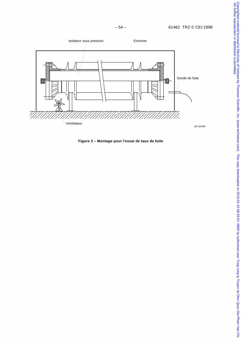
– 54 – 61462 TR2 © CEI:1998
Isolateur sous pression Enceinte
IEC 840/98Ventilateur
Sonde de fuite
Figure 3 – Montage pour l'essai de taux de fuite
Copyrighted m
aterial licensed to Electricity of V
ietnam by T
homson S
cientific, Inc. (ww
w.techstreet.com
). This copy dow
nloaded on 2015-01-10 08:33:51 -0600 by authorized user Tong cong ty T
ruyen tai Dien Q
uoc Gia P
ham V
an Chi.
No further reproduction or distribution is perm
itted.
61462 TR2 © IEC:1998 – 55 –
Gas pressurised insulator Enclosure
Leakage probe
IEC 840/98
Fan
Figure 3 – Test arrangement for the leakage rate test
Copyrighted m
aterial licensed to Electricity of V
ietnam by T
homson S
cientific, Inc. (ww
w.techstreet.com
). This copy dow
nloaded on 2015-01-10 08:33:51 -0600 by authorized user Tong cong ty T
ruyen tai Dien Q
uoc Gia P
ham V
an Chi.
No further reproduction or distribution is perm
itted.
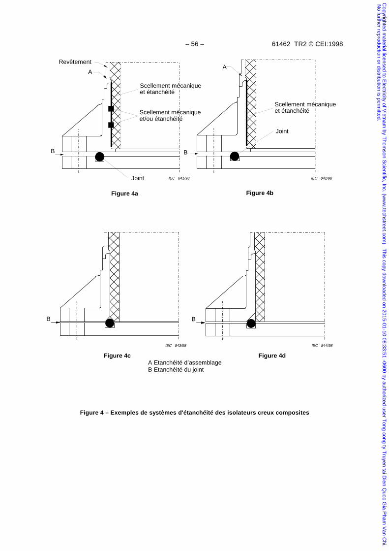
– 56 – 61462 TR2 © CEI:1998
Figure 4a
IEC 844/98IEC 843/98
IEC 842/98IEC 841/98Joint
A
Revêtement
Scellement mécaniqueet étanchéité
Scellement mécaniqueet/ou étanchéité
Figure 4b
Joint
A
Scellement mécaniqueet étanchéité
Figure 4d
B B
A Etanchéité d’assemblageB Etanchéité du joint
B
Figure 4c
B
Figure 4 – Exemples de systèmes d'étanchéité des isolateurs creux composites
Copyrighted m
aterial licensed to Electricity of V
ietnam by T
homson S
cientific, Inc. (ww
w.techstreet.com
). This copy dow
nloaded on 2015-01-10 08:33:51 -0600 by authorized user Tong cong ty T
ruyen tai Dien Q
uoc Gia P
ham V
an Chi.
No further reproduction or distribution is perm
itted.
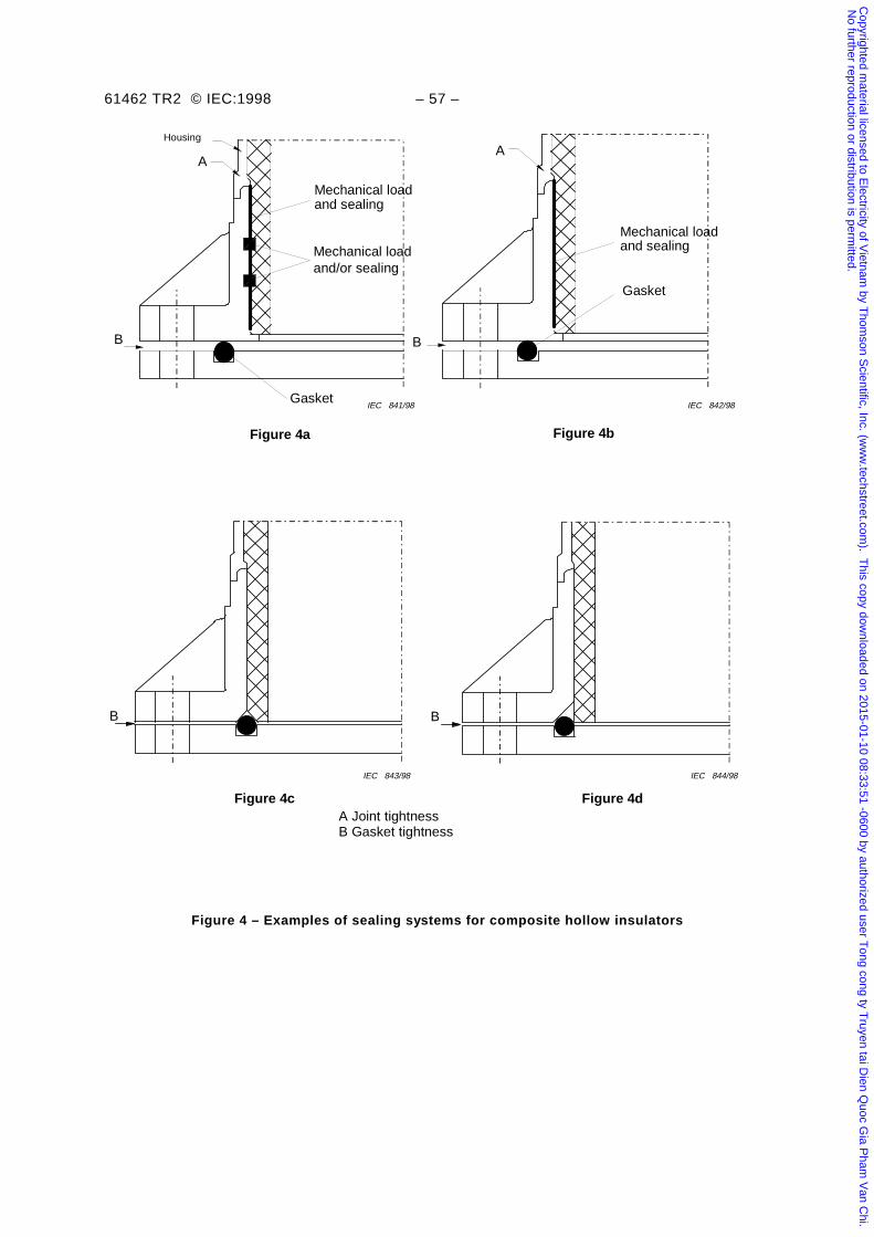
61462 TR2 © IEC:1998 – 57 –
Figure 4a
IEC 844/98IEC 843/98
IEC 842/98IEC 841/98Gasket
A
Housing
Mechanical loadand sealing
Mechanical loadand/or sealing
Figure 4b
Gasket
A
Mechanical loadand sealing
Figure 4d
B B
A Joint tightnessB Gasket tightness
B
Figure 4c
B
Figure 4 – Examples of sealing systems for composite hollow insulators
Copyrighted m
aterial licensed to Electricity of V
ietnam by T
homson S
cientific, Inc. (ww
w.techstreet.com
). This copy dow
nloaded on 2015-01-10 08:33:51 -0600 by authorized user Tong cong ty T
ruyen tai Dien Q
uoc Gia P
ham V
an Chi.
No further reproduction or distribution is perm
itted.
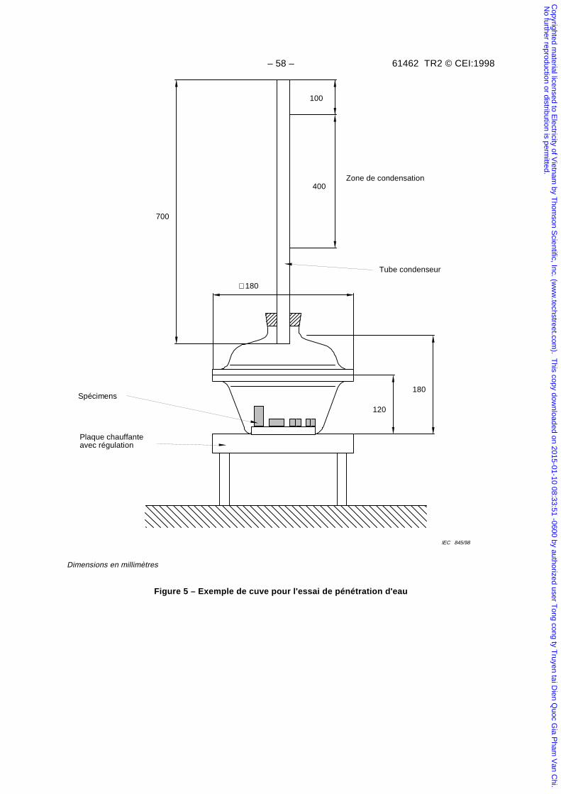
– 58 – 61462 TR2 © CEI:1998
700
100
400
∅180
IEC 845/98
120
180
Plaque chauffanteavec régulation
Spécimens
Tube condenseur
Zone de condensation
Dimensions en millimètres
Figure 5 – Exemple de cuve pour l'essai de pénétration d'eau
Copyrighted m
aterial licensed to Electricity of V
ietnam by T
homson S
cientific, Inc. (ww
w.techstreet.com
). This copy dow
nloaded on 2015-01-10 08:33:51 -0600 by authorized user Tong cong ty T
ruyen tai Dien Q
uoc Gia P
ham V
an Chi.
No further reproduction or distribution is perm
itted.
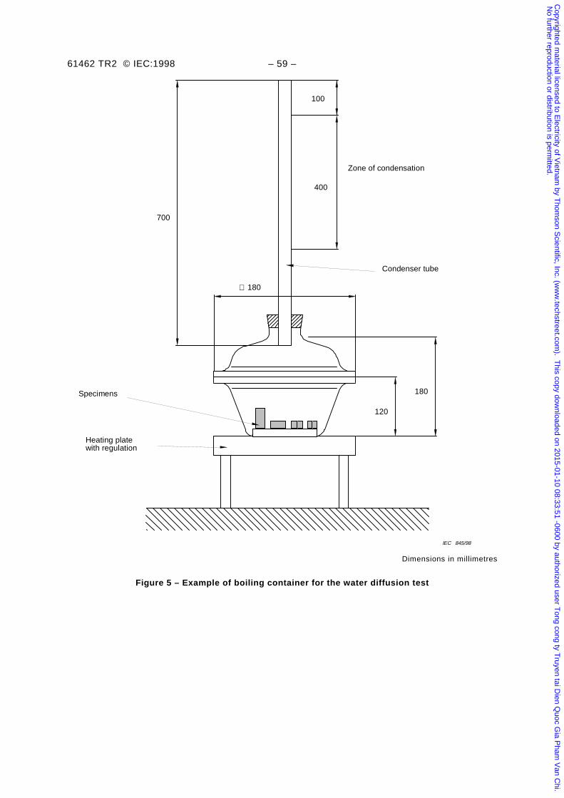
61462 TR2 © IEC:1998 – 59 –
700
100
400
∅ 180
IEC 845/98
120
180
Heating platewith regulation
Specimens
Condenser tube
Zone of condensation
Dimensions in millimetres
Figure 5 – Example of boiling container for the water diffusion test
Copyrighted m
aterial licensed to Electricity of V
ietnam by T
homson S
cientific, Inc. (ww
w.techstreet.com
). This copy dow
nloaded on 2015-01-10 08:33:51 -0600 by authorized user Tong cong ty T
ruyen tai Dien Q
uoc Gia P
ham V
an Chi.
No further reproduction or distribution is perm
itted.
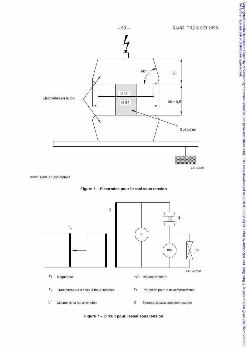
– 60 – 61462 TR2 © CEI:1998
30 ± 0,5
2560°
Electrodes en laiton
IEC 846/98
Spécimen
∅ 64
∅ 50
Dimensions en millimètres
Figure 6 – Electrodes pour l'essai sous tension
V
IEC 847/98
mA
S
Pr
T1
T2
T1 Régulateur
Transformateur d'essai à haute tensionT2
Mesure de la haute tensionV
MilliampèremètremA
Protection pour le milliampèremètrePr
Electrodes avec spécimen essayéS
Figure 7 – Circuit pour l'essai sous tension
Copyrighted m
aterial licensed to Electricity of V
ietnam by T
homson S
cientific, Inc. (ww
w.techstreet.com
). This copy dow
nloaded on 2015-01-10 08:33:51 -0600 by authorized user Tong cong ty T
ruyen tai Dien Q
uoc Gia P
ham V
an Chi.
No further reproduction or distribution is perm
itted.
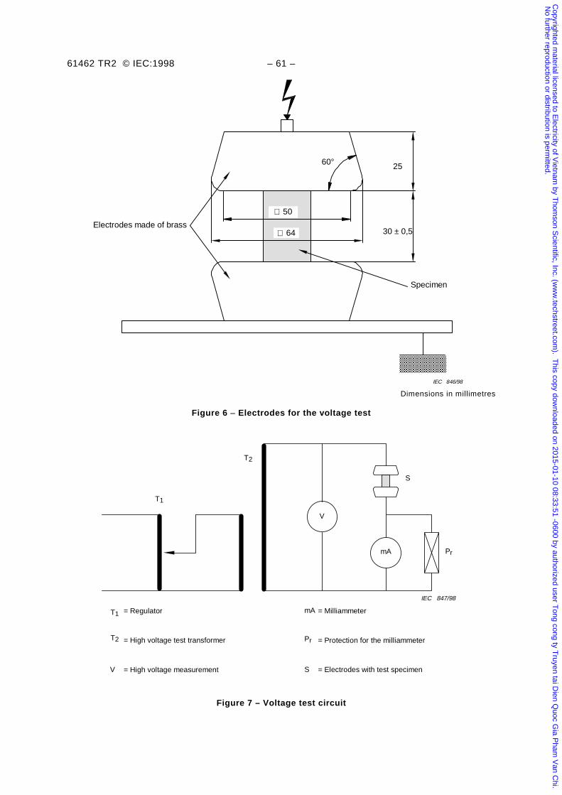
61462 TR2 © IEC:1998 – 61 –
30 ± 0,5
2560°
Electrodes made of brass
IEC 846/98
Specimen
∅ 50
∅ 64
Dimensions in millimetres
Figure 6 – Electrodes for the voltage test
V
IEC 847/98
mA
S
Pr
T1
T2
T1 = Regulator
= High voltage test transformerT2
= High voltage measurementV
= MilliammetermA
= Protection for the milliammeterPr
= Electrodes with test specimenS
Figure 7 – Voltage test circuit
Copyrighted m
aterial licensed to Electricity of V
ietnam by T
homson S
cientific, Inc. (ww
w.techstreet.com
). This copy dow
nloaded on 2015-01-10 08:33:51 -0600 by authorized user Tong cong ty T
ruyen tai Dien Q
uoc Gia P
ham V
an Chi.
No further reproduction or distribution is perm
itted.
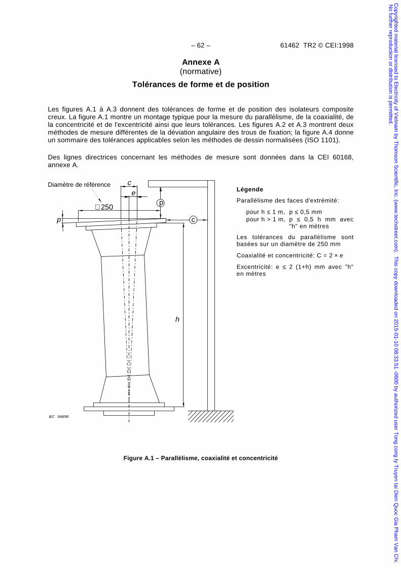
– 62 – 61462 TR2 © CEI:1998
Annexe A(normative)
Tolérances de forme et de position
Les figures A.1 à A.3 donnent des tolérances de forme et de position des isolateurs compositecreux. La figure A.1 montre un montage typique pour la mesure du parallélisme, de la coaxialité, dela concentricité et de l'excentricité ainsi que leurs tolérances. Les figures A.2 et A.3 montrent deuxméthodes de mesure différentes de la déviation angulaire des trous de fixation; la figure A.4 donneun sommaire des tolérances applicables selon les méthodes de dessin normalisées (ISO 1101).
Des lignes directrices concernant les méthodes de mesure sont données dans la CEI 60168,annexe A.
IEC 848/98
h
p
ce
c
p∅250
Diamètre de référenceLégende
Parallélisme des faces d'extrémité:
pour h ≤ 1 m, p ≤ 0,5 mmpour h > 1 m, p ≤ 0,5 h mm avec
"h" en mètres
Les tolérances du parallélisme sontbasées sur un diamètre de 250 mm
Coaxialité et concentricité: C = 2 × e
Excentricité: e ≤ 2 (1+h) mm avec "h"en mètres
Figure A.1 – Parallélisme, coaxialité et concentricité
Copyrighted m
aterial licensed to Electricity of V
ietnam by T
homson S
cientific, Inc. (ww
w.techstreet.com
). This copy dow
nloaded on 2015-01-10 08:33:51 -0600 by authorized user Tong cong ty T
ruyen tai Dien Q
uoc Gia P
ham V
an Chi.
No further reproduction or distribution is perm
itted.
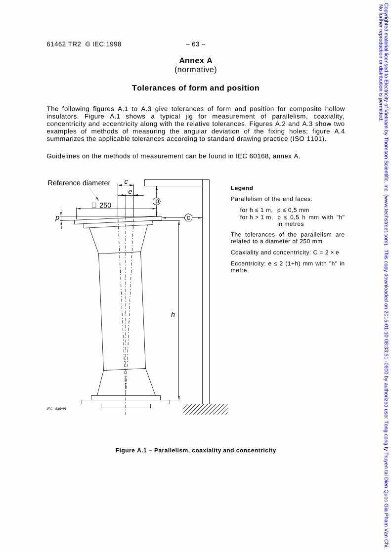
61462 TR2 © IEC:1998 – 63 –
Annex A(normative)
Tolerances of form and position
The following figures A.1 to A.3 give tolerances of form and position for composite hollowinsulators. Figure A.1 shows a typical jig for measurement of parallelism, coaxiality,concentricity and eccentricity along with the relative tolerances. Figures A.2 and A.3 show twoexamples of methods of measuring the angular deviation of the fixing holes; figure A.4summarizes the applicable tolerances according to standard drawing practice (ISO 1101).
Guidelines on the methods of measurement can be found in IEC 60168, annex A.
IEC 848/98
h
p
ce
c
p∅ 250
Reference diameterLegend
Parallelism of the end faces:
for h ≤ 1 m, p ≤ 0,5 mmfor h > 1 m, p ≤ 0,5 h mm with "h"
in metres
The tolerances of the parallelism arerelated to a diameter of 250 mm
Coaxiality and concentricity: C = 2 × e
Eccentricity: e ≤ 2 (1+h) mm with "h" inmetre
Figure A.1 – Parallelism, coaxiality and concentricity
Copyrighted m
aterial licensed to Electricity of V
ietnam by T
homson S
cientific, Inc. (ww
w.techstreet.com
). This copy dow
nloaded on 2015-01-10 08:33:51 -0600 by authorized user Tong cong ty T
ruyen tai Dien Q
uoc Gia P
ham V
an Chi.
No further reproduction or distribution is perm
itted.
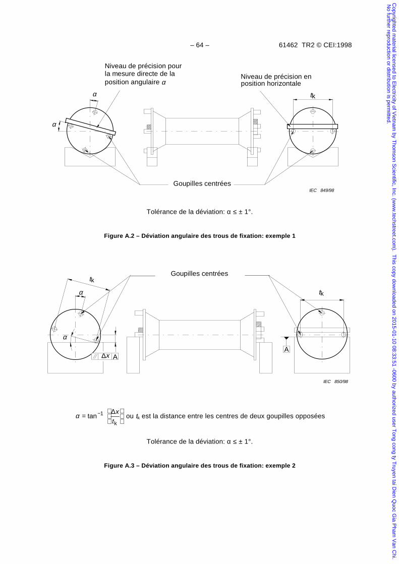
– 64 – 61462 TR2 © CEI:1998
α
α tk
IEC 849/98Goupilles centrées
Niveau de précision pourla mesure directe de laposition angulaire α
Niveau de précision enposition horizontale
Tolérance de la déviation: α ≤ ± 1°.
Figure A.2 – Déviation angulaire des trous de fixation: exemple 1
Goupilles centrées
tk
tk
α
α
IEC 850/98
A ∆x A
α =
−tan
k
1 ∆xt
ou tk est la distance entre les centres de deux goupilles opposées
Tolérance de la déviation: α ≤ ± 1°.
Figure A.3 – Déviation angulaire des trous de fixation: exemple 2
Copyrighted m
aterial licensed to Electricity of V
ietnam by T
homson S
cientific, Inc. (ww
w.techstreet.com
). This copy dow
nloaded on 2015-01-10 08:33:51 -0600 by authorized user Tong cong ty T
ruyen tai Dien Q
uoc Gia P
ham V
an Chi.
No further reproduction or distribution is perm
itted.
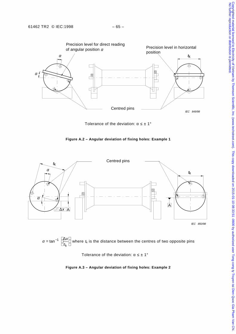
61462 TR2 © IEC:1998 – 65 –
α
α tk
IEC 849/98Centred pins
Precision level for direct readingof angular position α Precision level in horizontal
position
Tolerance of the deviation: α ≤ ± 1°
Figure A.2 – Angular deviation of fixing holes: Example 1
tk
Centred pinstk
α
α
IEC 850/98
A ∆x A
α =
−tan
k
1 ∆xt
where tk is the distance between the centres of two opposite pins
Tolerance of the deviation: α ≤ ± 1°
Figure A.3 – Angular deviation of fixing holes: Example 2
Copyrighted m
aterial licensed to Electricity of V
ietnam by T
homson S
cientific, Inc. (ww
w.techstreet.com
). This copy dow
nloaded on 2015-01-10 08:33:51 -0600 by authorized user Tong cong ty T
ruyen tai Dien Q
uoc Gia P
ham V
an Chi.
No further reproduction or distribution is perm
itted.
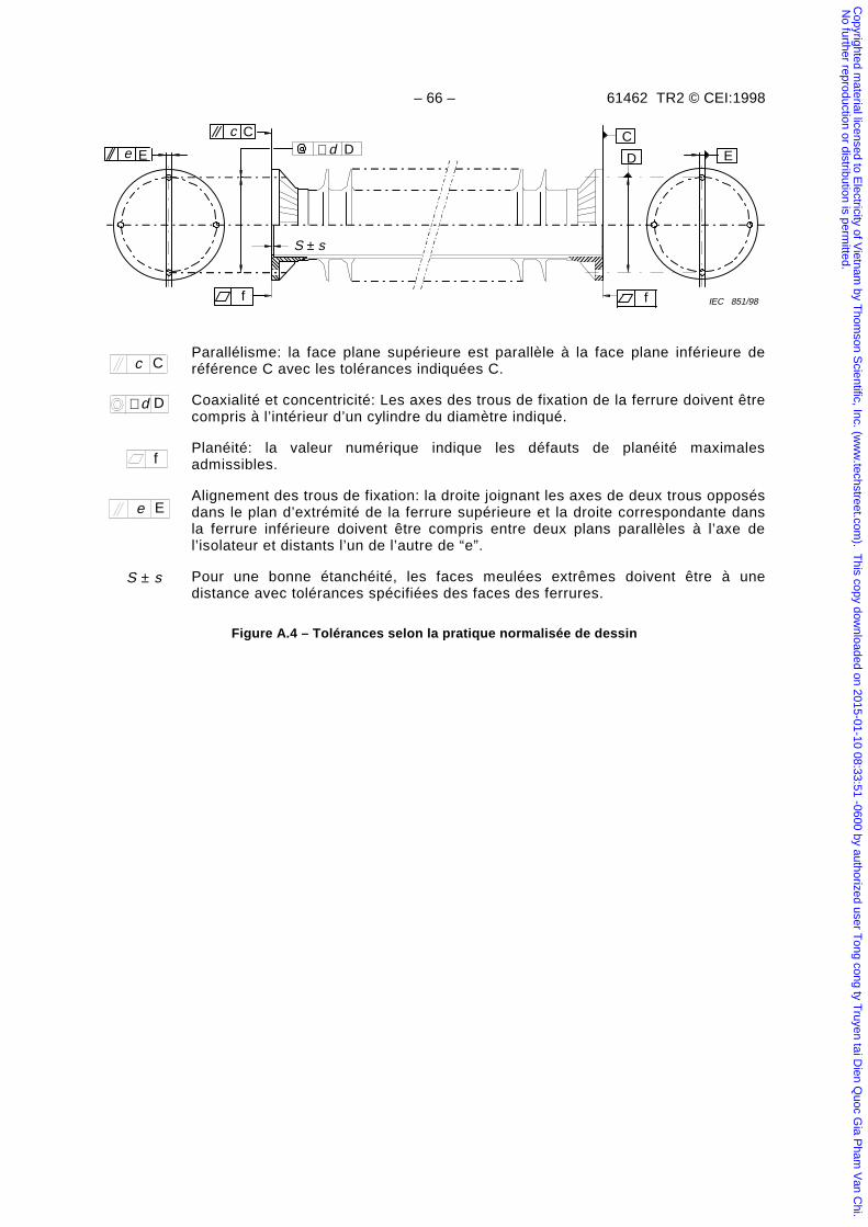
– 66 – 61462 TR2 © CEI:1998
Ee
Cc
IEC 851/98f
D
CE
f
∅d D
S ± s
Parallélisme: la face plane supérieure est parallèle à la face plane inférieure deréférence C avec les tolérances indiquées C.
Coaxialité et concentricité: Les axes des trous de fixation de la ferrure doivent êtrecompris à l’intérieur d’un cylindre du diamètre indiqué.
Planéité: la valeur numérique indique les défauts de planéité maximalesadmissibles.
Alignement des trous de fixation: la droite joignant les axes de deux trous opposésdans le plan d’extrémité de la ferrure supérieure et la droite correspondante dansla ferrure inférieure doivent être compris entre deux plans parallèles à l’axe del’isolateur et distants l’un de l’autre de “e”.
S ± s Pour une bonne étanchéité, les faces meulées extrêmes doivent être à unedistance avec tolérances spécifiées des faces des ferrures.
Figure A.4 – Tolérances selon la pratique normalisée de dessin
Cc
f
Ee
d D∅
Copyrighted m
aterial licensed to Electricity of V
ietnam by T
homson S
cientific, Inc. (ww
w.techstreet.com
). This copy dow
nloaded on 2015-01-10 08:33:51 -0600 by authorized user Tong cong ty T
ruyen tai Dien Q
uoc Gia P
ham V
an Chi.
No further reproduction or distribution is perm
itted.
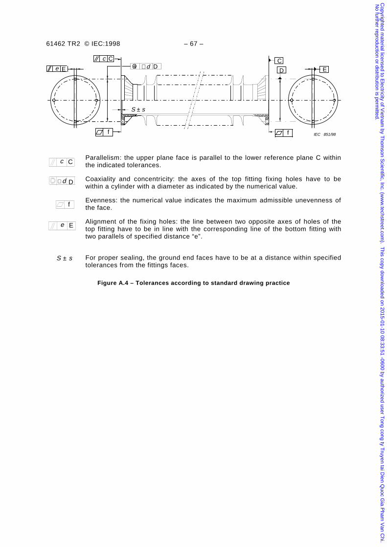
61462 TR2 © IEC:1998 – 67 –
Ee
Cc
IEC 851/98f
D
CE
f
∅d D
S ± s
Parallelism: the upper plane face is parallel to the lower reference plane C withinthe indicated tolerances.
Coaxiality and concentricity: the axes of the top fitting fixing holes have to bewithin a cylinder with a diameter as indicated by the numerical value.
Evenness: the numerical value indicates the maximum admissible unevenness ofthe face.
Alignment of the fixing holes: the line between two opposite axes of holes of thetop fitting have to be in line with the corresponding line of the bottom fitting withtwo parallels of specified distance “e”.
S ± s For proper sealing, the ground end faces have to be at a distance within specifiedtolerances from the fittings faces.
Figure A.4 – Tolerances according to standard drawing practice
Cc
f
Ee
d D∅
Copyrighted m
aterial licensed to Electricity of V
ietnam by T
homson S
cientific, Inc. (ww
w.techstreet.com
). This copy dow
nloaded on 2015-01-10 08:33:51 -0600 by authorized user Tong cong ty T
ruyen tai Dien Q
uoc Gia P
ham V
an Chi.
No further reproduction or distribution is perm
itted.
– 68 – 61462 TR2 © CEI:1998
Annexe B(informative)
Recommandations générales pour la conception et la construction
B.1 Guide de conception
Le guide de conception des isolateurs composites creux sous pression pour des équipements hautetension décrits dans cette annexe prend en compte le fait que ces isolateurs creux sont soumis àdes conditions opératoires particulières qui les différencient des enceintes sous pression d'air oud'autres enceintes similaires de stockage.
Pour la conception d'un isolateur creux, on doit prendre en compte les points suivants:
– les propriétés électriques, les propriétés mécaniques et les problèmes technologiquesconcernant les matériaux de fixation et de collage qui influencent la construction finale. Lacomplexité du sujet rend difficile tout guide unique et rigide;
– une sélection critique des matériaux pour le corps isolant est nécessaire. Il convient que seulsles matériaux et les technologies qui ont fait leurs preuves dans les isolateurs composites deligne soient utilisés;
– un type d'isolateur creux pour service sous pression ne peut être considéré comme convenant àl'usage auquel il est destiné que lorsque l'équipement dans lequel il est monté a subi avecsuccès tous les essais décrits dans les spécifications de l'équipement.
B.2 Guide concernant la pression maximum de service
Usuellement, la PMS est la pression de conception. On doit tenir compte de l'irradiation solaire sicelle-ci a un effet significatif sur la pression du gaz.
NOTE – Dans certains cas spéciaux (par exemple les disjoncteurs), il faut prendre en compte la pression transitoire qui sedéveloppe au moment de la coupure.
B.3 Guide concernant la température requise par le fabricant de l'équipement
Le fabricant de l'équipement doit déterminer les valeurs de température de service. Ces valeursdoivent être dans les limites de la ou des températures spécifiées.
B.4 Guide concernant les charges mécaniques requises par le fabricantde l'équipement
Le fabricant de l'équipement spécifie les charges mécaniques pour l'isolateur creux composite sur labase des contraintes pondérées résultant des divers efforts de service. L'attention est attirée sur lefait que, pour les isolateurs creux composite, l'importance relative de chacun de ces efforts peutêtre différente de celle assignée au même effort sur un isolateur creux en porcelaine équivalentproposé par la CEI 61264.
En plus des charges de fonctionnement, les sources suivantes sont recommandées pourdéterminer les charges mécaniques:
– charges d'extrémité: CEI 60056;
– charges dues au vent: CEI 60056 et CEI 60694;
– charges dues à la glace: CEI 60056 et CEI 60694;
– charges dues au courts-circuits: CEI 60865;
– charges dues aux séismes: CEI 61166.
Copyrighted m
aterial licensed to Electricity of V
ietnam by T
homson S
cientific, Inc. (ww
w.techstreet.com
). This copy dow
nloaded on 2015-01-10 08:33:51 -0600 by authorized user Tong cong ty T
ruyen tai Dien Q
uoc Gia P
ham V
an Chi.
No further reproduction or distribution is perm
itted.
61462 TR2 © IEC:1998 – 69 –
Annex B(informative)
General recommendations for design and construction
B.1 Guidance for design
The guidance for the design of gas-pressurized composite hollow insulators for high-voltageequipment given in this annex takes into account that these hollow insulators are subjected toparticular operating conditions which distinguish them from compressed air receivers andsimilar storage vessels.
When designing composite hollow insulators the following points shall be taken intoconsideration:
– electrical strength, mechanical strength and technological problems including materials forfittings and jointing may influence the real construction, but due to the complexity of thissubject no definitive guide can be given;
– a critical selection of materials for the insulating body is also necessary. Only suchmaterials and technologies should be used as are reliably approved for compositetransmission line insulators;
– a type of an insulating pressurized enclosure may be considered as appropriate forintended use only after the electrical equipment of which it is a part has satisfactorilypassed the type tests called for by the particular standards with which the equipment mustcomply.
B.2 Guidance for the maximum service pressure
Usually the MSP is the "design pressure". Solar radiation shall be taken into account when ithas a significant effect on the pressure of the gas.
NOTE – In some special cases (for example circuit breakers) the transient pressure rise occurring during breakingoperation must be taken into account.
B.3 Guidance for the temperature required by the equipment manufacturer
The equipment manufacturer shall define the applicable service temperature values. Thesevalues shall be within the limits of the specified temperature(s).
B.4 Guidance for the mechanical loads required by the equipment manufacturer
The equipment manufacturer specifies the mechanical loads for the hollow composite insulatoron the basis of weighted stresses arising from various service loads. Attention is drawn to thefact that the relative importance of each of these loads for composite hollow insulators may bedifferent from that assigned to the same load on equivalent porcelain hollow insulators assuggested in IEC 61264.
In addition to operating loads, the following sources are recommended for determining thevalues necessary for calculating various loads:
– terminal loads: IEC 60056;
– wind loads: IEC 60056 and IEC 60694;
– ice loads: IEC 60056 and IEC 60694;
– short-circuit loads: IEC 60865;
– seismic loads: IEC 61166.
Copyrighted m
aterial licensed to Electricity of V
ietnam by T
homson S
cientific, Inc. (ww
w.techstreet.com
). This copy dow
nloaded on 2015-01-10 08:33:51 -0600 by authorized user Tong cong ty T
ruyen tai Dien Q
uoc Gia P
ham V
an Chi.
No further reproduction or distribution is perm
itted.
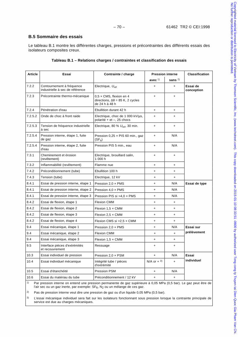
– 70 – 61462 TR2 © CEI:1998
B.5 Sommaire des essais
Le tableau B.1 montre les différentes charges, pressions et précontraintes des différents essais desisolateurs composites creux.
Tableau B.1 – Relations charges / contraintes et classification des essais
Article Essai Contrainte / charge Pression interne Classification
avec 1) sans 2)
7.2.2 Contournement à fréquenceindustrielle à sec de référence
Electrique, Uréf + + Essai deconception
7.2.3 Précontrainte thermo-mécanique 0,5 × CMS, flexion en 4directions, ∆θ = 85 K, 2 cyclesde 24 h à 48 h
+ +
7.2.4 Pénétration d'eau Ebullition durant 42 h + +
7.2.5.2 Onde de choc à front raide Electrique, choc de 1 000 kV/µs,polarité + et –, 25 chocs
+ +
7.2.5.3 Tension de fréquence industrielleà sec
Electrique, 80 % Uréf, 30 min. + +
7.2.5.4 Pression interne, étape 1, fuitede gaz
Pression 0,25 × PIS 60 min., gaz(SF6)
+ N/A
7.2.5.4 Pression interne, étape 2, fuited'eau
Pression PIS 5 min., eau + N/A
7.3.1 Cheminement et érosion(revêtement)
Electrique, brouillard salin,1 000 h
+ +
7.3.2 Inflammabilité (revêtement) Flamme nue + +
7.4.2 Préconditionnement (tube) Ebullition 100 h + +
7.4.3 Tension (tube) Electrique, 12 kV + +
8.4.1 Essai de pression interne, étape 1 Pression 2,0 × PMS + N/A Essai de type
8.4.1 Essai de pression interne, étape 2 Pression 4,0 × PMS + N/A
8.4.1 Essai de pression interne, étape 3 Pression PIS si >4,0 × PMS + N/A
8.4.2 Essai de flexion, étape 1 Flexion CMM + +
8.4.2 Essai de flexion, étape 2 Flexion 1,5 × CMM + +
8.4.2 Essai de flexion, étape 3 Flexion 2,5 × CMM + +
8.4.2 Essai de flexion, étape 4 Flexion CMS si >2,5 × CMM + +
9.4 Essai mécanique, étape 1 Pression 2,0 × PMS + N/A Essai sur
9.4 Essai mécanique, étape 2 Flexion CMM + + prélèvement
9.4 Essai mécanique, étape 3 Flexion 1,5 × CMM + +
9.5 Interface pièces d'extrémitéset recouvrement
Ressuage + +
10.3 Essai individuel de pression Pression 2,0 × PSM + N/A Essai
10.4 Essai individuel mécanique Intégrité tube / piècesd'extrémité
N/A or + 3) + individuel
10.5 Essai d'étanchéité Pression PSM + N/A
10.6 Essai du matériau du tube Préconditionnement / 12 kV + +
1) Par pression interne on entend une pression permanente de gaz supérieure à 0,05 MPa (0,5 bar). Le gaz peut être del'air sec ou un gaz inerte, par exemple: SF6, N2 ou un mélange de ces gaz.
2) Pas de pression interne veut dire une pression de gaz ou d'un liquide 0,05 MPa (0,5 bar).
3) L'essai mécanique individuel sera fait sur les isolateurs fonctionnant sous pression lorsque la contrainte principale deservice est due au charges mécaniques.
Copyrighted m
aterial licensed to Electricity of V
ietnam by T
homson S
cientific, Inc. (ww
w.techstreet.com
). This copy dow
nloaded on 2015-01-10 08:33:51 -0600 by authorized user Tong cong ty T
ruyen tai Dien Q
uoc Gia P
ham V
an Chi.
No further reproduction or distribution is perm
itted.
61462 TR2 © IEC:1998 – 71 –
B.5 Summary of the tests
Table B.1 shows the different loads, pressure, and pre-stressing of the different tests forcomposite hollow insulators.
Table B.1 – Loads/stress and classification of tests
Clause Test Stress / Load Internal pressure Classification
with 1) without 2)
7.2.2 Reference dry power frequencyflashover
Electrical, Uref + + Design tests
7.2.3 Thermal mechanical pre-stress 0,5 × SML bending in four direc-tions, ∆θ = 85 K, two 24 h – 48 hcycles
+ +
7.2.4 Water immersion Boiling, 42 h + +
7.2.5.2 Steep-front impulse voltage Electrical, 1 000 kV/ms impulsevoltage, 25 impulses ±
+ +
7.2.5.3 Dry power frequency voltage Electrical, 80 % Uref, 30 min + +
7.2.5.4 Internal pressure – stage one – gasleakage
Pressure 0,25 × SIP 60 min,gas (SF6)
+ N/A
7.2.5.4 Internal pressure – stage two –water leakage
Pressure SIP 5 min water + N/A
7.3.1 Tracking and erosion (Housingmaterial)
Electrical, salt fog, 1 000 h + +
7.3.2 Flammability (Housing material) Naked flame + +
7.4.2 Pre-stressing (Tube material) Boiling, 100 h + +
7.4.3 Voltage (Tube material) Electrical, 12 kV + +
8.4.1 Internal pressure test – stage one Pressure 2,0 × MSP + N/A Type tests
8.4.1 Internal pressure test – stage two. Pressure 4,0 × MSP + N/A
8.4.1 Internal pressure test – stage three Pressure SIP if >4,0 × MSP + N/A
8.4.2 Cantilever bending test – stage one Bending MML. + +
8.4.2 Cantilever bending test – stage two Bending 1,5 × MML + +
8.4.2 Cantilever bending test – stage three Bending 2,5 × MML + +
8.4.2 Cantilever bending test – stage four Bending SML if > 2,5 × MML + +
9.4 Mechanical test – stage one Pressure 2,0 × MSP + N/A Sample tests
9.4 Mechanical test – stage two Bending MML + +
9.4 Mechanical test – stage three Bending 1,5 × MML + +
9.5 Interface between fittings / housing Dye penetration + +
10.3 Routine pressure test Pressure 2,0 × MSP + N/A Routine tests
10.4 Routine mechanical test Fitting/tube integrity N/A or +3) +
10.5 Routine tightness test Pressure MSP + N/A
10.6 Test for the tube material Prestressing /12 kV + +
1) Internal pressure means a permanent gas pressure greater than 0,05 MPa (0,5 bar) gauge. The gas can be dryair or inert gases, for example sulphur hexafluoride, nitrogen, or a mixture of such gases.
2) No internal pressure means a gas pressure, or a liquid pressure smaller than or equal to 0,05 MPa (0,5 bar)gauge.
3) The routine mechanical test is applicable to pressurized insulators when the principle service stress is due tomechanical loads.
Copyrighted m
aterial licensed to Electricity of V
ietnam by T
homson S
cientific, Inc. (ww
w.techstreet.com
). This copy dow
nloaded on 2015-01-10 08:33:51 -0600 by authorized user Tong cong ty T
ruyen tai Dien Q
uoc Gia P
ham V
an Chi.
No further reproduction or distribution is perm
itted.
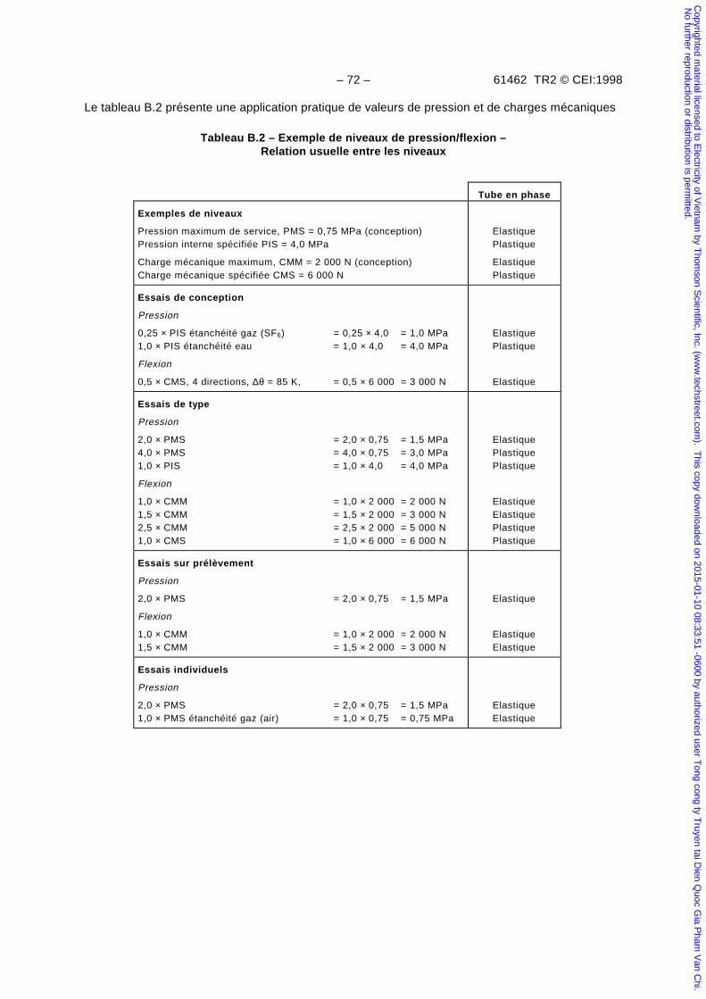
– 72 – 61462 TR2 © CEI:1998
Le tableau B.2 présente une application pratique de valeurs de pression et de charges mécaniques
Tableau B.2 – Exemple de niveaux de pression/flexion –Relation usuelle entre les niveaux
Tube en phase
Exemples de niveaux
Pression maximum de service, PMS = 0,75 MPa (conception)Pression interne spécifiée PIS = 4,0 MPa
Charge mécanique maximum, CMM = 2 000 N (conception)Charge mécanique spécifiée CMS = 6 000 N
ElastiquePlastique
ElastiquePlastique
Essais de conception
Pression
0,25 × PIS étanchéité gaz (SF6) = 0,25 × 4,0 = 1,0 MPa1,0 × PIS étanchéité eau = 1,0 × 4,0 = 4,0 MPa
Flexion
0,5 × CMS, 4 directions, ∆θ = 85 K, = 0,5 × 6 000 = 3 000 N
ElastiquePlastique
Elastique
Essais de type
Pression
2,0 × PMS = 2,0 × 0,75 = 1,5 MPa4,0 × PMS = 4,0 × 0,75 = 3,0 MPa1,0 × PIS = 1,0 × 4,0 = 4,0 MPa
Flexion
1,0 × CMM = 1,0 × 2 000 = 2 000 N1,5 × CMM = 1,5 × 2 000 = 3 000 N2,5 × CMM = 2,5 × 2 000 = 5 000 N1,0 × CMS = 1,0 × 6 000 = 6 000 N
ElastiquePlastiquePlastique
ElastiqueElastiquePlastiquePlastique
Essais sur prélèvement
Pression
2,0 × PMS = 2,0 × 0,75 = 1,5 MPa
Flexion
1,0 × CMM = 1,0 × 2 000 = 2 000 N1,5 × CMM = 1,5 × 2 000 = 3 000 N
Elastique
ElastiqueElastique
Essais individuels
Pression
2,0 × PMS = 2,0 × 0,75 = 1,5 MPa1,0 × PMS étanchéité gaz (air) = 1,0 × 0,75 = 0,75 MPa
ElastiqueElastique
Copyrighted m
aterial licensed to Electricity of V
ietnam by T
homson S
cientific, Inc. (ww
w.techstreet.com
). This copy dow
nloaded on 2015-01-10 08:33:51 -0600 by authorized user Tong cong ty T
ruyen tai Dien Q
uoc Gia P
ham V
an Chi.
No further reproduction or distribution is perm
itted.
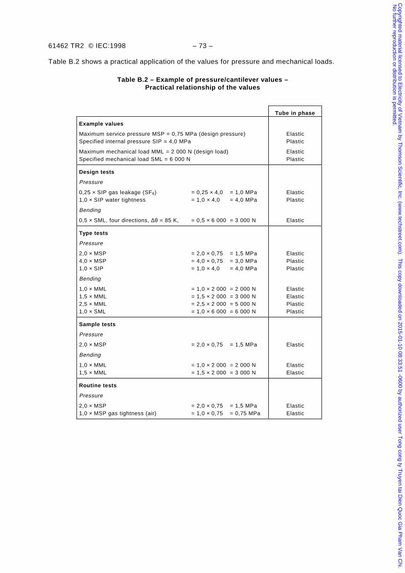
61462 TR2 © IEC:1998 – 73 –
Table B.2 shows a practical application of the values for pressure and mechanical loads.
Table B.2 – Example of pressure/cantilever values –Practical relationship of the values
Tube in phase
Example values
Maximum service pressure MSP = 0,75 MPa (design pressure)Specified internal pressure SIP = 4,0 MPa
Maximum mechanical load MML = 2 000 N (design load)Specified mechanical load SML = 6 000 N
ElasticPlastic
ElasticPlastic
Design tests
Pressure
0,25 × SIP gas leakage (SF6) = 0,25 × 4,0 = 1,0 MPa1,0 × SIP water tightness = 1,0 × 4,0 = 4,0 MPa
Bending
0,5 × SML, four directions, ∆θ = 85 K, = 0,5 × 6 000 = 3 000 N
ElasticPlastic
Elastic
Type tests
Pressure
2,0 × MSP = 2,0 × 0,75 = 1,5 MPa4,0 × MSP = 4,0 × 0,75 = 3,0 MPa1,0 × SIP = 1,0 × 4,0 = 4,0 MPa
Bending
1,0 × MML = 1,0 × 2 000 = 2 000 N1,5 × MML = 1,5 × 2 000 = 3 000 N2,5 × MML = 2,5 × 2 000 = 5 000 N1,0 × SML = 1,0 × 6 000 = 6 000 N
ElasticPlasticPlastic
ElasticElasticPlasticPlastic
Sample tests
Pressure
2,0 × MSP = 2,0 × 0,75 = 1,5 MPa
Bending
1,0 × MML = 1,0 × 2 000 = 2 000 N1,5 × MML = 1,5 × 2 000 = 3 000 N
Elastic
ElasticElastic
Routine tests
Pressure
2,0 × MSP = 2,0 × 0,75 = 1,5 MPa1,0 × MSP gas tightness (air) = 1,0 × 0,75 = 0,75 MPa
ElasticElastic
Copyrighted m
aterial licensed to Electricity of V
ietnam by T
homson S
cientific, Inc. (ww
w.techstreet.com
). This copy dow
nloaded on 2015-01-10 08:33:51 -0600 by authorized user Tong cong ty T
ruyen tai Dien Q
uoc Gia P
ham V
an Chi.
No further reproduction or distribution is perm
itted.
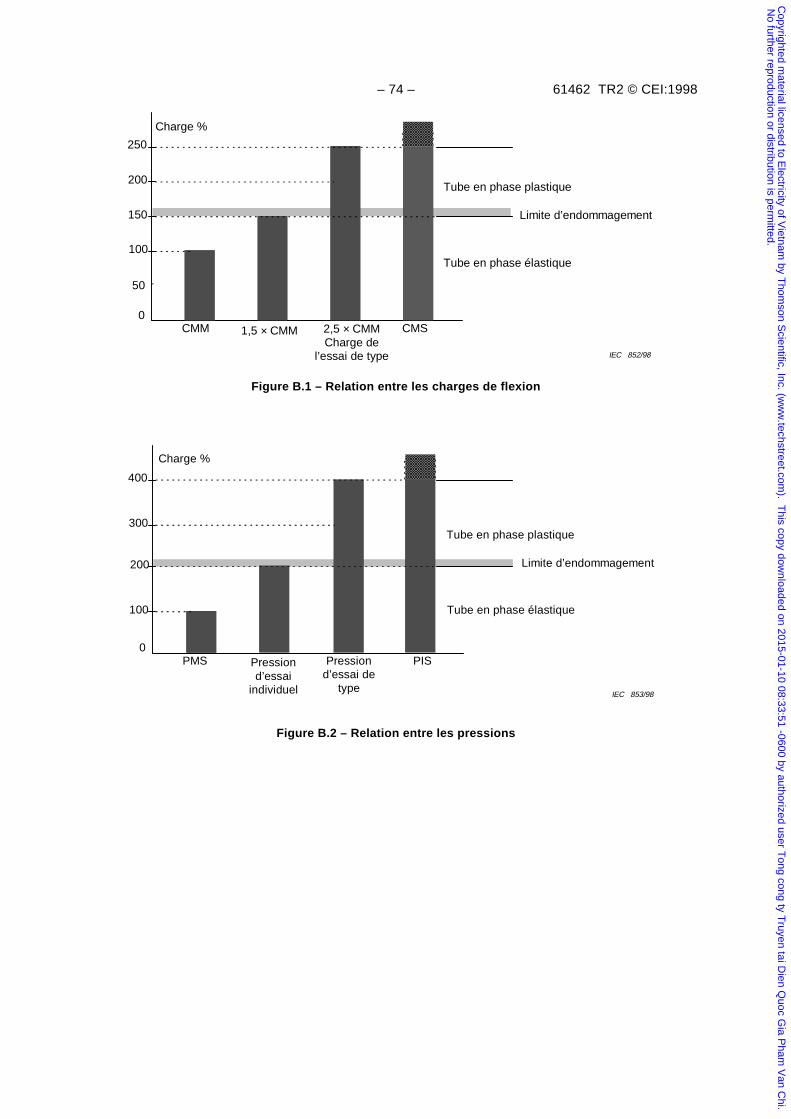
– 74 – 61462 TR2 © CEI:1998
0
100
150
200
250
IEC 852/98
CMM 1,5 × CMM 2,5 × CMMCharge de
l’essai de type
CMS
Charge %
Tube en phase élastique
Tube en phase plastique
Limite d’endommagement
50
Figure B.1 – Relation entre les charges de flexion
100
200
300
400
IEC 853/98
PMS Pressiond’essai
individuel
Pressiond’essai de
type
PIS0
Charge %
Tube en phase élastique
Tube en phase plastique
Limite d’endommagement
Figure B.2 – Relation entre les pressions
Copyrighted m
aterial licensed to Electricity of V
ietnam by T
homson S
cientific, Inc. (ww
w.techstreet.com
). This copy dow
nloaded on 2015-01-10 08:33:51 -0600 by authorized user Tong cong ty T
ruyen tai Dien Q
uoc Gia P
ham V
an Chi.
No further reproduction or distribution is perm
itted.
61462 TR2 © IEC:1998 – 75 –
0
100
150
200
250
IEC 852/98
MML 1,5 × MML 2,5 × MMLType test load
SML
Load %
Tube in elastic phase
Tube in plastic phase
Damage limit
50
Figure B.1 – Relationship of bending loads
100
200
300
400
IEC 853/98
MSP Routine testpressure
Type testpressure
SIP0
Load %
Tube in elastic phase
Tube in plastic phase
Damage limit
Figure B.2 – Relationship of pressures
Copyrighted m
aterial licensed to Electricity of V
ietnam by T
homson S
cientific, Inc. (ww
w.techstreet.com
). This copy dow
nloaded on 2015-01-10 08:33:51 -0600 by authorized user Tong cong ty T
ruyen tai Dien Q
uoc Gia P
ham V
an Chi.
No further reproduction or distribution is perm
itted.

– 76 – 61462 TR2 © CEI:1998
B.6 Bibliographie
CEI 60056:1987, Disjoncteurs à courant alternatif à haute tension
CEI 60507:1991, Essais sans pollution artificielle des isolateurs pour haute tension destinés auxréseaux à courant alternatif
CEI 60694:1996, Spécifications communes aux normes de l'appareillage à haute tension
CEI 60865:—, Courants de court circuit – Calcul des effets
CEI 61166:1993, Disjoncteurs à courant alternatif à haute tension – Guide pour la qualificationsismique des disjoncteurs à courant alternatif à haute tension
CEI 61264:1994, Enveloppes isolantes sous pression en matière céramique pour l'appareillage àhaute tension
Copyrighted m
aterial licensed to Electricity of V
ietnam by T
homson S
cientific, Inc. (ww
w.techstreet.com
). This copy dow
nloaded on 2015-01-10 08:33:51 -0600 by authorized user Tong cong ty T
ruyen tai Dien Q
uoc Gia P
ham V
an Chi.
No further reproduction or distribution is perm
itted.
61462 TR2 © IEC:1998 – 77 –
B.6 Bibliography
IEC 60056:1987, High-voltage alternating-current circuit breakers
IEC 60507:1991, Artificial pollution tests on high voltage insulators to be used on a.c. systems
IEC 60694:1996, Common specifications for high-voltage switchgear and controlgear standards
IEC 60865-2:—, Short circuit currents – Calculation of effects
IEC 61166:1993, High voltage alternating current circuit breakers – Guide for seismicqualification of high voltage alternating current circuit-breakers
IEC 61264:1994, Ceramic pressurized hollow insulators for high voltage switchgear andcontrolgear
Copyrighted m
aterial licensed to Electricity of V
ietnam by T
homson S
cientific, Inc. (ww
w.techstreet.com
). This copy dow
nloaded on 2015-01-10 08:33:51 -0600 by authorized user Tong cong ty T
ruyen tai Dien Q
uoc Gia P
ham V
an Chi.
No further reproduction or distribution is perm
itted.
– 78 – 61462 TR2 © CEI:1998
Annexe C(informative)
Limite entre les allongements réversibles et irréversibles de tubesd'isolateurs composites creux dus aux pressions internes
et ou aux forces de flexion
C.1 Définition
Mesures d'allongement avec des jauges de contrainte selon la figure C.1 (voir 8.4.1 et 8.4.2).
– Il n'y a pas de dommage et la déformation est réversible si, à la fin de l'essai, lorsque la chargeest nulle, l'allongement est aussi 0 ± 5 % de l'allongement maximum (voir figure C.2). Dans cecas, on considère que le tube est en phase élastique.
– Il y a dommages et la déformation est irréversible si, à la fin de l'essai, lorsque la charge estnulle, l'allongement est plus grand que 0 ± 5 % de l'allongement maximum (voir figure C.3). Dansce cas, on considère que le tube est en phase plastique irréversible. Souvent les dommages nesont pas détectables visuellement.
Explication de la tolérance ±5 % de l'allongement maximum: cette tolérance est due auximprécisions de mesures attribuables
– à l'équipement d'essai;
– aux jauges de contrainte;
– à la fixation des jauges de contrainte;
– aux mauvais contacts électriques;
– à l’état initial du tube ;
– au relâchement de contraintes avec le temps.
C.2 Exemple d'évaluation de la tolérance d'élongation
Si l'élongation maximum (100 %) est 2 000 µm/m, alors:
tolérance = 2 000 µm/m × 5 % = 100 µm/m
Copyrighted m
aterial licensed to Electricity of V
ietnam by T
homson S
cientific, Inc. (ww
w.techstreet.com
). This copy dow
nloaded on 2015-01-10 08:33:51 -0600 by authorized user Tong cong ty T
ruyen tai Dien Q
uoc Gia P
ham V
an Chi.
No further reproduction or distribution is perm
itted.
61462 TR2 © IEC:1998 – 79 –
Annex C(informative)
Limits defining reversible and irreversible strain due tointernal pressure and/or bending loads on tubes used in
composite hollow insulators
C.1 Definition
Strain measurement with strain gauges as shown in figure C.1 (see 8.4.1 and 8.4.2):
– An irreversible process without damage to the tube occurs, if, at the end of the test, theload is zero and the strain is also 0 ± 5 % of the maximum strain (see figure C.2). In thiscase, the tube is considered to be in the elastic phase.
– An irreversible process with damage to the tube occurs, if, at the end of the test, the load iszero and the strain is greater than 0 ± 5 % of the maximum strain (see figure C.3). In thiscase, the tube is considered to be in the irreversible plastic phase. Visible damage may notbe apparent.
The reason for applying a tolerance of ±5 % of the maximum strain is due to the possibility thatmeasurement inaccuracies may arise from:
– test equipment inaccuracy;
– strain gauge inaccuracy;
– the method of attachment of accuracy of positioning the strain gauges;
– poor electrical contacts;
– the initial condition of the tube;
– any time-related relaxation.
C.2 Example of determining the strain tolerance
If the maximum (100 %) strain is 2 000 µm/m, then
tolerance = 2 000 µm/m × 5 % = 100 µm/m
Copyrighted m
aterial licensed to Electricity of V
ietnam by T
homson S
cientific, Inc. (ww
w.techstreet.com
). This copy dow
nloaded on 2015-01-10 08:33:51 -0600 by authorized user Tong cong ty T
ruyen tai Dien Q
uoc Gia P
ham V
an Chi.
No further reproduction or distribution is perm
itted.
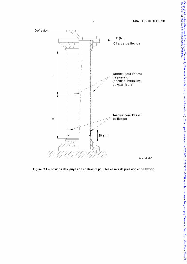
– 80 – 61462 TR2 © CEI:1998
=
Déflexion
F (N)
Charge de flexion
=
IEC 854/98
30 mm
Jauges pour l'essaide pression(position intérieureou extérieure)
Jauges pour l'essaide flexion
Figure C.1 – Position des jauges de contrainte pour les essais de pression et de flexion
Copyrighted m
aterial licensed to Electricity of V
ietnam by T
homson S
cientific, Inc. (ww
w.techstreet.com
). This copy dow
nloaded on 2015-01-10 08:33:51 -0600 by authorized user Tong cong ty T
ruyen tai Dien Q
uoc Gia P
ham V
an Chi.
No further reproduction or distribution is perm
itted.
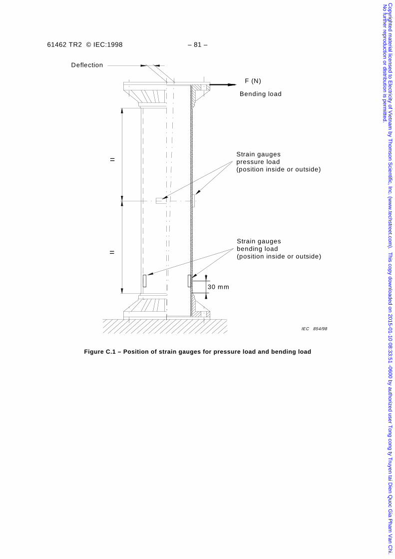
61462 TR2 © IEC:1998 – 81 –
=
Deflection
F (N)
Bending load
=
IEC 854/98
30 mm
Strain gaugespressure load(position inside or outside)
Strain gaugesbending load(position inside or outside)
Figure C.1 – Position of strain gauges for pressure load and bending load
Copyrighted m
aterial licensed to Electricity of V
ietnam by T
homson S
cientific, Inc. (ww
w.techstreet.com
). This copy dow
nloaded on 2015-01-10 08:33:51 -0600 by authorized user Tong cong ty T
ruyen tai Dien Q
uoc Gia P
ham V
an Chi.
No further reproduction or distribution is perm
itted.
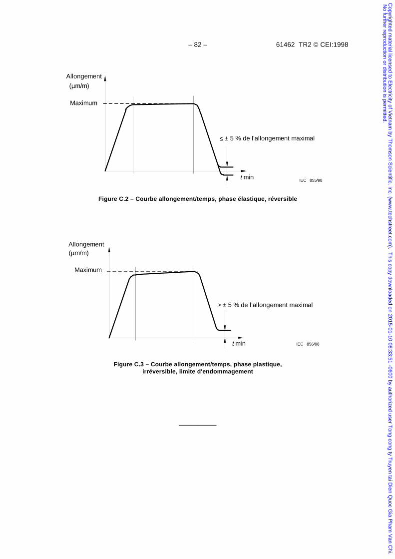
– 82 – 61462 TR2 © CEI:1998
IEC 855/98t min
Allongement
(µm/m)
≤ ± 5 % de l'allongement maximal
Maximum
Figure C.2 – Courbe allongement/temps, phase élastique, réversible
IEC 856/98t min
Allongement(µm/m)
> ± 5 % de l'allongement maximal
Maximum
Figure C.3 – Courbe allongement/temps, phase plastique,irréversible, limite d'endommagement
__________
Copyrighted m
aterial licensed to Electricity of V
ietnam by T
homson S
cientific, Inc. (ww
w.techstreet.com
). This copy dow
nloaded on 2015-01-10 08:33:51 -0600 by authorized user Tong cong ty T
ruyen tai Dien Q
uoc Gia P
ham V
an Chi.
No further reproduction or distribution is perm
itted.
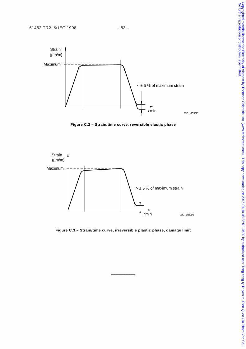
61462 TR2 © IEC:1998 – 83 –
t minIEC 855/98
Strain(µm/m)
≤ ± 5 % of maximum strain
Maximum
Figure C.2 – Strain/time curve, reversible elastic phase
IEC 856/98t min
Strain(µm/m)
> ± 5 % of maximum strain
Maximum
Figure C.3 – Strain/time curve, irreversible plastic phase, damage limit
__________
Copyrighted m
aterial licensed to Electricity of V
ietnam by T
homson S
cientific, Inc. (ww
w.techstreet.com
). This copy dow
nloaded on 2015-01-10 08:33:51 -0600 by authorized user Tong cong ty T
ruyen tai Dien Q
uoc Gia P
ham V
an Chi.
No further reproduction or distribution is perm
itted.

Copyrighted m
aterial licensed to Electricity of V
ietnam by T
homson S
cientific, Inc. (ww
w.techstreet.com
). This copy dow
nloaded on 2015-01-10 08:33:51 -0600 by authorized user Tong cong ty T
ruyen tai Dien Q
uoc Gia P
ham V
an Chi.
No further reproduction or distribution is perm
itted.
Standards Survey
The IEC would like to offer you the best quality standards possible. To make sure that wecontinue to meet your needs, your feedback is essential. Would you please take a minuteto answer the questions overleaf and fax them to us at +41 22 919 03 00 or mail them tothe address below. Thank you!
Customer Service Centre (CSC)
International Electrotechnical Commission3, rue de Varembé1211 Genève 20Switzerland
or
Fax to: IEC/CSC at +41 22 919 03 00
Thank you for your contribution to the standards-making process.
Non affrancareNo stamp required
Nicht frankierenNe pas affranchir
A Prioritaire
RÉPONSE PAYÉE
SUISSE
Customer Service Centre (CSC)International Electrotechnical Commission3, rue de Varembé1211 GENEVA 20Switzerland
Copyrighted m
aterial licensed to Electricity of V
ietnam by T
homson S
cientific, Inc. (ww
w.techstreet.com
). This copy dow
nloaded on 2015-01-10 08:33:51 -0600 by authorized user Tong cong ty T
ruyen tai Dien Q
uoc Gia P
ham V
an Chi.
No further reproduction or distribution is perm
itted.
Q1 Please report on ONE STANDARD andONE STANDARD ONLY . Enter the exactnumber of the standard: (e.g. 60601-1-1)
.............................................................
Q2 Please tell us in what capacity(ies) youbought the standard (tick all that apply).I am the/a:
purchasing agent R
librarian R
researcher R
design engineer R
safety engineer R
testing engineer R
marketing specialist R
other.....................................................
Q3 I work for/in/as a:(tick all that apply)
manufacturing R
consultant R
government R
test/certification facility R
public utility R
education R
military R
other.....................................................
Q4 This standard will be used for:(tick all that apply)
general reference R
product research R
product design/development R
specifications R
tenders R
quality assessment R
certification R
technical documentation R
thesis R
manufacturing R
other.....................................................
Q5 This standard meets my needs:(tick one)
not at all R
nearly R
fairly well R
exactly R
Q6 If you ticked NOT AT ALL in Question 5the reason is: (tick all that apply)
standard is out of date R
standard is incomplete R
standard is too academic R
standard is too superficial R
title is misleading R
I made the wrong choice R
other ....................................................
Q7 Please assess the standard in thefollowing categories, usingthe numbers:(1) unacceptable,(2) below average,(3) average,(4) above average,(5) exceptional,(6) not applicable
timeliness .............................................quality of writing....................................technical contents.................................logic of arrangement of contents ..........tables, charts, graphs, figures ...............other ....................................................
Q8 I read/use the: (tick one)
French text only R
English text only R
both English and French texts R
Q9 Please share any comment on anyaspect of the IEC that you would likeus to know:
............................................................
............................................................
............................................................
............................................................
............................................................
............................................................
............................................................
............................................................
............................................................
............................................................
............................................................
............................................................
Copyrighted m
aterial licensed to Electricity of V
ietnam by T
homson S
cientific, Inc. (ww
w.techstreet.com
). This copy dow
nloaded on 2015-01-10 08:33:51 -0600 by authorized user Tong cong ty T
ruyen tai Dien Q
uoc Gia P
ham V
an Chi.
No further reproduction or distribution is perm
itted.
Enquête sur les normes
La CEI ambitionne de vous offrir les meilleures normes possibles. Pour nous assurerque nous continuons à répondre à votre attente, nous avons besoin de quelquesrenseignements de votre part. Nous vous demandons simplement de consacrer un instantpour répondre au questionnaire ci-après et de nous le retourner par fax au+41 22 919 03 00 ou par courrier à l’adresse ci-dessous. Merci !
Centre du Service Clientèle (CSC)
Commission Electrotechnique Internationale3, rue de Varembé1211 Genève 20Suisse
ou
Télécopie: CEI/CSC +41 22 919 03 00
Nous vous remercions de la contribution que vous voudrez bien apporter ainsià la Normalisation Internationale.
Non affrancareNo stamp required
Nicht frankierenNe pas affranchir
A Prioritaire
RÉPONSE PAYÉE
SUISSE
Centre du Service Clientèle (CSC)Commission Electrotechnique Internationale3, rue de Varembé1211 GENÈVE 20Suisse
Copyrighted m
aterial licensed to Electricity of V
ietnam by T
homson S
cientific, Inc. (ww
w.techstreet.com
). This copy dow
nloaded on 2015-01-10 08:33:51 -0600 by authorized user Tong cong ty T
ruyen tai Dien Q
uoc Gia P
ham V
an Chi.
No further reproduction or distribution is perm
itted.
Q1 Veuillez ne mentionner qu’UNE SEULENORME et indiquer son numéro exact:(ex. 60601-1-1)
.............................................................
Q2 En tant qu’acheteur de cette norme,quelle est votre fonction?(cochez tout ce qui convient)Je suis le/un:
agent d’un service d’achat R
bibliothécaire R
chercheur R
ingénieur concepteur R
ingénieur sécurité R
ingénieur d’essais R
spécialiste en marketing R
autre(s).................................................
Q3 Je travaille:(cochez tout ce qui convient)
dans l’industrie R
comme consultant R
pour un gouvernement R
pour un organisme d’essais/ certification R
dans un service public R
dans l’enseignement R
comme militaire R
autre(s).................................................
Q4 Cette norme sera utilisée pour/comme(cochez tout ce qui convient)
ouvrage de référence R
une recherche de produit R
une étude/développement de produit R
des spécifications R
des soumissions R
une évaluation de la qualité R
une certification R
une documentation technique R
une thèse R
la fabrication R
autre(s).................................................
Q5 Cette norme répond-elle à vos besoins:(une seule réponse)
pas du tout R
à peu près R
assez bien R
parfaitement R
Q6 Si vous avez répondu PAS DU TOUT àQ5, c’est pour la/les raison(s) suivantes:(cochez tout ce qui convient)
la norme a besoin d’être révisée R
la norme est incomplète R
la norme est trop théorique R
la norme est trop superficielle R
le titre est équivoque R
je n’ai pas fait le bon choix R
autre(s) ................................................
Q7 Veuillez évaluer chacun des critères ci-dessous en utilisant les chiffres(1) inacceptable,(2) au-dessous de la moyenne,(3) moyen,(4) au-dessus de la moyenne,(5) exceptionnel,(6) sans objet
publication en temps opportun ..............qualité de la rédaction...........................contenu technique ................................disposition logique du contenu ..............tableaux, diagrammes, graphiques, figures ................................................autre(s) ................................................
Q8 Je lis/utilise: (une seule réponse)
uniquement le texte français R
uniquement le texte anglais R
les textes anglais et français R
Q9 Veuillez nous faire part de vosobservations éventuelles sur la CEI:
............................................................
............................................................
............................................................
............................................................
............................................................
............................................................
Copyrighted m
aterial licensed to Electricity of V
ietnam by T
homson S
cientific, Inc. (ww
w.techstreet.com
). This copy dow
nloaded on 2015-01-10 08:33:51 -0600 by authorized user Tong cong ty T
ruyen tai Dien Q
uoc Gia P
ham V
an Chi.
No further reproduction or distribution is perm
itted.

Copyrighted m
aterial licensed to Electricity of V
ietnam by T
homson S
cientific, Inc. (ww
w.techstreet.com
). This copy dow
nloaded on 2015-01-10 08:33:51 -0600 by authorized user Tong cong ty T
ruyen tai Dien Q
uoc Gia P
ham V
an Chi.
No further reproduction or distribution is perm
itted.

ISBN 2-8318-4437-1
&1+', ;776:7ICS 29.080.10
Typeset and printed by the IEC Central OfficeGENEVA, SWITZERLAND
Copyrighted m
aterial licensed to Electricity of V
ietnam by T
homson S
cientific, Inc. (ww
w.techstreet.com
). This copy dow
nloaded on 2015-01-10 08:33:51 -0600 by authorized user Tong cong ty T
ruyen tai Dien Q
uoc Gia P
ham V
an Chi.
No further reproduction or distribution is perm
itted.