hydrauliquedpa-hydraulique.com/medias/pdf/catalogue.pdf · fr : +33 (0)4 76 07 20 46 - de : nord :...
TRANSCRIPT

HydrauliqueHydraulic - Hydraulik
www.chapel-hydraulique.com
n°18

SOMMAIRE
STANDARD HYDRAULIC CYLINDER / HYDRAULIKZYLINDER STANDARD
A. VÉRIN HYDRAULIQUE STANDARD ............................................. 1
SPECIAL HYDRAULIC CYLINDER / HYDRAULIKZYLINDER SONDERANFERTIGUNG
B. VÉRIN HYDRAULIQUE SPÉCIAL ...............................................11
HYDRAULIC CYLINDER SAFETY / SICHERHEITSZUBEHÖR
C. SÉCURITÉ VÉRIN HYDRAULIQUE ............................................19
HYDRAULIC VALVE / WEGEVENTILE
D. DISTRIBUTEUR HYDRAULIQUE ................................................23
HYDRAULIC HAND PUMP / HYDRAULISCHE HANDPUMPE
E. POMPE À MAIN HYDRAULIQUE ................................................41
HYDRAULIC CYLINDER CRUTCH / HYDRAULISCHER STÜTZZYLINDER
F. VÉRIN HYDRAULIQUE BÉQUILLE .............................................47
HYDRAULIC BRAKE CYLINDER / BREMSZYLINDER
G. VÉRIN HYDRAULIQUE FREINAGE ............................................51
TELESCOPIC HYDRAULIC CYLINDER / HYDRAULISCHER TELESKOPZYLINDER
H. VÉRIN HYDRAULIQUE TÉLESCOPIQUE ..................................55
HYDRAULIC TIPPER SYSTEM / KIPPMECHANIKEN
I. COMPAS HYDRAULIQUE DE BENNAGE ....................................65
FÉVRIER 2013

A
1
/ Sta
nd
ar
d H
yd
ra
ulic
cy
lind
er
/ Hy
dr
au
likz
ylin
de
r S
tan
da
rd
Vé
rin
hy
dr
au
liqu
e
sta
nd
ar
dVérin Hydraulique StandardStandard Hydraulic cylinder
Hydraulikzylinder Standard
www.chapel-hydraulique.com

www.chapel-hydraulique.comFR : +33 (0)4 76 07 20 46 - DE : NORD :+49 (0) 4331 84 27-0 SÜD : +49 (0) 8221 20 44 03-0
2
Vérin hydraulique standardStandard Hydraulic cylinderHydraulikzylinder Standard
A
VéRiN SimplE EFFEtSingle-acting cylinder - einfacHwirkender zylinder
Ref.Artikel
ØA Z CourseStrokeHub
C D E G H J Vol. (Ltr) Poids (Kg)Weight Gewicht
625/10 25 100 14 14.2 190 40 24 40 0.08 1.5625/20 25 200 14 14.2 290 40 24 40 0.15 2.3625/30 25 300 14 14.2 390 40 24 40 0.25 3630/2 30 200 18 16.2 300 50 26 42 0.25 3.6630/3 30 300 18 16.2 400 50 26 42 0.35 4.8630/4 30 400 18 16.2 500 50 26 42 0.45 5.9630/5 30 550 18 16.2 650 50 26 42 0.65 7.5630/7 30 700 18 16.2 800 50 26 42 0.80 9.2640/2 40 200 22 23 330 60 32 47 0.40 5.9640/250 40 250 22 23 380 60 32 47 0.5 7640/3 40 300 22 23 430 60 32 47 0.6 7.7640/4 40 400 22 23 530 60 32 47 0.8 9.3640/5 40 550 22 23 680 60 32 47 1.1 11.8640/7 40 700 22 23 830 60 32 47 1.4 14.2

www.chapel-hydraulique.comFR : +33 (0)4 76 07 20 46 - DE : NORD : +49 (0) 4331 84 27-0
SÜD : +49 (0) 8221 20 44 03-0
3
Vérin hydraulique standardStandard Hydraulic cylinder
Hydraulikzylinder Standard
A
VéRiN SimplE EFFEt guiDagE aRRièRESingle-acting cylinder witH rod guide ring - einfacHwirkender zylinder Hinten gefüHrt
Ref. Artikel
ØA Z CourseStrokeHub
C D E G H J O P Vol. (Ltr) Poids (Kg)Weight Gewicht
645/2 45 200 22 23 330 60 34 47 70 77 0.40 7645/3 45 300 22 23 430 60 34 47 70 77 0.60 8.9645/4 45 400 22 23 530 60 34 47 70 77 0.80 10.9645/5 45 550 22 23 680 60 34 47 70 77 1.10 13.8645/7 45 700 22 23 830 60 34 47 70 77 1.40 16.6650/2 50 200 25 25.25 360 65 49 50 75 80 0.50 9650/3 50 300 25 25.25 460 65 49 50 75 80 0.70 11.2650/4 50 400 25 25.25 560 65 49 50 75 80 0.95 13.5650/5 50 550 25 25.25 710 65 49 50 75 80 1.30 16.9650/7 50 700 25 25.25 860 65 49 50 75 80 1.65 20.3655/3 55 300 25 25.25 460 70 41 50 85 95 0.85 13.5655/5 55 550 25 25.25 710 70 41 50 85 95 1.55 20.2655/7 55 700 25 25.25 860 70 41 50 85 95 2.00 24.1660/2 60 200 25 25.25 360 75 36 50 90 95 0.65 12.7660/3 60 300 25 25.25 460 75 36 50 90 95 1.00 15.7660/4 60 400 25 25.25 560 75 36 50 90 95 1.35 18.6660/5 60 550 25 25.25 710 75 36 50 90 95 1.85 23.4660/7 60 700 25 25.25 860 75 36 50 90 95 2.35 28670/3 70 300 30 30.25 509 85 66 55 100 95 1.35 22.5670/4 70 400 30 30.25 609 85 66 55 100 95 1.75 26.5670/5 70 500 30 30.25 709 85 66 55 100 95 2.15 30.5

www.chapel-hydraulique.comFR : +33 (0)4 76 07 20 46 - DE : NORD :+49 (0) 4331 84 27-0 SÜD : +49 (0) 8221 20 44 03-0
4
Vérin hydraulique standardStandard Hydraulic cylinderHydraulikzylinder Standard
A
VéRiN DOublE EFFEtdouble-acting cylinder - doppeltwirkender zylinder

www.chapel-hydraulique.comFR : +33 (0)4 76 07 20 46 - DE : NORD : +49 (0) 4331 84 27-0
SÜD : +49 (0) 8221 20 44 03-0
5
Vérin hydraulique standardStandard Hydraulic cylinder
Hydraulikzylinder Standard
A
Ref. Artikel
ØA ØB Z CourseStrokeHub
C D E F G H I J K L M Vol. (Ltr)
Poids (Kg)Weight Gewicht
700/05 20 32 50 14 16.2 205 35 40 61 30 32 35 13 1/4 0.05 1.7700/10 20 32 100 14 16.2 255 35 40 61 30 32 35 13 1/4 0.10 2700/15 20 32 150 14 16.2 305 35 40 61 30 32 35 13 1/4 0.13 2.3700/20 20 32 200 14 16.2 355 35 40 61 30 32 35 13 1/4 0.17 2.6700/30 20 32 300 14 16.2 455 35 40 61 30 32 35 13 1/4 0.25 3.2700/400 20 32 400 14 16.2 555 35 40 61 30 32 35 13 1/4 0.32 3.6700/500 20 32 500 14 16.2 655 35 40 61 30 32 35 13 1/4 0.4 4.2700/600 20 32 600 14 16.2 755 35 40 61 30 32 35 13 1/4 0.48 4.8700/700 20 32 700 14 16.2 855 35 40 61 30 32 35 13 1/4 0.56 5.3701/1 25 40 100 18 20.25 270 40 50 65 35 38 40 15 3/8 0.15 2.9701/2 25 40 200 18 20.25 370 40 50 65 35 38 40 15 3/8 0.25 3.8701/3 25 40 300 18 20.25 470 40 50 65 35 38 40 15 3/8 0.40 4.8701/4 25 40 400 18 20.25 570 40 50 65 35 38 40 15 3/8 0.50 5.7701/5 25 40 500 18 20.25 670 40 50 65 35 38 40 15 3/8 0.65 6.6701/600 25 40 600 18 20.25 770 40 50 65 35 38 40 15 3/8 0.75 7.6701/700 25 40 700 18 20.25 870 40 50 65 35 38 40 15 3/8 0.88 9701/800 25 40 800 18 20.25 970 40 50 65 35 38 40 15 3/8 1.00 9.5701/1000 25 40 1000 18 20.25 1170 40 50 65 35 38 40 15 3/8 1.25 11702/1 30 50 100 22 25.25 300 45 60 85 40 42 43 15 3/8 0.20 4.4702/150 30 50 150 22 25.25 350 45 60 85 40 42 43 15 3/8 0.30 4.7702/2 30 50 200 22 25.25 400 45 60 85 40 42 43 15 3/8 0.40 5.7702/3 30 50 300 22 25.25 500 45 60 85 40 42 43 15 3/8 0.60 6.9702/4 30 50 400 22 25.25 600 45 60 85 40 42 43 15 3/8 0.80 8.1702/5 30 50 500 22 25.25 700 45 60 85 40 42 43 15 3/8 1.00 9.3702/6 30 50 600 22 25.25 800 45 60 85 40 42 43 15 3/8 1.20 10.6702/7 30 50 700 22 25.25 900 45 60 85 40 42 43 15 3/8 1.40 11.9702/800 30 50 800 22 25.25 1000 45 60 85 40 42 43 15 3/8 1.57 13.2702/900 30 50 900 22 25.25 1100 45 60 85 40 42 43 15 3/8 1.78 15702/1000 30 50 1000 22 25.25 1200 45 60 85 40 42 43 15 3/8 2.00 15.4703/1 30 60 100 22 25.25 300 45 70 83 40 42 45 15 3/8 0.30 5.5703/2 30 60 200 22 25.25 400 45 70 83 40 42 45 15 3/8 0.60 6.9703/3 30 60 300 22 25.25 500 45 70 83 40 42 45 15 3/8 0.90 8.2703/4 30 60 400 22 25.25 600 45 70 83 40 42 45 15 3/8 1.15 9.6703/5 30 60 500 22 25.25 700 45 70 83 40 42 45 15 3/8 1.45 11703/6 30 60 600 22 25.25 800 45 70 83 40 42 45 15 3/8 1.75 12.2703/7 30 60 700 22 25.25 900 45 70 83 40 42 45 15 3/8 2.00 13.6704/2 40 70 200 28 30.25 410 55 80 82 50 47 49 15 3/8 0.85 10704/3 40 70 300 28 30.25 510 55 80 82 50 47 49 15 3/8 1.20 12704/4 40 70 400 28 30.25 610 55 80 82 50 47 49 15 3/8 1.60 14704/5 40 70 500 28 30.25 710 55 80 82 50 47 49 15 3/8 2.00 16704/6 40 70 600 28 30.25 810 55 80 82 50 47 49 15 3/8 2.35 18704/7 40 70 700 28 30.25 910 55 80 82 50 47 49 15 3/8 2.75 20704/800 40 70 800 28 30.25 1010 55 80 82 82 47 49 15 3/8 3.00 23704/1000 40 70 1000 28 30.25 1210 55 80 82 50 47 49 15 3/8 3.84 26705/2 40 80 200 28 30.25 410 55 90 70 50 47 54 15 3/8 1.10 12.3705/3 40 80 300 28 30.25 510 55 90 70 50 47 54 15 3/8 1.60 14.1705/4 40 80 400 28 30.25 610 55 90 70 50 47 54 15 3/8 2.10 16.3705/5 40 80 500 28 30.25 710 55 90 70 50 47 54 15 3/8 2.60 18.4705/6 40 80 600 28 30.25 810 55 90 70 50 47 54 15 3/8 3.10 20.3705/7 40 80 700 28 30.25 910 55 90 70 50 47 54 15 3/8 3.60 22,5706/3 50 100 300 28 30.25 525 70 115 75 60 47 60 20 1/2 2.50 25706/4 50 100 400 28 30.25 625 70 115 75 60 47 60 20 1/2 3.30 28.5706/5 50 100 500 28 30.25 725 70 115 75 60 47 60 20 1/2 4.10 32706/7 50 100 700 28 30.25 925 70 115 75 60 47 60 20 1/2 5.65 39.1706/9 50 100 900 28 30.25 1125 70 115 75 60 47 60 20 1/2 7.25 46.1707/5 70 120 500 40 40.5 770 80 140 55 80 65 82 20 1/2 5.90 60707/10 70 120 1000 40 40.5 1270 80 140 55 80 65 82 20 1/2 11.55 90

www.chapel-hydraulique.comFR : +33 (0)4 76 07 20 46 - DE : NORD :+49 (0) 4331 84 27-0 SÜD : +49 (0) 8221 20 44 03-0
6
Vérin hydraulique standardStandard Hydraulic cylinderHydraulikzylinder Standard
A
micRO VéRiN DOublE EFFEtdouble-acting Micro cylinder - doppeltwirkender Mikrozylinder
Ref. Artikel
ØA ØB Z CourseStrokeHub
C D E F G H I J K L M N Vol. (Ltr)
Poids (Kg)Weight Gewicht
71220/25 12 20 25 9 10 118 35 28 47 60 15 23.5 18 M10 11 12 0.5871220/50 12 20 50 9 10 143 35 28 72 60 15 23.5 18 M10 11 20 0.6671220/80 12 20 80 9 10 173 35 28 102 60 15 23.5 18 M10 11 29 0.7671625/50 16 25 50 11 12 146 40 35 72 65 18 25 22 M12 9 31 0.9471625/100 16 25 100 11 12 196 40 35 122 65 18 25 22 M12 9 56 1.2271625/150 16 25 150 11 12 246 40 35 172 65 18 25 22 M12 9 80 1.571625/200 16 25 200 11 12 296 40 35 222 65 18 25 22 M12 9 105 1.78

www.chapel-hydraulique.comFR : +33 (0)4 76 07 20 46 - DE : NORD : +49 (0) 4331 84 27-0
SÜD : +49 (0) 8221 20 44 03-0
7
Vérin hydraulique standardStandard Hydraulic cylinder
Hydraulikzylinder Standard
A
VéRiN DOublE EFFEt à tOuRillONS typE «FENDEuSE»“wood Splitter” double-acting trunnion-Mounted cylinder - doppeltwirkender zylinder «HolzSpalter»
Ref. Artikel
ØA ØB Z CourseStrokeHub
C D E F G H I K L N Vol. (Ltr)
Poids (Kg)WeightGewicht
75070/420BEQ 50 70 420 180 Ø55 384 20 Ø80 67.5 100 49 533 Ø16.5 1.6 2376080/570BEQ 60 80 570 190 Ø66 246 15 Ø90 80 90 54 695 Ø15 2.9 34
Ref. Artikel
ØA ØB Z CourseStrokeHub
C D E F G H I J K L M N P Vol. (Ltr)
Poids (Kg)WeightGewicht
74590/700T 45 90 700 135 20.5 185 37 100 35 25 45 64 851 3/8 45 45 4.6 2874590/1000T 45 90 1000 135 20.5 185 37 100 35 25 45 64 1151 3/8 45 45 6.5 35706/1000T 50 100 1000 151 25.5 280 42 115 44 30 48 60 1145 1/2 50 50 8.0 50706/1100T 50 100 1100 151 25.5 280 42 115 44 30 48 60 1245 1/2 50 50 8.6 56760100/1000T 60 100 1000 151 25.5 280 42 115 44 30 58 60 1145 1/2 50 50 8.0 57760110.1100T 60 110 1100 170 25.5 280 42 125 44 30 48 70 1255 1/2 50 50 10.5 67770100/1000T 70 100 1000 151 25.5 280 42 115 44 30 68 60 1145 1/2 50 50 8.0 66707/1000T 70 120 1000 191 280 50 140 55 82 1200 1/2 50 50 11.5 92
VéRiN DOublE EFFEt béquillEdouble-acting cylinder crutcH - doppeltwirkender Stützzylinder

www.chapel-hydraulique.comFR : +33 (0)4 76 07 20 46 - DE : NORD :+49 (0) 4331 84 27-0 SÜD : +49 (0) 8221 20 44 03-0
8
Vérin hydraulique standardStandard Hydraulic cylinderHydraulikzylinder Standard
A
VéRiN 3èmE pOiNt DOublE EFFEtdouble-acting top link cylinder - oberlenker
Ref. Artikel
ØA ØB Z CourseStrokeHub
E H Vol. (Ltr) Poids (Kg)WeightGewicht
736/B 30 60 250 530 90 0.75 9.8
Ref. Artikel
ØA ØB Z CourseStrokeHub
E G H K L Vol. (Ltr) Poids (Kg)WeightGewicht
RAR253P 1.5746/B1 40 60 250 480 70 40 45 280 0.75 8.9746/C1 40 60 300 530 70 40 45 330 0.90 9.8747/B1 45 70 250 485 80 39 49 282 1.00 11.2747/C1 45 70 300 535 80 39 49 332 1.20 12.3
736
746 - 747

www.chapel-hydraulique.comFR : +33 (0)4 76 07 20 46 - DE : NORD : +49 (0) 4331 84 27-0
SÜD : +49 (0) 8221 20 44 03-0
9
Vérin hydraulique standardStandard Hydraulic cylinder
Hydraulikzylinder Standard
A
Caractéristiques
- Pression maxi d’utilisation : 200 bars (Attention au flambage de la tige, voir tableaux) - Pression d’épreuve : 300 bars - Vitesse maxi : 0,5 m / seconde - Température : - 30 °C à + 90 °C - Huile hydraulique minérale
• Matériaux : - Tige CK45 chromée f7 Ra < 0,2, chrome ép. 20 µ mini, Tenue à la corrosion : 120 heures NSS ISO 9227 class 9 (ISO 4540) dureté 900 HV. - Tube St 52.3 BK DIN 2393/C tolérance H9/10 Ra < 0,8 µ. - Guide avant acier 35MF6 + traitement. - Piston acier C35R.
• Etanchéité : - Tige : joint à lèvres compact en polyuréthane + 1 joint racleur. - Piston : joint compact en polyuréthane + nitrile.
• Marquage : - Sur le tube : référence + CH + semaine et année de fabrication.
• Essai : par prélèvement.
• Protection : - Peinture d’apprêt noire RAL 9005 sauf 707.5, 707.10 et vérins de fendeuse. - Zingage sur micro vérins.
Recommandations- Protection du circuit hydraulique par un limi-teur de pression, un filtre. - Vérifier l’état de pureté du fluide (corps étran-gers). - Penser à purger les vérins et le circuit hydrau-lique.
• Soudure : - Ne pas souder sur le tube. - Démonter le vérin pour souder sur la tige ou le fond.
• Stockage : - Vérin avec tige sortie en stockage : prévoir impérativement un graissage. - Pour le nettoyage vapeur haute pression : prévoir une protection de la tige.
• Démontage : - Attention: piston collé (prévoir collage au remontage).
• Pièces de rechange : pochette de joints, voir tarif.
• Notice : sur demande.
• Garantie : se reporter aux conditions géné-rales de vente.
Technical data
- Max working pressure: 200 bars - Proof pressure: 300 bars - Maximum speed: 0.5m/s - Temperature: - 30°C to + 90°C - Hydraulic mineral oil
• Materials - Rod: CK45 chrome plated f7 Ra<0.2 - Chrome thickness 20µ mini - Corrosion test: 120 hours NSS ISO9227 class9 (ISO4540) Hardness 900 HV - Tube: St 52.3 BK DIN 2393 /C tolerance H9/10. Ra<0.8µ - Gland: nitride hardening steel (38MF5) - Piston: Steel C35R
• Seals - Rod: compact polyurethane lip seal + 1 wiper seal - Piston: compact polyurethane seal + nitrile
• Marking - On the tube: REFERENCE + CH + WEEK/YEAR of manufacture
• Testing: by “pick up”
• Protection - Priming paint black RAL9005 except on type 707.5 and 707.10 and wood splitter cylinder - Zinc plating on micro cylinders
Recommendations- Protection of the circuit by a relief valve and a filter - Check the oil cleanness (pollution) - To bleed the air from the cylinder and the hydraulic circuit
The cylinder should not, under any circums-tances, be used as a mechanical limit stop for moving loads. Single-acting cylinders must be fitted with a tank return for unused power.
• Welding: do not weld on the tube. Dismount the cylinder to weld on the rod or on the base
• Storing: storage of extended cylinder, the rod must be greased. For high pressure cleaning, protect the rod. The cylinder cannot be used to hold any loads. Mechanical locks must be used. For double acting cylinders working as single acting, it is essential to connect the unused port to the tank
• Striping down: Warning : the piston is locked with glue (glue it again when re-assembling)
• Spare parts seal kits see price list
• Technical notice on request
• Warranty: see our standard terms of sale
Eigenschaften
- Max. Betriebsdruck: 200 bar - Prüfdruck: 300 bar - Max. Hubgeschwindigkeit: 0,5 m/s - Temperaturbereich: - 30 °C bis + 90 °C - Mineralisches Hydrauliköl
• Werkstoffe - Stange CK45 verchromt f7 Ra<0,2 - Chromschicht mind. 20 µ - Korrosionsbeständigkeit: 120 Stunden NSS ISO 9227 Klasse 9 (ISO 4540) Vickershärte 900 HV - Rohr St 52.3 BK DIN 2393/C Toleranz H9/10 Ra <0,8 µ - Führung: Stahl 38 MF5 m. Salzbadnitrierung - Kolben: Stahl C35R
• Dichtungen - Stange: Polyurethan - Kompaktlippendichtung + Abstreifer - Kolben: Polyurethan - Kompaktlippendichtung + Nitril-Dichtring
• Kennzeichnung auf dem Rohr: Artikelnummer + CH + Herstell- woche und –jahr.
• Kontrolle mittels Proben
• Konservierung - schwarze Grundierfarbe RAL 9005 außer 707.5, 707.10 und Holzspaltzylinder - Oberlenker schwarz grundiert - Mikrozylinder verzinkt
Empfehlungen- Schutz des Hydraulikkreislaufs durch Druck-begrenzungsventil und Filter - Sauberkeit des Mediums (Fremdkörper) kontrollieren - Nicht vergessen, Zylinder und Hydraulikkreis-lauf zu entlüften
Der Zylinder darf auf keinen Fall als mechani-scher Anschlag dienen. Beim Einsatz doppeltwirkender Zylinder, die einfachwirkend arbeiten, unbedingt die un-benutzte Ölkammer zum Tank hin verbinden!
• Schweißarbeiten: Keine Schweißarbeiten am Rohr vornehmen. Zylinder demontieren, um Schweißarbeiten an der Kolbenstange oder am Boden vorzunehmen.
• Lagerung: Zylinder mit ausgezogener Stange unbedingt einfetten. Beim Reinigen mit Ho-chdruckreiniger die Stange schützen.
• Demontage: Achtung: Kolben sind geklebt (beim Wiedereinbau Klebung vorsehen)
• Ersatzteile: Dichtungssatz siehe Preisliste
• Anleitung auf Anfrage
• Garantie: Siehe Allgemeine Verkaufsbedin-gungen


B
11
/ Sp
ec
ial H
yd
rau
lic c
ylin
de
r / H
yd
rau
likzy
lind
er
So
nd
er
an
fer
tigu
ng
Vé
rin
hy
dr
au
liqu
e
sp
éc
ial
Vérin Hydraulique SpécialSpecial Hydraulic cylinder
Hydraulikzylinder Sonderanfertigung
www.chapel-hydraulique.com

12
Vérin hydraulique spécialSpecial Hydraulic cylinderHydraulikzylinder Sonderanfertigung
www.chapel-hydraulique.comFR : +33 (0)4 76 07 20 46 - DE : NORD :+49 (0) 4331 84 27-0 SÜD : +49 (0) 8221 20 44 03-0
B
aVEc captEuR DE pOSitiON iNtégRé
aVEc DétEctEuR iNDuctiF DE FiN DE cOuRSE
aVEc amORti FiN DE cOuRSE (aVaNt Et/Ou aRRièRE)
witH linear tranSducerS - Mit integrierteM wegMeSSSySteM
witH induction SenSorS at botH endS - Mit induktiver poSitionSabfrage
witH cuSHioning botH endS - Mit endlagendäMpfung vorn und/oder Hinten
13
Vérin hydraulique spécialSpecial Hydraulic cylinder
Hydraulikzylinder Sonderanfertigung
www.chapel-hydraulique.comFR : +33 (0)4 76 07 20 46 - DE : NORD : +49 (0) 4331 84 27-0
SÜD : +49 (0) 8221 20 44 03-0
B
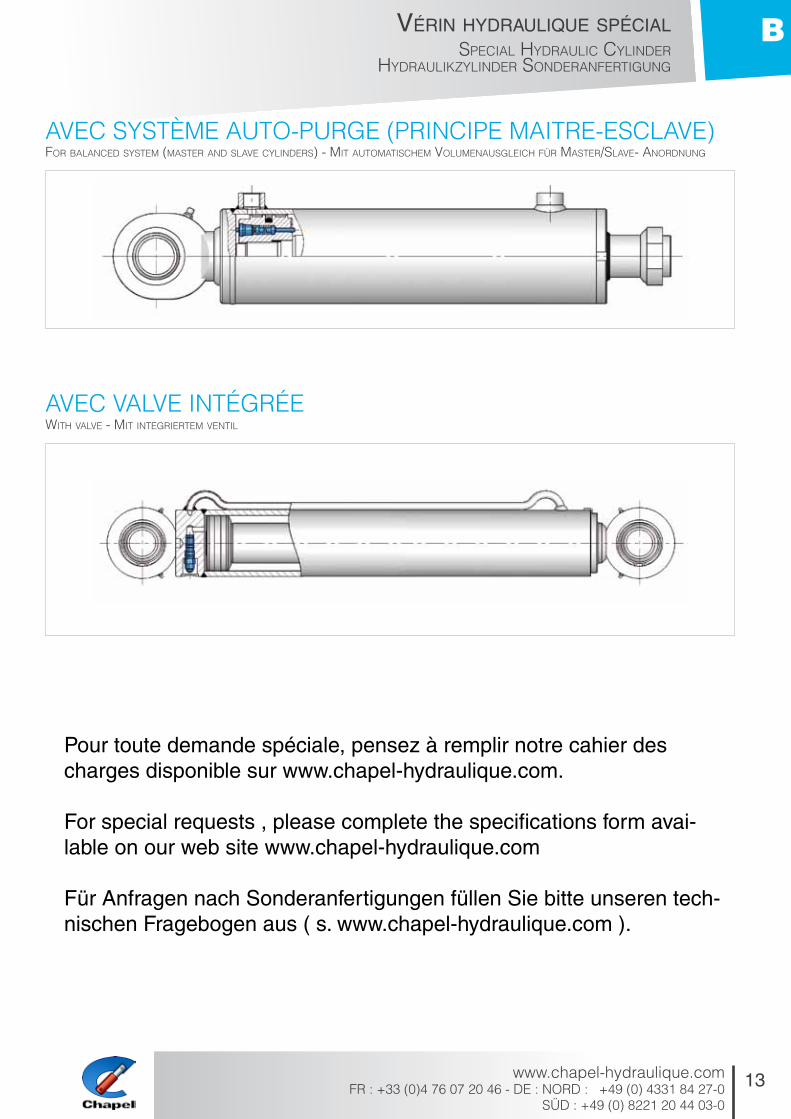
aVEc SyStèmE autO-puRgE (pRiNcipE maitRE-ESclaVE)
aVEc ValVE iNtégRéE
for balanced SySteM (MaSter and Slave cylinderS) - Mit autoMatiScHeM voluMenauSgleicH für MaSter/Slave- anordnung
witH valve - Mit integrierteM ventil
pour toute demande spéciale, pensez à remplir notre cahier des charges disponible sur www.chapel-hydraulique.com.
for special requests , please complete the specifications form avai-lable on our web site www.chapel-hydraulique.com
für anfragen nach Sonderanfertigungen füllen Sie bitte unseren tech-nischen fragebogen aus ( s. www.chapel-hydraulique.com ).

14
Vérin hydraulique spécialSpecial Hydraulic cylinderHydraulikzylinder Sonderanfertigung
www.chapel-hydraulique.comFR : +33 (0)4 76 07 20 46 - DE : NORD :+49 (0) 4331 84 27-0 SÜD : +49 (0) 8221 20 44 03-0
B
ENcOmbREmENt VéRiN DOublE EFFEtdouble-acting cylinder diMenSionS - doppeltwirkender zylinder HauptabMeSSungen
Ref. Artikel
ØA ØB F min HT min X min
700 20 32 13 Z + 102 13701 25 40 13 Z + 111 1372550 25 50 13 Z + 116 13702 30 50 13 Z + 116 13703 30 60 13 Z + 118 1373550 35 50 13 Z + 116 1373560 35 60 13 Z + 118 1373570 35 70 15 Z + 126 1373580 35 80 15 Z + 138 1374060 40 60 13 Z + 118 13704 40 70 15 Z + 126 13705 40 80 15 Z + 138 1374570 45 70 15 Z + 126 1374580 45 80 15 Z + 138 1374590 45 90 15 Z + 164 13706 50 100 25 Z + 158 1375070 50 70 15 Z + 126 1375080 50 80 15 Z + 138 1375090 50 90 15 Z + 164 13760100 60 100 25 Z + 158 1576080 60 80 15 Z + 138 1576090 60 90 15 Z + 164 15770100 70 100 25 Z + 158 15707 70 120 30 Z + 215 20770140 70 140 30 Z + 225 20780120 80 120 30 Z + 215 20780140 80 140 30 Z + 225 20790160 90 160 35 Z + 265 20

15
Vérin hydraulique spécialSpecial Hydraulic cylinder
Hydraulikzylinder Sonderanfertigung
www.chapel-hydraulique.comFR : +33 (0)4 76 07 20 46 - DE : NORD : +49 (0) 4331 84 27-0
SÜD : +49 (0) 8221 20 44 03-0
B
ENcOmbREmENt VéRiN SimplE EFFEtSingle-acting cylinder diMenSionS - einfacHwirkender zylinder HauptabMeSSungen
Ref. Artikel
ØA F min HT min X min
625 25 13 Z + 74 13630 30 13 Z + 80 13635 35 13 Z + 89 13640 40 13 Z + 99 13645 45 13 Z + 97 13650 50 15 Z + 111 13655 55 13 Z + 117 13660 60 15 Z + 124 13670 70 15 Z + 140 15
Recommandations
Si vous n’avez pas trouvé la réponse à votre besoin spécifique dans notre gamme de vérins standard (pour des pressions jusqu’à 200 bars), nous vous invitons à composer votre propre solution en choisissant : - votre diamètre de tige et piston. - vos fixations. - fixations particulières, nous consulter.
Devis sur simple demande à notre service commercial. Pour des pressions supérieures à 200 bars n’hésitez pas à nous consulter.
Recommendations
If you have not found the answer to your specific requirement in our standard range (for pressure up to 200 bars) we invite you to obtain your own solution in choosing: - Your diameter of rod and piston - Your mountings - For special mountings, please ask
Quotation available on request from our com-mercial team For pressure above 200 bars please contact us
Empfehlungen
Wenn Sie in unserem Sortiment an Standar-dzylindern keine Antwort auf Ihre spezifischen Bedürfnisse gefunden haben (Betriebsdruck bis 200 bar), laden wir Sie ein, Ihre eigene Lö-sung zusammenzustellen. Wählen Sie hierfür: - Ihren Stangen- und Kolbendurchmesser. - Ihre Befestigungen. - für Sonderausführungen wenden Sie sich bitte an uns.
Angebote auf Anfrage bei unserer Verkaufsab-teilung. Bei Drücken über 200 bar wenden Sie sich bitte an uns.

16
Vérin hydraulique spécialSpecial Hydraulic cylinderHydraulikzylinder Sonderanfertigung
www.chapel-hydraulique.comFR : +33 (0)4 76 07 20 46 - DE : NORD :+49 (0) 4331 84 27-0 SÜD : +49 (0) 8221 20 44 03-0
B
chOix DES FixatiONS
chapES
ROtulES agRi-RONDES
tENONS
ROtulES agRi-platES
cHoice of MountingS - befeStigungSMöglicHkeiten
feMale cleviS - gabelgelenke
agricultural SpHerical bearingS-rounded agro-gelenkaugen/rund
Male cleviS - laScHen
agricultural SpHerical bearingS-flat agro-gelenkaugen/flacH
Ref. Artikel
D max E H M N
CH4521 20 40 45 21 10CH5025 20 40 50 25 10CH5027 25 50 50 27 12CH6027 25 50 60 27 12CH6030 30 60 60 30 15CH7030 30 60 70 30 15
Ref. Artikel
D E H M N
RAR19 19.5 44 54 55 25RAR22 22.5 51 80 81 30RAR25 25.8 51 80 80 30RAR25H70 25.8 51 70 85 45RAR28 28.8 38 80 81 30RAR30H65 30.2 55 65 83 50RAR32 32.2 51 85 90 40
Ref. Artikel
D max E H M N
TNF2 30 20 45 50 38TNF3 35 30 50 55 42TNX2 25 15 44 48 55TNX3 30 25 50 50 65TNX5 40 25 70 70 85
Ref. Ref.
D E H M N
RAP19 19.5 44 50 52 52RAP22 22.5 35 72 66 60RAP22H40 22.5 35 40 70 60RAP25 25.8 38 80 80 70RAP25H40 25.8 38 40 80 70RAP28 28.8 38 80 80 70RAP28H40 28.8 35 40 75 70

17
Vérin hydraulique spécialSpecial Hydraulic cylinder
Hydraulikzylinder Sonderanfertigung
www.chapel-hydraulique.comFR : +33 (0)4 76 07 20 46 - DE : NORD : +49 (0) 4331 84 27-0
SÜD : +49 (0) 8221 20 44 03-0
B
chOix DES FixatiONS
ROtulES iNDuStRiEllES
tOuRillONS
bRiDES
tigES FilEtéES
cHoice of MountingS - befeStigungSMöglicHkeiten
induStrial SpHerical bearingS - induStrie-gelenkaugen
trunnionS - zapfen
flangeS - flanScH
tHreaded rod endS - gewinde
Ref. / Artikel D E H M N
RIP25 25 23 45 55 55RIP30 30 28 51 65 65RIR17 17 14 35 46 24RIR20 20 16 38 53 28RIR25 25 20 45 64 35RIR30 30 22 51 73 40RIR35 35 25 61 82 47RIR40 40 28 69 92 52
Ref. / Artikel B C D E X min
TL700 32 55 16 20 82TL701 40 78 25 45 101TL702 50 90 30 45 104TL703 60 100 30 45 106TL704 70 115 40 65 120TL705 80 128 40 65 125TL706 100 151 50 80 155TL707 120 191 50 90 172
Ref. Artikel
B C D E F G X min
BR700 32 100 40 10 9 80 21BR701 40 120 50 10 11 90 20BR702 50 130 60 12 13 100 21BR703 60 140 70 12 13 110 21BR704 70 160 80 15 15 130 23BR705 80 170 90 15 15 140 23BR706 100 200 115 20 20 160 23BR707 120 240 140 25 20 200 30
A C D L X
20 8 M12 x 1.5 20 1425 8 M16 x 2 25 1930 8 M24 x 2 30 2435 10 M24 x 2 30 2740 10 M27 x 2 35 3045 12 M27 x 2 35 3650 12 M33 x 2 45 4155 12 M33 x 2 45 4660 20 M33 x 2 45 5070 20 M55 x 2 60 6080 20 M55 x 2 65 7090 25 M55 x 2 70 80

/ Hy
dr
au
lic c
ylin
de
r S
af
et
y / S
icH
er
He
itS
zu
be
Hö
r
sé
cu
rit
é V
ér
in
hy
dr
au
liq
ue
Sécurité Vérin HydrauliqueHydraulic cylinder Safety
SicHerHeitSzubeHör
www.chapel-hydraulique.com
C
19

20
sécurité Vérin hydrauliqueHydraulic cylinder SafetySicHerHeitSzubeHör
www.chapel-hydraulique.comFR : +33 (0)4 76 07 20 46 - DE : NORD :+49 (0) 4331 84 27-0 SÜD : +49 (0) 8221 20 44 03-0
C
clapEt DOublE pilOté
blOc pOuR ValVE D’équilibRagE SimplE
double pilot operated cHeck valve - doppelt entSperrbareS rückScHlagventil
over center valve - einfacHeS SenkbreMSHalteventil iM block
Ref. Artikel
E M Pression (bar)Pressure Druck
Débit (Ltr/min)Flow Leistung
Rapport de pilotagePilot ratioAufsteuerung
ARDP6350 350 3/8 BSP 350 30 1/6ARDP6750 750 3/8 BSP 350 30 1/6ARDPNU12 1/2 BSP 350 50 1/4ARDPNU6 3/8 BSP 350 30 1/6
Ref. Artikel
E M Pression (bar)Pressure Druck
Pression maxMax pressureMax Druck
Débit maxMax flow Max Leistung
Rapport de pilotagePilot ratioAufsteuerung
BL38SCB60-210 3/8 106 b/turn 210 bars 60 l/min 3:1BL38SCB60-210B 3/8 106 b/turn 210 bars 60 l/min 3:1BL38SCB60-350 3/8 165 b/turn 350 bars 60 l/min 3:1KITBL38S750 750 3/8KITBL38S750B 750 3/8

21
sécurité Vérin hydrauliqueHydraulic cylinder Safety
SicHerHeitSzubeHör
www.chapel-hydraulique.comFR : +33 (0)4 76 07 20 46 - DE : NORD : +49 (0) 4331 84 27-0
SÜD : +49 (0) 8221 20 44 03-0
C
blOc pOuR ValVE D’équilibRagE DOublE
SécuRité pOuR VéRiN télEScOpiquE
dual over center valve - doppelteS SenkbreMSHalteventil iM block
Safety for teleScopic cylinder - elektriScHeS Senkventil
Ref. Artikel
E M Pression (bar)Pressure Druck
Pression maxMax pressureMax druck
Débit maxMax flow Max leistung
Rapport de pilotagePilot ratioAufsteuerung
BL38DCB60-210 3/8 106 b/turn 210 bars 60 l/min 3:1BL38DCB60-210B 3/8 106 b/turn 210 bars 60 l/min 3:1BL38DCB60-350 3/8 165 b/turn 350 bars 60 l/min 3:1KITBL38D750 750 3/8KITBL38D750B 750 3/8
Ref. Ref.Artikel
T Pression maxMax pressureMax druck
Débit maxMax flow Max leistung
ES38 12V 200 bars 50 l/minES3824V 24V 200 bars 50 l/minVFCT 350 bars 50 l/min
22
sécurité Vérin hydrauliqueHydraulic cylinder SafetySicHerHeitSzubeHör
www.chapel-hydraulique.comFR : +33 (0)4 76 07 20 46 - DE : NORD :+49 (0) 4331 84 27-0 SÜD : +49 (0) 8221 20 44 03-0
C
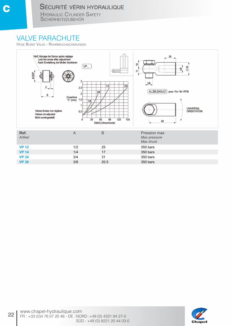
ValVE paRachutEHoSe burSt valve - roHrbrucHSicHerungen
Ref. Artikel
A B Pression maxMax pressureMax druck
VP 12 1/2 25 350 barsVP 14 1/4 17 350 barsVP 34 3/4 31 350 barsVP 38 3/8 20.5 350 bars

D
23
/ Hy
dr
au
lic V
alV
e / W
eg
eV
en
tile
d
ist
rib
ut
eu
r
hy
dr
au
liq
ue
diStributeur HydrauliqueHydraulic ValVe
WegeVentile
www.chapel-hydraulique.com
24
distributeur hydrauliqueHydraulic valvewegeventile
www.chapel-hydraulique.comFR : +33 (0)4 76 07 20 46 - DE : NORD :+49 (0) 4331 84 27-0 SÜD : +49 (0) 8221 20 44 03-0
D
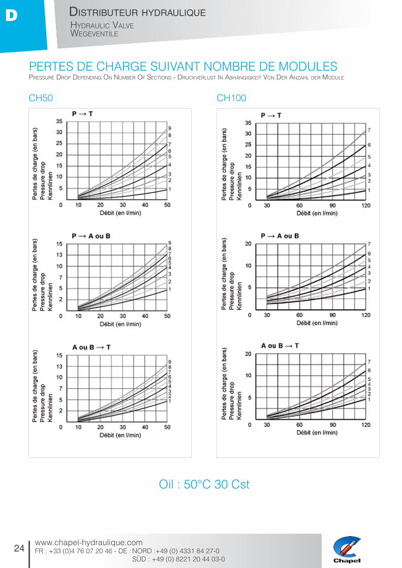
pERtES DE chaRgE SuiVaNt NOmbRE DE mODulES
Oil : 50°c 30 cst
preSSure drop depending on nuMber of SectionS - druckverluSt in abHängigkeit von der anzaHl der Module
ch50 ch100

25
distributeur hydrauliqueHydraulic valve
wegeventile
www.chapel-hydraulique.comFR : +33 (0)4 76 07 20 46 - DE : NORD : +49 (0) 4331 84 27-0
SÜD : +49 (0) 8221 20 44 03-0
D
Les distributeurs CH50 et CH100 sont de type modulaire et compact. L’assemblage est composé de 1 à 9 modules, avec une entrée munie d’un limiteur de pres-sion et une sortie. Le tout est assemblé par 4 tirants.
• Débit : - CH50 de 15 à 50 litres/mn* - CH100 de 40 à 120 litres/mn* *suivant circuit et composition du distributeur
• Pression maxi d’utilisation : 320 bars (350 bars nous consulter).
• Pression de retour maxi : 35 bars.
• Circuit parallèle.
• Limiteur de pression sur l’entrée réglable de 40 à 320 bars (350 bars nous consulter), réglage standard : 180 bars.
• Filtration recommandée à 15 µ.
AVANTAGES• Dimensions réduites
• Grande souplesse d’emploi (modules)
• Gamme étendue de tiroirs, de commandes
• Matériaux de haute qualité
• Fabrication de grande précision
• DISPONIBILITE
CH50 & CH100 are compact modular valves. The assembly is built up from 1 to 9 sections complete with, inlet cover with an integral, ad-justable pressure relief and an outlet cover. All sections are fastened together with 4 tie rods.
• Rated flow - CH50: from 15 to 50 litres/min* - CH100: from 40 to 120 litres/min* *Depending on the circuit and composition of the valve
• Max pressure = 320 bar (for 350 bar please ask)
• Max back pressure = 35 bar
• Parallel circuitry
• The inlet cover contains a pressure relief valve, adjustable from 40 to 320 bar (for 350 bars please ask). Preset to 180 bar
• Recommended filtration: 15µ
ADVANTAGES • Compact design
• Easy to assemble
• Large range of sections available
• High quality materials
• Precision machined
• AVAILABLE ON STOCK
CH50 und CH100 sind kompakte Wegeventile in Modulbauweise. Ein Block besteht aus 1 bis 9 Sektionen, einem Eingangselement mit Druckbegrenzungsventil und einem Aus-gangselement. Die Montage erfolgt mittels 4 Zugankern.
• Maximaler Durchfluss: - CH50: 15 bis 50 l/min* - CH100: 40 bis 120 l/min* * Abhängig von der Anzahl d. Elemente
• Max. Betriebsdruck = 320 bar
• Max. Rücklaufdruck = 35 bar
• Druckloser Umlauf
• Einstellbares Druckbegrenzungsventil im Eingangselement 40 bis 320 bar. Voreinstellung = 180 bar
• Empfohlene Filtrierung 15µ
VORTEILE • Kleine Abmessungen
• Einfache Variationsmöglichkeiten durch Modulbauweise
• Umfangreiches Sortiment - an Schiebern und Betätigungen
• Materialen von hoher Qualität
• Fertigung von hoher Präzision
• LIEFERBAR
DiStRibutEuRS mODulaiRES 50 Et 100 litRESModular Hydraulic valve - wegeventile in ModulbauweiSe

26
distributeur hydrauliqueHydraulic valvewegeventile
www.chapel-hydraulique.comFR : +33 (0)4 76 07 20 46 - DE : NORD :+49 (0) 4331 84 27-0 SÜD : +49 (0) 8221 20 44 03-0
D
uN SyStèmE cOmplEt DE mODulES Et FONctiONSModular Hydraulic valve cH50 - cH100 - Modulare wegeventile cH50 - cH100

27
distributeur hydrauliqueHydraulic valve
wegeventile
www.chapel-hydraulique.comFR : +33 (0)4 76 07 20 46 - DE : NORD : +49 (0) 4331 84 27-0
SÜD : +49 (0) 8221 20 44 03-0
D
pOuR DES SOlutiONS aDaptéES à chaquE bESOiNfor SolutionS adapted to every need - löSungen für alle einSatzfälle

28
distributeur hydrauliqueHydraulic valvewegeventile
www.chapel-hydraulique.comFR : +33 (0)4 76 07 20 46 - DE : NORD :+49 (0) 4331 84 27-0 SÜD : +49 (0) 8221 20 44 03-0
D
Le choix d’un distributeur dépend du débit uti-lisé de la pompe et du nombre de modules.
La formulation d’un distributeur modulaire CHAPEL est une nomenclature de pièces décrivant l’ensemble des modules dans l’ordre d’assemblage. Cette nomenclature est établie de gauche à droite, vue face au levier de commande, comme suit:- Entrée - Module 1 - Module 2 - Module...etc...jusqu’à 9 (maximum) - Tirants (pièces d’assemblage) - Sortie
Les modules 1 à 9 peuvent être des com-mandes (manuelle, pneumatique,...), ou des éléments techniques (régulateur de débit, électro-hydraulique, float...).
Pour procéder à cette formulation, l’idéal est de disposer d’un schéma hydraulique de principe. En l’absence de schéma, établissez de gauche à droite, la liste: - Entrée - fonction + commande + spécificité = Module 1 - fonction + commande + spécificité = Module 2 - fonct... - Tirant (T + nombre de module) - Sortie
The choice of a directional valve depends on the pump flow used and the number of sections.
Building a Chapel valve consists of a list of va-rious parts describing the sections in the order they need to be assembled. This list runs from left to right, this means from the inlet cover to the outlet cover. Example: - Inlet cover - Section 1 - Section 2 - Section...etc...up to a maximum of 9 sections - Tie rods (assembly parts) - Outlet cover
The sections 1 to 9 can be manual operated or fitted with various control operations such as pneumatic actuator, detents, micro spools, etc. The sections can be supplied with flow controls, service line relief’s, electric sections and float controls. To ensure the construction of the valve is correct, it is best to have a schematic diagram. If not available, make a list of sections required from left to right: - Inlet cover - function + control + specification = Section 1 - function + control + specification = Section 2 - funct... - Tie rod (T + module number) - Outlet cover
Die Wahl eines Wegeventils hängt vom Volu-menstrom und der Anzahl der Module ab.
Der Aufbau eines modularen Chapel-Wege-ventils entspricht der Artikelbezeichnung, die Gesamtheit der Module in der Reihenfolge ihres Zusammenbaus beschreibt. Diese Bezeichnung wird von links nach rechts erstellt, mit Blick auf den Schalthebel, wie nachfolgend dargestellt: - Eingangselement - Modul 1 - Modul 2 - Modul...etc...bis 9 (Maximum) - Zuganker (Montagesatz) - Ausgangselement
Die Module 1 bis 9 können Steuerelemente sein (manuell, pneumatisch,...) oder technische Elemente (Stromregelventil, elektrohydrau-lische Vorsteuerung,...).
Um diesen Aufbau durchzuführen, verfügt man idealerweise über ein Prinzip-Hydraulikschema. Die Liste wird von links nach rechts erstellt: - Eingangselement - Funktion + Steuerung + Spezifizierung = Modul 1 - Funktion + Steuerung + Spezifizierung = Modul 2 - Funkt... - Zuganker (T + Anzahl der Module) - Ausgangselement
REcOmmaNDatiONS
ExEmplE DE Schéma hyDRauliquE
recoMMendationS - eMpfeHlungen
Hydraulic diagraM exaMple - beiSpiel eineS HydraulikScHeMaS
29
distributeur hydrauliqueHydraulic valve
wegeventile
www.chapel-hydraulique.comFR : +33 (0)4 76 07 20 46 - DE : NORD : +49 (0) 4331 84 27-0
SÜD : +49 (0) 8221 20 44 03-0
D
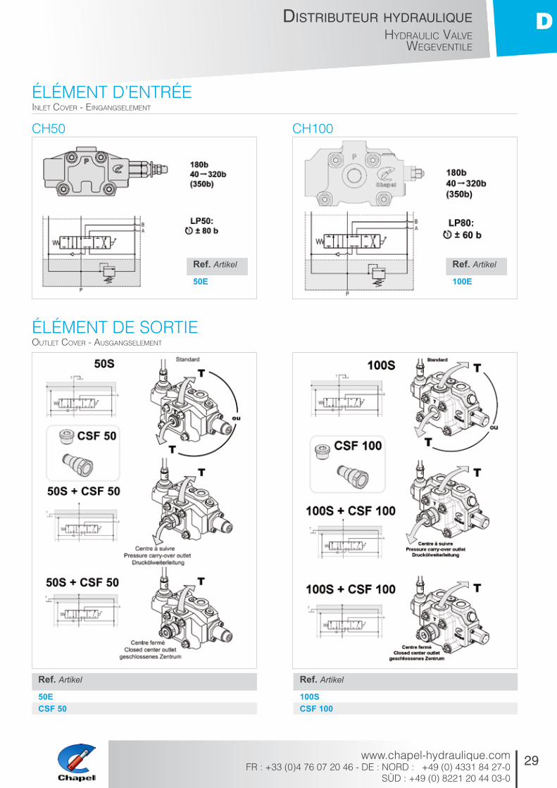
élémENt D’ENtRéE
élémENt DE SORtiE
ch50 ch100
inlet cover - eingangSeleMent
outlet cover - auSgangSeleMent
Ref. Artikel
50E
Ref. Artikel
50ECSF 50
Ref. Artikel
100SCSF 100
Ref. Artikel
100E

30
distributeur hydrauliqueHydraulic valvewegeventile
www.chapel-hydraulique.comFR : +33 (0)4 76 07 20 46 - DE : NORD :+49 (0) 4331 84 27-0 SÜD : +49 (0) 8221 20 44 03-0
D
tiROiR SimplE EFFEt
tiROiR DOublE EFFEt
ch50 ch100
Single acting Spool - einfacHwirkender eleMente
double-acting Spool - doppeltwirkender eleMente
Ref. Artikel
B 50 M 50 S 50
Ref. Artikel
D 50 F 50 L 50
Ref. Artikel
B 100 M 100 S 100
Ref. Artikel
D 100 F 100 L 100

31
distributeur hydrauliqueHydraulic valve
wegeventile
www.chapel-hydraulique.comFR : +33 (0)4 76 07 20 46 - DE : NORD : +49 (0) 4331 84 27-0
SÜD : +49 (0) 8221 20 44 03-0
D
pOSitiONNEmENt Du tiROiR
ch50 ch100
Spool poSition - raStung der ScHieberpoSitionen
Ref. Artikel
C1 50C2 50C3 50C4 50RR
Ref. Artikel
C1 80C2 80C3 80C4 80RR

32
distributeur hydrauliqueHydraulic valvewegeventile
www.chapel-hydraulique.comFR : +33 (0)4 76 07 20 46 - DE : NORD :+49 (0) 4331 84 27-0 SÜD : +49 (0) 8221 20 44 03-0
D
ValVE aNti-chOc RéglablE
ch50 ch100
adjuStable relief valve - einStellbareS druckbegrenzungSventil
Ref. Artikel
VAC 140VAC 320VAC B
Ref. Artikel
VAC 80
cOmmaNDE pNEumatiquEpneuMatic control - pneuMatiScHe betätigung
Ref. Artikel
CP 50
Ref. Artikel
CP 80

33
distributeur hydrauliqueHydraulic valve
wegeventile
www.chapel-hydraulique.comFR : +33 (0)4 76 07 20 46 - DE : NORD : +49 (0) 4331 84 27-0
SÜD : +49 (0) 8221 20 44 03-0
D
cOmmaNDE paR câblE
micRORuptEuR
ch50
ch100
ch50
cable control - betätigung per Seilzug
Micro SwitcH - MikroScHalter
Ref. Artikel
Long. (m) Length. Länge
CC1 1CC1.5 1.5CC2 2CC2.5 2.5CC3 3CCD1 1CCD1.5 1.5CCD2 2
Ref. Artikel
Long. (m) Length. Länge
CC1 80 1CC1.5 80 1.5CC2 80 2CC2.5 80 2.5CC3 80 3CCD1 80 1CCD1.5 80 1.5CCD2 80 2
Ref. Artikel
CMI 50

34
distributeur hydrauliqueHydraulic valvewegeventile
www.chapel-hydraulique.comFR : +33 (0)4 76 07 20 46 - DE : NORD :+49 (0) 4331 84 27-0 SÜD : +49 (0) 8221 20 44 03-0
D
Non disponible avec CSF50
Il est important de préciser le débit et le nombre de modules utilisés pour que le réglage usine du ERER50 soit correct.
Kit de connexion étanche fourni en pièces détachées. Protection = IP67 Alim = fil Ø 1,3 à 3,3 mm (isolant)
ERER50: Pression de pilotage environ 25 bars. Doit être placé obligatoirement juste après la plaque d’entrée 50E et avant le tiroir com-mande électro-hydraulique. Voir type de tiroir dispo et voltage (12 et 24V)
Avantages: - Maintien de la commande manuelle (standard ou commande par cable)- Montage de tous les types de modules (électrique - pneumatique - manuel - ...) sur un même distributeur.
Not available with CSF50
It is important that the back pressure of the ERER50 is set in factory before despatch and depends on the number of sections and flow in the valve.
Watertight connection kit, supplied separately. Protection = IP67 Wiring = insulated wire 1,3 to 3,3 mm
ERER50: Piloted pressure approx 25 bars. It must be assembled directly after the inlet cover 50E and directly before the electrical section. Available for 12 or 24 volt applications.
Advantages: - Manual control still possible either standard or cable- In the same valve assembly all other types of spool control are possible (electrical, pneuma-tic, manual, etc).
Nicht verfügbar mit CSF50
Zur korrekten Einstellung des Elementes ERER50 müssen der Volumenstrom und die Anzahl der verwendeten Elemente bekannt sein.
Steckersatz lose beiliegend Schutzgrad IP67 Kabel Ø 1,3 bis 3,3 mm (isoliert)
ERER50: Steuerdruck ca. 25 bar. Das Element ist direkt hinter das Eingangselement 50E und vor das elektrohydraulisch betätigte Element zu setzen. S. lieferbare Schiebertypen und Spannungen (12V und 24V).
Vorteile: - Erhaltung der manuellen Betätigung (Stan-dard oder Kabelzug) - Möglichkeit der Montage aller Modultypen (elektrohydraulisch, pneumatisch, manuell,...) im selben Ventilblock.
cOmmaNDE élEctRO-hyDRauliquE baSSE pRESSiON ch50electro-Hydraulic control (low preSSure) - elektro-HydrauliScHe betätigung (niederdruck)

35
distributeur hydrauliqueHydraulic valve
wegeventile
www.chapel-hydraulique.comFR : +33 (0)4 76 07 20 46 - DE : NORD : +49 (0) 4331 84 27-0
SÜD : +49 (0) 8221 20 44 03-0
D
Non disponible avec CSF100
Il est important de préciser le débit et le nombre de modules utilisés pour que le réglage usine du ERER100 soit correct.
Kit de connexion étanche fourni en pièces détachées. Protection = IP67 Alim = fil Ø 1,3 à 3,3 mm (isolant)
ERER100: Pression de pilotage environ 25 bars. Doit être placé obligatoirement juste après la plaque d’entrée 100E et avant le tiroir commande électro-hydraulique. Voir type de tiroir dispo et voltage (12 et 24V)
Avantages: - Maintien de la commande manuelle (standard ou commande par cable)- Montage de tous les types de modules (électrique - pneumatique - manuel - ...) sur un même distributeur.
Not available with CSF100
It is important that the back pressure of the ERER100 is set in factory before despatch and depends on the number of sections and flow in the valve.
Watertight connection kit, supplied separately. Protection = IP67 Wiring = insulated wire 1,3 to 3,3 mm
ERER100: Piloted pressure approx 25 bars. It must be assembled directly after the inlet cover 100E and directly before the electrical section. Available for 12 or 24 volt applications.
Advantages: - Manual control still possible either standard or cable- In the same valve assembly all other types of spool control are possible (electrical, pneuma-tic, manual, etc).
Nicht verfügbar mit CSF100
Zur korrekten Einstellung des Elementes ERER100 müssen der Volumenstrom und die Anzahl der verwendeten Elemente bekannt sein.
Steckersatz lose beiliegend Schutzgrad IP67 Kabel Ø 1,3 bis 3,3 mm (isoliert)
ERER100: Steuerdruck ca. 25 bar. Das Element ist direkt hinter das Eingangselement 100E und vor das elektrohydraulisch betätigte Element zu setzen. S. lieferbare Schiebertypen und Spannungen (12V und 24V).
Vorteile: Erhaltung der manuellen Betätigung (Standard oder Kabelzug) Möglichkeit der Montage aller Modultypen (elektrohydraulisch, pneumatisch, manuell,...) im selben Ventilblock.
cOmmaNDE élEctRO-hyDRauliquE baSSE pRESSiON ch100electro-Hydraulic control (low preSSure) - elektro-HydrauliScHe betätigung (niederdruck)

36
distributeur hydrauliqueHydraulic valvewegeventile
www.chapel-hydraulique.comFR : +33 (0)4 76 07 20 46 - DE : NORD :+49 (0) 4331 84 27-0 SÜD : +49 (0) 8221 20 44 03-0
D
Section régulateur de débit: ERD50 (0 à 50 l/min):
La section régulateur de débit ERD50 se monte juste après les sections à débit régulé (R). Elle permet de régler manuellement et avec préci-sion le débit, c’est à dire la vitesse du récepteur (moteur ou vérin). Une fois réglé, ce débit est constant quelque soit la variation de pression du récepteur ou la variation de vitesse de rotation de la pompe d’alimentation. Le débit excéden-taire est directement envoyé sur les sections suivantes qui peuvent donc être utilisées en même temps. Lorsque les sections à débit ré-gulé (R) ne sont pas utilisées, tout le débit est envoyé sur les sections suivantes.
Important: Les sections régulées (R) sont diffé-rentes des sections standard.
Exemple: Section standard ref: D50.RR, Section régulée ref: DR50.RR
Flow control section: ERD50 (0 to 50 l/min)
The ERD50 section flow regulator is to be mounted immediately after the regulated flow sections (R). This enables the flow, i.e. the speed of the receiver (motor or cylinder), to be precisely adjusted manually. Once set, this flow is constant whatever the pressure variation of the receiver or the rotation speed variation of the feed pump. The redundant flow is directly sent to the subsequent sections which may, consequently, be used at the same time. When the regulated flow sections (R) are not used, all the flow is sent to the subsequent sections.
Important: The regulated sections (R) are diffe-rent to the standard sections.
Example: Standard section ref: D50.RR, Regu-lated section ref: DR50.RR
Stromregelement ERD50 (0 bis 50 l/min)
Das Stromregelventil ERD50 wird gleich hinter die regulierten Elemente montiert (R). Der Durchfluss kann manuell und exakt reguliert werden. Die Geschwindigkeit des Verbrauchers (Motor oder Zylinder) wird hierdurch eingestellt. Einmal eingestellt, bleibt der Durchfluss konstant, egal wie der Verbraucherdruck oder die Drehzahl der Pumpe schwanken. Das überschüssige Öl wird direkt an die folgenden Module weitergeleitet, die somit gleichzeitig verwendet werden können. Wenn die Elemente mit geregeltem Durchfluss (R) nicht in Verwen-dung sind, steht der gesamte Volumenstrom den nachfolgenden Elementen zur Verfügung.
Wichtig: Die geregelten Elemente (R) unters-cheiden sich von den Standard-elementen.
Beispiel: Standardelement Artikel: D50.RR, reguliertes Element Artikel: DR50.RR
RégulatEuR DE Débit maNuEl ch50flow regulator - StroMregelventil
Ref. Artikel
ERD 50

37
distributeur hydrauliqueHydraulic valve
wegeventile
www.chapel-hydraulique.comFR : +33 (0)4 76 07 20 46 - DE : NORD : +49 (0) 4331 84 27-0
SÜD : +49 (0) 8221 20 44 03-0
D
Section régulateur de débit: ERD100 (10 à 90 l/min):
La section régulateur de débit ERD100 se monte juste après les sections à débit régulé (R). Elle permet de régler manuellement et avec préci-sion le débit, c’est à dire la vitesse du récepteur (moteur ou vérin). Une fois réglé, ce débit est constant quelque soit la variation de pression du récepteur ou la variation de vitesse de rotation de la pompe d’alimentation. Le débit excéden-taire est directement envoyé sur les sections suivantes qui peuvent donc être utilisées en même temps. Lorsque les sections à débit ré-gulé (R) ne sont pas utilisées, tout le débit est envoyé sur les sections suivantes.
Important: Les sections régulées (R) sont diffé-rentes des sections standard.
Exemple: Section standard ref: D100.RR, Sec-tion régulée ref: DR100.RR
Flow control section: ERD100 (10 à 90 l/min)
The ERD100 section flow regulator is to be mounted immediately after the regulated flow sections (R). This enables the flow, i.e. the speed of the receiver (motor or cylinder), to be precisely adjusted manually. Once set, this flow is constant whatever the pressure variation of the receiver or the rotation speed variation of the feed pump. The redundant flow is directly sent to the subsequent sections which may, consequently, be used at the same time. When the regulated flow sections (R) are not used, all the flow is sent to the subsequent sections.
Important: The regulated sections (R) are diffe-rent to the standard sections.
Example: Standard section ref: D100.RR, Re-gulated section ref: DR100.RR
Stromregelement ERD100 (10 bis 90 l/min)
Das Stromregelventil ERD100 wird gleich hinter die regulierten Elemente montiert (R). Der Durchfluss kann manuell und exakt reguliert werden. Die Geschwindigkeit des Verbrauchers (Motor oder Zylinder) wird hierdurch eingestellt. Einmal eingestellt, bleibt der Durchfluss konstant, egal wie der Verbraucherdruck oder die Drehzahl der Pumpe schwanken. Das überschüssige Öl wird direkt an die folgenden Module weitergeleitet, die somit gleichzeitig verwendet werden können. Wenn die Elemente mit geregeltem Durchfluss (R) nicht in Verwen-dung sind, steht der gesamte Volumenstrom den nachfolgenden Elementen zur Verfügung.
Wichtig: Die geregelten Elemente (R) unters-cheiden sich von den Standard-elementen.
Beispiel: Standardelement Artikel: D100.RR, reguliertes Element Artikel: DR100.RR
RégulatEuR DE Débit maNuEl ch100flow regulator - StroMregelventil
Ref. Artikel
ERD 100
38
distributeur hydrauliqueHydraulic valvewegeventile
www.chapel-hydraulique.comFR : +33 (0)4 76 07 20 46 - DE : NORD :+49 (0) 4331 84 27-0 SÜD : +49 (0) 8221 20 44 03-0
D
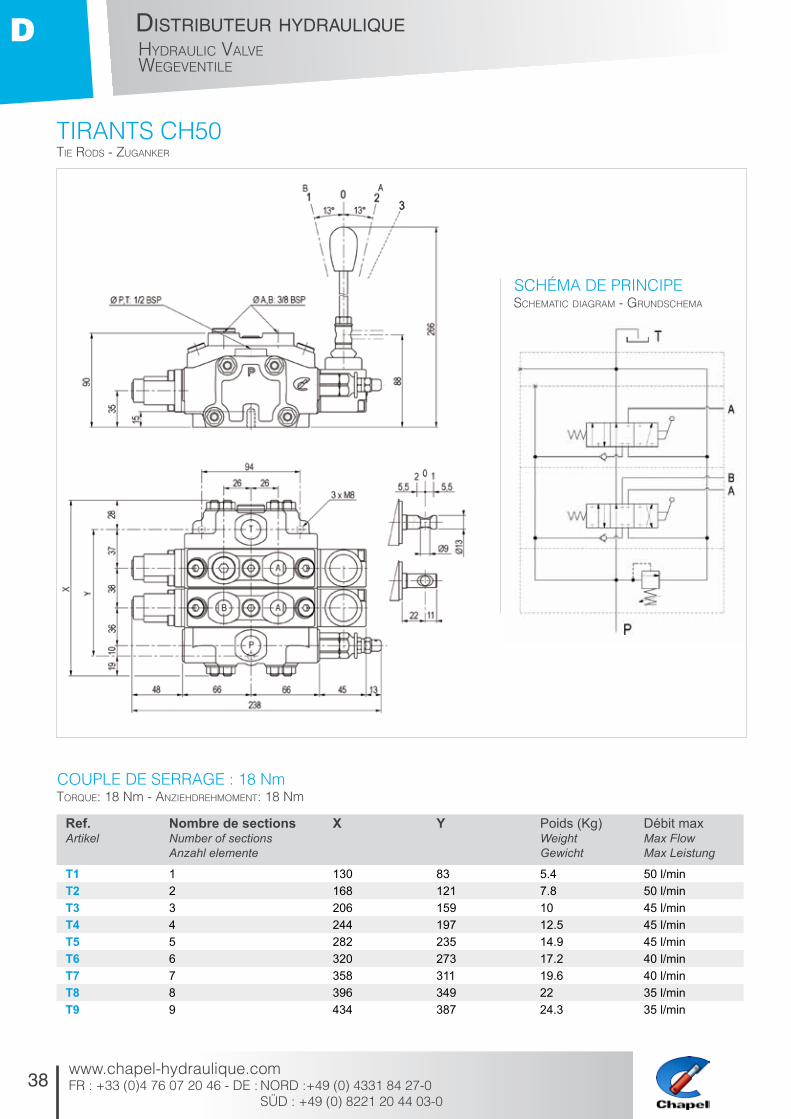
tiRaNtS ch50tie rodS - zuganker
ScHeMatic diagraM - grundScHeMa
torque: 18 nm - anzieHdreHMoMent: 18 nm
Schéma DE pRiNcipE
cOuplE DE SERRagE : 18 Nm
Ref. Artikel
Nombre de sections Number of sectionsAnzahl elemente
X Y Poids (Kg)Weight Gewicht
Débit maxMax FlowMax Leistung
T1 1 130 83 5.4 50 l/minT2 2 168 121 7.8 50 l/minT3 3 206 159 10 45 l/minT4 4 244 197 12.5 45 l/minT5 5 282 235 14.9 45 l/minT6 6 320 273 17.2 40 l/minT7 7 358 311 19.6 40 l/minT8 8 396 349 22 35 l/minT9 9 434 387 24.3 35 l/min

39
distributeur hydrauliqueHydraulic valve
wegeventile
www.chapel-hydraulique.comFR : +33 (0)4 76 07 20 46 - DE : NORD : +49 (0) 4331 84 27-0
SÜD : +49 (0) 8221 20 44 03-0
D
tiRaNtS ch100tie rodS - zuganker
ScHeMatic diagraM - grundScHeMa
torque: 18 nm - anzieHdreHMoMent: 18 nm
Schéma DE pRiNcipE
cOuplE DE SERRagE : 18 Nm
Ref. Artikel
Nombre de sections Number of sectionsAnzahl elemente
X Y Poids (Kg)Weight Gewicht
Débit maxMax FlowMax Leistung
T1 80 1 161 115 13.6 120 l/minT2 80 2 206 160 18.6 110 l/minT3 80 3 251 205 23.6 105 l/minT4 80 4 296 250 28.6 100 l/minT5 80 5 341 295 33.6 95 l/minT6 80 6 386 340 38.6 90 l/minT7 80 7 431 385 43.6 90 l/min


E
41
/ Hy
dr
au
lic H
an
d p
um
p / H
yd
ra
uliS
cH
e H
an
dp
um
pe
po
mp
e à
ma
in
hy
dr
au
liq
ue
pompe à main HydrauliqueHydraulic Hand pump
HydrauliScHe Handpumpe
www.chapel-hydraulique.com
42
pompe à main hydrauliqueHydraulic Hand puMpHydrauliScHe HandpuMpe
www.chapel-hydraulique.comFR : +33 (0)4 76 07 20 46 - DE : NORD :+49 (0) 4331 84 27-0 SÜD : +49 (0) 8221 20 44 03-0
E
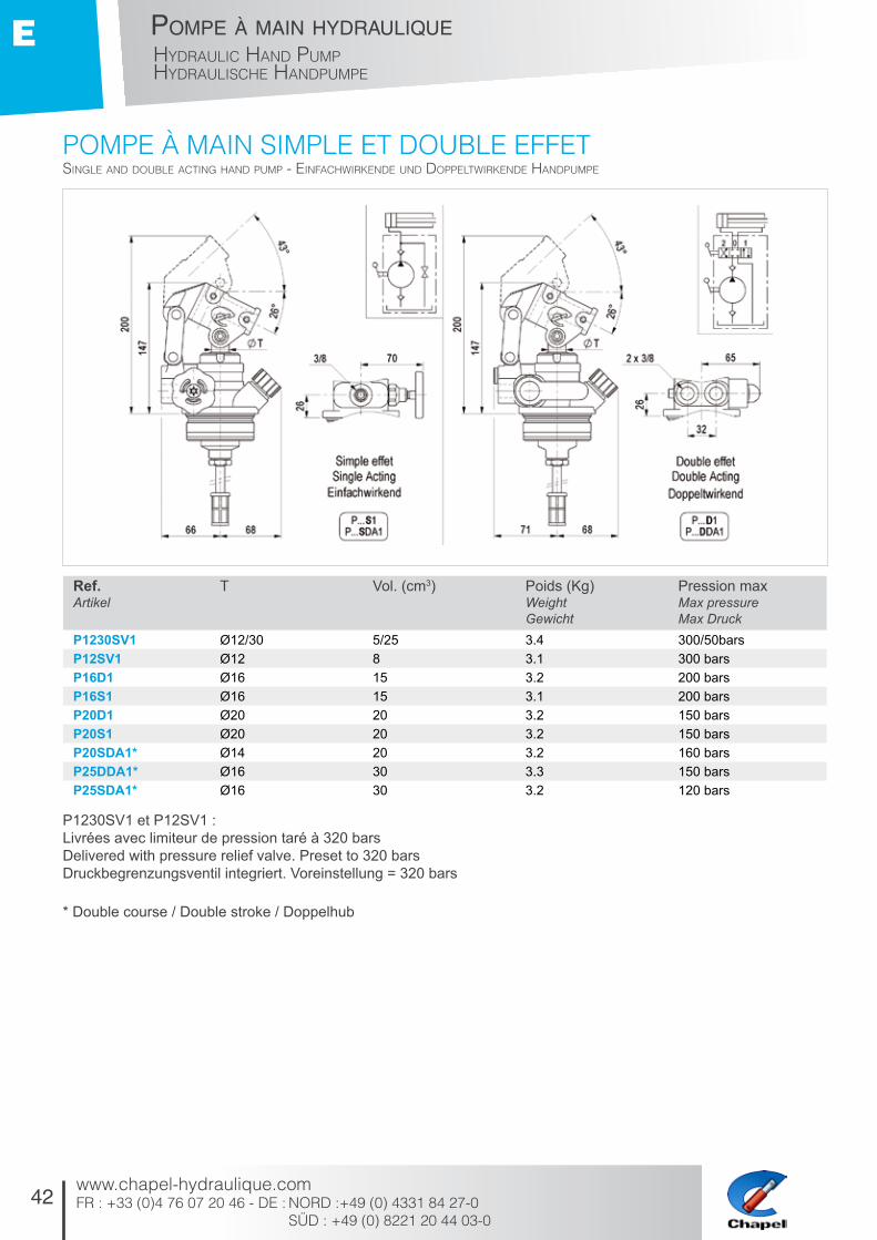
pOmpE à maiN SimplE Et DOublE EFFEtSingle and double acting Hand puMp - einfacHwirkende und doppeltwirkende HandpuMpe
P1230SV1 et P12SV1 :Livrées avec limiteur de pression taré à 320 barsDelivered with pressure relief valve. Preset to 320 barsDruckbegrenzungsventil integriert. Voreinstellung = 320 bars
* Double course / Double stroke / Doppelhub
Ref. Artikel
T Vol. (cm3) Poids (Kg)Weight Gewicht
Pression maxMax pressureMax Druck
P1230SV1 Ø12/30 5/25 3.4 300/50barsP12SV1 Ø12 8 3.1 300 barsP16D1 Ø16 15 3.2 200 barsP16S1 Ø16 15 3.1 200 barsP20D1 Ø20 20 3.2 150 barsP20S1 Ø20 20 3.2 150 barsP20SDA1* Ø14 20 3.2 160 barsP25DDA1* Ø16 30 3.3 150 barsP25SDA1* Ø16 30 3.2 120 bars
43
pompe à main hydrauliqueHydraulic Hand puMp
HydrauliScHe HandpuMpe
www.chapel-hydraulique.comFR : +33 (0)4 76 07 20 46 - DE : NORD : +49 (0) 4331 84 27-0
SÜD : +49 (0) 8221 20 44 03-0
E
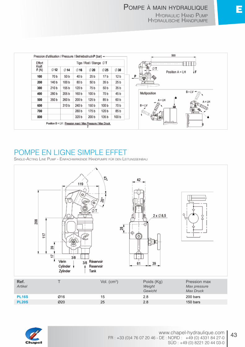
pOmpE EN ligNE SimplE EFFEtSingle-acting line puMp - einfacHwirkende HandpuMpe für den leitungSeinbau
Ref. Artikel
T Vol. (cm3) Poids (Kg)Weight Gewicht
Pression maxMax pressureMax Druck
PL16S Ø16 15 2.8 200 barsPL20S Ø20 25 2.8 150 bars
44
pompe à main hydrauliqueHydraulic Hand puMpHydrauliScHe HandpuMpe
www.chapel-hydraulique.comFR : +33 (0)4 76 07 20 46 - DE : NORD :+49 (0) 4331 84 27-0 SÜD : +49 (0) 8221 20 44 03-0
E
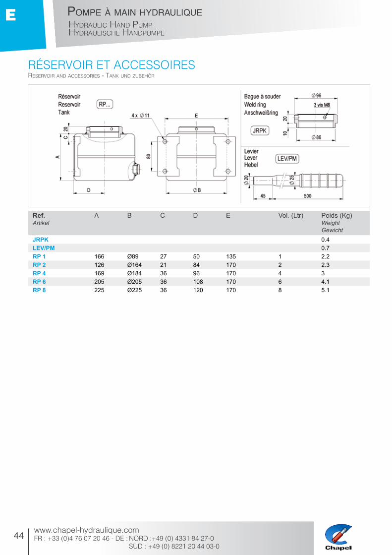
RéSERVOiR Et accESSOiRESreServoir and acceSSorieS - tank und zubeHör
Ref. Artikel
A B C D E Vol. (Ltr) Poids (Kg)Weight Gewicht
JRPK 0.4LEV/PM 0.7RP 1 166 Ø89 27 50 135 1 2.2RP 2 126 Ø164 21 84 170 2 2.3RP 4 169 Ø184 36 96 170 4 3RP 6 205 Ø205 36 108 170 6 4.1RP 8 225 Ø225 36 120 170 8 5.1

45
pompe à main hydrauliqueHydraulic Hand puMp
HydrauliScHe HandpuMpe
www.chapel-hydraulique.comFR : +33 (0)4 76 07 20 46 - DE : NORD : +49 (0) 4331 84 27-0
SÜD : +49 (0) 8221 20 44 03-0
E
pOmpE à maiN SimplE EFFEt + RéSERVOiR plaStiquESingle-acting Hand puMp + plaStic reServoir - einfacHwirkende HandpuMpe + kunStStofftank
Ref. Artikel
A B T Vol. (cm3) Poids (Kg)WeightGewicht
Pression maxMax pressureMax Druck
PE16S Ø16 17 3.2 200 barsPE20S Ø20 25 3.2 150 barsPE25S Ø25 35 3.2 100 barsRP1P 134 Ø100 1.2 Litres 0.2RP4P 198 Ø196 4 Litres 0.5
Réservoir plastique RP4P: Montage verticalPlastic reservoir RP4P: Vertical mountingKunststofftank RP4P: Vertikaler Einbau
NEw DESigN : SEptEmbER 2013
46
pompe à main hydrauliqueHydraulic Hand puMpHydrauliScHe HandpuMpe
www.chapel-hydraulique.comFR : +33 (0)4 76 07 20 46 - DE : NORD :+49 (0) 4331 84 27-0 SÜD : +49 (0) 8221 20 44 03-0
E
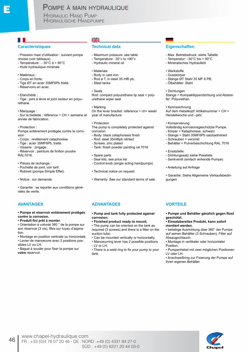
Caractéristiques
- Pression maxi d’utilisation : suivant pompe choisie (voir tableaux) - Température : - 30°C à + 90°C - Huile hydraulique minérale
• Matériaux : - Corps en fonte. - Tige ØT en acier 35MF6Pb traité. - Réservoirs en acier.
• Etanchéité : - Tige : joint à lèvre et joint racleur en polyu-réthane.
• Marquage : - Sur la biellette : référence + CH + semaine et année de fabrication.
• Protection : Pompe entièrement protégée contre la corro-sion : - Corps : revêtement cataphorèse. - Tige : acier 35MF6Pb, traité. - Visserie : zingage. - Réservoir : peinture de finition poudre RAL7016.
• Pièces de rechange : - Pochette de joint, voir tarif. - Robinet (pompe Simple Effet).
• Notice : sur demande.
• Garantie : se reporter aux conditions géné-rales de vente.
AVANTAGES
• Pompe et réservoir entièrement protégés contre la corrosion. • Produit fini prêt à monter. • Orientation à volonté 360 ° de la pompe sur son réservoir (3 vis), filtre sur tuyau d’aspira-tion. • Montage en position verticale ou horizontale. • Levier de manoeuvre avec 2 positions pos-sibles LV ou LH. • Bague à souder pour fixer la pompe sur votre réservoir.
Technical data
- Maximum pressure: see table - Temperature: -30°c to +90°c - Hydraulic mineral oil
• Materials - Body in cast iron - Rod ø T, in steel 35 mf6 pb, - Steel tanks
• Seals Rod: compact polyurethane lip seal + poly-urethane wiper seal
• Marking On the lever bracket: reference + ch+ week/year of manufacture
• Protection The pump is completely protected against corrosion - Body: black cataphoresis finish - Rod: steel 35mf6pb nitrited - Screws: zinc plated - Tank: finish powder painting ral 7016
• Spare parts - Seal kits, see price list - Control knob (single acting handpumps)
• Technical notice on request
• Warranty: See our standard terms of sale
ADVANTAGES
• Pump and tank fully protected against corrosion; • Finished product ready to mount; • The pump can be oriented on the tank as required (3 screws) and there is a filter on the suction tube; • Can be mounted vertically or horizontally; • Manoeuvring lever has 2 possible positions - LV or LH; • There is a weld ring to fix your pump to your tank.
Eigenschaften
- Max. Betriebsdruck: siehe Tabelle - Temperatur: –30°C bis + 90°C - Mineralisches Hydrauliköl
• Werkstoffe - Gusskörper - Stange ØT Stahl 35 MF 6 PB, - Ölbehälter: Stahl
• Dichtungen Stange = Kompaktlippendichtung und Abstrei-fer: Polyurethan
• Kennzeichnung Auf dem Hebelkopf: Artikelnummer + CH + Herstellwoche und –jahr.
• Konservierung Vollständig korrosionsgeschützte Pumpe. - Körper = Kataphorese, schwarz - Stange = Stahl 35MF6Pb salzbadnitriert - Schrauben = verzinkt - Behälter = Pulverbeschichtung RAL 7016
• Ersatzteile: - Dichtungssatz siehe Preisliste - Senkventil (einfach wirkende Pumpe)
• Anleitung auf Anfrage
• Garantie: Siehe Allgemeine Verkaufsbedin-gungen
VORTEILE
• Pumpe und Behälter gänzlich gegen Rost geschützt. • Einsatzbereites Produkt, kann sofort montiert werden. • beliebige Ausrichtung über 360° der Pumpe auf seinen Behälter (3 Schrauben), Filter auf Absaugschlauch. • Montage in vertikaler oder horizontaler Position. • Pumpenhebel mit zwei möglichen Positionen LV oder LH. • Anschweißring zur Fixierung der Pumpe auf Ihren eigenen Behälter.

F
47
/ Hy
dr
au
lic c
ylin
de
r c
ru
tc
H / H
yd
ra
uliS
cH
er
St
üt
zz
ylin
de
rV
ér
in h
yd
ra
uliq
ue
b
éq
uille
Vérin Hydraulique béquilleHydraulic cylinder crutcH
HydrauliScHer Stützzylinder
www.chapel-hydraulique.com

48
Vérin hydraulique béquilleHydraulic cylinder crutcHHydrauliScHer Stützzylinder
www.chapel-hydraulique.comFR : +33 (0)4 76 07 20 46 - DE : NORD :+49 (0) 4331 84 27-0 SÜD : +49 (0) 8221 20 44 03-0
F
béquillE hyDRauliquE DE FlèchEHydraulic crutcH - HydrauliScHer Stützzylinder
Ref. Artikel
Z CourseStrokeHub
D E F T Vol. (Ltr) Poids (Kg)WeightGewicht
101.BZ 190 135 390 90 Ø68 1.5 14.2101.BZNU 190 135 368 90 Ø68 1.5 12101.BZSV 190 135 390 90 Ø68 1.5 14100.BG 230 140 440 109 Ø91 3.4 17100.BGNU 230 140 418 109 Ø91 3.4 14.8100.BGSV 230 140 440 109 Ø91 3.4 16.7107.B 250 178 438 126 Ø107 4.3 25
chapEyoke - befeStigung
Non disponible pour 107.B / Not available for 107.B / Nicht verfügbar für 107.B
Ref. Artikel
A G H I J K
CH.B 90 140 31 146 122 8CH.B2 90 140 31 146 122 8

49
Vérin hydraulique béquilleHydraulic cylinder crutcH
HydrauliScHer Stützzylinder
www.chapel-hydraulique.comFR : +33 (0)4 76 07 20 46 - DE : NORD : +49 (0) 4331 84 27-0
SÜD : +49 (0) 8221 20 44 03-0
F
Caractéristiques
- Vérin simple effet avec rappel par ressort qui a pour usage principal le support de flèche. - Pression d’utilisation maxi : 200 bars - Vitesse maxi : 0,2 m / seconde - Température : – 30°C à + 90°C - Huile hydraulique minérale
• Matériaux : - Tige : tube sans soudure NFA 49 311, usiné, rectifié, traité et poli Ra < 0,4 µ. - Tube : tube sans soudure NFA49 311. - Fond : fonte GS.
• Etanchéité : - Tige : joint à lèvre compact et joint racleur en polyuréthane.
• Marquage : - Sur le tube ou fond : référence + CH + se-maine et année de fabrication.
• Essai : par prélèvement.
• Protection : - Corps : Zingage - Semelle : Revêtement cataphorèse - Axes : Zingage
Recommandations
- Vérifier l’état de pureté du fluide (corps étran-gers). - Alimenter la béquille par une pompe à main en direct. - Pour un bon fonctionnement du système auto block, faire un graissage régulier.
• Soudure : ne pas souder sur le corps, la tige, et le fond, pour un bon fonctionnement du rappel par ressort.
• Stockage : pour un stockage prolongé aux intempéries, la tige doit être en position ren-trée ou graissée.
• Pièces de rechange : - Pochette de joints, voir tarif. - Fond.
• Notice : sur demande.
• Garantie : se reporter aux conditions géné-rales de vente.
• Béquille entièrement protégée contre la corrosion. • Produit fini prêt à monter.
Technical data
- Single acting cylinder with spring return / main application is for hitch / stabilizer legs. - Maximum pressure: 200 bars - Maximum speed: 0,2 m/s - Temperature: -30°c to +90°c - Hydraulic mineral oil
• Materials - Rod: seamless tube nfa49311, machined, ground, nitrited and polished ra<0.4 - Tube: seamless tube nfa49311 - Cylinder bottom: cast iron ggg
• Seals - Rod: compact polyurethane lip seal - polyurethane wiper
• Marking On bottom or cylinder tube: reference + ch + week/year of manufacture
• Testing: by pick up
• Protection - Outside tube: zinc plated - Cylinder foot: cataphoresis - Spindles: zinc plated
Recommendations
- Check the oil cleanness - Use a handpump to feed the cylinder crutch - To ensure good operation of the autoblock system, grease regularly • Welding Do not weld on the tube, rod and bottom • Storing For a long storage in bad weather, the rod must be retracted and greased
• Spare parts - Seal kit, see price list. - Cyilinder head
• Technical notice on request
• Warranty: see our standard terms of sale
• Hydraulic crutch fully protected against corrosion. • Finished product ready to mount.
Eigenschaften
- Einfach wirkender Zylinder mit Rückholfeder zur Abstützung der Deichsel. - Max. Betriebsdruck: 200 bar - Max. Hubgeschwindigkeit 0,2 m/s - Temperatur: –30°C bis + 90°C - Mineralisches Hydrauliköl
• Werkstoffe - Stange: nahtloses, bearbeitetes, geschlif-fenes, salzbadnitriertes und poliertes Rohr NFA 49311 Ra <0,4 µ - Rohr: nahtloses Rohr NFA49 311 - Boden: Sphäroguss GS
• Dichtungen - Stange: Kompaktlippendichtung: Polyurethan - Abstreifer: Polyurethan
• Kennzeichnung Auf Boden oder Rohr Artikelnummer + CH + Herstellwoche und –jahr.
• Kontrolle mittels Proben
• Konservierung - Außenrohr: verzinkt - Fuß: Kataphorese - Achsen: verzinkt
Empfehlungen
- Sauberkeit des Öls kontrollieren - Stützzylinder direkt mit Handpumpe versor-gen - Zur einwandfreien Funktion des Autoblock-systems dieses regelmäßig schmieren.
• Schweißarbeiten Keine Schweißarbeiten am Rohr, der Stange oder dem Boden vornehmen, um die einwand-freie Funktion der Rückholfeder zu garantieren
• Lagerung Bei längerer Lagerung muss zum Schutz vor Witterungseinflüssen die Stange eingefahren oder gefettet sein.
• Ersatzteile - Dichtungssatz siehe Preisliste - Boden
• Anleitung auf Anfrage
• Garantie: Siehe Allgemeine Verkaufsbedin-gungen
• Stützzylinder gänzlich gegen Rost geschützt. • Einsatzbereites Produkt, kann sofort montiert werden.

G
51
/ Hy
dr
au
lic b
ra
ke
cy
lind
er
/ br
em
Sz
ylin
de
rV
ér
in h
yd
ra
uliq
ue
fr
ein
ag
eVérin Hydraulique freinageHydraulic brake cylinder
bremSzylinder
www.chapel-hydraulique.com
52
Vérin hydraulique de freinageHydraulic brake cylinderbreMSzylinder
www.chapel-hydraulique.comFR : +33 (0)4 76 07 20 46 - DE : NORD :+49 (0) 4331 84 27-0 SÜD : +49 (0) 8221 20 44 03-0
G
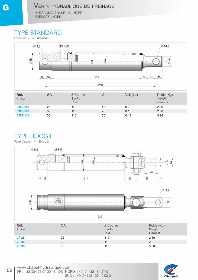
typE StaNDaRDStandard - typ Standard
Ref. Artikel
ØA Z CourseStrokeHub
G Vol. (Ltr) Poids (Kg)Weight Gewicht
625F/110 25 110 45 0.08 2.20630F/110 30 110 45 0.10 2.68635F/110 35 110 50 0.13 3.26
Ref. Artikel
ØA Z CourseStrokeHub
Poids (Kg)Weight Gewicht
VF 25 25 110 2.50VF 30 30 110 2.97VF 35 35 110 3.56
typE bOOgiEwitH cleviS - typ boogie

53
Vérin hydraulique de freinageHydraulic brake cylinder
breMSzylinder
www.chapel-hydraulique.comFR : +33 (0)4 76 07 20 46 - DE : NORD : +49 (0) 4331 84 27-0
SÜD : +49 (0) 8221 20 44 03-0
G
typE palONNiERwitH Spring MecHaniSM - typ palonnier
Ref. Artikel
ØA Z CourseStrokeHub
Poids (Kg)Weight Gewicht
VFP 25 25 110 4.47VFP 30 30 110 4.93VFP 35 35 110 5.5
54
Vérin hydraulique de freinageHydraulic brake cylinderbreMSzylinder
www.chapel-hydraulique.comFR : +33 (0)4 76 07 20 46 - DE : NORD :+49 (0) 4331 84 27-0 SÜD : +49 (0) 8221 20 44 03-0
G
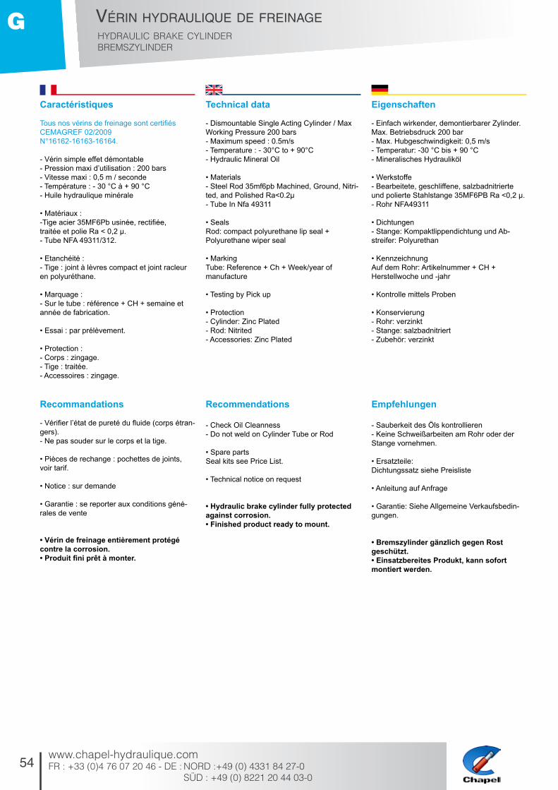
Caractéristiques
Tous nos vérins de freinage sont certifiés CEMAGREF 02/2009N°16162-16163-16164.
- Vérin simple effet démontable- Pression maxi d’utilisation : 200 bars- Vitesse maxi : 0,5 m / seconde- Température : - 30 °C à + 90 °C- Huile hydraulique minérale
• Matériaux :-Tige acier 35MF6Pb usinée, rectifiée, traitée et polie Ra < 0,2 µ.- Tube NFA 49311/312.
• Etanchéité :- Tige : joint à lèvres compact et joint racleur en polyuréthane.
• Marquage :- Sur le tube : référence + CH + semaine et année de fabrication.
• Essai : par prélèvement.
• Protection :- Corps : zingage.- Tige : traitée.- Accessoires : zingage.
Recommandations
- Vérifier l’état de pureté du fluide (corps étran-gers).- Ne pas souder sur le corps et la tige.
• Pièces de rechange : pochettes de joints, voir tarif.
• Notice : sur demande
• Garantie : se reporter aux conditions géné-rales de vente
• Vérin de freinage entièrement protégé contre la corrosion.• Produit fini prêt à monter.
Technical data
- Dismountable Single Acting Cylinder / Max Working Pressure 200 bars- Maximum speed : 0.5m/s- Temperature : - 30°C to + 90°C- Hydraulic Mineral Oil
• Materials- Steel Rod 35mf6pb Machined, Ground, Nitri-ted, and Polished Ra<0.2µ- Tube In Nfa 49311
• SealsRod: compact polyurethane lip seal + Polyurethane wiper seal
• MarkingTube: Reference + Ch + Week/year of manufacture
• Testing by Pick up
• Protection- Cylinder: Zinc Plated- Rod: Nitrited- Accessories: Zinc Plated
Recommendations
- Check Oil Cleanness- Do not weld on Cylinder Tube or Rod
• Spare partsSeal kits see Price List.
• Technical notice on request
• Hydraulic brake cylinder fully protected against corrosion.• Finished product ready to mount.
Eigenschaften
- Einfach wirkender, demontierbarer Zylinder. Max. Betriebsdruck 200 bar- Max. Hubgeschwindigkeit: 0,5 m/s- Temperatur: -30 °C bis + 90 °C- Mineralisches Hydrauliköl
• Werkstoffe- Bearbeitete, geschliffene, salzbadnitrierte und polierte Stahlstange 35MF6PB Ra <0,2 µ.- Rohr NFA49311
• Dichtungen- Stange: Kompaktlippendichtung und Ab- streifer: Polyurethan
• KennzeichnungAuf dem Rohr: Artikelnummer + CH + Herstellwoche und -jahr
• Kontrolle mittels Proben
• Konservierung- Rohr: verzinkt- Stange: salzbadnitriert- Zubehör: verzinkt
Empfehlungen
- Sauberkeit des Öls kontrollieren- Keine Schweißarbeiten am Rohr oder der Stange vornehmen.
• Ersatzteile: Dichtungssatz siehe Preisliste
• Anleitung auf Anfrage
• Garantie: Siehe Allgemeine Verkaufsbedin-gungen.
• Bremszylinder gänzlich gegen Rost geschützt.• Einsatzbereites Produkt, kann sofort montiert werden.
H
55
/ te
leS
co
pic
Hy
dr
au
lic c
ylin
de
r f
or
tip
pe
r
Hy
dr
au
liSc
He
r t
ele
Sk
op
zy
lind
er
fü
r k
ipp
er
Vé
rin
hy
dr
au
liqu
e té
les
co
piq
ue
po
ur
be
nn
e b
as
cu
lan
te
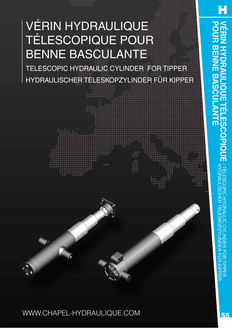
Vérin Hydraulique téleScopique pour benne baSculanteteleScopic Hydraulic cylinder for tipper
HydrauliScHer teleSkopzylinder für kipper
www.chapel-hydraulique.com

56
Vérin hydraulique télescopiqueteleScopic Hydraulic cylinderHydrauliScHer teleSkopzylinder
www.chapel-hydraulique.comFR : +33 (0)4 76 07 20 46 - DE : NORD :+49 (0) 4331 84 27-0 SÜD : +49 (0) 8221 20 44 03-0
H
StaNDaRD - pOuR bENNE baSculaNtEStandard - for kipper - Standard - für kipper
Ref. Artikel
H I B ØT1 ØT2 ØT3 ØT4 ØT5 Z course StrokeHub
A B C D E F F’ G M Vol. (Ltr)
Poids (Kg)Weight Gewicht
OptionCradle n°
294 100 283 45 61 390 26 25 98 25 293 30 25 80 16x1.5 1.0 10.4 00295 100 338 45 61 500 26 25 98 25 348 30 25 80 16x1.5 1.3 12.3 00296 107 399 45 61 620 26 40 100 40 409 30 25 80 1/2 1.6 15.1 0297 100 439 45 61 700 26 40 100 40 449 30 25 80 1/2 2.0 16.3 0298 107 499 45 61 820 26 40 100 40 509 30 25 80 1/2 2.1 18.2 0201 107 396 61 76 595 31 45 115 45 406 30 25 95 1/2 2.5 23 1202 107 496 61 76 795 26 45 115 45 506 30 25 95 1/2 3.3 26 1203 107 589 68 88 950 36 45 128 45 594 40 30 108 1/2 5.1 40 1204 107 584 88 107 930 36 45 148 45 589 40 30 128 1/2 7.8 41 2305 110 283 45 61 76 570 26 45 115 45 293 30 25 95 1/2 1.9 15.4 1306 110 399 45 61 76 910 26 45 115 45 409 30 25 95 1/2 3.1 20.8 1307 110 200 391 61 76 91 875 31 45 128 45 406 30 25 108 1/2 4.5 26 1308 110 200 454 61 76 91 1060 36 45 128 45 469 30 30 108 1/2 5.5 30.1 1310 110 413 68 88 107 895 36 45 148 45 418 40 30 128 1/2 6.2 37 2311 110 200 502 68 88 107 1160 36 45 148 45 507 40 30 128 1/2 8.0 45 2312 110 200 548 68 88 107 1300 36 45 148 45 553 40 30 128 1/2 9.0 49 2313 110 200 540 88 107 126 1260 36 45 170 45 545 40 30 150 1/2 12.6 55 3314 110 200 494 88 107 126 1125 36 45 170 45 499 40 30 150 1/2 11.2 52 3315 110 200 579 88 107 126 1380 36 45 170 45 584 40 30 150 1/2 13.8 58 3316 110 200 88 107 126 1710 45 45 170 45 694 50 35 150 1/2 17.0 72 3317 200 107 126 147 1670 45 50 198 50 699 50 35 178 1/2 23.2 99 4445 113 203 394 45 61 76 91 1190 26 45 128 45 409 30 25 108 1/2 5.0 25 1447 113 209 449 61 76 91 107 1380 36 45 148 45 464 30 30 128 1/2 8.4 40 2419 113 203 497 68 88 107 126 1520 36 45 170 45 502 40 30 150 1/2 12.9 61 3420 113 203 543 68 88 107 126 1705 36 45 170 45 548 40 30 150 1/2 14.5 64 3421 113 203 582 68 88 107 126 1860 36 45 170 45 587 40 35 150 1/2 15.8 71 3451 113 203 68 88 107 126 2305 36 45 170 45 697 50 35 150 1/2 19.7 81 3422 203 494 88 107 126 147 1470 45 50 198 50 507 50 35 178 1/2 17.6 77 4423 203 579 88 107 126 147 1810 45 50 198 50 592 50 35 178 1/2 21.7 88 4424 203 88 107 126 147 2250 45 50 198 50 702 50 35 178 1/2 27.0 103 4425 203 107 126 147 170 2200 45 50 238 50 702 50 35 204 1/2 36.0 134 5426 203 107 126 147 170 1760 45 50 238 50 592 50 35 204 1/2 29.5 116 5429 203 107 126 147 170 2590 45 50 238 50 802 50 35 204 1/2 46.0 130 5434 203 107 126 147 170 2780 45 50 238 50 849 50 35 204 1/2 48.5 160 5525 206 88 107 126 147 170 1805 45 50 238 50 510 50 35 204 1/2 25.8 104 5526 206 88 107 126 147 170 2230 45 50 238 50 595 50 35 204 1/2 31.9 120 5527 206 88 107 126 147 170 2780 45 50 238 50 705 50 35 204 1/2 39.9 140 5528 206 88 107 126 147 170 2035 45 50 238 50 556 50 35 204 1/2 29.0 111 5540 206 88 107 126 147 170 2470 45 50 238 50 643 50 35 204 1/2 36.0 130 5
57
Vérin hydraulique télescopiqueteleScopic Hydraulic cylinder
HydrauliScHer teleSkopzylinder
www.chapel-hydraulique.comFR : +33 (0)4 76 07 20 46 - DE : NORD : +49 (0) 4331 84 27-0
SÜD : +49 (0) 8221 20 44 03-0
H
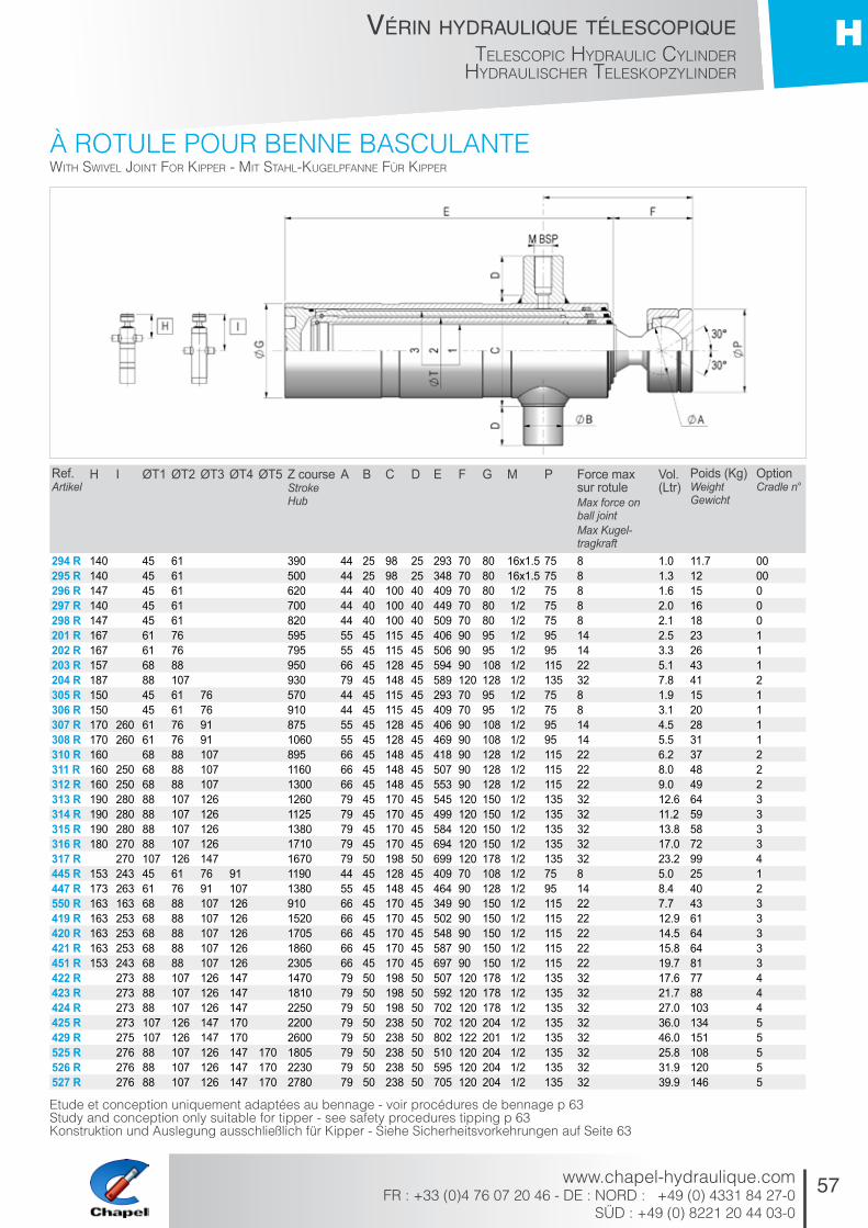
à ROtulE pOuR bENNE baSculaNtEwitH Swivel joint for kipper - Mit StaHl-kugelpfanne für kipper
Etude et conception uniquement adaptées au bennage - voir procédures de bennage p 63Study and conception only suitable for tipper - see safety procedures tipping p 63Konstruktion und auslegung ausschließlich für Kipper - Siehe Sicherheitsvorkehrungen auf Seite 63
Ref. Artikel
H I ØT1 ØT2 ØT3 ØT4 ØT5 Z course StrokeHub
A B C D E F G M P Force max sur rotuleMax force on ball jointMax Kugel- tragkraft
Vol. (Ltr)
Poids (Kg)Weight Gewicht
OptionCradle n°
294 R 140 45 61 390 44 25 98 25 293 70 80 16x1.5 75 8 1.0 11.7 00295 R 140 45 61 500 44 25 98 25 348 70 80 16x1.5 75 8 1.3 12 00296 R 147 45 61 620 44 40 100 40 409 70 80 1/2 75 8 1.6 15 0297 R 140 45 61 700 44 40 100 40 449 70 80 1/2 75 8 2.0 16 0298 R 147 45 61 820 44 40 100 40 509 70 80 1/2 75 8 2.1 18 0201 R 167 61 76 595 55 45 115 45 406 90 95 1/2 95 14 2.5 23 1202 R 167 61 76 795 55 45 115 45 506 90 95 1/2 95 14 3.3 26 1203 R 157 68 88 950 66 45 128 45 594 90 108 1/2 115 22 5.1 43 1204 R 187 88 107 930 79 45 148 45 589 120 128 1/2 135 32 7.8 41 2305 R 150 45 61 76 570 44 45 115 45 293 70 95 1/2 75 8 1.9 15 1306 R 150 45 61 76 910 44 45 115 45 409 70 95 1/2 75 8 3.1 20 1307 R 170 260 61 76 91 875 55 45 128 45 406 90 108 1/2 95 14 4.5 28 1308 R 170 260 61 76 91 1060 55 45 128 45 469 90 108 1/2 95 14 5.5 31 1310 R 160 68 88 107 895 66 45 148 45 418 90 128 1/2 115 22 6.2 37 2311 R 160 250 68 88 107 1160 66 45 148 45 507 90 128 1/2 115 22 8.0 48 2312 R 160 250 68 88 107 1300 66 45 148 45 553 90 128 1/2 115 22 9.0 49 2313 R 190 280 88 107 126 1260 79 45 170 45 545 120 150 1/2 135 32 12.6 64 3314 R 190 280 88 107 126 1125 79 45 170 45 499 120 150 1/2 135 32 11.2 59 3315 R 190 280 88 107 126 1380 79 45 170 45 584 120 150 1/2 135 32 13.8 58 3316 R 180 270 88 107 126 1710 79 45 170 45 694 120 150 1/2 135 32 17.0 72 3317 R 270 107 126 147 1670 79 50 198 50 699 120 178 1/2 135 32 23.2 99 4445 R 153 243 45 61 76 91 1190 44 45 128 45 409 70 108 1/2 75 8 5.0 25 1447 R 173 263 61 76 91 107 1380 55 45 148 45 464 90 128 1/2 95 14 8.4 40 2550 R 163 163 68 88 107 126 910 66 45 170 45 349 90 150 1/2 115 22 7.7 43 3419 R 163 253 68 88 107 126 1520 66 45 170 45 502 90 150 1/2 115 22 12.9 61 3420 R 163 253 68 88 107 126 1705 66 45 170 45 548 90 150 1/2 115 22 14.5 64 3421 R 163 253 68 88 107 126 1860 66 45 170 45 587 90 150 1/2 115 22 15.8 64 3451 R 153 243 68 88 107 126 2305 66 45 170 45 697 90 150 1/2 115 22 19.7 81 3422 R 273 88 107 126 147 1470 79 50 198 50 507 120 178 1/2 135 32 17.6 77 4423 R 273 88 107 126 147 1810 79 50 198 50 592 120 178 1/2 135 32 21.7 88 4424 R 273 88 107 126 147 2250 79 50 198 50 702 120 178 1/2 135 32 27.0 103 4425 R 273 107 126 147 170 2200 79 50 238 50 702 120 204 1/2 135 32 36.0 134 5429 R 275 107 126 147 170 2600 79 50 238 50 802 122 201 1/2 135 32 46.0 151 5525 R 276 88 107 126 147 170 1805 79 50 238 50 510 120 204 1/2 135 32 25.8 108 5526 R 276 88 107 126 147 170 2230 79 50 238 50 595 120 204 1/2 135 32 31.9 120 5527 R 276 88 107 126 147 170 2780 79 50 238 50 705 120 204 1/2 135 32 39.9 146 5

58
Vérin hydraulique télescopiqueteleScopic Hydraulic cylinderHydrauliScHer teleSkopzylinder
www.chapel-hydraulique.comFR : +33 (0)4 76 07 20 46 - DE : NORD :+49 (0) 4331 84 27-0 SÜD : +49 (0) 8221 20 44 03-0
H
aVEc ROtulE EN FONtE gS pOuR bENNE baSculaNtEwitH ductile iron Swivel joint for kipper - Mit kugelpfanne auS ggg-guSS für kipper
Ref. Artikel
ØT1 ØT2 ØT3 ØT4 ØT5 Z course StrokeHub
B C D E G Y Force max sur rotule (T)Max force on ball joint Max Kugeltragkraft
Vol. (Ltr)
Poids (Kg)Weight Gewicht
OptionCradle n°
3305 45 61 76 570 45 115 45 293 95 143 8 2.5 17 13395 45 61 76 730 40 128 40 348 95 180 8 3.0 19 13306 45 61 76 912 45 115 45 409 95 143 8 3.6 22 13397 45 61 76 1030 40 128 40 449 95 180 8 4.0 23 13405 45 61 76 91 726 40 128 40 293 108 146 8 3.1 19 13495 45 61 76 91 945 40 128 40 348 108 186 8 5.0 22 13445 45 61 76 91 1190 45 128 45 409 108 146 8 6.5 26 13585 45 61 76 91 107 875 45 148 45 288 128 186 8 5.2 26.5 23595 45 61 76 91 107 1150 45 148 45 343 128 186 8 7.7 30 23598 45 61 76 91 107 1475 45 148 45 424 128 139 8 9.9 34.5 2
59
Vérin hydraulique télescopiqueteleScopic Hydraulic cylinder
HydrauliScHer teleSkopzylinder
www.chapel-hydraulique.comFR : +33 (0)4 76 07 20 46 - DE : NORD : +49 (0) 4331 84 27-0
SÜD : +49 (0) 8221 20 44 03-0
H
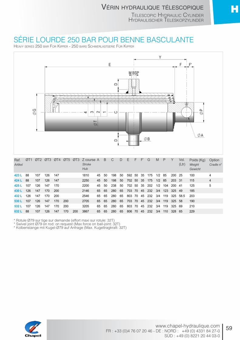
SéRiE lOuRDE 250 baR pOuR bENNE baSculaNtEHeavy SerieS 250 bar for kipper - 250 barS ScHwerlaStSerie für kipper
Ref. Artikel
ØT1 ØT2 ØT3 ØT4 ØT5 ØT3 Z course StrokeHub
A B C D E F F’ G M P Y Vol. (Ltr)
Poids (Kg)Weight Gewicht
OptionCradle n°
423 L 88 107 126 147 1810 45 50 198 50 592 50 35 175 1/2 85 200 25 100 4424 L 88 107 126 147 2250 45 50 198 50 702 50 35 175 1/2 85 203 31 115 4425 L 107 126 147 170 2200 45 50 238 50 702 50 35 202 1/2 104 200 41 125 5430 L 126 147 170 200 2146 65 65 280 65 703 70 45 232 3/4 123 325 49 185432 L 126 147 170 200 2546 65 65 280 65 803 70 45 232 3/4 119 325 58.5 203530 L 107 126 147 170 200 2705 65 65 280 65 703 70 45 232 3/4 119 325 58 190532 L 107 126 147 170 200 3205 65 65 280 65 803 70 45 232 3/4 119 325 69 210632 L 88 107 126 147 170 200 3867 65 65 280 65 806 70 45 232 3/4 110 328 65 229
* Rotule Ø79 sur tige sur demande (effort maxi sur rotule: 32t) * Swivel joint Ø79 on rod: on request (max force on ball-joint: 32t) * Kolbenstange mit Kugel-Ø79 auf anfrage (max. Kugeltragkraft: 32t)
60
Vérin hydraulique télescopiqueteleScopic Hydraulic cylinderHydrauliScHer teleSkopzylinder
www.chapel-hydraulique.comFR : +33 (0)4 76 07 20 46 - DE : NORD :+49 (0) 4331 84 27-0 SÜD : +49 (0) 8221 20 44 03-0
H
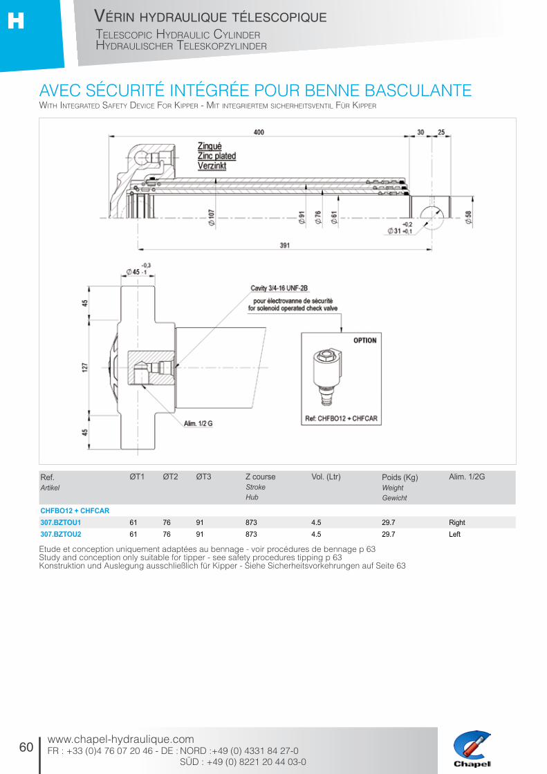
aVEc SécuRité iNtégRéE pOuR bENNE baSculaNtEwitH integrated Safety device for kipper - Mit integrierteM SicHerHeitSventil für kipper
Ref. Artikel
ØT1 ØT2 ØT3 Z course StrokeHub
Vol. (Ltr) Poids (Kg)Weight Gewicht
Alim. 1/2G
CHFBO12 + CHFCAR307.BZTOU1 61 76 91 873 4.5 29.7 Right307.BZTOU2 61 76 91 873 4.5 29.7 Left
Etude et conception uniquement adaptées au bennage - voir procédures de bennage p 63Study and conception only suitable for tipper - see safety procedures tipping p 63Konstruktion und auslegung ausschließlich für Kipper - Siehe Sicherheitsvorkehrungen auf Seite 63

61
Vérin hydraulique télescopiqueteleScopic Hydraulic cylinder
HydrauliScHer teleSkopzylinder
www.chapel-hydraulique.comFR : +33 (0)4 76 07 20 46 - DE : NORD : +49 (0) 4331 84 27-0
SÜD : +49 (0) 8221 20 44 03-0
H
Ref. Artikel
A B C D E F G Force max sur rotule (T)Max force on ball joint MaxKugeltragkraft
Poids (Kg)Weight Gewicht
ROT44 M+F 44 75 24 45 69 5 14 8 1.5ROT55 M+F 55 95 34 52 91 5 16 14 3ROT66 M+F 66 115 34 59 89 5 19 22 4ROT79 M+F 79 135 71 74 109 50 22 32 7
Ref. Artikel
A B C D E F Force max sur rotule (T)Max force on ball jointMaxKugeltragkraft
Poids (Kg)Weight Gewicht
BER.0 154 40 102 25 172 20 3 2.6BER.00 154 25 102 25 172 20 3 2.6BER.1 225 45 130 40 260 40 8 6.7BER.2 230 45 150 40 270 40 10 7.2BER.3 270 45 173 45 310 40 15 13.2BER.4 310 50 200 50 360 50 20 26.7BER.5 392 50 243 50 440 50 25 45
Ref. Artikel
A B M Poids (Kg)WeightGewicht
RAC/T 17 11 1/2 0.18RAC/T 13 13 8 1/2 0.18RAC/T 16 16 11 1/2 0.18RAC/T 21 21 13.5 1/2 0.28RAC/T 27 27 16 3/4 0.55
accESSOiRES
ROtulES à SOuDER
bERcEaux
RaccORD tOuRNaNt
acceSSorieS - zubeHör
weld-on Swivel jointS - anScHweißbare kugelgelköpfe
cradleS - kardanringe
Swivel fitting - dreHverScHraubung
62
Vérin hydraulique télescopiqueteleScopic Hydraulic cylinderHydrauliScHer teleSkopzylinder
www.chapel-hydraulique.comFR : +33 (0)4 76 07 20 46 - DE : NORD :+49 (0) 4331 84 27-0 SÜD : +49 (0) 8221 20 44 03-0
H
Ref. Artikel
A B C D E F G H K Poids (Kg)Weight Gewicht
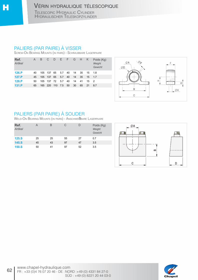
126.P 40 105 137 65 5.7 40 14 35 15 1.8127.P 45 105 137 65 5.7 40 14 35 15 1.7128.P 50 105 137 72 5.7 40 14 41 15 2131.P 65 165 220 110 7.5 50 30 65 21 8.7
Ref. Artikel
A B C D Poids (Kg)Weight Gewicht
125.S 25 25 55 27 0.7145.S 45 43 97 47 3.5150.S 50 41 97 52 3.5
paliERS (paR paiRE) à ViSSER
paliERS (paR paiRE) à SOuDER
Screw-on bearing MountS (in pairS) - ScHraubbare lagerpaare
weld-on bearing MountS (in pairS) - anScHweißbare lagerpaare
63
Vérin hydraulique télescopiqueteleScopic Hydraulic cylinder
HydrauliScHer teleSkopzylinder
www.chapel-hydraulique.comFR : +33 (0)4 76 07 20 46 - DE : NORD : +49 (0) 4331 84 27-0
SÜD : +49 (0) 8221 20 44 03-0
H
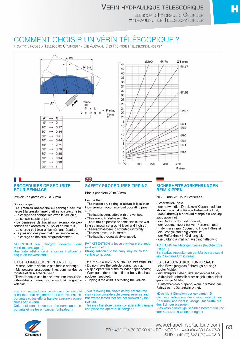
cOmmENt chOiSiR uN VéRiN téléScOpiquE ?How to cHooSe a teleScopic cylinder? - die auSwaHl deS ricHtigen teleSkopzylinderS?
PROCEDURES DE SECURITE POUR BENNAGE Prévoir une garde de 20 à 30mm
S’assurer que : - La pression nécessaire au bennage soit infé-rieure à la pression maxi d’utilisation préconisée,- La charge soit compatible avec le véhicule, - Le sol soit stable et plat, - Le périmètre de travail soit exempt de per-sonnes et d’obstacles (au sol et en hauteur), - La charge soit bien uniformément répartie, - La pression des pneumatiques soit correcte, - La charge se déverse progressivement.
ATTENTION aux charges collantes (terre mouillée, ensilage...) Une forte adhérence à la caisse implique un risque de renversement.
IL EST FORMELLEMENT INTERDIT DE : - Manoeuvrer le véhicule pendant le bennage, - Manoeuvrer brusquement les commandes de montée et descente du vérin, - Travailler sous une benne levée non sécurisée, - Procéder au bennage si le vent fait tanguer le véhicule.
«Le non respect des procédures de sécurité ci-dessus peut engendrer des surpressions im-portantes et des efforts transversaux non admis-sibles par le vérin. Cela peut donc provoquer des dommages im-portants et mettre en danger l’utilisateur.»
SAFETY PROCEDURES TIPPING Plan a gap from 20 to 30mm
Ensure that - The necessary tipping pressure is less than the maximum recommended operating pres-sure; - The load is compatible with the vehicle; - The ground is stable and flat; - There are no people or obstacles in the wor-king perimeter (at ground level and high up), - The load has been distributed uniformly; - The tyre pressure is correct; - The load is progressively emptied.
PAY ATTENTION to loads sticking in the body (wet earth, etc...) Strong adhesion to the body may cause the vehicle to tip over.
THE FOLLOWING IS STRICTLY PROHIBITED: - Do not move the vehicle during tipping; - Rapid operation of the cylinder tipper control; - Working under a raised tipper body that has not been secured; - Tipping if the wind is buffeting the vehicle.
«Not following the above safety procedures may cause considerable over-pressures and transverse forces that are not allowed by the cylinder. This may therefore cause considerable damage and place the operator in danger.»
SICHERHEITSVORKEHRUNGEN BEIM KIPPEN20 - 30 mm «Nullhub» vorsehen
Sicherstellen, dass - der notwendige Druck zum Kippen niedriger als der maximal zulässige Betriebsdruck ist, - das Fahrzeug für Art und Menge der Ladung zugelassen ist. - der Boden stabil und eben ist, - der Arbeitsumkreis frei von Personen und Hindernissen (am Boden und in der Höhe) ist. - die Last gleichmäßig verteilt ist, - der Reifendruck in Ordnung ist, - die Ladung allmählich ausgeschüttet wird.
ACHTUNG bei klebrigen Lasten (feuchte Erde, Silage...) Ein starkes Anbacken an der Mulde verursacht ein Risiko des Umstürzens.
ES IST AUSDRÜCKLICH UNTERSAGT: - eine Bewegung des Fahrzeugs bei ange-kippter Mulde, - ein abruptes Heben und Senken der Mulde, - Aufenthalt unterhalb einer angekippten, nicht gesicherten Mulde, - Fortsetzen des Kippens, wenn der Wind das Fahrzeug ins Schaukeln bringt.
«Das Nicht-Einhalten der genannten Si-cherheitsmaßnahmen kann einen erheblichen Überdruck und nicht zulässige Querkräfte auf den Zylinder erzeugen. Dies kann gewichtige Schäden hervorrufen und den Benutzer in Gefahr bringen»

64
Vérin hydraulique télescopiqueteleScopic Hydraulic cylinderHydrauliScHer teleSkopzylinder
www.chapel-hydraulique.comFR : +33 (0)4 76 07 20 46 - DE : NORD :+49 (0) 4331 84 27-0 SÜD : +49 (0) 8221 20 44 03-0
H
Caractéristiques
L’étude, la conception, et les caractéristiques sont uniquement adaptées au basculement de bennes.
- Pression maxi d’utilisation : 200 bars - Pression d’épreuve : 300 bars - Vitesse maxi : 0,2 m / seconde - Température : - 30 °C à + 90 °C - Huile hydraulique minérale
• Matériaux : - Tube sans soudure NFA 49311/312 usiné, rectifié, traité et poli Ra < 0,4 µ. - Rond C35R usiné, rectifié, traité et poli Ra < 0,4 µ. - Nitruration de toutes les pièces (sauf le fond).
• Etanchéité : - Tige : joint à lèvres compact et joint racleur en polyuréthane. - Fond : joint torique 80 shore + bague anti-extrusion ou joint statique.
• Marquage : - Sur le tube ou fond : référence + CH + se-maine et année de fabrication.
• Essai : par prélèvement.
Recommandations- Protection du circuit hydraulique par un limiteur de pression, un filtre. - Vérifier l’état de pureté du fluide (corps étran-gers). - Penser à purger les vérins et le circuit hydraulique. - Ne pas souder sur le vérin. - Le vérin ne doit en aucun cas servir de butée mécanique. - La caisse en position route ne doit jamais appuyer sur le vérin (garde > 20mm).
• Stockage - Vérin avec tige sortie en stockage : prévoir impérativement un graissage. - Pour le nettoyage vapeur haute pression : prévoir une protection de la tige.
• Pièces de rechange : pochettes de joints, voir tarif.
• Notice : sur demande
• Garantie : se reporter aux conditions géné-rales de vente
La fonction normale d’un vérin télescopique CHAPEL consiste à lever régulièrement une benne basculante pour déverser progressive-ment la charge sur toute sa course en respec-tant les conditions d’utilisation et de sécurité.
Un vérin est uniquement un instrument de levage, il ne peut en aucun cas assurer la stabilisation ou le guidage de la benne.
Lors du choix du vérin, le poids C est égal au poids de la caisse ajouté au poids de la charge.
Technical data
The study, the conception and the technical specifications are only suitable for tippers
- Max pressure : 200 bars - Proof pressure : 300 bars - Maximum speed : 0.2m/s - Temperature : - 30°C to + 90°C - Hydraulic mineral oil
• Materials - Seamless tube NFA 49311/312 tube machined, ground, treated and polished Ra<0.4µ - Round bar Steel C35R, machined, ground and polished Ra<0.4µ - Each component is nitrited (except cylinder bottom)
• Seals - Rod: compact polyurethane lip seal + 1 poly-urethane wiper seal - Cylinder bottom: O RING 80 shore + back up ring or static seal
• Marking On the tube or bottom: REFERENCE + CH + WEEK/YEAR of manufacture
• Testing by “pick up”
Recommendations- Protect the hydraulic circuit by a relief valve and a filter; - Check the state of purity of the fluid (foreign bodies); - Remember to purge the cylinders and the hydraulic circuit; - Do not weld onto the cylinder; - Do not, under any circumstances, use the tipping system as a mechanical stop; - Never allow the body to lean against the cylin-der when in stowed position (gap > 20mm).
• Storage: - The cylinder rod must be greased before being stored; - Protect the cylinder shaft and trunnions during high pressure steam cleaning.
• Spare parts: joint pockets, see price list.
• Instructions: on request.
• Guarantee: please refer to the general sales conditions.
The normal operation of a CHAPEL telescopic cylinder consists in the regular lifting of a tipper body to progressively empty its load over its path, whilst respecting the operating and safety conditions.
A tipping system is solely a lifting device, it can-not, under any circumstances, stabilise or guide the tipper body.
On choosing a cylinder, the weight C is equal to the weight of the body added to the weight of the load.
Eigenschaften
Auslegung, Ausführung und Eigenschaften nur für Kipper.
- Max. Betriebsdruck: 200 bar - Prüfdruck: 300 bar - Max. Hubgeschwindigkeit: 0,2 m/s - Temperaturbereich: -30 °C bis + 90 °C - Mineralisches Hydrauliköl
• Werkstoffe - Nahtloses, bearbeitetes, geschliffenes, salz-badnitriertes und poliertes Rohr NFA 49311/312 Ra <0,4 µ - Bearbeiteter, geschliffener, salzbadnitrierter und polierter Rundstahl C35R Ra <0,4 µ - Salzbadnitrierung aller Teile (außer Boden)
• Dichtungen - Stange: Kompaktlippendichtung und Abstreifer: Polyurethan - Boden: O-Ring 80° Shore + Stützring oder JOP
• Kennzeichnung Auf Rohr oder Boden: Artikelnummer + CH + Herstellwoche und -jahr
• Kontrolle mittels Proben
Empfehlungen- Schutz des Ölkreislaufs durch einen Druckbe-grenzer und einen Filter. - Prüfung des Ölzustands (Fremdkörper). - Regelmäßige Ölwechsel durchführen. - Nicht auf dem Zylinder schweißen. - Der Zylinder darf nicht als mechanischer Anschlag dienen. - Der Aufbau darf niemals auf den Zylinder drücken («Nullhub» > 20mm).
• Lagerung: - dauerhaft ausgefahrene Ausschübe fetten. - «Nullhub» gegen Korrosion schützen (z. B. durch Küpferpaste) - Bei Reinigung mit Hochdruckreiniger die Ausschübe und Abstreifer schützen.
• Ersatzteile: Dichtsätze: siehe Preisliste.
• Anleitung auf Anfrage.
• Die Garantie s. allgemeine Verkaufbedingun-gen.
Die normale Funktion eines einfachwirkenden Teleskopzylinders besteht in Anheben eines Kippbehälters zur allmählichen Ausschüttung der Last auf seinem gesamten Hub unter Einhaltung der Gebrauchs- und Sicherheitsbes-timmungen.
Ein Kipperzylinder ist ein reines Hubinstrument. Es kann auf keinen Fall die Stabilität oder die Querkräfte der Fahrzeuges übernehmen.
Bei der Auswahl des Zylinders ist das Gewicht C das Gesamtgewicht der Behälters zuzüglich des Gewichtes der Ladung.

I
65
/ Hy
dr
au
lic t
ipp
er
Sy
St
em
/ kip
pm
ec
Ha
nik
en
co
mpa
s h
yd
ra
uliq
ue
d
e b
en
na
ge
compaS Hydraulique de bennageHydraulic tipper SyStem
kippmecHaniken
www.chapel-hydraulique.com
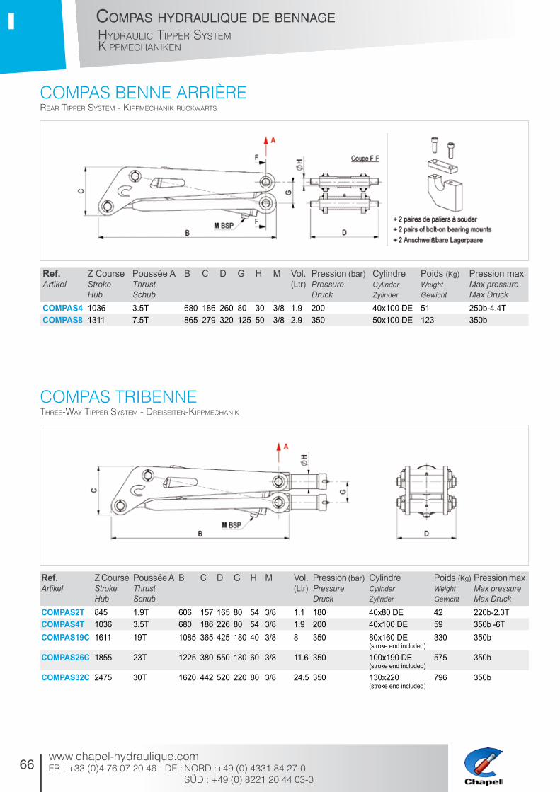
66
compas hydraulique de bennageHydraulic tipper SySteMkippMecHaniken
www.chapel-hydraulique.comFR : +33 (0)4 76 07 20 46 - DE : NORD :+49 (0) 4331 84 27-0 SÜD : +49 (0) 8221 20 44 03-0
I
cOmpaS bENNE aRRièRE
cOmpaS tRibENNE
rear tipper SySteM - kippMecHanik rückwartS
tHree-way tipper SySteM - dreiSeiten-kippMecHanik
Ref. Artikel
Z CourseStrokeHub
Poussée AThrust Schub
B C D G H M Vol. (Ltr)
Pression (bar)PressureDruck
CylindreCylinderZylinder
Poids (Kg)Weight Gewicht
Pression maxMax pressureMax Druck
COMPAS4 1036 3.5T 680 186 260 80 30 3/8 1.9 200 40x100 DE 51 250b-4.4TCOMPAS8 1311 7.5T 865 279 320 125 50 3/8 2.9 350 50x100 DE 123 350b
Ref. Artikel
Z CourseStrokeHub
Poussée AThrustSchub
B C D G H M Vol. (Ltr)
Pression (bar)Pressure Druck
CylindreCylinderZylinder
Poids (Kg)Weight Gewicht
Pression maxMax pressureMax Druck
COMPAS2T 845 1.9T 606 157 165 80 54 3/8 1.1 180 40x80 DE 42 220b-2.3TCOMPAS4T 1036 3.5T 680 186 226 80 54 3/8 1.9 200 40x100 DE 59 350b -6TCOMPAS19C 1611 19T 1085 365 425 180 40 3/8 8 350 80x160 DE
(stroke end included)330 350b
COMPAS26C 1855 23T 1225 380 550 180 60 3/8 11.6 350 100x190 DE (stroke end included)
575 350b
COMPAS32C 2475 30T 1620 442 520 220 80 3/8 24.5 350 130x220 (stroke end included)
796 350b

67
compas hydraulique de bennageHydraulic tipper SySteM
kippMecHaniken
www.chapel-hydraulique.comFR : +33 (0)4 76 07 20 46 - DE : NORD : +49 (0) 4331 84 27-0
SÜD : +49 (0) 8221 20 44 03-0
I
aNglES DE baSculEmENt EN FONctiON DE ltipping angleS depending on l - kippwinkel in abHängigkeit von l

68
compas hydraulique de bennageHydraulic tipper SySteMkippMecHaniken
www.chapel-hydraulique.comFR : +33 (0)4 76 07 20 46 - DE : NORD :+49 (0) 4331 84 27-0 SÜD : +49 (0) 8221 20 44 03-0
I
CaractéristiquesL’étude, la conception et les caractéristiques sont uniquement adaptées au basculement de bennes.
- Pression de service : suivant le compas choisi (voir tableau) - Pression maxi d’utilisation : suivant le compas choisi (voir tableau) - Fabrication robuste, axes traités - Vitesse maxi : 0,2 m / seconde - Température : - 30°C à + 90°C - Huile hydraulique minérale
Recommandations- Protection du circuit hydraulique par un limiteur de pression, un filtre. - Vérifier l’état de pureté du fluide (corps étrangers). - Penser à purger les vérins et le circuit hydraulique. - Le compas ne doit en aucun cas servir de butée mécanique. - La caisse en position route ne doit jamais appuyer sur le vérin (garde > 20mm).
• Stockage : - Pour un stockage prolongé du compas: prévoir impérativement un graissage des axes. - Pour le nettoyage vapeur haute pression: prévoir une protection de la tige du vérin et des axes.
• Pièces de rechange : pochettes de joints, voir tarif.
• Notice : sur demande.
• Garantie : se reporter aux conditions générales de vente.
La fonction normale d’un compas hydraulique CHAPEL consiste à lever régulièrement une benne basculante pour déverser progressivement la charge sur toute sa course en respectant les conditions d’uti-lisation et de sécurité.
Un compas est uniquement un instrument de levage, il ne peut en aucun cas assurer la stabilisation ou le guidage de la benne.
Procédures de sécurité pour bennage S’assurer que : - La pression nécessaire au bennage soit inférieure à la pression maxi d’utilisation préconisée,- La charge soit compatible avec le véhicule, - Le sol soit stable et plat, - Le périmètre de travail soit exempt de personnes et d’obstacles (au sol et en hauteur), - La charge soit bien uniformément répartie, - La pression des pneumatiques soit correcte, - La charge se déverse progressivement.
ATTENTION aux charges collantes (terre mouillée, ensilage...) Une forte adhérence à la caisse implique un risque de renversement.
IL EST FORMELLEMENT INTERDIT DE : - Manoeuvrer le véhicule pendant le bennage, - Manoeuvrer brusquement les commandes de montée et descente du compas, - Travailler sous une benne levée non sécurisée, - Procéder au bennage si le vent fait tanguer le véhicule.
«Le non respect des procédures de sécurité ci-dessus peut engendrer des surpressions importantes et des efforts transversaux non admissibles par le compas. Cela peut donc provoquer des dommages importants et mettre en danger l’utilisateur.»
Technical dataThe study, the conception and the technical specifi-cations are only suitable for tippers.
- Service pressure: depending on the tipping system chosen (see table) - Max. operating pressure: depending on the tipping system chosen (see table) - Sturdy construction, treated trunnions - Max. speed: 0.2 m / second - Temperature: - 30°C to + 90°C - Mineral hydraulic oil
Recommandations- Protect the hydraulic circuit by a relief valve and a filter; - Check the state of purity of the fluid (foreign bodies); - Remember to purge the cylinders and the hydraulic circuit; - Do not, under any circumstances, use the tipping system as a mechanical stop; - Never allow the body to lean against the cylinder when in stowed position (gap > 20mm).
• Storage: - The trunnions must be greased if the tipping system is to be stored for an extended period of time; - Protect the cylinder shaft and trunions during high pressure steam cleaning.
• Spare parts: seal kits, see price list.
• Instructions: on request.
• Guarantee: please refer to the general sales conditions.
The normal operation of a CHAPEL hydraulic tipping system consists in the regular lifting of a tipper body to progressively empty its load over its path, whilst respecting the operating and safety conditions.
A tipping system is solely a lifting device, it cannot, under any circumstances, stabilise or guide the tipper body.
Safety procedures tippingEnsure that - The necessary tipping pressure is less than the maximum recommended operating pressure; - The load is compatible with the vehicle; - The ground is stable and flat; - There are no people or obstacles in the working perimeter (at ground level and high up), - The load has been distributed uniformly; - The tyre pressure is correct; - The load is progressively emptied.
PAY ATTENTION to loads sticking in the body (wet earth, etc...) Strong adhesion to the body may cause the vehicle to tip over.
THE FOLLOWING IS STRICTLY PROHIBITED: - Do not move the vehicle during tipping; - Rapid operation of the cylinder tipper control; - Working under a raised tipper body that has not been secured; - Tipping if the wind is buffeting the vehicle.
«Not following the above safety procedures may cause considerable over-pressures and transverse forces that are not allowed by the cylinder. This may therefore cause considerable damage and place the operator in danger.»
EigenschaftenDie mechanischeKonzeption sieht nur eine Verwen-dung als Betätigung von Kippbehältern vor.
- Arbeitsdruck: siehe Tabelle - Maximaler Betriebsdruck: siehe Tabelle - Solide Konstruktion, salzbadnitrierte Achsen - Höchstgeschwindigkeit : 0,2 m/Sekunde - Temperatur: - 30°C bis + 90°C - Hydraulisches Mineralöl
Empfehlungen- Schutz des Ölkreislaufs durch einen Druckbegren-zer und einen Filter. - Prüfung des Ölzustands (Fremdkörper). - Regelmäßige Ölwechsel durchführen. - Nicht auf dem Zylinder schweißen. - Der Zylinder darf nicht als mechanischer Anschlag dienen. - Der Aufbau darf niemals auf den Zylinder drücken («Nullhub» > 20mm).
• Lagerung: - dauerhaft ausgefahrene Ausschübe fetten. - «Nullhub» gegen Korrosion schützen (z. B. durch Küpferpaste) - Bei Reinigung mit Hochdruckreiniger die Ausschübe und Abstreifer schützen.
• Ersatzteile: Dichtsätze: siehe Preisliste.
• Anleitung auf Anfrage.
• Die Garantie s. allgemeine Verkaufbedingungen.
Die normale Funktion eines einfachwirkenden Teles-kopzylinders besteht in Anheben eines Kippbehälters zur allmählichen Ausschüttung der Last auf seinem gesamten Hub unter Einhaltung der Gebrauchs- und Sicherheitsbestimmungen.
Ein Kipperzylinder ist ein reines Hubinstrument. Es kann auf keinen Fall die Stabilität oder die Querkräfte der Fahrzeuges übernehmen.
Bei der Auswahl des Zylinders ist das Gewicht C das Gesamtgewicht der Behätters zuzüglich des Gewichtes der Ladung.
Sicherheitsvorkehrungen beimSicherstellen, dass - der notwendige Druck zum Kippen niedriger als der maximal zulässige Betriebsdruck ist, - das Fahrzeug für Art und Menge der Ladung zugelassen ist. - der Boden stabil und eben ist, - der Arbeitsumkreis frei von Personen und Hinder-nissen (am Boden und in der Höhe) ist. - die Last gleichmäßig verteilt ist, - der Reifendruck in Ordnung ist, - die Ladung allmählich ausgeschüttet wird.
ACHTUNG bei klebrigen Lasten (feuchte Erde, Silage...) Ein starkes Anbacken an der Mulde verursacht ein Risiko des Umstürzens.
ES IST AUSDRÜCKLICH UNTERSAGT: - eine Bewegung des Fahrzeugs bei angekippter Mulde, - ein abruptes Heben und Senken der Mulde, - Aufenthalt unterhalb einer angekippten, nicht gesi-cherten Mulde, - Fortsetzen des Kippens, wenn der Wind das Fa-hrzeug ins Schaukeln bringt.
«Das Nicht-Einhalten der genannten Sicherheits-maßnahmen kann einen erheblichen Überdruck und nicht zulässige Querkräfte auf den Zylinder erzeugen. Dies kann gewichtige Schäden hervorrufen und den Benutzer in Gefahr bringen»

69www.chapel-hydraulique.comFR : +33 (0)4 76 07 20 46 - DE : NORD : +49 (0) 4331 84 27-0
SÜD : +49 (0) 8221 20 44 03-0
conditions générales de Vente
1 – GénéralitésLes présentes conditions générales de vente sont applicables quelles que soient les conditions générales d’achat du client. Toute dérogation prévue dans la commande ne peut être considérée comme acceptée que si elle a fait l’objet d’un accord écrit de la société CHAPEL.Les renseignements portés sur les catalogues, notices et barèmes ne sont donnés qu’à titre indicatif, la société pouvant être amenée à les modifier à tout moment et sans préavis en raison de l’évolution de la technique ou des conditions économiques.La société se réserve le droit de transférer à un tiers les droits et obligations résultant pour elle du présent contrat.
2 – Commande-OffreUne commande ne peut être considérée comme définitive qu’après acceptation écrite de la société CHAPEL.Les offres sont valables pour une durée de 30 jours prenant effet à la date de l’offre.Les fournitures additionnelles feront l’objet d’une nouvelle offre de la société CHAPEL.
3 – Modification ou annulation de commandeSi en cours d’exécution, le client apporte des modi-fications par écrit dans la quantité ou les caractéris-tiques du matériel, les prix et délais prévus pourront être revus.Il ne sera accepté aucune annulation de commande portant sur du matériel spécifique à un client.Pour toute annulation de commande par le client, les sommes versées à titre d’acompte resteront ac-quises à la société CHAPEL à titre d’indemnisation.
4 – Prix-PaiementLes prix s’entendent hors taxes, franco départ usines ou magasins de la société CHAPEL. La livraison au départ de nos usines (ou magasins) constitue le fait générateur de la facturation.Si la livraison des marchandises de la société CHA-PEL se trouvait retardée du fait du client, il pourra être établi une facture de mise à disposition payable dans les mêmes délais que si la marchandise avait été expédiée à la date prévue par le contrat, sans préjudice de la facturation des frais de magasinage.Les cotations étant établies au cours du jour, la société CHAPEL se réserve la faculté, sans avis préalable, de modifier ses prix pour les adapter aux nouveaux barèmes qui viendraient à être adoptés avant la livraison, en conformité avec les règles légales.Un acompte de 20% du montant total TTC de la commande sera versé par chèque à la commande. Le solde des factures est payable à réception.Il est expressément convenu que le défaut de paie-ment d’une quelconque facture, à la date de règle-ment convenue figurant sur cette facture, entraînera de plein droit, 8 jours après une mise en demeure faite par lettre recommandée, les conséquences suivantes :- L’exigibilité immédiate de toutes les autres factures, même si elles ont donné lieu à un effet de com-merce, de traites, de LCR ou de BOR,- Par application de la loi n°2008-776 du 4 août 2008, l’exigibilité d’une pénalité pour retard de paiement qui prendra la forme d’intérêts de retard calculés prorata temporis, à compter de la date de règlement convenue,mentionnée sur la facture, par application à l’intégra-lité des sommes restant dues par le client d’un taux d’ intérêt égal à trois fois le taux de l’intérêt légal. - L’exigibilité, à titre de clause pénale, d’ une indem-nité forfaitaire égale à 15 % des sommes restant dues par le client au titre du présent contrat, à la date ou le défaut de paiement est constaté, avec un minimum de 150 euros.- Le droit pour la société CHAPEL, de suspendre ou d’annuler sans indemnité l’exécution des marchés, commandes et contrats en cours.
5 – LivraisonLes délais prévisionnels sont donnés à titre indicatif et ne sont pas formels.
Aucune pénalité de retard ne peut être exigée en cas de retard de livraison, sauf stipulation expresse ou écrite entre les parties. Les retards ne peuvent justifier l’annulation de la commande, ni constituer un motif de pénalités ou de dommages et intérêts d’aucune sorte.La société CHAPEL sera en droit de suspendre l’exé-cution de la commande dans les cas ci-après :- Non respect des modalités de paiement par le client,- Carence du client à fournir les renseignements en temps voulu,- Force majeure, catastrophe naturelle, ou tout cas fortuit non imputable à la société,- Si les éventuels travaux préparatoires à la charge du client ne sont pas terminés en temps utile,- En cas de modification quant à la quantité ou la nature des travaux.Pour toute expédition en express (livraison garantie le lendemain), la totalité du port en express sera facturé au client.
6 – RéceptionSi aucune spécification n’est proposée par le client dans sa commande, et acceptée par la société CHA-PEL, il ne pourra être exigé par le client autre chose que la qualité courante, et marchande, avec les tolérances d’usage sur les dimensions et les poids.En cas de manque ou d’avarie à la réception des matériels, le destinataire devra exercer son recours contre le transporteur, dans les formes et délais légaux.Toutes les réclamations sur la qualité des matériels livrés doivent, pour être admises, être formulées par écrit dans un délai de 15 jours suivant la date de livraison.A défaut de réclamation dans les délais convenus, la livraison vaudra acceptation du matériel et couver-ture des vices apparents.En cas de matériel livré non-conforme aux spéci-fications du bon de commande, celui pourra être retourné à la société CHAPEL lorsque les conditions ci-dessous seront remplies :- Le client devra indiquer les motifs précis du retour,- Le retour doit être effectué dans l’emballage d’ori-gine complet et en parfait état, aux frais du client,- Le matériel ne doit avoir subit aucune détérioration pour quelque raison que se soit (tel que notamment au cours des opérations de stockage, de contrôle, de montage ou de démontage),- Le matériel ne doit avoir subi aucune transformation postérieurement à la livraison.
7 – Réserve de propriété, transfert des risquesDe convention expresse, le transfert de propriété est subordonné au paiement complet du prix.Huit jours après une mise en demeure restée infructueuse, adressée par lettre recommandée, la société CHAPEL pourra obtenir la restitution du matériel, et en cas de refus, sur simple ordonnance des référés du tribunal auquel les parties ont attribué compétence.Le transfert des risques s’opère dès la livraison du matériel par la société CHAPEL dans les locaux du client.
8 – GarantieLe matériel fourni est garanti par la société CHAPEL contre tout défaut de matière et défaut de fonction-nement provenant d’un vice de conception et/ou de fabrication, pendant une période de 6 mois après la livraison, à charge pour le client de prouver lesdits défauts ou vices.La garantie couvre le remplacement gratuit des appareils ou des pièces affectés d’un vice de conception ou d’un défaut de fabrication, à l’exclu-sion des vices apparents couverts par l’acceptation du matériel par le client.Pour pouvoir invoquer le bénéfice de la garantie, le client doit aviser la société CHAPEL par écrit et sans retard, des vices qu’il impute au matériel. Il doit donner à la société CHAPEL toutes facilités pour procéder à la constatation de ces vices et pour y porter remède.Les pièces reconnues défectueuses devront être retournées FRANCO à la société CHAPEL, accom-pagnées d’un double de la facture et du bon de
livraison.La garantie se limite à l’échange des pièces recon-nues défectueuses par le service technique de la société CHAPEL, sans que la société n’ait à partici-per en aucune manière aux frais de main d’œuvre occasionnés par le démontage et le remontage, ni aux frais et conséquences de l’immobilisation du matériel, ni à la perte d’huile due à une panne.La garantie ne s’applique pas aux remplacements, ni aux réparations qui résulteraient de l’usure normale des appareils ou machines, de détériorations ou accidents provenant de négligences, défaut de surveillance ou d’entretien ou d’utilisations non-conformes des matériels vendus.Les échanges de pièces et réparations effectués au titre de la garantie ne peuvent avoir pour effet d’en prolonger la durée. En aucun cas l’immobilisation d’un appareil ne pourra donner lieu à une quel-conque indemnité.La société CHAPEL est dégagée de toutes obliga-tions relatives à la garantie si des modifications sont apportées au matériel livré sans son consentement express ou si des pièces étrangères à sa fabrication ont été substituées à son insu à des pièces d’origine.En cas de dommage imprévisible causé par le matériel vendu par la société CHAPEL, il est expres-sément convenu que la société CHAPEL ne pourra être tenu au maximum qu’au remboursement du prix perçu pour l’achat du matériel dans le cas où il serait détruit.En aucun cas la société CHAPEL ne pourra être tenue pour responsable du préjudice indirect ou éventuel.La société CHAPEL se dégage de toute responsabi-lité et le client renonce à tout recours contre elle si un accident ou des dommages directs ou indirects sont causés au client, suite à un défaut de fonctionnement ou à un mauvais usage du matériel vendu.
9 – RetourTout retour devra impérativement être accepté par notre service commercial.Un double du bon de livraison et de la facture seront obligatoirement joints au colis.Les retours seront acceptés uniquement pour les pièces neuves non montées, ni réparées ou modi-fiées soit par un tiers soit par l’utilisateur ou le client.Dans tous les cas, le prix des pièces facturées subira une moins value de 20%.Le montant d’un avoir relatif à un retour restera à déduire sur une prochaine facture.Contestations : en cas de contestations, les tribu-naux du siège de la SA CHAPEL sont seuls compé-tents. Traites et acceptations de règlement ne font ni novations, ni dérogations aux clauses de juridictions.Les frais d’emballage et de transport, à l’aller comme au retour, seront à la charge de l’acheteur.
10 – DocumentationLes droits afférents à la documentation fournie au client sont la propriété exclusive de la société CHA-PEL. Toute reproduction ou divulgation à des tiers de tout ou partie de cette documentation est interdite sans autorisation écrite de la société CHAPEL.
11 – Attribution de juridictionLe présent contrat est soumis au droit français.Tous litiges relatifs à l’existence, l’exécution ou l’interprétation du présent contrat seront de la com-pétence exclusive des Tribunaux de GRENOBLE, même en cas d’appel en garantie ou de pluralité de défendeurs.
12 – Conditions générales d’utilisationsLe client a toute connaissance des conditions générales de vente et d’utilisation et ne pourra en aucun cas se prévaloir d’un défaut de communication s’il n’en a pas fait la demande écrite auprès de la société CHAPEL.Le constructeur a obligation d’informer son client des procédures de sécurité lorsqu’il vend un produit équipé d’une de nos fabrications ; en cas de non respect de cette règle, il en assurera l’entière respon-sabilité.Les conditions générales de vente s’appliquent éga-lement à DPA Combrée 49520 COMBRÉE.
70www.chapel-hydraulique.comFR : +33 (0)4 76 07 20 46 - DE : NORD :+49 (0) 4331 84 27-0 SÜD : +49 (0) 8221 20 44 03-0
standard terms of sale
1 - GeneralThese standard terms of sale are applicable re-gardless of the client’s standard terms of purchase. Any derogation stipulated in the order may only be considered as accepted if it has been approved in writing by Chapel. The information contained in the catalogues, notices and pricelists is only given for information purposes and the company may modify it at any time, and without notice, as a result of changes in technology or economic conditions.The company reserves the right to transfer to a third party the rights and obligations resulting for it from this contract.
2 – Order - OfferAn order may only be considered as final after it has been accepted in writing by Chapel.Offers are valid for 30 days from the date of the offer.Additional supplies will be covered by a new offer from Chapel.
3 – Order modification or cancellationThe stipulated prices and timeframes may be modi-fied if, during execution, the client makes modifica-tions in writing to the quantity or characteristics of the equipment.No order cancellation will be accepted that covers the equipment specific to one client.For any order cancellation by the client, the amounts paid as instalment shall be kept by Chapel as com-pensation.
4 - Price PaymentThe prices are understood as excluding tax, and will be ex-Chapel works or ex-Chapel warehouses. Delivery from our plants (or warehouses) constitutes the operative invoicing event.If the delivery of the Chapel merchandise is delayed due to the client’s act or fault, a delivery invoice may be drawn up and shall be payable in the same time-frame as if the merchandise had been shipped on the date stipulated by the contract, without prejudice to invoicing of storage expenses.Prices are established during the day, and Chapel reserves the right, without prior notice, to modify its prices in order to bring them into line with the new pricelists that are adopted prior to delivery, in confor-mity with legal rules.A 20% instalment of the total amount (including all taxes) of the order shall be paid by cheque at the time of the order. Settlement of the balance of the invoices shall be due on receipt.It is expressly agreed that failure to make payment of a single invoice by the agreed payment date indicated on this invoice shall automatically give rise, 8 days after notice by registered mail, to the following consequences:- Immediate payability of all other invoices, even if these should have been paid by bills of exchange, drafts, letter of credit or promissory note,- Pursuant to altered Act No. 2008-776 of 4 August 2008, the payability of a penalty for payment delay that will take the form of delay interest calculated prorata temporis, as of the agreed payment date mentioned on the invoice, by application to all of the amounts still due by the client of interest rate equal to three (3) times the legal interest rate.- The payability, as penalty clause, of flat compen-sation equal to 15% of the amount still due by the client pursuant to this contract, on the date on which the failure to make payment is officially noted, with a minimum of EUR 150.-Chapel’s right to suspend or cancel without compen-sation the implementation of contracts and orders in progress.
5 - DeliveriesThe estimated timeframes are given for information purposes and are not formal.No delay penalty may be demanded in the event of a
delivery delay, unless expressly stipulated or set out in writing between the parties. Delays cannot justify the cancellation of the order nor constitute grounds for penalties or damages of any type.Chapel shall be entitled to suspend the order’s exe-cution in the following cases: - Client’s failure to comply with the payment condi-tions,- Client’s failure to provide information on a timely basis,- Force majeure, natural catastrophe, or any unfore-seeable situation not attributable to the company,- If any preparatory work for which the client is res-ponsible has not been finished on a timely basis,- In the event of a modification to the quantity or nature of the work,For any express shipment (delivery guaranteed the following day), all express carriage shall be invoiced to the client.
6 - AcceptanceIf no specification is proposed by the client in the order, and accepted by Chapel, the client may not demand anything other than standard, merchantable quality, with usage tolerances with respect to size and weight.In the event that items are missing or damaged at the time that the equipment is received, the recipient must exercise its remedy against the carrier, in the manner and within the timeframe stipulated by law.In order to be admissible, any claims concerning the quality of the equipment delivered must be made in writing within 15 days following the delivery date.If a claim is not brought within the agreed time-frames, the delivery shall be deemed as acceptance of the equipment and coverage of the visible defects.If the equipment delivered does not conform to the order form’s specifications, it may be returned to Chapel if the following conditions are satisfied:- The client must indicate the specific reasons for the return,- The product must be returned in the complete original packaging, in perfect condition, at the client’s expense,- The equipment must not have been damaged for any reason whatsoever (such as during storage, inspection, assembly or disassembly),- The equipment must not have been altered in any way following delivery.
7 - Reservation of title, transfer of risksIt is expressly agreed that the transfer of ownership is conditional upon complete payment of the price.Eight days after notice that has not caused the situation to be remedied, sent by registered mail, Chapel may obtain the return of the equipment, and in the case of refusal, it may do so by means of a provisional order of the court to which the parties have assigned jurisdiction.The risks shall be transferred as of the equipment’s delivery by Chapel on the client’s premises.
8 - WarrantyThe equipment furnished is guaranteed by Chapel against any materials defect and operational defect resulting from a design and/or manufacturing defect, for a period of 6 months after delivery. The client shall have the burden of proof with respect to said defects.The warranty covers the free replacement of the devices or parts having a design or manufacturing defect, with the exception of visible defects covered by the client’s acceptance of the equipment.In order to be able to rely on the warranty, the client must notify Chapel in writing and without delay of the defects that it attributes to the equipment. It must do everything possible to enable Chapel to officially note and remedy these defects.Parts recognised as defective must be returned carriage free to Chapel, accompanied by a copy of the invoice and the delivery slip.The warranty is limited to the exchange of parts that
are acknowledged as defective by Chapel’s technical department. The company need not cover in any way the labour expenses caused by disassembly and reassembly, nor the expenses and consequences of putting the equipment out of service, nor the loss of oil due to a breakdown.The warranty does not apply to replacements or repairs that result from normal wear and tear of the devices or machines, or from damages or accidents resulting from negligence, or from a failure to monitor or to perform maintenance on the equipment sold, or due to nonconforming use of said equipment.Exchanges of parts and repairs carried out under the warranty cannot extend the term of said warranty. Under no circumstances will the putting out of service of a device give rise to any compensation.Chapel is released from any obligations with respect to the warranty if modifications are made to the equipment delivered without its express consent, or if parts not made by it have replaced original parts, unbeknownst to it.In the case of unforeseeable damage caused by the equipment sold by Chapel, it is expressly agreed that Chapel cannot be held liable for more than the reimbursement of the price collected for the purchase of the equipment if it is destroyed.Under no circumstances will Chapel be held liable for any indirect or possible loss.Chapel waives any liability and the client waives any remedy against it if an accident or direct or indirect damages is/are caused to the client following an ope-rating defect or improper use of the equipment sold.
9 - ReturnAny return must be accepted by our sales depart-ment.A copy of the order form and the invoice must be enclosed with packages.Returns will only be accepted for new parts not as-sembled, repaired or modified, either by a third party, or by the user or the client.Regardless of the circumstances, the price of the invoiced parts shall be reduced by 20%.The amount of a credit for a return shall be deducted from a subsequent invoice.Disputes: in the event of a dispute, the courts of the legal district of Chapel’s registered office shall have sole jurisdiction. Drafts and payment acceptances will not novate or derogate from jurisdiction clauses.The buyer shall bear round-trip packaging and trans-port expenses.
10 - DocumentationThe rights with respect to the documentation fur-nished to the client are Chapel’s exclusive property. Any reproduction or disclosure to third parties of all or part of this documentation is prohibited without Chapel’s written authorisation.
11 - Assignment of jurisdictionThis contract is subject to French law.The courts of Grenoble, France shall have sole jurisdiction to resolve any disputes concerning this contract’s existence, implementation or interpreta-tion, even in the case of third party proceedings, or if there is more than one defendant in the proceedings.
12 - General conditions of useThe customer must familiarise himself with the terms and conditions of sale and the technical details of the products. There is no excuse for not receiving or reading this information and it can be obtained upon request in writing to Chapel. It is the manufacturers responsibility to inform his customers about the safe operation of the hydraulic components supplied by Chapel. If this is not done in a clear and recorded manner then the responsibility for any problems will stay with the manufacturer. This standard terms of sale are also applicable for the company DPA Com-brée 49520 COMBRÉE.
71www.chapel-hydraulique.comFR : +33 (0)4 76 07 20 46 - DE : NORD : +49 (0) 4331 84 27-0
SÜD : +49 (0) 8221 20 44 03-0
allgemeine Verkaufs- und lieferbedingungen
§ 1 Allgemeines, Geltungsbereich (1) Unsere Verkaufsbedingungen gelten ausschließlich; entge-genstehende oder von unseren Verkaufsbedingungen abwei-chende Bedingungen des Bestellers erkennen wir nicht an, es sei denn, wir hätten ausdrücklich schriftlich ihrer Geltung zugestimmt. Unsere Verkaufsbedingungen gelten auch dann, wenn wir in Kenntnis entgegenstehender oder von unseren Verkaufsbedin-gungen abweichender Bedingungen des Bestellers die Lieferung an den Besteller vorbehaltlos ausführen. (2) Mündliche Nebenabreden wurden nicht getroffen. Von unseren Lieferungs- und Verkaufsbedingungen abweichende oder sie ergänzende Abreden sind schriftlich niederzulegen. (3) Unsere Verkaufsbedingungen gelten nur gegenüber Unterneh-mern im Sinne von § 14 BGB.
§ 2 Angebot, Angebotsunterlagen (1) Ist die Bestellung als Angebot gemäß § 145 BGB zu qualifizie-ren, so können wir dieses innerhalb von 3 Wochen annehmen. (2) An Abbildungen, Zeichnungen, Kalkulationen und sonstigen Unterlagen behalten wir uns Eigentums- und Urheberrechte vor. Dies gilt auch für solche schriftlichen Unterlagen, die als „vertrau-lich“ bezeichnet sind. Vor ihrer Weitergabe an Dritte bedarf der Besteller unserer ausdrücklichen schriftlichen Zustimmung.
§ 3 Preise, Zahlungsbedingungen (1) Es gilt unsere jeweils gültige Preisliste, Wir behalten uns das Recht vor, unsere Preise angemessen zu ändern, wenn es nach Abschluss des Vertrages zu Kostensenkungen oder -erhöhun-gen kommt, die auf Materialpreisänderungen oder auf neuen Tarifabschlüssen beruhen. (2) Sofern sich aus der Auftragsbestätigung nichts anderes ergibt, gelten unsere Preise „ab Werk“. Die Kosten für Verpackung und Transport werden gesondert in Rechnung gestellt. (3) Die gesetzliche Mehrwertsteuer ist nicht in unseren Preisen eingeschlossen; sie wird in gesetzlicher Höhe am Tag der Rech-nungsstellung in der Rechnung gesondert ausgewiesen. (4) Der Abzug von Skonto bedarf besonderer schriftlicher Vereinbarung. (5) Sofern sich aus der Auftragsbestätigung nichts anderes ergibt, ist der Kaufpreis netto (ohne Abzug) innerhalb von 30 Tagen ab Rechnungsdatum zahlbar. Erfolgt Zahlung nicht innerhalb von 30 Tagen ab Fälligkeit und Zugang der Rechnung oder gleichwertiger Zahlungsaufstellung, sind wir berechtigt, Verzugszinsen in Höhe von 8 % p. a. über dem Basiszinssatz zu fordern. Die Geltendma-chung eines weiteren Schadens ist nicht ausgeschlossen. (6) Aufrechnungsrechte stehen dem Besteller nur zu, wenn seine Gegenansprüche rechtskräftig festgestellt, unbestritten oder von uns anerkannt sind. Außerdem ist er zur Ausübung eines Zurückbehaltungsrechts insoweit befugt, als sein Gegenanspruch auf dem gleichen Vertragsverhältnis beruht.
§ 4 Lieferzeit (1) Der Beginn der von uns angegebenen Lieferzeit setzt die Abklärung aller technischen Fragen voraus. (2) Die Einhaltung unserer Lieferverpflichtung setzt weiter die rechtzeitige und ordnungsgemäße Erfüllung der Lieferverpflichtun-gen des Bestellers, insbesondere zur Mitwirkung voraus. Die Einrede des nicht erfüllten Vertrages bleibt vorbehalten. (3) Kommt der Besteller in Annahmeverzug oder verletzt er sons-tige Mitwirkungspflichten, sind wir berechtigt, den uns insoweit entstehenden Schaden, einschließlich etwaiger Mehraufwen-dung ersetzt zu verlangen. Weitergehende Ansprüche bleiben vorbehalten. (4) Teillieferungen sind zulässig. Wir sind berechtigt, auch vor ei-nem vereinbarten Termin zu liefern. Werden wir durch Umstände, die erst nach Vertragsschluss erkennbar wurden, insbesondere durch höhere Gewalt, Naturkatastrophen, Arbeitskampfmaß-nahmen, behördliche Eingriffe, Versorgungsschwierigkeiten, Verkehrsstörungen, unvorhersehbare Betriebsstörungen, nicht vorhersehbare fehlende rechtzeitige Belieferung durch unsere Vorlieferanten oder aus anderen gleichartigen Gründen an der rechtzeitigen Erfüllung unserer Lieferverpflichtung gehindert, so ruht unsere Lieferverpflichtung für die Dauer des Hindernisses und im Umfang ihrer Wirkung. Ist dies für den Besteller nicht zumutbar, so ist er nach Ablauf einer von ihm zu setzenden angemessenen Frist berechtigt, vom Vertrag zurückzutreten, Eine Fristsetzung ist nicht erforderlich in den im Gesetz genannten Fällen ( 323 Abs. 2 und 4, § 326 Abs. 5 BGB). Wir haben die Nichtlieferung oder verspätete Lieferung aus den oben genannten Gründen nicht zu vertreten. Ein Anspruch auf Schadensersatz oder Aufwendungsersatz ist ausgeschlossen. Wurde eine Teilleistung bewirkt, kann der Besteller vom ganzen Vertrag nur zurücktreten, wenn er an der Teil- Leistung kein Interesse hat. Bei Lieferverzögerungen, die der Besteller zu vertreten hat,
verlängern bzw. verschieben sich die vereinbarten Lieferfristen und Liefertermine entsprechend. (5) Für die Haftung wegen Lieferverzugs gilt § 7. Der Höhe nach ist die Haftung begrenzt auf 10 % des Lieferwertes pro vollendeter Woche des Verzugs, maximal auf die Höhe des Lieferwertes. (6) Wird nach Abschluss des Vertrages erkennbar, dass der Anspruch auf Zahlung durch mangelnde Leistungsfähigkeit, insbesondere fehlende Kreditwürdigkeit des Bestellers gefährdet wird, so sind wir berechtigt, für sämtliche ausgelieferte und noch nicht bezahlte Ware sofortige Sicherheitsleistung oder Barzahlung ohne jeden Abzug und für sämtliche noch zu liefernde Ware Vorauszahlung zu verlangen und die noch zu liefernde Ware zurückzubehalten. Entspricht der Besteller unserem Siche-rungs- oder Zahlungsverlangen nicht fristgerecht, so sind wir berechtigt, von sämtlichen Lieferungsverträgen mit dem Besteller zurückzutreten.
§ 5 Gefahrenübergang, Verpackungskosten (1) Sofern sich aus der Auftragsbestätigung nichts anderes ergibt, ist Lieferung „ab Werk“ vereinbart. Dies gilt auch, wenn Teillieferungen erfolgen oder wir noch andere Leistungen wie z. B. Versandkosten oder Anlieferung übernommen haben. Verzögert sich die Auslieferung aus Gründen, die der Besteller zu vertreten hat, geht die Gefahr mit dem Tage der Mitteilung der Versandbe-reitschaft auf den Besteller über. (2) Transport- und alle sonstigen Verpackungen nach Maßgabe der Verpackungsordnung werden nicht zurückgenommen; ausgenommen sind Europaletten und Gitterboxen. Der Besteller ist verpflichtet, für eine Entsorgung der Verpackungen auf eigene Kosten zu sorgen. (3) Sofern der Besteller es wünscht, werden wir die Lieferung durch eine Transportversicherung eindecken; die insoweit anfal-lenden Kosten trägt der Besteller.
§ 6 Gewährleistung (1) Die Gewährleistungsrechte des Bestellers setzen voraus, dass dieser seinen nach § 377, 378 HGB geschuldeten Untersu-chungs- und Rügeobliegenheiten ordnungsgemäß nachgekom-men ist. (2) Unsere Haftung wegen Mängeln der Sache ist nach unserer Wahl zunächst beschränkt auf Beseitigung des Mangels oder Lie-ferung einer mangelfreien Sache. Schlägt die Nacherfüllung fehl, ist sie dem Besteller unzumutbar oder verweigern wir die Leistung ernsthaft und endgültig, so kann der Besteller nach seiner Wahl den Kaufpreis herabsetzen oder vom Vertrag zurücktreten. Die Haftung auf Schadensersatz ist beschränkt nach § 7. Das gilt auch für einen Anspruch auf Aufwendungsersatz. (3) Sämtliche Ansprüche, die aus der Mangelhaftigkeit der Ware hergeleitet werden, einschließlich etwaiger Ansprüche auf Schadensersatz verjähren in 1 Jahr auf Ablieferung der Ware, ausgenommen bei Vorsatz. Dies gilt auch für konkurrierende deckungsgleiche Schadensersatzansprüche aus außervertragli-cher Haftung. (4) Eine Haftung ist ausgeschlossen, soweit ein Schaden darauf zurückzuführen ist, dass die Kaufsache unsachgemäß, insbeson-dere nicht entsprechend unserer Vorgaben in der Betriebsan-leitung eingebaut, verwendet, gewartet, oder gereinigt wurde.
§ 7 Haftung (1) Wir haften auf Schadensersatz gleich aus welchem Rechtsgrund nur bei Vorsatz oder grober Fahrlässigkeit unserer Organe oder Gehilfen. Der vorstehende Haftungsausschluss für einfache Fahrlässigkeit gilt nicht für die Verletzung von wesentlichen Vertragspflichten, es sei denn es handelt sich um die Haftung für Sachmängel. Bei der Verletzung von wesentlichen Vertragspflichten ist die Haftung beschränkt auf typische vorher-sehbare Schäden. (2) Schadensersatzansprüche aus vertraglicher Haftung auße-rhalb von § 6 verjähren in 1 Jahr ab Lieferung der Kaufsache, ausgenommen bei Vorsatz. Dies gilt auch für deckungsgleiche konkurrierende Ansprüche aus außervertraglicher Haftung. (3) Eine Schadensersatzhaftung wegen einer von uns über-nommenen Garantie sowie eine Haftung nach dem Produk-thaftungsgesetz bleibt von den vorstehenden Bestimmungen unberührt. Das gleiche gilt bei Verursachung eines Schadens aus der Verletzung des Lebens, des Körpers oder der Gesundheit.
§ 8 Eigentumsvorbehalt (1) Wir behalten uns das Eigentum an der Kaufsache bis zum Ein-gang aller Zahlungen aus dem Liefervertrag vor. Bei vertragswidri-gem Verhalten des Bestellers, insbesondere bei Zahlungsverzug, sind wir berechtigt, die Kaufsache zurückzunehmen. In der Zurücknahme der Kaufsache oder in der Pfändung durch uns liegt kein Rücktritt vom Vertrag. (2) Der Besteller ist verpflichtet, die Kaufsache pfleglich zu be-handeln; insbesondere ist er verpflichtet, diese auf eigene Kosten
gegen Feuer-, Wasser- und Diebstahlsschäden ausreichend zum Neuwert zu versichern. Sofern Wartungs- und Inspektionsarbeiten erforderlich sind, muss der Besteller diese auf eigene Kosten rechtzeitig durchführen. (3) Bei Pfändungen oder sonstigen Eingriffen Dritter hat uns der Besteller unverzüglich schriftlich zu benachrichtigen, damit wir Klage gemäß § 771 ZPO erheben können. Soweit der Dritte nicht in der Lage ist, uns die gerichtlichen und außergerichtlichen Kosten einer Klage gemäß § 771 ZPO zu erstatten, haftet der Besteller für den uns entstandenen Ausfall. (4) Der Besteller ist berechtigt, die Kaufsache im ordentlichen Geschäftsgang weiter zu verkaufen; er tritt uns jedoch bereits jetzt alle Forderungen in Höhe des Fakturaendbetrages (einschließlich Mehrwertsteuer) unserer Forderung ab, die ihm aus der Weiterveräußerung gegen seine Abnehmer oder Dritte erwachsen, und zwar unabhängig davon, ob die Kaufsache ohne oder nach Verarbeitung weiterverkauft worden ist. Zur Einziehung dieser Forderung bleibt der Besteller auch nach der Abtretung ermächtigt. Unsere Befugnis, die Forderung selbst einzuziehen, bleibt hiervon unberührt. Wir verpflichten uns jedoch, die Forderung nicht einzuziehen, solange der Besteller seinen Zahlungsverpflichtungen aus den vereinnahmten Erlösen nachkommt, nicht in Zahlungsverzug gerät und insbesondere kein Antrag auf Eröffnung eines Vergleichs- oder Insolvenzverfahrens gestellt ist oder Zahlungseinstellung vorliegt. Ist aber dies der Fall, so können wir verlangen, dass der Besteller uns die abgetretenen Forderungen und deren Schuldner bekannt gibt, alle zum Einzug erforderlichen Angaben macht, die dazugehörigen Unterlagen aushändigt und den Schuldnern (Dritten) die Abtretung mitteilt. (5) Die Verarbeitung oder Umbildung der Kaufsache durch den Besteller wird stets für uns vorgenommen. Wird die Kaufsache mit anderen, uns nicht gehörenden Gegenständen verarbeitet, so erwerben wir das Miteigentum an der neuen Sache im Verhältnis des Wertes der Kaufsache (Fakturaendbetrag, einschließlich Mehrwertsteuer) zu den anderen verarbeiteten Gegenständen zur Zeit der Verarbeitung. Für die durch Verarbeitung entstehende Sache gilt im Übrigen das gleiche wie für die unter Vorbehalt gelieferte Kaufsache. (6) Wird die Kaufsache mit anderen, uns nicht gehörenden Gegenständen untrennbar vermischt, so erwerben wir das Miteigentum an der neuen Sache im Verhältnis des Wertes der Kaufsache (Fakturaendbetrag, einschließlich Mehrwertsteuer) zu den anderen vermischten Gegenständen zum Zeitpunkt der Vermischung. Erfolgt die Vermischung in der Weise, dass die Sache des Bestellers als Hauptsache anzusehen ist, so gilt als vereinbart, dass der Besteller uns anteilmäßig Miteigentum über-trägt. Der Besteller verwahrt das so entstandene Alleineigentum oder Miteigentum für uns. (7) Der Besteller tritt uns auch die Forderungen zur Sicherung unserer Forderungen gegen ihn ab, die durch die Verbindung der Kaufsache mit einem Grundstück gegen einen Dritten erwachsen. (8) Wir verpflichten uns, die uns zustehenden Sicherheiten auf Verlangen des Bestellers insoweit freizugeben, als der realisier-bare Wert unserer Sicherheiten die zu sichernden Forderungen um mehr als 10% übersteigt; die Auswahl der freizugebenden Sicherheiten obliegt uns.
§ 9 Retouren (1) Jede Retoure muss schriftlich angezeigt und von unserer Kundendienstabteilung akzeptiert werden. Eine Kopie des Liefers-cheins und der Rechnung sind der Rücksendung beizulegen. Es sind nur Retouren von fabrikneuen Teilen zulässig, die weder vom Besteller noch von einem Dritten eingebaut, zerlegt, repariert, geändert oder sonstwie genutzt worden sind. Mit dem Begehren nach Rücknahme des Teils garantiert der Besteller die Unversehrtheit im beschriebenen Sinne. (2) Vom Preis der in Rechnung gestellten Teile werden 20 % Wertverlust abgezogen. Die Kosten für Verpackung und Transport auf dem Hin- und Rückweg gehen zu Lasten des Bestellers, Sonderanfertigungen sind von der Rücknahme ausgeschlossen.
§ 10 Sonstiges (1) Erfüllungsort für alle Verpflichtungen aus dem Vertragsverhält-nis ist unser Geschäftssitz. (2) Gerichtsstand für alle aus dem Vertragsverhältnis entsprin-genden Rechtsstreitigkeiten ist, falls der Abnehmer Kaufmann, eine juristische Person des öffentlichen Rechts oder öffentlich-rechtliches Sondervermögen ist, das für unseren Sitz zuständige Gericht. Wir sind jedoch berechtigt, am Sitz des Bestellers Klage zu erheben. Diese Gerichtsstandsvereinbarung gilt auch, wenn der Abnehmer keinen allgemeinen Gerichtsstand im Inland hat. (3) Das Rechtsverhältnis untersteht dem Recht der Bundesrepu-blik Deutschland. (4) Sind einzelne Teile der vorstehenden Geschäftsbedingungen unwirksam oder abbedungen, so bleibt deren Wirksamkeit im Übrigen unberührt.

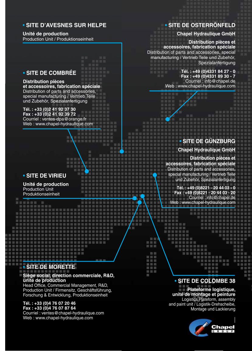
• SITE D’AVESNES SUR HELPEUnité de productionProduction Unit / Produktionseinheit
• SITE DE COMBRÉEDistribution pièces et accessoires, fabrication spécialeDistribution of parts and accessories, special manufacturing / Vertrieb Teile und Zubehör, Spezialanfertigung
Tél. : +33 (0)2 41 92 37 30Fax : +33 (0)2 41 92 39 72Courriel : [email protected] : www.chapel-hydraulique.com
• SITE DE MORETTESiège social, direction commerciale, R&D, unité de productionHead Offi ce, Commercial Management, R&D, Production Unit / Firmensitz, Geschäftsführung, Forschung & Entwicklung, Produktionseinheit
Tél. : +33 (0)4 76 07 20 46Fax : +33 (0)4 76 07 87 64 Courriel : [email protected] : www.chapel-hydraulique.com
• SITE DE OSTERRÖNFELDChapel Hydraulique GmbH
Distribution pièces et accessoires, fabrication spéciale
Distribution of parts and accessories, special manufacturing / Vertrieb Teile und Zubehör,
Spezialanfertigung
Tél. : +49 (0)4331 84 27 - 0Fax : +49 (0)4331 89 30 - 7
Courriel : [email protected] : www.chapel-hydraulique.com
• SITE DE GÜNZBURGChapel Hydraulique GmbH
Distribution pièces et accessoires, fabrication spécialeDistribution of parts and accessories, special manufacturing / Vertrieb Teile
und Zubehör, Spezialanfertigung
Tél. : +49 (0)8221 - 20 44 03 - 0Fax : +49 (0)8221 - 20 44 03 - 20
Courriel : [email protected] : www.chapel-hydraulique.com
• SITE DE COLOMBE 38Plateforme logistique,
unité de montage et peintureLogistics Plateform, assembly
and paint unit / Logistik-Drehscheibe, Montage und Lackierung
• SITE DE VIRIEUUnité de productionProduction UnitProduktionseinheit

FRANCE
MoretteChapel S.A.1157, Grand Chemin Royal38210 MoretteTél. : +33 (0)4 76 07 20 46Fax : +33 (0)4 76 07 87 64Email : [email protected]
CombréeDPA CombréeZ.A. de l’Ombrée49520 CombréeTél. : +33 (0)2 41 92 37 30Fax : +33 (0)2 41 92 39 72Email : [email protected]
ALLEMAGNE
OsterrönfeldChapel Hydraulique GmbHWalter-Zeidler-Straße 2024783 Osterrönfeld/RendsburgTél. : +49 (0)4331 84 27 - 0Fax : +49 (0)4331 89 30 – 7Email : [email protected]
GünzburgChapel Hydraulique GmbHKimmerle Ring 1689312 Günzburg/Deffi ngenTél. : +49 (0)8221 - 20 44 03 - 0Fax : +49 (0)8221 - 20 44 03 - 20Email : [email protected]
BELGIQUE
EMV NVMeense Steenweg 354B 8800 - RoeselareTél. : +32 (0) 51 221 069Fax : +32 (0) 51 221 339Email : [email protected]
ANGLETERRE
C&C Hydraulics LTDUnit 3 -Aireside Business ParkRoyd Ings AvenueKeighley, BD21 4BZTél. : +44 (0) 15 35 61 78 80Fax : +44 (0) 1535 662164
ESPAGNE
Cilindros y Cromados SLPoligono MunicipalCalle Ferrocarril, n° 534210 Duenas (Palencia)Tél. : +34 979 76 14 34Fax : +34 979 78 10 00
SUISSE
Bugnon Hydraulique SARLRoute du Simplon 1A1906 CharratTél. : +41 (0)27 746 44 44Fax : +41 (0)27 746 44 94Email : [email protected]