Centre Scientifique et Technique du Bâtiment 4, avenue du Recteur Poincaré F-75782 PARIS Cedex 16 Tél. : (33) 01 40 50 28 28 Fax : (33) 01 45 25 61 51
Autorisé etnotifié conformément à
l’article 10 de la directive89/106/EEC du Conseil, du
21 décembre 1988, relative aurapprochement des dispositions
législatives, réglementaireset administratives des Etats
membres concernantles produits deconstruction.
MEMBRE DE L’EOTA
European Technical Approval ETA-05/0022 (English language translation, the original version is in French language)
Trade name: Nom commercial :
WeberHaus
Holder of approval: Titulaire :
WeberHaus GmbH & Co Am Erlenpark 1 D-77866 RHEINAU-LINX
Generic type and use of construction product:
Timber frame building kit
Type générique et utilisation prévue du produit de construction :
Kit de construction à ossature bois
Validity from / to: Validité du : au :
12/05/2005 12/05/2010
This version replaces: Cette version remplace :
Validity extended (from) to : Validité étendue (du) au :
Manufacturing plant: Usine de fabrication :
WeberHaus GmbH & Co Am Erlenpark 1 D-77866 RHEINAU-LINX
This European Technical Approval contains: Le présent Agrément Technique Européen contient :
74 pages including 4 annexes which form an integra l part of the document 74 pages incluant 4 annexes faisant partie intégrante du document.
European Organisation for Technical Approvals
Organisation pour l’Agrément Technique Européen
Page 2 - European Technical Approval ETA-05/0022
Validity from 12/05/2005 to 12/05/2010
I LEGAL BASIS AND GENERAL CONDITIONS
1 - This European Technical Approval is issued by the Centre Scientifique et Technique du Bâtiment (CSTB) in accordance with:
� Council Directive 89/106/EEC of 21 December 1988 on the approximation of laws, regulations and administrative provisions of Member States relating to construction products1, modified by the Council Directive 93/68/EEC of 22 July 19932;
� Décret no. 92-647 du 8 juillet 19923 concernant l’aptitude à l’usage des produits de construction;
� Common Procedural Rules for Requesting, Preparing and the Granting of European Technical Approvals set out in the Annex of Commission Decision 94/23/EC4;
� Guideline for European Technical Approval 007 Timber Frame Building Kits Edition 2001.
2 - The Centre Scientifique et Technique du Bâtiment is authorised to check whether the provisions of this European Technical Approval are met. Checking may take place in the manufacturing plant (for example concerning the fulfilment of assumptions made in this European Technical Approval with regard to manufacturing). Nevertheless, the responsibility for the conformity of the products with the European Technical Approval and for their fitness for the intended use remains with the holder of the European Technical Approval.
3 - This European Technical Approval is not to be transferred to manufacturers or agents of manufacturer other than those indicated on page 1; or manufacturing plants other than those indicated on page 1 of this European Technical Approval.
4 - This European Technical Approval may be withdrawn by the Centre Scientifique et Technique du Bâtiment pursuant to Article 5 (1) of the Council Directive 89/106/EEC.
5 - Reproduction of this European Technical Approval including transmission by electronic means shall be in full. However, partial reproduction can be made with the written consent of the Centre Scientifique et Technique du Bâtiment. In this case, partial reproduction has to be designated as such. Texts and drawings of advertising brochures shall not contradict or misuse the European Technical Approval.
���������
1 Official Journal of the European Communities no. L 40, 11.2.1989, p. 12 2 Official Journal of the European Communities no. L 220, 30.8.1993, p. 1 3 Journal Officiel de la République française du 14 juillet 1992 4 Official Journal of the European Communities no. L 17, 20.1.1994, p. 34
Page 3 - European Technical Approval ETA-05/0022
Validity from 12/05/2005 to 12/05/2010
6 - The European Technical Approval is issued by the approval body in its official language. This version corresponds to the version circulated within EOTA. Translations into other languages have to be designated as such.
���������
Page 4 - European Technical Approval ETA-05/0022
Validity from 12/05/2005 to 12/05/2010
II SPECIFIC CONDITIONS OF THE EUROPEAN TECHNICAL AP PROVAL
1 Definition of product and intended use
1.1 Definition of product
WeberHaus buildings are predesigned and prefabricated timber frame building kits for individual houses including external walls, internal walls, floors and roof.
Every building element is pre-assembled in the factory including doors and windows and eventually completed with external and internal finishes.
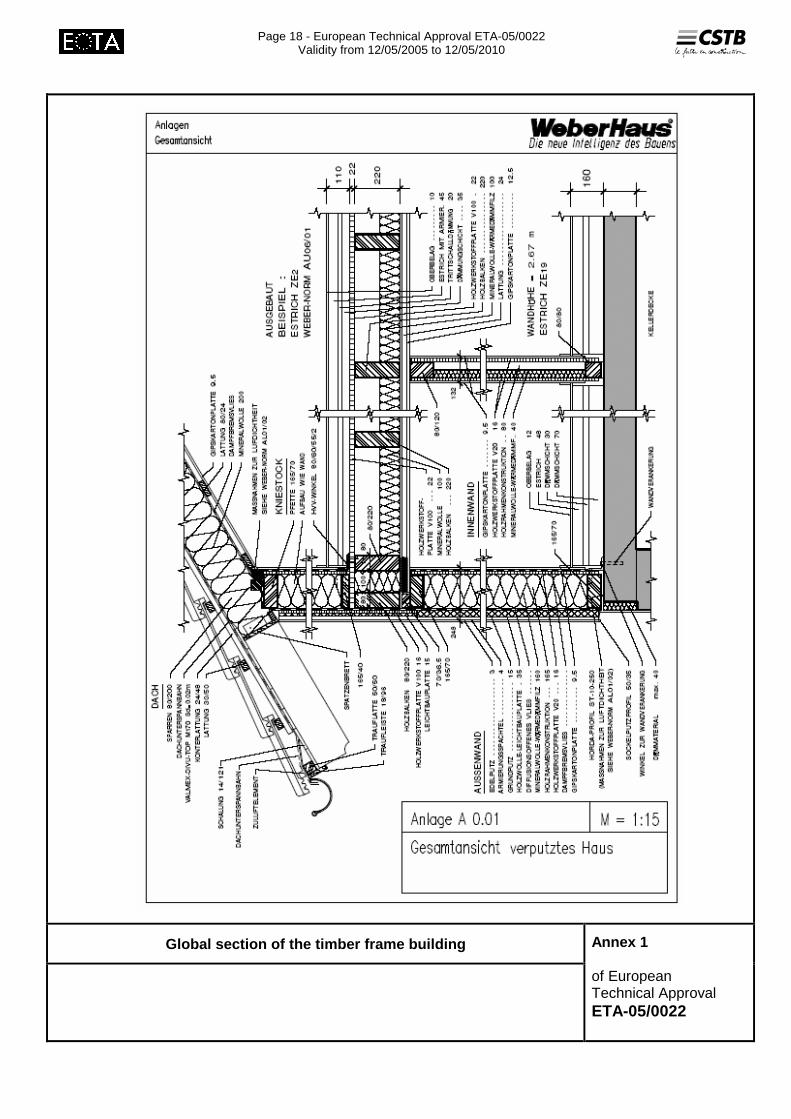
These elements are then assembled on site on an existing concrete base slab or on top of the basement floor (see fig. 1 Annex 1).
Every building element (wall, floor and roof) is described later on as well as the assembly principle.
All the materials data are given in Annex 3.
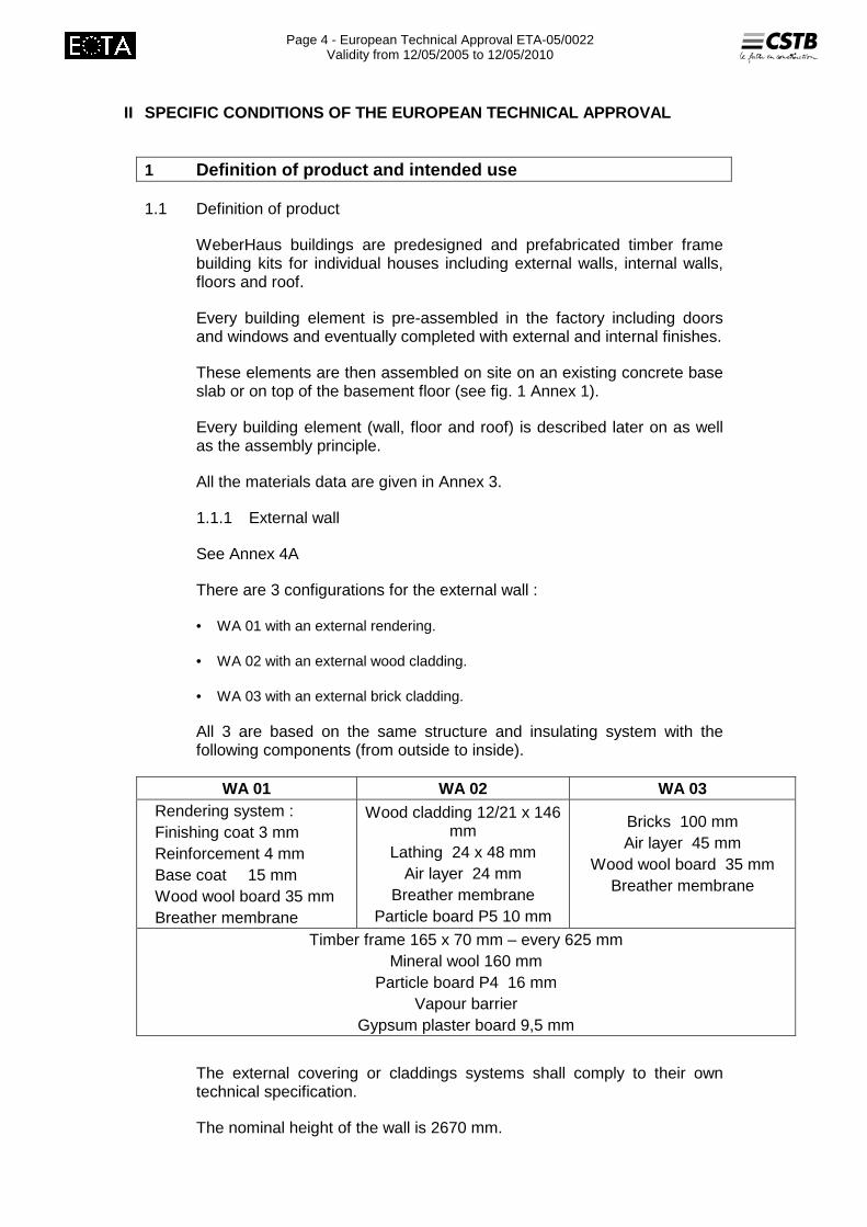
1.1.1 External wall
See Annex 4A
There are 3 configurations for the external wall :
• WA 01 with an external rendering.
• WA 02 with an external wood cladding.
• WA 03 with an external brick cladding.
All 3 are based on the same structure and insulating system with the following components (from outside to inside).
WA 01 WA 02 WA 03 Rendering system : Finishing coat 3 mm Reinforcement 4 mm Base coat 15 mm Wood wool board 35 mm Breather membrane
Wood cladding 12/21 x 146 mm
Lathing 24 x 48 mm Air layer 24 mm
Breather membrane Particle board P5 10 mm
Bricks 100 mm Air layer 45 mm
Wood wool board 35 mm Breather membrane
Timber frame 165 x 70 mm – every 625 mm Mineral wool 160 mm
Particle board P4 16 mm Vapour barrier
Gypsum plaster board 9,5 mm
The external covering or claddings systems shall comply to their own technical specification.
The nominal height of the wall is 2670 mm.
Page 5 - European Technical Approval ETA-05/0022
Validity from 12/05/2005 to 12/05/2010
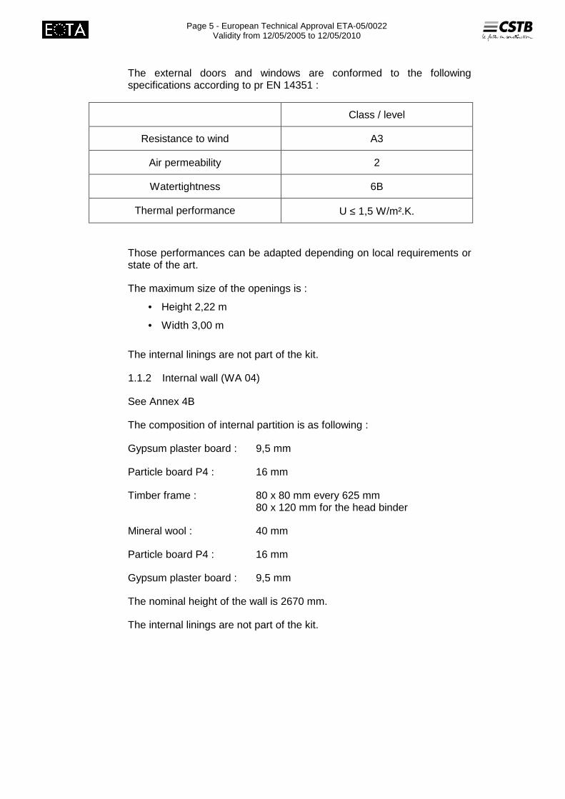
The external doors and windows are conformed to the following specifications according to pr EN 14351 :
Class / level
Resistance to wind A3
Air permeability 2
Watertightness 6B
Thermal performance U ≤ 1,5 W/m².K.
Those performances can be adapted depending on local requirements or state of the art.
The maximum size of the openings is :
• Height 2,22 m
• Width 3,00 m
The internal linings are not part of the kit.
1.1.2 Internal wall (WA 04)
See Annex 4B
The composition of internal partition is as following :
Gypsum plaster board : 9,5 mm
Particle board P4 : 16 mm
Timber frame : 80 x 80 mm every 625 mm 80 x 120 mm for the head binder
Mineral wool : 40 mm
Particle board P4 : 16 mm
Gypsum plaster board : 9,5 mm
The nominal height of the wall is 2670 mm.
The internal linings are not part of the kit.

Page 6 - European Technical Approval ETA-05/0022
Validity from 12/05/2005 to 12/05/2010
1.1.3 Floor
See Annex 4C
There are 2 configurations for the floor :
DE01 designed for an habitable attic
DE02 designed for a non occupied and unheated attic
The composition is as following from top to bottom.
DE 01 DE 02
Floor finishing (not part of the kit) ∼ 10 mm ∼ 10 mm
Reinforced screed 45 mm 45 mm
Impact sound insulation 35 mm 35 mm
Thermal insulation 20 mm 20 mm
Particle board P5 22 mm 22 mm
Joist 60 to 200 x 220 mm
Mineral wool 100 mm 200 mm
Lathing (spacing 0,416 m) 24 x 48 mm 24 x 48 mm
Vapour barrier Valmex WS 100
Gypsum plaster board 12,5 mm 12,5 mm
The floor covering is not part of the kit.
1.1.4 Roof (DA 01)
See Annex 4D
The composition is as following from outside to inside.
Concrete or clay roofing tiles: 10/m2 - 3,5 to 4,5 kg/unit Batten: 30 x 50 mm Counter-batter : 24 x 48 mm
Breathing membrane : DIVU TOP M170
Rafter: 80 x 200 mm every 833 mm Mineral wool: 200 mm Vapour barrier: 110 g/m2 Lathing: 24 x 80 mm (spacing 0,416 m) Gypsum plaster board: 9,5 mm

Page 7 - European Technical Approval ETA-05/0022
Validity from 12/05/2005 to 12/05/2010
The design of the roof (slope, ventilation section, protection against driving snow…) can be adapted case by case depending on national requirement.
1.1.5 Fixing devices
All connections are detailed on the cross sections in Annex 4 as well as the different staples or screws to fix the boards on the timber frame.
1.2 Intended use
The intended use for the building kits is a single family house of maximum 1 storey, with or without basement. The roof space is intended for living purposes.
The building kits are to be used in European countries.
The timber is not treated against termite attacks.
No performance has been determined regarding the seismic action.
The anchors to the substructure are designed case by case according to their own ETA.
Page 8 - European Technical Approval ETA-05/0022
Validity from 12/05/2005 to 12/05/2010
2 Characteristics of product and methods of verificat ion
2.1 Mechanical resistance and stability (ER1)
The mechanical performance of the building elements was determined according ENV 1995-1-1 : 2003.
The mechanical data corresponds to :
• Solid wood: EN 338 / EN 385
• Particle board: EN 312
• “Staples” : german technical approval Nr Z-9.1-73 and Z-9.1-1976.
The characteristic load capacities of the building elements are presented in Annex 2.
No performance has been determined on the complete building elements. The design shall be performed case by case.
No performance has been determined regarding the seismic action.
2.2 Safety in case of fire
2.2.1 Reaction to fire
The classification of a certain range of components has been given with material data in Annex 3.
No performance has been determined on the complete building element.
2.2.2 Resistance to fire
For the external wall, resistance to fire is based on a full scale testing: classification is given according to EN 13501.
External wall : REI 30
For the floor, resistance to fire is given on the bases of a calculation according to Eurcode 1995-1-2 (10.2002).
Floor : R15
No performance determined for the roof.
2.2.3 External fire performance of roof covering
According to the commission Decision 2000/553/CEE, the concrete tiles and clay tiles are deemed to satisfy all the requirements regarding the external fire performance without further testing.

Page 9 - European Technical Approval ETA-05/0022
Validity from 12/05/2005 to 12/05/2010
2.3 Hygiene, Health and Environment
2.3.1 Vapour permeability and moisture resistance
The design of the building elements and the experience on site, brings to the fact that there is no risk of interstitial or internal condensation in case of current humidity flow from inside towards outside.
The condensation risk has not been determined for southern countries with cooling devices where the humidity flow could be from the outside towards the inside.
2.3.2 Watertightness
The standard construction details allow to assess the watertightness of the building envelope favourably.
Regarding the watertightness of internal surfaces of wet areas, the performances depend on the floor and wall finishes which are note part of the kit. Some technical solutions are implemented in WeberHaus documentation. It has to be evaluated case by case depending on the real construction details on site.
2.3.3 Release of dangerous substances
Based on the declaration of the manufacturer, the WeberHaus buildings do not contain harmful or dangerous substances as defined in the EU database, with exception of formaldehyde.
In addition to the specific clauses relating to dangerous substances contained in this European Technical Approval, there may be other requirements applicable to the products falling within its scope (e.g. transposed European legislation and national laws, regulations and administrative provisions). In order to meet the provisions of the EU Construction Product Directive, these requirements need also to be complied with, when and where they apply.
2.4 Safety in use
2.4.1 Slipperiness of floor finishes
Due to the large range of possible floor finishes to be installed in the house, the performance has not been determined.
The slipperiness has to be evaluated case by case where national requirements are applicable.
2.4.2 Impact resistance
For both the external wall and the floor, the thickness of the particle board and the space between the timber corresponds to well known construction details. The impact resistance is then assessed positively without testing for the intended use.
On the inner side of the external wall and partition there are both a gypsum plasterboard and a particle board which limit indentation marks eventually due to hard body impacts.

Page 10 - European Technical Approval ETA-05/0022
Validity from 12/05/2005 to 12/05/2010
2.5 Protection against noise
2.5.1 Airborne sound insulation
Wall element Rw (C, C tr) WA 01 46 (-2, -6) dB WA 02 43 (-2, -6) dB WA 03 55 (-1, -6) dB
For the design of the sound insulation of the building, the national requirement shall be observed. 2.5.2 Impact sound insulation
No performance determined.
2.5.3 Sound Absorption
No performance determined.
2.6 Energy economy and health retention
2.6.1 Thermal resistance
The calculations have been performed according to the method of EN ISO 6946 on the basis of the data precised in Annex 3.
Building element R Value (m².K/W)
U – Value (W/m2.K)
WA 01 4.05 0,25 WA 02 3.50 0,30 External wall WA 03 4.01 0,26 b (mm)
60 4.20 0.24 80 4.12 0.24
100 4.06 0.25 140 3.94 0.25
2 x 60 3.99 0.25 2 x 80 3.89 0.26
Floor DE 01
2 x 100 3.79 0.26 b (mm)
60 5.81 0.17 80 5.55 0.18
100 5.33 0.19 140 4.97 0.20
2 x 60 5.14 0.19 2 x 80 4.82 0.21
Floor DE 02
2 x 100 4.56 0.22 Roof DA 01 4.93 0,21 Windows / doors < 1,5
Attention has to be paid to the fact that calculations were performed with tabulated values for thermal conductivity either from EN 12524 or from
Page 11 - European Technical Approval ETA-05/0022
Validity from 12/05/2005 to 12/05/2010
CE marking of insulating materials. Those values do not take into account eventual increase to be applied in accordance with national regulations.
2.6.2 Air permeability
The current construction details shown in Annex 4 present the continuity of both the internal vapour barrier and the external breather membrane.
The kit is then providing sufficient airtightness to be in accordance with the intended use.
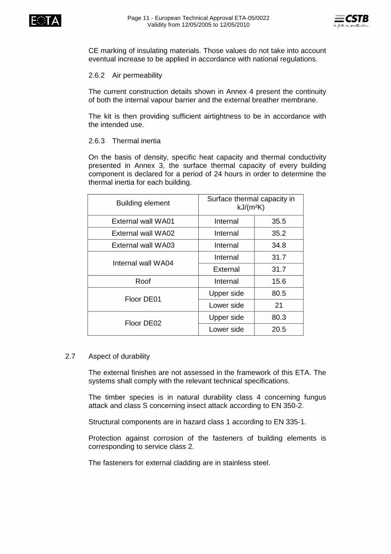
2.6.3 Thermal inertia
On the basis of density, specific heat capacity and thermal conductivity presented in Annex 3, the surface thermal capacity of every building component is declared for a period of 24 hours in order to determine the thermal inertia for each building.
Building element Surface thermal capacity in kJ/(m²K)
External wall WA01 Internal 35.5
External wall WA02 Internal 35.2
External wall WA03 Internal 34.8
Internal 31.7 Internal wall WA04
External 31.7
Roof Internal 15.6
Upper side 80.5 Floor DE01
Lower side 21
Upper side 80.3 Floor DE02
Lower side 20.5
2.7 Aspect of durability
The external finishes are not assessed in the framework of this ETA. The systems shall comply with the relevant technical specifications.
The timber species is in natural durability class 4 concerning fungus attack and class S concerning insect attack according to EN 350-2.
Structural components are in hazard class 1 according to EN 335-1.
Protection against corrosion of the fasteners of building elements is corresponding to service class 2.
The fasteners for external cladding are in stainless steel.
Page 12 - European Technical Approval ETA-05/0022
Validity from 12/05/2005 to 12/05/2010
The assumed working life of the house based on the description of the components on general knowledge of timber frame building and on a regular maintenance is :
� 50 years for the building (structure, insulation, boards, …)
� 25 years for the external finishes as well as windows or doors.
2.8 Aspects of serviceability
2.8.1 Limit deflections
The stiffnesses of floors and roofs are given in Annex 2. They should be used to check deflections according to regulations for works.
2.8.2 Vibration behaviour
In order to check the vibration behaviour of floors, it is indicated in table 4 Annex 2 those requiring a special investigation (fudamental frequency lower then 8 Hz).
Page 13 - European Technical Approval ETA-05/0022
Validity from 12/05/2005 to 12/05/2010
3 Evaluation of Conformity and CE marking
3.1 Attestation of conformity system
The system of attestation of conformity specified by the Commission decision 99/455/EC is system 1 according to Council Directive 89/106/EEC Annex III.
The certification of conformity of the product by a notified body is based on.
a) Tasks of the manufacturer:
1. Factory production control (FPC)
2. Further testing of samples taken at the factory by the manufacturer according to a prescribed test plan.
b) Tasks of the Notified Body:
3. Initial type testing
4. Initial inspection of factory and factory production control
5. Continuous surveillance, assessment of FPC
3.2 Responsibilities
3.2.1 Tasks of the manufacturer, factory production control
The manufacturer has a factory production control system in its plant and exercises permanent internal control of the production. All requirements and provisions adopted by the manufacturer are documented in a systematic manner in the form of written policies and procedures. This production control system ensures that the product is in conformity with the European Technical Approval.
The manufacturer proceeds to controls during the production according to specific policies. Those controls include :
Control of the incoming raw material - Examination of the moisture content of wood, dimensions,
sort class etc. - Examination of marking or labelling of the product from the
supplier - Archiving of the incoming goods in self-monitoring
Controls in production - Control of the woods, cut boards etc. during the assembling
of the elements on basis of the plans - Control of wiring (empty pipes) on basis of the plans

Page 14 - European Technical Approval ETA-05/0022
Validity from 12/05/2005 to 12/05/2010
Outgoing inspection with the loading
- Control for completeness - Comparison with plans - Damages control
There is no further test to be performed in the factory according to the prescribed test plan.
3.2.2 Tasks of the Notified Bodies
3.2.2.1 Initial assessment of the product
Initial assessment of WeberHaus building kits has been carried out by the approval body and will serve as the initial product assessment for the notified body.
3.2.2.2 Initial inspection of factory and of factory production control
The notified body shall assess the manufacture’s factory production control plan in full, and approve the control plan that is documented in the quality manual. The notified body shall also ensure that the manufacturer has the necessary competent staff, premises and production equipment to produce the timber frame kits as described in the ETA.
3.2.2.3 Continuous surveillance
The notified body shall normally visit the factory twice a year for routine inspections, and primarily check that the production is in conformity with the factory production control plan.
The notified body shall particular check that the manufacturer only use materials and components which are specified in Annex 3 of this ETA, and that all the specified case by case structural designs have been made and filed for each kit that is produced and delivered.
During the factory visits the notified body shall also make audit/visual inspections of prefabricated elements, components and material made ready for shipment to the building site, and that the kits and assembly instructions are in conformity with the construction details in Annex 4.
3.2.2.4 Certification
When all criterias for conformity attestation are fulfilled the notified body shall issue a product Certification of Conformity with this ETA.
3.2.3 CE marking
The CE marking shall be affixed on the document going with the supply of the house The symbol « CE » shall be accompanied by the following information:
• identification number of the certification body,
• name or identifying mark of the producer and manufacturing plant,
• the last two digits of the year in which the CE marking was affixed,
• number of the EC certificate of conformity,
Page 15 - European Technical Approval ETA-05/0022
Validity from 12/05/2005 to 12/05/2010
• number of the European Technical Approval,
• identification of the type of components (external wall WA 01, 02 or 03 internal wall WA 04, floor DE 01 or 02, roof DA 01).
Page 16 - European Technical Approval ETA-05/0022
Validity from 12/05/2005 to 12/05/2010
4 Assumptions under which the fitness of the product for the intended use was favourably assessed
4.1 Design
For every house, a set of specific plans and a set of details is available, based on specific design and also including eventual local specification.
The mechanical design is performed case by case.
4.2 Manufacturing
The kit is manufactured by WeberHaus (D-Linx) which has been using a specific manufacturing process summarised here after and identified during inspection of the plant by the Centre Scientifique et Technique du Bâtiment and laid down in the technical documents.
For each building element (wall, floor, roof) the main manufacturing stages are as following :
• Preparation of the timber frame,
• Fixing on one of the boards with vapour barrier,
• Preparation for plumbing and electricity,
• Installation of insulation panels,
• Fixing of the other board or lathing to “close” the element.
At the end of each assembly belt, the elements are loaded on a trailer and covered with a canvas cover and stored until delivery.
4.3 Installation
As for the manufacturing, the erection is ruled by specific process policies.
The installation is generally performed in one day with a team of 4 people :
• Erection of external wall immediately anchored on the foundation and the each other,
• Fixing of internal walls,
• Installation of the floor elements,
• Fixing of jamb wall and gable,
• Installation of purling and collard,
• Fixing of the roofing elements,
• Covering of the roof,
• Filling the joints between elements,
• Application of the screed,
• Internal finishes.
Page 17 - European Technical Approval ETA-05/0022
Validity from 12/05/2005 to 12/05/2010
5 Recommendations
5.1 Packaging, transport and storage
The elements are properly prepared to limit deformation and degradation during transportation. They are placed under a canvas cover in the workshops to get sufficient protection before storage.
Transportation is scheduled in a way to complete the erection in one day.
5.2 Maintenance and repair of works
When delivering the house, WeberHaus provides to their clients a maintenance manual taking into account all the aspect of the house.
5.3 Technical assistance
WeberHaus also provides technical assistance.
The original version is signed by H. BERRIER
Page 18 - European Technical Approval ETA-05/0022
Validity from 12/05/2005 to 12/05/2010
Global section of the timber frame building
Annex 1 of European Technical Approval ETA-05/0022
Page 19 - European Technical Approval ETA-05/0022
Validity from 12/05/2005 to 12/05/2010
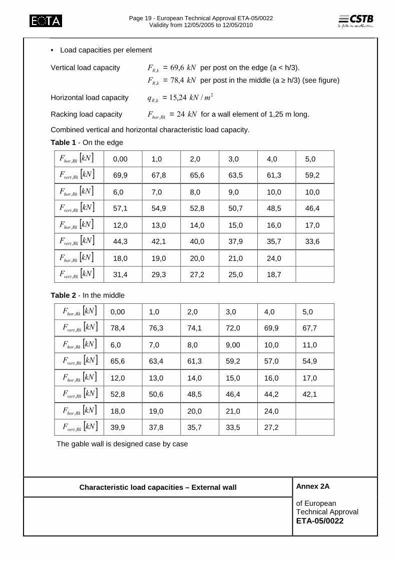
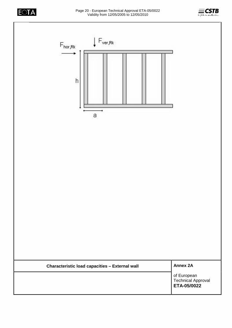
• Load capacities per element
Vertical load capacity ��� �� � �� = per post on the edge (a < h/3).
��� �� ����� = per post in the middle (a ≥ h/3) (see figure)
Horizontal load capacity �
� ����� ���� �� =
Racking load capacity ��� ���� ��� = for a wall element of 1,25 m long.
Combined vertical and horizontal characteristic load capacity.
Table 1 - On the edge
[ ]��� ���� � 0,00 1,0 2,0 3,0 4,0 5,0
[ ]��� ���� � 69,9 67,8 65,6 63,5 61,3 59,2
[ ]��� ���� � 6,0 7,0 8,0 9,0 10,0 10,0
[ ]��� ���� � 57,1 54,9 52,8 50,7 48,5 46,4
[ ]��� ���� � 12,0 13,0 14,0 15,0 16,0 17,0
[ ]��� ���� � 44,3 42,1 40,0 37,9 35,7 33,6
[ ]��� ���� � 18,0 19,0 20,0 21,0 24,0
[ ]��� ���� � 31,4 29,3 27,2 25,0 18,7
Table 2 - In the middle
[ ]��� ���� � 0,00 1,0 2,0 3,0 4,0 5,0
[ ]��� ���� � 78,4 76,3 74,1 72,0 69,9 67,7
[ ]��� ���� � 6,0 7,0 8,0 9,00 10,0 11,0
[ ]��� ���� � 65,6 63,4 61,3 59,2 57,0 54,9
[ ]��� ���� � 12,0 13,0 14,0 15,0 16,0 17,0
[ ]��� ���� � 52,8 50,6 48,5 46,4 44,2 42,1
[ ]��� ���� � 18,0 19,0 20,0 21,0 24,0
[ ]��� ���� � 39,9 37,8 35,7 33,5 27,2
The gable wall is designed case by case
Characteristic load capacities – External wall
Annex 2A of European Technical Approval ETA-05/0022
Page 20 - European Technical Approval ETA-05/0022
Validity from 12/05/2005 to 12/05/2010
Characteristic load capacities – External wall
Annex 2A of European Technical Approval ETA-05/0022
Page 21 - European Technical Approval ETA-05/0022
Validity from 12/05/2005 to 12/05/2010
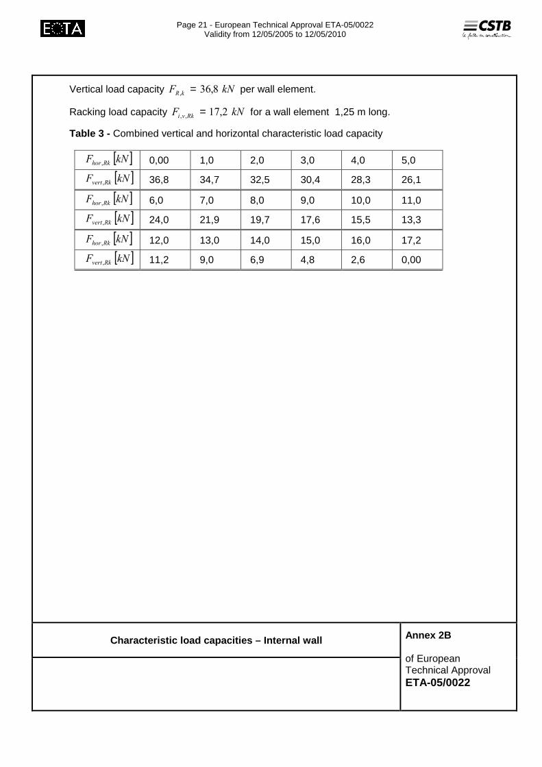
Vertical load capacity ��� �� ��� � = per wall element.
Racking load capacity ��� �� ����� = for a wall element 1,25 m long.
Table 3 - Combined vertical and horizontal characteristic load capacity
[ ]��� ���� � 0,00 1,0 2,0 3,0 4,0 5,0
[ ]��� ���� � 36,8 34,7 32,5 30,4 28,3 26,1
[ ]��� ���� � 6,0 7,0 8,0 9,0 10,0 11,0
[ ]��� ���� � 24,0 21,9 19,7 17,6 15,5 13,3
[ ]��� ���� � 12,0 13,0 14,0 15,0 16,0 17,2
[ ]��� ���� � 11,2 9,0 6,9 4,8 2,6 0,00
Characteristic load capacities – Internal wall
Annex 2B of European Technical Approval ETA-05/0022

Page 22 - European Technical Approval ETA-05/0022
Validity from 12/05/2005 to 12/05/2010
Table 4 - Load capacity floor DE01 and DE02 with sc reed
b [mm] max span �1[m] � 60 80 100 140 2 x 60 2 x 80 2 x 100
3,00 qRk [kN/m²] 16,52 22,03 27,53 34,52 33,04 34,52 34,52
3,25 qRk [kN/m²] 14,08 18,77 23,46 32,85 28,15 34,52 34,52
3,50 qRk [kN/m²] 12,12 16,18 20,23 28,32 24,28 32,37 34,52
3,75 qRk [kN/m²] 10,57 14,10 17,62 24,67 21,15 28,20 34,52
4,00 qRk [kN/m²] 9,29 12,39 15,49 21,68 18,59 24,78 30,98
4,25 qRk [kN/m²] 8,23 10,98 13,72 19,21 16,46 21,95 27,44
4,50 qRk [kN/m²] 7,34 9,79 12,24 17,13 14,68 19,58 24,47
4,75 qRk [kN/m²] 6,59 8,79 10,98 15,38 13,18 17,57 21,97
5,00 qRk [kN/m²] 5,95 7,93 9,91 13,88 11,89 15,86 19,82
5,25 qRk [kN/m²] 5,39 7,19 8,99 12,59 10,79 14,39 17,98
with qRk [kN/m²] load capacity in the ultimate limit state Below the line the frequency is lower then 8 Hz and special investigation shall be made case by case.
Characteristic load capacities - Floor
Annex 2C of European Technical Approval ETA-05/0022
Page 23 - European Technical Approval ETA-05/0022
Validity from 12/05/2005 to 12/05/2010
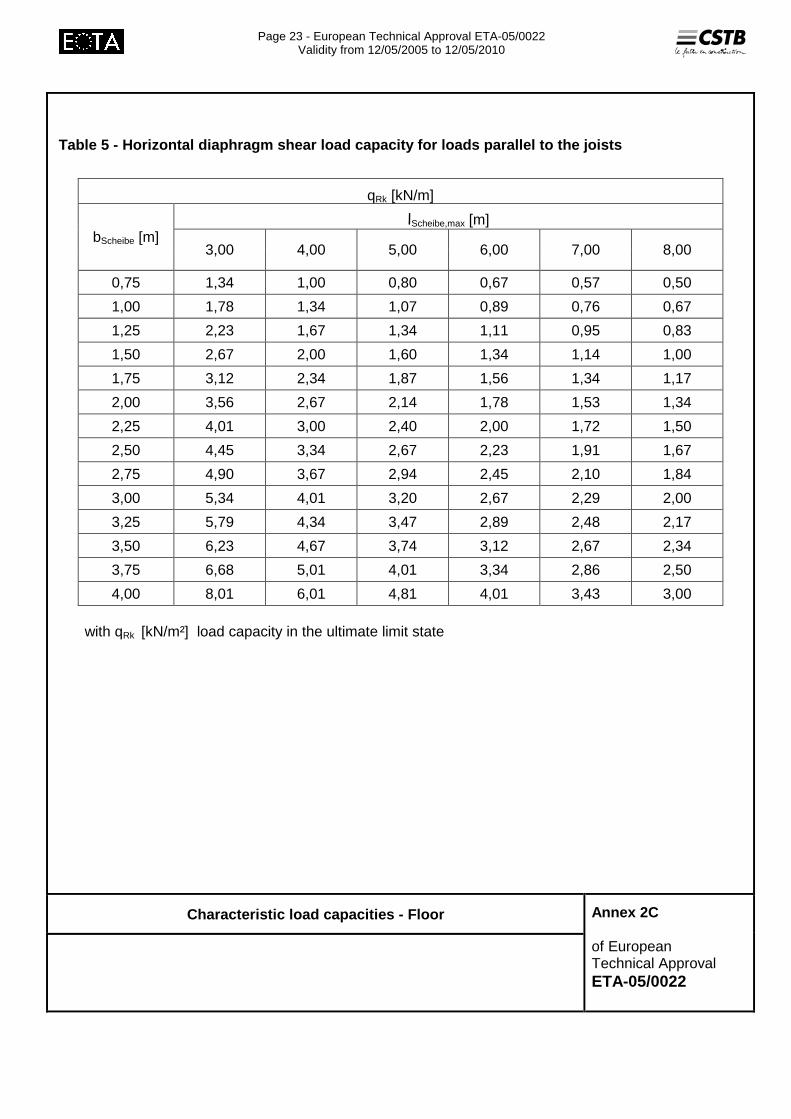
Table 5 - Horizontal diaphragm shear load capacity f or loads parallel to the joists
qRk [kN/m]
�Scheibe,max [m]�bScheibe [m]
3,00 4,00 5,00 6,00 7,00 8,00
0,75 1,34 1,00 0,80 0,67 0,57 0,50
1,00 1,78 1,34 1,07 0,89 0,76 0,67
1,25 2,23 1,67 1,34 1,11 0,95 0,83
1,50 2,67 2,00 1,60 1,34 1,14 1,00
1,75 3,12 2,34 1,87 1,56 1,34 1,17
2,00 3,56 2,67 2,14 1,78 1,53 1,34
2,25 4,01 3,00 2,40 2,00 1,72 1,50
2,50 4,45 3,34 2,67 2,23 1,91 1,67
2,75 4,90 3,67 2,94 2,45 2,10 1,84
3,00 5,34 4,01 3,20 2,67 2,29 2,00
3,25 5,79 4,34 3,47 2,89 2,48 2,17
3,50 6,23 4,67 3,74 3,12 2,67 2,34
3,75 6,68 5,01 4,01 3,34 2,86 2,50
4,00 8,01 6,01 4,81 4,01 3,43 3,00 with qRk [kN/m²] load capacity in the ultimate limit state
Characteristic load capacities - Floor
Annex 2C of European Technical Approval ETA-05/0022

Page 24 - European Technical Approval ETA-05/0022
Validity from 12/05/2005 to 12/05/2010
Table 6 - Horizontal diaphragm shear load capacity f or loads perpendicular to the joists
qRk [kN/m]
�Scheibe,max [m]
bScheibe [m] 3,00 4,00 5,00 6,00 7,00 8,00
0,75 4,19 3,24 2,63 2,21 1,90 1,67
1,00 5,30 4,19 3,44 2,90 2,51 2,21
1,25 6,25 5,04 4,19 3,56 3,10 2,73
1,50 7,04 5,80 4,88 4,19 3,66 3,24
1,75 - 6,46 5,51 4,77 4,19 3,72
2,00 - 7,04 6,08 5,30 4,69 4,19
2,25 - - 6,59 5,80 5,16 4,63
2,50 - - 7,04 6,25 5,59 5,04
2,75 - - - 1,97 1,78 1,61
3,00 - - - 2,09 1,89 1,72
3,25 - - - - 1,99 1,82
3,50 - - - - 2,09 1,91
3,75 - - - - - 2,00
4,00 - - - - - 2,09 with load from only one side only the values over the line are to be used ( in these cases the diaphragm width b should not exceed 1/4 of the diaphragm span)
Table 7 – Stiffness of the floor
Joist EI [mm] [Nm²/m]
60 937.000 80 1.249.000
100 1.562.000 140 2.186.000
2 x 60 1.874.000 2 x 80 2.499.000
2 x 100 3.123.000
Characteristic load capacities - Floor
Annex 2C of European Technical Approval ETA-05/0022

Page 25 - European Technical Approval ETA-05/0022
Validity from 12/05/2005 to 12/05/2010
Table 8 - Snow and for windload capacity
load capacity roof
max. span l1 [m] 3,20 3,30 3,40 3,50 3,60 3,70 3,80
ultimate limit state qRk [kN/m²] 12,00 11,30 10,60 10,00 9,50 9,00 8,50
max. span l1 [m] 3,90 4,00 4,10 4,20 4,30 4,40 4,50
ultimate limit state qRk [kN/m²] 8,10 7,70 7,30 7,00 6,60 6,30 6,10
Concentrated imposed load capacity qR,k = 11,4 kN
Horizontal diaphragm shear load capacity : not dertermined
Stiffness of the roof EI = 704 000 Nm²/m
Characteristic load capacities - Roof
Annex 2D of European Technical Approval ETA-05/0022
Page 26 - European Technical Approval ETA-05/0022
Validity from 12/05/2005 to 12/05/2010
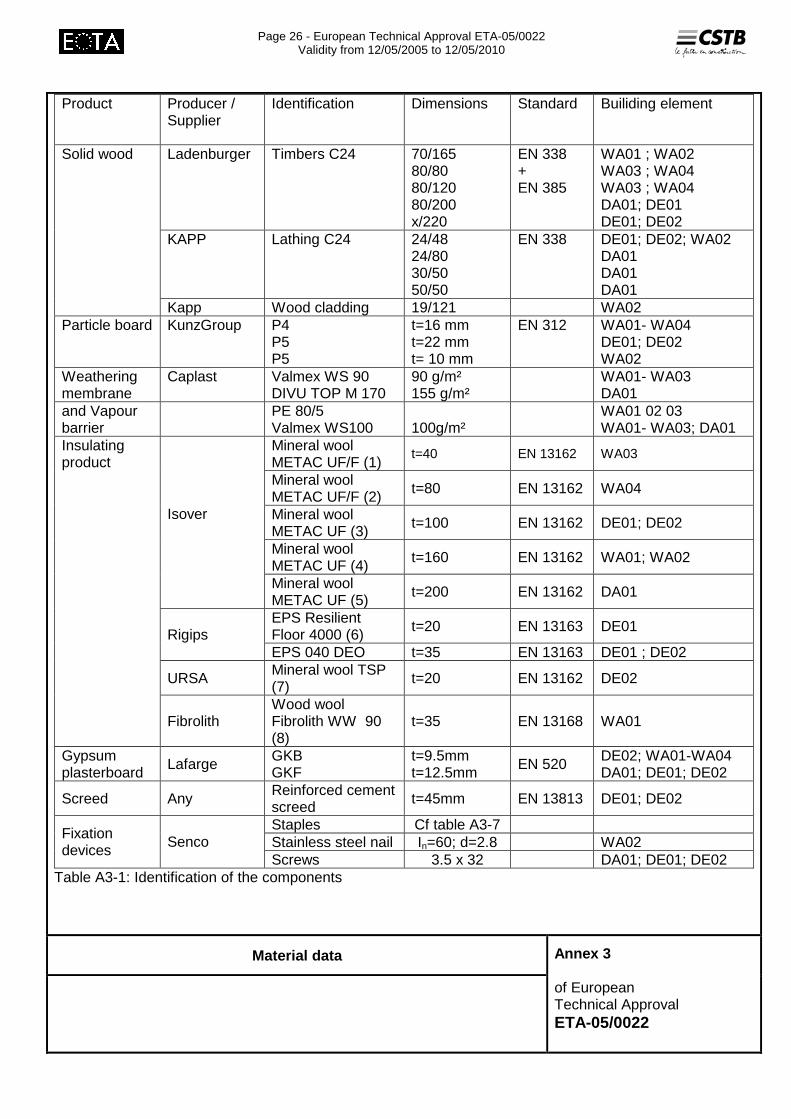
Product Producer /
Supplier Identification Dimensions Standard Builiding element
Ladenburger Timbers C24 70/165 80/80 80/120 80/200 x/220
EN 338 + EN 385
WA01 ; WA02 WA03 ; WA04 WA03 ; WA04 DA01; DE01 DE01; DE02
KAPP Lathing C24 24/48 24/80 30/50 50/50
EN 338 DE01; DE02; WA02 DA01 DA01 DA01
Solid wood
Kapp Wood cladding 19/121 WA02 Particle board KunzGroup P4
P5 P5
t=16 mm t=22 mm t= 10 mm
EN 312 WA01- WA04 DE01; DE02 WA02
Weathering membrane
Caplast Valmex WS 90 DIVU TOP M 170
90 g/m² 155 g/m²
WA01- WA03 DA01
and Vapour barrier
PE 80/5 Valmex WS100
100g/m²
WA01 02 03 WA01- WA03; DA01
Mineral wool METAC UF/F (1)
t=40 EN 13162 WA03
Mineral wool METAC UF/F (2) t=80 EN 13162 WA04
Mineral wool METAC UF (3) t=100 EN 13162 DE01; DE02
Mineral wool METAC UF (4) t=160 EN 13162 WA01; WA02
Isover
Mineral wool METAC UF (5) t=200 EN 13162 DA01
EPS Resilient Floor 4000 (6) t=20 EN 13163 DE01 Rigips EPS 040 DEO t=35 EN 13163 DE01 ; DE02
URSA Mineral wool TSP (7) t=20 EN 13162 DE02
Insulating product
Fibrolith Wood wool Fibrolith WW 90 (8)
t=35 EN 13168 WA01
Gypsum plasterboard Lafarge GKB
GKF t=9.5mm t=12.5mm EN 520 DE02; WA01-WA04
DA01; DE01; DE02
Screed Any Reinforced cement screed t=45mm EN 13813 DE01; DE02
Staples Cf table A3-7 Stainless steel nail In=60; d=2.8 WA02
Fixation devices Senco
Screws 3.5 x 32 DA01; DE01; DE02 Table A3-1: Identification of the components
Material data
Annex 3 of European Technical Approval ETA-05/0022
Page 27 - European Technical Approval ETA-05/0022
Validity from 12/05/2005 to 12/05/2010
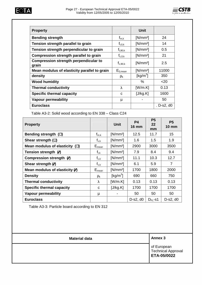
Property Unit
Bending strength fm,k [N/mm²] 24
Tension strength parallel to grain ft,0,k [N/mm²] 14
Tension strength perpendicular to grain ft,90,k [N/mm²] 0.5
Compression strength parallel to grain fc,0,k [N/mm²] 21 Compression strength perpendicular to grain
fc,90,k [N/mm²] 2.5
Mean modulus of elasticity parallel to grain E0,mean [N/mm²] 11000 density ρk [kg/m3] 350
Wood humidity % <20
Thermal conductivity λ [W/m.K] 0.13
Specific thermal capacity c [J/kg.K] 1600
Vapour permeability µ - 50
Euroclass . D-s2, d0
Table A3-2: Solid wood according to EN 338 – Class C24
Property Unit P4
16 mm
P5 22
mm
P5 10 mm
Bending strength ( ⊥⊥⊥⊥) fm,k [N/mm²] 12.5 11.7 15
Shear strength ( ⊥⊥⊥⊥) fv,k [N/mm²] 1.6 1.5 1.9
Mean modulus of elasticity ( ⊥⊥⊥⊥) Emean [N/mm²] 2900 3000 3500
Tension strength ( ⁄⁄⁄⁄⁄⁄⁄⁄) ft,k [N/mm²] 7.9 8.4 9.4
Compression strength ( ⁄⁄⁄⁄⁄⁄⁄⁄) fc,k [N/mm²] 11.1 10.3 12.7
Shear strength ( ⁄⁄⁄⁄⁄⁄⁄⁄) fv,k [N/mm²] 6.1 5.9 7
Mean modulus of elasticity ( ⁄⁄⁄⁄⁄⁄⁄⁄) Emean [N/mm²] 1700 1800 2000
Density ρk [kg/m3] 690 660 750
Thermal conductivity λ [W/m.K] 0.13 0.13 0.13
Specific thermal capacity c [J/kg.K] 1700 1700 1700
Vapour permeability µ - 50 50 50
Euroclass D-s2, d0 DFL-s1 D-s2, d0
Table A3-3: Particle board according to EN 312
Material data
Annex 3 of European Technical Approval ETA-05/0022

Page 28 - European Technical Approval ETA-05/0022
Validity from 12/05/2005 to 12/05/2010
Product reference Property Unit
1 2 3 4 5 6 7 8
Thickness t [mm] 40 100 160 200 20 35 20 35
Thermal conductivity λ [W/m.K] 0.040 0.035 0.035 0.035 0.045 0.040 0.045 0.040
Specific thermal capacity
c [J/kg.K] 1030 1030 1030 1030 1450 1450 1030 1470
Vapour permeability µ - 1 1 1 1 60 60 1 3
Water vapour transmission (EN 13162)
- MU1
Euroclass (EN 13501)
A1 A1 A1 A1 E E A2-s1, d0 B
Dynamic stifness s’ [MN/m3] <20 <10
Density ρ [kg/m3] >10 >10 >10 >10 >10 >10 >10 >250
Table A3-4 Insulating product
Product reference
Property Unit Lafarge GKB Lafarge GKF
Thickness t [mm] 9.5 12.5 Thermal conductivity λ
[W/m.K] 0.025 0.025
Specific thermal capacity
c [J/kg.K] 1000 1000
Vapour permeability µ - 10 10
Density ρ [kg/m3] 900 900
Euroclass A2-s1, d0 B-s1, d0 Table A3-5: Gypsum plasterboard according to EN 520
Material data
Annex 3 of European Technical Approval ETA-05/0022
Page 29 - European Technical Approval ETA-05/0022
Validity from 12/05/2005 to 12/05/2010
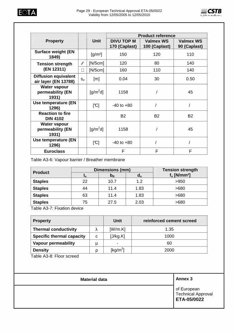
Product reference Property Unit DIVU TOP M
170 (Caplast) Valmex WS
100 (Caplast) Valmex WS 90 (Caplast)
Surface weight (EN 1849)
[g/m²] 150 120 110
⁄⁄ [N/5cm] 120 80 140 Tension strength (EN 12311) ⊥ [N/5cm] 160 110 140
Diffusion equivalent air layer (EN 13788)
sd [m] 0.04 30 0.50
Water vapour permeability (EN
1931) [g/m2d] 1158 / 45
Use temperature (EN 1296)
[°C] -40 to +80 / /
Reaction to fire DIN 4102
B2 B2 B2
Water vapour permeability (EN
1931) [g/m2d] 1158 / 45
Use temperature (EN 1296)
[°C] -40 to +80 / /
Euroclass F F F
Table A3-6: Vapour barrier / Breather membrane
Dimensions (mm) Product
In bR dn Tension strength
fu [N/mm²] Staples 22 10.7 1.2 >950
Staples 44 11.4 1.83 >680
Staples 63 11.4 1.83 >680
Staples 75 27.5 2.03 >680 Table A3-7: Fixation device
Property Unit reinforced cement screed
Thermal conductivity λ [W/m.K] 1.35
Specific thermal capacity c [J/kg.K] 1000
Vapour permeability µ - 60
Density ρ [kg/m3] 2000 Table A3-8: Floor screed
Material data
Annex 3 of European Technical Approval ETA-05/0022


