central management software user manual€¦ · alarm management with efficient control. 1.1 key...
TRANSCRIPT

CCeennttrraall MMaannaaggeemmeenntt SSooffttwwaarree
UUsseerr MMaannuuaall
2
订订UUsseerr MMaannuuaall
2
CONTENTS
1 Overviews .......................................................................................................................................................... 3
1.1 Key Features .............................................................................................................................................. 3
1.2 Installation Requirements ........................................................................................................................... 3
1.3 Software Installation ................................................................................................................................... 4
2 Surveillance Software GUI ................................................................................................................................ 6
2.1 Login Window ............................................................................................................................................. 6
2.2 Surveillance Window .................................................................................................................................. 8
3 Advanced Settings .......................................................................................................................................... 20
3.1 Cameras ................................................................................................................................................... 20
3.1.1 How to manage Areas ....................................................................................................................... 24
3.1.2 How to manage cameras ................................................................................................................... 27
3.2 System Settings ........................................................................................................................................ 32
3.2.1 Device Status ..................................................................................................................................... 33
3.2.2 Basic Settings .................................................................................................................................... 35
3.2.3 Network .............................................................................................................................................. 40
3.2.4 Video .................................................................................................................................................. 49
3.2.5 Alarm .................................................................................................................................................. 52
3.2.6 Record ................................................................................................................................................ 56
3.2.7 Permission Settings ........................................................................................................................... 58
3.2.8 PT ....................................................................................................................................................... 58
3.2.9 Path Settings ...................................................................................................................................... 62
3.2.10 Firewall ............................................................................................................................................. 63
3.2.11 System ............................................................................................................................................. 64
3.3 Record and Alarm ..................................................................................................................................... 67
3.3.1 Record and Alarm .............................................................................................................................. 67
3.3.2 Storage path and others .................................................................................................................... 69
3.4 Users ........................................................................................................................................................ 70
4 Play back ......................................................................................................................................................... 71
5 LOG ................................................................................................................................................................. 73
6 Lock ................................................................................................................................................................. 74
7 Obtaining technical support ............................................................................................................................ 74

3
订订UUsseerr MMaannuuaall
3
11 OOvveerrvviieewwss
FOSCAM offers the most comprehensive central management software IP Camera Client,
designed for managing all FOSCAM IP surveillance cameras with numerous features.
It supports management or monitoring multiple cameras for monitoring, recording, playback, and
alarm management with efficient control.
11..11 KKeeyy FFeeaattuurreess
Powerful function for multiple live views
Real-time 64 channel live viewing
Supports three recording methods: alarm recording, manually recording and recording
schedule management
Web-based configuration page embedded in the client for all functions
Intelligent Pan/ Tilt camera control
Supports Preset Positions
Multi-level users management with password protection
Supports playback recording files
Supports two-way audio
Supports Logs Management
11..22 IInnssttaallllaattiioonn RReeqquuiirreemmeennttss
PC: Pentium IV or above
CPU: 2.0G or above
RAM: 2.0G or above
Hard Disk Space: 120G or above
Suggested Display Screen: 1280 x 768
Suggested Operation system: Windows XP, Windows 7, Windows 8.
NOTE: The number of linked device has much relation with the computer performance and the
network bandwidth.

4
订订UUsseerr MMaannuuaall
4
11..33 SSooffttwwaarree IInnssttaallllaattiioonn
1) Insert the CD in the CD drive of your computer. Open the CD; find the software ―Foscam IP
Camera Client .msi‖.
2) Double click the software and install the program.
Figure1.1
Click Next till you see the following screen:
Figure1.2

5
订订UUsseerr MMaannuuaall
5
Click Close and complete the software installation. An icon appears on the desktop
automatically after a successful installation.
Note: Sometimes the program will be treated as virus, so before installing, please add the
software as trusted program on your computer.

6
订订UUsseerr MMaannuuaall
6
22 SSuurrvveeiillllaannccee SSooffttwwaarree GGUUII
After finishing software installation, you can take time to learn the operation of the software.
22..11 LLooggiinn WWiinnddooww
Double click the shortcut icon and it will pop up the login window:
Figure2.1
Please check the login window above, it was divided to 4 sections from no. 1 to 4.
Section1 User Name & Password
The default User Name and Password are all admin.
At your first time logging in the software, choose ―Settings” on the top of the software interface
and go to the ―Users” panel, then reset the username or password to prevent intruders access.
1
2
3 4

7
订订UUsseerr MMaannuuaall
7
Section2 Select Language
You can select the language you need via pull down the dropdown toolbar and click on the
language to switch.
Section3 Remember Password
Select it and you need not to re-enter the username & password next time logging in.
Section4 LOGIN
Click LOGIN button and login the software.
8
订订UUsseerr MMaannuuaall
8
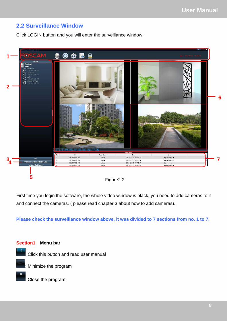
2.2 Surveillance Window
Click LOGIN button and you will enter the surveillance window.
Figure2.2
First time you login the software, the whole video window is black, you need to add cameras to it
and connect the cameras. ( please read chapter 3 about how to add cameras).
Please check the surveillance window above, it was divided to 7 sections from no. 1 to 7.
Section1 Menu bar
Click this button and read user manual
: Minimize the program
Close the program
1
2
3 4
5
6
7

9
订订UUsseerr MMaannuuaall
9
FOSCAM LOGO
Click it and back to the live view screen
Click it and back to the Playback UI
Click it and back to Setting UI
Click it and back to the LOGS UI
Lock the current screen
The user account who accessing the client and the PC time now
Section2 Camera List Tree (Area)
After adding device to the client, you can see the cameras in the Camera list tree panel (please
read chapter3.1 about how to add cameras).
Area: When you add cameras to the client, you must select one area for the camera. You can
define a name for the area.
For example:
You want to add one camera to the client which is installed in the garden, then you can create a
new area named ―garden‖. Then add the camera to the area ―garden‖. So when the camera
alarmed, you can know which camera and where it is installed immediately.
There is a icon before the area name, click it and you can see all cameras that belong to the
area.

10
订订UUsseerr MMaannuuaall
10
Figure2.3
There are two status for one camera:
: The camera has been added to the client but not connected and you cannot see the video
of the camera. Click the icon, if the camera connected successfully, the icon will be changed to
and you can see the video.
Figure2.4
Device name: The Device Name is a name that you can give to your device to help you identify
it. You can define a name for your camera in the Settings panel.
If the camera has been connected successfully, click the video of the camera, you can see four
icons below the camera icon, such as the following picture.
Figure2.5
Click this icon
All cameras that belong to Area 1
Device Name &IP

11
订订UUsseerr MMaannuuaall
11
Audio: Click the icon then you will hear sound captured by the camera’s built-in microphone.
You may need to plug in earphones or enable the computer speakers to hear from the camera’s
microphone. Make sure the camera supports audio. Click again and stop audio.
Record: Click it and do manually recording. You can see a green record icon in the video. Click it
again and stop recording. The recording files will be stored to F disk automatically. Please go to
this panel to change the storage path: Settings-> Record and Alarm panel (chapter 3.3.2).
Figure2.6
Snap: Click this button to take a snapshot of the video and the snap pictures will be stored to C
disk. Please go to this panel to change the storage path: Settings-> Record and Alarm panel
(chapter 3.3.2).
Talk: Click the talk icon and talk through your computer’s microphone which will transmit through
the camera’s speaker. People will hear your talking through the camera’s built-in speaker or
other audio output device. Click the icon again and stop talking.
Make sure the camera supports Talk.
The green dot

12
订订UUsseerr MMaannuuaall
12
Section3 PT(Pan / Tilt)
Click one connected device video, then click PT, if the camera supports PT, here you can
operate the cradle head.
H.264 MJPEG
Figure2.7
FOSCAM has two series cameras: MJPEG and H.264. There is something difference between
two series (as the above picture), H.264 cameras support Track, MJPEG supports Horizon /
Vertical Cruise.
Figure2.8
1------Up control button, 2----- Up-Right control button
3----- Right control button 4------ Down-Right control button
5------Down control button 6----- Down-Left control button
1
2
3
4 5 6
7
8
9
13
订订UUsseerr MMaannuuaall
13
7----- Left control button 8----- Up-Left control button
9------Go to center
For MJPEG Cameras
: Click the icon and the camera will horizontally rotate.
: Click the icon and the camera will vertically rotate.
: Click this icon and stop rotating.
If you only click the horizon or vertical cruise button, the camera will patrol circles that you set
before and then stop.
You can know and change the patrol circles by the following two ways:
1) Login the camera by the explorer and change the circles number in the web UI (Please read
the user manual of the camera).
2) Go to Settings-> System->PT panel in the client and change the circles number
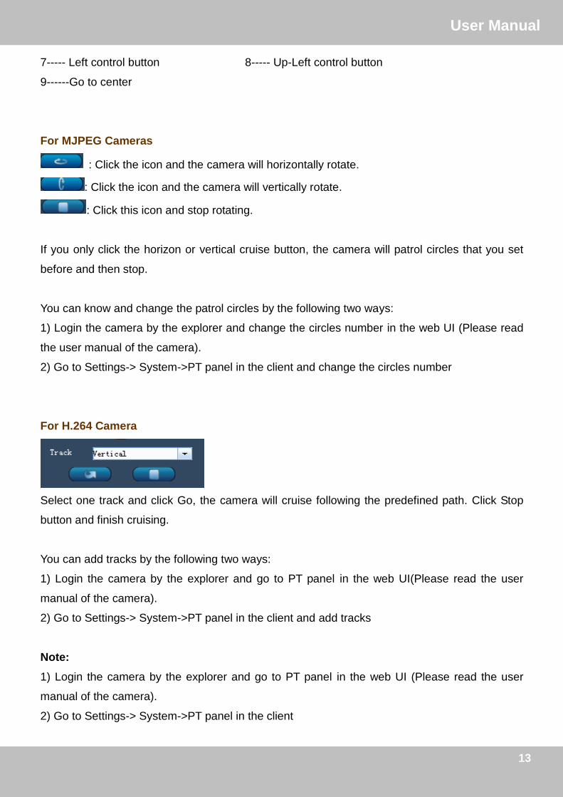
For H.264 Camera
Select one track and click Go, the camera will cruise following the predefined path. Click Stop
button and finish cruising.
You can add tracks by the following two ways:
1) Login the camera by the explorer and go to PT panel in the web UI(Please read the user
manual of the camera).
2) Go to Settings-> System->PT panel in the client and add tracks
Note:
1) Login the camera by the explorer and go to PT panel in the web UI (Please read the user
manual of the camera).
2) Go to Settings-> System->PT panel in the client

14
订订UUsseerr MMaannuuaall
14
Section4 Preset Position & IR LED
Click one connected device video, if the camera has connected with / built-in the cradle head,
then you can set Preset Position and IR LED.
H.264 MJPEG
Figure2.9
For H.264 Camera
Preset: Move the camera and stop at a desired place where you want to make preset
position, click Preset button to set preset position.
GO: Select one preset position in the preset dropdown list and click Go to make the
camera move the preset position
Delete: Select one preset position and click this button to delete it.
IR LED Lights: Here supports Manual and Auto.
How to do preset position?
Firstly, move the camera and stop at a desired place where you want to make preset position.
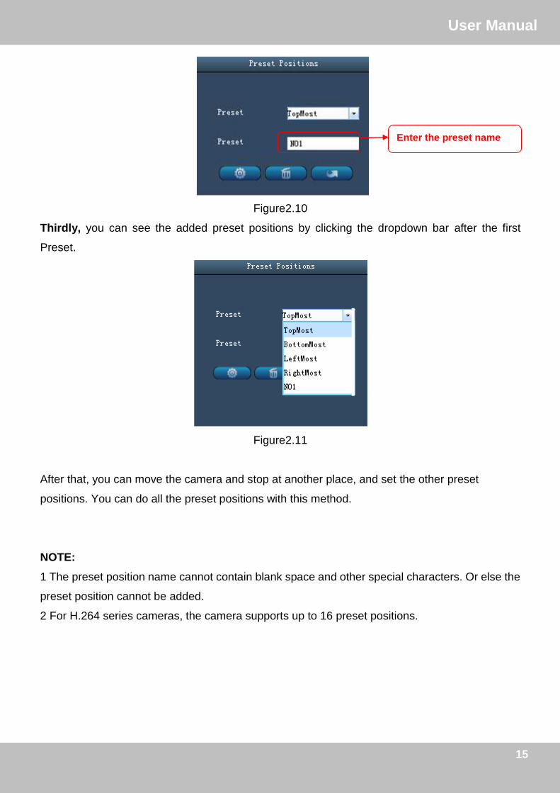
Secondly, enter a descriptive name for the preset position in the second preset blank box. Then
click Preset to save it.
15
订订UUsseerr MMaannuuaall
15
Figure2.10
Thirdly, you can see the added preset positions by clicking the dropdown bar after the first
Preset.
Figure2.11
After that, you can move the camera and stop at another place, and set the other preset
positions. You can do all the preset positions with this method.
NOTE:
1 The preset position name cannot contain blank space and other special characters. Or else the
preset position cannot be added.
2 For H.264 series cameras, the camera supports up to 16 preset positions.
Enter the preset name

16
订订UUsseerr MMaannuuaall
16
For MJPEG Camera
Figure2.12
Add: Move the camera and stop at a desired place where you want to make preset
position, click Add button to set preset position.
GO: Select one preset position in the preset dropdown list and click Go to make the
camera move the preset position
How to do preset position?
We can start preset settings from position 1.
Firstly, select no. 1 within the menu of Preset on the panel.
Secondly, move the camera and stop at a place where you want make preset position.
Thirdly, click Add button to save it as position 1 and you have done preset of position 1.
After that, you can select no. 2 within the menu of Preset on the panel, and move the camera and
stop at another place, and set as preset position 2. You can do all the 8 preset positions with this
method.
If you want to see the preset position you have set, such as the position 1, only select the preset
no.1 ,and click go button, the camera will go to position no.1.
Note: For MJPEG series cameras, the camera supports up to 8 preset positions.

17
订订UUsseerr MMaannuuaall
17
Section5 Image Settings
Select one connected device video then adjust the quality of the video.
H.264 MJPEG
Figure2.13
Brightness, contrast, hue and saturation are used to adjust the quality of the video.
Flip & Mirror
Show a reverse image .Make sure your camera support this function, or else it has no effection
after you select it.
For H.264 Cameras
Bit rate
The default Stream supports four modes: 0/720P/30fps/2M, 1/VGA/25fps/2M, 2/VGA/ 15fps/ 1M
and 3/ VGA/10fps/200 The format of the stream type is Stream type no. / Resolution /
Maximum frame rate/ Bit rate
1) Stream type no.
The number is used to identify the stream type.

18
订订UUsseerr MMaannuuaall
18
2) 720P/ VGA
There are two resolutions, the bigger one is 720P, and the smaller one (VGA) is 640x480 pixels.
The bigger the resolution, the better of the image quality is. If you are accessing the camera via
internet and want to get more fluent video streaming, please select resolution VGA.
3) Maximum frame rate
When the video format is 50Hz, the maximum frame rate is 25 fps. When the video format is
60Hz, the maximum frame rate is 30 fps. You should lower frame rate when the bandwidth is
limited. Normally, when the frame rate above 15, you can achieve fluently video.
4) Bit rate
Generally speaking, the larger the bit rate is, the clearer video will become. But the bit rate
configuration should combine well with the network bandwidth. When the bandwidth is very
narrow, and bit rate is large, that will lead to video can not play well.
You can reset the bit rate by the following two ways:
1) Login the camera by the explorer and go to video panel in the web UI(Please read the user
manual of the camera).
2) Go to Settings-> System->Video panel in the client
Mode
1) 50HZ ---------Indoor surveillance (Region: Europe, China)
2) 60HZ ---------Indoor surveillance (Region: USA, Canada)
For MJPEG Camera
Resolution
There are two resolutions, the bigger one (VGA) is 640x480 pixels, and the smaller one (QVGA)
is 320x240 pixels. The bigger the resolution, the better of the image quality is, but the lower the
frame rate is. If you are accessing the camera via internet and want to get more fluent video
streaming, please select resolution QVGA 320x240.
Mode
1) 50HZ ---------Indoor surveillance (Region: Europe, China)
19
订订UUsseerr MMaannuuaall
19
2) 60HZ ---------Indoor surveillance (Region: USA, Canada)
3) Outdoor-------Outdoor surveillance (Region: All over the world)
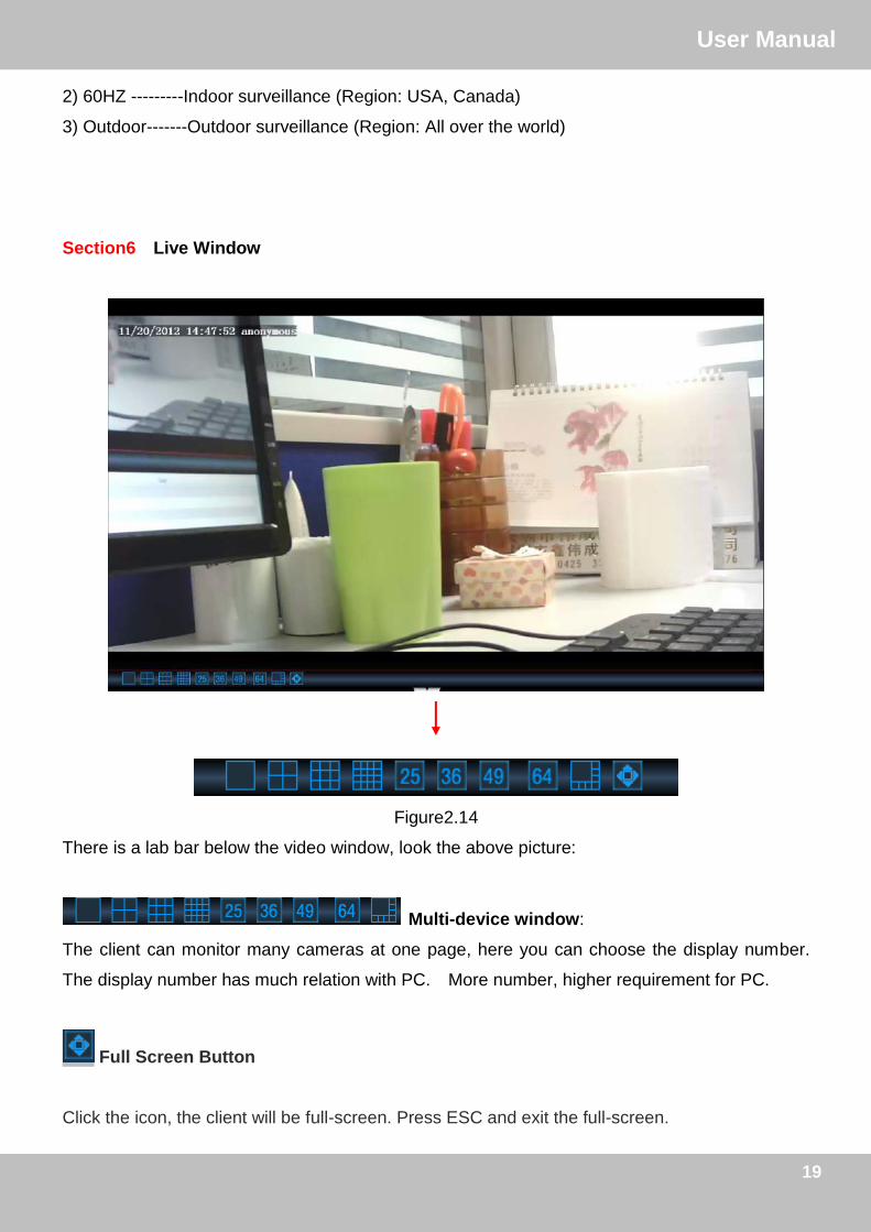
Section6 Live Window
Figure2.14
There is a lab bar below the video window, look the above picture:
Multi-device window:
The client can monitor many cameras at one page, here you can choose the display number.
The display number has much relation with PC. More number, higher requirement for PC.
Full Screen Button
Click the icon, the client will be full-screen. Press ESC and exit the full-screen.

20
订订UUsseerr MMaannuuaall
20
Section7 Device information
When you do some operation, here you can see the results. Such as the following picture:
33 AAddvvaanncceedd SSeettttiinnggss
Click the icon and back to Advanced Settings panel. This page will allow you to add
cameras, do system settings, Record and Alarm, Users Settings.
3.1 Cameras This section will show you how to add areas and cameras to the client.
Figure3.1
1
2
3
4
5 6

21
订订UUsseerr MMaannuuaall
21
The default Camera list tree is null, you need to create Area first then add cameras to the area.
Please check the windows above, it was divided to 6 sections from no. 1 to 6.
Section1 Camera/System/Record and Alarm/Users Buttons
: Click this button and go to Camera panel, you can add Cameras and Area to the
client
:Click this button and go to System panel, you can do settings about the added
cameras
:Click this button and go to Record and Alarm panel, this page will allow you to do
alarm settings about the added cameras.
: On this panel , you can alter the login user account and add other login users.
Section2 Area
: Click this button and it pop up the following windows,then you can add areas
to the client
Figure3.2
Note: The first area has no old area.

22
订订UUsseerr MMaannuuaall
22
:Click this button and change the area name of the added areas
.
Figure3.3
: Delete one added area, and the cameras that added to the area will be deleted
at the same time.
Section3 Add/ Edit / Delete cameras
: Click this button and add one camera to one area.
: Click this button and re-edit the added camers
: Delete cameras that have added to areas
Section4 Search cameras in LAN
: Click this button and the software will search all cameras in LAN automatically.
Enter the new area name
23
订订UUsseerr MMaannuuaall
23
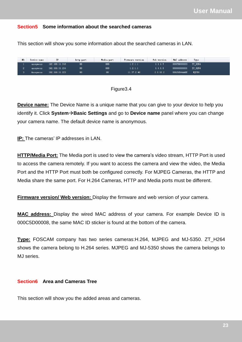
Section5 Some information about the searched cameras
This section will show you some information about the searched cameras in LAN.
Figure3.4
Device name: The Device Name is a unique name that you can give to your device to help you
identify it. Click SystemBasic Settings and go to Device name panel where you can change
your camera name. The default device name is anonymous.
IP: The cameras’ IP addresses in LAN.
HTTP/Media Port: The Media port is used to view the camera’s video stream, HTTP Port is used
to access the camera remotely. If you want to access the camera and view the video, the Media
Port and the HTTP Port must both be configured correctly. For MJPEG Cameras, the HTTP and
Media share the same port. For H.264 Cameras, HTTP and Media ports must be different.
Firmware version/ Web version: Display the firmware and web version of your camera.
MAC address: Display the wired MAC address of your camera. For example Device ID is
000C5D00008, the same MAC ID sticker is found at the bottom of the camera.
Type: FOSCAM company has two series cameras:H.264, MJPEG and MJ-5350. ZT_H264
shows the camera belong to H.264 series. MJPEG and MJ-5350 shows the camera belongs to
MJ series.
Section6 Area and Cameras Tree
This section will show you the added areas and cameras.

24
订订UUsseerr MMaannuuaall
24
3.1.1 How to manage Areas
This section will show you how to create/ edit/ delete the areas.
Create Area
Before adding devices to the client, you must create areas first.
Click Add Area button, you will see the following dialog box.
1) Enter the area name
2) If the area belongs to another area, here select the old area.
3) Click OK to take effect.
Figure3.5
The first area has no old area.
You can add other areas as the same way. On the right part of the Camera panel, you can see
the areas you have created.

25
订订UUsseerr MMaannuuaall
25
Figure3.6
Edit Area
Select one area and click Edit Area to change the area name.
1) Select one added area ( just by clicking the area name)
2) Click Edit Area
Figure3.7
3) Enter the new area name and click OK to take effect
4) You can see the new name area
Enter the new area name

26
订订UUsseerr MMaannuuaall
26
Figure3.9
Delete Area
1) Select one added area ( just by clicking the area name)
2) Click Delete Area button and you can see the following screen.
Figure3.10
3) Click OK to take effect.
If you have added cameras to the area, meanwhile the cameras list will be deleted.

27
订订UUsseerr MMaannuuaall
27
3.1.2 How to manage cameras
This section will tell you how to add or delete /edit the cameras.
The following steps are required before adding cameras to the client:
1) Install the IP Camera(s) which want to be monitored.
2) Login the IP Camera(s) by web browser and set the IP address, port, username & password
and make sure the camera can be accessed by browsers
3) DDNS setting is a plus whenever you want to add the devices by WAN
Add cameras
The software will search all cameras in LAN automatically and also you can add cameras
manually.
Add cameras in LAN
Click this button and the software will search all cameras in LAN, the the
camera list will be showed in the Cameras page.
Figure3.11
All cameras in LAN
28
订订UUsseerr MMaannuuaall
28
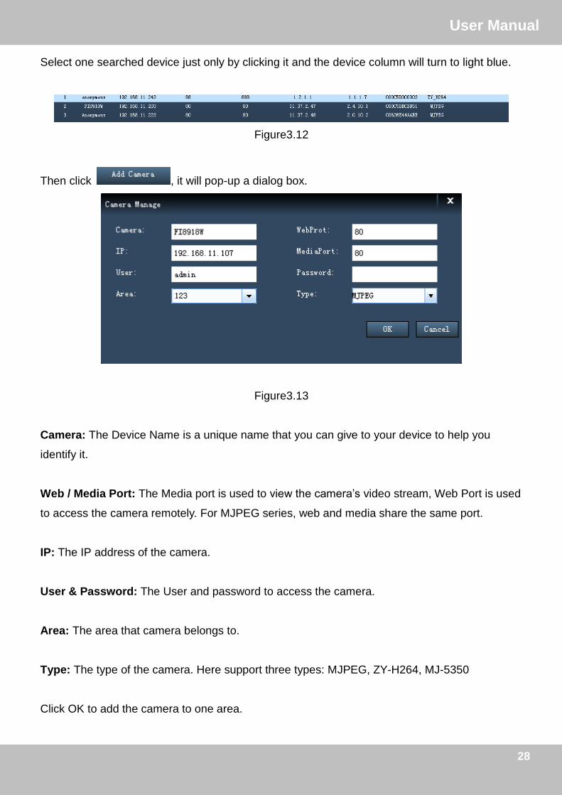
Select one searched device just only by clicking it and the device column will turn to light blue.
Figure3.12
Then click , it will pop-up a dialog box.
Figure3.13
Camera: The Device Name is a unique name that you can give to your device to help you
identify it.
Web / Media Port: The Media port is used to view the camera’s video stream, Web Port is used
to access the camera remotely. For MJPEG series, web and media share the same port.
IP: The IP address of the camera.
User & Password: The User and password to access the camera.
Area: The area that camera belongs to.
Type: The type of the camera. Here support three types: MJPEG, ZY-H264, MJ-5350
Click OK to add the camera to one area.
29
订订UUsseerr MMaannuuaall
29
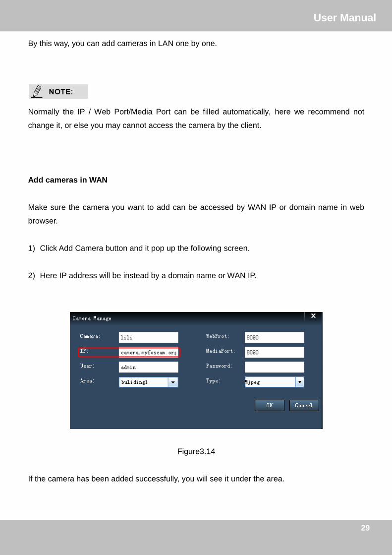
By this way, you can add cameras in LAN one by one.
Normally the IP / Web Port/Media Port can be filled automatically, here we recommend not
change it, or else you may cannot access the camera by the client.
Add cameras in WAN
Make sure the camera you want to add can be accessed by WAN IP or domain name in web
browser.
1) Click Add Camera button and it pop up the following screen.
2) Here IP address will be instead by a domain name or WAN IP.
Figure3.14
If the camera has been added successfully, you will see it under the area.
30
订订UUsseerr MMaannuuaall
30
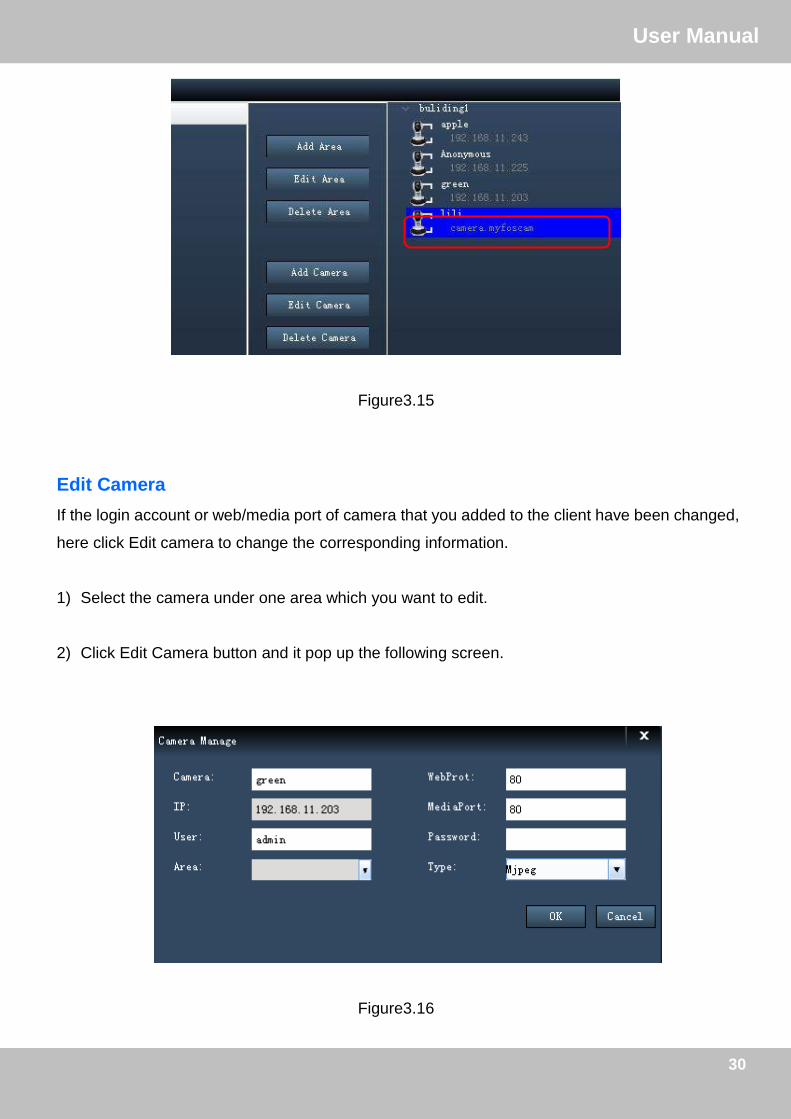
Figure3.15
Edit Camera
If the login account or web/media port of camera that you added to the client have been changed,
here click Edit camera to change the corresponding information.
1) Select the camera under one area which you want to edit.
2) Click Edit Camera button and it pop up the following screen.
Figure3.16

31
订订UUsseerr MMaannuuaall
31
This page will allow yo to change the Camera, Webport, Media port, User & Password and Type.
Camera: The device name in the client. It has no relation with the device name in the camera
web page.
3) Click OK to take effect.
Normally, if the camera’s IP has changed, you need to delete it and re-add again, there cannot
allow to change IP in the Edit Camera page.
Delete Camera
Select one camera, click Delete Camera button to delete it from the client.

32
订订UUsseerr MMaannuuaall
32
3.2 System Settings
Here you can do basic settings for the added device. These settings also can be done in the web
UI of the camera.
Click System button and double click one camera name in the camera list then you can go to the
System panel.
Figure3.17
Section 1 Function List
This section list all function of one camera. Double click one camera name in the Camera List,
then click one function and go to the corresponding page to read or change the information.
Section 2 Details
This page you can read the details of one function.
Click Refresh button to refresh the information.
Section 3 Camera List
This part you can see all cameras you added to the client.
There is a button before one area name, click this button to unfold all cameras that belongs to
the area.
1
3
2

33
订订UUsseerr MMaannuuaall
33
3.2.1 Device Status
For H.264 series cameras, Device Status contains four columns: Device Information, Device
Status, Session Status and Log, it will show you various information about your camera.
Figure3.18 Device Info Page
Figure3.19 Device Status Page
On this page you can see device status such as Alarm status/ Record Status ,DDNS status ,WIFI
status and so on.
34
订订UUsseerr MMaannuuaall
34
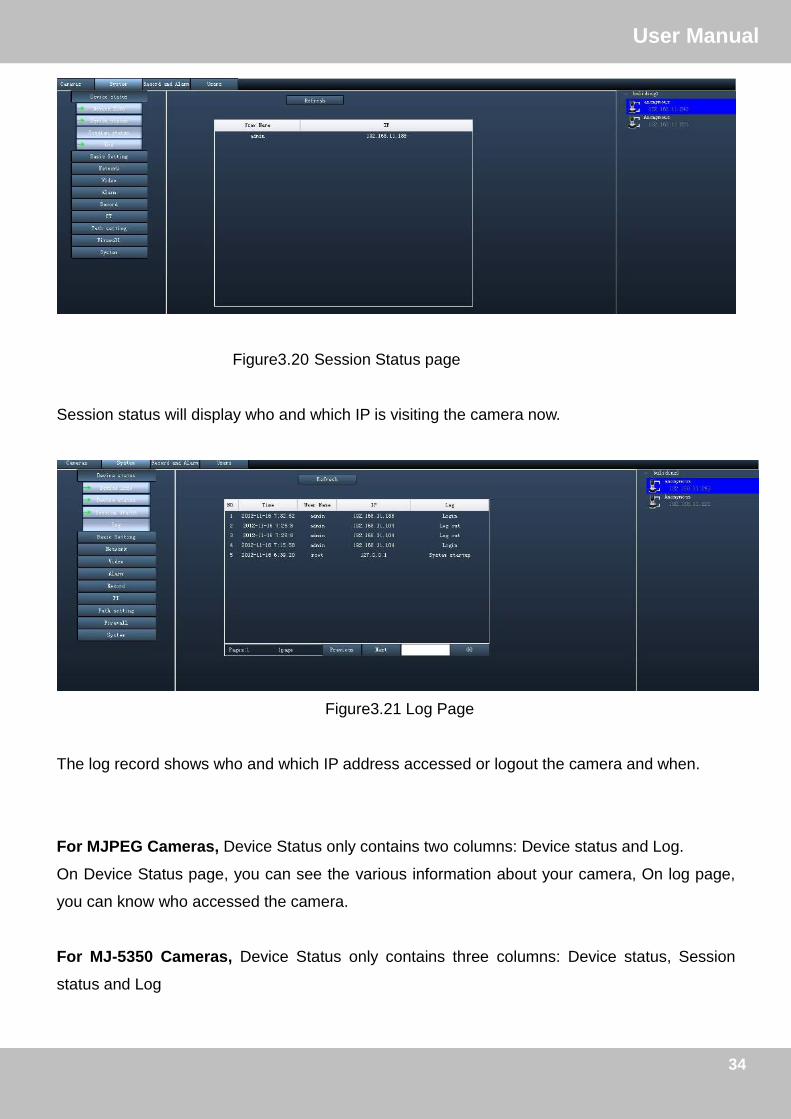
Figure3.20 Session Status page
Session status will display who and which IP is visiting the camera now.
Figure3.21 Log Page
The log record shows who and which IP address accessed or logout the camera and when.
For MJPEG Cameras, Device Status only contains two columns: Device status and Log.
On Device Status page, you can see the various information about your camera, On log page,
you can know who accessed the camera.
For MJ-5350 Cameras, Device Status only contains three columns: Device status, Session
status and Log

35
订订UUsseerr MMaannuuaall
35
3.2.2 Basic Settings
This section allows you to configure your camera’s Name, Time, Mail and User account.
Double click one camera icon on the camera list panel and click the corresponding function you
want to change.
Device Name
The Device Name is a unique name that you can give to your device to help you identify it.
Default Device name is anonymous. You can define a name for your camera here such as apple.
Click Save to save your changes.
Figure3.22
This page you can alter the displayed camera name in the web UI, if you want to change the
camera name that displayed in the client, you need to go to Cameras page to re-edit the camera.
System Time
This section allows you to configure the settings of the internal system clocks for your camera.
Figure3.23 (For MJPEG series cameras)

36
订订UUsseerr MMaannuuaall
36
Figure3.24 (For H.264 series cameras)
Sync with NTP server: Network Time Protocol will synchronize your camera with an Internet
time server. Choose the one that is closest to your camera.
Sync with PC: Select this option to synchronize the date and time of the Network Camera with
your computer.
Time Zone: Select the time zone for your region from the dropdown menu.
System time: The administrator can enter the date and time manually.
For MJPEG cameras, if your country implements the Daylight Saving Time, that option can also
be selected.
For H.264 Cameras, please select Date & Time format.

37
订订UUsseerr MMaannuuaall
37
If you want the camera to send emails when motion has been detected, Mail Service Settings
will need to be configured.
Enable the Mail settings.
Figure3.25
1----- SMTP Server/ Port /Transport Layer Security Enter SMTP server for sender. SMTP
port is usually set as 25. Some SMTP servers have their own port, such as 587 or 465, and
Transport Layer Security usually is None. If you use Gmail, Transport Layer Security must be set
to TLS or STARTTLS and SMTP Port must be set to 465 or 25 or 587, which port you choose
should be decided by which Transport Layer Security you select.
2-----SMTP Username/ password ID account and password of the sender email address
3----- Sender Mailbox for sender must support SMTP
4----- Receiver Mailbox for receiver need not support SMTP, you can set 4 receivers
5----Save Click Save to take effect
6----Test Click Test to see if Mail has been successfully configured.
38
订订UUsseerr MMaannuuaall
38
Click Test to see if Mail has been successfully configured.
If the test fails with one of the following errors after clicking Test, verify that the information you
entered is correct and again select Test .
1) Cannot connect to the server
2) Network Error. Please try later
3) Server Error
4) Incorrect user or password
5) The sender is denied by the server. Maybe the server need to authenticate the user, please
check it and try again
6) The receiver is denied by the server. Maybe because of the anti-spam privacy of the server
7) The message is denied by the server. Maybe because of the anti-spam privacy of the server
8) The server does not support the authentication mode used by the device
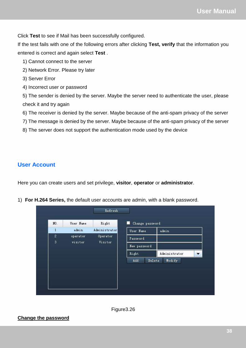
User Account
Here you can create users and set privilege, visitor, operator or administrator.
1) For H.264 Series, the default user accounts are admin, with a blank password.
Figure3.26
Change the password
39
订订UUsseerr MMaannuuaall
39
Firstly, select the account which you want to change the password, then select ―Change
password‖, enter the old password and the new password, lastly click modify to take effect.
Add an account
Select one blank column, then enter the new user name, password and privilege, last click Add
to take effect. You can see the new added account on the Account list.
Delete
Select the account which you want to delete, then click Delete button to take effect.
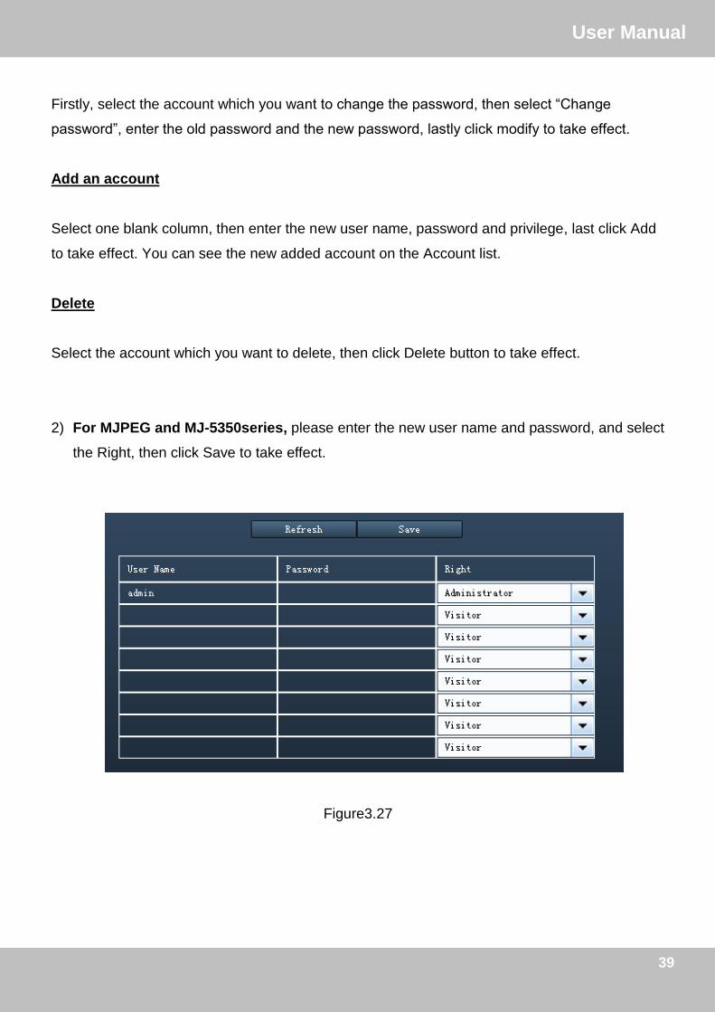
2) For MJPEG and MJ-5350series, please enter the new user name and password, and select
the Right, then click Save to take effect.
Figure3.27

40
订订UUsseerr MMaannuuaall
40
3.2.3 Network
This section will allow you to configure your camera’s IP, DDNS, Wireless Settings and UPnP.
For MJPEG cameras, there is other function: ADSL and MSN. For H.264 cameras, here supports
PPPoE and Port function.
IP
If you want to set a static IP for the camera, please go to IP page. Keep the camera in the same
subnet of your router or computer.
Figure3.28
It is recommended that you use the subnet mask, gateway and DNS server from your locally
attached PC. If you don’t know the subnet mask, gateway and DNS server, you can check your
computer’s local area connection as follows:
Control PanelNetwork ConnectionsLocal Area Connections Choose
SupportDetails.
For MJPEG cameras, here support Http Port. For H.264 cameras, please go to Port page to set
port no. .
41
订订UUsseerr MMaannuuaall
41
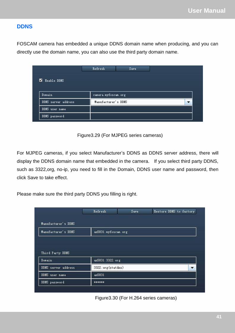
DDNS
FOSCAM camera has embedded a unique DDNS domain name when producing, and you can
directly use the domain name, you can also use the third party domain name.
Figure3.29 (For MJPEG series cameras)
For MJPEG cameras, if you select Manufacturer’s DDNS as DDNS server address, there will
display the DDNS domain name that embedded in the camera. If you select third party DDNS,
such as 3322,org, no-ip, you need to fill in the Domain, DDNS user name and password, then
click Save to take effect.
Please make sure the third party DDNS you filling is right.
Figure3.30 (For H.264 series cameras)

42
订订UUsseerr MMaannuuaall
42
Restore DDNS to factory: If you have configured Third Party DDNS successfully, but you want
to use Manufacturer’s DDNS again , here click this button and start Manufacturer’s DDNS
Service.
Now you can use http:// Domain name + HTTP Port to access the camera via internet.
Take hostname test09.myfoscam.org and HTTP Port no. 88 for example, the accessing link of
the camera via internet would be http:// camera.myfoscam.org:88.
Please make sure the port forwarding is successfully, here we recommend you to do port
forwarding manually.
For example: The camera’s LAN IP address is http://192.168.1.35 , HTTP Port is 88.
Firstly, login the router, goes to the menu of Port Forwarding or Port Trigger (or named Virtue
Server on some brands of router). Take Linksys brand router as an example, Login the
router, and goes to Applications & Gaming->Single Port Forwarding.
Secondly, Create a new column by LAN IP address & HTTP Port No. of the camera within the
router showed as below.
Figure3.31

43
订订UUsseerr MMaannuuaall
43
WIFI
This section will show you how to do wireless settings for your camera.
Step 1:
Click the Scanning button and the camera will detect all wireless networks around the area. It
should also display your router in the list
Figure3.32
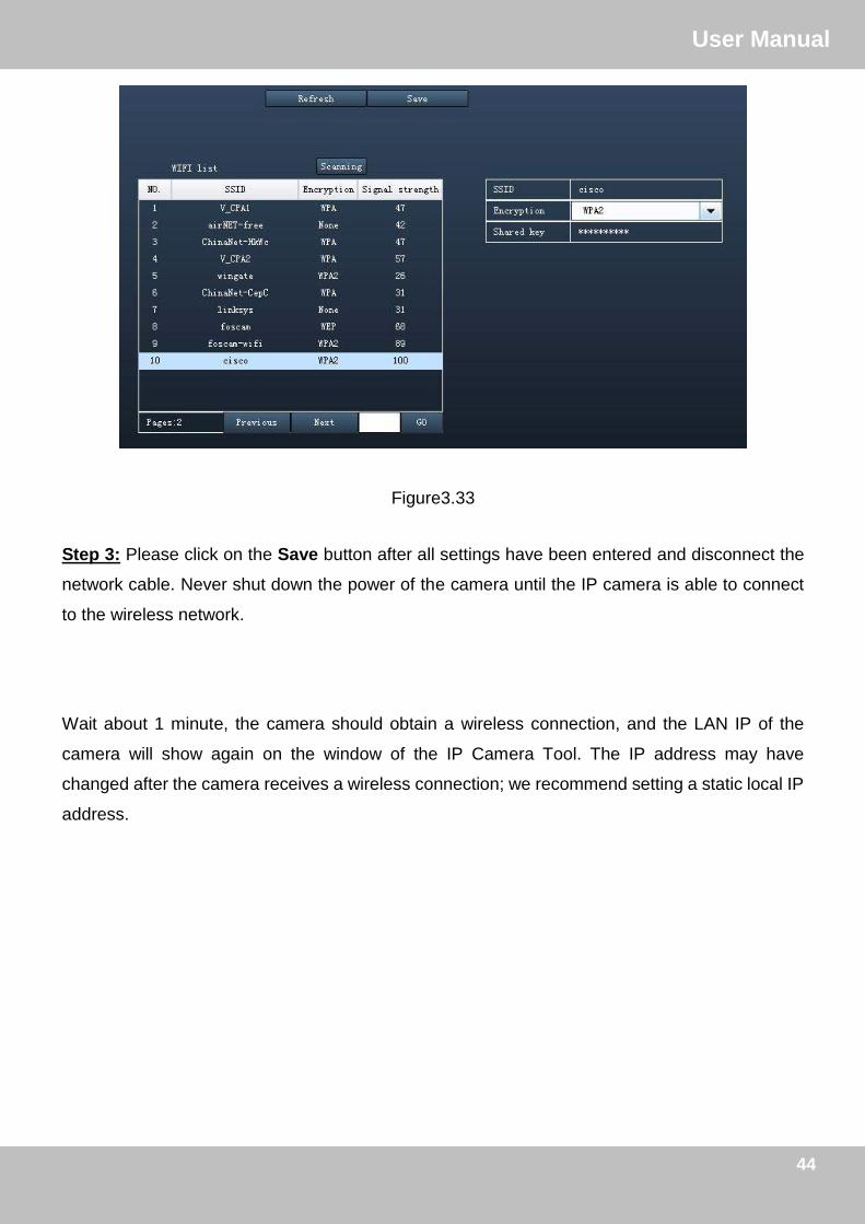
Step 2: Click the SSID (name of your router) in the list, the corresponding information related to
your network, such as the SSID and the encryption, will be filled into the relevant fields
automatically.
You will only need to fill in the password of your network. Make sure that the SSID, Encryption
and the password you filled in are exactly the same for your router.
Click Previous or Next to see other wireless networks devices if there are more than 10, you can also fill in one page number and click GO button
44
订订UUsseerr MMaannuuaall
44
Figure3.33
Step 3: Please click on the Save button after all settings have been entered and disconnect the
network cable. Never shut down the power of the camera until the IP camera is able to connect
to the wireless network.
Wait about 1 minute, the camera should obtain a wireless connection, and the LAN IP of the
camera will show again on the window of the IP Camera Tool. The IP address may have
changed after the camera receives a wireless connection; we recommend setting a static local IP
address.

45
订订UUsseerr MMaannuuaall
45
UPnP
The default UPnP status is closed. You can select the checkbox and open UPnP, then the camera’s software will be configured for port forwarding. Back to the ―Device Status‖ panel, you can see the UPnP status:
Figure3.34
There may be issues with your routers security settings, and sometimes may error. We recommend you configure port forwarding manually on your router (Figure 3.31).
ADSL (Only for MJPEG cameras)
Figure3.35
If you are connecting the camera directly to a ADSL modem, you can do ADSL settings with your
ADSL account &password provided by the ISP, then make the camera connected to the network.

46
订订UUsseerr MMaannuuaall
46
Figure3.36
MSN(Only for MJPEG cameras)
If you want the camera send its current internet IP address to you or your friends, please set
MSN settings.
Figure3.37
Click Save and go to the ―Device Status‖ screen and verify the MSN settings are succeed.
Fill in the user and password of the MSN ID you applied for your camera MSN ID in this list can chat with the camera

47
订订UUsseerr MMaannuuaall
47
When the MSN ID in the Friends list login the MAN, he can chat with camera. For example:
Foscam13(this account contained in the Friends list) log in MSN, and double click the camera’s
account (foscam31), then enter ―url?‖, the camera will send it’s current IP address to you.
Figure3.38
Note: Create a new MSN account for the camera, do not use the same MSN account as you
would like to chat with your friends. When the camera login uses the MSN account, this account
cannot be used for anything else when the camera works.

48
订订UUsseerr MMaannuuaall
48
PPPoE(Only for H.264 cameras)
If you are using a PPPoE connection, enable it and enter the User Name and Password for your
PPPoE account.
Figure3.39
Port(Only for H.264 cameras)
H.264 camera supports HTTP Port and Media Port. The Media port is used to view the camera’s
video stream, HTTP Port is used to access the camera remotely. If you want to access the
camera and view the video, the Media Port and the HTTP Port must both be configured correctly.
HTTP port / Media port: The ports can be assigned with other port number between 1 and
65535. But make sure they canl not be conflict with other existing ports like 25, 21.
Figure3.40

49
订订UUsseerr MMaannuuaall
49
3.2.4 Video
Only H.264 series camera supports video settings.
This section allows you to configure Video stream settings, On screen display and Snapshot
settings.
Encode param
Figure3.41
Stream type: There are four types to identify different streams you have set.
Resolution: The camera supports two types: 720P, VGA. The higher the resolution is, the
clearer video will become. But the code flux will become larger too, and it will take up more
bandwidth.
Bit rate: Generally speaking, the larger the bit rate is, the clearer video will become. But the bit
rate configuration should combine well with the network bandwidth. When the bandwidth is very
narrow, and bit rate is large, that will lead to video can not play well.
Frame rate: Note that a larger frame size takes up more bandwidth. When the video format is
50Hz, the maximum frame rate is 25 fps. When the video format is 60Hz, the maximum frame
rate is 30 fps. You should lower frame rate when the bandwidth is limited. Normally, when the
frame rate above 15, you can achieve fluently video.
Key Frame Interval: The time between last key frame and next key frame. The shorter the
duration, the more likely you will get a better video quality, but at the cost of higher network
bandwidth consumption.

50
订订UUsseerr MMaannuuaall
50
OSD
This page is used to add timestamp and device name on the video.
Figure3.42
Display Timestamp: There are two options: Yes or NO. Select Yes and you can see the system
date on the video,
Display Camera Name: There are two options: Yes or NO. Select Yes and you can see the
device name on the video,
Allow On Screen Display Mask: There are two options: Yes or NO. Select yes and draw a
mask area on the video, the mask area will be black on the video.
Figure3.43
The mask area

51
订订UUsseerr MMaannuuaall
51
Click Return button and return to the OSD page, click Save to take effect.
Back to the surveillance window, you can see the mask area as the following picture:
Figure 3.44
Snap
On this page you can set the snapshot pictures’ image quality and the storage path.
Figure3.45
Image Quality: Low, Middle and High. The higher the quality, the picture will be clearer.
Save To: FTP or SD Card. If you have done FTP and Alarm settings, when alarming, the camera
will snap pictures to the FTP automatically. If select SD Card as the save path, make sure the
camera has inserted in the SD card.

52
订订UUsseerr MMaannuuaall
52
3.2.5 Alarm
IP Camera supports Motion Detection Alarm, when the motion has been detected, it will send
emails or upload images to FTP.
For MJPEG Cameras
MJPEG cameras support motion alarm and sound alarm, if you want to use sound alarm, please
make sure the camera has built-in microphone or connected with outer sound pick-up device.
Figure3.46
1---- Enable alarm function
2---- The larger the number, the higher the motion sensitivity will be.
3---- Select this option to reduce false alarms when light changes.
4----- If you want to do Sound Detection Alarmed,select the checkbox.
5---- The larger the number, the higher the sound sensitivity will be.
6--- Alarm indicators.
1
2 3
4 5
7
6
8

53
订订UUsseerr MMaannuuaall
53
1) Camera will send emails when motion/sound is activated.
If you want to receive images when motion is detected, you must set Mail Service Settings first.
Then select the checkbox after Send Mail.
2)Snap Picture
When motion or sound is detected, the camera will snap pictures to you.
Capture interval: The interval time between two pictures.
7---Alarm Scheduler
Please select ―Select all‖ if you want the camera alarm at any time when motion/sound is
detected. Of course, you can select the alarm scheduler manually.
8---- Click Save to take effect
For H.264 Cameras
Figure3.47
1 2
3
4
5
6
54
订订UUsseerr MMaannuuaall
54
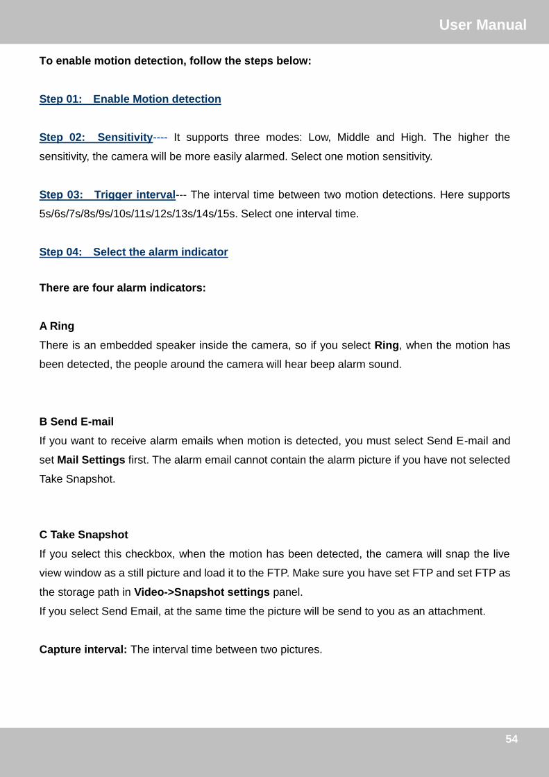
To enable motion detection, follow the steps below:
Step 01: Enable Motion detection
Step 02: Sensitivity---- It supports three modes: Low, Middle and High. The higher the
sensitivity, the camera will be more easily alarmed. Select one motion sensitivity.
Step 03: Trigger interval--- The interval time between two motion detections. Here supports
5s/6s/7s/8s/9s/10s/11s/12s/13s/14s/15s. Select one interval time.
Step 04: Select the alarm indicator
There are four alarm indicators:
A Ring
There is an embedded speaker inside the camera, so if you select Ring, when the motion has
been detected, the people around the camera will hear beep alarm sound.
B Send E-mail
If you want to receive alarm emails when motion is detected, you must select Send E-mail and
set Mail Settings first. The alarm email cannot contain the alarm picture if you have not selected
Take Snapshot.
C Take Snapshot
If you select this checkbox, when the motion has been detected, the camera will snap the live
view window as a still picture and load it to the FTP. Make sure you have set FTP and set FTP as
the storage path in Video->Snapshot settings panel.
If you select Send Email, at the same time the picture will be send to you as an attachment.
Capture interval: The interval time between two pictures.

55
订订UUsseerr MMaannuuaall
55
D Record
If you select this checkbox, when the motion has been detected, the camera will record
automatically and store the record files to the SD Card. Make sure the camera has inserted SD
card and you have set the SD card as the Alarm record files storage path, please go to
Record—> Storage Path page to verify this settings.
The default alarm record time is 30s and pre-alarm record time is 5s, please go to Record—>
Alarm Record page and change the alarm time settings.
Step 05: Alarm Schedule
Please select ―Select all‖ if you want the camera alarm at any time when motion/sound is
detected. Of course, you can select the alarm scheduler manually.
Step 06: Click Save button to take effect.
When the motion has been detected during the detection time in the detection area, the camera
will alarm and adopt the corresponding alarm indicators.

56
订订UUsseerr MMaannuuaall
56
3.2.6 Record
This section will allow you to change the record files storage path and the record time. Only
H.264 and MJ-5350 Camera supports this function.
For H.264 cameras
Storage path
The default alarm storage path is SD card. Make sure your camera has inserted in SD card.
Figure3.48
Alarm record
This page you can change the Pre-record time and Alarm record time.
Figure3.49
The default Pre-recorded time is 5s and the alarm record time is 30s, you can change another
time, click Save button to take effect.

57
订订UUsseerr MMaannuuaall
57
For MJ-5350 Cameras
This section will allow you to configure plan and alarm recording.
1- Enable the plan recording
2- Select it and the recording file will include the audio
3- Edit the plan recoding schedule
4- Select it and the camera will recording when there is motion or sound detected
5- Here you can set the Alarm and manual recording duration time
6- Her you can set the storage path of recording file, such as FTP server
7- Here you can configure the storage time of recording file
1
2 3
4
5
6
7

58
订订UUsseerr MMaannuuaall
58
3.2.7 Permission Settings
Only MJ-5350 Camera allow to use this function.
Here supports three Schedule types: Always Open, Schedule Open, and Schedule Close.
Always Open: Anyone who has the permission can access the camera anytime.
Schedule Open: Click Edit Schedule and set the time range. Anyone who has the permission
allow to access the camera during the schedule time you have Set.
Schedule Close: Click Edit Schedule and set the time range. Anyone who has the permission
can not access the camera during the schedule time you have Set.
3.2.8 PT
If you camera has connected with cradle head, here you can use PT (pan / tilt).
For MJPEG Camera
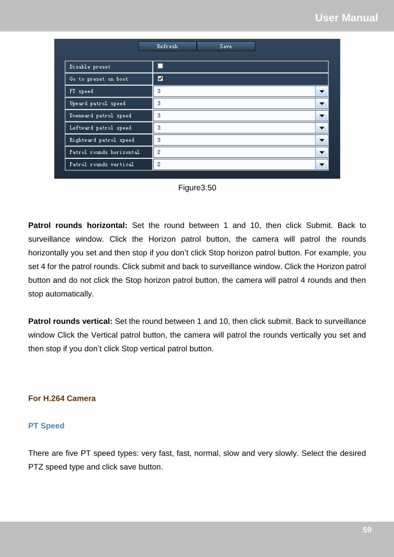
You can set pan/tilt speed. Normally, PT speed is 3. The larger the setting number, the lower
speed. Don’t enable the checkbox ―disable preset‖ if you want to use the function of preset, it will
be effective after you reboot device.
59
订订UUsseerr MMaannuuaall
59
Figure3.50
Patrol rounds horizontal: Set the round between 1 and 10, then click Submit. Back to
surveillance window. Click the Horizon patrol button, the camera will patrol the rounds
horizontally you set and then stop if you don’t click Stop horizon patrol button. For example, you
set 4 for the patrol rounds. Click submit and back to surveillance window. Click the Horizon patrol
button and do not click the Stop horizon patrol button, the camera will patrol 4 rounds and then
stop automatically.
Patrol rounds vertical: Set the round between 1 and 10, then click submit. Back to surveillance
window Click the Vertical patrol button, the camera will patrol the rounds vertically you set and
then stop if you don’t click Stop vertical patrol button.
For H.264 Camera
PT Speed
There are five PT speed types: very fast, fast, normal, slow and very slowly. Select the desired
PTZ speed type and click save button.

60
订订UUsseerr MMaannuuaall
60
Figure3.51
Cruise Track
This section explains how to add/ delete/ alter one cruise track.
There are two default cruise tracks: Vertical and Horizental.
Vertical: The camera will rotate from up to down
Horizental: The camera will rotate form left to right.
For MJ-5350 Camera
MJ-5350 Camera allow to configure PT Speed and Cruise Track.
PT Speed
Here you can set the patrol speed, patrol type and preset position on boot.
Patrol Schedule Type: Select the Patrol type and edit the schedule, during the schedule time,
the camera will patrol as the patrol type you set.
Go to preset on boot: Here select one preset position, and when the camera rebooting, it will go
to the preset position you set.

61
订订UUsseerr MMaannuuaall
61
Cruise Track
For MJ-5350 cameras, you can set the cruise track. One track can has 16 nodes at most. And
you can set the stay time for each Node.
For example: You has set one cruise track, it has four nodes, then the camera will patrol as the
track: node 1, node2, node3, then node 4.

62
订订UUsseerr MMaannuuaall
62
3.2.9 Path Settings
If you want to upload record files and images to your FTP server,you can set FTP Settings.
Figure3.52 (For H.264 series cameras)
Figure3.53 (For H.264 series cameras)
FTP server: The FTP address.
Port: Default is port 21. If changed, external FTP client program must change the server
connection port accordingly.
FTP Mode: Here supports two modes: PORT and PASV.
Username/password: The FTP account and password.
63
订订UUsseerr MMaannuuaall
63
For MJPEG Camera, here also support the following function:
Upload Image Now: This option will upload images continuously when you enable the checkbox
Enable Set Filename: When you enable this option the uploaded image will be named
according to the filename you enter. The next image will overwrite the filename of the previous
image. Hence there will only be one image, the last uploaded.
Filename: See the above option.
Note: You cannot change the name of the alarm image.
Click Save to take effect.
Click Test to see if FTP has been successfully configured.
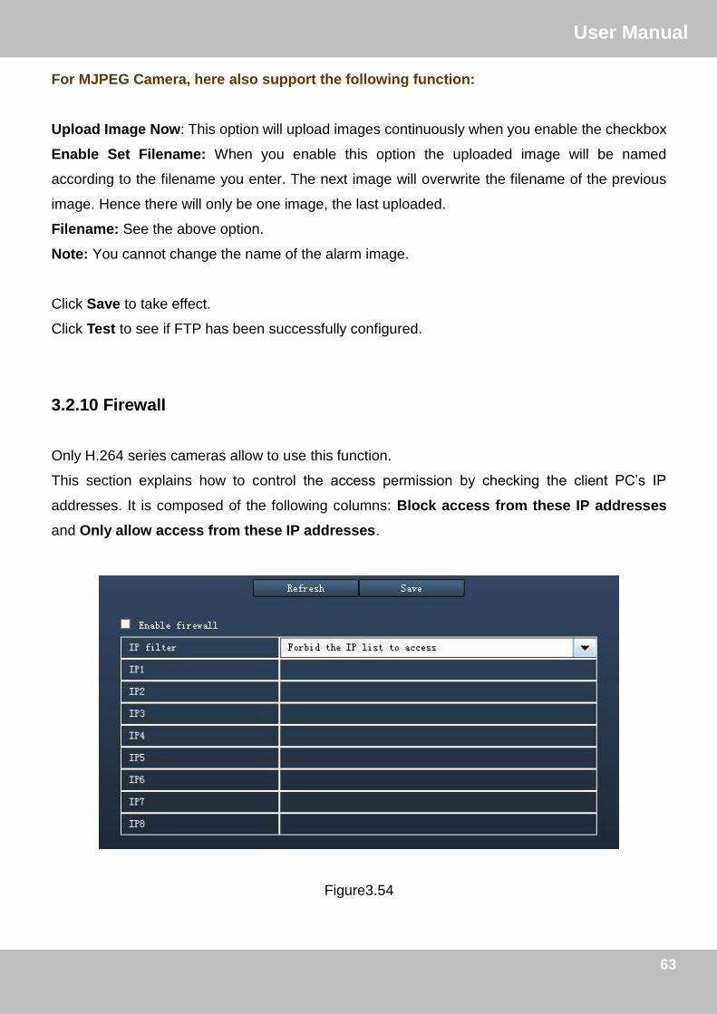
3.2.10 Firewall
Only H.264 series cameras allow to use this function.
This section explains how to control the access permission by checking the client PC’s IP
addresses. It is composed of the following columns: Block access from these IP addresses
and Only allow access from these IP addresses.
Figure3.54
64
订订UUsseerr MMaannuuaall
64
Enable firewall, If you select Only allow access from these IP addresses and fill in 8 IP addresses
at most, only those clients whose IP addresses listed in the Only allow access from these IP
addresses can access the Network Camera. If you select Block access from these IP
addresses, only those clients whose IP addresses are in the IP list cannot access the Network
Camera.
Click Save to take effect.
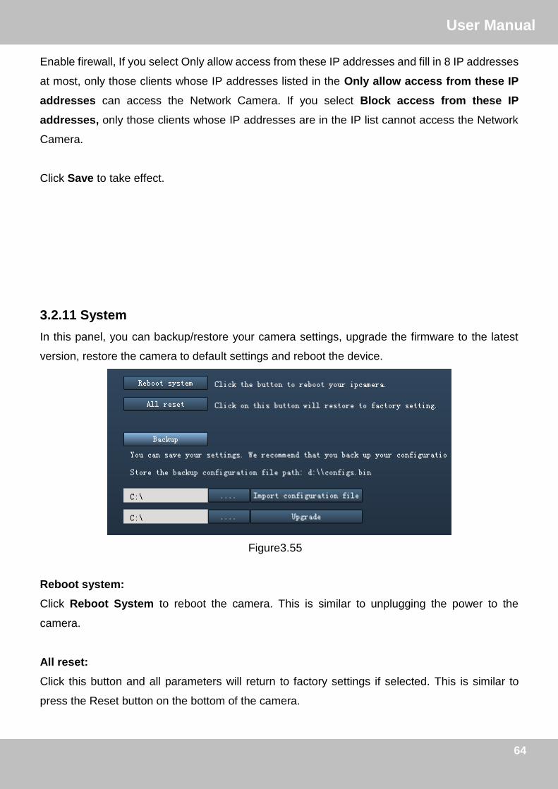
3.2.11 System
In this panel, you can backup/restore your camera settings, upgrade the firmware to the latest
version, restore the camera to default settings and reboot the device.
Figure3.55
Reboot system:
Click Reboot System to reboot the camera. This is similar to unplugging the power to the
camera.
All reset:
Click this button and all parameters will return to factory settings if selected. This is similar to
press the Reset button on the bottom of the camera.

65
订订UUsseerr MMaannuuaall
65
Backup:
Click Backup to save all the parameters you have set. These parameters will be stored in a bin
file for future use.
Import configuration file:
Select one bin file, the camera can be reloaded to restore the parameters that were set.
Upgrade:
Click Browse, choose the correct bin file and then click System upgrade. Make sure you have
unplugged the SD card.
Don’t shut down the power during upgrade. After upgrading, you can see the upgrade result.
CAUTION: If your camera works well with the current firmware, we recommend not upgrading.
Please don’t upgrade the firmware unnecessarily. Your camera may be damaged if
misconfigured during an upgrade.
1) Before upgrade the firmware, please unplug the SD card, the upgrade process may be failed
otherwise.
2) Please ensure you have download the correct firmware package for your camera before
upgrading. Read the upgrade documentation (readme.txt file) in the upgrade package before
you upgrade.
3) Upon downloading the firmware check the sizes of the .bin files. They must match the size in
the readme.txt file. If not, please download the firmware again until the sizes are the same.
Your camera will not function correctly if a corrupt .bin file is used.
4) Normally, only Device WEB UI need to be upgrade, please do not try to upgrade the Device
System Firmware.

66
订订UUsseerr MMaannuuaall
66
5) Never shut down the power of the camera during upgrade until the IP camera restart and get
connected.

67
订订UUsseerr MMaannuuaall
67
3.3 Record and Alarm This section explains how to do record for client and set the storage path for logs, pictures and
record files.
3.3.1 Record and Alarm
Figure3.56
1) Select one camera just by double clicking the camera icon in the camera list
2) Select the checkbox before Alarm timing or Record timing
Alarm timing – When the motion has been detected, the client will record automatically, and you
can see a red dot in the surveillance window of the client
Record timing—Plan record scheduler The client will record manually during the record time
range you have set, and you can see a blue dot in the surveillance window of the client
Note: For H.264 series cameras, here cannot supports Alarm timing.
3) Select one day
4) Set the Alarm or record timing
1
2 4
3 5

68
订订UUsseerr MMaannuuaall
68
5) Click Save to take effect
Now you can set alarm or plan record for each day by the same way.
The default storage path of record files is D:\Ipcam. You can change the path in this window.
When the camera alarmed, you can see a red dot in the live window:
When the camera is doing plan recording, you will see a blue dot in the live window:
1) The default storage path of recording files is F disk, when the current remaining space of disk
is less than 256M, the oldest recording files will be deleted automatically.
2) The alarm time you set in the camera web UI has much relation with the alarm time you set for
the client. If you have not set alarm time in the camera web UI, the client will not alarm anytime.

69
订订UUsseerr MMaannuuaall
69
3.3.2 Storage path and others
In the Record and Alarm page, you can set storage path and other settings for the client.
Figure3.57
Capture Picture Mode: The defalut capture picture type is JPEG, and you can not change it
here.
Automatically Save LOG to: The storage path of log history.
Save Picture To: The storage path of the sanpshot pictures.
Record Path: The storage path of record files (manually recording files, plan recording files and
alarm recording files).

70
订订UUsseerr MMaannuuaall
70
3.4 Users Here you can create users and set permission levels for client, visitor, operator or
administrator.
Figure3.58
Change the Password
Select one existent account, select Change password and enter the new password then click
Edit to take effect.
Create a new account
Enter the new user, password and permissions , then click Add to take effect.
Delete one existent account
Select the account you want to delete, then click Delete button to take effect.

71
订订UUsseerr MMaannuuaall
71
44 PPllaayy bbaacckk
This section explains how to search and play back the record files of the client or play other
videos.
Figure4.1
Step 1: Select the date: year–month-date.
.
Figure 4.2
Step 2: Select the searched types of recording files then click Search button.
Next month Last month

72
订订UUsseerr MMaannuuaall
72
Here supports three types of record files:
Manual: Manually record files.
Plan: The plan record files.
Alarm: The alarm record files.
Search: Search the record files which satisfy the corresponding conditions.
Step 3: Select the camera’s IP which you want to playback the record files.
Step 4: You will see all record files that satisfy the conditions.
Step 5: Select one record file and play it.
Select one record file just by clicking the record file name, then click Play button.
There is a button bar blow the play back window.
: Search one video files manually.
: Play one record file
: Stop playing

73
订订UUsseerr MMaannuuaall
73
: Full-screen. Press ESC and quit full-screen.
55 LLOOGG
The log record shows who accessed the client and when, what did he do with which camera.
Figure5.1
First choose the log type, the camera IP, User, Start and End time, then click Search, you can
see all logs that satisfied conditions.
Log type There are four types: All events, System events, Operation events and Alarm events.
Camera Here will show you all cameras IP that added to the client. Select one which you want to
see.
Article/page The record number of one page. You can select 100 or 1000.

74
订订UUsseerr MMaannuuaall
74
6 Lock
If you are leaving your PC, you had better lock the current screen to prevent illegal user using.
Click the icon and it will pop up a dialog box. Just click OK and lock the current screen.
7 Obtaining technical support While we hope your experience with the client is enjoyable and easy to use, you may experience
some issues or have questions that this User’s Manual has not answered. Please contact your
reseller and ask for help first, if they could not resolve your issue, please contact our company.