ce fascicule b regroupe les principes de concep-this … 9001 jar21 aqap 120 jar145 b2 premier...
TRANSCRIPT

b1
Ce fascicule "B" regroupe les principes de concep-tion des bielles métalliques et composites.
Il fait partie du catalogue général AERONAUTIQUE"AIR 2K".
• Fascicule E Embouts de bielles
• Fascicule F Equipements de bielles
• Fascicule R Roulements
• Fascicule A Rotules autolubrifiantes SARFLON
• Fascicule C Coussinets autolubrifiants SARFLON
• Fascicule M Rotules métal/métal
• Fascicule P Poulies
Le présent fascicule "B" se compose de :
• Table des matières
• Définition et applications
- pour bielles de transmission de mouvement- pour bielles de transmission d'effort
• Données techniques
1, avenue Marc Seguin - Boite postale n° 29 - 26241 SAINT-VALLIER / RHONE Cédex - FRANCETél. (33) 04.75.03.40.40 - Fax (33) 04.75.03.40.00
www.sarma-aerospace.com
This section "B" shows SARMA metallic and com-posite Rods.
It is a part of the general AERONAUTICAL "AIR 2K"catalogue.
• Section E Rod ends
• Section F Rod equipments
• Section R Rolling bearings
• Section A Self lubricating SARFLON spherical plain bearings
• Section C Self lubricating SARFLON journal bearings
• Section M Metal to metal spherical plain bearings
• Section P Pulleys
This section "B" includes the following information :
• Contents
• Definition and application
- for motion transmission rods- for load transmission rods
• Technical data
ISO 9001
JAR21
AQAP 120
JAR145
b2
PREMIER fabricant européen d'équipements pourcommandes de vol et pour structures d'avions etd'hélicoptères, SARMA participe à tous les prin-cipaux programmes aéronautiques, civils et mili-taires, au niveau MONDIAL.
Depuis plus de CINQUANTE ANS, SARMA offreaux constructeurs de l'industrie AERONAUTIQUE,le support de spécialistes hautement qualifiés etdes produits qui satisfont les spécifications lesplus exigeantes, pour les 3 lignes de produits :
● BIELLES (métalliques, composites)
● ROULEMENTS / ROTULES
● COMPOSANTS et EQUIPEMENTS ELECTRO-MECANIQUES.
La réputation de QUALITE et de FIABILITE deSARMA repose sur un programme d'investisse-ment intensif qui a permis à la Société d'équiperses nouvelles Unités de :
● SAINT-VALLIER FRANCE
● LONS LE SAUNIER FRANCE
● CLEVEDON ANGLETERRE
des moyens de production, d'études, de recherche,d'essais et de suivi de qualité les plus récents.
L'environnement qualité de SARMA, à tous lesstades industriels, de la conception à la produc-tion et au suivi en exploitation, a fait l'objet d'unereconnaissance formelle :
● De tous les clients de SARMA qui sont les donneurs d'ordre majeurs en aéronautique
● De la certification industrielle ISO 9001, décernée par le Lloyd Register
● Des certifications JAR21 et JAR145, décernées par les services officiels de navigabilité aéronautique
● De la certification AQAP 120 (OTAN), décernée par les autorités militaires françaises.
Foremost European manufacturer of flight controlequipment, aircraft and helicopter structures,SARMA participates in all the principal pro-grammes, civil and military, WORLDWIDE.
For more than 50 years, SARMA has offered to theAeronautical INDUSTRY, highly qualified specia-list support and products which satisfy the mostdemanding specifications for its 3 product lines :
● RODS (metallic and composite)
● SPHERICAL PLAIN BEARINGS / BALL BEARINGS
● COMPONENTS and ELECTRO-MECHANICALUNITS.
SARMA's reputation for quality and reliability isbased on an intensive investment programmewhich has enabled the company to equip its newsites at :
● SAINT-VALLIER FRANCE
● LONS LE SAUNIER FRANCE
● CLEVEDON ENGLAND
with the latest technology regarding production,study, research, testing, quality and follow up.
The total quality system used within SARMAhas enabled the company to obtain formal reco-gnition by :
● All SARMA's aerospace customers
● Industrial Cerification ISO 9001 as awarded by the Lloyds Register
● The certifications JAR21 and JAR145 as awarded by the Official Navigational Aeronautical Services
● The certification AQAP 120 (NATO) awarded by the French Military Authorities.
PREFACE
Propriété SARMA : ne peut être communiqué ni reproduit sans son autorisation / Property of SARMA : cannot be divulged or reproduced without company's authorization

b3
TABLE DES MATIÈRES / CONTENTS
p4-p5
p6-p7
p8-p9
p10-p12
p13
p14
p15
p16
p17
p18-p20
p20
MétalliquesMetallic
CompositesComposites Pages
Données Techniques - Technical Data
Définition et application des biellesDefinition and application of the rods
Commandes de vol linéairesLinear flight control
Commandes de vol rotativesRotational flight control
Commandes de mécanismesMechanism control
TélescopiquesTelescopisc
Limiteurs d'effort mécaniquesMechanical load limiters
Limiteurs d'effort électromécaniques Electronical load limiters
A démontage rapideQuick disassembly
De supportSupport/cross beam
De structureStruts
Biel
les
de tr
ansm
issi
on d
e m
ouve
men
tsM
otio
n tra
nsm
issi
on ro
dsBi
elle
s de
tran
smis
sion
d'e
fforts
Load
tran
smis
sion
rods
Propriété SARMA : ne peut être communiqué ni reproduit sans son autorisation / Property of SARMA : cannot be divulged or reproduced without company's authorization

I. OBJET
Les bielles étant spécifiques à chaque applica-tion, ce fascicule ne donne pas de standardsdimensionnels, mais regroupe :
• Les deux principales familles de bielles avec les règles de définition associées
- transmission de mouvements
- transmission d'efforts
• Les données techniques généralesavec les principales règles de conception.
DANS TOUS LES CAS, CONSULTER NOTRE SERVICETECHNIQUE QUI VOUS APPORTERA LES RÉPONSESAPPROPRIÉES A TOUS LES PROBLÈMES QUE VOUSVOUDREZ BIEN LUI SOUMETTRE.
II DÉFINITION
II.1 Transmissions de mouvements
• Bielles de commandes :
- Commandes de vol linéaires et rotatives
- Commandes de systèmes (mécanismes de porte, de trappe, de volets,…)
• Bielles mécaniques
- Télescopiques
- Limiteurs d'effort mécaniques et électromécaniques
- A démontage rapide.
I. PURPOSE
Since the rods are specific for each application,this section does not provide dimensional stan-dards but groups together :
• The two primary groups of rods with their corresponding rules governing definition
- motion transmission
- load transmission
• The general technical data with the primary rules governing design.
ALWAYS CONSULT OUR TECHNICAL DEPART-MENT, WHO WILL PROVIDE THE RIGHT ANSWERSTO ALL YOUR PROBLEMS.
II. DEFINITION
II.1 Motion transmission
• Control rods :
- Linear and rotational flight control
- System control (door, undercarriage door and flap mechanisms….)
• Mechanical rods
- Telescopic
- Mechanical and electromechanical load limiters
- Quick disassembly.
b4 Propriété SARMA : ne peut être communiqué ni reproduit sans son autorisation / Property of SARMA : cannot be divulged or reproduced without company's authorization
BIELLES MÉTALLIQUESMETALLIC AND
DÉFINITIONDEFINITION
Bielles de commande de vol / Flight control rods

Propriété SARMA : ne peut être communiqué ni reproduit sans son autorisation / Property of SARMA : cannot be divulged or reproduced without company's authorization b5
II.2 Transmissions d'effort
• Bielles de support
- Moteur auxiliaire- Conditionnement d'air et d'eau- Nacelles- Equipements- Aménagement intérieur- etc …
• Bielles de structure
- Support plancher- Caisson de voilure- Liaison empennage/fuselage- Fuselage- etc …
II.2 Load transmission
• Support rods
- Auxiliary engine - Air and water conditioning system- Nacelles- Equipment- Cabin equipment - etc …
• Structural rods
- Floor beam- Wing box- Tail/fuselage liaison - Fuselage - etc …
ET COMPOSITESCOMPOSITE RODS
DÉFINITIONDEFINITION
Bielles de structureStruts

Faisant partie du système de commande de vol,leur fonction est de transmettre un mouvement.
La conception d'un système de commande de volpar bielle se fait avec un maximum de bielles fixes(type ES pour les bielles métalliques et intégralespour les bielles composites) et un minimum debielles réglables.
La précision de réglage en longueur est obtenuepar une combinaison de filetage droite et gauche,associée à un freinage positif micrométrique (voir"Données techniques" §1 et §6).
Dans le cas de grande longueur, les bielles enmatériaux composites présentent un avantagedécisif de par leur plus grande rigidité.
Par ailleurs, leur avantage se confirme dans lecas d'un environnement structural lui-même enmatériau composite : en évitant les problèmes dedilatation linéaires différentielles.
Les charges transmises par les bielles de com-mande de vol excédant rarement 1 500 daN, nouspréconisons les embouts avec roulement à rotule.
Le tableau 1 donne, à partir d'une charge donnée,un choix d'embouts et de chapes répertoriés dansles fascicules E et F.
Le filetage de ces extrémités détermine le dia-mètre et l'épaisseur du tube à retenir pour unebielle équipée optimisée. Le choix définitif du tubedépend de la longueur de la bielle (voir "Donnéestechniques §IV).
As part of the flight control system, they are usedfor transferring linear motion.
A rod flight control system is designed with amaximum number of fixed rods (ES type for metal-lic rods and integral for composite rods), and aminimum number of adjustable rods.
Precision of the adjustment is obtained by acombination of the left and right threads, togetherwith a micrometric positive locking (see "Tech-nical Data" §1 and §6).
Where extra long rods are required compositematerial rods have a decisive advantage due totheir greater rigidity.
In addition they have a further advantage wherethe structural environment itself is made of com-posite materials, by avoiding problems of diffe-rential linear expansion.
Since the load transmitted by the flight controlseldom exceeds 1 500 daN we recommend ballbearing rod ends.
Table 1 provides, for a given load, a choice of rodends and fork ends listed in sections E and F.
The end threads give the diameter and thicknessof the tube required for an optimised rod assembly.The final choice depends on the rod length (seeTechnical Data §IV).
b6 Propriété SARMA : ne peut être communiqué ni reproduit sans son autorisation / Property of SARMA : cannot be divulged or reproduced without company's authorization
BIELLES MÉTALLIQUESMETALLIC AND
COMMANDES DE VOL LINÉAIRESLINEAR FLIGHT CONTROL

Propriété SARMA : ne peut être communiqué ni reproduit sans son autorisation / Property of SARMA : cannot be divulged or reproduced without company's authorization b7
ET COMPOSITESCOMPOSITE RODS
COMMANDES DE VOL LINÉAIRESLINEAR FLIGHT CONTROL
Tableau 1 : Applicable aux bielles en alliage léger Table 1 : Use for light alloy tube
1400
1200
1000
800
600
400
28X2
28X1
.528
X1.2
28X1
25X1
.625
X1.2
25X1
20X1
.620
X1.2
20X1
18X1
16X1
.616
X1.2
16X1
12X1
10X1
Tube
s m
étal
lique
s en
fonc
tion
des
extré
mité
s (d
iam
ètre
X é
pais
seur
s)Tu
be in
con
nect
ion
with
end
s (d
iam
eter
X th
ickn
ess)
Extré
mité
s en
fonc
tion
des
char
ges
(dan
)En
ds d
epen
ding
of t
he lo
ads
1/4 - 28 5/16 - 24 M8X1 3/8 - 24 M10X1 7/16 - 24 M12X1 M12X1.5 1/2 - 20 M14X1 M14X1.5
REP3M4-2RK3-4-127
C5M201-135-1
RN3-4-127RK3-4-127
CN6.35CSY4-5
CN6.35CSY4-6
CN6M201-136-1
RN4-6-175RK4-6-175
RN4-8-175RK4-8-175
CN8M201-138-1
CN8MSP1201-138-2
CN7.94CSY5-6
CN7.94CSY5-7
CN9.52CSY6-7
CN9.52CSY6-8
CN10MSP1201-1310-1
CN10M201-1310-2
filetagesthread
Filetages conseillés / Preferred thread
Filetages possibles / Possible thread
Filetages à éviter / Thread to avoid
Filetages à ne pas utiliser / Thread not to used
Embouts à roulementChapes
Ball bearing rod endsFork ends

Utilisées généralement pour les commandes devolets les bielles rotatives SARMA sont équipées :
- de "joints de cardan" pour assurer un mouvement rotatif homocinétique (applicable aux bielles métalliques et composites)
- ou de flasques intégrés (applicable aux bielles composites).
Bielles métalliques et composites avec "joint de cardan"
Metal and composite rods with "universal joint"
SARMA propose quatre tailles de “joints decardans” standard en fonction des couples àtransmettre, de la vitesse de rotation et de l’anglede désalignement ß.
Usually used for flap controls, SARMA rotationalrods have :
- "universal joints" for assuring a homokinematic rotational motion (applicable to metal and composite rods)
- integral flanges (applicable to composites rods).
Bielles composites avec flasques intégrésComposite rods with integral flanges
SARMA proposes four sizes of standard "univer-sal joints" depending on the torque to be trans-mitted, the rotational speed and angle out ofalignment ß.
b8 Propriété SARMA : ne peut être communiqué ni reproduit sans son autorisation / Property of SARMA : cannot be divulged or reproduced without company's authorization
BIELLES MÉTALLIQUESMETALLIC AND
COMMANDES DE VOL ROTATIVESROTATIONAL FLIGHT CONTROL

Propriété SARMA : ne peut être communiqué ni reproduit sans son autorisation / Property of SARMA : cannot be divulged or reproduced without company's authorization b9
ET COMPOSITESCOMPOSITE RODS
COMMANDES DE VOL ROTATIVESROTATIONAL FLIGHT CONTROL
Le tableau, ci-dessous, donne les dimensionsd’interface pour chacun des types et tailles de“joints de cardans” standard.
The table below gives the fit dimensions for eachtype and size of standard “universal joint”.
(1) CF = Cannelures femelles(2) CM = Cannelures mâles
Cardan fixeFixed universal joint
TypesDIMENSIONS
Cardan fenduSlotted universal joint
Cardan coulissant dans canneluresretreintes
Sliding Universal joint surged spline
Support roulementBearing support
(1) CF = Internal spline(2) CM = External spline
20
20
12 x 10 x 1
25
20
14 x 12 x 0,75
35
20
14 x 12 x 0,75
25
33
20
12 x 10 x 1
16
M18 x 1,5
27
48,5
60,5
D
CF(1)NFE22141
L
D
CF(1)NFE22141
L
D
CF(1)NFE22141
L
C CourseStroke
D
CM(2)NFE22141
d
M
L1
L2
L3
25
25
15 x 13 x 1
35
25
15 x 13 x 1
38
25
15 x 13 x 1
35
38
25
15 x 13 x 1
16
M18 x 1,5
37
48,5
60,5
32
32
17 x 15 x 1
40
32
17 x 15 x 1
44
32
17 x 15 x 1
40
46
32
17 x 15 x 1
20
M24 x 1,5
42
58,5
70,5
40
40
17 x 15 x 1
48
40
20 x 14 x 1,25
50
40
17 x 15 x 1
48
53
40
17 x 15 x 1
20
M24 x 1,5
50
58,5
70,5

Intégrées à un système, elles transmettent égale-ment un mouvement :
I. SYSTÈME DE VERROUILLAGE / DÉVERROUILLAGE DES PORTES
• Ce système doit être intégré dans l'épaisseurdes portes, d'où un encombrement le plus réduitpossible.
• Ce faible encombrement impose des bielles :- en tube rétreint- en tube usiné- monolithiquesdans lesquelles sont montées des rotules ou desembouts à rotule autolubrifiante de type SARFLON.Pour éviter un durcissement dans la commande(dû aux conditions de montage ou à des élémentsextérieurs). SARMA fournit ces rotules à "coupleréduit" (voir fascicule A) de l'ordre de 0,02 Nm.
• On trouve également des bielles, dites "méca-niques" intégrant des systèmes à ressort pourl'aide à l'effort de verrouillage ou démontablespour les intégrer facilement dans la structuremême de la porte (voir page b16).
• Du fait du faible encombrement, ces bielles sontgénéralement métalliques.
Included in a system they also transfer motion:
I. DOOR LOCKING/UNLOCKING SYSTEM
• The system must be included in the door thick-ness and therefore occupies as little space aspossible.
• This small size requires rods : - in swaged tube- in machined tube- monolithicin which are assembled bearings or SARFLONtype self lubricating rod ends.To avoid tightening of the control system (due tofitted conditions or external elements).SARMA supplies these bearings with “reducedtorque” (see Section A) of about 0,02 Nm.
• There are also so-called “mechanical” rodsincluding a spring system to compensate the loc-king strength, or that can be disassembled foreasy integration in the door structure itself(see page b16).
• Due to their small size these rods are usuallymetallic.
b10 Propriété SARMA : ne peut être communiqué ni reproduit sans son autorisation / Property of SARMA : cannot be divulged or reproduced without company's authorization
BIELLESMETALLIC
BIELLES DE MÉCANISMESMECHANISM RODS

Propriété SARMA : ne peut être communiqué ni reproduit sans son autorisation / Property of SARMA : cannot be divulged or reproduced without company's authorization b11
MÉTALLIQUESRODS
BIELLES DE MÉCANISMESMECHANISM RODS
II. BIELLES DE TRAPPE DE TRAIN D'ATTERRISSAGE
• Elles sont soumises à un environnement sévère :
- Contaminants tels que : liquide de nettoyage, de dégivrage, …
- Eau, glace,- Projection de pierres,
etc …
• Les tubes ont une protection renforcée : peintu-re intérieure et extérieure sur oxydation anodiquechromique pour les tubes en alliage léger. Destubes en acier inoxydable sont également utilisés,selon la sévérité de l'application.
• Pour conserver une grande rigidité, ils sontgénéralement équipés de rotules ou embouts àrotule de type métal/métal, donc à graisser (voirfascicules E et M).
• L'environnement très sévère impose des biellesmétalliques.
II. UNDERCARRIAGE EXIT DOOR RODS
• These are subjected to severe environmentalcondition:
- Contaminants such as : cleaning and defrosting liquids, …
- Water, ice,- Stone projection,
etc …
• The tubes have a protective reinforcement :internal and external paint work on anodisingoxidation for light alloy tubes. Stainless steeltubes are also used, depending on the severity ofthe application.
• To maintain rigidity,they usually have metal tometal spherical plain bearings or bearing rodends, which therefore require lubrication( seeSections E and M).
• The severe environment requires the use ofmetallic rods.

BIELLES MÉTALLIQUESMETALLIC RODS
BIELLES DE MÉCANISMESMECHANISM RODS
III. BIELLES DE PUISSANCE POUR COMMANDE DE VOLETS
Placées entre la structure de la voilure et lesvolets ces bielles supportent les efforts aérodyna-miques dus au déplacement de ceux-ci sous l'ac-tion des servo-commandes de puissance.Ces efforts sont très élevés, souvent plusieursdizaines de tonnes.
• Les tubes sont généralement en acier inoxy-dable pour supporter ces efforts importants.
• Le tableau ci-dessous donne, à titre d'exempleune sélection d'embouts à rotule préconisés.
CHOIX DES ÉQUIPEMENTS
III. FLAP CONTROL RODS
Located between the wing structure and theflaps, the rods support the aerodynamic stressdue to their movement under the action of thepowered servo-controls.The stress is very heavy, often of several tons.
• The tubes are usually made of stainless steel inorder to support these heavy stresses
• The table below gives a selection of ball bearingrod ends as an example.
CHOICE OF EQUIPMENT
b12 Propriété SARMA : ne peut être communiqué ni reproduit sans son autorisation / Property of SARMA : cannot be divulged or reproduced without company's authorization
46000
35400
32000
26700
15300
14000
13000
12800
12000
10000
9700
9000
FiletageThread 5/8-18 3/4-16 7/8-14 1.1/4-12 1.1/2-12
UMJ/XRL 15,87CEY10-10-190EMJ/RL 15,87CEY 10-10-190
UMJ/XRL 19,05CEY12-12-222
EMJ/RL 19,05CEY12-12-222EMJ/RT 15,87
UMJ/XRL 22,22
EMJ/RL22,22
EMJ/RT 22,22
EMJ/RT 19,05
UMJ/XRL 25,4
EMJ/RL 25,4
EMJ/RT 25,4
EM/RL 31,75
ChapesFork ends
EmboutsRod ends
CHA
RGES
STA
TIST
IQU
ES U
LTIM
ESUL
TIM
ATE
STAT
ISTI
CAL
LOAD
S

Propriété SARMA : ne peut être communiqué ni reproduit sans son autorisation / Property of SARMA : cannot be divulged or reproduced without company's authorization b13
BIELLES TÉLESCOPIQUES
Elles sont souvent utilisées pour le maintien enposition ouverte des capots ou trappes de visite.
Le système de verrouillage / déverrouillage estcomposé de plusieurs billes, largement dimen-sionnées pour supporter les charges de la bielle.Le déverrouillage s'effectue par simple coulisse-ment de la bague moletée.
Les bielles sont en général verrouillées en posi-tion étendues et libres en position rétractée.
Néanmoins, d'autres systèmes sont proposés :
• Verrouillage en position rétractée• Verrouillage dans les deux positions• Déverrouillage sous charge• Bielles compas
Par nature, ces bielles n'existent qu'en versionmétallique.
TELESCOPIC RODS
These are often used for maintaining inspectiondoors in an open position.
The locking/unlocking system has several ballsfor supporting the loads. Simply slide the knurledring to unlock.
The rods are usually locked in extended positionand free in retracted position.
Other systems, however, are suggested :
• Locking in retracted position• Locking in both positions• Unlocking under load• Compass rods
Of their nature, these rods exist only in metallicversion.
Position étendue / Extended position
Course / Stroke
Position rétractée / Retracted position
BIELLES MÉTALLIQUESMETALLIC RODS
BIELLES MÉCANIQUESMECHANICAL RODS

LIMITEURS D’EFFORTS MECANIQUES
Ces bielles de sécurité servent de "fusible" dans lachaîne cinématique lorsque l'effort nécessaire àla transmission du mouvement est supérieur àcelui initialement prévu :
• En fonctionnement, la bielle reste rigide et trans-met le mouvement demandé.
• Sous une surcharge, la bielle se comprime ou sedétend, ce qui bloque la transmission du mouve-ment.
L'ensemble de ce système repose sur un jeu deressorts judicieusement disposés.
Nous calculons le seuil de déclenchement enfonction de la courbe de charge, cas par cas.
MECHANICAL LOAD LIMITERS
These safety rods act as a “fuse” in the sequen-ce of operations chain when the necessary loadto transfer the motion is higher than allowed one:
• During operation the rod remains rigid andtransmits the required movement.
• Under overload the rod retracts or extends,which blocks the motion transmission.
The whole system rests on a set of accuratelyplaced springs.
We calculate the release level according to theload curve in case by case.
b14 Propriété SARMA : ne peut être communiqué ni reproduit sans son autorisation / Property of SARMA : cannot be divulged or reproduced without company's authorization
BIELLES MÉTALLIQUESMETALLIC AND
BIELLES MÉCANIQUESMECHANICAL RODS
Seuil de déclenchementRelease level
Seuil de déclenchementRelease level
mmExtension
Compressionmm
F
F
Propriété SARMA : ne peut être communiqué ni reproduit sans son autorisation / Property of SARMA : cannot be divulged or reproduced without company's authorization b15
ET COMPOSITESCOMPOSITE RODS
BIELLES MÉCANIQUESMECHANICAL RODS
LIMITEURS D’EFFORTS ELECTROMECANIQUES
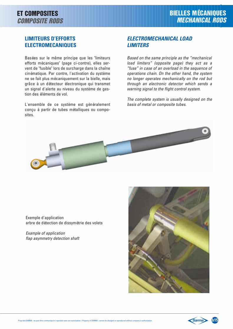
Basées sur le même principe que les "limiteursefforts mécaniques" (page ci-contre), elles ser-vent de "fusible" lors de surcharge dans la chaînecinématique. Par contre, l'activation du systèmene se fait plus mécaniquement sur la bielle, maisgrâce à un détecteur électronique qui transmetun signal d'alerte au niveau du système de ges-tion des éléments de vol.
L'ensemble de ce système est généralementconçu à partir de tubes métalliques ou compo-sites.
ELECTROMECHANICAL LOAD LIMITERS
Based on the same principle as the “mechanicalload limiters” (opposite page) they act as a“fuse” in case of an overload in the sequence ofoperations chain. On the other hand, the systemno longer operates mechanically on the rod butthrough an electronic detector which sends awarning signal to the flight control system.
The complete system is usually designed on thebasis of metal or composite tubes.
Exemple d'application arbre de détection de dissymétrie des volets
Example of application flap asymmetry detection shaft

BIELLES A DÉMONTAGE RAPIDE
Dans les cas : • où une bielle peut gêner, voire interdire l'accèsà un équipement,• où il est nécessaire pour une visite d'ouvrir pluslargement une trappe ou un capot,l'utilisation d'une bielle à démontage rapide estindispensable.
SARMA a développé des bielles qui se séparenten deux parties, sans recours à aucun outil, libé-rant ainsi le passage.
Elles peuvent ensuite être ré-assemblées trèsfacilement et même en "aveugle".
QUICK DISASSEMBLY RODS
If:• a rod prevents access to equipment,• or it is necessary to open a door or hood widerto carry out an inspection,a quick disassembly rod is necessary.
SARMA has developed rods that separate intotwo parts without the use of a tool, thus freeingthe passage.
They can be very easily, even “blindly”, reassem-bled.
b16 Propriété SARMA : ne peut être communiqué ni reproduit sans son autorisation / Property of SARMA : cannot be divulged or reproduced without company's authorization
BIELLES MÉTALLIQUESMETALLIC RODS
BIELLES MÉCANIQUESMECHANICAL RODS

Propriété SARMA : ne peut être communiqué ni reproduit sans son autorisation / Property of SARMA : cannot be divulged or reproduced without company's authorization b17
Elles peuvent être indifféremment "métalliques"(généralement en alliage léger) ou en matériaucomposite (presque toujours à base de fibres decarbone).
Toutes ces bielles sont calculées et définies àpartir des charges combinées axiales/latéralesqu'elles supportent.
Les extrémités sont généralement des chapes enalliage léger ou en titane (voir fascicule F).
On peut distinguer 2 grandes familles :
- Bielles pour fortes charges
- Bielles pour charges moyennes
Bielles pour fortes charges :
Par exemple pour support d'APU, de climatisa-tion,… Ces bielles sont très souvent de type"réglable" de manière à positionner avec préci-sion l'équipement dans la structure.
Pour les environnements sévères tels que "zonefeu" par exemple, SARMA a prévu des bielles inox.
Bielles pour charges moyennes :
Par exemple pour support d'aménagement decabine, de cloisons, ….Elles peuvent être fixes ou réglables selon les cas.
Pour les endroits "visibles", nous avons prévu unecondition "esthétique".
They may be either of metal (usually a light alloy)or of a composite material (nearly always on thebasis of carbon fibres).
All these rods are calculated and defined on thebasis of the combined axial/lateral loads theysupport.
The ends are usually light alloy or titanium forkends (see Section F).
There are 2 important groups :
- Heavy load rods
- Medium load rods
Heavy load rods :
For supporting APU, air conditioning, for example,… These rods are often “adjustable” for assem-bling equipment in the structure with precision.
SARMA provides stainless steel rods for severeenvironments such as the “fire area” for example.
Medium load rods :
For supporting cabin equipment, .…
These can be fixed or adjustable as required.
We provide an “aesthetic” look for “visible”parts.
BIELLES MÉTALLIQUES ET COMPOSITESMETALLIC AND COMPOSITE RODS
BIELLES DE SUPPORTSUPPORT RODS

Elles font partie intégrante de la structure et sontdonc soumises à toutes les charges importantesque subissent les structures d'avions ou d'hélico-ptères.
Elles peuvent être "métalliques" ou "composites".
Pour ces bielles de dimensions importantes, lasolution "composites" est particulièrement inté-ressante au niveau du meilleur compromiscoût/masse.
De par sa technologie utilisée pour les matériauxcomposites, SARMA maîtrise parfaitement lesvaleurs de rigidité pour optimiser le dimensionne-ment des bielles.
Quelle que soit la technologie utilisée, les biellesde structure sont toujours à entre-axes fixe.
Elles sont donc à :
embout fixe
ou intégrale,
c'est-à-dire chape usinée directement dans letube
Pour des raisons de simplicité, de coût et demeilleure performance, nous préconisons toujours
LA VERSION INTÉGRALE
These are an integral part of the frame and there-fore subject to all the important loads sustainedby aircraft and helicopter structures.
They may be either “metallic” or “composite”.
For these large rods the “composite” solution isof particular interest from the cost/weight pointof view.
Through its technology used in the manufactureof composite materials,SARMA has completecontrol of rigidity values for optimising rod sizing.
Whatever technology is used, the structural rodsalways have a fixed centre-to-centre distance.
They therefore have :
a fixed rod end
or an integral rod end
That is to say, a fork end machined directly on thetube.
For the sake of simplicity, cost and performancewe always recommend the
INTEGRAL VERSION
b18 Propriété SARMA : ne peut être communiqué ni reproduit sans son autorisation / Property of SARMA : cannot be divulged or reproduced without company's authorization
BIELLES MÉTALLIQUESMETALLIC AND
BIELLES DE STRUCTURESTRUCTURAL RODS

Propriété SARMA : ne peut être communiqué ni reproduit sans son autorisation / Property of SARMA : cannot be divulged or reproduced without company's authorization b19
ET COMPOSITESCOMPOSITE RODS
BIELLES DE STRUCTURESTRUCTURAL RODS
Pour les bielles métalliques, les capacités indus-trielles de SARMA permettent le rétreint par for-geage à froid, en version intégrale, des tubes enalliage léger de ø allant jusqu'à 100 mm avec unentre-axes de 2 m et de forger à chaud des tubesen acier inoxydable.Ces bielles étant à entre-axes fixe, celui-ci doitêtre réalisé avec une grande précision afin d'évi-ter toute précontrainte lors du montage sur lastructure.
2 possibilités :
- Perçage d'une extrémité par SARMA et contre-perçage de l'autre extrémité directement sur lastructure de l'aéronef.
- Entre-axes mesuré sur la structure, perçageeffectué par SARMA sur les 2 extrémités en fonc-tion de la cote relevée. SARMA livre ainsi cesbielles en KIT pour montage direct sur avion.
For metallic rods, SARMA’s industrial potentialallows cold forge swaging, in the integral version,of light alloy tubes with a diameter of up to 100mm and a centre-to-centre distance of 2m, andalso hot forging of stainless steel tubes.
Since these rods have a fixed center-to-centerdistance this must be carried out with great pre-cision to avoid any pre-stressing on structuralassembly.
There are 2 possibilities :
- Drilling of one end by SARMA and counterdrilling of the other end directly on the aircraftstructure.
- Center-to-center distances measured on thestructure, boring carried out by SARMA on bothends in accordance with the measurementstaken. SARMA therefore delivers these rods inKIT for direct aircraft assembly.
Exemple d’un kit de bielles prêt à monterExample of rod kit ready to be fitted

DONNÉES TECHNIQUES TECHNICAL DATA
b20 Propriété SARMA : ne peut être communiqué ni reproduit sans son autorisation / Property of SARMA : cannot be divulged or reproduced without company's authorization
I. CONCEPTION
I.1 - Bielles rétreintes à extrémités rapportées
I.1.1 - Extrémités réglablesI.1.2 - Extrémités fixes
I.2 - Bielles intégrales ou semi-intégrales
I.3 - Bielles monolithiques
I.4 - Bielles mécaniques
II. CONCEPTION DU CORPS DE BIELLE
II.1 - Corps de bielles métalliques rétreints
II.2 - Corps de bielles composites
III. PROTECTIONS
IV. SOLLICITATIONS MÉCANIQUES
V - SOLLICITATIONS ENVIRONNEMENTALES
VI - SYSTEME DE FREINAGE
VII - QUALIFICATION
VIII - SUIVI QUALITE EN FABRICATION
IX - CAHIER D'EXPRESSION DES BESOINS
l. DESIGN
I.1 - Swaged rods with added ends
I.1.1 - Adjustable endsI.1.2 - Fixed ends
I.2 - Integral or semi-integral rods
I.3 - Monolithic rods
I-4 - Mechanical rods
II. DESIGN OF THE ROD BODY
II.1 - Swaged metallic rod body
II.2 - Composite rod body
III - PROTECTION
IV - MECHANICAL STRENGTH
V - ENVIRONMENTAL STRENGTH
VI - LOCKING DEVICE
VII - QUALIFICATION
VIII - QUALITY ASSURANCE PROVISIONS
IX - SPECIFICATION OF REQUIREMENTS

Propriété SARMA : ne peut être communiqué ni reproduit sans son autorisation / Property of SARMA : cannot be divulged or reproduced without company's authorization b21
I. CONCEPTION
On distingue 4 familles principales de bielles :
• les bielles intégrales ou semi-intégralesintegral or semi-integral rods
I. DESIGN
There are 4 main groups of rods :
• les bielles monolithiquesmonolithic rods
• les bielles à extrémités rapportées / rods with inserted ends
• les bielles mécaniques / mechanical rods

b22 Propriété SARMA : ne peut être communiqué ni reproduit sans son autorisation / Property of SARMA : cannot be divulged or reproduced without company's authorization
I.1 Bielles à extrémités rapportées :
On regroupe sous cette terminologie l’ensembledes bielles composées d’un corps tubulairemétallique ou composite dont les 2 extrémitéssont des équipements rapportés par vissage ousertissage.
Les extrémités peuvent être à chape simple oudouble, à cardan, à embout à articulation simpleou à articulation double. Ces extrémités peuventêtre réglables ou fixes par rapport au corps tubu-laire.
Dans le cas des bielles composites, la liaisoncorps-extrémité est assurée par un insert titanesolidarisé mécaniquement lors de la polymérisation.
Bielle métallique réglableAdjustable length metallic rod
Bielle métallique fixe Fixed length metallic rod
Bielle Composite réglable ou fixeAdjustable or fixed length composite rod
I.1 Rods with added ends :
Under this heading we group all the rods having ametallic or composite tubular body with the 2ends added by screwing or swaging.
The ends can be a single or double fork end, uni-versal joint, or a single or double bearing rod end.They are adjustable or fixed to the tubular body.
For composite rods the body-end connection ismade secure by a titanium insert mechanicallyattached during curring.
{

Propriété SARMA : ne peut être communiqué ni reproduit sans son autorisation / Property of SARMA : cannot be divulged or reproduced without company's authorization b23
I.1.1 Extrémité réglable :
Une extrémité réglable est une extrémité visséedans le corps de bielle et immobilisée lors dumontage sur aéronefs par un dispositif frein/écrou après ajustement dans la position demandée.
• Dispositifs de freinage réglable : Ces dispositifspermettent de rendre l’ensemble corps de bielleet embouts solidaire en s’appuyant sur le principede l’écrou - contre-écrou.
On distingue 3 groupes principaux :
Les dispositifs les plus courants, ainsi que leursconditions d’utilisation sont décrits dans le cha-pitre VI.
• Précision d’ajustement : la précision d'entre-axes est souvent incompatible avec l'impositiond'orientation des extrémités l'une par rapport àl'autre. en choisissant la bonne configurationd'extrémité du tube et le type de freinage, SARMAobtient une très grande précision de ces biellesainsi assemblées.
I.1.1 Adjustable end :
An adjustable end is an end screwed into thebody of the rod and locked after assembly on theaircraft in the required position.
• Adjustable locking devices : Rod end installa-tion into the rod are safetied by the use of a loc-king device based on a check nut principle.
There are 3 main groups :
The most common devices and how to use themare described in Chapter VI.
• Adjustment precision : the center-to-centerdistance precision is often incompatible with theorientation imposed by the interrelation of theends. By choosing the right configuration of thetube end and type of lock, SARMA achieves greatprecision in the assembly of these rods.
Contre écrouCheck nut
Frein d'écrouTab washer
Freins d'extrémité et d'écrouLocking device, positive index

b24 Propriété SARMA : ne peut être communiqué ni reproduit sans son autorisation / Property of SARMA : cannot be divulged or reproduced without company's authorization
• Implantation minimale : celle-ci est contrôléeau moyen d'un repère visuel selon les deuxméthodes ci-dessous, couramment utilisées :
Gorge circulaire peinte en rouge sur emboutsCircular groove painted in red on the rod ends
CALCUL DES REGLAGES
Selon le type de repère utilisé, les calculs deréglage se font en cumulant les dimensions ettolérances de chaque pièce. Avec ses élémentsstandardisés, SARMA donne pour chaque appli-cation la valeur de réglage optimum.
I.1.2 Extrémité fixe :
Elle est rendue solidaire de façon permanente ducorps de bielle. Toute modification d'entre-axes oud'orientation entraîne une rupture de l'ensemble.
Cette technologie ne concerne que les biellesmétalliques. Pour les bielles composites, la ver-sion "intégrale" est plus avantageuse.
Cette fixation permanente peut-être réalisée dedifférentes façons :
• par rivetage• par boulonnage• par sertissage (système ES)• par l’utilisation d’un frein
Les 2 premiers modes sont encore réalisés dansle cadre de définition de première générationsupplantée depuis par l’utilisation du sertissageou système "ES" (voir détail en partie VI).
Dans certaines applications, le recours au freina-ge par frein cuvette permet de renforcer cetteliaison notamment avec l’emploi de frein cuvettede 2ème génération que sont les écrous freincuvettes (partie VI).
Dans tous les cas, une bielle fixe est un ensembleindissociable ; SARMA ne fournit que la bielle fixeéquipée.
• Minimum implant : this is controlled by a sightmark according to one of the usually usedmethods below :
Trou de contrôle sur corps de biellesInspection hole on the rod body
ADJUSTMENT CALCULATION
According to the type of sight mark used, adjust-ment is effected by cumulating the dimensionsand tolerances of each part. SARMA uses itsstandardised equipment to give optimum adjust-ment to each application.
I .1.2 Fixed end :
This is permanently attached to the rod body. Anymodification of the centre-to-centre distance ororientation results in breakage of the assembly.
This technology only concerns metallic rods. Forcomposite rods,the “integral” version is moreadvantageous.
This permanent attachment can be carried out indifferent ways :
• by riveting• by bolting• by swaging (ES system)• by using a locking device
The first 2 ways are still used in the definition ofthe first generation structures, since supplantedby the use of the swaging or “ES” system (seedetails in Part VI).
For certain applications the use of a cup lockingdevice reinforces this connection, especially withthe use of 2nd generation cup locks that are cuplock nuts (Part VI).
A fixed rod is in all cases an inseparable assem-bly ; SARMA only supplies the fixed assembly rod.

Propriété SARMA : ne peut être communiqué ni reproduit sans son autorisation / Property of SARMA : cannot be divulged or reproduced without company's authorization b25
I.2 Bielles intégrales ou semi-intégrales :
Une bielle intégrale (ou semi-intégrale) est unebielle dont les extrémités (ou une seule) font par-tie intégrante du corps de bielle ; elles sont obte-nues lors de la phase de fabrication du tube. Cesextrémités peuvent être sous forme de chape oude tenon permettant le montage de roulements,rotules.
I.3 Bielles monolithiques :
On regroupe sous cette dénomination les biellesobtenues par usinage.
Elles sont généralement de géométrie compacteet soumises à des efforts importants. Dans cesbielles monolithiques, les rotules sont soit serties,soit intégrées pour réduire l'encombrement.
La définition de ces ensembles s'appuient sur lestechnologies développées dans les fascicules :
A : rotules autolubrifiantesM : rotules métal/métalR : roulements
I.4 Bielles mécaniques :
Par définition, une bielle est un ensemble consti-tué d'un tube (métallique ou composite) muni dedeux extrémités intégrées ou rapportées.
Les bielles mécaniques sont des ensembles pluscomplexes, incorporant en elles-mêmes unecinématique. Nous y trouvons :
• Les bielles télescopiques : page b13
• Les limiteurs d'effort : pages b14 - b15 (mécaniques ou électromécaniques)
• Les bielles à démontage rapide : page b16
I.2 Integral or semi-integral rods :
An integral (or semi-integral) rod is one of whichboth ends (or a single end) form an integral partof the rod body ; they are made during manufac-ture of the tube. These ends are in the shape of afork or tenon for assembling bearings or spheri-cal plain bearings.
I.3 Monolithic rods :
Under this heading are grouped the rods obtai-ned by machining.
They are usually compact and subjected to heavystress. In these monolithic rods the sphericalplain bearings are either swaged or integrated inthe rod to reduce the size.
The definition of these assemblies is based on thetechnologies elaborated in Sections :
A : self-lubricating spherical plain bearingsM : metal to metal spherical plain bearingsR : rolling bearings
I.4 Mechanical rods :
By definition, a rod is an assembly having a tube(metal or composite) fitted with two integrated oradded ends.
Mechanical rods are more complicated assem-blies, including a sequence of operations.We have :
• Telescopic rods : page b13
• Load limiters : pages b14 - b15 (mechanical or electromechanical)
• Quick disassembly rods : page b16

b26 Propriété SARMA : ne peut être communiqué ni reproduit sans son autorisation / Property of SARMA : cannot be divulged or reproduced without company's authorization
II- CONCEPTION DU CORPS DE BIELLE
II-1 Corps de bielles métalliques rétreints :
Les corps de bielles métalliques rétreints sontélaborés à partir de tube en alliage d’aluminium,en acier, en acier inoxydable ou en titane.
Les figures ci-après montrent les différentesformes de rétreint les plus courantes :
En fonction de la ductilité initiale du matériau,SARMA a acquis une forte expérience dans latechnologie du rétreint à partir d'outillages spéci-fiques et de traitements thermiques appropriés.
Corps en alliage d’aluminium : Quand les condi-tions de charges et d’environnement le permet-tent, l’alliage d’aluminium 2024 est le matériauretenu par SARMA. Le tube est rétreint à sesextrémités à un diamètre contrôlé et forgé (géné-ralement à froid) pour réaliser par déformation lefiletage souhaité.
Dans cette technologie, SARMA maîtrise parfai-tement l'augmentation de l'épaisseur des extré-mités en contre-partie d'une diminution de leursection ; Ces bielles élaborées par rétreint d'ex-trémité sont dites "STANDARD".
II- DESIGN OF THE ROD BODY
II-1 Swaged metal rod bodies :
The bodies of swaged metallic rods are madefrom aluminium alloy, steel, stainless steel or tita-nium tubes.
The figures below show the different shapes ofthe more common types of swaging :
Depending on the initial ductility of the material,SARMA has acquired wide experience in swa-ging technology with the use of special tools andcorresponding heat treatment.
Bodies in aluminium alloy : When the load andenvironment conditions allow, SARMA uses 2024aluminium alloy. The tube ends are swaged to acontrolled diameter and (usually cold) forged inorder to obtain the required thread.
In this technology SARMA has perfected thetechnique of increasing thickness of the endswhile reducing their section.These rods obtained by swaged ends are called“STANDARD”.
Propriété SARMA : ne peut être communiqué ni reproduit sans son autorisation / Property of SARMA : cannot be divulged or reproduced without company's authorization b27
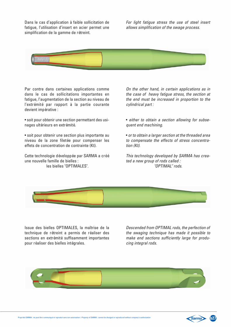
Dans le cas d’application à faible sollicitation defatigue, l’utilisation d’insert en acier permet unesimplification de la gamme de rétreint.
Par contre dans certaines applications commedans le cas de sollicitations importantes enfatigue, l’augmentation de la section au niveau del’extrémité par rapport à la partie courantedevient impérative :
• soit pour obtenir une section permettant des usi-nages ultérieurs en extrémité.
• soit pour obtenir une section plus importante auniveau de la zone filetée pour compenser leseffets de concentration de contrainte (Kt).
Cette technologie développée par SARMA a crééune nouvelle famille de bielles :
les bielles "OPTIMALES".
Issue des bielles OPTIMALES, la maîtrise de latechnique de rétreint a permis de réaliser dessections en extrémité suffisamment importantespour réaliser des bielles intégrales.
For light fatigue stress the use of steel insertallows simplification of the swage process.
On the other hand, in certain applications as inthe case of heavy fatigue stress, the section atthe end must be increased in proportion to thecylindrical part :
• either to obtain a section allowing for subse-quent end machining.
• or to obtain a larger section at the threaded areato compensate the effects of stress concentra-tion (Kt).
This technology developed by SARMA has crea-ted a new group of rods called :
"OPTIMAL" rods.
Descended from OPTIMAL rods, the perfection ofthe swaging technique has made it possible tomake end sections sufficiently large for produ-cing integral rods.

b28 Propriété SARMA : ne peut être communiqué ni reproduit sans son autorisation / Property of SARMA : cannot be divulged or reproduced without company's authorization
• Corps de bielles en acier et en alliage de Titane :
Les corps de bielle en acier et en titane sont utili-sés dans le cas où les efforts dépassent les pos-sibilités de l’aluminium et sous des conditionssévères d'environnement (température, pollution,etc).
En général, les aciers inoxydables et les alliagesde titane à faible ductilité ne sont pas utilisables.les nuances retenues par SARMA pour le rétreintsont présentées dans le tableau ci- dessous. Leformage des filetages dans ces matériaux, y com-pris pour les plus ductiles d’entre eux, n’est géné-ralement pas recommandé. Conformément à laspécification MIL STD 1599, l’usinage soigné etcontrôlé du filetage à partir d’un tube rétreintébauché est préférable.
Une attention particulière est accordée lors de ladéfinition des bielles SARMA en acier inoxydableet en titane pour éviter les variations brutales desection qui peuvent avoir des conséquencesnéfastes sur la tenue en fatigue.
• Corps de bielles rétreint en température :
SARMA a mis au point, sur ses machines, lerétreint à chaud pour les matériaux à faible ducti-lité ou pour les tubes de très forte épaisseur.
• Steel and titanium alloy rod bodies :
Steel and titanium rod bodies are used where thestresses are greater than can be supported byaluminium and under severe environmentalconditions (temperature, pollution, etc).
Stainless steel and titanium alloys with low ducti-lity are not usable. The types adopted by SARMAfor swaging are given in the table below. Formingof the threads in these materials, including themore ductile materials, is not usually recommen-ded. In conformity with specification MIL STD1599, careful, controlled machining of the threadson a rough forged swage tube is preferable.
Special attention is given to the definition ofSARMA stainless steel and titanium rods in orderto avoid sudden section variations, which mayhave harmful consequences on fatigue resistance.
• Heat swaged rod bodies :
SARMA has developed, on its machines, the heatswaging for low ductile materials or for very thicktubes.
NatureMaterial
AluminiumAluminium
Acier résistant à la corrosionCorrosion resistant steel
TitaneTitanium
NuanceType
20247075
AISI 304(Z2 CN18-10)
T40
Spécification d’approvisionnementDelivery Specificatioin
SARMA
SARMA
SARMA
Documents applicablesApplicable documents
WWT700-3
MIL-T-6845
AMS4942B
Nuances matières préconisées pour corps de bielleTypes of material recommended for rod bodies

Propriété SARMA : ne peut être communiqué ni reproduit sans son autorisation / Property of SARMA : cannot be divulged or reproduced without company's authorization b29
II-2 Corps de bielles composites :
Ces corps de bielles sont à base de :
• fibres de carbone haut module, très haut module, et haute résistance
• résine époxy, cyanate
Pour la fabrication des bielles composites,SARMA utilise deux procédés, selon schéma ci-dessous :
• Procédé nappage• Procédé R.T.M.
II-2 Composite rod bodies :
These rod bodies are based on :
• High modulus, ultra high modulus and high strength fibres
• Epoxy resin, cyanate
SARMA uses two processes for the manufactureof composite rods, as shown in the table below :
• Lay-up process• R.T.M. process
Les figures ci-dessous montrent les formes d’extrémité les plus courantes.The figures below show the most usual end fittings.
Renforts secsNon impregnated
Textil reinforcement
Découpe des plisCutting ply
Mise en moulePlace Lay-up in mould
Injection de résineResin injection
PolymérisationCurring
Fibres de carboneCarbon fiber
PROCÉDÉ NAPPAGELAY-UP PROCESS
Tissus - nappes préimprégnés
Prepregs tapes fabrics
Découpe des plisCutting ply
Mise en moulePlace Lay-up in mould
PolymérisationCurring
PROCÉDÉ R.T.M.Resin Transfert
Molding PROCESS

b30 Propriété SARMA : ne peut être communiqué ni reproduit sans son autorisation / Property of SARMA : cannot be divulged or reproduced without company's authorization
II-3 Critère de choix du corps de bielles
Le tableau ci-dessous donne, en fonction desapplications, les types de bielles préconisées parSARMA.
II-3 Rod body selection criteria
The table below gives the types of recommendedrods by SARMA according to the application.
ParamètresParameters
Conception des corps de bielles
StandardStandard
• • • • : Excellent Excellent• • • : Bon Good• • : Moyen Medium• : Faible Poor
(1) dépend du type de freinage (voir section F)(1) depending on locking devices (see section F)(2) perçage sur mesure(2) drilling on demand
MécaniqueMechanical
Commande de volFlight control
TractionTension
CompressionCompression
EncastrementCantilever load
FatigueFatigue
VibrationVibration
• •
• •
• •
• • •
• • •
• •
• • •
• • •
• • •
• • • •
• • • (1)
• • • •
• • • •
• • •
• • • •
• • • •
• • •
• • •
• • • •
• • •
• • •
• • • (1)
•
• •
•
•
•
•
•
•
• • •
• • •
• • • (1)
Capacité de charge
Load capacity
CapacitéCapacity
PrécisionPrecision
RéglageAdjustment
MasseWeight
EncombrementOverall dimensions
TempératureTemperature
EnvironnementEnvironment
AntiballesProof bullet
Signature radarRadar echo
Standard avec insertStandard with insert
OptimaleOptimal
Métalliques Metallic
Supports, attachesSupport, links

ParamètresParameters
• • • • : Excellent Excellent• • • : Bon Good• • : Moyen Medium• : Faible Poor
(1) dépend du type de freinage (voir section F)(1) depending on locking devices (see section F)(2) perçage sur mesure(2) drilling on demand
• • • •
• • • •
• • • •
• • • •
• • • •
• • •
• • • •
• • • •
•
• • •
• • • • (2)
• • •
• • •
• • • •
• • • •
• • • •
• • • •
• • • •
• • •
• • • •
• •
• • • •
• • •
• • • • (2)
• • • •
• • • •
• • • •
• • • • •
• • • •
• • • •
• • • •
• • •
• • • •
• •
• • • •
• • •
• • • • (2)
Composites Composites
IntégralesIntegral
Avec insertWith insert
IntégralesIntegral
TractionTension
CompressionCompression
EncastrementCantilever load
FatigueFatigue
VibrationVibration
Capacité de charge
Load capacity
CapacitéCapacity
PrécisionPrecision
RéglageAdjustment
MasseWeight
EncombrementOverall dimensions
TempératureTemperature
EnvironnementEnvironment
AntiballesProof bullet
Signature radarRadar echo
Propriété SARMA : ne peut être communiqué ni reproduit sans son autorisation / Property of SARMA : cannot be divulged or reproduced without company's authorization b31
Design of rod body
Structure fortes chargesStructural, heavy loads

b32 Propriété SARMA : ne peut être communiqué ni reproduit sans son autorisation / Property of SARMA : cannot be divulged or reproduced without company's authorization
III- PROTECTIONSIII-1 Protection des corps de bielles métalliques
Les corps de bielles métalliques doivent être pro-tégés en fonction de leur nature et de leur expo-sition (environnement, critère esthétique…).Le tableau ci-dessous reprend les principalesgammes de protection couramment utilisées.Les bielles sont généralement peintes sur les surfacesextérieures. Pour des applications particulières,SARMA a mis au point la peinture intérieure du tube.
III- PROTECTIONIII-1 Protection of metal rod bodies Metal rod bodies must be protected according totheir material and exposition (environment, aes-thetic requirements…).The table below gives the primary ranges of cur-rently used protective treatment.The rods are usually painted on the external sur-face. SARMA has perfected the internal paintingof the tube for special applications.
III-2 Protection des bielles composites :Les bielles composites ne nécessitent pas uneprotection particulière. Néanmoins, elles sontgénéralement peintes selon spécification client.
III-2 Protection of composite rods :Composite rods require no special protection.They are, however, usually painted according tothe customer’s specification.
MatériauxMaterials
AluminiumAluminium
Acier / Steel
Acier inoxStainless steel
TitaneTitanium
PrimairePrimary
EpoxyEpoxy
PolyuréthanePolyurethane
FinitionFinish
Sans / WithoutEpoxy bi-composantEpoxy bi-component
Polyuréthane bi-composantPolyurethane bi-component
Acrilique monovyniliqueMonovinyl acrylic
Sans / WithoutPolyuréthane bi-composantPolyurethane bi-component
N° de gammesOperations n°
➀
➁
➂
➃
➄
➅
Sans peintureUnpainted
Déconseillépour
applicationen fatigue
(2)
(1)➀
➀
➀
➀
➀ ou or ➅
➀ ou or ➅
➀ ou or ➄
➀ ou or ➄
➁ - ➂ - ➃ ou or ➅
➁ - ➂ - ➃ou or ➅
➁ - ➂ - ➃ou or ➅
➁ - ➂ - ➃ou or ➅
➁ - ➂ - ➃ou or ➅
(1)
(1)
(2)
Sans peinture / Unpainted
Sans peinture / Unpainted
Autres zonesinternes
Other internalareas
Zones “carburant”
“fuel”areas
N° gammes de peinture N° of paint ranges
Gammes de peinture Painting operations
Zones critiques en corrosion
Critical corrosion areas
Critères esthétiquesAesthetic
criteria
RemarquesRemarks
Traitement de surfaceSurface treatment
Conversion chimique (chromatisation)
Chemical conversion(chromatisation)
Cadmiage Cadmium platingPhosphatation Phosphatation
PassivationPassivation
Oxydation anodique
Anode oxidation
Avec colmatage
With sealingSans
colmatageWithout sealing
Oxydation anodique
Anode oxidation
Avec colmatage
With sealing
Sanscolmatage
Without sealing
(1) Traitement de surface conducteur(1) Conductive surface treatment
(2) Traitement de surface non conducteur(2) Non conductive surface treatment
Propriété SARMA : ne peut être communiqué ni reproduit sans son autorisation / Property of SARMA : cannot be divulged or reproduced without company's authorization b33
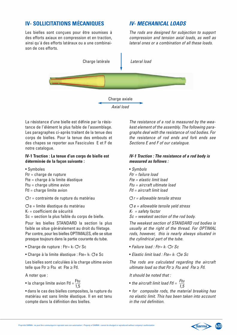
IV- SOLLICITATIONS MÉCANIQUESLes bielles sont conçues pour être soumises àdes efforts axiaux en compression et en traction,ainsi qu'à des efforts latéraux ou a une combinai-son de ces efforts.
La résistance d’une bielle est définie par la résis-tance de l’élément le plus faible de l’assemblage.Les paragraphes ci-après traitent de la tenue descorps de bielles. Pour la tenue des embouts etdes chapes se reporter aux Fascicules E et F denotre catalogue.
IV-1 Traction : La tenue d’un corps de bielle estdéterminée de la façon suivante :
• SymbolesFtr = charge de ruptureFte = charge à la limite élastiqueFtu = charge ultime avionFtl = charge limite avion
r = contrainte de rupture du matériau
e = limite élastique du matériauK1 = coefficient de sécuritéSc = section la plus faible du corps de bielle.Pour les bielles STANDARD la section la plusfaible se situe généralement au droit du filetage.Par contre, pour les bielles OPTIMALES, elle se situepresque toujours dans la partie courante du tube.
• Charge de rupture : Ftr= k1 r Sc
• Charge à la limite élastique : Fte= k1 e Sc
Les bielles sont calculées à la charge ultime aviontelle que Ftr ≥ Ftu et Fte ≥ Ftl.
A noter que :
• la charge limite avion Ftl =
• dans le cas des bielles composites, la rupture dumatériau est sans limite élastique. Il en est tenucompte dans la définition des bielles.
IV- MECHANICAL LOADSThe rods are designed for subjection to supportcompression and tension axial loads, as well aslateral ones or a combination of all these loads.
The resistance of a rod is measured by the wea-kest element of the assembly. The following para-graphs deal with the resistance of rod bodies. Forthe resistance of rod ends and fork ends seeSections E and F of our catalogue.
IV-1 Traction : The resistance of a rod body ismeasured as follows :
• SymbolsFtr = failure loadFte = elastic limit loadFtu = aircraft ultimate loadFtl = aircraft limit load
r = allowable tensile stress
e = allowable tensile yeld stressK1 = safety factorSc = weakest section of the rod body.The weakest section of STANDARD rod bodies isusually at the right of the thread. For OPTIMALrods, however, this is nearly always situated inthe cylindrical part of the tube.
• Failure load : Ftr= k1 r Sc
• Elastic limit load : Fte= k1 e Sc
The rods are calculated regarding the aircraftultimate load so that Ftr ≥ Ftu and Fte ≥ Ftl.
It should be noted that :
• the aircraft limit load Ftl =
• for composite rods, the material breaking hasno elastic limit. This has been taken into accountin the rod definition.
Charge axiale
Axial load
Charge latérale Lateral load
Ftu1,5
Ftu1,5

b34 Propriété SARMA : ne peut être communiqué ni reproduit sans son autorisation / Property of SARMA : cannot be divulged or reproduced without company's authorization
IV-2 Compression :
De part leur configuration, les bielles périssentgénéralement en flambage.
Le comportement en flambage fait l'objet de nom-breux modèles mathématiques et expérimentauxsymbolisé par les courbes de flambage de la pagesuivante. Une bielle peut être comparée à unepoutre cylindrique.
La tenue d’une bielle suit en première approxima-tion une loi du type :
FC= K. (ECIC / L2)Avec K = f(ECIC / EEIE , L /LT)
SymbolesFC = charge de flambageEC = module de Young du tubeIC = moment quadratique du tubeEE = module de Young des extrémitésIE = moment quadratique du filetage
des extrémitésL = longueur de l’entre-axes bielleLT = longueur du tube
• L’influence du rapport K des raideurs inertiellesentre le corps et les embouts peut devenir prédomi-nante dans le cas des bielles faiblement élancées.Ce facteur devient souvent critique dans le casdes corps de bielle en acier, car le rapport desinerties n’est plus compensé par les écarts derigidité de l’embout et du corps.
• L’apparition des matériaux composites présen-tant généralement un module 30% supérieur àcelui de l’aluminium pour une densité 40 % infé-rieure, constitue au vue du comportement enflambage un matériau idéal.
Avec son expérience, ses modélisations, SARMAdéfinit, en fonction des applications, des dimen-sionnements optimums.
IV-2 Compression :
By their configuration, the rods usually fail bybuckling.
Buckling behaviour is the subject of a number ofmathematical and experimental models symboli-sed by the buckling curves on the next page. Arod may be compared to a cylindrical beam.
The resistance of a rod follows on initial approxi-mation a rule of the type :
FC= K. (ECIC / L2)With K = f(ECIC / EEIE , L /LT)
SymbolsFC = buckling loadEC = Young modulus of rod bodyIC = moment of inertia of rod bodyEE = Young modulus of rod endsIE = moment of inertia of rod end threadL = centre to centre of rod assemblyLT = rod body length
• The influence of the K ratio of the inertia stiff-ness between the body and rod ends may predo-minate in the case of low slenderness rods.This is often a critical factor in the case of steelrod bodies, since the inertia ratio is no longercompensated by the rigidity deviations of the rodend and the body.
• The appearance of composite materials usuallypresenting a modulus 30% higher than that of alu-minium for a 40% lower density, is an ideal mate-rial in view of its behaviour under buckling.
With its experience and modelisations, SARMAdefines optimum sizing according to applications.

Propriété SARMA : ne peut être communiqué ni reproduit sans son autorisation / Property of SARMA : cannot be divulged or reproduced without company's authorization b35
COURBES DE FLAMBAGEPour bielles en alliage d’aluminium
BUCKLING CURVESFor aluminium alloy rods
4000
32x2
30x2
32x2
32x1
.628
x2
30x1
.6
25x2
25x1
.632
x1.2
30x1
.225
x1.6
32x1
12x1
28x1
.230
x120
x228
x125
x1.2
20x1
.6
25x1
20x1
.2
16x1
.620
x118
x116
x1.2
16x1
3500
3000
2500
2000
1500
1000 500 0 10
020
030
040
050
060
0 L en
mm
CHARGES en daNLOADS in daN
700
800
900
1000
1100
1200

b36 Propriété SARMA : ne peut être communiqué ni reproduit sans son autorisation / Property of SARMA : cannot be divulged or reproduced without company's authorization
IV-3 Fatigue :
Dans le cas essentiellement des bielles métal-liques, des sollicitations dynamiques de plusfaible amplitude peuvent être "dimensionnantes".Les corps de bielle en matériaux composites pré-sentent généralement d’excellentes caractéris-tiques en fatigue.
La courbe suivante donne, pour un niveau decontrainte donné, le nombre de cycles à rupturepour les bielles en alliages d’ aluminium.
IV-3 Fatigue :
Essentially in the case of metal rods, dynamicstresses of lesser amplitude can be "dimensio-ning”. Composite material rod bodies usually pre-sent excellent characteristics under fatigue.
The following curve shows the number of brea-king cycles for a given stress (S/N) for rods in alu-minium alloy.
500
0,01 0,1 1 10 100 1000 10000 100000
72.5
400
DUREE DE VIE EN KILOCYCLESFATIGUE LIFE IN KILOCYCLES
Courbe moyenneAverage curve
Zone de variation de durée de vie en fonction de la technologie et la forme de la pièceZone of average life curve depending on technologie and shape
Bielle SARMA selon EN2290SARMA rod according EN2290
CO
NT
RA
INT
E M
paS
TR
ES
S K
SI
58.0
30043.5
20029.0
100
0
14.5

Propriété SARMA : ne peut être communiqué ni reproduit sans son autorisation / Property of SARMA : cannot be divulged or reproduced without company's authorization b37
V- SOLLICITATIONS ENVIRONNEMENTALES
V-1 Vibrations :
Quelques soient leur localisation dans l’avion, lesbielles sont soumises à des vibrations d’originesdiverses. Pour minimiser la réponse dynamiquedes bielles, il convient d'éviter les dimensionne-ments dont le mode propre est situé dans leszones de densité vibratoire maximale.
De façon générale, les surtensions générées auniveau des bielles, même en cas de résonance,restent inférieures aux valeurs admissibles.
V-2 Corrosion - humidité :
Pour les bielles métalliques, la tenue à la corro-sion est obtenue par une protection spécifique(voir paragraphe III-1).
Dans le cas d’exposition dans des milieuxhumides, et pour éviter les risques de condensa-tion, d'éclatement par le gel, SARMA propose dessolutions originales.
Les bielles composites ne sont pas sensibles à lacorrosion. La peinture, sauf exigences esthé-tiques, n’a pour fonction que de révéler d’éven-tuels chocs. L’effet du vieillissement humide desmatériaux composites doit être prise en compte ;SARMA effectue de nombreux essais dans cedomaine.
V- 3 Température :
Les températures maximale et minimale d’utilisa-tion sont celles des matériaux constitutifs.
V- ENVIRONMENTAL CONDITIONS
V-1 Vibrations :
Whatever their localisation in the aircraft, therods are subject to vibrations from differentsources. In order to minimise the dynamic res-ponse of the rods, it is advisable to avoid dimen-sioning the natural mode of which is located inmaximum vibrational density areas.
Generally speaking, the overstresses generatedon the rods, even in the case of resonance,remain below the admissible values.
V-2 Corrosion - humidity :
For metallic rods, the resistance to corrosion isobtained by specific protection (see paragraphIII-1).
In the case of exposure to humid surroundingsand to avoid the risks of condensation, breakingunder icing cold, SARMA has original solutions tooffer.
Composite rods are not sensitive to corrosion.The function of the paint, except for aestheticrequirements, is simply to reveal possibleimpacts. The effect of ageing of composite mate-rials through humidity must be taken intoaccount; SARMA carries out numerous tests inthis field.
V- 3 Temperature :
The minimum and maximum operational tempera-tures are those of the constituent materials.
Enceinte de vieillissement humideHumidity ageing enclosure

b38 Propriété SARMA : ne peut être communiqué ni reproduit sans son autorisation / Property of SARMA : cannot be divulged or reproduced without company's authorization
VI SYSTÈMES DE FREINAGEIl existe de nombreux systèmes de freinage. Nousreportons ci-après les systèmes les plus commu-nément utilisés et dont les éléments sont définisdans le fascicule F :
• Pour bielles réglables : - contre-écrous- frein d'écrou ou frein tôle- frein demi-tour- frein micrométrique
• Pour bielles fixes :- frein cuvette- système ES- système EFC
VI-1 Terminologie :
Un système de freinage est dit de classe 1, c'est-à-dire POSITIF quand pour se desserrer, ce systè-me doit casser une des pièces en présence. Uncouple de serrage n’est pas un système de frei-nage positif.
VI-2 Pour bielles réglables :
VI-2-1 Freinage par contre-écrou :
Ce système est le plus simple. Il permet seule-ment de rendre l’ensemble rigide en s’appuyantsur le principe de l’écrou contre écrou.
Ce système est non positif et pour être efficace,sa mise en œuvre doit être effectuée avec soin.
Le couple de serrage doit être adapté :
au diamètre de filetageaux matériaux en présenceau type de lubrifiant utilisé
Il peut être amélioré par l’utilisation d’écrousavec bague auto-freinante incorporée ou par l’uti-lisation d’écrous percés et de fil frein.
VI LOCKING DEVICESThere are a number of locking devices. We givebelow the most commonly used systems, the ele-ments of which are defined in Section F:
• For adjustable rods :- check nuts - locking nut or tab washers- half-turn lock- micrometric washers
• For fixed rods :- cup washers- ES system - EFC system
VI-1 Terminology :
A locking device is said to be of class 1, that is tosay POSITIVE, when, to unlock, the system has tobreak one of the parts involved. A tighteningtorque is not a positive locking system.
VI-2 For adjustable rods :
VI-2-1 Locking by check-nut :
This is the simplest system. It only allows theassembly to be made rigid by relying on the nut-check nut principle.
This system is non positive and to be effective itmust be carried out with care.
The torque must be adapted :
to the thread diameterto the materials involvedto the type of lubricant used
It can be improved by the use of nuts with a selflocking ring or hexagonal nuts with locking wireholes.

Propriété SARMA : ne peut être communiqué ni reproduit sans son autorisation / Property of SARMA : cannot be divulged or reproduced without company's authorization b39
VI-2-2 Freinage par freins d’écrou ou freins tôle:
La fonction principale de ces freins est le freina-ge des écrous par pliage de languettes appro-priées sur l’écrou. De mise en œuvre simple,permettant toutes les orientations possibles del’embout, ce système de freinage ne peut êtreconsidéré comme un système de classe 1 ousystème positif.
Cependant dans le cas où les conditions de régla-ge le permettent, l’emploi de ce type de freinageavec deux embouts droits ou deux emboutsgauches est souvent suffisant. Dans ce type deconfiguration, il n’est pas nécessaire, sauf pourde rares exceptions, d’avoir recours à un systèmede classe 1. De part sa nature, il devra être rem-placé à chaque démontage.
Des fonctions annexes peuvent être attribuées àces freins tôles telles que point d’attache pourtresse de métallisation.
Un de ces systèmes a été mis au point parSARMA, il y a de nombreuses années, sous laréférence : 03G.
Il en existe aujourd’hui de nombreuses variantes.Voir Fascicule F.
VI-2-3 Freins d’embouts demi-tour (type 2194,2196, NAS 513, MS 14128, SAE-AS 81935/3,NAS 559) :
Ce type de freinage positif ne permet qu'uneseule orientation des extrémités.
S'ils sont utilisés aux 2 extrémités d’une bielledont les filetages sont à droite et à gauche, la pré-cision de réglage est égale au demi pas du filetage.
VI-2-2 Locking with tab washers :
The main function of these locks is to block thenuts by bending the tabs on the nut. This system,simple to operate, allowing the rod end to be tur-ned in any direction, cannot be regarded as aclass 1 or positive system.
Where adjustment conditions allow, however, theuse of this type of lock, with two right or two leftrod ends, is often sufficient. In this type of confi-guration it is not necessary, with rare exceptions,to have recourse to a class 1 system. Of its natu-re it should be replaced after each disassembly.
These tab washers may have auxillary functionssuch as seating for bonding jumper.
One of these systems was developed by SARMAmany years ago under the reference : 03G.
Today there are numerous variants.See Section F.
VI-2-3 Half- turn rod end locks (type 2194, 2196,NAS 513, MS 14128, SAE-AS 81935/3, NAS 559) :
This type of positive locking allows only a singleorientation of the ends.
If they are used at both ends of a rod having leftand right threads the adjustment precision is ahalf thread pitch.
b40 Propriété SARMA : ne peut être communiqué ni reproduit sans son autorisation / Property of SARMA : cannot be divulged or reproduced without company's authorization
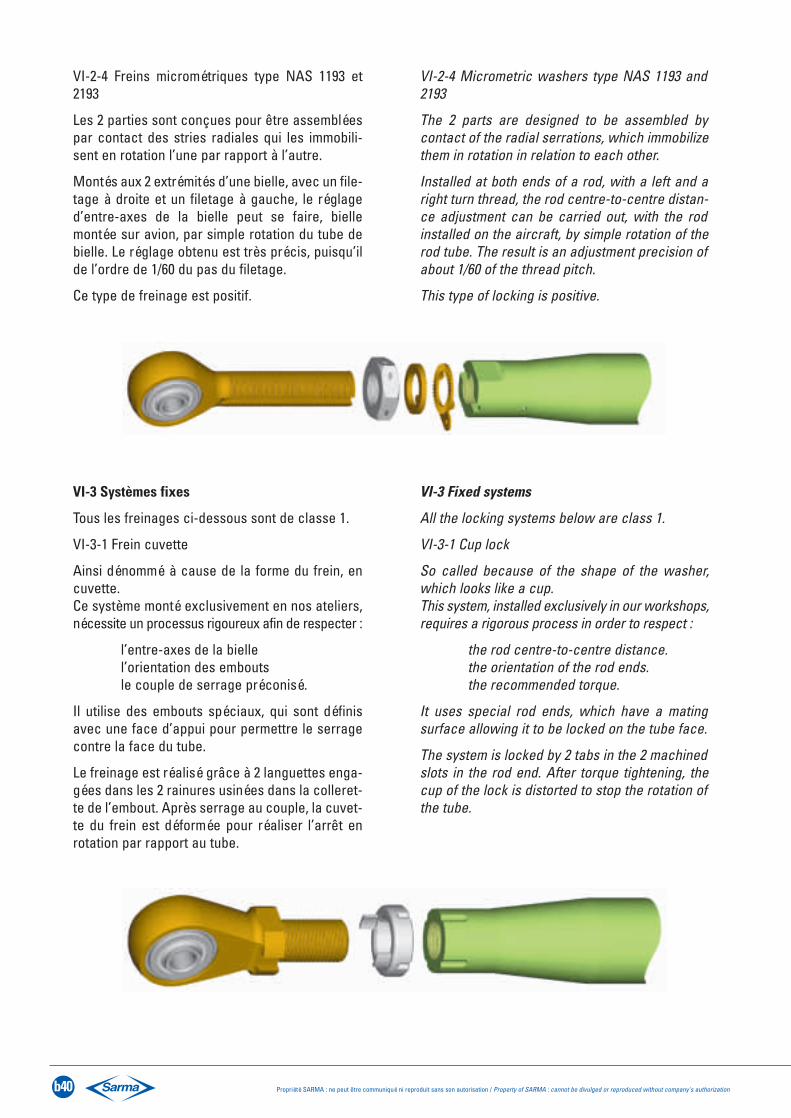
VI-2-4 Freins micrométriques type NAS 1193 et2193
Les 2 parties sont conçues pour être assembléespar contact des stries radiales qui les immobili-sent en rotation l’une par rapport à l’autre.
Montés aux 2 extrémités d’une bielle, avec un file-tage à droite et un filetage à gauche, le réglaged’entre-axes de la bielle peut se faire, biellemontée sur avion, par simple rotation du tube debielle. Le réglage obtenu est très précis, puisqu’ilde l’ordre de 1/60 du pas du filetage.
Ce type de freinage est positif.
VI-2-4 Micrometric washers type NAS 1193 and2193
The 2 parts are designed to be assembled bycontact of the radial serrations, which immobilizethem in rotation in relation to each other.
Installed at both ends of a rod, with a left and aright turn thread, the rod centre-to-centre distan-ce adjustment can be carried out, with the rodinstalled on the aircraft, by simple rotation of therod tube. The result is an adjustment precision ofabout 1/60 of the thread pitch.
This type of locking is positive.
VI-3 Systèmes fixes
Tous les freinages ci-dessous sont de classe 1.
VI-3-1 Frein cuvette
Ainsi dénommé à cause de la forme du frein, encuvette.Ce système monté exclusivement en nos ateliers,nécessite un processus rigoureux afin de respecter :
l’entre-axes de la biellel’orientation des emboutsle couple de serrage préconisé.
Il utilise des embouts spéciaux, qui sont définisavec une face d’appui pour permettre le serragecontre la face du tube.
Le freinage est réalisé grâce à 2 languettes enga-gées dans les 2 rainures usinées dans la colleret-te de l’embout. Après serrage au couple, la cuvet-te du frein est déformée pour réaliser l’arrêt enrotation par rapport au tube.
VI-3 Fixed systems
All the locking systems below are class 1.
VI-3-1 Cup lock
So called because of the shape of the washer,which looks like a cup.This system, installed exclusively in our workshops,requires a rigorous process in order to respect :
the rod centre-to-centre distance.the orientation of the rod ends.the recommended torque.
It uses special rod ends, which have a matingsurface allowing it to be locked on the tube face.
The system is locked by 2 tabs in the 2 machinedslots in the rod end. After torque tightening, thecup of the lock is distorted to stop the rotation ofthe tube.

Propriété SARMA : ne peut être communiqué ni reproduit sans son autorisation / Property of SARMA : cannot be divulged or reproduced without company's authorization b41
VI-3-2 Système ES
Contrairement aux freins cuvettes, ce systèmeprésente l’intérêt d’utiliser des embouts stan-dards sur lesquels est réalisé un moletage droit.
Le tube est serti sur ce moletage, ce qui permetde garantir un couple de non déblocage.
Le filetage, comme pour les systèmes réglables,assure la transmission des efforts en traction etcompression.
VI-3-2 ES System
Contrary to the cup washers, this system showsthe interest of using standard rod ends whichknurling have been machined on.
The tube is swaged on the knurling area, whichguarantees a non break out torque.
The thread, as in all adjustable systems, transmitsthe tension and compression loads.
VI-3-3 Système EFC
Ce système regroupe les avantages du systèmeES et du frein cuvette mais est utilisé dans le casde fortes sollicitations en fatigue et en vibration.
VI-3-3 EFC System
This system has the advantages of both the ESand cup lock systems but is used in cases ofheavy fatigue and vibration conditions.

b42 Propriété SARMA : ne peut être communiqué ni reproduit sans son autorisation / Property of SARMA : cannot be divulged or reproduced without company's authorization
VII - QUALIFICATIONVII -1 Bielles métalliques
La validation de la conception est effectuée sur labase des essais mécaniques suivants :
• Essais de rupture en traction et en compression,chargement parfois combiné avec des efforts latéraux
• Essais de fatigue
• Essais de vibration.
VII-2 Bielles composites
Les bielles composites sont qualifiées conformé-ment à des spécifications techniques client. Un dos-sier de qualification comprend généralement desessais aux températures critiques, à l'endommage-ment, au vieillissement humide, à la fatigue, auxcontaminants. Selon l'application, d'autres évalua-tions peuvent être demandées telles que des essaisaux tirs balistiques, aux vibrations, à la foudre.
VIII- SUIVI QUALITÉ EN FABRICATIONVIII-1 Bielles métalliques
Les corps de bielles métalliques sont lotis. Le suiviQualité en fabrication des bielles SARMA s'ap-puie sur les principaux contrôles suivants :
• Contrôle dimensionnel à 100 %• Contrôle visuel à 100 %• Contrôle dureté à 100 %• Contrôle conductivité à 100 %
(bielles en alliage d’aluminium seulement)• Contrôle criques par ressuage
ou par contrôle magnétique, à 100 %• Essais statiques destructifs
(1% ou 1 bielle par lot artificiel).
VIII-2 Bielles composites
Les bielles SARMA sont individualisées. Il est pos-sible, à partir du numéro de série, de connaître leslots matière constituant chaque bielle et le suiviindividuel de fabrication.
Les bielles composites SARMA sont contrôlées à100 % aux Ultra-Sons afin de détecter des défautsinternes éventuels tels que :
- délaminage- porosité- etc…
Des essais de "charge d'épreuve" en tractionet/ou compression sont effectués à 100 % sur cesbielles.
VII - QUALIFICATION VII -1 Metallic rods
Validation of the design is effected on the basis ofthe following mechanical tests :
• Tension and compression tests loading some-times combined with lateral loads.
• Fatigue tests
• Vibration tests.
VII-2 Composite rods
Composite rods are qualified according to thetechnical specifications of the customer. A quali-fication file usually includes critical temperature,damage tolerances, humidity ageing, fatigue andcontaminant tests. Depending on the applicationother evaluations may be required, such as ballis-tic firing, vibration and lightning tests.
VIII- QUALITY ASSURANCE PROVISIONVIII-1 Metallic rods
Metallic rod bodies are divided into batches. TheQuality follow-up main inspection :
• 100 % dimensional inspection• 100 % visual inspection• 100 % hardness check• 100 % conductivity inspection
(aluminium rods only)• 100 % check for cracks by fluorescent
penetrant or magnetic inspection (FPI or MPI)• Destructive static tests
(1% or 1 rod per artificial batch).
VIII-2 Composite rods
SARMA rods are serialised. It is possible toknow from a serial number, the batches of thematerial making up each rod and the individualmanufacturing follow up.
SARMA composite rods are 100% Ultra Sonicinspected in order to detect possible internaldefects such as :
- delamination- porosity- etc…
100% tension and/or compression "proof load"tests are carried out on the rods.

Structure - Struts
Support équipement - forte chargeEquipment support - heavy load
Aménagement intérieur - Cabin equipment
Exigences particulièresSpecific requirements
Commande de vol - Flight control
Système de porte - Door system
Système de trappe - Undercarriage door system
Commande de puissance - Power control
Environnement
Temperature :
Contaminants :
Autres - Other ones :
Protection :
Extrémité A - End A
Référence de base Alésage :Basic part number: Bore diameter
Client : Nom : Téléphone :Customer: Name: Fax:
Appareil : Quantité par appareilProgramme: Aircraft: Quantity per aircraft:
CHARGES ULTIMES AVION AIRCRAFT ULTIMATE LOAD
Traction Compression Latérale FatigueTension: Buckling: Lateral: Cycle Nbr:
APPLICATION
Propriété SARMA : ne peut être communiqué ni reproduit sans son autorisation / Property of SARMA : cannot be divulged or reproduced without company's authorization b43
CAHIER D’EXPRESSION DES BESOINS / DESIGN DATA WORK SHEET
L =Réglage
Adjustment
D max =
A B
= ±
Fixe - Fixed
E.S.
Frein cuvetteCup washer
E.F.C.
Réglable - Adjustable
Contre-écrouCheck nut
Frein d’écrouTab washer
Frein 1/2 tourHalf turn lock
Frein micrométriqueMicrometric washer
Extrémité B - End B
Référence de base Alésage :Basic part number: Bore diameter
Fixe - Fixed
E.S.
Frein cuvetteCup washer
E.F.C.
Réglable - Adjustable
Contre-écrouCheck nut
Frein d’écrouTab washer
Frein 1/2 tourHalf turn lock
Frein micrométriqueMicrometric washer

b44 Propriété SARMA : ne peut être communiqué ni reproduit sans son autorisation / Property of SARMA : cannot be divulged or reproduced without company's authorization
RESISTANCE DES MATERIAUXFIRST PRINCIPLES OF STRENGTHS OF MATERIALMOMENT D’INERTIEMOMENTS OF INERTIA
QUELQUES FORMULES USUELLESSTANDARD FORMULAE
AVERTISSEMENTTous nos produits sont vendus conformément à nos conditions générales de vente.SARMA se réserve le droit de modifier les données de ce catalogue sans information préalable.Le document a été élaboré avec le plus grand soin ; cependant, la responsabilité de SARMAne saurait être engagée en cas d’erreur ou d’omission.
WARNINGOur products are sold subject to our general conditions of sale.SARMA reserves the right to amend the information given in this catalog without prior notice.This document has been compiled with the greatest of care ; nevertheless, SARMA cannot be held responsible for errors or omissions.
SECTIONSSECTIONS
TORSION TORSION FLEXION BENDING
lo v lx’x v
CAS DE CHARGETYPE OF LOAD
REACTIONSREACTIONS
FORCES
MOMENT FLECHISSANTBENDING MOMENT
EFFORTTRANCHANT
SHEAR STRESS
DEFORMEEDEFLECTION
(EI = Cte)
Poutre sur deux appuisCharge concentrée en un pointquelconqueBeam on two supportsPoint load applied
Poutre sur deux appuisCharge concentrée sur un porte-à-fauxBeam on two supportsOverhanging load
Poutre sur deux appuisMoment µ appliqué entre appuisBeam on two supportsMoment applied beetween supports