avr.pdf
TRANSCRIPT

8/10/2019 avr.pdf
http://slidepdf.com/reader/full/avrpdf 1/365
CCS C Compiler ManualPCD
May 2014
ALL RIGHTS RESERVED.2014 Custom Computer Services, Inc.

8/10/2019 avr.pdf
http://slidepdf.com/reader/full/avrpdf 2/365

8/10/2019 avr.pdf
http://slidepdf.com/reader/full/avrpdf 3/365
iii
Table of ContentsOverview .................................................................................................................................... 1
C Compiler .............................................................................................................................. 1Technical Support ................................................................................................................... 1
Directories ............................................................................................................................... 2File Formats ............................................................................................................................ 2Invoking the Command Line Compiler ..................................................................................... 3PCW Overview ........................................................................................................................ 5Menu ....................................................................................................................................... 6Editor Tabs.............................................................................................................................. 7Slide Out Windows .................................................................................................................. 7Editor ...................................................................................................................................... 7Debugging Windows ............................................................................................................... 8Status Bar ............................................................................................................................... 8Output Messages .................................................................................................................... 8
Program Syntax ......................................................................................................................... 9
Overall Structure ..................................................................................................................... 9Comment ................................................................................................................................ 9Trigraph Sequences ...............................................................................................................11Multiple Project Files ..............................................................................................................11Multiple Compilation Units ......................................................................................................12Full Example Program ............................................................................................................12
Statements ................................................................................................................................15Statements .............................................................................................................................15if .............................................................................................................................................16while.......................................................................................................................................16do-while .................................................................................................................................17for ..........................................................................................................................................17
switch .....................................................................................................................................18return .....................................................................................................................................18goto ........................................................................................................................................18label .......................................................................................................................................19break ......................................................................................................................................19continue .................................................................................................................................20expr ........................................................................................................................................20; ..............................................................................................................................................20stmt ........................................................................................................................................21
Expressions ..............................................................................................................................23Constants ...............................................................................................................................23Identifiers ...............................................................................................................................24
Operators ...............................................................................................................................24Operator Precedence .............................................................................................................25Data Definitions .........................................................................................................................27
Data Definitions ......................................................................................................................27Declarations ...........................................................................................................................27Type Specifiers ......................................................................................................................28Type Qualifiers .......................................................................................................................29Enumerated Types .................................................................................................................30Structures and Unions ............................................................................................................31

8/10/2019 avr.pdf
http://slidepdf.com/reader/full/avrpdf 4/365
CCS C Compiler Manual - PCD
iv
typedef ...................................................................................................................................32Non-RAM Data Definitions .....................................................................................................32Using Program Memory for Data ............................................................................................34Named Registers ...................................................................................................................35
Function Definition ....................................................................................................................37Function Definition .................................................................................................................37Overloaded Functions ............................................................................................................38Reference Parameters ...........................................................................................................38Default Parameters ................................................................................................................39Variable Argument Lists .........................................................................................................39
Functional Overview..................................................................................................................41I2C .........................................................................................................................................41
ADC .......................................................................................................................................42 Analog Comparator ................................................................................................................43CAN Bus ................................................................................................................................44Code Profile ...........................................................................................................................50DAC .......................................................................................................................................51Data Eeprom ..........................................................................................................................52Data Signal Modulator ............................................................................................................53General Purpose I/O ..............................................................................................................54Interrupts ................................................................................................................................56PMP/EPMP ............................................................................................................................57Program Eeprom ....................................................................................................................58QEI ........................................................................................................................................60RS232 I/O ..............................................................................................................................61RTOS .....................................................................................................................................63SPI .........................................................................................................................................65TimerA ...................................................................................................................................67TimerB ...................................................................................................................................67Voltage Reference .................................................................................................................68
WDT or Watch Dog Timer ......................................................................................................69interrupt_enabled() .................................................................................................................70Stream I/O..............................................................................................................................71
PreProcessor ............................................................................................................................73PRE-PROCESSOR DIRECTORY ..........................................................................................73
__address__ ..........................................................................................................................74 _attribute_x ............................................................................................................................74#asm #endasm ......................................................................................................................75#bit .........................................................................................................................................84#build .....................................................................................................................................85#byte ......................................................................................................................................86#case .....................................................................................................................................87
_date_ ....................................................................................................................................88#define ...................................................................................................................................88definedinc ..............................................................................................................................89#device ..................................................................................................................................90
_device_ ................................................................................................................................92#if expr #else #elif #endif ........................................................................................................92#error .....................................................................................................................................93#export (options) ....................................................................................................................94
__file__ ..................................................................................................................................95

8/10/2019 avr.pdf
http://slidepdf.com/reader/full/avrpdf 5/365
Table of Contents
v
__filename__ .........................................................................................................................95#fill_rom .................................................................................................................................96#fuses ....................................................................................................................................96#hexcomment ........................................................................................................................97#id ..........................................................................................................................................98#ifdef #ifndef #else #elif #endif ...............................................................................................98#ignore_warnings ...................................................................................................................99#import (options) ....................................................................................................................99#include ............................................................................................................................... 101#inline .................................................................................................................................. 101#INT_DEFAULT ................................................................................................................... 102
__line__ ............................................................................................................................... 102#list ...................................................................................................................................... 103#line ..................................................................................................................................... 103#locate ................................................................................................................................. 104#module ............................................................................................................................... 104#nolist .................................................................................................................................. 105#ocs ..................................................................................................................................... 105#opt ...................................................................................................................................... 106#org...................................................................................................................................... 106#pin_select ........................................................................................................................... 108#pragma ............................................................................................................................... 111#profile ................................................................................................................................. 112#reserve ............................................................................................................................... 113#rom..................................................................................................................................... 113#separate ............................................................................................................................. 114#serialize .............................................................................................................................. 115#task .................................................................................................................................... 116
__time__ .............................................................................................................................. 118#type .................................................................................................................................... 118
#undef .................................................................................................................................. 120#use capture ........................................................................................................................ 120#use delay............................................................................................................................ 121#use dynamic_memory ........................................................................................................ 122#use fast_io .......................................................................................................................... 123#use fixed_io ........................................................................................................................ 123#use i2c ............................................................................................................................... 124#use profile() ........................................................................................................................ 125#use pwm ............................................................................................................................ 126#use rs232 ........................................................................................................................... 127#use rtos .............................................................................................................................. 131#use spi ............................................................................................................................... 132
#use standard_io.................................................................................................................. 133#use timer ............................................................................................................................ 134#use touchpad ..................................................................................................................... 135#warning .............................................................................................................................. 136#word ................................................................................................................................... 137#zero_ram ............................................................................................................................ 138
Built-in Functions .................................................................................................................... 139BUILT-IN FUNCTIONS ........................................................................................................ 139abs( ) .................................................................................................................................... 143

8/10/2019 avr.pdf
http://slidepdf.com/reader/full/avrpdf 6/365
CCS C Compiler Manual - PCD
vi
sin( ) cos( ) tan( ) asin( ) acos() atan() sinh() cosh() tanh() atan2() ....................................... 144adc_done( ) adc_done2( ) .................................................................................................... 145assert( ) ................................................................................................................................ 146atoe ...................................................................................................................................... 147atof( ) atof48( ) atof64( ) ....................................................................................................... 147strtof48() .............................................................................................................................. 147pin_select() .......................................................................................................................... 148atoi( ) atol( ) atoi32( ) ............................................................................................................ 149atol32() atoi48( ) atoi64( ) ..................................................................................................... 149bit_clear( ) ............................................................................................................................ 150bit_set( ) ............................................................................................................................... 151bit_test( ) .............................................................................................................................. 151bsearch( ) ............................................................................................................................. 152calloc( ) ................................................................................................................................ 153ceil( ) .................................................................................................................................... 153clear_interrupt( ) ................................................................................................................... 154cog_status( ) ........................................................................................................................ 154cog_restart( ) ........................................................................................................................ 155cwg_status( ) ........................................................................................................................ 155cwg_restart( ) ....................................................................................................................... 156dac_write( ) .......................................................................................................................... 156delay_cycles( ) ..................................................................................................................... 157delay_ms( ) .......................................................................................................................... 158delay_us( ) ........................................................................................................................... 158div( ) ldiv( ) ........................................................................................................................... 159exp( ) .................................................................................................................................... 160ext_int_edge( ) ..................................................................................................................... 161fabs( ) ................................................................................................................................... 161getc( ) getch( ) getchar( ) fgetc( ) .......................................................................................... 162gets( ) fgets( ) ....................................................................................................................... 163
floor( ) .................................................................................................................................. 164fmod( ) ................................................................................................................................. 164printf( ) fprintf( ) .................................................................................................................... 165putc( ) putchar( ) fputc( ) ....................................................................................................... 166puts( ) fputs( ) ....................................................................................................................... 167free( ) ................................................................................................................................... 168frexp( ) ................................................................................................................................. 168scanf( ) ................................................................................................................................. 169printf( ) ................................................................................................................................. 169get_capture( ) ....................................................................................................................... 172get_capture_event() ............................................................................................................. 172get_capture_time() ............................................................................................................... 173
get_nco_accumulator( )........................................................................................................ 173get_nco_inc_value( ) ............................................................................................................ 174get_ticks( ) ........................................................................................................................... 174get_timerA( ) ........................................................................................................................ 175get_timerB( ) ........................................................................................................................ 175get_timerx( ) ......................................................................................................................... 176get_tris_x( ) .......................................................................................................................... 176setup_sd_adc( ) ................................................................................................................... 177getenv( ) ............................................................................................................................... 178

8/10/2019 avr.pdf
http://slidepdf.com/reader/full/avrpdf 7/365
Table of Contents
vii
goto_address( ) .................................................................................................................... 182high_speed_adc_done( ) ...................................................................................................... 182i2c_init( ) .............................................................................................................................. 183i2c_isr_state( ) ..................................................................................................................... 184i2c_poll( ) ............................................................................................................................. 185i2c_read( ) ............................................................................................................................ 185i2c_slaveaddr( ) ................................................................................................................... 186i2c_speed( ) ......................................................................................................................... 186i2c_start( ) ............................................................................................................................ 187i2c_stop( ) ............................................................................................................................ 188i2c_write( ) ........................................................................................................................... 189input( ) .................................................................................................................................. 189input_change_x( ) ................................................................................................................ 190input_state( ) ........................................................................................................................ 191input_x( ) .............................................................................................................................. 191interrupt_active( ) ................................................................................................................. 192isalnum(char) isalpha(char) .................................................................................................. 193iscntrl(x) isdigit(char) ............................................................................................................ 193isgraph(x) islower(char) isspace(char) isupper(char) isxdigit(char) isprint(x)ispunct(x) ............................................................................................................................. 193itoa( ) .................................................................................................................................... 194kbhit( ) .................................................................................................................................. 195label_address( ) ................................................................................................................... 195labs( ) ................................................................................................................................... 196ldexp( ) ................................................................................................................................. 197log( )..................................................................................................................................... 197log10( ) ................................................................................................................................. 198longjmp( ) ............................................................................................................................. 198make8( ) ............................................................................................................................... 199make16( ) ............................................................................................................................. 200
make32( ) ............................................................................................................................. 200malloc( ) ............................................................................................................................... 201STANDARD STRING FUNCTIONS( ) memchr( ) memcmp( ) strcat( ) strchr( )strcmp( ) strcoll( ) strcspn( ) strerror( ) stricmp( ) strlen( ) strlwr( ) strncat( ) strncmp() strncpy( ) strpbrk( ) strrchr( ) strspn( ) strstr( ) strxfrm( ) ..................................................... 202memcpy( ) memmove( ) ....................................................................................................... 203memset( ) ............................................................................................................................. 204modf( ) ................................................................................................................................. 204
_mul( ) .................................................................................................................................. 205nargs( ) ................................................................................................................................ 206offsetof( ) offsetofbit( ) .......................................................................................................... 207output_x( ) ............................................................................................................................ 207
output_bit( ) .......................................................................................................................... 208output_drive( ) ...................................................................................................................... 209output_float( ) ....................................................................................................................... 210output_high( ) ....................................................................................................................... 210output_low( ) ........................................................................................................................ 211output_toggle( ) .................................................................................................................... 212perror( ) ................................................................................................................................ 212port_x_pullups ( ) ................................................................................................................. 213pow( ) pwr( ) ......................................................................................................................... 214

8/10/2019 avr.pdf
http://slidepdf.com/reader/full/avrpdf 8/365
CCS C Compiler Manual - PCD
viii
printf( ) fprintf( ) .................................................................................................................... 214profileout() ............................................................................................................................ 216psp_output_full( ) psp_input_full( ) psp_overflow( ) .............................................................. 217putc( ) putchar( ) fputc( ) ....................................................................................................... 218putc_send( ); ........................................................................................................................ 218fputc_send( ); ....................................................................................................................... 218pwm_off() ............................................................................................................................. 219pwm_on() ............................................................................................................................. 220pwm_set_duty() ................................................................................................................... 220pwm_set_duty_percent ........................................................................................................ 221pwm_set_frequency ............................................................................................................. 221qei_get_count( ) ................................................................................................................... 222qei_status( ) ......................................................................................................................... 222qsort( ) ................................................................................................................................. 223rand( ) .................................................................................................................................. 223rcv_buffer_bytes( ) ............................................................................................................... 224rcv_buffer_full( ) ................................................................................................................... 225read_adc( ) read_adc2( ) ...................................................................................................... 225read_configuration_memory( ) ............................................................................................. 226read_eeprom( ) .................................................................................................................... 227read_extended_ram( ) .......................................................................................................... 227read_program_memory( ) .................................................................................................... 228read_high_speed_adc( ) ...................................................................................................... 228read_rom_memory( ) ........................................................................................................... 230read_sd_adc( ) ..................................................................................................................... 231realloc( ) ............................................................................................................................... 231release_io() .......................................................................................................................... 232reset_cpu( ) .......................................................................................................................... 233restart_cause( ) .................................................................................................................... 233restart_wdt( ) ........................................................................................................................ 234
rotate_left( ) .......................................................................................................................... 235rotate_right( ) ....................................................................................................................... 235rtc_alarm_read( ).................................................................................................................. 236rtc_alarm_write( ) ................................................................................................................. 237rtc_read( ) ............................................................................................................................ 237rtc_write( ) ............................................................................................................................ 238rtos_await( ) ......................................................................................................................... 238rtos_disable( ) ...................................................................................................................... 239rtos_enable( ) ....................................................................................................................... 239rtos_msg_poll( ) ................................................................................................................... 240rtos_overrun( ) ..................................................................................................................... 240rtos_run( ) ............................................................................................................................ 241
rtos_signal( ) ........................................................................................................................ 241rtos_stats( ) .......................................................................................................................... 242rtos_terminate( ) ................................................................................................................... 243rtos_wait( ) ........................................................................................................................... 243rtos_yield( ) .......................................................................................................................... 244set_adc_channel( ) ............................................................................................................... 244set_adc_channel2( ) ............................................................................................................. 244scanf( ) ................................................................................................................................. 245printf( ) ................................................................................................................................. 245

8/10/2019 avr.pdf
http://slidepdf.com/reader/full/avrpdf 9/365
Table of Contents
ix
set_cog_blanking( ) .............................................................................................................. 248set_cog_dead_band( ) ......................................................................................................... 249set_cog_phase( ) ................................................................................................................. 249set_compare_time( ) ............................................................................................................ 250set_nco_inc_value( ) ............................................................................................................ 251set_pwm1_duty( ) set_pwm2_duty( ) set_pwm3_duty( ) set_pwm4_duty( )set_pwm5_duty( )................................................................................................................. 252set_rtcc( ) set_timer0( ) set_timer1( ) set_timer2( ) set_timer3( ) set_timer4( )set_timer5( ) ......................................................................................................................... 253set_ticks( )............................................................................................................................ 253setup_sd_adc_calibration( ) ................................................................................................. 254set_sd_adc_channel( ) ......................................................................................................... 255set_timerA( ) ........................................................................................................................ 255set_timerB( ) ........................................................................................................................ 256set_timerx( ) ......................................................................................................................... 256set_rtcc( ) set_timer0( ) set_timer1( ) set_timer2( ) set_timer3( ) set_timer4( )set_timer5( ) ......................................................................................................................... 257set_tris_x( ) .......................................................................................................................... 258set_uart_speed( ) ................................................................................................................. 259setjmp( ) ............................................................................................................................... 259setup_adc(mode) ................................................................................................................. 260setup_adc2(mode) ............................................................................................................... 260setup_adc_ports( ) ............................................................................................................... 261setup_adc_ports2( ) ............................................................................................................. 261setup_clc1() setup_clc2() setup_clc3() setup_clc4() ............................................................. 262setup_comparator( ) ............................................................................................................. 262setup_cog( ) ......................................................................................................................... 263setup_cwg( ) ........................................................................................................................ 264setup_dac( ) ......................................................................................................................... 265setup_high_speed_adc( ) ..................................................................................................... 266
setup_high_speed_adc_pair( ) ............................................................................................. 267setup_low_volt_detect( ) ...................................................................................................... 268setup_pmp(option,address_mask) ....................................................................................... 268setup_power_pwm_pins( ) ................................................................................................... 269setup_psp(option,address_mask) ........................................................................................ 270setup_pwm1( ) setup_pwm2( ) setup_pwm3( ) setup_pwm4( ) ............................................ 271setup_qei( ) .......................................................................................................................... 272setup_rtc( ) ........................................................................................................................... 272setup_rtc_alarm( ) ................................................................................................................ 273setup_sd_adc( ) ................................................................................................................... 274setup_spi( ) setup_spi2( ) ..................................................................................................... 275setup_timer_A( ) .................................................................................................................. 275
setup_timer_B( ) .................................................................................................................. 276setup_timer_0( ) ................................................................................................................... 277setup_timer_1( ) ................................................................................................................... 277setup_timer_2( ) ................................................................................................................... 278setup_timer_3( ) ................................................................................................................... 279setup_timer_4( ) ................................................................................................................... 279setup_timer_5( ) ................................................................................................................... 280setup_uart( ) ......................................................................................................................... 281setup_vref( ) ......................................................................................................................... 281

8/10/2019 avr.pdf
http://slidepdf.com/reader/full/avrpdf 10/365
CCS C Compiler Manual - PCD
x
setup_wdt( ) ......................................................................................................................... 282setup_zdc( ) ......................................................................................................................... 283shift_left( ) ............................................................................................................................ 283shift_right( ) .......................................................................................................................... 284sleep( ) ................................................................................................................................. 285spi_data_is_in( ) spi_data_is_in2( ) ...................................................................................... 286spi_init() ............................................................................................................................... 287spi_prewrite(data); ............................................................................................................... 287spi_read( ) spi_read2( ) ...................................................................................................... 288spi_read3( ) .......................................................................................................................... 288spi_read4( ) .......................................................................................................................... 288spi_read_16() ....................................................................................................................... 289spi_read2_16() ..................................................................................................................... 289spi_read3_16() ..................................................................................................................... 289spi_read4_16() ..................................................................................................................... 289spi_speed ............................................................................................................................ 290spi_write( ) spi_write2( ) ....................................................................................................... 290spi_write3( ) ......................................................................................................................... 290spi_write4( ) ......................................................................................................................... 290spi_xfer( ) ............................................................................................................................. 291SPII_XFER_IN() ................................................................................................................... 292sprintf( ) ................................................................................................................................ 292sqrt( ) ................................................................................................................................... 293srand( ) ................................................................................................................................ 294strtod( ) strtof( ) strtof48( ) .................................................................................................... 294strtok( ) ................................................................................................................................. 295strtol( ) .................................................................................................................................. 296strtoul( ) ................................................................................................................................ 297swap( ) ................................................................................................................................. 298tolower( ) toupper( ) .............................................................................................................. 298
touchpad_getc( ) .................................................................................................................. 299touchpad_hit( ) ..................................................................................................................... 300touchpad_state( ) ................................................................................................................. 300tolower( ) toupper( ) .............................................................................................................. 301tx_buffer_bytes() .................................................................................................................. 302tx_buffer_full( ) ..................................................................................................................... 302va_arg( ) .............................................................................................................................. 303va_end( ) .............................................................................................................................. 304va_start ................................................................................................................................ 304write_configuration_memory( ) ............................................................................................. 305write_eeprom( ) .................................................................................................................... 305write_extended_ram( ) ......................................................................................................... 306
zdc_status( ) ........................................................................................................................ 307Standard C Include Files ......................................................................................................... 309errno.h ................................................................................................................................. 309float.h ................................................................................................................................... 309limits.h .................................................................................................................................. 310locale.h ................................................................................................................................ 311setjmp.h ............................................................................................................................... 311stddef.h ................................................................................................................................ 311stdio.h .................................................................................................................................. 312

8/10/2019 avr.pdf
http://slidepdf.com/reader/full/avrpdf 11/365
Table of Contents
xi
stdlib.h ................................................................................................................................. 312Error Messages ....................................................................................................................... 313
Compiler Error Messages ..................................................................................................... 313Compiler Warning Messages .................................................................................................. 323
Compiler Warning Messages ............................................................................................... 323Common Questions & Answers .............................................................................................. 327
How are type conversions handled? .................................................................................... 327How can a constant data table be placed in ROM? .............................................................. 328How can I use two or more RS-232 ports on one PIC®? ...................................................... 329How do I directly read/write to internal registers? ................................................................. 329How do I do a printf to a string? ............................................................................................ 330How do I get getc() to timeout after a specified time? ........................................................... 330How do I wait only a specified time for a button press? ........................................................ 331How does one map a variable to an I/O port? ...................................................................... 331How does the compiler determine TRUE and FALSE on expressions? ................................ 332How does the PIC® connect to a PC?.................................................................................. 333How does the PIC® connect to an I2C device? .................................................................... 333How much time do math operations take? ........................................................................... 334What can be done about an OUT OF RAM error? ................................................................ 334What is an easy way for two or more PICs® to communicate? ............................................ 335What is an easy way for two or more PICs® to communicate? ............................................ 336Why does the .LST file look out of order? ............................................................................. 337Why is the RS-232 not working right? .................................................................................. 338
Example Programs ................................................................................................................. 341EXAMPLE PROGRAMS ...................................................................................................... 341
Software License Agreement .................................................................................................. 353SOFTWARE LICENSE AGREEMENT ................................................................................. 353
Index ........................................................................................... Error! Bookmark not defined.

8/10/2019 avr.pdf
http://slidepdf.com/reader/full/avrpdf 12/365

8/10/2019 avr.pdf
http://slidepdf.com/reader/full/avrpdf 13/365
1
OVERVIEW
C Compiler
PCD Overview
Technical Support
Directories
File Formats
Invoking the Command Line Compiler
Technical Support
Compiler, software, and driver updates are available to download at:http://www.ccsinfo.com/download
Compilers come with 30 or 60 days of download rights with the initial purchase. One yearmaintenance plans may be purchased for access to updates as released.
The intent of new releases is to provide up-to-date support with greater ease of use andminimal, if any, transition difficulty.
To ensure any problem that may occur is corrected quickly and diligently, it is recommended tosend an email to: [email protected] or use the Technical Support Wizard in PCW. Includethe version of the compiler, an outline of the problem and attach any files with the email request.CCS strives to answer technical support timely and thoroughly.
Technical Support is available by phone during business hours for urgent needs or if emailresponses are not adequate. Please call 262-522-6500 x32.

8/10/2019 avr.pdf
http://slidepdf.com/reader/full/avrpdf 14/365
PCD Manual
2
Directories
The compiler will search the following directories for Include files. Directories listed on the command line Directories specified in the .CCSPJT file
The same directory as the source.directories in the ccsc.ini fileBy default, the compiler files are put in C:\Program Files\PICC and the exampleprograms are in \PICC\EXAMPLES. The include files are in PICC\drivers. Thedevice header files are in PICC\devices.
The compiler itself is a DLL file. The DLL files are in a DLL directory by default in \PICC\DLL.
It is sometimes helpful to maintain multiple compiler versions. For example, a project wastested with a specific version, but newer projects use a newer version. When installing thecompiler you are prompted for what version to keep on the PC. IDE users can change versionsusing Help>about and clicking "other versions." Command Line users use start>all
programs>PIC-C>compiler version.Two directories are used outside the PICC tree. Both can be reached with start>allprograms>PIC-C.
1.) A project directory as a default location for your projects. By default put in "MyDocuments." This is a good place for VISTA and up.
2.) User configuration settings and PCWH loaded files are kept in %APPDATA%\PICC
File Formats
.c This is the source file containing user C source code.
.h These are standard or custom header files used to define pins, register, register bits,functions and preprocessor directives.
.pjt This is the older pre- Version 5 project file which contains information related to theproject.
.ccspjt This is the project file which contains information related to the project.
.lst
This is the listing file which shows each C source line and the associated assembly codegenerated for that line.
The elements in the .LST file may be selected in PCW under Options>Project>OutputFiles
Mach code Includes the HEX opcode for each instructionSFRnames
Instead of an address a name is used. For example instead of044 is will show CORCON

8/10/2019 avr.pdf
http://slidepdf.com/reader/full/avrpdf 15/365
Overview
3
Symbols Shows variable names instead of addressesInterpret Adds a pseudo code interpretation to the right of assembly
instruction to helpunderstand the operation.For example:
LSR W4,#8,W5 : W5=W4>>8
.sym This is the symbol map which shows each register location and what program variablesare stored in each location.
.sta The statistics file shows the RAM, ROM, and STACK usage. It provides information onthe source codes structural and textual complexities using Halstead and McCabe metrics.
.tre The tree file shows the call tree. It details each function and what functions it calls alongwith the ROM and RAM usage for each function.
.hexThe compiler generates standard HEX files that are compatible with all programmers.
The compiler can output 8-bet hex, 16-bit hex, and binary files.
.cof
This is a binary containing machine code and debugging information.The debug files may be output as Microchip .COD file for MPLAB 1-5, AdvancedTransdata .MAP file, expanded .COD file for CCS debugging or MPLAB 6 and up .xx.COF file. All file formats and extensions may be selected via Options File Associationsoption in Windows IDE.
.cod This is a binary file containing debug information.
.rtf The output of the Documentation Generator is exported in a Rich Text File format whichcan be viewed using the RTF editor or Wordpad.
.rvf The Rich View Format is used by the RTF Editor within the IDE to view the Rich TextFile.
.dgr The .DGR file is the output of the flowchart maker.
.esym
.xsym
These files are generated for the IDE users. The file contains Identifiers and Commentinformation. This data can be used for automatic documentation generation and for theIDE helpers.
.o Relocatable object file
.osym This file is generated when the compiler is set to export a relocatable object file. This fileis a .sym file for just the one unit.
.err Compiler error file
.ccsload used to link Windows 8 apps to CCSLoad
.ccssiow used to link Windows 8 apps to Serial Port Monitor
Invoking the Command Line Compiler
The command line compiler is invoked with the following command:CCSC [options] [cfilename]
Valid options:

8/10/2019 avr.pdf
http://slidepdf.com/reader/full/avrpdf 16/365
PCD Manual
4
+FB Select PCB (12 bit) -D Do not create debug file+FM Select PCM (14 bit) +DS Standard .COD format debug file+FH Select PCH (PIC18XXX) +DM .MAP format debug file+Yx Optimization level x (0-9) +DC Expanded .COD format debug file+FD Select PCD
(dsPIC30/dsPIC33/PIC24)
+DF Enables the output of an COFF debug
file.+FS Select SXC (SX) +EO Old error file format+ES Standard error file -T Do not generate a tree file+T Create call tree (.TRE) -A Do not create stats file (.STA)+A Create stats file (.STA) -EW Suppress warnings (use with +EA)+EW Show warning messages -E Only show first error+EA Show all error messages and all
warnings+EX Error/warning message format uses
GCC's "brief format" (compatible withGCC editor environments)
The xxx in the following are optional. If included it sets the file extension:
+LNxxx Normal list file +O8xxx 8-bit Intel HEX output file+LSxxx MPASM format list file +OWxxx 16-bit Intel HEX output file+LOxxx Old MPASM list file +OBxxx Binary output file+LYxxx Symbolic list file -O Do not create object file-L Do not create list file
+P Keep compile status window up after compile+Pxx Keep status window up for xx seconds after compile+PN Keep status window up only if there are no errors+PE Keep status window up only if there are errors
+Z Keep scratch files on disk after compile+DF COFF Debug fileI+="..." Same as I="..." Except the path list is appended to the current list
I="..." Set include directory search path, for example:I="c:\picc\examples;c:\picc\myincludes"If no I= appears on the command line the .PJT file will be used to supply theinclude file paths.
-P Close compile window after compile is complete+M Generate a symbol file (.SYM)-M Do not create symbol file+J Create a project file (.PJT)-J Do not create PJT file+ICD Compile for use with an ICD#xxx="yyy" Set a global #define for id xxx with a value of yyy, example:

8/10/2019 avr.pdf
http://slidepdf.com/reader/full/avrpdf 17/365
Overview
5
#debug="true"
+Gxxx="yyy" Same as #xxx="yyy"+? Brings up a help file-? Same as +?
+STDOUT Outputs errors to STDOUT (for use with third party editors)+SETUP Install CCSC into MPLAB (no compile is done)sourceline= Allows a source line to be injected at the start of the source file.
Example: CCSC +FM myfile.c sourceline=“#include <16F887.h>” +V Show compiler version (no compile is done)+Q Show all valid devices in database (no compile is done)
A / character may be used in place of a + character. The default options are as follows:
+FM +ES +J +DC +Y9 -T -A +M +LNlst +O8hex -P -ZIf @filename appears on the CCSC command line, command line options will be read from thespecified file. Parameters may appear on multiple lines in the file.
If the file CCSC.INI exists in the same directory as CCSC.EXE, then command line parametersare read from that file before they are processed on the command line.
Examples:CCSC +FM C:\PICSTUFF\TEST.C
CCSC +FM +P +T TEST.C
PCW Overview
The PCW IDE provides the user an easy to use editor and environment fordeveloping microcontroller applications. The IDE comprises of many components,which are summarized below. For more information and details, use the Help>PCWin the compiler..
Many of these windows can be re-arranged and docked into different positions.

8/10/2019 avr.pdf
http://slidepdf.com/reader/full/avrpdf 18/365
PCD Manual
6
Menu
All of the IDE's functions are on the main menu. The main menuis divided into separate sections, click on a section title ('Edit','Search', etc) to change the section. Double clicking on thesection, or clicking on the chevron on the right, will cause themenu to minimize and take less space.

8/10/2019 avr.pdf
http://slidepdf.com/reader/full/avrpdf 19/365
Overview
7
Editor Tabs
All of the open files are listed here. The active file, which is the file
currently being edited, is given a different highlight than the otherfiles. Clicking on the X on the right closes the active file. Rightclicking on a tab gives a menu of useful actions for that file.
Slide Out Windows
'Files' shows all the active files in the current project. 'Projects'shows all the recent projects worked on. 'Identifiers' shows all
the variables, definitions, prototypes and identifiers in yourcurrent project.
Editor
The editor is the main work area of the IDE and the place wherethe user enters and edits source code. Right clicking in this areagives a menu of useful actions for the code being edited.

8/10/2019 avr.pdf
http://slidepdf.com/reader/full/avrpdf 20/365
PCD Manual
8
Debugging Windows
Debugger control is donein the debuggingwindows. These
windows allow you setbreakpoints, single step,watch variables andmore.
Status Bar
The status bar gives the user helpful information like the cursorposition, project open and file being edited.
Output Messages
Output messages are displayed here. This includes messagesfrom the compiler during a build, messages from the programmer
tool during programming or the results from find and searching.

8/10/2019 avr.pdf
http://slidepdf.com/reader/full/avrpdf 21/365
9
PROGRAM SYNTAX
Overall Structure
A program is made up of the following four elements in a file:Comment Pre-Processor Directive Data Definition Function Definition
Statements Expressions
Every C program must contain a main function which is the starting point of the program
execution. The program can be split into multiple functions according to the their purpose andthe functions could be called from main or the sub-functions. In a large project functions canalso be placed in different C files or header files that can be included in the main C file to groupthe related functions by their category. CCS C also requires to include the appropriate devicefile using #include directive to include the device specific functionality. There are also somepreprocessor directives like #fuses to specify the fuses for the chip and #use delay to specifythe clock speed. The functions contain the data declarations,definitions,statements andexpressions. The compiler also provides a large number of standard C libraries as well as otherdevice drivers that can be included and used in the programs. CCS also provides a largenumber of built-in functions to access the various peripherals included in the PICmicrocontroller.
Comment
Comments – Standard Comments A comment may appear anywhere within a file except within a quoted string. Charactersbetween /* and */ are ignored. Characters after a // up to the end of the line are ignored.
Comments for Documentation Generator The compiler recognizes comments in the source code based on certain markups. The compilerrecognizes these special types of comments that can be later exported for use in thedocumentation generator. The documentation generator utility uses a user selectable templateto export these comments and create a formatted output document in Rich Text File Format.This utility is only available in the IDE version of the compiler. The source code markups are asfollows.
Global CommentsThese are named comments that appear at the top of your source code. The comment namesare case sensitive and they must match the case used in the documentation template.

8/10/2019 avr.pdf
http://slidepdf.com/reader/full/avrpdf 22/365
PCD Manual
10
For example://*PURPOSE This program implements a Bootloader.//*AUTHOR John Doe
A '//' followed by an * will tell the compiler that the keyword which follows it will be the namedcomment. The actual comment that follows it will be exported as a paragraph to thedocumentation generator.Multiple line comments can be specified by adding a : after the *, so the compiler will notconcatenate the comments that follow. For example:/**:CHANGES
05/16/06 Added PWM loop05/27.06 Fixed Flashing problem
*/
Variable Comments A variable comment is a comment that appears immediately after a variable declaration. Forexample:int seconds; // Number of seconds since last entrylong day, // Current day of the month, /* Current Month */long year; // Year
Function Comments A function comment is a comment that appears just before a function declaration. For example:// The following function initializes outputsvoid function_foo(){
init_outputs();}
Function Named CommentsThe named comments can be used for functions in a similar manner to the Global Comments.
These comments appear before the function, and the names are exported as-is to thedocumentation generator.For example://*PURPOSE This function displays data in BCD formatvoid display_BCD( byte n){
display_routine();}
8/10/2019 avr.pdf
http://slidepdf.com/reader/full/avrpdf 23/365
Program Syntax
11
Trigraph Sequences
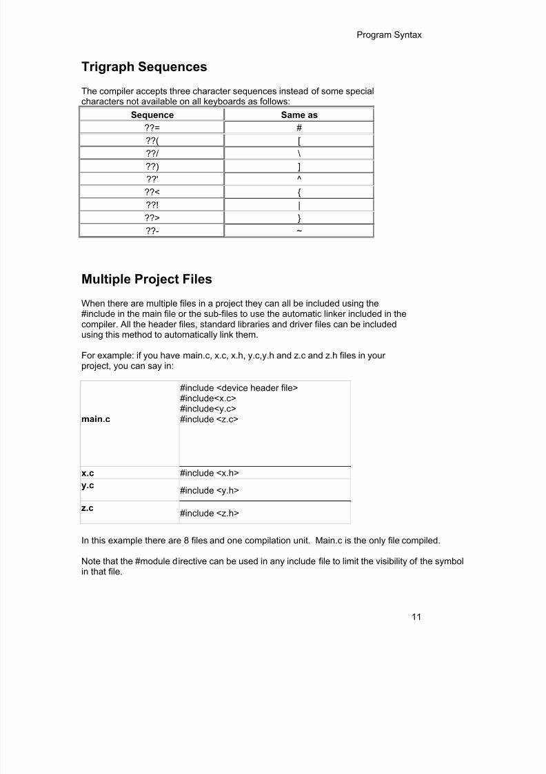
The compiler accepts three character sequences instead of some specialcharacters not available on all keyboards as follows:
Sequence Same as
??= #??( [??/ \??) ]??' ^??< {??! |??> }??- ~
Multiple Project Files
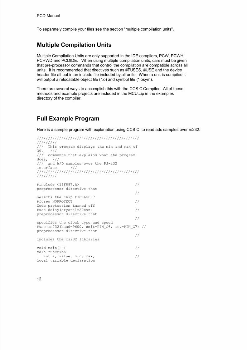
When there are multiple files in a project they can all be included using the#include in the main file or the sub-files to use the automatic linker included in thecompiler. All the header files, standard libraries and driver files can be includedusing this method to automatically link them.
For example: if you have main.c, x.c, x.h, y.c,y.h and z.c and z.h files in yourproject, you can say in:
main.c
#include <device header file>#include<x.c>#include<y.c>#include <z.c>
x.c #include <x.h>y.c #include <y.h>
z.c #include <z.h>
In this example there are 8 files and one compilation unit. Main.c is the only file compiled.
Note that the #module directive can be used in any include file to limit the visibility of the symbolin that file.
8/10/2019 avr.pdf
http://slidepdf.com/reader/full/avrpdf 24/365
PCD Manual
12
To separately compile your files see the section "multiple compilation units".
Multiple Compilation Units
Multiple Compilation Units are only supported in the IDE compilers, PCW, PCWH,PCHWD and PCDIDE. When using multiple compilation units, care must be giventhat pre-processor commands that control the compilation are compatible across allunits. It is recommended that directives such as #FUSES, #USE and the deviceheader file all put in an include file included by all units. When a unit is compiled itwill output a relocatable object file (*.o) and symbol file (*.osym).
There are several ways to accomplish this with the CCS C Compiler. All of thesemethods and example projects are included in the MCU.zip in the examplesdirectory of the compiler.
Full Example Program
Here is a sample program with explanation using CCS C to read adc samples over rs232:
////////////////////////////////////////////////////////// This program displays the min and max of30, ////// comments that explains what the programdoes, ////// and A/D samples over the RS-232interface. //////////////////////////////////////////////////////////
#include <16F887.h> //preprocessor directive that
//selects the chip PIC16F887#fuses NOPROTECT //Code protection turned off#use delay(crystal=20mhz) //preprocessor directive that
//specifies the clock type and speed
#use rs232(baud=9600, xmit=PIN_C6, rcv=PIN_C7) //preprocessor directive that//
includes the rs232 libraries
void main() { //main function
int i, value, min, max; //local variable declaration

8/10/2019 avr.pdf
http://slidepdf.com/reader/full/avrpdf 25/365
Program Syntax
13
printf("Sampling:"); //printf function included in the
//RS232 library
setup_port_a( ALL_ANALOG ); //A/D setup functions- built-in
setup_adc( ADC_CLOCK_INTERNAL ); //Internal clock always works
set_adc_channel( 0 ); //Set channel to AN0
do { // doforever statement
min=255;max=0;for(i=0; i<=30; ++i) { //
Take 30 samplesdelay_ms(100); //
Wait for a tenth of a secondvalue = read_adc(); //
A/D read functions- built-in
if(value<min) //Find smallest samplemin=value;
if(value>max) //Find largest sample
max=value;}printf("\n\rMin: %2X Max:
%2X\n\r",min,max);} while (TRUE);
}

8/10/2019 avr.pdf
http://slidepdf.com/reader/full/avrpdf 26/365

8/10/2019 avr.pdf
http://slidepdf.com/reader/full/avrpdf 27/365
15
STATEMENTS
Statements
STATEMENT Example
if (expr) stmt; [else stmt;]if (x==25)
x=0;else
x=x+1;
while (expr) stmt; while (get_rtcc()!=0)putc(‘n’);
do stmt while (expr);do {
putc(c=getc());} while (c!=0);
for (expr1;expr2;expr3) stmt; for (i=1;i<=10;++i)printf(“%u \r\ n”,i);
switch (expr) {case cexpr: stmt; //one or more case[default:stmt]... }
switch (cmd) {case 0: printf(“cmd
0”);break; case 1: printf(“cmd
1”);break; default: printf(“bad
cmd”);break;}
return [expr]; return (5);goto label; goto loop;
label : stmt; loop: i++;
break ; break;continue ; continue;
expr ; i=1;; ;{[stmt ]}
Zero or more
{a=1;b=1;}
declaration; int i;
Note: Items in [ ] are optional

8/10/2019 avr.pdf
http://slidepdf.com/reader/full/avrpdf 28/365
PCD Manual
16
if
if-elseThe if-else statement is used to make decisions.The syntax is:
if (expr)stmt-1;
[else stmt-2;]
The expression is evaluated; if it is true stmt-1 is done. If it is false then stmt-2 is done.
else -ifThis is used to make multi-way decisions.
The syntax is:
if (expr)stmt;[else if (expr)
stmt;]...
[else stmt;]
The expressions are evaluated in order; if any expression is true, the statement associated withit is executed and it terminates the chain. If none of the conditions are satisfied the last else partis executed.
Example:if (x==25)x=1;
elsex=x+1;
Also See: Statements
while
While is used as a loop/iteration statement.The syntax is:
while (expr)statement

8/10/2019 avr.pdf
http://slidepdf.com/reader/full/avrpdf 29/365
Statements
17
The expression is evaluated and the statement is executed until it becomes false in which casethe execution continues after the statement.
Example:while (get_rtcc()!=0)
putc('n');
Also See: Statements
do-while
do-while : Differs from while and for loop in that the terminationcondition is checked at the bottom of the loop rather than at thetop and so the body of the loop is always executed at least once.The syntax is:
do statement
while (expr);
The statement is executed; the expr is evaluated. If true, thesame is repeated and when it becomes false the loop terminates.
Also See: Statements , While
forFor is also used as a loop/iteration statement.The syntax is:
for (expr1;expr2;expr3)statement
The expressions are loop control statements. expr1 is theinitialization, expr2 is the termination check and expr3 is re-initialization. Any of them can be omitted.
Example:for (i=1;i<=10;++i)printf("%u\r\n",i);
Also See: Statements

8/10/2019 avr.pdf
http://slidepdf.com/reader/full/avrpdf 30/365
PCD Manual
18
switch
Switch is also a special multi-way decision maker.The syntax is
switch (expr) {case const1: stmt sequence;break;
...[default:stmt]
}
This tests whether the expression matches one of the constant values and branchesaccordingly.If none of the cases are satisfied the default case is executed. The break causes an immediateexit, otherwise control falls through to the next case.
Example:switch (cmd) {case 0:printf("cmd 0");
break;case 1:printf("cmd 1");
break;default:printf("bad cmd");
break; }
Also See: Statements
returnreturn
A return statement allows an immediate exit from a switch or a loop or function and alsoreturns a value.
The syntax is:
return (expr);
Example:return (5);
Also See: Statements
goto
goto

8/10/2019 avr.pdf
http://slidepdf.com/reader/full/avrpdf 31/365
Statements
19
The goto statement cause an unconditional branch to the label.
The syntax is:goto label;
A label has the same form as a variable name, and is followed by a colon. The goto'sare used sparingly, if at all.
Example:goto loop;
Also See: Statements
label
labe lThe label a goto jumps to.The syntax is:
label : stmnt;
Example:loop: i++;
Also See: Statements
break
break .The break statement is used to exit out of a control loop. It provides an early exitfrom while, for ,do and switch.The syntax is
break ;
It causes the innermost enclosing loop (or switch) to be exited immediately.
Example:break;
Also See: Statements

8/10/2019 avr.pdf
http://slidepdf.com/reader/full/avrpdf 32/365
PCD Manual
20
continue
The continue statement causes the next iteration of the enclosing loop(While, For,Do) to begin.The syntax is:
continue ;
It causes the test part to be executed immediately in case of do and while and thecontrol passes there-initialization step in case of for.
Example:continue;
Also See: Statements
expr
The syntax is:expr ;
Example:i=1;
Also See: Statements
;
Statement: ;
Example:;
Also See: Statements

8/10/2019 avr.pdf
http://slidepdf.com/reader/full/avrpdf 33/365
Statements
21
stmt
Zero or more semi-colon separated.The syntax is:
{[stmt ]}
Example:{a=1;
b=1;}
Also See: Statements

8/10/2019 avr.pdf
http://slidepdf.com/reader/full/avrpdf 34/365

8/10/2019 avr.pdf
http://slidepdf.com/reader/full/avrpdf 35/365
23
EXPRESSIONS
Constants
123 Decimal
123L Forces type to & long (UL also allowed)
123LL Forces type to &; 64 for PCD
0123 Octal
0x123 Hex
0b010010 Binary
123.456 Floating Point
123F Floating Point (FL also allowed)
123.4E-5 Floating Point in scientific notation
'x' Character'\010' Octal Character
'\xA5’ Hex Character
'\c'
Special Character. Where c is one of:\n Line Feed - Same as \x0a\r Return Feed - Same as \x0d\t TAB - Same as \x09\b Backspace - Same as \x08\f Form Feed - Same as x0c\a Bell - Same as \x07
\v Vertical Space - Same as \x0b\? Question Mark - Same as \x3f\' Single Quote - Same as \x22\" Double Quote - Same as \x22\\ A Single Backslash - Same as \x5c
"abcdef" String (null is added to the end)

8/10/2019 avr.pdf
http://slidepdf.com/reader/full/avrpdf 36/365
PCD Manual
24
Identifiers
ABCDEUp to 32 characters beginning with a non-numeric.Valid characters are A-Z, 0-9 and _ (underscore). Bydefault not case sensitive Use #CASE to turn on.
ID[X] Single SubscriptID[X][X] Multiple SubscriptsID.ID Structure or union referenceID->ID Structure or union reference
Operators
+ Addition Operator+= Addition assignment operator, x+=y, is the same as x=x+y[ ] Array subscrip operator
&= Bitwise and assignment operator, x&=y, is the same asx=x&y
& Address operator
& Bitwise and operator^= Bitwise exclusive or assignment operator, x^=y, is the same
as x=x^y^ Bitwise exclusive or operator
l= Bitwise inclusive or assignment operator, xl=y, is the sameas x=xly
l Bitwise inclusive or operator?: Conditional Expression operator- - Decrement/= Division assignment operator, x/=y, is the same as x=x/y/ Division operator== Equality> Greater than operator>= Greater than or equal to operator++ Increment* Indirection operator!= Inequality

8/10/2019 avr.pdf
http://slidepdf.com/reader/full/avrpdf 37/365
Expressions
25
<<= Left shift assignment operator, x<<=y, is the same asx=x<<y
< Less than operator<< Left Shift operator<= Less than or equal to operator&& Logical AND operator! Logical negation operatorll Logical OR operator. Member operator for structures and unions%= Modules assignment operator x%=y, is the same as x=x%y% Modules operator
*= Multiplication assignment operator, x*=y, is the same asx=x*y
* Multiplication operator
~ One's complement operator>>= Right shift assignment, x>>=y, is the same as x=x>>y>> Right shift operator-> Structure Pointer operation
-= Subtraction assignment operator, x-=y, is the same as x=x- y
- Subtraction operatorsizeof Determines size in bytes of operand
See also: Operator Precedence
Operator Precedence
PIN DESCENDING PRECEDENCE Associativity(expr ) exor++ expr->expr expr.expr Left to Right++expr expr ++ - - expr expr - - Left to Right
!expr ~ expr +expr -expr Right to Left
(type )expr *expr &value sizeof (type) Right to Leftexpr *expr expr /expr expr %expr Left to Rightexpr +expr expr -expr Left to Rightexpr <<expr expr >>expr Left to Rightexpr <expr expr <= expr expr >expr expr >= expr Left to Right
expr == expr expr != expr Left to Right

8/10/2019 avr.pdf
http://slidepdf.com/reader/full/avrpdf 38/365
PCD Manual
26
expr &expr Left to Rightexpr ̂ expr Left to Rightexpr | expr Left to Rightexpr && expr Left to Rightexpr || expr Left to Rightexpr ? expr : expr Right to Leftlvalue = expr lvalue += expr lvalue -= expr Right to Left
lvalue *= expr lvalue /= expr lvalue %= expr Right to Left
lvalue >>= expr lvalue <<= expr lvalue &= expr Right to Left
lvalue ^= expr lvalue |= expr Right to Leftexpr, expr Left to Right
(Operators on the same line are equal in precedence)

8/10/2019 avr.pdf
http://slidepdf.com/reader/full/avrpdf 39/365
27
DATA DEFINITIONS
Data Definitions
Basic Types
Declarations
Non-RAM Data Definitions
Using Program Memory for Data
Function Definition
Declarations
This section describes what the basic data types and specifiers are and howvariables can be declared using those types. In C all the variables should bedeclared before they are used. They can be defined inside a function (local) oroutside all functions (global). This will affect the visibility and life of the variables.
A declaration consists of a type qualifier and a type specifier, and is followed by a listof one or more variables of that type.For example:
int a,b,c,d;mybit e,f;mybyte g[3][2];char *h;colors j;struct data_record data[10];static int i;extern long j;
Variables can also be declared along with the definitions of the special types.
For example:enum colors{red, green=2,blue}i,j,k; // colors is the enum type andi,j,k
//are variables of that type
SEE ALSO:Type Specifiers Type Qualifiers Enumerated Types

8/10/2019 avr.pdf
http://slidepdf.com/reader/full/avrpdf 40/365
PCD Manual
28
Structures & Unions typedef Named Registers
Type Specifiers
Basic Types
Type-SpecifierRange
Size Unsigned Signed Digits
int1 1 bit number 0 to 1 N/A 1/2
int8 8 bit number 0 to 255 -128 to 127 2-3
int16 16 bit number 0 to 65535 -32768 to 32767 4-5
int32 32 bit number 0 to 4294967295-2147483648 to2147483647 9-10
int48 48 bit number 0 to281474976710655
-140737488355328 to140737488355327 14-15
int64 64 bit number N/A-9223372036854775808to9223372036854775807
18-19
float32 32 bit float -1.5 x 10 45 to 3.4 x 10 38 7-8
float4848 bit float (higher precision) -2.9 x 10
39 to 1.7 x 10
38 11-12
float64 64 bit float -5.0 x 10 324 to 1.7 x 10 308 15-16
C Standard Type Default Typeshort unsigned int8char unsigned int8int unsigned int16long unsigned int32long long unsigned int64
float float32double
Note: All types, except float char , by default are un-signed; however, may bepreceded by unsigned or signed (Except int64 may only be signed) . Short and longmay have the keyword INT following them with no effect. Also see #TYPE tochange the default size.

8/10/2019 avr.pdf
http://slidepdf.com/reader/full/avrpdf 41/365
Data Definitions
29
SHORT INT1 is a special type used to generate very efficient code for bit operationsand I/O. Arrays of bits (INT1 or SHORT ) in RAM are now supported. Pointers tobits are not permitted. The device header files contain defines for BYTE as an int8and BOOLEAN as an int1.
Integers are stored in little endian format. The LSB is in the lowest address. Floatformats are described in common questions.
SEE ALSO: Declarations , Type Qualifiers , Enumerated Types , Structures & Unions , typedef , Named Registers
Type Qualifiers
Type-Qualifier
staticVariable is globally active and initialized to 0. Only accessible from thiscompilation unit.
autoVariable exists only while the procedure is active. This is the default and
AUTO need not be used.
double Is a reserved word but is not a supported data type.
extern
External variable used with multiple compilation units. No storage isallocated. Is used to make otherwise out of scope data accessible. theremust be a non-extern definition at the global level in some compilationunit.
register If possible a CPU register instead of a RAM location.
_ fixed(n) Creates a fixed point decimal number where n is how many decimalplaces to implement.
unsigned Data is always positive.
signedData can be negative or positive. This is the default data type if notspecified.
volatileTells the compiler optimizer that this variable can be changed at any pointduring execution.
const
Data is read-only. Depending on compiler configuration, this qualifiermay just make the data read-only -AND/OR- it may place the data intoprogram memory to save space. (see #DEVICE const=)

8/10/2019 avr.pdf
http://slidepdf.com/reader/full/avrpdf 42/365
PCD Manual
30
rom Forces data into program memory. Pointers may be used to this data butthey can not be mixed with RAM pointers.
roml Same as rom except only the even program memory locations are used.
void
Built-in basic type. Type void is used to indicate no specific type in places
where a type is required.readonly Writes to this variable should be dis-allowed
_bif Used for compiler built in function prototypes on the same line
__attribute__ Sets various attributes
SEE ALSO: Declarations , Type Specifiers , Enumerated Types , Structures & Unions , typedef , Named Registers
Enumerated Types
enum enumeration type: creates a list of integer constants.
enum [id] { [ id [ = cexpr]] }
One or more comma separated
The id after enum is created as a type large enough to thelargest constant in the list. The ids in the list are each created asa constant. By default the first id is set to zero and theyincrement by one. If a = cexpr follows an id that id will have thevalue of the constant expression an d the following list willincrement by one.
For example:enum colors{red, green=2, blue}; // red will be 0, green will be 2 and
// blue will be 3
SEE ALSO: Declarations , Type Specifiers , Type Qualifiers , Structures & Unions , typedef , Named Registers

8/10/2019 avr.pdf
http://slidepdf.com/reader/full/avrpdf 43/365
Data Definitions
31
Structures and Unions
Struct structure type: creates a collection of one or morevariables, possibly of different types, grouped together as a
single unit.struct [*] [id] { type-qualifier [ *] id [:bits]; } [id]
One or more,semi-colonseparated
Zeroor more
For example:struct data_record {
in t a[2]; int b : 2; /*2 bits */ int c : 3; /*3 bits*/ int d;
} data_var; //data_record is a structure type //data_var is a variable
Field Allocation- Fields are allocated in the order they appear.- The low bits of a byte are filled first.- Fields 16 bits and up are aligned to a even byte boundary. Some Bits may by unused.
- No Field will span from an odd byte to an even byte unless the field width is a multiple of 16bits.
Union type: holds objects of different types and sizes, with thecompiler keeping track of size and alignment requirements. Theyprovide a way to manipulate different kinds of data in a singlearea of storage.
union [*] [id] { type-qualifier [*] id [:bits]; } [id]
One or more,semi-colonseparated
Zero
or more
For example:union u_tab {
in t ival; long lval; float fval; }; //u_tag is a union type that can hold a float

8/10/2019 avr.pdf
http://slidepdf.com/reader/full/avrpdf 44/365
PCD Manual
32
SEE ALSO: Declarations , Type Specifiers , Type Qualifiers , Enumerated Types ,
typedef , Named Registers
typedef
If typedef is used with any of the basic or special types it creates anew type name that can be used in declarations. The identifierdoes not allocate space but rather may be used as a type specifierin other data definitions.
typedef [type-qualifier] [type-specifier] [declarator];
For example:
typedef int mybyte; // mybyte can be used in declarationto // specify the int type
typedef short mybit; // mybyte can be used in declarationto // specify the int type
typedef enum {red,green=2,blue}colors; //colors can be used to declare
//variable of this enum type
SEE ALSO: Declarations , Type Specifiers , Type Qualifiers , Structures & Unions , Enumerated Types , Named Registers
Non-RAM Data Definitions
CCS C compiler also provides a custom qualifier addressmod which can
be used to define a memory region that can be RAM, program eeprom,data eeprom or external memory. Addressmod replaces the oldertypemod (with a different syntax).
The usage is :addressmod(name,read_function,write_function,start_address,end_address, share);

8/10/2019 avr.pdf
http://slidepdf.com/reader/full/avrpdf 45/365
Data Definitions
33
Where the read_function and write_function should be blank for RAM, orfor other memory should be the following prototype:
// read procedure for reading n bytes from the memory starting atlocation addrvoid read_function(int32 addr,int8 *ram, int nbytes) {}
//write procedure for writing n bytes to the memory starting atlocation addrvoid write_function(int32 addr,int8 *ram, int nbytes){
}
For RAM the share argument may be true if unused RAM in this area can be used by thecompiler for standard variables.
Example:void DataEE_Read(int32 addr, int8 * ram, int bytes) {
int i;for(i=0;i<bytes;i++,ram++,addr++)
*ram=read_eeprom(addr);}
void DataEE_Write(int32 addr, int8 * ram, int bytes) {int i;for(i=0;i<bytes;i++,ram++,addr++)
write_eeprom(addr,*ram);}
addressmod (DataEE,DataEE_read,DataEE_write,5,0xff);// would define a region called DataEE between// 0x5 and 0xff in the chip data EEprom.
void main (void){
int DataEE test;
int x,y;x=12;test=x; // writes x to the Data EEPROMy=test; // Reads the Data EEPROM
}
Note: If the area is defined in RAM then read and write functions are notrequired, the variables assigned in the memory region defined by theaddressmod can be treated as a regular variable in all valid expressions.
Any structure or data type can be used with an addressmod. Pointerscan also be made to an addressmod data type. The #type directive canbe used to make this memory region as default for variable allocations.
The syntax is :#type default=addressmodname // all the variable declarationsthat
// follow will use this memoryregion#type default= // goes back to the default mode
For example:Type default=emi //emi is the addressmod namedefined

8/10/2019 avr.pdf
http://slidepdf.com/reader/full/avrpdf 46/365
PCD Manual
34
char buffer[8192];#include <memoryhog.h>#type default=
Using Program Memory for DataCCS C Compiler provides a few different ways to use program memory for data. The differentways are discussed below:
Constant Data:The const qualifier will place the variables into program memory. If the keyword const is usedbefore the identifier, the identifier is treated as a constant. Constants should be initialized andmay not be changed at run-time. This is an easy way to create lookup tables.
The rom Qualifier puts data in program memory with 3 bytes per instruction space. The addressused for ROM data is not a physical address but rather a true byte address. The & operator canbe used on ROM variables however the address is logical not physical.
The syntax is:const type id[cexpr] = {value}
For example:Placing data into ROM
const int table[16]={0,1,2...15}Placing a string into ROM
const char cstring[6]={"hello"}Creating pointers to constants
const char *cptr;cptr = string;
The #org preprocessor can be used to place the constant to specified address blocks.For example:The constant ID will be at 1C00.
#ORG 0x1C00, 0x1C0FCONST CHAR ID[10]= {"123456789"};
Note : Some extra code will precede the 123456789.
The function label_address can be used to get the address of the constant. The constantvariable can be accessed in the code. This is a great way of storing constant data in largeprograms. Variable length constant strings can be stored into program memory.
A special method allows the use of pointers to ROM. This method does not contain extra codeat the start of the structure as does constant.
For example:char rom comm ands[] = {“put|get|status|shutdown”};
ROML may be used instead of ROM if you only to use even memory locations.
The compiler allows a non-standard C feature to implement a constant array of variable lengthstrings.
The syntax is:const char id[n] [*] = { "string", "string" ...};
Where n is optional and id is the table identifier.
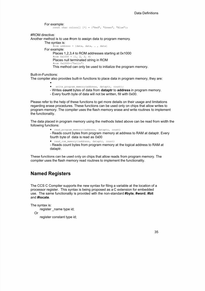
8/10/2019 avr.pdf
http://slidepdf.com/reader/full/avrpdf 47/365
Data Definitions
35
For example:const char colors[] [*] = {"Red", "Green", "Blue"};
#ROM directive: Another method is to use #rom to assign data to program memory.
The syntax is:#rom address = {data, data, … , data} For example:Places 1,2,3,4 to ROM addresses starting at 0x1000#rom 0x1000 = {1, 2, 3, 4}Places null terminated string in ROM#rom 0x1000={"hello"}This method can only be used to initialize the program memory.
Built-in-Functions:The compiler also provides built-in functions to place data in program memory, they are:
write_program_memory(address, dataptr, count);
- Writes count bytes of data from dataptr to address in program memory.
- Every fourth byte of data will not be written, fill with 0x00.
Please refer to the help of these functions to get more details on their usage and limitationsregarding erase procedures. These functions can be used only on chips that allow writes toprogram memory. The compiler uses the flash memory erase and write routines to implementthe functionality.
The data placed in program memory using the methods listed above can be read from width thefollowing functions:
read_program_memory((address, dataptr, count)- Reads count bytes from program memory at address to RAM at dataptr. Everyfourth byte of data is read as 0x00
read_rom_memory((address, dataptr, count)- Reads count bytes from program memory at the logical address to RAM atdataptr.
These functions can be used only on chips that allow reads from program memory. Thecompiler uses the flash memory read routines to implement the functionality.
Named Registers
The CCS C Compiler supports the new syntax for filing a variable at the location of aprocessor register. This syntax is being proposed as a C extension for embeddeduse. The same functionality is provided with the non-standard #byte , #word , #bit and #locate .
The syntax is:register _name type id;
Orregister constant type id;

8/10/2019 avr.pdf
http://slidepdf.com/reader/full/avrpdf 48/365
PCD Manual
36
name is a valid SFR name with an underscore before it.
Examples:register _status int8 status_reg;register _T1IF int8 timer_interrupt;register 0x04 int16 file_select_register;

8/10/2019 avr.pdf
http://slidepdf.com/reader/full/avrpdf 49/365

8/10/2019 avr.pdf
http://slidepdf.com/reader/full/avrpdf 50/365
PCD Manual
38
Overloaded Functions
Overloaded functions allow the user to have multiple functions with the same name, but theymust accept different parameters.
Here is an example of function overloading: Two functions have the same name but differ in thetypes of parameters. The compiler determines which data type is being passed as a parameterand calls the proper function.
This function finds the square root of a long integer variable.
long FindSquareRoot(long n){}
This function finds the square root of a float variable.
float FindSquareRoot(float n){}
FindSquareRoot is now called. If variable is of long type, it will call the first FindSquareRoot()example. If variable is of float type, it will call the second FindSquareRoot() example.
result=FindSquareRoot(variable);
Reference Parameters
The compiler has limited support for reference parameters. This increases the readability ofcode and the efficiency of some inline procedures. The following two procedures are thesame. The one with reference parameters will be implemented with greater efficiency when it isinline.
funct_a(int*x,int*y){/*Traditional*/if(*x!=5)
*y=*x+3;}
funct_a(&a,&b);
funct_b(int&x,int&y){/*Reference params*/if(x!=5)
y=x+3;}
funct_b(a,b);

8/10/2019 avr.pdf
http://slidepdf.com/reader/full/avrpdf 51/365
Function Definition
39
Default Parameters
Default parameters allows a function to have default values if nothing is passed to it whencalled.
int mygetc(char *c, int n=100){}
This function waits n milliseconds for a character over RS232. If a character is received, it savesit to the pointer c and returns TRUE. If there was a timeout it returns FALSE.
//gets a char, waits 100ms for timeoutmygetc(&c);//gets a char, waits 200ms for a timeoutmygetc(&c, 200);
Variable Argument Lists
The compiler supports a variable number of parameters. This works like the ANSI requirementsexcept that it does not require at least one fixed parameter as ANSI does. The function can bepassed any number of variables and any data types. The access functions are VA_START,VA_ARG, and VA_END. To view the number of arguments passed, the NARGS function can beused.
/*stdarg.h holds the macros and va_list data type needed for variable number of parameters.*/#include <stdarg.h>
A function with variable number of parameters requires two things. First, it requires the ellipsis(...), which must be the last parameter of the function. The ellipsis represents the variableargument list. Second, it requires one more variable before the ellipsis (...). Usually you will usethis variable as a method for determining how many variables have been pushed onto theellipsis.
Here is a function that calculates and returns the sum of all variables:int Sum(int count, ...){
//a pointer to the argument listva_list al;int x, sum=0;//start the argument list//count is the first variable before the ellipsisva_start(al, count);while(count--) {
//get an int from the listx = var_arg(al, int);sum += x;
}//stop using the listva_end(al);return(sum);
}
Some examples of using this new function:

8/10/2019 avr.pdf
http://slidepdf.com/reader/full/avrpdf 52/365
PCD Manual
40
x=Sum(5, 10, 20, 30, 40, 50);y=Sum(3, a, b, c);

8/10/2019 avr.pdf
http://slidepdf.com/reader/full/avrpdf 53/365
41
FUNCTIONAL OVERVIEW
I2C
I2C™ is a popular two -wire communication protocol developed by Phillips. Many PICmicrocontrollers support hardware- based I2C™. CCS offers support for the hardware -basedI2C™ and a software -based ma ster I2C™ device. (For more information on the hardware -basedI2C module, please consult the datasheet for you target device; not all PICs support I2C™.)
Relevant Functions: i2c_start() Issues a start command when in the I2C master mode.i2c_write(data) Sends a single byte over the I2C interface.
i2c_read() Reads a byte over the I2C interface.i2c_stop() Issues a stop command when in the I2C master mode.i2c_poll() Returns a TRUE if the hardware has received a byte in the
buffer.
Relevant Preprocessor:#USE I2C Configures the compiler to support I2C™ to your
specifications.
Relevant Interrupts:#INT_SSP I2C or SPI activity#INT_BUSCOL Bus Collision#INT_I2C I2C Interrupt (Only on 14000)#INT_BUSCOL2 Bus Collision (Only supported on some PIC18's)#INT_SSP2 I2C or SPI activity (Only supported on some PIC18's)#INT_mi2c Interrupts on activity from the master I2C module#INT_si2c Interrupts on activity form the slave I2C module
Relevant Include Files:None, all functions built-in
Relevant getenv() Parameters:I2C_SLAVE Returns a 1 if the device has I2C slave H/WI2C_MASTER Returns a 1 if the device has a I2C master H/W
Example Code:#define Device_SDA PIN_C3 // Pin defines#define Device_SLC PIN_C4

8/10/2019 avr.pdf
http://slidepdf.com/reader/full/avrpdf 54/365
PCD Manual
42
#use i 2c(master,sda=Device_SDA,scl=Device_SCL)
// Configure Device as Master
..
..
BYTE data; // Data to be transmittedi2c_start(); // Issues a start command when in the I2C master mode.i2c_write(data); // Sends a single byte over the I2C interface.i2c_stop(); // Issues a stop command when in the I2C master mode.
ADC
These options let the user configure and use the analog to digital converter module. They areonly available on devices with the ADC hardware. The options for the functions and directivesvary depending on the chip and are listed in the device header file. On some devices there aretwo independent ADC modules, for these chips the second module is configured usingsecondary ADC setup functions (Ex. setup_ADC2).
Relevant Functions:setup_adc(mode) Sets up the a/d mode like off, the adc clock etc.setup_adc_ports(value) Sets the available adc pins to be analog or digital.set_adc_channel(channel) Specifies the channel to be use for the a/d call.read_adc(mode) Starts the conversion and reads the value. The mode
can also control the functionality.adc_done() Returns 1 if the ADC module has finished its conversion.
setup_adc2(mode) Sets up the ADC2 module, for example the ADC clockand ADC sample time.
setup_adc_ports2(ports, reference) Sets the available ADC2 pins to be analog or digital, andsets the voltage reference for ADC2.
set_adc_channel2(channel) Specifies the channel to use for the ADC2 input.read_adc2(mode) Starts the sample and conversion sequence and reads
the value The mode can also control the functionality.
adc_done() Returns 1 if the ADC module has finished its conversion
Relevant Preprocessor:#DEVICE ADC=xx Configures the read_adc return size. For example, using
a PIC with a 10 bit A/D you can use 8 or 10 for xx- 8 willreturn the most significant byte, 10 will return the full A/Dreading of 10 bits.

8/10/2019 avr.pdf
http://slidepdf.com/reader/full/avrpdf 55/365
Functional Overview
43
Relevant Interrupts:INT_AD Interrupt fires when a/d conversion is completeINT_ADOF Interrupt fires when a/d conversion has timed out
Relevant Include Files:
None, all functions built-in
Relevant getenv() parameters: ADC_CHANNELS Number of A/D channels ADC_RESOLUTION Number of bits returned by read_adc
Example Code:#DEVICE ADC=10...long value;
...setup_adc(ADC_CLOCK_INTERNAL); //enables the a/d module
//and sets the clock to internal adc clocksetup_adc_ports(ALL_ANALOG); //sets all the adc pins to analogset_adc_channel(0); //the next read_adc call will read channel 0delay_us(10); //a small delay is required after setting the channel
//and before readvalue=read_adc(); //starts the conversion and reads the result
//and store it in valueread_adc(ADC_START_ONLY); //only starts the conversion
value=read_adc(ADC_READ_ONLY); //reads the result of the last conversion and store it in//value. Assuming the device hat a 10bit ADC module,//value will range between 0-3FF. If #DEVICE ADC=8had //been used instead the result will yield 0-FF. If#DEVICE //ADC=16 had been used instead the resultwill yield 0-//FFC0
Analog Comparator
These functions set up the analog comparator module. Only available in some devices.
Relevant Functions:
setup_comparator(mode)Enables and sets the analog comparator module. The optionsvary depending on the chip. Refer to the header file fordetails.
Relevant Preprocessor:None

8/10/2019 avr.pdf
http://slidepdf.com/reader/full/avrpdf 56/365
PCD Manual
44
Relevant Interrupts:
INT_COMP Interrupt fires on comparator detect. Some chips have morethan one comparator unit, and thus, more interrupts.
Relevant Include Files:
None, all functions built-in
Relevant getenv() Parameters:Returns 1 if the device has acomparator COMP
Example Code:setup_comparator(A4_A5_NC_NC);
if(C1OUT) output_low(PIN_D0);
else output_high(PIN_D1);
CAN Bus
These functions allow easy access to the Controller Area Network (CAN) features included withthe MCP2515 CAN interface chip and the PIC24, dsPIC30 and dsPIC33 MCUs. These functionswill only work with the MCP2515 CAN interface chip and PIC microcontroller units containingeither a CAN or an ECAN module. Some functions are only available for the ECAN module and
are specified by the word ECAN at the end of the description. The listed interrupts are notavailable to the MCP2515 interface chip.Relevant Functions:
can_init(void);
Initializes the CAN module and clears all the filtersand masks so that all messages can be receivedfrom any ID.
can_set_baud(void);
Initializes the baud rate of the CAN bus to125kHz, ifusing a 20 MHz clock and the default CAN-BRGdefines, it is called inside the can_init() function sothere is no need to call it.
can_set_mode (CAN_OP_MODE mode);
Allows the mode of the CAN module to be changedto configuration mode, listen mode, loop back mode,disabled mode, or normal mode.
can_set_functional_mode(CAN_FUN_OP_MODE mode);
Allows the functional mode of ECAN modules to bechanged to legacy mode, enhanced legacy mode,or first in firstout (fifo) mode. ECAN

8/10/2019 avr.pdf
http://slidepdf.com/reader/full/avrpdf 57/365

8/10/2019 avr.pdf
http://slidepdf.com/reader/full/avrpdf 58/365

8/10/2019 avr.pdf
http://slidepdf.com/reader/full/avrpdf 59/365
Functional Overview
47
can_set_baud(void); Initializes the baud rate of the bus to 62.5kHzfor ECAN and 125kHz for CAN. It is calledinside the can_init() function so there is noneed to call it.
can_set_mode(CAN_OP_MODE mode);
Allows the mode of the CAN module to bechanged to listen all mode, configurationmode, listen mode, loop back mode, disabledmode, or normal mode.
can_set_functional_mode(CAN_FUN_OP_MODE mode);
Allows the functional mode of ECAN modulesto be changed to legacy mode, enhancedlegacy mode, or first in firstout (fifo) mode.ECAN
can_set_id(int16 *addr, int32 id, int1 ext) Can be used to set the filter and mask ID's tothe value specified by addr. It is also used toset the ID of the message to be sent on CANchips.
can_set_buffer_id(BUFFER buffer, int32 id,int1 ext)
Can be used to set the ID of the message tobe sent for ECAN chips. ECAN
can_get_id(BUFFER buffer, int1 ext) Returns the ID of a received message.
can_putd(int32 id, int8 *data, int8 len, int8priority, int1 ext, int1 rtr)
Constructs a CAN packet using the givenarguments and places it in one of the
available transmit buffers.
can_getd(int32 &id, int8 *data, int8 &len,struct rx_stat &stat)
Retrieves a received message from one of theCAN buffers and stores the relevant data inthe referenced function parameters.
can_kbhit() Returns TRUE if valid CAN messages isavailable to be retrieved from one of thereceive buffers.
can_tbe() Returns TRUE if a transmit buffer is isavailable to send more data.
can_abort() Aborts all pending transmissions.
can_enable_b_transfer(BUFFER b) Sets the specified programmable buffer tobe a transmit buffer. ECAN
can_enable_b_receiver(BUFFER b) Sets the specified programmable buffer tobe a receive buffer. By default allprogrammable buffers are set to bereceive buffers. ECAN

8/10/2019 avr.pdf
http://slidepdf.com/reader/full/avrpdf 60/365
PCD Manual
48
can_enable_rtr(BUFFER b) Enables the automatic response featurewhich automatically sends a user createdpacket when a specified ID is received.ECAN
can_disable_rtr(BUFFER b) Disables the automatic response feature.ECAN
can_load_rtr (BUFFER b, int8 *data, int8len)
Creates and loads the packet that willautomatically transmitted when thetriggering ID is received. ECAN
can_set_buffer_size(int8 size) Set the number of buffers to use. Size canbe 4, 6, 8, 12, 16, 24, and 32. By defaultcan_init() sets size to 32. ECAN
can_enable_filter(CAN_FILTER_CONTROL filter)
Enables one of the acceptance filtersincluded in the ECAN module. ECAN
can_disable_filter(CAN_FILTER_CONTROL filter)
Disables one of the acceptance filtersincluded in the ECAN module. ECAN
can_associate_filter_to_buffer(CAN_FILTER_ASSOCIATION_BUFFERSbuffer, CAN_FILTER_ASSOCIATIONfilter)
Used to associate a filter to a specificbuffer. This allows only specific buffers tobe filtered and is available in the ECANmodule. ECAN
can_associate_filter_to_mask(CAN_MASK_FILTER_ASSOCIATIONmask, CAN_FILTER_ASSOCIATIONfilter)
Used to associate a mask to a specificbuffer. This allows only specific buffer tohave this mask applied. This feature isavailable in the ECAN module. ECAN
can_fifo_getd(int32 &id, int8 *data, int8&len, struct rx_stat &stat )
Retrieves the next buffer in the FIFO buffer.Only available in the ECAN module. ECAN
can_trb0_putd(int32 id, int8 *data, int8len, int8 pri, int1 ext, int1 rtr)
Constructs a CAN packet using the givenarguments and places it in transmit buffer0. Similar functions available for alltransmit buffers 0-7. Buffer must be madea transmit buffer withcan_enable_b_transfer() function beforefunction can be used. ECAN
can_enable_interrupts(INTERRUPTsetting)
Enables specified interrupt conditions thatcause the #INT_CAN1 interrupt to betriggered. Available options are:TB - Transmitt Buffer Interrupt
ECANRB - Receive Buffer Interrupt
ECANRXOV - Receive Buffer Overflow Interrupt
ECANFIFO - FIFO Almost Full Interrupt
ECANERR - Error interrupt
ECAN/CANWAK - Wake-Up Interrupt
ECAN/CAN

8/10/2019 avr.pdf
http://slidepdf.com/reader/full/avrpdf 61/365
Functional Overview
49
IVR - Invalid Message Received InterruptECAN/CAN
RX0 - Receive Buffer 0 InterruptCAN
RX1 - Receive Buffer 1 InterruptCAN
TX0 - Transmit Buffer 0 InterruptCAN
TX1 - Transmit Buffer 1 InterruptCAN
TX2 - Transmit Buffer 2 InterruptCAN
can_disable_interrupts(INTERRUPTsetting)
Disable specified interrupt conditions sothey doesn't cause the #INT_CAN1interrupt to be triggered. Availableoptions are the same as for thecan_enable_interrupts() function. Bydefault all conditions are disabled.
can_config_DMA(void) Configures the DMA buffers to use withthe ECAN module. It is called inside thecan_init() function so there is no need tocall it. ECAN
For PICs that have two CAN or ECANmodules all the above function areavailable for the second module, andthey start with can2 instead of can.
Examples:can2_init();can2_kbhit();
Relevant Preprocessor:None
Relevant Interrupts:#INT_CAN1 Interrupt for CAN or ECAN module 1. This
interrupt is triggered when one of theconditions set by thecan_enable_interrupts() is meet.
#INT_CAN2 Interrupt for CAN or ECAN module 2. Thisinterrupt is triggered when one of theconditions set by thecan2_enable_interrupts() is meet. Thisinterrupt is only available on PICs thathave two CAN or ECAN modules.
Relevant Include Files:can-mcp2510.c Drivers for the MCP2510 and MCP2515
interface chips.
can-dsPIC30.c Drivers for the built in CAN module ondsPIC30F chips.
can-PIC24.c Drivers for the build in ECAN module onPIC24HJ and dsPIC33FJ chips.

8/10/2019 avr.pdf
http://slidepdf.com/reader/full/avrpdf 62/365
PCD Manual
50
Relevant getenv() Parameters:None
Example Code:can_init(); // Initializes the CAN bus.
can_putd(0x300,data,8,3,TRUE,FALSE); // Places a message on the CAN bus with
// ID = 0x300 and eight bytes of data pointedto by
// “data”, the TRUE causes an extended IDto be
// sent, the FALSE causes no remotetransmission
// to be requested.
can_getd(ID,data,len,stat); // Retrieves a message from the CAN busstoring the
// ID in the ID variable, the data at the array
//pointed to by
// to by “data”, the number of data bytes inlen and staticstics
/ about the data in the stat structure.
Code Profile
Profile a program while it is running. Unlike in-circuit debugging, this tool grabs informationwhile the program is running and provides statistics, logging and tracing of it's execution. This
is accomplished by using a simple communication method between the processor and the ICDwith minimal side-effects to the timing and execution of the program. Another benefit of codeprofile versus in-circuit debugging is that a program written with profile support enabled will runcorrectly even if there is no ICD connected.
In order to use Code Profiling, several functions and pre-processor statements need to beincluded in the project being compiled and profiled. Doing this adds the proper code profilerun-time support on the microcontroller.
See the help file in the Code Profile tool for more helpand usage examples.
Relevant Functions:
profileout()Send a user specified message or variable to be displayed orlogged by the code profile tool.
Relevant Pre-Processor:
#use profile() Global configuration of the code profile run-time on themicrocontroller.

8/10/2019 avr.pdf
http://slidepdf.com/reader/full/avrpdf 63/365
Functional Overview
51
#profile Dynamically enable/disable specific elements of the profiler.
Relevant Interrupts:
The profiler can be configured to use a microcontroller'sinternal timer for more accurate timing of events over theclock on the PC. This timer is configured using the #profilepre-processor command.
Relevant Include Files: None – all the functions are built into the compiler.
Relevant getenv(): None
Example Code:
#include <18F4520.h>#use delay(crystal=10MHz, clock=40MHz)#profile functions, parametersvoid main(void){
int adc;setup_adc(ADC_CLOCK_INTERNAL);set_adc_channel(0);
for(;;){
adc = read_adc();profileout(adc);delay_ms(250);
}}
DAC
These options let the user configure and use the digital to analog converter module. They areonly available on devices with the DAC hardware. The options for the functions and directivesvary depending on the chip and are listed in the device header file.
Relevant Functions:setup_dac(divisor) Sets up the DAC e.g. Reference voltages
dac_write(value) Writes the 8-bit value to the DAC module
setup_dac(mode, divisor) Sets up the d/a mode e.g. Right enable, clock divisor
dac_write(channel, value) Writes the 16-bit value to the specified channel

8/10/2019 avr.pdf
http://slidepdf.com/reader/full/avrpdf 64/365
PCD Manual
52
Relevant Preprocessor:#USE DELAY Must add an auxiliary clock in the #use delay preprocessor. For
example:#USE DELAY(clock=20M, Aux: crystal=6M, clock=3M)
Relevant Interrupts:
None
Relevant Include Files:
None, all functions built-in
Relevant getenv()parameters:None
Example Code:int16 i = 0;setup_dac(DAC_RIGHT_ON,5);
//enables the d/a module with right channel enabled and adivision of the clock by 5
While(1){i++;dac_write(DAC_RIGHT, i); //writes i to the right DAC channel}
Data EepromThe data eeprom memory is readable and writable in some chips. These options lets the userread and write to the data eeprom memory. These functions are only available in flash chips.
Relevant Functions:(8 bit or 16 bit depending on thedevice)read_eeprom(address) Reads the data EEPROM memory location
write_eeprom(address, value) Erases and writes value to data EEPROM location address.
read_eeprom(address, [N]) Reads N bytes of data EEPROM starting at memory locationaddress. The maximum return size is int64.
read_eeprom(address, [variable]) Reads from EEPROM to fill variable starting at addressread_eeprom(address, pointer,N)
Reads N bytes, starting at address, to pointer
write_eeprom(address, value) Writes value to EEPROM address

8/10/2019 avr.pdf
http://slidepdf.com/reader/full/avrpdf 65/365
Functional Overview
53
write_eeprom(address, pointer,N)
Writes N bytes to address from pointer
Relevant Preprocessor:#ROM address={list} Can also be used to put data EEPROM memory data into the
hex file.
write_eeprom = noint Allows interrupts to occur while the write_eeprom() operationsis polling the done bit to check if the write operations hascompleted. Can be used as long as no EEPROM operationsare performed during an ISR.
Relevant Interrupts:INT_EEPROM Interrupt fires when EEPROM write is complete
Relevant Include Files:None, all functions built-in
Relevant getenv() parameters:DATA_EEPROM Size of data EEPROM memory.
Example Code:
#ROM 0x007FFC00={1,2,3,4,5} // Inserts this data into the hex file// The data EEPROM address differs between PICs// Please refer to the device editor for device specific values.
write_eeprom(0x10, 0x1337); // Writes 0x1337 to data EEPROM location 10.value=read_eeprom(0x0); // Reads data EEPROM location 10 returns 0x1337.
Data Signal Modulator
The Data Signal Modula tor (DSM) allows the user to mix a digital data stream (the “modulatorsignal”) with a carrier signal to produce a modulated output. Both the carrier and the modulatorsignals are supplied to the DSM module, either internally from the output of a peripheral, orexternally through an input pin. The modulated output signal is generated by performing alogical AND operation of both the carrier and modulator signals and then it is provided to theMDOUT pin. Using this method, the DSM can generate the following types of key modulationschemes:
Frequency Shift Keying (FSK) Phase Shift Keying (PSK) On-Off Keying (OOK)
Relevant Functions:(8 bit or 16 bit depending on thedevice)setup_dsm(mode,source,carrier) Configures the DSM module and selects the source signal and

8/10/2019 avr.pdf
http://slidepdf.com/reader/full/avrpdf 66/365
PCD Manual
54
carrier signals.
setup_dsm(TRUE) Enables the DSM module.
setup_dsm(FALSE) Disables the DSM module.
Relevant Preprocessor:None
Relevant Interrupts:None
Relevant Include Files:None, all functions built-in
Relevant getenv() parameters: None
Example Code:setup_dsm(DSM_ENABLED | //Enables DSM module with the output enabled and selects
UART1DSM_OUTPUT_ENABLED, //as the source signal and VSS as the high carrier signal
and OC1's
DSM_SOURCE_UART1, //PWM output as the low carrier signal.
DSM_CARRIER_HIGH_VSS |
DSM_CARRIER_LOW_OC1);
if(input(PIN_B0))setup_dsm(FALSE);
Disable DSM module
elsesetup_dsm(TRUE);
Enable DSM module
General Purpose I/O
These options let the user configure and use the I/O pins on the device. These functions willaffect the pins that are listed in the device header file.
Relevant Functions:output_high(pin) Sets the given pin to high state.output_low(pin) Sets the given pin to the ground state.output_float(pin) Sets the specified pin to the input mode. This will allow the pin to
float high to represent a high on an open collector type of

8/10/2019 avr.pdf
http://slidepdf.com/reader/full/avrpdf 67/365
Functional Overview
55
connection.output_x(value) Outputs an entire byte to the port.output_bit(pin,value) Outputs the specified value (0,1) to the specified I/O pin.input(pin) The function returns the state of the indicated pin.input_state(pin) This function reads the level of a pin without changing the
direction of the pin as INPUT() does.set_tris_x(value) Sets the value of the I/O port direction register. A '1' is an input
and '0' is for output.input_change_x( ) This function reads the levels of the pins on the port, and
compares them to the last time they were read to see if there wasa change, 1 if there was, 0 if there wasn't.
Relevant Preprocessor:#USE STANDARD_IO(port) This compiler will use this directive be default and it will
automatically inserts code for the direction register whenever anI/O function like output_high() or input() is used.
#USE FAST_IO( port ) This directive will configure the I/O port to use the fast method ofperforming I/O. The user will be responsible for setting the portdirection register using the set_tris_x() function.
#USE FIXED_IO( port_outputs=;in,pin? )
This directive set particular pins to be used an input or output,and the compiler will perform this setup every time this pin isused.
Relevant Interrupts:None
Relevant Include Files:
None, all functions built-in
Relevant getenv() parameters:PIN:pb Returns a 1 if bit b on port p is on this part
Example Code:#use fast_io(b)...Int8 Tris_value= 0x0F;int1 Pin_value;
...set_tris_b(Tris_value); //Sets B0:B3 as input and B4:B7 as outputoutput_high(PIN_B7); //Set the pin B7 to HighIf(input(PIN_B0)){ //Read the value on pin B0, set B7 to low if pin B0 is highoutput_high(PIN_B7);}

8/10/2019 avr.pdf
http://slidepdf.com/reader/full/avrpdf 68/365
PCD Manual
56
Interrupts
The following functions allow for the control of the interrupt subsystem of the microcontroller.With these functions, interrupts can be enabled, disabled, and cleared. With the preprocessordirectives, a default function can be called for any interrupt that does not have an associated
ISR, and a global function can replace the compiler generated interrupt dispatcher.
Relevant Functions:disable_interrupts() Disables the specified interrupt.
enable_interrupts() Enables the specified interrupt.
ext_int_edge() Enables the edge on which the edge interrupt should trigger. Thiscan be either rising or falling edge.
clear_interrupt() This function will clear the specified interrupt flag. This can be
used if a global isr is used, or to prevent an interrupt from beingserviced.
interrupt_active() This function checks the interrupt flag of specified interrupt andreturns true if flag is set.
interrupt_enabled() This function checks the interrupt enable flag of the specifiedinterrupt and returns TRUE if set.
Relevant Preprocessor:This directive tells the compiler to generate code for high priorityinterrupts.This directive tells the compiler that the specified interrupt should
be treated as a high priority interrupt.#INT_XXX level=x x is an int 0-7, that selects the interrupt priority level for that
interrupt.#INT_XXX fast This directive makes use of shadow registers for fast register
save.This directive can only be used in one ISR
Relevant Interrupts:#int_default This directive specifies that the following function should be called
if an interrupt is triggered but no routine is associated with thatinterrupt.
#int_global This directive specifies that the following function should be calledwhenever an interrupt is triggered. This function will replace thecompiler generated interrupt dispatcher.
#int_xxx This directive specifies that the following function should be calledwhenever the xxx interrupt is triggered. If the compiler generatedinterrupt dispatcher is used, the compiler will take care of clearingthe interrupt flag bits.
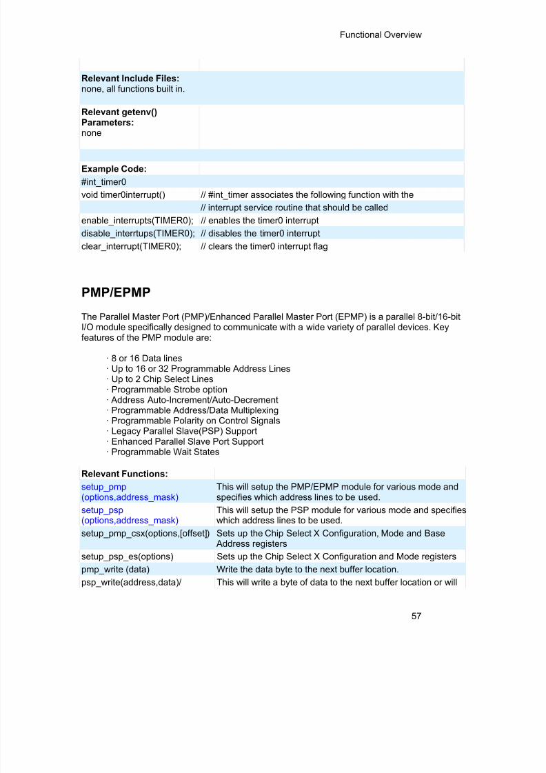
8/10/2019 avr.pdf
http://slidepdf.com/reader/full/avrpdf 69/365
Functional Overview
57
Relevant Include Files:none, all functions built in.
Relevant getenv()
Parameters:none
Example Code:#int_timer0void timer0interrupt() // #int_timer associates the following function with the
// interrupt service routine that should be calledenable_interrupts(TIMER0); // enables the timer0 interruptdisable_interrtups(TIMER0); // disables the timer0 interrupt
clear_interrupt(TIMER0); // clears the timer0 interrupt flag
PMP/EPMP
The Parallel Master Port (PMP)/Enhanced Parallel Master Port (EPMP) is a parallel 8-bit/16-bitI/O module specifically designed to communicate with a wide variety of parallel devices. Keyfeatures of the PMP module are:
· 8 or 16 Data lines· Up to 16 or 32 Programmable Address Lines· Up to 2 Chip Select Lines· Programmable Strobe option· Address Auto-Increment/Auto-Decrement· Programmable Address/Data Multiplexing· Programmable Polarity on Control Signals· Legacy Parallel Slave(PSP) Support· Enhanced Parallel Slave Port Support· Programmable Wait States
Relevant Functions:setup_pmp (options,address_mask)
This will setup the PMP/EPMP module for various mode andspecifies which address lines to be used.
setup_psp (options,address_mask)
This will setup the PSP module for various mode and specifieswhich address lines to be used.
setup_pmp_csx(options,[offset]) Sets up the Chip Select X Configuration, Mode and Base Address registers
setup_psp_es(options) Sets up the Chip Select X Configuration and Mode registerspmp_write (data) Write the data byte to the next buffer location.psp_write(address,data)/ This will write a byte of data to the next buffer location or will

8/10/2019 avr.pdf
http://slidepdf.com/reader/full/avrpdf 70/365
PCD Manual
58
psp_write(data) write a byte to the specified buffer location.pmp_read( ) Reads a byte of data.psp_read(address)/ psp_read() psp_read() will read a byte of data from the next buffer
location and psp_read ( address ) will read the buffer locationaddress.
pmp_address(address) Configures the address register of the PMP module with thedestination address during Master mode operation.
pmp_overflow () This will return the status of the output buffer underflow bit.pmp_input_full () This will return the status of the input buffers.psp_input_full() This will return the status of the input buffers.pmp_output_full() This will return the status of the output buffers.psp_output_full() This will return the status of the output buffers.Relevant Preprocessor:None
Relevant Interrupts :#INT_PMP Interrupt on read or write strobe
Relevant Include Files:None, all functions built-in
Relevant getenv() parameters:None
Example Code:setup_pmp( PAR_ENABLE | Sets up Master mode with address lines PMA0:PMA7PAR_MASTER_MODE_1 |PAR_STOP_IN_IDLE,0x00FF );
If ( pmp_output_full ( )){pmp_write(next_byte);}
Program Eeprom
The Flash program memory is readable and writable in some chips and is just readable insome. These options lets the user read and write to the Flash program memory. Thesefunctions are only available in flash chips.

8/10/2019 avr.pdf
http://slidepdf.com/reader/full/avrpdf 71/365
Functional Overview
59
Relevant Functions:read_program_eeprom(address) Reads the program memory location (16 bit or 32 bit depend
on the device).
write_program_eeprom(address, value) Writes value to program memory location address.
erase_program_eeprom(address) Erases FLASH_ERASE_SIZE bytes in program memory.
write_program_memory(address,dataptr,count) Writes count bytes to program memory from dataptr to addr When address is a mutiple of FLASH_ERASE_SIZE an ealso performed.
read_program_memory(address,dataptr,count) Read count bytes from program memory at address to data
write_rom_memory(address, dataptr, count)
Writes count bytes to program memory from address
read_rom_memory (address, dataptr, count) Read count bytes to program memory from address
Relevant Preprocessor:#ROM address={list} Can be used to put program memory data into the hex file.
#DEVICE(WRITE_EEPROM=ASYNC) Can be used with #DEVICE to prevent the write function fhanging. When this is used make sure the eeprom is not wboth inside and outside the ISR.
Relevant Interrupts:
INT_EEPROM Interrupt fires when eeprom write is complete.
Relevant Include Files:None, all functions built-in
Relevant getenv() parametersPROGRAM_MEMORY Size of program memoryREAD_PROGRAM Returns 1 if program memory can be readFLASH_WRITE_SIZE Smallest number of bytes written in flashFLASH_ERASE_SIZE Smallest number of bytes erased in flash
Example Code:
#ROM 0x300={1,2,3,4} // Inserts this data into the hex file.erase_program_eeprom(0x00000300); // Erases 32 instruction locations starting at 0x0300write_program_eeprom(0x00000300,0x123456); // Writes 0x123456 to 0x0300value=read_program_eeprom(0x00000300); // Reads 0x0300 returns 0x123456

8/10/2019 avr.pdf
http://slidepdf.com/reader/full/avrpdf 72/365
PCD Manual
60
write_program_memory(0x00000300,data,12); // Erases 32 instructions starting// at 0x0300 (multiple of erase block)// Writes 12 bytes from data to 0x0300
read_program_memory(0x00000300,value,12); //reads 12 bytes to value from 0x0300
For chips where getenv(“FLASH_ERASE_SIZE”) > getenv(“FLASH_WRITE_SIZE”) WRITE_PROGRAM_EEPROM - Writes 3 bytes, does not erase (use
ERASE_PROGRAM_EEPROM)WRITE_PROGRAM_MEMORY - Writes any number of bytes, will erase a block whenever t
(lowest) byte in a block is written to. If the first address is start of a block that block is not erased- While writing, every fourth byte will be ignored. Fill ignwith 0x00. This is due to the 32 bit addressing and 24 bitinstruction length on the PCD devices.
WRITE_ROM_MEMORY - Writes any number of bytes, will erase a block whenever t(lowest) byte in a block is written to. If the first address is start of a block that block is not erased.
ERASE_PROGRAM_EEPROM - Erases a block of size FLASH_ERASE_SIZE. The lowestaddress bits are not used.
For chips where getenv(“FLASH_ERASE_SIZE”) = get(“FLASH_WRITE_SIZE”) WRITE_PROGRAM_EEPROM - Writes 3 bytes, no erase is needed.WRITE_PROGRAM_MEMORY - Writes any numbers of bytes, bytes outside the range of th
write block are not changed. No erase is needed.- While writing, every fourth byte will be ignored. Fill ignwith 0x00. This is due to the 32 bit addressing and 24 bitinstruction length on the PCD devices.
WRITE_ROM_MEMORY - Writes any numbers of bytes, bytes outside the range of thwrite block are not changed. No erase is needed.
ERASE_PROGRAM_EEPROM - Erase a block of size FLASH_ERASE_SIZE. The lowestaddress bits are not used.
QEI
The Quadrature Encoder Interface (QEI) module provides the interface to incremental encodersfor obtaining mechanical positional data.
Relevant Functions:
setup_qei(options,filter,maxcount)
Configures the QEI module.
qei_status( ) Returns the status of the QUI module.
qei_set_count(value) Write a 16-bit value to the position counter.

8/10/2019 avr.pdf
http://slidepdf.com/reader/full/avrpdf 73/365
Functional Overview
61
qei_get_count( ) Reads the current 16-bit value of the position counter.
Relevant Preprocessor:
None
Relevant Interrupts :
#INT_QEI Interrupt on rollover or underflow of the position counter.
Relevant Include Files:None, all functions built-in
Relevant getenv()parameters:None
Example Code:
int16 Value;
setup_qei(QEI_MODE_X2 | Setup the QEI module
QEI_TIMER_INTERNAL,
QEI_FILTER_DIV_2,QEI_FORWARD);
Value = qei_get_count( ); Read the count.
RS232 I/O
These functions and directives can be used for setting up and using RS232 I/O functionality.
Relevant Functions:
getc() or getch() getchar() or fgetc() Gets a character on the receive pin(from the specified streamin case of fgetc, stdin by default). Use KBHIT to check if thecharacter is available.
gets() or fgets() Gets a string on the receive pin(from the specified stream incase of fgets, STDIN by default). Use getc to receive eachcharacter until return is encountered.

8/10/2019 avr.pdf
http://slidepdf.com/reader/full/avrpdf 74/365
PCD Manual
62
putc() or putchar() orfputc()
Puts a character over the transmit pin(on the specified streamin the case of fputc, stdout by default)
puts() or fputs() Puts a string over the transmit pin(on the specified stream inthe case of fputc, stdout by default). Uses putc to send eachcharacter.
printf() or fprintf() Prints the formatted string(on the specified stream in the caseof fprintf, stdout by default). Refer to the printf help for detailson format string.
kbhit() Return true when a character is received in the buffer in caseof hardware RS232 or when the first bit is sent on the RCV pinin case of software RS232. Useful for polling without waiting ingetc.
setup_uart(baud,[stream])
or
setup_uart_speed(baud,[stream]) Used to change the baud rate of the hardware UART at run-time. Specifying stream is optional. Refer to the help for moreadvanced options.
assert(condition) Checks the condition and if false prints the file name and lineto STDERR. Will not generate code if #DEFINE NODEBUG isused.
perror(message) Prints the message and the last system error to STDERR.
putc_send() or fputc_send() When using transmit buffer, used to transmit data from buffer.See function description for more detail on when needed.
rcv_buffer_bytes() When using receive buffer, returns the number of bytes inbuffer that still need to be retrieved.
tx_buffer_bytes() When using transmit buffer, returns the number of bytes inbuffer that still need to be sent.
tx_buffer_full() When using transmit buffer, returns TRUE if transmit buffer isfull.
receive_buffer_full() When using receive buffer, returns TRUE if receive buffer isfull.
Relevant Interrupts:
INT_RDA Interrupt fires when the receive data available

8/10/2019 avr.pdf
http://slidepdf.com/reader/full/avrpdf 75/365
Functional Overview
63
INT_TBE Interrupt fires when the transmit data empty
Some chips have more than one hardware uart, and hence more interrupts.
Relevant Include Files:
None, all functions built-in
Relevant getenv() parameters:
UART Returns the number of UARTs on this PIC
AUART Returns true if this UART is an advanced UART
UART_RX Returns the receive pin for the first UART on this PIC (seePIN_XX)
UART_TX Returns the transmit pin for the first UART on this PIC
UART2_RX Returns the receive pin for the second UART on this PIC
UART2_TX TX – Returns the transmit pin for the second UART on thisPIC
Example Code:
/* configure and enable uart, use first hardware UART on PIC */
#use rs232(uart1, baud=9600)
/* print a string */
printf(“enter a character”);
/* get a character */
if (kbhit()) //check if a character has been received
c = getc(); //read character from UART
RTOS
These functions control the operation of the CCS Real Time Operating System (RTOS). Thisoperating system is cooperatively multitasking and allows for tasks to be scheduled to run atspecified time intervals. Because the RTOS does not use interrupts, the user must be careful tomake use of the rtos_yield() function in every task so that no one task is allowed to run forever.
Relevant Functions:rtos_run() Begins the operation of the RTOS. All task management

8/10/2019 avr.pdf
http://slidepdf.com/reader/full/avrpdf 76/365
PCD Manual
64
tasks are implemented by this function.
rtos_terminate() This function terminates the operation of the RTOS andreturns operation to the original program. Works as areturn from the rtos_run()function.
rtos_enable(task) Enables one of the RTOS tasks. Once a task is enabled,the rtos_run() function will call the task when its timeoccurs. The parameter to this function is the name of taskto be enabled.
rtos_disable(task) Disables one of the RTOS tasks. Once a task is disabled,the rtos_run() function will not call this task until it isenabled using rtos_enable(). The parameter to thisfunction is the name of the task to be disabled.
rtos_msg_poll() Returns true if there is data in the task's message queue.
rtos_msg_read() Returns the next byte of data contained in the task'smessage queue.
rtos_msg_send(task,byte) Sends a byte of data to the specified task. The data isplaced in the receiving task's message queue.
rtos_yield() Called with in one of the RTOS tasks and returns controlof the program to the rtos_run() function. All tasks shouldcall this function when finished.
rtos_signal(sem) Increments a semaphore which is used to broadcast theavailability of a limited resource.
rtos_wait(sem) Waits for the resource associated with the semaphore tobecome available and then decrements to semaphore toclaim the resource.
rtos_await(expre) Will wait for the given expression to evaluate to truebefore allowing the task to continue.
rtos_overrun(task) Will return true if the given task over ran its alloted time.
rtos_stats(task,stat) Returns the specified statistic about the specified task.The statistics include the minimum and maximum times
for the task to run and the total time the task has spentrunning.
Relevant Preprocessor:#USE RTOS(options) This directive is used to specify several different RTOS

8/10/2019 avr.pdf
http://slidepdf.com/reader/full/avrpdf 77/365
Functional Overview
65
attributes including the timer to use, the minor cycle timeand whether or not statistics should be enabled.
#TASK(options) This directive tells the compiler that the following functionis to be an RTOS task.
#TASK specifies the rate at which the task should be called, the
maximum time the task shall be allowed to run, and howlarge it's queue should beRelevant Interrupts:none
Relevant Include Files:none all functions are built in
Relevant getenv() Parameters:none
Example Code:#USERTOS(timer=0,minor_cycle=20ms)
// RTOS will use timer zero, minor cycle will be 20ms
...int sem;...#TASK(rate=1s,max=20ms,queue=5) // Task will run at a rate of once per secondvoid task_name(); // with a maximum running time of 20ms and
// a 5 byte queuertos_run(); // begins the RTOSrtos_terminate(); // ends the RTOS
rtos_enable(task_name); // enables the previously declared task.rtos_disable(task_name); // disables the previously declared task
rtos_msg_send(task_name,5); // places the value 5 in task_names queue.rtos_yield(); // yields control to the RTOSrtos_sigal(sem); // signals that the resource represented by sem is
available.
For more information on the CCS RTOS please
SPI
SPI™ is a fluid standard for 3 or 4 wire, full duplex communications named by Motorola. MostPIC devices support mos t common SPI™ modes. CCS provides a support library for taking

8/10/2019 avr.pdf
http://slidepdf.com/reader/full/avrpdf 78/365
PCD Manual
66
advantage of both hardware and software based SPI™ functionality. For software support, see#USE SPI .
Relevant Functions:setup_spi(mode)setup_spi2( mode)setup_spi3 (mode) setup_spi4 (mode)
Configure the hardware SPI to the specified mode. The modeconfigures setup_spi2(mode) thing such as master or slavemode, clock speed and clock/data trigger configuration.
Note: for devices with dual SPI interfaces a second function, setup_spi2(), is provided toconfigure the second interface.
spi_data_is_in() Returns TRUE if the SPI receive buffer has a byte of data.spi_data_is_in2()
spi_write(value)spi_write2(value)
Transmits the value over the SPI interface. This will cause thedata to be clocked out on the SDO pin.
spi_read(value)spi_read2(value)
Performs an SPI transaction, where the value is clocked out onthe SDO pin and data clocked in on the SDI pin is returned. Ifyou just want to clock in data then you can use spi_read() withouta parameter .
Relevant Preprocessor:None
Relevant Interrupts:#int_ssp#int_ssp2
Transaction (read or write) has completed on the indicatedperipheral.
#int_spi1 Interrupts on activity from the first SPI module#int_spi2 Interrupts on activity from the second SPI module
Relevant Include Files:None, all functions built-in to the compiler.
Relevant getenv() Parameters:SPI Returns TRUE if the device has an SPI peripheral
Example Code://configure the device to be a master, data transmitted on H-to-L clock transitionsetup_spi(SPI_MASTER | SPI_H_TO_L | SPI_CLK_DIV_16);
spi_write(0x80); //write 0x80 to SPI devicevalue=spi_read(); //read a value from the SPI devicevalue=spi_read(0x80); //write 0x80 to SPI device the same time you are reading a value.

8/10/2019 avr.pdf
http://slidepdf.com/reader/full/avrpdf 79/365
Functional Overview
67
TimerA
These options lets the user configure and use timerA. It is available on devices with Timer A
hardware. The clock/counter is 8 bit. It counts up and also provides interrupt on overflow. Theoptions available are listed in the device's header file.
Relevant Functions:setup_timer_A(mode) Disable or sets the source and prescale for timerAset_timerA(value) Initializes the timerA clock/countervalue=get_timerA() Returns the value of the timerA clock/counterRelevant Preprocessor:None
Relevant Interrupts :INT_TIMERA Interrupt fires when timerA overflows
Relevant Include Files: None, all functions built-in
Relevant getenv() parameters:TIMERA Returns 1 if the device has timerA
Example Code:setup_timer_A(TA_OFF); //disable timerAor
setup_timer_A //sets the internal clock as source (TA_INTERNAL | TA_DIV_8); //and prescale as 8. At 20MHz timerA will increment
//every 1.6us in this setup and overflows every
//409.6us
set_timerA(0); //this sets timerA register to 0
time=get_timerA(); //this will read the timerA register value
TimerB
These options lets the user configure and use timerB. It is available on devices with TimerBhardware. The clock/counter is 8 bit. It counts up and also provides interrupt on overflow. Theoptions available are listed in the device's header file.
Relevant Functions:setup_timer_B(mode) Disable or sets the source and prescale for timerBset_timerB(value) Initializes the timerB clock/counter

8/10/2019 avr.pdf
http://slidepdf.com/reader/full/avrpdf 80/365
PCD Manual
68
value=get_timerB() Returns the value of the timerB clock/counterRelevant Preprocessor:None
Relevant Interrupts :
INT_TIMERB Interrupt fires when timerB overflows
Relevant Include Files: None, all functions built-in
Relevant getenv() parameters:TIMERB Returns 1 if the device has timerB
Example Code:setup_timer_B(TB_OFF); //disable timerBor
setup_timer_B //sets the internal clock as source (TB_INTERNAL | TB_DIV_8); //and prescale as 8. At 20MHz timerB will increment
//every 1.6us in this setup and overflows every
//409.6us
set_timerB(0); //this sets timerB register to 0
time=get_timerB(); //this will read the timerB register value
Voltage Reference
These functions configure the votlage reference module. These are available only in thesupported chips.Relevant Functions:setup_vref(mode | value) Enables and sets up the internal voltage reference value.
Constants are defined in the device's .h file.
Relevant Preprocesser:none
Relevant Interrupts:none
Relevant Include Files:
none, all functions built-in
Relevant getenv() parameters:
VREF Returns 1 if the device has VREF
Example code:for PIC12F675
#INT_COMP //comparator interrupt handlervoid isr() {

8/10/2019 avr.pdf
http://slidepdf.com/reader/full/avrpdf 81/365
Functional Overview
69
safe_conditions = FALSE;printf("WARNING!!!! Voltage level is above
3.6V. \r\n");}
setup_comparator(A1_VR_OUT_ON_A2)//sets 2
comparators(A1 and VR and A2 as output){setup_vref(VREF_HIGH | 15);//sets 3.6(vdd *
value/32 + vdd/4) if vdd is 5.0Venable_interrupts(INT_COMP); // enable the
comparator interruptenable_interrupts(GLOBAL); //enable global
interrupts}
WDT or Watch Dog TimerDifferent chips provide different options to enable/disable or configure the WDT.
Relevant Functions:setup_wdt() Enables/disables the wdt or sets the prescalar.restart_wdt() Restarts the wdt, if wdt is enables this must be periodically called
to prevent a timeout reset.
For PCB/PCM chips it is enabled/disabled using WDT or NOWDT fuses whereas on PCHdevice it is done using the setup_wdt function.
The timeout time for PCB/PCM chips are set using the setup_wdt function and on PCH usingfuses like WDT16, WDT256 etc.RESTART_WDT when specified in #USE DELAY, #USE I2C and #USE RS232 statements likethis #USE DELAY(clock=20000000, restart_wdt) will cause the wdt to restart if it times outduring the delay or I2C_READ or GETC.
Relevant Preprocessor:#FUSES WDT/NOWDT Enabled/Disables wdt in PCB/PCM devices#FUSES WDT16 Sets ups the timeout time in PCH devices
Relevant Interrupts:None
Relevant Include Files:None, all functions built-in
Relevant getenv() parameters:

8/10/2019 avr.pdf
http://slidepdf.com/reader/full/avrpdf 82/365
PCD Manual
70
None
Example Code:For PIC16F877#fuses wdt
setup_wdt(WDT_2304MS);while(true){
restart_wdt();perform_activity();}
For PIC18F452#fuse WDT1setup_wdt(WDT_ON);while(true){
restart_wdt();perform_activity();
}Some of the PCB chips are share the WDT prescalar bits with timer0 so the WDT prescalarconstants can be used with setup_counters or setup_timer0 or setup_wdt functions.
interrupt_enabled()
This function checks the interrupt enabled flag for the specified interrupt and returnsTRUE if set.
Syntax interrupt_enabled(interrupt);Parameters interrupt- constant specifying the interruptReturns Boolean valueFunction The function checks the interrupt enable flag of the specified
interrupt and returns TRUE when set. Availability Devices with interruptsRequires Interrupt constants defined in the device's .h file.Examples if(interrupt_enabled(INT_RDA))
disable_interrupt(INT_RDA);Example Files None
Also see DISABLE_INTERRUPTS(_ )Interrupts Overview , CLEAR_INTERRUPT() , ,ENABLE_INTERRUPTS() ,INTERRUPT_ACTIVE()

8/10/2019 avr.pdf
http://slidepdf.com/reader/full/avrpdf 83/365

8/10/2019 avr.pdf
http://slidepdf.com/reader/full/avrpdf 84/365
PCD Manual
72
no parameters. In this case the function is called for each character to be input.Make sure the function returns a \r to terminate the input statement.
variables/constants: May be any integer, char, float or fixed type. Char arrays areinput as strings. Floats may use the E format.Reading of each item terminates with any character not valid for the type. Usuallyitems are separated by spaces. The termination character is discarded. At the endof any stream input statement characters are read until a return (\r) is read. Notermination character is read for a single char input.
manipulators:hex -Hex format numbersdec- Decimal format numbers (default)noecho- Suppress echoingstrspace- Allow spaces to be input into stringsnostrspace- Spaces terminate string entry (default)iosdefault -All manipulators to default settings
Examples: cout << "Enter number: ";cin >> value;cout << "Enter title: ";cin >> strspace >> title;cin >> data[i].recordid >> data[i].xpos >> data[i].ypos >> data[i].sample ;string1 >> data;lcdputc << "\fEnter count";lcdputc << keypadgetc >> count; // read from keypad, echo to lcd
// This syntax only works with// user defined functions.

8/10/2019 avr.pdf
http://slidepdf.com/reader/full/avrpdf 85/365
73
PREPROCESSOR
PRE-PROCESSOR DIRECTORY
Pre-processor directives all begin with a # and are followed by a specific command. Syntax isdependent on the command. Many commands do not allow other syntactical elements on theremainder of the line. A table of commands and a description is listed on the previous page.
Several of the pre-processor directives are extensions to standard C. C provides a pre-processor directive that compilers will accept and ignore or act upon the following data. Thisimplementation will allow any pre-processor directives to begin with #PRAGMA. To becompatible with other compilers, this may be used before non-standard features.
Examples:Both of the following are valid#INLINE#PRAGMA INLINE
StandardC
#IF expr #DEFINE #LIST
#IFDEF #UNDEF #NOLIST
#IFNDEF #INCLUDE #PRAGMA
#ELSE #WARNING #ERROR#ELIF #ENDIF DEFINEDINC
FunctionQualifier
#INLINE #INT_xxxx #INT_GLOBAL#SEPARATE #INT_DEFAULT
#RECURSIVE
#INT_AUX #INT_xxxx a
Pre-Defined
Identifier
__ DATE_ _ __ LINE_ _ __PCH_ _ __ DEVICE_ _ __ FILENAME_ _ __PCM_ _ __ FILE_ _ __ TIME__ __PCB_ _ __ADDRESS__ __PCD__
RTOS #TASK #USE RTOS
DeviceSpecification
#DEVICE chip #ID "filename" #HEXCOMMENT
#FUSES #ID number #ID CHECKSUM
#SERIALIZE #PIN_SELECT a
Built-inLibraries
#USE DELAY #USE FIXED_IO #USE RS232
#USE FAST_IO #USE I2C #USE STANDARD_IO
#USE SPI #USE TOUCHPAD #USE TIMER
#USE CAPTURE a a
Memory #ASM #ENDASM #ROM

8/10/2019 avr.pdf
http://slidepdf.com/reader/full/avrpdf 86/365
PCD Manual
74
Control #BIT #FILL_ROM #TYPE
#USE DYNAMIC_MEMORY #LOCATE #ZERO_RAM
#LINE #ORG #WORD#RESERVE #BYTE
CompilerControl
#CASE #IMPORT #PRIORITY#EXPORT #OPT #OCS#IGNORE_WARNINGS #MODULE a
Linker #IMPORT #EXPORT #BUILD
__address__
A predefined symbol __address__ may be used to indicate atype that must hold a program memory address.
For example:___address__ testa = 0x1000 //will allocate 16 bits for test aand
//initialize to 0x1000
_attribute_x
Syntax: __attribute__x
Elements:
x is the attribute you want to apply. Valid values for x are as follows:
((packed))By default each element in a struct or union are padded to be evenlyspaced by the size of 'int'. This is to prevent an address fault whenaccessing an element of struct. See the following example:struct{
int8 a;int16 b;
} test;
On architectures where 'int' is 16bit (such as dsPIC or PIC24PICmicrocontrollers), 'test' would take 4 bytes even though it iscomprised of3 bytes. By applying the 'packed' attribute to this structthen it would take 3 bytes as originally intended:struct __attribute__((packed)){
int8 a;

8/10/2019 avr.pdf
http://slidepdf.com/reader/full/avrpdf 87/365
PreProcessor
75
int16 b;} test;
Care should be taken by the user when accessing individual elementsof a packed struct – creating a pointer to 'b' in 'test' and attempting todereference that pointer would cause an address fault. Any attemptsto read/write 'b' should be done in context of 'test' so the compilerknows it is packed:test.b = 5;
((aligned(y))By default the compiler will alocate a variable in the first free memorylocation. The aligned attribute will force the compiler to allocate alocation for the specified variable at a location that is modulus of the yparameter. For example:
int8 array[256] __attribute__((aligned(0x1000))); This will tell the compiler to try to place 'array' at either 0x0, 0x1000,0x2000, 0x3000, 0x4000, etc.
Purpose To alter some specifics as to how the compiler operates
Examples:
struct __attribute__((packed)){
int8 a;int8 b;
} test;int8 array[256] __attribute__((aligned(0x1000)));
Example Files: None
#asm #endasm
Syntax: #ASM or #ASM ASIS code #ENDASMElements: code is a list of assembly language instructions
Examples:
int_ffind_parity(int data){int count;, result,datal; data1=data; asm MOV#0x08, MOV WF, count CLRF result Loop: MOVF data1,w XORWFresult, F RRCF data1,F DECFSZ count,F BRA LOOP MOVLW 0x01
ANDWF resutt, F #end asmretturn (result)';}
Example Files: ex_glint.c Also See: None

8/10/2019 avr.pdf
http://slidepdf.com/reader/full/avrpdf 88/365
PCD Manual
76
ADD Wa,Wb,Wd Wd = Wa+Wb ADD f,W W0 = f+Wd ADD lit10,Wd Wd = lit10+Wd ADD Wa,lit5,Wd Wd = lit5+Wa ADD f,F f = f+Wd ADD acc Acc = AccA+AccB ADD Wd,{lit4},acc Acc = Acc+(Wa shifted slit4) ADD.B lit10,Wd Wd = lit10+Wd (byte) ADD Wd,{lit4},acc Acc = Acc+(Wa shifted slit4) ADD.B lit10,Wd Wd = lit10+Wd (byte) ADD.B f,F f = f+Wd (byte) ADD.B Wa,Wb,Wd Wd = Wa+Wb (byte) ADD.B Wa,lit5,Wd Wd = lit5+Wa (byte)
ADD.B f,W W0 = f+Wd (byte) ADDC f,W Wd =
f+Wa+C ADDC lit10,Wd Wd = lit10+Wd+C ADDC Wa,lit5,Wd Wd = lit5+Wa+C ADDC f,F Wd = f+Wa+C ADDC Wa,Wb,Wd Wd = Wa+Wb+C ADDC.B lit10,Wd Wd = lit10+Wd+C (byte) ADDC.B Wa,Wb,Wd Wd = Wa+Wb+C (byte) ADDC.B Wa,lit5,Wd Wd = lit5+Wa+C (byte) ADDC.B f,W Wd = f+Wa+C (byte)
ADDC.B f,F Wd = f+Wa+C (byte) AND Wa,Wb,Wd Wd = Wa.&.Wb AND lit10,Wd Wd = lit10.&.Wd AND f,W W0 = f.&.Wa AND f,F f = f.&.Wa AND Wa,lit5,Wd Wd = lit5.&.Wa AND.B f,W W0 = f.&.Wa (byte) AND.B Wa,Wb,Wd Wd = Wa.&.Wb (byte) AND.B lit10,Wd Wd = lit10.&.Wd (byte) AND.B f,F f = f.&.Wa (byte) AND.B Wa,lit5,Wd Wd = lit5.&.Wa (byte)
ASR f,W W0 = f >> 1 arithmetic ASR f,F f = f >> 1 arithmetic ASR Wa,Wd Wd = Wa >> 1 arithmetic ASR Wa,lit4,Wd Wd = Wa >> lit4 arithmetic ASR Wa,Wb,Wd Wd = Wa >> Wb arithmetic ASR.B f,F f = f >> 1 arithmetic (byte) ASR.B f,W W0 = f >> 1 arithmetic (byte) ASR.B Wa,Wd Wd = Wa >> 1 arithmetic (byte)

8/10/2019 avr.pdf
http://slidepdf.com/reader/full/avrpdf 89/365
PreProcessor
77
BCLR f,B f.bit = 0BCLR Wd,B Wa.bit = 0BCLR.B Wd,B Wa.bit = 0 (byte)BRA a Branch unconditionallyBRA Wd Branch PC+Wa
BRA BZ a Branch if ZeroBRA C a Branch if Carry (no borrow)BRA GE a Branch if greater than or equalBRA GEU a Branch if unsigned greater than or equalBRA GT a Branch if greater thanBRA GTU a Branch if unsigned greater thanBRA LE a Branch if less than or equalBRA LEU a Branch if unsigned less than or equalBRA LT a Branch if less thanBRA LTU a Branch if unsigned less thanBRA N a Branch if negative
BRA NC a Branch if not carry (Borrow)BRA NN a Branch if not negativeBRA NOV a Branch if not OverflowBRA NZ a Branch if not ZeroBRA OA a Branch if Accumulator A overflowBRA OB a Branch if Accumulator B overflowBRA OV a Branch if OverflowBRA SA a Branch if Accumulator A SaturateBRA SB a Branch if Accumulator B SaturateBRA Z a Branch if ZeroBREAK ICD BreakBSET Wd,B Wa.bit = 1BSET f,B f.bit = 1BSET.B Wd,B Wa.bit = 1 (byte)BSW.C Wa,Wd Wa.Wb = CBSW.Z Wa,Wd Wa.Wb = ZBTG Wd,B Wa.bit = ~Wa.bitBTG f,B f.bit = ~f.bitBTG.B Wd,B Wa.bit = ~Wa.bit (byte)BTSC f,B Skip if f.bit = 0BTSC Wd,B Skip if Wa.bit4 = 0BTSS f,B Skip if f.bit = 1BTSS Wd,B Skip if Wa.bit = 1BTST f,B Z = f.bitBTST.C Wa,Wd C = Wa.WbBTST.C Wd,B C = Wa.bitBTST.Z Wd,B Z = Wa.bitBTST.Z Wa,Wd Z = Wa.WbBTSTS f,B Z = f.bit; f.bit = 1

8/10/2019 avr.pdf
http://slidepdf.com/reader/full/avrpdf 90/365
PCD Manual
78
BTSTS.C Wd,B C = Wa.bit; Wa.bit = 1BTSTS.Z Wd,B Z = Wa.bit; Wa.bit = 1CALL a Call subroutineCALL Wd Call [Wa]CLR f,F f = 0
CLR acc,da,dc,pi Acc = 0; prefetch=0CLR f,W W0 = 0CLR Wd Wd = 0CLR.B f,W W0 = 0 (byte)CLR.B Wd Wd = 0 (byte)CLR.B f,F f = 0 (byte)CLRWDT Clear WDTCOM f,F f = ~fCOM f,W W0 = ~fCOM Wa,Wd Wd = ~WaCOM.B f,W W0 = ~f (byte)
COM.B Wa,Wd Wd = ~Wa (byte)COM.B f,F f = ~f (byte)CP W,f Status set for f - W0CP Wa,Wd Status set for Wb – Wa CP Wd,lit5 Status set for Wa – lit5 CP.B W,f Status set for f - W0 (byte)CP.B Wa,Wd Status set for Wb – Wa (byte) CP.B Wd,lit5 Status set f or Wa – lit5 (byte) CP0 Wd Status set for Wa – 0 CP0 W,f Status set for f – 0 CP0.B Wd Status set for Wa – 0 (byte) CP0.B W,f Status set for f – 0 (byte) CPB Wd,lit5 Status set for Wa – lit5 – C CPB Wa,Wd Status set for Wb – Wa – C CPB W,f Status set for f – W0 - CCPB.B Wa,Wd Status set for Wb – Wa – C (byte) CPB.B Wd,lit5 Status set for Wa – lit5 – C (byte) CPB.B W,f Status set for f – W0 - C (byte)CPSEQ Wa,Wd Skip if Wa = WbCPSEQ.B Wa,Wd Skip if Wa = Wb (byte)CPSGT Wa,Wd Skip if Wa > WbCPSGT.B Wa,Wd Skip if Wa > Wb (byte)CPSLT Wa,Wd Skip if Wa < WbCPSLT.B Wa,Wd Skip if Wa < Wb (byte)CPSNE Wa,Wd Skip if Wa != WbCPSNE.B Wa,Wd Skip if Wa != Wb (byte)DAW.B Wd Wa = decimal adjust WaDEC Wa,Wd Wd = Wa – 1 DEC f,W W0 = f – 1

8/10/2019 avr.pdf
http://slidepdf.com/reader/full/avrpdf 91/365
PreProcessor
79
DEC f,F f = f – 1 DEC.B f,F f = f – 1 (byte) DEC.B f,W W0 = f – 1 (byte) DEC.B Wa,Wd Wd = Wa – 1 (byte) DEC2 Wa,Wd Wd = Wa – 2
DEC2 f,W W0 = f – 2 DEC2 f,F f = f – 2 DEC2.B Wa,Wd Wd = Wa – 2 (byte) DEC2.B f,W W0 = f – 2 (byte) DEC2.B f,F f = f – 2 (byte) DISI lit14 Disable Interrupts lit14 cyclesDIV.S Wa,Wd Signed 16/16-bit integer divideDIV.SD Wa,Wd Signed 16/16-bit integer divide (dword)DIV.U Wa,Wd UnSigned 16/16-bit integer divideDIV.UD Wa,Wd UnSigned 16/16-bit integer divide (dword)DIVF Wa,Wd Signed 16/16-bit fractional divide
DO lit14,a Do block lit14 timesDO Wd,a Do block Wa timesED Wd*Wd,acc,da,db Euclidean Distance (No Accumulate)EDAC Wd*Wd,acc,da,db Euclidean DistanceEXCH Wa,Wd Swap Wa and WbFBCL Wa,Wd Find bit change from left (Msb) sideFEX ICD ExecuteFF1L Wa,Wd Find first one from left (Msb) sideFF1R Wa,Wd Find first one from right (Lsb) sideGOTO a GoToGOTO Wd GoTo [Wa]INC f,W W0 = f + 1INC Wa,Wd Wd = Wa + 1INC f,F f = f + 1INC.B Wa,Wd Wd = Wa + 1 (byte)INC.B f,F f = f + 1 (byte)INC.B f,W W0 = f + 1 (byte)INC2 f,W W0 = f + 2INC2 Wa,Wd Wd = Wa + 2INC2 f,F f = f + 2INC2.B f,W W0 = f + 2 (byte)INC2.B f,F f = f + 2 (byte)INC2.B Wa,Wd Wd = Wa + 2 (byte)IOR lit10,Wd Wd = lit10 | WdIOR f,F f = f | WaIOR f,W W0 = f | WaIOR Wa,lit5,Wd Wd = Wa.|.lit5IOR Wa,Wb,Wd Wd = Wa.|.WbIOR.B Wa,Wb,Wd Wd = Wa.|.Wb (byte)

8/10/2019 avr.pdf
http://slidepdf.com/reader/full/avrpdf 92/365
PCD Manual
80
IOR.B f,W W0 = f | Wa (byte)IOR.B lit10,Wd Wd = lit10 | Wd (byte)IOR.B Wa,lit5,Wd Wd = Wa.|.lit5 (byte)IOR.B f,F f = f | Wa (byte)LAC Wd,{lit4},acc Acc = Wa shifted slit4
LNK lit14 Allocate Stack FrameLSR f,W W0 = f >> 1LSR Wa,lit4,Wd Wd = Wa >> lit4LSR Wa,Wd Wd = Wa >> 1LSR f,F f = f >> 1LSR Wa,Wb,Wd Wd = Wb >> WaLSR.B f,W W0 = f >> 1 (byte)LSR.B f,F f = f >> 1 (byte)LSR.B Wa,Wd Wd = Wa >> 1 (byte)MAC Wd*Wd,acc,da,dc Acc = Acc + Wa * Wa; {prefetch}MAC Wd*Wc,acc,da,dc,pi Acc = Acc + Wa * Wb; {[W13] = Acc}; {prefetch}
MOV W,f f = WaMOV f,W W0 = fMOV f,F f = fMOV Wd,? F = WaMOV Wa+lit,Wd Wd = [Wa +Slit10]MOV ?,Wd Wd = fMOV lit16,Wd Wd = lit16MOV Wa,Wd Wd = WaMOV Wa,Wd+lit [Wd + Slit10] = WaMOV.B lit8,Wd Wd = lit8 (byte)MOV.B W,f f = Wa (byte)MOV.B f,W W0 = f (byte)MOV.B f,F f = f (byte)MOV.B Wa+lit,Wd Wd = [Wa +Slit10] (byte)MOV.B Wa,Wd+lit [Wd + Slit10] = Wa (byte)MOV.B Wa,Wd Wd = Wa (byte)MOV.D Wa,Wd Wd:Wd+1 = Wa:Wa+1MOV.D Wa,Wd Wd:Wd+1 = Wa:Wa+1MOVSAC acc,da,dc,pi Move ? to ? and ? To ?MPY Wd*Wc,acc,da,dc Acc = Wa*WbMPY Wd*Wd,acc,da,dc Square to AccMPY.N Wd*Wc,acc,da,dc Acc = -(Wa*Wb)MSC Wd*Wc,acc,da,dc,pi Acc = Acc – Wa*Wb MUL W,f W3:W2 = f * WaMUL.B W,f W3:W2 = f * Wa (byte)MUL.SS Wa,Wd {Wd+1,Wd}= sign(Wa) * sign(Wb)MUL.SU Wa,Wd {Wd+1,Wd} = sign(Wa) * unsign(Wb)MUL.SU Wa,lit5,Wd {Wd+1,Wd}= sign(Wa) * unsign(lit5)MUL.US Wa,Wd {Wd+1,Wd} = unsign(Wa) * sign(Wb)

8/10/2019 avr.pdf
http://slidepdf.com/reader/full/avrpdf 93/365

8/10/2019 avr.pdf
http://slidepdf.com/reader/full/avrpdf 94/365
PCD Manual
82
SETM.B Wd Wd = 0xFFFF (byte)SETM.B f,W W0 = 0xFFFF (byte)SETM.B f,F W0 = 0xFFFF (byte)SFTAC acc,Wd Arithmetic shift Acc by (Wa)SFTAC acc,lit5 Arithmetic shift Acc by Slit6
SL f,W W0 = f << 1SL Wa,Wb,Wd Wd = Wa << WbSL Wa,lit4,Wd Wd = Wa << lit4SL Wa,Wd Wd = Wa << 1SL f,F f = f << 1SL.B f,W W0 = f << 1 (byte)SL.B Wa,Wd Wd = Wa << 1 (byte)SL.B f,F f = f << 1 (byte)SSTEP ICD Single StepSUB f,F f = f – W0 SUB f,W W0 = f – W0
SUB Wa,Wb,Wd Wd = Wa – Wb SUB Wa,lit5,Wd Wd = Wa – lit5 SUB acc Acc = AccA – AccB SUB lit10,Wd Wd = Wd – lit10 SUB.B Wa,lit5,Wd Wd = Wa – lit5 (byte) SUB.B lit10,Wd Wd = Wd – lit10 (byte) SUB.B f,W W0 = f – W0 (byte) SUB.B Wa,Wb,Wd Wd = Wa – Wb (byte) SUB.B f,F f = f – W0 (byte) SUBB f,W W0 = f – W0 – C SUBB Wa,Wb,Wd Wd = Wa – Wb – C SUBB f,F f = f – W0 – C SUBB Wa,lit5,Wd Wd = Wa – lit5 - CSUBB lit10,Wd Wd = Wd – lit10 – CSUBB.B lit10,Wd Wd = Wd – lit10 – C (byte) SUBB.B Wa,Wb,Wd Wd = Wa – Wb – C (byte) SUBB.B f,F f = f – W0 – C (byte) SUBB.B Wa,lit5,Wd Wd = Wa – lit5 - C (byte)SUBB.B f,W W0 = f – W0 – C (byte) SUBBR Wa,lit5,Wd Wd = lit5 – W a - CSUBBR f,W W0 = W0 – f – C SUBBR f,F f = W0 – f – C SUBBR Wa,Wb,Wd Wd = Wa – Wb - CSUBBR.B f,F f = W0 – f – C (byte) SUBBR.B f,W W0 = W0 – f – C (byte) SUBBR.B Wa,Wb,Wd Wd = Wa – Wb - C (byte)SUBBR.B Wa,lit5,Wd Wd = lit 5 – Wa - C (byte)SUBR Wa,lit5,Wd Wd = lit5 – Wb SUBR f,F f = W0 – f

8/10/2019 avr.pdf
http://slidepdf.com/reader/full/avrpdf 95/365
PreProcessor
83
SUBR Wa,Wb,Wd Wd = Wa – Wb SUBR f,W W0 = W0 – fSUBR.B Wa,Wb,Wd Wd = Wa – Wb (byte) SUBR.B f,F f = W0 – f (byte) SUBR.B Wa,lit5,Wd Wd = lit5 – Wb (byte)
SUBR.B f,W W0 = W0 – f (byte) SWAP Wd Wa = byte or nibble swap WaSWAP.B Wd Wa = byte or nibble swap Wa (byte)TBLRDH Wa,Wd Wd = ROM[Wa] for odd ROMTBLRDH.B Wa,Wd Wd = ROM[Wa] for odd ROM (byte)TBLRDL Wa,Wd Wd = ROM[Wa] for even ROMTBLRDL.B Wa,Wd Wd = ROM[Wa] for even ROM (byte)TBLWTH Wa,Wd ROM[Wa] = Wd for odd ROMTBLWTH.B Wa,Wd ROM[Wa] = Wd for odd ROM (byte)TBLWTL Wa,Wd ROM[Wa] = Wd for even ROMTBLWTL.B Wa,Wd ROM[Wa] = Wd for even ROM (byte)
ULNK Deallocate Stack FrameURUN ICD RunXOR Wa,Wb,Wd Wd = Wa ^ WbXOR f,F f = f ^ W0XOR f,W W0 = f ^ W0XOR Wa,lit5,Wd Wd = Wa ^ lit5XOR lit10,Wd Wd = Wd ^ lit10XOR.B lit10,Wd Wd = Wd ^ lit10 (byte)XOR.B f,W W0 = f ^ W0 (byte)XOR.B Wa,lit5,Wd Wd = Wa ^ lit5 (byte)XOR.B Wa,Wb,Wd Wd = Wa ^ Wb (byte)XOR.B f,F f = f ^ W0 (byte)ZE Wa,Wd Wd = Wa & FF
12 Bit and 14 Bit ADDWF f,d ANDWF f,dCLRF f CLRWCOMF f,d DECF f,dDECFSZ f,d INCF f,dINCFSZ f,d IORWF f,dMOVF f,d MOVPHW
MOVPLW MOVWF fNOP RLF f,dRRF f,d SUBWF f,dSWAPF f,d XORWF f,dBCF f,b BSF f,bBTFSC f,b BTFSS f,b
ANDLW k CALL kCLRWDT GOTO kIORLW k MOVLW k

8/10/2019 avr.pdf
http://slidepdf.com/reader/full/avrpdf 96/365
PCD Manual
84
RETLW k SLEEPXORLW OPTIONTRIS k
14 Bit ADDLW kSUBLW kRETFIERETURN
PIC 18 ADDWF f,d ADDWFC f,d ANDWFCLRF f COMF f,d CPFSEQCPFSGT f CPFSLT f DECFDECFSZ f,d DCFSNZ f,d INCFINFSNZ f,d IORWF f,d MOVFMOVFF fs,d MOVWF f MULWFNEGF f RLCF f,d RLNCFRRCF f,d RRNCF f,d SETFSUBFWB f,d SUBWF f,d SUBWFBSWAPF f,d TSTFSZ f XORWFBCF f,b BSF f,b BTFSCBTFSS f,b BTG f,d BCBN n BNC n BNNBNOV n BNZ n BOVBRA n BZ n CALLCLRWDT - DAW - GOTONOP - NOP - POPPUSH - RCALL n RESETRETFIE s RETLW k RETURNSLEEP - ADDLW k ANDLWIORLW k LFSR f,k MOVLBMOVLW k MULLW k RETLWSUBLW k XORLW k TBLRDTBLRD *+ TBLRD *- TBLRDTBLWT * TBLWT *+ TBLWTTBLWT +*
#bit
Syntax: #BIT id = x .y
Elements: id is a valid C identifier,

8/10/2019 avr.pdf
http://slidepdf.com/reader/full/avrpdf 97/365
PreProcessor
85
x is a constant or a C variable,y is a constant 0-7 (for 8-bit PICs)y is a constant 0-15 (for 16-bit PICs)
Purpose: A new C variable (one bit) is created and is placed in memory at byte x and bit y. Thisis useful to gain access in C directly to a bit in the processors special function registermap. It may also be used to easily access a bit of a standard C variable.
Examples: #bit T1IF = 0x 84.3...T1IF = 0; // Clear Timer 0 interrupt flag
int result;#bit result_odd = result.0...if (result_odd)
Example
Files:
ex_glint.c
Also See: #BYTE, #RESERVE , #LOCATE , #WORD
#build
Syntax: #BUILD( segment = address )#BUILD(segment = address , segment = address )
#BUILD(segment = start :en d )#BUILD(segment = start : en d , segment = s tar t : en d )#BUILD(nosleep )#BUILD(segment = s ize ) : For STACK use only#BUILD(ALT_INTERRUPT )#BUILD(AUX_MEMORY)
Elements: segment is one of the following memory segments which may be assigned alocation: RESET, INTERRUPT , or STACK
address is a ROM location memory address. Start and end are used to specify arange in memory to be used. Start is the first ROM location and end is the lastROM location to be used.
RESET will move the compiler's reset vector to the specified location.INTERRUPT will move the compiler's interrupt service routine to the specified
location. This just changes the location the compiler puts it's reset and ISR, itdoesn't change the actual vector of the PIC. If you specify a range that is largerthan actually needed, the extra space will not be used and prevented from use bythe compiler.
STACK configures the range (start and end locations) used for the stack, if not

8/10/2019 avr.pdf
http://slidepdf.com/reader/full/avrpdf 98/365

8/10/2019 avr.pdf
http://slidepdf.com/reader/full/avrpdf 99/365
PreProcessor
87
x. In this case the variable type does not change from the original definition. If the id isnot known a new C variable is created and placed at address x with the type int (8 bit)
Warning: In both cases memory at x is not exclusive to this variable. Other variablesmay be located at the same location. In fact when x is a variable, then id and x sharethe same memory location.
Examples: #byte status _register = 0x42#byte b_port = 0x02C8
struct {short int r_w;short int c_d;
int data : 6 ; } E _port;#byte a_port = 0x2DA...a_port.c_d = 1;
ExampleFiles:
ex_glint.c
Also See: #bit, #locate , #reserve , #word , Named Registers , Type Specifiers , Type Qualifiers , Enumerated Types , Structures & Unions , Typedef
#case
Syntax: #CASE
Elements: None
Purpose: Will cause the compiler to be case sensitive. By default the compiler is case insensitive.When linking multiple compilation units, this directive must appear exactly the same ineach compilation unit.
Warning: Not all the CCS example programs, headers and drivers have been testedwith case sensitivity turned on.
Examples: #case
int STATUS;
void func() {int status;
...STATUS = status; // Copy local status to//global
}
ExampleFiles:
ex_cust.c
Also See: None

8/10/2019 avr.pdf
http://slidepdf.com/reader/full/avrpdf 100/365
PCD Manual
88
_date_
Syntax: __DATE__
Elements: None
Purpose: This pre-processor identifier is replaced at compile time with the date of thecompile in the form: "31-JAN-03"
Examples: printf("Software was compiled on ");printf(__DATE__);
ExampleFiles:
None
Also See: None
#define
Syntax: #define id textor
#define id (x ,y ...) text
Elements: id is a preprocessor identifier, text is any text, x ,y is a list of local preprocessoridentifiers, and in this form there may be one or more identifiers separated by commas.
Purpose: Used to provide a simple string replacement of the ID with the given text from this pointof the program and on.
In the second form (a C macro) the local identifiers are matched up with similaridentifiers in the text and they are replaced with text passed to the macro where it isused.
If the text contains a string of the form #idx then the result upon evaluation will be theparameter id concatenated with the string x.
If the text contains a string of the form #idx#idy then parameter idx is concatenated withparameter idy forming a new identifier.
Within the define text two special operators are supported:#x is the stringize operator resulting in "x"x##y is the concatination operator resulting in xy
The varadic macro syntax is supported where the last parameter is specified as ... and

8/10/2019 avr.pdf
http://slidepdf.com/reader/full/avrpdf 101/365
PreProcessor
89
the local identifier used is __va_args__. In this case, all remaining arguments arecombined with the commas.
Examples: #define BITS 8a=a+BITS; //same as a=a+8;
#define hi(x) (x<<4)a=hi(a); //same as a=(a<<4);
#define isequal(a,b) (primary_##a[b]==backup_##a[b])// usage iseaqual(names,5) is the same as// (primary_names[5]==backup_names[5])
#define str(s) #s#define part(device) #include str(device##.h)
// usage part(16F887) is the same as// #include "16F887.h"
#define DBG(...) fprintf(debug,__VA_ARGS__)
ExampleFiles:
ex_stwt.c , ex_macro.c
Also See: #UNDEF , #IFDEF , #IFNDEF
definedinc
Syntax: value = definedinc( variable );
Parameters: variable is the name of the variable, function, or type to be checked.
Returns: A C status for the type of id entered as follows:0 – not known1 – typedef or enum2 – struct or union type3 – typemod qualifier4 – defined function5 – function prototype6 – compiler built-in function7 – local variable8 – global variable
Function: This function checks the type of the variable or function being passed in and returns aspecific C status based on the type.
Availability: All devicesRequires: None.Examples: int x, y = 0;
y = definedinc( x ); // y will return 7 – x is a local variable
Example Files: None

8/10/2019 avr.pdf
http://slidepdf.com/reader/full/avrpdf 102/365

8/10/2019 avr.pdf
http://slidepdf.com/reader/full/avrpdf 103/365
PreProcessor
91
passing a pointer to RAM to the function.CONST=READ_ONLY Uses the ANSI keyword CONST definition,
making CONST variables read only, rather thanlocated in program memory.
CONST=ROM Uses the CCS compiler traditional keywordCONST definition, making CONST variableslocated in program memory.
NESTED_INTERRUPTS=TRUE Enables interrupt nesting for PIC24, dsPIC30, anddsPIC33 devices. Allows higher priority interruptsto interrupt lower priority interrupts.
NORETFIE ISR functions (preceeded by a #int_xxx) will use aRETURN opcode instead of the RETFIE opcode.This is not a commonly used option; used rarely incases where the user is writing their own ISRhandler.
Both chip and options are optional, so multiple #DEVICE lines may be used to fullydefine the device. Be warned that a #DEVICE with a chip identifier, will clear all previous#DEVICE and #FUSE settings.
Comp ilat ion mode select ion-The #DEVICE directive supports compilation mode selection. The valid keywords areCCS2, CCS3, CCS4 and ANSI. The default mode is CCS4. For the CCS4 and ANSImode, the compiler uses the default fuse settings NOLVP, PUT for chips with thesefuses. The NOWDT fuse is default if no call is made to restart_wdt().
CCS4 This is the default compilation mode.
ANSI Default data type is SIGNED all other modes default is UNSIGNED.Compilation is case sensitive, all other modes are case insensitive.
CCS2CCS3
var16 = NegConst8 is compiled as: var16 = NegConst8 & 0xff (no signextension) . The overload keyword is required.
CCS2only
The default #DEVICE ADC is set to the resolution of the part, all othermodes default to 8.onebit = eightbits is compiled as onebit = (eightbits != 0)
All other modes compile as: onebit = (eightbits & 1)
Purpose: Chip Opt ions -Defines the target processor. Every program must have exactly one#DEVICE with a chip. When linking multiple compilation units, this directive must appearexactly the same in each compilation unit.
Comp ilat ion mode select ion - The compilation mode selection allows existing code tobe compiled without encountering errors created by compiler compliance. As CCSdiscovers discrepancies in the way expressions are evaluated according to ANSI, thechange will generally be made only to the ANSI mode and the next major CCS release.

8/10/2019 avr.pdf
http://slidepdf.com/reader/full/avrpdf 104/365
PCD Manual
92
Examples: Chip Options-#device DSPIC33FJ64GP306#device PIC24FJ64GA002 ICD=TRUE#device ADC=10#device ICD=TRUE ADC=10Float Options-#device %f=.printf("%f",.5); //will print .5, without the directive it will print 0.5
Comp ilat ion mode select ion-#device CCS2
ExampleFiles:
None
Also See: None
_device_
Syntax: __DEVICE__
Elements: None
Purpose: This pre-processor identifier is defined by the compiler with the base number of thecurrent device (from a #DEVICE). The base number is usually the number after theC in the part number. For example the PIC16C622 has a base number of 622.
Examples: #if __device__==71SETUP_ADC_PORTS( ALL_DIGITAL );#endif
ExampleFiles:
None
Also See: #DEVICE
#if expr #else #elif #endif
Syntax: #if expr code
#elif expr //Optional, any number may be usedcode
#else //Optionalcode
#endif

8/10/2019 avr.pdf
http://slidepdf.com/reader/full/avrpdf 105/365
PreProcessor
93
Elements: expr is an expression with constants, standard operators and/or preprocessoridentifiers. Code is any standard c source code.
Purpose: The pre-processor evaluates the constant expression and if it is non-zero willprocess the lines up to the optional #ELSE or the #ENDIF.
Note: you may NOT use C variables in the #IF. Only preprocessor identifierscreated via #define can be used.The preprocessor expression DEFINED(id) may be used to return 1 if the id isdefined and 0 if it is not.== and != operators now accept a constant string as both operands. This allowsfor compile time comparisons and can be used with GETENV() when it returnsa string result.
Examples: #if MAX_VALUE > 255long value;
#elseint value;
#endif#if getenv(“DEVICE”)==”PIC16F877”
//do something special for the PIC16F877#endif
Example Files: ex_extee.c
Also See: #IFDEF , #IFNDEF , getenv()
#error
Syntax: #ERROR text #ERROR / warning text #ERROR / information text
Elements: text is optional and may be any text
Purpose: Forces the compiler to generate an error at the location thisdirective appears in the file. The text may include macros thatwill be expanded for the display. This may be used to see themacro expansion. The command may also be used to alert theuser to an invalid compile time situation.
Examples: #if BUFFER_SIZE>16#error Buffer size is too large#endif#error Macro test: min(x,y)
Example Files: ex_psp.c

8/10/2019 avr.pdf
http://slidepdf.com/reader/full/avrpdf 106/365
PCD Manual
94
Also See: #WARNING
#export (options)
Syntax: #EXPORT (options)
Elements: FILE=filnameThe filename which will be generated upon compile. If not given, the filname willbe the name of the file you are compiling, with a .o or .hex extension (dependingon output format).
ONLY=symbol+symbol+. . . . .+symbolOnly the listed symbols will be visible to modules that import or link this relocatable
object file. If neither ONLY or EXCEPT is used, all symbols are exported.EXCEPT=symbol+symbol+.. . . .+symbol
All symbols except the listed symbols will be visible to modules that import or linkthis relocatable object file. If neither ONLY or EXCEPT is used, all symbols areexported.
RELOCATABLECCS relocatable object file format. Must be imported or linked before loading intoa PIC. This is the default format when the #EXPORT is used.
HEX
Intel HEX file format. Ready to be loaded into a PIC. This is the default formatwhen no #EXPORT is used.
RANGE=star t :s topOnly addresses in this range are included in the hex file.
OFFSET=addressHex file address starts at this address (0 by default)
ODDOnly odd bytes place in hex file.
EVENOnly even bytes placed in hex file.
Purpose: This directive will tell the compiler to either generate a relocatable object file or astand-alone HEX binary. A relocatable object file must be linked into yourapplication, while a stand-alone HEX binary can be programmed directly into thePIC.The command line compiler and the PCW IDE Project Manager can also be usedto compile/link/build modules and/or projects.

8/10/2019 avr.pdf
http://slidepdf.com/reader/full/avrpdf 107/365
PreProcessor
95
Multiple #EXPORT directives may be used to generate multiple hex files. this maybe used for 8722 like devices with external memory.
Examples: #EXPORT(RELOCATABLE, ONLY=TimerTask)void TimerFunc1(void) { /* some code */ }void TimerFunc2(void) { /* some code */ }void TimerFunc3(void) { /* some code */ }
void TimerTask(void){
TimerFunc1();TimerFunc2();TimerFunc3();
}/*This source will be compiled into a relocatable object, but the object this isbeing linked to can only see TimerTask()*/
ExampleFiles:
None
See Also: #IMPORT , #MODULE, Invoking the Command Line Compiler , MultipleCompilation Unit
__file__
Syntax: __FILE__
Elements: None
Purpose: The pre-processor identifier is replaced at compile time withthe file path and the filename of the file being compiled.
Examples: if(index>MAX_ENTRIES)printf("Too many entries, source file: "
__FILE__ " at line " __LINE__ "\r\n");
ExampleFiles:
assert.h
Also See: _ _ line_ _
__filename__
Syntax: __FILENAME__
Elements: None
Purpose: The pre-processor identifier is replaced at compile time with thefilename of the file being compiled.
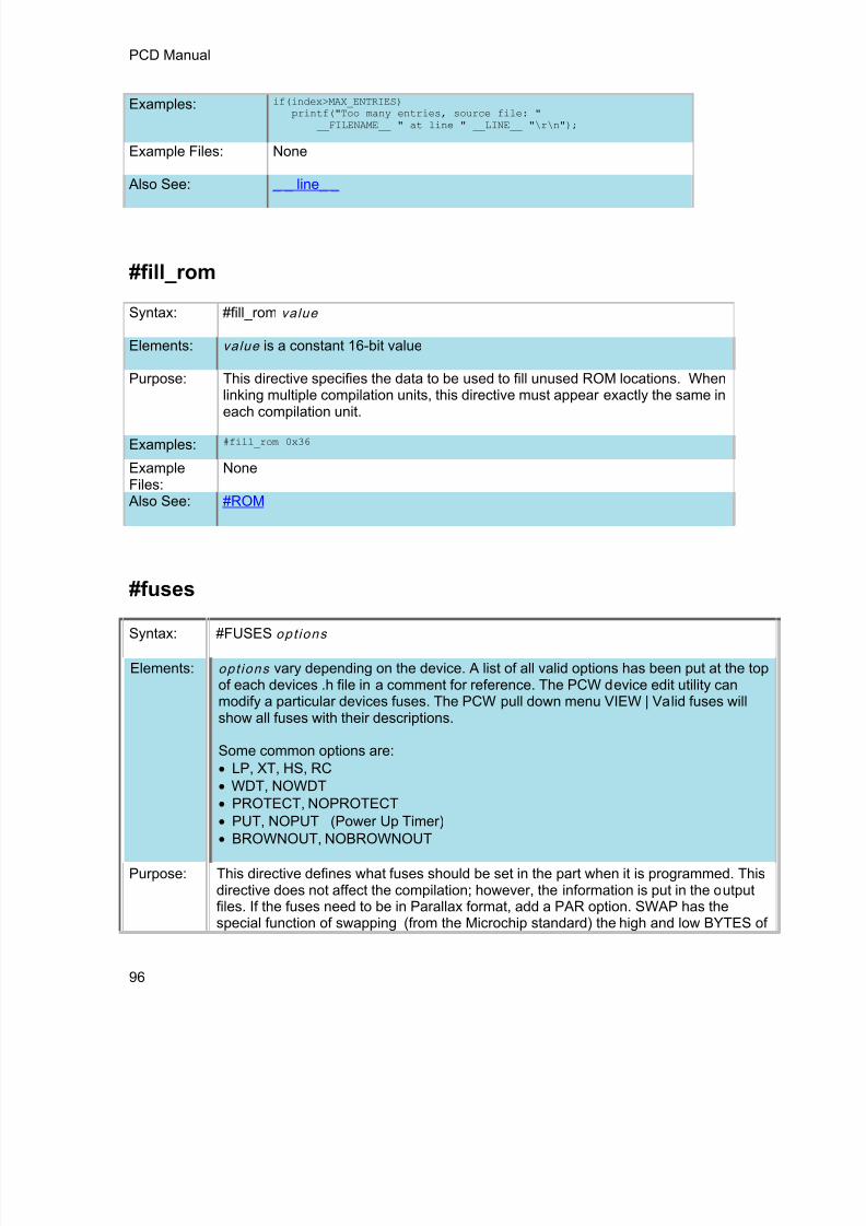
8/10/2019 avr.pdf
http://slidepdf.com/reader/full/avrpdf 108/365
PCD Manual
96
Examples: if(index>MAX_ENTRIES)printf("Too many entries, source file: "
__FILENAME__ " at line " __LINE__ "\r\n");
Example Files: None
Also See: _ _ line_ _
#fill_rom
Syntax: #fill_rom value
Elements: value is a constant 16-bit value
Purpose: This directive specifies the data to be used to fill unused ROM locations. When
linking multiple compilation units, this directive must appear exactly the same ineach compilation unit.
Examples: #fill_rom 0x36
ExampleFiles:
None
Also See: #ROM
#fusesSyntax: #FUSES opt ions
Elements: opt ions vary depending on the device. A list of all valid options has been put at the topof each devices .h file in a comment for reference. The PCW device edit utility canmodify a particular devices fuses. The PCW pull down menu VIEW | Valid fuses willshow all fuses with their descriptions.
Some common options are: LP, XT, HS, RC WDT, NOWDT PROTECT, NOPROTECT PUT, NOPUT (Power Up Timer) BROWNOUT, NOBROWNOUT
Purpose: This directive defines what fuses should be set in the part when it is programmed. Thisdirective does not affect the compilation; however, the information is put in the outputfiles. If the fuses need to be in Parallax format, add a PAR option. SWAP has thespecial function of swapping (from the Microchip standard) the high and low BYTES of

8/10/2019 avr.pdf
http://slidepdf.com/reader/full/avrpdf 109/365
PreProcessor
97
non-program data in the Hex file. This is required for some device programmers.
Some fuses are set by the compiler based on other compiler directives. For example,the oscillator fuses are set up by the #USE delay directive. The debug, No debug andICSPN Fuses are set by the #DEVICE ICD=directive.
Some processors allow different levels for certain fuses. To access these levels, assigna value to the fuse.
When linking multiple compilation units be aware this directive applies to the final objectfile. Later files in the import list may reverse settings in previous files.
To eliminate all fuses in the output files use:#FUSES none
To manually set the fuses in the output files use:#FUSES 1 = 0xC200 // sets config word 1 to 0xC200
Examples: #fuses HS,NOWDT
ExampleFiles:
None
Also See: None
#hexcomment
Syntax: #HEXCOMMENT text comment for the top of the hex file#HEXCOMMENT\ text comment for the end of the hex file
Elements: None
Purpose: Puts a comment in the hex file
Some programmers (MPLAB in particular) do not like comments at the top of thehex file.
Examples: #HEXCOMMENT Version 3.1 – requires 20MHz crystal
ExampleFiles:
None
Also See: None

8/10/2019 avr.pdf
http://slidepdf.com/reader/full/avrpdf 110/365
PCD Manual
98
#id
Syntax: #ID number 32 #ID number , number , number , number #ID "f i lename" #ID CHECKSUM
Elements: Number 3 2 is a 32 bit number, number is a 8 bit number, filename is any validPC filename and checksum is a keyword.
Purpose: This directive defines the ID word to be programmed into the part. This directivedoes not affect the compilation but the information is put in the output file.
The first syntax will take a 32 -bit number and put one byte in each of the four IDbytes in the traditional manner. The second syntax specifies the exact value to beused in each of the four ID bytes .
When a filename is specified the ID is read from the file. The format must besimple text with a CR/LF at the end. The keyword CHECKSUM indicates thedevice checksum should be saved as the ID.
Examples: #id 0x12345678#id 0x12, 0x34, 0x45, 0x67#id "serial.num"#id CHECKSUM
Example Files: ex_cust.c
Also See: None
#ifdef #ifndef #else #elif #endif
Syntax: #IFDEF id c o d e
#ELIFc o d e
#ELSEc o d e
#ENDIF
#IFNDEF id c o d e
#ELIFc o d e
#ELSEc o d e

8/10/2019 avr.pdf
http://slidepdf.com/reader/full/avrpdf 111/365
PreProcessor
99
#ENDIF
Elements: id is a preprocessor identifier, c o d e is valid C source code.
Purpose: This directive acts much like the #IF except that the preprocessor simply checks
to see if the specified ID is known to the preprocessor (created with a#DEFINE). #IFDEF checks to see if defined and #IFNDEF checks to see if it isnot defined.
Examples: #define debug // Comment line out for no debug
...#ifdef DEBUGprintf("debug point a");#endif
Example Files: ex_sqw.c
Also See: #IF
#ignore_warnings
Syntax: #ignore_warnings ALL#IGNORE_WARNINGS NONE#IGNORE_WARNINGS warn ings
Elements: warn ings is one or more warning numbers separated by commas
Purpose: This function will suppress warning messages from the compiler. ALL indicatesno warning will be generated. NONE indicates all warnings will be generated. Ifnumbers are listed then those warnings are suppressed.
Examples: #ignore_warnings 203while(TRUE) {#ignore_warnings NONE
ExampleFiles:
None
Also See: Warning messages
#import (options)
Syntax: #IMPORT (options)
Elements: FILE=filname

8/10/2019 avr.pdf
http://slidepdf.com/reader/full/avrpdf 112/365
PCD Manual
100
The filename of the object you want to link with this compilation.
ONLY=symbol+symbol+. . . . .+symbolOnly the listed symbols will imported from the specified relocatable objectfile. If neither ONLY or EXCEPT is used, all symbols are imported.
EXCEPT=symbol+symbol+.....+symbolThe listed symbols will not be imported from the specified relocatable objectfile. If neither ONLY or EXCEPT is used, all symbols are imported.
RELOCATABLECCS relocatable object file format. This is the default format when the#IMPORT is used.
COFFCOFF file format from MPASM, C18 or C30.
HEX
Imported data is straight hex data.
RANGE=star t :s topOnly addresses in this range are read from the hex file.
LOCATION=idThe identifier is made a constant with the start address of the imported data.
SIZE=idThe identifier is made a constant with the size of the imported data.
Purpose: This directive will tell the compiler to include (link) a relocatable object withthis unit during compilation. Normally all global symbols from the specifiedfile will be linked, but the EXCEPT and ONLY options can prevent certainsymbols from being linked.The command line compiler and the PCW IDE Project Manager can also beused to compile/link/build modules and/or projects.
Examples: #IMPORT(FILE=timer.o, ONLY=TimerTask)void main(void){
while(TRUE)TimerTask();
}/*timer.o is linked with this compilation, but only TimerTask() is visible inscope from this object.*/
Example Files: None
See Also: #EXPORT , #MODULE, Invoking the Command Line Compiler , MultipleCompilation Unit

8/10/2019 avr.pdf
http://slidepdf.com/reader/full/avrpdf 113/365
PreProcessor
101
#include
Syntax: #INCLUDE < f i lename >or
#INCLUDE "f i lename "
Elements: f i lename is a valid PC filename. It may include normal drive and pathinformation. A file with the extension ".encrypted" is a valid PC file. The standardcompiler #INCLUDE directive will accept files with this extension and decryptthem as they are read. This allows include files to be distributed withoutreleasing the source code.
Purpose: Text from the specified file is used at this point of the compilation. If a full path isnot specified the compiler will use the list of directories specified for the project tosearch for the file. If the filename is in "" then the directory with the main sourcefile is searched first. If the filename is in <> then the directory with the mainsource file is searched last.
Examples: #include <16C54.H>
#include <C:\INCLUDES\COMLIB\MYRS232.C>
Example Files: ex_sqw.c
Also See: None
#inline
Syntax: #INLINE
Elements: None
Purpose: Tells the compiler that the function immediately following the directive is to beimplemented INLINE. This will cause a duplicate copy of the code to be placedeverywhere the function is called. This is useful to save stack space and toincrease speed. Without this directive the compiler will decide when it is best tomake procedures INLINE.
Examples: #inlineswapbyte(int &a, int &b) {
int t;t=a;a=b;b=t;
}

8/10/2019 avr.pdf
http://slidepdf.com/reader/full/avrpdf 114/365
PCD Manual
102
Example Files: ex_cust.c
Also See: #SEPARATE
#INT_DEFAULT
Syntax: #INT_DEFAULT
Elements: None
Purpose: The following function will be called if the ds PIC® triggers an interrupt and a#INT_xxx hadler has not been defined for the interrupt.
Examples: #int_defaultdefault_isr() {
printf("Unexplained interrupt\r\n");}
Example Files: None
Also See: #INT_xxxx,
__line__
Syntax: __line__
Elements: None
Purpose: The pre-processor identifier is replaced at compile time with line number ofthe file being compiled.
Examples: if(index>MAX_ENTRIES)printf("Too many entries, source file: "
__FILE__" at line " __LINE__ "\r\n");
Example Files: assert.h
Also See: _ _ file_ _

8/10/2019 avr.pdf
http://slidepdf.com/reader/full/avrpdf 115/365
PreProcessor
103
#list
Syntax: #LIST
Elements: None
Purpose: #LIST begins inserting or resumes inserting source lines into the .LST file aftera #NOLIST.
Examples: #NOLIST // Don't clutter up the list file#include <cdriver.h>#LIST
Example Files: 16c74.h
Also See: #NOLIST
#line
Syntax: #LINE number file name
Elements: Number is non-negative decimal integer. File name is optional.
Purpose: The C pre-processor informs the C Compiler of the location in your sourcecode. This code is simply used to change the value of _LINE_ and _FILE_variables.
Examples: 1. void main(){#line 10 // specifies the line number that
// should be reported for// the following line of input
2. #line 7 "hello.c"// line number in the source file// hello.c and it sets the// line 7 as current line// and hello.c as current file
Example Files: None Also See: None

8/10/2019 avr.pdf
http://slidepdf.com/reader/full/avrpdf 116/365

8/10/2019 avr.pdf
http://slidepdf.com/reader/full/avrpdf 117/365
PreProcessor
105
#define G_COUNT_MAX 100int GetCount(void) {return(g_count);}void SetCount(int newCount) {
if (newCount>G_COUNT_MAX)newCount=G_COUNT_MAX;
g_count=newCount;}/*
the functions GetCount() and SetCount() have global scope, but thevariable g_count and the #define G_COUNT_MAX only has scope to this file.*/
Example Files: None
See Also: #EXPORT , Invoking the Command Line Compiler , Multiple CompilationUnit
#nolistSyntax: #NOLIST
Elements: None
Purpose: Stops inserting source lines into the .LST file (until a #LIST)
Examples: #NOLIST // Don't clutter up the list file#include <cdriver.h>#LIST
Example Files: 16c74.h Also See: #LIST
#ocs
Syntax: #OCS x
Elements: x is the clock's speed and can be 1 Hz to 100 MHz.Purpose: Used instead of the #use delay(clock = x)
Examples: #include <18F4520.h>#device ICD=TRUE#OCS 20 MHz#use rs232(debugger)
void main(){-------;

8/10/2019 avr.pdf
http://slidepdf.com/reader/full/avrpdf 118/365
PCD Manual
106
}
Example Files: None
Also See: #USE DELAY
#opt
Syntax: #OPT n
Elements: All Devices: n is the optimization level 0-9
Purpose: The optimization level is set with this directive. This setting applies to the entireprogram and may appear anywhere in the file. The default is 9 for normal.
Examples: #opt 5
Example Files: None
Also See: None
#org
Syntax: #ORG s tar t , en d or
#ORG segment or
#ORG s tar t , end { } or
#ORG s tar t , end auto =0 #ORG s tar t ,en d DEFAULT
or#ORG DEFAULT
Elements: s tar t is the first ROM location (word address) to use, en d is the last ROMlocation, segment is the start ROM location from a previous #ORG
Purpose: This directive will fix the following function, constant or ROM declaration into aspecific ROM area. End may be omitted if a segment was previously defined if youonly want to add another function to the segment.
Follow the ORG with a { } to only reserve the area with nothing inserted by the

8/10/2019 avr.pdf
http://slidepdf.com/reader/full/avrpdf 119/365

8/10/2019 avr.pdf
http://slidepdf.com/reader/full/avrpdf 120/365
PCD Manual
108
#pin_select
Syntax: #PIN_SELECT function=pin_xx
Elements: function is the Microchip defined pin function name, such as:
U1RX (UART1 receive), INT1 (external interrupt 1), T2CK(timer 2 clock), IC1 (input capture 1), OC1 (output capture1).
NULL NULLC1OUT Comparator 1 OutputC2OUT Comparator 2 OutputC3OUT Comparator 3 OutputC4OUT Comparator 4 OutputU1TX UART1 TransmitU1RTS UART1 Request to Send
U2TX UART2 TransmitU2RTS UART2 Request to SendU3TX UART3 TransmitU3RTS UART3 Request to SendU4TX UART4 TransmitU4RTS UART4 Request to SendSDO1 SPI1 Data OutputSCK1OUT SPI1 Clock OutputSS1OUT SPI1 Slave Select OutputSDO2 SPI2 Data OutputSCK2OUT SPI2 Clock OutputSS2OUT SPI2 Slave Select OutputSDO3 SPI3 Data OutputSCK3OUT SPI3 Clock OutputSS3OUT SPI3 Slave Select OutputSDO4 SPI4 Data OutputSCK4OUT SPI4 Clock OutputSS4OUT SPI4 Slave Select OutputOC1 Output Compare 1OC2 Output Compare 2OC3 Output Compare 3OC4 Output Compare 4OC5 Output Compare 5OC6 Output Compare 6OC7 Output Compare 7OC8 Output Compare 8OC9 Output Compare 9OC10 Output Compare 10OC11 Output Compare 11OC12 Output Compare 12OC13 Output Compare 13OC14 Output Compare 14

8/10/2019 avr.pdf
http://slidepdf.com/reader/full/avrpdf 121/365
PreProcessor
109
OC15 Output Compare 15OC16 Output Compare 16C1TX CAN1 TransmitC2TX CAN2 TransmitCSDO DCI Serial Data OutputCSCKOUT DCI Serial Clock OutputCOFSOUT DCI Frame Sync OutputUPDN1 QEI1 Direction Status OutputUPDN2 QEI2 Direction Status OutputCTPLS CTMU Output PulseSYNCO1 PWM Synchronization Output
SignalSYNCO2 PWM Secondary Synchronization
Output SignalREFCLKO REFCLK Output SignalCMP1 Analog Comparator Output 1CMP2 Analog Comparator Output 2CMP3 Analog Comparator Output 3CMP4 Analog Comparator Output 4PWM4H PWM4 High OutputPWM4L PWM4 Low OutputQEI1CCMP QEI1 Counter Comparator OutputQEI2CCMP QEI2 Counter Comparator OutputMDOUT DSM Modulator OutputDCIDO DCI Serial Data OutputDCISCKOUT DCI Serial Clock OutputDCIFSOUT DCI Frame Sync OutputINT1 External Interrupt 1 InputINT2 External Interrupt 2 Input
INT3 External Interrupt 3 InputINT4 External Interrupt 4 InputT1CK Timer 1 External Clock InputT2CK Timer 2 External Clock InputT3CK Timer 3 External Clock InputT4CK Timer 4 External Clock InputT5CK Timer 5 External Clock InputT6CK Timer 6 External Clock InputT7CK Timer 7 External Clock InputT8CK Timer 8 External Clock InputT9CK Timer 9 External Clock InputIC1 Input Capture 1
IC2 Input Capture 2IC3 Input Capture 3IC4 Input Capture 4IC5 Input Capture 5IC6 Input Capture 6IC7 Input Capture 7IC8 Input Capture 8IC9 Input Capture 9IC10 Input Capture 10

8/10/2019 avr.pdf
http://slidepdf.com/reader/full/avrpdf 122/365
PCD Manual
110
IC11 Input Capture 11IC12 Input Capture 12IC13 Input Capture 13IC14 Input Capture 14IC15 Input Capture 15IC16 Input Capture 16C1RX CAN1 ReceiveC2RX CAN2 ReceiveOCFA Output Compare Fault A InputOCFB Output Compare Fault B InputOCFC Output Compare Fault C InputU1RX UART1 ReceiveU1CTS UART1 Clear to SendU2RX UART2 ReceiveU2CTS UART2 Clear to SendU3RX UART3 ReceiveU3CTS UART3 Clear to SendU4RX UART4 ReceiveU4CTS UART4 Clear to SendSDI1 SPI1 Data InputSCK1IN SPI1 Clock InputSS1IN SPI1 Slave Select InputSDI2 SPI2 Data InputSCK2IN SPI2 Clock InputSS2IN SPI2 Slave Select InputSDI3 SPI3 Data InputSCK3IN SPI3 Clock InputSS3IN SPI3 Slave Select InputSDI4 SPI4 Data Input
SCK4IN SPI4 Clock InputSS4IN SPI4 Slave Select InputCSDI DCI Serial Data InputCSCK DCI Serial Clock InputCOFS DCI Frame Sync InputFLTA1 PWM1 Fault InputFLTA2 PWM2 Fault InputQEA1 QEI1 Phase A InputQEA2 QEI2 Phase A InputQEB1 QEI1 Phase B InputQEB2 QEI2 Phase B InputINDX1 QEI1 Index Input
INDX2 QEI2 Index InputHOME1 QEI1 Home InputHOME2 QEI2 Home InputFLT1 PWM1 Fault InputFLT2 PWM2 Fault InputFLT3 PWM3 Fault InputFLT4 PWM4 Fault InputFLT5 PWM5 Fault InputFLT6 PWM6 Fault Input

8/10/2019 avr.pdf
http://slidepdf.com/reader/full/avrpdf 123/365
PreProcessor
111
FLT7 PWM7 Fault InputFLT8 PWM8 Fault InputSYNCI1 PWM Synchronization Input 1SYNCI2 PWM Synchronization Input 2DCIDI DCI Serial Data InputDCISCKIN DCI Serial Clock InputDCIFSIN DCI Frame Sync InputDTCMP1 PWM Dead Time Compensation 1
InputDTCMP2 PWM Dead Time Compensation 2
InputDTCMP3 PWM Dead Time Compensation 3
InputDTCMP4 PWM Dead Time Compensation 4
InputDTCMP5 PWM Dead Time Compensation 5
InputDTCMP6 PWM Dead Time Compensation 6
InputDTCMP7 PWM Dead Time Compensation 7
Input
pin_xx is the CCS provided pin definition. For example:PIN_C7, PIN_B0, PIN_D3, etc.
Purpose: On PICs that contain Peripheral Pin Select (PPS), thisallows the programmer to define which pin a peripheral ismapped to.
Examples: #pin_select U1TX=PIN_C6#pin_select U1RX=PIN_C7#pin_select INT1=PIN_B0
ExampleFiles:
None
Also See: None
#pragma
Syntax: #PRAGMA cm d
Elements: cm d is any valid preprocessor directive.
Purpose: This directive is used to maintain compatibility between C compilers. This

8/10/2019 avr.pdf
http://slidepdf.com/reader/full/avrpdf 124/365
PCD Manual
112
compiler will accept this directive before any other pre-processor command. Inno case does this compiler require this directive.
Examples: #pragma device PIC16C54
Example Files: ex_cust.c
Also See: None
#profile
Syntax: #profile options
Elements: opt ions may be one of the following:
functions Profiles the start/end of functions and allprofileout() messages.
functions,parameters
Profiles the start/end of functions,parameters sent to functions, and allprofileout() messages.
profileout Only profile profilout() messages.
paths Profiles every branch in the code.
off Disable all code profiling.
on
Re-enables the code profiling that waspreviously disabled with a #profile offcommand. This will use the last optionsbefore disabled with the off command.
Purpose: Large programs on the microcontroller may generate lots of profile data, whichmay make it difficult to debug or follow. By using #profile the user candynamically control which points of the program are being profiled, and limitdata to what is relevant to the user.
Examples: #profile offvoid BigFunction(void){
// BigFunction code goes here.// Since #profile off was called above,// no profiling will happen even for other// functions called by BigFunction().
}#profile on
Example ex_profile.c

8/10/2019 avr.pdf
http://slidepdf.com/reader/full/avrpdf 125/365
PreProcessor
113
Files: Also See: #use profile( ), profileout() , Code Profile overview
#reserve
Syntax: #RESERVE address or
#RESERVE address , address , address or
#RESERVE s tar t :en d
Elements: address is a RAM address, start is the first address and en d is the last address
Purpose: This directive allows RAM locations to be reserved from use by thecompiler. #RESERVE must appear after the #DEVICE otherwise it will have no effect.When linking multiple compilation units be aware this directive applies to the final objectfile.
Examples: #DEVICE dsPIC30F2010#RESERVE 0x800:0x80B3
ExampleFiles:
ex_cust.c
Also See: #ORG
#rom
Syntax: #ROM address = {l i s t } #ROM type address = {l i s t }
Elements: address is a ROM word address, l i s t is a list of words separated by commas
Purpose: Allows the insertion of data into the .HEX file. In particular, this may be used toprogram the '84 data EEPROM, as shown in the following example.
Note that if the #ROM address is inside the program memory space, thedirective creates a segment for the data, resulting in an error if a #ORG is overthe same area. The #ROM data will also be counted as used program memoryspace.
The type option indicates the type of each item, the default is 16 bits. Using

8/10/2019 avr.pdf
http://slidepdf.com/reader/full/avrpdf 126/365
PCD Manual
114
char as the type treats each item as 7 bits packing 2 chars into every pcm 14-bitword.
When linking multiple compilation units be aware this directive applies to thefinal object file.
Some special forms of this directive may be used for verifying program memory:
#ROM address = checksumThis will put a value at address such that the entire program memory will
sum to 0x1248
#ROM address = crc16This will put a value at address that is a crc16 of all the program memory
except the specified address
#ROM address = crc8This will put a value at address that is a crc16 of all the program memory
except the specified address
Examples: #rom getnev ("EEPROM_ADDRESS")={1,2,3,4,5,6,7,8}#rom int8 0x1000={"(c)CCS, 2010"}
Example Files: None
Also See: #ORG
#separate
Syntax: #SEPARATE options
Elements: opt ions is optional, and are:
STDCALL – Use the standard Microchip calling method, used in C30. W0-W7is used for function parameters, rest of the working registers are not touched,remaining function parameters are pushed onto the stack.
ARG=Wx:Wy – Use the working registers Wx to Wy to hold functionparameters. Any remaining function parameters are pushed onto the stack.
DND=Wx:Wy – Function will not change Wx to Wy working registers.
AVOID=Wx:Wy – Function will not use Wx to Wy working registers for functionparameters.
NO RETURN - Prevents the compiler generated return at the end of a function.

8/10/2019 avr.pdf
http://slidepdf.com/reader/full/avrpdf 127/365
PreProcessor
115
You cannot use STDCALL with the ARG, DND or AVOID parameters.
If you do not specify one of these options, the compiler will determine the bestconfiguration, and will usually not use the stack for function parameters(usually scratch space is allocated for parameters).
Purpose: Tells the compiler that the procedure IMMEDIATELY following the directive isto be implemented SEPARATELY. This is useful to prevent the compiler fromautomatically making a procedure INLINE. This will save ROM space but itdoes use more stack space. The compiler will make all procedures markedSEPARATE, separate, as requested, even if there is not enough stack space toexecute.
Examples: #separate ARG=W0:W7 AVOID=W8:W15 DND=W8:W15swapbyte (int *a, int *b) {int t;
t=*a;*a=*b;
*b=t;}
Example Files: ex_cust.c
Also See: #INLINE
#serialize
Syntax: #SERIALIZE ( id=xxx , next="x" | f i le="f i lename. txt" " |l i s t f i le="f i lename. txt" , "prompt=" tex t" , log="f i lename. txt" ) -or#SERIALIZE( dataee=x , binary=x , next="x" | f i le="f i lename. txt" |l i s t f i le="f i lename. txt" , prompt=" tex t" , log="f i lename. txt" )
Elements: id=xxx - Specify a C CONST identifier, may be int8, int16, int32 or chararray
Use in place of id parameter, when storing serial number to EEPROM:dataee=x - The address x is the start address in the data EEPROM.binary=x - The integer x is the number of bytes to be written to addressspecified. -or-s t r ing=x - The integer x is the number of bytes to be written to addressspecified.
Use only one of the next three options:f i le="f i lename. txt" - The file x is used to read the initial serial numberfrom, and this file is updated by the ICD programmer. It is assumed thisis a one line file with the serial number. The programmer will increment

8/10/2019 avr.pdf
http://slidepdf.com/reader/full/avrpdf 128/365
PCD Manual
116
the serial number.
l i s t f i le="f i lename. txt" - The file x is used to read the initial serial numberfrom, and this file is updated by the ICD programmer. It is assumed thisis a file one serial number per line. The programmer will read the first linethen delete that line from the file.
nex t="x" - The serial number X is used for the first load, then the hex fileis updated to increment x by one.
Other optional parameters:prompt=" tex t" - If specified the user will be prompted for a serialnumber on each load. If used with one of the above three options thenthe default value the user may use is picked according to the aboverules.
log=xxx - A file may optionally be specified to keep a log of the date,time, hex file name and serial number each time the part is programmed.If no id=xxx is specified then this may be used as a simple log of all loadsof the hex file.
Purpose: Assists in making serial numbers easier to implement when working withCCS ICD units. Comments are inserted into the hex file that the ICDsoftware interprets.
Examples: //Prompt user for serial number to be placed//at address of serialNumA//Default serial number = 200int8int8 const serialNumA=100;#serialize(id=serialNumA,next="200",prompt="Enter the serial number")
//Adds serial number log in seriallog.txt#serialize(id=serialNumA,next="200",prompt="Enter the serial number",
log="seriallog.txt")
//Retrieves serial number from serials.txt#serialize(id=serialNumA,listfile="serials.txt")
//Place serial number at EEPROM address 0, reserving 1 byte#serialize(dataee=0,binary=1,next="45",prompt="Put in Serial number")
//Place string serial number at EEPROM address 0, reserving 2 bytes#serialize(dataee=0, string=2,next="AB",prompt="Put in Serial number")
Example Files: None
Also See: None
#task
(The RTOS is only included with the PCW, PCWH, and PCWHD software packages.)

8/10/2019 avr.pdf
http://slidepdf.com/reader/full/avrpdf 129/365
PreProcessor
117
Each RTOS task is specified as a function that has no parameters and no return. The #TASKdirective is needed just before each RTOS task to enable the compiler to tell which functions areRTOS tasks. An RTOS task cannot be called directly like a regular function can.
Syntax: #TASK (opt ions)
Elements: opt ions are separated by comma and may be:rate=timeWhere time is a number followed by s, ms, us, or ns. This specifies howoften the task will execute.
max=timeWhere time is a number followed by s, ms, us, or ns. This specifies thebudgeted time for this task.
queue=bytesSpecifies how many bytes to allocate for this task's incoming messages.The default value is 0.
enabled=valueSpecifies whether a task is enabled or disabled by rtos_run( ).True for enabled, false for disabled. The default value is enabled.
Purpose: This directive tells the compiler that the following function is an RTOStask.
The rate option is used to specify how often the task should execute.This must be a multiple of the minor_cycle option if one is specified in the#USE RTOS directive.
The max option is used to specify how much processor time a task willuse in one execution of the task. The time specified in max must beequal to or less than the time specified in the minor_cycle option of the#USE RTOS directive before the project will compile successfully. Thecompiler does not have a way to enforce this limit on processor time, soa programmer must be careful with how much processor time a taskuses for execution. This option does not need to be specified.
The queue option is used to specify the number of bytes to be reservedfor the task to receive messages from other tasks or functions. Thedefault queue value is 0.
Examples: #task(rate=1s, max=20ms, queue=5)
Also See: #USE RTOS

8/10/2019 avr.pdf
http://slidepdf.com/reader/full/avrpdf 130/365
PCD Manual
118
__time__
Syntax: __TIME__
Elements: None
Purpose: This pre-processor identifier is replaced at compile time with the time of thecompile in the form: "hh:mm:ss"
Examples: printf("Software was compiled on ");printf(__TIME__);
Example Files: None
Also See: None
#type
Syntax: #TYPE s tandard -type =size #TYPE default=area #TYPE unsigned #TYPE signed #TYPE char=signed #TYPE char=unsigned
#TYPE ARG=Wx:Wy#TYPE DND=Wx:Wy#TYPE AVOID=Wx:Wy#TYPE RECURSIVE#TYPE CLASSIC
Elements: s tandard- type is one of the C keywords short, int, long, float, or doublesize is 1,8,16, 48, or 64 area is a memory region defined before the #TYPE using the addressmod directive
Wx:Wy is a range of working registers (example: W0, W1, W15, etc)
Purpose: By default the compiler treats SHORT as 8 bits , INT as 16 bits, and LONG as 32 bits.The traditional C convention is to have INT defined as the most efficient size for thetarget processor. This is why it is 16 bits on the dsPIC/PIC24 ® . In order to help withcode compatibility a #TYPE directive may be used to allow these types to be changed.#TYPE can redefine these keywords.
Note that the commas are optional. Be warned CCS example programs and includefiles may not work right if you use #TYPE in your program.

8/10/2019 avr.pdf
http://slidepdf.com/reader/full/avrpdf 131/365

8/10/2019 avr.pdf
http://slidepdf.com/reader/full/avrpdf 132/365
PCD Manual
120
#undef
Syntax: #UNDEF id
Elements: id is a pre-processor id defined via #DEFINE
Purpose: The specified pre-processor ID will no longer have meaning to the pre-processor.
Examples: #if MAXSIZE<100#undef MAXSIZE#define MAXSIZE 100#endif
Example Files: None
Also See: #DEFINE
#use capture
Syntax: #USE CAPTURE(options)Elements: ICx/CCPx
Which CCP/Input Capture module to us.
INPUT = PIN_xxSpecifies which pin to use. Useful for device with remappable pins,this will cause compiler to automatically assign pin to peripheral.
TIMER=x Specifies the timer to use with capture unit. If not specified default totimer 1 for PCM and PCH compilers and timer 3 for PCD compiler.
TICK=x The tick time to setup the timer to. If not specified it will be set tofastest as possible or if same timer was already setup by a previousstream it will be set to that tick time. If using same timer as previousstream and different tick time an error will be generated.
FASTESTUse instead of TICK=x to set tick time to fastest as possible.
SLOWESTUse instead of TICK=x to set tick time to slowest as possible.
CAPTURE_RISING

8/10/2019 avr.pdf
http://slidepdf.com/reader/full/avrpdf 133/365
PreProcessor
121
Specifies the edge that timer value is captured on. Defaults toCAPTURE_RISING.
CAPTURE_FALLINGSpecifies the edge that timer value is captured on. Defaults toCAPTURE_RISING.
CAPTURE_BOTHPCD only. Specifies the edge that timer value is captured on.Defaults to CAPTURE_RISING.
PRE=xSpecifies number of rising edges before capture event occurs. Validoptions are 1, 4 and 16, default to 1 if not specified. Options 4 and 16are only valid when using CAPTURE_RISING, will generate an erroris used with CAPTURE_FALLING or CAPTURE_BOTH.
ISR=xPCD only. Specifies the number of capture events to occur beforegenerating capture interrupt. Valid options are 1, 2, 3 and 4, defaultsto 1 is not specified. Option 1 is only valid option when usingCAPTURE_BOTH, will generate an error if trying to use 2, 3 or 4 withit.
STREAM=id Associates a stream identifier with the capture module. The identifiermay be used in functions like get_capture_time().
DEFINE=idCreates a define named id which specifies the number of capture persecond. Default define name if not specified isCAPTURES_PER_SECOND. Define name must start with an ASCIIletter 'A' to 'Z', an ASCII letter 'a' to 'z' or an ASCII underscore ('_').
Purpose: This directive tells the compiler to setup an input capture on thespecified pin using the specified settings. The #USE DELAY directivemust appear before this directive can be used. This directive enablesuse of built-in functions such as get_capture_time() andget_capture_event().
Examples: #USECAPTURE(INPUT=PIN_C2,CAPTURE_RISING,TIMER=1,FASTEST)
ExampleFiles:
None.
Also See: get_capture_time() , get_capture_event()
#use delay
Syntax: #USE DELAY (options))

8/10/2019 avr.pdf
http://slidepdf.com/reader/full/avrpdf 134/365
PCD Manual
122
Elements: Options may be any of the following separated by commas:
clock=speed speed is a constant 1-100000000 (1 hz to 100 mhz).This number can contains commas. This number also supports the following
denominations: M, MHZ, K, KHZ. This specifies the clock the CPU runs at. Dependingon the PIC this is 2 or 4 times the instruction rate. This directive is not needed if thefollowing type=speed is used and there is no frequency multiplication or division.
type=speed type defines what kind of clock you are using, and the following values arevalid: oscillator, osc (same as oscillator), crystal, xtal (same as crystal), internal, int(same as internal) or rc. The compiler will automatically set the oscillator configurationbits based upon your defined type. If you specified internal, the compiler will alsoautomatically set the internal oscillator to the defined speed. Configuration fuses aremodified when this option is used. Speed is the input frequency.
res tar t_wdt will restart the watchdog timer on every delay_us() and delay_ms() use.
AUX: ty pe=speed Some chips have a second oscillator used by specific periphrials andwhen this is the case this option sets up that oscillator.
Also See: delay_ms() , delay_us()
#use dynamic_memory
Syntax: #USE DYNAMIC_MEMORYElements: None
Purpose: This pre-processor directive instructs the compiler to create the _DYNAMIC_HEAD object. _DYNAMIC_HEAD is the location where the first freespace is allocated.
Examples: #USE DYNAMIC_MEMORYvoid main ( ){
}
Example
Files:
ex_malloc.c
Also See: None

8/10/2019 avr.pdf
http://slidepdf.com/reader/full/avrpdf 135/365
PreProcessor
123
#use fast_io
Syntax: #USE FAST_IO ( por t )
Elements: por t is A, B, C, D, E, F, G, H, J or ALL
Purpose: Affects how the compiler will generate code for input and output instructions thatfollow. This directive takes effect until another #use xxxx_IO directive isencountered. The fast method of doing I/O will cause the compiler to perform I/O withoutprogramming of the direction register. The compiler's default operation is the opposite ofthis command, the direction I/O will be set/cleared on each I/O operation. The user mustensure the direction register is set correctly via set_tris_X(). When linking multiplecompilation units be aware this directive only applies to the current compilation unit.
Examples: #use fast_io(A)
ExampleFiles:
ex_cust.c
Also See: #USE FIXED_IO , #USE STANDARD_IO , set_tris_X() , General Purpose I/O
#use fixed_io
Syntax: #USE FIXED_IO ( por t_ou tpu t s =pin , pin ?)
Elements: por t is A-G, p in is one of the pin constants defined in the devices .h file.Purpose: This directive affects how the compiler will generate code for input and output
instructions that follow. This directive takes effect until another #USE XXX_IO directiveis encountered. The fixed method of doing I/O will cause the compiler to generate codeto make an I/O pin either input or output every time it is used. The pins are programmedaccording to the information in this directive (not the operations actuallyperformed). This saves a byte of RAM used in standard I/O. When linking multiplecompilation units be aware this directive only applies to the current compilation unit.
Examples: #use fixed_io(a_outputs=PIN_A2, PIN_A3)
ExampleFiles: None Also See: #USE FAST_IO , #USE STANDARD_IO , General Purpose I/O

8/10/2019 avr.pdf
http://slidepdf.com/reader/full/avrpdf 136/365
PCD Manual
124
#use i2c
Syntax: #USE I2C ( opt ions )
Elements: Opt ions are separated by commas and may be:MASTER Sets to the master modeMULTI_MASTER Set the multi_master modeSLAVE Set the slave modeSCL=pin Specifies the SCL pin (pin is a bit address)SDA=pin Specifies the SDA pin
ADDRESS=nn Specifies the slave mode addressFAST Use the fast I 2C specification.FAST=nnnnnn Sets the speed to nnnnnn hzSLOW Use the slow I 2C specificationRESTART_WDT Restart the WDT while waiting in I 2C_READ
FORCE_HW Use hardware I 2C functions.FORCE_SW Use software I2C functions.NOFLOAT_HIGH Does not allow signals to float high, signals are
driven from low to highSMBUS Bus used is not I 2C bus, but very similarSTREAM=id Associates a stream identifier with this I 2C port.
The identifier may then be used in functions likei2c_read or i 2c_write.
NO_STRETCH Do not allow clock streachingMASK=nn Set an address mask for parts that support it
I2C1 Instead of SCL= and SDA= this sets the pins tothe first module
I2C2 Instead of SCL= and SDA= this sets the pins tothe second module
NOINIT No initialization of the I2C peripheral is performed.Use I2C_INIT() to initialize peripheral at run time.
Only some chips allow the following:DATA_HOLD No ACK is sent until I2C_READ is called for data bytes (slave
only) ADDRESS_HOLD No ACK is sent until I2C_read is called for the address byte
(slave only)SDA_HOLD Min of 300ns holdtime on SDA a from SCL goes low
Purpose: CCS offers support for the hardware-based I2C TM and a software-based master I2C TM device.(For more information on the hardware-based I2C module, please consult thedatasheet for your target device; not all PICs support I2C TM.
The I 2C library contains functions to implement an I 2C bus. The #USE I2C remains ineffect for the I2C_START, I2C_STOP, I2C_READ, I2C_WRITE and I2C_POLL functions

8/10/2019 avr.pdf
http://slidepdf.com/reader/full/avrpdf 137/365
PreProcessor
125
until another USE I2C is encountered. Software functions are generated unless theFORCE_HW is specified. The SLAVE mode should only be used with the built-in SSP.The functions created with this directive are exported when using multiple compilationunits. To access the correct function use the stream identifier.
Examples: #use I2C(master, sda=PIN_B0, scl=PIN_B1)
#use I2C(slave,sda=PIN_C4,scl=PIN_C3address=0xa0,FORCE_HW)
#use I2C(master, scl=PIN_B0, sda=PIN_B1, fast=450000)//sets the target speed to 450 KBSP
ExampleFiles:
ex_extee.c with 16c74.h
Also See: i2c_poll , i2c_speed , i2c_start , i2c_stop , i2c_slaveaddr , i2c_isr_state , i2c_write , i2c_read , I2C Overview
#use profile()
Syntax: #use profile(options)
Elements: opt ions may be any of the following, comma separated:
ICD Default – configures code profiler to use the ICDconnection.
TIMER1
Optional. If specified, the code profiler run-time on
the microcontroller will use the Timer1 peripheral asa timestamp for all profile events. If not specifiedthe code profiler tool will use the PC clock, whichmay not be accurate for fast events.
BAUD=x
Optional. If specified, will use a different baud ratebetween the microcontroller and the code profilertool. This may be required on slow microcontrollersto attempt to use a slower baud rate.
Purpose: Tell the compiler to add the code profiler run-time in the microcontroller and configurethe link and clock.
Examples: #profile(ICD, TIMER1, baud=9600)
ExampleFiles:
ex_profile.c
Also See: #profile() , profileout() , Code Profile overview

8/10/2019 avr.pdf
http://slidepdf.com/reader/full/avrpdf 138/365
PCD Manual
126
#use pwm
Syntax: #USE PWM(options)
Elements: Opt ions are separated by commas and may be:
PWMx or CCPx Selects the CCP to use, x being the module number to use.
PWMx or OCx Selects the Output Compare module, x being the module number touse.
OUTPUT=PIN_xx
Selects the PWM pin to use, pin must be one of the OC pins. If devicehas remappable pins compiler will assign specified pin to specified OCmodule. If OC module not specified it will assign remappable pin tofirst available module.
TIMER=x Selects timer to use with PWM module, default if not specified is timer2.
FREQUENCY=x
Sets the period of PWM based off specified value, should not be usedif PERIOD is already specified. If frequency can't be achieved exactlycompiler will generate a message specifying the exact frequency andperiod of PWM. If neither FREQUENCY or PERIOD is specified, theperiod defaults to maximum possible period with maximum resolutionand compiler will generate a message specifying the frequency andperiod of PWM, or if using same timer as previous stream instead ofsetting to maximum possible it will be set to the same as previousstream. If using same timer as previous stream and frequency isdifferent compiler will generate an error.
PERIOD=x
Sets the period of PWM, should not be used if FREQUENCY is alreadyspecified. If period can't be achieved exactly compiler will generate amessage specifying the exact period and frequency of PWM. If neitherPERIOD or FREQUENCY is specified, the period defaults to maximumpossible period with maximum resolution and compiler will generate amessage specifying the frequency and period of PWM, or if usingsame timer as previous stream instead of setting to maximum possibleit will be set to the same as previous stream. If using same timer asprevious stream and period is different compiler will generate an error.
BITS=x
Sets the resolution of the the duty cycle, if period or frequency isspecified will adjust the period to meet set resolution and will generatean message specifying the frequency and duty of PWM. If period orfrequency not specified will set period to maximum possible forspecified resolution and compiler will generate a message specifyingthe frequency and period of PWM, unless using same timer asprevious then it will generate an error if resolution is different thenprevious stream. If not specified then frequency, period or previousstream using same timer sets the resolution.

8/10/2019 avr.pdf
http://slidepdf.com/reader/full/avrpdf 139/365
PreProcessor
127
DUTY=x Selects the duty percentage of PWM, default if not specified is 50%.
STREAM=id Associates a stream identifier with the PWM signal. The identifier maybe used in functions like pwm_set_duty_percent().
Purpose:
This directive tells the compiler to setup a PWM on the specified pinusing the specified frequency, period, duty cycle and resolution. The
#USE DELAY directive must appear before this directive can be used.This directive enables use of built-in functions such asset_pwm_duty_percent(), set_pwm_frequency(), set_pwm_period(),pwm_on() and pwm_off().
Example Files None Also See:
#use rs232
Syntax: #USE RS232 ( opt ions )
Elements: Opt ions are separated by commas and may be:STREAM=id Associates a stream identifier with this RS232 port.
The identifier may then be used in functions like fputc.
BAUD=x Set baud rate to x
XMIT=pin Set transmit pin
RCV=pin Set receive pin
FORCE_SW Will generate software serial I/O routines even whenthe UART pins are specified.
BRGH1OK Allow bad baud rates on chips that have baud rateproblems.
ENABLE=pin The specified pin will be high during transmit. Thismay be used to enable 485 transmit.
DEBUGGER Indicates this stream is used to send/receive datathough a CCS ICD unit. The default pin used in B3,use XMIT= and RCV= to change the pin used. Both
should be the same pin.
RESTART_WDT Will cause GETC() to clear the WDT as it waits for acharacter.
INVERT Invert the polarity of the serial pins (normally notneeded when level converter, such as the MAX232).May not be used with the internal UART.

8/10/2019 avr.pdf
http://slidepdf.com/reader/full/avrpdf 140/365
PCD Manual
128
PARITY=X Where x is N, E, or O.
BITS =X Where x is 5-9 (5-7 may not be used with the SCI).
FLOAT_HIGH The line is not driven high. This is used for opencollector outputs. Bit 6 in RS232_ERRORS is set if thepin is not high at the end of the bit time.
ERRORS Used to cause the compiler to keep receive errors inthe variable RS232_ERRORS and to reset errorswhen they occur.
SAMPLE_EARLY A getc() normally samples data in the middle of a bittime. This option causes the sample to be at the startof a bit time. May not be used with the UART.
RETURN=pin For FLOAT_HIGH and MULTI_MASTER this is the pinused to read the signal back. The default forFLOAT_HIGH is the XMIT pin and forMULTI_MASTER the RCV pin.
MULTI_MASTER Uses the RETURN pin to determine if another masteron the bus is transmitting at the same time. If acollision is detected bit 6 is set in RS232_ERRORSand all future PUTC's are ignored until bit 6 is cleared.The signal is checked at the start and end of a bit
time. May not be used with the UART.
LONG_DATA Makes getc() return an int16 and putc accept an int16.This is for 9 bit data formats.
DISABLE_INTS Will cause interrupts to be disabled when the routinesget or put a character. This prevents characterdistortion for software implemented I/O and preventsinteraction between I/O in interrupt handlers and themain program when using the UART.
STOP=X To set the number of stop bits (default is 1). Thisworks for both UART andnon-UART ports.
TIMEOUT=X To set the time getc() waits for a byte in milliseconds.If no character comes in within this time theRS232_ERRORS is set to 0 as well as the returnvalue form getc(). This works for both UART and non-UART ports.
SYNC_SLAVE Makes the RS232 line a synchronous slave, makingthe receive pin a clock in, and the data pin the datain/out.

8/10/2019 avr.pdf
http://slidepdf.com/reader/full/avrpdf 141/365
PreProcessor
129
SYNC_MASTER Makes the RS232 line a synchronous master, makingthe receive pin a clock out, and the data pin the datain/out.
SYNC_MATER_CONT Makes the RS232 line a synchronous master mode incontinuous receive mode. The receive pin is set as aclock out, and the data pin is set as the data in/out.
UART1 Sets the XMIT= and RCV= to the chips first hardwareUART.
UART1A Uses alternate UART pins
UART2 Sets the XMIT= and RCV= to the chips secondhardware UART.
UART2A Uses alternate UART pins
NOINIT No initialization of the UART peripheral is performed.Useful for dynamic control of the UART baudrate orinitializing the peripheral manually at a later point inthe program's run time. If this option is used, thensetup_uart( ) needs to be used to initialize theperipheral. Using a serial routine (such as getc( ) orputc( )) before the UART is initialized will causeundefined behavior.
Serial Buffer Options:RECEIVE_BUFFER=x Size in bytes of UART circular receive buffer, default if
not specified is zero. Uses an interrupt to receivedata, supports RDA interrupt or external interrupts.
TRANSMIT_BUFFER=x Size in bytes of UART circular transmit buffer, defaultif not specified is zero.
TXISR If TRANSMIT_BUFFER is greater then zero specifiesusing TBE interrupt for transmitting data. Default isNOTXISR if TXISR or NOTXISR is not specified.TXISR option can only be used when using hardware
UART.NOTXISR If TRANSMIT_BUFFER is greater then zero specifies
to not use TBE interrupt for transmitting data. Defaultis NOTXISR if TXISR or NOTXISR is not specified andXMIT_BUFFER is greater then zero
Flow Control Options:RTS = PIN_xx Pin to use for RTS flow control. When using
FLOW_CONTROL_MODE this pin is driven to theactive level when it is ready to receive more data. InSIMPLEX_MODE the pin is driven to the active levelwhen it has data to transmit.FLOW_CONTROL_MODE can only be use when
using RECEIVE_BUFFERRTS_LEVEL=x Specifies the active level of the RTS pin, HIGH is

8/10/2019 avr.pdf
http://slidepdf.com/reader/full/avrpdf 142/365
PCD Manual
130
active high and LOW is active low. Defaults to LOW ifnot specified.
CTS = PIN_xx Pin to use for CTS flow control. In bothFLOW_CONTROL_MODE and SIMPLEX_MODE thispin is sampled to see if it clear to send data. If pin isat active level and there is data to send it will sendnext data byte.
CTS_LEVEL=x Specifies the active level of the CTS pin, HIGH isactive high and LOW is active low. Default to LOW ifnot specified
FLOW_CONTROL_MODE Specifies how the RTS pin is used. ForFLOW_CONTROL_MODE the RTS pin is driven tothe active level when ready to receive data. Defaultsto FLOW_CONTROL_MODE when neitherFLOW_CONTROL_MODE or SIMPLEX_MODE isspecified. If RTS pin isn't specified then this option isnot used.
SIMPLEX_MODE Specifies how the RTS pin is used. ForSIMPLEX_MODE the RTS pin is driven to the activelevel when it has data to send. Defaults toFLOW_CONTROL_MODE when neitherFLOW_CONTROL_MODE or SIMPLEX_MODE isspecified. If RTS pin isn't specified then this option isnot used.
Purpose: This directive tells the compiler the baud rate and pins used for serial I/O. This directivetakes effect until another RS232 directive is encountered. The #USE DELAY directivemust appear before this directive can be used. This directive enables use of built-infunctions such as GETC, PUTC, and PRINTF. The functions created with this directiveare exported when using multiple compilation units. To access the correct function usethe stream identifier.
When using parts with built-in UART and the UART pins are specified, the SCI will beused. If a baud rate cannot be achieved within 3% of the desired value using the currentclock rate, an error will be generated. The definition of the RS232_ERRORS is asfollows:
No UART: Bit 7 is 9th bit for 9 bit data mode (get and put). Bit 6 set to one indicates a put failed in float high mode.
With a UART: Used only by get: Copy of RCSTA register except: Bit 0 is used to indicate a parity error.
Warning:The PIC UART will shut down on overflow (3 characters received by the hardware witha GETC() call). The "ERRORS" option prevents the shutdown by detecting the conditionand resetting the UART.

8/10/2019 avr.pdf
http://slidepdf.com/reader/full/avrpdf 143/365
PreProcessor
131
Examples: #use rs232(baud=9600, xmit=PIN_A2,rcv=PIN_A3)
ExampleFiles:
ex_cust.c
Also See: getc() , putc() , printf(), setup_uart( ) , RS2332 I/O overview
#use rtos
(The RTOS is only included with the PCW and PCWH packages.)
The CCS Real Time Operating System (RTOS) allows a PICmicro controller to run regularly scheduled tasks without the needfor interrupts. This is accomplished by a function (RTOS_RUN())that acts as a dispatcher. When a task is scheduled to run, thedispatch function gives control of the processor to that task.When the task is done executing or does not need the processoranymore, control of the processor is returned to the dispatchfunction which then will give control of the processor to the nexttask that is scheduled to execute at the appropriate time. Thisprocess is called cooperative multi-tasking.
Syntax: #USE RTOS (options)
Elements:
options are separated by comma and may be:timer=X Where x is 0-4 specifying the timer used by the
RTOS.minor_cycle=time Where time is a number followed by s, ms, us, ns.
This is the longest time any task will run. Eachtask's execution rate must be a multiple of thistime. The compiler can calculate this if it is notspecified.
statistics Maintain min, max, and total time used by eachtask.
Purpose:
This directive tells the compiler which timer on the PIC to use for monitoring andwhen to grant control to a task. Changes to the specified timer's prescaler willeffect the rate at which tasks are executed.
This directive can also be used to specify the longest time that a task will ever taketo execute with the minor_cycle option. This simply forces all task execution ratesto be a multiple of the minor_cycle before the project will compile successfully. Ifthe this option is not specified the compiler will use a minor_cycle value that is thesmallest possible factor of the execution rates of the RTOS tasks.
If the statistics option is specified then the compiler will keep track of the minimum

8/10/2019 avr.pdf
http://slidepdf.com/reader/full/avrpdf 144/365
PCD Manual
132
processor time taken by one execution of each task, the maximum processor timetaken by one execution of each task, and the total processor time used by eachtask.
When linking multiple compilation units, this directive must appear exactly thesame in each compilation unit.
Examples:#use rtos(timer=0, minor_cycle=20ms)
Also See: #TASK
#use spi
Syntax: #USE SPI ( opt ions )
Elements: Opt ions are separated by commas and may be:MASTER Set the device as the master. (default)SLAVE Set the device as the slave.BAUD=n Target bits per second, default is as fast as
possible.CLOCK_HIGH=n High time of clock in us (not needed if BAUD= is
used). (default=0)CLOCK_LOW=n Low time of clock in us (not needed if BAUD= is
used). (default=0)DI=pin Optional pin for incoming data.DO=pin Optional pin for outgoing data.
CLK=pin Clock pin.MODE=n The mode to put the SPI bus.ENABLE=pin Optional pin to be active during data transfer.LOAD=pin Optional pin to be pulsed active after data is
transferred.DIAGNOSTIC=pin Optional pin to the set high when data is sampled.SAMPLE_RISE Sample on rising edge.SAMPLE_FALL Sample on falling edge (default).BITS=n Max number of bits in a transfer. (default=32)SAMPLE_COUNT=n Number of samples to take (uses majority vote).
(default=1LOAD_ACTIVE=n Active state for LOAD pin (0, 1).
ENABLE_ACTIVE=n Active state for ENABLE pin (0, 1). (default=0)IDLE=n Inactive state for CLK pin (0, 1). (default=0)ENABLE_DELAY=n Time in us to delay after ENABLE is activated.
(default=0)DATA_HOLD=n Time between data change and clock changeLSB_FIRST LSB is sent first.MSB_FIRST MSB is sent first. (default)STREAM=id Specify a stream name for this protocol.SPI1 Use the hardware pins for SPI Port 1

8/10/2019 avr.pdf
http://slidepdf.com/reader/full/avrpdf 145/365
PreProcessor
133
SPI2 Use the hardware pins for SPI Port 2FORCE_HW Use the pic hardware SPI.SPI3 Use the hardware pins for SPI Port 3SPI4 Use the hardware pins for SPI Port 4NOINIT Don't initialize the hardware SPI PortXFER16 Uses 16 BIT transfers instead of two 8 BIT
transfers
Purpose: The SPI library contains functions to implement an SPI bus. After setting all of theproper parameters in #USE SPI, the spi_xfer() function can be used to bothtransfer and receive data on the SPI bus.
The SPI1 and SPI2 options will use the SPI hardware onboard the PIC. The mostcommon pins present on hardware SPI are: DI, DO, and CLK. These pins don’tneed to be assigned values through the options; the compiler will automaticallyassign hardware-specific valu es to these pins. Consult your PIC’s data sheet as towhere the pins for hardware SPI are. If hardware SPI is not used, then softwareSPI will be used. Software SPI is much slower than hardware SPI, but softwareSPI can use any pins to transfer and receive data other than just the pins tied tothe PIC’s hardware SPI pins.
The MODE option is more or less a quick way to specify how the stream is goingto sample data. MODE=0 sets IDLE=0 and SAMPLE_RISE. MODE=1 setsIDLE=0 and SAMPLE_FALL. MODE=2 sets IDLE=1 and SAMPLE_FALL.MODE=3 sets IDLE=1 and SAMPLE_RISE. There are only these 4 MODEs.
SPI cannot use the same pins for DI and DO. If needed, specify two streams: oneto send data and another to receive data.
The pins must be specified with DI, DO, CLK or SPIx, all other options aredefaulted as indicated above.
Examples: #use spi(DI=PIN_B1, DO=PIN_B0, CLK=PIN_B2, ENABLE=PIN_B4, BITS=16)// uses software SPI
#use spi(FORCE_HW, BITS=16, stream=SPI_STREAM)// uses hardware SPI and gives this stream the name SPI_STREAM
ExampleFiles:
None
Also See: spi_xfer()
#use standard_io
Syntax: #USE STANDARD_IO ( por t )
Elements: por t is A, B, C, D, E, F, G, H, J or ALL
Purpose: This directive affects how the compiler will generate code for input and output

8/10/2019 avr.pdf
http://slidepdf.com/reader/full/avrpdf 146/365
PCD Manual
134
instructions that follow. This directive takes effect until another #USE XXX_IO directiveis encountered. The standard method of doing I/O will cause the compiler to generatecode to make an I/O pin either input or output every time it is used. On the 5Xprocessors this requires one byte of RAM for every port set to standard I/O.
Standard_io is the default I/O method for all ports.
When linking multiple compilation units be aware this directive only applies to the currentcompilation unit.
Examples: #use standard_io(A)
ExampleFiles:
ex_cust.c
Also See: #USE FAST_IO , #USE FIXED_IO , General Purpose I/O
#use timer
Syntax: #USE TIMER (options)
Elements: TIMER=xSets the timer to use as the tick timer. x is a valid timer that the PIC has. Defaultvalue is 1 for Timer 1.
TICK=xxSets the desired time for 1 tick. xx can be used with ns(nanoseconds), us(microseconds), ms (milliseconds), or s (seconds). If the desired tick time can't beachieved it will set the time to closest achievable time and will generate a warningspecifying the exact tick time. The default value is 1us.
BITS=xSets the variable size used by the get_ticks() and set_ticks() functions forreturning and setting the tick time. x can be 8 for 8 bits, 16 for 16 bits, 32 for32bits or 64 for 64 bits. The default is 32 for 32 bits.
ISRUses the timer's interrupt to increment the upper bits of the tick timer. This moderequires the the global interrupt be enabled in the main program.
NOISRThe get_ticks() function increments the upper bits of the tick timer. This requiresthat the get_ticks() function be called more often then the timer's overflow rate.NOISR is the default mode of operation.
STREAM=id

8/10/2019 avr.pdf
http://slidepdf.com/reader/full/avrpdf 147/365

8/10/2019 avr.pdf
http://slidepdf.com/reader/full/avrpdf 148/365
PCD Manual
136
THRESHOLD=xx is a number between 1-100 and represents the percent reduction in the nominalfrequency that will generate a valid key press in software. Default value is 6%.
SCANTIME=xxMSxx is the number of milliseconds used by the microprocessor to scan for one keypress. If utilizing multiple touch pads, each pad will use xx milliseconds to scan forone key press. Default is 32ms.
PIN=charIf a valid key press is determined on “PIN”, the software wi ll return the character“char” in the function touchpad_getc(). (Example: PIN_B0='A')
SOURCETIME=xxus (CTMU only)xx is thenumber of microseconds each pin is sampled for by ADC during eachscan time period. Default is 10us.
Purpose: This directive will tell the compiler to initialize and activate the Capacitive SensingModule (CSM)or Charge Time Measurement Unit (CTMU) on the microcontroller.The compiler requires use of the TIMER0 and TIMER1 modules for CSM andTimer1 ADC modules for CTMU, and global interrupts must still be activated inthe main program in order for the CSM or CTMU to begin normal operation. Formost applications, a higher RANGE, lower THRESHOLD, and higher SCANTIMEwill result better key press detection. Multiple PIN's may be declar ed in “options”,but they must be valid pins used by the CSM or CTMU. The user may alsogenerate a TIMER0 ISR with TIMER0's interrupt occuring every SCANTIMEmilliseconds. In this case, the CSM's or CTMU's ISR will be executed first.
Examples: #USE TOUCHPAD (THRESHOLD=5, PIN_D5='5', PIN_B0='C')
void main(void){char c;enable_interrupts(GLOBAL);
while(1){c = TOUCHPAD_GETC(); //will wait until a pin is detected
} //if PIN_B0 is pressed, c will have 'C'} //if PIN_D5 is pressed, c will have '5'
ExampleFiles:
None
Also See: touchpad_state( ) , touchpad_getc( ) , touchpad_hit( )
#warning
Syntax: #WARNING text
Elements: text is optional and may be any text

8/10/2019 avr.pdf
http://slidepdf.com/reader/full/avrpdf 149/365

8/10/2019 avr.pdf
http://slidepdf.com/reader/full/avrpdf 150/365
PCD Manual
138
ExampleFiles:
None
Also See: #bit, #byte , #locate , #reserve , Named Registers , Type Specifiers , Type Qualifiers , Enumerated Types , Structures & Unions , Typedef
#zero_ram
Syntax: #ZERO_RAM
Elements: None
Purpose: This directive zero's out all of the internal registers that may be used to hold variablesbefore program execution begins.
Examples: #zero_ramvoid main() {
}
ExampleFiles:
ex_cust.c
Also See: None

8/10/2019 avr.pdf
http://slidepdf.com/reader/full/avrpdf 151/365
139
BUILT-IN FUNCTIONS
BUILT-IN FUNCTIONS
The CCS compiler provides a lot of built-in functions to access and use the PIC microcontroller'speripherals. This makes it very easy for the users to configure and use the peripherals withoutgoing into in depth details of the registers associated with the functionality. The functionscategorized by the peripherals associated with them are listed on the next page. Click on thefunction name to get a complete description and parameter and return value descriptions.
RS232I/O
assert( ) getch( ) putc( )
fgetc( ) getchar( ) putchar( )fgets( ) gets( ) puts( )fprintf( ) kbhit( ) setup_uart( )fputc( ) perror( ) set_uart_speed( )fputs( ) getc( ) printf( )
DISCRETEI/O
get_tris_x( ) output_X( ) output_drive( )input( ) output_bit( ) output_low( )input_state( ) input_change_x( ) output_toggle( )set_tris_x( ) output_float( ) set_pullup()
input_x( ) output_high( ) a
PARALLELPORT
psp_input_full( ) psp_output_full( ) a
psp_overflow( ) setup_psp(option, address_mask)
I2CI/O
i2c_isr_state( ) i2c_slaveaddr( ) i2c_write( )i2c_poll( ) i2c_start( ) i2c_speed( )i2c_read( ) i2c_stop( ) i2c_init( )
PROCESSORCONTROLS
clear_interrupt( ) goto_address( ) reset_cpu( )
disable_interrupts( ) interrupt_active( ) restart_cause( )enable_interrupts( ) setup_oscillator( )ext_int_edge( ) label_address( ) sleep( )getenv( )
a a
BIT/BYTEMANIPULATION
bit_clear( ) make8( ) _mul( )bit_set( ) make16( ) rotate_left( )shift_left( ) shift_right( ) swap( )

8/10/2019 avr.pdf
http://slidepdf.com/reader/full/avrpdf 152/365

8/10/2019 avr.pdf
http://slidepdf.com/reader/full/avrpdf 153/365
Built-in Functions
141
ispunct(x) strlwr( ) toupper( )
isspace(char) strncat( ) strtof48()
isupper(char) strncmp( ) a
TIMERS
get_timer_x( ) set_timerx( )
restart_wdt( ) setup_wdt( )
set_ticks( ) get_ticks( )
get_timerxy()
set_timerxy() setup_timerx a
STANDARDC
MEMORY
calloc( ) memcmp( ) offsetofbit( )
free( ) memcpy( ) realloc( )
longjmp( ) memmove( ) setjmp( )
malloc( ) memset( ) a
memchr( ) offsetof( ) a
CAPTURECOMARE/PWM
setup_cwg( ) set_pwmx_duty( )
cwg_restart( ) setup_power_pwm( ) cwg_status( )
setup_power_pwm_pins( ) set_motor_unit()
get_motor_pwm_count() set_motor_pwm_duty() setup_motor_pwm()
get_capture() set_compare_time() setup_capture()
setup_compare() a a
NON-VOLATILEMEMORY
erase_eeprom( ) write_eeprom( )
read_program_memory( )
read_configuration_memory( ) write_program_memory(
read_eeprom( ) write_configuration_memory() read_rom_memory()
STANDARDC SPECIAL bsearch( ) rand( ) va_end( )

8/10/2019 avr.pdf
http://slidepdf.com/reader/full/avrpdf 154/365
PCD Manual
142
nargs( ) srand( ) va_start( )
qsort( ) va_arg( ) a
DELAYS delay_cycles( ) delay_ms( ) delay_us( )
RTOS
rtos_await( ) rtos_msg_send( ) rtos_terminate( )
rtos_disable( ) rtos_overrun( ) rtos_wait( )
rtos_enable( ) rtos_run( ) rtos_yield( )
rtos_msg_poll( ) rtos_signal( ) a
rtos_msg_read( ) rtos_stats( ) a
LCDlcd_contrast( ) lcd_load( ) lcd_symbol( )
setup_lcd( ) a a
QEIqei_get_count( ) qei_set_count( ) qei_status( )
setup_qei( ) a a
D/ACONVERSION
dac_write() setup_dac() setup_high_speed_adc()setup_high_speed_adc_pair() read_high_speed_adc() high_speed_adc_done()
REAL TIMECLOCK
CALENDAR
rtc_read( ) setup_rtc( ) rtc_alarm_read( )
rtc_alarm_write( ) setup_rtc_alarm( ) rtc_write()
CAPACITIVE
TOUCH PADtouchpad_getc( ) touchpad_hit( ) touchpad_state( )
PARALLELMASTER
PORT
setup_pmp( ) pmp_address(address) psp_read()
pmp_overflow() setup_pmp(option, address,mask) psp_write()
pmp_output_full() pmp_input_full() setup_psp(option,addremask)
pmp_write() pmp_read() psp_input_full()

8/10/2019 avr.pdf
http://slidepdf.com/reader/full/avrpdf 155/365
Built-in Functions
143
psp_output_full()
MISC.setup_opamp1( ) setup_opamp2( ) sleep_ulpwu( )
DSP TBD
DCIdci_data_received( ) dci_read( ) dci_start( )
dci_transmit_ready( ) dci_write( ) setup_dci( )
CRCcrc_calc(mode) crc_init(mode) setup_crc(mode)crc_calc8( ) a a
abs( )
Syntax: value = abs( x )
Parameters: x is any integer or float type.
Returns: Same type as the parameter.
Function: Computes the absolute value of a number.
Availability: All devices
Requires: #INCLUDE <stdlib.h>

8/10/2019 avr.pdf
http://slidepdf.com/reader/full/avrpdf 156/365
PCD Manual
144
Examples: signed int target,actual;...
error = abs(target-actual);
Example Files: None
Also See: labs()
sin( ) cos( ) tan( ) asin( ) acos() atan() sinh() cosh() tanh()atan2()
Syntax: val = sin ( rad )val = cos ( rad )val = tan ( rad )rad = asin ( val )rad1 = acos ( val )rad = atan ( val )rad2=atan2( val , val )result=sinh( value )result=cosh( value )result=tanh( value )
Parameters: rad is any float type representing an angle in Radians -2pi to 2pi.val is any float type with the range -1.0 to 1.0.Value is any float type
Returns: rad is a float with a precision equal to val representing an angle in Radians -pi/2 topi/2
val is a float with a precision equal to rad within the range -1.0 to 1.0.
rad1 is a float with a precision equal to val representing an angle in Radians 0 to pi
rad2 is a float with a precision equal to val representing an angle in Radians -pi to pi
Result is a float with a precision equal to value
Function: These functions perform basic Trigonometric functions.sin returns the sine value of the parameter (measured in radians)cos returns the cosine value of the parameter (measured in radians)tan returns the tangent value of the parameter (measured in radians)asin returns the arc sine value in the range [-pi/2,+pi/2] radiansacos returns the arc cosine value in the range[0,pi] radiansatan returns the arc tangent value in the range [-pi/2,+pi/2] radiansatan2 returns the arc tangent of y/x in the range [-pi,+pi] radians

8/10/2019 avr.pdf
http://slidepdf.com/reader/full/avrpdf 157/365
Built-in Functions
145
sinh returns the hyperbolic sine of xcosh returns the hyperbolic cosine of xtanh returns the hyperbolic tangent of x
Note on error handling:If "errno.h" is included then the domain and range errors are stored in the errnovariable. The user can check the errno to see if an error has occurred and print theerror using the perror function.
Domain error occurs in the following cases:asin: when the argument not in the range[-1,+1]acos: when the argument not in the range[-1,+1]atan2: when both arguments are zero
Range error occur in the following cases:cosh: when the argument is too largesinh: when the argument is too large
Availability: All devices
Requires: #INCLUDE <math.h>
Examples: float phase;// Output one sine wavefor(phase=0; phase<2*3.141596; phase+=0.01)
set_analog_voltage( sin(phase)+1 );
ExampleFiles:
ex_tank.c
Also See: log(), log10() , exp() , pow() , sqrt()
adc_done( ) adc_done2( )
Syntax: value = adc_done();value = adc_done2( );
Parameters: None
Returns: A short int. TRUE if the A/D converter is done with conversion,FALSE if it is still busy.
Function: Can be polled to determine if the A/D has valid data.
Availability: Only available on devices with built in analog to digital converters
Requires: None

8/10/2019 avr.pdf
http://slidepdf.com/reader/full/avrpdf 158/365
PCD Manual
146
Examples: int16 value;setup_adc_ports(sAN0|sAN1, VSS_VDD);setup_adc(ADC_CLOCK_DIV_4|ADC_TAD_MUL_8);set_adc_channel(0);read_adc(ADC_START_ONLY);
int1 done = adc_done();while(!done) {
done = adc_done();}value = read_adc(ADC_READ_ONLY);printf(“A/C value = %LX \n\ r”, value); }
ExampleFiles:
None
Also See: setup_adc() , set_adc_channel() , setup_adc_ports() , read_adc() , ADC Overview
assert( )
Syntax: assert ( cond i t ion );
Parameters: cond i t ion is any relational expression
Returns: Nothing
Function: This function tests the condition and if FALSE will generate an errormessage on STDERR (by default the first USE RS232 in theprogram). The error message will include the file and line of theassert(). No code is generated for the assert() if you #define NODEBUG. Inthis way you may include asserts in your code for testing and quicklyeliminate them from the final program.
Availability: All devices
Requires: assert.h and #USE RS232
Examples: assert( number_of_entries<TABLE_SIZE );
// If number_of_entries is >= TABLE_SIZE then// the following is output at the RS232:// Assertion failed, file myfile.c, line 56
ExampleFiles:
None
Also See: #USE RS232 , RS232 I/O Overview
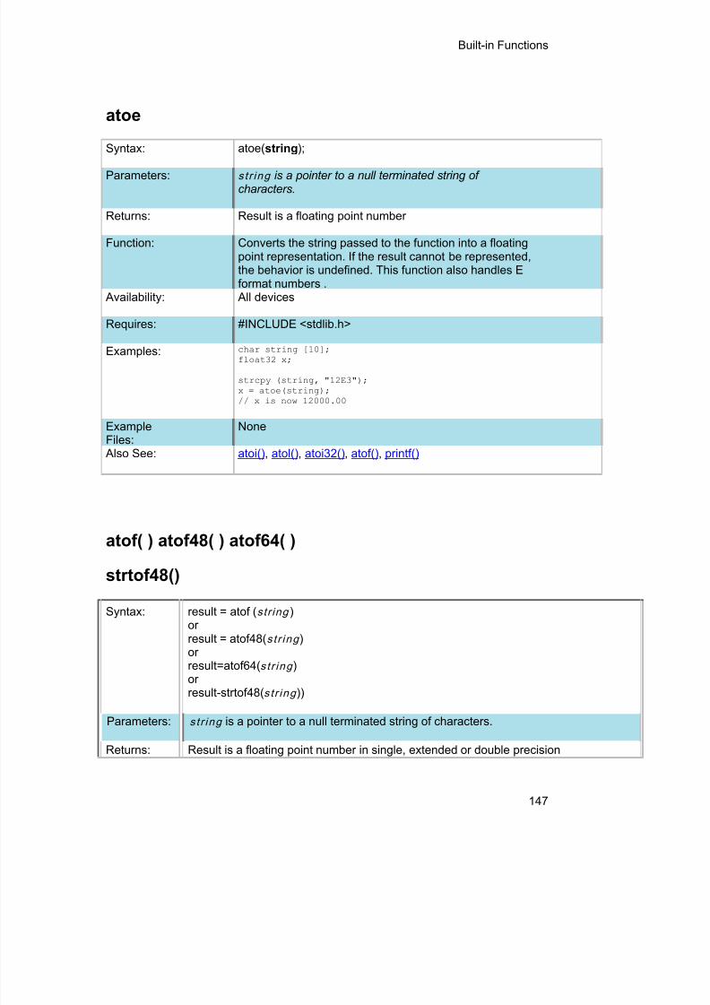
8/10/2019 avr.pdf
http://slidepdf.com/reader/full/avrpdf 159/365
Built-in Functions
147
atoe
Syntax: atoe( string );
Parameters: s t r ing is a pointer to a null terminated string ofcharacters.
Returns: Result is a floating point number
Function: Converts the string passed to the function into a floatingpoint representation. If the result cannot be represented,the behavior is undefined. This function also handles Eformat numbers .
Availability: All devices
Requires: #INCLUDE <stdlib.h>
Examples: char string [10];float32 x;
strcpy (string, "12E3");x = atoe(string);// x is now 12000.00
ExampleFiles:
None
Also See: atoi() , atol() , atoi32() , atof() , printf()
atof( ) atof48( ) atof64( )
strtof48()
Syntax: result = atof ( s t r ing )orresult = atof48( s t r ing )
orresult=atof64( s t r ing )orresult-strtof48( s t r ing ))
Parameters: s t r ing is a pointer to a null terminated string of characters.
Returns: Result is a floating point number in single, extended or double precision

8/10/2019 avr.pdf
http://slidepdf.com/reader/full/avrpdf 160/365
PCD Manual
148
format
Function: Converts the string passed to the function into a floating pointrepresentation. If the result cannot be represented, the behavior isundefined.
Availability: All devices
Requires: #INCLUDE <stdlib.h>
Examples: char string [10];float x;
strcpy (string, "123.456");x = atof(string);// x is now 123.456
ExampleFiles:
ex_tank.c
Also See: atoi() , atol() , atoi32() , printf()
pin_select()
Syntax: pin_select( peripheral _ pin , pin , [unlock ],[lock ])
Parameters: periphera l_pin – a constant string specifying which peripheral pin to mapthe specified pin to. Refer to #pin_select for all available strings. Using“NULL” for the peripheral_pin parameter will unassign the output
peripheral pin that is currently assigned to the pin passed for the pinparameter.
pin – the pin to map to the specified peripheral pin. Refer to device'sheader file for pin defines. If the peripheral_pin parameter is an input,passing FALSE for the pin parameter will unassign the pin that iscurrently assigned to that peripheral pin.
unlock – optional parameter specifying whether to perform an unlocksequence before writing the RPINRx or RPORx register registerdetermined by peripheral_pin and pin options. Default is TRUE if notspecified. The unlock sequence must be performed to allow writes to the
RPINRx and RPORx registers. This option allows calling pin_select()multiple times without performing an unlock sequence each time.
lock – optional parameter specifying whether to perform a lock sequenceafter writing the RPINRx or RPORx registers. Default is TRUE if notspecified. Although not necessary it is a good idea to lock the RPINRxand RPORx registers from writes after all pins have been mapped. Thisoption allows calling pin_select() multiple times without performing alock sequence each time.

8/10/2019 avr.pdf
http://slidepdf.com/reader/full/avrpdf 161/365
Built-in Functions
149
Returns: Nothing.
Availability: On device with remappable peripheral pins.Requires: Pin defines in device's header file.Examples: pin_select(“U2TX”,PIN_B0);
//Maps PIN_B0 to U2TX //peripheral pin, performs unlock//and lock sequences.
pin_select(“U2TX”,PIN_B0,TRUE,FALSE);
//Maps PIN_B0 to U2TX //peripheral pin and performs //unlocksequence.
pin_select(“U2RX”,PIN_B1,FALSE,TRUE);
//Maps PIN_B1 to U2RX //peripheral pin and performs lock//sequence.
Example Files: None. Also See: #pin_select
atoi( ) atol( ) atoi32( )
atol32() atoi48( ) atoi64( )
Syntax: ivalue = atoi( s t r ing )or
lvalue = atol( s t r ing )or
i32value = atoi32( s t r ing )ori48value=atoi48( s t r ing )ori64value=atoi64( s t r ing )orL32vale=atol32( s t r ing )
Parameters: s t r ing is a pointer to a null terminated string of characters.
Returns: ivalue is an 8 bit int.lvalue is a 16 bit int.i32value is a 32 bit int.48value is a 48 bit int.i64value is a 64 bit int.L32value is a 32 bit long.

8/10/2019 avr.pdf
http://slidepdf.com/reader/full/avrpdf 162/365
PCD Manual
150
Function: Converts the string passed to the function into an intrepresentation. Accepts both decimal and hexadecimal argument. If theresult cannot be represented, the behavior is undefined.
Availability: All devices
Requires: #INCLUDE <stdlib.h>
Examples: char string[10];int x;
strcpy(string,"123");x = atoi(string);// x is now 123
ExampleFiles:
input.c
Also See: printf()
bit_clear( )
Syntax: bit_clear( var , bi t )
Parameters: var may be a any bit variable (any lvalue)b it is a number 0- 63 representing a bit number, 0 is the least significantbit.
Returns: undefined
Function: Simply clears the specified bit in the given variable. The least significantbit is 0. This function is the similar to: var &= ~(1<<bit);
Availability: All devices
Requires: Nothing
Examples:int x;x=5;bit_clear(x,2);// x is now 1
ExampleFiles:
ex_patg.c
Also See: bit_set() , bit_test()

8/10/2019 avr.pdf
http://slidepdf.com/reader/full/avrpdf 163/365
Built-in Functions
151
bit_set( )
Syntax: bit_set( var , b it )
Parameters: var may be any variable (any lvalue)bi t is a number 0- 63 representing a bit number, 0 is the least significantbit.
Returns: Undefined
Function: Sets the specified bit in the given variable. The least significant bit is 0.This function is the similar to: var |= (1<<bit);
Availability: All devices
Requires: Nothing
Examples: int x;x=5;bit_set(x,3);// x is now 13
Example Files: ex_patg.c
Also See: bit_clear() , bit_test()
bit_test( )
Syntax: value = bit_test ( var , bi t )
Parameters: var may be a any bit variable (any lvalue)b it is a number 0- 63 representing a bit number, 0 is the least significant bit.
Returns: 0 or 1
Function: Tests the specified bit in the given variable. The least significant bit is 0. Thisfunction is much more efficient than, but otherwise similar to:((var & (1<<bit)) != 0)
Availability: All devices
Requires: Nothing
Examples: if( bit_test(x,3) || !bit_test (x,1) ){//either bit 3 is 1 or bit 1 is 0

8/10/2019 avr.pdf
http://slidepdf.com/reader/full/avrpdf 164/365
PCD Manual
152
}
if(data!=0)for(i=31;!bit_test(data, i);i--) ;
// i now has the most significant bit in data// that is set to a 1
ExampleFiles:
ex_patg.c
Also See: bit_clear() , bit_set()
bsearch( )
Syntax: ip = bsearch ( &key, base, num, width, com pare )
Parameters: k ey : Object to search forbase : Pointer to array of search datan um : Number of elements in search datawidth : Width of elements in search datacompare : Function that compares two elements in search data
Returns: bsearch returns a pointer to an occurrence of key in the array pointed toby base. If key is not found, the function returns NULL. If the array is notin order or contains duplicate records with identical keys, the result isunpredictable.
Function: Performs a binary search of a sorted array
Availability: All devices
Requires: #INCLUDE <stdlib.h>
Examples: int nums[5]={1,2,3,4,5};int compar(const void *arg1,const void *arg2);
void main() {int *ip, key;key = 3;ip = bsearch(&key, nums, 5, sizeof(int), compar);
}
int compar(const void *arg1,const void *arg2) {if ( * (int *) arg1 < ( * (int *) arg2) return – 1else if ( * (int *) arg1 == ( * (int *) arg2) return 0else return 1;
}
Example Files: None
Also See: qsort()

8/10/2019 avr.pdf
http://slidepdf.com/reader/full/avrpdf 165/365
Built-in Functions
153
calloc( )
Syntax: ptr=calloc( nmem , size )
Parameters: nmem is an integer representing the number of member objectssize is the number of bytes to be allocated for each one of them.
Returns: A pointer to the allocated memory, if any. Returns null otherwise.
Function: The calloc function allocates space for an array of nmem objects whose size isspecified by size. The space is initialized to all bits zero.
Availability: All devices
Requires: #INCLUDE <stdlibm.h>
Examples: int * iptr;iptr=calloc(5,10);// iptr will point to a block of memory of// 50 bytes all initialized to 0.
Example Files: None
Also See: realloc() , free() , malloc()
ceil( )
Syntax: result = ceil ( value )
Parameters: value is any float type
Returns: A float with precision equal to value
Function: Computes the smallest integer value greater than the argument. CEIL(12.67) is13.00.
Availability: All devices
Requires: #INCLUDE<math.h>
Examples: // Calculate cost based on weight rounded

8/10/2019 avr.pdf
http://slidepdf.com/reader/full/avrpdf 166/365
PCD Manual
154
// up to the next pound
cost = ceil( weight ) * DollarsPerPound;
Example Files: None
Also See: floor()
clear_interrupt( )
Syntax: clear_interrupt( level )
Parameters: level - a constant defined in the devices.h file
Returns: undefinedFunction: Clears the interrupt flag for the given level. This function is designed for
use with a specific interrupt, thus eliminating the GLOBAL level as apossible parameter. Some chips that have interrupt on change forindividual pins allow the pin to be specified like INT_RA1.
Availability: All devices
Requires: Nothing
Examples: clear_interrupt(int_timer1);
Example Files: None
Also See: enable_interrupts , #INT , Interrupts Overview disable_interrupts(), interrupt_actvie()
cog_status( )
Syntax: value=cog_status();
Parameters: None
Returns: value - the status of the COG module
Function: To determine if a shutdown event occurred on the Complemen(COG) module.
Availability: All devices with a COG module.

8/10/2019 avr.pdf
http://slidepdf.com/reader/full/avrpdf 167/365
Built-in Functions
155
Examples:if(cog_status()==COG_AUTO_SHUTDOWN)
cog_restart();
Example Files: None
Also See: setup_cog() , set_cog_dead_band() , set_cog_blanking() , set_c
.
cog_restart( )
Syntax: cog_restart();
Parameters: None
Returns: Nothing
Function: To restart the Complementary Output Generator (COG) modulevent occurs, when not using auto-restart option of module.
Availability: All devices with a COG module.
Examples:if(cog_status()==COG_AUTO_SHUTDOWN)
cog_restart();
Example Files: None
Also See: setup_cog() , set_cog_dead_band() , set_cog_blanking() , set_c
cwg_status( )
Syntax: value = cwg_status( );
Parameters: None
Returns: the status of the CWG module
Function: To determine if a shutdown event occured causing themodule to auto-shutdown

8/10/2019 avr.pdf
http://slidepdf.com/reader/full/avrpdf 168/365
PCD Manual
156
Availability: On devices with a CWG module.
Examples: if(cwg_status( ) == CWG_AUTO_SHUTDOWN)cwg_restart( );
ExampleFiles:
None
Also See: setup_cwg( ) , cwg_restart( )
cwg_restart( )
Syntax: cwg_restart( );
Parameters: None
Returns: Nothing
Function: To restart the CWG module after an auto-shutdown eventoccurs, when not using auto-raster option of module.
Availability: On devices with a CWG module.
Examples: if(cwg_status( ) == CWG_AUTO_SHUTDOWN)cwg_restart( );
ExampleFiles:
None
Also See: setup_cwg( ) , cwg_status( )
dac_write( )
Syntax: dac_write ( value )dac_write (channel, value)
Parameters: Value : 8-bit integer value to be written to the DAC moduleValue: 16-bit integer value to be written to the DAC modulechannel: Channel to be written to. Constants are:
DAC_RIGHTDAC_DEFAULTDAC_LEFT
Returns: undefined

8/10/2019 avr.pdf
http://slidepdf.com/reader/full/avrpdf 169/365
Built-in Functions
157
Function: This function will write a 8-bit integer to the specified DAC channel.This function will write a 16-bit integer to the specified DAC channel.
Availability: Only available on devices with built in digital to analog converters.
Requires: Nothing
Examples: int i = 0;setup_dac(DAC_VDD | DAC_OUTPUT);while(1){
i++;dac_write(i);
}int i = 0;setup_dac(DAC_RIGHT_ON, 5);while(1){
i++;dac_write(DAC_RIGHT | i);
}
Also See: setup_dac( ) , DAC Overview , see header file for device selected
delay_cycles( )
Syntax: delay_cycles ( c o u n t )
Parameters: coun t - a constant 1-255
Returns: undefined
Function: Creates code to perform a delay of the specified number of instruction clocks(1-255). An instruction clock is equal to four oscillator clocks.
The delay time may be longer than requested if an interrupt is serviced duringthe delay. The time spent in the ISR does not count toward the delay time.
Availability: All devices
Requires: Nothing
Examples: delay_cycles( 1 ); // Same as a NOP
delay_cycles(25); // At 20 mhz a 5us delay
Example Files: ex_cust.c
Also See: delay_us() , delay_ms()

8/10/2019 avr.pdf
http://slidepdf.com/reader/full/avrpdf 170/365
PCD Manual
158
delay_ms( )
Syntax: delay_ms ( t ime )
Parameters: t ime - a variable 0-65535(int16) or a constant 0-65535
Note: Previous compiler versions ignored the upper byte of an int16, now theupper byte affects the time.
Returns: undefined
Function: This function will create code to perform a delay of the specified length. Timeis specified in milliseconds. This function works by executing a precisenumber of instructions to cause the requested delay. It does not use anytimers. If interrupts are enabled the time spent in an interrupt routine is notcounted toward the time.
The delay time may be longer than requested if an interrupt is serviced duringthe delay. The time spent in the ISR does not count toward the delay time.
Availability: All devices
Requires: #USE DELAY
Examples: #use delay (clock=20000000)
delay_ms( 2 );
void delay_seconds(int n) {for (;n!=0; n- -)delay_ms( 1000 );
}
Example Files: ex_sqw.c
Also See: delay_us() , delay_cycles() , #USE DELAY
delay_us( )
Syntax: delay_us ( t ime )
Parameters: t ime - a variable 0-65535(int16) or a constant 0-65535
Note: Previous compiler versions ignored the upper byte of an int16, now the

8/10/2019 avr.pdf
http://slidepdf.com/reader/full/avrpdf 171/365
Built-in Functions
159
upper byte affects the time.
Returns: undefined
Function: Creates code to perform a delay of the specified length. Time is specified in
microseconds. Shorter delays will be INLINE code and longer delays andvariable delays are calls to a function. This function works by executing aprecise number of instructions to cause the requested delay. It does not useany timers. If interrupts are enabled the time spent in an interrupt routine isnot counted toward the time.
The delay time may be longer than requested if an interrupt is serviced duringthe delay. The time spent in the ISR does not count toward the delay time.
Availability: All devices
Requires: #USE DELAY
Examples: #use delay(clock=20000000)
do {output_high(PIN_B0);delay_us(duty);output_low(PIN_B0);delay_us(period-duty);} while(TRUE);
Example Files: ex_sqw.c
Also See: delay_ms() , delay_cycles() , #USE DELAY
div( ) ldiv( )
Syntax: idiv=div( n um , denom )ldiv =ldiv(lnum , ldenom )
Parameters: n um and denom are signed integers.n um is the numerator and denom is the denominator.lnum and ldenom are signed longs , signed int32, int48 or int64lnum is the numerator and ldenom is the denominator.
Returns: idiv is a structure of type div_t and lidiv is a structure of type ldiv_t. The divfunction returns a structure of type div_t, comprising of both the quotient andthe remainder. The ldiv function returns a structure of type ldiv_t, comprising ofboth the quotient and the remainder.
Function: The div and ldiv function computes the quotient and remainder of the division

8/10/2019 avr.pdf
http://slidepdf.com/reader/full/avrpdf 172/365
PCD Manual
160
of the numerator by the denominator. If the division is inexact, theresulting quotient is the integer or long of lesser magnitude that is the nearestto the algebraic quotient. If the result cannot be represented, the behavior isundefined; otherwise quot*denom(ldenom)+rem shall equal num(lnum).
Availability: All devices.
Requires: #INCLUDE <STDLIB.H>
Examples: div_t idiv;ldiv_t lidiv;idiv=div(3,2);//idiv will contain quot=1 and rem=1
lidiv=ldiv(300,250);//lidiv will contain lidiv.quot=1 and lidiv.rem=50
Example Files: None
Also See: None
exp( )
Syntax: result = exp ( value )
Parameters: value is any float type
Returns: A float with a precision equal to value
Function: Computes the exponential function of the argument. This is e to the power ofvalue where e is the base of natural logarithms. exp(1) is 2.7182818.
Note on error handling:If "errno.h" is included then the domain and range errors are stored in the errnovariable. The user can check the errno to see if an error has occurred and printthe error using the perror function.
Range error occur in the following case: exp: when the argument is too large
Availability: All devices
Requires: #INCLUDE <math.h>
Examples: // Calculate x to the power of y
x_power_y = exp( y * log(x) );

8/10/2019 avr.pdf
http://slidepdf.com/reader/full/avrpdf 173/365
Built-in Functions
161
Example Files: None
Also See: pow() , log(), log10()
ext_int_edge( )
Syntax: ext_int_edge ( source , edge )
Parameters: source is a constant 0,1 or 2 for the PIC18XXX and 0 otherwise.source is a constant from 0 to 4.Source is optional and defaults to 0.edge is a constant H_TO_L or L_TO_H representing "high to low" and "low tohigh"
Returns: undefined
Function: Determines when the external interrupt is acted upon. The edge may beL_TO_H or H_TO_L to specify the rising or falling edge.
Availability: Only devices with interrupts
Requires: Constants are in the devices .h file
Examples: ext_int_edge( 2, L_TO_H); // Set up PIC18 EXT2ext_int_edge( 2, L_TO_H); // Set up external interrupt 2 to interrupt
// on rising edgeext_int_edge( H_TO_L ); // Sets up EXText_int_edge( H_TO_L ); // Sets up external interrupt 0 to interrupt
// on falling edge
Example Files: ex_wakup.c
Also See: #INT_EXT , enable_interrupts() , disable_interrupts , Interrupts Overview
fabs( )
Syntax: result=fabs ( value )
Parameters: value is any float type
Returns: result is a float with precision to value
Function: The fabs function computes the absolute value of a float

8/10/2019 avr.pdf
http://slidepdf.com/reader/full/avrpdf 174/365

8/10/2019 avr.pdf
http://slidepdf.com/reader/full/avrpdf 175/365
Built-in Functions
163
...while(TRUE) {
c=fgetc(GPS);fputc(c,HOSTPC);if(c==13)
fprintf(DEBUG,"Got a CR\r\n");}
ExampleFiles:
ex_stwt.c
Also See: putc() , kbhit(), printf(), #USE RS232 , input.c, RS232 I/O Overview
gets( ) fgets( )
Syntax: gets ( s t r ing )
value = fgets ( s t r ing , stream )
Parameters: s t r ing is a pointer to an array of characters.Stream is a stream identifier (a constant byte)
Returns: undefined
Function: Reads characters (using getc()) into the string until a RETURN (value 13) isencountered. The string is terminated with a 0. Note that INPUT.C has a moreversatile get_string function.
If fgets() is used then the specified stream is used where gets() defaults toSTDIN (the last USE RS232).
Availability: All devices
Requires: #USE RS232
Examples: char string[30];
printf("Password: ");gets(string);if(strcmp(string, password))
printf("OK");
Example Files: None
Also See: getc() , get_string in input.c

8/10/2019 avr.pdf
http://slidepdf.com/reader/full/avrpdf 176/365
PCD Manual
164
floor( )
Syntax: result = floor ( value )
Parameters: value is any float type
Returns: result is a float with precision equal to value
Function: Computes the greatest integer value not greater than the argument. Floor(12.67) is 12.00.
Availability: All devices.
Requires: #INCLUDE <math.h>
Examples: // Find the fractional part of a value
frac = value - floor(value);
Example Files: None
Also See: ceil()
fmod( )
Syntax: result= fmod ( val1 , val2 )
Parameters: val1 is any float typeval2 is any float type
Returns: result is a float with precision equal to input parameters val1 and val2
Function: Returns the floating point remainder of val1/val2. Returns the value val1 - i*val2for some integer “i” such that, if val2 is nonzero, the result has the same signas val1 and magnitude less than the magnitude of val2.
Availability: All devices.
Requires: #INCLUDE <math.h>
Examples: float result;result=fmod(3,2);// result is 1
Example Files: None

8/10/2019 avr.pdf
http://slidepdf.com/reader/full/avrpdf 177/365
Built-in Functions
165
Also See: None
printf( ) fprintf( )
Syntax: printf ( s t r ing )or
printf (cs t r ing , values ...)or
printf (fname , cs t r ing , values ...)fprintf (stream , cs t r ing , values ...)
Parameters: Str ing is a constant string or an array of characters null terminated.
Values is a list of variables separated by commas, fname is a function name tobe used for outputting (default is putc is none is specified.
Stream is a stream identifier (a constant byte). Note that format specifies donot work in ram band strings.
Returns: undefined
Function: Outputs a string of characters to either the standard RS-232 pins (first twoforms) or to a specified function. Formatting is in accordance with the stringargument. When variables are used this string must be a constant. The %character is used within the string to indicate a variable value is to be formattedand output. Longs in the printf may be 16 or 32 bit. A %% will output a single%. Formatting rules for the % follows.
See the Expressions > Constants and Trigraph sections of this manual forother escape character that may be part of the string.
If fprintf() is used then the specified stream is used where printf() defaults toSTDOUT (the last USE RS232).
Format:The format takes the generic form %nt. n is optional and may be 1-9 to specify
how many characters are to be outputted, or 01-09 to indicate leading zeros, or1.1 to 9.9 for floating point and %w output. t is the type and may be one of thefollowing:
c Characters String or characteru Unsigned intd Signed intLu Long unsigned intLd Long signed int

8/10/2019 avr.pdf
http://slidepdf.com/reader/full/avrpdf 178/365
PCD Manual
166
x Hex int (lower case)X Hex int (upper case)Lx Hex long int (lower case)LX Hex long int (upper case)f Float with truncated decimalg Float with rounded decimale Float in exponential formatw Unsigned int with decimal place inserted.
Specify two numbers for n. The first is atotal field width. The second is the desirednumber of decimal places.
Example formats:Specifier Value=0x12 Value=0xfe%03u 018 254%u 18 254%2u 18 *%5 18 254%d 18 -2%x 12 fe%X 12 FE%4X 0012 00FE%3.1w 1.8 25.4
* Result is undefined - Assume garbage.
Availability: All Devices
Requires: #USE RS232 (unless fname is used)
Examples: byte x,y,z;printf("HiThere");printf("RTCCValue=>%2x\n\r",get_rtcc());printf("%2u %X %4X\n\r",x,y,z);printf(LCD_PUTC, "n=%u",n);
Example Files: ex_admm.c , ex_lcdkb.c
Also See: atoi() , puts() , putc() , getc() (for a stream example), RS232 I/O Overview
putc( ) putchar( ) fputc( )
Syntax: putc ( cdata )putchar ( cdata )fputc( cdata , stream )
Parameters: cdata is a 8 bit character.Stream is a stream identifier (a constant byte)
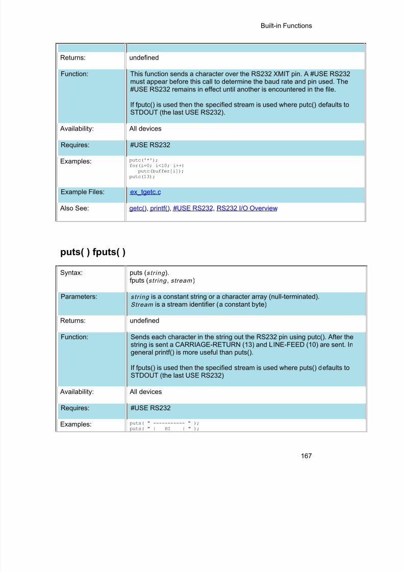
8/10/2019 avr.pdf
http://slidepdf.com/reader/full/avrpdf 179/365
Built-in Functions
167
Returns: undefined
Function: This function sends a character over the RS232 XMIT pin. A #USE RS232must appear before this call to determine the baud rate and pin used. The
#USE RS232 remains in effect until another is encountered in the file.If fputc() is used then the specified stream is used where putc() defaults toSTDOUT (the last USE RS232).
Availability: All devices
Requires: #USE RS232
Examples: putc('*');for(i=0; i<10; i++)
putc(buffer[i]);putc(13);
Example Files: ex_tgetc.c
Also See: getc() , printf(), #USE RS232 , RS232 I/O Overview
puts( ) fputs( )
Syntax: puts ( s t r ing ).fputs ( s t r ing , stream )
Parameters: s t r ing is a constant string or a character array (null-terminated).Stream is a stream identifier (a constant byte)
Returns: undefined
Function: Sends each character in the string out the RS232 pin using putc(). After thestring is sent a CARRIAGE-RETURN (13) and LINE-FEED (10) are sent. Ingeneral printf() is more useful than puts().
If fputs() is used then the specified stream is used where puts() defaults toSTDOUT (the last USE RS232)
Availability: All devices
Requires: #USE RS232
Examples: puts( " ----------- " );puts( " | HI | " );
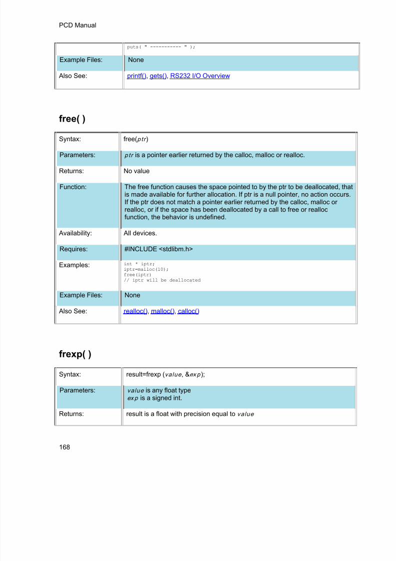
8/10/2019 avr.pdf
http://slidepdf.com/reader/full/avrpdf 180/365
PCD Manual
168
puts( " ----------- " );
Example Files: None
Also See: printf(), gets() , RS232 I/O Overview
free( )
Syntax: free( p tr )
Parameters: p tr is a pointer earlier returned by the calloc, malloc or realloc.
Returns: No value
Function: The free function causes the space pointed to by the ptr to be deallocated, thatis made available for further allocation. If ptr is a null pointer, no action occurs.If the ptr does not match a pointer earlier returned by the calloc, malloc orrealloc, or if the space has been deallocated by a call to free or reallocfunction, the behavior is undefined.
Availability: All devices.
Requires: #INCLUDE <stdlibm.h>
Examples: int * iptr;iptr=malloc(10);free(iptr)// iptr will be deallocated
Example Files: None
Also See: realloc() , malloc() , calloc()
frexp( )
Syntax: result=frexp ( value , &ex p );
Parameters: value is any float typeex p is a signed int.
Returns: result is a float with precision equal to value

8/10/2019 avr.pdf
http://slidepdf.com/reader/full/avrpdf 181/365
Built-in Functions
169
Function: The frexp function breaks a floating point number into a normalized fractionand an integral power of 2. It stores the integer in the signed int objectexp. The result is in the interval [1/2 to1) or zero, such that value is resulttimes 2 raised to power exp. If value is zero then both parts are zero.
Availability: All devices.
Requires: #INCLUDE <math.h>
Examples: float result;signed int exp;result=frexp(.5,&exp);// result is .5 and exp is 0
Example Files: None
Also See: ldexp() , exp() , log(), log10() , modf()
scanf( )
printf( )
Syntax: scanf( cstring );scanf( cstring, values... )fscanf( stream, cstring, values... )
Parameters: cs t r ing is a constant string.
values is a list of variables separated by commas.
stream is a stream identifier.
Returns: 0 if a failure occurred, otherwise it returns the number of conversion specifiersthat were read in, plus the number of constant strings read in.
Function: Reads in a string of characters from the standard RS-232 pins and formats thestring according to the format specifiers. The format specifier character (%)
used within the string indicates that a conversion specification is to be done andthe value is to be saved into the corresponding argument variable. A %% willinput a single %. Formatting rules for the format specifier as follows:
If fscanf() is used, then the specified stream is used, where scanf() defaults toSTDIN (the last USE RS232).
Format:The format takes the generic form %nt. n is an option and may be 1-99

8/10/2019 avr.pdf
http://slidepdf.com/reader/full/avrpdf 182/365
PCD Manual
170
specifying the field width, the number of characters to be inputted. t is the typeand maybe one of the following:
c Matches a sequence of characters of the number specified by thefield width (1 if no field width is specified). The correspondingargument shall be a pointer to the initial character of an array longenough to accept the sequence.
s Matches a sequence of non-white space characters. Thecorresponding argument shall be a pointer to the initial characterof an array long enough to accept the sequence and aterminating null character, which will be added automatically.
u Matches an unsigned decimal integer. The correspondingargument shall be a pointer to an unsigned integer.
Lu Matches a long unsigned decimal integer. The correspondingargument shall be a pointer to a long unsigned integer.
d Matches a signed decimal integer. The corresponding argumentshall be a pointer to a signed integer.
Ld Matches a long signed decimal integer. The correspondingargument shall be a pointer to a long signed integer.
o Matches a signed or unsigned octal integer. The correspondingargument shall be a pointer to a signed or unsigned integer.
Lo Matches a long signed or unsigned octal integer. Thecorresponding argument shall be a pointer to a long signed orunsigned integer.
x or X Matches a hexadecimal integer. The corresponding argumentshall be a pointer to a signed or unsigned integer.
Lx or LX Matches a long hexadecimal integer. The correspondingargument shall be a pointer to a long signed or unsigned integer.
i Matches a signed or unsigned integer. The correspondingargument shall be a pointer to a signed or unsigned integer.
Li Matches a long signed or unsigned integer. The correspondingargument shall be a pointer to a long signed or unsigned integer.
f,g or e Matches a floating point number in decimal or exponential format.The corresponding argument shall be a pointer to a float.
[ Matches a non-empty sequence of characters from a set ofexpected characters. The sequence of characters included in theset are made up of all character following the left bracket ([) up tothe matching right bracket (]). Unless the first character after the

8/10/2019 avr.pdf
http://slidepdf.com/reader/full/avrpdf 183/365
Built-in Functions
171
left bracket is a ^ , in which case the set of characters contain allcharacters that do not appear between the brackets. If a - character is in the set and is not the first or second, where thefirst is a ^ , nor the last character, then the set includes allcharacters from the character before the - to the character afterthe -.For example, %[a-z] would include all characters from a to z inthe set and %[^a-z] would exclude all characters from a to z fromthe set. The corresponding argument shall be a pointer to theinitial character of an array long enough to accept the sequenceand a terminating null character, which will be addedautomatically.
n Assigns the number of characters read thus far by the call toscanf() to the corresponding argument. The correspondingargument shall be a pointer to an unsigned integer.
An optional assignment-suppressing character ( *) can be usedafter the format specifier to indicate that the conversionspecification is to be done, but not saved into a correspondingvariable. In this case, no corresponding argument variableshould be passed to the scanf() function.
A string composed of ordinary non-white space characters isexecuted by reading the next character of the string. If one of theinputted characters differs from the string, the function fails andexits. If a white-space character precedes the ordinary non-whitespace characters, then white-space characters are first read inuntil a non-white space character is read.
White-space characters are skipped, except for the conversionspecifiers [, c or n , unless a white-space character precedes the [ or c specifiers.
Availability: All Devices
Requires: #USE RS232
Examples: char name[2-];unsigned int8 number;signed int32 time;
if(scanf("%u%s%ld",&number,name,&time))printf"\r\nName: %s, Number: %u, Time: %ld",name,number,time);
ExampleFiles:
None
Also See: RS232 I/O Overview , getc() , putc() , printf()

8/10/2019 avr.pdf
http://slidepdf.com/reader/full/avrpdf 184/365
PCD Manual
172
get_capture( )
Syntax: value = get_capture( x )
Parameters: x defines which ccp module to read from.
Returns: A 16-bit timer value.
Function: This function obtains the last capture time from the indicated CCP module
Availability: Only available on devices with Input Capture modules
Requires: None
Examples:
Example Files: ex_ccpmp.c
Also See: setup_ccpx( )
get_capture_event()
Syntax: result = get_capture_event([ stream ]);Parameters: stream – optional parameter specifying the stream defined in #USE
CAPTURE.Returns: TRUE if a capture event occurred, FALSE otherwise.Function: To determine if a capture event occurred.
Availability: All devices.
Requires: #USE CAPTURE Examples: #USE CAPTURE(INPUT=PIN_C2,CAPTURE_RISING,TIMER=1,FASTEST)
if(get_capture_event())result = get_capture_time();
ExampleFiles:
None
Also See: #use_capture , get_capture_time()

8/10/2019 avr.pdf
http://slidepdf.com/reader/full/avrpdf 185/365

8/10/2019 avr.pdf
http://slidepdf.com/reader/full/avrpdf 186/365
PCD Manual
174
get_nco_inc_value( )
Syntax: value =get_nco_inc_value( );
Parameters: None
Returns: - current value set in increment registers.
Availability: On devices with a NCO module.
Examples: value = get_nco_inc_value( );
ExampleFiles:
None
Also See: setup_nco( ), set_nco_inc_value( ) , get_nco_accumulator( )
get_ticks( )
Syntax: value = get_ticks ([stream] );Parameters: stream – optional parameter specifying the stream defined in #USE TIMER.
Returns: value – a 8, 16, 32 or 64 bit integer. (int8, int16, int32 or int64)
Function:Returns the current tick value of the tick timer. The size returned depends onthe size of the tick timer.
Availability: All devices.
Requires: #USE TIMER(options)
Examples:
#USE TIMER(TIMER=1,TICK=1ms,BITS=16,NOISR)
void main(void) {unsigned int16 current_tick;
current_tick = get_ticks();}
ExampleFiles: None
Also See: #USE TIMER , set_ticks()

8/10/2019 avr.pdf
http://slidepdf.com/reader/full/avrpdf 187/365
Built-in Functions
175
get_timerA( )
Syntax: value=get_timerA();
Parameters: none
Returns: The current value of the timer as an int8
Function: Returns the current value of the timer. All timers count up. When a timerreaches the maximum value it will flip over to 0 and continue counting(254, 255, 0, 1, 2, …).
Availability: This function is only available on devices with Timer A hardware.
Requires: Nothing
Examples: set_timerA(0);while(timerA < 200);
Example Files: none
Also See: set_timerA( ) , setup_timer_A( ) , TimerA Overview
get_timerB( )
Syntax: value=get_timerB();
Parameters: none
Returns: The current value of the timer as an int8
Function: Returns the current value of the timer. All timers count up. When a timerreaches the maximum value it will flip over to 0 and continue counting(254, 255, 0, 1, 2, …).
Availability: This function is only available on devices with Timer B hardware.
Requires: Nothing
Examples: set_timerB(0);while(timerB < 200);
Example Files: none
Also See: set_timerB( ) , setup_timer_B( ) , TimerB Overview

8/10/2019 avr.pdf
http://slidepdf.com/reader/full/avrpdf 188/365
PCD Manual
176
get_timerx( )
Syntax: value=get_timer1( )value=get_timer2( )value=get_timer3( )value=get_timer4( )value=get_timer5( )value=get_timer6( )value=get_timer7( )value=get_timer8( )value=get_timer9( )
Parameters: None
Returns: The current value of the timer as an int16
Function: Retrieves the value of the timer, specified by X (which may be 1-9)
Availability: This function is available on all devices that have a valid timerX.
Requires: Nothing
Examples: if(get_timer2() % 0xA0 == HALF_WAVE_PERIOD)output_toggle(PIN_B0);
Example Files: ex_stwt.c
Also See: Timer Overview , setup_timerX(), get_timerXY(), set_timerX() , set_timerXY()
get_tris_x( )
Syntax: value = get_tris_A();value = get_tris_B();value = get_tris_C();value = get_tris_D();value = get_tris_E();value = get_tris_F();value = get_tris_G();value = get_tris_H();value = get_tris_J();value = get_tris_K()
Parameters: None

8/10/2019 avr.pdf
http://slidepdf.com/reader/full/avrpdf 189/365
Built-in Functions
177
Returns: int16, the value of TRIS register
Function: Returns the value of the TRIS register of port A, B, C, D, E, F, G, H, J, orK.
Availability: All devices.
Requires: Nothing
Examples: tris_a = GET_TRIS_A();
Example Files: None
Also See: input() , output_low() , output_high()
setup_sd_adc( )
Syntax: setup_sd_adc(settings1, settings 2, settings3);
Parameters: set t ings1 - settings for the SD1CON1 register of the SD ADC module. See thedevice's .h file for all options. Some options include:
SDADC_ENABLED SDADC_NO_HALT SDADC_GAIN_1 SDADC_NO_DITHER SDADC_SVDD_SVSS SDADC_BW_NORMAL
set t ings2 - settings for the SD1CON2 register of the SD ADC module. See thedevice's .h file for all options. Some options include:
SDADC_CHOPPING_ENABLED SDADC_INT_EVERY_SAMPLE SDADC_RES_UPDATED_EVERY_INT SDADC_NO_ROUNDING
set t ings3 - settings for the SD1CON3 register of the SD ADC module. See thedevice's .h file for all options. Some options include:
SDADC_CLOCK_DIV_1 SDADC_OSR_1024 SDADC_CLK_SYSTEM
Returns: Nothing

8/10/2019 avr.pdf
http://slidepdf.com/reader/full/avrpdf 190/365
PCD Manual
178
Function: To setup the Sigma-Delta Analog to Digital Converter (SD ADC) module.
Availability: Only devices with a SD ADC module.
Examples: setup_sd_adc(SDADC_ENABLED | SDADC_DITHER_LOW,SDADC_CHOPPING_ENABLED |
SDADC_INT_EVERY_5TH_SAMPLE |SDADC_RES_UPDATED_EVERY_INT, SDADC_CLK_SYSTEM |SDADC_CLOCK_DIV_4);
ExampleFiles:
None
Also See: set_sd_adc_channel() , read_sd_adc() , set_sd_adc_calibration()
getenv( )
Syntax: value = getenv ( cs t r ing );
Parameters: cstring is a constant string with a recognized keyword
Returns: A constant number, a constant string or 0
Function: This function obtains information about the execution environment. Thefollowing are recognized keywords. This function returns a constant 0 if thekeyword is not understood.
FUSE_SET:fffff Returns 1 if fuse fffff is enabled
FUSE_VALID:fffff Returns 1 if fuse fffff is validINT:iiiii Returns 1 if the interrupt iiiii is valid
ID Returns the device ID (set by #ID)
DEVICE Returns the device name string (like"PIC16C74")
CLOCK Returns the MPU FOSCVERSION Returns the compiler version as a float
VERSION_STRING Returns the compiler version as a string
PROGRAM_MEMORY Returns the size of memory for code (inwords)
STACK Returns the stack sizeSCRATCH Returns the start of the compiler scratch
area

8/10/2019 avr.pdf
http://slidepdf.com/reader/full/avrpdf 191/365
Built-in Functions
179
DATA_EEPROM Returns the number of bytes of dataEEPROM
EEPROM_ADDRESS Returns the address of the start ofEEPROM. 0 if not supported by the device.
READ_PROGRAM Returns a 1 if the code memory can be read
ADC_CHANNELS Returns the number of A/D channels
ADC_RESOLUTION Returns the number of bits returned fromREAD_ADC()
ICD Returns a 1 if this is being compiled for aICD
SPI Returns a 1 if the device has SPI
USB Returns a 1 if the device has USB
CAN Returns a 1 if the device has CAN
I2C_SLAVE Returns a 1 if the device has I2C slave H/W
I2C_MASTER Returns a 1 if the device has I2C masterH/W
PSP Returns a 1 if the device has PSP
COMP Returns a 1 if the device has a comparator
VREF Returns a 1 if the device has a voltagereference
LCD Returns a 1 if the device has direct LCDH/W
UART Returns the number of H/W UARTs
AUART Returns 1 if the device has an ADV UART
CCPx Returns a 1 if the device has CCP number x
TIMERx Returns a 1 if the device has TIMERnumber x
FLASH_WRITE_SIZE Smallest number of bytes that can bewritten to FLASH
FLASH_ERASE_SIZE Smallest number of bytes that can beerased in FLASH
BYTES_PER_ADDRESS Returns the number of bytes at an addresslocation
BITS_PER_INSTRUCTION Returns the size of an instruction in bits
RAM Returns the number of RAM bytes availablefor your device.

8/10/2019 avr.pdf
http://slidepdf.com/reader/full/avrpdf 192/365
PCD Manual
180
SFR:name Returns the address of the specified specialfile register. The output format can be usedwith the preprocessor command #bit. namemust match SFR denomination of yourtarget PIC (example: STATUS, INTCON,TXREG, RCREG, etc)
BIT:name Returns the bit address of the specifiedspecial file register bit. The output formatwill be in “address:bit”, which can be usedwith the preprocessor command #byte.name must match SFR.bit denomination ofyour target PIC (example: C, Z, GIE,TMR0IF, etc)
SFR_VALID:name Returns TRUE if the specified special fileregister name is valid and exists for yourtarget PIC (example:getenv("SFR_VALID:INTCON"))
BIT_VALID:name Returns TRUE if the specified special fileregister bit is valid and exists for your targetPIC (example:getenv("BIT_VALID:TMR0IF"))
PIN:PB Returns 1 if PB is a valid I/O PIN (like A2)
UARTx_RX Returns UARTxPin (like PINxC7)
UARTx_TX Returns UARTxPin (like PINxC6)
SPIx_DI Returns SPIxDI PinSPIxDO Returns SPIxDO PinSPIxCLK Returns SPIxCLK PinETHERNET Returns 1 if device supports Ethernet
QEI Returns 1 if device has QEIDAC Returns 1 if device has a D/A Converter
DSP Returns 1 if device supports DSPinstructions
DCI Returns 1 if device has a DCI module
DMA Returns 1 if device supports DMA
CRC Returns 1 if device has a CRC module
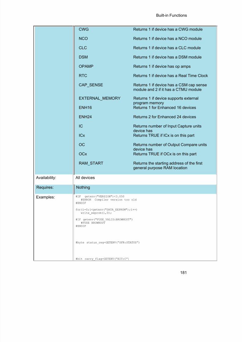
8/10/2019 avr.pdf
http://slidepdf.com/reader/full/avrpdf 193/365

8/10/2019 avr.pdf
http://slidepdf.com/reader/full/avrpdf 194/365
PCD Manual
182
Example Files: None
Also See: None
goto_address( )
Syntax: goto_address( locat ion );
Parameters: location is a ROM address, 16 or 32 bit int.
Returns: Nothing
Function: This function jumps to the address specified by location. Jumps outside of thecurrent function should be done only with great caution. This is not a normallyused function except in very special situations.
Availability: All devices
Requires: Nothing
Examples: #define LOAD_REQUEST PIN_B1#define LOADER 0x1f00
if(input(LOAD_REQUEST))goto_address(LOADER);
Example Files: setjmp.h
Also See: label_address( )
high_speed_adc_done( )
Syntax: value = high_speed_adc_done([ pair ]);
Parameters: pair – Optional parameter that determines which ADC pair's ready flag to check.If not used all ready flags are checked.
Returns: An int16. If pair is used 1 will be return if ADC is done with conversion, 0 will bereturn if still busy. If pair isn't use it will return a bit map of which conversion areready to be read. For example a return value of 0x0041 means that ADC pair 6,
AN12 and AN13, and ADC pair 0, AN0 and AN1, are ready to be read.

8/10/2019 avr.pdf
http://slidepdf.com/reader/full/avrpdf 195/365
Built-in Functions
183
Function: Can be polled to determine if the ADC has valid data to be read.
Availability: Only on dsPIC33FJxxGSxxx devices.
Requires: None
Examples: int16 result[2]setup_high_speed_adc_pair(1, INDIVIDUAL_SOFTWARE_TRIGGER);setup_high_speed_adc( ADC_CLOCK_DIV_4);
read_high_speed_adc(1, ADC_START_ONLY);while(!high_speed_adc_done(1));read_high_speed_adc(1, ADC_READ_ONLY, result);printf(“AN2 value = %LX, AN3 value = %LX \n\ r”,resul t[0],result[1]);
ExampleFiles:
None
Also See: setup_high_speed_adc() , setup_high_speed_adc_pair() , read_high_speed_adc()
i2c_init( )
Syntax: i2c_init([stream],baud);
Parameters: stream – optional parameter specifying the stream defined in#USE I2C.
baud – if baud is 0, I2C peripheral will be disable. If baud is 1, I2Cperipheral is initialized and enabled with baud rate specified in #USE I2Cdirective. If baud is > 1 then I2C peripheral is initialized and enabled tospecified baud rate.
Returns: NothingFunction: To initialize I2C peripheral at run time to specified baud rate.
Availability: All devices.Requires: #USE I2C
Examples: #USE I2C(MASTER,I2C1, FAST,NOINIT)i2c_init(TRUE); //initialize and enable I2C peripheral to baudrate specified in //#USE I2Ci2c_init(500000); //initialize and enable I2C peripheral to abaud rate of 500 //KBPS
Example Files: None Also See: I2C_POLL( ) , i2c_speed( ) , I2C_SlaveAddr( ) , I2C_ISR_STATE(_)
,I2C_WRITE( ) ,
I2C_READ( ) , _USE_I2C( ) , I2C( )

8/10/2019 avr.pdf
http://slidepdf.com/reader/full/avrpdf 196/365
PCD Manual
184
i2c_isr_state( )
Syntax: state = i 2c_isr_state();state = i 2c_isr_state( stream );Parameters: NoneReturns: state is an 8 bit int
0 - Address match received with R/W bit clear, perform i2c_read( ) to readthe I2C address.1-0x7F - Master has written data; i 2c_read() will immediately return thedata0x80 - Address match received with R/W bit set; perform i2c_read( ) toread the I2C address, and use i2c_write( ) to pre-load the transmit bufferfor the next transaction (next I2C read performed by master will read thisbyte).
0x81-0xFF - Transmission completed and acknowledged; respond withi2c_write() to pre-load the transmit buffer for the next transation (the nextI2C read performed by master will read this byte).
Function: Returns the state of I2C communications in I2C slave mode after an SSPinterrupt. The return value increments with each byte received or sent.
If 0x00 or 0x80 is returned, an i2C_read( ) needs to be performed to readthe I2C address that was sent (it will match the address configured by#USE I2C so this value can be ignored)
Availability: Devices with i 2c hardware
Requires: #USE I2CExamples: #INT_SSP
void i2c_isr() {state = i2c_isr_state();if(state== 0 ) i2c_read();
i@c_read();if(state == 0x80)
i2c_read(2);if(state >= 0x80)
i2c_write(send_buffer[state - 0x80]);else if(state > 0)
rcv_buffer[state - 1] = i2c_read();}
Example Files: ex_slave.c
Also See: i2c_poll , i2c_speed , i2c_start , i2c_stop , i2c_slaveaddr , i2c_write , i2c_read , #USE I2C , I2C Overview

8/10/2019 avr.pdf
http://slidepdf.com/reader/full/avrpdf 197/365
Built-in Functions
185
i2c_poll( )
Syntax: i 2c_poll()i2c_poll( stream )
Parameters: stream (optional)- specify the stream defined in #USE I 2C
Returns: 1 (TRUE) or 0 (FALSE)
Function: The I2C_POLL() function should only be used when the built-in SSP isused. This function returns TRUE if the hardware has a received byte in thebuffer. When a TRUE is returned, a call to I2C_READ() will immediately returnthe byte that was received.
Availability: Devices with built in I 2C
Requires: #USE I2CExamples: if(i2c-poll())
buffer [index]=i2c-read();//read data
Example Files: None
Also See: i2c_speed , i2c_start , i2c_stop , i2c_slaveaddr , i2c_isr_state , i2c_write , i2c_read , #USE I2C , I2C Overview
i2c_read( )
Syntax: data = i 2c_read();data = i 2c_read(ack);data = i 2c_read(stream, ack);
Parameters: ac k -Optional, defaults to 1.0 indicates do not ack.1 indicates to ack.2 slave only, indicates to not release clock at end of read. Use when
i2c_isr_state ()returns 0x80.stream - specify the stream defined in #USE I2C
Returns: data - 8 bit int
Function: Reads a byte over the I2C interface. In master mode this function willgenerate the clock and in slave mode it will wait for the clock. There is notimeout for the slave, use i2c_poll() to prevent a lockup. Use restart_wdt() in

8/10/2019 avr.pdf
http://slidepdf.com/reader/full/avrpdf 198/365
PCD Manual
186
the #USE I2C to strobe the watch-dog timer in the slave mode while waiting.
Availability: All devices.
Requires: #USE I2C
Examples: i2c_start();i2c_write(0xa1);data1 = i2c_read(TRUE);data2 = i2c_read(FALSE);i2c_stop();
Example Files: ex_extee.c with 2416.c
Also See: i2c_poll , i2c_speed , i2c_start , i2c_stop , i2c_slaveaddr , i2c_isr_state , i2c_write , #USE I2C , I2C Overview
i2c_slaveaddr( )
Syntax: I2C_SlaveAddr( addr );I2C_SlaveAddr(stream, addr );
Parameters: addr = 8 bit device addressstream (optional) - specifies the stream used in #USE I2C
Returns: Nothing
Function: This functions sets the address for the I2C interface in slave mode.
Availability: Devices with built in I2C
Requires: #USE I2C
Examples: i2c_SlaveAddr(0x08);i2c_SlaveAddr(i2cStream1, 0x08);
Example Files: ex_slave.c
Also See: i2c_poll , i2c_speed , i2c_start , i2c_stop , i2c_isr_state , i2c_write , i2c_read , #USE I2C , I2C Overview
i2c_speed( )
Syntax: i 2c_speed ( baud )i2c_speed (stream , baud )

8/10/2019 avr.pdf
http://slidepdf.com/reader/full/avrpdf 199/365
Built-in Functions
187
Parameters: baud is the number of bits per second.stream - specify the stream defined in #USE I 2C
Returns: Nothing.
Function: This function changes the I2c bit rate at run time. This only works if thehardware I2C module is being used.
Availability: All devices.
Requires: #USE I2C
Examples: I2C_Speed (400000);
Example Files: none
Also See: i2c_poll , i2c_start , i2c_stop , i2c_slaveaddr , i2c_isr_state , i2c_write ,
i2c_read , #USE I2C , I2C Overview
i2c_start( )
Syntax: i 2c_start()i2c_start( stream )
i2c_start( stream , restart)
Parameters: stream: specify the stream defined in #USE I 2Crestart : 2 – new restart is forced instead of start1 – normal start is performed0 (or not specified) – restart is done only if the compiler last encountered aI2C_START and no I 2C_STOP
Returns: undefined
Function: Issues a start condition when in the I 2C master mode. After the start conditionthe clock is held low until I2C_WRITE() is called. If another I 2C_start is calledin the same function before an i 2c_stop is called, then a special restartcondition is issued. Note that specific I 2C protocol depends on the slavedevice. The I2C_START function will now accept an optional parameter. If 1the compiler assumes the bus is in the stopped state. If 2 the compiler treatsthis I2C_START as a restart. If no parameter is passed a 2 is used only if thecompiler compiled a I2C_START last with no I2C_STOP since.
Availability: All devices.

8/10/2019 avr.pdf
http://slidepdf.com/reader/full/avrpdf 200/365
PCD Manual
188
Requires: #USE I2C
Examples: i2c_start();i2c_write(0xa0); // Device addressi2c_write(address); // Data to devicei2c_start(); // Restarti2c_write(0xa1); // to change data directiondata=i2c_read(0); // Now read from slavei2c_stop();
Example Files: ex_extee.c with 2416.c
Also See: i2c_poll , i2c_speed , i2c_stop , i2c_slaveaddr , i2c_isr_state , i2c_write , i2c_read , #USE I2C , I2C Overview
i2c_stop( )
Syntax: i 2c_stop()i2c_stop(stream)
Parameters: stream: (optional) specify stream defined in #USE I 2C
Returns: undefined
Function: Issues a stop condition when in the I 2C master mode.
Availability: All devices.
Requires: #USE I2C
Examples: i2c_start(); // Start conditioni2c_write(0xa0); // Device addressi2c_write(5); // Device commandi2c_write(12); // Device datai2c_stop(); // Stop condition
Example Files: ex_extee.c with 2416.c
Also See: i2c_poll , i2c_speed , i2c_start , i2c_slaveaddr , i2c_isr_state , i2c_write , i2c_read , #USE I2C , I2C Overview

8/10/2019 avr.pdf
http://slidepdf.com/reader/full/avrpdf 201/365
Built-in Functions
189
i2c_write( )
Syntax: i 2c_write ( data )i2c_write (stream, data )
Parameters: data is an 8 bit intstream - specify the stream defined in #USE I 2C
Returns: This function returns the ACK Bit.0 means ACK, 1 means NO ACK, 2 means there was a collision if inMulti_Master Mode.This does not return an ACK if using i2c in slave mode.
Function: Sends a single byte over the I 2C interface. In master mode this function willgenerate a clock with the data and in slave mode it will wait for the clock fromthe master. No automatic timeout is provided in this function. This functionreturns the ACK bit. The LSB of the first write after a start determines thedirection of data transfer (0 is master to slave). Note that specific I 2C protocoldepends on the slave device.
Availability: All devices.
Requires: #USE I2C
Examples: long cmd;...
i2c_start(); // Start conditioni2c_write(0xa0);// Device addressi2c_write(cmd);// Low byte of commandi2c_write(cmd>>8);// High byte of command
i2c_stop(); // Stop condition
Example Files: ex_extee.c with 2416.c
Also See: i2c_poll , i2c_speed , i2c_start , i2c_stop , i2c_slaveaddr , i2c_isr_state , i2c_read , #USE I2C , I2C Overview
input( )
Syntax: value = input ( p in )
Parameters: Pi n to read. Pins are defined in the devices .h file. The actual value is a bitaddress. For example, port a (byte 0x2C2 ) bit 3 would have a value of0x2C2*8+3 or 5651 . This is defined as follows: #define PIN_A3 5651 .
The PIN could also be a variable. The variable must have a value equal toone of the constants (like PIN_A1) to work properly. The tristate register is

8/10/2019 avr.pdf
http://slidepdf.com/reader/full/avrpdf 202/365
PCD Manual
190
updated unless the FAST_IO mode is set on port A. note that doing I/O with avariable instead of a constant will take much longer time.
Returns: 0 (or FALSE) if the pin is low,1 (or TRUE) if the pin is high
Function: This function returns the state of the indicated pin. The method of I/O isdependent on the last USE *_IO directive. By default with standard I/O beforethe input is done the data direction is set to input.
Availability: All devices.
Requires: Pin constants are defined in the devices .h file
Examples: while ( !input(PIN_B1) );// waits for B1 to go high
if( input(PIN_A0) )printf("A0 is now high\r\n");
int16 i=PIN_B1;while(!i);//waits for B1 to go high
Example Files: ex_pulse.c
Also See: input_x() , output_low() , output_high() , #USE FIXED_IO , #USE FAST_IO , #USE STANDARD_IO , General Purpose I/O
input_change_x( )Syntax: value = input_change_a( );
value = input_change_b( );value = input_change_c( );value = input_change_d( );value = input_change_e( );value = input_change_f( );value = input_change_g( );value = input_change_h( );value = input_change_j( );value = input_change_k( );
Parameters: None
Returns: An 8-bit or 16-bit int representing the changes on the port.
Function: This function reads the level of the pins on the port and compares them to theresults the last time the input_change_x( ) function was called. A 1 is returned ifthe value has changed, 0 if the value is unchanged.

8/10/2019 avr.pdf
http://slidepdf.com/reader/full/avrpdf 203/365
Built-in Functions
191
Availability: All devices.
Requires: None
Examples: pin_check = input_change_b( );
ExampleFiles:
None
Also See: input( ) , input_x( ) , output_x( ) , #USE FIXED_IO , #USE FAST_IO , #USESTANDARD_IO , General Purpose I/O
input_state( )
Syntax: value = input_state( pin )Parameters: p in to read. Pins are defined in the devices .h file. The actual value is a
bit address. For example, port a (byte 0x2C2 ) bit 3 would have a value of0x2C2*8+3 or 5651 . This is defined as follows: #define PIN_A3 5651 .
Returns: Bit specifying whether pin is high or low. A 1 indicates the pin is high anda 0 indicates it is low.
Function: This function reads the level of a pin without changing the direction of thepin as INPUT() does.
Availability: All devices.Requires: Nothing
Examples: level = input_state(pin_A3);printf("level: %d",level);
Example Files: None
Also See: input() , set_tris_x() , output_low() , output_high() , General Purpose I/O
input_x( )
Syntax: value = input_a()value = input_b()value = input_c()value = input_d()

8/10/2019 avr.pdf
http://slidepdf.com/reader/full/avrpdf 204/365
PCD Manual
192
value = input_e()value = input_f()value = input_g()value = input_h()value = input_j()value = input_k()
Parameters: None
Returns: An 16 bit int representing the port input data.
Function: Inputs an entire word from a port. The direction register is changed in accordancewith the last specified #USE *_IO directive. By default with standard I/O before theinput is done the data direction is set to input.
Availability: All devices.
Requires: Nothing
Examples: data = input_b();
ExampleFiles:
ex_psp.c
Also See: input() , output_x() , #USE FIXED_IO , #USE FAST_IO , #USE STANDARD_IO
interrupt_active( )Syntax: interrupt_active ( interrupt )
Parameters: Interrupt – constant specifying the interrupt
Returns: Boolean value
Function: The function checks the interrupt flag of the specified interrupt andreturns true in case the flag is set.
Availability: Device with interrupts
Requires: Should have a #INT_xxxx, Constants are defined in the devices .h file.
Examples: interrupt_active(INT_TIMER0);interrupt_active(INT_TIMER1);
Example Files: None
Also See: disable_interrupts() , #INT , Interrupts Overview

8/10/2019 avr.pdf
http://slidepdf.com/reader/full/avrpdf 205/365
Built-in Functions
193
clear_interrupt , enable_interrupts()
isalnum(char) isalpha(char)
iscntrl(x) isdigit(char)
isgraph(x) islower(char) isspace(char) isupper(char)isxdigit(char) isprint(x) ispunct(x)
Syntax: value = isalnum( datac )value = isalpha( datac )value = isdigit( datac )value = islower( datac )
value = isspace( datac )value = isupper( datac )value = isxdigit( datac )value = iscntrl( datac )value = isgraph( datac )value = isprint( datac )value = punct( datac )
Parameters: datac is a 8 bit character
Returns: 0 (or FALSE) if datac dose not match the criteria, 1 (or TRUE) if datac doesmatch the criteria.
Function: Tests a character to see if it meets specific criteria as follows:isalnum(x) X is 0..9, 'A'..'Z', or 'a'..'z'isalpha(x) X is 'A'..'Z' or 'a'..'zisdigit(x) X is '0'..'9'islower(x) X is 'a'..'z'isupper(x) X is 'A'..'Zisspace(x) X is a spaceisxdigit(x) X is '0'..'9', 'A'..'F', or 'a'..'fiscntrl(x) X is less than a spaceisgraph(x) X is greater than a spaceisprint(x) X is greater than or equal to a spaceispunct(x) X is greater than a space and not a letter or
number
Availability: All devices.
Requires: #INCLUDE <ctype.h>
Examples: char id[20];...

8/10/2019 avr.pdf
http://slidepdf.com/reader/full/avrpdf 206/365
PCD Manual
194
if(isalpha(id[0])) {valid_id=TRUE;for(i=1;i<strlen(id);i++)
valid_id=valid_id && isalnum(id[i]);} else
valid_id=FALSE;
Example Files: ex_str.c
Also See: isamong()
itoa( )
Syntax: string = itoa( i32value , i8base, string )string = itoa( i48value, i8base, string)
string = itoa( i64value, i8base, string )
Parameters: i32value is a 32 bit inti48value is a 48 bit inti64value is a 64 bit inti8base is a 8 bit intstring is a pointer to a null terminated string of characters
Returns: string is a pointer to a null terminated string of characters
Function: Converts the signed int32 , int48, or a int64 to a string according to theprovided base and returns the converted value if any. If the result cannot
be represented, the function will return 0.
Availability: All devices
Requires: #INCLUDE <stdlib.h>
Examples: int32 x=1234;char string[5];
itoa(x,10, string);// string is now “1234”
Example Files: None
Also See: None

8/10/2019 avr.pdf
http://slidepdf.com/reader/full/avrpdf 207/365

8/10/2019 avr.pdf
http://slidepdf.com/reader/full/avrpdf 208/365
PCD Manual
196
Parameters: label is a C label anywhere in the function
Returns: A 16 bit int in PCB,PCM and a 32 bit int for PCH, PCD
Function: This function obtains the address in ROM of the next instruction after the
label. This is not a normally used function except in very special situations. Availability: All devices.
Requires: Nothing
Examples: start:a = (b+c)<<2;
end:printf("It takes %lu ROM locations.\r\n",label_address(end)-label_address(start));
Example Files: setjmp.h
Also See: goto_address()
labs( )
Syntax: result = labs ( value )
Parameters: value is a 16 , 32, 48 or 64 bit signed long int
Returns: A signed long int of type value
Function: Computes the absolute value of a long integer.
Availability: All devices.
Requires: #INCLUDE <stdlib.h>
Examples: if(labs( target_value - actual_value ) > 500)printf("Error is over 500 points\r\n");
Example Files: None
Also See: abs()

8/10/2019 avr.pdf
http://slidepdf.com/reader/full/avrpdf 209/365
Built-in Functions
197
ldexp( )
Syntax: result= ldexp ( value , ex p );
Parameters: value is float any float typeex p is a signed int.
Returns: result is a float with value result times 2 raised to power exp.result will have a precision equal to value
Function: The ldexp function multiplies a floating-point number by an integral power of 2.
Availability: All devices.
Requires: #INCLUDE <math.h>
Examples:float result;result=ldexp(.5,0);// result is .5
Example Files: None
Also See: frexp() , exp() , log(), log10() , modf( )
log( )
Syntax: result = log ( value )
Parameters: value is any float type
Returns: A float with precision equal to value
Function: Computes the natural logarithm of the float x. If the argument is less than orequal to zero or too large, the behavior is undefined.
Note on error handling:
"errno.h" is included then the domain and range errors are stored in the errnovariable. The user can check the errno to see if an error has occurred and printthe error using the perror function.
Domain error occurs in the following cases: log: when the argument is negative
Availability: All devices

8/10/2019 avr.pdf
http://slidepdf.com/reader/full/avrpdf 210/365
PCD Manual
198
Requires: #INCLUDE <math.h>
Examples: lnx = log(x);
Example Files: None
Also See: log10() , exp() , pow()
log10( )
Syntax: result = log10 ( value )
Parameters: value is any float type
Returns: A float with precision equal to value
Function: Computes the base-ten logarithm of the float x. If the argument is less than orequal to zero or too large, the behavior is undefined.
Note on error handling:If "errno.h" is included then the domain and range errors are stored in the errnovariable. The user can check the errno to see if an error has occurred and printthe error using the perror function.
Domain error occurs in the following cases: log10: when the argument is negative
Availability: All devices
Requires: #INCLUDE <math.h>
Examples: db = log10( read_adc()*(5.0/255) )*10;
Example Files: None
Also See: log(), exp() , pow()
longjmp( )
Syntax: longjmp ( env, val )

8/10/2019 avr.pdf
http://slidepdf.com/reader/full/avrpdf 211/365

8/10/2019 avr.pdf
http://slidepdf.com/reader/full/avrpdf 212/365
PCD Manual
200
make16( )
Syntax: i16 = MAKE16( varhigh , varlow )
Parameters: varhigh and varlow are 8 bit integers.
Returns: A 16 bit integer
Function: Makes a 16 bit number out of two 8 bit numbers. If either parameter is 16 or32 bits only the lsb is used. Same as: i16 =(int16)(varhigh&0xff)*0x100+(varlow&0xff) except it is done with two bytemoves.
Availability: All devices
Requires: Nothing
Examples: long x;int hi,lo;
x = make16(hi,lo);
Example Files: ltc1298.c
Also See: make8() , make32()
make32( )
Syntax: i32 = MAKE32( var1 , var2 , var3 , var4 )
Parameters: var1-4 are a 8 or 16 bit integers. var2-4 are optional.
Returns: A 32 bit integer
Function: Makes a 32 bit number out of any combination of 8 and 16 bit numbers. Notethat the number of parameters may be 1 to 4. The msb is first. If the total bitsprovided is less than 32 then zeros are added at the msb.
Availability: All devices
Requires: Nothing
Examples: int32 x;

8/10/2019 avr.pdf
http://slidepdf.com/reader/full/avrpdf 213/365
Built-in Functions
201
int y;long z;
x = make32(1,2,3,4); // x is 0x01020304
y=0x12;z=0x4321;
x = make32(y,z); // x is 0x00124321
x = make32(y,y,z); // x is 0x12124321
Example Files: ex_freqc.c
Also See: make8() , make16()
malloc( )
Syntax: ptr=malloc( size )
Parameters: size is an integer representing the number of byes to be allocated.
Returns: A pointer to the allocated memory, if any. Returns null otherwise.
Function: The malloc function allocates space for an object whose size is specified bysize and whose value is indeterminate.
Availability: All devices
Requires: #INCLUDE <stdlibm.h>
Examples: int * iptr;iptr=malloc(10);// iptr will point to a block of memory of 10 bytes.
Example Files: None
Also See: realloc() , free() , calloc()

8/10/2019 avr.pdf
http://slidepdf.com/reader/full/avrpdf 214/365
PCD Manual
202
STANDARD STRING FUNCTIONS( ) memchr( ) memcmp( )strcat( ) strchr( ) strcmp( ) strcoll( ) strcspn( ) strerror( )stricmp( ) strlen( ) strlwr( ) strncat( ) strncmp( ) strncpy( )strpbrk( ) strrchr( ) strspn( ) strstr( ) strxfrm( )
Syntax:
ptr=strcat ( s1 , s2 ) Concatenate s2 onto s1ptr=strchr ( s1 , c ) Find c in s1 and return &s1[i]ptr=strrchr ( s1 , c ) Same but search in reversecresult=strcmp ( s1 , s2 ) Compare s1 to s2iresult=strncmp ( s1 , s2 , n ) Compare s1 to s2 (n bytes)iresult=stricmp ( s1 , s2 ) Compare and ignore caseptr=strncpy ( s1 , s2 , n ) Copy up to n characters s2->s1iresult=strcspn ( s1 , s2 ) Count of initial chars in s1 not in s2iresult=strspn ( s1 , s2 ) Count of initial chars in s1 also in s2iresult=strlen ( s 1 ) Number of characters in s1ptr=strlwr ( s1 ) Convert string to lower caseptr=strpbrk ( s1 , s2 ) Search s1 for first char also in s2ptr=strstr ( s1 , s2 ) Search for s2 in s1ptr=strncat( s1 ,s2 ) Concatenates up to n bytes of s2 onto
s1iresult=strcoll( s1 ,s2 ) Compares s1 to s2, both interpreted as
appropriate to the current locale.res=strxfrm( s 1 ,s2 ,n ) Transforms maximum of n characters
of s2 and places them in s1, such thatstrcmp(s1,s2) will give the same resultas strcoll(s1,s2)
iresult=memcmp( m 1 ,m 2 ,n ) Compare m1 to m2 (n bytes)ptr=memchr( m 1 ,c ,n ) Find c in first n characters of m1 and
return &m1[i]ptr=strerror(errnum) Maps the error number in errnum to an
error message string. The parameters'errnum' is an unsigned 8 bit int.Returns a pointer to the string.
Parameters:
s1 and s2 are pointers to an array of characters (or the name of anarray). Note that s1 and s2 MAY NOT BE A CONSTANT (like "hi").
n is a count of the maximum number of character to operate on.
c is a 8 bit character
m 1 and m 2 are pointers to memory.
Returns:
ptr is a copy of the s1 pointeriresult is an 8 bit intresult is -1 (less than), 0 (equal) or 1 (greater than)res is an integer.
Function: Functions are identified above.

8/10/2019 avr.pdf
http://slidepdf.com/reader/full/avrpdf 215/365
Built-in Functions
203
Availability: All devices.
Requires: #include <string.h>
Examples:
char string1[10], string2[10];
strcpy(string1,"hi ");strcpy(string2,"there");strcat(string1,string2);
printf("Length is %u\r\n", strlen(string1));// Will print 8
Example Files: ex_str.c
Also See: strcpy(), strtok()
memcpy( ) memmove( )
Syntax: memcpy ( dest inat ion , source , n )memmove( dest inat ion , source , n )
Parameters: dest inat ion is a pointer to the destination memory.source is a pointer to the source memory,.n is the number of bytes to transfer
Returns: undefined
Function: Copies n bytes from source to destination in RAM. Be aware that array namesare pointers where other variable names and structure names are not (andtherefore need a & before them).
Memmove performs a safe copy (overlapping objects doesn't cause aproblem). Copying takes place as if the n characters from the source are firstcopied into a temporary array of n characters that doesn't overlap thedestination and source objects. Then the n characters from the temporary arrayare copied to destination.
Availability: All devices
Requires: Nothing
Examples: memcpy(&structA, &structB, sizeof (structA));memcpy(arrayA,arrayB,sizeof (arrayA));memcpy(&structA, &databyte, 1);
char a[20]="hello";memmove(a,a+2,5);

8/10/2019 avr.pdf
http://slidepdf.com/reader/full/avrpdf 216/365
PCD Manual
204
// a is now "llo"
Example Files: None
Also See: strcpy(), memset()
memset( )
Syntax: memset ( dest inat ion , value , n )
Parameters: dest inat ion is a pointer to memory.value is a 8 bit int
n is a 16 bit int.
Returns: undefined
Function: Sets n number of bytes, starting at destination, to value. Be aware that arraynames are pointers where other variable names and structure names are not(and therefore need a & before them).
Availability: All devices
Requires: Nothing
Examples: memset(arrayA, 0, sizeof(arrayA));memset(arrayB, '?', sizeof(arrayB));memset(&structA, 0xFF, sizeof(structA));
Example Files: None
Also See: memcpy()
modf( )
Syntax: result= modf ( value , & in tegral )
Parameters: value is any float typein tegral is any float type
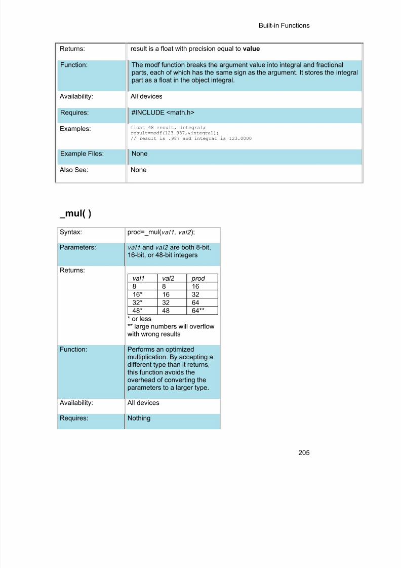
8/10/2019 avr.pdf
http://slidepdf.com/reader/full/avrpdf 217/365
Built-in Functions
205
Returns: result is a float with precision equal to value
Function: The modf function breaks the argument value into integral and fractionalparts, each of which has the same sign as the argument. It stores the integralpart as a float in the object integral.
Availability: All devices
Requires: #INCLUDE <math.h>
Examples: float 48 result, integral;result=modf(123.987,&integral);// result is .987 and integral is 123.0000
Example Files: None
Also See: None
_mul( )
Syntax: prod=_mul( val1, val2 );
Parameters: val1 and val2 are both 8-bit,16-bit, or 48-bit integers
Returns:val1 val2 prod8 8 1616* 16 3232* 32 6448* 48 64**
* or less** large numbers will overflowwith wrong results
Function: Performs an optimizedmultiplication. By accepting adifferent type than it returns,this function avoids theoverhead of converting theparameters to a larger type.
Availability: All devices
Requires: Nothing

8/10/2019 avr.pdf
http://slidepdf.com/reader/full/avrpdf 218/365
PCD Manual
206
Examples: int a=50, b=100;long int c;c = _mul(a, b); //c holds5000
ExampleFiles:
None
Also See: None
nargs( )
Syntax: void foo(char * str , int count , ...)
Parameters: The function can take variable parameters. The user can use stdarglibrary to create functions that take variable parameters.
Returns: Function dependent.
Function: The stdarg library allows the user to create functions that supportsvariable arguments.The function that will accept a variable number of arguments must haveat least one actual, known parameters, and it may have more. Thenumber of arguments is often passed to the function in one of its actualparameters. If the variable-length argument list can involve more thatone type, the type information is generally passed as well. Beforeprocessing can begin, the function creates a special argument pointer oftype va_list.
Availability: All devices
Requires: #INCLUDE <stdarg.h>
Examples: int foo(int num, ...){
int sum = 0;int i;va_list argptr; // create special argument pointerva_start(argptr,num); // initialize argptrfor(i=0; i<num; i++)
sum = sum + va_arg(argptr, int);va_end(argptr); // end variable processingreturn sum;
}void main()
{int total;total = foo(2,4,6,9,10,2);
}
Example Files: None
Also See: va_start( ) , va_end( ) , va_arg( )

8/10/2019 avr.pdf
http://slidepdf.com/reader/full/avrpdf 219/365
Built-in Functions
207
offsetof( ) offsetofbit( )
Syntax: value = offsetof( s type , field );value = offsetofbit( s type , field );
Parameters: s type is a structure type name.Field is a field from the above structure
Returns: An 8 bit byte
Function: These functions return an offset into a structure for the indicated field.offsetof returns the offset in bytes and offsetofbit returns the offset in bits.
Availability: All devices
Requires: #INCLUDE <stddef.h>
Examples: struct time_structure {int hour, min, sec;int zone : 4;intl daylight_savings;
}
x = offsetof(time_structure, sec);
// x will be 2x = offsetofbit(time_structure, sec);// x will be 16
x = offsetof (time_structure,daylight_savings);
// x will be 3x = offsetofbit(time_structure,
daylight_savings);// x will be 28
Example Files: None
Also See: None
output_x( )
Syntax: output_a ( value )output_b ( value )

8/10/2019 avr.pdf
http://slidepdf.com/reader/full/avrpdf 220/365
PCD Manual
208
output_c ( value )output_d ( value )output_e ( value )output_f ( value )output_g ( value )output_h ( value )output_j ( value )output_k ( value )
Parameters: value is a 16 bit int
Returns: undefined
Function: Output an entire word to a port. The direction register is changed inaccordance with the last specified #USE *_IO directive.
Availability: All devices, however not all devices have all ports (A-E)
Requires: Nothing
Examples: OUTPUT_B(0xf0);
Example Files: ex_patg.c
Also See: input() , output_low() , output_high() , output_float() , output_bit() , #USEFIXED_IO, #USE FAST_IO , #USE STANDARD_IO , General Purpose I/O
output_bit( )
Syntax: output_bit ( pin , value )
Parameters: Pins are defined in the devices .h file. The actual number is a bit address. Forexample, port a (byte 0x2C2 ) bit 3 would have a value of 0x2C2*8+3 or 5651. This is defined as follows: #define PIN_A3 5651 . The PIN could also be avariable. The variable must have a value equal to one of the constants (likePIN_A1) to work properly. The tristate register is updated unless the FAST_IOmode is set on port A. Note that doing I/O with a variable instead of a constantwill take much longer time.Value is a 1 or a 0.
Returns: undefined
Function: Outputs the specified value (0 or 1) to the specified I/O pin. Themethod of setting the direction register is determined by the last#USE *_IO directive.

8/10/2019 avr.pdf
http://slidepdf.com/reader/full/avrpdf 221/365
Built-in Functions
209
Availability: All devices.
Requires: Pin constants are defined in the devices .h file
Examples:output_bit( PIN_B0, 0);// Same as output_low(pin_B0);
output_bit( PIN_B0,input( PIN_B1 ) );// Make pin B0 the same as B1
output_bit( PIN_B0,shift_left(&data,1,input(PIN_B1)));// Output the MSB of data to// B0 and at the same time// shift B1 into the LSB of data
int16 i=PIN_B0;ouput_bit(i,shift_left(&data,1,input(PIN_B1)));//same as above example, but//uses a variable instead of a constant
Example Files: ex_extee.c with 9356.c
Also See: input() , output_low() , output_high() , output_float() , output_x() , #USEFIXED_IO, #USE FAST_IO , #USE STANDARD_IO , General Purpose I/O
output_drive( )
Syntax: output_drive(pin)
Parameters: Pins are defined in the devices .h file. The actual value is a bitaddress. For example, port a (byte 0x2C2 ) bit 3 would have a value of 0x2C2*8+3 or 5651 . This is defined as follows: #DEFINE PIN_A3 5651 .
Returns: undefined
Function: Sets the specified pin to the output mode.
Availability: All devices.
Requires: Pin constants are defined in the devices.h file.
Examples: output_drive(pin_A0); // sets pin_A0 to output its valueoutput_bit(pin_B0, input(pin_A0)) // makes B0 the same as A0
Example Files: None
Also See: input() , output_low() , output_high() , output_bit() , output_x() , output_float()
.

8/10/2019 avr.pdf
http://slidepdf.com/reader/full/avrpdf 222/365
PCD Manual
210
output_float( )
Syntax: output_float ( pin )
Parameters: Pins are defined in the devices .h file. The actual value is a bit address. Forexample, port a (byte 0x2C2 ) bit 3 would have a value of 0x2C2*8+3 or 5651. This is defined as follows: #DEFINE PIN_A3 5651 . The PIN could also be avariable to identify the pin. The variable must have a value equal to one of theconstants (like PIN_A1) to work properly. Note that doing I/O with a variableinstead of a constant will take much longer time.
Returns: undefined
Function: Sets the specified pin to the input mode. This will allow the pin to float high torepresent a high on an open collector type of connection.
Availability: All devices.
Requires: Pin constants are defined in the devices .h file
Examples: if( (data & 0x80)==0 )output_low(pin_A0);
elseoutput_float(pin_A0);
Example Files: None
Also See: input() , output_low() , output_high() , output_bit() , output_x() , output_drive() , #USE FIXED_IO , #USE FAST_IO , #USE STANDARD_IO , General PurposeI/O
output_high( )
Syntax: output_high ( p in )
Parameters: Pi n to write to. Pins are defined in the devices .h file. The actual value is a bitaddress. For example, port a (byte 0x2C2 ) bit 3 would have a value of0x2C2*8+3 or 5651 . This is defined as follows: #DEFINE PIN_A3 5651 . ThePIN could also be a variable. The variable must have a value equal to one ofthe constants (like PIN_A1) to work properly. The tristate register is updatedunless the FAST_IO mode is set on port A. Note that doing I/O with a variableinstead of a constant will take much longer time.

8/10/2019 avr.pdf
http://slidepdf.com/reader/full/avrpdf 223/365
Built-in Functions
211
Returns: undefined
Function: Sets a given pin to the high state. The method of I/O used is dependent on thelast USE *_IO directive.
Availability: All devices.
Requires: Pin constants are defined in the devices .h file
Examples: output_high(PIN_A0);output_low(PIN_A1);
Example Files: ex_sqw.c
Also See: input() , output_low() , output_float() , output_bit() , output_x() , #USE FIXED_IO , #USE FAST_IO , #USE STANDARD_IO , General Purpose I/O
output_low( )
Syntax: output_low ( p in )
Parameters: Pins are defined in the devices .h file. The actual value is a bit address. Forexample, port a (byte 0x2C2 ) bit 3 would have a value of 0x2C2*8+3 or 5651. This is defined as follows: #DEFINE PIN_A3 5651 . The PIN could also be a
variable. The variable must have a value equal to one of the constants (likePIN_A1) to work properly. The tristate register is updated unless the FAST_IOmode is set on port A. Note that doing I/O with a variable instead of a constantwill take much longer time.
Returns: undefined
Function: Sets a given pin to the ground state. The method of I/O used is dependent onthe last USE *_IO directive.
Availability: All devices.
Requires: Pin constants are defined in the devices .h file
Examples: output_low(PIN_A0);
Int16i=PIN_A1;output_low(PIN_A1);
Example Files: ex_sqw.c

8/10/2019 avr.pdf
http://slidepdf.com/reader/full/avrpdf 224/365

8/10/2019 avr.pdf
http://slidepdf.com/reader/full/avrpdf 225/365
Built-in Functions
213
perror("Problem in find_area");
Example Files: None
Also See: RS232 I/O Overview
port_x_pullups ( )
Syntax: port_a_pullups ( value )port_b_pullups ( value )port_d_pullups ( value )port_e_pullups ( value )port_j_pullups ( value )port_x_pullups ( upmask )port_x_pullups ( upmask , downmask )
Parameters: value is TRUE or FALSE on most parts, some parts that allow pullups tobe specified on individual pins permit an 8 bit int here, one bit for eachport pin.upmask for ports that permit pullups to be specified on a pin basis. Thismask indicates what pins should have pullups activated. A 1 indicates thepullups is on.d o w n m a s k for ports that permit pulldowns to be specified on a pin basis.This mask indicates what pins should have pulldowns activated. A 1indicates the pulldowns is on.
Returns: undefined
Function: Sets the input pullups. TRUE will activate, and a FALSE will deactivate.
Availability: Only 14 and 16 bit devices (PCM and PCH). (Note: useSETUP_COUNTERS on PCB parts).
Requires: Nothing
Examples: port_a_pullups(FALSE);
Example Files: ex_lcdkb.c , kbd.c
Also See: input() , input_x() , output_float()

8/10/2019 avr.pdf
http://slidepdf.com/reader/full/avrpdf 226/365
PCD Manual
214
pow( ) pwr( )
Syntax: f = pow ( x ,y )f = pwr ( x ,y )
Parameters: x and y are any float type
Returns: A float with precision equal to function parameters x and y.
Function: Calculates X to the Y power.
Note on error handling:If "errno.h" is included then the domain and range errors are stored in theerrno variable. The user can check the errno to see if an error has occurredand print the error using the perror function.
Range error occurs in the following case: pow: when the argument X is negative
Availability: All Devices
Requires: #INCLUDE <math.h>
Examples: area = pow (size,3.0);
Example Files: None
Also See: None
printf( ) fprintf( )
Syntax: printf ( s t r ing )or
printf (cs t r ing , values ...)or
printf (fname , cs t r ing , values ...)
fprintf (stream , cs t r ing , values ...)
Parameters: Str ing is a constant string or an array of characters null terminated.
Values is a list of variables separated by commas, fname is a function name tobe used for outputting (default is putc is none is specified.
Stream is a stream identifier (a constant byte). Note that format specifies do
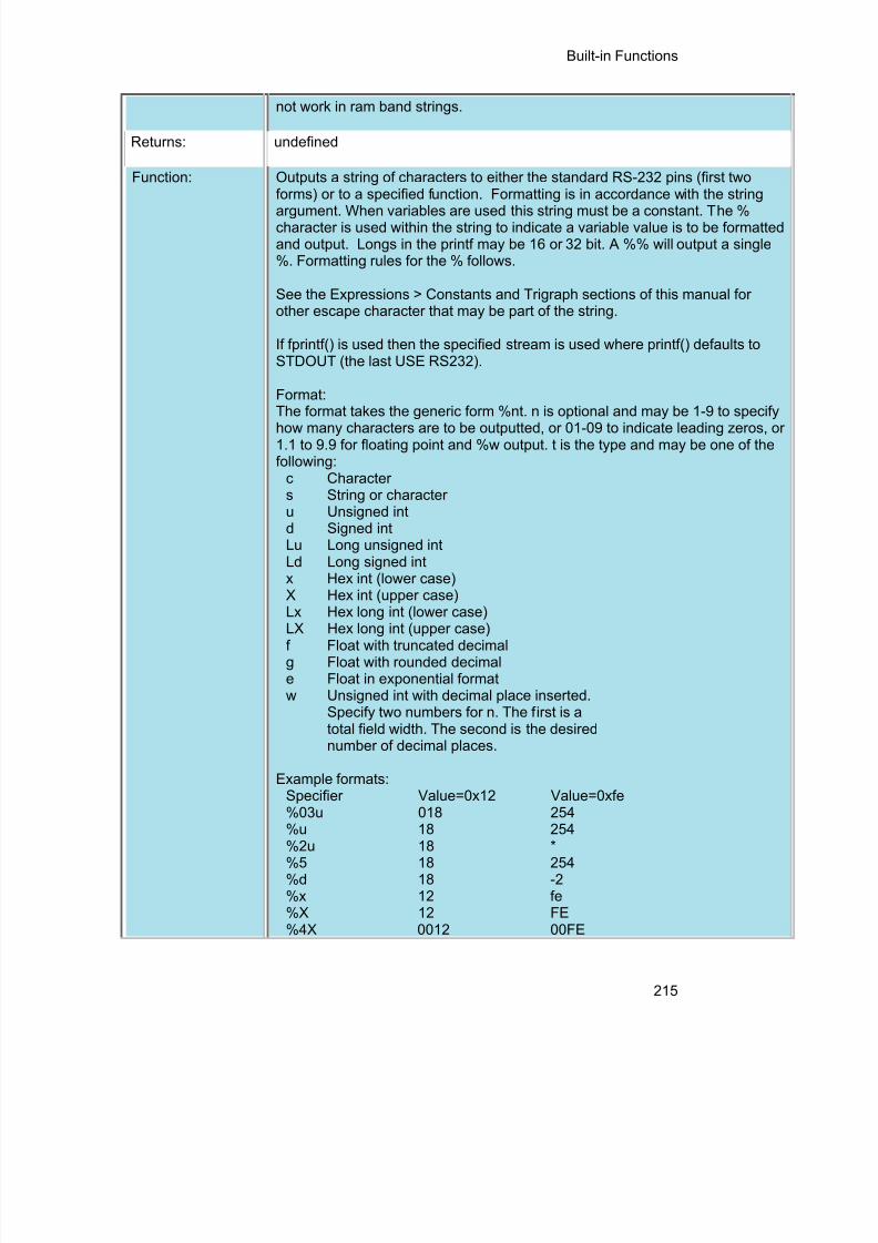
8/10/2019 avr.pdf
http://slidepdf.com/reader/full/avrpdf 227/365
Built-in Functions
215
not work in ram band strings.
Returns: undefined
Function: Outputs a string of characters to either the standard RS-232 pins (first two
forms) or to a specified function. Formatting is in accordance with the stringargument. When variables are used this string must be a constant. The %character is used within the string to indicate a variable value is to be formattedand output. Longs in the printf may be 16 or 32 bit. A %% will output a single%. Formatting rules for the % follows.
See the Expressions > Constants and Trigraph sections of this manual forother escape character that may be part of the string.
If fprintf() is used then the specified stream is used where printf() defaults toSTDOUT (the last USE RS232).
Format:The format takes the generic form %nt. n is optional and may be 1-9 to specifyhow many characters are to be outputted, or 01-09 to indicate leading zeros, or1.1 to 9.9 for floating point and %w output. t is the type and may be one of thefollowing:
c Characters String or characteru Unsigned intd Signed intLu Long unsigned intLd Long signed intx Hex int (lower case)X Hex int (upper case)Lx Hex long int (lower case)LX Hex long int (upper case)f Float with truncated decimalg Float with rounded decimale Float in exponential formatw Unsigned int with decimal place inserted.
Specify two numbers for n. The first is atotal field width. The second is the desirednumber of decimal places.
Example formats:Specifier Value=0x12 Value=0xfe%03u 018 254%u 18 254%2u 18 *%5 18 254%d 18 -2%x 12 fe%X 12 FE%4X 0012 00FE

8/10/2019 avr.pdf
http://slidepdf.com/reader/full/avrpdf 228/365
PCD Manual
216
%3.1w 1.8 25.4* Result is undefined - Assume garbage.
Availability: All Devices
Requires: #USE RS232 (unless fname is used)Examples: byte x,y,z;
printf("HiThere");printf("RTCCValue=>%2x\n\r",get_rtcc());printf("%2u %X %4X\n\r",x,y,z);printf(LCD_PUTC, "n=%u",n);
Example Files: ex_admm.c , ex_lcdkb.c
Also See: atoi() , puts() , putc() , getc() (for a stream example), RS232 I/O Overview
profileout()
Syntax: profileout(string);profileout(string, value);profileout(value);
Parameters: string is any constant string, and value can be any constant or variableinteger. Despite the length of string the user specifies here, the codeprofile run-time will actually only send a one or two byte identifier tag tothe code profile tool to keep transmission and execution time to aminimum.
Returns: Undefined
Function: Typically the code profiler will log and display function entry and exits, toshow the call sequence and profile the execution time of the functions.By using profileout(), the user can add any message or display any
variable in the code profile tool. Most messages sent by profileout() aredisplayed in the 'Data Messages' and 'Call Sequence' screens of the codeprofile tool.If a profileout(string) is used and the first word of string is "START", thecode profile tool will then measure the time it takes until it sees the sameprofileout(string) where the "START" is replaced with "STOP". Thismeasurement is then displayed in the 'Statistics' screen of the code profiletool, using string as the name (without "START" or "STOP")
Availability: Any device.
Requires: #use profile() used somewhere in the project source code.Examples: // send a simple string.
profileout("This is a text string");// send a variable with a string identifier.profileout("RemoteSensor=", adc);

8/10/2019 avr.pdf
http://slidepdf.com/reader/full/avrpdf 229/365
Built-in Functions
217
// just send a variable.profileout(adc);// time how long a block of code takes to execute.// this will be displayed in the 'Statistics' of the// Code Profile tool.profileout("start my algorithm");/* code goes here */
profileout("stop my algorithm");
Example Files: ex_profile.c
Also See: #use profile() , #profile , Code Profile overview
psp_output_full( ) psp_input_full( ) psp_overflow( )
Syntax: result = psp_output_full()result = psp_input_full()result = psp_overflow()result = psp_error(); //EPMP onlyresult = psp_timeout(); //EPMP only
Parameters: None
Returns: A 0 (FALSE) or 1 (TRUE)
Function: These functions check the Parallel Slave Port (PSP) for the indicatedconditions and return TRUE or FALSE.
Availability: This function is only available on devices with PSP hardware on chips.
Requires: Nothing
Examples: while (psp_output_full()) ;psp_data = command;while(!psp_input_full()) ;
if ( psp_overflow() )error = TRUE;else
data = psp_data;
Example Files: ex_psp.c
Also See: setup_psp() , PSP Overview

8/10/2019 avr.pdf
http://slidepdf.com/reader/full/avrpdf 230/365
PCD Manual
218
putc( ) putchar( ) fputc( )
Syntax: putc ( cdata )putchar ( cdata )fputc( cdata , stream )
Parameters: cdata is a 8 bit character.Stream is a stream identifier (a constant byte)
Returns: undefined
Function: This function sends a character over the RS232 XMIT pin. A #USE RS232must appear before this call to determine the baud rate and pin used. The#USE RS232 remains in effect until another is encountered in the file.
If fputc() is used then the specified stream is used where putc() defaults toSTDOUT (the last USE RS232).
Availability: All devices
Requires: #USE RS232
Examples: putc('*');for(i=0; i<10; i++)
putc(buffer[i]);putc(13);
Example Files: ex_tgetc.c
Also See: getc() , printf(), #USE RS232 , RS232 I/O Overview
putc_send( );
fputc_send( );
Syntax: putc_send();fputc_send( stream );
Parameters: stream – parameter specifying the stream defined in #USE RS232.Returns: Nothing
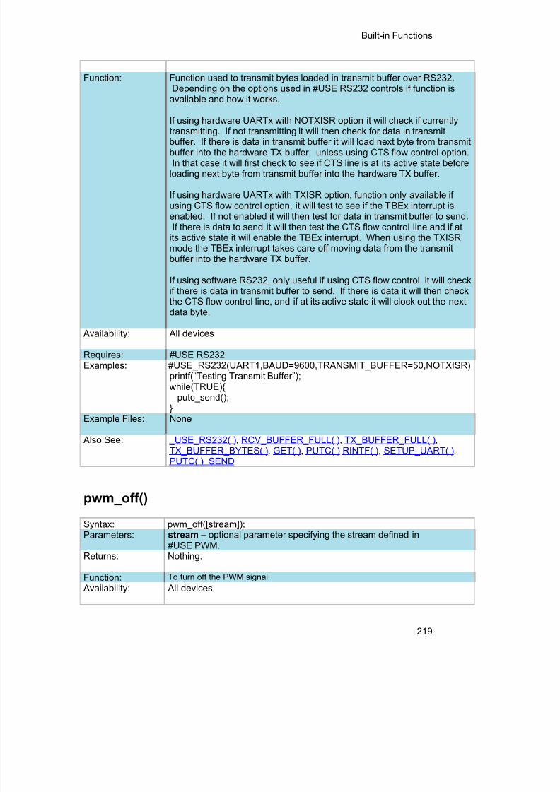
8/10/2019 avr.pdf
http://slidepdf.com/reader/full/avrpdf 231/365
Built-in Functions
219
Function: Function used to transmit bytes loaded in transmit buffer over RS232.Depending on the options used in #USE RS232 controls if function is
available and how it works.
If using hardware UARTx with NOTXISR option it will check if currentlytransmitting. If not transmitting it will then check for data in transmitbuffer. If there is data in transmit buffer it will load next byte from transmitbuffer into the hardware TX buffer, unless using CTS flow control option.In that case it will first check to see if CTS line is at its active state before
loading next byte from transmit buffer into the hardware TX buffer.
If using hardware UARTx with TXISR option, function only available ifusing CTS flow control option, it will test to see if the TBEx interrupt isenabled. If not enabled it will then test for data in transmit buffer to send.If there is data to send it will then test the CTS flow control line and if at
its active state it will enable the TBEx interrupt. When using the TXISRmode the TBEx interrupt takes care off moving data from the transmitbuffer into the hardware TX buffer.
If using software RS232, only useful if using CTS flow control, it will checkif there is data in transmit buffer to send. If there is data it will then checkthe CTS flow control line, and if at its active state it will clock out the nextdata byte.
Availability: All devices
Requires: #USE RS232Examples: #USE_RS232(UART1,BAUD=9600,TRANSMIT_BUFFER=50,NOTXISR)
printf(“Testing Transmit Buffer”); while(TRUE){
putc_send();}
Example Files: None
Also See: _USE_RS232( ) , RCV_BUFFER_FULL( ) , TX_BUFFER_FULL( ) , TX_BUFFER_BYTES( ) , GET( ) , PUTC( ) RINTF( ) , SETUP_UART( ) , PUTC( )_SEND
pwm_off()
Syntax: pwm_off([stream]);
Parameters: stream – optional parameter specifying the stream defined in#USE PWM.
Returns: Nothing.
Function: To turn off the PWM signal.
Availability: All devices.

8/10/2019 avr.pdf
http://slidepdf.com/reader/full/avrpdf 232/365
PCD Manual
220
Requires: #USE PWMExamples: #USE PWM(OUTPUT=PIN_C2, FREQUENCY=10kHz, DUTY=25)
while(TRUE){if(kbhit()){
c = getc();
if(c=='F')pwm_off();
}}
Example Files: None Also See: #use_pwm , pwm_on() , pwm_set_duty_percent() ,
pwm_set_duty() , pwm_set_frequency()
pwm_on()
Syntax: pwm_on([stream]);
Parameters: stream – optional parameter specifying the stream defined in
#USE PWM.Returns: Nothing.
Function: To turn on the PWM signal. Availability: All devices.
Requires: #USE PWMExamples: #USE PWM(OUTPUT=PIN_C2, FREQUENCY=10kHz, DUTY=25)
while(TRUE){if(kbhit()){
c = getc();
if(c=='O')pwm_on();
}}
Example Files: None Also See: #use_pwm , pwm_off() , pwm_set_duty_percent() ,
pwm_set_duty , pwm_set_frequency()
pwm_set_duty()
Syntax: pwm_set_duty([ stream ],duty) ;Parameters: stream – optional parameter specifying the stream defined in
#USE PWM.
duty – an int16 constant or variable specifying the new PWMhigh time.Returns: Nothing.
Function: To change the duty cycle of the PWM signal. The duty cyclepercentage depends on the period of the PWM signal. Thisfunction is faster than pwm_set_duty_percent(), but requiresyou to know what the period of the PWM signal is.
Availability: All devices.

8/10/2019 avr.pdf
http://slidepdf.com/reader/full/avrpdf 233/365
Built-in Functions
221
Requires: #USE PWM
Examples: #USE PWM(OUTPUT=PIN_C2, FREQUENCY=10kHz, DUTY=25)
Example Files: None
Also See: #use_pwm, pwm_on , pwm_off() , pwm_set_frequency() , pwm_set_duty_percent()
pwm_set_duty_percent
Syntax: pwm_set_duty_percent([stream]), percent
Parameters: stream – optional parameter specifying the stream defined in #USE PWM.
percent- an int16 constant or variable ranging from 0 to 1000 specifyingthe new PWM duty cycle, D is 0% and 1000 is 100.0%.
Returns: Nothing.
Function: To change the duty cycle of the PWM signal. Duty cycle percentage isbased off the current frequency/period of the PWM signal.
Availability: All devices.
Requires: #USE PWMExamples: #USE PWM(OUTPUT=PIN_C2, FREQUENCY=10kHz, DUTY=25)
pwm_set_duty_percent(500); //set PWM duty cycle to 50%Example Files: None
Also See: #use_pwm , pwm_on() , pwm_off() , pwm_set_frequency() , pwm_set_duty()
pwm_set_frequency
Syntax: pwm_set_frequency([stream],frequency);
Parameters: stream – optional parameter specifying the stream defined in#USE PWM.
frequency – an int32 constant or variable specifying the newPWM frequency.
Returns: Nothing.
Function: To change the frequency of the PWM signal. Warning this
may change the resolution of the PWM signal. Availability: All devices.
Requires: #USE PWMExamples: #USE PWM(OUTPUT=PIN_C2, FREQUENCY=10kHz, DUTY=25)
pwm_set_frequency(1000); //set PWM frequency to 1kHzExample Files: None
Also See: #use_pwm , pwm_on() , pwm_off() , pwm_set_duty_percent , pwm_set_duty()

8/10/2019 avr.pdf
http://slidepdf.com/reader/full/avrpdf 234/365
PCD Manual
222
qei_get_count( )
Syntax: value = qei_get_count( [ uni t ] );
Parameters: value - The 16-bit value of the position counter.uni t - Optional unit number, defaults to 1.
Returns: void
Function: Reads the current 16-bit value of the position counter.
Availability: Devices that have the QEI module.
Requires: Nothing.
Examples: value = qei_get_counter();
Example Files: None
Also See: setup_qei() , qei_set_count() , qei_status() .
qei_status( )
Syntax: status = qei_status( [ uni t ] );
Parameters: s ta tus - The status of the QEI moduleuni t - Optional unit number, defaults to 1.
Returns: void
Function: Returns the status of the QUI module.
Availability: Devices that have the QEI module.
Requires: Nothing.
Examples: status = qei_status();
Example Files: None
Also See: setup_qei() , qei_set_count() , qei_get_count() .

8/10/2019 avr.pdf
http://slidepdf.com/reader/full/avrpdf 235/365
Built-in Functions
223
qsort( )
Syntax: qsort ( base, num , width , com pare )
Parameters: base : Pointer to array of sort datanum : Number of elementswidth : Width of elementscompare : Function that compares two elements
Returns: None
Function: Performs the shell-metzner sort (not the quick sort algorithm). Thecontents of the array are sorted into ascending order according to acomparison function pointed to by compare.
Availability: All devices
Requires: #INCLUDE <stdlib.h>
Examples: int nums[5]={ 2,3,1,5,4};int compar(void *arg1,void *arg2);
void main() {qsort ( nums, 5, sizeof(int), compar);
}
int compar(void *arg1,void *arg2) {if ( * (int *) arg1 < ( * (int *) arg2) return – 1else if ( * (int *) arg1 == ( * (int *) arg2) return 0
else return 1;}
Example Files: ex_qsort.c
Also See: bsearch()
rand( )
Syntax: re=rand()
Parameters: None
Returns: A pseudo-random integer.

8/10/2019 avr.pdf
http://slidepdf.com/reader/full/avrpdf 236/365
PCD Manual
224
Function: The rand function returns a sequence of pseudo-random integers in the rangeof 0 to RAND_MAX.
Availability: All devices
Requires: #INCLUDE <STDLIB.H>
Examples: int I;I=rand();
Example Files: None
Also See: srand()
rcv_buffer_bytes( )
Syntax: value = rcv_buffer_bytes([ stream ]);Parameters: stream – optional parameter specifying the stream defined in #USE
RS232.
Returns: Number of bytes in receive buffer that still need to be retrieved.
Function: Function to determine the number of bytes in receive buffer that still needto be retrieved.
Availability: All devices
Requires: #USE RS232Examples: #USE_RS232(UART1,BAUD=9600,RECEIVE_BUFFER=100)
void main(void) {char c;if(rcv_buffer_bytes() > 10)c = getc();
}Example Files: None
Also See: _USE_RS232( ) , RCV_BUFFER_FULL( ) , TX_BUFFER_FULL( ) , TX_BUFFER_BYTES( ) , GETC( ) , PUTC( ) ,PRINTF( ) , SETUP_UART(), PUTC_SEND( )

8/10/2019 avr.pdf
http://slidepdf.com/reader/full/avrpdf 237/365
Built-in Functions
225
rcv_buffer_full( )
Syntax: value = rcv_buffer_full([stream]);
Parameters: stream – optional parameter specifying the stream defined in #USERS232.
Returns: TRUE if receive buffer is full, FALSE otherwise.Function: Function to test if the receive buffer is full.
Availability: All devices
Requires: #USE RS232Examples: #USE_RS232(UART1,BAUD=9600,RECEIVE_BUFFER=100)
void main(void) {char c;if(rcv_buffer_full())c = getc();
}Example Files: None
Also See: _USE_RS232( ) ,RCV_BUFFER_BYTES( ) , TX_BUFFER_BYTES( ),TX_BUFFER_FULL( ) , GETC( ) , PUTC( ) , PRINTF( ) , SETUP_UART( ) ,
PUTC_SEND( )
read_adc( ) read_adc2( )
Syntax: value = read_adc ([ m o d e ])value = read_adc2 ([ m o d e ])
Parameters: m o d e is an optional parameter. If used the values may be: ADC_START_AND_READ (continually takes readings, this is the default) ADC_START_ONLY (starts the conversion and returns) ADC_READ_ONLY (reads last conversion result)
Returns: Either a 8 or 16 bit int depending on #DEVICE ADC= directive.
Function: This function will read the digital value from the analog to digital converter.Calls to setup_adc(), setup_adc_ports() and set_adc_channel() should bemade sometime before this function is called. The range of the return valuedepends on number of bits in the chips A/D converter and the setting in the#DEVICE ADC= directive as follows:#DEVICE 10 bit 12 bit
ADC=8 00-FF 00-FF ADC=10 0-3FF 0-3FF
ADC=11 x x ADC=12 0-FFC 0-FFF

8/10/2019 avr.pdf
http://slidepdf.com/reader/full/avrpdf 238/365
PCD Manual
226
ADC=16 0-FFC0 0-FFF0Note: x is not defined
Availability: Only available on devices with built in analog to digital converters.
Requires: Pin constants are defined in the devices .h file.Examples: int16 value;
setup_adc_ports(sAN0|sAN1, VSS_VDD);setup_adc(ADC_CLOCK_DIV_4|ADC_TAD_MUL_8);
while (TRUE){
set_adc_channel(0);value = read_adc();printf(“Pin AN0 A/C value = %LX \n\ r”, value);
delay_ms(5000);
set_adc_channel(1);read_adc(ADC_START_ONLY);...value = read_adc(ADC_READ_ONLY);printf("Pin AN1 A/D value = %LX\n\r", value);
}
ExampleFiles:
ex_admm.c ,
read_configuration_memory( )
Syntax: read_configuration_memory( ramPtr , n )
Parameters: ramPtr is the destination pointer for the read results coun t is an 8 bit integer
Returns: undefined
Function: Reads n bytes of configuration memory and saves the values to ramPtr .
Availability: All
Requires: Nothing
Examples: int data[6];read_configuration_memory(data,6);
Example Files: None
Also See: write_configuration_memory() , read_program_memory() , ConfigurationMemory Overview

8/10/2019 avr.pdf
http://slidepdf.com/reader/full/avrpdf 239/365
Built-in Functions
227
read_eeprom( )
Syntax: value = read_eeprom ( address , [N] )read_eeprom( address , variable )
read_eeprom( address , pointer , N )
Parameters: address is an 8 bit or 16 bit int depending on the partN specifies the number of EEPROM bytes to readvariable a specif ied locat ion to s to re EEPROM read resul tspointer is a pointer to lo cat ion to s to re EEPROM read resul ts
Returns: An 16 bit int
Function: By default the function reads a word from EEPROM at the specified address.The number of bytes to read can optionally be defined by argument N. If avariable is used as an argument, then EEPROM is read and the results areplaced in the variable until the variable data size is full. Finally, if a pointer isused as an argument, then n bytes of EEPROM at the given address are readto the pointer.
Availability: This command is only for parts with built-in EEPROMS
Requires: Nothing
Examples: #define LAST_VOLUME 10volume = read_EEPROM (LAST_VOLUME);
Example Files: None
Also See: write_eeprom() , Data Eeprom Overview
read_extended_ram( )
Syntax: read_extended_ram( page,address,data,count );
Parameters: page – the page in extended RAM to read fromaddress – the address on the selected page to start reading fromdata – pointer to the variable to return the data tocount – the number of bytes to read (0-32768)
Returns: Undefined
Function: To read data from the extended RAM of the PIC.

8/10/2019 avr.pdf
http://slidepdf.com/reader/full/avrpdf 240/365
PCD Manual
228
Availability: On devices with more then 30K of RAM.
Requires: Nothing
Examples: unsigned int8 data[8];
read_extended_ram(1,0x0000,data,8);
Example Files: None
Also See: read_extended_ram() , Extended RAM Overview
read_program_memory( )
Syntax: READ_PROGRAM_MEMORY ( address , dataptr , coun t );
Parameters: address is 32 bits . The least significant bit should always be 0 in PCM.dataptr is a pointer to one or more bytes.c o u n t is a 16 bit integer on PIC16 and 16-bit for PIC18
Returns: undefined
Function: Reads c o u n t bytes from program memory at address to RAM at dataptr .BDue to the 24 bit program instruction size on the PCD devices, everyfourth byte will be read as 0x00
Availability: Only devices that allow reads from program memory.
Requires: Nothing
Examples: char buffer[64];read_external_memory(0x40000, buffer, 64);
Example Files: None
Also See: write program memory( ), Program Eeprom Overview
read_high_speed_adc( )
Syntax:
read_high_speed_adc( pair ,mode ,result) ; // Individual start andread or
// read onlyread_high_speed_adc( pair ,result ); // Individual start andread
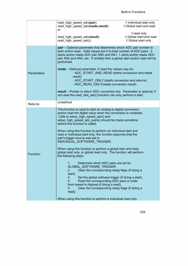
8/10/2019 avr.pdf
http://slidepdf.com/reader/full/avrpdf 241/365
Built-in Functions
229
read_high_speed_adc( pair ); // Individual start onlyread_high_speed_adc( mode ,result ); // Global start and reador
// read onlyread_high_speed_adc( result ); // Global start and readread_high_speed_adc(); // Global start only
Parameters:
pair – Optional parameter that determines which ADC pair number tostart and/or read. Valid values are 0 to total number of ADC pairs. 0starts and/or reads ADC pair AN0 and AN1, 1 starts and/or reads ADCpair AN2 and AN3, etc. If omitted then a global start and/or read will beperformed.
mode – Optional parameter, if used the values may be:· ADC_START_AND_READ (starts conversion and readsresult)· ADC_START_ONLY (starts conversion and returns)· ADC_READ_ONLY(reads conversion result)
result – Pointer to return ADC conversion too. Parameter is optional, ifnot used the read_fast_adc() function can only perform a start.
Returns: Undefined
Function:
This function is used to start an analog to digital conversionand/or read the digital value when the conversion is complete.Calls to setup_high_speed_adc() and
setup_high_speed_adc_pairs() should be made sometimebefore this function is called.
When using this function to perform an individual start andread or individual start only, the function assumes that thepair's trigger source was set toINDIVIDUAL_SOFTWARE_TRIGGER.
When using this function to perform a global start and read,global start only, or global read only. The function will performthe following steps:
1. Determine which ADC pairs are set forGLOBAL_SOFTWARE_TRIGGER.2. Clear the corresponding ready flags (if doing astart).3. Set the global software trigger (if doing a start).4. Read the corresponding ADC pairs in orderfrom lowest to highest (if doing a read).5. Clear the corresponding ready flags (if doing aread).
When using this function to perform a individual read only.

8/10/2019 avr.pdf
http://slidepdf.com/reader/full/avrpdf 242/365
PCD Manual
230
The function can read the ADC result from any triggersource.
Availability: Only on dsPIC33FJxxGSxxx devices.
Requires:Constants are define in the device .h file.
Examples:
//Individual start and readint16 result[2];
setup_high_speed_adc(ADC_CLOCK_DIV_4);setup_high_speed_adc_pair(0, INDIVIDUAL_SOFTWARE_TRIGGER);read_high_speed_adc(0, result); //starts conversion for AN0 and AN1 andstores
//result in result[0] and result[1]
//Global start and readint16 result[4];
setup_high_speed_adc(ADC_CLOCK_DIV_4);setup_high_speed_adc_pair(0, GLOBAL_SOFTWARE_TRIGGER);setup_high_speed_adc_pair(4, GLOBAL_SOFTWARE_TRIGGER);
read_high_speed_adc(result); //starts conversion for AN0, AN1,//AN8 and AN9 and//stores result in result[0], result //[1],
result[2]and result[3]
Example Files: None
Also See:setup_high_speed_adc() , setup_high_speed_adc_pair() , high_speed_adc_done()
read_rom_memory( )
Syntax: READ_ROM_MEMORY ( address , dataptr , coun t );
Parameters: address is 32 bits. The least significant bit should always be 0.dataptr is a pointer to one or more bytes.c o u n t is a 16 bit integer
Returns: undefined
Function: Reads c o u n t bytes from program memory at address to dataptr . Due to the 24
bit program instruction size on the PCD devices, three bytes are read from eachaddress location.
Availability: Only devices that allow reads from program memory.
Requires: Nothing
Examples: char buffer[64];read_program_memory(0x40000, buffer, 64);

8/10/2019 avr.pdf
http://slidepdf.com/reader/full/avrpdf 243/365
Built-in Functions
231
ExampleFiles:
None
Also See: write_eeprom() , read_eeprom() , Program eeprom overview
read_sd_adc( )
Syntax: value = read_sd_adc();
Parameters: None
Returns: A signed 32 bit int.
Function: To poll the SDRDY bit and if set return the signed 32 bit value stored in theSD1RESH and SD1RESL registers, and clear the SDRDY bit. The resultreturned depends on settings made with the setup_sd_adc() function, but willalways be a signed int32 value with the most significant bits being meaningful.Refer to Section 66, 16-bit Sigma-Delta A/D Converter, of the PIC24F Family
Reference Manual for more information on the module and the result format.
Availability: Only devices with a Sigma-Delta Analog to Digital Converter (SD ADC) module.
Examples: value = read_sd_adc()
ExampleFiles:
None
Also See: setup_sd_adc() , set_sd_adc_calibration() , set_sd_adc_channel()
realloc( )
Syntax: realloc ( p tr , size )
Parameters: p tr is a null pointer or a pointer previously returned by calloc or malloc orrealloc function, size is an integer representing the number of byes to beallocated.
Returns: A pointer to the possibly moved allocated memory, if any. Returns nullotherwise.
Function: The realloc function changes the size of the object pointed to by the ptr to the

8/10/2019 avr.pdf
http://slidepdf.com/reader/full/avrpdf 244/365
PCD Manual
232
size specified by the size. The contents of the object shall be unchanged up tothe lesser of new and old sizes. If the new size is larger, the value of the newlyallocated space is indeterminate. If ptr is a null pointer, the realloc functionbehaves like malloc function for the specified size. If the ptr does not match apointer earlier returned by the calloc, malloc or realloc, or if the space hasbeen deallocated by a call to free or realloc function, the behavior is undefined.If the space cannot be allocated, the object pointed to by ptr is unchanged. Ifsize is zero and the ptr is not a null pointer, the object is to be freed.
Availability: All devices
Requires: #INCLUDE <stdlibm.h>
Examples: int * iptr;iptr=malloc(10);realloc(iptr,20)
// iptr will point to a block of memory of 20 bytes, if available.
Example Files: None
Also See: malloc() , free() , calloc()
release_io()
Syntax: release_io();
Parameters: none
Returns: nothingFunction: The function releases the I/O pins after the device wakes up from deep
sleep, allowingthe state of the I/O pins to change
Availability: Devices with a deep sleep module.
Requires: Nothing
Examples: unsigned int16 restart;
restart = restart_cause();if(restart == RTC_FROM_DS)
release_io();Example Files: None
Also See: sleep()

8/10/2019 avr.pdf
http://slidepdf.com/reader/full/avrpdf 245/365
Built-in Functions
233
reset_cpu( )
Syntax: reset_cpu()
Parameters: None
Returns: This function never returns
Function: This is a general purpose device reset. It will jump to location 0 on PCB andPCM parts and also reset the registers to power-up state on the PIC18XXX.
Availability: All devices
Requires: Nothing
Examples: if(checksum!=0)reset_cpu();
Example Files: None
Also See: None
restart_cause( )
Syntax: value = restart_cause()Parameters: None
Returns: A value indicating the cause of the last processor reset. The actual values aredevice dependent. See the device .h file for specific values for a specific device.Some example values are: RESTART_POWER_UP, RESTART_BROWNOUT,RESTART_WDT and RESTART_MCLR
Function: Returns the cause of the last processor reset.
In order for the result to be accurate, it should be called immediately in main().
Availability: All devices
Requires: Constants are defined in the devices .h file.
Examples: switch ( restart_cause() ) {
case RESTART_BROWNOUT:case RESTART_WDT:case RESTART_MCLR:

8/10/2019 avr.pdf
http://slidepdf.com/reader/full/avrpdf 246/365
PCD Manual
234
handle_error();}
Example Files: ex_wdt.c
Also See: restart_wdt() , reset_cpu()
restart_wdt( )
Syntax: restart_wdt()
Parameters: None
Returns: undefined
Function: Restarts the watchdog timer. If the watchdog timer is enabled,this must be called periodically to prevent the processor fromresetting.
The watchdog timer is used to cause a hardware reset if thesoftware appears to be stuck.
The timer must be enabled, the timeout time set and softwaremust periodically restart the timer. These are done differently onthe PCB/PCM and PCH parts as follows:
PCB/PCM PCHEnable/Disable #fuses setup_wdt()Timeout time setup_wdt() #fusesrestart restart_wdt() restart_wdt()
Availability: All devices
Requires: #FUSES
Examples: #fuses WDT // PCB/PCM example// See setup_wdt for a// PIC18 example
main() {setup_wdt(WDT_2304MS);while (TRUE) {
restart_wdt();perform_activity();
}}
ExampleFiles:
ex_wdt.c

8/10/2019 avr.pdf
http://slidepdf.com/reader/full/avrpdf 247/365
Built-in Functions
235
Also See: #FUSES , setup_wdt() , WDT or Watch Dog Timer Overview
rotate_left( )
Syntax: rotate_left ( address , bytes )
Parameters:address is a pointer to memorybytes is a count of the number of bytes to work with.
Returns: undefined
Function:
Rotates a bit through an array or structure. The address may be an arrayidentifier or an address to a byte or structure (such as &data). Bit 0 of the
lowest BYTE in RAM is considered the LSB.
Availability: All devices
Requires: Nothing
Examples:x = 0x86;rotate_left( &x, 1);// x is now 0x0d
Example Files: None
Also See: rotate_right() , shift_left() , shift_right()
rotate_right( )
Syntax: rotate_right ( address , bytes )
Parameters: address is a pointer to memory,bytes is a count of the number of bytes to work with.
Returns: undefined
Function: Rotates a bit through an array or structure. The address may be an arrayidentifier or an address to a byte or structure (such as &data). Bit 0 of thelowest BYTE in RAM is considered the LSB.
Availability: All devices

8/10/2019 avr.pdf
http://slidepdf.com/reader/full/avrpdf 248/365

8/10/2019 avr.pdf
http://slidepdf.com/reader/full/avrpdf 249/365
Built-in Functions
237
rtc_alarm_write( )
Syntax: rtc_alarm_write(& datet ime );
Parameters: datet ime - A structure that will contain the values to be written to the
alarm in the RTCC module.
Structure used in read and write functions are defined in the deviceheader file as rtc_time_t.
Returns: void
Function: Writes the date and time to the alarm in the RTCC module as specified inthe structure date time.
Availability: Devices that have the RTCC module.
Requires: Nothing.Examples: rtc_alarm_write(&datetime);
Example Files: None
Also See: rtc_read() , rtc_alarm_read() , rtc_alarm_write() , setup_rtc_alarm() , rtc_write() , setup_rtc()
rtc_read( )
Syntax: rtc_read(& datet ime );
Parameters: datet ime - A structure that will contain the values returned by the RTCCmodule.
Structure used in read and write functions are defined in the deviceheader file as rtc_time_t.
Returns: void
Function: Reads the current value of Time and Date from the RTCC module andstores the structure date time.
Availability: Devices that have the RTCC module.
Requires: Nothing.

8/10/2019 avr.pdf
http://slidepdf.com/reader/full/avrpdf 250/365
PCD Manual
238
Examples: rtc_read(&datetime);
Example Files: ex_rtcc.c
Also See: rtc_read() , rtc_alarm_read() , rtc_alarm_write() , setup_rtc_alarm() , rtc_write() , setup_rtc()
rtc_write( )
Syntax: rtc_write(& datet ime );
Parameters: datet ime - A structure that will contain the values to be written to theRTCC module.
Structure used in read and write functions are defined in the deviceheader file as rtc_time_t.
Returns: void
Function: Writes the date and time to the RTCC module as specified in the structuredate time.
Availability: Devices that have the RTCC module.
Requires: Nothing.
Examples: rtc_write(&datetime);
Example Files: ex_rtcc.c
Also See: rtc_read() , rtc_alarm_read() , rtc_alarm_write() , setup_rtc_alarm() ,rtc_write() , setup_rtc()
rtos_await( )The RTOS is only included in the PCW, PCWH and PCWHD software packages.
Syntax: rtos_await ( expre )
Parameters: expre is a logical expression.

8/10/2019 avr.pdf
http://slidepdf.com/reader/full/avrpdf 251/365
Built-in Functions
239
Returns: None
Function: This function can only be used in an RTOS task. This function waits forexpre to be true before continuing execution of the rest of the code ofthe RTOS task. This function allows other tasks to execute while the taskwaits for expre to be true.
Availability: All devices
Requires: #USE RTOS
Examples: rtos_await(kbhit());
Also See: None
rtos_disable( )
The RTOS is only included in the PCW, PCWH, and PCWHD software packages.
Syntax: rtos_disable (task)
Parameters: task is the identifier of a function that is being used as an RTOS task.
Returns: None
Function: This function disables a task which causes the task to not execute untilenabled by rtos_enable(). All tasks are enabled by default.
Availability: All devices
Requires: #USE RTOS
Examples: rtos_disable(toggle_green)
Also See: rtos enable()
rtos_enable( )
The RTOS is only included in the PCW, PCWH, and PCWHD software packages.

8/10/2019 avr.pdf
http://slidepdf.com/reader/full/avrpdf 252/365
PCD Manual
240
Syntax: rtos_enable (task)
Parameters: task is the identifier of a function that is being used as an RTOS task.
Returns: None
Function: This function enables a task to execute at it's specified rate.
Availability: All devices
Requires: #USE RTOS
Examples: rtos_enable(toggle_green);
Also See: rtos disable()
rtos_msg_poll( )
The RTOS is only included in the PCW, PCWH and PCWHD software packages.
Syntax: i = rtos_msg_poll()
Parameters: None
Returns: An integer that specifies how many messages are in the queue.Function: This function can only be used inside an RTOS task. This function
returns the number of messages that are in the queue for the task thatthe rtos_msg_poll() function is used in.
Availability: All devices
Requires: #USE RTOS
Examples: if(rtos_msg_poll())
Also See: rtos msg send(), rtos msg read()
rtos_overrun( )
The RTOS is only included in the PCW, PCWH and PCWHD software packages.

8/10/2019 avr.pdf
http://slidepdf.com/reader/full/avrpdf 253/365

8/10/2019 avr.pdf
http://slidepdf.com/reader/full/avrpdf 254/365
PCD Manual
242
Syntax: rtos_signal (sem)
Parameters: sem is a global variable that represents the current availability of asharedsystem resource (a semaphore).
Returns: None
Function: This function can only be used by an RTOS task. This functionincrements sem to let waiting tasks know that a shared resource isavailable for use.
Availability: All devices
Requires: #USE RTOS
Examples: rtos_signal(uart_use)
Also See: rtos wait()
rtos_stats( )
The RTOS is only included in the PCW, PCWH and PCWHD software packages.
Syntax: rtos_stats( task,&stat )
Parameters: task is the identifier of a function that is being used as an RTOS task.stat is a structure containing the following:
struct rtos_stas_struct {unsigned int32 task_total_ticks; //number of ticks the task
has//used
unsigned int16 task_min_ticks; //the minimum number ofticks
//usedunsigned int16 task_max_ticks; //the maximum number of
ticks
//usedunsigned int16 hns_per_tick; //us =(ticks*hns_per_tick)/10
};Returns: Undefined
Function: This function returns the statistic data for a specified task .
Availability: All devices
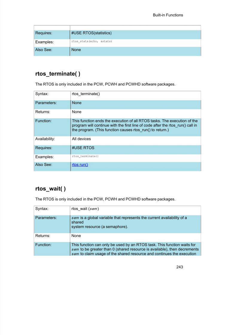
8/10/2019 avr.pdf
http://slidepdf.com/reader/full/avrpdf 255/365
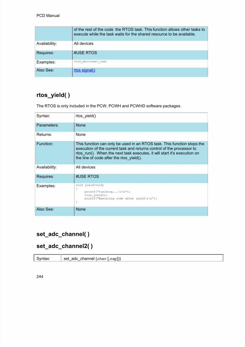
8/10/2019 avr.pdf
http://slidepdf.com/reader/full/avrpdf 256/365
PCD Manual
244
of the rest of the code the RTOS task. This function allows other tasks toexecute while the task waits for the shared resource to be available.
Availability: All devices
Requires: #USE RTOS
Examples: rtos_wait(uart_use)
Also See: rtos signal()
rtos_yield( )
The RTOS is only included in the PCW, PCWH and PCWHD software packages.
Syntax: rtos_yield()
Parameters: None
Returns: None
Function: This function can only be used in an RTOS task. This function stops theexecution of the current task and returns control of the processor tortos_run(). When the next task executes, it will start it's execution onthe line of code after the rtos_yield().
Availability: All devicesRequires: #USE RTOS
Examples: void yield(void){
printf(“Yielding... \r\ n”); rtos_yield();printf(“Executing code after yield \r\ n”);
}
Also See: None
set_adc_channel( )
set_adc_channel2( )
Syntax: set_adc_channel ( chan [,n eg ]))

8/10/2019 avr.pdf
http://slidepdf.com/reader/full/avrpdf 257/365
Built-in Functions
245
set_adc_channel2( chan )
Parameters: chan is the channel number to select. Channel numbers start at 0 and are labeled inthe data sheet AN0, AN1. For devices with a differential ADC it sets the positivechannel to use.
neg is optional and is used for devices with a differential ADC only. It sets the negativechannel to use, channel numbers can be 0 to 6 or VSS. If no parameter is used thenegative channel will be set to VSS by default.
Returns: undefined
Function: Specifies the channel to use for the next read_adc() call. Be aware that you must wait ashort time after changing the channel before you can get a valid read. The time variesdepending on the impedance of the input source. In general 10us is good for mostapplications. You need not change the channel before every read if the channel doesnot change.
Availability: Only available on devices with built in analog to digital converters
Requires: Nothing
Examples: set_adc_channel(2);value = read_adc();
ExampleFiles:
ex_admm.c
Also See: read_adc() , setup_adc() , setup_adc_ports() , ADC Overview
scanf( )
printf( )
Syntax: scanf( cstring );scanf( cstring, values... )fscanf( stream, cstring, values... )
Parameters: cs t r ing is a constant string.
values is a list of variables separated by commas.
stream is a stream identifier.
Returns: 0 if a failure occurred, otherwise it returns the number of conversion specifiersthat were read in, plus the number of constant strings read in.

8/10/2019 avr.pdf
http://slidepdf.com/reader/full/avrpdf 258/365
PCD Manual
246
Function: Reads in a string of characters from the standard RS-232 pins and formats thestring according to the format specifiers. The format specifier character (%)used within the string indicates that a conversion specification is to be done andthe value is to be saved into the corresponding argument variable. A %% willinput a single %. Formatting rules for the format specifier as follows:
If fscanf() is used, then the specified stream is used, where scanf() defaults toSTDIN (the last USE RS232).
Format:The format takes the generic form %nt. n is an option and may be 1-99specifying the field width, the number of characters to be inputted. t is the typeand maybe one of the following:
c Matches a sequence of characters of the number specified by thefield width (1 if no field width is specified). The correspondingargument shall be a pointer to the initial character of an array longenough to accept the sequence.
s Matches a sequence of non-white space characters. Thecorresponding argument shall be a pointer to the initial characterof an array long enough to accept the sequence and aterminating null character, which will be added automatically.
u Matches an unsigned decimal integer. The correspondingargument shall be a pointer to an unsigned integer.
Lu Matches a long unsigned decimal integer. The correspondingargument shall be a pointer to a long unsigned integer.
d Matches a signed decimal integer. The corresponding argumentshall be a pointer to a signed integer.
Ld Matches a long signed decimal integer. The correspondingargument shall be a pointer to a long signed integer.
o Matches a signed or unsigned octal integer. The correspondingargument shall be a pointer to a signed or unsigned integer.
Lo Matches a long signed or unsigned octal integer. Thecorresponding argument shall be a pointer to a long signed orunsigned integer.
x or X Matches a hexadecimal integer. The corresponding argumentshall be a pointer to a signed or unsigned integer.
Lx or LX Matches a long hexadecimal integer. The correspondingargument shall be a pointer to a long signed or unsigned integer.
i Matches a signed or unsigned integer. The corresponding

8/10/2019 avr.pdf
http://slidepdf.com/reader/full/avrpdf 259/365
Built-in Functions
247
argument shall be a pointer to a signed or unsigned integer.
Li Matches a long signed or unsigned integer. The correspondingargument shall be a pointer to a long signed or unsigned integer.
f,g or e Matches a floating point number in decimal or exponential format.The corresponding argument shall be a pointer to a float.
[ Matches a non-empty sequence of characters from a set ofexpected characters. The sequence of characters included in theset are made up of all character following the left bracket ([) up tothe matching right bracket (]). Unless the first character after theleft bracket is a ^ , in which case the set of characters contain allcharacters that do not appear between the brackets. If a - character is in the set and is not the first or second, where thefirst is a ^ , nor the last character, then the set includes allcharacters from the character before the - to the character afterthe -.For example, %[a-z] would include all characters from a to z inthe set and %[^a-z] would exclude all characters from a to z fromthe set. The corresponding argument shall be a pointer to theinitial character of an array long enough to accept the sequenceand a terminating null character, which will be addedautomatically.
n Assigns the number of characters read thus far by the call toscanf() to the corresponding argument. The correspondingargument shall be a pointer to an unsigned integer.
An optional assignment-suppressing character ( *) can be usedafter the format specifier to indicate that the conversionspecification is to be done, but not saved into a correspondingvariable. In this case, no corresponding argument variableshould be passed to the scanf() function.
A string composed of ordinary non-white space characters isexecuted by reading the next character of the string. If one of theinputted characters differs from the string, the function fails andexits. If a white-space character precedes the ordinary non-whitespace characters, then white-space characters are first read inuntil a non-white space character is read.
White-space characters are skipped, except for the conversionspecifiers [, c or n , unless a white-space character precedes the [ or c specifiers.
Availability: All Devices
Requires: #USE RS232

8/10/2019 avr.pdf
http://slidepdf.com/reader/full/avrpdf 260/365
PCD Manual
248
Examples: char name[2-];unsigned int8 number;signed int32 time;
if(scanf("%u%s%ld",&number,name,&time))printf"\r\nName: %s, Number: %u, Time: %ld",name,number,time);
ExampleFiles:
None
Also See: RS232 I/O Overview , getc() , putc() , printf()
set_cog_blanking( )
Syntax: set_cog_blanking(falling_time, rising_time);
Parameters:
falling time - sets the falling edge blanking time.
rising time - sets the rising edge blanking time.
Returns: Nothing
Function:
To set the falling and rising edge blanking times on the Compl
Output Generator (COG) module. The time is based off the smodule, the times are either a 4-bit or 6-bit value, depending odevice's datasheet for the correct width.
Availability: All devices with a COG module.
Examples: set_cog_blanking(10,10);
Example Files: None
Also See: setup_cog() , set_cog_phase() , set_cog_dead_band() , cog_st

8/10/2019 avr.pdf
http://slidepdf.com/reader/full/avrpdf 261/365
Built-in Functions
249
set_cog_dead_band( )
Syntax: set_cog_dead_band(falling_time, rising_time);
Parameters:
falling time - sets the falling edge dead-band time.
rising time - sets the rising edge dead-band time.
Returns: Nothing
Function:
To set the falling and rising edge dead-band times on the ComOutput Generator (COG) module. The time is based off the smodule, the times are either a 4-bit or 6-bit value, depending odevice's datasheet for the correct width.
Availability: All devices with a COG module.
Examples:set_cog_dead_band(16,32);
Example Files: None
Also See: setup_cog() , set_cog_phase() , set_cog_blanking() , cog_statu
set_cog_phase( )
Syntax:
set_cog_phase(rising_time);set_cog_phase(falling_time, rising_time);
Parameters:
falling time - sets the falling edge phase time.
rising time - sets the rising edge phase time.
Returns: Nothing
Function:
To set the falling and rising edge phase times on the CompleOutput Generator (COG) module. The time is based off the smodule, the times are either a 4-bit or 6-bit value, dependingSome devices only have a rising edge delay, refer to the devi
Availability: All devices with a COG module.

8/10/2019 avr.pdf
http://slidepdf.com/reader/full/avrpdf 262/365
PCD Manual
250
Examples: set_cog_phase(10,10);
Example Files: None
Also See: setup_cog() , set_cog_dead_band() , set_cog_blanking() , cog
.
set_compare_time( )
Syntax: set_compare_time( x , t iccr, [ccrs] ])
Parameters: x is 1-8 and defines which output compare module to set time for oc r is the compare time for the primary compare register. oc r is the optional compare time for the secondary register. Used for dualcompare mode.
Returns: None
Function: This function sets the compare value for the output compare module. If the
output compare module is to perform only a single compare than the ocrs register is not used. If the output compare module is using double compare togenerate an output pulse, the ocr signifies the start of the pulse and ocrs defines the pulse termination time.
Availability: Only available on devices with output compare modules.
Requires: Nothing
Examples: // Pin OC1 will be set when timer 2 is equal to 0xF000setup_timer2(TMR_INTERNAL | TIMER_DIV_BY_8);setup_compare_time(1, 0xF000);setup_compare(1, COMPARE_SET_ON_MATCH | COMPARE_TIMER2);
ExampleFiles:
None
Also See: get_capture( ), setup_compare( ), Output Compare, PWM Overview

8/10/2019 avr.pdf
http://slidepdf.com/reader/full/avrpdf 263/365
Built-in Functions
251
set_nco_inc_value( )
Syntax: set_nco_inc_value (value );
Parameters: value - 16-bit value to set the NCO increment registers to
(0 - 65535)
Returns: Undefined
Function: Sets the value that the NCO's accumulator will beincremented by on each clock pulse. The incrementregisters are double buffered so the new value won't beapplied until the accumulator rolls-over.
Availability: On devices with a NCO module.
Examples: set_nco_inc_value(inc_value); //sets the new increment value
ExampleFiles:
None
Also See: setup_nco( ), get_nco_accumulator( ) , get_nco_inc_value()
set_open_drain_a(value)set_open_drain_b(value)set_open_drain_c(value)set_open_drain_d(value)set_open_drain_e(value)
set_open_drain_f(value)set_open_drain_g(value)set_open_drain_h(value)set_open_drain_j(value)
Syntax: set_open_drain_a(value)set_open_drain_b(value)set_open_drain_c(value)set_open_drain_d(value)set_open_drain_e(value)set_open_drain_f(value)set_open_drain_g(value)set_open_drain_h(value)set_open_drain_j(value)set_open_drain_k(value)
Parameters: valu e – is a bitmap corresponding to the pins of the port. Setting a bitcauses the corresponding pin to act as an open-drain output.
Returns: Nothing

8/10/2019 avr.pdf
http://slidepdf.com/reader/full/avrpdf 264/365
PCD Manual
252
Function Enables/Disables open-drain output capability on port pins. Not all portsor port pins have open-drain capability, refer to devices datasheet forport and pin availability.
Availability On device that have open-drain capability.
Examples: set_open_drain_b(0x0001); //enables open-drain output onPIN_B0, disable on all //other port B pins.
Example Files: None.
set_pwm1_duty( ) set_pwm2_duty( ) set_pwm3_duty( )set_pwm4_duty( ) set_pwm5_duty( )
Syntax: set_pwm1_duty ( value )set_pwm2_duty ( value )
set_pwm3_duty ( value )set_pwm4_duty ( value )set_pwm5_duty ( value )
Parameters: value may be an 8 or 16 bit constant or variable.
Returns: undefined
Function: Writes the 10-bit value to the PWM to set the duty. An 8-bit value may beused if the most significant bits are not required. The 10 bit value is then usedto determine the duty cycle of the PWM signal as follows:
duty cycle = value / [ 4 * (PR2 +1 ) ]
Where PR2 is the maximum value timer 2 will count to before toggling theoutput pin.
Availability: This function is only available on devices with CCP/PWM hardware.
Requires: Nothing
Examples: // For a 20 mhz clock, 1.2 khz frequency,// t2DIV set to 16, PR2 set to 200// the following sets the duty to 50% (or 416 us).
long duty;
duty = 408; // [408/(4*(200+1))]=0.5=50%set_pwm1_duty(duty);
Example Files: ex_pwm.c
Also See: setup_ccpX(), CCP1 Overview

8/10/2019 avr.pdf
http://slidepdf.com/reader/full/avrpdf 265/365
Built-in Functions
253
set_rtcc( ) set_timer0( ) set_timer1( ) set_timer2( )set_timer3( ) set_timer4( ) set_timer5( )
Syntax: set_timer0(value) or set_rtcc (value)set_timer1(value)set_timer2(value)set_timer3(value)set_timer4(value)set_timer5(value)
Parameters: Timers 1 & 5 get a 16 bit int.Timer 2 and 4 gets an 8 bit int.Timer 0 (AKA RTCC) gets an 8 bit int except on the PIC18XXX where itneeds a 16 bit int.
Timer 3 is 8 bit on PIC16 and 16 bit on PIC18Returns: undefined
Function: Sets the count value of a real time clock/counter. RTCC and Timer0 are thesame. All timers count up. When a timer reaches the maximum value it willflip over to 0 and continue counting (254, 255, 0, 1, 2...)
Availability: Timer 0 - All devicesTimers 1 & 2 - Most but not all PCM devicesTimer 3 - Only PIC18XXX and some pick devicesTimer 4 - Some PCH devices
Timer 5 - Only PIC18XX31
Requires: Nothing
Examples: // 20 mhz clock, no prescaler, set timer 0// to overflow in 35us
set_timer0(81); // 256-(.000035/(4/20000000))
Example Files: ex_patg.c
Also See: set_timer1() , get_timerX() Timer0 Overview, Timer1Overview, Timer2Overview, Timer5 Overview
set_ticks( )
Syntax: set_ticks([ stream ],value );

8/10/2019 avr.pdf
http://slidepdf.com/reader/full/avrpdf 266/365
PCD Manual
254
Parameters: stream – optional parameter specifying the stream defined in #USETIMERvalue – a 8, 16, 32 or 64 bit integer, specifying the new value of the ticktimer. (int8, int16, int32 or int64)
Returns: void
Function: Sets the new value of the tick timer. Size passed depends on the size ofthe tick timer.
Availability: All devices.
Requires: #USE TIMER(options)
Examples: #USE TIMER(TIMER=1,TICK=1ms,BITS=16,NOISR)
void main(void) {unsigned int16 value = 0x1000;
set_ticks(value);}
Example Files: None Also See: #USE TIMER , get_ticks()
setup_sd_adc_calibration( )
Syntax: setup_sd_adc_calibration(model);
Parameters: m o d e - selects whether to enable or disable calibration mode for the SD ADCmodule. The following defines are made in the device's .h file:
SDADC_START_CALIBRATION_MODE SDADC_END_CALIBRATION_MODE
Returns: Nothing
Function: To enable or disable calibration mode on the Sigma-Delta Analog toDigital Converter (SD ADC) module. This can be used to determinethe offset error of the module, which then can be subtracted fromfuture readings.
Availability: Only devices with a SD ADC module.
Examples: signed int 32 result, calibration;
set_sd_adc_calibration(SDADC_START_CALIBRATION_MODE);calibration = read_sd_adc();set_sd_adc_calibration(SDADC_END_CALIBRATION_MODE);

8/10/2019 avr.pdf
http://slidepdf.com/reader/full/avrpdf 267/365
Built-in Functions
255
result = read_sd_adc() - calibration;
ExampleFiles:
None
Also See: setup_sd_adc() , read_sd_adc( ), set_sd_adc_channel()
set_sd_adc_channel( )
Syntax: setup_sd_adc(channel);
Parameters: channel - sets the SD ADC channel to read. Channel can be 0 to read the
difference between CH0+ and CH0-, 1 to read the difference between CH1+and CH1-, or one of the following:
SDADC_CH1SE_SVSS SDADC_REFERENCE
Returns: Nothing
Function: To select the channel that the Sigma-Delta Analog to Digital Converter (SD ADC) performs the conversion on.
Availability: Only devices with a SD ADC module.
Examples: set_sd_adc_channel(0);
ExampleFiles:
None
Also See: setup_sd_adc() , read_sd_adc() , set_sd_adc_calibration()
set_timerA( )
Syntax: set_timerA( value );
Parameters: An 8 bit integer. Specifying the new value of the timer. (int8)
Returns: undefined
Function: Sets the current value of the timer. All timers count up. When a timerreaches the maximum value it will flip over to 0 and continue counting

8/10/2019 avr.pdf
http://slidepdf.com/reader/full/avrpdf 268/365
PCD Manual
256
(254, 255, 0, 1, 2, …).
Availability: This function is only available on devices with Timer A hardware.
Requires: Nothing
Examples: // 20 mhz clock, no prescaler, set timer A// to overflow in 35us
set_timerA(81); // 256-(.000035/(4/20000000))
Example Files: none
Also See: get_timerA( ) , setup_timer_A( ) , TimerA Overview
set_timerB( )Syntax: set_timerB( value );
Parameters: An 8 bit integer. Specifying the new value of the timer. (int8)
Returns: undefined
Function: Sets the current value of the timer. All timers count up. When a timerreaches the maximum value it will flip over to 0 and continue counting(254, 255, 0, 1, 2, …).
Availability: This function is only available on devices with Timer B hardware.
Requires: Nothing
Examples: // 20 mhz clock, no prescaler, set timer B// to overflow in 35us
set_timerB(81); // 256-(.000035/(4/20000000))
Example Files: none
Also See: get_timerB( ) , setup_timer_B( ) , TimerB Overview
set_timerx( )
Syntax: set_timerX( value )
Parameters: A 16 bit integer, specifiying the new value of the timer.

8/10/2019 avr.pdf
http://slidepdf.com/reader/full/avrpdf 269/365
Built-in Functions
257
(int16)Returns: void
Function: Allows the user to set the value of the timer. Availability: This function is available on all devices that have a valid
timerX.Requires: Nothing
Examples: if(EventOccured())set_timer2(0);//reset the timer.
ExampleFiles:
None
Also See: Timer Overview, setup_timerX(), get_timerXY() ,set_timerX() , set_timerXY()
set_rtcc( ) set_timer0( ) set_timer1( ) set_timer2( )set_timer3( ) set_timer4( ) set_timer5( )
Syntax: set_timer0(value) or set_rtcc (value)set_timer1(value)set_timer2(value)set_timer3(value)set_timer4(value)set_timer5(value)
Parameters: Timers 1 & 5 get a 16 bit int.Timer 2 and 4 gets an 8 bit int.Timer 0 (AKA RTCC) gets an 8 bit int except on the PIC18XXX where itneeds a 16 bit int.Timer 3 is 8 bit on PIC16 and 16 bit on PIC18
Returns: undefined
Function: Sets the count value of a real time clock/counter. RTCC and Timer0 are thesame. All timers count up. When a timer reaches the maximum value it willflip over to 0 and continue counting (254, 255, 0, 1, 2...)
Availability: Timer 0 - All devicesTimers 1 & 2 - Most but not all PCM devicesTimer 3 - Only PIC18XXX and some pick devicesTimer 4 - Some PCH devicesTimer 5 - Only PIC18XX31
Requires: Nothing

8/10/2019 avr.pdf
http://slidepdf.com/reader/full/avrpdf 270/365

8/10/2019 avr.pdf
http://slidepdf.com/reader/full/avrpdf 271/365
Built-in Functions
259
Also See: #USE FAST_IO , #USE FIXED_IO , #USE STANDARD_IO , General Purpose I/O
set_uart_speed( )
Syntax: set_uart_speed ( baud , [s t ream, c lock ])
Parameters: baud is a constant representing the number of bits per second.stream is an optional stream identifier.c lock is an optional parameter to indicate what the current clock is if it isdifferent from the #use delay value
Returns: undefined
Function: Changes the baud rate of the built-in hardware RS232 serial port at run-time.
Availability: This function is only available on devices with a built in UART.
Requires: #USE RS232
Examples: // Set baud rate based on setting// of pins B0 and B1
switch( input_b() & 3 ) {case 0 : set_uart_speed(2400); break;case 1 : set_uart_speed(4800); break;case 2 : set_uart_speed(9600); break;case 3 : set_uart_speed(19200); break;
}
Example Files: loader.c
Also See: #USE RS232 , putc() , getc() , setup uart() , RS232 I/O Overview ,
setjmp( )
Syntax: result = setjmp ( en v )
Parameters: en v : The data object that will receive the current environment
Returns: If the return is from a direct invocation, this function returns 0.If the return is from a call to the longjmp function, the setjmp functionreturns a nonzero value and it's the same value passed to the longjmpfunction.

8/10/2019 avr.pdf
http://slidepdf.com/reader/full/avrpdf 272/365
PCD Manual
260
Function: Stores information on the current calling context in a data object of type jmp_buf and which marks where you want control to pass on acorresponding longjmp call.
Availability: All devices
Requires: #INCLUDE <setjmp.h>
Examples: result = setjmp(jmpbuf);
Example Files: None
Also See: longjmp()
setup_adc(mode)setup_adc2(mode)
Syntax: setup_adc ( m o d e );setup_adc2( m o d e );
Parameters:
m o d e - Analog to digital mode. The valid options vary depending on thedevice. See the devices .h file for all options. Some typical options include:
ADC_OFF ADC_CLOCK_INTERNAL ADC_CLOCK_DIV_32 ADC_CLOCK_INTERNAL – The ADC will use an internal clock ADC_CLOCK_DIV_32 – The ADC will use the external clock scaled
down by 32 ADC_TAD_MUL_16 – The ADC sample time will be 16 times the
ADC conversion time
Returns: undefined
Function:
Configures the ADC clock speed and the ADC sample time. The ADCconverters have a maximum speed of operation, so ADC clock needs to bescaled accordingly. In addition, the sample time can be set by using a bitwiseOR to concatenate the constant to the argument.
Availability: Only the devices with built in analog to digital converter.
Requires: Constants are defined in the devices .h file.
Examples:setup_adc_ports( ALL_ANALOG );setup_adc(ADC_CLOCK_INTERNAL );set_adc_channel( 0 );value = read_adc();

8/10/2019 avr.pdf
http://slidepdf.com/reader/full/avrpdf 273/365
Built-in Functions
261
setup_adc( ADC_OFF );
Example Files: ex_admm.c
Also See:setup_adc_ports() , set_adc_channel() , read_adc() , #DEVICE, ADCOverview , see header file for device selected
setup_adc_ports( )
setup_adc_ports2( )
Syntax: setup_adc_ports ( value )setup_adc_ports ( por t s , [ reference ])
setup_adc_ports ( por t s , [reference ])
Parameters: value - a constant defined in the devices .h file
por t s - is a constant specifying the ADC pins to usereference - is an optional constant specifying the ADC reference to useBy default, the reference voltage are Vss and Vdd
Returns: undefined
Function: Sets up the ADC pins to be analog, digital, or a combination and the voltagereference to use when computing the ADC value. The allowed analog pincombinations vary depending on the chip and are defined by using the bitwise ORto concatenate selected pins together. Check the device include file for a completelist of available pins and reference voltage settings. The constants ALL_ANALOGand NO_ANALOGS are valid for all chips. Some other example pin definitions are:
• sAN1 | sAN2 – AN1 and AN2 are analog, remaining pins are digital• sAN0 | sAN3 – AN0 and AN3 are analog, remaining pins are digital
Availability: Only available on devices with built in analog to digital converters
Requires: Constants are defined in the devices .h file.
Examples: // Set all ADC pins to analog modesetup_adc_ports(ALL_ANALOG);
// Pins AN0, AN1 and AN3 are analog and all other pins// are digital.setup_adc_ports(sAN0|sAN1|sAN3);
// Pins AN0 and AN1 are analog. The VrefL pin// and Vdd are used for voltage referencessetup_adc_ports(sAN0|sAN1, VREF_VDD);

8/10/2019 avr.pdf
http://slidepdf.com/reader/full/avrpdf 274/365
PCD Manual
262
ExampleFiles:
ex_admm.c
Also See: setup_adc() , read_adc() , set_adc_channel() , ADC Overview
setup_clc1() setup_clc2() setup_clc3() setup_clc4()
Syntax: setup_clc1(mode);setup_clc2(mode);setup_clc3(mode);setup_clc4(mode);
Parameters: mode – The mode to setup the Configurable Logic Cell (CLC)module into. See the device's .h file for all options. Some
typical options include:CLC_ENABLEDCLC_OUTPUTCLC_MODE_AND_ORCLC_MODE_OR_XOR
Returns: Undefined.
Function: Sets up the CLC module to performed the specified logic.Please refer to the device datasheet to determine what each
input to the CLC module does for the select logic function
Availability: On devices with a CLC module.
Returns: Undefined.
Examples: setup_clc1(CLC_ENABLED | CLC_MODE_AND_OR);
Example Files: None
Also See: clcx_setup_gate(), clcx_setup_input()
setup_comparator( )
Syntax: setup_comparator ( m o d e )
Parameters: m o d e is a bit-field comprised of the following constants:

8/10/2019 avr.pdf
http://slidepdf.com/reader/full/avrpdf 275/365
Built-in Functions
263
NC_NC_NC_NC A4_A5_NC_NC A4_VR_NC_NC A5_VR_NC_NCNC_NC_A2_A3NC_NC_A2_VRNC_NC_A3_VR
A4_A5_A2_A3 A4_VR_A2_VR A5_VR_A3_VRC1_INVERTC2_INVERTC1_OUTPUTC2_OUTPUT
Returns: void
Function: Configures the voltage comparator.
The voltage comparator allows you to compare two voltages and find thegreater of them. The configuration constants for this function specify thesources for the comparator in the order C1- C1+, C2-, C2+.The constantsmay be or’ed together if the NC’s do not overlap; A4_A5_NC_NC |NC_NC_A3_VR is valid, however, A4_A5_NC_NC | A4_VR_NC_NC mayproduce unexpected results. The results of the comparator module are storedin C1OUT and C2OUT, respectively. Cx_INVERT will invert the results of thecomparator and Cx_OUTPUT will output the results to the comparator outputpin.
Availability: Some devices, consult your target datasheet.
Requires Constants are defined in the devices .h file.
Examples: setup_comparator(A4_A5_NC_NC);//use C1, not C2
Example Files:
setup_cog( )
Syntax:setup_cog( mode , [shutdown] );setup_cog(mode, [shutdown], [sterring]);
Parameters:
mode - the setup of the COG module. See the device's .h file for aSome typical options include:
COG_ENABLED

8/10/2019 avr.pdf
http://slidepdf.com/reader/full/avrpdf 276/365
PCD Manual
264
COG_DISABLED COG_CLOCK_HFINTOSC COG_CLOCK_FOSC
shutdown - the setup for the auto-shutdown feature of COG modSee the device's .h file for all the options. Some typical options in
COG_AUTO_RESTART COG_SHUTDOWN_ON_C1OUT COG_SHUTDOWN_ON_C2OUT
steering - optional parameter for steering the PWM signal to COGthe COG pins static level. Used when COG is set for steered PWPWM modes. Not available on all devices, see the device's .h fileSome typical options include:
COG_PULSE_STEERING_A COG_PULSE_STEERING_B COG_PULSE_STEERING_C COG_PULSE_STEERING_D
Returns: undefined
Function:Sets up the Complementary Output Generator (COG) module, ththe module and if available steers the signal to the different outpu
Availability: All devices with a COG module.
Examples:setup_cog(COG_ENABLED | COG_PWM | COG_FALLING_SOURCE_PWM3 |COG_RISING_SOURCE_PWM3, COG_NO_AUTO_SHUTDOWN,COG_PULSE_STEERING_A | COG_PULSE_STEERING_B);
Example Files: None
Also See: set_cog_dead_band() , set_cog_phase() , set_cog_blanking() , cog
setup_cwg( )
Syntax: setup_cwg( mode ,shutdown ,dead_time_rising ,dead_ti
Parameters:
mode - the setup of the CWG module. See the device's .hSome typical options include:
CWG_ENABLED

8/10/2019 avr.pdf
http://slidepdf.com/reader/full/avrpdf 277/365
Built-in Functions
265
CWG_DISABLED CWG_OUTPUT_B CWG_OUTPUT_A
shutdown - the setup for the auto-shutdown feature of CSee the device's .h file for all the options. Some typical op
CWG_AUTO_RESTARTCWG_SHUTDOWN_ON)COMP1CWG_SHUTDOWN_ON_FLTCWG_SHUTDOWN_ON_CLC2
dead_time_rising - value specifying the dead time betweerising edge. (0-63)
dead_time_rising - value specifying the dead time betweefalling edge. (0-63)
Returns: undefined
Function:Sets up the CWG module, the auto-shutdown feature of mand falling dead times of the module.
Availability: All devices with a CWG module.
Examples:setup_cwg(CWG_ENABLED|CWG_OUTPUT_A|CWG_OUTPUT_B|CWG_INPUT_PWM1,CWG_SHUTDOWN_ON_FLT,60,30);
Example Files: None
Also See:cwg_status( ) , cwg_restart( )
setup_dac( )
Syntax: setup_dac(mode);setup_dac(mode, divisor);
Parameters:
mode- The valid options vary depending on the device. See the devices.h file for all options. Some typical options include:
· DAC_OUTPUT
div i so r- Divides the provided clock
Returns: undefined

8/10/2019 avr.pdf
http://slidepdf.com/reader/full/avrpdf 278/365
PCD Manual
266
Function: Configures the DAC including reference voltage. Configures the DACincluding channel output and clock speed.
Availability: Only the devices with built in digital to analog converter.
Requires:Constants are defined in the devices .h file.
Examples:setup_dac(DAC_VDD | DAC_OUTPUT);dac_write(value);setup_dac(DAC_RIGHT_ON, 5);
Example Files: None
Also See: dac_write( ) , DAC Overview , See header file for device selected
setup_high_speed_adc( )
Syntax: setup_high_speed_adc ( m o d e );
Parameters:
mode – Analog to digital mode. The valid options vary depending on the device.See the devices .h file for all options. Some typical options include:
· ADC_OFF· ADC_CLOCK_DIV_1· ADC_HALT_IDLE – The ADC will not run when PIC is idle.
Returns: Undefined
Function:
Configures the High-Speed ADC clock speed and other High-Speed ADCoptions including, when the ADC interrupts occurs, the output result format, theconversion order, whether the ADC pair is sampled sequentially orsimultaneously, and whether the dedicated sample and hold is continuouslysampled or samples when a trigger event occurs.
Availability: Only on dsPIC33FJxxGSxxx devices.
Requires:Constants are define in the device .h file.
Examples:
setup_high_speed_adc_pair(0, INDIVIDUAL_SOFTWARE_TRIGGER);setup_high_speed_adc(ADC_CLOCK_DIV_4);read_high_speed_adc(0, START_AND_READ, result);setup_high_speed_adc(ADC_OFF);
ExampleFiles:
None
Also See: setup_high_speed_adc_pair() , read_high_speed_adc() , high_speed_adc_done()

8/10/2019 avr.pdf
http://slidepdf.com/reader/full/avrpdf 279/365
Built-in Functions
267
setup_high_speed_adc_pair( )
Syntax: setup_high_speed_adc_pair( pair, mo de );
Parameters: pair – The High-Speed ADC pair number to setup, valid values are 0 to totalnumber of ADC pairs. 0 sets up ADC pair AN0 and AN1, 1 sets up ADC pair
AN2 and AN3, etc.
mode – ADC pair mode. The valid options vary depending on the device. Seethe devices .h file for all options. Some typical options include:
· INDIVIDUAL_SOFTWARE_TRIGGER· GLOBAL_SOFTWARE_TRIGGER· PWM_PRIMARY_SE_TRIGGER· PWM_GEN1_PRIMARY_TRIGGER· PWM_GEN2_PRIMARY_TRIGGER
Returns: Undefined
Function: Sets up the analog pins and trigger source for the specified ADC pair. Also setsup whether ADC conversion for the specified pair triggers the common ADCinterrupt.
If zero is passed for the second parameter the corresponding analog pins will beset to digital pins.
Availability: Only on dsPIC33FJxxGSxxx devices.Requires: Constants are define in the device .h file.
Examples: setup_high_speed_adc_pair(0, INDIVIDUAL_SOFTWARE_TRIGGER);
setup_high_speed_adc_pair(1, GLOBAL_SOFTWARE_TRIGGER);
setup_high_speed_adc_pair(2, 0) – sets AN4 and AN5 as digital pins.
ExampleFiles:
None
Also See: setup_high_speed_adc() , read_high_speed_adc() , high_speed_adc_done()

8/10/2019 avr.pdf
http://slidepdf.com/reader/full/avrpdf 280/365
PCD Manual
268
setup_low_volt_detect( )
Syntax: setup_low_volt_detect( mode )
Parameters: mode may be one of the constants defined in the devices .h file.
LVD_LVDIN, LVD_45, LVD_42, LVD_40, LVD_38, LVD_36, LVD_35,LVD_33, LVD_30, LVD_28, LVD_27, LVD_25, LVD_23, LVD_21,LVD_19One of the following may be or’ed(via |) with the above if high voltagedetect is also available in the deviceLVD_TRIGGER_BELOW, LVD_TRIGGER_ABOVE
Returns: undefined
Function: This function controls the high/low voltage detect module in the device.The mode constants specifies the voltage trip point and a direction ofchange from that point (available only if high voltage detect module is
included in the device). If the device experiences a change past the trippoint in the specified direction the interrupt flag is set and if the interruptis enabled the execution branches to the interrupt service routine.
Availability: This function is only available with devices that have the high/lowvoltage detect module.
Requires Constants are defined in the devices.h file.
Examples: setup_low_volt_detect( LVD_TRIGGER_BELOW | LVD_36 );
This would trigger the interrupt when the voltage is below 3.6 volts
setup_pmp(option,address_mask)
Syntax: setup_pmp( opt ions ,address_mask );
Parameters: options - The mode of the Parallel Master Port that allows to set theMaster Port mode, read-write strobe options and other functionality of thePMPort module. See the device's .h file for all options. Some typicaloptions include:
· PAR_PSP_AUTO_INC· PAR_CONTINUE_IN_IDLE· PAR_INTR_ON_RW //Interrupt on read write· PAR_INC_ADDR //Increment address by 1every
//read/write cycle· PAR_MASTER_MODE_1 //Master Mode 1· PAR_WAITE4 //4 Tcy Wait for data hold

8/10/2019 avr.pdf
http://slidepdf.com/reader/full/avrpdf 281/365
Built-in Functions
269
after// strobe
address_mask - this allows the user to setup the address enable registerwith a 16-bit value. This value determines which address lines are activefrom the available 16 address lines PMA0:PMA15.
Returns: Undefined.
Function: Configures various options in the PMP module. The options are present inthe device's .h file and they are used to setup the module. The PMPmodule is highly configurable and this function allows users to setupconfigurations like the Slave module, Interrupt options, addressincrement/decrement options, Address enable bits, and various strobeand delay options.
Availability: Only the devices with a built-in Parallel Master Port module.
Requires: Constants are defined in the device's .h file.
Examples: setup_psp(PAR_ENABLE| //Sets up Master mode with addressPAR_MASTER_MODE_1|PAR_ //lines PMA0:PMA7STOP_IN_IDLE,0x00FF);
Example Files: None
Also See: setup_pmp( ) , pmp_address( ), pmp_read( ), psp_read( ), psp_write( ),pmp_write( ), psp_output_full( ) , psp_input_full( ) , psp_overflow( ) , pmp_output_full( ), pmp_input_full( ), pmp_overflow( )See header file for device selected
setup_power_pwm_pins( )
Syntax: setup_power_pwm_pins( module 0,module 1,module 2,module 3)
Parameters: For each module (two pins) specify:PWM_PINS_DISABLED, PWM_ODD_ON, PWM_BOTH_ON,PWM_COMPLEMENTARY
Returns: undefined
Function: Configures the pins of the Pulse Width Modulation (PWM) device.
Availability: All devices equipped with a power control PWM.
Requires: None

8/10/2019 avr.pdf
http://slidepdf.com/reader/full/avrpdf 282/365
PCD Manual
270
Examples: setup_power_pwm_pins(PWM_PINS_DISABLED, PWM_PINS_DISABLED,PWM_PINS_DISABLED,
PWM_PINS_DISABLED);setup_power_pwm_pins(PWM_COMPLEMENTARY,
PWM_COMPLEMENTARY, PWM_PINS_DISABLED, PWM_PINS_DISABLED);
Example Files: None
Also See: setup_power_pwm(),set_power_pwm_override(),set_power_pwmX_duty()
setup_psp(option,address_mask)
Syntax: setup_psp ( opt ions ,address_mask );setup_psp( opt ions );
Parameters: Opt ion - The mode of the Parallel slave port. This allows to set the slaveport mode, read-write strobe options and other functionality of thePMP/EPMP module. See the devices .h file for all options. Some typicaloptions include:
· PAR_PSP_AUTO_INC· PAR_CONTINUE_IN_IDLE· PAR_INTR_ON_RW //Interrupt on read write· PAR_INC_ADDR //Increment address by 1every
//read/write cycle
· PAR_WAITE4 //4 Tcy Wait for data holdafter//strobe
address_mask - This allows the user to setup the address enableregister with a 16 bit or 32 bit (EPMP) value. This value determineswhich address lines are active from the available 16 address linesPMA0: PMA15 or 32 address lines PMAO:PMA31 (EPMP only).
Returns: Undefined.
Function: Configures various options in the PMP/EPMP module. The options arepresent in the device.h file and they are used to setup the module. ThePMP/EPMP module is highly configurable and this function allows usersto setup configurations like the Slave mode, Interrupt options, addressincrement/decrement options, Address enable bits and various strobeand delay options.
Availability: Only the devices with a built in Parallel Port module or EnhancedParallel Master Port module.

8/10/2019 avr.pdf
http://slidepdf.com/reader/full/avrpdf 283/365
Built-in Functions
271
Requires: Constants are defined in the devices .h file.
Examples: setup_psp(PAR_PSP_AUTO_INC| //Sets up legacy slave//mode with
PAR_STOP_IN_IDLE,0x00FF ); //read and write buffers//auto increment.
Example Files: NoneAlso See: setup_pmp() , pmp_address() , pmp_read() , psp_read() , psp_write() ,
pmp_write() , psp_output_full() , psp_input_full() , psp_overflow() , pmp_output_full() , pmp_input_full() , pmp_overflow()
See header file for device selected.
setup_pwm1( ) setup_pwm2( ) setup_pwm3( )setup_pwm4( )
Syntax: setup_pwm1( settings );setup_pwm2( settings );setup_pwm3( settings );setup_pwm4( settings );
Parameters: settings - setup of the PWM module. See the device's .hfile for all options.Some typical options include:
· PWM_ENABLED· PWM_OUTPUT· PWM_ACTIVE_LOW
Returns: Undefined
Function: Sets up the PWM module.
Availability: On devices with a PWM module.
Examples: setup_pwm1(PWM_ENABLED|PWM_OUTPUT);
ExampleFiles:
None
Also See: set_pwm_duty( )

8/10/2019 avr.pdf
http://slidepdf.com/reader/full/avrpdf 284/365
PCD Manual
272
setup_qei( )
Syntax: setup_qei( [ uni t ,]opt ions , fil ter , maxcount );
Parameters: Opt ions - The mode of the QEI module. See the devices .h file for all
options
Some common options are:· QEI_MODE_X2· QEI_TIMER_GATED· QEI_TIMER_DIV_BY_1
fil ter - This parameter is optional and the user can specify the digital filterclock divisor.
maxcount - This will specify the value at which to reset the positioncounter.
uni t - Optional unit number, defaults to 1.
Returns: void
Function: Configures the Quadrature Encoder Interface. Various settingslike modes, direction can be setup.
Availability: Devices that have the QEI module.
Requires: Nothing.
Examples:setup_qei(QEI_MODE_X2|QEI_TIMER_INTERNAL,QEI_FILTER_DIV_2,QEI_FORWARD);
Example Files: None
Also See: qei_set_count() , qei_get_count() , qei_status()
setup_rtc( )
Syntax: setup_rtc() ( opt ions , cal ibrat ion );
Parameters: Opt ions - The mode of the RTCC module. See the devices .h file for all options
Calibrat ion - This parameter is optional and the user can specify an 8 bit valuethat will get written to the calibration configuration register.
Returns: void

8/10/2019 avr.pdf
http://slidepdf.com/reader/full/avrpdf 285/365
Built-in Functions
273
Function: Configures the Real Time Clock and Calendar module. The module requiresan external 32.768 kHz clock crystal for operation.
Availability: Devices that have the RTCC module.
Requires: Nothing.
Examples: setup_rtc(RTC_ENABLE | RTC_OUTPUT SECONDS, 0x00);// Enable RTCC module with seconds clock and no calibration
ExampleFiles:
None
Also See: rtc_read() , rtc_alarm_read() , rtc_alarm_write() , setup_rtc_alarm() , rtc_write( , setup_rtc()
setup_rtc_alarm( )
Syntax: setup_rtc_alarm( opt ions , mask , repeat );
Parameters: opt ions - The mode of the RTCC module. See the devices .h file for all options
mask - specifies the alarm mask bits for the alarm configuration.
repeat - Specifies the number of times the alarm will repeat. It can have a maxvalue of 255.
Returns: void
Function: Configures the alarm of the RTCC module.
Availability: Devices that have the RTCC module.
Requires: Nothing.
Examples: setup_rtc_alarm(RTC_ALARM_ENABLE, RTC_ALARM_HOUR, 3);
ExampleFiles:
None
Also See: rtc_read() , rtc_alarm_read() , rtc_alarm_write() , setup_rtc_alarm() , rtc_write() , setup_rtc()

8/10/2019 avr.pdf
http://slidepdf.com/reader/full/avrpdf 286/365
PCD Manual
274
setup_sd_adc( )
Syntax: setup_sd_adc(settings1, settings 2, settings3);
Parameters: set t ings1 - settings for the SD1CON1 register of the SD ADC module. See thedevice's .h file for all options. Some options include: SDADC_ENABLED SDADC_NO_HALT SDADC_GAIN_1 SDADC_NO_DITHER SDADC_SVDD_SVSS SDADC_BW_NORMAL
set t ings2 - settings for the SD1CON2 register of the SD ADC module. See thedevice's .h file for all options. Some options include:
SDADC_CHOPPING_ENABLED SDADC_INT_EVERY_SAMPLE SDADC_RES_UPDATED_EVERY_INT SDADC_NO_ROUNDING
set t ings3 - settings for the SD1CON3 register of the SD ADC module. See thedevice's .h file for all options. Some options include:
SDADC_CLOCK_DIV_1 SDADC_OSR_1024 SDADC_CLK_SYSTEM
Returns: NothingFunction: To setup the Sigma-Delta Analog to Digital Converter (SD ADC) module.
Availability: Only devices with a SD ADC module.
Examples: setup_sd_adc(SDADC_ENABLED | SDADC_DITHER_LOW,SDADC_CHOPPING_ENABLED |
SDADC_INT_EVERY_5TH_SAMPLE |SDADC_RES_UPDATED_EVERY_INT, SDADC_CLK_SYSTEM |SDADC_CLOCK_DIV_4);
ExampleFiles:
None
Also See: set_sd_adc_channel() , read_sd_adc() , set_sd_adc_calibration()

8/10/2019 avr.pdf
http://slidepdf.com/reader/full/avrpdf 287/365
Built-in Functions
275
setup_spi( ) setup_spi2( )
Syntax: setup_spi ( m o d e )setup_spi2 ( m o d e )
Parameters: m o d e may be: SPI_MASTER, SPI_SLAVE, SPI_SS_DISABLED SPI_L_TO_H, SPI_H_TO_L SPI_CLK_DIV_4, SPI_CLK_DIV_16, SPI_CLK_DIV_64, SPI_CLK_T2 SPI_SAMPLE_AT_END, SPI_XMIT_L_TO_H SPI_MODE_16B, SPI_XMIT_L_TO_H Constants from each group may be or'ed together with |.
Returns: undefined
Function: Configures the hardware SPI ™ module. • SPI_MASTER will configure the module as the bus master• SPI_SLAVE will configure the module as a slave on the SPI™ bus • SPI_SS_DISABLED will turn off the slave select pin so the slave modulereceives any transmission on the bus.• SPI_x_to_y will specify the clock edge on which to sample and transmit data• SPI_CLK_DIV_x will specify the divisor used to create the SCK clock fromsystem clock.
Availability: This function is only available on devices with SPI hardware.
Requires: Constants are defined in the devices .h file.
Examples: setup_spi(SPI_MASTER | SPI_L_TO_H | SPI_DIV_BY_16);
Example Files: ex_spi.c
Also See: spi_write() , spi_read() , spi_data_is_in() , SPI Overview
setup_timer_A( )
Syntax: setup_timer_A ( mode );
Parameters: m o d e values may be:· TA_OFF, TA_INTERNAL, TA_EXT_H_TO_L, TA_EXT_L_TO_H· TA_DIV_1, TA_DIV_2, TA_DIV_4, TA_DIV_8, TA_DIV_16,
TA_DIV_32,TA_DIV_64, TA_DIV_128, TA_DIV_256
· constants from different groups may be or'ed together with |.

8/10/2019 avr.pdf
http://slidepdf.com/reader/full/avrpdf 288/365
PCD Manual
276
Returns: undefined
Function: sets up Timer A.
Availability: This function is only available on devices with Timer A hardware.
Requires: Constants are defined in the device's .h file.
Examples: setup_timer_A(TA_OFF);setup_timer_A(TA_INTERNAL | TA_DIV_256);setup_timer_A(TA_EXT_L_TO_H | TA_DIV_1);
Example Files: none
Also See: get_timerA( ) , set_timerA( ) , TimerA Overview
setup_timer_B( )
Syntax: setup_timer_B ( mode );
Parameters: m o d e values may be:· TB_OFF, TB_INTERNAL, TB_EXT_H_TO_L, TB_EXT_L_TO_H· TB_DIV_1, TB_DIV_2, TB_DIV_4, TB_DIV_8, TB_DIV_16,
TB_DIV_32,TB_DIV_64, TB_DIV_128, TB_DIV_256
· constants from different groups may be or'ed together with |.
Returns: undefined
Function: sets up Timer B
Availability: This function is only available on devices with Timer B hardware.
Requires: Constants are defined in device's .h file.
Examples: setup_timer_B(TB_OFF);setup_timer_B(TB_INTERNAL | TB_DIV_256);setup_timer_B(TA_EXT_L_TO_H | TB_DIV_1);
Example Files: none
Also See: get_timerB( ) , set_timerB( ) , TimerB Overview

8/10/2019 avr.pdf
http://slidepdf.com/reader/full/avrpdf 289/365
Built-in Functions
277
setup_timer_0( )
Syntax: setup_timer_0 ( m o d e )
Parameters: m o d e may be one or two of the constants defined in the devices .hfile. RTCC_INTERNAL, RTCC_EXT_L_TO_H or RTCC_EXT_H_TO_L
RTCC_DIV_2, RTCC_DIV_4, RTCC_DIV_8, RTCC_DIV_16, RTCC_DIV_32,RTCC_DIV_64, RTCC_DIV_128, RTCC_DIV_256
PIC18XXX only: RTCC_OFF, RTCC_8_BIT
One constant may be used from each group or'ed together with the | operator.
Returns: undefined
Function: Sets up the timer 0 (aka RTCC).
Availability: All devices.
Requires: Constants are defined in the devices .h file.
Examples: setup_timer_0 (RTCC_DIV_2|RTCC_EXT_L_TO_H);
Example Files: Also See: get_timer0() , set_timer0() , setup counters()
setup_timer_1( )
Syntax: setup_timer_1 ( m o d e )
Parameters: m o d e values may be: T1_DISABLED, T1_INTERNAL, T1_EXTERNAL,
T1_EXTERNAL_SYNC T1_CLK_OUT T1_DIV_BY_1, T1_DIV_BY_2, T1_DIV_BY_4, T1_DIV_BY_8 constants from different groups may be or'ed together with |.
Returns: undefined
Function: Initializes timer 1. The timer value may be read and written to usingSET_TIMER1() and GET_TIMER1()Timer 1 is a 16 bit timer.
With an internal clock at 20mhz and with the T1_DIV_BY_8 mode, the timer

8/10/2019 avr.pdf
http://slidepdf.com/reader/full/avrpdf 290/365
PCD Manual
278
will increment every 1.6us. It will overflow every 104.8576ms.
Availability: This function is only available on devices with timer 1 hardware.
Requires: Constants are defined in the devices .h file.
Examples: setup_timer_1 ( T1_DISABLED );setup_timer_1 ( T1_INTERNAL | T1_DIV_BY_4 );setup_timer_1 ( T1_INTERNAL | T1_DIV_BY_8 );
Example Files: Also See: get_timer1() , Timer1 Overview
setup_timer_2( )
Syntax: setup_timer_2 ( mo de, per iod, postsc ale )
Parameters: m o d e may be one of: T2_DISABLED T2_DIV_BY_1, T2_DIV_BY_4, T2_DIV_BY_16
Period is a int 0-255 that determines when the clock value is resetPostscale is a number 1-16 that determines how many timer overflowsbefore an interrupt: (1 means once, 2 means twice, an so on)
Returns: undefined
Function: Initializes timer 2. The mode specifies the clock divisor (from the oscillatorclock).The timer value may be read and written to using GET_TIMER2() andSET_TIMER2().2 is a 8-bit counter/timer.
Availability: This function is only available on devices with timer 2 hardware.
Requires: Constants are defined in the devices .h file.
Examples: setup_timer_2 ( T2_DIV_BY_4, 0xc0, 2) //at 20mhz, the timer will//increment every 800ns//will overflow every 154.4us,//and will interrupt every 308.us
Example Files:
Also See: get_timer2() , set_timer2() Timer2 Overview

8/10/2019 avr.pdf
http://slidepdf.com/reader/full/avrpdf 291/365
Built-in Functions
279
setup_timer_3( )
Syntax: setup_timer_3 ( m o d e )
Parameters: Mode may be one of the following constants from each group or'ed (via |)together:
T3_DISABLED, T3_INTERNAL, T3_EXTERNAL,T3_EXTERNAL_SYNC T3_DIV_BY_1, T3_DIV_BY_2, T3_DIV_BY_4, T3_DIV_BY_8
Returns: undefined
Function: Initializes timer 3 or 4.The mode specifies the clock divisor (from the oscillatorclock). The timer value may be read and written to using GET_TIMER3() andSET_TIMER3(). Timer 3 is a 16 bit counter/timer.
Availability: This function is only available on devices with timer 3 hardware.
Requires: Constants are defined in the devices .h file.
Examples: setup_timer_3 (T3_INTERNAL | T3_DIV_BY_2);
Example Files: None
Also See: get_timer3() , set_timer3()
setup_timer_4( )
Syntax: setup_timer_4 (mode , period , postscale )
Parameters: m o d e may be one of: T4_DISABLED, T4_DIV_BY_1, T4_DIV_BY_4, T4_DIV_BY_16
period is a int 0-255 that determines when the clock value is reset,
postscale is a number 1-16 that determines how many timer overflows
before an interrupt: (1 means once, 2 means twice, and so on).Returns: undefined
Function: Initializes timer 4. The mode specifies the clock divisor (from the oscillatorclock).The timer value may be read and written to using GET_TIMER4() andSET_TIMER4().Timer 4 is a 8 bit counter/timer.

8/10/2019 avr.pdf
http://slidepdf.com/reader/full/avrpdf 292/365
PCD Manual
280
Availability: This function is only available on devices with timer 4 hardware.
Requires: Constants are defined in the devices .h file
Examples: setup_timer_4 ( T4_DIV_BY_4, 0xc0, 2);
// At 20mhz, the timer will increment every 800ns,// will overflow every 153.6us,// and will interrupt every 307.2us.
ExampleFiles:
Also See: get_timer4() , set_timer4()
setup_timer_5( )
Syntax: setup_timer_5 ( m o d e )
Parameters: mode may be one or two of the constants defined in the devices .h file.
T5_DISABLED, T5_INTERNAL, T5_EXTERNAL, orT5_EXTERNAL_SYNC
T5_DIV_BY_1, T5_DIV_BY_2, T5_DIV_BY_4, T5_DIV_BY_8
T5_ONE_SHOT, T5_DISABLE_SE_RESET, orT5_ENABLE_DURING_SLEEP
Returns: undefined
Function: Initializes timer 5. The mode specifies the clock divisor (from theoscillator clock). The timer value may be read and written to usingGET_TIMER5() and SET_TIMER5(). Timer 5 is a 16 bit counter/timer.
Availability: This function is only available on devices with timer 5 hardware.
Requires: Constants are defined in the devices .h file.
Examples: setup_timer_5 (T5_INTERNAL | T5_DIV_BY_2);
Example Files: None
Also See: get_timer5() , set_timer5() , Timer5 Overview

8/10/2019 avr.pdf
http://slidepdf.com/reader/full/avrpdf 293/365
Built-in Functions
281
setup_uart( )
Syntax: setup_uart( baud , stream )setup_uart( baud )setup_uart( baud, s t ream, c loc k)
Parameters: baud is a constant representing the number of bits per second. A one or zeromay also be passed to control the on/off status.Stream is an optional stream identifier.
Chips with the advanced UART may also use the following constants: UART_ADDRESS UART only accepts data with 9th bit=1UART_DATA UART accepts all data
Chips with the EUART H/W may use the following constants: UART_AUTODETECT Waits for 0x55 character and sets the UART baud rate tomatch.
UART_AUTODETECT_NOWAIT Same as above function, except returnsbefore 0x55 is received. KBHIT() will be true when the match is made. A call toGETC() will clear the character.UART_WAKEUP_ON_RDA Wakes PIC up out of sleep when RCV goes fromhigh to low
c lock - If specified this is the clock rate this function should assume. The defaultcomes from the #USE DELAY.
Returns: undefined
Function: Very similar to SET_UART_SPEED. If 1 is passed as a parameter, the UART is
turned on, and if 0 is passed, UART is turned off. If a BAUD rate is passed to it,the UART is also turned on, if not already on.
Availability: This function is only available on devices with a built in UART.
Requires: #USE RS232
Examples: setup_uart(9600);setup_uart(9600, rsOut);
ExampleFiles:
None
Also See: #USE RS232 , putc() , getc() , RS232 I/O Overview
setup_vref( )
Syntax: setup_vref ( m o d e )

8/10/2019 avr.pdf
http://slidepdf.com/reader/full/avrpdf 294/365
PCD Manual
282
Parameters: m o d e is a bit-field comprised of the following constants:• VREF_DISABLED• VREF_LOW ( Vdd * value / 24)• VREF_HIGH ( Vdd * value / 32 + Vdd/4 )•
VREF_ANALOGReturns: undefined
Function: Configures the voltage reference circuit used by the voltage comparator.
The voltage reference circuit allows you to specify a reference voltage that thecomparator module may use. You may use the Vdd and Vss voltages as yourreference or you may specify VREF_ANALOG to use supplied Vdd and Vss. Voltagesmay also be tuned to specific values in steps, 0 through 15. That value must be or’edto the configuration constants.
Availability: Some devices, consult your target datasheet.
Requires: Constants are defined in the devices .h file.
Examples: /* Use the 15th step on the course setting */setup_vref(VREF_LOW | 14);
ExampleFiles:
None
setup_wdt( )Syntax: setup_wdt ( m o d e )
Parameters: Mode is a bit-field comprised of the following constants:• WDT_ON• WDT_OFFSpecific Time Options vary between chips, some examples are:WDT_2msWDT_64MSWDT_1S
WDT_16SFunction: Configures the watchdog timer.
The watchdog timer is used to monitor the software. If the software does notreset the watchdog timer before it overflows, the device is reset, preventingthe device from hanging until a manual reset is initiated. The watchdog timeris derived from the slow internal timer.
Availability:

8/10/2019 avr.pdf
http://slidepdf.com/reader/full/avrpdf 295/365
Built-in Functions
283
Examples: setup_wdt(WDT_ON);
ExampleFiles:
ex_wdt.c
Also See: Internal Oscillator Overview
setup_zdc( )
Syntax: setup_zdc(mode);
Parameters:
mode - the setup of the ZDC module. The options for setting
ZCD_ENABLED ZCD_DISABLED ZCD_INVERTED ZCD_INT_L_TO_H ZCD_INT_H_TO_L
Returns: Nothing
Function: To set-up the Zero_Cross Detection (ZCD) module.
Availability: All devices with a ZCD module.
Examples: setup_zcd(ZCD_ENABLE|ZCD_INT_H_TO_L);
Example Files: None
Also See: zcd_status()
shift_left( )
Syntax: shift_left ( address , bytes , value )
Parameters: address is a pointer to memory.bytes is a count of the number of bytes to work withvalue is a 0 to 1 to be shifted in.

8/10/2019 avr.pdf
http://slidepdf.com/reader/full/avrpdf 296/365
PCD Manual
284
Returns: 0 or 1 for the bit shifted out
Function: Shifts a bit into an array or structure. The address may be an array identifier or anaddress to a structure (such as &data). Bit 0 of the lowest byte in RAM is treated asthe LSB.
Availability: All devices
Requires: Nothing
Examples: byte buffer[3];for(i=0; i<=24; ++i){
// Wait for clock highwhile (!input(PIN_A2));shift_left(buffer,3,input(PIN_A3));// Wait for clock lowwhile (input(PIN_A2));
}// reads 24 bits from pin A3,each bit is read// on a low to high on pin A2
ExampleFiles:
ex_extee.c , 9356.c
Also See: shift_right() , rotate_right() , rotate_left() ,
shift_right( )
Syntax: shift_right ( address , bytes , value )
Parameters: address is a pointer to memorybytes is a count of the number of bytes to work withvalue is a 0 to 1 to be shifted in.
Returns: 0 or 1 for the bit shifted out
Function: Shifts a bit into an array or structure. The address may be an array identifier or anaddress to a structure (such as &data). Bit 0 of the lowest byte in RAM is treated asthe LSB.
Availability: All devices
Requires: Nothing
Examples: // reads 16 bits from pin A1, each bit is read// on a low to high on pin A2struct {
byte time;byte command : 4;byte source : 4;} msg;

8/10/2019 avr.pdf
http://slidepdf.com/reader/full/avrpdf 297/365
Built-in Functions
285
for(i=0; i<=16; ++i) {while(!input(PIN_A2));shift_right(&msg,3,input(PIN_A1));while (input(PIN_A2)) ;}
// This shifts 8 bits out PIN_A0, LSB first.for(i=0;i<8;++i)
output_bit(PIN_A0,shift_right(&data,1,0));
ExampleFiles:
ex_extee.c , 9356.c
Also See: shift_left() , rotate_right() , rotate_left() ,
sleep( )
Syntax: sleep(mode)
Parameters: m o d e configures what sleep mode to enter, mode is optional. If mode isSLEEP_IDLE, the PIC will stop executing code but the peripherals will still beoperational. If mode is SLEEP_FULL, the PIC will stop executing code andthe peripherals will stop being clocked, peripherals that do not need a clock orare using an external clock will still be operational. SLEEP_FULL will reducepower consumption the most. If no parameter is specified, SLEEP_FULL willbe used.
Returns: Undefined
Function: Issues a SLEEP instruction. Details are device dependent. However, ingeneral the part will enter low power mode and halt program execution untilwoken by specific external events. Depending on the cause of the wake upexecution may continue after the sleep instruction. The compiler inserts asleep() after the last statement in main().
Availability: All devices
Requires: Nothing
Examples: disable_interrupts(INT_GLOBAL);enable_interrupt(INT_EXT);clear_interrupt();sleep(SLEEP_FULL); //sleep until an INT_EXT interrupt//after INT_EXT wake-up, will resume operation from this point
Example Files: ex_wakup.c
Also See: reset cpu()

8/10/2019 avr.pdf
http://slidepdf.com/reader/full/avrpdf 298/365
PCD Manual
286
sleep_ulpwu( )
Syntax: sleep_ulpwu( t ime )
Parameters: t ime specifies how long, in us, to charge the capacitor on the ultra-lowpower wakeup pin (by outputting a high on PIN_B0).
Returns: undefined
Function: Charges the ultra-low power wake-up capacitor on PIN_B0 for timemicroseconds, and then puts the PIC to sleep. The PIC will then wake-upon an 'Interrupt-on-Change' after the charge on the cap is lost.
Availability: Ultra Low Power Wake-Up support on the PIC (example,PIC124F32KA302)
Requires: #USE DELAY
Examples: while(TRUE){
if (input(PIN_A1))//do something
elsesleep_ulpwu(10); //cap will be charged for 10us,
//then goto sleep}
Example Files: None
Also See: #USE DELAY
spi_data_is_in( ) spi_data_is_in2( )
Syntax: result = spi_data_is_in()result = spi_data_is_in2()
Parameters: None
Returns: 0 (FALSE) or 1 (TRUE)
Function: Returns TRUE if data has been received over the SPI.
Availability: This function is only available on devices with SPI hardware.
Requires: Nothing

8/10/2019 avr.pdf
http://slidepdf.com/reader/full/avrpdf 299/365
Built-in Functions
287
Examples: ( !spi_data_is_in() && input(PIN_B2) );if( spi_data_is_in() )data = spi_read();
Example Files: None
Also See: spi_read() , spi_write() , SPI Overview
spi_init()
Syntax: spi_init(baud);spi_init(stream,baud);
Parameters: stream – is the SPI stream to use as defined in the STREAM=name
option in #USE SPI.band - the band rate to initialize the SPI module to. If FALSE it will disablethe SPI module, if TRUE it will enable the SPI module to the band ratespecified in #use SPI.
Returns: Nothing.
Function: Initializes the SPI module to the settings specified in #USE SPI.
Availability: This function is only available on devices with SPI hardware.
Requires: #USE SPI
Examples: #use spi(MATER, SPI1, baud=1000000, mode=0, stream=SPI1_MODE0)
pi_init(SPI1_MODE0, TRUE); //initialize and enable SPI1 to setting in #USESPI
pi_init(FALSE); //disable SPI1pi_init(250000);//initialize and enable SPI1 to a baud rate of 250K
Example Files: None
Also See: #USE SPI, spi_xfer(), spi_xfer_in(), spi_prewrite(), spi_speed()
spi_prewrite(data);
Syntax: spi_prewrite( data );spi_prewrite( stream , data );
Parameters: stream – is the SPI stream to use as defined in the STREAM=nameoption in #USE SPI.data - the variable or constant to transfer via SPI
Returns: Nothing.

8/10/2019 avr.pdf
http://slidepdf.com/reader/full/avrpdf 300/365

8/10/2019 avr.pdf
http://slidepdf.com/reader/full/avrpdf 301/365
Built-in Functions
289
Examples: data_in = spi_read(out_data);
Example Files: ex_spi.c
Also See: spi_write() , spi_write_16(), spi_read_16() , spi_data_is_in() , SPI Overview
spi_read_16()
spi_read2_16()
spi_read3_16()
spi_read4_16()
Syntax: value = spi_read_16([data]);value = spi_read2_16([data]);value = spi_read3_16([data]);value = spi_read4_16([data]);
Parameters: data – optional parameter and if included is a 16 bit int
Returns: A 16 bit int
Function: Return a value read by the SPI. If a value is passed to the spi_read_16() the datawill be clocked out and the data received will be returned. If no data is ready,spi_read_16() will wait for the data is a SLAVE or return the last DATA clocked infrom spi_write_16().If this device is the MASTER then either do a spi_write_16(data) followed by aspi_read_16() or do a spi_read_16(data). These both do the same thing and willgenerate a clock. If there is no data to send just do a spi_read_16(0) to get theclock.If this device is a slave then either call spi_read_16() to wait for the clock and dataor use_spi_data_is_in() to determine if data is ready.
Availability: This function is only available on devices with SPI hardware.
Requires: NThat the option SPI_MODE_16B be used in setup_spi() function, or that theoption XFER16 be used in #use SPI(
Examples: data_in = spi_read_16(out_data);
Example None

8/10/2019 avr.pdf
http://slidepdf.com/reader/full/avrpdf 302/365
PCD Manual
290
Files: Also See: spi_read(), spi_write(), spi_write_16(), spi_data_is_in(), SPI Overview
spi_speed
Syntax: spi_speed( baud );spi_speed( stream ,baud );spi_speed (stream ,baud ,clock );
Parameters: stream – is the SPI stream to use as defined in the STREAM=nameoption in #USE SPI.band - the band rate to set the SPI module toclock - the current clock rate to calculate the band rate with.If not specified it uses the value specified in #use delay ().
Returns: Nothing.
Function: Sets the SPI module's baud rate to the specified value.
Availability: This function is only available on devices with SPI hardware.
Requires: #USE SPI
Examples: spi_speed(250000);spi_speed(SPI1_MODE0, 250000);spi_speed(SPI1_MODE0, 125000, 8000000);
Example Files: None
Also See: #USE SPI, spi_xfer(), spi_xfer_in(), spi_prewrite(), spi_init()
spi_write( ) spi_write2( )
spi_write3( )
spi_write4( )
Syntax: spi_write([ wait ],value );spi_write2( [wait ],value );spi_write3([wait],value);spi_write4([wait],value);
Parameters: value is an 8 bit int

8/10/2019 avr.pdf
http://slidepdf.com/reader/full/avrpdf 303/365
Built-in Functions
291
wait - an optional parameter specifying whether the function will wait for theSPI transfer to complete before exiting. Default is TRUE if not specified.
Returns: Nothing
Function: Sends a byte out the SPI interface. This will cause 8 clocks to be generated.This function will write the value out to the SPI. At the same time data isclocked out data is clocked in and stored in a receive buffer. spi_read() maybe used to read the buffer.
Availability: This function is only available on devices with SPI hardware.
Requires: Nothing
Examples: spi_write( data_out );data_in = spi_read();
Example Files: ex_spi.c
Also See: spi_read() , spi_data_is_in() , SPI Overview , spi_write_16() , spi_read_16()
spi_xfer( )
Syntax: spi_xfer(data)spi_xfer(stream, data)
spi_xfer(stream, data, bits)result = spi_xfer(data)result = spi_xfer(stream, data)result = spi_xfer(stream, data, bits)
Parameters: data is the variable or constant to transfer via SPI. The pin used totransfer data is defined in the DO=pin option in #use spi. s t ream is theSPI stream to use as defined in the STREAM=name option in #USESPI. b i t s is how many bits of data will be transferred.
Returns: The data read in from the SPI. The pin used to transfer result is definedin the DI=pin option in #USE SPI.
Function: Transfers data to and reads data from an SPI device.
Availability: All devices with SPI support.
Requires: #USE SPI
Examples: int i = 34;spi_xfer(i);

8/10/2019 avr.pdf
http://slidepdf.com/reader/full/avrpdf 304/365
PCD Manual
292
// transfers the number 34 via SPIint trans = 34, res;res = spi_xfer(trans);// transfers the number 34 via SPI// also reads the number coming in from SPI
Example Files: None
Also See: #USE SPI
SPII_XFER_IN()
Syntax: value = spi_xfer_in();value = spi_xfer_in(bits);value = spi_xfer_in(stream,bits);
Parameters: stream – is the SPI stream to use as defined in the STREAM=nameoption in #USE SPI.bits – is how many bits of data to be received.
Returns: The data read in from the SPI
Function: Reads data from the SPI, without writing data into the transmit buffer first.
Availability: This function is only available on devices with SPI hardware.
Requires: #USE SPI, and the option SLAVE is used in #USE SPI to setup PIC as aSPI slave device.
Examples: data_in = spi_xfer_in();
Example Files: ex_spi_slave.c
Also See: #USE SPI, spi_xfer(), spi_prewrite(), spi_init(), spi_speed()
sprintf( )
Syntax: sprintf( s t r ing , cs t r ing , values ...);bytes=sprintf( s t r ing , cs t r ing , values ...)
Parameters: s t r ing is an array of characters.cs t r ing is a constant string or an array of characters null terminated.Values are a list of variables separated by commas. Note that format specifies donot work in ram band strings.
Returns: Bytes is the number of bytes written to string.
Function: This function operates like printf() except that the output is placed into the specified

8/10/2019 avr.pdf
http://slidepdf.com/reader/full/avrpdf 305/365
Built-in Functions
293
string. The output string will be terminated with a null. No checking is done to ensurethe string is large enough for the data. See printf() for details on formatting.
Availability: All devices.
Requires: NothingExamples: char mystring[20];
long mylong;
mylong=1234;sprintf(mystring,"<%lu>",mylong);// mystring now has:// < 1 2 3 4 > \0
ExampleFiles:
None
Also See: printf()
sqrt( )
Syntax: result = sqrt ( value )
Parameters: value is any float type
Returns: Returns a floating point value with a precision equal to value
Function: Computes the non-negative square root of the float value x. If the argument isnegative, the behavior is undefined.
Note on error handling:If "errno.h" is included then the domain and range errors are stored in theerrno variable. The user can check the errno to see if an error has occurredand print the error using the perror function.
Domain error occurs in the following cases:sqrt: when the argument is negative
Availability: All devices.Requires: #INCLUDE <math.h>
Examples: distance = sqrt( pow((x1-x2),2)+pow((y1-y2),2) );
Example Files: None
Also See: None

8/10/2019 avr.pdf
http://slidepdf.com/reader/full/avrpdf 306/365
PCD Manual
294
srand( )
Syntax: srand( n )
Parameters: n is the seed for a new sequence of pseudo-random numbers to be returnedby subsequent calls to rand.
Returns: No value.
Function: The srand() function uses the argument as a seed for a new sequence ofpseudo-random numbers to be returned by subsequent calls to rand. Ifsrand() is then called with same seed value, the sequence of random
numbers shall be repeated. If rand is called before any call to srand() havebeen made, the same sequence shall be generated as when srand() is firstcalled with a seed value of 1.
Availability: All devices.
Requires: #INCLUDE <STDLIB.H>
Examples: srand(10);I=rand();
Example Files: None
Also See: rand()
strtod( ) strtof( ) strtof48( )
Syntax: result=strtod( npt r ,& endptr )result=strtof( npt r ,& endptr )result=strtof48( npt r ,& endptr )
Parameters: npt r and endptr are strings
Returns: strtod returns a double precision floating point number.strtof returns a single precision floating point number.strtof48 returns a extended precision floating point number.returns the converted value in result, if any. If no conversion could beperformed, zero is returned.

8/10/2019 avr.pdf
http://slidepdf.com/reader/full/avrpdf 307/365
Built-in Functions
295
Function: The strtod function converts the initial portion of the string pointed to by nptr toa float representation. The part of the string after conversion is stored in theobject pointed to endptr, provided that endptr is not a null pointer. If nptr isempty or does not have the expected form, no conversion is performed andthe value of nptr is stored in the object pointed to by endptr, provided endptr isnot a null pointer.
Availability: All devices.
Requires: #INCLUDE <stdlib.h>
Examples: double result;char str[12]="123.45hello";char *ptr;result=strtod(str,&ptr);//result is 123.45 and ptr is "hello"
Example Files: None
Also See: strtol() , strtoul()
strtok( )
Syntax: ptr = strtok( s1 , s2 )
Parameters: s1 and s2 are pointers to an array of characters (or the name of anarray). Note that s1 and s2 MAY NOT BE A CONSTANT (like "hi"). s1 may be0 to indicate a continue operation.
Returns: ptr points to a character in s1 or is 0
Function: Finds next token in s1 delimited by a character from separator string s2 (whichcan be different from call to call), and returns pointer to it.
First call starts at beginning of s1 searching for the first character NOTcontained in s2 and returns null if there is none are found.
If none are found, it is the start of first token (return value). Function thensearches from there for a character contained in s2.
If none are found, current token extends to the end of s1, and subsequentsearches for a token will return null.
If one is found, it is overwritten by '\0', which terminates currenttoken. Function saves pointer to following character from which next search

8/10/2019 avr.pdf
http://slidepdf.com/reader/full/avrpdf 308/365
PCD Manual
296
will start.
Each subsequent call, with 0 as first argument, starts searching from thesaved pointer.
Availability: All devices.
Requires: #INCLUDE <string.h>
Examples: char string[30], term[3], *ptr;
strcpy(string,"one,two,three;");strcpy(term,",;");
ptr = strtok(string, term);while(ptr!=0) {
puts(ptr);ptr = strtok(0, term);}
// Prints:onetwothree
Example Files: ex_str.c
Also See: strxxxx() , strcpy()
strtol( )
Syntax: result=strtol( npt r ,& endptr , base )
Parameters: npt r and endptr are strings and base is an integer
Returns: result is a signed long int.returns the converted value in result , if any. If no conversion could beperformed, zero is returned.
Function: The strtol function converts the initial portion of the string pointed to by nptr toa signed long int representation in some radix determined by the value ofbase. The part of the string after conversion is stored in the object pointed toendptr, provided that endptr is not a null pointer. If nptr is empty or does nothave the expected form, no conversion is performed and the value of nptr isstored in the object pointed to by endptr, provided endptr is not a null pointer.
Availability: All devices.
Requires: #INCLUDE <stdlib.h>

8/10/2019 avr.pdf
http://slidepdf.com/reader/full/avrpdf 309/365
Built-in Functions
297
Examples: signed long result;char str[9]="123hello";char *ptr;result=strtol(str,&ptr,10);//result is 123 and ptr is "hello"
Example Files: None
Also See: strtod() , strtoul()
strtoul( )
Syntax: result=strtoul( npt r ,endptr , base )
Parameters: npt r and endptr are strings pointers and base is an integer 2-36.
Returns: result is an unsigned long int.returns the converted value in result , if any. If no conversion could beperformed, zero is returned.
Function: The strtoul function converts the initial portion of the string pointed to by nptrto a long int representation in some radix determined by the value of base.The part of the string after conversion is stored in the object pointed to endptr,provided that endptr is not a null pointer. If nptr is empty or does not have theexpected form, no conversion is performed and the value of nptr is stored inthe object pointed to by endptr, provided endptr is not a null pointer.
Availability: All devices.
Requires: STDLIB.H must be included
Examples: long result;char str[9]="123hello";char *ptr;result=strtoul(str,&ptr,10);//result is 123 and ptr is "hello"
Example Files: None
Also See: strtol() , strtod()

8/10/2019 avr.pdf
http://slidepdf.com/reader/full/avrpdf 310/365
PCD Manual
298
swap( )
Syntax: swap ( lvalue )result = swap( lvalue )
Parameters: lvalue is a byte variable
Returns: A byte
Function: Swaps the upper nibble with the lower nibble of the specified byte. This is thesame as:byte = (byte << 4) | (byte >> 4);
Availability: All devices.
Requires: Nothing
Examples: x=0x45;swap(x);//x now is 0x54
int x = 0x42;int result;result = swap(x);// result is 0x24;
Example Files: None
Also See: rotate_right() , rotate_left()
tolower( ) toupper( )
Syntax: result = tolower ( cvalue )result = toupper ( cvalue )
Parameters: cvalue is a character
Returns: An 8 bit character
Function: These functions change the case of letters in the alphabet.
TOLOWER(X) will return 'a'..'z' for X in 'A'..'Z' and all other characters areunchanged. TOUPPER(X) will return 'A'..'Z' for X in 'a'..'z' and all othercharacters are unchanged.
Availability: All devices.

8/10/2019 avr.pdf
http://slidepdf.com/reader/full/avrpdf 311/365
Built-in Functions
299
Requires: Nothing
Examples: switch( toupper(getc()) ) {case 'R' : read_cmd(); break;case 'W' : write_cmd(); break;case 'Q' : done=TRUE; break;
}
Example Files: ex_str.c
Also See: None
touchpad_getc( )
Syntax: input = TOUCHPAD_GETC( );
Parameters: None
Returns: char (returns corresponding ASCII number is “input” declared as int)
Function: Actively waits for firmware to signal that a pre-declared CapacitiveSensing Module (CSM) or charge time measurement unit (CTMU) pin isactive, then stores the pre- declared character value of that pin in “input”.
Note: Until a CSM or CTMU pin is read by firmware as active, thisinstruction will cause the microcontroller to stall.
Availability: All PIC's with a CSM or CTMU Module
Requires: #USE TOUCHPAD (options)
Examples: //When the pad connected to PIN_B0 is activated, store the letter 'A'
#USE TOUCHPAD (PIN_B0='A')void main(void){
char c;enable_interrupts(GLOBAL);
c = TOUCHPAD_GETC();//will wait until one of declared pins is detected//if PIN_B0 is pressed, c will get value 'A'
}
Example Files: None
Also See: #USE TOUCHPAD , touchpad_state( )

8/10/2019 avr.pdf
http://slidepdf.com/reader/full/avrpdf 312/365
PCD Manual
300
touchpad_hit( )
Syntax: value = TOUCHPAD_HIT( )
Parameters: None
Returns: TRUE or FALSE
Function: Returns TRUE if a Capacitive Sensing Module (CSM) or Charge TimeMeasurement Unit (CTMU) key has been pressed. If TRUE, then a call totouchpad_getc() will not cause the program to wait for a key press.
Availability: All PIC's with a CSM or CTMU Module
Requires: #USE TOUCHPAD (options)
Examples: // When the pad connected to PIN_B0 is activated, store the letter 'A'
#USE TOUCHPAD (PIN_B0='A')void main(void){
char c;enable_interrupts(GLOBAL);
while (TRUE) {if ( TOUCHPAD_HIT() )
//wait until key on PIN_B0 is pressedc = TOUCHPAD_GETC(); //get key that was pressed} //c will get value 'A'
}
Example Files: None
Also See: #USE TOUCHPAD ( ) , touchpad_state( ) , touchpad_getc( )
touchpad_state( )
Syntax: TOUCHPAD_STATE (state) ;
Parameters: s ta te is a literal 0, 1, or 2.
Returns: None
Function: Sets the current state of the touchpad connected to the CapacitiveSensing Module (CSM). The state can be one of the following threevalues:
0 : Normal state1 : Calibrates, then enters normal state2 : Test mode, data from each key is collected in the int16 array
TOUCHDATA

8/10/2019 avr.pdf
http://slidepdf.com/reader/full/avrpdf 313/365
Built-in Functions
301
Note: If the state is set to 1 while a key is being pressed, the touchpadwill not calibrate properly.
Availability: All PIC's with a CSM Module
Requires: #USE TOUCHPAD (options)
Examples: #USE TOUCHPAD (THRESHOLD=5, PIN_D5='5', PIN_B0='C')void main(void){
char c;TOUCHPAD_STATE(1); //calibrates, then enters normal stateenable_interrupts(GLOBAL);while(1){
c = TOUCHPAD_GETC();//will wait until one of declared pins is detected
}//if PIN_B0 is pressed, c will get value 'C'
} //if PIN_D5 is pressed, c will get value '5'
Example Files: None
Also See: #USE TOUCHPAD , touchpad_getc( ) , touchpad_hit( )
tolower( ) toupper( )
Syntax: result = tolower ( cvalue )result = toupper ( cvalue )
Parameters: cvalue is a character
Returns: An 8 bit character
Function: These functions change the case of letters in the alphabet.
TOLOWER(X) will return 'a'..'z' for X in 'A'..'Z' and all other characters areunchanged. TOUPPER(X) will return 'A'..'Z' for X in 'a'..'z' and all othercharacters are unchanged.
Availability: All devices.
Requires: Nothing
Examples: switch( toupper(getc()) ) {case 'R' : read_cmd(); break;case 'W' : write_cmd(); break;case 'Q' : done=TRUE; break;
}
Example Files: ex_str.c

8/10/2019 avr.pdf
http://slidepdf.com/reader/full/avrpdf 314/365
PCD Manual
302
Also See: None
tx_buffer_bytes()
Syntax: value = tx_buffer_bytes([ stream] );
Parameters: stream – optional parameter specifying the stream defined in#USE RS232.
Returns: Number of bytes in transmit buffer that still need to be sent.
Function: Function to determine the number of bytes in transmit buffer that stillneed to be sent .
Availability: All devicesRequires: #USE RS232Examples: #USE_RS232(UART1,BAUD=9600,TRANSMIT_BUFFER=50)
void main(void) {char string[] = “Hello”; if(tx_buffer_bytes() <= 45)printf(“%s”,string);
}Example Files: None
Also See: _USE_RS232( ) , RCV_BUFFER_FULL( ) , TX_BUFFER_FULL( ) ,
RCV_BUFFER_BYTES( ) , GET( ) , PUTC( ) ,PRINTF( ) , SETUP_UART(), PUTC_SEND( )
.
tx_buffer_full( )
Syntax: value = tx_buffer_full([stream])
Parameters: stream – optional parameter specifying the stream defined in#USE RS232Returns: TRUE if transmit buffer is full, FALSE otherwise.Function: Function to determine if there is room in transmit buffer for another
character. Availability: All devices
Requires: #USE RS232Examples: #USE_RS232(UART1,BAUD=9600,TRANSMIT_BUFFER=50)

8/10/2019 avr.pdf
http://slidepdf.com/reader/full/avrpdf 315/365
Built-in Functions
303
void main(void) {char c;
if(!tx_buffer_full())putc(c);
}Example Files: None
Also See: _USE_RS232( ) , RCV_BUFFER_FULL( ) , TX_BUFFER_FULL( ). , RCV_BUFFER_BYTES( ) , GETC( ) , PUTC( ) , PRINTF( ) , SETUP_UART()., PUTC_SEND( )
va_arg( )
Syntax: va_arg( argptr , type)
Parameters: argptr is a special argument pointer of type va_list
type – This is data type like int or char.
Returns: The first call to va_arg after va_start return the value of the parametersafter that specified by the last parameter. Successive invocations returnthe values of the remaining arguments in succession.
Function: The function will return the next argument every time it is called.
Availability: All devices.
Requires: #INCLUDE <stdarg.h>
Examples: int foo(int num, ...){int sum = 0;int i;va_list argptr; // create special argument pointerva_start(argptr,num); // initialize argptrfor(i=0; i<num; i++)
sum = sum + va_arg(argptr, int);va_end(argptr); // end variable processingreturn sum;}
Example Files: None
Also See: nargs() , va_end() , va_start()

8/10/2019 avr.pdf
http://slidepdf.com/reader/full/avrpdf 316/365
PCD Manual
304
va_end( )
Syntax: va_end( argptr )
Parameters: argptr is a special argument pointer of type va_list.
Returns: None
Function: A call to the macro will end variable processing. This will facillitate anormal return from the function whose variable argument list wasreferred to by the expansion of va_start().
Availability: All devices.
Requires: #INCLUDE <stdarg.h>
Examples:int foo(int num, ...){int sum = 0;int i;va_list argptr; // create special argument pointerva_start(argptr,num); // initialize argptrfor(i=0; i<num; i++)
sum = sum + va_arg(argptr, int);va_end(argptr); // end variable processingreturn sum;}
Example Files: None
Also See: nargs() , va_start() , va_arg()
va_start
Syntax: va_start( argptr , variable )
Parameters: argpt r is a special argument pointer of type va_list
variable – The second parameter to va_start() is the name of the lastparameter before the variable-argument list.
Returns: None
Function: The function will initialize the argptr using a call to the macro va_start().
Availability: All devices.
Requires: #INCLUDE <stdarg.h>
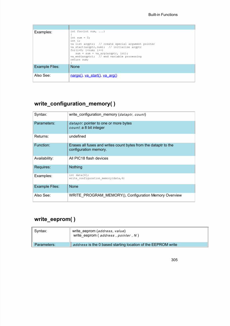
8/10/2019 avr.pdf
http://slidepdf.com/reader/full/avrpdf 317/365
Built-in Functions
305
Examples: int foo(int num, ...){int sum = 0;int i;va_list argptr; // create special argument pointerva_start(argptr,num); // initialize argptrfor(i=0; i<num; i++)
sum = sum + va_arg(argptr, int);va_end(argptr); // end variable processingreturn sum;}
Example Files: None
Also See: nargs() , va_start() , va_arg()
write_configuration_memory( )Syntax: write_configuration_memory ( dataptr, count )
Parameters: dataptr : pointer to one or more bytesc o u n t : a 8 bit integer
Returns: undefined
Function: Erases all fuses and writes count bytes from the dataptr to theconfiguration memory.
Availability: All PIC18 flash devices
Requires: Nothing
Examples: int data[6];write_configuration_memory(data,6)
Example Files: None
Also See: WRITE_PROGRAM_MEMORY(), Configuration Memory Overview
write_eeprom( )
Syntax: write_eeprom ( address , value )write_eeprom ( address , pointer , N )
Parameters: address is the 0 based starting location of the EEPROM write

8/10/2019 avr.pdf
http://slidepdf.com/reader/full/avrpdf 318/365
PCD Manual
306
N specifies the number of EEPROM bytes to writevalue is a constant or variable to write to EEPROMpointer is a pointer to location to data to be written to EEPROM
Returns: undefined
Function: This function will write the specified value to the given address of EEPROM. Ifpointers are used than the function will write n bytes of data from the pointer toEEPROM starting at the value of address.In order to allow interrupts to occur while using the write operation, use the#DEVICE option WRITE_EEPROM = NOINT. This will allow interrupts to occurwhile the write_eeprom() operations is polling the done bit to check if the writeoperations has completed. Can be used as long as no EEPROM operationsare performed during an ISR.
Availability: This function is only available on devices with supporting hardware on chip.
Requires: Nothing
Examples: #define LAST_VOLUME 10 // Location in EEPROM
volume++;write_eeprom(LAST_VOLUME,volume);
Example Files: None
Also See: read_eeprom() , write_program_eeprom(), read_program_eeprom(), dataEeprom Overview
write_extended_ram( )
Syntax: write_extended_ram ( page,address,data,count );
Parameters: page – the page in extended RAM to write toaddress – the address on the selected page to start writing todata – pointer to the data to be writtencount – the number of bytes to write (0-32768)
Returns: undefined
Function: To write data to the extended RAM of the PIC.
Availability: On devices with more then 30K of RAM.
Requires: Nothing
Examples: unsigned int8 data[8] = {0x01,0x02,0x03,0x04,0x05,0x06,0x07,0x08};

8/10/2019 avr.pdf
http://slidepdf.com/reader/full/avrpdf 319/365
Built-in Functions
307
write_extended_ram(1,0x0000,data,8);
Example Files: None
Also See: read_extended_ram() , Extended RAM Overview
zdc_status( )
Syntax: value=zcd_status()
Parameters: None
Returns:
value - the status of the ZCD module. The following defines areheader file and are as follows:
ZCD_IS_SINKING ZCD_IS_SOURCING
Function:To determine if the Zero-Cross Detection (ZCD) module is currentIf the ZCD module is setup to have the output polarity inverted, th
Availability: All devices with a ZCD module.
Examples: value=zcd_status():
Example Files: None
Also See: setup_zcd()

8/10/2019 avr.pdf
http://slidepdf.com/reader/full/avrpdf 320/365

8/10/2019 avr.pdf
http://slidepdf.com/reader/full/avrpdf 321/365
309
STANDARD C INCLUDE FILES
errno.h
errno.hEDOM Domain error valueERANGE Range error valueerrno error value
float.h
float.hFLT_RADIX: Radix of the exponent representationFLT_MANT_DIG: Number of base digits in the floating point significantFLT_DIG: Number of decimal digits, q, such that any floating point
number with q decimal digits can be rounded into afloating point number with p radix b digits and backagain without change to the q decimal digits.
FLT_MIN_EXP: Minimum negative integer such that FLT_RADIX raisedto that power minus 1 is a normalized floating-point
number.FLT_MIN_10_EXP: Minimum negative integer such that 10 raised to thatpower is in the range of normalized floating-pointnumbers.
FLT_MAX_EXP: Maximum negative integer such that FLT_RADIX raisedto that power minus 1 is a representable finite floating-point number.
FLT_MAX_10_EXP: Maximum negative integer such that 10 raised to thatpower is in the range representable finite floating-pointnumbers.
FLT_MAX: Maximum representable finite floating point number.FLT_EPSILON: The difference between 1 and the least value greater
than 1 that is representable in the given floating pointtype.FLT_MIN: Minimum normalized positive floating point numberDBL_MANT_DIG: Number of base digits in the double significantDBL_DIG: Number of decimal digits, q, such that any double
number with q decimal digits can be rounded into adouble number with p radix b digits and back againwithout change to the q decimal digits.
DBL_MIN_EXP: Minimum negative integer such that FLT_RADIX raised

8/10/2019 avr.pdf
http://slidepdf.com/reader/full/avrpdf 322/365
PCD Manual
310
to that power minus 1 is a normalized double number.DBL_MIN_10_EXP: Minimum negative integer such that 10 raised to that
power is in the range of normalized double numbers.DBL_MAX_EXP: Maximum negative integer such that FLT_RADIX raised
to that power minus 1 is a representable finite doublenumber.
DBL_MAX_10_EXP: Maximum negative integer such that 10 raised to thatpower is in the range of representable finite doublenumbers.
DBL_MAX: Maximum representable finite floating point number.DBL_EPSILON: The difference between 1 and the least value greater
than 1 that is representable in the given floating pointtype.
DBL_MIN: Minimum normalized positive double number.LDBL_MANT_DIG: Number of base digits in the floating point significantLDBL_DIG: Number of decimal digits, q, such that any floating point
number with q decimal digits can be rounded into afloating point number with p radix b digits and backagain without change to the q decimal digits.
LDBL_MIN_EXP: Minimum negative integer such that FLT_RADIX raisedto that power minus 1 is a normalized floating-pointnumber.
LDBL_MIN_10_EXP: Minimum negative integer such that 10 raised to thatpower is in the range of normalized floating-pointnumbers.
LDBL_MAX_EXP: Maximum negative integer such that FLT_RADIX raisedto that power minus 1 is a representable finite floating-point number.
LDBL_MAX_10_EXP: Maximum negative integer such that 10 raised to thatpower is in the range of representable finite floating-
point numbers.LDBL_MAX: Maximum representable finite floating point number.LDBL_EPSILON: The difference between 1 and the least value greater
than 1 that is representable in the given floating pointtype.
LDBL_MIN: Minimum normalized positive floating point number.
limits.h
limits.hCHAR_BIT: Number of bits for the smallest object that is not a
bit_field.SCHAR_MIN: Minimum value for an object of type signed charSCHAR_MAX: Maximum value for an object of type signed charUCHAR_MAX: Maximum value for an object of type unsigned charCHAR_MIN: Minimum value for an object of type char(unsigned)CHAR_MAX: Maximum value for an object of type char(unsigned)

8/10/2019 avr.pdf
http://slidepdf.com/reader/full/avrpdf 323/365
Standard C Include Files
311
MB_LEN_MAX: Maximum number of bytes in a multibyte character.SHRT_MIN: Minimum value for an object of type short intSHRT_MAX: Maximum value for an object of type short intUSHRT_MAX: Maximum value for an object of type unsigned short intINT_MIN: Minimum value for an object of type signed intINT_MAX: Maximum value for an object of type signed intUINT_MAX: Maximum value for an object of type unsigned intLONG_MIN: Minimum value for an object of type signed long intLONG_MAX: Maximum value for an object of type signed long intULONG_MAX: Maximum value for an object of type unsigned long int
locale.h
locale.h
locale.h (Localization not supported)lconv localization structureSETLOCALE() returns nullLOCALCONV() returns clocale
setjmp.h
setjmp.h
jmp_buf: An array used by the following functionssetjmp: Marks a return point for the next longjmplongjmp: Jumps to the last marked point
stddef.h
stddef.hptrdiff_t: The basic type of a pointersize_t: The type of the sizeof operator (int)wchar_t The type of the largest character set supported (char) (8 bits)NULL A null pointer (0)

8/10/2019 avr.pdf
http://slidepdf.com/reader/full/avrpdf 324/365
PCD Manual
312
stdio.h
stdio.hstderr The standard error s stream (USE RS232 specified as stream or the first
USE RS232)stdout The standard output stream (USE RS232 specified as stream last USERS232)
stdin The standard input s stream (USE RS232 specified as stream last USERS232)
stdlib.h
stdlib.hdiv_t structure type that contains two signed integers
(quot and rem).ldiv_t structure type that contains two signed longs (quot
and remEXIT_FAILURE returns 1EXIT_SUCCESS returns 0RAND_MAX-MBCUR_MAX- 1SYSTEM() Returns 0( not supported)Multibyte character and stringfunctions:
Multibyte characters not supported
MBLEN() Returns the length of the string.MBTOWC() Returns 1.WCTOMB() Returns 1.MBSTOWCS() Returns length of string.WBSTOMBS() Returns length of string.
Stdlib.h functions included just for compliance with ANSI C.

8/10/2019 avr.pdf
http://slidepdf.com/reader/full/avrpdf 325/365
313
ERROR MESSAGESCompiler Error Messages
# ENDIF with no corresponding #IFCompiler found a #ENDIF directive without a corresponding #IF.#ERROR
A #DEVICE required before this lineThe compiler requires a #device before it encounters any statement or compiler directive thatmay cause it to generate code. In general #defines may appear before a #device but not muchmore.
ADDRESSMOD function definition is incorrect
ADDRESSMOD range is invalid A numeric expression must appear hereSome C expression (like 123, A or B+C) must appear at this spot in the code. Some expressionthat will evaluate to a value.
Arrays of bits are not permitted Arrays may not be of SHORT INT. Arrays of Records are permitted but the record size isalways rounded up to the next byte boundary.
Assignment invalid: value is READ ONLY Attempt to create a pointer to a constantConstant tables are implemented as functions. Pointers cannot be created to functions. Forexample CHAR CONST MSG[9]={"HI THERE"}; is permitted, however you cannot use &MSG.
You can only reference MSG with subscripts such as MSG[i] and in some function calls such asPrintf and STRCPY. Attributes used may only be applied to a function (INLINE or SEPARATE) An attempt was made to apply #INLINE or #SEPARATE to something other than a function.
Bad ASM syntaxBad expression syntaxThis is a generic error message. It covers all incorrect syntax.Baud rate out of rangeThe compiler could not create code for the specified baud rate. If the internal UART is beingused the combination of the clock and the UART capabilities could not get a baud rate within3% of the requested value. If the built in UART is not being used then the clock will not permit
the indicated baud rate. For fast baud rates, a faster clock will be required.BIT variable not permitted here Addresses cannot be created to bits. For example &X is not permitted if X is a SHORT INT.
Branch out of range Cannot change device type this far into the codeThe #DEVICE is not permitted after code is generated that is device specific. Move the#DEVICE to an area before code is generated.Character constant constructed incorrectly

8/10/2019 avr.pdf
http://slidepdf.com/reader/full/avrpdf 326/365
PCD Manual
314
Generally this is due to too many characters within the single quotes. For example 'ab' is anerror as is '\nr'. The backslash is permitted provided the result is a single character such as'\010' or '\n'.Constant out of the valid rangeThis will usually occur in inline assembly where a constant must be within a particular range andit is not. For example BTFSC 3,9 would cause this error since the second operand must be from0-8.
Data item too big Define expansion is too large
A fully expanded DEFINE must be less than 255 characters. Check to be sure the DEFINE isnot recursively defined.Define syntax errorThis is usually caused by a missing or misplaced (or) within a define.Demo period has expiredPlease contact CCS to purchase a licensed copy.
www.ccsinfo.com/pricing Different levels of indirectionThis is caused by a INLINE function with a reference parameter being called with a parameterthat is not a variable. Usually calling with a constant causes this.Divide by zero
An attempt was made to divide by zero at compile time using constants.Duplicate case valueTwo cases in a switch statement have the same value.Duplicate DEFAULT statementsThe DEFAULT statement within a SWITCH may only appear once in each SWITCH. This errorindicates a second DEFAULT was encountered.Duplicate function
A function has already been defined with this name. Remember that the compiler is not case
sensitive unless a #CASE is used.Duplicate Interrupt ProcedureOnly one function may be attached to each interrupt level. For example the #INT_RB may onlyappear once in each program.Element is not a member
A field of a record identified by the compiler is not actually in the record. Check the identifierspelling.ELSE with no corresponding IFCompiler found an ELSE statement without a corresponding IF. Make sure the ELSE statementalways match with the previous IF statement.End of file while within define definitionThe end of the source file was encountered while still expanding a define. Check for a missing
).End of source file reached without closing comment */ symbolThe end of the source file has been reached and a comment (started with /*) is still in effect.The */ is missing.
type are INT and CHAR.
Expect ;Expect }Expect CASE

8/10/2019 avr.pdf
http://slidepdf.com/reader/full/avrpdf 327/365
Error Messages
315
Expect commaExpect WHILEExpecting *Expecting :Expecting <Expecting =Expecting >Expecting a (Expecting a , or )Expecting a , or }Expecting a .Expecting a ; or ,Expecting a ; or {Expecting a close parenExpecting a declarationExpecting a structure/unionExpecting a variableExpecting an =Expecting a ]Expecting a {Expecting an arrayExpecting an identifierExpecting function nameExpecting an opcode mnemonicThis must be a Microchip mnemonic such as MOVLW or BTFSC.Expecting LVALUE such as a variable name or * expressionThis error will occur when a constant is used where a variable should be. For example 4=5; willgive this error.Expecting a basic typeExamples of a basic type are INT and CHAR.
Expression must be a constant or simple variableThe indicated expression must evaluate to a constant at compile time. For example 5*3+1 ispermitted but 5*x+1 where X is a INT is not permitted. If X were a DEFINE that had a constantvalue then it is permitted.Expression must evaluate to a constantThe indicated expression must evaluate to a constant at compile time. For example 5*3+1 ispermitted but 5*x+1 where X is a INT is not permitted. If X were a DEFINE that had a constantvalue then it is permitted.Expression too complexThis expression has generated too much code for the compiler to handle for a singleexpression. This is very rare but if it happens, break the expression up into smaller parts.
Too many assembly lines are being generated for a single C statement. Contact CCS toincrease the internal limits.
EXTERNal symbol not found
EXTERNal symbol type mis-match Extra characters on preprocessor command line

8/10/2019 avr.pdf
http://slidepdf.com/reader/full/avrpdf 328/365
PCD Manual
316
Characters are appearing after a preprocessor directive that do not apply to that directive.Preprocessor commands own the entire line unlike the normal C syntax. For example the
following is an error:#PRAGMA DEVICE <PIC16C74> main() { int x; x=1;}File cannot be openedCheck the filename and the current path. The file could not be opened.
File cannot be opened for writeThe operating system would not allow the compiler to create one of the output files. Make surethe file is not marked READ ONLY and that the compiler process has write privileges to thedirectory and file.Filename must start with " or <The correct syntax of a #include is one of the following two formats:#include "filename.ext"#include <filename.ext>This error indicates neither a " or < was found after #include.Filename must terminate with " or; msg:' 'The filename specified in a #include must terminate with a " if it starts with a ". It must terminatewith a > if it starts with a <.Floating-point numbers not supported for this operation
A floating-point number is not permitted in the operation near the error. For example, ++Fwhere F is a float is not allowed.Function definition different from previous definitionThis is a mis-match between a function prototype and a function definition. Be sure that if a#INLINE or #SEPARATE are used that they appear for both the prototype and definition. Thesedirectives are treated much like a type specifier.
Function used but not definedThe indicated function had a prototype but was never defined in the program.Identifier is already used in this scope
An attempt was made to define a new identifier that has already been defined.Illegal C character in input file
A bad character is in the source file. Try deleting the line and re-typing it.
Import error Improper use of a function identifierFunction identifiers may only be used to call a function. An attempt was made to otherwisereference a function. A function identifier should have a ( after it.Incorrectly constructed labelThis may be an improperly terminated expression followed by a label. For example:x=5+MPLAB:Initialization of unions is not permittedStructures can be initialized with an initial value but UNIONS cannot be.Internal compiler limit reachedThe program is using too much of something. An internal compiler limit was reached. ContactCCS and the limit may be able to be expanded.Internal Error - Contact CCSThis error indicates the compiler detected an internal inconsistency. This is not an error with thesource code; although, something in the source code has triggered the internal error. Thisproblem can usually be quickly corrected by sending the source files to CCS so the problem canbe re-created and corrected.

8/10/2019 avr.pdf
http://slidepdf.com/reader/full/avrpdf 329/365
Error Messages
317
In the meantime if the error was on a particular line, look for another way to perform the sameoperation. The error was probably caused by the syntax of the identified statement. If the errorwas the last line of the code, the problem was in linking. Look at the call tree for something outof the ordinary.Interrupt handler uses too much stackToo many stack locations are being used by an interrupt handler.Invalid conversion from LONG INT to INTIn this case, a LONG INT cannot be converted to an INT. You can type cast the LONG INT toperform a truncation. For example:I = INT(LI);Invalid interrupt directiveInvalid parameters to built in functionBuilt-in shift and rotate functions (such as SHIFT_LEFT) require an expression that evaluates toa constant to specify the number of bytes.Invalid Pre-Processor directiveThe compiler does not know the preprocessor directive. This is the identifier in one of thefollowing two places:#xxxxx#PRAGMA xxxxx
Invalid ORG rangeThe end address must be greater than or equal to the start address. The range may not overlapanother range. The range may not include locations 0-3. If only one address is specified itmust match the start address of a previous #org.
Invalid overload function Invalid type conversionLabel not permitted hereLibrary in USE not foundThe identifier after the USE is not one of the pre-defined libraries for the compiler. Check thespelling.Linker Error: "%s" already defined in "%s"Linker Error: ("%s'Linker Error: Canont allocate memory for the section "%s" in the module "%s", because itoverlaps with other sections.Linker Error: Cannot find unique match for symbol "%s"Linker Error: Cannot open file "%s"Linker Error: COFF file "%s" is corrupt; recompile module.Linker Error: Not enough memory in the target to reallocate the section "%s" in the module"%s".Linker Error: Section "%s" is found in the modules "%s" and "%s" with different section types.Linker Error: Unknown error, contact CCS support.Linker Error: Unresolved external symbol "%s" inside the module "%s".Linker option no compatible with prior options.Linker Warning: Section "%s" in module "%s" is declared as shared but there is no sharedmemory in the target chip. The shared flag is ignored.Linker option not compatible with prior optionsConflicting linker options are specified. For example using both the EXCEPT= and ONLY=options in the same directive is not legal.LVALUE requiredThis error will occur when a constant is used where a variable should be. For example 4=5; willgive this error.Macro identifier requires parameters

8/10/2019 avr.pdf
http://slidepdf.com/reader/full/avrpdf 330/365
PCD Manual
318
A #DEFINE identifier is being used but no parameters were specified, as required. Forexample:#define min(x,y) ((x<y)?x:y)When called MIN must have a (--,--) after it such as:r=min(value, 6);Macro is defined recursively
A C macro has been defined in such a way as to cause a recursive call to itself.Missing #ENDIF A #IF was found without a corresponding #ENDIF.Missing or invalid .CRG fileThe user registration file(s) are not part of the download software. In order for the software torun the files must be in the same directory as the .EXE files. These files are on the originaldiskette, CD ROM or e-mail in a non-compressed format. You need only copy them to the .EXEdirectory. There is one .REG file for each compiler (PCB.REG, PCM.REG and PCH.REG).
More info:
Must have a #USE DELAY before this #USEMust have a #USE DELAY before a #USE RS232The RS232 library uses the DELAY library. You must have a #USE DELAY before you can doa #USE RS232.No errorsThe program has successfully compiled and all requested output files have been created.No MAIN() function found
All programs are required to have one function with the name main().
No overload function matches
No valid assignment made to function pointer Not enough RAM for all variablesThe program requires more RAM than is available. The symbol map shows variables allocated.The call tree shows the RAM used by each function. Additional RAM usage can be obtained by
breaking larger functions into smaller ones and splitting the RAM between them.
For example, a function A may perform a series of operations and have 20 local variablesdeclared. Upon analysis, it may be determined that there are two main parts to the calculationsand many variables are not shared between the parts. A function B may be defined with 7 localvariables and a function C may be defined with 7 local variables. Function A now calls B and Cand combines the results and now may only need 6 variables. The savings are accomplishedbecause B and C are not executing at the same time and the same real memory locations willbe used for their 6 variables (just not at the same time). The compiler will allocate only 13locations for the group of functions A, B, C where 20 were required before to perform the sameoperation.Number of bits is out of rangeFor a count of bits, such as in a structure definition, this must be 1-8. For a bit numberspecification, such as in the #BIT, the number must be 0-7.
Only integers are supported for this operation
Option invalid Out of ROM, A segment or the program is too large

8/10/2019 avr.pdf
http://slidepdf.com/reader/full/avrpdf 331/365
Error Messages
319
A function and all of the INLINE functions it calls must fit into one segment (a hardware codepage). For example, on the PIC16 chip a code page is 512 instructions. If a program has onlyone function and that function is 600 instructions long, you will get this error even though thechip has plenty of ROM left. The function needs to be split into at least two smaller functions.Even after this is done, this error may occur since the new function may be only called once
and the linker might automatically INLINE it. This is easily determined by reviewing the call tree.If this error is caused by too many functions being automatically INLINED by the linker, simply
add a #SEPARATE before a function to force the function to be SEPARATE. Separatefunctions can be allocated on any page that has room. The best way to understand the causeof this error is to review the call tree.
Parameters must be located in RAM Parameters not permitted
An identifier that is not a function or preprocessor macro can not have a ' ( ' after it.Pointers to bits are not permitted
Addresses cannot be created to bits. For example, &X is not permitted if X is a SHORT INT.Previous identifier must be a pointer
A -> may only be used after a pointer to a structure. It cannot be used on a structure itself orother kind of variable.Printf format type is invalid
An unknown character is after the % in a printf. Check the printf reference for valid formats.Printf format (%) invalid
A bad format combination was used. For example, %lc.Printf variable count (%) does not match actual countThe number of % format indicators in the printf does not match the actual number of variablesthat follow. Remember in order to print a single %, you must use %%.Recursion not permittedThe linker will not allow recursive function calls. A function may not call itself and it may not callany other function that will eventually re-call it.Recursively defined structures not permitted
A structure may not contain an instance of itself.Reference arrays are not permitted
A reference parameter may not refer to an array.Return not allowed in void function
A return statement may not have a value if the function is void.
RTOS call only allowed inside task functions
Selected part does not have ICD debug capabilitySTDOUT not defined (may be missing #RS 232)
An attempt was made to use a I/O function such as printf when no default I/O stream has beenestablished. Add a #USE RS232 to define a I/O stream.
Stream must be a constant in the valid rangeI/O functions like fputc, fgetc require a stream identifier that was defined in a #USE RS232.This identifier must appear exactly as it does when it was defined. Be sure it has not been
redefined with a #define.String too longStructure field name required
A structure is being used in a place where a field of the structure must appear. Change to theform s.f where s is the structure name and f is a field name.

8/10/2019 avr.pdf
http://slidepdf.com/reader/full/avrpdf 332/365
PCD Manual
320
Structures and UNIONS cannot be parameters (use * or &) A structure may not be passed by value. Pass a pointer to the structure using &.Subscript out of range
A subscript to a RAM array must be at least 1 and not more than 128 elements. Note that largearrays might not fit in a bank. ROM arrays may not occupy more than 256 locations.This linker function is not available in this compiler version.Some linker functions are only available if the PCW or PCWH product is installed.This type cannot be qualified with this qualifierCheck the qualifiers. Be sure to look on previous lines. An example of this error is:VOID X;Too many array subscripts
Arrays are limited to 5 dimensions.Too many constant structures to fit into available space
Available space depends on the chip. Some chips only allow constant structures in certainplaces. Look at the last calling tree to evaluate space usage. Constant structures will appearas functions with a @CONST at the beginning of the name.Too many elements in an ENUM
A max of 256 elements are allowed in an ENUM.
Too many fast interrupt handlers have been defined Too many fast interrupt handlers have been identifiedToo many nested #INCLUDEsNo more than 10 include files may be open at a time.Too many parametersMore parameters have been given to a function than the function was defined with.Too many subscriptsMore subscripts have been given to an array than the array was defined with.Type is not definedThe specified type is used but not defined in the program. Check the spelling.Type specification not valid for a function
This function has a type specifier that is not meaningful to a function.Undefined identifierUndefined label that was used in a GOTOThere was a GOTO LABEL but LABEL was never encountered within the required scope. AGOTO cannot jump outside a function.Unknown device type
A #DEVICE contained an unknown device. The center letters of a device are always Cregardless of the actual part in use. For example, use PIC16C74 not PIC16RC74. Be sure thecorrect compiler is being used for the indicated device. See #DEVICE for more information.Unknown keyword in #FUSESCheck the keyword spelling against the description under #FUSES.
Unknown linker keywordThe keyword used in a linker directive is not understood.Unknown typeThe specified type is used but not defined in the program. Check the spelling.
User aborted compilationUSE parameter invalidOne of the parameters to a USE library is not valid for the current environment.

8/10/2019 avr.pdf
http://slidepdf.com/reader/full/avrpdf 333/365
Error Messages
321
USE parameter value is out of rangeOne of the values for a parameter to the USE library is not valid for the current environment.
Variable never used
Variable of this data type is never greater than this constant

8/10/2019 avr.pdf
http://slidepdf.com/reader/full/avrpdf 334/365
8/10/2019 avr.pdf
http://slidepdf.com/reader/full/avrpdf 335/365
323
COMPILER WARNING MESSAGES
Compiler Warning Messages
#error/warning Assignment inside relational expression Although legal it is a common error to do something like if(a=b) when it was intended to doif(a==b).
Assignment to enum is not of the correct type.This warning indicates there may be such a typo in this line:
Assignment to enum is not of the correct typeIf a variable is declared as a ENUM it is best to assign to the variables only elements of the
enum. For example:enum colors {RED,GREEN,BLUE} color;...color = GREEN; // OKcolor = 1; // Warning 209color = (colors)1; //OK
Code has no effectThe compiler can not discern any effect this source code could have on the generated code.Some examples:
1;a==b;1,2,3;
Condition always FALSEThis error when it has been determined at compile time that a relational expression will never be
true. For example:int x;if( x>>9 )
Condition always TRUEThis error when it has been determined at compile time that a relational expression will never befalse. For example:
#define PIN_A1 41...if( PIN_A1 ) // Intended was: if( input(PIN_A1) )
Function not void and does not return a valueFunctions that are declared as returning a value should have a return statement with a value tobe returned. Be aware that in C only functions declared VOID are not intended to return a value.If nothing is specified as a function return value "int" is assumed.
Duplicate #defineThe identifier in the #define has already been used in a previous #define. To redefine anidentifier use #UNDEF first. To prevent defines that may be included from multiple source dosomething like:
#ifndef ID#define ID text#endif
Feature not supported

8/10/2019 avr.pdf
http://slidepdf.com/reader/full/avrpdf 336/365
PCD Manual
324
Function never called
Function not void and does not return a value.
Info:
Interrupt level changed
Interrupts disabled during call to prevent re-entrancy.Linker Warning: "%s" already defined in object "%s"; second definition ignored.Linker Warning: Address and size of section "%s" in module "%s" exceeds maximum range forthis processor. The section will be ignored.Linker Warning: The module "%s" doesn't have a valid chip id. The module will be consideredfor the target chip "%s".Linker Warning: The target chip "%s" of the imported module "%s" doesn't match the target chip"%s" of the source.Linker Warning: Unsupported relocation type in module "%s".
Memory not available at requested location.Operator precedence rules may not be as intended, use() to clarifySome combinations of operators are confusing to some programmers. This warning is issuedfor expressions where adding() would help to clarify the meaning. For example:
if( x << n + 1 )would be more universally understood when expressed:
if( x << (n + 1) )Option may be wrongStructure passed by valueStructures are usually passed by reference to a function. This warning is generated if thestructure is being passed by value. This warning is not generated if the structure is less than 5bytes. For example:
void myfunct( mystruct s1 ) // Pass by value - Warning
myfunct( s2 );void myfunct( mystruct * s1 ) // Pass by reference - OKmyfunct( &s2 );void myfunct( mystruct & s1 ) // Pass by reference - OKmyfunct( s2 );
Undefined identifierThe specified identifier is being used but has never been defined. Check the spelling.Unprotected call in a #INT_GLOBALThe interrupt function defined as #INT_GLOBAL is intended to be assembly language or verysimple C code. This error indicates the linker detected code that violated the standard memoryallocation scheme. This may be caused when a C function is called from a #INT_GLOBALinterrupt handler.Unreachable code
Code included in the program is never executed. For example:if(n==5)goto do5;
goto exit;if(n==20) // No way to get to this line
return;Unsigned variable is never less than zeroUnsigned variables are never less than 0. This warning indicates an attempt to check to see ifan unsigned variable is negative. For example the following will not work as intended:
int i;for(i=10; i>=0; i--)

8/10/2019 avr.pdf
http://slidepdf.com/reader/full/avrpdf 337/365
Compiler Warning Messages
325
Variable assignment never used.Variable of this data type is never greater than this constant
A variable is being compared to a constant. The maximum value of the variable could never belarger than the constant. For example the following could never be true:
int x; // 8 bits, 0-255
if ( x>300)
Variable never used A variable has been declared and never referenced in the code.
Variable used before assignment is made.

8/10/2019 avr.pdf
http://slidepdf.com/reader/full/avrpdf 338/365

8/10/2019 avr.pdf
http://slidepdf.com/reader/full/avrpdf 339/365
327
COMMON QUESTIONS & ANSWERS
How are type conversions handled?
The compiler provides automatic type conversions when an assignment is performed. Someinformation may be lost if the destination can not properly represent the source. For example:int8var = int16var; Causes the top byte of int16var to be lost.
Assigning a smaller signed expression to a larger signed variable will result in the sign beingmaintained. For example, a signed 8 bit int that is -1 when assigned to a 16 bit signed variableis still -1.
Signed numbers that are negative when assigned to a unsigned number will cause the 2's
complement value to be assigned. For example, assigning -1 to a int8 will result in the int8 being255. In this case the sign bit is not extended (conversion to unsigned is done before conversionto more bits). This means the -1 assigned to a 16 bit unsigned is still 255.
Likewise assigning a large unsigned number to a signed variable of the same size or smaller willresult in the value being distorted. For example, assigning 255 to a signed int8 will result in -1.
The above assignment rules also apply to parameters passed to functions.
When a binary operator has operands of differing types then the lower order operand isconverted (using the above rules) to the higher. The order is as follows:
Float
Signed 32 bit Unsigned 32 bit Signed 16 bit Unsigned 16 bit Signed 8 bit Unsigned 8 bit 1 bit
The result is then the same as the operands. Each operator in an expression is evaluatedindependently. For example:
i32 = i16 - (i8 + i8)
The + operator is 8 bit, the result is converted to 16 bit after the addition and the - is 16 bit, thatresult is converted to 32 bit and the assignment is done. Note that if i8 is 200 and i16 is 400then the result in i32 is 256. (200 plus 200 is 144 with a 8 bit +)
Explicit conversion may be done at any point with (type) inserted before the expression to beconverted. For example in the above the perhaps desired effect may be achieved by doing:
i32 = i16 - ((long)i8 + i8)

8/10/2019 avr.pdf
http://slidepdf.com/reader/full/avrpdf 340/365
PCD Manual
328
In this case the first i8 is converted to 16 bit, then the add is a 16 bit add and the second i8 isforced to 16 bit.
A common C programming error is to do something like:
i16 = i8 * 100;
When the intent was:i16 = (long) i8 * 100;
Remember that with unsigned ints (the default for this compiler) the values are nevernegative. For example 2-4 is 254 (in 8 bit). This means the following is an endless loop since iis never less than 0:
int i;for( i=100; i>=0; i--)
How can a constant data table be placed in ROM?
The compiler has support for placing any data structure into the device ROM as a constantread-only element. Since the ROM and RAM data paths are separate , there are restrictions onhow the data is accessed. For example, to place a 10 element BYTE array in ROM use:BYTE CONST TABLE [10]= {9,8,7,6,5,4,3,2,1,0};
and to access the table use:x = TABLE [i];ORx = TABLE [5];
BUT NOTptr = &TABLE [i];
In this case, a pointer to the table cannot be constructed.
Similar constructs using CONST may be used with any data type including structures, longs andfloats.
The following are two methods provided:
1. Efficient access with "const".
2. Pointer friendly "ROM" Qualifier, for example:ROM BYTE TABLE[10] = {9,8,7,6,5,4,3,2,1,0}and to access the table use:
x = TABLE[i];orPTR = &TABLE[i];and

8/10/2019 avr.pdf
http://slidepdf.com/reader/full/avrpdf 341/365
Common Questions & Answers
329
x = *PTR;//Be sure not to mix RAM and ROM pointers. They are not interchangeable.
How can I use two or more RS-232 ports on one PIC®?
The #USE RS232 (and I2C for that matter) is in effect for GETC, PUTC, PRINTF and KBHITfunctions encountered until another #USE RS232 is found.
The #USE RS232 is not an executable line. It works much like a #DEFINE.
The following is an example program to read from one RS-232 port (A) and echo the data toboth the first RS-232 port (A) and a second RS-232 port (B).
#USE RS232(BAUD=9600, XMIT=PIN_B0, RCV=PIN_B1)void put_to_a( char c ) {
put(c);}
char get_from_a( ) {return(getc()); }#USE RS232(BAUD=9600, XMIT=PIN_B2,RCV=PIN_B3)void put_to_b( char b ) {
putc(c);}main() {
char c;put_to_a("Online\n\r");put_to_b("Online\n\r");while(TRUE) {
c=get_from_a();put_to_b(c);put_to_a(c);
}}
The following will do the same thing but is more readable and is the recommended method:
#USE RS232(BAUD=9600, XMIT=PIN_B0, RCV=PIN_B1, STREAM=COM_A)#USE RS232(BAUD=9600, XMIT=PIN_B2, RCV=PIN_B3, STREAM=COM_B)
main() {char c;fprintf(COM_A,"Online\n\r");fprintf(COM_B,"Online\n\r");while(TRUE) {
c = fgetc(COM_A);fputc(c, COM_A);fputc(c, COM_B);
}}
How do I directly read/write to internal registers?
A hardware register may be mapped to a C variable to allow direct read and write capability tothe register. The following is an example using the TIMER0 register:#BYTE timer 1 = 0x 100

8/10/2019 avr.pdf
http://slidepdf.com/reader/full/avrpdf 342/365
PCD Manual
330
timer0= 128; //set timer0 to 128while (timer 1 ! = 200); // wait for timer0 to reach 200
Bits in registers may also be mapped as follows:#BIT T 1 IF = 0x 84.3...while (!T 1 IF); //wait for timer0 interrupt
Registers may be indirectly addressed as shown in the following example:printf ("enter address:");a = gethex ();printf ("\r\n value is %x\r\n", *a);
The compiler has a large set of built-in functions that will allow one to perform the most commontasks with C function calls. When possible, it is best to use the built-in functions rather thandirectly write to registers. Register locations change between chips and some registeroperations require a specific algorithm to be performed when a register value is changed. Thecompiler also takes into account known chip errata in the implementation of the built-infunctions. For example, it is better to do set_tris_ B (0); rather than *0x 02C6 =0;
How do I do a printf to a string?
The following is an example of how to direct the output of a printf to a string. We used the \f toindicate the start of the string.
This example shows how to put a floating point number in a string.
main() {char string[20];float f;f=12.345;sprintf(string,"\f%6.3f",f);
}
How do I get getc() to timeout after a specified time?
GETC will always wait for a character to become available unless a timeout time is specified inthe #use rs232().The following is an example of how to setup the PIC to timeout when waiting for an RS232character.
#include <18F4520.h>#fuses HS,NOWDT#use delay(clock=20MHz)#use rs232(UART1,baud=9600,timeout=500) //timeout = 500 milliseconds, 1/2 secondvoid main(){
char c;
while(TRUE)

8/10/2019 avr.pdf
http://slidepdf.com/reader/full/avrpdf 343/365
Common Questions & Answers
331
{c=getc(); //if getc() timeouts 0 is returned to c
//otherwise receive character is returned to c
if(c) //if not zero echo character backputc(c);
//user to do codeoutput_toggle(PIN_A5);
}}
How do I wait only a specified time for a button press?
The following is an example of how to wait only a specific time for a button press.
#define PUSH_BUTTON PIN_A4int1 timeout_error;int1 timed_get_button_press(void){
int16 timeout;
timeout_error=FALSE;timeout=0;while(input(PUSH_BUTTON) && (++timeout<50000)) // 1/2 second
delay_us(10);if(!input(PUSH_BUTTON))
return(TRUE); //button pressedelse{
timeout_error=TRUE;return(FALSE); //button not pressed timeout occurred
}}
How does one map a variable to an I/O port?
Two methods are as follows:#byte PORTB = 0x02C8 //Just an example, check the#define ALL_OUT 0 //DATA sheet for the correct#define ALL_IN 0xff //address for your chipmain() {
int i;
set_tris_b(ALL_OUT);PORTB = 0;// Set all pins lowfor(i=0;i<=127;++i) // Quickly count from 0 to 127
PORTB=i; // on the I/O port pinset_tris_b(ALL_IN);i = PORTB; // i now contains the portb value.
}
Remember when using the #BYTE, the created variable is treated like memory. You mustmaintain the tri-state control registers yourself via the SET_TRIS_X function. Following is anexample of placing a structure on an I/O port:
struct port_b_layout{int data : 4;

8/10/2019 avr.pdf
http://slidepdf.com/reader/full/avrpdf 344/365
PCD Manual
332
int rw : 1;int cd : 1;
};struct port_b_layout port_b;#byte port_b = 0x02C8struct port_b_layout const INIT_1 = {0, 1,1, };struct port_b_layout const INIT_2 = {3, 1,1, };
struct port_b_layout const INIT_3 = {0, 0,0, };struct port_b_layout const FOR_SEND = {0,0,0, };// All outputs
struct port_b_layout const FOR_READ = {15,0,0, };// Data is an input
main() {int x;set_tris_b((int)FOR_SEND); // The constant
// structure is// treated like// a byte and// is used to// set the data// direction
port_b = INIT_1;delay_us(25);
port_b = INIT_2; // These constant structures delay_us(25);// are used to set all fieldsport_b = INIT_3; // on the port with a single
// command
set_tris_b((int)FOR_READ);port_b.rw=0;
// Here the individualport_b.cd=1; // fields are accessed
// independently.x = port_b.data;
}
How does the compiler determine TRUE and FALSE onexpressions?
When relational expressions are assigned to variables, the result is always 0 or 1.
For example:
bytevar = 5>0; //bytevar will be 1bytevar = 0>5; //bytevar will be 0
The same is true when relational operators are used in expressions.
For example:
bytevar = (x>y)*4;
is the same as:
if( x>y )bytevar=4;

8/10/2019 avr.pdf
http://slidepdf.com/reader/full/avrpdf 345/365
Common Questions & Answers
333
elsebytevar=0;
SHORT INTs (bit variables) are treated the same as relational expressions. They evaluate to 0or 1.
When expressions are converted to relational expressions or SHORT INTs, the result will beFALSE (or 0) when the expression is 0, otherwise the result is TRUE (or 1).
For example:
bytevar = 54;bitvar = bytevar; //bitvar will be 1 (bytevar ! = O)if(bytevar) //will be TRUEbytevar = 0;bitvar = bytevar; //bitvar will be 0
How does the PIC® connect to a PC? A level converter should be used to convert the TTL (0-5V_ levels that the PIC® operates withto the RS-232 voltages (+/- 3-12V) used by the PIC®. The following is a popular configurationusing the MAX232 chip as a level converter.
How does the PIC® connect to an I2C device?
Two I/O lines are required for I2C. Both lines must have pullup registers. Often the I2C devicewill have a H/W selectable address. The address set must match the address in S/W. Theexample programs all assume the selectable address lines are grounded.

8/10/2019 avr.pdf
http://slidepdf.com/reader/full/avrpdf 346/365
PCD Manual
334
How much time do math operations take?
Unsigned 8 bit operations are quite fast and floating point is very slow. If possible consider fixedpoint instead of floating point. For example instead of "float cost_in_dollars;" do "longcost_in_cents;". For trig formulas consider a lookup table instead of real time calculations (seeEX_SINE.C for an example). The following are some rough times on a 24-bit PIC®. Note timeswill vary depending on memory banks used.
80mhz dsPIC33FJ (40MIPS)
int8[us]
int16[us]
int32[us]
int48[us]
int64[us]
float32[us]
float48[us]
float 64[us]
+ 0.075 0.75 0.175 0.275 0.375 3.450 3.825 5.025- 0.125 0.125 0.200 0.350 0.400 3.375 3.725 5.225* 0.175 0.100 1.150 1.850 1.975 2.450 2.950 4.525/ 0.650 0.550 13.500 25.550 68.225 12.475 22.575 33.80exp() * * * * * 70.675 158.55 206.125ln() * * * * * 94.475 157.400 201.825sin() * * * * * 77.875 136.925 184.225
What can be done about an OUT OF RAM error?
The compiler makes every effort to optimize usage of RAM. Understanding the RAM allocationcan be a help in designing the program structure. The best re-use of RAM is accomplishedwhen local variables are used with lots of functions. RAM is re-used between functions not

8/10/2019 avr.pdf
http://slidepdf.com/reader/full/avrpdf 347/365
Common Questions & Answers
335
active at the same time. See the NOT ENOUGH RAM error message in this manual for a moredetailed example.
RAM is also used for expression evaluation when the expression is complex. The more complexthe expression, the more scratch RAM locations the compiler will need to allocate to thatexpression. The RAM allocated is reserved during the execution of the entire function but maybe re-used between expressions within the function. The total RAM required for a function is thesum of the parameters, the local variables and the largest number of scratch locations requiredfor any expression within the function. The RAM required for a function is shown in the call treeafter the RAM=. The RAM stays used when the function calls another function and new RAM isallocated for the new function. However when a function RETURNS the RAM may be re-usedby another function called by the parent. Sequential calls to functions each with their own localvariables is very efficient use of RAM as opposed to a large function with local variablesdeclared for the entire process at once.
Be sure to use SHORT INT (1 bit) variables whenever possible for flags and other booleanvariables. The compiler can pack eight such variables into one byte location. The compiler doesthis automatically whenever you use SHORT INT. The code size and ROM size will be smaller.
Finally, consider an external memory device to hold data not required frequently. An external 8pin EEPROM or SRAM can be connected to the PIC® with just 2 wires and provide a great dealof additional storage capability. The compiler package includes example drivers for thesedevices. The primary drawback is a slower access time to read and write the data. The SRAMwill have fast read and write with memory being lost when power fails. The EEPROM will have avery long write cycle, but can retain the data when power is lost.
What is an easy way for two or more PICs® to communicate?
There are two example programs (EX_PBUSM.C and EX_PBUSR.C) that show how to use asimple one-wire interface to transfer data between PICs®. Slower data can use pin B0 and theEXT interrupt. The built-in UART may be used for high speed transfers. An RS232 driver chipmay be used for long distance operations. The RS485 as well as the high speed UART require2 pins and minor software changes. The following are some hardware configurations.

8/10/2019 avr.pdf
http://slidepdf.com/reader/full/avrpdf 348/365
PCD Manual
336
What is an easy way for two or more PICs® to communicate?
There are two example programs (EX_PBUSM.C and EX_PBUSR.C) that show howto use a simple one-wire interface to transfer data between PICs®. Slower data canuse pin B0 and the EXT interrupt. The built-in UART may be used for high speedtransfers. An RS232 driver chip may be used for long distance operations. TheRS485 as well as the high speed UART require 2 pins and minor software changes.The following are some hardware configurations.

8/10/2019 avr.pdf
http://slidepdf.com/reader/full/avrpdf 349/365
Common Questions & Answers
337
Why does the .LST file look out of order?
The list file is produced to show the assembly code created for the C source code. Each Csource line has the corresponding assembly lines under it to show the compiler ’ s work. Thefollowing three special cases make the .LST file look strange to the first time viewer.
Understanding how the compiler is working in these special cases will make the .LST file appearquite normal and very useful.
1. Stray code near the top of the program is sometimes under what looks like a non-executablesource line.
Some of the code generated by the compiler does not correspond to any particular sourceline. The compiler will put this code either near the top of the program or sometimes under a#USE that caused subroutines to be generated.
2. The addresses are out of order.
The compiler will create the .LST file in the order of the C source code. The linker has re-arranged the code to properly fit the functions into the best code pages and the best half of acode page. The resulting code is not in source order. Whenever the compiler has a discontinuityin the .LST file, it will put a * line in the file. This is most often seen between functions and inplaces where INLINE functions are called. In the case of an INLINE function, the addresses willcontinue in order up where the source for the INLINE function is located.
3. The compiler has gone insane and generated the same instruction over and over.

8/10/2019 avr.pdf
http://slidepdf.com/reader/full/avrpdf 350/365
PCD Manual
338
For example:...........A=0;03F: CLRF 15*46:CLRF 15*051: CLRF 15*113: CLRF 15
This effect is seen when the function is an INLINE function and is called from more than oneplace. In the above case, the A=0 line is in an INLINE function called in four places. Each placeit is called from gets a new copy of the code. Each instance of the code is shown along with theoriginal source line, and the result may look unusual until the addresses and the * are noticed.
Why is the RS-232 not working right?
1. The PIC® is Sending Garbage Characters.
A. Check the clock on the target for accuracy. Crystals are usually not a problem but RCoscillators can cause trouble with RS-232. Make sure the #USE DELAY matches theactual clock frequency.
B. Make sure the PC (or other host) has the correct baud and parity setting.
C. Check the level conversion. When using a driver/receiver chip, such as the MAX 232,do not use INVERT when making direct connections with resistors and/or diodes. Youprobably need the INVERT option in the #USE RS232.
D. Remember that PUTC(6) will send an ASCII 6 to the PC and this may not be a visiblecharacter. PUTC('A') will output a visible character A.
2. The PIC® is Receiving Garbage Characters.
A. Check all of the above.
3. Nothing is Being Sent.
A. Make sure that the tri-state registers are correct. The mode (standard, fast, fixed) usedwill be whatever the mode is when the #USE RS232 is encountered. Staying with thedefault STANDARD mode is safest.
B. Use the following main() for testing:
main() {while(TRUE)
putc('U');}

8/10/2019 avr.pdf
http://slidepdf.com/reader/full/avrpdf 351/365
Common Questions & Answers
339
Check the XMIT pin for activity with a logic probe, scope or whatever you can. If you canlook at it with a scope, check the bit time (it should be 1/BAUD). Check again after thelevel converter.
4. Nothing is being received.
First be sure the PIC® can send data. Use the following main() for testing:
main() {printf("start");
while(TRUE)putc( getc()+1 );
}
When connected to a PC typing A should show B echoed back.If nothing is seen coming back (except the initial "Start"), check the RCV pin on the PIC®with a logic probe. You should see a HIGH state and when a key is pressed at the PC, apulse to low. Trace back to find out where it is lost.
5. The PIC® is always receiving data via RS-232 even when none is being sent. A. Check that the INVERT option in the USE RS232 is right for your level converter. Ifthe RCV pin is HIGH when no data is being sent, you should NOT use INVERT. If the pinis low when no data is being sent, you need to use INVERT.
B. Check that the pin is stable at HIGH or LOW in accordance with A above when nodata is being sent.
C. When using PORT A with a device that supports the SETUP_ADC_PORTS functionmake sure the port is set to digital inputs. This is not the default. The same is true fordevices with a comparator on PORT A.
6. Compiler reports INVALID BAUD RATE.
A. When using a software RS232 (no built-in UART), the clock cannot be really slowwhen fast baud rates are used and cannot be really fast with slow baudrates. Experiment with the clock/baud rate values to find your limits.
B. When using the built-in UART, the requested baud rate must be within 3% of a ratethat can be achieved for no error to occur. Some parts have internal bugs with BRGH setto 1 and the compiler will not use this unless you specify BRGH1OK in the #USE RS232directive.

8/10/2019 avr.pdf
http://slidepdf.com/reader/full/avrpdf 352/365

8/10/2019 avr.pdf
http://slidepdf.com/reader/full/avrpdf 353/365
341
EXAMPLE PROGRAMS
EXAMPLE PROGRAMS
A large number of example programs are included with the software. The following is a list ofmany of the programs and some of the key programs are re-printed on the following pages.Most programs will work with any chip by just changing the #INCLUDE line that includes thedevice information. All of the following programs have wiring instructions at the beginning of thecode in a comment header. The SIOW.EXE program included in the program directory may beused to demonstrate the example programs. This program will use a PC COM port tocommunicate with the target.
Generic header files are included for the standard PIC® parts. These files are in the DEVICES
directory. The pins of the chip are defined in these files in the form PIN_B2. It is recommendedthat for a given project, the file is copied to a project header file and the PIN_xx defines bechanged to match the actual hardware. For example; LCDRW (matching the mnemonic on theschematic). Use the generic include files by placing the following in your main .C file:#include <16C74.H>
LIST OF COMPLETE EXAMPLE PROGRAMS (in the EXAMPLES directory)
EX_1920.CUses a Dallas DS1920 button to read temperature
EX_AD12.C
Shows how to use an external 12 bit A/D converter
EX_ADMM.C A/D Conversion example showing min and max analog readings
EX_ADMM10.CSimilar to ex_admm.c, but this uses 10bit A/D readings.
EX_ADMM_STATS.CSimilar to ex_admm.c, but this uses also calculates the mean and standard deviation.
EX_BOOTLOAD.C
A stand-alone application that needs to be loaded by a bootloader (see ex_bootloader.c for abootloader).
EX_BOOTLOADER.C A bootloader, loads an application onto the PIC (see ex_bootload.c for an application).
EX_CAN.CReceive and transmit CAN packets.

8/10/2019 avr.pdf
http://slidepdf.com/reader/full/avrpdf 354/365
PCD Manual
342
EX_CHECKSUM.CDetermines the checksum of the program memory, verifies it agains the checksum that waswritten to the USER ID location of the PIC.
EX_COMP.CUses the analog comparator and voltage reference available on some PIC 24 s
EX_CRC.CCalculates CRC on a message showing the fast and powerful bit operations
EX_CUST.CChange the nature of the compiler using special preprocessor directives
EX_FIXED.CShows fixed point numbers
EX_DPOT.CControls an external digital POT
EX_DTMF.CGenerates DTMF tones
EX_ENCOD.CInterfaces to an optical encoder to determine direction and speed
EX_EXPIO.CUses simple logic chips to add I/O ports to the PIC
EX_EXSIO.CShows how to use a multi-port external UART chip
EX_EXTEE.CReads and writes to an external EEPROM
EX_EXTDYNMEM.CUses addressmod to create a user defined storage space, where a new qualifier is created thatreads/writes to an extrenal RAM device.
EX_FAT.C An example of reading and writing to a FAT file system on an MMC/SD card.
EX_FLOAT.C
Shows how to use basic floating point
EX_FREQC.C A 50 mhz frequency counter
EX_GLCD.CDisplays contents on a graphic LCD, includes shapes and text.
EX_GLINT.C

8/10/2019 avr.pdf
http://slidepdf.com/reader/full/avrpdf 355/365
Example Programs
343
Shows how to define a custom global interrupt hander for fast interrupts
EX_HUMIDITY.CHow to read the humidity from a Humirel HT3223/HTF3223 Humidity module
EX_ICD.CShows a simple program for use with Microchips ICD debugger
EX_INPUTCAPTURE.CUses the PIC input capture module to measure a pulse width
EX_INTEE.CReads and writes to the PIC internal EEPROM
EX_LCDKB.CDisplays data to an LCD module and reads data for keypad
EX_LCDTH.C
Shows current, min and max temperature on an LCD
EX_LED.CDrives a two digit 7 segment LED
EX_LOAD.CSerial boot loader program
EX_LOGGER.C A simple temperature data logger, uses the flash program memory for saving data
EX_MACRO.C
Shows how powerful advanced macros can be in C
EX_MALLOC.C An example of dynamic memory allocation using malloc().
EX_MCR.C An example of reading magnetic card readers.
EX_MMCSD.C An example of using an MMC/SD media card as an external EEPROM. To use this card with aFAT file system, see ex_fat.c
EX_MODBUS_MASTER.C An example MODBUS application, this is a master and will talk to the ex_modbus_slave.cexample.
EX_MODBUS_SLAVE.C An example MODBUS application, this is a slave and will talk to the ex_modbus_master.cexample.
EX_MOUSE.C

8/10/2019 avr.pdf
http://slidepdf.com/reader/full/avrpdf 356/365
PCD Manual
344
Shows how to implement a standard PC mouse on a PIC
EX_MXRAM.CShows how to use all the RAM on parts with problem memory allocation
EX_OUTPUTCOMPARE.CGenerates a precision pulse using the PIC output compare module.
EX_PATG.CGenerates 8 square waves of different frequencies
EX_PBUSM.CGeneric PIC to PIC message transfer program over one wire
EX_PBUSR.CImplements a PIC to PIC shared RAM over one wire
EX_PBUTT.C
Shows how to use the B port change interrupt to detect pushbuttons
EX_PGEN.CGenerates pulses with period and duty switch selectable
EX_PLL.CInterfaces to an external frequency synthesizer to tune a radio
EX_PSP.CUses the PIC PSP to implement a printer parallel to serial converter
EX_PULSE.C
Measures a pulse width using timer0
EX_PWM.CUses the PIC output compare module to generate a PWM pulse stream.
EX_QSORT.C An example of using the stdlib function qsort() to sort data. Pointers to functions is used byqsort() so the user can specify their sort algorithm.
EX_REACT.CTimes the reaction time of a relay closing using the input capture module.
EX_RFID.C An example of how to read the ID from a 125kHz RFID transponder tag.
EX_RMSDB.CCalculates the RMS voltage and dB level of an AC signal
EX_RS485.C An application that shows a multi-node communication protocol commonly found on RS-485busses.

8/10/2019 avr.pdf
http://slidepdf.com/reader/full/avrpdf 357/365
Example Programs
345
EX_RTC.CSets and reads an external Real Time Clock using RS232
EX_RTCLK.CSets and reads an external Real Time Clock using an LCD and keypad
EX_RTCTIMER.CHow to use the PIC's hardware timer as a real time clock.
EX_RTOS_DEMO_X.C9 examples are provided that show how to use CCS's built-in RTOS (Real Time OperatingSystem).
EX_SINE.CGenerates a sine wave using a D/A converter
EX_SISR.C
Shows how to do RS232 serial interrupts
EX_STISR.CShows how to do RS232 transmit buffering with interrupts
EX_SLAVE.CSimulates an I2C serial EEPROM showing the PIC slave mode
EX_SPEED.CCalculates the speed of an external object like a model car
EX_SPI.C
Communicates with a serial EEPROM using the H/W SPI module
EX_SPI_SLAVE.CHow to use the PIC's MSSP peripheral as a SPI slave. This example will talk to the ex_spi.cexample.
EX_SQW.CSimple Square wave generator
EX_SRAM.CReads and writes to an external serial RAM
EX_STEP.CDrives a stepper motor via RS232 commands and an analog input
EX_STR.CShows how to use basic C string handling functions
EX_STWT.C A stop Watch program that shows how to user a timer interrupt

8/10/2019 avr.pdf
http://slidepdf.com/reader/full/avrpdf 358/365
PCD Manual
346
EX_SYNC_MASTER.CEX_SYNC_SLAVE.C
An example of using the USART of the PIC in synchronous mode. The master and slaveexamples talk to each other.
EX_TANK.CUses trig functions to calculate the liquid in a odd shaped tank
EX_TEMP.CDisplays (via RS232) the temperature from a digital sensor
EX_TGETC.CDemonstrates how to timeout of waiting for RS232 data
EX_TONES.CShows how to generate tones by playing "Happy Birthday"
EX_TOUCH.C
Reads the serial number from a Dallas touch device
EX_USB_HID.CImplements a USB HID device on the PIC16C765 or an external USB chip
EX_USB_SCOPE.CImplements a USB bulk mode transfer for a simple oscilloscope on an ext ernal USB chip
EX_USB_KBMOUSE.CEX_USB_KBMOUSE2.CExamples of how to implement 2 USB HID devices on the same device, by combining a mouseand keyboard.
EX_USB_SERIAL.CEX_USB_SERIAL2.CExamples of using the CDC USB class to create a virtual COM port for backwards compatabilitywith legacy software.
EX_VOICE.CSelf learning text to voice program
EX_WAKUP.CShows how to put a chip into sleep mode and wake it up
EX_WDTDS.CShows how to use the dsPIC30/dsPIC33/PIC24 watchdog timer
EX_X10.CCommunicates with a TW523 unit to read and send power line X10 codes
EX_EXTA.CThe XTEA encryption cipher is used to create an encrypted link between two PICs.

8/10/2019 avr.pdf
http://slidepdf.com/reader/full/avrpdf 359/365
Example Programs
347
LIST OF INCLUDE FILES (in the DRIVERS directory)
2401.CSerial EEPROM functions
2402.CSerial EEPROM functions
2404.CSerial EEPROM functions
2408.CSerial EEPROM functions
24128.CSerial EEPROM functions
2416.C
Serial EEPROM functions
24256.CSerial EEPROM functions
2432.CSerial EEPROM functions
2465.CSerial EEPROM functions
25160.C
Serial EEPROM functions
25320.CSerial EEPROM functions
25640.CSerial EEPROM functions
25C080.CSerial EEPROM functions
68HC68R1
C Serial RAM functions
68HC68R2.CSerial RAM functions
74165.CExpanded input functions
74595.C
8/10/2019 avr.pdf
http://slidepdf.com/reader/full/avrpdf 360/365
PCD Manual
348
Expanded output functions
9346.CSerial EEPROM functions
9356.CSerial EEPROM functions
9356SPI.CSerial EEPROM functions (uses H/W SPI)
9366.CSerial EEPROM functions
AD7705.C A/D Converter functions
AD7715.C
A/D Converter functions
AD8400.CDigital POT functions
ADS8320.C A/D Converter functions
ASSERT.HStandard C error reporting
AT25256.C
Serial EEPROM functions
AT29C1024.CFlash drivers for an external memory chip
CRC.CCRC calculation functions
CE51X.CFunctions to access the 12CE51x EEPROM
CE62X.C
Functions to access the 12CE62x EEPROM
CE67X.CFunctions to access the 12CE67x EEPROM
CTYPE.HDefinitions for various character handling functions
DS1302.C

8/10/2019 avr.pdf
http://slidepdf.com/reader/full/avrpdf 361/365
Example Programs
349
Real time clock functions
DS1621.CTemperature functions
DS1621M.CTemperature functions for multiple DS1621 devices on the same bus
DS1631.CTemperature functions
DS1624.CTemperature functions
DS1868.CDigital POT functions
ERRNO.H
Standard C error handling for math errors
FLOAT.HStandard C float constants
FLOATEE.CFunctions to read/write floats to an EEPROM
INPUT.CFunctions to read strings and numbers via RS232
ISD4003.C
Functions for the ISD4003 voice record/playback chip
KBD.CFunctions to read a keypad
LCD.CLCD module functions
LIMITS.HStandard C definitions for numeric limits
LMX2326.C
PLL functions
LOADER.C A simple RS232 program loader
LOCALE.HStandard C functions for local language support
LTC1298.C

8/10/2019 avr.pdf
http://slidepdf.com/reader/full/avrpdf 362/365
PCD Manual
350
12 Bit A/D converter functions
MATH.HVarious standard trig functions
MAX517.CD/A converter functions
MCP3208.C A/D converter functions
NJU6355.CReal time clock functions
PCF8570.CSerial RAM functions
SC28L19X.C
Driver for the Phillips external UART (4 or 8 port)
SETJMP.HStandard C functions for doing jumps outside functions
STDDEF.HStandard C definitions
STDIO.HNot much here - Provided for standard C compatibility
STDLIB.H
String to number functions
STDLIBM.HStandard C memory management functions
STRING.HVarious standard string functions
TONES.CFunctions to generate tones
TOUCH.C
Functions to read/write to Dallas touch devices
USB.HStandard USB request and token handler code
USBN960X.CFunctions to interface to Nationals USBN960x USB chips
USB.C

8/10/2019 avr.pdf
http://slidepdf.com/reader/full/avrpdf 363/365
Example Programs
351
USB token and request handler code, Also includes usb_desc.h and usb.h
X10.CFunctions to read/write X10 codes

8/10/2019 avr.pdf
http://slidepdf.com/reader/full/avrpdf 364/365

8/10/2019 avr.pdf
http://slidepdf.com/reader/full/avrpdf 365/365
SOFTWARE LICENSE AGREEMENT
SOFTWARE LICENSE AGREEMENT
Carefully read this Agreement prior to opening this package. By opening thispackage, you agree to abide by the following provisions.If you choose not to accept these provisions, promptly return the unopenedpackage for a refund.
All materials supplied herein are owned by Custom Computer Services, Inc. (“CCS”)and is protected by copyright law and international copyright treaty. Software shallinclude, but not limited to, associated media, printed materials, and electronic
documentation.
These license terms are an agreement between You (“Licensee” ) and CCS for useof the Software (“Software”). By installation, copy, download, or otherwise use of theSoftware, you agree to be bound by all the provisions of this License Agreement.
1. LICENSE - CCS grants Licensee a license to use in one of the two followingoptions:1) Software may be used solely by single-user on multiple computer systems;2) Software may be installed on single-computer system for use by multipleusers. Use of Software by additional users or on a network requires payment ofadditional fees.
Licensee may transfer the Software and license to a third party; and such thirdparty will be held to the terms of this Agreement. All copies of Software must betransferred to the third party or destroyed. Written notification must be sent toCCS for the transfer to be valid.
2. APPLICATIONS SOFTWARE - Use of this Software and derivative programscreated by Licensee shall be identified as Applications Software, are not subjectto this Agreement. Royalties are not be associated with derivative programs.
3. WARRANTY - CCS warrants the media to be free from defects in material andworkmanship, and that the Software will substantially conform to the relateddocumentation for a period of thirty (30) days after the date of purchase. CCSdoes not warrant that the Software will be free from error or will meet yourspecific requirements. If a breach in warranty has occurred, CCS will refund thepurchase price or substitution of Software without the defect.