asics pour les détecteurs de trace - in2p3 pour les... · ecole in2p3 de microélectronique 24-27...
TRANSCRIPT

ASICS POUR LES
DÉTECTEURS DE
TRACES
1
Ecole IN2P3 de Microélectronique 24-27 juin 2013

Plan 2
ASICS pour les détecteurs de trace
Introduction
ASiCs pour les trajectographes Silicium
ASICs pour les trajectographes gazeux
Bibliography

Détection uniquement des traces de particules
chargées => sinon détection indirecte,
Construction d’évènements,
Mesure de la courbure de traces dans un champs magnétique: spectromètre => mesure de l’impulsion et du signe de la charge,
Identifier et déterminer la position des désintégrations de particules issues des interactions dans un collisionneur (vertexs secondaires),
Impulsion + dE/dx => Identification de particules,
En Ph. Nucléaire : connaitre la cinématique des particules du faisceau avant leur interaction avec la cible
Des détecteurs de trace, pour quoi faire ? 3

Types de détecteurs de Trace
Plaque photographique, émulsion
Gaz: Compteur Geiger, chambre à fils,
MSGC, GEM, Micromegas,
TPC, TRT
Liquide : Chambre à bulles
Solide : Scintillateur
Silicium : STRIPS
PIXELS
MAPS
DEPFET
CCD
Principe Général:
Ionisation du milieu,
Détection du passage d’une particule chargée en mesurant la charge totale (e-+ions) produite par l’ionisation du milieu.
La détection doit perturber le moins possible le trajet de la particule(<> calorimètre) : diffusion multiple, X0,
ATLAS
CMS
4
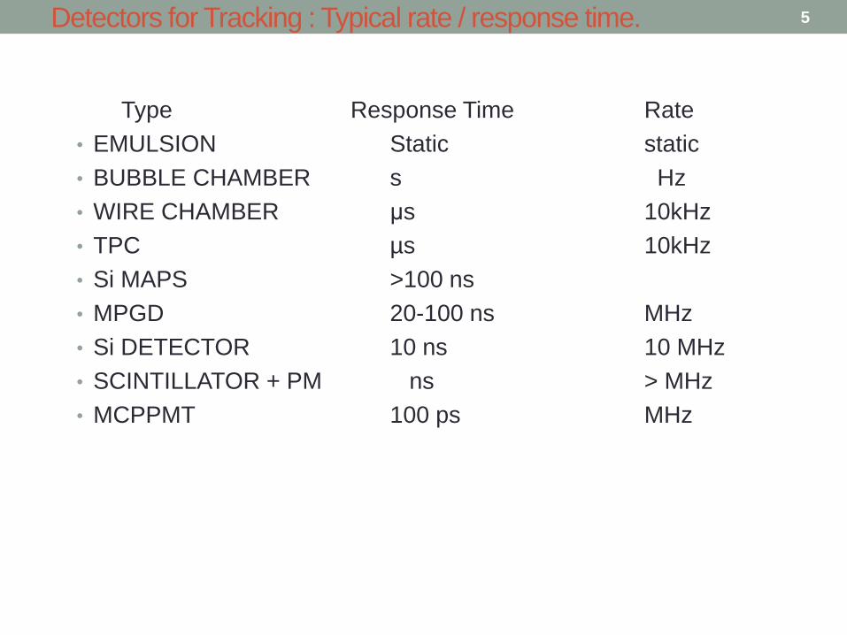
Detectors for Tracking : Typical rate / response time.
Type Response Time Rate
• EMULSION Static static
• BUBBLE CHAMBER s Hz
• WIRE CHAMBER μs 10kHz
• TPC µs 10kHz
• Si MAPS >100 ns
• MPGD 20-100 ns MHz
• Si DETECTOR 10 ns 10 MHz
• SCINTILLATOR + PM ns > MHz
• MCPPMT 100 ps MHz
5
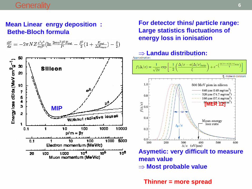
Generality
Mean Linear enrgy deposition :
Bethe-Bloch formula
For detector thins/ particle range:
Large statistics fluctuations of
energy loss in ionisation
Landau distribution:
Asymetic: very difficult to measure
mean value
Most probable value
Thinner = more spread
MIP [MER 12]
6
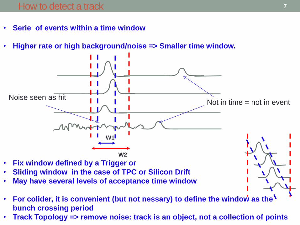
How to detect a track
• Serie of events within a time window
• Higher rate or high background/noise => Smaller time window.
• Fix window defined by a Trigger or
• Sliding window in the case of TPC or Silicon Drift
• May have several levels of acceptance time window
• For colider, it is convenient (but not nessary) to define the window as the
bunch crossing period
• Track Topology => remove noise: track is an object, not a collection of points
Not in time = not in event
W1
W2
Noise seen as hit
7
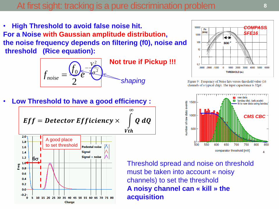
At first sight: tracking is a pure discrimination problem
• High Threshold to avoid false noise hit.
For a Noise with Gaussian amplitude distribution,
the noise frequency depends on filtering (f0), noise and
threshold (Rice equation):
• Low Threshold to have a good efficiency :
2
2
20
2
thV
noise ef
f
CMS CBC
COMPASS
SFE16
𝑬𝒇𝒇 = 𝑫𝒆𝒕𝒆𝒄𝒕𝒐𝒓 𝑬𝒇𝒇𝒊𝒄𝒊𝒆𝒏𝒄𝒚 × 𝑸 𝒅𝑸
∞
𝑽𝒕𝒉
A good place
to set threshold
6 Threshold spread and noise on threshold
must be taken into account « noisy
channels) to set the threshold
A noisy channel can « kill » the
acquisition
Not true if Pickup !!!
shaping
8

Occupancy
• Hit can also be missed because the electronics is doing something else:
𝑶𝒄𝒄. 𝑰𝒏𝒆𝒇𝒇𝒊𝒆𝒏𝒄𝒚 = 𝒓𝒂𝒕𝒆 𝒊𝒏𝒄𝒍. 𝑩𝒂𝒄𝒌𝒈𝒓𝒐𝒖𝒏𝒅 ×
𝑻𝑶𝑻
𝑾𝒊𝒏𝒅𝒐𝒘
Time over Threshold
Signal width
Background event (1) Good event (2)
If event defined by Th Xing
during W:
=> Event 2 missed.
If event defined by amplitude > Th
during W:
=> Event 1 considered as good
W
• Other strategies possible if waveform known
• Symetric shaping better for occupancy
• Tracking IS timing
Shaping time = tradeoff between noise and occupancy
The best way to decrease occupancy is to segment the detector => pixel
Th TOT
9
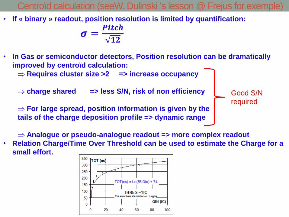
Centroïd calculation (seeW. Dulinski ‘s lesson @ Frejus for exemple)
• If « binary » readout, position resolution is limited by quantification:
𝝈 =𝑷𝒊𝒕𝒄𝒉
𝟏𝟐
• In Gas or semiconductor detectors, Position resolution can be dramatically
improved by centroïd calculation:
Requires cluster size >2 => increase occupancy
charge shared => less S/N, risk of non efficiency
For large spread, position information is given by the
tails of the charge deposition profile => dynamic range
Analogue or pseudo-analogue readout => more complex readout
• Relation Charge/Time Over Threshold can be used to estimate the Charge for a
small effort.
Good S/N
required
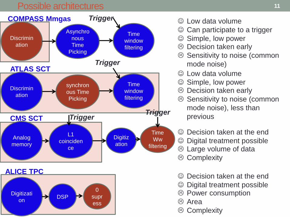
Possible architectures
Asynchro
nous
Time
Picking
Discrimin
ation
Time
window
filtering
Low data volume
Can participate to a trigger
Simple, low power Decision taken early
Sensitivity to noise (common
mode noise)
Trigger COMPASS Mmgas
synchron
ous Time
Picking
Discrimin
ation
Time
window
filtering
Low data volume
Simple, low power Decision taken early
Sensitivity to noise (common
mode noise), less than
previous
ATLAS SCT Trigger
L1
coinciden
ce
Analog
memory
Time
Ww
filtering
CMS SCT Trigger
Decision taken at the end
Digital treatment possible Large volume of data
Complexity
Digitiz
ation
Trigger
Digitizati
on DSP
0
supr
ess
Decision taken at the end
Digital treatment possible Power consumption
Area
Complexity
ALICE TPC
11
Analog front-end circuits => see R. Hermel’s lecture
• Front end amplifier design
• Scaling and optimization
• Detector capacitance
• Technology generation
• Power and speed
• Signal processing
• Continuous time filter, “RC” network
• Asynchronous
• Issue: low noise passive reset
• Time variant filter, “switched capacitors”
• Synchronous timing
• Issue: signal processing of random events with a simple readout scheme
12

Silicon Strip Detectors 13

Principles of the silicon detectors for tracking applications
Solid-State Ionization chamber
p-n junction reverse biased forms the detection zone
Ionization along the track of the high-energy particle (e-h+) in the depletion region
For 300μm Si detector the most probable signal for a Minimum Ionizing article is around 3.5fC (non-irradiated detector)
Drift of the charge in the electric field
Current induced by this drift collected by the FE electronics
Spatial resolution provided by the segmentation of the detector
Single sided DC
Single sided AC
DSSD
On detector bias
resistors
14
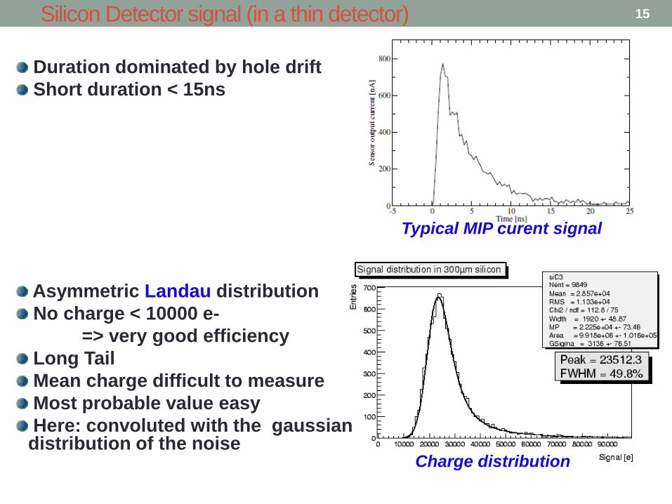
Silicon Detector signal (in a thin detector)
Typical MIP curent signal
Charge distribution
Duration dominated by hole drift
Short duration < 15ns
Asymmetric Landau distribution
No charge < 10000 e-
=> very good efficiency
Long Tail
Mean charge difficult to measure
Most probable value easy
Here: convoluted with the gaussian distribution of the noise
15

Les détecteurs Silicium: avant les ASICs
1966
Détecteurs Si double face => XY
[Hof66]
1960 Détecteurs Si 1984
1985
16

MICROPLEX 1983: Le premier chip pour détecteurs Si à Strips
5m NMOS technology 128 channels, 6.4x4.4 mm Simple amplifier, no cascod, with T&H No shaping Mux Output Power 1.6W ENC noise > 2000 e- rms
[Walk 84]
17

Dans le même numéro de NIM: R. Hoffman et G. Lutz (MPI)
CDS Multiplexing
Power pulsing
[Hof 84]
18
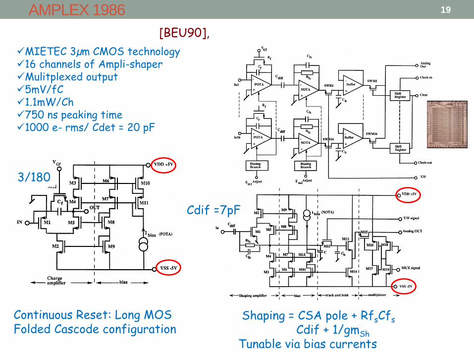
AMPLEX 1986
MIETEC 3µm CMOS technology 16 channels of Ampli-shaper Mulitplexed output 5mV/fC 1.1mW/Ch 750 ns peaking time 1000 e- rms/ Cdet = 20 pF
Continuous Reset: Long MOS Folded Cascode configuration
Shaping = CSA pole + RfsCfs
Cdif + 1/gmSh
Tunable via bias currents
Cdif =7pF
3/180
[BEU90],
19
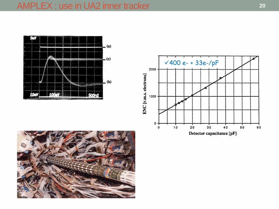
400 e- + 33e-/pF
AMPLEX : use in UA2 inner tracker 20
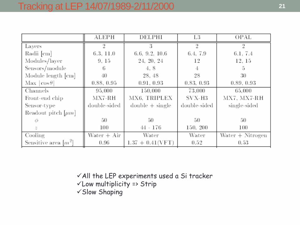
Tracking at LEP 14/07/1989-2/11/2000
All the LEP experiments used a Si tracker Low multiplicity => Strip Slow Shaping
21
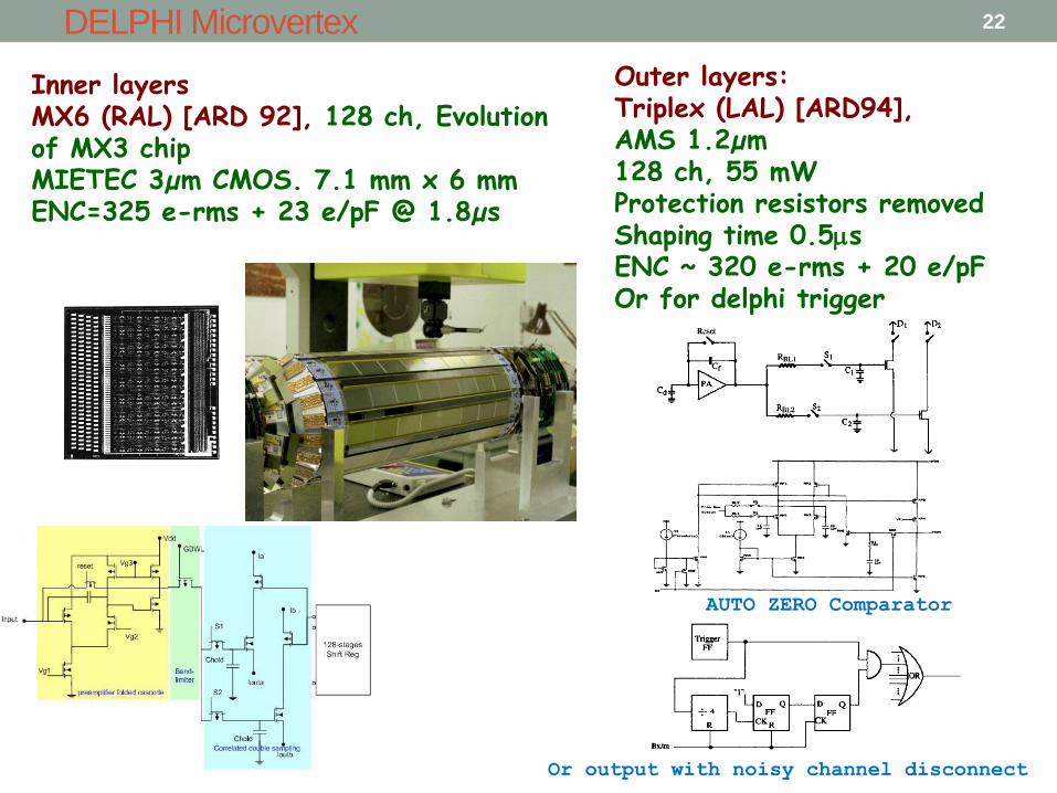
Inner layers MX6 (RAL) [ARD 92], 128 ch, Evolution of MX3 chip MIETEC 3µm CMOS. 7.1 mm x 6 mm ENC=325 e-rms + 23 e/pF @ 1.8µs
DELPHI Microvertex
Outer layers: Triplex (LAL) [ARD94], AMS 1.2µm 128 ch, 55 mW Protection resistors removed Shaping time 0.5s ENC ~ 320 e-rms + 20 e/pF Or for delphi trigger
AUTO ZERO Comparator
Or output with noisy channel disconnect
22
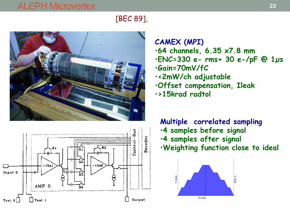
CAMEX (MPI) •64 channels, 6.35 x7.8 mm •ENC=330 e- rms+ 30 e-/pF @ 1µs •Gain=70mV/fC •<2mW/ch adjustable •Offset compensation, Ileak •>15krad radtol
ALEPH Microvertex
Multiple correlated sampling •4 samples before signal •4 samples after signal •Weighting function close to ideal
[BEC 89],
23
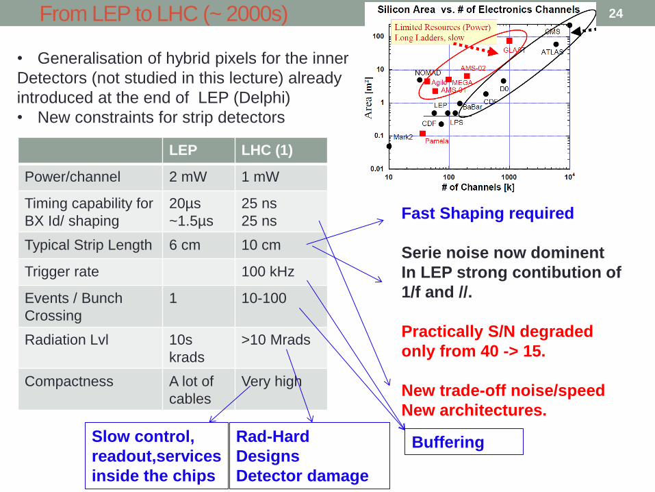
From LEP to LHC (~ 2000s)
LEP LHC (1)
Power/channel 2 mW 1 mW
Timing capability for
BX Id/ shaping
20µs
~1.5µs
25 ns
25 ns
Typical Strip Length 6 cm 10 cm
Trigger rate 100 kHz
Events / Bunch
Crossing
1 10-100
Radiation Lvl 10s
krads
>10 Mrads
Compactness A lot of
cables
Very high
• Generalisation of hybrid pixels for the inner
Detectors (not studied in this lecture) already
introduced at the end of LEP (Delphi)
• New constraints for strip detectors
Fast Shaping required
Serie noise now dominent
In LEP strong contibution of
1/f and //.
Practically S/N degraded
only from 40 -> 15.
New trade-off noise/speed
New architectures.
Slow control,
readout,services
inside the chips
Buffering Rad-Hard
Designs
Detector damage
24
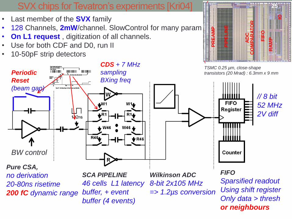
SVX chips for Tevatron’s experiments [Kri04]
• Last member of the SVX family
• 128 Channels, 2mW/channel. SlowControl for many param
• On L1 request , digitization of all channels.
• Use for both CDF and D0, run II
• 10-50pF strip detectors
Pure CSA,
no derivation
20-80ns risetime
200 fC dynamic range
SCA PIPELINE
46 cells L1 latency
buffer, + event
buffer (4 events)
TSMC 0.25 µm, close-shape
transistors (20 Mrad) : 6.3mm x 9 mm
Wilkinson ADC
8-bit 2x10⁵ MHz
=> 1.2µs conversion
FIFO
Sparsified readout
Using shift register
Only data > thresh
or neighbours
CDS + 7 MHz
sampling
BXing freq
// 8 bit
52 MHz
2V diff
BW control
PIP
EL
INE
PR
EA
MP
FIF
O
AD
C
CO
MP
AR
AT
OR
RA
MP
IO
Periodic
Reset
(beam gap)
25
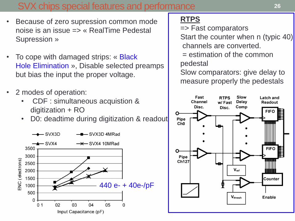
SVX chips special features and performance
• Because of zero supression common mode
noise is an issue => « RealTime Pedestal
Supression »
• To cope with damaged strips: « Black
Hole Elimination », Disable selected preamps
but bias the input the proper voltage.
• 2 modes of operation:
• CDF : simultaneous acquistion &
digitization + RO
• D0: deadtime during digitization & readout
RTPS
=> Fast comparators
Start the counter when n (typic 40)
channels are converted.
= estimation of the common
pedestal
Slow comparators: give delay to
measure properly the pedestals
440 e- + 40e-/pF
26
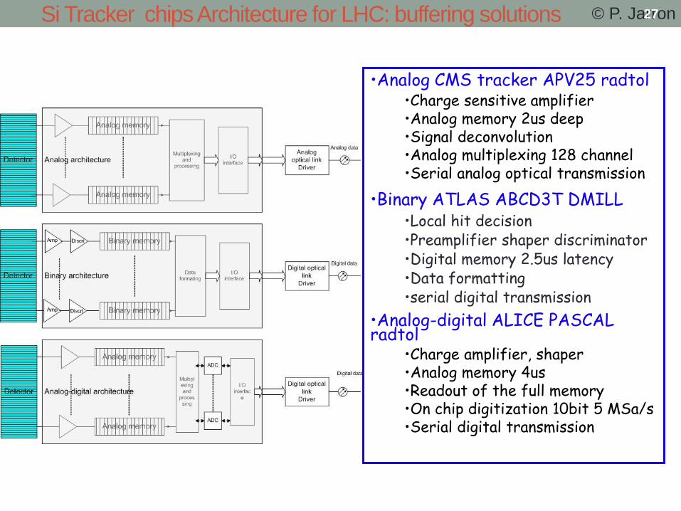
Si Tracker chips Architecture for LHC: buffering solutions
•Analog CMS tracker APV25 radtol •Charge sensitive amplifier •Analog memory 2us deep •Signal deconvolution •Analog multiplexing 128 channel •Serial analog optical transmission
•Binary ATLAS ABCD3T DMILL •Local hit decision •Preamplifier shaper discriminator •Digital memory 2.5us latency •Data formatting •serial digital transmission
•Analog-digital ALICE PASCAL radtol
•Charge amplifier, shaper •Analog memory 4us •Readout of the full memory •On chip digitization 10bit 5 MSa/s •Serial digital transmission
© P. Jarron 27

» FRONTEND PREAMPLIFIER WITH BIPOLAR INPUT
» 128 binary channels, 3.3uS 1 bit storage @ 40MHz
»DMILL~ 30 000 bipolar’s , ~ 200 000 MOS’s
» LVL1 DERANDOMIZER (8 EVENTS)
» Data compression, errors and overflow handling
» Serial 40Mbits input & output coding
ATLAS silicon tracker: ABCD3 28
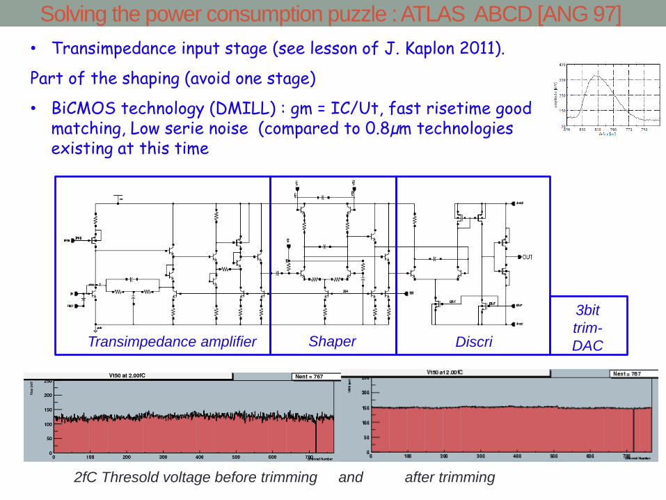
• Transimpedance input stage (see lesson of J. Kaplon 2011).
Part of the shaping (avoid one stage)
• BiCMOS technology (DMILL) : gm = IC/Ut, fast risetime good matching, Low serie noise (compared to 0.8µm technologies existing at this time
Solving the power consumption puzzle : ATLAS ABCD [ANG 97]
Transimpedance amplifier Shaper Discri
3bit
trim-
DAC
2fC Thresold voltage before trimming and after trimming
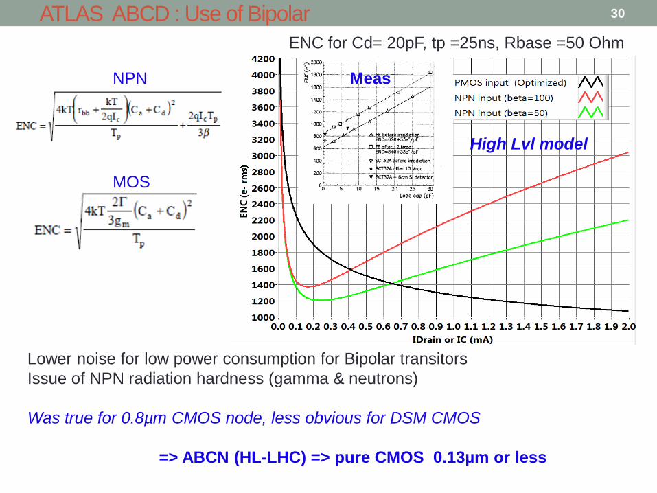
ATLAS ABCD : Use of Bipolar
ENC for Cd= 20pF, tp =25ns, Rbase =50 Ohm
Lower noise for low power consumption for Bipolar transitors
Issue of NPN radiation hardness (gamma & neutrons)
Was true for 0.8µm CMOS node, less obvious for DSM CMOS
=> ABCN (HL-LHC) => pure CMOS 0.13µm or less
MOS
NPN Meas
High Lvl model
30
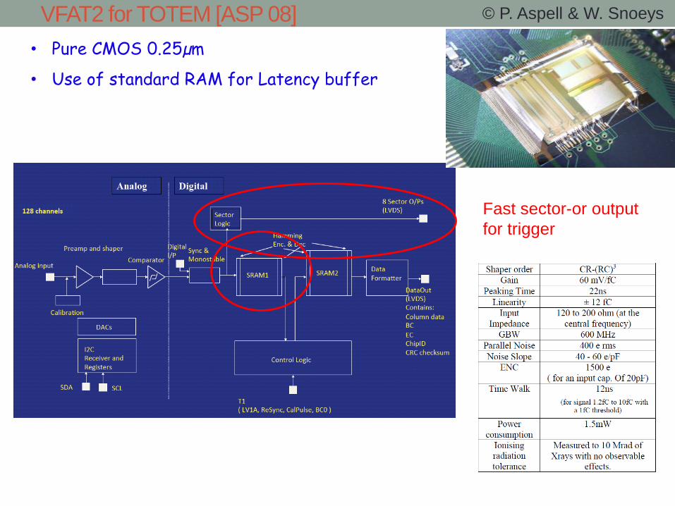
VFAT2 for TOTEM [ASP 08] © P. Aspell & W. Snoeys
Fast sector-or output
for trigger
• Pure CMOS 0.25µm
• Use of standard RAM for Latency buffer
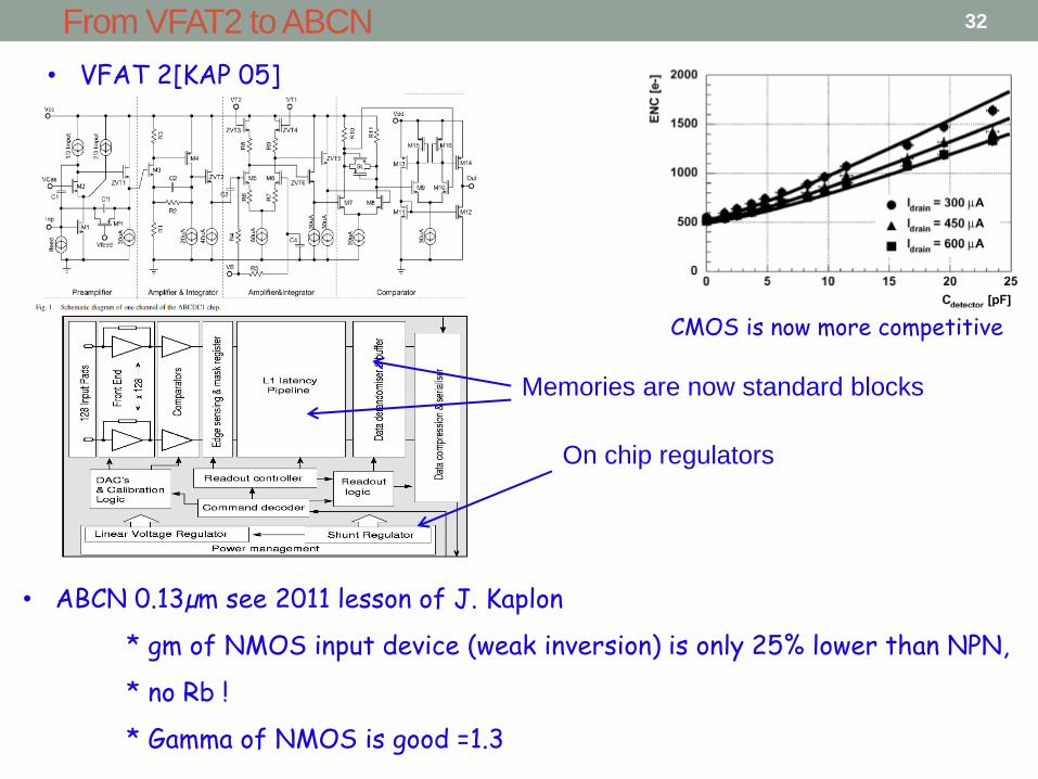
From VFAT2 to ABCN
• VFAT 2[KAP 05]
• ABCN 0.13µm see 2011 lesson of J. Kaplon
* gm of NMOS input device (weak inversion) is only 25% lower than NPN,
* no Rb !
* Gamma of NMOS is good =1.3
CMOS is now more competitive
Memories are now standard blocks
On chip regulators
32
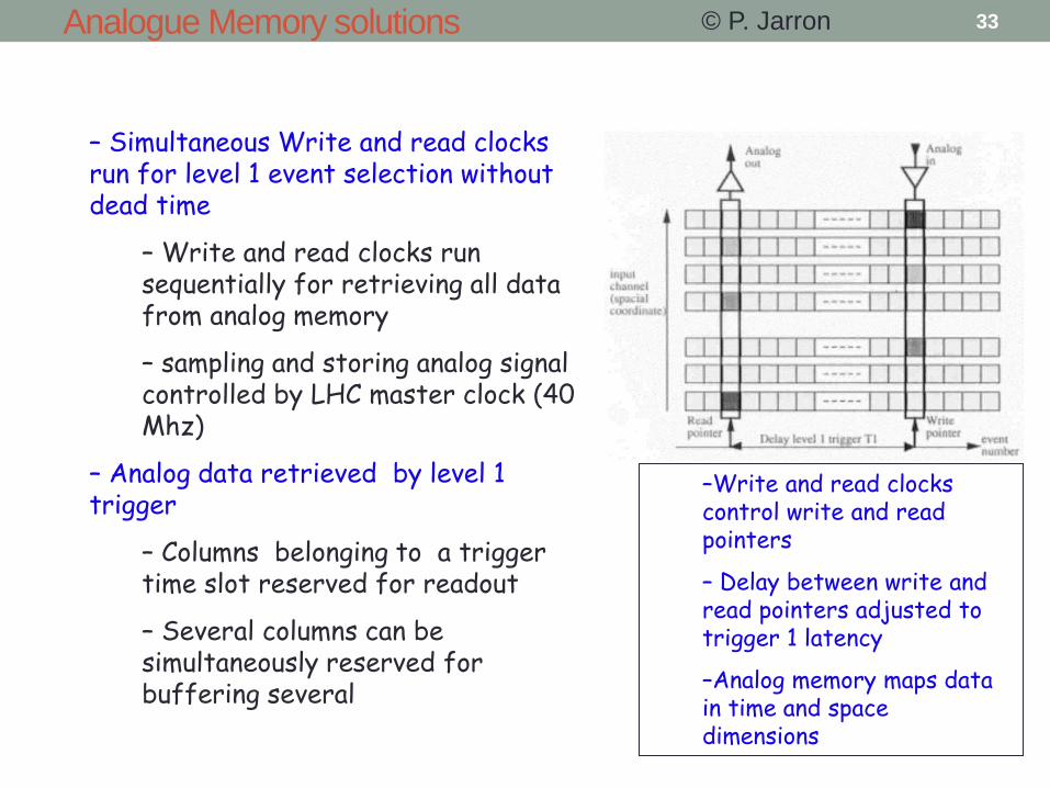
– Simultaneous Write and read clocks run for level 1 event selection without dead time
– Write and read clocks run sequentially for retrieving all data from analog memory
– sampling and storing analog signal controlled by LHC master clock (40 Mhz)
– Analog data retrieved by level 1 trigger
– Columns belonging to a trigger time slot reserved for readout
– Several columns can be simultaneously reserved for buffering several level 1 requests
–Write and read clocks control write and read pointers
– Delay between write and read pointers adjusted to trigger 1 latency
–Analog memory maps data in time and space dimensions
Analogue Memory solutions © P. Jarron 33

CMS strip readout ASIC : APV25
128 channels: 2mW/ch
0.25µm IBM technology (>50 Mrads)
50 nsec. CR-RC shaper/amplifier
192 cell 40-MHz analog pipeline for:
4sec L1 latency + buffering)
up to 32 event buffering
Peak/deconvolution operating mode
Embedded common mode subtraction system
Differential current buffer, 20 or 40MHz readout
I2C slow control interface
On-chip CAL circuit: amplitude and delay programmable
Rad-Hard: >>10 Mrads
No on-chip zero supress
1 value/ch/trigger
Digital header
128 analogue data
34

25ns
Switched Capacitor deconvolution
An other way to save power : Deconvolution [BIN93]
h(t)
CSA
shaper
w(t)
deconvol
s(t) v(t) s(t) Det
For sampled signals
Convolution:
Deconvolution Filter W:
A simple matrix inversion operation ??
Usually, no simple exact solution => requires a lot of samples (infinite)
But for CR-RC filter, very simple and exact solution:
=> Very simple FIR with only 3 weights
Pre deconvolution
Post deconvolution
....
0
00
000
123
12
1
1
www
ww
w
HW
Equivalent to fast
FE with less power
BX Id. necessary
for high luminosity
Peak mode =s3
Deconvol = w0.S0+w1.s1+w2.s2
35
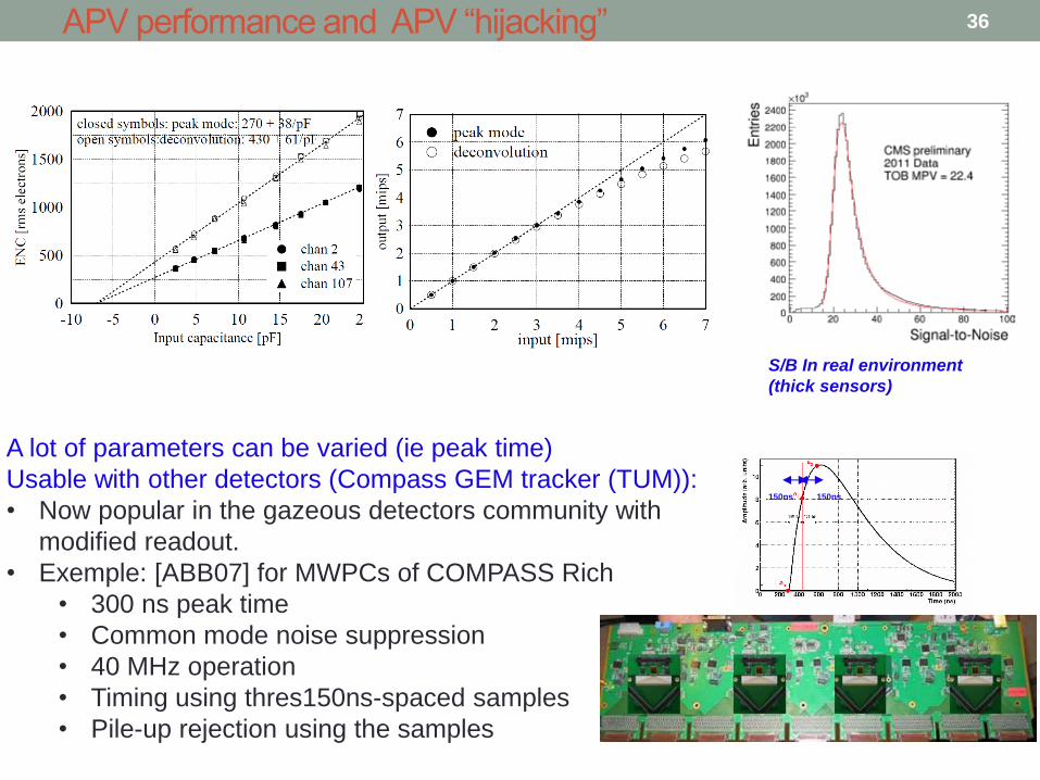
APV performance and APV “hijacking”
A lot of parameters can be varied (ie peak time)
Usable with other detectors (Compass GEM tracker (TUM)):
• Now popular in the gazeous detectors community with
modified readout.
• Exemple: [ABB07] for MWPCs of COMPASS Rich
• 300 ns peak time
• Common mode noise suppression
• 40 MHz operation
• Timing using thres150ns-spaced samples
• Pile-up rejection using the samples
150ns 150ns
S/B In real environment
(thick sensors)
36

SuperLHC: CMS Silicon Tracker: upgrade for High Luminosity
• Shorter strips for Less Occupancy
• Binary solution for easier interfaces
• Limit the trigger rate to 100kHz =>
Tracker now participates to the L1 trigger:
• Higgs golden channel : HZZ 4µ
• No interest for low momentum tracks
• Trigger on high momentum tracks
• Deduce particle momentum from track
curvature In the Tracker
Concept of PT module
Need immediate tagging of interesting
tracks.
37
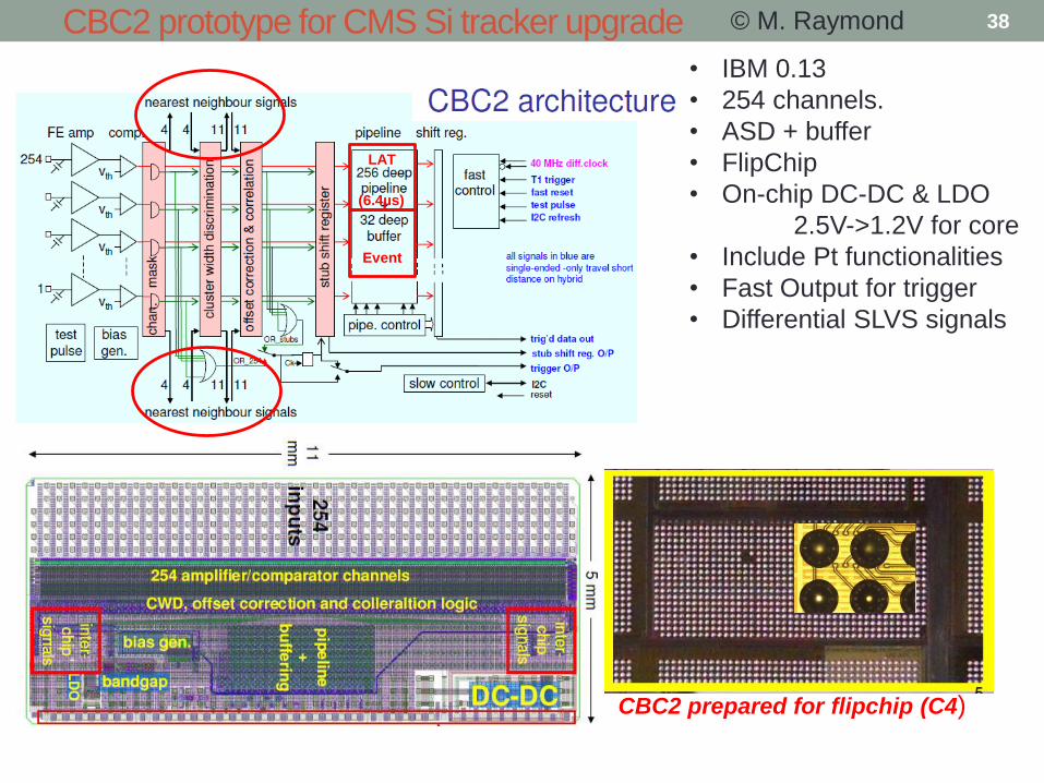
CBC2 prototype for CMS Si tracker upgrade
CBC2 prepared for flipchip (C4)
© M. Raymond
• IBM 0.13
• 254 channels.
• ASD + buffer
• FlipChip
• On-chip DC-DC & LDO
2.5V->1.2V for core
• Include Pt functionalities
• Fast Output for trigger
• Differential SLVS signals
LAT
Event
(6.4µs)
38

CBC Front-end
1000e- for 8pF/ 350µW
<50ns width for Q<2fC
Det.
Type
select 1th/discri
© M. Raymond 39

CBC- PT logic © M. Raymond 40
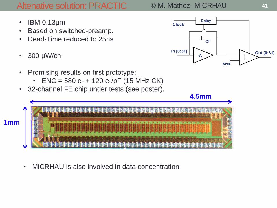
Altenative solution: PRACTIC © M. Mathez- MICRHAU
• IBM 0.13µm
• Based on switched-preamp.
• Dead-Time reduced to 25ns
• 300 µW/ch
• Promising results on first prototype:
• ENC = 580 e- + 120 e-/pF (15 MHz CK)
• 32-channel FE chip under tests (see poster). 4.5mm
1mm
• MiCRHAU is also involved in data concentration
41

Principle of the Silicon Drift Detector (SDD)
• 2D readout with single measurement
• Low capacitance (anode only) for a
large detector surface.
• Position reconstruction :
•Centroid calculation
•Position X : anods
•Position Y : drift time (T dependency)
•dE/dx : Integral of the signal
Requires waveform sampling of all the
drift ~6µs
P+ Cathods on both side of the wafer :
Depletion of the Silicon
|HV| decreases toward the anods
→ Drift field => collection
Last cathods below the anods potential
Potential inside the SDD
« Tobogan » effect
HV
42
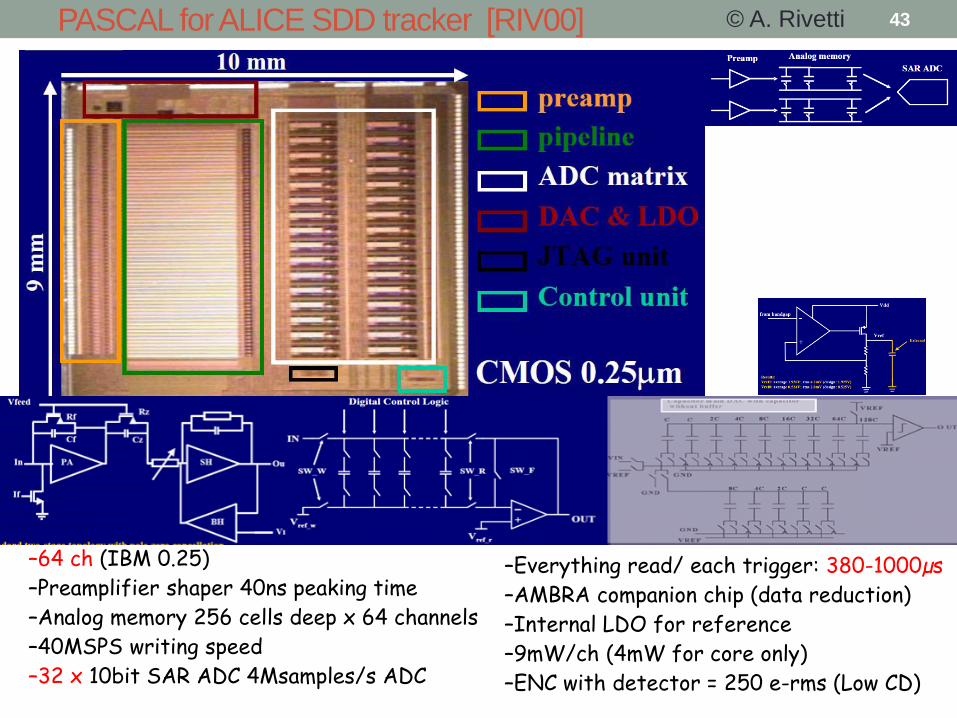
–64 ch (IBM 0.25)
–Preamplifier shaper 40ns peaking time
–Analog memory 256 cells deep x 64 channels
–40MSPS writing speed
–32 x 10bit SAR ADC 4Msamples/s ADC
PASCAL for ALICE SDD tracker [RIV00]
–Everything read/ each trigger: 380-1000µs
–AMBRA companion chip (data reduction)
–Internal LDO for reference
–9mW/ch (4mW for core only)
–ENC with detector = 250 e-rms (Low CD)
© A. Rivetti 43
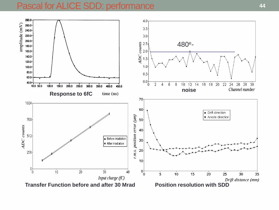
Pascal for ALICE SDD: performance
Response to 6fC noise
480e-
Position resolution with SDD Transfer Function before and after 30 Mrad
44
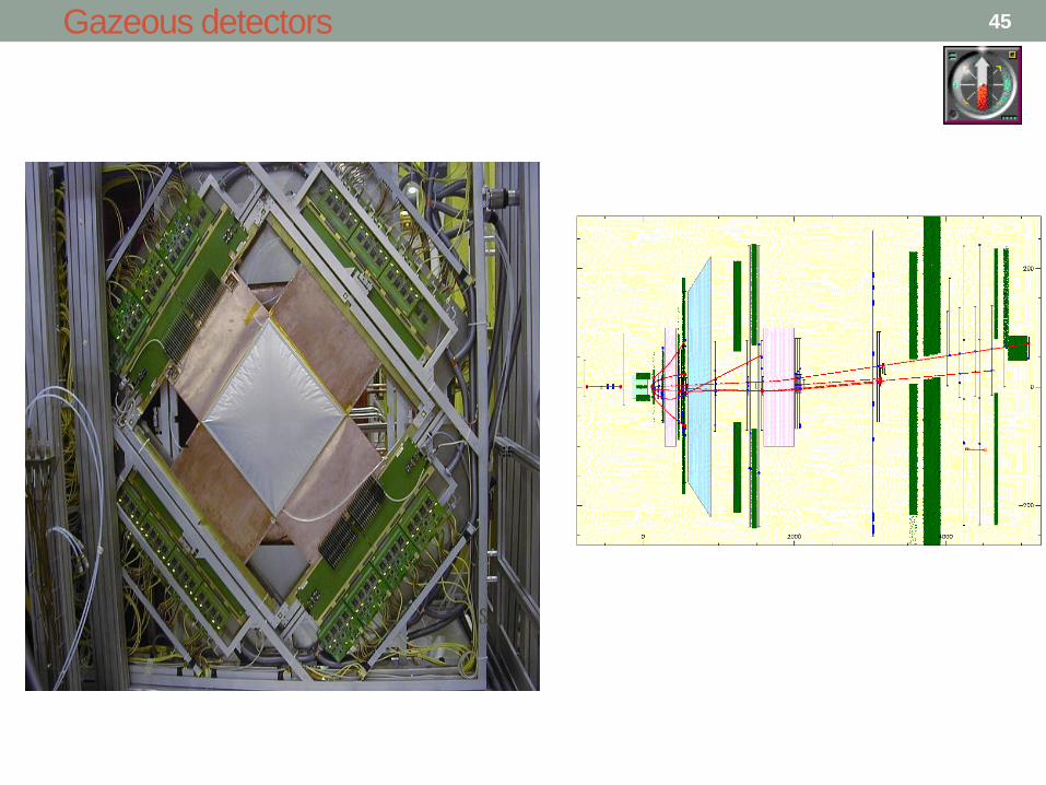
Gazeous detectors 45
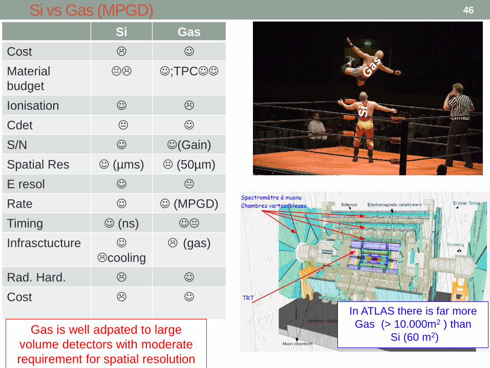
Si vs Gas (MPGD)
Si
In ATLAS there is far more
Gas (> 10.000m2 ) than
Si (60 m2)
Si Gas
Cost
Material
budget
;TPC
Ionisation
Cdet
S/N (Gain)
Spatial Res (µms) (50µm)
E resol
Rate (MPGD)
Timing (ns)
Infrasctucture
cooling
(gas)
Rad. Hard.
Cost
Gas is well adpated to large
volume detectors with moderate
requirement for spatial resolution
46

Wire Chambers: principle
~ tens of e-/ion pairs created by ionisation in gas (4 order of magnitude
less than in Si !
E field proportional to 1/r
High field near the wire.
Mulitplication by 104 – 105
Limited by sparks
Ion drift to the cathod
hyperbolicSignal induced in both electrod
Long ion tail (up to µs), usually cut by shaping
=> Ballistic deficit, often <50% of the charge is used
Large density of charge (ion) in the gaz
=> space charge limit at high rate
Tail and ion density problems no more existing in MPGD
Very small capacitance for wires
Large detector with high S/N
Charge statistics = ionization (Poisson) convoluted Avalanche statistics (POLYA
or Fury exp distribution): E resolution Not as good as with Si.
- -
- -
+ +
+ +
cathode
anode
(HV+)
+
+ +
+ +
+ +
Drift
- -
- - +
+ +
+ - - -
- +
+ +
Avalanche
- - + +
Here it is the simplest wire chamber
Proportional counter.
A lot of more complex and samart designs,
but based on the same principle:
• MWPC (Charpak)
• Wire or cathod plane (strips or pads) readout
* Drift Chambers
…..
47
Ionization
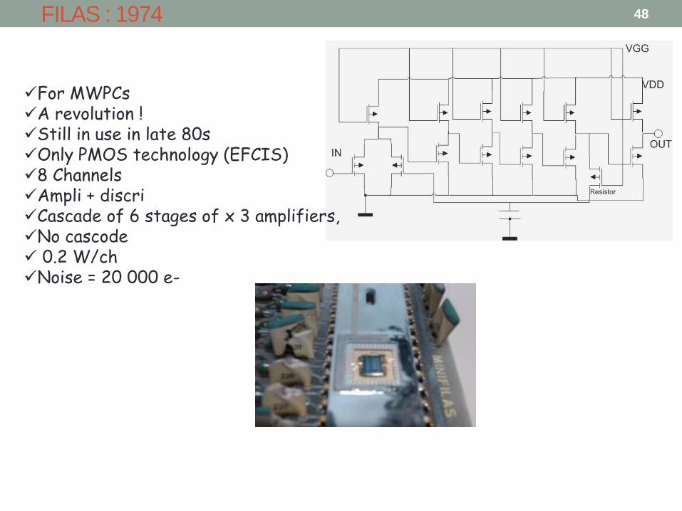
FILAS : 1974
For MWPCs A revolution ! Still in use in late 80s Only PMOS technology (EFCIS) 8 Channels Ampli + discri Cascade of 6 stages of x 3 amplifiers, No cascode 0.2 W/ch Noise = 20 000 e-
48
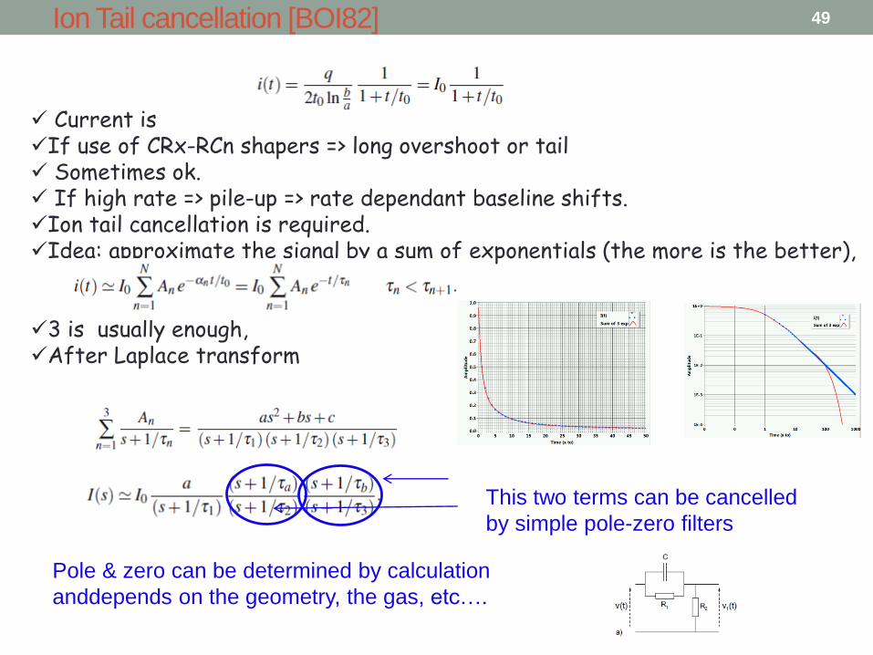
Ion Tail cancellation [BOI82]
Current is If use of CRx-RCn shapers => long overshoot or tail Sometimes ok. If high rate => pile-up => rate dependant baseline shifts. Ion tail cancellation is required. Idea: approximate the signal by a sum of exponentials (the more is the better),
3 is usually enough, After Laplace transform
This two terms can be cancelled
by simple pole-zero filters
Pole & zero can be determined by calculation
anddepends on the geometry, the gas, etc….
49
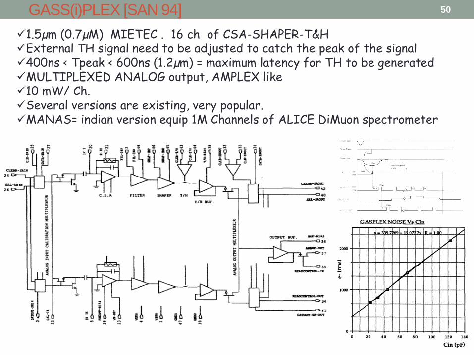
GASS(i)PLEX [SAN 94]
1.5µm (0.7µM) MIETEC . 16 ch of CSA-SHAPER-T&H External TH signal need to be adjusted to catch the peak of the signal 400ns < Tpeak < 600ns (1.2µm) = maximum latency for TH to be generated MULTIPLEXED ANALOG output, AMPLEX like 10 mW/ Ch. Several versions are existing, very popular. MANAS= indian version equip 1M Channels of ALICE DiMuon spectrometer
50

GAS(i)PLEX: several innovations
High value of CSA Rf (RFCf= 20µs) made with a resistor + attenuating current conveyor
Ion tail cancellation using PZ technique
Semi-Gaussian Filter using multiple-loop feedback
Input current CSA Tail
cancellation
Shaper
51
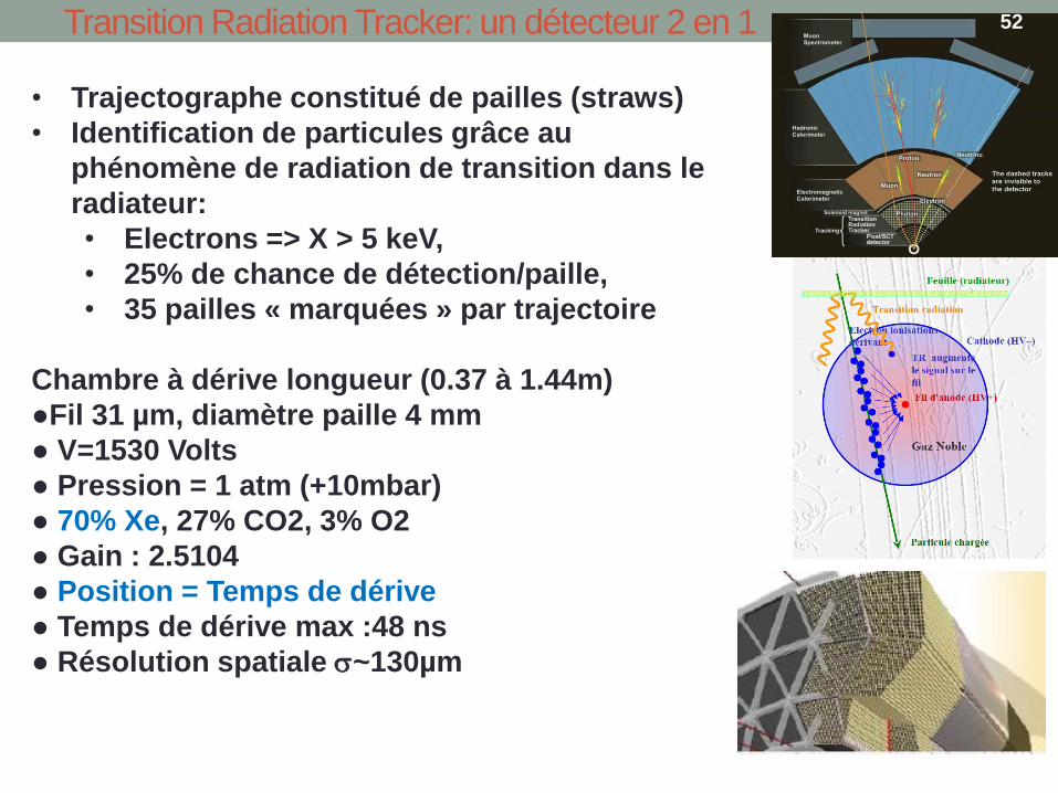
Transition Radiation Tracker: un détecteur 2 en 1
• Trajectographe constitué de pailles (straws)
• Identification de particules grâce au
phénomène de radiation de transition dans le
radiateur:
• Electrons => X > 5 keV,
• 25% de chance de détection/paille,
• 35 pailles « marquées » par trajectoire
Chambre à dérive longueur (0.37 à 1.44m)
●Fil 31 µm, diamètre paille 4 mm
● V=1530 Volts
● Pression = 1 atm (+10mbar)
● 70% Xe, 27% CO2, 3% O2
● Gain : 2.5104
● Position = Temps de dérive
● Temps de dérive max :48 ns
● Résolution spatiale ~130µm
52

TRT Electronics Overview
ASDBLR Die
DMILL 0.8µm
3.6 x 3.6mm
DTMROC
IBM 0.25µm
Size 7.7 x9.3 mm
DTMROC side
ASD side
AR1FS
53
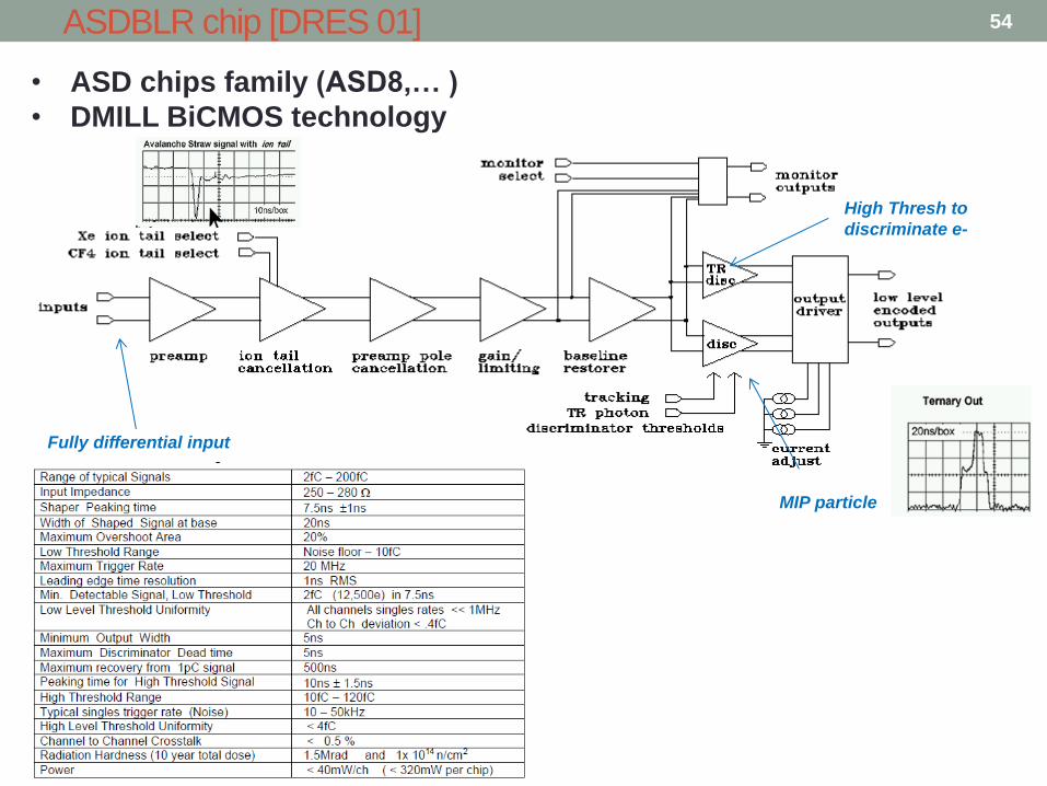
ASDBLR chip [DRES 01]
• ASD chips family (ASD8,… )
• DMILL BiCMOS technology
High Thresh to
discriminate e-
MIP particle
Fully differential input
54
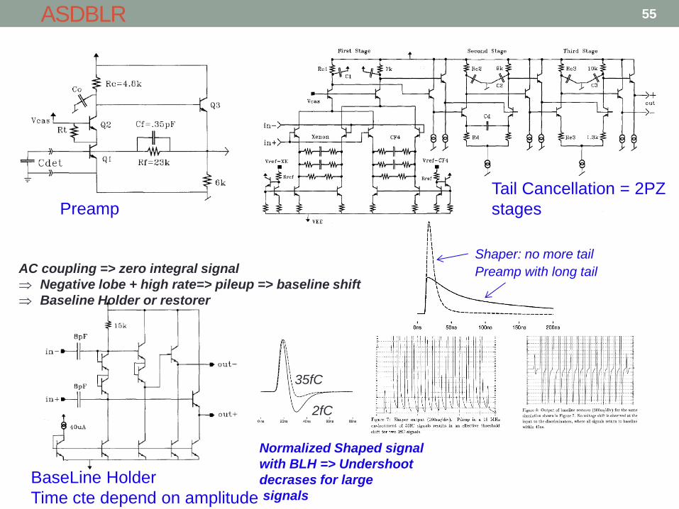
ASDBLR
Preamp
Tail Cancellation = 2PZ
stages
BaseLine Holder
Time cte depend on amplitude
Normalized Shaped signal
with BLH => Undershoot
decrases for large
signals
AC coupling => zero integral signal
Negative lobe + high rate=> pileup => baseline shift
Baseline Holder or restorer
2fC
35fC
Preamp with long tail
Shaper: no more tail
55
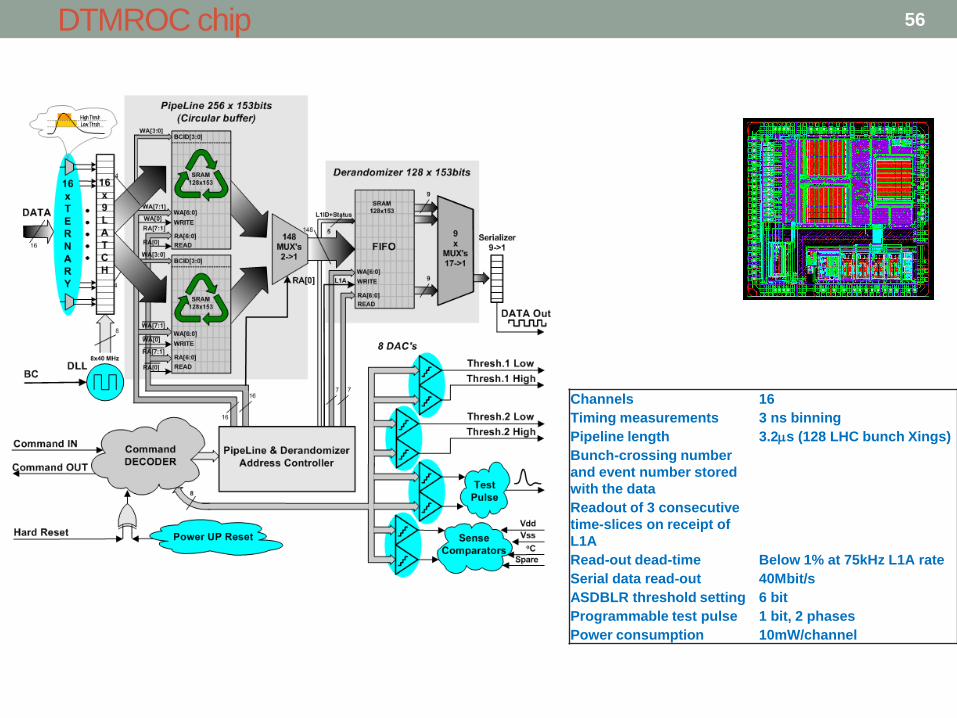
DTMROC chip
Channels 16
Timing measurements 3 ns binning
Pipeline length 3.2s (128 LHC bunch Xings)
Bunch-crossing number
and event number stored
with the data
Readout of 3 consecutive
time-slices on receipt of
L1A
Read-out dead-time Below 1% at 75kHz L1A rate
Serial data read-out 40Mbit/s
ASDBLR threshold setting 6 bit
Programmable test pulse 1 bit, 2 phases
Power consumption 10mW/channel
56

Gaseous detectors 57

Principle of a TPC
Muliplication readout at anode:
- MWPC (Delphi, ALICE, ALEPH)
- Micromegas (T2K, ILC, ACTAR)
- GEM (ALICE upgrade, ILC)
XY are given by the pad location
Z is given by the time of arrival
of drifted e-
dE/dx = charge collected • Very low material budget
• Real 3D trackings
• Complete Tracks and not only points
• Read the complete waveform for each pad,
extract time:
• Analogue memory readout (STAR, T2K)
• ADC readout (ALICE, STAR …)
+ -
Gas
or Liquid
58

ALTRO for the ALICE TPC [BOE03] [MUS 03]: early digitization
• PASA (AMS 0.35): • 16 CH CSA+ SHAPER
• AMS 0.35 µm
• ALTRO (ST 0.25) 64mm2
• 16 ADC 10-bit 20MHz
• Digital filtering
• Memories & RO
TOTAL POWER =40 mW/ch
Philosophy: In (large) detectors, the signals are perturbated by
common mode noise, fix pattern parasitics…that makes their
discrimination difficult (or zero supress).
Instead of removing them in the analogue world (grounding…), let us
filter them digitally…
© L. Musa
59
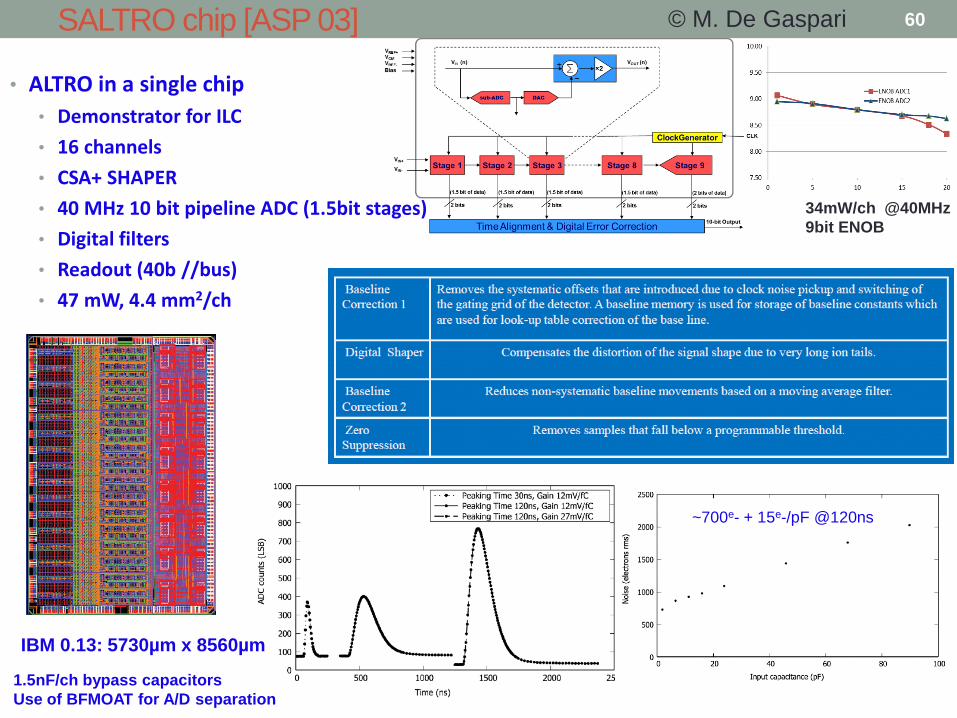
SALTRO chip [ASP 03]
• ALTRO in a single chip
• Demonstrator for ILC
• 16 channels
• CSA+ SHAPER
• 40 MHz 10 bit pipeline ADC (1.5bit stages)
• Digital filters
• Readout (40b //bus)
• 47 mW, 4.4 mm2/ch
34mW/ch @40MHz
9bit ENOB
IBM 0.13: 5730µm x 8560µm
1.5nF/ch bypass capacitors
Use of BFMOAT for A/D separation
© M. De Gaspari
~700e- + 15e-/pF @120ns
60
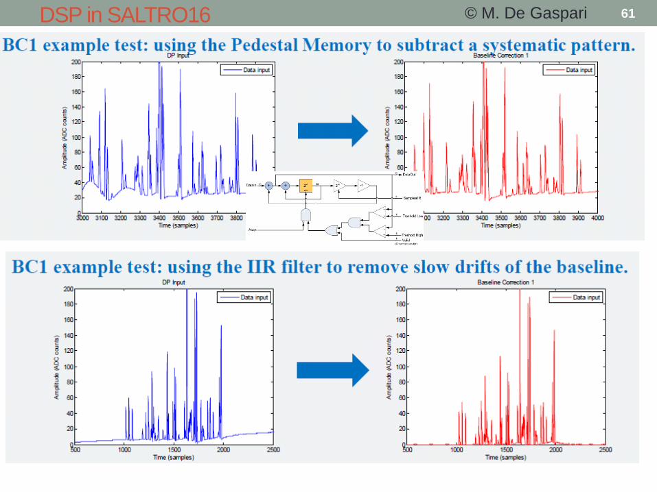
DSP in SALTRO16 © M. De Gaspari 61
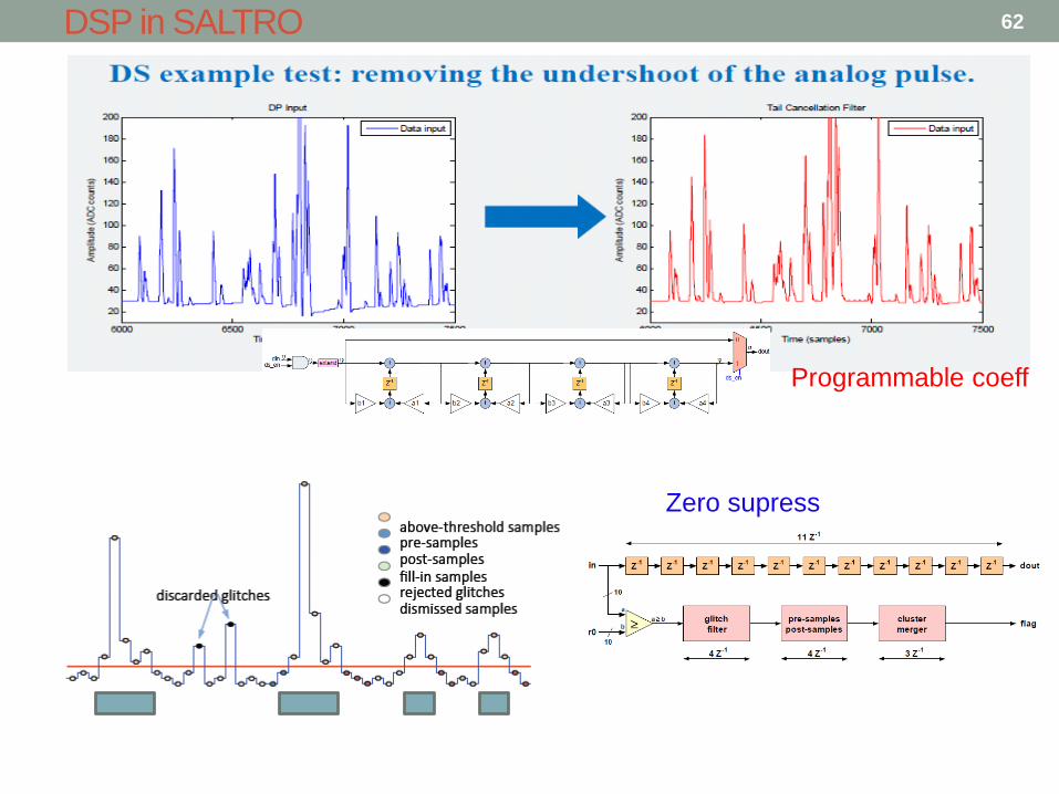
DSP in SALTRO
Programmable coeff
Zero supress
62
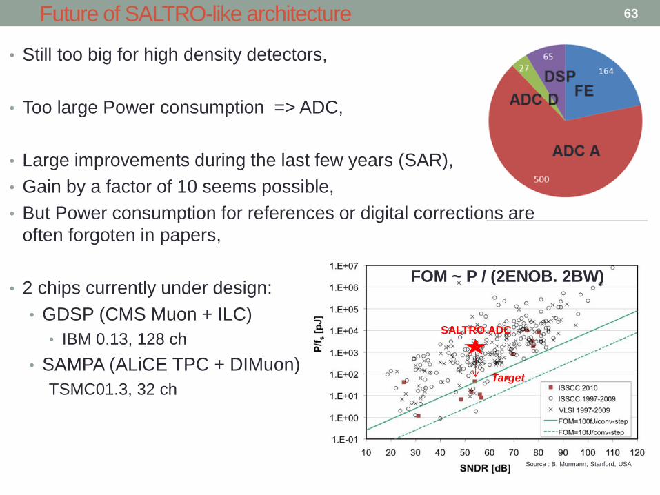
Future of SALTRO-like architecture
• Still too big for high density detectors,
• Too large Power consumption => ADC,
• Large improvements during the last few years (SAR),
• Gain by a factor of 10 seems possible,
• But Power consumption for references or digital corrections are
often forgoten in papers,
• 2 chips currently under design:
• GDSP (CMS Muon + ILC)
• IBM 0.13, 128 ch
• SAMPA (ALiCE TPC + DIMuon)
TSMC01.3, 32 ch
SALTRO ADC
Target
FOM ~ P / (2ENOB. 2BW)
Source : B. Murmann, Stanford, USA
63

VMM chips for ATLAS muon chambers
• New electronics for HL-LHC Muon chambers (>1000 m2)
• ITGC and resistive Micromegas
• Now same detectors for the trigger and and the tracking. 25ns Real time position of the hits:
Fast shaping required
Fine measurements : Timing used for track angle measurement (mini TPC mode).
« risetime measurement »
High dynamic range (gas)
Good resolution required => centroïd for position.
• Totally Asynchronous architecture: • Discri + Peak detectors
• Treatment on hit channels + neighbours
• On chip digitization.
• Ultra versatile: 10pF-200pF, 25ns-200ns, all polarities
• 64 channels; IBM 0.13
• 4mW/Ch
• VMM1 tested succesfully, VMM2 is comming soon
© G. De Geronimo
Expected size =9x9 mm
64

VMM2 (VMM1 in yellow) architecture [DE GER 13]
CSA shaper
logic
or
neighbor
addr.
channel (64x)
trigger
6b ADC
TGC out (ToT, TtP, PtT, 6bADC) x 64
TGC clock (160 MHz)
spr 1-bit
thr 1-bit
addr 6-bit
ampl 10-bit
time 10-bit
BC 12-bit
L1A 8-bit
ART (flag, serial address) ART clock (160 MHz)
12b BC
Gray code cter
DATA 48-bit
2-bit
FIFO
10b ADC
10b ADC
DATA sync BC clock (40 MHz) L1A trigger
DATA clock (80 MHz)
8b L1A
logic
time
peak
• 2-bit DATA output with dedicated sync and 80 MHz clock
• TGC: 64 outputs, PtT, 6-bit ADC 25ns serial with dedicated clock
• ART: flag and address serialized with dedicated clock
• 10-bit ADCs 200ns for amplitude and timing, digital memories
• Gray-code counters for BC-ID (12-bit) and L1A-ID (8-bit)
© G. De Geronimo 65
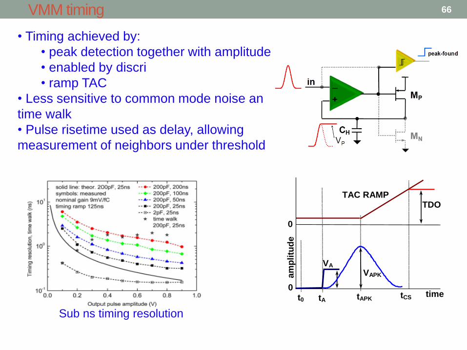
VMM timing
Sub ns timing resolution
• Timing achieved by:
• peak detection together with amplitude
• enabled by discri
• ramp TAC
• Less sensitive to common mode noise an
time walk
• Pulse risetime used as delay, allowing
measurement of neighbors under threshold
am
pli
tud
e
time t0 tA
VA VAPK
tAPK tCS
ENABLE
TAC RAMP
0
0
TDO
66
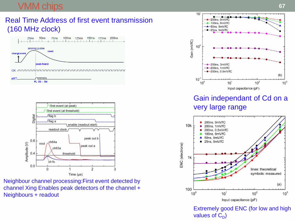
VMM chips
Real Time Address of first event transmission
(160 MHz clock)
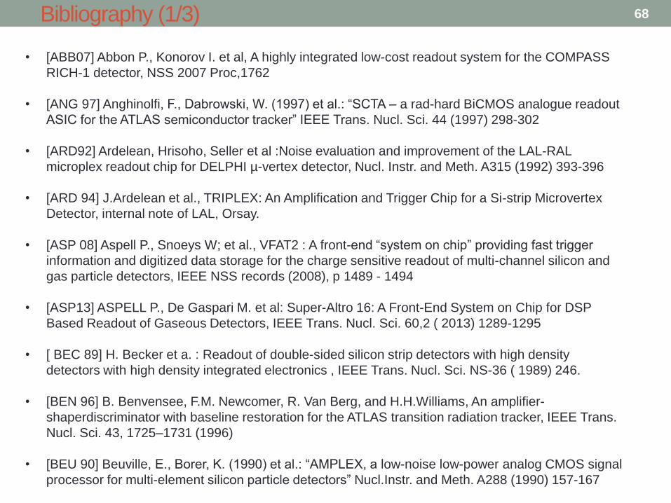
Extremely good ENC (for low and high
values of CD)
Gain independant of Cd on a
very large range
Neighbour channel processing:First event detected by
channel Xing Enables peak detectors of the channel +
Neighbours + readout
67
Bibliography (1/3)
• [ABB07] Abbon P., Konorov I. et al, A highly integrated low-cost readout system for the COMPASS
RICH-1 detector, NSS 2007 Proc,1762
• [ANG 97] Anghinolfi, F., Dabrowski, W. (1997) et al.: “SCTA – a rad-hard BiCMOS analogue readout
ASIC for the ATLAS semiconductor tracker” IEEE Trans. Nucl. Sci. 44 (1997) 298-302
• [ARD92] Ardelean, Hrisoho, Seller et al :Noise evaluation and improvement of the LAL-RAL
microplex readout chip for DELPHI µ-vertex detector, Nucl. Instr. and Meth. A315 (1992) 393-396
• [ARD 94] J.Ardelean et al., TRIPLEX: An Amplification and Trigger Chip for a Si-strip Microvertex
Detector, internal note of LAL, Orsay.
• [ASP 08] Aspell P., Snoeys W; et al., VFAT2 : A front-end “system on chip” providing fast trigger
information and digitized data storage for the charge sensitive readout of multi-channel silicon and
gas particle detectors, IEEE NSS records (2008), p 1489 - 1494
• [ASP13] ASPELL P., De Gaspari M. et al: Super-Altro 16: A Front-End System on Chip for DSP
Based Readout of Gaseous Detectors, IEEE Trans. Nucl. Sci. 60,2 ( 2013) 1289-1295
• [ BEC 89] H. Becker et a. : Readout of double-sided silicon strip detectors with high density
detectors with high density integrated electronics , IEEE Trans. Nucl. Sci. NS-36 ( 1989) 246.
• [BEN 96] B. Benvensee, F.M. Newcomer, R. Van Berg, and H.H.Williams, An amplifier-
shaperdiscriminator with baseline restoration for the ATLAS transition radiation tracker, IEEE Trans.
Nucl. Sci. 43, 1725–1731 (1996)
• [BEU 90] Beuville, E., Borer, K. (1990) et al.: “AMPLEX, a low-noise low-power analog CMOS signal
processor for multi-element silicon particle detectors” Nucl.Instr. and Meth. A288 (1990) 157-167
68
Bibliography (2/3)
69
• [BEU 90] Beuville, E., Borer, K. (1990) et al.: “AMPLEX, a low-noise low-power analog CMOS signal
processor for multi-element silicon particle detectors” Nucl.Instr. and Meth. A288 (1990) 157-167
• [BIN 93] Bingefors N. et al, A novel technique for fast pulse-shaping using a slow amplifier at LHC,
Nucl. Instr. and Meth. A326 (1993) 112-119
• [BOI 82] R.A. Boie, A.T. Hrisoho, P. Rehak, Signal shaping and tail cancellation for gas proportional
detectors at high counting rates, Nucl. Instr. Meth. Phys. Res. A 192, 365–374 (1982)
• [BOS 03] R.E. Bosch, A.J. de Parga, B. Mota and L. Musa, The ALTRO Chip: a 16-channel A/D
converter and digtal processor for gas detectors, IEEE Trans. Nucl. Sci. 50, 2460–2469 (2003)
• [DEGER 13] De Geronimo et al: VMM1—An ASIC for Micropattern Detectors accepted for
publication in IEEE Trans. Nucl. Sci
• [DRES 01] N. Dressnandt, N. Lam, F.M. Newcomer, R. Van Berg, and H.H.Williams “Implementation
of the ASDBLR Straw Tube Readout ASIC in DMILL Technology”, IEEE Trans. Nucl. Sci., vol. 48,
no.4 p1239, Aug.2001
• [HOF 66] The Checker Board Counter: A Semiconductor dE/dx Detector with Position Indication
Hofker, W.K. ; Oosthoek, D.P. ; Hoeberechts, A.M.E. ; van Dantzig, R. ; Mulder, K. ; Oberski, J.E.J. ;
Koerts, L.A.Ch. ; Dieperink, J.H. ; Kok, E. ; Rumphorst, R.F. Nuclear Science, IEEE Transactions on
Volume: 13 , Issue: 3 Digital Object Identifier: 10.1109/TNS.1966.4324100 Publication Year: 1966 ,
Page(s): 208 - 213
• [HOF 84] Hoffman R., Lutz G., Development of readout electronics for monolithic interation with
diode strip detectors, NIM A, Volume 226, Issue 1, 15 September 1984, Pages 196-
Bibliography (3/3)
70
• [KAP 05] Kaplon J. et al : Fast CMOS Binary Front End for Silicon Strip Detectors at LHC
Experiments , IEEE Trans. Nucl. Sci. 52 ( 2005) 2713-2720
• [KRI04] KRIEGER et al.: SVX4: A NEW DEEP-SUBMICRON READOUT IC FOR THE TEVATRON
COLLIDER AT FERMILAB, IEEE Trans. Nucl. Sci. ,VOL. 51-5, (2004), 1968
• [MER12] http://meroli.web.cern.ch/meroli/lecture_stragglingfunction.html
• [MUS 03] L. Musa et al., The ALICE TPC front end electronics, IEEE Nucl. Sci. Symp. Conf. Rec. 5,
3647–3651 (2003)
• [OCO 99] P. O’Connor et al., Readout electronics for a high-rate CSC detector, Proceedings of the
FifthWorkshop on Electronics for LHC Experiments, CERN, Geneva, Switzerland, 452–456 (1999)
• [RAD 88]] V. Radeka, “Low Noise Techniques in Detectors, Annual Reviews of Nuclear and Particle
Science”, Vol. 38, 1988.
• [RIV00] A.Rivetti et al, "A mixed−signal ASIC for the silicon drift detectors of the ALICE experiment in
a 0.25 μm CMOS" CERN−2000−010, CERN−LHCC−2000−041, pp.42−146
• [SAN 94] J.C. Santiard et al, GASPLEX, A low noise analog signal processor for readout of gaseous
detectors, CERN-ECP/94-17.
• [WALK 84] James T. Walker et al., Development of high density readout for silicon strip detectors
Original Research Article Nuclear Instruments and Methods in Physics Research Section A:
Accelerators, Spectrometers, Detectors and Associated Equipment, Volume 226, Issue 1, 15
September 1984, Pages 200-203