a publication for the radio amateur · diode mi~ers, or too iowan output power ot transmit...
TRANSCRIPT
12041 f
A PUBLICATION FOR THE RADIO AMATEURESPECIAllY COVERING VHF, UHF AND MICROWAVES
VOLUME NO.8 SUMMER 2/ 1976 DM 4.50

VHFCOMMUNICATIONS
Publi,h.d by :Verlag UKW·BEAICHTE. Han, J Doh"'" aHG. 8521 Aa lh l berg iErlan gen , Zum AUII,cnl llurm 17Fed Rep 01 Garman)' T"I (09191)9157,(09133)33 40
Publilhe r. :T Butsn. H Oohlul
Ed, lorl :Terry 0 Buren. G3JVO OIOBO , respontlbl" lor the 1,,.1 pnd la youtRober! E Lentz. Ol3WR. re,pon, 'bl" for the technlce l content,
...d... . . Ii. i...g manager :T B'U8n.
VHF CO M MUNICATIONS ,the m,.rnat,onal ed.ncn of the Gerrnll n PI,lOIICI I ,on UKW ·BERICHTE, " /I quar lerly amateur(ad, a maga N'le elpec",lIy catering lor the VHF .UHF / SHf techno logy . Il l ' publi lhed In Spri ng,Summer, Autumn an d W,nle. The lublcnpllon pnce " OM 16 00 or nal,onal eq uiva lent pe ryell . IndiVidual cap,el are 8va,laole 8t OM 4 50 . or equivalent. each S UbI C"pl,onl , order' ofInd,v,dual ecp.ea purchue of P C, board' an d ad vertl'ed . pecla l compOnen t•. advertl,e me n',and conl" but,on, 10 Ihe ma gu,ne 'hould be addrelled to the nat ion al re pr el enl allve
V.rI'g UKW-BERICHTE HillSAll rIght. relerved Repron". tra n, lallonl or edraCl, anI >, w,th the wr,llen approval of thepubt'."'er
Pnnled In the Fed Rep 01 Germany by R Re Iche nbach KG . 85 Nuernbe rg. Kre l,ng ,tra!)e 39
VERTRETUNGEN ;.4 w.......<-0,-,., ., ....(M"",ny
-,~,.~,..L...-.v_ Z. .......
-".....Ipoo", +~.-_1fI....."'U.4 ·h.. e....1
V.....,... .
REPRESENTATIVES ;
_J OcHw.er.o_"__n WIt J'jKIO II ·lIO_ PSc",,""'_ '" I ,et ,..WlA 1'0 80. 'liO . TOOI\AII VIC3'''1 'el 1<o.-W_ a..-, P!knKIO :IOI!l!I_ ",~,~
_OU( ........,.. Ol'l . ~G! 001 OK,. 'OO"1N05UO ""-'II.... 111ll11OOCh< ..I,_ loIoc-..t. f ~ 5tlI f -M PAA l V I .. PlIIM_.-V"'-U UOIW ·8 11l 1C...I( ... Don"" o!'4U ann... ,. D·&!>7.l I!""( "SOOfII t.,D\l'JJ ·MHI!18!(on. ... .....,0<:"'-..0."""' ~._g :J')l U-_ Com"" "c>on. E".--tro -, l!>l0.0..'0<", 8IIn . hl""Vl" 11 ·olOO eo_ 0..."..., .....10<'-...,..'0 1.1"'_'11 304 M-_I _ . • • • • T 1'080. m K IMllK IJ'j,," lD Til 11.-. ·"«1711sn" I II ~ Gloll V.. MMI4a9<> , ~ , I ·~ ' )ol MIlANO t il IWll'~ 1MI.ComoCot, PooI3 ' • • lIMP W..,11 U I CW T__. OUO£ l.AtoOf ......0<'-."""'" 1700&E M1_ II I AOQ P0 8o. !at. WH l llfQRO 'el 1Ol'........"'lIt""'" I.A. YG --.10 1<l - '~ lYSAKE" ......II',...."""', •• OOW.... Pu_........ P080.~ ~(Sfl\.IIlO'" I_ n·,'•.- ... Pt__ U 'CJ t,I,I()RlO· l ~ Doo.-ConM~~·8 Til ~.3f,J '"
__ 5""10"o-~.. I-n&O'VEIL~ T.. ooo-.olOUlI
~"" Q W IM ·._J~ a.,.•....,K'_,..-nW..oet< KIO_ lU-<I l f'5c ""lOlUfIlC"'l)-!>l""toA88Q 111 fI""nlon C_ 01.0 COlJlaDOfoo . eft, • L"..... f COIoIo.outtlCAIl()Oo1 R_ PI_"" . 2 ' XII.' a.rr"'-oon W2uez' " tM><' n 51 JAAOE51()WOo ",y ,.ItI•.'el 1I"l!6ol 1l3ol~
" 10 C <tYOt ,u-~ V1... 0VCI l"'I,...... :Ill

A PUBLICATION FOR THE RADIO AMATEURESPECIALLY COVERING VHF. UHF AND MI CROWAVESVOLUME NO. 8 SUMMER EDITION 2/ 1976
W , Rah e A Relal!ve'V SImple Linear Tra" smll -Conver1er ...7•OC8 NR from 144 MHz to 1296 MHz
B. lubbe Receive Converter WIth Scho ttky Diode Mi~er 'or 24 em 80 · 8.OJ 5 XA
J.Grimm ATV lniormai ion 90- .5DJ6 PI
K. Ochs Ten Metor Version al tha DC 6 HL Transceiver '5 · 99OJ6 au
R. Teller1 An FM-Handh eld Transceiver 'Of the 2 m Band 100 · nsDC 3 NT Pari 2: cooetrucncn and Alignment
A. W(.ifzmg er Concept of a Combmed SSB Stancn 116 · 117DJ 4 BH lor bo th 2 m and 70 em
J Kestler A Preci sion Dig ital Mult lmel or 118 · 127OK 1 OF Part 1: Analog /Dig ital Converter , Decod er
and Ind ica tor Modules
Our title ph otograph shows the range 01 our descriptions and the frequency f llnge from DC10 2304 MHz. One photograph shows the 12 em and 23 em antennas 01 DL 8 ZX whi ch weredesc ribed by OJ 1 EE. The 23 cm transver1er designed by DC 8 NR is descnbed In this eerno o.as is the OK 1OF digital multi meter . The HB 9 MIN frequency co unter has already beendescribed .
A VHF COMMUNICATIONS 2/ 1976

A RELATIVELY SIMPLE LINEAR TRANSMIT-CONVERTERFROM 144 MHz TO 1296 MHz
by W. Aen. , DC ' NA
A I. rge number 01 rece ive converters lor Ihe 23 em band (1296 to 1298 MHz) have boondescribed (rel .' ·4). How ever , very lew hnear transm l' converter, have been described ForIhi' reason , the foll owing . ..'bele is to describe I fe lallvel~ Ilmple linear Ir8oam" converlertogether With 8 mal ch lng loc al osculatcr c hain. Bo l h modules ope rate according 10 a Ilmltarpr inciple 10 the modu les descnbed in IS) by J. Oaoma, DC a OA, and G AUlh, OJ 2 HF. Thecirc ui l, which was nol published. ha. been lurthet developed 10 im prove the repr od ucebllilyand make II more favorable 'or prachcal ope ratio n , Also, the descflbed system uses an sseexcner sig nal on the 2 m band. where. , Ihe Iranamll convener desc nbed by DC 0 OA andOJ 2 HF used an excuer on the 10 m band
The loca l OSCillato r chai n II accommoda lod on the PC-board and II eqUiPped With sermccn
duct ors. A aecond outpul III p rovlI:led lor a reOltlYe convel1et 10 ensu re IranscelYe operationIn additIon 10 th iS. the CIrCUlI can be changed 10 obtaIn an out pu l l requencv 01 2160 MHIwhich is sUllable for use lI$ loca l OSClllalor SIgnal 10f 13 ern 1 2 m Conyel1erl In contrasl 10Ihe local OSCillato r chain, the transmll ml_er, and linear amplllier are eqUiPped With tubesTh ll II to be desc rIbed In del all In l he 1'18_1 sec tion,
1. CONS IDERATIO NS WITH RESPECT TO THE TRANSMIT CO NVE RTER
The mber and linear ampli ll er modu le is equrpoec Wllh lour lubf:!I Iype 8255 . These l ube sha\le a picc-g-ecc ket and possess 8 some whal Ihol1er erwerope tnan tne well ·k nown IypesEC 801 0 or PC 88. The lube Iype 8255 II a lul1her developmen l by Telalunken 01 tube IypeE 88 C and specia l allenl,on has been paid 10 reducing lhe dimenSIons 01 the electrodes Thered uced reactance values o f the elec trodes h....e especially improved the characler lshcl 01the lube wllh respect to the upper Irequency IImll. The power oaln 01 Ihl l type 01 lube al II
wavelenglh of 23 em is sllli apprO_lmalely 8 dB
The anOdes 01 the lubes work in to 'J..12 lines whICh are easy 10 manufacture Due to Ihe con sid erable sho l1eOlng due to th e lube capacllances. It IS no l posSible 10 use 'J.. /4 hnes 10 Ihllfrequen cy ranoa · Thil meanl Ihal MYe fal problem. encountered With J..I4 cllculls and cavllyresonalor . (2 C 39) are no l encoun tered : The bvpasl capacl lors requIred must !AuaUv behomemade due 10 Ihe high operallllg lrequency and high plate vollaoes (Imear Opefa llOn lSu ch mechamcal work usuall v discourage. a lot o f ama leur. who are ,nlefMled 10 ge t1mg onltle 23 cm bancf When com paring the OeICrlbed conllruchon With Ih al descrIbed In (6) . II WIllbe aeen Ihallh ll type 01coneteucncn is la r te.. e_lenllve.
66 ~ VHF COMMUNICATIONS 2/ 1976
~,;~""''''
_·..
....
....
.fO
C.N
Il_
'...
."
SlI
U9I
,IIH
I'..
:r'.
lnM
IWQ
DC
8t.
fl
10'''''
' ...
-;8_
_
~"
." "
il
'
'1"" "..
. •.-
,
.@s"
o., r>.
.1210£
c..
m
fit,
:r:c
--......
ol'.
.._
.._
....
....
....
....
....
....
..,,.
...tt
a,
"._
.......
as5

2. CIRCUIT DETAilS
2.1. l ocal Olcl1l81or ChaIn
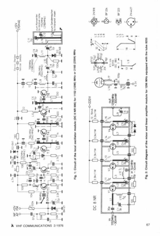
The cucu.t 01 the local oscillator ctlaln IS shown In Figure 1 The OSCillator tranSistor T 1operates wilh a 96 MHz crystal. The subsequent stages equipped With IranSlstors T 2 and T 3double th iS frequenc y to 192 MHz and 384 MHz respec tively The lollowlng stra lghl amptmerequipped With transistors T 4 to T 6 provide s enough gaIn to ensure an output power ot150 mW at 384 MHz, This amplilier is followed by a fr8'Quency tnpta r uSing the varactce di ode0 3 which feeds a )../4 circurt tune to the I ina l output Irequency o f 1t5 2 MHz. An output power01 40 mW is available here lor the transmit mrxer, and a second, capacltlvely co upled outputprovides 5 mW lor a receree rruxer
The best elliciency 01 the cheaper varecto r diodes was cuereo by the SA 149, Which IS rIOlonger manufactu red . The varactc r dIOde BB 105 does nOI provrce such good results In thiScbcuu. bUI is eun usable, Only recen t eenvenes of the Iran ststor type 2 N 4427 shou ld be usedin this cirCUlI. because me first manufactUring lois possessed only a transit trequencv o f500 MHz, whereas the later series e~hlblted 700 MHZ,
The serecnvuv al the r8'Quired frequencie s. and the suppression of unwanted nermomcs ISmade in a bandpass 1IIIer uSing concentrated CIrCUits al 192 MHz and auspscec lines at384 MHz and 1152 MHz.
The type 01 construc tion in chambers play s an Impo rtant part in the suppression 01unwantedharmonics SUCh dillicui ties tha t are someti mes observed such as too low a senslllllily 01 thedIode m i~e rs, or too Iowan output power ot transmIt cco verters due to Insul liclent localoscillalor level should no t be Observed when usin g this local oscilla tor chain . The outputpower is eu ttrcient tcr dr iving passive ring ml ~ers,
2.1.1. Om eren t Application.
When rep laci ng the crystal With one In th e order 01 108,000 10 108,166 MHz, It is possrbte touse the descr ibed mod ule as beacon transmi ller, portable tran smitter, or exciter . Both CWand NBFM are posSIble. The cn curt diag ram shows a simple accessory cu con. which is nOIprovided on the PC-board , This is also not present on the described prototype. The AF Inputshou ld be co nnected to some type 01 limiter , such as the AF cli pper OJ 4 BG 006 ,
It is also possible to modify the local OSCilla tor ci rCUit 10 obtllin an output trequencv in theorder o f 2160 MHz. so lhat the modu le can be used 115 local OSCillator chain in cc enuncncnWith muers Ir om 2304 MHz to an IF of t 44 MHz, and vice versa , In tms mo de, a 90,000 MHzcrystal is used wh ich is tr ipled With the aId 01 tranSIstor T 2 to 270 MHz, subsequentlydoub led 10 540 MHz lind ampli fied . The varaclOl' dIode 0 3 is now used as quadrupler trom540 MHz to 2160 MHz. The id ler c irCUl i w ith Indu ctan ce l 11 IS tuned to 1080 MHz Whenusing a Schollky diode, this idler circUlI wi ll not be necessary. but the elflciency Will on ly beIn th e orde r 01 3 to 5 % . The efficie ncy when uSll1g special varactor d iodes such as theBXY 14, BXY 19, or MA 4060 0 provide effic iency values in the order of 40 %. However, theyare nol o f great interest in th iS power range due to their high pri ces
68 ~ VHF COMMUNICATIONS 2/ 1976

The above Irequen c ies are g ....en In brack ets 10 the CltCUlt d iag ram , Any component de tails(Induc ta nces, trimmers. and semiconduc to rl) are given In sect ion 3.1. 0 1 courM. the outputpo we r at 2 160 MHz is lar lowar . When uSlOg a crystal wl lh a Irequency 01 between 96.000 and960833 MH z II is poSSib le to make a beaco n or mmlatura transmitter lor 13 em (2304 to2306 MHz )
2.2. MI..e, a nd Lln • • r AmpUI I.,
As can be seen In the CirCUit d iagram given In F~ur. 2.all lour tubes 01 this modu le operate10 a grounded grid Citcul l The Ilrst tu be (V 11 ampli lles the loc al OSCi lla to r Ireq uency 011152 MHz to a sulhcient leve l lor lhe ml.er lube V 2 , The Iflput Clr CUIt lor the 1152 MHz l ig nal
represents a pi-I l iler togelher wllh the Input capaci tance 01 the tube. Indu ct ance L 10 repr esen ts a A./4 cho ke lor this frequency and ccorecu the cathod e 01 the lu be VI' the requiredres ls lor to ground to p rov ide Ihe automahc grid bias ,
The an ode 0' the tube works inlo a shorte ned )J2 line which is in me lorm 01 a re latively lo wImpe danc e errspe ced stnpllne and tuned to resonance With tne aid 01 a ceraeuc tubularIrtmmer at meo ther end 01 the line Irom the tube ,
The miller tube V 2 is prOVided With the loca l OSCi llato r signal via the coupli ng link L 3 The
144 MHz is led to the COld end 0 ' th iS co uplin g li nk , The leedthrough capaci to r C 7 lo r Ihecathod e res islor po5MS5eS , very low value so thai Ihe 144 MH z voltage IS no t bypassed Thecececnaece valoe IS. however, no t Cfl tlcal . but musl be large enough so thaI l he coupling link
IS bypassed lor 1152 MHz, but not allenua le the eeeue r voltage Inducl ance L 12 represents a'A/ 4 Choke lor 1152 MHz. wh ich ensu f'MI Ih at the loc al OSCi lla to r vo ltage II not led 10 the144 MH z Input
The 'A12 CirCUit o f Ille ml.er lube hlters o ul Ihe sum frequency 01 1296 MHz. The two. seesequent stages are idenl lcal and , mp lrly the reqUired Signal to an oulpu t po we r 01 appro.i·mately 300 10 400 mW ThIS power level IS sulllc l8nl 10 dflve a Iw o -stage ampli lier eqUIPped
With tubes 01 the 2 C 39 tamlly to app ro.,mately 30 W.
The anode voltage o f all fout lUbes IS led via ;'/ 4 cho kes The cho kes In the heater eveun afe
made acc ording to details given In (7) and .re ,Iso gi ven in Figu re 2, They provide Ihe meetfavo rable cnerecteneuce wl lh respect to gain and noee IIgure since Ihey ensura l hal no UHFpower is lost via the cathode-heater capacitance and grounded via Ihe heater CirCUlI The
diSC cepacttor C 8 wh ich is SOldered dir ectly to the chastllS, provides a UHF bypass lOr cho keL 16 The subseq uent 'A/4 choke L 18 ensures that the loss ctme teedthrough cecec uor C 9IS not tr an siormed to C 8 where II would inc reaM the loss o t the healer cncun ThiS IInecessary since an e. acl g roundi ng IS not poSSible With the aid 01 capaci to r C 8 Capaci to rC 8 possesses a sullicl en i value lor 1200 MH z when i t IS In the order 0139 to 100 pF.
2.2.1. Tube D.t .
The socket con nectIons 01 th e AEG-Te le lunken tu be type 8255 and the posi tion 01 thesc ree ning plate are given In FIgure 2, The specl flc allons of thiS tube and the abso tute limll 1are as follows :
~ VHF COM MUNICATIONS 2/ 1976 6.

Nomlnel v.lues:
Anode yolla98Cal h. resisl. :Anode curr.:S ,
",NOise equ.resist.:Add norse teeter :
160 Vl00U12 5 mA13,5 mANes240U9
Absolute Umlts:
Ma l ,anodeYollage(w arm -up)Mal ,anodeYollage(operat lon ):Anode dlSSlpallon :cem. current:Grid bia s:Grid resil lor :Heat er/ calh ,Yo ltage 'Heal er/ cath reeetence:
'00 V200 V,6 Wt65mA· 60 V05 MU
1 100 V20 kU
Capecllenca. :(outer ecr••ning to g l
Cg.m/ c.;. l : 3BpFCa/g • m : 1,7 pf
Calc. I ; 0 ,055 pF
63V 1 5 %app rox 160 mA
The gua ran teed nte 01 to 000 hours is only yaltd when the healer Yollage remam, wll hln IheIIml tlof t 5 %.
3. CONSTRUCTION
3.1. Loul Oacmetor Module
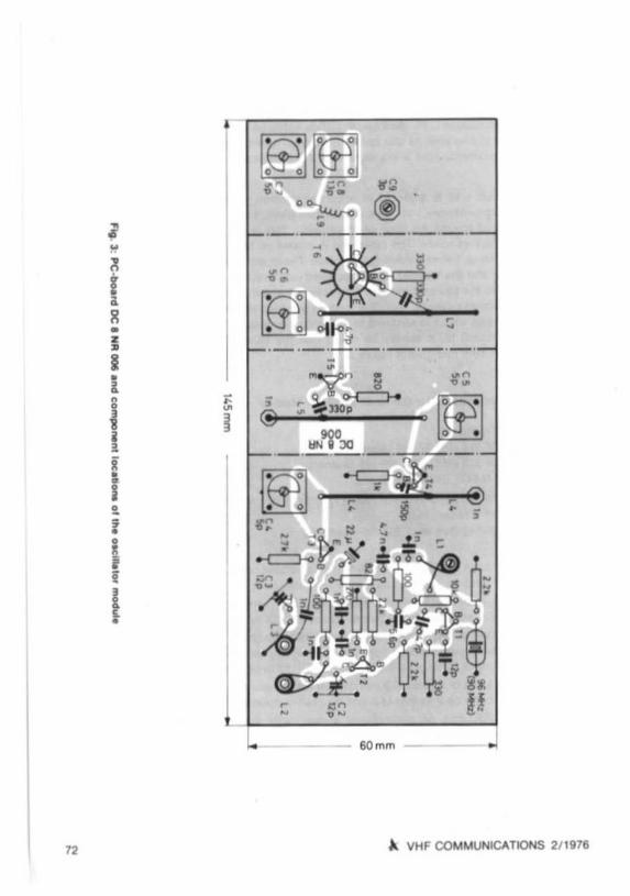
The double-coaled PC·bOard designed lor accommodahng Ihil module hal been deslgn aledDC 8 NR 006 The dmlflnitoni are 145 mm x 60 mm and thiS board is shown In Figure 3 Theground surface on Ihe upper side 01 Ihe bOard (co mponenl l ide) remelns inlac f except lorIhe co nneeuon hOles and a small area around them where Ihe copper l urlace II removedUling • 3 mm diameler dr i ll in order 10 enl ure Ihal no I horts occur between Ihe componentlead s and ground , The conduc lo r side 01 the board il also provided With a large ground surl ace, f or Ih is reason , hol es are also dri lled lor the grou nd connec tions ol lhe components toIhal these are also gr ounded to Ihe lower side ,
The photographs glyen In f igur.s 4 and 5 lhow' th ai the PC·board il .ccommodaled m •40 mm high Ir amework made Irom 11'110 br, " or l in plale . ThiS II made alter drilling theboard , but belo re mountmg the componen ll . Three in lermedlate panell are prOYlded on meupper side 01 the board. whereas a 42 mm x t 5 mm large cha mber il provided on the lowersid e 01 the board lor tbe oul put CirCUli and Yl racto r Irlpler, II II now pollible lor Ihe complel e module 10 be silYer· plaled HoINeYer , Ihil is only real ty necesaary lor Ihe Wlr" 01 theinduc tances and hne CIrCullS, as well al lor the tub in g 01 the oul pu t CirCUli The InSI. llal lon01 lhe PC-board in a sealed Clse yirtually represent l a - ccic- Ihermoalat This means ' halrapid lem per alure yarla hons do nol have such a greal alleel on Ihe oulpul Irequeney (mu lhplication x 12 or x 24). al would be the ceee Wlfh an open, PC-board conllr ucllon,
The l eedt hrough capac.to re . 1 m e end 01 lin " L 4 and L 5 ara loldeled on Ihe componentIide 01 the PC·bOard where Ihey support Ihe hne ci rCUits The cryl tal 15 dl reclly soldered ,wllhoUI soc ket, and the case should be grounded Tranlillol T 6 II p roYlded '0'11111'1 I mall cool.ing IIn l 01 on ly 12 mm dl ameler, The follOWing componentl ale located on lhe conduclorside ctme board : Ihe zener di ode 02. lhe lead trom Il l taedth rough capaCIlor, lhe eeneetor
70 A. VHf COMMUNICATIONS 2/1976

resisi o rs 01 Iransislors T 3. T 4. T 5 (looU. 47 U . 22 UI, ChOke' L 6 and L 8, as well as theverec to r tr tprer . The connec tion po int at Ihe 1'101 end 01 diode 03 IS supporled by the smelltnmmer capaci to r C 10 wh ich In II. lum i. SOldered 10 Ihe sptndle Side 01 a teuoo. or ceramiCleed l hrough lor the coupling link L 12. The tubu lar Ir lmm er C 9 " mounled on Ihe PC-boardand supports Induclance L 1" Induclance L 10 is SOldered d lrec lly 10 lhe conduClor lane 10Ihe tnmmer C 8 al one end , At th tl POIn!. Ihe autho r provided a small lesl polnl lor 364 . or540 MHz in h iS prototy pe (use a low capaci tance leed lhrough and short connechon 10 C 8 /L 101.
The coa..ial ci rCUit L 13 is loldered to a cen lr al pos it ion in me small chamber The lubesho ul d be cui appro.imately 1 10 2 mm lon ger Ihan given. placed Ih rough a 6 mm hole rn Ihepanel and so ldered around Ihe edge on the outside. Th ll il nor poilible on the mside 01 thepanel du e to a lack o lspactI , The o lher end is placed on 10 me lubular tnmmer C tt . allerremoving the coa lmg , befo re so ldering Inlo place The inner condUClor Ihen represenll a part01 Ihe cepacuor. and Ihe Irlmmer IS l hen sCfewed Inlo place on the outer panel The ou lpulBNC connec lor 10 the transm ll mixer II connected 10 mm Irom Ihe cold end 01 L 13. and Ihesocket fo r Ihe rece ive mixer 28 mm. The laller II provided With a Ihm melal plale 01 eppeoarmalely 3 mm .. 5 mm wh iCh is IOldered 10 Ihe Inner conduclor and represents the lOner co nduct or 01 cececucr C 12. II should be not ed Ihat me PC-boa rd 01 Ihe au lhO"1 pro lotypedi ller, som ewhal trcm thai gi...e in f igure 3
3.1,1. Sp acIal Componants lor Ihe local Oscli ialor Modula
T 1:T 2, T 3:T4.T 5. T 6:
01 :0 2:0 3
L 2, L 3
L 4. L5, L 7;
L 6. L 8
L9
LIDL I I :
L 12:
2 N 918BF 224 (TIl. BF 199 (Siemens)BF m (AEO-Tl k). BF 199 (Siemenl)2 N 4427 (RCA and o thers)
BA 121 (AEO·Tl kl. BA 110 (ITI). BB 105 ,S,amenl)9,I V zener mcoeBA 149 (see lexl) . BB 105 (Siemens)
6 1urns 01 1 mm dla (18 AWGI sil...er -plaled copper w ifewound on a 5 mm ccutcrmer With core (red)
4 turns each in the same duecucn, wire and coil tormer al lor L 1.co ld ends lacmg PC-board. lap on L 3. 2.5 tu rn l I rom co ld end , wlthoul cores
silver- plaled coppe r wife 01 2 mm dla.• Itr.ighl length 37 mm .bent . pp rox. 5 mm Irom lhe /'lot end. spaced 5 106 mm abo ...e Ihe gfoundsurface, tap lngs: L 4, t o mm , L 5. L 7: 13 1014 mm from the cold end
8 lurns 01 appro x. 0.3 mm di e. (29 AWGl ename lled co pper wirewoun d on a l or mer 01 3 mm ene • sell -Iupportmg
1.75 lurns 01 silver-pla led coppe r wir e wound on a 5 mm d,a lo rmerpu lled OUl 10 1.1 ho les on the PC-board . sell -supporlmg
2 lurns, olherwlN as L 9
1 furn on 6 mm lor mar
s.....er·pl.led copper w ife 01 1 mm d,a (18 AWOl. 14 mm long.spaced I 10 1.5 mm in pereuerte l 13
~ VHF COMMUNICATIONS 2/1976 71
~
fH•••Ii-
tIi"
i•li;
!
.•
- - 6Omm -I-- ~
72 A. VHF COMMUNICATIONS 2/1976

Fig 5: Ph Ologr.ph ol lhe .ulho' ". p'Olol'f~ !rom bekM. howlng the ".,.elOf trlpl.,
~ VHF COMMUNICATIONS 2/ 1976 73

l13
L14
C 1 C3.C 4 C 7:C 8
C'C 10:
C 11:C 12:
Silver -plated brass lube 01 6 mm die ., 0 ,5 mm tubing. 34 mm 'on g.mounted cenlrally In Itle melal chamber 1Smm .. 15 mm .. 42 mm
sdver -plated coppe r wife 01 1 mm diB . 10 mm long .spaced 1 mm In parallel With L 13
13 pF ceremrc or plastic IOll lnrnmer 01 7 mrn dlBS pF airspace<! trimmer Wit h two or lou r plnalor PC-board mounting13 pF . ,rspaced Inmmer as C 43 pF cerermc tubular trimme r Ph, lIps 2222 80 1 2000 1 or 802 20001
3 pF ceearme miniature tubular ' rimmer, 4 mm die ., app rcx. to mm longlor singla hate &Older moun lmg. Phi lips 2222 801 2005 I
3 pF ceram ic tubular trimmer. Philips 2222 802 20001, ramO\l8 lIa,or coalmghem.-rnade Irom metal ptete. see 'e lll
6 pieces leedlhrOUOh capacitor . 01 between l00pF and 1 NF,All ' ,xed capacitors lor 5 mm SpaCing : all rellslor. ' or to mrn spa cmg. Sile 0207,crysl al HC·25/U,
3.1.2. Dmerent Com ponents requIred wh en constr ucti ng lor 2160 MH;r
T 3:T4T 5:T.03
L 2, L 3'
L4
L 5, L 7:
L 6. L 8:L 10:L 11:L13L14
C2. C3:
BFY 90, BFX 47 (PhIlips). or BFX 89 (Phil ips. Siemens, AEG·Tlk )BFX 47, BFX 89. or BFW 30 (PhIlips)BFW 16 A. BFW 17 A (PhIlips. Siemens)BFA 65. BLX 65 /66 (PhilipS)
BA 149 or SChollky dIode such IS HP 2800 or SImi lar
2 lurns, tap on L 3. 0,75 lurns Irom Cold end
lenglh 27 mm . space ma• . 5 mm O'<'er Ihe board.cOil l ap appro. 810 10 m m ' rom the cold end
30 mm long. space ma. 5 mm over Ihe board.ccu l ap epprox 8 10 10 mm from tne cold end
6 tu rns: L 9 1.5 turns wound on a 4 mm lorme,1 turnU·shaped, 15 mm long. L 12: 6 mm long16 mm long. slide ,rHO Ihe ceramiC part 01 C 11 bY approlumalely 5 mm6 mm loog
6 pF ; 2 pF cepecucr allhe ceueetor 01 T 6 deleled ,
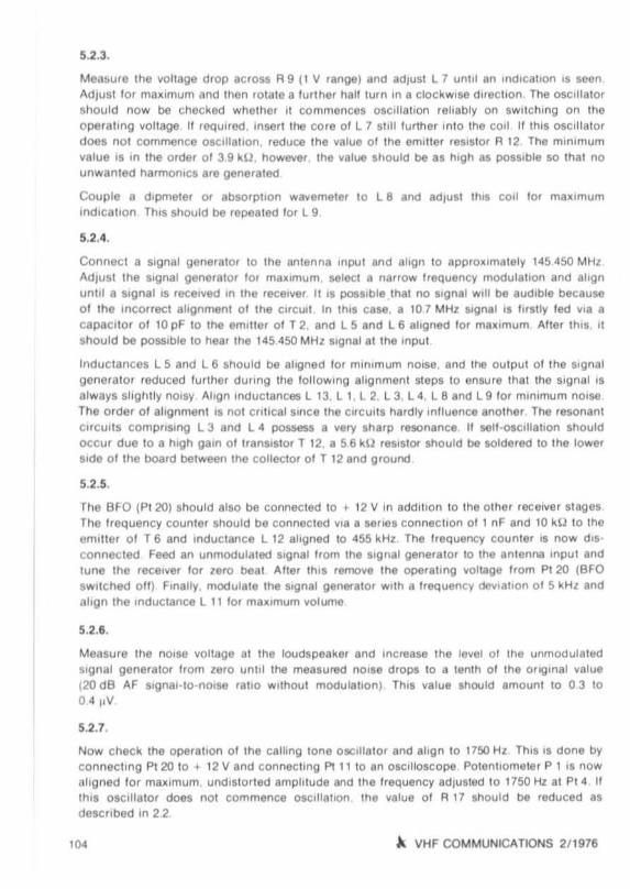
3.2. Transml1 Converter
Photographs 01 the aul ho r' s prot oty pe 01 lhe miller Ind linear Imphlter module are given In
Figures 6 and 7. The ChaSsis 01 Ihis module is made lrom Ihin br l SS or l in ptete . Thedimensions are 145 mm II 60 mm Ind 30 mm hIgh . The holes lo r the lettdthrough caplcllors01 Ihe anode and helter voUage (4 each) Ind lor lhe BNC inpul connec lo r Ire drilled I Ssho wn In Figure ' The ..,,111 short penels Ife prOVIded With I BNC connec to r lor Ihe loca'o-cmalor and slgnal lrequencv· Four I'IoIttS are dnlled In lhe upper panel lor Ihelube aockels .lou r for Ihe ClIlhode leedthrough CIIp8CltOrs Ind Sill lor the trimmer capaCito rs, Aller IheIrlme and cover have been drilled Ind jOined Iogelher, the screenlOQ conars 01 Ihe lubelOCke ts should be soldered inlo pllce
A VHF COMMUNICATIONS 211976

~ VHF COMMUNICATIONS 2/ 1976 75

37 - 1 1) ~
30 - _ 27 ...-30
4 _ ~ Q :
~-O :- - 0 -1I II II I
-30
____ 1--Q ::::... .....
-e,"",_~~~ !/
:\.D'OIl. ,
I I
1 !'2~ ,
I,- !-_ ---:......:...._ --'-_ _ --'-__---+_-JPI... 27 _
IL
apprm 17
I,
Fig I , Jl .etui," 110M. Oft p 0'''' mpIIf ..
,I7
t1152 MHZ
•
14,(, t.f-1z
"'C2
DC 8 NR
1296 t-t-lz
,., VHF COMMUNICATIONS 2/1978
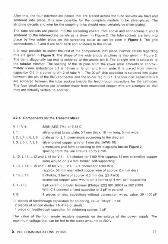
Alter tms. the lour mlermecllale pana ls thai are placed acrou the lube soc kets are I iled andso ldered ,n lO place It IS no w po SSible lor ee complele module to be s" \ler -plaled Thestrip lme CirCUits and w ire lor me coupling !inka shou ld mosl cel1ainly be sil\ler -p laled ,
The l ube soc kel s are placed in lo the screening collars Irom above and connec llons 1 and 6soldered 10 the intermed iate panels as is shown in Figure 2. The tube soc kets are held in loplace by two so lder blobs on Ihe screeni ng collar as can be seen In Figura I The gridconnec tions 3. 7 and 9 are bent back and sol dered to the co llar ,
It IS no w possible to solder Ihe rest 0 1 th e com po nents mt o place . FUl1her detail. regardmgIhlS are gl\len In F~ure i , The shapa 01 Ihe Wide an Ode Slrl plmes IS also gl\len 10 Figure 2.The bent, diagonally cut end is so ldered to the anode pm 8 The Ilralghl end IS SOldered tothe lubu lar tri mmer, The spacing 01 Ihe atrtpline Irom the cover plale amount. 10 epprcxtmalely 5 mm. Induc tance I I IS 18 mm 10 lenglh and 5 mm wide II is placed Irom Irt mmercapac itor e l m a curve 10 pin 2 0 1 lube V I: The 30 pF Chip ceoecnc r is so ldered «uc placebe tween the p in 0 1 the BNC connec tor and the sol der tag 0 1 C 1, The lour diSC capac, to r. C 8are so ldered between the tube sockets beside the leedthrough capacito rs lor the calhodesThe lour small cho kes per chember made Irom enamelled copper Wire are arranged SO thatthey are \lil1ually vemcer tc another .
3.2.1. Co mpo nentl lor the Tran lmll Mil . '
8255 (AEO- Tl k ). o r E 88 C
sll\ler -plated bra ss pla le , 0 ,7 mm th ick . 18 mm long,S mm Wide
prate as lo r l 1. dimenSions accordmg 10 the diag ram
sil\ler-pla ted copper wire 0 1 1 mm dla , (AWG 18 )
dimenSions and lo rm according 10 the diagrams beside Figure 2.SpaCing from the hne cirCUits 1,5 to 2 mm
l 10. l 11. l 12 arw;1 l 18 lor V 1: )./4 cho kes lor 11!lO MHl (app rox 65 mm enamelled copperwif e ) wou nd on a 4 mm l ormer. sell -supporting
l 13. l 14. l 15 and l 18 lor V 2 ... V 4 ), /4 cho kes lor 1300 MHl(appro x. 58 mm enamelled copp er wIFe 01 apprcx . 0 4 mm dla )
8 cho kes, 3 turns 0 1 approx 03 mm dla (29 AWO)l;lnametled co pper wire . woun d on a lo rmer 0 1 4 mm . sell -support ing
Vl -V 4
II :
l2. l 4 . l 6. l 8 :
t ac s.i. r. t s
l16. l 17,
C I · C 6
C 8
3 pF ceramic tubular tnmmee (Phi lips 2222 801 20001 or 8022(X)(11Wllh C 6 connec t a Ilxed capa ci tor 0 1 3 pF In parallel
4 pieces 0 1 diSC capac llors wlthoul connection Wires. \lalu e 39 - 100 pF
11 pieces o l leed lhrough capaci to r. lor sol deri ng . \l8 lue 100 pF . I nF2 pieces ot erhcon d iodes I N 4 148 or SImilar1 piece 0 1 leedthrough cececucr lor soldermg epprcx 2 pF
The veiue 0 1 me tou r anode relli SlOrs depends on the \IOftage 01 the po wer supply, Themal lmum \lOltage lhat can be led 10 me lubes amounl. 10 200 V
~ VHF COMMUNICATIONS 2/ 1976 77

4. ALIGNM ENT
The alignment 01 bo th modules should not cause any d illic ulhes to e. peflenc ed resncamateurs. Since the ci rcu i ts are not entreat, and re latIvely high levels are available , However.required are an absorption wavemeter (8) lor rrequ enctee above appro.imately 700 MHz. aswelt as a frequency counter lor frequencies o f up to 540 MHz (9) or at least an absorp tionw avem eter . In addi tion to this. a Simpl e po wer meter is reqUired to ind icate th e outpu t po wer.
4.1. OscUlator Module
The osci lla tion 01 the crys tal at the hUh overto ne must be CheCked wllh the aid 0 1 a VHFbroadcast receiver il a Irequ ency counter is not avai lable
ThIS is because the cscmatc r can also OSCIlla te at the third overtone 0 1 approximatel y576 MHz If the core is completely inser ted.
The transistor slages T 3 to T 6 are no w aligned lor max imum collec to r cu rrent 01 the subsequent stage dUrin g wh ich the treqoenctee should be checked ThiS IS tonow ec by co nnec ting a pow er meter to the previously mentio ned testpomt. Alter dis connecting Induc tance l 10and connec ting 15 pF In para lle l With Iflmmer cacecnor C 8. It IS po SSIb le to ahgn the tran sis to r stages l or max imum po wer reading at 384 MHz (540 MHz) After thiS. the origi nal cuc urtsho uld be connected again .
The absorption wevemetee is no w connected 10 the c cro ut eocset 01 the trenemn mrxer. andth e coax ial ctrcu« compriSing L 13 / C 11 IS tuned , A small reading should appear at resonance . al ter whi ch the other co mponen ts can be aligned alternately lor maxrmum reading.Atten tion shou ld be paId th at the coaxial CirCUli can also resonate at the lourth herrncmc 011536M Hz when the trimmer capac i tor 's vir tually at minimum capaci tance
Alter co nnecti ng a receive converter. the value ottnmmer capacitor C 12 should be Inc reasedtrom ItS maximum spac ing unttl no lurt her incr ease in sensitivi ty IS no ticed.
Using a sens iti ve abso rption waverrer ee It was only possible to lind the second harm onic(768 MH z) with a level o f less than 05 mW as only spuriOus Signal. tr ue frequency Will begreally suppressed 10 the subsequent ampli li er stage equippe d With V I. and the hnearampli fie r.
4.2. MI••r and L1n..r Ampfll ier Module
Thi s is commenced by alig ning the local oscillator emplure r by coneecun a a pow er meier orebsorpnon wevemerer to the 144 MHz input and aligni ng trimmer C 1 and C 2 to maximumreading The local osci lla to r vcna ce at th iS po int is sutl,c iently high lor a reading to be ob tained. Alt er this. the power meter is ccnnectec 10 the 1296 MHz ou tput soc ket . and a 144MHz sig nal 0 1 approximatel y 10 mW is co nnec ted to the signal inpu t, A sho rt piece 0 1 wire IS
now co nnected to the input 0 1 l he absorpt ion wavemeter and placed 10 the ViCinity 01 theanode slriplines , Th is allows th ese lines 10 be coarsely alig ned un fll a po wer reading is obtained at the output. The l tnal alignmen t IS made With the base plate In place It IS also possible for all stages to be IIr stly aligned to t l 52 MHz. and lor t nmmer capaci tors C 3. C 4 and
7. A VHF CO MMUNICATIONS 2/1976

C 5 to be decreased in value Irom thi s position un til a reading ia observed The values 01 thequiescent current and l ull dr ive current 01 V 4 are given In the crrcvu di agram ,
The output pow er will only Increase up to an osc ill ator l6\lel 01 approx Imately 25 mW , Inexcess 01 th is, the conversio n gain will no longer in crea se, The Input stage co mpriSing C 1
becomes very wldeband In excess o f 20 mW, wh ich means that the allgnmen l shou ld bemade er II lower level.
No tendency to sell-osc illa tion was Observed even when removing the screening cans, whi chshows Ihat simple epollY glasslit>er socke ts without screening can be used (glue Into plece},
When frying a tube EC 8010 instead 01 Ihe 8255 in the output. It was round tha t the outputcirCUIt comprl smg L 8 1 C 5 COu ld no longer be broughl to resonance due to the high er value01 th e anode 10 gr id Capacitance tCa/g).
Spurious frequencies, including the osc ill ator frequency COuld not be observed m the spec trum 01 the output frequency WIth the measuring eqUipment avail able to the author. The output power was measured to be 350 mW. G, AUlh , DJ 2 HF, gives the lollowing values l or asimilar construc tion with an intermediate uequencv 01 28 MHz .
Oulput power:1 dB bandwidth:Suppression 01 the local osc illator Signal :
400 mW4 5 MHz20 dB
Due to the far greater spacing 01 the loc al OSCillator Signal from the recurred teeqoen cv . thesoppressrcn o f the local OSCillator IreQuency In the case 01 the ceecnceo module Shou ld beat leas t 40 dB
5, REFERENCES
(1) E. Hunecke: Ein 1297/145 MHz Konverter mIt HalblelterUKW -BERICHTE 8, Edi tion 2/ 1968, page s 61 - 80
(2) L. Wagner and H.W, Binder: A 23 cm Converler With Hot -caffler DIode MixerVHF COMMUNICATIONS 3. Editi on 3/ 1971, pages 134 - 140
(3) R, Lentz: Ein 24-cm -Konverter cnne RohrenUKW-BERI CHTE 7, Edi tion 2/ 1967, pag es 69 ·87
(4) E. Fisher : Interd lg ltal Converters lor 1296 MHz and 2304 MHzCST 6, Edrtrcn 111974. pages 11 - 15
(5) J Dahms and G Auth : Wle weree ich aul 23 cm tn SSB CRV ?CQ- DL, Editi on 7/ 1974, pages 404 ·405
(6) R. JUIl and H, Dlllberger: A Transmit Mixer and Lmear Amp li l ler lor 23 ernusing lor 2 C 39 lubes
(7) Ole Aohre 8255 eer Frequenzen uber 1 GHlTelel unken Taschenbuch 1967, 'tecn mscoer Anhang , pages 51 - 55
(8) K, Hu pfer: A SHF WavemeterVHF COMMUNICATIONS 7, Editi on 211975, pages 90 ·92
(9) G Bergmann and M , Streibel : A 500 MHz srescerer and Preamplif ier rorFrequency CountersVHF COMMUNICATIONS 6, Edit ion 411974 , pages 236 ·245
A VHF COMMUNICATIONS 2/ 1976 79

RECEIVE CONVERTERWITH SCHOTTKY DIODE MIXER FOR 24 em
br 8 . lubbe, OJ 5 XA
lithe ecu...I'Y on the 24 em amateur band is 10 be Increased. II is necessary lor II number 01kit. to be avai lable In addition to the reeov -ro -cper ere converters_ThiS reee....e converter uses
prin ted slriplines. II prin ted hybnd fin'll and 5chollky d iode m.~el . The demands placed onthe rad iO ama teu' With respect 10 measurmg mstruments lind meawre w ork are therefor every low .
A local oscillator cham and II IF preamphhel a,e accommodated on the PC-board Two V8r ·
sions are ceecnoeo. one lor communtca tlon, (1296 MHz · 1298 MHz / 28 · 30 MHz) or ATV·operation (1252.5 MHz · 48.25 MH Z). In order 10 keep the PC-board liS small as posSible. nopreampli f ier and aelec llYlly is provided l or the mpu t frequency ThiS also eaMI construc tionemce it is 811!lIef to manufact ure the complete I latlon 'r om smalle r modules Section 5 givesde lalls reg ard ing a SUitable preamphllftl' and Mlermg A pho tog raph 0 ' lhe au thor's proto typeIS gIven in Figure 1
-,-,,~-_..
1. CHARACTER ISTICS
Opera lmg vo llageCu rren t dram :Overa ll gain :UHF-bandWidthIF·bandwld lh at 30 MHz:IF-bandwidt h e t so MHz.NOIse I lgure (With Imagel '01mensions'
80
Fig . 1: A 24 em conurte r with SChOll", mlOe '
12V I -l /_2Vjappro~ 30 mAepprcx 20 dB12!lO - 1300 MHzeppe ox 3 MHzappro~ 7 MHz
appro~ 7 dB135mm ~65mm
~ VHF COMMUNICATIONS 211976

.;
t
I1
I&
r!fI
18..~no
;; "' ...r.:-.. ~
\ul"8.. ~
. Ii R< . ~.
" ,*...,
"• ••~ .
~ !- 0 ~
i, ~ ;
••
~ IIH F COMMUNICATIONS 2/1916 81

2. CI RCUIT DESCRIPTION
The CIrcuit diagram 01 the converter IS gIven In Figur. 2 The maIO leature 01 the converter ISthe emphne hyb ftd flng work ing In conjunc tion w ith th. SChottky-d 'ode rrnxer ThiS hybridr ing is u sed as a 3 dB coupler, The ml .er diodes are ccooecree rn an l,phase and are, w ll ched in the lorward d,rec l, on at the sam. time. whereas the OSCIllator voltage at the mt er connec tion point 01 the two d iodes is cance lled ou t
The norse 01 the OSCi ll ator is also cance lled ou l together With the required stgnal and IStberetcre no t led to the IF-am plil ler , Th,s results In a nolic lble Improvement 01 the senSltlvl lyThe hybrid ring crrc uu is crec ussec tn mor e detail In section 6 Measurement s have shownthat the use of UHf-Schotlky-dl odes such as hp 5082-2811 can bllng an improvement In theno ise fig ure 01 1,5 to 2 dB over when uSing universa l SCho llky diodes such as hp 5082·2800
The type 01 ml.er crr cuu used does no t allow the dtode cu rren l 10 be measuf9d duringope ra tion. However , lhlS IS not necessary , If lhe alignment IS 10 be checked . one of lhe d iodescan be d laconnecled and Ihe cu rrent of the second dIode can be measured between conneencn po int PI 6 and PI 7 DUring no rmal ope rauon . Ihese Iw O polnls a.e bridged w,l h thea,d o f a ceceeucr. A OC-bndge tS nc r necelsary and would Interf ere wll h the dlodlt cu rrenls
A dual-g al e MOSFET has bee n used as ,ntermed ,ale Ir eQuency p.eamplther. wh'ch po ISes58'Sa resonant crcuu al mpul an d ou ipul Couphng li nkS are used lor matc hing 10 Ihe mrxerd iodes and 10 me 50 U coa . la l cable to Ihe sho rtw ave receiver Th iS siage has a conSiderablemncence on the noee Ilgure 01 the converter (1). lor Ih ,s reason . a norse matchmg and notpo wer ma lch lng II selected
A further Important part 01 Ihe cucurt With reepect to the nOise I lgure 01 me rmxer IS the lastresonanl cueuu 01 the osci li alor chain . II the a 01 lh e I lrlpline CirCUlI L 6 1 C 5 IS 100 low . thiSWill cause an Inc rease of the nOI58 I,gure Fo. Ih ll reason , l 6 IS made In the Iorm 01 anair -spa ced I I " phne . II a pllnled stllpllne was used on Ihe epo .y malenal, the a would be 100low , a PTFE (Tellon) PC-boa rd wou ld be 100 e.penSlve
The crys lal OSCillato r com ptlSlng tranSistor T , operales tn co nJunCho n wolh a sefles- resonanlc rys tal (!11 th overtone) at a frequency In l he order 01 70 MHz The ccnectc r cllcu,1 15 tuned tothe crys tal frequency, The suDsectuenl stage eqUIpped w,lh tranSlIlor T 2 Inples Ihe trequencyto appro. lmalely 2 tO MHz; a bandpass h iior comprisi ng L 2 / 1 3 suppresses any un wan tedIrequenCles
The ' Ir " two slages are led wllh a stabilized vollag e 01 app ro.imately 85 V tn order 10 aVOidany Ireq uency var iat ion s due to uu ctuatrcn a 01 the suppl y volt age , The thir d slage comptlSlngT 3 doubles Ihe Irequency 10 appro.imalely 420 MHz , A bandpass l ill er is also used here , Al,immer potentiometer in me ermtter ClfCUit aUOONS the moat favo, ab le OSCi lla to r ampli tud e 10be adjusted as was lhe case wilh the 70 cm converte r OJ 5 XA 003 (21· The lourth stage 01 theosci ll ato r chain hna Uy tr ip les to Ihe reqUIred Irequ en cy
A low -noise SIlicon PNP h lgh -cu rrenl t,an Slsl or is used lor IransiSlor T.t , The PNP·conllgu ,ahon all ow s the co ll ec to r circu it 10 be d'r ectl y grounded (negallve) The l,anSlstor typeBF 479 In a plast iC r -eese is designed lor VHF and UHF TV tune,. w,Ih PIN diode contro l Inthis case, the gatn Of lhe tranSIstor IS oc t controll ed . and 11 ope rates With a relatIvely high
82 ~ VHF COMMUNICATIONS 2/ 1976

couecto r curren l 01 10 10 20 mA o ThIS all o ws lhe hIgh outpu l voltage 01 lor Inslance 200 mV10 be prov ided at a large IOlermcdulat lon ral lO 01 lo r meteoce • 40 dB Germamum !ranSlsl orssu ch as Siemens AF 379 are also used lo r suc h. tune rs However, no e_pe fl menls were made10 see how SUllable they would be lor Ih ls applicati on
o
•
'"
DJ5XA OO4
3. CONSTRUCTION
The PC·board OJ 5 XA 004 was dewloped lor accommodatIon 01 Ihe converter , The d lm en ·slons 01 Ihl l doubl&-coa led board w llhoul lhrou gh·con lacll are 135 mm _ 65 mm The pc.board and lhe compo nenl locailons are sho wn In Fig ur. 3 The componen ls are mounled on
the side 01 tne bo ard wllh Ihe hybrid r ing Tran Slstor T 4 sho uld be so lDered dlrec lty on to rneconduc to r lanes on top 01 the PC-board. The ccuecto r ecenecncn IS benl up low ards the ai r ·spaced sl rl plme l 6 and eeroe reo 1010 place The two SCho llky dlode ll are also dl reCllyso ldered to the conduc to r lanes. II shou ld be nOled thaI they Sho uld be mounted as sho wn Inantiphase . Ihal only one dIod e II Ifl slalled dUring the al ignment. and Ihal the connecnon
wtSland w I hou ld be co nnected Ulllng a wile bridge to Ihe con duc lor on Ihe lower SIde 01 theboa.d
The ba se 01 lra nSll l or T 4 and Ihe IF-conn eclI on 01 Ihe two mlker d,ed. are bypaS&tld uSing
ce ramic chIp cepacuors. SUitab le slo ts should be u wn Inlo tne PC·board lo r IhtifIe capaCltOtS, w hose values are nol cnncet
The coakl al cabletrc m the anlenn a is d ir ectly SOldered WIth the Inner conduclor to the sho rtccnoecnco line o f the hybrid r ing. and Ihe shIeld 10 Ihe lower Side 01 Ihe board II Ihe pc.board II 10 be mou nled in a case , It is very lavor able lor !he COUl,1 soc ke t 10 be dl leclly
so lde red mt c poslhon as sho wn In FlOure 1.
The converter can be Inslalled ,n an aluminIum Tell,o bo x. I lle '" A However. , match ing casemade Irom brass pla te o r PC·board material would be more l avor ab le , The ground su rfaceso t tne PC·bo ard should Ihen be d ll ect ly soldered to Ihe ease. Th iS makes th e co nwr1er Inse nsif lVe fa adjacent eueere II is only necessa ry lo r the cay to be 30 mm. or even 25 mm . high
A VHF COMMUNICATIONS 211976 83
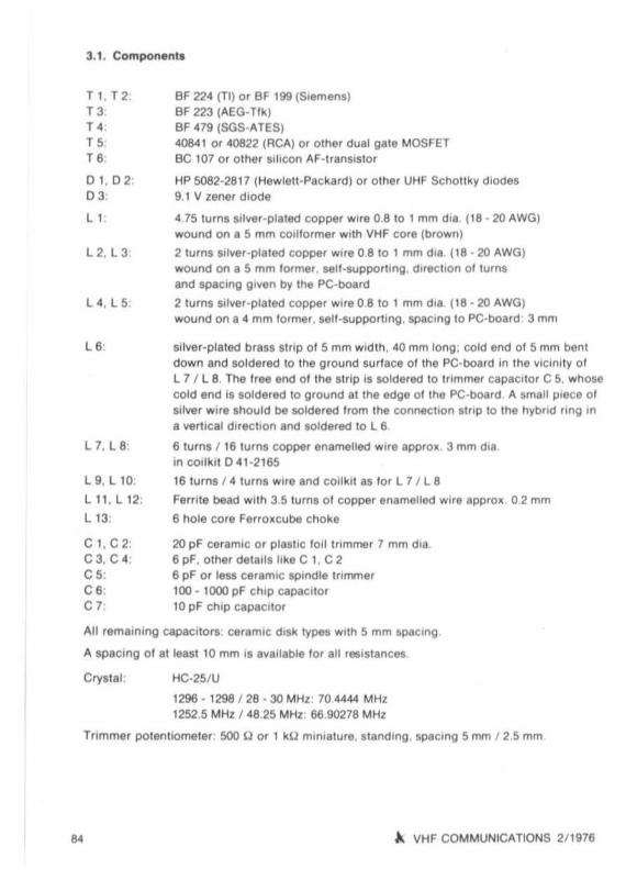
3.1, Component.
T t . T 2:T3TOTOT 6:
D 1, D 2:D 3:
L1 .
L 2. L3
L oi . L 5:
L 6 :
L 7.L8
L 9.L IO:
Ll1 , l12:
L1 3:
C I, C2:C3, C 4,C5:C6:C 7:
BF 224 (Tl) or ee 199 (SIemens)BF 223 (AEO·Tlk lBF 479 (SGS-ATES)4084 1 or 40822 (RCA) or ot her dual ga te MOSFETBC 107 or o ther SIlicon AF-If ansisl or
HP 5082·2817 (Hewlell·Packa rd) or o ther UHF Scho llky dIodes9 1 V zener dIod e
4 15 lu rns sIlver-plated copper wire 08 to I mm d,a 118 ·20 AWOlwound on a 5 mm cOlllormer wIth VHF core (brown)
2 lu rns sdver-plated copper WIre 0 810 1 mm d,a (18 ·20 AWO)wound on a 5 mm lormer , sell-suppothng. d"echon 01 lurnsand spacing gIven by Ihe PC·board
2 lurns sllver -plaled copper wIre 0 810 1 mm d,a 118 ·20 AWOlwound on a 4 mm lormer. sell·supportlng . spacmg 10 PC-boa rd 3 mm
silver-plated br ass slrlp 01 5 mm widlh. 40 mm long : col d end 01 5 mm bentdown and soldllred 10 the ground surlace 01 Ihe PC·board In 11'111 vlClnlly 01L 7 I l 8. The free lind 01 the smp is aoldllred 10 tnm mer capecuor C 5. whoseco ld end is soldered 10 ground al Ihe edge 01 Ihe pc·board A small p,ece 01"Iver wIre shou ld be solde red Irom the cormectren sirlp 10 the hybrid rIng Ina vertical duecncn and soldered 10 L 6
61urns I 16 lurns copper enamelled wif e appro .. 3 mm dIeIn co-r kIt 041 ·2165
16 1urns f 4 turns wife and coi lk,l as lor l 7 J L8
Femte bead WIth 3.5 lurns 01 copper enamelled wlte appro.. 02 mm
6 hole co re Ferro..cube cho ke
20 pF ceraeuc or p lasl lC 10,1tnm mer 7 mm dIe6 pF. ot her details hka C 1. C 26 pF or leu ceramIc spInd le l tlfnmer100 · 1000 pF chIp capaCItorto pF chIp capaci tor
Crys la l :
..
All remaInIng capacllors: cererruc dIsk types Wll h 5 mm spaCIng
A spac mg 01at least 10 mm IS avaIlab le lor all reslstanCM
HC-25JU
1296 ·1 298 f 28 ·30 MHz: 70,4444 MHz1252,S MHz f 48 25 MHz. 6690278 MHz
Trim mer potennemeter : 500 U or 1 kU mmiature. standIng. spacing 5 mm 1 2 ,5 mm
~ VHF COMMUNICATIONS 211976

• . ALIG NME NT
A IreQuency cou nler or absorpl lon wavemel er IS reqUIred lor allgnmenl ol lhe cscrnatc r chai n10 ens u re Ihal the co rrec t harmon ic is selecled The relOnant Circul i compr l' lng L 1 shouldbe aligned 10 thai Ihe OIcl ll alor commences ccereucn rehably on sWllchlng Ihe opera hngvo lt age . The two bandpass liller , lor 210 MHz and ' 20 MHz are ahgned lo r mU lmumcollecto r cunent of Ih e eubsequeot stage (chokes l 11. L 12 or Ihe l 0U resls lor should bedisconnected al one side) . The allgnmenl i ' slmpli lled when a simple powe r indica tor is pro Vided ,
Th e lasl os c illator c ircu li co mpriSing L 6 1 C 5 ca n be coa rsely aligned wh en one 01 IheSchon ky diodes is d isconnec led and Ihe current between ee neecuen po inl PI 6 and PI 7 IS
Ind icated . All previou s adluslmenls can be opti mized durmg thIS The IInal allgnmenl o .tr immer C 5 is made In conluncllon With a rece.ve Signal
The IF preamplil ler must now be aligned Prehmlnary. It is sulllClent lor an ahgnmenl lormaxImum noise or 'ignal 10 be made at tne cen tre 01 the ba nd II " possIble tha i the IFamphller w ill oscillale wh en no l cc-eecuv lermmaled 10 Ihe 'ubsequenl rece iver. II Ihe
receiver is nol to be mod il led . a 3 dB allenua to r should be connected belween Itle IF OUlpul01 Ihe convel1er and Ihe subse-quenl recei ver
The fo llOWing allgnmenl step, sho uld be made In Ihe 10llOWlng order : Ad lusl t flmmer C 5 Inconjunc tion wllh a weak ,igna' at lhe cen le r o l lhe band lor mu,mum s.gnal
The tnmmer resetcr in me emi tte r lead 01 T 3 is redu ced Irom lis ma~lmum value In conJun cllon w' lh a very strong signal until no Inc rease 01 Signal takes place AI the same ume.tne noi se w ill be red uced 10 a mimmum ,
Ophmize th e alignment 01C 5 and Ihe ct ner osc illa lor slages
Finally. align ind uc tance L 8 in conjunction With a weak Signal , or II poMlble t0Q8lher With a
norse oener ator lor basi nOI.. matching (bests'Onal· lo·nolS8 ral lo l
S. POSSIBLE EXTENSIONS
As wa s shown tn Ihe e~ample. given In ( I ). me highest poSSible senSlllVIly 01 a receivesyslem lo r 24 cm cannOI be aChieved when only uSing a miller . Al leasl one, and be tter 11'10
preamplif ier slages sho uld be u&ed belore the ove ra ll noise I lgure I. mamly determmed byIhe hrsl I ransiSlor, This was underlJned In a reciure given by DIeter Vollhard l , OL 3 NO. al Ihe
wemnerm VHF ecnvenucn in t975 DL 3 NO recom mended the tr anSisto r Iype BFA 34 A in apreamplifier such as PTFE PC·board deSCri bed by OJ 1 EE (3), II IS lus t as Importan l to IIm llthe no ise compo nent 01 Ihe Image Ireq uency wil h the alC! 01 a hil er lor Ihe reqUired Ire
qu en cy . Th is all ows a senslllvl ty Inc rease 01 a ma~ lmum of 3 dB 10 be obta med assumi ng me tmser sion loss 01 Ihe hlter IS zero Conial and InlerdlQltal hll ers can be u$8d fo r th iS eppnCalion . The in lerdlglla l I llter deSCribed in (4) pow.sesses a bandWIdth 01 50 10 more l h~n 100MHz accordtnO 10 adJus lment. Thll means Ihal II IS nol sul lable for s.uppresSlng Ihe ImageIrequency 01 1324 MHz al an inlermedlate I req uen cy 01 28 MHz, AI leas l Ihe I itl er should be
aligned 10 Ihal In. rece ive Ireq uency range IS e t Ihe upper end 01 Ihe passband 0 1 course,an inte rmedlale I req uency in the order 01 70 MHz or 100 MHz Islar more lavora ble
~ VHF COMMUNICATIONS 2/ 1976 es
5.1. atv O,Nutlon
In the ATV mod e on the 24 em band. the Video C8Fr1er 01 1252.5 MHI II converted 10 an Inle r·mediat e frequency o f 48.25 MHI (CCIR c hannel 2) ThiS reqUIres a loc al osci ll alor Irequencyo f 1204 25 MH,; when mulltplylng by 18. a crys tal IrftQuency o f 66902177 MHI is roqUlred
No modif icat ions are required to the osc illato r cham 01 the conver ter II IS on ly necessary 10mOdify Ihe resonanl Clrcu,ls 01 the IF preamplll ier
L 7 /L8L 8 /l 10
5.2. Higher IF
4 /10 turns Wire and cod da ta as In lechon 31 .10/4 lurns Wife and COil data .III In section 3 1.
II the in le rmedlale Irequency IS to be In Ihe order 01 70 MHI . 100 MHz or l ·U MHI . onl y mmo rmodllicahonl need be mad e to Ihe OSCillato r chain wllh lhe exception 01 Ihe cryllal Irequencies. The IF COils are Ihen wound on 5 mm coruc rmerem screened cans The tu rns-ratiobe tween the coupli ng w ind ing and Ihe reec nem ci rcui l should be malnlalned approx lmahl ly
It may be necesaary to reduce the value 01capacl lor C 1
5.3. Tran smit Miler
Mod ule OJ 5 XA004 can allo be used as tran llfT"t mlker In th is CI58. Ihe IF preampliller IIIde le ted and me Iransm ll slgnl l II led al lOw Impedan ce 10 the mterconnec tlon pomt 01 themixer d iode, The requlfed signal and Ihe Image appea r at Ihe otlglnal an tenna Input. 0 1course. the mller shou ld be fo llow ed by a nrter .
The OSCillatOr leve l sho uld be In lhe order 01 1 dBm (5 mW) and the TranSml1 SIgn al 0 dB m(1 mW I. This resu llSln an output power 01 app rOl lmately 01 mW (. tOdBm ) 1/ t"gher po werd iodes are used. higher dri ve levels and hi gher output powers can be achieved The expenmeot s made by the author only used d iode s Iype hp 5082·2 800
6. APPENDIX
6.1. Further Deta U. on lhe Miler CirculI
The 1'10158 o f a 5cho ltky mooe mixer COmp fl l8l shOI enec t nOise (1) o f the Scho lTky Junct ion .and thermal nOlsa (1) of the dIode path resistance both In lhe frequency range otmteres t andat If level. NOise compo nents 01 Ihe diode paltl resistan ce al The Image IrftQuency are alsoconverted to the IF level ,I lhls IS nollillered Oul Th iS can be made USing coupled resonalorsfor lhe ima ge Irequency (5)
86 ~ VHF COMMUNICATIONS 2/ 1916

In addition to the g iven noise components of the Scho ttky diode, the no ise o f the localcscnreror can oetenorere the senSitivity o f the mixer , No cscinetor IS com pletely fret! ot spontaneous ucctcancns of the trequencv and amplitude, whi ch means that a spectrum o f frequencres is generated mstead of one d iscr ete frequency Accordmg to the 0 01 the OSCillator,Ihe envelo pe o f tms spec trum decreases on incre asing the spac ing from the center frequency
NOise compo nents Ihat are spaced al the same value as the Intermed iate frequency h om thecenter Irequency (In other words those that are wutun the receive fraquency or Image Ire quency range) are also converte d 10 IF level In Ihe same way as the Image frequency m themiller. They are super impose d on to the required Signal in lhe form of noise mterterence .
This noise component can be very high, espeCially al low Intermed iate trequencres since theno ise spectrum 0 1 the local OSCi llator IS not suppressed suff Ici ently at 50ch a small spacmgIrom the center freQuency
In order to supp ress Ih ls norse interference Irom the local oscilla tor, II IS pOSSible l or thISspec trum to be decreased using narrowband Iliters However , thi s requires resonators havinga very hig h O. which means that line or cavity resonators musl be used ThiS can be aVOIdedby use o f sui table mixer CirCUits that use two or lour paired diodes In a balanced or anti phasecircu it. Su ch a cucurt suppresse s (cancels 0 1,11) the noi se 01 the local oscillator (5)
The simplest cirCUit to achieve uue aim wou ld be a pu sh-pull mixer , In order to eeram mesumat One Side and the drtterence Of the signal and local OSCill ator at the othe r Side a 3 cadirect ional coupler is etten used at higher feequenc-es. Flgur. 4 shows such a 3 dBdirectiona l coupler; Its term makes il relatively un cnncat In ItS dimen sions. and makes IIsuitable lor use up to very high frequencies .
ue z-=-<
zt "·
t,i
FI9 4: 3 dB d irections ' coupls, 1- c:::J- -=-., ' /Ii • z
The operation 01 this hybrid ring IS as tcuowe:
A sig na l tha t it passe d on the upper l ine from 1 to 2 firstly coup'es via the hne 1-3 to hne 3·4and causes a lorward and renectee wave, The signal from 1 to 2 also co up les via 2-4 to nne3-4 and causes a second forward and reuecrec wave at 4 , The I WO torward waves are mphase al posi tion 4 si nce Ihey have equally long paths on all lines The tw o reflec ted wavesare, howeve r. In eoncnese at posmon 3 Since the Signal component pa ssin g VII line 2 -4possesses a delay of )., /2 With respect to th e signal componen t driVing dir ectly bcm 1 to 3,When connec tions 2 and 4 are ccerecuv loaded . Ihese components Will be cancelled so thaIthe d ir ec!ivity is guaranteed and po lnl 3 IS eecoucree from pomt t . The Impedances and
'" VHF COMMUNICATIONS 2/ 1976 87
cc nnec ucns lor the CirCUli g iven In Figure" had been !Illiecled so ThaT nOI only II 3 decou p led Irom I , bul also ttla l a signal connec led 10 pOlIllOn 1 Will be dIVided equa lly beTweenpolnl 2 and 4. as II reQuIred Ir om an ideal 3 dB coupl er
The ma lchlng 01 the mi xer dIodes IS never ideal In practi ce, Thi s means thaI a port ion 01 thepo we r l rom the local osc illa Tor wi ll always be rellecTed at pomt 2 and .. and ted to Thean lenna via po int t In orde r to avOid thla. a 90" phase ShllTer in Ihe lorm o t a )..14 line Shouldbe inserted belween the hybrid flng and one er The IwO diodes II the mISmatch 01 the di odesIS equal. Ihe oscillalo r Irequency Will be cancelled 0 1,11 al pcm t t . ThiS type 01 CIn;:Ult II usedlor the tmxer on PC·board OJ S XA()()4
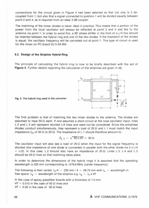
6.2. O• • lgn 01 the Strlpll~ Hybrid Ring
The prinCiple 01 calc ulating the hybrid fl ng IS no w 10 be brletly deWlbed Wlttl the aid 01Ftg ur. S Further delalls regarding !he calc ulaTion 01 the str lphne. are gIVen In (6)
,
- - - .
The l lr sl problem il thaT cr malallng the two mi.er diodes to lhe .nTenna The dlodel areassumed 10 have 50 U each . II one assumes a short ,clrcull at t he loc al cs crnarc r Input . line.L 2 and l3 WIll rep resen t shorted )./4 lines and need nOI be conlldered Since the antiphasedi odes conduct l imu llaneously. they repr esenl a load 01 25 Q and L I musT match the Inputim ped ance 1m 01 SO Uta 25 U , The Impedance 01 L I should !herelore amount 10 :
ZL , . V SO. 25' .. 3SU
The oscillato r Input Will also lee a load 01 2SU when the mput tor !he Signal 1I1I'Quency i.shorted (the Impedance a l one diode is connecled in par.llel With The other d iOde via 2 • )./ 4
• )./ 2 ) , In thIS case. L 2 Ihould also have an Impedance 01 3S U . lines L 3. L 4 and L 5Sho uld be 50 U lines so that match ing take s place
In o rder to deTermine fhe d lmensiOfl. 01 the hybrid flng. It is assumed that the operallngwavelengt h IS 235 mm co rrespondIng 10 12766 MHz (cen ler freQuencyl
The lo llowlng I' then vafled l.eJ4 • 235 mm 1 4 • 58 75 mm WITh ~ _ wavelenglh Intree space , "s - waveleng th 01me stfl plme e g I..a • ~ . VF
In Ihe case 01epoxy glass hber boardS WITh a thlckne.. 01 1.5 mm :VF . 051S In The case 01SO U lines andVF • 050 In the case 01 35 U linea
.. .\ VHF COMMUNICATIONS 211976
Th ill means tha i the 50 U line' WIll be 25 mm wide af'ld 30 2 mm long . and lhe 35 U hnell4 5 mm wide and 29 4 mm long
7. LITERATURE
( 1) R. lenlz . NoIse In ReceIVe SVlllemsVHF COMMUNICATIONS 7. EdiTion 4/ 1975. page s 217·235
(2) B L....bbe A versahle 70 cm Conven er wllh SCho llky·D,ode M,.erVHF COMMUNICATIONS 7. EdiTion 2/19 75. pages 83 ·89
(3) K. Hupler A 23 cm Preamphhe r WITh Prin ted StnphnellVHF COMMUNICATIONS 4. Ed,l,on 2/19 72. pagel 92 ·95
(41 A Gfl ek An Interdlg,lal Bandpau Fil ter lo r 23 ernVHF COMMUNICATIONS 3. Edill on 3/ 1971. page l 141 • 144
(5) Unger/Harth Hochlrequenz ·Ha lbl6ller EleklromkS Hirzel -Ver lag. Slullgart /Ge,many 1912, page 204
(6) W Schumacher: Dmlenlllonmg of M1C,0ll1flpline ClfCUllllVHF COMMUNICATIONS 4. Ed,llon 3/1972 , page s 130 · t43
A VHF COMMUNICATIONS 2/1916
AMERICA 'SLeading technical journal
for amateursThIS monthly mAQalmll has ..I a whole new standardlor slaTe-.ol- the-art construC llon and techni cal artlc l.sE.Tenslve coverlloe 01 VHF/UHf , RTTY. f M, le s. andmUCh, much more
t vear US $ 12.003 years US $ 24.00
Inch,l(j,ng bulk " rf'.'ghl to EuropeEUROPE : escu, PERSSON SM 5 CJP
Frolul\llgrand 119400 Upplands Vasby.S~n
as

A T V INFORMATIONby J . Grimm, OJ 6 PI
1. COM BINING lliE VIDEO AND SOUND SIGNA LS
1.1. Variou s POlilbUlIl••
a) Separa te video and sound l ransmlllers led 10 sepa rate anlennas This ma lh od is vBry in elflcient, but avoids problems 0 ' comb,nlng these two signals,
b ) Separate Video and lone l ransmillers thaI are connected 10 a common Sienna we adiplslIer. Such 8 snplexer is usually QI.ule expensive.
C) Separate Video and tone pro cessing al IF.I9\lel , comb ining be lore the rruxar . This allow sthe use of a common 70 em-miller and subsequent linear amplifier (as used by OJ 4 LB).
1.2. R••Uzetlon 01 th e Met hod given In 1.1.c.
G , Sallier . OJ 4 LB , developed and Improved a method 01 comb ining the Video eeo soundsignal wh ich was no l publis hed ThISsecond c ircul i ollefS several advantages 10 that given In( 1). The Circuit diagr am ct uus co mbin ing network is give n In Flgur. 1.
The mput impedance 01 each inpul amoun ts to appro~ 60 U. Each Input II decoupled Withth e aid 01 the 3JO U resisto rs. The tri mm er pctenuometer IS provi ded to allow a gain adJustment 01 tne combined Video and sou nd signal.
ouPI O~Z (0)4 LS I
•- ll Y
"'
1.3. Conllruc tlon of. Video / Sou nd Cou pling Network
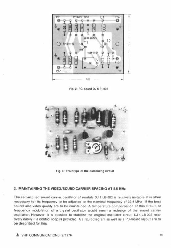
PC·board OJ6 PI 002 and the component rccetc ns are sho wn In Flg ur. 2 The dimenSIons 01th is PC-board are 60 mm ~ 50 mm , No prob lems are to be expected II Ihis PC-boa rd is usedlor ccnetrucucn The boa rd w idt h 01 50 mm was sele ctee so that It matChes the Sll e 01 meOJ 4 LB boa rds Inductance l 1 is a s-nore lenlle choke
90 .. VHF COMMUNICATIONS 2/ 1976
"'. 0115" 1 001 11 ."0
~~~ ~u~0.. ,.:
0 -11<02111
o 1" 041 -0
.~' J>P 0 ~
•..~ ~
,-,, ~ ~ ~ i• 00...
0 -..'"I- eo J
FIg_:I: PC· bo ••d OJ. PI 001
e,~ .
•
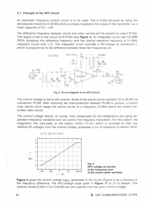
Fig . 3: Prolol~pe ol in. com bining elreull
• .." ...'
•
It.
-4-
2. MAINTAININQ THE VIDEO / SOUND CARRIER SPACING AT 5.5 MHl
The sell-a_ci ted sound carrie r oscIlla tor 01 mod ule OJ 4 LBOO2 I' r81811Yel y Inslable It'l c uennec essary lor Its frequency to be adJUsted 10 lhe no minal Irequency 01 33,4 MHI lI the bellsound and vrdeo qua lity arlt 10 be maintained A tem peral ure compensatIon 01 th ll CirCUIt, orfrequen cy modulat ion of a crystal oscillato , wou ld mean a redeSign 01 the aound carrie,oscilla tOf . However . il il pos.slble 10 ata M ll . the Oftg,n8' oscillato , CI'CUI' OJ 4 LBOO2 ra'a ·lIVely e.s.ly" a controltoop .s prOVIded . ... CI,CUI' d iag ram 8. _ II 81 a PC-board layout . '8 10be deSCrlbedlor th i• .
" VHF COMMUNICATIONS 2 / 1916 9 1
2.1. Princ iple 0' th e AFe CirCUlI
An aulomallc Irequency control C.rcUlI " 10 be u sed Th.. II " ratly ach,e~ed by u5mg thedemod u lato r bo ard OJ 4LB 005 wh ich 'S IOOMly coupled to the ou lput 0 1 me Iran5rruller ~Ia asmall capacitor 010 5 - 1 pF .
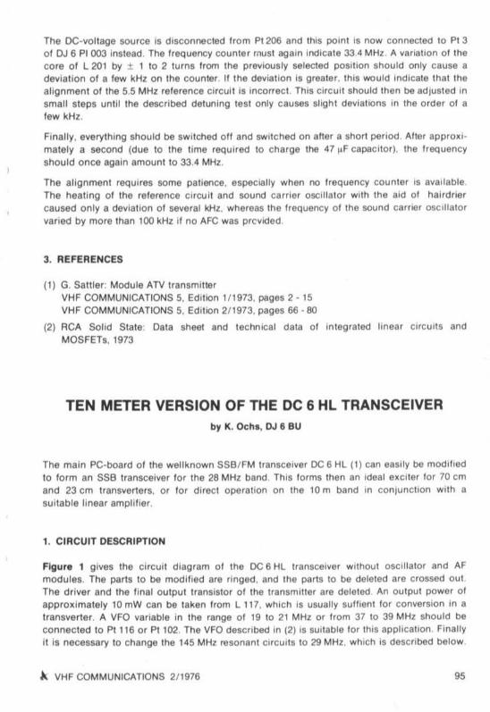
The cmereoce treq uen cy between 50und and video carners w.1l he pre5ent at ou tput Pt 502ThIS SIgnal IS led 10 the circul i OJ 6 PI 003 (see Fig ure 4) An mlegr a1ed Circ ul I type CA 3089
(RCA) compar85 Ihl s d llf erence Irequency w.lh the IOTernal re lerence lI equency 0 1 55 M Hl
(reso nant CIrcUIt WITh L 3) The IOlegrated circul i prov .deI • DC-vol lage at connectIon 1.whi ch is propornonat to the dillerence beTween reese tw o IrequenCles (21
"'G!, ,, JQnllO
_ OJ H8~
o}J- P1 ZlI6
IC ..='".=
~; r IWHo] 1, • [ . I .
(
I I n = ,$!u &ell &P•Ll
"I,"•
ptll · 11 ~ 1llo
~ 11 •
OJ6PlOOJ
""f . '"0<Ll :::g6p*lOD
1 "la~
The cont ro l vo ltage 15 led to lhe ~araclor diode ct tne 50und camer O5CI lla lor OJ 4 LB 002 viaccooeenco PI 206 A'ter remOYlng lhe ,nlerconnechon be!'NMn Pt 206 10 g 'ound a com-erloop resuils wh iCh keeps the sound cam er at a frequency 5S MH l billow the cryslal- conIrolled vrcec cam er
The cc ruror ~ollage shou ld. 0 1 course. on ly compensate lor lhe lemperal ure and agmg dependent frequency vana hon 5 and not co ntro l lhe Irequency modula tion For th ll ' eason , theIn l&grahon link (Iow-passl at Ihe cctou t (10 kU 1 41 ",Fl . Which 15 prOVided 10 Il lte' anyres.du al AF -voltag85 I,om the control venece, polSe5S41'S a cu i 01 ',equency 01 several He'l l
GJ~" OQ l /DHtlaOl
. --,,
./Ol
1
,- - '"
Fig . 5;AFe-von_ea a.funcllon01tha freq ua ncy a"o,o l tha . ound t a rrier o.clll. lo,
Figure 5 giv 85 me co ntro l yollage UAFC generaled in Ihe circuli {Figu re 41 as a 'u nct ion 01me frequency d illerence The AFC-vo ltage eroce g l ~en In Flgur. 11 ot (1) .1 sleeper Theveraetor ceoe (0203 In OJ4LB 002) WIll alae operate from the gl~en COnlro l ~ollage
92 A VHF COMMUNICATIONS 2/ 1916

The 0 01 the rel erence resonanl CIl'(;u,1 (l 31 de lermmes both Ihe hOld range and the residualcon l ro l dev18tlon a hig h 0 rep resen ls a small hold range and small conlrol dfl'tlahon. andvice versa II is neceu.ary 10 make a comprormee be tween the targels 01 the lowest poulblecon trol dev iati on and the w ldesl ho ld range The a can be reduced (large hold range l byprovidmg Ihe damping resistor shown m dashed lines ThiS resis to r will lmearlle the AFCcnerectensuca and will allow Irequency deviahons 01 maxim um 1 1 MHI to be contro lled IItne reset ance value is 10 lh e order 01 82 kU Since lhe sound carner osc illator Will mos tcerla tnly no l be mo re than 1 MHI Irom its nominal lI equency even al exlreme temperaturevenencne. th iS resistor IS usually no t required and should be lell out lo r con tro l acc uracyreasons The 10llOWlng measured values resulled on the author 's pro lotype
cconcr range .t 500 kHz
Commencemenlfreq uency dfl'tlahon
500 kHz200 kHI100 kHI
RftSlduai deViation
10 kHI3 kHz1 kHI
Control lac tor
5066
100
II WIll be seen In the di llermg cont rol factor lhat the AFC charac teristic IS not tinear How ever,thiS IS 01 no Importance
oen
eo
f ig 1: A"lhor ', prolotype 01 the AfC-clrcu"
2.2. Construction 01 the AFC-Clrcult
The PC· boa rd OJ 6 PI 003 has been deSIgned lor accommodation 01 the Ar c con trol CirCUlias gIven In Figure 4 The dimenSiOns 01 lhls board .,. allO 60 mm x 50 mm The component
~ VHF COMMUNICATIONS 2/ 1976 93

toceuons are given In Figure e and photooraph 01 the author'1 prototype In Flgu " 7, It willbe seen thai lhe IwO polled co res are uaed wlll'loul aligrment ICrews, 'Ince lhe allgnmenlrange I' found 10 be too small. Insteaet 01 thIS, trimmer capacItor. are uaed
Inductance L 4 IS a mlnlalure Femte wldeband Choke 01 apprOll , SO I'H Since the InductlY.ty01 thi , choke has an enect on the AFC charact... .sue. a home·wou nd v~H,ion should only be
used when an mduc tlvlly meter ISava.lable
2.2.1 CompoMnt De'all .
I 1: CA 3089 E (ACA) w.lh or w lthoul sockel
2 pieces po lled core kIt 11 mm ere . II 7 m mSiemens B 65 531 or Philip, P 11 AL 40 406
Co re. B 65 531 • K 0040 · A 001 (malenal K 1. AL· 40)B 65 531 • L 0016· A 012 (malerlal. K 12, AL -16)(see number ct tum e given In bracket.)
Co il former , B 65 532 - A oooo • H 001 or • A 002
HOlder : B 65 535 · A 001 • X 000
WindIngsL 1. 3 lu rn. (5 tu rns)L 2. L 3 16 tu rn, (26 lurns)02 mm dla enamelled copper wIre ('Ilk co vered)
L 4 ' 50 · 70~ Fe"" e chokes (Amphenol-Delevan)
2 piece. l rimmer capaci to r, 01 apprOll 20 pF. 7 mm dla ,.ceramic or p lastic loil types
2.3. Alignment
AeqUired eqUipmen l Olpmeler, a Irequency eeenter I' also 01 advantage The~ U re' ll torIS dIsconnect ed alone end and lhe mpu t erreuu I' .lIgned 10 55 MHz. Thl' I' done bypla cing Ihe co d 01 the dlpmele r near to Ihe top 01 th e meter clamp eree pOlled core The dipIS nOI lIery deep due 10 the weak couphng (lOW stray field cttne palled core) bul can be eeenAlter th is. replace the reslsl or.
Aller Ihi S. Ihe relerence ci rCUli Including Inductance L 3 IS . 110 ahgnfld to 55 MHz It II necessary lor the operatlOg voltage to be SWitched oil dUring th ll alignment SInce thiSresonant clrcu.1 De'ermtnea ' he spacIOQ belween vmec and sound catTIer. It I' aetv,uble lorthe dlp meter to be cahbrate<! With me aid 01a l requency counler where poSSible
The input PI 1 is connecte<! to PI 502 01 module OJ 4 LB 005 The operattng ",ol taoe 01 12 Vshou ld now be co nnec ted and the AFC-inp ul PI 206 (module OJ 4 LB 002) prO"'lded wll h 6 Vwll h the aid 01 a ",ollage divider. Connect the freq uency co un ler 10 PI 202 and align mesound camer OSCl lia lo r by adjusting the core 01 L 201 to 33 4 MHz The AFC vOltage al lheou lput (PI 3. OJ6 PI (03) should now amount 10 appro. 6 II
.. VHF COMMUNICATIONS 2/ 1976
The DC-vo ltage source is d lsconnec l9d Irom P1 206 and this po int is now co nnected to PI 3of OJ 6 PI 003 instead The Irequency counter rl"lUsI again Indi cate 334 MHz, A vanat lon 01 thecare 01 l 201 by ± 1 to 2 tu rns Irom the prev iously eerected po siti on shou ld only cause adeviat ion 01 a few kHz on the counter. " the deviation is greala r. Ihls would Indl cale Ihat tnealignment o f the 5.5 MHz retereoce ci rcu it is mccrrect . This ci rCUit should then be adjusl ed insma ll ste ps unti l the described detuning lest only causes slight deviallOns In the order 01 afew kHz .
Finally. everyth ing should be swilched 011 and swit ched on after a short period After app rO~ I '
matel y a second (due to the l ime requued to charge lhe 47 I.F capac ito r). the Irequencysho uld once again amount to 33 .4 MHz.
The alignmenl requires some ceneoce. especially when no frequency counter IS available .The heal ing 01 the reference cirCU lI and sound carrier OSCillator With the aid 01 hal rdflercaused only a deviation 01 several kHz. whereas the frequen cy 01 the sound carte r osc i ll ato rvaried by mor e Ihan 100 kHz if no AFC was prcvided
3. REFERENCES
(1) G sa tuer: Modu le ATV transrmnerVHF COMMUNICATIONS 5. Edit IOn 1/ 1973. page s 2· I SVHF COMMUNICATIONS 5, Edillon 2/ 1973. pages 66 - 80
(2) RCA Solid State: Data sheet and technical data 01 In tegra ted linear cecuus andMOSFETs. 1973
TEN METER VERSION OF THE DC 6 HL TRANSCEIVERby K. Och s, OJ IS au
The mai n PC-boa rd o f lhe wellknow n SSB / FM transceiver OC 6 HL I I) can easily be modlhedto for m an SSB transceiver lo r the 28 MHz band ThiS tonn e then an Ideal excner lor 70 cmand 23 cm transvene-e. or fo r di rect operallon on rne 10 m ban d In conjunc tion With asu itab le linear ampli fier .
1. CIRCUIT DESCRIPTIO N
Flgur. 1 g ives the cncurt d iagram of th e DC 6 HL transceiver w llhout OSCillator and AFmodules. The parl s to be modi fied are ringed. and the parts to be deleted are crossed ou lThe driver and the fina l ou tput transistor 01 the transmiller are deleted An output power 01appro~ ima te ly 10 mW can be taken from l 117. wh ich is usua lly sullleni lor conversion In atransvener . A VFO vari able in the range 01 19 to 21 MHz or trom 37 to 39 MHz should becc nnec tec to P1116 or Pt 102. The VFO descr.bed In (2) IS SUitable lor ttus application FinallyIt is necessary 10 change tne 145 MHz resonant ctrcuus to 29 MHz. which IS descnbed belo w
A VHF COMMUNICATIONS 2/ 1976 95

,", - --
' ../0017 1
.---1---
-- 2,
o JJ' .
o
'I.',n,
-,----f- :._.,I
••
..
! ,,'. ............ If 'I,... . 1. ...
" '''1 1. '.
"I!I " ".u.
~ VHF COMMUNICATIONS 211976

• •
I-=- ~___L_ _l_+__:---...IL~ t
..--
'" VHF COMMUNICATIONS 211976 97

2. RESONANT CIRCUIT DATA FOR 28 .30 MHz
2.1 , Input Circuit of the Recel nr
ThE' resonant c ircuits 0 1 transistor s T 101 to T 103 must be changed
Coi llormers : 5 mm cuter diameter, WIth red or pOSSibly brown co reWire : Appro ll . asmm dla, (26 AWO) enamelled copper Wire, close wound
Remove the foll OWing trimmer capa cito rs and replace by cera-mecrsc Iypes 0 1 30 pF:C 101. C 103, C 106, C 109, C 111 ,
The fo llOWing damp ing resistors should be reduced from 3 9 k~l to 22 kU:R t03 , R lOS, R 107, R 109,
COils'
L 101: 10 turns, coup ling Wind ing 3 turns on co ld end,L 102 • 1()4: 10 tu rnsL 105' 10 tur ns, coil tap 4 l urns Irom hot end .L 106: 10 turns. coupli ng wind ing 3 tu rns at cold end
Parallel capaci tor C 114 VFO 37 • 39 MHz: 10 pFVFO 19 · 21 MHZ. 40 pF
l122 : deleted
The input euccu possesses a very high senSitiv ity and gain , II ellhlblts a lendency 10 sell cecmaucn . even ette- the damping reSisto rs have been redu ced m value The resonantCirCUitS should tneretcr e be aligned lor several dl tle rent Irequenc ies ever tbe 10 m band Thereceive converter DC 0 DA oeeenteo In (3) 15 very SUitable lor use w ll h the transceiver.
2.2. T,ansmlt Mlxe, and Lln..r Amplll le,
PC board DC 6 HL 00 1 is sawn 011 et me last screen ing panel c t tne receiver inpul CirCUli (seeFigure 2) because the drive r and output amphller are not requir ed cerncrrners and COil wi reas for the receiver,
L 115: 10 tu rns wl l h center lap , C 178 30 pFL 116: 10 tu rns With pa rallel capac ito r C 179 30 pFL 117: 10 turns, co upling wmdlng 3 turns at COld end C 182: 30 pF
All com ponents alter C 183 are dele led Module OJ 4 LB 004 (4) IS very SUItable lor use asIransmlt converter lor 70 cm,
3. GENERAL MODIFICATIONS
The product de tec tor (T 107 } T 108) should always be equi pped wrtn Ihe transisl or BF 245 A,When usmg the tranSistor BF 245 C, so mu ch cur ren t l lows via -esutcr A 133 (1 kUI tha t th ed rain -source voltage drops to a lew volts This causes a large d istOrt iOn 01 the AF SIgnaL Aproduct cetectoe eq u.p pec With a OG·MOS FET would be bet ter
98 ~ VHF COMMUNICATIONS 2/ 1976
4. REFERENCES
( I) G Olio A PortJ,bIe sse T,anse.,,,., lor I• • - ' .6 MHzVHF COMMUNICATIONS 4 . Ed,l oantl - . /1972
(2) 0 E SChm'tz. r A Vaflab l. FreqUflOCY o.c,U.tor Mod ule lor the Modul. r RK.'ve' SvsllMnVHF COMMUNICATIONS S. Ed " 100 . 11973. paQH 2.' - 2.9
(3) J Dahms A Recetve Convert... .&32128 MH1 malehlOg the Tr.n.m,' Con....rt.r OJ 6 11 002VHF COMMUNICATIONS S. Ed 'l lOO 3/1973 . paoes 165 - 166
I. ' G Sall'-' A Modula' ATV T'aMlTt'u ...VHF COMMUNICATIONS S. Ed 'll()n 111973 . paQeS 2 - 15
NEW HIGH PERFORMANCE ROTATORS
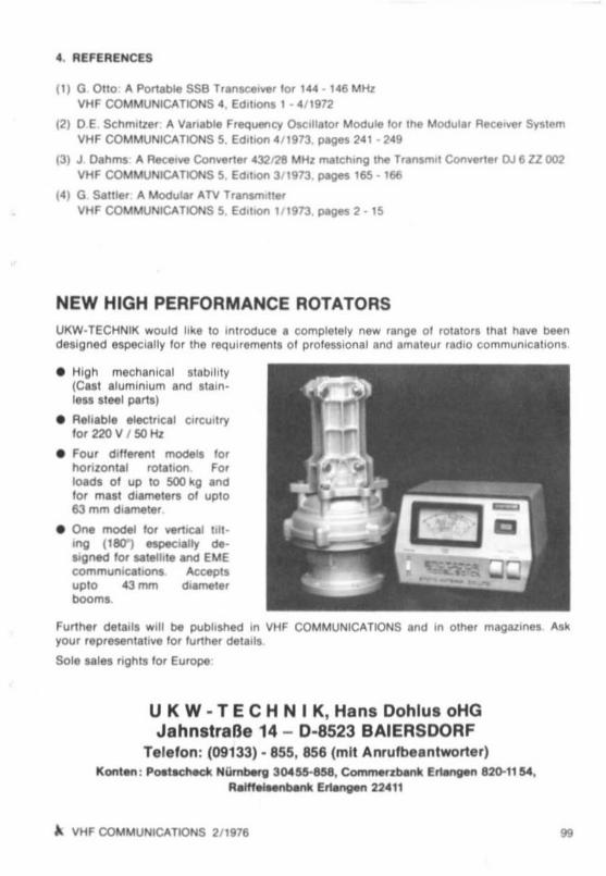
UKW -TECHN tK wou ld like 10 Introd uce. eomplelely new range 01 rOl a'or. thaI h. .... beendeSigned . spec iall y lor the requ"emenll 01 pro fessional and amale ur radiO eommunlc atlon,
• High mechanical , tablhW(CaS! alumln'um and , 'ain Ie" S1eel parts)
• Ae liable eltcl ncal Clrcu, lrylor 220 V J SO H1
• F~, d 'fferent model' lo r1'\o"10n1.ll1 tOlat'on ForIoadl 01 up 10 500 kg .ndlor mall diameters 01 upl O63 m m d,amaler.
• One~ lor vert lC&l nn '''9 ( 180") MpeCi.11y deargn«! lor ..tel ll i . and EMEcommuniCIIl lC)nt A«epl lup to 43 mm d18melerboom.
Further de la l's Will be pubhshed In VHF COMMUNICAliONS . nd In olher m.gAZlnes .... ky~' represenlaflve lor lu rther d.la" l
Sol. sal.. nghts lo r EuroPfl
U K W - T E C H N I K, Hans Oohlus oHGJahnstraBe 14 - 0 -8523 BAIERSOORF
Teleten: (09133) ·855,856 (mit Anrufb••nlwor1er )Konl en : Poet~ NOmberg 304 M--858, Comm«rber*. ENngen 820-1154,
R.mal• • nber*. Ert.ngen 224"
A VHF COM MUNICATIONS 2/ 1976 ..

AN FM·HANDHELD TRANSCEIVER FOR THE 2 m BAN DbW' R. Ten art . DC 3 NT
Pari 2: Con.tructlon and " ' ''enmenl
The order 01 construcnoo lind ahgnmpnl II l ll sl! y 10 be gIllen lor Inlormatlon
Complete PC·board DC 3 NT 00 1Make II fun cllona llesl 01 module DC 3 NT 00 1.Complete Pc-bcaro DC 3 NT 002Malle 8 functional teer 01 module DC 3 NT ()()l
Prep are the case , mounllng plAtes .nd other mec hanical piecesMou nl the squa re and he_ laganat bolls '0 the mounllng pla te
Mou n! the rear panel (3 scx:kets and Iha AF ou tput trM , 'sl or )Mount bolh PC-boards to the mouollng pla le
Complete me Iron t penet and solder the wires Into placeSc rew bo th the fronl and the rear panels to the mounting pla te
Complete the wIring ollhe um tCarry cut the fmal alignment
S. CON STRUCTION DETAi l S FOR PC·BOARD DC 3 NT 001(RECEIVER)
5. t o Compleme nt
5.1. t .
The PC·board 01 135 mm _ 90 mm sho uld be drilled wIl h the fo llOWing holes accordmg 10
Fiiure 4:
Trim mer capacitors and resrstor, : 1 3 mm cra . ce ramic Il ller and SCfaenlng cans 1.5 mm me ,
cod lo rmefs 4 2 mm dill (ltle ou t l lig hlly 10 thaI me COil lormer i hI l lgh lly ) Hol es o f 3 5 mmdill Sho uld be pfOVlded lor the Ih rtle mount ing ho les and l or lhe antenna cable : all Olhe rho les should be I mm In drameter
5.1.2.
The co mponents should no w be mounted IS shown tn me component iccencn plan
All reSIsto rs and d iod es are mounled ver llcally. as are C 20 and C 71 Imporl ant C 16 andC 79 musl be ceearmc orsc ceoecuo re 0 1 5 mm In dlameler: " no t. a lendency 10 cecutencnmay be noticed
II IS also impo rtant lhat the conoecuon leads 10 these cap ac ito rs should be ilS ebc rt aspoSSIble 0 1 co cese. Ihls II valid lor all component, o f the VHF-stages The lowe r sur face 0 1
the tr an l illo r, type SF 324 Should neV\'lr be more th an 3 mm Irom me sur fac e of the PC
board The ce ramiC capaCl fo rs With value, up 10 an inCluding 22 nF 'hOuld be d iSC type s 015 mm In dlame ler lor a spacmg 01 5 mm Spac ings 01 5 mm and 7 5 mm are used lo r the10 nF ce pecnors A spacing 01 5 mm IS , ISO availa ble lor ce eecuoe e C 42, C 43, C S2 and
100 A VHF COMMUNICATIONS 2/ 1976

It
I~ l)')mm
• •t I!
!:;:I
I,
F'tjI. I , Phololl,.pfl oIt". leU ln bo.,d OC ) NT 001
'" VHF COMMUNICATIONS 211976 '0'

C 64 . ellhtH ceramic o r pla ,tlC 1011ceoacuors can be used here, The 10 nF cececnc rs Wllh asJ)IIcln g 01 75 mm . hould alw ay. be p laltic foil Iype. sInce Ihe l oleraou. may no l be solarge Capac llor. C 46. C 47 and C 504 should also be craeuc tol l lype.
5.1.3.
Wind all COIl. an<:! sol der tnem In IO placeThe fOllowing sho uld be ceservec dUrin g Ih l' electrically speaking. the d irection 01 lums 01all mouctances IS not 0 1 importance Howevel , In o rder 10 ensure Ihal one obla,n 4 2 5 and001 3 75 tum s II IS Impo rt anl w llh resoect to lhe VHf Induc tances tbet tbe g ,veo dllec l loo ISma inlaloed
5. 1.e.The moucta nces L 5, L 6 . L II and L 12 a re wound d lreclly onlo Ihelr ccutc rmera dnd g luedIn lo place w llh a small amount 01 duar.componem gl ue L 7 and L 10 sho uld also be glUedAll etner COIls are WOund on a lI,lrmet o f 4 3 mm diameter . aller wh ich tbe eods are benl
, tralghl and solder co aled The cOil tap a on Ihe cOil. USing 0 8 mm dla enamelled ccppeew ire are made by connec llng a Ih lo w ire betcre WindIng and Ihen wind ing Ihe COIl. on bolhSIdes commenclflQ wllh Ihe tap The connechon o f tne Inducl il ncM I hould be so lde red
QUIckly 10 as nol do damage Ihe COll lorme rl
5.1 5.
A 55 "}", long piece 01 Ih ln coeua r cab le (AG· 174) IS now prepared by removmg the
mscretron Irom 10 mm al one end and 8 mm Irom lhe ctnar end aller wh Ich lhe shleldmg ISpushed ba ck The moer co nduc to r 01 Ihe 10 mm Side IS co nnec ted 10 tee co oc uctor lanebetween C 38 and pin 14 01 I I The sCiea nlng 01 Ihll end is soldered 10 the ground I url acebe low I I The Inner co nduc to r o f the ol her eod IS soldered 10 Ihe I ur l ace ~a. (near C 36)
ThIS conductor lane leads 10 relay Rei I oIod 10 ~S~ (wiper ol lhe channet awllch) The sh,eld
IS so ld ered to lhe grou nd COOO8Cllon ol Itlmmer cecacuoe C 36
5.1.6.
A Iurther cable IS requlfoo as above Ihat II 30 10 J!) cm lon g The msutahon la removed tOI12 mm at bo th ends 01 the cable .lind lhe mne, co eocctor IS co nnected 10 PI I Th~ cab le ISled vIa me 3.5 mm hole provro ed lor Itle anlenna cable and the sc r&anlng IS loldered 10 l heg ro und su rlaee around me ho le
' 02
Fig. 5:S<:r..nlng pIIn." ollne... put Mag.1 of .... ree.l".r
~ VHF COMMUNICATIONS 2/ 1976

5.1.7.
Prepare the screening plate as shown In Figure 5 and solder mto place aCCOfdmg 10 thecomponen t locati on plan Solder the screening cans of the IF cone mto place
Approll imately 70 mm length of sHanded Wire 15 so ldered mtc the coeoecnon ocmrs for therange SWitch (E·R ·S ·Ql The channel sWitc h IS also connected With tne aid 01 sl rande d wneThe spacing between me edge 01 the board and the solder tag s shou ld amount to app ru x15 mm The eonnecnons Irom channel 0, 7, and 6 should ro t be led aro und the edg t! 01 Ihebo ard sin ce lh ls could cause a larg e de lufllng e ttec t due 10 the ground ceoacueoce
ApprOlllmalely 15 mm length 01 Wire shOU ld be soldered 10 all three connec tion pomts PIand provided wl lh a lenglh 01 approXimately 8 mm 01 Iflsulahng tub ing Only lou r conoecnoepo ints are required lo r the AF outpu t tran s.stors ( . Ub. ground. E. B) as long as Ihe em uteeand ba se connections are directly connec ted to ano ther
5.1.8.
Two co nnecti ng supports are now prepared lo r the add' l ,ona l resonan t cncu« compfl s,ngL 14 so tnat II IS poSSible to mount rt above I I The requ.red values for thIS resonant ctecurtare C .. 47 nF I L . 30·40 turn s 01 0 1 mm d,amet!!r (38 AWGj wound on a Japanese 455kH z resonan t CIfCUlt Align to 455 kHz eetore mountmg Into place
5.1.9.
Co nnec t a 25 mm length ot Sllve r·pla ted copper wile 01 appe ox 0 8 Inn! rn d'il (20 AWGj torne ground surtace between C 1 and C 2. ThiS wIre must be so ldered to a lag mounted un derIhe hell tagonal bo lls on the channel selec tor SWIIch on Installing Ihe PC-board mtc the caseII trns ground connection '5 not made. the uansmrtter w,1I an ect the VFO, wrncn causes adll/ermg frequency spaCing trom channel to channel. wh ich IS so grl;lat tha t ,t canner ne co mpensa ted to r With Ihe aid 01 tr immer capac ito r C 37
5.2. Fun ct lon .1 T••l of Mod ule DC 3 NT 001
The comp leted receive board (see Flgur. 6115 now chec ked and pr tlllminary aligned
5.2.1.
Conne ct Pt 19 10 PI 2 and pla ce a Ferrll bead on 10 ' htl ccnnecucn wortl, Also connec t Pt 19to PI 4 Connec t Pt 4 10 Pt 3
Temporan ly connect me AF output transistors Co nnec t Ihe squelch ccreouometer to PI 14,
PI 15. PI 16. and tne volume potentiometer 10 PI 12. PI 13 and PI 16
Co nnec t a to 5 (crystal oscllia lor). Pt 9 to PI 17 and connect tne rcuoepeaker
5.2.2.
Feed a stabilized voltage 01 12 V to PI 17. Align L 11 lo r maxrrrrurn noi~ . The squelch cueunShou ld now operate.
Con nect 8 Irequency counter via a capac itor 01 epprox. 1 nF to PI 6 and ground AdJuSI C 13lor maximum ce ce c.t e oce and align the resonant CIfCUOt co mpfls lng L 10 to 10250 MHz,
" VHF COMMUNICATIONS 211976 103
5.2.3.
Meil !>ure Ihe voltage drop across R9 ( I V range) and ad,ust L7 unhl an Indication II eeenAdjust lor maxrmum ",nd then ro tate a lurther hall tUln In a Clockwise d llechon The osc ill ato rshou ld now be cheeked wnemer II co mmences ceeurenon reliab ly on SWitc hing on theope rahng voltage II recuueo . Inse rt t~ co re 01 L 7 shll l uf1hel In lo lhe co ,1 II IhlS cecruetcrdoe s no l Commence cecurenon . reduce the value 01 lhe emi lie' reslslor R 12, The minimumval ue IS In the oroer 0139 kU. ho welle r. the value should be as hIgh as possI ble so th at nounweoreo ha rmoniCS are generaled
Co uple a d,pmeler 01 abSOlpllon wavemel el to L8 and adJus l thll COil lor ma ximummdlcal lon Ttus should be repeal ed lor L 9
5.2.4.
Connect a Signal genelalOI 10 ' he antenna Inpu l and align 10 apploxl mdlel y 145 450 MHzAdJuSI Ihe Signal gene ra lor lo r maxrmv m . selec t a narro w IreQuency moeuteucn and ahgnun hl a SIgnal IS recervec m tne receiver II IS posSible that no IIgnal Will be audi ble because01 tne mconec t alignmen t 01 th e CIrCUi t In Ih ll case . a 10 7 MHz "gnal II hflt ly led via acepacucr 01 10 pF to the emner 01 T 2. and L 5 and L 6 aligned lor maxImum Al ter ' hll , IIsho uld be ccssere to hear tne 145450 MHz I lgnal al the mput
Induc tan ces L 5 and L 6 should be aligned lor minimum no-se, and ire output 01 the Ilgnalgenelator reduced Iurther du ring the lonowlng alignment steps 10 ensure that Ihe SIgnal IIalways slightly nOIsy Ali gn Ind uc tances L 13. L I . l 2. l 3. l 4, l 8 and 19 lo r minimum nOISeThe ord er 01allg nmttnl IS no l cnncer s.oce Ihe cucullS hardly In ll uence another The resonanlCIfCUlts compllSIng L 3 and L 4 possess a very sha rp resonan ce II sen -cecutaucn shou'dOCCur due '0 a high gain 01 IranSlSlor T 12. • 56 kU resIstor should be SOldered 10 the lowerSIde 01 tne boa rd eetween Ihe COllector 01 T 12 and ground
5.2.5.
I he BFO tp12O) sho uld also be conoectee to I 12 V In addrnon 10 tne Ol her receive r si agesThe Irequency co un ter sho uld be connected v.. a &erles conneC'lon 01 I nF and ,0 kU to lheemmer 01 T 6 and mductence L 12 aligned to 455 kHz The IreQuency coun ler II no w d lscc noecreo Feed an unmoduldled Signal Irom the Signa l gene ra lor to uie an tenna Input andtune Ihe recewee lor tero bed l Alter Ih ls remove Ihe operahng vollag., fr om Pt 20 (B FOsWllched Oil) Finally . modulate Ihe SIgna l generalor With a IreQut' ncv c1Pvllthon 01 5 kHz af'ldalign lhe Inductance l II lor ma ximum volume
5.2.6.
Mea su re tne norse vol lage at the louds pea ker and Inc rease the level 01 Ihe unmodutatedSlg n.d gen era lor from z.,ro un ll l the measured nOise drops 10 a tenlh 01 lh e orlQlnal value120dB AF SlgnaHo·nOlse rahO w llh out modula tio n) Th's value should amount to 03 10
0 41'V
5.2.7.
Now chec k lhe opera tion 01 Ihe calling lon e eecuretor and altgn to 1750Hz, Thll II done byconnec ting Pt 20 to + 12 V and connecting PI 11 to an OSCilloscope Potenll omeler P 1 IS nOWahgned lo r mUlmum, und/s lorled amp ill ude 8f\d the frequency ad,usted 10 1750 Hz a t Pt 4 It
Ih ll cecureror doe s not commenc e oSCllialton . the value 01 A 11 sho uld be reduced asdescnbtKl In 22
,.. " VHF COMMUNICATIONS 2/ 1976
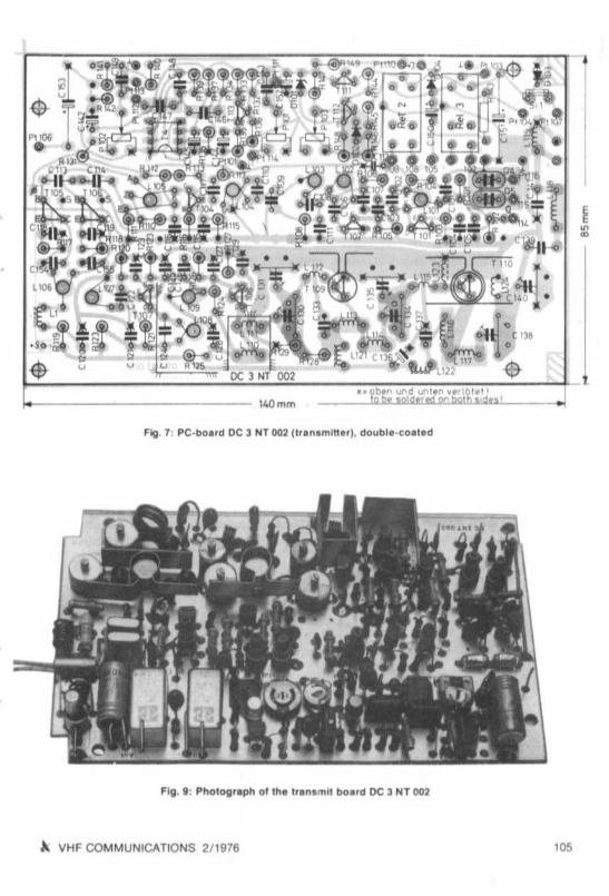
1.- 1401'11'1
••
••
A VHF COMMUNICATIONS 211976 '05

6. CON STRUCTION DETAILS FOR PC-BOARD DC 3 NT 002 (TRANSMmERj
6.1. Moun ting th e Compon.nt.
6.1.1.
The double-coated PC-board o f 140 mm x 85 mm IS drilled according 10 Figur. 7 In a SImilarmanner to the receiver board (see 5 1.1,), The shaded areas are sawn 01150 that the board htsbetween the squa re bolts.
All reser crs and d iodes are mounted varllcally, Exception ; A 143 whIch i5 mounted noreentally in front 01 C 151 since the ceoecuo- partially covers the resistor, C 151 and C 153 shouldbe spaced 4 mm from the board so thai the mounllng screw is accessible , Tha posillonsmarked with ~x~ shou ld be so ldered on lhe lop and bottom 01 Ihe board All bypass capacrto rs (2 ,2 nF) . and all tranSist ors should be SOldered 10 Ihe board with short eonoecuo ns
6.1.2.
The same is valid lor me mounting 01 the cOila lIS waa given In 5.1.3 and 51.4 Chokes L 120.L 121 and L 122 comprise 10 to tz tum s 01 enamelled copper wir e wound on a 1 kU / 0 ,5 Wresi stor ,
6.1.3 .
Since the metal case 01 the dnver and outpul trsns .stcr can make contact 01 the ground surlace on the other Side 01 the board . an approxlmalely 2 mm Ihl ck plastoc spacer IS ptacec onthe wires 01 the driver, and the output tran81slor IS insulated with a pIece 01 mica (do nOIlorge t the heat cc noucnve paste lor heat di SSIpation to tne ground surface).
6.1.4 ,
Two screening plates, Iwo cooling braCkets and a small tunnel should be ccnsnucrec asshown In Figure 8 Irom 0.5 mm brass pIa te . The angle piece and the tunnel are SOldered tothe ground surtace on the componen t side 01 me PC-board according 10 the dashed lines
106
Fig. I :2 acr••nl"V pt_te. ,2 cooling Iln_, _ncf1 tunnet for DC3 NT 002
.-I I ' C '~ - .""l _ _: ..,
~ -2' J ~ ' e.J
e n D-~. t
Cf ~,., ,.,-tr- t , to• •. ' . ,
, ... 20 I ~,\"J:.CIlIJ • []]I] •I ,
A. VHF COMMUNICATIONS 2/ 1976

6.1.5.
On the lower side o t the boa rd . an app rOlumalely 35 mm leng lh 01 Ih ,n coulal cable (e gRG 174) sho uld be connec led belweeo Ihe Iw o po in l! deSlgoaled wllh _a_ The !lCroenl ng ISconnected to grou nd between the des.gnal lons . ER- and .LEO- . Th is lIS ' o llow ed by sol derIng lour damping resislors 10 Ihe conductor ' Ide c t the board R 107 10 the ccuecrorconnec tion 01 T 1().4 and A 110 (C 116 s,de) A 109 10 L 110. A 15O Io C l 13 / C 114and 10 theg round ccnnecuen 01C 119. A 151 10 the hOI end 01C 154 01 C 155
6.1.6.
An app ro ll.lmately 70 mm lengl h 01 Insulated sl r/lflded wlr . III ecooecree to ccenecncn pOlnl sPI 114. 115 and 116 The three Wil es are pl aced thr ou gh the lunn el.
Co nnechon POint PI 10 1 IS tne free end o. R 114 The o ther ccnnecncn pomts lIhou ld be pre par ed as g lvefl 10 5 1,7
&.1.7.
When uSing ple strc loll Ir lmmert '01 C 131 . C 135 and C 140. ' ,rlllly place a thm w ife thr ough_ll._ and solder at the top afld bottom . Aller thiS, so lder Ihe tnmmer mto place The gro undSide 01 cepecnc r C 112 (al PI 109 ) sho uld be soldered 10 Ihe ground surlace above
&.2. Functional T. st of Modu'. DC 3 NT 002
Th. comp leled Iransmll board (see Flgur. II) IS no w chec ked and preliminarily ahg ned
&.2.1.
Co nnect connec tion po lnl PI 114 and Pt t 15 Connec l IS s.gna l generato r ( 10 250 MHz. min200 mY ) or lhe VFO on the rec. ...fer board to con necho n PI 101 and gfound Connee l IS wanme ter With tennlnal lng reSistor between Pt 103 and gr oun d Tnmmers C t 3O. C 138. C t4 0shou ld be aligned lor mlmmum capacitance C 134 to app l O.lmately 10 pF, C 131 and C 135to app rOll.lmate'y 20 to 30 pF ,
&.2.2.
FIMKI apprOll. lma tely 15 V to co nne<:IIOO Pt 107 connec t IS vollmeter eet weeo PI 111 andground and adjust the lod,caled vo ltage w ll h ne aid 01 P 102 10 12 V Co nn ect PI 109 tLEOIto ground
&.2.3.
PrOVide conr ecuc n PI 107 With 13 5 V, co nnect PI 109 to groun d and align mcu ctance l 101lor mall imum Ind ,eat ,oo on a d lpmeter o r abso rp tion waVflfTlet ef (45 MHz) When aligned Inthis rnanfler , the oscilla lor should opef8te reli ably on SWitching on the ope rating vollage
~ VHF COMMUNICATIONS 2/ 1976 10'

,,--
-
...-
-----"
---,,-
---
"I
0-
--
,_,.1
-"
_~
.<>S:==-==--==-J
---
,,--
I~
,I'-
'"
--
I
--
I
o•
oo
0.....-...
~-
Io
.~
,--...,.--
o,
·~O_I
o,
_Q
o0
.-o e '"
,"0
.-,
"'
__
II_
__
11-_
_
___".--
-'"
'"'
-,-I"
.;:;.-,
_r
__
",_IL
Jl_
,_
"-,--,,,.'
'"All•
•
_i._
-'J"
"I
"!laT
&11••
UL
Fig
.10
:C
II_;
louch
.pe.
...ho&
es-'-let
on
ly'"
drY
,"O
fl_
..,.


6.2.e.
Ali gn L 102. L IOJ and L 104 lor malllmum readIng al 135 MHlAlign L 105 lor max Imum al 10 250 MHlAli gn L 106 lind L 107 lor mUlmum reading at t45 MHlFmally. align L 108 and L 109
6.2.5.
Place a dlpmeler 0 ' absorptIon wavemeler In lhe vlCln.ly 0 1 L 113 and align C 130 and C 13tlor max imum read ing The lo llow lng are then aligned lor mllJllmu m reading on me wallmele,C 134 , C t 35. C 138 and C 140 ThIS alig nment should be mad & several l imes tne ou lpu tpo wer should drop to zero on sWitching oil the Signal gon&ralor or r&moving me cryslal
6.2.6.
Ccnoect a microphone between PI 114 and ground Place PlOt 10 II. lu ll y anhclockwlseSlop P 102 to a cenl ral poSItion Co nnec t an cee.uceccee be lwf!iln Pt 113 and gl ound and. peak Int o me mic rophone ApprOXimately 6 V peak 10 pIIak i!>hou ld be seen on Ihe cscmoooope
' 1.... ~ " _, _'_ 11 5_ -,'--~ I ... -Iil .{ lh=~: · . 10" "01-' I . I i, I .J ,.l.. i ~ 11 ..J I m-,, .. - I - +- .. ': - ,
I
"I
@-.-, . (-~J(i) E::::3I,., ltJ 1 . _ . ,, : I I I I I f... -1' • ...,..... - - II- - f ill , 14: SIIU It pl.e.. ..qu l,. d,
7. MANUFACTURE OF THE CASE AND MOUNTING PARTS
A 2 mm Ih ick alum inium plale II used lor ail part s Flgur• • 10 10 14 show draWIngs or themdivldua l part. two-p iece case, one mounting p late. one Ironl and ,ear pane l as well aso lher small pIeces. The lollow lng small pa rt s are requI'ed as shown In Figure 14 lour p ieces0 1 he . lagonal bars 01 24 mm In length on Ihe rece iver SIde (DC 3 NT 001 ). lour P/1'lCe& 01 he. tagonal bar. 0 1 16 mm In leng th on tha I ' aoamll s.da (DC 3 NT 002). two pIeces 01 equare bars0 1 25 mm In leng th lor mouohng ,he rear panal . aod 'wo PIfl'C8S 01 squa ra bar, 01 30 mm ,nleoo lh lor Ihe Ironl panel In add ltlOo to th,• . six losulall ng collars 01 5 mm In leng'h al erequired lor mounllng the PC-boards. as well as a 12 mm • 31 mm pIece 0 1 PC-boaldmateri al. This plale will only be required when a spiodle Irlmm e' lor solder mOuo"ng is USfldlor C 35,
110 A. VHF COMMUNICATIONS 2/ 1976

S<.I'IOlltlu'"''SCI(~.1 1 S.. ,I,"
OC 3NT 001
OC3NT 002
~,
T9TW@l @l
.,•·•U DC3NT 001Z
•· "'01\01~
lOIO"" PSOld ... ,,,; TOlll
o@!
~ VHF COMMUNICATIONS 2f1976 "'

t hese pieces are mounted together i1S sho wn In Figur. t5 The square bars are mounted 10Ihe mount mg pla'e wllh the aid 01 the he _tll<JOnal bol ts 81'e r wh Ich the th ree sock"ls lorcha rgmg (+ I. tran&ffill (+ I . po wer supply and the two AF-oulput tr l nSlsto rs are mounted tothe rear panel Atter thiS. the completed PC-boards are mounled w llh Ihe aid 01 the msula tedspace rs 10 the mount ing plata The rece l ~e r board Should be grounded ~ Ia Ihe moun tmgsc rew in the ~Icm l ty 0 1 th", crySla ls The Transm it board IS ground ed ~ III the mou n ting nu ts onth e upp er Side 01 The boa rd Finally, the Iront pan el should be eqUipped It IS neceSSllry lo rthe meier 10 be mounted In an msu lated manner. (gluedlSlnce there IS somellmBS an tnterconnection between the coli 0 1 the meIer end Ihe case Section 8 g'~" lurlhe' det.ll ls regard mg th e so ldeflng 01 the mterccnoecnon wlfes The trom and batk panels are mounted mlOp lace aller comcrenon. atter whiCh the I inal alignment IS made IIccording to secnce 9
8. WIRING DETAI l.S
Insulated stranded Wiles 01 $8~vrdl dillerent colours should be used lor wiring Coaual AFcable snocld be used for all screeoec connec tions. and Tellon (PTFE I AG 1741 should be
used at VHF The lollOWlng details Indicate the most la~orable order 01 Wifing and comb ination mto cab le harneSMS
8.1.
II IS ad~lsable lor the ooreouomerera for ~olume and squelch . as well as SWItch S 4 10 beprO~Ided With w ires eetore screwing Ihe uont pdnel m to place A common ecnoecuon can be
used 10 ' the ground ottne loudspeaker and SQuelch lPt 181
8.2.
Two wl.es are ccooecrecrc one con tact or 5 4 one goes ccwn tc the transrnuter (Pt I 11).and the o the r 10 the receiver Wt 9) This mllans tha t a stabIlized ~oltaoe 01 12 V IS connectedto the IF and VFO Ano ther w l' e IS connected TO the second eon rect 01 S 4. wh IC h IS late ,ecrcerec 10 PI 10 The 'r onl panel can now be mounled Into place
8.3 .
So lder th e range SWItch to Ihe recel~er and harness the four cab les Together Sc rew theChanne l SWitc h In to place. The leads Irom me pot entlOlll8te rs I nd from S 4 shoul d be fedlog el her trc m P 3 alo ng me outer edge 0 1 tne PC·boa rd up to L 7. From there, II IS ad ~ l sab le
to sol der a lead to connec tion Pt 3 8S well 8S • screened AF cable to PI 11 and gro und Thecable harness should then be led 10 Pl iO The lead 'r om 5 " (SWItched opera llOg ~oltage)
should be SOldered 10 PI 10 and led IUrlh e' to PI 20 , The conneclions 01 P 3. P 2. PI 3 and S "
a'e then dl Slnbllted trcrn here according to the CirCUli d iagram .
8.4 .
Solder the ccnnecucue to ' he AF cctoct tranSllll ora The lead Irom Pill can be led With memterconnecnoes 01 the ou tpu t tranSisto rs At the cu tout lor The accu mulators (2 _ 6 OI;:ACce lls 01 225 mAh). all leads Irom the reC81ve, boa rd (w, lh the e_cepTlOn 0 1 the w ire I, omPI 109 to PI 5) should be led to lhe tranamlller paSI lhe he_lIgonll bol!ll on the same Side aslhe sockets Do no l 'orgel the connections lor the loudspeaker
"' A VHF COM MUNICATIONS 2/ 1976
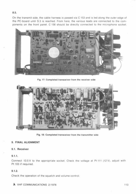
8.5.
On Ihe IranSfl!ll l ,de. lhe cable harOMa 1$ pauoo vIa C 153 and tl lfld along Ihe oultlr edge 0 'me PC-board un ltl 53,s rescnee seem he re. lhe vallou$ leads are connected 10 Ihe com·po oeots on lhe IlOnl panel C I~ Should be d"ecll y connec ted 10 lhft m,clOphone soc kel
9. FINAL ALIGNMENT
9.1.1.
connec t 13 S V 10 lhe appro pria te locke l cnecx Ihe ~oll<lge al PI 111 (12111. adjUst Wll hPI 103 ,I reqUIred
9.1.2.
Check th e operaiton 0 1 tne squelc h and ~olume control
~ II HF COMMUNICATIONS 2/1978 "'

IU.3.
connect tne Irequency counter VII I CapaCIIO' 01 appro_ 1 nF 10 PI 101 Sel C 35. C 36 andC 37 10 a cenlral pos lllOn and place S 2 to o
9.U .
Thf! ,"(hcated Irequen cy stI<X.Ild be variable tn the ra"98 of 10050 to 10450 MHz wllh Ihe a.d01 C I Th,s range can be correcled If reqUI.ed by adjust'ng L 10 F,. lhe pos,hon 01 L 10 w'thlhe a,d 01 a drop of dual-componenl glue
9.1.5.
Align the Irlmme r capaCIIOrs C I •ell . according to the hequency plan. to 10120 ·10370 MH z SWitch Irom one pos.hon 10 the other and ccrrecr the ahgnmenl unl,1 teedeVla l,ons are not more Ihan 1 kHz
11.1.6.
Measure Ihe BFQ IrOQuency and adJusll i reQu,rft(! (see 525)
11.1.7.
connect tne Signal generalo. 10 me antenna Inpu l soc kel and adl usl 10 145 4 50 MHz setectchanne l 6. simp lex and align the Ilr sl IF as well as Ihe VHF Inpul lIages lor rrummum ncrseThe ' ,nal all gnmen l corm IS Ihe mpu t Induc lances L 13 Two ma .,mums are Ind,cated dUflngIh is ali gnmen t 10' no ise matchi ng and power matc h,ng In Ihe case 01 nOtse malchlng therece iver w,lI be more senl,ltve as long as lhe anlenna used possesses Ihe same real Impedance as Ihe s'Onal gene,alo,
11.2.1.
Connect lhe term,na t,no rn,slo, v,a a watt me!" r to lhe oulpul sock"l K~ the l'ansm,lI"r Ifno reading IS ItKhcated. check the oPtJratlon ot lhe crystal ascotlalor w.l h a d,pmelerConl,"ue as dnc"bed In 6 2
11.2.2.
Ad lUSI Ihe aperat,ng vollage to 12 V All resonant C"CUtlS Should now be aligned lormaJl,mum ou lput power In tne case 01 L i l li. thtS IS made by varying the ecu spac,ng
11.2.3.
II poSSIble. measure Ihe SpUflOUS argnals Ahgn L 104 and L 105 lo r minimum SpUriOUSou tput SWitc h Irom one channe l 10 tho c tner The spunous Signal auenuanon shou ld be atteast 60 ca
11.2.4.
Sel the channel SWI lc h belween l wo ranges the po wer oulpul should drop to lero Evenwhen the VFQ ISdtsconnechtd Irom PIIO I lhe oulpu! power should also be l " ' O
,,. ). VHF COMMUNICATIONS 2/ 11116

9.2.5.
Adju st P l Ot to maxnnum . spea k a 10000d _a_ mtc the microphone and adlu st the t-equencvde viation to 5 kHz WIth the aid 01 P 102. Remove the microphone plug and SWitch on theca ll in g tone (BFO-sw l tch ) Check the Irequency (1750 Hz) and adjust the frequency oevreucnto 5 kH z With the aid 01 P 1.
9.2.8.
SWitch to receive and net In a signal With the BFO SWitch on the transmuter and align I t 10
the same frequency With the aid 01 C 37. Check the tracking between transmitt er and recerverat each channel. u deviat ions 01 more than 2 kHz are pre sent. the ground contact 01 therec eiver board sho uld be chec ked (see sec tion 5 1 9 )
9.3. Frequency hble
Channel
o12a4
56789
10
BFO : 455 kHz
tcsc . (MHz)
10,12010,14510 17010,19510.22010.24510.27010.29510.32010.34510.370
+ 455 kHz · ' IF 1
10.57510 60010.62510 65010 6 7510,70010 72510,75010 ,7751080010 825
Crystal rreqceocee:
Rece ive Irequ ,range : lO-frequency : Crystal fr eq uency Applica tion ,
145,000 - 145,250 134 424 44 808 MHz (a 1) Relay Input
145 600 - 145 ,850 135 024 45 008 MHz (0 2) Relay ou tput145 325 - 145575 134 750 44 917 MHz (0 3) Simple~
Trans mi t treq u.ranqe LO·j.eq uency: Crys tal lrequency ' Appl iCation
145 000 - 145 250 134 880 44960 MHz (0 4) Relay Input145,325 - 145 575 135,206 45 069 MHz (0 5) Si mp le ~
'" VHF COMMUNICATIONS 211976 115

CONCEPT OF A COMBINED SSB STATIONFOR BOTH 2 m AND 70 em
by A. Wurz lng. r , OJ 4 BH
Under pracncar cond itions . ,I II very adv isable when one IS able 10 SWitch Irom one band 10ano mer at a turn 01 • sWllch ThIS can be ach ieved In an economical manner by SUitablecom bin ation 01 the vari ou s modules The lo llow lng . rllcle descr ibes .. prinCip le that can be
used 10 de!llgn a combined sse tran SCel'o'lH 101 both the 2 m and the 70 em band a Th iSI l allon is SUitable lo r operation Ir om 12 5 to 13 SV sources The block d iag ram o l lh.s systemIS gj ...en in Flgut. 1.
IL
I!I -IOIlN,
11l"' ~
ntr
OJ ' 8H
,.,/ .
'"70tm
116 " VHF COMMUNICATIONS 2/ 1976

1. OPERATION ON THE 2 m BAND
The syn thesIs VFO to be found In the cen ter 01 Figu re 1 mIJU!S the crys tal-cont rolled oscil lator Irequency 01 116 MHz With a variable VFO trequencv 01 19 to ~ MH z The resui lingtrequency IS tberetcre 135 MHz to 136 MHz Th,s Signal III amphlled and lad to Ihe sse·tr anscei ver boa rd DC 6 HL 00 1 (1) In the 2 m·m od tl . thIS board operales In lIs angInalcond,hon w llh lhe excepuoe 01 the .mproved com-or vol tage generatlQn uSing a Ples84:1Y IeSL 621 C. The modules desc nbed ,n (1) or any other Simila r modu les can be used lo r the AFampliher and carrie r OSCi lla tor A m,niatu le cereouc .e lay or the Nal lonal rela y RH-12 can beused l or aruenoa sWItching
2. OPERATION ON THE 70 cm BAND
The lollowlng modules ale dll~coonected I rom tee operating yollage Inpul slages 01 lheDC 6 HL utCelver. and ou tpu t amph ller 0 1 the transm.ltel . 116 MHz OSCilla tor . mraer and135 MH z amphl ler. The VFO Signal 119·20 MHl ) .s no w ml led w.1I1 the 9 MHz sse s.gnaltaken trom Ihe second 9 MHz amphtrer stage 01DC 6 Hl 00 1 With the aid 0 1 a coupling lin kon L 113 The resu lt ing hequency range II Irom 28 to 29 MHz Altel wnphhtdtlon. a turt tterconvers.on IS made With a Irequency 0 1 404 MHz to the requ lfed ou tpu l I.uquency 01 432 10
433 MH z, A mOl:hhed modu le OJ6lZ002 (3)11 used asloeal osc.llator and m.ler Th,sllto ll ow ed by low -po wer amplli ler us.,ng a tranSGlor Iype BFS 86. whIch proy.des an outputpo wer 01 apprOl 500 mW , II would also be posSIble to use a tranSis tor type 2 N 5913 (RCA)In th iS case.•1 wou ld be poeerbre 10 connect a hnear amphher comPrlslOg a tramllstor2 N 5914 or 2 N 5915 (ACA) via a bandpass Ii ttm . which would then prOV ide an output po wer01 1.5 to 2,5 W
In the 70 cm rece ive mode. a module DC 0 0.11, 001 14~ II lllied wh ich hdS been eltended byuse 01 a lun her mller from 28 MHz to 9 MHz The local OSCillator Signal lo r the seccoc con vers.on is p rovtded by the VFO The 9 MHz Signal '1 no w preampllhed and led to the cr~tal
tuter 01 the SSB- IF on boa rd DC 6 HL 001 The an lenna SWitching at 432 MHz can be madeuSlOg a mi ni atu re cerermc retay or a small coaual lype
The vancus DC Yoltage SWltchmg can be made With a .elay haVing mutupte contaclS so thaton ly one IlOgl e SWItch need" to be actuated dum'll the prac tical operahon ThCl au thor has TOac tcete th ree loggle SWitches whtm no l uSing me comblOCld stancn
3. REFERENCES
( 1) G Otto A portebse sse transce,.. tll l or 144 ·1 46 MHz With FN euecnmeetVHF COMMUNICATIONS 4. EdltlQns 1.2.3, and 4
(2) A SchmId t Impr ovement 01 Ihe AGC and tM DC 6 Hl transctt,ye'VHF COMMUNICATIONS 6. Edition 1/1 974 pagel 46 ·47
(3) F. We.ngartner : 28/432 MHz Iransmlt conYClrler w ll h FET ml lClrVHF COMMUNICATIONS 3, Ed il lon 2/1971 . pages 99 · 106
(4) J, Dahms Recei ve convener 432/28 MH z malch lng tne transmit converter OJ 6 ZZ 002VHF COMMUNICATIONS 5. Edi tion 3/1 973. pagCls 160 · 164
A VHF COMMUNICATlQNS 211976 tl7

A PRECISION DIGITAL MULTIMETERPa11 1: Analog /Olglt. 1Coollerter . Decoder and Indlulor Module.
by J . K••tler. OK 1 OF
Th is emcre IS to describe a th ree aflCl a hall dlgl l mu thmeler lor DC. AC·voUages and reSIStance. Allhough the construc tion uses rel ative ly cheap standard componenls, l is accu racy 18su tncrent lor laboratory measurements The mult imeier etters an automanc pius/minUSSWitc hing as well as a blink mdrcetron when the range ., esceeoec
1. CHARACTERISTICS
Ra nge : 000 to 1999 (3.5 digItS)
DC-vollage
Mall imum reeonmcn:Measuring ranges:Accu racy:Input impedance:
AC-volta ge:
Frequency range :
Maltimum resolu tion :
MeasU' lng ranges 'Input im pedance:
Resistance .
Mall imum reso lut ion:Measuring ranges:Measur ing cu rrent:Accuracy:
100",V199 9 mV, 1.999 V, 19 ,99 V, 199 ,9 V and 1,999 kV1: 02% ± I d igit10 M~l ln 1999 ev range; 1 1 M~l l n me other ranges
20 Hz 10 20 kHz (1 % erro r)10 Hz to 50 kHZ (5 % erro r)
100 ltV199 .9 mV, 1,999 V, 19 99 V, 199 9 V1.1 Mtl , para llel 100 pF
0.1 U199 ,9 U, 1,999 kU, 19 ,99 kU , 199,9 kU . 1,999 MU
20 mA, 2 mA , 200 ..,A. 20 ~, 2 ~11.5 % ± 1 digit
Measur ing rete : appro a. 3 measurements/ second, dependent on rne measuring valueIntegrat ion time 01 the measured valu e, 200 ms ± 5 %, adj ustableZero poinl dri l l: less th an 1 digit/hou r alte r a warmu p period 01 15 min ,Powe r requirements: 220 V I SO10 400 Hz, epprox . 35 VA
2. ANALOG / DIGITAL CONVERTER
From the various methods 01 A/D co nvertrcn . It is mainly me dual -slope met hod lhat IS ingene ral use since It allows a high accuracy to be obtained w ll h relat ively cheap componentsThe pr in ciple 01 opera tion was described in (1) In detail, whi ch means that only a few notes
together w ith the block diagram give n in Flgur. 1 are required
118 -' VHF COMMUNICATIONS 2/ 1976

If
I'-----,.- i t.b. 1.·••~Il JI~ (0110.....-..~, . , ~_ . ;;:::.......J .""'01 ,. '".,...",.., --' ''''--
. JLIl (, IIIOK l OF l" ' .~'.'" __,.!o.
The negative measurtng 811;108' and Ihe post ll..., reterence Signal 1111 al1t"nalel~ connec tad tothe Inpul 01 an In legrator w ith the aid 01 an analog SWllch The mlegr.lor prOVIde, an m
creasing voltage ar the ou lput whlltl the swit ch '8 in P08,1I00 ~8~ The ,ale b~ whi ch thl '
VOl tage mcreesee IS propo'ltona' to the provldtld meaSUring vollage The subsequent VOltagecomparalo, provides a negative vollage when. and as long II the tawlOOlh voltage from the
mtegrator II less than 0 V II Ih ll voltage ' $ gre1l.ter. the output '0'011898 will Jump 10 • POSitivevalue. This upward gOIng SlOpe " led V'8 the d,IIerenhallink CoI Ro 1o the digital co unter and!leIS Itlll 10 aero
The Yotlage 10 be measured II now ,"legraTed untIl tee counter has obtaIned li S m.u.mum
count and passes a pulse to Ihe tr.nsler output Th.s pul se trlgglJr. a Ihp ·Uop wh' Ch bringsIhe analog SWItch Into POSItIon - b • . AI IhlS tIme , the counter co nte nts are aga,n zero. SIncethe count IS comp leted
The re ference SIgnal IS now ,n legrated , and a laillng slope cttne sawtooth voU.gEl apptlar s al
the output 01 the in legrator . The lalltlme sptHKI is dependenl on Ihe value 01 Ihe re'erencesIgnal. A. soon as 0 V " ob t.,ned. the outpul voltage o t Ihe comparalo r w.1I Jump to minusThl' pul... slope IS dlllerenhaled b~ Cs/ As .nd led 10 tee sto r. ge Iltp·Uop At Ih.s tIme, IheInd'CatOr storage WIll take over lhe contents 01 the counl iIInd the mea suring resu lt WIll beava.lable at lhe dlg.tal outpul untIl the ne~t measuremenl lScompleled
The lalhng , lOpe 01 the comparato r outpul vollage also rese" th e control IlIp·lIop 01 Iheanalog t WItch so Ihal th. , re turns to posuron _a_ and the new measunng c~c le can eem
mence . Flgur. 2 sho ws the operallon 0 ' the A,O converter logether WIth typical Voltageslopes,
The advant.ges 01 the dual·sl ope method can eaSII~ be seen :
The lIme constanl 01 Ihe Integrator, Ihe zero-error 01 the comparator as well as Ihe rrequency 01 lhe clock do nOI h.... any .ffect on the musunng rnull as long as they
remain COtlSlant WI thIn the meu.uflng c~cle , Thl, means that only a . hort· l lme stablhly '1
required . Actually. It II the ra llO belween the mealurlng value and Ihe referlOC. IIgnalIhal is meaSlJred .
A VHF COM MUNICATIONS 211976 '19

The Signal Integration tim e IS ellactly de fmed and is Independent 01 Ihe measurmg valueIf the tim e IS selected to be an even harmomc 01 an mte rlerence AC vol tage (e.gAC hum). lh ls will allow the Interfe rence to be co mpletely suppressed
The quaIlly 01 the AID co nvene r IS co mpletely oet ereuneo by lhe stabIli ty 01 the -ererencevoltaqe sou rce. and Irom me balance 01 the analog SWitc h
DI\.IOf "O~ fp.., ' , g lf o ,," ,, '
, ,, ,, ~O "" oQ'. ''''
, ,, ,c
, ,, - ,--- , •, , ,, , ,, , , II I
, , I'. j u,
't,
I,O~ fp.., ' ,,,11"90 01 ,l"oc_,,,I.. • •,,,,,
I, ,, ,
---l l,,
Zo< " "" Pu"., ,• ,I ,I L,
I'<l ~".' p"IH •,SU"" ,/" ... ,,1>0 P"I .. l
fill . 2: Puis. dl sllrem 01 lh. AID tonverte r
2.2 Circuit Dla g/ a m o l lhe AID Con verte r
The cecuu d iagram 01 the AID converter 15 giv en rn Fig ure J The DC-voltage 10 be measuredIS ted Irom lhe mpul (connec tion J ) via reslslor A I 10 lhe analog SWitch This SWitch co mp rises both systems 01 a double fET (T 251) The exact matChing 01 lhese Iwo tren erstorsc rcv.oee a good balance 01me SWitch. The reterence voltage IS stabi liZed by Ihe temperatur ecompen eered retereoce crcoe D 252. •s amphhed 10 e llac ll y 10 V in amphue r 1252 and fed viiiA 3 10 Ihe other mp ut 01 the ana log swccn. The Integralo r (125 1) and the comparalo r (1253)are also bUi ll up usmg mleg raled operational ampli l lers The two. antiphase diodes al themput Of the com parator ensure Ihat It cannot be overloaded This also reduces the sWllchl ngli mes
The output 01 Ihe comparato r contro ls tn e contro l mp-uop 01 lhe analog SWitc h via translslorT 252 and an Inverter (1257) ThiS HlP' nap is formed Irom two NOR-gales. TranSlslors T 258and T 259 ensure lh at me ou lpul voltage 01 the ga te (TIl· level approx . 4 V) IS ampli l led 1020 V. so Ihat the FETs 01 the ana log swi tc h are secu rely block ed The decouphng diodesensure that no current can flow via the app ropria te control transistor when lhe FET is open.
The dillerentiat lin ks Ro/Co. or Rs/Cs l orm steep pulses (dural lon apptox . 2 1'5) Irom thesquarewave ou tput sig nal 01 the comperetc r. These pulses are led via T 254 10 Ihe resetmcuts 01 the counler. or via T 253 to the c lock Inpu ts 01 lhe sto rage lllp-fl ops.
120 ~ VHF COMMUNICATIONS 2/ 1976

··•
..
.'~- . .~1~·69
• y
..,
.~ ~.~j !Cl': ~ 1
- - 11-. 'll~ .•
. ~-e.- ~ .
, ~..••-,
i
-,<. ¥;;: O t
•
' <H' <H
.,
.•
MUNlCAn ONS~ VHF COM 2/ 1976 12'

The clock generator II eqUiPped with a unqu ncuoo tran51510r IT 255) CT and RT are Ihe IreQuency dependen l componenlS CT II cha rged yia RT elpotentlally When tee aCl uatlngYoUage 01 T 255 i. reachttd . Ihe ceoecuce II rapid ly d.scha rged The sawloalh yollageob tained In thll manner II laken Yla lhe ermner follow er T 256 and limited 10 a SQuarewayeyo llage In T 257 It II lhen uRd to contro l a Ihreoe-sl age decade counler co mpfl l,ng the Integrated CtrCutts 1254 a. tl and c The lourt h pell tlon IS prOYlded In • Simple I lIp -llop (Ihown .5
Ihe lo wer ha ll 01 1256 In the CIfCUlt dIag ram) . 10 that a mal lmum count 01 1999 IS prOYlded
The mdrca tor sto rage (1255 a, b . C and th e upper hall 01 1256) ensures thai the measullngreecn is sto red untu the nelll measuring cycle has been com pleted. and a new reeutt is p ro Yld ed Thi s In lorm at,on is led Yla Ihe outpu ts A1 10 0 , to the deCOder and indicator module
Pc tenncmerer R 25 1 IS p rOYlded lor zero adluslmen t As can be seen In Figure 2. the ou tp utvol tage o f Ihe In leg ralo r Will be In the nega tive range lor a shorl penod The causa 01 IhlS ilIhe Inavoldable SWitching li mes 01 the comparalo r and Ihe analog SWllch It the Input voltage01 th e AID converte r was zero . Ihe pcsmve range could """,er be otl laln8d due to the hnlteIn leg rahon l ime ThIS can be aVOided by proYld lng \ti e mealUllng inputs wl lh • bias voltagevia A 2 whi ch ensures Ihat \tie measun ng cycle IS made correc tly even when the measuringvoltage IS zero Th iS meal'll th at a hn ,te vo llage can be integ rated However. II II ocr Ihenumber 0000 that appe ar, at Ihe dlgllal outpul. but a h igher value, The descllbed CIrCUit hasboon designed so thaI a readou t 0100 IS md ,cated at a measurtn g vol lag e a t 0 V. ThIS _err or_can eaSily be ccoectec In th e Ind icato r module, The lener d iode 0 251 prOVides Ihe reQuitedslabl li ty o f Ihe aerc vo llage II cceeere. stable-- temperal ure reslslor s (metal layer) should beused l or A I , A 2 and A 3
2.3. Construction
The PC-board OK t OF 025 has bean deSIgned lor accommodation 01 the AID converter It iso f the shortened. european standard ee e 01 t20 mm l 100 mm This board IS doubl e -coatedand possesses through-cOnlactl , The connections can ei the r be directly $Oldere<:! to lheboa rd or be in the form 01 a 31-pi n connector. Soc kels should be provided l or all lCs. sinceth iS slmp li l ies laultl lndlng considerably. The com ponen t loca tions are given In Flgur. 4, andFlgur. 5 sho ws a pho tograph 01 the author' S proto lype (Ihe capac itance value l 2,2 1lF and0 22 IlF on the fighthand side are ncr co rrect . and elec l rol ytlc capacitors were pr OVidedIns tead 01 plastic -l ol l types)
2.4. Component.
1251,1 252,1 253.1254 a. 1254 b. 1254 c :1255 a. t 255 b. 1255 c :1256:1257 ;
T 251:T 252,T 253.T 254.T 256,T 257.
02510 252,
LM 741 CM INS) or TBA 221 B (Siemens)SN 1490 N (TI) or FU 161 (SIemens)SN 7475 N (TI) o r FU 151 (Siemens)SN 7473 N (TI) o r FU 121 (Siemens)SN 7400 N (TI) o r FLH 10 1 (Siemens)
dual N channel FET 2 N 3958 (Sillconl l)BC t08 or Simil ar. NPN-SH ranl lstor
IF 6 2 or other 6 2 V l ener dIodeI N 3155 lemperal ure compensaled 84 V aener dIode(Motorola)
A VHF COMMUNICATIONS 2/ 1976

R 1A 252:
25 kU , A 2. roo kU , A 3 51 kU mfllat ·layflr ,esistor. , %2 II U , R 253 I kU,lnmmer potOl"lllomfller, &pacIng 111/115
c : plasl lc ·IOII capaCItor '" 7 ..r / 25 11 te 0 $'8m...". B 32110-0 3475·M000)Cr : sl yro lle.. capacitor 4.7 nFCo . Ca. e ll, : cera-me eee types 4.7 nFConnec tors : 31 pin Siemens C 42334-A55-A8 and Siemens C 7t334-Al0·A2
e". •••".••••••••••". •••••••".•..•'.••.·z•,.o
• ~-
~ VHf COMMUNICATIONS 2/ 1916

3. DECODER AND INDICATOR MODULE
The CIrc ui t diligram 01 th is module II given In Fig ur. t The dlgllal output 01 the AI D converter (A I 10 C4) is connec ted to lhe appropria le Inpuls 01 the BCD/decimal decoders 1261.1262 , and t 263 The ,nd,calor lubes V I and V 2 (unit and lenl h dlglls) are connected to theeppropnate decoder ou lputs . whereas lhe sequence 81 V 3 IS shIlled by one digit. Thisensures Ihat V 3 Ind ,ca les one dIgi t lowe r Ihan the inpu l yalue (C , to C41 ThIS IS the preViously menhoned correctIOn 01 Ihe bIas yollage al tne SIgnal mput
TI"Ie ga le CirCUlI comprising I 264 and 1265 ensures Iha l dlgll ~ 1. 01 V 4 SWitches on whenC - 0 and 0, _ L (Iowl o r C • 0 and 01 - H (hIgh) .. valid
3.1, Co nst ruc tion
The ind icalor module IS accommoda ted on pc-boa rd OK 1 OF 026 The d,mllOllions 01 thiSboa rd ere 100 mm.ll 65 mm ; II is also double-coa led and possesses Ihrou gh -contac ls. ThiSbo ard can also be used logel her With a 31-plO connector LEOs are prOVided l or lhe decimalpoin ls, ho weve r, it is possible lor Ihe dec imal polnls 01 the readout l Ubes also 10 be used InIhl ' case, the co rresponding ccnnecncn pins 01 Ihe l ubes should be con nected w ll h tne aid01 wire b ridges 10 the Inp u lS OP, (21), OP2 ( ' 41 and DP3(10) on the PC-board The component locations are gIVen in Figure 7. and Figur. t shows a photog raph 01 Ihe author'1prot ot ype
3.2, Componenls
V lIoV 4
1261 ,1 262.1 26312641265 '
T 26 ' :
Ind,calor lubes ZM 1330 (S,emensl
SN 74141 N (Til o r r t.t t o t (S,emen l lSN 7425 N ttl) Of FlH 521 (Slemenl)SN 7400 N (TI) Of FlH tOI (SIemens)
SF 258 (ITI), SF " 0 or l imllar video lranSlslo r(breakd own vollage min . 200 V)
4. CONNECTION AND ALIGNMENT
Alter In ler connechng the two prevIo usly desc ribed modules, (da la hnes A, 10 0, . ground and+ 5 V), " is possible 10 connec t the supply vollages A lol al 01 lIve dllle,ent VOl tages arereq uired ; + 15 V, - 15 V. + 5 V, - 20 V, + 200 V, The descflphon 01 a SUllable power supply IS' 0 be gIven together wllh the desc nphon 01 me Inpul amphllers In the second part 01 thISartic le .
A voltmeter o t lhe hIghest poSSible accu racy .. connecled between connecncn 8 and groundThis VOl tage is adjusted 10 euctly ... 10 V wl lh Ihe aid 01 resllio r R 252.11 pceebre. anOlher.ca lib ra ted dlgllal vcnmetee or a compe nsall on measur ing bfldge should be used lor Ih, salignment ,
,,. ~ VHF COMMUNICATIONS 21t976

.""" "
"A
2A
l
",.
"e, "
8182
"~
""
(2C' .,
(, •
C< •", ~
,•
yi
~~
~~
9 -·~v
IL .. 7c.15
""11
65•
aS1
r174
OQ
"", ,
,,
•,
."."
.".1
2..
,J
112-fs
1';
2f~
)T
'2i~
,•
,e
,,
•,
,•
n,.
s
I1
1162
I1
1261
."11
6351
014
'"'"
!oN""
"'"
S..
74
'4"
"•
"•
,'"
•",
'",,
~,
• ",
"1
01,
,,,•
,,'"
,,
,~
'"no
16'
!nojm
'" (,
10
12
l4
S',. ')
-r'2
)4
56
,. ')~
(o1
21
..S
6,.
e'1
VL
z..1
))0
V]
2..
1110
V1
:..,
))O
V1Z"1
) "•
••
•~o
."n
·."
n.
-sv
'"ltv
n·
.D
K10
F02
s
, I "." ,)22
~ < % ~ 8 ~ s c z 1\ • ~ is z "''''
'~ ~
"", ~
."

o.:'..' ~.: 00 •
f 0 : 0 0
-~ l/bl '~
,: - i71 f§1~ "b' ;! l:J
o
'"i:l -
ec 0 0 0 0
000 0 00. '" , ... .., ~... ... ... '" .... ....
DOD 0 0 0 0 0 0 00 0 0 0 0 0 0 0 0 0'?' ~ ' :"' :. JI> , ... ... o
... - - lOO m m
Fig . 1: Compon,nt Ioc.llon, Oft PC·bo.rd OK 1 OF 026(decod., .nd Indlc.to, modul.)
~__._._._._._........••.••".'\.~~.'\~~~-"
Fig I : Ph OIOV" ptl olth• • uthor ', p rolo l'tPl'(d ecod., . nd lndle-lo' mod ule OK 1 OF 02'6)
". A VHF COMMUNICATIONS 2/ 1916
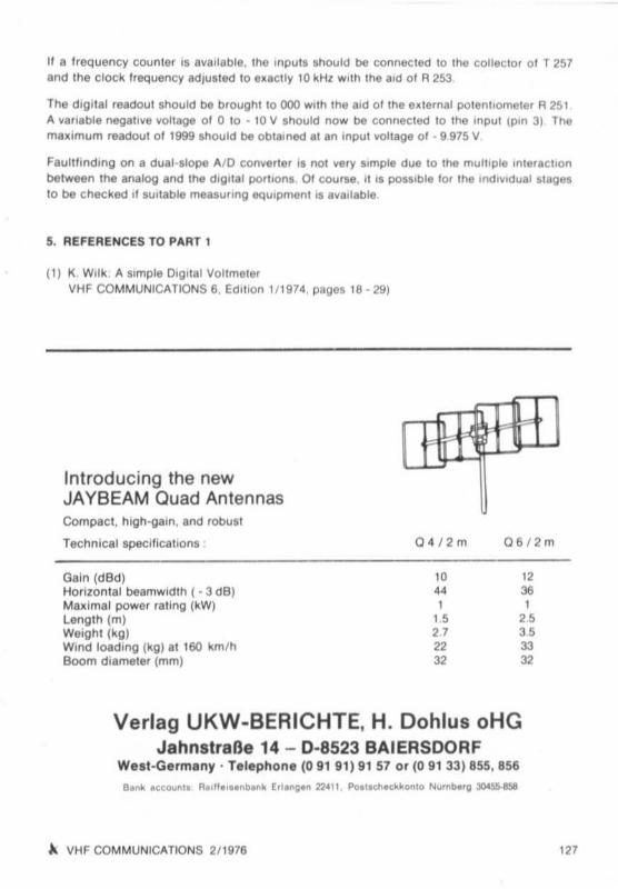
II a I reQuency counter 15 avai lable. the Inputs should be connec ted to thtt co llecto r 01 T257and the clock freQuency ad jus ted 10 e~aclly 10 kHz Wlltl rne aid 01 R 253
The dlgllal readout should be brought to 000 with the aid c t tbe eatemer po tentiometer A 25 1A Yarlable nega tive vollage 01 0 to - 10 V should now be connec ted 10 the Input (pin 31 Thema~imum readout 01 1999 shoUld be obtained al an Input voltage 01 - 9 975 V
Faullllnding on a dual-slope AI D conyel ter 15 not very s,mple due to the multiple ,ntelact lonbetween the analog and the dlgllal polllons 01 course . II IS poss'b le 101 the In<!'Y,dua t . tdgnto be Chec ked II SUitab le measu l lng eqUipment I. aVllllable
5. REFERENCES TO PART 1
(1) K. WoIk A SImple Drgllal VoltmeterVHF COMMUNICATIONS 6. Edit ion 1/19 74, pages 18 · 291
Introducing the newJAYBEAM Quad AntennasCo mpac t. high-va ln, and rObusl
Technical speci llcatlons ,
Gain (dBd)Horizon tal beamwldlh ( - 3 dB )Mall imal power rallng (kWllenglh (m)Weight (kg)Wind loadi ng (kg) al 160 km/hBoom diameter (mm)
Q4 / 2 m,.44,"272232
Db /2m
12ae,"as3332
Verlag UKW-BERICHTE. H. Dohlus oHGJahnstraBe 14 - 0·8523 BAIERSOORF
We st -Germ any · Telephone (0 9191) 9157 or (0 91 33) 855, 856
~ VHF COMMUNICATIONS 2/1976 121

MA TERIAL PRIC E LIS T OF EQUIPMENTdescribed In Edition 211976 of VHF COMMUNICATIONS
DC 8 NR 006DC 8 NR OO6
DC8NROO6
PC-board
Sem ic onduct or sMmlkil A
Crystal
LINEAR TRANSMIT CONVERTERA. LOCAL OSCILLATOR CHAIN (1152 MHI)
DC8 NR 006 (double-c oi led . no tnru-coetects .With printed plan )
(6 tranSisto rs, 3 di odes)(3 ecrucrmers with co re. I I trimm ers,6 leedlh rough cepecrto rs)
96.0000 MHz HC·25/U . . . . . .. . . . .. . . . . .
Ed . 2/1976
OM 20.-
OM 46.50
OM 32.-
OM 34,-
Kit A DC 8 NR 006 with . bo ll. p.rt, , •..... , , ,. OM 128.-
OJ 5 XAOO4
HC-25/ U
OJ 5 XA 004
TubesMlnikil BKit B
OJ 5 XA 004
PC-board
Semi cond ucto rs
Mln iki t
Crystal
.11DC 3 NT 001/002
PC-board
PC·boardSemiconductorsMmikil
Ceramic fill ersCrystals.11
B. TRANSMIT MIXER AND LINEAR AMPLIFIER
DC 8 NA 006 (4 p ieces 8255. 4 pieces tube bases)DC 8 NR 006 (10 tnmmers. 12 fee<lthru-capacl tor sJDC 8 NR 006 with sbo lls PSr11 • ••• ••••• ••• ••••••••••• , ••••
24 cm RECEIVE CONVE RTER
OJ 5 XA004 (double-coated, no tnru -conte crajOJ 5 XA004 (6 transist ors, 2 $cho lt ky and
1 zener dIode)(1 co i llo rmer, 2 ccueets. z remte bead s,1 choke, 4 trimmer capaci tors, 1 spind letr immer, 2 chip cepe. 1 tri mmer pot.)
euner 70,4444 MHz or 66.90278 MHzwith sbolle part• . . . . • • . . . • • . • • • • • •• •• • • • • • • •
FM TRANSCEIVER
DC 3 NT 001 (With printed plan )
DC 3 NT 002 (double coated )DC 3 NT 0 1/02 (24 tran sistors, 9 di odes, 4 ICs)
DC 3 NT 0 1/02 (3 relays. 23 courormers. 19lo i l tri mmers,1 spmdle tr immer , 10 s ty rol l e ~ capac itors$ FE 10.7 MA and CFM 455 e
HC/25-U (5 crys tals see mag)DC 3 NT 01/02 with sbo lle pe r1• ••• , •••• • • • , ••• • , •••••• • ••• •
Ed. 2/1916
OM 140,OM 28,OM 165.-
Ed. 2/1976
OM 26.-
OM 48,-
OM 11.OM 26,
OM 115.-
Ed,1+ 2116
OM 15,OM 24,OM 114,-
OM 74.OM 40.OM 120.
OM 380.-
'28
Verlag UKW-BERICHTE. H. Dohlus oHGJa hnslraBe 14 - 0 ·8523 BAIERSOORF
We.t~Germa n)' · Telephone (09191)9157 or (0 91 33) 855, 856
t\ VHF COMMUNICATIONS 211976

HIGH -PERFORMANCE VHF EQUIPMENT
2 m SS B/FM·rren ace lve r Sf 400 digit.'....tou",,'''lI """....,.. I ................ II. ..... -. ......_ eo_~ ......~n•••• '0 no _".", ..,'~ _, ... '... _ ,,,,'. <'_ """"",",_...,.c"0tI . .... _ .,.... 01 ..... II' ..... 8t 000 "'9"" .... _ cwUSII LSll ' 101 .. 'w·_ .. _ ..., ...... _"'. r..._ e-..-""''''0'''''" I Ill' .., Dogolel ,,_. _ "._.. ".--,..M''''_ ,... _ ...__'" __NO ..... 110I_.., lOICAI"l,""" t.__o..__ ,ow!1V_.."'O-.__·.. IloC__
_ ....~1- w.__ ._ ........ ' ..."....-..---2 m (70 em) SSB/FM/ AM· RltCellle r RX 420 digit.'T ID "'_ ... ",,_ """_, Iy ................... _"'lI_,, ..... _ ........ T_ ..... o< "" n. __.... "'--- ....,.. - ...... _..-.._......._"""._-0.-.''''0 _ cw I.e lA , c..w--"'- _ ...,.. ...... D9"" '-'.- _ ......... _ ... JO_ ..._ _OXI . -'O ...... r,,"'->q-. _ "'-\10<1 ""_.. _be_ __ " 11 _ ...... -... ..._ ..,...___ _ .... _ _ ",__noV"C__
0-85
Write lor tuutecnmcat details
Karl BraunCom munications Equipment
2 m I 70 c:m Un••, l , en. vert., LT 410....__ ,............. "..._,.:10 ...., ...."....._ _ ' CW_II""n..1'0 _. atl_ ..... _
.... ,"'_ ........ at __..__ "-.-...._ .. '--. . <_ ...... _at •
...."""'IO E__ ,,,,''',,__,,_"_ ,-.0 , ... _ __ I0 .... _at.Iow-_ _ osOttr ,,_ '" _ """'" A _ at coo. ... ........_ • •__.._ '''' ' 1'0em l'Oem "'" OulpIo' _ ' OWavo"-", "" ' __ ."., _ _ 11<oo"-,• •_ .too .,-.,..........._ U_ ..,'h"'Pu' __""" 'oJO W PfP
NurnbergDeichslerstr.13 . W.Germany
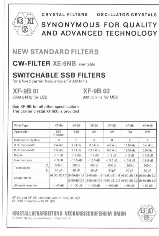
I:~ CRY S TAL FILTERS OSCILLATOR CRY STALS
~}l) SYNONYMOUS FOR QUALITYAND ADVANCED TECHNOLOGY
NEW STANDARD FILTERS
CW-FILTER XE·9NB see table
SWITCHABLE SSB FILTERSfor a fixed carrier frequency of 9 .000 MHz
XF-9B 01 XF·9B 028998.5 kHz for LSB 9001.5 kHz for USB
See XF-98 lor all o the r specificationsThe ca rrie r crystal XF 900 is provided
Filler Type I XF-9A I XF·98 I XF<lC xr-so XF-llE XF-9NB
Apphcollon ssa 55. AM AM ' M CWTransmit
Num ber or crystals S a • • • a3 dB bandWidth 2 4 kHz 2 3kHz 36 kHz 4 6 kHz 11 5 kHz 0 4 kHz
6 dB bandw,dlh 25 kHz 24 kHz 375 kHz 50 kHz 12.0 kHz 05kHz
R,pple c 1 dB < 2 dB < 2dB < 2dB < ace < 0.5 dB
Inserli on 1018 < 3dB < 3 5 d8 < 35 dB < 35dB < 35d8 < B,SdB
Z 500 0 500 0 500 0 500 0 '200 0 500 0Termmalton
C "' pf '" peo c "'pf "" , "'pf
(6 SOd 8) 1 7 (6 6O(8) 18 (6 60 dB) 1 8 (6 6OdB) 18 (8 6Od8) , B (6 60 d8) 22Shope faClor
(6 BOdBl 2 2 (680dB) 2 2 (68O d8)22 (680 d8) 2 2 (680d8) 40
Uilimate .elechon > 45d8 > 100 d8 > HXldB > l 00 dB I > 9IJdB > 90 d8
XF-9A and Xf ·98 complete with XF 901 , Xf 902XF-9N B complete with XF 903
KRISTALLVERARBEITUNGNECKARBISCHOFSHEIM GMBH *0 6924 Neckar bi.chollhe im . POl llech 1