zigbee technique for distributed sensingcradpdf.drdc-rddc.gc.ca/pdfs/unc83/p531381.pdf · zigbee™...
TRANSCRIPT
Defence R&D Canada – Atlantic
DEFENCE DÉFENSE&
ZigBee™ Technique for Distributed Sensing
Nezih MradDRDC Atlantic
Zheng LiuInstitute for Research in Construction (IRC)National Research Council Canada (NRC)
Technical Memorandum
DRDC Atlantic TM 2006-220
November 2006
Copy No. _____
Defence Research andDevelopment Canada
Recherche et développementpour la défense Canada

This page intentionally left blank.
ZigBeeTM Technique for Distributed Sensing
Nezih Mrad DRDC Atlantic Zheng Liu Institute for Research in Construction (IRC) National Research Council Canada (NRC)
Defence R&D Canada – Atlantic Technical Memorandum DRDC Atlantic TM 2006-220 November 2006
Principal Author
Original signed by Nezih Mrad
Nezih Mrad
Defence Scientist
Approved by
Original signed by Ken McRae
Ken McRae
Head/ Air Vehicle Research Section
Approved for release by
Original signed by Ron Kuwahara for
Kirk Foster
DRP Chair
© Her Majesty the Queen as represented by the Minister of National Defence, 2006
© Sa Majesté la Reine, représentée par le ministre de la Défense nationale, 2006
Abstract
This document describes a high-level communication protocol, the ZigBee™ technique, and its potential use for distributed sensing and monitoring. The framework for a ZigBee™ based wireless sensor network is proposed and a feasibility study is carried out employing a Microchip development kit (PICDEM Z) with built-in temperature sensor. Temperature measurements in the range of 25oC and 65oC with 1oC accuracy were demonstrated. It is expected that other types of sensors, which can be applied to aircraft structural health monitoring, can be integrated with the ZigBee™ technique. Furthermore, it is recommended that this document is used as a reference for programming the Microchip PICDEM Z board.
Résumé
On décrit dans ce document un protocole de communication évolué, la technique ZigBeeTM, et la possibilité de l’exploiter pour la détection et la surveillance distribuées. On y propose le cadre d’un réseau de capteurs sans fil basés sur ZigBeeTM, et on mène une étude de faisabilité au moyen de la trousse de développement Microchip (PICDEM Z) doté d’un thermocapteur intégré. On a mesurés des températures dans la fourchette de 25oC à 65oC avec une exactitude de 1 oC. On espère parvenir à intégrer à la technique ZigBeeTM d’autres capteurs de surveillance de la bonne tenue structurale des aéronefs. Enfin, on recommande d’utiliser ce document à titre de référence pour la programmation d’une plaquette de circuit Microchip PICDEM Z.
DRDC Atlantic TM 2006-220 i

This page intentionally left blank.
ii DRDC Atlantic TM 2006-220
Executive summary
ZigBeeTM Technique for Distributed Sensing Mrad, N. and Liu, Z.; DRDC Atlantic TM 2006-220; Defence R&D Canada – Atlantic; November 2006.
Introduction or background
The increasing interest in in-situ and online health monitoring of civilian and military platforms and the drive to deliver such capabilities at reduced weight and increased efficiency has significantly impacted the use of wired systems and wireless networks. Wireless sensors technology is expected to significantly impact any future development in data acquisition, analysis and transmission along with decision making on the state of platforms. We currently enjoy a diverse range of services employing several wireless protocols including Bluetooth and Wi-Fi. The emerging ZigBee™ protocol is a specification for a suite of high level communication protocols using small, low-power digital radio based on the IEEE 802.15.4 standard for wireless personal area networks (WPANs). ZigBee™ is poised to become the global control/sensor network standard. It can be simply implemented and contains features like low power consumption and low data rate. The focus of ZigBee™ technique is to define a general-purpose, inexpensive, self-organizing low power mesh network that can be used for various applications like industrial control, embedded sensing, medical data collection, etc. where low data transfer rate is sufficient for these applications.
Results
The feasibility study of this emerging wireless protocol employing a microchip development kit (PICDEM Z) provided an introduction to ZigBee™ protocol and the IEEE 1451 standard. In addition, it provided a mean for increased level of understanding of the requirement and potential applications of wireless sensors and sensors networks, through the case study of temperature monitoring.
Significance
The knowledge developed through this feasibility study is expected to contribute to efforts underway in the development of advanced sensor technology for enhanced structural health monitoring and prognostics health management.
Future plans
Future efforts will focus on evaluating such ZigBee™ protocol employing other sensors such as, resistive strain gauges and piezoelectric materials and expand such evaluation to multi-nodes using specific network topology.
DRDC Atlantic TM 2006-220 iii
Sommaire
Technique ZigBeeTM en vue de la détection distribuée Mrad, N. et Liu, Z.; RDDC Atlantique TM 2006-220; R&D pour la Défense Canada – Atlantique; novembre 2006.
Introduction ou contexte
L’intérêt accru pour la surveillance sur place et en ligne de la bonne tenue des plateformes civiles et militaires et la volonté d’en arriver à livrer des capacités de cette nature de façon moins encombrante et avec plus d’efficacité ont eu une incidence importante sur la façon d’utiliser les réseaux câblés et les réseaux sans fil. La technologie des capteurs sans fil devrait, selon les prévisions, avoir un impact majeur sur le développement futur de l’acquisition, de l’analyse et de la transmission des données, ainsi que sur le choix de l’état des plateformes. Actuellement, nous avons la chance de disposer d’une gamme diversifiée de services fonctionnant avec des protocoles sans fil comme Bluetooth et Wi-Fi. Le protocole émergeant ZigBeeTM est la spécification d’une suite de protocoles de communication évolués qui emploie de petites radios numériques de faible puissance basées sur la norme IEEE 802.15.4 pour les réseaux personnels sans fil (WPAN). ZigBeeTM est destiné à devenir la norme pour le réseau global de contrôle et de capteurs. Il peut être mis en oeuvre sans problèmes et possède des caractéristiques comme une faible consommation et un petit débit de données. La technique ZigBeeTM est axée sur la définition d’un réseau maillé de faible puissant, à organisation automatique, peu coûteux et polyvalent. Un tel réseau peut servir dans diverses applications comme le contrôle industriel, la détection embarquée, la collecte de données médicales, qui sont des applications où un faible taux de transfert des données est acceptable.
Résultats
L’étude de faisabilité de ce protocole sans fil émergeant qui se fonde sur une trousse de développement de microchip (PICDEM X) se veut une introduction au protocole ZigBeeTM et à la norme IEEE 1451. En outre, cette étude vise à rehausser votre niveau de connaissance des besoins et des possibilités des applications de capteurs sans fil et de réseau de capteurs, par le truchement de l’étude de cas d’une surveillance de la température.
Importance
Les connaissances acquises durant cette étude de faisabilité devraient contribuer à faire progresser le développement d’une technologie de détection avancée nécessaire à la surveillance de la bonne tenue structurale et à sa gestion prévisionnelle.
iv DRDC Atlantic TM 2006-220
Plans futurs
Les travaux annoncés graviteront autour de l’évaluation d’un tel protocole ZigBeeTM mettant en oeuvre d’autres capteurs comme des extensomètres résistifs et des matériaux piézoélectriques. Ces travaux d’évaluation aborderont les noeuds multiples au sein d’une certaine topologie de réseau.
DRDC Atlantic TM 2006-220 v

This page intentionally left blank.
vi DRDC Atlantic TM 2006-220
Table of contents
Abstract ............................................................................................................................................ i Résumé ............................................................................................................................................. i Executive summary ........................................................................................................................ iii Sommaire........................................................................................................................................ iv Table of contents ........................................................................................................................... vii List of figures ............................................................................................................................... viii List of tables ................................................................................................................................... ix Acknowledgements ......................................................................................................................... x 1. Introduction............................................................................................................................... 1 2. Smart Sensor and Wireless Sensor Networks........................................................................... 3
2.1 Smart and intelligent sensors......................................................................................... 3 2.2 Wireless Sensor Network Topologies ........................................................................... 5
3. The ZigBee™ Protocol and Microchip Stack ........................................................................... 6 4. ZigBee™ based Microchip PICDEM Z Board for Temperature Measurement ....................... 9 5. Summary................................................................................................................................. 11 References ..................................................................................................................................... 12
DRDC Atlantic TM 2006-220 vii
List of figures
Figure 1: Communication channels defined by IEEE 802.15.4 ...................................................... 1 Figure 2: Smart sensor architecture ................................................................................................. 3 Figure 3: Smart sensor concept defined by IEEE 1451................................................................... 4 Figure 4: A prototype of a multi-parameter smart sensor concept .................................................. 4 Figure 5: Example of Sensor Networks Topology .......................................................................... 5 Figure 6: Description of ZigBeeTM protocol profile architecture .................................................... 7 Figure 7: The architecture of ZigBeeTM stack ................................................................................. 8 Figure 8: Microchip ZigBee™ demo board (left) and 2.4 GHz RF card (right). The location
of the TC77 sensor is highlighted with a red circle....................................................... 9 Figure 9: The block diagram of a 5-pin thermal sensor TC77 ...................................................... 10 Figure 10: The HyperTerminal display of the temperature from a remote node........................... 10
viii DRDC Atlantic TM 2006-220
List of tables
Table 1: Comparison of wireless communication standards (I) ...................................................... 1 Table 2: Comparison of wireless communication standards (II)..................................................... 2 Table 3: Comparison of ZigBeeTM and Bluetooth – Competitive or Complementary .................... 2 Table 4: Comparison of Networks Topology .................................................................................. 6 Table 5: The responsibilities of NWK sub-layers ........................................................................... 8
DRDC Atlantic TM 2006-220 ix

Acknowledgements
The Authors would like to acknowledge the financial support of the Director General Air Equipment Program Management (DGAEPM) of the Department of National Defence (DND).
x DRDC Atlantic TM 2006-220
1. Introduction
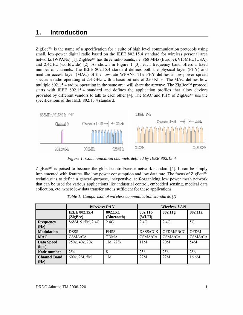
ZigBee™ is the name of a specification for a suite of high level communication protocols using small, low-power digital radio based on the IEEE 802.15.4 standard for wireless personal area networks (WPANs) [1]. ZigBee™ has three radio bands, i.e. 868 MHz (Europe), 915MHz (USA), and 2.4GHz (worldwide) [2]. As shown in Figure 1 [3], each frequency band offers a fixed number of channels. The IEEE 802.15.4 standard defines both the physical layer (PHY) and medium access layer (MAC) of the low-rate WPANs. The PHY defines a low-power spread spectrum radio operating at 2.4 GHz with a basic bit rate of 250 Kbps. The MAC defines how multiple 802.15.4 radios operating in the same area will share the airwave. The ZigBee™ protocol starts with IEEE 802.15.4 standard and defines the application profiles that allow devices provided by different vendors to talk to each other [4]. The MAC and PHY of ZigBee™ use the specifications of the IEEE 802.15.4 standard.
Figure 1: Communication channels defined by IEEE 802.15.4
ZigBee™ is poised to become the global control/sensor network standard [5]. It can be simply implemented with features like low power consumption and low data rate. The focus of ZigBee™ technique is to define a general-purpose, inexpensive, self-organizing low power mesh network that can be used for various applications like industrial control, embedded sensing, medical data collection, etc. where low data transfer rate is sufficient for these applications.
Table 1: Comparison of wireless communication standards (I)
Wireless PAN Wireless LAN IEEE 802.15.4
(ZigBee) 802.15.1 (Bluetooth)
802.11b (Wi-Fi)
802.11g 802.11a
Frequency (Hz)
868M, 915M, 2.4G 2.4G 2.4G 2.4G 5G
Modulation DSSS FHSS DSSS/CCK OFDM/PBCC OFDM MAC CSMA/CA TDMA CSMA/CA CSMA/CA CSMA/CAData Speed (bps)
250k, 40k, 20k 1M, 723k 11M 20M 54M
Node number 254 8 256 256 256 Channel Band (Hz)
600k, 2M, 5M 1M 22M 22M 16.6M
DRDC Atlantic TM 2006-220 1
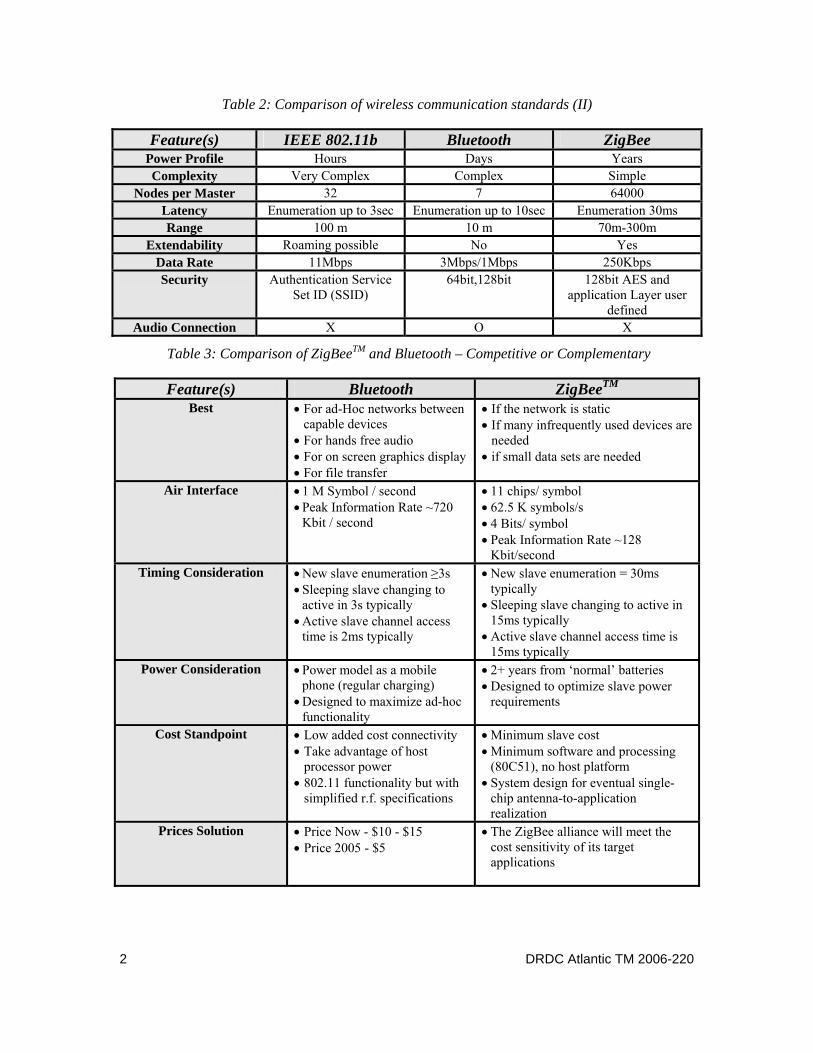
Table 2: Comparison of wireless communication standards (II)
Feature(s) IEEE 802.11b Bluetooth ZigBee Power Profile Hours Days Years Complexity Very Complex Complex Simple
Nodes per Master 32 7 64000 Latency Enumeration up to 3sec Enumeration up to 10sec Enumeration 30ms Range 100 m 10 m 70m-300m
Extendability Roaming possible No Yes Data Rate 11Mbps 3Mbps/1Mbps 250Kbps Security Authentication Service
Set ID (SSID) 64bit,128bit 128bit AES and
application Layer user defined
Audio Connection X O X
Table 3: Comparison of ZigBeeTM and Bluetooth – Competitive or Complementary
Feature(s) Bluetooth ZigBeeTM
Best • For ad-Hoc networks between capable devices
• For hands free audio • For on screen graphics display • For file transfer
• If the network is static • If many infrequently used devices are
needed • if small data sets are needed
Air Interface • 1 M Symbol / second • Peak Information Rate ~720
Kbit / second
• 11 chips/ symbol • 62.5 K symbols/s • 4 Bits/ symbol • Peak Information Rate ~128
Kbit/second Timing Consideration • New slave enumeration ≥3s
• Sleeping slave changing to active in 3s typically
• Active slave channel access time is 2ms typically
• New slave enumeration = 30ms typically
• Sleeping slave changing to active in 15ms typically
• Active slave channel access time is 15ms typically
Power Consideration • Power model as a mobile phone (regular charging)
• Designed to maximize ad-hoc functionality
• 2+ years from ‘normal’ batteries • Designed to optimize slave power
requirements
Cost Standpoint • Low added cost connectivity • Take advantage of host
processor power • 802.11 functionality but with
simplified r.f. specifications
• Minimum slave cost • Minimum software and processing
(80C51), no host platform • System design for eventual single-
chip antenna-to-application realization
Prices Solution • Price Now - $10 - $15 • Price 2005 - $5
• The ZigBee alliance will meet the cost sensitivity of its target applications
2 DRDC Atlantic TM 2006-220
ZigBee™ is actually a complementary to the Bluetooth technique. ZigBee™ can accommodate maximum 255 devices per node with a capacity of 65000 nodes [6]. Moreover, ZigBee™-based chip requires only about 20mA power consumption and use direct sequence spread spectrum (DSSS) method for low power consumption with a protocol stack size less than 32KB. A comparison of ZigBee™ with other techniques is summarized in Tables 1-2. It can also be seen from Table 3 [7] that ZigBee™ and Bluetooth are neither competitive nor complimentary but are two different solutions optimized for different application areas. For instance, ZigBee™ protocol is optimized for timing critical applications. 2. Smart Sensor and Wireless Sensor Networks
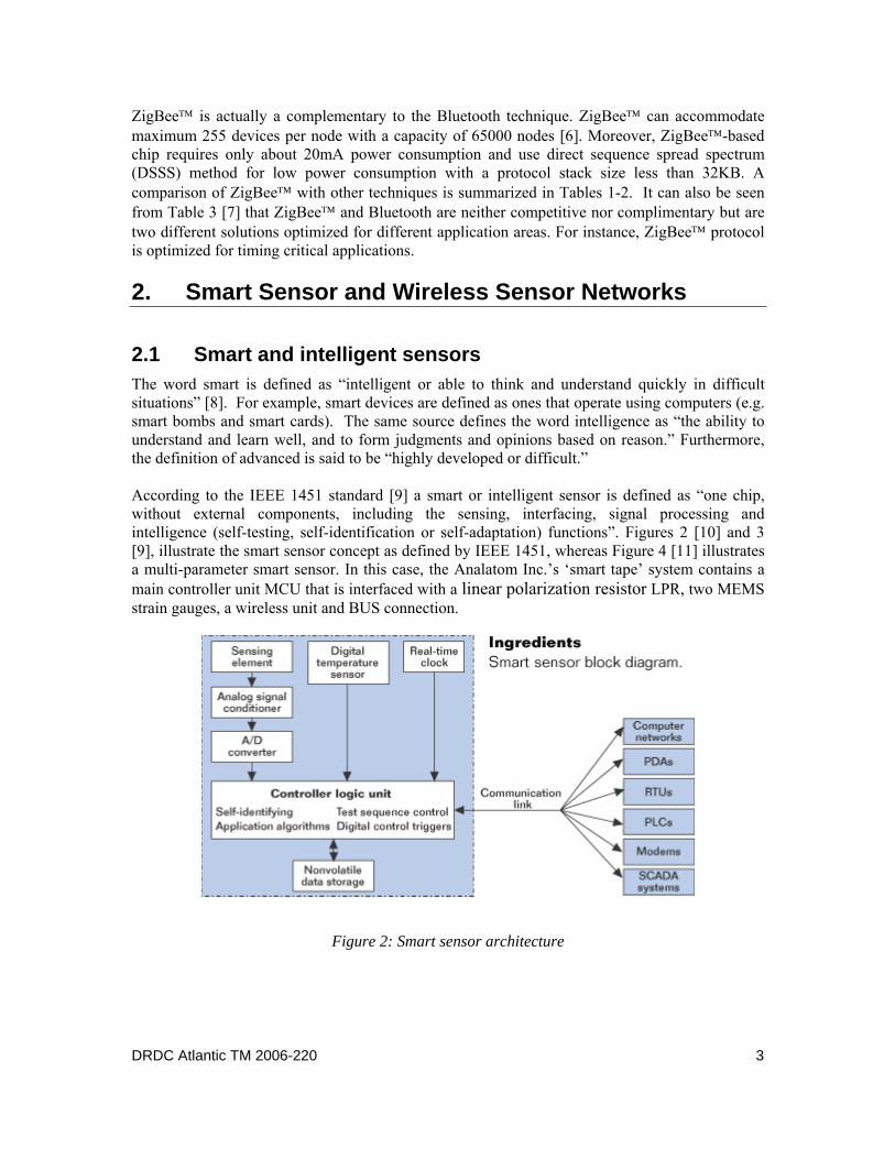
2.1 Smart and intelligent sensors The word smart is defined as “intelligent or able to think and understand quickly in difficult situations” [8]. For example, smart devices are defined as ones that operate using computers (e.g. smart bombs and smart cards). The same source defines the word intelligence as “the ability to understand and learn well, and to form judgments and opinions based on reason.” Furthermore, the definition of advanced is said to be “highly developed or difficult.” According to the IEEE 1451 standard [9] a smart or intelligent sensor is defined as “one chip, without external components, including the sensing, interfacing, signal processing and intelligence (self-testing, self-identification or self-adaptation) functions”. Figures 2 [10] and 3 [9], illustrate the smart sensor concept as defined by IEEE 1451, whereas Figure 4 [11] illustrates a multi-parameter smart sensor. In this case, the Analatom Inc.’s ‘smart tape’ system contains a main controller unit MCU that is interfaced with a linear polarization resistor LPR, two MEMS strain gauges, a wireless unit and BUS connection.
Figure 2: Smart sensor architecture
DRDC Atlantic TM 2006-220 3
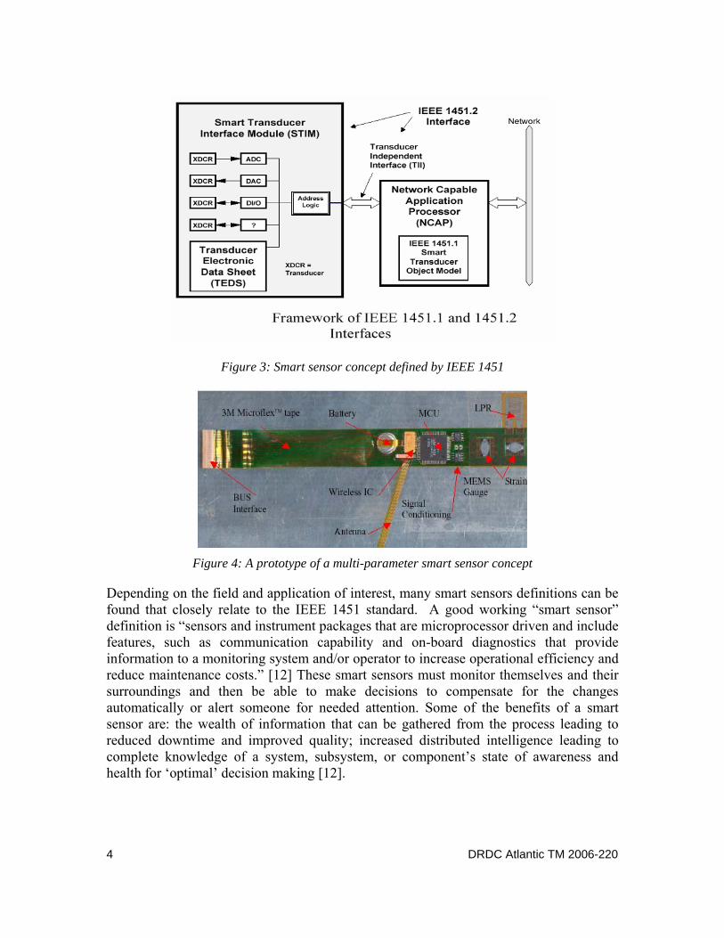
Figure 3: Smart sensor concept defined by IEEE 1451
Figure 4: A prototype of a multi-parameter smart sensor concept
Depending on the field and application of interest, many smart sensors definitions can be found that closely relate to the IEEE 1451 standard. A good working “smart sensor” definition is “sensors and instrument packages that are microprocessor driven and include features, such as communication capability and on-board diagnostics that provide information to a monitoring system and/or operator to increase operational efficiency and reduce maintenance costs.” [12] These smart sensors must monitor themselves and their surroundings and then be able to make decisions to compensate for the changes automatically or alert someone for needed attention. Some of the benefits of a smart sensor are: the wealth of information that can be gathered from the process leading to reduced downtime and improved quality; increased distributed intelligence leading to complete knowledge of a system, subsystem, or component’s state of awareness and health for ‘optimal’ decision making [12].
4 DRDC Atlantic TM 2006-220
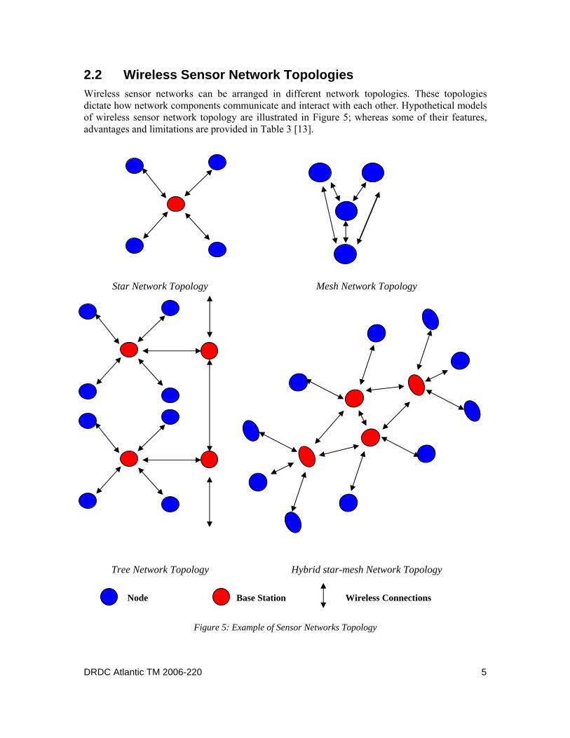
2.2 Wireless Sensor Network Topologies Wireless sensor networks can be arranged in different network topologies. These topologies dictate how network components communicate and interact with each other. Hypothetical models of wireless sensor network topology are illustrated in Figure 5; whereas some of their features, advantages and limitations are provided in Table 3 [13].
Star Network Topology Mesh Network Topology
Tree Network Topology Hybrid star-mesh Network Topology
Node Base Station Wireless Connections
Figure 5: Example of Sensor Networks Topology
DRDC Atlantic TM 2006-220 5
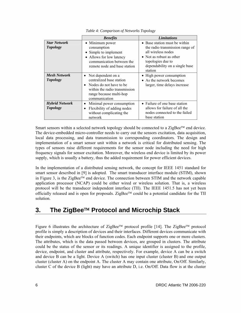
Table 4: Comparison of Networks Topology
Benefits Limitations Star Network Topology
• Minimum power consumption
• Simple to implement • Allows for low latency
communication between the remote node and base station
• Base station must be within the radio transmission range of all wireless nodes
• Not as robust as other topologies due to dependability on a single base station
Mesh Network Topology
• Not dependent on a centralized base station
• Nodes do not have to be within the radio transmission range because multi-hop communication
• High power consumption • As the network becomes
larger, time delays increase
Hybrid Network Topology
• Minimal power consumption • Flexibility of adding nodes
without complicating the network
• Failure of one base station allows for failure of all the nodes connected to the failed base station
Smart sensors within a selected network topology should be connected to a ZigBee™ end device. The device-embedded micro-controller needs to carry out the sensors excitation, data acquisition, local data processing, and data transmission to corresponding coordinators. The design and implementation of a smart sensor unit within a network is critical for distributed sensing. The types of sensors raise different requirements for the sensor node including the need for high frequency signals for sensor excitation. Moreover, the wireless end device is limited by its power supply, which is usually a battery, thus the added requirement for power efficient devices. In the implementation of a distributed sensing network, the concept for IEEE 1451 standard for smart sensor described in [9] is adopted. The smart transducer interface module (STIM), shown in Figure 3, is the ZigBee™ end device. The connection between STIM and the network capable application processor (NCAP) could be either wired or wireless solution. That is, a wireless protocol will be the transducer independent interface (TII). The IEEE 1451.5 has not yet been officially released and is open for proposals. ZigBee™ could be a potential candidate for the TII solution.
3. The ZigBee™ Protocol and Microchip Stack
Figure 6 illustrates the architecture of ZigBee™ protocol profile [14]. The ZigBee™ protocol profile is simply a description of devices and their interfaces. Different devices communicate with their endpoints, which are blocks of function codes. Each endpoint supports one or more clusters. The attributes, which is the data passed between devices, are grouped in clusters. The attribute could be the status of the sensor or its readings. A unique identifier is assigned to the profile, device, endpoint, and cluster and attribute, respectively. For example, device A can be a switch and device B can be a light. Device A (switch) has one input cluster (cluster B) and one output cluster (cluster A) on the endpoint A. The cluster A may contain one attribute, On/Off. Similarly, cluster C of the device B (light) may have an attribute D, i.e. On/Off. Data flow is at the cluster
6 DRDC Atlantic TM 2006-220
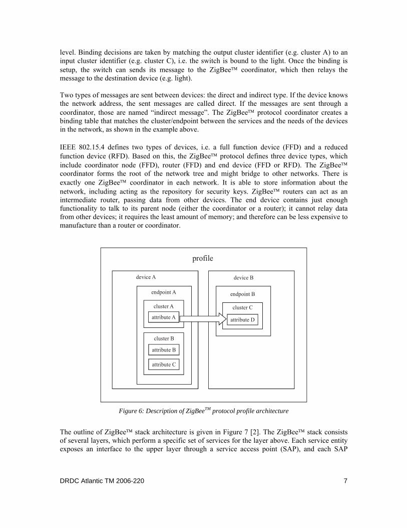
level. Binding decisions are taken by matching the output cluster identifier (e.g. cluster A) to an input cluster identifier (e.g. cluster C), i.e. the switch is bound to the light. Once the binding is setup, the switch can sends its message to the ZigBee™ coordinator, which then relays the message to the destination device (e.g. light). Two types of messages are sent between devices: the direct and indirect type. If the device knows the network address, the sent messages are called direct. If the messages are sent through a coordinator, those are named “indirect message”. The ZigBee™ protocol coordinator creates a binding table that matches the cluster/endpoint between the services and the needs of the devices in the network, as shown in the example above.
IEEE 802.15.4 defines two types of devices, i.e. a full function device (FFD) and a reduced function device (RFD). Based on this, the ZigBee™ protocol defines three device types, which include coordinator node (FFD), router (FFD) and end device (FFD or RFD). The ZigBee™ coordinator forms the root of the network tree and might bridge to other networks. There is exactly one ZigBee™ coordinator in each network. It is able to store information about the network, including acting as the repository for security keys. ZigBee™ routers can act as an intermediate router, passing data from other devices. The end device contains just enough functionality to talk to its parent node (either the coordinator or a router); it cannot relay data from other devices; it requires the least amount of memory; and therefore can be less expensive to manufacture than a router or coordinator.
device A
endpoint A
cluster A
attribute A
cluster B
attribute B
attribute C
device B
endpoint B
cluster C
attribute D
profile
Figure 6: Description of ZigBeeTM protocol profile architecture
The outline of ZigBee™ stack architecture is given in Figure 7 [2]. The ZigBee™ stack consists of several layers, which perform a specific set of services for the layer above. Each service entity exposes an interface to the upper layer through a service access point (SAP), and each SAP
DRDC Atlantic TM 2006-220 7
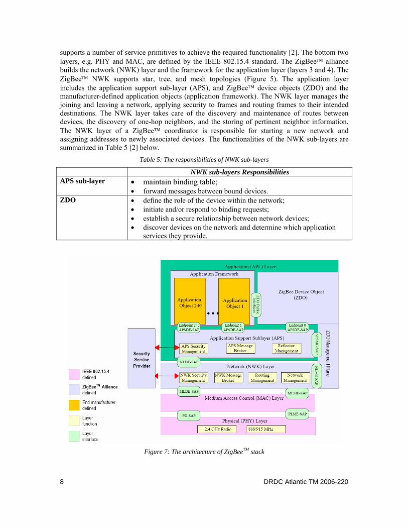
supports a number of service primitives to achieve the required functionality [2]. The bottom two layers, e.g. PHY and MAC, are defined by the IEEE 802.15.4 standard. The ZigBee™ alliance builds the network (NWK) layer and the framework for the application layer (layers 3 and 4). The ZigBee™ NWK supports star, tree, and mesh topologies (Figure 5). The application layer includes the application support sub-layer (APS), and ZigBee™ device objects (ZDO) and the manufacturer-defined application objects (application framework). The NWK layer manages the joining and leaving a network, applying security to frames and routing frames to their intended destinations. The NWK layer takes care of the discovery and maintenance of routes between devices, the discovery of one-hop neighbors, and the storing of pertinent neighbor information. The NWK layer of a ZigBee™ coordinator is responsible for starting a new network and assigning addresses to newly associated devices. The functionalities of the NWK sub-layers are summarized in Table 5 [2] below.
Table 5: The responsibilities of NWK sub-layers
NWK sub-layers Responsibilities APS sub-layer • maintain binding table;
• forward messages between bound devices. ZDO • define the role of the device within the network;
• initiate and/or respond to binding requests; • establish a secure relationship between network devices; • discover devices on the network and determine which application
services they provide.
Figure 7: The architecture of ZigBeeTM stack
8 DRDC Atlantic TM 2006-220
The microchip stack selected for the feasibility study was designed to follow the ZigBee™ protocol and IEEE 802.15.4 specifications, employing a PICDEM Z board and a temperature transducer.
4. ZigBee™ based Microchip PICDEM Z Board for Temperature Measurement
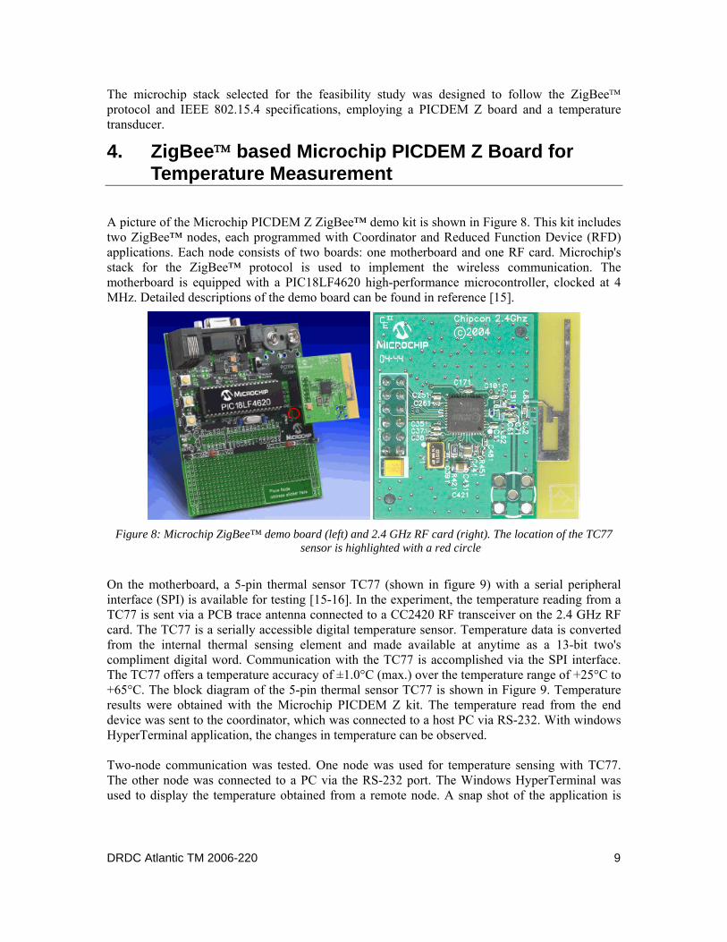
A picture of the Microchip PICDEM Z ZigBee™ demo kit is shown in Figure 8. This kit includes two ZigBee™ nodes, each programmed with Coordinator and Reduced Function Device (RFD) applications. Each node consists of two boards: one motherboard and one RF card. Microchip's stack for the ZigBee™ protocol is used to implement the wireless communication. The motherboard is equipped with a PIC18LF4620 high-performance microcontroller, clocked at 4 MHz. Detailed descriptions of the demo board can be found in reference [15].
Figure 8: Microchip ZigBee™ demo board (left) and 2.4 GHz RF card (right). The location of the TC77
sensor is highlighted with a red circle
On the motherboard, a 5-pin thermal sensor TC77 (shown in figure 9) with a serial peripheral interface (SPI) is available for testing [15-16]. In the experiment, the temperature reading from a TC77 is sent via a PCB trace antenna connected to a CC2420 RF transceiver on the 2.4 GHz RF card. The TC77 is a serially accessible digital temperature sensor. Temperature data is converted from the internal thermal sensing element and made available at anytime as a 13-bit two's compliment digital word. Communication with the TC77 is accomplished via the SPI interface. The TC77 offers a temperature accuracy of ±1.0°C (max.) over the temperature range of +25°C to +65°C. The block diagram of the 5-pin thermal sensor TC77 is shown in Figure 9. Temperature results were obtained with the Microchip PICDEM Z kit. The temperature read from the end device was sent to the coordinator, which was connected to a host PC via RS-232. With windows HyperTerminal application, the changes in temperature can be observed. Two-node communication was tested. One node was used for temperature sensing with TC77. The other node was connected to a PC via the RS-232 port. The Windows HyperTerminal was used to display the temperature obtained from a remote node. A snap shot of the application is
DRDC Atlantic TM 2006-220 9
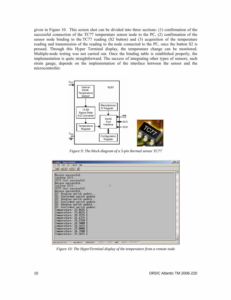
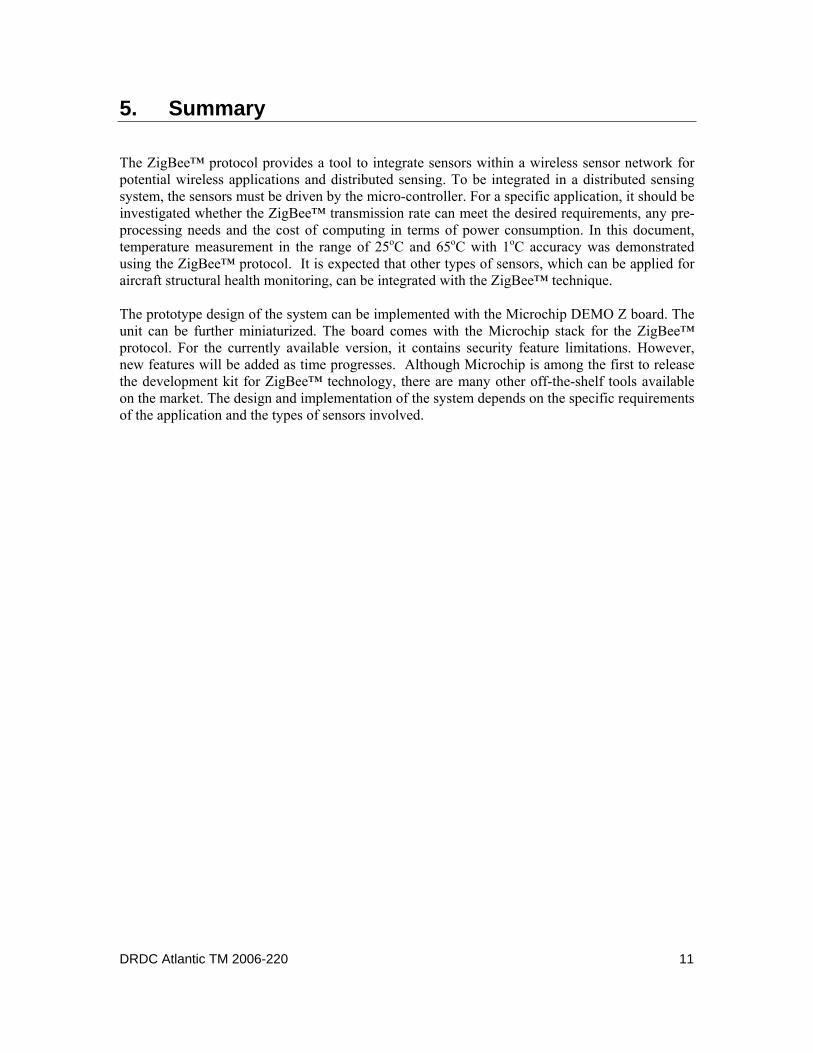
given in Figure 10. This screen shot can be divided into three sections: (1) confirmation of the successful connection of the TC77 temperature sensor node to the PC, (2) confirmation of the sensor node binding to the TC77 reading (S2 button) and (3) acquisition of the temperature reading and transmission of the reading to the node connected to the PC, once the button S2 is pressed. Through this Hyper Terminal display, the temperature change can be monitored. Multiple-node testing was not carried out. Once the binding table is established properly, the implementation is quite straightforward. The success of integrating other types of sensors, such strain gauge, depends on the implementation of the interface between the sensor and the microcontroller.
Figure 9: The block diagram of a 5-pin thermal sensor TC77
Figure 10: The HyperTerminal display of the temperature from a remote node
10 DRDC Atlantic TM 2006-220
5. Summary
The ZigBee™ protocol provides a tool to integrate sensors within a wireless sensor network for potential wireless applications and distributed sensing. To be integrated in a distributed sensing system, the sensors must be driven by the micro-controller. For a specific application, it should be investigated whether the ZigBee™ transmission rate can meet the desired requirements, any pre-processing needs and the cost of computing in terms of power consumption. In this document, temperature measurement in the range of 25oC and 65oC with 1oC accuracy was demonstrated using the ZigBee™ protocol. It is expected that other types of sensors, which can be applied for aircraft structural health monitoring, can be integrated with the ZigBee™ technique. The prototype design of the system can be implemented with the Microchip DEMO Z board. The unit can be further miniaturized. The board comes with the Microchip stack for the ZigBee™ protocol. For the currently available version, it contains security feature limitations. However, new features will be added as time progresses. Although Microchip is among the first to release the development kit for ZigBee™ technology, there are many other off-the-shelf tools available on the market. The design and implementation of the system depends on the specific requirements of the application and the types of sensors involved.
DRDC Atlantic TM 2006-220 11
References
[1] http://en.wikipedia.org/wiki/ZigBee. [2] ZigBee Alliance, "ZigBee Specification Version 1.1", September 5th, 2005 [3] http://www.zigbee.org/en/about/faq.asp [4] D. Geer, "Users Make a Beeline for ZigBee Sensor Technology", Computer, Vol.38, No.
12, pp.16-19, Dec. 2005. [5] R. Kinney, "ZigBee Technology: Wireless Control that Simply Works", White Paper
retrieved from http://www.zigbee.org/en/resources/. [6] N. Baker, "ZigBee and Bluetooth Strengths and Weakness for Industrial Application",
Computing & Control Engineering Journal, Vol.16, No.2, pp.20-25, April-May 2005. [7] Venkat Bahl, ZigBee and Bluetooth – Competitive or Complementary?, September 2002,
ZigBee Alliance. [8] http://dictionary.cambridge.org/results.asp?searchword=smart. [9] National Institute of Standards and Technology, IEEE1451 Website,
http://ieee1451.nist.gov/. [10] G.S. Gustafson and L. J. Chapman, “Data acquisition getting smaller,” July 2004, InTech. [11] T. Niblock, B. Laskowski, H. Surangalikar and J.Moreno, “STape (Smart Tape),”
Analatom Inc., retrieved from http://analatom.com [12] http://www.ceasiamag.com/article.asp?id=1493 [13] C. Townsend and S. Arms, “Wireless Sensor Networks: Principles and Applications,”
Microstrain Inc, 2004. [14] Microchip Technology Inc. Application Note 965, "Microchip Stack for the ZigBee™
Protocol", 2006 [15] PICDEM™ Z Demonstration Kit User's Guide, Microchip Technology Inc. 2004. [16] TC77 Thermal Sensor with SPI™ Interface, Microchip Technology Inc. 2002.
12 DRDC Atlantic TM 2006-220
Distribution list
Document No.: DRDC Atlantic TM 2006-220
LIST PART 1: Internal Distribution by Centre:
7 AVRS 3 (6 hard copies and one soft copy) 5 Library
12 TOTAL LIST PART 1
LIST PART 2: External Distribution by DRDKIM: National Defence Headquarters
101 Colonel By Drive Ottawa, ON K1A 0K2
1 DRDKIM 1 Library & Archives Canada
Attn: Military Archivist, Government Records Branch 1 DSTA 1 NDHQ/DTA 1 NDHQ/DTA/DAES 4-4 1 NDHQ/DTA/DAES 4-2 1 NDHQ/DTA / DAES 2
7 TOTAL LIST PART 2
19 TOTAL COPIES REQUIRED
DRDC Atlantic TM 2006-220 13

14 DRDC Atlantic TM 2006-220
This page intentionally left blank.

DOCUMENT CONTROL DATA (Security classification of title, body of abstract and indexing annotation must be entered when the overall document is classified)
1. ORIGINATOR (The name and address of the organization preparing the document. Organizations for whom the document was prepared, e.g. Centre sponsoring a contractor's report, or tasking agency, are entered in section 8.) DRDC Atlantic
2. SECURITY CLASSIFICATION (Overall security classification of the document
including special warning terms if applicable.) Unclassified
3. TITLE (The complete document title as indicated on the title page. Its classification should be indicated by the appropriate abbreviation (S, C, R or U) in parentheses after the title.) ZigBee Technique for Distributed Sensing
4. AUTHORS (last name, followed by initials – ranks, titles, etc. not to be used) Mrad, N. and Liu, Z.
5. DATE OF PUBLICATION (Month and year of publication of document.) November 2006
6a. NO. OF PAGES (Total containing information, including Annexes, Appendices, etc.)
30
6b. NO. OF REFS (Total cited in document.) 16
7. DESCRIPTIVE NOTES (The category of the document, e.g. technical report, technical note or memorandum. If appropriate, enter the type of report, e.g. interim, progress, summary, annual or final. Give the inclusive dates when a specific reporting period is covered.) Technical Memorandum
8. SPONSORING ACTIVITY (The name of the department project office or laboratory sponsoring the research and development – include address.) DGAEPM
9a. PROJECT OR GRANT NO. (If appropriate, the applicable research
and development project or grant number under which the document was written. Please specify whether project or grant.) 13 gp
9b. CONTRACT NO. (If appropriate, the applicable number under which the document was written.)
10a. ORIGINATOR'S DOCUMENT NUMBER (The official document
number by which the document is identified by the originating activity. This number must be unique to this document.) DRDC Atlantic TM 2006-220
10b. OTHER DOCUMENT NO(s). (Any other numbers which may be assigned this document either by the originator or by the sponsor.)
11. DOCUMENT AVAILABILITY (Any limitations on further dissemination of the document, other than those imposed by security classification.)
( X ) Unlimited distribution ( ) Defence departments and defence contractors; further distribution only as approved ( ) Defence departments and Canadian defence contractors; further distribution only as approved ( ) Government departments and agencies; further distribution only as approved ( ) Defence departments; further distribution only as approved ( ) Other (please specify):
12. DOCUMENT ANNOUNCEMENT (Any limitation to the bibliographic announcement of this document. This will normally correspond to the
Document Availability (11). However, where further distribution (beyond the audience specified in (11) is possible, a wider announcement audience may be selected.))
13. ABSTRACT (A brief and factual summary of the document. It may also appear elsewhere in the body of the document itself. It is highly desirable that the abstract of classified documents be unclassified. Each paragraph of the abstract shall begin with an indication of the security classification of the information in the paragraph (unless the document itself is unclassified) represented as (S), (C), (R), or (U). It is not necessary to include here abstracts in both official languages unless the text is bilingual.)
This document describes a high-level communication protocol, the ZigBee™ technique, and itspotential use for distributed sensing and monitoring. The framework of ZigBee™ based wirelesssensor network is proposed and a feasibility study is carried out employing a Microchipdevelopment kit (PICDEM Z) with built-in temperature sensor. Temperature measurements inthe range of 25oC and 65oC with 1oC accuracy were demonstrated. It is expected that other typesof sensors, which can be applied for aircraft structural health monitoring, can be integrated withthe ZigBee™ technique. Furthermore, it is recommended that this document is used as areference for programming the Microchip PICDEM Z board.
14. KEYWORDS, DESCRIPTORS or IDENTIFIERS (Technically meaningful terms or short phrases that characterize a document and could be helpful in cataloguing the document. They should be selected so that no security classification is required. Identifiers, such as equipment model designation, trade name, military project code name, geographic location may also be included. If possible keywords should be selected from a published thesaurus, e.g. Thesaurus of Engineering and Scientific Terms (TEST) and that thesaurus identified. If it is not possible to select indexing terms which are Unclassified, the classification of each should be indicated as with the title.) smart sensors, wireless sensors, sensor networks, Blue tooth protocol, ZigBee Protocol, sensor networks topology

This page intentionally left blank.