xl series xl11 xl14 xl16 xl19
TRANSCRIPT

PIATTAFORME AEREE SEMOVENTI SELF-PROPELLED WORK-PLATFORMS
PLATEFORMES DE TRAVAIL AUTOMOTRICES SELBSTFAHRENDE HUBARBEITSBÜHNEN
PLATAFORMAS ELEVADORAS AUTOPROPULSADAS ZELFRIJDENDE HOOGWERKERS
SJÄLVGÅENDE ARBETSPLATTFORMAR SAMOKRETNE RADNE PLATFORME ÖNHAJTÁSÚ MUNKAÁLLVÁNYOK
„XL “SERIES XL11 XL14 XL16 XL19
USER'S MANUAL ENGLISH TRANSLATION OF THE ORIGINAL USER MANUAL
AIRO is a division of TIGIEFFE SRL Via Villasuperiore, 82 - 42045 Luzzara (RE) ITALY - +39-0522-977365 - +39-0522-977015
WEB: www.airo.it
027.20.UEM-EN 2017-02

User's Manual – XL Series Page 2
Review date Modifications Log
01-2010 Update to the new Machine Directive 2006/42/EC.
Model name update.
11-2010 Biodegradable oil instructions introduced.
Temperatures and oil list updated.
05-2011
Amended information on “Commissioning and first inspection, subsequent inspections and title transfer report”.
Additions to the Technical Data: “Total quantity of battery electrolyte”
Corrected "Max. power" diesel engine and inserted "Adjusted Power"
08-2011 Further to replacement the 48V-12V converter of XL E installations, some diagrams and
electrical wiring have been upgraded and moved to the second part of the manual.
04-2012 Parking brakes removed from electric versions XL16 and E16 XXL; descriptions and electric
diagrams upgraded.
08-2012 "Maximum load with stabilizer" has been added to the technical specifications.
11-2012 Parking brakes removed from electric versions XL19 E; descriptions and an electric diagram
changed.
07-2013 The new model XL14 E 6P has been added.
2013-10 Details added to the instructions on harness anchoring points
2014-09 Added information on the maximum manual forces.
Changed name CEO.
2015-01 EC Statement of Compliance updated
Additional instructions on hand position have been added.
2015-10
The list of recommended hydraulic oils was updated.
A paragraph was added stating strictly original spare parts should be used or alternatively the approval of the manufacturer should priory obtained.
The whole paragraph “Deboarding the platform off the ground ”is new.
The activation procedure for the battery charger has been updated.
2015-12 Electric connections changed (the SPI was replaced).
2017-02 A new load control system has been installed and additions have been made in the manual.
User's Manual – XL Series Page 3
Tigieffe thanks you for purchasing a product of its range, and invites you to read this manual. Here you can find all the necessary
information for a correct use of the purchased machine; therefore, you are advised to follow the instructions carefully and to read the manual thoroughly. The manual should be kept in a suitable place where no damage can occur to it. The contents of this manual may be modified as a result of any change or improvement done by the manufacturer. This will involve no prior notice and no other obligations of the manufacturer to make any upgrade, change, or improvement of the units already in the market. The reproduction or translation of the whole manual or parts thereof is strictly forbidden without prior written approval of the owner.
Contents: 1. INTRODUCTION ............................................................................................................................................................................ 6
1.1 Legal mentions ........................................................................................................................................................................... 6 1.1.1. Handover of deliveries ............................................................................................................................................................ 6 1.1.2. Statements of successful commissioning, first installation test, periodical functional tests and property transfers. .............. 6 1.1.1.1 Statements of successful commissioning, and first installation test. ................................................................................... 6 1.1.1.2 Periodical Functional Tests. ................................................................................................................................................. 7 1.1.1.3 Transfers of ownership ......................................................................................................................................................... 7 1.1.3. Operators training and information. ........................................................................................................................................ 7 1.2 Tests performed before delivery. ................................................................................................................................................ 7 1.3 Intended use ............................................................................................................................................................................... 7 1.4 Unboarding the platform off the ground ...................................................................................................................................... 8 1.5 Description of the machine ......................................................................................................................................................... 8 1.6 Operator's Stations ..................................................................................................................................................................... 9 1.7 Power supply .............................................................................................................................................................................. 9 1.8 Machine life, decommissioning and disposal. ........................................................................................................................... 9 1.9 Identification ............................................................................................................................................................................. 10 1.10 Location of main components................................................................................................................................................. 11
2. TECHNICAL FEATURES OF THE STANDARD MACHINES ..................................................................................................... 12
2.1 Model XL11 E ........................................................................................................................................................................... 12 2.2 Model XL14 E. .......................................................................................................................................................................... 14 2.3 Model XL14 E 6P ..................................................................................................................................................................... 16 2.4 Model XXL14 E. ....................................................................................................................................................................... 18 2.5 Model XL14 RTD ...................................................................................................................................................................... 20 2.6 Model XL16 E ........................................................................................................................................................................... 22 2.7 Model XXL16 E ........................................................................................................................................................................ 24 2.8 Model XL16 RTD ...................................................................................................................................................................... 26 2.9 Model XL19 E ........................................................................................................................................................................... 28 2.10 Model XL19 RTD .................................................................................................................................................................... 30 2.11 Vibrations and noise. .............................................................................................................................................................. 32
3. SAFETY SIGNS ........................................................................................................................................................................... 33
3.1 Personal protection devices (PPE). .......................................................................................................................................... 33 3.2 General safety norms. .............................................................................................................................................................. 33 3.3 General ..................................................................................................................................................................................... 34 3.3.1. Operating tips and instructions ............................................................................................................................................. 34 3.3.2. Handling ............................................................................................................................................................................... 34 3.3.3. Operating procedures ........................................................................................................................................................... 36 3.3.4. Wind speed according to BEAUFORT SCALE ..................................................................................................................... 37 3.3.5. Ground Pressure and load-bearing capacity . ...................................................................................................................... 38 3.3.6. High-voltage lines ................................................................................................................................................................. 39 3.4 Hazardous situations and/or accidents. .................................................................................................................................... 39
4. INSTALLATION AND PRELIMINARY CHECKS ......................................................................................................................... 40
4.1 Familiarizing with the machine. ................................................................................................................................................ 40 4.2 Preliminary controls. ................................................................................................................................................................. 40
5. USE INSTRUCTIONS .................................................................................................................................................................. 41
5.1 Platform control panel .............................................................................................................................................................. 41 5.1.1. Travelling and steering . ....................................................................................................................................................... 43

User's Manual – XL Series Page 4
5.1.2. Drive with operator on the ground. ....................................................................................................................................... 44 5.1.3. Platform positioning .............................................................................................................................................................. 44 5.1.3.1 Platform Lifting / Lowering .................................................................................................................................................. 44 5.1.3.2 Platform extraction/retraction (optional) .............................................................................................................................. 45 5.1.3.3 Sliding platform extraction/retraction (optional) .................................................................................................................. 45 5.1.3.4 Extension deck extraction/retraction (optional) ................................................................................................................... 45 5.1.4. Levelling outriggers control (OPTIONAL) ............................................................................................................................. 46 5.1.4.1 Levelling outriggers manual control (OPTIONAL) .............................................................................................................. 46 5.1.4.2 Levelling outriggers automatic control (OPTIONAL) .......................................................................................................... 46 5.1.5. Other functions of the platform control panel ........................................................................................................................ 47 5.1.5.1 Selection of electric or gasoline/diesel power ..................................................................................................................... 47 5.1.5.2 Electrical pump start/stop button (OPTIONAL) ................................................................................................................... 47 5.1.5.3 Heat engine starting switch (models ”D”, “ED”, “B”, EB”). ................................................................................................... 47 5.1.5.4 Manual horn ....................................................................................................................................................................... 47 5.1.5.5 Emergency stop button ...................................................................................................................................................... 47 5.1.5.6 Warning lights ..................................................................................................................................................................... 48 5.1.5.7 Green pilot (O) on the control panel enabled ..................................................................................................................... 48 5.1.5.8 Sliding platform position green warning light (P - only for machines with sliding platform) ................................................. 48 5.1.5.9 Flat battery red warning light (Q – only Electric and Electro/diesel models) ....................................................................... 48 5.1.5.10 Drive enable green warning light (R) ................................................................................................................................ 48 5.1.5.11 Danger red warning light (S) ............................................................................................................................................. 49 5.1.5.12 Lifting enable green warning light (T) ............................................................................................................................... 49 5.1.5.13 Overload red warning light (U) .......................................................................................................................................... 49 5.1.5.14 Diesel engine fault / low fuel red warning light (V) ............................................................................................................ 49 5.2 Ground control panel and electric control unit .......................................................................................................................... 50 5.3.1. On-off key and control panel selector (A) ............................................................................................................................. 51 5.3.2. Emergency stop button (B) ................................................................................................................................................... 51 5.3.3. Diesel/electric power selector (C) ........................................................................................................................................ 51 5.3.4. Gasoline engine switch (D)................................................................................................................................................... 51 5.3.5. User interface display (E) ..................................................................................................................................................... 52 5.3.6. Battery charger warning light (F) .......................................................................................................................................... 52 5.3.7. Enabled control panel warning light (G) ............................................................................................................................... 52 5.3.8. Diesel engine warning lights (G-H-L-M-N) ............................................................................................................................ 52 5.3.9. Platform control levers (O-P-Q-R) ........................................................................................................................................ 52 5.4 Boarding the platform ............................................................................................................................................................... 53 5.5 Machine start-up ....................................................................................................................................................................... 53 5.5.1. Heat engine start-up ............................................................................................................................................................. 54 5.5.2. Starting the 230V single-phase electric pump (OPTIONAL) ................................................................................................. 54 5.5.3. Starter for the 3-phase electric pump (OPTIONAL). ............................................................................................................. 55 5.6 Stopping the machine ............................................................................................................................................................... 56 5.6.1. Normal stop .......................................................................................................................................................................... 56 5.6.2. Emergency stop button ........................................................................................................................................................ 56 5.6.3. Stopping the diesel engine ................................................................................................................................................... 56 5.6.4. Stopper of the 380V three-phase or 230V single-phase electrical pump (optional) ............................................................. 57 5.7 Emergency manual pump ........................................................................................................................................................ 57 5.7.1. Platform emergency descent ................................................................................................................................................ 58 5.7.2. Other emergency operations ................................................................................................................................................ 58 5.8 Socket for electric tool connection (optional) ............................................................................................................................ 59 5.9 Fuel level and re-fuelling (models “ED”, “D”)............................................................................................................................. 59 5.10 End of a work day ................................................................................................................................................................... 60
6. HANDLING AND TRANSPORTATION ........................................................................................................................................ 61
6.1 Handling ................................................................................................................................................................................... 61 6.2 Transportation. ......................................................................................................................................................................... 62 6.2.1. Fold-down rails ..................................................................................................................................................................... 64 6.3 Emergency tow-away of the machine ....................................................................................................................................... 65
7. MAINTENANCE ........................................................................................................................................................................... 66
7.1 Safety lock for maintenance operations ................................................................................................................................... 67 7.2 Machine cleaning ..................................................................................................................................................................... 67

User's Manual – XL Series Page 5
7.3 General maintenance ............................................................................................................................................................... 68 7.3.1. Adjustments .......................................................................................................................................................................... 69 7.3.2. Greasing ............................................................................................................................................................................... 70 7.3.3. Checking and changing the hydraulic oil .............................................................................................................................. 71 7.3.3.1 Hydraulic bio-oil (optional). ................................................................................................................................................. 72 7.3.3.2 Emptying ............................................................................................................................................................................ 72 7.3.3.3 Filters.................................................................................................................................................................................. 72 7.3.3.4 Washing ............................................................................................................................................................................. 72 7.3.3.5 Filling .................................................................................................................................................................................. 72 7.3.3.6 Commissioning / check ...................................................................................................................................................... 72 7.3.3.7 Mixing ................................................................................................................................................................................. 73 7.3.3.8 Micro-filtration ..................................................................................................................................................................... 73 7.3.3.9 Disposal .............................................................................................................................................................................. 73 7.3.3.10 Topping up ....................................................................................................................................................................... 73 7.3.4. Hydraulic filter replacement .................................................................................................................................................. 74 7.3.4.1 Suction filters ...................................................................................................................................................................... 74 7.3.4.2 Return filters (XXL14 D - XL14 RTD - XL16 E – XL16 RTD - XL19 E – XL19 RTD). .......................................................... 75 7.3.5. Drive reduction gear oil level check and change. ................................................................................................................. 76 7.3.5.1 Checks in the use of synthetic biodegradable oil in the main reduction gears ................................................................... 76 7.3.6. Air purging from oscillating axle locking cylinders ................................................................................................................ 77 7.3.7. Pressure relief valve adjustment and operation check. ........................................................................................................ 78 7.3.8. Lifting circuit pressure relief valve adjustment ...................................................................................................................... 79 7.3.9. Braking system efficiency check ........................................................................................................................................... 80 7.3.10. Slide-out extension deck clearance adjustment ................................................................................................................. 81 7.3.11. Inclinometer operation check.............................................................................................................................................. 82 7.3.12. Operation check and adjustment of platform overload controller. ...................................................................................... 83 7.3.13. Overload controller by-pass – ONLY FOR EMERGENCY OPERATIONS ......................................................................... 85 7.3.14. Operation check of safety microswitches ........................................................................................................................... 86 7.3.14.1 Microswitch M1 ................................................................................................................................................................. 86 7.3.14.2 Microswitch M1S (if available) .......................................................................................................................................... 86 7.3.14.3 Microswitch M3 (OPTIONAL) ........................................................................................................................................... 86 7.3.14.4 Microswitches M5A-M5B (if available) .............................................................................................................................. 86 7.3.14.5 Microswitch M5A-M5B for machines with sliding platform ................................................................................................ 86 7.3.14.6 Microswitches M5A and M5B for machines with dual slide-out extension deck (if available) ........................................... 87 7.3.14.7 Microswitches ST1A-ST1B-ST1C-ST1D (machines with levelling outriggers) ................................................................. 87 7.3.14.8 Microswitches STP1-STP2-STP3-STP4 (machines with levelling outriggers) .................................................................. 87 7.3.15. Dead-man safety system operation check ......................................................................................................................... 88 7.3.15.1 Dead-man detector pedal ................................................................................................................................................. 88 7.3.15.2 Dead-man Button ............................................................................................................................................................. 88 7.4 Starter battery ........................................................................................................................................................................... 89 7.4.1. Starter battery models “D“ ”ED” ............................................................................................................................................ 89 7.4.2. Starter type battery for models “E” ........................................................................................................................................ 89 7.4.3. Starter battery maintenance ................................................................................................................................................. 89 7.4.4. Starter battery recharge ....................................................................................................................................................... 89 7.5 “DRIVE ”battery for models “E ”and “ED” ................................................................................................................................. 90 7.5.1. General instructions for the MAIN DRIVE BATTERY ........................................................................................................... 90 7.5.2. DRIVE battery recharge. ...................................................................................................................................................... 90 7.5.3. DRIVE battery recharge. ...................................................................................................................................................... 91 7.5.4. Battery charger trouble-shooting .......................................................................................................................................... 92 7.5.5. Battery replacement ............................................................................................................................................................. 92
8 . MARKS AND CERTIFICATIONS ................................................................................................................................................. 94
9. PLATES AND STICKERS ............................................................................................................................................................ 95
10. CONTROL LEDGER .................................................................................................................................................................... 98
11. HYDRAULIC DIAGRAM - STANDARD MACHINES ................................................................................................................. 115
12. WIRING DIAGRAM .................................................................................................................................................................... 125
13. CE DECLARATION OF CONFORMITY ..................................................................................................................................... 137

User's Manual – XL Series Page 6
1. INTRODUCTION This Use and Maintenance Manual provides general instructions concerning the complete range of machines indicated on the cover. Therefore the description of their components, as well as control and safety systems, may include parts not present on Your machine since supplied on request or not available. In order to keep pace with the technical development, AIRO-Tigieffe s.r.l. reserves itself the right to modify the product and/or the user's manuals as needed and without any obligation to prior updates of already existing manuals.
1.1 Legal mentions
1.1.1. Handover of deliveries Within EU (European Union) member countries the machine is delivered complete with: Use and Maintenance manual in your language CE mark applied on the machine EC Statement of Compliance Warranty certificate If the machine is destined for Italy the following additional documents will be available: Notification to INAIL (Italian Health Insurance Company) of successful commissioning. List of local INAIL departments Statement of in-house testing It is to be noted that the Use and Maintenance Manual is an integral part of the machine and a copy of this, together with copies of the documents certifying that the periodical checks have been carried out, must be kept on board in its suitable container. Should you sell, lease or elsehow transfer the ownership the machine, make sure that a copy of the manual is handed over with the machine.
1.1.2. Statements of successful commissioning, first installation test, periodical functional tests and property transfers.
The legal obligations of the owner of the machine vary according to the country of commissioning. It is therefore recommended to inquire about the procedures in force in your country from the boards responsible for industrial safety. This manual contains a final section called "Check register" for a better filing of documents and recording of any modifications.
1.1.1.1 Statements of successful commissioning, and first installation test. In ITALY the owner of the Aerial Platform must notify the user of the machine to the local competent INAIL and submit it to periodical compulsory checks. The first of such checks is performed by the INAIL within sixty days from a request being made. In the event of such time passing without the inspection being made, the employer can call in the ASL (Local Health Unit) or qualified public or private services. Subsequent checks are made by the already-mentioned parties within thirty days from a request being made. In the event of such time passing without these checks being made, the employer can call in qualified public or private services. The employer (machine owner) is to bear all costs of the aforementioned checkups and tests. The local inspection Authorities (ASL/USL, ARPA and INAIL) may appoint any other qualified public or private service to carry out the test. In this case, the appointed private Authorities will act on behalf of Inail (State Authority) by the same powers and qualification of the latter. Italian Customers using the machine in Italy: please notify successful commissioning of the machine to the competent INAIL department using the special form found with the other delivery documents and send it by registered letter with bill of receipt. INAIL will assign the machine a serial number and fill out a “Technical Data Sheet ”on the day of the first installation test. The Data Sheet will exclusively contain the main details of the equipment as-is that will be checked off against the information contained in the instruction manual. The “Technical Data Sheet ”will form an integral part of the machine.
User's Manual – XL Series Page 7
1.1.1.2 Periodical Functional Tests. Yearly overhauls are compulsory. In Italy, the owners of an Aerial Platform must apply for a periodical check by sending a registered letter to the local competent inspection board (ASL/USL or other qualified public or private services) at least twenty days before the expiry of the year from the last check. PLEASE NOTE: If a machine without a valid control document should be moved into an area outside the competence of the usual inspection board, the owner of the machine must ask the inspection board, competent for the new territory where the machine is to be used, for the annual check.
1.1.1.3 Transfers of ownership If the machine is transferred in Italy, the new owner is to notify the ownership of the machine to the local competent Authorities (ASL/USL or other qualified public or private services) by supplying a copy of: Declaration of conformity issued by the manufacturer. Statements of successful commissioning carried out by the first owner.
1.1.3. Operators training and information. The employer must ensure that the workers appointed to use the equipment are adequately and specifically trained so they are able to use the Mobile Elevating Work Platform in a proper and safe way and also avoid the risks caused by other people.
1.2 Tests performed before delivery. Before being placed on the market, each MEWP undergoes the following tests:
Braking test Overload test Operating test
1.3 Intended use The machine described in this use and maintenance manual is a self-propelled aerial platform intended for lifting persons and materials (equipment and work materials) in order to carry out maintenance, installation, cleaning, painting, de-painting, sand-blasting, welding operations, etc. The max. capacity allowed (which varies according to the model – see paragraph “Technical features”) is divided as follows: 80 Kg for each person on board 40 Kg for equipment any remaining load is represented by the material being worked. In any case NEVER exceed the maximum capacity allowed as indicated in paragraph "Technical features”. Persons, tools and work materials can be loaded on the platform only from the initial boarding position (platform lowered). It is absolutely forbidden to load persons, tools and work materials on the platform when it is not in the boarding position. All loads must be positioned inside the platform. Do not lift loads (even if complying with the maximum capacity allowed) hanging from the platform or lifting structure. Do not carry large-sized panels since they increase the resistance to wind force thus causing the machine to overturn. Do not load anything on the platform while the platform is up and the machine travels (operators on board are not allowed to pull wires or ropes, etc.). An overload controller stops the operation of the machine if the load on the platform exceeds by 30% approx. the nominal load (see chapter "General use rules”) and platform is lifted. The machine cannot be used in areas where road vehicles operate. Always surround the working area by means of suitable signs when the machine is used in public areas. Do not use the machine to tow trucks or other vehicles. Any other use different than those for which it was designed must be approved in writing by the manufacturer following a specific request on the part of the user.
User's Manual – XL Series Page 8
Do not use the machine for purposes other than those for which it was designed, except after making a request and having obtained written permission in this sense from the manufacturer.
1.4 Unboarding the platform off the ground The risk of deboarding the Aerial Work Platform when the platform is off the ground has not been accounted in our design safety because the only possible deboarding configuration is the one with the platform completely lowered on ground. For this reason deboarding or leaving a raised platform is absolutely prohibited. However, operators do happen to incur certain situations where they need to leave or access the platform in different positions than the initial boarding one. These situations are commonly referred to as “Deboarding the platform off the ground”. The risks relative to “deboarding a platform off the ground ”depend on the configuration of the platform, but also from the risk assessment analysis carried out by the employer before authorizing any such condition. However, the following circumstances should always be taken in due account;
site/area characteristics; use of the machine as an anchoring point for other operators and other applications, which should be prevented and never
be possible for no reasons; use of the machine at xx% of the its performance to prevent additional stress resulting from specific operations, or flexural
bending of the chassis which may force the platform away from the landing area. In this case, it is recommendable to perform a few trials and define these limit conditions;
implementation of a special emergency evacuation procedure (for instance having a man on the platform; another one at the control station on ground, while a third one leaves a raised platform);
administration of extensive training of the persons involved (both operators and passengers); installation of all implements needed at the point of deboarding to prevent falling of the persons leaving the platform.
This paragraph should not be interpreted as a formal approval by the manufacturer to deboard the platform off-the-ground, which remains a strictly prohibited action. The Employer is the ultimate person responsible for making any such decision and this paragraph is merely meant to supply additional informations and help.
1.5 Description of the machine The machine described in this use and maintenance manual is a Mobile Elevating Work Platform equipped with: Motorised chassis equipped with wheels and, on request, with levelling outriggers (optional); Vertical lifting structure, scissors type, activated by one or several hydraulic cylinders (the number of cylinders depends on the
model of the machine); Operator platform which can be of two types (the max. capacity varies according to the model - see chapter "Technical
features”): o Manual extension in both directions. o Hydraulic extension in both directions.
The chassis is motorised to allow the machine to move (see "General use instructions"). On 2 wheel drive models the chassis is equipped with two rear driving wheels and two front idle steering wheels. On 4 wheel drive models the chassis is equipped with two rear driving wheels and two front driving and steering wheels. All driving wheels are equipped with hydraulic parking brakes, positive logic type (when drive controls are released brakes are automatically activated). On request the machine may be equipped with levelling outriggers to operate on inclined grounds (but sufficiently firm). Even in this case the machine is steady enough to operate on horizontal and sufficiently firm grounds and the platform can be lifted with the chassis resting on the four puncture-proof tires without using the levelling outriggers. These must be used when operating on uneven but sufficiently firm grounds. The levelling outriggers are controlled from the platform control panel, where machine levelling and operations in progress can be checked by means of a spirit level. The machine is also equipped with an inclinometer, a device that stops lifting in the event that the platform is lifted at a height from the ground, which varies from model to model (the stability limits of each model are indicated in paragraph "Technical Features"). The hydraulic cylinders which move the articulated structure and the levelling outriggers are provided with solenoid valves or safety valves directly flanged on the same. This enables the machine to be held in position also in the event of an accidental breaking of the supply pipe. The platform can be of two types: The fixed platform is fitted with two manual slide-out extension decks which extend the operator’s work surface.

User's Manual – XL Series Page 9
The fixed platform is fitted with two hydraulic slide-out extension decks which extend the operator’s work surface.
The platform is equipped with guardrails and toe-boards of a predefined height (the height of the guardrail is 1100 mm; the height
of the toe-boards is 150 mm). When no motive power is available, the manual emergency lowering can be controlled by means of the manual pump and knob indicated by the instruction plates.
1.6 Operator's Stations The machine is equipped with two operator stations: On the platform for normal use of the machine On the chassis you can find: the emergency controls to lower or stop the platform and the emergency stop button, a key-
selector to select the control panel and to start the machine.
1.7 Power supply
The machines can be powered by: An electric-hydraulic system composed of rechargeable batteries and electrical pump; An engine (diesel engine models are identified by the abbreviation “D”; gasoline engine models are identified by the
abbreviation “B”); A combination-power system (Electric/Diesel models are identified by the abbreviation “ED”; Combi models with
electric/gasoline power are identified by the abbreviation “EB”). In any case, both the hydraulic and the electric systems are equipped with all necessary protections (see wiring and hydraulic circuit diagrams annexed to this manual).
1.8 Machine life, decommissioning and disposal. The machine has been designed to last for 10 years in normal operating environments, if properly used and serviced. Within this period, the manufacturer must carry out a complete inspection/overhaul. If the disposal of the unit is necessary, comply with current local regulations. In Italy, the demolition/decommissioning must be notified to the local ASL / USL or ARPA. The machine consists mainly of metal parts which are easy to be identified (steel for the most parts, and aluminium for the hydraulic blocks); thus, we can state that the machine can be recycled at 90%.
European standards and those transposed by the member countries relating to respect for the environment and the disposal of wastes envisage heavy administrative and penal fines in case of infringement. In case of demolition/decommissioning, carefully keep to the provisions of applicable regulations, especially as regards materials such as hydraulic oil and batteries.

User's Manual – XL Series Page 10
1.9 Identification In order to identify the machine, when spare parts and service are required, always mention the information given in the serial number plate. Should this plate (as well as the various stickers applied on the machine) be lost or illegible, it is to be replaced as soon as possible. In order to identify the a machine without a plate or a label, please check the production number punched underneath the chassis. To locate the plate and the stamp of the serial number, see the following picture. It is recommended to copy such data in the following boxes.
MODEL: _________________ CHASSIS: __________________ YEAR: __________________
Fig. 1
User's Manual – XL Series Page 11
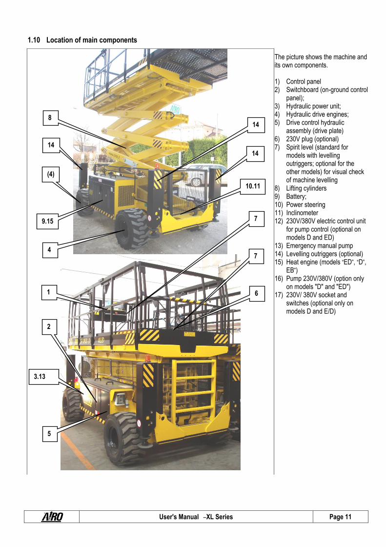
1.10 Location of main components The picture shows the machine and its own components. 1) Control panel 2) Switchboard (on-ground control
panel); 3) Hydraulic power unit; 4) Hydraulic drive engines; 5) Drive control hydraulic
assembly (drive plate) 6) 230V plug (optional) 7) Spirit level (standard for
models with levelling outriggers; optional for the other models) for visual check of machine levelling
8) Lifting cylinders 9) Battery; 10) Power steering 11) Inclinometer 12) 230V/380V electric control unit
for pump control (optional on models D and ED)
13) Emergency manual pump 14) Levelling outriggers (optional) 15) Heat engine (models “ED”, “D”,
EB”) 16) Pump 230V/380V (option only
on models "D" and "ED") 17) 230V/ 380V socket and
switches (optional only on models D and E/D)
2
1
8
5
4
3.13
(4)
7
7
9.15
10.11
14
14
14
6

User's Manual – XL Series Page 12
2. TECHNICAL FEATURES OF THE STANDARD MACHINES
THE TECHNICAL FEATURES OF THE PRODUCTS IN THE FOLLOWING PAGES CAN BE MODIFIED WITHOUT PRIOR NOTICE
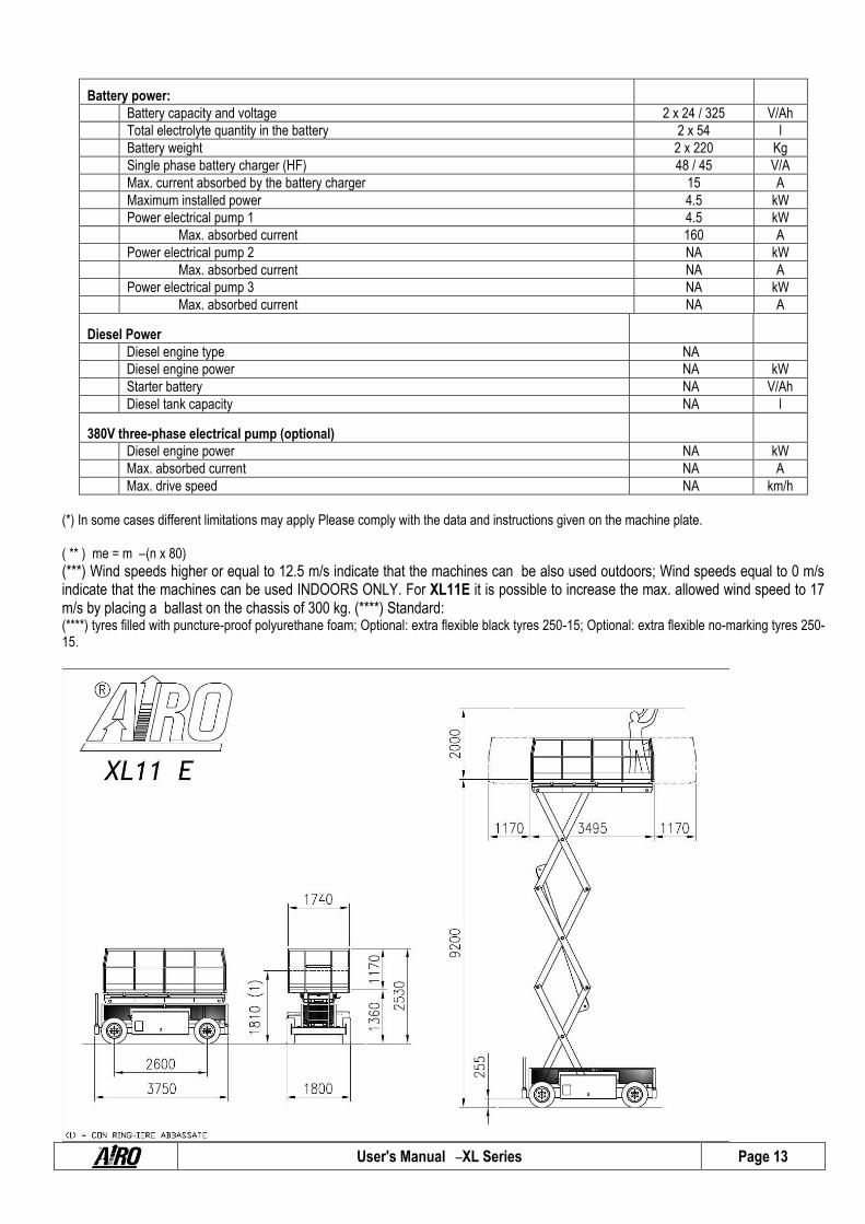
2.1 Model XL11 E XL11 E
Dimensions:
Maximum working height 11.2 m
Max. height of the platform floor 9.2 m
Ground clearance 255 mm
Max. height of the platform floor, safety valve activation 2 m
Internal steering radius 3.3 m
External steering radius 5.8 m
Maximum capacity (m) 700 Kg
Max. number (n) of people on the platform – indoors 3
Mass weight of tool and material (me) (**) – outdoors 460 Kg
Max. number of people on the platform (n) – outdoors 3
Tool and material mass weight (me) (**) – outdoors 460 Kg
Maximum slide-out extension deck 1.17 / 1.17 m
Maximum capacity with platform extended 700 Kg
Max. No. of people with platform extended 3
Maximum height during drive Max
Maximum dimensions with platform extended 1.74 x 5.835 m
Maximum hydraulic pressure 210 Bar
Max. pressure of lifting circuit 140 Bar
Min. pressure of braking circuit 50 ÷ 60 Bar
Tire dimensions (****) Ø 730 x 265 mm
Tire type (****) 10 x 16.5
Transport dimensions with removable rails installed 3.75 x 1.8 x 2.53 m
Transport dimensions without removable rails N.A. m
Transport dimensions with rails folded down 3.75 x 1.8 x 1.81 m
Machine weight w. no load (*) 4850 Kg
Stability limits:
Longitudinal inclination 3 °
Lateral inclination 2 °
Maximum wind speed (***) 12.5 m/s
Maximum stress by hand 400 N
Max. load per wheel 1940 Kg
Specifications:
Driving wheels 2 N
Max. drive speed 4 km/h
Safety drive speed 0.36 km/h
Descent/lifting time (without load) 85 / 80 Sec.
Oil tank capacity 40 l
Maximum admissible gradient 25 %
Max. operating temperature +50 °C
Min. operating temperature -15 °C
User's Manual – XL Series Page 13
Battery power:
Battery capacity and voltage 2 x 24 / 325 V/Ah
Total electrolyte quantity in the battery 2 x 54 l
Battery weight 2 x 220 Kg
Single phase battery charger (HF) 48 / 45 V/A
Max. current absorbed by the battery charger 15 A
Maximum installed power 4.5 kW
Power electrical pump 1 4.5 kW
Max. absorbed current 160 A
Power electrical pump 2 NA kW
Max. absorbed current NA A
Power electrical pump 3 NA kW
Max. absorbed current NA A
Diesel Power
Diesel engine type NA
Diesel engine power NA kW
Starter battery NA V/Ah
Diesel tank capacity NA l
380V three-phase electrical pump (optional)
Diesel engine power NA kW
Max. absorbed current NA A
Max. drive speed NA km/h
(*) In some cases different limitations may apply Please comply with the data and instructions given on the machine plate. ( ** ) me = m – (n x 80)
(***) Wind speeds higher or equal to 12.5 m/s indicate that the machines can be also used outdoors; Wind speeds equal to 0 m/s indicate that the machines can be used INDOORS ONLY. For XL11E it is possible to increase the max. allowed wind speed to 17 m/s by placing a ballast on the chassis of 300 kg. (****) Standard: (****) tyres filled with puncture-proof polyurethane foam; Optional: extra flexible black tyres 250-15; Optional: extra flexible no-marking tyres 250-15.

User's Manual – XL Series Page 14
2.2 Model XL14 E.
XL14 E
Dimensions:
Maximum working height 13.8 m
Max. height of the platform floor 11.8 m
Ground clearance 255 mm
Max. height of the platform floor, safety valve activation 2.3 m
Internal steering radius 3.3 m
External steering radius 5.8 m
Maximum capacity (m) 500 kg
Max. number (n) of people on the platform – indoors 3
Mass weight of tool and material (me) (**) – outdoors 260 kg
Max. number of people on the platform (n) – outdoors 3
Tool and material mass weight (me) (**) – outdoors 260 kg
Maximum slide-out extension deck 1.17 / 1.17 m
Maximum capacity with platform extended 500 kg
Max. No. of people with platform extended 3
Maximum height during drive 8 m
Maximum dimensions with platform extended 1.74 x 5.835 m
Maximum hydraulic pressure 210 bar
Max. pressure of lifting circuit 180 bar
Min. pressure of braking circuit 50 ÷ 60 bar
Tire dimensions (****) Ø 730 x 265 mm
Tire type (****) 10 x 16.5
Transport dimensions with removable rails installed 3.75 x 1.8 x 2.73 m
Transport dimensions without removable rails N.A. m
Transport dimensions with rails folded down 3.75 x 1.8 x 2.01 m
Machine weight w. no load (*) 5150 kg
Stability limits:
Longitudinal inclination 3 °
Lateral inclination 2 °
Maximum wind speed (***) 12.5 m/s
Maximum stress by hand 400 N
Max. load per wheel 2060 Kg
Specifications:
Driving wheels 2 n
Max. drive speed 4 km/h
Safety drive speed 0.36 km/h
Descent/lifting time (without load) 85 / 80 Sec.
Oil tank capacity 40 l
Maximum admissible gradient 22 %
Max. operating temperature +50 °C
Min. operating temperature -15 °C
Battery power:
Battery capacity and voltage 2 x 24 / 325 V/Ah
Total electrolyte quantity in the battery 2 x 54 l
Battery weight 2 x 220 kg
Single phase battery charger (HF) 48 / 45 V/A
Max. current absorbed by the battery charger 15 A
Maximum installed power 4.5 kW
Power electrical pump 1 4.5 kW
Max. absorbed current 160 A
Power electrical pump 2 NA kW
Max. absorbed current NA A
Power electrical pump 3 NA kW
Max. absorbed current NA A

User's Manual – XL Series Page 15
Diesel Power
Diesel engine type NA
Diesel engine power NA kW
Starter battery NA V/Ah
Diesel tank capacity NA l
380V three-phase electrical pump (optional)
Diesel engine power NA kW
Max. absorbed current NA A
Max. drive speed NA km/h
(*) In some cases different limitations may apply Please comply with the data and instructions given on the machine plate. ( ** ) me = m – (n x 80)
(***) Wind speeds higher or equal to 12.5 m/s indicate that the machines can be also used outdoors; Wind speeds equal to 0 m/s indicate that the machines can be used INDOORS ONLY. (****) tyres filled with puncture-proof polyurethane foam; Optional: extra flexible black tyres 250-15; Optional: extra flexible no-marking tyres 250-15.

User's Manual – XL Series Page 16
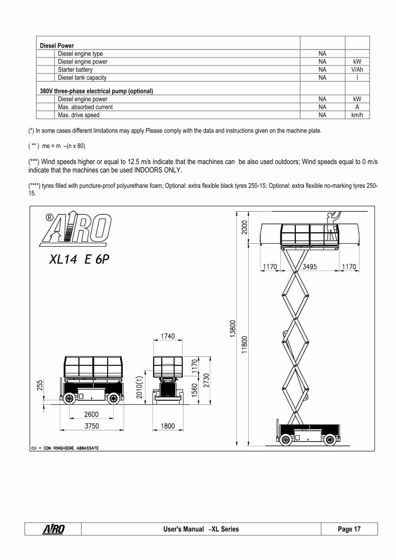
2.3 Model XL14 E 6P
XL14 E 6P
Dimensions:
Maximum working height 13.8 m
Max. height of the platform floor 11.8 m
Ground clearance 255 mm
Max. height of the platform floor, safety valve activation 2.3 m
Internal steering radius 3.3 m
External steering radius 5.8 m
Maximum capacity (m) 520 kg
Max. number (n) of people on the platform – indoors 6
Mass weight of tool and material (me) (**) – outdoors 40 kg
Max. number of people on the platform (n) – outdoors 0
Tool and material mass weight (me) (**) – outdoors 0 kg
Maximum slide-out extension deck 1,17 + 1,17 m
Maximum capacity with platform extended 520 kg
Max. No. of people with platform extended 6
Maximum height during drive 7 m
Maximum dimensions with platform extended 1.74 x 5.835 m
Maximum hydraulic pressure 210 bar
Max. pressure of lifting circuit 180 bar
Min. pressure of braking circuit 50 ÷ 60 bar
Tire dimensions (****) Ø 730 x 265 mm
Tire type (****) 10 x 16.5
Transport dimensions with removable rails installed 3.75 x 1.8 x 2.73 m
Transport dimensions without removable rails N.A. m
Transport dimensions with rails folded down 3.75 x 1.8 x 2.01 m
Machine weight w. no load (*) 5150 kg
Stability limits:
Longitudinal inclination 3 °
Lateral inclination 2 °
Maximum wind speed (***) 0 m/s
Maximum stress by hand 400 N
Max. load per wheel 2060 Kg
Specifications:
Driving wheels 2 n
Max. drive speed 4 km/h
Safety drive speed 0.36 km/h
Descent/lifting time (without load) 85 / 80 Sec.
Oil tank capacity 40 l
Maximum admissible gradient 22 %
Max. operating temperature +50 °C
Min. operating temperature -15 °C
Battery power:
Battery capacity and voltage 2 x 24 / 325 V/Ah
Total electrolyte quantity in the battery 2 x 54 l
Battery weight 2 x 220 kg
Single phase battery charger (HF) 48 / 45 V/A
Max. current absorbed by the battery charger 15 A
Maximum installed power 4.5 kW
Power electrical pump 1 4.5 kW
Max. absorbed current 160 A
Power electrical pump 2 NA kW
Max. absorbed current NA A
Power electrical pump 3 NA kW
Max. absorbed current NA A
User's Manual – XL Series Page 17
Diesel Power
Diesel engine type NA
Diesel engine power NA kW
Starter battery NA V/Ah
Diesel tank capacity NA l
380V three-phase electrical pump (optional)
Diesel engine power NA kW
Max. absorbed current NA A
Max. drive speed NA km/h
(*) In some cases different limitations may apply Please comply with the data and instructions given on the machine plate. ( ** ) me = m – (n x 80)
(***) Wind speeds higher or equal to 12.5 m/s indicate that the machines can be also used outdoors; Wind speeds equal to 0 m/s indicate that the machines can be used INDOORS ONLY. (****) tyres filled with puncture-proof polyurethane foam; Optional: extra flexible black tyres 250-15; Optional: extra flexible no-marking tyres 250-15.
User's Manual – XL Series Page 18
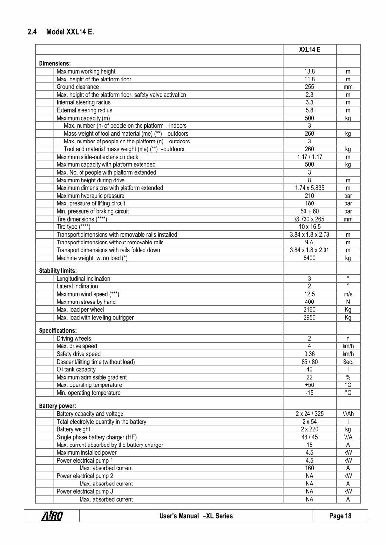
2.4 Model XXL14 E.
XXL14 E
Dimensions:
Maximum working height 13.8 m
Max. height of the platform floor 11.8 m
Ground clearance 255 mm
Max. height of the platform floor, safety valve activation 2.3 m
Internal steering radius 3.3 m
External steering radius 5.8 m
Maximum capacity (m) 500 kg
Max. number (n) of people on the platform – indoors 3
Mass weight of tool and material (me) (**) – outdoors 260 kg
Max. number of people on the platform (n) – outdoors 3
Tool and material mass weight (me) (**) – outdoors 260 kg
Maximum slide-out extension deck 1.17 / 1.17 m
Maximum capacity with platform extended 500 kg
Max. No. of people with platform extended 3
Maximum height during drive 8 m
Maximum dimensions with platform extended 1.74 x 5.835 m
Maximum hydraulic pressure 210 bar
Max. pressure of lifting circuit 180 bar
Min. pressure of braking circuit 50 ÷ 60 bar
Tire dimensions (****) Ø 730 x 265 mm
Tire type (****) 10 x 16.5
Transport dimensions with removable rails installed 3.84 x 1.8 x 2.73 m
Transport dimensions without removable rails N.A. m
Transport dimensions with rails folded down 3.84 x 1.8 x 2.01 m
Machine weight w. no load (*) 5400 kg
Stability limits:
Longitudinal inclination 3 °
Lateral inclination 2 °
Maximum wind speed (***) 12.5 m/s
Maximum stress by hand 400 N
Max. load per wheel 2160 Kg
Max. load with levelling outrigger 2950 Kg
Specifications:
Driving wheels 2 n
Max. drive speed 4 km/h
Safety drive speed 0.36 km/h
Descent/lifting time (without load) 85 / 80 Sec.
Oil tank capacity 40 l
Maximum admissible gradient 22 %
Max. operating temperature +50 °C
Min. operating temperature -15 °C
Battery power:
Battery capacity and voltage 2 x 24 / 325 V/Ah
Total electrolyte quantity in the battery 2 x 54 l
Battery weight 2 x 220 kg
Single phase battery charger (HF) 48 / 45 V/A
Max. current absorbed by the battery charger 15 A
Maximum installed power 4.5 kW
Power electrical pump 1 4.5 kW
Max. absorbed current 160 A
Power electrical pump 2 NA kW
Max. absorbed current NA A
Power electrical pump 3 NA kW
Max. absorbed current NA A

User's Manual – XL Series Page 19
Diesel Power
Diesel engine type NA
Diesel engine power NA kW
Starter battery NA V/Ah
Diesel tank capacity NA l
380V three-phase electrical pump (optional)
Diesel engine power NA kW
Max. absorbed current NA A
Max. drive speed NA km/h
(*) In some cases different limitations may apply Please comply with the data and instructions given on the machine plate. ( ** ) me = m – (n x 80)
(***) Wind speeds higher or equal to 12.5 m/s indicate that the machines can be also used outdoors; Wind speeds equal to 0 m/s indicate that the machines can be used INDOORS ONLY. (****) tyres filled with puncture-proof polyurethane foam; Optional: extra flexible black tyres 250-15; Optional: extra flexible no-marking tyres 250-15.

User's Manual – XL Series Page 20
2.5 Model XL14 RTD
XL14 RTD
Dimensions:
Maximum working height 14 m
Max. height of the platform floor 12 m
Ground clearance 370 mm
Max. height of the platform floor, safety valve activation 2.6 m
Internal steering radius 4.2 m
External steering radius 7.2 m
Maximum capacity (m) 700 kg
Max. number (n) of people on the platform – indoors 3
Mass weight of tool and material (me) (**) – outdoors 460 kg
Max. number of people on the platform (n) – outdoors 3
Tool and material mass weight (me) (**) – outdoors 460 kg
Maximum slide-out extension deck 1.17 / 1.17 m
Maximum capacity with platform extended 500 kg
Max. No. of people with platform extended 3
Maximum height during drive 8 m
Maximum dimensions with platform extended 1.74 x 5.835 m
Maximum hydraulic pressure 190 bar
Max. pressure of lifting circuit 190 bar
Min. pressure of braking circuit 45 ÷ 60 bar
Tyre dimensions Ø 760 x 390 mm
Type of tyres 31 x 15.50 x 15
Transport dimensions with removable rails installed 4.02 x 2.11 x 2.92 m
Transport dimensions without removable rails N.A. m
Transport dimensions with rails folded down 4.02 x 2.11 x 2.26 m
Machine weight w. no load (*) 5870 kg
Stability limits:
Longitudinal inclination 3 °
Lateral inclination 2 °
Maximum wind speed (***) 12.5 m/s
Maximum stress by hand 400 N
Max. load per wheel 2350 Kg
Max. load with levelling outrigger 3285 Kg
Specifications:
Driving wheels 4 n
Max. drive speed 4.7 km/h
Safety drive speed 0.36 km/h
Descent/lifting time (without load) 40 / 50 Sec.
Oil tank capacity 145 l
Maximum admissible gradient 35 %
Max. operating temperature +50 °C
Min. operating temperature -15 °C
Battery power:
Battery capacity and voltage NA V/Ah
Battery weight NA kg
Single phase battery charger (HF) NA V/A
Max. current absorbed by the battery charger NA A
Maximum installed power NA kW
Power electrical pump 1 NA kW
Max. absorbed current NA A
Power electrical pump 2 NA kW
Max. absorbed current NA A
Power electrical pump 3 NA kW
Max. absorbed current NA A

User's Manual – XL Series Page 21
Diesel Power
Diesel engine type Isuzu 3CD1
Max. engine power 24.6 kW
Rated Power 24 kW
Starter battery 12/135 V/Ah
Total electrolyte quantity in the battery 7 l
Diesel tank capacity 45 l
380V three-phase electrical pump (optional)
Diesel engine power NA kW
Max. absorbed current NA A
Max. drive speed NA km/h
(*) In some cases different limitations may apply Please comply with the data and instructions given on the machine plate. ( ** ) me = m – (n x 80)
(***) Wind speeds higher or equal to 12.5 m/s indicate that the machines can be also used outdoors; Wind speeds equal to 0 m/s indicate that the machines can be used INDOORS ONLY.

User's Manual – XL Series Page 22
2.6 Model XL16 E
XL16 E
Dimensions:
Maximum working height 15.8 m
Max. height of the platform floor 13.8 m
Ground clearance 255 mm
Max. height of the platform floor, safety valve activation 2.5 m
Internal steering radius 4 m
External steering radius 6.9 m
Maximum capacity (m) 500 kg
Max. number (n) of people on the platform – indoors 3
Mass weight of tool and material (me) (**) – outdoors 260 kg
Max. number of people on the platform (n) – outdoors 3
Tool and material mass weight (me) (**) – outdoors 260 kg
Maximum slide-out extension deck 1.17 / 1.17 m
Maximum capacity with platform extended 500 kg
Max. No. of people with platform extended 3
Maximum height during drive MAX
Maximum dimensions with platform extended 1.87 x 6.38 m
Maximum hydraulic pressure 190 bar
Max. pressure of lifting circuit 180 bar
Min. pressure of braking circuit 50 ÷ 60 bar
Tire dimensions (****) Ø 730 x 265 mm
Tire type (****) 10 x 16.5
Transport dimensions with removable rails installed 4.32 x 2.12 x 2.83 m
Transport dimensions without removable rails N.A. m
Transport dimensions with rails folded down 4.32 x 2.12 x 2.12 m
Machine weight w. no load (*) 7050 kg
Stability limits:
Longitudinal inclination 2 °
Lateral inclination 2 °
Maximum wind speed (***) 12.5 m/s
Maximum stress by hand 400 N
Max. load per wheel 2820 Kg
Specifications:
Driving wheels 2 n
Max. drive speed 4 km/h
Safety drive speed 0.36 km/h
Descent/lifting time (without load) 85 / 80 Sec.
Oil tank capacity 110 l
Maximum admissible gradient 22 %
Max. operating temperature +50 °C
Min. operating temperature -15 °C
Battery power:
Battery capacity and voltage 2 x 24 / 450 V/Ah
Total electrolyte quantity in the battery 2 x 84 l
Battery weight 2 x 400 kg
Single phase battery charger (HF) 48 / 45 V/A
Max. current absorbed by the battery charger 15 A
Maximum installed power 9 kW
Power electrical pump 1 4.5 kW
Max. absorbed current 160 A
Power electrical pump 2 4.5 kW
Max. absorbed current 160 A
Power electrical pump 3 NA kW
Max. absorbed current NA A

User's Manual – XL Series Page 23
Diesel Power
Diesel engine type NA
Diesel engine power NA kW
Starter battery NA V/Ah
Diesel tank capacity NA l
380V three-phase electrical pump (optional)
Diesel engine power NA kW
Max. absorbed current NA A
Max. drive speed NA km/h
(*) In some cases different limitations may apply Please comply with the data and instructions given on the machine plate. ( ** ) me = m – (n x 80)
(***) Wind speeds higher or equal to 12.5 m/s indicate that the machines can be also used outdoors; Wind speeds equal to 0 m/s indicate that the machines can be used INDOORS ONLY. (****) tyres filled with puncture-proof polyurethane foam; Optional: extra flexible black tyres 250-15; Optional: extra flexible no-marking tyres 250-15.

User's Manual – XL Series Page 24
2.7 Model XXL16 E
XXL16 E
Dimensions:
Maximum working height 15.8 m
Max. height of the platform floor 13.8 m
Ground clearance 255 mm
Max. height of the platform floor, safety valve activation 2.5 m
Internal steering radius 4 m
External steering radius 6.9 m
Maximum capacity (m) 500 kg
Max. number (n) of people on the platform – indoors 3
Mass weight of tool and material (me) (**) – outdoors 260 kg
Max. number of people on the platform (n) – outdoors 3
Tool and material mass weight (me) (**) – outdoors 260 kg
Maximum slide-out extension deck 1.17 + 1.17 m
Maximum capacity with platform extended 500 kg
Max. No. of people with platform extended 3
Maximum height during drive MAX
Maximum dimensions with platform extended 1.87 x 6.38 m
Maximum hydraulic pressure 190 bar
Max. pressure of lifting circuit 180 bar
Min. pressure of braking circuit 50 ÷ 60 bar
Tire dimensions (****) Ø 730 x 265 mm
Tire type (****) 10 x 16.5
Transport dimensions with removable rails installed 4.4 x 2.12 x 2.83 m
Transport dimensions without removable rails N.A. m
Transport dimensions with rails folded down 4.4 x 2.12 x 2.12 m
Machine weight w. no load (*) 7125 kg
Stability limits:
Longitudinal inclination 2 °
Lateral inclination 2 °
Maximum wind speed (***) 12.5 m/s
Maximum stress by hand 400 N
Max. load per wheel 2850 Kg
Max. load with levelling outrigger 3813 Kg
Specifications:
Driving wheels 2 n
Max. drive speed 4 km/h
Safety drive speed 0.36 km/h
Descent/lifting time (without load) 85 / 80 Sec.
Oil tank capacity 110 l
Maximum admissible gradient 22 %
Max. operating temperature +50 °C
Min. operating temperature -15 °C
Battery power:
Battery capacity and voltage 2 x 24 / 450 V/Ah
Total electrolyte quantity in the standard battery 2 x 84 l
Battery weight 2 x 400 kg
Single phase battery charger (HF) 48 / 45 V/A
Max. current absorbed by the battery charger 15 A
Maximum installed power 9 kW
Power electrical pump 1 4.5 kW
Max. absorbed current 160 A
Power electrical pump 2 4.5 kW
Max. absorbed current 160 A
Power electrical pump 3 NA kW
Max. absorbed current NA A

User's Manual – XL Series Page 25
Diesel Power
Diesel engine type NA
Diesel engine power NA kW
Starter battery NA V/Ah
Diesel tank capacity NA l
380V three-phase electrical pump (optional)
Diesel engine power NA kW
Max. absorbed current NA A
Max. drive speed NA km/h
(*) In some cases different limitations may apply Please comply with the data and instructions given on the machine plate. ( ** ) me = m – (n x 80)
(***) Wind speeds higher or equal to 12.5 m/s indicate that the machines can be also used outdoors; Wind speeds equal to 0 m/s indicate that the machines can be used INDOORS ONLY. (****) tyres filled with puncture-proof polyurethane foam; Optional: extra flexible black tyres 250-15; Optional: extra flexible no-marking tyres 250-15.

User's Manual – XL Series Page 26
2.8 Model XL16 RTD
XL16 RTD
Dimensions:
Maximum working height 16 m
Max. height of the platform floor 14 m
Ground clearance 370 mm
Max. height of the platform floor, safety valve activation 2.7 m
Internal steering radius 4 m
External steering radius 6.9 m
Maximum capacity (m) 700 kg
Max. number (n) of people on the platform – indoors 3
Mass weight of tool and material (me) (**) – outdoors 460 kg
Max. number of people on the platform (n) – outdoors 3
Tool and material mass weight (me) (**) – outdoors 460 kg
Maximum slide-out extension deck 1,17 + 1,17 m
Maximum capacity with platform extended 700 kg
Max. No. of people with platform extended 3
Maximum height during drive MAX
Maximum dimensions with platform extended 1.87 x 6.38 m
Maximum hydraulic pressure 190 bar
Max. pressure of lifting circuit 190 bar
Min. pressure of braking circuit 50 ÷ 60 bar
Tyre dimensions Ø 800 x 320 mm
Type of tyres 12 x 16.5
Transport dimensions with removable rails installed 4.53 x 2.33 x 2.98 m
Transport dimensions without removable rails N.A. m
Transport dimensions with rails folded down 4.53 x 2.33 x 2.245 m
Machine weight w. no load (*) 8000 kg
Stability limits:
Longitudinal inclination 4 °
Lateral inclination 3 °
Maximum wind speed (***) 12.5 m/s
Maximum stress by hand 400 N
Max. load per wheel 3200 Kg
Max. load with levelling outrigger 4350 Kg
Specifications:
Driving wheels 4 n
Max. drive speed 5 km/h
Safety drive speed 0.36 km/h
Descent/lifting time (without load) 65 / 75 Sec.
Oil tank capacity 150 l
Maximum admissible gradient 40 %
Max. operating temperature +50 °C
Min. operating temperature -15 °C
Battery power:
Battery capacity and voltage NA V/Ah
Battery weight NA kg
Single phase battery charger (HF) NA V/A
Max. current absorbed by the battery charger NA A
Maximum installed power NA kW
Power electrical pump 1 NA kW
Max. absorbed current NA A
Power electrical pump 2 NA kW
Max. absorbed current NA A
Power electrical pump 3 NA kW
Max. absorbed current NA A

User's Manual – XL Series Page 27
Diesel Power
Diesel engine type Hatz 3L41C -
Isuzu 4LE1
Max. engine power 38.8 -
39
kW
kW
Rated Power 35.5 -
35
kW
kW
Starter battery 12/135 V/Ah
Total electrolyte quantity in the battery 7 l
Diesel tank capacity 45 l
380V three-phase electrical pump (optional)
Diesel engine power 7.5 kW
Max. absorbed current 15.6 A
Max. drive speed 2.2 km/h
(*) In some cases different limitations may apply Please comply with the data and instructions given on the machine plate. ( ** ) me = m – (n x 80)
(***) Wind speeds higher or equal to 12.5 m/s indicate that the machines can be also used outdoors; Wind speeds equal to 0 m/s indicate that the machines can be used INDOORS ONLY.

User's Manual – XL Series Page 28
2.9 Model XL19 E
XL19 E
Dimensions:
Maximum working height 19.3 m
Max. height of the platform floor 17.3 m
Ground clearance 290 mm
Max. height of the platform floor, safety valve activation 3.3 m
Internal steering radius 4 m
External steering radius 6.9 m
Maximum capacity (m) 500 kg
Max. number (n) of people on the platform – indoors 3
Mass weight of tool and material (me) (**) – outdoors 260 kg
Max. number of people on the platform (n) – outdoors 3
Tool and material mass weight (me) (**) – outdoors 260 kg
Maximum slide-out extension deck 1,17 + 1,17 m
Maximum capacity with platform extended 500 kg
Max. No. of people with platform extended 3
Maximum height during drive 14 M
Maximum dimensions with platform extended 1.87 x 6.38 m
Maximum hydraulic pressure 190 bar
Max. pressure of lifting circuit 150 bar
Min. pressure of braking circuit 50 ÷ 60 bar
Tire dimensions (****) Ø 710 x 230 mm
Tire type (****) 300-15
Transport dimensions with removable rails installed 4.53 x 2.21 x 3.21 m
Transport dimensions without removable rails N.A. m
Transport dimensions with rails folded down 4.53 x 2.21 x 2.5 m
Machine weight w. no load (*) 9645 kg
Stability limits:
Longitudinal inclination 1.5 °
Lateral inclination 1.5 °
Maximum wind speed (***) 12.5 m/s
Maximum stress by hand 400 N
Max. load per wheel 3860 Kg
Max. load with levelling outrigger 5073 Kg
Specifications:
Driving wheels 2 n
Max. drive speed 4.3 km/h
Safety drive speed 0.36 km/h
Descent/lifting time (without load) 105 / 80 Sec.
Oil tank capacity 150 l
Maximum admissible gradient 20 %
Max. operating temperature +50 °C
Min. operating temperature -15 °C
Battery power:
Battery capacity and voltage 48 /750 V/Ah
Total electrolyte quantity in the battery 168 l
Battery weight 1275 kg
Three-phase battery charger (HF) 48 / 80 V/A
Max. current absorbed by the battery charger 16 (380 V) A
Maximum installed power 13.5 kW
Power electrical pump 1 4.5 kW
Max. absorbed current 160 A
Power electrical pump 2 4.5 kW
Max. absorbed current 160 A
Power electrical pump 3 4.5 kW
Max. absorbed current 160 A

User's Manual – XL Series Page 29
Diesel Power
Diesel engine type NA
Diesel engine power NA kW
Starter battery NA V/Ah
Diesel tank capacity NA l
380V three-phase electrical pump (optional)
Diesel engine power NA kW
Max. absorbed current NA A
Max. drive speed NA km/h
(*) In some cases different limitations may apply Please comply with the data and instructions given on the machine plate. ( ** ) me = m – (n x 80)
(***) Wind speeds higher or equal to 12.5 m/s indicate that the machines can be also used outdoors; Wind speeds equal to 0 m/s indicate that the machines can be used INDOORS ONLY. (****) Standard extra flexible no-marking tyres 300-15; Optional tyres filled with polyurethane foam 12x16.5.
User's Manual – XL Series Page 30
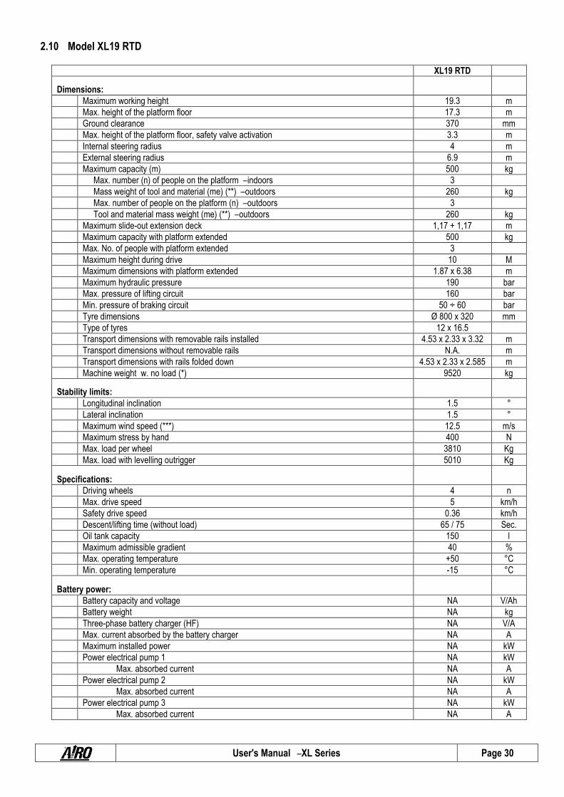
2.10 Model XL19 RTD
XL19 RTD
Dimensions:
Maximum working height 19.3 m
Max. height of the platform floor 17.3 m
Ground clearance 370 mm
Max. height of the platform floor, safety valve activation 3.3 m
Internal steering radius 4 m
External steering radius 6.9 m
Maximum capacity (m) 500 kg
Max. number (n) of people on the platform – indoors 3
Mass weight of tool and material (me) (**) – outdoors 260 kg
Max. number of people on the platform (n) – outdoors 3
Tool and material mass weight (me) (**) – outdoors 260 kg
Maximum slide-out extension deck 1,17 + 1,17 m
Maximum capacity with platform extended 500 kg
Max. No. of people with platform extended 3
Maximum height during drive 10 M
Maximum dimensions with platform extended 1.87 x 6.38 m
Maximum hydraulic pressure 190 bar
Max. pressure of lifting circuit 160 bar
Min. pressure of braking circuit 50 ÷ 60 bar
Tyre dimensions Ø 800 x 320 mm
Type of tyres 12 x 16.5
Transport dimensions with removable rails installed 4.53 x 2.33 x 3.32 m
Transport dimensions without removable rails N.A. m
Transport dimensions with rails folded down 4.53 x 2.33 x 2.585 m
Machine weight w. no load (*) 9520 kg
Stability limits:
Longitudinal inclination 1.5 °
Lateral inclination 1.5 °
Maximum wind speed (***) 12.5 m/s
Maximum stress by hand 400 N
Max. load per wheel 3810 Kg
Max. load with levelling outrigger 5010 Kg
Specifications:
Driving wheels 4 n
Max. drive speed 5 km/h
Safety drive speed 0.36 km/h
Descent/lifting time (without load) 65 / 75 Sec.
Oil tank capacity 150 l
Maximum admissible gradient 40 %
Max. operating temperature +50 °C
Min. operating temperature -15 °C
Battery power:
Battery capacity and voltage NA V/Ah
Battery weight NA kg
Three-phase battery charger (HF) NA V/A
Max. current absorbed by the battery charger NA A
Maximum installed power NA kW
Power electrical pump 1 NA kW
Max. absorbed current NA A
Power electrical pump 2 NA kW
Max. absorbed current NA A
Power electrical pump 3 NA kW
Max. absorbed current NA A
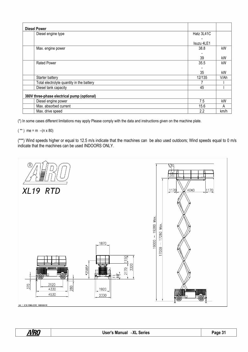
User's Manual – XL Series Page 31
Diesel Power
Diesel engine type Hatz 3L41C -
Isuzu 4LE1
Max. engine power 38.8 -
39
kW
kW
Rated Power 35.5 -
35
kW
kW
Starter battery 12/135 V/Ah
Total electrolyte quantity in the battery 7 l
Diesel tank capacity 45 l
380V three-phase electrical pump (optional)
Diesel engine power 7.5 kW
Max. absorbed current 15.6 A
Max. drive speed 2.2 km/h
(*) In some cases different limitations may apply Please comply with the data and instructions given on the machine plate. ( ** ) me = m – (n x 80)
(***) Wind speeds higher or equal to 12.5 m/s indicate that the machines can be also used outdoors; Wind speeds equal to 0 m/s indicate that the machines can be used INDOORS ONLY.

User's Manual – XL Series Page 32
2.11 Vibrations and noise. Noise tests have been carried out under the most unfavourable conditions to study the effects on the operator. The level of acoustic pressure weighed (A) at work places does not exceed 82dB (A) for each electrical model. For models with diesel engine the level of continuous acoustic pressure (A) measured at the place of work does not exceed 110 dB(A). As to vibrations in ordinary working conditions:
The average weighted quadratic value in the frequency of the acceleration which the upper members have to withstand is below 2.5 m/sec² for each of the models to which this Use and Maintenance manual refers.
The average weighted quadratic value in the frequency of the acceleration which the body has to withstand is below 0.5 m/sec² for each of the models to which this Use and Maintenance manual refers.

User's Manual – XL Series Page 33
3. SAFETY SIGNS
3.1 Personal protection devices (PPE).
Always wear personal protective equipment according to current regulations concerning industrial health and safety (in particular, hard hat and safety shoes are COMPULSORY).
It is the operator or safety manager’s responsibility to choose the personal protective equipment (PPE) depending on the activity to be carried out. For their correct use and maintenance, refer to the equipment manuals themselves.
The use of safety harness is not compulsory except in certain countries with specific regulations. In Italy, the consolidation act on safety, Law Decree 81/08, has made the use of a safety harness mandatory.
The harness attaches to one of the anchors shown by the labels, as in the following picture.
Fig. 3
3.2 General safety norms.
Only adults (18 years old), after carefully reading this manual, are allowed to use the machine. The employer is responsible for training.
The platform is designed to carry persons on board; therefore, compliance with the current local regulations relevant to this class of machines (see paragraphs 1) must be ensured.
The machine is a two-man operation unit. This means at least one man must be on the ground and assigned to all emergency operations as described in this handbook.
Always keep the machine at a safety distance from the power lines as indicated in the following chapters. Never exceed the capacity ratings shown in this manual under "machine technical specifications". The
identification plate shows the maximum number of people allowed on the platform, the maximum capacity and the mass weight of tools and ancillary materials. Never exceed these figures.
Do NOT use the platform steelwork or any of its parts for grounding applications while welding on the platform. NEVER board/deboard passengers and NEVER load/unload any materials if the platform is not in the initial
boarding position. The owner and/or safety manager are liable and responsible for due maintenance and repair operations to be
carried out strictly by skilled and qualified labour.
User's Manual – XL Series Page 34
3.3 General
3.3.1. Operating tips and instructions
The electric and hydraulic circuits are provided with safety devices, calibrated and sealed by the manufacturer:
DO NOT TAMPER WITH AND MODIFY THE CALIBRATION OF ANY COMPONENT OF THE ELECTRIC AND HYDRAULIC SYSTEMS.
The machine must be used only in areas well lit up, checking that the ground is flat and firm. The machine may not be used if the lighting conditions are not sufficient. The machine is not equipped with any lightening system.
Before using the machine check its integrity and good, functional preservation state. During maintenance operations do not dispose of any waste materials in the environment, but comply with current
regulations. Do not carry out any service or maintenance operations when the machine is connected to the mains supply. Follow
the instructions given in the following paragraphs. Do not approach the electric and hydraulic system components with sources of heat or flames. Do not increase the max. allowed height by means of scaffolds, ladders or other. With the machine elevated, do not fasten the platform to any structure (beams, pillars or wall). Do not use the machine as a crane, hoist or lift. Protect the machine (in particular the platform control panel by means of the specially provided cover - optional) and
the operator when working in adverse environmental conditions (painting, de-painting, sand-blasting, washing, etc.). Using the machine in bad weather conditions is forbidden; in particular, wind speeds must not exceed the limits
indicated in the technical specifications (to measure speeds, see following chapters). Machines with a wind speed limit of 0 m/s are to be used indoors only. In the event of rain or when the machine is parked, always cover the platform control panel by means of the special
hood or guard (optional). Do not use the machine in areas where risks of fire or explosion exist. Do not use pressurized water jets (high-pressure cleaners) to wash the machine. Overloading the work platform is forbidden. Avoid knocks and/or contacts with other vehicles and fixed structures. Leaving or accessing the work platform is forbidden unless this is in the position required for access or leaving (see
the “Accessing the platform ”chapter).
3.3.2. Handling
Before moving the machine make sure that all connections are disconnected from the power supply source. To avoid any instability, strictly use the machine on regular and firm grounds. To prevent the machine from overturning,
comply with the max. gradeability values indicated in the Technical data section under paragraph "Stability limits". However, movements on inclined grounds are to be carried out with the utmost caution.
As soon as the platform is lifted (the tolerance varies from model to model) the safety drive speed is automatically activated (all models of this handbook have passed the stability tests in compliance with standard EN280:2001 ).
Drive the machine with lifted platform only on flat grounds, verifying the absence of holes or steps on the floor and bearing in mind the overall dimensions of the machine.
Backward drive (in the direction of the fixed wheels) does not allow the operator on the control panel a complete visibility. Use extreme care for this operation.
While the machine is being displaced with lifted platform, no horizontal loads can be loaded onto the platform (operators on board are not allowed to pull wires or ropes, etc.).
The machine must not be used directly for road transport. Do not use it for material transport (see chapter “Intended use”).

User's Manual – XL Series Page 35
Do not operate the machine if components boxes are not properly closed. Check that in the operating area there are not obstacles or other dangerous elements. Pay particular attention to the area above the machine during lifting to avoid any crushing and collisions. While handling or operating, make sure your hands never infringe a dangerous area. Drivers should keep their hands
as shown in picture A or B, whilst passengers should hold their hands as in C.
Fig. 4

User's Manual – XL Series Page 36
3.3.3. Operating procedures
The machine is equipped with an inclination control system to disable lifting operations in case of unstable positioning. Working operations can be resumed only after placing the machine in a steady position. Should the audible alarm and the red light on the platform control panel turn on, the machine is not correctly positioned (see paragraphs relevant to “Use instructions ”). Bring it to safety rest position before starting operations again. If the platform inclination is activated with platform raised, the only possible platform operation is lowering.
The machine is equipped with a control load system at platform to stop lifting and lowering of the platform when it is overloaded. In case of platform overloading when lifted, also drive is disabled. Platform operation can be resumed only after removing the exceeding load. Should the alarm and the red light located on the platform control panel turn on, then the machine is overloaded (see chapter "Red warning light overload"). Remove the exceeding load before starting operations again.
The machine can be equipped with a device to avoid the risk of shearing and crushing in the lifting structure in compliance with PrEN280:2009. With this device, the lowering movement is automatically stopped in position when the vertical distance between the scissor ends exceeds 50 mm. In this condition the audible movement alarm signals the danger by increasing its frequency. The operator on the platform must release the lowering control and wait until the alarm stops (about 3 sec.), then he can resume the lowering control (see chapter "Lifting and lowering").
Electric power machines are fitted with a device for checking the state of battery charge (battery protection). When the battery charge is as low as 20%, a red flashing light goes on to alert the operator on the platform of the low-battery status. In this condition, lifting is disabled, and the battery should be immediately recharged.
Do not lean over the platform rails. During operations in public areas surround the working area by means of barriers or other suitable signs. Do not use diesel or gasoline powered engines indoors or in insufficiently ventilated areas. Make sure that no people, apart from the operator, are in the area where the machine is operating. While moving the
platform or operating the outriggers, the operator should pay particular attention to avoid any contact with the personnel on the ground.
Specially provided micro-switches located on the (optional) levelling outriggers control their position. When the cylinders are lowered, drive is disabled. In order to carry out the drive, lift the pads completely.
To avoid any improper use, machines with (optional) levelling outriggers are equipped with a suitable microswitch that checks the position of the platform. When the platform is at a height above 3 meters from the ground the levelling outriggers cannot be operated.
Lift the platform only if the machine is resting on solid and horizontal surfaces. Drive the machine with lifted platform only if the ground is solid and horizontal. Always place working tools in a steady position to prevent them from falling and hurting the operators on the ground. After each work session, always take the keys out of the control panels and keep them in a safe place to prevent
unauthorized people from using the machine.
When choosing the positioning point of the chassis, to prevent unexpected possible contacts with obstacles, always observe the figures carefully as these make it possible to identify the range of action of the platform ( chap.2).
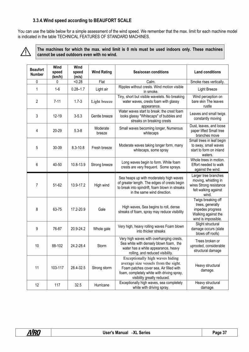
User's Manual – XL Series Page 37
3.3.4. Wind speed according to BEAUFORT SCALE You can use the table below for a simple assessment of the wind speed. We remember that the max. limit for each machine model is indicated in the table TECHNICAL FEATURES OF STANDARD MACHINES.
The machines for which the max. wind limit is 0 m/s must be used indoors only. These machines cannot be used outdoors even with no wind.
Beaufort Number
Wind speed (km/h)
Wind speed (m/s)
Wind Rating Sea/ocean conditions Land conditions
0 0 <0.28 Flat Calm. Smoke rises vertically.
1 1-6 0.28–1.7 Light air Ripples without crests. Wind motion visible
in smoke. Light Breeze
2 7-11 1.7-3 Light breeze Tiny, short but visible wavelets. No breaking
water waves, crests foam with glassy appearance.
Wind perception on bare skin The leaves
rustle
3 12-19 3-5.3 Gentle breeze Water waves start to break: the crest foam looks glassy "Whitecaps" of bubbles and
streaks on breaking crests
Leaves and small twigs constantly moving
4 20-29 5.3-8 Moderate
breeze Small waves becoming longer, Numerous
whitecaps
Dust, leaves, and loose paper lifted Small tree
branches move
5 30-39 8.3-10.8 Fresh breeze Moderate waves taking longer form, many
whitecaps, some spray
Small trees in leaf begin to sway, small waves start to form on inland
waters.
6 40-50 10.8-13.9 Strong breeze Long waves begin to form. White foam crests are very frequent. Some sprays.
Whole trees in motion. Effort needed to walk
against the wind.
7 51-62 13.9-17.2 High wind
Sea heaps up with moderately high waves of greater length. The edges of crests begin to break into spindrift, foam blown in streaks
in the same wind direction.
Larger tree branches moving, whistling in
wires Strong resistance felt walking against
wind.
8 63-75 17.2-20.9 Gale High waves, Sea begins to roll, dense
streaks of foam, spray may reduce visibility
Twigs breaking off trees, generally
impedes progress Walking against the wind is impossible.
9 76-87 20.9-24.2 Whole gale Very high, heavy rolling waves Foam blown
into thicker streaks
Slight structural damage occurs (slate
blows off roofs)
10 88-102 24.2-28.4 Storm
Very high waves with overhanging crests, Sea white with densely blown foam, the
water has a white appearance, heavy rolling, and reduced visibility.
Trees broken or uprooted, considerable
structural damage
11 103-117 28.4-32.5 Strong storm
Exceptionally high waves hiding
average size vessels from the sight. Foam patches cover sea, Air filled with
foam, completely white with driving spray, visibility greatly reduced.
Heavy structural damage.
12 117 32.5 Hurricane Exceptionally high waves, sea completely
white with driving spray. Heavy structural
damage.

User's Manual – XL Series Page 38
3.3.5. Ground Pressure and load-bearing capacity .
Before using the machine, the operator must make sure the floor is suitable for withstanding the specific loads and pressures on the ground with a certain safety margin. The following chart provides the parameters in play and two examples of calculation of the average pressure on the ground below the machine and max pressure underneath the wheels or stabiliser outriggers (p1 and p2).
SYMBOL U.M. DESCRIPTION EXPLANATION FORMULA
P1 Kg Total machine weight
Represents the weight of the machine, not including nominal load. Note: always refer to the details indicated on the plates affixed to the machine.
-
M Kg Nominal Load The max. load allowed for the work platform. -
A1 cm² Ground area occupied
by the machine Surface area under the machine determined by multiplying TRACK x WHEEL BASE
A1 = c × i
c cm Track
Out-to-out width of machine measured outside the wheels. or: Out-to-out width of machine measured between outrigger centres.
-
i cm Wheel base
Front-to-back length of machine measured between wheel centres. or: Front-to-back length of machine measured between outrigger middle lines.
-
A2 cm² Wheel or outrigger
surface
Wheel or outrigger foundation The operator is to check the foundation area under each wheel; the outrigger foundation will depend on the shape of the floor plate.
-
P2 Kg Max. load on wheels or
outriggers
This is the max. load transferred to the ground by a wheel or by an outrigger with the machine in the worst position and load condition. Note: always refer to the details indicated on the plates affixed to the machine.
-
p1 Kg/cm² Pressure on ground Average pressure placed on the ground in idle conditions and supporting the nominal load. p1 = (P1 + M) / A1
p1 = (P1 + M) / A1
p2 Kg/cm² Max specific pressure Max. pressure which a wheel or a levelling outrigger can apply to the ground when the machine is in the worst position and load conditions.
p2 = P2 / A2

User's Manual – XL Series Page 39
The table below shows the load-bearing capacity of the ground split up by ground type. For the max pressure on the ground by the single wheel, please refer to the data contained in the specific tables of each model (chapter 2, TECHNICAL FEATURES OF STANDARD MACHINES).
Using the machine is forbidden if the max pressure on the ground per wheel is above the load-bearing capacity of the specific type of ground on which the machine is to be used.
TYPE OF GROUND BEARING CAPACITY IN Kg/ cm²
Non compact filling earth 0 – 1
Mud, peat, etc. 0
Sand 1.5
Gravel 2
Friable earth 0
Soft earth 0.4
Rigid earth 1
Semi-solid earth 2
Solid earth 4
Rocks 15 - 30
Should you have any doubts, verify the load-bearing capacity with specific tests. In case of constructed surfaces (concrete floors, bridges, etc.) the load-bearing capacity must be provided by the builder.
3.3.6. High-voltage lines
The machine is not electrically insulated and is not protected in case of contact with or proximity to power lines. A minimum distance must be kept from power lines according to applicable laws and the following table
Type of power lines Voltage (KV) Minimum distance (m)
Light poles
1 3
1-10 3.5
10 - 15 3.5
15 - 132 5
132 - 220 7
220 - 380 7
High-voltage pylons 380 15
3.4 Hazardous situations and/or accidents.
If, during Preliminary Operation Checks or when using the machine, the operator discovers a defect that could produce a hazardous situation, the machine must be placed in safety condition (isolate it and affix a notice) and the employer must be notified about the fault.
If, during use, an accident occurs, with injury to the operators, caused by operating errors (e.g., collisions) or any structural yielding, the machine must be placed in safety condition (isolate it and affix a notice) and the employer must be notified about the fault.
In case of an accident with injuries to one of more operators, the operator on the ground (or on a platform not involved in the accident) must:
Seek help immediately. Perform the operation to return the platform to the ground only if he is certain this will not make the situation worse. Place the machine in safety condition and notify the fault to the employer.
User's Manual – XL Series Page 40
4. INSTALLATION AND PRELIMINARY CHECKS The machine is supplied completely assembled, therefore it can perform all functions in safety as provided for by the manufacturer. No preliminary operation is required. To unload the machine, follow the instructions in chapter “handling and carrying”. Place the machine on a sturdy enough surface (see paragraph 3.3.5) and with a gradient below max. allowed gradient (see technical features “Stability limits”).
4.1 Familiarizing with the machine.
Anyone wishing to use a machine with weight, height, width and length characteristics that significantly differ from the training received must be updated in order to cover the differences. The employer shall be responsible for ensuring that all operators working with the equipment are adequately trained and aware of the applicable health and safety legislation.
4.2 Preliminary controls.
Before using the machine read the instructions in this manual and the short instructions reported on the manufacturer's plate on the platform. Visually check for perfect integrity of the machine and read the plates showing machine operating limits. Before using the machine the operator is to carry out a visual inspection to ensure that: Make sure the battery is fully charged and the fuel tank is full. The oil level ranges between the min. and max. value (with platform lowered and outriggers lifted). The ground is sufficiently horizontal and solid. The machine carries out all operations in safety. The wheels and drive engines are properly fixed. The wheels are in good condition. The rails are fastened to the platform and the gate/s are in automatic reclosing mode. The structure does not show clear faults (visually check welding of lifting structure). The instructions plates are perfectly readable. The platform control panel and the ground emergency control panel, dead-man detector included, are perfectly efficient. The anchoring points for the harness are in perfect state of conservation.
Do not use the machine for purposes different from those it was intended for.

User's Manual – XL Series Page 41
5. USE INSTRUCTIONS Before using the machine read this chapter thoroughly.
PLEASE NOTE! Follow exclusively the instructions given in the next paragraphs and the safety rules described both hereafter and in the previous paragraphs. Read the next paragraphs carefully in order to properly understand the starting/stopping procedures as well as all other functionalities of the machine and their correct use.
5.1 Platform control panel The control panel is located on the platform. The control panel is fixed to the front rail and is used to: Turn the machine on/off. Move the platform during ordinary working procedures. Display some operating parameters (alarms, Deadman’s working, etc…).
Fig.5
A) Drive and steering proportional joystick control A1) Left steering control switch A2) Right steering control switch B) Lifting/lowering control proportional lever C) Sliding platform extraction/retraction control proportional lever (optional) D) Front extension deck extraction/retraction control proportional lever (optional) E) Rear extension deck extraction/retraction control proportional lever (optional)

User's Manual – XL Series Page 42
F) Drive speed selector G) Diesel engine starting switch H) Diesel/electric drive power selector (optional) I) Single-phase/three-phase electrical pump start/stop button (optional) L) Differential lock button (series/parallel connection drive motors) M Manual horn N) Emergency STOP button O) Enabled control panel warning light P) Sliding platform position warning light (only for machines with sliding platform) Q) Flat battery warning light – Electric models R) Drive enable warning light S) Danger warning light (unsteady position and faults indicator) T) Lifting enable warning light U) Overload alarm warning light V) Diesel engine fault / low fuel level warning light – Thermic models
ZA) Manual levelling outriggers control switches (optional) ZB) Levelling outriggers position warning lights (optional) ZC) Automatic levelling control switch (optional) ZD) Dead-man button ZE) Dead-man pedal Drive, lifting and (optional) platform extraction/retraction operations are controlled by the proportional joysticks A-B-C-D-E; it is therefore possible to adjust movement speed by means of the relative controls. To avoid sudden shakes during movements, it is advisable to operate the proportional joystick controls gradually.
For safety reasons, to operate the machine, it is necessary to press and hold down dead-man pedal ZE or press dead-man button ZD at platform before operating the controls.. If the dead-man pedal is accidentally released, the movement is immediately stopped
PLEASE NOTE! Holding down the dead-man pedal for over 10 seconds without carrying out any operation will disable the control panel. Once the dead-man button is pressed, you have 2 seconds to activate the controls. If no operation is performed after 2 seconds, the control panel is disabled.
The flashing green pilot lamp indicates that the operator's station is disabled (see paragraph “Warning
lights”). To restart the machine, you need to release the "dead-man" pedal and repress it, or alternatively
press the dead-man button down.

User's Manual – XL Series Page 43
5.1.1. Travelling and steering .
Before carrying out any travel, make sure that no people are in the proximity of the machine and in any case proceed with the utmost caution.
IT IS FORBIDDEN to drive the machine when the platform is lifted unless the chassis is flat and steady with no holes and steps.
The travel procedure is the following:
a) Press and hold down dead-man pedal ZE or press and release dead-man button ZD located on the platform; the green led O will light up steady indicating its enabling;
b-1) If the pedal is engaged within 10 seconds from the green steady led O lighting up, engage the proportional joystick A to the front or to the back to respectively start forward or reverse drive.
b-2) If the push-button is engaged within 2 seconds from the green steady led O lighting up, engage the proportional joystick A to the front or to the back to respectively start forward or reverse drive.
PLEASE BEWARE!! Drive and steering controls can take place at the same time but they are interlocked with the platform movement controls (lifting/lowering/rotation). Drive control is active only if drive enable green warning light (R) is ON. If it is OFF, drive control is stopped. See paragraph “Warning lights”.
With platform completely lowered, operating the drive speed selector F, and/or differential lock button L, different drive speeds can be selected. Due to the rigid frame of the machine, when driving on uneven grounds, one of the two driving wheels may be lifted thus absorbing all oil capacity and idling. In this condition the machine cannot move. To overcome this condition, press the differential locking button L. BEAWARE: To achieve maximum drive speed, set speed selector F to position III, hold down the differential locking button L, and press down the proportional joystick A. To operate on high ascending slopes (e.g. while loading the machine onto a truck) set speed selector F to position I (electric models) or II (gasoline models). To operate on high descending slopes (e.g. while unloading the machine from a truck) set speed selector F to position I (all models). With lifted platform, safety drive speed is automatically enabled, therefore neither speed selector F nor differential lock button L are active. PLEASE BEWARE!! The differential lock button (L) is to be used by the operator to drive the machine on uneven grounds, if one of the driving wheels is lifted and absorbs the whole drive power and to perform rapid straightforward movements. Do not hold down this press-button while steering. To steer, press buttons A1 or A2 located on the drive proportional joystick control (press the right button for right steering and vice versa). Also the steering control is enabled by the dead-man pedal or dead-man button and is possible only if: The green warning led O is ON when the control panel is enabled; The green warning led R is ON when the Drive mode is ready.

User's Manual – XL Series Page 44
5.1.2. Drive with operator on the ground. If drive operations are to be carried out not from the preset control position on the platform (e.g. transit through doors where the machine height is too high) you can proceed as follows: Lower the machine completely. Remove the platform control panel. If necessary, remove or fold down the rails to further reduce the overall height. Select the slow drive speed, as indicated in ("Snail"). Carry out the movements at a safety distance from the machine of at least 1 metre. Pay attention to the directions of drive and steering, keeping in mind that the indications on the “platform control panel ”refer to
its preset position (fixed to the guardrails).
DO NOT
lift/lower the machine using the “platform control panel ”on the ground.
5.1.3. Platform positioning To carry out all movements, except for drive, use proportional levers C-D-E. To achieve the movement the following operations are to be carried out in sequence:
a) Press and hold down dead-man pedal ZE or press and release dead-man button ZD located on the platform; the green led O will light up steady indicating its enabling;
b-1) in case of use of the pedal within 10 seconds from the green pilot lamp O lighting up, set the proportional joystick or the desired switch in the direction shown by the label screen-printed on the control panel.
b-2) In case of use of the pedal within 2 seconds from the green pilot lamp O lighting up, set the proportional joystick in the direction shown by the label screen-printed on the control panel.
5.1.3.1 Platform Lifting / Lowering To lift/lower the platform, use the proportional lever B. Set the proportional lever forward for lifting or backward for lowering. By operating the joystick control gradually smooth accelerations and decelerations can be achieved during platform lifting. Platform lowering is performed at one speed only.
PLEASE BEWARE!! Control the platform lifting movement only on sufficiently solid and flat surfaces. Lifting control is active only if lifting enables green warning light (T) is ON. If it is OFF, lifting control is stopped. See paragraph “Warning lights”.
BEAWARE: The machine is equipped with a device to avoid the risk of shearing and crushing in the lifting structure in compliance
with “PrEN280:2009”. With this device, the lowering movement is automatically stopped in position when the vertical
distance between the scissor ends exceeds 50 mm. In this condition the audible movement alarm signals the danger by increasing its frequency. The operator on the platform must release the lowering control and wait until the alarm stops (about 3 sec.), then he can resume the lowering control (see chapter "Lifting and lowering").

User's Manual – XL Series Page 45
5.1.3.2 Platform extraction/retraction (optional)
5.1.3.3 Sliding platform extraction/retraction (optional) For machines with platform which can slide on both sides, to extract/retract the sliding platform, use the proportional lever C. Set the proportional lever forward for forward sliding; set the proportional lever backward for backward sliding. By operating the joystick control gradually smooth accelerations and decelerations can be achieved during platform sliding.
PLEASE BEWARE!! Special microswitches under the platform stop all machine movements (except platform extraction/retraction) if platform is not in central position (green warning light P ON). The control for sliding the sliding platform forward/backward is fully active only if the instability alarm is not present (warning light S ON in case of alarm). In case of instability alarm (warning light S ON) only the controls allowing the platform to be positioned within its shape are active. The sliding platform has successfully reached its position within the shape when the green warning light P turns on. See paragraph “Warning lights”.
5.1.3.4 Extension deck extraction/retraction (optional) In dual slide-out extension deck machines, the STANDARD control to extract/retract the double slide-out extension decks is of manual type (it is manually operated by the operator). Upon REQUEST the electro-hydraulic control can be supplied with the platform. With this control (OPTIONAL) the space for the operators on the platform can be increased by sliding the slide-out extension decks. To achieve extraction/retraction of the front slide-out extension deck, use the proportional lever D; for rear slide-out extension deck, use the proportional lever E. Set the proportional lever forward for sliding the slide-out deck forward; set the proportional lever backward for sliding the slide-out deck backward. By operating the joystick control gradually smooth accelerations and decelerations can be achieved during platform lifting. Platform lowering is performed at one speed only.
PLEASE BEWARE!! The control for sliding the slide-out extension decks is active only if the instability alarm is not present (warning light S ON in case of alarm). In case of instability alarm (warning light S ON) only the controls allowing the slide-out extension decks to be retracted within the platform shape are active. The sliding platform has successfully reached its position within the shape when the green warning light P turns on. See paragraph “Warning lights”.

User's Manual – XL Series Page 46
5.1.4. Levelling outriggers control (OPTIONAL)
Some models are fitted with four levelling outriggers to allow the machine to be positioned on inclined grounds. To activate the levelling outriggers it is necessary to:
a) Press and hold down dead-man pedal ZE or press and release dead-man button ZD located on the platform; the green led O will light up steady indicating its enabling;
b-1) In case of use of the pedal within 10 seconds from the green steady led O lighting up set the desired switch. b-2) In case of use of the push-button within 2 seconds from the green steady led O lighting up set the desired switch.
PLEASE BEWARE!! Always check the firmness of the ground before lifting the platform. Place strong wooden boards under the outriggers pads so as to spread the load on a wider surface. While using the outriggers, an automatic system stops platform lifting in the event that one of the pads does not rest perfectly on the ground. The levelling outrigger pads are resting on the ground when all warning lights ZB are ON. Specially provided microswitches located on the levelling outriggers control their position. With lowered outriggers – even if not resting on the ground – drive is stopped. If the pads are neither resting on the ground nor completely lifted, the warning lights ZB are flashing. In order to carry out the drive, lift the pads completely. When warning lights ZB turn off, pads are completely lifted. To avoid any improper use, machines with levelling outriggers are equipped with a suitable microswitch that checks the position of the platform. When the platform is at a height above 3 meters (approx.) from the ground the levelling outriggers cannot be operated. The levelling outriggers operation is signalled by warning lights ZB. See paragraph “Warning lights”.
5.1.4.1 Levelling outriggers manual control (OPTIONAL) To lift/lower the levelling outriggers it is necessary to operate one or more of the four control levers ZA. If you set levers ZA downwards, the levelling pads extract; vice versa, if you set the levers upwards, they retract. The location of the control levers ZA and relevant warning lights ZB corresponds to the arrangement of the levelling outriggers: Lever/Warning light A = Front left levelling outrigger Lever/Warning light B = Front right levelling outrigger Lever/Warning light C = Rear left levelling outrigger Lever/Warning light D = Rear right levelling outrigger
5.1.4.2 Levelling outriggers automatic control (OPTIONAL) The machine can be supplied with an optional automatic levelling system. The system has two operating modes: manual mode (see previous paragraph) automatic mode For AUTOMATIC LEVELLING set the control lever ZC downwards. The control system will independently control the levelling outriggers until the machine is levelled. Levelling is correct when: All four warning lights ZB are turned on; Inclination alarm warning light S turns off (if an alarm condition due to instability was present before levelling control) and lifting
enable warning light T turns on at the same time.

User's Manual – XL Series Page 47
For AUTOMATIC RETRACTION of all pads, set the control lever ZC upwards. The control system will retract all pads up to the upper stop. Retraction is complete when all warning lights ZB turn off.
During the automatic levelling, the system aims to level the machine within an allowance of 0.4° both longitudinally and transversely. The system continues the pad control until levelling within this tolerance is reached. If the automatic system is unable to obtain levelling within the expected allowance, yet the four pads are firmly resting on the ground and the machine is within the stability limits controlled by the inclinometer, the lifting enables green warning light T will still light up and lifting can be carried out. Excessive longitudinal and/or transversal inclinations may prevent the automatic levelling from being reached.
5.1.5. Other functions of the platform control panel
5.1.5.1 Selection of electric or gasoline/diesel power On some models the type of propulsion can be selected using selector H. Set it to position ELECTRIC to use the electric propulsion (battery or mains power); set it to position THERMIC to use the engine (Diesel engine for ED models; gasoline engine for EB models).
5.1.5.2 Electrical pump start/stop button (OPTIONAL) Diesel power models can be equipped, on request, with a working pump (230V single-phase or 380V three-phase) as an alternative to gasoline power for short works indoors. If the machine is correctly connected to the mains power (230 V or 380V depending on the available function), and selector H is in
position ELECTRIC, by pressing the button I – before operating the dead-man pedal ZE or dead-man button ZD – the pump is
turned on (if off) or turned off (if on). The electric pump is on when the green led close to button I is lighting up. In the event of a 380V three-phase electric pump, the machine controls are enabled only after 3 Sec. after pump starting.
PLEASE NOTE!
Always check the position of the power cable during transfers and operating motions.
5.1.5.3 Heat engine starting switch (models ”D”, “ED”, “B”, EB”). It starts the heat engine (Diesel or gasoline) on combination-power models (ED or EB) and on gasoline models (D or B). With selector H in position THERMIC operating the switch G: The engine starts in the “Start ”position;
In position 3 sec, the plugs are pre-heated (only for engines with plugs). the gasoline engine stops in position 0.
5.1.5.4 Manual horn It warns that the machine is moving. It is manually operated by means of the button M.
5.1.5.5 Emergency stop button By pressing the red emergency STOP button N all machine control functions are stopped. Normal functions are enabled by rotating the button of 1/4 turn clockwise.
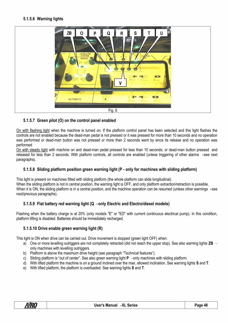
User's Manual – XL Series Page 48
5.1.5.6 Warning lights
Fig. 6
5.1.5.7 Green pilot (O) on the control panel enabled On with flashing light when the machine is turned on. If the platform control panel has been selected and this light flashes the controls are not enabled because the dead-man pedal is not pressed or it was pressed for more than 10 seconds and no operation was performed or dead-man button was not pressed or more than 2 seconds went by since its release and no operation was performed On with steady light with machine on and dead-man pedal pressed for less than 10 seconds; or dead-man button pressed and released for less than 2 seconds. With platform controls, all controls are enabled (unless triggering of other alarms – see next paragraphs).
5.1.5.8 Sliding platform position green warning light (P - only for machines with sliding platform) This light is present on machines fitted with sliding platform (the whole platform can slide longitudinal). When the sliding platform is not in central position, the warning light is OFF, and only platform extraction/retraction is possible. When it is ON, the sliding platform is in a central position, and the machine operation can be resumed (unless other warnings – see next/previous paragraphs).
5.1.5.9 Flat battery red warning light (Q – only Electric and Electro/diesel models) Flashing when the battery charge is at 20% (only models "E" or "ED" with current continuous electrical pump). In this condition, platform lifting is disabled. Batteries should be immediately recharged.
5.1.5.10 Drive enable green warning light (R) This light is ON when drive can be carried out. Drive movement is stopped (green light OFF) when:
a) One or more levelling outriggers are not completely retracted (did not reach the upper stop). See also warning lights ZB –
only machines with levelling outriggers. b) Platform is above the maximum drive height (see paragraph “Technical features”).
c) Sliding platform is “out of center”. See also green warning light P – only machines with sliding platform.
d) With lifted platform the machine is on a ground inclined over the max. allowed inclination. See warning lights S and T. e) With lifted platform, the platform is overloaded. See warning lights S and T.

User's Manual – XL Series Page 49
5.1.5.11 Danger red warning light (S) It flashes quickly for 4 seconds together with the alarm at the machine start-up in case of fault during safety test on controls (pedal, joystick control, switches, etc) during machine start-up. It is lit up steady together with an acoustic alarm when the chassis inclination exceeds the allowed angle. Lifting and platform extractions are disabled (in case of electric control). If platform is lifted, drive is also disabled. It is necessary to lower the platform completely and then place the machine onto a flat surface.
PLEASE NOTE!
The activation of this indicator warns of a dangerous situation since the machine has reached a dangerous inclination level for the machine stability.
5.1.5.12 Lifting enable green warning light (T) This light is ON when lifting can be carried out, i.e. when:
a) All or none of the pads are resting on the ground (no pads resting means that the machine rests on its wheels). See also warning lights ZB – only machines with levelling outriggers.
b) Sliding platform is in retracted position. See also warning light R – only machines with sliding platform.
c) Machine is in levelled position. See also warning light S. d) Overload alarm is not present. See also warning light U.
e) Flat battery alarm is not present. See also warning light Q – only models “E ”and “ED”.
5.1.5.13 Overload red warning light (U) On steady and activation of audible alarm with a platform overload exceeding 20% the rated load. If the platform is lifted, the machine is completely locked. If the platform is completely lowered all driving/steering operations are still possible but lifting is stopped. Remove the excess load before reusing the machine again. Fast flashing in case of fault in the overload control system. With lifted platform the machine is completely deactivated and stopped.
PLEASE NOTE!
The activation of this indicator is a synonym of danger since the load at the platform is exceeding or no load control is active upon signal.
For adjustment or activation in emergency situations read the MAINTENANCE chapter.
5.1.5.14 Diesel engine fault / low fuel red warning light (V) This warning light indicates malfunctioning of the diesel engine or low fuel. On with steady light when: the machine is on; platform controls are activated and Diesel power is selected. Diesel engine off, ready for start-up. Insufficient engine oil pressure. Slow flashing in the event of the engine head overheating (optional function). If on, it stops the diesel engine; if off, it prevents the diesel engine from starting. Quickly flashing when the fuel is running low. This warning is active only when the engine is running. Double fast flashing when the fuse on the electric fan of the air/oil exchanger (if present) is burnt out. PLEASE NOTE! Change the fuse. Danger of overheating of hydraulic oil.

User's Manual – XL Series Page 50
5.2 Ground control panel and electric control unit The ground control panel (or electric central unit - fig. 6) contains the main electronic boards necessary to operate the machine and to carry out safety checks. The ground control panel is located on the chassis (see paragraph "Location of main components") and is used to: Turn the machine on/off. Select the control panel (ground or platform). Operate the platform in emergency cases. Display some operation parameters (working hours; Diesel engine operational faults; battery charger operation; etc.).
DO NOT use the on-ground control panel as a workstation when personnel is on the platform.
Strictly use the on-ground control panel to start/stop the machine, to select the control panel or in emergency situations to allow the platform to be recovered.
Give the keys to authorized persons only and keep a duplicate in a safe place. Always remove the on/off key at the end of work shifts.
Access to the controllers is allowed to specialized personnel only for maintenance and/or repair purposes. Access the electric control unit only after the machine has been disconnected from any 230V or 380V power sources.
Fig. 7
A) ON-OFF key and control panel selector (ground/platform) B) Emergency STOP button C) DIESEL/ELECTRIC drive power selector D) Heat engine starting button (models “D ”and “ED”) E) User interface display F) Battery charger warning light (models “E ”and “ED”) G) Enabled control panel warning light H) Alternator warning light (models “D ”and “ED”) L) Oil warning light (models “D ”and “ED”) M Air filter warning light (models “D ”and “ED”)
User's Manual – XL Series Page 51
N) Motor head temperature warning light (models “D ”and “ED”) O) Lifting/lowering lever P) Front slide-out extension deck extension/retraction lever (OPTIONAL) Q) Rear slide-out extension deck extension/retraction lever (OPTIONAL) R) Sliding platform extension/retraction lever (OPTIONAL)
5.3.1. On-off key and control panel selector (A)
The on-off key located on the ground control panel is used to: start the machine by selecting one of the two control panels:
platform control panel enabled with locking key switch set to the "platform" icon. Stable key position with possibility to extract the key.
Ground controls enabled (for emergency operations) with key switch set to “chassis ”symbol. Press-and-hold function When the key is released the machine is off.
Turn OFF the control circuits by turning it to OFF.
5.3.2. Emergency stop button (B) By pressing this button the machine (as well as the heat engine on models "D", "ED" and "EB") is completely stopped. By rotating it of 1/4 turn (clockwise) the machine can be turned ON by means of the ON-OFF key.
5.3.3. Diesel/electric power selector (C) Holding the ON-OFF key in position “ground controls ”it is possible to select the type of power for the ground controls: If ELECTRIC is selected and the ON-OFF key is kept active in position “ground controls ”the electrical pump is started while
operating the ground controls. If DIESEL is selected and the ON-OFF key is kept active in position “ground controls ”the Diesel engine can be started.
5.3.4. Gasoline engine switch (D) Holding the ON-OFF key in position “ground controls ”after selecting the DIESEL power, the diesel engine can be started by means of the relevant switch. In “0 ”position the Diesel engine is off. In “3 sec ”position the plugs pre-heating takes place (only for engines with plugs). In the “Start ”position the engine starts.

User's Manual – XL Series Page 52
5.3.5. User interface display (E)
The multifunction display for machine/user interface is used to: Display the operation parameters of the machine during normal functioning or in the event of a fault. Working hours of Diesel engine (when Diesel power is selected the working hours are displayed in the format HOURS:
MINUTES and final letter D). Working hours of the work pump (when electric power is selected the working hours are displayed in the format
HOURS:MINUTES and final letter E). Charge level of the battery (only electrical models E).
The user interface display is also used during any interventions by specialized personnel to adjust the working parameters of the machine. This function is not available to the user.
5.3.6. Battery charger warning light (F) Electric power and bi-fuel models (“E”, “ED ”and “EB”), equipped with a built-in high frequency battery charger, are provided with this warning light indicating the operation of the battery charger (for more detailed information read the paragraph “Battery charge”).
5.3.7. Enabled control panel warning light (G) The green warning light ON indicates that the machine is ON and the ground control station is enabled (main key should be kept in “chassis ”position).
5.3.8. Diesel engine warning lights (G-H-L-M-N) These warning lights warn the user of any Diesel engine operational faults (models “D ”and “ED”). One of these warning lights turns ON when the engine is stopped. A “fault ”message is sent to the operator on the platform (see paragraph “Platform control panel”). Once the Diesel engine has stopped due to a problem signalled by one of these warning lights, the engine can no longer be re-started until such problem has been solved.
5.3.9. Platform control levers (O-P-Q-R) The various levers shown in the figure allow the platform to be operated. According to the various signs the corresponding movements are activated. These controls can be operated only if the on-off key is set to ON down (ground control panel selected). Please be reminded that the on-ground controls are to be used to operate the platform only in emergency situations and should not be used for any other purpose.
Use the ground controls only in emergency situations to allow the platform to be lowered. IT IS FORBIDDEN to use the ground control station as a workstation when personnel is on the platform.

User's Manual – XL Series Page 53
5.4 Boarding the platform The “boarding position ”is the only position from which loading or unloading of persons and materials is allowed. The “boarding position ”is with the platform completely lowered.
To board the platform: climb the ladder holding on to the steps, the ladder uprights
or the entry rail uprights; Raise the bar and get on board. Check that, once you are on the platform, the bar falls down closing the access. Fasten the safety harness to the special hooks provided for this purpose.
To board the platform strictly use the special facilities installed on the platform. When moving up or down, always keep your eyes on the machine and hold onto the entry stringers.
DO NOT lock the closing bar so as to keep the platform boarding gate open.
DO NOT leave or board the work platform if this is not in the position required for boarding or leaving.
Fig. 8
5.5 Machine start-up To start the machine the operator shall:
Release the emergency stop button on the ground control panel by rotating it of 1/4 turn clockwise. Turn the on-off key on the on-ground control panel to the "Platform" position. Remove the starting key and hand it over to a person in charge on ground, properly informed of the use of the emergency
controls. Close the protection cover (if available). Board the platform. Release the stop button on the platform control panel (see previous paragraphs).
For ELECTRIC propulsion machines (models “E”), at this point the various functions can be performed by thoroughly following
the instructions given in the previous paragraphs. The machine won't start until the battery charger is disconnected from the power supply. While the battery is being charged, the machine is off and cannot be operated. On dual propulsion models (Electric/Diesel) (models “ED ”or “EB”), it is necessary to select the power supply type by means
of the selector. To use the electric propulsion once this option has been selected the operator can start performing the various functions by following the instructions given in the previous paragraphs. To use the thermic propulsion read the next paragraphs to start the heat engine.
For DIESEL propulsion machines (models “D”) read the following paragraphs concerning the heat engine start-up procedure.
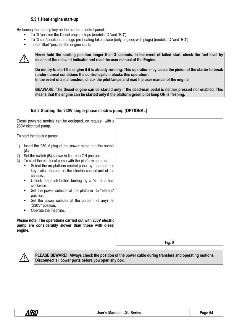
User's Manual – XL Series Page 54
5.5.1. Heat engine start-up
By turning the starting key on the platform control panel: To “0 ”position the Diesel engine stops (models “D ”and “ED”). To “3 sec ”position the plugs pre-heating takes place (only engines with plugs) (models “D ”and “ED”). In the “Start ”position the engine starts.
Never hold the starting position longer than 3 seconds. In the event of failed start, check the fuel level by means of the relevant indicator and read the user manual of the Engine. Do not try to start the engine if it is already running. This operation may cause the pinion of the starter to break (under normal conditions the control system blocks this operation). In the event of a malfunction, check the pilot lamps and read the user manual of the engine. BEAWARE: The Diesel engine can be started only if the dead-man pedal is neither pressed nor enabled. This means that the engine can be started only if the platform green pilot lamp ON is flashing.
5.5.2. Starting the 230V single-phase electric pump (OPTIONAL)
Diesel powered models can be equipped, on request, with a 230V electrical pump. To start the electric pump: 1) Insert the 230 V plug of the power cable into the socket
(A). 2) Set the switch (B) shown in figure to ON position. 3) To start the electrical pump with the platform controls:
Select the on-platform control panel by means of the key-switch located on the electric control unit of the chassis.;
Unlock the push-button turning by a ¼ of a turn clockwise.
Set the power selector at the platform to "Electric" position.
Set the power selector at the platform (if any) to "230V" position.
Operate the machine.
Please note: The operations carried out with 230V electric pump are considerably slower than those with diesel engine.
Fig. 9
PLEASE BEWARE!! Always check the position of the power cable during transfers and operating motions. Disconnect all power ports before you open any box.

User's Manual – XL Series Page 55
5.5.3. Starter for the 3-phase electric pump (OPTIONAL).
Diesel powered models can be equipped, on request, with a 380V three-phase electrical pump. To start the three-phase electrical pump: 1) Insert the 380 V plug of the power cable into socket (A)
on the chassis. 2) Set the switches (C) shown in figure to ON position. 3) Set the angular red switch (F) to ON turning it
downwards or upwards. If the connection has been successfully carried out it is possible to start the electrical pump as indicated in next paragraphs. On the contrary, in the event of a phase fault in the electric power the alarm is automatically enabled, and the electrical pump cannot be started. In this case it is possible to compensate the power phases by turning the angular red switch (F) on the electric case by 90°.
4) To start the electrical pump with the platform controls: Select the on-platform control panel by means of the
key-switch located on the electric control unit of the chassis;
Unlock the push-button turning by a ¼ of turn clockwise.
Set the power selector to "Electric" position. Select the 380V power with selector. Press the push-button (H). When on, the green pilot
indicates that the three-phase electrical pump is turned on.
Wait 5 seconds before moving the machine. 5) To stop the electrical pump press button (H) again.
Fig. 10
Please note: The platform with 380V three-phase power can be operated only from the platform. The operations carried out with 380V electrical pump are considerably slower than those with diesel engine.
BEAWARE: The electric pump can be started only if the dead-man pedal and button are neither pressed nor enabled. This means that the electrical pump can be started only if the platform green warning light ON is flashing.
PLEASE BEWARE!! Always check the position of the power cable during transfers and operating motions. Disconnect all power ports before you open any box.

User's Manual – XL Series Page 56
5.6 Stopping the machine
5.6.1. Normal stop In normal operating conditions:
Release the controls to discontinue the operation and stop the machine. The machine will come to a complete stop occurs within a default time set by the factory in order to ensure smooth braking.
By releasing the dead-man pedal located on the platform, the operation is immediately stopped. In the event of an immediate stop, braking is sudden.
5.6.2. Emergency stop button If needed, the operator may stop all machine functions at once using either the controls on the platform or those on-ground (control board). From the control station on board on the platform:
Press the emergency stop button on the control panel to turn the machine off; By releasing the dead-man pedal, the operation is immediately stopped. Braking may cause some sudden and jerky
motion in case of safety immediate stops. From the control board on ground:
Press the emergency stop button and the machine (all models) and the heat engine (models “D”, “ED”, “EB”) are stopped; Press the power stop button (if available – “ E ”models), thus cutting out machine power (power circuit cut-out).
To retrieve normal operation: On the platform control panel turn the stop button by a ¼ of a turn clockwise. From the control board on ground:
Turn the stop button (if available) of 1/4 turn clockwise. Pull out the mushroom button on the power circuit (if available) until it locks in position to power the unit again.
5.6.3. Stopping the diesel engine To stop the diesel engine: From the control station on board on the platform:
Turn the starting key anti-clockwise to "0" position. Otherwise, press the emergency stop button (mushroom).
From the control board on ground: Turn the starter key to position “0”. Otherwise, press the emergency stop button (mushroom).
Do not stop the engine when the r.p.m. is high. Before stopping the engine wait until the r.p.m. is at the lowest.

User's Manual – XL Series Page 57
5.6.4. Stopper of the 380V three-phase or 230V single-phase electrical pump (optional) To stop the electrical pump (optional): From the control station on board of the platform:
Press the switch-off button; Otherwise, press the emergency stop button (mushroom).
From the control board on ground: Press the emergency stop button (mushroom).
5.7 Emergency manual pump
This function is to be used only in emergency situations when no other source of supply is available.
Fig. 11
In case of fault in the electric or hydraulic system, carry out the following emergency procedures.
EV5M
S
M M
S
M

User's Manual – XL Series Page 58
5.7.1. Platform emergency descent
Open the cowling and locate the components shown in the previous figure. Insert the specially provided lever on the manual pump handle.
For platform EMERGENCY LOWERING operate the manual pump and simultaneously the manual operator marked with EV5M. THE EMERGENCY LOWERING CONTROL CAN BE STOPPED AT ANY TIME BY RELEASING THE MANUAL OPERATOR MARKED WITH EV5AM.
5.7.2. Other emergency operations For OTHER EMERGENCY OPERATIONS:
Open the cowling and locate the components shown in the above figure. Insert the specially provided lever on the manual pump handle. Completely unscrew the knurled knob of the solenoid valve corresponding to the desired movement according to the
following table. Activate the emergency pump. Check the correct execution of this procedure.
Solenoid valve abbreviations (M) and relevant platform operations: EV6 = Front platform extraction (or forward sliding of sliding platform) EV7 = Front platform retraction (or backward sliding of sliding platform) EV36 = Rear platform extraction EV37 = Rear platform retraction Following the same sequence previously described, also the pads of the levelling outriggers can be operated manually. Such procedure shall be carried out only with platform completely lowered and with no operators on board. Solenoid valve abbreviations (S) and relevant levelling outriggers operations: EV21 front left levelling outrigger pad lifting EV22 front left levelling outrigger pad lowering EV23 front right levelling outrigger pad lifting EV24 front right levelling outrigger pad lowering EV25 rear left levelling outrigger pad lifting EV26 rear left levelling outrigger pad lowering EV27 rear right levelling outrigger pad lifting EV28 rear right levelling outrigger pad lowering
PLEASE NOTE! IT IS ABSOLUTELY FORBIDDEN TO ACTIVATE THE EMERGENCY CONTROLS OF THE LEVELLING OUTRIGGERS WITH PLATFORM NOT IN REST POSITION. RISK OF MACHINE OVERTURN!
Once the emergency manoeuvres have been carried out, the knurled knobs must be set to their initial position again in order to resume the operations (in normal position the knobs are completely screwed).

User's Manual – XL Series Page 59
5.8 Socket for electric tool connection (optional)
The work platform can be equipped with a socket (230V Ac) allowing the attachment of any electric tool needed to carry out the various operations. To activate the electric line (see pictures above) introduce a cable into the plug connected to the 230V AC 50 Hz mains, with all protections according to the current standards in force. If there is the circuit breaker switch (optional), to activate the electric line set the switch to ON position. It is advisable to check the earth-leakage circuit breaker by means of the specially provided TEST button. The plugs and sockets equipped on standard machines comply with EC standards and can therefore be used in EU member countries. On request the machine can be equipped with plugs and sockets in compliance with local standards or with particular needs.
Fig. 12
Connect to power supplies of the following type:
Power voltage 230V ± 10% Frequency 50÷60 Hz Earthing Safety and protection devices
according to current standards in force.
Do not use extension cables exceeding 5 m length.
Use a cable of a suitable section (min 3x2.5 mm2).
Do not use rolled-up cables.
5.9 Fuel level and re-fuelling (models “ED”, “D”) Before using the diesel engine check the fuel level in the tank. This operation is to be carried out by visually checking the fuel level after unscrewing the filling cap.
Visually check the fuel level before starting to work. Keep the fuel tank and the engine clean.

User's Manual – XL Series Page 60
5.10 End of a work day After stopping the machine according to the instructions given in the previous paragraphs:
Always set the machine to rest position (platform completely lowered). Press the emergency Stop button on the on-ground control panel. Remove the keys from the control panel to prevent unauthorized people from using the machine. Recharge the battery according to the instructions given in section "Maintenance" (models “E ”and “ED ”only). To fill the tank (if it applies).

User's Manual – XL Series Page 61
6. HANDLING AND TRANSPORTATION
6.1 Handling To handle the machine in normal operating conditions follow the instructions given in chapter "USE INSTRUCTIONS" under paragraph "Drive and steering”. When the platform is completely lowered (or up to a height set according to different needs and tests) the machine can be handled (i.e. drive can be performed) at different speeds to be freely selected by the user. With platform at a given height, the drive speed is automatically limited, and cannot be changed. The section TECHNICAL FEATURES indicates the limits concerning drive for each model.
PLEASE NOTE! Driving with the lifted platform may be subject to different restrictions according to the country where the machine is used. Find out about the legislative limits concerning this operation from Health and Safety Authorities at your place.
It is absolutely forbidden to travel with the machine when the platform is lifted unless the ground is horizontal, flat and solid.
Before carrying out any travel, make sure that no people are in the proximity of the machine and in any case proceed with the utmost caution.
Backward drive (in the direction of the fixed wheels) does not allow the operator on the control panel a complete visibility. Use extreme care for this operation.
Before moving the machine make sure that all connections are disconnected from the power supply source.
Check that there are no holes and/or steps on the floor and bear in mind machine overall dimensions.
Do not use the machine to tow other vehicles.
Do not load anything on the platform while the platform is up and the machine travels (operators on board are not allowed to pull wires or ropes, etc.).
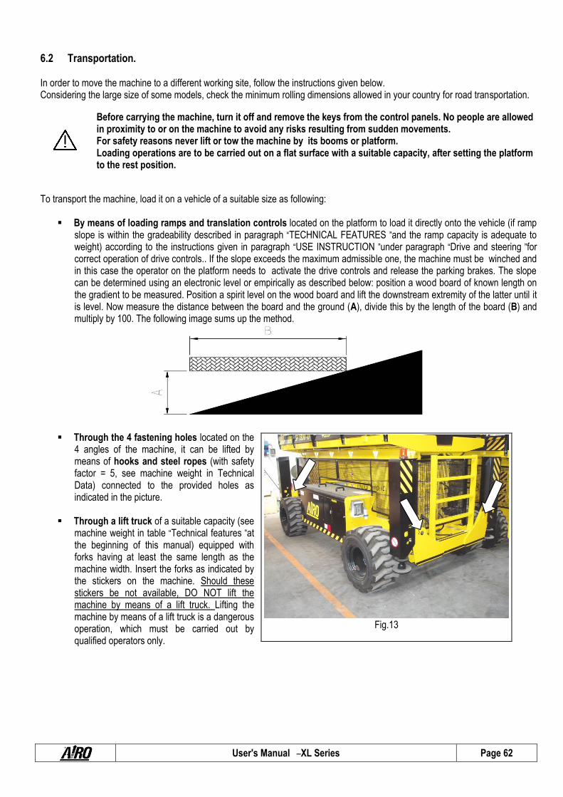
User's Manual – XL Series Page 62
6.2 Transportation. In order to move the machine to a different working site, follow the instructions given below. Considering the large size of some models, check the minimum rolling dimensions allowed in your country for road transportation.
Before carrying the machine, turn it off and remove the keys from the control panels. No people are allowed in proximity to or on the machine to avoid any risks resulting from sudden movements. For safety reasons never lift or tow the machine by its booms or platform. Loading operations are to be carried out on a flat surface with a suitable capacity, after setting the platform to the rest position.
To transport the machine, load it on a vehicle of a suitable size as following:
By means of loading ramps and translation controls located on the platform to load it directly onto the vehicle (if ramp slope is within the gradeability described in paragraph “TECHNICAL FEATURES ”and the ramp capacity is adequate to weight) according to the instructions given in paragraph “USE INSTRUCTION ”under paragraph “Drive and steering ”for correct operation of drive controls.. If the slope exceeds the maximum admissible one, the machine must be winched and in this case the operator on the platform needs to activate the drive controls and release the parking brakes. The slope can be determined using an electronic level or empirically as described below: position a wood board of known length on the gradient to be measured. Position a spirit level on the wood board and lift the downstream extremity of the latter until it is level. Now measure the distance between the board and the ground (A), divide this by the length of the board (B) and multiply by 100. The following image sums up the method.
Through the 4 fastening holes located on the 4 angles of the machine, it can be lifted by means of hooks and steel ropes (with safety factor = 5, see machine weight in Technical Data) connected to the provided holes as indicated in the picture.
Through a lift truck of a suitable capacity (see
machine weight in table “Technical features ”at the beginning of this manual) equipped with forks having at least the same length as the machine width. Insert the forks as indicated by the stickers on the machine. Should these stickers be not available, DO NOT lift the machine by means of a lift truck. Lifting the machine by means of a lift truck is a dangerous operation, which must be carried out by qualified operators only.
Fig.13

User's Manual – XL Series Page 63
After placing the machine onto the carrying vehicle, fasten it by means of the same holes used for lifting. To avoid breaking the platform overload controller, thus causing the machine to stop, DO NOT fix the machine onto a vehicle platform by tying-up the platform or the last lifting boom. PLEASE MIND THIS INSTRUCTION FOR ALL MODELS
Before transporting the machine its stability. The platform must be fully lowered and the platform extension must be in retracted position to ensure adequate stability during the entire operation.

User's Manual – XL Series Page 64
6.2.1. Fold-down rails The machine is equipped with rails which can be folded down to the inside of the platform. Folding down the rails it is possible to reduce the height of the machine for:
Transport. Passage through lowered areas (e.g. doors)
To fold down the rails follow this procedure: 1) Remove the control panel from the front rail. 2) Unlock the two locks of the front rail by pulling the knob A
to the inside. 3) Fold down the front rail to the inside and repeat steps 2)
and 3) for the rail of the entrance area. 4) Lift and turn the side rails B with a coupling pin to the
inside.; 5) Lift and turn the side rails C to the inside.
Fig. 14
PLEASE BEWARE!! The sole purpose of this operation is to reduce the height of the closed machine to facilitate transport operations. IT IS ABSOLUTELY FORBIDDEN to lift the platform when personnel is on board if rails are not raised and locked by their relevant latches.
PLEASE BEWARE!! On machines with dual slide-out extension deck it is ABSOLUTELY FORBIDDEN to control the extraction / retraction of the platforms if rails are not raised.

User's Manual – XL Series Page 65
6.3 Emergency tow-away of the machine In the event of a fault, carry out the following operations to tow the machine:
A) FOR XL11 and XL14:
Hook the machine to the provided holes. Completely screw the threaded dowels at the centre
of the drive reduction gears by means of a 6 mm hexagonal wrench.
Tow at a very slow speed (remember that when the machine is being towed, brakes are out of service).
Fig.15
B) FOR XL16 and XL19 :
Hook the machine to the provided holes. Disengage the drive wheels ( 2 or 4) by acting on
drive reduction gears in the following manner: Reduction gear Type 1: - Loosen the two screws (A) in the centre with a 10 mm wrench for hex head and slide on the slots the cover (B) of the reduction gears; then remove the pin (C) placed at the centre of the reduction gears; - Reposition the pin in the reduction gears in the reverse order in their seat; - Restore the cover and tighten the screws; Reduction gear Type 2: - Remove the centre cover with a ¾ " hex key; - Remove the centre pin with the help of an M6 screw ; - Replace the cover.
Tow at a very slow speed (remember that when the machine is being towed, brakes are out of service).
Type 1
Type 2
Fig.16
PLEASE NOTE! THIS OPERATION MAY CAUSE OIL LEAKAGE FROM THE DRIVE REDUCTION GEARS. To restart normal operation, set the machine back to the initial conditions and, if necessary, top up the oil level inside the drive reduction gears (XL16 XL19).
Tow at a very slow speed (remember that when the machine is being towed, brakes are out of service). Tow only on a flat ground. Do not park the machine without brakes on. Should the brakes be completely out of order put wedges under the wheels to prevent the machine from moving accidentally.

User's Manual – XL Series Page 66
7. MAINTENANCE
Always carry out maintenance operations with machine at standstill, after having removed the key from the control panel, and with the platform in rest position.
The maintenance operations described here below refer to a machine in ordinary working conditions. In case of difficult operating conditions (extreme temperatures, corrosive environments, etc.) or following long non-use, contact AIRO customer service to adjust the maintenance schedule.
Repairs and maintenance operations are to be carried out by trained and authorised personnel only. All maintenance operations should be carried out in compliance with the actual work safety regulations (safety at work places, personal protection equipment, etc...).
Carry out only the maintenance and adjustment operations described in this user manual. In emergency situations (e.g. breakdown, wheels replacement) contact our Technical Service
During maintenance interventions, the machine must be completely locked. Before carrying out maintenance operations inside the lifting equipment, check that this is off-line in order to avoid accidental lowering of the booms (chapter "Safety lock").
Remove the battery cables and provide batteries with a suitable protection during welding operations. Carry out maintenance operations on the heat engine only when it is not running and sufficiently cool
(except for those operations, such as oil change, which must be performed when the engine is hot). Risk of burns in contact with hot parts.
Do not use petrol or other flammable materials to clean the heat engine. For maintenance operations on the heat engine, read the manufacturer's manual of the engine supplied
on machine purchase. In case of replacement, use original spare parts only. For parts that are not original please ask the
manufacturer for prior approval. Disconnect the 230V AC and/or 380V AC sockets, if any. The lubricants, hydraulic oils, electrolytes and all detergent products should be handled with care and
disposed of in safety according to the current regulations. Prolonged contact with the skin may cause forms of irritation and skin diseases; wash with water and soap and rinse well. Also contact with the eyes, especially with the electrolytes, is dangerous; wash with water and see a doctor.
PLEASE NOTE! NEVER MODIFY OR TAMPER WITH MACHINE PARTS TO IMPROVE THE MACHINE PERFORMANCE AS
THIS MAY AFFECT ITS SAFE OPERATION.

User's Manual – XL Series Page 67
7.1 Safety lock for maintenance operations Before carrying out any maintenance or repairs to it, activate the lifting structure locking system (by placing safety lock as shown in figure).
7.2 Machine cleaning To clean the machine use non-pressurized water jets after properly protecting the following parts: The control panel (both platform and ground); The electric ground control unit and all electric boxes in general; The electric motors.
Do not use pressurized water jets (high-pressure cleaners) to clean the machine.
After washing the machine, always: Dry the machine. Check integrity of plates and stickers. Lubricate the articulated joints equipped with greaser and the sliding ways.
Fig. 17
SF920 SF1200 SF1380
SF1700
XL11 XL14 XL16
XL19
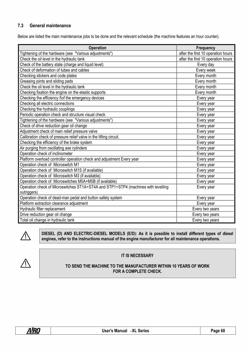
User's Manual – XL Series Page 68
7.3 General maintenance Below are listed the main maintenance jobs to be done and the relevant schedule (the machine features an hour counter).
Operation Frequency
Tightening of the hardware (see "Various adjustments") after the first 10 operation hours
Check the oil level in the hydraulic tank after the first 10 operation hours
Check of the battery state (charge and liquid level) Every day
Check of deformation of tubes and cables Every week
Checking stickers and code plates Every month
Greasing joints and sliding pads Every month
Check the oil level in the hydraulic tank Every month
Checking fixation the engine on the elastic supports Every month
Checking the efficiency fìof the emergency devices Every year
Checking all electric connections Every year
Checking the hydraulic couplings Every year
Periodic operation check and structure visual check Every year
Tightening of the hardware (see "Various adjustments") Every year
Check of drive reduction gear oil change Every year
Adjustment check of main relief pressure valve Every year
Calibration check of pressure relief valve in the lifting circuit. Every year
Checking the efficiency of the brake system Every year
Air purging from oscillating axe cylinders Every year
Operation check of inclinometer Every year
Platform overload controller operation check and adjustment Every year Every year
Operation check of Microswitch M1 Every year
Operation check of Microswitch M1S (if available) Every year
Operation check of Microswitch M3 (if available) Every year
Operation check of Microswitches M5A+M5B (if available) Every year
Operation check of Microswitches ST1A÷ST4A and STP1÷STP4 (machines with levelling outriggers)
Every year
Operation check of dead-man pedal and button safety system Every year
Platform extraction clearance adjustment Every year
Hydraulic filter replacement Every two years
Drive reduction gear oil change Every two years
Total oil change in hydraulic tank Every two years
DIESEL (D) AND ELECTRIC-DIESEL MODELS (E/D): As it is possible to install different types of diesel engines, refer to the instructions manual of the engine manufacturer for all maintenance operations.
IT IS NECESSARY
TO SEND THE MACHINE TO THE MANUFACTURER WITHIN 10 YEARS OF WORK FOR A COMPLETE CHECK.

User's Manual – XL Series Page 69
7.3.1. Adjustments Check the conditions of the following components and, if necessary, tighten after the first 10 working hours and, afterwards, at least once a year: 1) Wheel screws 2) Drive engine, fixation screws 3) Steering cylinder fixing screws 4) fixing screws of platforms and rails; 5) Hydraulic fittings 6) Lock pins and safety dowels of boom pins 7) Elastic supports of heat engine 8) Sliding platform counter bearings For torque. please refer to the table below.
SCREW TORQUE (metric thread, normal pitch)
Class 8.8 (8G) 10.9 (10K) 12.9 (12K)
Diameter kgm Nm kgm Nm kgm Nm
M4 0.28 2.8 0.39 3.9 0.49 4.9
M5 0.55 5.5 0.78 7.8 0.93 9.3
M6 0.96 9.6 1.30 13.0 1.60 16.0
M8 2.30 23.0 3.30 33.0 3.90 39.0
M10 4.60 46.0 6.50 65.0 7.80 78.0
M12 8.0 80.0 11.0 110 14.0 140
M14 13.0 130 18.0 180 22.0 220
M16 19.0 190 27.0 270 33.0 330
M18 27.0 270 38.0 380 45.0 450
M20 38.0 380 53.0 530 64.0 640
M22 51.0 510 72.0 720 86.0 860
M24 65.0 650 92.0 920 110 1100
Fig. 18
1-2
4 4 8
3
6
1-2 7 5

User's Manual – XL Series Page 70
7.3.2. Greasing Grease all articulated joints equipped with greaser (or provision for greaser attachment) at least every month. At least once a month with a spatula or a brush, it is recommended to lubricate the sliding guides:
a) Sliding blocks/rolls of the extension structure on the chassis.
b) Sliding blocks/rolls of the extension structure under the platform.
c) Counter-pressure sliding blocks/rolls of the mobile platform.
Moreover, remember to grease the articulated joints in the following cases:
After washing the machine Before using the machine again after a
long time-interval. After using the machine in adverse
environmental conditions (high humidity levels; presence of dust; coastal areas, etc).
Before greasing clean properly with a wet cloth. Grease all points indicated in the picture aside (and all articulated joints equipped with greaser) with grease type ESSO BEACON-EP2 or similar.
(OPTIONAL BIODEGRADABLE OIL KIT) PANOLIN BIOGREASE 2
Fig. 19

User's Manual – XL Series Page 71
7.3.3. Checking and changing the hydraulic oil After the first 10 working hours and, afterwards, at least once a month, check the level by means of the provided cap (A) equipped with a dipstick; always make sure that the level lies between the max. and min. values. If necessary top up until max. level is reached. The oil check should be carried out when platform is completely lowered, with sliding platform in central position (if present) and with outriggers completely retracted (if present). Completely change the hydraulic oil at least every two years. To empty the tank:
Lower the platform completely. Place sliding platform in central position (if present). Retract the outriggers completely (if present). stop the machine by pressing the emergency stop
button on the ground control panel place a container under cap (B), under the tank, and
unscrew it. Use only the oil types and quantity indicated in the table below.
HYDRAULIC SYSTEM OIL
BRAND TYPE
-20°C +79°C
TYPE
-30°C +48°C REQUIRED QUANTITY
SYNTHETIC OILS
See chapter "Technical features".
ESSO Invarol EP46 Invarol EP22
AGIP Arnica 46 Arnica 22
ELF Hydrelf DS46 Hydrelf DS22
SHELL Tellus SX46 Tellus SX22
BP Energol SHF46 Energol SHF22
TEXACO Rando NDZ46 Rando NDZ22
Q8 LI HVI 46 LI HVI 22
PETRONAS HIDROBAK 46 HV HIDROBAK 22 HV
BIODEGRADABLE OILS - OPTIONAL
PANOLIN HLP SINTH E46 HLP SINTH E22
Do not dispose of used oil in the environment. Comply with the current local standards.
The lubricants, hydraulic oils, electrolytes and all detergent products should be handled with care and disposed of in safety according to the current regulations. Prolonged contact with the skin may cause forms of irritation and skin diseases; wash with water and soap and rinse well. Also contact with the eyes, especially with the electrolytes, is dangerous; wash with water and see a doctor.
Fig. 20
B A
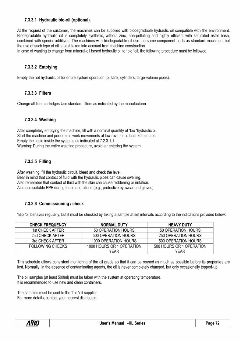
User's Manual – XL Series Page 72
7.3.3.1 Hydraulic bio-oil (optional). At the request of the customer, the machines can be supplied with biodegradable hydraulic oil compatible with the environment. Biodegradable hydraulic oil is completely synthetic, without zinc, non-polluting and highly efficient with saturated ester base, combined with special additives. The machines with biodegradable oil use the same component parts as standard machines, but the use of such type of oil is best taken into account from machine construction. In case of wanting to change from mineral-oil based hydraulic oil to “bio ”oil, the following procedure must be followed.
7.3.3.2 Emptying Empty the hot hydraulic oil for entire system operation (oil tank, cylinders, large-volume pipes).
7.3.3.3 Filters Change all filter cartridges Use standard filters as indicated by the manufacturer.
7.3.3.4 Washing
After completely emptying the machine, fill with a nominal quantity of “bio ”hydraulic oil. Start the machine and perform all work movements at low revs for at least 30 minutes. Empty the liquid inside the systems as indicated at 7.2.3.1.1. Warning: During the entire washing procedure, avoid air entering the system.
7.3.3.5 Filling
After washing, fill the hydraulic circuit, bleed and check the level. Bear in mind that contact of fluid with the hydraulic pipes can cause swelling. Also remember that contact of fluid with the skin can cause reddening or irritation. Also use suitable PPE during these operations (e.g., protective eyewear and gloves).
7.3.3.6 Commissioning / check
“Bio ”oil behaves regularly, but it must be checked by taking a sample at set intervals according to the indications provided below:
CHECK FREQUENCY NORMAL DUTY HEAVY DUTY
1st CHECK AFTER 50 OPERATION HOURS 50 OPERATION HOURS
2nd CHECK AFTER 500 OPERATION HOURS 250 OPERATION HOURS
3rd CHECK AFTER 1000 OPERATION HOURS 500 OPERATION HOURS
FOLLOWING CHECKS 1000 HOURS OR 1 OPERATION YEAR
500 HOURS OR 1 OPERATION YEAR
This schedule allows consistent monitoring of the oil grade so that it can be reused as much as possible before its properties are lost. Normally, in the absence of contaminating agents, the oil is never completely changed, but only occasionally topped-up. The oil samples (at least 500ml) must be taken with the system at operating temperature. It is recommended to use new and clean containers. The samples must be sent to the “bio ”oil supplier. For more details, contact your nearest distributor.

User's Manual – XL Series Page 73
Copies of the analysis report must be kept in the check register. This is mandatory. 7.3.3.7 Mixing
Mixtures with other biodegradable oils are not allowed. The remaining amount of mineral oil must not exceed 5% of total filling quantity as long as the mineral oil is suitable for the same use.
7.3.3.8 Micro-filtration
When making the conversion on second-hand machines, always take into account the high dirt dissolution power of biodegradable oil. After conversion from one oil to another, a certain amount of deposits may be dissolved in the hydraulic system. In extreme cases, washing the seal housings can cause greater leaks. To prevent faults as well as avoid any negative effect on the oil quality, clean the hydraulic system using a micro-filtration system after each system conversion to a new oil type.
7.3.3.9 Disposal
The biodegradable oil, inasmuch as saturated ester, is suitable for both thermal and material re-use. It therefore provides the same disposal / re-use options as mineral based old oil. Such oil can be incinerated whenever local laws allow. Recycling the oil is preferable to disposal on dumps or incineration.
7.3.3.10 Topping up
The oil must ONLY EVER be topped up with the same product. Note: Max water contamination is 0.1%.
During oil change or topping up, do not discard the hydraulic oil in the environment.

User's Manual – XL Series Page 74
7.3.4. Hydraulic filter replacement
7.3.4.1 Suction filters All models are equipped with suction filter. It is best to replace it at least every two years. Suction filters can be placed:
Outside the tank (XL11 E - XL14 E). Inside the tank (XL14RTD - XL16 E – SL16 RTD -
XL19 E – XL19 RTD). MODELS XL11 E- XL14 E: The suction filter directly flanged to the tank is equipped with a clogging indicator E indicates the moment when the filtering cartridge is to be cleaned.. When the clogging indicator is in the red zone, the filtering cartridge is to be cleaned or replaced. To dismount the filtering cartridge from the suction filter the operator shall (see picture aside):
Stop the machine by pressing the push-button of the power line.
Remove the cover A of the filter unscrewing the four hexagonal nuts B (13mm wrench) keeping one hand under the bowl C of the filter to prevent it from detaching.
Extract the bowl with the cartridge D. Remove the cartridge D and check its condition. If necessary, clean the filter by means of compressed
air paying attention not to alter the filtering surface. Otherwise replace the cartridge.
Fit the new cartridge paying attention to the correct positioning of the retaining spring F and place the bowl.
It is to be noted that the bowl containing the filtering cartridge is full of oil. Therefore, during these operations a quantity of oil may leak out onto the side floor of the machine. In this case, remove the oil by means of cloths or the outlet holes by placing a suitable container under it.
Fig. 21

User's Manual – XL Series Page 75
MODELS XL16 E - XL19 E:
To replace the suction filters installed inside the tank the operator has to (see picture aside):
Stop the machine by pressing the push-button of the power line.
Disconnect the power cords of the electrical pumps A (XL16 E).
Unscrew the coupling flange B unlocking the screws (5mm Allen wrench) XL16 E
Unscrew the cover of the tank on which the suction tubes are flanged.
Lift the electrical pump and remove it from the tank (the weight of the electrical pump is 25 Kg) XL16 E
Unscrew the filters C from the suction tubes. To restore the initial condition, carry out the above-
mentioned operation in reverse order.
7.3.4.2 Return filters (XXL14 D - XL14 RTD - XL16 E – XL16 RTD - XL19 E – XL19 RTD). The return filter directly flanged on the tank is equipped with a visual clogging indicator. During normal operation, the visual indicator is in the green zone. When the indicator is in the red zone, the filtering cartridge is to be replaced. However, the filtering cartridge should be replaced at least every two years. To replace the filter cartridge:
Stop the machine by pressing the mushroom button on the ground power unit; Remove the cover of the filter unscrewing the four hexagonal screws (10mm wrench). Remove cartridge; Fit the new cartridge paying attention to the correct position of the retaining spring and place the cover back on again.
IT IS FORBIDDEN to start the machine when the filter cover is missing or not properly tightened.
Replace the filters using only original accessories available at our Technical Service. Do not re-use used oil and do not leave it in the environment, but dispose of in compliance with local standards in force. Once the filters have been replaced, check the hydraulic oil level in the tank.
Fig. 22

User's Manual – XL Series Page 76
7.3.5. Drive reduction gear oil level check and change. The oil level should be checked at least once a year. Remove the driving wheels (only for models XL11 and XL14) and place the reduction gears so as to have the two caps A and B in the position shown in the picture aside. The level must be checked by means of cap A. Oil check must be carried out when the oil is hot. The level is correct when the reduction gear body is full of oil up to the cap limit A. Should a lubricant volume higher than 10% be topped up, check that there is no leakage in the group. Do not mix different types of oil, of the same or of different brands. Do not mix mineral oils and synthetic oils. The oil must be changed the first time after 50-100 working hours, and afterwards after every 2500 working hours or at least every two years. Depending on the actual working conditions, these periods may be modified according to the single case. While changing the oil, wash the internal parts of the casing with the fluid recommended by the lubricant producer. To avoid sludge deposits, the oil must be changed when the reduction gear is hot. To change the oil unscrew cap B , and place a container of a 2-litre capacity under it. Empty the reduction gear bodies completely, clean it as described above and then fill it up to the limit level of the cap A through the same hole.
LUBRICATING OIL FOR DRIVE REDUCTION GEARS REQUIRED QUANTITY
BRAND ISO 4438 VG 150-200
XL11 …XL14… XL16 …XL19…
SYNTHETIC OILS
1 litre for each reduction gear
1 litre for each reduction gear
ESSO Compressor oil LG 150 AGIP Blasia S 220 ELF Oritis 125 MS
CASTROL Alpha SN 6
IP Telesia oil 150
BIODEGRADABLE OILS - OPTIONAL
PANOLIN Biogear 80W90
7.3.5.1 Checks in the use of synthetic biodegradable oil in the main reduction gears Quarterly or every 500 hours check the oil level. In case of need top up. If you notice that more than 10% of oil lacks in the reduction gear, check if there are any leaks. Change the oil in the slewing reduction gear after the first 100 hours of operation and then every 6000 hours or every 3 years. Depending on the actual operating conditions, these intervals may change. When changing the oil, run a wash cycle inside the casing. Change the oil when the reduction gear is hot. Mixtures of different oils (either biodegradable or mineral) even of the same brand are not allowed.
During oil change or topping up, do not discard the hydraulic oil in the environment.
Fig. 23
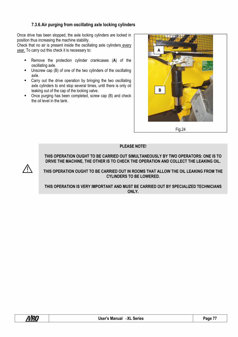
User's Manual – XL Series Page 77
7.3.6. Air purging from oscillating axle locking cylinders Once drive has been stopped, the axle locking cylinders are locked in position thus increasing the machine stability. Check that no air is present inside the oscillating axle cylinders every year. To carry out this check it is necessary to:
Remove the protection cylinder crankcases (A) of the
oscillating axle. Unscrew cap (B) of one of the two cylinders of the oscillating
axle. Carry out the drive operation by bringing the two oscillating
axle cylinders to end stop several times, until there is only oil leaking out of the cap of the locking valve.
Once purging has been completed, screw cap (B) and check the oil level in the tank.
PLEASE NOTE!
THIS OPERATION OUGHT TO BE CARRIED OUT SIMULTANEOUSLY BY TWO OPERATORS: ONE IS TO DRIVE THE MACHINE, THE OTHER IS TO CHECK THE OPERATION AND COLLECT THE LEAKING OIL.
THIS OPERATION OUGHT TO BE CARRIED OUT IN ROOMS THAT ALLOW THE OIL LEAKING FROM THE
CYLINDERS TO BE LOWERED.
THIS OPERATION IS VERY IMPORTANT AND MUST BE CARRIED OUT BY SPECIALIZED TECHNICIANS ONLY.
Fig.24
A
B

User's Manual – XL Series Page 78
7.3.7. Pressure relief valve adjustment and operation check. The pressure relief valve controls the maximum pressure of the hydraulic circuit. Normally, this valve does not require any adjustment, since it is calibrated at the factory before the machine is delivered. The settings of the main pressure relief valve must be checked: after replacement of the hydraulics after replacemente of the pressure relief valve Perform one functional check a year. To check the operation of the main pressure relief valve (see figure aside): Disconnect the power cords of the electrical pumps EV2 and EV3
(A and B). Introduce a pressure gauge with full scale of at least 250 bar in the
special quick coupling (1/4 ”BSP) D Using the platform control panel drive the machine forward and
backward. Initially carry out the manoeuvre softly to check that the above mentioned valves have been disconnected properly (the machine should not move).
Check the detected pressure value. The correct value is indicated in the chapter “Technical features".
To calibrate the pressure relief valve: Disconnect the power cords of the electric pumps EV2 and EV3
(A and B). Introduce a pressure gauge with full scale of at least 250 bar in the
special quick coupling (1/4 ”BSP) D. Locate the main pressure relief valve E. Unscrew the adjusting dowel lock-nut. Using the platform control panel, drive the machine forward or backward, and adjust the pressure relief valve by means of the
adjusting dowel so as to reach the pressure value indicated in chapter "Technical Features". Initially carry out the manoeuvre softly to check that the above mentioned valves have been disconnected properly (the machine should not move).
Once calibration has been carried out, lock the adjusting dowel by means of the lock-nut.
PLEASE NOTE! THIS OPERATION IS VERY IMPORTANT AND MUST BE CARRIED OUT BY SPECIALIZED TECHNICIANS
ONLY.
Fig. 25

User's Manual – XL Series Page 79
7.3.8. Lifting circuit pressure relief valve adjustment The self-propelled platforms, XL series, have a relief pressure valve on the lifting circuit to avoid dangerous overpressure values. Normally, this valve does not require any adjustment, since it is calibrated at the factory before the machine is delivered. The adjustment of the system is required: after replacement of the hydraulics In case of replacement of the pressure relief valve only: Perform a functional control at least once a year. To check the pressure relief valve on the lifting circuit : Introduce a pressure gauge with full scale of at least 250 bar in the
special quick coupling (1/4 ”BSP) D Using the ground control panel lift the pantograph (lower boom) up
to the end stop.
Check the detected pressure value. The correct value should be as stated in the “Technical Data".
To calibrate the pressure relief valve on the lifting circuit: Introduce a pressure gauge with full scale of at least 250 bar in the special quick coupling (1/4 ”BSP) D.
Locate the pressure relief valve of the lifting circuit C. Unscrew the adjusting dowel lock-nut. Perform lifting from the control panel on ground. Keep on lifting up to stroke-end and force a bit. Adjust the pressure relief valve by means of the adjusting dowel so as to reach the pressure value indicated in "Technical
Data". Once calibration has been carried out, lock the adjusting dowel by means of the lock-nut.
PLEASE NOTE! THIS OPERATION IS VERY IMPORTANT AND MUST BE CARRIED OUT BY SPECIALIZED TECHNICIANS
ONLY.
Fig. 26

User's Manual – XL Series Page 80
7.3.9. Braking system efficiency check These valves check the minimum operating pressure during drive (in both running directions) and affect the dynamic braking and the drive speed. These valves do not usually need any adjustment as they were previously calibrated in the workshop before the delivery of the machine. The braking systems stop the machine when the drive controls are released. Once the machine has stopped, the automatic intervention of the parking brakes keeps the machine in position. Perform a functional control at least once a year. To check the operation of the braking system: With platform completely lowered place the machine on a flat
ground, free of obstacles, operate the drive control and when the max. speed is reached, release the control immediately.
The correct operation of the braking system allows the machine to stop in a space lower than 100 cm;
However, the braking system can stop and hold the machine on the slopes indicated in chapter “Technical Features ”(the
braking space on descents is obviously longer; descend at minimum drive speed). The calibration of both braking valves is necessary: In case of replacement of the hydraulic unit A. If one or both braking valves are to be replaced. To calibrate the braking valves: Locate the hydraulic unit called "drive plate". Locate the braking valves B (one for each running direction). Connect a pressure gauge of at least 250-bar scale to the provided quick coupling in the hydraulic control unit (1/4" BSP). Select the minimum drive speed on the platform control box; Unscrew the lock-nuts C of the adjusting dowels. Using the platform control station drive the machine (in the direction influenced by the action of the valve) on a flat ground and
straight running, and adjust the braking valve (concerning that direction of running) acting on the adjusting dowel D to obtain the required pressure value (call the nearest Customer Service to request this information)
Once the required pressure value has been achieved, check that the valve controlling the braking in the opposite direction has maintained its adjustment.
Once the adjustments have been completed (the pressure values in the two directions should not vary from each other by ±5 bar) lock the adjusting dowel by means of the lock nut.
PLEASE NOTE!
THIS OPERATION IS VERY IMPORTANT AND MUST BE CARRIED OUT BY SPECIALIZED TECHNICIANS ONLY.
Fig. 27

User's Manual – XL Series Page 81
7.3.10. Slide-out extension deck clearance adjustment Every year check the clearance of the nylon counter-pressure rolls of both slide-out extension decks. To adjust:
Remove the side rails. Extract the platform completely using the ground controls
and turn off the machine. Unscrew dowel A. Screw in the adjusting dowel B unscrewing or screwing
depending on the case. Once the desired clearance is achieved, reposition dowel
A. PLEASE BEWARE!! SOME CLEARANCE IS NECESSARY FOR THE GOOD OPERATION OF THE MECHANISM. DO NOT TIGHTEN THE ADJUSTING DOWEL COMPLETELY. BEFORE USING THE MACHINE, TEST THE PLATFORMS BY MEANS OF THE GROUND CONTROLS (IF AVAILABLE) OR MANUALLY AND WITH UNLOADED PLATFORM.
PLEASE NOTE!
THIS OPERATION IS VERY IMPORTANT AND MUST BE CARRIED OUT BY SPECIALIZED TECHNICIANS ONLY.
Fig. 28
A B

User's Manual – XL Series Page 82
7.3.11. Inclinometer operation check
PLEASE NOTE! Usually the inclinometer does not need to be adjusted unless the electronic control unit has been replaced. The equipment needed for the replacement and adjustment of this component requires skilled personnel.
THIS OPERATION IS VERY IMPORTANT AND MUST BE CARRIED OUT BY SPECIALIZED TECHNICIANS ONLY.
The inclinometer does not require any adjustment since it is calibrated in the factory before the machine is delivered. The inclinometer controls the chassis inclination and stops further lifting when the maximum admissible lifting inclination of the chassis is reached. It disables drive when platform exceeds a given height (varying
according to model). It warns the user of the instability condition by means of the alarm
and the platform warning light (see chapter 5 ). The inclinometer checks the inclination against two axes (X; Y). On machine models that have the same lateral and longitudinal inclination limits, the control is carried out against one axis only (X-axis). Perform a functional control at least once a year. To check the inclinometer operation against longitudinal axis (generally X-axis): Using the controls of the control panel set the machine so as to
place a shim of dimension (A+10 mm) under the two rear or front wheels (see following table).
Wait for three seconds (operation lag set at factory) until the red pilot and the acoustic alarm turn on.
If the alarm doesn’t go on, please CALL FOR TECHNICAL SERVICE. To check the inclinometer against the lateral axis (normally Y-axis): Using the controls of the control panel set the machine so as to place a shim of dimension (B+10 mm) under the two side right
or left wheels (see following table). Wait for three seconds (operation lag set at factory) until the red pilot and the acoustic alarm turn on. If the alarm doesn’t go on, please CALL FOR TECHNICAL SERVICE.
MODELS
THICKNESS XL11… XL14… XL14 RTD XL16… XL16 RTD… XL19…
A [mm] 135 135 140 110 220 85
B [mm] 65 65 65 75 95 50
PLEASE NOTE! The thickness of shims A and B refers to the max. inclination as indicated in table “TECHNICAL FEATURES”. To be used during the inclinometer calibration.
Fig.29

User's Manual – XL Series Page 83
7.3.12. Operation check and adjustment of platform overload controller.
AIRO self-propelled aerial platforms, XL series, are equipped with a sophisticated overload controller. Normally the overload controllers do not require any adjustments, since they are calibrated in the factory before the machine is delivered. This device checks the load on the platform and: Stops all movements if platform is overloaded by 20% compared to the
rated load (drive and steering stopped with platform lifted). With platform in transport position and overloaded by 20% compared to
the rated load, it stop lifting only. Overload controllers warn the user when overloading occurs by means
of an acoustic alarms and a pilot light on the platform. By removing the exceeding load, the machine can be operated again. Perform a functional control at least once a year. The overload controller consists of: Deformation transducer (A) (load cells). Electronic board (B) for the device adjustment located inside the control
panel on the platform. Functional check of the overload controller: When the platform is completely lowered and with extension retracted,
load a charge evenly distributed equal to the max. rated load allowed by the platform (paragraph “Technical features”). In this condition all manoeuvres should be possible both on platform control panel and ground control panel.
With platform completely lowered, add to the rated load an overload of 25% of the rated load and carry out the lifting operation. In this condition the red pilot light and the acoustic alarm will turn on.
If the platform is at a height from the ground higher than that indicated in chapter “Technical features”, the alarm condition blocks the machine completely. To operate the machine again, remove the excessive load.
Fig.30a
The system needs calibration: In case of replacement of one of the items composing the system. When, following an excessive overload, even after removing the
excessive load, the danger condition is signalled anyway. The settings depends on the type of controller used. If your electronic board is the same as in picture fig.31a:
Switch the machine off Open the case containing the electronic board C; with no load on the platform, insert a jumper in connector G; Switch the machine on. press the button D (wait for both yellow and red pilots to switch
on); Press button E (the luminosity of the red light increases a few
seconds), and the overload controller will be reset.; Place a load at the centre of the platform equal to the rated load +
20%. Press button F (the green light turns on a few seconds) to store the overload condition;
B
AB
AB
AB
AB
D E F
G
C
Fig.30b
4 3 2 1

User's Manual – XL Series Page 84
Press button D again to exit the calibration procedure (the yellow light turns off and if the procedure has been carried out correctly, the red light stays on signalling the overload);
Switch the machine off open the jumper on connector G; Switch the machine on. Check that after removing the 20% overload (only the rated load remains on the platform) the alarm condition does
not occur in any of the platform positions (platform down, up, driving, rotated). Once the adjustment has been completed, close the box which contains the board.
If your electronic board is the same as in picture fig.31a:
Switch the machine off Open the case containing the electronic board; Switch the machine on. without load on the platform, press and hold buttons 1 and 4 until the CONS is displayed; press 4 to enter CAP and 4 again to display the value; enter the right value = 4000 using the keys 1, 2 and 3. Press 4 to save and exit. press 2 and 2 again to move to J01J, and press 4 to display the value; enter the right value = 1 using the keys 1, and 2. Press 4 to save and exit. press 3 and then 2 to move to CALB. Press 4 to move to CAL; check that no load is on the platform, and press 1 to perform zero-setting; place a load same as the design load, and check the reading on the display. If the value is ok, press 4 to save and
exit; otherwise press 2 and then use the numeric keys 1, 2 and 3 to enter the new correct figure. Press 4 and then 4 to move to CALB.
Press 2 and then 2 again to move to ALAR, then press 4 and 2 again to move to BLOC; press 4 to enter and then enter the alarm settings using the numeric figures 1, 2 and 3. The right alarm settings is
same as for design load + 20% safety factor. Press 4 to save; Press 2 to move to DIFF and then 4 to enter. Set the figure = 0080 using the keys 1, 2 and 3; then press 4 to save; Press 2 to move to TEST and then 4 to run the test. When PASS is displayed, press 3 for three time and exit the
setting function. Check the reading on the display and make sure it shows the amount of the actual load on the platform; Try a load ≥the design load + 20% safety factor and make sure that the alarm goes off; then remove the extra 20%
safety load and make sure that the alarm goes off. Once the adjustment has been completed, close the box which contains the board.
THIS OPERATION IS VERY IMPORTANT AND MUST BE CARRIED OUT BY SPECIALIZED TECHNICIANS ONLY.
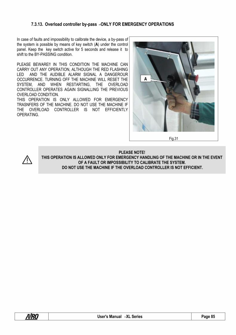
User's Manual – XL Series Page 85
7.3.13. Overload controller by-pass – ONLY FOR EMERGENCY OPERATIONS
In case of faults and impossibility to calibrate the device, a by-pass of the system is possible by means of key switch (A) under the control panel. Keep the key switch active for 5 seconds and release it to shift to the BY-PASSING condition. PLEASE BEWARE!! IN THIS CONDITION THE MACHINE CAN CARRY OUT ANY OPERATION, ALTHOUGH THE RED FLASHING LED AND THE AUDIBLE ALARM SIGNAL A DANGEROUR OCCURRENCE. TURNING OFF THE MACHINE WILL RESET THE SYSTEM, AND WHEN RESTARTING, THE OVERLOAD CONTROLLER OPERATES AGAIN SIGNALLING THE PREVIOUS OVERLOAD CONDITION. THIS OPERATION IS ONLY ALLOWED FOR EMERGENCY TRASNFERS OF THE MACHINE. DO NOT USE THE MACHINE IF THE OVERLOAD CONTROLLER IS NOT EFFICIENTLY OPERATING.
Fig.31
PLEASE NOTE! THIS OPERATION IS ALLOWED ONLY FOR EMERGENCY HANDLING OF THE MACHINE OR IN THE EVENT
OF A FAULT OR IMPOSSIBILITY TO CALIBRATE THE SYSTEM. DO NOT USE THE MACHINE IF THE OVERLOAD CONTROLLER IS NOT EFFICIENT.

User's Manual – XL Series Page 86
7.3.14. Operation check of safety microswitches
Some microswitches are placed in strategic positions to check the different configurations of the machine and activate safety functions. Their activation implies visual indication through the warning lights located on the platform control panel (see relevant chapter). The check of the actual operation of the microswitches should be carried out at least every year.
7.3.14.1 Microswitch M1
The microswitch M1 on the chassis checks the position of the lifting structure. With platform completely lowered the microswitch M1A is not activated. With lifted platform (with some tolerance due to the type of activation of the microswitch), the microswitch M1 is activated and: If the chassis is inclined over the max. allowed inclination the lifting and drive controls are stopped and:
The danger warning light and danger alarm turn on. The drive enable warning light turns off. The lifting enable warning light turns off. The safety drive speed is automatically activated.
When platform is overloaded ALL operations until removal of overload are stopped and: The overload warning light and danger alarm turn on. The drive enable warning light turns off. The lifting enable warning light turns off. The levelling outriggers control is stopped (if available).
7.3.14.2 Microswitch M1S (if available) The microswitch M1S on the chassis checks the position of the lifting structure. The activation of the microswitch M1S stops the drive control at a given platform height from the ground and turns off the drive enable warning light. Not all machines mentioned in this manual have a microswitch M1S; check in the chapter “TECHNICAL FEATURES ”if the maximum drive height is different from the maximum height that the platform can reach.
7.3.14.3 Microswitch M3 (OPTIONAL) The microswitch M3 on the chassis checks the position of the lifting structure. The activation of the microswitch M3 stops the lifting movement (lifting microswitch) before reaching the lifting cylinder end stop and turns off the lifting enable warning light.
7.3.14.4 Microswitches M5A-M5B (if available) The microswitches M5 are under the platform (if available) and check its position.
7.3.14.5 Microswitch M5A-M5B for machines with sliding platform With platform outside the central position (moved forward or backward) one of the microswitches M5A-M5B is activated and:
Drive/lifting/lowering movements are stopped and: The drive enable warning light turns off. The lifting enable warning light turns off. The platform position warning light turns off. On machines with variable capacity (see chapter “TECHNICAL FEATURES”) the overload controller is activated.
The condition of platform within its shape (central position) is signalled by the platform position warning light.

User's Manual – XL Series Page 87
7.3.14.6 Microswitches M5A and M5B for machines with dual slide-out extension deck (if available) The machines with dual slide-out extension deck can have two microswitches M5A (on the front deck) and M5B (on the rear deck). With one (or both) slide-out extension deck not fully retracted, the microswitch M5A (or M5B or both) is activated and:
On machines with variable capacity (see chapter “TECHNICAL FEATURES”) the overload controller is activated. The microswitches M5A and M5B are available only on machines with dual slide-out extension deck and variable capacity (see chapter “TECHNICAL FEATURE ”for capacity changes).
7.3.14.7 Microswitches ST1A-ST1B-ST1C-ST1D (machines with levelling outriggers) The microswitches ST1A-ST1B-ST1C-ST1D on the chassis near the levelling outriggers check the position of the pads of the levelling outriggers. With pads completely lifted all microswitches ST1…are activated and:
Drive can be controlled – drive enable warning light is on. All levelling outriggers position warning lights are off.
With at least one pad not completely lifted one or more microswitches ST1…is activated and: Drive is stopped – drive enable warning light is off. The levelling outriggers position warning lights concerning the levelling outriggers that have not retracted are flashing.
7.3.14.8 Microswitches STP1-STP2-STP3-STP4 (machines with levelling outriggers) The microswitches STP1-STP2-STP3-STP4 on the chassis near the levelling outriggers check the position of the pads of the levelling outriggers. With all pads not resting on the ground (the machine rests on its wheels) all microswitches STP …are not activated and:
Lifting can be controlled (unless other alarms) – the lifting enable warning light is on. With all pads resting on the ground (the machine rests on the levelling outriggers) all microswitches STP …are activated and:
Lifting can be controlled (unless other alarms) – the lifting enable warning light is on. Drive is stopped – drive enable warning light is off.
When the machine is resting on both pads/ wheels: Lifting is stopped – lifting enable warning light is off. Drive is stopped – drive enable warning light is off. The levelling outriggers position warning lights concerning the levelling outriggers that have not retracted are flashing.
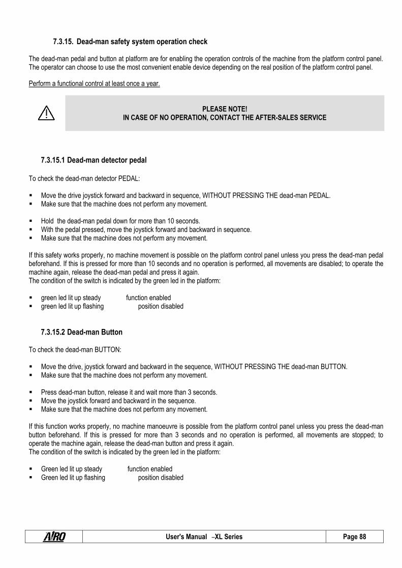
User's Manual – XL Series Page 88
7.3.15. Dead-man safety system operation check
The dead-man pedal and button at platform are for enabling the operation controls of the machine from the platform control panel. The operator can choose to use the most convenient enable device depending on the real position of the platform control panel.
Perform a functional control at least once a year.
PLEASE NOTE! IN CASE OF NO OPERATION, CONTACT THE AFTER-SALES SERVICE
7.3.15.1 Dead-man detector pedal To check the dead-man detector PEDAL: Move the drive joystick forward and backward in sequence, WITHOUT PRESSING THE dead-man PEDAL. Make sure that the machine does not perform any movement. Hold the dead-man pedal down for more than 10 seconds. With the pedal pressed, move the joystick forward and backward in sequence. Make sure that the machine does not perform any movement. If this safety works properly, no machine movement is possible on the platform control panel unless you press the dead-man pedal beforehand. If this is pressed for more than 10 seconds and no operation is performed, all movements are disabled; to operate the machine again, release the dead-man pedal and press it again. The condition of the switch is indicated by the green led in the platform: green led lit up steady function enabled green led lit up flashing position disabled
7.3.15.2 Dead-man Button To check the dead-man BUTTON: Move the drive, joystick forward and backward in the sequence, WITHOUT PRESSING THE dead-man BUTTON. Make sure that the machine does not perform any movement. Press dead-man button, release it and wait more than 3 seconds. Move the joystick forward and backward in the sequence. Make sure that the machine does not perform any movement. If this function works properly, no machine manoeuvre is possible from the platform control panel unless you press the dead-man button beforehand. If this is pressed for more than 3 seconds and no operation is performed, all movements are stopped; to operate the machine again, release the dead-man button and press it again. The condition of the switch is indicated by the green led in the platform: Green led lit up steady function enabled Green led lit up flashing position disabled

User's Manual – XL Series Page 89
7.4 Starter battery The battery is one of the most important elements of the machine. It is recommended to keep it in an efficient condition to increase its useful life, to avoid faults and to reduce the management costs of the machine.
7.4.1. Starter battery models “D“ ”ED”
On machines with a gasoline/diesel engine the starter battery is for: Powering the machine control circuits. Starting the engine.
7.4.2. Starter type battery for models “E”
On machines with batteries the starter battery is for: Powering the control circuits of the machine.
7.4.3. Starter battery maintenance The starter battery does not require any special maintenance:
Keep terminals clean by removing any oxidation residues. Check correct terminal tightening.
7.4.4. Starter battery recharge Starter batteries do not require any recharge. During normal operation of the Diesel engine an alternator recharges the battery (machines “D”, “ED”). On those machines equipped with a 380 three-phase electrical pump, the electrical pump control system keeps the starter battery charged. On machines with battery a DC-DC converter keeps the starter battery charged.

User's Manual – XL Series Page 90
7.5 “DRIVE ”battery for models “E ”and “ED” The battery is one of the most important elements of the machine. It is recommended to keep it in an efficient condition to increase its useful life, to avoid faults and to reduce the management costs of the machine.
7.5.1. General instructions for the MAIN DRIVE BATTERY In case of new batteries do not wait for the flat battery warning before recharging; recharge the batteries after 3 or 4 working
hours for the first 4/5 times. In case of new batteries full performance is achieved after approx. ten discharge/charge cycles. Charge the battery in airy rooms and open the caps to allow the outflow of gas. Do not use extension leads exceeding 5 metres to connect the battery charger to the power supply. Use a cable of a suitable section (min 3x2.5 mm2). Do not use rolled-up cables. Do not approach the battery with flames. Risk of explosion due to the formation of explosive gases. Do not carry out temporary or irregular electric connections. The terminals must be tightened and without deposits. The cables must be provided with a good insulation. Keep the battery cleaned, dry and free of oxidation products by using antistatic cloths. Do not place tools or any other metal object on the battery. Check that the electrolyte level is 5-7 mm higher than the splash guard level. During charging operations check that the electrolyte temperature is not higher than 45°C max. If the machine is equipped with an automatic topping up device, follow the instructions described in the battery user manual
carefully.
7.5.2. DRIVE battery recharge. For normal water operating conditions, water topping up is to be carried out every week. Top up using distilled or demineralized water. Top up after battery charging. After this operation, the electrolyte level must be 5-7 mm higher than the splash guard level. For machines equipped with automatic topping up device, follow the instructions given in the battery user manual. Battery discharge must be stopped when 80% of the battery rated capacity has been used. An excessive and prolonged
discharge irreversibly damages the battery. The machine is equipped with a device that, when the battery is discharged by 80%, lifting operations are disabled. The battery needs to be recharged. This condition is signalled by a flashing light of the relevant led on the platform control panel.
Battery charge is to be carried out according to the instructions given in the next paragraphs. Keep caps and connections covered and dry. A careful cleaning allows electric insulation protection, good operation and useful
life of the battery. In case of faulty operations due to the battery, avoid any direct intervention and call the Customer Service. When the machine is not being used the batteries will run down automatically (automatic discharge). To avoid the battery
operation from being compromised charge it at least once a month. This has to be done even if the density values of the electrolyte are high.
To limit automatic battery discharge during periods of inactivity store the machine in environments with temperatures lower than a 30°C.

User's Manual – XL Series Page 91
7.5.3. DRIVE battery recharge.
PLEASE NOTE! EXPLOSIVE gas is originated during battery charging process. Therefore, charging must take place in airy
rooms where no risks of fire and explosion exist and in the presence of fire extinguishers.
Connect the battery charger to a power supply having all protections according to the current standards and with the following features: Power voltage 230V ± 10% Frequency 50÷60 Hz Activated grounding line Magneto-thermal protection switch and residual current device (“circuit breaker”) Moreover: Do not use extension leads exceeding 5 metres to connect the battery charger to the power supply. Use a cable of a suitable section (min 3x2.5 mm2). Do not use rolled-up cables.
DO NOT to connect to power networks that do not comply with the above mentioned features.
Failure to observe the above mentioned instructions may result in malfunctioning of the battery charger with consequent damage not covered by the guarantee.
PLEASE NOTE! After charging and with the battery charger is still connected to power supply, the electrolyte density
values should range from 1.260 g/l to 1.270 g/l (at 25thC).
To use the battery charger follow this procedure: Connect the battery charger by means of plug A to a current socket with the a.m. features. Check the connection state of the battery charger through led B. If it is on, connection has taken place and charging has
started. The colour and enable mode of the led indicate the charging phase (refer to table below).
Fig.32

User's Manual – XL Series Page 92
WARNING DESCRIPTION
Red led flashing for a few seconds Battery charger self-diagnostic phase
Red led on Show that the first and second charging phase are accomplished
Yellow led on Shows that charge equalization is in progress
Green led on Shows that charging is over; buffer charge active.
With the battery charger ON, the machine is automatically off.
To disconnect the battery chargers from the power source, disconnect the machine from the electric line.
PLEASE NOTE!
Before using the machine check that the power cord of the battery charger is disconnected.
7.5.4. Battery charger trouble-shooting An intermittent alarm and the flashing LED on the battery charger indicator described in the previous paragraph indicate that a warning situation has occurred:
Alarm Type of alarm Description and troubleshooting
Alarm+ flashing RED Battery presence Battery is disconnected or faulty (check connection and the rated voltage of the battery).
Alarm+ flashing YELLOW Thermal probe Thermal probe is disconnected during charging or outside working range (check probe connection and measure battery temperature).
Alarm+ flashing GREEN Timeout Phase 1 and/or Phase 2 of duration higher than the max. allowed value (check battery capacity).
Alarm+ flashing RED Battery Current Loss of output current control (fault in control logic).
Alarm+ flashing RED-GREEN
Battery Voltage Loss of output voltage control (battery disconnected or fault in the control logic).
Alarm+ flashing RED-YELLOW-GREEN
Thermal Over temperature of semiconductors (check the fan operation).
PLEASE NOTE!
In presence of alarm the battery charger stops the current delivery.
7.5.5. Battery replacement
Replace the old batteries only with models of the same voltage, capacity, dimensions and mass. Batteries must be approved by the manufacturer.
Do not dispose of used oil in the environment. Comply with the current local standards.
User's Manual – XL Series Page 93
THIS OPERATION IS VERY IMPORTANT AND MUST BE CARRIED OUT BY SPECIALIZED TECHNICIANS ONLY.
CALL FOR TECHNICAL SERVICE

User's Manual – XL Series Page 94
8 . MARKS AND CERTIFICATIONS The models of self-propelled aerial platform described in this manual were subjected to the CE type testing according to the Directive 2006/42/EC. The certification was issued by:
ICE Spa
Via Garibaldi, 20 40011 Anzola Emilia – BO (Italia)
Test carrying out is shown by the above plate with CE mark applied on the machine and by the statement of compliance enclosed in this user manual.
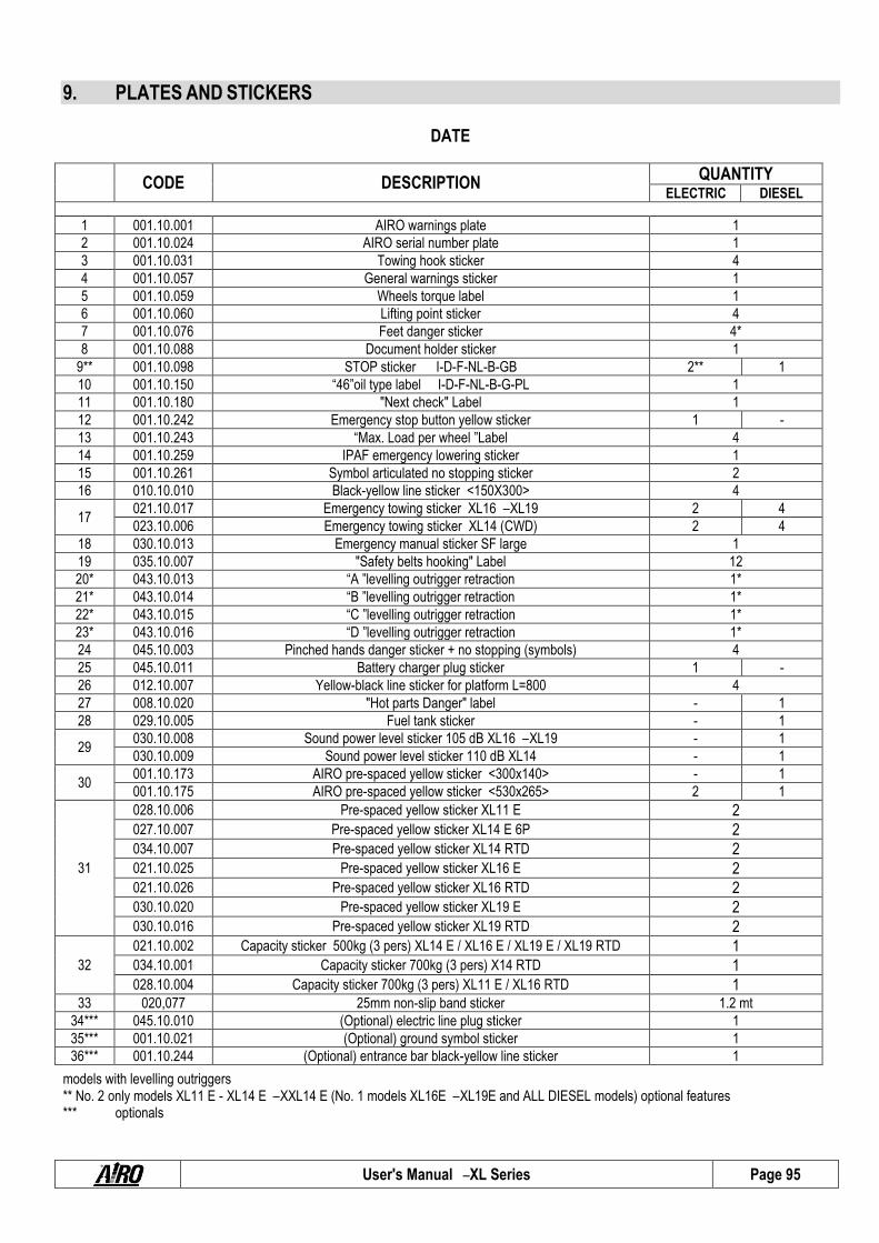
User's Manual – XL Series Page 95
9. PLATES AND STICKERS
DATE
CODE DESCRIPTION QUANTITY
ELECTRIC DIESEL
1 001.10.001 AIRO warnings plate 1
2 001.10.024 AIRO serial number plate 1
3 001.10.031 Towing hook sticker 4
4 001.10.057 General warnings sticker 1
5 001.10.059 Wheels torque label 1
6 001.10.060 Lifting point sticker 4
7 001.10.076 Feet danger sticker 4*
8 001.10.088 Document holder sticker 1
9** 001.10.098 STOP sticker I-D-F-NL-B-GB 2** 1
10 001.10.150 “46”oil type label I-D-F-NL-B-G-PL 1
11 001.10.180 "Next check" Label 1
12 001.10.242 Emergency stop button yellow sticker 1 -
13 001.10.243 “Max. Load per wheel ”Label 4
14 001.10.259 IPAF emergency lowering sticker 1
15 001.10.261 Symbol articulated no stopping sticker 2
16 010.10.010 Black-yellow line sticker <150X300> 4
17 021.10.017 Emergency towing sticker XL16 – XL19 2 4
023.10.006 Emergency towing sticker XL14 (CWD) 2 4
18 030.10.013 Emergency manual sticker SF large 1
19 035.10.007 "Safety belts hooking" Label 12
20* 043.10.013 “A ”levelling outrigger retraction 1*
21* 043.10.014 “B ”levelling outrigger retraction 1*
22* 043.10.015 “C ”levelling outrigger retraction 1*
23* 043.10.016 “D ”levelling outrigger retraction 1*
24 045.10.003 Pinched hands danger sticker + no stopping (symbols) 4
25 045.10.011 Battery charger plug sticker 1 -
26 012.10.007 Yellow-black line sticker for platform L=800 4
27 008.10.020 "Hot parts Danger" label - 1
28 029.10.005 Fuel tank sticker - 1
29 030.10.008 Sound power level sticker 105 dB XL16 – XL19 - 1
030.10.009 Sound power level sticker 110 dB XL14 - 1
30 001.10.173 AIRO pre-spaced yellow sticker <300x140> - 1
001.10.175 AIRO pre-spaced yellow sticker <530x265> 2 1
31
028.10.006 Pre-spaced yellow sticker XL11 E 2 027.10.007 Pre-spaced yellow sticker XL14 E 6P 2 034.10.007 Pre-spaced yellow sticker XL14 RTD 2 021.10.025 Pre-spaced yellow sticker XL16 E 2 021.10.026 Pre-spaced yellow sticker XL16 RTD 2 030.10.020 Pre-spaced yellow sticker XL19 E 2 030.10.016 Pre-spaced yellow sticker XL19 RTD 2
32
021.10.002 Capacity sticker 500kg (3 pers) XL14 E / XL16 E / XL19 E / XL19 RTD 1 034.10.001 Capacity sticker 700kg (3 pers) X14 RTD 1 028.10.004 Capacity sticker 700kg (3 pers) XL11 E / XL16 RTD 1
33 020,077 25mm non-slip band sticker 1.2 mt
34*** 045.10.010 (Optional) electric line plug sticker 1
35*** 001.10.021 (Optional) ground symbol sticker 1
36*** 001.10.244 (Optional) entrance bar black-yellow line sticker 1
models with levelling outriggers ** No. 2 only models XL11 E - XL14 E – XXL14 E (No. 1 models XL16E – XL19E and ALL DIESEL models) optional features *** optionals

User's Manual – XL Series Page 96
XL11 E – XL14 E – XXL14 E – XL16 E – XL19 E

User's Manual – XL Series Page 97
XL14 RTD – XL16 RTD – XL19 RTD

User's Manual – XL Series Page 98
10. CONTROL LEDGER A control ledger is supplied to the user of the platform in conformance with Attachment 1 of Directive 2006/42/EC. This ledger is to be considered an integral part of the equipment and must accompany the machine for its entire life until its final disposal. The ledger is provided for the notation, according to the proposed format, of the following events that regard the life of the machine: Periodic mandatory inspections by the competent Control Authorities (in Italy, ASL or ARPA).
Mandatory periodic inspections to assess the structure, proper machine operation and safety systems. Such inspections are
the responsibility of the safety manager of the company that owns the machine and must occur with frequency indicated.
Transfers of ownership In Italy, the purchaser must notify the INAIL department responsible that the installation of the machine has occurred.
Extraordinary maintenance work and replacement of important elements of the machine.

User's Manual – XL Series Page 99
REQUIRED PERIODIC INSPECTIONS BY THE REGULATORY AGENCY Date Observations Signature + Stamp

User's Manual – XL Series Page 100
REQUIRED PERIODIC INSPECTIONS BY THE OWNER STRUCTURAL CHECK DESCRIPTION OF OPERATIONS TO BE PERFORMED
VISUAL CONTROLS Check the integrity of the guardrails; the harness anchoring points; the status of the lifting structure; access ladders; rust; state of the tyres; oil leaks; locking pins on the structure.
DATE REMARKS SIGNATURE + STAMP
1st YEAR
2nd YEAR
3rd YEAR
4th YEAR
5th YEAR
6th YEAR
7th YEAR
8th YEAR
9th YEAR
10th YEAR
DEFORMED HOSES AND CABLES
Most of all, check that tubes and cables do not show any evident defects at the joints. Monthly maintenance Monthly entries are not needed. Enter details once a year when the other operations are carried out.
DATE REMARKS SIGNATURE + STAMP
1st YEAR
2nd YEAR
3rd YEAR
4th YEAR
5th YEAR
6th YEAR
7th YEAR
8th YEAR
9th YEAR
10th YEAR

User's Manual – XL Series Page 101
REQUIRED PERIODIC INSPECTIONS BY THE OWNER STRUCTURAL CHECK DESCRIPTION OF OPERATIONS TO BE PERFORMED
VARIOUS ADJUSTMENTS See Chapter 7.3.1 DATE REMARKS SIGNATURE + STAMP
1st YEAR
2nd YEAR
3rd YEAR
4th YEAR
5th YEAR
6th YEAR
7th YEAR
8th YEAR
9th YEAR
10th YEAR
GREASING See chapter 7.3.2 Monthly maintenance Monthly entries are not needed. Enter details once a year when the other operations are carried out.
DATE REMARKS SIGNATURE + STAMP
1st YEAR
2nd YEAR
3rd YEAR
4th YEAR
5th YEAR
6th YEAR
7th YEAR
8th YEAR
9th YEAR
10th YEAR
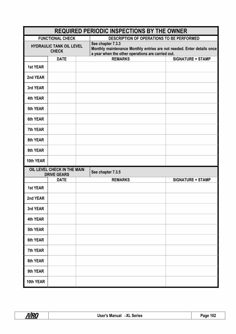
User's Manual – XL Series Page 102
REQUIRED PERIODIC INSPECTIONS BY THE OWNER FUNCTIONAL CHECK DESCRIPTION OF OPERATIONS TO BE PERFORMED
HYDRAULIC TANK OIL LEVEL CHECK
See chapter 7.3.3 Monthly maintenance Monthly entries are not needed. Enter details once a year when the other operations are carried out.
DATE REMARKS SIGNATURE + STAMP
1st YEAR
2nd YEAR
3rd YEAR
4th YEAR
5th YEAR
6th YEAR
7th YEAR
8th YEAR
9th YEAR
10th YEAR
OIL LEVEL CHECK IN THE MAIN DRIVE GEARS
See chapter 7.3.5
DATE REMARKS SIGNATURE + STAMP
1st YEAR
2nd YEAR
3rd YEAR
4th YEAR
5th YEAR
6th YEAR
7th YEAR
8th YEAR
9th YEAR
10th YEAR
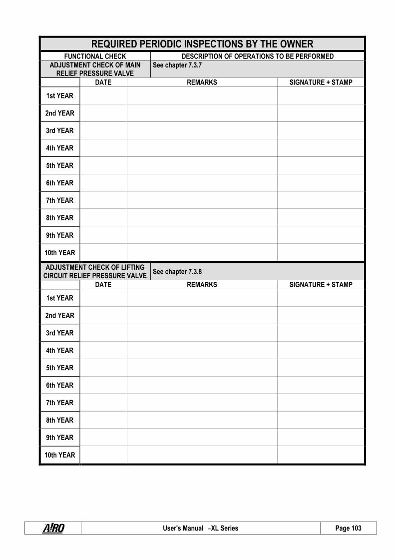
User's Manual – XL Series Page 103
REQUIRED PERIODIC INSPECTIONS BY THE OWNER FUNCTIONAL CHECK DESCRIPTION OF OPERATIONS TO BE PERFORMED
ADJUSTMENT CHECK OF MAIN RELIEF PRESSURE VALVE
See chapter 7.3.7
DATE REMARKS SIGNATURE + STAMP
1st YEAR
2nd YEAR
3rd YEAR
4th YEAR
5th YEAR
6th YEAR
7th YEAR
8th YEAR
9th YEAR
10th YEAR
ADJUSTMENT CHECK OF LIFTING CIRCUIT RELIEF PRESSURE VALVE
See chapter 7.3.8
DATE REMARKS SIGNATURE + STAMP
1st YEAR
2nd YEAR
3rd YEAR
4th YEAR
5th YEAR
6th YEAR
7th YEAR
8th YEAR
9th YEAR
10th YEAR

User's Manual – XL Series Page 104
REQUIRED PERIODIC INSPECTIONS BY THE OWNER FUNCTIONAL CHECK DESCRIPTION OF OPERATIONS TO BE PERFORMED
BATTERY STATE See chapter 7.4 and 7.5 Daily operation. Daily entries are not needed. Enter details once a year when the other operations are carried out.
DATE REMARKS SIGNATURE + STAMP
1st YEAR
2nd YEAR
3rd YEAR
4th YEAR
5th YEAR
6th YEAR
7th YEAR
8th YEAR
9th YEAR
10th YEAR
PLATFORM EXTRACTION CLEARANCE ADJUSTMENT
See chapter 07.03.10
DATE REMARKS SIGNATURE + STAMP
1st YEAR
2nd YEAR
3rd YEAR
4th YEAR
5th YEAR
6th YEAR
7th YEAR
8th YEAR
9th YEAR
10th YEAR
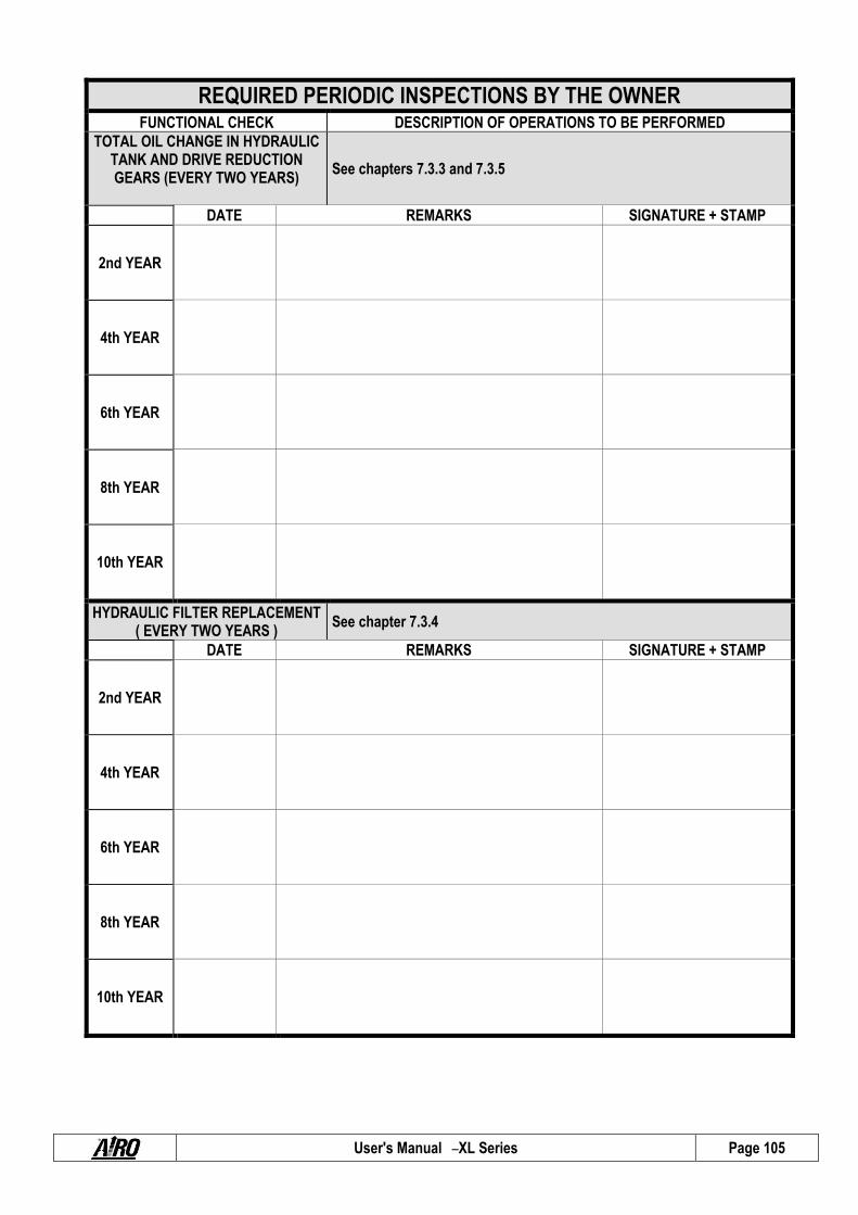
User's Manual – XL Series Page 105
REQUIRED PERIODIC INSPECTIONS BY THE OWNER FUNCTIONAL CHECK DESCRIPTION OF OPERATIONS TO BE PERFORMED
TOTAL OIL CHANGE IN HYDRAULIC TANK AND DRIVE REDUCTION GEARS (EVERY TWO YEARS)
See chapters 7.3.3 and 7.3.5
DATE REMARKS SIGNATURE + STAMP
2nd YEAR
4th YEAR
6th YEAR
8th YEAR
10th YEAR
HYDRAULIC FILTER REPLACEMENT ( EVERY TWO YEARS )
See chapter 7.3.4
DATE REMARKS SIGNATURE + STAMP
2nd YEAR
4th YEAR
6th YEAR
8th YEAR
10th YEAR

User's Manual – XL Series Page 106
REQUIRED PERIODIC INSPECTIONS BY THE OWNER FUNCTIONAL CHECK DESCRIPTION OF OPERATIONS TO BE PERFORMED
AIR PURGING FROM THE CYLINDERS OF THE OSCILLATING
AXLES See chapter 7.3.6
DATE REMARKS SIGNATURE + STAMP
1st YEAR
2nd YEAR
3rd YEAR
4th YEAR
5th YEAR
6th YEAR
7th YEAR
8th YEAR
9th YEAR
10th YEAR

User's Manual – XL Series Page 107
REQUIRED PERIODIC INSPECTIONS BY THE OWNER SAFETY SYSTEM CHECKS DESCRIPTION OF OPERATIONS TO BE PERFORMED
INCLINOMETER OPERATION CHECK See chapter 07.03.11 DATE REMARKS SIGNATURE + STAMP
1st YEAR
2nd YEAR
3rd YEAR
4th YEAR
5th YEAR
6th YEAR
7th YEAR
8th YEAR
9th YEAR
10th YEAR
EFFICIENCY CHECK OF PLATFORM OVERLOAD CONTROLLER
See chapter 07.03. 12
DATE REMARKS SIGNATURE + STAMP
1st YEAR
2nd YEAR
3rd YEAR
4th YEAR
5th YEAR
6th YEAR
7th YEAR
8th YEAR
9th YEAR
10th YEAR

User's Manual – XL Series Page 108
REQUIRED PERIODIC INSPECTIONS BY THE OWNER SAFETY SYSTEM CHECKS DESCRIPTION OF OPERATIONS TO BE PERFORMED
BRAKING SYSTEM EFFICIENCY CHECK
See chapter 7.3.9
DATE REMARKS SIGNATURE + STAMP
1st YEAR
2nd YEAR
3rd YEAR
4th YEAR
5th YEAR
6th YEAR
7th YEAR
8th YEAR
9th YEAR
10th YEAR
OPERATION CHECK MICROSWITCHES MICROS
See chapter 7.3.14
DATE REMARKS SIGNATURE + STAMP
1st YEAR
2nd YEAR
3rd YEAR
4th YEAR
5th YEAR
6th YEAR
7th YEAR
8th YEAR
9th YEAR
10th YEAR

User's Manual – XL Series Page 109
SAFETY SYSTEM CHECKS DESCRIPTION OF OPERATIONS TO BE PERFORMED
DEAD-MAN CONTROL
See chapter 07.03.2015
DATE REMARKS SIGNATURE + STAMP
1st YEAR
2nd YEAR
3rd YEAR
4th YEAR
5th YEAR
6th YEAR
7th YEAR
8th YEAR
9th YEAR
10th YEAR
REQUIRED PERIODIC INSPECTIONS BY THE OWNER SAFETY SYSTEM CHECKS DESCRIPTION OF OPERATIONS TO BE PERFORMED
STICKERS AND PLATES CHECK
See chapter 9 See Chapter 9. Check the legibility of the aluminium plate on the platform where the main instructions are summarised; that the capacity labels are on the platform and that they are legible; that the labels on the ground and platform controls are legible.
DATE REMARKS SIGNATURE + STAMP
1st YEAR
2nd YEAR
3rd YEAR
4th YEAR
5th YEAR
6th YEAR
7th YEAR
8th YEAR
9th YEAR
10th YEAR

User's Manual – XL Series Page 110
REQUIRED PERIODIC INSPECTIONS BY THE OWNER
CHECK OF EMERGENCY DEVICES DESCRIPTION OF OPERATIONS TO BE PERFORMED
MANUAL EMERGENCY LOWERING CHECK
See chapter 5.6
DATE REMARKS SIGNATURE + STAMP
1st YEAR
2nd YEAR
3rd YEAR
4th YEAR
5th YEAR
6th YEAR
7th YEAR
8th YEAR
9th YEAR
10th YEAR

User's Manual – XL Series Page 111
TRANSFERS OF OWNERSHIP
FIRST OWNER
COMPANY DATE MODEL SERIAL NUMBER DELIVERY DATE
AIRO – Tigieffe S.r.l.
SUBSEQUENT TRANSFERS OF OWNERSHIP
COMPANY DATE
We affirm that, as of the date quoted above, the technical, dimensional and functional features of this machine were in conformance with what was originally required and that any changes have been recorded in this Register.
SELLER BUYER
SUBSEQUENT TRANSFERS OF OWNERSHIP
COMPANY DATE
We affirm that, as of the date quoted above, the technical, dimensional and functional features of this machine were in conformance with what was originally required and that any changes have been recorded in this Register.
SELLER BUYER
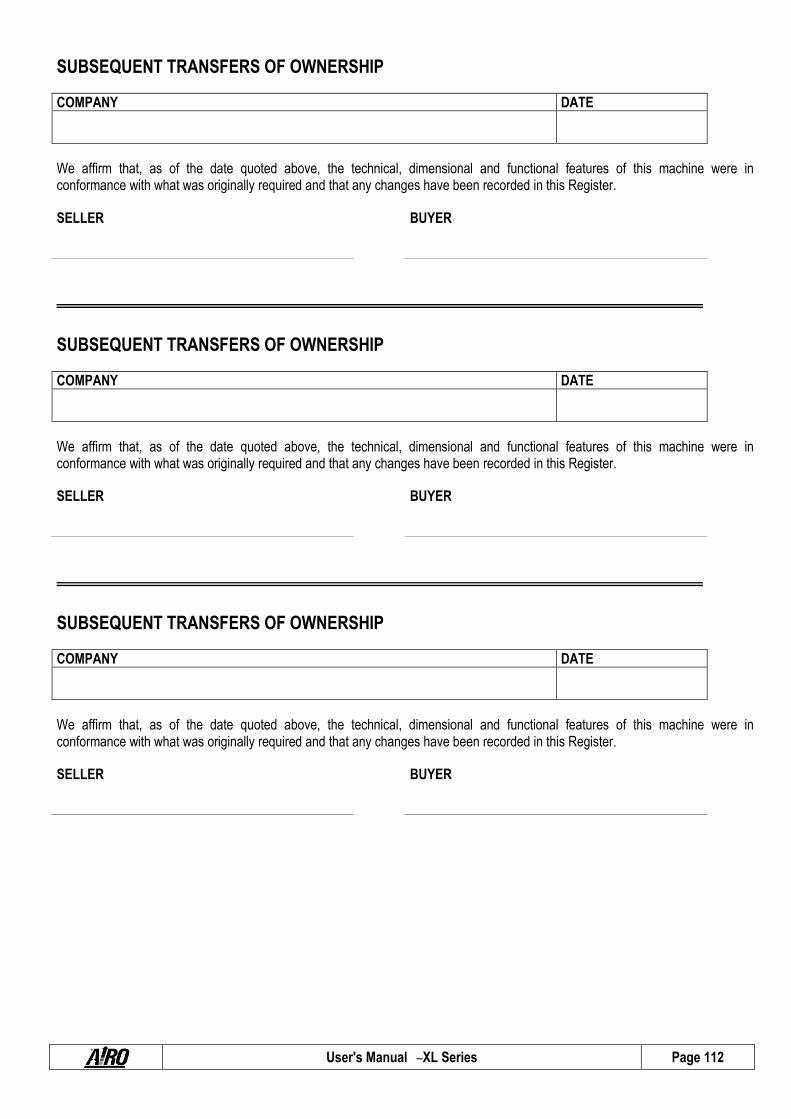
User's Manual – XL Series Page 112
SUBSEQUENT TRANSFERS OF OWNERSHIP
COMPANY DATE
We affirm that, as of the date quoted above, the technical, dimensional and functional features of this machine were in conformance with what was originally required and that any changes have been recorded in this Register.
SELLER BUYER
SUBSEQUENT TRANSFERS OF OWNERSHIP
COMPANY DATE
We affirm that, as of the date quoted above, the technical, dimensional and functional features of this machine were in conformance with what was originally required and that any changes have been recorded in this Register.
SELLER BUYER
SUBSEQUENT TRANSFERS OF OWNERSHIP
COMPANY DATE
We affirm that, as of the date quoted above, the technical, dimensional and functional features of this machine were in conformance with what was originally required and that any changes have been recorded in this Register.
SELLER BUYER

User's Manual – XL Series Page 113
MAJOR TROUBLES
DATE TROUBLE DESCRIPTION REMEDY
SPARE PARTS USED DESCRIPTION
CODE QUANTITY
SERVICE SAFETY MANAGER
DATE TROUBLE DESCRIPTION REMEDY
SPARE PARTS USED DESCRIPTION
CODE QUANTITY
SERVICE SAFETY MANAGER

User's Manual – XL Series Page 114
MAJOR TROUBLES
DATE TROUBLE DESCRIPTION REMEDY
SPARE PARTS USED DESCRIPTION
CODE QUANTITY
SERVICE SAFETY MANAGER
DATE TROUBLE DESCRIPTION REMEDY
SPARE PARTS USED DESCRIPTION
CODE QUANTITY
SERVICE SAFETY MANAGER

User's Manual – XL Series Page 115
11. HYDRAULIC DIAGRAM - STANDARD MACHINES
XL11 E XL14 E XL14 E 6P N° 027.07.048
EV1 PROPORTIONAL FLOW ADJUSTER EV2 FORWARD DRIVE SOLENOID VALVE EV3 BACKWARD DRIVE SOLENOID VALVE EV4 LIFTING SOLENOID VALVE EV5A/B LOWERING SOLENOID VALVE EV5M EMERGENCY LOWERING MANUAL CONTROL EV6 FRONT PLATFORM EXTENSION SOLENOID VALVE (OPTIONAL) EV7 FRONT PLATFORM RETRACTION SOLENOID VALVE (OPTIONAL) EV8 LEFT STEERING SOLENOID VALVE EV9 RIGHT STEERING SOLENOID VALVE EV10A/B DRIVE MOTOR SERIES SOLENOID VALVE EV11 BY-PASS SOLENOID VALVE EV20 DISPLACEMENT EXCHANGE SOLENOID VALVE EV21÷28 LEVELLING JACK CYLINDER SOLENOID VALVES EV36 REAR PLATFORM EXTENSION SOLENOID VALVE (OPTIONAL) EV37 REAR PLATFORM RETRACTION SOLENOID VALVE (OPTIONAL) ME ELECTRIC MOTOR MD DIESEL MOTOR 1 TANK 1a TANK COVER 2 SUCTION FILTER 3 DOUBLE PUMP 4 ELECTRIC PROPULSION 5 DIESEL PROPULSION 6 MANUAL PUMP 7 PRESSURE GAGE CONNECTION 8 SF CONTROL HYDRAULIC BLOCK 9 STEERING CONTROL HYDRAULIC BLOCK 10 STABILIZATION CONTROL HYDRAULIC BLOCK 11 LEVELLING JACK CYLINDER 12 STEERING CYLINDER 13 DRIVE REDUCTION GEAR 13a DRIVE HYDRAULIC MOTOR 14 LOWERING CONTROL INTEGRATED ASSEMBLY 15 LIFTING CYLINDER 16 TANK 17 PUMP 18 SUCTION FILTER 19 DRIVE PLATE 20 DOUBLE EXTENSION CONTROL HYDRAULIC BLOCK (OPTIONAL) 21 PLATFORM EXTENSION CYLINDER (OPTIONAL) 22 OVER-CENTER VALVE (OPTIONAL)
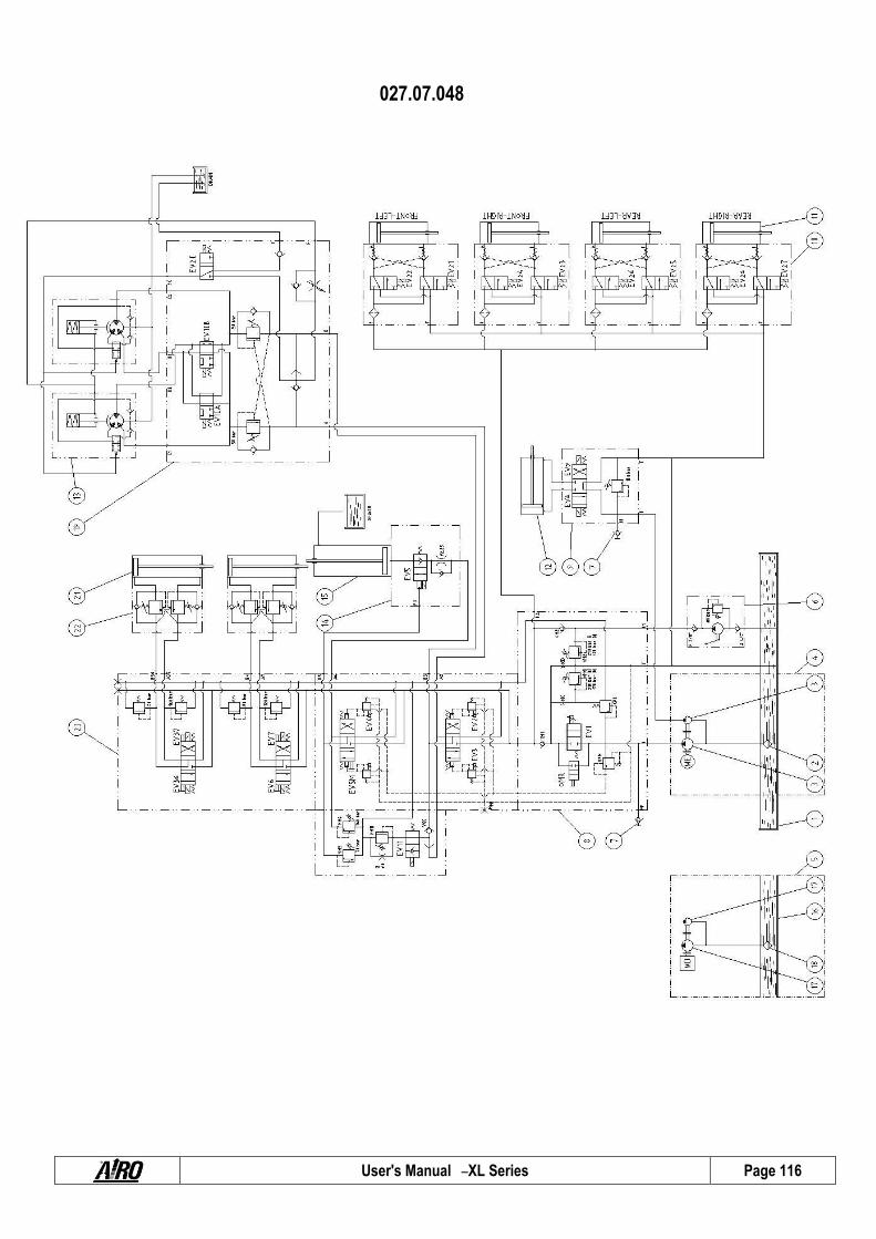
User's Manual – XL Series Page 116
027.07.048

User's Manual – XL Series Page 117
HYDRAULIC DIAGRAM - STANDARD MACHINES XL14 RTD
N° 034.07.060
EV1 PROPORTIONAL FLOW ADJUSTER EV2 FORWARD DRIVE SOLENOID VALVE EV3 BACKWARD DRIVE SOLENOID VALVE EV4 LIFTING SOLENOID VALVE EV5A/B LOWERING SOLENOID VALVE EV5M EMERGENCY LOWERING MANUAL CONTROL EV6 FRONT PLATFORM EXTENSION SOLENOID VALVE (OPTIONAL) EV7 FRONT PLATFORM RETRACTION SOLENOID VALVE (OPTIONAL) EV8 LEFT STEERING SOLENOID VALVE EV9 RIGHT STEERING SOLENOID VALVE EV10A/B FRONT MOTOR SERIES SOLENOID VALVE EV10C/D REAR MOTOR SERIES SOLENOID VALVE EV11 BY-PASS SOLENOID VALVE EV20 DISPLACEMENT EXCHANGE SOLENOID VALVE EV21÷28 LEVELLING JACK CYLINDER SOLENOID VALVES EV36 REAR PLATFORM EXTENSION SOLENOID VALVE (OPTIONAL) EV37 REAR PLATFORM RETRACTION SOLENOID VALVE (OPTIONAL) M DIESEL MOTOR 1 TANK 1a TANK COVER 2 DISCHARGE FILTER 3 SUCTION FILTER 4 DOUBLE PUMP 5 UNIDIRECTIONAL FLOW RESTRICTOR 6 MANUAL PUMP 7 PRESSURE GAGE CONNECTION 8 SF HYDRAULIC BLOCK 9 STEERING HYDRAULIC BLOCK 10 LEVELLING JACK HYDRAULIC BLOCK 11 LEVELLING JACK CYLINDER 12 STEERING CYLINDER 13 SELECTOR VALVE 14 DRIVE REDUCTION GEAR 14a DRIVE HYDRAULIC MOTOR 15 LOWERING CONTROL INTEGRATED ASSEMBLY 16 LIFTING CYLINDER 17 SWING AXLE CYLINDER 18 BLOCK VALVE 19 DRIVE PLATE 20 DOUBLE EXTENSION CONTROL HYDRAULIC BLOCK (OPTIONAL) 21 PLATFORM EXTENSION CYLINDER (OPTIONAL) 22 OVER-CENTER VALVE (OPTIONAL)
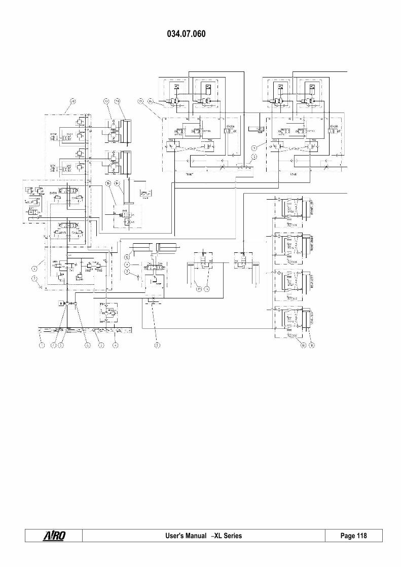
User's Manual – XL Series Page 118
034.07.060

User's Manual – XL Series Page 119
SCHEMA HYDRAULIQUE MACHINES STANDARDS
XL16 E XXL16 E XXL16 D 021.07.044
EV1 REGOLATORE DI FLUSSO PROPORZIONALE EV2 ELETTROVALVOLA TRAZIONE AVANTI EV3 ELETTROVALVOLA TRAZIONE INDIETRO EV4 ELETTROVALVOLA SOLLEVAMENTO EV5A/B ELETTROVALVOLA DISCESA EV5M COMANDO MANUALE DISCESA EMERGENZA EV6 ELETTROVALVOLA SFILO PIATTAFORMA ANTERIORE (OPZIONALE) EV7 ELETTROVALVOLA RIENTRO PIATTAFORMA ANTERIORE (OPZIONALE) EV8 ELETTROVALVOLA STERZO SINISTRA EV9 ELETTROVALVOLA STERZO DESTRA EV10A/B ELETTROVALVOLA SERIE MOTORI TRAZIONE EV11 ELETTROVALVOLA BY-PASS EV20 ELETTROVALVOLA SCAMBIO CILINDRATA EV21÷28 ELETTROVALVOLE CILINDRI LIVELLATORI EV36 ELETTROVALVOLA SFILO PIATTAFORMA POSTERIORE (OPZIONALE) EV37 ELETTROVALVOLA RIENTRO PIATTAFORMA POSTERIORE (OPZIONALE) M1, M2 MOTORI ELETTRICI MD MOTORE DIESEL 1 SERBATOIO 1a COPERCHIO SERBATOIO – MODELLI ELETTRICI 1b COPERCHIO SERBATOIO – MODELLI DIESEL 2 FILTRO DI ASPIRAZIONE 3 POMPA DOPPIA 4 PROPULSIONE ELETTRICA 5 PROPULSIONE DIESEL 6 POMPA MANUALE 7 ATTACCO MANOMETRO 8 BLOCCO IDRAULICO COMANDO 9 BLOCCO IDRAULICO COMANDO STERZO 10 BLOCCO IDRAULICO COMANDO STABILIZZAZIONE 11 CILINDRO STABILIZZATORE 12 CILINDRO STERZO 13 RIDUTTORE TRAZIONE 13a MOTORE IDRAULICO TRAZIONE 14 GRUPPO INTEGRATO CONTROLLO DISCESA 15 CILINDRO SOLLEVAMENTO 16 VALVOLA UNIDIREZIONALE 17 POMPA DOPPIA – MODELLI DIESEL 18 FILTRO ASPIRAZIONE – MODELLI DIESEL 19 PIASTRA TRAZIONE 20 BLOCCO IDRAULICO COMANDO DOPPIO SFILO (OPZIONALE) 21 CILINDRO SFILO PIATTAFORMA (OPZIONALE) 22 VALVOLA OVER-CENTER (OPZIONALE) 23 POMPA – MODELLI ELETTRICI 26 FILTRO IN RITORNO

User's Manual – XL Series Page 120
021.07.044

User's Manual – XL Series Page 121
SCHEMA HYDRAULIQUE MACHINES STANDARDS
XL19 E N° 030.07.099
EV1 REGULATEUR DE FLUX PROPORTIONNEL EV2 ELECTROVANNE TRACTION AVANT EV3 ELECTROVANNE TRACTION ARRIERE EV4 ELECTROVANNE SOULEVEMENT EV5A/B ELECTROVANNE DESCENTE EV5M COMMANDE MANUELLE DESCENTE D’URGENCE EV6 ELECTROVANNE EXTRACTION PLATE-FORME AVANT (OPTIONEEL) EV7 ELECTROVANNE RENTREE PLATE-FORME AVANT (OPTIONEEL) EV8 ELECTROVANNE DIRECTION GAUCHE EV9 ELECTROVANNE DIRECTION DROITE EV10A/B ELECTROVANNE SERIE MOTEURS TRACTION EV11 ELECTROVANNE BY-PASS EV20 ELECTROVANNE CHANGEMENT CYLINDREE EV21÷28 ELECTROVANNES CYLINDRES NIVELEURS EV36 ELECTROVANNE EXTRACTION PLATE-FORME ARRIERE (OPTIONEEL) EV37 ELECTROVANNE RENTREE PLATE-FORME ARRIERE (OPTIONEEL) MD MOTEUR DIESEL ME ELECTRO-POMPE M1-2-3 MOTEUR ELECTRIQUE 1 RESERVOIR 1a COUVERCLE RESERVOIR 2 FILTRE VIDANGE 3 FILTRE ASPIRATION 4 POMPE DOUBLE 5 FILTRE ASPIRATION 6 POMPE MANUELLE 7 CONNEXION MANOMETRE 8 BLOC HYDRAULIQUE SF 9 BLOC HYDRAULIQUE DIRECTION 10 BLOC HYDRAULIQUE STABILISATEUR 11 VERIN STABILISATEUR 12 VERIN DIRECTION 14 REDUCTEUR TRACTION 14a MOTEUR HYDRAULIQUE TRACTION 15 GROUPE INTEGREE CONTROLE DESCENTE 16 VERIN SOULEVEMENT 17 BLOC HYDRAULIQUE COMMANDE EXTRACTION DOUBLE (OPTIONEEL) 19 PIASTRA TRAZIONE 20 VANNE OVER-CENTER (OPTIONEEL) 21 VERIN EXTRACTION PLATE-FORME (OPTIONEEL) 22 GROUPE PROPULSION ELECTRO-POMPE 23 GROUPE PROPULSION ELECTRIQUE 24 GROUPE PROPULSION THERMIQUE 25 VANNE UNIDIRECTIONNELLE 26 VANNE UNIDIRECTIONNELLE 27 VANNE UNIDIRECTIONNELLE 28 POMPE 29 POMPE 30 COLLECTEUR ASPIARTION ET REFOULEMENT

User's Manual – XL Series Page 122
030.07.099

User's Manual – XL Series Page 123
HYDRAULIC DIAGRAM - STANDARD MACHINES
XL16 RTD XL19 RTD N° 030.07.082
EV1 PROPORTIONAL FLOW ADJUSTER EV2 FORWARD DRIVE SOLENOID VALVE EV3 BACKWARD DRIVE SOLENOID VALVE EV4 LIFTING SOLENOID VALVE EV5A/B LOWERING SOLENOID VALVE EV5M EMERGENCY LOWERING MANUAL CONTROL EV6 FRONT PLATFORM EXTENSION SOLENOID VALVE (OPTIONAL) EV7 FRONT PLATFORM RETRACTION SOLENOID VALVE (OPTIONAL) EV8 LEFT STEERING SOLENOID VALVE EV9 RIGHT STEERING SOLENOID VALVE EV10A/B FRONT MOTOR SERIES SOLENOID VALVE EV10C/D REAR MOTOR SERIES SOLENOID VALVE EV11 BY-PASS SOLENOID VALVE EV20 DISPLACEMENT EXCHANGE SOLENOID VALVE EV21÷28 LEVELLING JACK CYLINDER SOLENOID VALVES EV36 REAR PLATFORM EXTENSION SOLENOID VALVE (OPTIONAL) EV37 REAR PLATFORM RETRACTION SOLENOID VALVE (OPTIONAL) MD DIESEL MOTOR 1 TANK 1a TANK COVER 2 DISCHARGE FILTER 3 SUCTION FILTER 4 DOUBLE PUMP 5 UNIDIRECTIONAL VALVE 6 MANUAL PUMP 7 PRESSURE GAGE CONNECTION 8 SF HYDRAULIC BLOCK 9 STEERING HYDRAULIC BLOCK 10 LEVELLING JACK HYDRAULIC BLOCK 11 LEVELLING JACK CYLINDER 12 STEERING CYLINDER 13 SELECTOR VALVE 14 DRIVE REDUCTION GEAR 14a DRIVE HYDRAULIC MOTOR 15 LOWERING CONTROL INTEGRATED ASSEMBLY 16 LIFTING CYLINDER 17 SWING AXLE CYLINDER 18 BLOCK VALVE 19 DRIVE PLATE 20 DOUBLE EXTENSION CONTROL HYDRAULIC BLOCK (OPTIONAL) 21 PLATFORM EXTENSION CYLINDER (OPTIONAL) 22 OVER-CENTER VALVE (OPTIONAL) 23 SUCTION FILTER 24 ELECTRIC PUMP KIT 25 ELECTRIC PUMP 26 SUCTION FILTER 27 SUCTION FILTER 28 VALVE 29 VALVE 30 VALVE

User's Manual – XL Series Page 124
030.07.082
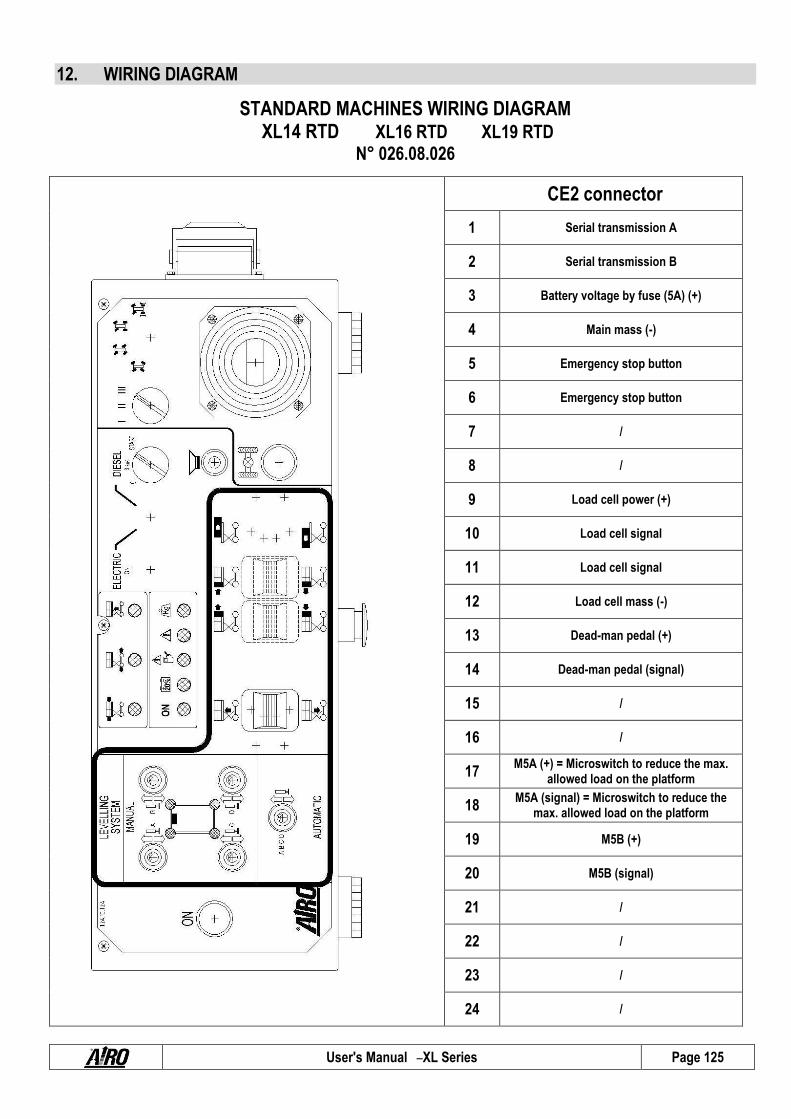
User's Manual – XL Series Page 125
12. WIRING DIAGRAM
STANDARD MACHINES WIRING DIAGRAM XL14 RTD XL16 RTD XL19 RTD
N° 026.08.026
CE2 connector
1 Serial transmission A
2 Serial transmission B
3 Battery voltage by fuse (5A) (+)
4 Main mass (-)
5 Emergency stop button
6 Emergency stop button
7 /
8 /
9 Load cell power (+)
10 Load cell signal
11 Load cell signal
12 Load cell mass (-)
13 Dead-man pedal (+)
14 Dead-man pedal (signal)
15 /
16 /
17 M5A (+) = Microswitch to reduce the max.
allowed load on the platform
18 M5A (signal) = Microswitch to reduce the
max. allowed load on the platform
19 M5B (+)
20 M5B (signal)
21 /
22 /
23 /
24 /

User's Manual – XL Series Page 126
STANDARD MACHINES WIRING DIAGRAM XL14 RTD XL16 RTD XL19 RTD
N° 026.08.027
CA1 connector
CA2 connector
MO connector
CA3 connector
CE connector

User's Manual – XL Series Page 127
CA1 Connector 1 EV1 (+): proportional movements 22 EV1 (-): proportional movements
2 EV2 (+): backward drive 23 EV2 (-): backward drive
3 EV3 (+): forward drive 24 EV3 (-): forward drive
4 EV4 (+): UP 25 EV4 (-): UP
5 EV5 (+): DOWN 26 EV5 (-): DOWN
6 EV6 (+) 27 EV6 (-)
7 EV7 (+) 28 EV7 (-)
8 EV8 (+): steering 29 EV8 (-): steering
9 EV9 (+): steering 30 EV9 (-): steering
10 EV10A and EV10B (+): series 31 EV10A and EV10B (-): series
11 EV10C and EV10D (+): series 32 EV10C and EV10D (-): series
12 / 33 /
13 EV11 (+): anti-step 34 EV11 (-): anti-step
14 EV20A and EV20B (+) 35 EV20A and EV20B (-)
15 EV36 (+) 36 EV36 (-)
16 EV37 (+) 37 EV37 (-)
17 / 38 /
18 / 39 /
19 / 40 /
20 / 41 /
21 Rotating beacons (+) 42 Rotating beacons (-)
CA2 connector 1 / 22 /
2 / 23 /
3 Horn (+) 24 /
4 M1 (+): anti-step microswitch 25 /
5 M1S (+): drive disable microswitch 26 /
6 / 27 /
7 / 28 /
8 PQ (signal): inclinometer 29 /
9 / 30 /
10 / 31 AM (signal)
11 Horn (-) 32 AM (+)
12 M1 (-): anti-step microswitch 33 AM (-)
13 M1S (-): drive disable microswitch 34 /
14 / 35 /
15 / 36 /
16 / 37 Fuse (+)
17 / 38 Fuse (+)
18 PQ (+): inclinometer 39 Fuse (+)
19 PQ (-): inclinometer 40 Battery (-)
20 / 41 Battery (-)
21 / 42 Battery (-)

User's Manual – XL Series Page 128
MO Connector 1 Alternator alarm 13 Motor electrostart
2 Oil pressure alarm 14 Motor electrostop
3 Air filter alarm 15 Motor preheating
4 Head overheating alarm 16 Motor electroaccelerator
5 / 17 /
6 / 18 /
7 / 19 /
8 / 20 Fuel alarm
9 / 21 /
10 / 22 /
11 / 23 /
12 / 24 /
CA3 connector 1 ST1A (Signal): lower outrigger microswitch 22 STP2 (+): upper outrigger microswitch
2 ST2A (Signal): lower outrigger microswitch 23 STP3 (+): upper outrigger microswitch
3 ST3A (Signal): lower outrigger microswitch 24 STP4 (+): upper outrigger microswitch
4 ST4A (Signal): lower outrigger microswitch 25 EV21 (+): outrigger up
5 STP1 (Signal): upper outrigger microswitch 26 EV22 (+): outrigger down
6 STP2 (Signal): upper outrigger microswitch 27 EV23 (+): outrigger up
7 STP3 (Signal): upper outrigger microswitch 28 EV24 (+): outrigger down
8 STP4 (Signal): upper outrigger microswitch 29 EV25 (+): outrigger up
9 EV21 (+): outrigger up 30 EV26 (+): outrigger down
10 EV22 (+): outrigger down 31 EV27 (+): outrigger up
11 EV23 (+): outrigger up 32 EV28 (+): outrigger down
12 EV24 (+): outrigger down 33 INCLINOMETER Y+
13 EV25 (+): outrigger up 34 INCLINOMETER Y-
14 EV26 (+): outrigger down 35 INCLINOMETER X+
15 EV27 (+): outrigger up 36 INCLINOMETER X-
16 EV28 (+): outrigger down 37 /
17 ST1A (+): lower outrigger microswitch 38 /
18 ST2A (+): lower outrigger microswitch 39 /
19 ST3A (+): lower outrigger microswitch 40 /
20 ST4A (+): lower outrigger microswitch 41 /
21 STP1 (+): upper outrigger microswitch 42 /
CE connector 1 Serial transmission A 13 /
2 Serial transmission B 14 /
3 Battery voltage by fuse (5A) (+) 15 /
4 Main mass 16 /
5 Emergency stop button 17 /
6 Emergency stop button 18 /
7 / 19 /
8 / 20 /
9 / 21 /
10 / 22 /
11 / 23 /
12 / 24 /

User's Manual – XL Series Page 129
STANDARD MACHINES WIRING DIAGRAM XL11 E XL14 E XL14 E 6P XL16 E
N° 026.08.025
CE2 connector
1 Serial transmission A
2 Serial transmission B
3 Battery voltage by fuse (5A) (+)
4 Main mass (-)
5 Emergency stop button
6 Emergency stop button
7 /
8 /
9 Load cell power (+)
10 Load cell signal
11 Load cell signal
12 Load cell mass (-)
13 Dead-man pedal (+)
14 Dead-man pedal (signal)
15 /
16 /
17 M5A (+) = Microswitch to reduce the max.
allowed load on the platform
18 M5A (signal) = Microswitch to reduce the
max. allowed load on the platform
19 M5B (+)
20 M5B (signal)
21 /
22 /
23 /
24 /

User's Manual – XL Series Page 130
STANDARD MACHINES WIRING DIAGRAM XL11 E XL14 E XL14 E 6P XL16 E
N° 026.08.024
CA1 connector
CA2 connector
X
X
CE connector

User's Manual – XL Series Page 131
CA1 Connector 1 EV1 (+): proportional movements 22 EV1 (-): proportional movements
2 EV2 (+): backward drive 23 EV2 (-): backward drive
3 EV3 (+): forward drive 24 EV3 (-): forward drive
4 EV4 (+): UP 25 EV4 (-): UP
5 EV5 (+): DOWN 26 EV5 (-): DOWN
6 EV6 (+) 27 EV6 (-)
7 EV7 (+) 28 EV7 (-)
8 EV8 (+): steering 29 EV8 (-): steering
9 EV9 (+): steering 30 EV9 (-): steering
10 EV10A and EV10B (+): series 31 EV10A and EV10B (-): series
11 EV10C and EV10D (+): series 32 EV10C and EV10D (-): series
12 / 33 /
13 EV11 (+): anti-step 34 EV11 (-): anti-step
14 EV20A and EV20B (+) 35 EV20A and EV20B (-)
15 EV36 (+) 36 EV36 (-)
16 EV37 (+) 37 EV37 (-)
17 / 38 /
18 / 39 /
19 / 40 /
20 / 41 /
21 Rotating beacons (+) 42 Rotating beacons (-)
CA2 connector 1 TLR1 (+) 22 Battery Charger indicator - brown
2 / 23 Battery Charger relay
3 Horn (+) 24 Battery Charger relay
4 M1 (Sign): anti-step microswitch 25 SPI power supply (+48V)
5 M1S (Sign): drive disable microswitch 26 SPI power supply (-Batt)
6 / 27 SPI Signal
7 / 28 +12V Sic
8 PQ (signal): inclinometer 29 +48V from Battery
9 TLR1 (-) 30 /
10 / 31 AM (signal)
11 Horn (-) 32 AM (+)
12 M1 (+): anti-step microswitch 33 AM (-)
13 M1S (+): drive disable microswitch 34 /
14 / 35 /
15 / 36 /
16 / 37 Fuse (+)
17 / 38 Fuse (+)
18 PQ (+): inclinometer 39 Fuse (+)
19 PQ (-): inclinometer 40 Battery (-)
20 Battery Charger indicator - green 41 Battery (-)
21 Battery Charger indicator - white 42 Battery (-)

User's Manual – XL Series Page 132
CE connector 1 Serial transmission A 13 /
2 Serial transmission B 14 /
3 Battery voltage by fuse (5A) (+) 15 /
4 Main mass 16 /
5 Emergency stop button 17 /
6 Emergency stop button 18 /
7 / 19 /
8 / 20 /
9 / 21 /
10 / 22 /
11 / 23 /
12 / 24 /

User's Manual – XL Series Page 133
STANDARD MACHINES WIRING DIAGRAM XXL14 E XXL16 E XL19 E
N° 026.08.029
CE2 connector
1 Serial transmission A
2 Serial transmission B
3 Battery voltage by fuse (5A) (+)
4 Main mass (-)
5 Emergency stop button
6 Emergency stop button
7 /
8 /
9 Load cell power (+)
10 Load cell signal
11 Load cell signal
12 Load cell mass (-)
13 Dead-man pedal (+)
14 Dead-man pedal (signal)
15 /
16 /
17 M5A (+) = Microswitch to reduce the max.
allowed load on the platform
18 M5A (signal) = Microswitch to reduce the
max. allowed load on the platform
19 M5B (+)
20 M5B (signal)
21 /
22 /
23 /
24 /
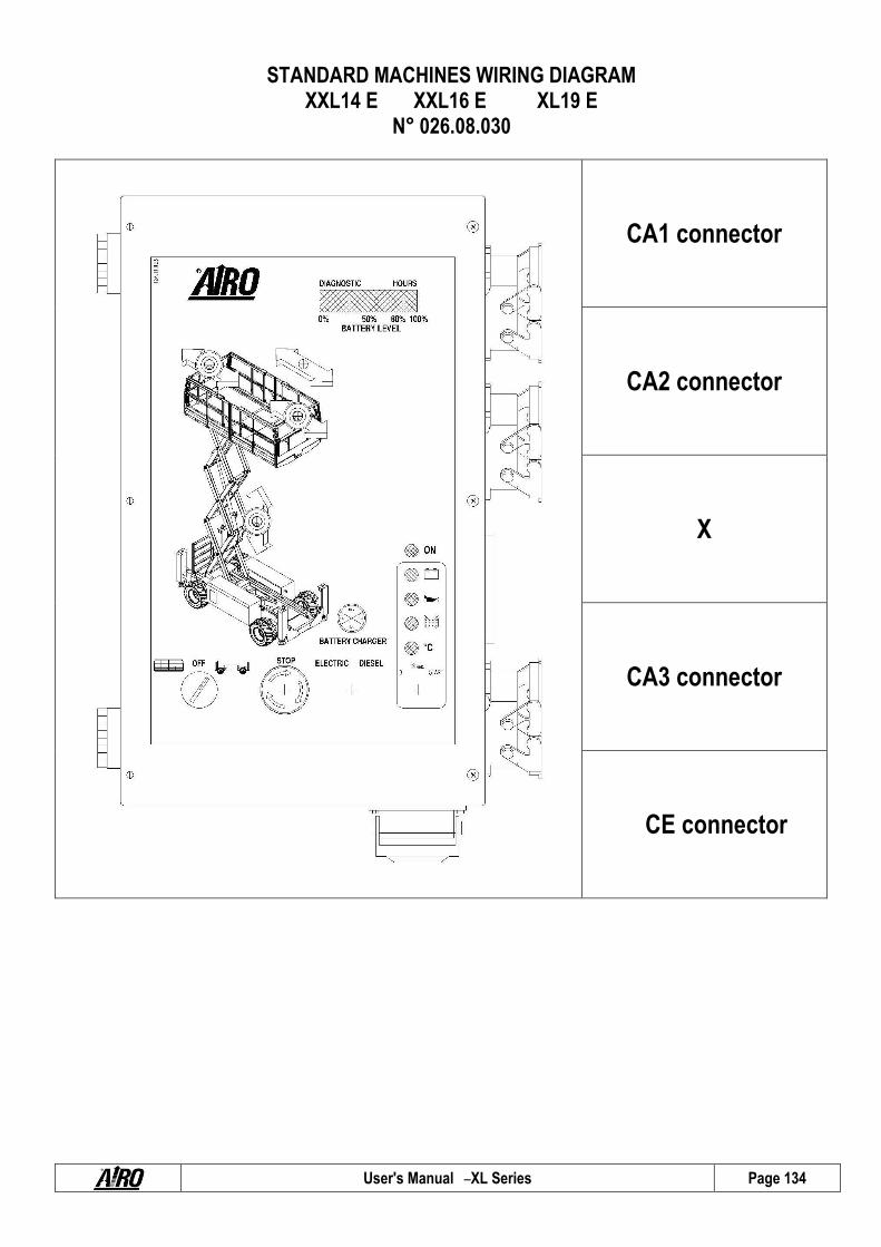
User's Manual – XL Series Page 134
STANDARD MACHINES WIRING DIAGRAM XXL14 E XXL16 E XL19 E
N° 026.08.030
CA1 connector
CA2 connector
X
CA3 connector
CE connector

User's Manual – XL Series Page 135
CA1 Connector 1 EV1 (+): proportional movements 22 EV1 (-): proportional movements
2 EV2 (+): backward drive 23 EV2 (-): backward drive
3 EV3 (+): forward drive 24 EV3 (-): forward drive
4 EV4 (+): UP 25 EV4 (-): UP
5 EV5 (+): DOWN 26 EV5 (-): DOWN
6 EV6 (+) 27 EV6 (-)
7 EV7 (+) 28 EV7 (-)
8 EV8 (+): steering 29 EV8 (-): steering
9 EV9 (+): steering 30 EV9 (-): steering
10 EV10A and EV10B (+): series 31 EV10A and EV10B (-): series
11 EV10C and EV10D (+): series 32 EV10C and EV10D (-): series
12 / 33 /
13 EV11 (+): anti-step 34 EV11 (-): anti-step
14 EV20A and EV20B (+) 35 EV20A and EV20B (-)
15 EV36 (+) 36 EV36 (-)
16 EV37 (+) 37 EV37 (-)
17 / 38 /
18 / 39 /
19 / 40 /
20 / 41 /
21 Rotating beacons (+) 42 Rotating beacons (-)
CA2 connector 1 TLR1 (+) 22 Battery Charger Led - brown
2 / 23 Battery Charger relay
3 Horn (+) 24 Battery Charger relay
4 M1 (signal): anti-step microswitch 25 SPI (+) +48V
5 M1S (signal): drive disable microswitch 26 SPI (-) –batt.
6 / 27 SPI (signal)
7 / 28 +12V sic
8 PQ (signal): inclinometer 29 +48V batt.
9 TLR1 (-) 30 /
10 / 31 AM (signal)
11 Horn (-) 32 AM (+)
12 M1 (+): anti-step microswitch 33 AM (-)
13 M1S (+): drive disable microswitch 34 /
14 / 35 /
15 / 36 /
16 / 37 Fuse (+)
17 / 38 Fuse (+)
18 PQ (+): inclinometer 39 Fuse (+)
19 PQ (-): inclinometer 40 Battery (-)
20 Battery Charger Led - green 41 Battery (-)
21 Battery Charger Led - white 42 Battery (-)
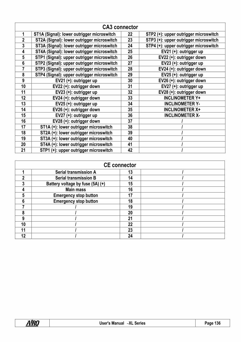
User's Manual – XL Series Page 136
CA3 connector 1 ST1A (Signal): lower outrigger microswitch 22 STP2 (+): upper outrigger microswitch
2 ST2A (Signal): lower outrigger microswitch 23 STP3 (+): upper outrigger microswitch
3 ST3A (Signal): lower outrigger microswitch 24 STP4 (+): upper outrigger microswitch
4 ST4A (Signal): lower outrigger microswitch 25 EV21 (+): outrigger up
5 STP1 (Signal): upper outrigger microswitch 26 EV22 (+): outrigger down
6 STP2 (Signal): upper outrigger microswitch 27 EV23 (+): outrigger up
7 STP3 (Signal): upper outrigger microswitch 28 EV24 (+): outrigger down
8 STP4 (Signal): upper outrigger microswitch 29 EV25 (+): outrigger up
9 EV21 (+): outrigger up 30 EV26 (+): outrigger down
10 EV22 (+): outrigger down 31 EV27 (+): outrigger up
11 EV23 (+): outrigger up 32 EV28 (+): outrigger down
12 EV24 (+): outrigger down 33 INCLINOMETER Y+
13 EV25 (+): outrigger up 34 INCLINOMETER Y-
14 EV26 (+): outrigger down 35 INCLINOMETER X+
15 EV27 (+): outrigger up 36 INCLINOMETER X-
16 EV28 (+): outrigger down 37 /
17 ST1A (+): lower outrigger microswitch 38 /
18 ST2A (+): lower outrigger microswitch 39 /
19 ST3A (+): lower outrigger microswitch 40 /
20 ST4A (+): lower outrigger microswitch 41 /
21 STP1 (+): upper outrigger microswitch 42 /
CE connector 1 Serial transmission A 13 /
2 Serial transmission B 14 /
3 Battery voltage by fuse (5A) (+) 15 /
4 Main mass 16 /
5 Emergency stop button 17 /
6 Emergency stop button 18 /
7 / 19 /
8 / 20 /
9 / 21 /
10 / 22 /
11 / 23 /
12 / 24 /
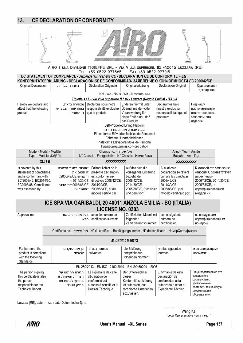
User's Manual – XL Series Page 137
13. CE DECLARATION OF CONFORMITY
EC STATEMENT OF COMPLIANCE - תאימות על הצהרה CE - DECLARATION CE DE CONFORMITE' - EG KONFORMITÄTSERKLÄRUNG - DECLARACION CE DE CONFORMIDAD- ЗАЯВЛЕНИЕ О КОНФОРМНОСТИ EC 2006/42/CE
Original Declaration מקורית הצהרה Déclaration Originale Originalerklärung Declaración Original Оригинальнaя декларация
Noi - We - Nous - Wir – Nosotros- мы
Tigieffe s.r.l. - Via Villa Superiore N.° 82 - Luzzara (Reggio Emilia) - ITALIA
Hereby we declare and attest that the following product:
, בזאת מצהירה, הבלעדית באחריותה
:המוצר כי
Declarons sous notre responsabilitè exclusive que le produit:
Erklaren hiermit unter Übernahme der vollen Verantwortung für diese Erklärung , daß das Produkt:
Declaramos bajo nuestra exclusiva responsabilidad que el producto:
Под нашу исключительную ответственность заявляем, что изделие:
Self-Propelled Lifting Platform ניידת מתרוממת עבודה במת
Plates-forme Elévatrice Mobiles de Personnel Fahrbare Hubarbeitsbühnen
Plataforma Elevadora Móvil de Personal Платформa для высотнoгo работ
Model - Model - Modèle Type – Modelo-МОДЕЛЬ
Chassis no. – שלדה' מס N° Chassis - Fahrgestellnr - N° Chassis - НомерРама
Anno - Year - Année Baujahr – Ano -Год
XL11 E XXXXXXXXXX XXXXXXXXXX
Is covered by this statement of compliance and is conformant with EC/2006/42, EC2014/30, EC2005/88. Compliance was assessed by:
הצהרה ניתנת שעבורו את תואם זו
, 2006/42/CEההנחיות2014/30/CE ו-2005/88/CEהדגם ואת
:י“ע שאושר
Faisant l’objet de la présente déclaration est conforme aux directives 2006/42/CE, 2014/30/CE, 2005/88/CE, et au modéle certifié par
Auf das sich die vorliegende Erklärung bezieht, den 2006/42/CE, 2014/30/CE, 2005/88/CE, Richtlinien und dem von:
Al cual esta declaración se refiere cumple las directivas 2006/42/CE, 2014/30/CE, 2005/88/CE, y el modelo certificato por:
К которой это заявление относится, соответствует директивами 2006/42/CE, 2014/30/CE, 2005/88/CE, и сертифицированной модели из:
ICE SPA VIA GARIBALDI, 20 40011 ANZOLA EMILIA - BO (ITALIA) LICENSE NO. 0303
Approval no.: האישור מספר בעל :הבא
avec le numèro de certification suivant:
Zertifizierten Modell mit folgender Zertifizierungsnummer:
con el siguiente número de certificación:
со следующим сертифицированным номером:
Certificate no. – אישור' מס - N° du certificat - Bestätigungnummer - N° de certificado – НомерСертификатa
M.0303.15.5813
Furthermore, the product is compliant with the following Standards:
התקנים את וכן :הבאים
et aux normes suivantes:
die Erklärung entspricht den folgenden Normen:
y a las siguentes normas:
и со следующими нормами:
EN 280:2013 EN ISO 12100:2010 EN ISO 60204-1:2006
The person signing this certificate is also the person responsible for the Technical Report.
על החתום הגורם זו תאימות הצהרת את לפתוח מוסמך .הטכני התיק
Le signataire de cette déclaration de conformité est autorisé à constituer le Dossier Technique.
Der Unterzeichner dieser Konformitätserklärung ist autorisiert, das technische Unterlagen abzufassen.
El firmante de esta declaración de conformidad está autorizado a crear el Expediente Técnico.
Лицо, подписавшее это заявление о соответствии, уполномочено составить техническую документацию оборудования.
Luzzara (RE), date -תאריך-date-Datum-fecha-Дата
............................................................
Wang Kai (Legal Representative - החוקי הנציג )
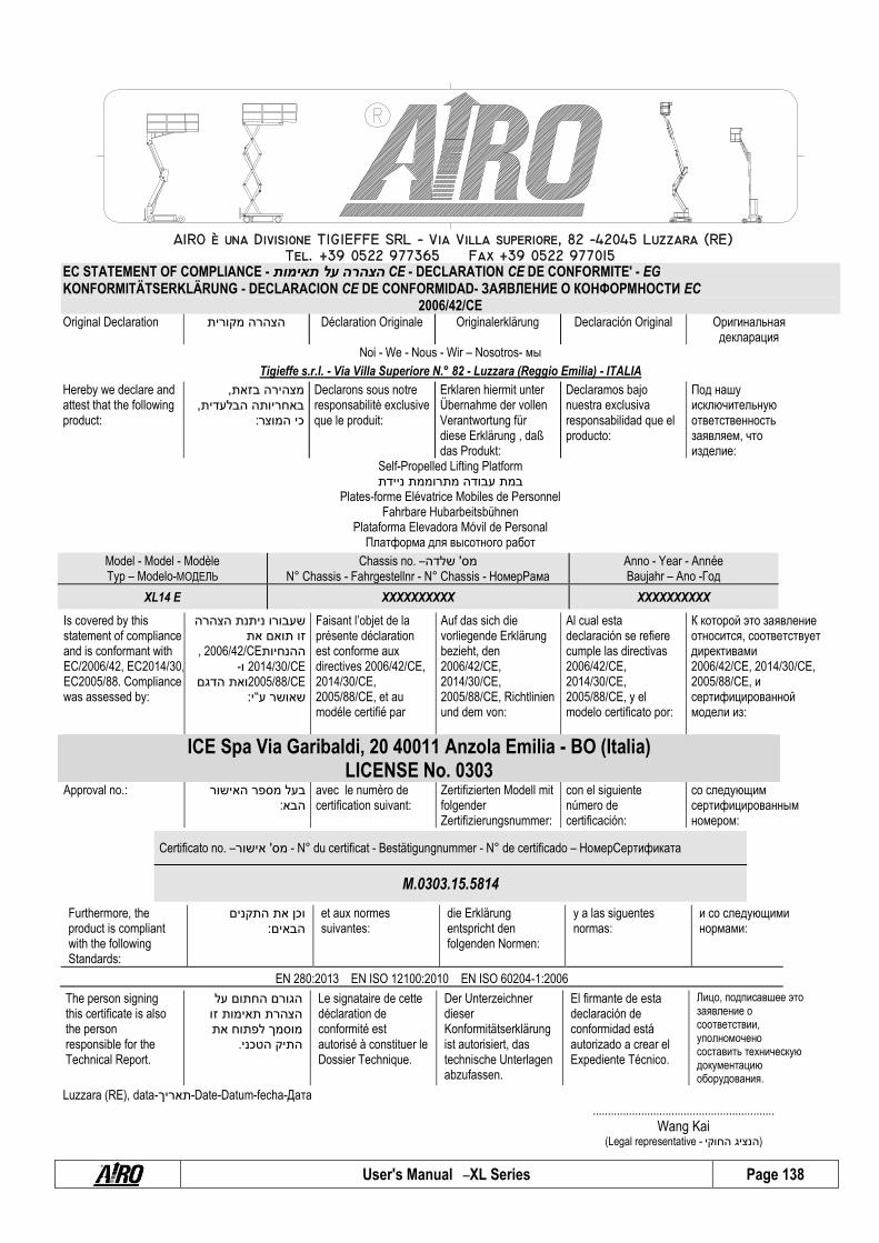
User's Manual – XL Series Page 138
EC STATEMENT OF COMPLIANCE - תאימות על הצהרה CE - DECLARATION CE DE CONFORMITE' - EG KONFORMITÄTSERKLÄRUNG - DECLARACION CE DE CONFORMIDAD- ЗАЯВЛЕНИЕ О КОНФОРМНОСТИ EC
2006/42/CE Original Declaration
מקורית הצהרה Déclaration Originale Originalerklärung Declaración Original Оригинальнaя
декларация Noi - We - Nous - Wir – Nosotros- мы
Tigieffe s.r.l. - Via Villa Superiore N.° 82 - Luzzara (Reggio Emilia) - ITALIA
Hereby we declare and attest that the following product:
, בזאת מצהירה, הבלעדית באחריותה
:המוצר כי
Declarons sous notre responsabilitè exclusive que le produit:
Erklaren hiermit unter Übernahme der vollen Verantwortung für diese Erklärung , daß das Produkt:
Declaramos bajo nuestra exclusiva responsabilidad que el producto:
Под нашу исключительную ответственность заявляем, что изделие:
Self-Propelled Lifting Platform ניידת מתרוממת עבודה במת
Plates-forme Elévatrice Mobiles de Personnel Fahrbare Hubarbeitsbühnen
Plataforma Elevadora Móvil de Personal Платформa для высотнoгo работ
Model - Model - Modèle Typ – Modelo-МОДЕЛЬ
Chassis no. – שלדה' מס N° Chassis - Fahrgestellnr - N° Chassis - НомерРама
Anno - Year - Année Baujahr – Ano -Год
XL14 E XXXXXXXXXX XXXXXXXXXX
Is covered by this statement of compliance and is conformant with EC/2006/42, EC2014/30, EC2005/88. Compliance was assessed by:
הצהרה ניתנת שעבורו את תואם זו
, 2006/42/CEההנחיות2014/30/CE ו-2005/88/CEהדגם ואת
:י“ע שאושר
Faisant l’objet de la présente déclaration est conforme aux directives 2006/42/CE, 2014/30/CE, 2005/88/CE, et au modéle certifié par
Auf das sich die vorliegende Erklärung bezieht, den 2006/42/CE, 2014/30/CE, 2005/88/CE, Richtlinien und dem von:
Al cual esta declaración se refiere cumple las directivas 2006/42/CE, 2014/30/CE, 2005/88/CE, y el modelo certificato por:
К которой это заявление относится, соответствует директивами 2006/42/CE, 2014/30/CE, 2005/88/CE, и сертифицированной модели из:
ICE Spa Via Garibaldi, 20 40011 Anzola Emilia - BO (Italia) LICENSE No. 0303
Approval no.: האישור מספר בעל :הבא
avec le numèro de certification suivant:
Zertifizierten Modell mit folgender Zertifizierungsnummer:
con el siguiente número de certificación:
со следующим сертифицированным номером:
Certificato no. – אישור' מס - N° du certificat - Bestätigungnummer - N° de certificado – НомерСертификатa
M.0303.15.5814
Furthermore, the product is compliant with the following Standards:
התקנים את וכן :הבאים
et aux normes suivantes:
die Erklärung entspricht den folgenden Normen:
y a las siguentes normas:
и со следующими нормами:
EN 280:2013 EN ISO 12100:2010 EN ISO 60204-1:2006
The person signing this certificate is also the person responsible for the Technical Report.
על החתום הגורם זו תאימות הצהרת את לפתוח מוסמך .הטכני התיק
Le signataire de cette déclaration de conformité est autorisé à constituer le Dossier Technique.
Der Unterzeichner dieser Konformitätserklärung ist autorisiert, das technische Unterlagen abzufassen.
El firmante de esta declaración de conformidad está autorizado a crear el Expediente Técnico.
Лицо, подписавшее это заявление о соответствии, уполномочено составить техническую документацию оборудования.
Luzzara (RE), data-תאריך-Date-Datum-fecha-Дата ............................................................
Wang Kai (Legal representative - החוקי הנציג )

User's Manual – XL Series Page 139
EC STATEMENT OF COMPLIANCE - תאימות על הצהרה CE - DECLARATION CE DE CONFORMITE' - EG KONFORMITÄTSERKLÄRUNG - DECLARACION CE DE CONFORMIDAD- ЗАЯВЛЕНИЕ О КОНФОРМНОСТИ EC
2006/42/CE Original Declaration
מקורית הצהרה Déclaration Originale Originalerklärung Declaración Original Оригинальнaя декларация
Noi - We - Nous - Wir – Nosotros- мы
Tigieffe s.r.l. - Via Villa Superiore N.° 82 - Luzzara (Reggio Emilia) - ITALIA
Hereby we declare and attest that the following product
, בזאת מצהירה, הבלעדית באחריותה
:המוצר כי
Declarons sous notre responsabilitè exclusive que le produit:
Erklaren hiermit unter Übernahme der vollen Verantwortung für diese Erklärung , daß das Produkt:
Declaramos bajo nuestra exclusiva responsabilidad que el producto:
Под нашу исключительную ответственность заявляем, что изделие:
Self-Propelled Lifting Platform ניידת מתרוממת עבודה במת
Plates-forme Elévatrice Mobiles de Personnel Fahrbare Hubarbeitsbühnen
Plataforma Elevadora Móvil de Personal Платформa для высотнoгo работ
Model - Model - Modèle Typ – Modelo-МОДЕЛЬ
Chassis No. – שלדה' מס N° Chassis - Fahrgestellnr - N° Chassis - НомерРама
Anno - Year - Année Baujahr – Ano -Год
XL14 E 6P XXXXXXXXXX XXXXXXXXXX
Is covered by this statement of compliance and is conformant with EC/2006/42, EC2014/30, EC2005/88. Compliance was assessed by:
הצהרה ניתנת שעבורו את תואם זו
, 2006/42/CEההנחיות2014/30/CE ו-2005/88/CEהדגם ואת
:י“ע שאושר
Faisant l’objet de la présente déclaration est conforme aux directives 2006/42/CE, 2014/30/CE, 2005/88/CE, et au modéle certifié par
Auf das sich die vorliegende Erklärung bezieht, den 2006/42/CE, 2014/30/CE, 2005/88/CE, Richtlinien und dem von:
Al cual esta declaración se refiere cumple las directivas 2006/42/CE, 2014/30/CE, 2005/88/CE, y el modelo certificato por:
К которой это заявление относится, соответствует директивами 2006/42/CE, 2014/30/CE, 2005/88/CE, и сертифицированной модели из:
ICE Spa Via Garibaldi, 20 40011 Anzola Emilia - BO (Italia) LICENCE no. 0303
Approval no.: האישור מספר בעל :הבא
avec le numèro de certification suivant:
Zertifizierten Modell mit folgender Zertifizierungsnummer:
con el siguiente número de certificación:
со следующим сертифицированным номером:
Certificate no. – אישור' מס - N° du certificat - Bestätigungnummer - N° de certificado – НомерСертификатa
M.0303.15.5815
Furthermore, the product is compliant with the following Standards:
התקנים את וכן :הבאים
et aux normes suivantes:
die Erklärung entspricht den folgenden Normen:
y a las siguentes normas:
и со следующими нормами:
EN 280:2013 EN ISO 12100:2010 EN ISO 60204-1:2006
The person signing this certificate is also the person responsible for the Technical Report.
על החתום הגורם זו תאימות הצהרת את לפתוח מוסמך .הטכני התיק
Le signataire de cette déclaration de conformité est autorisé à constituer le Dossier Technique.
Der Unterzeichner dieser Konformitätserklärung ist autorisiert, das technische Unterlagen abzufassen.
El firmante de esta declaración de conformidad está autorizado a crear el Expediente Técnico.
Лицо, подписавшее это заявление о соответствии, уполномочено составить техническую документацию оборудования.
Luzzara (RE), data-תאריך-date-Datum-fecha-Дата ............................................................
Wang Kai (Legal representative - החוקי הנציג )

User's Manual – XL Series Page 140
EC STATEMENT OF COMPLIANCE - תאימות על הצהרה CE - DECLARATION CE DE CONFORMITE' - EG KONFORMITÄTSERKLÄRUNG - DECLARACION CE DE CONFORMIDAD- ЗАЯВЛЕНИЕ О КОНФОРМНОСТИ EC
2006/42/CE Original Declaration
מקורית הצהרה Déclaration Originale Originalerklärung Declaración Original Оригинальнaя декларация
Noi - We - Nous - Wir – Nosotros- мы
Tigieffe s.r.l. - Via Villa Superiore N.° 82 - Luzzara (Reggio Emilia) - ITALIA
Hereby we declare and attest that the following product:
, בזאת מצהירה, הבלעדית באחריותה
:המוצר כי
Declarons sous notre responsabilitè exclusive que le produit:
Erklaren hiermit unter Übernahme der vollen Verantwortung für diese Erklärung , daß das Produkt:
Declaramos bajo nuestra exclusiva responsabilidad que el producto:
Под нашу исключительную ответственность заявляем, что изделие:
Self-Propelled Lifting Platform ניידת מתרוממת עבודה במת
Plates-forme Elévatrice Mobiles de Personnel Fahrbare Hubarbeitsbühnen
Plataforma Elevadora Móvil de Personal Платформa для высотнoгo работ
Model - Model - Modèle Typ – Modelo-МОДЕЛЬ
Chassis No. – שלדה' מס N° Chassis - Fahrgestellnr - N° Chassis - НомерРама
Anno - Year - Année Baujahr – Ano -Год
XXL14 E XXXXXXXXXX XXXXXXXXXX
Is covered by this statement of compliance and is conformant with EC/2006/42, EC2014/30, EC2005/88. Compliance was assessed by::
הצהרה ניתנת שעבורו את תואם זו
, 2006/42/CEההנחיות2014/30/CE ו-2005/88/CEהדגם ואת
:י“ע שאושר
Faisant l’objet de la présente déclaration est conforme aux directives 2006/42/CE, 2014/30/CE, 2005/88/CE, et au modéle certifié par
Auf das sich die vorliegende Erklärung bezieht, den 2006/42/CE, 2014/30/CE, 2005/88/CE, Richtlinien und dem von:
Al cual esta declaración se refiere cumple las directivas 2006/42/CE, 2014/30/CE, 2005/88/CE, y el modelo certificato por:
К которой это заявление относится, соответствует директивами 2006/42/CE, 2014/30/CE, 2005/88/CE, и сертифицированной модели из:
ICE Spa Via Garibaldi, 20 40011 Anzola Emilia - BO (Italia) LICENSE no. 0303
Approval no.: האישור מספר בעל :הבא
avec le numèro de certification suivant:
Zertifizierten Modell mit folgender Zertifizierungsnummer:
con el siguiente número de certificación:
со следующим сертифицированным номером:
Certificate No. – אישור' מס - N° du certificat - Bestätigungnummer - N° de certificado – НомерСертификатa
M.0303.15.5822
Furthermore, the product is compliant with the following Standards:
התקנים את וכן :הבאים
et aux normes suivantes:
die Erklärung entspricht den folgenden Normen:
y a las siguentes normas:
и со следующими нормами:
EN 280:2013 EN ISO 12100:2010 EN ISO 60204-1:2006
The person signing this certificate is also the person responsible for the Technical Report.
על החתום הגורם זו תאימות הצהרת את לפתוח מוסמך .הטכני התיק
Le signataire de cette déclaration de conformité est autorisé à constituer le Dossier Technique.
Der Unterzeichner dieser Konformitätserklärung ist autorisiert, das technische Unterlagen abzufassen.
El firmante de esta declaración de conformidad está autorizado a crear el Expediente Técnico.
Лицо, подписавшее это заявление о соответствии, уполномочено составить техническую документацию оборудования.
Luzzara (RE), data-תאריך-date-Datum-fecha-Дата
............................................................
Wang Kai (Legal Representative - החוקי הנציג )

User's Manual – XL Series Page 141
EC STATEMENT OF COMPLIANCE - תאימות על הצהרה CE - DECLARATION CE DE CONFORMITE' - EG KONFORMITÄTSERKLÄRUNG - DECLARACION CE DE CONFORMIDAD- ЗАЯВЛЕНИЕ О КОНФОРМНОСТИ EC
2006/42/CE Original Declaration
מקורית הצהרה Déclaration Originale Originalerklärung Declaración Original Оригинальнaя
декларация Noi - We - Nous - Wir – Nosotros- мы
Tigieffe s.r.l. - Via Villa Superiore N.° 82 - Luzzara (Reggio Emilia) - ITALIA
Hereby we declare and attest that the following product:
, בזאת מצהירה, הבלעדית באחריותה
:המוצר כי
Declarons sous notre responsabilitè exclusive que le produit:
Erklaren hiermit unter Übernahme der vollen Verantwortung für diese Erklärung , daß das Produkt:
Declaramos bajo nuestra exclusiva responsabilidad que el producto:
Под нашу исключительную ответственность заявляем, что изделие:
Self-Propelled Lifting Platform ניידת מתרוממת עבודה במת
Plates-forme Elévatrice Mobiles de Personnel Fahrbare Hubarbeitsbühnen
Plataforma Elevadora Móvil de Personal Платформa для высотнoгo работ
Model - Model - Modèle Typ – Modelo-МОДЕЛЬ
Chassis No. – שלדה' מס N° Chassis - Fahrgestellnr - N° Chassis - НомерРама
Anno - Year - Année Baujahr – Ano -Год
XXL14 D XXXXXXXXXX XXXXXXXXXX
Is covered by this statement of compliance and is conformant with EC/2006/42, EC2014/30, EC2005/88. Compliance was assessed by:
הצהרה ניתנת שעבורו את תואם זו
, 2006/42/CEההנחיות2014/30/CE ו-2005/88/CEהדגם ואת
:י“ע שאושר
Faisant l’objet de la présente déclaration est conforme aux directives 2006/42/CE, 2014/30/CE, 2005/88/CE, et au modéle certifié par
Auf das sich die vorliegende Erklärung bezieht, den 2006/42/CE, 2014/30/CE, 2005/88/CE, Richtlinien und dem von:
Al cual esta declaración se refiere cumple las directivas 2006/42/CE, 2014/30/CE, 2005/88/CE, y el modelo certificato por:
К которой это заявление относится, соответствует директивами 2006/42/CE, 2014/30/CE, 2005/88/CE, и сертифицированной модели из:
ICE Spa Via Garibaldi, 20 40011 Anzola Emilia - BO (Italia) LICENCE no. 0303
Approval no.: האישור מספר בעל :הבא
avec le numèro de certification suivant:
Zertifizierten Modell mit folgender Zertifizierungsnummer:
con el siguiente número de certificación:
со следующим сертифицированным номером:
Certificate No. – אישור' מס - N° du certificat - Bestätigungnummer - N° de certificado – НомерСертификатa
M.0303.15.5821
Furthermore, the product is compliant with the following Standards:
התקנים את וכן :הבאים
et aux normes suivantes:
die Erklärung entspricht den folgenden Normen:
y a las siguentes normas:
и со следующими нормами:
EN 280:2013 EN ISO 12100:2010 EN ISO 60204-1:2006
The person signing this certificate is also the person responsible for the Technical Report.
על החתום הגורם זו תאימות הצהרת את לפתוח מוסמך .הטכני התיק
Le signataire de cette déclaration de conformité est autorisé à constituer le Dossier Technique.
Der Unterzeichner dieser Konformitätserklärung ist autorisiert, das technische Unterlagen abzufassen.
El firmante de esta declaración de conformidad está autorizado a crear el Expediente Técnico.
Лицо, подписавшее это заявление о соответствии, уполномочено составить техническую документацию оборудования.
Luzzara (RE), data-תאריך-date-Datum-fecha-Дата ............................................................
Wang Kai (Legal Representative - החוקי הנציג )

User's Manual – XL Series Page 142
EC STATEMENT OF COMPLIANCE - תאימות על הצהרה CE - DECLARATION CE DE CONFORMITE' - EG KONFORMITÄTSERKLÄRUNG - DECLARACION CE DE CONFORMIDAD- ЗАЯВЛЕНИЕ О КОНФОРМНОСТИ EC
2006/42/CE Original Declaration מקורית הצהרה Déclaration Originale Originalerklärung Declaración Original Оригинальнaя
декларация Noi - We - Nous - Wir – Nosotros- мы
Tigieffe s.r.l. - Via Villa Superiore N.° 82 - Luzzara (Reggio Emilia) - ITALIA
Hereby we declare and attest that the following product:
, בזאת מצהירה, הבלעדית באחריותה
:המוצר כי
Declarons sous notre responsabilitè exclusive que le produit:
Erklaren hiermit unter Übernahme der vollen Verantwortung für diese Erklärung , daß das Produkt:
Declaramos bajo nuestra exclusiva responsabilidad que el producto:
Под нашу исключительную ответственность заявляем, что изделие:
Self-Propelled Lifting Platform ניידת מתרוממת עבודה במת
Plates-forme Elévatrice Mobiles de Personnel Fahrbare Hubarbeitsbühnen
Plataforma Elevadora Móvil de Personal Платформa для высотнoгo работ
Model - Model - Modèle Typ – Modelo-МОДЕЛЬ
Chassis No. – שלדה' מס N° Chassis - Fahrgestellnr - N° Chassis - НомерРама
Anno - Year - Année Baujahr – Ano -Год
XL14 RTD XXXXXXXXXX XXXXXXXXXX
Is covered by this statement of compliance and is conformant with EC/2006/42, EC2014/30, EC2005/88. Compliance was assessed by:
הצהרה ניתנת שעבורו את תואם זו
, 2006/42/CEההנחיות2014/30/CE ו-2005/88/CEהדגם ואת
:י“ע שאושר
Faisant l’objet de la présente déclaration est conforme aux directives 2006/42/CE, 2014/30/CE, 2005/88/CE, et au modéle certifié par
Auf das sich die vorliegende Erklärung bezieht, den 2006/42/CE, 2014/30/CE, 2005/88/CE, Richtlinien und dem von:
Al cual esta declaración se refiere cumple las directivas 2006/42/CE, 2014/30/CE, 2005/88/CE, y el modelo certificato por:
К которой это заявление относится, соответствует директивами 2006/42/CE, 2014/30/CE, 2005/88/CE, и сертифицированной модели из:
ICE Spa Via Garibaldi, 20 40011 Anzola Emilia - BO (Italia) LICENCE No. 0303
Approval no.: האישור מספר בעל :הבא
avec le numèro de certification suivant:
Zertifizierten Modell mit folgender Zertifizierungsnummer:
con el siguiente número de certificación:
со следующим сертифицированным номером:
Certificate No. – אישור' מס - N° du certificat - Bestätigungnummer - N° de certificado – НомерСертификатa
M.0303.15.5816
Furthermore, the product is compliant with the following Standards:
התקנים את וכן :הבאים
et aux normes suivantes:
die Erklärung entspricht den folgenden Normen:
y a las siguentes normas:
и со следующими нормами:
EN 280:2013 EN ISO 12100:2010 EN ISO 60204-1:2006
The person signing this certificate is also the person responsible for the Technical Report.
על החתום הגורם זו תאימות הצהרת את לפתוח מוסמך .הטכני התיק
Le signataire de cette déclaration de conformité est autorisé à constituer le Dossier Technique.
Der Unterzeichner dieser Konformitätserklärung ist autorisiert, das technische Unterlagen abzufassen.
El firmante de esta declaración de conformidad está autorizado a crear el Expediente Técnico.
Лицо, подписавшее это заявление о соответствии, уполномочено составить техническую документацию оборудования.
Luzzara (RE), data-תאריך-date-Datum-fecha-Дата
Wang Kai (Legal Representative - החוקי הנציג )
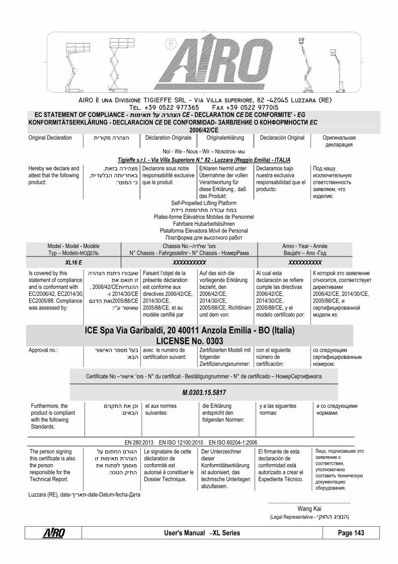
User's Manual – XL Series Page 143
EC STATEMENT OF COMPLIANCE - תאימות על הצהרה CE - DECLARATION CE DE CONFORMITE' - EG KONFORMITÄTSERKLÄRUNG - DECLARACION CE DE CONFORMIDAD- ЗАЯВЛЕНИЕ О КОНФОРМНОСТИ EC
2006/42/CE Original Declaration
מקורית הצהרה Déclaration Originale Originalerklärung Declaración Original Оригинальнaя
декларация Noi - We - Nous - Wir – Nosotros- мы
Tigieffe s.r.l. - Via Villa Superiore N.° 82 - Luzzara (Reggio Emilia) - ITALIA
Hereby we declare and attest that the following product:
, בזאת מצהירה, הבלעדית באחריותה
:המוצר כי
Declarons sous notre responsabilitè exclusive que le produit:
Erklaren hiermit unter Übernahme der vollen Verantwortung für diese Erklärung , daß das Produkt:
Declaramos bajo nuestra exclusiva responsabilidad que el producto:
Под нашу исключительную ответственность заявляем, что изделие:
Self-Propelled Lifting Platform ניידת מתרוממת עבודה במת
Plates-forme Elévatrice Mobiles de Personnel Fahrbare Hubarbeitsbühnen
Plataforma Elevadora Móvil de Personal Платформa для высотнoгo работ
Model - Model - Modèle Typ – Modelo-МОДЕЛЬ
Chassis No.– שלדה' מס N° Chassis - Fahrgestellnr - N° Chassis - НомерРама
Anno - Year - Année Baujahr – Ano -Год
XL16 E XXXXXXXXXX XXXXXXXXXX
Is covered by this statement of compliance and is conformant with EC/2006/42, EC2014/30, EC2005/88. Compliance was assessed by:
הצהרה ניתנת שעבורו את תואם זו
, 2006/42/CEההנחיות2014/30/CE ו-2005/88/CEהדגם ואת
:י“ע שאושר
Faisant l’objet de la présente déclaration est conforme aux directives 2006/42/CE, 2014/30/CE, 2005/88/CE, et au modéle certifié par
Auf das sich die vorliegende Erklärung bezieht, den 2006/42/CE, 2014/30/CE, 2005/88/CE, Richtlinien und dem von:
Al cual esta declaración se refiere cumple las directivas 2006/42/CE, 2014/30/CE, 2005/88/CE, y el modelo certificato por:
К которой это заявление относится, соответствует директивами 2006/42/CE, 2014/30/CE, 2005/88/CE, и сертифицированной модели из:
ICE Spa Via Garibaldi, 20 40011 Anzola Emilia - BO (Italia) LICENSE No. 0303
Approval no.: האישור מספר בעל :הבא
avec le numèro de certification suivant:
Zertifizierten Modell mit folgender Zertifizierungsnummer:
con el siguiente número de certificación:
со следующим сертифицированным номером:
Certificate No – אישור' מס - N° du certificat - Bestätigungnummer - N° de certificado – НомерСертификатa
M.0303.15.5817
Furthermore, the product is compliant with the following Standards:
התקנים את וכן :הבאים
et aux normes suivantes:
die Erklärung entspricht den folgenden Normen:
y a las siguentes normas:
и со следующими нормами:
EN 280:2013 EN ISO 12100:2010 EN ISO 60204-1:2006
The person signing this certificate is also the person responsible for the Technical Report.
על החתום הגורם זו תאימות הצהרת את לפתוח מוסמך .הטכני התיק
Le signataire de cette déclaration de conformité est autorisé à constituer le Dossier Technique.
Der Unterzeichner dieser Konformitätserklärung ist autorisiert, das technische Unterlagen abzufassen.
El firmante de esta declaración de conformidad está autorizado a crear el Expediente Técnico.
Лицо, подписавшее это заявление о соответствии, уполномочено составить техническую документацию оборудования.
Luzzara (RE), data-תאריך-date-Datum-fecha-Дата ............................................................
Wang Kai (Legal Representative - החוקי הנציג )

User's Manual – XL Series Page 144
EC STATEMENT OF COMPLIANCE - תאימות על הצהרה CE - DECLARATION CE DE CONFORMITE' - EG KONFORMITÄTSERKLÄRUNG - DECLARACION CE DE CONFORMIDAD- ЗАЯВЛЕНИЕ О КОНФОРМНОСТИ EC
2006/42/CE Original Declaration
מקורית הצהרה Déclaration Originale Originalerklärung Declaración Original Оригинальнaя
декларация Noi - We - Nous - Wir – Nosotros- мы
Tigieffe s.r.l. - Via Villa Superiore N.° 82 - Luzzara (Reggio Emilia) - ITALIA
Hereby we declare and attest that the following product
, בזאת מצהירה, הבלעדית באחריותה
:המוצר כי
Declarons sous notre responsabilitè exclusive que le produit:
Erklaren hiermit unter Übernahme der vollen Verantwortung für diese Erklärung , daß das Produkt:
Declaramos bajo nuestra exclusiva responsabilidad que el producto:
Под нашу исключительную ответственность заявляем, что изделие:
Self-Propelled Lifting Platform ניידת מתרוממת עבודה במת
Plates-forme Elévatrice Mobiles de Personnel Fahrbare Hubarbeitsbühnen
Plataforma Elevadora Móvil de Personal Платформa для высотнoгo работ
Model - Model - Modèle Typ – Modelo-МОДЕЛЬ
Chassis No. – שלדה' מס N° Chassis - Fahrgestellnr - N° Chassis - НомерРама
Anno - Year - Année Baujahr – Ano -Год
XXL16 E XXXXXXXXXX XXXXXXXXXX
Is covered by this statement of compliance and is conformant with EC/2006/42, EC2014/30, EC2005/88. Compliance was assessed by:
הצהרה ניתנת שעבורו את תואם זו
, 2006/42/CEההנחיות2014/30/CE ו-2005/88/CEהדגם ואת
:י“ע שאושר
Faisant l’objet de la présente déclaration est conforme aux directives 2006/42/CE, 2014/30/CE, 2005/88/CE, et au modéle certifié par
Auf das sich die vorliegende Erklärung bezieht, den 2006/42/CE, 2014/30/CE, 2005/88/CE, Richtlinien und dem von:
Al cual esta declaración se refiere cumple las directivas 2006/42/CE, 2014/30/CE, 2005/88/CE, y el modelo certificato por:
К которой это заявление относится, соответствует директивами 2006/42/CE, 2014/30/CE, 2005/88/CE, и сертифицированной модели из:
ICE Spa Via Garibaldi, 20 40011 Anzola Emilia - BO (Italia) LICENSE no. 0303
Approval no.: האישור מספר בעל :הבא
avec le numèro de certification suivant:
Zertifizierten Modell mit folgender Zertifizierungsnummer:
con el siguiente número de certificación:
со следующим сертифицированным номером:
Certificate No. – אישור' מס - N° du certificat - Bestätigungnummer - N° de certificado – НомерСертификатa
XXXXXXXXXXXXXXXXX
Furthermore, the product is compliant with the following Standards:
התקנים את וכן :הבאים
et aux normes suivantes:
die Erklärung entspricht den folgenden Normen:
y a las siguentes normas:
и со следующими нормами:
EN 280:2013 EN ISO 12100:2010 EN ISO 60204-1:2006
The person signing this certificate is also the person responsible for the Technical Report.
על החתום הגורם זו תאימות הצהרת את לפתוח מוסמך .הטכני התיק
Le signataire de cette déclaration de conformité est autorisé à constituer le Dossier Technique.
Der Unterzeichner dieser Konformitätserklärung ist autorisiert, das technische Unterlagen abzufassen.
El firmante de esta declaración de conformidad está autorizado a crear el Expediente Técnico.
Лицо, подписавшее это заявление о соответствии, уполномочено составить техническую документацию оборудования.
Luzzara (RE), data-תאריך-date-Datum-fecha-Дата
............................................................
Wang Kai (Legal Representative - החוקי הנציג )

User's Manual – XL Series Page 145
EC STATEMENT OF COMPLIANCE - תאימות על הצהרה CE - DECLARATION CE DE CONFORMITE' - EG KONFORMITÄTSERKLÄRUNG - DECLARACION CE DE CONFORMIDAD- ЗАЯВЛЕНИЕ О КОНФОРМНОСТИ EC
2006/42/CE Original Declaration
מקורית הצהרה Déclaration Originale Originalerklärung Declaración Original Оригинальнaя
декларация Noi - We - Nous - Wir – Nosotros- мы
Tigieffe s.r.l. - Via Villa Superiore N.° 82 - Luzzara (Reggio Emilia) - ITALIA
Hereby we declare and attest that the following product
, בזאת מצהירה, הבלעדית באחריותה
:המוצר כי
Declarons sous notre responsabilitè exclusive que le produit:
Erklaren hiermit unter Übernahme der vollen Verantwortung für diese Erklärung , daß das Produkt:
Declaramos bajo nuestra exclusiva responsabilidad que el producto:
Под нашу исключительную ответственность заявляем, что изделие:
Self-Propelled Lifting Platform ניידת מתרוממת עבודה במת
Plates-forme Elévatrice Mobiles de Personnel Fahrbare Hubarbeitsbühnen
Plataforma Elevadora Móvil de Personal Платформa для высотнoгo работ
Model - Model - Modèle Typ – Modelo-МОДЕЛЬ
Chassis No. – שלדה' מס N° Chassis - Fahrgestellnr - N° Chassis - НомерРама
Anno - Year - Année Baujahr – Ano -Год
XL16 RTD XXXXXXXXXX XXXXXXXXXX
Is covered by this statement of compliance and is conformant with EC/2006/42, EC2014/30, EC2005/88. Compliance was assessed by:
הצהרה ניתנת שעבורו את תואם זו
, 2006/42/CEההנחיות2014/30/CE ו-2005/88/CEהדגם ואת
:י“ע שאושר
Faisant l’objet de la présente déclaration est conforme aux directives 2006/42/CE, 2014/30/CE, 2005/88/CE, et au modéle certifié par
Auf das sich die vorliegende Erklärung bezieht, den 2006/42/CE, 2014/30/CE, 2005/88/CE, Richtlinien und dem von:
Al cual esta declaración se refiere cumple las directivas 2006/42/CE, 2014/30/CE, 2005/88/CE, y el modelo certificato por:
К которой это заявление относится, соответствует директивами 2006/42/CE, 2014/30/CE, 2005/88/CE, и сертифицированной модели из:
ICE Spa Via Garibaldi, 20 40011 Anzola Emilia - BO (Italia) LICENSE no. 0303
Approval no.: האישור מספר בעל :הבא
avec le numèro de certification suivant:
Zertifizierten Modell mit folgender Zertifizierungsnummer:
con el siguiente número de certificación:
со следующим сертифицированным номером:
Certificate No. – אישור' מס - N° du certificat - Bestätigungnummer - N° de certificado – НомерСертификатa
M.0303.15.5818
Furthermore, the product is compliant with the following Standards:
התקנים את וכן :הבאים
et aux normes suivantes:
die Erklärung entspricht den folgenden Normen:
y a las siguentes normas:
и со следующими нормами:
EN 280:2013 EN ISO 12100:2010 EN ISO 60204-1:2006
The person signing this certificate is also the person responsible for the Technical Report.
על החתום הגורם זו תאימות הצהרת את לפתוח מוסמך .הטכני התיק
Le signataire de cette déclaration de conformité est autorisé à constituer le Dossier Technique.
Der Unterzeichner dieser Konformitätserklärung ist autorisiert, das technische Unterlagen abzufassen.
El firmante de esta declaración de conformidad está autorizado a crear el Expediente Técnico.
Лицо, подписавшее это заявление о соответствии, уполномочено составить техническую документацию оборудования.
Luzzara (RE), data-תאריך-date-Datum-fecha-Дата
............................................................
Wang Kai (Legal Representative - החוקי הנציג )

User's Manual – XL Series Page 146
EC STATEMENT OF COMPLIANCE - תאימות על הצהרה CE - DECLARATION CE DE CONFORMITE' - EG KONFORMITÄTSERKLÄRUNG - DECLARACION CE DE CONFORMIDAD- ЗАЯВЛЕНИЕ О КОНФОРМНОСТИ EC
2006/42/CE Original Declaration
מקורית הצהרה Déclaration Originale Originalerklärung Declaración Original Оригинальнaя
декларация Noi - We - Nous - Wir – Nosotros- мы
Tigieffe s.r.l. - Via Villa Superiore N.° 82 - Luzzara (Reggio Emilia) - ITALIA
Hereby we declare and attest that the following product
, בזאת מצהירה, הבלעדית באחריותה
:המוצר כי
Declarons sous notre responsabilitè exclusive que le produit:
Erklaren hiermit unter Übernahme der vollen Verantwortung für diese Erklärung , daß das Produkt:
Declaramos bajo nuestra exclusiva responsabilidad que el producto:
Под нашу исключительную ответственность заявляем, что изделие:
Self-Propelled Lifting Platform ניידת מתרוממת עבודה במת
Plates-forme Elévatrice Mobiles de Personnel Fahrbare Hubarbeitsbühnen
Plataforma Elevadora Móvil de Personal Платформa для высотнoгo работ
Model - Model - Modèle Typ – Modelo-МОДЕЛЬ
Chassis No. – שלדה' מס N° Chassis - Fahrgestellnr - N° Chassis - НомерРама
Anno - Year - Année Baujahr – Ano -Год
XL19 E XXXXXXXXXX XXXXXXXXXX
Is covered by this statement of compliance and is conformant with EC/2006/42, EC2014/30, EC2005/88. Compliance was assessed by:
הצהרה ניתנת שעבורו את תואם זו
, 2006/42/CEההנחיות2014/30/CE ו-2005/88/CEהדגם ואת
:י“ע שאושר
Faisant l’objet de la présente déclaration est conforme aux directives 2006/42/CE, 2014/30/CE, 2005/88/CE, et au modéle certifié par
Auf das sich die vorliegende Erklärung bezieht, den 2006/42/CE, 2014/30/CE, 2005/88/CE, Richtlinien und dem von:
Al cual esta declaración se refiere cumple las directivas 2006/42/CE, 2014/30/CE, 2005/88/CE, y el modelo certificato por:
К которой это заявление относится, соответствует директивами 2006/42/CE, 2014/30/CE, 2005/88/CE, и сертифицированной модели из:
ICE Spa Via Garibaldi, 20 40011 Anzola Emilia - BO (Italia) LICENSE no. 0303
Approval no.: האישור מספר בעל :הבא
avec le numèro de certification suivant:
Zertifizierten Modell mit folgender Zertifizierungsnummer:
con el siguiente número de certificación:
со следующим сертифицированным номером:
Certificate No – אישור' מס - N° du certificat - Bestätigungnummer - N° de certificado – НомерСертификатa
M.0303.15.5819
Furthermore, the product is compliant with the following Standards:
התקנים את וכן :הבאים
et aux normes suivantes:
die Erklärung entspricht den folgenden Normen:
y a las siguentes normas:
и со следующими нормами:
EN 280:2013 EN ISO 12100:2010 EN ISO 60204-1:2006
The person signing this certificate is also the person responsible for the Technical Report.
על החתום הגורם זו תאימות הצהרת את לפתוח מוסמך .הטכני התיק
Le signataire de cette déclaration de conformité est autorisé à constituer le Dossier Technique.
Der Unterzeichner dieser Konformitätserklärung ist autorisiert, das technische Unterlagen abzufassen.
El firmante de esta declaración de conformidad está autorizado a crear el Expediente Técnico.
Лицо, подписавшее это заявление о соответствии, уполномочено составить техническую документацию оборудования.
Luzzara (RE), data-תאריך-date-Datum-fecha-Дата ............................................................
Wang Kai (Legal Representative - החוקי הנציג )

User's Manual – XL Series Page 147
EC STATEMENT OF COMPLIANCE - תאימות על הצהרה CE - DECLARATION CE DE CONFORMITE' - EG KONFORMITÄTSERKLÄRUNG - DECLARACION CE DE CONFORMIDAD- ЗАЯВЛЕНИЕ О КОНФОРМНОСТИ EC
2006/42/CE Original Declaration
מקורית הצהרה Déclaration Originale Originalerklärung Declaración Original Оригинальнaя
декларация Noi - We - Nous - Wir – Nosotros- мы
Tigieffe s.r.l. - Via Villa Superiore N.° 82 - Luzzara (Reggio Emilia) - ITALIA
Hereby we declare and attest that the following product
, בזאת מצהירה, הבלעדית באחריותה
:המוצר כי
Declarons sous notre responsabilitè exclusive que le produit:
Erklaren hiermit unter Übernahme der vollen Verantwortung für diese Erklärung , daß das Produkt:
Declaramos bajo nuestra exclusiva responsabilidad que el producto:
Под нашу исключительную ответственность заявляем, что изделие:
Self-Propelled Lifting Platform ניידת מתרוממת עבודה במת
Plates-forme Elévatrice Mobiles de Personnel Fahrbare Hubarbeitsbühnen
Plataforma Elevadora Móvil de Personal Платформa для высотнoгo работ
Model - Model - Modèle Typ – Modelo-МОДЕЛЬ
Chassis No. – שלדה' מס N° Chassis - Fahrgestellnr - N° Chassis - НомерРама
Anno - Year - Année Baujahr – Ano -Год
XL19 RTD XXXXXXXXXX XXXXXXXXXX
Is covered by this statement of compliance and is conformant with EC/2006/42, EC2014/30, EC2005/88. Compliance was assessed by:
הצהרה ניתנת שעבורו את תואם זו
, 2006/42/CEההנחיות2014/30/CE ו-2005/88/CEהדגם ואת
:י“ע שאושר
Faisant l’objet de la présente déclaration est conforme aux directives 2006/42/CE, 2014/30/CE, 2005/88/CE, et au modéle certifié par
Auf das sich die vorliegende Erklärung bezieht, den 2006/42/CE, 2014/30/CE, 2005/88/CE, Richtlinien und dem von:
Al cual esta declaración se refiere cumple las directivas 2006/42/CE, 2014/30/CE, 2005/88/CE, y el modelo certificato por:
К которой это заявление относится, соответствует директивами 2006/42/CE, 2014/30/CE, 2005/88/CE, и сертифицированной модели из:
ICE Spa Via Garibaldi, 20 40011 Anzola Emilia - BO (Italia) LICENSE no. 0303
Approval no.: האישור מספר בעל :הבא
avec le numèro de certification suivant:
Zertifizierten Modell mit folgender Zertifizierungsnummer:
con el siguiente número de certificación:
со следующим сертифицированным номером:
Certificate No. – אישור' מס - N° du certificat - Bestätigungnummer - N° de certificado – НомерСертификатa
M.0303.15.5820
Furthermore, the product is compliant with the following Standards:
התקנים את וכן :הבאים
et aux normes suivantes:
die Erklärung entspricht den folgenden Normen:
y a las siguentes normas:
и со следующими нормами:
EN 280:2013 EN ISO 12100:2010 EN ISO 60204-1:2006
The person signing this certificate is also the person responsible for the Technical Report.
על החתום הגורם זו תאימות הצהרת את לפתוח מוסמך .הטכני התיק
Le signataire de cette déclaration de conformité est autorisé à constituer le Dossier Technique.
Der Unterzeichner dieser Konformitätserklärung ist autorisiert, das technische Unterlagen abzufassen.
El firmante de esta declaración de conformidad está autorizado a crear el Expediente Técnico.
Лицо, подписавшее это заявление о соответствии, уполномочено составить техническую документацию оборудования.
Luzzara (RE), data-תאריך-date-Datum-fecha-Дата ............................................................
Wang Kai (Legal Representative - החוקי הנציג )

User's Manual – XL Series Page 148
EC STATEMENT OF COMPLIANCE - תאימות על הצהרה CE - DECLARATION CE DE CONFORMITE' - EG KONFORMITÄTSERKLÄRUNG - DECLARACION CE DE CONFORMIDAD- ЗАЯВЛЕНИЕ О КОНФОРМНОСТИ EC
2006/42/CE Original Declaration
מקורית הצהרה Déclaration Originale Originalerklärung Declaración Original Оригинальнaя
декларация Noi - We - Nous - Wir – Nosotros- мы
Tigieffe s.r.l. - Via Villa Superiore N.° 82 - Luzzara (Reggio Emilia) - ITALIA
Hereby we declare and attest that the following product
, בזאת מצהירה, הבלעדית באחריותה
המוצר כי :
Declarons sous notre responsabilitè exclusive que le produit:
Erklaren hiermit unter Übernahme der vollen Verantwortung für diese Erklärung , daß das Produkt:
Declaramos bajo nuestra exclusiva responsabilidad que el producto:
Под нашу исключительную ответственность заявляем, что изделие:
Self-Propelled Lifting Platform v ניידת מתרוממת עבודה במת
Plates-forme Elévatrice Mobiles de Personnel Fahrbare Hubarbeitsbühnen
Plataforma Elevadora Móvil de Personal Платформa для высотнoгo работ
Model - Model - Modèle Typ – Modelo-МОДЕЛЬ
Chassis No. – שלדה' מס N° Chassis - Fahrgestellnr - N° Chassis - НомерРама
Anno - Year - Année Baujahr – Ano -Год
XXL19 D XXXXXXXXXX XXXXXXXXXX
Is covered by this statement of compliance and is conformant with EC/2006/42, EC2014/30, EC2005/88. Compliance was assessed by:
הצהרה ניתנת שעבורו את תואם זו
, 2006/42/CEההנחיות2014/30/CE ו-2005/88/CEהדגם ואת
:י“ע שאושר
Faisant l’objet de la présente déclaration est conforme aux directives 2006/42/CE, 2014/30/CE, 2005/88/CE, et au modéle certifié par
Auf das sich die vorliegende Erklärung bezieht, den 2006/42/CE, 2014/30/CE, 2005/88/CE, Richtlinien und dem von:
Al cual esta declaración se refiere cumple las directivas 2006/42/CE, 2014/30/CE, 2005/88/CE, y el modelo certificato por:
К которой это заявление относится, соответствует директивами 2006/42/CE, 2014/30/CE, 2005/88/CE, и сертифицированной модели из:
ICE Spa Via Garibaldi, 20 40011 Anzola Emilia - BO (Italia) LICENSE No. 0303
Approval no.: האישור מספר בעל :הבא
avec le numèro de certification suivant:
Zertifizierten Modell mit folgender Zertifizierungsnummer:
con el siguiente número de certificación:
со следующим сертифицированным номером:
Certificate No. – אישור' מס - N° du certificat - Bestätigungnummer - N° de certificado – НомерСертификатa
M.0303.15.5823
Furthermore, the product is compliant with the following Standards:
התקנים את וכן :הבאים
et aux normes suivantes:
die Erklärung entspricht den folgenden Normen:
y a las siguentes normas:
и со следующими нормами:
EN 280:2013 EN ISO 12100:2010 EN ISO 60204-1:2006
The person signing this certificate is also the person responsible for the Technical Report.
על החתום הגורם זו תאימות הצהרת את לפתוח מוסמך .הטכני התיק
Le signataire de cette déclaration de conformité est autorisé à constituer le Dossier Technique.
Der Unterzeichner dieser Konformitätserklärung ist autorisiert, das technische Unterlagen abzufassen.
El firmante de esta declaración de conformidad está autorizado a crear el Expediente Técnico.
Лицо, подписавшее это заявление о соответствии, уполномочено составить техническую документацию оборудования.
Luzzara (RE), data-תאריך-date-Datum-fecha-Дата ............................................................
Wang Kai (Legal Representative - החוקי הנציג )