webpak 3000 dc drives hardware reference, …...instruction manual c ul r ul r manual p/n: 899.07.86...
TRANSCRIPT
WebPak 3000 DC DrivesHardware Reference, Installation,and Troubleshooting
Instruction Manual
ULC RULR
Manual P/N: 899.07.86 User Manual: 491359e (02)Publication: WP3000-UM010B-EN

.
CONTENTS
Contents I
General NotesSafety Instructions................................................................................................ VGeneral Notes ..................................................................................................... VI
Chapter 1 Introduction to the Drive 1-1..1-4
1.1 Store the Drive ................................................................................................. 1-11.2 Drive Identification Nameplate........................................................................... 1-11.3 Drive Selection .................................................................................................. 1-21.4 Drive Description ............................................................................................... 1-31.5 Related Publications........................................................................................... 1-31.6 Optional Kits ...................................................................................................... 1-4
Chapter 2 Install and Wire the Drive 2-1...2-20
2.0 Recommended AC Line and DC Armature Fuses ............................................. 2-12.1 Install the Drive, Dimensions ............................................................................. 2-12.2 Install a Line Reactor or Transformer for Input Power Conditioning................... 2-82.3 Install an Input Disconnect - Guidelines............................................................. 2-82.4 Install the Motor................................................................................................. 2-92.5 Wire the Drive ................................................................................................... 2-9
2.5.0 General Wiring Practices ....................................................................... 2-92.5.1 Ground the Drive, the Motor and the Operator's Control Station. ........... 2-92.5.2 Recommended Lugs ............................................................................ 2-102.5.3 Wire AC Power to the Drive ................................................................. 2-132.5.4 Wire the DC Motor to the Drive ............................................................ 2-13
2.5.4.1 Motor Overload Protection ........................................................ 2-132.5.5. Wire Stopping Devices to the Drive ..................................................... 2-13
2.5.5.1 Description of Stop Modes and Drive States............................. 2-132.5.5.2 Provide the Emergency Stop Function...................................... 2-142.5.5.3 COAST/STOP Digital Input ...................................................... 2-152.5.5.4 SECTION OFF Digital Input .................................................... 2-152.5.5.5 Customer Interlock Digital Input ............................................... 2-15
2.5.6 Wire the Main Contactor to the Drive ................................................... 2-152.5.7 Wire Optional Devices to the Drive ..................................................... 2-162.5.8 Wire the I/O Expansion Board ............................................................. 2-18
Chapter 3 Drive Setup and Adjustment 3-1...3-10
3.1 Perform a Power Off Inspection ........................................................................ 3-13.2 Test Equipment Needed.................................................................................... 3-13.3 Perform a Motor Ground Check......................................................................... 3-13.4 Set Jumpers on the Regulator Board ................................................................ 3-2
3.4.1 Set Regulator Type Jumper J15 ............................................................ 3-33.4.2 Setting Program Protection Jumper J16 ................................................ 3-43.4.3 Inspect the Field Loss Detection Jumper J20......................................... 3-43.4.4 Inspect the Field Supply Jumper J21 ..................................................... 3-43.4.5 Set the Source of Manual Mode Reference Jumper J19 ....................... 3-43.4.6 Set the Voltage Range and Scale of Analog Tacho Jumpers J14 / J11 . 3-43.4.7 Set the Line Speed Reference Jumper J12 and J10 ............................. 3-53.4.8 Scale the Armature Current Feedback Jumper J18 .............................. 3-53.4.9 Inspect Jumper J26 ............................................................................... 3-53.4.10 Inspect the Spare 1 and Spare 2 Jumper J27 ....................................... 3-63.4.11 Inspect the Filter Select Jumper J28 ..................................................... 3-63.4.12 Inspect the Spare 2 Jumper J29 ............................................................ 3-63.4.13 Inspect the Power Interface Jumper J30 ............................................... 3-6
II WebPak 3000 DC Drive Hardware Reference
3.5 Set the Jumpers on the I/O Expansion Board ....................................................3-73.6 Verify the Correct Direction of Motor Rotation .................................................... 3-93.7 Determine the DC Tachometer Lead Polarity..................................................... 3-93.8 Make Tachometer and Armature Feedback Adjustments................................. 3-103.9 Make Final Adjustments................................................................................... 3-10
Chapter 4 Troubleshooting/Diagnostics 4-1..4-16
4.1 Checking for Wiring Errors................................................................................. 4-14.2 Verify AC Line and Power Input ......................................................................... 4-14.3 Verify DC Motor Connections............................................................................. 4-14.4 Verifying Optional Kits........................................................................................ 4-24.5 Check the Regulator LED Status ...................................................................... 4-24.6 Fault and Alarm Messages, Descriptions, and Code Numbers............................4-34.7 Adjusting the Tachometer or Encoder Loss Sensitivity..................................... 4-104.8 Phase Locked Loop (PLL) Maximum Error....................................................... 4-104.9 SCR Diagnostics and Adjusting Open SCR Sensitivity..................................... 4-114.10 Armature Phase Fire Test ................................................................................ 4-134.11 Setting Reversed Tachometer or Reversed Encoder Lead Detection .............. 4-154.12 Setting Up Inverting Fault Avoidance ............................................................... 4-154.13 Checking the AC Line Period and Voltage ....................................................... 4-164.14 Checking Drive Information.............................................................................. 4-164.15 Power Supply Test Pin Identification ................................................................ 4-15
Chapter 5 Replacement Parts and Accessories 5-1..5-20
5.0 Replacement of Components............................................................................. 5-15.1 Recommended Spare Parts ............................................................................... 5-35.2 Accessories........................................................................................................ 5-5
Appendix A Technical Specifications A-1...A-6
Appendix B CE-Conformity B-1...B-4
Appendix C Cross Reference Part Numbers Catalogue Numbers C-1...C-2
Contents III
List of Figures
Figure 1.1 - Sample WebPak 3000 Nameplate.........................................................................1.1Figure 1.2 - WebPak 3000 Functional Block Diagram............................................................. 1-3Figure 2.1 - Mounting Dimensions for WebPak 3000, 25 and 60 A...................................... 2-2Figure 2.2 - Mounting Dimensions for WebPak 3000, 150 A.................................................. 2-3Figure 2.3 - Mounting Dimensions for WebPak 3000, 250 and 450 A.................................... 2-4Figure 2.4 - Mounting Dimensions for WebPak 3000, 800 A.................................................. 2-5Figure 2.5 - Mounting Dimensions for WebPak 3000, 1200 and 1600 A................................ 2-6Figure 2.6 - Mounting Dimensions for WebPak 3000, 2000 A................................................ 2-7Figure 2.7a - Principle Wiring Diagram, 150 A ........................................................................ 2-11Figure 2.7b - Principle Wiring Diagram, 1600 A ...................................................................... 2-12Figure 2.8a - Main Contactor Connection Diagram - Example ................................................ 2-15Figure 2.8b - CTB Connection Diagram - Example ................................................................. 2-17Figure 2.9: I/O Expansion Board Terminal Strip Connection Diagram .................................. 2-18Figure 3.1 - Regulator Board Jumper Positions ...................................................................... 3-3Figure 3.2 - AUTO REF Jumpers............................................................................................ 3-5Figure 3.3 - I/O Expansion Board Jumper Locations............................................................... 3-7Figure 3.4 - Jumper Settings on the I/O Expansion board........................................................ 3-8Figure 4.1 - SCR Armature Current During Normal Operation .............................................. 4-13Figure 4.2 - Load SCRs Fail to Turn On................................................................................ 4-14Figure 4.3 - Thyristors Fail to contact.................................................................................... 4-15Figure 5.2 - AC-Line Choke Dimensions ................................................................................ 5-9Figure 5.3 - HF Filter Dimensions ........................................................................................ 5-10Figure 5.4 to 5.12 - RFI-Filter Dimensions .............................................................................. 5-12Figure B.1 - Cabinet Configuration .......................................................................................... B-2Figure B.2 - Specification for screened Cable ......................................................................... B-3
List of Tables
Table 1.1 - Drive Selection .................................................................................................... 1-2Table 1.2 - Drive Modification Kits ......................................................................................... 1-4Table 2.1 - Recommended Lugs for Grounding WebPak Drives in UL / cUL Version. ......... 2-10Table 2.2 - User Device Connections to the Control Terminal Board. .................................. 2-16Table 2.3 to 2.8 - Input/Output Connections to the I/O Expansion Terminal Board ................... 2-19Table 3.1 - Jumper and Adjustment Settings on the Regulator Board. .................................. 3-2Table 4.1 - Fault Codes ......................................................................................................... 4-3Table 4.2 - Alarm Codes........................................................................................................ 4-8Table 5.1 - Replacement Parts for WebPak 3000 25-150 A ............................................ 5-3Table 5.2 - Replacement Parts for WebPak 3000 250-800 A ............................................ 5-3Table 5.3 - Replacement Parts for WebPak 3000 1200-2000 A ........................................... 5-4Table 5.4 to 5.7 - Accessories .................................................................................................... 5-5Table A.1 - Armature Voltage................................................................................................. A-3Table A.2 - Tachometer Speed Regulation . .......................................................................... A-3Table A.3 - Drive Specifications ............................................................................................. A-4Table C.1 - Cross Reference Part Numbers Catalogue Numbers .......................................C-1

IV WebPak 3000 DC Drive Hardware Reference
.

GENERAL NOTES
General Notes V
Safety Instructions
ATTENTION: Identifies information about practices or circumstances that can lead topersonal injury or death, property damage, or economic loss.
Important: Identifies information that is critical for successful application and understanding of theproduct.
ATTENTION: Before installing and/or operating this device, this manual must beunderstood by the qualified electrical maintenance person who is familiar with this type ofequipment and the hazards involved. Failure to observe this precaution could result inbodily injury.
ATTENTION: Earth fault detection devices must not be used on this converter as the soleprotection measure against unintentional touching. The DC-component in the earth faultcurrent may inhibit the correct function of the fault detector.
ATTENTION: Electronic converters cause disturbances to the supply network. The basicversion of this converter does not include any harmonic filters and may not fulfil the limitsof the national recommendations. The harmonic voltage disturbances produced by theconverter are dependent on the supply network impedance.
Machinery Directive
ATTENTION: This inverter device is a component intended for implementation inmachines or systems for the capital goods industry.
The start-up of the inverter in the European market is not permitted until it has beenconfirmed that the machine into which the inverters are built is in conformance with theregulations of the Council Directive Machinery 98/37/EWG.
ATTENTION: To inhibit uncontrolled machine operation in case of the malfunction of thedrive, the user must provide an external emergency stop circuit, which ensuresdisconnection of the power source from the motor.This circuit must be hardwired with electro-mechanic components and shall not dependon electronic logic or software. The stopping device (e.g. mushroom head pushbuttonwith lock) must be accessible to the operator.Failure to observe this precaution could result in bodily injury or loss of life.
Electromagnetic Compatibility (EMC-Directive)
ATTENTION: The operating of inverters in the European market is only permitted if theCouncil Directive Electromagnetic Compatibility 89/336/EWG has been observed.
It is the responsibility of the manufacturer of the machine or system to observe theimmunity and emission limits, requested by the Council Directive EMC in the Europeanmarket. Guidelines for the installation according EMC-regulations - for shielding,grounding, filter arrangement as well as wiring instructions - are summarized inAppendix B, CE-Conformance of this Instruction manual.

VI WebPak 3000 DC Drive Hardware Reference
General Notes
Copyright © 2001 Rockwell International Corporation
Each reproduction of this manual may be prosecuted. The copyright of the user's manualremains at Rockwell Automation AG, CH-6036 Dierikon.
Trade mark WebPak and Reliance® are registered trade marks of Rockwell Automation
Manual Scope
This manual contains information on drive installation, drive startup, and troubleshooting procedures.
Measures for CE Conformity on Electro Magnetic Compatibility (EMC) are shown in Appendix B
CHAPTER 1
Introduction to the WebPak3000 Drive 1-1
Introduction to the WebPak 3000 DriveThis section provides specifications and a description of the WebPak 3000 Drive.
1.1 Store the Drive
After receipt inspection, repack the drive in its original shipping container until ready for installation.To ensure satisfactory operation at startup and to maintain warranty coverage, store the drive as follows:
• In its original shipping container in a clean, dry, safe place.
• In an ambient temperature that does not exceed 65°C (149°F) or go below -30°C (-22°F).
• Within a relative humidity range of 5 to 95% without condensation.
• Away from a corrosive atmosphere. In harsh environments, cover the shipping/storagecontainer.
• At an altitude of less than 3,000 meters (10,000 ft.) above sea level.
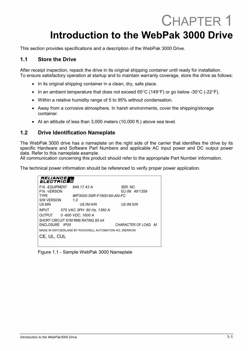
1.2 Drive Identification Nameplate
The WebPak 3000 drive has a nameplate on the right side of the carrier that identifies the drive by itsspecific Hardware and Software Part Numbers and applicable AC input power and DC output powerdata. Refer to this nameplate example.All communication concerning this product should refer to the appropriate Part Number information.
The technical power information should be referenced to verify proper power application.
P.N. -EQUIPMENT 849.17.43 A SER. NO. P.N. -VERSION EU I/M 491359TYPE WP3000-S6R-F1600-60-AN-FCS/W VERSION 1.0US M/N US I/M H/W US I/M S/W
INPUT 575 VAC 3PH 60 Hz, 1360 A
OUTPUT 0 -600 VDC, 1600 A
SHORT CIRCUIT SYM RMS RATING 85 kAENCLOSURE IP00 CHARACTER OF LOAD M
MADE IN SWITZERLAND BY ROCKWELL AUTOMATION AG, DIERIKON
CE, UL, CUL
Figure 1.1 - Sample WebPak 3000 Nameplate
1-2 WebPak 3000 DC Drive Hardware Reference
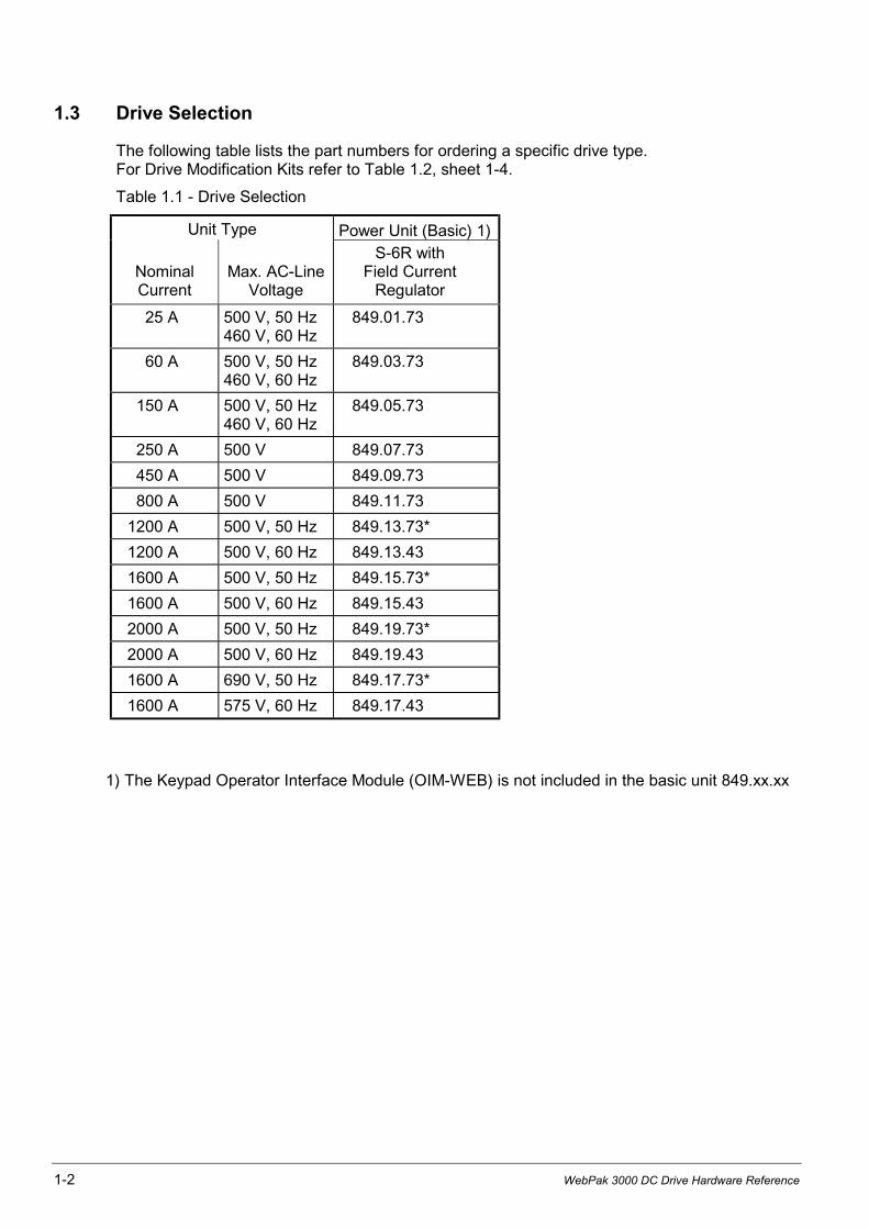
1.3 Drive Selection
The following table lists the part numbers for ordering a specific drive type.For Drive Modification Kits refer to Table 1.2, sheet 1-4.
Table 1.1 - Drive Selection
Unit Type Power Unit (Basic) 1)
NominalCurrent
Max. AC-LineVoltage
S-6R withField Current
Regulator
25 A 500 V, 50 Hz460 V, 60 Hz
849.01.73
60 A 500 V, 50 Hz460 V, 60 Hz
849.03.73
150 A 500 V, 50 Hz460 V, 60 Hz
849.05.73
250 A 500 V 849.07.73
450 A 500 V 849.09.73
800 A 500 V 849.11.73
1200 A 500 V, 50 Hz 849.13.73*
1200 A 500 V, 60 Hz 849.13.43
1600 A 500 V, 50 Hz 849.15.73*
1600 A 500 V, 60 Hz 849.15.43
2000 A 500 V, 50 Hz 849.19.73*
2000 A 500 V, 60 Hz 849.19.43
1600 A 690 V, 50 Hz 849.17.73*
1600 A 575 V, 60 Hz 849.17.43
1) The Keypad Operator Interface Module (OIM-WEB) is not included in the basic unit 849.xx.xx
Introduction to the WebPak3000 Drive 1-3
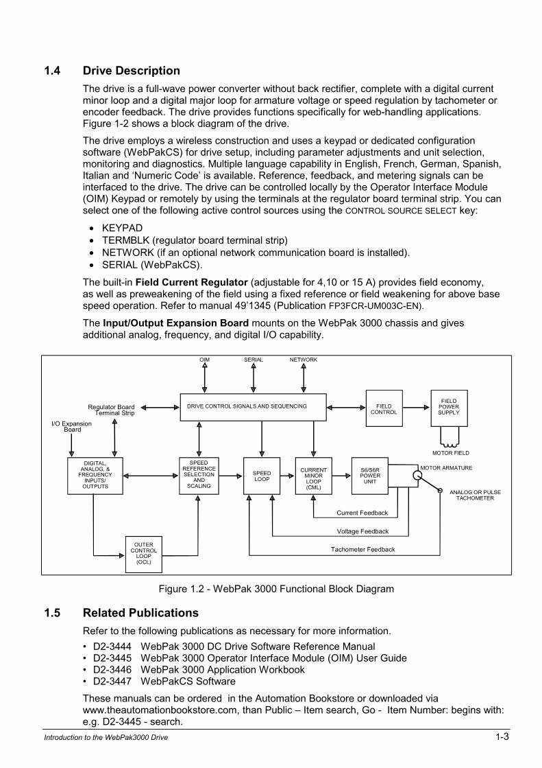
1.4 Drive Description
The drive is a full-wave power converter without back rectifier, complete with a digital currentminor loop and a digital major loop for armature voltage or speed regulation by tachometer orencoder feedback. The drive provides functions specifically for web-handling applications.Figure 1-2 shows a block diagram of the drive.
The drive employs a wireless construction and uses a keypad or dedicated configurationsoftware (WebPakCS) for drive setup, including parameter adjustments and unit selection,monitoring and diagnostics. Multiple language capability in English, French, German, Spanish,Italian and Numeric Code is available. Reference, feedback, and metering signals can beinterfaced to the drive. The drive can be controlled locally by the Operator Interface Module(OIM) Keypad or remotely by using the terminals at the regulator board terminal strip. You canselect one of the following active control sources using the CONTROL SOURCE SELECT key:
• KEYPAD• TERMBLK (regulator board terminal strip)• NETWORK (if an optional network communication board is installed).• SERIAL (WebPakCS).
The built-in Field Current Regulator (adjustable for 4,10 or 15 A) provides field economy,as well as preweakening of the field using a fixed reference or field weakening for above basespeed operation. Refer to manual 491345 (Publication FP3FCR-UM003C-EN).
The Input/Output Expansion Board mounts on the WebPak 3000 chassis and givesadditional analog, frequency, and digital I/O capability.
DRIVE CONTROL SIGNALS AND SEQUENCING
OIM SERIAL NETWORK
SPEEDLOOP
CURRENTMINORLOOP(CML)
FIELDCONTROL
S6/S6RPOWER
UNIT
FIELDPOWERSUPPLY
SPEEDREFERENCESELECTION
ANDSCALING
OUTERCONTROL
LOOP(OCL)
Regulator BoardTerminal Strip
I/O ExpansionBoard
Current Feedback
Voltage Feedback
Tachometer Feedback
MOTOR ARMATURE
ANALOG OR PULSETACHOMETER
MOTOR FIELD
DIGITAL,ANALOG, &
FREQUENCYINPUTS/
OUTPUTS
Figure 1.2 - WebPak 3000 Functional Block Diagram
1.5 Related Publications
Refer to the following publications as necessary for more information.
D2-3444 WebPak 3000 DC Drive Software Reference Manual D2-3445 WebPak 3000 Operator Interface Module (OIM) User Guide D2-3446 WebPak 3000 Application Workbook D2-3447 WebPakCS Software
These manuals can be ordered in the Automation Bookstore or downloaded viawww.theautomationbookstore.com, than Public Item search, Go - Item Number: begins with:e.g. D2-3445 - search.
1-4 WebPak 3000 DC Drive Hardware Reference
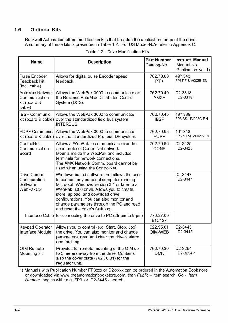
1.6 Optional Kits
Rockwell Automation offers modification kits that broaden the application range of the drive.A summary of these kits is presented in Table 1.2. For US Model-No's refer to Appendix C.
Table 1.2 - Drive Modification Kits
Name Description Part NumberCatalog-No.
Instruct. Manual Manual No. Publication No. 1)
Pulse EncoderFeedback Kit(incl. cable)
Allows for digital pulse Encoder speedfeedback.
762.70.00PTK
491343FP3TIF-UM002B-EN
AutoMax NetworkCommunicationkit (board &cable)
Allows the WebPak 3000 to communicate onthe Reliance AutoMax Distributed ControlSystem (DCS).
762.70.40AMXF
D2-3318 D2-3318
IBSF Communic.kit (board & cable)
Allows the WebPak 3000 to communicateover the standardized field bus systemINTERBUS.
762.70.45IBSF
491339FP3IBS-UM003C-EN
PDPF Communic.kit (board & cable)
Allows the WebPak 3000 to communicateover the standardized Profibus-DP system.
762.70.95PDPF
491348FP3PDP-UM002B-EN
ControlNetCommunicationBoard
Allows a WebPak to communicate over theopen protocol ControlNet network.Mounts inside the WebPak and includesterminals for network connections.The AMX Network Comm. board cannot beused when using the ControlNet.
762.70.96CONF
D2-3425 D2-3425
Drive ControlConfigurationSoftwareWebPakCS
Windows-based software that allows the userto connect any personal computer runningMicro-soft Windows version 3.1 or later to aWebPak 3000 drive. Allows you to create,store, upload, and download driveconfigurations. You can also monitor andchange parameters through the PC and readand reset the drives fault log.
D2-3447 D2-3447
Interface Cable for connecting the drive to PC (25-pin to 9-pin) 772.27.0061C127
Keypad OperatorInterface Module
Allows you to control (e.g. Start, Stop, Jog)the drive. You can also monitor and changeparameters, read and clear the drive's alarmand fault log.
922.95.01OIM-WEB
D2-3445 D2-3445
OIM RemoteMounting kit
Provides for remote mounting of the OIM upto 5 meters away from the drive. Containsalso the cover plate (762.70.31) for theregulator unit.
762.70.30DMK
D2-3294 D2-3294-1
1) Manuals with Publication Number FP3xxx or D2-xxxx can be ordered in the Automation Bookstoreor downloaded via www.theautomationbookstore.com, than Public Item search, Go - ItemNumber: begins with: e.g. FP3 or D2-3445 - search.
CHAPTER 2
Install and Wire the Drive 2-1
Install and Wire the DriveATTENTION: .The user is responsible for conforming to all other applicablestandards. Wiring practices, grounding, disconnects, and overcurrent protection areof particular importance. Size and install all wiring in conformance with theapplicable standards. Failure to observe this precaution could result in severebodily injury or loss of life.
ATTENTION: .This equipment must be connected to a power source for which itwas designed. Compare available power with the requirements listed on thenameplate to insure that voltage, frequency, phase, current capacity andinterrupting capacity are adequate.Failure to observe this precaution could result in severe bodily injury or loss of life.
2.0 Recommended AC Line and DC Armature Fuses
The user must select the correct fuse type (ultra fast, semiconductor protection) for drive ACline and DC armature fuses from the table 5.4 in chapter 5. The armature fuse is only for fourquadrant drives (S-6R).
2.1 Install the Drive
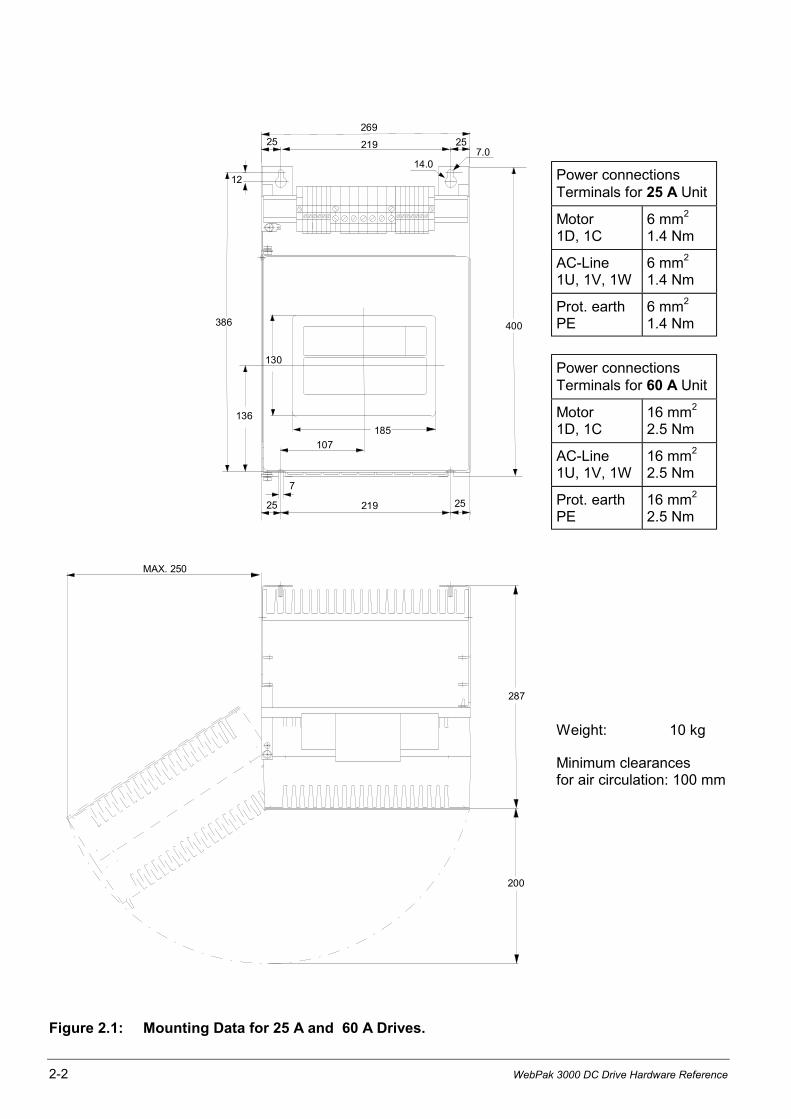
Install the drive(s) in the cabinet. Refer to figures 2.1 to 2.6 for mounting dimensions.
Minimum clearances of 100 mm must be maintained when the drive is mounted within acabinet. This allows adequate ventilation for the drive.
The user must ensure that the drive's ambient temperature specification is met.For more information refer to page 1 of Appendix A.
2-2 WebPak 3000 DC Drive Hardware Reference
Power connectionsTerminals for 25 A Unit
Motor1D, 1C
6 mm2
1.4 Nm
AC-Line1U, 1V, 1W
6 mm2
1.4 Nm
Prot. earthPE
6 mm2
1.4 Nm
Power connectionsTerminals for 60 A Unit
Motor1D, 1C
16 mm2
2.5 Nm
AC-Line1U, 1V, 1W
16 mm2
2.5 Nm
Prot. earthPE
16 mm2
2.5 Nm
Weight: 10 kg
Minimum clearancesfor air circulation: 100 mm
Figure 2.1: Mounting Data for 25 A and 60 A Drives.
MAX. 250
200
287
269
219
107
185
386 400
14.0
136
130
7.02525
12
7
219 2525
Install and Wire the Drive 2-3
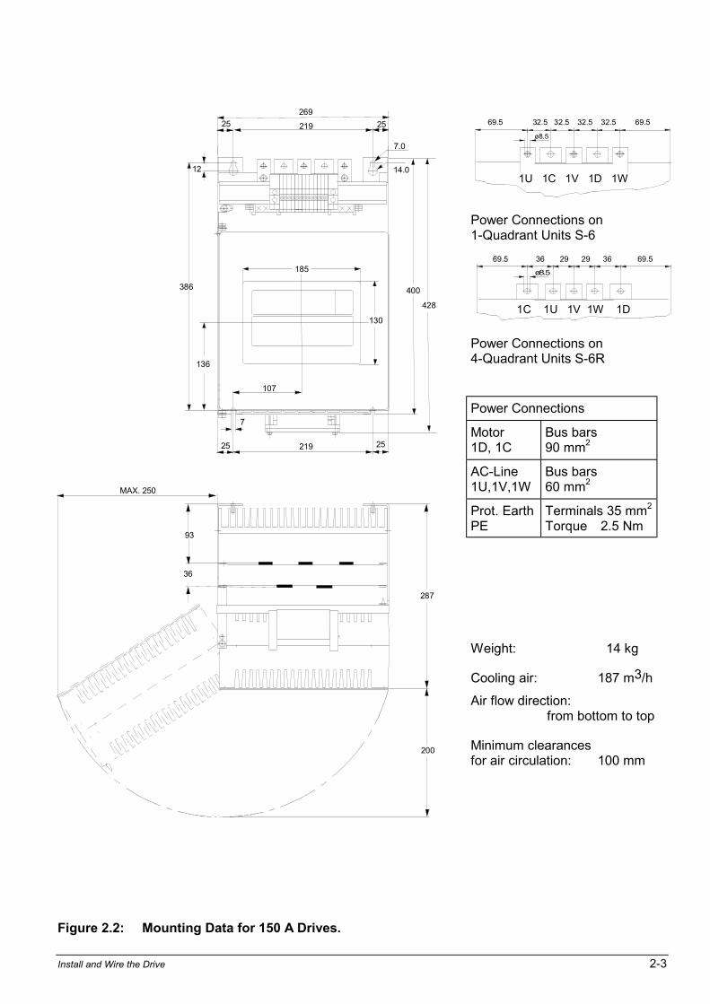
Power Connections on1-Quadrant Units S-6
Power Connections on4-Quadrant Units S-6R
Power Connections
Motor1D, 1C
Bus bars90 mm2
AC-Line1U,1V,1W
Bus bars60 mm2
Prot. EarthPE
Terminals 35 mm2
Torque 2.5 Nm
Weight: 14 kg
Cooling air: 187 m3/h
Air flow direction:from bottom to top
Minimum clearancesfor air circulation: 100 mm
Figure 2.2: Mounting Data for 150 A Drives.
MAX. 250
200
287
269
219
107
185
386
428
14.0
136
130
7.0
2525
12
7
219 2525
400
93
36
69.5 32.5 32.5 32.5 32.5 69.5
ø8.5
1U 1C 1V 1D 1W
ø8.5
69.5 36 29 29 36 69.5
1C 1U 1V 1W 1D
2-4 WebPak 3000 DC Drive Hardware Reference
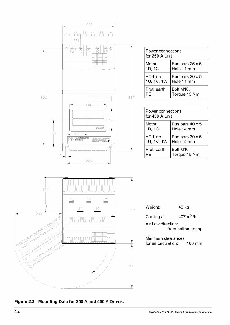
Power connectionsfor 250 A Unit
Motor1D, 1C
Bus bars 25 x 5,Hole 11 mm
AC-Line1U, 1V, 1W
Bus bars 20 x 5,Hole 11 mm
Prot. earthPE
Bolt M10,Torque 15 Nm
Power connectionsfor 450 A Unit
Motor1D, 1C
Bus bars 40 x 5,Hole 14 mm
AC-Line1U, 1V, 1W
Bus bars 30 x 5,Hole 14 mm
Prot. earthPE
Bolt M10Torque 15 Nm
Weight: 40 kg
Cooling air: 407 m3/h
Air flow direction:from bottom to top
Minimum clearancesfor air circulation: 100 mm
Figure 2.3: Mounting Data for 250 A and 450 A Drives.
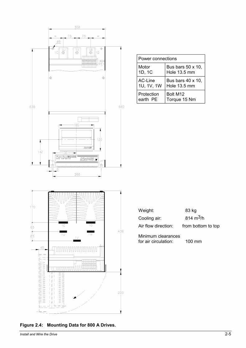
Install and Wire the Drive 2-5
Power connections
Motor1D, 1C
Bus bars 50 x 10,Hole 13.5 mm
AC-Line1U, 1V, 1W
Bus bars 40 x 10,Hole 13.5 mm
Protectionearth PE
Bolt M12Torque 15 Nm
Weight: 83 kg
Cooling air: 814 m3/h
Air flow direction: from bottom to top
Minimum clearancesfor air circulation: 100 mm
Figure 2.4: Mounting Data for 800 A Drives.
2-6 WebPak 3000 DC Drive Hardware Reference
M12
160
6
197
21
=
=
=
=
==
49 50
5052
200
418
317
240
515
400
905
60
455
6089.56089.560
26
26
M12
100 40
10040
190
138185
130
154
DC OUTPUT
DC OUTPUT
975
14
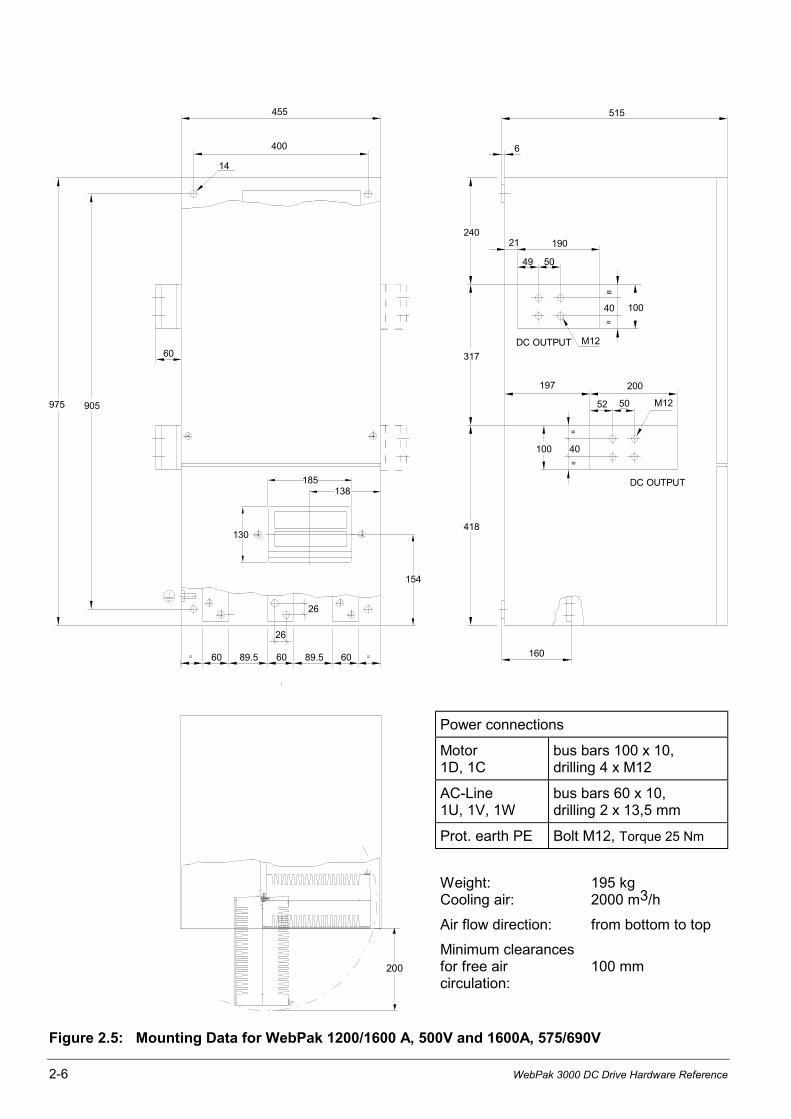
Power connections
Motor1D, 1C
bus bars 100 x 10,drilling 4 x M12
AC-Line1U, 1V, 1W
bus bars 60 x 10,drilling 2 x 13,5 mm
Prot. earth PE Bolt M12, Torque 25 Nm
Weight:Cooling air:
195 kg2000 m3/h
Air flow direction: from bottom to top
200
Minimum clearancesfor free aircirculation:
100 mm
Figure 2.5: Mounting Data for WebPak 1200/1600 A, 500V and 1600A, 575/690V
Install and Wire the Drive 2-7
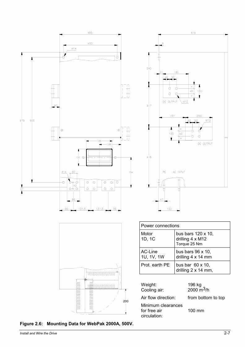
Power connections
Motor1D, 1C
bus bars 120 x 10,drilling 4 x M12Torque 25 Nm
AC-Line1U, 1V, 1W
bus bars 96 x 10,drilling 4 x 14 mm
Prot. earth PE bus bar 60 x 10,drilling 2 x 14 mm,
Weight:Cooling air:
196 kg2000 m3/h
Air flow direction: from bottom to top200
Minimum clearancesfor free aircirculation:
100 mm
Figure 2.6: Mounting Data for WebPak 2000A, 500V.

2-8 WebPak 3000 DC Drive Hardware Reference
2.2 Install a Line Reactor or Transformer for Input Power Conditioning
ATTENTION: Distribution system capacity above the maximum permitted systemkVA, as well as limitation of commutation notches, requires always adding animpedance at line input (terminals 1U, 1V, 1W).You can use a 3-phase line reactorwith 2% voltage drop minimum (refer to Table 5.6) or other means of adding similarimpedance (e.g. matched isolation or auto transformer).
If an input transformer is installed ahead of the drive, a power disconnecting devicemust be installed between the power line and the primary of the transformer. If thispower disconnecting device is a circuit breaker, the circuit breaker trip rating mustbe coordinated with the inrush current (10 to 12 times full-load current) of the inputtransformer. Failure to observe these precautions could result in damage to, ordestruction of, the equipment.
ATTENTION: Connection of a drive to a transformer with a primary rating of 2300VAC or more may require additional input line conditioning. Contact your localRockwell Automation sales/service office for assistance when this is required.Failure to observe this precaution could result in damage to, or destruction of, theequipment.
The star point of the external AC-line transformer must always be grounded (Zeropotential) and connected to the drive ground point (terminal PE or ground stud).
Input transformers step up or step down input voltage and can be either auto or isolationtransformer types. Users should consider using an isolation transformer instead of an autotransformer for the following advantages:
• AC power line disturbances and transients are minimized by an isolation transformer, thusreducing or eliminating possible damage to solid state components.
• An isolation transformer provides electrical isolation for the drive from plant power systemgrounds. Damaging currents may be avoided in instances where the DC output isaccidentally grounded or where the DC motor circuits are grounded.
Rockwell Automation offers a series of isolation transformers suitable for use with the drive.
2.3 Install an Input Disconnect
ATTENTION: .The standard EN 60204-1 requires that an input disconnect must beprovided in the incoming power line and either be located within sight of the drive orhave provisions for a padlock. Install an input disconnect in the incoming power linethat is located in sight of the drive or one that has provisions for a padlock. Failureto observe this precaution could result in severe bodily injury or loss of life.
Any fused disconnect or circuit breaker in the incoming AC line must accommodate a maximumsymmetrical AC fault current as indicated in A.1 of this instruction manual. Size the disconnectto handle the transformer primary current as well as any additional loads the disconnect maysupply.
1. Install an input disconnect in the incoming power line according to the standard EN 60204-1if not provided with the drive.
The disconnect switch should be within clear view of machine operator and maintenancepersonnel for easy access and safety. An open-type switch with provisions for a padlock isrecommended.
2. Wire this disconnect in the primary circuit of the drive isolation transformer (if used).

Install and Wire the Drive 2-9
2.4 Install the Motor
1. Verify that the motor is the appropriate rating to use with the drive.
2. Install the DC motor in accordance with its installation instructions.
3. Make sure that coupled applications have proper shaft alignment with the driven machine orthat belted applications have proper sheave/belt alignment to minimize unnecessary motorloading.
4. If the motor is accessible while it is running, install a protective guard around all exposedrotating parts.
5. Wire the motor to the drive. Refer to "Wire the DC-Motor to the Drive".
2.5 Wiring
ATTENTION: The user is responsible for conforming to all applicable standards.Wiring, grounding, disconnects and overcurrent protection are of particularimportance. Size and install all wiring in conformance with all other applicablestandards. Failure to observe this precaution could result in severe bodily injury orloss of life.
2.5.0 General Wiring Practices
The Drive is designed for AC entry and DC power exiting at the top and control and signalwiring entering from the bottom.
Reference signal wiring should be run in a separate conduit isolated from all AC and DC powerand control. Signal wires should not be run in parallel with high voltage or electrically noisyconductors. Always cross such conductors at 90°.All reference signals should be wired with either twisted double or twisted triple conductor wire,40 twists per meter, stranded copper, 1.5 mm2 , or screened 4-stranded (3, PE) 0.5 mm2 (PN380.35.01), 600 VAC rated insulation, with a temperature range of 40 - 105°C.
Analog tachometer feedback should be run in a separate conduit isolated from all AC and DCpower and logic control. Wiring should be the same as for the reference signals but screenedper pair if stranded cable 0.5 mm2 (PN 380.33.00) is used.Digital tachometer feedback (Encoder) wiring should be twisted per pair, not screened and berun in a separate conduit isolated from all AC and DC power and logic control.
For mounting with external contacts and solenoids, coils should be suppressed to reduce noise.
Important: The maximum recommended wire length from the drive to the motor is 300 meter.
2.5.1 Ground the Drive and Enclosure, the Motor and the Operator's Control Station
(for Grounding WebPak Drives in UL / cUL Version refer Recommended Lugs, next page)
You must ground both the control and power wiring.
1. Locate the drive ground points as shown in figures 2.4 to 2.6.
2. Run a suitable equipment grounding conductor unbroken from either drive ground point(terminal PE or ground stud) to the plant ground (grounding electrode). A ring lug isrecommended at the ground point.
3. Connect a suitable grounding conductor from each conduit to this drive ground point.
4. Connect a suitable equipment grounding conductor to the motor frame, the transformerenclosure if used, and the drive enclosure. Run this conductor unbroken to the groundingelectrode.
5. Connect the PE (green/yellow) wire brought in with the incoming AC power line to the driveground point.
6. Tighten chassis ground connections per tables in figures 2.1 to 2.6.
2-10 WebPak 3000 DC Drive Hardware Reference
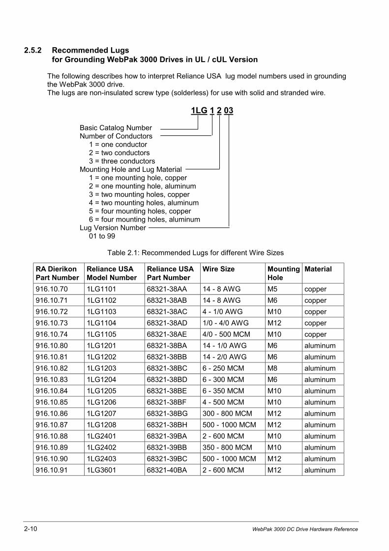
2.5.2 Recommended Lugsfor Grounding WebPak 3000 Drives in UL / cUL Version
The following describes how to interpret Reliance USA lug model numbers used in groundingthe WebPak 3000 drive.The lugs are non-insulated screw type (solderless) for use with solid and stranded wire.
1LG 1 2 03
Basic Catalog NumberNumber of Conductors
1 = one conductor2 = two conductors3 = three conductors
Mounting Hole and Lug Material1 = one mounting hole, copper2 = one mounting hole, aluminum3 = two mounting holes, copper4 = two mounting holes, aluminum5 = four mounting holes, copper6 = four mounting holes, aluminum
Lug Version Number01 to 99
Table 2.1: Recommended Lugs for different Wire Sizes
RA DierikonPart Number
Reliance USAModel Number
Reliance USAPart Number
Wire Size MountingHole
Material
916.10.70 1LG1101 68321-38AA 14 - 8 AWG M5 copper
916.10.71 1LG1102 68321-38AB 14 - 8 AWG M6 copper
916.10.72 1LG1103 68321-38AC 4 - 1/0 AWG M10 copper
916.10.73 1LG1104 68321-38AD 1/0 - 4/0 AWG M12 copper
916.10.74 1LG1105 68321-38AE 4/0 - 500 MCM M10 copper
916.10.80 1LG1201 68321-38BA 14 - 1/0 AWG M6 aluminum
916.10.81 1LG1202 68321-38BB 14 - 2/0 AWG M6 aluminum
916.10.82 1LG1203 68321-38BC 6 - 250 MCM M8 aluminum
916.10.83 1LG1204 68321-38BD 6 - 300 MCM M6 aluminum
916.10.84 1LG1205 68321-38BE 6 - 350 MCM M10 aluminum
916.10.85 1LG1206 68321-38BF 4 - 500 MCM M10 aluminum
916.10.86 1LG1207 68321-38BG 300 - 800 MCM M12 aluminum
916.10.87 1LG1208 68321-38BH 500 - 1000 MCM M12 aluminum
916.10.88 1LG2401 68321-39BA 2 - 600 MCM M10 aluminum
916.10.89 1LG2402 68321-39BB 350 - 800 MCM M10 aluminum
916.10.90 1LG2403 68321-39BC 500 - 1000 MCM M12 aluminum
916.10.91 1LG3601 68321-40BA 2 - 600 MCM M12 aluminum
Install and Wire the Drive 2-11
K1K
1
K1
L3L2L1PE
X6 78119
X1:
4
X1:
3
X1:
6
X1:
5X
3
MC
R
M
TIC
81
3.3
9.00
PO
WE
R I
NT
ER
FA
CE
483G
382G
481G
47
1W1V1U
X4
43
21
X6
X5
21
2W2V
2U
53
1X
2
X1
FP
P 8
10.8
9.0
0
PO
WE
R S
UP
PLY
J7J1
J6
81
0.7
9.4
0
RE
GU
LA
TO
R
1D1C
~
~
321
J4J3
J2J1
J8
47G
45
V3
V2
V1
V6
V5
V4
THY6
THY3
THY5
THY2
THY4
THY1
45G
V16
V15
V14
V13
V12
V11
THY13
THY16
THY12
THY15
THY11
THY14
RC
C1R1
X7
1211
87
53
1
3V 3WM
AX
. 415
V
1
2
4
3
-+
75
X3
J2
M
31
230
115
0
X3
65
43
21
F1
J
T1
T2
MO
V 2
-4
OIM
(O
ptio
n)
922
.95
.01
I/O
EX
PA
NS
ION
762
.70
.80
J5J9
J1J1
38..
.....
......
.....
.....
....
......
.....
......
....
.69
J5
J6
J7
J8
J
9
~~
-+58
2
583
37 35
J3J6
Fie
ld C
urr
.R
eg
ula
tor
76
2.7
0.7
0
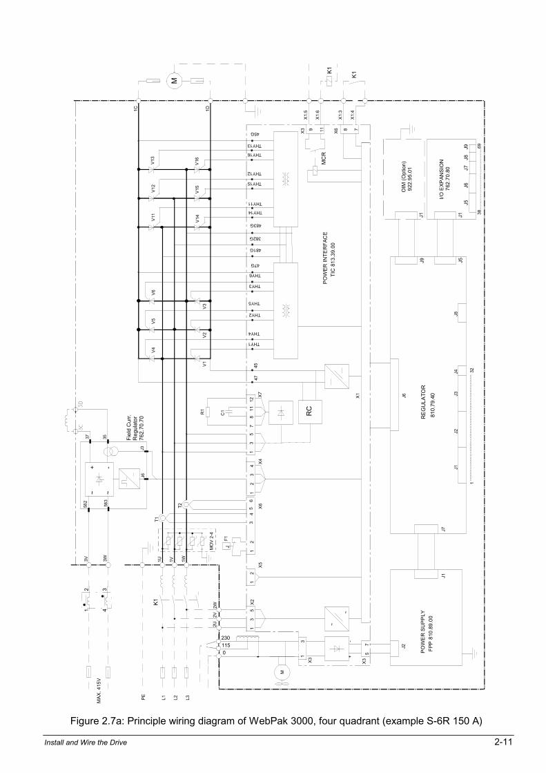
Figure 2.7a: Principle wiring diagram of WebPak 3000, four quadrant (example S-6R 150 A)
2-12 WebPak 3000 DC Drive Hardware Reference
81
0.7
9.4
0
~~
-+58
2
583
37 35
J3J6
Fie
ld C
urr
.R
eg
ula
tor
76
2.7
0.7
0
1
2
4
3
2301150
MO
V 2
-4
460 V
OIM
(O
ptio
n)
922
.95
.01
I/O
EX
PA
NS
ION
762
.70
.80
J5J9
J1J1
38..
......
.....
......
.....
.....
......
.....
.......
..69
J5
J6
J
7
J8
J9
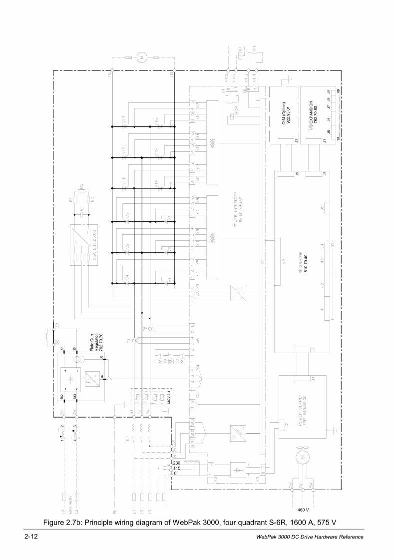
Figure 2.7b: Principle wiring diagram of WebPak 3000, four quadrant S-6R, 1600 A, 575 V
Install and Wire the Drive 2-13
2.5.3 Wire AC-Power to the Drive
ATTENTION: The user is responsible for conforming to all applicable standards.Wiring, grounding, disconnects and overcurrent protection are of particularimportance. Size and install all wiring in conformance with all applicable standards.Failure to observe this precaution could result in severe bodily injury or loss of life.
ATTENTION: The drive requires a three-phase power source of ether 200 - 500 or300 - 575/690 V, 50/60 Hz (see A-2). If the correct voltage is not available, atransformer must be installed between power source and drive. Do not connect thedrive to a power source with available short circuit capacity in excess of the max.symmetrical fault current listed in Appendix A, page A-1. Failure to observe thisprecaution could result in bodily injury or equipment damage.
1. Size the AC line supply conductors for the specific drive rating (see figures 2.1 to 2.6) andaccording to all applicable standards.
2. Connect the AC line supply via disconnect (if used) and line reactor or matched transformerto the terminal strips or bus bars at the top of the converter or to the disconnect.
3. Tighten incoming AC line connections per tables in figures 2.1 to 2.6.
Important: The tightening torque in the table applies to the wiring device (stud or terminalboard) provided. When an input or an output device (breaker or lug kit) is added,refer to the kit instructions for tightening specifications.
2.5.4 Wire the DC-Motor to the Drive
1. Size the motor armature circuit conductors for the specific drive rating (see figures 2.1 to2.6) and according to applicable standards. Use only copper wire rated 60/70°C or higher.
2. Locate the DC-motor armature and field supply leads on the drive.
4. Connect the DC-motor armature leads and the shunt field supply leads to the drive.
5. Tighten armature connections per tables in figures 2.1 to 2.6.
2.5.4.1 Motor Overload Protection
A software (internal) static overload is provided. In addition to the software (internal) overloadfunction, a DC-motor thermostat can be used for motor thermal overload protection. Thethermostat leads are brought out through the motor terminal box as leads P1 and P2.
These two leads must be wired to the regulator board control terminals 13 and 14.The thermostat leads can be run with the motor armature and field power wiring.
NOTE: The Drive will not start if the circuit between terminals 13 and 14 is not made.See Figure 2.8b.
2.5.5 Wiring Stopping Devices to the Drive
2.5.5.1 Description of Stop Modes and Drive States
The WebPak 3000 drive can be stopped by the assertion of a stop input (which can beconfigured as a ramp stop, a current limit stop, or a coast/DB stop), opening a permissive input(coast/DB interlock or customer interlock), deassertion of the JOG FWD or JOG REV input, orin the event of a fault. Depending on the type of stop, one of two different stop sequences areexecuted to provide an orderly method of deactivating the armature.
To the internal sequencing algorithm, the drive is always in one of three states: armature notactive (main contactor open), run mode, or jog mode. The armature is not active while in theNOT READY and READY states. The drive is considered to be in RUN mode if it was startedby the SECTION RUN input or the TENSION ON input.
2-14 WebPak 3000 DC Drive Hardware Reference
The following three states are considered to be permutations of RUN mode:SPEED, RUN TENSION, and JOG TENSION.
The drive will remain in RUN mode until the completion of a stop sequence and the maincontactor is opened. The drive is considered to be in the JOG mode if the drive was started viathe JOG input.
Note that the drive can enter the SPEED state from the JOG state if the SECTION RUN input isasserted while in JOG mode. The drive will remain in JOG mode until the completion of a stopsequence or until the RUN input is asserted causing the drive to switch from JOG mode to RUNmode.
Note that the drive will only enter RUN mode on a rising transition of JOG, SECTION RUN,or TENSION ON. This is to prevent unintentional starts when changing control sources.For example, changing the control source from KEYPAD to TERMBLK will not start the drivewhile the terminal block SECTION RUN is asserted. SECTION RUN must be deasserted thenreasserted to start the drive.
The addition of the TENSION ON input represents an additional start mechanism to the drive.A rising transition on TENSION ON from the READY state will cause the drive to enter the RUNmode with the tension major loop active in stall tension. If the drive is in not ready when a risingedge is generated on TENSION ON, the same drive not ready message will appear on theOIM. Once the drive is in the STALL TENSION state, a rising transition on the SECTION RUNinput will cause the drive to switch to the RUN TENSION state.
2.5.5.2 Provide the Emergency Stop-Function
WARNING: To inhibit uncontrolled machine operation in case of the malfunctionof the drive, the user must provide an external emergency stop circuit, whichensures disconnection of the power source from the motor.This circuit must be hardwired with electro-mechanic components and shall notdepend on electronic logic or software. The stopping device (e.g. mushroom headpushbutton) must be accessible to the operator.Failure to observe this precaution could result in bodily injury or loss of life.
It is the responsibility of the user to decide, how the Emergency Stop Function is fulfilled,depending on the requirements of the application and based on a risk assessment of themachine. Disconnection of the power source from the motor may be reached e.g. by one of thefollowing measures:
a) Circuit breaker used as Emergency Stopping Device:- easy accessible to the operator, hand operated or- remote operated, e. g. undervoltage trip coil released by mushroom head pushbutton.
b) Circuit breaker not used as Emergency Stopping Device:- Emergency Stopping Device (mushroom head pushbutton) interrupts control circuit andreleases Coast Stop according to Category 0.
A Connection Diagram - Example for case b) is shown in Figures 3-8a and 3-8b.
FUNCTION: Actuating of the Emergency Stop pushbutton during operation, causes immediatedrop out of relay K10, opening the n.o. contact at input terminal 8 and blocking of the regulator.At zero current, opening of contact output MCR will drop out the main contactor via auxiliarycontactor K1. The time delayed normally open contact of timer relay K10T ensures, that in caseof malfunction of the internal control circuit (MCR does not open) the main contactor drops outafter 1 second.
Install and Wire the Drive 2-15
2.5.5.3 COAST/STOP Digital Input
The WebPak 3000 drive can be configured to provide a coast-to-rest operational stop withoutphysical separation of the power source from the motor. A coast-to-rest stop turns off thetransistor power device drivers.Opening of the digital input COAST/STOP (terminal 8) during operation causes blocking of theregulator and the drive to Coast-to-rest. This input may be used for the Emergency Stop controlcircuit, if the main contactor drop out is forced by electro mechanic device, otherwise this Stopfunction corresponds with Category 2. NOTE: If this digital input is not used, a jumper must bewired between drive terminals 7 and 8, otherwise the drive will not start.
2.5.5.4 SECTION OFF Digital Input
Opening the SECTION OFF input (terminal 3) with the drive running causes the drive to stop inthe selected Stop-Mode (Coast-to-rest, Ramp-to-rest or Current limit Stop). This STOP-function corresponds with Category 2, if the main contactor drop out is not forced by electro-mechanic device. The function is active at all times regardless of the selection ofAUTO/MANUAL or the CSS setting (KEYPAD/TERMBLK).
2.5.5.5 Customer Interlock Digital Input
Opening the control input at terminal 9 during operation is the fastest way to disable the driveoutput. By software it directly ramps down armature current to zero and then opens the maincontactor. The motor will coast to rest. Because this is a software function it must not be usedfor safety relevant stopping. For emergency stop use the COAST/STOP input.NOTE: If this digital input is not used, a jumper must be wired between terminal 9 and 11,otherwise the drive will not start.
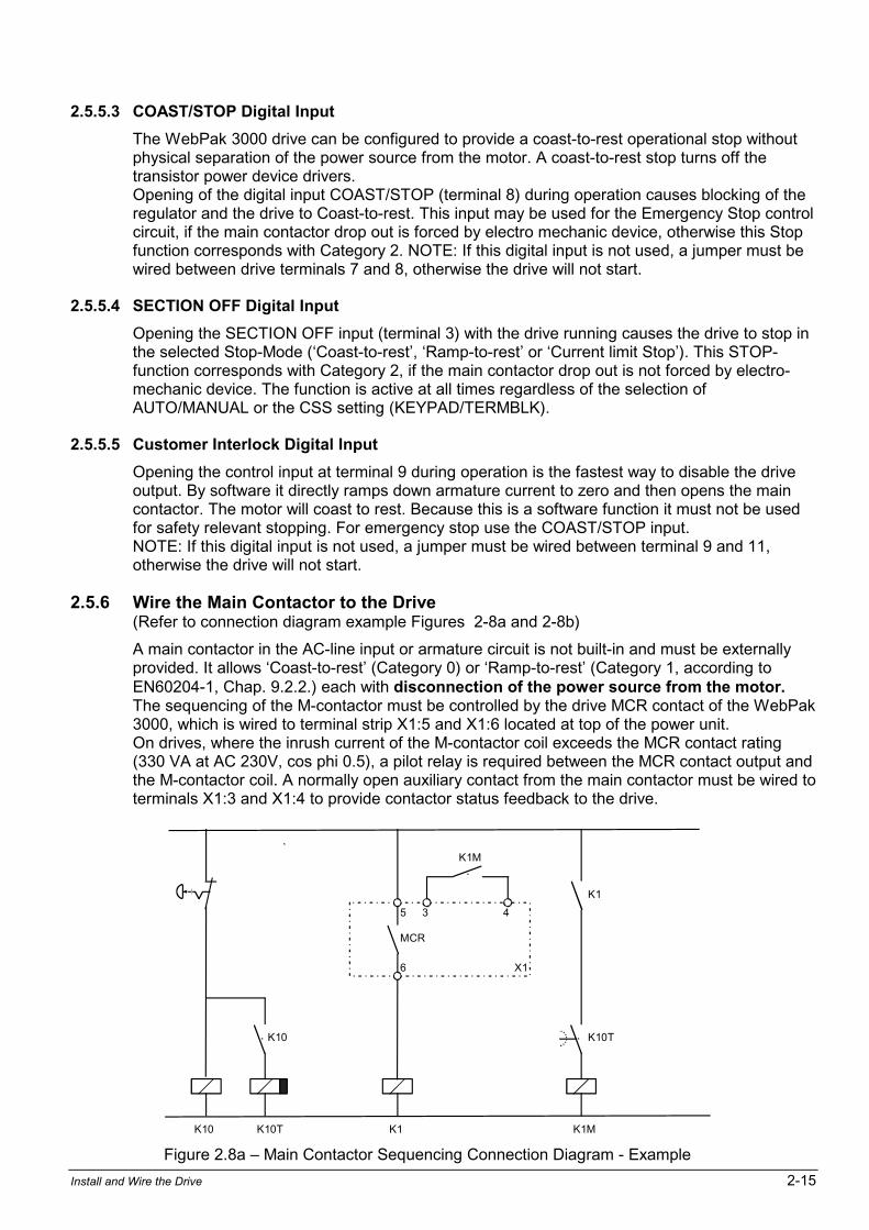
2.5.6 Wire the Main Contactor to the Drive(Refer to connection diagram example Figures 2-8a and 2-8b)
A main contactor in the AC-line input or armature circuit is not built-in and must be externallyprovided. It allows Coast-to-rest (Category 0) or Ramp-to-rest (Category 1, according toEN60204-1, Chap. 9.2.2.) each with disconnection of the power source from the motor.The sequencing of the M-contactor must be controlled by the drive MCR contact of the WebPak3000, which is wired to terminal strip X1:5 and X1:6 located at top of the power unit.On drives, where the inrush current of the M-contactor coil exceeds the MCR contact rating(330 VA at AC 230V, cos phi 0.5), a pilot relay is required between the MCR contact output andthe M-contactor coil. A normally open auxiliary contact from the main contactor must be wired toterminals X1:3 and X1:4 to provide contactor status feedback to the drive.
X1
K10 K10T K1 K1M
5
6
3 4
MCR
K10
K1
K1M
K10T
Figure 2.8a Main Contactor Sequencing Connection Diagram - Example
2-16 WebPak 3000 DC Drive Hardware Reference
2.5.7 Wire Optional Devices to the Drive
ATTENTION: Do not route signal wiring with power wiring in the same conduit. Thismight cause interference with drive operation. Route signal wiring and power wiringin separate conduits. Failure to observe this precaution could result in damage to,or destruction of, the equipment.
ATTENTION: Connecting an external power source to any of the +24 voltconnections (terminals 1, 7, 11, and 14) on the Regulator board terminal strip willdamage the drive. DO NOT connect the external power source on the +24 voltconnections on the Regulator board terminal strip. Failure to observe thisprecaution could result in damage to, or destruction of, the equipment.
ATTENTION: At very low input levels, noise or drift could cause analog inputpolarity to change. This could result in damage to, or destruction of, the equipment.
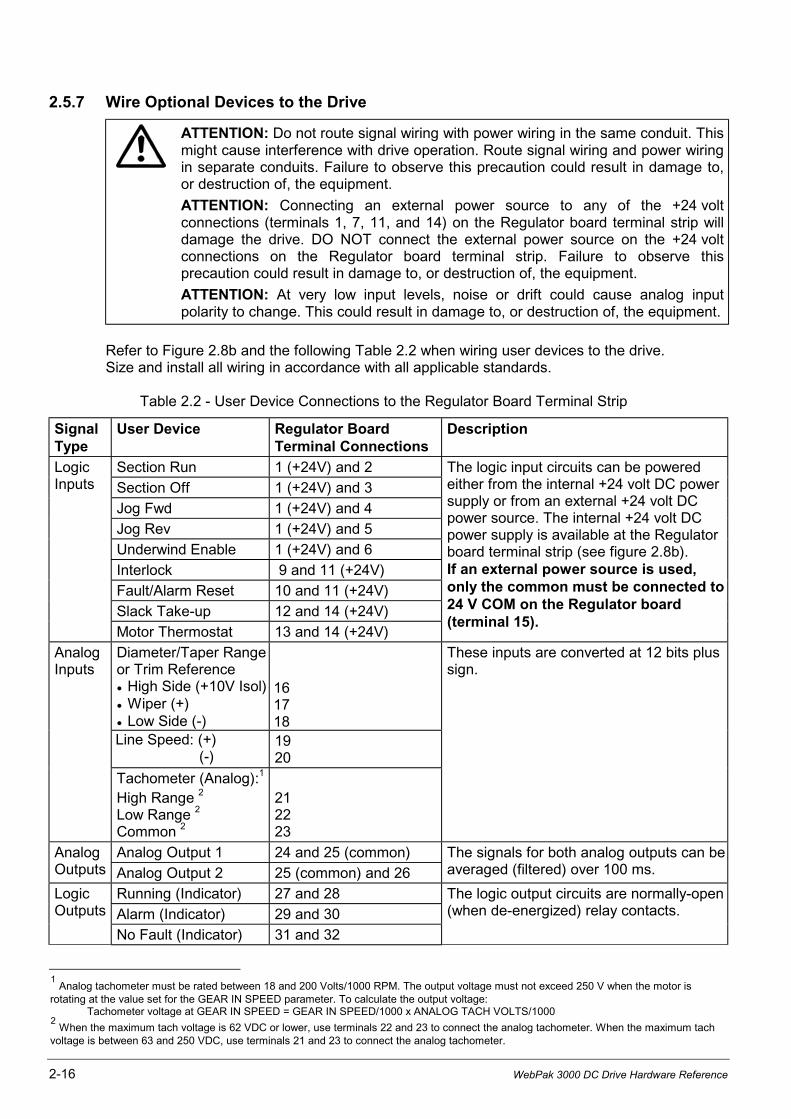
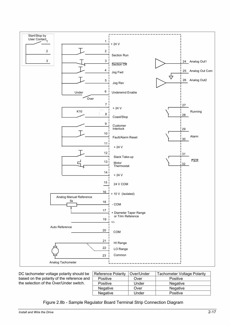
Refer to Figure 2.8b and the following Table 2.2 when wiring user devices to the drive.Size and install all wiring in accordance with all applicable standards.
Table 2.2 - User Device Connections to the Regulator Board Terminal Strip
SignalType
User Device Regulator BoardTerminal Connections
Description
Section Run 1 (+24V) and 2
Section Off 1 (+24V) and 3
Jog Fwd 1 (+24V) and 4
Jog Rev 1 (+24V) and 5
Underwind Enable 1 (+24V) and 6
Interlock 9 and 11 (+24V)
Fault/Alarm Reset 10 and 11 (+24V)
Slack Take-up 12 and 14 (+24V)
LogicInputs
Motor Thermostat 13 and 14 (+24V)
The logic input circuits can be poweredeither from the internal +24 volt DC powersupply or from an external +24 volt DCpower source. The internal +24 volt DCpower supply is available at the Regulatorboard terminal strip (see figure 2.8b).If an external power source is used,only the common must be connected to24 V COM on the Regulator board(terminal 15).
Diameter/Taper Rangeor Trim Reference
• High Side (+10V Isol) • Wiper (+) • Low Side (-)
161718
Line Speed: (+) (-)
1920
AnalogInputs
Tachometer (Analog):1
High Range 2
Low Range 2
Common 2
212223
These inputs are converted at 12 bits plussign.
Analog Output 1 24 and 25 (common)AnalogOutputs Analog Output 2 25 (common) and 26
The signals for both analog outputs can beaveraged (filtered) over 100 ms.
Running (Indicator) 27 and 28
Alarm (Indicator) 29 and 30
LogicOutputs
No Fault (Indicator) 31 and 32
The logic output circuits are normally-open(when de-energized) relay contacts.
1 Analog tachometer must be rated between 18 and 200 Volts/1000 RPM. The output voltage must not exceed 250 V when the motor is
rotating at the value set for the GEAR IN SPEED parameter. To calculate the output voltage:Tachometer voltage at GEAR IN SPEED = GEAR IN SPEED/1000 x ANALOG TACH VOLTS/1000
2 When the maximum tach voltage is 62 VDC or lower, use terminals 22 and 23 to connect the analog tachometer. When the maximum tach
voltage is between 63 and 250 VDC, use terminals 21 and 23 to connect the analog tachometer.
Install and Wire the Drive 2-17
15
14
13
12
11
10
9
8
7
6
5
4
3
2
1
Customer Interlock
Fault/Alarm Reset
+ 24 V
Slack Take-up
MotorThermostat
+ 24 V
24 V COM
Coast/Stop
+ 24 V
+ 24 V
Section Off
Jog Fwd
Jog Rev
Underwind Enable
24 Analog Out1
27
28
29
30
31
32Fault
Analog Tachometer
Running
Alarm
18
17
16
5kAnalog Manual Reference
- COM
+ 10 V (Isolated)
+ Diameter Taper Range or Trim Reference
21
23
19
20
22
+/-
Auto Reference
HI Range
LO Range
Common
COM
K10
Section Run
Under
Over
26 Analog Out2
25 Analog Out Com
3
2
1
Start/Stop byUser Contact
Reference Polarity Over/Under Tachometer Voltage PolarityPositive Over Positive
DC tachometer voltage polarity should bebased on the polarity of the reference andthe selection of the Over/Under switch. Positive Under Negative
Negative Over NegativeNegative Under Positive
Figure 2.8b - Sample Regulator Board Terminal Strip Connection Diagram
2-18 WebPak 3000 DC Drive Hardware Reference
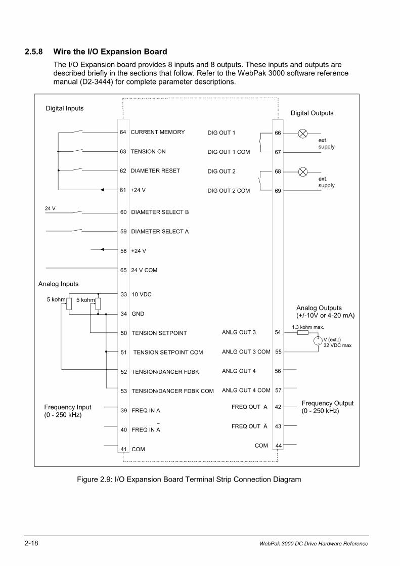
2.5.8 Wire the I/O Expansion Board
The I/O Expansion board provides 8 inputs and 8 outputs. These inputs and outputs aredescribed briefly in the sections that follow. Refer to the WebPak 3000 software referencemanual (D2-3444) for complete parameter descriptions.
Digital Inputs
64 CURRENT MEMORY
63 TENSION ON
62 DIAMETER RESET
61 +24 V
Frequency Input (0 - 250 kHz)
Analog Inputs
Analog Outputs(+/-10V or 4-20 mA)
Digital Outputs
DIG OUT 1
DIG OUT 1 COM
DIG OUT 2
DIG OUT 2 COM
5 kohm 5 kohm33 10 VDC 34 GND
50 TENSION SETPOINT
51 TENSION SETPOINT COM 52 TENSION/DANCER FDBK 53 TENSION/DANCER FDBK COM
39 FREQ IN A
40 FREQ IN A
41 COM
60 DIAMETER SELECT B
59 DIAMETER SELECT A
58 +24 V
65 24 V COM
FREQ OUT A 42
FREQ OUT A 43
COM 44
ANLG OUT 3 54
ANLG OUT 3 COM 55 ANLG OUT 4 56
ANLG OUT 4 COM 57
+ -
1.3 kohm max.
V (ext.:)32 VDC max
Frequency Output (0 - 250 kHz)
24 V
66
67
68
69
ext.supply
ext.supply
Figure 2.9: I/O Expansion Board Terminal Strip Connection Diagram

Install and Wire the Drive 2-19
Digital Inputs
ATTENTION: The user must read and understand the drive sequencing descriptionand state diagram (WebPak 3000 Software Reference, chapter 3) before using theTENSION ON input. Setting OCL SELECT ≠ NONE permits the TENSION ON input to startthe drive. Once the TENSION ON input is permitted to start the drive, negating theTENSION ON input while in any other state than the stall tension state will not stopthe drive. Failure to observe this precaution could result in severe bodily injury orloss of life.
The I/O Expansion board supports five digital inputs. The function of each digital input is fixed,and is shown in table 2.3. The drive will recognize a change in the state of a digital input signal(e.g. 0 to 24 VDC) if it is applied for longer than 20 msec.
Table 2.3 - I/O Expansion Digital Inputs
Parameter Name Parameter Number Terminal Strip Location*
DIAMETER SELECT A TP P.495 59DIAMETER SELECT B TP P.496 60DIAMETER RST DIN TP P.497 62TENSION ON DIN TP P.498 63CURRENT MEMORY DIN TP P.499 64
* Terminals 58 and 61 (+24 VDC) and 65 (24 V COM) are available for use with the digital inputs.
Digital Outputs
The I/O Expansion board supports two digital outputs. Digital outputs can be sourced fromvarious functions of the drive, and hold their state for a minimum of 20 msec. The digital outputparameters are listed in table 2.4.
Table 2.4 - I/O Expansion Digital Outputs
Parameter Name Parameter Number Terminal Strip Location
DIG OUT 1 SELECT P.409 66, 67DIG OUT 2 SELECT P.411 68, 69DIG OUT 1 CONTACT TYP P.410DIG OUT 2 CONTACT TYP P.412
Important: If digital output 1 or 2 is configured as normally closed, it will act as normally openduring a power cycle until the software contact type is read. This should beaccounted for in your application program.
Analog Inputs
ATTENTION: At very low input levels, noise or drift could cause analog inputpolarity to change. This could result in damage to, or destruction of, the equipment.
The I/O Expansion board supports two analog inputs: TENSION SETPOINT IN (P.492) andTENSION/DANCER FDBK (P.493). TENSION/DANCER FDBK accepts a bipolar DC voltageonly. TENSION SETPOINT IN can be configured to accept any of the following signals:bipolar DC voltage, unipolar DC voltage, 4-20 mA, or 10-50 mA. Analog inputs can be scaled touse DC voltage signals as low as 4.5 V (5V + 10%), but maximum resolution (0.024%) isobtained when the full scale input signal is used. Analog input signals are read every 20 msec.
Table 2.5 lists the analog inputs and related parameters. Figure 2.9 provides wiring diagram forconnecting 5 kΩ potentiometers.
2-20 WebPak 3000 DC Drive Hardware Reference
Table 2.5 - I/O Expansion Analog Inputs
Parameter Name Parameter Number Terminal Strip Location
TENSION SETPOINT IN P.492 50, 51
TENSION/DANCER FDBK P.493 52, 53
TENSION SETPT SIG TYPE P.413
TENSION SETPOINT ZERO P.414
TENSION SETPOINT GAIN P.415
TENSION/DANCER ZERO P.416
TENSION/DANCER GAIN P.417* Terminals 33 (+10 VDC) and 34 (GND) are available for use with up to two 5 kΩ potentiometers.
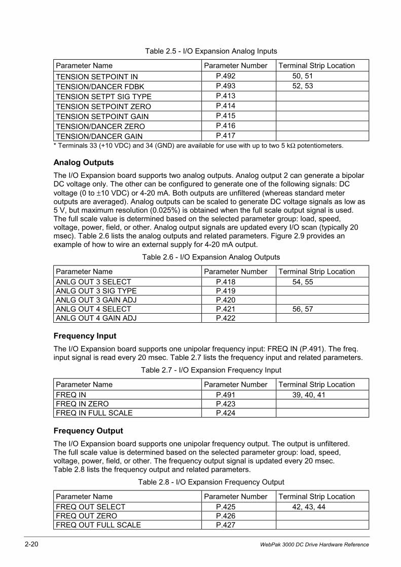
Analog Outputs
The I/O Expansion board supports two analog outputs. Analog output 2 can generate a bipolarDC voltage only. The other can be configured to generate one of the following signals: DCvoltage (0 to ±10 VDC) or 4-20 mA. Both outputs are unfiltered (whereas standard meteroutputs are averaged). Analog outputs can be scaled to generate DC voltage signals as low as5 V, but maximum resolution (0.025%) is obtained when the full scale output signal is used.The full scale value is determined based on the selected parameter group: load, speed,voltage, power, field, or other. Analog output signals are updated every I/O scan (typically 20msec). Table 2.6 lists the analog outputs and related parameters. Figure 2.9 provides anexample of how to wire an external supply for 4-20 mA output.
Table 2.6 - I/O Expansion Analog Outputs
Parameter Name Parameter Number Terminal Strip Location
ANLG OUT 3 SELECT P.418 54, 55ANLG OUT 3 SIG TYPE P.419ANLG OUT 3 GAIN ADJ P.420ANLG OUT 4 SELECT P.421 56, 57ANLG OUT 4 GAIN ADJ P.422
Frequency Input
The I/O Expansion board supports one unipolar frequency input: FREQ IN (P.491). The freq.input signal is read every 20 msec. Table 2.7 lists the frequency input and related parameters.
Table 2.7 - I/O Expansion Frequency Input
Parameter Name Parameter Number Terminal Strip Location
FREQ IN P.491 39, 40, 41FREQ IN ZERO P.423FREQ IN FULL SCALE P.424
Frequency Output
The I/O Expansion board supports one unipolar frequency output. The output is unfiltered.The full scale value is determined based on the selected parameter group: load, speed,voltage, power, field, or other. The frequency output signal is updated every 20 msec.Table 2.8 lists the frequency output and related parameters.
Table 2.8 - I/O Expansion Frequency Output
Parameter Name Parameter Number Terminal Strip Location
FREQ OUT SELECT P.425 42, 43, 44FREQ OUT ZERO P.426FREQ OUT FULL SCALE P.427

CHAPTER 3
Drive Setup and Adjustment 3-1
Drive Setup and Adjustment
ATTENTION: Only qualified electrical personnel familiar with the construction andoperation of this equipment and the hazards involved should install, adjust, operateand/or service this equipment. Read and understand this section in its entiretybefore proceeding. Failure to observe this precaution could result in bodily injury orloss of life.
3.1 Perform a Power Off Inspection
Inspect the Drive and modification kits for possible physical damage or improper connections.
Verify that the wiring of the operator's station and the wiring to the Drive is made with sufficientbare wire to make a good electrical connection. The removal of an excessive length ofinsulation may needlessly expose conductors resulting in the possibility of shorts or safetyhazards.
3.2 Test Equipment Needed
ATTENTION: Do not use a megohmmeter for continuity checks in the drive. Thehigh voltage of the megohmmeter can damage the drive's electronic circuits.Failure to observe this precaution could result in damage to, or destruction of, theequipment.
A volt-ohmmeter having a sensitivity of 20,000 ohms per volt may be used.
3.3 Perform a Motor Ground Check
ATTENTION: A megohmmeter can be used for this motor ground check, but allconductors between the motor and the drive must be disconnected. Themegohmmeters high voltage can damage the drive's electronic circuits. Disconnectall conductors between the motor and the drive before using a megohmmeter forthis motor ground check. Failure to observe this precaution could result in damageto, or destruction of, the equipment.
The DC Motor frame and conduit box should be connected to a good earth ground per themotor instruction manual.
Verify that there is no path to ground in either the DC Motor armature circuit, the shunt fieldcircuit or the thermostat circuit. Connect one lead of a standard ohm reading meter to the motorframe and the other lead to the two armature leads, then to the two field leads and to the twothermostat leads. If a reading of less than 100,000 ohms is observed, a ground condition existsand MUST be corrected before power is applied.
3-2 WebPak 3000 DC Drive Hardware Reference
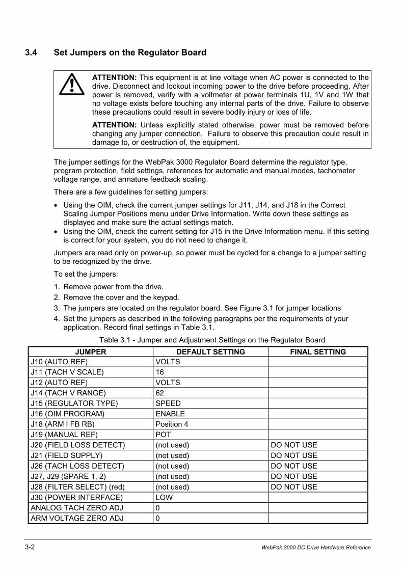
3.4 Set Jumpers on the Regulator Board
ATTENTION: This equipment is at line voltage when AC power is connected to thedrive. Disconnect and lockout incoming power to the drive before proceeding. Afterpower is removed, verify with a voltmeter at power terminals 1U, 1V and 1W thatno voltage exists before touching any internal parts of the drive. Failure to observethese precautions could result in severe bodily injury or loss of life.
ATTENTION: Unless explicitly stated otherwise, power must be removed beforechanging any jumper connection. Failure to observe this precaution could result indamage to, or destruction of, the equipment.
The jumper settings for the WebPak 3000 Regulator Board determine the regulator type,program protection, field settings, references for automatic and manual modes, tachometervoltage range, and armature feedback scaling.
There are a few guidelines for setting jumpers:
• Using the OIM, check the current jumper settings for J11, J14, and J18 in the CorrectScaling Jumper Positions menu under Drive Information. Write down these settings asdisplayed and make sure the actual settings match.
• Using the OIM, check the current setting for J15 in the Drive Information menu. If this settingis correct for your system, you do not need to change it.
Jumpers are read only on power-up, so power must be cycled for a change to a jumper settingto be recognized by the drive.
To set the jumpers:
1. Remove power from the drive.
2. Remove the cover and the keypad.
3. The jumpers are located on the regulator board. See Figure 3.1 for jumper locations
4. Set the jumpers as described in the following paragraphs per the requirements of yourapplication. Record final settings in Table 3.1.
Table 3.1 - Jumper and Adjustment Settings on the Regulator Board
JUMPER DEFAULT SETTING FINAL SETTINGJ10 (AUTO REF) VOLTS
J11 (TACH V SCALE) 16
J12 (AUTO REF) VOLTS
J14 (TACH V RANGE) 62
J15 (REGULATOR TYPE) SPEED
J16 (OIM PROGRAM) ENABLE
J18 (ARM I FB RB) Position 4
J19 (MANUAL REF) POT
J20 (FIELD LOSS DETECT) (not used) DO NOT USE
J21 (FIELD SUPPLY) (not used) DO NOT USE
J26 (TACH LOSS DETECT) (not used) DO NOT USE
J27, J29 (SPARE 1, 2) (not used) DO NOT USE
J28 (FILTER SELECT) (red) (not used) DO NOT USE
J30 (POWER INTERFACE) LOW
ANALOG TACH ZERO ADJ 0
ARM VOLTAGE ZERO ADJ 0

Drive Setup and Adjustment 3-3
3.4.1 Set the Regulator Type Jumper J15
ATTENTION: The J15 jumper must be set to the TORQUE/CURRENT positionwhen using the WebPak 3000 drives feature to switch-on-the-fly from speed/voltage control to torque/current control. Applying a drive as a direct currentregulator has safety issues that must be considered. Refer to the WebPak 3000Software Reference (D2-3444) for proper setup of this function. Failure to observethese precautions could result in severe bodily injury or loss of life.
J15 determines whether the drive uses Speed/Voltage or Torque/Current regulation.
J15 must be set to CURRENT in order to be able to switch from a speed regulator to a currentregulator over the network.
When CURRENT is selected, only the terminal strip or a Communication Board can be used asthe control source.
Also note that speed/voltage parameters must be set to provide overspeed protection for thedrive.
J17 J28 J22
J15 J20 J26
J16 J21
J25
F2GNDF1
GND1
ARM I IOGND2
J7
J5J2
0VI2
F3GND3
J9
J1J8F4GND4
J18
J12 J10 J19
J14 J11
J6
EPROM790.30.70
J30 J29 J27
J4
J3
Figure 3.1 - Regulator Board Jumpers, Connectors and Test Points
3-4 WebPak 3000 DC Drive Hardware Reference
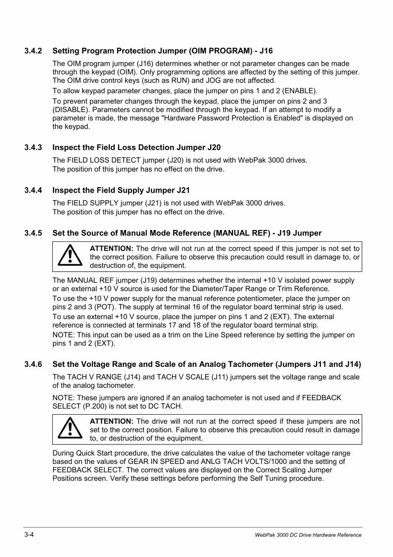
3.4.2 Setting Program Protection Jumper (OIM PROGRAM) - J16
The OIM program jumper (J16) determines whether or not parameter changes can be madethrough the keypad (OIM). Only programming options are affected by the setting of this jumper.The OIM drive control keys (such as RUN) and JOG are not affected.
To allow keypad parameter changes, place the jumper on pins 1 and 2 (ENABLE).
To prevent parameter changes through the keypad, place the jumper on pins 2 and 3(DISABLE). Parameters cannot be modified through the keypad. If an attempt to modify aparameter is made, the message "Hardware Password Protection is Enabled" is displayed onthe keypad.
3.4.3 Inspect the Field Loss Detection Jumper J20
The FIELD LOSS DETECT jumper (J20) is not used with WebPak 3000 drives.The position of this jumper has no effect on the drive.
3.4.4 Inspect the Field Supply Jumper J21
The FIELD SUPPLY jumper (J21) is not used with WebPak 3000 drives.The position of this jumper has no effect on the drive.
3.4.5 Set the Source of Manual Mode Reference (MANUAL REF) - J19 Jumper
ATTENTION: The drive will not run at the correct speed if this jumper is not set tothe correct position. Failure to observe this precaution could result in damage to, ordestruction of, the equipment.
The MANUAL REF jumper (J19) determines whether the internal +10 V isolated power supplyor an external +10 V source is used for the Diameter/Taper Range or Trim Reference.To use the +10 V power supply for the manual reference potentiometer, place the jumper onpins 2 and 3 (POT). The supply at terminal 16 of the regulator board terminal strip is used.To use an external +10 V source, place the jumper on pins 1 and 2 (EXT). The externalreference is connected at terminals 17 and 18 of the regulator board terminal strip.NOTE: This input can be used as a trim on the Line Speed reference by setting the jumper onpins 1 and 2 (EXT).
3.4.6 Set the Voltage Range and Scale of an Analog Tachometer (Jumpers J11 and J14)
The TACH V RANGE (J14) and TACH V SCALE (J11) jumpers set the voltage range and scaleof the analog tachometer.
NOTE: These jumpers are ignored if an analog tachometer is not used and if FEEDBACKSELECT (P.200) is not set to DC TACH.
ATTENTION: The drive will not run at the correct speed if these jumpers are notset to the correct position. Failure to observe this precaution could result in damageto, or destruction of the equipment.
During Quick Start procedure, the drive calculates the value of the tachometer voltage rangebased on the values of GEAR IN SPEED and ANLG TACH VOLTS/1000 and the setting ofFEEDBACK SELECT. The correct values are displayed on the Correct Scaling JumperPositions screen. Verify these settings before performing the Self Tuning procedure.
Drive Setup and Adjustment 3-5
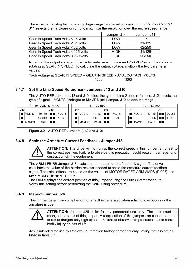
The expected analog tachometer voltage range can be set to a maximum of 250 or 62 VDC.J11 selects the hardware circuitry to maximize the resolution over the entire speed range.
Jumper J14 Jumper J11Gear In Speed Tach Volts < 16 volts LOW 16Gear In Speed Tach Volts < 31 volts LOW 31/125Gear In Speed Tach Volts < 62 volts LOW 62/250Gear In Speed Tach Volts < 125 volts HIGH 31/125Gear In Speed Tach Volts < 250 volts HIGH 62/250
Note that the output voltage of the tachometer must not exceed 250 VDC when the motor isrotating at GEAR IN SPEED. To calculate the output voltage, multiply the two parametervalues:
Tach Voltage at GEAR IN SPEED = GEAR IN SPEED x ANALOG TACH VOLTS1000 1000
3.4.7 Set the Line Speed Reference - Jumpers J12 and J10
The AUTO REF Jumpers J12 and J10 select the type of Line Speed reference. J12 selects thetype of signal - VOLTS (Voltage) or MAMPS (milli-amps). J10 selects the range.
+ / - 10 VOLTS MAX 4 - 20 mA 10 - 50 mA J12 J10 J12 J10 J12 J10
! VOLTS 10 - 50 ! ! VOLTS ! VOLTS 10 - 50 ! ! VOLTS ! VOLTS 10 - 50 ! ! VOLTS
! (BOTH) ! ! 4 - 20 ! (BOTH) ! ! 4 - 20 ! (BOTH) ! ! 4 - 20
! MAMPS PARK ! ! ! MAMPS PARK ! ! ! MAMPS PARK ! !
Figure 3.2 - AUTO REF Jumpers (J12 and J10)
3.4.8 Scale the Armature Current Feedback - Jumper J18
ATTENTION: The drive will not run at the correct speed if this jumper is not set tothe correct position. Failure to observe this precaution could result in damage to, ordestruction of, the equipment.
The ARM I FB RB Jumper J18 scales the armature current feedback signal. The drivecalculates the value of the burden resistor needed to scale the armature current feedbacksignal. The calculations are based on the values of MOTOR RATED ARM AMPS (P.008) andMAXIMUM CURRENT (P.007).The OIM displays the correct position of this jumper during the Quick Start procedure.Verify this setting before performing the Self-Tuning procedure.
3.4.9 Inspect Jumper J26
This jumper determines whether or not a fault is generated when a tacho loss occurs or thearmature is open.
ATTENTION: Jumper J26 is for factory personnel use only. The user must notchange the status of this jumper. Misapplication of this jumper can cause the motorto run at dangerously high speeds. Failure to observe this precaution could result inbodily injury or loss of life.
J26 is intended for use by Rockwell Automation factory personnel only. Verify that it is set aslisted in table 3.1.

3-6 WebPak 3000 DC Drive Hardware Reference
3.4.10 Inspect the Spare 1 Jumper (J27)
J27 is not used. The position of this jumper has no effect on the drive. Do not install a jumperblock on this jumper.
3.4.11 Inspect the Filter Select Jumper (J28)
J28 is not used. Do not install a jumper block on this jumper..
3.4.12 Inspect the Spare 2 Jumper (J29)
J29 is not used. The position of this jumper has no effect on the drive. Do not install a jumperblock on this jumper.
3.4.13 Inspect the POWER INTERFACE Jumper (J30)
ATTENTION: The drive can operate at excessive armature voltage and speed ifJ30 is improperly set to the LOW position when it should be set to HI.
This jumper is factory set according to the type of Power Interface module installed in the drive.jumper positions are labeled LOW and HIGH. For WebPak 3000 drives with a nominal voltagerating AC 575 V, 60 Hz and 690 V, 50 Hz the jumper J30 must be set to HIGH, for all otherdrives this jumper must stay in position LOW. Please refer to the AC Input data on thenameplate.
If this jumper is not set to the correct position nuisance AC line voltage high/low alarms mayoccur or, if configured as a voltage regulator, the drive will not operate at the correct speed.
Drive Setup and Adjustment 3-7
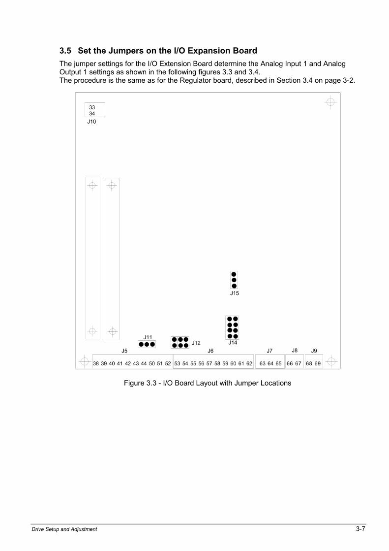
3.5 Set the Jumpers on the I/O Expansion Board
The jumper settings for the I/O Extension Board determine the Analog Input 1 and AnalogOutput 1 settings as shown in the following figures 3.3 and 3.4.The procedure is the same as for the Regulator board, described in Section 3.4 on page 3-2.
J15
J14J12J11
38 39 40 41 42 43 44 50 51 52
3334
53 54 55 56 57 58 59 60 61 62 63 64 65 66 67 68 69
J10
J5 J6 J7 J8 J9
Figure 3.3 - I/O Board Layout with Jumper Locations
3-8 WebPak 3000 DC Drive Hardware Reference
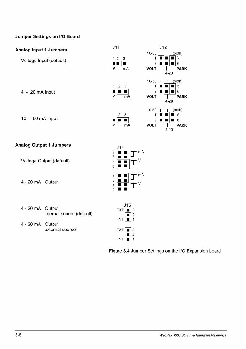
Jumper Settings on I/O Board
Analog Input 1 Jumpers
Voltage Input (default)
4 - 20 mA Input
10 - 50 mA Input
Analog Output 1 Jumpers
Voltage Output (default)
4 - 20 mA Output
4 - 20 mA Outputinternal source (default)
4 - 20 mA Outputexternal source
J11 J1210-50 (both)
1 2 3 1 ! ! ! 5
! ! ! 2 ! ! ! 6V mA VOLT PARK
4-20
10-50 (both)1 2 3 1 ! ! ! 5! ! ! 2 ! ! ! 6V mA VOLT PARK
4-20
10-50 (both)1 2 3 1 ! ! ! 5! ! ! 2 ! ! ! 6V mA VOLT PARK
4-20
J148 ! !
6 ! !
4 ! !
2 ! !
8 ! !
6 ! !
4 ! !
2 ! !
J15EXT ! 3
! 2INT ! 1
EXT ! 3! 2
INT ! 1
Figure 3.4 Jumper Settings on the I/O Expansion board
mA
V
mA
V
Drive Setup and Adjustment 3-9
3.6 Verify the Correct Direction of Motor Rotation
ATTENTION: If tachometer and/or rotation is incorrect, sudden and rapidacceleration may result which can cause overspeed of the drive.Failure to observe this precaution could result in bodily injury.
Power up the Drive
1. Apply AC power to the drive after you complete the Power Off Inspection, Motor GroundCheck and Drive Setup procedures .
2. See the OIM instruction manual for the displays during power-up.
Turn power to the drive OFF.
1. Verify the operation of the Coast/Stop pushbutton using an ohmmeter. When pressed, theohmmeter should read infinite ohms (open); when released, the reading should be 0 (short).
2. Turn power to the drive ON.
3. After power-up, select ARMATURE VOLT for FEEDBACK SELECT (P.200) by taking thefollowing path from the main menu to access this parameter:
Speed/Voltage Loop (SPD) Speed/Voltage Loop (SPD) Feedback
4. Initiate a JOG Fwd command to verify that the motor is rotating in the desired direction.
5. If the direction of rotation is incorrect, stop the drive and then disconnect and lockout or tagpower to the drive.
6. To change the direction of motor rotation, reverse the connection of the motor armatureleads 1C and 1D.
Important: Wrong rotation direction can be caused by incorrect wiring of the field (3C and 3D).
3.7 Determine the DC Tachometer Lead Polarity
1. Turn power to the drive ON.
2. After power-up, select ARMATURE VOLT for FEEDBACK SELECT (P.200) by using thefollowing path from the main menu to access this parameter:
Speed/Voltage Loop (SPD) Speed/Voltage Loop (SPD) Feedback
Refer to the WebPak 3000 Software Reference Manual (D2-3444) for more information onchanging parameter values.
3. Initiate a JOG Fwd command.
4. Use a voltmeter on the tachometer leads to determine the lead polarity for the Forwarddirection of rotation. Label the tachometer leads accordingly, (+) and (-).
5. Verify that the (+) tachometer lead is connected to terminal 21 or 22, and that the (-)tachometer lead is connected to terminal 23. If the (+) tachometer lead is not connected toterminal 21 or 22, stop the drive. Disconnect and lockout or tag power to the drive. Reversethe connection of the tachometer leads.
3-10 WebPak 3000 DC Drive Hardware Reference
3.8 Make Tachometer and Armature Feedback Zero Adjustments
This section describes Zero adjustments to compensate for signal drift when tachometer orarmature feedback is used. See the OIM instruction manual for instructions on changing theseparameter values.
ATTENTION: The incorrect setting of the parameters described below can causean overspeed condition. These parameters must be set by a qualified person whounderstands the significance of setting them accurately. Verify that the value ofthese parameters is accurate for your application. Failure to observe this precautioncould result in bodily injury.
1. Stop the drive.
2. Check the value of the output parameter ARMATURE VOLTAGE (P.289).If the value is 0: Go to step 5.If the value is not ZERO: Go to step 3.
3. Adjust ARM VOLTAGE ZERO ADJ (P.205). If ARMATURE VOLTAGE was more than 0(positive), adjust ARM VOLTAGE ZERO ADJ to a negative value. If it was less than 0(negative), adjust ARM VOLTAGE ZERO ADJ to a positive value.
4. Repeat steps 2 and 3 until ARMATURE VOLTAGE is zero.
5. Record the final value of ARM VOLTAGE ZERO ADJ in table 3.1.
6. Check the value of output parameter ANALOG TACH FEEDBACK (P.291).If the value is 0: Go to step 9.If the value is not zero: Go to step 7.
7. Adjust ANALOG TACH ZERO ADJ (P.202). If analog tach feedback was more than 0(positive), adjust ANALOG TACH ZERO ADJ to a negative value. If it was less than 0(negative), adjust ANALOG TACH ZERO ADJ to a positive value.
8. Repeat steps 2 and 3 until ANALOG TACH FEEDBACK is zero.
9. Record the final value of ANALOG TACH ZERO ADJ in table 3.1.
3.9 Make Final Adjustments
Set the Quick Start parameters and perform drive self-tuning, as described in the OIM orWebPakCS instruction manuals.
When Quick Start and self-tuning are complete, adjust the nominal AC line frequency, nominalAC line voltage, and the field economy reference as follows. See the OIM instruction manual forinformation on setting parameters.
1. The default value of NOMINAL AC LINE FREQ (P.306) is 60 Hz. Adjust the frequency to thenominal value of the line frequency for your application.
2. The default value of NOMINAL AC LINE VOLTS (P.307) is 230 VAC. Adjust the voltage tothe nominal value of the line RMS voltage for your application.
ATTENTION: Improper setting of parameter FIELD ECONOMY REF (P.511) can causea motor overvoltage condition. Set parameter MOTOR HOT FLD AMPS (P.510) to themotor's nameplate value. Make sure FIELD ECONOMY REF (P.511) and/or FIELD REF
REGISTER (P.513) are above parameter FIELD LOSS THRESHOLD (P.512). Failure toobserve this precaution could result in bodily injury and damage to the equipment.
4. The default value of FIELD ECONOMY REF (P.511) is 0 %. Adjust the percentage to avalue higher than that of FIELD LOSS THRESHOLD (P.512).
CHAPTER 4
Troubleshooting/Diagnostics 4-1
Troubleshooting/Diagnostics
ATTENTION: Only qualified electrical personnel familiar with the construction andoperation of this equipment and the hazards involved should install, adjust, operateand/or service this equipment. Read and understand this section in its entiretybefore proceeding. Failure to observe this precaution could result in severe bodilyinjury or loss of life.
ATTENTION: This equipment is at line voltage when AC power is connected to thedrive. Disconnect and lockout incoming power to the drive before proceeding. Afterpower is removed, verify with a voltmeter at power terminals 1U, 1V and 1W thatno voltage exists before touching any internal parts of the drive. Failure to observethese precautions could result in severe bodily injury or loss of life.
This chapter provides troubleshooting and diagnostics information for the WebPak 3000 drive.It lists faults and alarms that can occur and the possible causes. It also references parametersthat can be helpful when troubleshooting. For instruction on how to clear faults and alarms, seeyour OIM manual (D2-3445, WebPak 3000 Operator Interface Module (OIM) Users Guide).
4.1 Checking for Wiring Errors
Wiring errors and loose or grounded wiring are common problems that can inhibit operation of adrive. Verify that the wiring has been correctly installed and that the drive is free of looseterminations and grounded conductors.
4.2 Verifying AC Line and Power Input
Verify that the applied AC power is correct for the specific drive. If an isolation transformer hasbeen installed on the incoming AC power, verify its output voltage and that it has been properlyconnected. Verify that the AC line fuses are semiconductor protection type and have beencorrectly sized per Table 5.4. The AC and DC power conductors should have been sized perlocal standards.
4.3 Verifying DC Motor Connections
ATTENTION: A megohmmeter can be used for this motor ground check, but allconductors between the motor and the drive must be disconnected. The megohm-meters high voltage can damage the drive's electronic circuits. Disconnect allconductors between the motor and the drive before using a megohmmeter for thismotor ground check. Failure to observe this precaution could result in damage to,or destruction of, the equipment.
Verify that all DC motor connections are correct.
• Recheck all motor connections for tightness and correct identification.
• Verify that there is no path to ground in either the DC motor armature circuit, the shunt fieldcircuit or the thermostat circuit. Connect one lead of a standard ohm meter to the motorframe and the other lead to the two armature leads. then connect to the two thermostatleads and then to the two field leads. If a reading of less than 100,000 ohms is observed, aground condition exists and MUST be corrected before power is applied. Check that the fieldwinding is not open or shorted.
• Verify the continuity of the motor thermostat and its proper connection to regulator boardterminals 13 and 14. If a motor thermostat has been installed, verify that it's circuit maintainscontinuity in the terminal 13 and 14 circuit.

4-2 WebPak 3000 DC Drive Hardware Reference
4.4 Verifying Optional Kits
Verify that each optional kit has been installed correctly according the appropriate instructions.Refer to the appropriate instruction manuals. See section 1.5 and 1.6.
4.5 Checking the Regulator Led Status
Two LEDs are located on the Regulator board to indicate the operating status of the Regulatorboard. The cover on the OIM must be removed to observe these LEDs. Check and observethese LEDs when the OIM is not communicating with the regulator. Typically, there will be nofault indication on the display when the OIM is not communicating with the regulator board.If a fault can be displayed, the fault would be OIM COMMUNICATIONS TIMEOUT (F00011).
The two LEDs are labeled CPU OK and OIM COMM OK. CPU OK will be on whenever the inputsand outputs are being scanned (I/O is not scanned during power-up diagnostics and followingcertain faults). OIM COMM OK will be on whenever the regulator board and the OIM are commu-nicating properly. The following table summarizes the possible states of the two LED indicators.
CPU OK LED OIM COMM OK LED Indication(s) and Action(s)
Off Off • No power - verify that the drive power is on. Check for 24 volt atthe regulator board terminals 1 and 15 (COM).
• LED failure - cycle power and verify that both LED's illuminatebriefly (lamp test).
• Power-up diagnostics failed - replace the Regulator board.
On • Combination not used.
Blink • Combination not used.
On Off • I/O is being scanned, regulator is not communicating with theOIM - check OIM cable, check voltages at the OIM.
On • I/O is being scanned, the regulator is communicating with theOIM, no faults - this is a normal condition, no action is required.
• I/O is being scanned, the regulator is communicating with theOIM, - diagnose/correct the fault condition and reset the faultfrom the selected control source fault reset.
• Power-up diagnostics in progress (lamp test).
Blink • Combination not used.
Blink Off • I/O is not being scanned, Regulator board is not communicatingwith the OIM,- initialize card: set P.010, P.306, P.307 and execute MEMORY SAVE,- press the OIM fault reset key- check the OIM cable or cycle power.
On • I/O is not being scanned, the regulator board is communicatingwith the OIM,- initialize card: set P.010, P.306, P.307 and execute MEMORY SAVE,- press OIM fault reset key,- record information on the fault.
Blink • I/O is not being scanned, regulator board is not communicatingwith the OIM,- initialize card: set P.010, P.306, P.307 and execute M. S.- press the OIM fault reset key- record any information about the fault and cycle power.
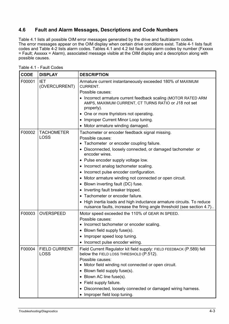
Troubleshooting/Diagnostics 4-3
4.6 Fault and Alarm Messages, Descriptions and Code Numbers
Table 4.1 lists all possible OIM error messages generated by the drive and fault/alarm codes.The error messages appear on the OIM display when certain drive conditions exist. Table 4-1 lists faultcodes and Table 4-2 lists alarm codes. Tables 4.1 and 4.2 list fault and alarm codes by number (Fxxxxx= Fault; Axxxxx = Alarm), associated message visible at the OIM display and a description along withpossible causes.
Table 4.1 - Fault Codes
CODE DISPLAY DESCRIPTION
F00001 IET(OVERCURRENT)
Armature current instantaneously exceeded 180% of MAXIMUMCURRENT.Possible causes:
• Incorrect armature current feedback scaling (MOTOR RATED ARMAMPS, MAXIMUM CURRENT, CT TURNS RATIO or J18 not setproperly).
• One or more thyristors not operating.
• Improper Current Minor Loop tuning.
• Motor armature winding damaged.
F00002 TACHOMETERLOSS
Tachometer or encoder feedback signal missing.Possible causes:• Tachometer or encoder coupling failure.
• Disconnected, loosely connected, or damaged tachometer orencoder wires.
• Pulse encoder supply voltage low.
• Incorrect analog tachometer scaling.
• Incorrect pulse encoder configuration.
• Motor armature winding not connected or open circuit.
• Blown inverting fault (DC) fuse.
• Inverting fault breaker tripped.
• Tachometer or encoder failure.
• High inertia loads and high inductance armature circuits. To reducenuisance faults, increase the firing angle threshold (see section 4.7)..
F00003 OVERSPEED Motor speed exceeded the 110% of GEAR IN SPEED.Possible causes:• Incorrect tachometer or encoder scaling.
• Blown field supply fuse(s).
• Improper speed loop tuning.
• Incorrect pulse encoder wiring.
F00004 FIELD CURRENTLOSS
Field Current Regulator kit field supply: FIELD FEEDBACK (P.589) fellbelow the FIELD LOSS THRESHOLD (P.512).Possible causes:• Motor field winding not connected or open circuit.
• Blown field supply fuse(s).
• Blown AC line fuse(s).
• Field supply failure.
• Disconnected, loosely connected or damaged wiring harness.
• Improper field loop tuning.
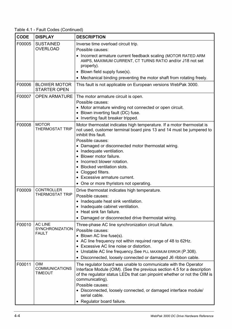
4-4 WebPak 3000 DC Drive Hardware Reference
Table 4.1 - Fault Codes (Continued)
CODE DISPLAY DESCRIPTION
F00005 SUSTAINEDOVERLOAD
Inverse time overload circuit trip.Possible causes:
• Incorrect armature current feedback scaling (MOTOR RATED ARMAMPS, MAXIMUM CURRENT, CT TURNS RATIO and/or J18 not setproperly).
• Blown field supply fuse(s).
• Mechanical binding preventing the motor shaft from rotating freely.
F00006 BLOWER MOTORSTARTER OPEN
This fault is not applicable on European versions WebPak 3000.
F00007 OPEN ARMATURE The motor armature circuit is open.Possible causes:• Motor armature winding not connected or open circuit.• Blown inverting fault (DC) fuse.• Inverting fault breaker tripped.
F00008 MOTORTHERMOSTAT TRIP
Motor thermostat indicates high temperature. If a motor thermostat isnot used, customer terminal board pins 13 and 14 must be jumpered toinhibit this fault.Possible causes:• Damaged or disconnected motor thermostat wiring.• Inadequate ventilation.• Blower motor failure.• Incorrect blower rotation.• Blocked ventilation slots.• Clogged filters.• Excessive armature current.
• One or more thyristors not operating.
F00009 CONTROLLERTHERMOSTAT TRIP
Drive thermostat indicates high temperature.Possible causes:• Inadequate heat sink ventilation.• Inadequate cabinet ventilation.• Heat sink fan failure.
• Damaged or disconnected drive thermostat wiring.
F00010 AC LINESYNCHRONIZATIONFAULT
Three-phase AC line synchronization circuit failure.Possible causes:• Blown AC line fuse(s).• AC line frequency not within required range of 48 to 62Hz.• Excessive AC line noise or distortion.• Unstable AC line frequency.See PLL MAXIMUM ERROR (P.308).
• Disconnected, loosely connected or damaged J6 ribbon cable.
F00011 OIMCOMMUNICATIONSTIMEOUT
The regulator board was unable to communicate with the OperatorInterface Module (OIM). (See the previous section 4.5 for a descriptionof the regulator status LEDs that can pinpoint whether or not the OIM iscommunicating).Possible causes:• Disconnected, loosely connected, or damaged interface module/
serial cable.
• Regulator board failure.
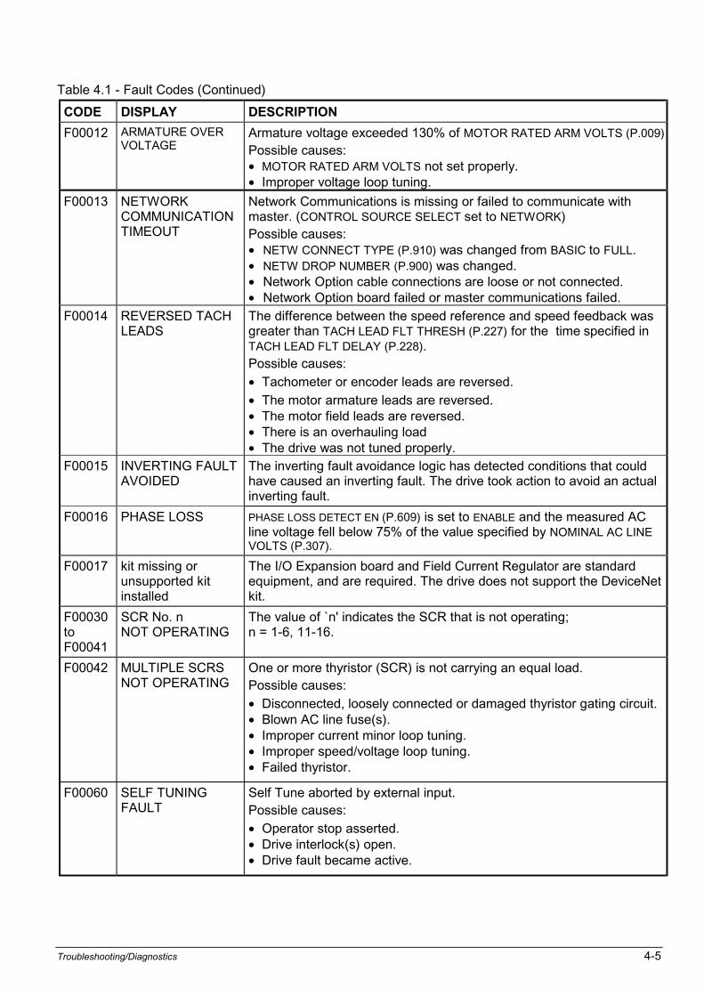
Troubleshooting/Diagnostics 4-5
Table 4.1 - Fault Codes (Continued)
CODE DISPLAY DESCRIPTION
F00012 ARMATURE OVERVOLTAGE
Armature voltage exceeded 130% of MOTOR RATED ARM VOLTS (P.009).Possible causes:• MOTOR RATED ARM VOLTS not set properly.• Improper voltage loop tuning.
F00013 NETWORKCOMMUNICATIONTIMEOUT
Network Communications is missing or failed to communicate withmaster. (CONTROL SOURCE SELECT set to NETWORK)Possible causes:• NETW CONNECT TYPE (P.910) was changed from BASIC to FULL.• NETW DROP NUMBER (P.900) was changed.• Network Option cable connections are loose or not connected.• Network Option board failed or master communications failed.
F00014 REVERSED TACHLEADS
The difference between the speed reference and speed feedback wasgreater than TACH LEAD FLT THRESH (P.227) for the time specified inTACH LEAD FLT DELAY (P.228).Possible causes:
• Tachometer or encoder leads are reversed.
• The motor armature leads are reversed.• The motor field leads are reversed.• There is an overhauling load• The drive was not tuned properly.
F00015 INVERTING FAULTAVOIDED
The inverting fault avoidance logic has detected conditions that couldhave caused an inverting fault. The drive took action to avoid an actualinverting fault.
F00016 PHASE LOSS PHASE LOSS DETECT EN (P.609) is set to ENABLE and the measured ACline voltage fell below 75% of the value specified by NOMINAL AC LINEVOLTS (P.307).
F00017 kit missing orunsupported kitinstalled
The I/O Expansion board and Field Current Regulator are standardequipment, and are required. The drive does not support the DeviceNetkit.
F00030toF00041
SCR No. nNOT OPERATING
The value of `n' indicates the SCR that is not operating;n = 1-6, 11-16.
F00042 MULTIPLE SCRSNOT OPERATING
One or more thyristor (SCR) is not carrying an equal load.Possible causes:
• Disconnected, loosely connected or damaged thyristor gating circuit.• Blown AC line fuse(s).• Improper current minor loop tuning.• Improper speed/voltage loop tuning.• Failed thyristor.
F00060 SELF TUNINGFAULT
Self Tune aborted by external input.Possible causes:
• Operator stop asserted.• Drive interlock(s) open.• Drive fault became active.
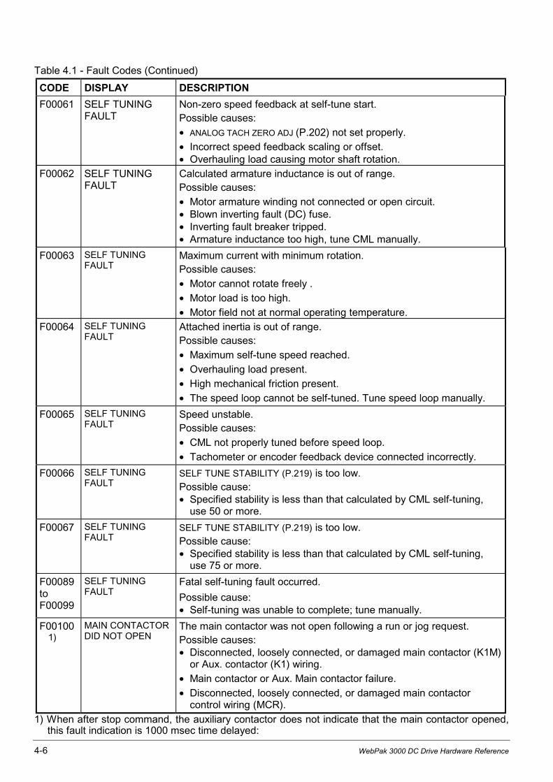
4-6 WebPak 3000 DC Drive Hardware Reference
Table 4.1 - Fault Codes (Continued)
CODE DISPLAY DESCRIPTION
F00061 SELF TUNINGFAULT
Non-zero speed feedback at self-tune start.Possible causes:
• ANALOG TACH ZERO ADJ (P.202) not set properly.
• Incorrect speed feedback scaling or offset.• Overhauling load causing motor shaft rotation.
F00062 SELF TUNINGFAULT
Calculated armature inductance is out of range.Possible causes:
• Motor armature winding not connected or open circuit.• Blown inverting fault (DC) fuse.• Inverting fault breaker tripped.• Armature inductance too high, tune CML manually.
F00063 SELF TUNINGFAULT
Maximum current with minimum rotation.Possible causes:
• Motor cannot rotate freely .
• Motor load is too high.
• Motor field not at normal operating temperature.
F00064 SELF TUNINGFAULT
Attached inertia is out of range.Possible causes:
• Maximum self-tune speed reached.
• Overhauling load present.
• High mechanical friction present.
• The speed loop cannot be self-tuned. Tune speed loop manually.
F00065 SELF TUNINGFAULT
Speed unstable.Possible causes:
• CML not properly tuned before speed loop.
• Tachometer or encoder feedback device connected incorrectly.
F00066 SELF TUNINGFAULT
SELF TUNE STABILITY (P.219) is too low.Possible cause:• Specified stability is less than that calculated by CML self-tuning,
use 50 or more.
F00067 SELF TUNINGFAULT
SELF TUNE STABILITY (P.219) is too low.Possible cause:• Specified stability is less than that calculated by CML self-tuning,
use 75 or more.
F00089toF00099
SELF TUNINGFAULT
Fatal self-tuning fault occurred.
Possible cause:• Self-tuning was unable to complete; tune manually.
F00100 1)
MAIN CONTACTORDID NOT OPEN
The main contactor was not open following a run or jog request.Possible causes:• Disconnected, loosely connected, or damaged main contactor (K1M)
or Aux. contactor (K1) wiring.
• Main contactor or Aux. Main contactor failure.
• Disconnected, loosely connected, or damaged main contactorcontrol wiring (MCR).
1) When after stop command, the auxiliary contactor does not indicate that the main contactor opened,this fault indication is 1000 msec time delayed:
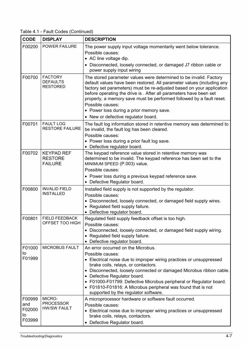
Troubleshooting/Diagnostics 4-7
Table 4.1 - Fault Codes (Continued)
CODE DISPLAY DESCRIPTION
F00200 POWER FAILURE The power supply input voltage momentarily went below tolerance.Possible causes:• AC line voltage dip.
• Disconnected, loosely connected, or damaged J7 ribbon cable orpower supply input wiring
F00700 FACTORYDEFAULTSRESTORED
The stored parameter values were determined to be invalid. Factorydefault values have been restored. All parameter values (including anyfactory set parameters) must be re-adjusted based on your applicationbefore operating the drive is . After all parameters have been setproperly, a memory save must be performed followed by a fault reset.Possible causes:• Power loss during a prior memory save.
• New or defective regulator board.
F00701 FAULT LOGRESTORE FAILURE
The fault log information stored in retentive memory was determined tobe invalid, the fault log has been cleared.Possible causes:• Power loss during a prior fault log save.• Defective regulator board.
F00702 KEYPAD REFRESTOREFAILURE
The keypad reference value stored in retentive memory wasdetermined to be invalid. The keypad reference has been set to theMINIMUM SPEED (P.003) value.Possible causes:
• Power loss during a previous keypad reference save.• Defective Regulator board.
F00800 INVALID FIELDINSTALLED
Installed field supply is not supported by the regulator.Possible causes:• Disconnected, loosely connected, or damaged field supply wires.• Regulated field supply failure.• Defective regulator board.
F00801 FIELD FEEDBACKOFFSET TOO HIGH
Regulated field supply feedback offset is too high.Possible causes:• Disconnected, loosely connected, or damaged field supply wiring.• Regulated field supply failure.• Defective regulator board.
F01000toF01999
MICROBUS FAULT An error occurred on the Microbus.Possible causes:• Electrical noise due to improper wiring practices or unsuppressed
brake coils, relays, or contactors.• Disconnected, loosely connected or damaged Microbus ribbon cable.• Defective Regulator board.• F01000-F01799: Defective Microbus peripheral or Regulator board.• F01810-F01816: A Microbus peripheral was found that is not
supported by the regulator software.
F00999andF02000toF03999
MICRO-PROCESSORHW/SW FAULT
A microprocessor hardware or software fault occurred.Possible causes:• Electrical noise due to improper wiring practices or unsuppressed
brake coils, relays, contactors.
• Defective Regulator board.
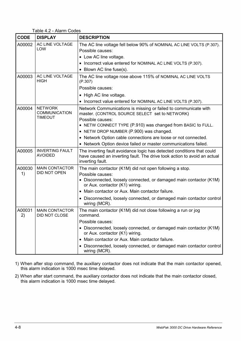
4-8 WebPak 3000 DC Drive Hardware Reference
Table 4.2 - Alarm Codes
CODE DISPLAY DESCRIPTION
A00002 AC LINE VOLTAGELOW
The AC line voltage fell below 90% of NOMINAL AC LINE VOLTS (P.307).Possible causes:
• Low AC line voltage.
• Incorrect value entered for NOMINAL AC LINE VOLTS (P.307).
• Blown AC line fuse(s).
A00003 AC LINE VOLTAGEHIGH
The AC line voltage rose above 115% of NOMINAL AC LINE VOLTS(P.307)
Possible causes:
• High AC line voltage.
• Incorrect value entered for NOMINAL AC LINE VOLTS (P.307).
A00004 NETWORKCOMMUNICATIONTIMEOUT
Network Communications is missing or failed to communicate withmaster. (CONTROL SOURCE SELECT set to NETWORK)Possible causes:• NETW CONNECT TYPE (P.910) was changed from BASIC to FULL.
• NETW DROP NUMBER (P.900) was changed.
• Network Option cable connections are loose or not connected.
• Network Option device failed or master communications failed.
A00005 INVERTING FAULTAVOIDED
The inverting fault avoidance logic has detected conditions that couldhave caused an inverting fault. The drive took action to avoid an actualinverting fault.
A00030 1)
MAIN CONTACTORDID NOT OPEN
The main contactor (K1M) did not open following a stop.Possible causes:• Disconnected, loosely connected, or damaged main contactor (K1M)
or Aux. contactor (K1) wiring.
• Main contactor or Aux. Main contactor failure.
• Disconnected, loosely connected, or damaged main contactor controlwiring (MCR).
A00031 2)
MAIN CONTACTORDID NOT CLOSE
The main contactor (K1M) did not close following a run or jogcommand.
Possible causes:
• Disconnected, loosely connected, or damaged main contactor (K1M)or Aux. contactor (K1) wiring.
• Main contactor or Aux. Main contactor failure.
• Disconnected, loosely connected, or damaged main contactor controlwiring (MCR).
1) When after stop command, the auxiliary contactor does not indicate that the main contactor opened,this alarm indication is 1000 msec time delayed.
2) When after start command, the auxiliary contactor does not indicate that the main contactor closed,this alarm indication is 1000 msec time delayed.

Troubleshooting/Diagnostics 4-9
Table 4.2 - Alarm Codes (Continued)
CODE DISPLAY DESCRIPTION
A00032 SUSTAINED SPEED Motor speed did not fall below STOP SPEED THRESHOLD (P.113) in therequired amount of time during a stop (this time is automatically set totwo times the DECELERATION RATE (P.002) time).Possible causes:
• DECELERATION RATE (P.002) not set properly.
• STOP SPEED THRESHOLD (P.113) not set properly.
• Overhauling load maintaining motor speed higher than the STOPSPEED THRESHOLD.
• Incorrect speed/voltage feedback scaling.
A00033 SUSTAINEDARMATURECURRENT
Armature current was unable to reach discontinuous conduction whilestopping the drive.Possible causes:
• Motor CEMF too high or line voltage too low for proper commutation.
A00050 CML FEEDBACKSCALING ERROR
Armature current feedback could not be scaled properly based on thevalues entered for MOTOR RATED ARM AMPS and MAXIMUM CURRENT.Verify that these parameter values are correct for your application.Verify that CT TURNS RATIO has been set to the correct value for yourdrive (see parameter description).
A00051 LOW MINIMUMSPEED
The MINIMUM SPEED value is less than 10% of the MAXIMUMSPEED value. This alarm will not be triggered on power-up. It onlyoccurs when maximum or minimum speed has changed.Verify that these parameter values are correct for your application.
A00052 (no message) NEG CUR LIM INV EN (P.226) has changed state, either enabling ordisabling the negative current limit inverters. The parameters POSCURRENT LIMIT SEL (P.223) and NEG CURRENT LIMIT SEL (P.224) havebeen set to REGISTER- Carefully check your current limit scheme andthe values of POSITIVE CURRENT LIM (P.005) and NEGATIVE CURRENT LIM
(P.006) to avoid unintended drive operation.
A00700 RETENTIVEMEMORY SAVEERROR
An attempt to save information (parameter values, fault log data or thekeypad reverence value) to retentive memory failed. The drive maycontinue to be operated.Possible cause:
Regulator board failure.

4-10 WebPak 3000 DC Drive Hardware Reference
4.7 Adjusting the Tachometer or Encoder Loss Sensitivity
Normally, tachometer or encoder loss is reported when the SCR firing angle reaches 109° whenarmature current is present and the speed feedback is less than 5% of GEAR IN SPEED(P.011). If you are getting nuisance trips associated with high inertia loads, you can adjust theSCR angle at which tachometer or encoder loss is reported.
For a description of parameter TACH LOSS SCR ANGLE (P.608), refer to the WebPak 3000Software Reference manual.
ATTENTION: This equipment is at line voltage when AC power is connected to thedrive. Disconnect and lockout incoming power to the drive before proceeding. Afterpower is removed, verify with a voltmeter at power terminals 1U, 1V and 1W thatno voltage exists before touching any internal parts of the drive. Failure to observethese precautions could result in severe bodily injury or loss of life.
If you are getting nuisance tachometer or encoder loss trips:
1. Lockout and tag power as necessary.
2. Turn off power to the drive.
3. Check all tachometer or encoder lead connections, including polarity.
4. If there is no problem with the connections, increase TACH LOSS SCR ANGLE by 1 degree.
5. Restart the drive.
6. If a tachometer or encoder loss is reported and the angle is less than 127°, repeat thisprocedure.
4.8 Phase Locked Loop (PLL) Maximum Error
If your drive power is supplied by a source that cannot maintain a suitable fixed frequencyoutput (such as an alternator), you can adjust PLL MAXIMUM ERROR (P.308) to prevent faultsrelated to line synchronization.
For a description of parameter PLL MAXIMUM ERROR, refer to the WebPak 3000 SoftwareReference manual.
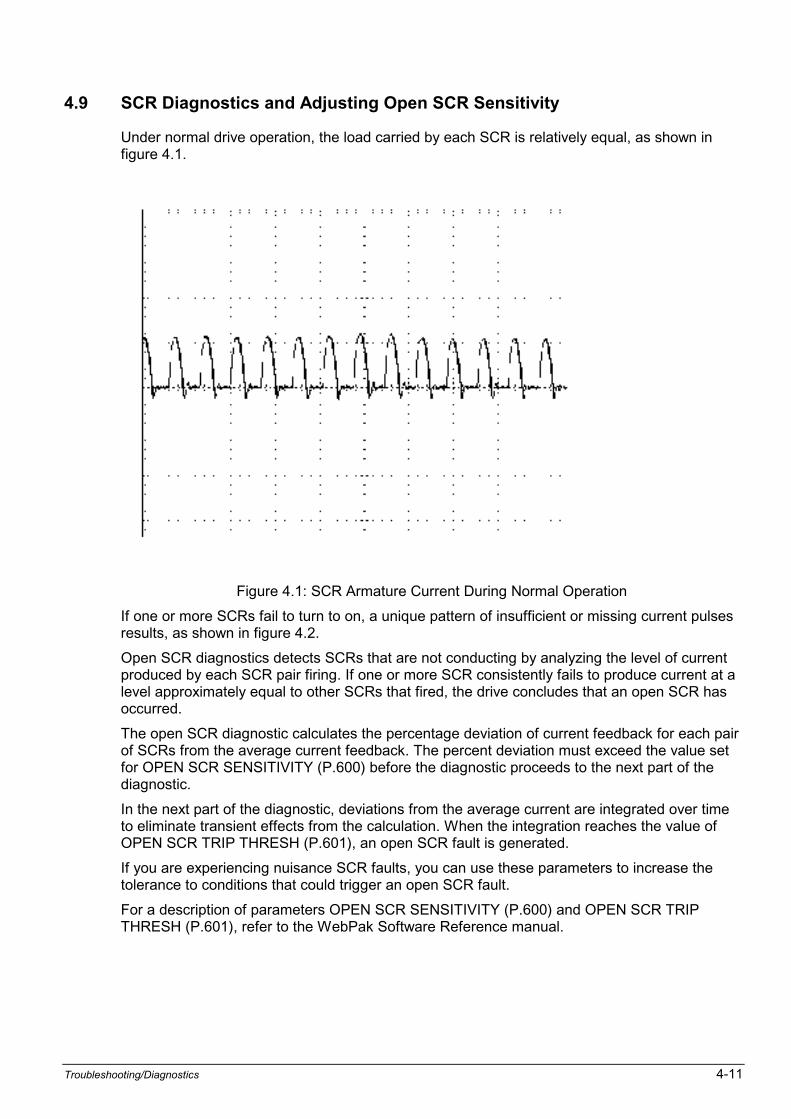
Troubleshooting/Diagnostics 4-11
4.9 SCR Diagnostics and Adjusting Open SCR Sensitivity
Under normal drive operation, the load carried by each SCR is relatively equal, as shown infigure 4.1.
Figure 4.1: SCR Armature Current During Normal Operation
If one or more SCRs fail to turn to on, a unique pattern of insufficient or missing current pulsesresults, as shown in figure 4.2.
Open SCR diagnostics detects SCRs that are not conducting by analyzing the level of currentproduced by each SCR pair firing. If one or more SCR consistently fails to produce current at alevel approximately equal to other SCRs that fired, the drive concludes that an open SCR hasoccurred.
The open SCR diagnostic calculates the percentage deviation of current feedback for each pairof SCRs from the average current feedback. The percent deviation must exceed the value setfor OPEN SCR SENSITIVITY (P.600) before the diagnostic proceeds to the next part of thediagnostic.
In the next part of the diagnostic, deviations from the average current are integrated over timeto eliminate transient effects from the calculation. When the integration reaches the value ofOPEN SCR TRIP THRESH (P.601), an open SCR fault is generated.
If you are experiencing nuisance SCR faults, you can use these parameters to increase thetolerance to conditions that could trigger an open SCR fault.
For a description of parameters OPEN SCR SENSITIVITY (P.600) and OPEN SCR TRIPTHRESH (P.601), refer to the WebPak Software Reference manual.

4-12 WebPak 3000 DC Drive Hardware Reference
Figure 4.2: Load SCRs Fail to Turn On
Troubleshooting/Diagnostics 4-13
4.10 Armature Phase Fire Test
ATTENTION: Only qualified electrical personnel familiar with the construction andoperation of this equipment and the hazards involved should install, adjust, operateand/or service this equipment. Read and understand this section in its entiretybefore proceeding. Failure to observe this precaution could result in severe bodilyinjury or loss of life.
ATTENTION: This is an open loop test. To prevent excess motor speed andcurrent, lock the motor shaft or disconnect the motor armature leads from the driveand replace them with a dummy load (e.g. bulbs in series). Failure to observe thisprecaution could result in severe bodily injury or loss of life.
ATTENTION: If the field is disconnected, the armature must be locked to preventrotation. Failure to observe this precaution could result in bodily injury.
ATTENTION: This equipment is at line voltage when AC power is connected to thedrive. Disconnect and lockout incoming power to the drive before proceeding. Afterpower is removed, verify with a voltmeter at power terminals 1U, 1V and 1W thatno voltage exists before touching any internal parts of the drive. Failure to observethese precautions could result in severe bodily injury or loss of life.
An armature phase fire test mode is available to verify the operation of the S6R rectifier bridge.This test should only be performed by qualified personnel.
For a description of parameters PHASE FIRE TEST DELTA (P.309) and PHASE FIRE TST BRIDGE(P.310), refer to the WebPak 3000 Software Reference manual.
To perform an armature phase fire test:
1. .Lockout and tag power as necessary
2. Turn off power to the drive
3. Either lock the motor armature to prevent rotation or disconnect the motor armature leadsfrom the drive and replace with bulbs in series.When locking the motor armature, the motor field winding can be disconnected to preventexcessive torque. If the motor field winding is disconnected field current loss faults must beinhibited by setting Parameter FIELD LOSS THRESHOLD (P.512).
4. Turn on power to the drive. The drive must be stopped and the Drive Ready Indicator mustbe ON.
5. Set CONTROL SOURCE SELECT to KEYPAD.
6. On the OIM, select CURRENT MINOR LOOP (CML) SCR Diagnostics Armature Phase FireTest.
7. Set PHASE FIRE TST BRIDGE (P.310). This parameter must be set to the appropriate valuebefore activating the armature phase fire test mode.
8. Attach an oscilloscope to the armature current feedback test point (J17+, J22 on theRegulator board). Note that the WebPakCS software oscilloscope mode does not havesufficient bandwidth for this test.
9. Press RUN. The armature phase fire test mode is now active. The OIM Running indicator willbe on.
10. Set PHASE FIRE TEST DELTA (P.309) to 55 degrees. Slowly increase PHASE FIRE TESTDELTA until a steady pattern of bumps appears on the oscilloscope. If all thyristors in theselected bridge are operating, there will be six bumps per AC line cycle, similar to theexample in figure 4.2.. If any bumps are missing, one or more thyristors are not conductingsimilar to the example in figure 4.3.
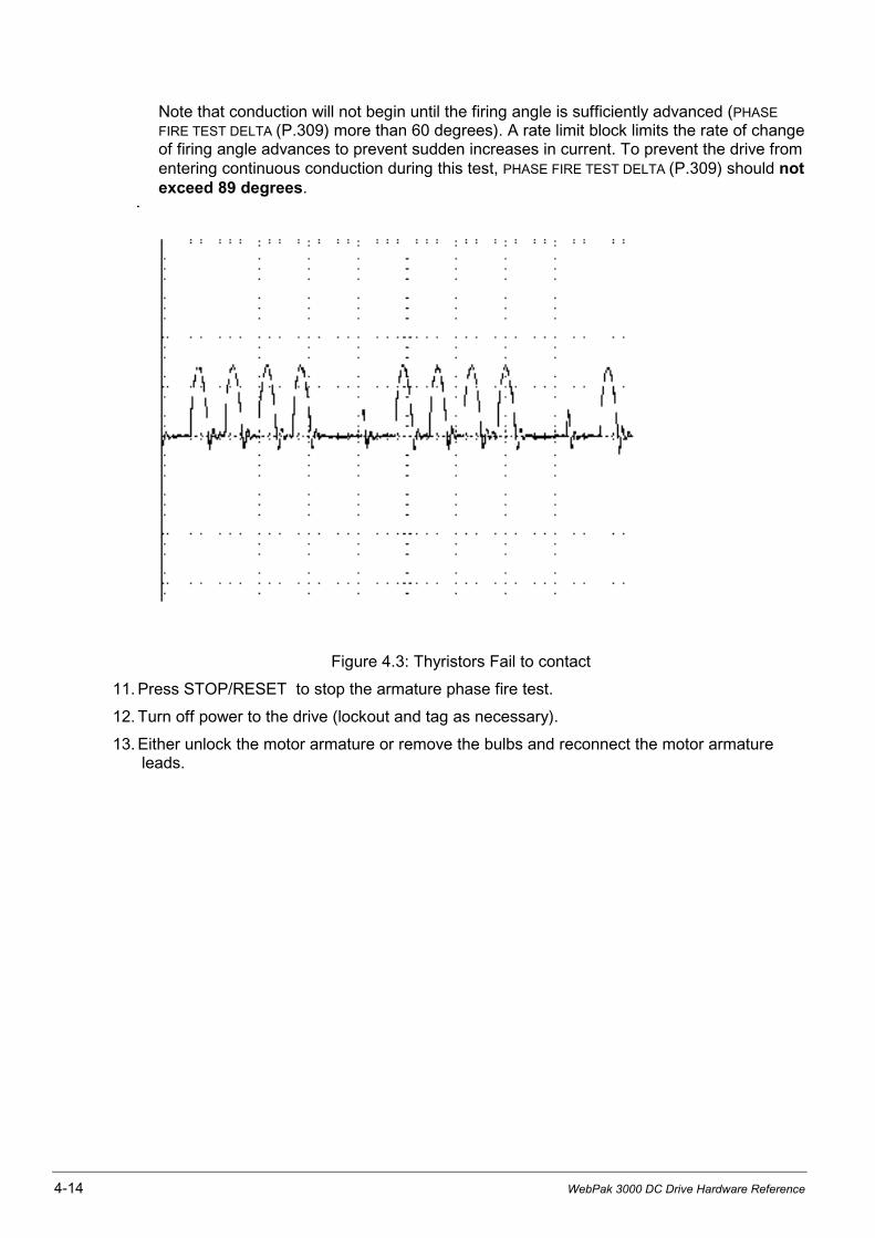
4-14 WebPak 3000 DC Drive Hardware Reference
Note that conduction will not begin until the firing angle is sufficiently advanced (PHASE
FIRE TEST DELTA (P.309) more than 60 degrees). A rate limit block limits the rate of changeof firing angle advances to prevent sudden increases in current. To prevent the drive fromentering continuous conduction during this test, PHASE FIRE TEST DELTA (P.309) should notexceed 89 degrees.
Figure 4.3: Thyristors Fail to contact
11. Press STOP/RESET to stop the armature phase fire test.
12. Turn off power to the drive (lockout and tag as necessary).
13. Either unlock the motor armature or remove the bulbs and reconnect the motor armatureleads.
Troubleshooting/Diagnostics 4-15
4.11 Setting Reversed Tachometer or Reversed Encoder Lead Detection
The WebPak 3000 drive includes an algorithm for detecting reversed speed feedback wiring.The logic verifies that the difference between the speed reference and the speed feedback isgreater than the threshold set by TACH LEAD FLT THRESH (P.227) for the amount of time set byTACH LEAD FLT DELAY (P.228). When the threshold is greater than the difference for thespecified delay, and the speed reference and speed feedback are opposite in polarity, aREVERSED TACH LEADS fault is generated (fault F00014). For a description of TACH LEAD FLTTHRESH (P.227) and TACH LEAD FLT DELAY (P.228), refer to the WebPak 3000 SoftwareReference manual.
Fault F00014 can also be caused by an overhauling load, improper drive tuning, or atachometer or encoder loss.
The tachometer lead fault parameters have default values that are set so that reversedtachometer lead detection is effectively disabled. You must empirically determine values forthese parameters so that reversed tachometer or encoder wiring can be detected withoutgenerating nuisance faults.
The ability to check for reversed tachometer lead faults is useful for machine manufacturersthat require their equipment to be disassembled for shipping and reassembled and rewired at acustomer site.
4.12 Setting Up Inverting Fault Avoidance
An inverting fault is an uncontrollable high current resulting from commutation failure. It istypically caused by an excessive armature-to-line voltage ratio, which can be caused bysituations such as a line voltage dip, a poorly tuned field regulator, or an overhauling load.Inverting faults can also be caused by thyristor misfiring induced by noise, or a current minorloop rate limit that is set too fast.
Inverting faults can cause:
• clearing of the AC line fuses that protect the armature thyristors
• tripping of an inverting fault circuit breaker
• clearing of an armature DC fuse
• loss of thyristors
• degradation of commutator due to high current
• flashover in the motor or power unit
Inverting faults are only a concern in regenerative DC drive applications. Typically, aregenerative drive application uses a regenerative power unit (S6R).
Inverting fault avoidance can be used in regenerative drive applications to prevent theoccurrence of an inverting fault. If inverting fault avoidance is used, the drive recognizesconditions that could lead to an inverting fault and dynamically adjusts drive operation toprevent an inverting fault.
For a description of parameter INV FAULT AVOID SEL (P.312), refer to the WebPak 3000Software Reference manual.
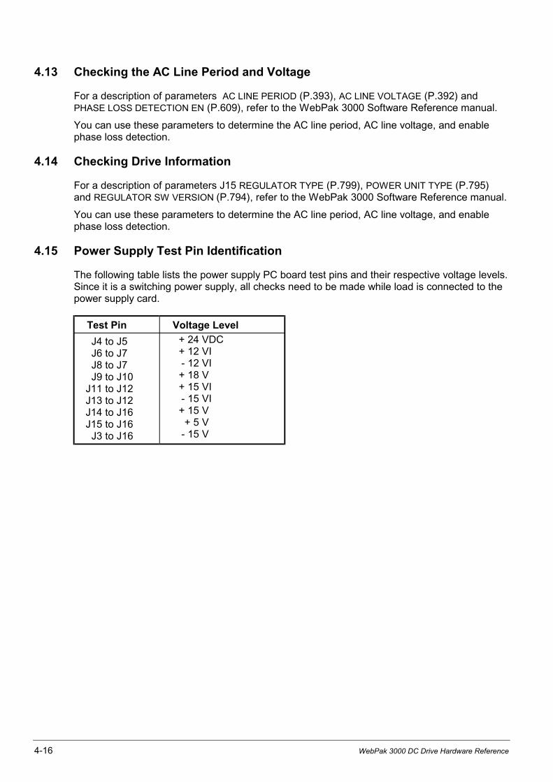
4-16 WebPak 3000 DC Drive Hardware Reference
4.13 Checking the AC Line Period and Voltage
For a description of parameters AC LINE PERIOD (P.393), AC LINE VOLTAGE (P.392) andPHASE LOSS DETECTION EN (P.609), refer to the WebPak 3000 Software Reference manual.
You can use these parameters to determine the AC line period, AC line voltage, and enablephase loss detection.
4.14 Checking Drive Information
For a description of parameters J15 REGULATOR TYPE (P.799), POWER UNIT TYPE (P.795)and REGULATOR SW VERSION (P.794), refer to the WebPak 3000 Software Reference manual.
You can use these parameters to determine the AC line period, AC line voltage, and enablephase loss detection.
4.15 Power Supply Test Pin Identification
The following table lists the power supply PC board test pins and their respective voltage levels.Since it is a switching power supply, all checks need to be made while load is connected to thepower supply card.
Test Pin Voltage Level
J4 to J5J6 to J7J8 to J7J9 to J10
J11 to J12J13 to J12J14 to J16J15 to J16J3 to J16
+ 24 VDC+ 12 VI- 12 VI+ 18 V+ 15 VI- 15 VI+ 15 V+ 5 V
- 15 V

CHAPTER 5
Replacement Parts and Accessories 5-1
Replacement Parts and Accessories5.0 Replacement of components
Use original spare parts only.Selection according to Tables 5.1 to 5.6.The location of the parts is shown on the layoutlabel inside the U-frame.
5
6
7
8
4a
4
3
2
1
(1) Screws(2) Steel plate(3) Housing(4a) Flat washer(4) Plate springs(5) Stamp(6) Semiconductor(7) Centering bolt(8) Heatsink
Replacement of a thyristor or thyristormodule Type 25 - 800 A
• Loosen and swing out regulator and Interfaceassembly
• Remove bus bars above the thyristors
• Remove gate leads of the thyristor concerned
• Unscrew thyristor or thyristor module
• Before mounting the new thyristor or thyristormodule, coat the side, which is in contact withthe heat sink, with a thin layer of heatconducting paste.
For units 800 A:
NOTE: for safe and easy mounting of thyristorson 800 A units we recommend the toolPN 050.00.00
• Insert thyristor into box-clamp and put thepackage on the centering bolt on theheatsink
• Fasten the four hexagon bolts by hand untilall slack is taken out and take care that theclamp housing stays parallel to the heatsink.
• Tighten each bolt by half a revolution at onetime with hexagonal torque socket spanner 8mm (10 mm), diagonally.
NOTE: Observe recommended torque!
• Repeat the procedure until the clamp is helddown firmly to the heatsink on each side.
• Re-connect gate leads
• Screw on bus bars.
NOTE: Before replacing a thyristor or thyristormodule the gate and cathode fastonconnectors must be checked forconductivity.
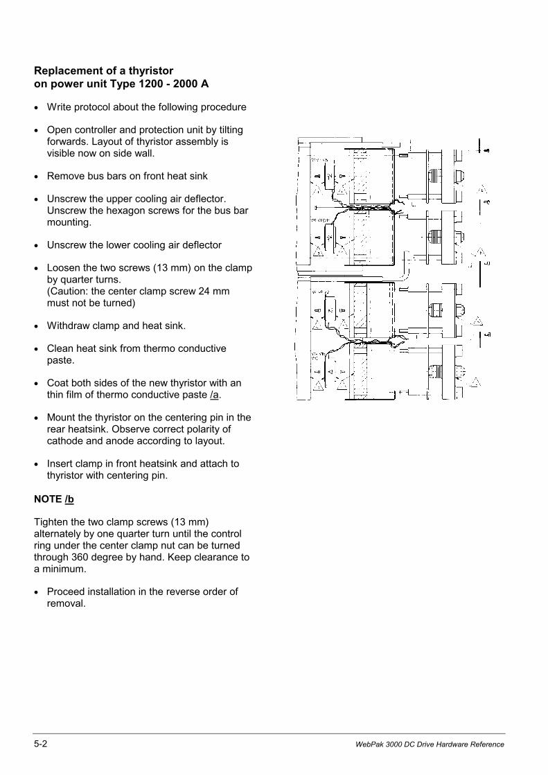
5-2 WebPak 3000 DC Drive Hardware Reference
Replacement of a thyristoron power unit Type 1200 - 2000 A
• Write protocol about the following procedure
• Open controller and protection unit by tiltingforwards. Layout of thyristor assembly isvisible now on side wall.
• Remove bus bars on front heat sink
• Unscrew the upper cooling air deflector.Unscrew the hexagon screws for the bus barmounting.
• Unscrew the lower cooling air deflector
• Loosen the two screws (13 mm) on the clampby quarter turns.(Caution: the center clamp screw 24 mmmust not be turned)
• Withdraw clamp and heat sink.
• Clean heat sink from thermo conductivepaste.
• Coat both sides of the new thyristor with anthin film of thermo conductive paste /a.
• Mount the thyristor on the centering pin in therear heatsink. Observe correct polarity ofcathode and anode according to layout.
• Insert clamp in front heatsink and attach tothyristor with centering pin.
NOTE /b
Tighten the two clamp screws (13 mm)alternately by one quarter turn until the controlring under the center clamp nut can be turnedthrough 360 degree by hand. Keep clearance toa minimum.
• Proceed installation in the reverse order ofremoval.
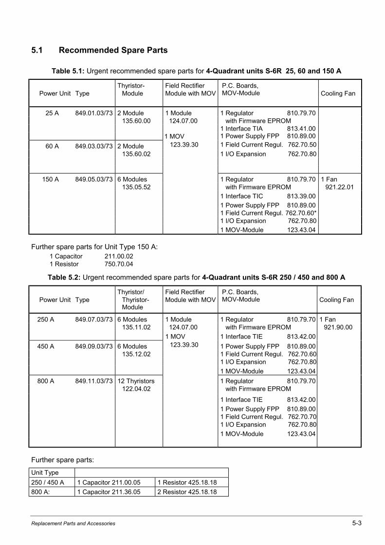
Replacement Parts and Accessories 5-3
5.1 Recommended Spare Parts
Table 5.1: Urgent recommended spare parts for 4-Quadrant units S-6R 25, 60 and 150 A
Thyristor- Field Rectifier P.C. Boards,Power Unit Type Module Module with MOV MOV-Module Cooling Fan
25 A 849.01.03/73 2 Module 1 Module 1 Regulator 810.79.70135.60.00 124.07.00 with Firmware EPROM
1 Interface TIA 813.41.001 MOV 1 Power Supply FPP 810.89.00
60 A 849.03.03/73 2 Module 123.39.30 1 Field Current Regul. 762.70.50
135.60.02 1 I/O Expansion 762.70.80
150 A 849.05.03/73 6 Modules 1 Regulator 810.79.70 1 Fan135.05.52 with Firmware EPROM 921.22.01
1 Interface TIC 813.39.00
1 Power Supply FPP 810.89.001 Field Current Regul. 762.70.60*1 I/O Expansion 762.70.80
1 MOV-Module 123.43.04
Further spare parts for Unit Type 150 A:1 Capacitor 211.00.021 Resistor 750.70.04
Table 5.2: Urgent recommended spare parts for 4-Quadrant units S-6R 250 / 450 and 800 A
Thyristor/ Field Rectifier P.C. Boards,Power Unit Type Thyristor- Module with MOV MOV-Module Cooling Fan
Module
250 A 849.07.03/73 6 Modules 1 Module 1 Regulator 810.79.70 1 Fan135.11.02 124.07.00 with Firmware EPROM 921.90.00
1 MOV 1 Interface TIE 813.42.00
450 A 849.09.03/73 6 Modules 123.39.30 1 Power Supply FPP 810.89.00135.12.02 1 Field Current Regul. 762.70.60
1 I/O Expansion 762.70.80
1 MOV-Module 123.43.04
800 A 849.11.03/73 12 Thyristors 1 Regulator 810.79.70122.04.02 with Firmware EPROM
1 Interface TIE 813.42.00
1 Power Supply FPP 810.89.001 Field Current Regul. 762.70.701 I/O Expansion 762.70.80
1 MOV-Module 123.43.04
Further spare parts:
Unit Type
250 / 450 A 1 Capacitor 211.00.05 1 Resistor 425.18.18
800 A: 1 Capacitor 211.36.05 2 Resistor 425.18.18
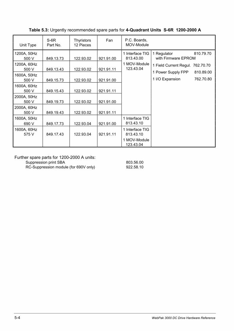
5-4 WebPak 3000 DC Drive Hardware Reference
Table 5.3: Urgently recommended spare parts for 4-Quadrant Units S-6R 1200-2000 A
S-6R Thyristors FanUnit Type Part No. 12 Pieces
P.C. Boards,MOV-Module
1200A, 50Hz500 V 849.13.73 122.93.02 921.91.00
1200A, 60Hz500 V 849.13.43 122.93.02 921.91.11
1600A, 50Hz500 V 849.15.73 122.93.02 921.91.00
1600A, 60Hz500 V 849.15.43 122.93.02 921.91.11
2000A, 50Hz500 V 849.19.73 122.93.02 921.91.00
2000A, 60Hz500 V 849.19.43 122.93.02 921.91.11
1 Interface TIG813.43.00
1 MOV-Module123.43.04
1 Regulator 810.79.70 with Firmware EPROM
1 Field Current Regul. 762.70.70
1 Power Supply FPP 810.89.00
1 I/O Expansion 762.70.80
1600A, 50Hz 690 V 849.17.73 122.93.04 921.91.00
1 Interface TIG813.43.10
1600A, 60Hz575 V 849.17.43 122.93.04 921.91.11
1 Interface TIG813.43.10
1 MOV-Module123.43.04
Further spare parts for 1200-2000 A units:Suppression print SBA 803.56.00RC-Suppression module (for 690V only) 922.58.10

Replacement Parts and Accessories 5-5
5.2 Accessories
Semiconductor protection fuses in the AC-line input of the converter and field circuit and in the motorarmature circuit are to be selected from the following tables 5.4 and 5.5. Chokes in the AC-line input ofthe converter and field circuit are to be selected from the table 5.6. The fuses and chokes are externallymounted and not supplied with the power module.
Table 5.4: Semiconductor Protection Fuses
Motor Armature (4-Qd)Fuses
AC-Line inputFuses
Fuse Accessory **)(per Fuse)
DriveType
MotorInom
CurrentIad
Rating Part No.(2 pieces)
Rating Part No.(3 pieces)
Fuse TripIndicator
FuseHolder
25A 21A 25A 32A 553.28.02 32A 553.28.02 553.29.00 511.23.00
60A 33A 40A 80A 553.28.07 63A 553.28.06 553.29.00 511.23.0050A 60A 80A 553.28.07 63A 553.28.06 553.29.00 511.23.00
150A 75A 90A 125A 553.28.09 100A 553.28.08 553.29.00 511.23.00108A 130A 200A 553.30.05* 160A 553.30.04* 553.29.00 511.24.00125A 150A 200A 553.30.05* 160A 553.30.04* 553.29.00 511.24.00
250A 158A 190A 315A 553.31.13* 250A 553.30.06* 553.29.00 511.24.00208A 250A 315A 553.31.13* 250A 553.30.06* 553.29.00 511.24.00
450A 294A 350A 450A 553.32.16* 350A 553.31.14* 553.29.00 511.24.00375A 450A 550A 553.32.18* 450A 553.32.16* 553.29.00 511.24.00
800A 525A 630A 800A 553.33.21* 630A 553.33.19* 553.29.00 511.26.01666A 800A 1000A 553.33.22* 800A 553.33.21* 553.29.00 511.26.01
1200A 833A 1000A 1250A 553.33.23* 1000A 553.33.22* 553.29.00 511.26.01500V 1000A 1200A 2 // 800A 553.33.21* 1250A 553.33.23* 553.29.00 511.26.01
1600A 1167A 1400A 2 // 1000A 553.33.22* 2 // 900A 553.33.24* 553.29.00 511.26.01500V 1334A 1600A 2 // 1000A 553.33.22* 2 // 900A 553.33.24* 553.29.00 511.26.01
2000A 1667A 2000A 2500A 553.72.01 2000A 553.72.00 553.26.30 -500V 2 // 1250A 553.33.23* 2 // 1000A 553.33.22* 553.29.00 511.26.01
1600A 833A 1000A 2 // 700A 553.34.35 2 // 630A 553.34.34 553.26.30 511.26.03690V 1167A 1400A 2 // 900A 553.34.37 2 // 800A 553.34.36 553.26.30 511.26.03
50 Hz 1334A 1600A 2 // 900A 553.34.37 2 // 800A 553.34.36 553.26.30 511.26.03
1600A 833A 1000A 2 // 800A 553.33.21* 1250A 553.33.23* 553.29.00 511.26.01575V 1167A 1400A 2 // 900A 553.33.24* 2 // 800A 553.33.21* 553.29.00 511.26.01
60 Hz 1334A 1600A 2 // 900A 553.33.24* 2 // 800A 553.33.21* 553.29.00 511.26.01
Fuses and accessories marked in grey are not UL, cUL* Fuse trip indicator 553.29.00 included in fuse package** For selection and dimensions see also following pages
Table 5.5: Field Supply Input Fuse
Field AC-Input Fuse Holder DimensionsMax.FieldCurrent Fuse
RatingFuseType
FusePart No.
Fuse Holder Size 11Part No. (2 pieces)
6 A 12 A aR 553.00.09 511.21.00
12 A 16 A aR 553.00.10 511.21.00
20 A 30 A aR 553.00.11 511.21.00
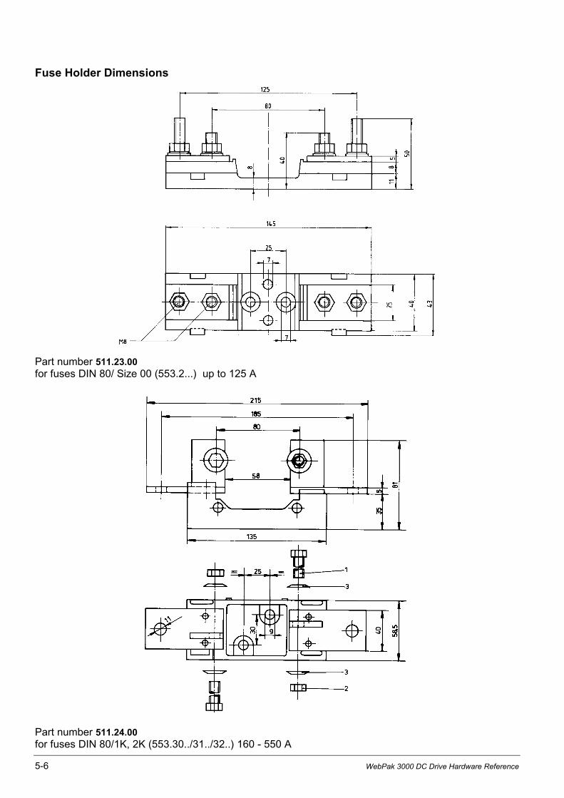
5-6 WebPak 3000 DC Drive Hardware Reference
Fuse Holder Dimensions
Part number 511.23.00for fuses DIN 80/ Size 00 (553.2...) up to 125 A
Part number 511.24.00for fuses DIN 80/1K, 2K (553.30../31../32..) 160 - 550 A
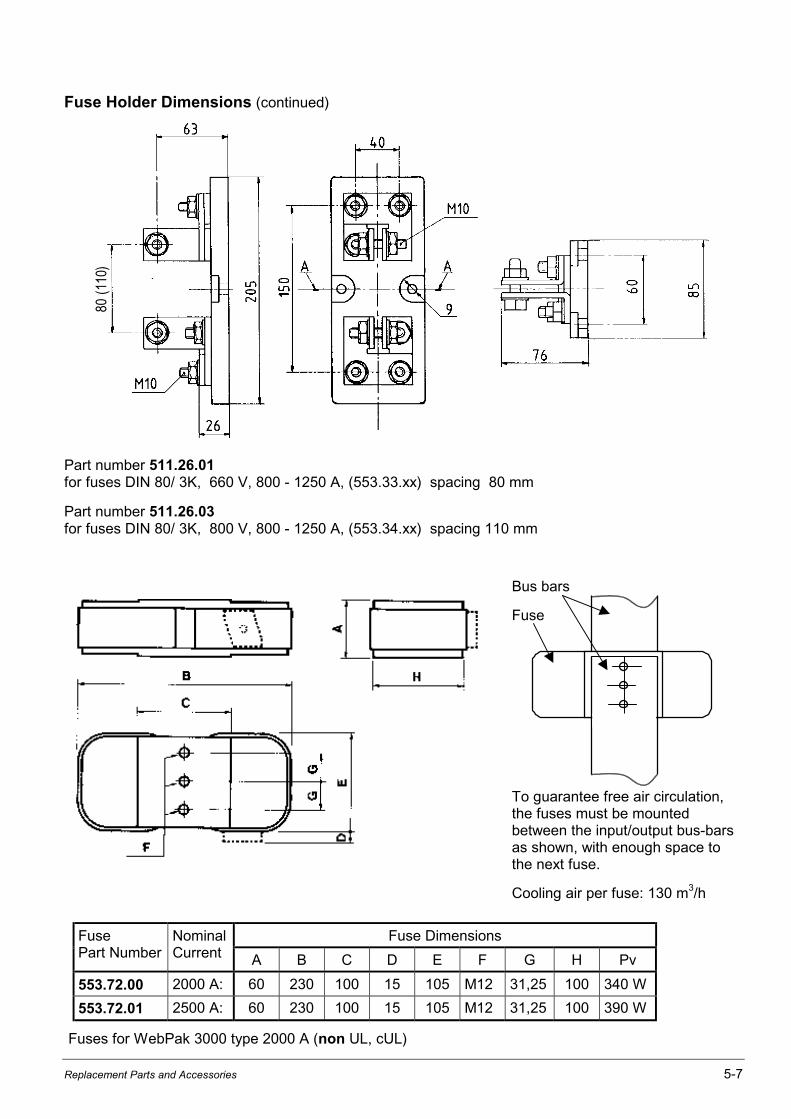
Replacement Parts and Accessories 5-7
Fuse Holder Dimensions (continued)80
(110
)
Part number 511.26.01for fuses DIN 80/ 3K, 660 V, 800 - 1250 A, (553.33.xx) spacing 80 mm
Part number 511.26.03for fuses DIN 80/ 3K, 800 V, 800 - 1250 A, (553.34.xx) spacing 110 mm
Bus bars
Fuse
To guarantee free air circulation,the fuses must be mountedbetween the input/output bus-barsas shown, with enough space tothe next fuse.
Cooling air per fuse: 130 m3/h
Fuse DimensionsFusePart Number
NominalCurrent A B C D E F G H Pv
553.72.00 2000 A: 60 230 100 15 105 M12 31,25 100 340 W
553.72.01 2500 A: 60 230 100 15 105 M12 31,25 100 390 W
Fuses for WebPak 3000 type 2000 A (non UL, cUL)
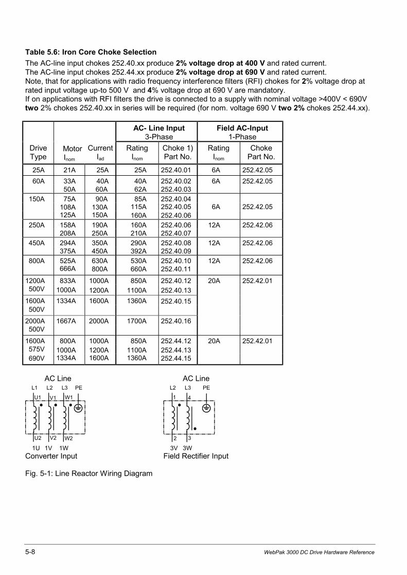
5-8 WebPak 3000 DC Drive Hardware Reference
Table 5.6: Iron Core Choke Selection
The AC-line input chokes 252.40.xx produce 2% voltage drop at 400 V and rated current.The AC-line input chokes 252.44.xx produce 2% voltage drop at 690 V and rated current.Note, that for applications with radio frequency interference filters (RFI) chokes for 2% voltage drop atrated input voltage up-to 500 V and 4% voltage drop at 690 V are mandatory.If on applications with RFI filters the drive is connected to a supply with nominal voltage >400V < 690Vtwo 2% chokes 252.40.xx in series will be required (for nom. voltage 690 V two 2% chokes 252.44.xx).
AC- Line Input3-Phase
Field AC-Input1-Phase
DriveType
MotorInom
CurrentIad
RatingInom
Choke 1)Part No.
RatingInom
ChokePart No.
25A 21A 25A 25A 252.40.01 6A 252.42.05
60A 33A 40A 40A 252.40.02 6A 252.42.0550A 60A 62A 252.40.03
150A 75A 90A 85A 252.40.04108A 130A 115A 252.40.05 6A 252.42.05125A 150A 160A 252.40.06
250A 158A 190A 160A 252.40.06 12A 252.42.06208A 250A 210A 252.40.07
450A 294A 350A 290A 252.40.08 12A 252.42.06375A 450A 392A 252.40.09
800A 525A 630A 530A 252.40.10 12A 252.42.06666A 800A 660A 252.40.11
1200A 833A 1000A 850A 252.40.12 20A 252.42.01500V 1000A 1200A 1100A 252.40.13
1600A 1334A 1600A 1360A 252.40.15500V
2000A 1667A 2000A 1700A 252.40.16500V
1600A 800A 1000A 850A 252.44.12 20A 252.42.01575V 1000A 1200A 1100A 252.44.13690V 1334A 1600A 1360A 252.44.15
AC Line AC Line
U1 V1
U2
W1
W2V2
L1 L2 L3 PE
1 4
2 3
L2 L3 PE
1U 1V 1W 3V 3WConverter Input Field Rectifier Input
Fig. 5-1: Line Reactor Wiring Diagram
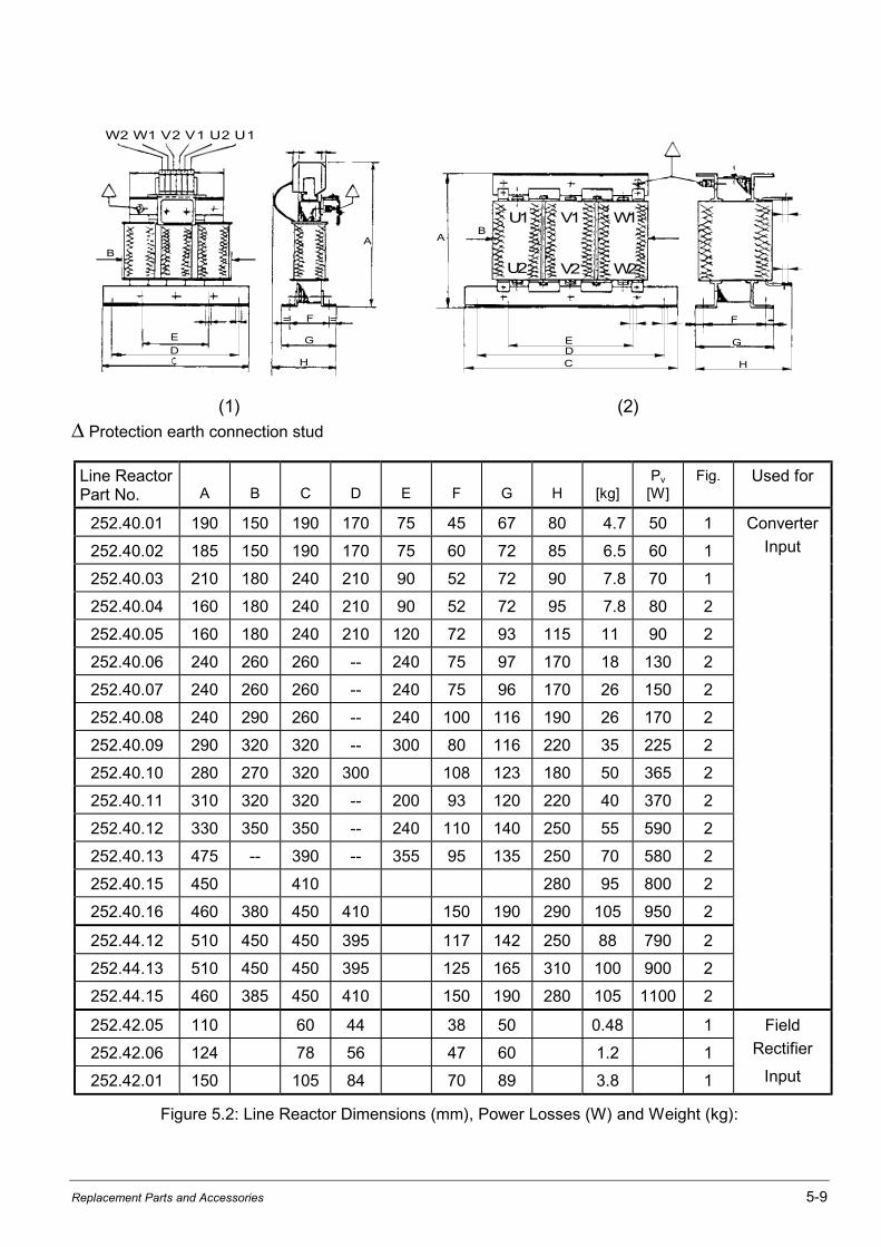
Replacement Parts and Accessories 5-9
U1 V1 W1
W2V2U2
AB
EDC
F
H
G
B
E
D
F
G
H
= =
A
W 2 W 1 V 2 V 1 U 2 U 1
(1) (2)
∆ Protection earth connection stud
Line ReactorPart No. A B C D E F G H [kg]
Pv
[W]Fig. Used for
252.40.01 190 150 190 170 75 45 67 80 4.7 50 1 Converter
252.40.02 185 150 190 170 75 60 72 85 6.5 60 1 Input
252.40.03 210 180 240 210 90 52 72 90 7.8 70 1
252.40.04 160 180 240 210 90 52 72 95 7.8 80 2
252.40.05 160 180 240 210 120 72 93 115 11 90 2
252.40.06 240 260 260 -- 240 75 97 170 18 130 2
252.40.07 240 260 260 -- 240 75 96 170 26 150 2
252.40.08 240 290 260 -- 240 100 116 190 26 170 2
252.40.09 290 320 320 -- 300 80 116 220 35 225 2
252.40.10 280 270 320 300 108 123 180 50 365 2
252.40.11 310 320 320 -- 200 93 120 220 40 370 2
252.40.12 330 350 350 -- 240 110 140 250 55 590 2
252.40.13 475 -- 390 -- 355 95 135 250 70 580 2
252.40.15 450 410 280 95 800 2
252.40.16 460 380 450 410 150 190 290 105 950 2
252.44.12 510 450 450 395 117 142 250 88 790 2
252.44.13 510 450 450 395 125 165 310 100 900 2
252.44.15 460 385 450 410 150 190 280 105 1100 2
252.42.05 110 60 44 38 50 0.48 1 Field
252.42.06 124 78 56 47 60 1.2 1 Rectifier
252.42.01 150 105 84 70 89 3.8 1 Input
Figure 5.2: Line Reactor Dimensions (mm), Power Losses (W) and Weight (kg):

5-10 WebPak 3000 DC Drive Hardware Reference
EMC Filters for WebPak 3000
General Description
Power converters in general cause line disturbances over a wide frequency range.Through the correct connection of the adapted filters (HF filter or Radio Frequency Interference (RFI)filter according to the following Table 5.7), the conducted emissions in the frequency range 150 kHz to30 MHz can be kept below the limits stated in product standard EN 61800-3.
The radiated emissions in the frequency range 30 -1000 MHz will stay below the limits, if for theinstallation the same EMC measures are taken into account as for the conducted HF emissions.
NOTE: On all WebPak drives a line input reactor must be connected between filter output and converterinput. This line reactor should be rated for minimum 2% voltage drop on drives up to 500 V and 4% for690 V drives (selection according to Table 5-6). The drives AC-line input semiconductor protection fusesas per Table 5.4 must be mounted between filter output and line reactor. Otherwise the filter inrushcurrent may damage the fuses. For installation instructions refer to Appendix B
HF Filter
If this filter is used on WebPak 3000 converters with AC line input currents above 100 A the HFemission limits for class A, group 2* (EN 55011) in the 2nd environment (industrial supply network)according to the product standard EN 61800-3 are met and the drive fulfills CE conformity.
The HF filter is connected in front of the AC line reactor between the three AC line input phases and theprotection earth conductor PE.
Filter part no.: 839.52-20Nominal voltage L-L: 690 V
Figure 5.3: HF-Filter dimensions (mm)
PE
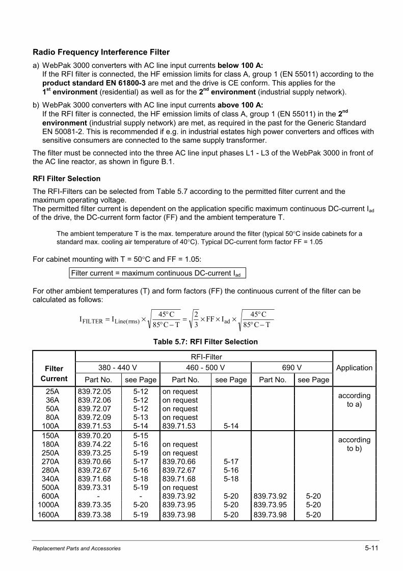
Replacement Parts and Accessories 5-11
Radio Frequency Interference Filter
a) WebPak 3000 converters with AC line input currents below 100 A:If the RFI filter is connected, the HF emission limits for class A, group 1 (EN 55011) according to theproduct standard EN 61800-3 are met and the drive is CE conform. This applies for the1st environment (residential) as well as for the 2nd environment (industrial supply network).
b) WebPak 3000 converters with AC line input currents above 100 A:If the RFI filter is connected, the HF emission limits of class A, group 1 (EN 55011) in the 2nd
environment (industrial supply network) are met, as required in the past for the Generic StandardEN 50081-2. This is recommended if e.g. in industrial estates high power converters and offices withsensitive consumers are connected to the same supply transformer.
The filter must be connected into the three AC line input phases L1 - L3 of the WebPak 3000 in front ofthe AC line reactor, as shown in figure B.1.
RFI Filter Selection
The RFI-Filters can be selected from Table 5.7 according to the permitted filter current and themaximum operating voltage.The permitted filter current is dependent on the application specific maximum continuous DC-current Iad
of the drive, the DC-current form factor (FF) and the ambient temperature T.
The ambient temperature T is the max. temperature around the filter (typical 50°C inside cabinets for astandard max. cooling air temperature of 40°C). Typical DC-current form factor FF = 1.05
For cabinet mounting with T = 50°C and FF = 1.05:
Filter current = maximum continuous DC-current Iad
For other ambient temperatures (T) and form factors (FF) the continuous current of the filter can becalculated as follows:
I IC
C TFF I
C
C TFILTER Line rms ad= × °° −
= × × × °° −( )
45
85
2
3
45
85
Table 5.7: RFI Filter Selection
RFI-Filter
Filter 380 - 440 V 460 - 500 V 690 V
Current Part No. see Page Part No. see Page Part No. see Page
Application
25A 839.72.05 5-12 on request36A 839.72.06 5-12 on request50A 839.72.07 5-12 on request80A 839.72.09 5-13 on request
100A 839.71.53 5-14 839.71.53 5-14
accordingto a)
150A 839.70.20 5-15180A 839.74.22 5-16 on request250A 839.73.25 5-19 on request270A 839.70.66 5-17 839.70.66 5-17280A 839.72.67 5-16 839.72.67 5-16340A 839.71.68 5-18 839.71.68 5-18500A 839.73.31 5-19 on request600A - - 839.73.92 5-20 839.73.92 5-20
1000A 839.73.35 5-20 839.73.95 5-20 839.73.95 5-201600A 839.73.38 5-19 839.73.98 5-20 839.73.98 5-20
accordingto b)
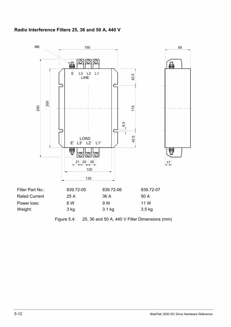
5-12 WebPak 3000 DC Drive Hardware Reference
Radio Interference Filters 25, 36 and 50 A, 440 V
M6
E L3 L2 L1LINE
LOAD E' L3' L2' L1'
11
54
2.5
6.5
42
.5
150 652
00
25
0
21 20 20 17
120
135
Filter Part No.: 839.72-05 839.72-06 839.72-07
Rated Current 25 A 36 A 50 A
Power loss: 8 W 9 W 11 W
Weight: 3 kg 3.1 kg 3.5 kg
Figure 5.4: 25, 36 and 50 A, 440 V Filter Dimensions (mm)

Replacement Parts and Accessories 5-13
Radio Interference Filter 80 A, 440 V
6.5
E L3 L2 L1LINE
150
M10
LOAD E' L3' L2' L1'
130
30 30 30
37
5
42
7 35
0
40
0
90
15
70
Filter Part No.: 839.72-09
Power loss: 23 W
Weight: 9.5 kg
Figure 5.5: 80 A, 440 V Filter Dimensions (mm)
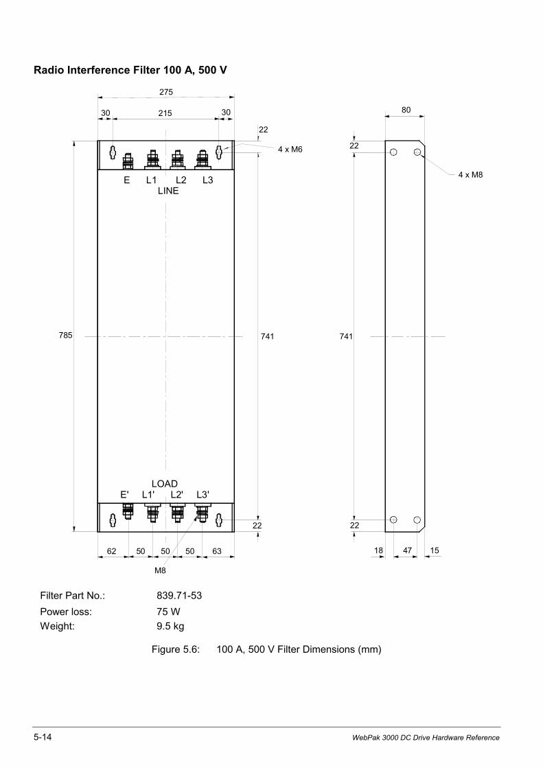
5-14 WebPak 3000 DC Drive Hardware Reference
Radio Interference Filter 100 A, 500 V
275
215
741
30
22
30
22
E L1 L2 L3LINE
LOADE' L1' L2' L3'
22 22
M8
62 50 50 50 63 18 47 15
785 741
4 x M8
80
4 x M6
Filter Part No.: 839.71-53
Power loss: 75 W
Weight: 9.5 kg
Figure 5.6: 100 A, 500 V Filter Dimensions (mm)
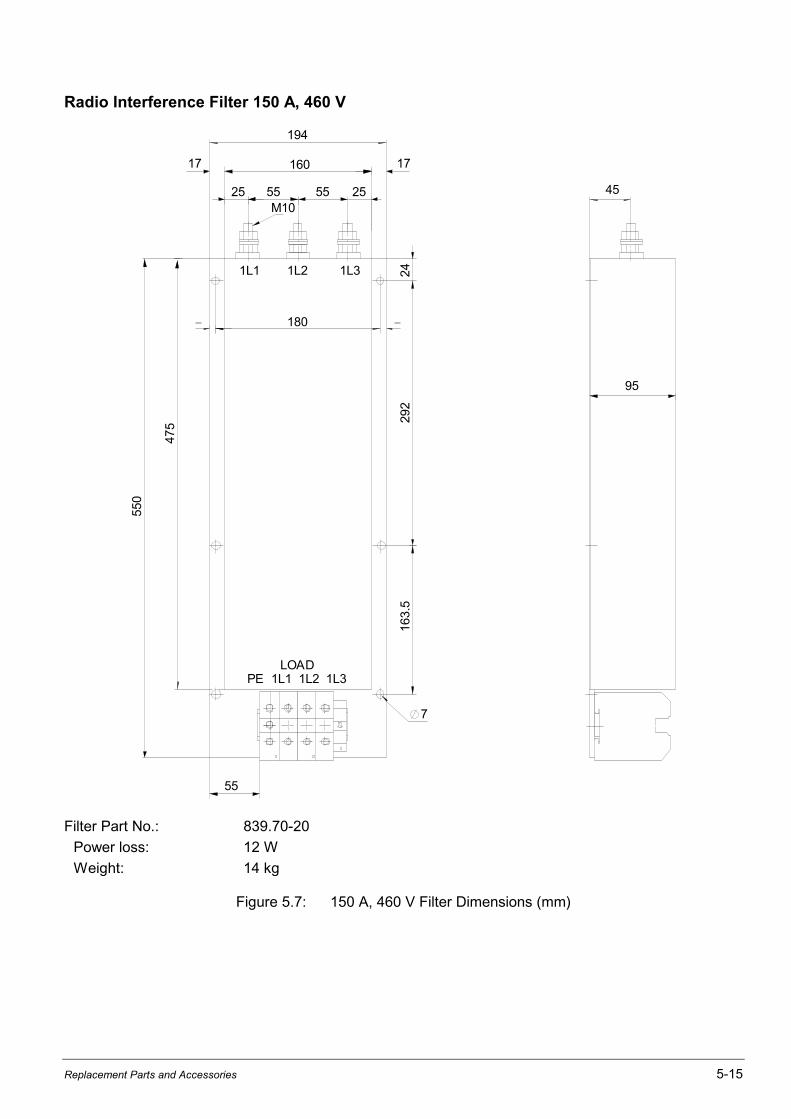
Replacement Parts and Accessories 5-15
Radio Interference Filter 150 A, 460 V
194
160
25 55 55
17
M10
1L1 1L2 1L3
25
17
180
7
95
45
55
LOADPE 1L1 1L2 1L3
475
550
292
163.
524
Filter Part No.: 839.70-20
Power loss: 12 W
Weight: 14 kg
Figure 5.7: 150 A, 460 V Filter Dimensions (mm)

5-16 WebPak 3000 DC Drive Hardware Reference
Radio Interference Filter 180 A, 440 Vand 280 A, 500 V
LOAD E' L3' L2' L1'
E L3 L2 L1 LINE
J
M10
E
4
6.5
C L
H G G
15
A F B P
I[A]
FilterPart No. A B C E F G H J L P R [kg]
Pv
[W]Terminal
max. mm2
180 839.74-22 537 360 88 132 470 25 28 180 156 510 77 13 49 95
280 839.72-67 742 530 103 153 660 31 59 260 220 700 82 28 70 150
Figure 5.8: 180 A, 440 V and 280 A, 500 V RFI-Filter Dimensions (mm)

Replacement Parts and Accessories 5-17
Radio Interference Filter 270 A, 440/500 V
13
51
35
11
01
10
55
0
30
30
65
65
350
335
5.1
M12
320
16
0
50
40 8080 80
LOAD E' L3' L2' L1'
E L3 L2 L1LINE
Filter Part No.: 839.70-66
Power loss: 26 W
Weight: 48 kg
Figure 5.9: 270 A, 500 V RFI-Filter Dimensions (mm)

5-18 WebPak 3000 DC Drive Hardware Reference
Radio Interference Filter 340 A, 440/500 V
873
797
420 110
797
12
24.5
62360
Filter Part No.: 839.71-68
Power loss: 50 W
Weight: 22 kg
Figure 5.10: 340 A, 440/500 V RFI-Filter Dimensions (mm)

Replacement Parts and Accessories 5-19
Radio Interference Filter 250, 500, 1000 and 1600 A, 440 V
L3 L2 L1LINE
PE L1/L3 L2
C D
G
E
LOADL3' L2' L1'
PE' L1'/L3' L2'
H
Q M
S
T
P
L
K
=
=
A B F
R
I[A]
FilterPart No. A B C D E F G H K L M
250 839.73-25 460 350 230 149 260 200 285 120 100 79.5 24
500 839.73-31 590 500 250 154 280 280 305 150 93 59.5 24
1000 839.73-35 840 650 400 204 440 320 465 262 127 79 34
1600 839.73-38 870 680 400 204 440 340 465 262 127 79 34
I[A] P Q R S T
GroundBolt
W[kg]
Pv
[W]
250 - 24 30 ∅10.5 ∅10.5 M10 18 18
500 15 30 30 ∅11 ∅12 M12 49 45
1000 20 50 40 ∅14 ∅12 M12 90 90
1600 20 50 40 2x ∅14 ∅12 M12 130 144
Figure 5.11 250, 500, 1000 and 1600 A, 440 V RFI-Filter Dimensions (mm)
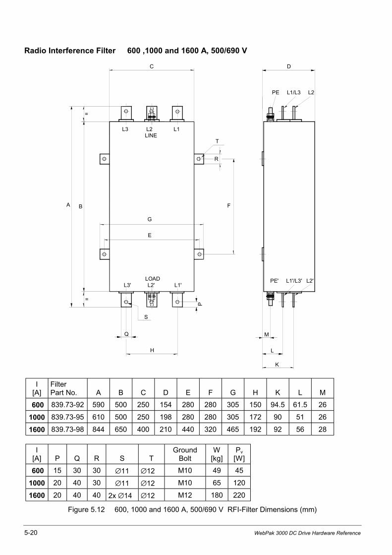
5-20 WebPak 3000 DC Drive Hardware Reference
Radio Interference Filter 600 ,1000 and 1600 A, 500/690 V
L3 L2 L1LINE
PE L1/L3 L2
C D
G
E
LOADL3' L2' L1'
PE' L1'/L3' L2'
H
Q M
S
T
P
L
K
=
=
A B F
R
I[A]
FilterPart No. A B C D E F G H K L M
600 839.73-92 590 500 250 154 280 280 305 150 94.5 61.5 26
1000 839.73-95 610 500 250 198 280 280 305 172 90 51 26
1600 839.73-98 844 650 400 210 440 320 465 192 92 56 28
I[A] P Q R S T
GroundBolt
W[kg]
Pv
[W]
600 15 30 30 ∅11 ∅12 M10 49 45
1000 20 40 30 ∅11 ∅12 M10 65 120
1600 20 40 40 2x ∅14 ∅12 M12 180 220
Figure 5.12 600, 1000 and 1600 A, 500/690 V RFI-Filter Dimensions (mm)
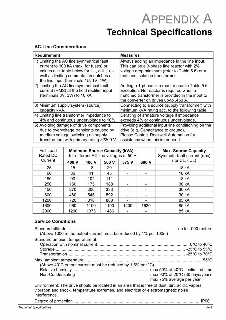
APPENDIX A
Technical Specifications A-1
Technical Specifications
AC-Line Considerations
Requirement Measures
1) Limiting the AC line symmetrical faultcurrent to 100 kA (max. for fuses) orvalues acc. table below for UL, cUL, aswell as limiting commutation notches atthe line input (terminals 1U, 1V, 1W).
Always adding an impedance in the line input.This can be a 3-phase line reactor with 2%voltage drop minimum (refer to Table 5.6) or amatched isolation transformer.
2) Limiting the AC line symmetrical faultcurrent (RMS) at the field rectifier input(terminals 3V, 3W) to 10 kA.
Adding a 1-phase line reactor acc. to Table 5.6Exception: No reactor is required when amatched transformer is provided in the input tothe converter on drives up-to .450 A.
3) Minimum supply system (source)capacity kVA.
Connecting to a source (supply transformer) withminimum kVA rating acc. to the following table.
4) Limiting line transformer impedance to4% and continuous undervoltage to 10%.
Derating of armature voltage if impedanceexceeds 4% or continuous undervoltage.
5) Avoiding damage of drive componentsdue to overvoltage transients caused bymedium voltage switching on supplytransformers with primary rating >2300 V.
Providing additional input line conditioning on thedrive (e.g. Capacitance to ground).Please Contact Rockwell Automation forassistance when this is required.
Minimum Source Capacity (kVA)for different AC line voltages at 50 Hz
Full LoadRated DCCurrent 400 V 460 V 500 V 575 V 690 V
Max. Source CapacitySymmetr. fault current (rms)
(for UL, cUL)
25 15 18 20 - - 18 kA60 36 41 45 - - 18 kA
150 90 102 111 - - 18 kA250 150 175 188 - - 30 kA450 270 306 333 - - 30 kA800 480 545 592 - - 30 kA
1200 720 818 888 - - 85 kA1600 960 1100 1190 1400 1630 85 kA2000 1200 1373 1486 - - 85 kA
Service Conditions
Standard altitude.............................................................................................. up to 1000 meters(Above 1000 m the output current must be reduced by 1% per 100m)
Standard ambient temperature at:Operation with nominal current..............................................................................0°C to 40°CStorage ............................................................................................................. -25°C to 55°CTransportation ................................................................................................... -25°C to 70°C
Max. ambient temperature ................................................................................................. 55°C(Above 40°C output current must be reduced by 1.5% per °C)Relative humidity ............................................................... max 50% at 40°C unlimited timeNon-Condensating max 90% at 20°C (30 days/year)
max 75% average per year
Environment: The drive should be located in an area that is free of dust, dirt, acidic vapors,vibration and shock, temperature extremes, and electrical or electromagnetic noiseinterference.
Degree of protection .......................................................................................................... IP00

A-2 WebPak 3000 DC Drive Hardware Reference
Input Voltage and Frequency Ratings:
Nominal voltage for three-phase at terminals 1U, 1V, 1W and 2U, 2V, 2WOn units 25, 60, 150 A...................................................... 200 - 500 VAC at 50 Hz
200 - 460 VAC at 60 HzOn units 500 V, 250, 450, 800, 1200, 1600 and 2000 A ..................... 200 - 500 VACOn units 575 V, 60 Hz, 1600 A ........................................................... 300 - 575 VACOn units 690 V, 50 Hz, 1600 A ........................................................... 300 - 690 VAC
Input voltage for Field Controller Supply (on WebPak 25 - 800 A)............... max. 415 VACInput voltage for Field Current Regulator Kit (Option) .................................. max. 460 VACVoltage variation ......................................................................+10% and -10% of NominalNominal line frequency ......................................................................................50 or 60 HzFrequency variation .................................................................................................. ±2 Hz
Fan Supply Voltage and Current Consumption on Units 1200 - 2000 A
Three-phase input voltageat terminals 5U, 5W, 5W ............................... ... 400 V, 50 Hz or. 460 V, 60 Hz, 1A
NOTE: On units 60 Hz, 1200 -2000 A in UL, cUL version the fan must be external protectedby the following, thermal magnetic circuit breaker:Dierikon part No. 610.11.05, RA catalog No. 140M-C2E1316.
Regulator Supply Voltage and Power Consumption
Single-phase input voltage, via autotransformer......................230 VAC at terminals 0, 230or 115 VAC at terminals 0, 115
Power Consumption (including fan on type 150 - 800 A) .................................max. 120 VAThermal magnetic protection by external circuit breaker
NOTE: On units with terminals 4U, 4V (without autotransformer) input voltage 230 VAC isrequired.
Relay Output for Main Contactor
Relay MCR at terminals X1:5 and X1:6Nominal contact rating at AC 230 V, cos phi = 0.5 .................................................. 330 VAMaximum current............................................................................................................3 A
DC Voltage Ratings:
Maximum permissible armature voltage Ua max at inductive voltage drop of Uk ≤ 4% per phaseand max. 10% line undervoltage. At Uk = 4 to 7% Ua max must be derated per 5%.
Ua nom is the recommended standard motor armature voltage for the selected linevoltage and operation mode.
Table A.1: Armature voltage for various line voltages
AC Line Motoring operation Regenerating operationVoltage Armature Voltage Armature Voltage
UN Ua nom Ua max Ua nom Ua max
200 V 200 V 230 V 200 V 214 V400 V 460 V 490 V 400 V 440 V460 V 520 V 570 V 500 V 500 V500 V 600 V 620 V 520 V 535 V575 V 700 V 710 V 600 V 615 V660 V 800 V 810 V 700 V 706 V690 V 800 V 850 V 700 V 738 V
Field voltage .........................................................................max. 90% of line input voltageProtection by external fuses according to table 5.5.
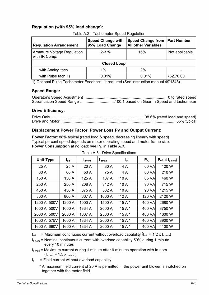
Technical Specifications A-3
Regulation (with 95% load change):
Table A.2 - Tachometer Speed Regulation
Regulation ArrangementSpeed Change with95% Load Change
Speed Change fromAll other Variables
Part Number
Armature Voltage Regulationwith IR Comp.
2-3 % 15% Not applicable.
Closed Loop
with Analog tach 1% 2% -
with Pulse tach 1) 0.01% 0.01% 762.70.00
1) Optional Pulse Tachometer Feedback kit required (See instruction manual 491343).
Speed Range:
Operator's Speed Adjustment .............................................................................0 to rated speedSpecification Speed Range ................................100:1 based on Gear In Speed and tachometer
Drive Efficiency:
Drive Only ......................................................................................98.6% (rated load and speed)Drive and Motor ..........................................................................................................85% typical
Displacement Power Factor, Power Loss Pv and Output Current:
Power Factor: 88% typical (rated load & speed, decreasing linearly with speed)Typical percent speed depends on motor operating speed and motor frame size.Power Consumption at no load: see PA in Table A.3.
Table A.3 - Drive Specifications
Unit-Type Iad Ianom I amax IF PA Pv (at Ia nom)
25 A 25 A 20 A 30 A 4 A 60 VA 120 W
60 A 60 A 50 A 75 A 4 A 60 VA 210 W
150 A 150 A 125 A 187 A 10 A 85 VA 460 W
250 A 250 A 208 A 312 A 10 A 90 VA 715 W
450 A 450 A 375 A 562 A 10 A 90 VA 1215 W
800 A 800 A 667 A 1000 A 12 A 120 VA 2120 W
1200 A, 500V 1200 A 1000 A 1500 A 15 A * 400 VA 2680 W
1600 A, 500V 1600 A 1334 A 2000 A 15 A * 400 VA 3750 W
2000 A, 500V 2000 A 1667 A 2500 A 15 A * 400 VA 4600 W
1600 A, 575V 1600 A 1334 A 2000 A 15 A * 400 VA 3900 W
1600 A, 690V 1600 A 1334 A 2000 A 15 A * 400 VA 4100 W
Iad = Maximum continuous current without overload capability (Iad = 1.2 x Ia nom)
Ia nom = Nominal continuous current with overload capability 50% during 1 minuteevery 10 minutes
Ia max = Maximum current during 1 minute after 9 minutes operation with Ia nom(Ia max = 1.5 x Ia nom)
IF = Field current without overload capability
* A maximum field current of 20 A is permitted, if the power unit blower is switched ontogether with the motor field.
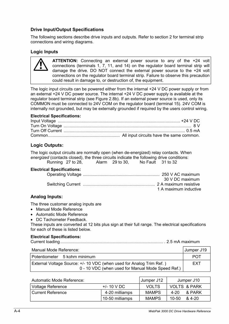
A-4 WebPak 3000 DC Drive Hardware Reference
Drive Input/Output Specifications
The following sections describe drive inputs and outputs. Refer to section 2 for terminal stripconnections and wiring diagrams.
Logic Inputs
ATTENTION: Connecting an external power source to any of the +24 voltconnections (terminals 1, 7, 11, and 14) on the regulator board terminal strip willdamage the drive. DO NOT connect the external power source to the +24 voltconnections on the regulator board terminal strip. Failure to observe this precautioncould result in damage to, or destruction of, the equipment.
The logic input circuits can be powered either from the internal +24 V DC power supply or froman external +24 V DC power source. The internal +24 V DC power supply is available at theregulator board terminal strip (see Figure 2.8b). If an external power source is used, only itsCOMMON must be connected to 24V COM on the regulator board (terminal 15). 24V COM isinternally not grounded, but may be externally grounded if required by the users control wiring.
Electrical Specifications:Input Voltage ...................................................................................................... +24 V DCTurn On Voltage .......................................................................................................... 8 VTurn Off Current ..................................................................................................... 0.5 mACommon............................................................ All input circuits have the same common.
Logic Outputs:
The logic output circuits are normally open (when de-energized) relay contacts. Whenenergized (contacts closed), the three circuits indicate the following drive conditions:
Running 27 to 28, Alarm 29 to 30, No Fault 31 to 32
Electrical Specifications:Operating Voltage ................................................................ 250 V AC maximum
30 V DC maximumSwitching Current ............................................................ 2 A maximum resistive
1 A maximum inductive
Analog Inputs:
The three customer analog inputs are• Manual Mode Reference• Automatic Mode Reference• DC Tachometer Feedback.These inputs are converted at 12 bits plus sign at their full range. The electrical specificationsfor each of these is listed below.
Electrical Specifications:Current loading...................................................................................... . 2.5 mA maximum
Manual Mode Reference: Jumper J19
Potentiometer 5 kohm minimum POT
External Voltage Source: +/- 10 VDC (when used for Analog Trim Ref. )0 - 10 VDC (when used for Manual Mode Speed Ref.)
EXT
Automatic Mode Reference: Jumper J12 Jumper J10
Voltage Reference +/- 10 V DC VOLTS VOLTS & PARK
Current Reference 4-20 milliamps MAMPS 4-20 & PARK
10-50 milliamps MAMPS 10-50 & 4-20
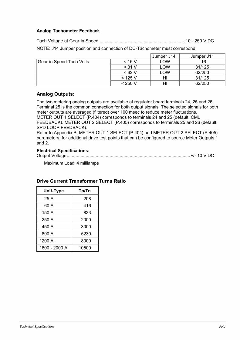
Technical Specifications A-5
Analog Tachometer Feedback
Tach Voltage at Gear-in Speed .................................................................... 10 - 250 V DC
NOTE: J14 Jumper position and connection of DC-Tachometer must correspond.
Jumper J14 Jumper J11Gear-in Speed Tach Volts < 16 V LOW 16
< 31 V LOW 31/125 < 62 V LOW 62/250 < 125 V HI 31/125 < 250 V HI 62/250
Analog Outputs:
The two metering analog outputs are available at regulator board terminals 24, 25 and 26.Terminal 25 is the common connection for both output signals. The selected signals for bothmeter outputs are averaged (filtered) over 100 msec to reduce meter fluctuations.METER OUT 1 SELECT (P.404) corresponds to terminals 24 and 25 (default: CMLFEEDBACK). METER OUT 2 SELECT (P.405) corresponds to terminals 25 and 26 (default:SPD LOOP FEEDBACK).Refer to Appendix B, METER OUT 1 SELECT (P.404) and METER OUT 2 SELECT (P.405)parameters, for additional drive test points that can be configured to source Meter Outputs 1and 2.
Electrical Specifications:Output Voltage..................................................................................................+/- 10 V DC
Maximum Load 4 milliamps
Drive Current Transformer Turns Ratio
Unit-Type Tp/Tn
25 A 208
60 A 416
150 A 833
250 A 2000
450 A 3000
800 A 5230
1200 A, 8000
1600 - 2000 A 10500

A-6 WebPak 3000 DC Drive Hardware Reference
Technical Specifications of the I/O Expansion Board
Digital Inputs
Input Voltage .................................... +24 VDCInput Current Draw ........................... 9 mA (at Vin = 24 VDC)Common ........................................... All inputs share the same common
Digital Outputs
Operating Voltage ............................ 250 VAC maximum 30 VDC maximum
Switching Current .............................. 2 amps maximum resistive1 amp maximum inductive
Analog Inputs
Analog Input 1Potentiometer .............................. 5 kΩ minimumInput Voltage ................................ ±10 VDCInput Current Reference .............. 4-20 mA, 10-50 mA
Analog Input 2Potentiometer .............................. 5 kΩ minimumInput Voltage ................................ ±10 VDC maximum
Analog Outputs
Analog Output 1Output Voltage ............................. ±10 VDCMaximum Load ............................ 4 mACurrent Output ............................. 4-20 mA
External Supply for 4-20 mA Output ........................... 5-32 VDC, 0 - 1.3 kΩ maximum loadAnalog Output 2
Output Voltage ............................. ±10 VDCMaximum Load ............................. 4 mA
Frequency Input
Maximum Frequency ........................ 250 kHzMinimum Duty Cycle ......................... 25% at 250 kHz, 20% at 100 kHz(time on to time off)Minimum Pulse Width ....................... 2msInput ................................................. Differential A and A NotInput Voltage .................................... 50 V maximum differential (25 V to common)
1.5 V minimum differential voltage swingInput Impedance ............................... 22 kΩ differential, 11 kΩ to isolated +15 V commonSignal Common ................................ 100 Ω to isolated +15 V common
Frequency Output
Maximum Frequency ........................ 250 kHzDuty Cycle ........................................ 50%Output Voltage ................................. 5 V differentialMaximum Output Offset .................... 0.4 VMaximum Load ................................. 5 mASignal Common ................................ 100 Ω to isolated +15 V commonSignal Termination ............................ 100 Ω in series with 3900 pf
APPENDIX B
CE Conformity B-1
CE-ConformityEMC Directive
This converter device is a component intended for implementation in machines or systems for the capitalgoods industry. They have been tested to meet Council Directive 89/336 Electromagnetic Compatibility(EMC) and all applicable standards (listed in the technical construction file).
With the specified EMC filters and the measures as described in this guidelines the WebPak 3000 canbe operated CE-conform according to product standard EN 61800-3.
ATTENTION: The conformity of the drive and filter to any standard does not guarantee thatthe entire installation will conform. Many other factors can influence the total installation andonly direct measurements can verify total conformity. It is therefore the responsibility of themachine manufacturer, to ensure, that the EC-conformity is met.
Disturbances
Conducted, High Frequency Disturbances (0.15 - 30 MHz)
Depending on location - first environment (residential or public low voltage supply network), secondenvironment (industrial supply network) - and converter rating different limits are permitted, whereas thepractical limit for the first environment is 100 A. For converters with AC line input current below 100 A,which are located in the first, as well as in the second environment, lower limits are required than forconverters above 100 A in the second environment.
Radiated, High Frequency Disturbances (30 - 1000 MHz)
The radiated disturbances of the converter will be kept below the limits, if for the installation the sameEMV-Measures are taken into account as for the conducted disturbances.
Conducted, Low Frequency Disturbances (Harmonics 0.1 - 2.5 kHz)
Converters with non sinusoidal AC line input current always generate current harmonics. The degree ofdisturbances, caused by harmonics, depends not only on the supply network (total Impedance), but alsoon the relative converter power.
Voltage harmonics may cause disturbances e.g. in centralized telecontrol systems or other electricalconsumers. If high power converters are connected to low voltage distribution networks with low faultlevels, the resulting voltage harmonic content could be claimed by the power supply authority to exceedthe permitted values, stated in their regulations.If the limits of the individual harmonic voltage portions are exceeded, the harmonic currents must bereduced in the supply network e.g. by means of active or passive harmonic filters.
On request Rockwell Automation will provide the harmonics current spectrum generated by eachWebPak 3000 or perform a harmonics analysis for the complete installation based on delivered data.
Immunity
Immunity against Conducted and Radiated, High Frequency Disturbances
The WebPak DC-converters have been tested to fulfill the Immunity requirement in the first, as well as inthe second environment.

B-2 WebPak 3000 DC Drive Hardware Reference
Essential Requirements for Conforming Installation
The following items are required for CE conformance:
1. Connection of EMC filter (RFI-Filter on drives <100 A or HF filter on drives >100 A) as specified inChapter 5, Accessories.
2. Because WebPak 3000 and filter have protection class IP00 they must be built in a cabinet.Both units must be mounted on a blank (not painted) panel with good conductivity.
3. Correct grounding of the equipment and the cable screens as shown in example Figure B.1.
4. Output power wiring (drive to motor) must be screened cable or run in a separate steel conduit.
5. All control (I/O) and signal wiring must be screened cable.
6. The braid of screened cables must be connected to the terminal box of the motor by the use ofsuitable, EMC-tested cable glands.
7. For all DC-converters a minimum line reactor of 2% voltage drop will be required.The line reactors must be linked between filter (Output) and DC-Converter (Input).For line reactor selection refer to Table 5.6.
Mounting Instructions(Refer to Figure B.1)
• The filters must be screwed directly to the panel with the largest possible contact area.
• The support panel for the converters and filters must be a conducting steel sheet, with a commonground busbar at the bottom. This ground busbar, mounted in front of the terminals, must besolidly connected to the panel, ensuring good conductivity.
• All cable screens, entering the cabinet, must be connected to the control cabinets ground busbar.To ensure that the screen of the individual cable is connected solidly and with good conductivity tothe ground busbar, galvanised cable brackets as shown in Figure B.1 are recommended.This applies also for coaxial cable, at which only the outer insulation should be removed.
Cable Glands
• Use suitable EMC-tested cable glands only
• The conductivity of the screen ground connection is ensured by laying the braid over a plasticcone which will press it to the inner side of the gland when mounted. It is important that theconnection area is 360 degree around the cone. The cable glands provide pull-relief through thecable jacket.
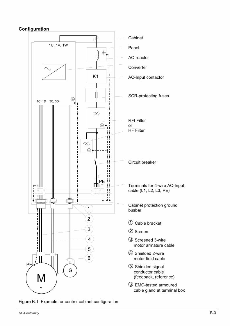
CE-Conformity B-3
Configuration
1U, 1V, 1W
M
PE
PE
2
1
6
3
4
5
G
1C, 1D 3C, 3D
-
K1
Cabinet
Panel
AC-reactor
Converter
AC-Input contactor
SCR-protecting fuses
RFI FilterorHF Filter
Circuit breaker
Terminals for 4-wire AC-Inputcable (L1, L2, L3, PE)
Cabinet protection groundbusbar
➀ Cable bracket
➁ Screen
➂ Screened 3-wiremotor armature cable
➃ Shielded 2-wiremotor field cable
➄ Shielded signalconductor cable(feedback, reference)
➅ EMC-tested armouredcable gland at terminal box
Figure B.1: Example for control cabinet configuration

B-4 WebPak 3000 DC Drive Hardware Reference
Wiring Instruction
Motor Cable
• The cables between cabinet / armature output and DC-motor armature shall be 3-wire screenedcable (+, - and earth conductor green/yellow) as specified in Figure B.2.
• The cables between field supply output and DC-motor field shall be 2-wire screened cable.
• The screen must be tinned copper braid or tinned steel braid. It must be solidly connected to thecontrol cabinet ground busbar or ground stud of the converter with large connection area and goodconductivity.
• The screen on the motor side must be solidly connected to the motor housing providing largeconnection area with good conductivity.
• If screened cables are not available (limited by the obtainable cross sections) the individualconductors and protective conductors must be run in steel conduits or enclosed metal cable ductsalso connected to ground at both ends.
• All leads shall have the same cross section(earth conductors with cross section. >162 : min. 162 or 50% of armature lead)
• The connections between filter and converter should be as short as possible!!These conductors must be bound together (with tie wrap) forming a triangle in cross section.
• Power and signal leads inside the cabinet must be distanced.
Analog or Digital Signals (e.g. reference, feedback signals),Control Signals (Relays)
These signal leads must be screened cable as specified in Figure B.2.The individual conductors must be stranded, but twisted pairs are not required.The screen must be grounded at both ends.
Stranded copper wire
Plastic insulation
Inner plastic sheath
Compact screen of galvanised (tinned) copper or steel braid
Outer plastic jacket
Figure B.2: Specification for screened cable
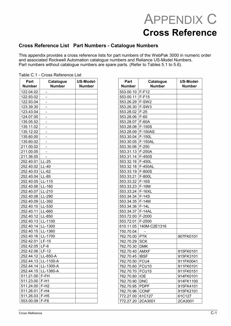
APPENDIX C
Cross Reference C-1
Cross ReferenceCross Reference List Part Numbers - Catalogue Numbers
This appendix provides a cross reference lists for part numbers of the WebPak 3000 in numeric orderand associated Rockwell Automation catalogue numbers and Reliance US-Model Numbers.Part numbers without catalogue numbers are spare parts. (Refer to Tables 5.1 to 5.6).
Table C.1 - Cross Reference List
PartNumber
CatalogueNumber
US-Model-Number
122.04.02 -122.93.02 -122.93.04 -123.39.30 -123.43.04 -124.07.00 -135.05.52 -135.11.02 -135.12.02 -135.60.00 -135.60.02 -211.00.02 -211.00.05 -211.36.05 -252.40.01 LL-25252.40.02 LL-40252.40.03 LL-62252.40.04 LL-85252.40.05 LL-115252.40.06 LL-160252.40.07 LL-210252.40.08 LL-290252.40.09 LL-392252.40.10 LL-530252.40.11 LL-660252.40.12 LL-850252.40.13 LL-1100252.40.14 LL-1300252.40.15 LL-1360252.40.16 LL-1700252.42.01 LF-15252.42.05 LF-6252.42.06 LF-12252.44.12 LL-850-A252.44.13 LL-1100-A252.44.14 LL-1300-A252.44.15 LL-1360-A511.21.00 F-FH511.23.00 F-H1511.24.00 F-H2511.26.01 F-H4511.26.03 F-H5553.00.09 F-F6
PartNumber
CatalogueNumber
US-Model-Number
553.00.10 F-F12553.00.11 F-F15553.26.29 F-SW2553.26.30 F-SW3553.28.02 F-25553.28.06 F-60553.28.07 F-60A553.28.08 F-150S553.28.09 F-150AS553.30.04 F-150L553.30.05 F-150AL553.30.06 F-250553.31.13 F-250A553.31.14 F-450S553.32.16 F-450L553.32.18 F-450AL553.33.19 F-800S553.33.21 F-800L553.33.22 F-16S553.33.23 F-16M553.33.24 F-16XL553.34.34 F-14S553.34.35 F-14M553.34.36 F-14L553.34.37 F-14AL553.72.00 F-2000553.72.01 F-2500610.11.05 140M-C2E1316750.70.04 -762.70.00 PTK 907FK0101762.70.29 SCK762.70.30 DMK762.70.40 AMXF 915FK0101762.70.45 IBSF 915FK3101762.70.50 FCU4 911FK0041762.70.60 FCU10 911FK0101762.70.70 FCU15 911FK0151762.70.80 IOE 914FK0101762.70.90 DNC 914FK1100762.70.95 PDPF 915FK4101762.70.96 CONF 915FK2101772.27.00 61C127 61C127772.27.20 2CA3001 2CA3001
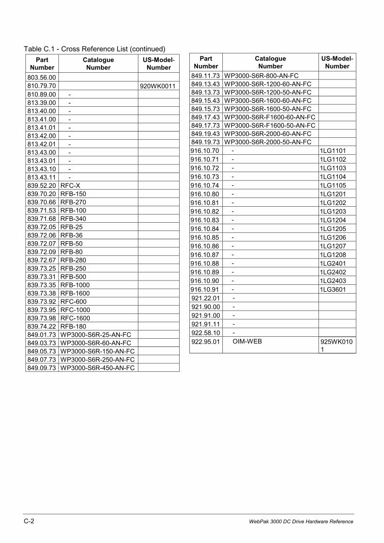
C-2 WebPak 3000 DC Drive Hardware Reference
Table C.1 - Cross Reference List (continued)
PartNumber
CatalogueNumber
US-Model-Number
803.56.00810.79.70 920WK0011810.89.00 -813.39.00 -813.40.00 -813.41.00 -813.41.01 -813.42.00 -813.42.01 -813.43.00 -813.43.01 -813.43.10 -813.43.11 -839.52.20 RFC-X839.70.20 RFB-150839.70.66 RFB-270839.71.53 RFB-100839.71.68 RFB-340839.72.05 RFB-25839.72.06 RFB-36839.72.07 RFB-50839.72.09 RFB-80839.72.67 RFB-280839.73.25 RFB-250839.73.31 RFB-500839.73.35 RFB-1000839.73.38 RFB-1600839.73.92 RFC-600839.73.95 RFC-1000839.73.98 RFC-1600839.74.22 RFB-180849.01.73 WP3000-S6R-25-AN-FC849.03.73 WP3000-S6R-60-AN-FC849.05.73 WP3000-S6R-150-AN-FC849.07.73 WP3000-S6R-250-AN-FC849.09.73 WP3000-S6R-450-AN-FC
PartNumber
CatalogueNumber
US-Model-Number
849.11.73 WP3000-S6R-800-AN-FC849.13.43 WP3000-S6R-1200-60-AN-FC849.13.73 WP3000-S6R-1200-50-AN-FC849.15.43 WP3000-S6R-1600-60-AN-FC849.15.73 WP3000-S6R-1600-50-AN-FC849.17.43 WP3000-S6R-F1600-60-AN-FC849.17.73 WP3000-S6R-F1600-50-AN-FC849.19.43 WP3000-S6R-2000-60-AN-FC849.19.73 WP3000-S6R-2000-50-AN-FC916.10.70 - 1LG1101916.10.71 - 1LG1102916.10.72 - 1LG1103916.10.73 - 1LG1104916.10.74 - 1LG1105916.10.80 - 1LG1201916.10.81 - 1LG1202916.10.82 - 1LG1203916.10.83 - 1LG1204916.10.84 - 1LG1205916.10.85 - 1LG1206916.10.86 - 1LG1207916.10.87 - 1LG1208916.10.88 - 1LG2401916.10.89 - 1LG2402916.10.90 - 1LG2403916.10.91 - 1LG3601921.22.01 -
921.90.00 -
921.91.00 -
921.91.11 -
922.58.10 -
922.95.01 OIM-WEB 925WK0101

Publication WP3000-UM010B-EN - Aug. 2001 © 2001 Copyright Rockwell International Corporation
Reach us now at www.rockwellautomation.comWherever you need us, Rockwell Automation brings together leadingbrands in industrial automation including Allen-Bradley controls,Reliance Electric power transmission products, Dodge mechanical powertransmission components, and Rockwell Software. Rockwell Automation'sunique, flexible approach to helping customers achieve a competitiveadvantage is supported by thousands of authorized partners, distributorsand system integrators around the world.
Americas Headquarters, 1201 South Second Street, Milwaukee, WI 53204, USA, Tel: (01) 414 382-2000, Fax: (01) 414 382-4444European Headquarters SA/NV, Boulevard du Souverain, 36, 1170 Brussels, Belgium, Tel: (32) 2 663 06 00, Fax: (32) 2 663 06 40Asia Pacific Headquarters, 27/F Citicorp Centre, 18 Whitfield Road, Causeway Bay, Hong Kong, Tel: (852) 2887 4788, Fax: (852) 2508 1846