systems description part 1 - candu owners group library/19980102.pdfŁ the fuelling machine takes...
TRANSCRIPT
1
Systems Description Part 1Systems Description Part 1
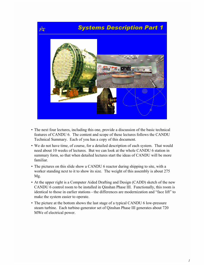
� The next four lectures, including this one, provide a discussion of the basic technicalfeatures of CANDU 6. The content and scope of these lectures follows the CANDUTechnical Summary. Each of you has a copy of this document.
� We do not have time, of course, for a detailed description of each system. That wouldneed about 10 weeks of lectures. But we can look at the whole CANDU 6 station insummary form, so that when detailed lectures start the ideas of CANDU will be morefamiliar.
� The pictures on this slide show a CANDU 6 reactor during shipping to site, with aworker standing next to it to show its size. The weight of this assembly is about 275Mg.
� At the upper right is a Computer Aided Drafting and Design (CADD) sketch of the newCANDU 6 control room to be installed in Qinshan Phase III. Functionally, this room isidentical to those in earlier stations - the differences are modernization and �face lift� tomake the system easier to operate.
� The picture at the bottom shows the last stage of a typical CANDU 6 low-pressuresteam turbine. Each turbine-generator set of Qinshan Phase III generates about 720MWe of electrical power.
2
CANDU 6 NSSS OverviewCANDU 6 NSSS Overview
Qinshan Phase III Sketch
Point Lepreau - Canada
Wolsong - Korea
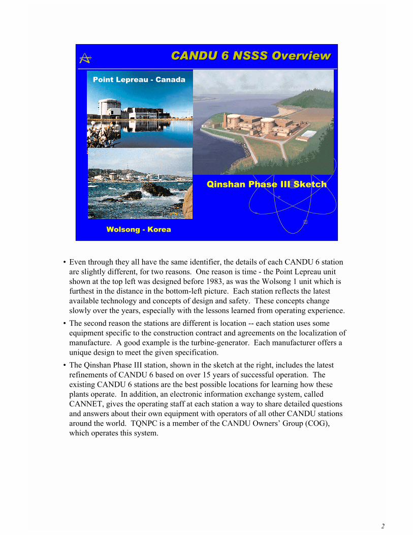
� Even through they all have the same identifier, the details of each CANDU 6 stationare slightly different, for two reasons. One reason is time - the Point Lepreau unitshown at the top left was designed before 1983, as was the Wolsong 1 unit which isfurthest in the distance in the bottom-left picture. Each station reflects the latestavailable technology and concepts of design and safety. These concepts changeslowly over the years, especially with the lessons learned from operating experience.
� The second reason the stations are different is location -- each station uses someequipment specific to the construction contract and agreements on the localization ofmanufacture. A good example is the turbine-generator. Each manufacturer offers aunique design to meet the given specification.
� The Qinshan Phase III station, shown in the sketch at the right, includes the latestrefinements of CANDU 6 based on over 15 years of successful operation. Theexisting CANDU 6 stations are the best possible locations for learning how theseplants operate. In addition, an electronic information exchange system, calledCANNET, gives the operating staff at each station a way to share detailed questionsand answers about their own equipment with operators of all other CANDU stationsaround the world. TQNPC is a member of the CANDU Owners� Group (COG),which operates this system.
3
Components of the NSSSComponents of the NSSS
�� ReactorReactor�� Fuel HandlingFuel Handling�� Heat TransportHeat Transport�� ModeratorModerator�� FeedwaterFeedwater and Steam Generators and Steam Generators�� Reactor Regulating SystemReactor Regulating System�� SafetySafety
� These are the topics to be discussed in this lecture
4
Reactor Assembly and FuelReactor Assembly and Fuel
Feeder Cabinet
Feeder Pipes
Fuel Channels
Fuelling Machine Bridge Assembly
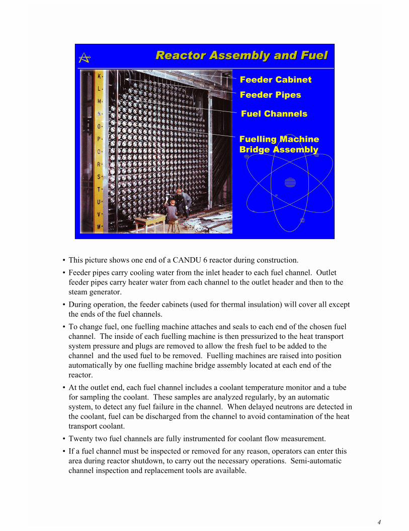
� This picture shows one end of a CANDU 6 reactor during construction.� Feeder pipes carry cooling water from the inlet header to each fuel channel. Outlet
feeder pipes carry heater water from each channel to the outlet header and then to thesteam generator.
� During operation, the feeder cabinets (used for thermal insulation) will cover all exceptthe ends of the fuel channels.
� To change fuel, one fuelling machine attaches and seals to each end of the chosen fuelchannel. The inside of each fuelling machine is then pressurized to the heat transportsystem pressure and plugs are removed to allow the fresh fuel to be added to thechannel and the used fuel to be removed. Fuelling machines are raised into positionautomatically by one fuelling machine bridge assembly located at each end of thereactor.
� At the outlet end, each fuel channel includes a coolant temperature monitor and a tubefor sampling the coolant. These samples are analyzed regularly, by an automaticsystem, to detect any fuel failure in the channel. When delayed neutrons are detected inthe coolant, fuel can be discharged from the channel to avoid contamination of the heattransport coolant.
� Twenty two fuel channels are fully instrumented for coolant flow measurement.� If a fuel channel must be inspected or removed for any reason, operators can enter this
area during reactor shutdown, to carry out the necessary operations. Semi-automaticchannel inspection and replacement tools are available.
5
CANDU 6 Fuel ChannelCANDU 6 Fuel Channel
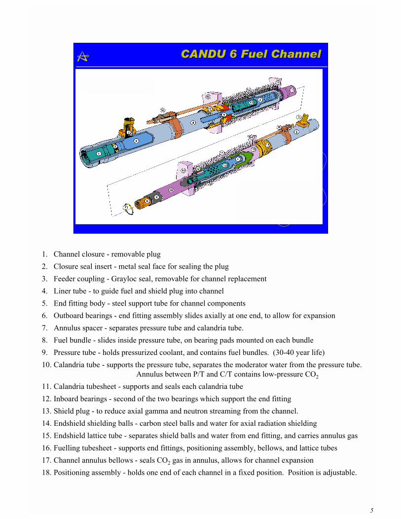
1. Channel closure - removable plug2. Closure seal insert - metal seal face for sealing the plug3. Feeder coupling - Grayloc seal, removable for channel replacement4. Liner tube - to guide fuel and shield plug into channel5. End fitting body - steel support tube for channel components6. Outboard bearings - end fitting assembly slides axially at one end, to allow for expansion7. Annulus spacer - separates pressure tube and calandria tube.8. Fuel bundle - slides inside pressure tube, on bearing pads mounted on each bundle9. Pressure tube - holds pressurized coolant, and contains fuel bundles. (30-40 year life)10. Calandria tube - supports the pressure tube, separates the moderator water from the pressure tube.
Annulus between P/T and C/T contains low-pressure CO2
11. Calandria tubesheet - supports and seals each calandria tube12. Inboard bearings - second of the two bearings which support the end fitting13. Shield plug - to reduce axial gamma and neutron streaming from the channel.14. Endshield shielding balls - carbon steel balls and water for axial radiation shielding15. Endshield lattice tube - separates shield balls and water from end fitting, and carries annulus gas16. Fuelling tubesheet - supports end fittings, positioning assembly, bellows, and lattice tubes17. Channel annulus bellows - seals CO2 gas in annulus, allows for channel expansion18. Positioning assembly - holds one end of each channel in a fixed position. Position is adjustable.
6
Closure Plug, Feeder ConnectionClosure Plug, Feeder Connection
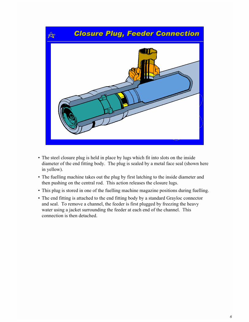
� The steel closure plug is held in place by lugs which fit into slots on the insidediameter of the end fitting body. The plug is sealed by a metal face seal (shown herein yellow).
� The fuelling machine takes out the plug by first latching to the inside diameter andthen pushing on the central rod. This action releases the closure lugs.
� This plug is stored in one of the fuelling machine magazine positions during fuelling.� The end fitting is attached to the end fitting body by a standard Grayloc connector
and seal. To remove a channel, the feeder is first plugged by freezing the heavywater using a jacket surrounding the feeder at each end of the channel. Thisconnection is then detached.
7
Positioning AssemblyPositioning Assembly
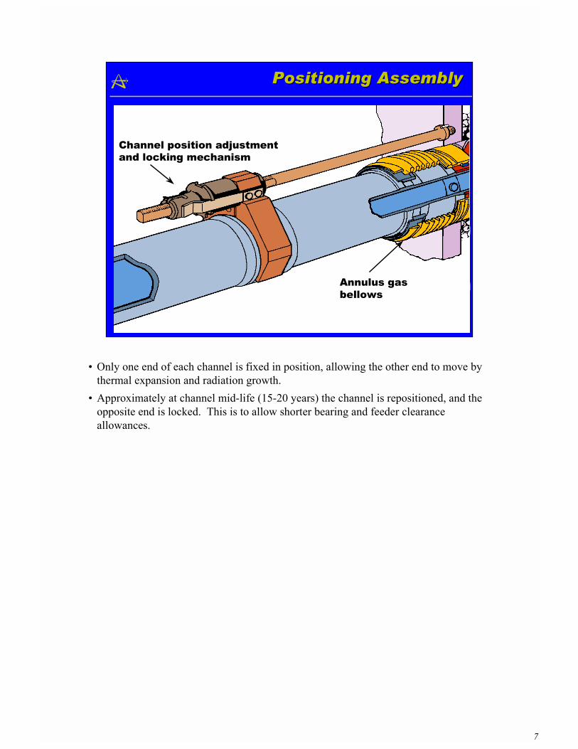
Channel position adjustmentand locking mechanism
Annulus gas bellows
� Only one end of each channel is fixed in position, allowing the other end to move bythermal expansion and radiation growth.
� Approximately at channel mid-life (15-20 years) the channel is repositioned, and theopposite end is locked. This is to allow shorter bearing and feeder clearanceallowances.
8
TubesheetTubesheet Region Region
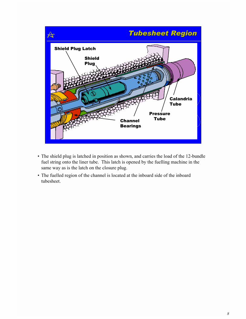
ChannelBearings
ShieldPlug
PressureTube
CalandriaTube
Shield Plug Latch
� The shield plug is latched in position as shown, and carries the load of the 12-bundlefuel string onto the liner tube. This latch is opened by the fuelling machine in thesame way as is the latch on the closure plug.
� The fuelled region of the channel is located at the inboard side of the inboardtubesheet.
9
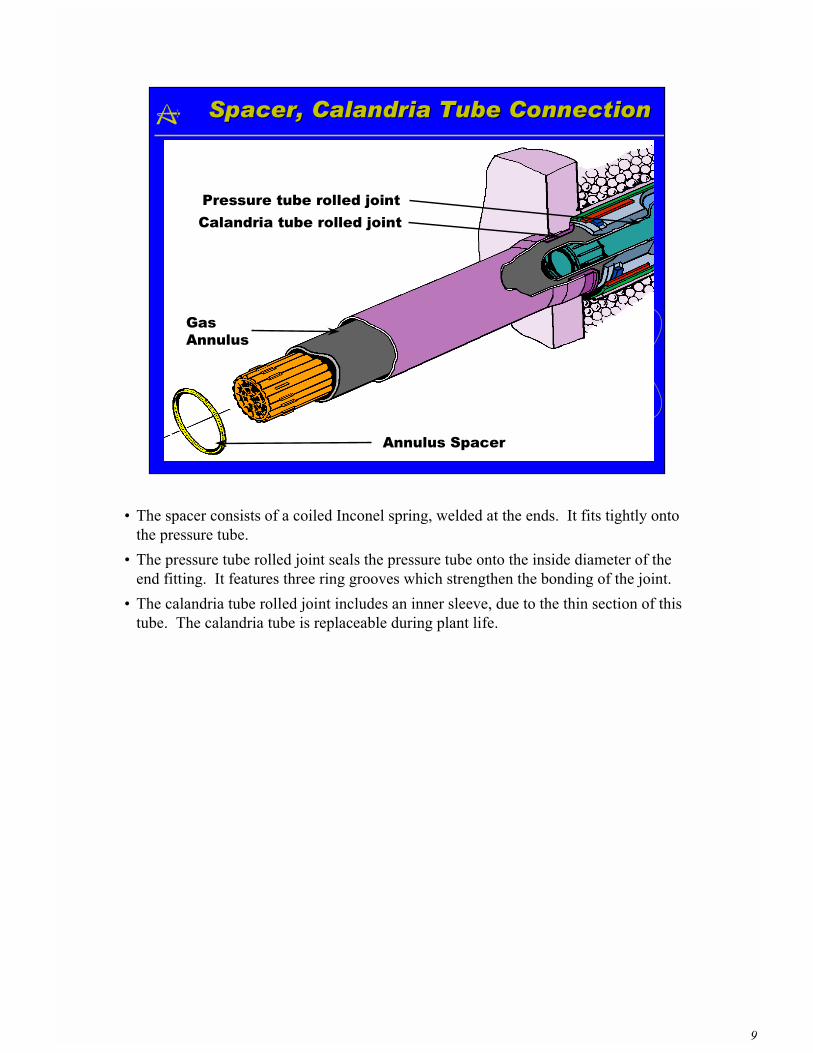
Spacer,Spacer, Calandria Calandria Tube Connection Tube Connection
GasAnnulus
Annulus Spacer
Pressure tube rolled jointCalandria tube rolled joint
� The spacer consists of a coiled Inconel spring, welded at the ends. It fits tightly ontothe pressure tube.
� The pressure tube rolled joint seals the pressure tube onto the inside diameter of theend fitting. It features three ring grooves which strengthen the bonding of the joint.
� The calandria tube rolled joint includes an inner sleeve, due to the thin section of thistube. The calandria tube is replaceable during plant life.
10
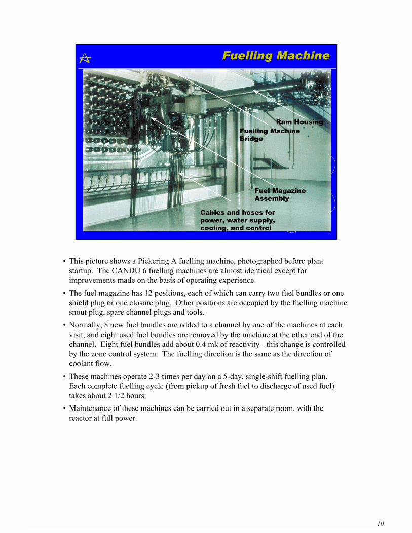
Fuelling MachineFuelling Machine
Ram HousingFuelling MachineBridge
Fuel MagazineAssembly
Cables and hoses for power, water supply,cooling, and control
� This picture shows a Pickering A fuelling machine, photographed before plantstartup. The CANDU 6 fuelling machines are almost identical except forimprovements made on the basis of operating experience.
� The fuel magazine has 12 positions, each of which can carry two fuel bundles or oneshield plug or one closure plug. Other positions are occupied by the fuelling machinesnout plug, spare channel plugs and tools.
� Normally, 8 new fuel bundles are added to a channel by one of the machines at eachvisit, and eight used fuel bundles are removed by the machine at the other end of thechannel. Eight fuel bundles add about 0.4 mk of reactivity - this change is controlledby the zone control system. The fuelling direction is the same as the direction ofcoolant flow.
� These machines operate 2-3 times per day on a 5-day, single-shift fuelling plan.Each complete fuelling cycle (from pickup of fresh fuel to discharge of used fuel)takes about 2 1/2 hours.
� Maintenance of these machines can be carried out in a separate room, with thereactor at full power.
11
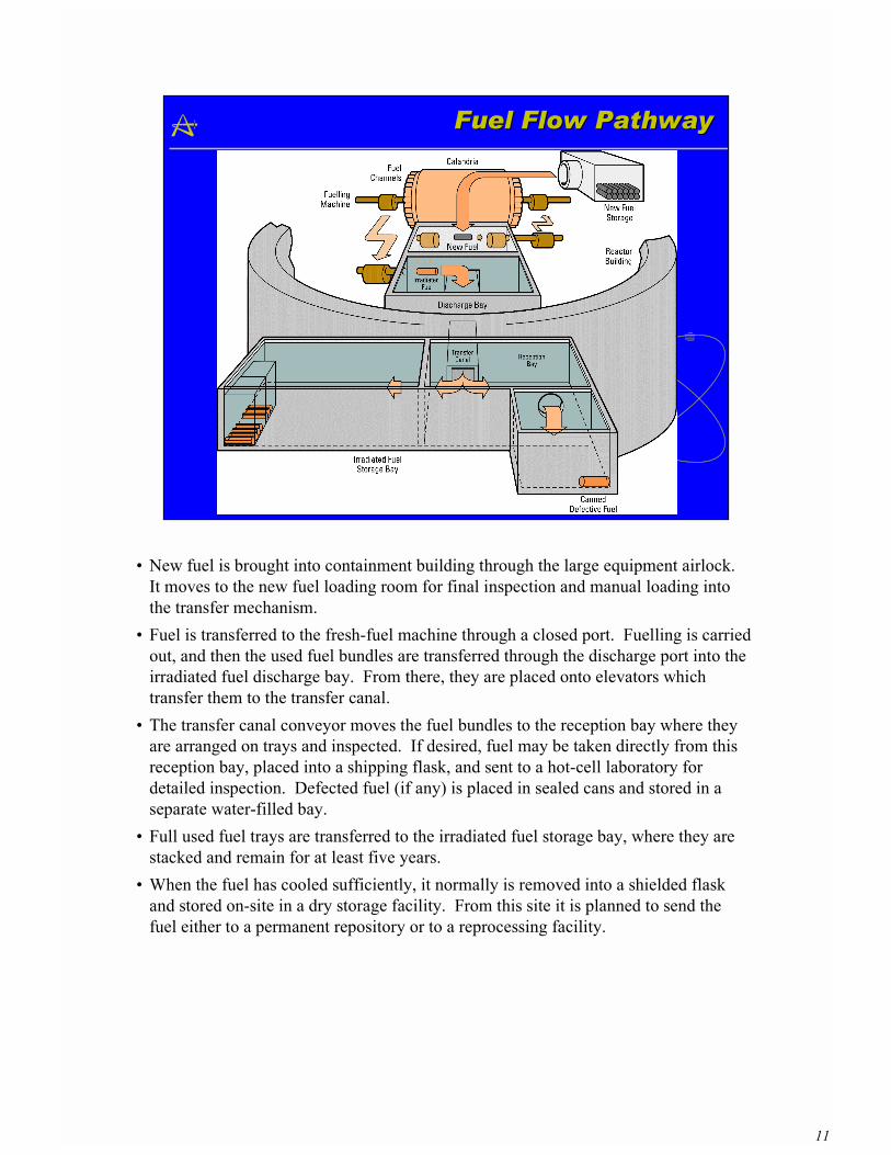
Fuel Flow PathwayFuel Flow Pathway
� New fuel is brought into containment building through the large equipment airlock.It moves to the new fuel loading room for final inspection and manual loading intothe transfer mechanism.
� Fuel is transferred to the fresh-fuel machine through a closed port. Fuelling is carriedout, and then the used fuel bundles are transferred through the discharge port into theirradiated fuel discharge bay. From there, they are placed onto elevators whichtransfer them to the transfer canal.
� The transfer canal conveyor moves the fuel bundles to the reception bay where theyare arranged on trays and inspected. If desired, fuel may be taken directly from thisreception bay, placed into a shipping flask, and sent to a hot-cell laboratory fordetailed inspection. Defected fuel (if any) is placed in sealed cans and stored in aseparate water-filled bay.
� Full used fuel trays are transferred to the irradiated fuel storage bay, where they arestacked and remain for at least five years.
� When the fuel has cooled sufficiently, it normally is removed into a shielded flaskand stored on-site in a dry storage facility. From this site it is planned to send thefuel either to a permanent repository or to a reprocessing facility.
12
CANDU 6 - Fuelling SystemsCANDU 6 - Fuelling Systems
21
22
2324
2526
30
28
27
29
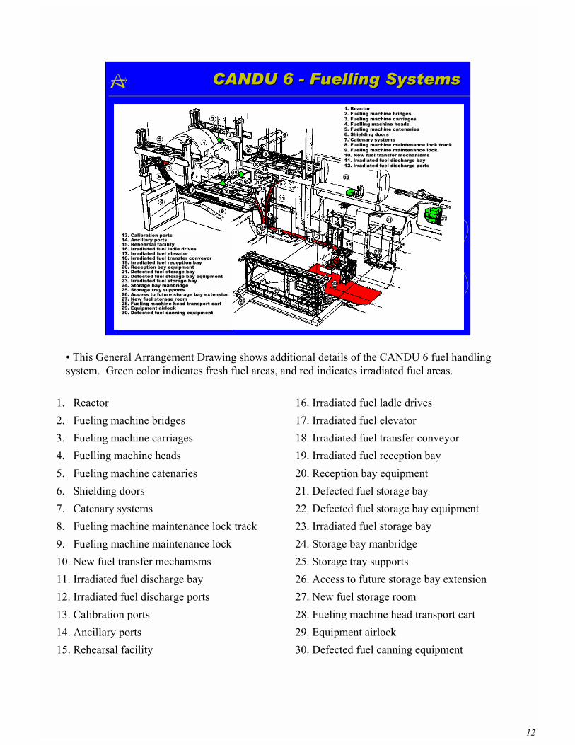
1. Reactor2. Fueling machine bridges3. Fueling machine carriages4. Fuelling machine heads5. Fueling machine catenaries6. Shielding doors7.`Catenary systems8. Fueling machine maintenance lock track9. Fueling machine maintenance lock10. New fuel transfer mechanisms11. Irradiated fuel discharge bay12. Irradiated fuel discharge ports
13. Calibration ports14. Ancillary ports15. Rehearsal facility16. Irradiated fuel ladle drives17. Irradiated fuel elevator18. Irradiated fuel transfer conveyor19. Irradiated fuel reception bay20. Reception bay equipment21. Defected fuel storage bay22. Defected fuel storage bay equipment23. Irradiated fuel storage bay24. Storage bay manbridge25. Storage tray supports26. Access to future storage bay extension27. New fuel storage room28. Fueling machine head transport cart29. Equipment airlock30. Defected fuel canning equipment
1. Reactor2. Fueling machine bridges3. Fueling machine carriages4. Fuelling machine heads5. Fueling machine catenaries6. Shielding doors7. Catenary systems8. Fueling machine maintenance lock track9. Fueling machine maintenance lock10. New fuel transfer mechanisms11. Irradiated fuel discharge bay12. Irradiated fuel discharge ports13. Calibration ports14. Ancillary ports15. Rehearsal facility
16. Irradiated fuel ladle drives17. Irradiated fuel elevator18. Irradiated fuel transfer conveyor19. Irradiated fuel reception bay20. Reception bay equipment21. Defected fuel storage bay22. Defected fuel storage bay equipment23. Irradiated fuel storage bay24. Storage bay manbridge25. Storage tray supports26. Access to future storage bay extension27. New fuel storage room28. Fueling machine head transport cart29. Equipment airlock30. Defected fuel canning equipment
� This General Arrangement Drawing shows additional details of the CANDU 6 fuel handlingsystem. Green color indicates fresh fuel areas, and red indicates irradiated fuel areas.