study on simple signal area estimation for efficient
TRANSCRIPT

Study on Simple Signal Area Estimation forEfficient Spectrum Measurements
Kenta Umebayashi†, and Hiroki IwataDept. of Electrical & Electronic Eng.,
Tokyo University of Agriculture and Technology,Japan, Email: ume [email protected]†
Janne J. LehtomakiCentre for Wireless Communications,
University of Oulu,Finland
Miguel Lopez-BenıtezDept. of Electrical
Eng. & Electronics,University of Liverpool, UK
Abstract—This paper investigates a signal area (SA) estimationmethod for spectrum measurements. The spectrum measurementsis for estimating statistical information of spectrum usage andrequired latency is not very critical compared to spectrumsensing. SA denotes the area (in time/frequency domain) occupiedby the primary user’s signal. The traditional approach, whichutilizes Fourier transform (FT) and energy detector (ED) forSA estimation, can achieve low complexity, but its estimationperformance is not very high. For this issue, we propose a post-processing, simple SA (S-SA) estimation. S-SA estimation exploitsthe correlation of the spectrum states among the neighboringtiles, i.e., time/frequency grids, and the fact that SA typicallyhas a rectangular shape to estimate SA with high accuracy andrelatively low complexity compared to a conventional method,contour tracing based SA (CT-SA) estimation. Numerical resultswill show that the S-SA estimation method can achieve betterdetection performance than CT-SA. Furthermore, it can reducethe computation time compared to the CT-SA estimation.
I. INTRODUCTION
In the wireless communication field, spectrum scarcityproblem is a pressing problem. On the other hand, spectrumutilization measurement reports have revealed that the utiliza-tion rate of most of the licensed spectrum is not very high inspatial and/or temporal domains. The portions of spectrum leftunused are commonly referred to as white space (WS) [1]. Forthis problem, dynamic spectrum access (DSA) with cognitiveradio techniques employed by the unlicensed user (secondaryuser: SU) on the spectrum owned by the licensed user (primaryuser: PU) have been investigated [2]. In the DSA, the SU canutilize the vacant spectrum as long as it will not cause anyharmful interference to the PU. To enable DSA, a technique forunderstanding the state of the spectrum, i.e. whether it is vacantor occupied, is necessary. Spectrum sensing [3] techniqueshave been investigated in order to understand the instantaneousspectrum state. However, it requires high accuracy, low latencyand low cost and it is difficult achieve the all requirements.One potential approach to solve the issue in spectrum sensingis smart spectrum access (SSA) which is an extended DSA thatutilizes useful prior information, such as statistical informationof PU spectrum usages [4]. The statistical information canenhance not only spectrum sensing [5], but also other tech-niques, such as spectrum management, channel selection andMAC protocol design [6], [7]. One important issue in SSAis the implementation cost of the function obtaining the priorinformation, especially at wireless terminals. For this issue, weproposed a system architecture consisting of two layers in [4]:the first layer corresponds to a DSA system and the second
layer is a spectrum awareness system (SAS). In the two-layer SSA, the SAS is dedicated for spectrum measurementto obtain the prior information. Therefore, DSA terminals nolonger suffer from the high implementation cost, but the usefulinformation is provided by the SAS.
In this paper, we focus on spectrum usage measurementsat observation equipments (OEs) in SAS and the purpose ofspectrum measurements is to obtain the statistical information.There are several spectrum measurement campaigns for theassessment of WS based on spectrum usage detection [8],[9]. One of the basic approaches in the spectrum measure-ments is FT (Fourier transform)-based energy detector (ED)to detect PU spectrum utilization in the considered frequencybins and is denoted by FT-ED. Output of the FT-ED basedspectrum measurement consists of signal detection resultsin two-dimensional time/frequency grids. Let us denote asingle element of the grid corresponding to one time slot andone frequency bin by tile. In addition, a rectangular set ofcontiguous tiles wherein a PU signal is detected is referredto as estimated signal area (SA). Detection result H can beeither H1 (the tile is occupied by PU signal) or H0 (the tileis not occupied). In signal detection, there are two errors: thefirst one is missed detection (H = H0|H1) where | meansgiven that correct hypothesis is H1, and the second one is falsealarm (H = H1|H0). ED is very simple and does not requireany prior information about the PU signal [10], however thedetection performance is not very high [3].
A post-processing to the outputs of FT-ED can easilyimprove the detection performance and this is applicable inthe spectrum measurement for obtaining statistical information.Specifically, latency requirements in spectrum measurementare relaxed compared to spectrum sensing. Now we defineSA as follows: a cluster of H1 tiles due to one continuoussignal transmission such as one data packet. The time durationof SA is determined by the time duration of the continuoussignal and the bandwidth of the SA is determined by thesymbol rate and band limited filter used in the transmitter. SAhas typically a rectangular shape [11], since symbol rate istypically fixed during one continuous signal. There are severalmethods employing the post-processing [12], [13]. In [14],FT-ED is used and clusters of connected H = H1 tiles areobtained by using standard contour tracing (CT) techniques[15]. This approach is denoted by CT-SA and corresponds toa baseline for comparisons with our proposed method.
In this paper, we propose an SA estimation based on theoutput of the Welch FFT based ED. Welch FFT [16] based ED

can achieve better detection performance compared to typicalFFT based ED [17]. Our main contributions in this paper aresummarized as follows:
• Simple-SA (S-SA) estimation is proposed in this pa-per. Unlike conventional CT-SA estimation, S-SA es-timates the width corresponding to frequency domainand the height corresponding to time domain of therectangle which leads to less complexity. Similar toCT-SA, S-SA combines the several detection resultsin time and frequency domains and it can recognizeSA accurately.
• Extensive performance evaluations are performed toverify the performances and complexity benefits of S-SA estimation compared with the FT-ED and CT-SA.
II. OUTLINE OF SIGNAL PROCESSING IN OBSERVATIONEQUIPMENT (OE)
Fig. 1: Block diagram for spectrum measurement in OE.
A block diagram of the signal processing flow in OE isshown in Fig. 1. The signal processing in the OE consistsof three processes; Welch FFT, ED, and SA estimation. Thedetails about ED based on Welch FFT are provided in ourearlier paper [17].
Observed samples are obtained at fS Hz sampling rate.The center frequency of the observed spectrum is set to 0 Hzby downconversion, and it is band-limited to [−fS/2, fS/2]Hz. The observed bandwidth is large enough compared to thePU signal bandwidth. We assume AWGN channel, i.e., non-frequency selectivity and signal power is constant during themeasurement.
To obtain PSD, Welch FFT is used and the number ofsamples in time domain for single Welch FFT is denoted byNS . The NS samples resulting from the Welch FFT correspondto a single time slot. We also set the number of time slots inone observation to Ntimeslot. In the Welch FFT, NS samplesare divided into Nseg segments where the number of samplesin one segment is denoted by NW . Without loss of generality,NS and NW are assumed to be powers of two and Nseg isgiven by
Nseg =NS −NW
NO+ 1 =
2NS
NW− 1, (1)
where NO indicates overlapped samples which is set toNO = NW /2 and NS > NW . The obtained PSD valuesare denoted by PnF ,nT
where nF ∈ {1, 2, ..., NW} andnT ∈ {1, 2, Ntimeslot} are the frequency and time indexnumbers of the tile. The Fig. 1 (a) shows an example of thePSD values. In the Welch FFT, Hamming window is used.
The ED provides signal detection result at the tile (nF , nT )and it is given by
D(ED)nF ,nT
=
{1 (PnF ,nT
> τ)0 (otherwise),
(2)
where D(·)nF ,nT = 1 and D
(·)nF ,nT = 0 indicate that the tile
is either estimated to be occupied by PU signal or vacant,respectively, the superscript notation (·) indicates the methodto obtain the decision, such as S-SA estimation, and τ is thethreshold for ED. Fig. 1 (b) shows an example of D(ED)
nF ,nT .
There are several ways to define the bins where signal isactually present. We use the 30-dB bandwidth [18], so that thesignal bandwidth is defined by the frequency bins when thesignal power is 30 dB below its peak value. The correspondingSA is defined by the signal bandwidth and the time durationof the continuous signal emission. A correct decision for afrequency bin within this area is H1 otherwise H0 is correct.
We define false alarm probability for the output of EDas PFA
(ED) = Pr(D(ED)nF ,nT = 1|H(nF , nT ) = H0) where
H(nF , nT ) indicate the spectrum state in the tile at (nF , nT )and H0 indicates that the tile is not occupied by PU sig-nal. In addition, detection probability (PD
(ED)) indicates thatPD
(ED) = Pr(D(ED)nF ,nT = 1|H(nF , nT ) = H1) where H1
indicates that the tile is occupied by PU signal.
All the SA estimation approaches utilize the outputs fromED and process them. Due to processing, the false alarmprobability in the output may change compared to the falsealarm probability in the input data. Thus in SA estimation,there are two false alarm probabilities, such as PFA
(ED) andPFA
(S−SA). The threshold τ is set based on target false alarmrate P
(S−SA)FA , where · indicates target value.
The description of general behavior of SA estimationshown in (b) and (c) of Fig. 1 is described as follows. In Fig. 1(b), D(ED)
nF ,nT (ED output) are clusters colored by dark color andthey are almost rectangular. The SA estimation recognizes theclusters and approximates them to rectangles as shown in Fig. 1(c). The white colored tiles (D(ED)
nF ,nT = 0) inside the rectanglesin Fig. 1 (b) are missed detections. The SA estimation has apotential to reduce the missed detections by filling the whitecolored tiles within rectangle.
III. SIGNAL AREA ESTIMATION
The general outline of the process common to both CT-SA and S-SA estimation methods is illustrated in Fig. 2. Inboth SA estimation methods, the first step of the algorithmis to find a starting point for the occupied signal area. Thisis done by performing a raster scan on the spectrum gridfrom left to right and bottom to up until the first occupiedtile, i.e. D(ED)
nF ,nT = 1, is found. The coordinates of the firsttile are denoted by S and in the example of Fig. 2 (a) areequal to S = (3, 2). After this, each method estimates the
11
10
9
8
7
6
5
4
3
2 S
1
0
0 1 2 3 4 5 6 7 8 9
Tn
Fn
11
10
9 A
8
7
6
5
4
3
2
1
0
0 1 2 3 4 5 6 7 8 9
SA estimationTn
Fn
Raster scan
0,)ED( =
TF nnD
(a) (b)
Output of ED
1,)ED( =
TF nnD 0,)SA( =
TF nnD 1,)SA( =
TF nnD
W
H
Fig. 2: Example outputs of ED and SA estimation.
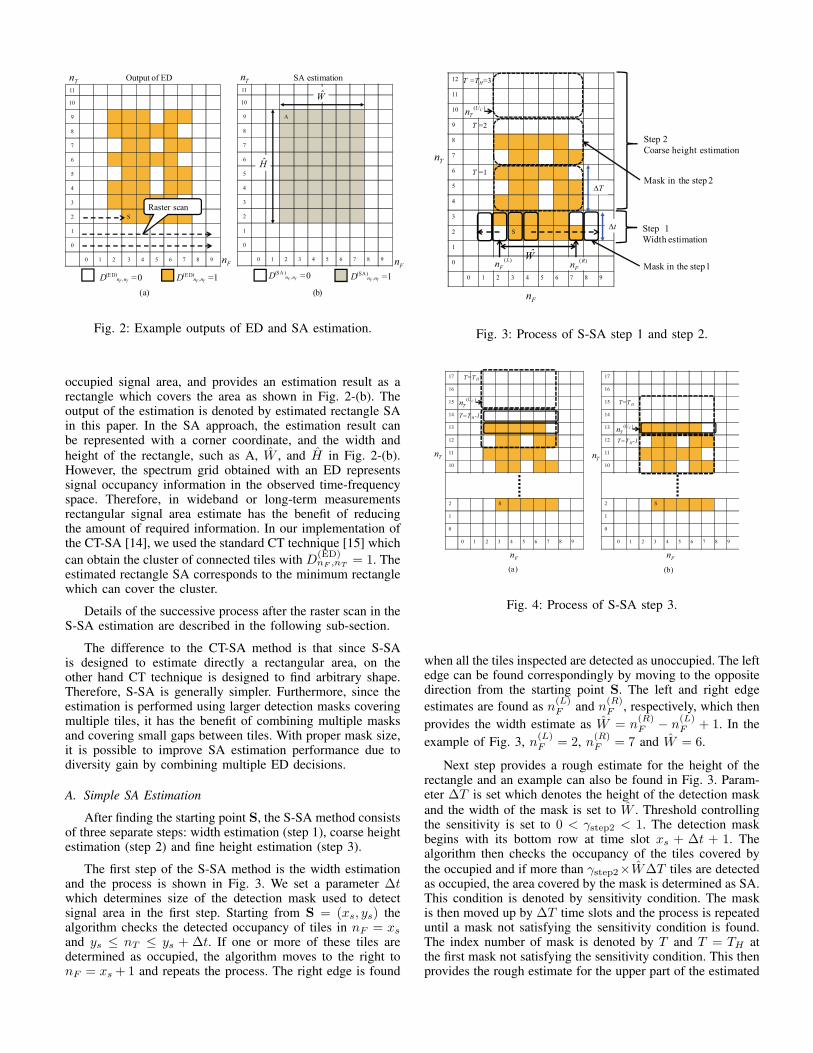
occupied signal area, and provides an estimation result as arectangle which covers the area as shown in Fig. 2-(b). Theoutput of the estimation is denoted by estimated rectangle SAin this paper. In the SA approach, the estimation result canbe represented with a corner coordinate, and the width andheight of the rectangle, such as A, W , and H in Fig. 2-(b).However, the spectrum grid obtained with an ED representssignal occupancy information in the observed time-frequencyspace. Therefore, in wideband or long-term measurementsrectangular signal area estimate has the benefit of reducingthe amount of required information. In our implementation ofthe CT-SA [14], we used the standard CT technique [15] whichcan obtain the cluster of connected tiles with D
(ED)nF ,nT = 1. The
estimated rectangle SA corresponds to the minimum rectanglewhich can cover the cluster.
Details of the successive process after the raster scan in theS-SA estimation are described in the following sub-section.
The difference to the CT-SA method is that since S-SAis designed to estimate directly a rectangular area, on theother hand CT technique is designed to find arbitrary shape.Therefore, S-SA is generally simpler. Furthermore, since theestimation is performed using larger detection masks coveringmultiple tiles, it has the benefit of combining multiple masksand covering small gaps between tiles. With proper mask size,it is possible to improve SA estimation performance due todiversity gain by combining multiple ED decisions.
A. Simple SA Estimation
After finding the starting point S, the S-SA method consistsof three separate steps: width estimation (step 1), coarse heightestimation (step 2) and fine height estimation (step 3).
The first step of the S-SA method is the width estimationand the process is shown in Fig. 3. We set a parameter ∆twhich determines size of the detection mask used to detectsignal area in the first step. Starting from S = (xs, ys) thealgorithm checks the detected occupancy of tiles in nF = xs
and ys ≤ nT ≤ ys + ∆t. If one or more of these tiles aredetermined as occupied, the algorithm moves to the right tonF = xs +1 and repeats the process. The right edge is found
12
11
10
9
8
7
6
5
4
3
2 S
1
0
0 1 2 3 4 5 6 7 8 9
Tn
Fn
∆t Step 1
Width estimation
W
∆T
Step 2
Coarse height estimation
T =1
T =2
T =TH=3
)(R
Fn
)(L
Fn
)( CU
Tn
Mask in the step 1
Mask in the step 2
Fig. 3: Process of S-SA step 1 and step 2.
17
16
15
14
13
12
11
10
2 S
1
0
0 1 2 3 4 5 6 7 8 9
Fn
17
16
15
14
13
12
11
10
2 S
1
0
0 1 2 3 4 5 6 7 8 9
T=TH
T=TH-1
T=TH
T=TH-1
Fn
TnT
n
(a) (b)
)(C
U
Tn
)(C
U
Tn
Fig. 4: Process of S-SA step 3.
when all the tiles inspected are detected as unoccupied. The leftedge can be found correspondingly by moving to the oppositedirection from the starting point S. The left and right edgeestimates are found as n(L)
F and n(R)F , respectively, which then
provides the width estimate as W = n(R)F − n
(L)F + 1. In the
example of Fig. 3, n(L)F = 2, n(R)
F = 7 and W = 6.
Next step provides a rough estimate for the height of therectangle and an example can also be found in Fig. 3. Param-eter ∆T is set which denotes the height of the detection maskand the width of the mask is set to W . Threshold controllingthe sensitivity is set to 0 < γstep2 < 1. The detection maskbegins with its bottom row at time slot xs + ∆t + 1. Thealgorithm then checks the occupancy of the tiles covered bythe occupied and if more than γstep2×W∆T tiles are detectedas occupied, the area covered by the mask is determined as SA.This condition is denoted by sensitivity condition. The maskis then moved up by ∆T time slots and the process is repeateduntil a mask not satisfying the sensitivity condition is found.The index number of mask is denoted by T and T = TH atthe first mask not satisfying the sensitivity condition. This thenprovides the rough estimate for the upper part of the estimated
area as n(UC)T which corresponds to the bottom time slot in the
TH th mask.
In the rough height estimation there are two differentscenarios to consider which are illustrated in Fig. 4 (a) and(b). In the scenario (a), the algorithm stops because there areno occupied tiles in the last mask. On the other hand, in thescenario (b), the algorithm stops because of the sensitivity con-dition is not satisfied but there are still less than γstep2×W∆T
occupied tiles in the mask above the estimated n(UC)T time
slot. Therefore, a final height estimation step is performed toobtain a more accurate result. In this fine height estimation, thedetection mask is set to W frequency bins and this correspondsto setting ∆T = 1 in step 2. We also set a sensitivity parameter0 < γstep3 < 1 and check if more than γstep3 × W tiles underthe mask are occupied or not. The search starts at n
(UC)T . If
the sensitivity condition is not satisfied at the n(UC)T time slot,
it goes downwards to find a detection mask which satisfies thesensitivity condition. This corresponds to scenario (a) in Fig.4 and the time slot satisfying the sensitivity condition is thefinal estimate n
(UF )T .
On the other hand, if the sensitivity condition is satisfiedat the n
(UC)T time slot, it goes to upwards to find a detection
mask which does not satisfy the sensitivity condition. Thiscorresponds to scenario (b) in Fig. 4 and the previous timeslot of the time slot not satisfying the sensitivity condition isthe final estimate n
(UF )T . The decision result obtained by S-
SA is denoted by D(S−SA)nF ,nT and the state of tiles inside the
estimated SA is D(S−SA)nF ,nT = 1.
IV. NUMERICAL EVALUATIONS
In this section, we will evaluate SA estimation methods(CT-SA and S-SA) and the typical approach, i.e. FT-ED,in terms of detection probability, and computational time.Assumptions in the numerical evaluations are as follows. Ob-served bandwidth is set to 40MHz, i.e., fS = 2BS = 40MHzand the 30-dB bandwidth is set to 22MHz. This bandwidth isequal to a bandwidth in IEEE 802.11g WLAN since it assumesstrong filtering used at the transmitter. Number of samples ina time frame is set to NS = 1024 and the number of samplesin segment size of Welch FFT to NW = 128. The number ofNW corresponds to the number of frequency bins. The numberof time slots for one observation is set to Ntimeslot = 300.
To fairly evaluate detection performance, we use CFARin the evaluations of detection probability and computationaltime. The target false alarm rate for output of the SA methodsis set to P
(SA)FA = 0.01.
We set ∆t and ∆T on the assumption that WLAN isoperating in ISM band. Specifically, based on the Monte Carlosimulations we found proper parameter setting as ∆t = 8and ∆T = 4. Moreover, γstep2 and γstep3 are set based onminimizing RMSE (root mean square error) with target SNRbeing equal to −5 dB, which is reasonable since most chal-lenging for spectrum measurement and sensing is performingwith low SNR values such as −5 dB, i.e. γstep2 = 0.1 andγstep3 = 0.15, by the Monte Carlo simulations.
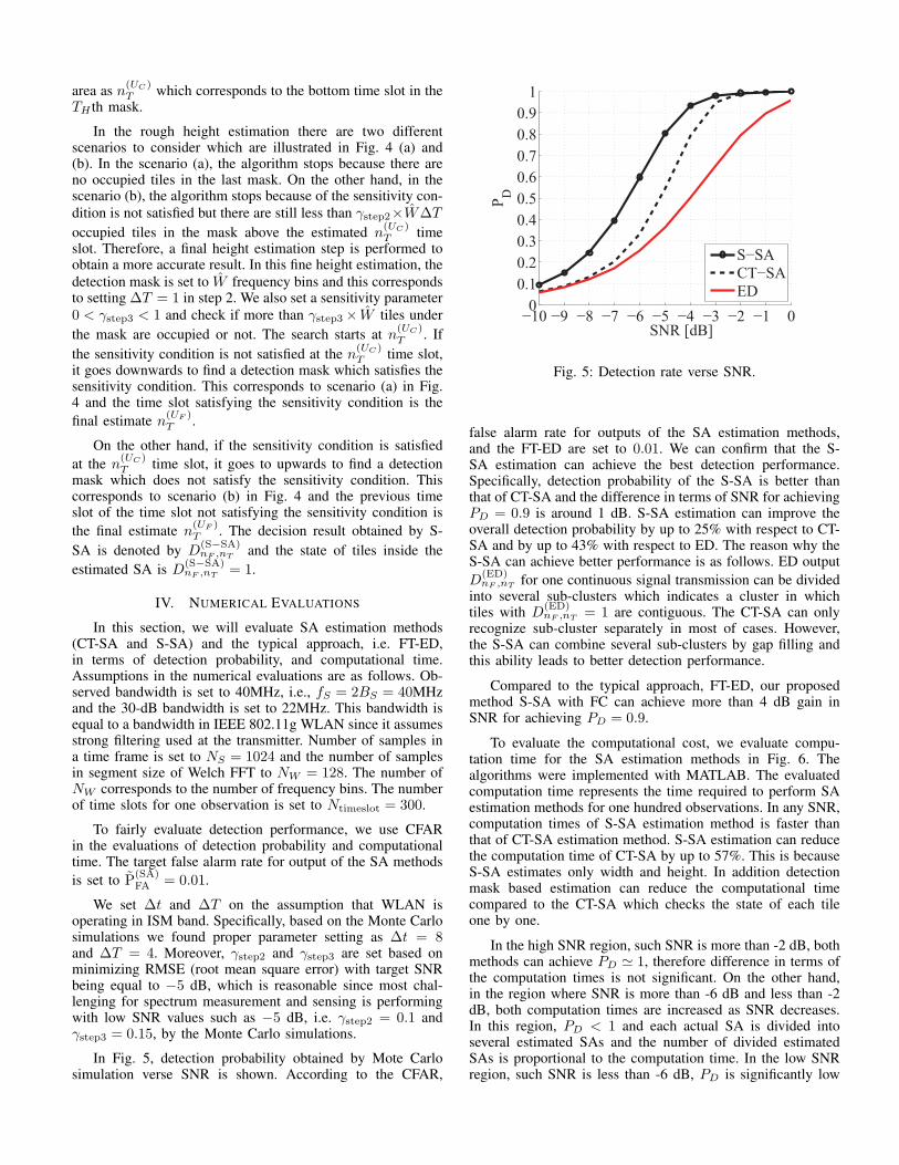
In Fig. 5, detection probability obtained by Mote Carlosimulation verse SNR is shown. According to the CFAR,
−10 −9 −8 −7 −6 −5 −4 −3 −2 −1 00
0.1
0.2
0.3
0.4
0.5
0.6
0.7
0.8
0.9
1
SNR [dB]
PD
S−SA
CT−SA
ED
Fig. 5: Detection rate verse SNR.
false alarm rate for outputs of the SA estimation methods,and the FT-ED are set to 0.01. We can confirm that the S-SA estimation can achieve the best detection performance.Specifically, detection probability of the S-SA is better thanthat of CT-SA and the difference in terms of SNR for achievingPD = 0.9 is around 1 dB. S-SA estimation can improve theoverall detection probability by up to 25% with respect to CT-SA and by up to 43% with respect to ED. The reason why theS-SA can achieve better performance is as follows. ED outputD
(ED)nF ,nT for one continuous signal transmission can be divided
into several sub-clusters which indicates a cluster in whichtiles with D
(ED)nF ,nT = 1 are contiguous. The CT-SA can only
recognize sub-cluster separately in most of cases. However,the S-SA can combine several sub-clusters by gap filling andthis ability leads to better detection performance.
Compared to the typical approach, FT-ED, our proposedmethod S-SA with FC can achieve more than 4 dB gain inSNR for achieving PD = 0.9.
To evaluate the computational cost, we evaluate compu-tation time for the SA estimation methods in Fig. 6. Thealgorithms were implemented with MATLAB. The evaluatedcomputation time represents the time required to perform SAestimation methods for one hundred observations. In any SNR,computation times of S-SA estimation method is faster thanthat of CT-SA estimation method. S-SA estimation can reducethe computation time of CT-SA by up to 57%. This is becauseS-SA estimates only width and height. In addition detectionmask based estimation can reduce the computational timecompared to the CT-SA which checks the state of each tileone by one.
In the high SNR region, such SNR is more than -2 dB, bothmethods can achieve PD ≃ 1, therefore difference in terms ofthe computation times is not significant. On the other hand,in the region where SNR is more than -6 dB and less than -2dB, both computation times are increased as SNR decreases.In this region, PD < 1 and each actual SA is divided intoseveral estimated SAs and the number of divided estimatedSAs is proportional to the computation time. In the low SNRregion, such SNR is less than -6 dB, PD is significantly low

−10 −9 −8 −7 −6 −5 −4 −3 −2 −1 00
0.05
0.1
0.15
0.2
0.25
0.3
0.35
0.4
0.45
0.5
0.55
0.6
SNR [dB]
tim
e [s
ec]
S−SA
CT−SA
Fig. 6: Computational time as a function of SNR. Computerspecifications: CPU is Intel Core i7-2600 @3.4 GHz, sizeof memory size is 8 G byte, and programing language isMATLAB.
and it decreases the number of estimated SAs and leads to lowcomputation time.
V. CONCLUSION
In this paper, we have investigated SA estimation tech-niques for spectrum measurement. To perform proper mea-surement, the OE is required to be able to achieve adequatedetection accuracy at relatively low computational cost as wellas low amount of information in terms of local observations. Atypical approach for spectrum measurement is FT-ED, howeverit cannot achieve adequate detection accuracy. For this issue,we have proposed a simple SA estimation method, S-SA.The S-SA is designed to estimate rectangular SA efficiently.Specifically, the S-SA only estimates the location and the widthand height and it leads to less complexity. In addition, diversitygain is available due to the covering several tiles. ThereforeSA can improve detection probability and it was shown bynumerical results, such as three dB gain in SNR for achieving0.9 detection probability. In addition, it is also possible toachieve shorter computational time especially in the low SNRregion.
ACKNOWLEDGMENT
This research and development work was supported bythe MIC/SCOPE #165003006, and JSPS KAKENHI GrantNumbers JP15K06053, JP15KK0200.
REFERENCES
[1] I. F. Akyildiz, W.-Y. Lee, M. C. Vuran, and S. Mohanty, “A surveyon spectrum management in cognitive radio networks,” IEEE Commun.Mag., vol. 46, no. 4, pp. 4182–4195, Apr. 2008.
[2] Q. Zhao, “A survey of dynamic spectrum access: signal processing,networking, and regulatory policy,” IEEE Signal Processing Mag.,vol. 24, pp. 79–89, May 2007.
[3] T. Yucek and H. Arslan, “A survey of spectrum sensing algorithmsfor cognitive radio applications,” IEEE Communications Surveys &Tutorials, vol. 11, pp. 116–130, 2009.
[4] K. Umebayashi, S. Tiiro, and J. J. Lehtomaki, “Development of a mea-surement system for spectrum awareness,” in Proc. of 1st InternationalConference on 5G for Ubiquitous Connectivity, Nov. 2014.
[5] T. Nguyen, B. L. Mark, and Y. Ephraim, “Spectrum sensing usinga hidden bivariate markov model,” IEEE Trans. Wireless Commun.,vol. 12, no. 9, pp. 4582–4591, Sept. 2013.
[6] K. Umebayashi, Y. Suzuki, and J. Lehtomaki, “Dynamic selection ofCWmin in cognitive radio networks for protecting IEEE 802.11 primaryusers,” in Proc. CROWNCOM, June 2011, pp. 266–270.
[7] Y. Xu, A. Anpalagan, Q. Wu, L. Shen, Z. Gao, and J. Wang, “Decision-theoretic distributed channel selection for opportunistic spectrum ac-cess: Strategies, challenges and solutions,” IEEE Communications Sur-veys and Tutorials, vol. 15, no. 4, pp. 1689–1713, 2013.
[8] M. Mehdawi, N. Riley, K. Paulson, A. Fanan, and M. Ammar, “Spec-trum occupancy survey in hull-uk for cognitive radio applications: Mea-surement & analysis,” International Journal of Scientific & TechnologyResearch, vol. 2, no. 4, pp. 231–236, Apr. 2013.
[9] M. Lopez-Benıtez and F. Casadevall, “Spectrum usage in cognitive radionetworks: From field measurements to empirical models,” IEICE Trans.Commun.,, vol. E97-B, no. 2, pp. 242–250, Feb. 2014.
[10] H. Urkowitz, “Energy detection of unknown deterministic signals,”Proc. IEEE, vol. 55, no. 4, pp. 523–531, Apr. 1967.
[11] J. Vartiainen, J. Lehtomaki, T. Braysy, and K. Umebayashi, “Spectrumsensing in public safety applications: The 2-d lad acc method,” inProc. Cognitive Radio Oriented Wireless Networks & Communications(CROWNCOM), June 2011, pp. 61–65.
[12] J. Vartiainen, H. Sarvanko, J. Lehtomaki, M. Juntti, and M. Latva-Aho, “Spectrum sensing with lad-based methods,” in Proc. IEEEInternational Symposium on Personal, Indoor and Mobile Radio Com-munciations (PIMRC), Sept. 2007, pp. 1–5.
[13] M. Lopez-Benıtez and F. Casadevall, “Improved energy detection spec-trum sensing for cognitive radio,” IET Communications, vol. 6, no. 8,pp. 785–796, May 2012.
[14] J. Kokkoniemi and J. Lehtomaki, “Spectrum occupancy measurementsand analysis methods on the 2.45 ghz ISM band,” in Proc. CognitiveRadio Oriented Wireless Networks & Communications (CROWNCOM),June 2012, pp. 285–290.
[15] D. W. Capson, “Parformance comparisons of contour extraction algo-rithms,” IEEE Trans. Instrum. Meas., vol. IM-35, no. 4, pp. 409–417,Dec. 1986.
[16] P. D. Welch, “The use of fast fourier transform for the estimation ofpower spectra: A method based on time averaging over short, modifiedperiodograms,” IEEE Trans. Audio Electroacoust., vol. 15, pp. 70–73,June 1967.
[17] K. Umebayashi, R. Takagi, N. Ioroi, Y. Suzuki, and J. J. Lehtomaki,“Duty cycle and noise floor estimation with welch fft for spectrumusage measurements,” in Proc. of Cognitive Radio Oriented WirelessNetworks and Communications (CROWNCOM), June 2014, pp. 73 –78.
[18] “Recommendation ITU-R SM.328-10. Spectra and bandwidth of emis-sions,” 1992.