solutions de régulation des fluides - ugal
TRANSCRIPT

Raccords forgés / Forged fittings
Petrometalic SA32 rue de l’Ermitage78000 VERSAILLES
www.petrometalic.comnegoceversailles@[email protected]
Solutions de régulation des fluides

1
haute pressionhigh pressure pages 3 - 38
raccords forgés (acier carbone, alliés, inoxydables)forged fittings (carbon, alloy and stainless steels) ....................................... 3 - 29
raccords de dérivation renforcés (acier, carbone, alliés, inoxydables)reinforced branch fittings (carbon, alloy and stainless steels)...................... 30 - 38
basse pressionlow pressure division pages 39 - 43
raccord acier gaz suivant EN 10241wrought steel threaded fittings EN 10241.......................................................... 39 - 40
mamelons en acier et pièces tubulairespipe nipples and tubulars................................................................................. 41
manchons en acier et raccords pour installations anti-feusteel couplings / sockets and fittings for fire fighting installations ........................ 42 - 43

2
Spécifications matières materials requirements ...............................................3-4
pression de service pressure rating............................................................5
pression et températures de service working pressure temperature rating ..........................6
tés et croix réduits - reduced tees and crosses longueur de filetage - length of thread ........................7
filetage conique pour tubes (NPT) standard taper pipe thread (NPT) ...............................8
coude 90° séries 3000-6000 90° elbows class 3000 lb-6000 lb coude 45° séries 3000-6000 45° elbows class 3000 lb-6000 lb ...............................9
tés - tees - croix - crosses manchons - couplings demi-manchons - half-couplings.................................10
bouchons femelles séries 3000-6000 caps class 3000 lb-6000 lb bouchons mâle tête hexagonale séries 3000-6000 hex head plugs - class 3000 lb-6000 lb ......................11
réductions mâle-femelle séries 3000-6000 hex head bushings - class 3000 lb-6000 lb ................12
réductions femelle-mâle - séries 3000 female-male - reducer - class 3000 lb ........................13
mamelons réduits séries 3000-6000 female-male reducer - class 3000 lb - 6000 lb ...........14
manchons réduits - séries 3000 - 6000 reducing coupling - class 3000 lb - 6000 lb ................15
mamelons - séries 3000 - 6000 hexagonal nipples - class 3000 lb - 6000 lb ...............16
coudes mâle-femelle - séries 3000 - 6000 90° street elbows - class 3000 lb - 6000 lb coudes union - tés union - séries 3000 union elbows - union tees - class 3000 lb...................17
union mâle-femelle - séries 3000 - 6000 male-female - unions - class 3000 lb - 6000 lb ..........18
mamelons tube - pipe nipples.....................................19
swedge nipples - séries 3000 - 6000 swedge nipples - class 3000 lb - 6000 lb code utilisé pour la nomenclature des swedge nipples mamelons tubes réduits - code used in material list of swedge nipples - reduced nipples ..............................20
dimensions des raccords à souder suivant ASME B16.11 - 2005 ......................................21
dimensions of socket welding fittings according to ASME B16.11 - 2005 ..............................22
coudes - séries 3000 - 6000elbows - class 3000 lb - 6000 lb tés - tees - séries 3000 - 6000 croix - crosses - class 3000 lb- 6000 lb ......................23
manchons - couplings - séries 3000 - 6000 demi-manchons - half-couplings - class 3000 lb - 6000 lb bouchons femelles - séries 3000 - 6000 caps - class 3000 lb- 6000 lb ......................................24
manchons réduits - séries 3000 - 6000 reduced couplings - class 3000 lb - 6000 lb bossage à souder - séries 3000 - 6000 welding bosses - class 3000 lb - 6000 lb ....................25
réductions mâle-femelle - reducer inserts réductions mâle-femelle - séries 3000 - 6000 reducer inserts - class 3000 lb- 6000 lb......................26
unions - séries 3000 - 6000 unions - class 3000 lb - 6000 lb ..................................27
liste de poids en kg/pc - weight list in kgs/pc ..............28
liste de poids en kg/pc - weight list in kgs/pc ..............29
Raccords de dérivation renforcés Reinforced branch fittings ...........................................30
weld-outlets STD - weld-outlets STD..........................31
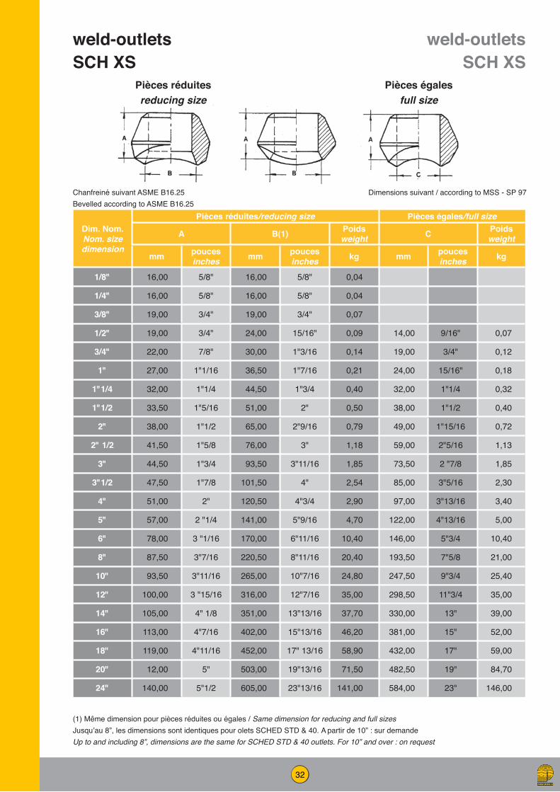
weld-outlets SCH XS - weld-outlets SCH XS .............32
weld-outlets SCH 160 - XXS ......................................33
sock-outlets - raccords emboîtés Soudés socket welding fittings thread-outlets - raccords taraudés threaded fittings ...34
sock-outlets ................................................................35
raccords taraudés - threaded fittings ..........................36
nip-outlets - raccords allongés extended fittings ........37
dimensions du tube selon ANSI B36.10 pipe dimensions as per ANSI B36.10 .........................
raccords gaz - wrought steel fittings ...........................
mamelons en acier & pièces tubulaires pipe nipples and tubulars............................................
manchons en acier - steel couplings ..........................
manchons grugés pour installations anti-feu profile sockets for sprinkler systems bobines grugées rainurées ou filetées profile tubular groved or threaded ..............................
38
39-40
41
43
42
3
Spec
ifica
tions
Com
posi
tions
chi
miq
ues
- che
mic
al c
ompo
sitio
n %
Car
acte
ristiq
ues
mec
aniq
ues
Mec
hani
cal p
rope
rtie
s
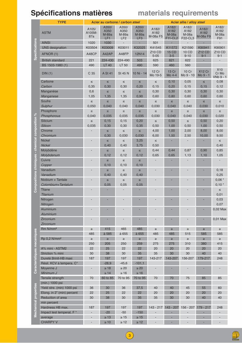
Spécifications matières materials requirementsTYPE Acier au carbone / carbon steel Acier allie / alloy steel
ASTMA105/
A105M-87a
A350/ A350 M-89a LF1
A350/ A350 M-89a LF2
A350/ A350 M-89a LF3
A182/ A182
M-08a F5
A182/ A182 M-08a
F11-CL2
A182/ A182 M-08a
F22-CL3
A182/ A182
M-08a F9
A182/ A182 M-08a F91
AINSI 1020 1030 - - 501 - - - - UNS designation K03504 K03009 K03011 K32025 K41545 K11572 K21590 K90941 K90901
AFNOR (1) A48CP A42AP A48FP 12N14 Z10 CD 5-05
15 CD 3-5
10 CD 9-10
Z12 CD 9-1
Z10 CD 9-1
British standard 221 224-430 224-490 503 625 621 622 - - BS 1503-1980 (1) 490 LT 40 LT 50 490 590 460 560
DIN (1) C 35 A St 41 St 45 N 10 Ni - 14 12 Cr Mo 19-5
13 Cr Mo 4-4
10 Cr Mo 9 - 10
X12 Cr Mo 9 - 1
X10 Cr Mo
VNb 9 - 1Carbone ≤ ≤ ≤ ≤ ≤ 0,10 0,05 ≤ 0,08Carbon 0,35 0,30 0,30 0,20 0,15 0,20 0,15 0,15 0,12Manganèse 0,6 ≤ ≤ ≤ 0,30 0,30 0,30 0,30 0,30Manganese 1,05 1,35 1,35 0,90 0,60 0,80 0,60 0,60 0,60Soufre ≤ ≤ ≤ ≤ ≤ ≤ ≤ ≤ ≤Sulphur 0,050 0,040 0,040 0,040 0,030 0,040 0,040 0,030 0,010Phosphore ≤ ≤ ≤ ≤ ≤ ≤ ≤ ≤ ≤Phosphorous 0,040 0,035 0,035 0,035 0,030 0,040 0,040 0,030 0,020Silicium ≤ 0,15 0,15 0,20 ≤ 0,50 ≤ 0,50 0,20Silicon 0,035 0,30 0,30 0,35 0,50 1,00 0,50 1,00 0,50Chrome - ≤ ≤ ≤ 4,00 1,00 2,00 8,00 8,00Chromium 0,30 0,030 0,030 6,00 1,50 2,50 10,00 9,50Nickel - ≤ ≤ 3,25 ≤ - - - ≤Nickel 0,40 0,40 3,75 0,50 0,40Molybdène - ≤ ≤ ≤ 0,44 0,44 0,87 0,90 0,85Molybdenum 0,12 0,12 0,12 0,65 0,65 1,13 1,10 1,05Cuivre - ≤ ≤ ≤ - - - - -Copper 0,10 0,10 0,10Vanadium - ≤ ≤ ≤ - - - - 0,18Vanadium 0,40 0,40 0,40 0,25Niobium + Tantale - ≤ ≤ ≤ - - - - 0,06 *Colombium+Tantalum 0,05 0,05 0,05 0,10 *Titane - - - - - - - - ≤Titanium 0,01Nitrogen - - - - - - - - 0,03Nitrogen 0,07Aluminium - - - - - - - - 0,02 MaxAluminiumZirconium - - - - - - - - 0,01 MaxZirconium
≥ 415 465 485 ≥ ≥ ≥ ≥ ≥485 à 585 à 655 à 655 485 485 515 585 585
≥ ≥ ≥ ≥ ≥ ≥ ≥ ≥ ≥250 205 250 259 275 275 310 380 415
A% mini - ASTM2 22 25 22 22 20 20 20 20 20Striction % mini 30 38 30 35 35 30 30 40 40Dureté Brinll-HB maxi 187 197 197 197 143-217 143-207 156-207 179-217 248Résil. KCV à tempera. C° -28,9 -45,6 -101,1Moyenne J - ≥ 18 ≥ 20 ≥ 20 - - - - -Minimum J ≥ 14 ≥ 16 ≥ 16Tensile strength 70 60 to 85 70 to 95 70 to 95 70 70 75 85 85(min.) 1000 psiYield stre. (min) 1000 psi 36 30 36 37,5 40 40 45 55 60Elong. in 2” (min) percent 22 25 22 22 20 20 20 20 20Reduction of area 30 38 30 35 35 30 30 40 40min percentHardness HB max. 187 197 197 197 143 - 217 143 - 207 156 - 207 179 - 217 248Impact test temperat. F ° - -20 -50 -150 - - - - -average - ≥ 13 ≥ 15 ≥ 15 - - - - -CHARPY V - ≥ 10 ≥ 12 ≥ 12 - - - - -

4
Spécifications matières materials requirementsTYPE Acier au chrome nickel / stainless steel
Acier inoxydable austeno-ferritique / ferritic-austenitic
stainless steelSp
ecifi
catio
ns
ASTMA182/ A182 M-08a F304L
A182/ A182 M-08a F316L
A182/ A182 M-08a F321
A182/ A182 M-08a F347
A182/ A182 M-08a F304 H
A182/ A182 M-08a F316 H
A182/ A182 M-08a F317L
A182/ A182 M-08a F321 H
A182/ A182 M-08a F347 H
A182/ A182 M-08a F 44
A182/ A182 M-08a F 51
A182/ A182 M-08a F 53
AINSI 304 L 316 L 321 347 304 H 316 H 317 L 321 H 347 H F 44 - - UNS designation S30403 S31603 S32100 S34700 S30409 S31609 S31703 S32109 S34709 S31254 S31803 S32750
AFNOR (1) Z3 CN 18-10
Z3 CND 17-12
TNC 6Z18-10
Z3 CNNb 18-10
Z6 CN 18-09
Z6 CND 17-12
Z3 CND
19-15-4 TNC 6Z
18-12Z6
CNNb 18-10
Z1 CNDU 20-18-06 Az
Z3 CND
22-05-Az
Z3 CNDU 25-07-
Az British standard 304 316 321 347 304 316 317 321 347 - 318 - BS 1503-1980 (1) S 11 S 11 S 31 S 31 S 25 S 26 S 12 S 22 S 59 S 13
DIN (1)X3 Cr Ni 18-
09
X3 Cr-Ni Ni 18-
10
X6 Cr Ni Ti 18-
10
X6 Cr Ni
Nb 18-10
X6 Cr Ni 18-10
X8 Cr Ni
Mo 17-13
X2 Cr Ni
Mo 18-16-4
X12 Cr Ni
Ti 18-9
X6 Cr Ni Nb 18-10
X1 Cr Ni Mo Cun
20-18-7
X2 Cr Ni Mo N 22-5-3
X2 Cr Ni Mo N 25-7-4
Carbone ≤ ≤ ≤ ≤ 0,04 0,04 ≤ 0,04 0,04 ≤ ≤ ≤
Com
posi
tions
chi
miq
ues
- che
mic
al c
ompo
sitio
n %
Carbon 0,030 0,030 0,08 0,08 0,10 0,10 0,030 0,10 0,10 0,020 0,030 0,030Manganèse ≤ ≤ ≤ ≤ ≤ ≤ ≤ ≤ ≤ ≤ ≤ ≤Manganese 2,0 2,0 2,0 2,0 2,0 2,0 2,0 2,0 2,0 1,0 2,0 1,2Soufre ≤ ≤ ≤ ≤ ≤ ≤ ≤ ≤ ≤ ≤ ≤ ≤Sulphur 0,030 0,030 0,030 0,030 0,030 0,030 0,030 0,030 0,030 0,010 0,020 0,020Phosphore ≤ ≤ ≤ ≤ ≤ ≤ ≤ ≤ ≤ ≤ ≤ ≤Phosphorous 0,05 0,05 0,05 0,05 0,05 0,05 0,05 0,05 0,05 0,030 0,030 0,04Silicium ≤ ≤ ≤ ≤ ≤ ≤ ≤ ≤ ≤ ≤ ≤ ≤Silicon 1,0 1,0 1,0 1,0 1,0 1,0 1,0 1,0 1,0 0,30 1,0 0,80Chrome 18,0 16,0 17,0 17,0 18,0 16,0 18,0 17,0 17 19,5 21,0 24,0Chromium 20,0 18,0 19,0 20,0 20,0 18,0 20,0 19,0 20 20,5 23,0 26,0Nickel 8,0 10,0 9,0 9,0 8,0 10,0 11,0 9,0 9,0 17,5 4,5 6,0Nickel 13,0 15,0 12,0 13,0 11,0 14,0 15,0 12,0 13,0 18,5 6,5 8,0Molybdène - 2,0 - - - 2,0 3,0 - - 6,0 2,5 3,0Molybdenum 3,0 3,0 4,0 6,5 3,5 5,0
0,50
%
Cuivre - - - - - - - - - 0,50 - 0,50 MAX
Copper 1,00Vanadium - - - - - - - - - - - -Vanadium
Niobium + Tantale - - - ≥ 10 C * - - - - ≥ 8 C * - - -
Colombium+Tantalum ≤ 1,10 *
≤ 1,10 *
Titane - - ≥ 5 C - - - - ≥ 4 C - - - -Titanium ≤ 0,70 ≤ 0,70Nitrogen - - - - - - - - - 0,18 0,08 0,24Nitrogen 0,22 0,20 0,32Aluminium - - - - - - - - - - - -AluminiumZirconium - - - - - - - - - - - -Zirconium
≥ ≥ ≥ ≥ ≥ ≥ ≥ ≥ ≥ ≥ ≥ ≥
Car
acte
ristiq
ues
mec
aniq
ues
485 485 515 515 515 515 485 515 515 650 620 800≥ ≥ ≥ ≥ ≥ ≥ ≥ ≥ ≥ ≥ ≥ ≥
170 170 205 205 205 205 170 205 205 300 450 550A% mini - ASTM2 30 30 30 30 30 30 30 30 30 35 25 15Striction % mini 50 50 50 50 50 50 50 50 50 50 45 -Dureté Brinll-HB maxi - - - - - - - - - - - 310Résil. KCV à tempera. C°Moyenne J - - - - - - - - - - - -Minimum J
Mec
hani
cal p
rope
rtie
s
Tensile strength 70 70 75 75 75 75 70 75 75 94 90 116(min.) 1000 psiYield stre. (min) 1000 psi 25 25 30 30 30 30 25 30 30 44 65 80Elong. in 2” (min) percent 30 30 30 30 30 30 30 30 30 35 25 15Reduction of area 50 50 50 50 50 50 50 50 50 50 45 -min percentHardness HB max. - - - - - - - - - - - 310Impact test temperat. F °averageCHARPY V

5
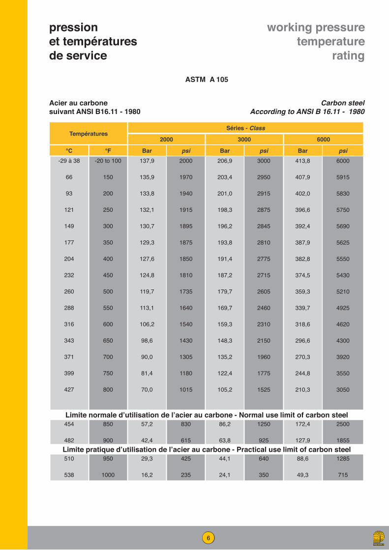
pression de service
pressure rating
Relation entre la série des raccords et l’épaisseur du tubeCorrelation of fittings class with wall designation of pipe
Pression et températures de service suivant ANSI B 16.11 - 1966Pressure - temperatures rating to ANSI B 16.11 - 1966
RACCORDTube
Série Type3000 lb6000 lb
FiletéFileté
Sch. 160Double extra-fort
3000 lb6000 lb9000 lb
A souderA souderA souder
Sch. 80Sch. 160
XXS
FITTINGPipe
Class Type3000 lb6000 lb
ThreadedThreaded
Sch. 160XXS
3000 lb6000 lb9000 lb
Socket-weldingSocket-weldingSocket-welding
Sch. 80Sch. 160
XXS
Acier au carbone A 48 CP Carbon steel ASTM A 105
Acier au carbone Molybdène Z 10 CD 5-05 Alloy steel ASTM A 182 F 5a
Acier au chrome Molybdène 10 CD 9-10 Alloy steel ASTM A 182 F 22
Acier au chrome Molybdène 15 CSD 5-03-05 Alloy steel ASTM A 182 F 11
Conditions de service valables pour travail sans coup de bélier
Acier inoxydable Z 2 CN 18-10 Stainless steel low carbon ASTM A 182 F 304 L
Acier inoxydable Z 2 CND 17-12 Stainless steel carbon ASTM A 182 F 316 L
Acier inoxydable Z 6 CN Nb 18-10 Stainless steel ASTM A 182 F 347
Acier inoxydable Z 6 CNT 18-10 Stainless steel ASTM A 182 F 321
Pressure ratings indicate non-shock working pressure of the fitting
6
pression et températures de service
working pressure temperature
rating
TempératuresSéries - Class
2000 3000 6000
°C °F Bar psi Bar psi Bar psi-29 à 38
66
93
121
149
177
204
232
260
288
316
343
371
399
427
-20 to 100
150
200
250
300
350
400
450
500
550
600
650
700
750
800
137,9
135,9
133,8
132,1
130,7
129,3
127,6
124,8
119,7
113,1
106,2
98,6
90,0
81,4
70,0
2000
1970
1940
1915
1895
1875
1850
1810
1735
1640
1540
1430
1305
1180
1015
206,9
203,4
201,0
198,3
196,2
193,8
191,4
187,2
179,7
169,7
159,3
148,3
135,2
122,4
105,2
3000
2950
2915
2875
2845
2810
2775
2715
2605
2460
2310
2150
1960
1775
1525
413,8
407,9
402,0
396,6
392,4
387,9
382,8
374,5
359,3
339,7
318,6
296,6
270,3
244,8
210,3
6000
5915
5830
5750
5690
5625
5550
5430
5210
4925
4620
4300
3920
3550
3050
Limite normale d’utilisation de l’acier au carbone - Normal use limit of carbon steel454
482
850
900
57,2
42,4
830
615
86,2
63,8
1250
925
172,4
127,9
2500
1855Limite pratique d’utilisation de l’acier au carbone - Practical use limit of carbon steel510
538
950
1000
29,3
16,2
425
235
44,1
24,1
640
350
88,6
49,3
1285
715
Acier au carbone suivant ANSI B16.11 - 1980
Carbon steel According to ANSI B 16.11 - 1980
ASTM A 105
7
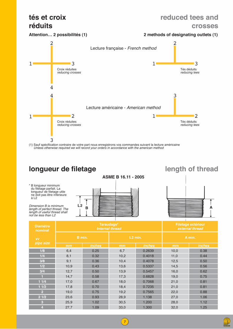
Diamètre nominal
vv pipe size
Taraudage*Internal thread
Filetage extérieurexternal thread
B min. L2 min. A min.
mm inches mm inches mm inches1/8 6,4 0.25 6,7 0.2639 10,0 0.381/4 8,1 0.32 10,2 0.4018 11,0 0.443/8 9,1 0.36 10,4 0.4078 12,5 0.501/2 10,9 0.43 13,6 0.5337 14,5 0.563/4 12,7 0.50 13,9 0.5457 16,0 0.621 14,7 0.58 17,3 0.6828 19,0 0.75
1 1/4 17,0 0.67 18,0 0.7068 21,0 0.811 1/2 17,8 0.70 18,4 0.7235 21,0 0.81
2 19,0 0.75 19,2 0.7565 22,0 0.882 1/2 23,6 0.93 28,9 1.138 27,0 1.06
3 25,9 1.02 30,5 1.200 28,0 1.124 27,7 1.09 33,0 1.300 32,0 1.25
longueur de filetage
tés et croix réduits
length of thread
reduced tees and crosses
ASME B 16.11 - 2005
* B longueur minimum du filetage parfait. La longueur de filetage utile ne doit pas être inférieure à L2
Dimension B is minimum length of perfect thread. The length of useful thread shall not be less than L2
2
4
2
3
3
2
3
2
1
1
1
1
4
3
Attention… 2 possibilités (1) 2 methods of designating outlets (1)
Lecture française - French method
Lecture américaine - American method
Croix réduites reducing crosses
Croix réduites reducing crosses
Tés déduits reducing tees
Tés déduits reducing tees
(1) Sauf spécification contraire de votre part nous enregistrons vos commandes suivant la lecture américaine Unless otherwise required we will record your orders in accordance with the american method

8
Diamètre nominal du tube
Diamètre extérieur du tube
Nombre de filets
par pouce
Pas Ø sur flancs extrémité engagem.
filetage ext.
Ø sur flancs extrémité engagem.
filetage int.
longueur effective
de filetage
Longueur serrage à main
Accrois. du diam. par tour
Longueur de serrage
à la clé
D n P E0 E1 L2 L1 A1/8 10,29 27 0,940 9,233 9,489 6,703 4,102 0,0586 06,91/4 13,72 18 1,411 12,126 12,487 10,205 5,786 0,0881 103/8 17,14 18 1,411 15,545 15,926 10,358 6,096 0,0881 10,31/2 21,34 14 1,814 19,624 19,772 13,556 8,128 0,1132 13,63/4 26,67 14 1,814 24,579 25,117 13,860 8,610 0,1132 14,11 33,40 11 1/2 2,209 30,826 31,461 17,343 10,160 0,1379 16,8
1 1/4 42,16 11 1/2 2,209 39,551 40,218 17,952 10,668 0,1379 17,31 1/2 48,26 11 1/2 2,209 45,621 46,287 18,377 10,668 0,1379 17,3
2 60,32 11 1/2 2,209 57,633 58,325 19,215 11,074 0,1379 17,72 1/2 73,02 8 3,175 69,076 70,159 28,892 17,322 0,1933 23,7
3 88,90 8 3,175 84,852 86,068 30,480 19,456 0,1933 25,83 1/2 101,60 8 3,175 97,472 98,776 31,750 20,853 0,1933 27,2
4 114,30 8 3,175 110,093 111,433 33,020 21,437 0,1933 27,8
Nominal pipe size
Outside diameter of pipe
D
Number of threads per inch
n
Pitch of thread
P
Pitch diameter
at external thread end
E0
Pitch diameter
at internal thread end
E1
Effective threads length
L2
Length of hand
tightening
L1
Increase in diameter per thread
0.0625/n
Length of wrench tightening
Ainches inches inches inches inches inches inches inches inches
1/8 0.405 27 0.03704 0.36351 0.37360 0.2639 0.1615 0.00231 0.27261/4 0.540 18 0.05556 0.47739 0.49163 0.4018 0.2278 0.00347 0.39453/8 0.675 18 0.05556 0.61201 0.62701 0,4078 0.240 0.00347 0.40671/2 0.840 14 0.07143 0.75843 0.77843 0.5337 3.320 0.00446 0.53433/4 1.050 14 0.07143 0.96768 0.98887 0.5457 0.339 0.00446 0.55331 1.315 11 1/2 0.08696 1.21363 1.23863 0.6828 0.400 0.00543 0.6609
1 1/4 1.660 11 1/2 0.08696 1.55713 1.58338 0.7068 0.420 0.00543 0.68091 1/2 1.900 11 1/2 0.08696 1.79609 1.82234 0.7235 0.420 0.00543 0.6809
2 2.375 11 1/2 0.08696 2.26902 2.29627 0.7565 0.436 0.00543 0.69692 1/2 2.875 8 0.12500 2.71953 2.76216 1.1375 0.682 0.00781 0.9320
3 3.500 8 0.12500 3.34062 3.38850 1.2000 0.766 0.00781 1.0163 1/2 4.000 8 0.12500 3.83750 3.88881 1.2500 0.821 0.00781 1.071
4 4.500 8 0.12500 4.33438 4.38712 1.3000 0.844 0.00781 1.094
filetage conique pour tubes (NPT)
standard taper pipe thread (NPT)
Engagement à la clé des filetages mâle et femelle suivant normes ANSI-B. 1.20.1 ou API Std 5 B.Toutes les dimensions données ci-dessus correspondent aux normes américaines ANSI-B 1.20.1 ou API Standard 5 B. Excepté pour les dimensions nominales 1/8” et 1/4” ou E1 et L1 ne sont pas mesurées sur le même plan d’après l’API Std 5B. Toutefois, ces dimensions ramenées sur le même plan sont identiques.
Normal engagement between male and female threads to make tight joints according to standards ANSI-B. 1.20.1 or API Std 5 B.All the dimensions above correspond to the American standards ANSI-B. 1.20.1 and API standard 5B. Except for the nominal sizes 1/8” and 1/4”, for which E1 and L1 are not measured on the same plan, according to API Std 5 B. However, the dimensions are identical when referred to the same plan.

9
coude 90°séries 3000-6000
coude 45°séries 3000-6000
90° elbowsclass 3000 lb-6000 lb
45° elbowsclass 3000 lb-6000 lb
Taraudage suivant ANSI B 1.20.1 - 1983
Thread according to ANSI B 1.20.1 - 1983
Taraudage suivant ANSI B 1.20.1 - 1983
Thread according to ANSI B 1.20.1 - 1983
Dimensions suivant ASME B 16.11-2005
Dimensions according to ASME B 16.11-2005
Dimensions suivant ASME B 16.11-2005
Dimensions according to ASME B 16.11-2005
Diamètre nominalNominalpipe size
3000 6000
A H G A H G
mm inches mm inches mm inches mm inches mm inches mm inches
1/4 25 0.97 25 1.00 3,30 0.130 28 1.12 33 1.31 6,60 0.2603/8 28 1.12 33 1.31 3,51 0.138 33 1.31 38 1.50 6,98 0.2751/2 33 1.31 38 1.50 4,09 0.161 38 1.50 46 1.81 8,15 0.3213/4 38 1.50 46 1.81 4,32 0.170 44 1.75 56 2.19 8,53 0.3361 44 1.75 56 2.19 4,98 0.196 51 2.00 62 2.44 9,93 0.391
1 1/4 51 2.00 62 2.44 5,28 0.208 60 2.38 75 2.97 10,59 0.4171 1/2 60 2.38 75 2.97 5,50 0.219 64 2.50 84 3.31 11,07 0.436
2 64 2.50 84 3.31 7,14 0.281 83 3.25 102 4.00 12,09 0.4762 1/2 83 3.25 102 4.00 7,65 0.301 95 3.75 121 4.75 15,29 0.602
3 95 3.75 121 4.75 8,84 0.348 106 4.19 146 5.75 16,64 0.6554 114 4.50 152 6.00 11,18 0.440 114 4.50 152 6.00 18,67 0.735
Diamètre nominalNominalpipe size
3000 6000
C H G C H G
mm inches mm inches mm inches mm inches mm inches mm inches1/4 19 0.75 25 1.00 3,30 0.130 22 0.88 33 1.31 6,60 0.2603/8 22 0.88 33 1.31 3,51 0.138 25 1.00 38 1.50 6,98 0.2751/2 25 1.00 38 1.50 4,09 0.161 28 1.12 46 1.81 8,15 0.3213/4 28 1.12 46 1.81 4,32 0.170 33 1.31 56 2.19 8,53 0.3361 33 1.31 56 2.19 4,98 0.196 35 1.38 62 2.44 9,93 0.391
1 1/4 35 1.38 62 2.44 5,28 0.208 43 1.69 75 2.97 10,59 0.4171 1/2 43 1.69 75 2.97 5,50 0.219 44 1.72 84 3.31 11,07 0.436
2 44 1.72 84 3.31 7,14 0.281 52 2.06 102 4.00 12,09 0.4762 1/2 52 2.06 102 4.00 7,65 0.301 64 2.50 121 4.75 15,29 0.602
3 64 2.50 121 4.75 8,84 0.348 79 3.12 146 5.75 16,64 0.6554 79 3.12 152 6.00 11,18 0.440 79 3.12 152 6.00 18,67 0.735

10
tés tees
manchonscouplings
demi-manchonshalf-couplings
croix crosses
Taraudage suivant ANSI B 1.20.1 - 1983
Thread according to ANSI B 1.20.1 - 1983
Taraudage suivant ANSI B 1.20.1 - 1983
Thread according to ANSI B 1.20.1 - 1983
Dimensions suivant ASME B 16.11-
2005
Dimensions according to ASME
B 16.11-2005
Dimensions suivant ASME B 16.11-
2005
Dimensions according to ASME
B 16.11-2005
Diamètre nominalNominal pipe size
3000 6000
A H G A H Gmm inches mm inches mm inches mm inches mm inches mm inches
1/4 25 0.97 25 1.00 3,30 0.130 29 1.12 33 1.31 6,60 0.2603/8 29 1.12 33 1.31 3,51 0.138 33 1.31 38 1.50 6,98 0.2751/2 33 1.31 38 1.50 4,09 0.161 38 1.50 46 1.81 8,15 0.3213/4 38 1.50 46 1.81 4,32 0.170 44 1.75 56 2.19 8,53 0.3361 44 1.75 56 2.19 4,98 0.196 51 2,00 62 2.44 9,93 0.391
1 1/4 51 2.00 62 2.44 5,28 0.208 60 2.38 75 2.97 10,59 0.4171 1/2 60 2.38 75 2.97 5,50 0.219 64 2.50 84 3.31 11,07 0.436
2 64 2.50 84 3.31 7,14 0.281 83 3.25 102 4.00 12,09 0.4762 1/2 83 3.25 102 4.00 7,65 0.301 95 3.75 121 4.75 15,29 0.602
3 95 3.75 121 4.75 8,84 0.348 106 4.19 146 5.75 16,64 0.6554 114 4.50 152 6.00 11,18 0.440 114 4.50 152 6.00 18,67 0.735
Diamètre nominalNominal pipe size
3000 6000
W D W Dmm inches mm inches mm inches mm inches
1/4 35 1.38 20 0.75 35 1.38 26 1.003/8 38 1.50 22 0.88 38 1.50 32 1.251/2 48 1.88 28 1.12 48 1.88 38 1.503/4 51 2.00 35 1.38 51 2.00 44 1.751 60 2.38 44 1.75 60 2.38 57 2.25
1 1/4 67 2.62 57 2.25 67 2.62 64 2.501 1/2 79 3.12 64 2.50 79 3.12 76 3.00
2 86 3.38 76 3.00 86 3.38 92 3.622 1/2 92 3.62 92 3.62 92 3.62 108 4.25
3 108 4.25 108 4.25 108 4.25 127 5.004 121 4.75 140 5.50 121 4.75 159 6.25
séries 3000-6000
séries 3000-6000
class 3000 lb-6000 lb
class 3000 lb-6000 lb
11
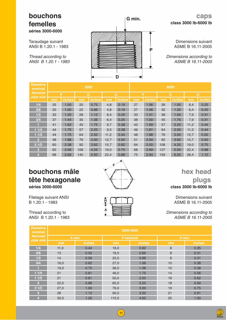
DiamètrenominalNominalpipe size
3000 6000
P D G P D Gmm inches mm inches mm inches mm inches mm inches mm inches
1/4 25 1.00 20 0.75 4,8 0.19 27 1.06 26 1.00 6,4 0.253/8 25 1.00 22 0.88 4,8 0.19 27 1.06 32 1.25 6,4 0.251/2 32 1.25 28 1.12 6,4 0.25 33 1.31 38 1.50 7,9 0.313/4 37 1.44 35 1.38 6,4 0.25 38 1.50 45 1.75 7,9 0.311 41 1.62 45 1.75 9,7 0.38 43 1.69 57 2.25 11,2 0.44
1 1/4 44 1.75 57 2.25 9,5 0.38 46 1.81 64 2.50 11,2 0.441 1/2 44 1.75 64 2.50 11,2 0.44 48 1.88 76 3.00 12,7 0.50
2 48 1.88 76 3.00 12,7 0.50 51 2.00 92 3.62 15,7 0.622 1/2 60 2.38 92 3.62 15,7 0.62 64 2.50 108 4.25 19,0 0.75
3 65 2.56 108 4.25 19,0 0.75 68 2.69 127 5.00 22,4 0.884 68 2.69 140 5.50 22,4 0.88 75 2.94 159 6.25 28,4 1.12
DiamètrenominalNominalpipe size
3000-6000
A min F nominal H min.mm inches mm inches mm inches
1/4 11,0 0.44 16,0 0.62 6 0.253/8 13 0.50 18,0 0.69 8 0.311/2 14 0.56 22,0 0.88 8 0.313/4 16,0 0.62 27,0 1.06 10 0.381 19,0 0.75 36,0 1.38 10 0.38
1 1/4 21 0.81 46,0 1.75 14 0.561 1/2 21 0.81 50,0 2.00 16 0.62
2 22,0 0.88 65,0 2.50 18 0.692 1/2 27,0 1.06 76,0 3.00 19 0.75
3 28 1.12 90,0 3.50 21 0.814 32,0 1.25 115,0 4.62 25 1.00
bouchons femellesséries 3000-6000
bouchons mâle tête hexagonaleséries 3000-6000
capsclass 3000 lb-6000 lb
hex head plugs
class 3000 lb-6000 lb
Taraudage suivant ANSI B 1.20.1 - 1983
Thread according to ANSI B 1.20.1 - 1983
Filetage suivant ANSI B 1.20.1 - 1983
Thread according to ANSI B 1.20.1 - 1983
Dimensions suivant ASME B 16.11-2005
Dimensions according to ASME B 16.11-2005
Dimensions suivant ASME B 16.11-2005
Dimensions according to ASME B 16.11-2005

12
Diamètre nominalNominal pipe size
3000 - 6000
A min. F nominal G min.mm inches mm inches mm inches
3/8 x 1/4 13 0.50 18,0 0.69 4 0.16
1/2 x 3/8 14 0.56 22,0 0.88 5 0.19
1/2 x 1/4 14 0.56 22,0 0.88 5 0.19
3/4 x 1/2 16,0 0.62 27,0 1.06 6 0.22
3/4 x 1/4 16,0 0.62 27,0 1.06 6 0.22
1 x 3/4 19,0 0.75 36,0 1.38 6 0.25
1 x 1/2 19,0 0.75 36,0 1.38 6 0.25
1 x 1/4 19,0 0.75 36,0 1.38 6 0.25
1 1/4 x 1 21 0.81 46,0 1.75 7 0.28
1 1/2 x 1 21 0.81 50,0 2.00 8 0.31
1 1/2 x 3/4 21 0.81 50,0 2.00 8 0.31
1 1/2 x 1/2 21 0.81 50,0 2.00 8 0.31
2 x 1 1/2 22,0 0.88 65,0 2.50 9 0.34
2 x 1 22,0 0.88 65,0 2.50 9 0.34
2 1/2 x 2 27,0 1.06 75,0 3.00 10 0.38
3 x 2 28 1.12 90,0 3.50 10 0.41
4 x 3 32,0 1.25 115,0 4.62 13 0.50
4 x 2 32,0 1.25 115,0 4.62 13 0.50
réductions mâle-femelleséries 3000-6000
hex head bushings
class 3000 lb-6000 lb
Filetage et taraudage suivant ANSI B 1.20.1 - 1983
Thread according to ANSI B 1.20.1 - 1983
Dimensions suivant ASME B 16.11-2005
Dimensions according to ASME B 16.11-2005
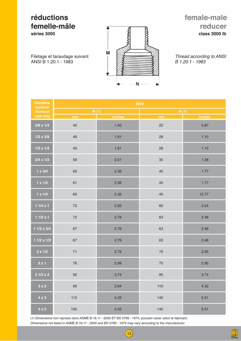
13
Diamètre nominalNominal pipe size
3000
M (1) N (1)mm inches mm inches
3/8 x 1/4 42 1.50 22 0.87
1/2 x 3/8 49 1.81 28 1.10
1/2 x 1/4 49 1.81 28 1.10
3/4 x 1/2 59 2.01 35 1.38
1 x 3/4 63 2.36 45 1.77
1 x 1/2 61 2.36 45 1.77
1 x 1/4 60 2.36 45 12.77
1 1/4 x 1 72 2.83 60 2.24
1 1/2 x 1 72 2.76 63 2.48
1 1/2 x 3/4 67 2.76 63 2.48
1 1/2 x 1/2 67 2.76 63 2.48
2 x 1/2 71 2.79 75 2.95
2 x 1 76 2.99 75 2.95
2 1/2 x 2 92 3.74 95 3.74
3 x 2 95 3.94 110 4.33
4 x 3 113 4.33 140 5.51
4 x 2 100 4.33 140 5.51
réductions femelle-mâleséries 3000
female-male reducer
class 3000 lb
Filetage et taraudage suivant ANSI B 1.20.1 - 1983
Thread according to ANSI B 1.20.1 - 1983
(1) Dimensions non reprises dans ASME B 16.11 - 2005 ET BS 3799 - 1974, pouvant varier selon le fabricant.Dimensions not listed in ASME B 16.11 - 2005 and BS 3799 - 1974 may vary according to the manufacturer.

14
mamelons réduitsséries 3000-6000
female-male reducer
class 3000 lb - 6000 lb
Diamètres nominauxNominal
pipe sizes
A (mini)
E (mini)
F (mini)
C (mini)
W (mini)
B*
3000 6000
pouces inches
mmmm mm inc. mm inc. mm inc. mm inc. mm inc. mm inc. mm inc.
1/4 x 1/8 8 x 6 15 0.59 15 0.59 10 0.39 5 0.19 31 1.22 5 0.20 2 0.08
3/8 x 1/4 10 x 8 18 0.71 16 0.63 15 0.59 8 0.31 39 1.54 8 0.31 6 0.24
1/2 x 3/8 15 x 10 22 0.87 20 0.79 16 0.63 8 0.31 44 1.73 11 0.43 8 0.31
1/2 x 1/4 15 x 8 22 0.87 20 0.79 15 0.59 8 0.31 43 1.69 8 0.31 6 0.24
3/4 x 1/2 20 x 15 27 1.06 21 0.83 20 0.79 9 0.35 50 1.97 14 0.55 11 0.43
3/4 x 3/8 20 x 10 27 1.06 21 0.83 16 0.63 9 0.35 46 1.81 11 0.43 8 0.31
1 x 3/4 25 x 20 35 1.38 25 0.98 21 0.83 10 0.39 56 2.20 19 0.75 13 0.51
1 x 1/2 25 x 15 35 1.38 25 0.98 20 0.79 10 0.39 55 2.17 14 0.55 11 0.43
1 1/2 x 1 40 x 25 50 1.97 26 1.02 25 0,98 16 0.63 67 2.64 24 0.94 17 0.67
1 1/2 x 3/4 40 x 20 50 1.97 26 1.02 21 0.83 16 0.63 63 2.48 19 0.75 13 0.51
1 1/2 x 1/2 40 x 15 50 1.97 26 1.02 20 0.79 16 0.63 62 2.44 14 0.55 11 0.43
2 x 1 1/2 50 x 40 62 2.44 27 1.06 26 1.02 17 0.67 70 2.76 38 1.50 30 1.18
2 x 1 50 x 25 62 2.44 27 1.06 25 0.98 18 0.71 70 2.76 24 0.94 17 0.67
2 x 3/4 50 x 20 62 2.44 27 1.06 21 0.83 17 0.67 65 2.60 19 0.75 13 0.51
2 x 1/2 50 x 15 62 2.44 27 1.06 20 0.79 18 0.71 65 2.60 14 0.55 11 0.43
* «b» dimension nominale soumise aux tolérances normales de fabricationDimension «b» is nominal and is subject to normal manufacturing tolerances
Filetage et taraudage suivant ANSI B 1.20.1 - 1983
Thread according to ANSI B 1.20.1 - 1983
Dimensions suivant BS 3799 - 1974
Dimensions according to BS 3799 - 1974

15
manchons réduitsséries 3000 - 6000
reducing coupling
class 3000 lb - 6000 lb
Dimensions identiques à celles des manchons
Same dimensions as for couplings
ASME B16-11 2005
Taraudage suivant ANSI B 1.20.1 - 1983
Thread according to ANSI B 1.20.1 - 1983
(1) Dimensions non reprises dans ASME B 16.11 - 2005 ET BS 3799 - 1974, pouvant varier selon le fabricant.Dimensions not listed in ASME B 16.11 - 2005 and BS 3799 - 1974 may vary according to the manufacturer.
Diamètres nominauxNominal
pipe sizes
3000 6000
W (1) D (1) W (1) D (1)mm inches mm inches mm inches mm inches
3/8 x 1/4 38 1.50 22 0.87 38 1.50 32 1.26
1/2 x 3/8 48 1.89 28 1.10 48 1.88 38 1.50
1/2 x 1/4 48 1.89 28 1.10 48 1.88 38 1.50
3/4 x 1/2 51 2.00 35 1.38 51 2.00 45 1.77
3/4 x 1/4 51 2.00 35 1.38 51 2.00 45 1.77
1 x 3/4 60 2.36 45 1.77 60 2.36 57 2.24
1 x 1/2 60 2.36 45 1.77 60 2.36 57 2.24
1 x 1/4 60 2.36 45 1.77 60 2.36 57 2.24
1 1/4 x 1 67 2.64 57 2.24 67 2.64 63 2.48
1 1/2 x 1 79 3.11 64 2.52 79 3.11 76 2.99
1 1/2 x 3/4 79 3.11 64 2.52 79 3.11 76 2.99
1 1/2 x 1/2 79 3.11 64 2.52 79 3.11 76 2.99
2 x 1 1/2 86 3.39 76 2.99 86 3.39 92 3.62
2 x 1 86 3.39 76 2.99 86 3.39 92 3.62
2 1/2 x 2 92 3.62 92 3.62 92 3.62 108 4.25
3 x 2 108 4.25 108 4.25 108 4.25 127 5.00
4 x 3 121 4.75 140 5.50 121 4.75 159 6.25
4 x 2 121 4.75 140 5.50 121 4.75 159 6.25

16
mamelonsséries 3000 - 6000
bossages à souderséries 3000 - 6000
hexagonal nipplesclass 3000 lb - 6000 lb
welding bossesclass 3000 lb - 6000 lb
Diamètre nominalNominal pipe size
3000 - 6000
K (1) M (1) N (1)mm inches mm inches mm inches
1/4 30 1,18 28,0 1,10 14,0 0,553/8 30 1,18 32,0 1,26 17,4 0,691/2 33,5 1,32 38,0 1,50 21,6 0,853/4 35,5 1,40 45 1,77 26,9 1,061 43,0 1,69 63 2,48 33,6 1,32
1 1/4 48,0 1,89 68 2,68 42,4 1,671 1/2 51,0 2,00 76 3,00 48,5 1,91
2 57,5 2,26 95 3,74 60,9 2,40
Diamètres nominauxNominal
pipe sizes
A (mini)
E (mini)
C (mini)
W (mini)
B*
3000 6000
pouces inches
mmmm mm inc. mm inc. mm inc. mm inc. mm inc. mm inc.
1/8 6 11 0.43 10 0.39 6 0.24 26 1.02 5 0.20 2 0.08
1/4 8 15 0.59 15 0.59 6 0.24 36 1.42 8 0.31 6 0.24
3/8 10 18 0.71 16 0.63 8 0.31 40 1.57 11 0.43 8 0.31
1/2 15 22 0.87 20 0.79 8 0.31 48 1.89 14 0.55 11 0.43
3/4 20 27 1.06 21 0.83 10 0.39 52 2.05 19 0.75 13 0.51
1 25 35 1.38 25 0.98 10 0.39 60 2.36 24 0.94 17 0.67
1”1/2 40 50 1.97 26 1.02 16 0.63 68 2.68 38 1.50 30 1.18
2 50 62 2.44 27 1.06 17 0.67 71 2.80 49 1.93 39 1.54
Filetage et taraudage suivant ANSI B 1.20.1 - 1983
Thread according to ANSI B 1.20.1 - 1983
Taraudage suivant ANSI B 1.20.1 - 1983
Thread according to ANSI B 1.20.1 - 1983
Dimensions suivant BS 3799 - 1974
Dimensions according to BS 3799 - 1974
De 1/4” à 2” O=9,5 mmFrom 1/4” to 2” O=0.375 in
17
Diamètre nominalNominal pipe size
3000 6000
A J A Jmm inches mm inches mm inches mm inches
1/4 25 0.97 32 1.25 28 1.12 38 1.503/8 28 1.12 38 1.50 33 1.31 41 1.621/2 33 1.31 41 1.62 38 1.50 48 1.883/4 38 1.50 48 1.88 44 1.75 57 2.251 44 1.75 57 2.25 51 2.00 66 2.62
1 1/4 51 2.00 66 2.62 60 2.38 71 2.811 1/2 60 2.38 71 2.81 64 2.50 84 3.31
2 64 2.50 84 3.31 83 3.25 105 4.13
Diamètre nominalNominal pipe size
1/4 3/8 1/2 3/4 1 1 1/4 1 1/2 2
3000M(1)
mm 29 29,5 35,5 39,5 45,5 61 61 84inches 1.14 1.16 1.40 1.56 1.79 2.40 2.40 3.31
N(1)
mm 33 33 38 46 56 76 76 102inches 1.30 1.30 1.50 1.81 2.20 3.00 3.00 4.02
O(1)
mm 51,5 52,5 61,5 67 76 94 100 130inches 2.03 2.07 2.42 2.64 2.99 3.70 3.94 5.12
P(1)
mm 67 72,5 83 90 102 123 129 160inches 2.64 2.85 3.27 3.55 4.25 4.84 5.08 6.30
coudes mâle-femelleséries 3000 - 6000
coudes union tés unionséries 3000 (1)
90° street elbowsclass 3000 lb - 6000 lb
union elbows union teesclass 3000 lb (1)
Filetage et taraudage suivant ANSI B 1.20.1 - 1983
Thread according to ANSI B 1.20.1 - 1983
Filetage et taraudage suivant ANSI B 1.20.1 - 1983
Thread according to ANSI B 1.20.1 - 1983
Dimensions suivant ASME B 16.11 - 2005
Dimensions according to ASME B 16.11 - 2005
Femelle/Femelle (F.F.)Female/Female
Mâle/Femelle (M.F.)Male/Female
(1) Dimensions non reprises dans ASME B 16.11 - 2005 ET BS 3799 - 1974, pouvant varier selon le fabricant.Dimensions not listed in ASME B 16.11 - 2005 and BS 3799 - 1974 may vary according to the manufacturer.

18
Diamètre nominalNominal pipe size
3000 6000
Q (1) R (1) Q (1) R (1)mm inches mm inches mm inches mm inches
1/4 45 1.67 36,0 1.423/8 51 1.87 41,0 1.621/2 52 2.05 46,0 1.81 63 2.72 64,5 2.363/4 57 2.25 56,0 2.20 63 2.84 64,5 2.841 63 2.48 65,0 2.56 71 3.15 80,0 3.15
1 1/4 66 2.76 80,0 3.07 89 3.50 87,0 3.701 1/2 78 30.7 87,0 3.39 89 4.25 100,0 3.94
2 91 3.50 100,0 4.06 119 4.49 122,0 4.802 1/2 118 4.49 125,0 4.80 128 5.13 144,0 5.67
3 120 5.12 144,0 5.67 148 5.91 200,0 7.094 148 5.91 200,0 7.09
Diamètre nominalNominal pipe size
3000 6000
Q (1) R (1) Q (1) R (1)mm inches mm inches mm inches mm inches
1/4 61,0 2.48 36,0 1.263/8 69,0 2.72 41,0 1.501/2 75,0 3.03 46,0 1.81 94,5 3.72 64,5 2.363/4 80,0 3.15 56,0 2.00 98,5 3.88 64,5 2.841 90,0 3.82 65,0 2.36 108,0 4.25 80,0 3.15
1 1/4 98,0 3.98 80,0 2.84 120,0 4.72 87,0 3.701 1/2 100,0 4.33 87,0 3.15 138,0 5.44 100,0 3.94
2 120,0 4.72 100,0 3.70 146,0 5.75 122,0 4.80
union mâle-femelleséries 3000 - 6000
union mâle-femelleséries 3000 - 6000
male-female unions
class 3000 lb - 6000 lb
male-female unions
class 3000 lb - 6000 lb
Taraudage suivant ANSI B 1.20.1 - 1983
Thread according to ANSI B 1.20.1 - 1983
Filetage et taraudage suivant ANSI B 1.20.1 - 1983
Thread according to ANSI B 1.20.1 - 1983
Dimensions suivant MSS SP 83-BS 3799
Dimensions according to MSS SP 83-BS 3799
(1) Dimensions pouvant varier selon le fabricant. Dimensions may vary according to the manufacturer.
(1) Dimensions pouvant varier selon le fabricant. Dimensions may vary according to the manufacturer.

19
mam
elon
s tu
bepi
pe n
ippl
es
Dim
ensi
ons
suiv
ant /
acc
ordi
ng to
: A73
3-03
/ AS
ME
B36.
10-0
4 / A
106-
08
Extré
mité
à s
oude
r sui
vant
AN
SI B
16-
25 -
2007
Buttw
eldi
ng e
nd a
ccor
ding
to
AN
SI B
16-
25 -
2007
Extré
mité
liss
e co
upée
d’é
quer
reC
ut s
quar
e pl
ain
end
Extré
mité
s fil
etée
s su
ivan
t AN
SI B
1.2
0.1
- 198
3Th
read
end
s ac
cord
ing
to
ANSI
B 1
.20.
1 - 1
983
19DIA
M.
NO
M.
NO
M.
SIZE
O.D
.CL
OSE
LE
NGTH
LON
GU
EUR
STA
ND
AR
D /
STA
ND
AR
D L
ENG
TH1”
1/2
(38,
1 m
m)
2” (5
0,8
mm
)2”
1/2
(63,
5 m
m)
3” (7
6,2
mm
)4”
(101
,6 m
m)
5” (1
27 m
m)
6” (1
52,4
mm
)8”
(203
,2 m
m)
12”
(304
,8 m
m)
mm
inch
Sch.
40
Sch.
80
Sch.
16
0Sc
h.
XXS
Sch.
40
Sch.
80
Sch.
16
0Sc
h.
XXS
Sch.
40
Sch.
80
Sch.
16
0Sc
h.
XXS
Sch.
40
Sch.
80
Sch.
16
0Sc
h.
XXS
Sch.
40
Sch.
80
Sch.
16
0Sc
h.
XXS
Sch.
40
Sch.
80
Sch.
16
0Sc
h.
XXS
Sch.
40
Sch.
80
Sch.
16
0Sc
h.
XXS
Sch.
40
Sch.
80
Sch.
16
0Sc
h.
XXS
Sch.
40
Sch.
80
Sch.
16
0Sc
h.
XXS
1/8”
10,3
0,40
53/
4”O
KO
KO
KO
KO
KO
KO
KO
KO
KO
KO
KO
KO
KO
KO
KO
KO
KO
KO
KO
KO
KO
KO
KO
KO
KO
KO
KO
KO
KO
KO
KO
KO
KO
KO
KO
K
1/4”
13,7
0,54
07/
8”O
KO
KO
KO
KO
KO
KO
KO
KO
KO
KO
KO
KO
KO
KO
KO
KO
KO
KO
KO
KO
KO
KO
KO
KO
KO
KO
KO
KO
KO
KO
KO
KO
KO
KO
KO
K
3/8”
17,1
0,67
51”
OK
OK
OK
OK
OK
OK
OK
OK
OK
OK
OK
OK
OK
OK
OK
OK
OK
OK
OK
OK
OK
OK
OK
OK
OK
OK
OK
OK
OK
OK
OK
OK
OK
OK
OK
OK
1/2”
21,3
0,84
01”
1/8
OK
OK
OK
OK
OK
OK
OK
OK
OK
OK
OK
OK
OK
OK
OK
OK
OK
OK
OK
OK
OK
OK
OK
OK
OK
OK
OK
OK
OK
OK
OK
OK
OK
OK
OK
OK
3/4”
26,7
1,05
01”
3/8
OK
OK
OK
OK
OK
OK
OK
OK
OK
OK
OK
OK
OK
OK
OK
OK
OK
OK
OK
OK
OK
OK
OK
OK
OK
OK
OK
OK
OK
OK
OK
OK
OK
OK
OK
OK
1”33
,41,
315
1”1/
2O
KO
KO
KO
KO
KO
KO
KO
KO
KO
KO
KO
KO
KO
KO
KO
KO
KO
KO
KO
KO
KO
KO
KO
KO
KO
KO
KO
KO
KO
KO
KO
KO
KO
KO
KO
K
1”1/
442
,21,
660
1”5/
8O
KO
KO
KO
KO
KO
KO
KO
KO
KO
KO
KO
KO
KO
KO
KO
KO
KO
KO
KO
KO
KO
KO
KO
KO
KO
KO
KO
KO
KO
KO
KO
KO
KO
KO
KO
K
1”1/
248
,31,
900
1”3/
4O
KO
KO
KO
KO
KO
KO
KO
KO
KO
KO
KO
KO
KO
KO
KO
KO
KO
KO
KO
KO
KO
KO
KO
KO
KO
KO
KO
KO
KO
KO
KO
KO
KO
KO
KO
K
2”60
,32,
375
2”-
--
-O
KO
KO
KO
KO
KO
KO
KO
KO
KO
KO
KO
KO
KO
KO
KO
KO
KO
KO
KO
KO
KO
KO
KO
KO
KO
KO
KO
KO
KO
KO
KO
K
2”1/
273
,02,
875
2”1/
2-
--
--
--
-O
KO
K-
OK
OK
OK
-O
KO
KO
K-
OK
OK
OK
-O
KO
KO
K-
OK
OK
OK
-O
KO
KO
K-
OK
3”88
,93,
500
3”-
--
--
--
--
--
-O
KO
K-
OK
OK
OK
-O
KO
KO
K-
OK
OK
OK
-O
KO
KO
K-
OK
OK
OK
-O
K
4”11
4,3
4,50
04”
--
--
--
--
--
--
--
--
OK
OK
-O
KO
KO
K-
OK
OK
OK
-O
KO
KO
K-
OK
OK
OK
-O
K

20
Diamètres nominauxNominal
pipe sizesA x B
3000 Épaisseur suivant ANSI B36-10
Thickness according to ANSI B 36-10
K LBS3799 MSS SP95
mm inches mm inches mm inches3/8 x 1/4 76 3.74 64 2.52 16 0.63 Sch 40 Sch 801/2 x 3/8 89 3.50 70 2.76 19 0.75 Sch 40 Sch 801/2 x 1/4 89 3.50 70 2.76 19 0.75 Sch 40 Sch 803/4 x 1/2 95 3.75 76 2.99 22 0.87 Sch 40 Sch 80 Sch 1603/4 x 1/4 95 3.75 76 2.99 22 0.87 Sch 40 Sch 801 x 3/4 102 4.02 89 3.50 22 0.87 Sch 40 Sch 80 Sch 1601 x 1/2 102 4.02 89 3.50 22 0.87 Sch 40 Sch 80 Sch 1601 x 1/4 102 4.02 89 3.50 22 0.87 Sch 40 Sch 80 Sch 160
1 1/4 x 1 114 4.49 102 4.02 25 0.98 Sch 40 Sch 80 Sch 1601 1/2 x 1 114 4.49 114 4.49 25 0.98 Sch 40 Sch 80 Sch 160
1 1/2 x 3/4 114 4.49 114 4.49 25 0.98 Sch 40 Sch 80 Sch 1601 1/2 x 1/2 165 6.50 165 6.50 25 0.98 Sch 40 Sch 80 Sch 1602 x 1 1/2 165 6.50 165 6.50 29 1.14 Sch 40 Sch 80 Sch 160
2 x 1 165 6.50 165 6.50 30 1.14 Sch 40 Sch 80 Sch 1602 1/2 x 2 178 7.01 178 7.01 32 1.26 Sch 40 Sch 80 Sch 160
3 x 2 203 7.99 203 7.99 41 1.61 Sch 40 Sch 80 Sch 1604 x 3 229 9,02 229 9,02 48 1.89 Sch 40 Sch 80 Sch 1604 x 2 229 9.02 229 9.02 48 1.89 Sch 40 Sch 80 Sch 160
swedge nipplesséries 3000 - 6000
code utilisé pour la nomenclature des swedge nipplesmamelons tubes réduits
swedge nipplesclass 3000 lb - 6000 lb
code used in material list of swedge nipples
reduced nipples
Extrémité à souder suivant ANSI B 16-25 - 2007
Buttwelding end according to ANSI B 16-25 - 2007
Extrémité lisse coupée d’équerre
Cut square plain end
Extrémités filetées suivant
ANSI B 1.20.1 - 1983
Thread ends according to
ANSI B 1.20.1 - 1983
Dimensions suivant BS 3799/MSS SP 95
Dimensions according to 3799/MSS SP 95
Tolérances sur diamètre et épaisseur suivant ASTM A 106Variations in outside diameter and thickness according to ASTM A 106
P.B.E. Deux extremités d’équerre et lisse / Plain both endsP.L.E. Grande extrémité d’équerre et lisse / Plain large endP.S.E. Petite extrémité d’équerre et lisse / Plain small end
B.B.E. Deux extrémités chanfreinées / Bevelled both endsB.L.E. Grande extrémité chanfreinée / Bevelled large endB.S.E. Petite extrémité chanfreinée / Bevelled small end
T.B.E. Deux extrémités filetées / Threaded both endsT.L.E. Grande extrémité filetée / Threaded large end T.S.E. Petite extrémité filetée / Threaded small end
B.O.E. Une extrémité chanfreinée / Bevelled one endP.O.E. Une extrémité d’équerre et lisse / Plain one endT.O.E. Une extrémité Filetée / Threaded one end
S’appliquent uniquement aux mamelons tubes For barrel nipples only
On peut trouver pour une même pièce deux codes réunis. Exemple :Two codes may be used on the same item for example : 1 Swedge Nipple 3 x 2 BLE/TSE
Ce qui se lit : Which means : - Large extrémité chanfreinée / Bevelled large end- Petite extrémité filetée / Threaded small end

21
dimensions des raccords à soudersuivant ASME B16.11 - 2005
Diamètre nominal 1/8 1 /4 3/8 1/2 3/4 1 1 1/4 1 1/2 2 2 1/2 3 4
BMini 10,8 14,2 17,6 21,8 27,2 33,90 42,7 48,8 61,2 73,9 89,80 115,2
Maxi 11,2 14,6 18,0 22,2 27,6 34,3 43,1 49,2 61,7 74,4 90,3 115,7
D
3000 ibMini 6,1 8,5 11,8 15,0 20,2 25,9 34,3 40,10 51,7 61,2 76,4 100,7
Maxi 7,6 10,0 13,3 16,6 21,7 27,4 35,8 41,60 53,3 64,2 79,4 103,8
6000 ibMini 3,2 5,6 8,4 11,0 14,8 19,9 28,7 33,2 42,1
Maxi 4,8 7,1 9,9 12,5 16,3 21,5 30,2 34,7 43,6
C (1)
3000 ibMoyen 3,18 3,78 4,01 4,67 4,90 5,69 6,07 6,35 6,93 8,76 9,52 10,69
Mini 3,18 3,30 3,50 4,09 4,27 4,98 5,28 5,54 6,04 7,67 8,30 9,35
6000 ibMoyen 3,96 4,60 5,03 5,97 6,96 7,92 7,92 8,92 10,92
Mini 3,43 4,01 4,37 5,18 6,04 6,93 6,93 7,80 9,50
G mini.3000 ib 2,41 3,02 3,20 3,73 3,91 4,55 4,85 5,08 5,54 7,01 7,62 8,56
6000 ib 3,15 3,68 4,01 4,78 5,56 6,35 6,35 7,14 8,74
J mini. 9,5 9,5 9,5 9,5 12,5 12,5 12,5 12,5 16,00 16,00 16,00 19,00
(1) La moyenne de l’épaisseur de l’emboitement sur la périphérie ne sera pas inférieure aux valeurs indiquées. Les valeurs minimales sont autorisées sur des surfaces délimitées.
Dimensions exigées pour la soudure d’éléments à emboitement à souder (S.W.)
0,75 xC mini (épaisseur mini de la chambre)
Dimensions en mm

22
Nominal pipe size 1/8 1/4 3/8 1/2 3/4 1 1 1/4 1 1/2 2 2 1/2 3 4
BMini 0.420 0.555 0.690 0.855 1.065 1.330 1.675 1.915 2.406 2.906 3.535 4.545
Maxi 0.440 0.575 0.710 0.875 1.085 1.350 1.695 1.935 2.426 2.931 3.560 4.570
D
3000 ibMini 0.239 0.334 0.463 0.592 0.794 1.019 1.350 1.580 2.037 2.409 3.008 3.966
Maxi 0.299 0.394 0.523 0.652 0.854 1.079 1.410 1.640 2.097 2.529 3.128 4.086
6000 ibMini 0.126 0.220 0.329 0,434 0.582 0.785 1.130 1.308 1.657
Maxi 0.189 0.280 0.389 0.494 0.642 0.845 1.190 1.368 1.717
C (1)
3000 ibMoyen 0.125 0.149 0.158 0.184 0.193 0.224 0.239 0.250 0.273 0.345 0.375 0.421
Mini 0.125 0.130 0.138 0.161 0.168 0.196 0.208 0.218 0.238 0.302 0.327 0.368
6000 ibMoyen 0.156 0.181 0.198 0.235 0.274 0.312 0.312 0.351 0.430
Mini 0.135 0.158 0.172 0.204 0.238 0.273 0.273 0.307 0.374
G mini.3000 ib 0.095 0.119 0.126 0.147 0.154 0.179 0.191 0.200 0.218 0.276 0.300 0.337
6000 ib 0.124 0.145 0.158 0.188 0.219 0.250 0.250 0.281 0.344
J mini. 0.38 0.38 0.38 0.38 0.50 0.50 0.50 0.50 0.62 0.62 0.62 0.75
dimensions of socket welding fittingsaccording to ASME B16.11 - 2005
Welding dimensions required for socket-welding components
(1) Average of socket wall thickness around periphery shall not be no less than listed values. The minimum values are permitted in localized areas.
Dimensions in inches
0,75 xC mini (minimum socket wall thickness)

23
coudesséries 3000 - 6000
tésteesséries 3000 - 6000
elbowsclass 3000 lb - 6000 lb
croixcrosses
class 3000 lb- 6000 lb
Diamètre nominalNominal pipe size
Centre au fond de l’emboîtement A - Center to bottom of socket ACoude 90° - Té - Croix Coude 45°
Tolérances ±3000 6000 3000 6000
mm inches mm inches mm inches mm inches mm inches
1/4 11,0 0.44 13,5 0.53 8,0 0.31 8,0 0.31 1,0 0.03
3/8 13,5 0.53 15,5 0.62 8,0 0.31 11,0 0.44 1,5 0.06
1/2 15,5 0.62 19,0 0.75 11,0 0.44 12,5 0.50 1,5 0.06
3/4 19,0 0.75 22,5 0.88 13,0 0.50 14,0 0.56 1,5 0.06
1 22,5 0.88 27,0 1.06 14,0 0.56 17,5 0.69 2,0 0.08
1 1/4 27,0 1.06 32,0 1.25 17,5 0.69 20,5 0.81 2,0 0.08
1 1/2 32,0 1.25 38,0 1.50 20,5 0.81 25,5 1.00 2,0 0.08
2 38,0 1.50 41,0 1.62 25,5 1.00 28,5 1.12 2,0 0.08
2 1/2 41,0 1.62 28,5 1.12 2,5 0.10
3 57,0 2.25 32,0 1.25 2,5 0.10
4 66,5 2.62 41,0 1.62 2,5 0.10
Emboîtement à souder et dimensions suivant ASME B 16.11 - 2005Socket welding end and dimensions according to ASME B 16.11 - 2005
Emboîtement à souder et dimensions suivant ASME B 16.11 - 2005Socket welding end and dimensions according to ASME B 16.11 - 2005
Dimensions B-C-D-G-J, voir caractéristiques dimensionnelles
For dimensions B-C-D-G-J refer to dimensions of S.W. fittings

24
manchonscouplingsséries 3000 - 6000
bouchons femellesséries 3000 - 6000
demi-manchonshalf-couplings
class 3000 lb - 6000 lb
capsclass 3000 lb- 6000 lb
Diamètre nominalNominal pipe size
Côtes de montage / Laying lengths
Manchons / Couplings -E Demi-manchons / Half-couplings - F
3000 / 6000 Tolérances ± 3000 / 6000 Tolérances ±mm inches mm inches mm inches mm inches
1/4 6,5 0.25 1,5 0.06 16,0 0.62 1,0 0.033/8 6,5 0.25 3,0 0.12 17,5 0.69 1,5 0.061/2 9,5 0.38 3,0 0.12 22,5 0.88 1,5 0.063/4 9,5 0.38 3,0 0.12 24,0 0.94 1,5 0.061 12,5 0.50 4,0 0.16 28,5 1.12 2,0 0.08
1 1/4 12,5 0.50 4,0 0.16 30,0 1.19 2,0 0.081 1/2 12,5 0.50 4,0 0.16 32,0 1.25 2,0 0.08
2 19,0 0.75 4,0 0.16 41,0 1.62 2,0 0.082 1/2 19,0 0.75 5,0 0.20 43,0 1.69 2,5 0.10
3 19,0 0.75 5,0 0.20 44,5 1.75 2,5 0.104 19,0 0.75 5,0 0.20 48,0 1.88 2,5 0.10
Diamètre nominalNominal pipe size
3000 6000
O (1) P (1) O (1) P (1)mm inches mm inches mm inches mm inches
1/4 20 0.79 22 0.87 20 0.79 26 0.903/8 20 0.79 26 1.02 20 0.79 28 1.101/2 20 0.79 32 1.26 22 0.87 35 1.383/4 24 0.94 38 1.50 25 0.98 45 1.571 27 1.06 45 1.77 28 1.10 50 1.97
1 1/4 27 1.06 55 2.17 28 1.10 60 2.361 1/2 28 1.10 63 2.48 30 1.18 65 2.56
2 33 1.30 75 2.95 36 1.42 85 3.352 1/2 36 1.42 95 3.62 39 1.53 100 3.94
3 40 1.57 110 4.33 44 1.73 120 4.724 45 1.77 140 5.51 51 2.01 150 5.91
Emboîtement à souder et dimensions suivant ASME B 16.11 - 2005Socket welding end and dimensions according to ASME B 16.11 - 2005
Emboîtement à souder suivant ASME B 16.11 - 2005Socket welding end according to ASME B 16.11 - 2005
Dimensions B-C-D-J, voir caractéristiques dimensionnelles
For dimensions B-C-D-J refer to dimensions of S.W. fittings
Dimensions B-J, voir caractéristiques dimensionnelles
For dimensions B-J refer to dimensions of S.W. fittings
(1) Dimensions non reprises dans ASME B 16.11 - 2005 ET BS 3799 - 1974, pouvant varier selon le fabricant.Dimensions not listed in ASME B 16.11 - 2005 and BS 3799 - 1974 may vary according to the manufacturer.

25
manchons réduitsséries 3000 - 6000
bossage à souderséries 3000 - 6000
reduced couplings
class 3000 lb - 6000 lb
welding bossesclass 3000 lb - 6000 lb
3000 - 6000
K (1) M (1) N (1)mm inches mm inches mm inches
1/4 30,0 1.18 28,0 1.10 14,0 0.55
3/8 30,0 1.18 28,0 1.10 17,4 0.69
1/2 33,5 1.32 38,0 1.50 21,6 0.85
3/4 35,5 1.38 45,0 1.77 26,9 1.06
1 43,0 1.69 50,0 1.97 33,6 1.32
1 1/4 48,0 1.89 63,0 2.48 42,4 1.67
1 1/2 50,0 1.97 68,0 2.68 48,5 1.91
2 57,5 2.26 95,0 3.74 60,9 2.40
Diamètre nominalNominal pipe size
3000 6000
Q (1) R (1) Q (1) R (1)mm inches mm inches mm inches mm inches
3/8 x 1/4 25,0 0.98 26,0 1.02 25,0 0.98 28,0 1.101/2 x 3/8 28,0 1.10 32,0 1.26 28,0 1.10 35,0 1.381/2 x 1/4 28,0 1.10 32,0 1.26 28,0 1.10 35,0 1.383/4 x 1/2 31,0 1.22 38,0 1.50 31,0 1.22 45,0 1.773/4 x 1/4 31,0 1.22 38,0 1.50 31,0 1.22 45,0 1.771 x 3/4 37,0 1.46 45,0 1.77 37,0 1.46 50,0 1.971 x 1/2 34,0 1.34 45,0 1.77 34,0 1.34 50,0 1.971 x 1/4 34,0 1.34 45,0 1.77 34,0 1.34 50,0 1.97
1 1/4 x 1 37,0 1.46 55,0 2.17 37,0 1.46 60,0 2.361 1/2 x 1 37,0 1.46 63,0 2.48 38,0 1.50 65,0 2.56
1 1/2 x 3/4 37,0 1.46 63,0 2.48 38,0 1.50 65,0 2.561 1/2 x 1/2 34,0 1.34 63,0 2.48 38,0 1.50 65,0 2.562 x 1 1/2 46,0 1.81 75,0 2.95 51,0 2.01 85,0 3.35
2 x 1 46,0 1.81 75,0 2.95 51,0 2.01 85,0 3.35
Emboîtement à souder suivant ASME B 16.11 - 2005Socket welding end according to ASME B 16.11 - 2005
Emboîtement à souder suivant ASME B 16.11 - 2005Socket welding end according to ASME B 16.11 - 2005
Dimensions B-D-J, voir caractéristiques
dimensionnelles
For dimensions B-D-J refer to dimensions of S.W. fittings
Dimensions B-D-J, voir caractéristiques
dimensionnelles
For dimensions B-D-J refer to dimensions of S.W. fittings
De 1/4” à 2” L=9,5mmFrom 1/4” to 2” L=0.375 in
(1) Dimensions non reprises dans ASME B 16.11 - 2005 ET BS 3799 - 1974, pouvant varier selon le fabricant.Dimensions not listed in ASME B 16.11 - 2005 and BS 3799 - 1974 may vary according to the manufacturer.

26
réductions mâle-femelleexemple d’utilisation d’une réduction mâle-femelle
reducer insertsapplication of reducer insert
réductions mâle-femelleséries 3000 - 6000
reducer insertsclass 3000 lb- 6000 lb
Diamètre nominalNominal pipe size
Type(2) SocketShank
Dia.SD
Laying length A
Bore D
Wall min. C
LengthSL RL (min)
3M 6M Dia. B
Depth Min.
K3M 6M 3M 6M 3M 6M 3M 6M 3M 6M
3/8 x 1/4 1 1 14.35 10 17.15 19 21 9.0 6.5 3.78 4.60 14 161/2 x 3/8 1 1 17.78 10 21.34 21 23 12.5 9.0 4.01 5.03 16 16
x 1/4 1 1 14.35 10 21.34 21 21 9.0 6.5 3.78 4.60 16 163/4 x 1/2 1 1 21.97 10 26.67 22 25 16.0 11.5 4.67 5.97 17 19
x 3/8 2 1 17.78 10 26.67 16 22 12.5 9,0 4.01 5.03 19 27x 1/4 2 2 14.35 10 26.67 18 22 9.0 6.5 3.78 4.60 27 32
1 x 3/4 1 1 27.31 13 33.40 24 28 21.0 15.5 4.90 6.96 19 21x 1/2 2 1 21.97 10 33.40 16 28 16.0 11.5 4.67 5.97 21 28x 3/8 2 2 17.78 10 33.40 18 22 12.5 9.0 4.01 5.03 28 33x 1/4 2 2 14.35 10 33.40 19 24 9.0 6.5 3.78 4.60 28 33
1 1/4 x 1 1 1 34.04 13 42.16 25 30 26.5 20.5 5.69 7.92 21 22x 3/4 2 2 27.31 13 42.16 18 21 21.0 15.5 4.90 6.96 32 35x 1/2 2 2 21.97 10 42.16 19 22 16.0 11.5 4.67 5.97 32 35x 3/8 2 2 17.78 10 42.16 21 24 12.5 9.0 4.01 5.03 32 35x 1/4 2 2 14.35 10 42.16 22 25 9.0 6.5 3.78 4.60 32 35
1 1/2 x 1 1/4 1 1 42.80 13 48.26 28 35 35.0 29.5 6.07 7.92 22 25x 1 2 1 34.04 13 48.26 18 29 26.5 20.5 5.69 7.92 25 33
x 3/4 2 2 27.31 13 48.26 19 25 21.0 15.5 4.90 6.96 33 40x 1/2 2 2 21.97 10 48.26 21 27 16.0 11.5 4.67 5.97 33 40x 3/8 2 2 17.78 10 48.26 22 28 12.5 9.0 4.01 5.03 33 40
TYPE 1 TYPE 2Dimensions in mm
(1) Option du fabricant - inserts type 2 peuvent être livrés en configuration type 1. (2) 3M et 6M valent pour les classes 3000 et 6000(1) At the option of the manufacturer Type 2 Reducers may be furnished in Type 1 configuration. (2) 3M and 6M symbols denote 3000 and 6000 classes
Dimensions suivant MSS SP79
Dimensions according to MSS SP79
27
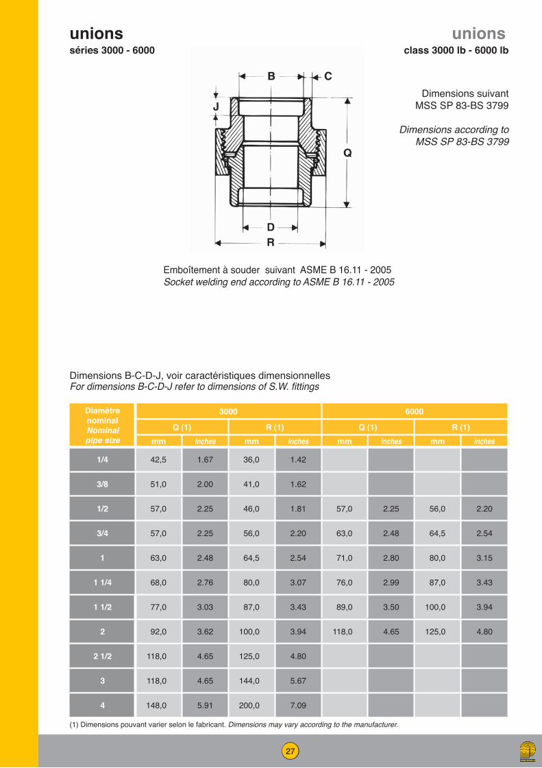
unionsséries 3000 - 6000
unionsclass 3000 lb - 6000 lb
Diamètre nominalNominal pipe size
3000 6000
Q (1) R (1) Q (1) R (1)mm inches mm inches mm inches mm inches
1/4 42,5 1.67 36,0 1.42
3/8 51,0 2.00 41,0 1.62
1/2 57,0 2.25 46,0 1.81 57,0 2.25 56,0 2.20
3/4 57,0 2.25 56,0 2.20 63,0 2.48 64,5 2.54
1 63,0 2.48 64,5 2.54 71,0 2.80 80,0 3.15
1 1/4 68,0 2.76 80,0 3.07 76,0 2.99 87,0 3.43
1 1/2 77,0 3.03 87,0 3.43 89,0 3.50 100,0 3.94
2 92,0 3.62 100,0 3.94 118,0 4.65 125,0 4.80
2 1/2 118,0 4.65 125,0 4.80
3 118,0 4.65 144,0 5.67
4 148,0 5.91 200,0 7.09
Dimensions suivant MSS SP 83-BS 3799
Dimensions according to MSS SP 83-BS 3799
(1) Dimensions pouvant varier selon le fabricant. Dimensions may vary according to the manufacturer.
Emboîtement à souder suivant ASME B 16.11 - 2005Socket welding end according to ASME B 16.11 - 2005
Dimensions B-C-D-J, voir caractéristiques dimensionnellesFor dimensions B-C-D-J refer to dimensions of S.W. fittings
28
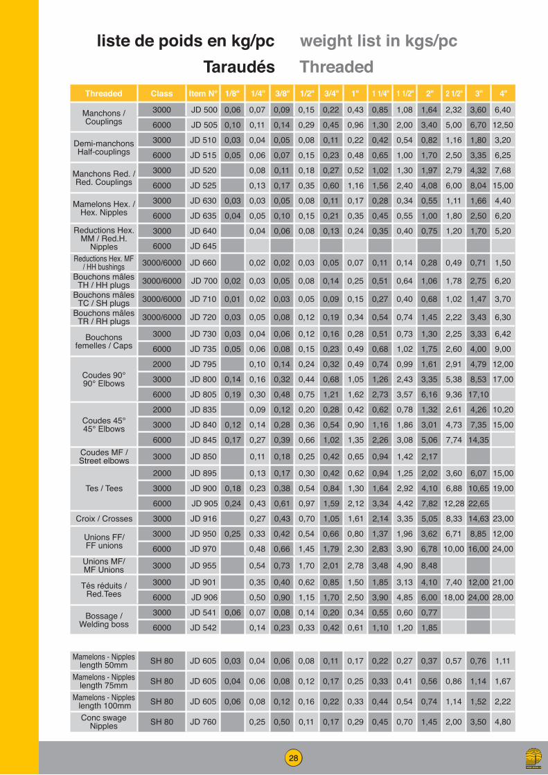
28
Threaded Class Item N° 1/8" 1/4" 3/8" 1/2" 3/4" 1" 1 1/4" 1 1/2" 2" 2 1/2" 3" 4"
Manchons / Couplings
3000 JD 500 0,06 0,07 0,09 0,15 0,22 0,43 0,85 1,08 1,64 2,32 3,60 6,40
6000 JD 505 0,10 0,11 0,14 0,29 0,45 0,96 1,30 2,00 3,40 5,00 6,70 12,50
Demi-manchonsHalf-couplings
3000 JD 510 0,03 0,04 0,05 0,08 0,11 0,22 0,42 0,54 0,82 1,16 1,80 3,20
6000 JD 515 0,05 0,06 0,07 0,15 0,23 0,48 0,65 1,00 1,70 2,50 3,35 6,25
Manchons Red. / Red. Couplings
3000 JD 520 0,08 0,11 0,18 0,27 0,52 1,02 1,30 1,97 2,79 4,32 7,68
6000 JD 525 0,13 0,17 0,35 0,60 1,16 1,56 2,40 4,08 6,00 8,04 15,00
Mamelons Hex. / Hex. Nipples
3000 JD 630 0,03 0,03 0,05 0,08 0,11 0,17 0,28 0,34 0,55 1,11 1,66 4,40
6000 JD 635 0,04 0,05 0,10 0,15 0,21 0,35 0,45 0,55 1,00 1,80 2,50 6,20Reductions Hex.
MM / Red.H. Nipples
3000 JD 640 0,04 0,06 0,08 0,13 0,24 0,35 0,40 0,75 1,20 1,70 5,20
6000 JD 645Reductions Hex. MF
/ HH bushings 3000/6000 JD 660 0,02 0,02 0,03 0,05 0,07 0,11 0,14 0,28 0,49 0,71 1,50Bouchons mâles
TH / HH plugs 3000/6000 JD 700 0,02 0,03 0,05 0,08 0,14 0,25 0,51 0,64 1,06 1,78 2,75 6,20Bouchons mâles
TC / SH plugs 3000/6000 JD 710 0,01 0,02 0,03 0,05 0,09 0,15 0,27 0,40 0,68 1,02 1,47 3,70Bouchons mâles
TR / RH plugs 3000/6000 JD 720 0,03 0,05 0,08 0,12 0,19 0,34 0,54 0,74 1,45 2,22 3,43 6,30
Bouchons femelles / Caps
3000 JD 730 0,03 0,04 0,06 0,12 0,16 0,28 0,51 0,73 1,30 2,25 3,33 6,42
6000 JD 735 0,05 0,06 0,08 0,15 0,23 0,49 0,68 1,02 1,75 2,60 4,00 9,00
Coudes 90° 90° Elbows
2000 JD 795 0,10 0,14 0,24 0,32 0,49 0,74 0,99 1,61 2,91 4,79 12,00
3000 JD 800 0,14 0,16 0,32 0,44 0,68 1,05 1,26 2,43 3,35 5,38 8,53 17,00
6000 JD 805 0,19 0,30 0,48 0,75 1,21 1,62 2,73 3,57 6,16 9,36 17,10
Coudes 45° 45° Elbows
2000 JD 835 0,09 0,12 0,20 0,28 0,42 0,62 0,78 1,32 2,61 4,26 10,20
3000 JD 840 0,12 0,14 0,28 0,36 0,54 0,90 1,16 1,86 3,01 4,73 7,35 15,00
6000 JD 845 0,17 0,27 0,39 0,66 1,02 1,35 2,26 3,08 5,06 7,74 14,35Coudes MF / Street elbows 3000 JD 850 0,11 0,18 0,25 0,42 0,65 0,94 1,42 2,17
Tes / Tees
2000 JD 895 0,13 0,17 0,30 0,42 0,62 0,94 1,25 2,02 3,60 6,07 15,00
3000 JD 900 0,18 0,23 0,38 0,54 0,84 1,30 1,64 2,92 4,10 6,88 10,65 19,00
6000 JD 905 0,24 0,43 0,61 0,97 1,59 2,12 3,34 4,42 7,82 12,28 22,65
Croix / Crosses 3000 JD 916 0,27 0,43 0,70 1,05 1,61 2,14 3,35 5,05 8,33 14,63 23,00
Unions FF/ FF unions
3000 JD 950 0,25 0,33 0,42 0,54 0,66 0,80 1,37 1,96 3,62 6,71 8,85 12,00
6000 JD 970 0,48 0,66 1,45 1,79 2,30 2,83 3,90 6,78 10,00 16,00 24,00Unions MF/ MF Unions 3000 JD 955 0,54 0,73 1,70 2,01 2,78 3,48 4,90 8,48
Tés réduits / Red.Tees
3000 JD 901 0,35 0,40 0,62 0,85 1,50 1,85 3,13 4,10 7,40 12,00 21,00
6000 JD 906 0,50 0,90 1,15 1,70 2,50 3,90 4,85 6,00 18,00 24,00 28,00
Bossage / Welding boss
3000 JD 541 0,06 0,07 0,08 0,14 0,20 0,34 0,55 0,60 0,77
6000 JD 542 0,14 0,23 0,33 0,42 0,61 1,10 1,20 1,85
Mamelons - Nippleslength 50mm SH 80 JD 605 0,03 0,04 0,06 0,08 0,11 0,17 0,22 0,27 0,37 0,57 0,76 1,11
Mamelons - Nippleslength 75mm SH 80 JD 605 0,04 0,06 0,08 0,12 0,17 0,25 0,33 0,41 0,56 0,86 1,14 1,67
Mamelons - Nipples length 100mm SH 80 JD 605 0,06 0,08 0,12 0,16 0,22 0,33 0,44 0,54 0,74 1,14 1,52 2,22
Conc swage Nipples SH 80 JD 760 0,25 0,50 0,11 0,17 0,29 0,45 0,70 1,45 2,00 3,50 4,80
weight list in kgs/pcliste de poids en kg/pcTaraudés Threaded

29
Socket-weld Class Item N° 1/8" 1/4" 3/8" 1/2" 3/4" 1" 1 1/4" 1 1/2" 2" 2 1/2" 3" 4"
Manchons / Couplings
3000 JD 550 0,06 0,07 0,09 0,14 0,20 0,34 0,49 0,66 1,04 1,70 2,15 3,61
6000 JD 555 0,11 0,21 0,29 0,40 0,72 0,95 1,35 2,24 3,13 4,20 7,50
Demi-manchons Half-couplings
3000 JD 560 0,06 0,07 0,10 0,16 0,23 0,38 0,63 0,80 1,24 1,90 2,45 4,16
6000 JD 565 0,14 0,23 0,35 0,45 0,80 1,08 1,52 2,55 3,61 5,00 8,50
Manchons red. / Red. Couplings
3000 JD 570 0,08 0,11 0,17 0,27 0,40 0,60 0,80 1,25 2,04 2,58 4,33
6000 JD 575 0,10 0,24 0,35 0,48 0,86 1,14 1,62 2,69 3,76 5,04 9,00
Bouchons femelles / Caps
3000 JD 750 0,03 0,06 0,08 0,12 0,16 0,25 0,43 0,55 0,93 1,43 2,31 4,20
6000 JD 755 0,09 0,16 0,19 0,28 0,59 0,77 1,09 1,55 2,57 3,53 6,30
Coudes 90° 90° Elbows
3000 JD 820 0,10 0,10 0,13 0,24 0,34 0,51 0,77 1,03 1,59 2,79 4,80 14,50
6000 JD 825 0,18 0,31 0,46 0,73 1,13 1,50 2,59 3,47 6,21 9,52 15,50
Coudes 45° 45° Elbows
3000 JD 860 0,09 0,09 0,11 0,20 0,28 0,44 0,65 0,84 1,30 2,50 4,15 12,50
6000 JD 865 0,15 0,29 0,40 0,65 0,96 1,30 2,20 3,01 5,20 7,50 13,25
Tes / Tees3000 JD 920 0,15 0,16 0,17 0,32 0,45 0,70 0,99 1,29 2,10 3,72 6,25 18,50
6000 JD 925 0,23 0,48 0,62 0,99 1,51 2,03 3,42 4,50 7,82 12,50 20,00
Croix / Crosses 3000 JD 940 0,18 0,19 0,27 0,39 0,56 0,84 1,23 1,66 2,64 5,10 8,05 23,00
6000 JD 941 0,55 0,77 1,28 1,96 2,60 4,50 5,95 10,50 15,50 25,00
Inserts 3000 JD 675 0,02 0,04 0,06 0,10 0,18 0,30 0,40 0,60
6000 JD 680 0,10 0,25 0,35 0,44 0,70 1,00
Unions3000 JD 990 0,27 0,30 0,39 0,52 0,70 1,10 1,36 1,94 2,87 6,60 8,20 13,00
6000 JD 995 1,43 1,87 2,24 2,87 4,10 7,15
Tés réduits / Red. Tees
3000 JD 930 0,15 0,25 0,36 0,50 0,70 1,10 1,50 2,20 7,80 9,00 13,00
6000 JD 931 0,70 0,90 1,15 1,60 2,10 3,40 4,50 9,00 15,00 18,00
Bossage / Welding boss
3000 JD 581 0,07 0,08 0,17 0,22 0,37 0,53 0,68 0,82
6000 JD 582 0,14 0,23 0,30 0,52 0,92 1,10 1,30 2,00
weight list in kgs/pcliste de poids en kg/pcSocket-weld

30
Généralités Matériel obtenu par forgeage Matériaux couramment utilisés :• ASTM A 105 - A 350 - A 182 - A694. Ces raccords, n'étant pas normalisés, sont conçus suivant les recommandations du code ASME B 31.3.
Descriptif Ce type de raccord est posé droit ou incliné sur le collecteur principal ; la face d'appui du raccord épouse la forme de ce collecteur, d'où la nécessité de connaître le diamètre extérieur de celui-ci. Possibilité NPS 3/8" à 60". La liaison collecteur/raccord se fait par une soudure d'angle. La liaison raccord/tube de dérivation peut se faire de plusieurs manières. Les rayons de raccordement des raccords de dérivation ont été unifiés pour permettre l'utilisation, en général jusqu'au diamètre de sortie 4", d'un même raccord sur différents collecteurs, avec un espace maximum de 0,8 mm (1/32") entre le sommet du collecteur et la base du raccord. Pour les diamètres de sortie supérieurs à 4", le rayon de raccordement est en général spécifique à chaque diamètre de collecteur. Chaque raccord est marqué et identifié par la dimension nominale (diamètre de sortie) et par la gamme de collecteurs sur lesquels il peut être soudé.
General Material manufactured by forging Materials frequently used :• ASTM A 105 - A 350 - A 182 A694.. These fittings are not standardised and are manufactured in accordance with the recommendations of the ASME B 31.3. code
Description This type of fittings is installed either straight or at an angle to the main pipe. As the bearing surface fits the shape of the pipe exactly, the outside diameter of the pipe must be known. Range : NPS 3/8" to 60". The main pipe and the fittings are connected by means of a fillet weld. The fitting and the branch pipe can be connected in several different ways Outlet radius of branch fittings have been unified in order to allow, generally speaking up to size 4", the use of same fitting on different run pipe sizes, with a maximum gap of 1/32" (0,8 mm) between the top of the run pipe and the base of the fitting. For outlet sizes over 4", usually a specific radius is required for each run size. Each fitting is marked with its nominal size (outlet diameter) and the range of run sizes on which it can be welded.
Raccords de dérivation renforcés
Reinforced branch fittings
Diamètre sortie / Outlet size1/8” 1/4” 3/8” 1/2” 3/4” 1” 1” 1/4 1” 1/2 2” 2”1/2 3” 4” 6”
3/8” 3/8” 1/2” 1/2” 3/4” 1” 1”1/4 1”1/2 2” 2”1/2 3” 4” 6”
1/2” 1/2” 1” - 3/4” 3/4” 1” 1”1/4 1”1/2 2” 2”1/2 3” 3”1/2 5” 8”
1” - 3/4” 1” - 3/4” 2”1/2 - 1”1/4 1” 1”1/2 - 1”1/4 1”1/2 2” 2”1/2 3” 3”1/2 4” 6” 10”
2”1/2 - 1”1/4 2”1/2 - 1”1/4 36” - 3” 1”1/2 - 1”1/4 2”1/2 - 2” 2” 2”1/2 3” 4” 4” 5” 8” 14” - 12”
36” - 3” 36” - 3” 2”1/2 - 2” 5” - 3” 2”1/2 3”1/2 - 3” 4” - 3”1/2 5” 5” 6” 10” 16”
8” - 3” 12” - 6” 3”1/2 - 3” 5” - 4” 6” - 5” 6” 6” 8” 14” - 12” 18”
36” - 10” 36” - 14” 5” - 4” 8”-6” 12” - 8” 10” - 8” 8” 10” 20” - 16” 22” - 20”
10” - 6” 18”-10” 24 ”- 14” 18” - 12” 12” - 10” 14” - 12” 36” - 24” 28” - 24”
36” - 12” 36” - 20” 36” - 26” 36” - 20” 18” - 14” 20” - 16” 36” - 30”
36” - 20” 36” - 24”
Dim
ensi
ons
colle
cteu
rs -
Run
size
s
Diamètre sortie / Outlet size1/2” 3/4” 1” 1” 1/4 1” 1/2 2”1/2” 1” - 3/4” 1” 1”1/2 - 1”1/4 1”1/2 2”
1”1/4 - 3/4” 2” - 1”1/4 2” - 1”1/4 2”1/2 - 2” 2”1/2 - 2” 2”1/236” - 1”1/2 6” - 2”1/2 10” - 3” 10” - 3” 3”1/2 - 3” 3”1/2 - 3”
36” - 8” 36” - 12” 36” - 12” 8” - 4” 5” - 4”20” - 10” 8” - 6”36” 24” 18” - 10”
36” - 20”
Dim
ensi
ons
colle
cteu
rs
Run
size
s
Standard - XS
SCH 160 - XXS

31
weld-outlets STD
weld-outletsSTD
Dim. Nom.Nom. size dimension
Pièces réduites/reducing size Pièces égales/full size
A B(1) Poids weight C Poids
weight
mm pouces inches mm pouces
inches kg mm pouces inches kg
1/8" 16,00 5/8" 16,00 5/8" 0,04
1/4" 16,00 5/8" 16,00 5/8" 0.04
3/8" 19,00 3/4" 19,00 3/4" 0,07
1/2" 19,00 3/4" 24,00 15/16" 0,08 16,00 5/8" 0,07
3/4" 22,00 7/8" 30,00 1"3/16 0,12 20,50 13/16" 0,12
1" 27,00 1”1/16 36,50 1"7/16 0,22 26,00 1"1/32 0,18
1"1/4 32,00 1"1/4 44,50 1"3/4 0,36 35,00 1"3/8 0,32
1"1/2 33,50 1"5/16 51,00 2" 0,45 41,00 1"5/8 0,36
2" 38,00 1"1/2 65,00 2"9/16 0,80 52,50 2"1/16 0,70
2" 1/2 41,50 1"5/8 76,00 3" 1,15 62,00 2"7/16 1,10
3" 44,50 1"3/4 93,50 3"11/16 1,80 78,00 3 "1/16 1,70
3"1/2 47,50 1"7/8 101,50 4" 2,50 90,50 3"9/16 2,25
4" 51,00 2" 120,50 4"3/4 2,90 101,50 4 3,05
5" 57,00 2"1/4 141,00 5"9/l6 4,60 128,50 5 "1/16 4,85
6" 60,50 2"3/8 170,00 6" 11/16 7,00 154,00 6"1/16 7,50
8" 70,00 2 "3/4 220,50 8" 11/16 12,00 201,50 7"15/16 12,70
10" 78,00 3"1/16 274,50 10"13/16 19,50 254,00 10 20,00
12" 85,50 3"3/8 325,50 12"13/16 26,70 304,50 12 29,40
14" 89,00 3"1/2 357,00 14"1/16 29,90 336,50 13"1/4 31,80
16" 93,50 3"11/16 408,00 16"1/16 34,00 387,50 15"1/4 41,70
18" 101,50 4" 459,00 18" 1/16 44,00 438,00 17"1/4 56,70
20" 114,50 4" 1/2 510,00 20"1/16 53,50 489,00 19"1/4 79.30
24" 124,00 4"7/8 611,00 24"1/16 99,70 590,50 23 "1/4 127,00
(1) Même dimension pour pièces réduites ou égales / Same dimension for reducing and full sizesJusqu’au 10”, les dimensions sont identiques pour olets SCHED STD & 40. A partir de 12” : sur demande Up to and including 10”, dimensions are the same for SCHED STD & 40 outlets. For 12” and over : on request
Pièces réduitesreducing size
Chanfreiné suivant ASME B16.25Bevelled according to ASME B16.25
Dimensions suivant / according to MSS - SP 97
Pièces égalesfull size
32
weld-outletsSCH XS
weld-outletsSCH XS
Dim. Nom.Nom. size dimension
Pièces réduites/reducing size Pièces égales/full size
A B(1) Poids weight C Poids
weight
mm pouces inches mm pouces
inches kg mm pouces inches kg
1/8" 16,00 5/8" 16,00 5/8" 0,04
1/4" 16,00 5/8" 16,00 5/8" 0,04
3/8" 19,00 3/4" 19,00 3/4" 0,07
1/2" 19,00 3/4" 24,00 15/16" 0,09 14,00 9/16" 0,07
3/4" 22,00 7/8" 30,00 1"3/16 0,14 19,00 3/4" 0,12
1" 27,00 1"1/16 36,50 1"7/16 0,21 24,00 15/16" 0,18
1"1/4 32,00 1"1/4 44,50 1"3/4 0,40 32,00 1"1/4 0,32
1"1/2 33,50 1"5/16 51,00 2" 0,50 38,00 1"1/2 0,40
2" 38,00 1"1/2 65,00 2"9/16 0,79 49,00 1"15/16 0,72
2" 1/2 41,50 1"5/8 76,00 3" 1,18 59,00 2"5/16 1,13
3" 44,50 1"3/4 93,50 3"11/16 1,85 73,50 2 "7/8 1,85
3"1/2 47,50 1"7/8 101,50 4" 2,54 85,00 3"5/16 2,30
4" 51,00 2" 120,50 4"3/4 2,90 97,00 3"13/16 3,40
5" 57,00 2 "1/4 141,00 5"9/16 4,70 122,00 4"13/16 5,00
6" 78,00 3 "1/16 170,00 6"11/16 10,40 146,00 5"3/4 10,40
8" 87,50 3"7/16 220,50 8"11/16 20,40 193,50 7"5/8 21,00
10" 93,50 3"11/16 265,00 10"7/16 24,80 247,50 9"3/4 25,40
12" 100,00 3 "15/16 316,00 12"7/16 35,00 298,50 11"3/4 35,00
14" 105,00 4" 1/8 351,00 13"13/16 37,70 330,00 13" 39,00
16" 113,00 4"7/16 402,00 15"13/16 46,20 381,00 15" 52,00
18" 119,00 4"11/16 452,00 17" 13/16 58,90 432,00 17" 59,00
20" 12,00 5" 503,00 19"13/16 71,50 482,50 19" 84,70
24" 140,00 5"1/2 605,00 23"13/16 141,00 584,00 23" 146,00
(1) Même dimension pour pièces réduites ou égales / Same dimension for reducing and full sizesJusqu’au 8”, les dimensions sont identiques pour olets SCHED STD & 40. A partir de 10” : sur demande Up to and including 8”, dimensions are the same for SCHED STD & 40 outlets. For 10” and over : on request
Pièces réduitesreducing size
Chanfreiné suivant ASME B16.25Bevelled according to ASME B16.25
Dimensions suivant / according to MSS - SP 97
Pièces égalesfull size

33
weld-outletsSCH 160 - XXS
weld-outlets SCH 160 - XXS
Dim. Nom.Nom. size dimension
Pièces réduites/reducing size Pièces égales/full size
A B(1) Poids weight C Poids
weight
mm pouces inches mm pouces
inches kg mm pouces inches kg
1/8” 28,00 1"1/8 14,00 9/16" 0,15 11,50 7/16" 0,15
3/4” 32,00 1"1/4 19,00 3/4" 0,32 15,50 5/8" 0,32
1” 38,00 1"1/2 25,50 1" 0,38 21,00 13/16" 0,38
1”1/4 44,00 1"3/4 33,50 1"5/16 0,55 29,50 1"3/16 0,60
1”1/2 51,00 2" 38,00 1"1/2 0,80 34,00 1"5/16 0,85
2” 55,00 2"3/16 43,00 1"11/16 0,97 43,00 1"11/16 1,00
2”1/2 62,00 2"7/16 54,00 2"1/8 1,55 54,00 2"1/8 1,70
3” 73,00 2"7/8 73,00 2"7/8 2,85 66,50 2"5/8 2,95
4” 84,00 3"5/16 98,50 3 "7/8 4,75 87,00 3"7/16 4,95
5” 94,00 3"11/16 122,00 4"13/16 6,50 109,50 4"5/16 6,80
6” 105,00 4”1/8 146,00 5"3/4 12,70 132,00 5"3/16 13,70
autres dimensions disponibles sur demandeother dimensions available on request
Les dimensions d’olets listés sont disponibles pour les diamètres de collecteurs en Sch.160 et XXS. A partir de 8”, il convient de toujours préciser l’épaisseurOutlets sizes listed in the chart are suitable for Sch.160 and XXS. For 8” outlet and over, always specify run pipe thickness
Dimensions pour collecteurs Sch 160 / Suitable for Sch 160 run pipe
Pièces réduitesreducing size
Chanfreiné suivant ASME B16.25Bevelled according to ASME B16.25
Dimensions suivant / according to MSS - SP 97
Pièces égalesfull size

34
Diamètre sortie / Outlet size1/8” 1/4” 3/8” 1/2” 3/4” 1” 1” 1/4 1” 1/2 2” 2”1/2 3” 4”3/8" 3/8" 1/2" 1/2" 3/4" 1" 1"1/4 1"1/2 2" 2" 1/2 3" 4"
1/2" 1/2" 1"-3/4" 3/4" 1" 1"1/4 1"1/2 2" 2" 1/2 3" 3" 1/2 5"
1" - 3/4" 1" - 3/4" 2"1/2 - 1"1/4 1" 1"1/2-1"1/4 1"1/2 2" 2" 1/2 3" 3" 1/2 4" 6"
2"1/2 - 1"1/4 2"1/2 - 1"1/4 36" - 3" 1"1/2 - 1"1/4 2"1/2 - 2" 2" 2" 1/2 3" 4" 4" 5" 8"
36" - 3" 36" - 3" 2"1/2 - 2" 5" - 3" 2"1/2 3"1/2 - 3" 4" - 3"1/2 5" 5" 6" 10"
8" - 3" 12" - 6" 3"1/2 - 3" 5" - 4" 6" - 5" 6" 6" 8" 14" - 12"
36" - 10" 36" - 14" 5" - 4" 8" - 6" 12" - 8" 10"-8" 8" 10" 20" - 16"
10" - 6" 18" - 10" 24" - 14" 18" - 12" 12" - 10" 14" - 12" 36" - 24"
36" - 12" 36" - 20" 36" - 26" 36" - 20" 18" - 14" 20" - 16"
36" - 20" 36" - 24"
Diamètre sortie / Outlet size1/2” 3/4” 1” 1”1/4 1”1/2 2”
1" - 3/4" 1" 1"1/2 - 1"1/4 1"1/2 2" 2"1/22" - 1"1/4 2"1/2 - 1"1/4 2"1/2 - 2" 2"1/2 - 2" 2"1/2 3"6" - 2"1/2 10" - 3" 10" - 3" 3"1/2 - 3" 3" 1/2 - 3" 4"
36"/8" 36" - 12" 36"12" 8" - 4" 5" - 4" 5"20" - 10" 8"-6" 6"36" - 24" 18" - 10" 10" - 8"
36" - 20" 20" - 12"36" - 24"
Dim
ensi
ons
colle
cteu
rs -
Run
size
sDi
men
sion
s co
llect
eurs
- Ru
n si
zes
The fitting is threaded NPT according to ASME B 1.20.1 (BSP THREAD on request)Range : Class 3000 : 1/8” to 4”
Class 6000 : 1/2” to 2”
sock-outlets raccords emboîtés Soudés
socket welding fittings
thread-outlets raccords taraudésthreaded fittings
Le raccord comporte une chambre «Socket welding» emboîtement conforme à ASME B 16.11Gamme : Classe 3000 : 1/8” à 4”
Classe 6000 : 1/2” à 2”
The fitting incorporates a socket end, whose dimensions comply with ASME B 16.11Range : Class 3000 : 1/8” to 4”
Class 6000 :1/2” to 2”
Le raccord comporte un taraudage NPT suivant ASME B 1.20.1 (BSP sur demande)Gamme : Classe 3000 : 1/8” à 4”
Classe 6000 : 1/2” à 2”
Class 3000
Class 6000

35
Dim. Nom.Nom. size dimension
Pièces réduites/reducing size Pièces égales/full size
A B Poids weight C (1) Poids
weight
mm pouces inches mm pouces
inches kg mm pouces inches kg
1/8 19,0 3/4" 16,0 5/8" 0,061/4 19,0 3/4" 16,0 5/8" 0,063/8 20,5 13/16" 19,0 3/4" 0,091/2 25,5 1" 24,0 15/16" 0,11 14,0 9/16" 0,123/4 27,0 1"1/16 30,0 1"3/16 0,17 19,0 3/4" 0,191 33,5 1"5/16 36,5 1"7/16 0,29 24,0 15/16" 0,31
1 1/4 33,5 1"5/16 44,5 1"3/4 0,41 32,0 1"1/4 0,451 1/2 35,0 1"3/8 51,0 2" 0,46 38,0 1"1/2 0,50
2 38,0 1"1/2 65,0 2"9/16 0,80 49,0 1"15/16 0,872 1/2 46,0 1"13/16 76,0 3" 1,40 59,0 2"5/16 1,50
3 51,0 2" 93,5 3"11/16 2,00 73,5 2"7/8 2,153 1/2 54,0 2"1/8 101,5 4" 2,60 85,0 3"5/16 2,80
4 57,0 2 "1/4 120,5 4"3/4 3,30 97,0 3"13/16 3,50
Dim. Nom.Nom. size dimension
Pièces réduites/reducing size
A B Poids weight
mm pouces inches mm pouces
inches kg
1/4 28,5 1"1/8 14,0 9/16" 0,203/8 28,5 1"1/8 14,0 9/16" 0,201/2 31,5 1"1/4 19,0 3/4" 0,303/4 36,5 1"7/16 25.5 1" 0,501 39,5 1"9/16 33,5 1"5/16 0,90
1 1/4 39,5 1"9/16 38,0 1"1/2 0,851 1/2 43,0 1"11/16 49,0 1"15/16 1,45
2 52,5 2 "1/6 59,0 2"5/16 2,75
Dim. Nom.Nom. size dimension
Pièces réduites/reducing size
A B Poids weight
mm pouces inches mm pouces
inches kg
1/2” 31,5 1"1/4 19,0 3/4" 0,323/4” 36,5 17/16" 25,5 1" 0,551” 39,5 19/16" 33,5 1"5/16 0,95
1”1/2 43,0 1"11/16 49,0 l"l5/16 1,502” 52,5 2"1/16 59,0 2"5/16 2,90
sock-outlets
Pièces réduitesreducing size
Pièces égalesfull size
(1) Raccordement pour tube STD & XS / Suitable for STD & XS run pipe WT
Raccordement pour tube SCH 160 / Suitable for 160 run pipe WT
Raccordement pour tube XXS / Suitable for XXS run pipe WT
Class 3000
Class 6000
Class 9000

36
Dim. Nom.Nom. size
Pièces réduites/reducing size Pièces égales/full size
A(1) B(2) Poids weight C (3) Poids
weight
mm pouces inches mm pouces
inches kg mm pouces inches kg
1/8” 19,0 3/4" 16,0 5/8" 0,061/4 19,0 3/4" 16,0 5/8" 0,063/8” 21,0 13/16" 19,0 3/4" 0,091/2” 25,0 1" 24,0 15/16" 0,11 14,0 9/16" 0,123/4” 27,0 1"1/16 30,0 1"3/16 0,17 19,0 3/4" 0,191” 33,0 1"5/16 36,5 1"7/16 0,29 24,0 15/16" 0,31
1” 1/4 33,0 1"5/16 44,5 1"3/4 0,41 32,0 1"1/4 0,451” 1/2 35,0 1"3/8 51,0 2" 0,46 38,0 1"1/2 0,50
2” 38,0 1"1/2 65,0 2"9/16 0,80 49,0 1"15/16 0,872”1/2 46,0 1"13/16 76,0 3" 1,74 59,0 2"5/16 1,50
3” 51,0 2" 93,5 3"11/16 2,00 73,5 2"7/8 2,154” 57,0 2"1/4 120,5 4"3/4 3,35 97,0 3"13/16 3.60
Dim. Nom.Nom. size
Pièces réduites/reducing size
A(1) B Poids weight
mm pouces inches mm pouces
inches kg
1/2” 32,0 1"1/4 19,0 3/4" 0,303/4” 37,0 1"7/16 25,5 1" 0,501” 40,0 1"9/16 33,5 1"5/16 0,90
1”1/4 41,0 1"5/8 38,0 1"1/2 0,851”1/2 43,0 1"11/16 49,0 1"15/16 1,45
2” 52,0 2"1/16 59,0 2"5/16 2,75
Class 3000
Class 6000
(1) Dimensions non reprises dans MSS SP97 / Dimensions not listed in MSS SP 97(2) Même dimension pour pièces égales et pièces réduites / Same dimension for full and reducing sizes(3) Dimensions appropriées pour collecteurs épaisseurs STD et XS / Suitable for STD and XS run pipe sizes
raccords taraudés
thread outlets threaded fittings
Pièces réduitesreducing size
Pièces égalesfull size

37
Dim. Nom.Nom. size dimension
B Poids weight
kgmm pouces inches
1/4” 16,0 5/8" 0,203/8” 19,0 3/4" 0,231/2” 24,0 15/16" 0,253/4” 30,0 1"3/16 0,401” 36,5 1"7/16 0,65
1”1/4 44,5 1"3/4 0,751”1/2 50,8 2" 0,95
2” 65,0 2"9/16 1,45
Dim. Nom.Nom. size dimension
B Poids weight
kgmm pouces inches
1/4”3/8”1/2” 14,0 9/16" 0,253/4” 19,0 3/4" 0,501” 25,5 1" 0,70
1”1/4 33,5 1"5/16 0,881”1/2 38,0 1"1/2 1,15
2” 43,0 1"11/16 1,50
Class 3000 - Standard - XS
Class 3000
Class 6000
Class 6000 - sch 160 - XXS
L'extrêmité du raccord pourra être :• Soit lisse,• Soit chanfreinée, suivant ASME B 16.25• Soit filetée NPT, suivant ASME B 1.20.1(BSP sur demande)
Gamme :- Classe 3000, Sch 80 :1/2" à 2"- Classe 6000, Sch 160 :1/2" à 2"
The end of the fitting can be :• Plain• Bevelled according to ASME B 16.25• Threaded NPT, according to ASME B 1.20.1 (BSP THREADS on request)
Range :- Class 3000, Sch 80 : 1/2» to 2»- Class 6000, Sch 160 : 1/2» to 2»
nip-outlets raccords allongés extended fittings
Diamètre sortie / Outlet size1/2” 3/4” 1” 1”1/2 2”
Dimensions collecteurs Run sizes
6"-1"1/2 3"-1"1/2 1-1/2 2" 3"36"-8" 2"1/2-2" 3"1/2-3" 4"-3"1/2
5"-3" 5"-4" 6"-5"36"-6" 12"-6" 12"-8"
36"-14" 36"-14"
Diamètre sortie / Outlet size1/2” 3/4” 1” 1”1/2 2”
Dimensions collecteurs Run sizes
36"-1"1/2 36"-1"1/2 4"-1"1/2 4"-2" 4"-3"36"-6" 36"-6" 8"-5"
36"-10"
• La longueur "L" reste identique quelque soit la dimension / Same lenght for all sizes• Classe 3000 correspond au Sch 80 et classe 6000 correspond au Sch 160 / Class 3000 corresponds to Sch 80 and class 6000 corresponds to Sch 160• XXS sur demande / XXS on request

38
dim
ensi
ons
du tu
be s
elon
A
NSI
B36
.10
pipe
dim
ensi
ons
as p
er a
nsi B
36.1
0D
IAM
.N
OM
NO
M.
PIPE
SI
ZE
DIA
M. E
XT.
O
UTS
IDE
DIA
M.
SCH
. 5SC
H. 1
0SC
H. 2
0SC
H. 3
0SC
H. S
TDSC
H. 4
0SC
H. 6
0SC
H. X
SSC
H. 8
0SC
H. 1
00SC
H. 1
20SC
H. 1
40SC
H. 1
60SC
H. X
XS
mm
inch
mm
inch
mm
inch
mm
inch
mm
inch
mm
inch
mm
inch
mm
inch
mm
inch
mm
inch
mm
inch
mm
inch
mm
inch
mm
inch
mm
inch
1/8”
10,3
0,40
5-
--
--
--
-1,
730,
068
IDEM SCH STD
SAME AS SCH STD
--
2,41
0,08
5
IDEM SCH XS
SAME AS SCH XS
--
--
--
--
--
1/4”
13,7
0,54
0-
--
--
--
-2,
240,
088
--
3,02
0,11
9-
--
--
--
--
-
3/8”
17,1
0,67
5-
--
--
--
-2,
310,
091
--
3,20
0,12
6-
--
--
--
--
-
1/2”
21,3
0,84
01,
650,
065
2,11
0,08
3-
--
-2,
770,
109
--
3,73
0,14
7-
--
--
-4,
750,
187
7,47
0,29
4
3/4”
26,7
1,05
01,
650,
065
2,11
0,08
3-
--
-2,
870,
113
--
3,91
0,15
4-
--
--
-5,
540,
218
7,82
0,30
8
1”33
,41,
315
1,65
0,06
52,
770,
109
--
--
3,38
0,13
3-
-4,
550,
179
--
--
--
6,35
0,25
09,
090,
358
1”1/
442
,21,
660
1,65
0,06
52,
770,
109
--
--
3,56
0,14
0-
-4,
850,
191
--
--
--
6,35
0,25
09,
700,
382
1”1/
248
,31,
900
1,65
0,06
52,
770,
109
--
--
3,68
0,14
5-
-5,
080,
200
--
--
--
7,14
0,28
110
,16
0,40
0
2”60
,32,
375
1,65
0,06
52,
770,
109
--
--
3,91
0,15
4-
-5,
540,
218
--
--
--
8,71
0,34
311
,07
0,43
6
2”1/
273
,02,
875
2,11
0,08
33,
050,
120
--
--
5,16
0,20
3-
-7,
010,
276
--
--
--
9,52
0,37
514
,02
0,55
2
3”88
,93,
500
2,11
0,08
33,
050,
120
--
--
5,49
0,21
6-
-7,
620,
300
--
--
--
11,1
30,
438
15,2
40,
600
3”1/
210
1,6
4,00
02,
110,
083
3,05
0,12
0-
--
-5,
740,
226
--
8,08
0,31
8-
--
--
--
-16
,15
0,63
6
4”11
4,3
4,50
02,
110,
083
3,05
0,12
0-
--
-6,
020,
237
--
8,56
0,33
7-
-11
,13
0,43
8-
-13
,49
0,53
117
,12
0,67
4
5”14
1,3
5,56
32,
770,
109
3,40
0,13
4-
--
-6,
550,
258
--
9,52
0,37
5-
-12
,70
0,50
0-
-15
,88
0,62
519
,05
0,75
0
6”16
8,3
6,62
52,
770,
109
3,40
0,13
4-
--
-7,
110,
280
--
10,9
70,
432
--
14,2
70,
562
--
18,2
40,
718
21,9
50,
864
8”21
9,1
8,62
52,
770,
109
3,76
0,14
86,
350,
250
7,04
0,27
78,
180,
322
10,3
10,
406
12,7
00,
500
15,0
60,
593
18,2
40,
718
20,6
20,
812
23,0
10,
906
22,2
30,
875
10”
273,
010
,750
3,40
0,13
44,
190,
165
6,35
0,25
07,
800,
307
9,27
0,36
512
,70
0,50
012
,70
0,50
015
,06
0,59
318
,24
0,71
821
,41
0,84
325
,40
1,00
028
,58
1,12
5-
-
12”
323,
912
,750
4,19
0,16
54,
570,
180
6,35
0,25
08,
380,
330
9,52
0,37
510
,31
0,40
614
,27
0,56
212
,70
0,50
017
,45
0,68
721
,41
0,84
325
,40
1,00
028
,58
1,12
533
,32
1,31
2-
-
14”
355,
614
,000
--
6,35
0,25
07,
920,
312
9,52
0,37
59,
520,
375
11,1
30,
438
15,1
60,
593
12,7
00,
750
19,0
50,
750
23,8
0,93
727
,76
1,09
331
,75
1,25
035
,71
1,40
6-
-
16”
406,
416
,000
--
6,35
0,25
07,
920,
312
9,52
0,37
59,
520,
375
12,7
00,
500
16,6
60,
656
12,7
00,
500
21,4
10,
843
26,1
91,
031
30,9
41,
218
36,5
31,
438
40,4
61,
593
--
18”
457,
218
,000
--
6,35
0,25
07,
920,
312
11,1
30,
438
9,52
0,37
514
,27
0,56
219
,05
0,75
012
,70
0,50
023
,80
0,93
729
,36
1,15
634
,93
1,37
539
,67
1,56
245
,24
1,78
1-
-
20”
508,
020
,000
--
6,35
0,25
09,
520,
375
12,7
00,
500
9,52
0,37
515
,06
0,59
320
,62
0,81
212
,70
0,50
026
,19
1,03
132
,54
1,28
138
,10
1,50
044
,45
1,75
049
,99
1,96
8-
-
22”
558,
822
,000
--
6,35
0,25
09,
520,
375
12,7
00,
500
9,52
0,37
5-
-22
,22
0,87
512
,70
0,50
028
,57
1,12
534
,92
1,37
541
,27
1,52
547
,62
1,87
553
,97
2,12
5-
-
24”
609,
624
,000
--
6,35
0,25
09,
520,
375
14,2
70,
562
9,52
0,37
517
,45
0,68
724
,59
0,96
812
,70
0,50
030
,94
1,21
838
,89
1,53
146
,02
1,81
252
,37
2,06
259
,51
2,34
3-
-
26”
660,
426
,000
--
7,92
0,31
212
,70
0,50
0-
-9,
520,
375
--
--
12,7
00,
500
--
--
--
--
--
--
28”
711,
228
,000
--
7,92
0,31
212
,70
0,50
015
,87
0,62
59,
520,
375
--
--
12,7
00,
500
--
--
--
--
--
--
30”
762,
030
,000
--
7,92
0,31
212
,70
0,50
015
,87
0,62
59,
520,
375
--
--
12,7
00,
500
--
--
--
--
--
--
32”
812,
832
,000
--
7,92
0,31
212
,70
0,50
015
,87
0,62
59,
520,
375
17,4
70,
688
--
12,7
00,
500
--
--
--
--
--
--
34”
863,
634
,000
--
7,92
0,31
212
,70
0,50
015
,87
0,62
59,
520,
375
17,4
70,
688
--
12,7
00,
500
--
--
--
--
--
--
36”
914,
436
,000
--
7,92
0,31
212
,70
0,50
015
,87
0,62
59,
520,
375
19,0
50,
750
--
12,7
00,
500
--
--
--
--
--
--
6”-
--
--
--
--
-
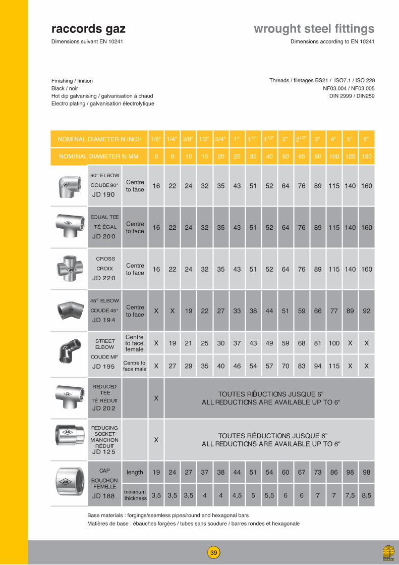
39
NOMINAL DIAMETER IN INCH 1/8“ 1/4“ 3/8“ 1/2“ 3/4“ 1“ 11/4“ 11/2“ 2“ 21/2“ 3“ 4“ 5“ 6“
NOMINAL DIAMETER IN MM 6 8 10 15 20 25 32 40 50 65 80 100 125 150
90° ELBOW
COUDE 90°
JD 190
Centre to face 16 22 24 32 35 43 51 52 64 76 89 115 140 160
EQUAL TEE
TÉ ÉGAL
JD 20 0
Centre to face 16 22 24 32 35 43 51 52 64 76 89 115 140 160
CROSS
CROIX
JD 22 0
Centre to face 16 22 24 32 35 43 51 52 64 76 89 115 140 160
45° ELBOW
COUDE 45°
JD 19 4
Centre to face X X 19 22 27 33 38 44 51 59 66 77 89 92
STREET ELBOW
COUDE MF
JD 195
Centre to face female
X 19 21 25 30 37 43 49 59 68 81 100 X X
Centre to face male X 27 29 35 40 46 54 57 70 83 94 115 X X
REDUCED TEE
TÉ RÉDUITJD 20 2
X TOUTES RÉDUCTIONS JUSQUE 6”ALL REDUCTIONS ARE AVAILABLE UP TO 6“
REDUCING SOCKET
MANCHON RÉDUIT
JD 12 5
X TOUTES RÉDUCTIONS JUSQUE 6”ALL REDUCTIONS ARE AVAILABLE UP TO 6“
CAP
BOUCHON FEMELLE
JD 188
length 19 24 27 37 38 44 51 54 60 67 73 86 98 98
minimum thickness 3,5 3,5 3,5 4 4 4,5 5 5,5 6 6 7 7 7,5 8,5
wrought steel fittingsraccords gaz
Finishing / finitionBlack / noirHot dip galvanising / galvanisation à chaudElectro plating / galvanisation électrolytique
Dimensions according to EN 10241Dimensions suivant EN 10241
NF03.004 / NF03.005DIN 2999 / DIN259
Base materials : forgings/seamless pipes/round and hexagonal barsMatières de base : ébauches forgées / tubes sans soudure / barres rondes et hexagonale
Threads / filetages BS21 / ISO7.1 / ISO 228

40
wrought steel fittingsraccords gazFinishing / finitionBlack / noirHot dip galvanising / galvanisation à chaudElectro plating / galvanisation électrolytiqueZinc flake / dachromate
Threads / filetages BS21 / ISO7.1 / ISO 228NF03.004 / NF03.005
DIN 2999 / DIN259
NOMINAL DIAMETER IN INCH 1/8“ 1/4“ 3/8“ 1/2“ 3/4“ 1“ 11/4“ 11/2“ 2“ 21/2“ 3“ 4“ 5“ 6“
NOMINAL DIAMETER IN MM 6 8 10 15 20 25 32 40 50 65 80 100 125 150
HEXAGONAL NIPPLE
MAMELON HEXAGONAL
JD 161
min length of thread 9,5 12,5 12,5 17,5 19 21 24 24 27 32 35 40 45 45
Width across flats of
hexagon12 14 17 22 27 36 46 50 65 78 90 115 140 166
Dimensions according to / suivant EN 10241
HEXAGONAL BUSHING
RÉDUCTION MÂLE-FEMELLE
JD 17 7
Overall length X 18,5 20,5 25,5 29 31 35 37 41 48 54 62 70 70
width across flats of hexagon
X 14 17 22 27 36 46 50 65 78 90 115 140 166
SQUARE HEAD PLUG
BOUCHON MÂLE TÊTE
CARRÉE
JD 18 1
minimum length of
thread6,5 9,7 10,1 13,2 14,5 16,8 19,1 19,1 23,4 26,7 29,8 35,8 40,1 40,1
size of square 6 9 11 13 14 17 22 27 32 37 37 46 51 60
minimum height of square
6 6 10 10 12 12 16 16 19 19 22 25 29 32
FLAT & CONICAL SEAT UNION overall 37 40 46 51 57 64 70 79 89 102 107 118 X X
MF Union also available / union MF disponible - ref JD 211
FLAT & CONICAL SE T UNION
RACCORD UNION JOINTS PLAT ET
CONIQUE JD 209 -
208length of nut 15 15 16 18 20 22 24 25 27 30 31 34 X X
HEXAGONAL HEAD PLUG
BOUCHON MÂLE TÊTE
HEXAGONALE
JD 18 7
minimum length of
thread9,5 12,5 12,5 17,5 19 21 24 24 27 32 35 40 X X
Size of hexagon 12 14 17 22 27 36 46 50 65 78 90 115 X X
minimum heigth of hexagon
6 6 8 8 10 10 11 13 14 16 19 22 X X
HEXAGONAL BACKNUT
ÉCROU HEXAGONAL
JD 13 2
Width across flats
17 19 24 30 36 41 50 60 70 90 100 130 160 190
length of nut 6,5 6,5 7 8 9 9,5 11 12 13 17 21 22 24 25
WELDING UNION BUTT/BUTT
RACCORD UNION BUTTWELDING
JD 230
length X
On
requ
est
On
requ
est 44 54 65 66 67 67 X X X X X
Hex. diameter X 32 41 50 55 60 60 X X X X X
OD in mm X 21,3 26,9 33,7 42,4 48,3 60,3 X X X X X
WELDING UNION BUTT/MALE
RACCORD UNION BUTTWELDING -
MÂLE FILETÉ DIN 2999
JD 229
length X
On
requ
est
On
requ
est 61 71 81 89 99 105 X X X X X
Hex. diameter X 32 41 50 60 70 85 X X X X X
OD in mm X 21,3 26,9 33,7 42,4 48,3 60,3 X X X X XBase materials : forgings/seamless pipes/round and hexagonal barsMatières de base : ébauches forgées / tubes sans soudure / barres rondes et hexagonales
HEXAGONAL HEAD PLUG
BOUCHON MÂLE TÊTE
HEXAGONALE
JD 18 7
minimum length of
thread9,5 12,5 12,5 17,5 19 21 24 24 27 32 35 40 X X
Size of hexagon 12 14 17 22 27 36 46 50 65 78 90 115 X X
minimum heigth of hexagon
6 6 8 8 10 10 11 13 14 16 19 22 X X
HEXAGONAL BACKNUT
ÉCROU HEXAGONAL
JD 13 2
Width across flats
17 19 24 30 36 41 50 60 70 90 100 130 160 190
length of nut 6,5 6,5 7 8 9 9,5 11 12 13 17 21 22 24 25
WELDING UNION BUTT/BUTT
RACCORD UNION BUTTWELDING
JD 230
length X
On
requ
est
On
requ
est 44 54 65 66 67 67 X X X X X
Hex. diameter X 32 41 50 55 60 60 X X X X X
OD in mm X 21,3 26,9 33,7 42,4 48,3 60,3 X X X X X
WELDING UNION BUTT/MALE
RACCORD UNION BUTTWELDING -
MÂLE FILETÉ DIN 2999
JD 229
length X
On
requ
est
On
requ
est 61 71 81 89 99 105 X X X X X
Hex. diameter X 32 41 50 60 70 85 X X X X X
OD in mm X 21,3 26,9 33,7 42,4 48,3 60,3 X X X X X

41
NOMINAL DIAMETER IN INCH 1/8“ 1/4“ 3/8“ 1/2“ 3/4“ 1“ 11/4“ 11/2“ 2“ 21/2“ 3“ 4“ 5“ 6“
NOMINAL DIAMETER IN MM 6 8 10 15 20 25 32 40 50 65 80 100 125 150RUNNING NIPPLE
MAMELON CYLINDRIQUEJD 153
length in mm x 19 21 27 30 33 38 38 48 51 57 70 78 78
CLOSE NIPPLE MAMELON COURT
JD 151length in
mm X 27 28 37 39 46 51 51 60 69 75 87 96 96
BARREL NIPPLE MAMELON TUBEJD 150
length in mm X 38 38 51 54 60 70 70 79 89 102 114 124 127
90° BEND COURBE 90°JD F90
centre to face X 64 73 86 102 121 146 165 203 248 292 381 540 622
45° BEND COURBE 45°JD F45
centre to face X 57 64 76 89 105 127 143 175 213 248 324 457 540
BARREL NIPPLES
BOBINE FILETÉE
JD 150
BOUT À SOUDER
HALF-NIPPLE
JD 152
Ø / mm 1/8“ 1/4“ 3/8“ 1/2“ 3/4“ 1“ 11/4“ 11/2“ 2“ 21/2“ 3“ 4“
30 ab ab ab ab ab ab40 ab ab ab ab ab ab ab ab ab50 abc abc abc abc abc abc abc abc abc60 ab ab ab ab ab ab ab ab ab ab ab80 ab ab ab ab ab ab ab ab ab ab ab ab
100 abc abc abc abc abc abc abc abc abc abc abc abc120 ab ab ab ab ab ab ab ab ab ab ab ab150 abc abc abc abc abc abc abc abc abc abc abc abc180 a a a a a a a a a a a a200 abc abc abc abc abc abc abc abc abc abc abc abc250 a a a a a a a a a a a a300 a a a a a a a a a a a a
a : B arrel nipples welded tube (black or galvanized )
b : Half nipples welded tube (black or galvanized)
c : seamless pipe standard lengths-other on request
LONGSCREWS LONGUE VIS
JD 154
NOMINAL SIZE IN MM
NOMINAL SIZE IN INCH
MIN. USEFUL LENGTH OF THE THREAD IN MM
OVERALL LENGTH IN MM
8 1/4“ 37 8010 3/8“ 40 10015 1/2“ 52 10020 3/4“ 54 12025 1“ 62 14032 1 1/4“ 70 15040 1 1/2“ 71 15050 2“ 82 17065 2 1/2“ 97 18080 3“ 106 200100 4“ 121 250125 5“ 130 on request150 6“ 132 on request
a.b.c : Any other lengths available on request
mamelons en acier & pièces tubulaires
pipe nipples and tubulars
Finishing/finitionBlack / noirHot dip galvanising / galvanisation à chaud
Threads / filetagesBS21 / ISO7.1 / ISO 228
NF03.004 / NF03.005DIN 2999/DIN259
Dimensions according to / suivant EN 10241
Base materials :medium and heavy series welded pipes / seamless pipesMatières de base : tubes soudés séries moyenne et forte / tubes sans soudure

42
NOMINAL DIAMETER IN INCH 1/8“ 1/4“ 3/8“ 1/2“ 3/4“ 1“ 11/4“ 11/2“ 2“ 21/2“ 3“ 3 1/2“ 4“ 5“ 6“
NOMINAL DIAMETER IN MM 6 8 10 15 20 25 32 40 50 65 80 90 100 125 150
SOCKETS MEDIUM TYPE
JD 10 1
EN 10241
min OD 15 18,5 21,3 26,6 31,8 39,5 48,3 54,5 66,2 82 95
on re
ques
t 121,4 146,3 173,3
length 17 25 26 34 36 43 48 48 56 65 71 83 92 92
HALF SOCKETS
MEDIUM TYPE
JD 140
EN 10241
min OD 15 18,5 21,3 26,6 31,8 39,5 48,3 54,5 68 84,2 98,4
on re
ques
t 124 149 177
length 8 11 12 15 17 20 22 22 26 30 34 40 44 44
G40 1“ ( OD 39,5 - L 20) G40 1 1/2“ (OD 54,5 - L 25) ALSO AVAILABLE
SOCKETS HEAVY TYPE
JD 10 2
EN 10241
min OD 15 18,5 22 27 32,5 39,5 49 56 68 84 98
on re
ques
t 124 151 177
length 19 27 28 37 39 46 51 51 60 69 75 87 96 96
HALF SOCKETS
HEAVY TYPE
JD 141
EN 10241
min OD 15 18,5 22 27 32,5 39,5 49 56 68 84 98
on re
ques
t 124 151 177
length 8 11 12 16 19 21 25 25 28 30 35 40 44 44
G41 3/4“ ( OD 33,3 - L 17) G41 1 1/4“ (OD 49 - L 22) G41 2“ (OD 69,5 - L 28) ALSO AVAILABLE
HEAVY COUPLING
JD 105DIN 2999
DIN 2986-1959
diameter in mm X X X X 33,1 X 49 56 69,1 81 98
on re
ques
t 123,4 151,3 176,5
length in mm X X X X 36 X 48 48 56 65 71 83 92 92
SEAMLESS COUPLING
JD 127P235 GH TC 1
DIN 2999 ST 35.8/1 DIN 17175
P235GH TC1
diameter in mm 15 18,5 21,3 26,9 33,7 42,4 51 57 70 88,9 101,6 X 132 X X
length in mm 17 25 26 34 36 43 48 48 56 65 71 X 83
on re
ques
t
on re
ques
t
SEAMLESS HALF
COUPLING JD 147DIN 2999ST 35.8/1 DIN 17175
diameter in mm 15 18,5 21,3 26,9 33,7 42,4 51 57 70 88,9 101,6 X 132
length in mm 8 11 12 15 17 20 22 22 26 30 35 X 40
EUR
OPE
AN S
TAN
DAR
DS
steel couplingsmanchons en acier Finishing/finitionBlack / noirDegreased / dégraisséHot dip galvanising / galvanisation à chaudElectro plating / galvanisation électrolytique
Dimensions according to/suivant EN 10241
Threads / filetagesBS21 / ISO7.1 / ISO 228
NF03.004 / NF03.005DIN 2999 / DIN259
Base materials : special Delcorte socket tubing / seamless pipesMatières de base : tubes à manchons suivant spécification Delcorte / tubes sans soudure

43
OD inch 1/2” 3/4” 1” 1 1/4” 1 1/2” 2” 2 1/2” 3”OD nom 15 20 25 32 40 50 65 80OD mm 21,3 26,9 33,7 42,4 48,3 60,3 76,1/73c 88,9Lengtha 80 80 80 80 80 80 80 80
Run Pipe inch 3/4” - 4” 1”-4” 1 1/4”-6” 1 1/2”-6” 2”-6” 2 1/2”-6” 3”-8” 4”-8”
Run Pipe mm 20-100 20-100 32-150 40-150 50-150 65-150 80-200 100-200
Threadsb BSP/NPT BSP/NPT BSP/NPT BSP/NPT BSP/NPT BSP/NPT BSP/NPT BSP/NPTa : autres longueurs sur demande / other lengths on requestb : concerne les bobines filetées / for threaded nipplesc : diamètre 73mm pour les tubes suivant ASME / 73mm OD for ASME pipes
Dimensions / sizes
profile tubular groved or threaded
bobines grugées rainurées ou filetées
bobine rainuréegroved and profile pipe piece
bobine filetéeprofile threaded
nipple
manchons grugés pour installations anti-feu
profile sockets for sprinkler systems
taraudages disponibles: BSP et NPT available thread types: BSP and NPT
Dimension du manchonsocket size
Sock
et siz
es / M
anch
ons
ODinch 1/2” 3/4” 1” 1 1/4” 1 1/2” 2” 2 1/2”nom 15 20 25 32 40 50 65mm 26,6 33,3 a 40 49,25 56,3 69,5 84,4
Base lengths options mm
23 23 27 35 35 45 65
34 36 43 on request sur demande
on request sur demande
on request sur demande
on request sur demande
OD inch nom other base lengths on request / autres longueurs sur demande
Run
pipe
size
/ tu
be p
orte
ur b
1” 25 15 x 25 20 x 25 on request sur demande
1 1/4” 32 15 x 32 20 x 32 25 x 32 on request sur demande
1 1/2” 40 15 x 40 20 x 40 25 x 40 32 x 40 on request sur demande
2” 50 15 x 50 20 x 50 25 x 50 32 x 50 on request sur demande
on request sur demande
2 1/2” 65 15 x 65 20 x 65 25 x 65 32 x 65 40 x 65 50 x 65 on request sur demande
3” 80 15 x 80 20 x 80 25 x 80 32 x 80 40 x 80 50 x 80 65 x 80
4” 100 on request sur demande 20 x 100 25 x 100 32 x 100 40 x 100 50 x 100 65 x 100
6” 150 on request sur demande
on request sur demande 25 x 150 32 x 150 40 x 150 50 x 150 65 x 150
a : diamètre extérieur 32 mm disponible sur demande / alternatively, OD 32mm available on requestb : tube porteur 8” et plus sur demande / run pipe sizes of 8” and above on request

PETROMETALIC
www.petrometalic.comnegoceversailles@[email protected]
Siège social32 rue de l'Ermitage78000 VERSAILLESTel : +33 1 39 23 96 70Fax : +33 1 39 23 96 71
Petrometalic CambraiRue des Ecluses de SellesBP 28759400 Cambrai CedexTél : +33 3 27 72 06 16Fax : +33 3 27 72 06 11