seismic retrofit of existing single storey steel cbf
TRANSCRIPT
3rd Specialty Conference on Disaster Prevention and Mitigation 3e Conférence spécialisée sur la prévention et la mitigation des désastres naturels
Montréal, Québec
May 29 to June 1, 2013 / 29 mai au 1 juin 2013
DIS-040-1
SEISMIC RETROFIT OF EXISTING SINGLE STOREY STEEL CBF STRUCTURES WITH A RING FUSE T. E. Morrison1, C. A. Rogers2 1Heritage Standing Inc. 2Department of Civil Engineering and Applied Mechanics, McGill University
Abstract: This paper presents a summary of the development of the line ring and cross ring brace fuses evaluated by means of laboratory tests. The ring fuses are designed to add ductility to a non-ductile brace system while controlling the seismic forces on the building. Research and testing identified brittle failure as a concern in existing steel concentrically braced frame (CBF) systems. Using a steel ring as a fuse to provide ductility to the building through providing large stable deformations to the brace system was proposed. Increasing ductility will improve energy dissipation and seismic performance. This idea evolved into physical testing and numerical modeling of braced systems with and without the ring fuse. Five progressive testing stages were implemented in conjunction with finite element modeling of the components and system, including: prototype testing of the fuse; tension only testing of brace sections; reduced scale tests of a full brace; full scale tests with a full brace, and; pin connected frame tests of the cross brace system. Seismic simulation models of the original and retrofitted buildings were calibrated to the physical tests and used to perform further analysis. The structures containing a ring fuse, both the line ring fuse and the cross ring fuse, were shown to provide superior earthquake performance when compared to the original un-retrofitted structures. This paper is limited to a discussion of the laboratory component of the research program.
1 Introduction
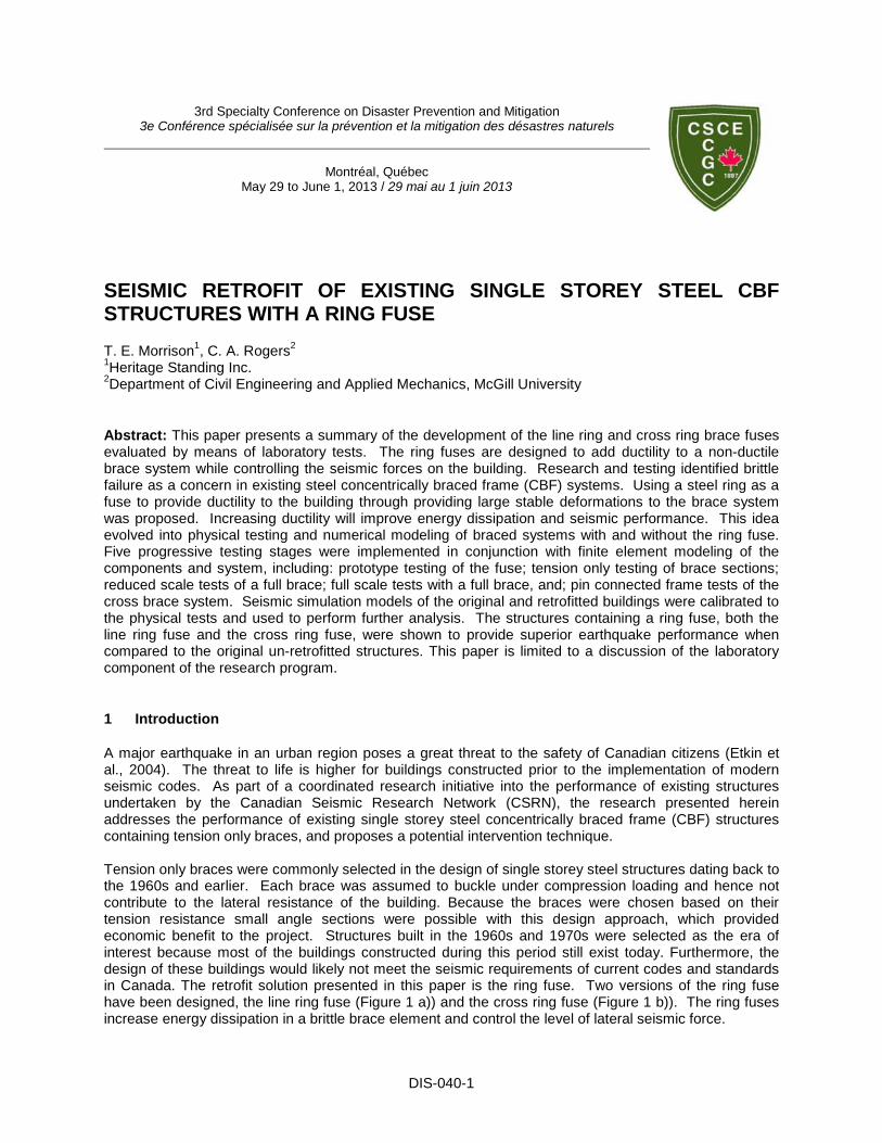
A major earthquake in an urban region poses a great threat to the safety of Canadian citizens (Etkin et al., 2004). The threat to life is higher for buildings constructed prior to the implementation of modern seismic codes. As part of a coordinated research initiative into the performance of existing structures undertaken by the Canadian Seismic Research Network (CSRN), the research presented herein addresses the performance of existing single storey steel concentrically braced frame (CBF) structures containing tension only braces, and proposes a potential intervention technique. Tension only braces were commonly selected in the design of single storey steel structures dating back to the 1960s and earlier. Each brace was assumed to buckle under compression loading and hence not contribute to the lateral resistance of the building. Because the braces were chosen based on their tension resistance small angle sections were possible with this design approach, which provided economic benefit to the project. Structures built in the 1960s and 1970s were selected as the era of interest because most of the buildings constructed during this period still exist today. Furthermore, the design of these buildings would likely not meet the seismic requirements of current codes and standards in Canada. The retrofit solution presented in this paper is the ring fuse. Two versions of the ring fuse have been designed, the line ring fuse (Figure 1 a)) and the cross ring fuse (Figure 1 b)). The ring fuses increase energy dissipation in a brittle brace element and control the level of lateral seismic force.
DIS-040-2
a) b) c) d)
Figure 1: a) Line Ring Fuse; b) Cross Ring Fuse; c) Brittle Net Section Failure 1; b) Brittle Net Section
1.1 Objective
The objective of the research discussed in this paper is to identify the performance of the ring fuse using laboratory based tests, and determine if the fuse may provide potential improvement to the seismic performance of the brace frame system. This research was done as part of a larger project in which the performance of seismic ring fuses was evaluated for use in existing single storey buildings (Morrison, 2013).
2 Background
Investigations undertaken following recent earthquakes identified brittle failure of the brace connections as a problem for existing steel CBF buildings. The 1994 Northridge earthquake (Tremblay et al., 1995), 1995 Kobe earthquake (Tremblay et al., 1996), 2011 Canterbury earthquake (Clifton et al., 2011) and 2011 Tohoku earthquake (Lignos et al., 2012) demonstrated that brittle failure of steel brace connections is of concern. With similar design approaches and building technology histories in Canada to the US, Japan and New Zealand brittle brace failure is a justified concern for existing CBF buildings. Hartley (2011) and Caruso-Juliano (2012) obtained angle brace connection specimens from existing buildings in the Montreal region and confirmed that brittle failure modes dominated in testing. None of the 24 tests of existing braces and their connections produced the desired ductile response of the brace. Net section failure of the brace angle at the connection was the most common failure mode, while bolt shear failure was the next most common. Extremely brittle net section failure was discovered during testing, with some net section failure modes providing less ductility than bolt shear failure. These extremely brittle failures, shown in Figure 1 c) and 1 d), provide less ductility to the brace system than expected in current assessment guidelines (ASCE, 2003; FEMA, 2009). Multiple retrofit approaches are available for improving deficiencies in existing structures, including strengthening the weaknesses, adding dampening systems, and installing base isolation, among others (ASCE, 2006; CEN, 2010; FEMA, 2006). Strengthening of the brace system was decided against as the strengthening of one component often leads to failure in another component of the seismic force resisting system (SFRS) without large performance gain – therefore a full strengthening approach becomes expensive. Installation of a base isolation or dampening system into an existing structure which is typically used for warehouses, retail space or industrial purposes is likewise uneconomical. In contrast, the use of a simple fuse device ( Figure 1a) & 1b) ) to add ductility to the brace system without increasing the lateral loads on the SFRS would improve seismic performance and allow for greater energy dissipation prior to failure than the original system without significant cost.
3 Prototype Tests of Ring Fuses
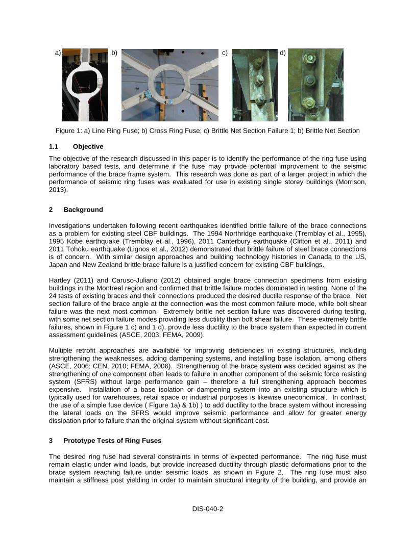
The desired ring fuse had several constraints in terms of expected performance. The ring fuse must remain elastic under wind loads, but provide increased ductility through plastic deformations prior to the brace system reaching failure under seismic loads, as shown in Figure 2. The ring fuse must also maintain a stiffness post yielding in order to maintain structural integrity of the building, and provide an
DIS-040-3
economical solution to retrofit requirements. Early performance estimates proved difficult as available stress strain relations focused on either elastic models of the performance of compressive models, while early finite element models could not be gauged for accuracy without some form of calibration. For this reason two physical tests were conducted as part of the prototype development. The prototype ring fuses were cut from steel plate using computer guided plasma cutters. The outer diameter of the ring fuses was 400mm, inner diameter of the prototype ring fuse 1C was 250mm and 1D was 300mm. The fuse dimensions were selected to be large enough for easier data collection and visual inspection, but small enough to test monotonically in tension to failure. Failure expectations based on stress stain relations (Pilkey, 1993), and as found for the initial finite element predictions, produced widely varying results.
Deformation
Load
Brittle Brace
Brace with Ring Fuse
Maximum Wind Load
Brace Fracture Load
MaximumStoreyDrift
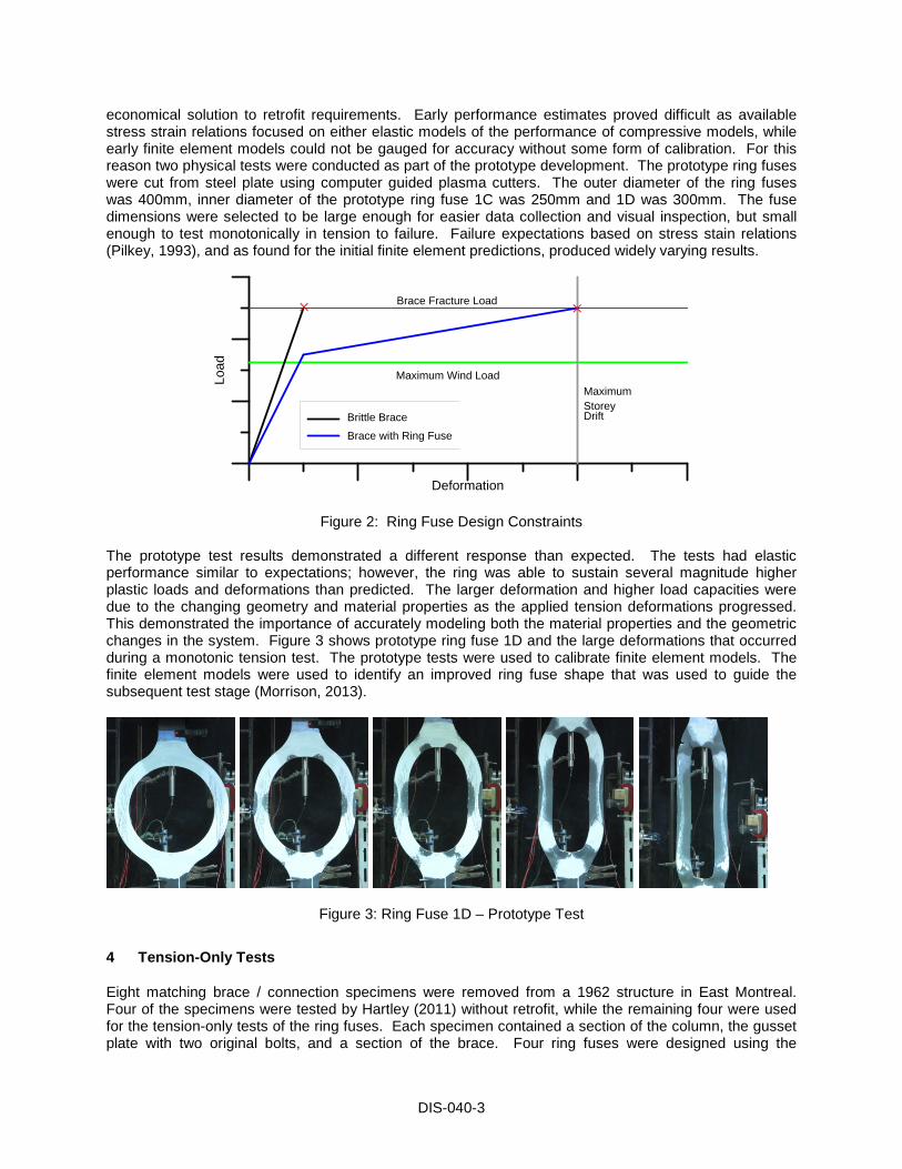
Figure 2: Ring Fuse Design Constraints The prototype test results demonstrated a different response than expected. The tests had elastic performance similar to expectations; however, the ring was able to sustain several magnitude higher plastic loads and deformations than predicted. The larger deformation and higher load capacities were due to the changing geometry and material properties as the applied tension deformations progressed. This demonstrated the importance of accurately modeling both the material properties and the geometric changes in the system. Figure 3 shows prototype ring fuse 1D and the large deformations that occurred during a monotonic tension test. The prototype tests were used to calibrate finite element models. The finite element models were used to identify an improved ring fuse shape that was used to guide the subsequent test stage (Morrison, 2013).
Figure 3: Ring Fuse 1D – Prototype Test
4 Tension-Only Tests
Eight matching brace / connection specimens were removed from a 1962 structure in East Montreal. Four of the specimens were tested by Hartley (2011) without retrofit, while the remaining four were used for the tension-only tests of the ring fuses. Each specimen contained a section of the column, the gusset plate with two original bolts, and a section of the brace. Four ring fuses were designed using the
DIS-040-4
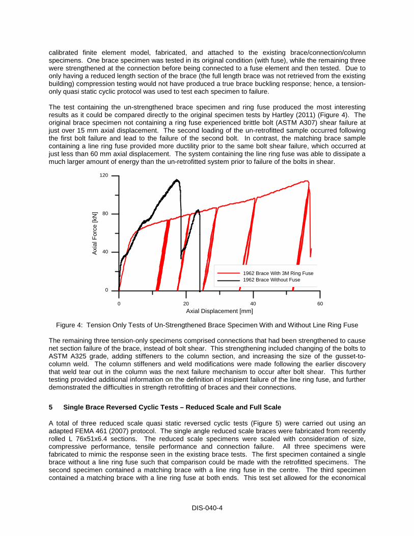
calibrated finite element model, fabricated, and attached to the existing brace/connection/column specimens. One brace specimen was tested in its original condition (with fuse), while the remaining three were strengthened at the connection before being connected to a fuse element and then tested. Due to only having a reduced length section of the brace (the full length brace was not retrieved from the existing building) compression testing would not have produced a true brace buckling response; hence, a tension-only quasi static cyclic protocol was used to test each specimen to failure. The test containing the un-strengthened brace specimen and ring fuse produced the most interesting results as it could be compared directly to the original specimen tests by Hartley (2011) (Figure 4). The original brace specimen not containing a ring fuse experienced brittle bolt (ASTM A307) shear failure at just over 15 mm axial displacement. The second loading of the un-retrofitted sample occurred following the first bolt failure and lead to the failure of the second bolt. In contrast, the matching brace sample containing a line ring fuse provided more ductility prior to the same bolt shear failure, which occurred at just less than 60 mm axial displacement. The system containing the line ring fuse was able to dissipate a much larger amount of energy than the un-retrofitted system prior to failure of the bolts in shear.
0 20 40 60Axial Displacement [mm]
0
40
80
120
Axi
al F
orce
[kN
]
1962 Brace With 3M Ring Fuse1962 Brace Without Fuse
Figure 4: Tension Only Tests of Un-Strengthened Brace Specimen With and Without Line Ring Fuse The remaining three tension-only specimens comprised connections that had been strengthened to cause net section failure of the brace, instead of bolt shear. This strengthening included changing of the bolts to ASTM A325 grade, adding stiffeners to the column section, and increasing the size of the gusset-to-column weld. The column stiffeners and weld modifications were made following the earlier discovery that weld tear out in the column was the next failure mechanism to occur after bolt shear. This further testing provided additional information on the definition of insipient failure of the line ring fuse, and further demonstrated the difficulties in strength retrofitting of braces and their connections.
5 Single Brace Reversed Cyclic Tests – Reduced Scale and Full Scale
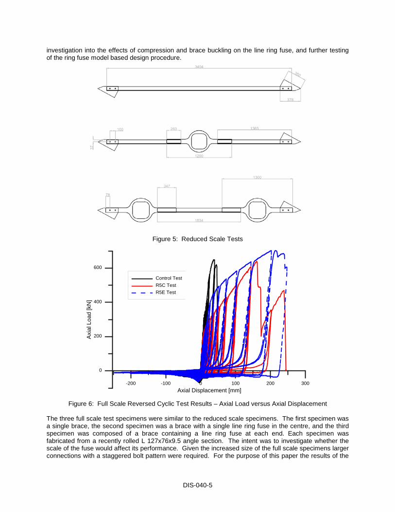
A total of three reduced scale quasi static reversed cyclic tests (Figure 5) were carried out using an adapted FEMA 461 (2007) protocol. The single angle reduced scale braces were fabricated from recently rolled L 76x51x6.4 sections. The reduced scale specimens were scaled with consideration of size, compressive performance, tensile performance and connection failure. All three specimens were fabricated to mimic the response seen in the existing brace tests. The first specimen contained a single brace without a line ring fuse such that comparison could be made with the retrofitted specimens. The second specimen contained a matching brace with a line ring fuse in the centre. The third specimen contained a matching brace with a line ring fuse at both ends. This test set allowed for the economical
DIS-040-5
investigation into the effects of compression and brace buckling on the line ring fuse, and further testing of the ring fuse model based design procedure.
Figure 5: Reduced Scale Tests
-200 -100 0 100 200 300Axial Displacement [mm]
0
200
400
600
Axi
al L
oad
[kN
]
Control TestR5C TestR5E Test
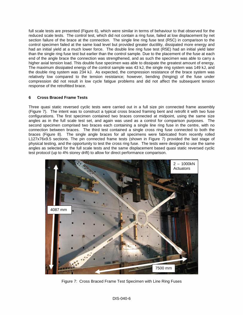
Figure 6: Full Scale Reversed Cyclic Test Results – Axial Load versus Axial Displacement The three full scale test specimens were similar to the reduced scale specimens. The first specimen was a single brace, the second specimen was a brace with a single line ring fuse in the centre, and the third specimen was composed of a brace containing a line ring fuse at each end. Each specimen was fabricated from a recently rolled L 127x76x9.5 angle section. The intent was to investigate whether the scale of the fuse would affect its performance. Given the increased size of the full scale specimens larger connections with a staggered bolt pattern were required. For the purpose of this paper the results of the
DIS-040-6
full scale tests are presented (Figure 6), which were similar in terms of behaviour to that observed for the reduced scale tests. The control test, which did not contain a ring fuse, failed at low displacement by net section failure of the brace at the connection. The single line ring fuse test (R5C) in comparison to the control specimen failed at the same load level but provided greater ductility, dissipated more energy and had an initial yield at a much lower force. The double line ring fuse test (R5E) had an initial yield later than the single ring fuse test but earlier than the control sample. Due to the placement of the fuse at each end of the angle brace the connection was strengthened, and as such the specimen was able to carry a higher axial tension load. This double fuse specimen was able to dissipate the greatest amount of energy. The maximum dissipated energy of the control sample was 43 kJ, the single ring system was 149 kJ, and the double ring system was 234 kJ. As expected, the compression resistance of the brace system was relatively low compared to the tension resistance; however, bending (hinging) of the fuse under compression did not result in low cycle fatigue problems and did not affect the subsequent tension response of the retrofitted brace.
6 Cross Braced Frame Tests
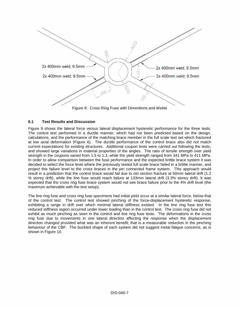
Three quasi static reversed cyclic tests were carried out in a full size pin connected frame assembly (Figure 7). The intent was to construct a typical cross braced framing bent and retrofit it with two fuse configurations. The first specimen contained two braces connected at midpoint, using the same size angles as in the full scale test set, and again was used as a control for comparison purposes. The second specimen comprised two braces each containing a single line ring fuse in the centre, with no connection between braces. The third test contained a single cross ring fuse connected to both the braces (Figure 8). The single angle braces for all specimens were fabricated from recently rolled L127x76x9.5 sections. The pin connected frame tests (shown in Figure 7) provided the last stage of physical testing, and the opportunity to test the cross ring fuse. The tests were designed to use the same angles as selected for the full scale tests and the same displacement based quasi static reversed cyclic test protocol (up to 4% storey drift) to allow for direct performance comparison.
Figure 7: Cross Braced Frame Test Specimen with Line Ring Fuses
4087 mm
7500 mm
2 – 1000kN Actuators
DIS-040-7
Figure 8: Cross Ring Fuse with Dimentions and Welds
6.1 Test Results and Discussion
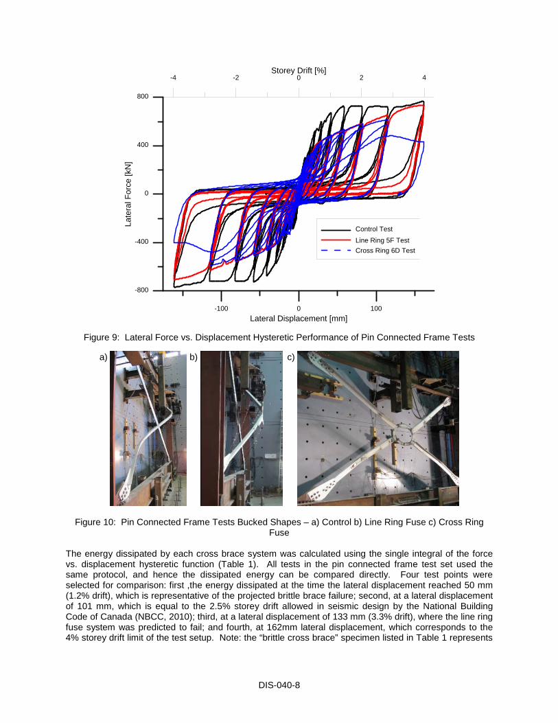
Figure 9 shows the lateral force versus lateral displacement hysteretic performance for the three tests. The control test performed in a ductile manner, which had not been predicted based on the design, calculations, and the performance of the matching brace member in the full scale test set which fractured at low axial deformation (Figure 6). The ductile performance of the control brace also did not match current expectations for existing structures. Additional coupon tests were carried out following the tests, and showed large variations in material properties of the angles. The ratio of tensile strength over yield strength in the coupons varied from 1.5 to 1.3, while the yield strength ranged from 341 MPa to 411 MPa. In order to allow comparison between the fuse performance and the expected brittle brace system it was decided to select the force level where the previously tested full scale brace failed in a brittle manner, and project this failure level to the cross braces in the pin connected frame system. This approach would result in a prediction that the control brace would fail due to net section fracture at 50mm lateral drift (1.2 % storey drift), while the line fuse would reach failure at 133mm lateral drift (3.3% storey drift). It was expected that the cross ring fuse brace system would not see brace failure prior to the 4% drift level (the maximum achievable with the test setup). The line ring fuse and cross ring fuse specimens had initial yield occur at a similar lateral force, below that of the control test. The control test showed pinching of the force-displacement hysteretic response, exhibiting a range in drift over which minimal lateral stiffness existed. In the line ring fuse test this reduced stiffness region occurred under lower loading than in the control test. The cross ring fuse did not exhibit as much pinching as seen in the control and line ring fuse tests. The deformations in the cross ring fuse due to movements in one lateral direction affecting the response when the displacement direction changed provided what was an inherent benefit; that is a measurable reduction in the pinching behaviour of the CBF. The buckled shape of each system did not suggest metal fatigue concerns, as is shown in Figure 10.
DIS-040-8
-100 0 100Lateral Displacement [mm]
-4 -2 0 2 4Storey Drift [%]
-800
-400
0
400
800
Late
ral F
orce
[kN
]
Control TestLine Ring 5F TestCross Ring 6D Test
Figure 9: Lateral Force vs. Displacement Hysteretic Performance of Pin Connected Frame Tests
a)
b)
c)
Figure 10: Pin Connected Frame Tests Bucked Shapes – a) Control b) Line Ring Fuse c) Cross Ring Fuse
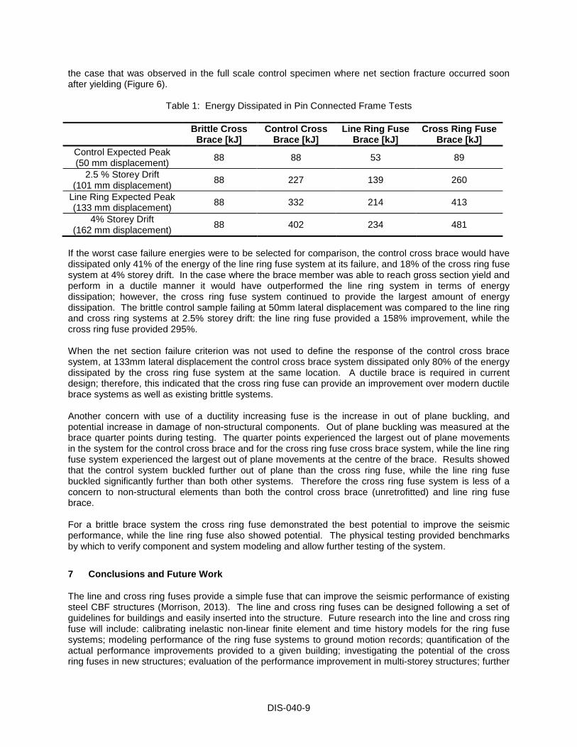
The energy dissipated by each cross brace system was calculated using the single integral of the force vs. displacement hysteretic function (Table 1). All tests in the pin connected frame test set used the same protocol, and hence the dissipated energy can be compared directly. Four test points were selected for comparison: first ,the energy dissipated at the time the lateral displacement reached 50 mm (1.2% drift), which is representative of the projected brittle brace failure; second, at a lateral displacement of 101 mm, which is equal to the 2.5% storey drift allowed in seismic design by the National Building Code of Canada (NBCC, 2010); third, at a lateral displacement of 133 mm (3.3% drift), where the line ring fuse system was predicted to fail; and fourth, at 162mm lateral displacement, which corresponds to the 4% storey drift limit of the test setup. Note: the “brittle cross brace” specimen listed in Table 1 represents
DIS-040-9
the case that was observed in the full scale control specimen where net section fracture occurred soon after yielding (Figure 6).
Table 1: Energy Dissipated in Pin Connected Frame Tests
Brittle Cross Brace [kJ]
Control Cross Brace [kJ]
Line Ring Fuse Brace [kJ]
Cross Ring Fuse Brace [kJ]
Control Expected Peak (50 mm displacement) 88 88 53 89
2.5 % Storey Drift (101 mm displacement) 88 227 139 260
Line Ring Expected Peak (133 mm displacement) 88 332 214 413
4% Storey Drift (162 mm displacement) 88 402 234 481
If the worst case failure energies were to be selected for comparison, the control cross brace would have dissipated only 41% of the energy of the line ring fuse system at its failure, and 18% of the cross ring fuse system at 4% storey drift. In the case where the brace member was able to reach gross section yield and perform in a ductile manner it would have outperformed the line ring system in terms of energy dissipation; however, the cross ring fuse system continued to provide the largest amount of energy dissipation. The brittle control sample failing at 50mm lateral displacement was compared to the line ring and cross ring systems at 2.5% storey drift: the line ring fuse provided a 158% improvement, while the cross ring fuse provided 295%. When the net section failure criterion was not used to define the response of the control cross brace system, at 133mm lateral displacement the control cross brace system dissipated only 80% of the energy dissipated by the cross ring fuse system at the same location. A ductile brace is required in current design; therefore, this indicated that the cross ring fuse can provide an improvement over modern ductile brace systems as well as existing brittle systems. Another concern with use of a ductility increasing fuse is the increase in out of plane buckling, and potential increase in damage of non-structural components. Out of plane buckling was measured at the brace quarter points during testing. The quarter points experienced the largest out of plane movements in the system for the control cross brace and for the cross ring fuse cross brace system, while the line ring fuse system experienced the largest out of plane movements at the centre of the brace. Results showed that the control system buckled further out of plane than the cross ring fuse, while the line ring fuse buckled significantly further than both other systems. Therefore the cross ring fuse system is less of a concern to non-structural elements than both the control cross brace (unretrofitted) and line ring fuse brace. For a brittle brace system the cross ring fuse demonstrated the best potential to improve the seismic performance, while the line ring fuse also showed potential. The physical testing provided benchmarks by which to verify component and system modeling and allow further testing of the system.
7 Conclusions and Future Work
The line and cross ring fuses provide a simple fuse that can improve the seismic performance of existing steel CBF structures (Morrison, 2013). The line and cross ring fuses can be designed following a set of guidelines for buildings and easily inserted into the structure. Future research into the line and cross ring fuse will include: calibrating inelastic non-linear finite element and time history models for the ring fuse systems; modeling performance of the ring fuse systems to ground motion records; quantification of the actual performance improvements provided to a given building; investigating the potential of the cross ring fuses in new structures; evaluation of the performance improvement in multi-storey structures; further
DIS-040-10
development of the double line ring fuse concept; and, using the line or cross ring fuse with structural systems other than steel CBF.
Acknowledgements
As with any major project there is a multitude of people to thank, and to try to name everyone one in detail would be impossible. We would like to highlight the Canadian Seismic Research Network and the Natural Sciences and Engineering Research Council of Canada for funding this research. Other important assistance came from research colleagues Anthony Caruso-Julanio and John Hartley, technicians at both McGill University and Ecole Polytechnique de Montreal, and companies who contributed samples and fuse fabrication, including; Constructions Proco Inc., ADF Group Inc., Delsan-AIM Environmental Services Inc., Hatch Ltd., and Rio Tinto.
References
ASCE. (2003). Seismic Evalutation of Existing Buildings. In Darrick B Hom & Chris D Poland (Eds.): American Society of Civil Engineers.
ASCE. (2006). Seismic Rehabilitation of Existing Buildings - ASCE 41: American Society of Civil Engineers.
Caruso-Juliano, A. (2012). Performance of Seismically Deficient Existing Braced Steel Frame Structures with Flexible Diaphragms. M.Eng, McGill University, Montreal, QC.
CEN, E. C. f. S.-. (2010). Eurocode 8: Design of structures for earthquake resistance Part 3: Asssessment and retrofitting of buildings (Vol. BS EN 1998-3:2005). Great Brittan: British Standards.
Clifton, C., Bruneau, M., MacRae, G., Leon, R. T., & Fussell, A. (2011). Steel structures damage from the Christchurch earthquake series of 2010 and 2011. Bulletin of the New Zealand Society for Earthquake Engineering, 44(4), 297 - 318.
Etkin, D., Haque, C. E., & Brooks, G. R. (2004). An Assessment of Natural Hazards and Disasters in Canada. Ottawa: Public Safety and Emergency Preparedness Canada, Environment Canada.
FEMA. (2006). Techniques for the Seismic Rehabilitation of Existing Buildings Federal Emergency Management Agency FEMA (Ed.) FEMA 547
FEMA. (2007). Interm Testing Protocols for Determining the Seismic Performance Characteristics of Structural and Nonstructural Components. In Applied Technology Council - ATC (Ed.), FEMA 461 (Vol. 461). Washington, DC: Federal Emergency Management Agency.
FEMA. (2009). Quantification of building sesmic performance factors - FEMA P695. Washington, D.C. Hartley, J. (2011). Performance and retrofit of seismically deficient existing braced steel frame structures:
Testing of brace connections from existing concentrically braced steel frames (Department of Civil Engineering and Applied Mechanics, Trans.) (pp. 104). Montreal: McGill University.
Lignos, D., Ricles, J. M., Love, J., Okazaki, T., & Midorikawa, M. (2012). Seismic Effects of the 2011 Tohoku, Japan Earthquake on Steel Buildings. Paper presented at the 9th International Conference on Urban Earthquake Engineering, Tokyo Institute of Technology, Tokyo, Japan.
Morrison, T. (2013). Seismic Mitigation Technique for Existing Single Storey Steel CBF Structures. Ph.D., McGill University, Montreal, QC.
NBCC. (2010). National Building Code of Canada. Ottawa, ON: National Research Council of Canada. Pilkey, W. D. (1993). Formulas for Stress Strain and Structural Matrices. New York, NY: John Wiley &
Sons Inc. Tremblay, R., Bruneau, M., Nakashima, N., Prion, H. G. L., Filiatrault, A., & DeVall, R. (1996). Seismic
design of steel buildings: Lessons from the 1995 Hyogo-ken Nanbu earthquake. Canadian Journal of Civil Engineering, 23(3), 727-756.
Tremblay, R., Filiatrault, A., Timler, P., & Bruneau, M. (1995). Performance of steel structures during the 1994 Northridge earthquake. Canadian Journal of Civil Engineering, 22(2), 338-360. doi: 10.1139/l95-046