raider b2297000 rev2 - ets buissonets.buisson.free.fr/pdf/doc_tec/automatisme/aprimatic/...con el...
TRANSCRIPT
BUT DU MANUELCe manuel a été réalisé par le constructeur et fait partie intégrante du produit.Il contient toutes les informations nécessaires pour:• sensibiliser les installateurs aux problèmes liés à la sécurité;• installer le dispositif de manière correcte;• connaître le fonctionnement et les limites du dispositif;• utiliser correctement le dispositif dans des conditions de sécurité optimales.Le respect des indications fournies dans ce manuel garantit la sécurité personnelle, une économie de fonctionnement et une longue durée de vie du produit.Afi n d’éviter des opérations incorrectes et de ne pas risquer des accidents sérieux, lire attentivement ce manuel et respecter scrupuleusement les informations fournies.Les instructions, les dessins, les photos et la documentation contenus dans ce manuel sont la propriété de la société APRIMATIC S.p.a et ne peuvent être reproduits sous aucune forme, ni intégralement, ni partiellement.Le logo « APRIMATIC » est une marque enregistrée de APRIMATIC S.p.a.
OBJETO DEL MANUALEste manual ha sido redactado por el constructor y forma parte integrante del producto.Contiene todas las informaciones necesarias para:• la correcta sensibilización de los instaladores hacia los problemas de la seguridad;• la correcta instalación del dispositivo;• el conocimiento en profundidad de su funcionamiento y de sus límites;• el correcto uso en condiciones de seguridad;La constante observación de las indicaciones suministradas en este manual, garantiza la seguridad del hombre, la economía del ejercicio y una mayor duración de funcionamiento del producto.Con el fi n de evitar maniobras equivocadas con riesgo de accidente, es importante leer atentamente este manual, respetando escrupulosamente las informaciones suministradas.Las instrucciones, los dibujos, las fotografías y la documentación que contiene este manual son propiedad de APRIMATIC S.p.a. y no pueden ser reproducidas en ninguna manera, ni integral ni parcialmente.El logotipo “APRIMATIC” es una marca registrada de APRIMATIC S.p.a.
ZWECK DES HANDBUCHSDieses Handbuch wurde vom Hersteller verfasst und ist ein ergänzender Bestandteil des Produkts.Es enthält alle nötigen Informationen für:• die richtige Sensibilisierung der Monteure für Fragen der Sicherheit;• die vorschriftsmäßige Installation der Vorrichtung;• die umfassende Kenntnis ihrer Funktionsweise und ihrer Grenzen;• die vorschriftsmäßige und sichere Benutzung.Die ständige Beachtung der in diesem Handbuch gelieferten Hinweise gewährleistet die Sicherheit der Personen, wirtschaftlichen Betrieb und eine lange Lebensdauer des Produkts.Zur Vermeidung fehlerhafter Manöver mit Unfallgefahr ist es wichtig, dieses Handbuch aufmerksam durchzulesen und die darin enthaltenen Informationen genauestens zu beachten.Die Anleitungen, Zeichnungen, Fotos und Dokumentationen in diesem Handbuch sind Eigentum von APRIMATIC S.p.a. und dürfen in keiner Weise ganz oder teilweise reproduziert werden.Das Logo „APRIMATIC“ ist eine eingetragene Marke der APRIMATIC S.p.a.
ABOUT THIS MANUALThis manual has been drafted by the manufacturer and is an integral part of the product.The manual contains information about:• Safety precautions for installers.• Installation instructions.• Detailed operating instructions.• Using the device safely.Follow the instructions given in this manual. This will ensure that your Aprimatic product gives long, trouble-free service.Follow the safety precautions and instructions given in this manual. This will ensure that your Aprimatic product gives long, safe service.All rights reserved. All the instructions, drawings, photos and documentation in this manual are the property of Aprimatic S.p.a. All copying, in part or in whole, is strictly forbidden.The “APRIMATIC” logo is a registered trade mark of APRIMATIC S.p.a.
Istruzioni per l’installazioneInstallation instructions
Instructions pour l’installationInstallationsanleitung
Instrucciones para la instalación
SCOPO DEL MANUALEQuesto manuale è stato redatto dal costruttore ed è parte integrante del prodotto. In esso sono contenute tutte le informazioni necessarie per:• la corretta sensibilizzazione degli installatori alle problematiche della sicurezza;• la corretta installazione del dispositivo;• la conoscenza approfondita del suo funzionamento e dei suoi limiti;• il corretto uso in condizioni di sicurezza;La costante osservanza delle indicazioni fornite in questo manuale, garantisce la sicurezza dell’uomo, l’economia di esercizio e una più lunga durata di funzionamento del prodotto.Al fi ne di evitare manovre errate con il rischio di incidenti, è importante leggere attentamente questo manuale, rispettando scrupolosamente le informazioni fornite.Le istruzioni, i disegni, le fotografi e e la documentazione contenuti nel presente manuale sono di proprietà APRIMATIC S.p.a. e non possono essere riprodotti in alcun modo, né integralmente, né parzialmente.Il logo “APRIMATIC” è un marchio registrato di APRIMATIC S.p.a.
Italia
noEn
glis
h
Cod
. B22
9700
0 - r
ev.2
- di
cem
bre
2005
RAIDER
Fran
çais
Deu
tsch
Espa
ñol
- 2 -
Italia
no
2
3x0.75 Ø
6
3x0.75 Ø
3x0.75 Ø
2x1.5 Ø
1
2x1.5 Ø
2x1 Ø
1
5
7 7
10Alc= 30mA 4
8
Aprimatic
Aprimatic
3
9
Sommario
�
max 147 N(15 kg)
�
L
a
B
Y
A
E
L
30 mm
FA
SE
TE
RR
A
NE
UT
RO
FO
TO
CE
LL
UL
A
LA
MP
EG
GIA
TO
RE
+ 24
V A
CC
ES
SO
RI
ST
AR
T
SICUREZZA in APERTURA
ST
OP
GN
D
+ 24
V
LA
MP
AD
A S
PIA
24V
3W
max
.
PHPH N
230V
50H
z+6
% -
10%
alim
enta
zio
ne
TRASFORMATORE
SE
CO
ND
AR
IO0-
20V
AC
PR
IMA
RIO
0-23
0VA
C
M1M1 M2M2
MOTORE1
MOTORE2
12 Vac 15 W max.
EL
ET
TR
OS
ER
RA
TU
RA
EL
ET
TR
OS
ER
RA
TU
RA
GN
D
ATTENZIONE ! i contatti N.C. devono essere ponticellati verso massa (morsetto 9 o 11) quando non vengono utilizzati. In caso contrario l’automazione NON PUO’ funzionare!NOTA: il morsetto 6 è N.A. per default, ma può diventare N.C. in base al settaggio del parametro H (par.7.1).
Mar
rone
Blu
Mar
rone
Blu
+- + - -
ST
AR
T p
edo
nal
e
LEGENDA:M1 = motore 1 a anta in apertura o monoantaM2 = motore 2 a anta in apertura
= contatto di tipo NO= contatto di tipo NC
24 V AC24 V AC BATTBATT- + +
L N M1 M2 M3 M4 1 3 6 7 10 11 122 4 5 8 9
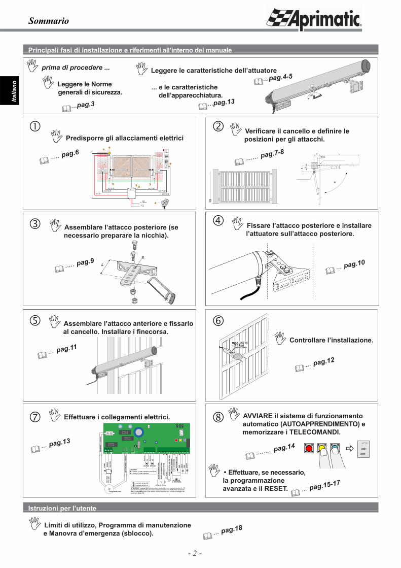
Principali fasi di installazione e riferimenti all’interno del manuale
� Leggere le Norme generali di sicurezza.
� Leggere le caratteristiche dell’attuatore
� Verifi care il cancello e defi nire le posizioni per gli attacchi.
Istruzioni per l’utente
� Limiti di utilizzo, Programma di manutenzione e Manovra d’emergenza (sblocco).
�...pag.3
�...pag.4-5� prima di procedere ...
� Predisporre gli allacciamenti elettrici
� ..... pag.6
� ..... pag.9
� Assemblare l’attacco posteriore (se necessario preparare la nicchia).
� Fissare l’attacco posteriore e installare l’attuatore sull’attacco posteriore.
��
180˚
�
� ... pag.10
� ... pag.11
� Assemblare l’attacco anteriore e fi ssarlo al cancello. Installare i fi necorsa.
�� Controllare l’installazione.
� ... pag.12
� ... pag.13
� Effettuare i collegamenti elettrici.
� ....... pag.7-8
� ... pag.18
�
� AVVIARE il sistema di funzionamento automatico (AUTOAPPRENDIMENTO) e memorizzare i TELECOMANDI.
� ........ pag.14
� Effettuare, se necessario, la programmazione avanzata e il RESET.
� ... pag.15-17
... e le caratteristiche dell’apparecchiatura.
�...pag.13
180˚
180˚
- 3 -
Italia
no
Premessa / Norme di sicurezza
Fig.1 Fig.2
1.1 GLOSSARIO E ABBREVIAZIONINel paragrafo sono elencati i termini non comuni, o comunque con signifi cato diverso da quello comune, e le abbreviazioni utilizzate nel testo. Questi, i termini non comuni:• ZONA D’INTERVENTO zona che circoscrive l’area in cui si esegue l’installazione e dove la presenza di una
persona esposta costituisce un rischio per la sicurezza e la salute della persona stessa (Allegato I, 1.1.1 Direttiva 89/392/CEE);
• PERSONA ESPOSTA qualsiasi persona che si trovi interamente o in parte in una zona pericolosa (Allegato I, 1.1.1 - Direttiva 89/392/CEE);
• INSTALLATORE persona incaricata di installare, far funzionare, regolare, eseguire la manutenzione, pulire, riparare e trasportare il dispositivo (Allegato I, 1.1.1 - Direttiva 89/392/CEE);
• PERICOLO RESIDUO pericolo che non è stato possibile eliminare o sufficientemente ridurre attraverso la progettazione.
Queste invece le abbreviazioni: • Cap. = Capitolo • Par. = Paragrafo1.2 PITTOGRAMMI REDAZIONALI
Attenzione!
Le indicazioni precedute da questo simbolo contengono informazioni, prescrizioni o procedure che se non eseguite correttamente possono causare lesioni, morte o rischi a lungo termine per la salute delle persone e per l’ambiente.
Cautela
Le indicazioni precedute da questo simbolo contengono procedure o pratiche che, se non eseguite correttamente, possono causare gravi danni alla macchina o al prodotto.
InformazioniLe indicazioni precedute da questo simbolo contengono informazioni su qualsiasi soggetto di particolare importanza: il loro mancato rispetto può comportare la perdita della garanzia contrattuale.
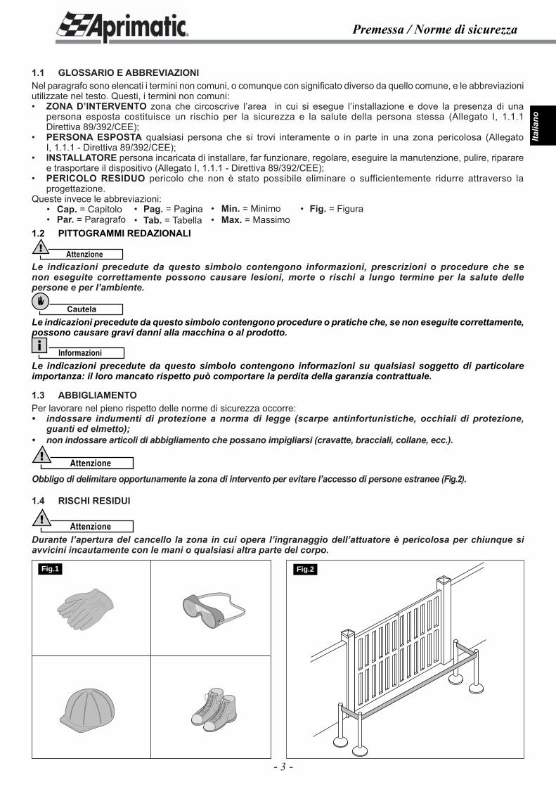
1.3 ABBIGLIAMENTOPer lavorare nel pieno rispetto delle norme di sicurezza occorre:• indossare indumenti di protezione a norma di legge (scarpe antinfortunistiche, occhiali di protezione,
guanti ed elmetto);• non indossare articoli di abbigliamento che possano impigliarsi (cravatte, bracciali, collane, ecc.).
Attenzione!
Obbligo di delimitare opportunamente la zona di intervento per evitare l’accesso di persone estranee (Fig.2).
1.4 RISCHI RESIDUI
Attenzione!Durante l’apertura del cancello la zona in cui opera l’ingranaggio dell’attuatore è pericolosa per chiunque si avvicini incautamente con le mani o qualsiasi altra parte del corpo.
• Pag. = Pagina • Tab. = Tabella
• Min. = Minimo• Max. = Massimo
• Fig. = Figura
- 4 -
Italia
noCaratteristiche dell’attuatore
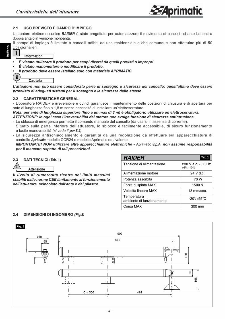
2.1 USO PREVISTO E CAMPO D’IMPIEGOL’attuatore elettromeccanico RAIDER è stato progettato per automatizzare il movimento di cancelli ad ante battenti a doppia anta o in versione monoanta. Il campo di impiego è limitato a cancelli adibiti ad uso residenziale e che comunque non effettuino più di 50 cicli giornalieri.
Informazioni• È vietato utilizzare il prodotto per scopi diversi da quelli previsti o impropri.• È vietato manomettere o modifi care il prodotto.• Il prodotto deve essere istallato solo con materiale APRIMATIC.
Cautela
L’attuatore non può essere considerato parte di sostegno o sicurezza del cancello; quest’ultimo deve essere provvisto di adeguati sistemi per il sostegno e la sicurezza dello stesso.
2.2 CARATTERISTICHE GENERALI- L’operatore RAIDER è irreversibile e quindi garantisce il mantenimento delle posizioni di chiusura e di apertura per ante di lunghezza fi no a 1,8 m senza necessità di installare un’elettroserratura.Nota: per ante di lunghezza superiore (fi no a un max di 3 m) è obbligatorio utilizzare un’elettroserratura.ATTENZIONE: in ogni caso l’irreversibilità del motore non svolge funzione di sicurezza antintrusione.- Lo sblocco di emergenza permette il comando manuale del cancello (da usarsi in assenza di corrente). Situato sulla parte inferiore dell’attuatore, lo sblocco è facilmente accessibile, di sicuro funzionamento e facile manovrabilità (si veda il par.8.2).- La sicurezza antischiacciamento è garantita da una regolazione da effettuare sull’apparecchiatura di controllo Aprimatic modello CCR24 o modello Aprimatic equivalente. IMPORTANTE! NON utilizzare altre apparecchiature elettroniche - Aprimatic S.p.A. non assume responsabilità per il mancato rispetto di tali prescrizioni.
2.3 DATI TECNICI (Tab. 1)
Attenzione!
Il livello di rumorosità rientra nei limiti massimi stabiliti dalle norme CEE limitamente al funzionamento dell’attuatore, svincolato dall’anta e dal pilastro.
2.4 DIMENSIONI DI INGOMBRO (Fig.3)
70 W
1500 N
13 mm/sec.
-20°/+55°C
300 mm
RAIDERTensione di alimentazione
24 V d.c.Alimentazione motore
Potenza assorbita
Forza di spinta MAX
Velocità lineare MAX
Temperaturaambiente di funzionamento
Corsa MAX
230 V a.c. - 50 Hz+6% -10%
Tab.1
55
909
871
128
55
168
168
C = 300 474
Fig. 3
- 5 -
Italia
no
Caratteristiche dell’attuatore
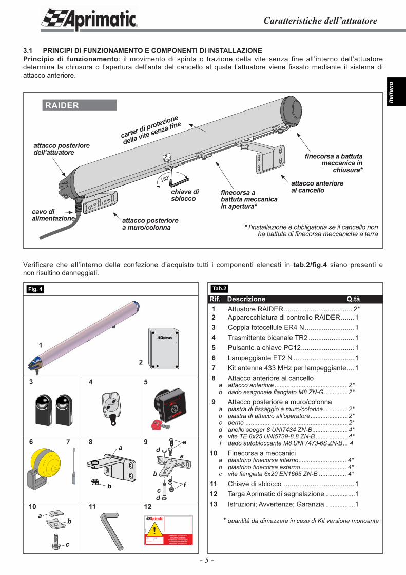
3.1 PRINCIPI DI FUNZIONAMENTO E COMPONENTI DI INSTALLAZIONEPrincipio di funzionamento: il movimento di spinta o trazione della vite senza fine all’interno dell’attuatore determina la chiusura o l’apertura dell’anta del cancello al quale l’attuatore viene fi ssato mediante il sistema di attacco anteriore.
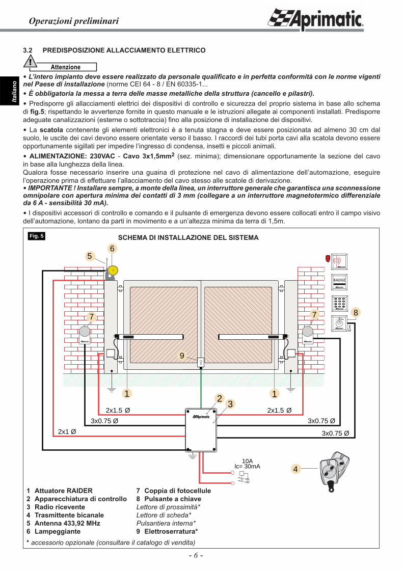
Rif. Descrizione Q.tà 1 Attuatore RAIDER .................................... 2* 2 Apparecchiatura di controllo RAIDER ....... 1 3 Coppia fotocellule ER4 N ..........................1 4 Trasmittente bicanale TR2 ........................1 5 Pulsante a chiave PC12 ............................1 6 Lampeggiante ET2 N ................................1 7 Kit antenna 433 MHz per lampeggiante .... 1 8 Attacco anteriore al cancello a attacco anteriore ...........................................2* b dado esagonale fl angiato M8 ZN-G ..............2* 9 Attacco posteriore a muro/colonna a piastra di fi ssaggio a muro/colonna ..............2* b piastra di attacco all’operatore ......................2* c perno ............................................................2* d anello seeger 8 UNI7434 ZN-B .....................4* e vite TE 8x25 UNI5739-8.8 ZN-B ...................4* f dado autobloccante M8 UNI 7473-6S ZN-B ... 4 10 Finecorsa a meccanici a piastrino fi necorsa interno ............................ 4* b piastrino fi necorsa esterno ........................... 4* c vite fl angiata 6x20 EN1665 ZN-B ................ 4* 11 Chiave di sblocco .....................................1 12 Targa Aprimatic di segnalazione .................1 13 Istruzioni; Avvertenze; Garanzia .................1
* quantità da dimezzare in caso di Kit versione monoanta
4
7 8
10 11
1
Aprimatic
5
96
2
3
12fi
IL CAMPIONE DELL’AUTOMAZIONE
!APERTURA AUTOMATICA
AUTOMATIC OPENINGOUVERTURE AUTOMATIQUEAUTOMATISCHE ÖFFNUNGAPERTURA AUTOMATICA
A58
4500
0
name model
serial number
a
c
b
a
b
c
de
d
Verificare che all’interno della confezione d’acquisto tutti i componenti elencati in tab.2/fig.4 siano presenti e non risultino danneggiati.
180˚
180˚attacco anterioreal cancello
attacco posteriorea muro/colonna
cavo di alimentazione
chiave di sblocco
RAIDER
attacco posterioredell’attuatore
carter di protezione
della vite senza fi ne
fi necorsa a battuta meccanica in apertura*
fi necorsa a battuta meccanica in
chiusura*
* l’installazione è obbligatoria se il cancello non ha battute di fi necorsa meccaniche a terra
Tab.2 Fig. 4
fb
a
- 6 -
Italia
no
3.2 PREDISPOSIZIONE ALLACCIAMENTO ELETTRICO
Attenzione!
L’intero impianto deve essere realizzato da personale qualifi cato e in perfetta conformità con le norme vigenti nel Paese di installazione (norme CEI 64 - 8 / EN 60335-1... È obbligatoria la messa a terra delle masse metalliche della struttura (cancello e pilastri). Predisporre gli allacciamenti elettrici dei dispositivi di controllo e sicurezza del proprio sistema in base allo schema di fi g.5; rispettando le avvertenze fornite in questo manuale e le istruzioni allegate ai componenti installati. Predisporre adeguate canalizzazioni (esterne o sottotraccia) fi no alla posizione di installazione dei dispositivi. La scatola contenente gli elementi elettronici è a tenuta stagna e deve essere posizionata ad almeno 30 cm dal suolo, le uscite dei cavi devono essere orientate verso il basso. I raccordi dei tubi porta cavi alla scatola devono essere opportunamente sigillati per impedire l’ingresso di condensa, insetti e piccoli animali. ALIMENTAZIONE: 230VAC - Cavo 3x1,5mm2 (sez. minima); dimensionare opportunamente la sezione del cavo in base alla lunghezza della linea.Qualora fosse necessario inserire una guaina di protezione nel cavo di alimentazione dell’automazione, eseguire l’operazione prima di effettuare l’allacciamento del cavo stesso alle scatole di derivazione. IMPORTANTE ! Installare sempre, a monte della linea, un interruttore generale che garantisca una sconnessione omnipolare con apertura minima dei contatti di 3 mm (collegare a un interruttore magnetotermico differenziale da 6 A - sensibilità 30 mA). I dispositivi accessori di controllo e comando e il pulsante di emergenza devono essere collocati entro il campo visivo dell’automazione, lontano da parti in movimento e a un’altezza minima da terra di 1,5m.
Operazioni preliminari
2
3x0.75 Ø
6
3x0.75 Ø
3x0.75 Ø
2x1.5 Ø
1
2x1.5 Ø
2x1 Ø
1
5
7 7
10Alc= 30mA 4
8
Aprimatic
Aprimatic
3
9
Fig. 5 SCHEMA DI INSTALLAZIONE DEL SISTEMA
7 Coppia di fotocellule8 Pulsante a chiaveLettore di prossimità*Lettore di scheda*Pulsantiera interna*9 Elettroserratura*
1 Attuatore RAIDER2 Apparecchiatura di controllo3 Radio ricevente4 Trasmittente bicanale5 Antenna 433,92 MHz6 Lampeggiante* accessorio opzionale (consultare il catalogo di vendita)
- 7 -
Italia
no
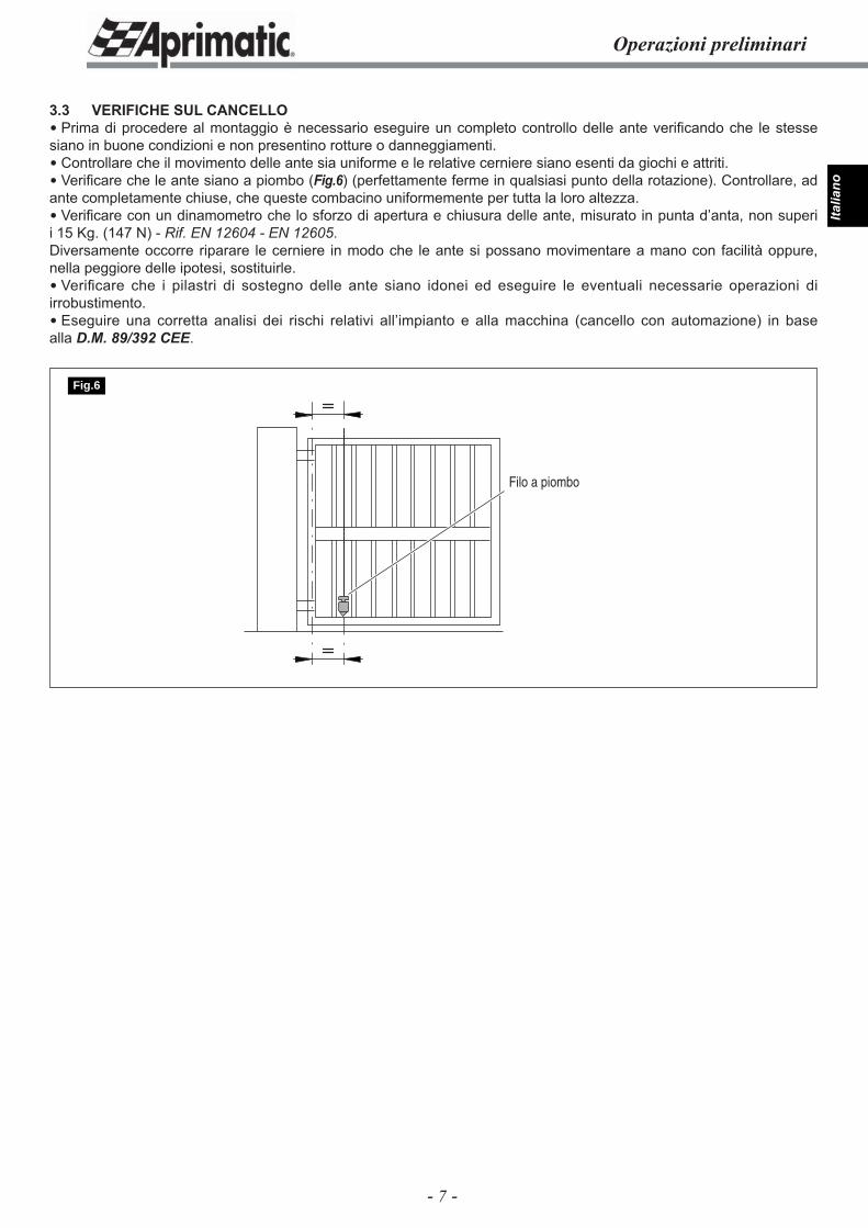
3.3 VERIFICHE SUL CANCELLO Prima di procedere al montaggio è necessario eseguire un completo controllo delle ante verifi cando che le stesse siano in buone condizioni e non presentino rotture o danneggiamenti. Controllare che il movimento delle ante sia uniforme e le relative cerniere siano esenti da giochi e attriti. Verifi care che le ante siano a piombo (Fig.6) (perfettamente ferme in qualsiasi punto della rotazione). Controllare, ad ante completamente chiuse, che queste combacino uniformemente per tutta la loro altezza. Verifi care con un dinamometro che lo sforzo di apertura e chiusura delle ante, misurato in punta d’anta, non superi i 15 Kg. (147 N) - Rif. EN 12604 - EN 12605.Diversamente occorre riparare le cerniere in modo che le ante si possano movimentare a mano con facilità oppure, nella peggiore delle ipotesi, sostituirle. Verifi care che i pilastri di sostegno delle ante siano idonei ed eseguire le eventuali necessarie operazioni di irrobustimento. Eseguire una corretta analisi dei rischi relativi all’impianto e alla macchina (cancello con automazione) in base alla D.M. 89/392 CEE.
Operazioni preliminari
Filo a piombo
Fig.6
- 8 -
Italia
no
B
Y
A
E
L
30 mm
Operazioni preliminari
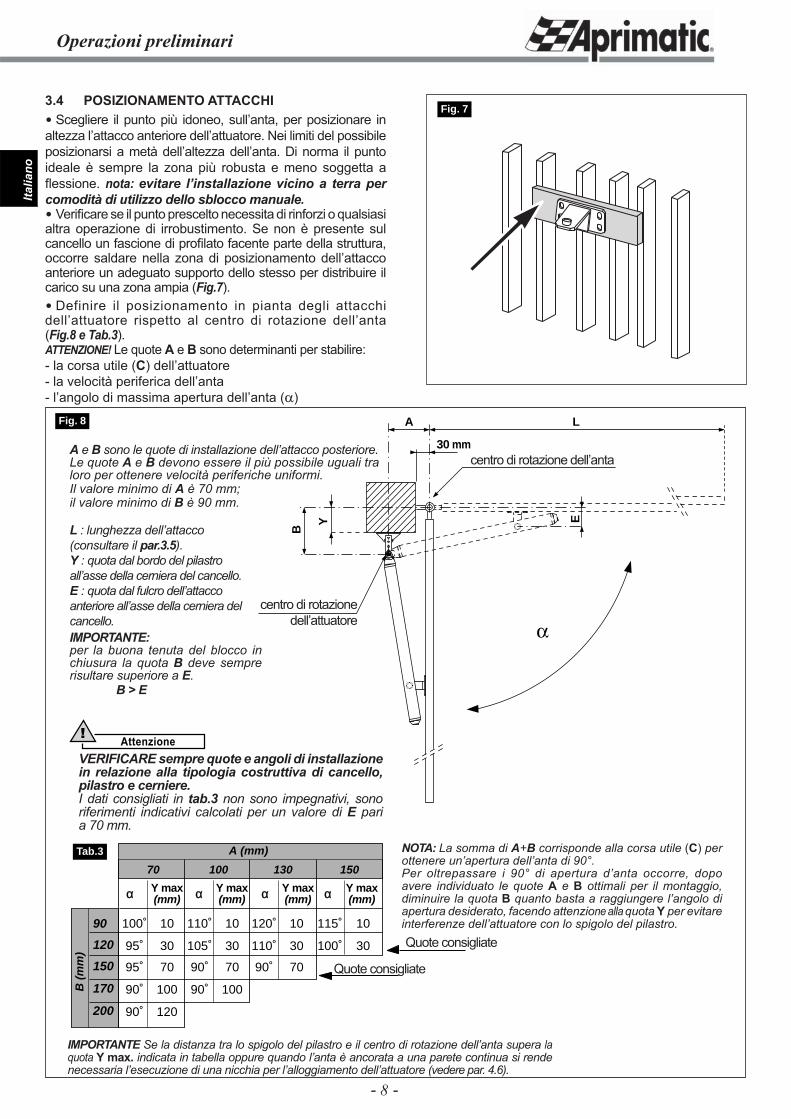
3.4 POSIZIONAMENTO ATTACCHI Scegliere il punto più idoneo, sull’anta, per posizionare in altezza l’attacco anteriore dell’attuatore. Nei limiti del possibile posizionarsi a metà dell’altezza dell’anta. Di norma il punto ideale è sempre la zona più robusta e meno soggetta a fl essione. nota: evitare l’installazione vicino a terra per comodità di utilizzo dello sblocco manuale. Verifi care se il punto prescelto necessita di rinforzi o qualsiasi altra operazione di irrobustimento. Se non è presente sul cancello un fascione di profi lato facente parte della struttura, occorre saldare nella zona di posizionamento dell’attacco anteriore un adeguato supporto dello stesso per distribuire il carico su una zona ampia (Fig.7). Definire il posizionamento in pianta degli attacchi dell’attuatore rispetto al centro di rotazione dell’anta (Fig.8 e Tab.3).ATTENZIONE! Le quote A e B sono determinanti per stabilire:- la corsa utile (C) dell’attuatore- la velocità periferica dell’anta- l’angolo di massima apertura dell’anta (α)
Fig. 7
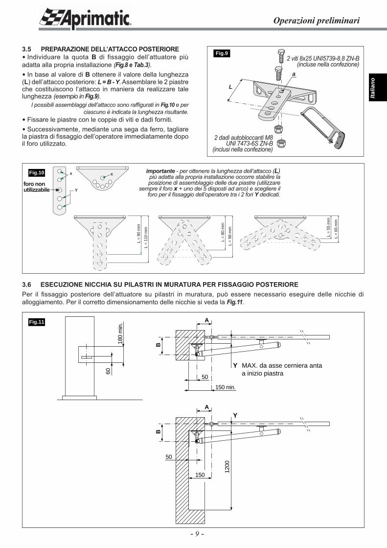
IMPORTANTE Se la distanza tra lo spigolo del pilastro e il centro di rotazione dell’anta supera la quota Y max. indicata in tabella oppure quando l’anta è ancorata a una parete continua si rende necessaria l’esecuzione di una nicchia per l’alloggiamento dell’attuatore (vedere par. 4.6).
90
120
150
170
200
B (
mm
)
A (mm)
α Y max α Y max α Y max α Y max(mm) (mm) (mm) (mm)
70 100 130 150
100˚ 10 110˚ 10 120˚ 10 115˚ 10
95˚ 30 105˚ 30 110˚ 30 100˚ 30
95˚ 70 90˚ 70 90˚ 70
90˚ 100 90˚ 100
90˚ 120
Tab.3
Fig. 8
Quote consigliate
Quote consigliate
NOTA: La somma di A+B corrisponde alla corsa utile (C) per ottenere un’apertura dell’anta di 90°.Per oltrepassare i 90° di apertura d’anta occorre, dopo avere individuato le quote A e B ottimali per il montaggio, diminuire la quota B quanto basta a raggiungere l’angolo di apertura desiderato, facendo attenzione alla quota Y per evitare interferenze dell’attuatore con lo spigolo del pilastro.
A e B sono le quote di installazione dell’attacco posteriore.Le quote A e B devono essere il più possibile uguali tra loro per ottenere velocità periferiche uniformi.Il valore minimo di A è 70 mm;il valore minimo di B è 90 mm.
L : lunghezza dell’attacco (consultare il par.3.5).Y : quota dal bordo del pilastro all’asse della cerniera del cancello.E : quota dal fulcro dell’attacco anteriore all’asse della cerniera del cancello.IMPORTANTE:per la buona tenuta del blocco in chiusura la quota B deve sempre risultare superiore a E.
B > E
centro di rotazione dell’anta
centro di rotazione dell’attuatore
Attenzione!
VERIFICARE sempre quote e angoli di installazione in relazione alla tipologia costruttiva di cancello, pilastro e cerniere.I dati consigliati in tab.3 non sono impegnativi, sono riferimenti indicativi calcolati per un valore di E pari a 70 mm.
- 9 -
Italia
no
L =
55 m
m
L =
65 m
m
L =
98 m
m
L =
80 m
m
L =
110
mm
L =
90 m
m
xx
Y
60
180
min
.
50
150
1200
Y MAX. da asse cerniera anta a inizio piastra
B
A
50
150 min.
Y
B
A
Fig.11
Operazioni preliminari
3.5 PREPARAZIONE DELL’ATTACCO POSTERIORE Individuare la quota B di fissaggio dell’attuatore più adatta alla propria installazione (Fig.8 e Tab.3). In base al valore di B ottenere il valore della lunghezza (L) dell’attacco posteriore: L = B - Y. Assemblare le 2 piastre che costituiscono l’attacco in maniera da realizzare tale lunghezza (esempio in Fig.9).
I possibili assemblaggi dell’attacco sono raffi gurati in Fig.10 e per ciascuno è indicata la lunghezza risultante.
Fissare le piastre con le coppie di viti e dadi forniti. Successivamente, mediante una sega da ferro, tagliare la piastra di fi ssaggio dell’operatore immediatamente dopo il foro utilizzato.
L
a
Fig.92 viti 8x25 UNI5739-8.8 ZN-B
(incluse nella confezione)
2 dadi autobloccanti M8 UNI 7473-6S ZN-B
(inclusi nella confezione)
importante - per ottenere la lunghezza dell’attacco (L) più adatta alla propria installazione occorre stabilire la posizione di assemblaggio delle due piastre (utilizzare
sempre il foro x + uno dei 5 disposti ad arco) e scegliere il foro per il fi ssaggio dell’operatore tra i 2 fori Y dedicati.
3.6 ESECUZIONE NICCHIA SU PILASTRI IN MURATURA PER FISSAGGIO POSTERIOREPer il fi ssaggio posteriore dell’attuatore su pilastri in muratura, può essere necessario eseguire delle nicchie di alloggiamento. Per il corretto dimensionamento delle nicchie si veda la Fig.11.
Fig.10
foro non utilizzabile
- 10 -
Italia
noInstallazione
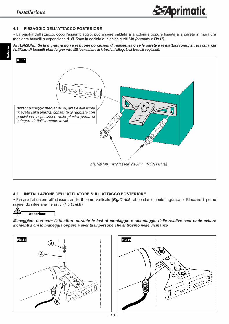
4.1 FISSAGGIO DELL’ATTACCO POSTERIORE La piastra dell’attacco, dopo l’assemblaggio, può essere saldata alla colonna oppure fi ssata alla parete in muratura mediante tasselli a espansione di Ø15mm in acciaio o in ghisa e viti M8 (esempio in Fig.12).ATTENZIONE: Se la muratura non è in buone condizioni di resistenza o se la parete è in mattoni forati, si raccomanda l’utilizzo di tasselli chimici per vite M8 (consultare le istruzioni allegate ai tasselli acqistati).
Fig.14B
A
B
Fig.13
Fig.12
n°2 Viti M8 + n°2 tasselli Ø15 mm (NON inclusi)
4.2 INSTALLAZIONE DELL’ATTUATORE SULL’ATTACCO POSTERIORE Fissare l’attuatore all’attacco tramite il perno verticale (Fig.13 rif.A) abbondantemente ingrassato. Bloccare il perno inserendo i due anelli elastici (Fig.13 rif.B).
Attenzione!
Maneggiare con cura l’attuattore durante le fasi di montaggio e smontaggio dalle relative sedi onde evitare incidenti a chi lo maneggia oppure a eventuali persone che si trovino nelle vicinanze.
nota: il fi ssaggio mediante viti, grazie alle asole ricavate sulla piastra, consente di regolare con precisione la posizione della piastra prima di stringere defi nitivamente le viti.
- 11 -
Italia
no
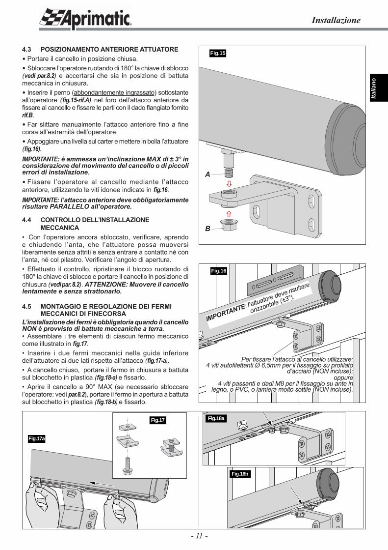
4.3 POSIZIONAMENTO ANTERIORE ATTUATORE Portare il cancello in posizione chiusa. Sbloccare l’operatore ruotando di 180° la chiave di sblocco (vedi par.8.2) e accertarsi che sia in posizione di battuta meccanica in chiusura. Inserire il perno (abbondantemente ingrassato) sottostante all’operatore (fi g.15-rif.A) nel foro dell’attacco anteriore da fi ssare al cancello e fi ssare le parti con il dado fl angiato fornito rif.B. Far slittare manualmente l’attacco anteriore fi no a fi ne corsa all’estremità dell’operatore. Appoggiare una livella sul carter e mettere in bolla l’attuatore (fi g.16).IMPORTANTE: è ammessa un’inclinazione MAX di ± 3° in considerazione del movimento del cancello o di piccoli errori di installazione. Fissare l’operatore al cancello mediante l’attacco anteriore, utilizzando le viti idonee indicate in fi g.16.IMPORTANTE: l’attacco anteriore deve obbligatoriamente risultare PARALLELO all’operatore.
4.4 CONTROLLO DELL’INSTALLAZIONE MECCANICA• Con l’operatore ancora sbloccato, verifi care, aprendo e chiudendo l’anta, che l’attuatore possa muoversi liberamente senza attriti e senza entrare a contatto né con l’anta, né col pilastro. Verifi care l’angolo di apertura.• Effettuato il controllo, ripristinare il blocco ruotando di 180° la chiave di sblocco e portare il cancello in posizione di chiusura (vedi par. 8.2). ATTENZIONE: Muovere il cancello lentamente e senza strattonarlo.
4.5 MONTAGGIO E REGOLAZIONE DEI FERMI MECCANICI DI FINECORSAL’installazione dei fermi è obbligatoria quando il cancello NON è provvisto di battute meccaniche a terra.• Assemblare i tre elementi di ciascun fermo meccanico come illustrato in fi g.17.• Inserire i due fermi meccanici nella guida inferiore dell’attuatore ai due lati rispetto all’attacco (fi g.17-a).• A cancello chiuso, portare il fermo in chiusura a battuta sul blocchetto in plastica (fi g.18-a) e fi ssarlo.• Aprire il cancello a 90° MAX (se necessario sbloccare l’operatore: vedi par.8.2), portare il fermo in apertura a battuta sul blocchetto in plastica (fi g.18-b) e fi ssarlo.
80˚
Fig.16
Installazione
Fig.17a
Per fi ssare l’attacco al cancello utilizzare:4 viti autofi lettanti Ø 6,5mm per il fi ssaggio su profi lato
d’acciaio (NON incluse);oppure
4 viti passanti e dadi M8 per il fi ssaggio su ante in legno, o PVC, o lamiera molto sottile (NON incluse).
Fig.15
Fig.17
IMPORTANTE: l’attuatore deve risultare
orizzontale (±3°).
180˚
Fig.18a
Fig.18b
�
�A
B
- 12 -
Italia
noControlli e regolazioni - Installazione elettrica
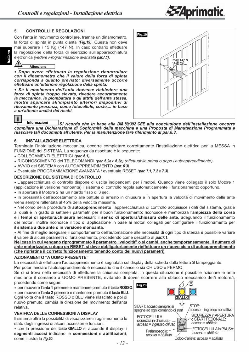
5. CONTROLLI E REGOLAZIONICon l’anta in movimento controllare, tramite un dinamometro, la forza di spinta in punta d’anta (Fig.19). Questa non deve mai superare i 15 Kg (147 N). In caso contrario effettuare la regolazione della forza di esercizio sull’apparecchiatura elettronica (vedere Programmazione avanzata par.7.1).
Attenzione!
Dopo avere effettuato la regolazione ricontrollare con il dinamometro che il valore della forza di spinta corrisponda a quanto previsto; diversamente occorre effettuare un’ulteriore regolazione della spinta. Se il movimento dell’anta dovesse richiedere una forza di spinta troppo elevata, rivedere accuratamente la meccanica, la piombatura e gli attriti dell’anta stessa. Inoltre applicare all’impianto ulteriori dispositivi di rilevamento presenza, come fotocellule, coste,... in base a un’attenta analisi dei rischi.
max 147 N(15 kg)
Fig.19
Informazioni Si ricorda che in base alla DM 89/392 CEE alla conclusione dell’installazione occorre compilare una Dichiarazione di Conformità della macchina e una Proposta di Manutenzione Programmata e rilasciare tali documenti all’utente. Per la manutenzione fare riferimento al par.8.3.
6. INSTALLAZIONE ELETTRICATerminata l’installazione meccanica, occorre completare correttamente l’installazione elettrica per la MESSA in FUNZIONE del SISTEMA. La sequenza da rispettare è la seguente: COLLEGAMENTI ELETTRICI (par. 6.1). RICONOSCIMENTO dei TELECOMANDI (par. 6.2a o 6.2b) (effettuabile prima o dopo l’autoapprendimento). AVVIO del SISTEMA con AUTOAPPRENDIMENTO (par. 6.3). Eventuale PROGRAMMAZIONE AVANZATA / eventuale RESET (par. 7.1, 7.2 e 7.3).DESCRIZIONE DEL SISTEMA DI CONTROLLO L’apparecchiatura di controllo dispone di uscite indipendenti per i motori. Quando viene collegato il solo Motore 1 (applicazione in versione monoanta) il sistema di controllo regola automaticamente il funzionamento opportuno. In apertura il Motore 2 ha un ritardo fi sso di 3 sec. In prossimità dell’accostamento alle battute di arresto in chiusura e in apertura la velocità di movimento delle ante viene sempre rallentata al 45% della velocità massima. Nel corso della procedura di autoapprendimento l’apparecchiatura di controllo acquisisce i dati del sistema, grazie ai quali è in grado di settare i parametri per il buon funzionamento: riconosce e memorizza l’ampiezza della corsa e i tempi di apertura/chiusura necessari; il senso di apertura/chiusura delle ante, adeguando il funzionamento dei motori; inoltre riconosce il tipo di applicazione in base ai motori collegati per confi gurare il funzionamento per il sistema a due ante o in versione monoanta. Al fi ne di meglio adeguare il comportamento dell’automazione alle necessità di ogni tipo di utenza è possibile variare il valore di alcuni parametri di funzionamento, procedendo come descritto al par.7.1.Nel caso in cui vengano riprogrammato il parametro “velocità” o si cambi, anche temporaneamente, il numero di ante motorizzate, o dopo un RESET, si deve obbligatoriamente rieffettuare un nuovo ciclo di autoapprendimento (che ripristina il corretto funzionamento tenendo conto dei nuovi parametri).AZIONAMENTO “A UOMO PRESENTE”La necessità di effettuare l’autoapprendimento è segnalata sul display della scheda dalla lettera S lampeggiante.Per poter lanciare l’autoapprendimento è necessario che il cancello sia CHIUSO e FERMO.Se ci si trova nella necessità di effettuare la chiusura completa, in questa situazione è possibile azionare le ante mediante il comando a UOMO PRESENTE, evitando di dover ricorrere alla sblocco meccanico del/i motore/i, procedendo come segue: per muovere l’anta 1 premere e mantenere premuto il tasto ROSSO. per muovere l’anta 2 premere e mantenere premuto il tasto BLU.Ogni volta che il tasto ROSSO o BLU viene rilasciato e poi di nuovo premuto, cambia la direzione del movimento dell’anta relativa.VERIFICA DELLE CONNESSIONI A DISPLAYIl sistema offre la possibilità di visualizzare in ogni momento lo stato degli ingressi di alcuni accessori e funzioni. con la pressione del tasto GIALLO si accende il display: i segmenti accesi indicano le connessioni e abilitazioni, come illustra la fi g.20.
�
�
START: acceso sempre; si spegne ad ogni comando di start
SICUREZZA in APERTURA o START PEDONALE: acceso = abilitato
STOP:acceso = ingresso non attivo
Prelampeggio: acceso = abilitato
FOTOCELLULA in PAUSA: acceso = abilitata
Colpo d’ariete: acceso = abilitato
FOTOCELLULA sicurezza in chiusura:acceso = ingresso chiuso
GIALLO
Fig.20
- 13 -
Italia
no
Installazione elettrica
SCHEMA A BLOCCHI DELL’APPARECCHIATURA DI CONTROLLO
FA
SE
TE
RR
A
NE
UT
RO
FO
TO
CE
LL
UL
A
LA
MP
EG
GIA
TO
RE
+ 24
V A
CC
ES
SO
RI
ST
AR
T
SICUREZZA in APERTURA
ST
OP
GN
D
+ 24
V
LA
MP
AD
A S
PIA
24V
3W
max
.
PH N
230V
50H
z+6
% -
10%
alim
enta
zio
ne
TRASFORMATORE
SE
CO
ND
AR
IO0-
20V
AC
PR
IMA
RIO
0-23
0VA
C
M1 M2
MOTORE1
MOTORE2
12 Vac 15 W max.
EL
ET
TR
OS
ER
RA
TU
RA
EL
ET
TR
OS
ER
RA
TU
RA
GN
D
ATTENZIONE ! i contatti N.C. devono essere ponticellati verso massa (morsetto 9 o 11) quando non vengono utilizzati. In caso contrario l’automazione NON PUO’ funzionare!NOTA: il morsetto 6 è N.A. per default, ma può diventare N.C. in base al settaggio del parametro H (par.7.1).
Mar
rone
Blu
Mar
rone
Blu
+- + - -
ST
AR
T p
edo
nal
e
LEGENDA:M1 = motore 1 a anta in apertura o monoantaM2 = motore 2 a anta in apertura
= contatto di tipo NO= contatto di tipo NC
24 V AC BATT- +
L N M1 M2 M3 M4 1 3 6 7 10 11 122 4 5 8 9
J1J3M5
J4
FS1 BATT
CN1
CN2
F1
F2
F3
Display
DL1
S1 S2 S3
Fig.21
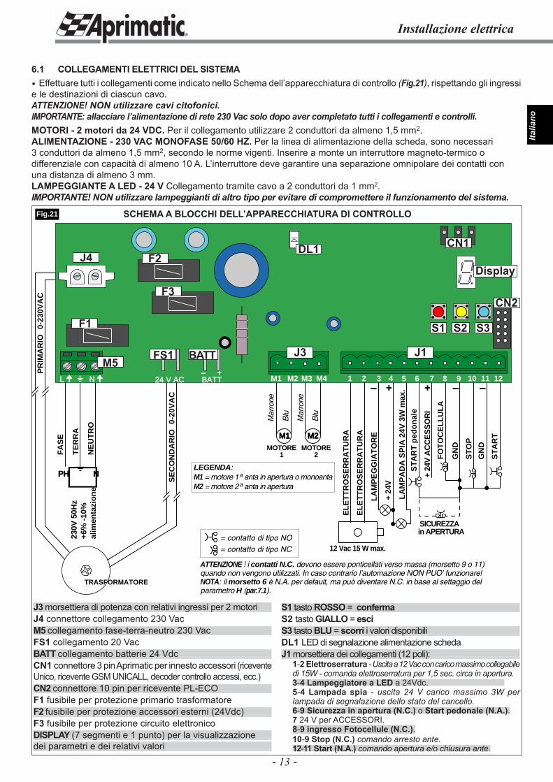
6.1 COLLEGAMENTI ELETTRICI DEL SISTEMA Effettuare tutti i collegamenti come indicato nello Schema dell’apparecchiatura di controllo (Fig.21), rispettando gli ingressi e le destinazioni di ciascun cavo.ATTENZIONE! NON utilizzare cavi citofonici.IMPORTANTE: allacciare l’alimentazione di rete 230 Vac solo dopo aver completato tutti i collegamenti e controlli.MOTORI - 2 motori da 24 VDC. Per il collegamento utilizzare 2 conduttori da almeno 1,5 mm2.ALIMENTAZIONE - 230 VAC MONOFASE 50/60 HZ. Per la linea di alimentazione della scheda, sono necessari 3 conduttori da almeno 1,5 mm2, secondo le norme vigenti. Inserire a monte un interruttore magneto-termico o differenziale con capacità di almeno 10 A. L’interruttore deve garantire una separazione omnipolare dei contatti con una distanza di almeno 3 mm.LAMPEGGIANTE A LED - 24 V Collegamento tramite cavo a 2 conduttori da 1 mm2.IMPORTANTE! NON utilizzare lampeggianti di altro tipo per evitare di compromettere il funzionamento del sistema.
J3 morsettiera di potenza con relativi ingressi per 2 motoriJ4 connettore collegamento 230 VacM5 collegamento fase-terra-neutro 230 VacFS1 collegamento 20 VacBATT collegamento batterie 24 VdcCN1 connettore 3 pin Aprimatic per innesto accessori (ricevente Unico, ricevente GSM UNICALL, decoder controllo accessi, ecc.) CN2 connettore 10 pin per ricevente PL-ECO F1 fusibile per protezione primario trasformatoreF2 fusibile per protezione accessori esterni (24Vdc)F3 fusibile per protezione circuito elettronicoDISPLAY (7 segmenti e 1 punto) per la visualizzazionedei parametri e dei relativi valori
S1 tasto ROSSO = confermaS2 tasto GIALLO = esciS3 tasto BLU = scorri i valori disponibiliDL1 LED di segnalazione alimentazione schedaJ1 morsettiera dei collegamenti (12 poli):
1-2 Elettroserratura - Uscita a 12 Vac con carico massimo collegabile di 15W - comanda elettroserratura per 1,5 sec. circa in apertura.3-4 Lampeggiatore a LED a 24Vdc. 5-4 Lampada spia - uscita 24 V carico massimo 3W per lampada di segnalazione dello stato del cancello.6-9 Sicurezza in apertura (N.C.) o Start pedonale (N.A.).7 24 V per ACCESSORI. 8-9 ingresso Fotocellule (N.C.).10-9 Stop (N.C.) comando arresto ante. 12-11 Start (N.A.) comando apertura e/o chiusura ante.
- 14 -
Italia
noAvvio del sistema e descrizione dei funzionamenti
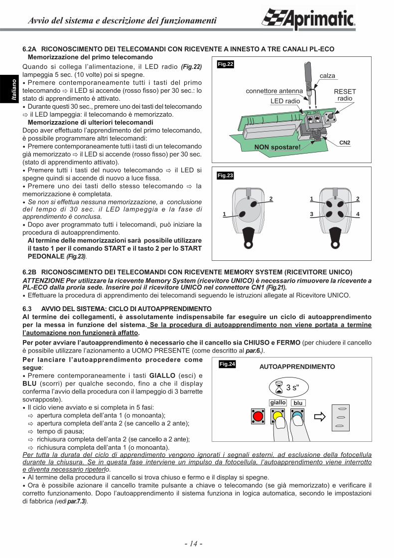
6.2A RICONOSCIMENTO DEI TELECOMANDI CON RICEVENTE A INNESTO A TRE CANALI PL-ECOMemorizzazione del primo telecomando
6.2B RICONOSCIMENTO DEI TELECOMANDI CON RICEVENTE MEMORY SYSTEM (RICEVITORE UNICO)ATTENZIONE Per utilizzare la ricevente Memory System (ricevitore UNICO) è necessario rimuovere la ricevente a PL-ECO dalla proria sede. Inserire poi il ricevitore UNICO nel connettore CN1 (Fig.21). Effettuare la procedura di apprendimento dei telecomandi seguendo le istruzioni allegate al Ricevitore UNICO.
6.3 AVVIO DEL SISTEMA: CICLO DI AUTOAPPRENDIMENTOAl termine dei collegamenti, è assolutamente indispensabile far eseguire un ciclo di autoapprendimento per la messa in funzione del sistema. Se la procedura di autoapprendimento non viene portata a termine l’automazione non funzionerà affatto.Per poter avviare l’autoapprendimento è necessario che il cancello sia CHIUSO e FERMO (per chiudere il cancello è possibile utilizzare l’azionamento a UOMO PRESENTE (come descritto al par.6.).Per lanciare l’autoapprendimento procedere come segue: Premere contemporaneamente i tasti GIALLO (esci) e BLU (scorri) per qualche secondo, fino a che il display conferma l’avvio della procedura con il lampeggio di 3 barrette sovrapposte). Il ciclo viene avviato e si completa in 5 fasi:� apertura completa dell’anta 1 (o monoanta);� apertura completa dell’anta 2 (se cancello a 2 ante);� tempo di pausa;� richiusura completa dell’anta 2 (se cancello a 2 ante);
GND
CN2
�
� 3 s"
giallo blu
Fig.24
Fig.22
1 2
3 4
2
1
Quando si collega l’alimentazione, il LED radio (Fig.22) lampeggia 5 sec. (10 volte) poi si spegne. Premere contemporaneamente tutti i tasti del primo telecomando � il LED si accende (rosso fi sso) per 30 sec.: lo stato di apprendimento è attivato. Durante questi 30 sec., premere uno dei tasti del telecomando � il LED lampeggia: il telecomando è memorizzato.
Memorizzazione di ulteriori telecomandiDopo aver effettuato l’apprendimento del primo telecomando, è possibile programmare altri telecomandi: Premere contemporaneamente tutti i tasti di un telecomando già memorizzato � il LED si accende (rosso fi sso) per 30 sec. (stato di apprendimento attivato). Premere tutti i tasti del nuovo telecomando � il LED si spegne quindi si accende di nuovo a luce fi ssa. Premere uno dei tasti dello stesso telecomando � la memorizzazione è completata. Se non si effettua nessuna memorizzazione, a conclusione del tempo di 30 sec. il LED lampeggia e la fase di apprendimento è conclusa. Dopo aver programmato tutti i telecomandi, può iniziare la procedura di autoapprendimento.
Al termine delle memorizzazioni sarà possibile utilizzare il tasto 1 per il comando START e il tasto 2 per lo START PEDONALE (Fig.23).
� richiusura completa dell’anta 1 (o monoanta).Per tutta la durata del ciclo di apprendimento vengono ignorati i segnali esterni, ad esclusione della fotocellula durante la chiusura. Se in questa fase interviene un impulso da fotocellula, l’autoapprendimento viene interrotto e diventa necessario ripeterlo. Al termine della procedura il cancello si trova chiuso e fermo e il display si spegne. Ora è possibile azionare il cancello tramite pulsante a chiave o telecomando (se già memorizzato) e verifi care il corretto funzionamento. Dopo l’autoapprendimento il sistema funziona in logica automatica, secondo le impostazioni di fabbrica (vedi par.7.3).
Fig.23
AUTOAPPRENDIMENTO
calza
LED radioconnettore antenna RESET
radio
NON spostare!
- 15 -
Italia
no
Programmazione avanzata
���
�
�
�
�
� �
� �� �
�
Tab.4
Fig.25
bluper selezionare
rossoper confermare
� bluseleziona il parametro da modifi care
� rossoentra in programmazione
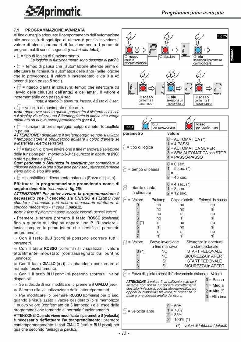
7.1 PROGRAMMAZIONE AVANZATAAl fi ne di meglio adeguare il comportamento dell’automazione alle necessità di ogni tipo di utenza è possibile variare il valore di alcuni parametri di funzionamento. I parametri programmabili sono i seguenti (i valori alla tab.4): = tipo di logica di funzionamento.
Le logiche di funzionamento sono descritte al par.7.3. = tempo di pausa che l’automazione attende prima di effettuare la richiusura automatica delle ante (nelle logiche che lo prevedono). Il valore è incrementabile da 0 a 45 secondi (con passo 5 sec.). = ritardo d’anta in chiusura: tempo che intercorre tra l’avvio della chiusura dell’anta2 e dell’anta1. Il valore è incrementabile con passo 4 sec.
nota: il ritardo in apertura, invece, è fi sso di 3 sec.
= velocità di movimento delle ante.nota: dopo aver variato questo parametro il sistema si blocca e il display visualizza una S lampeggiante in attesa che venga effettuato un nuovo autoapprendimento (par.6.3).
= funzioni di prelampeggio; colpo d’ariete; fotocellula in pausa.ATTENZIONE: disabilitare il prelampeggio se non si utilizza il lampeggiatore; è obbligatorio abilitare il colpo d’ariete se è installata l’elettroserratura. = funzioni di breve inversione a fi ne manovra e selezione della funzione per il morsetto 6-J1: sicurezza in apertura (NC) o start pedonale (NA).Start pedonale o Sicurezza in apertura: per comandare la chiusura parziale di una o due ante per 2 sec.; successivamente viene dato lo stop alle ante.
= sensibilità di rilevamento ostacolo (Forza di spinta).Effettuare la programmazione procedendo come di seguito descritto (esempio in fi g.25):ATTENZIONE! Per poter avviare la programmazione è necessario che il cancello sia CHIUSO e FERMO (per chiudere il cancello può essere necessario effettuare lo sblocco meccanico - si veda il par.8.2).nota: in fase di programmazione vengono ignorati i segnali esterni. Premere e tenere premuto il tasto ROSSO (conferma) fino a quando sul display appare una P. Rilasciare il tasto: compare la prima lettera che identifi ca i parametri programmabili.� Con il tasto BLU (scorri) si possono scorrere tutti i parametri.� Con il tasto ROSSO (conferma) si visualizza il valore attualmente impostato (contrassegnato dal puntino luminoso).� Con il tasto GIALLO (esci) si abbandona per tornare al normale funzionamento.� Con il il tasto BLU (scorri) si possono scorrere i valori disponibili.� Se si decide di non modifi care � premere il GIALLO (esci).� Si torna alla visualizzazione delle lettere/parametri.� Per modifi care � premere ROSSO (conferma) per 3 sec. quando è visualizzato il valore desiderato � si memorizza il nuovo valore (confermato da 3 lampeggi) e si esce dalla programmazione tornando al normale funzionamento.ATTENZIONE! Quando viene modifi cato il parametro S (velocità) è necessario rieffettuare l’autoapprendimento: premere contemporaneamente i tasti GIALLO (esci) e BLU (scorri) per qualche secondo (dettagli al par.6.3).
= tipo di logica
= tempo di pausa
= ritardo d’anta in chiusura
= velocità ante
� rilasciare
� rossoconferma il parametro
� bluseleziona un nuovo valore
� rossoconferma il nuovo valore
ATTENZIONE: il valore 3 va utilizzato solo se il sistema non possa funzionare correttamente con valori inferiori. In questa situazione utilizzare opportuni dispositivi rilevatori di presenza in base a una corretta analisi dei rischi.
parametro valore 0 = AUTOMATICA (*) 1 = 4 PASSI 2 = AUTOMATICA SUPER 3 = SEMIAUTOMATICA con STOP 4 = PASSO-PASSO
0 = 0 sec. 1 = 5 sec. (*) ... = ... 9 = 45 sec.
0 = 4 sec. (*) 1 = 8 sec. 2 = 12 sec.
= Valore Prelamp. Colpo d’ariete Fotocell. in pausa 0 no no no 1 no no sì 2 no sì no 3 no sì sì 4 (*) sì no no 5 sì no sì 6 sì sì no 7 sì sì sì
= Valore Breve inversione Sicurezza in apertura a fi ne manovra o start pedonale 0 (*) NO START PEDONALE 1 NO SICUREZZA in APERT. 2 SÌ START PEDONALE 3 SÌ SICUREZZA in APERT.
= Forza di spinta / sensibilità rilevamento ostacolo Valore 0 = Bassa 1 = Media 2 = Alta (*) 3 = Altissima
0 = 50% 1 = 70% 2 = 85% 3 = 100% (*)
(*) = valori di fabbrica (default)
- 16 -
Italia
noReset - Logiche di funzionamento
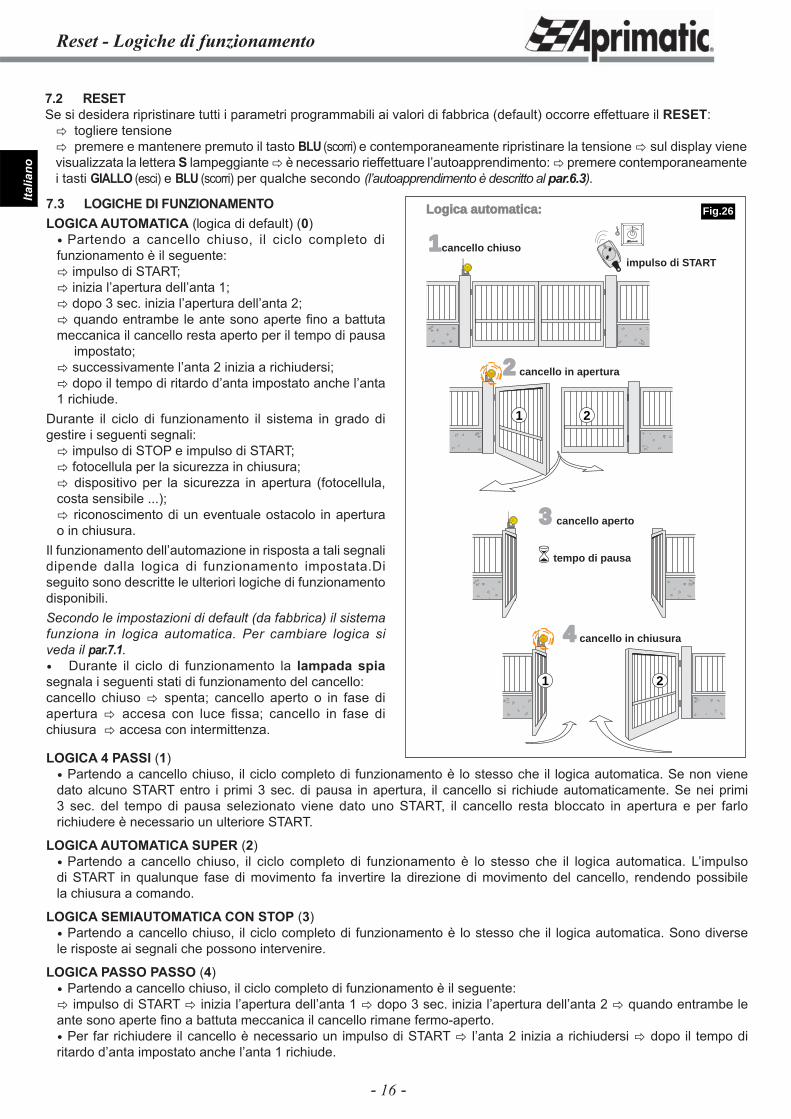
7.2 RESETSe si desidera ripristinare tutti i parametri programmabili ai valori di fabbrica (default) occorre effettuare il RESET:� togliere tensione� premere e mantenere premuto il tasto BLU (scorri) e contemporaneamente ripristinare la tensione � sul display viene visualizzata la lettera S lampeggiante � è necessario rieffettuare l’autoapprendimento: � premere contemporaneamente i tasti GIALLO (esci) e BLU (scorri) per qualche secondo (l’autoapprendimento è descritto al par.6.3).
LOGICA 4 PASSI (1) Partendo a cancello chiuso, il ciclo completo di funzionamento è lo stesso che il logica automatica. Se non viene dato alcuno START entro i primi 3 sec. di pausa in apertura, il cancello si richiude automaticamente. Se nei primi 3 sec. del tempo di pausa selezionato viene dato uno START, il cancello resta bloccato in apertura e per farlo richiudere è necessario un ulteriore START.
LOGICA AUTOMATICA SUPER (2) Partendo a cancello chiuso, il ciclo completo di funzionamento è lo stesso che il logica automatica. L’impulso di START in qualunque fase di movimento fa invertire la direzione di movimento del cancello, rendendo possibile la chiusura a comando.
LOGICA SEMIAUTOMATICA CON STOP (3) Partendo a cancello chiuso, il ciclo completo di funzionamento è lo stesso che il logica automatica. Sono diverse le risposte ai segnali che possono intervenire.
LOGICA PASSO PASSO (4) Partendo a cancello chiuso, il ciclo completo di funzionamento è il seguente:� impulso di START � inizia l’apertura dell’anta 1 � dopo 3 sec. inizia l’apertura dell’anta 2 � quando entrambe le ante sono aperte fi no a battuta meccanica il cancello rimane fermo-aperto. Per far richiudere il cancello è necessario un impulso di START � l’anta 2 inizia a richiudersi � dopo il tempo di ritardo d’anta impostato anche l’anta 1 richiude.
1cancello chiuso
2 cancello in apertura
3 cancello aperto
4 cancello in chiusura
impulso di START
tempo di pausa
1 2
�
21
Logica automatica:7.3 LOGICHE DI FUNZIONAMENTOLOGICA AUTOMATICA (logica di default) (0) Partendo a cancello chiuso, il ciclo completo di funzionamento è il seguente:� impulso di START;� inizia l’apertura dell’anta 1;� dopo 3 sec. inizia l’apertura dell’anta 2;� quando entrambe le ante sono aperte fi no a battuta meccanica il cancello resta aperto per il tempo di pausa impostato;� successivamente l’anta 2 inizia a richiudersi;� dopo il tempo di ritardo d’anta impostato anche l’anta 1 richiude.
Durante il ciclo di funzionamento il sistema in grado di gestire i seguenti segnali:� impulso di STOP e impulso di START;� fotocellula per la sicurezza in chiusura;� dispositivo per la sicurezza in apertura (fotocellula, costa sensibile ...);� riconoscimento di un eventuale ostacolo in apertura o in chiusura.
Il funzionamento dell’automazione in risposta a tali segnali dipende dalla logica di funzionamento impostata.Di seguito sono descritte le ulteriori logiche di funzionamento disponibili.Secondo le impostazioni di default (da fabbrica) il sistema funziona in logica automatica. Per cambiare logica si veda il par.7.1. Durante il ciclo di funzionamento la lampada spia segnala i seguenti stati di funzionamento del cancello:cancello chiuso � spenta; cancello aperto o in fase di apertura � accesa con luce fi ssa; cancello in fase di chiusura � accesa con intermittenza.
Fig.26
- 17 -
Italia
no
Logiche di funzionamento
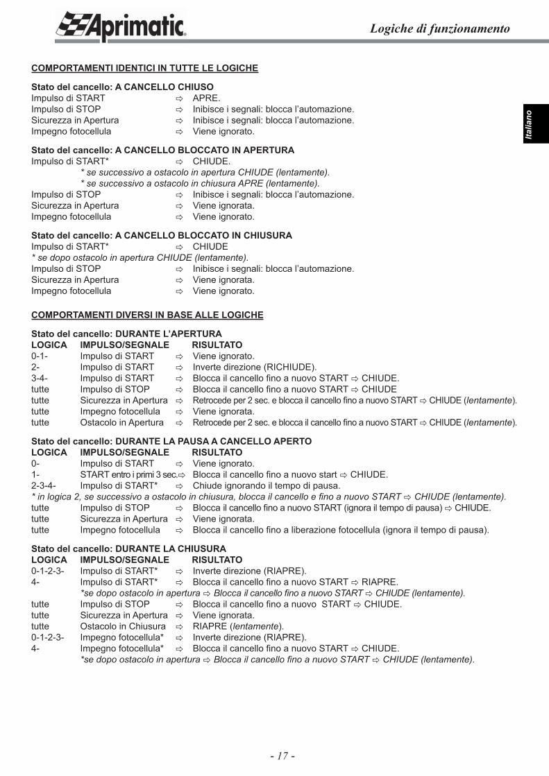
COMPORTAMENTI IDENTICI IN TUTTE LE LOGICHE
Stato del cancello: A CANCELLO CHIUSOImpulso di START � APRE.Impulso di STOP � Inibisce i segnali: blocca l’automazione.Sicurezza in Apertura � Inibisce i segnali: blocca l’automazione.Impegno fotocellula � Viene ignorato.
Stato del cancello: A CANCELLO BLOCCATO IN APERTURAImpulso di START* � CHIUDE. * se successivo a ostacolo in apertura CHIUDE (lentamente). * se successivo a ostacolo in chiusura APRE (lentamente).Impulso di STOP � Inibisce i segnali: blocca l’automazione.Sicurezza in Apertura � Viene ignorata.Impegno fotocellula � Viene ignorato.
Stato del cancello: A CANCELLO BLOCCATO IN CHIUSURAImpulso di START* � CHIUDE* se dopo ostacolo in apertura CHIUDE (lentamente).Impulso di STOP � Inibisce i segnali: blocca l’automazione.Sicurezza in Apertura � Viene ignorata.Impegno fotocellula � Viene ignorato.
COMPORTAMENTI DIVERSI IN BASE ALLE LOGICHE
Stato del cancello: DURANTE L’APERTURA LOGICA IMPULSO/SEGNALE RISULTATO0-1- Impulso di START � Viene ignorato.2- Impulso di START � Inverte direzione (RICHIUDE).3-4- Impulso di START � Blocca il cancello fi no a nuovo START � CHIUDE.tutte Impulso di STOP � Blocca il cancello fi no a nuovo START � CHIUDEtutte Sicurezza in Apertura � Retrocede per 2 sec. e blocca il cancello fi no a nuovo START � CHIUDE (lentamente).tutte Impegno fotocellula � Viene ignorata.tutte Ostacolo in Apertura � Retrocede per 2 sec. e blocca il cancello fi no a nuovo START � CHIUDE (lentamente).
Stato del cancello: DURANTE LA PAUSA A CANCELLO APERTO LOGICA IMPULSO/SEGNALE RISULTATO0- Impulso di START � Viene ignorato.1- START entro i primi 3 sec. � Blocca il cancello fi no a nuovo start � CHIUDE.2-3-4- Impulso di START* � Chiude ignorando il tempo di pausa.* in logica 2, se successivo a ostacolo in chiusura, blocca il cancello e fi no a nuovo START � CHIUDE (lentamente).tutte Impulso di STOP � Blocca il cancello fi no a nuovo START (ignora il tempo di pausa) � CHIUDE.tutte Sicurezza in Apertura � Viene ignorata.tutte Impegno fotocellula � Blocca il cancello fi no a liberazione fotocellula (ignora il tempo di pausa).
Stato del cancello: DURANTE LA CHIUSURA LOGICA IMPULSO/SEGNALE RISULTATO0-1-2-3- Impulso di START* � Inverte direzione (RIAPRE).4- Impulso di START* � Blocca il cancello fi no a nuovo START � RIAPRE. *se dopo ostacolo in apertura � Blocca il cancello fi no a nuovo START � CHIUDE (lentamente).tutte Impulso di STOP � Blocca il cancello fi no a nuovo START � CHIUDE.tutte Sicurezza in Apertura � Viene ignorata.tutte Ostacolo in Chiusura � RIAPRE (lentamente).0-1-2-3- Impegno fotocellula* � Inverte direzione (RIAPRE).4- Impegno fotocellula* � Blocca il cancello fi no a nuovo START � CHIUDE. *se dopo ostacolo in apertura � Blocca il cancello fi no a nuovo START � CHIUDE (lentamente).
- 18 -
Italia
no
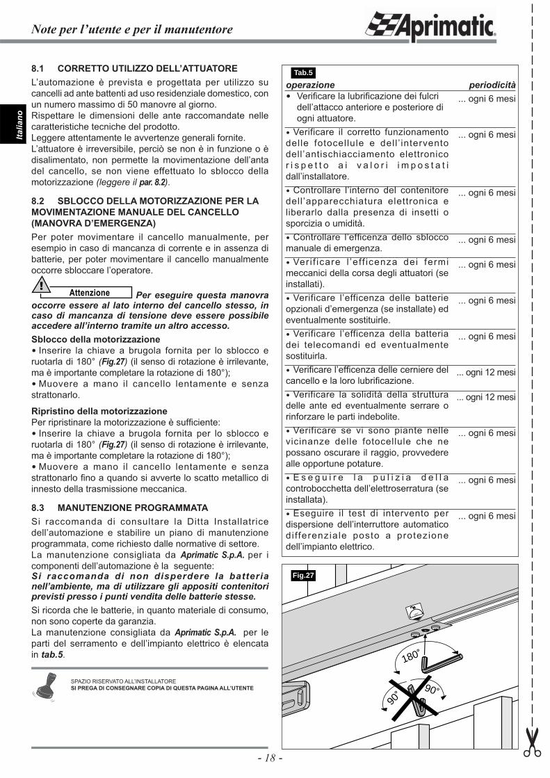
operazione Verifi care la lubrifi cazione dei fulcri
dell’attacco anteriore e posteriore di ogni attuatore.
Verificare il corretto funzionamento delle fotocellule e dell ’ intervento dell’antischiacciamento elettronico r i s p e t t o a i v a l o r i i m p o s t a t i dall’installatore. Controllare l’interno del contenitore dell ’apparecchiatura elettronica e liberarlo dalla presenza di insetti o sporcizia o umidità. Controllare l’effi cenza dello sblocco manuale di emergenza. Ver i f icare l ’e ff icenza dei fermi meccanici della corsa degli attuatori (se installati). Verificare l’efficenza delle batterie opzionali d’emergenza (se installate) ed eventualmente sostituirle. Verificare l’efficenza della batteria dei telecomandi ed eventualmente sostituirla. Verifi care l’effi cenza delle cerniere del cancello e la loro lubrifi cazione. Verificare la solidità della struttura delle ante ed eventualmente serrare o rinforzare le parti indebolite. Verificare se vi sono piante nelle vicinanze delle fotocellule che ne possano oscurare il raggio, provvedere alle opportune potature. E s e g u i r e l a p u l i z i a d e l l a controbocchetta dell’elettroserratura (se installata). Eseguire il test di intervento per dispersione dell’interruttore automatico di fferenziale posto a protezione dell’impianto elettrico.
periodicità... ogni 6 mesi
... ogni 6 mesi
... ogni 6 mesi
... ogni 6 mesi
... ogni 6 mesi
... ogni 6 mesi
... ogni 6 mesi
... ogni 12 mesi
... ogni 12 mesi
... ogni 6 mesi
... ogni 6 mesi
... ogni 6 mesi
8.1 CORRETTO UTILIZZO DELL’ATTUATOREL’automazione è prevista e progettata per utilizzo su cancelli ad ante battenti ad uso residenziale domestico, con un numero massimo di 50 manovre al giorno. Rispettare le dimensioni delle ante raccomandate nelle caratteristiche tecniche del prodotto.Leggere attentamente le avvertenze generali fornite.L’attuatore è irreversibile, perciò se non è in funzione o è disalimentato, non permette la movimentazione dell’anta del cancello, se non viene effettuato lo sblocco della motorizzazione (leggere il par. 8.2).
8.2 SBLOCCO DELLA MOTORIZZAZIONE PER LA MOVIMENTAZIONE MANUALE DEL CANCELLO (MANOVRA D’EMERGENZA)Per poter movimentare il cancello manualmente, per esempio in caso di mancanza di corrente e in assenza di batterie, per poter movimentare il cancello manualmente occorre sbloccare l’operatore.
Attenzione! Per eseguire questa manovra
occorre essere al lato interno del cancello stesso, in caso di mancanza di tensione deve essere possibile accedere all’interno tramite un altro accesso.Sblocco della motorizzazione Inserire la chiave a brugola fornita per lo sblocco e ruotarla di 180° (Fig.27) (il senso di rotazione è irrilevante, ma è importante completare la rotazione di 180°); Muovere a mano il cancello lentamente e senza strattonarlo.
Ripristino della motorizzazionePer ripristinare la motorizzazione è suffi ciente: Inserire la chiave a brugola fornita per lo sblocco e ruotarla di 180° (Fig.27) (il senso di rotazione è irrilevante, ma è importante completare la rotazione di 180°); Muovere a mano il cancello lentamente e senza strattonarlo fi no a quando si avverte lo scatto metallico di innesto della trasmissione meccanica.
8.3 MANUTENZIONE PROGRAMMATASi raccomanda di consultare la Ditta Installatrice dell’automazione e stabilire un piano di manutenzione programmata, come richiesto dalle normative di settore.La manutenzione consigliata da Aprimatic S.p.A. per i componenti dell’automazione è la seguente:Si raccomanda di non disperdere la batteria nell’ambiente, ma di utilizzare gli appositi contenitori previsti presso i punti vendita delle batterie stesse.Si ricorda che le batterie, in quanto materiale di consumo, non sono coperte da garanzia.La manutenzione consigliata da Aprimatic S.p.A. per le parti del serramento e dell’impianto elettrico è elencata in tab.5.
180˚
180˚
90˚
90˚
Fig.27
Note per l’utente e per il manutentore
✂
SPAZIO RISERVATO ALL’INSTALLATORESI PREGA DI CONSEGNARE COPIA DI QUESTA PAGINA ALL’UTENTE
Tab.5
- 19 -
Engl
ish
180˚
180˚
2
3x0.75 Ø
6
3x0.75 Ø
3x0.75 Ø
2x1.5 Ø
1
2x1.5 Ø
2x1 Ø
1
5
7 7
10Alc= 30mA 4
8
Aprimatic
Aprimatic
3
9
Overview
�
max 147 N(15 kg)
�
L
a
B
Y
A
E
L
30 mm
PH
AS
E
EA
RT
H
NE
UT
RA
L
PHPH N
230V
50H
z+6
% -
10%
po
wer
su
pp
ly
TRANSFORMER
SE
CO
ND
AR
Y0-
20V
AC
PR
IMA
RY
0-23
0VA
C
M1M1 M2M2
MOTOR1
MOTOR2
LEGENDM1 = motor 1st wing or single wing opening M2 = motor 2nd wing opening
Brow
n
Brow
n
Blu
e
Blu
e
FL
AS
HIN
G L
IGH
T
+ 24
V
WA
RN
ING
LIG
HT
24V
3W
MA
X.
12 Vac 15 W max.
EL
EC
TR
O-L
OC
K
EL
EC
TR
O-L
OC
K PH
OT
OC
EL
L
+ 24
V A
CC
ES
SO
RIE
S
ST
AR
T
STA
RT
PE
DE
STR
IAN
ST
OP
GN
D
GN
D
SAFETY OPENING
24 V AC24 V AC BATTBATT- + +
L N M1 M2 M3 M4 1 3 6 7 10 11 122 4 5 8 9+- + - -
CAUTION! The NC contacts must be jumpered to the earthing (terminal 9 or 11) when not used. If they are not, the automation CANNOT OPERATE!NOTA: the terminal 6 (NO) may become NC depending on the H parameter setting (par.7.1).
= NO type contact= NC type contact
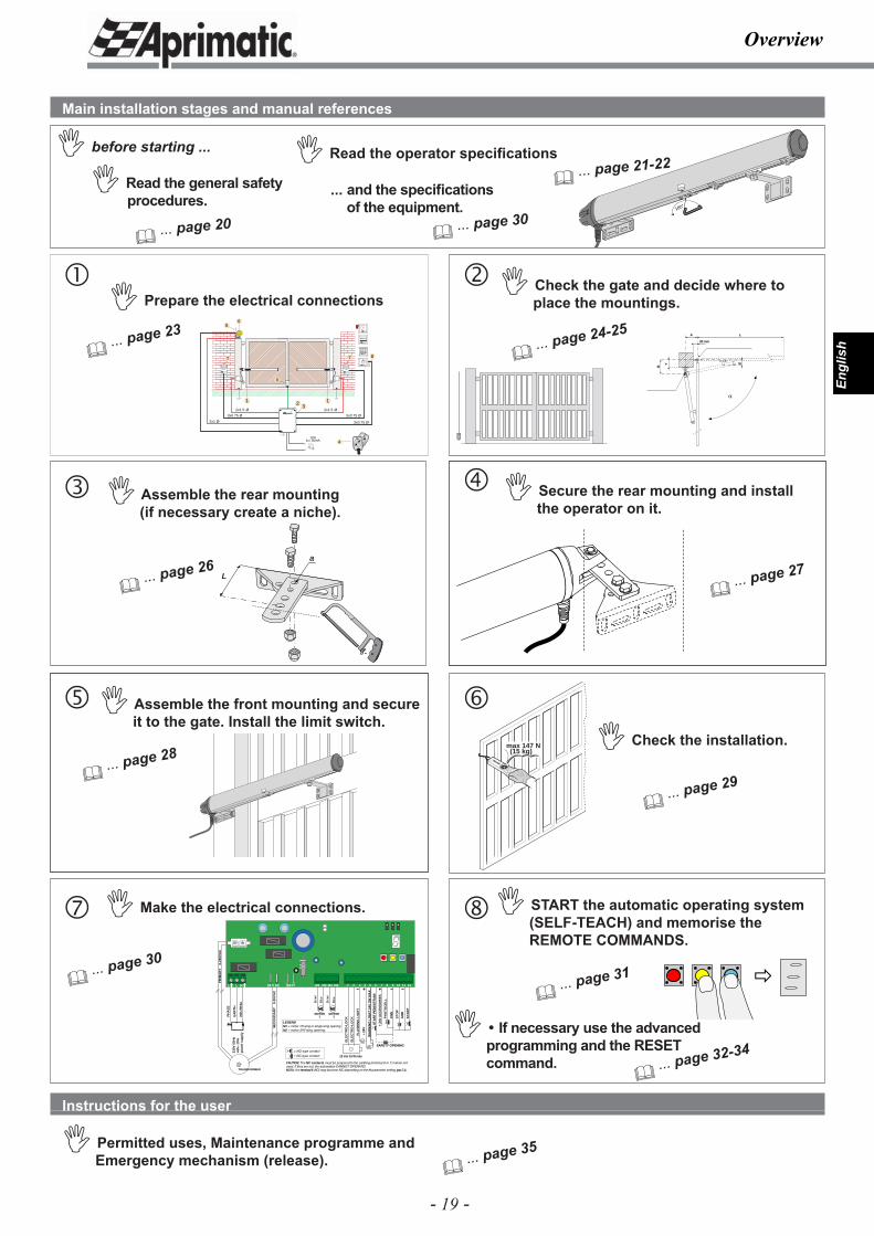
Main installation stages and manual references
� Read the general safety procedures.
� Read the operator specifi cations
� Check the gate and decide where to place the mountings.
Instructions for the user
� Permitted uses, Maintenance programme and Emergency mechanism (release).
� ... page 20
� ... page 21-22� before starting ...
� Prepare the electrical connections
� ... page 23
� ... page 26
� Assemble the rear mounting(if necessary create a niche).
� Secure the rear mounting and install the operator on it.
��
180˚
�
� ... page 27
� ... page 28
� Assemble the front mounting and secure it to the gate. Install the limit switch.
�� Check the installation.
� ... page 29
� ... page 30
� Make the electrical connections.
� ... page 24-25
� ... page 35
�
� START the automatic operating system (SELF-TEACH) and memorise the REMOTE COMMANDS.
� ... page 31
� If necessary use the advanced programming and the RESET command.
� ... page 32-34
... and the specifi cations of the equipment.
� ... page 30
- 20 -
Engl
ish
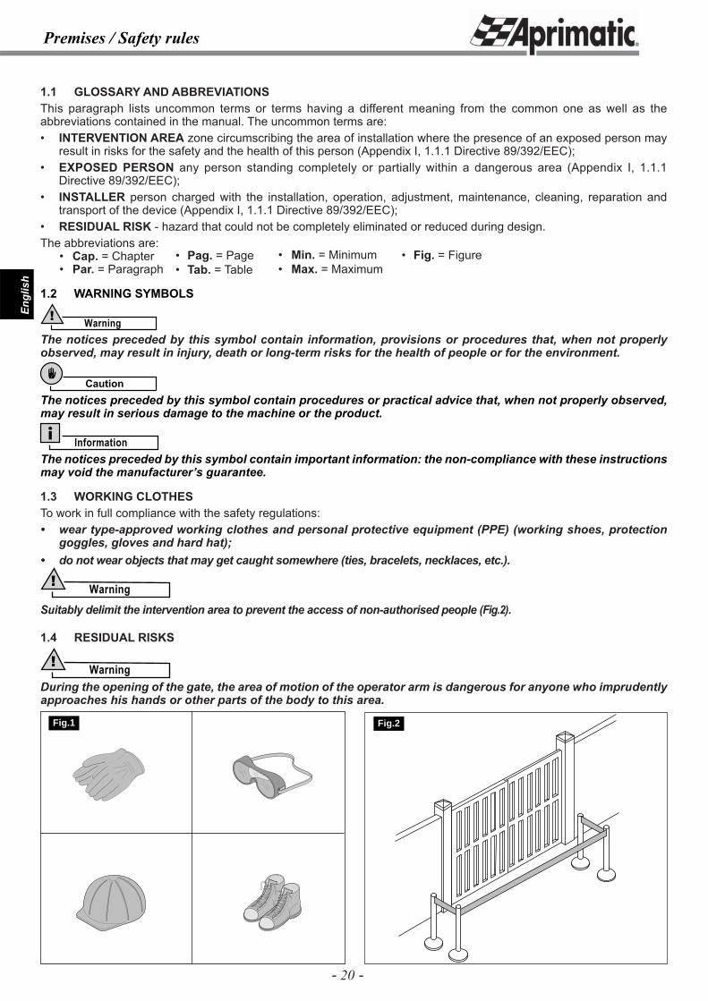
1.1 GLOSSARY AND ABBREVIATIONSThis paragraph lists uncommon terms or terms having a different meaning from the common one as well as the abbreviations contained in the manual. The uncommon terms are:• INTERVENTION AREA zone circumscribing the area of installation where the presence of an exposed person may
result in risks for the safety and the health of this person (Appendix I, 1.1.1 Directive 89/392/EEC);• EXPOSED PERSON any person standing completely or partially within a dangerous area (Appendix I, 1.1.1
Directive 89/392/EEC);• INSTALLER person charged with the installation, operation, adjustment, maintenance, cleaning, reparation and
transport of the device (Appendix I, 1.1.1 Directive 89/392/EEC);• RESIDUAL RISK - hazard that could not be completely eliminated or reduced during design.The abbreviations are: • Cap. = Chapter • Par. = Paragraph
1.2 WARNING SYMBOLS
Warning!
The notices preceded by this symbol contain information, provisions or procedures that, when not properly observed, may result in injury, death or long-term risks for the health of people or for the environment.
Caution
The notices preceded by this symbol contain procedures or practical advice that, when not properly observed, may result in serious damage to the machine or the product.
InformationThe notices preceded by this symbol contain important information: the non-compliance with these instructions may void the manufacturer’s guarantee.
1.3 WORKING CLOTHESTo work in full compliance with the safety regulations:• wear type-approved working clothes and personal protective equipment (PPE) (working shoes, protection
goggles, gloves and hard hat);• do not wear objects that may get caught somewhere (ties, bracelets, necklaces, etc.).
Warning!
Suitably delimit the intervention area to prevent the access of non-authorised people (Fig.2).
1.4 RESIDUAL RISKS
Warning!During the opening of the gate, the area of motion of the operator arm is dangerous for anyone who imprudently approaches his hands or other parts of the body to this area.
• Pag. = Page• Tab. = Table
• Min. = Minimum• Max. = Maximum
• Fig. = Figure
Premises / Safety rules
Fig.1 Fig.2
- 21 -
Engl
ish
Operator specifi cations
2.1 USE AND FIELD OF APPLICATIONThe RAIDER electro-mechanical operator is designed to move double wing gates or single wing gates automatically.It should be used on residential gates only and is designed for gates which are not open/closed more than 50 times daily.
Information• Only use the product for the permitted uses specifi ed. Do not use the product for purposes other than
those specifi ed.• Do not tamper with or modify the product.• The product should only be installed using APRIMATIC material.
Caution
The operator does not form part of the support or safety system of the gate. The gate should already have adequate safety and support features.
2.2 GENERAL SPECIFICATIONS- The RAIDER operator is non-reversible and will therefore keep gates with wings up to 1.8 metres long in the open or closed position without the need for an electric locking device.Note: For longer wings (up to a maximum of 3 metres) you should use an electric locking device.WARNING: The motor is non-reversing. This feature prevents intrusion on any size gate. - The emergency release will enable manual control of the gate in the event of a power failure.The emergency release is easily accessible on the lower part of the operator. It is guaranteed to work and is easy to use (see par. 8.2).- Anti-crushing safety is set by adjusting the Aprimatic controller model CCR24 or any similar Aprimatic controller model fi tted.IMPORTANT! DO NOT use other electronic equipment Aprimatic S.p.A. declines all liability for damages caused by failure to follow these instructions.
2.3 TECHNICAL DATA (Table 1)
Warning!
The noise level of the operator on release from the wing and the pillar, is within the maximum limits established by EU regulations.
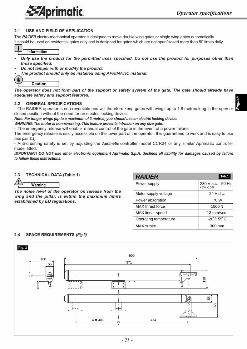
2.4 SPACE REQUIREMENTS (Fig.3)
70 W
1500 N
13 mm/sec.
-20˚/+55˚C
300 mm
RAIDERPower supply
24 V d.c.Motor supply voltage
Power absorption
MAX thrust force
MAX linear speed
Operating temperature
MAX stroke
230 V a.c. - 50 Hz+6% -10%
Tab.1
55
909
871
128
55
168
168
C = 300 474
Fig. 3
- 22 -
Engl
ish
Operator specifi cations
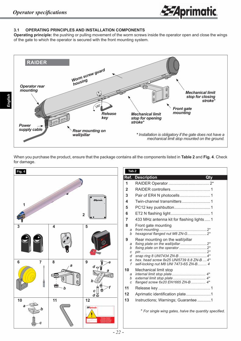
3.1 OPERATING PRINCIPLES AND INSTALLATION COMPONENTSOperating principle: the pushing or pulling movement of the worm screws inside the operator open and close the wings of the gate to which the operator is secured with the front mounting system.
Ref. Description Qty 1 RAIDER Operator .................................... 2* 2 RAIDER controllers ...................................1 3 Pair of ER4 N photocells ...........................1 4 Twin-channel transmitters .........................1 5 PC12 key pushbutton ................................1 6 ET2 N fl ashing light ...................................1 7 433 MHz antenna kit for fl ashing lights ..... 1 8 Front gate mounting a front mounting ...............................................2* b hexagonal fl anged nut M8 ZN-G ...................2* 9 Rear mounting on the wall/pillar a fi xing plate on the wall/pillar ..........................2* b fi xing plate on the operator ...........................2* c pin .................................................................2* d snap ring 8 UNI7434 ZN-B ...........................4* e hex. head screw 8x25 UNI5739 8.8 ZN-B ....4* f self-locking nut M8 UNI 7473-6S ZN-B ......... 4 10 Mechanical limit stop a internal limit stop plate ................................. 4* b external limit stop plate ................................ 4* c fl anged screw 6x20 EN1665 ZN-B .............. 4* 11 Release key ..............................................1 12 Aprimatic identifi cation plate ........................1 13 Instructions; Warnings; Guarantee .............1
* For single wing gates, halve the quantity specifi ed.
4
7
11
1
Aprimatic
5
96
2
3
12fi
IL CAMPIONE DELL’AUTOMAZIONE
!APERTURA AUTOMATICA
AUTOMATIC OPENINGOUVERTURE AUTOMATIQUEAUTOMATISCHE ÖFFNUNGAPERTURA AUTOMATICA
A58
4500
0
name model
serial number
a
b
c
de
d
When you purchase the product, ensure that the package contains all the components listed in Table 2 and Fig. 4. Check for damage.
180˚
180˚Front gate mounting
Rear mounting on wall/pillar
Powersupply cable
Release key
RAIDER
Operator rear mounting
Worm screw guard
housing
Mechanical limit stop for opening stroke*
Mechanical limit stop for closing
stroke*
* Installation is obligatory if the gate does not have a mechanical limit stop mounted on the ground.
Tab.2 Fig. 4
f
10a
c
b
8
b
a
- 23 -
Engl
ish
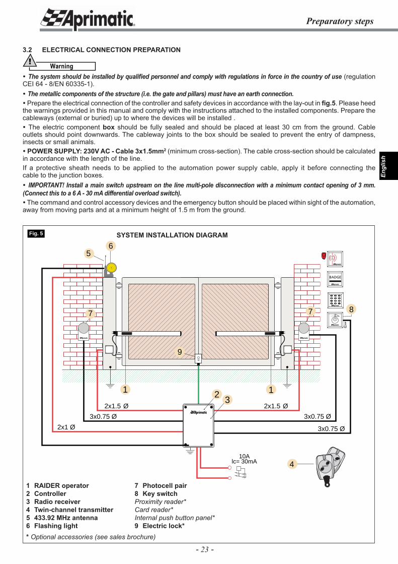
3.2 ELECTRICAL CONNECTION PREPARATION
Warning!
The system should be installed by qualifi ed personnel and comply with regulations in force in the country of use (regulation CEI 64 - 8/EN 60335-1). The metallic components of the structure (i.e. the gate and pillars) must have an earth connection. Prepare the electrical connection of the controller and safety devices in accordance with the lay-out in fi g.5. Please heed the warnings provided in this manual and comply with the instructions attached to the installed components. Prepare the cableways (external or buried) up to where the devices will be installed . The electric component box should be fully sealed and should be placed at least 30 cm from the ground. Cable outlets should point downwards. The cableway joints to the box should be sealed to prevent the entry of dampness, insects or small animals. POWER SUPPLY: 230V AC - Cable 3x1.5mm2 (minimum cross-section). The cable cross-section should be calculated in accordance with the length of the line.If a protective sheath needs to be applied to the automation power supply cable, apply it before connecting the cable to the junction boxes. IMPORTANT! Install a main switch upstream on the line multi-pole disconnection with a minimum contact opening of 3 mm. (Connect this to a 6 A - 30 mA differential overload switch). The command and control accessory devices and the emergency button should be placed within sight of the automation, away from moving parts and at a minimum height of 1.5 m from the ground.
Preparatory steps
2
3x0.75 Ø
6
3x0.75 Ø
3x0.75 Ø
2x1.5 Ø
1
2x1.5 Ø
2x1 Ø
1
5
7 7
10Alc= 30mA 4
8
Aprimatic
Aprimatic
3
9
Fig. 5 SYSTEM INSTALLATION DIAGRAM
7 Photocell pair8 Key switchProximity reader*Card reader* Internal push button panel*9 Electric lock*
1 RAIDER operator2 Controller3 Radio receiver4 Twin-channel transmitter5 433.92 MHz antenna 6 Flashing light* Optional accessories (see sales brochure)
- 24 -
Engl
ish
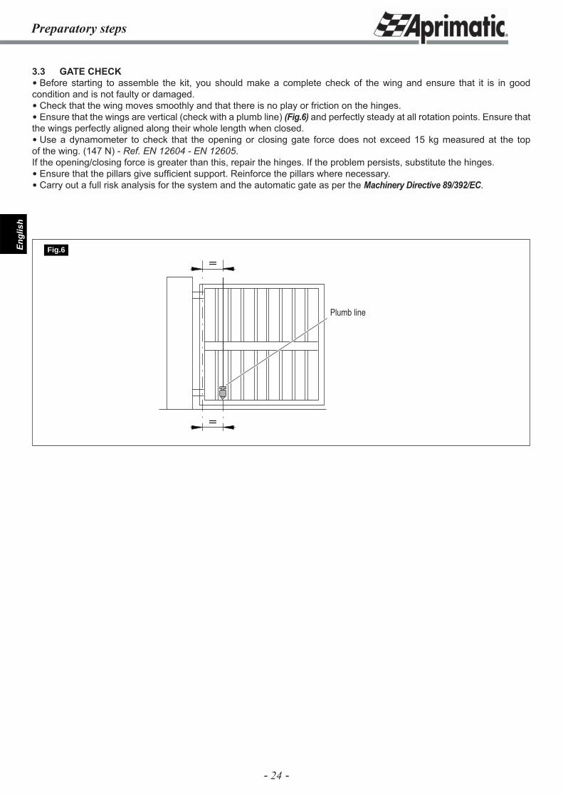
3.3 GATE CHECK Before starting to assemble the kit, you should make a complete check of the wing and ensure that it is in good condition and is not faulty or damaged. Check that the wing moves smoothly and that there is no play or friction on the hinges. Ensure that the wings are vertical (check with a plumb line) (Fig.6) and perfectly steady at all rotation points. Ensure that the wings perfectly aligned along their whole length when closed. Use a dynamometer to check that the opening or closing gate force does not exceed 15 kg measured at the top of the wing. (147 N) - Ref. EN 12604 - EN 12605.If the opening/closing force is greater than this, repair the hinges. If the problem persists, substitute the hinges. Ensure that the pillars give suffi cient support. Reinforce the pillars where necessary. Carry out a full risk analysis for the system and the automatic gate as per the Machinery Directive 89/392/EC.
Preparatory steps
Plumb line
Fig.6
- 25 -
Engl
ish
B
Y
A
E
L
30 mm
Preparatory steps
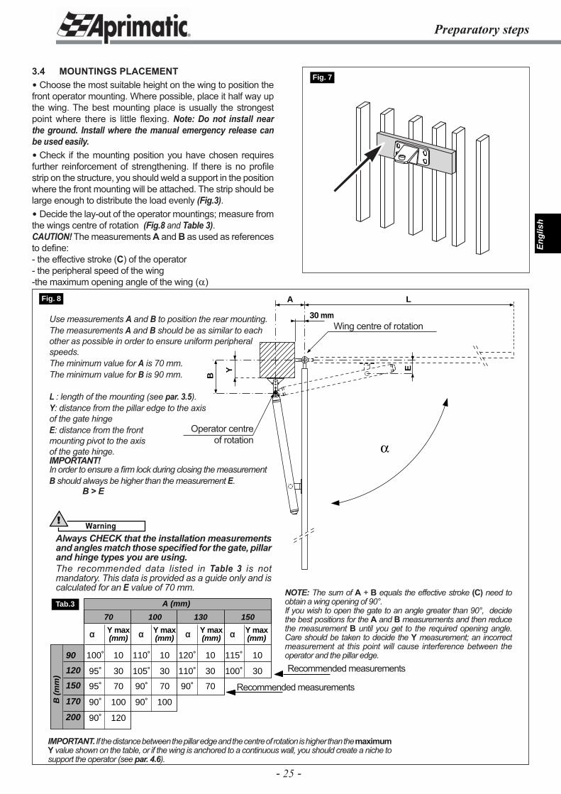
3.4 MOUNTINGS PLACEMENT Choose the most suitable height on the wing to position the front operator mounting. Where possible, place it half way up the wing. The best mounting place is usually the strongest point where there is little fl exing. Note: Do not install near the ground. Install where the manual emergency release can be used easily. Check if the mounting position you have chosen requires further reinforcement of strengthening. If there is no profi le strip on the structure, you should weld a support in the position where the front mounting will be attached. The strip should be large enough to distribute the load evenly (Fig.3). Decide the lay-out of the operator mountings; measure from the wings centre of rotation (Fig.8 and Table 3).CAUTION! The measurements A and B as used as references to defi ne:- the effective stroke (C) of the operator- the peripheral speed of the wing-the maximum opening angle of the wing (α)
Fig. 7
IMPORTANT. If the distance between the pillar edge and the centre of rotation is higher than the maximum Y value shown on the table, or if the wing is anchored to a continuous wall, you should create a niche to support the operator (see par. 4.6).
90
120
150
170
200
B (
mm
)
A (mm)
α Y max α Y max α Y max α Y max(mm) (mm) (mm) (mm)
70 100 130 150
100˚ 10 110˚ 10 120˚ 10 115˚ 10
95˚ 30 105˚ 30 110˚ 30 100˚ 30
95˚ 70 90˚ 70 90˚ 70
90˚ 100 90˚ 100
90˚ 120
Tab.3
Fig. 8
Recommended measurements
Recommended measurements
NOTE: The sum of A + B equals the effective stroke (C) need to obtain a wing opening of 90°.If you wish to open the gate to an angle greater than 90°, decide the best positions for the A and B measurements and then reduce the measurement B until you get to the required opening angle. Care should be taken to decide the Y measurement; an incorrect measurement at this point will cause interference between the operator and the pillar edge.
Use measurements A and B to position the rear mounting. The measurements A and B should be as similar to each other as possible in order to ensure uniform peripheral speeds.The minimum value for A is 70 mm.The minimum value for B is 90 mm.
L : length of the mounting (see par. 3.5).Y: distance from the pillar edge to the axisof the gate hingeE: distance from the frontmounting pivot to the axisof the gate hinge.IMPORTANT!In order to ensure a fi rm lock during closing the measurement B should always be higher than the measurement E.
B > E
Wing centre of rotation
Operator centreof rotation
Warning!
Always CHECK that the installation measurements and angles match those specifi ed for the gate, pillar and hinge types you are using.The recommended data listed in Table 3 is not mandatory. This data is provided as a guide only and is calculated for an E value of 70 mm.
- 26 -
Engl
ish
L =
55 m
m
L =
65 m
m
L =
98 m
m
L =
80 m
m
L =
110
mm
L =
90 m
m
xx
Y
60
180
min
.
50
150
1200
Y MAX. from the hinge axis to the plate surface
B
A
50
150 min.
Y
B
A
Fig.11
Preparatory steps
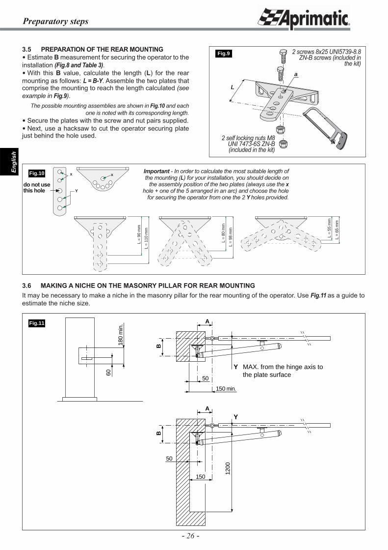
3.5 PREPARATION OF THE REAR MOUNTING Estimate B measurement for securing the operator to the installation (Fig.8 and Table 3). With this B value, calculate the length (L) for the rear mounting as follows: L = B-Y. Assemble the two plates that comprise the mounting to reach the length calculated (see example in Fig.9).
The possible mounting assemblies are shown in Fig.10 and each one is noted with its corresponding length.
Secure the plates with the screw and nut pairs supplied. Next, use a hacksaw to cut the operator securing plate just behind the hole used.
L
a
Fig.9 2 screws 8x25 UNI5739-8.8 ZN-B screws (included in
the kit)
2 self locking nuts M8 UNI 7473-6S ZN-B (included in the kit)
Important - In order to calculate the most suitable length of the mounting (L) for your installation, you should decide on
the assembly position of the two plates (always use the x hole + one of the 5 arranged in an arc) and choose the hole
for securing the operator from one the 2 Y holes provided.
3.6 MAKING A NICHE ON THE MASONRY PILLAR FOR REAR MOUNTINGIt may be necessary to make a niche in the masonry pillar for the rear mounting of the operator. Use Fig.11 as a guide to estimate the niche size.
Fig.10
do not use this hole
- 27 -
Engl
ish
Installation
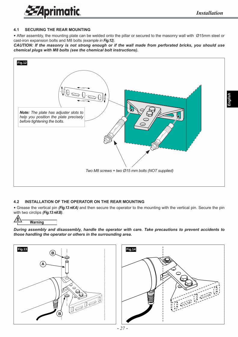
4.1 SECURING THE REAR MOUNTING After assembly, the mounting plate can be welded onto the pillar or secured to the masonry wall with Ø15mm steel or cast-iron expansion bolts and M8 bolts (example in Fig.12).CAUTION: If the masonry is not strong enough or if the wall made from perforated bricks, you should use chemical plugs with M8 bolts (see the chemical bolt instructions).
Fig.14B
A
B
Fig.13
Fig.12
Two M8 screws + two Ø15 mm bolts (NOT supplied)
4.2 INSTALLATION OF THE OPERATOR ON THE REAR MOUNTING Grease the vertical pin (Fig.13 réf.A) and then secure the operator to the mounting with the vertical pin. Secure the pin with two circlips (Fig.13 réf.B).
Warning!
During assembly and disassembly, handle the operator with care. Take precautions to prevent accidents to those handling the operator or others in the surrounding area.
Note: The plate has adjuster slots to help you position the plate precisely before tightening the bolts.
- 28 -
Engl
ish
4.3 FRONT OPERATOR PLACEMENT
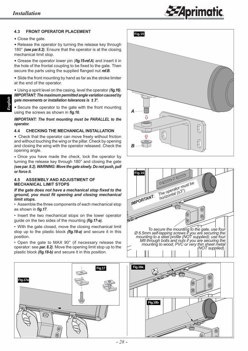
Close the gate. Release the operator by turning the release key through 180° (see par.8.2). Ensure that the operator is at the closing mechanical limit stop. Grease the operator lower pin (fi g.15-ref.A) and insert it in the hole of the frontal coupling to be fi xed to the gate. Then secure the parts using the supplied fl anged nut ref.B.
Slide the front mounting by hand as far as the stroke limiter at the end of the operator.
Using a spirit level on the casing, level the operator (fi g.16). IMPORTANT: The maximum permitted angle variation caused by gate movements or installation tolerances is ± 3°.
Secure the operator to the gate with the front mounting using the screws as shown in fi g.16.
IMPORTANT: The front mounting must be PARALLEL to the operator.4.4 CHECKING THE MECHANICAL INSTALLATION Check that the operator can move freely without friction and without touching the wing or the pillar. Check by opening and closing the wing with the operator released. Check the opening angle. Once you have made the check, lock the operator by turning the release key through 180° and closing the gate (see par. 8.2). WARNING: Move the gate slowly. Do not push, pull or force it.
4.5 ASSEMBLY AND ADJUSTMENT OF MECHANICAL LIMIT STOPSIf the gate does not have a mechanical stop fi xed to the ground, you must fi t opening and closing mechanical limit stops.• Assemble the three components of each mechanical stop as shown in fi g.17.• Insert the two mechanical stops on the lower operator guide on the two sides of the mounting (fi g.17-a).• With the gate closed, move the closing mechanical limit stop up to the plastic block (fi g.18-a) and secure it in this position.• Open the gate to MAX 90° (if necessary release the operator: see par. 8.2). Move the opening limit stop up to the plastic block (fi g.18-b) and secure it in this position.
Fig.16
Installation
Fig.17a
To secure the mounting to the gate, use four Ø 6.5mm self-tapping screws if you are securing the mounting to a steel profi le (NOT supplied); use four
M8 through bolts and nuts if you are securing the mounting to wood, PVC or very thin sheet metal
(NOT supplied).
Fig.17
IMPORTANT: The operator must be
horizontal (±3°).
180˚
Fig.18a
Fig.18b
Fig.15
�
�A
B
- 29 -
Engl
ish
Checking and adjustment - Electrical installation
max 147 N(15 kg)
Fig.19
�
�
START: always ON; it turnsOFF at every start command
OPENING SAFETY or PEDESTRIAN START:ON = enabled
STOP:ON = input disabled
Flashing:ON = enabled
PHOTOCELL PAUSED: ON = enabled
Reverse stroke: ON = enabled
PHOTOCELLClosing safety;ON = input closed
YELLOW
Fig.20
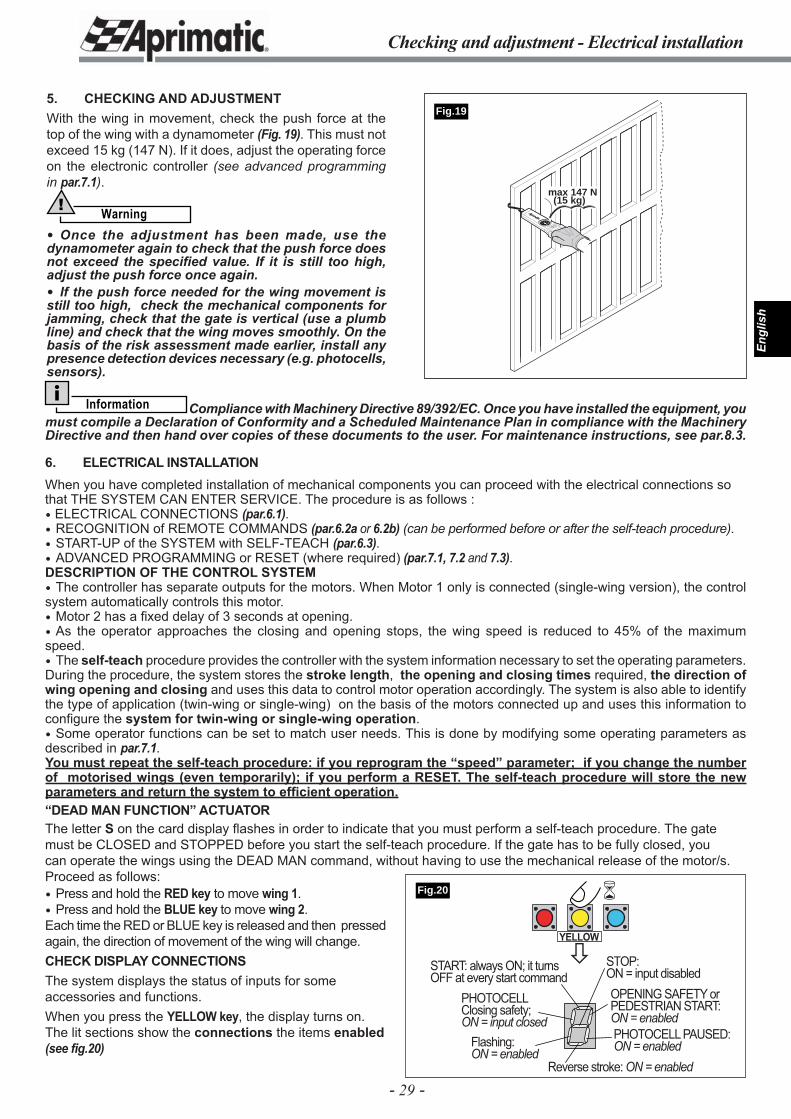
5. CHECKING AND ADJUSTMENTWith the wing in movement, check the push force at the top of the wing with a dynamometer (Fig. 19). This must not exceed 15 kg (147 N). If it does, adjust the operating force on the electronic controller (see advanced programming in par.7.1).
Warning!
Once the adjustment has been made, use the dynamometer again to check that the push force does not exceed the specifi ed value. If it is still too high, adjust the push force once again. If the push force needed for the wing movement is still too high, check the mechanical components for jamming, check that the gate is vertical (use a plumb line) and check that the wing moves smoothly. On the basis of the risk assessment made earlier, install any presence detection devices necessary (e.g. photocells, sensors).
Information Compliance with Machinery Directive 89/392/EC. Once you have installed the equipment, you must compile a Declaration of Conformity and a Scheduled Maintenance Plan in compliance with the Machinery Directive and then hand over copies of these documents to the user. For maintenance instructions, see par.8.3.
6. ELECTRICAL INSTALLATION When you have completed installation of mechanical components you can proceed with the electrical connections so that THE SYSTEM CAN ENTER SERVICE. The procedure is as follows : ELECTRICAL CONNECTIONS (par.6.1). RECOGNITION of REMOTE COMMANDS (par.6.2a or 6.2b) (can be performed before or after the self-teach procedure). START-UP of the SYSTEM with SELF-TEACH (par.6.3). ADVANCED PROGRAMMING or RESET (where required) (par.7.1, 7.2 and 7.3).DESCRIPTION OF THE CONTROL SYSTEM The controller has separate outputs for the motors. When Motor 1 only is connected (single-wing version), the control system automatically controls this motor. Motor 2 has a fi xed delay of 3 seconds at opening. As the operator approaches the closing and opening stops, the wing speed is reduced to 45% of the maximum speed. The self-teach procedure provides the controller with the system information necessary to set the operating parameters. During the procedure, the system stores the stroke length, the opening and closing times required, the direction of wing opening and closing and uses this data to control motor operation accordingly. The system is also able to identify the type of application (twin-wing or single-wing) on the basis of the motors connected up and uses this information to confi gure the system for twin-wing or single-wing operation. Some operator functions can be set to match user needs. This is done by modifying some operating parameters as described in par.7.1.You must repeat the self-teach procedure: if you reprogram the “speed” parameter; if you change the number of motorised wings (even temporarily); if you perform a RESET. The self-teach procedure will store the new parameters and return the system to effi cient operation.“DEAD MAN FUNCTION” ACTUATORThe letter S on the card display flashes in order to indicate that you must perform a self-teach procedure. The gate must be CLOSED and STOPPED before you start the self-teach procedure. If the gate has to be fully closed, you can operate the wings using the DEAD MAN command, without having to use the mechanical release of the motor/s. Proceed as follows: Press and hold the RED key to move wing 1. Press and hold the BLUE key to move wing 2. Each time the RED or BLUE key is released and then pressed again, the direction of movement of the wing will change.CHECK DISPLAY CONNECTIONSThe system displays the status of inputs for some accessories and functions.When you press the YELLOW key, the display turns on. The lit sections show the connections the items enabled (see fig.20)
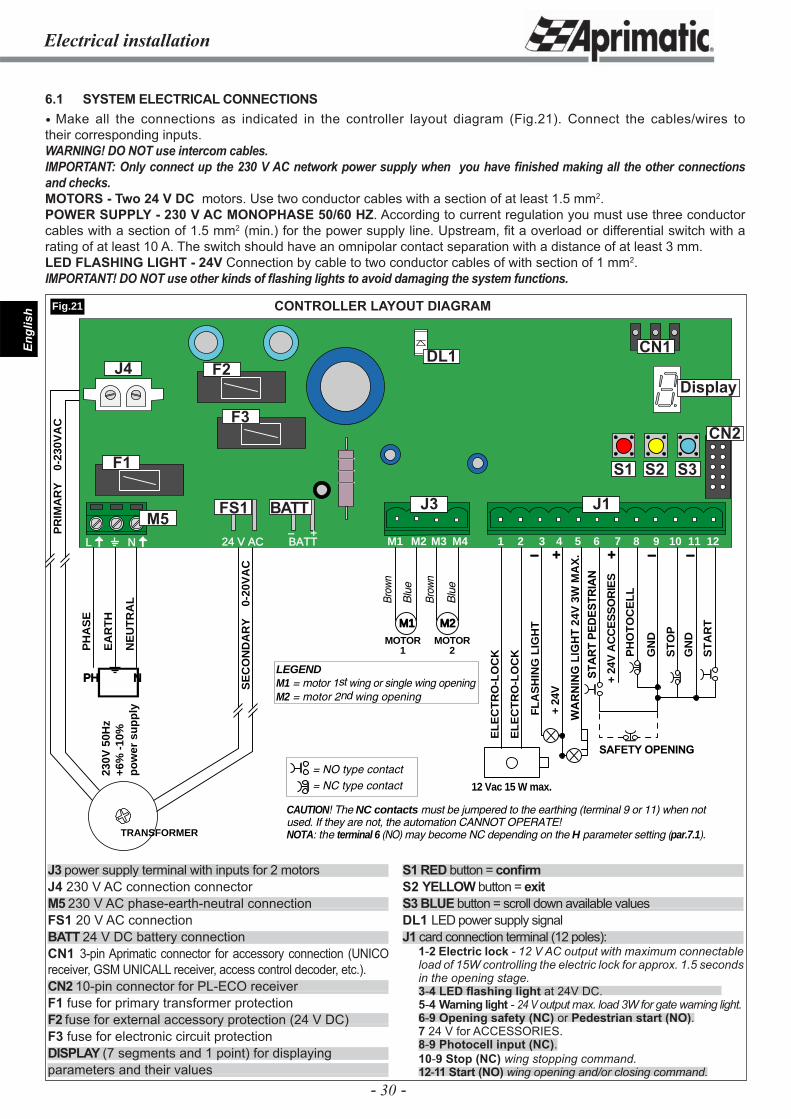
- 30 -
Engl
ish
Electrical installation
CONTROLLER LAYOUT DIAGRAM
PH
AS
E
EA
RT
H
NE
UT
RA
L
PH N
230V
50H
z+6
% -
10%
po
wer
su
pp
ly
TRANSFORMER
SE
CO
ND
AR
Y0-
20V
AC
PR
IMA
RY
0-23
0VA
C
M1 M2
MOTOR1
MOTOR2
LEGENDM1 = motor 1st wing or single wing opening M2 = motor 2nd wing opening
Brow
n
Brow
n
Blu
e
Blu
e
FL
AS
HIN
G L
IGH
T
+ 24
V
WA
RN
ING
LIG
HT
24V
3W
MA
X.
12 Vac 15 W max.
EL
EC
TR
O-L
OC
K
EL
EC
TR
O-L
OC
K PH
OT
OC
EL
L
+ 24
V A
CC
ES
SO
RIE
S
ST
AR
T
STA
RT
PE
DE
STR
IAN
ST
OP
GN
D
GN
D
SAFETY OPENING
24 V AC BATT- +
L N M1 M2 M3 M4 1 3 6 7 10 11 122 4 5 8 9+- + - -
CAUTION! The NC contacts must be jumpered to the earthing (terminal 9 or 11) when not used. If they are not, the automation CANNOT OPERATE!NOTA: the terminal 6 (NO) may become NC depending on the H parameter setting (par.7.1).
= NO type contact= NC type contact
J1J3M5
J4
FS1 BATT
F1
F2
F3
Display
DL1
Fig.21
6.1 SYSTEM ELECTRICAL CONNECTIONS Make all the connections as indicated in the controller layout diagram (Fig.21). Connect the cables/wires to their corresponding inputs.WARNING! DO NOT use intercom cables.IMPORTANT: Only connect up the 230 V AC network power supply when you have fi nished making all the other connections and checks.MOTORS - Two 24 V DC motors. Use two conductor cables with a section of at least 1.5 mm2.POWER SUPPLY - 230 V AC MONOPHASE 50/60 HZ. According to current regulation you must use three conductor cables with a section of 1.5 mm2 (min.) for the power supply line. Upstream, fi t a overload or differential switch with a rating of at least 10 A. The switch should have an omnipolar contact separation with a distance of at least 3 mm. LED FLASHING LIGHT - 24V Connection by cable to two conductor cables of with section of 1 mm2.IMPORTANT! DO NOT use other kinds of fl ashing lights to avoid damaging the system functions.
J3 power supply terminal with inputs for 2 motorsJ4 230 V AC connection connectorM5 230 V AC phase-earth-neutral connectionFS1 20 V AC connectionBATT 24 V DC battery connectionCN1 3-pin Aprimatic connector for accessory connection (UNICO receiver, GSM UNICALL receiver, access control decoder, etc.).CN2 10-pin connector for PL-ECO receiver F1 fuse for primary transformer protectionF2 fuse for external accessory protection (24 V DC)F3 fuse for electronic circuit protectionDISPLAY (7 segments and 1 point) for displayingparameters and their values
S1 RED button = confi rmS2 YELLOW button = exitS3 BLUE button = scroll down available valuesDL1 LED power supply signal J1 card connection terminal (12 poles):
1-2 Electric lock - 12 V AC output with maximum connectable load of 15W controlling the electric lock for approx. 1.5 seconds in the opening stage. 3-4 LED fl ashing light at 24V DC. 5-4 Warning light - 24 V output max. load 3W for gate warning light.6-9 Opening safety (NC) or Pedestrian start (NO).7 24 V for ACCESSORIES. 8-9 Photocell input (NC).10-9 Stop (NC) wing stopping command. 12-11 Start (NO) wing opening and/or closing command.
CN2
S1 S2 S3
CN1
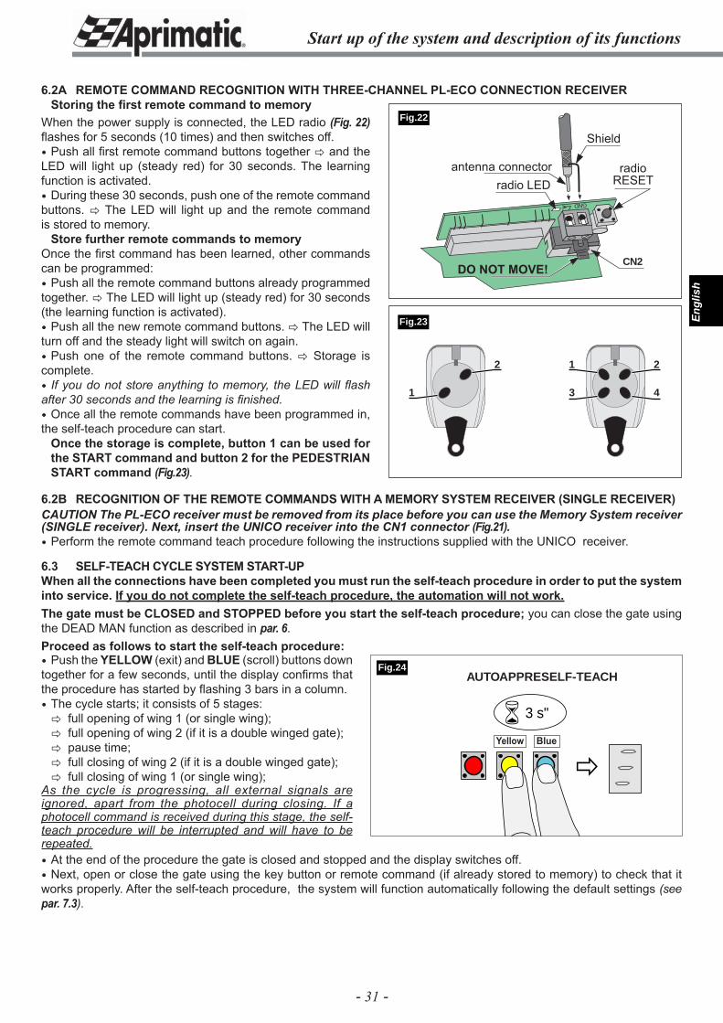
- 31 -
Engl
ish
Start up of the system and description of its functions
6.2A REMOTE COMMAND RECOGNITION WITH THREE-CHANNEL PL-ECO CONNECTION RECEIVER Storing the fi rst remote command to memory
6.2B RECOGNITION OF THE REMOTE COMMANDS WITH A MEMORY SYSTEM RECEIVER (SINGLE RECEIVER)CAUTION The PL-ECO receiver must be removed from its place before you can use the Memory System receiver (SINGLE receiver). Next, insert the UNICO receiver into the CN1 connector (Fig.21). Perform the remote command teach procedure following the instructions supplied with the UNICO receiver.
6.3 SELF-TEACH CYCLE SYSTEM START-UPWhen all the connections have been completed you must run the self-teach procedure in order to put the system into service. If you do not complete the self-teach procedure, the automation will not work.The gate must be CLOSED and STOPPED before you start the self-teach procedure; you can close the gate using the DEAD MAN function as described in par. 6.Proceed as follows to start the self-teach procedure: Push the YELLOW (exit) and BLUE (scroll) buttons down together for a few seconds, until the display confi rms that the procedure has started by fl ashing 3 bars in a column. The cycle starts; it consists of 5 stages:� full opening of wing 1 (or single wing);� full opening of wing 2 (if it is a double winged gate);� pause time;� full closing of wing 2 (if it is a double winged gate);� full closing of wing 1 (or single wing);
As the cycle is progressing, all external signals are ignored, apart from the photocell during closing. If a photocell command is received during this stage, the self-teach procedure will be interrupted and will have to be repeated.
GND
CN2
�
� 3 s"
Yellow Blue
Fig.24
Fig.22
1 2
3 4
2
1
When the power supply is connected, the LED radio (Fig. 22) fl ashes for 5 seconds (10 times) and then switches off. Push all fi rst remote command buttons together � and the LED will light up (steady red) for 30 seconds. The learning function is activated. During these 30 seconds, push one of the remote command buttons. � The LED will light up and the remote command is stored to memory.
Store further remote commands to memoryOnce the fi rst command has been learned, other commands can be programmed: Push all the remote command buttons already programmed together. � The LED will light up (steady red) for 30 seconds (the learning function is activated). Push all the new remote command buttons. � The LED will turn off and the steady light will switch on again. Push one of the remote command buttons. � Storage is complete. If you do not store anything to memory, the LED will fl ash after 30 seconds and the learning is fi nished. Once all the remote commands have been programmed in, the self-teach procedure can start.
Once the storage is complete, button 1 can be used for the START command and button 2 for the PEDESTRIAN START command (Fig.23).
At the end of the procedure the gate is closed and stopped and the display switches off. Next, open or close the gate using the key button or remote command (if already stored to memory) to check that it works properly. After the self-teach procedure, the system will function automatically following the default settings (see par. 7.3).
Fig.23
AUTOAPPRESELF-TEACH
Shield
radio LEDantenna connector radio
RESET
DO NOT MOVE!
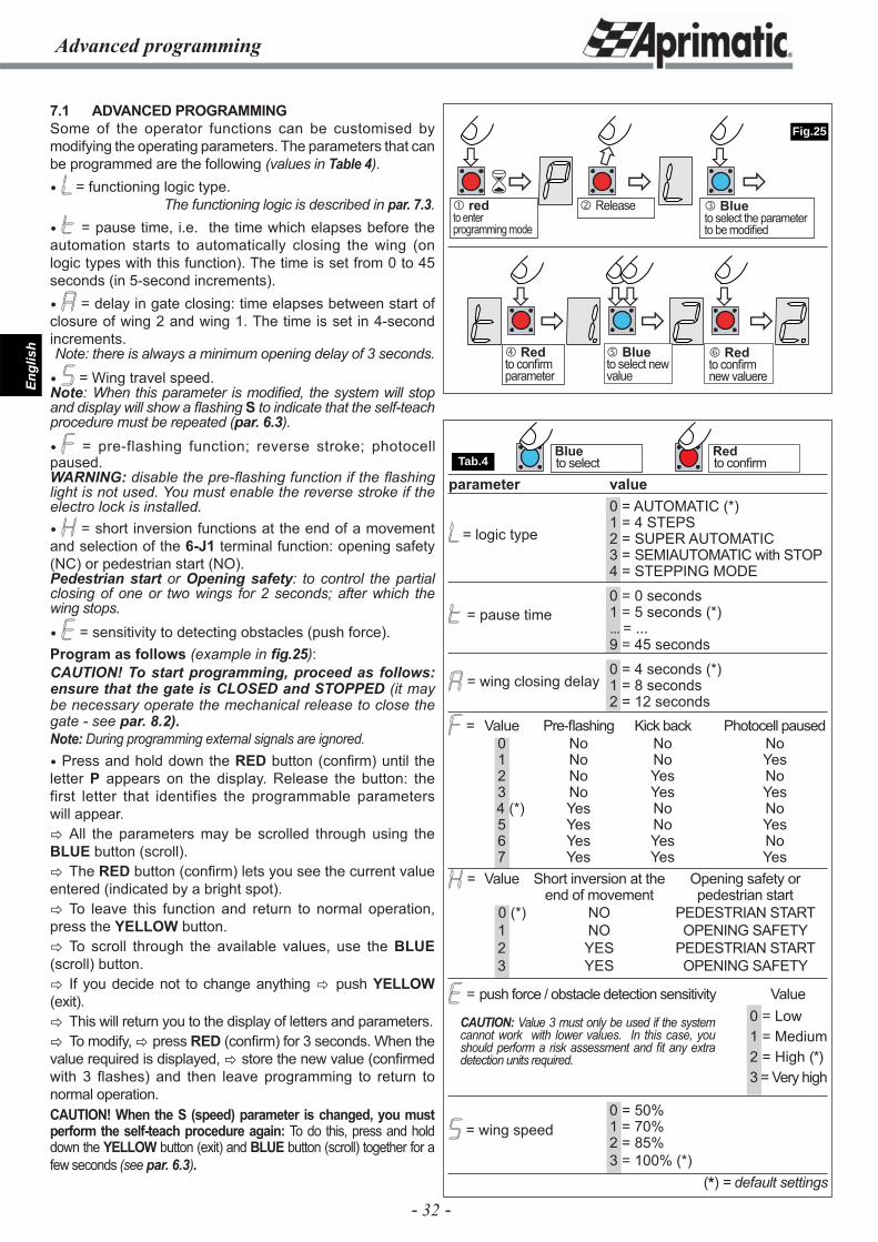
- 32 -
Engl
ish
to select
Advanced programming
���
�
�
�
�
� �
� �� �
�
Tab.4
Fig.25
Blue Redto confi rm
� Blueto select the parameter to be modifi ed
� redto enter programming mode
7.1 ADVANCED PROGRAMMINGSome of the operator functions can be customised by modifying the operating parameters. The parameters that can be programmed are the following (values in Table 4). = functioning logic type.
The functioning logic is described in par. 7.3. = pause time, i.e. the time which elapses before the automation starts to automatically closing the wing (on logic types with this function). The time is set from 0 to 45 seconds (in 5-second increments). = delay in gate closing: time elapses between start of closure of wing 2 and wing 1. The time is set in 4-second increments.Note: there is always a minimum opening delay of 3 seconds.
= Wing travel speed.Note: When this parameter is modifi ed, the system will stop and display will show a fl ashing S to indicate that the self-teach procedure must be repeated (par. 6.3).
= pre-flashing function; reverse stroke; photocell paused.WARNING: disable the pre-fl ashing function if the fl ashing light is not used. You must enable the reverse stroke if the electro lock is installed. = short inversion functions at the end of a movement and selection of the 6-J1 terminal function: opening safety (NC) or pedestrian start (NO).Pedestrian start or Opening safety: to control the partial closing of one or two wings for 2 seconds; after which the wing stops.
= sensitivity to detecting obstacles (push force).Program as follows (example in fi g.25):CAUTION! To start programming, proceed as follows: ensure that the gate is CLOSED and STOPPED (it may be necessary operate the mechanical release to close the gate - see par. 8.2).Note: During programming external signals are ignored. Press and hold down the RED button (confi rm) until the letter P appears on the display. Release the button: the first letter that identifies the programmable parameters will appear.� All the parameters may be scrolled through using the BLUE button (scroll).� The RED button (confi rm) lets you see the current value entered (indicated by a bright spot).� To leave this function and return to normal operation, press the YELLOW button.� To scroll through the available values, use the BLUE (scroll) button.� If you decide not to change anything � push YELLOW (exit).� This will return you to the display of letters and parameters.� To modify, � press RED (confi rm) for 3 seconds. When the value required is displayed, � store the new value (confi rmed with 3 flashes) and then leave programming to return to normal operation.CAUTION! When the S (speed) parameter is changed, you must perform the self-teach procedure again: To do this, press and hold down the YELLOW button (exit) and BLUE button (scroll) together for a few seconds (see par. 6.3).
= logic type
= pause time
= wing closing delay
= wing speed
� Release
� Redto confi rm parameter
� Blueto select new value
� Redto confi rm new valuere
CAUTION: Value 3 must only be used if the system cannot work with lower values. In this case, you should perform a risk assessment and fi t any extra detection units required.
parameter value 0 = AUTOMATIC (*) 1 = 4 STEPS 2 = SUPER AUTOMATIC 3 = SEMIAUTOMATIC with STOP 4 = STEPPING MODE
0 = 0 seconds 1 = 5 seconds (*) ... = ... 9 = 45 seconds
0 = 4 seconds (*) 1 = 8 seconds 2 = 12 seconds
= Value Pre-fl ashing Kick back Photocell paused 0 No No No 1 No No Yes 2 No Yes No 3 No Yes Yes 4 (*) Yes No No 5 Yes No Yes 6 Yes Yes No 7 Yes Yes Yes
= Value Short inversion at the Opening safety or end of movement pedestrian start 0 (*) NO PEDESTRIAN START 1 NO OPENING SAFETY 2 YES PEDESTRIAN START 3 YES OPENING SAFETY
= push force / obstacle detection sensitivity Value 0 = Low 1 = Medium 2 = High (*) 3 = Very high
0 = 50% 1 = 70% 2 = 85% 3 = 100% (*)
(*) = default settings
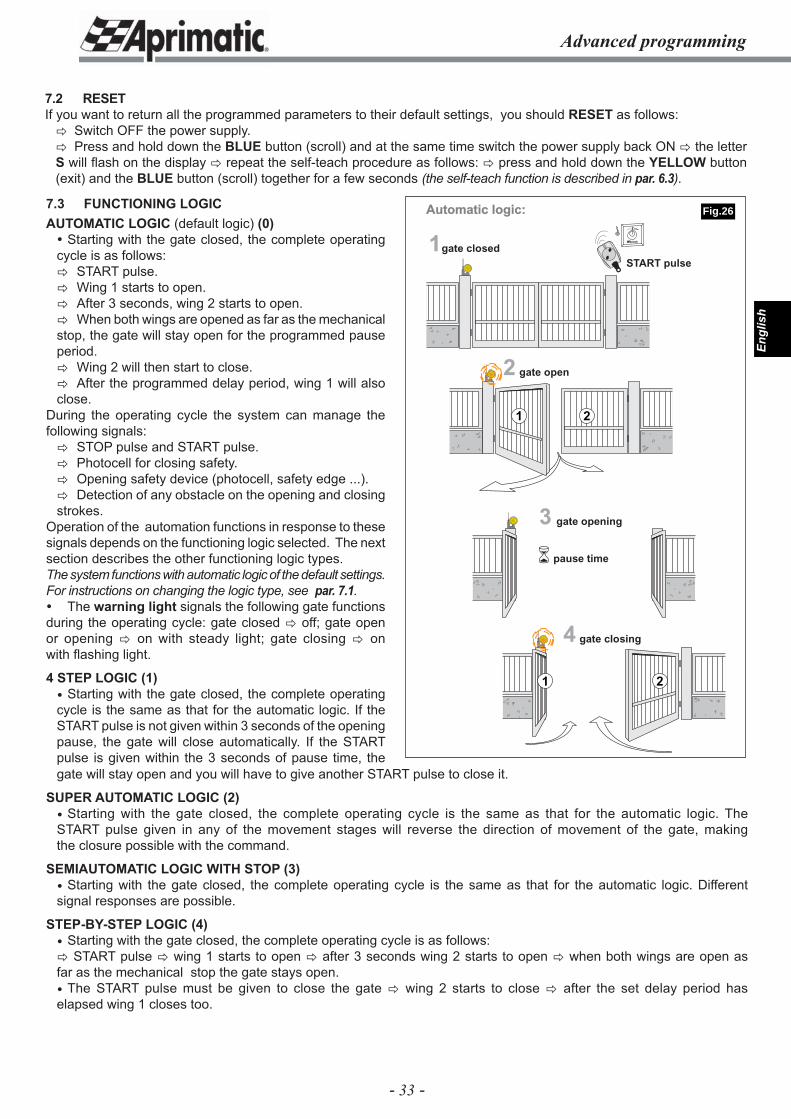
- 33 -
Engl
ish
Advanced programming
7.2 RESETIf you want to return all the programmed parameters to their default settings, you should RESET as follows:� Switch OFF the power supply.� Press and hold down the BLUE button (scroll) and at the same time switch the power supply back ON � the letter S will fl ash on the display � repeat the self-teach procedure as follows: � press and hold down the YELLOW button (exit) and the BLUE button (scroll) together for a few seconds (the self-teach function is described in par. 6.3).
gate will stay open and you will have to give another START pulse to close it.
SUPER AUTOMATIC LOGIC (2) Starting with the gate closed, the complete operating cycle is the same as that for the automatic logic. The START pulse given in any of the movement stages will reverse the direction of movement of the gate, making the closure possible with the command.
SEMIAUTOMATIC LOGIC WITH STOP (3) Starting with the gate closed, the complete operating cycle is the same as that for the automatic logic. Different signal responses are possible.
STEP-BY-STEP LOGIC (4) Starting with the gate closed, the complete operating cycle is as follows:� START pulse � wing 1 starts to open � after 3 seconds wing 2 starts to open � when both wings are open as far as the mechanical stop the gate stays open. The START pulse must be given to close the gate � wing 2 starts to close � after the set delay period has elapsed wing 1 closes too.
1gate closed
2 gate open
3 gate opening
4 gate closing
START pulse
pause time
1 2
�
21
Automatic logic:7.3 FUNCTIONING LOGICAUTOMATIC LOGIC (default logic) (0) Starting with the gate closed, the complete operating cycle is as follows:� START pulse.� Wing 1 starts to open.� After 3 seconds, wing 2 starts to open.� When both wings are opened as far as the mechanical stop, the gate will stay open for the programmed pause period.� Wing 2 will then start to close.� After the programmed delay period, wing 1 will also close.
During the operating cycle the system can manage the following signals:� STOP pulse and START pulse.� Photocell for closing safety.� Opening safety device (photocell, safety edge ...).� Detection of any obstacle on the opening and closing strokes.
Operation of the automation functions in response to these signals depends on the functioning logic selected. The next section describes the other functioning logic types.The system functions with automatic logic of the default settings. For instructions on changing the logic type, see par. 7.1. The warning light signals the following gate functions during the operating cycle: gate closed � off; gate open or opening � on with steady light; gate closing � on with fl ashing light.
4 STEP LOGIC (1) Starting with the gate closed, the complete operating cycle is the same as that for the automatic logic. If the START pulse is not given within 3 seconds of the opening pause, the gate will close automatically. If the START pulse is given within the 3 seconds of pause time, the
Fig.26
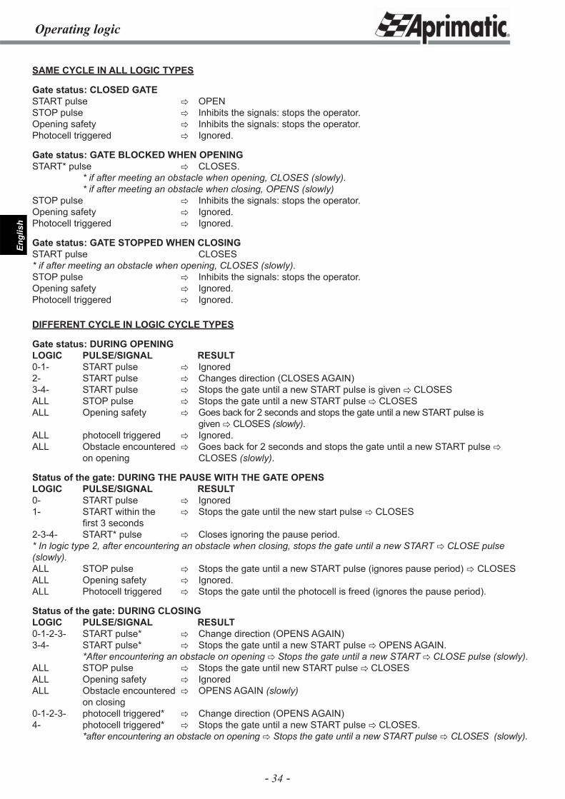
- 34 -
Engl
ish
Operating logic
SAME CYCLE IN ALL LOGIC TYPES
Gate status: CLOSED GATESTART pulse � OPENSTOP pulse � Inhibits the signals: stops the operator.Opening safety � Inhibits the signals: stops the operator.Photocell triggered � Ignored.
Gate status: GATE BLOCKED WHEN OPENINGSTART* pulse � CLOSES. * if after meeting an obstacle when opening, CLOSES (slowly). * if after meeting an obstacle when closing, OPENS (slowly)STOP pulse � Inhibits the signals: stops the operator. Opening safety � Ignored.Photocell triggered � Ignored.
Gate status: GATE STOPPED WHEN CLOSINGSTART pulse CLOSES* if after meeting an obstacle when opening, CLOSES (slowly).STOP pulse � Inhibits the signals: stops the operator.Opening safety � Ignored.Photocell triggered � Ignored.
DIFFERENT CYCLE IN LOGIC CYCLE TYPES
Gate status: DURING OPENING LOGIC PULSE/SIGNAL RESULT0-1- START pulse � Ignored2- START pulse � Changes direction (CLOSES AGAIN)3-4- START pulse � Stops the gate until a new START pulse is given � CLOSESALL STOP pulse � Stops the gate until a new START pulse � CLOSESALL Opening safety � Goes back for 2 seconds and stops the gate until a new START pulse is given � CLOSES (slowly).ALL photocell triggered � Ignored.ALL Obstacle encountered � Goes back for 2 seconds and stops the gate until a new START pulse � on opening CLOSES (slowly).
Status of the gate: DURING THE PAUSE WITH THE GATE OPENS LOGIC PULSE/SIGNAL RESULT0- START pulse � Ignored1- START within the � Stops the gate until the new start pulse � CLOSES fi rst 3 seconds2-3-4- START* pulse � Closes ignoring the pause period.* In logic type 2, after encountering an obstacle when closing, stops the gate until a new START � CLOSE pulse (slowly).ALL STOP pulse � Stops the gate until a new START pulse (ignores pause period) � CLOSESALL Opening safety � Ignored.ALL Photocell triggered � Stops the gate until the photocell is freed (ignores the pause period).
Status of the gate: DURING CLOSING LOGIC PULSE/SIGNAL RESULT0-1-2-3- START pulse* � Change direction (OPENS AGAIN)3-4- START pulse* � Stops the gate until a new START pulse � OPENS AGAIN. *After encountering an obstacle on opening � Stops the gate until a new START � CLOSE pulse (slowly).ALL STOP pulse � Stops the gate until new START pulse � CLOSESALL Opening safety � IgnoredALL Obstacle encountered � OPENS AGAIN (slowly) on closing0-1-2-3- photocell triggered* � Change direction (OPENS AGAIN)4- photocell triggered* � Stops the gate until a new START pulse � CLOSES. *after encountering an obstacle on opening � Stops the gate until a new START pulse � CLOSES (slowly).
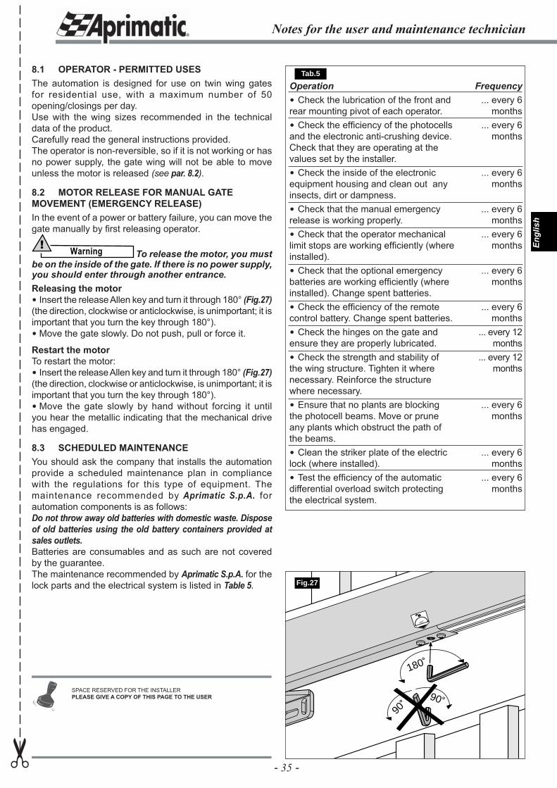
- 35 -
Engl
ish
Operation Check the lubrication of the front and rear mounting pivot of each operator. Check the effi ciency of the photocells and the electronic anti-crushing device. Check that they are operating at the values set by the installer. Check the inside of the electronic equipment housing and clean out any insects, dirt or dampness. Check that the manual emergency release is working properly. Check that the operator mechanical limit stops are working effi ciently (where installed). Check that the optional emergency batteries are working effi ciently (where installed). Change spent batteries. Check the effi ciency of the remote control battery. Change spent batteries. Check the hinges on the gate and ensure they are properly lubricated. Check the strength and stability of the wing structure. Tighten it where necessary. Reinforce the structure where necessary. Ensure that no plants are blocking the photocell beams. Move or prune any plants which obstruct the path of the beams. Clean the striker plate of the electric lock (where installed). Test the effi ciency of the automatic differential overload switch protecting the electrical system.
Frequency... every 6
months... every 6
months
... every 6 months
... every 6 months
... every 6 months
... every 6 months
... every 6 months
... every 12 months
... every 12 months
... every 6 months
... every 6 months
... every 6 months
8.1 OPERATOR - PERMITTED USESThe automation is designed for use on twin wing gates for residential use, with a maximum number of 50 opening/closings per day.Use with the wing sizes recommended in the technical data of the product.Carefully read the general instructions provided.The operator is non-reversible, so if it is not working or has no power supply, the gate wing will not be able to move unless the motor is released (see par. 8.2).
8.2 MOTOR RELEASE FOR MANUAL GATE MOVEMENT (EMERGENCY RELEASE)In the event of a power or battery failure, you can move the gate manually by fi rst releasing operator.
Warning! To release the motor, you must
be on the inside of the gate. If there is no power supply, you should enter through another entrance.Releasing the motor Insert the release Allen key and turn it through 180° (Fig.27) (the direction, clockwise or anticlockwise, is unimportant; it is important that you turn the key through 180°). Move the gate slowly. Do not push, pull or force it.
Restart the motorTo restart the motor: Insert the release Allen key and turn it through 180° (Fig.27) (the direction, clockwise or anticlockwise, is unimportant; it is important that you turn the key through 180°). Move the gate slowly by hand without forcing it until you hear the metallic indicating that the mechanical drive has engaged.
8.3 SCHEDULED MAINTENANCEYou should ask the company that installs the automation provide a scheduled maintenance plan in compliance with the regulations for this type of equipment. The maintenance recommended by Aprimatic S.p.A. for automation components is as follows:Do not throw away old batteries with domestic waste. Dispose of old batteries using the old battery containers provided at sales outlets.Batteries are consumables and as such are not covered by the guarantee.The maintenance recommended by Aprimatic S.p.A. for the lock parts and the electrical system is listed in Table 5.
180˚
180˚
90˚
90˚
Fig.27
Notes for the user and maintenance technician✂
SPACE RESERVED FOR THE INSTALLERPLEASE GIVE A COPY OF THIS PAGE TO THE USER
Tab.5
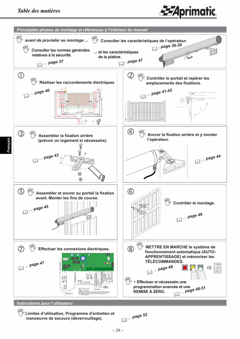
- 36 -
Fran
çais
180˚
180˚
2
3x0.75 Ø
6
3x0.75 Ø
3x0.75 Ø
2x1.5 Ø
1
2x1.5 Ø
2x1 Ø
1
5
7 7
10Alc= 30mA 4
8
Aprimatic
Aprimatic
3
9
Table des matières
max 147 N(15 kg)
�
L
a
B
Y
A
E
L
30 mm
CL
IGN
OT
AN
T
+ 24
V
VO
YA
NT
LUM
INE
UX
24V
3W
MA
XI
12 Vac 15 W maxi
SE
RR
UR
E É
LEC
TRO
MÉ
CA
NIQ
UE
SE
RR
UR
E É
LEC
TRO
MÉ
CA
NIQ
UE
PHO
TOC
ELLU
LE
+ 24
V A
CC
ES
SO
IRE
S
ST
AR
T (
MA
RC
HE
)
STA
RT
OU
VER
TUR
E PI
ETO
N
ST
OP
(A
RR
ET
)
GN
D
GN
D
SECURITE EN OUVERTURE
+- + - -
PH
AS
E
TE
RR
E
NE
UT
RE
PHPH N
230V
50H
z+6
% -
10%
alim
enta
tio
n
TRANSFORMATEUR
SE
CO
ND
AIR
E 0
-20
VA
C
Pri
mai
re 0
-230
VA
C
M1M1 M2M2
MOTEUR1
MOTEUR2
Mar
ron
Mar
ron
Ble
u
Ble
u
ATTENTION ! Les contacts N.F. doivent être dotés d'un jumper côté masse (borne 9 ou 11) quand ils sont inutilisés. Autrement l'automatisme NE PEUT PAS fonctionner!NOTE: La borne 6 (N.O.) peut devenir du type N.F. selon le paramétrage du
paramétre H (par.7.1).
LEGENDE:M1 = moteur du 1er vantail en phase
d'ouverture (ou un seul vantail)M2 = moteur 2 ème vantail en phase d'ouverture
= contact du type N.O.= contact du type N.F.
24 V AC24 V AC BATTBATT- + +
L N M1 M2 M3 M4 1 3 6 7 10 11 122 4 5 8 9
Principales phases de montage et références à l’intérieur du manuel
� Consulter les normes générales relatives à la sécurité.
� Consulter les caractéristiques de l’opérateur
� Contrôler le portail et repérer les emplacements des fi xations.
Instructions pour l’utilisateur
�Limites d’utilisation, Programme d’entretien et manoeuvre de secours (déverrouillage).
� ... page 37
�...page 38-39� avant de procéder au montage ...
� Réaliser les raccordements électriques
� ... page 40
� ... page 43
� Assembler la fi xation arrière(prévoir un logement si nécessaire).
� Ancrer la fi xation arrière et y monter l’opérateur.
180˚
� ... page 44
� ... page 45
� Assembler et ancrer au portail la fi xation avant. Monter les fi ns de course.
� Contrôler le montage.
� ... page 46
� ... page 47
� Effectuer les connexions électriques.
� ... page 41-42
� ... page 52
�
� METTRE EN MARCHE le système de fonctionnement automatique (AUTO-APPRENTISSAGE) et mémoriser les TÉLÉCOMMANDES.
� ... page 48
� Effectuer si nécessaire une programmation avancée et une REMISE À ZÉRO.
� ... page 49-51
... et les caractéristiques de la platine.
�...page 47
�
��
� �
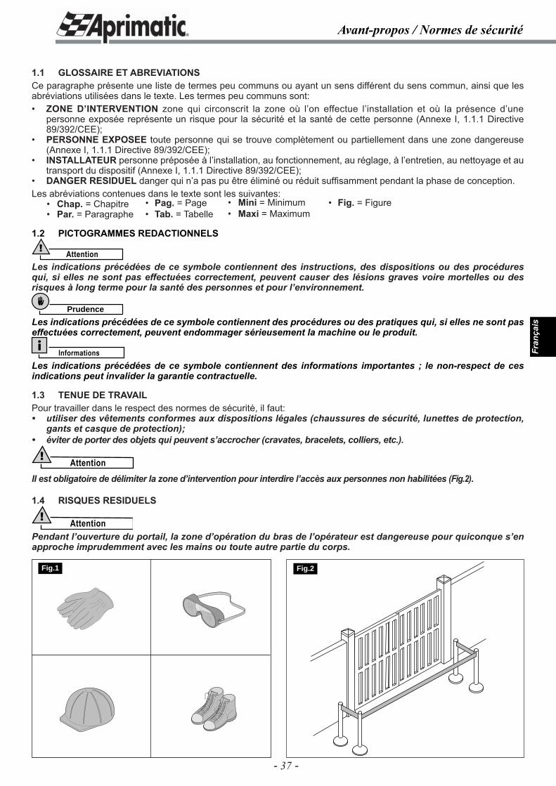
- 37 -
Fran
çais
Avant-propos / Normes de sécurité
1.1 GLOSSAIRE ET ABREVIATIONSCe paragraphe présente une liste de termes peu communs ou ayant un sens différent du sens commun, ainsi que les abréviations utilisées dans le texte. Les termes peu communs sont:• ZONE D’INTERVENTION zone qui circonscrit la zone où l’on effectue l’installation et où la présence d’une
personne exposée représente un risque pour la sécurité et la santé de cette personne (Annexe I, 1.1.1 Directive 89/392/CEE);
• PERSONNE EXPOSEE toute personne qui se trouve complètement ou partiellement dans une zone dangereuse (Annexe I, 1.1.1 Directive 89/392/CEE);
• INSTALLATEUR personne préposée à l’installation, au fonctionnement, au réglage, à l’entretien, au nettoyage et au transport du dispositif (Annexe I, 1.1.1 Directive 89/392/CEE);
• DANGER RESIDUEL danger qui n’a pas pu être éliminé ou réduit suffi samment pendant la phase de conception.Les abréviations contenues dans le texte sont les suivantes: • Chap. = Chapitre • Par. = Paragraphe
1.2 PICTOGRAMMES REDACTIONNELS
Attention!
Les indications précédées de ce symbole contiennent des instructions, des dispositions ou des procédures qui, si elles ne sont pas effectuées correctement, peuvent causer des lésions graves voire mortelles ou des risques à long terme pour la santé des personnes et pour l’environnement.
Prudence
Les indications précédées de ce symbole contiennent des procédures ou des pratiques qui, si elles ne sont pas effectuées correctement, peuvent endommager sérieusement la machine ou le produit.
InformationsLes indications précédées de ce symbole contiennent des informations importantes ; le non-respect de ces indications peut invalider la garantie contractuelle.
1.3 TENUE DE TRAVAILPour travailler dans le respect des normes de sécurité, il faut:• utiliser des vêtements conformes aux dispositions légales (chaussures de sécurité, lunettes de protection,
gants et casque de protection);• éviter de porter des objets qui peuvent s’accrocher (cravates, bracelets, colliers, etc.).
Attention!
Il est obligatoire de délimiter la zone d’intervention pour interdire l’accès aux personnes non habilitées (Fig.2).
1.4 RISQUES RESIDUELS
Attention!Pendant l’ouverture du portail, la zone d’opération du bras de l’opérateur est dangereuse pour quiconque s’en approche imprudemment avec les mains ou toute autre partie du corps.
• Pag. = Page• Tab. = Tabelle
• Mini = Minimum• Maxi = Maximum
• Fig. = Figure
Fig.1 Fig.2
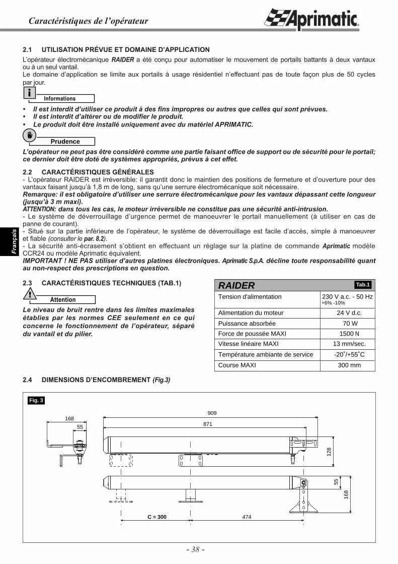
- 38 -
Fran
çais
Caractéristiques de l’opérateur
2.1 UTILISATION PRÉVUE ET DOMAINE D’APPLICATIONL’opérateur électromécanique RAIDER a été conçu pour automatiser le mouvement de portails battants à deux vantaux ou à un seul vantail.Le domaine d’application se limite aux portails à usage résidentiel n’effectuant pas de toute façon plus de 50 cycles par jour.
Informations
• Il est interdit d’utiliser ce produit à des fi ns impropres ou autres que celles qui sont prévues.• Il est interdit d’altérer ou de modifi er le produit.• Le produit doit être installé uniquement avec du matériel APRIMATIC.
Prudence
L’opérateur ne peut pas être considéré comme une partie faisant offi ce de support ou de sécurité pour le portail; ce dernier doit être doté de systèmes appropriés, prévus à cet effet.
2.2 CARACTÉRISTIQUES GÉNÉRALES- L’opérateur RAIDER est irréversible: il garantit donc le maintien des positions de fermeture et d’ouverture pour des vantaux faisant jusqu’à 1,8 m de long, sans qu’une serrure électromécanique soit nécessaire.Remarque: il est obligatoire d’utiliser une serrure électromécanique pour les vantaux dépassant cette longueur (jusqu’à 3 m maxi).ATTENTION: dans tous les cas, le moteur irréversible ne constitue pas une sécurité anti-intrusion.- Le système de déverrouillage d’urgence permet de manoeuvrer le portail manuellement (à utiliser en cas de panne de courant).- Situé sur la partie inférieure de l’opérateur, le système de déverrouillage est facile d’accès, simple à manoeuvrer et fi able (consulter le par. 8.2).- La sécurité anti-écrasement s’obtient en effectuant un réglage sur la platine de commande Aprimatic modèle CCR24 ou modèle Aprimatic équivalent.IMPORTANT ! NE PAS utiliser d’autres platines électroniques. Aprimatic S.p.A. décline toute responsabilité quant au non-respect des prescriptions en question.
2.3 CARACTÉRISTIQUES TECHNIQUES (TAB.1)
Attention!
Le niveau de bruit rentre dans les limites maximales établies par les normes CEE seulement en ce qui concerne le fonctionnement de l’opérateur, séparé du vantail et du pilier.
2.4 DIMENSIONS D’ENCOMBREMENT (Fig.3)
70 W
1500 N
13 mm/sec.
-20˚/+55˚C
300 mm
RAIDERTension d'alimentation
24 V d.c.Alimentation du moteur
Puissance absorbée
Force de poussée MAXI
Vitesse linéaire MAXI
Température ambiante de service
Course MAXI
230 V a.c. - 50 Hz+6% -10%
Tab.1
55
909
871
128
55
168
168
C = 300 474
Fig. 3
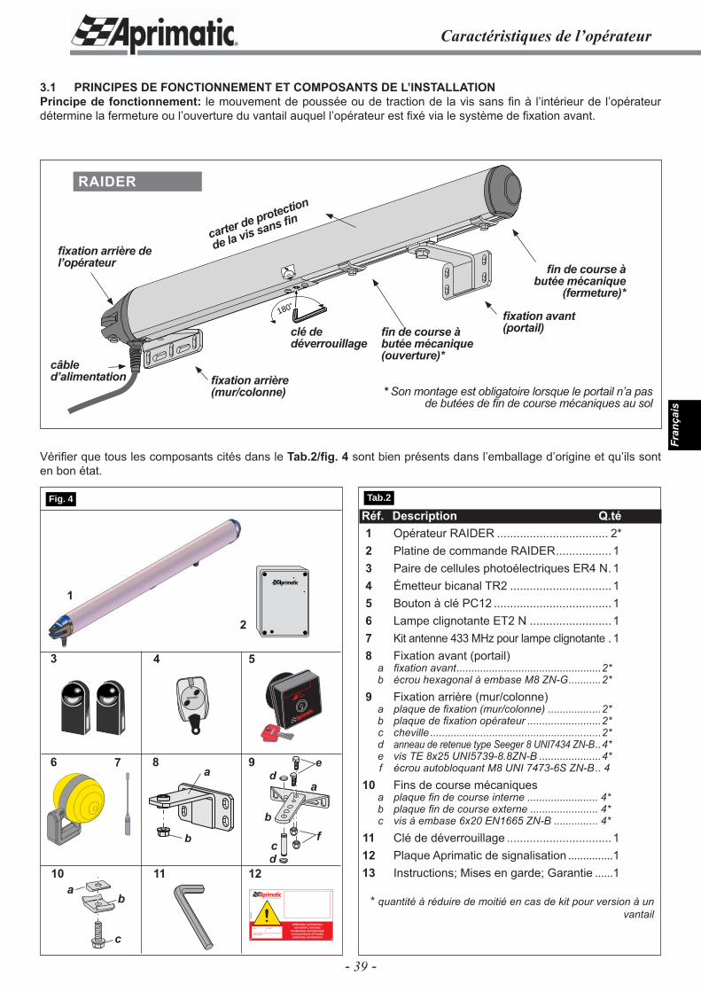
- 39 -
Fran
çais
Caractéristiques de l’opérateur
3.1 PRINCIPES DE FONCTIONNEMENT ET COMPOSANTS DE L’INSTALLATIONPrincipe de fonctionnement: le mouvement de poussée ou de traction de la vis sans fi n à l’intérieur de l’opérateur détermine la fermeture ou l’ouverture du vantail auquel l’opérateur est fi xé via le système de fi xation avant.
Réf. Description Q.té 1 Opérateur RAIDER .................................. 2* 2 Platine de commande RAIDER ................. 1 3 Paire de cellules photoélectriques ER4 N .1 4 Émetteur bicanal TR2 ...............................1 5 Bouton à clé PC12 ....................................1 6 Lampe clignotante ET2 N .........................1 7 Kit antenne 433 MHz pour lampe clignotante .1 8 Fixation avant (portail) a fi xation avant .................................................2* b écrou hexagonal à embase M8 ZN-G ...........2* 9 Fixation arrière (mur/colonne) a plaque de fi xation (mur/colonne) ..................2* b plaque de fi xation opérateur .........................2* c cheville ..........................................................2* d anneau de retenue type Seeger 8 UNI7434 ZN-B ..4* e vis TE 8x25 UNI5739-8.8ZN-B .....................4* f écrou autobloquant M8 UNI 7473-6S ZN-B .. 4 10 Fins de course mécaniques a plaque fi n de course interne ........................ 4* b plaque fi n de course externe ....................... 4* c vis à embase 6x20 EN1665 ZN-B ............... 4* 11 Clé de déverrouillage ................................1 12 Plaque Aprimatic de signalisation ...............1 13 Instructions; Mises en garde; Garantie ......1
* quantité à réduire de moitié en cas de kit pour version à un vantail
4
7
11
1
Aprimatic
5
96
2
3
12fi
IL CAMPIONE DELL’AUTOMAZIONE
!APERTURA AUTOMATICA
AUTOMATIC OPENINGOUVERTURE AUTOMATIQUEAUTOMATISCHE ÖFFNUNGAPERTURA AUTOMATICA
A58
4500
0
name model
serial number
a
b
c
de
d
Vérifi er que tous les composants cités dans le Tab.2/fi g. 4 sont bien présents dans l’emballage d’origine et qu’ils sont en bon état.
180˚
180˚fi xation avant (portail)
fi xation arrière (mur/colonne)
câble d’alimentation
clé de déverrouillage
RAIDER
fi xation arrière de l’opérateur
carter de protection
de la vis sans fi n
fi n de course à butée mécanique (ouverture)*
fi n de course à butée mécanique
(fermeture)*
* Son montage est obligatoire lorsque le portail n’a pas de butées de fi n de course mécaniques au sol
Tab.2 Fig. 4
f
8
b
a
10a
c
b
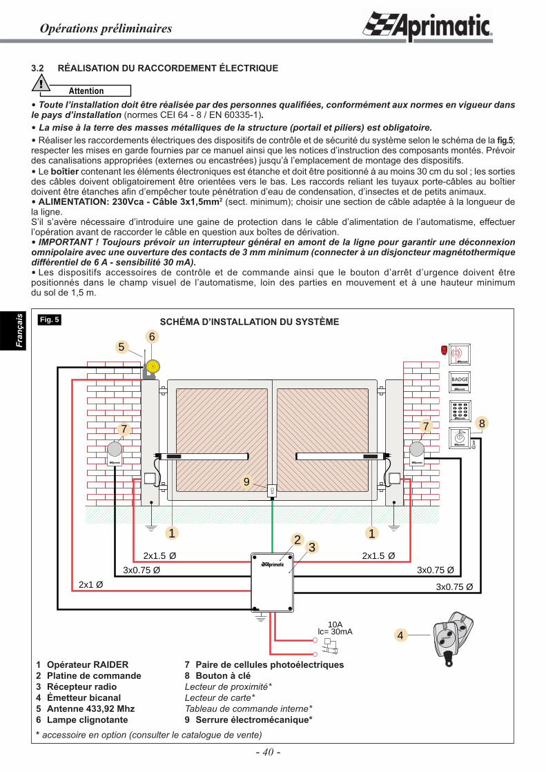
- 40 -
Fran
çais
3.2 RÉALISATION DU RACCORDEMENT ÉLECTRIQUE
Attention!
Toute l’installation doit être réalisée par des personnes qualifi ées, conformément aux normes en vigueur dans le pays d’installation (normes CEI 64 - 8 / EN 60335-1). La mise à la terre des masses métalliques de la structure (portail et piliers) est obligatoire. Réaliser les raccordements électriques des dispositifs de contrôle et de sécurité du système selon le schéma de la fi g.5; respecter les mises en garde fournies par ce manuel ainsi que les notices d’instruction des composants montés. Prévoir des canalisations appropriées (externes ou encastrées) jusqu’à l’emplacement de montage des dispositifs. Le boîtier contenant les éléments électroniques est étanche et doit être positionné à au moins 30 cm du sol ; les sorties des câbles doivent obligatoirement être orientées vers le bas. Les raccords reliant les tuyaux porte-câbles au boîtier doivent être étanches afi n d’empêcher toute pénétration d’eau de condensation, d’insectes et de petits animaux. ALIMENTATION: 230Vca - Câble 3x1,5mm2 (sect. minimum); choisir une section de câble adaptée à la longueur de la ligne.S’il s’avère nécessaire d’introduire une gaine de protection dans le câble d’alimentation de l’automatisme, effectuer l’opération avant de raccorder le câble en question aux boîtes de dérivation. IMPORTANT ! Toujours prévoir un interrupteur général en amont de la ligne pour garantir une déconnexion omnipolaire avec une ouverture des contacts de 3 mm minimum (connecter à un disjoncteur magnétothermique différentiel de 6 A - sensibilité 30 mA). Les dispositifs accessoires de contrôle et de commande ainsi que le bouton d’arrêt d’urgence doivent être positionnés dans le champ visuel de l’automatisme, loin des parties en mouvement et à une hauteur minimum du sol de 1,5 m.
Opérations préliminaires
2
3x0.75 Ø
6
3x0.75 Ø
3x0.75 Ø
2x1.5 Ø
1
2x1.5 Ø
2x1 Ø
1
5
7 7
10Alc= 30mA 4
8
Aprimatic
Aprimatic
3
9
Fig. 5 SCHÉMA D’INSTALLATION DU SYSTÈME
7 Paire de cellules photoélectriques8 Bouton à cléLecteur de proximité*Lecteur de carte* Tableau de commande interne*9 Serrure électromécanique*
1 Opérateur RAIDER2 Platine de commande3 Récepteur radio4 Émetteur bicanal5 Antenne 433,92 Mhz6 Lampe clignotante* accessoire en option (consulter le catalogue de vente)
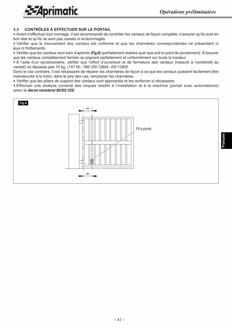
- 41 -
Fran
çais
3.3 CONTRÔLES À EFFECTUER SUR LE PORTAIL Avant d’effectuer tout montage, il est recommandé de contrôler les vantaux de façon complète; s’assurer qu’ils sont en bon état et qu’ils ne sont pas cassés ni endommagés. Vérifi er que le mouvement des vantaux est uniforme et que les charnières correspondantes ne présentent ni jeux ni frottements. Vérifi er que les vantaux sont bien d’aplomb (Fig.6) (parfaitement stables quel que soit le point de pivotement). S’assurer que les vantaux complètement fermés se joignent parfaitement et uniformément sur toute la hauteur. À l’aide d’un dynamomètre, vérifi er que l’effort d’ouverture et de fermeture des vantaux (mesuré à l’extrémité du vantail) ne dépasse pas 15 kg. (147 N) - Réf. EN 12604 - EN 12605.Dans le cas contraire, il est nécessaire de réparer les charnières de façon à ce que les vantaux puissent facilement être manoeuvrés à la main; dans le pire des cas, remplacer les charnières. Vérifi er que les piliers de support des vantaux sont appropriés et les renforcer si nécessaire. Effectuer une analyse correcte des risques relatifs à l’installation et à la machine (portail avec automatisme) selon le décret ministériel 89/392 CEE.
Opérations préliminaires
Fil à plomb
Fig.6
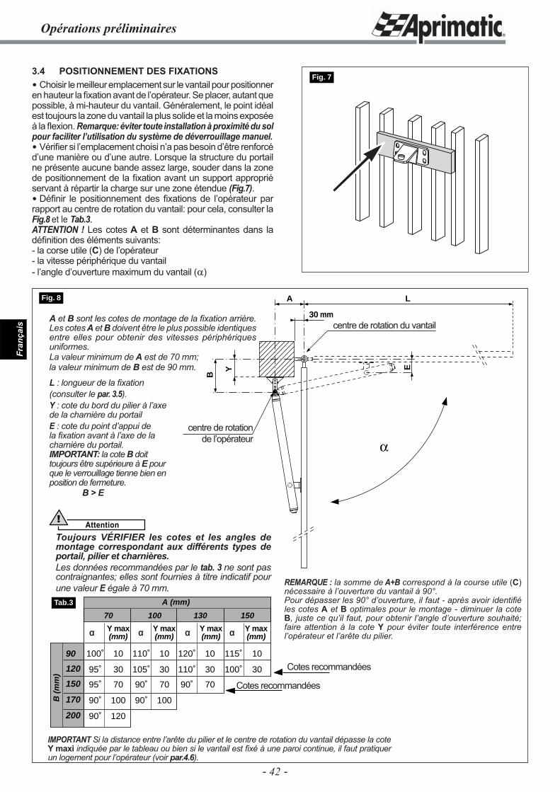
- 42 -
Fran
çais
B
Y
A
E
L
30 mm
Opérations préliminaires
3.4 POSITIONNEMENT DES FIXATIONS Choisir le meilleur emplacement sur le vantail pour positionner en hauteur la fi xation avant de l’opérateur. Se placer, autant que possible, à mi-hauteur du vantail. Généralement, le point idéal est toujours la zone du vantail la plus solide et la moins exposée à la fl exion. Remarque: éviter toute installation à proximité du sol pour faciliter l’utilisation du système de déverrouillage manuel. Vérifi er si l’emplacement choisi n’a pas besoin d’être renforcé d’une manière ou d’une autre. Lorsque la structure du portail ne présente aucune bande assez large, souder dans la zone de positionnement de la fi xation avant un support approprié servant à répartir la charge sur une zone étendue (Fig.7). Défi nir le positionnement des fi xations de l’opérateur par rapport au centre de rotation du vantail: pour cela, consulter la Fig.8 et le Tab.3.ATTENTION ! Les cotes A et B sont déterminantes dans la défi nition des éléments suivants:- la corse utile (C) de l’opérateur- la vitesse périphérique du vantail- l’angle d’ouverture maximum du vantail (α)
Fig. 7
IMPORTANT Si la distance entre l’arête du pilier et le centre de rotation du vantail dépasse la cote Y maxi indiquée par le tableau ou bien si le vantail est fi xé à une paroi continue, il faut pratiquer un logement pour l’opérateur (voir par.4.6).
90
120
150
170
200
B (
mm
)
A (mm)
α Y max α Y max α Y max α Y max(mm) (mm) (mm) (mm)
70 100 130 150
100˚ 10 110˚ 10 120˚ 10 115˚ 10
95˚ 30 105˚ 30 110˚ 30 100˚ 30
95˚ 70 90˚ 70 90˚ 70
90˚ 100 90˚ 100
90˚ 120
Tab.3
Fig. 8
Cotes recommandées
Cotes recommandées
REMARQUE : la somme de A+B correspond à la course utile (C) nécessaire à l’ouverture du vantail à 90°.Pour dépasser les 90° d’ouverture, il faut - après avoir identifi é les cotes A et B optimales pour le montage - diminuer la cote B, juste ce qu’il faut, pour obtenir l’angle d’ouverture souhaité; faire attention à la cote Y pour éviter toute interférence entre l’opérateur et l’arête du pilier.
A et B sont les cotes de montage de la fi xation arrière. Les cotes A et B doivent être le plus possible identiques entre elles pour obtenir des vitesses périphériques uniformes.La valeur minimum de A est de 70 mm;la valeur minimum de B est de 90 mm.
L : longueur de la fi xation (consulter le par. 3.5).Y : cote du bord du pilier à l’axe de la charnière du portailE : cote du point d’appui de la fi xation avant à l’axe de la charnière du portail.IMPORTANT: la cote B doit toujours être supérieure à E pour que le verrouillage tienne bien en position de fermeture.
B > E
centre de rotation du vantail
centre de rotation de l’opérateur
Attention!
Toujours VÉRIFIER les cotes et les angles de montage correspondant aux différents types de portail, pilier et charnières.Les données recommandées par le tab. 3 ne sont pas contraignantes; elles sont fournies à titre indicatif pour une valeur E égale à 70 mm.
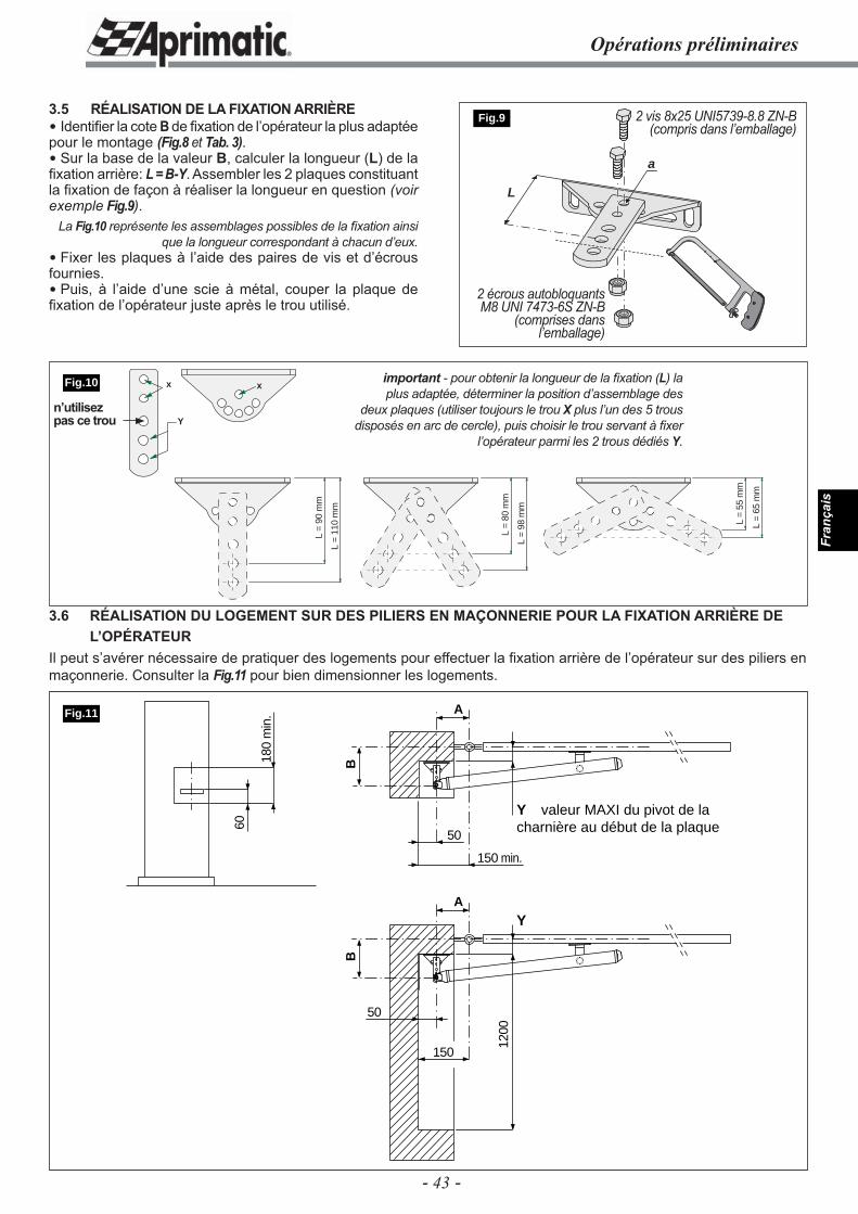
- 43 -
Fran
çais
L =
55 m
m
L =
65 m
m
L =
98 m
m
L =
80 m
m
L =
110
mm
L =
90 m
m
xx
Y
60
180
min
.
50
150
1200
Y valeur MAXI du pivot de la charnière au début de la plaque
B
A
50
150 min.
Y
B
A
Fig.11
Opérations préliminaires
3.5 RÉALISATION DE LA FIXATION ARRIÈRE Identifi er la cote B de fi xation de l’opérateur la plus adaptée pour le montage (Fig.8 et Tab. 3). Sur la base de la valeur B, calculer la longueur (L) de la fi xation arrière: L = B-Y. Assembler les 2 plaques constituant la fi xation de façon à réaliser la longueur en question (voir exemple Fig.9).
La Fig.10 représente les assemblages possibles de la fi xation ainsi que la longueur correspondant à chacun d’eux.
Fixer les plaques à l’aide des paires de vis et d’écrous fournies. Puis, à l’aide d’une scie à métal, couper la plaque de fi xation de l’opérateur juste après le trou utilisé.
L
a
Fig.9 2 vis 8x25 UNI5739-8.8 ZN-B (compris dans l’emballage)
2 écrous autobloquants M8 UNI 7473-6S ZN-B
(comprises dans l’emballage)
important - pour obtenir la longueur de la fi xation (L) la plus adaptée, déterminer la position d’assemblage des
deux plaques (utiliser toujours le trou X plus l’un des 5 trous disposés en arc de cercle), puis choisir le trou servant à fi xer
l’opérateur parmi les 2 trous dédiés Y.
3.6 RÉALISATION DU LOGEMENT SUR DES PILIERS EN MAÇONNERIE POUR LA FIXATION ARRIÈRE DE L’OPÉRATEURIl peut s’avérer nécessaire de pratiquer des logements pour effectuer la fi xation arrière de l’opérateur sur des piliers en maçonnerie. Consulter la Fig.11 pour bien dimensionner les logements.
Fig.10
n’utilisez pas ce trou
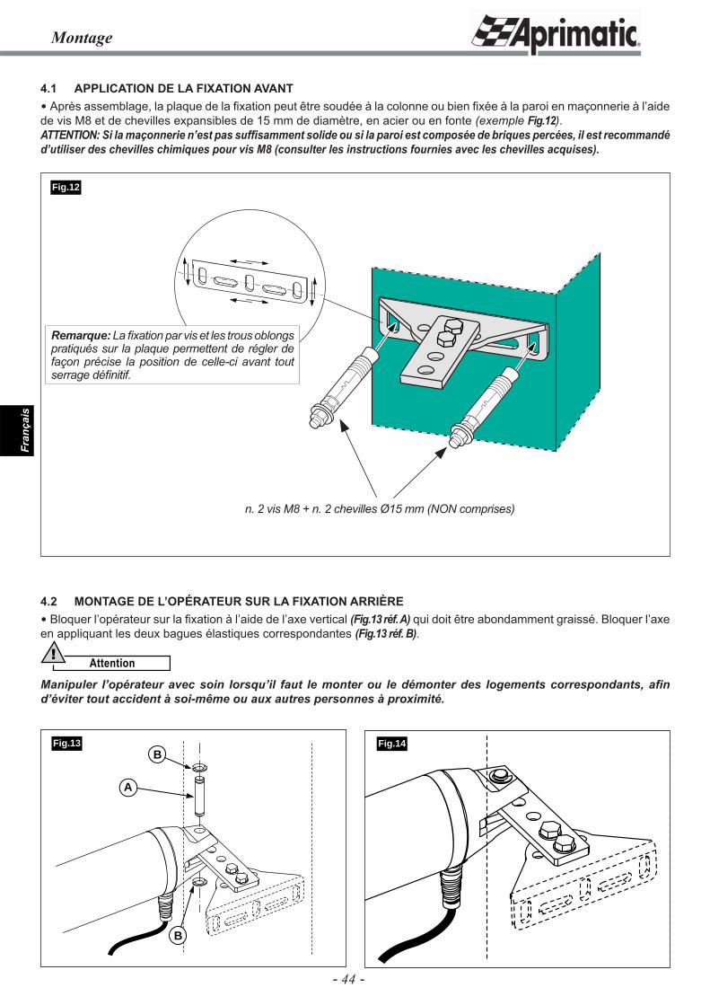
- 44 -
Fran
çais
Montage
4.1 APPLICATION DE LA FIXATION AVANT Après assemblage, la plaque de la fi xation peut être soudée à la colonne ou bien fi xée à la paroi en maçonnerie à l’aide de vis M8 et de chevilles expansibles de 15 mm de diamètre, en acier ou en fonte (exemple Fig.12).ATTENTION: Si la maçonnerie n’est pas suffi samment solide ou si la paroi est composée de briques percées, il est recommandé d’utiliser des chevilles chimiques pour vis M8 (consulter les instructions fournies avec les chevilles acquises).
Fig.14B
A
B
Fig.13
Fig.12
n. 2 vis M8 + n. 2 chevilles Ø15 mm (NON comprises)
4.2 MONTAGE DE L’OPÉRATEUR SUR LA FIXATION ARRIÈRE Bloquer l’opérateur sur la fi xation à l’aide de l’axe vertical (Fig.13 réf. A) qui doit être abondamment graissé. Bloquer l’axe en appliquant les deux bagues élastiques correspondantes (Fig.13 réf. B).
Attention!
Manipuler l’opérateur avec soin lorsqu’il faut le monter ou le démonter des logements correspondants, afi n d’éviter tout accident à soi-même ou aux autres personnes à proximité.
Remarque: La fi xation par vis et les trous oblongs pratiqués sur la plaque permettent de régler de façon précise la position de celle-ci avant tout serrage défi nitif.
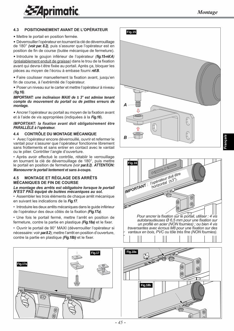
- 45 -
Fran
çais
4.3 POSITIONNEMENT AVANT DE L’OPÉRATEUR
Mettre le portail en position fermée. Déverrouiller l’opérateur en tournant la clé de déverrouillage de 180° (voir par. 8.2), puis s’assurer que l’opérateur est en position de fi n de course (butée mécanique de fermeture). Introduire le goujon inférieur de l’opérateur (fi g.15-réf.A) (préalablement enduit de graisse) dans le trou de la fi xation avant qui devra-t être fi xée au portail. Après ça, bloquer les pièces au moyen de l’écrou à embase fourni réf.B.
Faire coulisser manuellement la fi xation avant, jusqu’en fi n de course, à l’extrémité de l’opérateur. Poser un niveau sur le carter et mettre l’opérateur à niveau (fi g.16).IMPORTANT: une inclinaison MAXI de ± 3° est admise tenant compte du mouvement du portail ou de petites erreurs de montage.
Ancrer l’opérateur au portail au moyen de la fi xation avant et à l’aide de vis appropriées (indiquées à la Fig.16).IMPORTANT: la fixation avant doit obligatoirement être PARALLÈLE à l’opérateur.4.4 CONTRÔLE DU MONTAGE MÉCANIQUE• Avec l’opérateur encore déverrouillé, ouvrir et refermer le vantail pour s’assurer que l’opérateur fonctionne librement sans frottements et sans entrer en contact avec le vantail ou le pilier. Contrôler l’angle d’ouverture.• Après avoir effectué le contrôle, rétablir le verrouillage en tournant la clé de déverrouillage de 180°, puis mettre le portail en position de fermeture (voir par.8.2). ATTENTION: Manoeuvrer le portail lentement et sans à-coups.
4.5 MONTAGE ET RÉGLAGE DES ARRÊTS MÉCANIQUES DE FIN DE COURSELe montage des arrêts est obligatoire lorsque le portail N’EST PAS équipé de butées mécaniques au sol.• Assembler les trois éléments de chaque arrêt mécanique en suivant les indications de la Fig.17.• Introduire les deux arrêts mécaniques dans le guide inférieur de l’opérateur des deux côtés de la fi xation (Fig.17a).• Une fois le portail fermé, mettre l’arrêt en position de fermeture, contre la partie en plastique (Fig.18a) et le fi xer.• Ouvrir le portail de 90° MAXI (déverrouiller l’opérateur si nécessaire: voir par.8.2); mettre l’arrêt en position d’ouverture, contre la partie en plastique (Fig.18b) et le fi xer.
Fig.16
Montage
Fig.17a
Pour ancrer la fi xation sur le portail, utiliser : 4 vis autotaraudeuses Ø 6,5 mm pour une fi xation sur un profi lé en acier (NON fournies) ; ou bien 4 vis
traversantes avec écrous M8 pour une fi xation sur des vantaux en bois, PVC ou tôle très fi ne (NON fournies).
Fig.17
IMPORTANT : l’opérateur doit être
horizontal (±3°).
180˚
Fig.18a
Fig.18b
Fig.15
�
�A
B
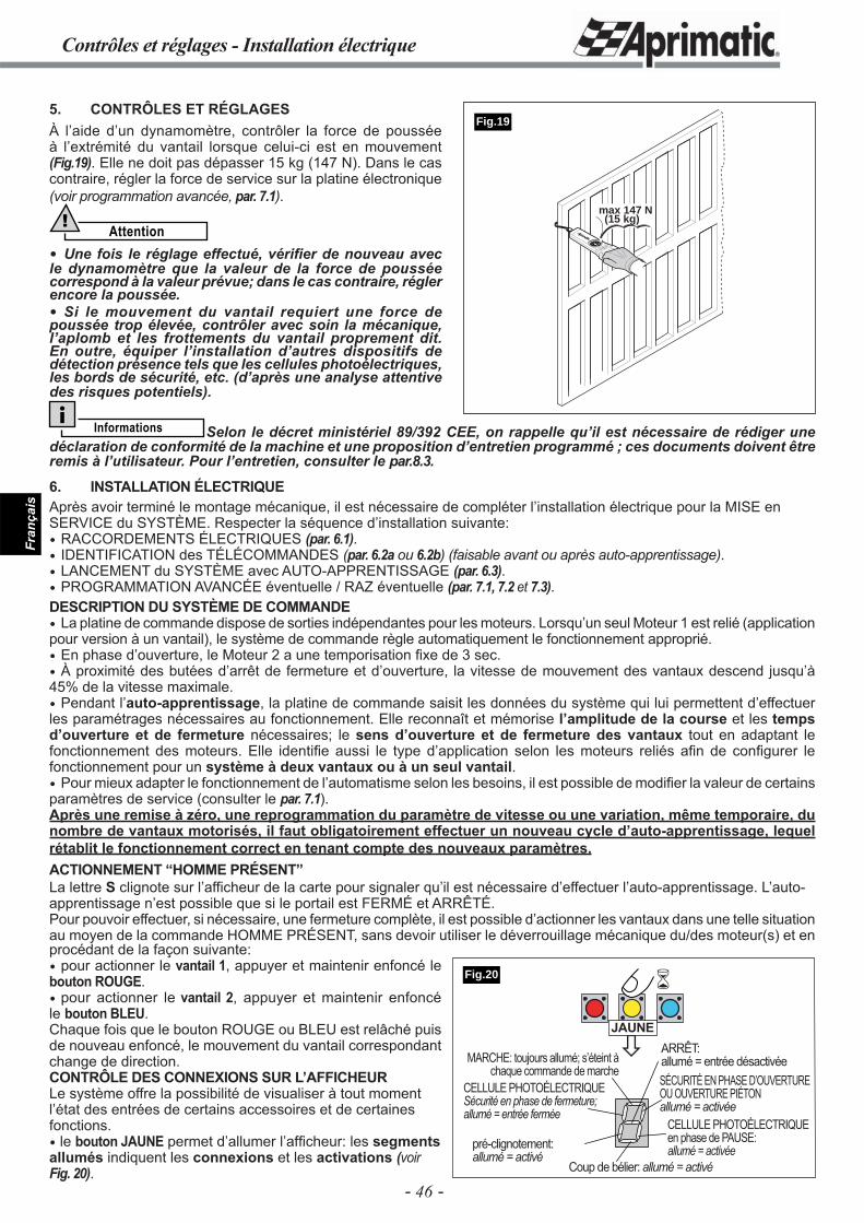
- 46 -
Fran
çais
Contrôles et réglages - Installation électrique
5. CONTRÔLES ET RÉGLAGESÀ l’aide d’un dynamomètre, contrôler la force de poussée à l’extrémité du vantail lorsque celui-ci est en mouvement (Fig.19). Elle ne doit pas dépasser 15 kg (147 N). Dans le cas contraire, régler la force de service sur la platine électronique (voir programmation avancée, par. 7.1).
Attention!
Une fois le réglage effectué, vérifi er de nouveau avec le dynamomètre que la valeur de la force de poussée correspond à la valeur prévue; dans le cas contraire, régler encore la poussée. Si le mouvement du vantail requiert une force de poussée trop élevée, contrôler avec soin la mécanique, l’aplomb et les frottements du vantail proprement dit. En outre, équiper l’installation d’autres dispositifs de détection présence tels que les cellules photoélectriques, les bords de sécurité, etc. (d’après une analyse attentive des risques potentiels).
max 147 N(15 kg)
Fig.19
Informations Selon le décret ministériel 89/392 CEE, on rappelle qu’il est nécessaire de rédiger une déclaration de conformité de la machine et une proposition d’entretien programmé ; ces documents doivent être remis à l’utilisateur. Pour l’entretien, consulter le par.8.3.
6. INSTALLATION ÉLECTRIQUEAprès avoir terminé le montage mécanique, il est nécessaire de compléter l’installation électrique pour la MISE en SERVICE du SYSTÈME. Respecter la séquence d’installation suivante: RACCORDEMENTS ÉLECTRIQUES (par. 6.1). IDENTIFICATION des TÉLÉCOMMANDES (par. 6.2a ou 6.2b) (faisable avant ou après auto-apprentissage). LANCEMENT du SYSTÈME avec AUTO-APPRENTISSAGE (par. 6.3). PROGRAMMATION AVANCÉE éventuelle / RAZ éventuelle (par. 7.1, 7.2 et 7.3).DESCRIPTION DU SYSTÈME DE COMMANDE La platine de commande dispose de sorties indépendantes pour les moteurs. Lorsqu’un seul Moteur 1 est relié (application pour version à un vantail), le système de commande règle automatiquement le fonctionnement approprié. En phase d’ouverture, le Moteur 2 a une temporisation fi xe de 3 sec. À proximité des butées d’arrêt de fermeture et d’ouverture, la vitesse de mouvement des vantaux descend jusqu’à 45% de la vitesse maximale. Pendant l’auto-apprentissage, la platine de commande saisit les données du système qui lui permettent d’effectuer les paramétrages nécessaires au fonctionnement. Elle reconnaît et mémorise l’amplitude de la course et les temps d’ouverture et de fermeture nécessaires; le sens d’ouverture et de fermeture des vantaux tout en adaptant le fonctionnement des moteurs. Elle identifi e aussi le type d’application selon les moteurs reliés afi n de confi gurer le fonctionnement pour un système à deux vantaux ou à un seul vantail. Pour mieux adapter le fonctionnement de l’automatisme selon les besoins, il est possible de modifi er la valeur de certains paramètres de service (consulter le par. 7.1).Après une remise à zéro, une reprogrammation du paramètre de vitesse ou une variation, même temporaire, du nombre de vantaux motorisés, il faut obligatoirement effectuer un nouveau cycle d’auto-apprentissage, lequel rétablit le fonctionnement correct en tenant compte des nouveaux paramètres.ACTIONNEMENT “HOMME PRÉSENT”La lettre S clignote sur l’afficheur de la carte pour signaler qu’il est nécessaire d’effectuer l’auto-apprentissage. L’auto-apprentissage n’est possible que si le portail est FERMÉ et ARRÊTÉ.Pour pouvoir effectuer, si nécessaire, une fermeture complète, il est possible d’actionner les vantaux dans une telle situation au moyen de la commande HOMME PRÉSENT, sans devoir utiliser le déverrouillage mécanique du/des moteur(s) et en procédant de la façon suivante: pour actionner le vantail 1, appuyer et maintenir enfoncé le bouton ROUGE. pour actionner le vantail 2, appuyer et maintenir enfoncé le bouton BLEU. Chaque fois que le bouton ROUGE ou BLEU est relâché puis de nouveau enfoncé, le mouvement du vantail correspondant change de direction.CONTRÔLE DES CONNEXIONS SUR L’AFFICHEURLe système offre la possibilité de visualiser à tout moment l’état des entrées de certains accessoires et de certaines fonctions. le bouton JAUNE permet d’allumer l’affi cheur: les segments allumés indiquent les connexions et les activations (voir Fig. 20).
�
�
MARCHE: toujours allumé; s’éteint à chaque commande de marche
SÉCURITÉ EN PHASE D’OUVERTURE OU OUVERTURE PIÉTONallumé = activée
ARRÊT:allumé = entrée désactivée
pré-clignotement: allumé = activé
CELLULE PHOTOÉLECTRIQUE en phase de PAUSE:allumé = activée
Coup de bélier: allumé = activé
CELLULE PHOTOÉLECTRIQUE Sécurité en phase de fermeture;allumé = entrée fermée
JAUNE
Fig.20
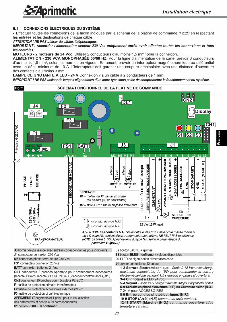
- 47 -
Fran
çais
Installation électrique
SCHÉMA FONCTIONNEL DE LA PLATINE DE COMMANDE
CL
IGN
OT
AN
T
+ 24
V
VO
YA
NT
LUM
INE
UX
24V
3W
MA
XI
12 Vac 15 W maxi
SE
RR
UR
E É
LEC
TRO
MÉ
CA
NIQ
UE
SE
RR
UR
E É
LEC
TRO
MÉ
CA
NIQ
UE
PHO
TOC
ELLU
LE
+ 24
V A
CC
ES
SO
IRE
S
ST
AR
T (
MA
RC
HE
)
STA
RT
OU
VER
TUR
E PI
ETO
N
ST
OP
(A
RR
ET
)
GN
D
GN
D
SECURITE EN OUVERTURE
+- + - -
PH
AS
E
TE
RR
E
NE
UT
RE
PH N
230V
50H
z+6
% -
10%
alim
enta
tio
n
TRANSFORMATEUR
SE
CO
ND
AIR
E 0
-20
VA
C
Pri
mai
re 0
-230
VA
C
M1 M2
MOTEUR1
MOTEUR2
Mar
ron
Mar
ron
Ble
u
Ble
u
ATTENTION ! Les contacts N.F. doivent être dotés d'un jumper côté masse (borne 9 ou 11) quand ils sont inutilisés. Autrement l'automatisme NE PEUT PAS fonctionner!NOTE: La borne 6 (N.O.) peut devenir du type N.F. selon le paramétrage du
paramétre H (par.7.1).
LEGENDE:M1 = moteur du 1er vantail en phase
d'ouverture (ou un seul vantail)M2 = moteur 2 ème vantail en phase d'ouverture
= contact du type N.O.= contact du type N.F.
24 V AC BATT- +
L N M1 M2 M3 M4 1 3 6 7 10 11 122 4 5 8 9
J1J3M5
J4
FS1 BATT
F1
F2
F3
Display
DL1
Fig.21
6.1 CONNEXIONS ÉLECTRIQUES DU SYSTÈME Effectuer toutes les connexions de la façon indiquée par le schéma de la platine de commande (Fig.21) en respectant les entrées et les destinations de chaque câble.ATTENTION ! NE PAS utiliser de câbles téléphoniques.IMPORTANT : raccorder l’alimentation secteur 230 Vca uniquement après avoir effectué toutes les connexions et tous les contrôles.MOTEURS - 2 moteurs de 24 Vcc. Utiliser 2 conducteurs d’au moins 1,5 mm2 pour la connexion.ALIMENTATION - 230 VCA MONOPHASÉE 50/60 HZ. Pour la ligne d’alimentation de la carte, prévoir 3 conducteurs d’au moins 1,5 mm2, selon les normes en vigueur. En amont, prévoir un interrupteur magnétothermique ou différentiel avec un débit minimum de 10 A. L’interrupteur doit garantir une coupure omnipolaire avec une distance d’ouverture des contacts d’au moins 3 mm.LAMPE CLIGNOTANTE À LED - 24 V Connexion via un câble à 2 conducteurs de 1 mm2.IMPORTANT ! NE PAS utiliser de lampes clignotantes d’un autre type sous peine de compromettre le fonctionnement du système.
J3 bornier de puissance avec entrées correspondantes pour 2 moteursJ4 connecteur connexion 230 VcaM5 connexion phase-terre-neutre 230 VcaFS1 connecteur connexion 20 VcaBATT connexion batteries 24 VccCN1 connecteur 3 broches Aprimatic pour branchement accessoires (récepteur Unico, récepteur GSM UNICALL, décodeur contrôle accès, etc.) CN2 connecteur 10 broches pour récepteur PL-ECOF1 fusible de protection primaire transformateurF2 fusible de protection accessoires externes (24Vcc)F3 fusible de protection circuit électroniqueAFFICHEUR (7 segments et 1 point) pour la visualisationdes paramètres et des valeurs correspondantesS1 bouton ROUGE = confi rmer
S2 bouton JAUNE = quitterS3 bouton BLEU = défi lement valeurs disponiblesDL1 LED de signalisation alimentation carteJ1 bornier connexions (12 pôles):
1-2 Serrure électromécanique - Sortie à 12 Vca avec charge maximum connectable de 15W pour commander la serrure électromécanique pendant 1,5 s environ en phase d’ouverture.3-4 Clignotant à LED 24Vcc. 5-4 Voyant - sortie 24 V charge maximale 3W pour voyant état portail.6-9 Sécurité en phase d’ouverture (N.F.) ou Ouverture piéton (N.O.).7 24 V pour ACCESSOIRES. 8-9 Entrée cellules photoélectriques (N.F.).10-9 STOP (Arrêt) (N.F.) commande arrêt vantaux. 12-11 START (Marche) (N.O.) commande ouverture et/ou fermeture vantaux.
CN2
CN1
S1 S2 S3
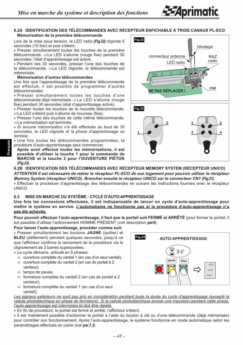
- 48 -
Fran
çais
Mise en marche du système et description des fonctions
6.2A IDENTIFICATION DES TÉLÉCOMMANDES AVEC RÉCEPTEUR ENFICHABLE À TROIS CANAUX PL-ECO Mémorisation de la première télécommande
6.2B IDENTIFICATION DES TÉLÉCOMMANDES AVEC RÉCEPTEUR MEMORY SYSTEM (RÉCEPTEUR UNICO)ATTENTION Il est nécessaire de retirer le récepteur PL-ECO de son logement pour pouvoir utiliser le récepteur Memory System (récepteur UNICO). Brancher ensuite le récepteur UNICO sur le connecteur CN1 (Fig.21). Effectuer la procédure d’apprentissage des télécommandes en suivant les instructions fournies avec le récepteur UNICO.
6.3 MISE EN MARCHE DU SYSTÈME : CYCLE D’AUTO-APPRENTISSAGEUne fois les connexions effectuées, il est indispensable de lancer un cycle d’auto-apprentissage pour mettre le système en service. L’automatisme ne fonctionne pas si la procédure d’auto-apprentissage n’a pas été achevée.Pour pouvoir effectuer l’auto-apprentissage, il faut que le portail soit FERMÉ et ARRÊTÉ (pour fermer le portail, il est possible d’utiliser l’actionnement HOMME PRÉSENT (voir description par.6). Pour lancer l’auto-apprentissage, procéder comme suit: Presser simultanément les boutons JAUNE (quitter) et BLEU (défi lement) pendant quelques secondes, jusqu’à ce que l’affi cheur confi rme le lancement de la procédure via le clignotement de 3 barres superposées. Le cycle démarre, articulé en 5 phases:� ouverture complète du vantail 1 (en cas d’un seul vantail);� ouverture complète du vantail 2 (en cas de portail à 2 vantaux);� temps de pause;� fermeture complète du vantail 2 (en cas de portail à 2 vantaux);� fermeture complète du vantail 1 (en cas d’un seul vantail);
GND
CN2
�
� 3 s"
jaune bleu
Fig.24
Fig.22
1 2
3 4
2
1
Lors de la mise sous tension, la LED radio (Fig.22) clignote 5 secondes (10 fois) et puis s’éteint. Presser simultanément toutes les touches de la première télécommande. �La LED s’allume (rouge fi xe) pendant 30 secondes: l’état d’apprentissage est activé. Pendant ces 30 secondes, presser l’une des touches de la télécommande. �La LED clignote: la télécommande est mémorisée.
Mémorisation d’autres télécommandesUne fois que l’apprentissage de la première télécommande est effectué, il est possible de programmer d’autres télécommandes: Presser simultanément toutes les touches d’une télécommande déjà mémorisée. �La LED s’allume (rouge fi xe) pendant 30 secondes (état d’apprentissage activé). Presser toutes les touches de la nouvelle télécommande. �La LED s’éteint puis s’allume de nouveau (fi xe). Presser l’une des touches de cette même télécommande. �La mémorisation est terminée. Si aucune mémorisation n’a été effectuée au bout de 30 secondes, la LED clignote et la phase d’apprentissage se termine. Une fois toutes les télécommandes programmées, la procédure d’auto-apprentissage peut commencer.
Après avoir effectué toutes les mémorisations, il est possible d’utiliser la touche 1 pour la commande de MARCHE et la touche 2 pour l’OUVERTURE PIÉTON (Fig.23).
Les signaux extérieurs ne sont pas pris en considération pendant toute la durée du cycle d’apprentissage (excepté la cellule photoélectrique en phase de fermeture). Si la cellule photoélectrique envoie une impulsion pendant cette phase, l’auto-apprentissage est interrompu et doit être répété. En fi n de procédure, le portail est fermé et arrêté; l’affi cheur s’éteint. Il est maintenant possible d’actionner le portail à l’aide du bouton à clé ou d’une télécommande (déjà mémorisée) pour contrôler son fonctionnement. Après l’auto-apprentissage, le système fonctionne en mode automatique selon les paramétrages effectués en usine (voir par.7.3).
Fig.23
AUTO-APPRENTISSAGE
blindage
LED radioconnecteur antenne RAZ
radio
NE PAS DÉPLACER !
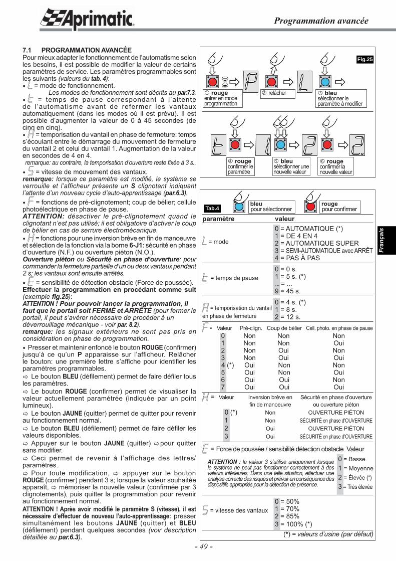
- 49 -
Fran
çais
Programmation avancée
���
�
�
�
�
� �
� �� �
�
Tab.4
Fig.25
bleupour sélectionner
rougepour confi rmer
� bleusélectionner le paramètre à modifi er
� rougeentrer en mode programmation
7.1 PROGRAMMATION AVANCÉEPour mieux adapter le fonctionnement de l’automatisme selon les besoins, il est possible de modifi er la valeur de certains paramètres de service. Les paramètres programmables sont les suivants (valeurs du tab. 4): = mode de fonctionnement.
Les modes de fonctionnement sont décrits au par.7.3. = temps de pause correspondant à l ’attente de l ’automatisme avant de refermer les vantaux automatiquement (dans les modes où il est prévu). Il est possible d’augmenter la valeur de 0 à 45 secondes (de cinq en cinq). = temporisation du vantail en phase de fermeture: temps s’écoulant entre le démarrage du mouvement de fermeture du vantail 2 et celui du vantail 1. Augmentation de la valeur en secondes de 4 en 4.remarque: au contraire, la temporisation d’ouverture reste fi xée à 3 s.. = vitesse de mouvement des vantaux.remarque: lorsque ce paramètre est modifi é, le système se verrouille et l’afficheur présente un S clignotant indiquant l’attente d’un nouveau cycle d’auto-apprentissage (par.6.3). = fonctions de pré-clignotement; coup de bélier; cellule photoélectrique en phase de pause.ATTENTION: désactiver le pré-clignotement quand le clignotant n’est pas utilisé; il est obligatoire d’activer le coup de bélier en cas de serrure électromécanique. = fonctions pour une inversion brève en fi n de manoeuvre et sélection de la fonction via la borne 6-J1: sécurité en phase d’ouverture (N.F.) ou ouverture piéton (N.O.).Ouverture piéton ou Sécurité en phase d’ouverture: pour commander la fermeture partielle d’un ou deux vantaux pendant 2 s; les vantaux sont ensuite arrêtés. = sensibilité de détection obstacle (Force de poussée).Effectuer la programmation en procédant comme suit (exemple fi g.25):ATTENTION ! Pour pouvoir lancer la programmation, ilfaut que le portail soit FERMÉ et ARRÊTÉ (pour fermer le portail, il peut s’avérer nécessaire de procéder à undéverrouillage mécanique - voir par. 8.2).remarque: les signaux extérieurs ne sont pas pris en considération en phase de programmation. Presser et maintenir enfoncé le bouton ROUGE (confi rmer) jusqu’à ce qu’un P apparaisse sur l’affi cheur. Relâcher le bouton: une première lettre s’affi che pour identifi er les paramètres programmables.� Le bouton BLEU (défi lement) permet de faire défi ler tous les paramètres.� Le bouton ROUGE (confi rmer) permet de visualiser la valeur actuellement paramétrée (indiquée par un point lumineux).� Le bouton JAUNE (quitter) permet de quitter pour revenir au fonctionnement normal.� Le bouton BLEU (défi lement) permet de faire défi ler les valeurs disponibles.� Appuyer sur le bouton JAUNE (quitter) �pour quitter sans modifi er.� Ceci permet de revenir à l’affichage des lettres/paramètres.� Pour toute modification, � appuyer sur le bouton ROUGE (confi rmer) pendant 3 s; lorsque la valeur souhaitée apparaît, � mémoriser la nouvelle valeur (confi rmée par 3 clignotements), puis quitter la programmation pour revenir au fonctionnement normal.ATTENTION ! Après avoir modifi é le paramètre S (vitesse), il est nécessaire d’effectuer de nouveau l’auto-apprentissage: presser simultanément les boutons JAUNE (quitter) et BLEU (défi lement) pendant quelques secondes (voir description détaillée au par.6.3).
= mode
= temps de pause
= temporisation du vantail en phase de fermeture
= vitesse des vantaux
� relâcher
� rougeconfi rmer le paramètre
� bleusélectionner une nouvelle valeur
� rougeconfi rmer la nouvelle valeur
ATTENTION : la valeur 3 s’utilise uniquement lorsque le système ne peut pas fonctionner correctement à des valeurs inférieures. Dans une telle situation, effectuer une analyse correcte des risques et prévoir en conséquence des dispositifs appropriés pour la détection de présence.
paramètre valeur 0 = AUTOMATIQUE (*) 1 = DE 4 EN 4 2 = AUTOMATIQUE SUPER 3 = SEMI-AUTOMATIQUE avec ARRÊT 4 = PAS À PAS
0 = 0 s. 1 = 5 s. (*) ... = ... 9 = 45 s.
0 = 4 s. (*) 1 = 8 s. 2 = 12 s.
= Valeur Pré-clign. Coup de bélier Cell. photo. en phase de pause 0 Non Non Non 1 Non Non Oui 2 Non Oui Non 3 Non Oui Oui 4 (*) Oui Non Non 5 Oui Non Oui 6 Oui Oui Non 7 Oui Oui Oui
= Valeur Inversion brève en Sécurité en phase d’ouverture fi n de manoeuvre ou ouverture piéton 0 (*) Non OUVERTURE PIÉTON 1 Non SÉCURITÉ en phase d’OUVERTURE 2 Oui OUVERTURE PIÉTON 3 Oui SÉCURITÉ en phase d’OUVERTURE
= Force de poussée / sensibilité détection obstacle Valeur 0 = Basse 1 = Moyenne 2 = Élevée (*) 3 = Très élevée
0 = 50% 1 = 70% 2 = 85% 3 = 100% (*)
(*) = valeurs d’usine (par défaut)
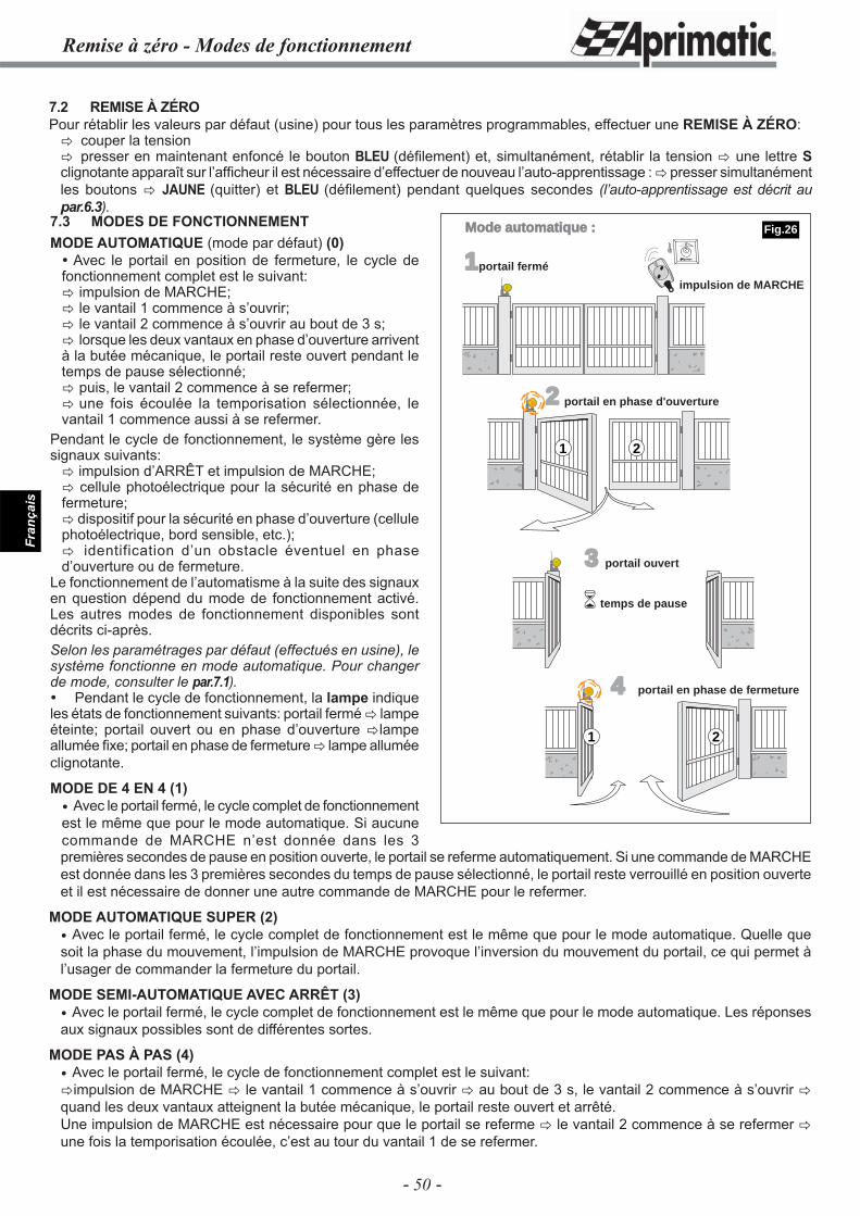
- 50 -
Fran
çais
Remise à zéro - Modes de fonctionnement
7.2 REMISE À ZÉROPour rétablir les valeurs par défaut (usine) pour tous les paramètres programmables, effectuer une REMISE À ZÉRO:� couper la tension� presser en maintenant enfoncé le bouton BLEU (défi lement) et, simultanément, rétablir la tension � une lettre S clignotante apparaît sur l’affi cheur il est nécessaire d’effectuer de nouveau l’auto-apprentissage : � presser simultanément les boutons � JAUNE (quitter) et BLEU (défi lement) pendant quelques secondes (l’auto-apprentissage est décrit au par.6.3).
premières secondes de pause en position ouverte, le portail se referme automatiquement. Si une commande de MARCHE est donnée dans les 3 premières secondes du temps de pause sélectionné, le portail reste verrouillé en position ouverte et il est nécessaire de donner une autre commande de MARCHE pour le refermer.
MODE AUTOMATIQUE SUPER (2) Avec le portail fermé, le cycle complet de fonctionnement est le même que pour le mode automatique. Quelle que soit la phase du mouvement, l’impulsion de MARCHE provoque l’inversion du mouvement du portail, ce qui permet à l’usager de commander la fermeture du portail.
MODE SEMI-AUTOMATIQUE AVEC ARRÊT (3) Avec le portail fermé, le cycle complet de fonctionnement est le même que pour le mode automatique. Les réponses aux signaux possibles sont de différentes sortes.
MODE PAS À PAS (4) Avec le portail fermé, le cycle de fonctionnement complet est le suivant:�impulsion de MARCHE � le vantail 1 commence à s’ouvrir � au bout de 3 s, le vantail 2 commence à s’ouvrir � quand les deux vantaux atteignent la butée mécanique, le portail reste ouvert et arrêté.Une impulsion de MARCHE est nécessaire pour que le portail se referme � le vantail 2 commence à se refermer � une fois la temporisation écoulée, c’est au tour du vantail 1 de se refermer.
1portail fermé
2
3
4
portail ouvert
temps de pause
1 2
�
21
Mode automatique :
impulsion de MARCHE
portail en phase d'ouverture
portail en phase de fermeture
7.3 MODES DE FONCTIONNEMENTMODE AUTOMATIQUE (mode par défaut) (0) Avec le portail en position de fermeture, le cycle de fonctionnement complet est le suivant:� impulsion de MARCHE;� le vantail 1 commence à s’ouvrir;� le vantail 2 commence à s’ouvrir au bout de 3 s;� lorsque les deux vantaux en phase d’ouverture arrivent à la butée mécanique, le portail reste ouvert pendant le temps de pause sélectionné;� puis, le vantail 2 commence à se refermer;� une fois écoulée la temporisation sélectionnée, le vantail 1 commence aussi à se refermer.
Pendant le cycle de fonctionnement, le système gère les signaux suivants:� impulsion d’ARRÊT et impulsion de MARCHE;� cellule photoélectrique pour la sécurité en phase de fermeture;� dispositif pour la sécurité en phase d’ouverture (cellule photoélectrique, bord sensible, etc.);� identification d’un obstacle éventuel en phase d’ouverture ou de fermeture.
Le fonctionnement de l’automatisme à la suite des signaux en question dépend du mode de fonctionnement activé. Les autres modes de fonctionnement disponibles sont décrits ci-après.Selon les paramétrages par défaut (effectués en usine), le système fonctionne en mode automatique. Pour changer de mode, consulter le par.7.1). Pendant le cycle de fonctionnement, la lampe indique les états de fonctionnement suivants: portail fermé � lampe éteinte; portail ouvert ou en phase d’ouverture �lampe allumée fi xe; portail en phase de fermeture � lampe allumée clignotante.
MODE DE 4 EN 4 (1) Avec le portail fermé, le cycle complet de fonctionnement est le même que pour le mode automatique. Si aucune commande de MARCHE n’est donnée dans les 3
Fig.26
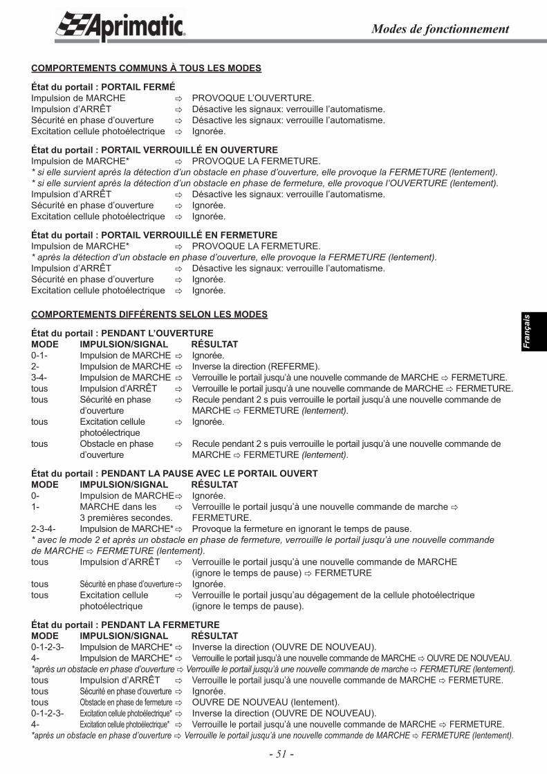
- 51 -
Fran
çais
Modes de fonctionnement
COMPORTEMENTS COMMUNS À TOUS LES MODES
État du portail : PORTAIL FERMÉImpulsion de MARCHE � PROVOQUE L’OUVERTURE.Impulsion d’ARRÊT � Désactive les signaux: verrouille l’automatisme.Sécurité en phase d’ouverture � Désactive les signaux: verrouille l’automatisme.Excitation cellule photoélectrique � Ignorée.
État du portail : PORTAIL VERROUILLÉ EN OUVERTUREImpulsion de MARCHE* � PROVOQUE LA FERMETURE.* si elle survient après la détection d’un obstacle en phase d’ouverture, elle provoque la FERMETURE (lentement).* si elle survient après la détection d’un obstacle en phase de fermeture, elle provoque l’OUVERTURE (lentement).Impulsion d’ARRÊT � Désactive les signaux: verrouille l’automatisme. Sécurité en phase d’ouverture � Ignorée.Excitation cellule photoélectrique � Ignorée.
État du portail : PORTAIL VERROUILLÉ EN FERMETUREImpulsion de MARCHE* � PROVOQUE LA FERMETURE.* après la détection d’un obstacle en phase d’ouverture, elle provoque la FERMETURE (lentement).Impulsion d’ARRÊT � Désactive les signaux: verrouille l’automatisme.Sécurité en phase d’ouverture � Ignorée.Excitation cellule photoélectrique � Ignorée.
COMPORTEMENTS DIFFÉRENTS SELON LES MODES
État du portail : PENDANT L’OUVERTURE MODE IMPULSION/SIGNAL RÉSULTAT0-1- Impulsion de MARCHE � Ignorée.2- Impulsion de MARCHE � Inverse la direction (REFERME).3-4- Impulsion de MARCHE � Verrouille le portail jusqu’à une nouvelle commande de MARCHE � FERMETURE.tous Impulsion d’ARRÊT � Verrouille le portail jusqu’à une nouvelle commande de MARCHE � FERMETURE.tous Sécurité en phase � Recule pendant 2 s puis verrouille le portail jusqu’à une nouvelle commande de d’ouverture MARCHE � FERMETURE (lentement).tous Excitation cellule � Ignorée. photoélectrique tous Obstacle en phase � Recule pendant 2 s puis verrouille le portail jusqu’à une nouvelle commande de d’ouverture MARCHE � FERMETURE (lentement).
État du portail : PENDANT LA PAUSE AVEC LE PORTAIL OUVERT MODE IMPULSION/SIGNAL RÉSULTAT0- Impulsion de MARCHE � Ignorée.1- MARCHE dans les � Verrouille le portail jusqu’à une nouvelle commande de marche � 3 premières secondes. FERMETURE.2-3-4- Impulsion de MARCHE* � Provoque la fermeture en ignorant le temps de pause.* avec le mode 2 et après un obstacle en phase de fermeture, verrouille le portail jusqu’à une nouvelle commande de MARCHE � FERMETURE (lentement).tous Impulsion d’ARRÊT � Verrouille le portail jusqu’à une nouvelle commande de MARCHE (ignore le temps de pause) � FERMETUREtous Sécurité en phase d’ouverture � Ignorée.tous Excitation cellule � Verrouille le portail jusqu’au dégagement de la cellule photoélectrique photoélectrique (ignore le temps de pause).
État du portail : PENDANT LA FERMETURE MODE IMPULSION/SIGNAL RÉSULTAT0-1-2-3- Impulsion de MARCHE* � Inverse la direction (OUVRE DE NOUVEAU).4- Impulsion de MARCHE* � Verrouille le portail jusqu’à une nouvelle commande de MARCHE � OUVRE DE NOUVEAU.*après un obstacle en phase d’ouverture � Verrouille le portail jusqu’à une nouvelle commande de marche � FERMETURE (lentement).tous Impulsion d’ARRÊT � Verrouille le portail jusqu’à une nouvelle commande de MARCHE � FERMETURE.tous Sécurité en phase d’ouverture � Ignorée.tous Obstacle en phase de fermeture � OUVRE DE NOUVEAU (lentement).0-1-2-3- Excitation cellule photoélectrique* � Inverse la direction (OUVRE DE NOUVEAU).4- Excitation cellule photoélectrique* � Verrouille le portail jusqu’à une nouvelle commande de MARCHE � FERMETURE.*après un obstacle en phase d’ouverture � Verrouille le portail jusqu’à une nouvelle commande de MARCHE � FERMETURE (lentement).
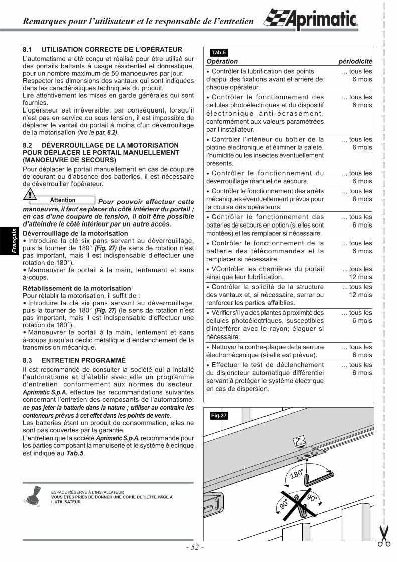
- 52 -
Fran
çais
Opération Contrôler la lubrifi cation des points d’appui des fi xations avant et arrière de chaque opérateur. Contrôler le fonctionnement des cellules photoélectriques et du dispositif é l e c t r o n i q u e a n t i - é c r a s e m e n t , conformément aux valeurs paramétrées par l’installateur. Contrôler l’intérieur du boîtier de la platine électronique et éliminer la saleté, l’humidité ou les insectes éventuellement présents. Contrôler le fonctionnement du déverrouillage manuel de secours. Contrôler le fonctionnement des arrêts mécaniques éventuellement prévus pour la course des opérateurs. Contrôler le fonctionnement des batteries de secours en option (si elles sont montées) et les remplacer si nécessaire. Contrôler le fonctionnement de la batterie des télécommandes et la remplacer si nécessaire. VContrôler les charnières du portail ainsi que leur lubrifi cation. Contrôler la solidité de la structure des vantaux et, si nécessaire, serrer ou renforcer les parties affaiblies. Vérifi er s’il y a des plantes à proximité des cellules photoélectriques, susceptibles d’interférer avec le rayon; élaguer si nécessaire. Nettoyer la contre-plaque de la serrure électromécanique (si elle est prévue). Effectuer le test de déclenchement du disjoncteur automatique différentiel servant à protéger le système électrique en cas de dispersion.
périodicité... tous les
6 mois
... tous les6 mois
... tous les6 mois
... tous les6 mois
... tous les6 mois
... tous les6 mois
... tous les6 mois
... tous les12 mois
... tous les12 mois
... tous les6 mois
... tous les6 mois
... tous les6 mois
8.1 UTILISATION CORRECTE DE L’OPÉRATEURL’automatisme a été conçu et réalisé pour être utilisé sur des portails battants à usage résidentiel et domestique, pour un nombre maximum de 50 manoeuvres par jour.Respecter les dimensions des vantaux qui sont indiquées dans les caractéristiques techniques du produit.Lire attentivement les mises en garde générales qui sont fournies.L’opérateur est irréversible, par conséquent, lorsqu’il n’est pas en service ou sous tension, il est impossible de déplacer le vantail du portail à moins d’un déverrouillage de la motorisation (lire le par. 8.2).
8.2 DÉVERROUILLAGE DE LA MOTORISATION POUR DÉPLACER LE PORTAIL MANUELLEMENT (MANOEUVRE DE SECOURS)Pour déplacer le portail manuellement en cas de coupure de courant ou d’absence des batteries, il est nécessaire de déverrouiller l’opérateur.
Attention! Pour pouvoir effectuer cette
manoeuvre, il faut se placer du côté intérieur du portail ; en cas d’une coupure de tension, il doit être possible d’atteindre le côté intérieur par un autre accès.Déverrouillage de la motorisation Introduire la clé six pans servant au déverrouillage, puis la tourner de 180° (Fig. 27) (le sens de rotation n’est pas important, mais il est indispensable d’effectuer une rotation de 180°). Manoeuvrer le portail à la main, lentement et sans à-coups.
Rétablissement de la motorisationPour rétablir la motorisation, il suffi t de : Introduire la clé six pans servant au déverrouillage, puis la tourner de 180° (Fig. 27) (le sens de rotation n’est pas important, mais il est indispensable d’effectuer une rotation de 180°). Manoeuvrer le portail à la main, lentement et sans à-coups jusqu’au déclic métallique d’enclenchement de la transmission mécanique.
8.3 ENTRETIEN PROGRAMMÉIl est recommandé de consulter la société qui a installé l’automatisme et d’établir avec elle un programme d’entretien, conformément aux normes du secteur. Aprimatic S.p.A. effectue les recommandations suivantes concernant l’entretien des composants de l’automatisme: ne pas jeter la batterie dans la nature ; utiliser au contraire les conteneurs prévus à cet effet dans les points de vente.Les batteries étant un produit de consommation, elles ne sont pas couvertes par la garantie.L’entretien que la société Aprimatic S.p.A. recommande pour les parties composant la menuiserie et le système électrique est indiqué au Tab.5.
180˚
180˚
90˚
90˚
Fig.27
Remarques pour l’utilisateur et le responsable de l’entretien
✂
ESPACE RÉSERVÉ À L’INSTALLATEURVOUS ÊTES PRIÉS DE DONNER UNE COPIE DE CETTE PAGE À L’UTILISATEUR
Tab.5
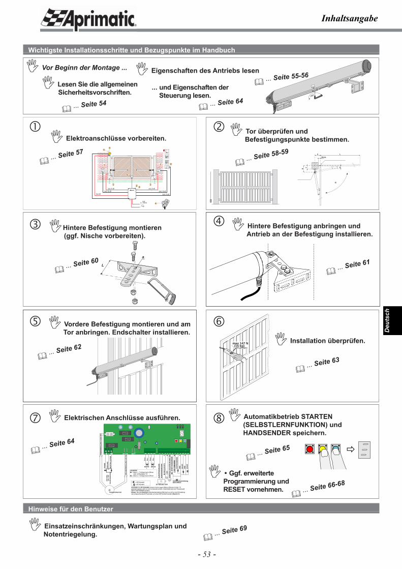
- 53 -
Deu
tsch
180˚
180˚
2
3x0.75 Ø
6
3x0.75 Ø
3x0.75 Ø
2x1.5 Ø
1
2x1.5 Ø
2x1 Ø
1
5
7 7
10Alc= 30mA 4
8
Aprimatic
Aprimatic
3
9
Inhaltsangabe
max 147 N(15 kg)
�
L
a
B
Y
A
E
L
30 mm
BL
INK
LE
UC
HT
E
+ 24
V
KO
NTR
OLL
LEU
CH
TE 2
4V M
AX
. 3W
12 V WS max. 15 W
EL
EK
TR
OS
CH
LO
SS
EL
EK
TR
OS
CH
LO
SS
+- + - -
PH
AS
E
ER
DU
NG
PHPH N
230V
50H
z+6
% -
10%
Ans
chlu
sssp
annu
ng
TRANSFORMATOR
SE
KU
ND
ÄR
WIC
KLU
NG
0-2
0V W
SPR
IMÄ
RW
ICK
LUN
G 0
-230
V W
S
M1M1 M2M2
MOTOR1
MOTOR2
Brau
n
Brau
n
Bla
u
Bla
u
NE
UT
RA
LL
EIT
ER
LIC
HTS
CH
RA
NK
E
+ 24
V Z
UB
EH
ÖR
S
ST
AR
T
STA
RT
FUS
SG
ÄN
GE
R
ST
OP
P
GN
D
GN
D
Sicherheitseinrichtung beim Öffnen
ACHTUNG! Die NC-Kontakte müssen immer gegen Masse (Klemme 9 oder 11) gebrückt werden, falls sie nicht verwendet werden. Andernfalls kann die Türautomatik NICHT BETRIEBEN werden!Hinweis: Bei der Klemme 6 (Standardeinstellung NO) kann es sich je nach Einstellung des entsprechenden H Parameter um einen NC-Kontakt handeln (Abschn.7.1).
LEGENDE:M1 = Motor 1. Torflügel beim Öffnen
oder einflügeliges TorM2 = Motor 2. Torflügel beim Öffnen
= NO-Kontakt= NC-Kontakt
24 V AC24 V AC BATTBATT- + +
L N M1 M2 M3 M4 1 3 6 7 10 11 122 4 5 8 9
Wichtigste Installationsschritte und Bezugspunkte im Handbuch
� Lesen Sie die allgemeinen Sicherheitsvorschriften.
� Eigenschaften des Antriebs lesen
� Tor überprüfen und Befestigungspunkte bestimmen.
Hinweise für den Benutzer
� Einsatzeinschränkungen, Wartungsplan und Notentriegelung.
� ... Seite 54
� ... Seite 55-56� Vor Beginn der Montage ...
� Elektroanschlüsse vorbereiten.
� ... Seite 57
� ... Seite 60
�Hintere Befestigung montieren(ggf. Nische vorbereiten).
� Hintere Befestigung anbringen und Antrieb an der Befestigung installieren.
180˚
� ... Seite 61
� ... Seite 62
� Vordere Befestigung montieren und am Tor anbringen. Endschalter installieren.
� Installation überprüfen.
� ... Seite 63
� ... Seite 64
� Elektrischen Anschlüsse ausführen.
� ... Seite 58-59
� ... Seite 69
�
� Automatikbetrieb STARTEN (SELBSTLERNFUNKTION) und HANDSENDER speichern.
� ... Seite 65
� Ggf. erweiterte Programmierung und RESET vornehmen.
� ... Seite 66-68
... und Eigenschaften der Steuerung lesen.
� ... Seite 64
�
��
� �
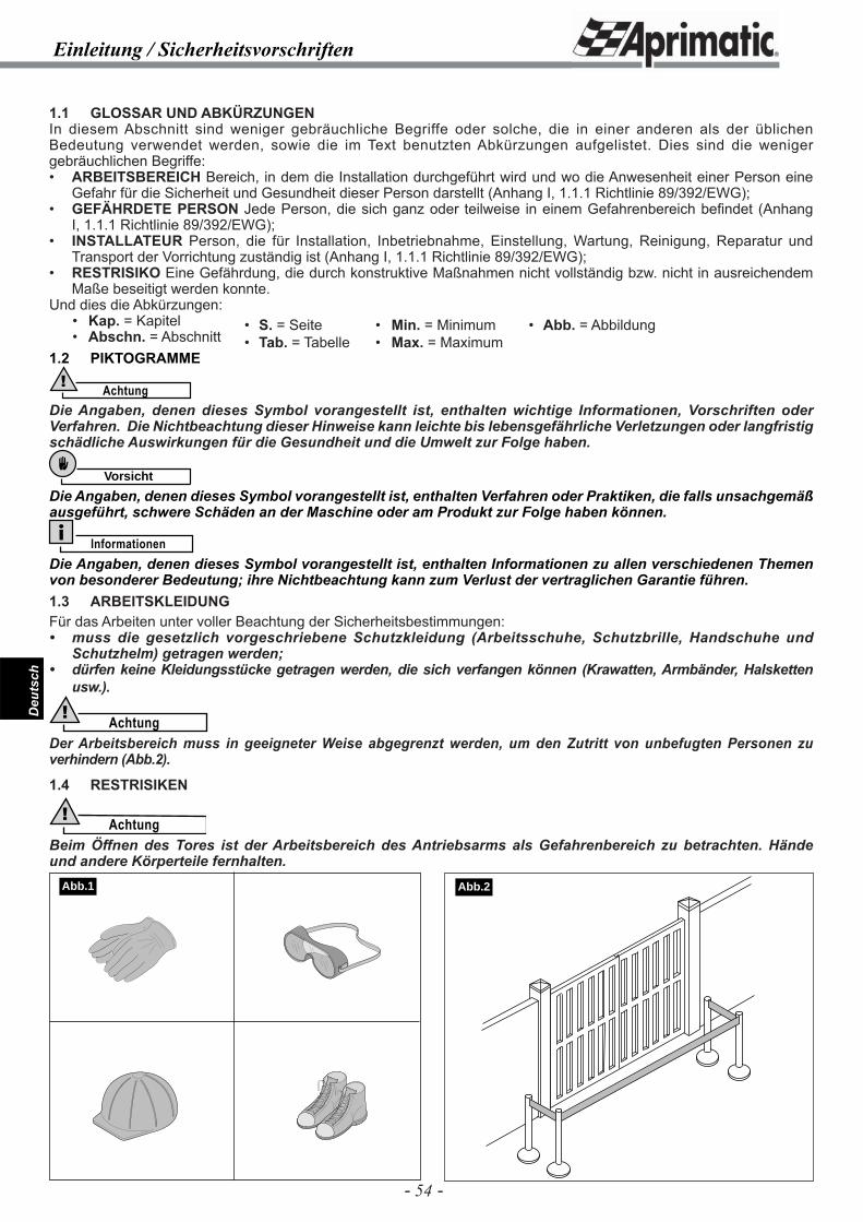
- 54 -
Deu
tsch
Einleitung / Sicherheitsvorschriften
1.1 GLOSSAR UND ABKÜRZUNGENIn diesem Abschnitt sind weniger gebräuchliche Begriffe oder solche, die in einer anderen als der üblichen Bedeutung verwendet werden, sowie die im Text benutzten Abkürzungen aufgelistet. Dies sind die weniger gebräuchlichen Begriffe:• ARBEITSBEREICH Bereich, in dem die Installation durchgeführt wird und wo die Anwesenheit einer Person eine
Gefahr für die Sicherheit und Gesundheit dieser Person darstellt (Anhang I, 1.1.1 Richtlinie 89/392/EWG);• GEFÄHRDETE PERSON Jede Person, die sich ganz oder teilweise in einem Gefahrenbereich befi ndet (Anhang
I, 1.1.1 Richtlinie 89/392/EWG);• INSTALLATEUR Person, die für Installation, Inbetriebnahme, Einstellung, Wartung, Reinigung, Reparatur und
Transport der Vorrichtung zuständig ist (Anhang I, 1.1.1 Richtlinie 89/392/EWG);• RESTRISIKO Eine Gefährdung, die durch konstruktive Maßnahmen nicht vollständig bzw. nicht in ausreichendem
Maße beseitigt werden konnte.Und dies die Abkürzungen: • Kap. = Kapitel • Abschn. = Abschnitt1.2 PIKTOGRAMME
Achtung!
Die Angaben, denen dieses Symbol vorangestellt ist, enthalten wichtige Informationen, Vorschriften oder Verfahren. Die Nichtbeachtung dieser Hinweise kann leichte bis lebensgefährliche Verletzungen oder langfristig schädliche Auswirkungen für die Gesundheit und die Umwelt zur Folge haben.
Vorsicht
Die Angaben, denen dieses Symbol vorangestellt ist, enthalten Verfahren oder Praktiken, die falls unsachgemäß ausgeführt, schwere Schäden an der Maschine oder am Produkt zur Folge haben können.
InformationenDie Angaben, denen dieses Symbol vorangestellt ist, enthalten Informationen zu allen verschiedenen Themen von besonderer Bedeutung; ihre Nichtbeachtung kann zum Verlust der vertraglichen Garantie führen.1.3 ARBEITSKLEIDUNGFür das Arbeiten unter voller Beachtung der Sicherheitsbestimmungen:• muss die gesetzlich vorgeschriebene Schutzkleidung (Arbeitsschuhe, Schutzbrille, Handschuhe und
Schutzhelm) getragen werden;• dürfen keine Kleidungsstücke getragen werden, die sich verfangen können (Krawatten, Armbänder, Halsketten
usw.).
Achtung!Der Arbeitsbereich muss in geeigneter Weise abgegrenzt werden, um den Zutritt von unbefugten Personen zu verhindern (Abb.2).
1.4 RESTRISIKEN
Achtung!Beim Öffnen des Tores ist der Arbeitsbereich des Antriebsarms als Gefahrenbereich zu betrachten. Hände und andere Körperteile fernhalten.
• S. = Seite• Tab. = Tabelle
• Min. = Minimum• Max. = Maximum
• Abb. = Abbildung
Abb.1 Abb.2
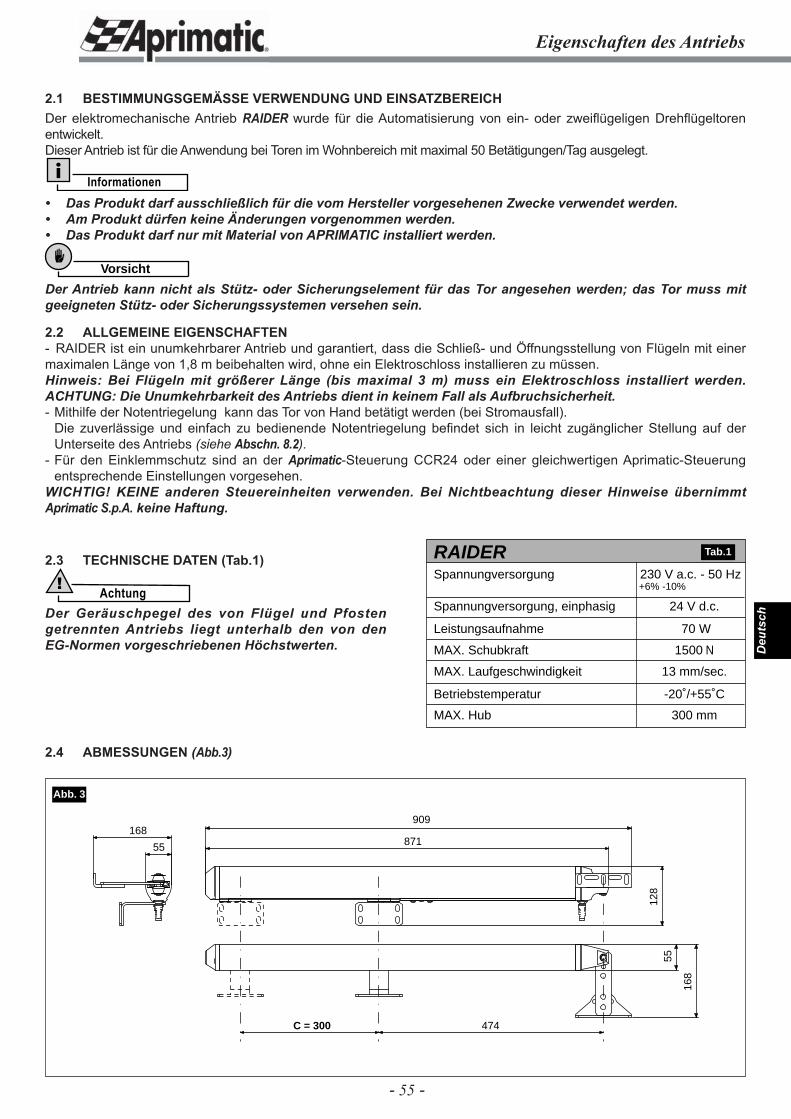
- 55 -
Deu
tsch
Eigenschaften des Antriebs
2.1 BESTIMMUNGSGEMÄSSE VERWENDUNG UND EINSATZBEREICHDer elektromechanische Antrieb RAIDER wurde für die Automatisierung von ein- oder zweiflügeligen Drehflügeltoren entwickelt.Dieser Antrieb ist für die Anwendung bei Toren im Wohnbereich mit maximal 50 Betätigungen/Tag ausgelegt.
Informationen• Das Produkt darf ausschließlich für die vom Hersteller vorgesehenen Zwecke verwendet werden.• Am Produkt dürfen keine Änderungen vorgenommen werden.• Das Produkt darf nur mit Material von APRIMATIC installiert werden.
Vorsicht
Der Antrieb kann nicht als Stütz- oder Sicherungselement für das Tor angesehen werden; das Tor muss mit geeigneten Stütz- oder Sicherungssystemen versehen sein.
2.2 ALLGEMEINE EIGENSCHAFTEN- RAIDER ist ein unumkehrbarer Antrieb und garantiert, dass die Schließ- und Öffnungsstellung von Flügeln mit einer maximalen Länge von 1,8 m beibehalten wird, ohne ein Elektroschloss installieren zu müssen.Hinweis: Bei Flügeln mit größerer Länge (bis maximal 3 m) muss ein Elektroschloss installiert werden. ACHTUNG: Die Unumkehrbarkeit des Antriebs dient in keinem Fall als Aufbruchsicherheit.- Mithilfe der Notentriegelung kann das Tor von Hand betätigt werden (bei Stromausfall). Die zuverlässige und einfach zu bedienende Notentriegelung befi ndet sich in leicht zugänglicher Stellung auf der
Unterseite des Antriebs (siehe Abschn. 8.2).- Für den Einklemmschutz sind an der Aprimatic-Steuerung CCR24 oder einer gleichwertigen Aprimatic-Steuerung
entsprechende Einstellungen vorgesehen.WICHTIG! KEINE anderen Steuereinheiten verwenden. Bei Nichtbeachtung dieser Hinweise übernimmt Aprimatic S.p.A. keine Haftung.
2.3 TECHNISCHE DATEN (Tab.1)
Achtung!
Der Geräuschpegel des von Flügel und Pfosten getrennten Antriebs liegt unterhalb den von den EG-Normen vorgeschriebenen Höchstwerten.
2.4 ABMESSUNGEN (Abb.3)
70 W
1500 N
13 mm/sec.
-20˚/+55˚C
300 mm
RAIDERSpannungversorgung
24 V d.c.Spannungversorgung, einphasig
Leistungsaufnahme
MAX. Schubkraft
MAX. Laufgeschwindigkeit
Betriebstemperatur
MAX. Hub
230 V a.c. - 50 Hz+6% -10%
Tab.1
55
909
871
128
55
168
168
C = 300 474
Abb. 3
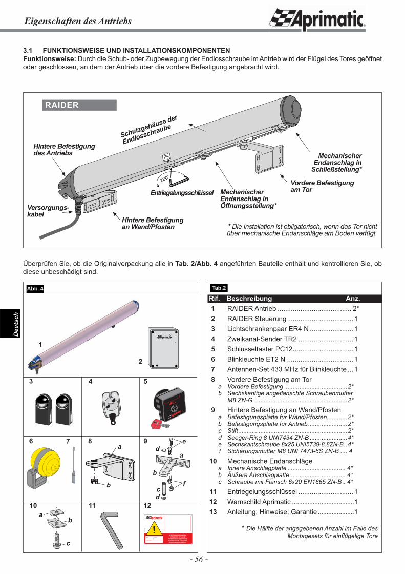
- 56 -
Deu
tsch
Eigenschaften des Antriebs
3.1 FUNKTIONSWEISE UND INSTALLATIONSKOMPONENTENFunktionsweise: Durch die Schub- oder Zugbewegung der Endlosschraube im Antrieb wird der Flügel des Tores geöffnet oder geschlossen, an dem der Antrieb über die vordere Befestigung angebracht wird.
Rif. Beschreibung Anz. 1 RAIDER Antrieb ....................................... 2* 2 RAIDER Steuerung ...................................1 3 Lichtschrankenpaar ER4 N .......................1 4 Zweikanal-Sender TR2 .............................1 5 Schlüsseltaster PC12 ................................1 6 Blinkleuchte ET2 N ...................................1 7 Antennen-Set 433 MHz für Blinkleuchte ... 1 8 Vordere Befestigung am Tor a Vordere Befestigung .....................................2* b Sechskantige angefl anschte Schraubenmutter M8 ZN-G .......................................................2* 9 Hintere Befestigung an Wand/Pfosten a Befestigungsplatte für Wand/Pfosten ............2* b Befestigungsplatte für Antrieb .......................2* c Stift ................................................................2* d Seeger-Ring 8 UNI7434 ZN-B ......................4* e Sechskantschraube 8x25 UNI5739-8.8ZN-B ..4* f Sicherungsmutter M8 UNI 7473-6S ZN-B .... 4 10 Mechanische Endanschläge a Innere Anschlagplatte .................................. 4* b Äußere Anschlagplatte ................................. 4* c Schraube mit Flansch 6x20 EN1665 ZN-B .. 4* 11 Entriegelungsschlüssel .............................1 12 Warnschild Aprimatic ....................................1 13 Anleitung; Hinweise; Garantie .....................1
* Die Hälfte der angegebenen Anzahl im Falle des Montagesets für einfl ügelige Tore
4
7
11
1
Aprimatic
5
96
2
3
12fi
IL CAMPIONE DELL’AUTOMAZIONE
!APERTURA AUTOMATICA
AUTOMATIC OPENINGOUVERTURE AUTOMATIQUEAUTOMATISCHE ÖFFNUNGAPERTURA AUTOMATICA
A58
4500
0
name model
serial number
a
b
c
de
d
Überprüfen Sie, ob die Originalverpackung alle in Tab. 2/Abb. 4 angeführten Bauteile enthält und kontrollieren Sie, ob diese unbeschädigt sind.
180˚
180˚Vordere Befestigung am Tor
Hintere Befestigung an Wand/Pfosten
Versorgungs-kabel
Entriegelungsschlüssel
RAIDER
Hintere Befestigung des Antriebs
Schutzgehäuse der
Endlosschraube
Mechanischer Endanschlag in Öffnungsstellung*
Mechanischer Endanschlag in
Schließstellung*
* Die Installation ist obligatorisch, wenn das Tor nicht über mechanische Endanschläge am Boden verfügt.
Tab.2 Abb. 4
f
8
b
a
10a
c
b
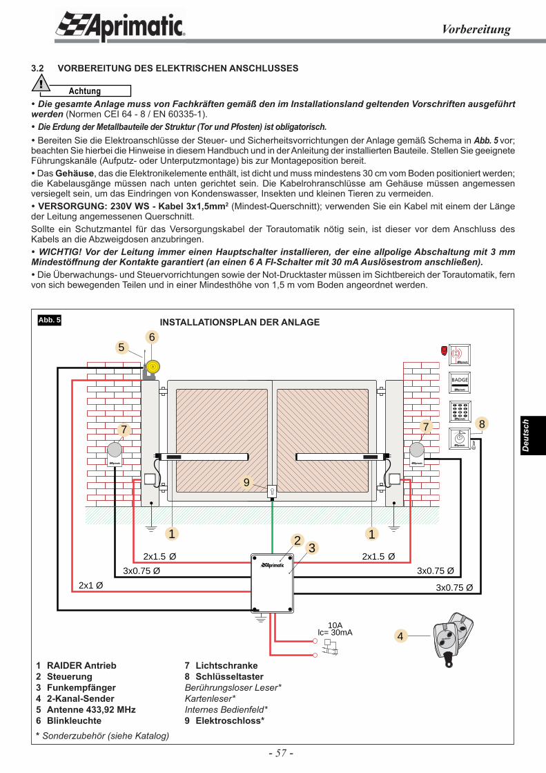
- 57 -
Deu
tsch
3.2 VORBEREITUNG DES ELEKTRISCHEN ANSCHLUSSES
Achtung! Die gesamte Anlage muss von Fachkräften gemäß den im Installationsland geltenden Vorschriften ausgeführt werden (Normen CEI 64 - 8 / EN 60335-1). Die Erdung der Metallbauteile der Struktur (Tor und Pfosten) ist obligatorisch. Bereiten Sie die Elektroanschlüsse der Steuer- und Sicherheitsvorrichtungen der Anlage gemäß Schema in Abb. 5 vor; beachten Sie hierbei die Hinweise in diesem Handbuch und in der Anleitung der installierten Bauteile. Stellen Sie geeignete Führungskanäle (Aufputz- oder Unterputzmontage) bis zur Montageposition bereit. Das Gehäuse, das die Elektronikelemente enthält, ist dicht und muss mindestens 30 cm vom Boden positioniert werden; die Kabelausgänge müssen nach unten gerichtet sein. Die Kabelrohranschlüsse am Gehäuse müssen angemessen versiegelt sein, um das Eindringen von Kondenswasser, Insekten und kleinen Tieren zu vermeiden. VERSORGUNG: 230V WS - Kabel 3x1,5mm2 (Mindest-Querschnitt); verwenden Sie ein Kabel mit einem der Länge der Leitung angemessenen Querschnitt.Sollte ein Schutzmantel für das Versorgungskabel der Torautomatik nötig sein, ist dieser vor dem Anschluss des Kabels an die Abzweigdosen anzubringen. WICHTIG! Vor der Leitung immer einen Hauptschalter installieren, der eine allpolige Abschaltung mit 3 mm Mindestöffnung der Kontakte garantiert (an einen 6 A FI-Schalter mit 30 mA Auslösestrom anschließen). Die Überwachungs- und Steuervorrichtungen sowie der Not-Drucktaster müssen im Sichtbereich der Torautomatik, fern von sich bewegenden Teilen und in einer Mindesthöhe von 1,5 m vom Boden angeordnet werden.
Vorbereitung
2
3x0.75 Ø
6
3x0.75 Ø
3x0.75 Ø
2x1.5 Ø
1
2x1.5 Ø
2x1 Ø
1
5
7 7
10Alc= 30mA 4
8
Aprimatic
Aprimatic
3
9
Abb. 5 INSTALLATIONSPLAN DER ANLAGE
7 Lichtschranke8 SchlüsseltasterBerührungsloser Leser*Kartenleser* Internes Bedienfeld*9 Elektroschloss*
1 RAIDER Antrieb2 Steuerung3 Funkempfänger4 2-Kanal-Sender5 Antenne 433,92 MHz 6 Blinkleuchte* Sonderzubehör (siehe Katalog)
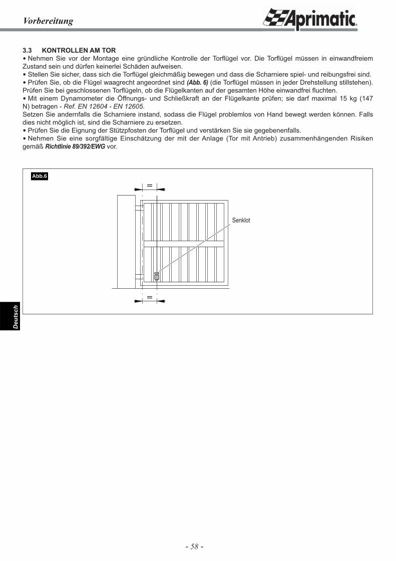
- 58 -
Deu
tsch
3.3 KONTROLLEN AM TOR Nehmen Sie vor der Montage eine gründliche Kontrolle der Torfl ügel vor. Die Torfl ügel müssen in einwandfreiem Zustand sein und dürfen keinerlei Schäden aufweisen. Stellen Sie sicher, dass sich die Torfl ügel gleichmäßig bewegen und dass die Scharniere spiel- und reibungsfrei sind. Prüfen Sie, ob die Flügel waagrecht angeordnet sind (Abb. 6) (die Torfl ügel müssen in jeder Drehstellung stillstehen). Prüfen Sie bei geschlossenen Torfl ügeln, ob die Flügelkanten auf der gesamten Höhe einwandfrei fl uchten. Mit einem Dynamometer die Öffnungs- und Schließkraft an der Flügelkante prüfen; sie darf maximal 15 kg (147 N) betragen - Ref. EN 12604 - EN 12605.Setzen Sie andernfalls die Scharniere instand, sodass die Flügel problemlos von Hand bewegt werden können. Falls dies nicht möglich ist, sind die Scharniere zu ersetzen. Prüfen Sie die Eignung der Stützpfosten der Torfl ügel und verstärken Sie sie gegebenenfalls. Nehmen Sie eine sorgfältige Einschätzung der mit der Anlage (Tor mit Antrieb) zusammenhängenden Risiken gemäß Richtlinie 89/392/EWG vor.
Vorbereitung
Senklot
Abb.6
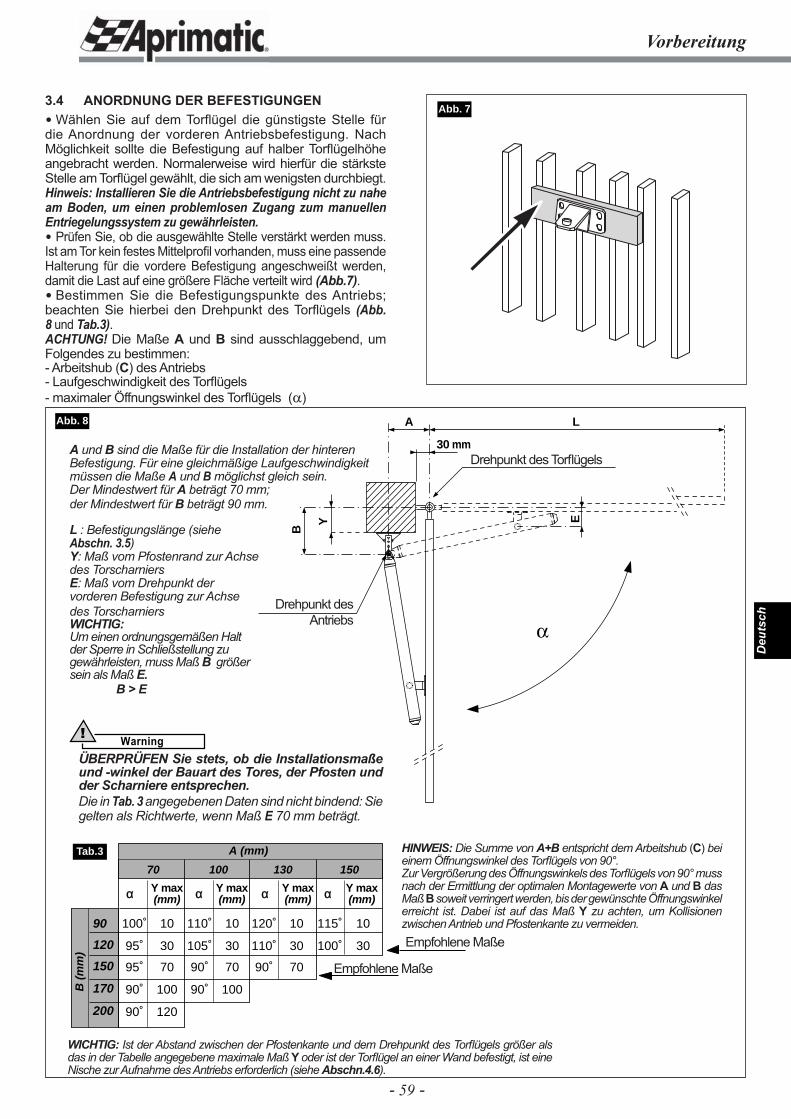
- 59 -
Deu
tsch
B
Y
A
E
L
30 mm
Vorbereitung
3.4 ANORDNUNG DER BEFESTIGUNGEN Wählen Sie auf dem Torflügel die günstigste Stelle für die Anordnung der vorderen Antriebsbefestigung. Nach Möglichkeit sollte die Befestigung auf halber Torfl ügelhöhe angebracht werden. Normalerweise wird hierfür die stärkste Stelle am Torfl ügel gewählt, die sich am wenigsten durchbiegt. Hinweis: Installieren Sie die Antriebsbefestigung nicht zu nahe am Boden, um einen problemlosen Zugang zum manuellen Entriegelungssystem zu gewährleisten. Prüfen Sie, ob die ausgewählte Stelle verstärkt werden muss. Ist am Tor kein festes Mittelprofi l vorhanden, muss eine passende Halterung für die vordere Befestigung angeschweißt werden, damit die Last auf eine größere Fläche verteilt wird (Abb.7). Bestimmen Sie die Befestigungspunkte des Antriebs; beachten Sie hierbei den Drehpunkt des Torfl ügels (Abb. 8 und Tab.3).ACHTUNG! Die Maße A und B sind ausschlaggebend, um Folgendes zu bestimmen:- Arbeitshub (C) des Antriebs- Laufgeschwindigkeit des Torfl ügels- maximaler Öffnungswinkel des Torfl ügels (α)
Abb. 7
WICHTIG: Ist der Abstand zwischen der Pfostenkante und dem Drehpunkt des Torfl ügels größer als das in der Tabelle angegebene maximale Maß Y oder ist der Torfl ügel an einer Wand befestigt, ist eine Nische zur Aufnahme des Antriebs erforderlich (siehe Abschn.4.6).
90
120
150
170
200
B (
mm
)
A (mm)
α Y max α Y max α Y max α Y max(mm) (mm) (mm) (mm)
70 100 130 150
100˚ 10 110˚ 10 120˚ 10 115˚ 10
95˚ 30 105˚ 30 110˚ 30 100˚ 30
95˚ 70 90˚ 70 90˚ 70
90˚ 100 90˚ 100
90˚ 120
Tab.3
Abb. 8
Empfohlene Maße
Empfohlene Maße
HINWEIS: Die Summe von A+B entspricht dem Arbeitshub (C) bei einem Öffnungswinkel des Torfl ügels von 90°.Zur Vergrößerung des Öffnungswinkels des Torfl ügels von 90° muss nach der Ermittlung der optimalen Montagewerte von A und B das Maß B soweit verringert werden, bis der gewünschte Öffnungswinkel erreicht ist. Dabei ist auf das Maß Y zu achten, um Kollisionen zwischen Antrieb und Pfostenkante zu vermeiden.
A und B sind die Maße für die Installation der hinteren Befestigung. Für eine gleichmäßige Laufgeschwindigkeit müssen die Maße A und B möglichst gleich sein.Der Mindestwert für A beträgt 70 mm;der Mindestwert für B beträgt 90 mm.
L : Befestigungslänge (siehe Abschn. 3.5)Y: Maß vom Pfostenrand zur Achse des TorscharniersE: Maß vom Drehpunkt der vorderen Befestigung zur Achsedes TorscharniersWICHTIG:Um einen ordnungsgemäßen Halt der Sperre in Schließstellung zu gewährleisten, muss Maß B größer sein als Maß E.
B > E
Drehpunkt des Torfl ügels
Drehpunkt des Antriebs
Warning!
ÜBERPRÜFEN Sie stets, ob die Installationsmaße und -winkel der Bauart des Tores, der Pfosten und der Scharniere entsprechen.Die in Tab. 3 angegebenen Daten sind nicht bindend: Sie gelten als Richtwerte, wenn Maß E 70 mm beträgt.
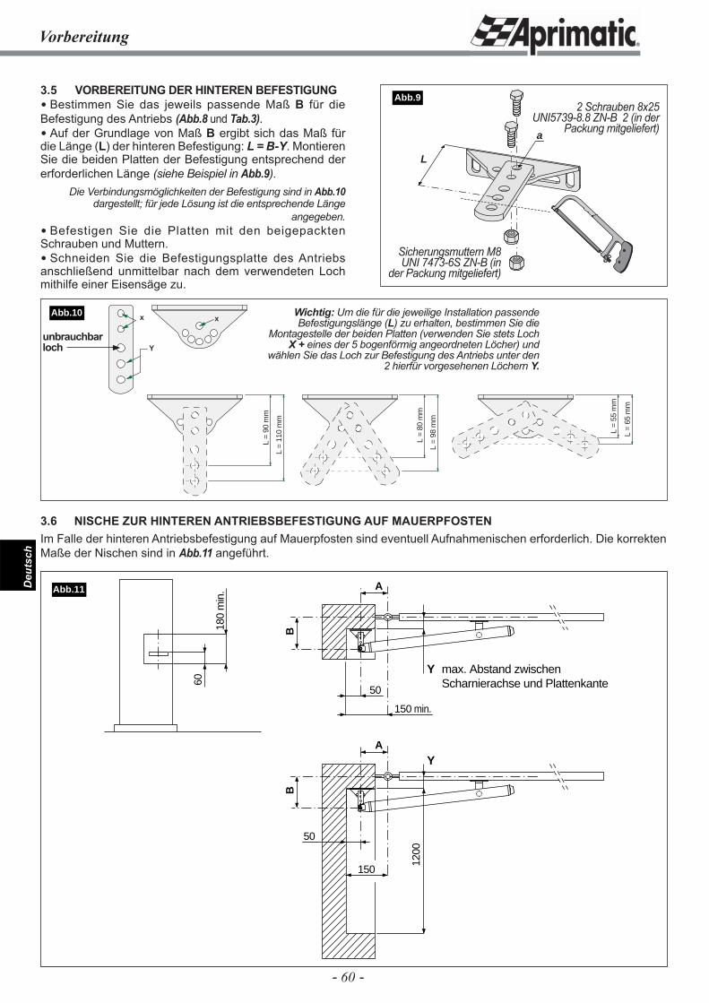
- 60 -
Deu
tsch
L =
55 m
m
L =
65 m
m
L =
98 m
m
L =
80 m
m
L =
110
mm
L =
90 m
m
xx
Y
60
180
min
.
50
150
1200
Y max. Abstand zwischen Scharnierachse und Plattenkante
B
A
50
150 min.
Y
B
A
Abb.11
Vorbereitung
3.5 VORBEREITUNG DER HINTEREN BEFESTIGUNG Bestimmen Sie das jeweils passende Maß B für die Befestigung des Antriebs (Abb.8 und Tab.3). Auf der Grundlage von Maß B ergibt sich das Maß für die Länge (L) der hinteren Befestigung: L = B-Y. Montieren Sie die beiden Platten der Befestigung entsprechend der erforderlichen Länge (siehe Beispiel in Abb.9).
Die Verbindungsmöglichkeiten der Befestigung sind in Abb.10 dargestellt; für jede Lösung ist die entsprechende Länge
angegeben. Befestigen Sie die Platten mit den beigepackten Schrauben und Muttern. Schneiden Sie die Befestigungsplatte des Antriebs anschließend unmittelbar nach dem verwendeten Loch mithilfe einer Eisensäge zu.
L
a
Abb.92 Schrauben 8x25
UNI5739-8.8 ZN-B 2 (in der Packung mitgeliefert)
Sicherungsmuttern M8 UNI 7473-6S ZN-B (in
der Packung mitgeliefert)
Wichtig: Um die für die jeweilige Installation passende Befestigungslänge (L) zu erhalten, bestimmen Sie die
Montagestelle der beiden Platten (verwenden Sie stets Loch X + eines der 5 bogenförmig angeordneten Löcher) und
wählen Sie das Loch zur Befestigung des Antriebs unter den 2 hierfür vorgesehenen Löchern Y.
3.6 NISCHE ZUR HINTEREN ANTRIEBSBEFESTIGUNG AUF MAUERPFOSTENIm Falle der hinteren Antriebsbefestigung auf Mauerpfosten sind eventuell Aufnahmenischen erforderlich. Die korrekten Maße der Nischen sind in Abb.11 angeführt.
Abb.10
unbrauchbar loch
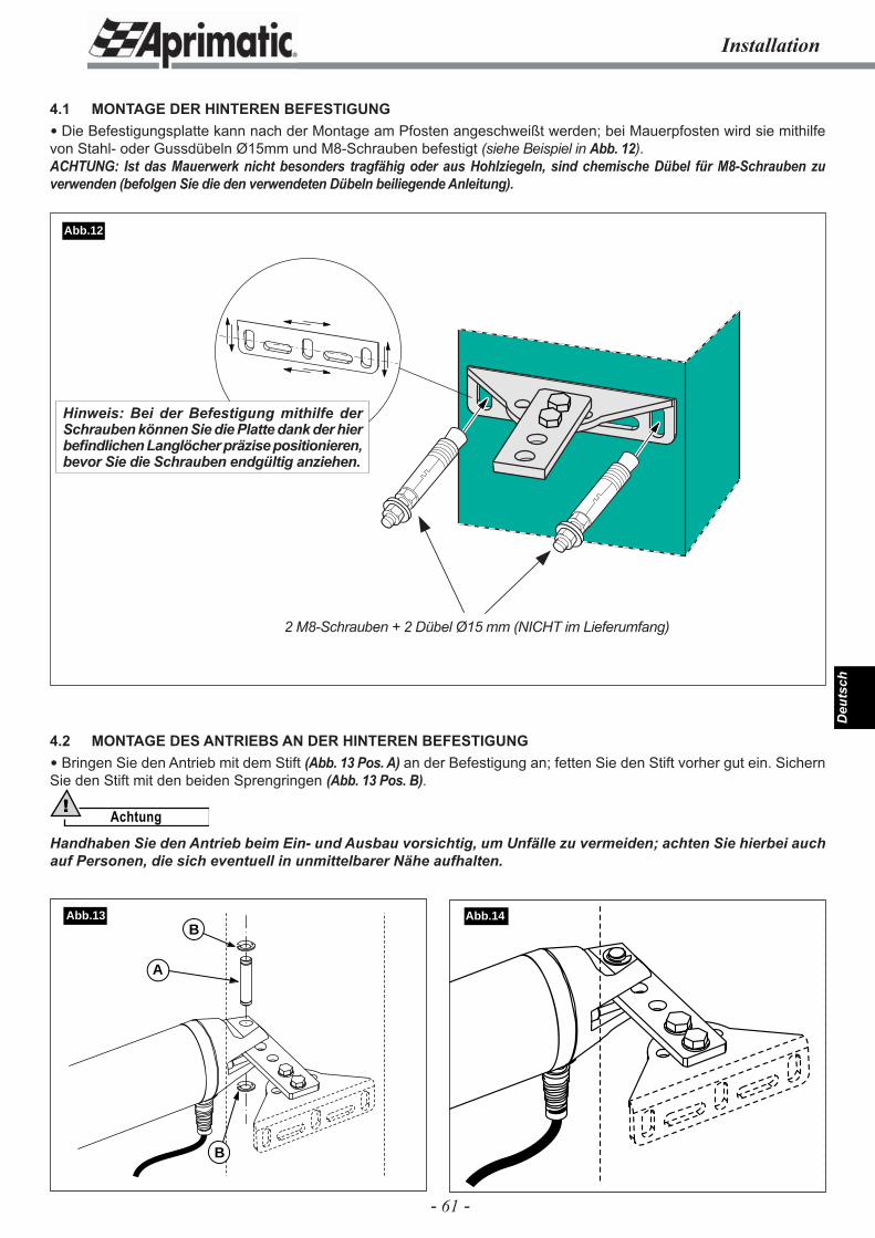
- 61 -
Deu
tsch
Installation
4.1 MONTAGE DER HINTEREN BEFESTIGUNG Die Befestigungsplatte kann nach der Montage am Pfosten angeschweißt werden; bei Mauerpfosten wird sie mithilfe von Stahl- oder Gussdübeln Ø15mm und M8-Schrauben befestigt (siehe Beispiel in Abb. 12).ACHTUNG: Ist das Mauerwerk nicht besonders tragfähig oder aus Hohlziegeln, sind chemische Dübel für M8-Schrauben zu verwenden (befolgen Sie die den verwendeten Dübeln beiliegende Anleitung).
Abb.14B
A
B
Abb.13
Abb.12
2 M8-Schrauben + 2 Dübel Ø15 mm (NICHT im Lieferumfang)
4.2 MONTAGE DES ANTRIEBS AN DER HINTEREN BEFESTIGUNG Bringen Sie den Antrieb mit dem Stift (Abb. 13 Pos. A) an der Befestigung an; fetten Sie den Stift vorher gut ein. Sichern Sie den Stift mit den beiden Sprengringen (Abb. 13 Pos. B).
Achtung!
Handhaben Sie den Antrieb beim Ein- und Ausbau vorsichtig, um Unfälle zu vermeiden; achten Sie hierbei auch auf Personen, die sich eventuell in unmittelbarer Nähe aufhalten.
Hinweis: Bei der Befestigung mithilfe der Schrauben können Sie die Platte dank der hier befi ndlichen Langlöcher präzise positionieren, bevor Sie die Schrauben endgültig anziehen.
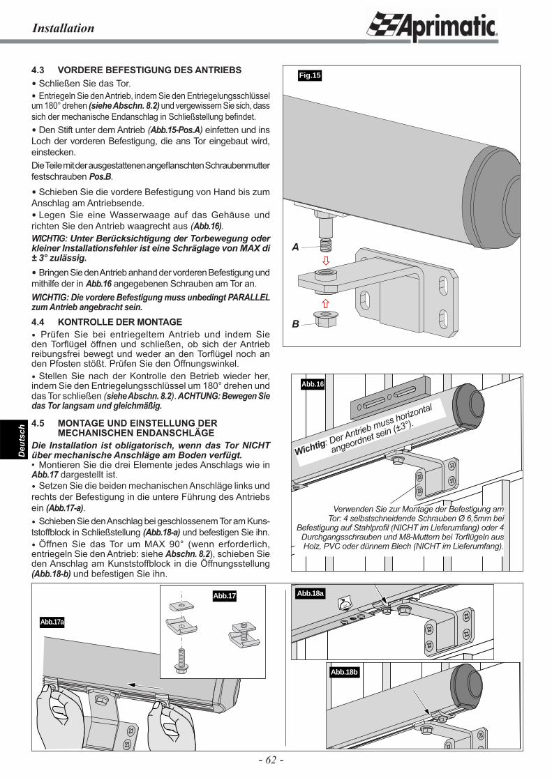
- 62 -
Deu
tsch
4.3 VORDERE BEFESTIGUNG DES ANTRIEBS Schließen Sie das Tor. Entriegeln Sie den Antrieb, indem Sie den Entriegelungsschlüssel um 180° drehen (siehe Abschn. 8.2) und vergewissern Sie sich, dass sich der mechanische Endanschlag in Schließstellung befi ndet. Den Stift unter dem Antrieb (Abb.15-Pos.A) einfetten und ins Loch der vorderen Befestigung, die ans Tor eingebaut wird, einstecken.Die Teile mit der ausgestattenen angefl anschten Schraubenmutter festschrauben Pos.B.
Schieben Sie die vordere Befestigung von Hand bis zum Anschlag am Antriebsende. Legen Sie eine Wasserwaage auf das Gehäuse und richten Sie den Antrieb waagrecht aus (Abb.16).WICHTIG: Unter Berücksichtigung der Torbewegung oder kleiner Installationsfehler ist eine Schräglage von MAX di ± 3° zulässig. Bringen Sie den Antrieb anhand der vorderen Befestigung und mithilfe der in Abb.16 angegebenen Schrauben am Tor an.WICHTIG: Die vordere Befestigung muss unbedingt PARALLEL zum Antrieb angebracht sein.4.4 KONTROLLE DER MONTAGE Prüfen Sie bei entriegeltem Antrieb und indem Sie den Torfl ügel öffnen und schließen, ob sich der Antrieb reibungsfrei bewegt und weder an den Torfl ügel noch an den Pfosten stößt. Prüfen Sie den Öffnungswinkel. Stellen Sie nach der Kontrolle den Betrieb wieder her, indem Sie den Entriegelungsschlüssel um 180° drehen und das Tor schließen (siehe Abschn. 8.2). ACHTUNG: Bewegen Sie das Tor langsam und gleichmäßig.
4.5 MONTAGE UND EINSTELLUNG DER MECHANISCHEN ENDANSCHLÄGEDie Installation ist obligatorisch, wenn das Tor NICHT über mechanische Anschläge am Boden verfügt.• Montieren Sie die drei Elemente jedes Anschlags wie in Abb.17 dargestellt ist. Setzen Sie die beiden mechanischen Anschläge links und rechts der Befestigung in die untere Führung des Antriebs ein (Abb.17-a). Schieben Sie den Anschlag bei geschlossenem Tor am Kuns-tstoffblock in Schließstellung (Abb.18-a) und befestigen Sie ihn. Öffnen Sie das Tor um MAX 90° (wenn erforderlich, entriegeln Sie den Antrieb: siehe Abschn. 8.2), schieben Sie den Anschlag am Kunststoffblock in die Öffnungsstellung (Abb.18-b) und befestigen Sie ihn.
Abb.16
Installation
Abb.17a
Verwenden Sie zur Montage der Befestigung am Tor: 4 selbstschneidende Schrauben Ø 6,5mm bei
Befestigung auf Stahlprofi l (NICHT im Lieferumfang) oder 4 Durchgangsschrauben und M8-Muttern bei Torfl ügeln aus Holz, PVC oder dünnem Blech (NICHT im Lieferumfang).
Abb.17
Wichtig: Der Antrieb muss horizontal
angeordnet sein (±3°).
180˚
Abb.18a
Abb.18b
Fig.15
�
�A
B
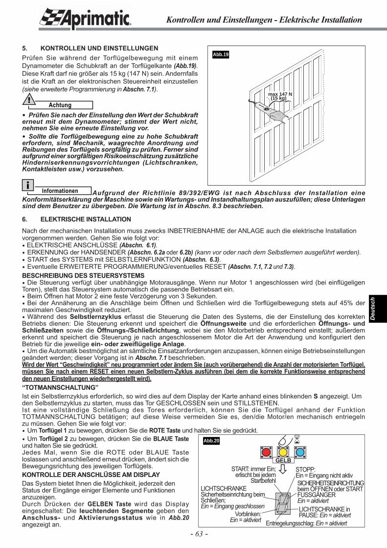
- 63 -
Deu
tsch
Kontrollen und Einstellungen - Elektrische Installation
5. KONTROLLEN UND EINSTELLUNGENPrüfen Sie während der Torflügelbewegung mit einem Dynamometer die Schubkraft an der Torfl ügelkante (Abb.19). Diese Kraft darf nie größer als 15 kg (147 N) sein. Andernfalls ist die Kraft an der elektronischen Steuereinheit einzustellen (siehe erweiterte Programmierung in Abschn. 7.1).
Achtung!
Prüfen Sie nach der Einstellung den Wert der Schubkraft erneut mit dem Dynamometer; stimmt der Wert nicht, nehmen Sie eine erneute Einstellung vor. Sollte die Torfl ügelbewegung eine zu hohe Schubkraft erfordern, sind Mechanik, waagrechte Anordnung und Reibungen des Torfl ügels sorgfältig zu prüfen. Ferner sind aufgrund einer sorgfältigen Risikoeinschätzung zusätzliche Hinderniserkennungsvorrichtungen (Lichtschranken, Kontaktleisten usw.) vorzusehen.
max 147 N(15 kg)
Abb.19
Informationen Aufgrund der Richtlinie 89/392/EWG ist nach Abschluss der Installation eine Konformitätserklärung der Maschine sowie ein Wartungs- und Instandhaltungsplan auszufüllen; diese Unterlagen sind dem Benutzer zu übergeben. Die Wartung ist in Abschn. 8.3 beschrieben.
6. ELEKTRISCHE INSTALLATION
Nach der mechanischen Installation muss zwecks INBETRIEBNAHME der ANLAGE auch die elektrische Installation vorgenommen werden. Gehen Sie wie folgt vor: ELEKTRISCHE ANSCHLÜSSE (Abschn. 6.1). ERKENNUNG der HANDSENDER (Abschn. 6.2a oder 6.2b) (kann vor oder nach dem Selbstlernen ausgeführt werden). START des SYSTEMS mit SELBSTLERNFUNKTION (Abschn. 6.3). Eventuelle ERWEITERTE PROGRAMMIERUNG/eventuelles RESET (Abschn. 7.1, 7.2 und 7.3).BESCHREIBUNG DES STEUERSYSTEMS Die Steuerung verfügt über unabhängige Motorausgänge. Wenn nur Motor 1 angeschlossen wird (bei einfl ügeligen Toren), stellt das Steuersystem automatisch die passende Betriebsart ein. Beim Öffnen hat Motor 2 eine feste Verzögerung von 3 Sekunden. Bei der Annäherung an die Anschläge beim Öffnen und Schließen wird die Torfl ügelbewegung stets auf 45% der maximalen Geschwindigkeit reduziert. Während des Selbstlernzyklus erfasst die Steuerung die Daten des Systems, die der Einstellung des korrekten Betriebs dienen: Die Steuerung erkennt und speichert die Öffnungsweite und die erforderlichen Öffnungs- und Schließzeiten sowie die Öffnungs-/Schließrichtung, wobei sie den Motorbetrieb entsprechend einstellt; außerdem erkennt und speichert die Steuerung je nach angeschlossenem Motor die Art der Anwendung und konfi guriert den Betrieb für die jeweilige ein- oder zweifl ügelige Anlage. Um die Automatik bestmöglichst an sämtliche Einsatzanforderungen anzupassen, können einige Betriebseinstellungen geändert werden; dieser Vorgang ist in Abschn. 7.1 beschrieben.Wird der Wert “Geschwindigkeit” neu programmiert oder ändern Sie (auch vorübergehend) die Anzahl der motorisierten Torfl ügel, müssen Sie nach einem RESET einen neuen Selbstlern-Zyklus ausführen (bei dem die korrekte Funktionsweise entsprechend den neuen Einstellungen wiederhergestellt wird).“TOTMANNSCHALTUNG”Ist ein Selbstlernzyklus erforderlich, so wird dies auf dem Display der Karte anhand eines blinkenden S angezeigt. Um den Selbstlernzyklus zu starten, muss das Tor GESCHLOSSEN sein und STILLSTEHEN.Ist eine vollständige Schließung des Tores erforderlich, können Sie die Torflügel anhand der Funktion TOTMANNSCHALTUNG betätigen; auf diese Weise vermeiden Sie es, den/die Motor/en mechanisch entriegeln zu müssen. Gehen Sie wie folgt vor: Um Torfl ügel 1 zu bewegen, drücken Sie die ROTE Taste und halten Sie sie gedrückt. Um Torfl ügel 2 zu bewegen, drücken Sie die BLAUE Taste und halten Sie sie gedrückt. Jedes Mal, wenn Sie die ROTE oder BLAUE Taste loslassen und anschließend erneut drücken, ändert sich die Bewegungsrichtung des jeweiligen Torfl ügels.KONTROLLE DER ANSCHLÜSSE AM DISPLAYDas System bietet Ihnen die Möglichkeit, jederzeit den Status der Eingänge einiger Elemente und Funktionen anzuzeigen.Durch Drücken der GELBEN Taste wird das Display eingeschaltet: Die leuchtenden Segmente geben den Anschluss- und Aktivierungsstatus wie in Abb.20 angezeigt an.
�
�
START: immer Ein; erlischt bei jedem
Startbefehl SICHERHEITSEINRICHTUNG beim ÖFFNEN oder START FUSSGÄNGEREin = aktiviert
STOPP:Ein = Eingang nicht aktiv
Vorblinken:Ein = aktiviert
LICHTSCHRANKE in PAUSE: Ein = aktiviert
Entriegelungsschlag: Ein = aktiviert
LICHTSCHRANKE Sicherheitseinrichtung beim Schließen;Ein = Eingang geschlossen
GELB
Abb.20
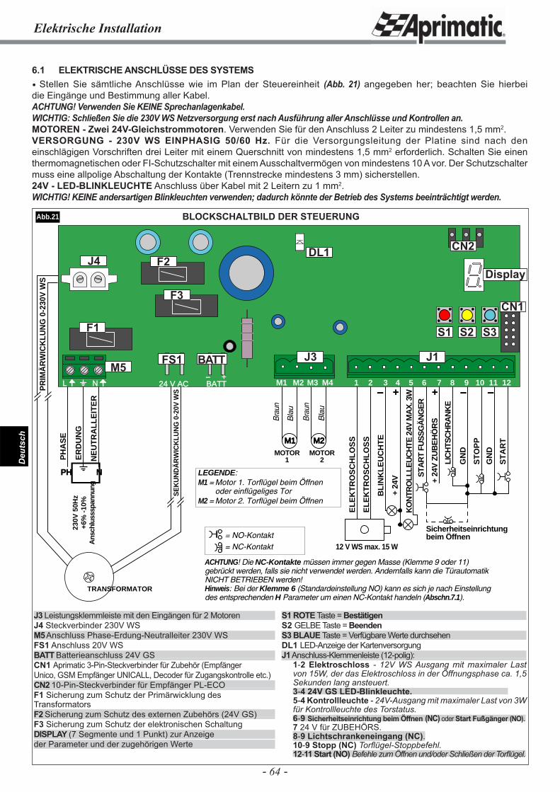
- 64 -
Deu
tsch
Elektrische Installation
BLOCKSCHALTBILD DER STEUERUNG
BL
INK
LE
UC
HT
E
+ 24
V
KO
NTR
OLL
LEU
CH
TE 2
4V M
AX
. 3W
12 V WS max. 15 W
EL
EK
TR
OS
CH
LO
SS
EL
EK
TR
OS
CH
LO
SS
+- + - -
PH
AS
E
ER
DU
NG
PH N
230V
50H
z+6
% -
10%
Ans
chlu
sssp
annu
ng
TRANSFORMATOR
SE
KU
ND
ÄR
WIC
KLU
NG
0-2
0V W
SPR
IMÄ
RW
ICK
LUN
G 0
-230
V W
S
M1 M2
MOTOR1
MOTOR2
Brau
n
Brau
n
Bla
u
Bla
u
NE
UT
RA
LL
EIT
ER
LIC
HTS
CH
RA
NK
E
+ 24
V Z
UB
EH
ÖR
S
ST
AR
T
STA
RT
FUS
SG
ÄN
GE
R
ST
OP
P
GN
D
GN
D
Sicherheitseinrichtung beim Öffnen
ACHTUNG! Die NC-Kontakte müssen immer gegen Masse (Klemme 9 oder 11) gebrückt werden, falls sie nicht verwendet werden. Andernfalls kann die Türautomatik NICHT BETRIEBEN werden!Hinweis: Bei der Klemme 6 (Standardeinstellung NO) kann es sich je nach Einstellung des entsprechenden H Parameter um einen NC-Kontakt handeln (Abschn.7.1).
LEGENDE:M1 = Motor 1. Torflügel beim Öffnen
oder einflügeliges TorM2 = Motor 2. Torflügel beim Öffnen
= NO-Kontakt= NC-Kontakt
24 V AC BATT- +
L N M1 M2 M3 M4 1 3 6 7 10 11 122 4 5 8 9
J1J3M5
J4
FS1 BATT
F1
F2
F3
Display
DL1
Abb.21
6.1 ELEKTRISCHE ANSCHLÜSSE DES SYSTEMS Stellen Sie sämtliche Anschlüsse wie im Plan der Steuereinheit (Abb. 21) angegeben her; beachten Sie hierbei die Eingänge und Bestimmung aller Kabel.ACHTUNG! Verwenden Sie KEINE Sprechanlagenkabel.WICHTIG: Schließen Sie die 230V WS Netzversorgung erst nach Ausführung aller Anschlüsse und Kontrollen an.MOTOREN - Zwei 24V-Gleichstrommotoren. Verwenden Sie für den Anschluss 2 Leiter zu mindestens 1,5 mm2.VERSORGUNG - 230V WS EINPHASIG 50/60 Hz. Für die Versorgungsleitung der Platine sind nach den einschlägigen Vorschriften drei Leiter mit einem Querschnitt von mindestens 1,5 mm2 erforderlich. Schalten Sie einen thermomagnetischen oder FI-Schutzschalter mit einem Ausschaltvermögen von mindestens 10 A vor. Der Schutzschalter muss eine allpolige Abschaltung der Kontakte (Trennstrecke mindestens 3 mm) sicherstellen.24V - LED-BLINKLEUCHTE Anschluss über Kabel mit 2 Leitern zu 1 mm2.WICHTIG! KEINE andersartigen Blinkleuchten verwenden; dadurch könnte der Betrieb des Systems beeinträchtigt werden.
J3 Leistungsklemmleiste mit den Eingängen für 2 MotorenJ4 Steckverbinder 230V WSM5 Anschluss Phase-Erdung-Neutralleiter 230V WSFS1 Anschluss 20V WSBATT Batterieanschluss 24V GSCN1 Aprimatic 3-Pin-Steckverbinder für Zubehör (EmpfängerUnico, GSM Empfänger UNICALL, Decoder für Zugangskontrolle etc.)CN2 10-Pin-Steckverbinder für Empfänger PL-ECOF1 Sicherung zum Schutz der Primärwicklung des TransformatorsF2 Sicherung zum Schutz des externen Zubehörs (24V GS)F3 Sicherung zum Schutz der elektronischen SchaltungDISPLAY (7 Segmente und 1 Punkt) zur Anzeigeder Parameter und der zugehörigen Werte
S1 ROTE Taste = BestätigenS2 GELBE Taste = BeendenS3 BLAUE Taste = Verfügbare Werte durchsehenDL1 LED-Anzeige der Kartenversorgung J1 Anschluss-Klemmenleiste (12-polig):
1-2 Elektroschloss - 12V WS Ausgang mit maximaler Last von 15W, der das Elektroschloss in der Öffnungsphase ca. 1,5 Sekunden lang ansteuert.3-4 24V GS LED-Blinkleuchte. 5-4 Kontrollleuchte - 24V-Ausgang mit maximaler Last von 3W für Kontrollleuchte des Torstatus.6-9 Sicherheitseinrichtung beim Öffnen (NC) oder Start Fußgänger (NO).7 24 V für ZUBEHÖRS. 8-9 Lichtschrankeneingang (NC).10-9 Stopp (NC) Torfl ügel-Stoppbefehl. 12-11 Start (NO) Befehle zum Öffnen und/oder Schließen der Torfl ügel.
CN2
CN1
S1 S2 S3
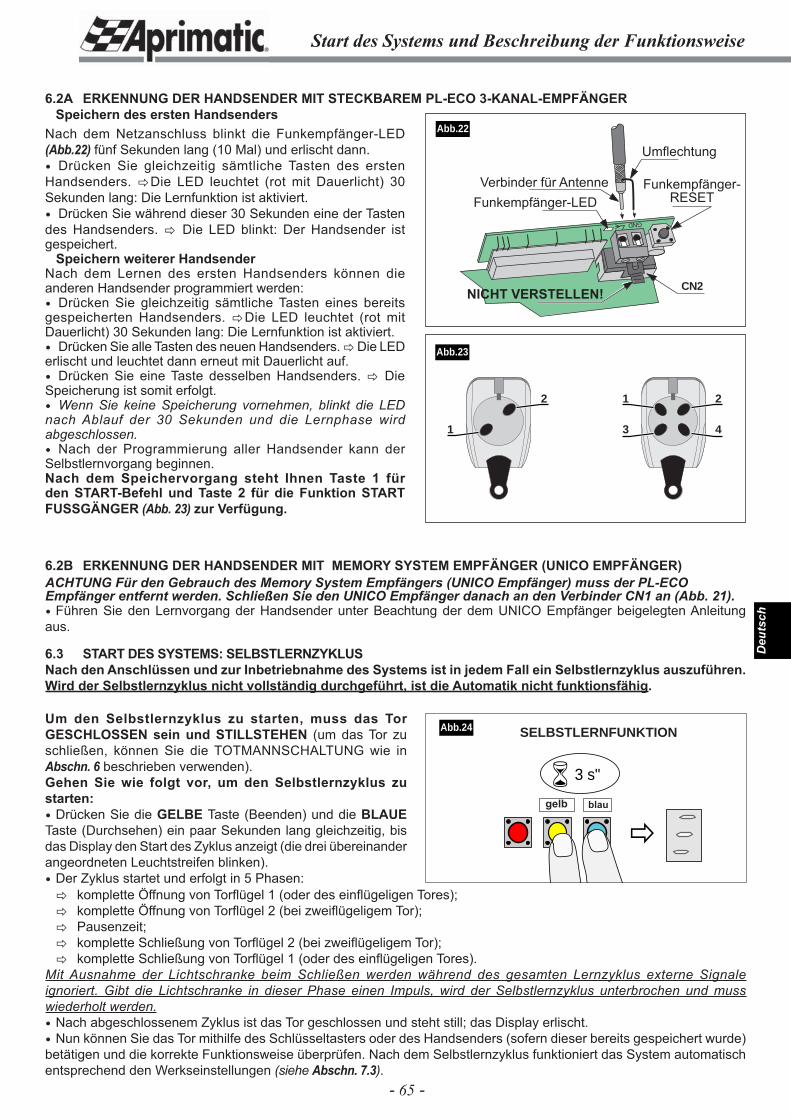
- 65 -
Deu
tsch
Start des Systems und Beschreibung der Funktionsweise
6.2A ERKENNUNG DER HANDSENDER MIT STECKBAREM PL-ECO 3-KANAL-EMPFÄNGER Speichern des ersten Handsenders
6.2B ERKENNUNG DER HANDSENDER MIT MEMORY SYSTEM EMPFÄNGER (UNICO EMPFÄNGER)ACHTUNG Für den Gebrauch des Memory System Empfängers (UNICO Empfänger) muss der PL-ECO Empfänger entfernt werden. Schließen Sie den UNICO Empfänger danach an den Verbinder CN1 an (Abb. 21). Führen Sie den Lernvorgang der Handsender unter Beachtung der dem UNICO Empfänger beigelegten Anleitung aus.
6.3 START DES SYSTEMS: SELBSTLERNZYKLUSNach den Anschlüssen und zur Inbetriebnahme des Systems ist in jedem Fall ein Selbstlernzyklus auszuführen. Wird der Selbstlernzyklus nicht vollständig durchgeführt, ist die Automatik nicht funktionsfähig.
Um den Selbstlernzyklus zu starten, muss das Tor GESCHLOSSEN sein und STILLSTEHEN (um das Tor zu schließen, können Sie die TOTMANNSCHALTUNG wie in Abschn. 6 beschrieben verwenden).Gehen Sie wie folgt vor, um den Selbstlernzyklus zu starten: Drücken Sie die GELBE Taste (Beenden) und die BLAUE Taste (Durchsehen) ein paar Sekunden lang gleichzeitig, bis das Display den Start des Zyklus anzeigt (die drei übereinander angeordneten Leuchtstreifen blinken). Der Zyklus startet und erfolgt in 5 Phasen:
GND
CN2
�
� 3 s"
gelb blau
Abb.24
Abb.22
1 2
3 4
2
1
Nach dem Netzanschluss blinkt die Funkempfänger-LED (Abb.22) fünf Sekunden lang (10 Mal) und erlischt dann. Drücken Sie gleichzeitig sämtliche Tasten des ersten Handsenders. �Die LED leuchtet (rot mit Dauerlicht) 30 Sekunden lang: Die Lernfunktion ist aktiviert. Drücken Sie während dieser 30 Sekunden eine der Tasten des Handsenders. � Die LED blinkt: Der Handsender ist gespeichert.
Speichern weiterer HandsenderNach dem Lernen des ersten Handsenders können die anderen Handsender programmiert werden: Drücken Sie gleichzeitig sämtliche Tasten eines bereits gespeicherten Handsenders. �Die LED leuchtet (rot mit Dauerlicht) 30 Sekunden lang: Die Lernfunktion ist aktiviert. Drücken Sie alle Tasten des neuen Handsenders. � Die LED erlischt und leuchtet dann erneut mit Dauerlicht auf. Drücken Sie eine Taste desselben Handsenders. � Die Speicherung ist somit erfolgt. Wenn Sie keine Speicherung vornehmen, blinkt die LED nach Ablauf der 30 Sekunden und die Lernphase wird abgeschlossen. Nach der Programmierung aller Handsender kann der Selbstlernvorgang beginnen.Nach dem Speichervorgang steht Ihnen Taste 1 für den START-Befehl und Taste 2 für die Funktion START FUSSGÄNGER (Abb. 23) zur Verfügung.
� komplette Öffnung von Torfl ügel 1 (oder des einfl ügeligen Tores); � komplette Öffnung von Torfl ügel 2 (bei zweifl ügeligem Tor); � Pausenzeit; � komplette Schließung von Torfl ügel 2 (bei zweifl ügeligem Tor); � komplette Schließung von Torfl ügel 1 (oder des einfl ügeligen Tores).Mit Ausnahme der Lichtschranke beim Schließen werden während des gesamten Lernzyklus externe Signale ignoriert. Gibt die Lichtschranke in dieser Phase einen Impuls, wird der Selbstlernzyklus unterbrochen und muss wiederholt werden. Nach abgeschlossenem Zyklus ist das Tor geschlossen und steht still; das Display erlischt. Nun können Sie das Tor mithilfe des Schlüsseltasters oder des Handsenders (sofern dieser bereits gespeichert wurde) betätigen und die korrekte Funktionsweise überprüfen. Nach dem Selbstlernzyklus funktioniert das System automatisch entsprechend den Werkseinstellungen (siehe Abschn. 7.3).
Abb.23
SELBSTLERNFUNKTION
Umfl echtung
Funkempfänger-LEDVerbinder für Antenne Funkempfänger-
RESET
NICHT VERSTELLEN!
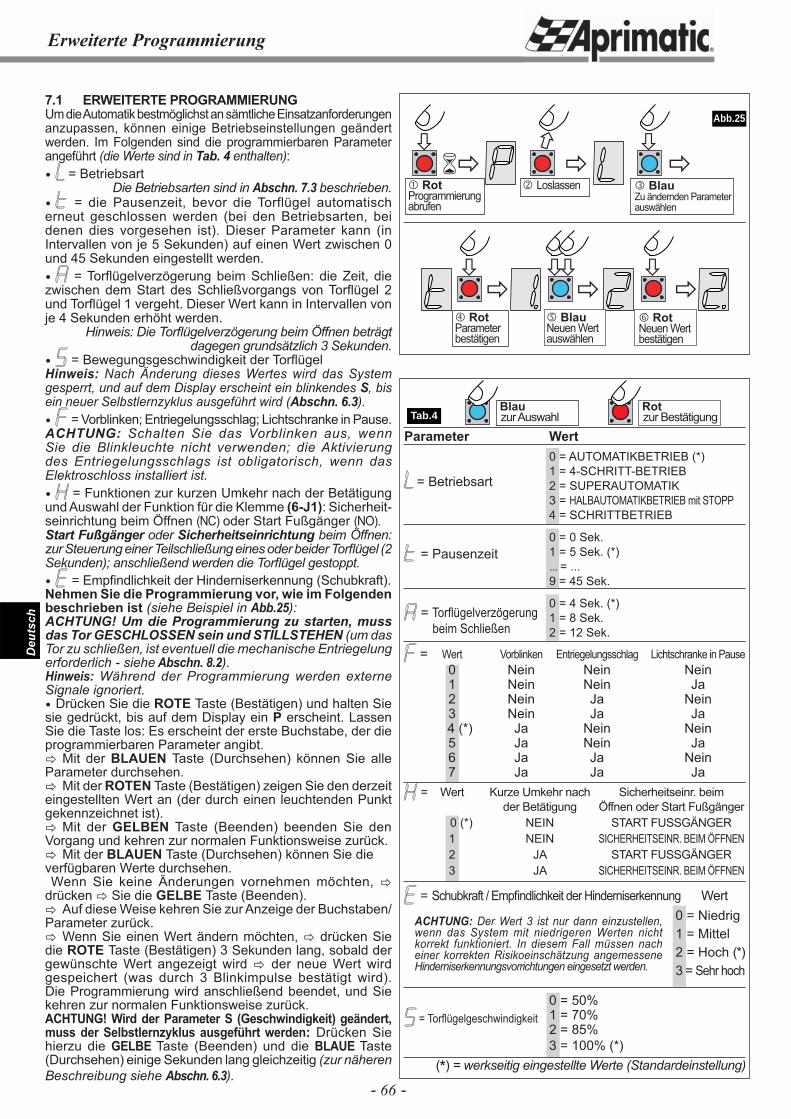
- 66 -
Deu
tsch
Erweiterte Programmierung
���
�
�
�
�
� �
� �� �
�
Tab.4
Abb.25
Blauzur Auswahl
Rotzur Bestätigung
� BlauZu ändernden Parameter auswählen
� RotProgrammierung abrufen
7.1 ERWEITERTE PROGRAMMIERUNGUm die Automatik bestmöglichst an sämtliche Einsatzanforderungen anzupassen, können einige Betriebseinstellungen geändert werden. Im Folgenden sind die programmierbaren Parameter angeführt (die Werte sind in Tab. 4 enthalten): = Betriebsart
Die Betriebsarten sind in Abschn. 7.3 beschrieben. = die Pausenzeit, bevor die Torflügel automatisch erneut geschlossen werden (bei den Betriebsarten, bei denen dies vorgesehen ist). Dieser Parameter kann (in Intervallen von je 5 Sekunden) auf einen Wert zwischen 0 und 45 Sekunden eingestellt werden. = Torfl ügelverzögerung beim Schließen: die Zeit, die zwischen dem Start des Schließvorgangs von Torfl ügel 2 und Torfl ügel 1 vergeht. Dieser Wert kann in Intervallen von je 4 Sekunden erhöht werden.
Hinweis: Die Torfl ügelverzögerung beim Öffnen beträgt dagegen grundsätzlich 3 Sekunden.
= Bewegungsgeschwindigkeit der Torfl ügelHinweis: Nach Änderung dieses Wertes wird das System gesperrt, und auf dem Display erscheint ein blinkendes S, bis ein neuer Selbstlernzyklus ausgeführt wird (Abschn. 6.3). = Vorblinken; Entriegelungsschlag; Lichtschranke in Pause.ACHTUNG: Schalten Sie das Vorblinken aus, wenn Sie die Blinkleuchte nicht verwenden; die Aktivierung des Entriegelungsschlags ist obligatorisch, wenn das Elektroschloss installiert ist. = Funktionen zur kurzen Umkehr nach der Betätigung und Auswahl der Funktion für die Klemme (6-J1): Sicherheit-seinrichtung beim Öffnen (NC) oder Start Fußgänger (NO).Start Fußgänger oder Sicherheitseinrichtung beim Öffnen: zur Steuerung einer Teilschließung eines oder beider Torfl ügel (2 Sekunden); anschließend werden die Torfl ügel gestoppt. = Empfi ndlichkeit der Hinderniserkennung (Schubkraft).Nehmen Sie die Programmierung vor, wie im Folgenden beschrieben ist (siehe Beispiel in Abb.25):ACHTUNG! Um die Programmierung zu starten, muss das Tor GESCHLOSSEN sein und STILLSTEHEN (um das Tor zu schließen, ist eventuell die mechanische Entriegelung erforderlich - siehe Abschn. 8.2).Hinweis: Während der Programmierung werden externe Signale ignoriert. Drücken Sie die ROTE Taste (Bestätigen) und halten Sie sie gedrückt, bis auf dem Display ein P erscheint. Lassen Sie die Taste los: Es erscheint der erste Buchstabe, der die programmierbaren Parameter angibt.� Mit der BLAUEN Taste (Durchsehen) können Sie alle Parameter durchsehen.� Mit der ROTEN Taste (Bestätigen) zeigen Sie den derzeit eingestellten Wert an (der durch einen leuchtenden Punkt gekennzeichnet ist).� Mit der GELBEN Taste (Beenden) beenden Sie den Vorgang und kehren zur normalen Funktionsweise zurück.� Mit der BLAUEN Taste (Durchsehen) können Sie dieverfügbaren Werte durchsehen. Wenn Sie keine Änderungen vornehmen möchten, � drücken � Sie die GELBE Taste (Beenden).� Auf diese Weise kehren Sie zur Anzeige der Buchstaben/Parameter zurück.� Wenn Sie einen Wert ändern möchten, � drücken Sie die ROTE Taste (Bestätigen) 3 Sekunden lang, sobald der gewünschte Wert angezeigt wird � der neue Wert wird gespeichert (was durch 3 Blinkimpulse bestätigt wird). Die Programmierung wird anschließend beendet, und Sie kehren zur normalen Funktionsweise zurück.ACHTUNG! Wird der Parameter S (Geschwindigkeit) geändert, muss der Selbstlernzyklus ausgeführt werden: Drücken Sie hierzu die GELBE Taste (Beenden) und die BLAUE Taste (Durchsehen) einige Sekunden lang gleichzeitig (zur näheren Beschreibung siehe Abschn. 6.3).
= Betriebsart
= Pausenzeit
= Torfl ügelverzögerung beim Schließen
= Torfl ügelgeschwindigkeit
� Loslassen
� RotParameter bestätigen
� BlauNeuen Wert auswählen
� RotNeuen Wert bestätigen
ACHTUNG: Der Wert 3 ist nur dann einzustellen, wenn das System mit niedrigeren Werten nicht korrekt funktioniert. In diesem Fall müssen nach einer korrekten Risikoeinschätzung angemessene Hinderniserkennungsvorrichtungen eingesetzt werden.
Parameter Wert 0 = AUTOMATIKBETRIEB (*) 1 = 4-SCHRITT-BETRIEB 2 = SUPERAUTOMATIK 3 = HALBAUTOMATIKBETRIEB mit STOPP 4 = SCHRITTBETRIEB
0 = 0 Sek. 1 = 5 Sek. (*) ... = ... 9 = 45 Sek.
0 = 4 Sek. (*) 1 = 8 Sek. 2 = 12 Sek.
= Wert Vorblinken Entriegelungsschlag Lichtschranke in Pause 0 Nein Nein Nein 1 Nein Nein Ja 2 Nein Ja Nein 3 Nein Ja Ja 4 (*) Ja Nein Nein 5 Ja Nein Ja 6 Ja Ja Nein 7 Ja Ja Ja
= Wert Kurze Umkehr nach Sicherheitseinr. beim der Betätigung Öffnen oder Start Fußgänger 0 (*) NEIN START FUSSGÄNGER 1 NEIN SICHERHEITSEINR. BEIM ÖFFNEN 2 JA START FUSSGÄNGER 3 JA SICHERHEITSEINR. BEIM ÖFFNEN
= Schubkraft / Empfi ndlichkeit der Hinderniserkennung Wert 0 = Niedrig 1 = Mittel 2 = Hoch (*) 3 = Sehr hoch
0 = 50% 1 = 70% 2 = 85% 3 = 100% (*)
(*) = werkseitig eingestellte Werte (Standardeinstellung)
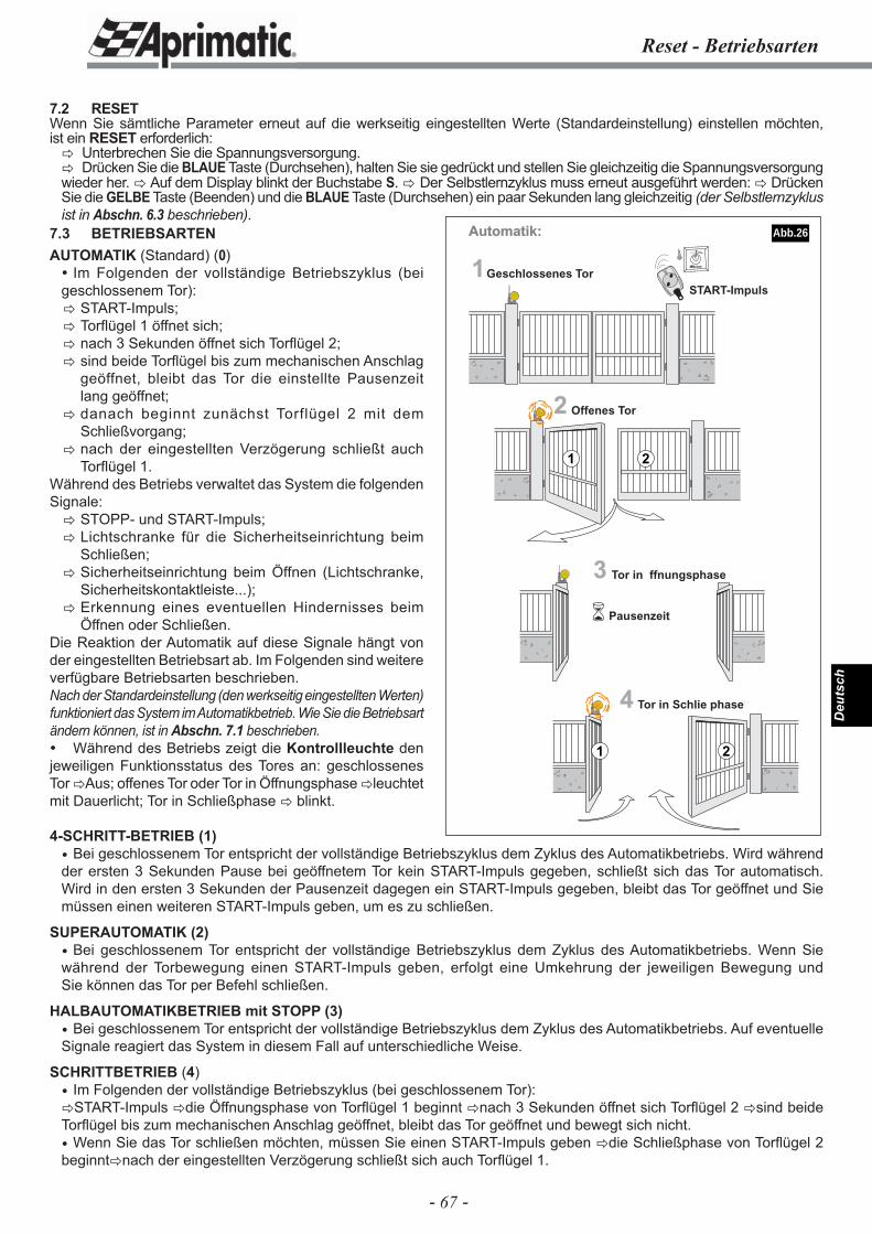
- 67 -
Deu
tsch
1
2 Offenes Tor
3
4 Tor in Schlie phase
START-Impuls
Pausenzeit
1 2
�
21
Automatik:
Geschlossenes Tor
Tor in ffnungsphase
Reset - Betriebsarten
7.2 RESETWenn Sie sämtliche Parameter erneut auf die werkseitig eingestellten Werte (Standardeinstellung) einstellen möchten, ist ein RESET erforderlich:� Unterbrechen Sie die Spannungsversorgung.� Drücken Sie die BLAUE Taste (Durchsehen), halten Sie sie gedrückt und stellen Sie gleichzeitig die Spannungsversorgung wieder her. � Auf dem Display blinkt der Buchstabe S. � Der Selbstlernzyklus muss erneut ausgeführt werden: � Drücken Sie die GELBE Taste (Beenden) und die BLAUE Taste (Durchsehen) ein paar Sekunden lang gleichzeitig (der Selbstlernzyklus ist in Abschn. 6.3 beschrieben).
4-SCHRITT-BETRIEB (1) Bei geschlossenem Tor entspricht der vollständige Betriebszyklus dem Zyklus des Automatikbetriebs. Wird während der ersten 3 Sekunden Pause bei geöffnetem Tor kein START-Impuls gegeben, schließt sich das Tor automatisch. Wird in den ersten 3 Sekunden der Pausenzeit dagegen ein START-Impuls gegeben, bleibt das Tor geöffnet und Sie müssen einen weiteren START-Impuls geben, um es zu schließen.
SUPERAUTOMATIK (2) Bei geschlossenem Tor entspricht der vollständige Betriebszyklus dem Zyklus des Automatikbetriebs. Wenn Sie während der Torbewegung einen START-Impuls geben, erfolgt eine Umkehrung der jeweiligen Bewegung und Sie können das Tor per Befehl schließen.
HALBAUTOMATIKBETRIEB mit STOPP (3) Bei geschlossenem Tor entspricht der vollständige Betriebszyklus dem Zyklus des Automatikbetriebs. Auf eventuelle Signale reagiert das System in diesem Fall auf unterschiedliche Weise.
SCHRITTBETRIEB (4) Im Folgenden der vollständige Betriebszyklus (bei geschlossenem Tor):�START-Impuls �die Öffnungsphase von Torfl ügel 1 beginnt �nach 3 Sekunden öffnet sich Torfl ügel 2 �sind beide Torfl ügel bis zum mechanischen Anschlag geöffnet, bleibt das Tor geöffnet und bewegt sich nicht. Wenn Sie das Tor schließen möchten, müssen Sie einen START-Impuls geben �die Schließphase von Torfl ügel 2 beginnt�nach der eingestellten Verzögerung schließt sich auch Torfl ügel 1.
7.3 BETRIEBSARTENAUTOMATIK (Standard) (0) Im Folgenden der vollständige Betriebszyklus (bei geschlossenem Tor):� START-Impuls;� Torfl ügel 1 öffnet sich;� nach 3 Sekunden öffnet sich Torfl ügel 2;� sind beide Torfl ügel bis zum mechanischen Anschlag
geöffnet, bleibt das Tor die einstellte Pausenzeit lang geöffnet;
� danach beginnt zunächst Torflügel 2 mit dem Schließvorgang;
� nach der eingestellten Verzögerung schließt auch Torfl ügel 1.
Während des Betriebs verwaltet das System die folgenden Signale:� STOPP- und START-Impuls;� Lichtschranke für die Sicherheitseinrichtung beim
Schließen;� Sicherheitseinrichtung beim Öffnen (Lichtschranke,
Sicherheitskontaktleiste...);� Erkennung eines eventuellen Hindernisses beim
Öffnen oder Schließen.Die Reaktion der Automatik auf diese Signale hängt von der eingestellten Betriebsart ab. Im Folgenden sind weitere verfügbare Betriebsarten beschrieben.Nach der Standardeinstellung (den werkseitig eingestellten Werten) funktioniert das System im Automatikbetrieb. Wie Sie die Betriebsart ändern können, ist in Abschn. 7.1 beschrieben. Während des Betriebs zeigt die Kontrollleuchte den jeweiligen Funktionsstatus des Tores an: geschlossenes Tor �Aus; offenes Tor oder Tor in Öffnungsphase �leuchtet mit Dauerlicht; Tor in Schließphase � blinkt.
Abb.26

- 68 -
Deu
tsch
Betriebsarten
GLEICHES VERHALTEN BEI ALLEN BETRIEBSARTEN
Torstatus: GESCHLOSSENSTART-Impuls � ÖFFNET.STOPP-Impuls � Sperrt die Signale: stoppt die Automatik.Sicherheitseinrichtung beim Öffnen � Sperrt die Signale: stoppt die Automatik.Lichtschranke beleg � Wird ignoriert.
Torstatus: BEIM ÖFFNEN GESTOPPTES TORSTART-Impuls* � SCHLIESST. * Im Falle eines Hindernisses beim Öffnen SCHLIESST sich das Tor (langsam). * Im Falle eines Hindernisses beim Schließen ÖFFNET sich das Tor (langsam).STOPP-Impuls � Sperrt die Signale: stoppt die Automatik. Sicherheitseinrichtung beim Öffnen � Wird ignoriert.Lichtschranke beleg � Wird ignoriert.
Torstatus: BEIM SCHLIESSEN GESTOPPTES TORSTART-Impuls � SCHLIESST.* Im Falle eines Hindernisses beim Öffnen SCHLIESST sich das Tor (langsam).STOPP-Impuls � Sperrt die Signale: stoppt die Automatik.Sicherheitseinrichtung beim Öffnen � Wird ignoriert.Lichtschranke belegt � Wird ignoriert.
UNTERSCHIEDLICHES VERHALTEN DER EINZELNEN BETRIEBSARTEN
Torstatus: IN ÖFFNUNGSPHASE BETRIEBSART IMPULS/SIGNAL ERGEBNIS0-1- START-Impuls � Wird ignoriert.2- START-Impuls � Kehrt Bewegungsrichtung um (SCHLIESST ERNEUT).3-4- START-Impuls � Stoppt das Tor bis zum erneuten START-Impuls � SCHLIESST.Alle STOPP-Impuls � Stoppt das Tor bis zum erneuten START-Impuls � SCHLIESST.Alle Sicherheitseinrichtung � 2 Sekunden Rückwärtsbewegung und Stopp bis zum erneuten START-Impuls beim Öffnen � SCHLIESST (langsam).Alle Lichtschranke belegt � Wird ignoriert.Alle Hindernis beim Öffnen � 2 Sekunden Rückwärtsbewegung und Stopp bis zum erneuten START-Impuls � SCHLIESST (langsam).
Torstatus: GEÖFFNETES TOR WÄHREND DER PAUSE BETRIEBSART IMPULS/SIGNAL ERGEBNIS0- START-Impuls � Wird ignoriert.1- START binnen ersten 3 Sek. � Stoppt das Tor bis zum erneuten Start � SCHLIESST. 2-3-4- START-Impuls* � Schließt und ignoriert Pausenzeit.* Bei Betriebsart 2 im Falle eines Hindernisses beim Schließen, stoppt das Tor und bis zum erneuten START �SCHLIESST (langsam).Alle STOPP-Impuls � Stoppt das Tor bis zum erneuten START (ignoriert Pausenzeit) �SCHLIESST.Alle Sicherheitseinrichtung � Wird ignoriert. beim ÖffnenAlle Lichtschranke belegt � Stoppt das Tor bis zur Freigabe der Lichtschranke (ignoriert Pausenzeit).
Torstatus: IN SCHLIESSPHASE BETRIEBSART IMPULS/SIGNAL ERGEBNIS0-1-2-3- START-Impuls* � Kehrt Richtung um (ÖFFNET SICH ERNEUT).4- START-Impuls* � Stoppt das Tor bis zum erneuten START � ÖFFNET SICH ERNEUT *Im Falle eines Hindernisses beim Öffnen � Stoppt das Tor bis zum erneuten START � SCHLIESST (langsam).Alle STOPP-Impuls � Stoppt das Tor bis zum erneuten START � SCHLIESST.Alle Sicherheitseinrichtung � Wird ignoriert. beim Öffnen Alle Hindernis beim Schließen � ÖFFNET SICH ERNEUT (langsam).0-1-2-3- Lichtschranke belegt* � Kehrt Richtung um (ÖFFNET SICH ERNEUT).4- Lichtschranke belegt* � Stoppt das Tor bis zum erneuten START � SCHLIESST. *Im Falle eines Hindernisses beim Öffnen �Stoppt das Tor bis zum erneuten START �SCHLIESST (langsam).
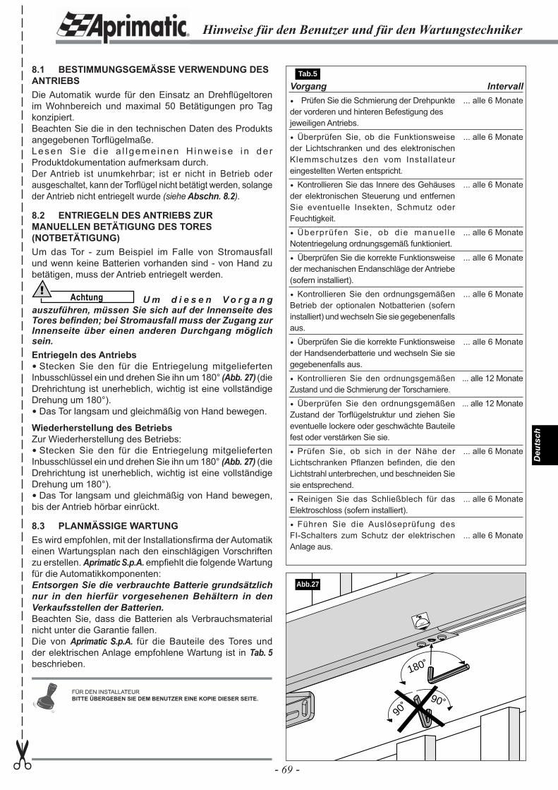
- 69 -
Deu
tsch
Vorgang Prüfen Sie die Schmierung der Drehpunkte der vorderen und hinteren Befestigung des jeweiligen Antriebs.
Überprüfen Sie, ob die Funktionsweise der Lichtschranken und des elektronischen Klemmschutzes den vom Installateur eingestellten Werten entspricht.
Kontrollieren Sie das Innere des Gehäuses der elektronischen Steuerung und entfernen Sie eventuelle Insekten, Schmutz oder Feuchtigkeit.
Überprüfen Sie, ob d ie manuel le Notentriegelung ordnungsgemäß funktioniert.
Überprüfen Sie die korrekte Funktionsweise der mechanischen Endanschläge der Antriebe (sofern installiert).
Kontrollieren Sie den ordnungsgemäßen Betrieb der optionalen Notbatterien (sofern installiert) und wechseln Sie sie gegebenenfalls aus.
Überprüfen Sie die korrekte Funktionsweise der Handsenderbatterie und wechseln Sie sie gegebenenfalls aus.
Kontrollieren Sie den ordnungsgemäßen Zustand und die Schmierung der Torscharniere.
Überprüfen Sie den ordnungsgemäßen Zustand der Torfl ügelstruktur und ziehen Sie eventuelle lockere oder geschwächte Bauteile fest oder verstärken Sie sie.
Prüfen Sie, ob sich in der Nähe der Lichtschranken Pflanzen befinden, die den Lichtstrahl unterbrechen, und beschneiden Sie sie entsprechend.
Reinigen Sie das Schließblech für das Elektroschloss (sofern installiert).
Führen Sie die Auslöseprüfung des FI-Schalters zum Schutz der elektrischen Anlage aus.
Intervall... alle 6 Monate
... alle 6 Monate
... alle 6 Monate
... alle 6 Monate
... alle 6 Monate
... alle 6 Monate
... alle 6 Monate
... alle 12 Monate
... alle 12 Monate
... alle 6 Monate
... alle 6 Monate
... alle 6 Monate
8.1 BESTIMMUNGSGEMÄSSE VERWENDUNG DES ANTRIEBSDie Automatik wurde für den Einsatz an Drehfl ügeltoren im Wohnbereich und maximal 50 Betätigungen pro Tag konzipiert.Beachten Sie die in den technischen Daten des Produkts angegebenen Torfl ügelmaße.Lesen S ie d ie a l l geme inen H inwe ise i n de r Produktdokumentation aufmerksam durch.Der Antrieb ist unumkehrbar; ist er nicht in Betrieb oder ausgeschaltet, kann der Torfl ügel nicht betätigt werden, solange der Antrieb nicht entriegelt wurde (siehe Abschn. 8.2).
8.2 ENTRIEGELN DES ANTRIEBS ZUR MANUELLEN BETÄTIGUNG DES TORES (NOTBETÄTIGUNG)Um das Tor - zum Beispiel im Falle von Stromausfall und wenn keine Batterien vorhanden sind - von Hand zu betätigen, muss der Antrieb entriegelt werden.
Achtung! U m d i e s e n V o r g a n g
auszuführen, müssen Sie sich auf der Innenseite des Tores befi nden; bei Stromausfall muss der Zugang zur Innenseite über einen anderen Durchgang möglich sein.Entriegeln des Antriebs Stecken Sie den für die Entriegelung mitgelieferten Inbusschlüssel ein und drehen Sie ihn um 180° (Abb. 27) (die Drehrichtung ist unerheblich, wichtig ist eine vollständige Drehung um 180°). Das Tor langsam und gleichmäßig von Hand bewegen.
Wiederherstellung des BetriebsZur Wiederherstellung des Betriebs: Stecken Sie den für die Entriegelung mitgelieferten Inbusschlüssel ein und drehen Sie ihn um 180° (Abb. 27) (die Drehrichtung ist unerheblich, wichtig ist eine vollständige Drehung um 180°). Das Tor langsam und gleichmäßig von Hand bewegen, bis der Antrieb hörbar einrückt.
8.3 PLANMÄSSIGE WARTUNGEs wird empfohlen, mit der Installationsfi rma der Automatik einen Wartungsplan nach den einschlägigen Vorschriften zu erstellen. Aprimatic S.p.A. empfi ehlt die folgende Wartung für die Automatikkomponenten: Entsorgen Sie die verbrauchte Batterie grundsätzlich nur in den hierfür vorgesehenen Behältern in den Verkaufsstellen der Batterien.Beachten Sie, dass die Batterien als Verbrauchsmaterial nicht unter die Garantie fallen.Die von Aprimatic S.p.A. für die Bauteile des Tores und der elektrischen Anlage empfohlene Wartung ist in Tab. 5 beschrieben.
180˚
180˚
90˚
90˚
Abb.27
Hinweise für den Benutzer und für den Wartungstechniker✂
FÜR DEN INSTALLATEURBITTE ÜBERGEBEN SIE DEM BENUTZER EINE KOPIE DIESER SEITE.
Tab.5
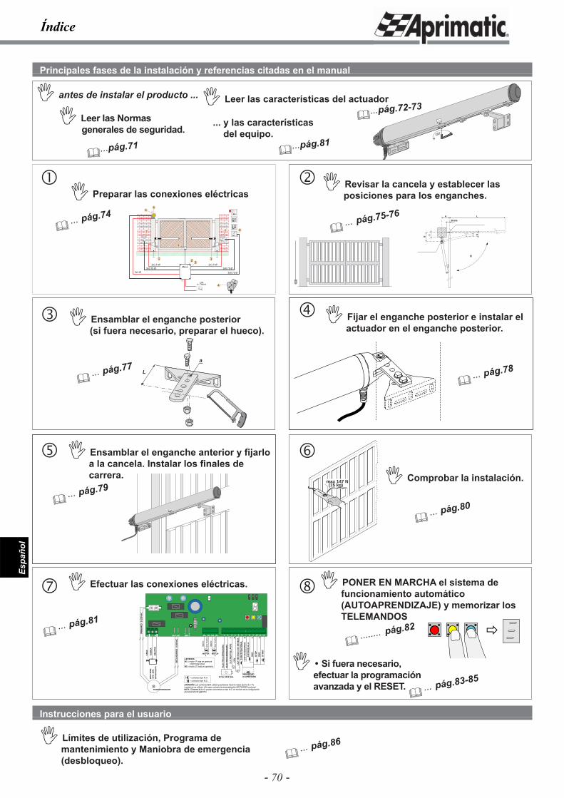
- 70 -
Espa
ñol
180˚
180˚
2
3x0.75 Ø
6
3x0.75 Ø
3x0.75 Ø
2x1.5 Ø
1
2x1.5 Ø
2x1 Ø
1
5
7 7
10Alc= 30mA 4
8
Aprimatic
Aprimatic
3
9
Índice
max 147 N(15 kg)
�
L
a
B
Y
A
E
L
30 mm
FO
TO
CÉ
LU
LA
+ 24
V A
CC
ES
OR
IOS
ST
AR
T
ST
AR
T P
EA
TO
NA
L
ST
OP
GN
D
GN
D
SEGURIDAD en APERTURA
LU
Z D
ES
TE
LL
AN
TE
+ 24
V
LU
Z T
ES
TIG
O 2
4V 3
W M
ÁX
.
12 Vac 15 W máx.
EL
EC
TR
OC
ER
RA
DU
RA
EL
EC
TR
OC
ER
RA
DU
RA
+- + - -
FA
SE
TIE
RR
A
NE
UT
RO
PHPH N
230V
50H
z+6
% -
10%
alim
enta
ció
n
TRANSFORMADOR
SE
CU
ND
AR
IO0-
20V
AC
PR
IMA
RIO
0-23
0VA
C
M1M1 M2M2
MOTOR1
MOTOR2
Mar
rón
Mar
rón
Azu
l mar
ino
Azu
l mar
ino
¡ATENCIÓN! Los contactos N.C. deben puentearse hacia la masa (borne 9 ó 11) cuando no se utilicen. ¡En caso contrario la automatización NO PUEDE funcionar!NOTA: El borne 6 (N.A.) puede convertirse en tipo N.C. en función de la configuración del parámetro H (párr.7.1).
LEYENDA:M1 = motor 1a hoja en apertura
o bien hoja únicaM2 = motor 2a hoja en apertura
= contacto tipo N.A.= contacto tipo N.C.
24 V AC24 V AC BATTBATT- + +
L N M1 M2 M3 M4 1 3 6 7 10 11 122 4 5 8 9
Principales fases de la instalación y referencias citadas en el manual
� Leer las Normas generales de seguridad.
� Leer las características del actuador
� Revisar la cancela y establecer las posiciones para los enganches.
Instrucciones para el usuario
� Límites de utilización, Programa de mantenimiento y Maniobra de emergencia (desbloqueo).
�...pág.71
�...pág.72-73� antes de instalar el producto ...
� Preparar las conexiones eléctricas
� ... pág.74
� ... pág.77
� Ensamblar el enganche posterior(si fuera necesario, preparar el hueco).
� Fijar el enganche posterior e instalar el actuador en el enganche posterior.
180˚
� ... pág.78
� ... pág.79
� Ensamblar el enganche anterior y fi jarlo a la cancela. Instalar los fi nales de carrera. � Comprobar la instalación.
� ... pág.80
� ... pág.81
� Efectuar las conexiones eléctricas.
� ... pág.75-76
� ... pág.86
�
� PONER EN MARCHA el sistema de funcionamiento automático (AUTOAPRENDIZAJE) y memorizar los TELEMANDOS
� ........ pág.82
� Si fuera necesario, efectuar la programación avanzada y el RESET.
� ... pág.83-85
... y las características del equipo.
�...pág.81
�
��
� �
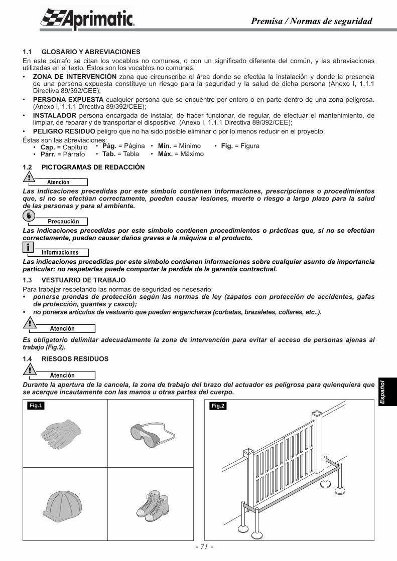
- 71 -
Espa
ñol
Premisa / Normas de seguridad
1.1 GLOSARIO Y ABREVIACIONESEn este párrafo se citan los vocablos no comunes, o con un signifi cado diferente del común, y las abreviaciones utilizadas en el texto. Éstos son los vocablos no comunes:• ZONA DE INTERVENCIÓN zona que circunscribe el área donde se efectúa la instalación y donde la presencia
de una persona expuesta constituye un riesgo para la seguridad y la salud de dicha persona (Anexo I, 1.1.1 Directiva 89/392/CEE);
• PERSONA EXPUESTA cualquier persona que se encuentre por entero o en parte dentro de una zona peligrosa. (Anexo I, 1.1.1 Directiva 89/392/CEE);
• INSTALADOR persona encargada de instalar, de hacer funcionar, de regular, de efectuar el mantenimiento, de limpiar, de reparar y de transportar el dispositivo (Anexo I, 1.1.1 Directiva 89/392/CEE);
• PELIGRO RESIDUO peligro que no ha sido posible eliminar o por lo menos reducir en el proyecto.Éstas son las abreviaciones: • Cap. = Capítulo • Párr. = Párrafo
1.2 PICTOGRAMAS DE REDACCIÓN
Atención!
Las indicaciones precedidas por este símbolo contienen informaciones, prescripciones o procedimientos que, si no se efectúan correctamente, pueden causar lesiones, muerte o riesgo a largo plazo para la salud de las personas y para el ambiente.
Precaución
Las indicaciones precedidas por este símbolo contienen procedimientos o prácticas que, si no se efectúan correctamente, pueden causar daños graves a la máquina o al producto.
InformacionesLas indicaciones precedidas por este símbolo contienen informaciones sobre cualquier asunto de importancia particular: no respetarlas puede comportar la perdida de la garantía contractual.1.3 VESTUARIO DE TRABAJOPara trabajar respetando las normas de seguridad es necesario:• ponerse prendas de protección según las normas de ley (zapatos con protección de accidentes, gafas
de protección, guantes y casco);• no ponerse artículos de vestuario que puedan engancharse (corbatas, brazaletes, collares, etc..).
Atención!
Es obligatorio delimitar adecuadamente la zona de intervención para evitar el acceso de personas ajenas al trabajo (Fig.2).
1.4 RIESGOS RESIDUOS
Atención!Durante la apertura de la cancela, la zona de trabajo del brazo del actuador es peligrosa para quienquiera que se acerque incautamente con las manos u otras partes del cuerpo.
• Pág. = Página• Tab. = Tabla
• Mín. = Mínimo• Máx. = Máximo
• Fig. = Figura
Fig.1 Fig.2
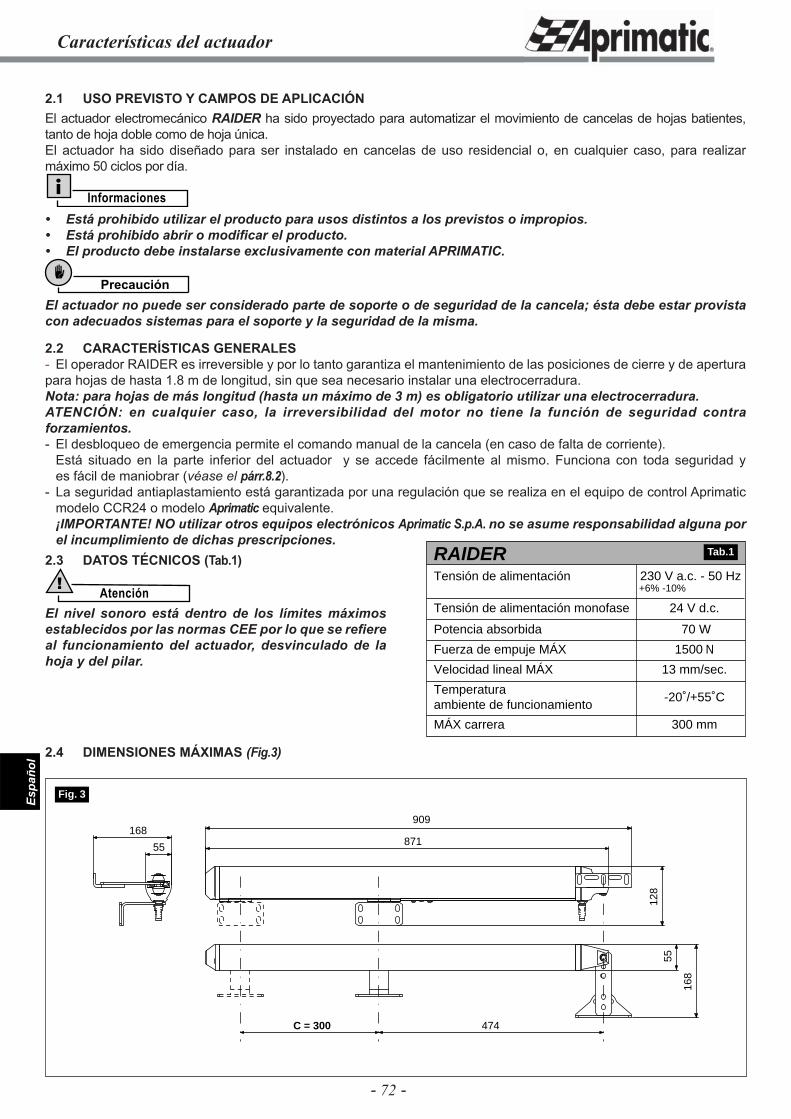
- 72 -
Espa
ñol
Características del actuador
2.1 USO PREVISTO Y CAMPOS DE APLICACIÓNEl actuador electromecánico RAIDER ha sido proyectado para automatizar el movimiento de cancelas de hojas batientes, tanto de hoja doble como de hoja única.El actuador ha sido diseñado para ser instalado en cancelas de uso residencial o, en cualquier caso, para realizar máximo 50 ciclos por día.
Informaciones• Está prohibido utilizar el producto para usos distintos a los previstos o impropios.• Está prohibido abrir o modifi car el producto.• El producto debe instalarse exclusivamente con material APRIMATIC.
Precaución
El actuador no puede ser considerado parte de soporte o de seguridad de la cancela; ésta debe estar provista con adecuados sistemas para el soporte y la seguridad de la misma.
2.2 CARACTERÍSTICAS GENERALES- El operador RAIDER es irreversible y por lo tanto garantiza el mantenimiento de las posiciones de cierre y de apertura para hojas de hasta 1.8 m de longitud, sin que sea necesario instalar una electrocerradura.Nota: para hojas de más longitud (hasta un máximo de 3 m) es obligatorio utilizar una electrocerradura.ATENCIÓN: en cualquier caso, la irreversibilidad del motor no tiene la función de seguridad contra forzamientos.- El desbloqueo de emergencia permite el comando manual de la cancela (en caso de falta de corriente). Está situado en la parte inferior del actuador y se accede fácilmente al mismo. Funciona con toda seguridad y
es fácil de maniobrar (véase el párr.8.2).- La seguridad antiaplastamiento está garantizada por una regulación que se realiza en el equipo de control Aprimatic
modelo CCR24 o modelo Aprimatic equivalente.¡IMPORTANTE! NO utilizar otros equipos electrónicos Aprimatic S.p.A. no se asume responsabilidad alguna por el incumplimiento de dichas prescripciones.
2.3 DATOS TÉCNICOS (Tab.1)
Atención!
El nivel sonoro está dentro de los límites máximos establecidos por las normas CEE por lo que se refi ere al funcionamiento del actuador, desvinculado de la hoja y del pilar.
2.4 DIMENSIONES MÁXIMAS (Fig.3)
70 W
1500 N
13 mm/sec.
-20˚/+55˚C
300 mm
RAIDERTensión de alimentación
24 V d.c.Tensión de alimentación monofase
Potencia absorbida
Fuerza de empuje MÁX
Velocidad lineal MÁX
Temperatura ambiente de funcionamiento
MÁX carrera
230 V a.c. - 50 Hz+6% -10%
Tab.1
55
909
871
128
55
168
168
C = 300 474
Fig. 3
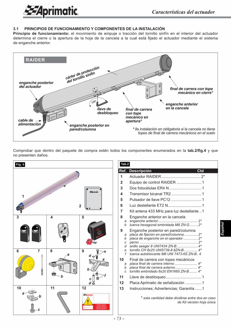
- 73 -
Espa
ñol
Características del actuador
3.1 PRINCIPIOS DE FUNCIONAMIENTO Y COMPONENTES DE LA INSTALACIÓNPrincipio de funcionamiento: el movimiento de empuje o tracción del tornillo sinfín en el interior del actuador determina el cierre o la apertura de la hoja de la cancela a la cual está fi jado el actuador mediante el sistema de enganche anterior.
Ref. Descripción Ctd 1 Actuador RAIDER .................................... 2* 2 Equipo de control RAIDER .......................1 3 Dos fotocélulas ER4 N ..............................1 4 Transmisor bicanal TR2 ............................1 5 Pulsador de llave PC12 ............................1 6 Luz destellante ET2 N ...............................1 7 Kit antena 433 MHz para luz destellante ..1 8 Enganche anterior en la cancela a enganche anterior .........................................2* b tuerca hexagonal embridada M8 ZN-G ........2* 9 Enganche posterior en pared/columna a placa de fi jación en pared/columna ..............2* b placa de enganche en el operador ...............2* c perno ............................................................2* d anillo seeger 8 UNI7434 ZN-B ......................4* e tornillo CH 8x25 UNI5739-8.8ZN-B ..............4* f tuerca autoblocante M8 UNI 7473-6S ZN-B . 4 10 Final de carrera con topes mecánicos a placa fi nal de carrera interno ....................... 4* b placa fi nal de carrera externo ...................... 4* c tornillo embridado 6x20 EN1665 ZN-B ........ 4* 11 Llave de desbloqueo .................................1 12 Placa Aprimatic de señalización .................1 13 Instrucciones; Advertencias; Garantía .......1
* esta cantidad debe dividirse entre dos en casode Kit versión hoja única
4
11
1
Aprimatic
5
7 96
2
3
12fi
IL CAMPIONE DELL’AUTOMAZIONE
!APERTURA AUTOMATICA
AUTOMATIC OPENINGOUVERTURE AUTOMATIQUEAUTOMATISCHE ÖFFNUNGAPERTURA AUTOMATICA
A58
4500
0
name model
serial number
a
b
c
de
d
Comprobar que dentro del paquete de compra estén todos los componentes enumerados en la tab.2/fi g.4 y que no presenten daños.
180˚
180˚enganche anterior en la cancela
enganche posterior en pared/columna
cable de alimentación
enganche posterior del actuador
fi nal de carrera con tope mecánico en apertura*
fi nal de carrera con tope mecánico en cierre*
RAIDER
llave de desbloqueo
cárter de protección
del tornillo sinfín
* lla instalación en obligatoria si la cancela no tiene topes de fi nal de carrera mecánicos en el suelo
Tab.2 Fig. 4
f
8
b
a
10a
c
b
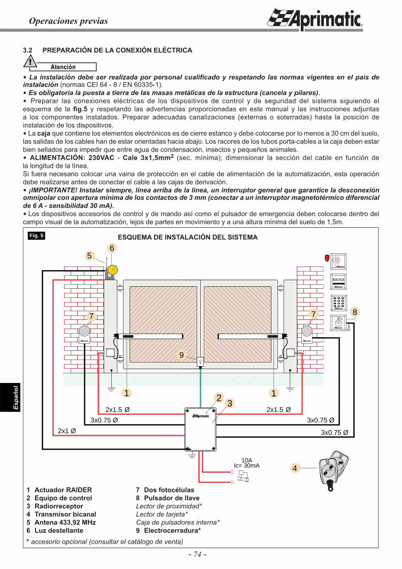
- 74 -
Espa
ñol
3.2 PREPARACIÓN DE LA CONEXIÓN ELÉCTRICA
Atención!
La instalación debe ser realizada por personal cualifi cado y respetando las normas vigentes en el país de instalación (normas CEI 64 - 8 / EN 60335-1). Es obligatoria la puesta a tierra de las masas metálicas de la estructura (cancela y pilares). Preparar las conexiones eléctricas de los dispositivos de control y de seguridad del sistema siguiendo el esquema de la fi g.5 y respetando las advertencias proporcionadas en este manual y las instrucciones adjuntas a los componentes instalados. Preparar adecuadas canalizaciones (externas o soterradas) hasta la posición de instalación de los dispositivos. La caja que contiene los elementos electrónicos es de cierre estanco y debe colocarse por lo menos a 30 cm del suelo, las salidas de los cables han de estar orientadas hacia abajo. Los racores de los tubos porta-cables a la caja deben estar bien sellados para impedir que entre agua de condensación, insectos y pequeños animales. ALIMENTACIÓN: 230VAC - Cale 3x1,5mm2 (sec. mínima); dimensionar la sección del cable en función de la longitud de la línea.Si fuera necesario colocar una vaina de protección en el cable de alimentación de la automatización, esta operación debe realizarse antes de conectar el cable a las cajas de derivación. ¡IMPORTANTE! Instalar siempre, línea arriba de la línea, un interruptor general que garantice la desconexión omnipolar con apertura mínima de los contactos de 3 mm (conectar a un interruptor magnetotérmico diferencial de 6 A - sensibilidad 30 mA). Los dispositivos accesorios de control y de mando así como el pulsador de emergencia deben colocarse dentro del campo visual de la automatización, lejos de partes en movimiento y a una altura mínima del suelo de 1,5m.
Operaciones previas
2
3x0.75 Ø
6
3x0.75 Ø
3x0.75 Ø
2x1.5 Ø
1
2x1.5 Ø
2x1 Ø
1
5
7 7
10Alc= 30mA 4
8
Aprimatic
Aprimatic
3
9
Fig. 5 ESQUEMA DE INSTALACIÓN DEL SISTEMA
7 Dos fotocélulas8 Pulsador de llaveLector de proximidad*Lector de tarjeta* Caja de pulsadores interna*9 Electrocerradura*
1 Actuador RAIDER2 Equipo de control3 Radiorreceptor4 Transmisor bicanal5 Antena 433,92 MHz 6 Luz destellante* accesorio opcional (consultar el catálogo de venta)
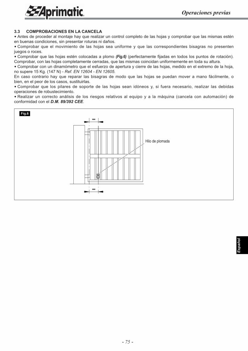
- 75 -
Espa
ñol
3.3 COMPROBACIONES EN LA CANCELA Antes de proceder al montaje hay que realizar un control completo de las hojas y comprobar que las mismas estén en buenas condiciones, sin presentar roturas ni daños. Comprobar que el movimiento de las hojas sea uniforme y que las correspondientes bisagras no presenten juegos o roces. Comprobar que las hojas estén colocadas a plomo (Fig.6) (perfectamente fi jadas en todos los puntos de rotación). Comprobar, con las hojas completamente cerradas, que las mismas coincidan uniformemente en toda su altura. Comprobar con un dinamómetro que el esfuerzo de apertura y cierre de las hojas, medido en el extremo de la hoja, no supere 15 Kg. (147 N) - Ref. EN 12604 - EN 12605.En caso contrario hay que reparar las bisagras de modo que las hojas se puedan mover a mano fácilmente, o bien, en el peor de los casos, sustituirlas. Comprobar que los pilares de soporte de las hojas sean idóneos y, si fuera necesario, realizar las debidas operaciones de robustecimiento. Realizar un correcto análisis de los riesgos relativos al equipo y a la máquina (cancela con automación) de conformidad con el D.M. 89/392 CEE.
Operaciones previas
Hilo de plomada
Fig.6
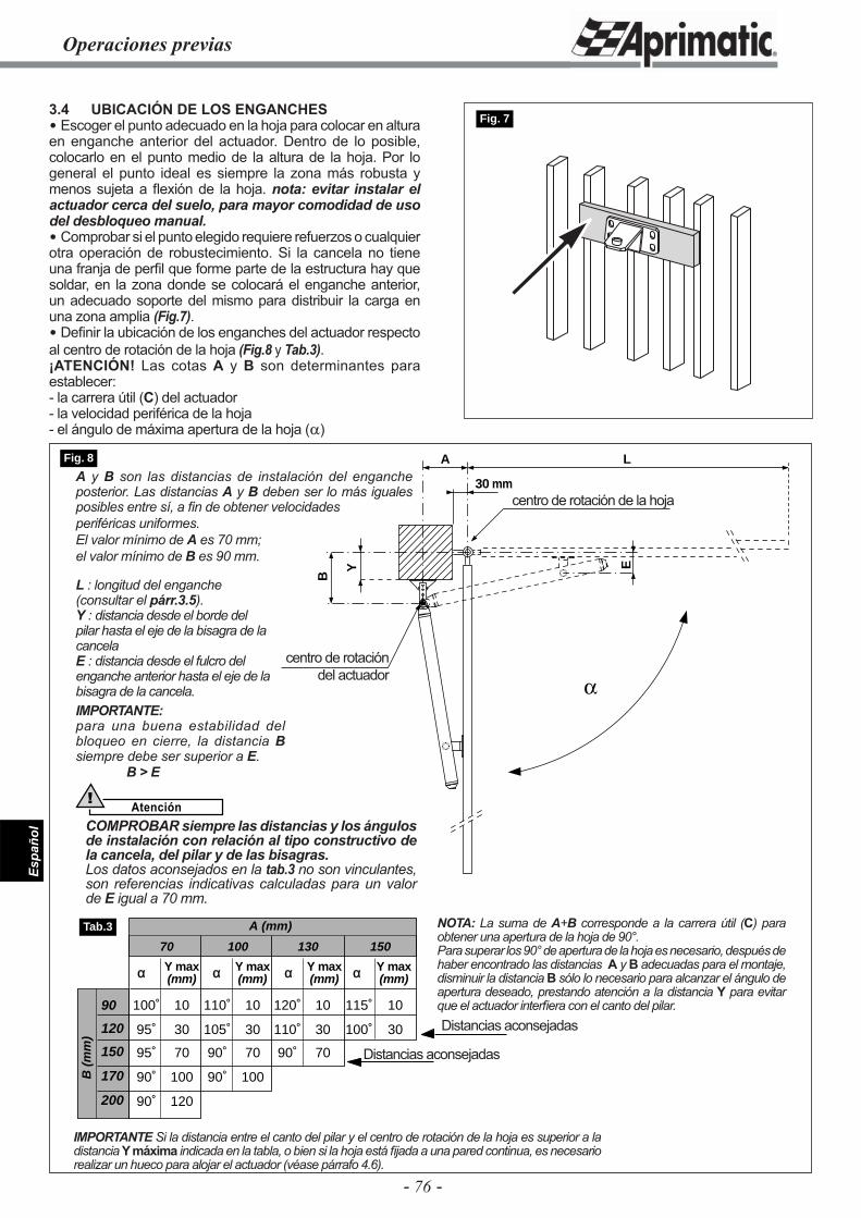
- 76 -
Espa
ñol
B
Y
A
E
L
30 mm
Operaciones previas
3.4 UBICACIÓN DE LOS ENGANCHES Escoger el punto adecuado en la hoja para colocar en altura en enganche anterior del actuador. Dentro de lo posible, colocarlo en el punto medio de la altura de la hoja. Por lo general el punto ideal es siempre la zona más robusta y menos sujeta a fl exión de la hoja. nota: evitar instalar el actuador cerca del suelo, para mayor comodidad de uso del desbloqueo manual. Comprobar si el punto elegido requiere refuerzos o cualquier otra operación de robustecimiento. Si la cancela no tiene una franja de perfi l que forme parte de la estructura hay que soldar, en la zona donde se colocará el enganche anterior, un adecuado soporte del mismo para distribuir la carga en una zona amplia (Fig.7). Defi nir la ubicación de los enganches del actuador respecto al centro de rotación de la hoja (Fig.8 y Tab.3).¡ATENCIÓN! Las cotas A y B son determinantes para establecer:- la carrera útil (C) del actuador- la velocidad periférica de la hoja- el ángulo de máxima apertura de la hoja (α)
Fig. 7
IMPORTANTE Si la distancia entre el canto del pilar y el centro de rotación de la hoja es superior a la distancia Y máxima indicada en la tabla, o bien si la hoja está fi jada a una pared continua, es necesario realizar un hueco para alojar el actuador (véase párrafo 4.6).
90
120
150
170
200
B (
mm
)
A (mm)
α Y max α Y max α Y max α Y max(mm) (mm) (mm) (mm)
70 100 130 150
100˚ 10 110˚ 10 120˚ 10 115˚ 10
95˚ 30 105˚ 30 110˚ 30 100˚ 30
95˚ 70 90˚ 70 90˚ 70
90˚ 100 90˚ 100
90˚ 120
Tab.3
Fig. 8
Distancias aconsejadas
Distancias aconsejadas
NOTA: La suma de A+B corresponde a la carrera útil (C) para obtener una apertura de la hoja de 90°.Para superar los 90° de apertura de la hoja es necesario, después de haber encontrado las distancias A y B adecuadas para el montaje, disminuir la distancia B sólo lo necesario para alcanzar el ángulo de apertura deseado, prestando atención a la distancia Y para evitar que el actuador interfi era con el canto del pilar.
A y B son las distancias de instalación del enganche posterior. Las distancias A y B deben ser lo más iguales posibles entre sí, a fi n de obtener velocidadesperiféricas uniformes.El valor mínimo de A es 70 mm;el valor mínimo de B es 90 mm.
L : longitud del enganche (consultar el párr.3.5).Y : distancia desde el borde del pilar hasta el eje de la bisagra de la cancelaE : distancia desde el fulcro del enganche anterior hasta el eje de la bisagra de la cancela.IMPORTANTE:para una buena estabilidad del bloqueo en cierre, la distancia B siempre debe ser superior a E.
B > E
centro de rotación de la hoja
centro de rotacióndel actuador
Atención!
COMPROBAR siempre las distancias y los ángulos de instalación con relación al tipo constructivo de la cancela, del pilar y de las bisagras.Los datos aconsejados en la tab.3 no son vinculantes, son referencias indicativas calculadas para un valor de E igual a 70 mm.
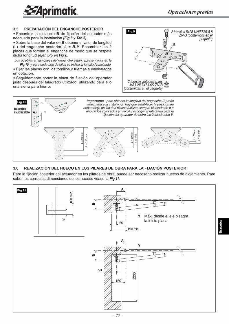
- 77 -
Espa
ñol
L =
55 m
m
L =
65 m
m
L =
98 m
m
L =
80 m
m
L =
110
mm
L =
90 m
m
xx
Y
60
180
min
.
50
150
1200
Y Máx. desde el eje bisagra la inicio placa
B
A
50
150 min.
Y
B
A
Fig.11
Operaciones previas
3.5 PREPARACIÓN DEL ENGANCHE POSTERIOR Encontrar la distancia B de fi jación del actuador más adecuada para la instalación (Fig.8 y Tab.3). Sobre la base del valor de B obtener el valor de longitud (L) del enganche posterior: L = B-Y. Ensamblar las 2 placas que forman el enganche de modo que se respete dicha longitud (ejemplo en Fig.9).Los posibles ensamblajes del enganche están representados en la
Fig.10, y para cada uno de ellos se indica la longitud resultante. Fijar las placas con los tornillos y tuercas suministrados en dotación. Seguidamente cortar la placa de fi jación del operador justo después del taladrado utilizado, utilizando para ello una sierra para hierro.
L
a
Fig.9 2 tornillos 8x25 UNI5739-8.8 ZN-B (contenidos en el
paquete)
2 tuercas autoblocantes M8 UNI 7473-6S ZN-B
(contenidas en el paquete)
importante - para obtener la longitud del enganche (L) más adecuada a la instalación hay que establecer la posición de
ensamblaje de las dos placas (utilizar siempre el taladrado x + uno de los colocados en arco) y escoger el taladrado para la
fi jación del operador de entre los 2 taladrados Y.
3.6 REALIZACIÓN DEL HUECO EN LOS PILARES DE OBRA PARA LA FIJACIÓN POSTERIORPara la fi jación posterior del actuador en los pilares de obra, puede ser necesario realizar huecos de alojamiento. Para saber las correctas dimensiones de los huecos véase la Fig.11.
Fig.10
talandro inutilizable
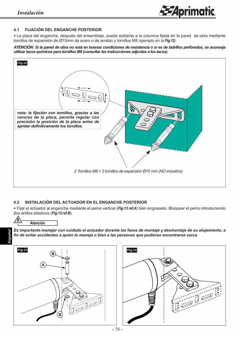
- 78 -
Espa
ñol
Instalación
4.1 FIJACIÓN DEL ENGANCHE POSTERIOR La placa del enganche, después del ensamblaje, puede soldarse a la columna fi jada en la pared de obra mediante tornillos de expansión de Ø15mm de acero o de arrabio y tornillos M8 (ejemplo en la Fig.12).ATENCIÓN: Si la pared de obra no está en buenas condiciones de resistencia o si es de ladrillos perforados, se aconseja utilizar tacos químicos para tornillos M8 (consultar las instrucciones adjuntas a los tacos).
Fig.14B
A
B
Fig.13
Fig.12
2 Tornillos M8 + 2 tornillos de expansión Ø15 mm (NO incluidos)
4.2 INSTALACIÓN DEL ACTUADOR EN EL ENGANCHE POSTERIOR Fijar el actuador al enganche mediante el perno vertical (Fig.13 ref.A) bien engrasado. Bloquear el perno introduciendo dos anillos elásticos (Fig.13 ref.B).
Atención!
Es importante manejar con cuidado el actuador durante las fases de montaje y desmontaje de su alojamiento, a fi n de evitar accidentes a quien lo maneja o bien a las personas que pudieran encontrarse cerca.
nota: la fi jación con tornillos, gracias a las ranuras de la placa, permite regular con precisión la posición de la placa antes de apretar defi nitivamente los tornillos.
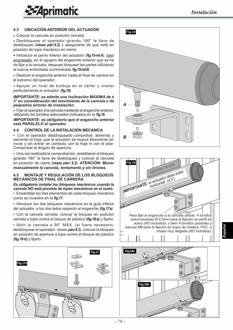
- 79 -
Espa
ñol
4.3 UBICACIÓN ANTERIOR DEL ACTUADOR Colocar la cancela en posición cerrada. Desbloquear el operador girando 180° la llave de desbloqueo (véase párr.8.2) y asegurarse de que esté en posición de tope mecánico en cierre. Introducir el perno inferior del actuador (fi g.15-ref.A), bien engrasado, en el agujero del enganche anterior que se ha de fi jar a la cancela, despues bloquear las partes utilizando la tuerca embridada suministrada fi g.15-ref.B. Deslizar el enganche anterior hasta el fi nal de carrera en el extremo del operador. Apoyar un nivel de burbuja en el cárter y nivelar perfectamente el actuador (fi g.16).IMPORTANTE: se admite una inclinación MÁXIMA de ± 3° en consideración del movimiento de la cancela o de pequeños errores de instalación. Fijar el operador a la cancela mediante el enganche anterior, utilizando los tornillos adecuados indicados en la fi g.16.IMPORTANTE: es obligatorio que el enganche anterior esté PARALELO al operador.4.4 CONTROL DE LA INSTALACIÓN MECÁNICA• Con el operador desbloqueado comprobar, abriendo y cerrando la hoja, que el actuador se mueva libremente sin roces y sin entrar en contacto con la hoja ni con el pilar. Comprobar el ángulo de apertura.• Una vez realizada la comprobación, restablecer el bloqueo girando 180° la llave de desbloqueo y colocar la cancela en posición de cierre (véase párr. 8.2). ATENCIÓN: Mover manualmente la cancela, lentamente y sin tirones.
4.5 MONTAJE Y REGULACIÓN DE LOS BLOQUEOS MECÁNICOS DE FINAL DE CARRERAEs obligatorio instalar los bloqueos mecánicos cuando la cancela NO está provista de topes mecánicos en el suelo.• Ensamblar los tres elementos de cada bloqueo mecánico como se muestra en la fi g.17.• Introducir los dos bloqueos mecánicos en la guía inferior del actuador, a los dos lados respecto al enganche (fi g.17a).• Con la cancela cerrada, colocar el bloqueo en posición cerrada a tope contra el bloque de plástico (fi g.18-a) y fi jarlo.• Abrir la cancela a 90° MÁX. (si fuera necesario, desbloquear el operador: véase párr.8.2), colocar el bloqueo en posición de apertura a tope contra el bloque de plástico (fi g.18-b) y fi jarlo.
Fig.16
Instalación
Fig.17a
Para fi jar el enganche a la cancela utilizar: 4 tornillos autorroscantes Ø 6.5mm para la fi jación en perfi l de
acero (NO incluidos); o bien 4 tornillos pasantes y tuercas M8 para la fi jación en hojas de madera, PVC, o
chapa muy delgada (NO incluidos).
Fig.17
IMPORTANTE: el actuador debe estar
horizontal (±3°).
180˚
Fig.18a
Fig.18b
Fig.15
�
�A
B
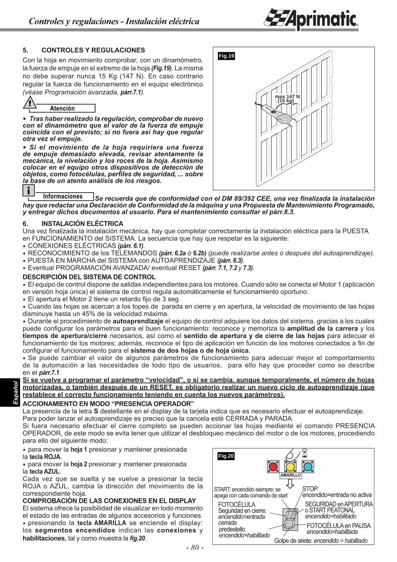
- 80 -
Espa
ñol
Controles y regulaciones - Instalación eléctrica
5. CONTROLES Y REGULACIONESCon la hoja en movimiento comprobar, con un dinamómetro, la fuerza de empuje en el extremo de la hoja (Fig.19). La misma no debe superar nunca 15 Kg (147 N). En caso contrario regular la fuerza de funcionamiento en el equipo electrónico (véase Programación avanzada, párr.7.1).
Atención!
Tras haber realizado la regulación, comprobar de nuevo con el dinamómetro que el valor de la fuerza de empuje coincida con el previsto; si no fuera así hay que regular otra vez el empuje. Si el movimiento de la hoja requiriera una fuerza de empuje demasiado elevada, revisar atentamente la mecánica, la nivelación y los roces de la hoja. Asimismo colocar en el equipo otros dispositivos de detección de objetos, como fotocélulas, perfi les de seguridad, ... sobre la base de un atento análisis de los riesgos.
max 147 N(15 kg)
Fig.19
Informaciones Se recuerda que de conformidad con el DM 89/392 CEE, una vez fi nalizada la instalación hay que redactar una Declaración de Conformidad de la máquina y una Propuesta de Mantenimiento Programado, y entregar dichos documentos al usuario. Para el mantenimiento consultar el párr.8.3.
6. INSTALACIÓN ELÉCTRICAUna vez finalizada la instalación mecánica, hay que completar correctamente la instalación eléctrica para la PUESTA en FUNCIONAMIENTO del SISTEMA. La secuencia que hay que respetar es la siguiente: CONEXIONES ELÉCTRICAS (párr. 6.1). RECONOCIMIENTO de los TELEMANDOS (párr. 6.2a ó 6.2b) (puede realizarse antes o después del autoaprendizaje). PUESTA EN MARCHA del SISTEMA con AUTOAPRENDIZAJE (párr. 6.3). Eventual PROGRAMACIÓN AVANZADA/ eventual RESET (párr. 7.1, 7.2 y 7.3).DESCRIPCIÓN DEL SISTEMA DE CONTROL El equipo de control dispone de salidas independientes para los motores. Cuando sólo se conecta el Motor 1 (aplicación en versión hoja única) el sistema de control regula automáticamente el funcionamiento oportuno. El apertura el Motor 2 tiene un retardo fi jo de 3 seg. Cuando las hojas se acercan a los topes de parada en cierre y en apertura, la velocidad de movimiento de las hojas disminuye hasta un 45% de la velocidad máxima. Durante el procedimiento de autoaprendizaje el equipo de control adquiere los datos del sistema, gracias a los cuales puede confi gurar los parámetros para el buen funcionamiento: reconoce y memoriza la amplitud de la carrera y los tiempos de apertura/cierre necesarios, así como el sentido de apertura y de cierre de las hojas para adecuar el funcionamiento de los motores; además, reconoce el tipo de aplicación en función de los motores conectados a fi n de confi gurar el funcionamiento para el sistema de dos hojas o de hoja única. Se puede cambiar el valor de algunos parámetros de funcionamiento para adecuar mejor el comportamiento de la automación a las necesidades de todo tipo de usuarios, para ello hay que proceder como se describe en el párr.7.1.Si se vuelve a programar el parámetro “velocidad”, o si se cambia, aunque temporalmente, el número de hojas motorizadas, o también después de un RESET, es obligatorio realizar un nuevo ciclo de autoaprendizaje (que restablece el correcto funcionamiento teniendo en cuenta los nuevos parámetros).ACCIONAMIENTO EN MODO “PRESENCIA OPERADOR”La presencia de la letra S destellante en el display de la tarjeta indica que es necesario efectuar el autoaprendizaje. Para poder lanzar el autoaprendizaje es preciso que la cancela esté CERRADA y PARADA.Si fuera necesario efectuar el cierre completo se pueden accionar las hojas mediante el comando PRESENCIA OPERADOR, de este modo se evita tener que utilizar el desbloqueo mecánico del motor o de los motores, procediendo para ello del siguiente modo: para mover la hoja 1 presionar y mantener presionadala tecla ROJA. para mover la hoja 2 presionar y mantener presionadala tecla AZUL. Cada vez que se suelta y se vuelve a presionar la tecla ROJA o AZUL, cambia la dirección del movimiento de la correspondiente hoja.COMPROBACIÓN DE LAS CONEXIONES EN EL DISPLAYEl sistema ofrece la posibilidad de visualizar en todo momento el estado de las entradas de algunos accesorios y funciones. presionando la tecla AMARILLA se enciende el display: los segmentos encendidos indican las conexiones y habilitaciones, tal y como muestra la fi g.20.
�
�
START: encendido siempre; se apaga con cada comando de start
SEGURIDAD en APERTURA o START PEATONALencendido=habilitado
STOP:encendido=entrada no activa
predestelloencendido=habilitado
FOTOCÉLULA en PAUSAencendido=habilitada
Golpe de ariete: encendido = habilitado
FOTOCÉLULASeguridad en cierre;encendido=entrada cerrada
AMARILLO
Fig.20
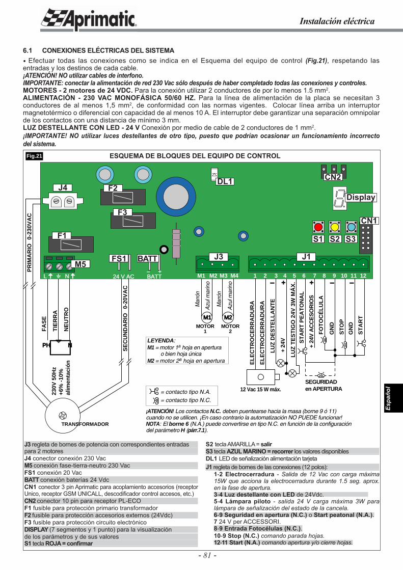
- 81 -
Espa
ñol
Instalación eléctrica
ESQUEMA DE BLOQUES DEL EQUIPO DE CONTROL
FO
TO
CÉ
LU
LA
+ 24
V A
CC
ES
OR
IOS
ST
AR
T
ST
AR
T P
EA
TO
NA
L
ST
OP
GN
D
GN
D
SEGURIDAD en APERTURA
LU
Z D
ES
TE
LL
AN
TE
+ 24
V
LU
Z T
ES
TIG
O 2
4V 3
W M
ÁX
.
12 Vac 15 W máx.
EL
EC
TR
OC
ER
RA
DU
RA
EL
EC
TR
OC
ER
RA
DU
RA
+- + - -
FA
SE
TIE
RR
A
NE
UT
RO
PH N
230V
50H
z+6
% -
10%
alim
enta
ció
n
TRANSFORMADOR
SE
CU
ND
AR
IO0-
20V
AC
PR
IMA
RIO
0-23
0VA
C
M1 M2
MOTOR1
MOTOR2
Mar
rón
Mar
rón
Azu
l mar
ino
Azu
l mar
ino
¡ATENCIÓN! Los contactos N.C. deben puentearse hacia la masa (borne 9 ó 11) cuando no se utilicen. ¡En caso contrario la automatización NO PUEDE funcionar!NOTA: El borne 6 (N.A.) puede convertirse en tipo N.C. en función de la configuración del parámetro H (párr.7.1).
LEYENDA:M1 = motor 1a hoja en apertura
o bien hoja únicaM2 = motor 2a hoja en apertura
= contacto tipo N.A.= contacto tipo N.C.
24 V AC BATT- +
L N M1 M2 M3 M4 1 3 6 7 10 11 122 4 5 8 9
J1J3M5
J4
FS1 BATT
F1
F2
F3
Display
DL1
Fig.21
6.1 CONEXIONES ELÉCTRICAS DEL SISTEMA Efectuar todas las conexiones como se indica en el Esquema del equipo de control (Fig.21), respetando las entradas y los destinos de cada cable.¡ATENCIÓN! NO utilizar cables de interfono.IMPORTANTE: conectar la alimentación de red 230 Vac sólo después de haber completado todas las conexiones y controles.MOTORES - 2 motores de 24 VDC. Para la conexión utilizar 2 conductores de por lo menos 1.5 mm2.ALIMENTACIÓN - 230 VAC MONOFÁSICA 50/60 HZ. Para la línea de alimentación de la placa se necesitan 3 conductores de al menos 1,5 mm2, de conformidad con las normas vigentes. Colocar línea arriba un interruptor magnetotérmico o diferencial con capacidad de al menos 10 A. El interruptor debe garantizar una separación omnipolar de los contactos con una distancia de mínimo 3 mm.LUZ DESTELLANTE CON LED - 24 V Conexión por medio de cable de 2 conductores de 1 mm2.¡IMPORTANTE! NO utilizar luces destellantes de otro tipo, puesto que podrían ocasionar un funcionamiento incorrecto del sistema.
J3 regleta de bornes de potencia con correspondientes entradaspara 2 motoresJ4 conector conexión 230 VacM5 conexión fase-tierra-neutro 230 VacFS1 conexión 20 VacBATT conexión baterías 24 VdcCN1 conector 3 pin Aprimatic para acoplamiento accesorios (receptor Unico, receptor GSM UNICALL, descodifi cador control accesos, etc.)CN2 conector 10 pin para receptor PL-ECO F1 fusible para protección primario transformadorF2 fusible para protección accesorios externos (24Vdc)F3 fusible para protección circuito electrónicoDISPLAY (7 segmentos y 1 punto) para la visualizaciónde los parámetros y de sus valoresS1 tecla ROJA = confi rmar
S2 tecla AMARILLA = salirS3 tecla AZUL MARINO = recorrer los valores disponiblesDL1 LED de señalización alimentación tarjetaJ1 regleta de bornes de las conexiones (12 polos):
1-2 Electrocerradura - Salida de 12 Vac con carga máxima 15W que acciona la electrocerradura durante 1.5 seg. aprox. en la fase de apertura.3-4 Luz destellante con LED de 24Vdc. 5-4 Lámpara piloto - salida 24 V carga máxima 3W para lámpara de señalización del estado de la cancela.6-9 Seguridad en apertura (N.C.) o Start peatonal (N.A.).7 24 V per ACCESSORI. 8-9 Entrada Fotocélulas (N.C.).10-9 Stop (N.C.) comando parada hojas. 12-11 Start (N.A.) comando apertura y/o cierre hojas.
CN2
CN1
S1 S2 S3
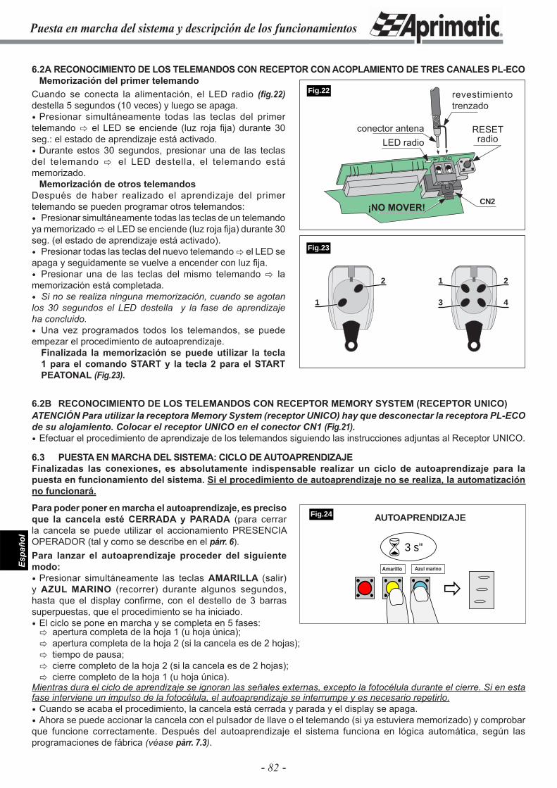
- 82 -
Espa
ñol
Puesta en marcha del sistema y descripción de los funcionamientos
6.2A RECONOCIMIENTO DE LOS TELEMANDOS CON RECEPTOR CON ACOPLAMIENTO DE TRES CANALES PL-ECOMemorización del primer telemando
6.2B RECONOCIMIENTO DE LOS TELEMANDOS CON RECEPTOR MEMORY SYSTEM (RECEPTOR UNICO)ATENCIÓN Para utilizar la receptora Memory System (receptor UNICO) hay que desconectar la receptora PL-ECO de su alojamiento. Colocar el receptor UNICO en el conector CN1 (Fig.21). Efectuar el procedimiento de aprendizaje de los telemandos siguiendo las instrucciones adjuntas al Receptor UNICO.
6.3 PUESTA EN MARCHA DEL SISTEMA: CICLO DE AUTOAPRENDIZAJEFinalizadas las conexiones, es absolutamente indispensable realizar un ciclo de autoaprendizaje para la puesta en funcionamiento del sistema. Si el procedimiento de autoaprendizaje no se realiza, la automatización no funcionará.
Para poder poner en marcha el autoaprendizaje, es preciso que la cancela esté CERRADA y PARADA (para cerrar la cancela se puede utilizar el accionamiento PRESENCIA OPERADOR (tal y como se describe en el párr. 6).Para lanzar el autoaprendizaje proceder del siguiente modo: Presionar simultáneamente las teclas AMARILLA (salir) y AZUL MARINO (recorrer) durante algunos segundos, hasta que el display confi rme, con el destello de 3 barras superpuestas, que el procedimiento se ha iniciado. El ciclo se pone en marcha y se completa en 5 fases:
GND
CN2
�
� 3 s"
Amarillo Azul marino
Fig.24
Fig.22
1 2
3 4
2
1
Cuando se conecta la alimentación, el LED radio (fig.22) destella 5 segundos (10 veces) y luego se apaga. Presionar simultáneamente todas las teclas del primer telemando � el LED se enciende (luz roja fi ja) durante 30 seg.: el estado de aprendizaje está activado. Durante estos 30 segundos, presionar una de las teclas del telemando � el LED destella, el telemando está memorizado.
Memorización de otros telemandos Después de haber realizado el aprendizaje del primer telemando se pueden programar otros telemandos: Presionar simultáneamente todas las teclas de un telemando ya memorizado � el LED se enciende (luz roja fi ja) durante 30 seg. (el estado de aprendizaje está activado). Presionar todas las teclas del nuevo telemando � el LED se apaga y seguidamente se vuelve a encender con luz fi ja. Presionar una de las teclas del mismo telemando � la memorización está completada. Si no se realiza ninguna memorización, cuando se agotan los 30 segundos el LED destella y la fase de aprendizaje ha concluido. Una vez programados todos los telemandos, se puede empezar el procedimiento de autoaprendizaje.
Finalizada la memorización se puede utilizar la tecla 1 para el comando START y la tecla 2 para el START PEATONAL (Fig.23).
� apertura completa de la hoja 1 (u hoja única);� apertura completa de la hoja 2 (si la cancela es de 2 hojas);� tiempo de pausa;� cierre completo de la hoja 2 (si la cancela es de 2 hojas);� cierre completo de la hoja 1 (u hoja única).
Mientras dura el ciclo de aprendizaje se ignoran las señales externas, excepto la fotocélula durante el cierre. Si en esta fase interviene un impulso de la fotocélula, el autoaprendizaje se interrumpe y es necesario repetirlo. Cuando se acaba el procedimiento, la cancela está cerrada y parada y el display se apaga. Ahora se puede accionar la cancela con el pulsador de llave o el telemando (si ya estuviera memorizado) y comprobar que funcione correctamente. Después del autoaprendizaje el sistema funciona en lógica automática, según las programaciones de fábrica (véase párr. 7.3).
Fig.23
AUTOAPRENDIZAJE
revestimiento trenzado
LED radioconector antena RESET
radio
¡NO MOVER!
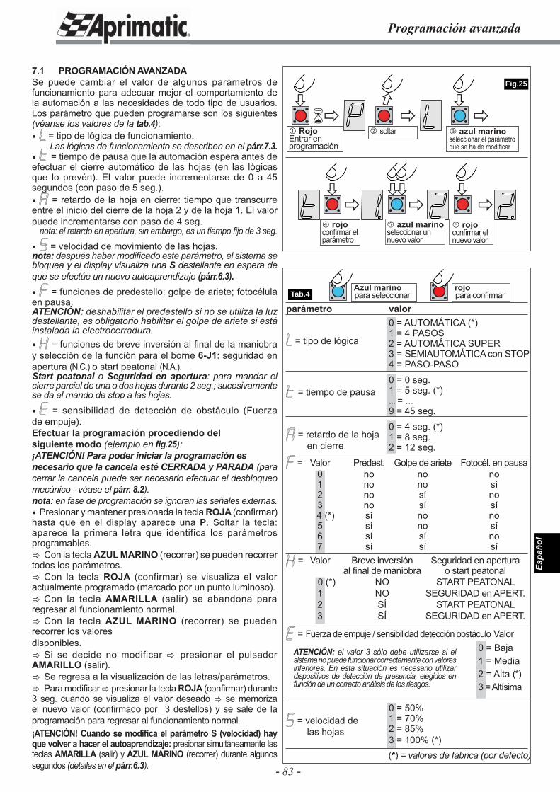
- 83 -
Espa
ñol
Programación avanzada
���
�
�
�
�
� �
� �� �
�
Tab.4
Fig.25
Azul marino para seleccionar
rojopara confi rmar
� azul marinoseleccionar el parámetro que se ha de modifi car
� RojoEntrar en programación
7.1 PROGRAMACIÓN AVANZADASe puede cambiar el valor de algunos parámetros de funcionamiento para adecuar mejor el comportamiento de la automación a las necesidades de todo tipo de usuarios. Los parámetro que pueden programarse son los siguientes (véanse los valores de la tab.4): = tipo de lógica de funcionamiento.
Las lógicas de funcionamiento se describen en el párr.7.3. = tiempo de pausa que la automación espera antes de efectuar el cierre automático de las hojas (en las lógicas que lo prevén). El valor puede incrementarse de 0 a 45 segundos (con paso de 5 seg.). = retardo de la hoja en cierre: tiempo que transcurre entre el inicio del cierre de la hoja 2 y de la hoja 1. El valor puede incrementarse con paso de 4 seg.
nota: el retardo en apertura, sin embargo, es un tiempo fi jo de 3 seg.
= velocidad de movimiento de las hojas.nota: después haber modifi cado este parámetro, el sistema se bloquea y el display visualiza una S destellante en espera de que se efectúe un nuevo autoaprendizaje (párr.6.3). = funciones de predestello; golpe de ariete; fotocélula en pausa.ATENCIÓN: deshabilitar el predestello si no se utiliza la luz destellante, es obligatorio habilitar el golpe de ariete si está instalada la electrocerradura. = funciones de breve inversión al fi nal de la maniobra y selección de la función para el borne 6-J1: seguridad en apertura (N.C.) o start peatonal (N.A.).Start peatonal o Seguridad en apertura: para mandar el cierre parcial de una o dos hojas durante 2 seg.; sucesivamente se da el mando de stop a las hojas.
= sensibilidad de detección de obstáculo (Fuerza de empuje).Efectuar la programación procediendo delsiguiente modo (ejemplo en fi g.25):¡ATENCIÓN! Para poder iniciar la programación esnecesario que la cancela esté CERRADA y PARADA (para cerrar la cancela puede ser necesario efectuar el desbloqueo mecánico - véase el párr. 8.2).nota: en fase de programación se ignoran las señales externas. Presionar y mantener presionada la tecla ROJA (confi rmar) hasta que en el display aparece una P. Soltar la tecla: aparece la primera letra que identifica los parámetros programables.� Con la tecla AZUL MARINO (recorrer) se pueden recorrer todos los parámetros.� Con la tecla ROJA (confirmar) se visualiza el valor actualmente programado (marcado por un punto luminoso).� Con la tecla AMARILLA (salir) se abandona para regresar al funcionamiento normal.� Con la tecla AZUL MARINO (recorrer) se pueden recorrer los valoresdisponibles.� Si se decide no modificar � presionar el pulsador AMARILLO (salir).� Se regresa a la visualización de las letras/parámetros.� Para modifi car � presionar la tecla ROJA (confi rmar) durante 3 seg. cuando se visualiza el valor deseado � se memoriza el nuevo valor (confi rmado por 3 destellos) y se sale de la programación para regresar al funcionamiento normal.¡ATENCIÓN! Cuando se modifi ca el parámetro S (velocidad) hay que volver a hacer el autoaprendizaje: presionar simultáneamente las teclas AMARILLA (salir) y AZUL MARINO (recorrer) durante algunos segundos (detalles en el párr.6.3).
= tipo de lógica
= tiempo de pausa
= retardo de la hoja en cierre
= velocidad de las hojas
� soltar
� rojoconfi rmar el parámetro
� azul marinoseleccionar un nuevo valor
� rojoconfi rmar el nuevo valor
ATENCIÓN: el valor 3 sólo debe utilizarse si el sistema no puede funcionar correctamente con valores inferiores. En esta situación es necesario utilizar dispositivos de detección de presencia, elegidos en función de un correcto análisis de los riesgos.
parámetro valor 0 = AUTOMÁTICA (*) 1 = 4 PASOS 2 = AUTOMÁTICA SUPER 3 = SEMIAUTOMÁTICA con STOP 4 = PASO-PASO
0 = 0 seg. 1 = 5 seg. (*) ... = ... 9 = 45 seg.
0 = 4 seg. (*) 1 = 8 seg. 2 = 12 seg.
= Valor Predest. Golpe de ariete Fotocél. en pausa 0 no no no 1 no no sí 2 no sí no 3 no sí sí 4 (*) sí no no 5 sí no sí 6 sí sí no 7 sí sí sí
= Valor Breve inversión Seguridad en apertura al fi nal de maniobra o start peatonal 0 (*) NO START PEATONAL 1 NO SEGURIDAD en APERT. 2 SÍ START PEATONAL 3 SÍ SEGURIDAD en APERT.
= Fuerza de empuje / sensibilidad detección obstáculo Valor 0 = Baja 1 = Media 2 = Alta (*) 3 = Altísima
0 = 50% 1 = 70% 2 = 85% 3 = 100% (*)
(*) = valores de fábrica (por defecto)
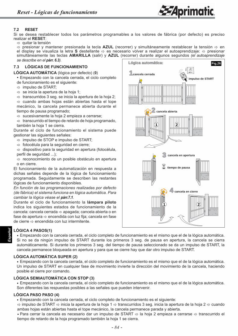
- 84 -
Espa
ñol
Reset - Lógicas de funcionamiento
7.2 RESETSi se desea restablecer todos los parámetros programables a los valores de fábrica (por defecto) es preciso realizar el RESET:� quitar la tensión� presionar y mantener presionada la tecla AZUL (recorrer) y simultáneamente restablecer la tensión � en el display se visualiza la letra S destellante � es necesario volver a realizar el autoaprendizaje: � presionar simultáneamente las teclas AMARILLA (salir) y AZUL (recorrer) durante algunos segundos (el autoaprendizaje se describe en el párr. 6.3).
LÓGICA 4 PASOS(1) Empezando con la cancela cerrada, el ciclo completo de funcionamiento es el mismo que el de la lógica automática. Si no se da ningún impulso de START durante los primeros 3 seg. de pausa en apertura, la cancela se cierra automáticamente. Si durante los primeros 3 seg. del tiempo de pausa seleccionado se da un impulso de START, la cancela permanece bloqueada en apertura y para que se cierre hay que dar otro impulso de START.
LÓGICA AUTOMÁTICA SUPER (2) Empezando con la cancela cerrada, el ciclo completo de funcionamiento es el mismo que el de la lógica automática. Un impulso de START en cualquier fase de movimiento invierte la dirección del movimiento de la cancela, haciendo posible el cierre por comando.
LÓGICA SEMIAUTOMÁTICA CON STOP (3) Empezando con la cancela cerrada, el ciclo completo de funcionamiento es el mismo que el de la lógica automática. Son diferentes las respuestas posibles a las señales que pueden intervenir.
LÓGICA PASO PASO (4) Empezando con la cancela cerrada, el ciclo completo de funcionamiento es el siguiente:� impulso de START � inicia la apertura de la hoja 1 � transcurridos 3 seg. inicia la apertura de la hoja 2 � cuando ambas hojas están abiertas hasta el tope mecánico, la cancela permanece parada y abierta. Para cerrar la cancela es necesario dar un impulso de START � la hoja 2 empieza a cerrarse � transcurrido el tiempo de retardo de la hoja programado también la hoja 1 se cierra.
1cancela cerrada
2 cancela abierta
3
4 cancela en cierre
impulso de START
1 2
�
21
Lógica automática:
cancela en apertura
tiempo de pausa
7.3 LÓGICAS DE FUNCIONAMIENTOLÓGICA AUTOMÁTICA (lógica por defecto) (0) Empezando con la cancela cerrada, el ciclo completo de funcionamiento es el siguiente:� impulso de START;� se inicia la apertura de la hoja 1;� transcurridos 3 seg. se inicia la apertura de la hoja 2;� cuando ambas hojas están abiertas hasta el tope mecánico, la cancela permanece abierta durante el tiempo de pausa programado;� sucesivamente la hoja 2 empieza a cerrarse; � transcurrido el tiempo de retardo de hoja programado, también la hoja 1 se cierra.
Durante el ciclo de funcionamiento el sistema puede gestionar las siguientes señales:� impulso de STOP e impulso de START;� fotocélula para la seguridad en cierre;� dispositivo para la seguridad en apertura (fotocélula, perfi l de seguridad ...);� reconocimiento de un posible obstáculo en apertura o en cierre.
El funcionamiento de la automatización en respuesta a dichas señales depende de la lógica de funcionamiento programada. Seguidamente se describen las restantes lógicas de funcionamiento disponibles.En función de las programaciones realizadas por defecto (de fábrica) el sistema funciona en lógica automática. Para cambiar la lógica véase el párr.7.1.Durante el ciclo de funcionamiento la lámpara piloto indica los siguientes estados de funcionamiento de la cancela: cancela cerrada � apagada; cancela abierta o en fase de apertura � encendida con luz fi ja; cancela en fase de cierre � encendida con luz intermitente.
Fig.26
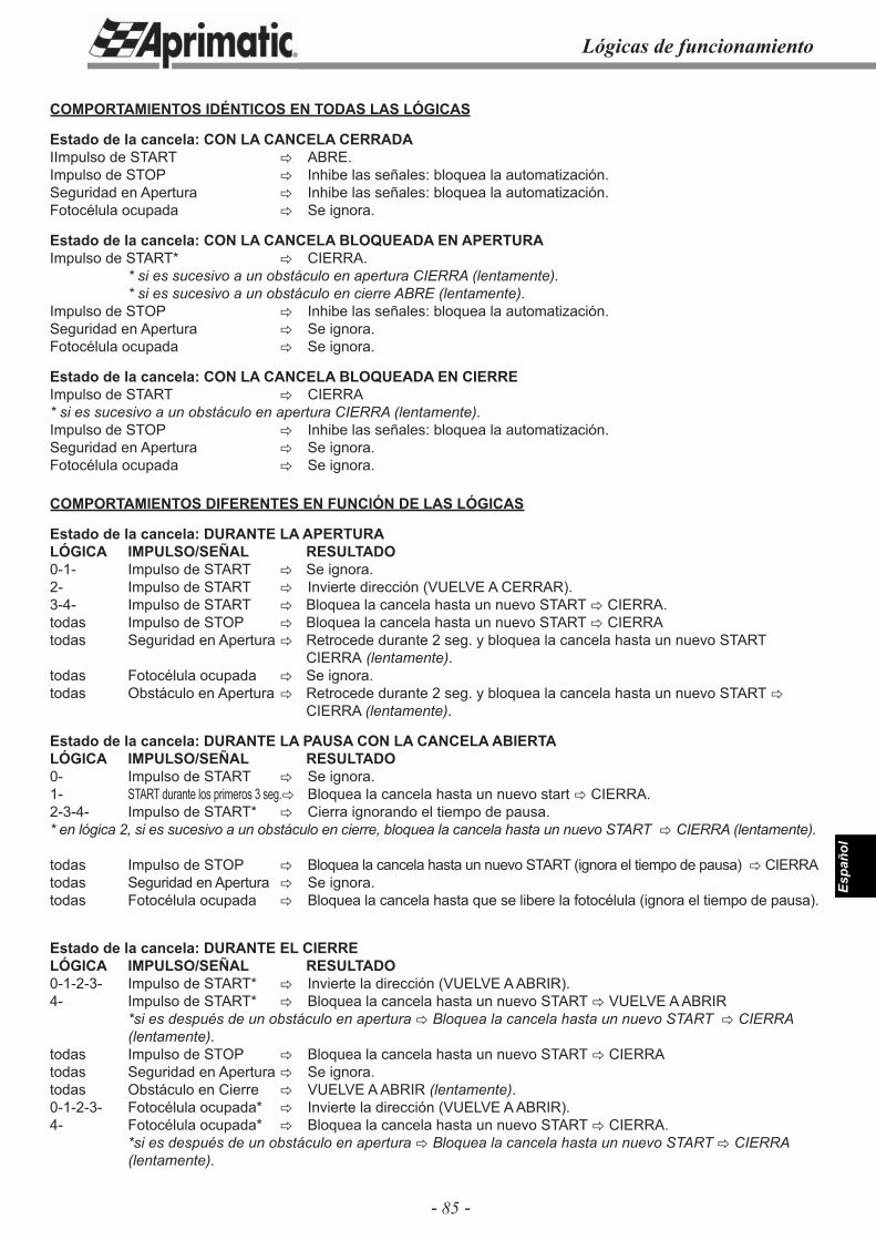
- 85 -
Espa
ñol
Lógicas de funcionamiento
COMPORTAMIENTOS IDÉNTICOS EN TODAS LAS LÓGICAS
Estado de la cancela: CON LA CANCELA CERRADAIImpulso de START � ABRE.Impulso de STOP � Inhibe las señales: bloquea la automatización.Seguridad en Apertura � Inhibe las señales: bloquea la automatización.Fotocélula ocupada � Se ignora.
Estado de la cancela: CON LA CANCELA BLOQUEADA EN APERTURAImpulso de START* � CIERRA. * si es sucesivo a un obstáculo en apertura CIERRA (lentamente). * si es sucesivo a un obstáculo en cierre ABRE (lentamente).Impulso de STOP � Inhibe las señales: bloquea la automatización. Seguridad en Apertura � Se ignora.Fotocélula ocupada � Se ignora.
Estado de la cancela: CON LA CANCELA BLOQUEADA EN CIERREImpulso de START � CIERRA* si es sucesivo a un obstáculo en apertura CIERRA (lentamente).Impulso de STOP � Inhibe las señales: bloquea la automatización.Seguridad en Apertura � Se ignora.Fotocélula ocupada � Se ignora.
COMPORTAMIENTOS DIFERENTES EN FUNCIÓN DE LAS LÓGICAS
Estado de la cancela: DURANTE LA APERTURA LÓGICA IMPULSO/SEÑAL RESULTADO0-1- Impulso de START � Se ignora.2- Impulso de START � Invierte dirección (VUELVE A CERRAR).3-4- Impulso de START � Bloquea la cancela hasta un nuevo START � CIERRA.todas Impulso de STOP � Bloquea la cancela hasta un nuevo START � CIERRAtodas Seguridad en Apertura � Retrocede durante 2 seg. y bloquea la cancela hasta un nuevo START CIERRA (lentamente).todas Fotocélula ocupada � Se ignora.todas Obstáculo en Apertura � Retrocede durante 2 seg. y bloquea la cancela hasta un nuevo START � CIERRA (lentamente).
Estado de la cancela: DURANTE LA PAUSA CON LA CANCELA ABIERTA LÓGICA IMPULSO/SEÑAL RESULTADO0- Impulso de START � Se ignora.1- START durante los primeros 3 seg. � Bloquea la cancela hasta un nuevo start � CIERRA. 2-3-4- Impulso de START* � Cierra ignorando el tiempo de pausa.* en lógica 2, si es sucesivo a un obstáculo en cierre, bloquea la cancela hasta un nuevo START � CIERRA (lentamente).
todas Impulso de STOP � Bloquea la cancela hasta un nuevo START (ignora el tiempo de pausa) � CIERRAtodas Seguridad en Apertura � Se ignora.todas Fotocélula ocupada � Bloquea la cancela hasta que se libere la fotocélula (ignora el tiempo de pausa).
Estado de la cancela: DURANTE EL CIERRE LÓGICA IMPULSO/SEÑAL RESULTADO0-1-2-3- Impulso de START* � Invierte la dirección (VUELVE A ABRIR).4- Impulso de START* � Bloquea la cancela hasta un nuevo START � VUELVE A ABRIR *si es después de un obstáculo en apertura � Bloquea la cancela hasta un nuevo START � CIERRA (lentamente).todas Impulso de STOP � Bloquea la cancela hasta un nuevo START � CIERRAtodas Seguridad en Apertura � Se ignora.todas Obstáculo en Cierre � VUELVE A ABRIR (lentamente).0-1-2-3- Fotocélula ocupada* � Invierte la dirección (VUELVE A ABRIR).4- Fotocélula ocupada* � Bloquea la cancela hasta un nuevo START � CIERRA. *si es después de un obstáculo en apertura � Bloquea la cancela hasta un nuevo START � CIERRA (lentamente).
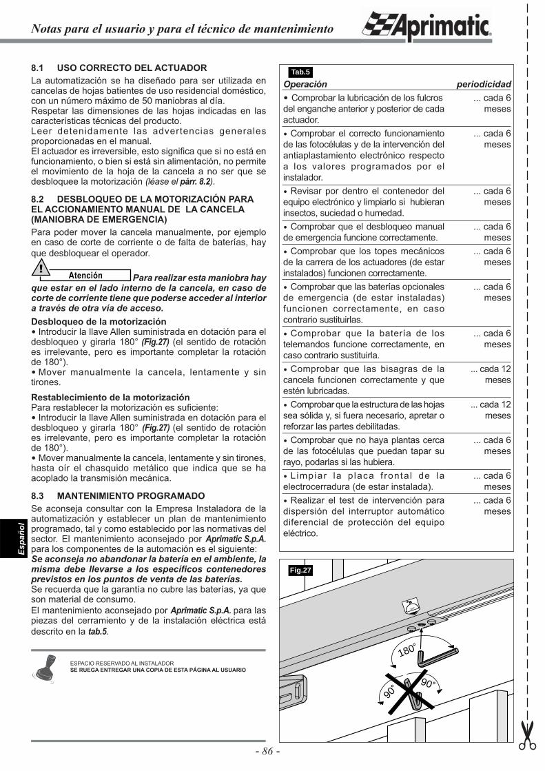
- 86 -
Espa
ñol
Operación Comprobar la lubricación de los fulcros del enganche anterior y posterior de cada actuador. Comprobar el correcto funcionamiento de las fotocélulas y de la intervención del antiaplastamiento electrónico respecto a los valores programados por el instalador. Revisar por dentro el contenedor del equipo electrónico y limpiarlo si hubieran insectos, suciedad o humedad. Comprobar que el desbloqueo manual de emergencia funcione correctamente. Comprobar que los topes mecánicos de la carrera de los actuadores (de estar instalados) funcionen correctamente. Comprobar que las baterías opcionales de emergencia (de estar instaladas) funcionen correctamente, en caso contrario sustituirlas. Comprobar que la batería de los telemandos funcione correctamente, en caso contrario sustituirla. Comprobar que las bisagras de la cancela funcionen correctamente y que estén lubricadas. Comprobar que la estructura de las hojas sea sólida y, si fuera necesario, apretar o reforzar las partes debilitadas. Comprobar que no haya plantas cerca de las fotocélulas que puedan tapar su rayo, podarlas si las hubiera. L impiar la p laca f ronta l de la electrocerradura (de estar instalada). Realizar el test de intervención para dispersión del interruptor automático diferencial de protección del equipo eléctrico.
periodicidad... cada 6
meses
... cada 6 meses
... cada 6 meses
... cada 6 meses
... cada 6 meses
... cada 6 meses
... cada 6 meses
... cada 12 meses
... cada 12 meses
... cada 6 meses
... cada 6 meses
... cada 6 meses
8.1 USO CORRECTO DEL ACTUADORLa automatización se ha diseñado para ser utilizada en cancelas de hojas batientes de uso residencial doméstico, con un número máximo de 50 maniobras al día.Respetar las dimensiones de las hojas indicadas en las características técnicas del producto.Leer detenidamente las advertencias generales proporcionadas en el manual.El actuador es irreversible, esto signifi ca que si no está en funcionamiento, o bien si está sin alimentación, no permite el movimiento de la hoja de la cancela a no ser que se desbloquee la motorización (léase el párr. 8.2).
8.2 DESBLOQUEO DE LA MOTORIZACIÓN PARA EL ACCIONAMIENTO MANUAL DE LA CANCELA (MANIOBRA DE EMERGENCIA)Para poder mover la cancela manualmente, por ejemplo en caso de corte de corriente o de falta de baterías, hay que desbloquear el operador.
Atención! Para realizar esta maniobra hay
que estar en el lado interno de la cancela, en caso de corte de corriente tiene que poderse acceder al interior a través de otra vía de acceso.Desbloqueo de la motorización Introducir la llave Allen suministrada en dotación para el desbloqueo y girarla 180° (Fig.27) (el sentido de rotación es irrelevante, pero es importante completar la rotación de 180°). Mover manualmente la cancela, lentamente y sin tirones.
Restablecimiento de la motorizaciónPara restablecer la motorización es sufi ciente: Introducir la llave Allen suministrada en dotación para el desbloqueo y girarla 180° (Fig.27) (el sentido de rotación es irrelevante, pero es importante completar la rotación de 180°). Mover manualmente la cancela, lentamente y sin tirones, hasta oír el chasquido metálico que indica que se ha acoplado la transmisión mecánica.
8.3 MANTENIMIENTO PROGRAMADOSe aconseja consultar con la Empresa Instaladora de la automatización y establecer un plan de mantenimiento programado, tal y como establecido por las normativas del sector. El mantenimiento aconsejado por Aprimatic S.p.A. para los componentes de la automación es el siguiente:Se aconseja no abandonar la batería en el ambiente, la misma debe llevarse a los específi cos contenedores previstos en los puntos de venta de las baterías.Se recuerda que la garantía no cubre las baterías, ya que son material de consumo.El mantenimiento aconsejado por Aprimatic S.p.A. para las piezas del cerramiento y de la instalación eléctrica está descrito en la tab.5.
180˚
180˚
90˚
90˚
Fig.27
Notas para el usuario y para el técnico de mantenimiento
✂
ESPACIO RESERVADO AL INSTALADORSE RUEGA ENTREGAR UNA COPIA DE ESTA PÁGINA AL USUARIO
Tab.5


www.aprimatic.com