quantification protocol for the conversion of drilling rigs from … · 2018-06-27 · conversion...
TRANSCRIPT
Conversion of Drilling Rigs from Diesel-Electric to High-line Electricity Sources February 2012
1
QQUUAANNTTIIFFIICCAATTIIOONN PPRROOTTOOCCOOLL FFOORR TTHHEE CCOONNVVEERRSSIIOONN OOFF DDRRIILLLLIINNGG
RRIIGGSS FFRROOMM DDIIEESSEELL--EELLEECCTTRRIICC TTOO HHIIGGHH--LLIINNEE EELLEECCTTRRIICCIITTYY
SSOOUURRCCEESS Version: 1.0 February 2012
Specified Gas Emitters Regulation
Withdra
wn

Conversion of Drilling Rigs from Diesel-Electric to High-line Electricity Sources February 2012
2
Disclaimer: The information provided in this document is intended as guidance only and is subject to periodic revisions. This document is not a substitute for the law. Please consult the Specified Gas Emitters Regulation and applicable legislation for all purposes of interpreting and applying the law. In the event that there is a discrepancy between this document and the Specified Gas Emitters Regulation or other legislation, the Specified Gas Emitters Regulation and other legislation prevail.
All Quantification Protocols approved under the Specified Gas Emitters Regulation are subject to periodic review as deemed necessary by the Department, and will be re-examined at a minimum of every 5 years from the original publication date to ensure methodologies and science continue to reflect best-available knowledge and best practices. Any updates to protocols occurring as a result of the 5-year and/or other reviews that are not due to legal requirements will apply at the end of the first credit duration period for applicable project extensions and for all new projects coming forward.
Where a project condition differs from approved government methodologies, or the project developer is unclear on protocol interpretation relative to their specific project, the project developer must contact Alberta Environment and Water to discuss an appropriate interpretation and receive approval for any methodology changes prior to undertaking the project.
Any comments, questions, or suggestions regarding the content of this document may be directed to:
Alberta Environment Climate Change Secretariat 12th Floor, 10025 – 106 Street Edmonton, Alberta, T5J 1G4 E-mail: [email protected]
Date of Publication: Febraury 2012
ISBN: 978-0-7785-9631-8 (Printed) ISBN: 978-0-7785-9632-5 (On-line)
Copyright in this publication, regardless of format, belongs to Her Majesty the Queen in right of the Province of Alberta. Reproduction of this publication, in whole or in part, regardless of purpose, requires the prior written permission of Alberta Environment.
© Her Majesty the Queen in right of the Province of Alberta, 2012
Withdra
wn

Conversion of Drilling Rigs from Diesel-Electric to High-line Electricity Sources February 2012
3
Table of Contents 1.0 Offset Project Description.................................................................................... 7
1.1 Protocol Scope ..................................................................................................... 7 1.2 Protocol Applicability.......................................................................................... 8 1.3 Protocol Flexibility .............................................................................................. 9 1.4 Glossary of New Terms ..................................................................................... 10
2.0 Baseline Condition............................................................................................. 12 2.1 Identification of Baseline Sources and Sinks .................................................... 14 Controlled: This classification indicates that the behaviour or operation of a controlled source and/or sink is under the direction and influence of a project developer through financial, policy, management, or other instruments. ........................................ 14 Related: A related source and/or sink has material and/or energy flows into, out of, or within a project, but is not under the reasonable control of the project proponent.......... 14 Affected: An affected source and/or sink is influenced by the project activity through changes in market demand or supply for projects or services associated with the project. 14
3.0 Project Condition ............................................................................................... 19 3.1 Identification of Project Sources and Sinks ....................................................... 21
4.0 Quantification .................................................................................................... 27 4.1 Quantification Methodology.............................................................................. 32
5.0 Data Management .............................................................................................. 39 5.1 Project Documentation....................................................................................... 39 5.2 Record Keeping ................................................................................................. 39 5.3 Quality Assurance/Quality Control Considerations........................................... 41 5.4 Liability.............................................................................................................. 41
6.0 References.......................................................................................................... 42 Appendix A: Sample Calculations....................................................................................... 43 Appendix B: Caterpillar Engine Model 3512 Manufacturer’s Data.................................... 49 With
drawn

Conversion of Drilling Rigs from Diesel-Electric to High-line Electricity Sources February 2012
4
List of Tables Table 1: Relevant Greenhouse Gases Applicable for the Conversion of Drilling Rigs......... 8 Table 2: Baseline Sources and Sinks ................................................................................... 16 Table 3: Project Condition Sources and Sinks..................................................................... 23 Table 4: Comparison of Sources/Sinks................................................................................ 28 Table 5: Quantification Methodology.................................................................................. 34
List of Figures Figure 1: Process Flow Diagram for the Drilling using Diesel Powered Genset Engines .. 13 Figure 2: Baseline Sources and Sinks for Conversion of Drilling Rigs .............................. 15 Figure 3: Process Flow Diagram for the Drilling Using High-line Electricity.................... 20 Figure 4: Project Conditions Sources and Sinks for Conversion of Drilling Rigs .............. 22
Withdra
wn
Conversion of Drilling Rigs from Diesel-Electric to High-line Electricity Sources February 2012
5
Alberta Environment Related Publications Climate Change and Emissions Management Act Specified Gas Emitters Regulation Specified Gas Reporting Regulation Alberta’s 2008 Climate Change Strategy Technical Guidance for Completing Annual Compliance Reports Technical Guidance for Completing Baseline Emissions Intensity Applications Additional Guidance for Cogeneration Facilities Technical Guidance for Landfill Operators Technical Guidance for Offset Project Developers Technical Guidance for Offset Protocol Developers Quantification Protocols (http://environment.alberta.ca/02275.html)
Withdra
wn

Conversion of Drilling Rigs from Diesel-Electric to High-line Electricity Sources February 2012
6
Withdra
wn
Conversion of Drilling Rigs from Diesel-Electric to High-line Electricity Sources February 2012
7
1.0 Offset Project Description This quantification protocol describes the process for quantifying greenhouse gas emissions reductions arising from a change in the energy source used to power drilling rig engines. Emissions reductions are achieved through the electrification of diesel powered drilling rigs in the baseline to high-line powered drilling rigs in the project condition based on rig specific fuel switch curves. Grid sourced electricity is assumed to be at 0.88 tCO2e per MWh. The project may be eligible to use an alternate emission factor consistent with flexibility mechanism 3 if it can be proven the electricity is a result of new electricity generation that is directly connected to the project. Project developers wishing to use this flexibility option must have written approval from Alberta Environment and Water. Familiarity with and general understanding of drilling rig operations and the fuel consumption of drilling rig engines and generators to produce rig electricity using electric motors is required.
1.1 Protocol Scope
This protocol provides general requirements for measurement, monitoring, verification, and greenhouse gas quantification requirements for greenhouse gas emission reductions resulting from the conversion of diesel-generated electricity to high-line electricity powered drilling rigs. Diesel-electric drilling rigs rely on a diesel electric generator (genset) to provide electricity to drive electric motors to allow rotation of the drill string. The drill string is essentially a hollow metal shaft that allows the drill bit to be run into the borehole and rotated by either direct means or by down-hole “mud motors”. These mud motors are driven by a portion of the drilling fluids circulated through the hole to cool the bit and remove drill cuttings from the hole. Drilling cuttings are material ground or chipped from rock by the drilling action. Electric motors also provide motive energy to allow the drill string to be raised and lowered in the hole and to drive the pumps circulating the drilling mud. Electric power is also consumed in utility services on the rig including control systems, heating, and lighting. Conversion to the high-line reduces the direct greenhouse gas emissions from the diesel genset(s). Project emissions are shifted from direct emissions from diesel combustion to indirect emissions from the Alberta electric power grid (Alberta grid). This protocol uses an average Alberta grid electricity greenhouse gas emissions intensity per MWh as 0.88 tCO2e/MWh to account for these indirect emissions. Flexibility is allowed for project developers that are using new electricity generation capacity that is directly connected to the project and is explained further in Section 1.3. The greenhouse gas reductions claimed in this project is then the difference between the greenhouse gas emissions from the Alberta grid (or other documented source) and those
Withdra
wn
Conversion of Drilling Rigs from Diesel-Electric to High-line Electricity Sources February 2012
8
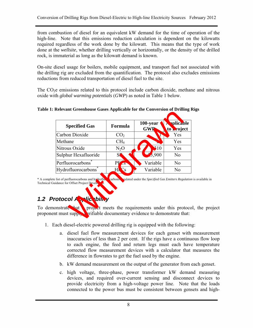
from combustion of diesel for an equivalent kW demand for the time of operation of the high-line. Note that this emissions reduction calculation is dependent on the kilowatts required regardless of the work done by the kilowatt. This means that the type of work done at the wellsite, whether drilling vertically or horizontally, or the density of the drilled rock, is immaterial as long as the kilowatt demand is known. On-site diesel usage for boilers, mobile equipment, and transport fuel not associated with the drilling rig are excluded from the quantification. The protocol also excludes emissions reductions from reduced transportation of diesel fuel to the site. The CO2e emissions related to this protocol include carbon dioxide, methane and nitrous oxide with global warming potentials (GWP) as noted in Table 1 below.
Table 1: Relevant Greenhouse Gases Applicable for the Conversion of Drilling Rigs
Specified Gas Formula 100-year
GWP Applicable to Project
Carbon Dioxide CO2 1 Yes Methane CH4 21 Yes Nitrous Oxide N2O 310 Yes Sulphur Hexafluoride SF6 23,900 No
Perfluorocarbons* PFCs Variable No Hydrofluorocarbons* HFCs Variable No
* A complete list of perfluorocarbons and hydrofluorocarbons regulated under the Specified Gas Emitters Regulation is available in Technical Guidance for Offset Project Developers.
1.2 Protocol Applicability
To demonstrate that a project meets the requirements under this protocol, the project proponent must supply verifiable documentary evidence to demonstrate that:
1. Each diesel-electric powered drilling rig is equipped with the following:
a. diesel fuel flow measurement devices for each genset with measurement inaccuracies of less than 2 per cent. If the rigs have a continuous flow loop to each engine, the feed and return legs must each have temperature corrected flow measurement devices with a calculator that measures the difference in flowrates to get the fuel used by the engine.
b. kW demand measurement on the output of the generator from each genset.
c. high voltage, three-phase, power transformer kW demand measuring devices, and required over-current sensing and disconnect devices to provide electricity from a high-voltage power line. Note that the loads connected to the power bus must be consistent between gensets and high-
Withdra
wn

Conversion of Drilling Rigs from Diesel-Electric to High-line Electricity Sources February 2012
9
line operations; if the loads change, the genset Fuel Switch Curve will need to be re-tested.
d. the Canadian Electrical Code must be followed in all respects, and specifically prevents genset operations when the high-line is connected.
e. an electronic datalogger (data recorder) must be installed with sufficient memory to record data to cover a rig’s typical operation on at least 10 wells. This data must include descriptive titles, dates, the rig number, owner and well identification data, and must be retained as part of the project’s permanent data records.
2. The project must meet all requirements for offset eligibility as specified in the Section 7 of the Specified Gas Emitters Regulation.
1.3 Protocol Flexibility
Flexibility in applying the quantification protocol is provided in the following ways: 1. Depending on re-checks of the genset Fuel Switch Curves, a rig may begin
operation immediately on the high-line, and use a tested average Rig Fuel Switch Curve.
2. If the rig is already connected to the high-line, the Fuel Switch Curve can still be completed using the same methodology and level of rigour outlined in this protocol, which will then be used to support emission reduction calculations based on kW demand.
3. Project developers that have new electricity generation capacity that is directly connected to the project may be eligible to use an alternate emission factor for project electricity. Project developers wishing to use this flexibility mechanism must receive written approval from Alberta Environment and Water in order to use an alternate emission factor. Project developers wishing to apply to use an alternate emission factor must demonstrate to Alberta Environment and Water that they meet the following requirements:
Electricity results from new capacity that is being built to meet project demand;
Electricity is directly connected to the offset project and does not first go onto the Alberta electricity grid; and
The project developer has or has obtained access to necessary supporting information to support electricity source quantification.
Withdra
wn
Conversion of Drilling Rigs from Diesel-Electric to High-line Electricity Sources February 2012
10
1.4 Glossary of New Terms
Alberta Electric Power Grid Refers to the Alberta electricity grid. Electricity sourced from the Alberta electric power grid is credited at 0.88 t CO2e per MWh.
CAPP Canadian Association of Petroleum Producers
Drilling rig A drilling rig is a machine that rotates a drill bit at the bottom of the string of pipe that creates a hole through the rock layers in the ground. It can be mobile equipment to drill any type of well, such as water wells, oil wells or natural gas extraction wells.
EIA Energy Information Administration is the official energy statistics from the U.S. Government
EPA The U.S. Environmental Protection Agency
Flash/Flashed Refers to the release or boiling of gases from a liquid hydrocarbon as pressure is released or the temperature is increased.
Fuel Switch Curve The Fuel Switch Curve is unique to a specific genset of a drilling rig. It is established based on direct measurement of the diesel flowrate per genset with the corresponding measurement of the electrical kilowatts for that genset.
Genset The diesel-fueled generator used to provide power to the drilling rig when it is not connected to the Alberta power grid.
Electricity grid factor
In this protocol, the intensity is for the Alberta grid as averaged for all the greenhouse gas emissions from all the power generators on the grid per megawatt-hours of electricity produced and is set at 0.88 t CO2e per MWh.
High-line Refers to electricity obtained by connecting to high voltage electricity transmission or distribution cables. Drilling rigs connect using a voltage of 2400 Volt and 3-phase power.
Withdra
wn

Conversion of Drilling Rigs from Diesel-Electric to High-line Electricity Sources February 2012
11
Directly connected power generation
Refers to electricity produced within the offset project boundary or immediately adjacent to it such that the electricity used in the project can be direct sourced from the power generator to the project.
Rig Fuel Switch Curve The total fuel flowrate for all the gensets on the rig are added together and plotted to form the Rig Fuel Switch Curve. The Rig Fuel Switch Curve can be matched by a polynomial equation that can then be used while on the high-line to calculate the equivalent diesel flowrate used in the baseline.
Rig power bus Is a device that connects the genset electricity delivery cables, the high line cables, and the rig electrical loads (motors, heaters, instruments, etc).
Rig release Is notice issued to the rig owner that confirms that drilling is complete, the well is isolated, and that the rig can be removed from the site.
Static factors Are common conversion factors such as feet to meters and/or published factors relating units such as tonnes CO2e per MWh for diesel combustion.
Wellsite It is a geographical point where the land owners/operators drill for underground resources such as hydrocarbon and water.
Withdra
wn
Conversion of Drilling Rigs from Diesel-Electric to High-line Electricity Sources February 2012
12
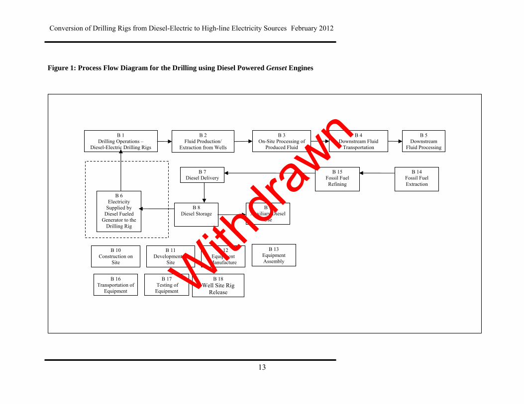
2.0 Baseline Condition This protocol uses a rig-specific, dynamic, project based baseline. The baseline scenario is the operation of a rig using the diesel-fired gensets as the source of electricity for drilling operations connected to the rig power bus. The greenhouse gas emissions reported as CO2e for diesel-fired gensets are determined based on kilowatt demand. Information for the individual gensets is grouped to create the baseline kilowatt demand for the rig. The kilowatt demand of a drilling rig can vary considerably between rigs. As such, it is necessary to establish the diesel flowrate required for every kilowatt to create a Rig Fuel Switch Curve for a specific rig. The diesel consumption for each diesel genset is different from any other as it depends on the engine, transmission, and generator design, the speed of operation, and the kilowatts demanded by all of the drilling rig electrical loads. The instantaneous rig electrical demand in kilowatts (kW demand) is supplied by a specific flowrate of diesel to each genset. Accordingly, each genset must have accurate fuel flow and kilowatt power delivered measurement devices installed and an electronic data recorder (datalogger) to allow the Fuel Switch Curve to be calculated over the range of kilowatts that each genset can provide. The total fuel flowrate for all the gensets on the rig are added together and plotted to form the Rig Fuel Switch Curve of the rig. If a genset has been removed and not replaced, or replaced by a different unit than the one originally used to set the curve, the genset Fuel Switch Curve must be re-established and the Rig Fuel Switch Curve must be re-calculated. The Rig Fuel Switch Curve must then be matched to a polynomial equation. This Rig Fuel Switch curve is used to calculate the equivalent diesel flowrate that would have been used for each kilowatt demand provided by the high-line. Figure 1 below provides a process flow diagram for the baseline condition of using diesel gensets to create electric power for drilling rigs.
Withdra
wn
Conversion of Drilling Rigs from Diesel-Electric to High-line Electricity Sources February 2012
13
Figure 1: Process Flow Diagram for the Drilling using Diesel Powered Genset Engines
B 2 Fluid Production/
Extraction from Wells
B 3 On-Site Processing of
Produced Fluid
B 6 Electricity
Supplied by Diesel Fueled
Generator to the Drilling Rig
B 4 Downstream Fluid
Transportation
B 5 Downstream
Fluid Processing
B 1 Drilling Operations –
Diesel-Electric Drilling Rigs
B 12 Equipment
Manufacture
B 16 Transportation of
Equipment
B 10 Construction on
Site
B 17 Testing of Equipment
B 18 Well Site Rig
Release
B 11 Development of
Site
B 8 Diesel Storage
B 9 Auxiliary Diesel
Use
B 7 Diesel Delivery
B 15 Fossil Fuel Refining
B 14 Fossil Fuel Extraction
B 13 Equipment Assembly With
drawn
Conversion of Drilling Rigs from Diesel-Electric to High-line Electricity Sources February 2012
14
2.1 Identification of Baseline Sources and Sinks
Sources and sinks for an activity are assessed based on guidance provided by Environment Canada and are classified as follows: Controlled: This classification indicates that the behaviour or operation of a
controlled source and/or sink is under the direction and influence of a project developer through financial, policy, management, or other instruments.
Related: A related source and/or sink has material and/or energy flows into,
out of, or within a project, but is not under the reasonable control of the project proponent.
Affected: An affected source and/or sink is influenced by the project activity
through changes in market demand or supply for projects or services associated with the project.
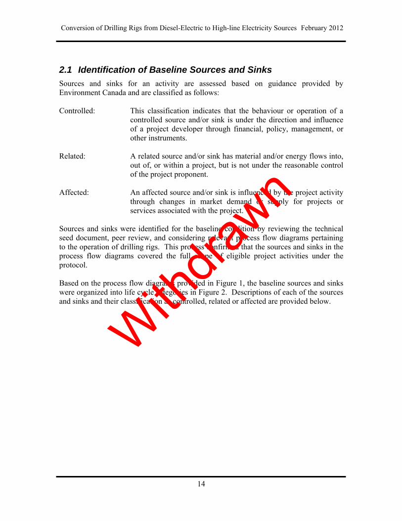
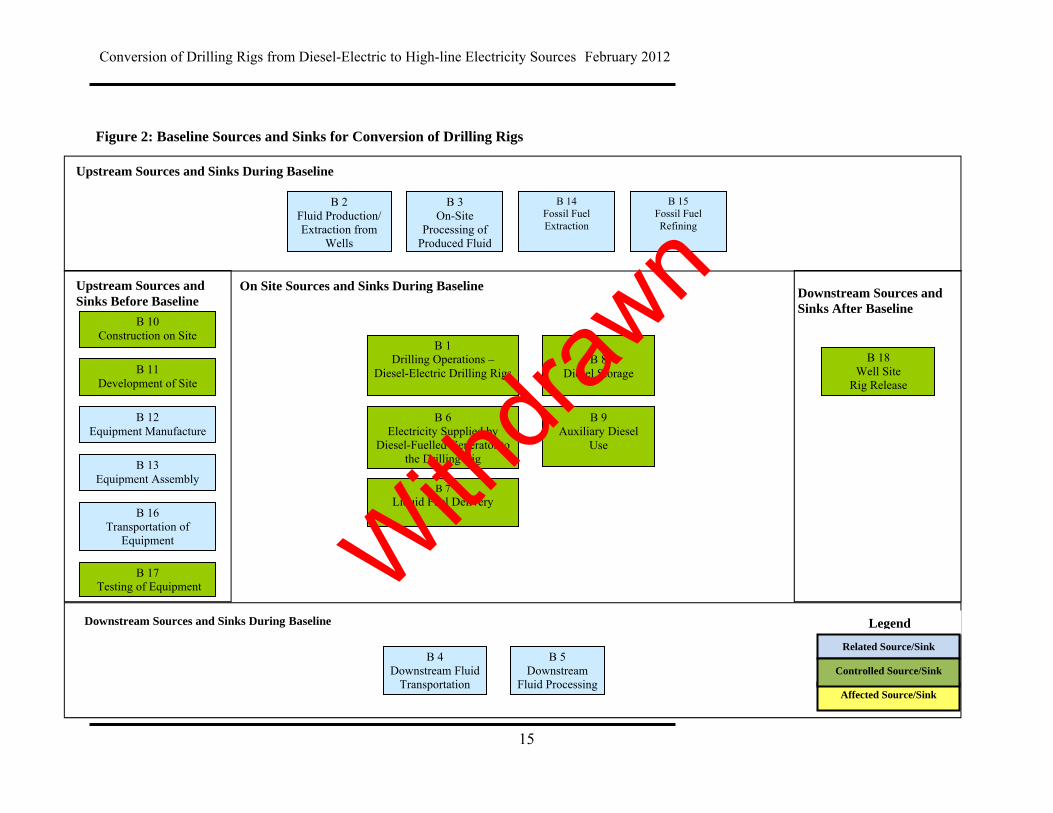
Sources and sinks were identified for the baseline condition by reviewing the technical seed document, peer review, and considering relevant process flow diagrams pertaining to the operation of drilling rigs. This process confirmed that the sources and sinks in the process flow diagrams covered the full scope of eligible project activities under the protocol. Based on the process flow diagrams provided in Figure 1, the baseline sources and sinks were organized into life cycle categories in Figure 2. Descriptions of each of the sources and sinks and their classification as controlled, related or affected are provided below.
Withdra
wn
Conversion of Drilling Rigs from Diesel-Electric to High-line Electricity Sources February 2012
15
Figure 2: Baseline Sources and Sinks for Conversion of Drilling Rigs
Upstream Sources and Sinks During Baseline
Upstream Sources and Sinks Before Baseline
On Site Sources and Sinks During Baseline Downstream Sources and Sinks After Baseline
Downstream Sources and Sinks During Baseline
Affected Source/Sink
Legend
Related Source/Sink
Controlled Source/Sink
B 1 Drilling Operations –
Diesel-Electric Drilling Rigs
B 6 Electricity Supplied by
Diesel-Fuelled Generator to the Drilling Rig
B 4 Downstream Fluid
Transportation
B 5 Downstream
Fluid Processing
B 2 Fluid Production/ Extraction from
Wells
B 3 On-Site
Processing of Produced Fluid
B 10 Construction on Site
B 11 Development of Site
B 12 Equipment Manufacture
B 16 Transportation of
Equipment
B 17 Testing of Equipment
B 18 Well Site
Rig Release
B 7 Liquid Fuel Delivery
B 8
Diesel Storage
B 9 Auxiliary Diesel
Use
B 13 Equipment Assembly
B 15 Fossil Fuel Refining
B 14 Fossil Fuel Extraction
Withdra
wn

Conversion of Drilling Rigs from Diesel-Electric to High-line Electricity Sources February 2012
16
Table 2: Baseline Sources and Sinks
Sources/Sinks Description Controlled, Affected, Related Upstream Sources and Sinks Before Baseline B 10 Construction on Site The process of construction at the site may require a variety of heavy equipment,
smaller power tools, cranes, and generators. The operation of this equipment will have associated greenhouse gas emissions from the use of fossil fuel and electricity.
Controlled
B 11 Development of Site The site may need to be developed. This could include civil infrastructure such as access to electricity, gas and water supply, as well as sewer. This may also include clearing (removing biomass), grading, building access roads, etc. There may also need to be some building of structures for the facility such as storage areas, storm water drainage, etc., as well as structures to enclose and house equipment. Greenhouse gas emissions would be primarily attributed to the use of fossil fuels and electricity used to power equipment required to develop the site such as graders, backhoes, trenching machines, etc.
Controlled
B 12 Equipment Manufacture Equipment may need to be built off-site. This includes all of the components of the storage, handling, processing, combustion, air quality control, system control, and safety systems. These may be sourced as pre-made standard equipment or custom built to specification. Greenhouse gas emissions would be primarily attributed to the use of fossil fuels and electricity used to power equipment for the manufacture of the raw materials and processing of the equipment.
Related
B 13 Equipment Assembly Equipment may need to be assembled either on-site or off-site. This includes all of the components of the handling, processing, combustion, air quality control, system control, and safety systems. These may be sourced as pre-made standard equipment or custom built to specification. Greenhouse gas emissions would be primarily attributed to the use of fossil fuels and electricity used to power equipment for the fabrication and assembly work.
Related
B 16 Transportation of Equipment
Equipment built off-site and the materials to build equipment on-site will all need to be delivered to the site. Transportation may be completed by train, truck, barge, or other means. Greenhouse gas emissions would be primarily attributed to the use of fossil fuels to power the equipment delivering the equipment to the site.
Related
B 17 Testing of Equipment Equipment may need to be tested to ensure that it is operational. This may result in running the equipment in order to ensure that it runs properly. These activities will result in greenhouse gas emissions associated with the combustion of fossil fuels and
Controlled With
drawn

Conversion of Drilling Rigs from Diesel-Electric to High-line Electricity Sources February 2012
17
the use of electricity.
Upstream Sources and Sinks During Baseline B 2 Fluid Production/ Extraction from Wells
The mixture of oil, gas, drill cuttings, and mud collected from the well at the drilling rig. Although drill cuttings are solids, they are suspended in the drilling mud while drilling and are included in “fluids” for the sake of simplicity.
Related
B 3 On-Site Processing of Produced Fluid
The mixture of oil, gas, drill cuttings and mud collected from the well is processed on-site and may be stored in tanks before transportation and the flashed and produced gases vented, flared or sometimes recovered to a gas-gathering system using temporary piping. Greenhouse gas emissions result from the venting or flaring of the equipment and fuel burned to operate the equipment that processes the fluids.
Related
B 14 Fossil Fuel Extraction Greenhouse gas emissions would be primarily attributed to the use of fossil fuels and electricity used to power the diesel-fuel gensets. The diesel comes from refining of oil which is extracted from underground reservoirs at other locations. The oil extraction process causes the emission of greenhouse gases due to extraction operations.
Related
B 15 Fossil Fuel Refining Greenhouse gas emissions would be primarily attributed to the use of fossil fuels and electricity used to power the diesel-fueled gensets. The diesel comes from the refining of oil. This refining process causes greenhouse gas emissions due to combustion of hydrocarbon fuels and usage of electricity. This does not include transportation of the diesel to the wellsite.
Related
Onsite Sources and Sinks During Baseline B 1 Drilling Operations – Diesel-Electric Drilling Rigs
The diesel-electric drilling rig operation requires electricity from the diesel-fuelled gensets.
Controlled
B 6 Electricity Supplied by Diesel-Fueled Generator
Diesel is required for generating electricity to operate the drilling rig under baseline conditions and may be sourced from connected facilities, such as the tanks on site. The electricity is supplied by the diesel gensets to the power bus on the rig. The measurement of the flowrate of diesel used by each genset for each measured kilowatt produced per genset over the range of kilowatts that the genset can produce provides a characteristic relationship called the Fuel Switch Curve. Converting the fuel used to the CO2e emitted and then adding the emissions from each genset over all the kilowatts used in a given duration gives the total greenhouse gas emissions over that duration.
Controlled
B 7 Liquid Fuel Delivery
The liquid fuel is delivered by trucks. The greenhouse gas emissions would be primarily attributed to the use of fossil fuels by the trucks for transportation. This is difficult to determine as it depends on the location of each supply depot relative to the
Controlled With
drawn

Conversion of Drilling Rigs from Diesel-Electric to High-line Electricity Sources February 2012
18
rig location and is determined and managed by the delivery service, not the rig owner or lessee.
B 8 Diesel Storage
The diesel fuel delivered to the site will be stored in the fuel tank. Any diesel flashed while the tank is in operation or being loaded releases diesel that currently is not required to be included in any measurement of greenhouse gas emissions.
Controlled
B 9 Auxiliary Diesel Use
These activities will result in greenhouse gas emissions associated with diesel combustion in the auxiliary equipment that uses the diesel stored in the fuel tank(s) on site. Examples would be mobile equipment and boilers. These devices would not be connected to the diesel gensets or the high-line.
Controlled
Downstream Sources and Sinks During Baseline B 4 Downstream Fluid Transportation
Waste materials from drilling (oil, drill cuttings and mud) are trucked to either an approved processing or disposal plant. The types and quantities of fuels used and that result in greenhouse gas emissions from transportation would be the same regardless of sourcing of electricity for the Project.
Related
B 5 Downstream Fluid Processing Each of the fluids produced throughout the project duration may need to be processed downstream. Types and quantities of fluids used and that result in greenhouse gas emissions would be the same regardless of sourcing of electricity for the Project.
Related
Downstream Sources and Sinks After Baseline B 18 Well Site Rig Release Once the drilling of the well is completed, the drilling rig may move to another well site
on the same drilling pad or to another area. Post-drilling clean-up may include disposal of some materials, environmental restoration, re-grading, and transportation of materials off-site. Greenhouse gas emissions would be primarily attributed to the use of fossil fuels and electricity used to power equipment required to move the rig and conduct these activities. The date of rig release from the site must be tracked in order to establish the starting date for this operation.
Controlled
Withdra
wn
Conversion of Drilling Rigs from Diesel-Electric to High-line Electricity Sources February 2012
19
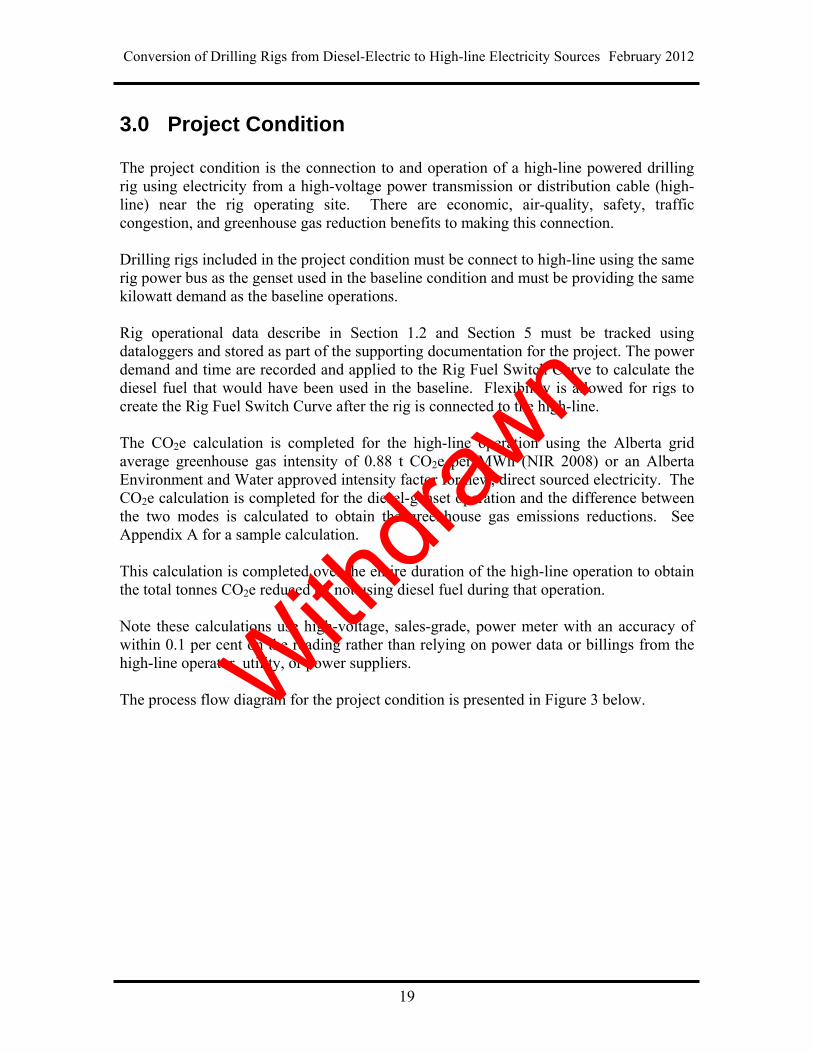
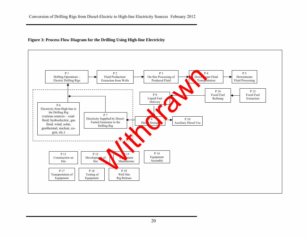
3.0 Project Condition The project condition is the connection to and operation of a high-line powered drilling rig using electricity from a high-voltage power transmission or distribution cable (high-line) near the rig operating site. There are economic, air-quality, safety, traffic congestion, and greenhouse gas reduction benefits to making this connection. Drilling rigs included in the project condition must be connect to high-line using the same rig power bus as the genset used in the baseline condition and must be providing the same kilowatt demand as the baseline operations. Rig operational data describe in Section 1.2 and Section 5 must be tracked using dataloggers and stored as part of the supporting documentation for the project. The power demand and time are recorded and applied to the Rig Fuel Switch Curve to calculate the diesel fuel that would have been used in the baseline. Flexibility is allowed for rigs to create the Rig Fuel Switch Curve after the rig is connected to the high-line. The CO2e calculation is completed for the high-line operation using the Alberta grid average greenhouse gas intensity of 0.88 t CO2e per MWh (NIR 2008) or an Alberta Environment and Water approved intensity factor for new, direct sourced electricity. The CO2e calculation is completed for the diesel-genset operation and the difference between the two modes is calculated to obtain the greenhouse gas emissions reductions. See Appendix A for a sample calculation. This calculation is completed over the entire duration of the high-line operation to obtain the total tonnes CO2e reduced by not using diesel fuel during that operation. Note these calculations use high-voltage, sales-grade, power meter with an accuracy of within 0.1 per cent on the reading rather than relying on power data or billings from the high-line operator, utility, or power suppliers. The process flow diagram for the project condition is presented in Figure 3 below.
Withdra
wn
Conversion of Drilling Rigs from Diesel-Electric to High-line Electricity Sources February 2012
20
Figure 3: Process Flow Diagram for the Drilling Using High-line Electricity
P 2 Fluid Production/
Extraction from Wells
P 3 On-Site Processing of
Produced Fluid
P 6 Electricity from High-line to
the Drilling Rig (various sources – coal-fired; hydroelectric, gas
fired, wind, solar, geothermal, nuclear, co-
gen, etc.)
P 4 Downstream Fluid
Transportation
P 5 Downstream
Fluid Processing
P 1 Drilling Operations – Electric Drilling Rigs
P 7 Electricity Supplied by Diesel-
Fueled Generator to the Drilling Rig
P 17 Transportation of
Equipment
P 11 Construction on
Site
P 18 Testing of Equipment
P 13 Equipment
Manufacture
P 19 Well Site
Rig Release
P 12 Development of
Site
P 9 Diesel Storage
P 10 Auxiliary Diesel Use
P 8 Liquid Fuel
Delivery
P 16 Fossil Fuel Refining
P 15 Fossil Fuel Extraction
P 14 Equipment Assembly With
drawn

Conversion of Drilling Rigs from Diesel-Electric to High-line Electricity Sources February 2012
21
3.1 Identification of Project Sources and Sinks
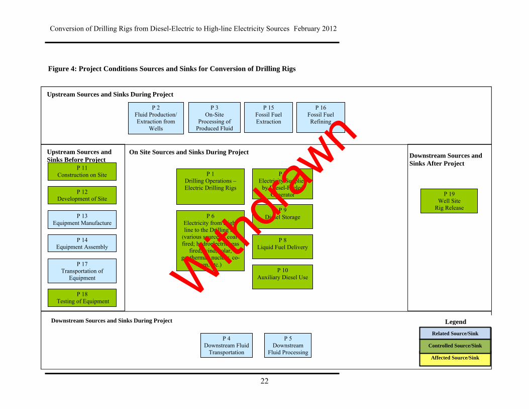
Sources and sinks for the conversion of diesel-electric to high-line powered drilling rigs were identified based on technical review. This process confirmed that source and sinks in the process flow diagram (Figure 3) covered the full scope of eligible project activities under this protocol. These sources and sinks have been further refined according to the life cycle categories identified in Figure 4, and are classified as controlled, related, or affected as described in Table 3 below. Sources and sinks were identified for the project by reviewing the technical seed document and relevant process flow diagrams pertaining to the operation of processing facilities. Note: the sources and sinks are similar to the baseline except for the sources and sink onsite during the project. Although the power source for the drilling rig is different in the project condition, the metering requirements are similar.
Withdra
wn
Conversion of Drilling Rigs from Diesel-Electric to High-line Electricity Sources February 2012
22
Figure 4: Project Conditions Sources and Sinks for Conversion of Drilling Rigs
Upstream Sources and Sinks During Project
Upstream Sources and Sinks Before Project
On Site Sources and Sinks During Project Downstream Sources and Sinks After Project
Downstream Sources and Sinks During Project
Affected Source/Sink
Legend
Related Source/Sink
Controlled Source/Sink P 4
Downstream Fluid Transportation
P 5 Downstream
Fluid Processing
P 2 Fluid Production/ Extraction from
Wells
P 3 On-Site
Processing of Produced Fluid
P 1 Drilling Operations – Electric Drilling Rigs
P 6 Electricity from High-line to the Drilling rig
(various sources – coal-fired; hydroelectric, gas
fired, wind, solar, geothermal, nuclear, co-
gen, etc.)
P 7 Electricity Supplied
by Diesel-Fueled Generator
P 11 Construction on Site
P 12 Development of Site
P 13 Equipment Manufacture
P 17 Transportation of
Equipment
P 18 Testing of Equipment
P 19 Well Site
Rig Release
P 8 Liquid Fuel Delivery
P 9 Diesel Storage
P 10 Auxiliary Diesel Use
P 14 Equipment Assembly
P 16 Fossil Fuel Refining
P 15 Fossil Fuel Extraction
Withdra
wn
Conversion of Drilling Rigs from Diesel-Electric to High-line Electricity Sources February 2012
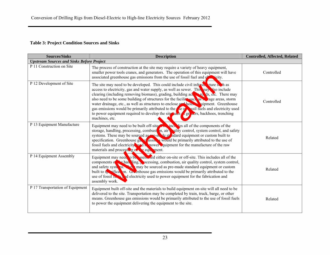
23
Table 3: Project Condition Sources and Sinks
Sources/Sinks Description Controlled, Affected, Related
Upstream Sources and Sinks Before Project P 11 Construction on Site The process of construction at the site may require a variety of heavy equipment,
smaller power tools cranes, and generators. The operation of this equipment will have associated greenhouse gas emissions from the use of fossil fuel and electricity.
Controlled
P 12 Development of Site The site may need to be developed. This could include civil infrastructure such as access to electricity, gas and water supply, as well as sewer. This may also include clearing (including removing biomass), grading, building access roads, etc. There may also need to be some building of structures for the facility such as storage areas, storm water drainage, etc., as well as structures to enclose and house equipment. Greenhouse gas emissions would be primarily attributed to the use of fossil fuels and electricity used to power equipment required to develop the site such as graders, backhoes, trenching machines, etc.
Controlled
P 13 Equipment Manufacture Equipment may need to be built off-site. This includes all of the components of the storage, handling, processing, combustion, air quality control, system control, and safety systems. These may be sourced as pre-made standard equipment or custom built to specification. Greenhouse gas emissions would be primarily attributed to the use of fossil fuels and electricity used to power equipment for the manufacture of the raw materials and processing of the equipment.
Related
P 14 Equipment Assembly Equipment may need to be assembled either on-site or off-site. This includes all of the components of the handling, processing, combustion, air quality control, system control, and safety systems. These may be sourced as pre-made standard equipment or custom built to specification. Greenhouse gas emissions would be primarily attributed to the use of fossil fuels and electricity used to power equipment for the fabrication and assembly work.
Related
P 17 Transportation of Equipment Equipment built off-site and the materials to build equipment on-site will all need to be delivered to the site. Transportation may be completed by train, truck, barge, or other means. Greenhouse gas emissions would be primarily attributed to the use of fossil fuels to power the equipment delivering the equipment to the site.
Related
Withdra
wn
Conversion of Drilling Rigs from Diesel-Electric to High-line Electricity Sources February 2012
24
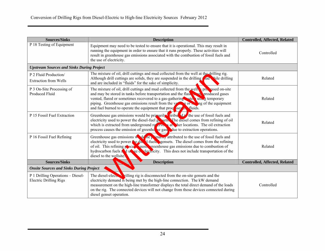
Sources/Sinks Description Controlled, Affected, Related P 18 Testing of Equipment Equipment may need to be tested to ensure that it is operational. This may result in
running the equipment in order to ensure that it runs properly. These activities will result in greenhouse gas emissions associated with the combustion of fossil fuels and the use of electricity.
Controlled
Upstream Sources and Sinks During Project
P 2 Fluid Production/
Extraction from Wells
The mixture of oil, drill cuttings and mud collected from the well at the drilling rig. Although drill cuttings are solids, they are suspended in the drilling mud while drilling and are included in “fluids” for the sake of simplicity.
Related
P 3 On-Site Processing of Produced Fluid
The mixture of oil, drill cuttings and mud collected from the well is processed on-site and may be stored in tanks before transportation and the flashed and produced gases vented, flared or sometimes recovered to a gas-gathering system using temporary piping. Greenhouse gas emissions result from the venting or flaring of the equipment and fuel burned to operate the equipment that processes the fluids.
Related
P 15 Fossil Fuel Extraction Greenhouse gas emissions would be primarily attributed to the use of fossil fuels and electricity used to power the diesel-fuel gensets. The diesel comes from refining of oil which is extracted from underground reservoirs at other locations. The oil extraction process causes the emission of greenhouse gases due to extraction operations.
Related
P 16 Fossil Fuel Refining Greenhouse gas emissions would be primarily attributed to the use of fossil fuels and electricity used to power the diesel-fueled gensets. The diesel comes from the refining of oil. This refining process causes greenhouse gas emissions due to combustion of hydrocarbon fuels and usage of electricity. This does not include transportation of the diesel to the wellsite.
Related
Sources/Sinks Description Controlled, Affected, Related
Onsite Sources and Sinks During Project
P 1 Drilling Operations – Diesel-Electric Drilling Rigs
The diesel-electric drilling rig is disconnected from the on-site gensets and the electricity demand is being met by the high-line connection. The kW demand measurement on the high-line transformer displays the total direct demand of the loads on the rig. The connected devices will not change from those devices connected during diesel genset operation.
Controlled
Withdra
wn

Conversion of Drilling Rigs from Diesel-Electric to High-line Electricity Sources February 2012
25
P 6 Electricity from High-line to the Drilling rig (various sources – coal-fired; hydroelectric, gas fired, wind, solar, geothermal, nuclear, co-gen, etc.)
Electricity is measured as the total direct demand of the electrical loads on the rig that are connected to the power bus. The greenhouse gas emissions intensity used to determine the total greenhouse gas emissions tonnage is based on the Alberta grid average, or the average greenhouse gas intensity of the independent power provider supplying electricity to the rig.
Various types of power generation systems feed electricity into the Alberta grid. Each has its own greenhouse gas emissions intensity (tCO2e/MWh). The annual average Alberta grid greenhouse gas intensity is published each year by Environment Canada. If an electric power provider agrees to provide electricity directly to the Protocol Project, the greenhouse gas intensity for that provider can be used to determine the Project greenhouse gas emissions.
A rig using the high-line as an electricity source is setting about a 1200 kW peak demand in a month with most operations at a lower demand. This is a small fraction of the mega-watts available on the Alberta grid at any time. Accordingly, the additional rig demand will not impact the average Alberta grid greenhouse gas intensity.
Controlled
P 7 Electricity Supplied by Diesel-fueled Generator
Diesel fuel may still be required for generating electricity to operate the drilling rig during instances where electricity supply from the high-line is interrupted or during rig-up and testing of equipment prior to high-line connection in the Project conditions.
Controlled
P 8 Liquid Fuel Delivery
The liquid fuel is delivered through trucks. The greenhouse gas emissions would be primarily attributed to the use of fossil fuels by the trucks for transportation. This is difficult to determine as it depends on the location of each supply depot relative to the rig location and is determined and managed by the delivery service, not the rig owner or lessee.
Controlled
P 9 Diesel Storage
The diesel fuel delivered to the site is stored in the fuel tank. Any diesel flashed while the tank is in operation or being loaded releases diesel that currently is not required to be included in any measurement of greenhouse gas emissions. Controlled
P 10 Auxiliary Diesel Use
These activities will result in greenhouse gas emissions associated with diesel combustion in the auxiliary equipment that uses the diesel stored in the fuel tank(s) on site. Examples would be mobile equipment and boilers. These devices would not be connected to the diesel gensets or the high-line.
Controlled With
drawn
Conversion of Drilling Rigs from Diesel-Electric to High-line Electricity Sources February 2012
26
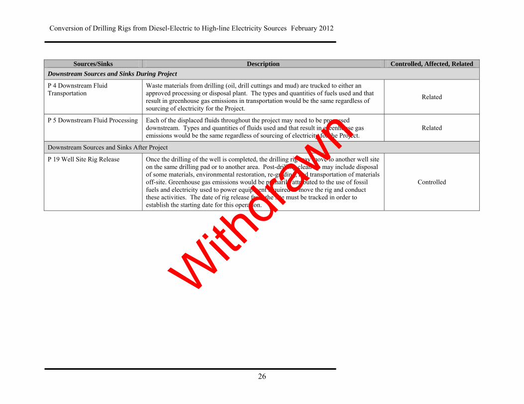
Sources/Sinks Description Controlled, Affected, Related
Downstream Sources and Sinks During Project
P 4 Downstream Fluid Transportation
Waste materials from drilling (oil, drill cuttings and mud) are trucked to either an approved processing or disposal plant. The types and quantities of fuels used and that result in greenhouse gas emissions in transportation would be the same regardless of sourcing of electricity for the Project.
Related
P 5 Downstream Fluid Processing Each of the displaced fluids throughout the project may need to be processed downstream. Types and quantities of fluids used and that result in greenhouse gas emissions would be the same regardless of sourcing of electricity for the Project.
Related
Downstream Sources and Sinks After Project
P 19 Well Site Rig Release Once the drilling of the well is completed, the drilling rig may move to another well site on the same drilling pad or to another area. Post-drilling clean-up may include disposal of some materials, environmental restoration, re-grading, and transportation of materials off-site. Greenhouse gas emissions would be primarily attributed to the use of fossil fuels and electricity used to power equipment required to move the rig and conduct these activities. The date of rig release from the site must be tracked in order to establish the starting date for this operation.
Controlled
Withdra
wn

Conversion of Drilling Rigs from Diesel-Electric to High-line Electricity Sources February 2012
27
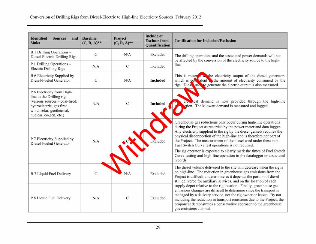
4.0 Quantification Baseline and project conditions were assessed against each other to determine the scope for reductions quantified under this protocol. Sources and sinks were either included or excluded depending on how they were impacted by the project condition. Sources that are not expected to change between baseline and project condition are excluded from the protocol quantification. It is assessed that excluded activities will occur at the same magnitude and emission rate during the baseline and project, so will therefore not be impacted by the project. Emissions that increase or decrease as a result of the project must be included and associated greenhouse gas emissions must be quantified as part of the project quantification. All sources and sinks identified in Table 2 and Table 3 above are listed in Table 4 below. Each source and sink is listed as include or excluded for protocol quantification. Justification for these choices is provided.
Withdra
wn
Conversion of Drilling Rigs from Diesel-Electric to High-line Electricity Sources February 2012
28
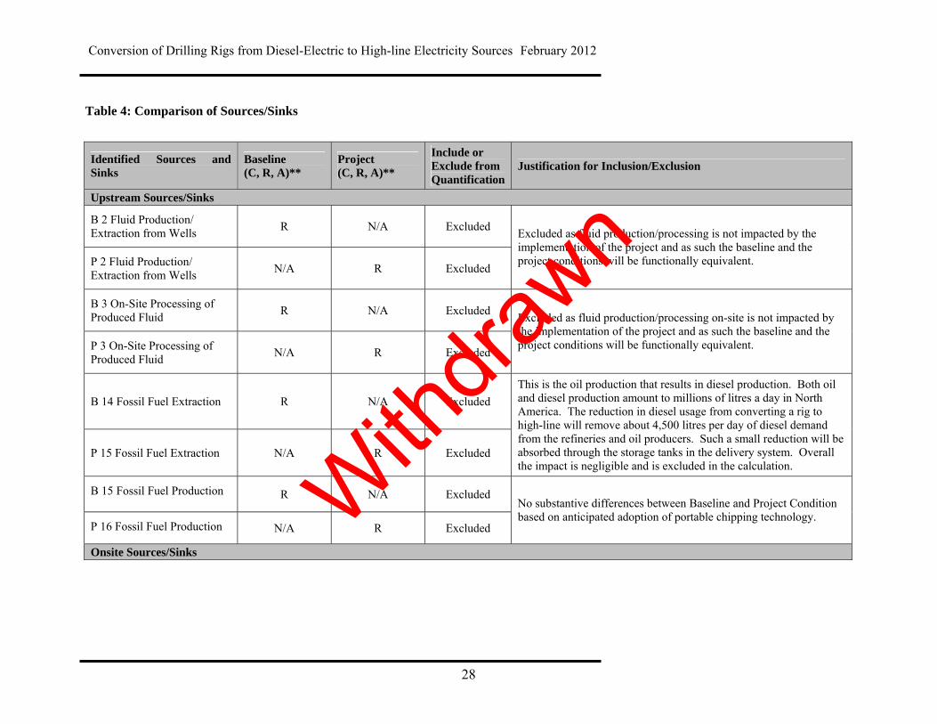
Table 4: Comparison of Sources/Sinks
Identified Sources and Sinks
Baseline (C, R, A)**
Project (C, R, A)**
Include or Exclude from Quantification
Justification for Inclusion/Exclusion
Upstream Sources/Sinks
B 2 Fluid Production/ Extraction from Wells
R N/A Excluded
P 2 Fluid Production/ Extraction from Wells
N/A R Excluded
Excluded as fluid production/processing is not impacted by the implementation of the project and as such the baseline and the project conditions will be functionally equivalent.
B 3 On-Site Processing of Produced Fluid
R N/A Excluded
P 3 On-Site Processing of Produced Fluid
N/A R Excluded
Excluded as fluid production/processing on-site is not impacted by the implementation of the project and as such the baseline and the project conditions will be functionally equivalent.
B 14 Fossil Fuel Extraction R N/A Excluded
P 15 Fossil Fuel Extraction N/A R Excluded
This is the oil production that results in diesel production. Both oil and diesel production amount to millions of litres a day in North America. The reduction in diesel usage from converting a rig to high-line will remove about 4,500 litres per day of diesel demand from the refineries and oil producers. Such a small reduction will be absorbed through the storage tanks in the delivery system. Overall the impact is negligible and is excluded in the calculation.
B 15 Fossil Fuel Production R N/A Excluded
P 16 Fossil Fuel Production N/A R Excluded
No substantive differences between Baseline and Project Condition based on anticipated adoption of portable chipping technology.
Onsite Sources/Sinks
Withdra
wn
Conversion of Drilling Rigs from Diesel-Electric to High-line Electricity Sources February 2012
29
Identified Sources and Sinks
Baseline (C, R, A)**
Project (C, R, A)**
Include or Exclude from Quantification
Justification for Inclusion/Exclusion
B 1 Drilling Operations – Diesel-Electric Drilling Rigs
C N/A Excluded
P 1 Drilling Operations – Electric Drilling Rigs
N/A C Excluded
The drilling operations and the associated power demands will not be affected by the conversion of the electricity source to the high-line.
B 6 Electricity Supplied by Diesel-Fueled Generator C N/A Included
This is metered at the electricity output of the diesel generators which is equivalent to the amount of electricity consumed by the rigs. Diesel used to generate the electric output is also measured.
P 6 Electricity from High-line to the Drilling rig (various sources – coal-fired; hydroelectric, gas fired, wind, solar, geothermal, nuclear, co-gen, etc.)
N/A C Included The electrical demand is now provided through the high-line connection. The kilowatt demand is measured and logged.
P 7 Electricity Supplied by Diesel-Fueled Generator
N/A C Excluded
Greenhouse gas reductions only occur during high-line operations during the Project as recorded by the power meter and data logger. Any electricity supplied to the rig by the diesel gensets requires the physical disconnection of the high-line and is therefore not part of the Project. The measurement of the diesel used under these non-Fuel Switch Curve test operations is not required.
The rig operator is expected to clearly mark the times of Fuel Switch Curve testing and high-line operation in the datalogger or associated records.
B 7 Liquid Fuel Delivery C N/A Excluded
P 8 Liquid Fuel Delivery N/A C Excluded
The diesel volume delivered to the site will decrease when the rig is on high-line. The reduction in greenhouse gas emissions from the Project is difficult to determine as it depends the portion of diesel still delivered for auxiliary services, and on the location of each supply depot relative to the rig location. Finally, greenhouse gas emissions changes are difficult to determine since the transport is managed by a delivery service, not the rig owner or lessee. By not including the reduction in transport emissions due to the Project, the proponent demonstrates a conservative approach to the greenhouse gas emissions claimed.
Withdra
wn
Conversion of Drilling Rigs from Diesel-Electric to High-line Electricity Sources February 2012
30
Identified Sources and Sinks
Baseline (C, R, A)**
Project (C, R, A)**
Include or Exclude from Quantification
Justification for Inclusion/Exclusion
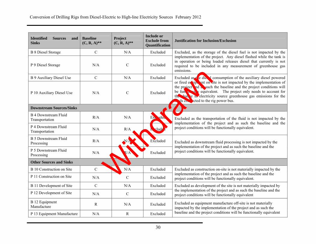
B 8 Diesel Storage C N/A Excluded
P 9 Diesel Storage N/A C Excluded
Excluded, as the storage of the diesel fuel is not impacted by the implementation of the project. Any diesel flashed while the tank is in operation or being loaded releases diesel that currently is not required to be included in any measurement of greenhouse gas emissions.
B 9 Auxiliary Diesel Use C N/A Excluded
P 10 Auxiliary Diesel Use N/A C Excluded
Excluded as the diesel consumption of the auxiliary diesel powered or fired equipment on site is not impacted by the implementation of the project and as such the baseline and the project conditions will be functionally equivalent. The project only needs to account for the change in electricity source greenhouse gas emissions for the loads connected to the rig power bus.
Downstream Sources/Sinks
B 4 Downstream Fluid Transportation
R/A N/A Excluded
P 4 Downstream Fluid Transportation
N/A R/A Excluded
Excluded as the transportation of the fluid is not impacted by the implementation of the project and as such the baseline and the project conditions will be functionally equivalent.
B 5 Downstream Fluid Processing
R/A N/A Excluded
P 5 Downstream Fluid Processing
N/A R/A Excluded
Excluded as downstream fluid processing is not impacted by the implementation of the project and as such the baseline and the project conditions will be functionally equivalent.
Other Sources and Sinks
B 10 Construction on Site C N/A Excluded
P 11 Construction on Site N/A C Excluded
Excluded as construction on-site is not materially impacted by the implementation of the project and as such the baseline and the project conditions will be functionally equivalent.
B 11 Development of Site C N/A Excluded
P 12 Development of Site N/A C Excluded
Excluded as development of the site is not materially impacted by the implementation of the project and as such the baseline and the project conditions will be functionally equivalent
B 12 Equipment Manufacture
R N/A Excluded
P 13 Equipment Manufacture N/A R Excluded
Excluded as equipment manufacture off-site is not materially impacted by the implementation of the project and as such the baseline and the project conditions will be functionally equivalent
Withdra
wn
Conversion of Drilling Rigs from Diesel-Electric to High-line Electricity Sources February 2012
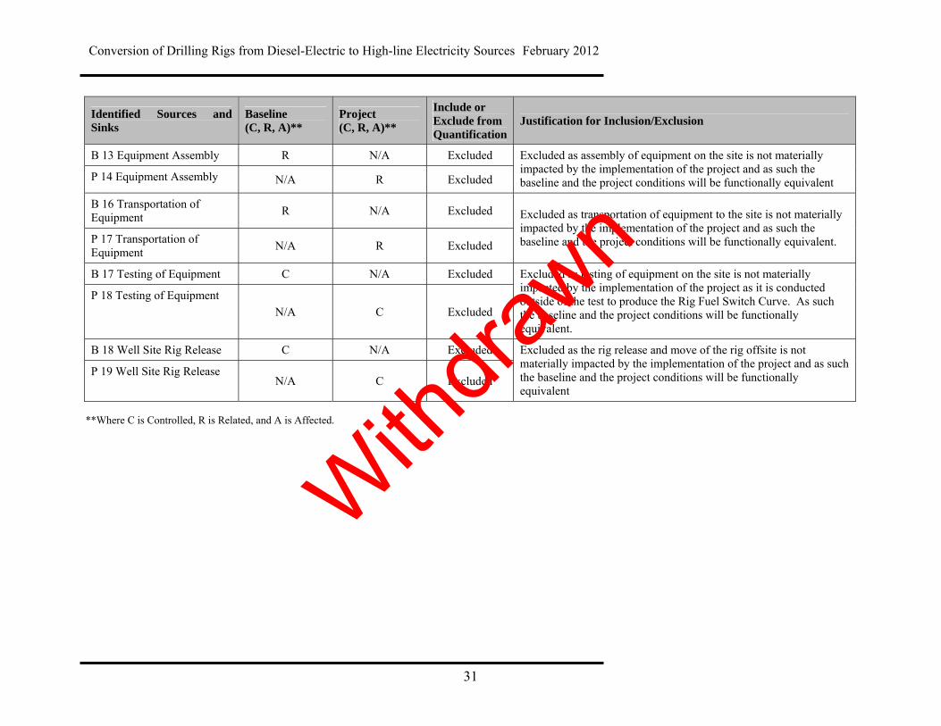
31
Identified Sources and Sinks
Baseline (C, R, A)**
Project (C, R, A)**
Include or Exclude from Quantification
Justification for Inclusion/Exclusion
B 13 Equipment Assembly R N/A Excluded
P 14 Equipment Assembly N/A R Excluded
Excluded as assembly of equipment on the site is not materially impacted by the implementation of the project and as such the baseline and the project conditions will be functionally equivalent
B 16 Transportation of Equipment
R N/A Excluded
P 17 Transportation of Equipment
N/A R Excluded
Excluded as transportation of equipment to the site is not materially impacted by the implementation of the project and as such the baseline and the project conditions will be functionally equivalent.
B 17 Testing of Equipment C N/A Excluded
P 18 Testing of Equipment
N/A C Excluded
Excluded as testing of equipment on the site is not materially impacted by the implementation of the project as it is conducted outside of the test to produce the Rig Fuel Switch Curve. As such the baseline and the project conditions will be functionally equivalent.
B 18 Well Site Rig Release C N/A Excluded
P 19 Well Site Rig Release N/A C Excluded
Excluded as the rig release and move of the rig offsite is not materially impacted by the implementation of the project and as such the baseline and the project conditions will be functionally equivalent
**Where C is Controlled, R is Related, and A is Affected.
With
drawn

Conversion of Drilling Rigs from Diesel-Electric to High-line Electricity Sources February 2012
32
4.1 Quantification Methodology
Quantification of the reductions, removals and reversals of relevant sources and sinks for each of the greenhouse gases will be completed using the methodologies outlined in Table 5 below. These calculation methodologies serve to complete the following three equations for calculating the emission reductions from the comparison of the baseline and project conditions. The general approach is to calculate the offsets as follows: Where:
Emissions Baseline = sum of the emissions included under the Baseline Condition. Emissions B6 = Emissions Project Genset Emissions Project = sum of emissions included under the Project Condition. Emissions P6 = Emissions Project High-line
Emissions Project Genset are calculated using a Rig Fuel Switch Curve equation relating kilowatts demand from the gensets on the rig to the fuel flowrate used to run the genset engines calculated as follows:.
This data is collected during genset performance tests on the rig.
The Rig Fuel Switch Curve is calculated by adding together the kilowatts from the generators over the capacity range of the gensets.
Fuel flowrates are added together for each of the totalled kilowatts.
Rig values are plotted and polynomial trend line is fit to the curve to get a Rig Fuel Switch Curve equation. This establishes the fuel flowrate for the rig at any kilowatt demand.
Flowrates are multiplied by the combustion emissions factor per cubic meter of fuel burned to calculate the baseline greenhouse gas emissions for the rig.
Emissions Project Genset = Avoided Emissions Combusted Diesel Fuel
Emission Reduction = Emissions Baseline – Emissions Project
Emissions Baseline = Emissions B6
Emissions Project = Emissions P6
Withdra
wn

Conversion of Drilling Rigs from Diesel-Electric to High-line Electricity Sources February 2012
33
When the rig switches to the high-line, the gensets are shut-down and disconnected. The volume of avoided emissions is determined by taking each high-line power demand and using the Rig Fuel Switch Curve equation to calculate the avoided fuel flowrate. This is then multiplied by the emissions factor to calculate the Avoided Emissions Combusted Diesel
Fuel noted in B6. The kilowatt-hours are determined using the high-voltage, sales grade power meter, and the high-line greenhouse gas emission factor used to determine the Emissions Project High-line noted in P6.
Withdra
wn
Conversion of Drilling Rigs from Diesel-Electric to High-line Electricity Sources February 2012
34
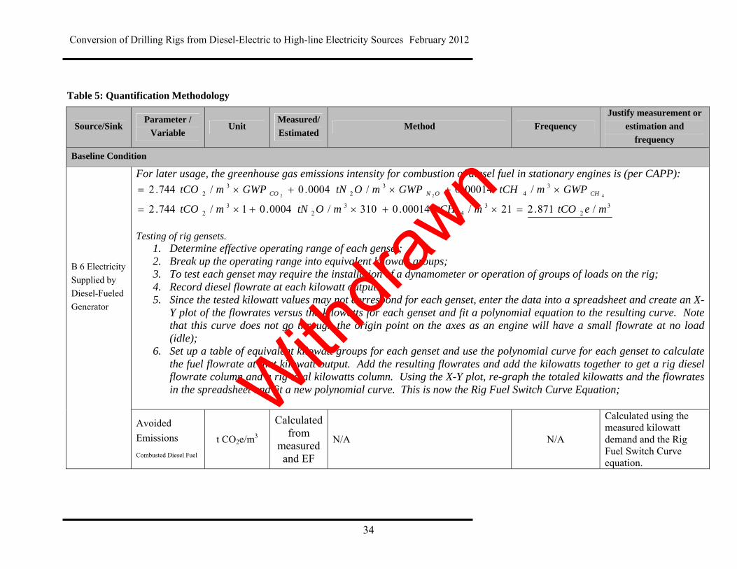
Table 5: Quantification Methodology
Source/Sink Parameter /
Variable Unit
Measured/
Estimated Method Frequency
Justify measurement or
estimation and
frequency
Baseline Condition
For later usage, the greenhouse gas emissions intensity for combustion of diesel fuel in stationary engines is (per CAPP):
32
34
32
32
34
32
32
/871.221/00014.0310/0004.01/744.2
/00014.0/0004.0/744.2422
metCOmtCHmOtNmtCO
GWPmtCHGWPmOtNGWPmtCO CHONCO
Testing of rig gensets.
1. Determine effective operating range of each genset; 2. Break up the operating range into equivalent kilowatt groups; 3. To test each genset may require the installation of a dynamometer or operation of groups of loads on the rig; 4. Record diesel flowrate at each kilowatt output. 5. Since the tested kilowatt values may not correspond for each genset, enter the data into a spreadsheet and create an X-
Y plot of the flowrates versus the kilowatts for each genset and fit a polynomial equation to the resulting curve. Note that this curve does not go through the origin point on the axes as an engine will have a small flowrate at no load (idle);
6. Set up a table of equivalent kilowatt groups for each genset and use the polynomial curve for each genset to calculate the fuel flowrate at that kilowatt output. Add the resulting flowrates and add the kilowatts together to get a rig diesel flowrate column and a rig total kilowatts column. Using the X-Y plot, re-graph the totaled kilowatts and the flowrates in the spreadsheet and fit a new polynomial curve. This is now the Rig Fuel Switch Curve Equation;
B 6 Electricity
Supplied by
Diesel-Fueled
Generator
Avoided
Emissions
Combusted Diesel Fuel
t CO2e/m3
Calculated from
measured and EF
N/A N/A
Calculated using the measured kilowatt demand and the Rig Fuel Switch Curve equation.
Withdra
wn

Conversion of Drilling Rigs from Diesel-Electric to High-line Electricity Sources February 2012
35
Source/Sink Parameter /
Variable Unit
Measured/
Estimated Method Frequency
Justify measurement or
estimation and
frequency
Flowrate of Diesel
Liters/second
Measured
Direct metering
Each time a
genset is added to a rig, and once
in winter and once in summer
and after maintenance
Engine and generator operation will be stable for most operating conditions. Flowrate must be measured to provide adequate accuracy.
High-line CO2e Emissions Factor for Diesel (EFdiesel CO2e)
tonnes CO2e per MWh Estimated Alberta Environment (see below) Annual
Reference values adjusted annually as part of Environment Canada reporting on Canada’s emissions inventory.
Genset CO2 Emissions Factor for Diesel Combustion ( EF Diesel CO2)
tonnes CO2 per m3 Estimated From CAPP reference documents Per CAPP
schedules Timing is not under Proponent control.
Genset CH4 Emissions Factor for Diesel Combustion (EF Diesel CH4)
tonnes CH4 per m3 Estimated From EPA, AP-42 and CAPP reference
documents Per EPA schedules
Timing is not under Proponent control. See Table 1 for the GWP for CH4.
Withdra
wn
Conversion of Drilling Rigs from Diesel-Electric to High-line Electricity Sources February 2012
36
Source/Sink Parameter /
Variable Unit
Measured/
Estimated Method Frequency
Justify measurement or
estimation and
frequency
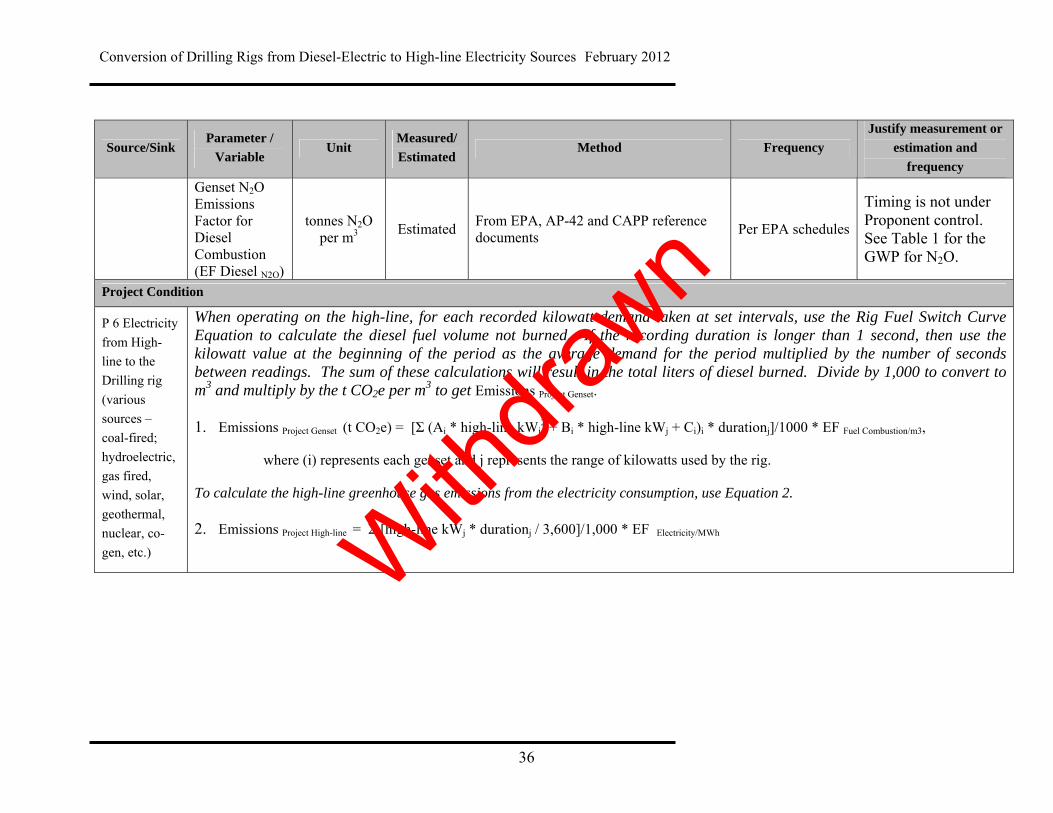
Genset N2O Emissions Factor for Diesel Combustion (EF Diesel N2O)
tonnes N2O per m3 Estimated From EPA, AP-42 and CAPP reference
documents Per EPA schedules
Timing is not under Proponent control. See Table 1 for the GWP for N2O.
Project Condition
P 6 Electricity
from High-
line to the
Drilling rig
(various
sources –
coal-fired;
hydroelectric,
gas fired,
wind, solar,
geothermal,
nuclear, co-
gen, etc.)
When operating on the high-line, for each recorded kilowatt demand taken at set intervals, use the Rig Fuel Switch Curve Equation to calculate the diesel fuel volume not burned. If the recording duration is longer than 1 second, then use the kilowatt value at the beginning of the period as the average demand for the period multiplied by the number of seconds between readings. The sum of these calculations will result in the total liters of diesel burned. Divide by 1,000 to convert to m3 and multiply by the t CO2e per m3 to get Emissions Project Genset. 1. Emissions Project Genset (t CO2e) = [Σ (Ai * high-line kWj
2 + Bi * high-line kWj + Ci)i * durationj]/1000 * EF Fuel Combustion/m3,
where (i) represents each genset and j represents the range of kilowatts used by the rig.
To calculate the high-line greenhouse gas emissions from the electricity consumption, use Equation 2. 2. Emissions Project High-line = Σ [high-line kWj * durationj / 3,600]/1,000 * EF Electricity/MWh
Withdra
wn
Conversion of Drilling Rigs from Diesel-Electric to High-line Electricity Sources February 2012
37
Source/Sink Parameter /
Variable Unit
Measured/
Estimated Method Frequency
Justify measurement or
estimation and
frequency
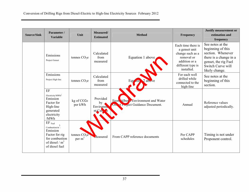
Emissions Project Genset
tonnes CO2e Calculated
from measured
Equation 1 above
Each time there is a genset unit
change such as a removal or
addition or a different type is
installed.
See notes at the beginning of this section. Whenever there is a change in a genset, the rig Fuel Switch Curve will likely change.
Emissions Project High-line tonnes CO2e
Calculated from
measured Equation 2 above
For each well drilled while
connected to the high-line
See notes at the beginning of this section.
EF Electricity/MWh: Emission Factor for High-line generated electricity /MWh
kg of CO2e per kWh
Provided by
Environment Canada
From Alberta Environment and Water Offset Project Guidance Document.
Annual Reference values adjusted periodically.
EF Fuel
Combustion/m3
:
Emission Factor for rig for combustion of diesel / m3 of diesel fuel
tonnes CO2e per m3 Measured From CAPP reference documents Per CAPP
schedules Timing is not under Proponent control. With
drawn

Conversion of Drilling Rigs from Diesel-Electric to High-line Electricity Sources February 2012
38
Source/Sink Parameter /
Variable Unit
Measured/
Estimated Method Frequency
Justify measurement or
estimation and
frequency
High-line kW kW Measured Time-of-use meter
A frequency that
is less than every
minute still
provides enough
accuracy to meet
the AENV
requirements.
With electronic
metering a
frequency that
goes down to
every second is
available but not
necessary.
Provides higher
accuracy of calculated
greenhouse gas
emissions
Withdra
wn
Conversion of Drilling Rigs from Diesel-Electric to High-line Electricity Sources February 2012
39
5.0 Data Management Data quality management must be of sufficient quality to fulfill the quantification requirements and be substantiated by actual records for the purpose of verification. The project developer shall establish and apply quality management procedures to manage data and information. Written procedures and documentation must be established for each measurement task outlining responsibility, timing and record location requirements.
5.1 Project Documentation
The project developer must ensure the following documentation is obtained in order to claim any emission reductions:
Diesel and high-line kilowatt demand must be determined by actual metered data. The diesel flowrate and power demand measurement systems must be accurate within 2 per cent for the readings. The sampling frequency depends on the speed and extent of power demand variation, and on the data rate of the recording system installed. Each rig owner should determine an appropriate to ensure accuracy in their measurements.
Information must be inserted into the electronic record with the data to provide
dates, and start or stop of specific operations such as rig pre-test, Rig Fuel Switch Curve testing, high-line operation and well site identification (well ID).
If a genset is removed or replaced with another genset, the change must be
documented and added to the record. A new test must be run to establish the genset Fuel Switch Curve. The results must replace the previous data from the removed genset to re-establish the Rig Fuel Switch Curve.
A record listing the specific drilling rig owner’s name and the rig number, with its
primary specifications including serial numbers of the gensets, status as a rig convertible to high-line, and maintenance records. If the drilling rigs are owned by another company, the rig owner and project developer must determine ownership of greenhouse gas offset credits and provide documentation to ensure any duplication of the carbon offset credits does not occur.
5.2 Record Keeping
Alberta Environment requires that project developers maintain appropriate supporting information for the project, including all raw data for the project for a period of 7 years
Withdra
wn

Conversion of Drilling Rigs from Diesel-Electric to High-line Electricity Sources February 2012
40
after the end of the project crediting period. Where the project developer is different from the person implementing the activity, as in the case of an aggregated project, the individual projects and the aggregator, must both maintain sufficient records to support the offset project. The project developer must keep the information listed below (in addition to others that will support the project) and disclose all information to the verifier and/or government auditor upon request. Record Keeping Requirements:
Raw baseline period data to determine the Rig Fuel Switch Curve, including, diesel flowrates and electrical demand data, matching serial numbers of the gensets, maintenance record/time data, ambient temperature, barometric pressure.
A record of all adjustments made to raw baseline data with justifications
All analyses of baseline data used to create mathematical model(s)
All data and analysis used to support estimates and factors used for quantification including?
Expected end of life date of equipment removed or renovated under the project
Metering equipment specifications (make and model number, serial number, manufacturer’s calibration procedures)
A record of changes in static factors along with all calculations for non-routine adjustments
All calculations of greenhouse gas emissions/reductions and emission factors
Measurement equipment maintenance activity logs
Measurement equipment calibration records
Initial and annual verification records and audit results
In order to support the third party verification and the potential supplemental government audit, the project proponent must put in place a system that meets the following criteria:
All records must be kept in areas that are easily located;
All records must be legible, dated and revised as needed;
All records must be maintained in an orderly manner;
All documents must be retained for 7 years after the project crediting period;
Systems for data collection, calculations and emissions estimates must include accuracy checks by supervisors;
Electronic and paper documentation are both satisfactory; and
Copies of records should be stored in two locations to prevent loss of data.
Note: Attestations will not be considered sufficient proof that an activity took place and will not meet verification requirements.
Withdra
wn
Conversion of Drilling Rigs from Diesel-Electric to High-line Electricity Sources February 2012
41
5.3 Quality Assurance/Quality Control Considerations
Quality Assurance/Quality Control can also be applied to add confidence that all measurements and calculations have been made correctly. These include, but are not limited to:
Ensuring that the changes to operational procedures continue to function as planned and achieve greenhouse gas reductions
Ensuring that the measurement and calculation system and greenhouse gas reduction reporting remains in place and accurate
Checking the validity of all data before it is processed, including emission factors, static factors, and acquired data
Performing recalculations of quantification procedures to reduce the possibility of mathematical errors
Storing the data in its raw form so it can be retrieved for verification. If in an electronic format, store the data in non-volatile read-only storage such as a DVD disc or other suitable long-term memory formats.
Protecting records of data and documentation by keeping both a hard and soft copy of all documents
Recording and explaining any adjustment made to raw data in the associated report and files.
Where possible, linking electronic data to reduce the possibility of transcription errors.
A contingency plan for potential data loss.
5.4 Liability
Offset projects must be implemented according to the approved protocol and in accordance with government regulations. Alberta Environment and Water reserves the right to audit offset credits and associated projects submitted to Alberta Environment and Water for compliance under the Specified Gas Emitters Regulation and may request corrections based on audit findings.
Withdra
wn
Conversion of Drilling Rigs from Diesel-Electric to High-line Electricity Sources February 2012
42
6.0 References Canadian Association of Oilwell Drilling Contractors (CAODC). Annual Drilling Rig Operating Days/Depth Summary (01-09) – pdf. http://www.caodc.ca/pdf/Annual%20Operating%20Days-Depth(01-09).pdf Canadian Association of Petroleum Producers (CAPP). Calculating Greenhouse Gas Emissions. April, 2003. Caterpillar. Caterpillar 3512 Industrial 1500 bHP, 1800 RPM. 2009. Caterpillar. Marine Engine Selection Guide. 2008. http://marine.cat.com Energy Information Administration U.S. Department of Energy. Instructions for Form EIA-1605 Voluntary Reporting of Greenhouse Gases – Revised Pursuant to 10 CFR Part 300 Guidelines for Voluntary Greenhouse Gas Reporting. October 15, 2007. Environment Canada. Environment Canada – Climate Change – Electricity Intensity Tables. April 30, 2010. http://www.ec.gc.ca/ges-ghg/default.asp?lang=En&n=EAF0E96A-1#section10 Government of Alberta. Technical Guidance for Offset Protocol Developers Version 1.0. January 2011.
Withdra
wn
Conversion of Drilling Rigs from Diesel-Electric to High-line Electricity Sources February 2012
43
Appendix A: Sample Calculations
Withdra
wn
Conversion of Drilling Rigs from Diesel-Electric to High-line Electricity Sources February 2012
44
Baseline Condition The greenhouse gas emissions intensity for combustion of diesel fuel in stationary engines is (per CAPP):
32
34
32
32
34
32
32
/871.221/00014.0310/0004.01/744.2
/00014.0/0004.0/744.2422
metCOmtCHmOtNmtCO
GWPmtCHGWPmOtNGWPmtCO CHONCO
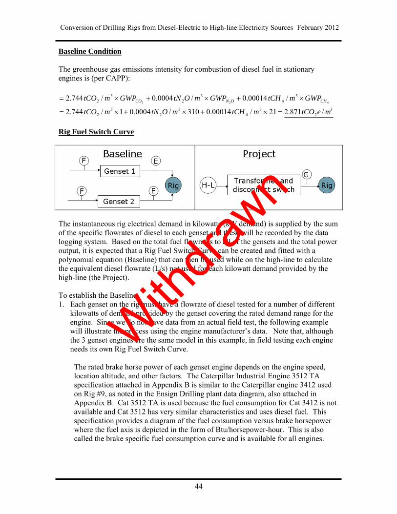
Rig Fuel Switch Curve
The instantaneous rig electrical demand in kilowatts (kW demand) is supplied by the sum of the specific flowrates of diesel to each genset and these will be recorded by the data logging system. Based on the total fuel flowrates to all of the gensets and the total power output, it is expected that a Rig Fuel Switch Curve can be created and fitted with a polynomial equation (Baseline) that can then be used while on the high-line to calculate the equivalent diesel flowrate (L/s) not used for each kilowatt demand provided by the high-line (the Project). To establish the Baseline, 1. Each genset on the rig must have a flowrate of diesel tested for a number of different
kilowatts of demand provided by the genset covering the rated demand range for the engine. Since we do not have data from an actual field test, the following example will illustrate the process using the engine manufacturer’s data. Note that, although the 3 genset engines are the same model in this example, in field testing each engine needs its own Rig Fuel Switch Curve.
The rated brake horse power of each genset engine depends on the engine speed, location altitude, and other factors. The Caterpillar Industrial Engine 3512 TA specification attached in Appendix B is similar to the Caterpillar engine 3412 used on Rig #9, as noted in the Ensign Drilling plant data diagram, also attached in Appendix B. Cat 3512 TA is used because the fuel consumption for Cat 3412 is not available and Cat 3512 has very similar characteristics and uses diesel fuel. This specification provides a diagram of the fuel consumption versus brake horsepower where the fuel axis is depicted in the form of Btu/horsepower-hour. This is also called the brake specific fuel consumption curve and is available for all engines.
Withdra
wn
Conversion of Drilling Rigs from Diesel-Electric to High-line Electricity Sources February 2012
45
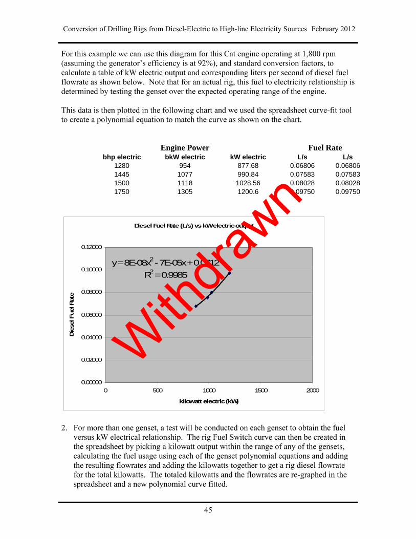
For this example we can use this diagram for this Cat engine operating at 1,800 rpm (assuming the generator’s efficiency is at 92%), and standard conversion factors, to calculate a table of kW electric output and corresponding liters per second of diesel fuel flowrate as shown below. Note that for an actual rig, this fuel to electricity relationship is determined by testing the genset over the expected operating range of the engine. This data is then plotted in the following chart and we used the spreadsheet curve-fit tool to create a polynomial equation to match the curve as shown on the chart.
Engine Power Fuel Rate bhp electric bkW electric kW electric L/s L/s
1280 954 877.68 0.06806 0.06806 1445 1077 990.84 0.07583 0.07583 1500 1118 1028.56 0.08028 0.08028 1750 1305 1200.6 0.09750 0.09750
Diesel Fuel Rate (L/s) vs kW electric output
y = 8E-08x2 - 7E-05x + 0.0712
R2 = 0.9985
0.00000
0.02000
0.04000
0.06000
0.08000
0.10000
0.12000
0 500 1000 1500 2000
kilowatt electric (kW)
Die
sel F
uel
Rat
e
2. For more than one genset, a test will be conducted on each genset to obtain the fuel
versus kW electrical relationship. The rig Fuel Switch curve can then be created in the spreadsheet by picking a kilowatt output within the range of any of the gensets, calculating the fuel usage using each of the genset polynomial equations and adding the resulting flowrates and adding the kilowatts together to get a rig diesel flowrate for the total kilowatts. The totaled kilowatts and the flowrates are re-graphed in the spreadsheet and a new polynomial curve fitted.
Withdra
wn
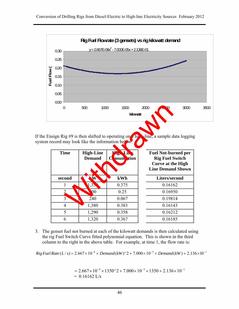
Conversion of Drilling Rigs from Diesel-Electric to High-line Electricity Sources February 2012
46
Rig Fuel Flowrate (3 gensets) vs rig kilowatt demand
y = 2.667E-08x2 - 7.000E-05x + 2.136E-01
0.00
0.05
0.10
0.15
0.20
0.25
0.30
0 500 1000 1500 2000 2500 3000 3500
kilowatt
Fuel F
low
(
If the Ensign Rig #9 is then shifted to operating on a high-line, a sample data logging system record may look like the information below:
Time High-Line Demand
High-Line Consumption
Fuel Not-burned per Rig Fuel Switch
Curve at the High Line Demand Shown
second kW kWh Liters/second
1 1,350 0.375 0.16162
2 900 0.25 0.16950
3 240 0.067 0.19814
4 1,380 0.383 0.16143
5 1,290 0.358 0.16212
6 1,320 0.367 0.16185
3. The genset fuel not burned at each of the kilowatt demands is then calculated using
the rig Fuel Switch Curve fitted polynomial equation. This is shown in the third column to the right in the above table. For example, at time 1, the flow rate is:
158 01136.2)(10000.72)^(10667.2)/( kWDemandkWDemandsLRateFuelRig
158 10136.2135010000.72^135010667.2 = 0.16162 L/s
Withdra
wn
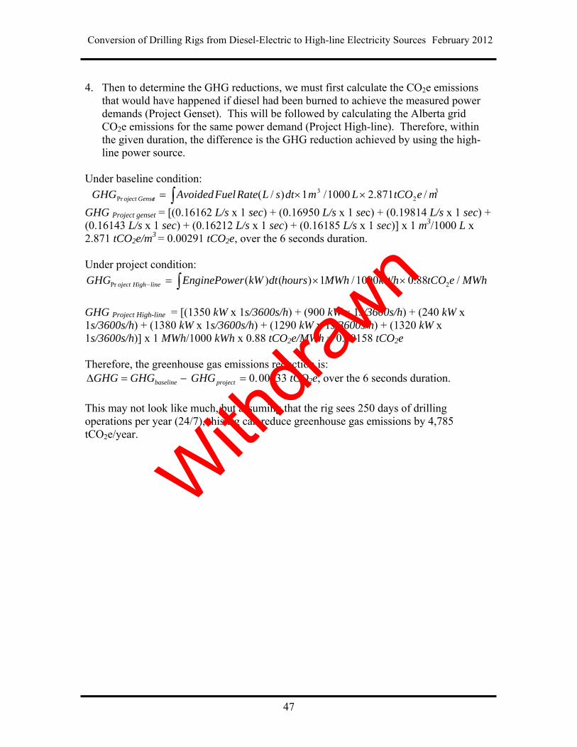
Conversion of Drilling Rigs from Diesel-Electric to High-line Electricity Sources February 2012
47
4. Then to determine the GHG reductions, we must first calculate the CO2e emissions
that would have happened if diesel had been burned to achieve the measured power demands (Project Genset). This will be followed by calculating the Alberta grid CO2e emissions for the same power demand (Project High-line). Therefore, within the given duration, the difference is the GHG reduction achieved by using the high-line power source.
Under baseline condition:
32
3Pr /871.21000/1)/( metCOLmdtsLRateFuelAvoidedGHG tGenseoject
GHG Project genset = [(0.16162 L/s x 1 sec) + (0.16950 L/s x 1 sec) + (0.19814 L/s x 1 sec) + (0.16143 L/s x 1 sec) + (0.16212 L/s x 1 sec) + (0.16185 L/s x 1 sec)] x 1 m3/1000 L x 2.871 tCO2e/m3 = 0.00291 tCO2e, over the 6 seconds duration. Under project condition:
MWhetCOkWhMWhhoursdtkWrEnginePoweGHG lineHighoject /88.01000/1)()( 2Pr
GHG Project High-line = [(1350 kW x 1s/3600s/h) + (900 kW x 1s/3600s/h) + (240 kW x 1s/3600s/h) + (1380 kW x 1s/3600s/h) + (1290 kW x 1s/3600s/h) + (1320 kW x 1s/3600s/h)] x 1 MWh/1000 kWh x 0.88 tCO2e/MWh = 0.00158 tCO2e Therefore, the greenhouse gas emissions reduction is:
.0 projectbaseline GHGGHGGHG 00133 tCO2e, over the 6 seconds duration.
This may not look like much, but assuming that the rig sees 250 days of drilling operations per year (24/7), this rig can reduce greenhouse gas emissions by 4,785 tCO2e/year. With
drawn

Conversion of Drilling Rigs from Diesel-Electric to High-line Electricity Sources February 2012
48
Withdra
wn
Conversion of Drilling Rigs from Diesel-Electric to High-line Electricity Sources February 2012
49
Appendix B: Caterpillar Engine Model 3512 Manufacturer’s Data
Withdra
wn

Conversion of Drilling Rigs from Diesel-Electric to High-line Electricity Sources February 2012
50
Withdra
wn
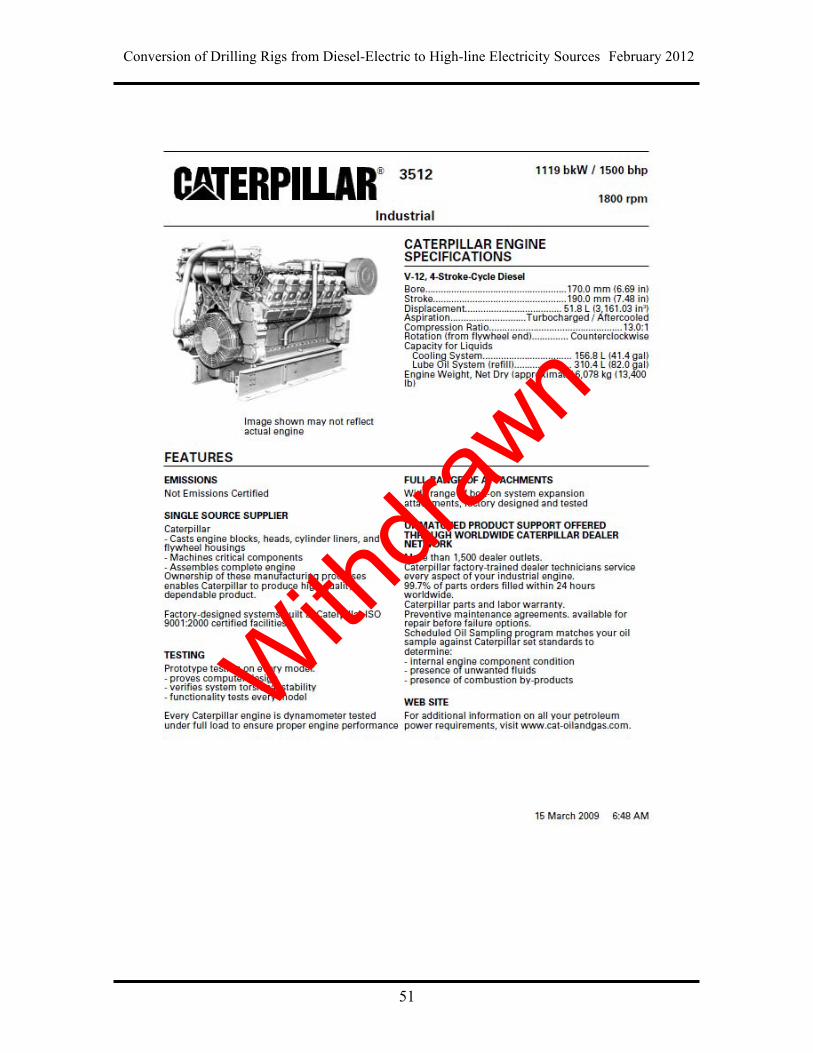
Conversion of Drilling Rigs from Diesel-Electric to High-line Electricity Sources February 2012
51
Withdra
wn
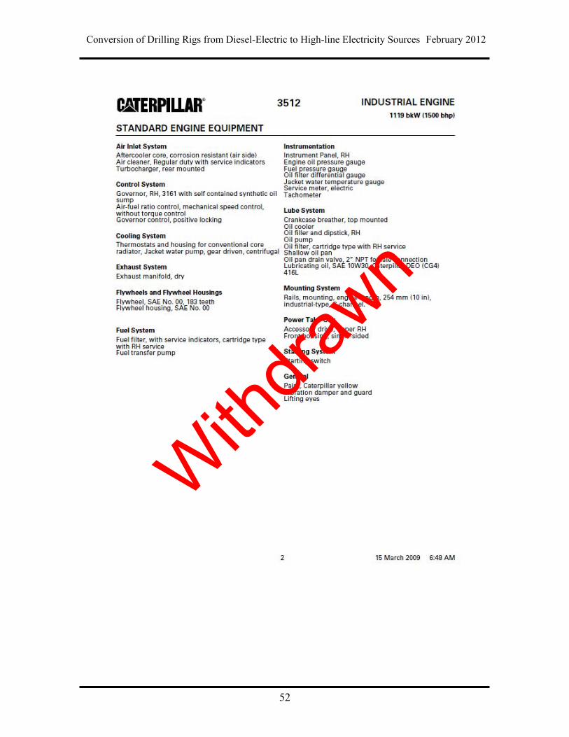
Conversion of Drilling Rigs from Diesel-Electric to High-line Electricity Sources February 2012
52
Withdra
wn
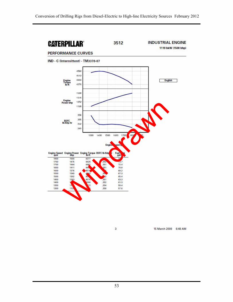
Conversion of Drilling Rigs from Diesel-Electric to High-line Electricity Sources February 2012
53
Withdra
wn
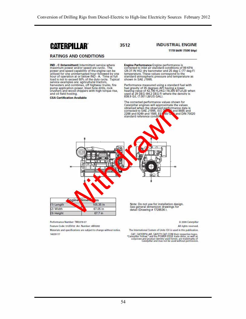
Conversion of Drilling Rigs from Diesel-Electric to High-line Electricity Sources February 2012
54
Withdra
wn
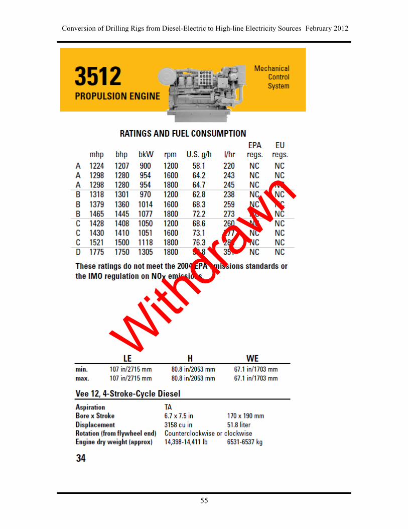
Conversion of Drilling Rigs from Diesel-Electric to High-line Electricity Sources February 2012
55
Withdra
wn
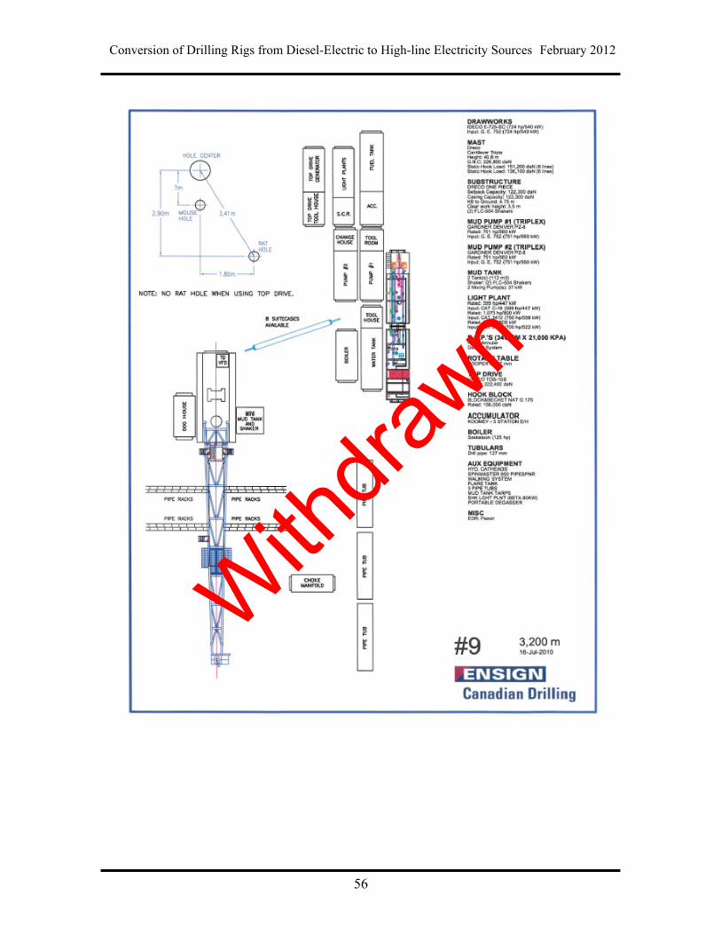
Conversion of Drilling Rigs from Diesel-Electric to High-line Electricity Sources February 2012
56
Withdra
wn