magnetic reversal of a quantum nanoferromagnet
TRANSCRIPT
PHYSICAL REVIEW B 87, 195402 (2013)
Magnetic reversal of a quantum nanoferromagnet
J. P. Gauyacq1 and N. Lorente2
1Institut des Sciences Moleculaires d’Orsay, ISMO, Unite Mixte de Recherches CNRS–Universite Paris-Sud, UMR 8214,Batiment 351, Universite Paris-Sud, 91405 Orsay Cedex, France
2Centre d’Investigacio en Nanociencia i Nanotecnologia (CSIC-ICN), Campus de la UAB, E-08193 Bellaterra, Spain(Received 8 February 2013; published 1 May 2013)
When the external magnetic field applied to a ferromagnetically coupled atomic chain is reversed suddenly,the magnetization of the chain switches, due to the reversal of all the atomic magnetic moments in the chain. Thequantum processes underlying the magnetization switching and the time required for the switching are analyzedfor model magnetic chains adsorbed on a surface at 0 K. The sudden field reversal brings the chain into anexcited state that relaxes towards the system ground state via interactions with the substrate electrons. Differentmechanisms are outlined, ranging from the global stepwise rotation of the chain macrospin induced by spin-flipcollisions with substrate electrons in the pure Heisenberg chain (Neel-Brown process) to a correlation-mediateddirect switching process in the presence of strong magnetic anisotropies in short chains (the global spin of thechain reverses in a single electron interaction). The processes for magnetization switching induced by electronstunneling from a scanning tunneling microscope tip are also analyzed.
DOI: 10.1103/PhysRevB.87.195402 PACS number(s): 68.37.Ef, 75.60.Jk, 75.75.Jn, 72.25.−b
I. INTRODUCTION
The fast development of miniaturization of electronic de-vices prompted an active series of studies on the structure anddynamics of small low-dimensional magnetic objects adsorbedon surfaces. Among these, the magnetization reversal of smallobjects received much attention because of its links with datastorage, and indeed, it is quite important to understand and beable to represent the processes underlying the reversal. Themagnetization reversal in ferromagnetic materials (magneticswitch of small magnetic domains) was described theoreticallyvery early by Neel and Brown.1,2 Basically, the idea is thatall the magnetic moments are aligned in small magneticdomains to form a classical macrospin that rotates as awhole. The dynamics of the spin can be described withinthe Landau-Lifshitz-Gilbert equation and lead to a descriptionof the thermally induced magnetization reversal process. Thedevelopment of spin-polarized scanning tunneling microscopy(SP-STM) led to detailed observations of the thermallyinduced magnetic switch in small ferromagnets, allowing a de-tailed test of the global rotation of the Neel-Brown view and ofits limits.3–10 In parallel, analyses led to the discussion of otherviews of the thermally activated magnetization switch,10–17
for example, spin-wave contributions, nucleation, edge effects,and anisotropy effect. Following earlier works on multilayeredmaterials,18,19 SP-STM experiments revealed that injection ofspin-polarized electrons into a nanoferromagnet could alsoswitch its magnetization.20–24 A similar process has beenobserved and modeled recently on adsorbed antiferromagneticchains: The switch between the two Neel states of the chaincan be induced by tunneling electrons from an STM tip.25,26
These works open the way toward the fascinating possibilityof controlling the magnetization of small objects at surfaces.Various processes have been proposed and discussed for theelectron-induced magnetic reversal:20–24 spin-transfer torque(the incident electron brings spin momentum to the object),Joule heating (the injected electrons locally heat the object,speeding up thermal reversal), and the Oerstedt field effect (theinjected electron current generates a magnetic field that can
influence the reversal), all possibly associated with quantumtunneling.
Recently, series of experimental27–30 and theoretical31–37
works have been reported on magnetic transitions induced bytunneling electrons in individual adsorbates, leading towarda full understanding of the magnetic dynamics at the atomiclevel and their possible control by electrons. A similar processhas also been studied experimentally: the relaxation of excitedmagnetic states in adsorbates.38–40 Indeed, in the case ofsupported magnetic objects, electrons from the substratecontinuously collide with adsorbates and go back into thesubstrate, and they can induce magnetic transitions in theadsorbate in a similar manner as tunneling electrons; inthis way, an excited magnetic state can be de-excited by anelectron-hole pair creation35,41,42 (see a review in Ref. 43). Inboth cases (excitation and de-excitation), an electron, possiblypolarized, colliding on a magnetic adsorbate induces magnetictransitions, i.e., changes the magnetic state of the adsorbate.This aspect bears strong resemblances with the problemof magnetization switch in small objects briefly discussedabove; it is either induced by thermal processes (interactionwith a thermal bath, the substrate electrons) or by tunnelingelectrons. The theoretical works devoted to the analysis ofthis excitation/de-excitation process in individual adsorbatesat a surface have been based on full quantum microscopicapproaches of the nanomagnetic properties. The aim of thepresent work is to see how these quantum microscopic studiescan be transferred to studies of magnetization reversal inadsorbed nanoferromagnets and how they can describe thecorresponding processes.
In the present work, we report on a theoretical model studyof the magnetization switch of a small ferromagnetic object,an adsorbed chain of atoms, under the reversal of the directionof an applied magnetic field, B. The small object is initiallyat equilibrium at 0 K for a finite B field pointing in a givendirection, and the B field direction is suddenly reversed. Suchan inversion of an applied field, similar to a quantum quench,allows us to study the fast time behavior far from equilibrium of
195402-11098-0121/2013/87(19)/195402(15) ©2013 American Physical Society
J. P. GAUYACQ AND N. LORENTE PHYSICAL REVIEW B 87, 195402 (2013)
a small ferromagnetic domain. The domain switch, both via theinteraction with substrate electrons and via electrons injectedby an STM tip, is discussed. Our study considers finite chainsof atomic spins and is of model character. It is based on thestrong coupling approach recently introduced to treat magnetictransitions induced by tunneling electrons in adsorbates andrelaxation of magnetic excitation by electron-hole pair creationin the substrate.34,41,43,44
II. METHOD
The present work uses the strong coupling approach,which has been developed to treat the excitation of individualmagnetic adsorbates at surfaces by tunneling electrons34,43,44
and extended to treat the electron-induced magnetic excitationsin chains45 as well as the lifetime of magnetic excitations.41,46
It is only briefly presented here.The finite-size chain of ferromagnetically coupled local
spins is described by the magnetic Hamiltonian, HMag:
HMag =N−1∑i=1
J �Si.�Si+1 +∑
i
[DS2
i,z + E(S2
i,x − S2i,y
)]
+∑
i
gμB�Si. �B, (1)
where �Si is the spin of the atom i in the chain, and J is theHeisenberg exchange coupling (J < 0 for the ferromagneticchains considered here). Only couplings between first neigh-bors are included. D and E terms are anisotropy terms (see adiscussion of their origin in Ref. 47), g is the gyromagnetic fac-tor, and μB is the Bohr magneton. The applied B field is takenalong the anisotropy z axis. Two applications are presentedhere, a pure Heisenberg chain (D = E = 0) of local spins 1
2(Sec. III) and a chain of local spins 2 with anisotropy (Sec. IV).
The eigenenergies, Ej , and eigenvectors, |�j 〉, of theHamiltonian [Eq. (1)] are obtained by diagonalization in thebasis set formed by direct products of eigenstates of �S2
i andSi,z, the squared modulus and projections on the z axis of thelocal spins: |M1,M2, . . . ,MN−1,MN 〉 (Mi is an eigenvalue ofthe Si,z operator). This diagonalization step is performed usinga standard library routine for the low N cases discussed here.The magnetic transitions induced by collision of an electron onthe chain are described in the strong coupling approximation:The evolution induced by the interaction terms in the magneticHamiltonian is slow, much slower than the collision process,so that one can resort to a sudden approximation in which thecollision only concerns the electron and one atom in the chain.The scattering amplitude, T , is then diagonal in the basis setformed by the eigenstates of �S2
T and ST,z (quantum numbers,ST and MT ), where �ST is the total spin of the scatteringatom + electron system. Only two ST values are possible: ST =S ± 1/2. The transition amplitude from a state of the chain|�i〉 to a state |�f 〉 induced by collision with an electron(the projection of the electron spin on the quantization z axischanges from mi to mf ),Ai,mi→f,mf
, is then written as:
Ai,mi→f,mf=
∑MT ,ST
〈mf ,�f |ST ,MT 〉T ST 〈ST ,MT |mi,�i〉,
(2)
where T ST is the amplitude for the transmission of the electronin the symmetry ST . Note that this amplitude only containsspin coupling matrix elements and the T ST amplitudes. It cancorrespond to a tunneling process (electrons transmitted fromtip to substrate) or to a scattering process (substrate electronsscattered by one atom of the chain). Note that this formalism isequivalent to that commonly used to treat rotational excitationof molecules (free or adsorbed)48–50 by electrons, where theorbital angular momentum plays a role analogous to that ofthe spin angular momentum.
A. Excitation by tunneling electrons
Let us first consider the case of the excitation of thechain by a tunneling electron. In the various systems onwhich we performed an ab initio study of the tip-substratetransmission,34,44 we found that only one symmetry ST isactive, so that Eq. (2) simplifies into the simple product ofa global flux factor |T ST |2 and a spin coupling factor thatdepends on the initial and final states. From this, one gets theprobabilities for the various excitations of the chain from state|�i〉, induced by an electron tunneling through one atom inthe chain:
PExc(i → f )
=∑
mi,mf
∣∣∣∣∑MT
〈mf ,�f | ST ,MT 〉〈ST ,MT |mi,�i〉∣∣∣∣2
, (3)
where the sums over mi and mf depend on the conditions of thepolarization of the tip and substrate. The normalization of theprobabilities in Eq. (3) is the following: for nonpolarized tipand substrate, for a given i, the sum including both valuesof ST is equal to 2 (the spin degeneracy in the incidentchannel). The projections in Eq. (3) and the similar ones inSec. II B are evaluated in the basis set built on local spins(|M1,M2, . . . ,MN−1,MN 〉), in which both ST and �i states areexpressed.
In the applications presented below, we chose two modelsystems for which we assumed that only one ST symmetrywas active in the excitation process. In Sec. III, we considerchains of spins 1
2 with the tunneling symmetry ST = 0, andin Sec. IV, we consider chains of spins 2, with the tunnelingsymmetry ST = 3/2.
B. Lifetime of magnetic excitations
Let us now consider the de-excitation of an excited stateof the chain by scattering of a substrate electron. A chain ofmagnetic atoms adsorbed on a surface is continuously hit byelectrons from the substrate that are scattered back into thesubstrate. At very low T , this collision cannot excite the chain,but it can very efficiently induce de-excitations of excited statesof the chain. This decay process can be described as inducedby electron-hole pair creation.
The lifetime of an excited magnetic state �i of the chain,τi (inverse of its total decay rate, �Tot,i), can be expressedfor a vanishing temperature from the T transition matrix forelectron scattering by one of the atoms in the chain as (see
195402-2
MAGNETIC REVERSAL OF A QUANTUM NANOFERROMAGNET PHYSICAL REVIEW B 87, 195402 (2013)
discussion in Refs. 41,46,51):
1
τi
= �Tot,i =∑f
�i,f =
=∑f
2πδ�f
h
∑ki ,kf ,mi ,mf
|〈kf ,mf ,�f |T |ki,mi,�i〉|2
× δ(εi − εf )δ(εi − EF ), (4)
where �i,f is the partial decay rate of state i towards the lower-lying states f ; �f is the final state of the decay, associatedto the energy transfer δ�f = Ei − Ef . The total energy is
ET = Ei + εi = Ef + εf . The initial state and final state ofthe substrate electrons are labeled by their energy εi and εf ,their wave number, ki and kf , and by their spin projectionson the quantization axis, mi and mf . Equation (4) is derivedunder two assumptions (see details in Refs. 41,46,51): (i)the system temperature is assumed to vanish, and (ii) the T
transition matrix elements are assumed to be constant in thesmall energy interval involved in the decay process. In thestrong coupling approach, the T matrix can be expressed asdiagonal terms in the tunneling ST symmetries [Eq. (2) above].The decay rate can then be expressed as:
1
τi
=∑f
2πδ�f
h
∑ki ,kf ,mi ,mf
δ(εi − εf )δ(εi − EF )
∣∣∣∣∣∑ST
〈kf |T ST |ki〉∑MT
〈mf ,�f |ST ,MT 〉〈ST ,MT |mi,�i〉∣∣∣∣∣2
=∑f
2πδ�f
h
∑ki ,kf ,mi ,mf
δ(εi − εf )δ(εi − EF )
∣∣∣∣∣∑ST
⟨kf
∣∣ T ST |ki〉AST
i,mi→f,mf
∣∣∣∣∣2
. (5)
This expression incorporates the two possible values of ST
and the corresponding interference effects. It can be furthersimplified if only one ST symmetry is considered to be activein the de-excitation process. In that case, Eq. (5) reduces tothe product of a flux factor and a spin coupling factor.41,43
For the present model study, we assumed that the two ST
symmetries contribute to the decay, and, similar to Ref. 41, weused a statistical expression neglecting the interference termsbetween transitions within the two ST symmetries that can beseen in Eq. (5). Finally, the decay rate of state i is obtained as:
1
τi
=∑f
�i,f = Ttotal(EF )∑f
δ�f
hPSpin(i → f ), (6)
where Ttotal(EF )/h is the total electron flux hitting theadsorbate per unit of energy and per unit of time; it appears asa general factor for the decay rate of all magnetic states in thesystem.
It is given by:
Ttotal(EF )
=∑ST
(2π )2∑ki ,kf
δ(εi − εf )δ(εi − EF )|〈kf |T ST |ki〉|2. (7)
PSpin(i → f ) is a mean decay efficiency over the two ST
symmetries, and it only depends on spin coupling coefficients.The above expression corresponds to decay by scattering ofa substrate electron on one given atom in the chain, andcontributions for the different atoms have to be added. Inthe case of an open chain of atoms, these contributions area priori different for the different sites in the chain via thePSpin(i → f ) factor, leading to a global PSpin(i → f ) factor.From Eq. (6), one can deduce the branching ratio for the decayof state i to a lower-lying state j , as:
Pdecay(i → j ) = �i,j∑f
�i,f
= δ�j PSpin(i → j )∑f
δ�f PSpin(i → f ). (8)
Note that these branching ratios only depend on the energydefect of the decay and on spin coupling coefficients and not onthe absolute strength of the coupling to the substrate governedby Ttotal(EF )/h.
In the model applications below, we took a numerical valueof Ttotal(EF ) equal to 1, similar to what we found in the caseof single Mn adsorbates on CuN/Cu(100) surfaces.41 It shouldbe representative of magnetic adsorbates separated from ametal surface by an ultrathin insulator layer and thus onlyweakly coupled to the substrate. In the case of magnetic atomsdirectly adsorbed on a metal surface, the interaction with thesubstrate electrons is much stronger, leading to much shorterlifetimes35,52–54 and possibly to different behaviors.55
C. Rate equation for the population dynamics
To describe the dynamics of the magnetization of aferromagnetic chain, we used a semiclassical rate equationapproach. It consists in describing the evolution of thepopulation of the different states of the chain as functionsof time, t , due to both the relaxation of the excited state’spopulation via electron-hole pair creation and/or excitation bytunneling electrons. This approach has been very successfullyapplied in several studies of magnetic state dynamics.38,41,56,57
Basically, it only considers populations and thus neglects allkinds of coherence effects between the various decays orexcitations by successive electrons. The time evolution of thepopulations, Popi(t), of the different states i due to relaxationis given by the rate equation:
dPopi(t)
dt= −Popi(t)
⎛⎝∑
j �=i
�i,j
⎞⎠ +
∑j �=i
P opj (t) �j,i ,
(9)
where �i,j is the partial decay rate of state i towards statej (Sec. II B). Equation (9) is solved numerically using anexponential approximation of the population decay for finite
195402-3

J. P. GAUYACQ AND N. LORENTE PHYSICAL REVIEW B 87, 195402 (2013)
time steps. In the applications below, the effect of tunnelingelectrons was modeled as the periodic injection of an electronin the junction. This does not represent a real random flowof electrons but has the advantage of being very efficient invisualizing the effect of relaxation and of tunneling electronsseparately. The instantaneous injection of an electron in thejunction at time t leads to a sudden change in the variouspopulations, Popi equal to:
Popi = −Popi(t)∑j �=i
C PExc(i → j )
+∑j �=i
P opj (t) C PExc(j → i), (10)
where PExc(i → j ) is given by Eq. (3), and C is a normalizationconstant.
In the applications below, we chose to mimic the situationof an STM tip located above an atom in the chain, at constantheight, with a constant bias; as a result of the magnetic fieldsudden reversal at t = 0, the system is initially in the upper stateof the STot = N/2 manifold, i.e., only one state is populated.The constant coefficient C in Eq. (10) is chosen such thatEq. (10) corresponds to the injection of a single electron, attime t = 0. The number of injected electrons then varies alongthe relaxation according to the variation of the magnetic state ofthe chain, because of the variation of the junction conductancewith the population of the various states of the chain (seeSec. III D) and similar effects due to excited state populationin Refs. 38,41,56,57).
III. FINITE-SIZE HEISENBERG CHAIN
In a first step, we consider the simple case of a chain of N
spins 1/2 with a Heisenberg exchange coupling between firstneighbors. The local spin at site i is �Si , and its projection onthe quantization z axis is Siz. The magnetic Hamiltonian of thesystem in the presence of an applied magnetic field, �B, alongthe z axis, is:
HMag =N−1∑i=1
J �Si�Si+1 +
N∑i=1
g μB SizBz, (11)
where g is the gyromagnetic factor, and μB is the Bohrmagneton. The total spin of the chain is given by: �STot = ∑
i�Si .
In the numerical application below, we took a g factor equal to2 and an Heisenberg coupling equal to 6 meV. In the absenceof a B field, the ground state of the system is the degeneratestate of maximum total spin: STot = N/2 (quantum numbersMTot = STot,z). In a finite field, the ground state splits in N +1 components according to the Zeeman effect. The magneticswitch, i.e., the reversal of the magnetic field direction, thusleads to the inversion of the order of the sublevels inside theSTot subspace; the instantaneous reversal of the B field leads tothe population of the highest sublevel of the Zeeman structure,which then relaxes down to the lowest sublevel, i.e., to therelaxation from MTot = N/2 to the MTot = − N/2 sublevel.For a chain adsorbed on a surface, the relaxation occurs byelectron-hole pair creation with the selection rule MTot =± 1, i.e., the population cascades down the Zeeman structurewith MTot = − 1 jumps. Higher-lying states with other values
of the STot are not involved at 0 K, for a low applied field.2 Onecan then view the magnetic switch in this case as the globalquantum rotation of the total spin of the chain in 2N quantumjumps, exactly corresponding to the Neel-Brown view. It alsocorresponds to the case studied recently by Wang and Sham;58
a stochastic Schrodinger equation approach allowed themto follow the quantuml trajectory of the magnetization anddiscuss the associated noise.
A. Magnetization switch induced by interactionwith the substrate
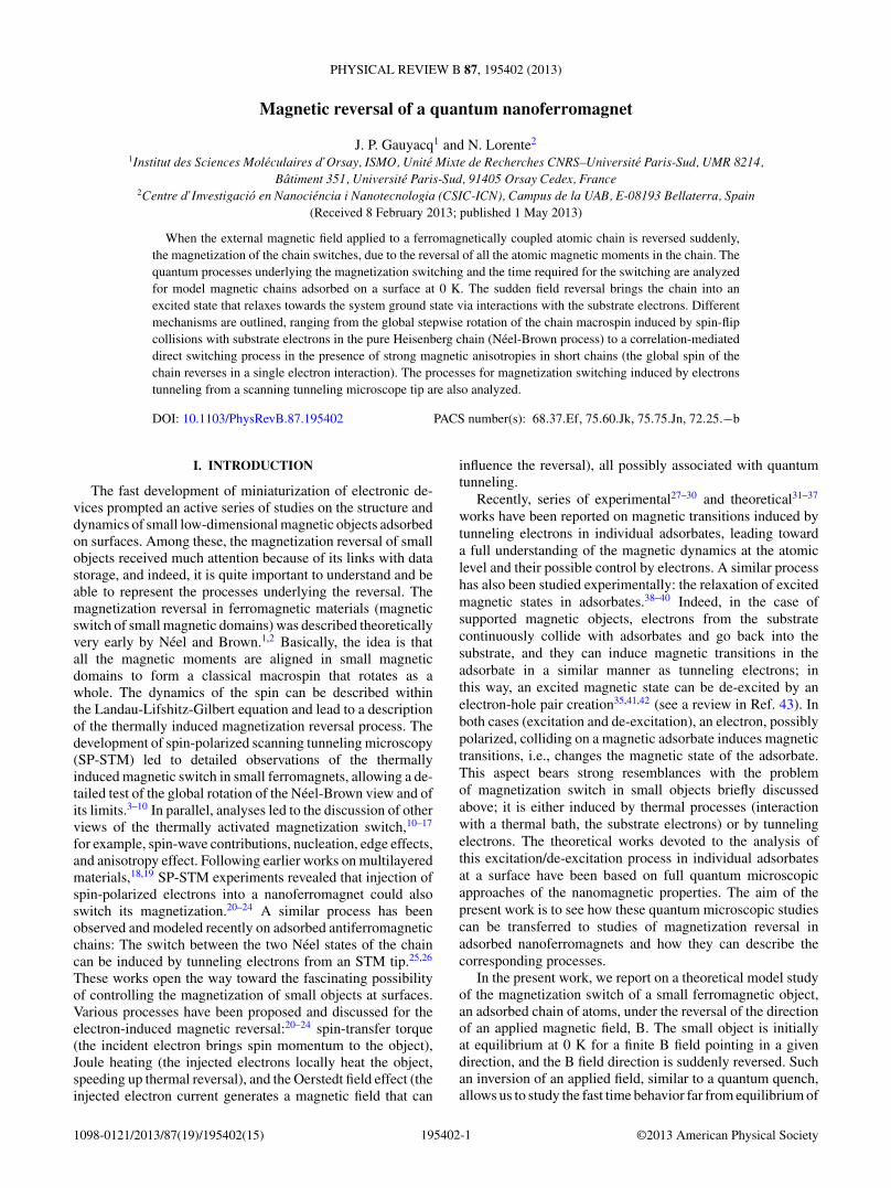
The method outlined in Sec. II enables us to evaluatethe rate for the various jumps and thus to describe the timedependence of the magnetization of the chain as a functionof time following the sudden B field reversal for a vanishingtemperature. Figure 1 presents the time dependence of thevarious sublevels in the STot = N/2 subspace in the case ofa chain of N = 12 atoms and an applied B field of 0.1 T.The flux factor T (E) (see Sec. II) is taken equal to 1, so thatthe timescale is characteristic of a spin chain adsorbed on anultrathin insulator on a metal substrate (see a discussion in thereview Ref. 43). At time t = 0, the system is in the highest level(MTot = +6), and the corresponding population decreasesexponentially, leading to a population of all the sublevelsand ultimately to the only population of the ground state(MTot = −6). This results in effective time delays betweenthe various states in the manifold; they appear and disappearsuccessively (the complete magnetization switch requires N
transitions, i.e., 12 transitions in the case of Fig. 1). The groundstate is not populated immediately after the B reversal; it startsto be populated only after around 3 ns in Fig. 1. However, onecan notice that several states are populated at the same time;typically around 4 ns, all states are populated significantly,
0 5 10 15Time (ns)
0
0.2
0.4
0.6
0.8
1
Popu
latio
ns
FIG. 1. (Color online) Populations of the 13 sublevels of theSTot = 6 lowest manifold of a chain of 12 atoms as a function oftime following the reversal of the direction of the applied B field(0.1 T). The system is initially in the highest state of the manifold(MTot = + 6, full green line) and relaxes to the ground state (MTot =− 6, full cyan line). The populations of the various MTot states appearand disappear successively. The population of the central state of themanifold (MTot = 0) is shown in red.
195402-4
MAGNETIC REVERSAL OF A QUANTUM NANOFERROMAGNET PHYSICAL REVIEW B 87, 195402 (2013)
and it is only in the early and late times that only one state ispopulated.
B. Dependence of the magnetization switch time on the chainlength (long chains)
We studied the variation of the magnetization dynamicswith the length of the spin chain numerically following Sec. IIfor short chains (N < 16). For longer chains, the numberof states to be considered becomes excessively large, andwe switched to an analytical approach only considering theprocess at low field and thus only computing the transitionsamong the sublevels of the ground manifold, STot = N/2. Letus consider one of these sublevels, with MTot = N/2 − j . Itsdecay by collision with the substrate electrons only populatesthe sublevel just below in the manifold, i.e., MTot = N/2 −j − 1. Considering the spin coupling element at play and thefact that the energy associated with all these individual decaysis equal to E = gμBB, we find the following decay rate forthe MTot = N/2 − j sublevel:
�(MTot = N/2 − j )
=[T (E) E
8π
](j + 1)(N − j )
N, j = 0,N. (12)
The term between brackets is the decay rate of the highestmember of the manifold (j = 0), and the second term yieldsthe dependence of the decay rate along the manifold. The ratemaximizes at the center of the manifold. One recognizes that,via the E term, the decay rate is proportional to B, so that theswitch should speed up with increasing applied B. Actually, theonly factors that are specific to a given system in Eq. (12) arethe T (E) flux factor, g the gyromagnetic factor, and the appliedfield B. In particular, all these decay rates are independent ofthe Heisenberg coupling, J , so that the behavior defined inEq. (12) is rather general.
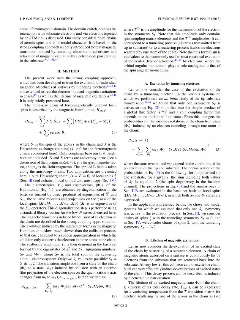
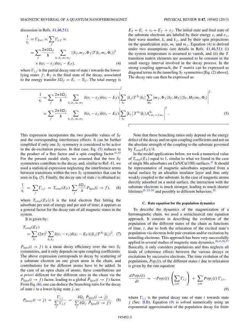
The lower panel of Fig. 2 presents the population of theground state of the system for various chain lengths as afunction of time after the reversal of the B direction (B =0.1 T). The time for a magnetization switch increases with thelength of the chain. Actually, the various population curvesappear to be roughly translated one from the other so thatthe increase of the magnetization switch time looks like anincreased time delay for the rise of the ground-state population.All this is not so surprising since complete switching requiresa number of transitions equal to N ; however, the decay rateof each individual state depends on the chain length, so theglobal behavior was not obvious. The upper panel of Fig. 2presents the magnetization switch in another way; it presentsthe average magnetic moment of the chain (mean value ofthe projection of �STot on the B field axis, 〈M〉), normalized toits maximum value as a function of time. It goes from + 1(highest state) at the time of the B reversal to − 1 (groundstate) for asymptotically long times. From Fig. 2, one candefine a switching time in different ways; one can define thetime, T (〈M〉 = 0), at which the chain magnetic moment iszero, which could be thought of as a half switch. One can alsolook at the time, T (90%), at which the population of the groundstate is equal to 90%, i.e., when the switch is almost complete.Figure 3 presents these two “switching times” (2T [〈M〉 = 0]and T [90%]) as a function of the number of atoms in the chain
0 10 20 30Time (ns)
0
0.2
0.4
0.6
0.8
1
Popu
latio
n
−1
−0.5
0
0.5
1
Mag
netiz
atio
n
N = 10N = 20N = 50N = 100N = 200N = 1000
FIG. 2. (Color online) Upper panel: variation of the magneticmoment of a chain of N atoms as a function of the time followingthe reversal of the direction of the applied magnetic field (0.1 T).The magnetic moment is plotted relative to its maximum value. Thenumber of atoms in the chain is given in the insert (the shorterthe chain, the faster the magnetic switch). Lower panel: variationof the population of the ground state of a chain of N atoms as afunction of the time following the reversal of the direction of theapplied magnetic field (0.1 T). Same color code as in the upper panel(the shorter the chain, the faster the magnetic switch).
(field B = 0.1 T). It appears that the two switching times,though numerically different as expected, exhibit the samelogarithmic behavior as a function of N , for large enough N .
At this point, one can stress that the decay rate given byEq. (12) is actually obtained by only considering the wavefunctions of the STot = N/2 manifold and the energy differencebetween two neighboring states in the manifold. The T (E)flux factor appears as a global factor. So any ensemble of spins
1 10 100 1000Chain length
0
5
10
15
20
25
Switc
hing
tim
e (n
s)
2 T (<M>=0)T (90%)
FIG. 3. (Color online) Switching time of the magnetization of achain of atoms when the direction of the applied B field (0.1 T) isreversed, as a function of the chain length (number of atoms in thechain). Two definitions of the switching time are shown: twice thetime for the magnetic moment of the chain (projection on the fieldaxis) to reach zero (2T [〈M〉 = 0]) and the time for the population ofthe ground state to reach 90%, T (90%).
195402-5

J. P. GAUYACQ AND N. LORENTE PHYSICAL REVIEW B 87, 195402 (2013)
12 , coupled by an Heisenberg Hamiltonian with a ground-statemanifold corresponding to STot = N/2, will behave in the sameway, and the dynamics under the reversal of an applied B fieldwill be the same, irrespective of its actual structure (open chainor ring) and dimensionality (one-dimensional [1D] chain ortwo-dimensional [2D] adsorbed island). In particular the logN behavior of the switching time (global rotation) should bea general feature of the Heisenberg systems.
C. Magnetization switching at high magnetic field
A change of the strength of the B field in the low-field rangeonly leads to a scaling effect on the time behavior. Indeed, asdiscussed in Sec. II and seen in Eq. (12), the decay rates ofthe various states are obtained as products of a term onlydepending on spin couplings and of an energy difference termthat is proportional to B. As a consequence, when B is changed,the time dependencies in Fig. 1 are identical if the time isscaled proportionally to B (the larger B, the faster the timeevolution). For the N = 12 chain, this remains true as long asthe B field is small enough for the decay to only concern thesublevels of the STot = 6 subspace. However, for very large B,the higher-lying STot = 6, MTot = 6 sublevel crosses levels ofhigher-lying manifolds (different values of STot), opening newdecay routes for the higher-lying states and thus shorteningthe magnetic switch time. This is illustrated in Fig. 4, whichpresents the population of the ground state of an N = 12 chainas a function of a scaled time for various values of the appliedB field. The scaled time is equal to the product of the physicaltime (in ns) and the applied B field (in tesla). At low fields, allthe curves in Fig. 4 fall on each other and are represented bythe single 0.1 T curve. As B is increased, the magnetic switchbecomes faster in scaled time above a certain threshold; inFig. 4, the curve B = 2 T is slightly above the threshold and is
0 0.5 1 1.5Scaled time (ns T)
0
0.2
0.4
0.6
0.8
1
Popu
latio
n
B = 0.1 TB = 2 TB = 5 TB = 10 TB = 15 T
FIG. 4. (Color online) Population of the ground state of a chainof 12 atoms as a function of a scaled time following the reversal of theapplied B field direction. The scaled time is equal to the product ofthe physical time in nanoseconds and the field strength expressed inTesla. Various strengths of the B field are shown (see insert). At lowfields, all the population curves are superimposed and represented bythe dashed line, which shows the results for 0.1 T; as the B field isincreased, the ground-state population increases earlier.
associated with a tiny shortening of the magnetization switch;the larger B field cases (10 and 15 T) exhibit a very clearshortening. One can stress that the threshold for this effect islinked to a comparison between the Heisenberg structure andthe Zeeman structure, and as such, its value depends on theexchange coupling, J , as well as on the precise structure ofthe system (chain or ring); this is at variance with the timedependence of the decay at low field (Figs. 1 and 2), which iscompletely independent of the strength of the ferromagneticHeisenberg coupling. The new decay route appears when statesin the ground manifold (STot = 6) cross states from a highermanifold (STot = 5); then the selection rules for a transitioninduced by an electron (STot = 0, ± 1; MTot = 0, ± 1) canbe fulfilled, and the population cascade a priori also involvesstates from the (STot = 5) manifold. The lowest states in theSTot = 5 manifold correspond to spin waves quantized in thefinite-size chain. As discussed in Ref. 45, tunneling electronsare very efficient in exciting spin waves in a Heisenberg spinchain, and furthermore the spin waves are the only statesexcited by tunneling electrons; similarly, in the present study,substrate electrons are very efficient in pumping the populationfrom the ground manifold to the spin waves. The shortening ofthe magnetization time switch seen in Fig. 4 then correspondsto the combined action of two switch mechanisms, bothinduced by collisions with electrons from the substrate: theglobal rotation of the ferromagnet and the decay via spin waveexcitation.
D. Magnetization switch induced by injected electrons
The above discussion of the effect of the strength of themagnetic field (Fig. 4) stresses the efficiency of the spin wavesfor accelerating a magnetization switching. This phenomenoncan be further put forward by considering the action oftunneling electrons injected from an STM (scanning tunnelingmicroscope) tip into one of the atoms in the chain. To mimicthe effect of a current of tunneling electrons, we studied themagnetization switching of a chain of atoms when an electronis injected periodically (constant time interval dt) into one ofthe atoms of the chain. The injected electron is supposed tobe fully polarized in the spin down state with respect to thequantization axis. This simple scheme neglects the randomaspect of electron tunneling. However, it should carry the mainphysical characteristics of the electron-induced magnetizationswitch; in addition, it allows easy visualization of the relativerole of relaxation by electron-hole pair creation and excitationby tunneling electrons. The evolution of the populations ofthe magnetic states in the chain is then governed by twoaspects: relaxation inside the manifold STot = N/2 inducedby collisions with the substrate electrons (see above sections),and periodic kicks induced by the tunneling electrons. TheSTM bias is chosen to be larger than all the excitationthresholds. In the case of a ferromagnetic chain, excitationby tunneling electrons from states in the STot = N/2 manifoldonly leads to spin-wave excitations that relax very quickly tothe lower STot = N/2 manifold, at least on the timescale of themagnetization switching (see Refs. 45 and 46 for a discussionof the excitation of ferromagnetic chains by tunneling electronsand of the excited state lifetimes). Excitations from the spin
195402-6
MAGNETIC REVERSAL OF A QUANTUM NANOFERROMAGNET PHYSICAL REVIEW B 87, 195402 (2013)
0 2 4 6 8 10 12Time (ns)
0
0.2
0.4
0.6
0.8
1Po
pula
tions
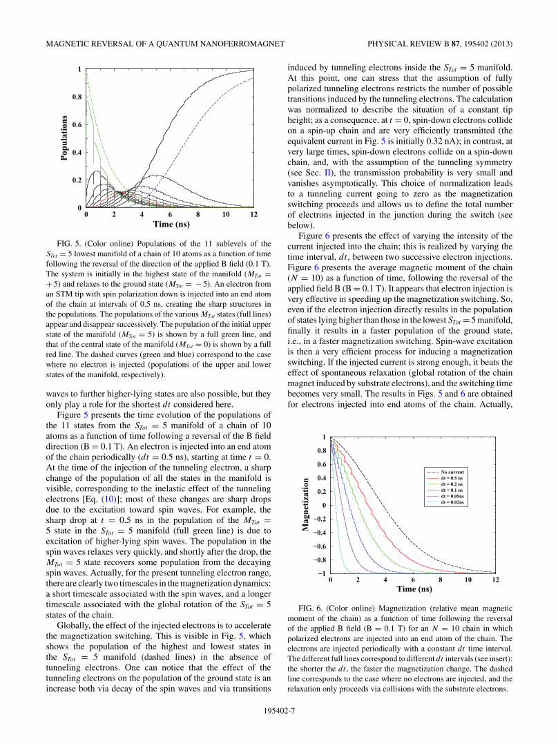
FIG. 5. (Color online) Populations of the 11 sublevels of theSTot = 5 lowest manifold of a chain of 10 atoms as a function of timefollowing the reversal of the direction of the applied B field (0.1 T).The system is initially in the highest state of the manifold (MTot =+ 5) and relaxes to the ground state (MTot = − 5). An electron froman STM tip with spin polarization down is injected into an end atomof the chain at intervals of 0.5 ns, creating the sharp structures inthe populations. The populations of the various MTot states (full lines)appear and disappear successively. The population of the initial upperstate of the manifold (MTot = 5) is shown by a full green line, andthat of the central state of the manifold (MTot = 0) is shown by a fullred line. The dashed curves (green and blue) correspond to the casewhere no electron is injected (populations of the upper and lowerstates of the manifold, respectively).
waves to further higher-lying states are also possible, but theyonly play a role for the shortest dt considered here.
Figure 5 presents the time evolution of the populations ofthe 11 states from the STot = 5 manifold of a chain of 10atoms as a function of time following a reversal of the B fielddirection (B = 0.1 T). An electron is injected into an end atomof the chain periodically (dt = 0.5 ns), starting at time t = 0.At the time of the injection of the tunneling electron, a sharpchange of the population of all the states in the manifold isvisible, corresponding to the inelastic effect of the tunnelingelectrons [Eq. (10)]; most of these changes are sharp dropsdue to the excitation toward spin waves. For example, thesharp drop at t = 0.5 ns in the population of the MTot =5 state in the STot = 5 manifold (full green line) is due toexcitation of higher-lying spin waves. The population in thespin waves relaxes very quickly, and shortly after the drop, theMTot = 5 state recovers some population from the decayingspin waves. Actually, for the present tunneling electron range,there are clearly two timescales in the magnetization dynamics:a short timescale associated with the spin waves, and a longertimescale associated with the global rotation of the STot = 5states of the chain.
Globally, the effect of the injected electrons is to acceleratethe magnetization switching. This is visible in Fig. 5, whichshows the population of the highest and lowest states inthe STot = 5 manifold (dashed lines) in the absence oftunneling electrons. One can notice that the effect of thetunneling electrons on the population of the ground state is anincrease both via decay of the spin waves and via transitions
induced by tunneling electrons inside the STot = 5 manifold.At this point, one can stress that the assumption of fullypolarized tunneling electrons restricts the number of possibletransitions induced by the tunneling electrons. The calculationwas normalized to describe the situation of a constant tipheight; as a consequence, at t = 0, spin-down electrons collideon a spin-up chain and are very efficiently transmitted (theequivalent current in Fig. 5 is initially 0.32 nA); in contrast, atvery large times, spin-down electrons collide on a spin-downchain, and, with the assumption of the tunneling symmetry(see Sec. II), the transmission probability is very small andvanishes asymptotically. This choice of normalization leadsto a tunneling current going to zero as the magnetizationswitching proceeds and allows us to define the total numberof electrons injected in the junction during the switch (seebelow).
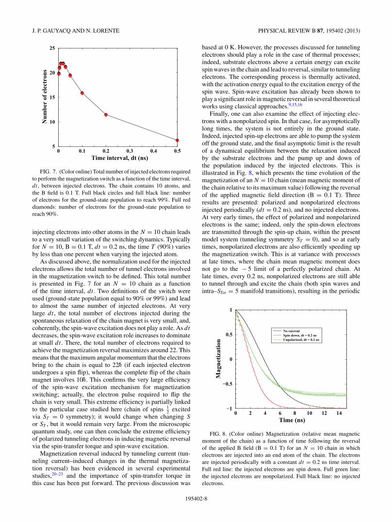
Figure 6 presents the effect of varying the intensity of thecurrent injected into the chain; this is realized by varying thetime interval, dt , between two successive electron injections.Figure 6 presents the average magnetic moment of the chain(N = 10) as a function of time, following the reversal of theapplied field B (B = 0.1 T). It appears that electron injection isvery effective in speeding up the magnetization switching. So,even if the electron injection directly results in the populationof states lying higher than those in the lowest STot = 5 manifold,finally it results in a faster population of the ground state,i.e., in a faster magnetization switching. Spin-wave excitationis then a very efficient process for inducing a magnetizationswitching. If the injected current is strong enough, it beats theeffect of spontaneous relaxation (global rotation of the chainmagnet induced by substrate electrons), and the switching timebecomes very small. The results in Figs. 5 and 6 are obtainedfor electrons injected into end atoms of the chain. Actually,
0 2 4 6 8 10 12Time (ns)
−1
−0.8
−0.6
−0.4
−0.2
0
0.2
0.4
0.6
0.8
1
Mag
netiz
atio
n
No currentdt = 0.5 nsdt = 0.2 nsdt = 0.1 nsdt = 0.05nsdt = 0.02ns
FIG. 6. (Color online) Magnetization (relative mean magneticmoment of the chain) as a function of time following the reversalof the applied B field (B = 0.1 T) for an N = 10 chain in whichpolarized electrons are injected into an end atom of the chain. Theelectrons are injected periodically with a constant dt time interval.The different full lines correspond to different dt intervals (see insert):the shorter the dt , the faster the magnetization change. The dashedline corresponds to the case where no electrons are injected, and therelaxation only proceeds via collisions with the substrate electrons.
195402-7
J. P. GAUYACQ AND N. LORENTE PHYSICAL REVIEW B 87, 195402 (2013)
0 0.1 0.2 0.3 0.4 0.5Time interval, dt (ns)
5
10
15
20
25N
umbe
r of
ele
ctro
ns
FIG. 7. (Color online) Total number of injected electrons requiredto perform the magnetization switch as a function of the time interval,dt , between injected electrons. The chain contains 10 atoms, andthe B field is 0.1 T. Full black circles and full black line: numberof electrons for the ground-state population to reach 99%. Full reddiamonds: number of electrons for the ground-state population toreach 90%.
injecting electrons into other atoms in the N = 10 chain leadsto a very small variation of the switching dynamics. Typicallyfor N = 10, B = 0.1 T, dt = 0.2 ns, the time T (90%) variesby less than one percent when varying the injected atom.
As discussed above, the normalization used for the injectedelectrons allows the total number of tunnel electrons involvedin the magnetization switch to be defined. This total numberis presented in Fig. 7 for an N = 10 chain as a functionof the time interval, dt . Two definitions of the switch wereused (ground-state population equal to 90% or 99%) and leadto almost the same number of injected electrons. At verylarge dt , the total number of electrons injected during thespontaneous relaxation of the chain magnet is very small, and,coherently, the spin-wave excitation does not play a role. As dt
decreases, the spin-wave excitation role increases to dominateat small dt . There, the total number of electrons required toachieve the magnetization reversal maximizes around 22. Thismeans that the maximum angular momentum that the electronsbring to the chain is equal to 22h (if each injected electronundergoes a spin flip), whereas the complete flip of the chainmagnet involves 10h. This confirms the very large efficiencyof the spin-wave excitation mechanism for magnetizationswitching; actually, the electron pulse required to flip thechain is very small. This extreme efficiency is partially linkedto the particular case studied here (chain of spins 1
2 excitedvia ST = 0 symmetry); it would change when changing S
or ST , but it would remain very large. From the microscopicquantum study, one can then conclude the extreme efficiencyof polarized tunneling electrons in inducing magnetic reversalvia the spin-transfer torque and spin-wave excitation.
Magnetization reversal induced by tunneling current (tun-neling current–induced changes in the thermal magnetiza-tion reversal) has been evidenced in several experimentalstudies,20–23 and the importance of spin-transfer torque inthis case has been put forward. The previous discussion was
based at 0 K. However, the processes discussed for tunnelingelectrons should play a role in the case of thermal processes;indeed, substrate electrons above a certain energy can excitespin waves in the chain and lead to reversal, similar to tunnelingelectrons. The corresponding process is thermally activated,with the activation energy equal to the excitation energy of thespin wave. Spin-wave excitation has already been shown toplay a significant role in magnetic reversal in several theoreticalworks using classical approaches.9,15,16
Finally, one can also examine the effect of injecting elec-trons with a nonpolarized spin. In that case, for asymptoticallylong times, the system is not entirely in the ground state.Indeed, injected spin-up electrons are able to pump the systemoff the ground state, and the final asymptotic limit is the resultof a dynamical equilibrium between the relaxation inducedby the substrate electrons and the pump up and down ofthe population induced by the injected electrons. This isillustrated in Fig. 8, which presents the time evolution of themagnetization of an N = 10 chain (mean magnetic moment ofthe chain relative to its maximum value) following the reversalof the applied magnetic field direction (B = 0.1 T). Threeresults are presented: polarized and nonpolarized electronsinjected periodically (dt = 0.2 ns), and no injected electrons.At very early times, the effect of polarized and nonpolarizedelectrons is the same; indeed, only the spin-down electronsare transmitted through the spin-up chain, within the presentmodel system (tunneling symmetry ST = 0), and so at earlytimes, nonpolarized electrons are also efficiently speeding upthe magnetization switch. This is at variance with processesat late times, where the chain mean magnetic moment doesnot go to the − 5 limit of a perfectly polarized chain. Atlate times, every 0.2 ns, nonpolarized electrons are still ableto tunnel through and excite the chain (both spin waves andintra–STot = 5 manifold transitions), resulting in the periodic
0 2 4 6 8 10 12 14Time (ns)
−1
−0.5
0
0.5
1
Mag
netiz
atio
n
No currentSpin down, dt = 0.2 nsUnpolarized, dt = 0.2 ns
FIG. 8. (Color online) Magnetization (relative mean magneticmoment of the chain) as a function of time following the reversalof the applied B field (B = 0.1 T) for an N = 10 chain in whichelectrons are injected into an end atom of the chain. The electronsare injected periodically with a constant dt = 0.2 ns time interval.Full red line: the injected electrons are spin down. Full green line:the injected electrons are nonpolarized. Full black line: no injectedelectrons.
195402-8
MAGNETIC REVERSAL OF A QUANTUM NANOFERROMAGNET PHYSICAL REVIEW B 87, 195402 (2013)
jumps in the magnetization. The asymptotic value of themagnetization depends on the dynamical equilibrium betweenthe spontaneous relaxation process (global rotation of the chainmoment) and the excitation/de-excitation process induced bythe injected electrons. As the injected current intensity goesup (dt goes down), the asymptotic relative magnetizationmoves away from − 1 and tends to 0 for extremely largenonpolarized currents. As a conclusion, one can say thatinjecting nonpolarized electrons into the chain speeds up thedynamics of the magnetization, but with the drawback ofleading to a chain that was not fully polarized at the end; apossible trick would be to use short pulses of nonpolarizedelectrons that would speed up the early relaxation and let thechain reach a full magnetization after the pulse end.
IV. FINITE-SIZE HEISENBERG CHAINS WITHANISOTROPY
We will now consider the case of a chain of localspins coupled by ferromagnetic Heisenberg couplings andinteracting with an anisotropic environment. The anisotropycorresponds to the D and E terms in Hamiltonian Eq. (1).The longitudinal term, D, simply induces a global energy shiftof the energies in the basis set formed of eigenvectors of �S2
i
and Si,z, |M1,M2, . . . ,MN−1,MN 〉 in the case of a chain oflocal spins 1
2 . To illustrate the effect of the anisotropy, wethen considered chains of local spins 2. The D anisotropysignificantly alters the wave functions of the lowest-lying statesof the chain and consequently can also affect the magneticswitching process. In the numerical applications of the effectof the longitudinal anisotropy (Sec. IV A), we considered agyromagnetic factor equal to 2, a ferromagnetic Heisenbergcoupling of 1 meV, and an anisotropy coupling D equal to− 1.5 meV (i.e., a strong anisotropy case). Study of the effectof the transverse coupling E (Sec. IV B) is made with a variableE value.
A. Effect of the longitudinal anisotropy (D �= 0, E = 0)
A negative anisotropy D term (‘easy axis’ case), partly liftsthe degeneracy of the ground state of the chain at vanishing Bfield, though the projection of the total spin of the chain on theanisotropy axis, STot,z, remains a good quantum number. For anN -atom chain, the doubly degenerate ground state correspondsto the STot = 2N and MTot = ± 2N states. The low-energy partof the energy spectrum of an N = 5 chain is shown in Fig. 9as a function of the applied field B (the B field is along theanisotropy axis of the local spins). Note that the crossingsbetween the various states are real crossings, although thecalculation performed with a finite B grid makes them looklike avoided crossings. Starting from B = 0, one can see thatthe ground state splits into two states, MTot = + 10 and MTot =− 10. The magnetic switching process then corresponds to therelaxation of the MTot = + 10 (green line in Fig. 9) to theground MTot = − 10 state (red dashed line). It appears that therelaxation process via global rotation of the total spin discussedabove (successive transitions with MTot = − 1) is impossibleat 0 K in the low-field region, since the intermediate states ofthe relaxation are not located energetically between the initialand final states (between the MTot = + 10 and MTot = − 10
0 2 4 6Magnetic field (B)
−55
−50
−45
−40
Ene
rgy
(meV
)
FIG. 9. (Color online) Energy diagram of an N = 5 chain of S =2 spins as a function of the applied B field (in Tesla). The local spinsare coupled by a ferromagnetic Heisenberg coupling and interactwith the environment via an anisotropy D term (easy axis kind). Thelowest-lying state energies are shown as full black lines; the energiesof the initial and final states of the magnetic switching process (M =+ 10 and M = − 10 states) are highlighted in full green and dashedred, respectively.
states). So in the low B range, the MTot = + 10 state is stable;several other states in the spectrum are also stable for the samereason. When the B field is increased, the MTot = + 10 stateenergy goes up and crosses the entire spectrum to becomethe highest state for asymptotically large fields. In this limit,the situation discussed in the previous section is recovered,and the magnetic switching can proceed via the global rotationof the total spin. However, for strong anisotropies, like in Fig. 9,this means extremely large B fields. One can see in Fig. 9, that,in the moderate B field range that is shown, the MTot = + 10state only crosses states with negative MTot values, whereasthe existence of the global rotation mechanism necessitatesthe presence of the whole spectrum of MTot states below theMTot = + 10 state. The threshold for global rotation is givenby the crossing between MTot = + 10 and MTot = + 9 states;it amounts to:
BT h = |D| (2S − 1)
gμB
. (13)
For the case depicted in Fig. 9, the threshold is at 38.9 T, a veryhigh field, due to the strong anisotropy. Just above threshold,the first step of the global rotation is very slow due to theenergy defect factor in the transition rate [Eq. (6)].
In a classical view, the magnetic anisotropy generates apotential barrier separating the two opposite magnetizationsthat the system has to overcome during the reversal, either bya large B field or by thermal excitation. The existence of amagnetic field threshold for reversal of a magnetic island inthe presence of anisotropy has been studied experimentallyin detail in Ref. 10; it was analyzed in a classical context10
with a field threshold equal to 2Kμ
in the T = 0 K limit (μ isthe magnetic moment per atom equal to gμBS with the presentnotations). K is the anisotropy energy per atom, i.e., the energybarrier to reversal for a single atom, equal to |D|S
2 (2S − 1)with the present notations. The classical B threshold is then
195402-9

J. P. GAUYACQ AND N. LORENTE PHYSICAL REVIEW B 87, 195402 (2013)
20 40 60 80 100Energy (meV)
10−10
10−8
10−6
10−4
10−2
100Pr
obab
ilitie
s
B = 10 TB = 20 TB = 30 TB = 40 T
FIG. 10. (Color online) Magnetic switching induced by tunnelingelectrons in a ferromagnetic chain of 5 local spins S = 2, witha longitudinal anisotropy. The full symbols present the excitationprobability from the initial MTot = + 10 state to an excited state j
as a function of the excited state energy for various strengths of theapplied B field (see insert). The open symbols present the probabilityfor the magnetic switch of the chain via the excited state j (transitionfrom the MTot = + 10 state through the intermediate excited j stateto the final MTot = − 10 state). Note that for the highest field (40 T),open and full symbols are superimposed. For the sake of clarity, theenergies of the intermediate states j are plotted relative to the energyof the ground state for a vanishing field.
equal to the quantum threshold given by Eq. (13). Note thatthis threshold is independent of the number of atoms in themagnetic object.
A similar B-threshold effect is visible on the magneticswitch induced by tunneling electrons. Figure 10 presents theexcitation probability PExc(init → j) from the initial state (init: MTot = + 10) to any excited state (j ) and the probabilityfor the magnetic switching induced by a tunneling electron(init → j → final), where ‘final’ is the ground state. Thelatter indirect probability is noted PInd(init → j → final). Thefigure presents these probabilities as a function of energy ofthe intermediate state, j , for several values of the applied field,B. For the sake of clarity, we used for the plot the energiesof the states relative to the energy of the ground state for avanishing field, in order to split the various B’s. For B = 10T, there is a very strong elastic probability (PExc[init → init])equal to 13/15 and only five inelastic processes; actually thesimple excitation scheme of a pure Heisenberg chain (onlyquantized spin waves are excited45) is preserved when aD anisotropy term is included. At B = 10 T, the indirectprobability PInd(init → j → final) is zero, due to the relativeenergy position of the states; indeed, the only state belowthe quantized spin waves associated with MTot = + 9 and towhich they can relax is the MTot = + 10 state, so that afteran excitation by a tunneling electron, the chain relaxes to thesame state. There is a threshold for the indirect process to exist,associated with a crossing between the spin waves and lowerMTot states. For B = 20 T, one can see in Fig. 10 that the twohigher-lying states excited by a tunneling electron can decayto the ground state, though with a very small probability dueto the energy defect factor in the decay rate. Note that the B
0 2 4 6Magnetic field, B (T)
−55
−50
−45
−40
Ene
rgy
(meV
)
FIG. 11. (Color online) Energy diagram of an N = 5 chain ofS = 2 spins as a function of the applied B field (in Tesla). Thelocal spins are coupled by a ferromagnetic Heisenberg coupling andinteract with the environment via anisotropy D and E terms (easyaxis kind). The lowest-lying state energies are shown as full blacklines. The full green and dashed red curves that overrun the avoidedcrossings highlight the energy of the initial and final states of themagnetic switching process (M ≈ + 10 and M ≈ − 10 states).
threshold for the electron-induced processes is similar, thoughsmaller than that for the global rotation process. For B = 30 T,the indirect probabilities have significantly increased, and forB = 40 T, the indirect probabilities, PInd(init → j → final),are equal to the excitation probabilities, PExc(init → j), i.e.,the relaxation always ends up in the ground state (this simplycorresponds to the fact that the field is larger than BT h andthe initial MTot = + 10 state itself also relaxes to the groundstate).
As a conclusion, the longitudinal anisotropy deeply modi-fies the magnetic switching of the chain: In a low-field region,no spontaneous switch is possible at 0 K; in an intermediaterange at finite B, the indirect switch induced by tunnelingelectrons is possible but with an efficiency much lower thanthat observed in pure Heisenberg chains; in the large Brange (when the Zeeman term dominates over the anisotropy),the situation is comparable to that of the pure Heisenbergchain, with efficient global rotation and switching induced bytunneling electrons.
The above discussion concerns negative D anisotropies. Inthe case of positive D, the ground state of the system at low Bis a MTot = 0 state, which is insensitive to the direction of theB field direction, so no magnetic switching exists.
B. Effect of a transverse anisotropy term (D, E �= 0)
The presence of transverse anisotropy further modifiesthe magnetic switching process. The main change is that,because of E, MTot is not a good quantum number anymore.So the selection rule on MTot for electron-induced transitionsdisappears as well as the stable states at low B discussed inSec. IV A.
The energies of the low-lying states of a chain of 5 localspins S = 2 (J = − 1.0 meV, D = − 1.5 meV, E = 0.3 meV)are shown in Fig. 11. Though the transverse anisotropy E issignificant, the changes in the low-energy part of the spectrum
195402-10

MAGNETIC REVERSAL OF A QUANTUM NANOFERROMAGNET PHYSICAL REVIEW B 87, 195402 (2013)
0.4 0.6 0.8 1Anisotropy, E (meV)
10−8
10−6
10−4
10−2
100Sw
itchi
ng ti
me
(s)
N = 5N = 4N = 6
FIG. 12. (Color online) Magnetization switching time for thedirect transitions induced by substrate electrons: The transitionbetween the two extreme magnetization states occurs in a singleelectron collision. The magnetization switching time (inverse of theswitching rate) is shown in seconds for three different chain lengths(N = 4, 5, and 6 atoms; see insert) as a function of the transversemagnetic anisotropy of the chain, E. The applied B field is 1 T.
are not very large visually (compare Figs. 9 and 11). Thedoubly degenerate ground state at B = 0 is split with a verytiny energy difference (around 10−7 meV in Fig. 11) in thepresent integer spin case (it would not be in a half integerspin case59). For small finite B, the two lowest states splitquasilinearly with B and are associated with mean valuesof STot,z very close to ± 10. Actually, the anisotropy term,E, introduces some mixing (correlation) between the variouskinds of magnetic configurations |M1,M2, . . . ,MN−1,MN 〉(where |Mi〉 is an eigenstate of Siz), and since the two loweststates in Fig. 11 are not exactly eigenvectors of STot,z, thereexists a finite probability for a direct transition between the twostates induced by a single collision with a substrate electron.This process is very different from the processes discussedbefore: The complete magnetic switching occurs in a singleelectron collision and not in a sequence of transitions asthose discussed above; it is made possible by the correlationsbetween magnetic configurations in the chain. However, sincethe mixing induced by the transverse anisotropy is not verylarge, the initial and final states are almost pure (STot,z = ± 10)states, the distance between the two states in terms of numberof local spin flips involved is very large, and the probabilityof transition induced by a single electron is very small. Atlow B fields, the switching time is given by the lifetime ofthe excited state [Eq. (6) above] and is shown in Fig. 12as a function of the transverse anisotropy term, E, for anapplied B field equal to 1 T. The switching time increasesvery rapidly when E decreases, and a very large anisotropy(remember E/|D| is smaller than one) is required for thistime to reach the nanosecond range. This switching processdepends drastically on the length of the chain; indeed, thedistance between the two states evaluated in terms of numberof local spin flips involved in the switching increases withthe number of atoms in the chain, and consequently thisdirect switching process slows down very rapidly when N
increases. For E = 0.8 meV, increasing N from 5 to 6 (ordecreasing N from 5 to 4) changes the switching time bya factor around 20. This direct switch then only exists forshort chains with significant transverse anisotropy. Thoughvery slow, this process should be significant at very lowtemperature. At this point, one can stress that this process isdifferent from quantum tunneling,4,60–62 which is also invokedin a magnetization switch at very low temperatures; indeed,in contrast to quantum tunneling, the present process involves(1) a collision with an electron and (2) a dissipation, i.e.,an energy change between the initial and final magnetizationstates that is balanced by heating a substrate electron. Ina classical view, there is still a barrier separating the twomagnetization states, lowered by the E contribution; thesystem does not tunnel through the barrier at constant energy,but, due to the symmetry lowering introduced by E, collisionwith a substrate electron is able to induce a direct transitionbetween the two magnetization states. A similar process hasbeen discussed in the context of the quantum-tunneling–induced Kondo effect.59 It was shown that a spin-flip process(magnetic transitions induced by collision with an electron)associated with quantum tunneling of magnetization (mixingof different magnetic configurations induced by the transverseanisotropy) leads to a higher-order process able to reverse amolecular spin and thus lead to the Kondo effect. The situationis very similar to the present one: Electron collision–induceddirect transitions between two states of opposite magnetizationare made possible by correlation effects induced by transverseanisotropy.
Actually, this mixing between the switching states, i.e., thefact that they are not exactly the MTot = ± 10 states, alsoperturbs the physical situation discussed here: When suddenlyreversing B, the system does not switch perfectly between thetwo MTot ≈ ± 10 states. The reversal induces the projectionof one of the states on the entire spectrum, but it dominantlypopulates the other state. Here, we neglect this small projectioneffect and consider switching to occur from the MTot ≈ + 10state.
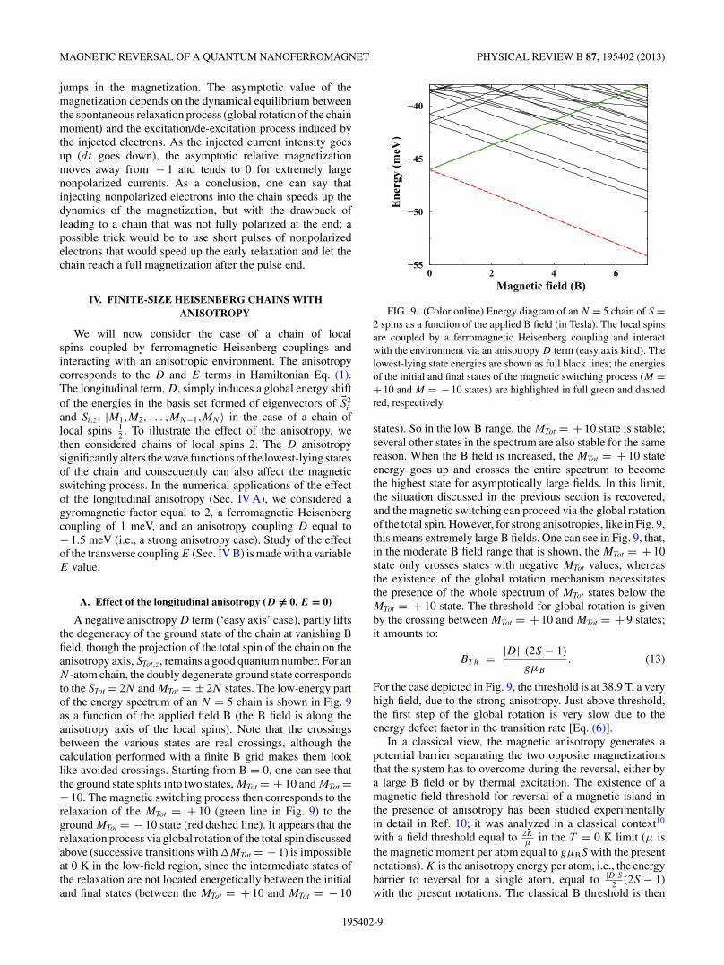
The presence of E also strongly affects the field thresholddiscussed in Sec. IV A, Eq. (13), above which the chainmagnetization can switch via substrate electron collisions.At low field, due to the direct transitions discussed above,magnetization switch occurs; so, there is no B threshold forthe magnetization switch, although the switch occurs at a veryslow rate (see Fig. 12). When the applied B field increases, theinitial state of the magnetization switch (init: MTot ≈ + 10)crosses successively the entire spectrum of magnetic statesto end up as the highest one in the Zeeman limit (Fig. 11).This affects the magnetization switch in two ways. First, whenthe MTot ≈ + 10 state crosses another state, this introduces anew decay channel for the MTot ≈ + 10 state, and thereforeit speeds up the state decay and the magnetization switch.Second, in the crossing region, possible interactions betweenthe two states lead to an avoided crossing, and in the B rangeof the avoided crossing, the decay rates of the states are deeplymodified. These two effects are visible in Fig. 13, whichpresents the lifetime of the MTot ≈ + 10 state as a functionof the applied B field (anisotropy E equal to 0.5 meV in aN = 5 chain). Note that the state lifetime is not equal to theswitching time when several states are involved in the switch:
195402-11
J. P. GAUYACQ AND N. LORENTE PHYSICAL REVIEW B 87, 195402 (2013)
0 1 2 3 4Magnetic field (T)
10−7
10−6
10−5
10−4
10−3
10−2L
ifetim
e (s
)
FIG. 13. (Color online) Lifetime of the upper state (MTot ≈ + 10state) of the magnetization switch induced by substrate electronsin a single collision event for a length chain N = 5. The transversemagnetic anisotropy, E, is equal to 0.5 meV. The state lifetime (inverseof the state decay rate) is shown in seconds as a function of the appliedB field in tesla.
Indeed, when several decay channels are open, the populationcascades down to the ground state, but in a nonexponentialway; the lifetime shown in Fig. 13 corresponds to the decayof the MTot ≈ + 10 state, irrespective of the decay final state.The lifetime of the MTot ≈ + 10 state is seen to shorten veryquickly as the B field is increased, well before approachingthe B threshold of the E = 0 case. The sharp drop in thelifetime around 1.9 T corresponds to the first crossing of theMTot ≈ + 10 state (see Fig. 11) and to the opening ofthe corresponding new decay channel. The minimum in the3.35 T range corresponds to a mixing between states (fifthand sixth in the increasing energy order). Beyond 4 T, theshortening of the state lifetime goes on, but it is difficult toassign the various effects due to the very large number of statecrossings involved.
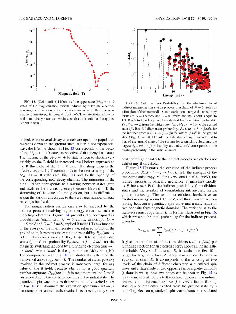
The magnetization switch can also be induced by theindirect process involving higher-energy electrons, such astunneling electrons. Figure 14 presents the correspondingprobabilities (chain with N = 5 atoms, anisotropy D =− 1.5 meV and E = 0.3 meV, applied B field: 1 T) as a functionof the energy of the intermediate state, referred to that of theground state. It presents the excitation probability PExc(init →j) from the initial state (init: MTot ≈ + 10) to all the excitedstates (j ) and the probability,PInd(init → j → final), for themagnetic switching induced by a tunneling electron (init → j→ final), where ‘final’ is the ground state (MTot ≈ + 10).The comparison with Fig. 10 illustrates the effect of thetransversal anisotropy term, E. The number of states possiblyinvolved in the indirect process is now very large, for anyvalue of the B field, because MTot is not a good quantumnumber anymore. PExc(init → j) is maximum around 2 meV,corresponding to the elastic probability in the initial state. Thequantized spin-wave modes that were the only excited statesin Fig. 10 still dominate the excitation spectrum (init → j),but many other states are also excited. As a result, many states
0 5 10 15 20Energy (meV)
10−8
10−6
10−4
10−2
100
Prob
abili
ty
FIG. 14. (Color online) Probability for the electron-inducedindirect magnetization switch process in a chain of N = 5 atoms asa function of the intermediate state excitation energy; the anisotropyterms are D = 1.5 meV and E = 0.3 meV, and the B field is equal to1 T. Black full circles joined by a dashed line: excitation probabilityPExc(init → j) from the initial state (init : MTot ≈ + 10) to the excitedstate (j ). Red full diamonds: probability, PInd(init → j → final), forthe indirect process (init → j → final), where ‘final’ is the groundstate (MTot ≈ − 10). The intermediate state energies are referred tothat of the ground state of the system for a vanishing field, and thelargest PExc(init → j) probability around 2 meV corresponds to theelastic probability in the initial channel.
contribute significantly to the indirect process, which does notexhibit any B threshold.
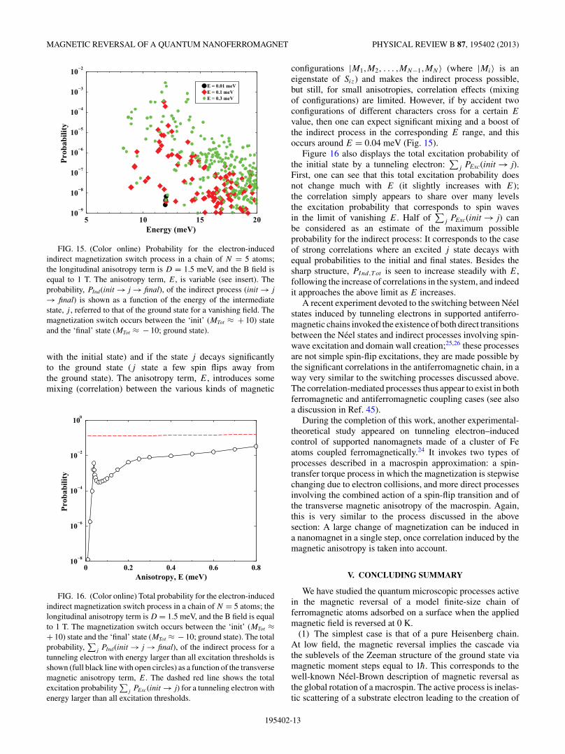
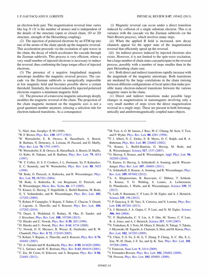
Figure 15 illustrates the variation of the indirect processprobability, PInd(init → j → final), with the strength of thetransverse anisotropy, E. For a very small E (0.01 meV), theindirect process is basically negligible; it increases rapidlyas E increases: Both the indirect probability for individualstates and the number of contributing intermediate states,j , are increasing. The two most efficient levels have anexcitation energy around 12 meV, and they correspond to amixing between a quantized spin wave and a state made oftwo opposite ferromagnetic domains. The variation with thetransverse anisotropy term, E, is further illustrated in Fig. 16,which presents the total probability for the indirect process,given by:
PInd,T ot =∑
j
PInd(init → j → final).
It gives the number of indirect transitions (init → final) pertunneling electron for an electron energy above all the inelasticthresholds. Very small at small E, it reaches the few 10−2
range for large E values. A sharp structure can be seen inPInd,T ot at small E. It corresponds to the crossing of twolevels of the chain of different character: a quantized spinwave and a state made of two opposite ferromagnetic domains(a domain wall); these two states can be seen in Fig. 15 asthe two main contributors to the indirect process. The indirectprocess via an intermediate level j is very efficient if the j
state can be efficiently excited from the ground state by atunneling electron (quantized spin-wave character associated
195402-12
MAGNETIC REVERSAL OF A QUANTUM NANOFERROMAGNET PHYSICAL REVIEW B 87, 195402 (2013)
5 10 15 20Energy (meV)
10−9
10−8
10−7
10−6
10−5
10−4
10−3
10−2Pr
obab
ility
E = 0.01 meVE = 0.1 meVE = 0.3 meV
FIG. 15. (Color online) Probability for the electron-inducedindirect magnetization switch process in a chain of N = 5 atoms;the longitudinal anisotropy term is D = 1.5 meV, and the B field isequal to 1 T. The anisotropy term, E, is variable (see insert). Theprobability, PInd(init → j → final), of the indirect process (init → j→ final) is shown as a function of the energy of the intermediatestate, j , referred to that of the ground state for a vanishing field. Themagnetization switch occurs between the ‘init’ (MTot ≈ + 10) stateand the ‘final’ state (MTot ≈ − 10; ground state).
with the initial state) and if the state j decays significantlyto the ground state (j state a few spin flips away fromthe ground state). The anisotropy term, E, introduces somemixing (correlation) between the various kinds of magnetic
0 0.2 0.4 0.6 0.8Anisotropy, E (meV)
10−8
10−6
10−4
10−2
100
Prob
abili
ty
FIG. 16. (Color online) Total probability for the electron-inducedindirect magnetization switch process in a chain of N = 5 atoms; thelongitudinal anisotropy term is D = 1.5 meV, and the B field is equalto 1 T. The magnetization switch occurs between the ‘init’ (MTot ≈+ 10) state and the ‘final’ state (MTot ≈ − 10; ground state). The totalprobability,
∑j PInd(init → j → final), of the indirect process for a
tunneling electron with energy larger than all excitation thresholds isshown (full black line with open circles) as a function of the transversemagnetic anisotropy term, E. The dashed red line shows the totalexcitation probability
∑j PExc(init → j) for a tunneling electron with
energy larger than all excitation thresholds.
configurations |M1,M2, . . . ,MN−1,MN 〉 (where |Mi〉 is aneigenstate of Siz) and makes the indirect process possible,but still, for small anisotropies, correlation effects (mixingof configurations) are limited. However, if by accident twoconfigurations of different characters cross for a certain E
value, then one can expect significant mixing and a boost ofthe indirect process in the corresponding E range, and thisoccurs around E = 0.04 meV (Fig. 15).
Figure 16 also displays the total excitation probability ofthe initial state by a tunneling electron:
∑j PExc(init → j).
First, one can see that this total excitation probability doesnot change much with E (it slightly increases with E);the correlation simply appears to share over many levelsthe excitation probability that corresponds to spin wavesin the limit of vanishing E. Half of
∑j PExc(init → j) can
be considered as an estimate of the maximum possibleprobability for the indirect process: It corresponds to the caseof strong correlations where an excited j state decays withequal probabilities to the initial and final states. Besides thesharp structure, PInd,T ot is seen to increase steadily with E,following the increase of correlations in the system, and indeedit approaches the above limit as E increases.
A recent experiment devoted to the switching between Neelstates induced by tunneling electrons in supported antiferro-magnetic chains invoked the existence of both direct transitionsbetween the Neel states and indirect processes involving spin-wave excitation and domain wall creation;25,26 these processesare not simple spin-flip excitations, they are made possible bythe significant correlations in the antiferromagnetic chain, in away very similar to the switching processes discussed above.The correlation-mediated processes thus appear to exist in bothferromagnetic and antiferromagnetic coupling cases (see alsoa discussion in Ref. 45).
During the completion of this work, another experimental-theoretical study appeared on tunneling electron–inducedcontrol of supported nanomagnets made of a cluster of Featoms coupled ferromagnetically.24 It invokes two types ofprocesses described in a macrospin approximation: a spin-transfer torque process in which the magnetization is stepwisechanging due to electron collisions, and more direct processesinvolving the combined action of a spin-flip transition and ofthe transverse magnetic anisotropy of the macrospin. Again,this is very similar to the process discussed in the abovesection: A large change of magnetization can be induced ina nanomagnet in a single step, once correlation induced by themagnetic anisotropy is taken into account.
V. CONCLUDING SUMMARY
We have studied the quantum microscopic processes activein the magnetic reversal of a model finite-size chain offerromagnetic atoms adsorbed on a surface when the appliedmagnetic field is reversed at 0 K.
(1) The simplest case is that of a pure Heisenberg chain.At low field, the magnetic reversal implies the cascade viathe sublevels of the Zeeman structure of the ground state viamagnetic moment steps equal to 1h. This corresponds to thewell-known Neel-Brown description of magnetic reversal asthe global rotation of a macrospin. The active process is inelas-tic scattering of a substrate electron leading to the creation of
195402-13
J. P. GAUYACQ AND N. LORENTE PHYSICAL REVIEW B 87, 195402 (2013)
an electron-hole pair. The magnetization reversal time varieslike log N (N is the number of atoms) and is independent ofthe details of the structure (open or closed chain, 1D or 2Dstructure, strength of the Heisenberg coupling).
(2) The injection of polarized electrons by an STM tip intoone of the atoms of the chain speeds up the magnetic reversal.This acceleration proceeds via the excitation of spin waves inthe chain, the decay of which accelerates the cascade throughthe Zeeman sublevels. This process is very efficient, where avery small number of injected electrons is necessary to inducethe reversal, thus confirming the large torque effect of injectedelectrons.
(3) The presence of a negative longitudinal magneticanisotropy modifies the magnetic reversal process. The cas-cade via the Zeeman sublevels is energetically impossibleat low magnetic field and becomes possible above a certainthreshold. Similarly, the reversal induced by injected polarizedelectrons requires a minimum magnetic field.
(4) The presence of a transverse magnetic anisotropy deeplymodifies the magnetic reversal of the chain. The projection ofthe chain magnetic moment on the magnetic axis is not agood quantum number anymore, relaxing a selection rule forelectron-induced transitions. As a consequence:
(i) Magnetic reversal can occur under a direct transitioninduced by collision of a single substrate electron. This is atvariance with the cascade via the Zeeman sublevels (or theNeel-Brown process), which involves many steps.
(ii) When the applied B field is increased, new decaychannels appear for the upper state of the magnetizationreversal that efficiently speed up the reversal.(iii) An indirect process induced by injected electrons also
exists. However, it is not limited to the spin-wave excitation,but a large number of chain states can participate in the reversalprocess, possibly with a number of steps smaller than in thepure Heisenberg chain case.
(iv) Both direct and indirect transitions rapidly increase withthe magnitude of the magnetic anisotropy. Both transitionsare mediated by the large correlations in the chain (mixingbetween different configurations of local spins) that make pos-sible many electron-induced transitions between the variousmagnetic states in the chain.
(v) Direct and indirect transitions make possible largechanges in magnetization in nanomagnets involving only avery small number of steps (even the direct magnetizationreversal in a single step). These are present in both ferromag-netically and antiferromagnetically coupled nano-objects.
1L. Neel, Ann. Geophys. 5, 99 (1949).2W. F. Brown, Phys. Rev. 130, 1677 (1963).3W. Wernsdorfer, E. B. Orozco, K. Hasselbach, A. Benoit,B. Barbara, N. Demoncy, A. Loiseau, H. Pascard, and D. Mailly,Phys. Rev. Lett. 78, 1791 (1997).
4W. Wernsdorfer, E. B. Orozco, K. Hasselbach, A. Benoit, D. Mailly,O. Kubo, H. Nakano, and B. Barbara, Phys. Rev. Lett. 79, 4014(1997).
5W. T. Coffey, D. S. F. Crothers, J. L. Dormann, Yu. P. Kalmykov,E. C. Kennedy, and W. Wernsdorfer, Phys. Rev. Lett. 80, 5655(1998).
6M. Bode, O. Pietzsch, A. Kubetzka, and R. Wiesendanger, Phys.Rev. Lett. 92, 067201 (2004).
7M. Bode, A. Kubetzka, K. von Bergmann, O. Pietzsch, andR. Wiesendanger, Micro. Res. Techn. 66, 117 (2005).
8S. Krause, G. Herzog, T. Stapelfeldt, L. Berbil-Bautista, M. Bode,E. Y. Vedmedenko, and R. Wiesendanger, Phys. Rev. Lett. 103,127202 (2009).
9S. Rohart, P. Campiglio, V. Repain, Y. Nahas, C. Chacon, Y. Girard,J. Lagoute, A. Thiaville, and S. Rousset, Phys. Rev. Lett. 104,137202 (2010).
10S. Ouazi, S. Wedekind, G. Rodary, H. Oka, D. Sander, andJ. Kirschner, Phys. Rev. Lett. 108, 107206 (2012).
11D. Hinzke and U. Nowak, Phys. Rev. B 58, 265 (1998).12D. Hinzke and U. Nowak, Phys. Rev. B 61, 6734 (2000).13U. Nowak, O. N. Mryasov, R. Wieser, K. Guslienko, and R. W.
Chantrell, Phys. Rev. B 72, 172410 (2005).14S. Rohart, V. Repain, A. Thiaville, and S. Rousset, Phys. Rev. B 76,
104401 (2007).15D. A. Garanin and H. Kachkachi, Phys. Rev. B 80, 014420 (2009).16V. L. Safonov and H. N. Bertram, Phys. Rev. B 63, 094419 (2001).17C. Etz, M. Costa, O. Eriksson, and A. Bergman, Phys. Rev. B 86,
224401 (2012).
18M. Tsoi, A. G. M. Jansen, J. Bass, W.-C. Chiang, M. Seck, V. Tsoi,and P. Wyder, Phys. Rev. Lett. 80, 4281 (1998).
19F. J. Albert, N. C. Emley, E. B. Myers, D. C. Ralph, and R. A.Buhrman, Phys. Rev. Lett. 89, 226802 (2002).
20S. Krause, L. Berbil-Bautista, G. Herzog, M. Bode, andR. Wiesendanger, Science 317, 1537 (2007).
21G. Herzog, S. Krause, and R. Wiesendanger, Appl. Phys. Lett. 96,102505 (2010).
22S. Krause, G. Herzog, A. Schlenhoff, A. Sonntag, and R. Wiesen-danger, Phys. Rev. Lett. 107, 186601 (2011).
23A. Schlenhoff, S. Krause, A. Sonntag, and R. Wiesendanger, Phys.Rev. Lett. 109, 097602 (2012).
24A. A. Khajetoorians, B. Baxevanis, C. Hubner, T. Schlenk,S. Krause, T. O. Wehling, S. Lounis, A. Lichtenstein,D. Pfannkuche, J. Wiebe, and R. Wiesendanger, Science 339, 55(2013).
25S. Loth, S. Baumann, C. P. Lutz, D. M. Eigler, and A. J. Heinrich,Science 335, 196 (2012).
26J. P. Gauyacq, S. M. Yaro, X. Cartoixa, and N. Lorente, Phys. Rev.Lett. 110, 087201 (2013).
27A. J. Heinrich, J. A. Gupta, C. P. Lutz, and D. M. Eigler, Science306, 466 (2004).
28C. F. Hirjibehedin, C. Y. Lin, A. F. Otte, M. Ternes, C. P. Lutz,B. A. Jones, and A. J. Heinrich, Science 317, 1199 (2007).
29N. Tsukahara, K. I. Noto, M. Ohara, S. Shiraki, N. Takagi, Y. Takata,J. Miyawaki, M. Taguchi, A. Chainani, S. Shin, and M. Kawai, Phys.Rev. Lett. 102, 167203 (2009).
30X. Chen, Y.-S. Fu, S.-H. Ji, T. Zhang, P. Cheng, X.-C. Ma, X.-L.Zou, W.-H. Duan, J.-F. Jia, and Q.-K. Xue, Phys. Rev. Lett. 101,197208 (2008).
31J. Fransson, Nano Lett. 9, 2414 (2009).32J. Fernandez-Rossier, Phys. Rev. Lett. 102, 256802 (2009).33M. Persson, Phys. Rev. Lett. 103, 050801 (2009).
195402-14

MAGNETIC REVERSAL OF A QUANTUM NANOFERROMAGNET PHYSICAL REVIEW B 87, 195402 (2013)
34N. Lorente and J. P. Gauyacq, Phys. Rev. Lett. 103, 176601 (2009).35S. Lounis, A. T. Costa, R. B. Muniz, and D. L. Mills, Phys. Rev. B
83, 035109 (2011).36B. Chilian, A. A. Khajetoorians, S. Lounis, A. T. Costa, D. L. Mills,
J. Wiebe, and R. Wiesendanger, Phys. Rev. B 84, 212401 (2011).37A. Hurley, N. Baadji, and S. Sanvito, Phys. Rev. B 84, 035427
(2011).38S. Loth, K. von Bergmann, M. Ternes, A. F. Otte, C. P. Lutz, and
A. J. Heinrich, Nat. Phys. 6, 340 (2010).39S. Loth, M. Etzkorn, C. P. Lutz, D. M. Eigler, and A. J. Heinrich,
Science 329, 1628 (2010).40H. Liu, D. Bedau, J. Z. Sun, S. Mangin, E. E. Fullerton, J. A. Katine,
and A. D. Kent, Phys. Rev. B 85, 220405 (2012).41F. D. Novaes, N. Lorente, and J. P. Gauyacq, Phys. Rev. B 82,
155401 (2010).42A. A. Khajetoorians, S. Lounis, B. Chilian, A. T. Costa, L. Zhou,
D. L. Mills, J. Wiebe, and R. Wiesendanger, Phys. Rev. Lett. 106,037205 (2011).
43J. P. Gauyacq, N. Lorente, and F. D. Novaes, Prog. Surf. Sci. 87, 63(2012).
44J. P. Gauyacq, F. D. Novaes, and N. Lorente, Phys. Rev. B 81,165423 (2010).
45J. P. Gauyacq and N. Lorente, Phys. Rev. B 83, 035418 (2011).46J. P. Gauyacq and N. Lorente, Phys. Rev. B 85, 115420 (2012).47K. Yosida, Theory of Magnetism (Springer, Berlin, 1991).48R. A. Abram and A. Herzenberg, Chem. Phys. Lett. 3, 187 (1969).
49D. Teillet-Billy, J. P. Gauyacq, and M. Persson, Phys. Rev. B 62,R13306 (2000).
50J. Schaffert, M. C. Cottin, A. Sonntag, H. Karacuban, C. A. Bobisch,N. Lorente, J. P. Gauyacq, and R. Moller, Nat. Mater. 12, 223 (2013).
51N. Lorente, in Dynamics, Handbook of Surface Science, edited byE. Hasselbrink and B. I. Lundquist (North Holland, Amsterdam,2008), p. 613.
52R. B. Muniz and D. L. Mills, Phys. Rev. B 68, 224414 (2003).53S. Lounis, A. T. Costa, R. B. Muniz, and D. L. Mills, Phys. Rev.
Lett. 105, 187205 (2010).54A. A. Khajetoorians, S. Lounis, B. Chilian, A. T. Costa, L. Zhou,
D. L. Mills, J. Wiebe, and R. Wiesendanger, Phys. Rev. Lett. 106,037205 (2011).
55A. M. Lobos, M. A. Cazalilla, and P. Chudzinski, Phys. Rev. B 86,035455 (2012).
56F. Delgado, J. J. Palacios, and J. Fernandez-Rossier, Phys. Rev. Lett.104, 026601 (2010).
57B. Sothmann and J. Konig, New J. Phys. 12, 083028 (2010).58Y. Wang and L. J. Sham, Phys. Rev. B 85, 092403 (2012).59C. Romeike, M. R. Wegewijs, W. Hofstetter, and H. Schoeller, Phys.
Rev. Lett. 96, 196601 (2006).60L. Thomas, F. Lionti, R. Ballou, D. Gatteschi, R. Sessoli, and
B. Barbara, Nature 383, 145 (1996).61M.-Carmen Miguel and E. M. Chudnovsky, Phys. Rev. B 54, 388
(1996).62D. Gatteschi and R. Sessoli, Angew. Chem. 42, 268 (2003).
195402-15