liens code de la propriété intellectuelle. articles l 122....
TRANSCRIPT
AVERTISSEMENT
Ce document est le fruit d'un long travail approuvé par le jury de soutenance et mis à disposition de l'ensemble de la communauté universitaire élargie. Il est soumis à la propriété intellectuelle de l'auteur. Ceci implique une obligation de citation et de référencement lors de l’utilisation de ce document. D'autre part, toute contrefaçon, plagiat, reproduction illicite encourt une poursuite pénale. Contact : [email protected]
LIENS Code de la Propriété Intellectuelle. articles L 122. 4 Code de la Propriété Intellectuelle. articles L 335.2- L 335.10 http://www.cfcopies.com/V2/leg/leg_droi.php http://www.culture.gouv.fr/culture/infos-pratiques/droits/protection.htm
ArcelorMittal Centro de desarrollo tecnologico
Avenida Del Marqués de Suances
Avilés, Spain
Training report
Energy and exergy analysis of a basic oxygen
furnace
Blanchard Catherine
From March to July 2011
Tutor: Rocío Llera Traviesa

Special thanks
First I would like to express my gratitude to the team of Avilés research center for
welcoming me and giving me the opportunity to work with them on this project. I
especially thank my tutor, Rocío Llera Traviesa, and Sara Villalobos Fernández for their
help and support.
I also thank Michel Feidt, teacher at the ENSEM, for helping me understand the concept
of exergy, for his presence and for his answers to the questions I had during my
training.
I address my final greetings to all the other members of the Energy group, for their
support and precious help.
Summary
Lexicon ......................................................................................................................................... 1
Introduction ................................................................................................................................. 1
The company ArcelorMittal ....................................................................................................... 2
I) Profile of ArcelorMittal ..................................................................................................... 2
II) History of ArcelorMittal .................................................................................................... 2
Part 1: The process of steel making ........................................................................................... 4
I) General description of steel making .................................................................................. 4
II) The sintering plant ......................................................................................................... 6
III) The coke oven ............................................................................................................... 7
IV) The blast furnace ........................................................................................................... 8
V) The basic oxygen furnace .............................................................................................. 9
1) General description ....................................................................................................... 9
2) Physico-chemical characterization of the conversion ................................................. 12
VI) The hot rolling ............................................................................................................. 14
Part 2: Energy analysis of the basic oxygen furnace .............................................................. 15
I) Calculation of the thermal energy ................................................................................... 15
II) Calculation of the energy of reaction .............................................................................. 15
III) Results of the energy analysis ..................................................................................... 17
Part 3: Exergy analysis of the basic oxygen furnace .............................................................. 19
I) Presentation of the exergy concept ................................................................................. 19
II) General calculation of exergy ..................................................................................... 21
1) Exergy of a heat reservoir at a fixed temperature T .................................................... 25
2) Exergy of a heat reservoir with a declining temperature T ......................................... 25
IV) Results of the exergy analysis ..................................................................................... 26
Presentation and interpretation of the results ........................................................................ 26
Conclusions and perspectives ................................................................................................... 31
Appendix .................................................................................................................................... 32
I) Cp formulas of the elements involved in steel making processes ................................... 32
II) Explanation of the EXCEL file ................................................................................... 34
1) The energy balance...................................................................................................... 34
2) The exergy balance...................................................................................................... 35
References .................................................................................................................................. 37
1
Lexicon
CO: Coke Oven.
BF: Blast Furnace.
BOF: Basic Oxygen Furnace.
NG: Natural Gas.
Nox, Sox: components principally used for the combustion of fossil fuels.
Hot metal = Pig iron
Introduction
Nowadays, the rational use of energy has become a priority all around the world
because of environmental concerns and the rising cost of energy. All these reasons lead
to the research for the improvement of plants performances, especially steel plants,
because of the large amount of energy involved.
In this type of industries, it has become crucial to specifically determine the exact
amount of energy needed and produced within the plant. The concept of exergy,
imagined in 1889 by Georges Gouy, includes the First and Second laws of
thermodynamics and has been proved to be a tool that can precisely assess the
thermodynamic losses of a system along with the thermodynamic efficiency of it. It thus
seems to be a good concept to work with for the analysis of steel plants.
In this report we are going to study one of the processes involved in steel making, the
basic oxygen furnace process.
First we're going to present the company ArcelorMittal with whom we worked with on
this project, then in a first part we will detail the steps of steel making, in a second part
present the energy analysis of the process and then finish with a third part on the exergy
analysis of it.
Because of the large number of documents consulted during this training, the assertions
made in this report are not always directly referenced to the specific document from
where we quoted it. Sometimes we can find reference into the text presented between
brackets. This corresponds to the articles we didn’t have at our disposal and they do not
figure in the references of this report but are important to understand the part where they
appear.
Training goal: Energy and exergy analysis of the basic oxygen furnace process.
2
The company ArcelorMittal
I) Profile of ArcelorMittal
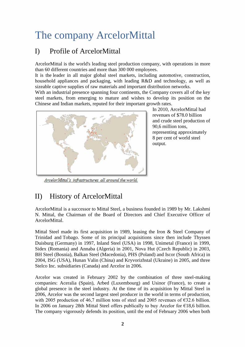
ArcelorMittal is the world's leading steel production company, with operations in more
than 60 different countries and more than 300 000 employees.
It is the leader in all major global steel markets, including automotive, construction,
household appliances and packaging, with leading R&D and technology, as well as
sizeable captive supplies of raw materials and important distribution networks.
With an industrial presence spanning four continents, the Company covers all of the key
steel markets, from emerging to mature and wishes to develop its position on the
Chinese and Indian markets, reputed for their important growth rates.
In 2010, ArcelorMittal had
revenues of $78.0 billion
and crude steel production of
90,6 million tons,
representing approximately
8 per cent of world steel
output.
II) History of ArcelorMittal
ArcelorMittal is a successor to Mittal Steel, a business founded in 1989 by Mr. Lakshmi
N. Mittal, the Chairman of the Board of Directors and Chief Executive Officer of
ArcelorMittal.
Mittal Steel made its first acquisition in 1989, leasing the Iron & Steel Company of
Trinidad and Tobago. Some of its principal acquisitions since then include Thyssen
Duisburg (Germany) in 1997, Inland Steel (USA) in 1998, Unimetal (France) in 1999,
Sidex (Romania) and Annaba (Algeria) in 2001, Nova Hut (Czech Republic) in 2003,
BH Steel (Bosnia), Balkan Steel (Macedonia), PHS (Poland) and Iscor (South Africa) in
2004, ISG (USA), Hunan Valin (China) and Kryvorizhstal (Ukraine) in 2005, and three
Stelco Inc. subsidiaries (Canada) and Arcelor in 2006.
Arcelor was created in February 2002 by the combination of three steel-making
companies: Aceralia (Spain), Arbed (Luxembourg) and Usinor (France), to create a
global presence in the steel industry. At the time of its acquisition by Mittal Steel in
2006, Arcelor was the second largest steel producer in the world in terms of production,
with 2005 production of 46,7 million tons of steel and 2005 revenues of €32.6 billion.
In 2006 on January 28th Mittal Steel offers publically to buy Arcelor for €18,6 billion.
The company vigorously defends its position, until the end of February 2006 when both

3
companies’ market capitalizations are almost the same. The fusion of both groups gives
birth to ArcelorMittal.
In 2007, ArcelorMittal continued to pursue a disciplined growth strategy, with a total of
35 transactions all around the world, and numbers of them were completed in 2007.
During 2007, ArcelorMittal also announced or completed buy-out offers for minority
interests in certain of its subsidiaries in Argentina, Brazil and Poland. ArcelorMittal also
initiated development plans for its greenfield projects in India, Liberia and Senegal and
announced new prospective development projects in Mauritania, Mozambique, Nigeria,
Russia, Saudi Arabia and Turkey.
During the first eight months of 2008, ArcelorMittal continued making investments,
with significant transactions announced in Australia, Brazil, Canada, Costa Rica,
France, Russia, South Africa, Sweden, Turkey, United Arab Emirates, the United
States, and Venezuela, the majority of which have been completed. More recently,
ArcelorMittal's acquisitions are focused on raw material producers and production sites.
4
Part 1: The process of steel making
I) General description of steel making
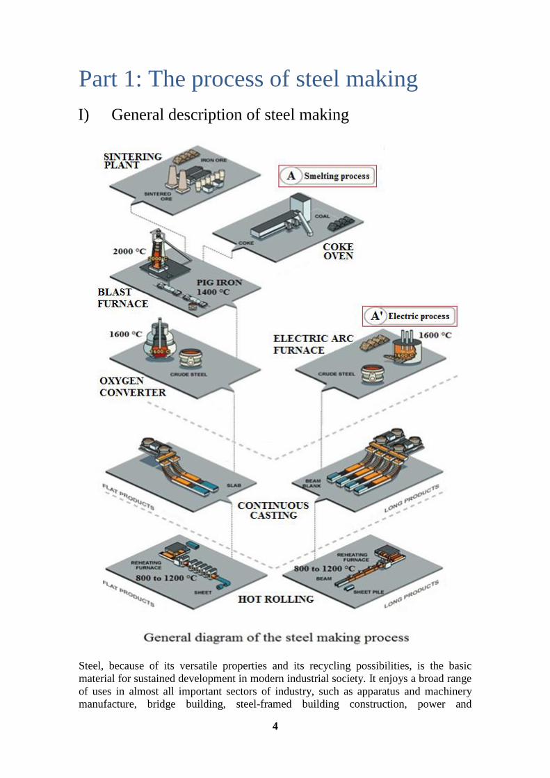
Steel, because of its versatile properties and its recycling possibilities, is the basic
material for sustained development in modern industrial society. It enjoys a broad range
of uses in almost all important sectors of industry, such as apparatus and machinery
manufacture, bridge building, steel-framed building construction, power and
5
environmental engineering, transportation, and the packaging industry, to name just a
few.
Raw materials for steel production are coal and iron (imported predominantly from
Brazil, Canada, Australia and Sweden). The coal is transported from the storage to the
coke plant, where metallurgical coke is obtained. The iron ore is sintered and taken to
the blast furnace where it is mixed with coke, lime and blown air to produce pig iron.
The pig iron is conveyed to the reduction oven or as we can also name it the basic
oxygen furnace where pure oxygen is injected to reduce pig iron in steel. Steel is then
molded into sheets, blocks and other forms through continuous casting and hot rolling.
Continuous casting consists in producing steel products such as rails, beams or slabs
through the use of molds. We are not going to describe this process because we are
more interested in the hot rolling process, which takes the slabs, heat them and flatten
them into coils. Coils can be used to build cars, cans, household appliance … It is thus
the main product of any steel plant, that’s why we are going to focus on describing this
process instead of the continuous casting one.
As we can see on the general diagram of steel making there are two ways to produce
steel, A and A’. In our study we are going to work with the A way because it is the one
that was used in the Avilés steel plant.
We are thus going to describe the following processes within the steel plant:
- The sintering plant
- The coke oven
- The blast furnace
- The basic oxygen furnace (object of our study) also called oxygen converter
- The hot rolling
With the A’ way we use an electric arc furnace to produce steel by using steel and iron
scrap. The electric arc furnace allows us to transforms electrical energy into melting
heat by using electrodes to conduct the electrical current and create the arc to the
metallic charge. Nowadays this process is less used than the one we are going to work
on.
The description of the basic oxygen furnace process is obviously going to be more
detailed than the other processes in this study.
6
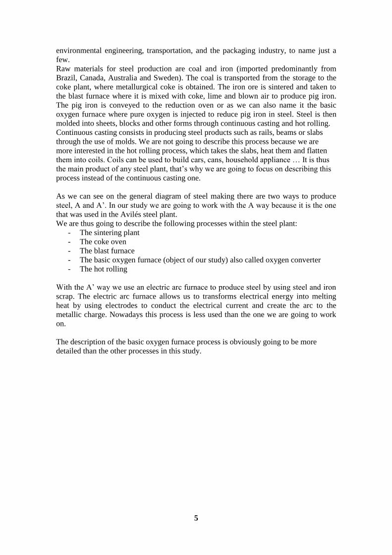
II) The sintering plant
Sintering is the welding together of small particles of metal by applying heat below
the melting point.
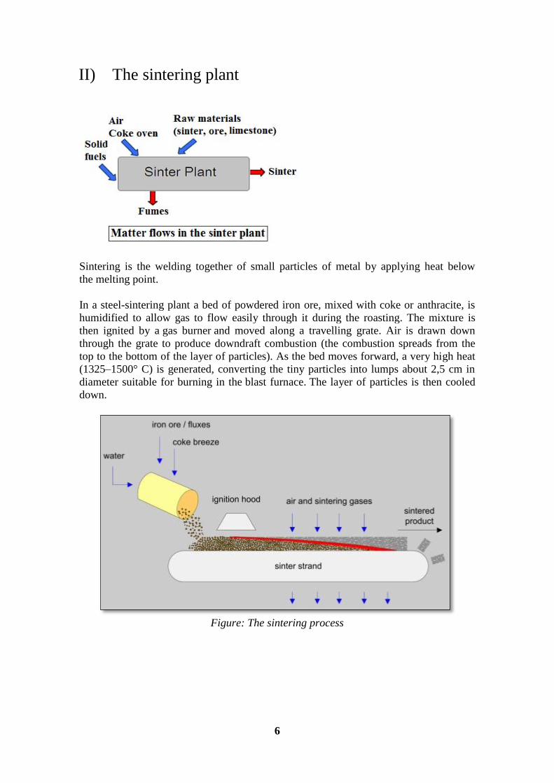
In a steel-sintering plant a bed of powdered iron ore, mixed with coke or anthracite, is
humidified to allow gas to flow easily through it during the roasting. The mixture is
then ignited by a gas burner and moved along a travelling grate. Air is drawn down
through the grate to produce downdraft combustion (the combustion spreads from the
top to the bottom of the layer of particles). As the bed moves forward, a very high heat
(1325–1500° C) is generated, converting the tiny particles into lumps about 2,5 cm in
diameter suitable for burning in the blast furnace. The layer of particles is then cooled
down.
Figure: The sintering process

7
III) The coke oven
Coke is obtained by heating up coal to 1000°C in silicon furnaces. During the pyrolysis
the coal releases gas, tar and water. The gas is purified before its reuse and the water
treated before being released in the environment.
The heart of the process is the coking battery comprising a number of tall, narrow
ovens. Coking is a dry distillation process, i.e., combustion without access to oxygen.
The coal is charged by ―coal machines‖ above the oven battery.
The ovens have brick partitions in which the heating wall channels are heated by the gas
generated in the coking battery itself, possibly mixed with blast furnace gas. The coal is
heated in the narrow, airtight ovens until it is in an almost flowing, plastic form.
The elements that are to be removed will then be gasified. The process takes about 18
hours. The temperature is above 1,000°C, and the coal is converted to 75 percent coke
and 25 percent gas. The coking plant has a number of processes in which the gas is
cleaned in several stages and many raw materials are recovered.
The most important is the cleaned gas that supplies energy to the processes of the
coking plant itself and to other users, such as the blast furnace. But raw materials are
also recovered for the chemical process industry, such as sulphur in desulphurizing,
fertilizers for agriculture, tar and asphalt. The end customers of the coking plant include
manufacturers of perfumes and pharmaceuticals.
8
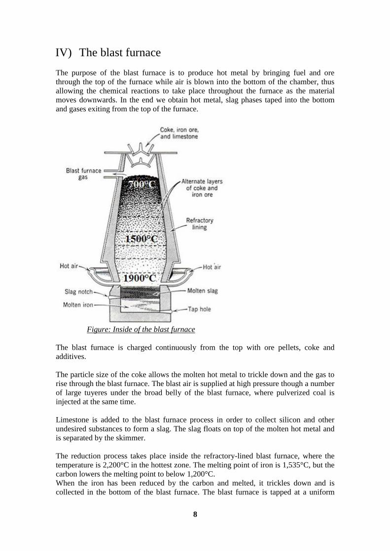
IV) The blast furnace
The purpose of the blast furnace is to produce hot metal by bringing fuel and ore
through the top of the furnace while air is blown into the bottom of the chamber, thus
allowing the chemical reactions to take place throughout the furnace as the material
moves downwards. In the end we obtain hot metal, slag phases taped into the bottom
and gases exiting from the top of the furnace.
Figure: Inside of the blast furnace
The blast furnace is charged continuously from the top with ore pellets, coke and
additives.
The particle size of the coke allows the molten hot metal to trickle down and the gas to
rise through the blast furnace. The blast air is supplied at high pressure though a number
of large tuyeres under the broad belly of the blast furnace, where pulverized coal is
injected at the same time.
Limestone is added to the blast furnace process in order to collect silicon and other
undesired substances to form a slag. The slag floats on top of the molten hot metal and
is separated by the skimmer.
The reduction process takes place inside the refractory-lined blast furnace, where the
temperature is 2,200°C in the hottest zone. The melting point of iron is 1,535°C, but the
carbon lowers the melting point to below 1,200°C.
When the iron has been reduced by the carbon and melted, it trickles down and is
collected in the bottom of the blast furnace. The blast furnace is tapped at a uniform
9
rate. Tapping takes place during about 2 hours and is then interrupted for 40-50 minutes
before the next tapping.
The released gas is composed with carbon monoxide CO and carbon dioxide CO2,
which is discharged from the blast furnace through large gas pipes to a gas treatment
plant. The carbon monoxide is rich in energy, and the blast furnace gas is recovered as
energy for the processes of the blast furnace itself and for other energy customers in the
steelworks, and also for power generation and for district heating (see the section on
Energy).
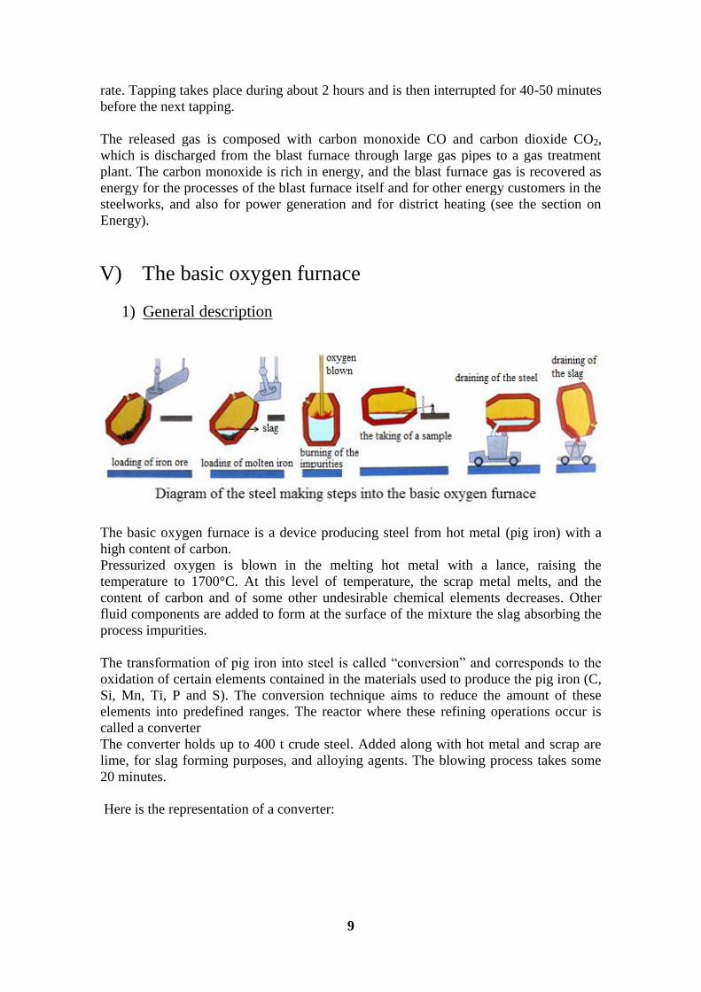
V) The basic oxygen furnace
1) General description
The basic oxygen furnace is a device producing steel from hot metal (pig iron) with a
high content of carbon.
Pressurized oxygen is blown in the melting hot metal with a lance, raising the
temperature to 1700°C. At this level of temperature, the scrap metal melts, and the
content of carbon and of some other undesirable chemical elements decreases. Other
fluid components are added to form at the surface of the mixture the slag absorbing the
process impurities.
The transformation of pig iron into steel is called ―conversion‖ and corresponds to the
oxidation of certain elements contained in the materials used to produce the pig iron (C,
Si, Mn, Ti, P and S). The conversion technique aims to reduce the amount of these
elements into predefined ranges. The reactor where these refining operations occur is
called a converter
The converter holds up to 400 t crude steel. Added along with hot metal and scrap are
lime, for slag forming purposes, and alloying agents. The blowing process takes some
20 minutes.
Here is the representation of a converter:
10
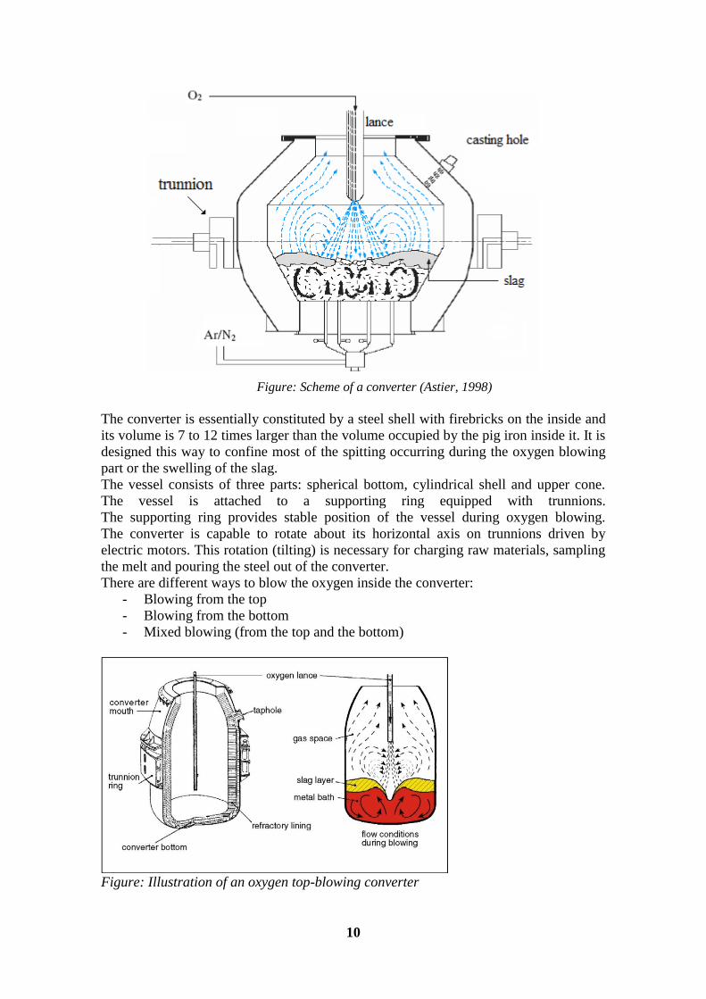
Figure: Scheme of a converter (Astier, 1998)
The converter is essentially constituted by a steel shell with firebricks on the inside and
its volume is 7 to 12 times larger than the volume occupied by the pig iron inside it. It is
designed this way to confine most of the spitting occurring during the oxygen blowing
part or the swelling of the slag.
The vessel consists of three parts: spherical bottom, cylindrical shell and upper cone.
The vessel is attached to a supporting ring equipped with trunnions.
The supporting ring provides stable position of the vessel during oxygen blowing.
The converter is capable to rotate about its horizontal axis on trunnions driven by
electric motors. This rotation (tilting) is necessary for charging raw materials, sampling
the melt and pouring the steel out of the converter.
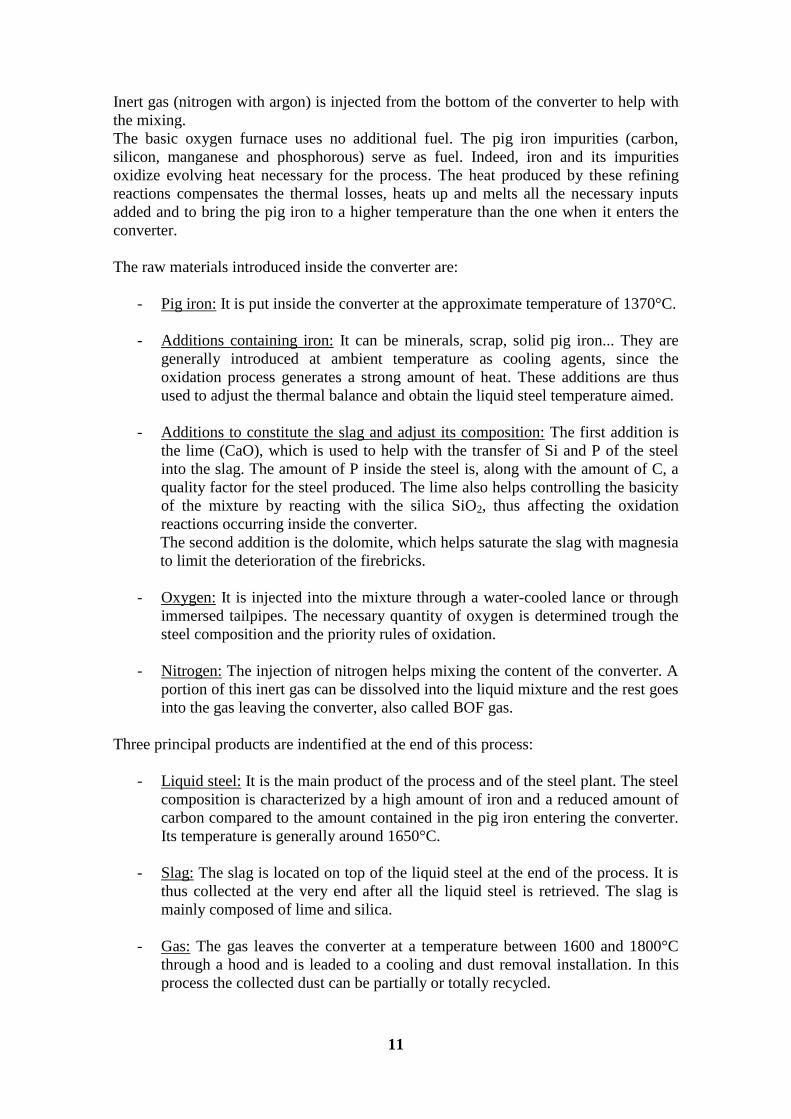
There are different ways to blow the oxygen inside the converter:
- Blowing from the top
- Blowing from the bottom
- Mixed blowing (from the top and the bottom)
Figure: Illustration of an oxygen top-blowing converter
11
Inert gas (nitrogen with argon) is injected from the bottom of the converter to help with
the mixing.
The basic oxygen furnace uses no additional fuel. The pig iron impurities (carbon,
silicon, manganese and phosphorous) serve as fuel. Indeed, iron and its impurities
oxidize evolving heat necessary for the process. The heat produced by these refining
reactions compensates the thermal losses, heats up and melts all the necessary inputs
added and to bring the pig iron to a higher temperature than the one when it enters the
converter.
The raw materials introduced inside the converter are:
- Pig iron: It is put inside the converter at the approximate temperature of 1370°C.
- Additions containing iron: It can be minerals, scrap, solid pig iron... They are
generally introduced at ambient temperature as cooling agents, since the
oxidation process generates a strong amount of heat. These additions are thus
used to adjust the thermal balance and obtain the liquid steel temperature aimed.
- Additions to constitute the slag and adjust its composition: The first addition is
the lime (CaO), which is used to help with the transfer of Si and P of the steel
into the slag. The amount of P inside the steel is, along with the amount of C, a
quality factor for the steel produced. The lime also helps controlling the basicity
of the mixture by reacting with the silica SiO2, thus affecting the oxidation
reactions occurring inside the converter.
The second addition is the dolomite, which helps saturate the slag with magnesia
to limit the deterioration of the firebricks.
- Oxygen: It is injected into the mixture through a water-cooled lance or through
immersed tailpipes. The necessary quantity of oxygen is determined trough the
steel composition and the priority rules of oxidation.
- Nitrogen: The injection of nitrogen helps mixing the content of the converter. A
portion of this inert gas can be dissolved into the liquid mixture and the rest goes
into the gas leaving the converter, also called BOF gas.
Three principal products are indentified at the end of this process:
- Liquid steel: It is the main product of the process and of the steel plant. The steel
composition is characterized by a high amount of iron and a reduced amount of
carbon compared to the amount contained in the pig iron entering the converter.
Its temperature is generally around 1650°C.
- Slag: The slag is located on top of the liquid steel at the end of the process. It is
thus collected at the very end after all the liquid steel is retrieved. The slag is
mainly composed of lime and silica.
- Gas: The gas leaves the converter at a temperature between 1600 and 1800°C
through a hood and is leaded to a cooling and dust removal installation. In this
process the collected dust can be partially or totally recycled.
12
The ratio pig iron/scrap put in the oven changes from a plant to another, following the
economic circumstances.
All the oxidation reactions are strongly exothermic, and the energy produced is higher
than the one necessary to heat up the pig iron (1350-1400°C) to the temperature wanted
for the steel (1650-1665°C) and to heat up and dissolve into the slag the lime and the
dolomite. The remaining energy is used to melt the scrap and/or reduce and melt the
iron ore.
2) Physico-chemical characterization of the conversion
The reactions occurring inside the converter are the refining reactions on the pig iron.
The refining reactions correspond with the oxidation reactions. They happen very
quickly and are triggered by the contact between the oxygen and the liquid metal.
Whatever the way of blowing the oxygen, as soon as they both interact the dissolved
elements (C, Si, Mn, P) are oxidized until there is no oxygen left (iron is also consumed
with the oxygen in this process because its initial amount is very high).
It is the FeO created that oxidizes the silicon, the manganese, the phosphorus and the
carbon (Sollac, 1976). Due to its reduced solubility into the metallic bath, the FeO
remaining goes to the surface, helping form the slag.
The silicon contained in the pig iron is irreversibly oxidized and after a few minutes its
amount in the metal is already really low. The main part of the silica formed goes in the
slag and the rest reacts with the lime to form Ca2SiO4.
The oxidations of manganese and silicon occur simultaneously. One part of the MnO
produced goes into the slag and the rest is decomposed and the manganese returns back
into the bath.
The formation of P2O5 is only possible in the presence of CaO and gives for example
P2O5(CaO)3.
When almost all of Si is consumed the oxygen contained in FeO reacts with the carbon
to give CO. This reaction is the one consuming the bigger part of the oxygen. When the
lance used to blow the oxygen is submerged, some of the CO produced is oxidized into
CO2. This reaction is called post combustion and only a part of the energy supplied is
retrieved by the gas.
The sulfur is principally brought into the converter via the pig iron. At high
temperatures (1600-1800°C) and when the slag is basic, it is possible to realize a
desulfurization of the pig iron. The more basic the slag is, the better this operation
works.
The reduction of the iron oxide Fe2O3 contained in the iron ore is supposedly managed
by the carbon (Huber, 2005).
Usually the refining part is studied by simplifying the chemical reactions occurring
inside the converter. Here are the reactions we are going to work on:

13
The oxygen converter (basic oxygen furnace) we chose to study is the one used in the
steel factory of Avilés (Spain), where this internship took place.
14
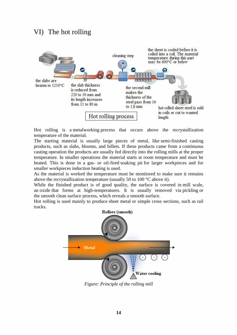
VI) The hot rolling
Hot rolling is a metalworking process that occurs above the recrystallization
temperature of the material.
The starting material is usually large pieces of metal, like semi-finished casting
products, such as slabs, blooms, and billets. If these products came from a continuous
casting operation the products are usually fed directly into the rolling mills at the proper
temperature. In smaller operations the material starts at room temperature and must be
heated. This is done in a gas- or oil-fired soaking pit for larger workpieces and for
smaller workpieces induction heating is used.
As the material is worked the temperature must be monitored to make sure it remains
above the recrystallization temperature (usually 50 to 100 °C above it).
While the finished product is of good quality, the surface is covered in mill scale,
an oxide that forms at high-temperatures. It is usually removed via pickling or
the smooth clean surface process, which reveals a smooth surface.
Hot rolling is used mainly to produce sheet metal or simple cross sections, such as rail
tracks.
Figure: Principle of the rolling mill
15
Part 2: Energy analysis of the basic
oxygen furnace
In the basic oxygen furnace the only energies involved are thermal energy (associated
with a change in temperature of the different inputs or outputs of the process) and the
energy associated with the reactions occurring inside the converter.
I) Calculation of the thermal energy
As mentioned before, the thermal energy is associated with a change in temperature.
When the different inputs of the process get inside the converter and the oxygen is
blown up, some reactions occur, raising the temperature of these inputs and thus
creating energy.
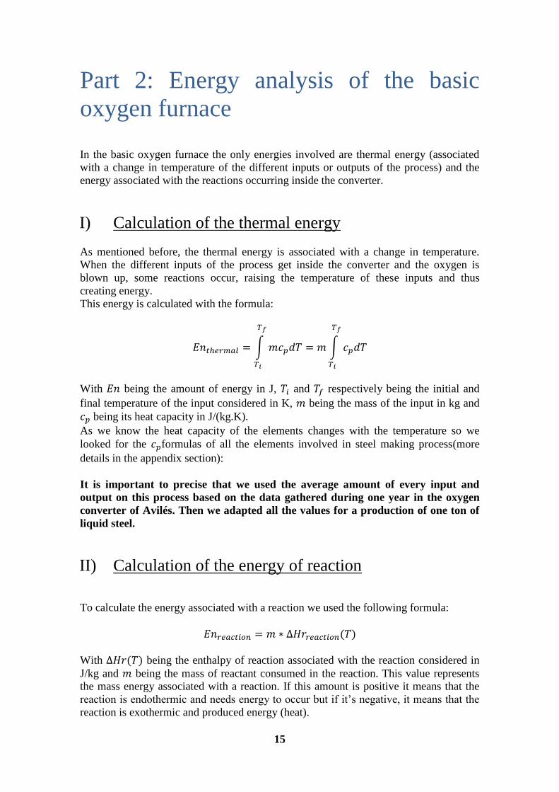
This energy is calculated with the formula:
With being the amount of energy in J, and respectively being the initial and
final temperature of the input considered in K, being the mass of the input in kg and
being its heat capacity in J/(kg.K).
As we know the heat capacity of the elements changes with the temperature so we
looked for the formulas of all the elements involved in steel making process(more
details in the appendix section):
It is important to precise that we used the average amount of every input and
output on this process based on the data gathered during one year in the oxygen
converter of Avilés. Then we adapted all the values for a production of one ton of
liquid steel.
II) Calculation of the energy of reaction
To calculate the energy associated with a reaction we used the following formula:
With being the enthalpy of reaction associated with the reaction considered in
J/kg and being the mass of reactant consumed in the reaction. This value represents
the mass energy associated with a reaction. If this amount is positive it means that the
reaction is endothermic and needs energy to occur but if it’s negative, it means that the
reaction is exothermic and produced energy (heat).
16
It is pretty hard to determine precisely the mass of reactant consumed in each reaction
because we are not really sure of what’s happening inside the converter. It is said that
the iron contained in the hot metal and in the scrap is oxidized by the oxygen blown in
the converter through a lance. The FeO produced then reacts with the other components
of the hot metal (Si, Mn, P and C) to produced oxides going in the slag. This
information was found in the reference:
- Chapitre V. Modélisation physico-chimique du convertisseur à oxygène et du
laminoir à chaud pour l’analyse de l’ICV.
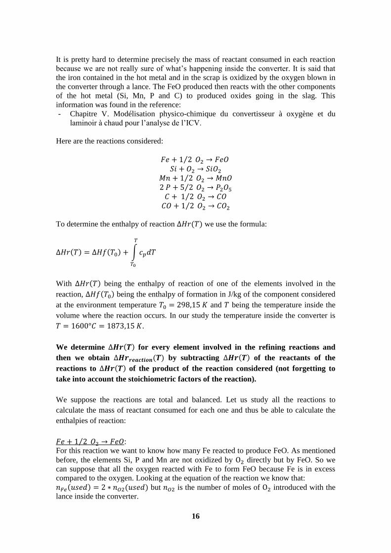
Here are the reactions considered:
To determine the enthalpy of reaction we use the formula:
With being the enthalpy of reaction of one of the elements involved in the
reaction, being the enthalpy of formation in J/kg of the component considered
at the environment temperature and being the temperature inside the
volume where the reaction occurs. In our study the temperature inside the converter is
.
We determine for every element involved in the refining reactions and
then we obtain by subtracting of the reactants of the
reactions to of the product of the reaction considered (not forgetting to
take into account the stoichiometric factors of the reaction).
We suppose the reactions are total and balanced. Let us study all the reactions to
calculate the mass of reactant consumed for each one and thus be able to calculate the
enthalpies of reaction:
:
For this reaction we want to know how many Fe reacted to produce FeO. As mentioned
before, the elements Si, P and Mn are not oxidized by directly but by FeO. So we
can suppose that all the oxygen reacted with Fe to form FeO because Fe is in excess
compared to the oxygen. Looking at the equation of the reaction we know that:
but is the number of moles of introduced with the
lance inside the converter.
17
:
In this reaction we can see that all the Si contained in the hot metal is consumed and
there is no Si left in the liquid steel so we can use the mass of Si inside the hot metal to
determine the energy associated with this reaction.
:
Here it is the same thing than the reaction before except that there is still Mn left in the
liquid steel so we determined the mass of Mn consumed by subtracting the mass of Mn
In liquid steel to the mass of Mn in hot metal.
With this reaction we used the same method that we used in the previous one.
With this reaction we used the same method that we used in the two previous ones.
:
Based on the last reaction we know that so we can find
the mass of CO produced. Since we know what mass of CO remains in the BOF gas, we
can determine what mass of CO reacted to produce
III) Results of the energy analysis
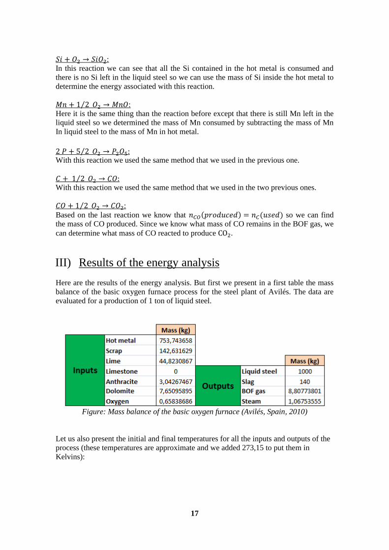
Here are the results of the energy analysis. But first we present in a first table the mass
balance of the basic oxygen furnace process for the steel plant of Avilés. The data are
evaluated for a production of 1 ton of liquid steel.
Figure: Mass balance of the basic oxygen furnace (Avilés, Spain, 2010)
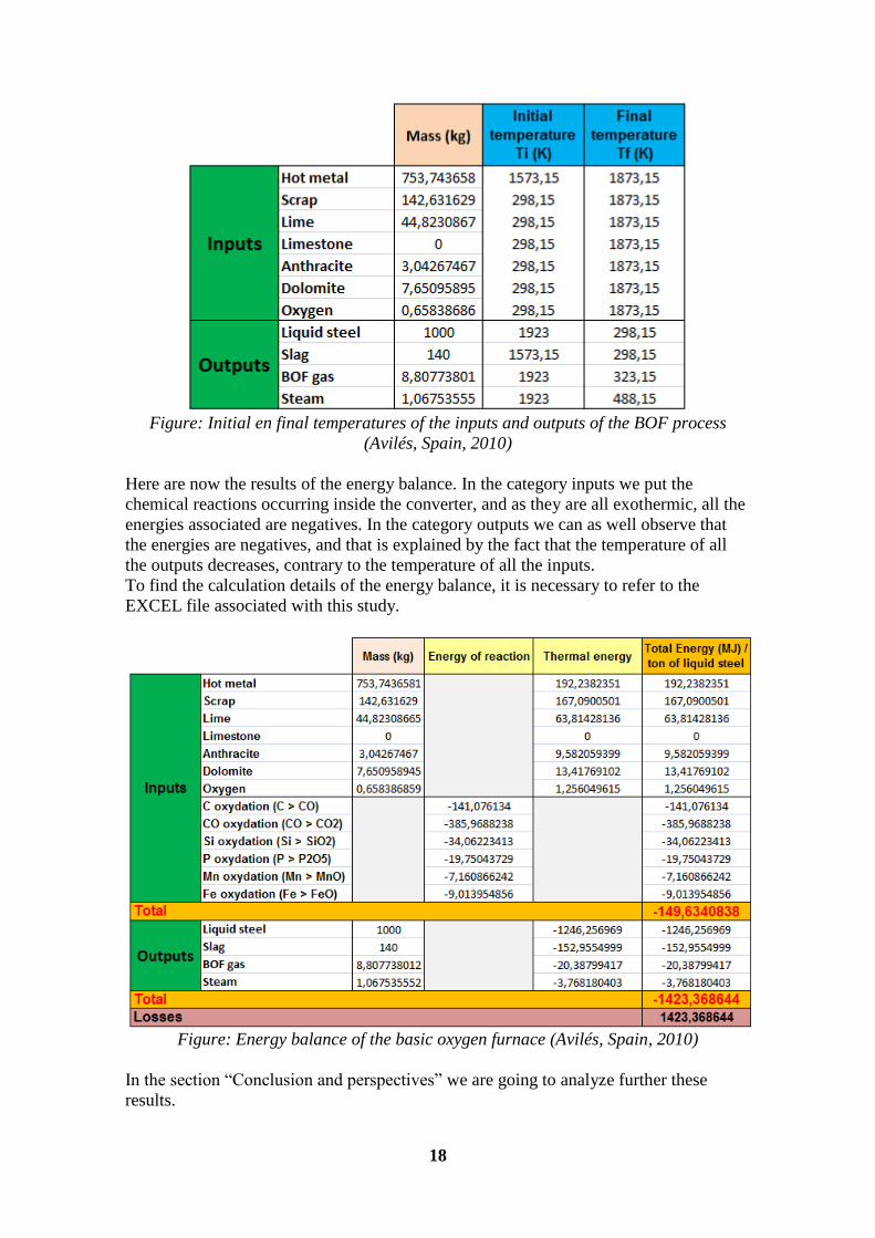
Let us also present the initial and final temperatures for all the inputs and outputs of the
process (these temperatures are approximate and we added 273,15 to put them in
Kelvins):
18
Figure: Initial en final temperatures of the inputs and outputs of the BOF process
(Avilés, Spain, 2010)
Here are now the results of the energy balance. In the category inputs we put the
chemical reactions occurring inside the converter, and as they are all exothermic, all the
energies associated are negatives. In the category outputs we can as well observe that
the energies are negatives, and that is explained by the fact that the temperature of all
the outputs decreases, contrary to the temperature of all the inputs.
To find the calculation details of the energy balance, it is necessary to refer to the
EXCEL file associated with this study.
Figure: Energy balance of the basic oxygen furnace (Avilés, Spain, 2010)
In the section ―Conclusion and perspectives‖ we are going to analyze further these
results.
19
Part 3: Exergy analysis of the basic
oxygen furnace
I) Presentation of the exergy concept
The first and second laws of thermodynamics are incontrovertible ―laws‖ in the
resolution of problems concerning energetic. The first law enunciates the equability of
diverse forms of energy (thermal, mechanical, electrical…) and allows us to examine
the energy flows to which the diverse systems are submitted.
However, we remark that even if there is quantitative equality of the diverse forms of
energy, the quality of these forms changes from one to the other, even inside one given
form, and also changes with the situations considered. Thereby, one MJ of thermal
energy at 1000°C doesn’t represent the same energetic ―potential‖ that one MJ of the
same thermal energy at 20°C. Similarly, the potential of use of one MJ of mechanical
energy quickly appears to be different from the one of one MJ of thermal energy.
Indeed, if mechanical energy can be spontaneously transformed into thermal energy
(through ―deterioration‖ for example), the reversed transformation, non spontaneous,
needs to proceed according a very specific scheme.
All these elements, linked with the energy quality and with the transformation of energy
constitute the second law of thermodynamics, also considered as an evolution law.
The physical quantity associated with this evolution is entropy whose creation we
observe for processes occurring outside of strict equilibrium, that is to say for all the
industrial operations which necessarily have to present a certain kinetic to occur in a
limited time. Thereby, the bigger the unbalance is in a process (heat transfer in a heat
exchanger for example) the bigger the power necessary is. But there is a drawback to
this observation: an important kinetic of transfer can be obtained by an important
deterioration of the energy (spontaneous and irreversible transformation of an energy
known to be ―noble‖ in heat) and an important creation of entropy.
Thereby, since a long time, entropy creation was used by scientists to measure the
deterioration of energy caused by the irreversibilities of the energetic transfers and
transformations. However, for the engineer, who is used to think in energetic terms in J,
MJ or kW.h, or in terms of power in watts, kW or MW, this measure isn’t practical.
Indeed, entropy, or its evolution in time, is measured in energy unit, or power unit, per
Kelvin (J.K−1
; W.K−1
).
This fact is at least one of the reasons why it is interesting to use the notion of exergy to
treat these problems of energy deterioration.
The exergy (unit: J), is the part of the energy amount for a specific transformation that
can be potentially retrieved in the form of work or electrical energy (these are
equivalently directly usable in a process). It is thus the maximum theoretical useful
work obtainable as the system interacts with the ambient. The rest of the energy amount
is called anergy and it's the part of energy that cannot be retrieved.
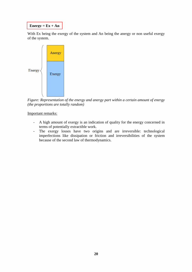
So we can write the energy of a system as following:
20
With Ex being the exergy of the system and An being the anergy or non useful exergy
of the system.
Figure: Representation of the energy and anergy part within a certain amount of energy
(the proportions are totally random)
Important remarks:
- A high amount of exergy is an indication of quality for the energy concerned in
terms of potentially extractible work.
- The exergy losses have two origins and are irreversible: technological
imperfections like dissipation or friction and irreversibilities of the system
because of the second law of thermodynamics.
Energy = Ex + An
21
II) General calculation of exergy
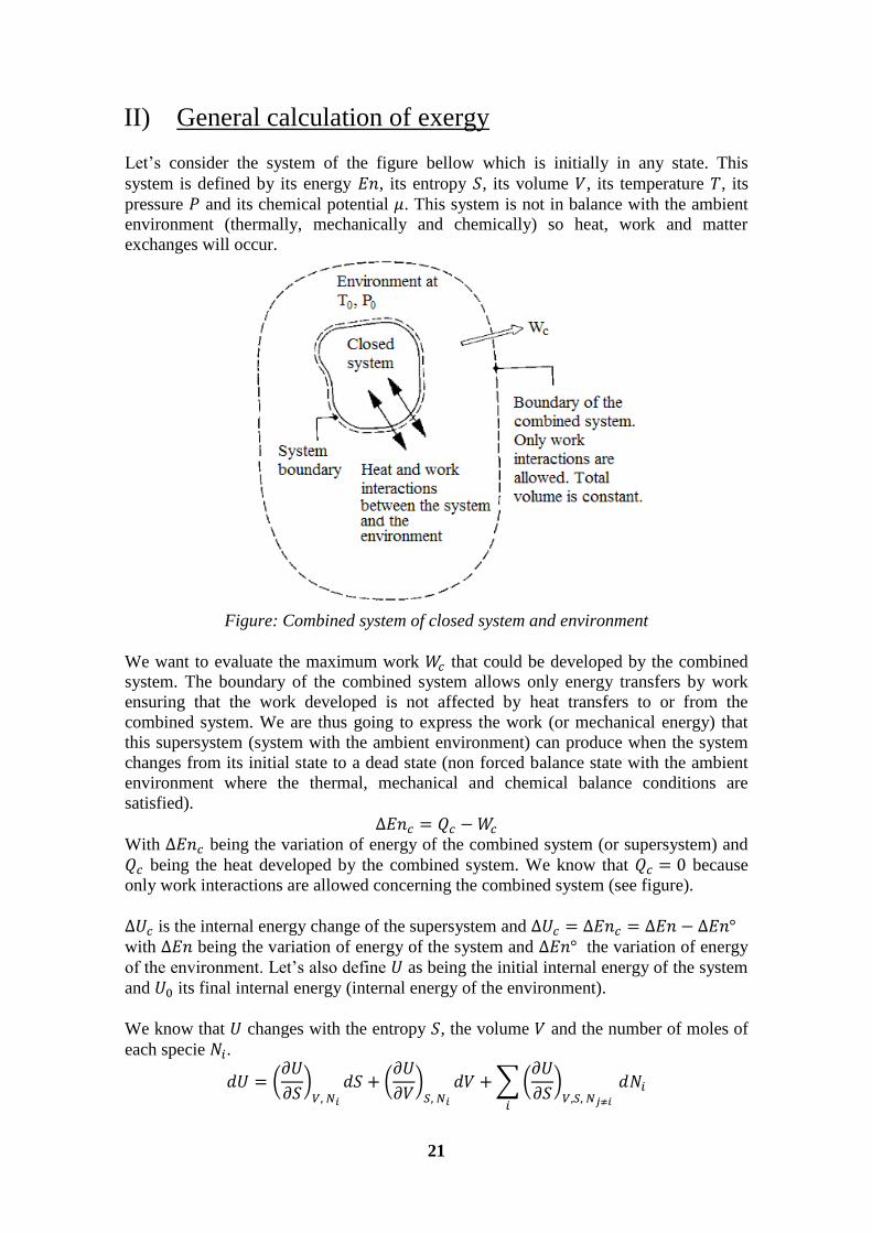
Let’s consider the system of the figure bellow which is initially in any state. This
system is defined by its energy , its entropy , its volume , its temperature , its
pressure and its chemical potential . This system is not in balance with the ambient
environment (thermally, mechanically and chemically) so heat, work and matter
exchanges will occur.
Figure: Combined system of closed system and environment
We want to evaluate the maximum work that could be developed by the combined
system. The boundary of the combined system allows only energy transfers by work
ensuring that the work developed is not affected by heat transfers to or from the
combined system. We are thus going to express the work (or mechanical energy) that
this supersystem (system with the ambient environment) can produce when the system
changes from its initial state to a dead state (non forced balance state with the ambient
environment where the thermal, mechanical and chemical balance conditions are
satisfied).
With being the variation of energy of the combined system (or supersystem) and
being the heat developed by the combined system. We know that because
only work interactions are allowed concerning the combined system (see figure).
is the internal energy change of the supersystem and with being the variation of energy of the system and the variation of energy
of the environment. Let’s also define as being the initial internal energy of the system
and its final internal energy (internal energy of the environment).
We know that changes with the entropy , the volume and the number of moles of
each specie .
22
But we know that for a .0closed system:
So for an open system: with
being the
chemical potential of the specie .
Since is an homogeneous function of the first degree with , and we can write:
so for the environment:
(the exponent ―°‖ refers to the environment while the index ―0‖ refers to the system
when it is in equilibrium with the environment).
And for a system of constant chemical composition:
So
And so
We know that the volume of the environment is really big compared to the volume of
the system so and we can replace with .
Likewise, so we can substitute with . We can say that because we want to express the maximum amount of work
(exergy) so we neglect the entropy production.
We also have:
-
-
-
-
So:
With being the variation of exergy of the supersystem.
But we know that
And that for a system balanced with the environment:
- - -
-
-
So:
All the different variations
concerning the system between
its initial state and the balanced
state with the environment
(described with the index ―0‖)
23
With being the exergy of the environment (always null), and being the exergy of
the system (which we are trying to evaluate).
but
So the exergy of a system can be calculated using the following general formula:
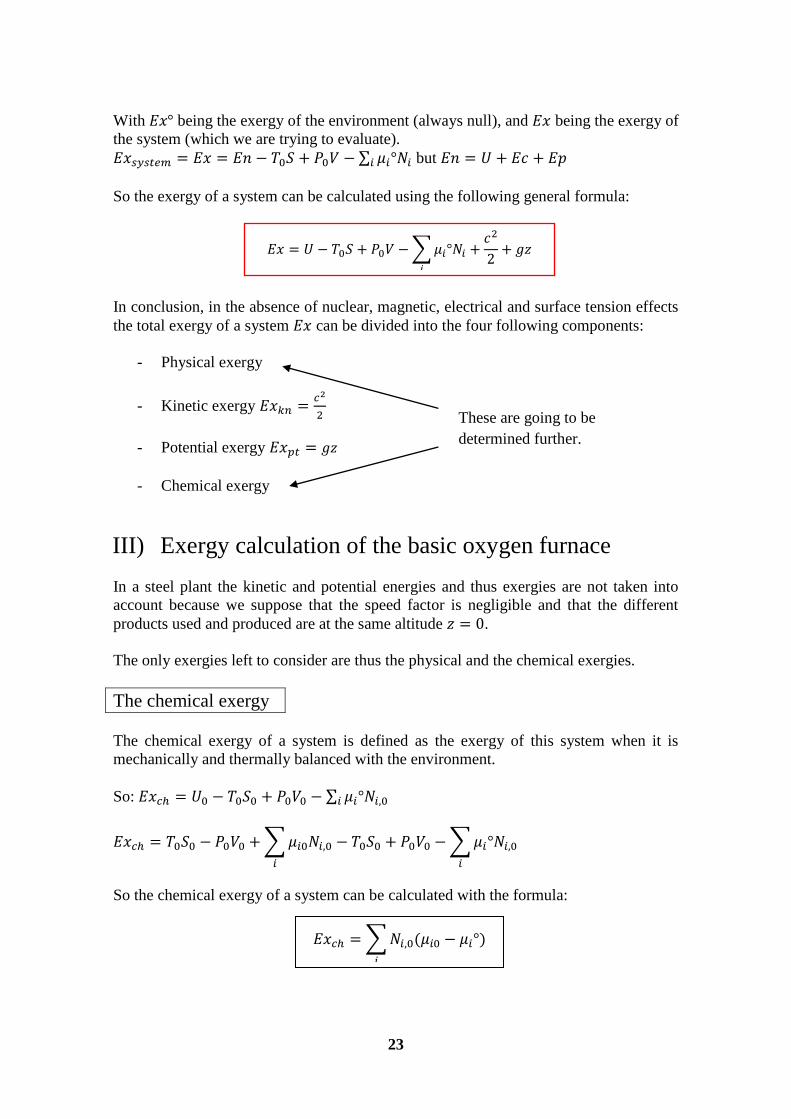
In conclusion, in the absence of nuclear, magnetic, electrical and surface tension effects
the total exergy of a system can be divided into the four following components:
- Physical exergy
- Kinetic exergy
- Potential exergy
- Chemical exergy
III) Exergy calculation of the basic oxygen furnace
In a steel plant the kinetic and potential energies and thus exergies are not taken into
account because we suppose that the speed factor is negligible and that the different
products used and produced are at the same altitude .
The only exergies left to consider are thus the physical and the chemical exergies.
The chemical exergy
The chemical exergy of a system is defined as the exergy of this system when it is
mechanically and thermally balanced with the environment.
So:
So the chemical exergy of a system can be calculated with the formula:
These are going to be
determined further.
24
With being the chemical potential of the specie within the environment (at and
) and being the chemical potential of the specie within the closed system in
equilibrium with the environment.
In most studies the chemical exergy is not taken into account because it is hard to
calculate and not really representative. In our study we chose to only consider physical
exergy because of these facts and also because in our energy analysis we only had
energies related with temperature changes and we wanted to do a direct comparison
between exergy and energy, which seemed simpler without the chemical exergy factor.
However, it is important to precise that it would be very interesting to learn more about
chemical exergy, how to evaluate it and what it exactly represents.
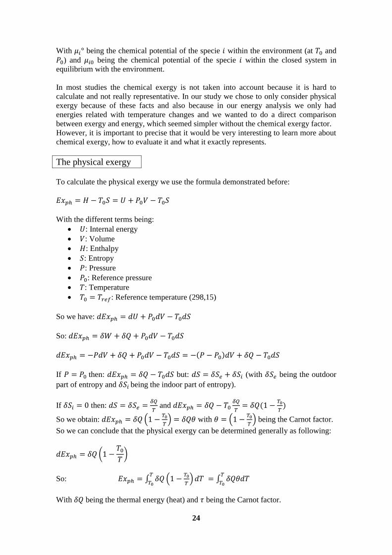
The physical exergy
To calculate the physical exergy we use the formula demonstrated before:
With the different terms being:
: Internal energy
: Volume
: Enthalpy
: Entropy
: Pressure
: Reference pressure
: Temperature
: Reference temperature (298,15)
So we have:
So:
If then: but: (with being the outdoor
part of entropy and being the indoor part of entropy).
If then:
and
So we obtain:
with
being the Carnot factor.
So we can conclude that the physical exergy can be determined generally as following:
So:
With being the thermal energy (heat) and being the Carnot factor.
25
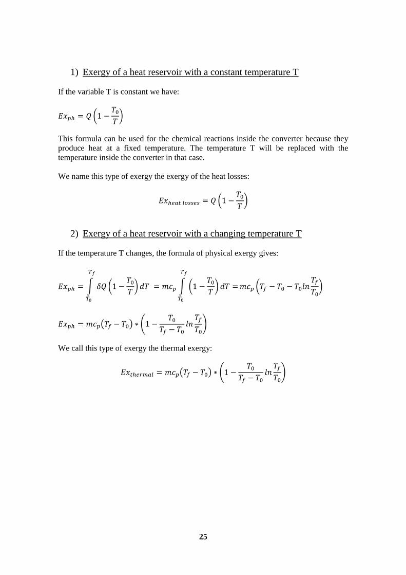
1) Exergy of a heat reservoir with a constant temperature T
If the variable T is constant we have:
This formula can be used for the chemical reactions inside the converter because they
produce heat at a fixed temperature. The temperature T will be replaced with the
temperature inside the converter in that case.
We name this type of exergy the exergy of the heat losses:
2) Exergy of a heat reservoir with a changing temperature T
If the temperature T changes, the formula of physical exergy gives:
We call this type of exergy the thermal exergy:
26
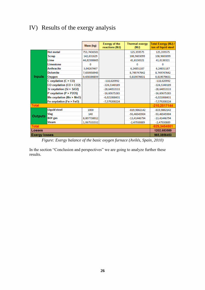
IV) Results of the exergy analysis
Figure: Exergy balance of the basic oxygen furnace (Avilés, Spain, 2010)
In the section ―Conclusion and perspectives‖ we are going to analyze further these
results.
27
Presentation and interpretation of the
results
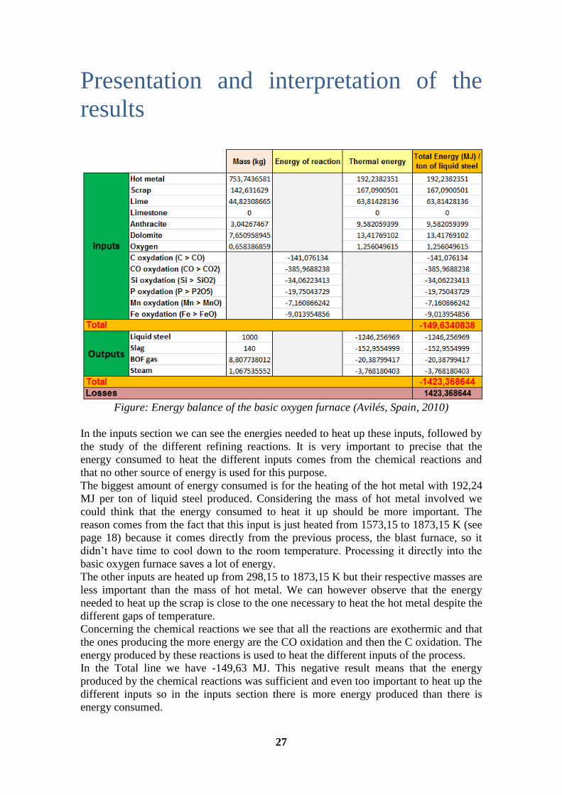
Figure: Energy balance of the basic oxygen furnace (Avilés, Spain, 2010)
In the inputs section we can see the energies needed to heat up these inputs, followed by
the study of the different refining reactions. It is very important to precise that the
energy consumed to heat the different inputs comes from the chemical reactions and
that no other source of energy is used for this purpose.
The biggest amount of energy consumed is for the heating of the hot metal with 192,24
MJ per ton of liquid steel produced. Considering the mass of hot metal involved we
could think that the energy consumed to heat it up should be more important. The
reason comes from the fact that this input is just heated from 1573,15 to 1873,15 K (see
page 18) because it comes directly from the previous process, the blast furnace, so it
didn’t have time to cool down to the room temperature. Processing it directly into the
basic oxygen furnace saves a lot of energy.
The other inputs are heated up from 298,15 to 1873,15 K but their respective masses are
less important than the mass of hot metal. We can however observe that the energy
needed to heat up the scrap is close to the one necessary to heat the hot metal despite the
different gaps of temperature.
Concerning the chemical reactions we see that all the reactions are exothermic and that
the ones producing the more energy are the CO oxidation and then the C oxidation. The
energy produced by these reactions is used to heat the different inputs of the process.
In the Total line we have -149,63 MJ. This negative result means that the energy
produced by the chemical reactions was sufficient and even too important to heat up the
different inputs so in the inputs section there is more energy produced than there is
energy consumed.
28
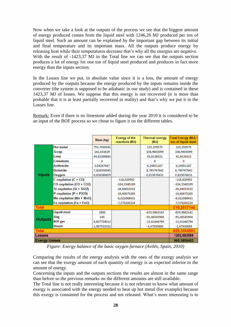
Now when we take a look at the outputs of the process we see that the biggest amount
of energy produced comes from the liquid steel with 1246,26 MJ produced per ton of
liquid steel. Such an amount can be explained by the important gap between its initial
and final temperature and its important mass. All the outputs produce energy by
releasing heat while their temperatures decrease that’s why all the energies are negative.
With the result of -1423,37 MJ in the Total line we can see that the outputs section
produces a lot of energy for one ton of liquid steel produced and produces in fact more
energy than the inputs section.
In the Losses line we put, in absolute value since it is a loss, the amount of energy
produced by the outputs because the energy produced by the inputs remains inside the
converter (the system is supposed to be adiabatic in our study) and is contained in these
1423,37 MJ of losses. We suppose that this energy is not recovered (it is more than
probable that it is at least partially recovered in reality) and that’s why we put it in the
Losses line.
Remark: Even if there is no limestone added during the year 2010 it is considered to be
an input of the BOF process so we chose to figure it on the different tables.
Figure: Exergy balance of the basic oxygen furnace (Avilés, Spain, 2010)
Comparing the results of the energy analysis with the ones of the exergy analysis we
can see that the exergy amount of each quantity of energy is as expected inferior to the
amount of energy.
Concerning the inputs and the outputs sections the results are almost in the same range
than before so the previous remarks on the different amounts are still available.
The Total line is not really interesting because it is not relevant to know what amount of
exergy is associated with the energy needed to heat up hot metal (for example) because
this exergy is consumed for the process and not released. What’s more interesting is to
29
know what amount of exergy can be retrieved from an amount of energy produced.
Here is the amount of exergy retrievable (in absolute value) on the inputs of the BOF
process:
. Concerning the chemical reactions, taking for example the amount of energy produced
by the oxidation of the carbon, we now know that on the 141,08 MJ of energy produced
only 118,62 MJ is pure exergy and can thus be retrieved. The rest of it, as mentioned
before, is lost and is called anergy.
In the outputs section the Total line represents the exergy retrievable on the outputs
(calculation we did before on the inputs part). The results of the exergy analysis show
that most of the exergy can be retrieved from the liquid steel and that the biggest the
energy is, the biggest the anergy is as well. We can thus now determine the real amount
of exergy we can hope to retrieve from the BOF process:
The losses are evaluated to be occurring at a temperature around 1873,15 K
(temperature inside the converter) so we determined the exergy associated with them
using this temperature and the formula of the exergy of the heat losses. We had no
information on the real temperature of the heat losses that’s why we had to make a
supposition. It is however easy to recalculate this result by referring to the exergy
calculation part (page 25) and by simply changing the temperature.
Finally the exergy losses represent the sum, in absolute value of all the anergies of the
process, also called exergies lost. This part cannot be retrieved and is definitively lost
(the origin of these losses is explained page 20).
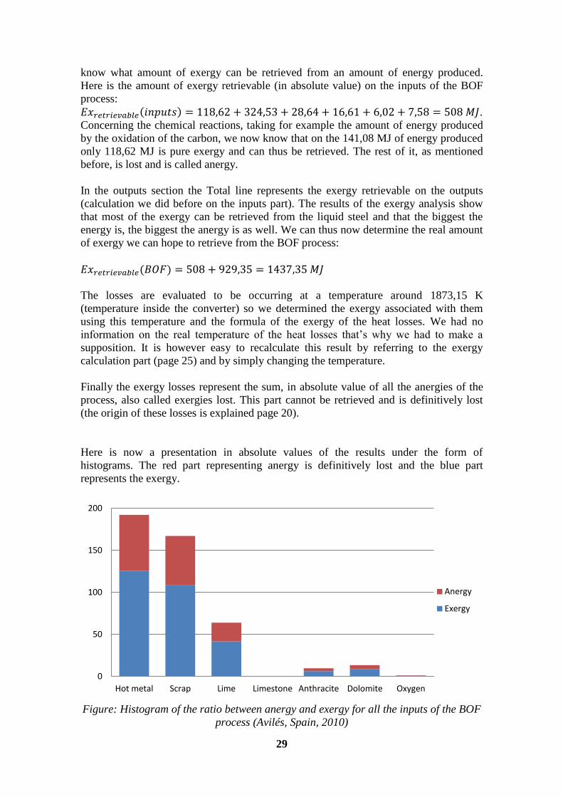
Here is now a presentation in absolute values of the results under the form of
histograms. The red part representing anergy is definitively lost and the blue part
represents the exergy.
Figure: Histogram of the ratio between anergy and exergy for all the inputs of the BOF
process (Avilés, Spain, 2010)
0
50
100
150
200
Hot metal Scrap Lime Limestone Anthracite Dolomite Oxygen
Anergy
Exergy
30
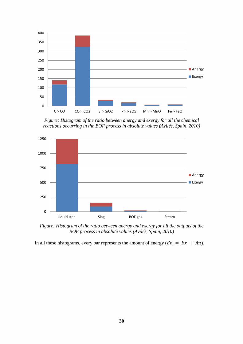
Figure: Histogram of the ratio between anergy and exergy for all the chemical
reactions occurring in the BOF process in absolute values (Avilés, Spain, 2010)
Figure: Histogram of the ratio between anergy and exergy for all the outputs of the
BOF process in absolute values (Avilés, Spain, 2010)
In all these histograms, every bar represents the amount of energy (
0
50
100
150
200
250
300
350
400
C > CO CO > CO2 Si > SiO2 P > P2O5 Mn > MnO Fe > FeO
Anergy
Exergy
0
250
500
750
1000
1250
Liquid steel Slag BOF gas Steam
Anergy
Exergy
31
Conclusions and perspectives
Conclusions of the analysis of the basic oxygen furnace:
This analysis was designed to compare energy and exergy analysis on the BOF process.
The results showed us the importance of the different streams within the process and
helped us quantify the real amount of retrievable energy (exergy) and its origin.
On this process we can conclude that there is more energy released than there is
consumed. We can thus imagine that the BOF process can be a good source of
improvement within the plant concerning exergy recuperation.
The exergy study is very interesting because it only takes into account exergy, so it fully
determines the real streams of usable energy in presence. It also helps us identify the
location and importance of the thermodynamic losses (exergy losses) and thus allows
the comparison of the different processes between them and with the environment (by
this mean we can then classify them in the order of their potential of improvement).
Regarding all these points it seems obvious that exergy analysis provides additional
information compared to a simple energy analysis because it can really identify where
we should really put the effort to retrieve energy and by this mean, economize it.
A good advantage of exergy analysis is that it can be used in different ways: an
environmental impact analysis will focus more on resource consumption and harm
caused by waste streams, whereas technical improvement of the process will be
achieved by pinpointing the main exergy losses and low exergy efficiencies.
Perspectives:
If this project is pursued, one important goal would be to study the other processes
within the steel plant and compare them to evaluate the most important losses and their
locations. This could be very interesting for the company in economical terms.
We can hope that it will be possible to analyze the different streams within the plant in
order to reduce the losses or to limit the impact of the plant on the environment.
Another goal to achieve in this work would be to fully determine what is called
―chemical exergy‖ and how to calculate it.
In conclusion, we can say that there's still a lot of work to accomplish concerning the
exergy analysis but that it seems to be an interesting concept to pursue studying.
32
Appendix
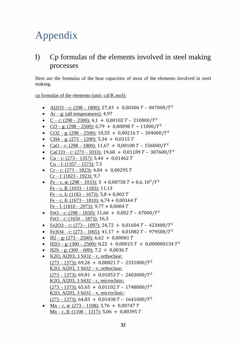
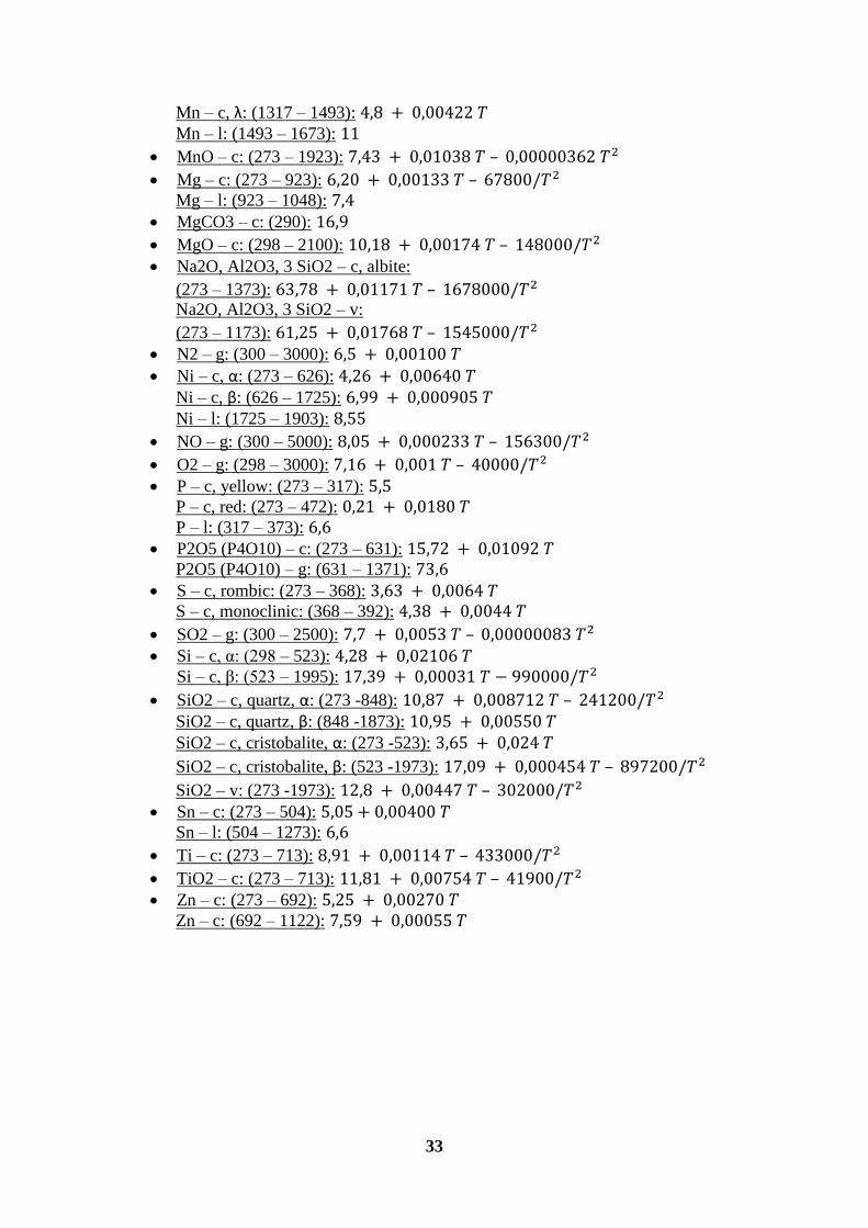
I) Cp formulas of the elements involved in steel making
processes
Here are the formulas of the heat capacities of most of the elements involved in steel
making.
cp formulas of the elements (unit: cal/K.mol):
Al2O3 – c: (298 – 1800): –
Ar – g: (all temperatures):
C – c: (298 – 2300): –
CO – g: (298 – 2500):
CO2 – g: (298 – 2500): –
CH4 – g: (273 – 1200):
CaO – c: (298 – 1800): –
CaCO3 – c: (273 – 1033): –
Cu – c: (273 – 1357):
Cu – l: (1357 – 1573): Cr – c: (273 – 1823):
Cr – l: (1823 - 1923): Fe – c, α: (298 – 1033):
Fe – c, β: (1033 – 1183): Fe – c, λ: (1183 – 1673): Fe – c, δ: (1673 – 1810): Fe – l: (1810 – 2973):
FeO – c: (298 – 1650): –
FeO – c: (1650 – 1873):
Fe2O3 – c: (273 – 1097): –
Fe3O4 – c: (273 – 1065): –
H2 – g: (273 – 2500):
H2O – g: (300 – 2500):
H2S – g: (300 – 600):
K2O, Al203, 3 SiO2 – c, orthoclase:
(273 – 1373): –
K2O, Al203, 3 SiO2 – v, orthoclase:
(273 – 1373): – K2O, Al203, 3 SiO2 – c, microclinic:
(273 – 1373): – K2O, Al203, 3 SiO2 – v, microclinic:
(273 – 1373): – Mn – c, α: (273 – 1108):
Mn – c, β: (1108 – 1317):
33
Mn – c, λ: (1317 – 1493): Mn – l: (1493 – 1673):
MnO – c: (273 – 1923): –
Mg – c: (273 – 923): –
Mg – l: (923 – 1048):
MgCO3 – c: (290):
MgO – c: (298 – 2100): –
Na2O, Al2O3, 3 SiO2 – c, albite:
(273 – 1373): –
Na2O, Al2O3, 3 SiO2 – v:
(273 – 1173): – N2 – g: (300 – 3000):
Ni – c, α: (273 – 626):
Ni – c, β: (626 – 1725): Ni – l: (1725 – 1903):
NO – g: (300 – 5000): –
O2 – g: (298 – 3000): –
P – c, yellow: (273 – 317):
P – c, red: (273 – 472): P – l: (317 – 373):
P2O5 (P4O10) – c: (273 – 631):
P2O5 (P4O10) – g: (631 – 1371): S – c, rombic: (273 – 368):
S – c, monoclinic: (368 – 392):
SO2 – g: (300 – 2500): –
Si – c, α: (298 – 523):
Si – c, β: (523 – 1995):
SiO2 – c, quartz, α: (273 -848): –
SiO2 – c, quartz, β: (848 -1873): SiO2 – c, cristobalite, α: (273 -523):
SiO2 – c, cristobalite, β: (523 -1973): –
SiO2 – v: (273 -1973): – Sn – c: (273 – 504):
Sn – l: (504 – 1273):
Ti – c: (273 – 713): –
TiO2 – c: (273 – 713): –
Zn – c: (273 – 692):
Zn – c: (692 – 1122):
34
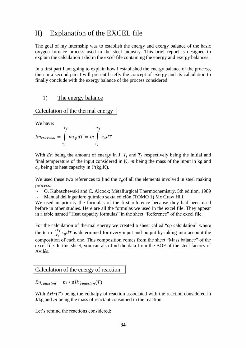
II) Explanation of the EXCEL file
The goal of my internship was to establish the energy and exergy balance of the basic
oxygen furnace process used in the steel industry. This brief report is designed to
explain the calculation I did in the excel file containing the energy and exergy balances.
In a first part I am going to explain how I established the energy balance of the process,
then in a second part I will present briefly the concept of exergy and its calculation to
finally conclude with the exergy balance of the process considered.
1) The energy balance
Calculation of the thermal energy
We have:
With being the amount of energy in J, and respectively being the initial and
final temperature of the input considered in K, being the mass of the input in kg and
being its heat capacity in J/(kg.K).
We used these two references to find the of all the elements involved in steel making
process:
- O. Kubaschewski and C. Alcock; Metallurgical Thermochemistry, 5th edition, 1989
- Manual del ingeniero químico sexta edición (TOMO 1) Mc Graw Hill
We used in priority the formulas of the first reference because they had been used
before in other studies. Here are all the formulas we used in the excel file. They appear
in a table named ―Heat capacity formulas‖ in the sheet ―Reference‖ of the excel file.
For the calculation of thermal energy we created a sheet called ―cp calculation‖ where
the term
is determined for every input and output by taking into account the
composition of each one. This composition comes from the sheet ―Mass balance‖ of the
excel file. In this sheet, you can also find the data from the BOF of the steel factory of
Avilés.
Calculation of the energy of reaction
With being the enthalpy of reaction associated with the reaction considered in
J/kg and being the mass of reactant consumed in the reaction.
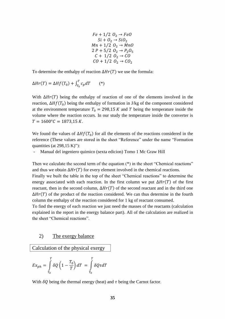
Let’s remind the reactions considered:
35
To determine the enthalpy of reaction we use the formula:
(*)
With being the enthalpy of reaction of one of the elements involved in the
reaction, being the enthalpy of formation in J/kg of the component considered
at the environment temperature and being the temperature inside the
volume where the reaction occurs. In our study the temperature inside the converter is
.
We found the values of for all the elements of the reactions considered in the
reference (These values are stored in the sheet ―Reference‖ under the name ―Formation
quantities (at 298,15 K)‖):
- Manual del ingeniero quimico (sexta edicion) Tomo 1 Mc Graw Hill
Then we calculate the second term of the equation (*) in the sheet ―Chemical reactions‖
and thus we obtain for every element involved in the chemical reactions.
Finally we built the table in the top of the sheet ―Chemical reactions‖ to determine the
energy associated with each reaction. In the first column we put of the first
reactant, then in the second column, of the second reactant and in the third one
of the product of the reaction considered. We can thus determine in the fourth
column the enthalpy of the reaction considered for 1 kg of reactant consumed.
To find the energy of each reaction we just need the masses of the reactants (calculation
explained in the report in the energy balance part). All of the calculation are realized in
the sheet ―Chemical reactions‖.
2) The exergy balance
Calculation of the physical exergy
With being the thermal energy (heat) and being the Carnot factor.
36
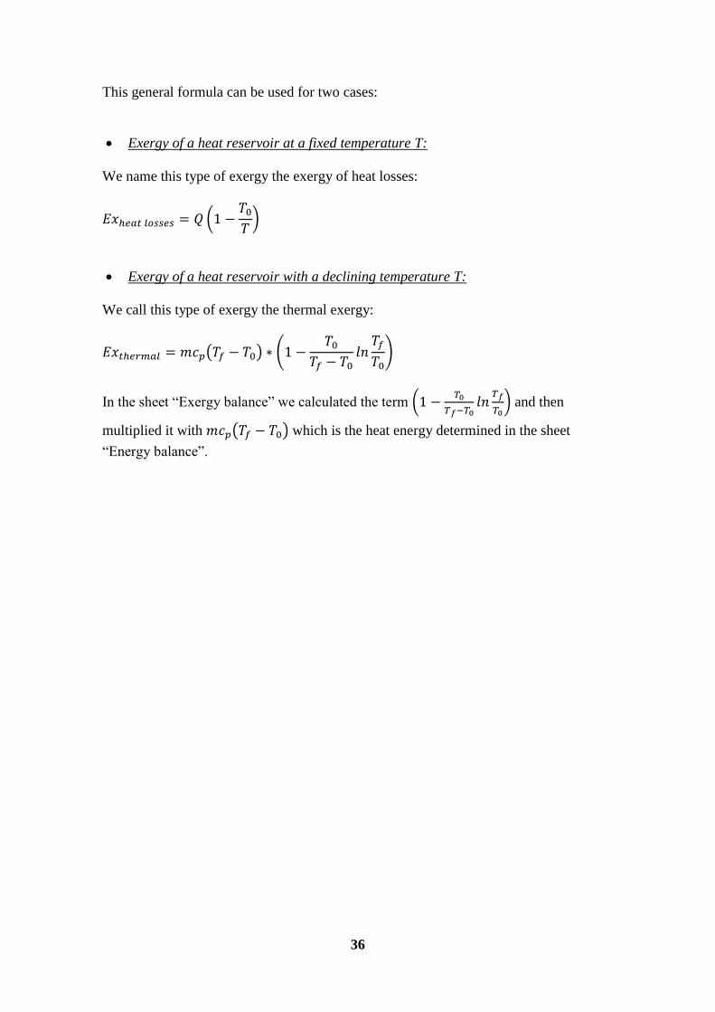
This general formula can be used for two cases:
Exergy of a heat reservoir at a fixed temperature T:
We name this type of exergy the exergy of heat losses:
Exergy of a heat reservoir with a declining temperature T:
We call this type of exergy the thermal exergy:
In the sheet ―Exergy balance‖ we calculated the term
and then
multiplied it with which is the heat energy determined in the sheet
―Energy balance‖.
37
References
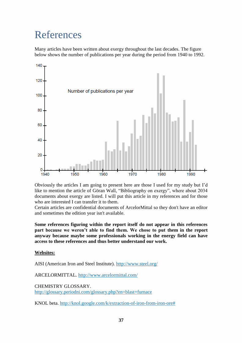
Many articles have been written about exergy throughout the last decades. The figure
below shows the number of publications per year during the period from 1940 to 1992.
Obviously the articles I am going to present here are those I used for my study but I’d
like to mention the article of Göran Wall, ―Bibliography on exergy‖, where about 2034
documents about exergy are listed. I will put this article in my references and for those
who are interested I can transfer it to them.
Certain articles are confidential documents of ArcelorMittal so they don't have an editor
and sometimes the edition year isn't available.
Some references figuring within the report itself do not appear in this references
part because we weren’t able to find them. We chose to put them in the report
anyway because maybe some professionals working in the energy field can have
access to these references and thus better understand our work.
Websites:
AISI (American Iron and Steel Institute). http://www.steel.org/
ARCELORMITTAL. http://www.arcelormittal.com/
CHEMISTRY GLOSSARY.
http://glossary.periodni.com/glossary.php?en=blast+furnace
KNOL beta. http://knol.google.com/k/extraction-of-iron-from-iron-ore#

38
SSAB. http://www.ssab.com/en/About-SSAB1/Steel-making-process/The-
metallurgical-process/Ore-based-hot-metal-and-steel/Cokoing-plant-and-blast-furnaces/
THERMOPTIM unit:
- http://www.thermoptim.org/sections/enseignement/cours-en-ligne/seances-
diapason/s06-bilans-exergetiques
- http://www.thermoptim.org/sections/bases-thermodynamique/principes/premier-
principe
- http://www.thermoptim.org/sections/bases-
thermodynamique/principes/deuxieme-principe
Web-Libre.org. http://www.web-libre.org/dossiers/arcelormittal,5780.html
WIKIPEDIA. http://fr.wikipedia.org/wiki/Exergie
http://www.faculty.ait.ac.th/visu/smi_roadmap/Publications/Project_Publications/ARRP
EEC1/IRON_and_STEEL.pdf
http://www.chemguide.co.uk/inorganic/extraction/iron.html
Books, articles and reports:
Abou Khalil, B./2008/Méthodologie d'analyses énergétique et exergétique des procédés
de transformation de produits dans l'industrie (a method for energy and exergy analyses
of product transformation processes in industry)/Mines ParisTech Ed n°432 : ―Sciences
des métiers de l'ingénieur‖, December 12 2008//
Adam, S., Claeys, M., Legrand, D., Trouillaud, A./2009/Bilan exergétique d'une usine
sidérurgique à chaud/April 6 2009//
Akiyama, T., Kasai, E., Oikawa, K., Shimada, T., Yagi, J./1999/Thermodynamic
analysis of thermochemical recovery of high temperature wastes/June 30 1999//
Akiyama, T., Okinaka, N., Nomura, T./2009/Waste heat transportation system, using
phase change material (PCM) from steelworks to chemical plant/July 21 2009//
Akiyama, T., Yagi, J./Storage of thermal energy for effective use of waste heat from
industries/ Institute for Advanced Materials Processing, Tohoku University Katahira 2-
1-1, Aoba-ku, Sendai, 980 Japan, Journal of Materials Processing Technology vol. 48,
p. 793 to 804, Elsevier Science Ltd., 1995//
Alaphilippe, M., Stouffs, P., Strub, F./2008/Analyse énergétique et exergétique d'une
installation de microcogénération solaire/SFT – Journée exergie, Paris, March 20 2008//
Arribas, J. J., Llera, R., Uche, J., Uson, S., Valero, A./2010/Engineering application of
exergy analysis: gas recovery system in steel industry/Lausanne, Switzerland, June 14-
17 2010//
Bejan, A., Moran, M., Tsatsaronis, G./1995/Thermal design & optimization/Wiley-
Interscience 1st edition, November 28 1995//
39
Benelmir, R., Feidt, M., Lallemand, A./2002/Analyse exergétique/Reference BE8015,
January 10 2002//
Benelmir, R./2008/Analyse exergétique et irréversibilités/Nancy université – Université
Henri-Poincaré LERMAB – Equipe énergétique et procédés, Journée société française
de thermique ―exergie : structuration et optimisation des systèmes‖, March 20 2008//
Béranger, G., Henry, G., Sanz, G./1994/Sanz, Le livre de l'acier/Editeurs scientifiques,
Tec & Doc (editions), 10 - 1994//
Berthon, B./2010/Exergy analysis/Internship report (personal document of
ArcelorMittal - Confidential), 2010//
Blok, K., De Beer, J., Worrell, E./1998/Future technologies for energy-efficient iron and
steelmaking/Energy Environment vol. 23, p. 123 to 205, Annual Reviews, 1998//
Borel, L., Favrat, F./2005/Thermodynamique et énergétique – 1. De l'énergie à
l'exergie/Presses polytechniques et universitaires romandes, PPUR; édition revue et
augmentée, February 17 2005//
Caton, J.A./2000/On the destruction of availability (exergy) due to combustion
processes — with specific application to internal-combustion engines/Texas A&M
University, Department of Mechanical Engineering, College Station, TX 77843-3123,
USA, Energy vol. 25, p. 1097 to 1117, Elsevier Science Ltd., 2000//
Clift, R., Jackson, T., Michaelis, P./1998/Exergy analysis of the life cycle of
steel/Centre for Environmental Strategy, University of Surrey, Guildford, GU2 5XH,
Surrey, U.K., Energy vol. 23, N° 3, p. 213 to 220, Elsevier Science Ltd., 1998//
Connelly, L., Koshland, C.P./1997/ Two aspects of consumption: using an exergy-based
measure of degradation to advance the theory and implementation of industrial
ecology/Resources, Conservation and Recycling vol. 19, p. 199 to 217, Elsevier Science
Ltd., 1997//
Costa, M.M., Schaeffer, R., Worrell, E./2001/Exergy accounting of energy and
materials flows in steel production systems/Elsevier Science Ltd., p. 363 to 384, 2001//
Dai, Y., Gao, L., Wang, J./2008/Exergy analyses and parametric optimizations for
different cogeneration power plants in cement industry/Institute of Turbomachinery,
Xi’an Jiaotong University, No. 28, Xianning West Road, Xi’an 710049, PR China,
April 5 2008//
De La Toba, E.T./2006/Proceso Siderúrgico Factorías de Avilés y Gijón/Manual de
proceso, stored in Centro de Formación de Arcelor (La Toba), 2nd
edition, Compuesto e
impreso en Grafinsa, Álvarez Lorenzana, 27. 33006 OVIEDO, March 2006//
Dincer, I., Kanoglu, M., Rosen, M.A./2007/Role of exergy in increasing efficiency and
sustainability and reducing environmental impact/Elsevier Ltd., October 23 2007//
40
George, E., Kara, Y., Quinqueneau, A., Villermaux, C./2010/CFD-Zones, un outil de
dimensionnement et d'optimisation des installations industrielles à hautes
températures/Congrès français de thermique, SFT2010, Le Touquet, May 25-28 2010//
Gicquel, R./2002/ Analyses quantitatives : Bilans énergétiques et exergétiques/Activités
pédagogiques avec Thermoptim, méthodologie d'optimisation, October 2002//
Heyen, G./2000/Analyse exergétique des systèmes industriels/Université de Liege
faculté des sciences appliquées, Edition 2000//
Iosif, A.M./2006/Modélisation physico-chimique de la filière classique de production
d'acier pour l'analyse de l'Inventaire du Cycle de Vie/Thesis, 2006//
Jiang, M., Min, Y./2010/Exergy analysis and optimization of ladle furnace refining
process/School of Materials and Metallurgy, Northeastern University, Shenyang
110819, Liaoning, China, ScienceDirect Journal of Iron and Steel Research,
International, p. 24 to 28, November 11 2010//
Lallemand, A./2005/Thermodynamique appliquée – Bilans entropiques et
exergétiques/Institut national des sciences appliquées de Lyon, FRANCE, Techniques
de l'ingénieur, April 10 2005//
Le Pierrès, N., Luo, L./2006/Analyse exergétique de différents systèmes passifs et actifs
de chauffage et de rafraîchissement pour l’habitat/IBPSA France 2006 à La Réunion,
LOCIE – Laboratoire Optimisation de la Conception et Ingénierie de l’Environnement,
Université de Savoie : Campus Scientifique, Savoie Technolac, 73376 Le Bourget du
Lac cedex, email : [email protected], November 2 and 3 2006//
Messelink, A./2007/Exergy Analysis Hot Strip Mill 2/Utrecht University, Corus,
Research report, June 15 2007//
Nebra, S.A., Modesto, M./2007/Applied thermal engineering - Exergoeconomic
analysis of the power generation system using blast furnace and coke oven gas in a
brazilian steel mill/ATE 2706, September 6 2007//
Rosen, M. A., Dincer, I., Kanoglu, M./2007/Role of exergy in increasing efficiency and
sustainability and reducing environmental impact/Faculty of Engineering and Applied
Science, University of Ontario Institute of Technology, 2000 Simcoe Street North,
Oshawa, Ontario, Canada L1H 7K4, July 24 2007//
Szklarek, P./Construction métallique/Université du Havre//
Wall, G./1988/Exergy flows in industrial processes/Physical Resource Theory Group,
Chalmers University of Technology and University of Göteborg, SE-412 96 Göteborg,
Sweden, Energy vol. 13 N° 2, p. 197 to 208, Pergamon Journals Ltd., 1988//
Wall, G./Bibliography on exergy/Solhemsgatan 46, SE-431 44 Mölndal, Sweden,
Tel/Fax +46-31-877579
41
Other references:
CEREN (Centre d'Etudes et de Recherches économiques sur l'Energie)/Guide de
l'énergie dans l'industrie. Editions apogée, collection exergie//
EUROPEAN COMMISSION/2009/Draft Reference Document on Best Available
Techniques for the Production of Iron and Steel/Directorate-general JRC (Joint
Research Centre), Institute for Prospective Technological Studies, Sustainable
Production and Consumption Unit, European IPPC Bureau, Integrated Pollution
Prevention and Control, July 2009//
IPPC (Integrated Pollution Prevention and Control)/2001/Best available techniques
reference document on the production of iron and steel. December 2001//
Chapitre V – Modélisation physico-chimique du convertisseur à oxygène et du laminoir
à chaud pour l’analyse de l’ICV//
Vademecum – Outils sidérurgiques (personal document of ArcelorMittal)//