gauss obc abacus 2017gauss obc abacus 2017 datasheet doc n: abacus_201702 3 of 13 1. introduction...
TRANSCRIPT
GAUSS OBC ABACUS 2017
Datasheet
[ABACUS_201702]
GAUSS OBC ABACUS 2017 Datasheet
Doc N:
ABACUS_201702
2 of 13
Table of contents
Table of contents ................................................................................................................. 1
1. Introduction ................................................................................................................... 3
1.1. ABACUS Features .................................................................................................. 3
1.2. Block Diagram ........................................................................................................ 6
2. Pinouts .......................................................................................................................... 7
3. Inertial Measurement Unit Details ............................................................................... 10
3.1. Orientation of Axes ............................................................................................... 10
4. Absolute Maximum Ratings ........................................................................................ 11
5. General Recommended Operating Conditions ........................................................... 11
6. Electrical Characteristics ............................................................................................ 12
7. Physical Characteristics and Drawings ....................................................................... 13
GAUSS OBC ABACUS 2017 Datasheet
Doc N:
ABACUS_201702
3 of 13
1. Introduction
ABACUS 2017 is an OBC unit with a general-purpose hardware platform, suited for a wide
range of satellite missions. It is designed to be flexible and scalable in terms of processing
power, with the goal of maintaining a very low power consumption. It is composed by two
different cores, a MCU and a FPGA working cooperatively.
The MCU of ABACUS is a MSP430F5438A-EP manufactured by Ti (Texas Instruments). Ti
already provides software examples in order to give the software developers examples on
how to use the MCU. GAUSS Srl, however provides another set of libraries that helps the
user to interface easily with all the components of the board requiring very little knowledge
of the low level hardware involved.
You can use ABACUS Libraries as example code for developing your own software or you
can also use directly these libraries on your code for easier development. Keep in mind that
this software has already flown on some satellites like TigriSat, UniSat-6 and Serpens.
1.1. ABACUS Features
The presence of a MSP430 microcontroller and a Spartan-3E FPGA, organized in two
independent but cooperative cores, provides the system with hardware redundancy and
common mode fault tolerance.
The two cores offer many modalities to be implemented (e.g. Master/Slave or multi-Master)
and the FPGA offers all the advantages of the RTL coding, for implementing specific tasks
(e.g. attitude control) or generic systems also with IP cores of third parts.
With the FPGA, high reliability may be achieved using TMR (triple modular redundancy)
configuration codes. Several embedded sensors provide health monitoring and attitude
control data.
The system design offers the possibility to reconfigure the FPGA code and the MCU
firmware in flight.
GAUSS OBC ABACUS 2017 Datasheet
Doc N:
ABACUS_201702
4 of 13
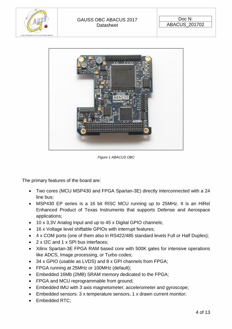
Figure 1 ABACUS OBC
The primary features of the board are:
Two cores (MCU MSP430 and FPGA Spartan-3E) directly interconnected with a 24
line bus;
MSP430 EP series is a 16 bit RISC MCU running up to 25MHz. It is an HiRel
Enhanced Product of Texas Instruments that supports Defense and Aerospace
applications;
10 x 3,3V Analog Input and up to 45 x Digital GPIO channels;
16 x Voltage level shiftable GPIOs with interrupt features;
4 x COM ports (one of them also in RS422/485 standard levels Full or Half Duplex);
2 x I2C and 1 x SPI bus interfaces;
Xilinx Spartan-3E FPGA RAM based core with 500K gates for intensive operations
like ADCS, Image processing, or Turbo codes;
34 x GPIO (usable as LVDS) and 8 x GPI channels from FPGA;
FPGA running at 25MHz or 100MHz (default);
Embedded 16Mb (2MB) SRAM memory dedicated to the FPGA;
FPGA and MCU reprogrammable from ground;
Embedded IMU with 3 axis magnetometer, accelerometer and gyroscope;
Embedded sensors: 3 x temperature sensors, 1 x drawn current monitor;
Embedded RTC;
GAUSS OBC ABACUS 2017 Datasheet
Doc N:
ABACUS_201702
5 of 13
Embedded 2 x 16MB flash NOR memories.
Both cores share the external sensors;
PC/104 CubeSat form factor compatible ;
Weight of 59 grams. (It might vary depending on your installed options);
Several modalities for low power consumption (about 50mW with the FPGA OFF, the
MCU ON and recording data from sensors on board);
Powered from the 5V satellite bus;
Off the shelf industrial grade / automotive components;
Operating temperature range -40°C to +85°C.
GAUSS OBC ABACUS 2017 Datasheet
Doc N:
ABACUS_201702
6 of 13
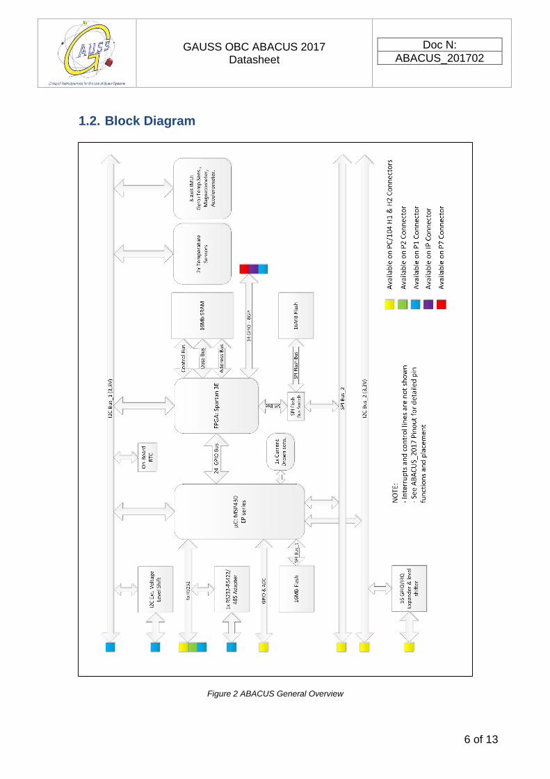
1.2. Block Diagram
Figure 2 ABACUS General Overview
GAUSS OBC ABACUS 2017 Datasheet
Doc N:
ABACUS_201702
7 of 13
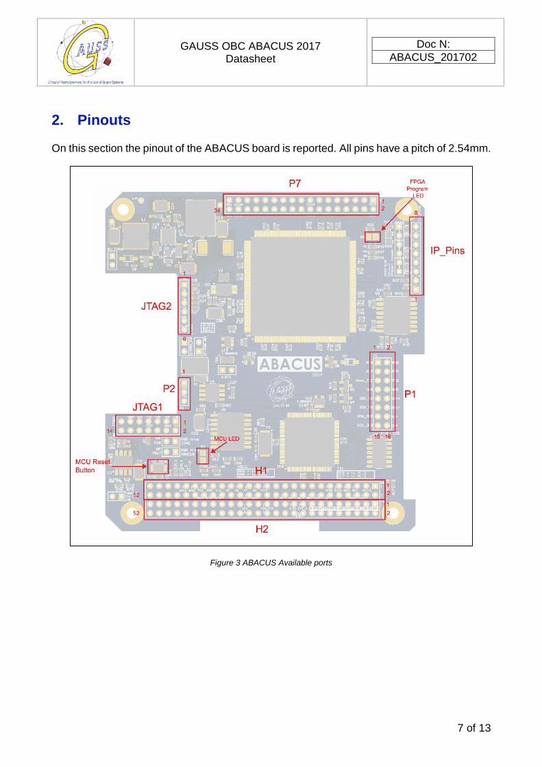
2. Pinouts
On this section the pinout of the ABACUS board is reported. All pins have a pitch of 2.54mm.
Figure 3 ABACUS Available ports
GAUSS OBC ABACUS 2017 Datasheet
Doc N:
ABACUS_201702
8 of 13
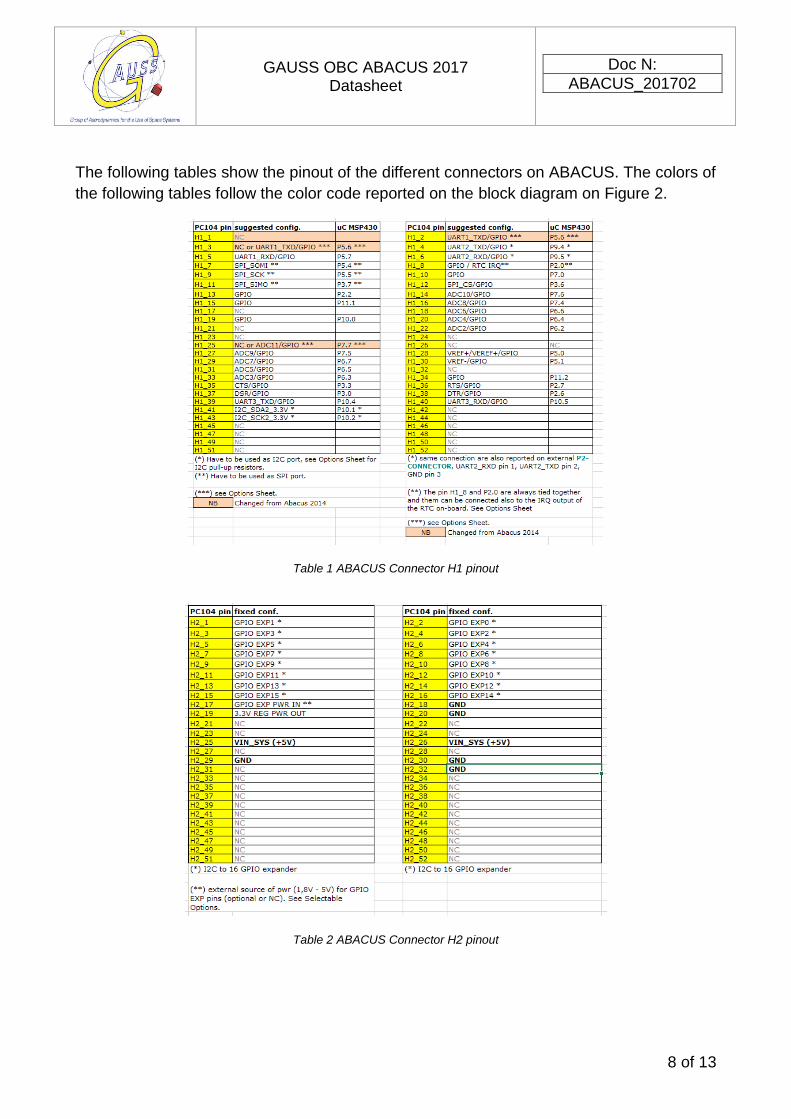
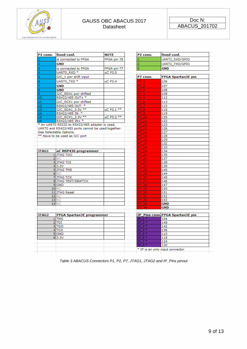
The following tables show the pinout of the different connectors on ABACUS. The colors of
the following tables follow the color code reported on the block diagram on Figure 2.
Table 1 ABACUS Connector H1 pinout
Table 2 ABACUS Connector H2 pinout
GAUSS OBC ABACUS 2017 Datasheet
Doc N:
ABACUS_201702
9 of 13
Table 3 ABACUS Connectors P1, P2, P7, JTAG1, JTAG2 and IP_Pins pinout
GAUSS OBC ABACUS 2017 Datasheet
Doc N:
ABACUS_201702
10 of 13
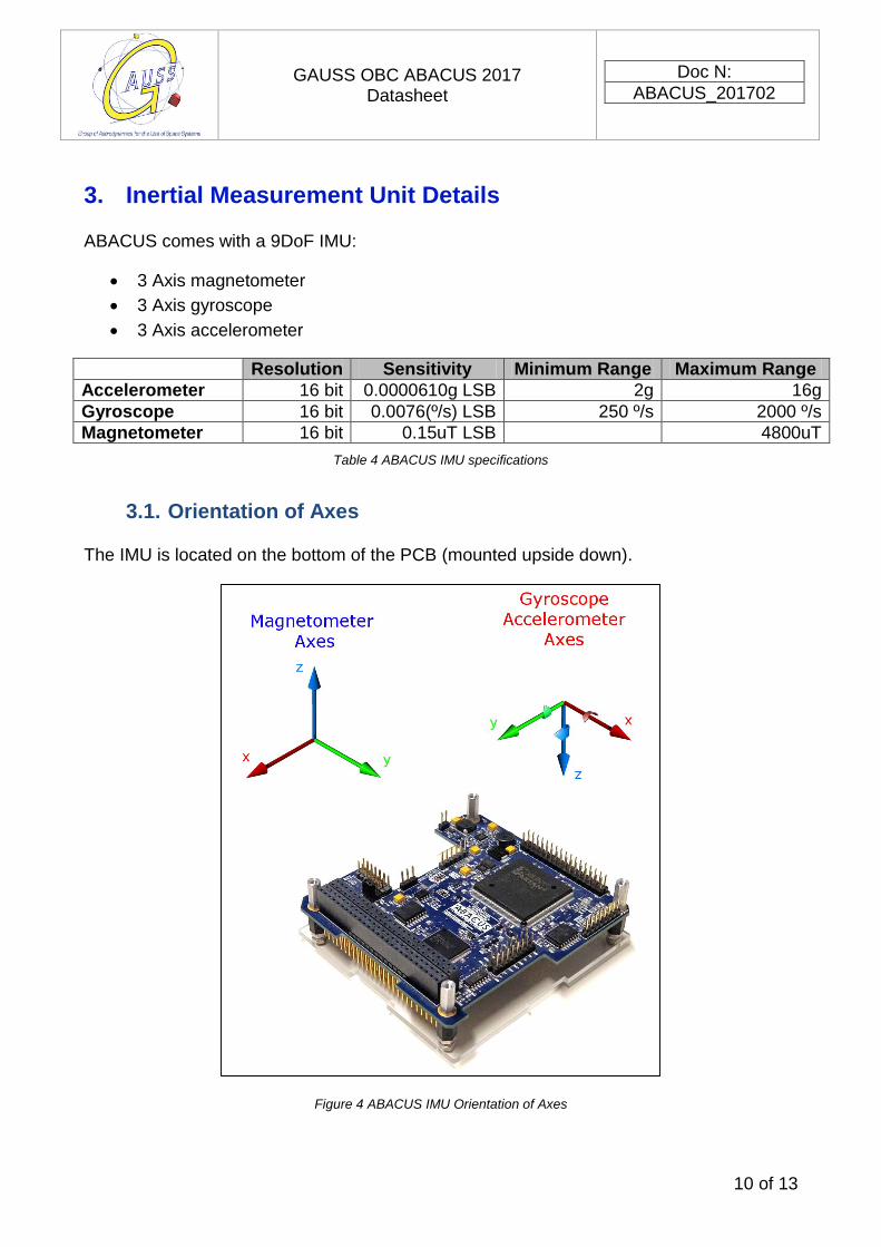
3. Inertial Measurement Unit Details
ABACUS comes with a 9DoF IMU:
3 Axis magnetometer
3 Axis gyroscope
3 Axis accelerometer
Resolution Sensitivity Minimum Range Maximum Range
Accelerometer 16 bit 0.0000610g LSB 2g 16g
Gyroscope 16 bit 0.0076(º/s) LSB 250 º/s 2000 º/s
Magnetometer 16 bit 0.15uT LSB 4800uT
Table 4 ABACUS IMU specifications
3.1. Orientation of Axes
The IMU is located on the bottom of the PCB (mounted upside down).
Figure 4 ABACUS IMU Orientation of Axes
GAUSS OBC ABACUS 2017 Datasheet
Doc N:
ABACUS_201702
11 of 13
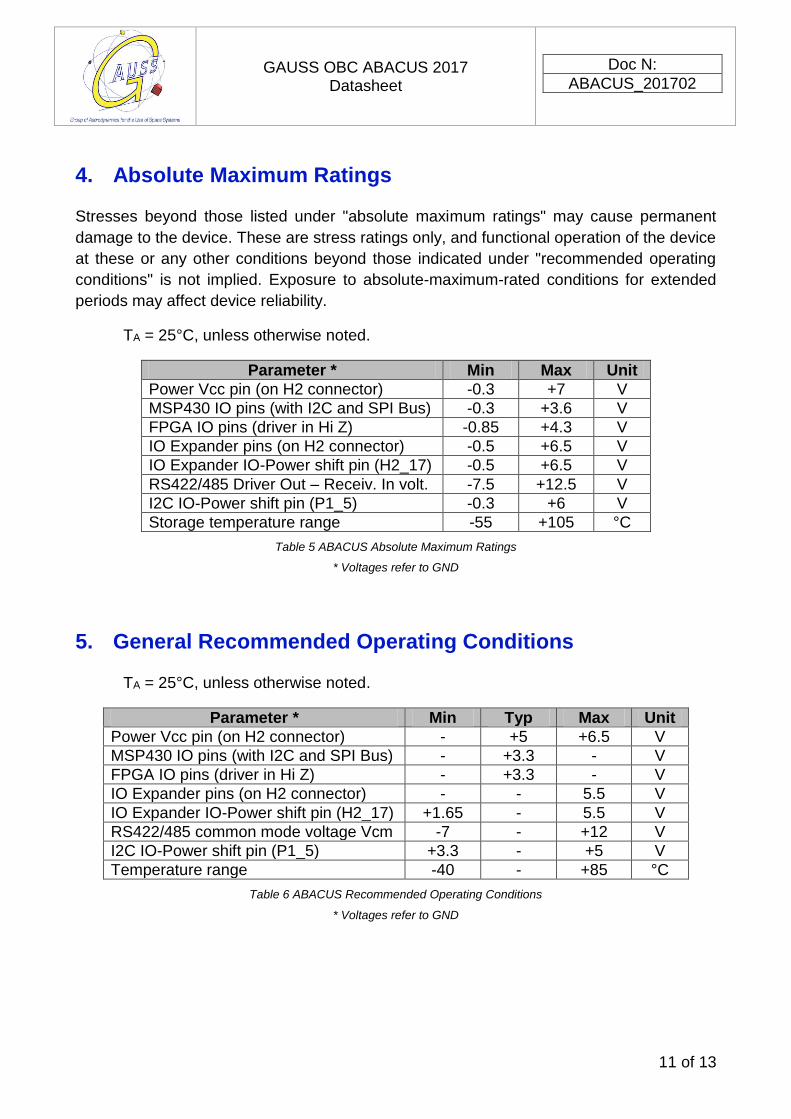
4. Absolute Maximum Ratings
Stresses beyond those listed under "absolute maximum ratings" may cause permanent
damage to the device. These are stress ratings only, and functional operation of the device
at these or any other conditions beyond those indicated under "recommended operating
conditions" is not implied. Exposure to absolute-maximum-rated conditions for extended
periods may affect device reliability.
TA = 25°C, unless otherwise noted.
Parameter * Min Max Unit
Power Vcc pin (on H2 connector) -0.3 +7 V
MSP430 IO pins (with I2C and SPI Bus) -0.3 +3.6 V
FPGA IO pins (driver in Hi Z) -0.85 +4.3 V
IO Expander pins (on H2 connector) -0.5 +6.5 V
IO Expander IO-Power shift pin (H2_17) -0.5 +6.5 V
RS422/485 Driver Out – Receiv. In volt. -7.5 +12.5 V
I2C IO-Power shift pin (P1_5) -0.3 +6 V
Storage temperature range -55 +105 °C
Table 5 ABACUS Absolute Maximum Ratings
* Voltages refer to GND
5. General Recommended Operating Conditions
TA = 25°C, unless otherwise noted.
Parameter * Min Typ Max Unit
Power Vcc pin (on H2 connector) - +5 +6.5 V
MSP430 IO pins (with I2C and SPI Bus) - +3.3 - V
FPGA IO pins (driver in Hi Z) - +3.3 - V
IO Expander pins (on H2 connector) - - 5.5 V
IO Expander IO-Power shift pin (H2_17) +1.65 - 5.5 V
RS422/485 common mode voltage Vcm -7 - +12 V
I2C IO-Power shift pin (P1_5) +3.3 - +5 V
Temperature range -40 - +85 °C
Table 6 ABACUS Recommended Operating Conditions
* Voltages refer to GND
GAUSS OBC ABACUS 2017 Datasheet
Doc N:
ABACUS_201702
12 of 13
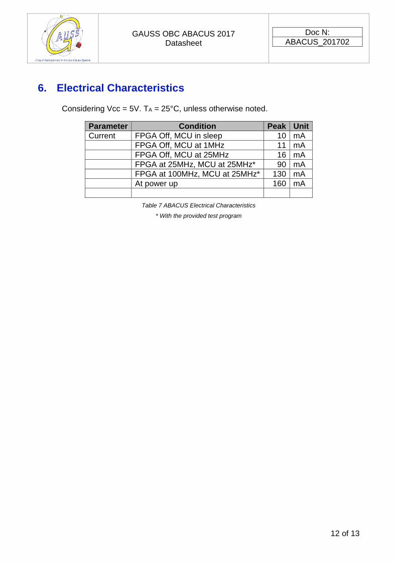
6. Electrical Characteristics
Considering Vcc = 5V. TA = 25°C, unless otherwise noted.
Parameter Condition Peak Unit
Current FPGA Off, MCU in sleep 10 mA
FPGA Off, MCU at 1MHz 11 mA
FPGA Off, MCU at 25MHz 16 mA
FPGA at 25MHz, MCU at 25MHz* 90 mA
FPGA at 100MHz, MCU at 25MHz* 130 mA
At power up 160 mA
Table 7 ABACUS Electrical Characteristics
* With the provided test program
GAUSS OBC ABACUS 2017 Datasheet
Doc N:
ABACUS_201702
13 of 13
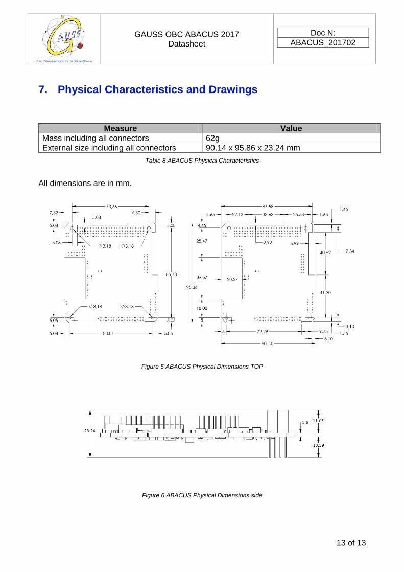
7. Physical Characteristics and Drawings
Measure Value
Mass including all connectors 62g
External size including all connectors 90.14 x 95.86 x 23.24 mm
Table 8 ABACUS Physical Characteristics
All dimensions are in mm.
Figure 5 ABACUS Physical Dimensions TOP
Figure 6 ABACUS Physical Dimensions side