gamme des produits / product range - … · dovetailers and connection units gs-gd brevete patented...
TRANSCRIPT
PRESENTATION DE LA SOCIETE ET TECHNOLOGIE PRESENTATION OF THE COMPANY AND TECHNOLOGY
2
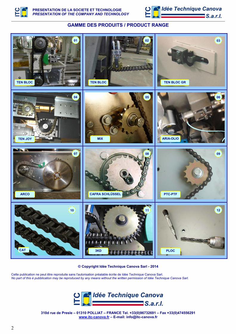
GAMME DES PRODUITS / PRODUCT RANGE
© Copyright Idée Technique Canova Sarl - 2014
Cette publication ne peut être reproduite sans l'autorisation préalable écrite de Idée Technique Canova Sarl. No part of this è pubblication may be reproduced by any means without the written permission of Idée Technique Canova Sarl.
310d rue de Presle – 01310 POLLIAT – FRANCE Tel. +33(0)96732691 – Fax +33(0)474556291 www.itc-canova.fr – E-mail: [email protected]
TEN BLOC TEN BLOC TEN BLOC GR
TEN JOY MIX ARIA-OLIO
ARCO CAFRA SCHLÜSSEL PTC-PTF
CAT 3KD PLOC
01 02 03
04 05 06
07 08 09
10 11 12
PRESENTATION DE LA SOCIETE ET TECHNOLOGIE PRESENTATION OF THE COMPANY AND TECHNOLOGY
3
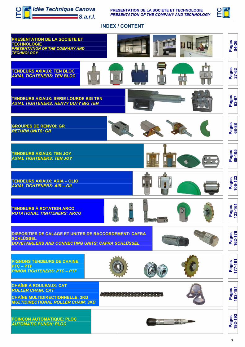
INDEX / CONTENT
PRESENTATION DE LA SOCIETE ET TECHNOLOGIE PRESENTATION OF THE COMPANY AND TECHNOLOGY
Page
s
04
-26
TENDEURS AXIAUX: TEN BLOC AXIAL TIGHTENERS: TEN BLOC
Page
s
27
-62
TENDEURS AXIAUX: SERIE LOURDE BIG TEN AXIAL TIGHTENERS: HEAVY DUTY BIG TEN
Page
s
63
-67
GROUPES DE RENVOI: GR RETURN UNITS: GR
Page
s
68
-88
TENDEURS AXIAUX: TEN JOY AXIAL TIGHTENERS: TEN JOY
Page
s
89
-105
TENDEURS AXIAUX: ARIA – OLIO AXIAL TIGHTENERS: AIR – OIL
Page
s
10
6-12
2
TENDEURS À ROTATION ARCO ROTATIONAL TIGHTENERS: ARCO
Page
s
12
3-16
1 DISPOSITIFS DE CALAGE ET UNITES DE RACCORDEMENT: CAFRA SCHLÜSSEL DOVETAIRLERS AND CONNECTING UNITS: CAFRA SCHLÜSSEL
Page
s
16
2-17
6
PIGNONS TENDEURS DE CHAINE: PTC – PTF PINION TIGHTENERS: PTC – PTF
Page
s
17
7-18
1
CHAÎNE À ROULEAUX: CAT ROLLER CHAIN: CAT
CHAÎNE MULTIDIRECTIONNELLE: 3KD MULTIDIRECTIONAL ROLLER CHAIN: 3KD
Page
s
18
2-19
1
POINÇON AUTOMATIQUE: PLOC AUTOMATIC PUNCH: PLOC
Page
s
19
2-19
3
PRESENTATION DE LA SOCIETE ET TECHNOLOGIE PRESENTATION OF THE COMPANY AND TECHNOLOGY
4
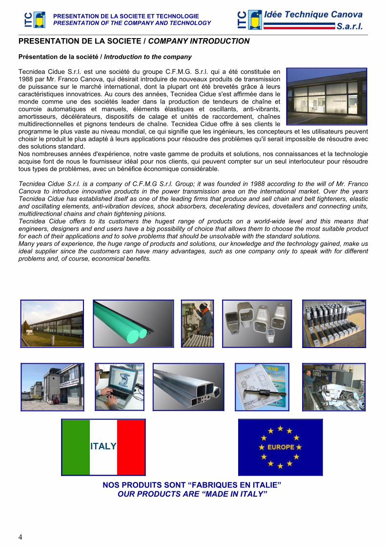
PRESENTATION DE LA SOCIETE / COMPANY INTRODUCTION Présentation de la société / Introduction to the company Tecnidea Cidue S.r.l. est une société du groupe C.F.M.G. S.r.l. qui a été constituée en 1988 par Mr. Franco Canova, qui désirait introduire de nouveaux produits de transmission de puissance sur le marché international, dont la plupart ont été brevetés grâce à leurs caractéristiques innovatrices. Au cours des années, Tecnidea Cidue s'est affirmée dans le monde comme une des sociétés leader dans la production de tendeurs de chaîne et courroie automatiques et manuels, éléments élastiques et oscillants, anti-vibrants, amortisseurs, décélérateurs, dispositifs de calage et unités de raccordement, chaînes multidirectionnelles et pignons tendeurs de chaîne. Tecnidea Cidue offre à ses clients le programme le plus vaste au niveau mondial, ce qui signifie que les ingénieurs, les concepteurs et les utilisateurs peuvent choisir le produit le plus adapté à leurs applications pour résoudre des problèmes qu'il serait impossible de résoudre avec des solutions standard. Nos nombreuses années d'expérience, notre vaste gamme de produits et solutions, nos connaissances et la technologie acquise font de nous le fournisseur idéal pour nos clients, qui peuvent compter sur un seul interlocuteur pour résoudre tous types de problèmes, avec un bénéfice économique considérable. Tecnidea Cidue S.r.l. is a company of C.F.M.G S.r.l. Group; it was founded in 1988 according to the will of Mr. Franco Canova to introduce innovative products in the power transmission area on the international market. Over the years Tecnidea Cidue has established itself as one of the leading firms that produce and sell chain and belt tighteners, elastic and oscillating elements, anti-vibration devices, shock absorbers, decelerating devices, dovetailers and connecting units, multidirectional chains and chain tightening pinions. Tecnidea Cidue offers to its customers the hugest range of products on a world-wide level and this means that engineers, designers and end users have a big possibility of choice that allows them to choose the most suitable product for each of their applications and to solve problems that should be unsolvable with the standard solutions. Many years of experience, the huge range of products and solutions, our knowledge and the technology gained, make us ideal supplier since the customers can have many advantages, such as one company only to speak with for different problems and, of course, economical benefits.
NOS PRODUITS SONT “FABRIQUES EN ITALIE” OUR PRODUCTS ARE “MADE IN ITALY”
PRESENTATION DE LA SOCIETE ET TECHNOLOGIE PRESENTATION OF THE COMPANY AND TECHNOLOGY
5
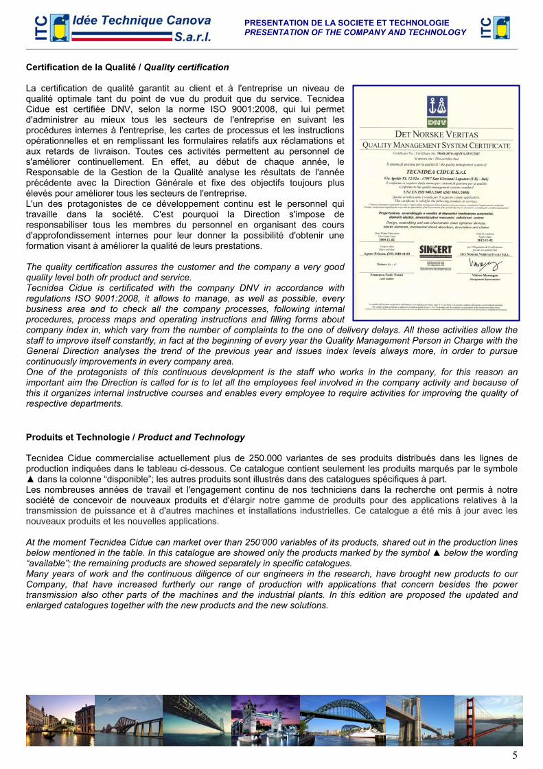
Certification de la Qualité / Quality certification La certification de qualité garantit au client et à l'entreprise un niveau de qualité optimale tant du point de vue du produit que du service. Tecnidea Cidue est certifiée DNV, selon la norme ISO 9001:2008, qui lui permet d'administrer au mieux tous les secteurs de l'entreprise en suivant les procédures internes à l'entreprise, les cartes de processus et les instructions opérationnelles et en remplissant les formulaires relatifs aux réclamations et aux retards de livraison. Toutes ces activités permettent au personnel de s'améliorer continuellement. En effet, au début de chaque année, le Responsable de la Gestion de la Qualité analyse les résultats de l'année précédente avec la Direction Générale et fixe des objectifs toujours plus élevés pour améliorer tous les secteurs de l'entreprise. L'un des protagonistes de ce développement continu est le personnel qui travaille dans la société. C'est pourquoi la Direction s'impose de responsabiliser tous les membres du personnel en organisant des cours d'approfondissement internes pour leur donner la possibilité d'obtenir une formation visant à améliorer la qualité de leurs prestations. The quality certification assures the customer and the company a very good quality level both ofr product and service. Tecnidea Cidue is certificated with the company DNV in accordance with regulations ISO 9001:2008, it allows to manage, as well as possible, every business area and to check all the company processes, following internal procedures, process maps and operating instructions and filling forms about company index in, which vary from the number of complaints to the one of delivery delays. All these activities allow the staff to improve itself constantly, in fact at the beginning of every year the Quality Management Person in Charge with the General Direction analyses the trend of the previous year and issues index levels always more, in order to pursue continuously improvements in every company area. One of the protagonists of this continuous development is the staff who works in the company, for this reason an important aim the Direction is called for is to let all the employees feel involved in the company activity and because of this it organizes internal instructive courses and enables every employee to require activities for improving the quality of respective departments. Produits et Technologie / Product and Technology Tecnidea Cidue commercialise actuellement plus de 250.000 variantes de ses produits distribués dans les lignes de production indiquées dans le tableau ci-dessous. Ce catalogue contient seulement les produits marqués par le symbole ▲ dans la colonne “disponible”; les autres produits sont illustrés dans des catalogues spécifiques à part. Les nombreuses années de travail et l'engagement continu de nos techniciens dans la recherche ont permis à notre société de concevoir de nouveaux produits et d'élargir notre gamme de produits pour des applications relatives à la transmission de puissance et à d'autres machines et installations industrielles. Ce catalogue a été mis à jour avec les nouveaux produits et les nouvelles applications. At the moment Tecnidea Cidue can market over than 250’000 variables of its products, shared out in the production lines below mentioned in the table. In this catalogue are showed only the products marked by the symbol ▲ below the wording “available”; the remaining products are showed separately in specific catalogues. Many years of work and the continuous diligence of our engineers in the research, have brought new products to our Company, that have increased furtherly our range of production with applications that concern besides the power transmission also other parts of the machines and the industrial plants. In this edition are proposed the updated and enlarged catalogues together with the new products and the new solutions.
PRESENTATION DE LA SOCIETE ET TECHNOLOGIE PRESENTATION OF THE COMPANY AND TECHNOLOGY
6
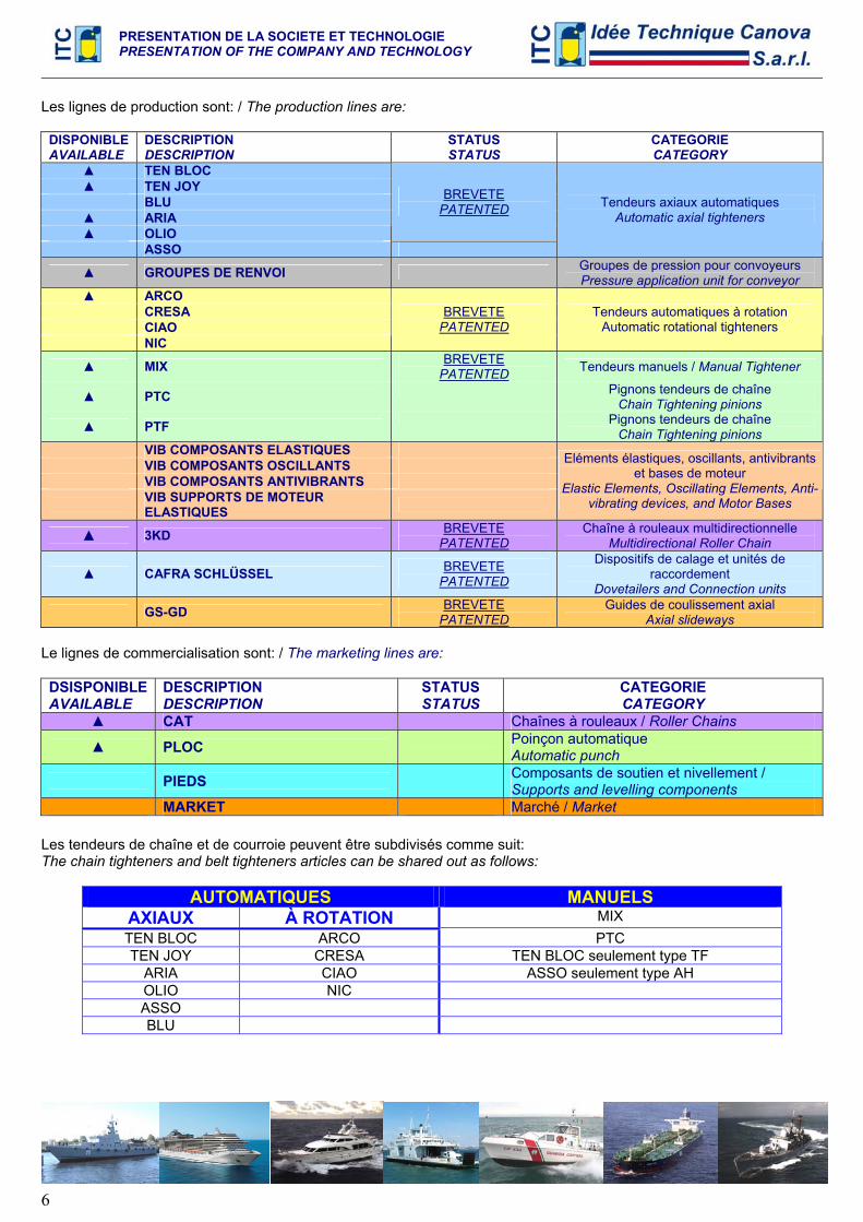
Les lignes de production sont: / The production lines are:
DISPONIBLE AVAILABLE
DESCRIPTION DESCRIPTION
STATUS STATUS
CATEGORIE CATEGORY
▲ TEN BLOC ▲ TEN JOY BLU ▲ ARIA ▲ OLIO
BREVETE PATENTED
ASSO
Tendeurs axiaux automatiques Automatic axial tighteners
▲ GROUPES DE RENVOI Groupes de pression pour convoyeurs Pressure application unit for conveyor
▲ ARCO CRESA CIAO NIC
BREVETE PATENTED
Tendeurs automatiques à rotation Automatic rotational tighteners
▲ MIX BREVETE PATENTED Tendeurs manuels / Manual Tightener
▲ PTC Pignons tendeurs de chaîne Chain Tightening pinions
▲ PTF Pignons tendeurs de chaîne Chain Tightening pinions
VIB COMPOSANTS ELASTIQUES VIB COMPOSANTS OSCILLANTS VIB COMPOSANTS ANTIVIBRANTS
VIB SUPPORTS DE MOTEUR ELASTIQUES
Eléments élastiques, oscillants, antivibrants et bases de moteur
Elastic Elements, Oscillating Elements, Anti-vibrating devices, and Motor Bases
▲ 3KD BREVETE PATENTED
Chaîne à rouleaux multidirectionnelle Multidirectional Roller Chain
▲ CAFRA SCHLÜSSEL BREVETE PATENTED
Dispositifs de calage et unités de raccordement
Dovetailers and Connection units
GS-GD BREVETE PATENTED
Guides de coulissement axial Axial slideways
Le lignes de commercialisation sont: / The marketing lines are: DSISPONIBLE AVAILABLE
DESCRIPTION DESCRIPTION
STATUS STATUS
CATEGORIE CATEGORY
▲ CAT Chaînes à rouleaux / Roller Chains
▲ PLOC Poinçon automatique Automatic punch
PIEDS Composants de soutien et nivellement / Supports and levelling components
MARKET Marché / Market Les tendeurs de chaîne et de courroie peuvent être subdivisés comme suit: The chain tighteners and belt tighteners articles can be shared out as follows:
AUTOMATIQUES MANUELS AXIAUX À ROTATION MIX TEN BLOC ARCO PTC TEN JOY CRESA TEN BLOC seulement type TF
ARIA CIAO ASSO seulement type AH OLIO NIC ASSO BLU
PRESENTATION DE LA SOCIETE ET TECHNOLOGIE PRESENTATION OF THE COMPANY AND TECHNOLOGY
7
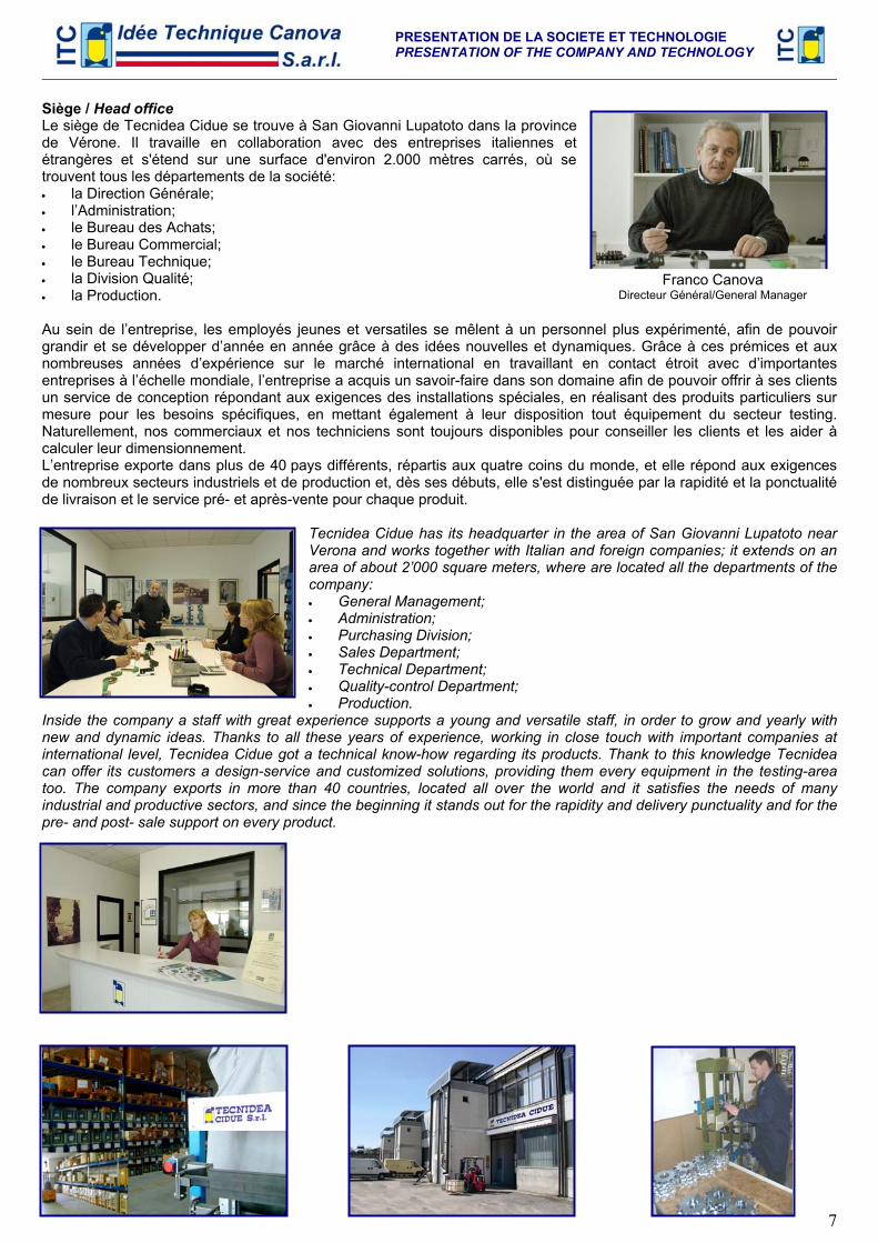
Siège / Head office Le siège de Tecnidea Cidue se trouve à San Giovanni Lupatoto dans la province de Vérone. Il travaille en collaboration avec des entreprises italiennes et étrangères et s'étend sur une surface d'environ 2.000 mètres carrés, où se trouvent tous les départements de la société: • la Direction Générale; • l’Administration; • le Bureau des Achats; • le Bureau Commercial; • le Bureau Technique; • la Division Qualité; • la Production. Au sein de l’entreprise, les employés jeunes et versatiles se mêlent à un personnel plus expérimenté, afin de pouvoir grandir et se développer d’année en année grâce à des idées nouvelles et dynamiques. Grâce à ces prémices et aux nombreuses années d’expérience sur le marché international en travaillant en contact étroit avec d’importantes entreprises à l’échelle mondiale, l’entreprise a acquis un savoir-faire dans son domaine afin de pouvoir offrir à ses clients un service de conception répondant aux exigences des installations spéciales, en réalisant des produits particuliers sur mesure pour les besoins spécifiques, en mettant également à leur disposition tout équipement du secteur testing. Naturellement, nos commerciaux et nos techniciens sont toujours disponibles pour conseiller les clients et les aider à calculer leur dimensionnement. L’entreprise exporte dans plus de 40 pays différents, répartis aux quatre coins du monde, et elle répond aux exigences de nombreux secteurs industriels et de production et, dès ses débuts, elle s'est distinguée par la rapidité et la ponctualité de livraison et le service pré- et après-vente pour chaque produit.
Tecnidea Cidue has its headquarter in the area of San Giovanni Lupatoto near Verona and works together with Italian and foreign companies; it extends on an area of about 2’000 square meters, where are located all the departments of the company: • General Management; • Administration; • Purchasing Division; • Sales Department; • Technical Department; • Quality-control Department; • Production.
Inside the company a staff with great experience supports a young and versatile staff, in order to grow and yearly with new and dynamic ideas. Thanks to all these years of experience, working in close touch with important companies at international level, Tecnidea Cidue got a technical know-how regarding its products. Thank to this knowledge Tecnidea can offer its customers a design-service and customized solutions, providing them every equipment in the testing-area too. The company exports in more than 40 countries, located all over the world and it satisfies the needs of many industrial and productive sectors, and since the beginning it stands out for the rapidity and delivery punctuality and for the pre- and post- sale support on every product.
Franco Canova Directeur Général/General Manager
PRESENTATION DE LA SOCIETE ET TECHNOLOGIE PRESENTATION OF THE COMPANY AND TECHNOLOGY
8
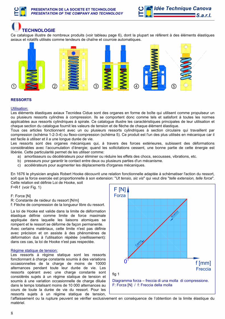
TECHNOLOGIE Ce catalogue illustre de nombreux produits (voir tableau page 6), dont la plupart se réfèrent à des éléments élastiques axiaux et rotatifs utilisés comme tendeurs de chaîne et courroie automatiques.
RESSORTS Utilisation: Les éléments élastiques axiaux Tecnidea Cidue sont des organes en forme de boîte qui utilisent comme propulseur un ou plusieurs ressorts cylindres à compression. Ils se comportent donc comme tels et satisfont à toutes les normes applicables aux ressorts cylindriques à spirale. Ce catalogue illustre les caractéristiques principales de leur utilisation et chaque section du catalogue fournit les valeurs de tension et de flèche de chaque élément élastique. Tous ces articles fonctionnent avec un ou plusieurs ressorts cylindriques à section circulaire qui travaillent par compression (schéma 1-2-3-4) ou flexo-compression (schéma 5). Ce produit est l'un des plus utilisés en mécanique car il est facile à utiliser et il a une longue durée de vie. Les ressorts sont des organes mécaniques qui, à travers des forces extérieures, subissent des déformations considérables avec l’accumulation d’énergie; quand les sollicitations cessent, une bonne partie de cette énergie est libérée. Cette particularité permet de les utiliser comme:
a) amortisseurs ou décélérateurs pour éliminer ou réduire les effets des chocs, secousses, vibrations, etc. b) presseurs pour garantir le contact entre deux ou plusieurs parties d'un mécanisme. c) accélérateurs pour augmenter les déplacements d'organes mécaniques.
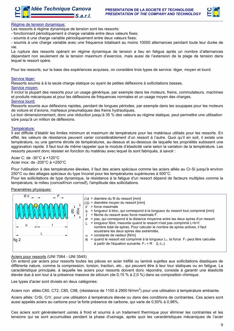
En 1676 le physicien anglais Robert Hooke découvrit une relation fonctionnelle adaptée à schématiser l'action du ressort, soit que la force exercée est proportionnelle à son extension: "Ut tensio, sic vis" qui veut dire "telle extension, telle force". Cette relation est définie Loi de Hooke, soit F=R⋅f (voir Fig. 1) F: Force [N] R: Constante de raideur du ressort [N/m] f: Flèche de compression de la longueur libre du ressort.
La loi de Hooke est valide dans la limite de déformation élastique définie comme limite de force maximale appliquée dans laquelle les liaisons atomiques se rompent et le ressort se déforme de façon permanente. Avec certains matériaux, cette limite n'est pas définie avec précision et on assiste à des phénomènes de déformation dus à l'utilisation répétée (vieillissement): dans ces cas, la loi de Hooke n'est pas respectée. Régime statique de tension: Les ressorts à régime statique sont les ressorts fonctionnant à charge constante soumis à des variations occasionnelles de la charge de moins de 10000 alternances pendant toute leur durée de vie. Les ressorts opérant avec une charge constante sont considérés sujets à un régime statique de tension et soumis à une variation occasionnelle de charge diluée dans le temps totalisant moins de 10 000 alternances au cours de toute la durée de vie du ressort. Pour les ressorts sujets à un régime statique de tension, l’affaissement ou la rupture peuvent se vérifier exclusivement en conséquence de l’obtention de la limite élastique du matériel.
① ② ③ ④ ⑤
F [N]
f [mm]0
Carico
Scaric
o
Forza
Freccia fig 1
Diagramma forza – freccia di una molla di compressione. F: Forza [N] / f: Freccia della molla
PRESENTATION DE LA SOCIETE ET TECHNOLOGIE PRESENTATION OF THE COMPANY AND TECHNOLOGY
9
Régime de tension dynamique: Les ressorts à régime dynamique de tension sont les ressorts: - fonctionnant périodiquement à charge variable entre deux valeurs fixes; - soumis à une charge variable périodiquement entre deux valeurs fixes; - soumis à une charge variable avec une fréquence totalisant au moins 10000 alternances pendant toute leur durée de vie. La rupture des ressorts opérant en régime dynamique de tension a lieu en fatigue après un nombre d’alternances dépendant non seulement de la tension maximum d’exercice, mais aussi de l’extension de la plage de tension dans lequel le ressort opère. Pour les ressorts, sur la base des expériences acquises, on considère trois types de service: léger, moyen et lourd. Service léger: Ressorts soumis à à la seule charge statique ou ayant de petites déflexions à sollicitations basses. Service moyen: Il inclut la plupart des ressorts pour un usage générique, par exemple dans les moteurs, freins, commutateurs, machines et produits mécaniques et pour les déflexions de fréquences normales et un usage moyen des charges. Service lourd: Ressorts soumis aux déflexions rapides, pendant de longues périodes, par exemple dans les soupapes pour les moteurs de voiture et d’avions, marteaux pneumatiques des freins hydrauliques. Le bon dimensionnement, donc une réduction jusqu’à 35 % des valeurs au régime statique, peut permettre une utilisation sûre jusqu'à un million de déflexions. Température: Il est difficile d’établir les limites minimum et maximum de température pour les matériaux utilisés pour les ressorts. En effet, les valeurs de résistance peuvent varier considérablement d’un ressort à l’autre. Quoi qu’il en soit, il existe une température, ou une gamme étroite de températures, au-dessus et au-dessous de laquelle les propriétés subissent une aggravation rapide. Il faut tout de même rappeler que le module d’élasticité varie selon la variation de la température. Les ressorts peuvent donc résister en fonction du matériau avec lequel ils sont fabriqués, à savoir :
Acier C: de -30°C à +120°C Acier inox: de -200°C à +250°C
Pour l'utilisation à des températures élevées, il faut des aciers spéciaux comme les aciers alliés au Cr-Si jusqu'à environ 250°C ou des alliages spéciaux du type Inconel pour les températures supérieures à 500°C. Pour les sollicitations de type dynamique, la résistance à la fatigue d'un ressort dépend de facteurs multiples comme la température, le milieu (corrosif/non corrosif), l'amplitude des sollicitations.
Paramètres physiques:
ØD
L
fb
ØD
e
PØ d
fig 2
∅d ∅D F b f P L n R
= = = = = = =
= =
diamère du fil du ressort [mm] diamètre moyen du ressort [mm] force maximale longueur à bloc, qui correspond à la longueur du ressort tout comprimé [mm] flèche du ressort avec force maximale F. pas, qui correspond à la distance moyenne entre les deux spires d'un ressort. longueur libre, mesurée quand le ressort n'est pas comprimé L=b+f. nombre total de spires. Pour calculer le nombre de spires actives, il faut soustraire les deux spires des extrémités. constante de raideur [N/m] quand le ressort est comprimé à la longueur L1, la force F1 peut être calculée à partir de l'équation suivante: F1 = R ⋅ (L-L1)
Aciers pour ressorts (UNI 7064 - UNI 3545)
On entend par aciers pour ressorts toutes les pièces en acier tréfilé ou laminé sujettes aux sollicitations élastiques de différente nature, comme la compression, torsion, traction, etc., qui peuvent être à leur tour statiques ou en fatigue. La caractéristique principale, à laquelle les aciers pour ressorts doivent donc répondre, consiste à garantir une élasticité élevée due à son tour à la présence massive de silicium (de 0,15 % à 2,0 %) dans sa composition chimique.
Les types d'acier sont divisés en deux catégories: Aciers non alliés:C60, C72, C85, C98, (résistance de 1100 à 2900 N/mm2) pour une utilisation à température ambiante.
Aciers alliés: CrSi, CrV, pour une utilisation à température élevée ou dans des conditions de contraintes. Ces aciers sont aussi appelés aciers au carbone pour la forte présence de carbone, qui varie de 0,50% à 0,98%.
Ces aciers sont généralement usinés à froid et soumis à un traitement thermique pour éliminer les contraintes et les tensions qui se sont accumulées pendant la phase d'usinage, après quoi les caractéristiques mécaniques de l’acier
PRESENTATION DE LA SOCIETE ET TECHNOLOGIE PRESENTATION OF THE COMPANY AND TECHNOLOGY
10
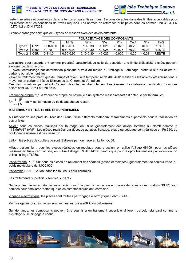
restent invariées et constantes dans le temps en garantissant des réactions durables dans des limites acceptables pour les matériaux et les conditions de travail requises. Les normes de référence principales sont les normes UNI 3823, EN 10270-1/2 et DIN 17223. Exemple d'analyse chimique de 3 types de ressorts avec des aciers différents:
POURCENTAGE DES COMPOSANTS C% Mn% Si% S% P% Cu% N% Fe% Type 1 C72: 0.60-0.80 0.50-0.90 0.10-0.30 <0.025 <0.025 <0.20 <0.08 RESTE Type 2 C85: >0.70 0.50-0.90 0.10-0.30 <0.025 <0.025 <0.20 <0.08 RESTE Type 2 C95: 0.8-1.0 0.50-0.90 0.10-0.30 <0.025 <0.025 <0.20 <0.08 RESTE
Les aciers pour ressorts ont comme propriété caractéristique celle de posséder une limite d’élasticité élevée, pouvant s’obtenir de deux façons : - avec l’écrouissage par déformation plastique à froid au moyen du tréfilage ou laminage, pratiqué sur les aciers au carbone ou faiblement liés; - avec le traitement thermique de trempe et revenu à la température de 400-450° réalisé sur les aciers dotés d’une teneur moyenne en carbone, liés au Silicium ou au Chrome et Vanadium. Ces deux solutions permettent d’obtenir des charges d'écoulement très élevées. Les tableaux d’unification pour ces aciers sont UNI 7064 et UNI 3545. Fréquence propre “fn“ La fréquence propre ou naturelle d'un système masse-ressort est obtenue par la formule:
fn= MR
21π
, où M est la masse du poids attaché au ressort.
MATERIAUX ET TRAITEMENTS SUPERFICIELS À l’intérieur de ses produits, Tecnidea Cidue utilise différents matériaux et traitements superficiels pour la réalisation de ses articles:
Acier : pour les pièces réalisées par tournage, on utilise généralement des aciers sommés au plomb comme le 11SMnPb37 (AVP). Les pièces réalisées par découpe au laser, fraisage, pliage ou soudage sont réalisées en Fe 360. La boulonnerie utilisée est de classe 8.8. Laiton: les pièces de coulissage sont réalisées par tournage en Laiton Ot 58. Alliage d'aluminium: pour les pièces réalisées en moulage sous pression, on utilise l'alliage 46100 ; pour les pièces réalisées en fusion en coquille, on utilise l’alliage EN AB 44100, tandis que pour les profilés réalisés par extrusion, on utilise l’alliage T6060. Polyéthylène PE 1000: pour les pièces de roulement des chaînes (patins et molettes), généralement de couleur verte, au poids moléculaire de 1.000.000.
Polyamide PA 6 + So.Mo: dans les rouleaux pour courroies. Les traitements superficiels sont les suivants: Sablage: les pièces en aluminium ou acier inox (plaques de connexion et chapes de la série des produits “BLU”) sont sablées pour améliorer l'esthétique et les caractéristiques anti-corrosion. Zingage électrolytique: les pièces sont traitées par zingage électrolytique Fe/Zn 5 c1A. Vernissage au four: les pièces sont vernies au four à 200°C ou pulvérisées.
Sur demande, les composants peuvent être soumis à un traitement superficiel différent de celui standard comme le nickelage ou le zingage à chaud.
PRESENTATION DE LA SOCIETE ET TECHNOLOGIE PRESENTATION OF THE COMPANY AND TECHNOLOGY
11
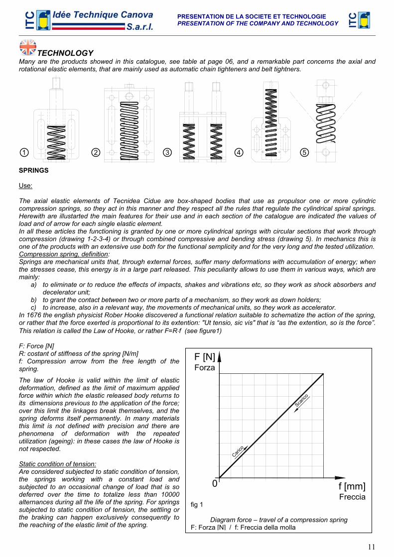
TECHNOLOGY Many are the products showed in this catalogue, see table at page 06, and a remarkable part concerns the axial and rotational elastic elements, that are mainly used as automatic chain tighteners and belt tightners.
SPRINGS Use: The axial elastic elements of Tecnidea Cidue are box-shaped bodies that use as propulsor one or more cylindric compression springs, so they act in this manner and they respect all the rules that regulate the cylindrical spiral springs. Herewith are illustarted the main features for their use and in each section of the catalogue are indicated the values of load and of arrow for each single elastic element. In all these articles the functioning is granted by one or more cylindrical springs with circular sections that work through compression (drawing 1-2-3-4) or through combined compressive and bending stress (drawing 5). In mechanics this is one of the products with an extensive use both for the functional semplicity and for the very long and the tested utilization. Compression spring, definition: Springs are mechanical units that, through external forces, suffer many deformations with accumulation of energy; when the stresses cease, this energy is in a large part released. This peculiarity allows to use them in various ways, which are mainly:
a) to eliminate or to reduce the effects of impacts, shakes and vibrations etc, so they work as shock absorbers and decelerator unit;
b) to grant the contact between two or more parts of a mechanism, so they work as down holders; c) to increase, also in a relevant way, the movements of mechanical units, so they work as accelerator.
In 1676 the english physicist Rober Hooke discovered a functional relation suitable to schematize the action of the spring, or rather that the force exerted is proportional to its extention: "Ut tensio, sic vis" that is “as the extention, so is the force”. This relation is called the Law of Hooke, or rather F=R⋅f (see figure1) F: Force [N] R: costant of stiffness of the spring [N/m] f: Compression arrow from the free length of the spring.
The law of Hooke is valid within the limit of elastic deformation, defined as the limit of maximum applied force within which the elastic released body returns to its dimensions previous to the application of the force; over this limit the linkages break themselves, and the spring deforms itself permanently. In many materials this limit is not defined with precision and there are phenomena of deformation with the repeated utilization (ageing): in these cases the law of Hooke is not respected. Static condition of tension: Are considered subjected to static condition of tension, the springs working with a constant load and subjected to an occasional change of load that is so deferred over the time to totalize less than 10000 alternances during all the life of the spring. For springs subjected to static condition of tension, the settling or the braking can happen exclusively consequently to the reaching of the elastic limit of the spring.
① ② ③ ④ ⑤
F [N]
f [mm]0
Carico
Scaric
o
Forza
fig 1
Diagram force – travel of a compression spring F: Forza [N] / f: Freccia della molla
PRESENTATION DE LA SOCIETE ET TECHNOLOGIE PRESENTATION OF THE COMPANY AND TECHNOLOGY
12
Dynamic condition of tension: Are considered subjected to dynamic condition of tension: - the springs working with periodical variable load between two fixed values - subjected to variable load in an occasional way periodically between two fixed values - subjected to variable load in an occasional way with such a frequenz to totalize almost 10000 alternances during all the life of the spring. The breaking of the working springs in the dynamic condition of tension, happens for fatigue after a number of alternances depending, besides to the maximum tension of exercise, also on the extension of the tension range in which works the spring. For the springs, on the base of the experiences made, are considered three types of service: light, medium and heavy. Light service: Springs subjected to only static load or with small deflections together with low stesses. Medium service: It includes the majority of screws for general use for example in the motors, brakes, commutators, mechanical machines and products. Deflections of normal frequencies and medium use of the loads. Heavy service: Springs subjected to quick deflections, for long periods of time, for example valves for motors of cars and planes, pneumatic hammers, hydraulic brakes. The correct dimensioning, therefore a reduction of up to 35% of the values at static condition, can allow a safe use up to one million deflections. Temperature: It is difficult to determine the minimum and maximum limits of the temperature for the materials used for the springs. In fact the resistance values can change considerably from a spring to another one. Anyway, there is a temperature, or a strict range of temperatures, above or below which the properties are subjected to a quick worsening. Anyhow it must be reminded that the elasticity module varies with the change of the temperature. So the spring can resist according to the material they are made by and this is:
Steel C: From -30°C to +120°C Stainless steel: From -200°C to +250°C
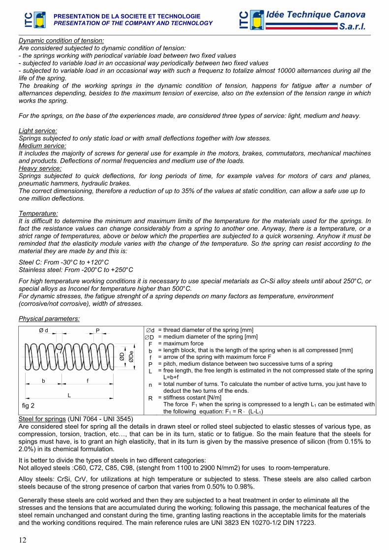
For high temperature working conditions it is necessary to use special metarials as Cr-Si alloy steels until about 250°C, or special alloys as Inconel for temperature higher than 500°C. For dynamic stresses, the fatigue strenght of a spring depends on many factors as temperature, environment (corrosive/not corrosive), width of stresses. Physical parameters:
ØD
L
fb
ØD
e
PØ d
fig 2
∅d ∅D
F b f P L
n
R
=======
=
=
thread diameter of the spring [mm] medium diameter of the spring [mm] maximum force length block, that is the length of the spring when is all compressed [mm] arrow of the spring with maximum force F pitch, medium distance between two successive turns of a spring free length, the free length is estimated in the not compressed state of the spring L=b+f total number of turns. To calculate the number of active turns, you just have to deduct the two turns of the ends. stiffness costant [N/m] The force F1 when the spring is compressed to a length L1 can be estimated with the following equation: F1 = R ⋅ (L-L1)
Steel for springs (UNI 7064 - UNI 3545)
Are considered steel for spring all the details in drawn steel or rolled steel subjected to elastic stesses of various type, as compression, torsion, traction, etc…, that can be in its turn, static or to fatigue. So the main feature that the steels for spings must have, is to grant an high elasticity, that in its turn is given by the massive presence of silicon (from 0.15% to 2.0%) in its chemical formulation.
It is better to divide the types of steels in two different categories: Not alloyed steels :C60, C72, C85, C98, (stenght from 1100 to 2900 N/mm2) for uses to room-temperature.
Alloy steels: CrSi, CrV, for utilizations at high temperature or subjected to stess. These steels are also called carbon steels because of the strong presence of carbon that varies from 0.50% to 0.98%. Generally these steels are cold worked and then they are subjected to a heat treatment in order to eliminate all the stresses and the tensions that are accumulated during the working; following this passage, the mechanical features of the steel remain unchanged and constant during the time, granting lasting reactions in the acceptable limits for the materials and the working conditions required. The main reference rules are UNI 3823 EN 10270-1/2 DIN 17223.
PRESENTATION DE LA SOCIETE ET TECHNOLOGIE PRESENTATION OF THE COMPANY AND TECHNOLOGY
13
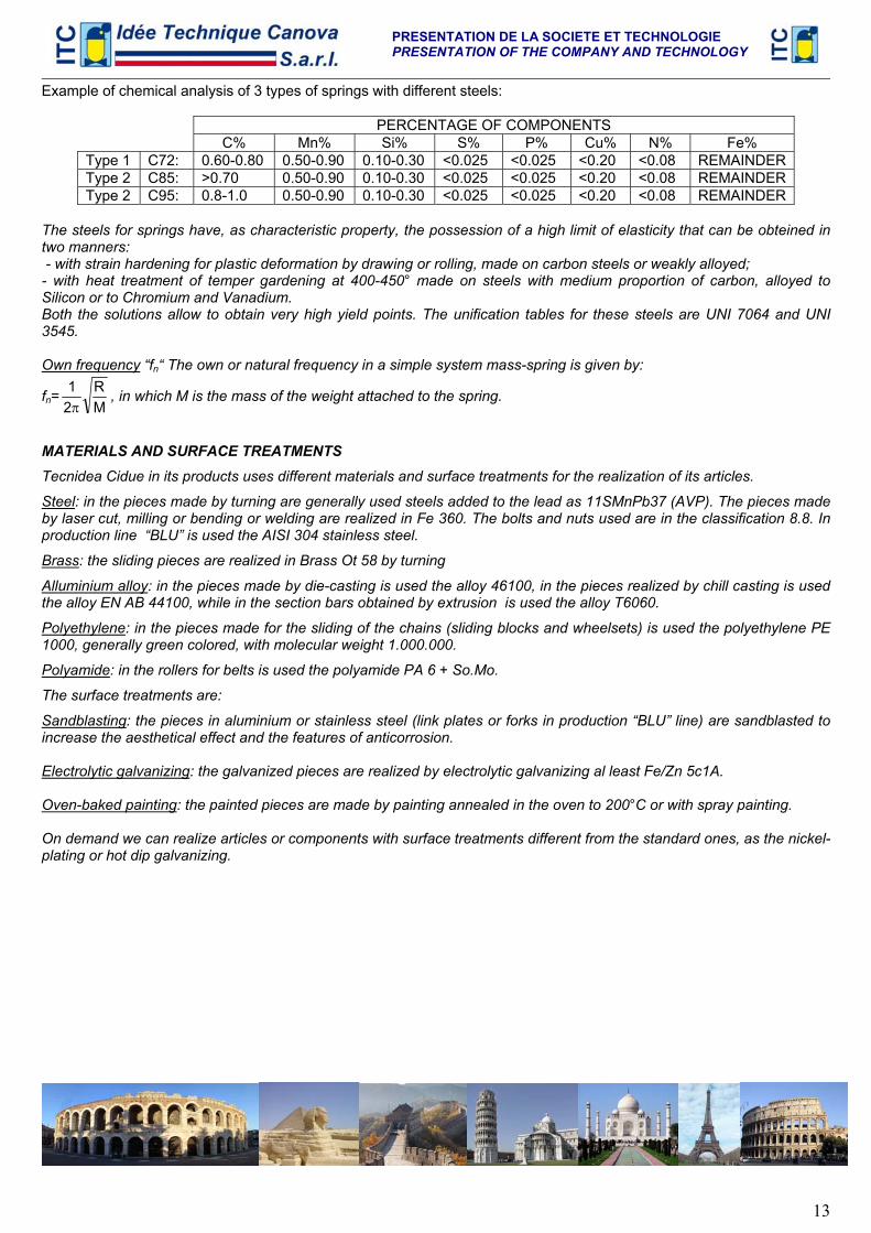
Example of chemical analysis of 3 types of springs with different steels:
PERCENTAGE OF COMPONENTS C% Mn% Si% S% P% Cu% N% Fe% Type 1 C72: 0.60-0.80 0.50-0.90 0.10-0.30 <0.025 <0.025 <0.20 <0.08 REMAINDERType 2 C85: >0.70 0.50-0.90 0.10-0.30 <0.025 <0.025 <0.20 <0.08 REMAINDERType 2 C95: 0.8-1.0 0.50-0.90 0.10-0.30 <0.025 <0.025 <0.20 <0.08 REMAINDER
The steels for springs have, as characteristic property, the possession of a high limit of elasticity that can be obteined in two manners: - with strain hardening for plastic deformation by drawing or rolling, made on carbon steels or weakly alloyed; - with heat treatment of temper gardening at 400-450° made on steels with medium proportion of carbon, alloyed to Silicon or to Chromium and Vanadium. Both the solutions allow to obtain very high yield points. The unification tables for these steels are UNI 7064 and UNI 3545. Own frequency “fn“ The own or natural frequency in a simple system mass-spring is given by:
fn= MR
21π
, in which M is the mass of the weight attached to the spring.
MATERIALS AND SURFACE TREATMENTS
Tecnidea Cidue in its products uses different materials and surface treatments for the realization of its articles.
Steel: in the pieces made by turning are generally used steels added to the lead as 11SMnPb37 (AVP). The pieces made by laser cut, milling or bending or welding are realized in Fe 360. The bolts and nuts used are in the classification 8.8. In production line “BLU” is used the AISI 304 stainless steel.
Brass: the sliding pieces are realized in Brass Ot 58 by turning
Alluminium alloy: in the pieces made by die-casting is used the alloy 46100, in the pieces realized by chill casting is used the alloy EN AB 44100, while in the section bars obtained by extrusion is used the alloy T6060.
Polyethylene: in the pieces made for the sliding of the chains (sliding blocks and wheelsets) is used the polyethylene PE 1000, generally green colored, with molecular weight 1.000.000.
Polyamide: in the rollers for belts is used the polyamide PA 6 + So.Mo.
The surface treatments are:
Sandblasting: the pieces in aluminium or stainless steel (link plates or forks in production “BLU” line) are sandblasted to increase the aesthetical effect and the features of anticorrosion. Electrolytic galvanizing: the galvanized pieces are realized by electrolytic galvanizing al least Fe/Zn 5c1A. Oven-baked painting: the painted pieces are made by painting annealed in the oven to 200°C or with spray painting. On demand we can realize articles or components with surface treatments different from the standard ones, as the nickel-plating or hot dip galvanizing.
PRESENTATION DE LA SOCIETE ET TECHNOLOGIE PRESENTATION OF THE COMPANY AND TECHNOLOGY
14
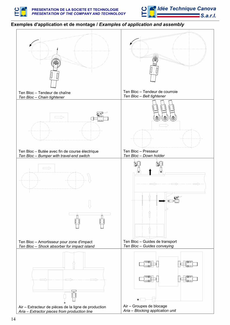
Exemples d'application et de montage / Examples of application and assembly
Ten Bloc – Tendeur de chaîne Ten Bloc – Chain tightener
Ten Bloc – Tendeur de courroie Ten Bloc – Belt tightener
Ten Bloc – Butée avec fin de course électrique Ten Bloc – Bumper with travel-end switch
Ten Bloc – Presseur Ten Bloc – Down holder
Ten Bloc – Amortisseur pour zone d'impact Ten Bloc – Shock absorber for impact island
Ten Bloc – Guides de transport Ten Bloc – Guides conveying
Air – Extracteur de pièces de la ligne de production Aria – Extractor pieces from production line
Air – Groupes de blocage Aria – Blocking application unit
PRESENTATION DE LA SOCIETE ET TECHNOLOGIE PRESENTATION OF THE COMPANY AND TECHNOLOGY
15
MANUEL DE CALCUL
TENDEURS AXIAUX AUTOMATIQUES
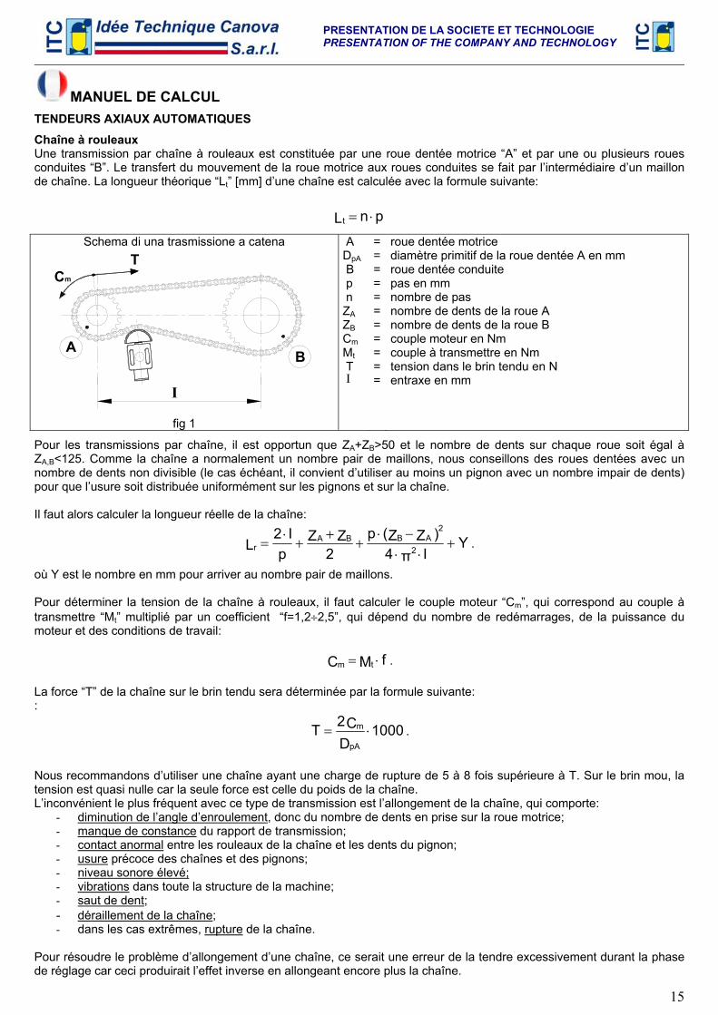
Chaîne à rouleaux Une transmission par chaîne à rouleaux est constituée par une roue dentée motrice “A” et par une ou plusieurs roues conduites “B”. Le transfert du mouvement de la roue motrice aux roues conduites se fait par l’intermédiaire d’un maillon de chaîne. La longueur théorique “Lt” [mm] d’une chaîne est calculée avec la formule suivante:
pnLt ⋅=
Schema di una trasmissione a catena
BA
I
Cm
T
fig 1
A DpA B p n ZA ZB Cm Mt T Ι
===========
roue dentée motrice diamètre primitif de la roue dentée A en mm roue dentée conduite pas en mm nombre de pas nombre de dents de la roue A nombre de dents de la roue B couple moteur en Nm couple à transmettre en Nm tension dans le brin tendu en N entraxe en mm
Pour les transmissions par chaîne, il est opportun que ZA+ZB>50 et le nombre de dents sur chaque roue soit égal à ZA,B<125. Comme la chaîne a normalement un nombre pair de maillons, nous conseillons des roues dentées avec un nombre de dents non divisible (le cas échéant, il convient d’utiliser au moins un pignon avec un nombre impair de dents) pour que l’usure soit distribuée uniformément sur les pignons et sur la chaîne. Il faut alors calculer la longueur réelle de la chaîne:
YIπ4
)ZZ(p2
ZZp
I2L 2
2ABBA
r +⋅⋅
−⋅+
++
⋅= .
où Y est le nombre en mm pour arriver au nombre pair de maillons. Pour déterminer la tension de la chaîne à rouleaux, il faut calculer le couple moteur “Cm”, qui correspond au couple à transmettre “Mt” multiplié par un coefficient “f=1,2÷2,5”, qui dépend du nombre de redémarrages, de la puissance du moteur et des conditions de travail:
fMC tm ⋅= .
La force “T” de la chaîne sur le brin tendu sera déterminée par la formule suivante: :
1000DC2TpA
m ⋅= .
Nous recommandons d’utiliser une chaîne ayant une charge de rupture de 5 à 8 fois supérieure à T. Sur le brin mou, la tension est quasi nulle car la seule force est celle du poids de la chaîne. L’inconvénient le plus fréquent avec ce type de transmission est l’allongement de la chaîne, qui comporte:
- diminution de l’angle d’enroulement, donc du nombre de dents en prise sur la roue motrice; - manque de constance du rapport de transmission; - contact anormal entre les rouleaux de la chaîne et les dents du pignon; - usure précoce des chaînes et des pignons; - niveau sonore élevé; - vibrations dans toute la structure de la machine; - saut de dent; - déraillement de la chaîne; - dans les cas extrêmes, rupture de la chaîne.
Pour résoudre le problème d’allongement d’une chaîne, ce serait une erreur de la tendre excessivement durant la phase de réglage car ceci produirait l’effet inverse en allongeant encore plus la chaîne.
PRESENTATION DE LA SOCIETE ET TECHNOLOGIE PRESENTATION OF THE COMPANY AND TECHNOLOGY
16
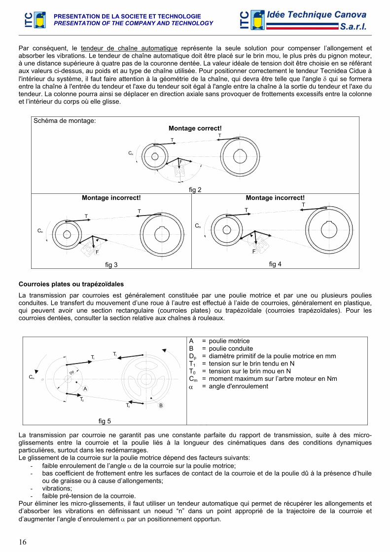
Par conséquent, le tendeur de chaîne automatique représente la seule solution pour compenser l’allongement et absorber les vibrations. Le tendeur de chaîne automatique doit être placé sur le brin mou, le plus près du pignon moteur, à une distance supérieure à quatre pas de la couronne dentée. La valeur idéale de tension doit être choisie en se référant aux valeurs ci-dessus, au poids et au type de chaîne utilisée. Pour positionner correctement le tendeur Tecnidea Cidue à l'intérieur du système, il faut faire attention à la géométrie de la chaîne, qui devra être telle que l'angle δ qui se formera entre la chaîne à l'entrée du tendeur et l'axe du tendeur soit égal à l'angle entre la chaîne à la sortie du tendeur et l'axe du tendeur. La colonne pourra ainsi se déplacer en direction axiale sans provoquer de frottements excessifs entre la colonne et l’intérieur du corps où elle glisse.
Schéma de montage: Montage correct!
Cm
F
TT
fig 2
Montage incorrect!
Cm
F
TT
fig 3
Montage incorrect!
F
Cm
TT
fig 4
Courroies plates ou trapézoïdales
La transmission par courroies est généralement constituée par une poulie motrice et par une ou plusieurs poulies conduites. Le transfert du mouvement d’une roue à l’autre est effectué à l’aide de courroies, généralement en plastique, qui peuvent avoir une section rectangulaire (courroies plates) ou trapézoïdale (courroies trapézoïdales). Pour les courroies dentées, consulter la section relative aux chaînes à rouleaux.
Dp
T0
A
T0 B
Cm
T1T1
fig 5
A B Dp T1 T0 Cm α
=======
poulie motrice poulie conduite diamètre primitif de la poulie motrice en mm tension sur le brin tendu en N tension sur le brin mou en N moment maximum sur l’arbre moteur en Nm angle d'enroulement
La transmission par courroie ne garantit pas une constante parfaite du rapport de transmission, suite à des micro-glissements entre la courroie et la poulie liés à la longueur des cinématiques dans des conditions dynamiques particulières, surtout dans les redémarrages. Le glissement de la courroie sur la poulie motrice dépend des facteurs suivants:
- faible enroulement de l’angle α de la courroie sur la poulie motrice; - bas coefficient de frottement entre les surfaces de contact de la courroie et de la poulie dû à la présence d’huile
ou de graisse ou à cause d’allongements; - vibrations; - faible pré-tension de la courroie.
Pour éliminer les micro-glissements, il faut utiliser un tendeur automatique qui permet de récupérer les allongements et d’absorber les vibrations en définissant un noeud “n” dans un point approprié de la trajectoire de la courroie et d’augmenter l’angle d’enroulement α par un positionnement opportun.
PRESENTATION DE LA SOCIETE ET TECHNOLOGIE PRESENTATION OF THE COMPANY AND TECHNOLOGY
17
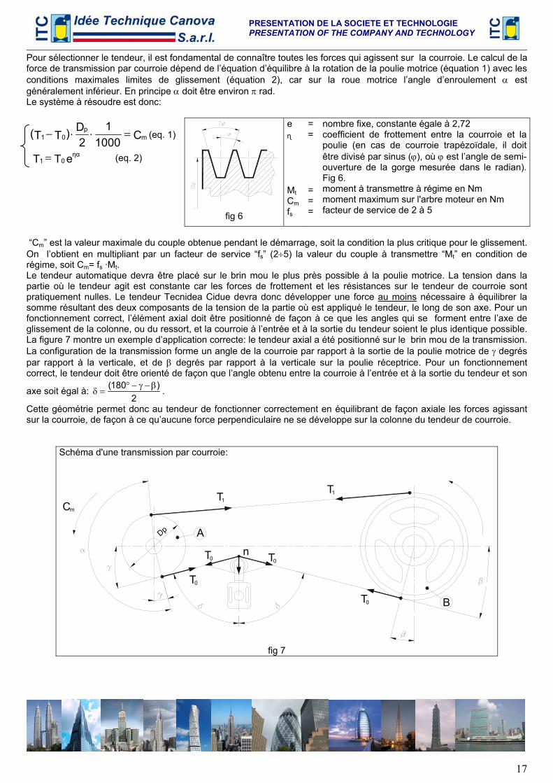
Pour sélectionner le tendeur, il est fondamental de connaître toutes les forces qui agissent sur la courroie. Le calcul de la force de transmission par courroie dépend de l’équation d’équilibre à la rotation de la poulie motrice (équation 1) avec les conditions maximales limites de glissement (équation 2), car sur la roue motrice l’angle d’enroulement α est généralement inférieur. En principe α doit être environ π rad. Le système à résoudre est donc:
C10001
2D)TT( m
p01 =⋅⋅− (eq. 1)
eTT ηα01 = (eq. 2)
fig 6
e ɳ Mt Cm fs
= = = = =
nombre fixe, constante égale à 2,72 coefficient de frottement entre la courroie et la poulie (en cas de courroie trapézoïdale, il doit être divisé par sinus (ϕ), où ϕ est l’angle de semi-ouverture de la gorge mesurée dans le radian). Fig 6. moment à transmettre à régime en Nm moment maximum sur l'arbre moteur en Nm facteur de service de 2 à 5
“Cm” est la valeur maximale du couple obtenue pendant le démarrage, soit la condition la plus critique pour le glissement. On l’obtient en multipliant par un facteur de service “fs” (2÷5) la valeur du couple à transmettre “Mt” en condition de régime, soit Cm= fs ·Mt. Le tendeur automatique devra être placé sur le brin mou le plus près possible à la poulie motrice. La tension dans la partie où le tendeur agit est constante car les forces de frottement et les résistances sur le tendeur de courroie sont pratiquement nulles. Le tendeur Tecnidea Cidue devra donc développer une force au moins nécessaire à équilibrer la somme résultant des deux composants de la tension de la partie où est appliqué le tendeur, le long de son axe. Pour un fonctionnement correct, l’élément axial doit être positionné de façon à ce que les angles qui se forment entre l’axe de glissement de la colonne, ou du ressort, et la courroie à l’entrée et à la sortie du tendeur soient le plus identique possible. La figure 7 montre un exemple d’application correcte: le tendeur axial a été positionné sur le brin mou de la transmission. La configuration de la transmission forme un angle de la courroie par rapport à la sortie de la poulie motrice de γ degrés par rapport à la verticale, et de β degrés par rapport à la verticale sur la poulie réceptrice. Pour un fonctionnement correct, le tendeur doit être orienté de façon que l’angle obtenu entre la courroie à l’entrée et à la sortie du tendeur et son
axe soit égal à: 2
)180( β−γ−°=δ .
Cette géométrie permet donc au tendeur de fonctionner correctement en équilibrant de façon axiale les forces agissant sur la courroie, de façon à ce qu’aucune force perpendiculaire ne se développe sur la colonne du tendeur de courroie.
Schéma d'une transmission par courroie:
n
T0
Cm
Dp
T
A
0
T1
0T B
T
T0
1
fig 7
PRESENTATION DE LA SOCIETE ET TECHNOLOGIE PRESENTATION OF THE COMPANY AND TECHNOLOGY
18
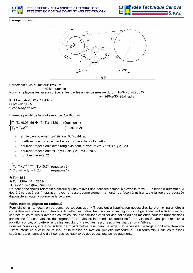
Exemple de calcul:
25°
64.5°
100Cm
197°
26°
64.5°
T0 F
T0 T0
T0
A
T1
B
1T
fig 8
Caractéristiques du moteur: P=3 Cv n=940 tours/min Nous remplaçons les valeurs précédentes par les unités de mesure du SI: P=3x735=2205 W ω= 940xπ/30=98,4 rad/s P= Mtxω Mt=P/ω=22,4 Nm Si prévoit fs=2,5 Cm=2,5xMt=56 Nm Diamètre primitif de la poulie motrice Dp=100 mm (T1-T0)x0,05=56 (T1-T0)=1120 (équation 1) eTT ηα
01 = (équation 2)
o angle d'enroulement α=197°xπ/180°=3,44 rad o coefficient de frottement entre la courroie et la poulie ɳ=0,2 o courroie trapézoïdale avec l'angle de semi-ouverture ϕ=17° sin(ϕ)=0,29 o courroie trapézoïdale ɳ’=0,2/sin(ϕ)=0,2/0,29=0,69 o nombre fixe e=2,72
T1=T0xe0,69x3,44= T0x10,74 (équation 2) (10,74T0-T0) =1120 (équation 1)
T0=115 N T1=1120+115=1235 N F=2x115xcos(64,5°)=99 N
On peut donc choisir l'élément élastique qui devra avoir une poussée compatible avec la force F. Le tendeur automatique devré être placé sur l'installation avec le ressort complètement remonté, de façon à utiliser toute la force de poussée disponible et toute la course de la colonne. Patin, molette, pignon ou rouleau? Pour choisir un tendeur, on se demande souvent quel KIT convient à l'application nécessaire. Le premier paramètre à considérer est la fonction du tendeur. En effet, les patins, les molettes et les pignons sont généralement utilisés avec les chaînes et les rouleaux avec les courroies. Nous conseillons d'utiliser des patins ou des molettes pour les transmissions par chaîne à basse vitesse, des pignons à une vitesse intermédiaire, tandis qu'à une vitesse élevée, pour réduire la pollution sonore, on préfère les patins aux pignons avec des ressorts pour les charges plus faibles. Pour les courroies, il faut considérer deux paramètres principaux: la largeur et la vitesse. La largeur doit être d'environ 10mm inférieure à celle du rouleau et la vitesse de rotation doit être inférieure à 3000 tours/min. Pour les vitesses supérieures, on conseille d'utiliser des rouleaux avec des coussinets au jeu augmenté.
PRESENTATION DE LA SOCIETE ET TECHNOLOGIE PRESENTATION OF THE COMPANY AND TECHNOLOGY
19
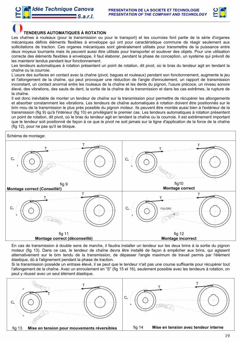
TENDEURS AUTOMATIQUES À ROTATION Les chaînes à rouleaux (pour la transmission ou pour le transport) et les courroies font partie de la série d'organes mécaniques définis éléments flexibles à enveloppe qui ont pour caractéristique commune de réagir seulement aux sollicitations de traction. Ces organes mécaniques sont généralement utilisés pour transmettre de la puissance entre deux moyeux tournants mais ils peuvent aussi être utilisés pour transporter et soulever des objets. Pour une utilisation correcte des éléments flexibles à enveloppe, il faut élaborer, pendant la phase de conception, un système qui prévoit de les maintenir tendus pendant leur fonctionnement. Les tendeurs automatiques à rotation présentent un point de rotation, dit pivot, où le bras du tendeur agit en tendant la chaîne ou la courroie. L’usure des surfaces en contact avec la chaîne (pivot, bagues et rouleaux) pendant son fonctionnement, augmente le jeu et l'allongement de la chaîne, qui peut provoquer une réduction de l'angle d'enroulement, un rapport de transmission inconstant, un contact anormal entre les rouleaux de la chaîne et les dents du pignon, l'usure précoce, un niveau sonore élevé, des vibrations, des sauts de dent, la sortie de la chaîne de la transmission et dans les cas extrêmes, la rupture de la chaîne. Il est donc inévitable de monter un tendeur de chaîne sur la transmission pour permettre de récupérer les allongements et absorber constamment les vibrations. Les tendeurs de chaîne automatiques à rotation doivent être positionnés sur le brin mou de la transmission le plus près possible du pignon moteur. Ils peuvent être montés aussi bien à l'extérieur de la transmission (fig 9) qu'à l'intérieur (fig 10) en privilégiant le premier cas. Les tendeurs automatiques à rotation présentent un point de rotation, dit pivot, où le bras du tendeur agit en tendant la chaîne ou la courroie. Il est extrêmement important que le tendeur soit positionné de façon à ce que le pivot ne soit jamais sur la ligne d'application de la force de la chaîne (fig 12), pour ne pas qu'il se bloque.
Schéma de montage:
Cm
TT
fig 9
Montage correct (Conseillé!)
Cm
TT
fig10
Montage correct
Cm
TT
fig 11
Montage correct (déconseillé)
Cm
TT
FULCRO
fig 12
Montage incorrect
En cas de transmission à double sens de marche, il faudra installer un tendeur sur les deux brins à la sortie du pignon moteur (fig 13). Dans ce cas, le tendeur de chaîne devra être installé de façon à empêcher aux brins, qui agissent alternativement sur le brin tendu de la transmission, de dépasser l'angle maximum de travail permis par l'élément élastique, dû à l'alignement pendant la phase de traction. Si la transmission possède un entraxe élevé, il se peut que le tendeur n'ait pas une course suffisante pour récupérer tout l'allongement de la chaîne. Avec un enroulement en “S” (fig 15 et 16), seulement possible avec les tendeurs à rotation, on peut y réussir avec un seul élément élastique.
Cm
T
T
fig 13 Mise en tension pour mouvements réversibles
mC
TT
fig 14 Mise en tension avec tendeur interne
PRESENTATION DE LA SOCIETE ET TECHNOLOGIE PRESENTATION OF THE COMPANY AND TECHNOLOGY
20
m
TT
fig 15
Tensionnement en “S” avec ARCO
Cm
TT
fig 16 Tensionnement en “S” avec ARCO spécial à double
ressort
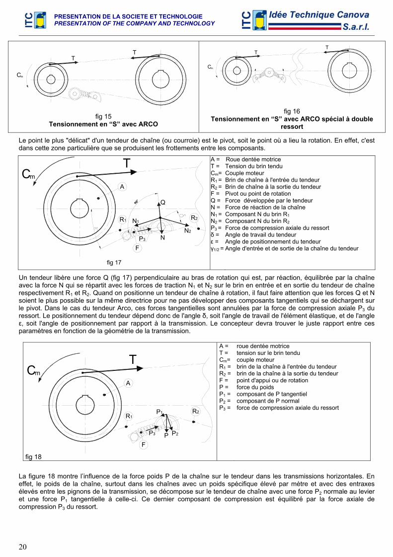
Le point le plus "délicat" d'un tendeur de chaîne (ou courroie) est le pivot, soit le point où a lieu la rotation. En effet, c'est dans cette zone particulière que se produisent les frottements entre les composants.
TmC
A
R1 R2
FN
N1
N2
Q90°
P3
fig 17
A = T = Cm= R1 = R2 = F = Q = N = N1 = N2 = P3 = δ = ε = γ1/2 =
Roue dentée motrice Tension du brin tendu Couple moteur Brin de chaîne à l'entrée du tendeur Brin de chaîne à la sortie du tendeur Pivot ou point de rotation Force développée par le tendeur Force de réaction de la chaîne Composant N du brin R1 Composant N du brin R2 Force de compression axiale du ressort Angle de travail du tendeur Angle de positionnement du tendeur Angle d'entrée et de sortie de la chaîne du tendeur
Un tendeur libère une force Q (fig 17) perpendiculaire au bras de rotation qui est, par réaction, équilibrée par la chaîne avec la force N qui se répartit avec les forces de traction N1 et N2 sur le brin en entrée et en sortie du tendeur de chaîne respectivement R1 et R2. Quand on positionne un tendeur de chaîne à rotation, il faut faire attention que les forces Q et N soient le plus possible sur la même directrice pour ne pas développer des composants tangentiels qui se déchargent sur le pivot. Dans le cas du tendeur Arco, ces forces tangentielles sont annulées par la force de compression axiale P3 du ressort. Le positionnement du tendeur dépend donc de l'angle δ, soit l'angle de travail de l'élément élastique, et de l'angle ε, soit l'angle de positionnement par rapport à la transmission. Le concepteur devra trouver le juste rapport entre ces paramètres en fonction de la géométrie de la transmission.
IIIII
Tm
A
R1R2
FP P2
P1
C
P3
fig 18
A = T = Cm= R1 = R2 = F = P = P1 = P2 = P3 =
roue dentée motrice tension sur le brin tendu couple moteur brin de la chaîne à l'entrée du tendeur brin de la chaîne à la sortie du tendeur point d'appui ou de rotation force du poids composant de P tangentiel composant de P normal force de compression axiale du ressort
La figure 18 montre l’influence de la force poids P de la chaîne sur le tendeur dans les transmissions horizontales. En effet, le poids de la chaîne, surtout dans les chaînes avec un poids spécifique élevé par mètre et avec des entraxes élevés entre les pignons de la transmission, se décompose sur le tendeur de chaîne avec une force P2 normale au levier et une force P1 tangentielle à celle-ci. Ce dernier composant de compression est équilibré par la force axiale de compression P3 du ressort.
PRESENTATION DE LA SOCIETE ET TECHNOLOGIE PRESENTATION OF THE COMPANY AND TECHNOLOGY
21
CALCULATION MANUAL AUTOMATIC AXIAL TIGHTENERS
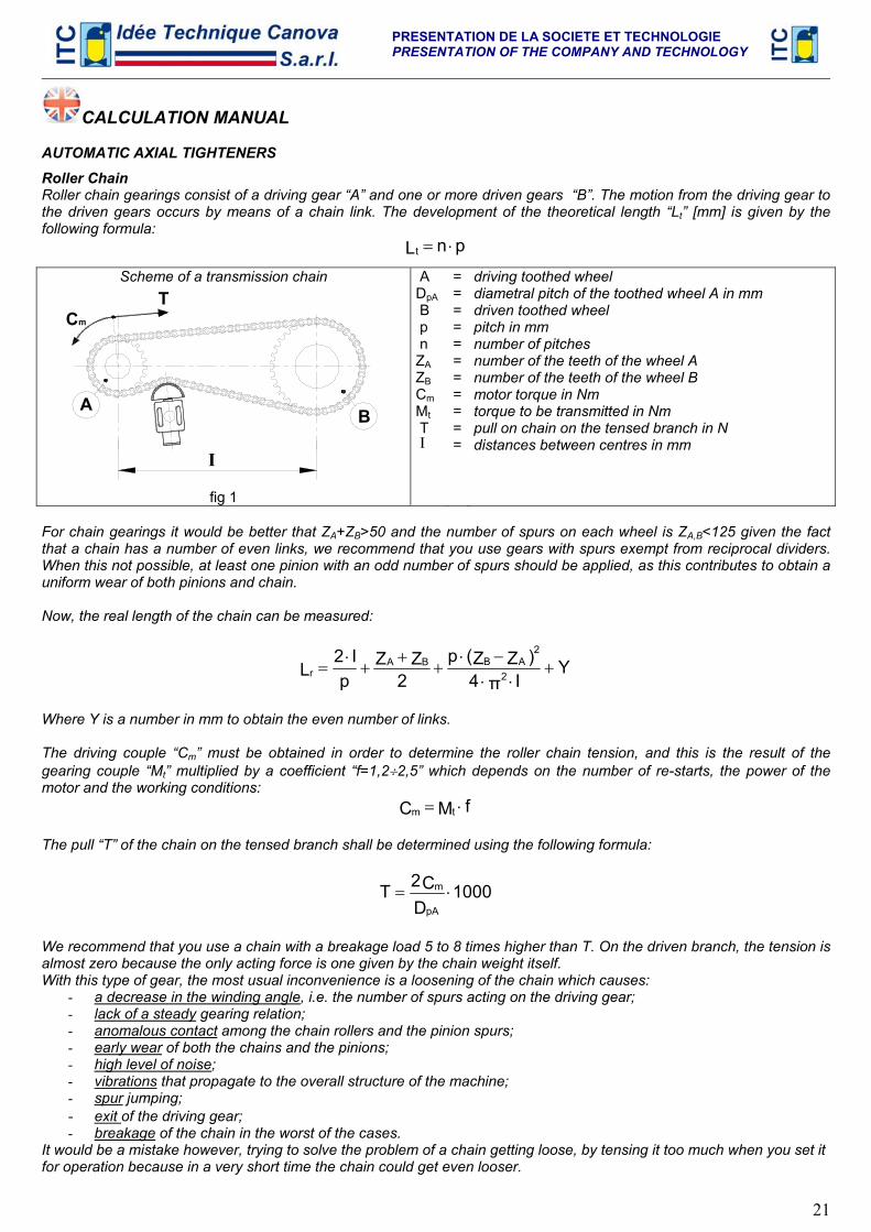
Roller Chain Roller chain gearings consist of a driving gear “A” and one or more driven gears “B”. The motion from the driving gear to the driven gears occurs by means of a chain link. The development of the theoretical length “Lt” [mm] is given by the following formula:
pnLt ⋅=
Scheme of a transmission chain
BA
I
Cm
T
fig 1
A DpA B p n ZA ZB Cm Mt T Ι
===========
driving toothed wheel diametral pitch of the toothed wheel A in mm driven toothed wheel pitch in mm number of pitches number of the teeth of the wheel A number of the teeth of the wheel B motor torque in Nm torque to be transmitted in Nm pull on chain on the tensed branch in N distances between centres in mm
For chain gearings it would be better that ZA+ZB>50 and the number of spurs on each wheel is ZA,B<125 given the fact that a chain has a number of even links, we recommend that you use gears with spurs exempt from reciprocal dividers. When this not possible, at least one pinion with an odd number of spurs should be applied, as this contributes to obtain a uniform wear of both pinions and chain. Now, the real length of the chain can be measured:
YIπ4
)ZZ(p2
ZZp
I2L 2
2ABBA
r +⋅⋅
−⋅+
++
⋅=
Where Y is a number in mm to obtain the even number of links. The driving couple “Cm” must be obtained in order to determine the roller chain tension, and this is the result of the gearing couple “Mt” multiplied by a coefficient “f=1,2÷2,5” which depends on the number of re-starts, the power of the motor and the working conditions:
fMC tm ⋅=
The pull “T” of the chain on the tensed branch shall be determined using the following formula:
1000DC2TpA
m ⋅=
We recommend that you use a chain with a breakage load 5 to 8 times higher than T. On the driven branch, the tension is almost zero because the only acting force is one given by the chain weight itself. With this type of gear, the most usual inconvenience is a loosening of the chain which causes:
- a decrease in the winding angle, i.e. the number of spurs acting on the driving gear; - lack of a steady gearing relation; - anomalous contact among the chain rollers and the pinion spurs; - early wear of both the chains and the pinions; - high level of noise; - vibrations that propagate to the overall structure of the machine; - spur jumping; - exit of the driving gear; - breakage of the chain in the worst of the cases.
It would be a mistake however, trying to solve the problem of a chain getting loose, by tensing it too much when you set it for operation because in a very short time the chain could get even looser.
PRESENTATION DE LA SOCIETE ET TECHNOLOGIE PRESENTATION OF THE COMPANY AND TECHNOLOGY
22
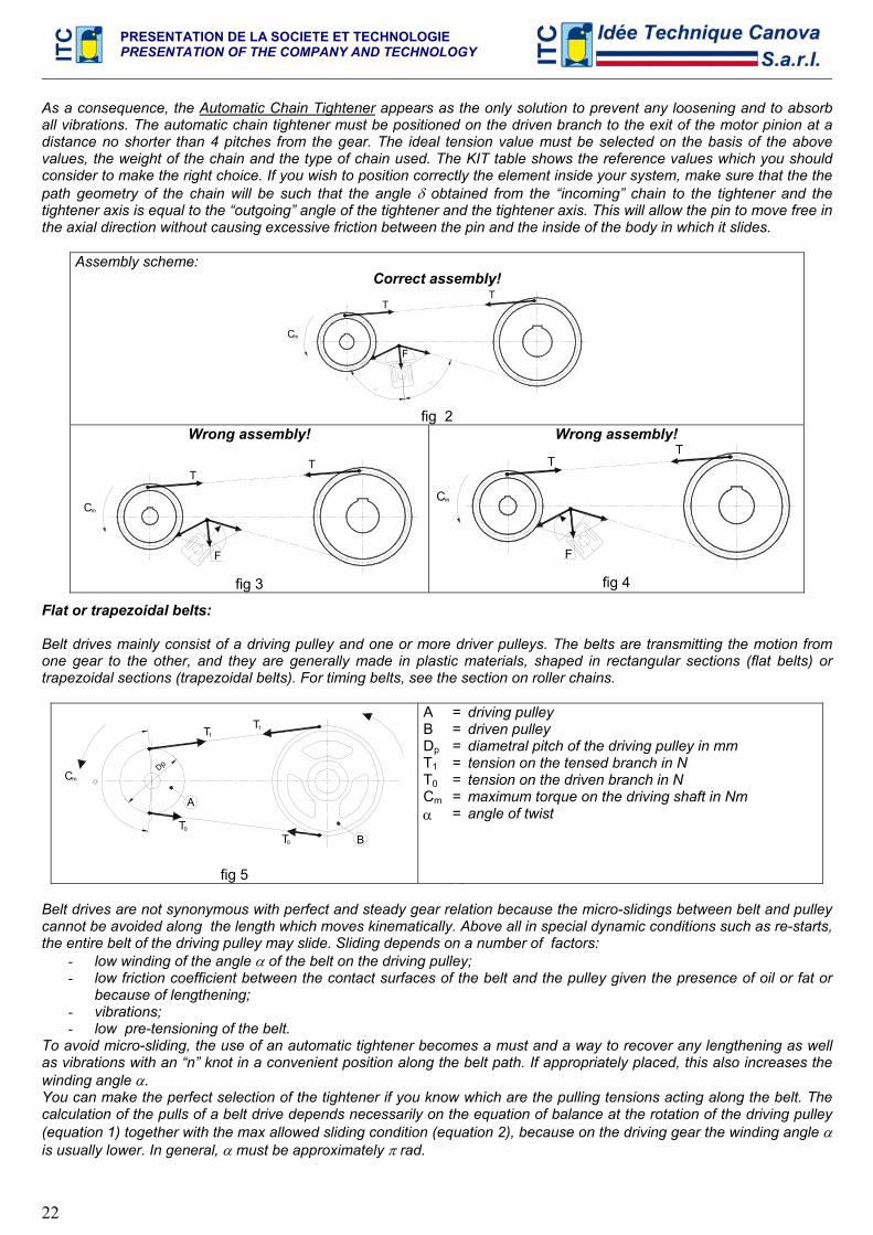
As a consequence, the Automatic Chain Tightener appears as the only solution to prevent any loosening and to absorb all vibrations. The automatic chain tightener must be positioned on the driven branch to the exit of the motor pinion at a distance no shorter than 4 pitches from the gear. The ideal tension value must be selected on the basis of the above values, the weight of the chain and the type of chain used. The KIT table shows the reference values which you should consider to make the right choice. If you wish to position correctly the element inside your system, make sure that the the path geometry of the chain will be such that the angle δ obtained from the “incoming” chain to the tightener and the tightener axis is equal to the “outgoing” angle of the tightener and the tightener axis. This will allow the pin to move free in the axial direction without causing excessive friction between the pin and the inside of the body in which it slides.
Assembly scheme: Correct assembly!
Cm
F
TT
fig 2
Wrong assembly!
Cm
F
TT
fig 3
Wrong assembly!
F
Cm
TT
fig 4
Flat or trapezoidal belts: Belt drives mainly consist of a driving pulley and one or more driver pulleys. The belts are transmitting the motion from one gear to the other, and they are generally made in plastic materials, shaped in rectangular sections (flat belts) or trapezoidal sections (trapezoidal belts). For timing belts, see the section on roller chains.
Dp
T0
A
T0 B
Cm
T1T1
fig 5
A B Dp T1 T0 Cm α
=======
driving pulley driven pulley diametral pitch of the driving pulley in mm tension on the tensed branch in N tension on the driven branch in N maximum torque on the driving shaft in Nm angle of twist
Belt drives are not synonymous with perfect and steady gear relation because the micro-slidings between belt and pulley cannot be avoided along the length which moves kinematically. Above all in special dynamic conditions such as re-starts, the entire belt of the driving pulley may slide. Sliding depends on a number of factors:
- low winding of the angle α of the belt on the driving pulley; - low friction coefficient between the contact surfaces of the belt and the pulley given the presence of oil or fat or
because of lengthening; - vibrations; - low pre-tensioning of the belt.
To avoid micro-sliding, the use of an automatic tightener becomes a must and a way to recover any lengthening as well as vibrations with an “n” knot in a convenient position along the belt path. If appropriately placed, this also increases the winding angle α. You can make the perfect selection of the tightener if you know which are the pulling tensions acting along the belt. The calculation of the pulls of a belt drive depends necessarily on the equation of balance at the rotation of the driving pulley (equation 1) together with the max allowed sliding condition (equation 2), because on the driving gear the winding angle α is usually lower. In general, α must be approximately π rad.
PRESENTATION DE LA SOCIETE ET TECHNOLOGIE PRESENTATION OF THE COMPANY AND TECHNOLOGY
23
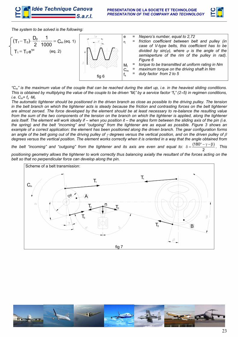
The system to be solved is the following:
C10001
2D)TT( m
p01 =⋅⋅− (eq. 1)
eTT ηα01 = (eq. 2)
fig 6
e ɳ Mt Cm fs
= = = = =
Nepero’s number, equal to 2,72 friction coefficient between belt and pulley (in case of V-type belts, this coefficient has to be divided by sin(ϕ), where ϕ is the angle of the semiaperture of the rim of the pulley in rad). Figure 6 torque to be transmitted at uniform rating in Nm maximum torque on the driving shaft in Nm duty factor from 2 to 5
“Cm” is the maximum value of the couple that can be reached during the start up, i.e. in the heaviest sliding conditions. This is obtained by multiplying the value of the couple to be driven “Mt” by a service factor “fs” (2÷5) in regimen conditions, i.e. Cm= fs ·Mt. The automatic tightener should be positioned in the driven branch as close as possible to the driving pulley. The tension in the belt branch on which the tightener acts is steady because the friction and contrasting forces on the belt tightener are almost zeroed. The force developed by the element should be at least necessary to re-balance the resulting value from the sum of the two components of the tension on the branch on which the tightener is applied, along the tightener axis itself. The element will work ideally if – when you position it – the angles form between the sliding axis of the pin (i.e. the spring) and the belt “incoming” and “outgoing” from the tightener are as equal as possible. Figure 3 shows an example of a correct application: the element has been positioned along the driven branch. The gear configuration forms an angle of the belt going out of the driving pulley of γ degrees versus the vertical position, and on the driven pulley of β degrees versus the vertical position. The element works correctly when it is oriented in a way that the angle obtained from
the belt “incoming” and “outgoing” from the tightener and its axis are even and equal to: 2
)180( β−γ−°=δ . This
positioning geometry allows the tightener to work correctly thus balancing axially the resultant of the forces acting on the belt so that no perpendicular force can develop along the pin.
Scheme of a belt transmission:
n
T0
Cm
Dp
T
A
0
T1
0T B
T
T0
1
fig 7
PRESENTATION DE LA SOCIETE ET TECHNOLOGIE PRESENTATION OF THE COMPANY AND TECHNOLOGY
24
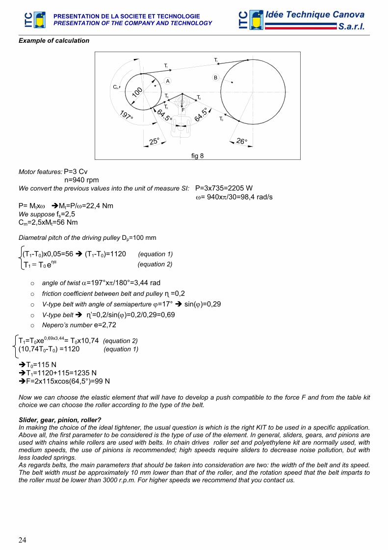
Example of calculation
25°
64.5°
100Cm
197°
26°
64.5°
T0 F
T0 T0
T0
A
T1
B
1T
fig 8
Motor features: P=3 Cv n=940 rpm We convert the previous values into the unit of measure SI: P=3x735=2205 W ω= 940xπ/30=98,4 rad/s P= Mtxω Mt=P/ω=22,4 Nm We suppose fs=2,5 Cm=2,5xMt=56 Nm Diametral pitch of the driving pulley Dp=100 mm (T1-T0)x0,05=56 (T1-T0)=1120 (equation 1) eTT ηα
01 = (equation 2)
o angle of twist α=197°xπ/180°=3,44 rad o friction coefficient between belt and pulley ɳ =0,2 o V-type belt with angle of semiaperture ϕ=17° sin(ϕ)=0,29 o V-type belt ɳ’=0,2/sin(ϕ)=0,2/0,29=0,69 o Nepero’s number e=2,72
T1=T0xe0,69x3,44= T0x10,74 (equation 2) (10,74T0-T0) =1120 (equation 1)
T0=115 N T1=1120+115=1235 N F=2x115xcos(64,5°)=99 N
Now we can choose the elastic element that will have to develop a push compatible to the force F and from the table kit choice we can choose the roller according to the type of the belt. Slider, gear, pinion, roller? In making the choice of the ideal tightener, the usual question is which is the right KIT to be used in a specific application. Above all, the first parameter to be considered is the type of use of the element. In general, sliders, gears, and pinions are used with chains while rollers are used with belts. In chain drives roller set and polyethylene kit are normally used, with medium speeds, the use of pinions is recommended; high speeds require sliders to decrease noise pollution, but with less loaded springs. As regards belts, the main parameters that should be taken into consideration are two: the width of the belt and its speed. The belt width must be approximately 10 mm lower than that of the roller, and the rotation speed that the belt imparts to the roller must be lower than 3000 r.p.m. For higher speeds we recommend that you contact us.
PRESENTATION DE LA SOCIETE ET TECHNOLOGIE PRESENTATION OF THE COMPANY AND TECHNOLOGY
25
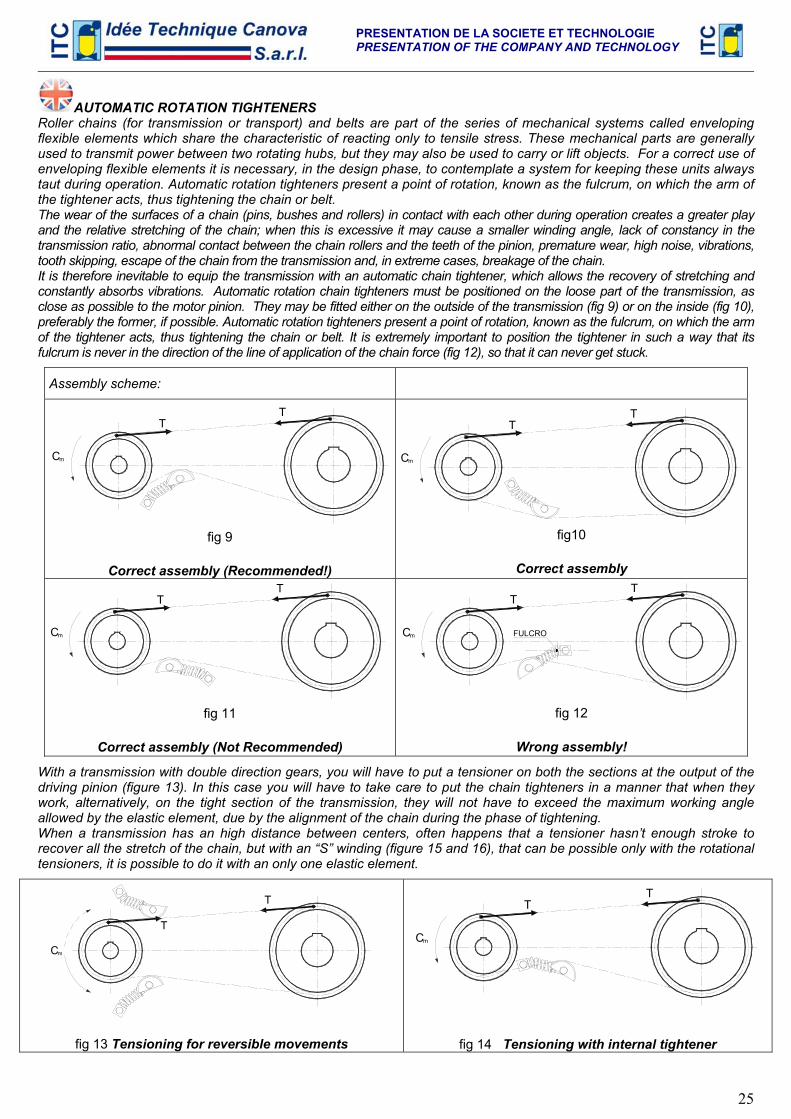
AUTOMATIC ROTATION TIGHTENERS Roller chains (for transmission or transport) and belts are part of the series of mechanical systems called enveloping flexible elements which share the characteristic of reacting only to tensile stress. These mechanical parts are generally used to transmit power between two rotating hubs, but they may also be used to carry or lift objects. For a correct use of enveloping flexible elements it is necessary, in the design phase, to contemplate a system for keeping these units always taut during operation. Automatic rotation tighteners present a point of rotation, known as the fulcrum, on which the arm of the tightener acts, thus tightening the chain or belt. The wear of the surfaces of a chain (pins, bushes and rollers) in contact with each other during operation creates a greater play and the relative stretching of the chain; when this is excessive it may cause a smaller winding angle, lack of constancy in the transmission ratio, abnormal contact between the chain rollers and the teeth of the pinion, premature wear, high noise, vibrations, tooth skipping, escape of the chain from the transmission and, in extreme cases, breakage of the chain. It is therefore inevitable to equip the transmission with an automatic chain tightener, which allows the recovery of stretching and constantly absorbs vibrations. Automatic rotation chain tighteners must be positioned on the loose part of the transmission, as close as possible to the motor pinion. They may be fitted either on the outside of the transmission (fig 9) or on the inside (fig 10), preferably the former, if possible. Automatic rotation tighteners present a point of rotation, known as the fulcrum, on which the arm of the tightener acts, thus tightening the chain or belt. It is extremely important to position the tightener in such a way that its fulcrum is never in the direction of the line of application of the chain force (fig 12), so that it can never get stuck.
Assembly scheme:
Cm
TT
fig 9
Correct assembly (Recommended!)
Cm
TT
fig10
Correct assembly
Cm
TT
fig 11
Correct assembly (Not Recommended)
Cm
TT
FULCRO
fig 12
Wrong assembly!
With a transmission with double direction gears, you will have to put a tensioner on both the sections at the output of the driving pinion (figure 13). In this case you will have to take care to put the chain tighteners in a manner that when they work, alternatively, on the tight section of the transmission, they will not have to exceed the maximum working angle allowed by the elastic element, due by the alignment of the chain during the phase of tightening. When a transmission has an high distance between centers, often happens that a tensioner hasn’t enough stroke to recover all the stretch of the chain, but with an “S” winding (figure 15 and 16), that can be possible only with the rotational tensioners, it is possible to do it with an only one elastic element.
Cm
T
T
fig 13 Tensioning for reversible movements
mC
TT
fig 14 Tensioning with internal tightener
PRESENTATION DE LA SOCIETE ET TECHNOLOGIE PRESENTATION OF THE COMPANY AND TECHNOLOGY
26
m
TT
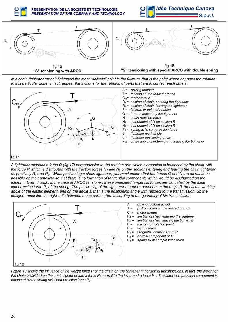
fig 15 “S” tensioning with ARCO
Cm
TT
fig 16 “S” tensioning with special ARCO with double spring
In a chain tightener (or belt tightener) the most “delicate” point is the fulcrum, that is the point where happens the rotation. In this particular zone, in fact, appear the frictions for the rubbing of parts that are in contact each others.
TmC
A
R1 R2
FN
N1
N2
Q90°
P3
fig 17
A = T = Cm= R1 = R2 = F = Q = N = N1 = N2 = P3 = δ = ε = γ1/2 =
driving toothed tension on the tensed branch motor torque section of chain entering the tightener section of chain leaving the tightener fulcrum or point of rotation force released by the tightener chain reaction force component of N on section R1 component of N on section R2 spring axial compression force tightener work angle tightener positioning angle chain angle of entering and leaving the tightener
A tightener releases a force Q (fig 17) perpendicular to the rotation arm which by reaction is balanced by the chain with the force N which is distributed with the traction forces N1 and N2 on the sections entering and leaving the chain tightener, respectively R1 and R2. When positioning a chain tightener, you must ensure that the forces Q and N are as much as possible on the same line so that there is no formation of tangential components which would be discharged on the fulcrum. Even though, in the case of ARCO tensioner, these undesired tangential forces are cancelled by the axial compression force P3 of the spring. The positioning of the tightener therefore depends on the angle δ, that is the working angle of the elastic element, and on the angle ε, that is the positioning angle with respect to the transmission. So the designer must find the right ratio between these parameters according to the geometry of his transmission.
Tm
A
R1R2
FP P2
P1
C
P3
fig 18
A = T = Cm= R1 = R2 = F = P = P1 = P2 = P3 =
driving toothed wheel pull on chain on the tensed branch motor torque section of chain entering the tightener section of chain leaving the tightener fulcrum or rotation point weight force tangential component of P normal component of P spring axial compression force
Figure 18 shows the influence of the weight force P of the chain on the tightener in horizontal transmissions. In fact, the weight of the chain is divided on the chain tightener into a force P2 normal to the lever and a force P1 . The latter compression component is balanced by the spring axial compression force P3.
TEN BLOC
27
C 2014
BREVETE – PATENTED
TEN BLOC
28
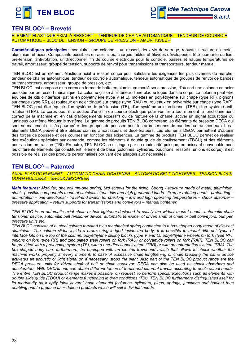
TEN BLOC® – Breveté ELEMENT ELASTIQUE AXIAL À RESSORT – TENDEUR DE CHAINE AUTOMATIQUE – TENDEUR DE COURROIE AUTOMATIQUE – BLOC DE TENSION – GROUPE DE PRESSION – AMORTISSEUR Caractéristiques principales: modulaire, une colonne – un ressort, deux vis de serrage, robuste, structure en métal, aluminium et acier. Composants possibles en acier inox, charges faibles et élevées développées, tête tournante ou fixe, pré-tension, anti-rotation, unidirectionnel, fin de course électrique pour le contrôle, basses et hautes températures de travail, amortisseur, groupe de tension, supports de renvoi pour transmissions et transporteurs, tendeur manuel. TEN BLOC est un élément élastique axial à ressort conçu pour satisfaire les exigences les plus diverses du marché: tendeur de chaîne automatique, tendeur de courroie automatique, tendeur automatique de groupes de renvoi de bandes ou transporteurs, amortisseur, groupe de pression, etc. TEN BLOC est composé d'un corps en forme de boîte en aluminium moulé sous pression, d'où sort une colonne en acier poussée par un ressort mécanique. La colonne glisse à l'intérieur d'une plaque logée dans le corps. La colonne peut être équipée de kits d'interface: patins en polyéthylène (type V et L), molettes en polyéthylène sur chape (type RF), pignons sur chape (type RR), et rouleaux en acier zingué sur chape (type RAU) ou rouleaux en polyamide sur chape (type RAP). TEN BLOC peut être équipé d'un système de pré-tension (TB), d'un système unidirectionnel (TBB), d'un système anti-rotation (TBA). Le corps peut être équipé d'une fin de course électrique pour vérifier à tout moment le fonctionnement correct de la machine et, en cas d'allongements excessifs ou de rupture de la chaîne, activer un signal acoustique ou lumineux ou même bloquer le système. La gamme de produits TEN BLOC comprend les éléments de pression DECA qui sont normalement utilisés pour créer des groupes de poussée pour les arbres menés de bandes ou transporteurs. Les -éléments DECA peuvent être utilisés comme amortisseurs et décélérateurs. Les éléments DECA permettent d'obtenir des forces de poussée et des courses en fonction des exigences. La gamme de produits TEN BLOC permet de réaliser des exécutions spéciales sur demande, comme les éléments à double guide de coulissement (TBCU) et des éléments pour action en traction (TBt). En outre, TEN BLOC se distingue par sa modularité puisque, en unissant convenablement les différents éléments qui constituent l’élément de base (colonnes, cylindres, bouchons, ressorts, unions et corps), il est possible de réaliser des produits personnalisés pouvant être adaptés aux nécessités.
TEN BLOC® – Patented AXIAL ELASTIC ELEMENT – AUTOMATIC CHAIN TIGHTENER – AUTOMATIC BELT TIGHTENER - TENSION BLOCK DOWN HOLDERS – SHOCK ABSORBER Main features: Modular, one column-one spring, two screws for the fixing, Strong - structure made of metal, aluminium, steel - possible components made of stainless steel - low and high generated loads - fixed or rotating head – preloading – anti-rotation – one-directional - travel-end switch for checking – low and high operating temperatures – shock absorber – pressure application – return supports for transmissions and conveyors – manual tightener. TEN BLOC is an automatic axial chain or belt tightener designed to satisfy the widest market-needs: automatic chain tensioner device, automatic belt tensioner device, automatic tensioner of driven shaft of chain or belt conveyors, bumper, pressure units etc. TEN BLOC consists of a steel column thrusted by a mechanical spring connected to a box-shaped body made of die-cast aluminium. The column slides inside a bronze ring lodged inside the body. It is possible to mount different types of interface kits on the top of the column: polyethylene sliding blocks (type V and L), polyethylene wheels on fork (type RF), pinions on fork (type RR) and zinc plated steel rollers on fork (RAU) or polyamide rollers on fork (RAP). TEN BLOC can be provided with a preloading system (TB), with a one-directional system (TBB) or with an anti-rotation system (TBA). The box-shaped body can, furthermore, be equipped with an electric travel-end switch that allows to check whether the machine works properly at every moment. In case of excessive chain lengthening or chain breaking the same device activates an acoustic or light signal or, if necessary, stops the plant. Also part of the TEN BLOC product range are the DECA pressure units for driven shaft of belt or chain conveyor. DECA can also be used as shock absorbers and decelerators. With DECAs one can obtain different forces of thrust and different travels according to one’s actual needs. The entire TEN BLOC product range makes it possible, on request, to perform special executions such as elements with double slide guide (TBCU) or elements functioning in drag conditions (TBt). TEN BLOC furthermore distinguishes itself for its modularity as it aptly joins several base elements (columns, cylinders, plugs, springs, junctions and bodies) thus enabling one to produce user-defined products which will suit individual needs.
TEN BLOC
29
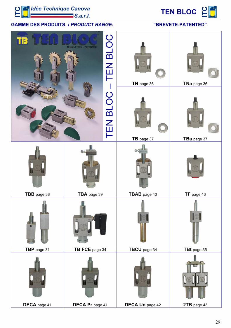
GAMME DES PRODUITS: / PRODUCT RANGE: “BREVETE-PATENTED”
TN page 36 TNa page 36
TB page 37 TBa page 37
TBB page 38 TBA page 39 TBAB page 40 TF page 43
TBP page 31 TB FCE page 34 TBCU page 34 TBt page 35
DECA page 41 DECA Pr page 41 DECA Un page 42 2TB page 43
TEN
BLO
C –
TE
N B
LOC
TEN BLOC
30
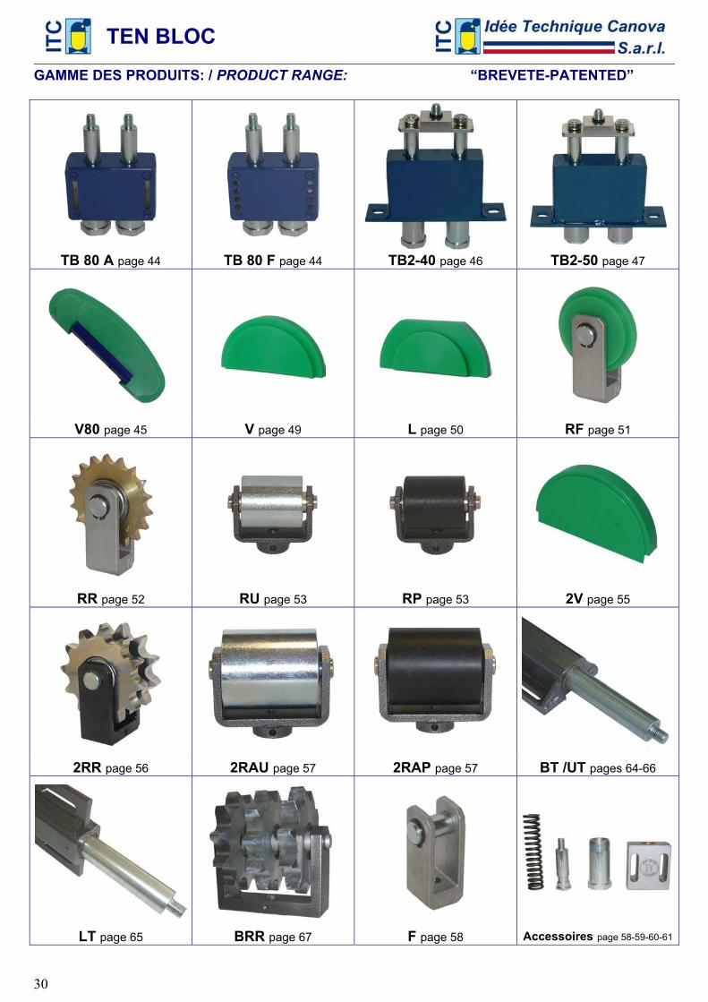
GAMME DES PRODUITS: / PRODUCT RANGE: “BREVETE-PATENTED”
TB 80 A page 44 TB 80 F page 44 TB2-40 page 46 TB2-50 page 47
V80 page 45 V page 49 L page 50 RF page 51
RR page 52 RU page 53 RP page 53 2V page 55
2RR page 56 2RAU page 57 2RAP page 57 BT /UT pages 64-66
LT page 65 BRR page 67 F page 58 Accessoires page 58-59-60-61
TEN BLOC
31
Instructions de montage: / Assembly instructions:
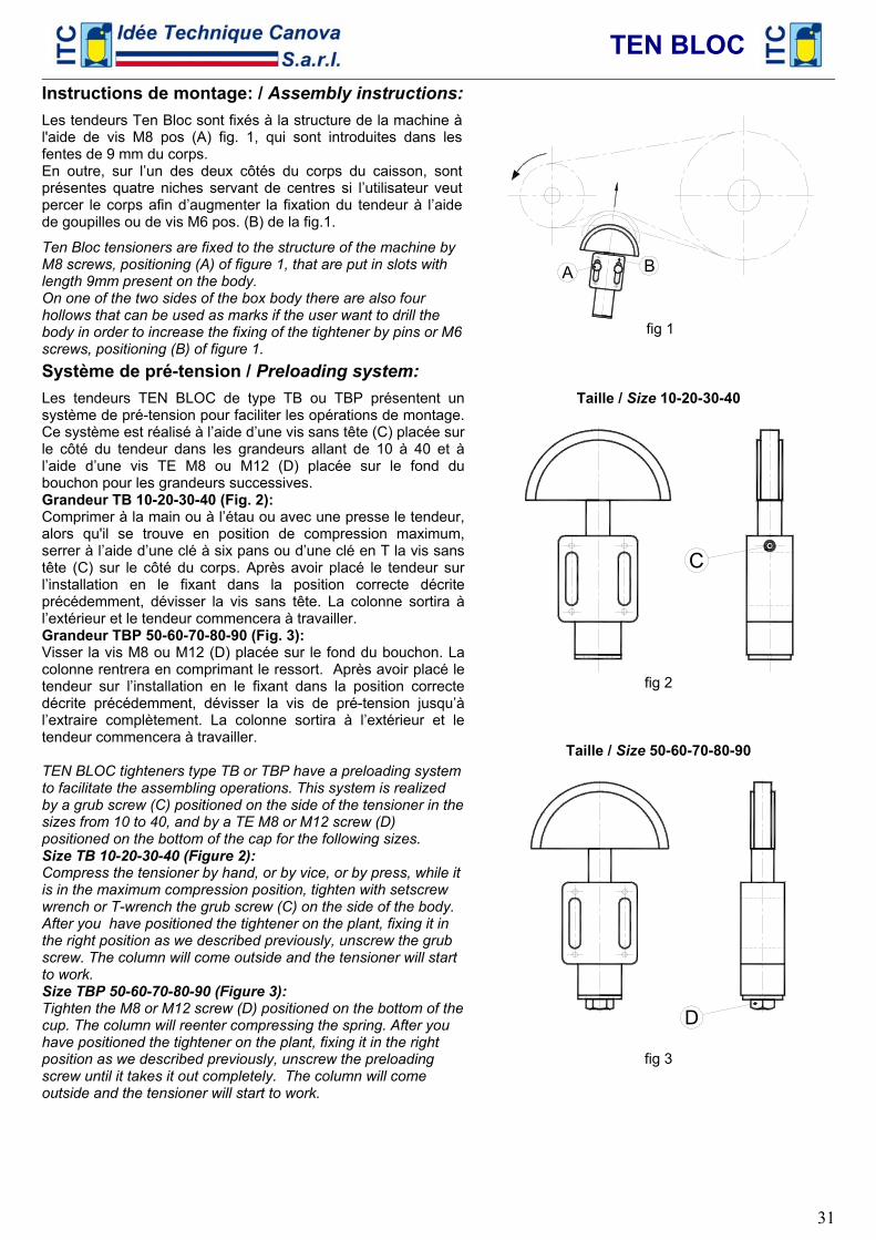
Les tendeurs Ten Bloc sont fixés à la structure de la machine à l'aide de vis M8 pos (A) fig. 1, qui sont introduites dans les fentes de 9 mm du corps. En outre, sur l’un des deux côtés du corps du caisson, sont présentes quatre niches servant de centres si l’utilisateur veut percer le corps afin d’augmenter la fixation du tendeur à l’aide de goupilles ou de vis M6 pos. (B) de la fig.1.
Ten Bloc tensioners are fixed to the structure of the machine by M8 screws, positioning (A) of figure 1, that are put in slots with length 9mm present on the body. On one of the two sides of the box body there are also four hollows that can be used as marks if the user want to drill the body in order to increase the fixing of the tightener by pins or M6 screws, positioning (B) of figure 1.
A B
fig 1
Système de pré-tension / Preloading system:
Les tendeurs TEN BLOC de type TB ou TBP présentent un système de pré-tension pour faciliter les opérations de montage. Ce système est réalisé à l’aide d’une vis sans tête (C) placée sur le côté du tendeur dans les grandeurs allant de 10 à 40 et à l’aide d’une vis TE M8 ou M12 (D) placée sur le fond du bouchon pour les grandeurs successives. Grandeur TB 10-20-30-40 (Fig. 2): Comprimer à la main ou à l’étau ou avec une presse le tendeur, alors qu'il se trouve en position de compression maximum, serrer à l’aide d’une clé à six pans ou d’une clé en T la vis sans tête (C) sur le côté du corps. Après avoir placé le tendeur sur l’installation en le fixant dans la position correcte décrite précédemment, dévisser la vis sans tête. La colonne sortira à l’extérieur et le tendeur commencera à travailler. Grandeur TBP 50-60-70-80-90 (Fig. 3): Visser la vis M8 ou M12 (D) placée sur le fond du bouchon. La colonne rentrera en comprimant le ressort. Après avoir placé le tendeur sur l’installation en le fixant dans la position correcte décrite précédemment, dévisser la vis de pré-tension jusqu’à l’extraire complètement. La colonne sortira à l’extérieur et le tendeur commencera à travailler. TEN BLOC tighteners type TB or TBP have a preloading system to facilitate the assembling operations. This system is realized by a grub screw (C) positioned on the side of the tensioner in the sizes from 10 to 40, and by a TE M8 or M12 screw (D) positioned on the bottom of the cap for the following sizes. Size TB 10-20-30-40 (Figure 2): Compress the tensioner by hand, or by vice, or by press, while it is in the maximum compression position, tighten with setscrew wrench or T-wrench the grub screw (C) on the side of the body. After you have positioned the tightener on the plant, fixing it in the right position as we described previously, unscrew the grub screw. The column will come outside and the tensioner will start to work. Size TBP 50-60-70-80-90 (Figure 3): Tighten the M8 or M12 screw (D) positioned on the bottom of the cup. The column will reenter compressing the spring. After you have positioned the tightener on the plant, fixing it in the right position as we described previously, unscrew the preloading screw until it takes it out completely. The column will come outside and the tensioner will start to work.
Taille / Size 10-20-30-40
C
fig 2
Taille / Size 50-60-70-80-90
D
fig 3
TEN BLOC
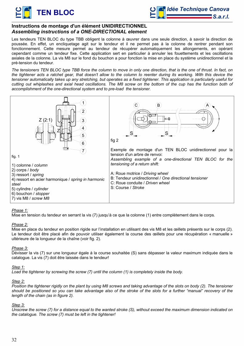
32
Instructions de montage d'un élément UNIDIRECTIONNEL Assembling instructions of a ONE-DIRECTIONAL element
Les tendeurs TEN BLOC du type TBB obligent la colonne à œuvrer dans une seule direction, à savoir la direction de poussée. En effet, un encliquetage agit sur le tendeur et il ne permet pas à la colonne de rentrer pendant son fonctionnement. Cette mesure permet au tendeur de récupérer automatiquement les allongements, en opérant cependant comme un tendeur fixe. Cette application sert en particulier à annuler les fouettements et les oscillations axiales de la colonne. La vis M8 sur le fond du bouchon a pour fonction la mise en place du système unidirectionnel et la pré-tension du tendeur.
The tensioners TEN BLOC type TBB force the column to move in only one direction, that is the one of thrust. In fact, on the tightener acts a ratchet gear, that doesn’t allow to the column to reenter during its working. With this device the tensioner automatically takes up any stretching, but operates as a fixed tightener. This application is particularly useful for cutting out whiplashes and axial head oscillations. The M8 screw on the bottom of the cup has the function both of accomplishment of the one-directional system and to pre-load the tensioner.
5
7
6
Z (2:1)
Z 4
3
2
1
fig. 1 1) colonne / column 2) corps / body 3) ressort / spring 4) ressort en acier harmonique / spring in harmonic steel 5) cylindre / cylinder 6) bouchon / stopper 7) vis M8 / screw M8
S
C
S
AB
fig 2 Exemple de montage d'un TEN BLOC unidirectionnel pour la tension d'un arbre de renvoi: Assembling example of a one-directional TEN BLOC for the tensioning of a return shift: A: Roue motrice / Driving wheel B: Tendeur unidirectionnel / One directional tensioner C: Roue conduite / Driven wheel S: Course / Stroke
Phase 1: Mise en tension du tendeur en serrant la vis (7) jusqu’à ce que la colonne (1) entre complètement dans le corps. Phase 2: Mise en place du tendeur en position rigide sur l’installation en utilisant des vis M8 et les œillets présents sur le corps (2). Le tendeur doit être placé afin de pouvoir utiliser également la course des œillets pour une récupération « manuelle » ultérieure de la longueur de la chaîne (voir fig. 2). Phase 3: Dévisser la vis (7) sur une longueur égale à la course souhaitée (S) sans dépasser la valeur maximum indiquée dans le catalogue. La vis (7) doit être laissée dans le tendeur! Step 1: Load the tightener by screwing the screw (7) until the column (1) is completely inside the body. Step 2: Position the tightener rigidly on the plant by using M8 screws and taking advantage of the slots on body (2). The tensioner should be positioned so you can take advantage also of the stroke of the slots for a further “manual” recovery of the length of the chain (as in figure 2). Step 3: Unscrew the screw (7) for a distance equal to the wanted stroke (S), without exceed the maximum dimension indicated on the catalogue. The screw (7) must be left in the tightener!
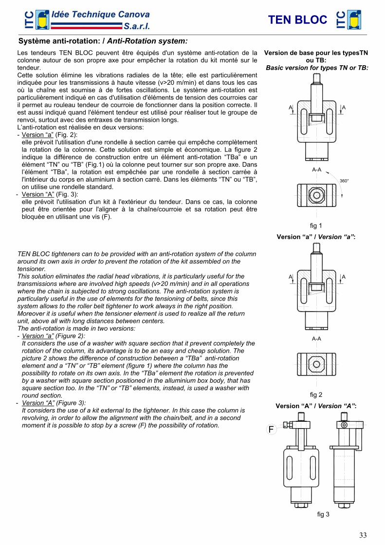
TEN BLOC
33
Système anti-rotation: / Anti-Rotation system:
Les tendeurs TEN BLOC peuvent être équipés d'un système anti-rotation de la colonne autour de son propre axe pour empêcher la rotation du kit monté sur le tendeur. Cette solution élimine les vibrations radiales de la tête; elle est particulièrement indiquée pour les transmissions à haute vitesse (v>20 m/min) et dans tous les cas où la chaîne est soumise à de fortes oscillations. Le système anti-rotation est particulièrement indiqué en cas d'utilisation d'éléments de tension des courroies car il permet au rouleau tendeur de courroie de fonctionner dans la position correcte. Il est aussi indiqué quand l'élément tendeur est utilisé pour réaliser tout le groupe de renvoi, surtout avec des entraxes de transmission longs. L’anti-rotation est réalisée en deux versions: - Version “a” (Fig. 2):
elle prévoit l'utilisation d'une rondelle à section carrée qui empêche complètement la rotation de la colonne. Cette solution est simple et économique. La figure 2 indique la différence de construction entre un élément anti-rotation “TBa” e un élément “TN” ou “TB” (Fig.1) où la colonne peut tourner sur son propre axe. Dans l’élément “TBa”, la rotation est empêchée par une rondelle à section carrée à l'intérieur du corps en aluminium à section carré. Dans les éléments “TN” ou “TB”, on utilise une rondelle standard.
- Version “A” (Fig. 3): elle prévoit l'utilisation d'un kit à l'extérieur du tendeur. Dans ce cas, la colonne peut être orientée pour l'aligner à la chaîne/courroie et sa rotation peut être bloquée en utilisant une vis (F).
TEN BLOC tighteners can to be provided with an anti-rotation system of the column around its own axis in order to prevent the rotation of the kit assembled on the tensioner. This solution eliminates the radial head vibrations, it is particularly useful for the transmissions where are involved high speeds (v>20 m/min) and in all operations where the chain is subjected to strong oscillations. The anti-rotation system is particularly useful in the use of elements for the tensioning of belts, since this system allows to the roller belt tightener to work always in the right position. Moreover it is useful when the tensioner element is used to realize all the return unit, above all with long distances between centers. The anti-rotation is made in two versions: - Version “a” (Figure 2):
It considers the use of a washer with square section that it prevent completely the rotation of the column, its advantage is to be an easy and cheap solution. The picture 2 shows the difference of construction between a “TBa” anti-rotation element and a “TN” or “TB” element (figure 1) where the column has the possibility to rotate on its own axis. In the “TBa” element the rotation is prevented by a washer with square section positioned in the alluminium box body, that has square section too. In the “TN” or “TB” elements, instead, is used a washer with round section.
- Version “A” (Figure 3): It considers the use of a kit external to the tightener. In this case the column is revolving, in order to allow the alignment with the chain/belt, and in a second moment it is possible to stop by a screw (F) the possibility of rotation.
Version de base pour les typesTN ou TB:
Basic version for types TN or TB:
A
360°
A-A
fig 1
Version “a” / Version “a”:
A
A-A
fig 2
Version “A” / Version “A”:
F
fig 3
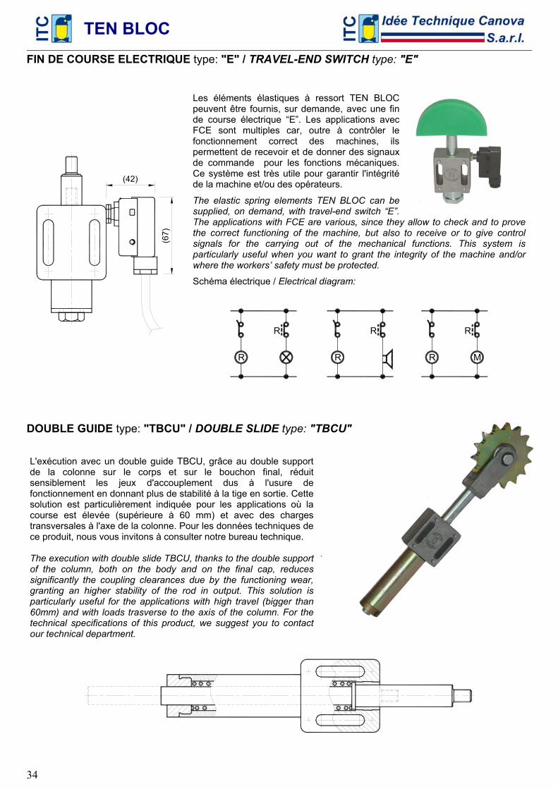
TEN BLOC
34
FIN DE COURSE ELECTRIQUE type: "E" / TRAVEL-END SWITCH type: "E"
(42)
(67)
Les éléments élastiques à ressort TEN BLOC peuvent être fournis, sur demande, avec une fin de course électrique “E”. Les applications avec FCE sont multiples car, outre à contrôler le fonctionnement correct des machines, ils permettent de recevoir et de donner des signaux de commande pour les fonctions mécaniques. Ce système est très utile pour garantir l'intégrité de la machine et/ou des opérateurs.
The elastic spring elements TEN BLOC can be supplied, on demand, with travel-end switch “E”. The applications with FCE are various, since they allow to check and to prove the correct functioning of the machine, but also to receive or to give control signals for the carrying out of the mechanical functions. This system is particularly useful when you want to grant the integrity of the machine and/or where the workers’ safety must be protected.
Schéma électrique / Electrical diagram:
R
R
R
R
R
R
M
DOUBLE GUIDE type: "TBCU" / DOUBLE SLIDE type: "TBCU"
L'exécution avec un double guide TBCU, grâce au double support de la colonne sur le corps et sur le bouchon final, réduit sensiblement les jeux d'accouplement dus à l'usure de fonctionnement en donnant plus de stabilité à la tige en sortie. Cette solution est particulièrement indiquée pour les applications où la course est élevée (supérieure à 60 mm) et avec des charges transversales à l'axe de la colonne. Pour les données techniques de ce produit, nous vous invitons à consulter notre bureau technique. The execution with double slide TBCU, thanks to the double support of the column, both on the body and on the final cap, reduces significantly the coupling clearances due by the functioning wear, granting an higher stability of the rod in output. This solution is particularly useful for the applications with high travel (bigger than 60mm) and with loads trasverse to the axis of the column. For the technical specifications of this product, we suggest you to contact our technical department.
.
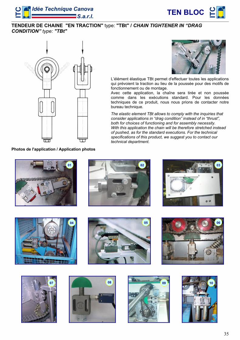
TEN BLOC
35
TENDEUR DE CHAINE "EN TRACTION" type: "TBt" / CHAIN TIGHTENER IN “DRAG CONDITION” type: "TBt"
L’élément élastique TBt permet d'effectuer toutes les applications qui prévoient la traction au lieu de la poussée pour des motifs de fonctionnement ou de montage. Avec cette application, la chaîne sera tirée et non poussée comme dans les exécutions standard. Pour les données techniques de ce produit, nous nous prions de contacter notre bureau technique.
The elastic element TBt allows to comply with the inquiries that consider applications in “drag condition” instead of in “thrust”, both for choices of functioning and for assembly necessity. With this application the chain will be therefore stretched instead of pushed, as for the standard executions. For the technical specifications of this product, we suggest you to contact our technical department.
Photos de l'application / Application photos
01 02 03
04 05 06
07 08 09 10
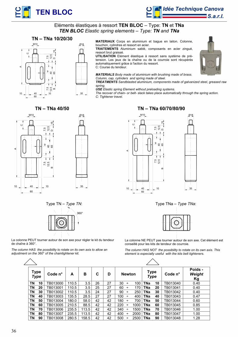
TEN BLOC
36
Eléments élastiques à ressort TEN BLOC – Type: TN et TNa TEN BLOC Elastic spring elements – Type: TN and TNa
TN – TNa 10/20/30
60 40 10 10
7.5
7.5
65
D
A
35
12.5
12
.5
40
Ø18 M10
C
9
B15
MATERIAUX Corps en aluminium et bague en laiton. Colonne, bouchon, cylindres et ressort en acier. TRAITEMENTS Aluminium sablé, composants en acier zingué, ressort brut graissé. UTILISATION Elément élastique à ressort sans système de pré-tension. Les jeux de la chaîne ou de la courroie sont récupérés automatiquement grâce à l'action du ressort. C: Course du tendeur. MATERIALS Body made of aluminium with brushing made of brass. Column, cap, cylinders and spring made of steel. TREATMENTS Sandblasted aluminium, components made of galvanized steel, greased raw spring. USE Elastic spring Element without preloading systems. The recover of chain- or belt- slack takes place automatically through the spring action. C: Tightener travel.
TN – TNa 40/50
60
40 10 10
7.5
7.5
65
D
A
35
B12
.5
12.5
40
Ø18 M10
C
9
15
TN – TNa 60/70/80/90
60 40 10 10
7.5
7.5
65
D
A
35
B12
.5
12.5
40
Ø18
C
9
15
Type TN – Type TN:
360°
La colonne PEUT tourner autour de son axe pour régler le kit du tendeur de chaîne à 360°.
The column HAS the possibility to rotate on its own axis to allow an adjustment on the 360° of the chaintightener kit.
Type TNa – Type TNa:
La colonne NE PEUT pas tourner autour de son axe. Cet élément est conseillé pour les kits de tendeur de courroie.
The column HAS NOT the possibility to rotate on its own axis. This element is especially useful with the kits belt tighteners.
Type Type Code n° A B C D Newton Type
Type Code n° Poids - Weight
Kg TN 10 TB013000 110.5 3.5 26 27 30 ÷ 100 TNa 10 TB013040 0.40 TN 20 TB013001 110.5 3.5 25 27 60 ÷ 170 TNa 20 TB013041 0.40 TN 30 TB013002 110.5 3.5 24 27 90 ÷ 250 TNa 30 TB013042 0.40 TN 40 TB013003 135.5 28.5 27 27 100 ÷ 400 TNa 40 TB013043 0.47 TN 50 TB013004 180.0 58.0 42 42 180 ÷ 700 TNa 50 TB013044 0.60 TN 60 TB013005 210.5 88.5 42 42 220 ÷ 1000 TNa 60 TB013045 0.85 TN 70 TB013006 235.5 113.5 42 42 340 ÷ 1500 TNa 70 TB013046 1.00 TN 80 TB013007 235.5 113.5 42 42 400 ÷ 2000 TNa 80 TB013047 1.00 TN 90 TB013008 280.5 158.5 42 42 500 ÷ 2500 TNa 90 TB013048 1.28
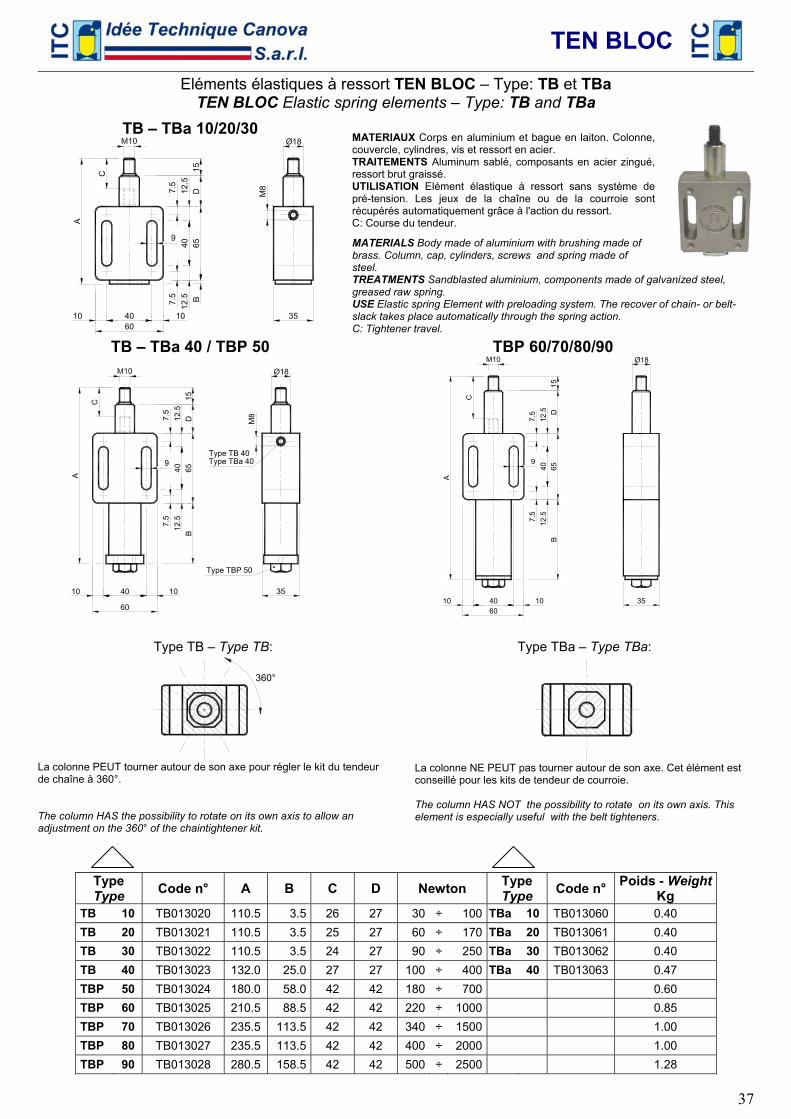
TEN BLOC
37
Eléments élastiques à ressort TEN BLOC – Type: TB et TBa TEN BLOC Elastic spring elements – Type: TB and TBa
TB – TBa 10/20/30
60 40 10 10
7.5
7.5
65
D
A
35
12.5
12
.5
40
M8
C
9
B15
MATERIAUX Corps en aluminium et bague en laiton. Colonne, couvercle, cylindres, vis et ressort en acier. TRAITEMENTS Aluminum sablé, composants en acier zingué, ressort brut graissé. UTILISATION Elément élastique à ressort sans système de pré-tension. Les jeux de la chaîne ou de la courroie sont récupérés automatiquement grâce à l'action du ressort. C: Course du tendeur.
MATERIALS Body made of aluminium with brushing made of brass. Column, cap, cylinders, screws and spring made of steel. TREATMENTS Sandblasted aluminium, components made of galvanized steel, greased raw spring. USE Elastic spring Element with preloading system. The recover of chain- or belt- slack takes place automatically through the spring action. C: Tightener travel.
TB – TBa 40 / TBP 50
60
40 10 10
7.5
7.5
65
D
A
35
B12
.5
12.5
40
M8
Type TB 40
Type TBP 50
Type TBa 40
C
9
15
TBP 60/70/80/90
60 40 10 10
7.5
7.5
65
D
A
35
B12
.5
12.5
40
Ø18
C9
15
Type TB – Type TB:
360°
La colonne PEUT tourner autour de son axe pour régler le kit du tendeur de chaîne à 360°. The column HAS the possibility to rotate on its own axis to allow an adjustment on the 360° of the chaintightener kit.
Type TBa – Type TBa:
La colonne NE PEUT pas tourner autour de son axe. Cet élément est conseillé pour les kits de tendeur de courroie. The column HAS NOT the possibility to rotate on its own axis. This element is especially useful with the belt tighteners.
Type Type Code n° A B C D Newton Type
Type Code n° Poids - WeightKg
TB 10 TB013020 110.5 3.5 26 27 30 ÷ 100 TBa 10 TB013060 0.40 TB 20 TB013021 110.5 3.5 25 27 60 ÷ 170 TBa 20 TB013061 0.40 TB 30 TB013022 110.5 3.5 24 27 90 ÷ 250 TBa 30 TB013062 0.40 TB 40 TB013023 132.0 25.0 27 27 100 ÷ 400 TBa 40 TB013063 0.47 TBP 50 TB013024 180.0 58.0 42 42 180 ÷ 700 0.60 TBP 60 TB013025 210.5 88.5 42 42 220 ÷ 1000 0.85 TBP 70 TB013026 235.5 113.5 42 42 340 ÷ 1500 1.00 TBP 80 TB013027 235.5 113.5 42 42 400 ÷ 2000 1.00 TBP 90 TB013028 280.5 158.5 42 42 500 ÷ 2500 1.28
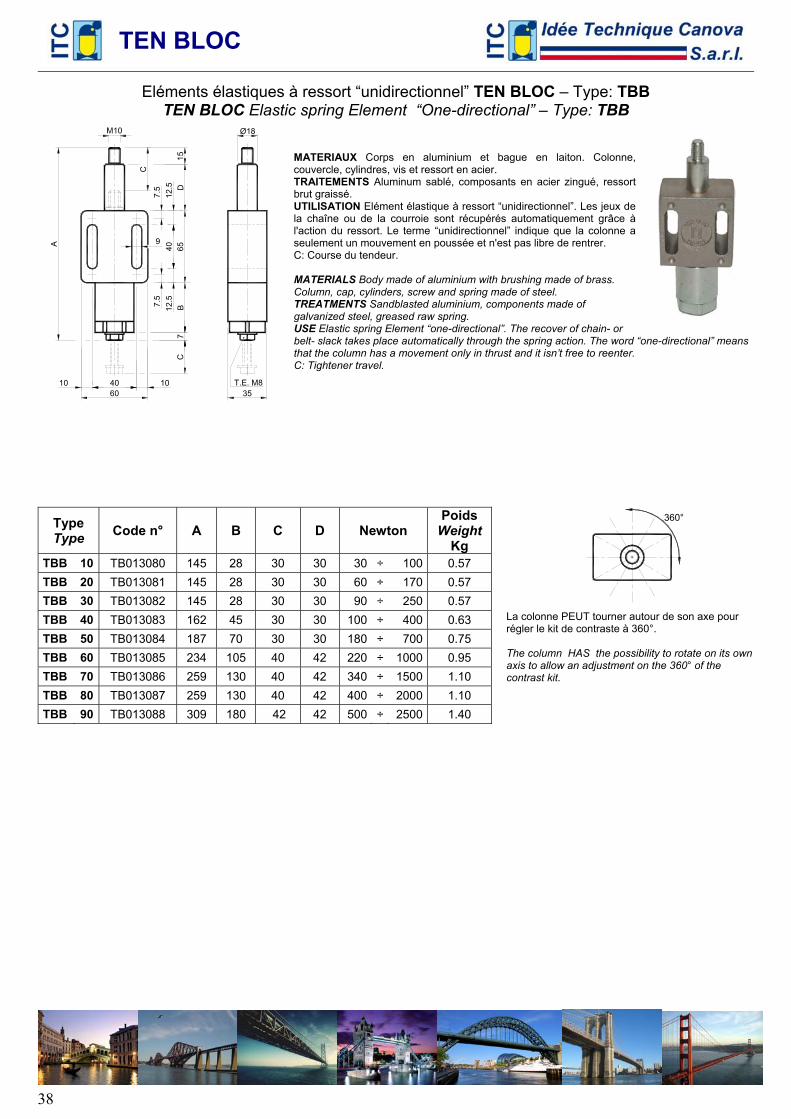
TEN BLOC
38
Eléments élastiques à ressort “unidirectionnel” TEN BLOC – Type: TBB TEN BLOC Elastic spring Element “One-directional” – Type: TBB
60 40 10 10 T.E. M8
35
7
A
7.5
7.5
65
DB
12.5
12
.5
40
CØ18
C
9
15
MATERIAUX Corps en aluminium et bague en laiton. Colonne, couvercle, cylindres, vis et ressort en acier. TRAITEMENTS Aluminum sablé, composants en acier zingué, ressort brut graissé. UTILISATION Elément élastique à ressort “unidirectionnel”. Les jeux de la chaîne ou de la courroie sont récupérés automatiquement grâce à l'action du ressort. Le terme “unidirectionnel” indique que la colonne a seulement un mouvement en poussée et n'est pas libre de rentrer. C: Course du tendeur. MATERIALS Body made of aluminium with brushing made of brass. Column, cap, cylinders, screw and spring made of steel. TREATMENTS Sandblasted aluminium, components made of galvanized steel, greased raw spring. USE Elastic spring Element “one-directional”. The recover of chain- or belt- slack takes place automatically through the spring action. The word “one-directional” means that the column has a movement only in thrust and it isn’t free to reenter. C: Tightener travel.
Type Type Code n° A B C D Newton
Poids Weight
Kg TBB 10 TB013080 145 28 30 30 30 ÷ 100 0.57 TBB 20 TB013081 145 28 30 30 60 ÷ 170 0.57 TBB 30 TB013082 145 28 30 30 90 ÷ 250 0.57 TBB 40 TB013083 162 45 30 30 100 ÷ 400 0.63 TBB 50 TB013084 187 70 30 30 180 ÷ 700 0.75 TBB 60 TB013085 234 105 40 42 220 ÷ 1000 0.95 TBB 70 TB013086 259 130 40 42 340 ÷ 1500 1.10 TBB 80 TB013087 259 130 40 42 400 ÷ 2000 1.10 TBB 90 TB013088 309 180 42 42 500 ÷ 2500 1.40
360°
La colonne PEUT tourner autour de son axe pour régler le kit de contraste à 360°. The column HAS the possibility to rotate on its own axis to allow an adjustment on the 360° of the contrast kit.
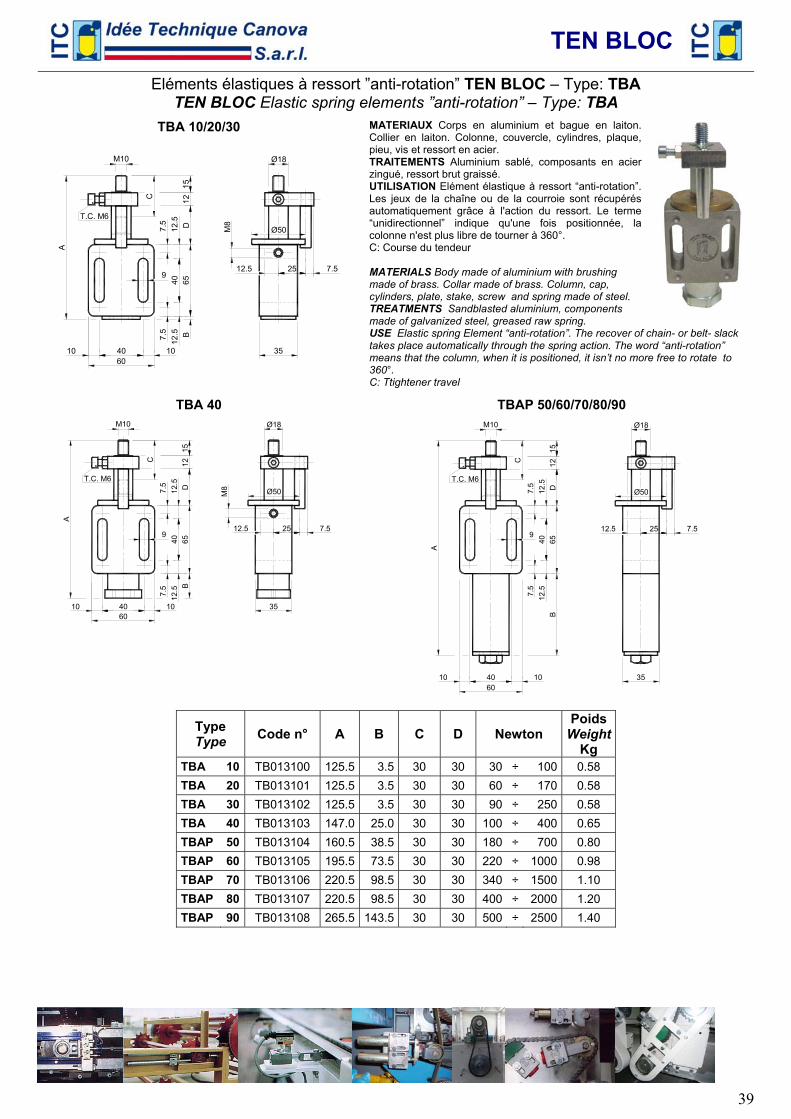
TEN BLOC
39
Eléments élastiques à ressort ”anti-rotation” TEN BLOC – Type: TBA TEN BLOC Elastic spring elements ”anti-rotation” – Type: TBA
TBA 10/20/30
Ø18
Ø50
12.5 25
A
7.5
7.5
65
DB
12.5
12
.5
40
T.C. M6
M10
7.5
C
M8
12
60 40 10 10 35
9
15
MATERIAUX Corps en aluminium et bague en laiton. Collier en laiton. Colonne, couvercle, cylindres, plaque, pieu, vis et ressort en acier. TRAITEMENTS Aluminium sablé, composants en acier zingué, ressort brut graissé. UTILISATION Elément élastique à ressort “anti-rotation”. Les jeux de la chaîne ou de la courroie sont récupérés automatiquement grâce à l'action du ressort. Le terme “unidirectionnel” indique qu'une fois positionnée, la colonne n'est plus libre de tourner à 360°. C: Course du tendeur MATERIALS Body made of aluminium with brushing made of brass. Collar made of brass. Column, cap, cylinders, plate, stake, screw and spring made of steel. TREATMENTS Sandblasted aluminium, components made of galvanized steel, greased raw spring. USE Elastic spring Element “anti-rotation”. The recover of chain- or belt- slack takes place automatically through the spring action. The word “anti-rotation” means that the column, when it is positioned, it isn’t no more free to rotate to 360°. C: Ttightener travel
TBA 40
Ø18
Ø50
12.5 25
A
7.5
7.5
65
DB
12.5
12
.5
40
T.C. M6
7.5
C
M8
12
60 40 10 10 35
9
15
TBAP 50/60/70/80/90
Ø18
Ø50
12.5 25
A
7.5
7.5
65
D12.5
12
.5
40
T.C. M6
M10
7.5 C 12
60 40 10 10 35
B
9
15
Type Type Code n° A B C D Newton
Poids Weight
Kg TBA 10 TB013100 125.5 3.5 30 30 30 ÷ 100 0.58 TBA 20 TB013101 125.5 3.5 30 30 60 ÷ 170 0.58 TBA 30 TB013102 125.5 3.5 30 30 90 ÷ 250 0.58 TBA 40 TB013103 147.0 25.0 30 30 100 ÷ 400 0.65 TBAP 50 TB013104 160.5 38.5 30 30 180 ÷ 700 0.80 TBAP 60 TB013105 195.5 73.5 30 30 220 ÷ 1000 0.98 TBAP 70 TB013106 220.5 98.5 30 30 340 ÷ 1500 1.10 TBAP 80 TB013107 220.5 98.5 30 30 400 ÷ 2000 1.20 TBAP 90 TB013108 265.5 143.5 30 30 500 ÷ 2500 1.40
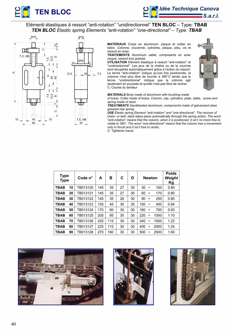
TEN BLOC
40
Elémenti élastiques à ressort “anti-rotation” “unidirectionnel” TEN BLOC – Type: TBAB TEN BLOC Elastic spring Elements “anti-rotation” “one-directional” – Type: TBAB
Ø50
12.5 25 A
7.5
7.5
65
DB
12.5
12
.5
40
35
T.C. M6
M10
7.5
C
T.E. M8
7
60 40 10 10
C
Ø18
9
15
MATERIAUX Corps en aluminium, plaque et collier en laiton. Colonne, couvercle, cylindres, plaque, pieu, vis et ressort en acier. TRAITEMENTS Aluminium sablé, composants en acier zingué, ressort brut graissé. UTILISATION Elément élastique à ressort “anti-rotation” et "unidirectionnel". Les jeux de la chaîne ou de la courroie sont récupérés automatiquement grâce à l'action du ressort. Le terme "anti-rotation" indique qu'une fois positionnée, la colonne n'est plus libre de tourner à 360°C tandis que le terme “unidirectionnel” indique que la colonne agit seulement en poussée et qu'elle n'est pas libre de rentrer. C: Course du tendeur MATERIALS Body made of aluminium with brushing made of brass. Collar made of brass. Column, cap, cylinders, plate, stake, screw and spring made of steel. TREATMENTS Sandblasted aluminium, components made of galvanized steel, greased raw spring. USE Elastic spring Element “anti-rotation” and “one-directional”. The recover of chain- or belt- slack takes place automatically through the spring action. The word “anti-rotation” means that the column, when it is positioned, it isn’t no more free to rotate to 360°. The word “one-directional” means that the column has a movement only in thrust and it isn’t free to renter. C: Tightener travel.
Type Type Code n° A B C D Newton
Poids Weight
Kg TBAB 10 TB013120 145 35 27 30 30 ÷ 100 0.80 TBAB 20 TB013121 145 35 27 30 60 ÷ 170 0.80 TBAB 30 TB013122 145 35 26 30 90 ÷ 250 0.80 TBAB 40 TB013123 155 45 30 30 100 ÷ 400 0.84 TBAB 50 TB013124 170 60 30 30 180 ÷ 700 0.93 TBAB 60 TB013125 205 95 30 30 220 ÷ 1000 1.10 TBAB 70 TB013126 225 115 30 30 340 ÷ 1500 1.22 TBAB 80 TB013127 225 115 30 30 400 ÷ 2000 1.24 TBAB 90 TB013128 270 160 30 30 500 ÷ 2500 1.60
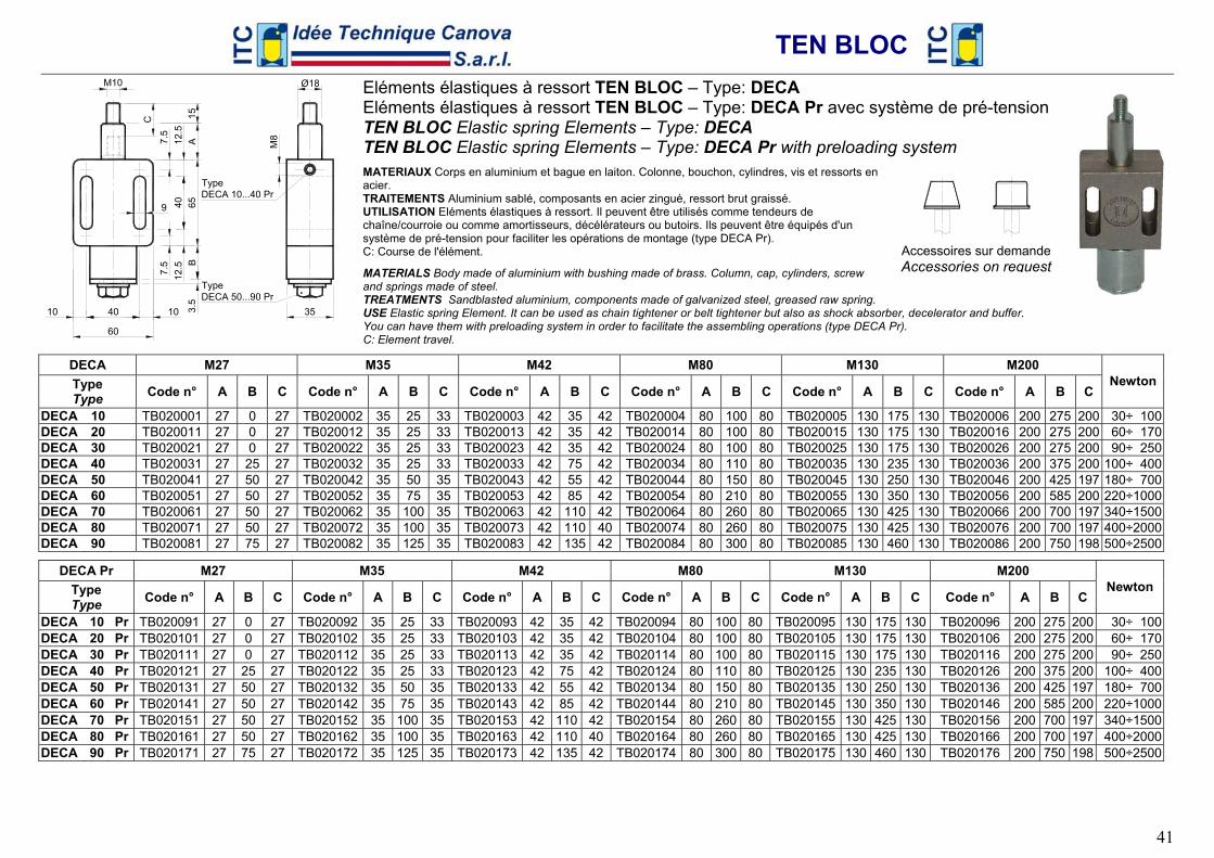
TEN BLOC
41
Accessoires sur demande Accessories on request
40 10 10
7.5
7.5
65
A
C
35
B12
.5
12.5
40
Ø18
159
3.5
60
Type DECA 10...40 Pr
M8
Type DECA 50...90 Pr
Eléments élastiques à ressort TEN BLOC – Type: DECA Eléments élastiques à ressort TEN BLOC – Type: DECA Pr avec système de pré-tension TEN BLOC Elastic spring Elements – Type: DECA TEN BLOC Elastic spring Elements – Type: DECA Pr with preloading system MATERIAUX Corps en aluminium et bague en laiton. Colonne, bouchon, cylindres, vis et ressorts en acier. TRAITEMENTS Aluminium sablé, composants en acier zingué, ressort brut graissé. UTILISATION Eléments élastiques à ressort. Il peuvent être utilisés comme tendeurs de chaîne/courroie ou comme amortisseurs, décélérateurs ou butoirs. Ils peuvent être équipés d'un système de pré-tension pour faciliter les opérations de montage (type DECA Pr). C: Course de l'élément.
MATERIALS Body made of aluminium with bushing made of brass. Column, cap, cylinders, screw and springs made of steel. TREATMENTS Sandblasted aluminium, components made of galvanized steel, greased raw spring. USE Elastic spring Element. It can be used as chain tightener or belt tightener but also as shock absorber, decelerator and buffer. You can have them with preloading system in order to facilitate the assembling operations (type DECA Pr). C: Element travel.
DECA M27 M35 M42 M80 M130 M200 Type Type Code n° A B C Code n° A B C Code n° A B C Code n° A B C Code n° A B C Code n° A B C
Newton
DECA 10 TB020001 27 0 27 TB020002 35 25 33 TB020003 42 35 42 TB020004 80 100 80 TB020005 130 175 130 TB020006 200 275 200 30÷ 100 DECA 20 TB020011 27 0 27 TB020012 35 25 33 TB020013 42 35 42 TB020014 80 100 80 TB020015 130 175 130 TB020016 200 275 200 60÷ 170 DECA 30 TB020021 27 0 27 TB020022 35 25 33 TB020023 42 35 42 TB020024 80 100 80 TB020025 130 175 130 TB020026 200 275 200 90÷ 250 DECA 40 TB020031 27 25 27 TB020032 35 25 33 TB020033 42 75 42 TB020034 80 110 80 TB020035 130 235 130 TB020036 200 375 200 100÷ 400 DECA 50 TB020041 27 50 27 TB020042 35 50 35 TB020043 42 55 42 TB020044 80 150 80 TB020045 130 250 130 TB020046 200 425 197 180÷ 700 DECA 60 TB020051 27 50 27 TB020052 35 75 35 TB020053 42 85 42 TB020054 80 210 80 TB020055 130 350 130 TB020056 200 585 200 220÷1000 DECA 70 TB020061 27 50 27 TB020062 35 100 35 TB020063 42 110 42 TB020064 80 260 80 TB020065 130 425 130 TB020066 200 700 197 340÷1500 DECA 80 TB020071 27 50 27 TB020072 35 100 35 TB020073 42 110 40 TB020074 80 260 80 TB020075 130 425 130 TB020076 200 700 197 400÷2000 DECA 90 TB020081 27 75 27 TB020082 35 125 35 TB020083 42 135 42 TB020084 80 300 80 TB020085 130 460 130 TB020086 200 750 198 500÷2500
DECA Pr M27 M35 M42 M80 M130 M200 Type Type Code n° A B C Code n° A B C Code n° A B C Code n° A B C Code n° A B C Code n° A B C
Newton
DECA 10 Pr TB020091 27 0 27 TB020092 35 25 33 TB020093 42 35 42 TB020094 80 100 80 TB020095 130 175 130 TB020096 200 275 200 30÷ 100 DECA 20 Pr TB020101 27 0 27 TB020102 35 25 33 TB020103 42 35 42 TB020104 80 100 80 TB020105 130 175 130 TB020106 200 275 200 60÷ 170 DECA 30 Pr TB020111 27 0 27 TB020112 35 25 33 TB020113 42 35 42 TB020114 80 100 80 TB020115 130 175 130 TB020116 200 275 200 90÷ 250 DECA 40 Pr TB020121 27 25 27 TB020122 35 25 33 TB020123 42 75 42 TB020124 80 110 80 TB020125 130 235 130 TB020126 200 375 200 100÷ 400 DECA 50 Pr TB020131 27 50 27 TB020132 35 50 35 TB020133 42 55 42 TB020134 80 150 80 TB020135 130 250 130 TB020136 200 425 197 180÷ 700 DECA 60 Pr TB020141 27 50 27 TB020142 35 75 35 TB020143 42 85 42 TB020144 80 210 80 TB020145 130 350 130 TB020146 200 585 200 220÷1000 DECA 70 Pr TB020151 27 50 27 TB020152 35 100 35 TB020153 42 110 42 TB020154 80 260 80 TB020155 130 425 130 TB020156 200 700 197 340÷1500 DECA 80 Pr TB020161 27 50 27 TB020162 35 100 35 TB020163 42 110 40 TB020164 80 260 80 TB020165 130 425 130 TB020166 200 700 197 400÷2000 DECA 90 Pr TB020171 27 75 27 TB020172 35 125 35 TB020173 42 135 42 TB020174 80 300 80 TB020175 130 460 130 TB020176 200 750 198 500÷2500
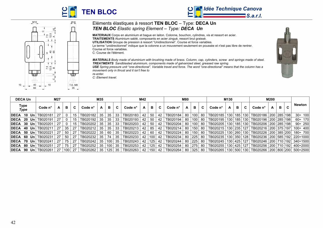
TEN BLOC
42
60 40 10 10 T.E. M8
35
7
7.5
7.5
65
AB
12.5
12
.5
40
C
M10 Ø18
C9
15
Eléments élastiques à ressort TEN BLOC – Type: DECA Un TEN BLOC Elastic spring Element – Type: DECA Un MATERIAUX Corps en aluminium et bague en laiton. Colonne, bouchon, cylindres, vis et ressort en acier. TRAITEMENTS Aluminium sablé, composants en acier zingué, ressort brut graissé. UTILISATION Groupe de pression à ressort “Unidirectionnel”. Course et force variables. Le terme “unidirectionnel” indique que la colonne a un mouvement seulement en poussée et n'est pas libre de rentrer. Course et force variables. C: Course de l'élément. MATERIALS Body made of aluminium with brushing made of brass. Column, cap, cylinders, screw and springs made of steel. TREATMENTS Sandblasted aluminium, components made of galvanized steel, greased raw spring. USE Spring pressure unit “one-directional”. Variable travel and force. The word “one-directional” means that the column has a movement only in thrust and it isn’t free to re-enter. C: Element travel.
DECA Un M27 M35 M42 M80 M130 M200
Type Type Code n° A B C Code n° A B C Code n° A B C Code n° A B C Code n° A B C Code n° A B C
Newton
DECA 10 Un TB020181 27 0 15 TB020182 35 35 33 TB020183 42 50 42 TB020184 80 100 80 TB020185 130 185 130 TB020186 200 285 198 30÷ 100 DECA 20 Un TB020191 27 0 15 TB020192 35 35 33 TB020193 42 50 42 TB020194 80 100 80 TB020195 130 185 130 TB020196 200 285 198 60÷ 170 DECA 30 Un TB020201 27 0 15 TB020202 35 35 33 TB020203 42 50 42 TB020204 80 100 80 TB020205 130 185 130 TB020206 200 285 198 90÷ 250 DECA 40 Un TB020211 27 35 27 TB020212 35 35 33 TB020213 42 85 42 TB020214 80 150 80 TB020215 130 235 127 TB020216 200 375 197 100÷ 400 DECA 50 Un TB020221 27 50 27 TB020222 35 60 35 TB020223 42 60 42 TB020224 80 150 80 TB020225 130 260 130 TB020226 200 385 200 180÷ 700 DECA 60 Un TB020231 27 50 27 TB020232 35 74 35 TB020233 42 100 42 TB020234 80 225 80 TB020235 130 350 128 TB020236 200 585 192 220÷1000 DECA 70 Un TB020241 27 75 27 TB020242 35 100 35 TB020243 42 125 42 TB020244 80 225 80 TB020245 130 425 127 TB020246 200 710 192 340÷1500 DECA 80 Un TB020251 27 75 27 TB020252 35 100 35 TB020253 42 125 42 TB020254 80 275 80 TB020255 130 425 127 TB020256 200 710 192 400÷2000 DECA 90 Un TB020261 27 100 27 TB020262 35 125 35 TB020263 42 150 42 TB020264 80 325 80 TB020265 130 500 130 TB020266 200 800 200 500÷2500
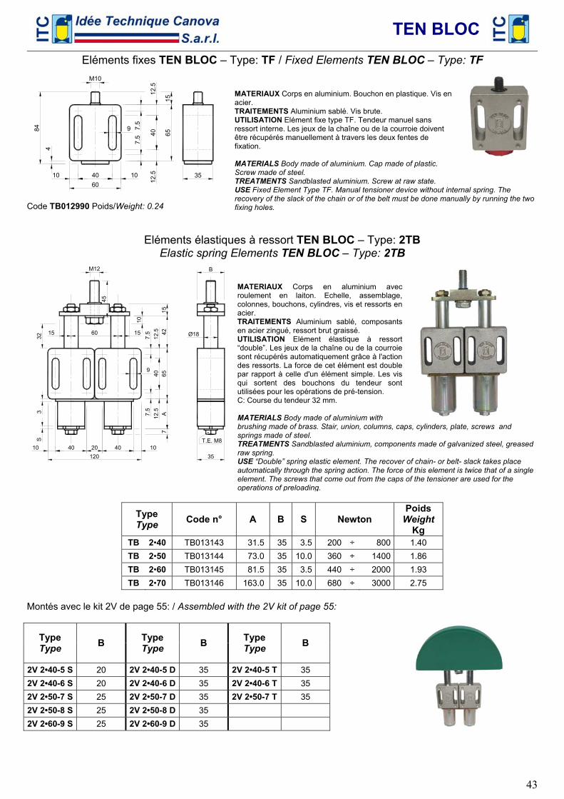
TEN BLOC
43
Eléments fixes TEN BLOC – Type: TF / Fixed Elements TEN BLOC – Type: TF
60 40 10 10
7.5
7.5
12.5
12
.5
40
65
15
84
35
4
M10
9
Code TB012990 Poids/Weight: 0.24
MATERIAUX Corps en aluminium. Bouchon en plastique. Vis en acier. TRAITEMENTS Aluminium sablé. Vis brute. UTILISATION Elément fixe type TF. Tendeur manuel sans ressort interne. Les jeux de la chaîne ou de la courroie doivent être récupérés manuellement à travers les deux fentes de fixation. MATERIALS Body made of aluminium. Cap made of plastic. Screw made of steel. TREATMENTS Sandblasted aluminium. Screw at raw state. USE Fixed Element Type TF. Manual tensioner device without internal spring. The recovery of the slack of the chain or of the belt must be done manually by running the two fixing holes.
Eléments élastiques à ressort TEN BLOC – Type: 2TB Elastic spring Elements TEN BLOC – Type: 2TB
10 40 1040120 20
60 15 15
35
Ø18
B
T.E. M8
M12
7
7.5
7.5
65
42
A12
.5
12.5
40
45
10
15
3 32
S
9
MATERIAUX Corps en aluminium avec roulement en laiton. Echelle, assemblage, colonnes, bouchons, cylindres, vis et ressorts en acier. TRAITEMENTS Aluminium sablé, composants en acier zingué, ressort brut graissé. UTILISATION Elément élastique à ressort “double”. Les jeux de la chaîne ou de la courroie sont récupérés automatiquement grâce à l'action des ressorts. La force de cet élément est double par rapport à celle d'un élément simple. Les vis qui sortent des bouchons du tendeur sont utilisées pour les opérations de pré-tension. C: Course du tendeur 32 mm. MATERIALS Body made of aluminium with brushing made of brass. Stair, union, columns, caps, cylinders, plate, screws and springs made of steel. TREATMENTS Sandblasted aluminium, components made of galvanized steel, greased raw spring. USE “Double” spring elastic element. The recover of chain- or belt- slack takes place automatically through the spring action. The force of this element is twice that of a single element. The screws that come out from the caps of the tensioner are used for the operations of preloading.
Type Type Code n° A B S Newton
Poids Weight
Kg TB 2•40 TB013143 31.5 35 3.5 200 ÷ 800 1.40 TB 2•50 TB013144 73.0 35 10.0 360 ÷ 1400 1.86 TB 2•60 TB013145 81.5 35 3.5 440 ÷ 2000 1.93 TB 2•70 TB013146 163.0 35 10.0 680 ÷ 3000 2.75
Montés avec le kit 2V de page 55: / Assembled with the 2V kit of page 55:
Type Type B Type
Type B Type Type B
2V 2•40-5 S 20 2V 2•40-5 D 35 2V 2•40-5 T 35 2V 2•40-6 S 20 2V 2•40-6 D 35 2V 2•40-6 T 35 2V 2•50-7 S 25 2V 2•50-7 D 35 2V 2•50-7 T 35 2V 2•50-8 S 25 2V 2•50-8 D 35 2V 2•60-9 S 25 2V 2•60-9 D 35
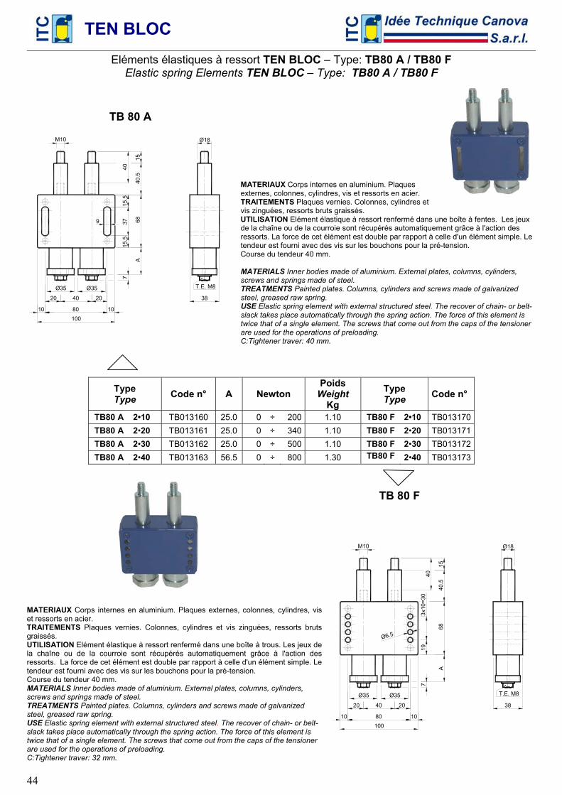
TEN BLOC
44
Eléments élastiques à ressort TEN BLOC – Type: TB80 A / TB80 F Elastic spring Elements TEN BLOC – Type: TB80 A / TB80 F
TB 80 A
38
68
80
20 40 20
40.5
A
7
10010 10
Ø35 Ø35
15.5
15.5
379
15
40
T.E. M8
MATERIAUX Corps internes en aluminium. Plaques externes, colonnes, cylindres, vis et ressorts en acier. TRAITEMENTS Plaques vernies. Colonnes, cylindres et vis zinguées, ressorts bruts graissés. UTILISATION Elément élastique à ressort renfermé dans une boîte à fentes. Les jeux de la chaîne ou de la courroie sont récupérés automatiquement grâce à l'action des ressorts. La force de cet élément est double par rapport à celle d'un élément simple. Le tendeur est fourni avec des vis sur les bouchons pour la pré-tension. Course du tendeur 40 mm. MATERIALS Inner bodies made of aluminium. External plates, columns, cylinders, screws and springs made of steel. TREATMENTS Painted plates. Columns, cylinders and screws made of galvanized steel, greased raw spring. USE Elastic spring element with external structured steel. The recover of chain- or belt- slack takes place automatically through the spring action. The force of this element is twice that of a single element. The screws that come out from the caps of the tensioner are used for the operations of preloading. C:Tightener traver: 40 mm.
Type Type Code n° A Newton
Poids Weight
Kg Type Type Code n°
TB80 A 2•10 TB013160 25.0 0 ÷ 200 1.10 TB80 F 2•10 TB013170TB80 A 2•20 TB013161 25.0 0 ÷ 340 1.10 TB80 F 2•20 TB013171TB80 A 2•30 TB013162 25.0 0 ÷ 500 1.10 TB80 F 2•30 TB013172TB80 A 2•40 TB013163 56.5 0 ÷ 800 1.30 TB80 F 2•40 TB013173
MATERIAUX Corps internes en aluminium. Plaques externes, colonnes, cylindres, vis et ressorts en acier. TRAITEMENTS Plaques vernies. Colonnes, cylindres et vis zinguées, ressorts bruts graissés. UTILISATION Elément élastique à ressort renfermé dans une boîte à trous. Les jeux de la chaîne ou de la courroie sont récupérés automatiquement grâce à l'action des ressorts. La force de cet élément est double par rapport à celle d'un élément simple. Le tendeur est fourni avec des vis sur les bouchons pour la pré-tension. Course du tendeur 40 mm. MATERIALS Inner bodies made of aluminium. External plates, columns, cylinders, screws and springs made of steel. TREATMENTS Painted plates. Columns, cylinders and screws made of galvanized steel, greased raw spring. USE Elastic spring element with external structured steel. The recover of chain- or belt- slack takes place automatically through the spring action. The force of this element is twice that of a single element. The screws that come out from the caps of the tensioner are used for the operations of preloading. C:Tightener traver: 32 mm.
TB 80 F
68
80
20 40 20
40.5
A
7
10 10
Ø35 Ø35
193x
10=3
0
Ø6.5
15
38
T.E. M8
100
40
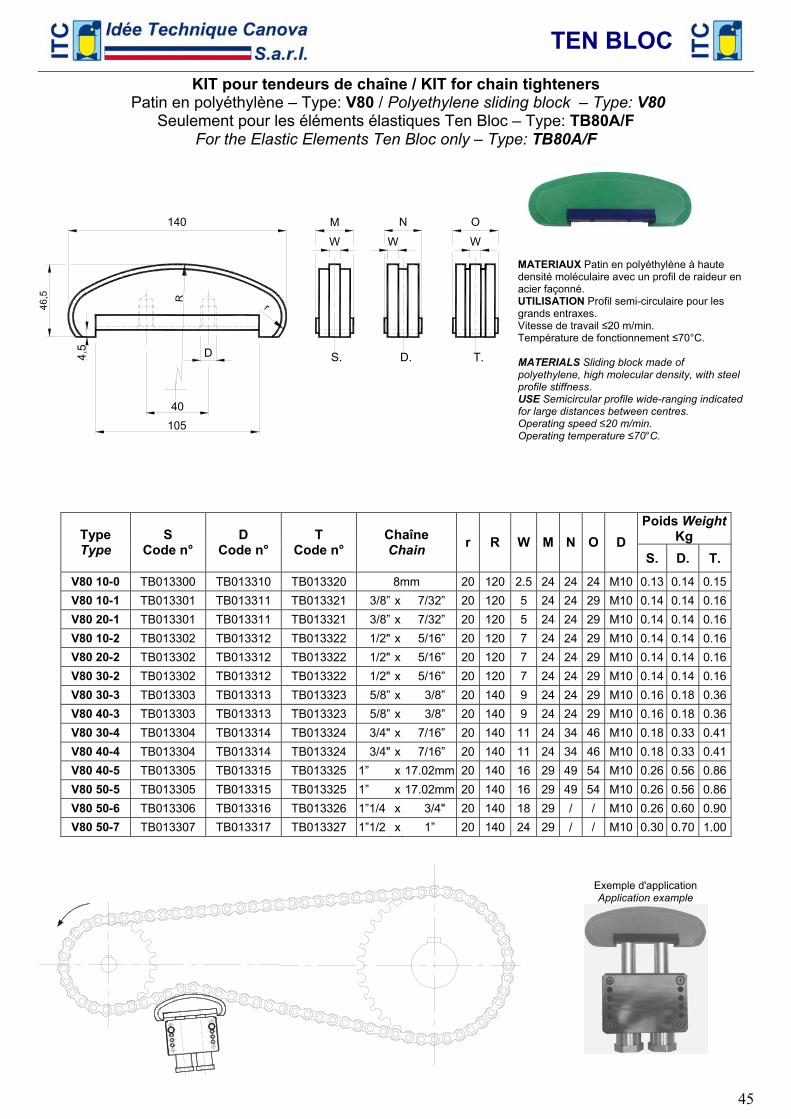
TEN BLOC
45
KIT pour tendeurs de chaîne / KIT for chain tighteners Patin en polyéthylène – Type: V80 / Polyethylene sliding block – Type: V80
Seulement pour les éléments élastiques Ten Bloc – Type: TB80A/F For the Elastic Elements Ten Bloc only – Type: TB80A/F
r
140
4.5
R
40
N
S. D. T.
W
M
WW
O
105
D
MATERIAUX Patin en polyéthylène à haute densité moléculaire avec un profil de raideur en acier façonné. UTILISATION Profil semi-circulaire pour les grands entraxes. Vitesse de travail ≤20 m/min. Température de fonctionnement ≤70°C. MATERIALS Sliding block made of polyethylene, high molecular density, with steel profile stiffness. USE Semicircular profile wide-ranging indicated for large distances between centres. Operating speed ≤20 m/min. Operating temperature ≤70°C.
Poids WeightKg Type
Type S
Code n° D
Code n° T
Code n° Chaîne Chain r R W M N O D
S. D. T. V80 10-0 TB013300 TB013310 TB013320 8mm 20 120 2.5 24 24 24 M10 0.13 0.14 0.15V80 10-1 TB013301 TB013311 TB013321 3/8” x 7/32” 20 120 5 24 24 29 M10 0.14 0.14 0.16V80 20-1 TB013301 TB013311 TB013321 3/8” x 7/32” 20 120 5 24 24 29 M10 0.14 0.14 0.16V80 10-2 TB013302 TB013312 TB013322 1/2" x 5/16” 20 120 7 24 24 29 M10 0.14 0.14 0.16V80 20-2 TB013302 TB013312 TB013322 1/2" x 5/16” 20 120 7 24 24 29 M10 0.14 0.14 0.16V80 30-2 TB013302 TB013312 TB013322 1/2" x 5/16” 20 120 7 24 24 29 M10 0.14 0.14 0.16V80 30-3 TB013303 TB013313 TB013323 5/8” x 3/8” 20 140 9 24 24 29 M10 0.16 0.18 0.36V80 40-3 TB013303 TB013313 TB013323 5/8” x 3/8” 20 140 9 24 24 29 M10 0.16 0.18 0.36V80 30-4 TB013304 TB013314 TB013324 3/4" x 7/16” 20 140 11 24 34 46 M10 0.18 0.33 0.41V80 40-4 TB013304 TB013314 TB013324 3/4" x 7/16” 20 140 11 24 34 46 M10 0.18 0.33 0.41V80 40-5 TB013305 TB013315 TB013325 1” x 17.02mm 20 140 16 29 49 54 M10 0.26 0.56 0.86V80 50-5 TB013305 TB013315 TB013325 1” x 17.02mm 20 140 16 29 49 54 M10 0.26 0.56 0.86V80 50-6 TB013306 TB013316 TB013326 1”1/4 x 3/4" 20 140 18 29 / / M10 0.26 0.60 0.90V80 50-7 TB013307 TB013317 TB013327 1”1/2 x 1” 20 140 24 29 / / M10 0.30 0.70 1.00
Exemple d'application Application example
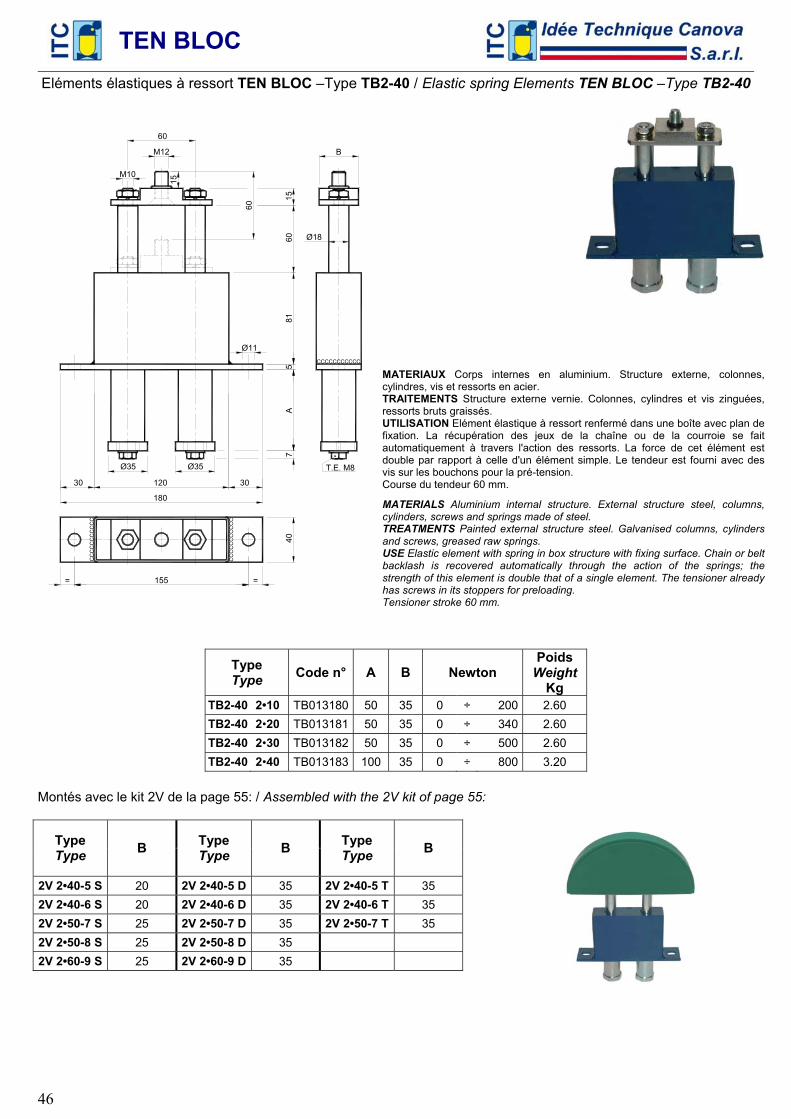
TEN BLOC
46
Eléments élastiques à ressort TEN BLOC –Type TB2-40 / Elastic spring Elements TEN BLOC –Type TB2-40
CC
CC
CC
CC
CC
C
405
8160
15
M12
A
180
M1015
120
Ø18
B
Ø11
30 30
7
Ø35 Ø35
155= =
T.E. M8
60
CCCCCCCCCCC
MATERIAUX Corps internes en aluminium. Structure externe, colonnes, cylindres, vis et ressorts en acier. TRAITEMENTS Structure externe vernie. Colonnes, cylindres et vis zinguées, ressorts bruts graissés. UTILISATION Elément élastique à ressort renfermé dans une boîte avec plan de fixation. La récupération des jeux de la chaîne ou de la courroie se fait automatiquement à travers l'action des ressorts. La force de cet élément est double par rapport à celle d'un élément simple. Le tendeur est fourni avec des vis sur les bouchons pour la pré-tension. Course du tendeur 60 mm.
MATERIALS Aluminium internal structure. External structure steel, columns, cylinders, screws and springs made of steel. TREATMENTS Painted external structure steel. Galvanised columns, cylinders and screws, greased raw springs. USE Elastic element with spring in box structure with fixing surface. Chain or belt backlash is recovered automatically through the action of the springs; the strength of this element is double that of a single element. The tensioner already has screws in its stoppers for preloading. Tensioner stroke 60 mm.
Type Type Code n° A B Newton
Poids Weight
Kg TB2-40 2•10 TB013180 50 35 0 ÷ 200 2.60 TB2-40 2•20 TB013181 50 35 0 ÷ 340 2.60 TB2-40 2•30 TB013182 50 35 0 ÷ 500 2.60 TB2-40 2•40 TB013183 100 35 0 ÷ 800 3.20
Montés avec le kit 2V de la page 55: / Assembled with the 2V kit of page 55:
Type Type B Type
Type B Type Type B
2V 2•40-5 S 20 2V 2•40-5 D 35 2V 2•40-5 T 35 2V 2•40-6 S 20 2V 2•40-6 D 35 2V 2•40-6 T 35 2V 2•50-7 S 25 2V 2•50-7 D 35 2V 2•50-7 T 35 2V 2•50-8 S 25 2V 2•50-8 D 35 2V 2•60-9 S 25 2V 2•60-9 D 35
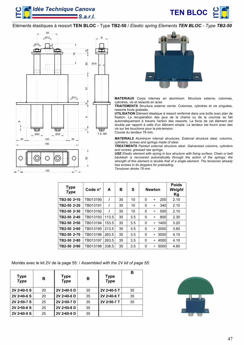
TEN BLOC
47
Eléments élastiques à ressort TEN BLOC - Type TB2-50 / Elastic spring Elements TEN BLOC - Type TB2-50
CCCCCCCCCCCCCCCCCCCCCCCCCCCCCCCCC
CC
CC
CC
CC
CC
C
Ø18
B
681
8015
M12
A
180
M10
15
120
Ø13
30 30
7
Ø35 Ø35
50
155= =
T.E. M8
78
S
CCCCCCCCCCC
MATERIAUX Corps internes en aluminium. Structure externe, colonnes, cylindres, vis et ressorts en acier. TRAITEMENTS Structure externe vernie. Colonnes, cylindres et vis zinguées, ressorts bruts graissés. UTILISATION Elément élastique à ressort renfermé dans une boîte avec plan de fixation. La récupération des jeux de la chaîne ou de la courroie se fait automatiquement à travers l'action des ressorts. La force de cet élément est double par rapport à celle d'un élément simple. Le tendeur est fourni avec des vis sur les bouchons pour la pré-tension. Course du tendeur 78 mm.
MATERIALS Aluminium internal structures. External structure steel, columns, cylinders, screws and springs made of steel. TREATMENTS Painted external structure steel. Galvanised columns, cylinders and screws, greased raw springs. USE Elastic element with spring in box structure with fixing surface. Chain or belt backlash is recovered automatically through the action of the springs; the strength of this element is double that of a single element. The tensioner already has screws in its stoppers for preloading. Tensioner stroke 78 mm.
Type Type Code n° A B S Newton
Poids Weight
Kg TB2-50 2•10 TB013190 / 35 10 0 ÷ 200 2.10 TB2-50 2•20 TB013191 / 35 10 0 ÷ 340 2.10 TB2-50 2•30 TB013192 / 35 10 0 ÷ 500 2.10 TB2-50 2•40 TB013193 113.5 35 3.5 0 ÷ 800 2.30 TB2-50 2•50 TB013194 153.5 35 3.5 0 ÷ 1400 3.20 TB2-50 2•60 TB013195 213.5 35 3.5 0 ÷ 2000 3.60 TB2-50 2•70 TB013196 263.5 35 3.5 0 ÷ 3000 4.10 TB2-50 2•80 TB013197 263.5 35 3.5 0 ÷ 4000 4.10 TB2-50 2•90 TB013198 338.5 35 3.5 0 ÷ 5000 4.60
Montés avec le kit 2V de la page 55: / Assembled with the 2V kit of page 55:
Type Type B Type
Type B Type Type
B
2V 2•40-5 S 20 2V 2•40-5 D 35 2V 2•40-5 T 35 2V 2•40-6 S 20 2V 2•40-6 D 35 2V 2•40-6 T 35 2V 2•50-7 S 25 2V 2•50-7 D 35 2V 2•50-7 T 35 2V 2•50-8 S 25 2V 2•50-8 D 35 2V 2•60-9 S 25 2V 2•60-9 D 35
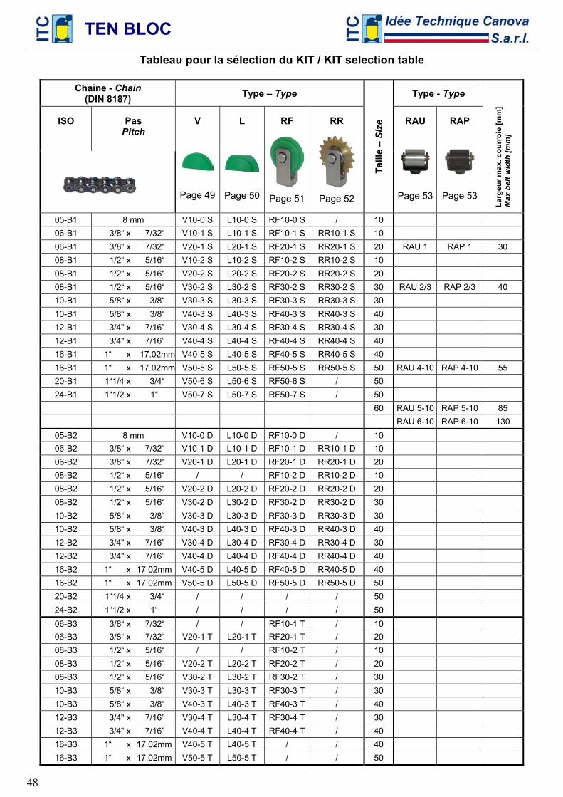
TEN BLOC
48
Tableau pour la sélection du KIT / KIT selection table
Chaîne - Chain (DIN 8187) Type – Type Type - Type
ISO
Pas
Pitch
V
Page 49
L
Page 50
RF
Page 51
RR
Page 52
Taill
e –
Size
RAU
Page 53
RAP
Page 53 La
rgeu
r max
. cou
rroi
e [m
m]
Max
bel
t wid
th [m
m]
05-B1 8 mm V10-0 S L10-0 S RF10-0 S / 10 06-B1 3/8“ x 7/32“ V10-1 S L10-1 S RF10-1 S RR10-1 S 10 06-B1 3/8“ x 7/32“ V20-1 S L20-1 S RF20-1 S RR20-1 S 20 RAU 1 RAP 1 30 08-B1 1/2“ x 5/16“ V10-2 S L10-2 S RF10-2 S RR10-2 S 10 08-B1 1/2“ x 5/16“ V20-2 S L20-2 S RF20-2 S RR20-2 S 20 08-B1 1/2“ x 5/16“ V30-2 S L30-2 S RF30-2 S RR30-2 S 30 RAU 2/3 RAP 2/3 40 10-B1 5/8“ x 3/8“ V30-3 S L30-3 S RF30-3 S RR30-3 S 30 10-B1 5/8“ x 3/8“ V40-3 S L40-3 S RF40-3 S RR40-3 S 40 12-B1 3/4" x 7/16” V30-4 S L30-4 S RF30-4 S RR30-4 S 30 12-B1 3/4" x 7/16” V40-4 S L40-4 S RF40-4 S RR40-4 S 40 16-B1 1“ x 17.02mm V40-5 S L40-5 S RF40-5 S RR40-5 S 40 16-B1 1“ x 17.02mm V50-5 S L50-5 S RF50-5 S RR50-5 S 50 RAU 4-10 RAP 4-10 55 20-B1 1“1/4 x 3/4“ V50-6 S L50-6 S RF50-6 S / 50 24-B1 1“1/2 x 1“ V50-7 S L50-7 S RF50-7 S / 50
60 RAU 5-10 RAP 5-10 85 RAU 6-10 RAP 6-10 130
05-B2 8 mm V10-0 D L10-0 D RF10-0 D / 10 06-B2 3/8“ x 7/32“ V10-1 D L10-1 D RF10-1 D RR10-1 D 10 06-B2 3/8“ x 7/32“ V20-1 D L20-1 D RF20-1 D RR20-1 D 20 08-B2 1/2“ x 5/16“ / / RF10-2 D RR10-2 D 10 08-B2 1/2“ x 5/16“ V20-2 D L20-2 D RF20-2 D RR20-2 D 20 08-B2 1/2“ x 5/16“ V30-2 D L30-2 D RF30-2 D RR30-2 D 30 10-B2 5/8“ x 3/8“ V30-3 D L30-3 D RF30-3 D RR30-3 D 30 10-B2 5/8“ x 3/8“ V40-3 D L40-3 D RF40-3 D RR40-3 D 40 12-B2 3/4" x 7/16” V30-4 D L30-4 D RF30-4 D RR30-4 D 30 12-B2 3/4" x 7/16” V40-4 D L40-4 D RF40-4 D RR40-4 D 40 16-B2 1“ x 17.02mm V40-5 D L40-5 D RF40-5 D RR40-5 D 40 16-B2 1“ x 17.02mm V50-5 D L50-5 D RF50-5 D RR50-5 D 50 20-B2 1“1/4 x 3/4“ / / / / 50 24-B2 1“1/2 x 1“ / / / / 50 06-B3 3/8“ x 7/32“ / / RF10-1 T / 10 06-B3 3/8“ x 7/32“ V20-1 T L20-1 T RF20-1 T / 20 08-B3 1/2“ x 5/16“ / / RF10-2 T / 10 08-B3 1/2“ x 5/16“ V20-2 T L20-2 T RF20-2 T / 20 08-B3 1/2“ x 5/16“ V30-2 T L30-2 T RF30-2 T / 30 10-B3 5/8“ x 3/8“ V30-3 T L30-3 T RF30-3 T / 30 10-B3 5/8“ x 3/8“ V40-3 T L40-3 T RF40-3 T / 40 12-B3 3/4" x 7/16” V30-4 T L30-4 T RF30-4 T / 30 12-B3 3/4" x 7/16” V40-4 T L40-4 T RF40-4 T / 40 16-B3 1“ x 17.02mm V40-5 T L40-5 T / / 40 16-B3 1“ x 17.02mm V50-5 T L50-5 T / / 50
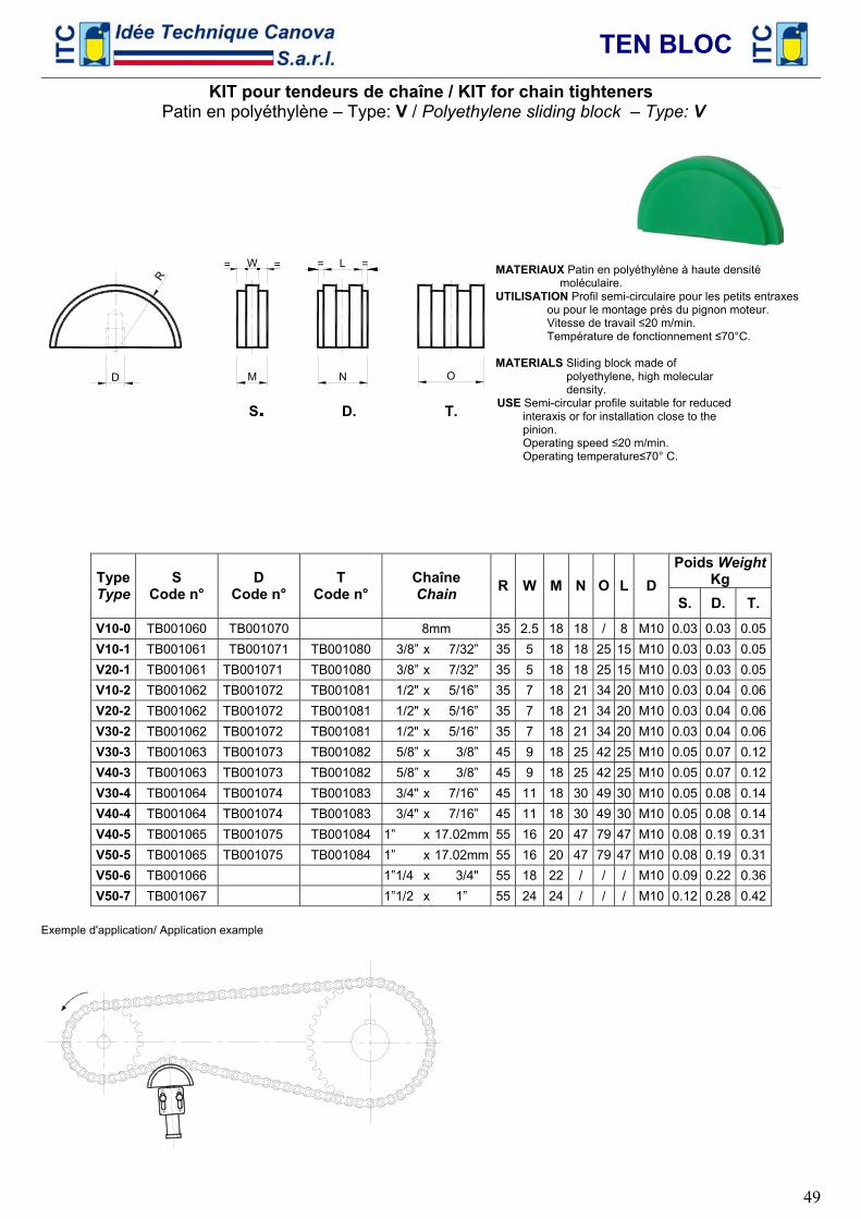
TEN BLOC
49
KIT pour tendeurs de chaîne / KIT for chain tighteners Patin en polyéthylène – Type: V / Polyethylene sliding block – Type: V
R
D
L=W
M N O
=
S. D. T.
MATERIAUX Patin en polyéthylène à haute densité moléculaire.
UTILISATION Profil semi-circulaire pour les petits entraxes ou pour le montage près du pignon moteur. Vitesse de travail ≤20 m/min. Température de fonctionnement ≤70°C.
MATERIALS Sliding block made of polyethylene, high molecular density. USE Semi-circular profile suitable for reduced interaxis or for installation close to the pinion. Operating speed ≤20 m/min. Operating temperature≤70° C.
Poids Weight
Kg Type Type
S Code n°
D Code n°
T Code n°
Chaîne Chain R W M N O L D
S. D. T. V10-0 TB001060 TB001070 8mm 35 2.5 18 18 / 8 M10 0.03 0.03 0.05V10-1 TB001061 TB001071 TB001080 3/8” x 7/32” 35 5 18 18 25 15 M10 0.03 0.03 0.05V20-1 TB001061 TB001071 TB001080 3/8” x 7/32” 35 5 18 18 25 15 M10 0.03 0.03 0.05V10-2 TB001062 TB001072 TB001081 1/2" x 5/16” 35 7 18 21 34 20 M10 0.03 0.04 0.06V20-2 TB001062 TB001072 TB001081 1/2" x 5/16” 35 7 18 21 34 20 M10 0.03 0.04 0.06V30-2 TB001062 TB001072 TB001081 1/2" x 5/16” 35 7 18 21 34 20 M10 0.03 0.04 0.06V30-3 TB001063 TB001073 TB001082 5/8” x 3/8” 45 9 18 25 42 25 M10 0.05 0.07 0.12V40-3 TB001063 TB001073 TB001082 5/8” x 3/8” 45 9 18 25 42 25 M10 0.05 0.07 0.12V30-4 TB001064 TB001074 TB001083 3/4" x 7/16” 45 11 18 30 49 30 M10 0.05 0.08 0.14V40-4 TB001064 TB001074 TB001083 3/4" x 7/16” 45 11 18 30 49 30 M10 0.05 0.08 0.14V40-5 TB001065 TB001075 TB001084 1” x 17.02mm 55 16 20 47 79 47 M10 0.08 0.19 0.31V50-5 TB001065 TB001075 TB001084 1” x 17.02mm 55 16 20 47 79 47 M10 0.08 0.19 0.31V50-6 TB001066 1”1/4 x 3/4" 55 18 22 / / / M10 0.09 0.22 0.36V50-7 TB001067 1”1/2 x 1” 55 24 24 / / / M10 0.12 0.28 0.42
Exemple d'application/ Application example
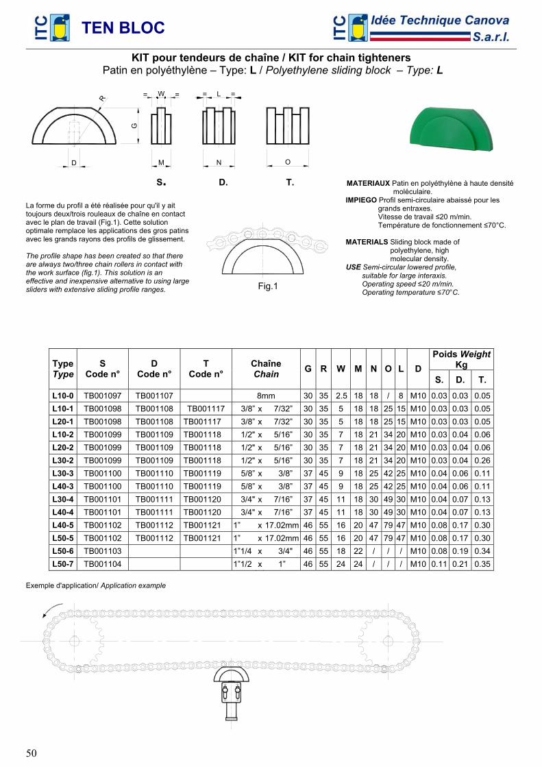
TEN BLOC
50
KIT pour tendeurs de chaîne / KIT for chain tighteners Patin en polyéthylène – Type: L / Polyethylene sliding block – Type: L
R
L=W
M N O
=
D
G
S. D. T.
La forme du profil a été réalisée pour qu'il y ait toujours deux/trois rouleaux de chaîne en contact avec le plan de travail (Fig.1). Cette solution optimale remplace les applications des gros patins avec les grands rayons des profils de glissement. The profile shape has been created so that there are always two/three chain rollers in contact with the work surface (fig.1). This solution is an effective and inexpensive alternative to using large sliders with extensive sliding profile ranges.
MATERIAUX Patin en polyéthylène à haute densité moléculaire. IMPIEGO Profil semi-circulaire abaissé pour les grands entraxes. Vitesse de travail ≤20 m/min. Température de fonctionnement ≤70°C. MATERIALS Sliding block made of polyethylene, high molecular density. USE Semi-circular lowered profile, suitable for large interaxis. Operating speed ≤20 m/min. Operating temperature ≤70°C.
Poids Weight
Kg Type Type
S Code n°
D Code n°
T Code n°
Chaîne Chain G R W M N O L D
S. D. T. L10-0 TB001097 TB001107 8mm 30 35 2.5 18 18 / 8 M10 0.03 0.03 0.05L10-1 TB001098 TB001108 TB001117 3/8” x 7/32” 30 35 5 18 18 25 15 M10 0.03 0.03 0.05L20-1 TB001098 TB001108 TB001117 3/8” x 7/32” 30 35 5 18 18 25 15 M10 0.03 0.03 0.05L10-2 TB001099 TB001109 TB001118 1/2" x 5/16” 30 35 7 18 21 34 20 M10 0.03 0.04 0.06L20-2 TB001099 TB001109 TB001118 1/2" x 5/16” 30 35 7 18 21 34 20 M10 0.03 0.04 0.06L30-2 TB001099 TB001109 TB001118 1/2" x 5/16” 30 35 7 18 21 34 20 M10 0.03 0.04 0.26L30-3 TB001100 TB001110 TB001119 5/8” x 3/8” 37 45 9 18 25 42 25 M10 0.04 0.06 0.11L40-3 TB001100 TB001110 TB001119 5/8” x 3/8” 37 45 9 18 25 42 25 M10 0.04 0.06 0.11L30-4 TB001101 TB001111 TB001120 3/4" x 7/16” 37 45 11 18 30 49 30 M10 0.04 0.07 0.13L40-4 TB001101 TB001111 TB001120 3/4" x 7/16” 37 45 11 18 30 49 30 M10 0.04 0.07 0.13L40-5 TB001102 TB001112 TB001121 1” x 17.02mm 46 55 16 20 47 79 47 M10 0.08 0.17 0.30L50-5 TB001102 TB001112 TB001121 1” x 17.02mm 46 55 16 20 47 79 47 M10 0.08 0.17 0.30L50-6 TB001103 1”1/4 x 3/4" 46 55 18 22 / / / M10 0.08 0.19 0.34L50-7 TB001104 1”1/2 x 1” 46 55 24 24 / / / M10 0.11 0.21 0.35
Exemple d'application/ Application example
Fig.1
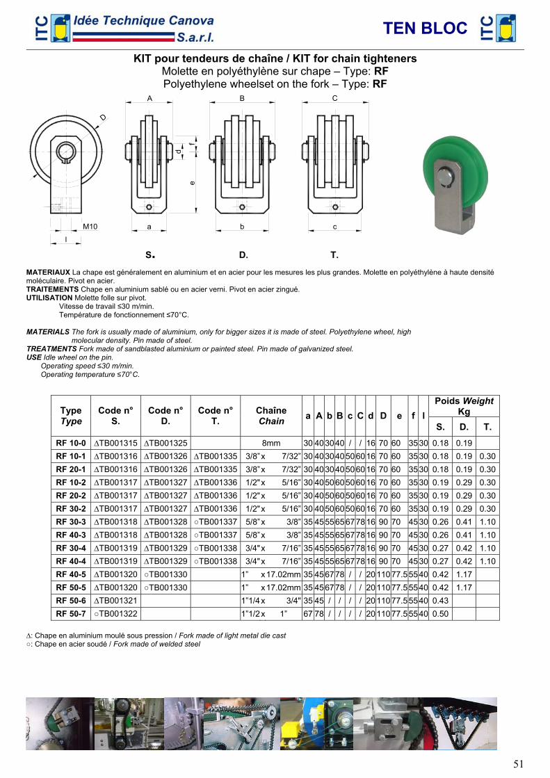
TEN BLOC
51
KIT pour tendeurs de chaîne / KIT for chain tighteners Molette en polyéthylène sur chape – Type: RF Polyethylene wheelset on the fork – Type: RF
a
d
ef
l
D
b c
A B C
M10
S. D. T.
MATERIAUX La chape est généralement en aluminium et en acier pour les mesures les plus grandes. Molette en polyéthylène à haute densité moléculaire. Pivot en acier. TRAITEMENTS Chape en aluminium sablé ou en acier verni. Pivot en acier zingué. UTILISATION Molette folle sur pivot. Vitesse de travail ≤30 m/min. Température de fonctionnement ≤70°C. MATERIALS The fork is usually made of aluminium, only for bigger sizes it is made of steel. Polyethylene wheel, high molecular density. Pin made of steel. TREATMENTS Fork made of sandblasted aluminium or painted steel. Pin made of galvanized steel. USE Idle wheel on the pin. Operating speed ≤30 m/min. Operating temperature ≤70°C.
Poids Weight
Kg Type Type
Code n° S.
Code n° D.
Code n° T.
Chaîne Chain a A b B c C d D e f l
S. D. T. RF 10-0 ∆TB001315 ∆TB001325 8mm 30 403040 / / 16 70 60 35 30 0.18 0.19 RF 10-1 ∆TB001316 ∆TB001326 ∆TB001335 3/8”x 7/32” 30 403040506016 70 60 35 30 0.18 0.19 0.30RF 20-1 ∆TB001316 ∆TB001326 ∆TB001335 3/8”x 7/32” 30 403040506016 70 60 35 30 0.18 0.19 0.30RF 10-2 ∆TB001317 ∆TB001327 ∆TB001336 1/2"x 5/16” 30 405060506016 70 60 35 30 0.19 0.29 0.30RF 20-2 ∆TB001317 ∆TB001327 ∆TB001336 1/2"x 5/16” 30 405060506016 70 60 35 30 0.19 0.29 0.30RF 30-2 ∆TB001317 ∆TB001327 ∆TB001336 1/2"x 5/16” 30 405060506016 70 60 35 30 0.19 0.29 0.30RF 30-3 ∆TB001318 ∆TB001328 ○TB001337 5/8”x 3/8” 35 455565677816 90 70 45 30 0.26 0.41 1.10RF 40-3 ∆TB001318 ∆TB001328 ○TB001337 5/8”x 3/8” 35 455565677816 90 70 45 30 0.26 0.41 1.10RF 30-4 ∆TB001319 ∆TB001329 ○TB001338 3/4"x 7/16” 35 455565677816 90 70 45 30 0.27 0.42 1.10RF 40-4 ∆TB001319 ∆TB001329 ○TB001338 3/4"x 7/16” 35 455565677816 90 70 45 30 0.27 0.42 1.10RF 40-5 ∆TB001320 ○TB001330 1” x17.02mm 35 456778 / / 20110 77.5 55 40 0.42 1.17 RF 50-5 ∆TB001320 ○TB001330 1” x17.02mm 35 456778 / / 20110 77.5 55 40 0.42 1.17 RF 50-6 ∆TB001321 1”1/4x 3/4" 35 45 / / / / 20110 77.5 55 40 0.43 RF 50-7 ○TB001322 1”1/2x 1” 67 78 / / / / 20110 77.5 55 40 0.50
∆: Chape en aluminium moulé sous pression / Fork made of light metal die cast ○: Chape en acier soudé / Fork made of welded steel
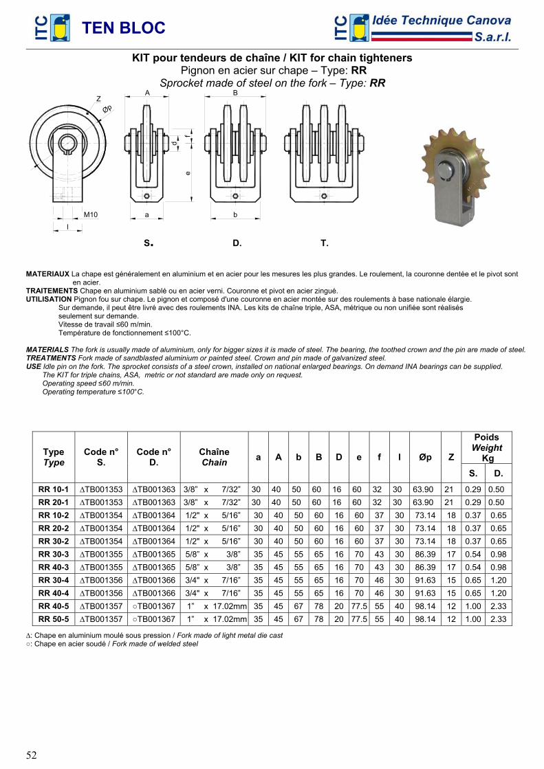
TEN BLOC
52
KIT pour tendeurs de chaîne / KIT for chain tighteners Pignon en acier sur chape – Type: RR
Sprocket made of steel on the fork – Type: RR
a
d
ef
l
b
A B
M10
Z
Øp
S. D. T.
MATERIAUX La chape est généralement en aluminium et en acier pour les mesures les plus grandes. Le roulement, la couronne dentée et le pivot sont en acier. TRAITEMENTS Chape en aluminium sablé ou en acier verni. Couronne et pivot en acier zingué. UTILISATION Pignon fou sur chape. Le pignon et composé d'une couronne en acier montée sur des roulements à base nationale élargie. Sur demande, il peut être livré avec des roulements INA. Les kits de chaîne triple, ASA, métrique ou non unifiée sont réalisés seulement sur demande. Vitesse de travail ≤60 m/min. Température de fonctionnement ≤100°C. MATERIALS The fork is usually made of aluminium, only for bigger sizes it is made of steel. The bearing, the toothed crown and the pin are made of steel. TREATMENTS Fork made of sandblasted aluminium or painted steel. Crown and pin made of galvanized steel. USE Idle pin on the fork. The sprocket consists of a steel crown, installed on national enlarged bearings. On demand INA bearings can be supplied. The KIT for triple chains, ASA, metric or not standard are made only on request. Operating speed ≤60 m/min. Operating temperature ≤100°C.
Poids
Weight Kg
Type Type
Code n° S.
Code n° D.
Chaîne Chain a A b B D e f l Øp Z
S. D. RR 10-1 ∆TB001353 ∆TB001363 3/8” x 7/32” 30 40 50 60 16 60 32 30 63.90 21 0.29 0.50 RR 20-1 ∆TB001353 ∆TB001363 3/8” x 7/32” 30 40 50 60 16 60 32 30 63.90 21 0.29 0.50 RR 10-2 ∆TB001354 ∆TB001364 1/2" x 5/16” 30 40 50 60 16 60 37 30 73.14 18 0.37 0.65 RR 20-2 ∆TB001354 ∆TB001364 1/2" x 5/16” 30 40 50 60 16 60 37 30 73.14 18 0.37 0.65 RR 30-2 ∆TB001354 ∆TB001364 1/2" x 5/16” 30 40 50 60 16 60 37 30 73.14 18 0.37 0.65 RR 30-3 ∆TB001355 ∆TB001365 5/8” x 3/8” 35 45 55 65 16 70 43 30 86.39 17 0.54 0.98 RR 40-3 ∆TB001355 ∆TB001365 5/8” x 3/8” 35 45 55 65 16 70 43 30 86.39 17 0.54 0.98 RR 30-4 ∆TB001356 ∆TB001366 3/4" x 7/16” 35 45 55 65 16 70 46 30 91.63 15 0.65 1.20 RR 40-4 ∆TB001356 ∆TB001366 3/4" x 7/16” 35 45 55 65 16 70 46 30 91.63 15 0.65 1.20 RR 40-5 ∆TB001357 ○TB001367 1” x 17.02mm 35 45 67 78 20 77.5 55 40 98.14 12 1.00 2.33 RR 50-5 ∆TB001357 ○TB001367 1” x 17.02mm 35 45 67 78 20 77.5 55 40 98.14 12 1.00 2.33
∆: Chape en aluminium moulé sous pression / Fork made of light metal die cast ○: Chape en acier soudé / Fork made of welded steel
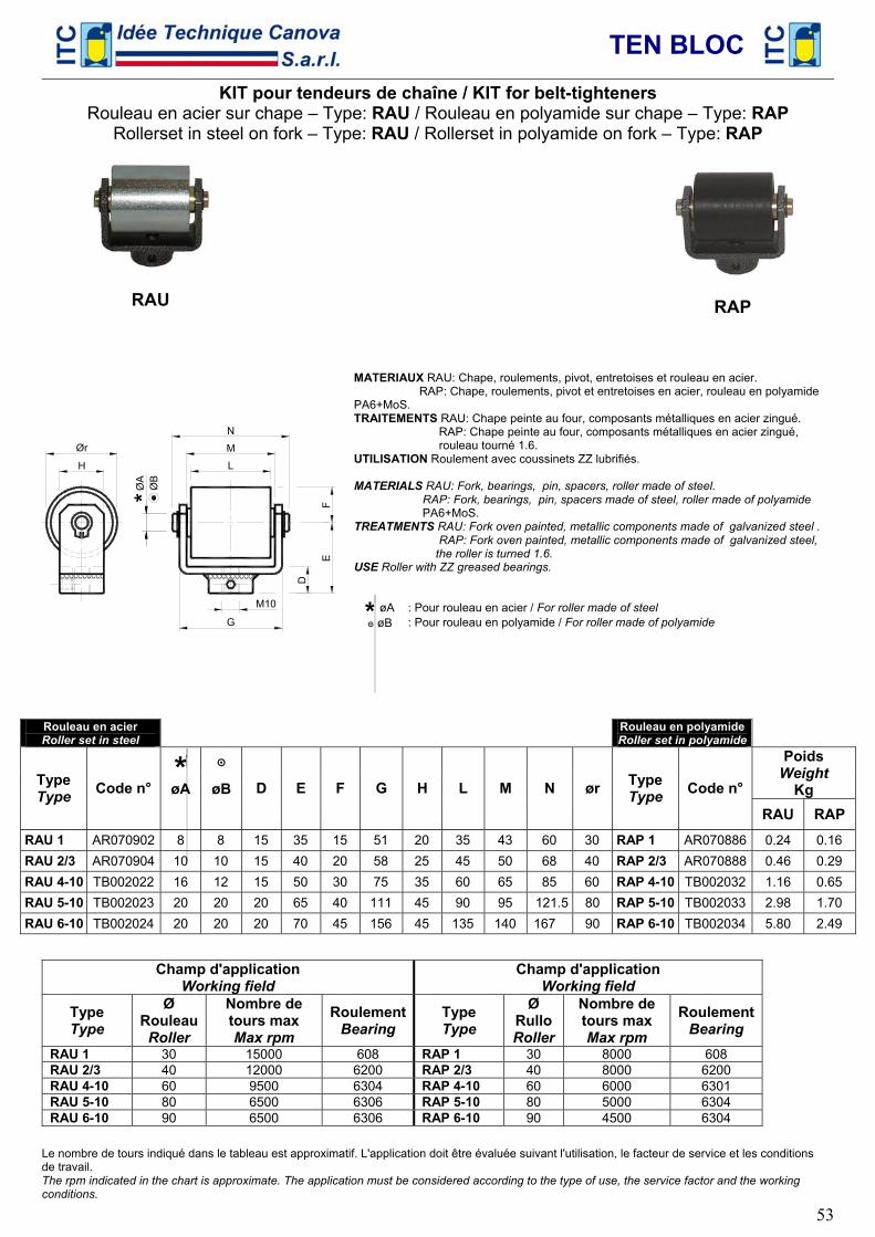
TEN BLOC
53
KIT pour tendeurs de chaîne / KIT for belt-tighteners Rouleau en acier sur chape – Type: RAU / Rouleau en polyamide sur chape – Type: RAP
Rollerset in steel on fork – Type: RAU / Rollerset in polyamide on fork – Type: RAP
Ør
H L
M
N
G
D
EF
M10
ØA
ØB
*
MATERIAUX RAU: Chape, roulements, pivot, entretoises et rouleau en acier. RAP: Chape, roulements, pivot et entretoises en acier, rouleau en polyamide PA6+MoS. TRAITEMENTS RAU: Chape peinte au four, composants métalliques en acier zingué. RAP: Chape peinte au four, composants métalliques en acier zingué, rouleau tourné 1.6. UTILISATION Roulement avec coussinets ZZ lubrifiés. MATERIALS RAU: Fork, bearings, pin, spacers, roller made of steel. RAP: Fork, bearings, pin, spacers made of steel, roller made of polyamide PA6+MoS. TREATMENTS RAU: Fork oven painted, metallic components made of galvanized steel . RAP: Fork oven painted, metallic components made of galvanized steel, the roller is turned 1.6. USE Roller with ZZ greased bearings.
* øA : Pour rouleau en acier / For roller made of steel ๏ øB : Pour rouleau en polyamide / For roller made of polyamide
Rouleau en acier Roller set in steel Rouleau en polyamide
Roller set in polyamide
* ๏ Poids Weight
Kg Type Type Code n° øA øB D E F G H L M N ør Type
Type Code n°
RAU RAP RAU 1 AR070902 8 8 15 35 15 51 20 35 43 60 30 RAP 1 AR070886 0.24 0.16 RAU 2/3 AR070904 10 10 15 40 20 58 25 45 50 68 40 RAP 2/3 AR070888 0.46 0.29 RAU 4-10 TB002022 16 12 15 50 30 75 35 60 65 85 60 RAP 4-10 TB002032 1.16 0.65 RAU 5-10 TB002023 20 20 20 65 40 111 45 90 95 121.5 80 RAP 5-10 TB002033 2.98 1.70 RAU 6-10 TB002024 20 20 20 70 45 156 45 135 140 167 90 RAP 6-10 TB002034 5.80 2.49
Champ d'application
Working field Champ d'application
Working field
Type Type
Ø Rouleau Roller
Nombre de tours max Max rpm
RoulementBearing
Type Type
Ø Rullo Roller
Nombre de tours max Max rpm
RoulementBearing
RAU 1 30 15000 608 RAP 1 30 8000 608 RAU 2/3 40 12000 6200 RAP 2/3 40 8000 6200 RAU 4-10 60 9500 6304 RAP 4-10 60 6000 6301 RAU 5-10 80 6500 6306 RAP 5-10 80 5000 6304 RAU 6-10 90 6500 6306 RAP 6-10 90 4500 6304
Le nombre de tours indiqué dans le tableau est approximatif. L'application doit être évaluée suivant l'utilisation, le facteur de service et les conditions de travail. The rpm indicated in the chart is approximate. The application must be considered according to the type of use, the service factor and the working conditions.
RAU
RAP
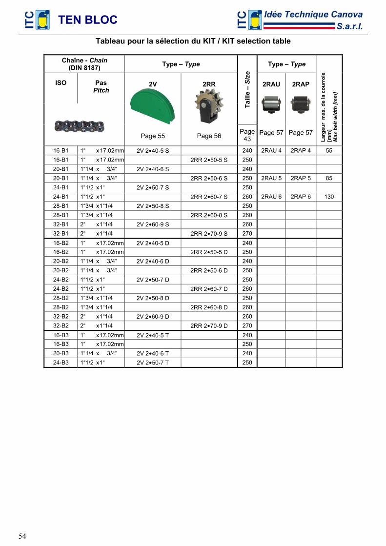
TEN BLOC
54
Tableau pour la sélection du KIT / KIT selection table
Chaîne - Chain (DIN 8187) Type – Type Type – Type
ISO
Pas
Pitch
Taill
e –
Size
2V
Page 55
2RR
Page 56 Page
43
2RAU
Page 57
2RAP
Page 57
Larg
eur
max
. de
la c
ourr
oie
[mm
] M
ax b
elt w
idth
[mm
]
16-B1 1“ x 17.02mm 2V 2•40-5 S 240 2RAU 4 2RAP 4 55 16-B1 1“ x 17.02mm 2RR 2•50-5 S 250 20-B1 1“1/4 x 3/4“ 2V 2•40-6 S 240 20-B1 1“1/4 x 3/4“ 2RR 2•50-6 S 250 2RAU 5 2RAP 5 85 24-B1 1“1/2 x 1“ 2V 2•50-7 S 250 24-B1 1“1/2 x 1“ 2RR 2•60-7 S 260 2RAU 6 2RAP 6 130 28-B1 1“3/4 x 1“1/4 2V 2•50-8 S 250 28-B1 1“3/4 x 1“1/4 2RR 2•60-8 S 260 32-B1 2“ x 1“1/4 2V 2•60-9 S 260 32-B1 2“ x 1“1/4 2RR 2•70-9 S 270 16-B2 1“ x 17.02mm 2V 2•40-5 D 240 16-B2 1“ x 17.02mm 2RR 2•50-5 D 250 20-B2 1“1/4 x 3/4“ 2V 2•40-6 D 240 20-B2 1“1/4 x 3/4“ 2RR 2•50-6 D 250 24-B2 1“1/2 x 1“ 2V 2•50-7 D 250 24-B2 1“1/2 x 1“ 2RR 2•60-7 D 260 28-B2 1“3/4 x 1“1/4 2V 2•50-8 D 250 28-B2 1“3/4 x 1“1/4 2RR 2•60-8 D 260 32-B2 2“ x 1“1/4 2V 2•60-9 D 260 32-B2 2“ x 1“1/4 2RR 2•70-9 D 270 16-B3 1“ x 17.02mm 2V 2•40-5 T 240 16-B3 1“ x 17.02mm 250 20-B3 1“1/4 x 3/4“ 2V 2•40-6 T 240 24-B3 1“1/2 x 1“ 2V 2•50-7 T 250
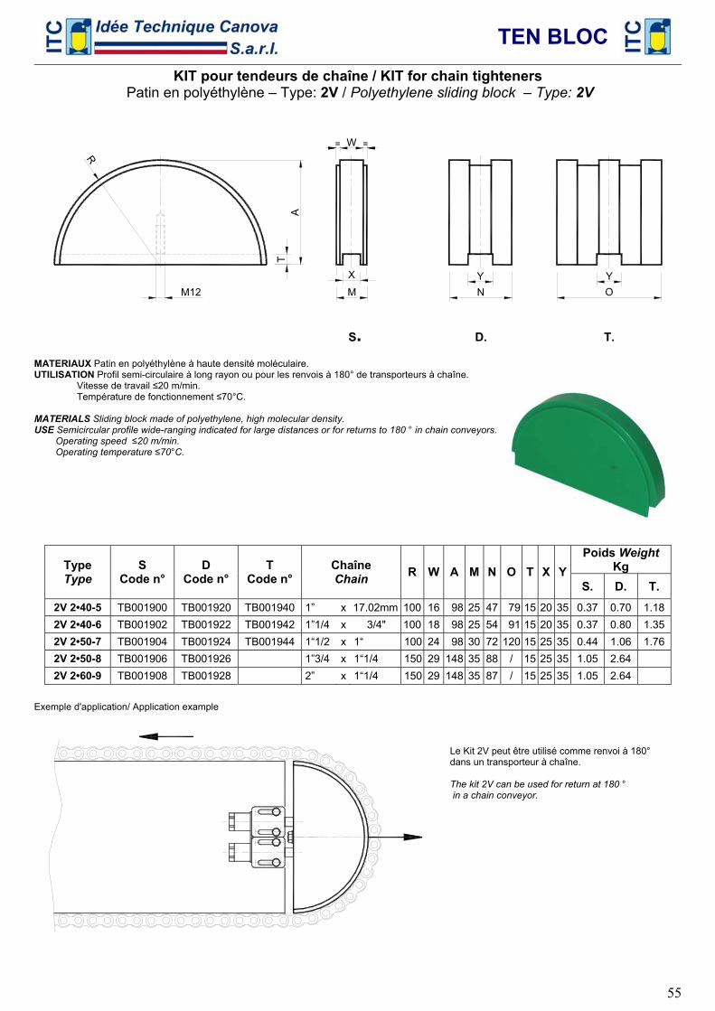
TEN BLOC
55
KIT pour tendeurs de chaîne / KIT for chain tighteners Patin en polyéthylène – Type: 2V / Polyethylene sliding block – Type: 2V
R
W=
N OA
TMM12
X Y Y
S. D. T. MATERIAUX Patin en polyéthylène à haute densité moléculaire. UTILISATION Profil semi-circulaire à long rayon ou pour les renvois à 180° de transporteurs à chaîne. Vitesse de travail ≤20 m/min. Température de fonctionnement ≤70°C. MATERIALS Sliding block made of polyethylene, high molecular density. USE Semicircular profile wide-ranging indicated for large distances or for returns to 180 ° in chain conveyors. Operating speed ≤20 m/min. Operating temperature ≤70°C.
Poids Weight
Kg Type Type
S Code n°
D Code n°
T Code n°
Chaîne Chain R W A M N O T X Y
S. D. T. 2V 2•40-5 TB001900 TB001920 TB001940 1” x 17.02mm 100 16 98 25 47 79 15 20 35 0.37 0.70 1.182V 2•40-6 TB001902 TB001922 TB001942 1”1/4 x 3/4" 100 18 98 25 54 91 15 20 35 0.37 0.80 1.352V 2•50-7 TB001904 TB001924 TB001944 1“1/2 x 1“ 100 24 98 30 72 120 15 25 35 0.44 1.06 1.762V 2•50-8 TB001906 TB001926 1”3/4 x 1“1/4 150 29 148 35 88 / 15 25 35 1.05 2.64 2V 2•60-9 TB001908 TB001928 2” x 1“1/4 150 29 148 35 87 / 15 25 35 1.05 2.64
Exemple d'application/ Application example
Le Kit 2V peut être utilisé comme renvoi à 180° dans un transporteur à chaîne. The kit 2V can be used for return at 180 ° in a chain conveyor.
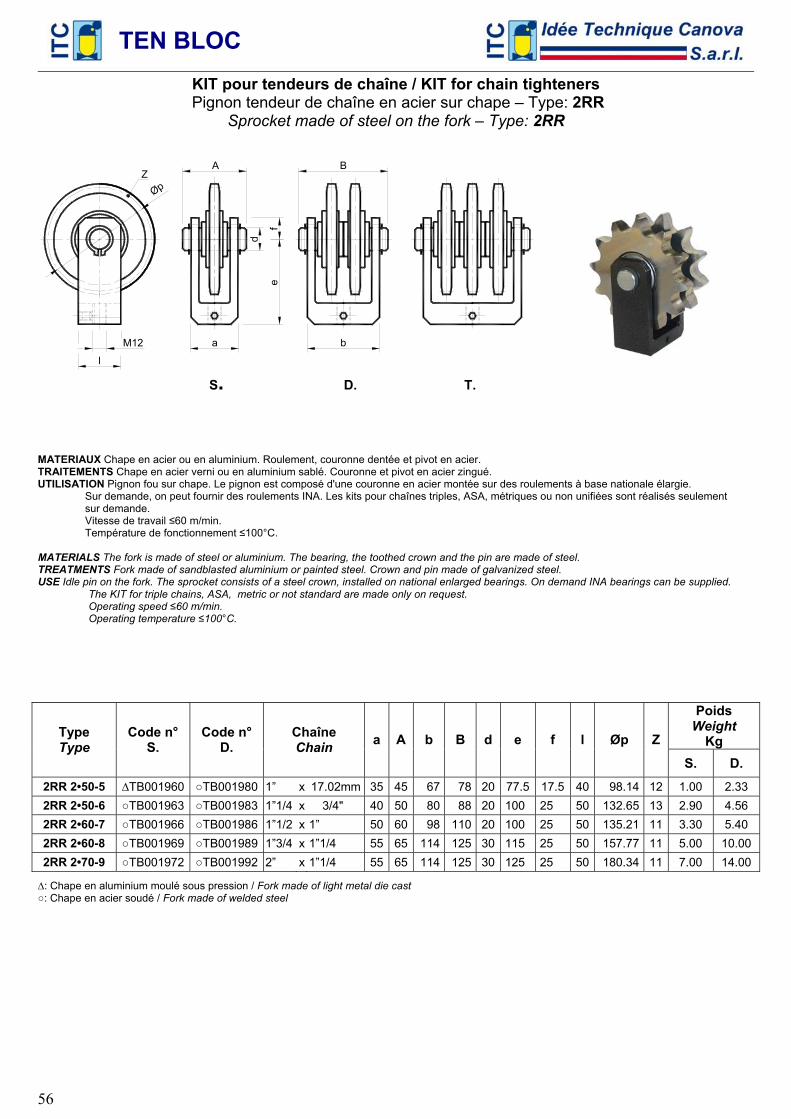
TEN BLOC
56
KIT pour tendeurs de chaîne / KIT for chain tighteners Pignon tendeur de chaîne en acier sur chape – Type: 2RR
Sprocket made of steel on the fork – Type: 2RR
a
d
ef
l
b
A B
M12
Z
Øp
S. D. T.
MATERIAUX Chape en acier ou en aluminium. Roulement, couronne dentée et pivot en acier. TRAITEMENTS Chape en acier verni ou en aluminium sablé. Couronne et pivot en acier zingué. UTILISATION Pignon fou sur chape. Le pignon est composé d'une couronne en acier montée sur des roulements à base nationale élargie. Sur demande, on peut fournir des roulements INA. Les kits pour chaînes triples, ASA, métriques ou non unifiées sont réalisés seulement sur demande. Vitesse de travail ≤60 m/min. Température de fonctionnement ≤100°C. MATERIALS The fork is made of steel or aluminium. The bearing, the toothed crown and the pin are made of steel. TREATMENTS Fork made of sandblasted aluminium or painted steel. Crown and pin made of galvanized steel. USE Idle pin on the fork. The sprocket consists of a steel crown, installed on national enlarged bearings. On demand INA bearings can be supplied.
The KIT for triple chains, ASA, metric or not standard are made only on request. Operating speed ≤60 m/min. Operating temperature ≤100°C.
Poids
Weight Kg Type
Type Code n°
S. Code n°
D. Chaîne Chain a A b B d e f l Øp Z
S. D. 2RR 2•50-5 ∆TB001960 ○TB001980 1” x 17.02mm 35 45 67 78 20 77.5 17.5 40 98.14 12 1.00 2.33 2RR 2•50-6 ○TB001963 ○TB001983 1”1/4 x 3/4" 40 50 80 88 20 100 25 50 132.65 13 2.90 4.56 2RR 2•60-7 ○TB001966 ○TB001986 1”1/2 x 1” 50 60 98 110 20 100 25 50 135.21 11 3.30 5.40 2RR 2•60-8 ○TB001969 ○TB001989 1”3/4 x 1”1/4 55 65 114 125 30 115 25 50 157.77 11 5.00 10.00 2RR 2•70-9 ○TB001972 ○TB001992 2” x 1”1/4 55 65 114 125 30 125 25 50 180.34 11 7.00 14.00
∆: Chape en aluminium moulé sous pression / Fork made of light metal die cast ○: Chape en acier soudé / Fork made of welded steel
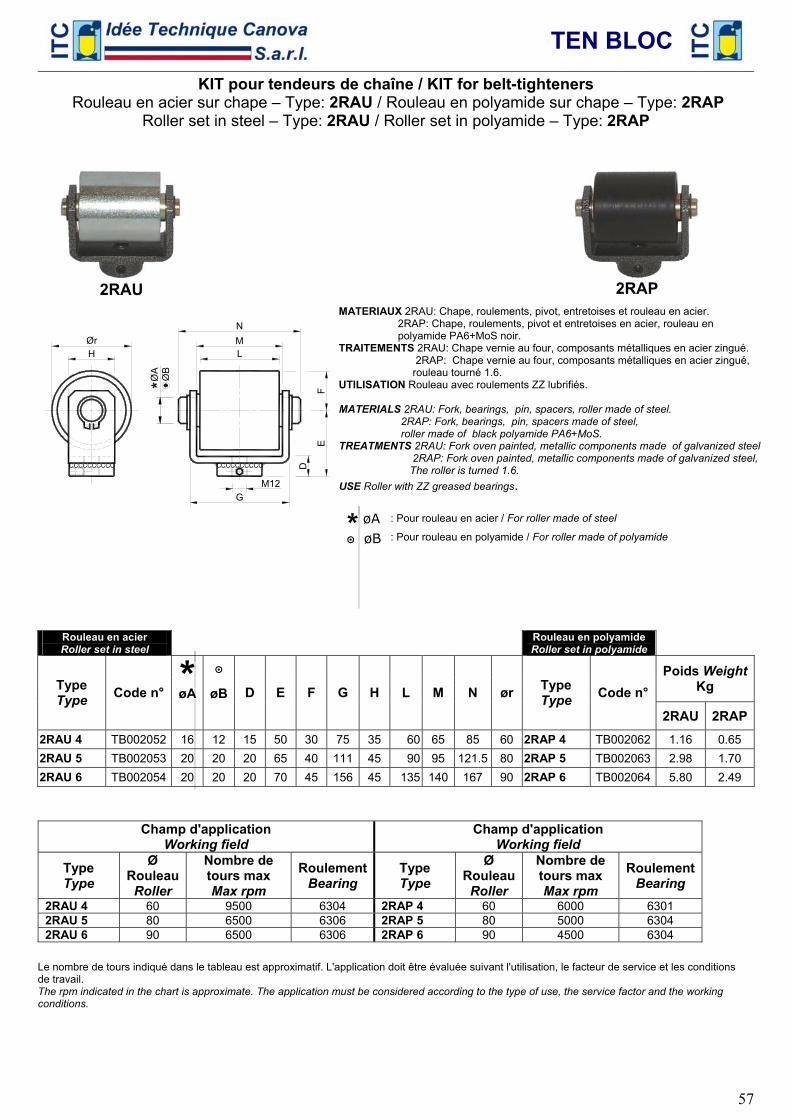
TEN BLOC
57
KIT pour tendeurs de chaîne / KIT for belt-tighteners Rouleau en acier sur chape – Type: 2RAU / Rouleau en polyamide sur chape – Type: 2RAP
Roller set in steel – Type: 2RAU / Roller set in polyamide – Type: 2RAP
CCCCCCCCCCCCCCCCCCCC
GM12
D
EF
LMN
ØrH
ØA
ØB
*
MATERIAUX 2RAU: Chape, roulements, pivot, entretoises et rouleau en acier. 2RAP: Chape, roulements, pivot et entretoises en acier, rouleau en polyamide PA6+MoS noir. TRAITEMENTS 2RAU: Chape vernie au four, composants métalliques en acier zingué. 2RAP: Chape vernie au four, composants métalliques en acier zingué, rouleau tourné 1.6. UTILISATION Rouleau avec roulements ZZ lubrifiés. MATERIALS 2RAU: Fork, bearings, pin, spacers, roller made of steel. 2RAP: Fork, bearings, pin, spacers made of steel, roller made of black polyamide PA6+MoS. TREATMENTS 2RAU: Fork oven painted, metallic components made of galvanized steel 2RAP: Fork oven painted, metallic components made of galvanized steel, The roller is turned 1.6. USE Roller with ZZ greased bearings.
* øA : Pour rouleau en acier / For roller made of steel
๏ øB : Pour rouleau en polyamide / For roller made of polyamide
Rouleau en acier Roller set in steel Rouleau en polyamide
Roller set in polyamide
* ๏ Poids WeightKg Type
Type Code n° øA øB D E F G H L M N ør Type Type Code n°
2RAU 2RAP2RAU 4 TB002052 16 12 15 50 30 75 35 60 65 85 60 2RAP 4 TB002062 1.16 0.65 2RAU 5 TB002053 20 20 20 65 40 111 45 90 95 121.5 80 2RAP 5 TB002063 2.98 1.70 2RAU 6 TB002054 20 20 20 70 45 156 45 135 140 167 90 2RAP 6 TB002064 5.80 2.49
Champ d'application Working field
Champ d'application Working field
Type Type
Ø Rouleau Roller
Nombre de tours max Max rpm
RoulementBearing
Type Type
Ø RouleauRoller
Nombre de tours max Max rpm
RoulementBearing
2RAU 4 60 9500 6304 2RAP 4 60 6000 6301 2RAU 5 80 6500 6306 2RAP 5 80 5000 6304 2RAU 6 90 6500 6306 2RAP 6 90 4500 6304
Le nombre de tours indiqué dans le tableau est approximatif. L'application doit être évaluée suivant l'utilisation, le facteur de service et les conditions de travail. The rpm indicated in the chart is approximate. The application must be considered according to the type of use, the service factor and the working conditions.
2RAU
2RAP
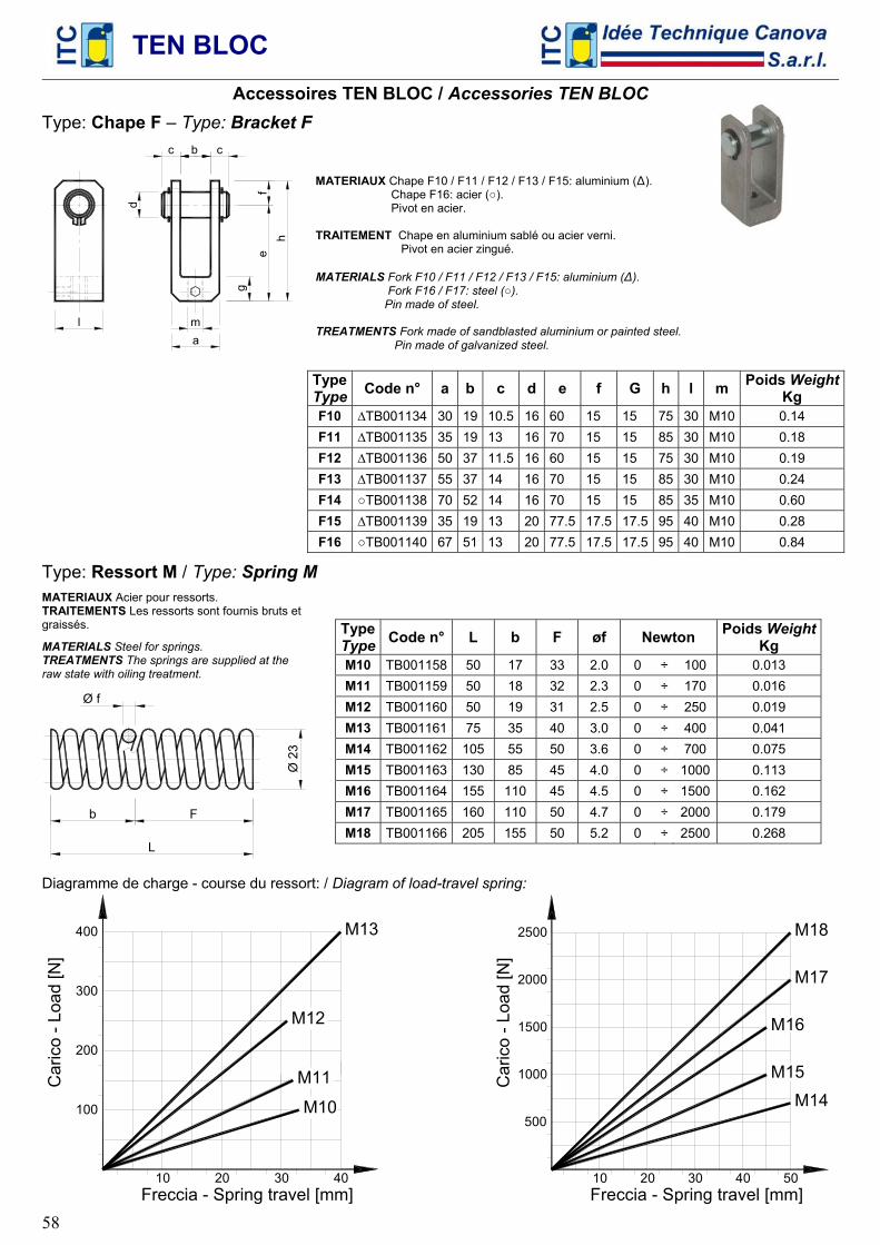
TEN BLOC
58
Accessoires TEN BLOC / Accessories TEN BLOC
Type: Chape F – Type: Bracket F c
a
cd
b
g
eh
f
l m
MATERIAUX Chape F10 / F11 / F12 / F13 / F15: aluminium (∆). Chape F16: acier (○). Pivot en acier. TRAITEMENT Chape en aluminium sablé ou acier verni. Pivot en acier zingué. MATERIALS Fork F10 / F11 / F12 / F13 / F15: aluminium (∆). Fork F16 / F17: steel (○). Pin made of steel. TREATMENTS Fork made of sandblasted aluminium or painted steel. Pin made of galvanized steel.
Type Type Code n° a b c d e f G h l m Poids Weight
Kg F10 ∆TB001134 30 19 10.5 16 60 15 15 75 30 M10 0.14 F11 ∆TB001135 35 19 13 16 70 15 15 85 30 M10 0.18 F12 ∆TB001136 50 37 11.5 16 60 15 15 75 30 M10 0.19 F13 ∆TB001137 55 37 14 16 70 15 15 85 30 M10 0.24 F14 ○TB001138 70 52 14 16 70 15 15 85 35 M10 0.60 F15 ∆TB001139 35 19 13 20 77.5 17.5 17.5 95 40 M10 0.28 F16 ○TB001140 67 51 13 20 77.5 17.5 17.5 95 40 M10 0.84
Type: Ressort M / Type: Spring M
MATERIAUX Acier pour ressorts. TRAITEMENTS Les ressorts sont fournis bruts et graissés.
MATERIALS Steel for springs. TREATMENTS The springs are supplied at the raw state with oiling treatment.
L
Fb
Ø 2
3
Ø f
TypeType Code n° L b F øf Newton Poids Weight
Kg M10 TB001158 50 17 33 2.0 0 ÷ 100 0.013 M11 TB001159 50 18 32 2.3 0 ÷ 170 0.016 M12 TB001160 50 19 31 2.5 0 ÷ 250 0.019 M13 TB001161 75 35 40 3.0 0 ÷ 400 0.041 M14 TB001162 105 55 50 3.6 0 ÷ 700 0.075 M15 TB001163 130 85 45 4.0 0 ÷ 1000 0.113 M16 TB001164 155 110 45 4.5 0 ÷ 1500 0.162 M17 TB001165 160 110 50 4.7 0 ÷ 2000 0.179 M18 TB001166 205 155 50 5.2 0 ÷ 2500 0.268
Diagramme de charge - course du ressort: / Diagram of load-travel spring:
400
10 20 30 40
200
100
300
Freccia - Spring travel [mm]
M13
M12
M11
M10
Car
ico
- Loa
d [N
]
500
1000
1500
2000
2500
10 20 30 40 50Freccia - Spring travel [mm]
Car
ico
- Loa
d [N
]
M18
M17
M16
M15M14
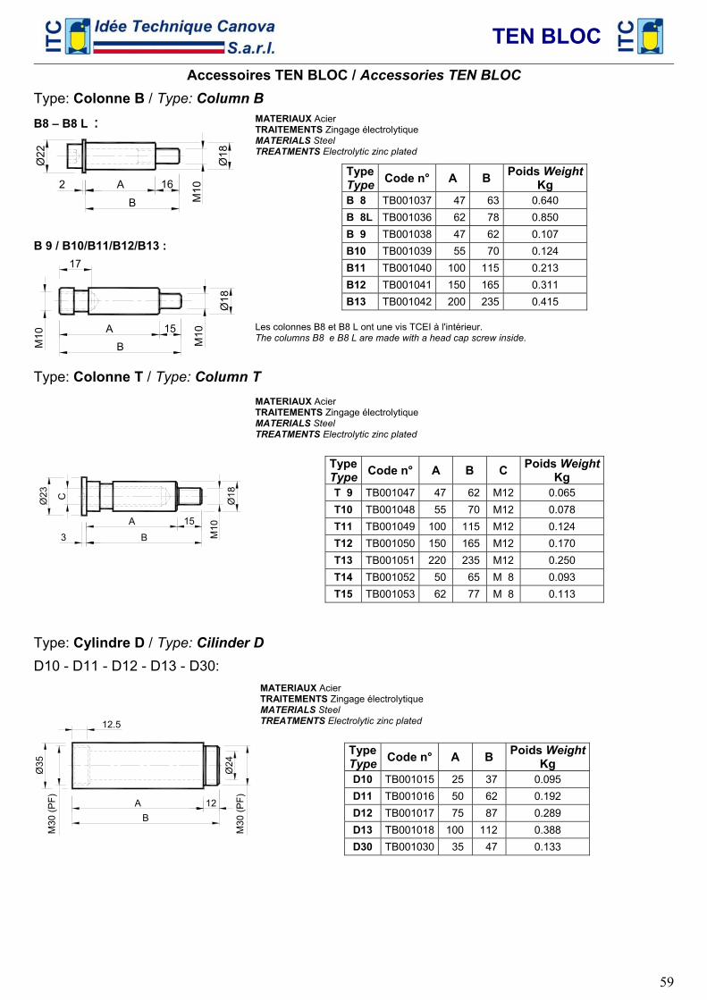
TEN BLOC
59
Accessoires TEN BLOC / Accessories TEN BLOC
Type: Colonne B / Type: Column B
B8 – B8 L :
M10
A 16
B
Ø18
2
Ø22
B 9 / B10/B11/B12/B13 :
B
A 15
17
M10
Ø18
MATERIAUX Acier TRAITEMENTS Zingage électrolytique MATERIALS Steel TREATMENTS Electrolytic zinc plated
TypeType Code n° A B Poids Weight
Kg B 8 TB001037 47 63 0.640 B 8L TB001036 62 78 0.850 B 9 TB001038 47 62 0.107 B10 TB001039 55 70 0.124 B11 TB001040 100 115 0.213 B12 TB001041 150 165 0.311 B13 TB001042 200 235 0.415
Les colonnes B8 et B8 L ont une vis TCEI à l'intérieur. The columns B8 e B8 L are made with a head cap screw inside.
Type: Colonne T / Type: Column T
B
A 15
M10
C Ø18
3
MATERIAUX Acier TRAITEMENTS Zingage électrolytique MATERIALS Steel TREATMENTS Electrolytic zinc plated
TypeType Code n° A B C Poids Weight
Kg T 9 TB001047 47 62 M12 0.065 T10 TB001048 55 70 M12 0.078 T11 TB001049 100 115 M12 0.124 T12 TB001050 150 165 M12 0.170 T13 TB001051 220 235 M12 0.250 T14 TB001052 50 65 M 8 0.093 T15 TB001053 62 77 M 8 0.113
Type: Cylindre D / Type: Cilinder D
D10 - D11 - D12 - D13 - D30:
Ø35
M
30 (P
F)
Ø24
M30
(PF)A 12
B
12.5
MATERIAUX Acier TRAITEMENTS Zingage électrolytique MATERIALS Steel TREATMENTS Electrolytic zinc plated
TypeType Code n° A B Poids Weight
Kg D10 TB001015 25 37 0.095 D11 TB001016 50 62 0.192 D12 TB001017 75 87 0.289 D13 TB001018 100 112 0.388 D30 TB001030 35 47 0.133
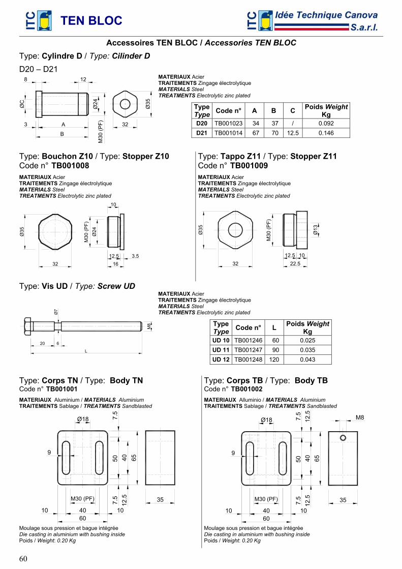
TEN BLOC
60
Accessoires TEN BLOC / Accessories TEN BLOC
Type: Cylindre D / Type: Cilinder D
D20 – D21
A
B
3
8
M30
(PF)
Ø24
12
Ø35
32
MATERIAUX Acier TRAITEMENTS Zingage électrolytique MATERIALS Steel TREATMENTS Electrolytic zinc plated
TypeType Code n° A B C Poids Weight
Kg D20 TB001023 34 37 / 0.092 D21 TB001014 67 70 12.5 0.146
Type: Bouchon Z10 / Type: Stopper Z10 Code n° TB001008
MATERIAUX Acier TRAITEMENTS Zingage électrolytique MATERIALS Steel TREATMENTS Electrolytic zinc plated
32 1612.5 3.5
Ø24
10
M30
(PF)
Type: Tappo Z11 / Type: Stopper Z11 Code n° TB001009 MATERIAUX Acier TRAITEMENTS Zingage électrolytique MATERIALS Steel TREATMENTS Electrolytic zinc plated
32 22.512.5 10
M30
(PF)
Ø13
Type: Vis UD / Type: Screw UD
M8
L
Ø7
20 6
MATERIAUX Acier TRAITEMENTS Zingage électrolytique MATERIALS Steel TREATMENTS Electrolytic zinc plated
TypeType Code n° L Poids Weight
Kg UD 10 TB001246 60 0.025 UD 11 TB001247 90 0.035 UD 12 TB001248 120 0.043
Type: Corps TN / Type: Body TN Code n° TB001001
MATERIAUX Aluminium / MATERIALS Aluminium TRAITEMENTS Sablage / TREATMENTS Sandblasted
65
60
40
5012
.5
9
Ø18 7.5
7.5 35
4010 10
M30 (PF)
Moulage sous pression et bague intégrée Die casting in aluminium with bushing inside Poids / Weight: 0.20 Kg
Type: Corps TB / Type: Body TB Code n° TB001002
MATERIAUX Alluminio / MATERIALS Aluminium TRAITEMENTS Sablage / TREATMENTS Sandblasted
65
60
40
5012
.5
9
Ø18 7.5
7.5 35
M8
4010 10
M30 (PF)
Moulage sous pression et bague intégrée Die casting in aluminium with bushing inside Poids / Weight: 0.20 Kg
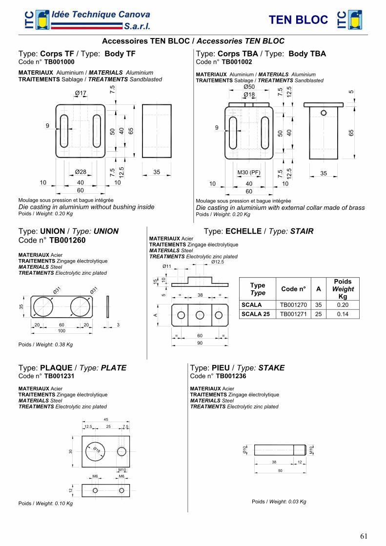
TEN BLOC
61
Accessoires TEN BLOC / Accessories TEN BLOC
Type: Corps TF / Type: Body TF Code n° TB001000
MATERIAUX Aluminium / MATERIALS Aluminium TRAITEMENTS Sablage / TREATMENTS Sandblasted
65
60
40
5012
.5
9
Ø17 7.5
7.5 35
4010 10
Ø28
Moulage sous pression et bague intégrée Die casting in aluminium without bushing inside Poids / Weight: 0.20 Kg
Type: Corps TBA / Type: Body TBA Code n° TB001002 MATERIAUX Aluminium / MATERIALS Aluminium TRAITEMENTS Sablage / TREATMENTS Sandblasted
65
60
40
5012
.5
12.5
9
7.5
7.5 35
4010 10
5
Ø50Ø18
M30 (PF)
Moulage sous pression et bague intégrée Die casting in aluminium with external collar made of brass Poids / Weight: 0.20 Kg
Type: UNION / Type: UNION Code n° TB001260 MATERIAUX Acier TRAITEMENTS Zingage électrolytique MATERIALS Steel TREATMENTS Electrolytic zinc plated
100 60 20 20
35
Ø31
Ø31
Poids / Weight: 0.38 Kg
Type: ECHELLE / Type: STAIR MATERIAUX Acier TRAITEMENTS Zingage électrolytique MATERIALS Steel TREATMENTS Electrolytic zinc plated
90 60 = =
A15
5 10
38 = =
Ø11
Type Type Code n° A
Poids Weight
Kg SCALA TB001270 35 0.20 SCALA 25 TB001271 25 0.14
Type: PLAQUE / Type: PLATE Code n° TB001231 MATERIAUX Acier TRAITEMENTS Zingage électrolytique MATERIALS Steel TREATMENTS Electrolytic zinc plated
30
25 7.512.5
12
Ø18
M10
M6 M6
Poids / Weight: 0.10 Kg
Type: PIEU / Type: STAKE Code n° TB001236 MATERIAUX Acier TRAITEMENTS Zingage électrolytique MATERIALS Steel TREATMENTS Electrolytic zinc plated
50
1238
M10
Poids / Weight: 0.03 Kg
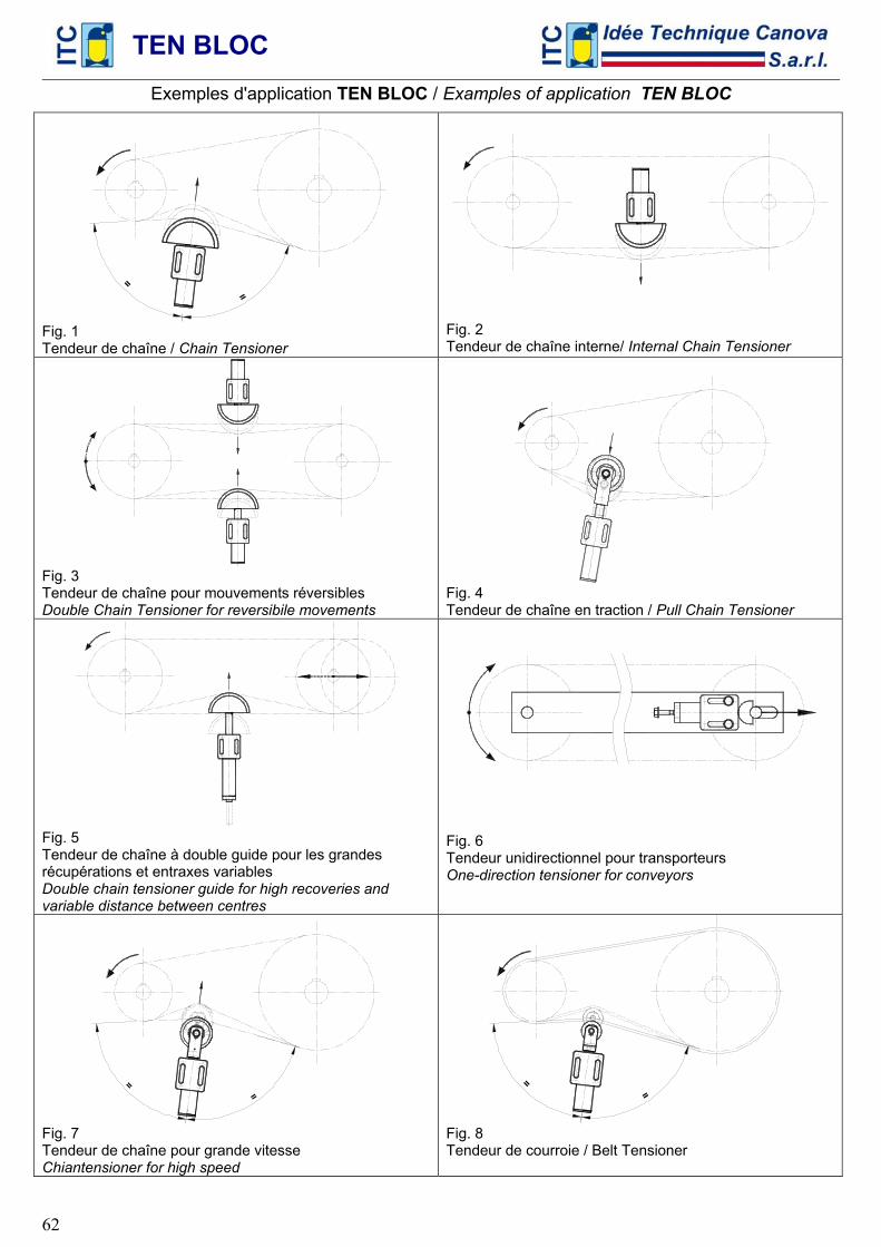
TEN BLOC
62
Exemples d'application TEN BLOC / Examples of application TEN BLOC
=
Fig. 1 Tendeur de chaîne / Chain Tensioner
Fig. 2 Tendeur de chaîne interne/ Internal Chain Tensioner
Fig. 3 Tendeur de chaîne pour mouvements réversibles Double Chain Tensioner for reversibile movements
Fig. 4 Tendeur de chaîne en traction / Pull Chain Tensioner
Fig. 5 Tendeur de chaîne à double guide pour les grandes récupérations et entraxes variables Double chain tensioner guide for high recoveries and variable distance between centres
Fig. 6 Tendeur unidirectionnel pour transporteurs One-direction tensioner for conveyors
=
Fig. 7 Tendeur de chaîne pour grande vitesse Chiantensioner for high speed
=
Fig. 8 Tendeur de courroie / Belt Tensioner