fps - schnaithmann.de¤tze/14... · profil 50x100 l profile 50x100 l profilé 50x100 l 17 profil...
TRANSCRIPT
D
E
F
Katalog . Catalogue . Catalogue . K27
FPS
K
atal
og . C
atal
ogue
. Cat
alog
ue . K
27
FPSFlexibles Profilsystem
Flexible Profile System
Système de profilé flexible
Die stabilen, zuverlässigen, flexibel einsetzbaren und servicefreundlichen Systeme von Schnaithmann lassen sich in jedes Fertigungs- und Logistik konzept integrieren. Durch die besondere Qualität der Einzelkomponenten ergeben sich zudem wirtschaftliche Vorteile.
Schnaithmann bietet Ihnen individuell maßgeschneiderte Sonder maschinen für Ihre Automationsaufgabe. Das kann eine einzelne Roboterzelle oder eine komplette Fertigungslinie sein.
The stable, reliable, versatile and service-friendly systems manufactured by Schnaithmann can be integrated into any production and logistics concept. The special quality of the individual components ultimately leads to economic advantages.
Schnaithmann offers tailor-made special machines for all of your automation tasks – from individual robot cells to complete production lines.
Les systèmes Schnaithmann stables, fiables, flexibles et faciles d’utilisation peuvent s’intégrer dans tous les concepts de fabrication et de logistique. En outre, grâce à la quali-té exceptionnelle des composants, ils présentent des avantages économiques.
Schnaithmann vous propose des machines spéciales taillées sur mesure en fonction de vos besoins en automatisation, et ce qu’il s’agisse d’une cellule de robot seule ou d’une chaîne de fabrication complète.
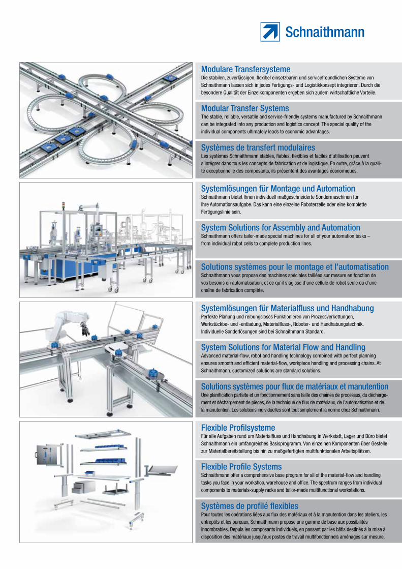
Modulare Transfersysteme
Systemlösungen für Montage und Automation
Modular Transfer Systems
System Solutions for Assembly and Automation
Systèmes de transfert modulaires
Solutions systèmes pour le montage et l’automatisation
Perfekte Planung und reibungsloses Funktionieren von Prozessver kettungen, Werkstückbe- und -entladung, Materialfluss-, Roboter- und Handhabungstechnik. Individuelle Sonderlösungen sind bei Schnaithmann Standard.
Advanced material-flow, robot and handling technology combined with perfect planning ensures smooth and efficient material-flow, workpiece handling and processing chains. At Schnaithmann, customized solutions are standard solutions.
Une planification parfaite et un fonctionnement sans faille des chaînes de processus, du décharge-ment et déchargement de pièces, de la technique de flux de matériaux, de l’automatisation et de la manutention. Les solutions individuelles sont tout simplement la norme chez Schnaithmann.
Systemlösungen für Materialfluss und Handhabung
System Solutions for Material Flow and Handling
Solutions systèmes pour flux de matériaux et manutention
Für alle Aufgaben rund um Materialfluss und Handhabung in Werkstatt, Lager und Büro bietet Schnaithmann ein umfangreiches Basisprogramm. Von einzelnen Komponenten über Gestelle zur Materialbereit stellung bis hin zu maßgefertigten multifunktionalen Arbeitsplätzen.
Schnaithmann offer a comprehensive base program for all of the material-flow and handling tasks you face in your workshop, warehouse and office. The spectrum ranges from individual components to materials-supply racks and tailor-made multifunctional workstations.
Pour toutes les opérations liées aux flux des matériaux et à la manutention dans les ateliers, les entrepôts et les bureaux, Schnaithmann propose une gamme de base aux possibilités innombrables. Depuis les composants individuels, en passant par les bâtis destinés à la mise à disposition des matériaux jusqu’aux postes de travail multifonctionnels aménagés sur mesure.
Flexible Profilsysteme
Flexible Profile Systems
Systèmes de profilé flexibles
1
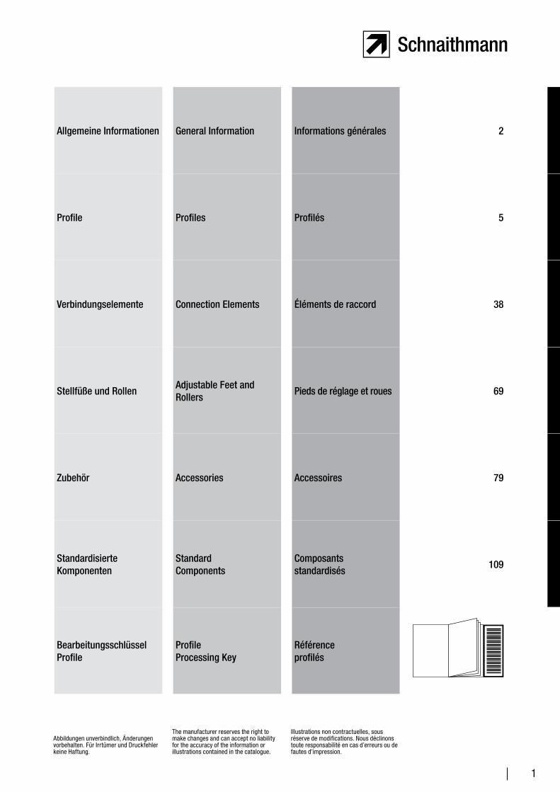
Allgemeine Informationen General Information Informations générales 2
Profile Profiles Profilés 5
Verbindungselemente Connection Elements Éléments de raccord 38
Stellfüße und RollenAdjustable Feet and Rollers
Pieds de réglage et roues 69
Zubehör Accessories Accessoires 79
Standardisierte Komponenten
Standard Components
Composants standardisés
109
BearbeitungsschlüsselProfile
Profile Processing Key
Référence profilés
Abbildungen unverbindlich, Änderungen vorbehalten. Für Irrtümer und Druckfehler keine Haftung.
The manufacturer reserves the right to make changes and can accept no liability for the accuracy of the information or illustrations contained in the catalogue.
Illustrations non contractuelles, sous réserve de modifications. Nous déclinons toute responsabilité en cas d’erreurs ou de fautes d’impression.
2
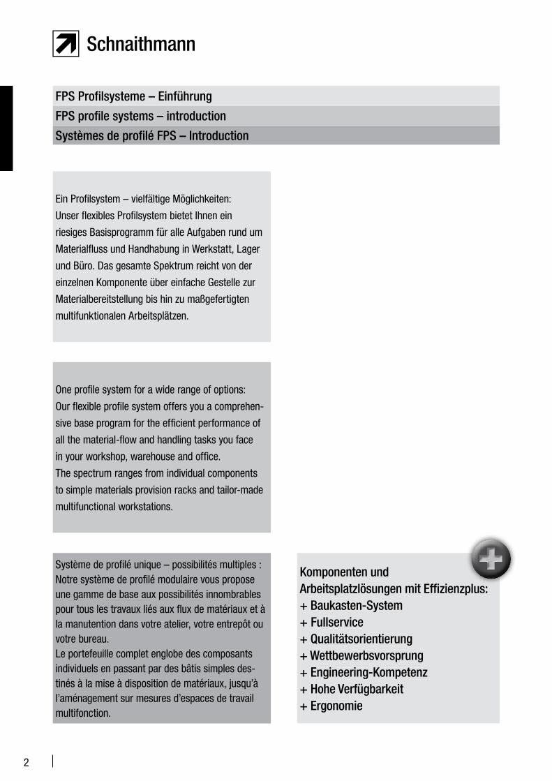
Ein Profilsystem – vielfältige Möglichkeiten:
Unser flexibles Profilsystem bietet Ihnen ein
riesiges Basisprogramm für alle Aufgaben rund um
Materialfluss und Handhabung in Werkstatt, Lager
und Büro. Das gesamte Spektrum reicht von der
einzelnen Komponente über einfache Gestelle zur
Materialbereitstellung bis hin zu maßgefertigten
multifunktionalen Arbeitsplätzen.
One profile system for a wide range of options:
Our flexible profile system offers you a comprehen-
sive base program for the efficient performance of
all the material-flow and handling tasks you face
in your workshop, warehouse and office.
The spectrum ranges from individual components
to simple materials provision racks and tailor-made
multifunctional workstations.
Système de profilé unique – possibilités multiples :Notre système de profilé modulaire vous propose une gamme de base aux possibilités innombrables pour tous les travaux liés aux flux de matériaux et à la manutention dans votre atelier, votre entrepôt ou votre bureau.Le portefeuille complet englobe des composants individuels en passant par des bâtis simples des-tinés à la mise à disposition de matériaux, jusqu’à l’aménagement sur mesures d’espaces de travail multifonction.
FPS Profilsysteme – Einführung
FPS profile systems – introduction
Systèmes de profilé FPS – Introduction
Komponenten und Arbeitsplatzlösungen mit Effizienzplus:+ Baukasten-System+ Fullservice+ Qualitätsorientierung+ Wettbewerbsvorsprung+ Engineering-Kompetenz+ Hohe Verfügbarkeit+ Ergonomie
3
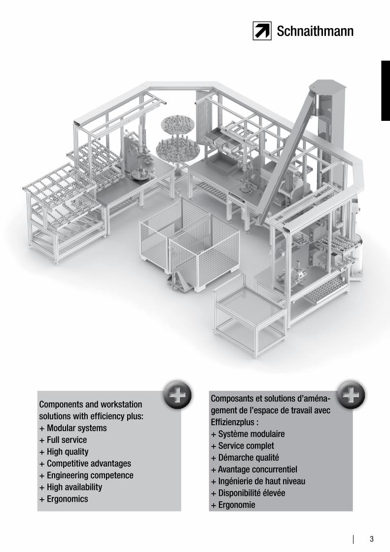
Components and workstation solutions with efficiency plus:+ Modular systems+ Full service+ High quality+ Competitive advantages+ Engineering competence+ High availability+ Ergonomics
Composants et solutions d’aména-gement de l’espace de travail avec Effizienzplus :+ Système modulaire+ Service complet+ Démarche qualité+ Avantage concurrentiel+ Ingénierie de haut niveau+ Disponibilité élevée+ Ergonomie

4
5
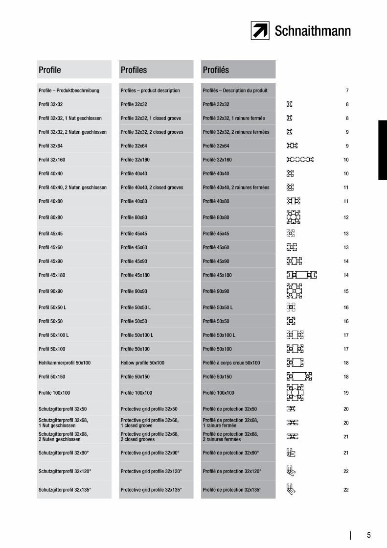
Profile Profiles Profilés
Profile – Produktbeschreibung Profiles – product description Profilés – Description du produit 7
Profil 32x32 Profile 32x32 Profilé 32x32 8
Profil 32x32, 1 Nut geschlossen Profile 32x32, 1 closed groove Profilé 32x32, 1 rainure fermée 8
Profil 32x32, 2 Nuten geschlossen Profile 32x32, 2 closed grooves Profilé 32x32, 2 rainures fermées 9
Profil 32x64 Profile 32x64 Profilé 32x64 9
Profil 32x160 Profile 32x160 Profilé 32x160 10
Profil 40x40 Profile 40x40 Profilé 40x40 10
Profil 40x40, 2 Nuten geschlossen Profile 40x40, 2 closed grooves Profilé 40x40, 2 rainures fermées 11
Profil 40x80 Profile 40x80 Profilé 40x80 11
Profil 80x80 Profile 80x80 Profilé 80x80 12
Profil 45x45 Profile 45x45 Profilé 45x45 13
Profil 45x60 Profile 45x60 Profilé 45x60 13
Profil 45x90 Profile 45x90 Profilé 45x90 14
Profil 45x180 Profile 45x180 Profilé 45x180 14
Profil 90x90 Profile 90x90 Profilé 90x90 15
Profil 50x50 L Profile 50x50 L Profilé 50x50 L 16
Profil 50x50 Profile 50x50 Profilé 50x50 16
Profil 50x100 L Profile 50x100 L Profilé 50x100 L 17
Profil 50x100 Profile 50x100 Profilé 50x100 17
Hohlkammerprofil 50x100 Hollow profile 50x100 Profilé à corps creux 50x100 18
Profil 50x150 Profile 50x150 Profilé 50x150 18
Profile 100x100 Profile 100x100 Profilé 100x100 19
Schutzgitterprofil 32x50 Protective grid profile 32x50 Profilé de protection 32x50 20
Schutzgitterprofil 32x68, 1 Nut geschlossen
Protective grid profile 32x68, 1 closed groove
Profilé de protection 32x68, 1 rainure fermée 20
Schutzgitterprofil 32x68, 2 Nuten geschlossen
Protective grid profile 32x68, 2 closed grooves
Profilé de protection 32x68, 2 rainures fermées 21
Schutzgitterprofil 32x90° Protective grid profile 32x90° Profilé de protection 32x90° 21
Schutzgitterprofil 32x120° Protective grid profile 32x120° Profilé de protection 32x120° 22
Schutzgitterprofil 32x135° Protective grid profile 32x135° Profilé de protection 32x135° 22
6
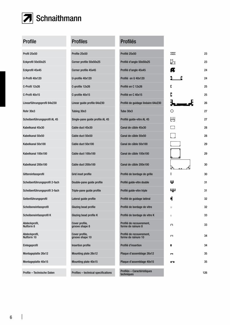
Profile Profiles Profilés
Profil 25x50 Profile 25x50 Profilé 25x50 23
Eckprofil 50x50x25 Corner profile 50x50x25 Profilé d’angle 50x50x25 23
Eckprofil 45x45 Corner profile 45x45 Profilé d’angle 45x45 24
U-Profil 40x120 U-profile 40x120 Profilé en U 40x120 24
C-Profil 12x26 C-profile 12x26 Profilé en C 12x26 25
C-Profil 40x15 C-profile 40x15 Profilé en C 40x15 25
Linearführungsprofil 64x230 Linear guide profile 64x230 Profilé de guidage linéaire 64x230 26
Rohr 30x3 Tubing 30x3 Tube 30x3 27
Scheibenführungsprofil AL 45 Single-pane guide profile AL 45 Profilé guide-vitre AL 45 27
Kabelkanal 45x30 Cable duct 45x30 Canal de câble 45x30 28
Kabelkanal 50x50 Cable duct 50x50 Canal de câble 50x50 28
Kabelkanal 50x100 Cable duct 50x100 Canal de câble 50x100 29
Kabelkanal 100x100 Cable duct 100x100 Canal de câble 100x100 29
Kabelkanal 200x100 Cable duct 200x100 Canal de câble 200x100 30
Gittereinfassprofil Grid inset profile Profilé de bordage de grille 30
Scheibenführungsprofil 2-fach Double-pane guide profile Profilé guide-vitre double 31
Scheibenführungsprofil 3-fach Triple-pane guide profile Profilé guide-vitre triple 31
Seitenführungsprofil Lateral guide profile Profilé de guidage latéral 32
Scheibeneinfassprofil Glazing bead profile Profilé de bordage de vitre 32
Scheibeneinfassprofil K Glazing bead profile K Profilé de bordage de vitre K 33
Abdeckprofil, Nutform 8
Cover profile, groove shape 8
Profilé de recouvrement, forme de rainure 8 33
Abdeckprofil, Nutform 10
Cover profile, groove shape 10
Profilé de recouvrement, forme de rainure 10 34
Einlegeprofil Insertion profile Profilé d’insertion 34
Montageplatte 26x12 Mounting plate 26x12 Plaque d’assemblage 26x12 35
Montageplatte 40x15 Mounting plate 40x15 Plaque d’assemblage 40x15 35
Profile – Technische Daten Profiles – technical specifications Profilés – Caractéristiques techniques 126
7
Unser Flexibles Profil System FPS ist als modularer Baukasten konzipiert. Dadurch ist ein Höchstmaß an Flexibilität gewährleistet.
Die wichtigsten technischen Daten unserer Profile: Herstellungsart: warmausgehärtetes Strangpressprofil Werkstoff: AIMgSi 0,5 F25 Werkstoffnummer: 3.3206.72 Zugfestigkeit: > 245 N/mm2 0,2 %-Dehngrenze: 200 N/mm2 Bruchdehnung A5: > 10% Bruchdehnung A10: > 8% Elastizitätsmodul: 70 000 N/mm2 Brinellhärte: ca. 75 HB 2,5/187,5 Oberfläche: Qualität E6/EV1 (matt gebeizt und naturfarben eloxiert) Eloxalschicht: ca. 10 µm Eloxalhärte: ca. 250 HV
Wir konfektionieren Ihnen die Profile nach Ihren Wünschen. Zuschnitte von Pro-filen fertigen wir mit einer Längentoleranz von +/- 0,2 mm (bezogen auf 20°).
Auf Wunsch liefern wir auch Profile mit vormontierten Verbindersätzen. Bitte geben Sie in diesem Fall die Gesamtzahl der zu montierenden Verbindersätze und die Bestellnummer extra an.
Our flexible profile system (FPS) is based on a modular design. This ensures a maximum degree of flexibility.
Technical specifications: Manufacturing method: Heat-cured extruded profile Material: AIMgSi 0.5 F25 Material number: 3.3206.72 Tensile strength: > 245 N/mm2 Yield point: 245 N/mm2 Yield strength at 0.2% strain: 200 N/mm2 A5 elongation: > 10% A10 elongation: > 8% Elastic modulus: 70 000 N/mm2 Brinell hardness: approx. 75 HB 2.5/187.5 Surface: quality E6/EV1 (pickled mat and anodized
in natural color) Anodized layer: approx. 10 µm Anodized hardness: approx. 250 HV
We manufacture profiles to meet your needs. The profile sections are manu-factured to a length tolerance of +/- 0.2 mm (relative to 20° C).
Upon request, we also supply profiles with pre-mounted connector sets. If applicable, please specify the total number of pre-mounted connector sets and the order number.
Notre système flexible de profilé (FPS) est conçu sous forme de blocs d’assemblage modulaires, ce qui garantit un maximum de flexibilité.
Principales caractéristiques techniques de nos profilés : Mode de fabrication : profilé extrudé Matériau : AIMgSi 0,5 F25 Numéro de matériau : 3.3206.72 Résistance à la traction : > 245 N/mm2
Limite d’élasticité 0,2 % : 200 N/mm2
Allongement à la rupture A5 : > 10 % Allongement à la rupture A10 : > 8 % Module d’élasticité : 70 000 N/mm2
Dureté brinell : env. 75 HB 2,5/187,5 Surface : qualité E6/EV1 (décapée mat et anodisée coloris naturel) Couche d’oxydation : env. 10 µxm Dureté d’oxydation : env. 250 HV
Nous fabriquons les profilés selon vos souhaits. Nous réalisons les découpes de pro-filés avec une tolérance de longueur de +/- 0,2 mm (à une température de 20 °C).
Sur demande, nous livrons également des profilés avec des jeux d’assem-blage préassemblés. Veuillez dans ce cas indiquer en supplément le nombre total de jeux d’assemblage à monter et le numéro de commande.
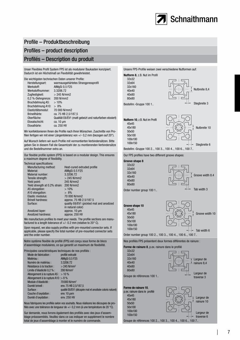
Profile – Produktbeschreibung
Profiles – product description
Profilés – Description du produit
Unsere FPS-Profile weisen zwei verschiedene Nutformen auf:
Nutform 8, z.B. Nut im Profil 32x32 32x64 32x160 40x40 40x80 80x80
Bestellnr.-Gruppe 100 1..
Nutform 10, z.B. Nut im Profil 45x45 45x180 50x50 50x100 100x100 100x150
Bestellnr.-Gruppe 100 2.., 100 3.., 100 4.., 100 6.., 100 7..
Our FPS profiles have two different groove shapes:
Groove shape 8 32x32 32x64 32x160 40x40 40x80 80x80
Order number group 100 1..
Groove shape 10 45x45 45x180 50x50 50x100 100x100 100x150
Order number group 100 2.., 100 3.., 100 4.., 100 6.., 100 7..
Nos profilés FPS présentent deux formes différentes de rainure :
Forme de rainure 8, p.ex. rainure dans le profilé 32x32 32x64 32x160 40x40 40x80 80x80
Groupe de références 100 1..
Forme de rainure 10, p.ex. rainure dans le profilé 45x45 45x180 50x50 50x100 100x100 100x150
Groupe de références 100 2.., 100 3.., 100 4.., 100 6.., 100 7..
Nutbreite 8,4
Stegbreite 3
Nutbreite 10
Stegbreite 6
Groove width 8.4
Tab width 3
Groove width 10
Tab width 6
Largeur de rainure 8,4
Largeur de traverse 3
Largeur de rainure 10
Largeur de traverse 6
8
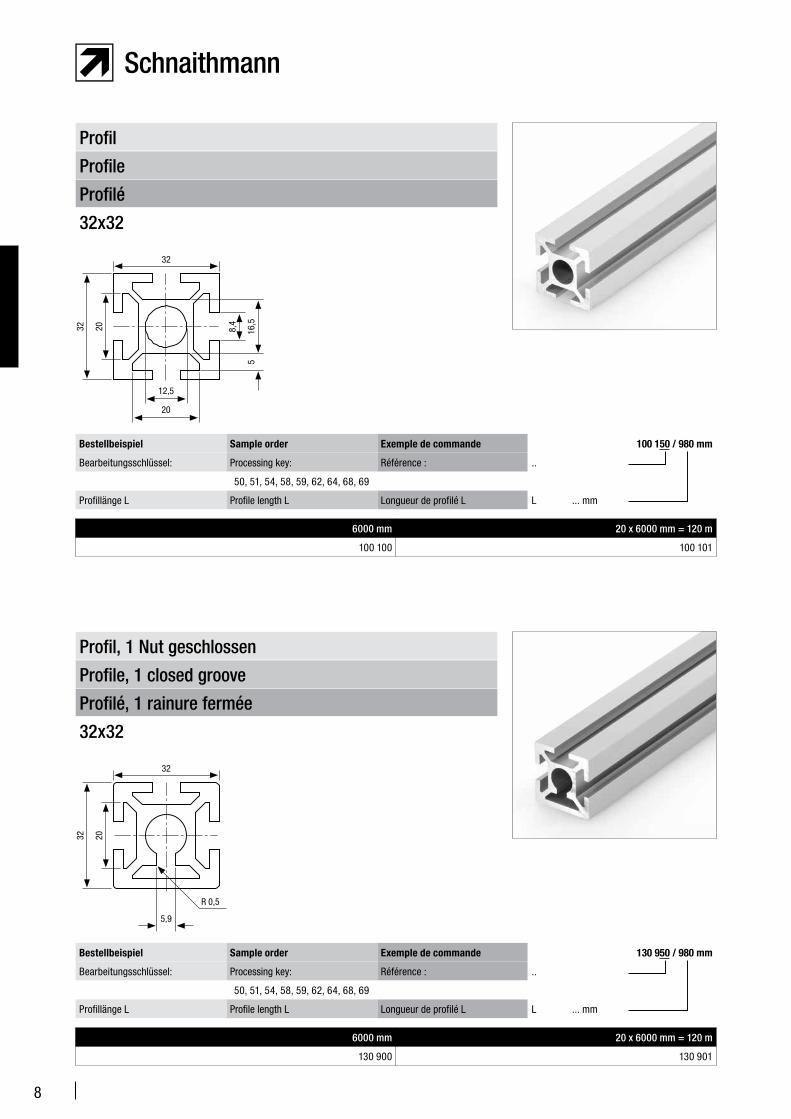
Profilé
Profile
Profil
32x32
6000 mm 20 x 6000 mm = 120 m
100 100 100 101
Bestellbeispiel Sample order Exemple de commande 100 150 / 980 mm
Bearbeitungsschlüssel: Processing key: Référence : ..
50, 51, 54, 58, 59, 62, 64, 68, 69
Profillänge L Profile length L Longueur de profilé L L ... mm
Profilé, 1 rainure fermée
Profile, 1 closed groove
Profil, 1 Nut geschlossen
32x32
6000 mm 20 x 6000 mm = 120 m
130 900 130 901
Bestellbeispiel Sample order Exemple de commande 130 950 / 980 mm
Bearbeitungsschlüssel: Processing key: Référence : ..
50, 51, 54, 58, 59, 62, 64, 68, 69
Profillänge L Profile length L Longueur de profilé L L ... mm
32
32
12,5
20
20
516
,5
8,4
32
32 20
5,9
R 0,5
9
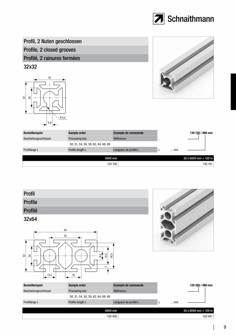
Profilé, 2 rainures fermées
Profile, 2 closed grooves
Profil, 2 Nuten geschlossen
32x32
6000 mm 20 x 6000 mm = 120 m
130 100 130 101
Bestellbeispiel Sample order Exemple de commande 130 150 / 980 mm
Bearbeitungsschlüssel: Processing key: Référence : ..
50, 51, 54, 58, 59, 62, 64, 68, 69
Profillänge L Profile length L Longueur de profilé L L ... mm
Profilé
Profile
Profil
32x64
6000 mm 20 x 6000 mm = 120 m
120 400 120 401
Bestellbeispiel Sample order Exemple de commande 120 450 / 980 mm
Bearbeitungsschlüssel: Processing key: Référence : ..
50, 51, 54, 58, 59, 62, 64, 68, 69
Profillänge L Profile length L Longueur de profilé L L ... mm
32
32 20
5,9
R 0,5
32
32 20
516
,5
8,4
64
12,5 16
26,5
10
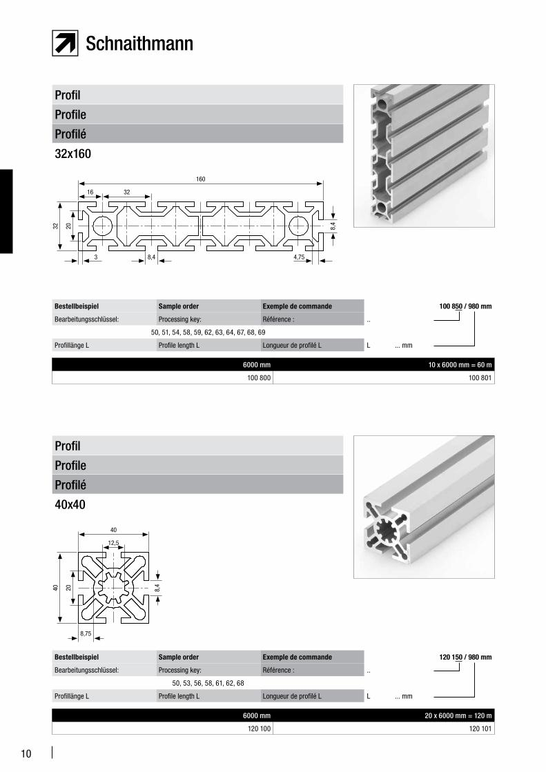
Profilé
Profile
Profil
32x160
6000 mm 10 x 6000 mm = 60 m
100 800 100 801
Bestellbeispiel Sample order Exemple de commande 100 850 / 980 mm
Bearbeitungsschlüssel: Processing key: Référence : ..
50, 51, 54, 58, 59, 62, 63, 64, 67, 68, 69
Profillänge L Profile length L Longueur de profilé L L ... mm
32 20
16
8,4
8,4
32
3 4,75
160
Profilé
Profile
Profil
40x40
6000 mm 20 x 6000 mm = 120 m
120 100 120 101
Bestellbeispiel Sample order Exemple de commande 120 150 / 980 mm
Bearbeitungsschlüssel: Processing key: Référence : ..
50, 53, 56, 58, 61, 62, 68
Profillänge L Profile length L Longueur de profilé L L ... mm
12,5
40 20
8,75
40
8,4
11
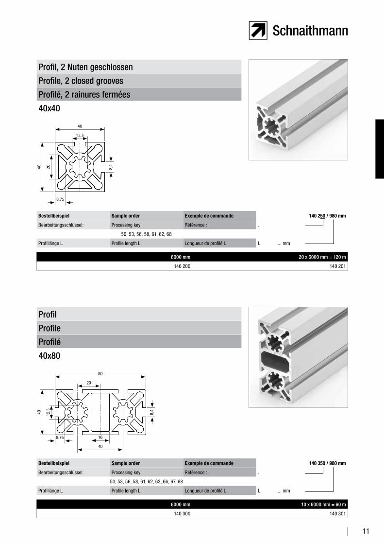
Profilé, 2 rainures fermées
Profile, 2 closed grooves
Profil, 2 Nuten geschlossen
40x40
6000 mm 20 x 6000 mm = 120 m
140 200 140 201
Bestellbeispiel Sample order Exemple de commande 140 250 / 980 mm
Bearbeitungsschlüssel: Processing key: Référence : ..
50, 53, 56, 58, 61, 62, 68
Profillänge L Profile length L Longueur de profilé L L ... mm
12,5
40 20
8,75
40
8,4
Profilé
Profile
Profil
40x80
6000 mm 10 x 6000 mm = 60 m
140 300 140 301
Bestellbeispiel Sample order Exemple de commande 140 350 / 980 mm
Bearbeitungsschlüssel: Processing key: Référence : ..
50, 53, 56, 58, 61, 62, 63, 66, 67, 68
Profillänge L Profile length L Longueur de profilé L L ... mm
20
40 12,5
8,75
80
8,4
16
40
12
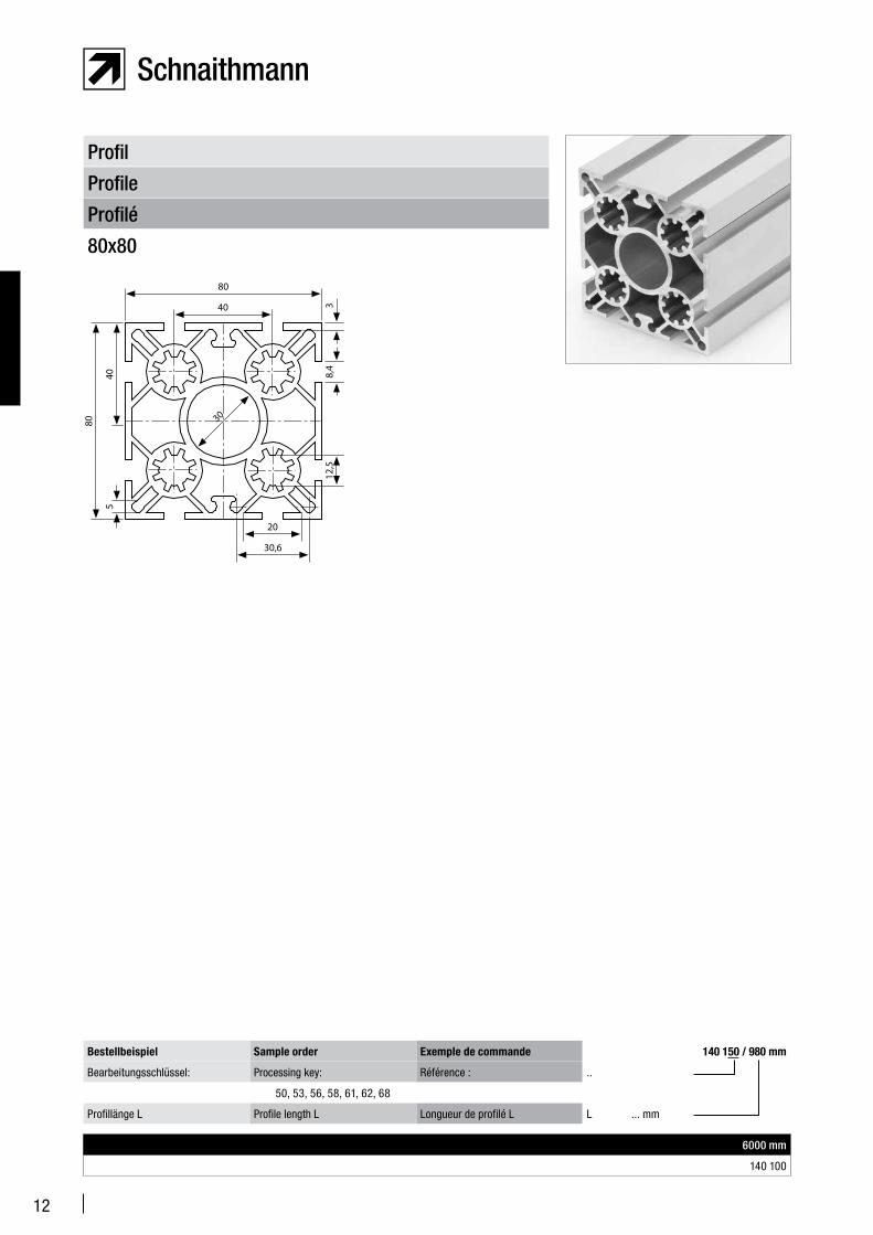
Profilé
Profile
Profil
80x80
6000 mm
140 100
Bestellbeispiel Sample order Exemple de commande 140 150 / 980 mm
Bearbeitungsschlüssel: Processing key: Référence : ..
50, 53, 56, 58, 61, 62, 68
Profillänge L Profile length L Longueur de profilé L L ... mm
40
40
12,5
80
3
20
30,6
80
5
30
8,4
13
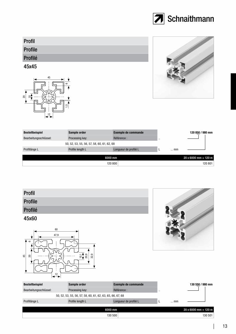
Profilé
Profile
Profil
45x45
6000 mm 20 x 6000 mm = 120 m
120 800 120 801
Bestellbeispiel Sample order Exemple de commande 120 850 / 980 mm
Bearbeitungsschlüssel: Processing key: Référence : ..
50, 52, 53, 55, 56, 57, 58, 60, 61, 62, 68
Profillänge L Profile length L Longueur de profilé L L ... mm
Profilé
Profile
Profil
45x60
6000 mm 20 x 6000 mm = 120 m
130 500 130 501
Bestellbeispiel Sample order Exemple de commande 130 550 / 980 mm
Bearbeitungsschlüssel: Processing key: Référence : ..
50, 52, 53, 55, 56, 57, 58, 60, 61, 62, 63, 65, 66, 67, 68
Profillänge L Profile length L Longueur de profilé L L ... mm
45
20
12
10
1,5
6
60
45
12
206
47,9
10,1
20,9
32,9
14
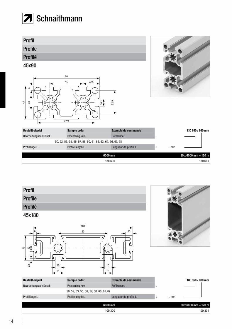
Profilé
Profile
Profil
45x90
6000 mm 20 x 6000 mm = 120 m
130 600 130 601
Bestellbeispiel Sample order Exemple de commande 130 650 / 980 mm
Bearbeitungsschlüssel: Processing key: Référence : ..
50, 52, 53, 55, 56, 57, 58, 60, 61, 62, 63, 65, 66, 67, 68
Profillänge L Profile length L Longueur de profilé L L ... mm
Profilé
Profile
Profil
45x180
6000 mm 20 x 6000 mm = 120 m
100 300 100 301
Bestellbeispiel Sample order Exemple de commande 100 350 / 980 mm
Bearbeitungsschlüssel: Processing key: Référence : ..
50, 52, 53, 55, 56, 57, 58, 60, 61, 62
Profillänge L Profile length L Longueur de profilé L L ... mm
90
45
77,9
206
45
10,1
32,9
22,5
180
45
21
12
90 136
3,5 10
16
10
15
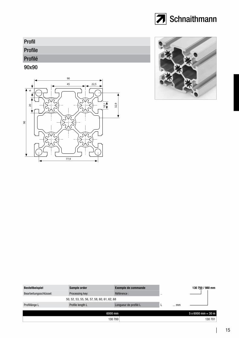
Profilé
Profile
Profil
90x90
6000 mm 5 x 6000 mm = 30 m
130 700 130 701
Bestellbeispiel Sample order Exemple de commande 130 750 / 980 mm
Bearbeitungsschlüssel: Processing key: Référence : ..
50, 52, 53, 55, 56, 57, 58, 60, 61, 62, 68
Profillänge L Profile length L Longueur de profilé L L ... mm
90
90
77,9
206
45
10,1
32,9
22,5
16
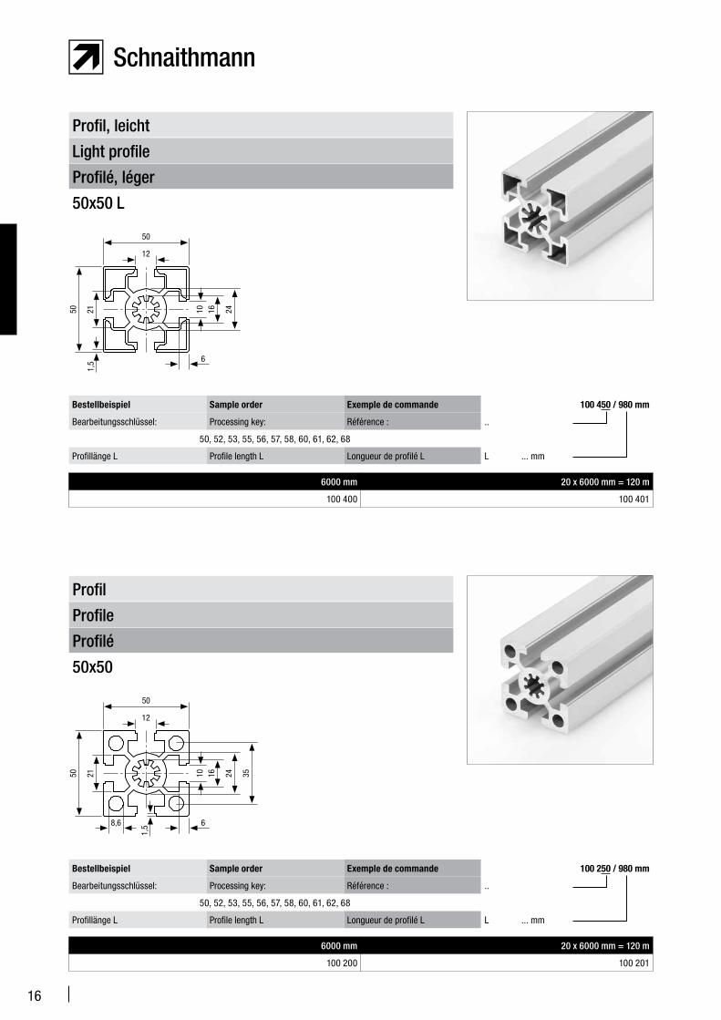
Profilé, léger
Light profile
Profil, leicht
50x50 L
6000 mm 20 x 6000 mm = 120 m
100 400 100 401
Bestellbeispiel Sample order Exemple de commande 100 450 / 980 mm
Bearbeitungsschlüssel: Processing key: Référence : ..
50, 52, 53, 55, 56, 57, 58, 60, 61, 62, 68
Profillänge L Profile length L Longueur de profilé L L ... mm
Profilé
Profile
Profil
50x50
6000 mm 20 x 6000 mm = 120 m
100 200 100 201
Bestellbeispiel Sample order Exemple de commande 100 250 / 980 mm
Bearbeitungsschlüssel: Processing key: Référence : ..
50, 52, 53, 55, 56, 57, 58, 60, 61, 62, 68
Profillänge L Profile length L Longueur de profilé L L ... mm
50 21
12
50
10 16
1,5 6
24
1,5
50 21
12
50
10 16
6
24 35
8,6
17
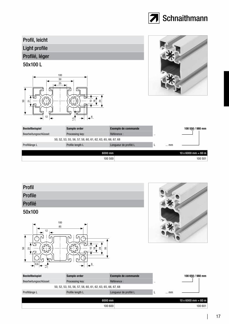
Profilé, léger
Light profile
Profil, leicht
50x100 L
6000 mm 10 x 6000 mm = 60 m
100 500 100 501
Bestellbeispiel Sample order Exemple de commande 100 550 / 980 mm
Bearbeitungsschlüssel: Processing key: Référence : ..
50, 52, 53, 55, 56, 57, 58, 60, 61, 62, 63, 65, 66, 67, 68
Profillänge L Profile length L Longueur de profilé L L ... mm
Profilé
Profile
Profil
50x100
6000 mm 10 x 6000 mm = 60 m
100 600 100 601
Bestellbeispiel Sample order Exemple de commande 100 650 / 980 mm
Bearbeitungsschlüssel: Processing key: Référence : ..
50, 52, 53, 55, 56, 57, 58, 60, 61, 62, 63, 65, 66, 67, 68
Profillänge L Profile length L Longueur de profilé L L ... mm
50 21
12
50
10 16
6
24
1,5
100
25
50 21
12
85
10 16
6
24 35
8,6
1,5
100
18
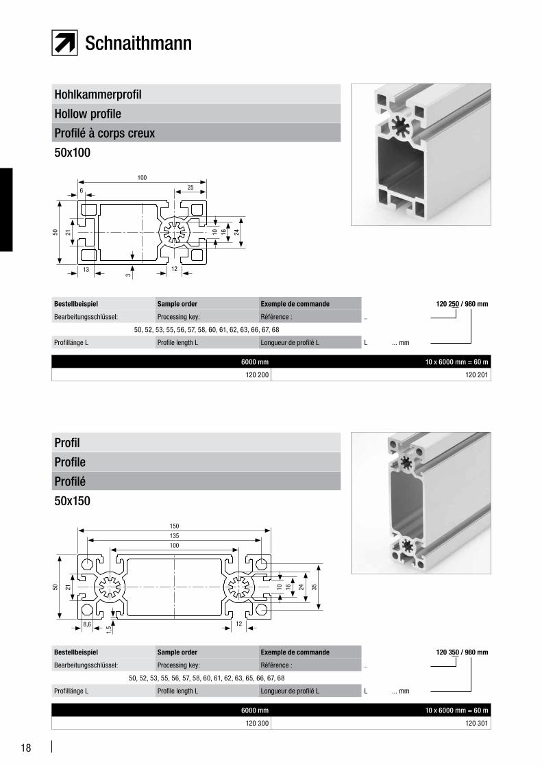
Profilé
Profile
Profil
50x150
6000 mm 10 x 6000 mm = 60 m
120 300 120 301
Bestellbeispiel Sample order Exemple de commande 120 350 / 980 mm
Bearbeitungsschlüssel: Processing key: Référence : ..
50, 52, 53, 55, 56, 57, 58, 60, 61, 62, 63, 65, 66, 67, 68
Profillänge L Profile length L Longueur de profilé L L ... mm
Profilé à corps creux
Hollow profile
Hohlkammerprofil
50x100
6000 mm 10 x 6000 mm = 60 m
120 200 120 201
Bestellbeispiel Sample order Exemple de commande 120 250 / 980 mm
Bearbeitungsschlüssel: Processing key: Référence : ..
50, 52, 53, 55, 56, 57, 58, 60, 61, 62, 63, 66, 67, 68
Profillänge L Profile length L Longueur de profilé L L ... mm
50 21
135
10 16 24 35
8,6
1,5
150
12
100
50 21
6 25
10 16 24
13
3
100
12
19
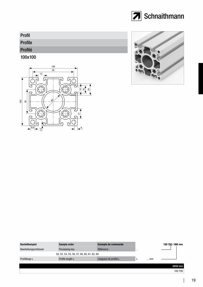
Profilé
Profile
Profil
100x100
6000 mm
100 700
Bestellbeispiel Sample order Exemple de commande 100 750 / 980 mm
Bearbeitungsschlüssel: Processing key: Référence : ..
50, 52, 53, 55, 56, 57, 58, 60, 61, 62, 68
Profillänge L Profile length L Longueur de profilé L L ... mm
50
12
85
10 16
6
24
8,6
1,5
100
21
100 40
20
68
32
25,75
8,4
10
34
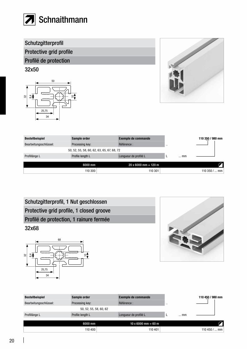
Profilé de protection
Protective grid profile
Schutzgitterprofil
32x50
6000 mm 20 x 6000 mm = 120 m
110 300 110 301 110 350 / ... mm
Bestellbeispiel Sample order Exemple de commande 110 350 / 980 mm
Bearbeitungsschlüssel: Processing key: Référence : ..
50, 52, 55, 58, 60, 62, 63, 65, 67, 68, 72
Profillänge L Profile length L Longueur de profilé L L ... mm
Profilé de protection, 1 rainure fermée
Protective grid profile, 1 closed groove
Schutzgitterprofil, 1 Nut geschlossen
32x68
6000 mm 10 x 6000 mm = 60 m
110 400 110 401 110 450 / ... mm
Bestellbeispiel Sample order Exemple de commande 110 450 / 980 mm
Bearbeitungsschlüssel: Processing key: Référence : ..
50, 52, 55, 58, 60, 62
Profillänge L Profile length L Longueur de profilé L L ... mm
50
32
25,75
8,4
10
34
21
50
32
25,75
8,4
50
34
R16
90°
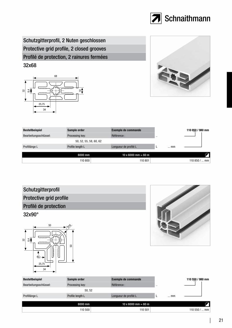
Profilé de protection, 2 rainures fermées
Protective grid profile, 2 closed grooves
Schutzgitterprofil, 2 Nuten geschlossen
32x68
6000 mm 10 x 6000 mm = 60 m
110 800 110 801 110 850 / ... mm
Bestellbeispiel Sample order Exemple de commande 110 850 / 980 mm
Bearbeitungsschlüssel: Processing key: Référence : ..
50, 52, 55, 58, 60, 62
Profillänge L Profile length L Longueur de profilé L L ... mm
Profilé de protection
Protective grid profile
Schutzgitterprofil
32x90°
6000 mm 10 x 6000 mm = 60 m
110 500 110 501 110 550 / ... mm
Bestellbeispiel Sample order Exemple de commande 110 550 / 980 mm
Bearbeitungsschlüssel: Processing key: Référence : ..
50, 52
Profillänge L Profile length L Longueur de profilé L L ... mm
68
32
25,75
8,4
10
34
22
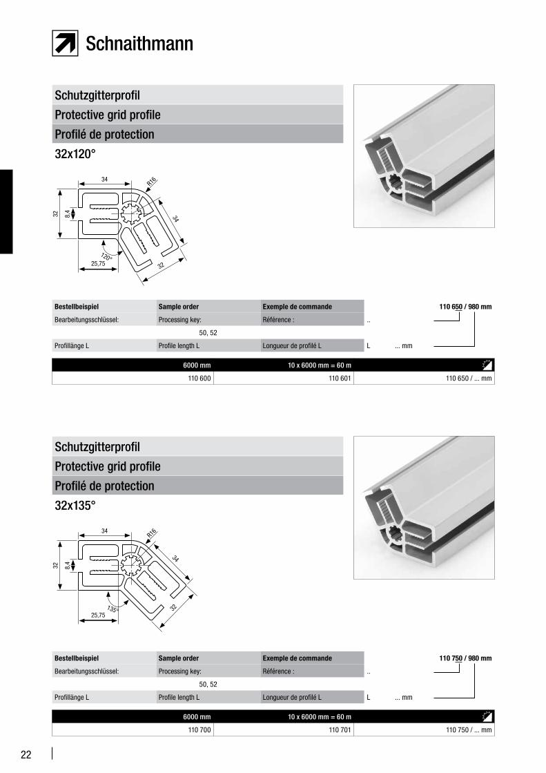
Profilé de protection
Protective grid profile
Schutzgitterprofil
32x120°
6000 mm 10 x 6000 mm = 60 m
110 600 110 601 110 650 / ... mm
Bestellbeispiel Sample order Exemple de commande 110 650 / 980 mm
Bearbeitungsschlüssel: Processing key: Référence : ..
50, 52
Profillänge L Profile length L Longueur de profilé L L ... mm
Profilé de protection
Protective grid profile
Schutzgitterprofil
32x135°
6000 mm 10 x 6000 mm = 60 m
110 700 110 701 110 750 / ... mm
Bestellbeispiel Sample order Exemple de commande 110 750 / 980 mm
Bearbeitungsschlüssel: Processing key: Référence : ..
50, 52
Profillänge L Profile length L Longueur de profilé L L ... mm
34
32
25,75
8,4
32
R16
120°
34
34
32
25,75
8,4
32
R16
34
135°
23
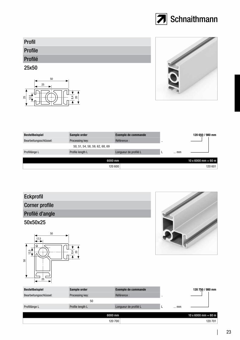
Profilé d’angle
Corner profile
Eckprofil
50x50x25
6000 mm 10 x 6000 mm = 60 m
120 700 120 701
Bestellbeispiel Sample order Exemple de commande 120 750 / 980 mm
Bearbeitungsschlüssel: Processing key: Référence : ..
50
Profillänge L Profile length L Longueur de profilé L L ... mm
Profilé
Profile
Profil
25x50
6000 mm 10 x 6000 mm = 60 m
120 600 120 601
Bestellbeispiel Sample order Exemple de commande 120 650 / 980 mm
Bearbeitungsschlüssel: Processing key: Référence : ..
50, 51, 54, 58, 59, 62, 68, 69
Profillänge L Profile length L Longueur de profilé L L ... mm
50
25 12,5 20
25
8,4
50
12,5 20
12,5
8,4
25
50
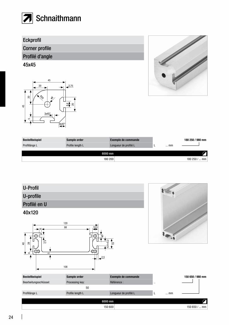
24
45
9x45°
20
208,4
45
20
5
2,75
3x45°
R20 ø8
Profilé en U
U-profile
U-Profil
40x120
6000 mm
150 600 150 650 / ... mm
Bestellbeispiel Sample order Exemple de commande 150 650 / 980 mm
Bearbeitungsschlüssel: Processing key: Référence : ..
50
Profillänge L Profile length L Longueur de profilé L L ... mm
Profilé d’angle
Corner profile
Eckprofil
45x45
6000 mm
180 200 180 250 / ... mm
Bestellbeispiel Sample order Exemple de commande 180 250 / 980 mm
Profillänge L Profile length L Longueur de profilé L L ... mm
40
108
19
120
ø5
28
88
6
4
5
4,3
2,5
10,5
8,4+
0,2
25
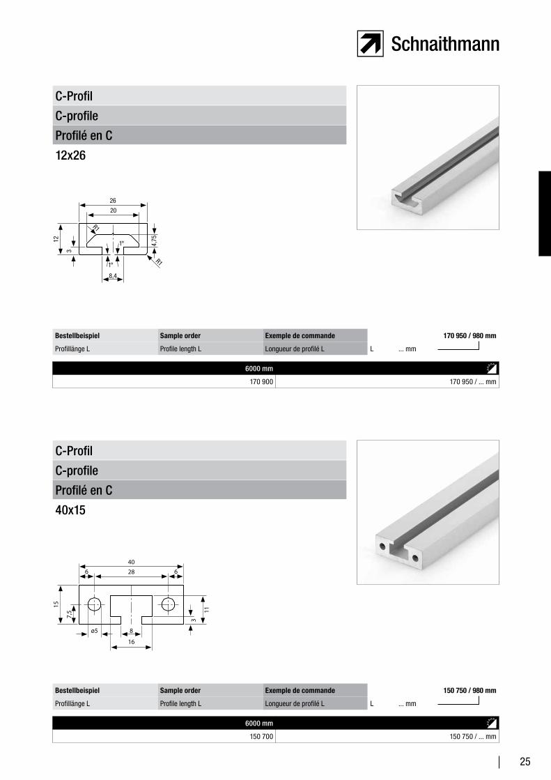
Profilé en C
C-profile
C-Profil
12x26
6000 mm
170 900 170 950 / ... mm
Bestellbeispiel Sample order Exemple de commande 170 950 / 980 mm
Profillänge L Profile length L Longueur de profilé L L ... mm
Profilé en C
C-profile
C-Profil
40x15
6000 mm
150 700 150 750 / ... mm
Bestellbeispiel Sample order Exemple de commande 150 750 / 980 mm
Profillänge L Profile length L Longueur de profilé L L ... mm
15
16
11
40
3
28
ø5
7,5
6 6
8
12
26
3
20
4,75
8,4
R1
R1
1°
1°
26
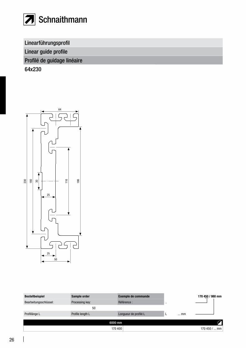
Profilé de guidage linéaire
Linear guide profile
Linearführungsprofil
64x230
6000 mm
170 400 170 450 / ... mm
Bestellbeispiel Sample order Exemple de commande 170 450 / 980 mm
Bearbeitungsschlüssel: Processing key: Référence : ..
50
Profillänge L Profile length L Longueur de profilé L L ... mm
64
230
180
186
116
30
50
25
25
27
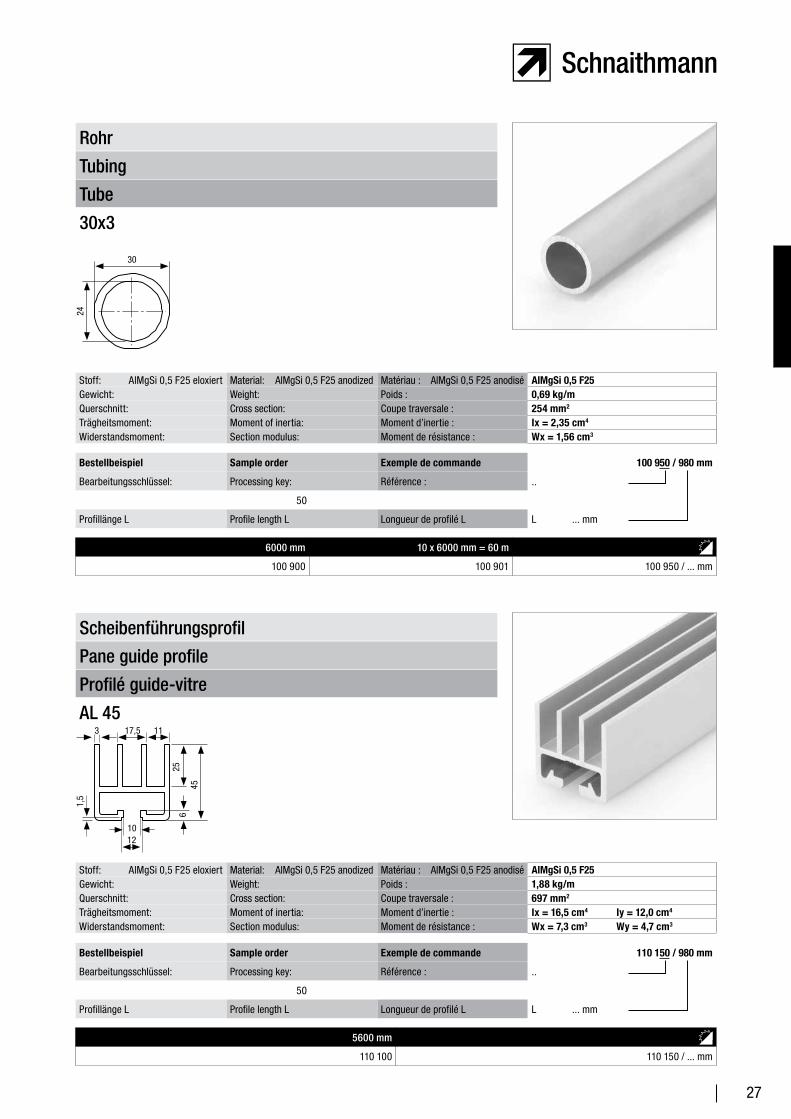
Tube
Tubing
Rohr
30x3
6000 mm 10 x 6000 mm = 60 m
100 900 100 901 100 950 / ... mm
Bestellbeispiel Sample order Exemple de commande 100 950 / 980 mm
Bearbeitungsschlüssel: Processing key: Référence : ..
50
Profillänge L Profile length L Longueur de profilé L L ... mm
Stoff: AlMgSi 0,5 F25 eloxiert Material: AlMgSi 0,5 F25 anodized Matériau : AlMgSi 0,5 F25 anodisé AlMgSi 0,5 F25Gewicht: Weight: Poids : 0,69 kg/mQuerschnitt: Cross section: Coupe traversale : 254 mm2
Trägheitsmoment: Moment of inertia: Moment d’inertie : Ix = 2,35 cm4
Widerstandsmoment: Section modulus: Moment de résistance : Wx = 1,56 cm3
Profilé guide-vitre
Pane guide profile
Scheibenführungsprofil
AL 45
5600 mm
110 100 110 150 / ... mm
Bestellbeispiel Sample order Exemple de commande 110 150 / 980 mm
Bearbeitungsschlüssel: Processing key: Référence : ..
50
Profillänge L Profile length L Longueur de profilé L L ... mm
Stoff: AlMgSi 0,5 F25 eloxiert Material: AlMgSi 0,5 F25 anodized Matériau : AlMgSi 0,5 F25 anodisé AlMgSi 0,5 F25Gewicht: Weight: Poids : 1,88 kg/mQuerschnitt: Cross section: Coupe traversale : 697 mm2
Trägheitsmoment: Moment of inertia: Moment d’inertie : Ix = 16,5 cm4 Iy = 12,0 cm4
Widerstandsmoment: Section modulus: Moment de résistance : Wx = 7,3 cm3 Wy = 4,7 cm3
30
24
3 1117,5
1,5
1012
645
25
28
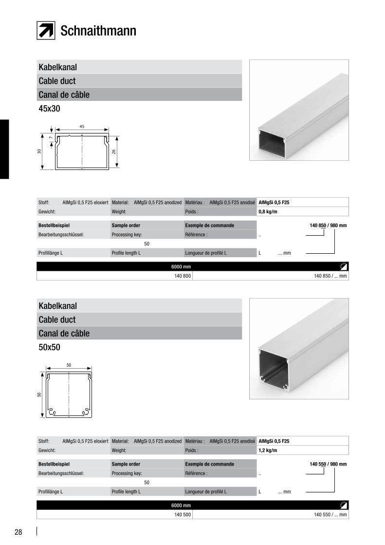
Canal de câble
Cable duct
Kabelkanal
45x30
6000 mm
140 800 140 850 / ... mm
Bestellbeispiel Sample order Exemple de commande 140 850 / 980 mm
Bearbeitungsschlüssel: Processing key: Référence : ..
50
Profillänge L Profile length L Longueur de profilé L L ... mm
Stoff: AlMgSi 0,5 F25 eloxiert Material: AlMgSi 0,5 F25 anodized Matériau : AlMgSi 0,5 F25 anodisé AlMgSi 0,5 F25
Gewicht: Weight: Poids : 0,8 kg/m
Canal de câble
Cable duct
Kabelkanal
50x50
6000 mm
140 500 140 550 / ... mm
Bestellbeispiel Sample order Exemple de commande 140 550 / 980 mm
Bearbeitungsschlüssel: Processing key: Référence : ..
50
Profillänge L Profile length L Longueur de profilé L L ... mm
Stoff: AlMgSi 0,5 F25 eloxiert Material: AlMgSi 0,5 F25 anodized Matériau : AlMgSi 0,5 F25 anodisé AlMgSi 0,5 F25
Gewicht: Weight: Poids : 1,2 kg/m
45
30 26
7
50
50
29
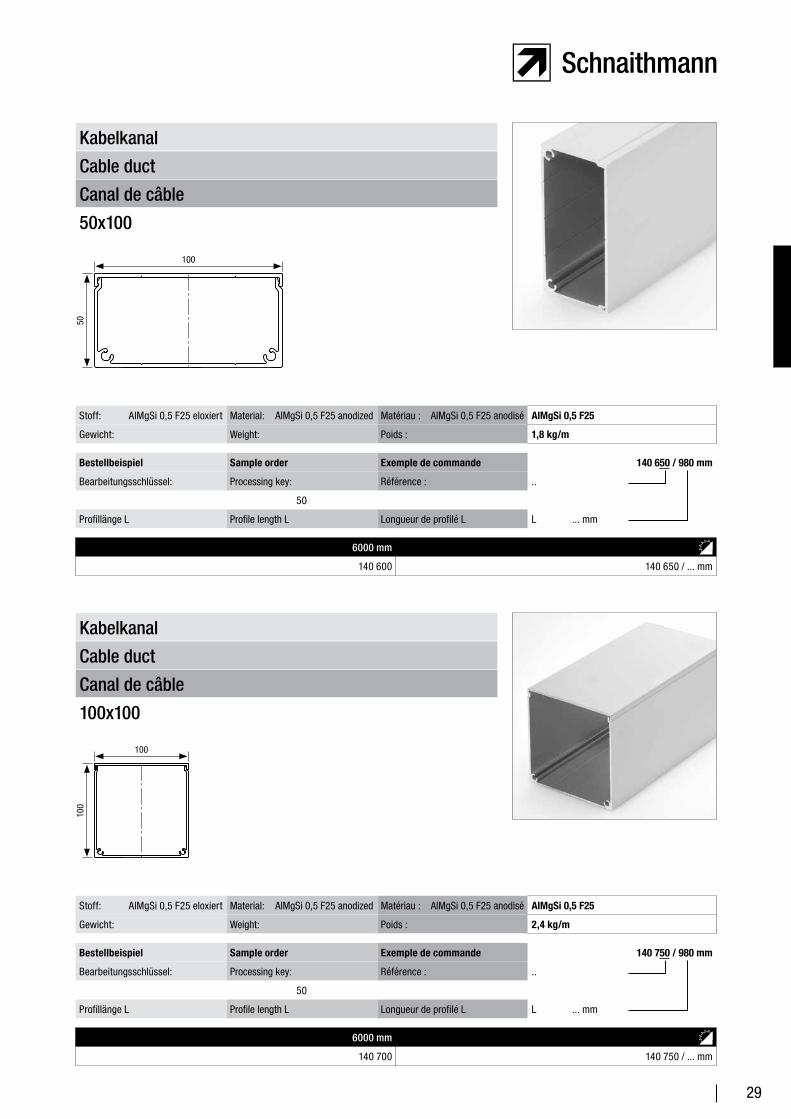
Canal de câble
Cable duct
Kabelkanal
50x100
6000 mm
140 600 140 650 / ... mm
Bestellbeispiel Sample order Exemple de commande 140 650 / 980 mm
Bearbeitungsschlüssel: Processing key: Référence : ..
50
Profillänge L Profile length L Longueur de profilé L L ... mm
Stoff: AlMgSi 0,5 F25 eloxiert Material: AlMgSi 0,5 F25 anodized Matériau : AlMgSi 0,5 F25 anodisé AlMgSi 0,5 F25
Gewicht: Weight: Poids : 1,8 kg/m
Canal de câble
Cable duct
Kabelkanal
100x100
6000 mm
140 700 140 750 / ... mm
Bestellbeispiel Sample order Exemple de commande 140 750 / 980 mm
Bearbeitungsschlüssel: Processing key: Référence : ..
50
Profillänge L Profile length L Longueur de profilé L L ... mm
Stoff: AlMgSi 0,5 F25 eloxiert Material: AlMgSi 0,5 F25 anodized Matériau : AlMgSi 0,5 F25 anodisé AlMgSi 0,5 F25
Gewicht: Weight: Poids : 2,4 kg/m
50
100
100
100
30
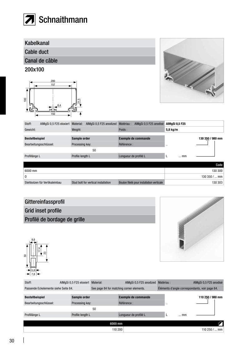
Canal de câble
Cable duct
Kabelkanal
200x100
Code
6000 mm 130 300
O 130 350 / ... mm
Stehbolzen für Vertikaleinbau Stud bolt for vertical installation Boulon fileté pour installation verticale 130 303
Bestellbeispiel Sample order Exemple de commande 130 350 / 980 mm
Bearbeitungsschlüssel: Processing key: Référence : ..
50
Profillänge L Profile length L Longueur de profilé L L ... mm
Stoff: AlMgSi 0,5 F25 eloxiert Material: AlMgSi 0,5 F25 anodized Matériau : AlMgSi 0,5 F25 anodisé AlMgSi 0,5 F25
Gewicht: Weight: Poids : 5,8 kg/m
Profilé de bordage de grille
Grid inset profile
Gittereinfassprofil
6000 mm
110 200 110 250 / ... mm
Bestellbeispiel Sample order Exemple de commande 110 250 / 980 mm
Bearbeitungsschlüssel: Processing key: Référence : ..
50
Profillänge L Profile length L Longueur de profilé L L ... mm
Stoff: AlMgSi 0,5 F25 eloxiert Material: AlMgSi 0,5 F25 anodized Matériau : AlMgSi 0,5 F25 anodisé
Passende Eckelemente siehe Seite 84. See page 84 for matching corner elements. Éléments d’angle correspondants, voir page 84.
100
200157
150
21,5
8,4
30
9,8
23
7,85,8
17,4
31
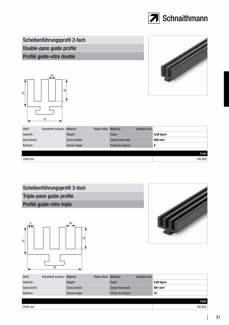
Profilé guide-vitre double
Double-pane guide profile
Scheibenführungsprofil 2-fach
Code
2000 mm 740 850
Stoff: Kunststoff schwarz Material: Plastic black Matériau : plastique noir
Gewicht: Weight: Poids : 0,58 kg/m
Querschnitt: Cross section: Coupe traversale : 608 mm2
Nutform: Groove shape: Forme de rainure : 8
Profilé guide-vitre triple
Triple-pane guide profile
Scheibenführungsprofil 3-fach
Code
2000 mm 740 855
Stoff: Kunststoff schwarz Material: Plastic black Matériau : plastique noir
Gewicht: Weight: Poids : 0,85 kg/m
Querschnitt: Cross section: Coupe traversale : 897 mm2
Nutform: Groove shape: Forme de rainure : 10
25
6,6
20
32
25
8,6
20
50
6
32
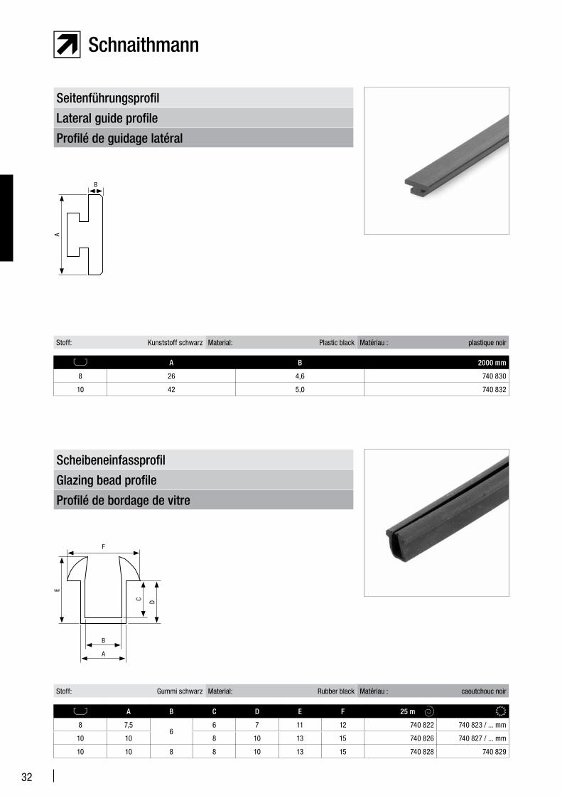
Profilé de bordage de vitre
Glazing bead profile
Scheibeneinfassprofil
A B C D E F 25 m
8 7,56
6 7 11 12 740 822 740 823 / ... mm
10 10 8 10 13 15 740 826 740 827 / ... mm
10 10 8 8 10 13 15 740 828 740 829
Profilé de guidage latéral
Lateral guide profile
Seitenführungsprofil
A B 2000 mm
8 26 4,6 740 830
10 42 5,0 740 832
Stoff: Kunststoff schwarz Material: Plastic black Matériau : plastique noir
Stoff: Gummi schwarz Material: Rubber black Matériau : caoutchouc noir
A
B
E
F
D
A
B
C
33
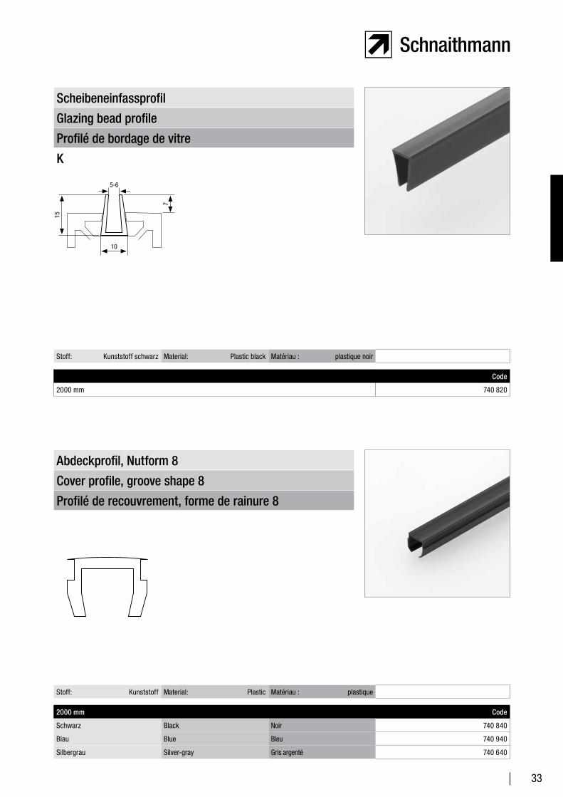
Profilé de bordage de vitre
Glazing bead profile
Scheibeneinfassprofil
K
Code
2000 mm 740 820
Stoff: Kunststoff schwarz Material: Plastic black Matériau : plastique noir
Profilé de recouvrement, forme de rainure 8
Cover profile, groove shape 8
Abdeckprofil, Nutform 8
2000 mm Code
Schwarz Black Noir 740 840
Blau Blue Bleu 740 940
Silbergrau Silver-gray Gris argenté 740 640
Stoff: Kunststoff Material: Plastic Matériau : plastique
15
7
10
5-6
34
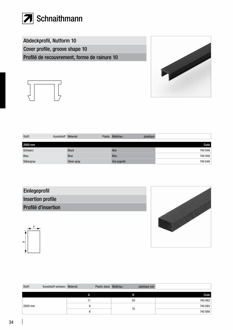
Profilé de recouvrement, forme de rainure 10
Cover profile, groove shape 10
Abdeckprofil, Nutform 10
2000 mm Code
Schwarz Black Noir 740 846
Blau Blue Bleu 740 946
Silbergrau Silver-gray Gris argenté 740 646
Stoff: Kunststoff Material: Plastic Matériau : plastique
Profilé d’insertion
Insertion profile
Einlegeprofil
A B Code
2000 mm
11 20 740 882
8 15
740 885
6 740 888
Stoff: Kunststoff schwarz Material: Plastic black Matériau : plastique noir
B
A
35
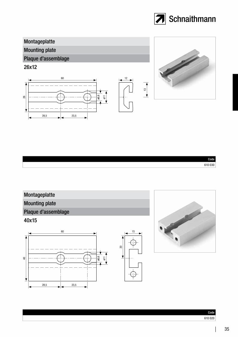
40
60
28,5
ø6,6
23,5
ø11
15
20
Plaque d’assemblage
Mounting plate
Montageplatte
26x12
Code
610 030
Plaque d’assemblage
Mounting plate
Montageplatte
40x15
Code
610 020
26
60
28,5
13
23,5
12
ø6,6
ø11

36
37
Verbindungselemente Connection Elements Éléments de raccord
Verbindungselemente – Produktbeschreibung
Connection elements – product description
Éléments de raccord – Description du produit
40
Verbindersätze – Produktbeschreibung
Connector sets – product description
Jeux d’assemblage – Description du produit
42
Verbindersatz – Nutform 10
Connector set – groove shape 10
Jeu d’assemblage – forme de rainure 10
44
Verbindersatz – Nutform 8
Connector set – groove shape 8
Jeu d’assemblage – forme de rainure 8
46
Längsverbinder – Nutform 8, 10
Longitudinal connector – groove shape 8, 10
Assemblage longitudinal – forme de rainure 8, 10
48
Montagebügel Mounting strap Traverse de montage 48
Montagewinkel Mounting bracket Équerre de montage 49
Konsolwinkel 40x300 Junction element 40x300 Équerre pour console 40x300 49
Knotenelement 30x43 Junction element 30x43 Élément de jonction 30x43 50
Knotenelement 30x100 Junction element 30x100 Élément de jonction 30x100 50
Knotenelement 42x45 Junction element 42x45 Élément de jonction 42x45 51
Knotenelement 42x100 Junction element 42x100 Élément de jonction 42x100 51
Knotenelement F42x100 Junction element F42x100 Élément de jonction F42x100 52
Knotenelement G42x88 Junction element G42x88 Élément de jonction G42x88 52
Knotenelement G Junction element G Élément de jonction G 53
Haltewinkel Angle bracket Équerre de maintien 53
Gewindeplatte Threaded nut Plaque de filetage 54
Hammerschraube Hammer head bolt Vis à tête rectangulaire 54
Federnutmutter Spring groove nut Écrou à encoches et à ressort 55
Hammermutter Hammer head nut Écrou type marteau 55
Rhombusstein – Nutform 10
Rhombus block – groove shape 10
Pierre en losange – forme de rainure 10
56
Profilmutter PM Profile nut PM Écrou de profilé PM 56
38
Verbindungselemente Connection Elements Éléments de raccord
Nutenstein Slot nut Coulisseau 57
Nutenstein mit Befestigungsgewinde
Slot nut with fastening thread
Coulisseau avec filet de fixation
57
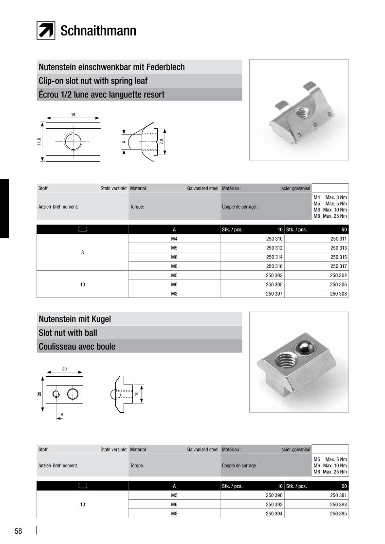
Nutenstein einschwenkbar mit Federblech
Clip-on slot nut with spring leafÉcrou 1/2 lune avec languette resort
58
Nutenstein mit Kugel Slot nut with ball Coulisseau avec boule 58
Verdrehsicherung Anti-twist lock Dispositif anti-torsion 59
Winkelverbinder innen/innen Angle connector (inside/inside)Raccord coudé intérieur/intérieur
59
Winkelverbinder innen/außen Angle connector (inside/outside)Raccord coudé intérieur/extérieur
60
Vario Winkelverbinder Vario angle connector Raccord coudé Vario 60
Profilverbinder zu Profil 50x50 Profile connector for profile 50x50 Raccord pour profilé 50x50 61
Eckverbinder 90° Corner connector 90° Raccord en coin 90° 61
Eckverbinder 45° Corner connector 45° Raccord en coin 45° 62
Halteplatte Retention plate Platine 62
Verbindungslasche Connector plate Éclisse 63
Scharnier Hinge Charnière 64
Rasterscharnier Grid hinge Charnière d’arrêt 64
Deckelscharnier Cover hinge Charnière de couvercle 65
Stufenwinkel Graduated angle bracket Équerre palier 65
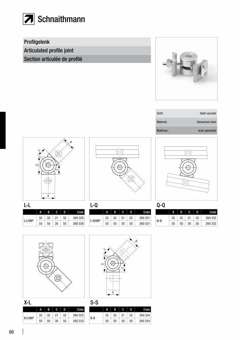
Profilgelenk Articulated profile joint Section articulée de profilé 66
Profilgelenk Nutform 10 mit Wechselplatte
Articulated profile joint, groove shape 10 with adapter plate
Section articulée de profilé, forme de rainure 10 avec plaque interchangeable
67
Kugelgelenk Ball joint Section articulée sphérique 67
39
40
Verbindungselemente – Produktbeschreibung
Connection Elements – Product Description
Éléments de raccord – Description du produit
Our connection elements offer the user a wide range of connection options. The connection elements and accessories illustrated below can be used to realize virtually any desired type of connection. When developing our connection elements, we placed special emphasis on flexibility and needs-based solutions.
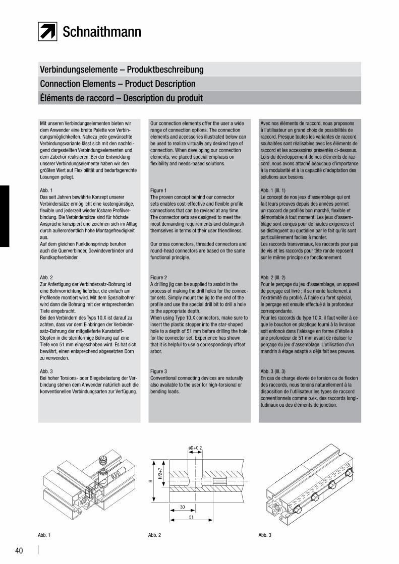
Figure 1The proven concept behind our connector sets enables cost-effective and flexible profile connections that can be revised at any time. The connector sets are designed to meet the most demanding requirements and distinguish themselves in terms of their user friendliness.
Our cross connectors, threaded connectors and round-head connectors are based on the same functional principle.
Figure 2A drilling jig can be supplied to assist in the process of making the drill holes for the connec-tor sets. Simply mount the jig to the end of the profile and use the special drill bit to drill a hole to the appropriate depth.When using Type 10.X connectors, make sure to insert the plastic stopper into the star-shaped hole to a depth of 51 mm before drilling the hole for the connector set. Experience has shown that it is helpful to use a correspondingly offset arbor.
Figure 3Conventional connecting devices are naturally also available to the user for high-torsional or bending loads.
Avec nos éléments de raccord, nous proposons à l’utilisateur un grand choix de possibilités de raccord. Presque toutes les variantes de raccord souhaitées sont réalisables avec les éléments de raccord et les accessoires présentés ci-dessous. Lors du développement de nos éléments de rac-cord, nous avons attaché beaucoup d’importance à la modularité et à la capacité d’adaptation des solutions aux besoins.
Abb. 1 (Ill. 1)Le concept de nos jeux d’assemblage qui ont fait leurs preuves depuis des années permet un raccord de profilés bon marché, flexible et démontable à tout moment. Les jeux d’assem-blage sont conçus pour de hautes exigences et se distinguent au quotidien par le fait qu’ils sont particulièrement faciles à monter.Les raccords transversaux, les raccords pour pas de vis et les raccords pour tête ronde reposent sur le même principe de fonctionnement.
Abb. 2 (Ill. 2)Pour le perçage du jeu d’assemblage, un appareil de perçage est livré ; il se monte facilement à l’extrémité du profilé. À l’aide du foret spécial, le perçage est ensuite effectué à la profondeur correspondante.Pour les raccords du type 10.X, il faut veiller à ce que le bouchon en plastique fourni à la livraison soit enfoncé dans l’alésage en forme d’étoile à une profondeur de 51 mm avant de réaliser le perçage du jeu d’assemblage. L’utilisation d’un mandrin à étage adapté a déjà fait ses preuves.
Abb. 3 (Ill. 3)En cas de charge élevée de torsion ou de flexion des raccords, nous tenons naturellement à la disposition de l’utilisateur les types de raccord conventionnels comme p.ex. des raccords longi-tudinaux ou des éléments de jonction.
Mit unseren Verbindungselementen bieten wir dem Anwender eine breite Palette von Verbin-dungsmöglichkeiten. Nahezu jede gewünschte Verbindungsvariante lässt sich mit den nachfol-gend dargestellten Verbindungselementen und dem Zubehör realisieren. Bei der Entwicklung unserer Verbindungselemente haben wir den größten Wert auf Flexibilität und bedarfsgerechte Lösungen gelegt.
Abb. 1Das seit Jahren bewährte Konzept unserer Verbindersätze ermöglicht eine kostengünstige, flexible und jederzeit wieder lösbare Profilver-bindung. Die Verbindersätze sind für höchste Ansprüche konzipiert und zeichnen sich im Alltag durch außerordentlich hohe Montagefreudigkeit aus. Auf dem gleichen Funktionsprinzip beruhen auch die Querverbinder, Gewindeverbinder und Rundkopfverbinder.
Abb. 2Zur Anfertigung der Verbindersatz-Bohrung ist eine Bohrvorrichtung lieferbar, die einfach am Profilende montiert wird. Mit dem Spezialbohrer wird dann die Bohrung mit der entsprechenden Tiefe eingebracht.Bei den Verbindern des Typs 10.X ist darauf zu achten, dass vor dem Einbringen der Verbinder-satz-Bohrung der mitgelieferte Kunststoff-Stopfen in die sternförmige Bohrung auf eine Tiefe von 51 mm eingeschoben wird. Es hat sich bewährt, einen entsprechend abgesetzten Dorn zu verwenden.
Abb. 3Bei hoher Torsions- oder Biegebelastung der Ver-bindung stehen dem Anwender natürlich auch die konventionellen Verbindungsarten zur Verfügung.
Abb. 1 Abb. 2 Abb. 3
øD+0,2
51
30
H
H/2+
7
41
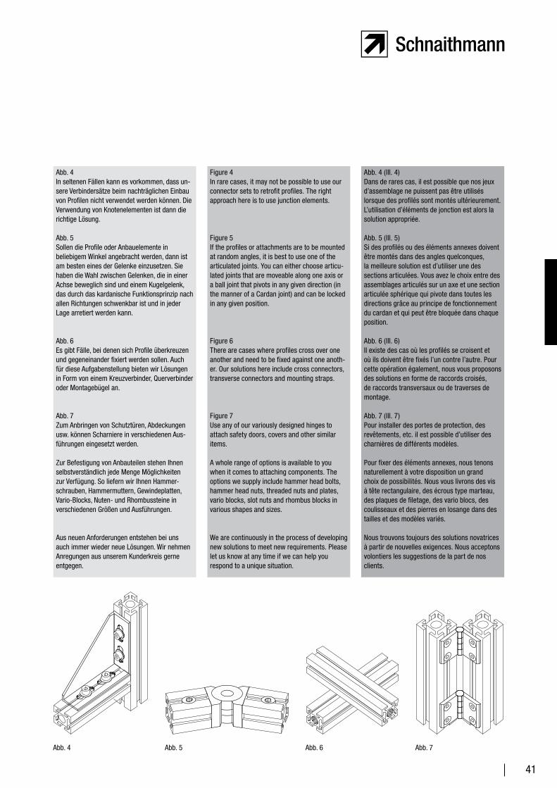
Figure 4In rare cases, it may not be possible to use our connector sets to retrofit profiles. The right approach here is to use junction elements.
Figure 5If the profiles or attachments are to be mounted at random angles, it is best to use one of the articulated joints. You can either choose articu-lated joints that are moveable along one axis or a ball joint that pivots in any given direction (in the manner of a Cardan joint) and can be locked in any given position.
Figure 6There are cases where profiles cross over one another and need to be fixed against one anoth-er. Our solutions here include cross connectors, transverse connectors and mounting straps.
Figure 7Use any of our variously designed hinges to attach safety doors, covers and other similar items.
A whole range of options is available to you when it comes to attaching components. The options we supply include hammer head bolts, hammer head nuts, threaded nuts and plates, vario blocks, slot nuts and rhombus blocks in various shapes and sizes.
We are continuously in the process of developing new solutions to meet new requirements. Please let us know at any time if we can help you respond to a unique situation.
Abb. 4 (Ill. 4)Dans de rares cas, il est possible que nos jeux d’assemblage ne puissent pas être utilisés lorsque des profilés sont montés ultérieurement. L’utilisation d’éléments de jonction est alors la solution appropriée.
Abb. 5 (Ill. 5)Si des profilés ou des éléments annexes doivent être montés dans des angles quelconques, la meilleure solution est d’utiliser une des sections articulées. Vous avez le choix entre des assemblages articulés sur un axe et une section articulée sphérique qui pivote dans toutes les directions grâce au principe de fonctionnement du cardan et qui peut être bloquée dans chaque position.
Abb. 6 (Ill. 6)Il existe des cas où les profilés se croisent et où ils doivent être fixés l’un contre l’autre. Pour cette opération également, nous vous proposons des solutions en forme de raccords croisés, de raccords transversaux ou de traverses de montage.
Abb. 7 (Ill. 7)Pour installer des portes de protection, des revêtements, etc. il est possible d’utiliser des charnières de différents modèles.
Pour fixer des éléments annexes, nous tenons naturellement à votre disposition un grand choix de possibilités. Nous vous livrons des vis à tête rectangulaire, des écrous type marteau, des plaques de filetage, des vario blocs, des coulisseaux et des pierres en losange dans des tailles et des modèles variés.
Nous trouvons toujours des solutions novatrices à partir de nouvelles exigences. Nous acceptons volontiers les suggestions de la part de nos clients.
Abb. 4In seltenen Fällen kann es vorkommen, dass un-sere Verbindersätze beim nachträglichen Einbau von Profilen nicht verwendet werden können. Die Verwendung von Knotenelementen ist dann die richtige Lösung.
Abb. 5Sollen die Profile oder Anbauelemente in beliebigem Winkel angebracht werden, dann ist am besten eines der Gelenke einzusetzen. Sie haben die Wahl zwischen Gelenken, die in einer Achse beweglich sind und einem Kugelgelenk, das durch das kardanische Funktionsprinzip nach allen Richtungen schwenkbar ist und in jeder Lage arretiert werden kann.
Abb. 6Es gibt Fälle, bei denen sich Profile überkreuzen und gegeneinander fixiert werden sollen. Auch für diese Aufgabenstellung bieten wir Lösungen in Form von einem Kreuzverbinder, Querverbinder oder Montagebügel an.
Abb. 7Zum Anbringen von Schutztüren, Abdeckungen usw. können Scharniere in verschiedenen Aus-führungen eingesetzt werden.
Zur Befestigung von Anbauteilen stehen Ihnen selbstverständlich jede Menge Möglichkeiten zur Verfügung. So liefern wir Ihnen Hammer-schrauben, Hammermuttern, Gewindeplatten, Vario-Blocks, Nuten- und Rhombussteine in verschiedenen Größen und Ausführungen.
Aus neuen Anforderungen entstehen bei uns auch immer wieder neue Lösungen. Wir nehmen Anregungen aus unserem Kunderkreis gerne entgegen.
Abb. 4 Abb. 5 Abb. 6 Abb. 7
42
Verbindersätze – Produktbeschreibung
Connector sets – Product description
Jeux d’assemblage – Description du produit
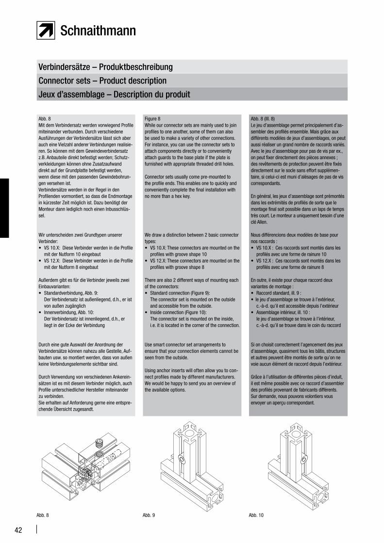
Figure 8While our connector sets are mainly used to join profiles to one another, some of them can also be used to make a variety of other connections. For instance, you can use the connector sets to attach components directly or to conveniently attach guards to the base plate if the plate is furnished with appropriate threaded drill holes.
Connector sets usually come pre-mounted to the profile ends. This enables one to quickly and conveniently complete the final installation with no more than a hex key.
We draw a distinction between 2 basic connector types:• VS 10.X: These connectors are mounted on the
profiles with groove shape 10• VS 12.X: These connectors are mounted on the
profiles with groove shape 8
There are also 2 different ways of mounting each of the connectors:• Standard connection (Figure 9):
The connector set is mounted on the outside and accessible from the outside.
• Inside connection (Figure 10): The connector set is mounted on the inside, i.e. it is located in the corner of the connection.
Use smart connector set arrangements to ensure that your connection elements cannot be seen from the outside.
Using anchor inserts will often allow you to con-nect profiles made by different manufacturers. We would be happy to send you an overview of the available options.
Abb. 8 (Ill. 8)Le jeu d’assemblage permet principalement d’as-sembler des profilés ensemble. Mais grâce aux différents modèles de jeux d’assemblages, on peut aussi réaliser un grand nombre de raccords variés. Avec le jeu d’assemblage pour pas de vis par ex., on peut fixer directement des pièces annexes ; des revêtements de protection peuvent être fixés directement sur le socle sans effort supplémen-taire, si celui-ci est muni d’alésages de pas de vis correspondants.
En général, les jeux d’assemblage sont prémontés dans les extrémités de profilés de sorte que le montage final soit possible dans un laps de temps très court. Le monteur a uniquement besoin d’une clé Allen.
Nous différencions deux modèles de base pour nos raccords :• VS 10.X : Ces raccords sont montés dans les
profilés avec une forme de rainure 10• VS 12.X : Ces raccords sont montés dans les
profilés avec une forme de rainure 8
En outre, il existe pour chaque raccord deux variantes de montage :• Raccord standard, ill. 9 : • le jeu d’assemblage se trouve à l’extérieur,
c.-à-d. qu’il est accessible depuis l’extérieur• Assemblage intérieur, ill. 10 :
le jeu d’assemblage se trouve à l’intérieur, c.-à-d. qu’il se trouve dans le coin du raccord
Si on choisit correctement l’agencement des jeux d’assemblage, quasiment tous les bâtis, structures et autres peuvent être montés de sorte qu’on ne voie aucun élément de raccord depuis l’extérieur.
Grâce à l’utilisation de différentes pièces d’induit, il est même possible avec ce raccord d’assembler des profilés provenant de fabricants différents.Sur demande, nous pouvons volontiers vous envoyer un aperçu correspondant.
Abb. 8Mit dem Verbindersatz werden vorwiegend Profile miteinander verbunden. Durch verschiedene Ausführungen der Verbindersätze lässt sich aber auch eine Vielzahl anderer Verbindungen realisie-ren. So können mit dem Gewindeverbindersatz z.B. Anbauteile direkt befestigt werden; Schutz-verkleidungen können ohne Zusatzaufwand direkt auf der Grundplatte befestigt werden, wenn diese mit den passenden Gewindebohrun-gen versehen ist.Verbindersätze werden in der Regel in den Profilenden vormontiert, so dass die Endmontage in kürzester Zeit möglich ist. Dazu benötigt der Monteur dann lediglich noch einen Inbusschlüs-sel.
Wir unterscheiden zwei Grundtypen unserer Verbinder:• VS 10.X: Diese Verbinder werden in die Profile
mit der Nutform 10 eingebaut• VS 12.X: Diese Verbinder werden in die Profile
mit der Nutform 8 eingebaut
Außerdem gibt es für die Verbinder jeweils zwei Einbauvarianten:• Standardverbindung, Abb. 9:
Der Verbindersatz ist außenliegend, d.h., er ist von außen zugänglich
• Innenverbindung, Abb. 10: Der Verbindersatz ist innenliegend, d.h., er liegt in der Ecke der Verbindung
Durch eine gute Auswahl der Anordnung der Verbindersätze können nahezu alle Gestelle, Auf-bauten usw. so montiert werden, dass von außen keine Verbindungselemente sichtbar sind.
Durch Verwendung von verschiedenen Ankerein-sätzen ist es mit diesem Verbinder möglich, auch Profile unterschiedlicher Hersteller miteinander zu verbinden. Sie erhalten auf Anforderung gerne eine entspre-chende Übersicht zugesandt.
Abb. 8 Abb. 9 Abb. 10
43
In addition to their mechanical dimensions, the two basic connector types, VS 10.X and VS 12.X differ only in terms of the position of their recoil springs that press the connector set anchor outwards.
In the case of type VS 10.X, this spring is positioned between the end of the anchor and a plastic plug that has to be inserted into the profile in advance.
In the case of type VS 12.X, the spring is positioned between the transverse bushing and the shoulder on the connector set’s anchor. This makes the plastic stopper unnecessary.
Mounting instructions:For type VS 10.X only: before drilling the hole for the connector set, make sure to insert the plastic stopper to a depth of 51 mm. In case of frequent use, we recommend the use of an appropriately sized offset arbor.
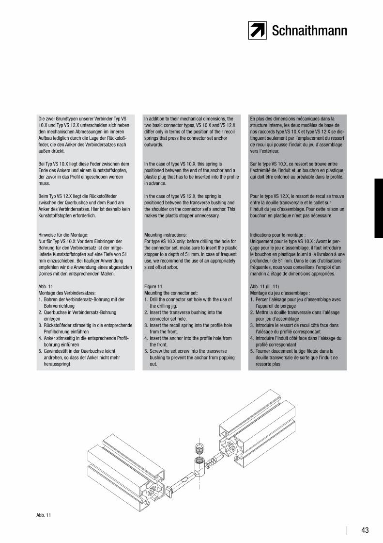
Figure 11Mounting the connector set: 1. Drill the connector set hole with the use of
the drilling jig.2. Insert the transverse bushing into the
connector set hole.3. Insert the recoil spring into the profile hole
from the front.4. Insert the anchor into the profile hole from
the front. 5. Screw the set screw into the transverse
bushing to prevent the anchor from popping out.
En plus des dimensions mécaniques dans la structure interne, les deux modèles de base de nos raccords type VS 10.X et type VS 12.X se dis-tinguent seulement par l’emplacement du ressort de recul qui pousse l’induit du jeu d’assemblage vers l’extérieur.
Sur le type VS 10.X, ce ressort se trouve entre l’extrémité de l’induit et un bouchon en plastique qui doit être enfoncé au préalable dans le profilé.
Pour le type VS 12.X, le ressort de recul se trouve entre la douille transversale et le collet sur l’induit du jeu d’assemblage. Pour cette raison un bouchon en plastique n’est pas nécessaire.
Indications pour le montage :Uniquement pour le type VS 10.X : Avant le per-çage pour le jeu d’assemblage, il faut introduire le bouchon en plastique fourni à la livraison à une profondeur de 51 mm. Dans le cas d’utilisations fréquentes, nous vous conseillons l’emploi d’un mandrin à étage de dimensions appropriées.
Abb. 11 (Ill. 11)Montage du jeu d’assemblage :1. Percer l’alésage pour jeu d’assemblage avec
l’appareil de perçage2. Mettre la douille transversale dans l’alésage
pour jeu d’assemblage3. Introduire le ressort de recul côté face dans
l’alésage du profilé correspondant4. Introduire l’induit côté face dans l’alésage du
profilé correspondant5. Tourner doucement la tige filetée dans la
douille transversale de sorte que l’induit ne ressorte plus
Die zwei Grundtypen unserer Verbinder Typ VS 10.X und Typ VS 12.X unterscheiden sich neben den mechanischen Abmessungen im inneren Aufbau lediglich durch die Lage der Rückstoß-feder, die den Anker des Verbindersatzes nach außen drückt.
Bei Typ VS 10.X liegt diese Feder zwischen dem Ende des Ankers und einem Kunststoffstopfen, der zuvor in das Profil eingeschoben werden muss.
Beim Typ VS 12.X liegt die Rückstoßfeder zwischen der Querbuchse und dem Bund am Anker des Verbindersatzes. Hier ist deshalb kein Kunststoffstopfen erforderlich.
Hinweise für die Montage:Nur für Typ VS 10.X: Vor dem Einbringen der Bohrung für den Verbindersatz ist der mitge-lieferte Kunststoffstopfen auf eine Tiefe von 51 mm einzuschieben. Bei häufiger Anwendung empfehlen wir die Anwendung eines abgesetzten Dornes mit den entsprechenden Maßen.
Abb. 11Montage des Verbindersatzes: 1. Bohren der Verbindersatz-Bohrung mit der
Bohrvorrichtung2. Querbuchse in Verbindersatz-Bohrung
einlegen3. Rückstoßfeder stirnseitig in die entsprechende
Profilbohrung einführen4. Anker stirnseitig in die entsprechende Profil-
bohrung einführen 5. Gewindestift in der Querbuchse leicht
andrehen, so dass der Anker nicht mehr herausspringt
Abb. 11
44
Jeu d’assemblage – forme de rainure 10
Connector set – groove shape 10
Verbindersatz – Nutform 10
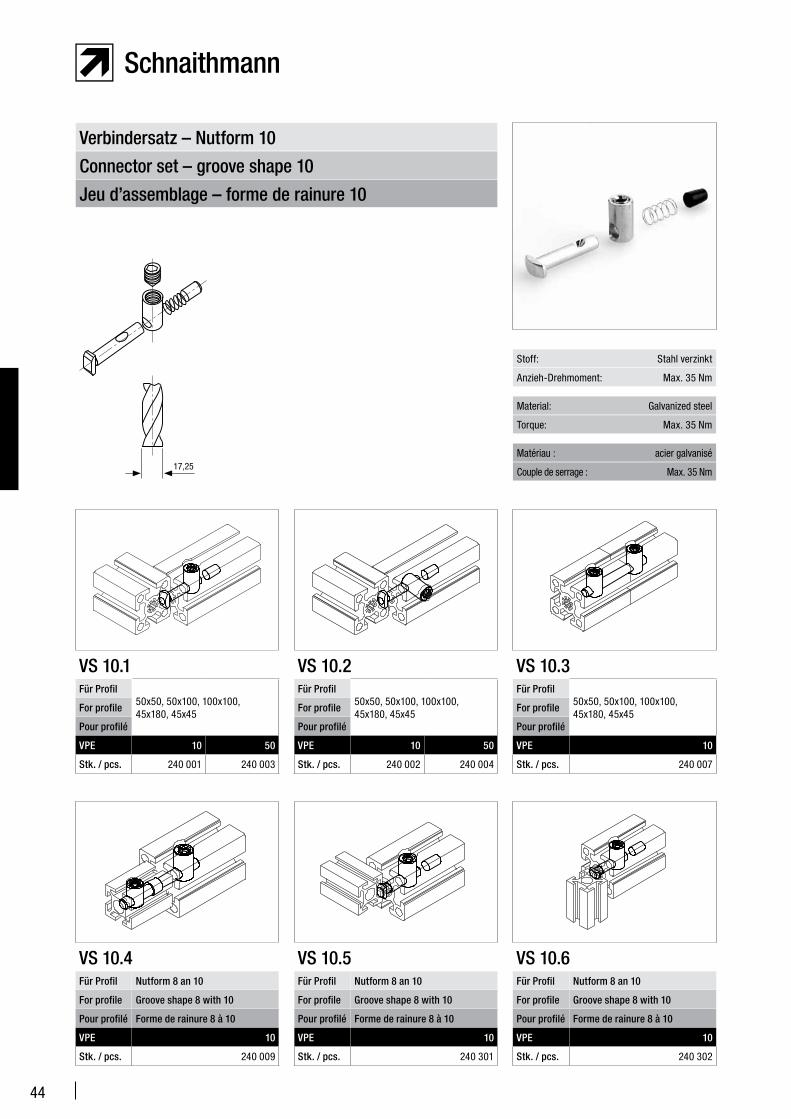
VS 10.1Für Profil
50x50, 50x100, 100x100, 45x180, 45x45
For profile
Pour profilé
VPE 10 50
Stk. / pcs. 240 001 240 003
VS 10.2Für Profil
50x50, 50x100, 100x100, 45x180, 45x45
For profile
Pour profilé
VPE 10 50
Stk. / pcs. 240 002 240 004
VS 10.3Für Profil
50x50, 50x100, 100x100, 45x180, 45x45
For profile
Pour profilé
VPE 10
Stk. / pcs. 240 007
Stoff: Stahl verzinkt
Material: Galvanized steel
Matériau : acier galvanisé
Anzieh-Drehmoment: Max. 35 Nm
Torque: Max. 35 Nm
Couple de serrage : Max. 35 Nm
VS 10.4Für Profil Nutform 8 an 10
For profile Groove shape 8 with 10
Pour profilé Forme de rainure 8 à 10
VPE 10
Stk. / pcs. 240 009
VS 10.5Für Profil Nutform 8 an 10
For profile Groove shape 8 with 10
Pour profilé Forme de rainure 8 à 10
VPE 10
Stk. / pcs. 240 301
VS 10.6Für Profil Nutform 8 an 10
For profile Groove shape 8 with 10
Pour profilé Forme de rainure 8 à 10
VPE 10
Stk. / pcs. 240 302
17,25
45
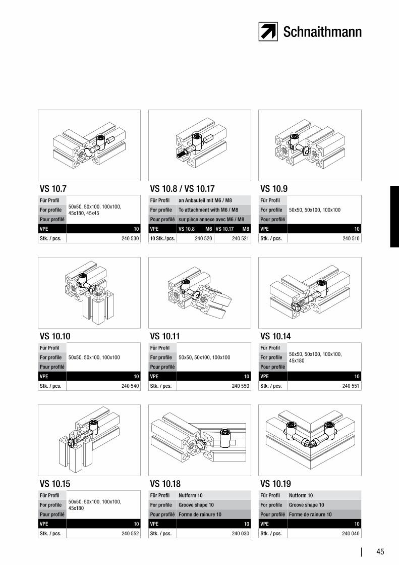
VS 10.7Für Profil
50x50, 50x100, 100x100, 45x180, 45x45
For profile
Pour profilé
VPE 10
Stk. / pcs. 240 530
VS 10.8 / VS 10.17Für Profil an Anbauteil mit M6 / M8
For profile To attachment with M6 / M8
Pour profilé sur pièce annexe avec M6 / M8
VPE VS 10.8 M6 VS 10.17 M8
10 Stk. / pcs. 240 520 240 521
VS 10.9Für Profil
50x50, 50x100, 100x100For profile
Pour profilé
VPE 10
Stk. / pcs. 240 510
VS 10.18Für Profil Nutform 10
For profile Groove shape 10
Pour profilé Forme de rainure 10
VPE 10
Stk. / pcs. 240 030
VS 10.19Für Profil Nutform 10
For profile Groove shape 10
Pour profilé Forme de rainure 10
VPE 10
Stk. / pcs. 240 040
VS 10.10Für Profil
50x50, 50x100, 100x100For profile
Pour profilé
VPE 10
Stk. / pcs. 240 540
VS 10.11Für Profil
50x50, 50x100, 100x100For profile
Pour profilé
VPE 10
Stk. / pcs. 240 550
VS 10.14Für Profil
50x50, 50x100, 100x100, 45x180
For profile
Pour profilé
VPE 10
Stk. / pcs. 240 551
VS 10.15Für Profil
50x50, 50x100, 100x100, 45x180
For profile
Pour profilé
VPE 10
Stk. / pcs. 240 552
46
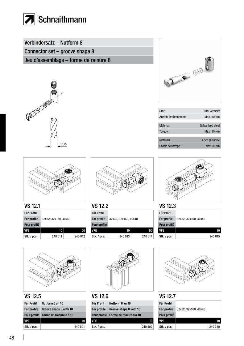
Jeu d’assemblage – forme de rainure 8
Connector set – groove shape 8
Verbindersatz – Nutform 8
VS 12.1Für Profil
32x32, 32x160, 40x40For profile
Pour profilé
VPE 10 50
Stk. / pcs. 240 011 240 012
VS 12.2Für Profil
32x32, 32x160, 40x40For profile
Pour profilé
VPE 10 50
Stk. / pcs. 240 013 240 014
Stoff: Stahl verzinkt
Material: Galvanized steel
Matériau : acier galvanisé
Anzieh-Drehmoment: Max. 30 Nm
Torque: Max. 30 Nm
Couple de serrage : Max. 30 Nm
VS 12.5Für Profil Nutform 8 an 10
For profile Groove shape 8 with 10
Pour profilé Forme de rainure 8 à 10
VPE 10
Stk. / pcs. 240 501
VS 12.6Für Profil Nutform 8 an 10
For profile Groove shape 8 with 10
Pour profilé Forme de rainure 8 à 10
VPE 10
Stk. / pcs. 240 502
VS 12.3Für Profil
32x32, 32x160, 40x40For profile
Pour profilé
VPE 10
Stk. / pcs. 240 015
VS 12.7Für Profil
32x32, 32x160, 40x40For profile
Pour profilé
VPE 10
Stk. / pcs. 240 330
15,25

47
VS 12.9Für Profil
32x32, 32x160For profile
Pour profilé
VPE 10
Stk. / pcs. 240 310
VS 12.8 / VS 12.17Für Profil an Anbauteil mit M6 / M8
For profile To attachment with M6 / M8
Pour profilé sur pièce annexe avec M6 / M8
VPE VS 12.8 M6 VS 12.17 M8
10 Stk. / pcs. 240 320 240 321
VS 12.10Für Profil
32x32For profile
Pour profilé
VPE 10
Stk. / pcs. 240 340
VS 12.19Für Profil Nutform 8
For profile Groove shape 8
Pour profilé Forme de rainure 8
VPE 10
Stk. / pcs. 240 060
VS 12.18Für Profil Nutform 8
For profile Groove shape 8
Pour profilé Forme de rainure 8
VPE 10
Stk. / pcs. 240 050
VS 12.11Für Profil
32x32For profile
Pour profilé
VPE 10
Stk. / pcs. 240 350
VS 12.12Für Profil
32x32, 32x160, 40x40For profile
Pour profilé
VPE 10
Stk. / pcs. 240 360
VS 12.13Für Profil
25x50For profile
Pour profilé
VPE 10
Stk. / pcs. 240 370
VS 12.20Für Profil
32x50, 32x68For profile
Pour profilé
VPE 10
Stk. / pcs. 240 380
48
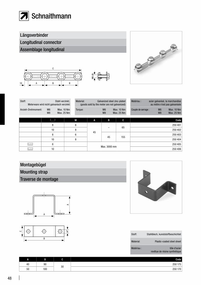
Assemblage longitudinal
Longitudinal connector
Längsverbinder
M A B C Code
8 6
45
– 65250 401
10 8 250 402
8 645 155
250 403
10 8 250 404
8Max. 3000 mm
250 405
10 250 406
Traverse de montage
Mounting strap
Montagebügel
Stoff: Stahl verzinkt, Meterware wird nicht galvanisch verzinkt
Material: Galvanized steel zinc-plated (goods sold by the meter are not galvanized)
Matériau : acier galvanisé, la marchandise au mètre n’est pas galvanisée
Anzieh-Drehmoment: M6 Max. 10 Nm M8 Max. 25 Nm
Torque: M6 Max. 10 Nm M8 Max. 25 Nm
Couple de serrage : M6 Max. 10 Nm M8 Max. 25 Nm
A B C Code
40 9030
250 175
50 100 250 170
Stoff: Stahlblech, kunststoffbeschichtet
Material: Plastic-coated steel sheet
Matériau : tôle d’acier revêtue de résine synthétique
C
M6
(8)
A10 B B
A
A
B
C ø7
49
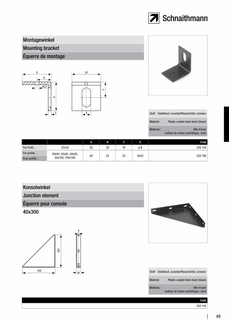
Équerre de montage
Mounting bracket
Montagewinkel
A B C D Code
Für Profil ... 32x32 30 20 16 ø 9 250 150
For profile ... 40x40, 45x45, 50x50, 50x100, 100x100
40 25 25 9x20 250 180Pour profilé ...
Stoff: Stahlblech, kunststoffbeschichtet, schwarz
Material: Plastic-coated steel sheet (black)
Matériau : tôle d’acier revêtue de résine synthétique, noire
Équerre pour console
Junction element
Konsolwinkel
40x300
Code
250 145
Stoff: Stahlblech, kunststoffbeschichtet, schwarz
Material: Plastic-coated steel sheet (black)
Matériau : tôle d’acier revêtue de résine synthétique, noire
A 30
B
C
A
3 9
ø4,5
300
300
40
9
50
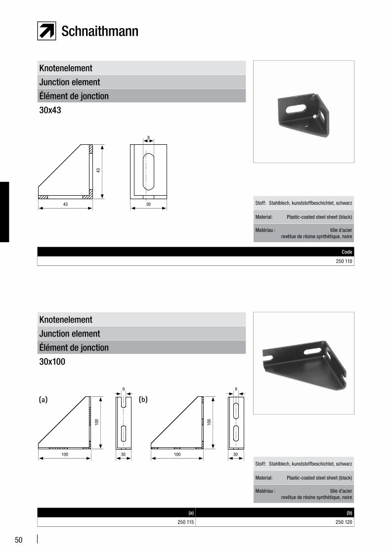
Élément de jonction
Junction element
Knotenelement
30x43
Code
250 110
Stoff: Stahlblech, kunststoffbeschichtet, schwarz
Material: Plastic-coated steel sheet (black)
Matériau : tôle d’acier revêtue de résine synthétique, noire
Élément de jonction
Junction element
Knotenelement
30x100
(a) (b)
250 115 250 120
Stoff: Stahlblech, kunststoffbeschichtet, schwarz
Material: Plastic-coated steel sheet (black)
Matériau : tôle d’acier revêtue de résine synthétique, noire
43
43 30
9
100
100
100
10030
9
30
9
51
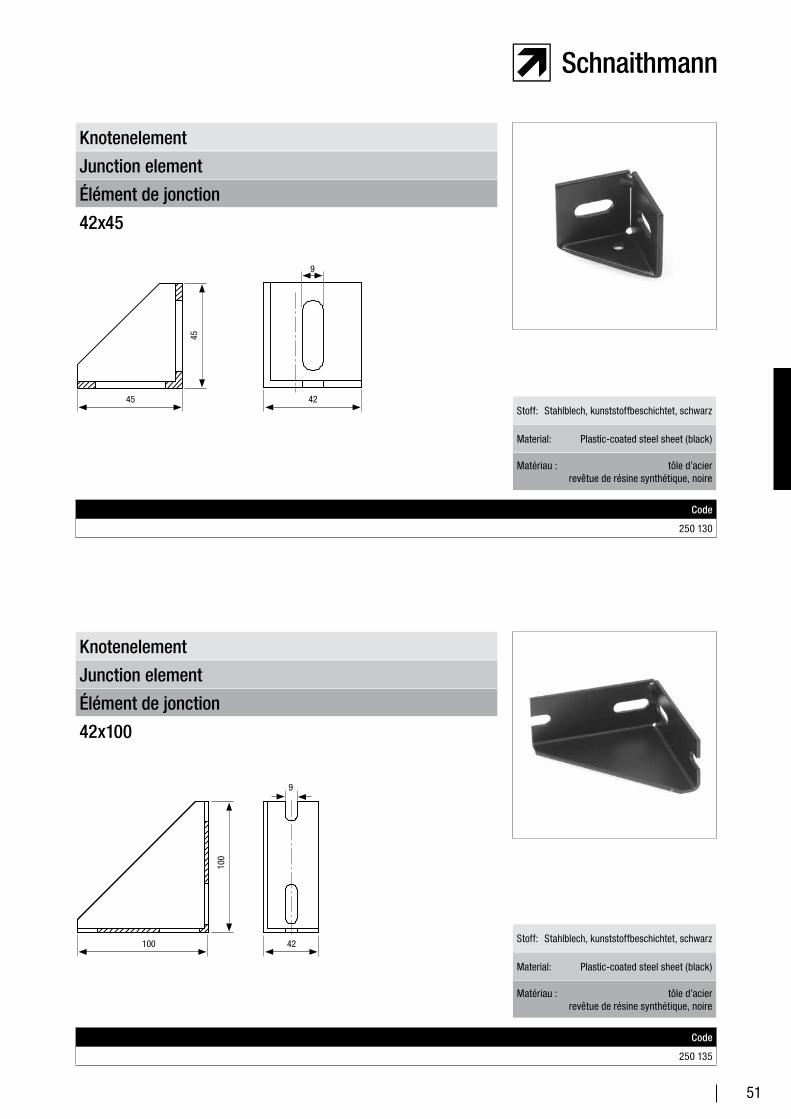
Élément de jonction
Junction element
Knotenelement
42x45
Code
250 130
Stoff: Stahlblech, kunststoffbeschichtet, schwarz
Material: Plastic-coated steel sheet (black)
Matériau : tôle d’acier revêtue de résine synthétique, noire
Élément de jonction
Junction element
Knotenelement
42x100
Code
250 135
Stoff: Stahlblech, kunststoffbeschichtet, schwarz
Material: Plastic-coated steel sheet (black)
Matériau : tôle d’acier revêtue de résine synthétique, noire
45
45 42
9
9
100
100 42
52
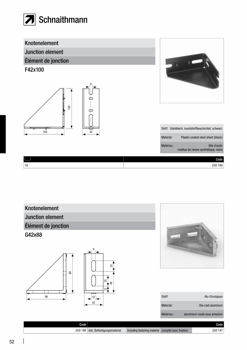
Élément de jonction
Junction element
Knotenelement
F42x100
Code
10 250 140
Stoff: Stahlblech, kunststoffbeschichtet, schwarz
Material: Plastic-coated steel sheet (black)
Matériau : tôle d’acier revêtue de résine synthétique, noire
9
100
100 42
Élément de jonction
Junction element
Knotenelement
G42x88
Code Code
250 146 inkl. Befestigungsmaterial Including fastening material complet avec fixation 250 147
Stoff: Alu-Druckguss
Material: Die-cast aluminum
Matériau : aluminium coulé sous pression
9
88
88
4825
2515
42
10
53
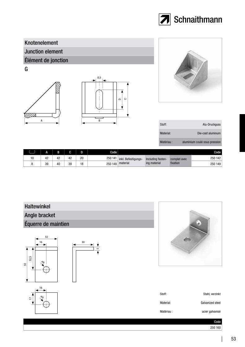
Élément de jonction
Junction element
Knotenelement
G
A B C D Code Code
10 42 42 42 20 250 141 inkl. Befestigungs-material
Including fasten-ing material
complet avec fixation
250 142
8 39 40 39 18 250 148 250 149
Stoff: Alu-Druckguss
Material: Die-cast aluminum
Matériau : aluminium coulé sous pression
8,5
A B
CD
Équerre de maintien
Angle bracket
Haltewinkel
Code
250 160
Stoff: Stahl, verzinkt
Material: Galvanized steel
Matériau : acier galvanisé
32
16 30
16
1732
,5
50
5
ø9
ø9
54
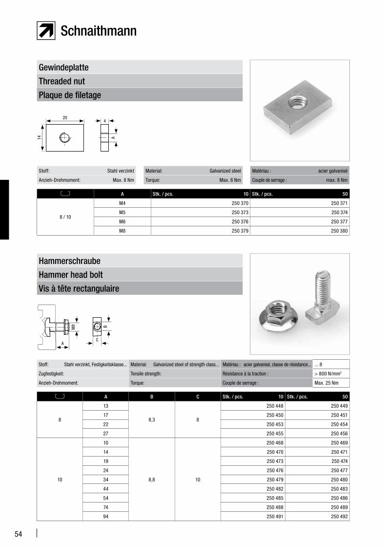
Plaque de filetage
Threaded nut
Gewindeplatte
A Stk. / pcs. 10 Stk. / pcs. 50
8 / 10
M4 250 370 250 371
M5 250 373 250 374
M6 250 376 250 377
M8 250 379 250 380
Stoff: Stahl verzinkt
Anzieh-Drehmoment: Max. 8 Nm
Matériau : acier galvanisé
Couple de serrage : max. 8 Nm
Material: Galvanized steel
Torque: Max. 8 Nm
Vis à tête rectangulaire
Hammer head bolt
Hammerschraube
A B C Stk. / pcs. 10 Stk. / pcs. 50
8
13
8,3 8
250 448 250 449
17 250 450 250 451
22 250 453 250 454
27 250 455 250 456
10
10
8,8 10
250 468 250 469
14 250 470 250 471
19 250 473 250 474
24 250 476 250 477
34 250 479 250 480
44 250 482 250 483
54 250 485 250 486
74 250 488 250 489
94 250 491 250 492
Stoff: Stahl verzinkt, Festigkeitsklasse... Material: Galvanized steel of strength class... Matériau : acier galvanisé, classe de résistance... ... 8
Zugfestigkeit: Tensile strength: Résistance à la traction : > 800 N/mm2
Anzieh-Drehmoment: Torque: Couple de serrage : Max. 25 Nm
B
C
M8
A
204
A14
55
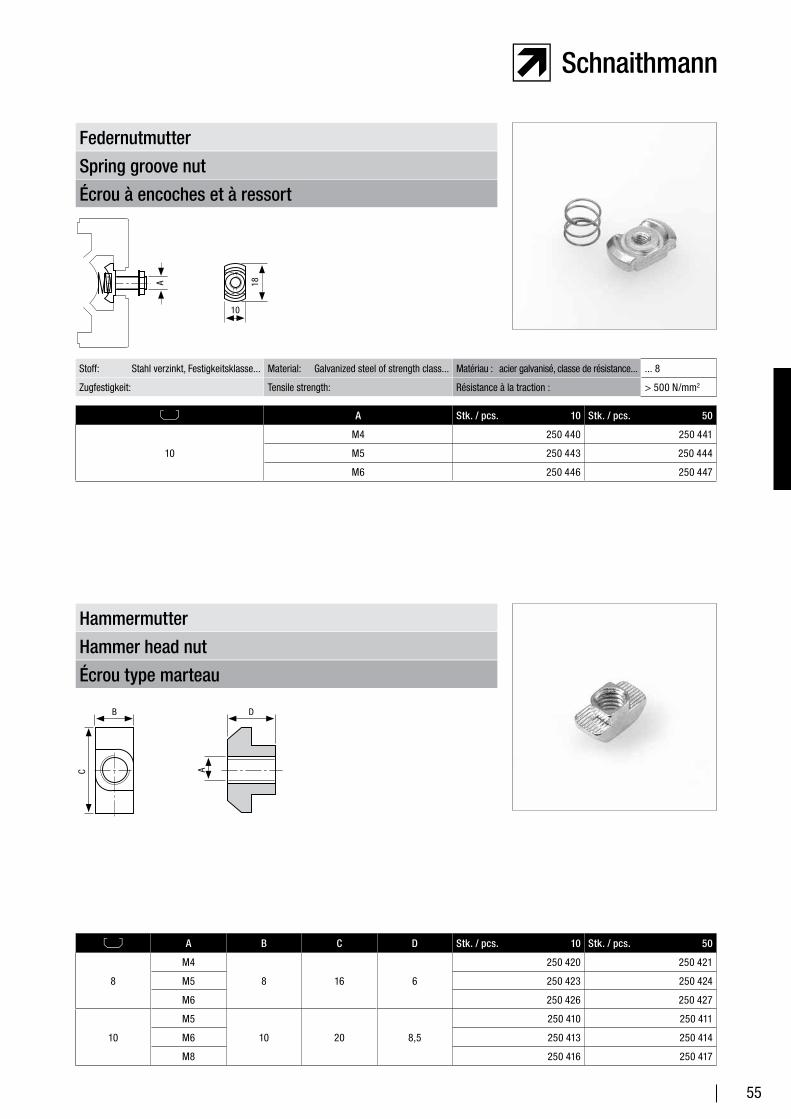
Écrou à encoches et à ressort
Spring groove nut
Federnutmutter
A Stk. / pcs. 10 Stk. / pcs. 50
10
M4 250 440 250 441
M5 250 443 250 444
M6 250 446 250 447
Stoff: Stahl verzinkt, Festigkeitsklasse... Material: Galvanized steel of strength class... Matériau : acier galvanisé, classe de résistance... ... 8
Zugfestigkeit: Tensile strength: Résistance à la traction : > 500 N/mm2
Écrou type marteau
Hammer head nut
Hammermutter
A B C D Stk. / pcs. 10 Stk. / pcs. 50
8
M4
8 16 6
250 420 250 421
M5 250 423 250 424
M6 250 426 250 427
10
M5
10 20 8,5
250 410 250 411
M6 250 413 250 414
M8 250 416 250 417
10
18A
C
B D
A
56
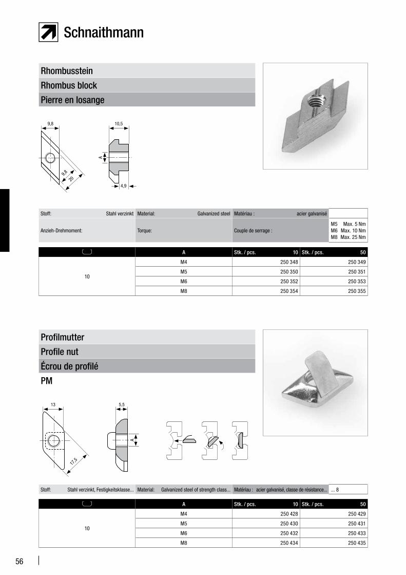
Pierre en losange
Rhombus block
Rhombusstein
A Stk. / pcs. 10 Stk. / pcs. 50
10
M4 250 348 250 349
M5 250 350 250 351
M6 250 352 250 353
M8 250 354 250 355
Stoff: Stahl verzinkt Material: Galvanized steel Matériau : acier galvanisé
Anzieh-Drehmoment: Torque: Couple de serrage :M5 Max. 5 NmM6 Max. 10 NmM8 Max. 25 Nm
A Stk. / pcs. 10 Stk. / pcs. 50
10
M4 250 428 250 429
M5 250 430 250 431
M6 250 432 250 433
M8 250 434 250 435
Stoff: Stahl verzinkt, Festigkeitsklasse... Material: Galvanized steel of strength class... Matériau : acier galvanisé, classe de résistance... ... 8
Écrou de profilé
Profile nut
Profilmutter
PM
9,8 10,5
A
209,8
4,9
13 5,5
17,5
A
57
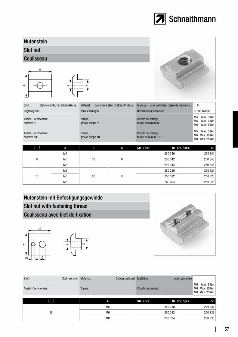
Coulisseau
Slot nut
Nutenstein
A B C Stk. / pcs. 10 Stk. / pcs. 50
8
M4
16 8
250 340 250 341
M5 250 342 250 343
M6 250 344 250 345
10
M5
20 10
250 320 250 321
M6 250 322 250 323
M8 250 324 250 325
Stoff: Stahl verzinkt, Festigkeitsklasse... Material: Galvanized steel of strength class... Matériau : acier galvanisé, classe de résistance... ... 8
Zugfestigkeit: Tensile strength: Résistance à la traction : > 500 N/mm2
Anzieh-Drehmoment, Nutform 8:
Torque, groove shape 8:
Couple de serrage, forme de rainure 8 :
M4 Max. 3 NmM5 Max. 4 NmM6 Max. 8 Nm
Anzieh-Drehmoment, Nutform 10:
Torque, groove shape 10:
Couple de serrage, forme de rainure 10 :
M5 Max. 5 NmM6 Max. 10 NmM8 Max. 25 Nm
Coulisseau avec filet de fixation
Slot nut with fastening thread
Nutenstein mit Befestigungsgewinde
A Stk. / pcs. 10 Stk. / pcs. 50
10
M5 250 330 250 331
M6 250 332 250 333
M8 250 334 250 335
Stoff: Stahl verzinkt Material: Galvanized steel Matériau : acier galvanisé
Anzieh-Drehmoment: Torque: Couple de serrage :M5 Max. 5 NmM6 Max. 10 NmM8 Max. 25 Nm
A
B
CA
10A
20
20
AM5
58
A Stk. / pcs. 10 Stk. / pcs. 50
8
M4 250 310 250 311
M5 250 312 250 313
M6 250 314 250 315
M8 250 316 250 317
10
M5 250 303 250 304
M6 250 305 250 306
M8 250 307 250 308
Stoff: Stahl verzinkt Material: Galvanized steel Matériau : acier galvanisé
Anzieh-Drehmoment: Torque: Couple de serrage :
M4 Max. 3 NmM5 Max. 5 NmM6 Max. 10 NmM8 Max. 25 Nm
Écrou 1/2 lune avec languette resort
Clip-on slot nut with spring leaf
Nutenstein einschwenkbar mit Federblech
Coulisseau avec boule
Slot nut with ball
Nutenstein mit Kugel
A Stk. / pcs. 10 Stk. / pcs. 50
10
M5 250 390 250 391
M6 250 392 250 393
M8 250 394 250 395
Stoff: Stahl verzinkt Material: Galvanized steel Matériau : acier galvanisé
Anzieh-Drehmoment: Torque: Couple de serrage :M5 Max. 5 NmM6 Max. 10 NmM8 Max. 25 Nm
10
20
20
A
7,9A
16
11,6
59
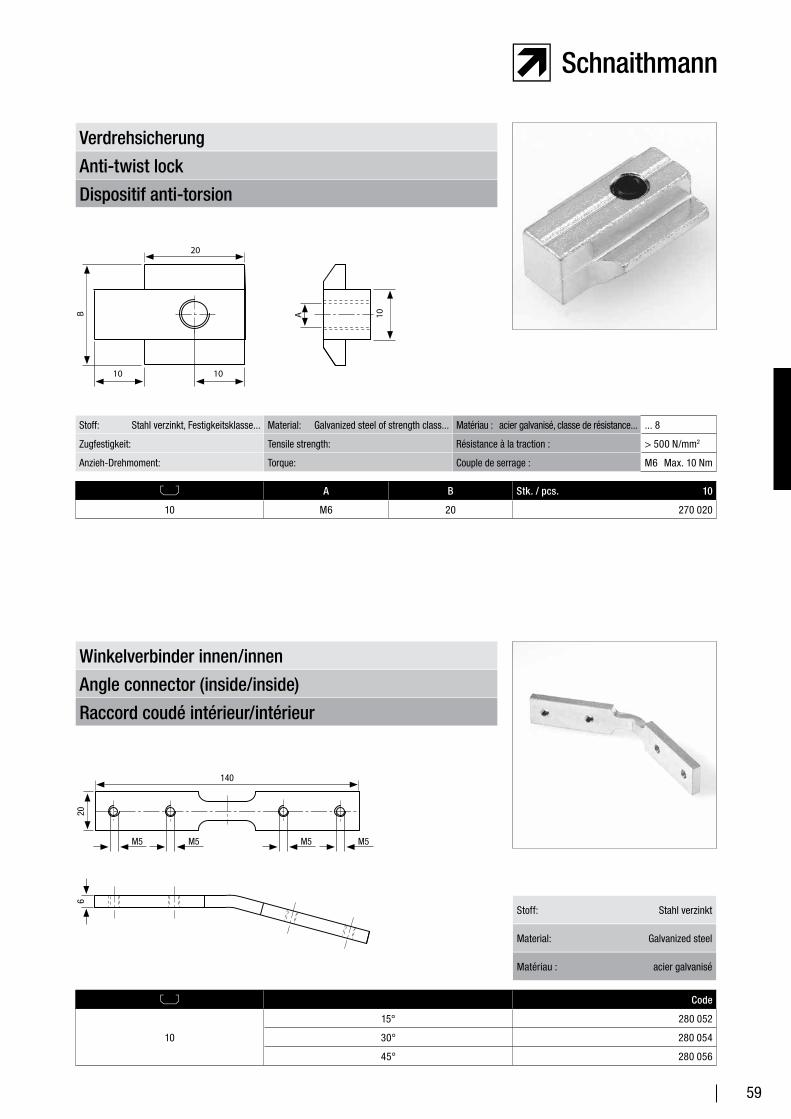
Dispositif anti-torsion
Anti-twist lock
Verdrehsicherung
A B Stk. / pcs. 10
10 M6 20 270 020
Stoff: Stahl verzinkt, Festigkeitsklasse... Material: Galvanized steel of strength class... Matériau : acier galvanisé, classe de résistance... ... 8
Zugfestigkeit: Tensile strength: Résistance à la traction : > 500 N/mm2
Anzieh-Drehmoment: Torque: Couple de serrage : M6 Max. 10 Nm
Raccord coudé intérieur/intérieur
Angle connector (inside/inside)
Winkelverbinder innen/innen
Code
10
15° 280 052
30° 280 054
45° 280 056
Stoff: Stahl verzinkt
Material: Galvanized steel
Matériau : acier galvanisé
10 1010
20
B A
140
206
M5 M5M5M5
60
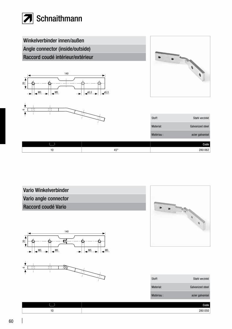
Raccord coudé intérieur/extérieur
Angle connector (inside/outside)
Winkelverbinder innen/außen
Code
10 45° 280 062
Stoff: Stahl verzinkt
Material: Galvanized steel
Matériau : acier galvanisé
Raccord coudé Vario
Vario angle connector
Vario Winkelverbinder
Code
10 280 050
Stoff: Stahl verzinkt
Material: Galvanized steel
Matériau : acier galvanisé
140
206
ø5,5 ø5,5M5M5
140
206
M5 M5M5M5
61
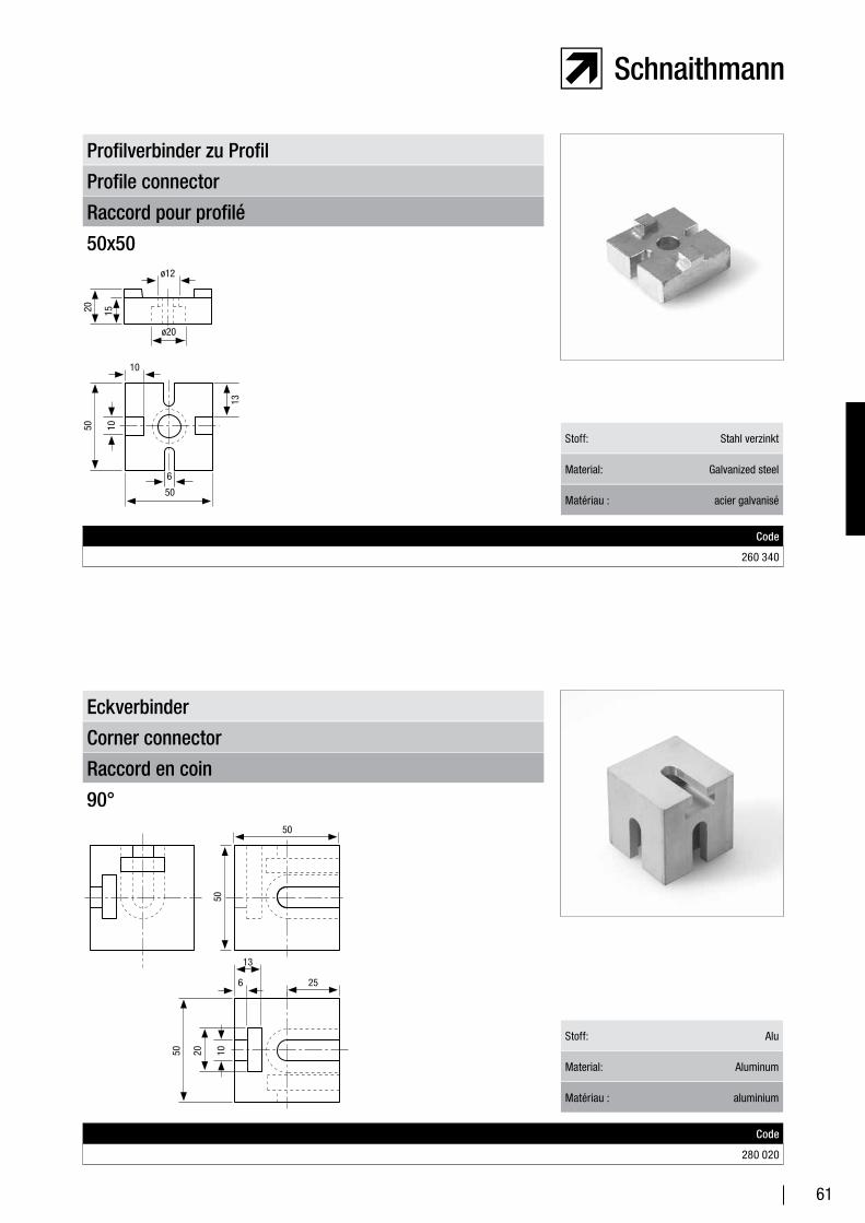
Raccord pour profilé
Profile connector
Profilverbinder zu Profil
50x50
Code
260 340
Stoff: Stahl verzinkt
Material: Galvanized steel
Matériau : acier galvanisé
Raccord en coin
Corner connector
Eckverbinder
90°
Code
280 020
Stoff: Alu
Material: Aluminum
Matériau : aluminium
10
10
ø12
20 15
50
ø20
50
6
13102050
50
50
13
6 25
62
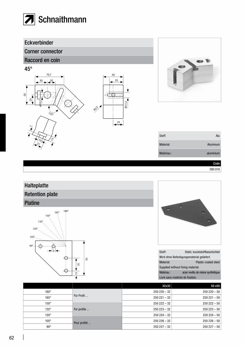
Raccord en coin
Corner connector
Eckverbinder
45°
Code
280 010
Stoff: Alu
Material: Aluminum
Matériau : aluminium
Platine
Retention plate
Halteplatte
Stoff: Stahl, kunststoffbeschichtet
Wird ohne Befestigungsmaterial geliefert.
Material: Plastic-coated steel
Supplied without fixing material.
Matériau : acier revêtu de résine synthétique
Livré sans matériel de fixation.
Für Profil ...
For profile ...
Pour profilé ...
32x32 50 x50
180° 250 220 – 32 250 220 – 50
165° 250 221 – 32 250 221 – 50
150° 250 222 – 32 250 222 – 50
135° 250 223 – 32 250 223 – 50
120° 250 224 – 32 250 224 – 50
105° 250 226 – 32 250 226 – 50
90° 250 227 – 32 250 227 – 50
135°
Ø17
,2
R2,5
70,7
30 20
50
25
ø10,
2
35
50
25
13
7
1021
35
50
165° 180°
90°
105°
120°
135°
150°
9
15
63
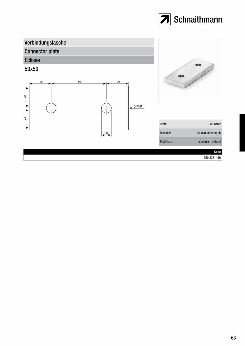
Éclisse
Connector plate
Verbindungslasche
50x50
Code
250 228 – 50
Stoff: Alu natur
Material: Aluminum (natural)
Matériau : aluminium naturel
20 20
gesägt
50
2020
ø9
64
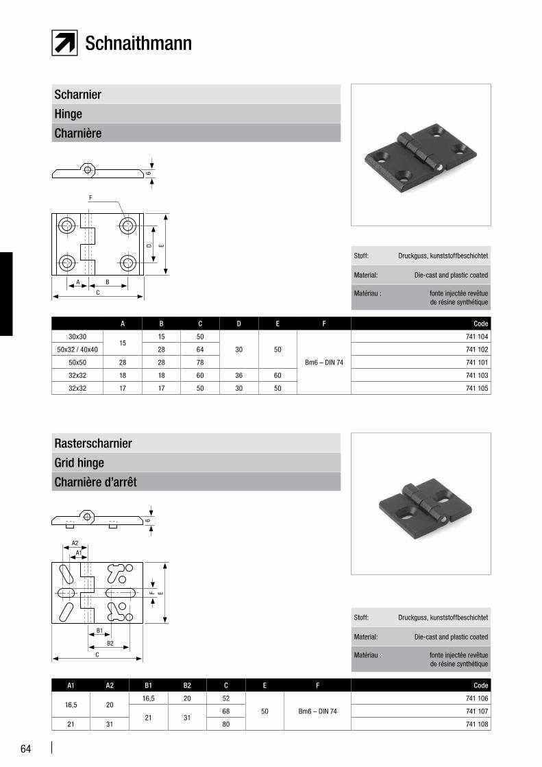
Charnière
Hinge
Scharnier
Charnière d’arrêt
Grid hinge
Rasterscharnier
A1 A2 B1 B2 C E F Code
16,5 2016,5 20 52
50 Bm6 – DIN 74
741 106
21 3168 741 107
21 31 80 741 108
Stoff: Druckguss, kunststoffbeschichtet
Material: Die-cast and plastic coated
Matériau : fonte injectée revêtue de résine synthétique
A B C D E F Code
30x3015
15 50
30 50
Bm6 – DIN 74
741 104
50x32 / 40x40 28 64 741 102
50x50 28 28 78 741 101
32x32 18 18 60 36 60 741 103
32x32 17 17 50 30 50 741 105
Stoff: Druckguss, kunststoffbeschichtet
Material: Die-cast and plastic coated
Matériau : fonte injectée revêtue de résine synthétique
6
F
ED
A B
C
6
E
B1
B2
C
A1
A2
F
65
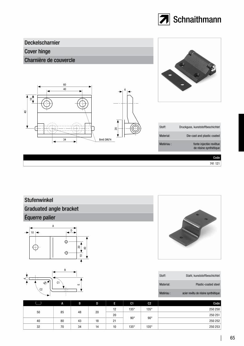
Équerre palier
Graduated angle bracket
Stufenwinkel
A B D E C1 C2 Code
50 85 48 2012 135° 135° 250 250
20 90° 90°
250 251
40 80 43 18 21 250 252
32 70 34 14 10 135° 135° 250 253
Stoff: Stahl, kunststoffbeschichtet
Material: Plastic-coated steel
Matériau : acier revêtu de résine synthétique
Charnière de couvercle
Cover hinge
Deckelscharnier
Code
741 121
Stoff: Druckguss, kunststoffbeschichtet
Material: Die-cast and plastic coated
Matériau : fonte injectée revêtue de résine synthétique
20
6
10
40
60
40
34 Bm6 DIN74
104020
ER4
A
D10
4
B
C2
C1
66
B
A
D
C
C
L-LA B C D Code
L-L180°32 32 21 32 260 320
50 50 30 50 260 330
Section articulée de profilé
Articulated profile joint
Profilgelenk
Stoff: Stahl verzinkt
Material: Galvanized steel
Matériau : acier galvanisé
L-QA B C D Code
L-Q180°32 32 21 32 260 321
50 50 30 50 260 331
Q-QA B C D Code
Q-Q32 32 21 32 260 322
50 50 30 50 260 332
X-LA B C D Code
X-L180°32 32 21 32 260 323
50 50 30 50 260 333
B
A
D
C
C
S-SA B C D Code
S-S32 32 21 32 260 324
50 50 30 50 260 334
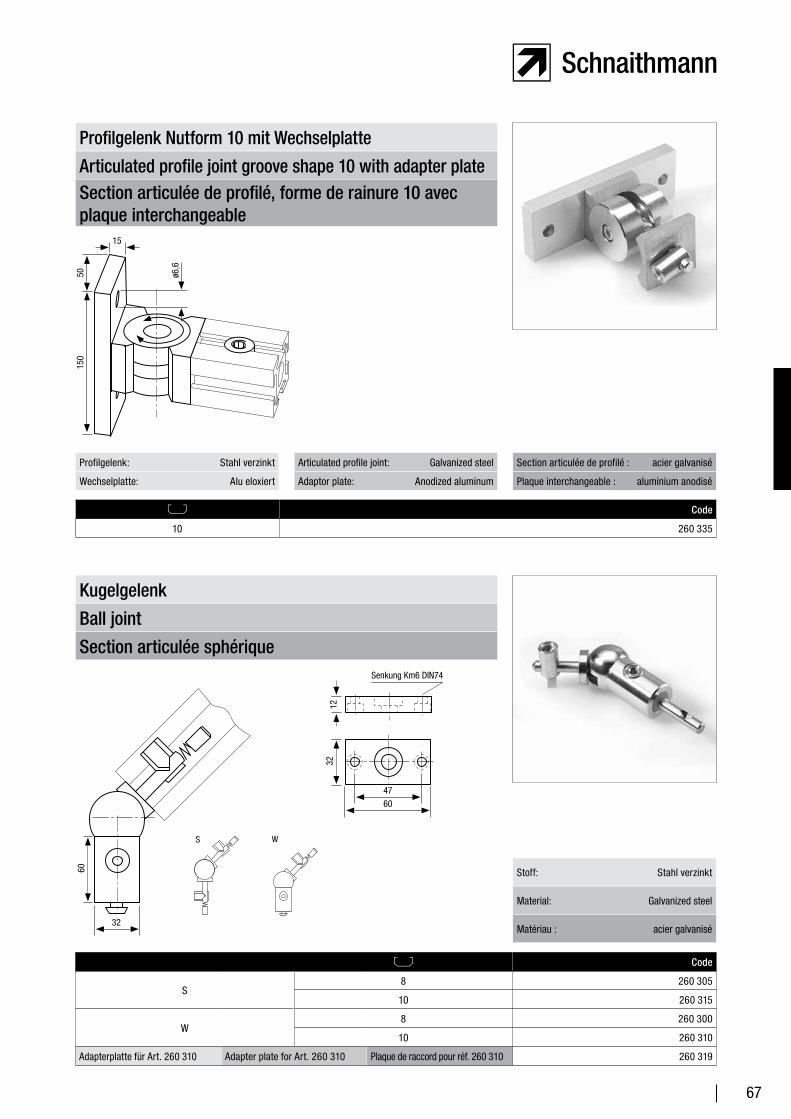
67
Articulated profile joint groove shape 10 with adapter plate
Profilgelenk Nutform 10 mit Wechselplatte
Section articulée de profilé, forme de rainure 10 avec plaque interchangeable
Code
10 260 335
Profilgelenk: Stahl verzinkt
Wechselplatte: Alu eloxiert
Section articulée de profilé : acier galvanisé
Plaque interchangeable : aluminium anodisé
Articulated profile joint: Galvanized steel
Adaptor plate: Anodized aluminum
Section articulée sphérique
Ball joint
Kugelgelenk
Code
S8 260 305
10 260 315
W8 260 300
10 260 310
Adapterplatte für Art. 260 310 Adapter plate for Art. 260 310 Plaque de raccord pour réf. 260 310 260 319
Stoff: Stahl verzinkt
Material: Galvanized steel
Matériau : acier galvanisé
Senkung Km6 DIN74
S W
32
60
12
6047
32
150
15
50 ø6,6

68
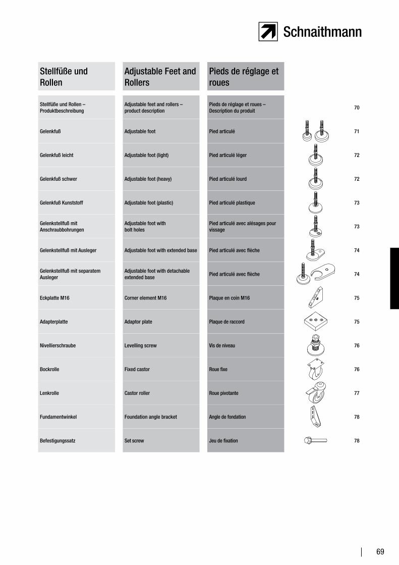
69
Stellfüße und Rollen
Adjustable Feet and Rollers
Pieds de réglage et roues
Stellfüße und Rollen – Produktbeschreibung
Adjustable feet and rollers – product description
Pieds de réglage et roues – Description du produit
70
Gelenkfuß Adjustable foot Pied articulé 71
Gelenkfuß leicht Adjustable foot (light) Pied articulé léger 72
Gelenkfuß schwer Adjustable foot (heavy) Pied articulé lourd 72
Gelenkfuß Kunststoff Adjustable foot (plastic) Pied articulé plastique 73
Gelenkstellfuß mit Anschraubbohrungen
Adjustable foot with bolt holes
Pied articulé avec alésages pour vissage
73
Gelenkstellfuß mit Ausleger Adjustable foot with extended base Pied articulé avec flèche 74
Gelenkstellfuß mit separatem Ausleger
Adjustable foot with detachable extended base
Pied articulé avec flèche 74
Eckplatte M16 Corner element M16 Plaque en coin M16 75
Adapterplatte Adaptor plate Plaque de raccord 75
Nivellierschraube Levelling screw Vis de niveau 76
Bockrolle Fixed castor Roue fixe 76
Lenkrolle Castor roller Roue pivotante 77
Fundamentwinkel Foundation angle bracket Angle de fondation 78
Befestigungssatz Set screw Jeu de fixation 78
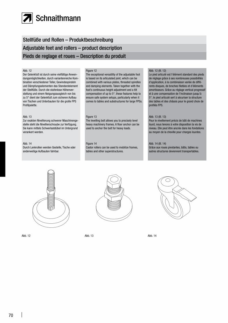
70
Stellfüße und Rollen – Produktbeschreibung
Adjustable feet and rollers – product description
Pieds de reglage et roues – Description du produit
Figure 12The exceptional versatility of the adjustable foot is based on its articulated joint, which can be combined with various plates, threaded spindles and damping elements. Taken together with the foot’s continuous height adjustment and a tilt compensation of up to 5°, these features help to ensure safe system setups, particularly when it comes to tables and substructures for large FPSs.
Figure 13The levelling bolt allows you to precisely level heavy machinery frames. A floor anchor can be used to anchor the bolt for heavy loads.
Figure 14Castor rollers can be used to mobilize frames, tables and other superstructures.
Abb. 12 (Ill. 12)Le pied articulé est l’élément standard des pieds de réglage grâce à ses nombreuses possibilités d’application, à la combinaison variée de diffé-rents disques, de broches filetées et d’éléments amortisseurs. Grâce au réglage vertical progressif et à une compensation de l’inclinaison jusqu’à 5°, le pied articulé sert à sécuriser la structure des tables et des châssis pour le grand choix de profilés FPS.
Abb. 13 (Ill. 13)Pour le nivellement précis de bâti de machines lourd, nous tenons à votre disposition la vis de niveau. Elle peut être ancrée dans les fondations au moyen de la cheville pour charges lourdes.
Abb. 14 (Ill. 14)Grâce aux roues pivotantes, bâtis, tables ou autres structures deviennent transportables.
Abb. 12Der Gelenkfuß ist durch seine vielfältige Anwen-dungsmöglichkeiten, durch variantenreiche Kom-bination verschiedener Teller, Gewindespindeln und Dämpfungselementen das Standardelement der Stellfüße. Durch die stufenlose Höhenver-stellung und einem Neigungsausgleich von bis zu 5° dient der Gelenkfuß zum sicheren Aufbau von Tischen und Unterbauten für die große FPS Profilpalette.
Abb. 13Zur exakten Nivellierung schwerer Maschinenge-stelle steht die Nivellierschraube zur Verfügung. Sie kann mittels Schwerlastdübel im Untergrund verankert werden.
Abb. 14Durch Lenkrollen werden Gestelle, Tische oder anderweitige Aufbauten fahrbar.
Abb. 12 Abb. 13 Abb. 14
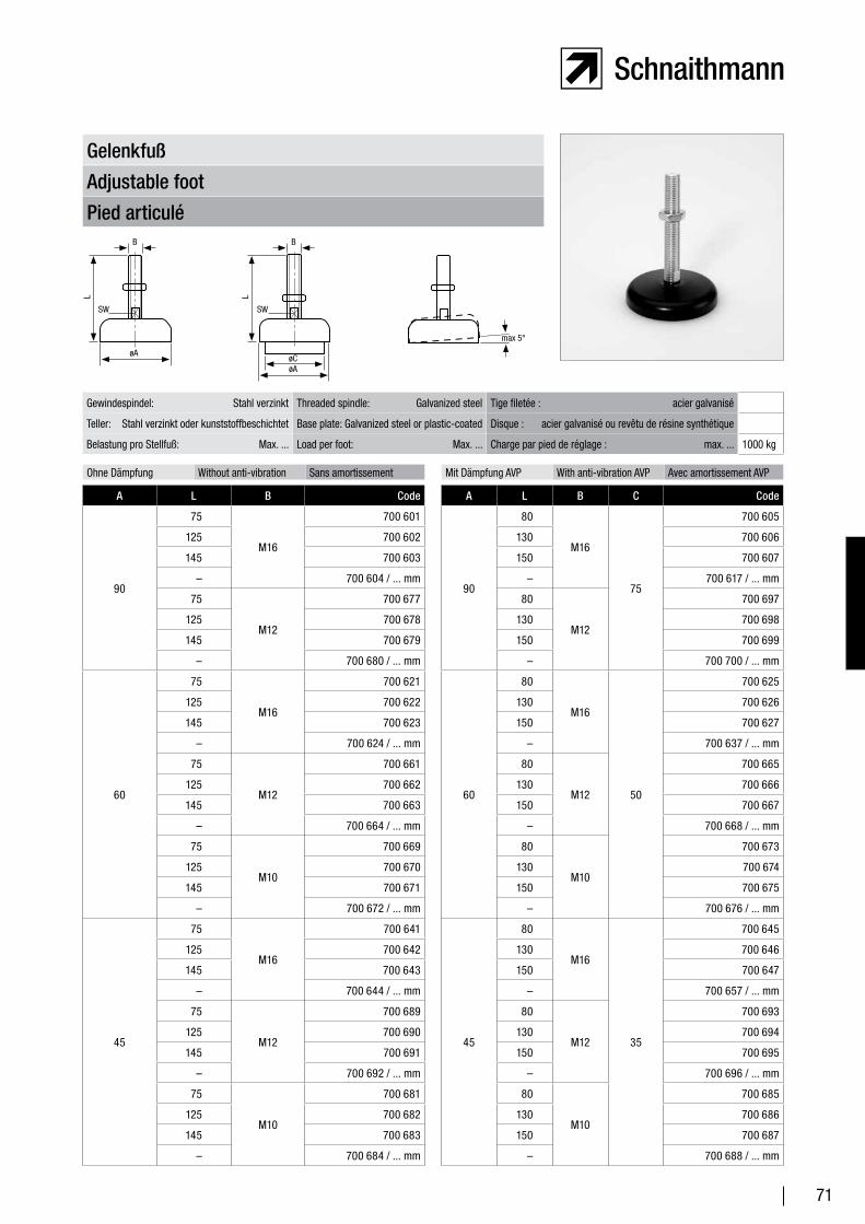
71
Pied articulé
Adjustable foot
Gelenkfuß
Gewindespindel: Stahl verzinkt Threaded spindle: Galvanized steel Tige filetée : acier galvanisé
Teller: Stahl verzinkt oder kunststoffbeschichtet Base plate: Galvanized steel or plastic-coated Disque : acier galvanisé ou revêtu de résine synthétique
Belastung pro Stellfuß: Max. ... Load per foot: Max. ... Charge par pied de réglage : max. ... 1000 kg
Ohne Dämpfung Without anti-vibration Sans amortissement Mit Dämpfung AVP With anti-vibration AVP Avec amortissement AVP
A L B Code
90
75
M16
700 601
125 700 602
145 700 603
– 700 604 / ... mm
75
M12
700 677
125 700 678
145 700 679
– 700 680 / ... mm
60
75
M16
700 621
125 700 622
145 700 623
– 700 624 / ... mm
75
M12
700 661
125 700 662
145 700 663
– 700 664 / ... mm
75
M10
700 669
125 700 670
145 700 671
– 700 672 / ... mm
45
75
M16
700 641
125 700 642
145 700 643
– 700 644 / ... mm
75
M12
700 689
125 700 690
145 700 691
– 700 692 / ... mm
75
M10
700 681
125 700 682
145 700 683
– 700 684 / ... mm
A L B C Code
90
80
M16
75
700 605
130 700 606
150 700 607
– 700 617 / ... mm
80
M12
700 697
130 700 698
150 700 699
– 700 700 / ... mm
60
80
M16
50
700 625
130 700 626
150 700 627
– 700 637 / ... mm
80
M12
700 665
130 700 666
150 700 667
– 700 668 / ... mm
80
M10
700 673
130 700 674
150 700 675
– 700 676 / ... mm
45
80
M16
35
700 645
130 700 646
150 700 647
– 700 657 / ... mm
80
M12
700 693
130 700 694
150 700 695
– 700 696 / ... mm
80
M10
700 685
130 700 686
150 700 687
– 700 688 / ... mm
B B
øA
SW
øA
max 5°
øC
L L
SW
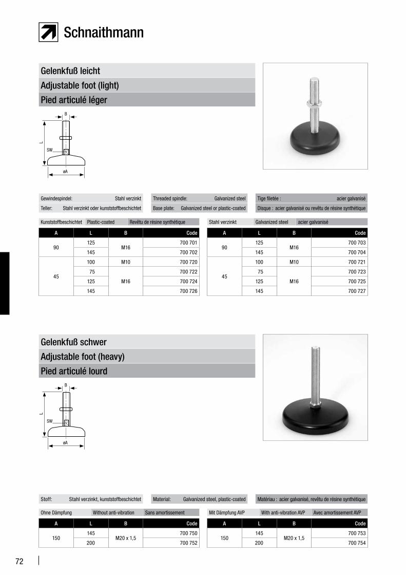
72
Pied articulé léger
Adjustable foot (light)
Gelenkfuß leicht
Kunststoffbeschichtet Plastic-coated Revêtu de résine synthétique
A L B Code
90125
M16700 701
145 700 702
45
100 M10 700 720
75
M16
700 722
125 700 724
145 700 726
Stahl verzinkt Galvanized steel acier galvanisé
A L B Code
90125
M16700 703
145 700 704
45
100 M10 700 721
75
M16
700 723
125 700 725
145 700 727
Gewindespindel: Stahl verzinkt
Teller: Stahl verzinkt oder kunststoffbeschichtet
Tige filetée : acier galvanisé
Disque : acier galvanisé ou revêtu de résine synthétique
Threaded spindle: Galvanized steel
Base plate: Galvanized steel or plastic-coated
Pied articulé lourd
Adjustable foot (heavy)
Gelenkfuß schwer
A L B Code
150145
M20 x 1,5700 750
200 700 752
A L B Code
150145
M20 x 1,5700 753
200 700 754
Stoff: Stahl verzinkt, kunststoffbeschichtet Matériau : acier galvanisé, revêtu de résine synthétiqueMaterial: Galvanized steel, plastic-coated
Ohne Dämpfung Without anti-vibration Sans amortissement Mit Dämpfung AVP With anti-vibration AVP Avec amortissement AVP
B
øA
L
SW
SW
B
øA
L
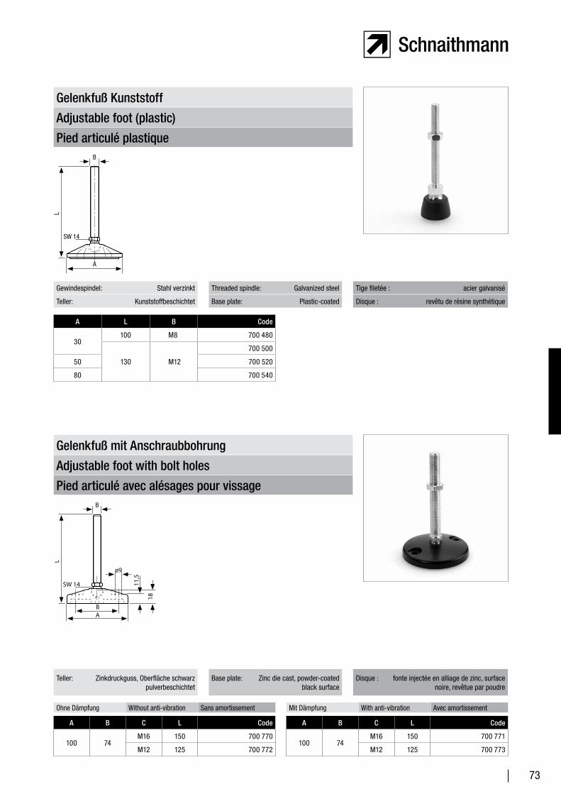
73
Pied articulé plastique
Adjustable foot (plastic)
Gelenkfuß Kunststoff
A L B Code
30100 M8 700 480
130 M12
700 500
50 700 520
80 700 540
Gewindespindel: Stahl verzinkt
Teller: Kunststoffbeschichtet
Tige filetée : acier galvanisé
Disque : revêtu de résine synthétique
Threaded spindle: Galvanized steel
Base plate: Plastic-coated
Pied articulé avec alésages pour vissage
Adjustable foot with bolt holes
Gelenkfuß mit Anschraubbohrung
A B C L Code
100 74M16 150 700 770
M12 125 700 772
A B C L Code
100 74M16 150 700 771
M12 125 700 773
Teller: Zinkdruckguss, Oberfläche schwarz pulverbeschichtet
Disque : fonte injectée en alliage de zinc, surface noire, revêtue par poudre
Base plate: Zinc die cast, powder-coated black surface
Ohne Dämpfung Without anti-vibration Sans amortissement Mit Dämpfung With anti-vibration Avec amortissement
B
A
L
SW 14
B
ø9
AB
L
SW 14 11,5
18
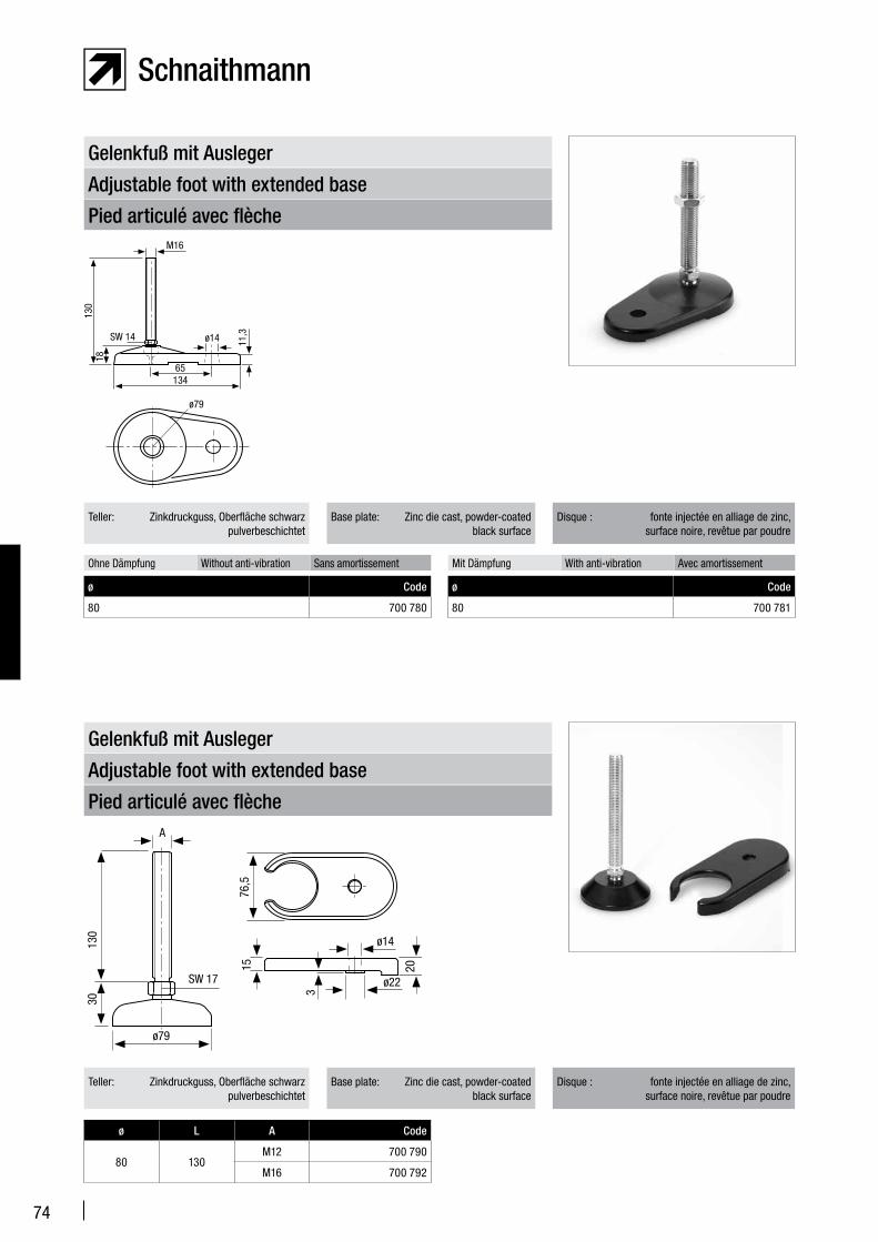
74
Pied articulé avec flèche
Adjustable foot with extended base
Gelenkfuß mit Ausleger
ø Code
80 700 780
ø Code
80 700 781
Teller: Zinkdruckguss, Oberfläche schwarz pulverbeschichtet
Disque : fonte injectée en alliage de zinc, surface noire, revêtue par poudre
Base plate: Zinc die cast, powder-coated black surface
Ohne Dämpfung Without anti-vibration Sans amortissement Mit Dämpfung With anti-vibration Avec amortissement
Pied articulé avec flèche
Adjustable foot with extended base
Gelenkfuß mit Ausleger
ø L A Code
80 130M12 700 790
M16 700 792
Teller: Zinkdruckguss, Oberfläche schwarz pulverbeschichtet
Disque : fonte injectée en alliage de zinc, surface noire, revêtue par poudre
Base plate: Zinc die cast, powder-coated black surface
M16
ø14
ø79
13465
130
18
SW 14 11,3
A
ø14
ø79
ø22
130
30
1576
,5
3
SW 17
20
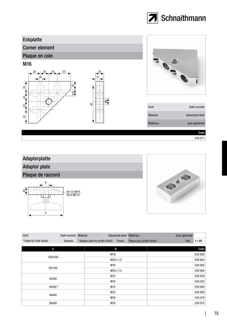
75
Plaque en coin
Corner element
Eckplatte
M16
Code
530 071
Stoff: Stahl verzinkt
Material: Galvanized steel
Matériau : acier galvanisé
Plaque de raccord
Adaptor plate
Adapterplatte
A B Code
100x100M16 530 060
M20 x 1,5 530 064
50x100M16 530 062
M20 x 1,5 530 066
45x90M12 530 050
M16 530 052
40x40 * M12 530 068
40x80M12 530 069
M16 530 070
80x80 M16 530 072
Stoff: Stahl verzinkt Material: Galvanized steel Matériau : acier galvanisé
* Platte für Profil 40x40: Gewinde ... * Adaptor plate for profile 40x40: Thread ... Plaque pour profilé 40x40 : Filet ... 4 x M6
28
90
2020
32
3220202820
M6
ø15
ø9 10
20
B
Km 12 DIN74Km 8 DIN 74
A
20

76
Vis de niveau
Levelling screw
Nivellierschraube
Stoff: Stahl verzinkt Material: Galvanized steel Matériau : acier galvanisé
Belastung max. ... Maximum load ... Charge max. ... 2000 kg
A Code
Komplett Complete Complet 116 mm 701 001
Sonderlänge Special length Longueur spéciale ... mm 701 003 / ... mm
Einzeln Separate La pièce 116 mm 701 011
Mutter M36 x 1,5 Nut M36 x 1.5 Écrou M36 x 1,5 701 012
Grundplatte rund, ø 100 mm Round base plate, ø 100 mm Socle rond, ø 100 mm 701 013
Roue fixe
Fixed castor
Bockrolle
Stoff: Stahl verzinkt Material: Galvanized steel Matériau : acier galvanisé
Aufbau: Stahl Structure: Steel Structure : acier
Tragkraft pro Rolle max. ... Maximum load per roller ... Charge par roue max. ... 1000 N
Weitere Rollen auf Anfrage. Additional rollers on request D’autres roues sur demande.
Code
Reifen: Gummi Inner tire: Rubber Pneu : caoutchouc 720 015
Laufbelag: Polyurethan Outer tire: Polyurethane Garniture de roue : polyuréthane 720 017
A
M36x1,5
ø25
ø100
ø20,2+0,3
SW36
SW55
95
75
70
45
90
75
4566
135
100 32
ø9
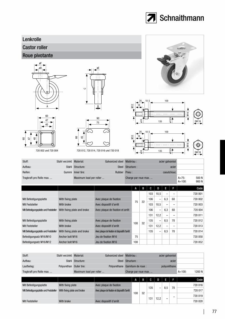
77
Roue pivotante
Castor roller
Lenkrolle
Stoff: Stahl verzinkt Material: Galvanized steel Matériau : acier galvanisé
Aufbau: Stahl Structure: Steel Structure : acier
Laufbelag: Polyurethan Outer tire: Polyurethane Garniture de roue : polyuréthane
Tragkraft pro Rolle max. ... Maximum load per roller ... Charge par roue max. ... A=100: 1200 N
A B C D E F Code
Mit Befestigungsplatte With fixing plate Avec plaque de fixation
100 32
135 – 8,5 70 720 016
Mit Befestigungsplatte und Feststeller With fixing plate and brake Avec plaque de fixation et dispositif d’arrêt 720 017
131 12,2 ––
720 019
Mit Feststeller With brake Avec dispositif d’arrêt 720 020
Stoff: Stahl verzinkt Material: Galvanized steel Matériau : acier galvanisé
Aufbau: Stahl Structure: Steel Structure : acier
Reifen: Gummi Inner tire: Rubber Pneu : caoutchouc
Tragkraft pro Rolle max. ... Maximum load per roller ... Charge par roue max. ... A=75: 500 NA=100: 900 N
A B C D E F Code
75 22
103 10,5 – – 720 001
Mit Befestigungsplatte With fixing plate Avec plaque de fixation 106 – 6,3 60 720 002
Mit Feststeller With brake Avec dispositif d’arrêt 103 10,5 – – 720 003
Mit Befestigungsplatte und Feststeller With fixing plate and brake Avec plaque de fixation et arrêt 106 – 6,3 60 720 004
100 32
131 12,2 – – 720 011
Mit Befestigungsplatte With fixing plate Avec plaque de fixation 135 – 8,5 70 720 012
Mit Feststeller With brake Avec dispositif d’arrêt 131 12,2 – – 720 013
Mit Befestigungsplatte und Feststeller With fixing plate and brake Avec plaque de fixation et dispositif d’arrêt 135 – 8,5 70 720 014
Befestigungsatz M16/M10 Anchor bolt M16 Jeu de fixation M16 75 720 050
Befestigungsatz M16/M12 Anchor bolt M16 Jeu de fixation M16 100 720 052
øF
øEøD
25 10 5 100
18A
SW 24
SW 24
B
C4566404760
90
7547
40
60
720 002 und 720 004 720 012, 720 014, 720 016 und 720 018
M16
ø13,
5
ø10
25 10 5 100
18
ø13,
5
ø10
M16
135
135
M10
M12
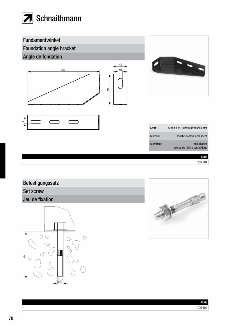
78
Angle de fondation
Foundation angle bracket
Fundamentwinkel
Code
700 801
Stoff: Stahlblech, kunststoffbeschichtet
Material: Plastic-coated steel sheet
Matériau : tôle d’acier revêtue de résine synthétique
Jeu de fixation
Set screw
Befestigungssatz
Code
700 802
42
13200
9
90
ø10
75
79
Zubehör – Produktbeschreibung
Accessories – product description
Accessoires – Description du produit
81
Bohrvorrichtung Drilling jig Appareil de perçage 82
Spezialbohrer Special drill bits Foret spécial 82
Varioblock Vario block Vario bloc 83
Rosette Rosette Rosette 83
Gewindehülse Threaded bushing Douille filetée 84
Eckelement Corner element Élément d’angle 84
Abdeckkappe End covers Capuchon 85
Türschloss Door lock Serrure de porte 86
Türschloss, Fallenverschluss Latch lock Serrure à loquet 86
Kugelraste Ball catch Loqueteau à billes 87
Kugelraste-Halter für Profil Ball catch holder for profileSupport loqueteau à billes pour profilé
87
Handgriff Handle Poignée 88
Rohrhandgriff Tube handle Poignée tubulaire 88
Kreuzgriff Cross handle Poignée en croix 89
Sterngriff Star handle Poignée en étoile 89
Magnetschnapper Magnetic catch Fermoir magnétique 90
Flächenelemente Surface elements Éléments de surface 91
Greifschale Tray Bac à suspendre 92
Greifschalenständer Tray stand Support pour bac à suspendre 92
Werkzeugköcher Tool holder Porte-outils 93
Verstellgleiter mit Karabiner Adjustable glider with carabinerÉlément coulissant réglable avec mousquetons
93
Arbeitskartenhalter 1 Work ticket holder 1 Support pour carte de travail 1 94
Arbeitskartenhalter 2 Work ticket holder 2 Support pour carte de travail 2 94
Ringbuchhalter Ring binder Support pour classeur 95
Zubehör Accessories Accessoires
80
Zubehör Accessories Accessoires
Einsteckbox Deposit box Boîtier pour fiches 95
Laufrolle Roller Roue pivotante 96
Stahlschubladenschrank Steel drawer cabinet Armoire à tiroirs en acier 96
Stahlschubladen Steel drawers Tiroirs en acier 97
Gleitschuh mit Mutter Slide element with nut Patin avec écrou 97
Schwenkblechhalter Tilting plate holder Support pivotant en tôle 98
Schwenkauflagenhalter Tilting platform holder Support de rangement pivotant 98
Schwenkablage Tilting platform Rangement pivotant 99
Fußauflage Footrest Repose-pieds 99
Beistellfußauflage Auxiliary footrest Repose-pieds supplémentaire 100
Fußauflage variabel verstellbar Adjustable footrest Repose-pieds réglable 100
Steckdosen-Anbauleiste Surface-mounted outlet track Baguette pour prises électriques 101
Steckdosen-Einbauleiste Flush-mounted outlet track Baguette pour prises électriques 101
Arbeitsplatzleuchte APL 236 und APL 236 S
Lighting fixture (APL 236 and APL 236 S)
Luminaire de plan de travail APL 236 et APL 236
102
LED-Arbeitsplatzleuchte LED lighting fixture Luminaire de plan de travail LED 103
Höhenverstellbarer Arbeitstisch Height-adjustable work desk Table de travail à hauteur réglable 104
Arbeitsstuhl Work chair Chaise de travail 104
Flaschenhalter Bottle holder Support pour bouteille 105
Lappenhalter Cloth holder Support pour chiffon 105
Potentialausgleich Electrical bonding element Conducteur d’équipotentialité 106
IR-Quick IR-Quick IR-Quick 106
Kabelklemme / Kabelbinder, 90° gedreht
Horizontal cable clampSerre-câble / anneau pour câble, rotation à 90°
107
Kabelklemme / Kabelbinder Vertical cable clamp Serre-câble / anneau pour câble 107
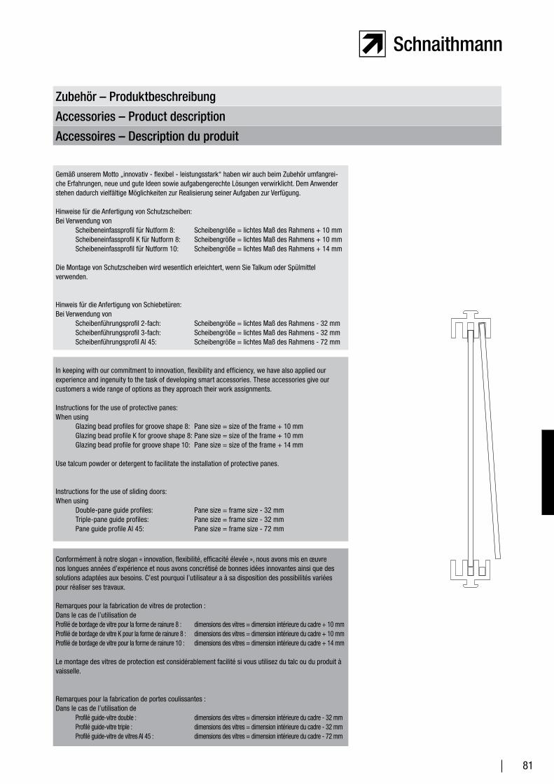
81
Zubehör – Produktbeschreibung
Accessories – Product description
Accessoires – Description du produit
In keeping with our commitment to innovation, flexibility and efficiency, we have also applied our experience and ingenuity to the task of developing smart accessories. These accessories give our customers a wide range of options as they approach their work assignments.
Instructions for the use of protective panes: When using
Glazing bead profiles for groove shape 8: Pane size = size of the frame + 10 mmGlazing bead profile K for groove shape 8: Pane size = size of the frame + 10 mmGlazing bead profile for groove shape 10: Pane size = size of the frame + 14 mm
Use talcum powder or detergent to facilitate the installation of protective panes.
Instructions for the use of sliding doors: When using
Double-pane guide profiles: Pane size = frame size - 32 mmTriple-pane guide profiles: Pane size = frame size - 32 mmPane guide profile Al 45: Pane size = frame size - 72 mm
Conformément à notre slogan « innovation, flexibilité, efficacité élevée », nous avons mis en œuvre nos longues années d’expérience et nous avons concrétisé de bonnes idées innovantes ainsi que des solutions adaptées aux besoins. C’est pourquoi l’utilisateur a à sa disposition des possibilités variées pour réaliser ses travaux.
Remarques pour la fabrication de vitres de protection :Dans le cas de l’utilisation deProfilé de bordage de vitre pour la forme de rainure 8 : dimensions des vitres = dimension intérieure du cadre + 10 mmProfilé de bordage de vitre K pour la forme de rainure 8 : dimensions des vitres = dimension intérieure du cadre + 10 mmProfilé de bordage de vitre pour la forme de rainure 10 : dimensions des vitres = dimension intérieure du cadre + 14 mm
Le montage des vitres de protection est considérablement facilité si vous utilisez du talc ou du produit à vaisselle.
Remarques pour la fabrication de portes coulissantes :Dans le cas de l’utilisation de
Profilé guide-vitre double : dimensions des vitres = dimension intérieure du cadre - 32 mmProfilé guide-vitre triple : dimensions des vitres = dimension intérieure du cadre - 32 mmProfilé guide-vitre de vitres Al 45 : dimensions des vitres = dimension intérieure du cadre - 72 mm
Gemäß unserem Motto „innovativ - flexibel - leistungsstark“ haben wir auch beim Zubehör umfangrei-che Erfahrungen, neue und gute Ideen sowie aufgabengerechte Lösungen verwirklicht. Dem Anwender stehen dadurch vielfältige Möglichkeiten zur Realisierung seiner Aufgaben zur Verfügung.
Hinweise für die Anfertigung von Schutzscheiben: Bei Verwendung von
Scheibeneinfassprofil für Nutform 8: Scheibengröße = lichtes Maß des Rahmens + 10 mmScheibeneinfassprofil K für Nutform 8: Scheibengröße = lichtes Maß des Rahmens + 10 mmScheibeneinfassprofil für Nutform 10: Scheibengröße = lichtes Maß des Rahmens + 14 mm
Die Montage von Schutzscheiben wird wesentlich erleichtert, wenn Sie Talkum oder Spülmittel verwenden.
Hinweis für die Anfertigung von Schiebetüren: Bei Verwendung von
Scheibenführungsprofil 2-fach: Scheibengröße = lichtes Maß des Rahmens - 32 mmScheibenführungsprofil 3-fach: Scheibengröße = lichtes Maß des Rahmens - 32 mmScheibenführungsprofil Al 45: Scheibengröße = lichtes Maß des Rahmens - 72 mm
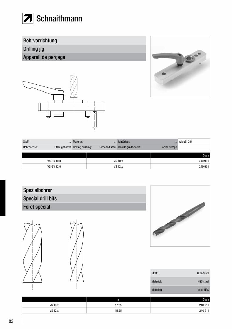
82
Appareil de perçage
Drilling jig
Bohrvorrichtung
Code
VS-BV 10.0 VS 10.x 240 900
VS-BV 12.0 VS 12.x 240 901
Stoff: ... Material: ... Matériau : ... AlMgSi 0,5
Bohrbuchse: Stahl gehärtet Drilling bushing: Hardened steel Douille guide-foret : acier trempé
Foret spécial
Special drill bits
Spezialbohrer
Stoff: HSS-Stahl
Material: HSS steel
Matériau : acier HSS
ø Code
VS 10.x 17,25 240 910
VS 12.x 15,25 240 911
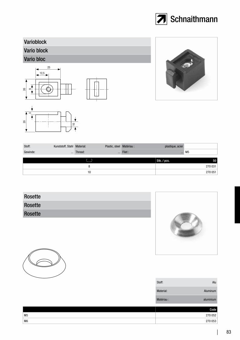
83
Vario bloc
Vario block
Varioblock
Stk. / pcs. 50
8 270 031
10 270 051
Stoff: Kunststoff, Stahl Material: Plastic, steel Matériau : plastique, acier
Gewinde: ... Thread: ... Filet : ... M5
Rosette
Rosette
Rosette
Stoff: Alu
Material: Aluminum
Matériau : aluminium
Code
M5 270 052
M6 270 053
25
12,5
20 9
20
3
10
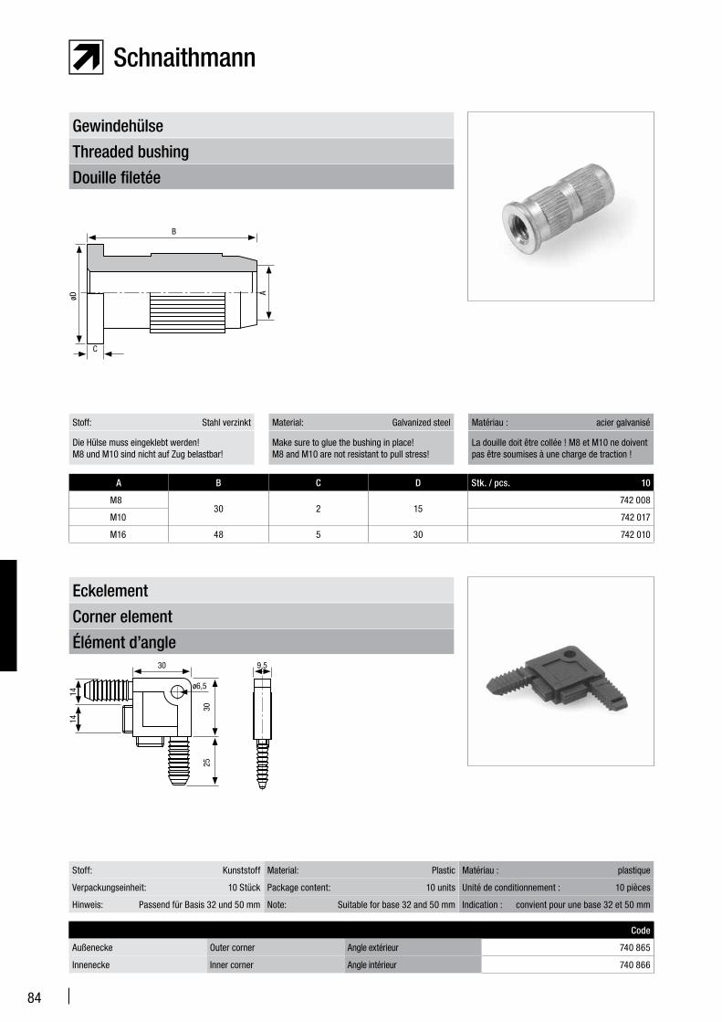
84
Douille filetée
Threaded bushing
Gewindehülse
A B C D Stk. / pcs. 10
M830 2 15
742 008
M10 742 017
M16 48 5 30 742 010
Stoff: Stahl verzinkt Material: Galvanized steel Matériau : acier galvanisé
Die Hülse muss eingeklebt werden! M8 und M10 sind nicht auf Zug belastbar!
Make sure to glue the bushing in place!M8 and M10 are not resistant to pull stress!
La douille doit être collée ! M8 et M10 ne doivent pas être soumises à une charge de traction !
Élément d’angle
Corner element
Eckelement
Code
Außenecke Outer corner Angle extérieur 740 865
Innenecke Inner corner Angle intérieur 740 866
Stoff: Kunststoff Material: Plastic Matériau : plastique
Verpackungseinheit: 10 Stück Package content: 10 units Unité de conditionnement : 10 pièces
Hinweis: Passend für Basis 32 und 50 mm Note: Suitable for base 32 and 50 mm Indication : convient pour une base 32 et 50 mm
B
øD
C
A
30
ø6,5
25
30 9,5
1414
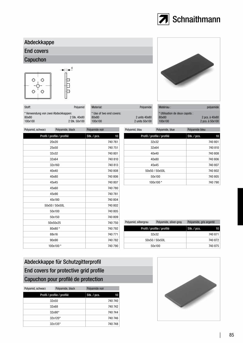
85
Capuchon
End covers
Abdeckkappe
Polyamid, schwarz Polyamide, black Polyamide noir Polyamid, blau Polyamide, blue Polyamide bleu
Profil / profile / profilé Stk. / pcs. 10
20x20 740 761
25x50 740 751
32x32 740 801
32x64 740 810
32x160 740 813
40x40 740 808
40x80 740 806
45x45 740 807
45x60 740 780
45x90 740 781
45x180 740 804
50x50 / 50x50L 740 802
50x100 740 805
50x150 740 809
50x50x25 740 750
80x80 * 740 792
88x16 740 771
90x90 740 782
100x100 * 740 790
Stoff: Polyamid Material: Polyamide Matériau : polyamide
* Verwendung von zwei Abdeckkappen: 80x80 2 Stk. 40x80 100x100 2 Stk. 50x100
* Use of two end covers: 80x80 2 units 40x80 100x100 2 units 50x100
* Utilisation de deux capots : 80x80 2 pcs. à 40x80 100x100 2 pcs. à 50x100
Profil / profile / profilé Stk. / pcs. 10
32x32 740 801
32x64 740 810
40x40 740 808
40x80 740 806
45x45 740 807
50x50 / 50x50L 740 802
50x100 740 805
100x100 * 740 790
Capuchon pour profilé de protection
End covers for protective grid profile
Abdeckkappe für Schutzgitterprofil
Profil / profile / profilé Stk. / pcs. 10
32x50 740 740
32x68 740 742
32x90° 740 744
32x120° 740 746
32x135° 740 748
Polyamid, schwarz Polyamide, black Polyamide noir
Polyamid, silbergrau Polyamide, silver-gray Polyamide, gris argenté
Profil / profile / profilé Stk. / pcs. 10
32x32 740 871
50x50 / 50x50L 740 872
50x100 740 875
4
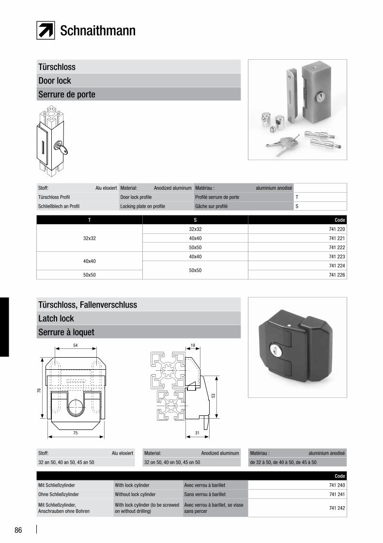
86
Serrure de porte
Door lock
Türschloss
T S Code
32x32
32x32 741 220
40x40 741 221
50x50 741 222
40x4040x40 741 223
50x50741 224
50x50 741 226
Stoff: Alu eloxiert Material: Anodized aluminum Matériau : aluminium anodisé
Türschloss Profil Door lock profile Profilé serrure de porte T
Schließblech an Profil Locking plate on profile Gâche sur profilé S
Serrure à loquet
Latch lock
Türschloss, Fallenverschluss
Code
Mit Schließzylinder With lock cylinder Avec verrou à barillet 741 240
Ohne Schließzylinder Without lock cylinder Sans verrou à barillet 741 241
Mit Schließzylinder, Anschrauben ohne Bohren
With lock cylinder (to be screwed on without drilling)
Avec verrou à barillet, se visse sans percer
741 242
Stoff: Alu eloxiert Material: Anodized aluminum Matériau : aluminium anodisé
32 an 50, 40 an 50, 45 an 50 32 on 50, 40 on 50, 45 on 50 de 32 à 50, de 40 à 50, de 45 à 50
76
54 19
75 31
53
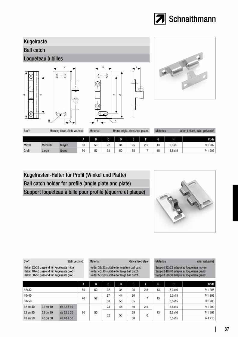
87
Loqueteau à billes
Ball catch
Kugelraste
Stoff: Messing blank, Stahl verzinkt Material: Brass bright, steel zinc-plated Matériau : laiton brillant, acier galvanisé
A B C D E F G H Code
Mittel Medium Moyen 60 50 22 34 25 2,5 13 5,3x8 741 202
Groß Large Grand 70 57 38 50 35 7 15 6,5x15 741 203
Support loqueteau à bille pour profilé (équerre et plaque)
Ball catch holder for profile (angle plate and plate)
Kugelrasten-Halter für Profil (Winkel und Platte)
Stoff: Stahl verzinkt Material: Galvanized steel Matériau : acier galvanisé
A B C D E F G H Code
32x32 60 50 22 34 25 2,5 13 5,3x10 741 205
40x4070 57
27 44 307 15
5,5x15 741 208
50x50 38 50 35 6,5x15 741 206
32 an 40 32 on 40 de 32 à 40
60 50
23 48 30 2,5
13
5,5x15 741 209
32 an 50 32 on 50 de 32 à 5032 53
250
5,3x10 741 207
40 an 50 40 on 50 de 40 à 50 30 5,5x15 741 210
Halter 32x32 passend für Kugelraste mittelHalter 40x40 passend für Kugelraste großHalter 50x50 passend für Kugelraste groß
Holder 32x32 suitable for medium ball catchHolder 40x40 suitable for large ball catch Holder 50x50 suitable for large ball catch
Support 32x32 adapté au loqueteau moyenSupport 40x40 adapté au loqueteau grandSupport 50x50 adapté au loqueteau grand
GED
A
CH HF
BB A
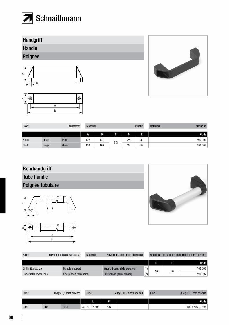
88
Poignée
Handle
Handgriff
Stoff: Kunststoff Material: Plastic Matériau : plastique
A B C D E Code
Klein Small Petit 122 1426,2
26 40 740 001
Groß Large Grand 152 167 28 52 740 002
Poignée tubulaire
Tube handle
Rohrhandgriff
Stoff: Polyamid, glasfaserverstärkt Material: Polyamide, reinforced fiberglass Matériau : polyamide, renforcé par fibre de verre
D E Code
Griffmittelstütze Handle support Support central de poignée (1)46 80
740 006
Endstücke (zwei Teile) End pieces (two parts) Extrémités (deux pièces) (2) 740 007
Rohr: AlMgSi 0,5 matt eloxiert Tube: AlMgSi 0,5 matt anodized Tube : AlMgSi 0,5 mat anodisé
L C Code
Rohr Tube Tube (3) A - 35 mm 8,5 100 950 / ... mm
ED
A
B
C
ED
A
B
C
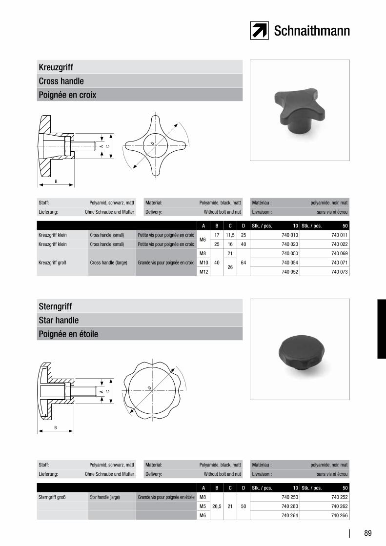
89
Poignée en croix
Cross handle
Kreuzgriff
Stoff: Polyamid, schwarz, matt Material: Polyamide, black, matt Matériau : polyamide, noir, mat
Lieferung: Ohne Schraube und Mutter Delivery: Without bolt and nut Livraison : sans vis ni écrou
A B C D Stk. / pcs. 10 Stk. / pcs. 50
Kreuzgriff klein Cross handle (small) Petite vis pour poignée en croixM6
17 11,5 25 740 010 740 011
Kreuzgriff klein Cross handle (small) Petite vis pour poignée en croix 25 16 40 740 020 740 022
Kreuzgriff groß Cross handle (large) Grande vis pour poignée en croix
M8
40
21
64
740 050 740 069
M1026
740 054 740 071
M12 740 052 740 073
Poignée en étoile
Star handle
Sterngriff
Stoff: Polyamid, schwarz, matt Material: Polyamide, black, matt Matériau : polyamide, noir, mat
Lieferung: Ohne Schraube und Mutter Delivery: Without bolt and nut Livraison : sans vis ni écrou
A B C D Stk. / pcs. 10 Stk. / pcs. 50
Sterngriff groß Star handle (large) Grande vis pour poignée en étoile M8
26,5 21 50
740 250 740 252
M5 740 260 740 262
M6 740 264 740 266
B
A C D
B
A C
D
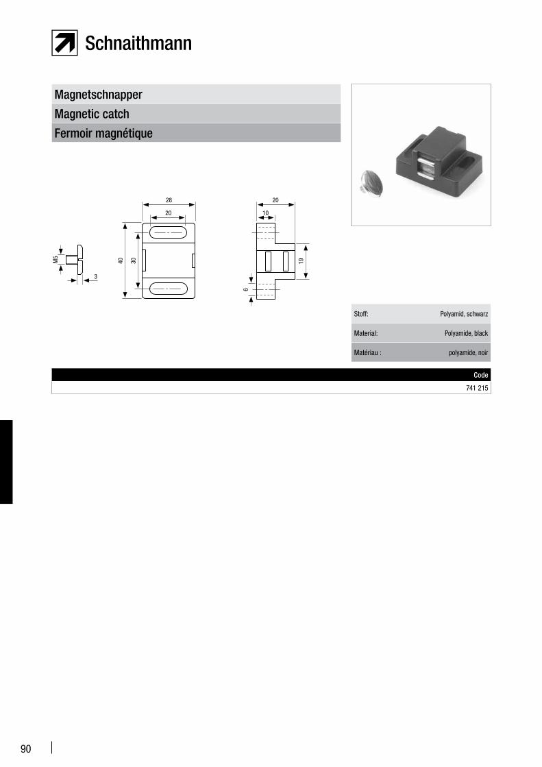
90
Fermoir magnétique
Magnetic catch
Magnetschnapper
Stoff: Polyamid, schwarz
Material: Polyamide, black
Matériau : polyamide, noir
Code
741 215
20
28
10
20
40 30 19
6
M5
3

91
Éléments de surface
Surface elements
Flächenelemente
Schutzscheibe: Acrylglas PMMA, klar (a) oder rauchfarben (b)
Guard pane: Clear acrylic (PMMA) glass (a) or tinted (b)
Vitre de protection : Plexiglas PMMA, clair (a) ou fumé (b)
PMMA d 1250 x 2000 mm A x B mm
(a)6 mm
700 301 / 1250 x 2000 700 302 / ... x ... mm
(b) 700 305 / 1250 x 2000 700 306 / ... x ... mm
(a)8 mm
700 311 / 1250 x 2000 700 312 / ... x ... mm
(b) 700 315 / 1250 x 2000 700 316 / ... x ... mm
Alle Flächenelemente sind als Fixgröße oder als Zuschnitt nach Maß lieferbar.
All surface elements are available in both stan-dard and custom-cut sizes.
Tous les éléments de surface peuvent être livrés en tailles fixes ou en coupe sur mesure.
Schutzscheibe: Polycarbonat PC, klar (a) oder rauchfarben (b)
Guard pane: Clear polycarbonate PC (a) or tinted (b)
Vitre de protection : polycarbonate PC clair (a) ou fumé (b)
PC d 1250 x 2000 mm A x B mm
(a)6 mm
700 321 / 1250 x 2000 700 322 / ... x ... mm
(b) 700 325 / 1250 x 2000 700 326 / ... x ... mm
(a)8 mm
700 331 / 1250 x 2000 700 332 / ... x ... mm
(b) 700 335 / 1250 x 2000 700 336 / ... x ... mm
Alu-Copond: Aluminiumverbund, walzmatt Aluminum compound: Aluminium composite, rolled finished Alu-Compound : composé d’aluminium, laminé mat
d 1250 x 2000 mm A x B mm
6 mm 700 340 / 1250 x 2000 700 341 / ... x ... mm
Schutzgitter: Stahl verzinkt Protective grid: Galvanized steel Vitre de protection : acier galvanisé
d 1250 x 2000 mm A x B mm
6 mm 700 350 / 1250 x 2000 700 351 / ... x ... mm
3
30
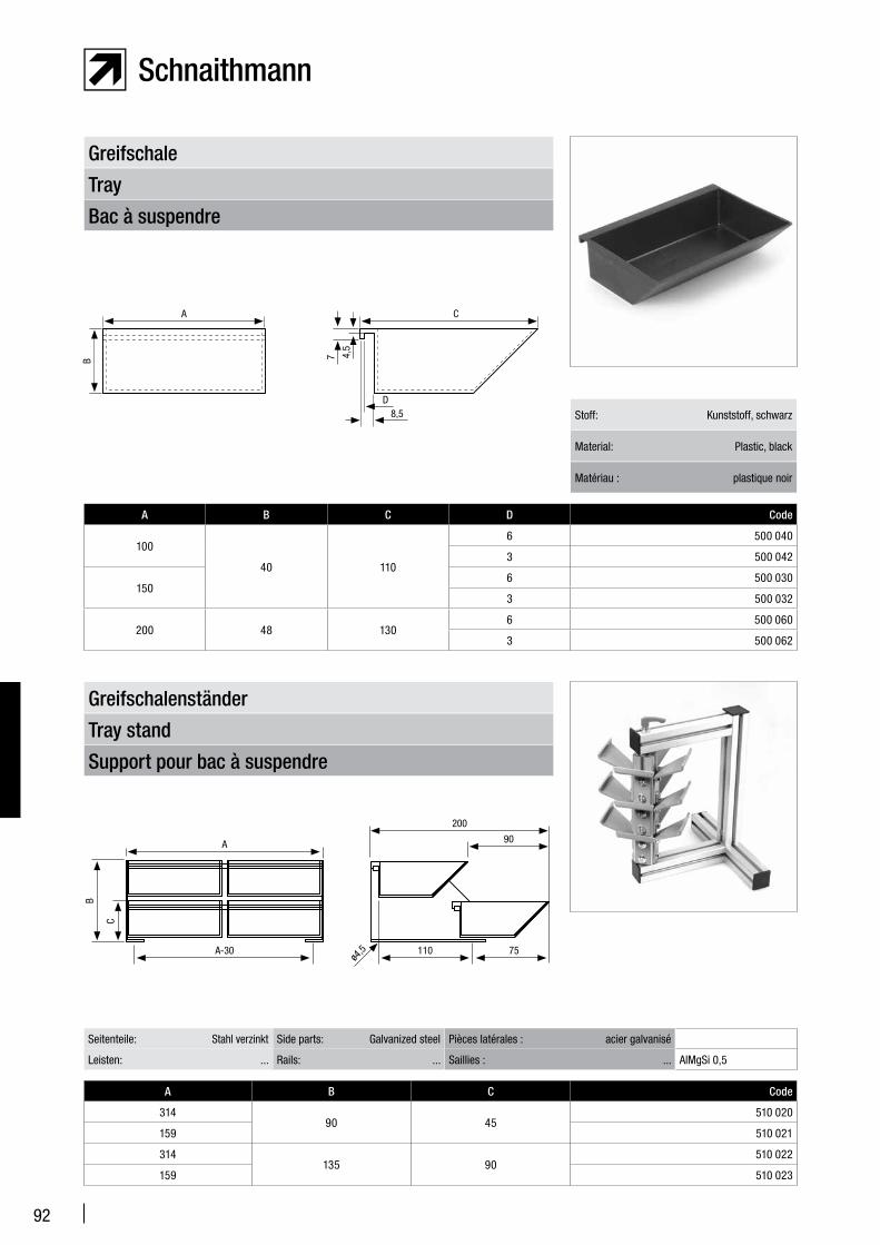
92
Support pour bac à suspendre
Tray stand
Greifschalenständer
A B C Code
31490 45
510 020
159 510 021
314135 90
510 022
159 510 023
Seitenteile: Stahl verzinkt Side parts: Galvanized steel Pièces latérales : acier galvanisé
Leisten: ... Rails: ... Saillies : ... AlMgSi 0,5
Bac à suspendre
Tray
Greifschale
Stoff: Kunststoff, schwarz
Material: Plastic, black
Matériau : plastique noir
A B C D Code
100
40 110
6 500 040
3 500 042
1506 500 030
3 500 032
200 48 1306 500 060
3 500 062
A C
B
8,5D
7 4,5
90
200
A
A-30
B
C
110 75ø4
,5
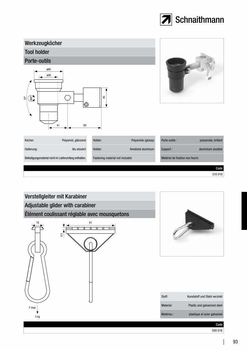
93
Élément coulissant réglable avec mousquetons
Adjustable glider with carabiner
Verstellgleiter mit Karabiner
Stoff: Kunststoff und Stahl verzinkt
Material: Plastic and galvanized steel
Matériau : plastique et acier galvanisé
Code
500 016
Porte-outils
Tool holder
Werkzeugköcher
Code
510 010
Köcher: Polyamid, glänzend Holder: Polyamide (glossy) Porte-outils : polyamide, brillant
Befestigungsmaterial nicht im Lieferumfang enthalten. Fastening material not included Matériel de fixation non fourni.
Halterung: Alu eloxiert Holder: Anodized aluminum Support : aluminium anodisé
41 80
ø66
ø48
75°
360° 45
18
5 kg
F max
81
4,5
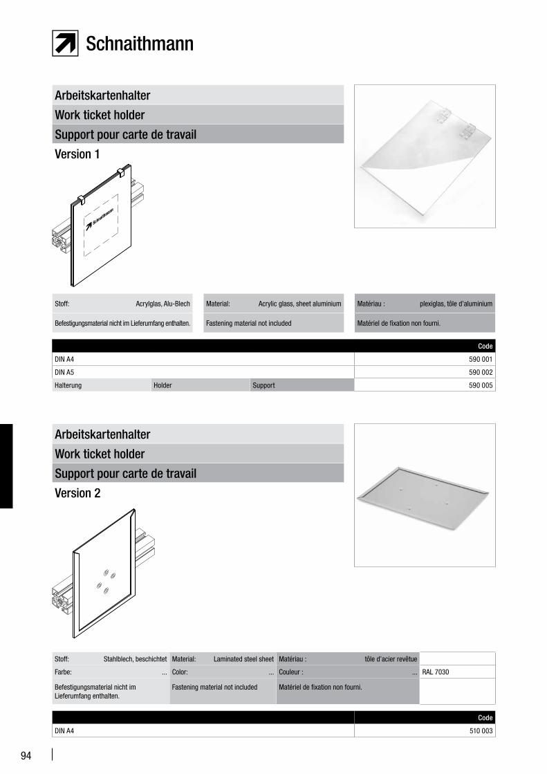
94
Support pour carte de travail
Work ticket holder
Arbeitskartenhalter
Version 2
Code
DIN A4 510 003
Support pour carte de travail
Work ticket holder
Arbeitskartenhalter
Version 1
Code
DIN A4 590 001
DIN A5 590 002
Halterung Holder Support 590 005
Befestigungsmaterial nicht im Lieferumfang enthalten. Fastening material not included Matériel de fixation non fourni.
Stoff: Acrylglas, Alu-Blech Material: Acrylic glass, sheet aluminium Matériau : plexiglas, tôle d’aluminium
Stoff: Stahlblech, beschichtet Material: Laminated steel sheet Matériau : tôle d’acier revêtue
Farbe: ... Color: ... Couleur : ... RAL 7030
Befestigungsmaterial nicht im Lieferumfang enthalten.
Fastening material not included Matériel de fixation non fourni.
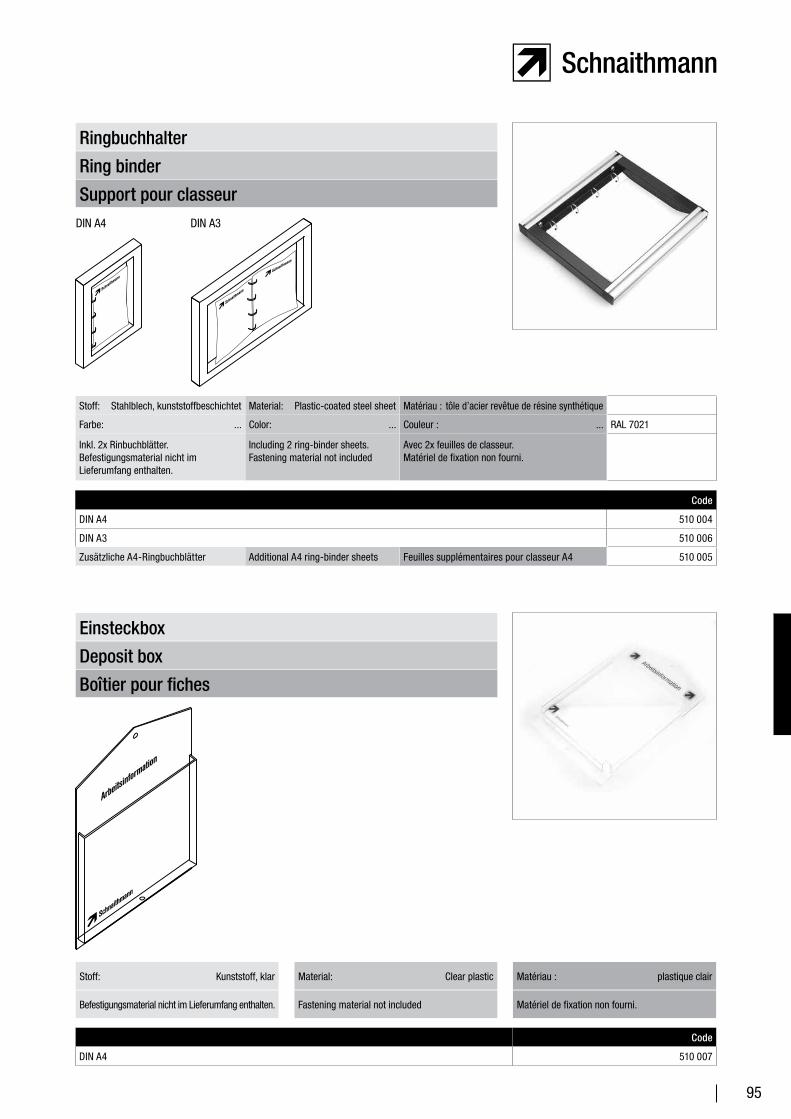
95
Boîtier pour fiches
Deposit box
Einsteckbox
Code
DIN A4 510 007
Support pour classeur
Ring binder
Ringbuchhalter
Code
DIN A4 510 004
DIN A3 510 006
Zusätzliche A4-Ringbuchblätter Additional A4 ring-binder sheets Feuilles supplémentaires pour classeur A4 510 005
Stoff: Stahlblech, kunststoffbeschichtet Material: Plastic-coated steel sheet Matériau : tôle d’acier revêtue de résine synthétique
Farbe: ... Color: ... Couleur : ... RAL 7021
Inkl. 2x Rinbuchblätter.Befestigungsmaterial nicht im Lieferumfang enthalten.
Including 2 ring-binder sheets.Fastening material not included
Avec 2x feuilles de classeur.Matériel de fixation non fourni.
Befestigungsmaterial nicht im Lieferumfang enthalten. Fastening material not included Matériel de fixation non fourni.
Stoff: Kunststoff, klar Material: Clear plastic Matériau : plastique clair
DIN A4 DIN A3
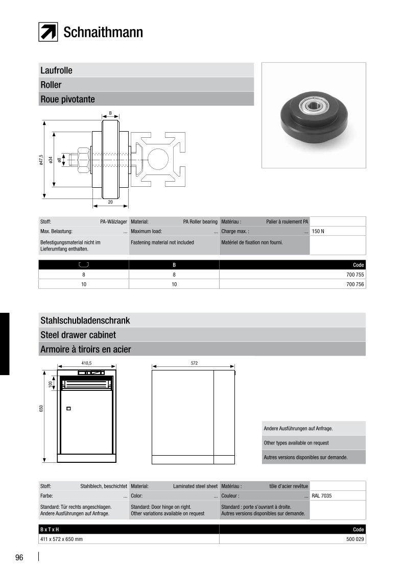
96
Roue pivotante
Roller
Laufrolle
B Code
8 8 700 755
10 10 700 756
Stoff: PA-Wälzlager Material: PA Roller bearing Matériau : Palier à roulement PA
Max. Belastung: ... Maximum load: ... Charge max. : ... 150 N
Befestigungsmaterial nicht im Lieferumfang enthalten.
Fastening material not included Matériel de fixation non fourni.
Armoire à tiroirs en acier
Steel drawer cabinet
Stahlschubladenschrank
B x T x H Code
411 x 572 x 650 mm 500 029
Stoff: Stahlblech, beschichtet Material: Laminated steel sheet Matériau : tôle d’acier revêtue
Farbe: ... Color: ... Couleur : ... RAL 7035
Standard: Tür rechts angeschlagen.Andere Ausführungen auf Anfrage.
Standard: Door hinge on right.Other variations available on request
Standard : porte s’ouvrant à droite.Autres versions disponibles sur demande.
B
20
ø47,
5
ø34
ø8
410,5 572
650
100
Andere Ausführungen auf Anfrage.
Other types available on request
Autres versions disponibles sur demande.
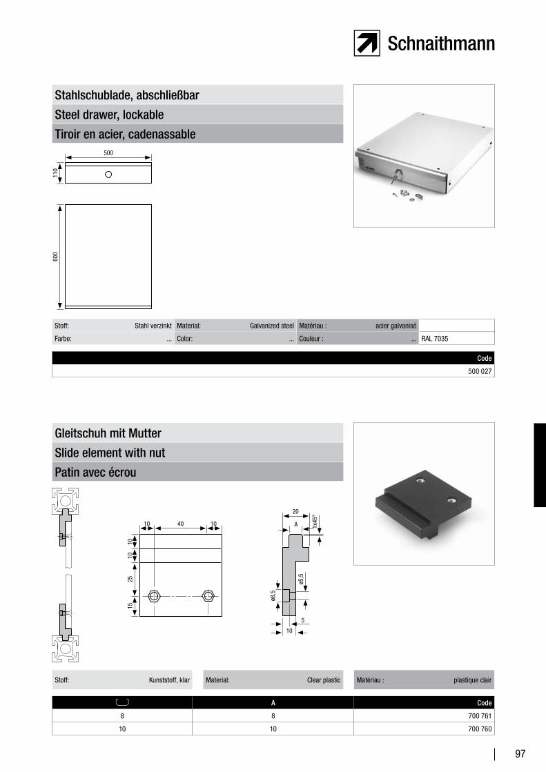
97
Tiroir en acier, cadenassable
Steel drawer, lockable
Stahlschublade, abschließbar
Code
500 027
Stoff: Stahl verzinkt Material: Galvanized steel Matériau : acier galvanisé
Farbe: ... Color: ... Couleur : ... RAL 7035
Patin avec écrou
Slide element with nut
Gleitschuh mit Mutter
A Code
8 8 700 761
10 10 700 760
Stoff: Kunststoff, klar Material: Clear plastic Matériau : plastique clair
600
500
110
1010
2515
104010
ø8,5
A
20
5
10
ø5,5
1x45
°
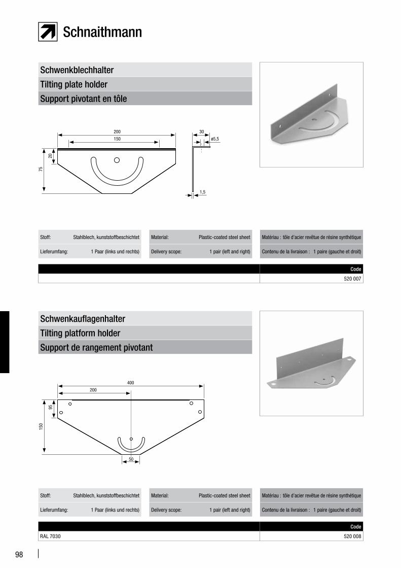
98
Support pivotant en tôle
Tilting plate holder
Schwenkblechhalter
Lieferumfang: 1 Paar (links und rechts) Delivery scope: 1 pair (left and right) Contenu de la livraison : 1 paire (gauche et droit)
Stoff: Stahlblech, kunststoffbeschichtet Material: Plastic-coated steel sheet Matériau : tôle d’acier revêtue de résine synthétique
Support de rangement pivotant
Tilting platform holder
Schwenkauflagenhalter
Code
RAL 7030 520 008
Lieferumfang: 1 Paar (links und rechts) Delivery scope: 1 pair (left and right) Contenu de la livraison : 1 paire (gauche et droit)
Stoff: Stahlblech, kunststoffbeschichtet Material: Plastic-coated steel sheet Matériau : tôle d’acier revêtue de résine synthétique
75
20
200
150
30
ø5,5
1,5
150
95
400
200
50
Code
520 007
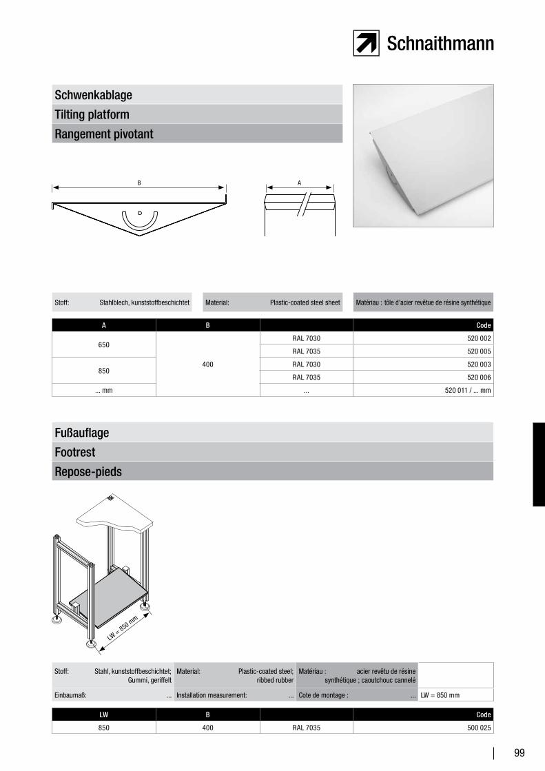
99
Rangement pivotant
Tilting platform
Schwenkablage
A B Code
650
400
RAL 7030 520 002
RAL 7035 520 005
850RAL 7030 520 003
RAL 7035 520 006
... mm ... 520 011 / ... mm
Stoff: Stahlblech, kunststoffbeschichtet Material: Plastic-coated steel sheet Matériau : tôle d’acier revêtue de résine synthétique
Repose-pieds
Footrest
Fußauflage
LW B Code
850 400 RAL 7035 500 025
Stoff: Stahl, kunststoffbeschichtet; Gummi, geriffelt
Material: Plastic-coated steel; ribbed rubber
Matériau : acier revêtu de résine synthétique ; caoutchouc cannelé
Einbaumaß: ... Installation measurement: ... Cote de montage : ... LW = 850 mm
B A
LW = 850 m
m
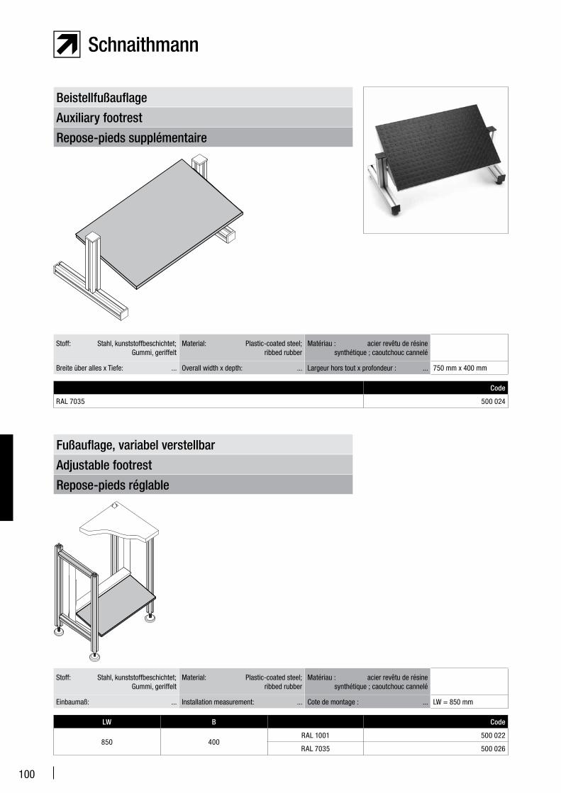
100
Repose-pieds réglable
Adjustable footrest
Fußauflage, variabel verstellbar
LW B Code
850 400RAL 1001 500 022
RAL 7035 500 026
Stoff: Stahl, kunststoffbeschichtet; Gummi, geriffelt
Material: Plastic-coated steel; ribbed rubber
Matériau : acier revêtu de résine synthétique ; caoutchouc cannelé
Einbaumaß: ... Installation measurement: ... Cote de montage : ... LW = 850 mm
Repose-pieds supplémentaire
Auxiliary footrest
Beistellfußauflage
Code
RAL 7035 500 024
Stoff: Stahl, kunststoffbeschichtet; Gummi, geriffelt
Material: Plastic-coated steel; ribbed rubber
Matériau : acier revêtu de résine synthétique ; caoutchouc cannelé
Breite über alles x Tiefe: ... Overall width x depth: ... Largeur hors tout x profondeur : ... 750 mm x 400 mm
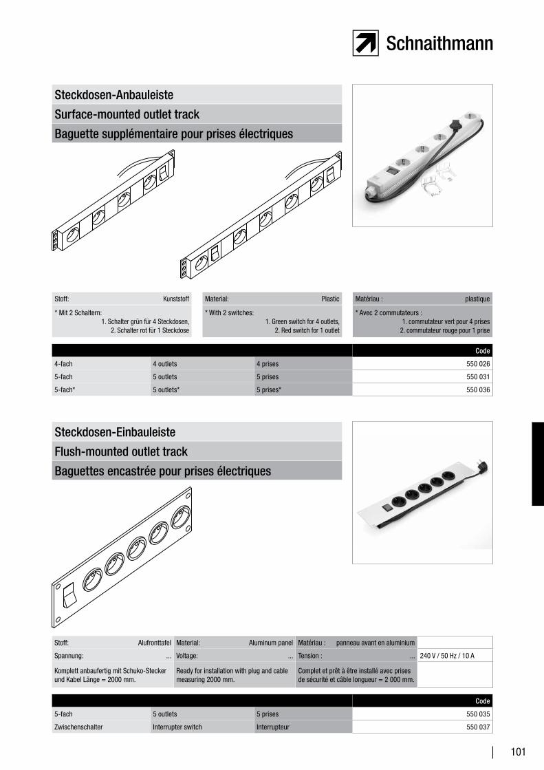
101
Baguette supplémentaire pour prises électriques
Surface-mounted outlet track
Steckdosen-Anbauleiste
Stoff: Kunststoff Material: Plastic Matériau : plastique
* Mit 2 Schaltern: 1. Schalter grün für 4 Steckdosen, 2. Schalter rot für 1 Steckdose
* With 2 switches: 1. Green switch for 4 outlets, 2. Red switch for 1 outlet
* Avec 2 commutateurs : 1. commutateur vert pour 4 prises 2. commutateur rouge pour 1 prise
Code
4-fach 4 outlets 4 prises 550 026
5-fach 5 outlets 5 prises 550 031
5-fach* 5 outlets* 5 prises* 550 036
Baguettes encastrée pour prises électriques
Flush-mounted outlet track
Steckdosen-Einbauleiste
Code
5-fach 5 outlets 5 prises 550 035
Zwischenschalter Interrupter switch Interrupteur 550 037
Stoff: Alufronttafel Material: Aluminum panel Matériau : panneau avant en aluminium
Spannung: ... Voltage: ... Tension : ... 240 V / 50 Hz / 10 A
Komplett anbaufertig mit Schuko-Stecker und Kabel Länge = 2000 mm.
Ready for installation with plug and cable measuring 2000 mm.
Complet et prêt à être installé avec prises de sécurité et câble longueur = 2 000 mm.
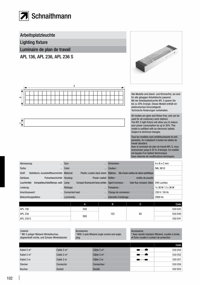
102
Luminaire de plan de travail
Lighting fixture
Arbeitsplatzleuchte
APL 136, APL 236, APL 236 S
Abmessung: ... Size: ... Dimension : ... A x B x C mm
Farbe: ... Color: ... Couleur : ... RAL 9010
Stoff: Stahlblech, kunststoffbeschichtet Material: Plastic-coated steel sheet Matériau : tôle d’acier revêtue de résine synthétique
Gehäuse: Pulverbeschichtet Housing: Power coated Boîtier : revêtu de poudre
Leuchtmittel: Kompaktleuchtstofflampe, weiß Lamp: Compact fluorescent lamp (white) Agent lumineux : tube fluo compact, blanc 840 Lumilux
Leistung: ... Wattage: ... Puissance : ... 1x 36 W / 2 x 36 W
Anschlusswert: ... Connected load: ... Charge de connexion : ... 230 V / 50 Hz
Beleuchtungsstärke: ... Luminosity: ... Intensité d’éclairage : ... 2900 lm
Alle Modelle sind blend- und flimmerfrei, sie sind für alle gängigen Arbeitstische passend.Mit der Arbeitsplatzleuchte APL S sparen Sie bis zu 30% Energie. Dieses Modell enthält ein elektronisches Vorschaltgerät.Technische Änderungen vorbehalten.
All models are glare and flicker-free, and can be used for all customary work stations. The APL S light fixture will allow you to reduce your power consumption by up to 30%. This model is outfitted with an electronic ballast.Subject to technical changes.
Tous les modèles sont antiéblouissants et anti-parasites, ils s’adaptent à toutes les tables de travail standard. Avec le luminaire de plan de travail APL S, vous économisez jusqu’à 30 % d’énergie. Ce modèle est équipé d’un ballast électronique. Sous réserves de modifications techniques.
A B C Code
APL 136 500
125 60
550 042
APL 236900
550 040
APL 236 S 550 041
Zubehör* Mit 3-poliger Wieland-Winkelbuchse, abgewinkelt rechts, und Schuko-Winkelstecker
Accessories* With 3-pole Wieland angle socket and angle plug
Accessoires* Avec douille tripolaire Wieland, coudée à droite, et fiche coudée à contact de protection
Code
Kabel 5 m* Cable 5 m* Câble 5 m* 550 050
Kabel 2 m* Cable 2 m* Câble 2 m* 550 052
Kabel 2 m Cable 2 m Câble 2 m 550 051
Stecker Connector Connecteur 550 056
Buchse Socket Douille 550 055
A
BC
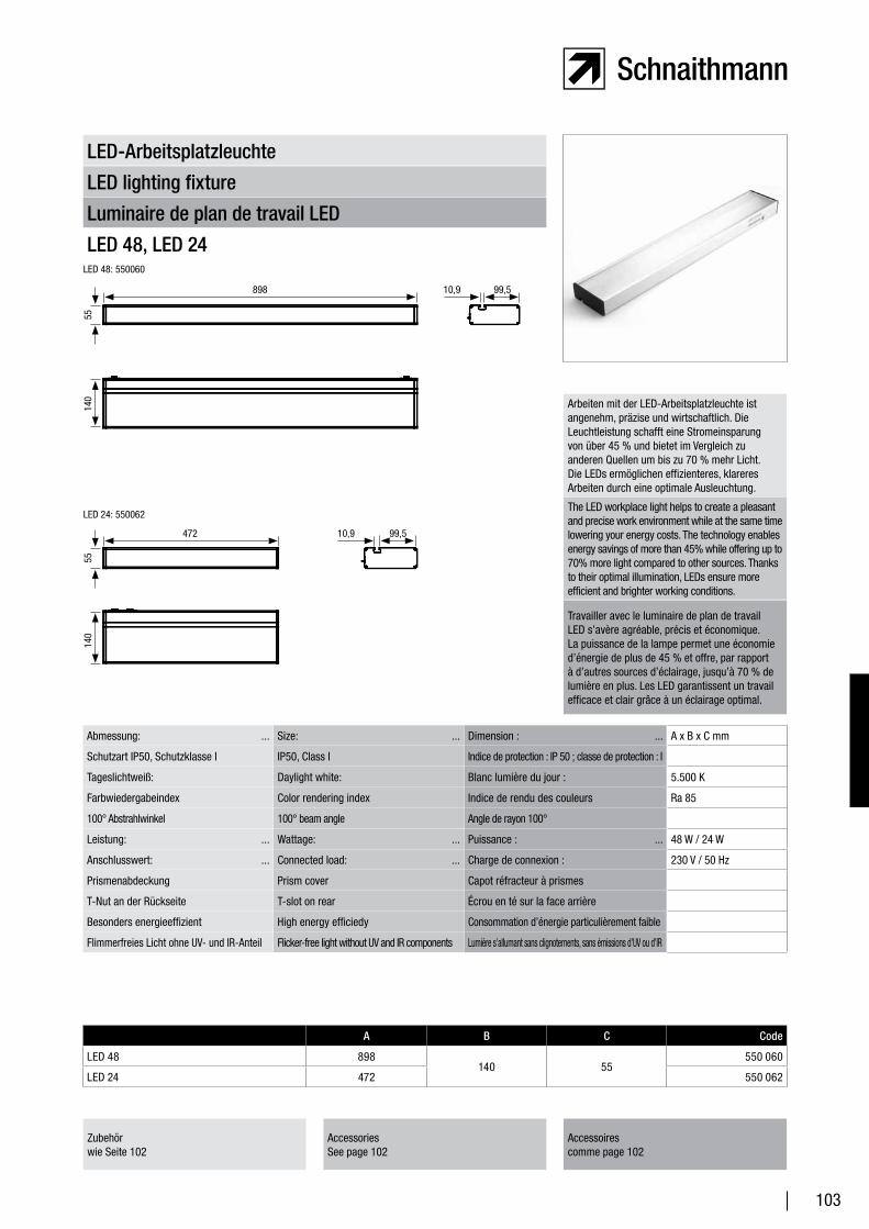
103
Luminaire de plan de travail LED
LED lighting fixture
LED-Arbeitsplatzleuchte
LED 48, LED 24
Abmessung: ... Size: ... Dimension : ... A x B x C mm
Schutzart IP50, Schutzklasse I IP50, Class I Indice de protection : IP 50 ; classe de protection : I
Tageslichtweiß: Daylight white: Blanc lumière du jour : 5.500 K
Farbwiedergabeindex Color rendering index Indice de rendu des couleurs Ra 85
100° Abstrahlwinkel 100° beam angle Angle de rayon 100°
Leistung: ... Wattage: ... Puissance : ... 48 W / 24 W
Anschlusswert: ... Connected load: ... Charge de connexion : 230 V / 50 Hz
Prismenabdeckung Prism cover Capot réfracteur à prismes
T-Nut an der Rückseite T-slot on rear Écrou en té sur la face arrière
Besonders energieeffizient High energy efficiedy Consommation d’énergie particulièrement faible
Flimmerfreies Licht ohne UV- und IR-Anteil Flicker-free light without UV and IR components Lumière s’allumant sans clignotements, sans émissions d’UV ou d’IR
Arbeiten mit der LED-Arbeitsplatzleuchte ist angenehm, präzise und wirtschaftlich. Die Leuchtleistung schafft eine Stromeinsparung von über 45 % und bietet im Vergleich zu anderen Quellen um bis zu 70 % mehr Licht. Die LEDs ermöglichen effizienteres, klareres Arbeiten durch eine optimale Ausleuchtung.
The LED workplace light helps to create a pleasant and precise work environment while at the same time lowering your energy costs. The technology enables energy savings of more than 45% while offering up to 70% more light compared to other sources. Thanks to their optimal illumination, LEDs ensure more efficient and brighter working conditions.
Travailler avec le luminaire de plan de travail LED s’avère agréable, précis et économique. La puissance de la lampe permet une économie d’énergie de plus de 45 % et offre, par rapport à d’autres sources d’éclairage, jusqu’à 70 % de lumière en plus. Les LED garantissent un travail efficace et clair grâce à un éclairage optimal.
A B C Code
LED 48 898140 55
550 060
LED 24 472 550 062
Zubehörwie Seite 102
AccessoriesSee page 102
Accessoirescomme page 102
140
140
898
55
472
LED 24: 550062
LED 48: 550060
10,9 99,5
10,9 99,5
55
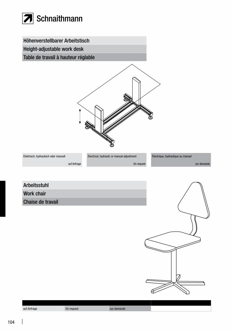
104
Table de travail à hauteur réglable
Height-adjustable work desk
Höhenverstellbarer Arbeitstisch
Elektrisch, hydraulisch oder manuell auf Anfrage
Electrical, hydraulic or manual adjustment
On request
Électrique, hydraulique ou manuel
sur demande
Chaise de travail
Work chair
Arbeitsstuhl
auf Anfrage On request sur demande
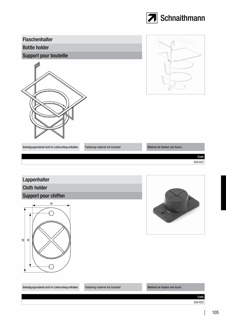
105
Support pour bouteille
Bottle holder
Flaschenhalter
Code
550 022
Befestigungsmaterial nicht im Lieferumfang enthalten. Fastening material not included Matériel de fixation non fourni.
Support pour chiffon
Cloth holder
Lappenhalter
Code
550 023
Befestigungsmaterial nicht im Lieferumfang enthalten. Fastening material not included Matériel de fixation non fourni.
40
68 56
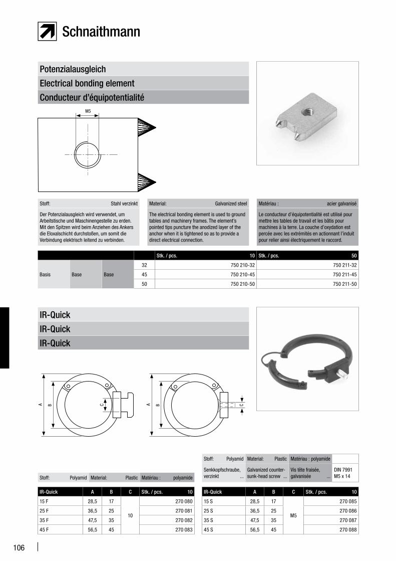
106
Conducteur d’équipotentialité
Electrical bonding element
Potenzialausgleich
Stk. / pcs. 10 Stk. / pcs. 50
Basis Base Base
32 750 210-32 750 211-32
45 750 210-45 750 211-45
50 750 210-50 750 211-50
Stoff: Stahl verzinkt Material: Galvanized steel Matériau : acier galvanisé
Der Potenzialausgleich wird verwendet, um Arbeitstische und Maschinengestelle zu erden. Mit den Spitzen wird beim Anziehen des Ankers die Eloxalschicht durchstoßen, um somit die Verbindung elektrisch leitend zu verbinden.
The electrical bonding element is used to ground tables and machinery frames. The element’s pointed tips puncture the anodized layer of the anchor when it is tightened so as to provide a direct electrical connection.
Le conducteur d’équipotentialité est utilisé pour mettre les tables de travail et les bâtis pour machines à la terre. La couche d’oxydation est percée avec les extrémités en actionnant l’induit pour relier ainsi électriquement le raccord.
IR-Quick
IR-Quick
IR-Quick
IR-Quick A B C Stk. / pcs. 10
15 F 28,5 17
10
270 080
25 F 36,5 25 270 081
35 F 47,5 35 270 082
45 F 56,5 45 270 083
Stoff: Polyamid Material: Plastic Matériau : polyamide
IR-Quick A B C Stk. / pcs. 10
15 S 28,5 17
M5
270 085
25 S 36,5 25 270 086
35 S 47,5 35 270 087
45 S 56,5 45 270 088
Stoff: Polyamid Material: Plastic Matériau : polyamide
Senkkopfschraube, verzinkt ...
Galvanized counter-sunk-head screw ...
Vis tête fraisée, galvanisée ...
DIN 7991 M5 x 14
M5
CCBA BA
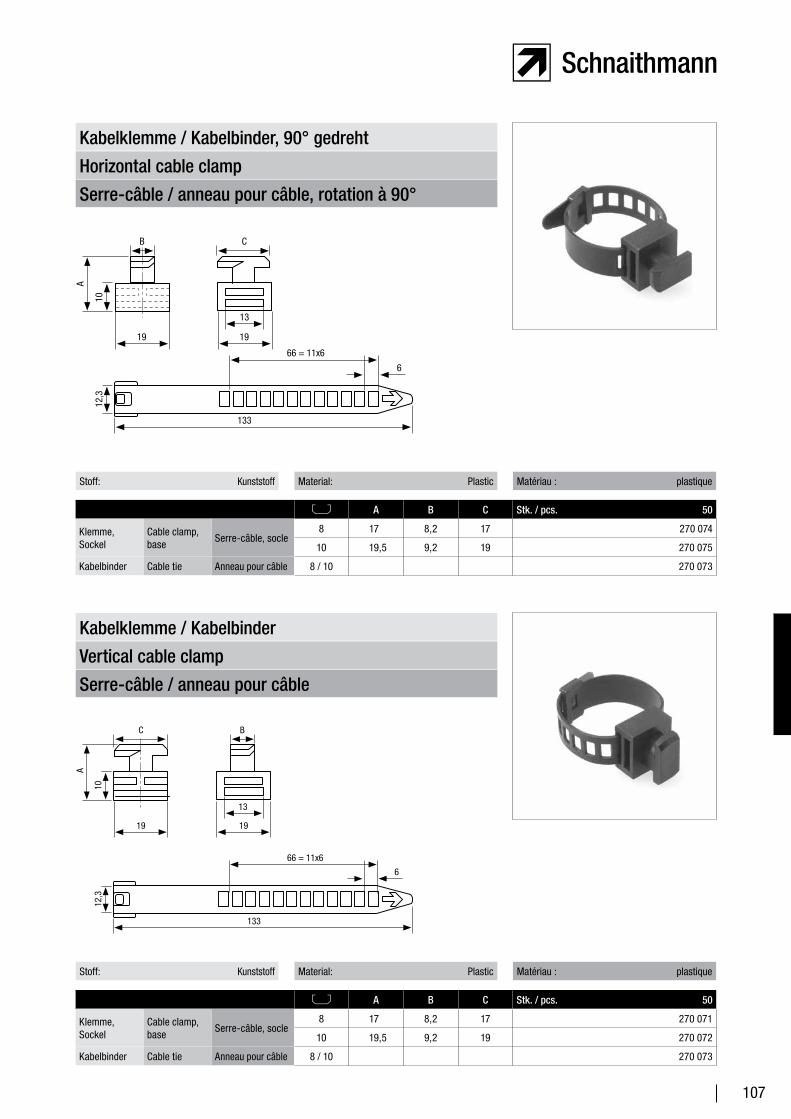
107
Serre-câble / anneau pour câble
Vertical cable clamp
Kabelklemme / Kabelbinder
Serre-câble / anneau pour câble, rotation à 90°
Horizontal cable clamp
Kabelklemme / Kabelbinder, 90° gedreht
Stoff: Kunststoff Material: Plastic Matériau : plastique
A B C Stk. / pcs. 50
Klemme, Sockel
Cable clamp, base
Serre-câble, socle8 17 8,2 17 270 074
10 19,5 9,2 19 270 075
Kabelbinder Cable tie Anneau pour câble 8 / 10 270 073
Stoff: Kunststoff Material: Plastic Matériau : plastique
A B C Stk. / pcs. 50
Klemme, Sockel
Cable clamp, base
Serre-câble, socle8 17 8,2 17 270 071
10 19,5 9,2 19 270 072
Kabelbinder Cable tie Anneau pour câble 8 / 10 270 073
19
13
133
19
CB
66 = 11x6
6
A
1012
,3
19
13
133
19
BC
66 = 11x6
6
A
1012
,3
108
109
Standardisierte Komponenten
Standard Components
Composants standardisés
Standardisierte Komponenten – Produktbeschreibung
Standard components – product description
Composants standardisés – Description du produit
110
Kistenträger Box rack Porte-caisses 111
Drehspeicher Rotary storage rack Réservoir tournant 112
Luftspeicher Air cell Réservoir d’air 113
Luftspeichersystem Air cell system Système de réservoir d’air 114
Schwenkvorrichtung Swivel device Dispositif pivotant 116
Dreh- /Schwenkablage Rotary swivel shelf Rangement pivotant / tournant 116
Dreh- /Schwenkarm Rotary swivel device Bras pivotant / tournant 117
Anwendungsbeispiel: Maschinen-Grundgestell
Sample application: machinery base frame
Exemple d’application : bâti de base pour machines
118
Anwendungsbeispiel: Maschinen-Gestell mit Schutzverkleidung
Sample application: machinery frame with protective cladding
Exemple d’application : bâti pour machines avec revêtement de protection
119
Arbeitstisch Work table Table de travail 120
Gestelle Racks Bâti 121
Festigkeitsberechnungen bei FPS-Profilen
Resistance calculations for FPSsCalculs de résistance pour les profilés FPS
122
Grafische Ermittlung der Festigkeitswerte von FPS-Profilen
Graph showing resistance specifications for FPSs
Détermination graphique des valeurs de résistance des profilés FPS
123
Hinweise auf die DIN-Normen References to DIN standardsRemarques concernant les normes DIN
124
Profile – Technische Daten Profiles – technical specificationsProfilés – Caractéristiques techniques
126
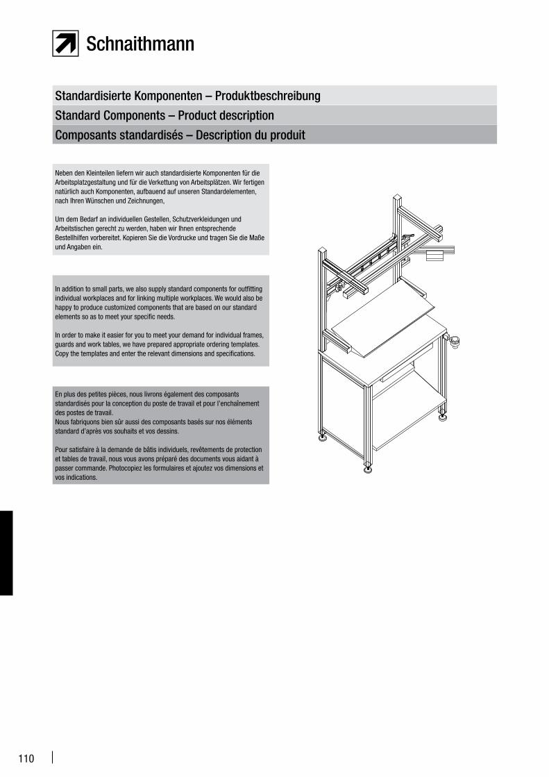
110
Standardisierte Komponenten – Produktbeschreibung
Standard Components – Product description
Composants standardisés – Description du produit
In addition to small parts, we also supply standard components for outfitting individual workplaces and for linking multiple workplaces. We would also be happy to produce customized components that are based on our standard elements so as to meet your specific needs.
In order to make it easier for you to meet your demand for individual frames, guards and work tables, we have prepared appropriate ordering templates. Copy the templates and enter the relevant dimensions and specifications.
En plus des petites pièces, nous livrons également des composants standardisés pour la conception du poste de travail et pour l’enchaînement des postes de travail.Nous fabriquons bien sûr aussi des composants basés sur nos éléments standard d’après vos souhaits et vos dessins.
Pour satisfaire à la demande de bâtis individuels, revêtements de protection et tables de travail, nous vous avons préparé des documents vous aidant à passer commande. Photocopiez les formulaires et ajoutez vos dimensions et vos indications.
Neben den Kleinteilen liefern wir auch standardisierte Komponenten für die Arbeitsplatzgestaltung und für die Verkettung von Arbeitsplätzen. Wir fertigen natürlich auch Komponenten, aufbauend auf unseren Standardelementen, nach Ihren Wünschen und Zeichnungen,
Um dem Bedarf an individuellen Gestellen, Schutzverkleidungen und Arbeitstischen gerecht zu werden, haben wir Ihnen entsprechende Bestellhilfen vorbereitet. Kopieren Sie die Vordrucke und tragen Sie die Maße und Angaben ein.
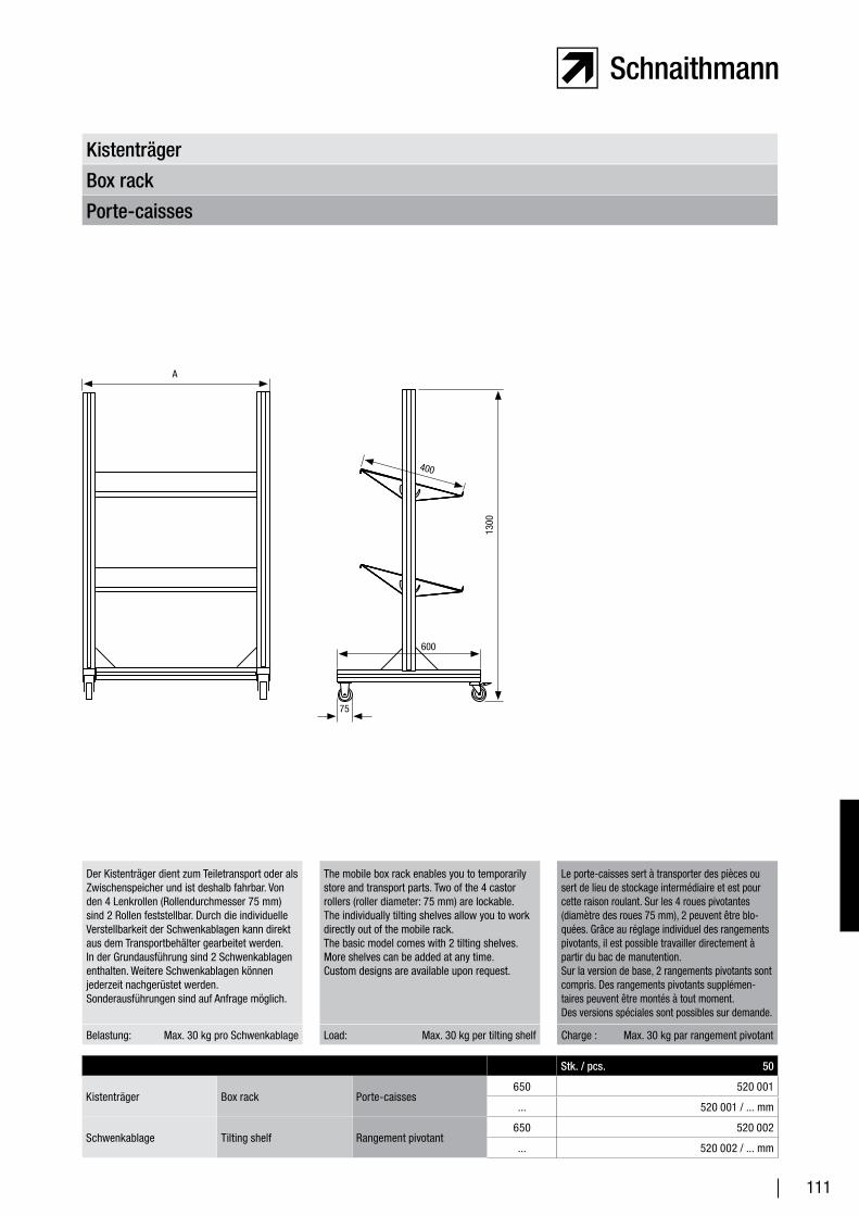
111
Porte-caisses
Box rack
Kistenträger
Stk. / pcs. 50
Kistenträger Box rack Porte-caisses650 520 001
... 520 001 / ... mm
Schwenkablage Tilting shelf Rangement pivotant650 520 002
... 520 002 / ... mm
Belastung: Max. 30 kg pro Schwenkablage Load: Max. 30 kg per tilting shelf Charge : Max. 30 kg par rangement pivotant
Der Kistenträger dient zum Teiletransport oder als Zwischenspeicher und ist deshalb fahrbar. Von den 4 Lenkrollen (Rollendurchmesser 75 mm) sind 2 Rollen feststellbar. Durch die individuelle Verstellbarkeit der Schwenkablagen kann direkt aus dem Transportbehälter gearbeitet werden.In der Grundausführung sind 2 Schwenkablagen enthalten. Weitere Schwenkablagen können jederzeit nachgerüstet werden.Sonderausführungen sind auf Anfrage möglich.
The mobile box rack enables you to temporarily store and transport parts. Two of the 4 castor rollers (roller diameter: 75 mm) are lockable. The individually tilting shelves allow you to work directly out of the mobile rack.The basic model comes with 2 tilting shelves. More shelves can be added at any time.Custom designs are available upon request.
Le porte-caisses sert à transporter des pièces ou sert de lieu de stockage intermédiaire et est pour cette raison roulant. Sur les 4 roues pivotantes (diamètre des roues 75 mm), 2 peuvent être blo-quées. Grâce au réglage individuel des rangements pivotants, il est possible travailler directement à partir du bac de manutention. Sur la version de base, 2 rangements pivotants sont compris. Des rangements pivotants supplémen-taires peuvent être montés à tout moment.Des versions spéciales sont possibles sur demande.
A
600
1300
400
75
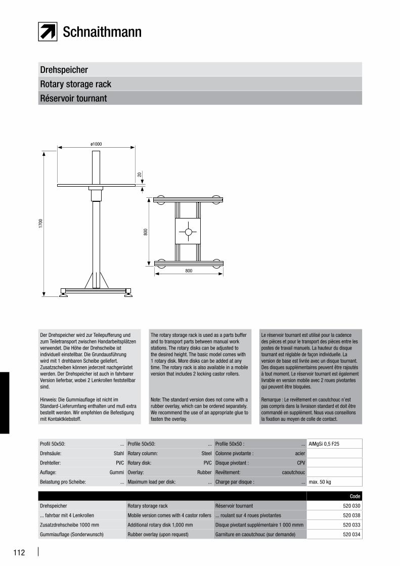
112
Réservoir tournant
Rotary storage rack
Drehspeicher
Code
Drehspeicher Rotary storage rack Réservoir tournant 520 030
... fahrbar mit 4 Lenkrollen Mobile version comes with 4 castor rollers ... roulant sur 4 roues pivotantes 520 038
Zusatzdrehscheibe 1000 mm Additional rotary disk 1,000 mm Disque pivotant supplémentaire 1 000 mmm 520 033
Gummiauflage (Sonderwunsch) Rubber overlay (upon request) Garniture en caoutchouc (sur demande) 520 034
Der Drehspeicher wird zur Teilepufferung und zum Teiletransport zwischen Handarbeitsplätzen verwendet. Die Höhe der Drehscheibe ist individuell einstellbar. Die Grundausführung wird mit 1 drehbaren Scheibe geliefert. Zusatzscheiben können jederzeit nachgerüstet werden. Der Drehspeicher ist auch in fahrbarer Version lieferbar, wobei 2 Lenkrollen feststellbar sind.
Hinweis: Die Gummiauflage ist nicht im Standard-Lieferumfang enthalten und muß extra bestellt werden. Wir empfehlen die Befestigung mit Kontaktklebstoff.
The rotary storage rack is used as a parts buffer and to transport parts between manual work stations. The rotary disks can be adjusted to the desired height. The basic model comes with 1 rotary disk. More disks can be added at any time. The rotary rack is also available in a mobile version that includes 2 locking castor rollers.
Note: The standard version does not come with a rubber overlay, which can be ordered separately. We recommend the use of an appropriate glue to fasten the overlay.
Le réservoir tournant est utilisé pour la cadence des pièces et pour le transport des pièces entre les postes de travail manuels. La hauteur du disque tournant est réglable de façon individuelle. La version de base est livrée avec un disque tournant. Des disques supplémentaires peuvent être rajoutés à tout moment. Le réservoir tournant est également livrable en version mobile avec 2 roues pivotantes qui peuvent être bloquées.
Remarque : Le revêtement en caoutchouc n’est pas compris dans la livraison standard et doit être commandé en supplément. Nous vous conseillons la fixation au moyen de colle de contact.
Profil 50x50: ... Profile 50x50: ... Profile 50x50 : ... AlMgSi 0,5 F25
Drehsäule: Stahl Rotary column: Steel Colonne pivotante : acier
Drehteller: PVC Rotary disk: PVC Disque pivotant : CPV
Auflage: Gummi Overlay: Rubber Revêtement: caoutchouc
Belastung pro Scheibe: ... Maximum load per disk: ... Charge par disque : ... max. 50 kg
ø1000
1700
800
800
20
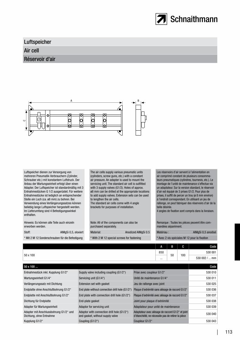
113
Réservoir d’air
Air cell
Luftspeicher
A B C Code
50 x 100850
50 100530 001
... 530 002 / ... mm
Stoff: AlMgSi 0,5, eloxiert Material: Anodized AlMgSi 0.5 Matériau : AlMgSi 0,5 anodisé
Luftspeicher dienen zur Versorgung von mehreren Pneumatik-Verbrauchern (Zylinder, Schrauber etc.) mit konstantem Luftdruck. Der Anbau der Wartungseinheit erfolgt über einen Adapter. Der Luftspeicher ist standardmäßig mit 3 Entnahmestücken G 1/2 ausgerüstet. Für weitere Entnahmestücke ist lediglich an entsprechender Stelle ein Loch (ca. ø8 mm) zu bohren. Bei Verwendung eines Verlängerungssatzes können beliebig lange Luftspeicher hergestellt werden. Im Lieferumfang sind 4 Befestigungswinkel enthalten.
Hinweis: Es können alle Teile auch einzeln erworben werden.
The air cells supply various pneumatic units (cylinders, screw guns, etc.) with a constant air pressure. An adapter is used to mount the servicing unit. The standard air cell is outfitted with 3 supply valves (G1/2). Holes of approx. ø8 mm can be drilled at the appropriate locations to add supply valves. Extension sets can be used to lengthen the air cells.The standard air cells come with 4 angle brackets for purposes of installation.
Note: All of the components can also be purchased separately.
Les réservoirs d’air servent à l’alimentation en air comprimé constant de plusieurs consomma-teurs pneumatiques (cylindres, tournevis, etc.). Le montage de l’unité de maintenance s’effectue via un adaptateur. Sur la version standard, le réservoir d’air est équipé de 3 prises G1/2. Pour plus de prises, il suffit de percer un trou (ø 8 mm environ) à l’endroit correspondant. En utilisant un jeu de rallonge, on peut fabriquer des réservoirs d’air de la taille désirée.4 angles de fixation sont compris dans la livraison.
Remarque : Toutes les pièces peuvent être com-mandées séparément.
* Mit 2 M 12 Sonderschrauben für die Befestigung * With 2 M 12 special screws for fastening * Avec 2 vis spéciales M 12 pour la fixation
50 x 100 ... Code
Entnahmestück inkl. Kupplung G1/2“ Supply valve including coupling (G1/2“) Prise avec coupleur G1/2“ 530 010
Wartungseinheit G1/4“ Servicing unit (G1/4“) Unité de maintenance G1/4“ 530 011
Verlängerungssatz mit Dichtung Extension set with gasket Jeu de rallonge avec joint 530 025
Endplatte ohne Anschlußbohrung G1/2“ End plate without connection drill hole (G1/2“) Plaque d’extrémité sans alésage de raccord G1/2“ 530 036
Endplatte mit Anschlußbohrung G1/2“ End plate with connection drill hole (G1/2“) Plaque d’extrémité avec alésage de raccord G1/2“ 530 037
Dichtung für Endplatte End-plate gasket Joint pour plaque d’extrémité 530 038
Adapter für Wartungseinheit Adaptor for servicing unit Adaptateur pour unité de maintenance 530 039
Adapter mit Anschlussbohrung G1/2“ und Dichtung, ohne Entnahme
Adaptor with connection drill hole (G1/2“) and gasket, without supply valve
Adaptateur avec alésage de raccord G1/2“ et joint d’étanchéité, ne nécessite pas de retirer la pièce
530 040
Kupplung G1/2“ Coupling (G1/2“) Coupleur G1/2“ 530 043
C
A B
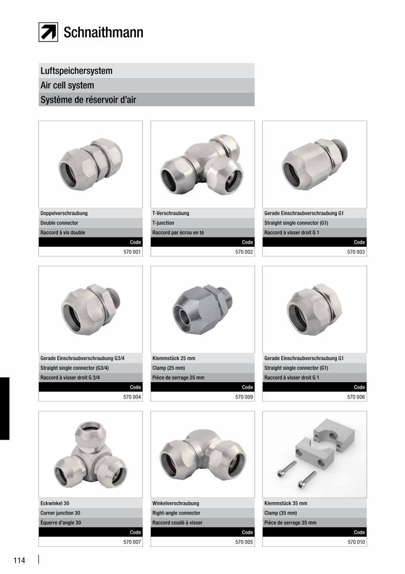
114
Système de réservoir d’air
Air cell system
Luftspeichersystem
Eckwinkel 30
Corner junction 30
Équerre d’angle 30
Code
570 007
Winkelverschraubung
Right-angle connector
Raccord coudé à visser
Code
570 005
Klemmstück 35 mm
Clamp (35 mm)
Pièce de serrage 35 mm
Code
570 010
Gerade Einschraubverschraubung G3/4
Straight single connector (G3/4)
Raccord à visser droit G 3/4
Code
570 004
Klemmstück 25 mm
Clamp (25 mm)
Pièce de serrage 25 mm
Code
570 009
Gerade Einschraubverschraubung G1
Straight single connector (G1)
Raccord à visser droit G 1
Code
570 006
Doppelverschraubung
Double connector
Raccord à vis double
Code
570 001
T-Verschraubung
T-junction
Raccord par écrou en té
Code
570 002
Gerade Einschraubverschraubung G1
Straight single connector (G1)
Raccord à visser droit G 1
Code
570 003
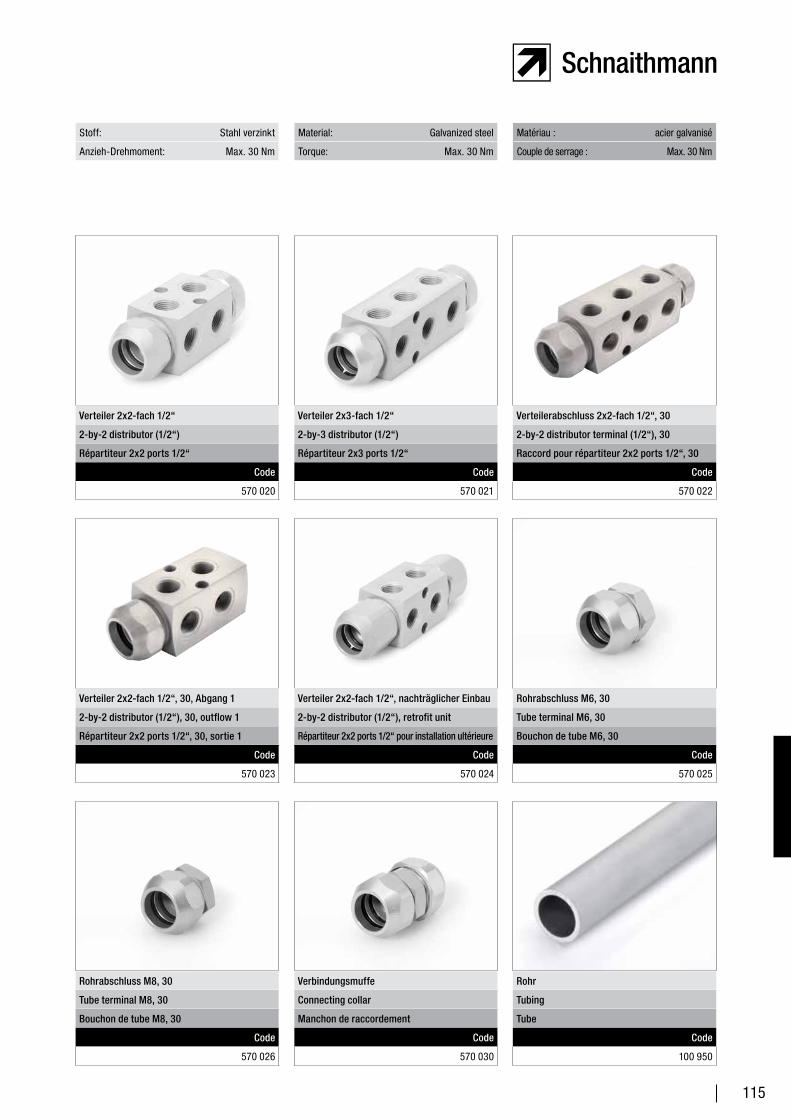
115
Stoff: Stahl verzinkt Material: Galvanized steel Matériau : acier galvanisé
Anzieh-Drehmoment: Max. 30 Nm Torque: Max. 30 Nm Couple de serrage : Max. 30 Nm
Rohrabschluss M8, 30
Tube terminal M8, 30
Bouchon de tube M8, 30
Code
570 026
Verbindungsmuffe
Connecting collar
Manchon de raccordement
Code
570 030
Rohr
Tubing
Tube
Code
100 950
Verteiler 2x2-fach 1/2“, 30, Abgang 1
2-by-2 distributor (1/2“), 30, outflow 1
Répartiteur 2x2 ports 1/2“, 30, sortie 1
Code
570 023
Verteiler 2x2-fach 1/2“, nachträglicher Einbau
2-by-2 distributor (1/2“), retrofit unit
Répartiteur 2x2 ports 1/2“ pour installation ultérieure
Code
570 024
Rohrabschluss M6, 30
Tube terminal M6, 30
Bouchon de tube M6, 30
Code
570 025
Verteiler 2x2-fach 1/2“
2-by-2 distributor (1/2“)
Répartiteur 2x2 ports 1/2“
Code
570 020
Verteiler 2x3-fach 1/2“
2-by-3 distributor (1/2“)
Répartiteur 2x3 ports 1/2“
Code
570 021
Verteilerabschluss 2x2-fach 1/2“, 30
2-by-2 distributor terminal (1/2“), 30
Raccord pour répartiteur 2x2 ports 1/2“, 30
Code
570 022
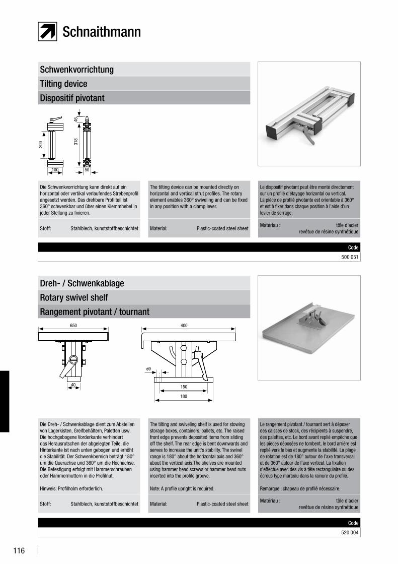
116
Dispositif pivotant
Tilting device
Schwenkvorrichtung
Code
500 051
Die Schwenkvorrichtung kann direkt auf ein horizontal oder vertikal verlaufendes Strebenprofil angesetzt werden. Das drehbare Profilteil ist 360° schwenkbar und über einen Klemmhebel in jeder Stellung zu fixieren.
The tilting device can be mounted directly on horizontal and vertical strut profiles. The rotary element enables 360° swiveling and can be fixed in any position with a clamp lever.
Le dispositif pivotant peut être monté directement sur un profilé d’étayage horizontal ou vertical.La pièce de profilé pivotante est orientable à 360° et est à fixer dans chaque position à l’aide d’un levier de serrage.
Rangement pivotant / tournant
Rotary swivel shelf
Dreh- / Schwenkablage
Code
520 004
Die Dreh- / Schwenkablage dient zum Abstellen von Lagerkisten, Greifbehältern, Paletten usw. Die hochgebogene Vorderkante verhindert das Herausrutschen der abgelegten Teile, die Hinterkante ist nach unten gebogen und erhöht die Stabilität. Der Schwenkbereich beträgt 180° um die Querachse und 360° um die Hochachse.Die Befestigung erfolgt mit Hammerschrauben oder Hammermuttern in die Profilnut.
Hinweis: Profilholm erforderlich.
The tilting and swiveling shelf is used for stowing storage boxes, containers, pallets, etc. The raised front edge prevents deposited items from sliding off the shelf. The rear edge is bent downwards and serves to increase the unit‘s stability. The swivel range is 180° about the horizontal axis and 360° about the vertical axis.The shelves are mounted using hammer head screws or hammer head nuts inserted into the profile groove.
Note: A profile upright is required.
Le rangement pivotant / tournant sert à déposer des caisses de stock, des récipients à suspendre, des palettes, etc. Le bord avant replié empêche que les pièces déposées ne tombent, le bord arrière est replié vers le bas et augmente la stabilité. La plage de rotation est de 180° autour de l’axe transversal et de 360° autour de l’axe vertical. La fixation s’effectue avec des vis à tête rectangulaire ou des écrous type marteau dans la rainure du profilé.
Remarque : chapeau de profilé nécessaire.
Stoff: Stahlblech, kunststoffbeschichtet Material: Plastic-coated steel sheetMatériau : tôle d’acier revêtue de résine synthétique
Stoff: Stahlblech, kunststoffbeschichtet Material: Plastic-coated steel sheetMatériau : tôle d’acier revêtue de résine synthétique
200 31
846
100 50
650 400
40 150
180
ø9
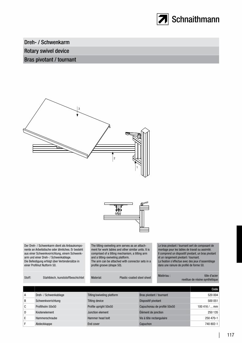
117
Bras pivotant / tournant
Rotary swivel device
Dreh- / Schwenkarm
Der Dreh- / Schwenkarm dient als Anbaukompo-nente an Arbeitstische oder ähnliches. Er besteht aus einer Schwenkvorrichtung, einem Schwenk-arm und einer Dreh- / Schwenkablage.Die Befestigung erfolgt über Verbindersätze in einer Profilnut Nutform 50.
The tilting-swiveling arm serves as an attach-ment for work tables and other similar units. It is comprised of a tilting mechanism, a tilting arm and a tilting-swiveling platform.The arm can be attached with connector sets in a profile groove (shape 50).
Le bras pivotant / tournant sert de composant de montage pour les tables de travail ou assimilé.Il comprend un dispositif pivotant, un bras pivotant et un rangement pivotant / tournant.La fixation s’effectue avec des jeux d’assemblage dans une rainure de profilé de forme 50.
Code
A Dreh- / Schwenkablage Tilting/swiveling platform Bras pivotant / tournant 520 004
B Schwenkvorrichtung Tilting device Dispositif pivotant 500 051
C Profilholm 50x50 Profile upright 50x50 Capuchonau de profilé 50x50 100 416 / ... mm
D Knotenelement Junction element Élément de jonction 250 135
E Hammerschraube Hammer head bolt Vis à tête rectangulaire 250 470-1
F Abdeckkappe End cover Capuchon 740 802-1
Stoff: Stahlblech, kunststoffbeschichtet Material: Plastic-coated steel sheetMatériau : tôle d’acier revêtue de résine synthétique
3
2
1
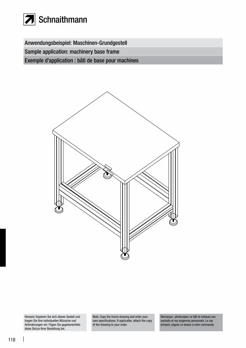
118
Exemple d’application : bâti de base pour machines
Sample application: machinery base frame
Anwendungsbeispiel: Maschinen-Grundgestell
Hinweis: Kopieren Sie sich dieses Gestell und tragen Sie Ihre individuellen Wünsche und Anforderungen ein. Fügen Sie gegebenenfalls diese Skizze Ihrer Bestellung bei.
Note: Copy the frame drawing and enter your own specifications. If applicable, attach the copy of the drawing to your order.
Remarque : photocopiez ce bâti et indiquez vos souhaits et vos exigences personnels. Le cas échéant, joignez ce dessin à votre commande.
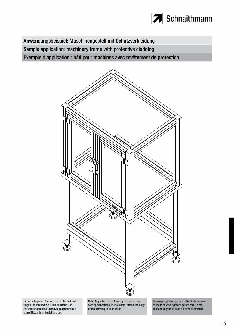
119
Exemple d’application : bâti pour machines avec revêtement de protection
Sample application: machinery frame with protective cladding
Anwendungsbeispiel: Maschinengestell mit Schutzverkleidung
Hinweis: Kopieren Sie sich dieses Gestell und tragen Sie Ihre individuellen Wünsche und Anforderungen ein. Fügen Sie gegebenenfalls diese Skizze Ihrer Bestellung bei.
Note: Copy the frame drawing and enter your own specifications. If applicable, attach the copy of the drawing to your order.
Remarque : photocopiez ce bâti et indiquez vos souhaits et vos exigences personnels. Le cas échéant, joignez ce dessin à votre commande.
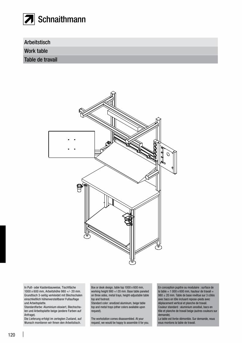
120
Table de travail
Work table
Arbeitstisch
In Pult- oder Kastenbauweise, Tischfläche 1000 x 600 mm, Arbeitshöhe 980 +/- 20 mm. Grundtisch 3-seitig verkleidet mit Blechschalen einschließlich höhenverstellbarer Fußauflage und Arbeitsplatte.Standardfarbe: Aluminium eloxiert, Blechscha-len und Arbeitsplatte beige (andere Farben auf Anfrage). Die Lieferung erfolgt im zerlegten Zustand, auf Wunsch montieren wir Ihnen den Arbeitstisch.
Box or desk design, table top 1000 x 600 mm, working height 980 +/-20 mm. Base table paneled on three sides, metal trays, height-adjustable table top and footrest.Standard color: anodized aluminum, beige table top and metal trays (other colors available upon request).
The workstation comes disassembled. At your request, we would be happy to assemble it for you.
En conception pupitre ou modulaire : surface de la table = 1 000 x 600 mm, hauteur de travail = 980 ± 20 mm. Table de base revêtue sur 3 côtés avec bacs en tôle incluant repose-pieds avec déplacement vertical et planche de travail.Couleur standard : aluminium anodisé, bacs en tôle et planche de travail beige (autres couleurs sur demande).La table est livrée démontée. Sur demande, nous vous montons la table de travail.
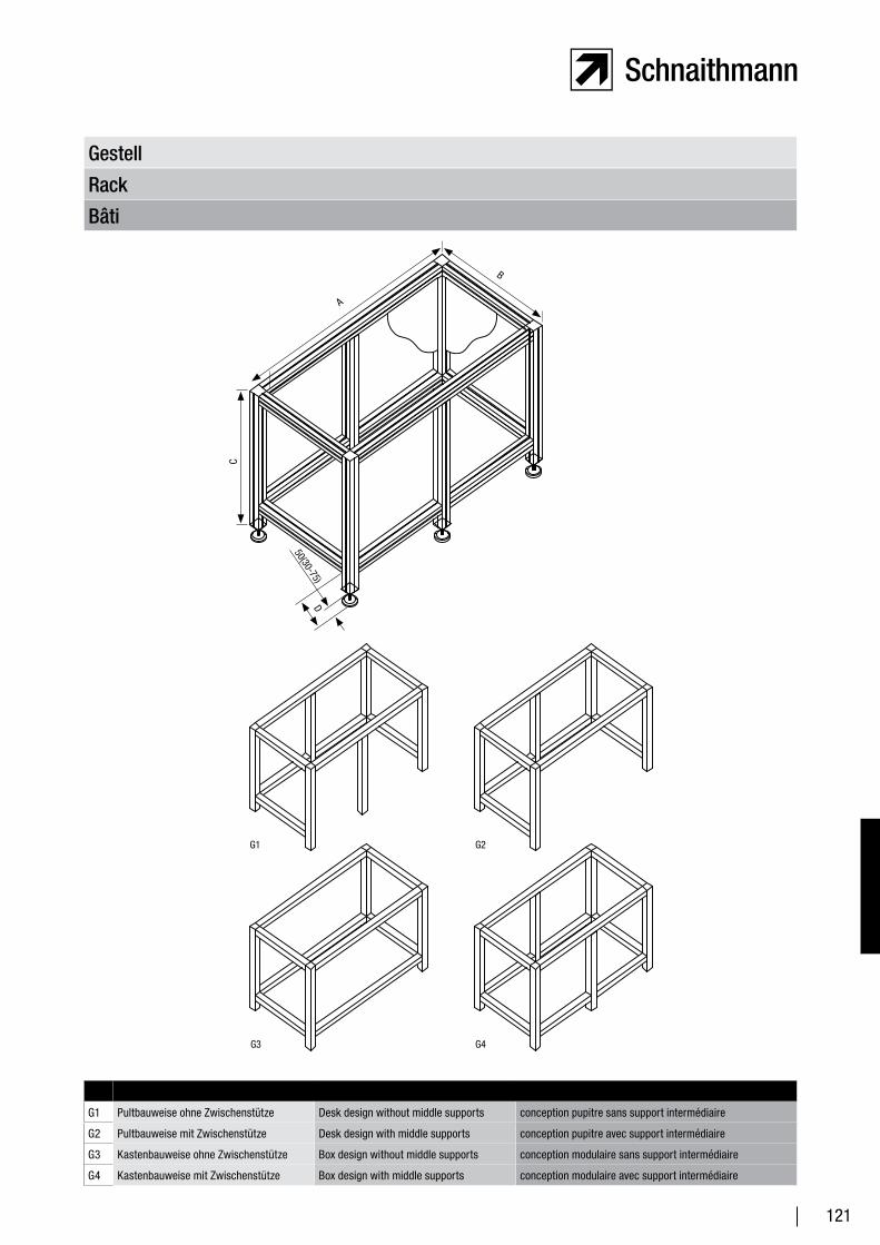
121
Bâti
Rack
Gestell
G1 Pultbauweise ohne Zwischenstütze Desk design without middle supports conception pupitre sans support intermédiaire
G2 Pultbauweise mit Zwischenstütze Desk design with middle supports conception pupitre avec support intermédiaire
G3 Kastenbauweise ohne Zwischenstütze Box design without middle supports conception modulaire sans support intermédiaire
G4 Kastenbauweise mit Zwischenstütze Box design with middle supports conception modulaire avec support intermédiaire
B
A
G1 G2
G4G3
D
50(30-75)
C
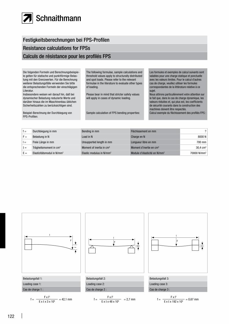
122
Calculs de résistance pour les profilés FPS
Resistance calculations for FPSs
Festigkeitsberechnungen bei FPS-Profilen
Die folgenden Formeln und Berechnungsbeispie-le gelten für statische und punktförmige Belas-tung mit den Grenzwerten. Für die Berechnung weiterer Belastungsfälle verwenden Sie bitte die entsprechenden Formeln der einschlägigen Literatur. Insbesondere weisen wir darauf hin, daß bei dynamischer Belastung reduzierte Werte und darüber hinaus die im Maschinenbau üblichen Sicherheitszahlen zu berücksichtigen sind.
Beispiel-Berechnung der Durchbiegung von FPS-Profilen:
The following formulae, sample calculations and threshold values apply to structurally distributed and spot loads. Please refer to the relevant formulae in the literature to evaluate other types of loading.
Please bear in mind that stricter safety values will apply in cases of dynamic loading.
Sample calculation of FPS bending properties:
Les formules et exemples de calcul suivants sont valables pour une charge statique et ponctuelle avec les valeurs limites. Pour le calcul d’autres cas de charge, veuillez utiliser les formules correspondantes de la littérature relative à ce sujet. Nous attirons particulièrement votre attention sur le fait que, dans le cas de charge dynamique, les valeurs réduites et, qui plus est, les coefficients de sécurité courants dans la construction des machines doivent être respectés.Calcul exemple du fléchissement des profilés FPS :
f = Durchbiegung in mm Bending in mm Fléchissement en mm ?
F = Belastung in N Load in N Charge en N 8000 N
l = Freie Länge in mm Unsupported length in mm Longueur libre en mm 700 mm
I = Trägheitsmoment in cm4 Moment of inertia in cm4 Moment d’inertie en cm4 30,4 cm4
E = Elastizitätsmodul in N/mm2 Elastic modulus in N/mm2 Module d’élasticité en N/mm2 70000 N/mm2
I
F
f
Belastungsfall 1: Belastungsfall 2: Belastungsfall 3:
I
F
f
I
F
f
Loading case 1: Loading case 2: Loading case 3:
Cas de charge 1 : Cas de charge 2 : Cas de charge 3 :
f =F x l3
= 2,7 mmE x I x 48 x 104
f =F x l3
= 0,67 mmE x I x 192 x 104
f =F x l3
= 42,1 mmE x I x 3 x 10⁴
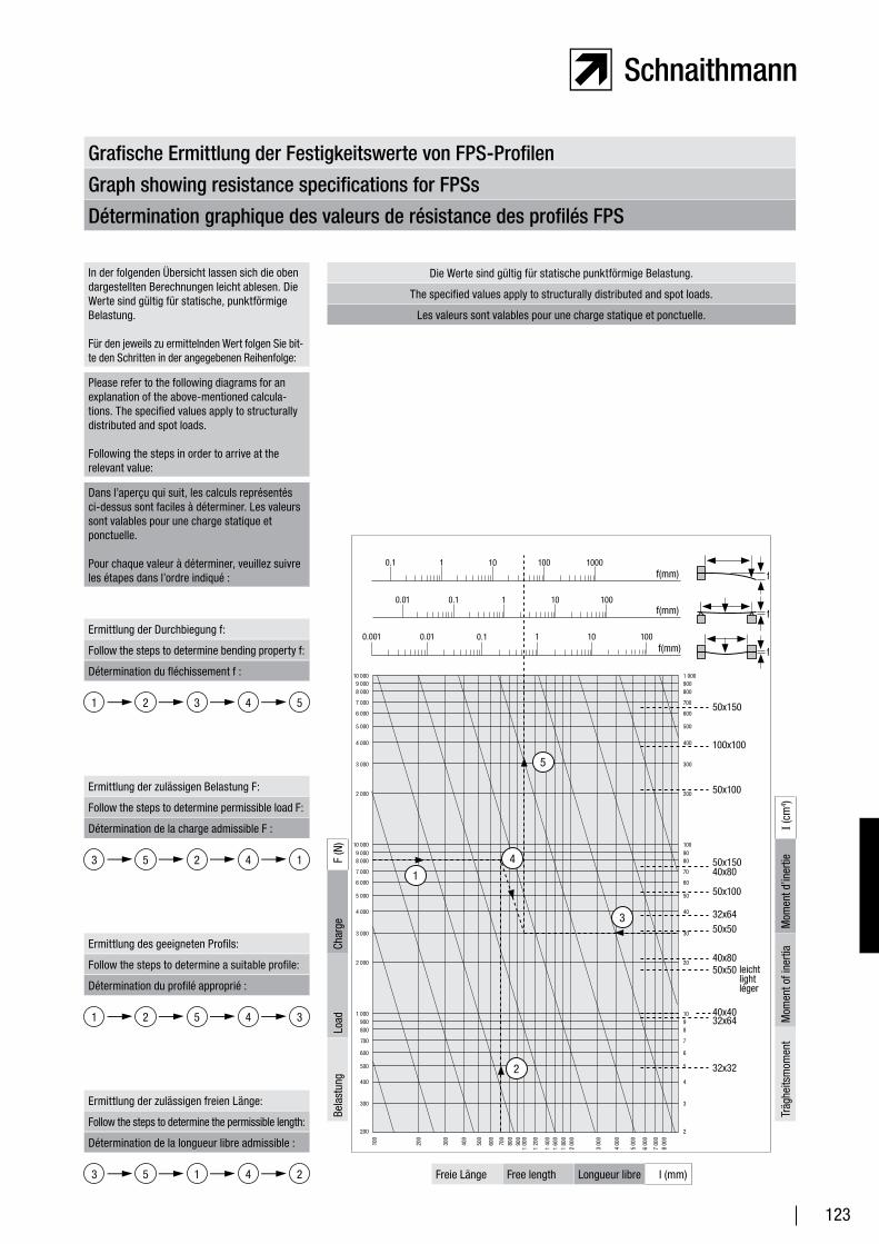
123
Détermination graphique des valeurs de résistance des profilés FPS
Graph showing resistance specifications for FPSs
Grafische Ermittlung der Festigkeitswerte von FPS-Profilen
In der folgenden Übersicht lassen sich die oben dargestellten Berechnungen leicht ablesen. Die Werte sind gültig für statische, punktförmige Belastung.
Für den jeweils zu ermittelnden Wert folgen Sie bit-te den Schritten in der angegebenen Reihenfolge:
Please refer to the following diagrams for an explanation of the above-mentioned calcula-tions. The specified values apply to structurally distributed and spot loads.
Following the steps in order to arrive at the relevant value:
Dans l’aperçu qui suit, les calculs représentés ci-dessus sont faciles à déterminer. Les valeurs sont valables pour une charge statique et ponctuelle.
Pour chaque valeur à déterminer, veuillez suivre les étapes dans l’ordre indiqué :
Ermittlung der Durchbiegung f:
Follow the steps to determine bending property f:
Détermination du fléchissement f :
Ermittlung der zulässigen Belastung F:
Follow the steps to determine permissible load F:
Détermination de la charge admissible F :
Ermittlung des geeigneten Profils:
Follow the steps to determine a suitable profile:
Détermination du profilé approprié :
Ermittlung der zulässigen freien Länge:
Follow the steps to determine the permissible length:
Détermination de la longueur libre admissible :
1 5432
3 1425
1 3452
2415
0.1 1 10 100 1000f(mm)
0.01 0.1 1 10 100f(mm)
0.001 0.01 0.1 1 10 100f(mm)
50x150
100x100
50x100
50x15040x80
50x100
32x6450x50
40x8050x50 leicht
lightléger
40x4032x64
32x32
100
200
300
400
500
600
700
800
900
1 00
0
1 20
0
1 40
01
600
1 80
02
000
3 00
0
4 0
00
5 00
0
6 00
0
7 00
08
000
10 0009 000 8 000
7 000
6 000
5 000
4 000
3 000
2 000
10 0009 000 8 000
7 000
6 000
5 000
4 000
3 000
2 000
1 000900800
700
600
500
400
300
200
1 000900800
700
600
500
400
300
200
1009080
70
60
50
40
30
20
1098
7
6
5
4
3
2
2
f
f
f
14
3
2
5
Die Werte sind gültig für statische punktförmige Belastung.
The specified values apply to structurally distributed and spot loads.
Les valeurs sont valables pour une charge statique et ponctuelle.
Freie Länge Free length Longueur libre l (mm)
Bela
stun
gLo
adCh
arge
F (N
)
Träg
heits
mom
ent
Mom
ent o
f ine
rtia
Mom
ent d
’iner
tieI (
cm4 )
3
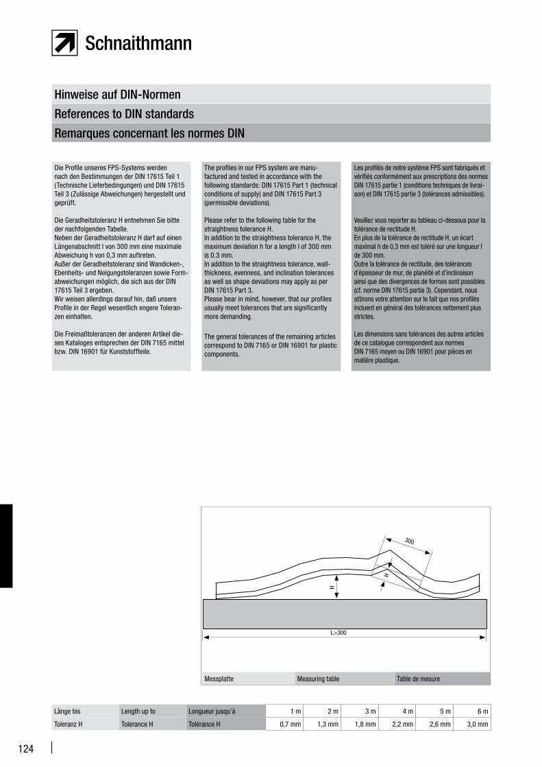
124
Remarques concernant les normes DIN
References to DIN standards
Hinweise auf DIN-Normen
Die Profile unseres FPS-Systems werden nach den Bestimmungen der DIN 17615 Teil 1 (Technische Lieferbedingungen) und DIN 17615 Teil 3 (Zulässige Abweichungen) hergestellt und geprüft.
Die Geradheitstoleranz H entnehmen Sie bitte der nachfolgenden Tabelle.Neben der Geradheitstoleranz H darf auf einen Längenabschnitt I von 300 mm eine maximale Abweichung h von 0,3 mm auftreten.Außer der Geradheitstoleranz sind Wandicken-, Ebenheits- und Neigungstoleranzen sowie Form-abweichungen möglich, die sich aus der DIN 17615 Teil 3 ergeben.Wir weisen allerdings darauf hin, daß unsere Profile in der Regel wesentlich engere Toleran-zen einhalten.
Die Freimaßtoleranzen der anderen Artikel die-ses Kataloges entsprechen der DIN 7165 mittel bzw. DIN 16901 für Kunststoffteile.
The profiles in our FPS system are manu-factured and tested in accordance with the following standards: DIN 17615 Part 1 (technical conditions of supply) and DIN 17615 Part 3 (permissible deviations).
Please refer to the following table for the straightness tolerance H.In addition to the straightness tolerance H, the maximum deviation h for a length I of 300 mm is 0.3 mm.In addition to the straightness tolerance, wall-thickness, evenness, and inclination tolerances as well as shape deviations may apply as per DIN 17615 Part 3.Please bear in mind, however, that our profiles usually meet tolerances that are significantly more demanding.
The general tolerances of the remaining articles correspond to DIN 7165 or DIN 16901 for plastic components.
Les profilés de notre système FPS sont fabriqués et vérifiés conformément aux prescriptions des normes DIN 17615 partie 1 (conditions techniques de livrai-son) et DIN 17615 partie 3 (tolérances admissibles).
Veuillez vous reporter au tableau ci-dessous pour la tolérance de rectitude H. En plus de la tolérance de rectitude H, un écart maximal h de 0,3 mm est toléré sur une longueur I de 300 mm. Outre la tolérance de rectitude, des tolérances d’épaisseur de mur, de planéité et d’inclinaison ainsi que des divergences de formes sont possibles (cf. norme DIN 17615 partie 3). Cependant, nous attirons votre attention sur le fait que nos profilés incluent en général des tolérances nettement plus strictes.
Les dimensions sans tolérances des autres articles de ce catalogue correspondent aux normes DIN 7165 moyen ou DIN 16901 pour pièces en matière plastique.
Länge bis Length up to Longueur jusqu’à 1 m 2 m 3 m 4 m 5 m 6 m
Toleranz H Tolerance H Tolérance H 0,7 mm 1,3 mm 1,8 mm 2,2 mm 2,6 mm 3,0 mm
Messplatte Measuring table Table de mesure
H
H
L>300
300

125
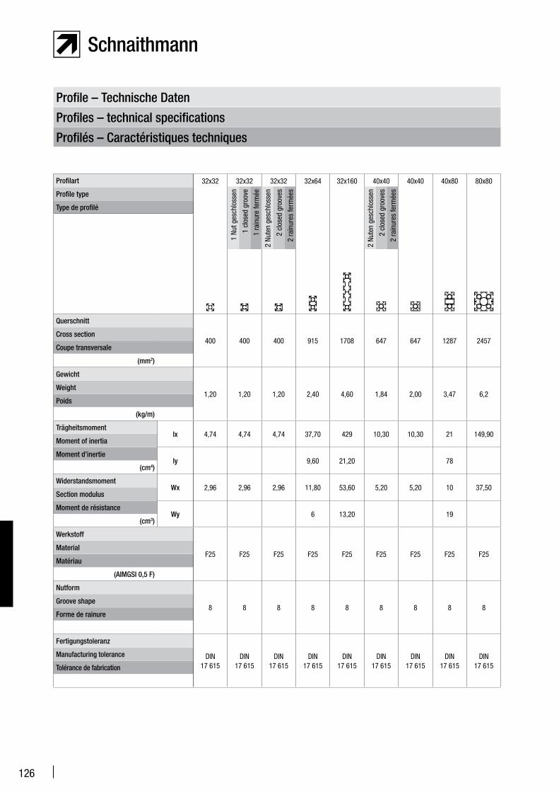
126
Profile – Technische Daten
Profiles – technical specifications
Profilés – Caractéristiques techniques
Profilart
Profile type
Type de profilé
Querschnitt
Cross section
Coupe transversale
(mm2)
Gewicht
Weight
Poids
(kg/m)
Trägheitsmomentlx
Moment of inertia
Moment d’inertiely
(cm4)
WiderstandsmomentWx
Section modulus
Moment de résistanceWy
(cm3)
Werkstoff
Material
Matériau
(AIMGSI 0,5 F)
Nutform
Groove shape
Forme de rainure
Fertigungstoleranz
Manufacturing tolerance
Tolérance de fabrication
32x32 32x32 32x32 32x64 32x160 40x40 40x40 40x80 80x80
400 400 400 915 1708 647 647 1287 2457
1,20 1,20 1,20 2,40 4,60 1,84 2,00 3,47 6,2
4,74 4,74 4,74 37,70 429 10,30 10,30 21 149,90
9,60 21,20 78
2,96 2,96 2,96 11,80 53,60 5,20 5,20 10 37,50
6 13,20 19
F25 F25 F25 F25 F25 F25 F25 F25 F25
8 8 8 8 8 8 8 8 8
DIN 17 615
DIN 17 615
DIN 17 615
DIN 17 615
DIN 17 615
DIN 17 615
DIN 17 615
DIN 17 615
DIN 17 615
2 Nu
ten
gesc
hlos
sen
2 cl
osed
gro
oves
2 ra
inur
es fe
rmée
s
2 Nu
ten
gesc
hlos
sen
2 cl
osed
gro
oves
2 ra
inur
es fe
rmée
s
1 Nu
t ges
chlo
ssen
1 cl
osed
gro
ove
1 ra
inur
e fe
rmée
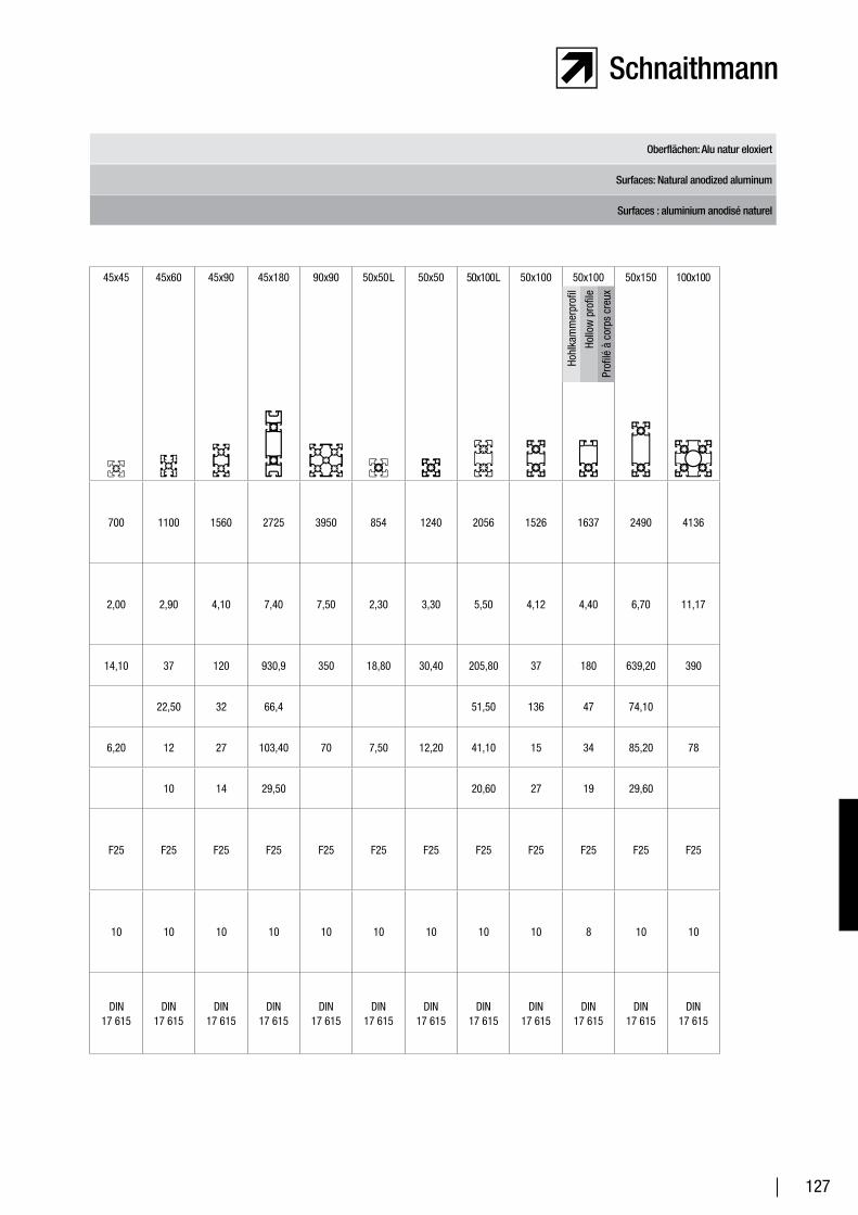
127
Oberflächen: Alu natur eloxiert
Surfaces: Natural anodized aluminum
Surfaces : aluminium anodisé naturel
45x45 45x60 45x90 45x180 90x90 50x50 L 50x50 50x100 L 50x100 50x100 50x150 100x100
700 1100 1560 2725 3950 854 1240 2056 1526 1637 2490 4136
2,00 2,90 4,10 7,40 7,50 2,30 3,30 5,50 4,12 4,40 6,70 11,17
14,10 37 120 930,9 350 18,80 30,40 205,80 37 180 639,20 390
22,50 32 66,4 51,50 136 47 74,10
6,20 12 27 103,40 70 7,50 12,20 41,10 15 34 85,20 78
10 14 29,50 20,60 27 19 29,60
F25 F25 F25 F25 F25 F25 F25 F25 F25 F25 F25 F25
10 10 10 10 10 10 10 10 10 8 10 10
DIN 17 615
DIN 17 615
DIN 17 615
DIN 17 615
DIN 17 615
DIN 17 615
DIN 17 615
DIN 17 615
DIN 17 615
DIN 17 615
DIN 17 615
DIN 17 615
Hohl
kam
mer
prof
il
Hollo
w p
rofil
e
Prof
ilé à
cor
ps c
reux
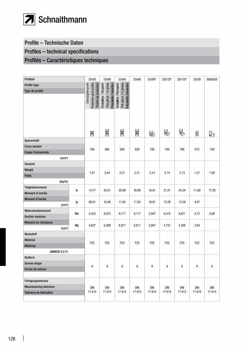
128
Profile – Technische Daten
Profiles – technical specifications
Profilés – Caractéristiques techniques
32x50 32x68 32x68 32x68 32x90° 32x120° 32x135° 25x50 50x50x25
706 904 929 929 795 794 788 575 740
1,91 2,44 2,51 2,51 2,14 2,14 2,13 1,57 1,80
14,77 30,51 30,99 30,99 16,91 21,51 24,34 11,80 17,20
80,01 10,48 11,05 11,05 16,91 15,29 13,59 4,47
5,423 8,975 9,117 9,117 5,947 6,474 6,671 4,72 8,89
4,827 6,389 6,911 6,911 5,947 4,731 4,358 3,84
F25 F25 F25 F25 F25 F25 F25 F25 F25
8 8 8 8 8 8 8 8 8
DIN 17 615
DIN 17 615
DIN 17 615
DIN 17 615
DIN 17 615
DIN 17 615
DIN 17 615
DIN 17 615
DIN 17 615
Profilart
Profile type
Type de profilé
Querschnitt
Cross section
Coupe transversale
(mm2)
Gewicht
Weight
Poids
(kg/m)
Trägheitsmomentlx
Moment of inertia
Moment d’inertiely
(cm4)
WiderstandsmomentWx
Section modulus
Moment de résistanceWy
(cm3)
Werkstoff
Material
Matériau
(AIMGSI 0,5 F)
Nutform
Groove shape
Forme de rainure
Fertigungstoleranz
Manufacturing tolerance
Tolérance de fabrication
Schu
tzgi
tterp
rofil
Prot
ectiv
e gr
id p
rofil
e
Prof
ilé d
e pr
otec
tion
Schu
tzgitte
rpr., 1
Nut
gesc
hl.
Prot.
grid
pr., 1
cl. g
roov
e
Pr. de
prote
ction, 1
rainu
re fer
m.
Schu
tzgitte
rpr., 2
Nut e
nges
chl.
Prot.
grid
pr., 2
cl. g
roov
es
Pr. de
prote
ction, 2
rainu
res fer
m.
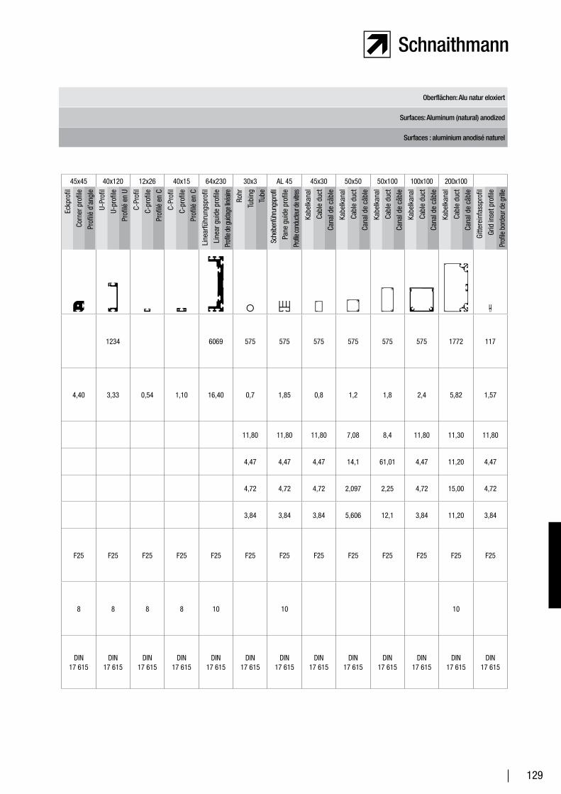
129
Oberflächen: Alu natur eloxiert
Surfaces: Aluminum (natural) anodized
Surfaces : aluminium anodisé naturel
45x45 40x120 12x26 40x15 64x230 30x3 AL 45 45x30 50x50 50x100 100x100 200x100
1234 6069 575 575 575 575 575 575 1772 117
4,40 3,33 0,54 1,10 16,40 0,7 1,85 0,8 1,2 1,8 2,4 5,82 1,57
11,80 11,80 11,80 7,08 8,4 11,80 11,30 11,80
4,47 4,47 4,47 14,1 61,01 4,47 11,20 4,47
4,72 4,72 4,72 2,097 2,25 4,72 15,00 4,72
3,84 3,84 3,84 5,606 12,1 3,84 11,20 3,84
F25 F25 F25 F25 F25 F25 F25 F25 F25 F25 F25 F25 F25
8 8 8 8 10 10 10
DIN 17 615
DIN 17 615
DIN 17 615
DIN 17 615
DIN 17 615
DIN 17 615
DIN 17 615
DIN 17 615
DIN 17 615
DIN 17 615
DIN 17 615
DIN 17 615
DIN 17 615
Eckp
rofil
Corn
er p
rofil
e
Prof
ilé d
’ang
le
Sche
ibenf
ühru
ngsp
rofil
Pane
gui
de p
rofil
e
Profi
le co
nduc
teur d
e vitre
s
C-Pr
ofil
C-pr
ofile
Prof
ilé e
n C
Kabe
lkan
al
Cabl
e du
ct
Cana
l de
câbl
e
U-Pr
ofil
U-pr
ofile
Prof
ilé e
n U
Kabe
lkan
al
Cabl
e du
ct
Cana
l de
câbl
e
Line
arfü
hrun
gspr
ofil
Line
ar g
uide
pro
file
Profi
le de
guida
ge lin
éaire
Kabe
lkan
al
Cabl
e du
ct
Cana
l de
câbl
e
C-Pr
ofil
C-pr
ofile
Prof
ilé e
n C
Kabe
lkan
al
Cabl
e du
ct
Cana
l de
câbl
e
Rohr
Tubi
ng
Tube
Kabe
lkan
al
Cabl
e du
ct
Cana
l de
câbl
e
Gitte
rein
fass
prof
il
Grid
inse
t pro
file
Prof
ile b
orde
ur d
e gr
ille

130

131

132
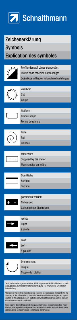
Zeichenerklärung
Symbols
Explication des symboles
Profilenden auf Länge plangesägt
Profile ends machine cut to length
Extrémités de profilé sciées horizontalement sur la longueur
Zuschnitt
Cut
Coupe
Nutform
Groove shape
Forme de rainure
Rolle
Roll
Rouleau
Meterware
Supplied by the meter
Marchandise au mètre
Oberfläche
Surface
Surface
galvanisch verzinkt
Galvanized
Galvanisé par électrolyse
rechts
Right
à droite
links
Left
à gauche
Drehmoment
Torque
Couple de rotation
Technische Änderungen vorbehalten, Abbildungen unverbindlich. Nachdruck, auch auszugsweise, nur mit schriflicher Genehmigung. Für Irrtümer und Druckfehler keine Haftung.
We reserve the right to make technical changes and can accept no liability for the accuracy of the information or illustrations contained in the catalogue. Any repro-duction of the catalogue or any parts thereof without the express, written consent of the manufacturer is prohibited.
Sous réserve de modifications techniques, illustrations non contractuelles. Repro-duction, même partielle, uniquement sur autorisation écrite. Nous déclinons toute responsabilité en cas d’erreurs ou de fautes d’impression.
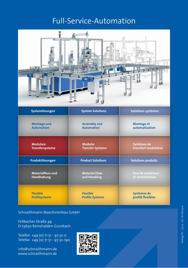
Full-Service-Automation
Kata
log
FPS
| 0
5/14
– A
rt. -
Nr.
8200
504
ModulareTransfersysteme
ModularTransfer Systems
Systèmes de transfert modulaires
FlexibleProfilsysteme
FlexibleProfile Systems
Systèmes de profilé flexibles
Materialfluss und Handhabung
Material Flowand Handling
Flux de matériaux et manutention
Montage und Automation
Assembly andAutomation
Montage et automatisation
Produktlösungen Product Solutions Solutions produits
Systemlösungen System Solutions Solutions systèmes
Schnaithmann Maschinenbau GmbH
Fellbacher Straße 49D-73630 Remshalden-Grunbach
Telefon +49 (0) 71 51 - 97 32-0Telefax +49 (0) 71 51 - 97 32-190
FPS
K
atal
og . C
atal
ogue
. Cat
alog
ue . K
27