en 14470-2:2006 - 64 e stf - asecos nen-en-14470-2.pdf · en 14470-2 august 2006 ... part 1: safety...
TRANSCRIPT
EUROPEAN STANDARD
NORME EUROPÉENNE
EUROPÄISCHE NORM
EN 14470-2
August 2006
ICS 13.220.40; 71.040.10
English Version
Fire safety storage cabinets - Part 2: Safety cabinets forpressurised gas cylinders
Armoires de stockage de sécurité incendie - Partie 2 :Armoires de stockage de sécurité pour bouteilles de gaz
comprimé
Feuerwiderstandsfähige Lagerschränke - Teil 2:Sicherheitsschränke für Druckgasflaschen
This European Standard was approved by CEN on 21 July 2006.
CEN members are bound to comply with the CEN/CENELEC Internal Regulations which stipulate the conditions for giving this EuropeanStandard the status of a national standard without any alteration. Up-to-date lists and bibliographical references concerning such nationalstandards may be obtained on application to the Central Secretariat or to any CEN member.
This European Standard exists in three official versions (English, French, German). A version in any other language made by translationunder the responsibility of a CEN member into its own language and notified to the Central Secretariat has the same status as the officialversions.
CEN members are the national standards bodies of Austria, Belgium, Cyprus, Czech Republic, Denmark, Estonia, Finland, France,Germany, Greece, Hungary, Iceland, Ireland, Italy, Latvia, Lithuania, Luxembourg, Malta, Netherlands, Norway, Poland, Portugal, Romania,Slovakia, Slovenia, Spain, Sweden, Switzerland and United Kingdom.
EUROPEAN COMMITTEE FOR STANDARDIZATIONC OM ITÉ EUR OP ÉEN DE NOR M ALIS AT IONEUROPÄISCHES KOMITEE FÜR NORMUNG
Management Centre: rue de Stassart, 36 B-1050 Brussels
© 2006 CEN All rights of exploitation in any form and by any means reservedworldwide for CEN national Members.
Ref. No. EN 14470-2:2006: E
EN 14470-2:2006 (E)
2
Contents Page
Foreword..............................................................................................................................................................3 Introduction .........................................................................................................................................................4 1 Scope ......................................................................................................................................................5 2 Normative references ............................................................................................................................5 3 Terms and Definitions ...........................................................................................................................5 4 Classification..........................................................................................................................................6 5 Construction...........................................................................................................................................6 5.1 Fire protection........................................................................................................................................6 5.2 Ventilation...............................................................................................................................................6 5.3 Gas cylinder restraining........................................................................................................................7 5.4 Insertion and removal of pressurised gas cylinders ........................................................................7 5.5 Installation of gas pipelines (for gas cylinders in use)......................................................................7 5.6 Installation of electric cables (where appropriate).............................................................................7 6 Fire resistance........................................................................................................................................7 7 Information to be supplied....................................................................................................................7 8 Manufacturer's marking and labelling .................................................................................................8 Annex A (normative) Type G testing to determine fire resistance.................................................................9 A.1 Principle..................................................................................................................................................9 A.2 Testing apparatus and test methods...................................................................................................9 A.2.1 Furnace ...................................................................................................................................................9 A.2.2 Measuring equipment............................................................................................................................9 A.2.3 Weighing system ...................................................................................................................................9 A.3 Test models ............................................................................................................................................9 A.3.1 Quantity and description of test models.............................................................................................9 A.3.2 Preliminary examination of the test model .......................................................................................10 A.4 Preparation of fire test ........................................................................................................................10 A.4.1 Safety cabinet.......................................................................................................................................10 A.4.2 Installation of test model ....................................................................................................................10 A.4.3 Temperature measuring device placement.......................................................................................11 A.4.4 Temperature measuring device placement in the fire room ...........................................................11 A.5 Fire testing procedure.........................................................................................................................11 A.6 Test report ............................................................................................................................................11 Annex B (informative) Approval regarding construction alterations.........................................................15 Bibliography ......................................................................................................................................................16
EN 14470-2:2006 (E)
3
Foreword
This document (EN 14470-2:2006) has been prepared by Technical Committee CEN/TC 332 “Laboratory equipment”, the secretariat of which is held by DIN.
This European Standard shall be given the status of a national standard, either by publication of an identical text or by endorsement, at the latest by February 2007, and conflicting national standards shall be withdrawn at the latest by February 2007.
EN 14470, Fire safety storage cabinets, consists of the following parts:
Part 1: Safety storage cabinets for flammable liquids
Part 2: Safety cabinets for pressurised gas cylinders
According to the CEN/CENELEC Internal Regulations, the national standards organizations of the following countries are bound to implement this European Standard: Austria, Belgium, Cyprus, Czech Republic, Denmark, Estonia, Finland, France, Germany, Greece, Hungary, Iceland, Ireland, Italy, Latvia, Lithuania, Luxembourg, Malta, Netherlands, Norway, Poland, Portugal, Romania, Slovakia, Slovenia, Spain, Sweden, Switzerland and United Kingdom.
EN 14470-2:2006 (E)
4
Introduction
This European standard describes the design and test criteria for safety cabinets used by laboratories to store pressurised gas cylinders at normal room temperature.
The cabinet is designed and constructed to ensure that in the event of fire, the contents of the cabinet do not contribute any additional risks or spread the fire for at least 15 minutes.
The cabinet is also designed and constructed to ventilate minor gas leakage within the cabinet.
Testing the cabinet under fire conditions is a normative part of this standard and the procedures and interpretation of the tests are described in detail.
The fire rating allows time for personnel to leave and fire fighters to enter the area before the pressurised gas cylinders become unstable.
EN 14470-2:2006 (E)
5
1 Scope
This European standard is a product specification, giving performance requirements for fire safety cabinets used for storing pressurised gas cylinders. It is applicable to cabinets with a total internal volume suitable to store pressurised gas cylinders with a total volume not exceeding 220 l, including cylinders of purging gases.
NOTE 1 This means that up to four gas cylinders of 50 l or up to three gas cylinders of 70 l can be stored in a single cabinet.
NOTE 2 It is intended that the pressurised gas cylinders can be in use while in the cabinet.
NOTE 3 Attention is drawn to national regulations which can apply with regard to the storage and use of pressurised gas cylinders.
NOTE 4 The safety cabinet can be free standing, restrained to a wall or mounted on wheels or castors.
This standard is not applicable to brick enclosures, walk-in storage rooms or cabinets which do not take their weight on their base.
Requirements are given in respect to the construction of the cabinet and its capacity to resist fire conditions on the outside. A type test is included, which is based on the already existing fire resistance (heating curve) tests given in EN 14470-1.
The tests described in this European Standard are type tests (for the storage of flammable liquids EN 14470-1 is applicable – the criteria for failure are different – see Annex A).
2 Normative references
The following referenced documents are indispensable for the application of this European Standard. For dated references, only the edition cited applies. For undated references, the latest edition of the referenced document (including any amendments) applies.
EN 1363-1:1999, Fire resistance tests — Part 1: General requirements
EN ISO 13943:2000, Fire safety — Vocabulary (ISO 13943:2000)
ISO 3864 (all parts), Graphical symbols - Safety colours and safety signs
3 Terms and Definitions
For the purposes of this document, the terms and definitions given in EN ISO 13943:2000 and the following apply.
3.1 type specimen of a design manufactured with the characteristics intended for serial production
3.2 type testing conformity testing on the basis of one or more specimens of product representative of the production
EN 14470-2:2006 (E)
6
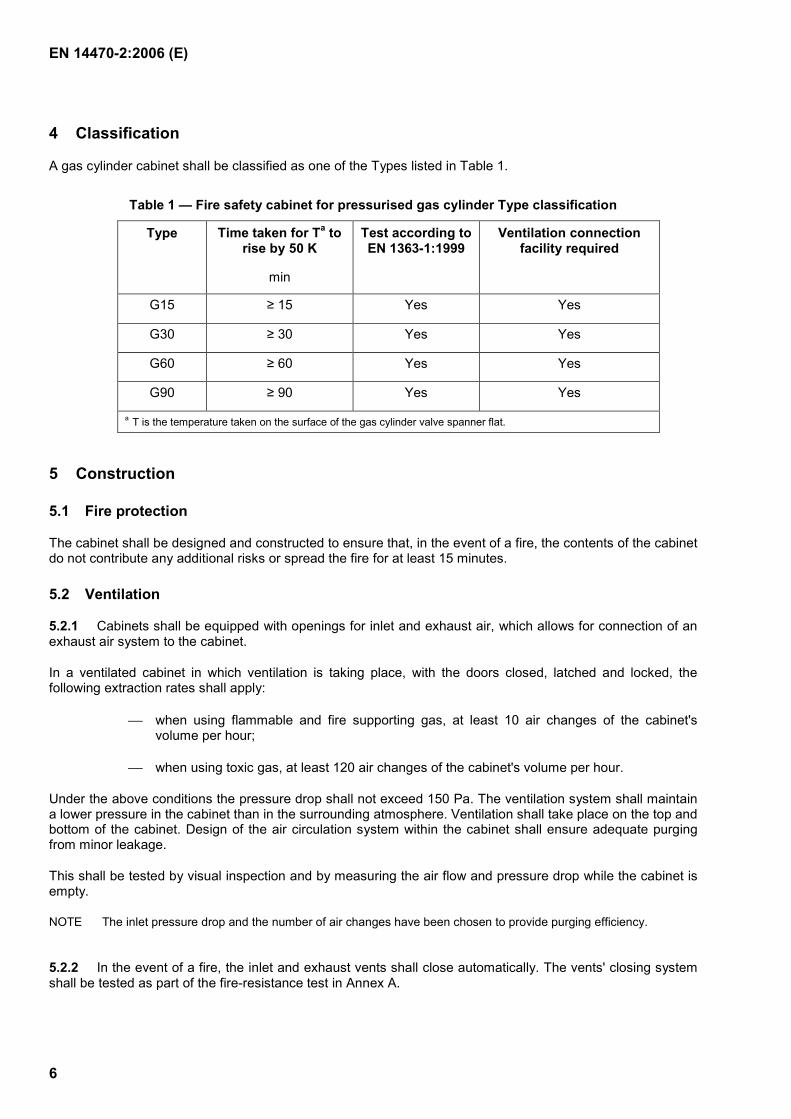
4 Classification
A gas cylinder cabinet shall be classified as one of the Types listed in Table 1.
Table 1 — Fire safety cabinet for pressurised gas cylinder Type classification
Type Time taken for Ta to rise by 50 K
min
Test according to EN 1363-1:1999
Ventilation connection facility required
G15 ≥ 15 Yes Yes
G30 ≥ 30 Yes Yes
G60 ≥ 60 Yes Yes
G90 ≥ 90 Yes Yes
a T is the temperature taken on the surface of the gas cylinder valve spanner flat.
5 Construction
5.1 Fire protection
The cabinet shall be designed and constructed to ensure that, in the event of a fire, the contents of the cabinet do not contribute any additional risks or spread the fire for at least 15 minutes.
5.2 Ventilation
5.2.1 Cabinets shall be equipped with openings for inlet and exhaust air, which allows for connection of an exhaust air system to the cabinet.
In a ventilated cabinet in which ventilation is taking place, with the doors closed, latched and locked, the following extraction rates shall apply:
when using flammable and fire supporting gas, at least 10 air changes of the cabinet's volume per hour;
when using toxic gas, at least 120 air changes of the cabinet's volume per hour.
Under the above conditions the pressure drop shall not exceed 150 Pa. The ventilation system shall maintain a lower pressure in the cabinet than in the surrounding atmosphere. Ventilation shall take place on the top and bottom of the cabinet. Design of the air circulation system within the cabinet shall ensure adequate purging from minor leakage.
This shall be tested by visual inspection and by measuring the air flow and pressure drop while the cabinet is empty.
NOTE The inlet pressure drop and the number of air changes have been chosen to provide purging efficiency.
5.2.2 In the event of a fire, the inlet and exhaust vents shall close automatically. The vents' closing system shall be tested as part of the fire-resistance test in Annex A.
EN 14470-2:2006 (E)
7
5.3 Gas cylinder restraining
Within the cabinet a suitable system shall be installed to prevent gas cylinders from falling over. The system shall be suitable for the quantity and dimensions of cylinders, which can be used in accordance with the user's instruction manual.
5.4 Insertion and removal of pressurised gas cylinders
The cabinet shall be constructed so that cylinders can be inserted and removed as safely as possible with minimum manual effort.
For example, when cabinet bases are above floor level a ramp and/or mechanical lifting equipment can be employed, however, these shall not be made of aluminium.
5.5 Installation of gas pipelines (for gas cylinders in use)
The number of pipe penetrations through the wall or roof of the cabinet shall be restricted to the minimum necessary and a maximum of 3 for each cylinder. Unused holes/penetrations shall be sealed in accordance with the user's instruction manual. The three holes should have a maximum diameter of 10 mm each.
NOTE In order to maintain the fire resistance as tested and specified in accordance with Annex A (see A.4.1), it is recommended that the pipes are made from stainless steel or from a material of similar thermal conductivity.
5.6 Installation of electric cables (where appropriate)
The number of penetrations through the wall or roof of the cabinet shall be restricted to the minimum necessary and a maximum of 2 for each cylinder. Unused holes/penetrations shall be sealed in accordance with the user's instruction manual. The two holes should be a maximum diameter of 20 mm each.
6 Fire resistance
The fire resistance of the cabinet for storing pressurised gas cylinders shall be determined by a type test. This type test is performed by heating the cabinet in a furnace according to the time-temperature curve described in clause 5.1.1 of EN 1363-1:1999 and measuring the temperature increase on the surface of an empty gas cylinder within the cabinet. The temperature increase on the surface of the cylinder valve spanner flat (see Figure A.1) shall not exceed 50 K. Test details are given in Annex A.
7 Information to be supplied
The cabinet manufacturer shall supply with the cabinet a user information manual, which includes at least the following:
a) instructions for correct cabinet installation;
b) maximum combined volumetric capacity of the gas cylinders stored within the cabinet;
c) safety procedure instructions in the event of fire, particularly the minimum time, when after a fire, the doors can be safely opened;
d) instructions concerning the effect of gas pipes passing through (penetration of) the walls and roof of the cabinet, particularly the potential of reduced fire resistance;
e) instructions to correctly seal the unused gas pipe feeds through the cabinet (penetration to the cabinet’s walls and roof);
f) warning that storing corrosive gases will adversely affect the effectiveness of the inlet and exhaust closing mechanisms;
EN 14470-2:2006 (E)
8
g) instructions to check that installation of the ventilation system, if carried out, is correctly realised (for example by using a smoke tube);
h) recommendation to undertake regular inspection and maintenance;
i) supplier’s declaration of conformity or the certificate(s) of conformity of a test house.
8 Manufacturer's marking and labelling
The following which should be a legible size, shall be fixed in a visible position and on the front of the cabinet:
a) fire resistance class, specified in minutes, e.g. Type G15, G30, G60 or G90;
b) instruction that the door(s) shall be kept closed;
c) safety sign in accordance with ISO 3864 as warning of pressurised gas cylinders;
d) name and/or trademark of the manufacturer;
e) model number, year of construction and, if appropriate, serial number;
f) marking of the inlet and exhaust connections to differentiate between them;
g) advice to read the user instruction manual.
EN 14470-2:2006 (E)
9
Annex A (normative)
Type G testing to determine fire resistance
A.1 Principle The safety cabinet is exposed to flames in a suitable furnace so that a standard time-temperature curve is generated as specified in clause 5.1.1 of EN 1363-1:1999. The temperature increase, and the time taken until the temperature increase reaches 50 K as measured on the surface of the valve spanner flat on the empty gas cylinder valve, shall be recorded.
NOTE The fire resistance of cabinets storing pressurised gas cylinders (EN 14470-2) is not comparable with the fire resistance of cabinets to store flammable liquids (EN 14470-1) due to the different methods of measuring the temperatures involved in determining the “time taken for T to rise” see Table 1.
A.2 Testing apparatus and test methods
A.2.1 Furnace
The furnace shall be arranged so that the doors, walls, roof and floor of the tested cabinet receive equal heat conditions but without flames directly touching the cabinet body.
A.2.2 Measuring equipment
Measuring equipment for monitoring the ambient temperature, furnace temperature, temperature of the wall of the cabinet and the temperature on the surface of the gas cylinder shall be in accordance with the requirements of EN 1363-1:1999.
The means of heating shall be in accordance with the requirements of EN 1363-1:1999.
A.2.3 Weighing system
A weighing system shall be used with a maximum permitted load of 500 g and a maximum possible reading error of 1 % plus a second system for weighing the cabinet, also with a maximum possible reading error of 1 %.
A.3 Test models
A.3.1 Quantity and description of test models
For testing the fire resistance, two cabinets of the same model shall be provided. One cabinet shall be used to conduct the fire test and the other to determine the humidity of the insulation material and to verify the design and specifications of the cabinet.
Detailed construction drawings with specifications shall be provided, which shall include the following:
a) inner and outer dimensions;
b) specification of all materials used in the cabinet construction;
c) sheet steel thickness;
d) insulating material thickness;
e) gap dimensions around and between the doors and door seals;
EN 14470-2:2006 (E)
10
f) inlet and exhaust air closing mechanism;
g) welded and other fixings and their design and standard of workmanship;
h) manufacturer's information on the materials or components that have a bearing on the fire performance of the cabinet.
A.3.2 Preliminary examination of the test model
Before actual fire testing, the test model shall be checked for conformity with drawing specifications. Any differences found shall be added to the drawings and specifications. The weight of each test model shall be determined.
Photographic documentation shall be performed both before and after testing with views of the open and closed cabinet, as well as detailed views of the doors, conditions of seals, etc.
Before fire testing begins, if present, approximately 250 g in each sample, from three different areas (e. g. door and wall) of one of the cabinets, shall be taken. The three samples shall be weighed and then dried for 24 hours at (40 ± 1) °C, at a relative humidity of 50 %, after which the moisture content is calculated. None of the three samples shall weigh less than 95 % of the original weight.
A.4 Preparation of fire test
A.4.1 Safety cabinet
In order to limit the space between the top of the cylinders and the inner ceiling of the cabinet, it is recommended at type testing that large cabinets be tested with larger cylinders and small cabinets with smaller cylinders.
An empty 50 litre gas cylinder shall be placed no further than 175 mm from the inner ceiling of the cabinet to the highest point of the gas cylinder valve mechanism. A stainless steel pipe with a 10 mm outer diameter and a 1 mm wall thickness shall be connected to the gas cylinders outlet. This pipe shall penetrate the top of the cabinet and shall not exceed 500 mm in length.
In addition, an electric cable with 3 conducting wires (cross-section 3 x 1,5 mm2) shall be positioned through the top of the cabinet hanging approximately 500 mm into the interior of the cabinet. Its length outside the cabinet shall be approximately 100 mm.
A.4.2 Installation of test model
All cabinets are to be tested as free standing single cabinets. If the cabinet is used on wheels or castors, it shall be tested as such. The model shall be positioned with its back wall at a minimum of 100 mm from the fire room wall.
The test shall be performed:
a) with open inlet and exhaust openings (see clause 5.2.1), but without being connected to an exhaust air system;
b) with the doors closed and latched;
c) with an empty gas cylinder inside the cabinet with its valve open and a stainless steel pipe connected as stated in clause A.4.1. The cylinder shall be placed in the middle of the cabinet in case of double door cabinets and 100 mm from the unhinged side of a single door cabinet. In both cases the cylinder shall be restrained to the back wall.
EN 14470-2:2006 (E)
11
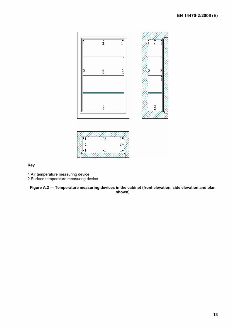
A.4.3 Temperature measuring device placement
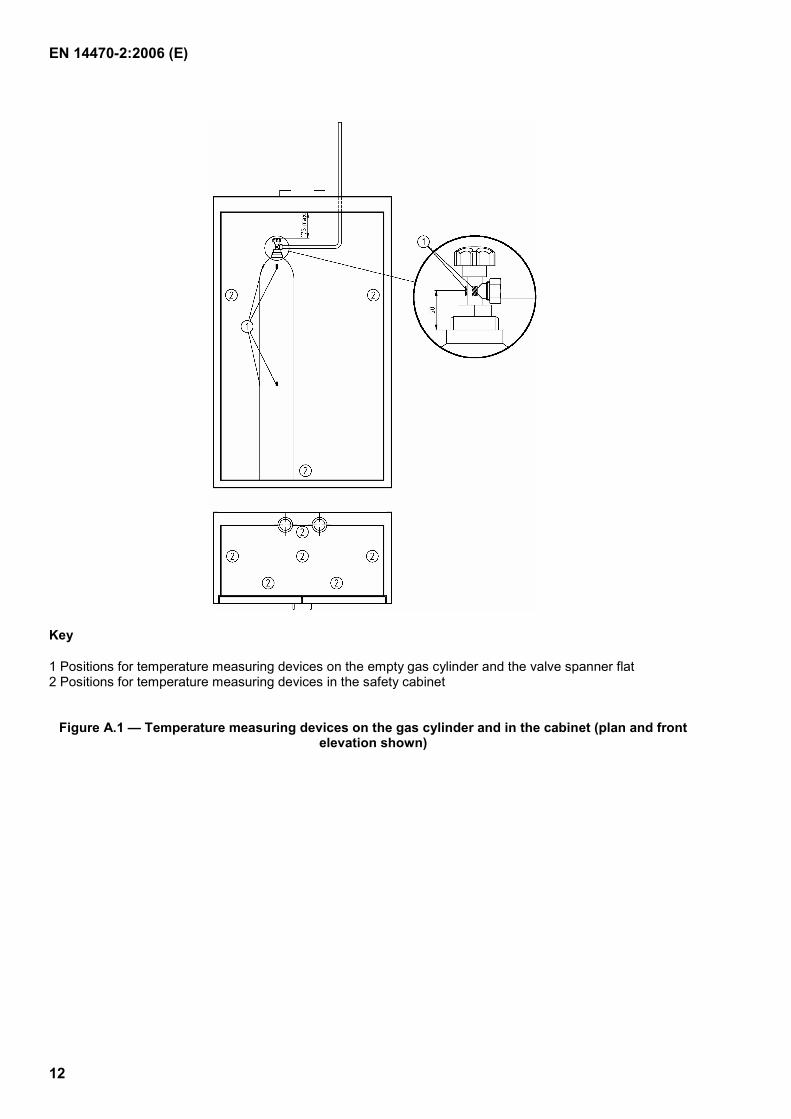
On an empty gas cylinder, the following surface temperature measuring devices shall be fixed in pairs; one facing towards the door and the other facing towards the nearest side wall in the following positions:
a) on the spanner flat, between valve and cylinder body (see Figure A.1);
b) on the middle of the shoulder radius;
c) half way up the cylinder;
d) surface temperature measuring devices fixed to the ceiling, floor, walls and door(s), each in the middle of the surface as shown in figure A.1.
The temperature measured at a) shall be used for classifying the cabinet (see Table 1). The results b) to d) shall be used as information for the type test report but not as part of classifying the cabinet.
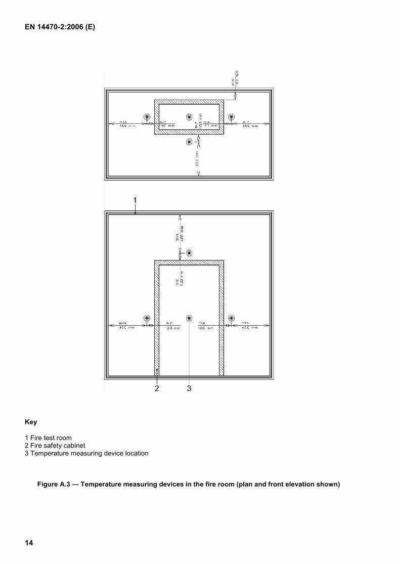
A.4.4 Temperature measuring device placement in the fire room
At least four temperature measuring locations are required as shown in figure A.2 and A.3, each 100 mm away from the wall, ceiling and door surfaces of the cabinet. They shall be located centrally with respect to each surface. The measurement locations shall be at least 400 mm deep into the fire room.
A.5 Fire testing procedure
The cabinet front wall, side walls, ceiling and floor shall be heated with flames, according to the standard temperature-time curve given in EN 1363-1:1999. During the time of temperature increase, the temperatures of all temperature measuring devices shall be recorded continuously.
A.6 Test report
The test report shall include at least the following:
a) reference to this standard i.e. EN 14470-2;
b) name of the testing laboratory, test report number, place and date of type testing;
c) name of the manufacturer;
d) manufacturer's product and identification code;
e) weight of both test models;
f) description and drawings of the test model, including all pertinent dimensions, building materials, seals, shutters, etc.;
g) results of humidity testing of insulation (see clause A.3.2);
h) details regarding the positioning of temperature measuring devices and procedures;
i) which fuel was used in the test;
j) observations during test;
k) comment about the sturdiness during the heating process, insofar as information is available;
l) indication of the fire resistance capability during the flaming process, insofar as information is available;
m) photographs taken before and after the test.
EN 14470-2:2006 (E)
12
Key
1 Positions for temperature measuring devices on the empty gas cylinder and the valve spanner flat 2 Positions for temperature measuring devices in the safety cabinet
Figure A.1 — Temperature measuring devices on the gas cylinder and in the cabinet (plan and front elevation shown)
EN 14470-2:2006 (E)
13
Key
1 Air temperature measuring device 2 Surface temperature measuring device
Figure A.2 — Temperature measuring devices in the cabinet (front elevation, side elevation and plan shown)
EN 14470-2:2006 (E)
14
Key
1 Fire test room 2 Fire safety cabinet 3 Temperature measuring device location
Figure A.3 — Temperature measuring devices in the fire room (plan and front elevation shown)
EN 14470-2:2006 (E)
15
Annex B (informative)
Approval regarding construction alterations
Construction alterations to the test model can be evaluated by the body performing the test, however, comparison tests may be necessary, according to the circumstances.
Safety cabinets of the same design and protection level (such as material and thickness of the insulation, arrangement of folded joints and sealings, number of doors, door locking devices) can only receive the same approval (without another test) when they have similar outer dimensions.
Dimension tolerances shall be evaluated in the framework of an expert opinion by the testing laboratory.
Only a reduction in height or width not exceeding 100 mm or a reduction in depth not exceeding 150 mm may be accepted. Safety cabinets exceeding these tolerances or differing in more than one outer dimension shall require testing according to Annex A before classification.
EN 14470-2:2006 (E)
16
Bibliography
[1] EN 14470-1, Fire safety storage cabinets - Part 1: Safety storage cabinets for flammable liquids