efficient organic solar cells with helical perylene diimide...
TRANSCRIPT
Efficient Organic Solar Cells with Helical Perylene Diimide ElectronAcceptorsYu Zhong,‡ M. Tuan Trinh,‡ Rongsheng Chen,‡,§ Wei Wang,‡ Petr P. Khlyabich,∥ Bharat Kumar,‡
Qizhi Xu,‡ Chang-Yong Nam,⊥ Matthew Y. Sfeir,⊥ Charles Black,⊥ Michael L. Steigerwald,‡
Yueh-Lin Loo,∥ Shengxiong Xiao,*,† Fay Ng,*,‡ X.-Y. Zhu,*,‡ and Colin Nuckolls*,† ,‡
† The Education Ministry Key Lab of Resource Chemistry, Shanghai Key Laboratory of Rare Earth Functional Materials,Optoelectronic Nano Materials and Devices Institute, Department of Chemistry, Shanghai Normal University, Shanghai 200234,China‡Department of Chemistry, Columbia University, New York, New York 10027, United States§College of Chemical Engineering and Technology, Wuhan University of Science and Technology, Wuhan 430081, China∥Department of Chemical and Biological Engineering, Princeton University, Princeton, New Jersey 08544, United States⊥Center for Functional Nanomaterials, Brookhaven National Laboratory, Upton, New York 11973, United States
*S Supporting Information
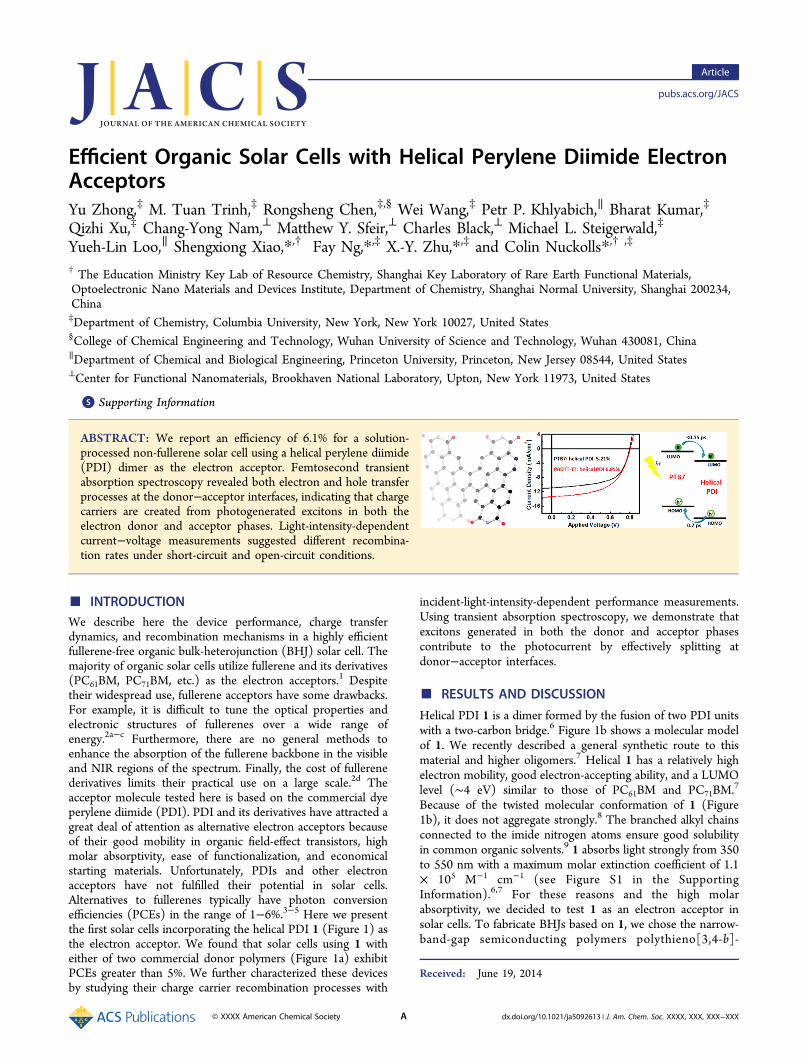
ABSTRACT: We report an efficiency of 6.1% for a solution-processed non-fullerene solar cell using a helical perylene diimide(PDI) dimer as the electron acceptor. Femtosecond transientabsorption spectroscopy revealed both electron and hole transferprocesses at the donor−acceptor interfaces, indicating that chargecarriers are created from photogenerated excitons in both theelectron donor and acceptor phases. Light-intensity-dependentcurrent−voltage measurements suggested different recombina-tion rates under short-circuit and open-circuit conditions.
■ INTRODUCTIONWe describe here the device performance, charge transferdynamics, and recombination mechanisms in a highly efficientfullerene-free organic bulk-heterojunction (BHJ) solar cell. Themajority of organic solar cells utilize fullerene and its derivatives(PC61BM, PC71BM, etc.) as the electron acceptors.1 Despitetheir widespread use, fullerene acceptors have some drawbacks.For example, it is difficult to tune the optical properties andelectronic structures of fullerenes over a wide range ofenergy.2a−c Furthermore, there are no general methods toenhance the absorption of the fullerene backbone in the visibleand NIR regions of the spectrum. Finally, the cost of fullerenederivatives limits their practical use on a large scale.2d Theacceptor molecule tested here is based on the commercial dyeperylene diimide (PDI). PDI and its derivatives have attracted agreat deal of attention as alternative electron acceptors becauseof their good mobility in organic field-effect transistors, highmolar absorptivity, ease of functionalization, and economicalstarting materials. Unfortunately, PDIs and other electronacceptors have not fulfilled their potential in solar cells.Alternatives to fullerenes typically have photon conversionefficiencies (PCEs) in the range of 1−6%.3−5 Here we presentthe first solar cells incorporating the helical PDI 1 (Figure 1) asthe electron acceptor. We found that solar cells using 1 witheither of two commercial donor polymers (Figure 1a) exhibitPCEs greater than 5%. We further characterized these devicesby studying their charge carrier recombination processes with
incident-light-intensity-dependent performance measurements.Using transient absorption spectroscopy, we demonstrate thatexcitons generated in both the donor and acceptor phasescontribute to the photocurrent by effectively splitting atdonor−acceptor interfaces.
■ RESULTS AND DISCUSSION
Helical PDI 1 is a dimer formed by the fusion of two PDI unitswith a two-carbon bridge.6 Figure 1b shows a molecular modelof 1. We recently described a general synthetic route to thismaterial and higher oligomers.7 Helical 1 has a relatively highelectron mobility, good electron-accepting ability, and a LUMOlevel (∼4 eV) similar to those of PC61BM and PC71BM.7
Because of the twisted molecular conformation of 1 (Figure1b), it does not aggregate strongly.8 The branched alkyl chainsconnected to the imide nitrogen atoms ensure good solubilityin common organic solvents.9 1 absorbs light strongly from 350to 550 nm with a maximum molar extinction coefficient of 1.1× 10⁵ M−1 cm−1 (see Figure S1 in the SupportingInformation).6,7 For these reasons and the high molarabsorptivity, we decided to test 1 as an electron acceptor insolar cells. To fabricate BHJs based on 1, we chose the narrow-band-gap semiconducting polymers polythieno[3,4-b]-
Received: June 19, 2014
Article
pubs.acs.org/JACS
© XXXX American Chemical Society A dx.doi.org/10.1021/ja5092613 | J. Am. Chem. Soc. XXXX, XXX, XXX−XXX
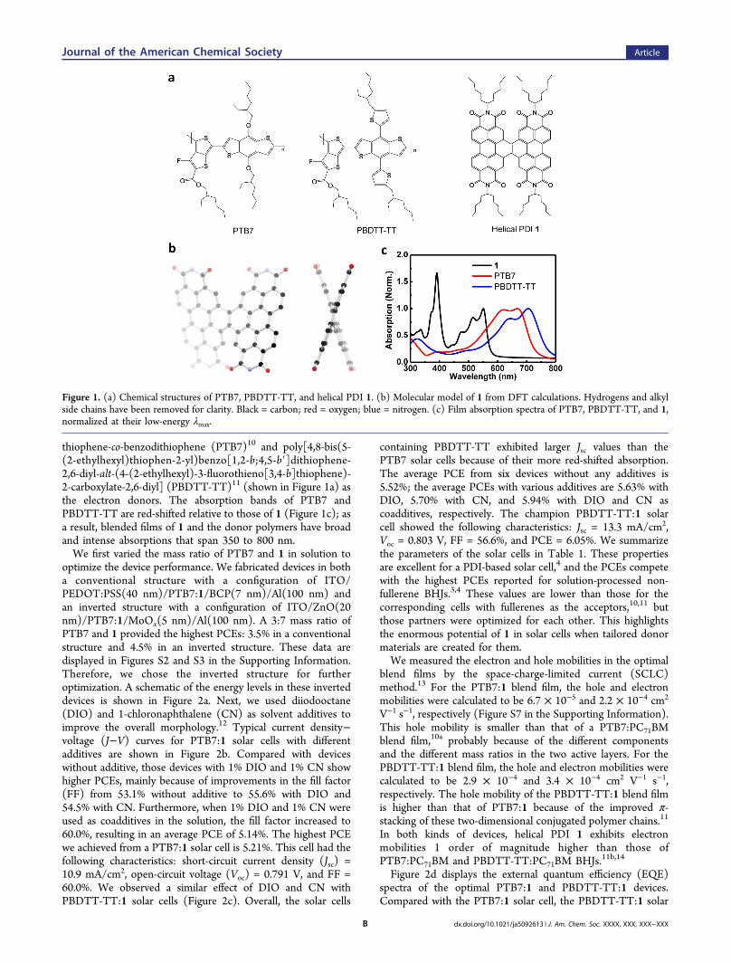
thiophene-co-benzodithiophene (PTB7)10 and poly[4,8-bis(5-(2-ethylhexyl)thiophen-2-yl)benzo[1,2-b;4,5-b′]dithiophene-2,6-diyl-alt-(4-(2-ethylhexyl)-3-fluorothieno[3,4-b]thiophene)-2-carboxylate-2,6-diyl] (PBDTT-TT)11 (shown in Figure 1a) asthe electron donors. The absorption bands of PTB7 andPBDTT-TT are red-shifted relative to those of 1 (Figure 1c); asa result, blended films of 1 and the donor polymers have broadand intense absorptions that span 350 to 800 nm.We first varied the mass ratio of PTB7 and 1 in solution to
optimize the device performance. We fabricated devices in botha conventional structure with a configuration of ITO/PEDOT:PSS(40 nm)/PTB7:1/BCP(7 nm)/Al(100 nm) andan inverted structure with a configuration of ITO/ZnO(20nm)/PTB7:1/MoOx(5 nm)/Al(100 nm). A 3:7 mass ratio ofPTB7 and 1 provided the highest PCEs: 3.5% in a conventionalstructure and 4.5% in an inverted structure. These data aredisplayed in Figures S2 and S3 in the Supporting Information.Therefore, we chose the inverted structure for furtheroptimization. A schematic of the energy levels in these inverteddevices is shown in Figure 2a. Next, we used diiodooctane(DIO) and 1-chloronaphthalene (CN) as solvent additives toimprove the overall morphology.12 Typical current density−voltage (J−V) curves for PTB7:1 solar cells with differentadditives are shown in Figure 2b. Compared with deviceswithout additive, those devices with 1% DIO and 1% CN showhigher PCEs, mainly because of improvements in the fill factor(FF) from 53.1% without additive to 55.6% with DIO and54.5% with CN. Furthermore, when 1% DIO and 1% CN wereused as coadditives in the solution, the fill factor increased to60.0%, resulting in an average PCE of 5.14%. The highest PCEwe achieved from a PTB7:1 solar cell is 5.21%. This cell had thefollowing characteristics: short-circuit current density (Jsc) =10.9 mA/cm2, open-circuit voltage (Voc) = 0.791 V, and FF =60.0%. We observed a similar effect of DIO and CN withPBDTT-TT:1 solar cells (Figure 2c). Overall, the solar cells
containing PBDTT-TT exhibited larger Jsc values than thePTB7 solar cells because of their more red-shifted absorption.The average PCE from six devices without any additives is5.52%; the average PCEs with various additives are 5.63% withDIO, 5.70% with CN, and 5.94% with DIO and CN ascoadditives, respectively. The champion PBDTT-TT:1 solarcell showed the following characteristics: Jsc = 13.3 mA/cm2,Voc = 0.803 V, FF = 56.6%, and PCE = 6.05%. We summarizethe parameters of the solar cells in Table 1. These propertiesare excellent for a PDI-based solar cell,4 and the PCEs competewith the highest PCEs reported for solution-processed non-fullerene BHJs.3,4 These values are lower than those for thecorresponding cells with fullerenes as the acceptors,10,11 butthose partners were optimized for each other. This highlightsthe enormous potential of 1 in solar cells when tailored donormaterials are created for them.We measured the electron and hole mobilities in the optimal
blend films by the space-charge-limited current (SCLC)method.13 For the PTB7:1 blend film, the hole and electronmobilities were calculated to be 6.7 × 10⁻⁵ and 2.2 × 10⁻⁴ cm2
V−1 s−1, respectively (Figure S7 in the Supporting Information).This hole mobility is smaller than that of a PTB7:PC71BMblend film,10a probably because of the different componentsand the different mass ratios in the two active layers. For thePBDTT-TT:1 blend film, the hole and electron mobilities werecalculated to be 2.9 × 10⁻⁴ and 3.4 × 10⁻⁴ cm2 V−1 s−1,respectively. The hole mobility of the PBDTT-TT:1 blend filmis higher than that of PTB7:1 because of the improved π-stacking of these two-dimensional conjugated polymer chains.11
In both kinds of devices, helical PDI 1 exhibits electronmobilities 1 order of magnitude higher than those ofPTB7:PC71BM and PBDTT-TT:PC71BM BHJs.11b,14
Figure 2d displays the external quantum efficiency (EQE)spectra of the optimal PTB7:1 and PBDTT-TT:1 devices.Compared with the PTB7:1 solar cell, the PBDTT-TT:1 solar
Figure 1. (a) Chemical structures of PTB7, PBDTT-TT, and helical PDI 1. (b) Molecular model of 1 from DFT calculations. Hydrogens and alkylside chains have been removed for clarity. Black = carbon; red = oxygen; blue = nitrogen. (c) Film absorption spectra of PTB7, PBDTT-TT, and 1,normalized at their low-energy λmax.
Journal of the American Chemical Society Article
dx.doi.org/10.1021/ja5092613 | J. Am. Chem. Soc. XXXX, XXX, XXX−XXXB
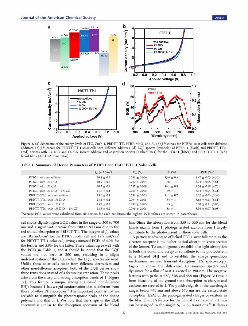
cell shows slightly higher EQE values in the range of 300 to 700nm and a significant increase from 700 to 800 nm due to thered-shifted absorption of PBDTT-TT. The integrated Jsc valuesare 10.2 mA/cm2 for the PTB7:1 solar cell and 12.8 mA/cm2
for PBDTT-TT:1 solar cell, giving estimated PCEs of 4.9% forthe former and 5.8% for the latter. These values agree well withthe PCEs in Table 1, and it should be noted that the EQEvalues are not zero at 300 nm, resulting in a slightunderestimation of the PCEs when the EQE spectra are used.Unlike those solar cells made from fullerene derivatives andother non-fullerene acceptors, both of the EQE curves showthree transitions instead of a featureless transition. These peaksarise from the sharp and strong absorption bands of 1 (Figure1c). This feature is unique among PDI-based non-fullereneBHJs because 1 has a rigid conformation that is different fromthose of other PDI acceptors.4 The important point is that weare able to distinguish the photoresponse peaks of the donorpolymers and that of 1. We note that the shape of the EQEspectrum is similar to the absorption spectrum of the blend
film. Since the absorption from 350 to 550 nm for the blendfilm is mainly from 1, photogenerated excitons from 1 largelycontribute to the photocurrent in these solar cells.A particular advantage of helical PDI 1 over fullerenes as the
electron acceptor is the higher optical absorption cross sectionof the former. To unambiguously establish that light absorptionin both the donor and acceptor contribute to the photocurrentin a 1-based BHJ and to establish the charge generationmechanisms, we used transient absorption (TA) spectroscopy.Figure 3 shows the differential transmission spectra anddynamics for a film of neat 1 excited at 390 nm. The negativefeatures with peaks at 480, 516, and 556 nm (Figure 3a) resultfrom bleaching of the ground-state absorption as charges andexcitons are created in 1. The positive signals in the wavelengthranges below 470 nm and above 570 nm are the excited-stateabsorption (ESA) of the photogenerated charges or excitons inthe film. The ESA feature for the film of 1 centered at 700 nmcan be assigned to the singlet S1 → SN transitions.15 It decays
Figure 2. (a) Schematic of the energy levels of ITO, ZnO, 1, PBDTT-TT, PTB7, MoOx and Al. (b) J-V curves for PTB7:1 solar cells with differentadditives. (c) J-V curves for PBDTT-TT:1 solar cells with different additives. (d) EQE spectra (symbols) of PTB7: 1 (black) and PBDTT-TT:1(red) devices with 1% DIO and 1% CN solvent additive and absorption spectra (dashed lines) for the PTB7:1 (black) and PBDTT-TT:1 (red)blend films (3:7 D/A mass ratio).
Table 1. Summary of Device Parameters of PTB7:1 and PBDTT-TT:1 Solar Cells
Jsc (mA/cm2) Voc (V) FF (%) PCE (%)a
PTB7:1 with no additive 10.5 ± 0.2 0.796 ± 0.006 53.6 ± 0.5 4.47 ± 0.03 (4.50)PTB7:1 with 1% DIO 10.9 ± 0.2 0.782 ± 0.004 56 ± 1 4.74 ± 0.05 (4.81)PTB7:1 with 1% CN 10.7 ± 0.4 0.787 ± 0.009 54.1 ± 0.8 4.54 ± 0.18 (4.70)PTB7:1 with 1% DIO + 1% CN 11.0 ± 0.1 0.789 ± 0.005 59 ± 1 5.14 ± 0.04 (5.21)PBDTT-TT:1 with no additive 13.6 ± 0.1 0.796 ± 0.005 51.1 ± 0.7 5.52 ± 0.05 (5.59)PBDTT-TT:1 with 1% DIO 13.2 ± 0.1 0.794 ± 0.005 54 ± 1 5.63 ± 0.11 (5.81)PBDTT-TT:1 with 1% CN 13.7 ± 0.2 0.790 ± 0.005 53 ± 1 5.70 ± 0.11 (5.86)PBDTT-TT:1 with 1% DIO + 1% CN 13.5 ± 0.2 0.796 ± 0.005 55 ± 1 5.94 ± 0.07 (6.05)
aAverage PCE values were calculated from six devices for each condition; the highest PCE values are shown in parentheses.
Journal of the American Chemical Society Article
dx.doi.org/10.1021/ja5092613 | J. Am. Chem. Soc. XXXX, XXX, XXX−XXXC
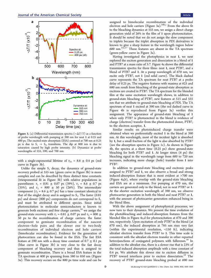
with a single-exponential lifetime of τS1 = 8.6 ± 0.4 ps (redcurve in Figure 3b).Unlike the simple S1 decay, the dynamics of ground-state
recovery probed at 555 nm (green curve in Figure 3b) is morecomplex and can be described by three distinct time constants(triexponential fit in Figure 3b) with relative populations inparentheses: τ1 = 0.81 ± 0.07 ps (39%), τ2 = 8.6 ± 0.7 ps(35%), and τ3 = 800 ± 50 ps (26%). The intermediatecomponent (τ2 = 8.6 ± 0.7 ps) has a time constant identical tothat of the singlet decay and is assigned to S1. The faster (0.81ps) and slower (800 ps) components do not correspond to S1and must be attributed to different species. Since initialphotoexcitation in molecular semiconductors is known togenerate both excitons and free charge carriers,16 we assign theground-state recovery with τ1 = 0.81 ± 0.07 ps and τ3 = 800 ±50 ps to the recombination of charge carriers: the fastercomponent to geminate recombination of the nascentelectron−hole pairs and the slower one to two-bodyrecombination of individual electron and hole carriers(bimolecular recombination). Evidence for the generation ofphotocarriers can also be found in the ESA. The fast ESAfeature at 590 nm with a decay time constant of 0.7 ± 0.1 ps(blue curve in Figure 3b) is very close to the fast decaycomponent of bleaching recovery and thus is assigned togeminate recombination. There is a broad ESA feature in theTA spectrum at 400 ps spanning from 580 to 850 nm (Figure3a). This recovery occurs on the 800 ps time scale and can be
assigned to bimolecular recombination of the individualelectron and hole carriers (Figure 3a).16b,c From the above fitto the bleaching dynamics at 555 nm, we assign a direct chargegeneration yield of 26% in the film of 1 upon photoexcitation.It should be noted that we do not assign the slow componentto triplets because the triplet absorption in PDI derivatives isknown to give a sharp feature in the wavelength region below600 nm.15c,17 These features are absent in the TA spectrum(green-yellow curve in Figure 3a).Having investigated the photophysics in neat 1, we next
explored the exciton generation and dissociation in a blend of 1and PTB7 at a mass ratio of 3:7. Figure 4a shows the differentialtransmission spectra for three films: neat 1, neat PTB7, and ablend of PTB7 and 1. At a pump wavelength of 670 nm, weexcite only PTB7, not 1 (red solid curve). The black dashedcurve represents the TA spectrum for neat PTB7 at a probedelay of 0.25 ps. The negative features with maxima at 625 and680 nm result from bleaching of the ground-state absorption asexcitons are created in PTB7. The TA spectrum for the blendedfilm at the same excitation wavelength shows, in addition toground-state bleaching of PTB7, new features at 515 and 555nm that we attribute to ground-state bleaching of PDI. The TAspectrum of neat 1 excited at 390 nm (the red dashed curve inFigure 4b is reproduced from Figure 3a) verifies thisassignment. The appearance of ground-state bleaching of 1when only PTB7 is photoexcited in the blend is evidence ofcharge (electron) transfer from the photoexcited donor, PTB7,to the electron acceptor, 1.Similar results on photoinduced charge transfer were
obtained when we preferentially excited 1 in the blend at 390nm. At this wavelength, most of the incident light is absorbedby 1, but a small fraction of the light is also absorbed by PTB7(see the absorption spectra in Figure 1c). As shown in Figure4b, the spectra at a short time (0.25 ps) show ground-statebleaching for both PTB7 and 1. At longer times (6 ps) thebleaching signal in the wavelength range from 600 to 720 nmincreases, indicating more charge (hole) transfer from 1 intoPTB7.In addition to ground-state bleaching and excitonic peaks
assigned to PTB7 and 1, we also observe a broad and stronginduced-absorption feature that is most evident at >700 nm(Figure 4a,b), where overlap with the ground-state bleachingand ESA are at a minimum. For pumping at 670 nm, thecarriers are generated only in the blend, not in neat PTB7 or 1.At the shorter excitation wavelength of 390 nm, we observephotocarrier generation in both the blend and neat PTB7 or 1,with the amount of photocarrier generation enhanced being inthe blend films.With the above assignment of photophysical processes, we
now turn to their dynamics. We present the time evolution ofthe photobleaching and induced-absorption features from theblended film in Figure 4c,d for photoexcitation at 670 and 390nm, respectively. Upon excitation of only PTB7 in the blend (at670 nm), the induced absorption at 785 nm rises very fast(within the experimental resolution, <150 fs), indicatingultrafast electron transfer from PTB7 to 1. This time scale isconsistent with the ultrafast electron transfer in other reportedheterojunctions of conjugated polymers with fullerenes.18 Inaddition to the ultrafast rise, there is a slower rise that is 23% ofthe total induced absorption amplitude with a time constant of0.4 ps. We attribute this slower rise to exciton diffusion inPTB7 toward interfaces prior to exciton dissociation.19 Therecovery of PTB7 ground-state bleaching probed at 690 nm
Figure 3. (a) Differential transmission spectra (−ΔT/T) as a functionof probe wavelength with pumping at 390 nm for neat 1 at 0.25 and400 ps. The excited-state absorption (ESA) centered at 700 nm at 0.25ps is due to S1 → SN transitions. The dip at 800 nm is due tosaturation caused by high probe intensity. (b) Dynamics at probewavelengths of 555, 590, and 700 nm.
Journal of the American Chemical Society Article
dx.doi.org/10.1021/ja5092613 | J. Am. Chem. Soc. XXXX, XXX, XXX−XXXD
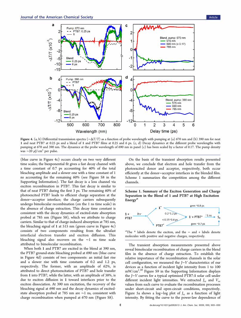
(blue curve in Figure 4c) occurs clearly on two very differenttime scales; the biexponential fit gives a fast decay channel witha time constant of 0.7 ps accounting for 40% of the totalbleaching amplitude and a slower one with a time constant of 1ns accounting for the remaining 60% (see Figure S8 in theSupporting Information). The fast decay is a loss channel viaexciton recombination in PTB7. This fast decay is similar tothat of neat PTB7 during the first 3 ps. The remaining 60% ofphotoexcited PTB7 leads to efficient charge separation at thedonor−acceptor interface; the charge carriers subsequentlyundergo bimolecular recombination (on the 1 ns time scale) inthe absence of charge extraction. This decay time constant isconsistent with the decay dynamics of excited-state absorptionprobed at 785 nm (Figure S8), which we attribute to chargecarriers. Similar to that of charge-induced absorption at 785 nm,the bleaching signal of 1 at 515 nm (green curve in Figure 4c)consists of two components resulting from the ultrafastinterfacial electron transfer and exciton diffusion. Thisbleaching signal also recovers on the ∼1 ns time scaleattributed to bimolecular recombination.When both 1 and PTB7 are excited in the blend at 390 nm,
the PTB7 ground-state bleaching probed at 690 nm (blue curvein Figure 4d) consists of two components: an initial fast riseand a slower rise with time constants of 0.2 and 1.2 ps,respectively. The former, with an amplitude of 62%, isattributed to direct photoexcitation of PTB7 and hole transferfrom 1 into PTB7, while the latter, with an amplitude of 38%, isdue to exciton diffusion in 1 toward interfaces prior to theexciton dissociation. At 390 nm excitation, the recovery of thebleaching signal at 690 nm and the decay dynamics of excited-state absorption probed at 785 nm are ∼1 ns, consistent withcharge recombination when pumped at 670 nm (Figure S8).
On the basis of the transient absorption results presentedabove, we conclude that electron and hole transfer from thephotoexcited donor and acceptor, respectively, both occurefficiently at the donor−acceptor interfaces in the blended film.Scheme 1 summarizes the competition among the differentchannels.
The transient absorption measurements presented abovereveal bimolecular recombination of charge carriers in the blendfilm in the absence of charge extraction. To establish therelative importance of the recombination channels in the solarcell configuration, we measured the J−V characteristics of ourdevices as a function of incident light intensity from 1 to 100mW/cm2.20 Figure S9 in the Supporting Information displaysthe J−V curves for a typical optimized PTB7:1 solar cell underdifferent incident light intensities. We extracted Jsc and Vocvalues from each curve to evaluate the recombination processesunder short-circuit and open-circuit conditions, respectively.Figure 5a shows a log−log plot of Jsc as a function of lightintensity. By fitting the curve to the power-law dependence of
Figure 4. (a, b) Differential transmission spectra (−ΔT/T) as a function of probe wavelength with pumping at (a) 670 nm and (b) 390 nm for neat1 and neat PTB7 at 0.25 ps and a blend of 1 and PTB7 films at 0.25 and 6 ps. (c, d) Decay dynamics at the different probe wavelengths withpumping at 670 and 390 nm. The dynamics at the probe wavelength of 690 nm in panel (c) has been scaled by a factor of 0.17. The pump densitywas ∼20 μJ/cm2 per pulse.
Scheme 1. Summary of the Exciton Generation and ChargeSeparation in the Blend of 1 and PTB7 at High ExcitationEnergya
aThe * labels denote the exciton, and the − and + labels denotemolecules with positive and negative charges, respectively.
Journal of the American Chemical Society Article
dx.doi.org/10.1021/ja5092613 | J. Am. Chem. Soc. XXXX, XXX, XXX−XXXE
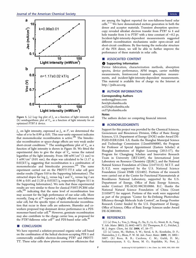
Jsc on light intensity, expressed as Jsc ∝ Iα, we determined thevalue of α to be 0.99 ± 0.01. This near-unity exponent indicatesthat monomolecular recombination is active.20b The bimolec-ular recombination or space-charge effects are very weak undershort-circuit conditions.21 The semilogarithmic plot of Voc as afunction of light intensity is shown in Figure 5b. We fitted theexperimental data to give the slope of Voc versus the naturallogarithm of the light intensity. From 100 mW/cm2 (1 sun) to1 mW/cm2 (0.01 sun), the slope was calculated to be (1.17 ±0.02)kT/q, suggesting that recombination is a combination ofmonomolecular and bimolecular processes.20b The sameexperiment carried out on the PBDTT-TT:1 solar cell gavesimilar results (Figure S10 in the Supporting Information). Theextracted slopes for log Jsc versus log I and Voc versus log I are0.96 ± 0.01 and (1.20 ± 0.03)kT/q, respectively (Figure S11 inthe Supporting Information). We note that these experimentalresults are very similar to those for classical P3HT:PCBM solarcells,20b indicating that the same level of recombination lossmay account for the high performance of our solar cells. Morerecently, Zang et al.4g reported a highly efficient non-fullerenesolar cell, but the specific types of monomolecular recombina-tion that occur in these cells are unknown. Sharenko and co-workers proposed trap-dominant device performance in a PDI-monomer-based solar cell.4b However, geminate recombinationmay also contribute to the charge carrier loss, as proposed forthe PTB7:fullerene solar cell22 and PDI-based solar cells.4b
■ CONCLUSIONWe have reported a solution-processed organic solar cell basedon the combination of the helical electron-accepting PDI 1 andcommercially available electron-donating PTB7 and PBDTT-TT. These solar cells show photon conversion efficiencies that
are among the highest reported for non-fullerene-based solarcells.3−5 We have demonstrated exciton generation in both thedonor and acceptor materials. Transient absorption spectros-copy revealed ultrafast electron transfer from PTB7 to 1 andhole transfer from 1 to PTB7 with a time constant of ∼0.2 ps.Incident-light-intensity-dependent measurements suggesteddifferent recombination mechanisms under open-circuit andshort-circuit conditions. By fine-tuning the molecular structureof the PDI dimer, we will be able to further improve theperformance of these materials in solar cells.
■ ASSOCIATED CONTENT*S Supporting InformationDevice fabrication, characterization methods, absorptionspectra, device performance, AFM images, carrier mobilitymeasurements, femtosecond transient absorption measure-ments, and incident-light-intensity-dependent measurements.This material is available free of charge via the Internet athttp://pubs.acs.org.
■ AUTHOR INFORMATIONCorresponding [email protected]@[email protected]@columbia.eduNotesThe authors declare no competing financial interest.
■ ACKNOWLEDGMENTSSupport for this project was provided by the Chemical Sciences,Geosciences and Biosciences Division, Office of Basic EnergySciences, U.S. Department of Energy (DOE) under Award DE-FG02-01ER15264. S.X. thanks the Shanghai Municipal Scienceand Technology Commission (12nm0504000), the Programfor Professor of Special Appointment (Eastern Scholar) atShanghai Institutions of Higher Learning (2013-57), theProgram for Changjiang Scholars and Innovative ResearchTeam in University (IRT1269), the International JointLaboratory on Resource Chemistry (IJLRC), and the NationalNatural Science Foundation of China (21473113). M.T.T. andX.-Y.Z. were supported by the U.S. National ScienceFoundation (Grant DMR 1321405). Portions of the researchwere carried out at the Center for Functional Nanomaterials atBrookhaven National Laboratory, supported by the U.S.Department of Energy, Office of Basic Energy Sciences,under Contract DE-AC02-98CH10886. R.C. thanks theNational Natural Science Foundation of China (Grant21105077) for support. Portions of this work were supportedas part of the program “Center for Re-Defining PhotovoltaicEfficiency through Molecule Scale Control”, an Energy FrontierResearch Center funded by the U.S. Department of Energy,Office of Science, Office of Basic Energy Sciences under AwardDE-SC0001085.
■ REFERENCES(1) (a) Dou, L.; You, J.; Hong, Z.; Xu, Z.; Li, G.; Street, R. A.; Yang,Y. Adv. Mater. 2013, 25, 6642−6671. (b) Thompson, B. C.; Frechet, J.M. J. Angew. Chem., Int. Ed. 2008, 47, 58−77.(2) (a) Lenes, M.; Shelton, S. W.; Sieval, A. B.; Kronholm, D. F.;Hummelen, J. C.; Blom, P. W. M. Adv. Funct. Mater. 2009, 19, 3002−3007. (b) Ross, R. B.; Cardona, C. M.; Guldi, D. M.;Sankaranarayanan, S. G.; Reese, M. O.; Kopidakis, N.; Peet, J.;
Figure 5. (a) Log−log plot of Jsc as a function of light intensity and(b) semilogarithmic plot of Voc as a function of light intensity for anoptimized PTB7:1 device.
Journal of the American Chemical Society Article
dx.doi.org/10.1021/ja5092613 | J. Am. Chem. Soc. XXXX, XXX, XXX−XXXF
Walker, B.; Bazan, G. C.; Van Keuren, E.; Holloway, B. C.; Drees, M.Nat. Mater. 2009, 8, 208−212. (c) He, Y.; Chen, H.-Y.; Hou, J.; Li, Y.J. Am. Chem. Soc. 2010, 132, 1377−1382. (d) Anctil, A.; Babbitt, C.W.; Raffaelle, R. P.; Landi, B. J. Environ. Sci. Technol. 2011, 45, 2353−2359.(3) For examples of non-fullerene bulk-junction solar cells, see:(a) Woo, C. H.; Holcombe, T. W.; Unruh, D. A.; Sellinger, A.;Frechet, J. M. J. Chem. Mater. 2010, 22, 1673−1679. (b) Zhou, Y.; Dai,Y.-Z.; Zheng, Y.-Q.; Wang, X.-Y.; Wang, J.-Y.; Pei, J. Chem. Commun.2013, 49, 5802−5804. (c) Winzenberg, K. N.; Kemppinen, P.; Scholes,F. H.; Collis, G. E.; Shu, Y.; Birendra Singh, T.; Bilic, A.; Forsyth, C.M.; Watkins, S. E. Chem. Commun. 2013, 49, 6307−6309. (d) Ren, G.;Ahmed, E.; Jenekhe, S. A. J. Mater. Chem. 2012, 22, 24373−24379.(e) Li, H.; Kim, F. S.; Ren, G.; Hollenbeck, E. C.; Subramaniyan, S.;Jenekhe, S. A. Angew. Chem., Int. Ed. 2013, 52, 5513−5517.(f) Boudreault, P.-L. T.; Michaud, A.; Leclerc, M. Macromol. RapidCommun. 2007, 28, 2176−2179. (g) Douglas, J. D.; Chen, M. S.;Niskala, J. R.; Lee, O. P.; Yiu, A. T.; Young, E. P.; Frechet, J. M. J. Adv.Mater. 2014, 26, 4313−4319. (h) Eftaiha, A. F.; Sun, J.-P.; Hill, I. G.;Welch, G. C. J. Mater. Chem. A 2014, 2, 1201−1213.(4) For examples of non-fullerene solar cells based on PDIs, see:(a) Lin, Y.; Wang, Y.; Wang, J.; Hou, J.; Li, Y.; Zhu, D.; Zhan, X. Adv.Mater. 2014, 26, 5137−5142. (b) Sharenko, A.; Proctor, C. M.; vander Poll, T. S.; Henson, Z. B.; Nguyen, T.-Q.; Bazan, G. C. Adv. Mater.2013, 25, 4403−4406. (c) Zhang, X.; Lu, Z.; Ye, L.; Zhan, C.; Hou, J.;Zhang, S.; Jiang, B.; Zhao, Y.; Huang, J.; Zhang, S.; Liu, Y.; Shi, Q.; Liu,Y.; Yao, J. Adv. Mater. 2013, 25, 5791−5797. (d) Jiang, W.; Ye, L.; Li,X.; Xiao, C.; Tan, F.; Zhao, W.; Hou, J.; Wang, Z. Chem. Commun.2014, 50, 1024−1026. (e) Lu, Z.; Jiang, B.; Zhang, X.; Tang, A.; Chen,L.; Zhan, C.; Yao, J. Chem. Mater. 2014, 26, 2907−2914. (f) Zhou, Y.;Kurosawa, T.; Ma, W.; Guo, Y.; Fang, L.; Vandewal, K.; Diao, Y.;Wang, C.; Yan, Q.; Reinspach, J.; Mei, J.; Appleton, A. L.; Koleilat, G.I.; Gao, Y.; Mannsfeld, S. C. B.; Salleo, A.; Ade, H.; Zhao, D.; Bao, Z.Adv. Mater. 2014, 26, 3767−3772. (g) Zang, Y.; Li, C.-Z.; Chueh, C.-C.; Williams, S. T.; Jiang, W.; Wang, Z.-H.; Yu, J.-S.; Jen, A. K. Y. Adv.Mater. 2014, 26, 5708−5714.(5) Higher PCE has been achieved in a fullerene-free organic solarcell with a multilayer structure. See: Cnops, K.; Rand, B. P.; Cheyns,D.; Verreet, B.; Empl, M. A.; Heremans, P. Nat. Commun. 2014, 5,No. 3406.(6) Li, Y.; Wang, C.; Li, C.; Di Motta, S.; Negri, F.; Wang, Z. Org.Lett. 2012, 14, 5278−5281.(7) Zhong, Y.; Kumar, B.; Oh, S.; Trinh, M. T.; Wu, Y.; Elbert, K.; Li,P.; Zhu, X.; Xiao, S.; Ng, F.; Steigerwald, M. L.; Nuckolls, C. J. Am.Chem. Soc. 2014, 136, 8122−8130.(8) Strong aggregation is a problem for PDIs in organic BHJs. See:(a) Sharma, G. D.; Suresh, P.; Mikroyannidis, J. A.; Stylianakis, M. M.J. Mater. Chem. 2010, 20, 561−567. (b) Kamm, V.; Battagliarin, G.;Howard, I. A.; Pisula, W.; Mavrinskiy, A.; Li, C.; Mullen, K.; Laquai, F.Adv. Energy Mater. 2011, 1, 297−302.(9) C7-helical PDI has very poor solubility in chloroform andchlorobenzene and cannot form smooth films by the spin-coatingprocess.(10) (a) Liang, Y.; Xu, Z.; Xia, J.; Tsai, S.-T.; Wu, Y.; Li, G.; Ray, C.;Yu, L. Adv. Mater. 2010, 22, E135−E138. (b) He, Z. C.; Zhong, C. M.;Su, S. J.; Xu, M.; Wu, H. B.; Cao, Y. Nat. Photonics 2012, 6, 591−595.(11) (a) Cui, C.; Wong, W.-Y.; Li, Y. Energy Environ. Sci. 2014, 7,2276−2284. (b) Liao, S.-H.; Jhuo, H.-J.; Cheng, Y.-S.; Chen, S.-A. Adv.Mater. 2013, 25, 4766−4771.(12) (a) Lee, J. K.; Ma, W. L.; Brabec, C. J.; Yuen, J.; Moon, J. S.;Kim, J. Y.; Lee, K.; Bazan, G. C.; Heeger, A. J. J. Am. Chem. Soc. 2008,130, 3619−3623. (b) Graham, K. R.; Wieruszewski, P. M.; Stalder, R.;Hartel, M. J.; Mei, J.; So, F.; Reynolds, J. R. Adv. Funct. Mater. 2012,22, 4801−4813. (c) Guo, X.; Cui, C.; Zhang, M.; Huo, L.; Huang, Y.;Hou, J.; Li, Y. Energy Environ. Sci. 2012, 5, 7943−7949.(13) Malliaras, G. G.; Salem, J. R.; Brock, P. J.; Scott, C. Phys. Rev. B1998, 58, R13411−R13414.
(14) Lee, B. R.; Jung, E. D.; Nam, Y. S.; Jung, M.; Park, J. S.; Lee, S.;Choi, H.; Ko, S.-J.; Shin, N. R.; Kim, Y.-K.; Kim, S. O.; Kim, J. Y.; Shin,H.-J.; Cho, S.; Song, M. H. Adv. Mater. 2014, 26, 494−500.(15) (a) Giaimo, J. M.; Lockard, J. V.; Sinks, L. E.; Scott, A. M.;Wilson, T. M.; Wasielewski, M. R. J. Phys. Chem. A 2008, 112, 2322−2330. (b) Ramanan, C.; Smeigh, A. L.; Anthony, J. E.; Marks, T. J.;Wasielewski, M. R. J. Am. Chem. Soc. 2012, 134, 386−397. (c) Eaton,S. W.; Shoer, L. E.; Karlen, S. D.; Dyar, S. M.; Margulies, E. A.;Veldkamp, B. S.; Ramanan, C.; Hartzler, D. A.; Savikhin, S.; Marks, T.J.; Wasielewski, M. R. J. Am. Chem. Soc. 2013, 135, 14701−14712.(16) (a) Piris, J.; Dykstra, T. E.; Bakulin, A. A.; van Loosdrecht, P. H.M.; Knulst, W.; Trinh, M. T.; Schins, J. M.; Siebbeles, L. D. A. J. Phys.Chem. C 2009, 113, 14500−14506. (b) Howard, I. A.; Laquai, F.;Keivanidis, P. E.; Friend, R. H.; Greenham, N. C. J. Phys. Chem. C2009, 113, 21225−21232. (c) Holman, M. W.; Yan, P.; Adams, D. M.;Westenhoff, S.; Silva, C. J. Phys. Chem. A 2005, 109, 8548−8552.(17) Ford, W. E.; Kamat, P. V. J. Phys. Chem. 1987, 91, 6373−6380.(18) (a) Hwang, I.; Beaupre, S.; Leclerc, M.; Scholes, G. D. Chem. Sci.2012, 3, 2270−2277. (b) Hwang, I. W.; Soci, C.; Moses, D.; Zhu, Z.;Waller, D.; Gaudiana, R.; Brabec, C. J.; Heeger, A. J. Adv. Mater. 2007,19, 2307−2312. (c) Grancini, G.; Maiuri, M.; Fazzi, D.; Petrozza, A.;Egelhaaf, H.-J.; Brida, D.; Gerullo, G.; Lanzani, G. Nat. Mater. 2013,12, 29−33. (d) Gelinas, S.; Rao, A.; Kumar, A.; Smith, S. L.; Chin, A.W.; Clark, J.; van der Poll, T. S.; Bazan, G. C.; Friend, R. H. Science.2014, 343, 512−516.(19) Kaake, L. G.; Jasieniak, J. J.; Bakus, R. C.; Welch, G. C.; Moses,D.; Bazan, G. C.; Heeger, A. J. J. Am. Chem. Soc. 2012, 134, 19828−19838.(20) (a) Koster, L. J. A.; Mihailetchi, V. D.; Ramaker, R.; Blom, P. W.M. Appl. Phys. Lett. 2005, 86, No. 123509. (b) Cowan, S. R.; Roy, A.;Heeger, A. J. Phys. Rev. B 2010, 82, No. 245207.(21) Koster, L. J. A.; Mihailetchi, V. D.; Xie, H.; Blom, P. W. M. Appl.Phys. Lett. 2005, 87, No. 203502.(22) Foertig, A.; Kniepert, J.; Gluecker, M.; Brenner, T.; Dyakonov,V.; Neher, D.; Deibel, C. Adv. Funct. Mater. 2014, 24, 1306−1311.
Journal of the American Chemical Society Article
dx.doi.org/10.1021/ja5092613 | J. Am. Chem. Soc. XXXX, XXX, XXX−XXXG