draft work plan landfill gas system expansion unit landfills
TRANSCRIPT

DDRRAAFFTT WWOORRKK PPLLAANN LLAANNDDFFIILLLL GGAASS SSYYSSTTEEMM EEXXPPAANNSSIIOONN
OOPPEERRAABBLLEE UUNNIITT 22 LLAANNDDFFIILLLLSS
FFOORRMMEERR FFOORRTT OORRDD,, CCAALLIIFFOORRNNIIAA
TTOOTTAALL EENNVVIIRROONNMMEENNTTAALL RREESSTTOORRAATTIIOONN CCOONNTTRRAACCTT DDAACCWW0055--9966--DD--00001111
Submitted to:
U. S. Department of the Army Corps of Engineers
1325 “J” Street Sacramento, California 95814-2922
Submitted by:
Shaw Environmental, Inc. PO Box 1968
#4 All Pro Lane Marina, California 93933
Revision C
September 2004
Issued to:_____________________________ Date:_______________
Copy #:_______ ⌧ Controlled Uncontrolled
DDRRAAFFTT WWOORRKK PPLLAANN LLAANNDDFFIILLLL GGAASS SSYYSSTTEEMM EEXXPPAANNSSIIOONN
OOPPEERRAABBLLEE UUNNIITT 22 LLAANNDDFFIILLLLSS
FFOORRMMEERR FFOORRTT OORRDD,, CCAALLIIFFOORRNNIIAA
TTOOTTAALL EENNVVIIRROONNMMEENNTTAALL RREESSTTOORRAATTIIOONN CCOONNTTRRAACCTT DDAACCWW0055--9966--DD--00001111
Revision C September 2004
Approved by: Signature on File Date: Andrew Wang, PE Project Engineer Approved by: Signature on File Date: Jen Moser, RG Task Manager
Approved by: Signature on File Date: Tom Ghigliotto Contractor Quality Control Systems Manager Approved by: Signature on File Date: Peter Kelsall Project Manager
Revision C Draft WP, LFG System Expansion OU2 Landfills
Former Fort Ord, California
i
Table of Contents________________________________________________
List of Appendices ......................................................................................................................................... iii List of Tables .................................................................................................................................................iv List of Figures ................................................................................................................................................ v List of Forms..................................................................................................................................................vi List of Photographs.......................................................................................................................................vii List of Acronyms and Abbreviations............................................................................................................. viii 1.0 Introduction ..................................................................................................................................... 1-1
1.1 Site Location and History...................................................................................................... 1-1 1.2 Landfill Closure..................................................................................................................... 1-2 1.3 Landfill Gas Monitoring System............................................................................................ 1-3 1.4 Existing Landfill Gas Pilot Extraction and Treatment System ............................................... 1-5 1.5 System Expansion Work Plan Organization ......................................................................... 1-6
2.0 Objectives and Benefits of Expansion............................................................................................. 2-1 2.1 General Description.............................................................................................................. 2-1
2.1.1 Additional Extraction Wells ...................................................................................... 2-1 2.1.2 Thermal Oxidation Process Description .................................................................. 2-1
2.2 Benefits of Expanding the Landfill Gas Extraction and Treatment System........................... 2-3 2.2.1 Objectives for Landfill Gas Expansion ..................................................................... 2-3 2.2.2 Overview of the Proposed Landfill Gas Expansion.................................................. 2-4 2.2.3 Installation Costs ..................................................................................................... 2-4 2.2.4 Operating and Maintenance Costs .......................................................................... 2-4 2.2.5 Projected Removal of VOCs.................................................................................... 2-5 2.2.6 Cost Benefit Analysis............................................................................................... 2-6
3.0 Regulatory Requirements ............................................................................................................... 3-1 3.1 California Integrated Waste Management Board Regulations.............................................. 3-1 3.2 Monterey Bay Unified Air Pollution Control District Regulations ........................................... 3-1
3.2.1 Regulation II, Rule 207 ............................................................................................ 3-2 3.2.2 Regulation X, Rule 1000.......................................................................................... 3-2 3.2.3 Standard Permit Requirements ............................................................................... 3-3
3.3 Federal Clean Air Act New Source Performance Standards ................................................ 3-3 3.4 Monterey County Health Department - Well Drilling Permits ................................................ 3-4
4.0 Construction Work Plan, Extraction System.................................................................................... 4-1 4.1 Extraction System................................................................................................................. 4-1
4.1.1 Perimeter Extraction Wells ...................................................................................... 4-1 4.1.2 Interior Extraction Wells........................................................................................... 4-1
4.1.2.1 Pre-Drilling Investigation ........................................................................... 4-2 4.1.2.2 Extraction Flow Testing............................................................................. 4-3
4.2 Collection Pipes and Valves ................................................................................................. 4-3 4.3 Extraction Well Vaults........................................................................................................... 4-4 4.4 Condensate Tank Installation ............................................................................................... 4-4 4.5 Drilling of Extraction Wells.................................................................................................... 4-4
4.5.1 Equipment Decontamination ................................................................................... 4-4

Revision C Draft WP, LFG System Expansion OU2 Landfills
Former Fort Ord, California
ii
Table of Contents (continued) ______________________________________
4.5.2 Investigation Derived Waste.................................................................................... 4-5 4.6 Environmental Protection ..................................................................................................... 4-5
4.6.1 Dust Control ............................................................................................................ 4-5 4.6.2 Erosion Control........................................................................................................ 4-5 4.6.3 Security ................................................................................................................... 4-5
5.0 Construction Work Plan, Treatment System ................................................................................... 5-1 5.1 Subgrade and Concrete Pad Installation .............................................................................. 5-1 5.2 Installation of Treatment System .......................................................................................... 5-1 5.3 Electrical Installation............................................................................................................. 5-2
6.0 Start up Operations......................................................................................................................... 6-1 6.1 Shakedown of the Treatment System................................................................................... 6-1
6.1.1 Manufacturer's Start-up ........................................................................................... 6-1 6.1.2 Daily Equipment Inspection ..................................................................................... 6-2 6.1.3 Weekly Equipment Inspection ................................................................................. 6-3
6.2 Balance LFG Extraction Wellfield ......................................................................................... 6-3 6.2.1 Procedures .............................................................................................................. 6-3 6.2.2 Instrumentation........................................................................................................ 6-4 6.2.3 Daily Monitoring Requirements ............................................................................... 6-4 6.2.4 LFG Flow Adjustment .............................................................................................. 6-4 6.2.5 Data Recording ....................................................................................................... 6-5 6.2.6 Calculations............................................................................................................. 6-5
6.3 Optimize Treatment System Flow Rates .............................................................................. 6-6 6.4 Demonstrate Air Quality Compliance.................................................................................... 6-6 6.5 Decommissioning of Existing Treatment System.................................................................. 6-6
7.0 Site Safety and Health Plan ............................................................................................................ 7-1 8.0 Contractor Quality Control Plan ...................................................................................................... 8-1
8.1 Project Organization ............................................................................................................. 8-1 8.1.1 Project Manager ...................................................................................................... 8-1 8.1.2 Project Engineer...................................................................................................... 8-1 8.1.3 Task Manager ......................................................................................................... 8-1 8.1.4 Contractor Quality Control System Manager ........................................................... 8-1 8.1.5 Certified Industrial Hygienist.................................................................................... 8-2 8.1.6 Site Safety and Health Officer ................................................................................. 8-2 8.1.7 Project Superintendent ............................................................................................ 8-2 8.1.8 Project Subcontractors ............................................................................................ 8-2
8.2 Definable Features of Work.................................................................................................. 8-2 8.3 Deliverables.......................................................................................................................... 8-3
9.0 References ..................................................................................................................................... 9-1
Revision C Draft WP, LFG System Expansion OU2 Landfills
Former Fort Ord, California
iii
List of Appendices_______________________________________________
Appendix A Area E Testing Appendix B Landfill Gas Design Basis Memorandum Appendix C Screening Level Health Risk Assessment Appendix D Construction Drawings Appendix E Construction Specifications Appendix F Activity Hazard Analysis Appendix G Area F Interior Wells Landfill Gas Flow Extraction Testing

Revision C Draft WP, LFG System Expansion OU2 Landfills
Former Fort Ord, California
iv
List of Tables ___________________________________________________
Table 8-1 Summary of Project Team QC Responsibilities

Revision C Draft WP, LFG System Expansion OU2 Landfills
Former Fort Ord, California
v
List of Figures __________________________________________________
Figure 1-1 Location Map Figure 1-2 Site Plan, OU2 Landfills Figure 1-3 Landfill Gas Perimeter Probe Locations, OU2 Landfills Figure 1-4 Existing Landfill Gas Extraction System, OU2 Landfills Figure 1-5 Typical Cross Section, Landfill Gas Extraction System, OU2 Landfills Figure 1-6 Area E Landfill Gas Flow Extraction Testing, OU2 Landfills Figure 8-1 Project Organization, OU2 Landfill Gas Expansion

Revision C Draft WP, LFG System Expansion OU2 Landfills
Former Fort Ord, California
vi
List of Forms____________________________________________________
Form 6-1 Calibration Log Form 6-2 Sample Collection Log – Field Measurements Form 6-3 Field Activity Daily Log
Revision C Draft WP, LFG System Expansion OU2 Landfills
Former Fort Ord, California
vii
List of Photographs _____________________________________________
Photograph 2-1 Model EF3.51814 Enclosed Ground Flare, LFG Specialties, Inc Photograph 2-2 H2 400 CFM Thermal Oxidizer, Oil Recovery Equipment, Inc
Revision C Draft WP, LFG System Expansion OU2 Landfills
Former Fort Ord, California
viii
List of Acronyms and Abbreviations_________________________________
AHA activity hazard analysis amps amperes Army U.S. Department of the Army BACT Best Available Control Technology bgs below ground surface Btu British thermal unit CCR California Code of Regulations CFR Code of Federal Regulations CIH Certified Industrial Hygienist CIWMB California Integrated Waste Management Board COC chemical of concern CQCSM Contractor Quality Control System Manager CSUMB California State University Monterey Bay CTAC carcinogenic toxic air contaminants EG Emission Guidelines EM electromagnetic EPA Environmental Protection Agency GAC granular activated carbon GPR ground penetrating radar HDPE high-density polyethylene KMnO4 potassium permanganate lbs/day pounds per day lb/MMBtu pound per million British thermal units LEL lower explosive limit LFG landfill gas MBUAPCD Monterey Bay Unified Air Pollution Control District MCDH Monterey County Department of Health NSPS New Source Performance Standards O&M operation and maintenance OU2 Operable Unit 2 ppmv parts per million by volume PVC polyvinyl chloride psi pounds per square inch QC quality control RACCR Remedial Action Construction Completion Report ROD Record of Decision scfm standard cubic feet per minute SSHO Site Safety and Health Officer SSHP Site Safety and Health Plan
Revision C Draft WP, LFG System Expansion OU2 Landfills
Former Fort Ord, California
ix
List of Acronyms and Abbreviations (continued) _____________________
TAC toxic air contaminant TERC Total Environmental Restoration Contract THC total hydrocarbons TTU thermal treatment unit VOC volatile organic compound

Revision C Draft WP, LFG System Expansion OU2 Landfills
Former Fort Ord, California
1-1
1.0 Introduction
This work plan describes the expansion of the landfill gas (LFG) extraction and treatment system that was previously installed to control the migration of LFG including volatile organic compounds (VOCs) along the eastern perimeter of Area F, Operable Unit 2 (OU2) Landfills, former Fort Ord, Marina, California. This work plan was prepared for the U.S. Department of the Army (Army) by Shaw Environmental, Inc. (formerly IT Corporation) under the Total Environmental Restoration Contract (TERC) II No. DACW05-96-D-0011.
Currently, migration of LFG including VOCs is controlled along the eastern perimeter of Area F by a line of 11 extraction wells. Installation and operation of the system is described in the Draft Evaluation Report, Landfill Gas Pilot Test (Evaluation Report) (Shaw, 2003a). As described in this work plan, the Army will install 18 additional extraction wells along the northern, western and southern perimeter of Area F and five extraction wells in the interior of Area F. The wells will be tied in via pipeline to work in conjunction with the previously installed extraction wells. The new extraction system will reduce the migration of VOCs from the landfill to the underlying groundwater and reduce emissions of VOCs to the atmosphere.
The current treatment system uses granulated activated carbon (GAC) and potassium permanganate (KMnO4) to remove VOCs but does not remove or destroy the methane. Methane is vented to the atmosphere at a safe location such that the concentration does not exceed 5 percent at the fence line. The expansion includes replacement of the existing treatment system with a thermal treatment unit (TTU). Operation of the existing treatment system will continue during expansion. The GAC/KMnO4 treatment system will be decommissioned after installation and testing of the TTU. The new treatment system, unlike the current treatment system, will remove and treat both VOCs and methane. Replacement of the existing treatment system with a TTU will increase the destruction efficiency for VOCs and eliminate venting of methane, a greenhouse gas, into the atmosphere.
1.1 Site Location and History Ford Ord is a former military installation that comprises approximately 46 square miles in northwestern Monterey County, California, and is located approximately 80 miles south of San Francisco (Figure 1-1). Monterey Bay and Santa Lucia Range form the western and southern boundaries of Fort Ord, respectively. The cities of Marina and Seaside are northwest and southwest of Fort Ord, respectively.
Fort Ord served as a training and staging facility for infantry troops from its opening in 1917 until its closure in 1993. In 1990, Fort Ord was placed on the U.S. Environmental Protection
Revision C Draft WP, LFG System Expansion OU2 Landfills
Former Fort Ord, California
1-2
Agency (EPA) National Priority List, primarily due to VOCs found in groundwater beneath the Fort Ord OU2 Landfills.
1.2 Landfill Closure Operable Unit 2 formerly included six landfill cells, one cell north and five cells south of Imjin Road, covering approximately 150 acres, including the immediate surrounding area (Figure 1-2). The Area A Landfill was an irregularly shaped area of approximately 33 acres separated from the main landfill to the south by Imjin Road. The landfill south of Imjin Road (Areas B through F) encompasses approximately 120 acres of land that was undeveloped other than for the use as landfill. Surrounding land uses include former military training areas and military housing developments in close proximity to or encroaching upon the landfill areas, particularly Area F.
The six landfill areas were used for residential and on-base waste disposal. Area A was used from 1956 to 1966. Areas B through F were operated from 1960 until 1987, when interim closure of the facility began, effectively terminating waste disposal activities at the OU2 Landfills.
The disposal methods used at the OU2 Landfills, including Area F, were generally similar. Waste received was placed in shallow, parallel trenches approximately 30 feet wide, 10 to 15 feet apart, and 10 to 30 feet deep. Waste was typically placed in the trenches to within 2 feet of the ground surface and covered with native dune sand excavated during trenching operations.
Closure of the OU2 Landfills is being completed as a remedial action in accordance with the Record of Decision, Operable Unit 2, Fort Ord Landfills, Fort Ord, California (OU2 Landfills ROD) (Army, 1994). When the OU2 Landfills ROD was prepared, placing an engineered cover system, or cap, over all six landfill areas was planned, with some excavation on the perimeter of the northern portion of the landfill. Subsequent evaluations indicated that all of Area A and some perimeter areas of the main landfill should be removed and consolidated into the main landfill south of Imjin Road. This revised approach was intended to provide fill material necessary to construct the landfill cap cover system for the main landfill and to consolidate landfilled waste into the main landfill. In addition, removing waste from Area A, the only portion of the landfill planned for future residential development, eliminated the need for maintenance and monitoring and reduced the area extent of contamination. The Explanation of Significant Differences, Area A, Operable Unit Landfill, Fort Ord, California (Army, 1996) was prepared to address this modification. The Remedial Action Work Plan, Operable Unit 2, Landfill Closure, Fort Ord, California (IT, 1996) presented the approach used to execute and accomplish the selected remedial action.

Revision C Draft WP, LFG System Expansion OU2 Landfills
Former Fort Ord, California
1-3
The remedial action at Area A was conducted from 1996 to 1998. Excavated refuse and impacted soil from Area A was placed as part of the general fill in Areas B, C, D, and F. There are no remedial systems at Area A that require post-closure operation or maintenance (IT, 1999).
Construction of the engineered cover over the landfill south of Imjin Road (Areas B through F) was completed from 1997 to 2002. Construction of the engineered cover for Areas B, C, D, and F, as well as part of Area E was completed from 1997 to 1998. A 7-acre portion of Area E (Interim Area E) was kept open to allow the Army to add additional waste from other Fort Ord remediation sites (Army, 1997). Closure of the Interim Area E was completed in December 2002. Remedial action and construction activities are presented in the Draft Remedial Action Construction Completion Report, Operable Unit 2 Landfills, Areas A through F, Former Fort Ord, California (RACCR) (Shaw, 2003b).
The engineered cover consists of a 2-foot foundation layer placed over the general fill, a low-hydraulic conductivity barrier layer, composed of a linear-low-density-polyethylene geomembrane, and a 2-foot vegetative top layer designed to protect the geomembrane and support the growth of native vegetation. Vents are installed through the cover at 22 locations along the center ridge of each cell. All but one of these vents consists of a vertical high-density polyethylene (HDPE) pipe that penetrates through the geomembrane a few feet into the underlying foundation material. The exception is the vent in the Interim Area E, which connects to two horizontal collector pipes installed in the foundation layer below the geomembrane. This collector system was installed specifically for the purpose of collecting methane to supplement a future treatment system.
1.3 Landfill Gas Monitoring System To provide for the protection of public health and safety and the environment, the California Integrated Waste Management Board (CIWMB) regulations [formerly 14 California Code of Regulations (CCR) Section 17783 and currently 27 CCR Section 20932] require that methane concentrations do not exceed the lower explosive limit (LEL) of 5 percent at the landfill property boundary or an alternate boundary. Also, trace gases should be controlled to prevent adverse acute and chronic exposure to toxic and/or carcinogenic compounds. The CIWMB requires that perimeter monitoring probes be spaced a maximum of 1,000 feet apart.
To monitor LFG migration beyond the landfill, 27 perimeter probes were initially installed at 17 locations around Areas B through F. Perimeter probes were installed at a spacing of 1,000 feet or less as required by CIWMB. The probes monitor soil gas at depths below surface ranging from 12 to 32 feet. Each probe is completed inside an 8-inch diameter borehole using 3/4-inch diameter polyvinyl chloride (PVC) with 0.020-slotted screen and blank casing fitted with a gas valve and a sample port. The probes were constructed using 3/8-inch washed pea gravel as filter pack, with a 4-foot bentonite seal and a 4-foot cement seal to the surface. The 2.5-foot blank

Revision C Draft WP, LFG System Expansion OU2 Landfills
Former Fort Ord, California
1-4
PVC casing that extends above the ground surface is protected with a locked 12-inch "stovepipe" and bollards. The LFG perimeter probe monitoring requirements are presented in the Post-Closure Operation and Maintenance Plan, Areas B through F, Operable Unit 2 Landfills Remedial Action, Fort Ord, California (OU2 Landfills O&M Plan) (IT, 2000).
The CIWMB regulations require monitoring and control of LFG migration at the property boundary or designated alternate boundary. When the original perimeter probes were installed it was intended that the existing landfill fence would be the designated compliance boundary for the control of LFG migration. The probes were installed typically 25 to 35 feet inside the landfill perimeter fence line. On the eastern side of Area F, the Army has transferred adjacent property to the California State University Monterey Bay (CSUMB) and the fence is constructed on the property boundary. On all other parts of the landfill, the Army property extends beyond the landfill fence line. The 27 perimeter probes and 21 passive vents along the center ridgelines of each area were first monitored in June 2000 in accordance with the requirements specified in Appendix B, Landfill Gas Sampling and Analysis Plan of the OU2 Landfills O&M Plan (IT, 2000).
Due to the high methane concentrations, an additional investigation was conducted in August 2000, focused on the eastern side of Area F where housing is located closest to the landfill. The investigation was conducted to determine if methane concentrations at the fence line exceed the CIWMB limit of 5 percent by volume and the extent to which methane is detectable beyond the fence line. Additional subsurface probes were aligned at varying distances from the edge of the landfill so that profiles of methane concentration could be established. The results showed that methane was detectable in subsurface probes extending out about 70 feet from the fence line. The minimum separation from the zero methane line to the CSUMB housing was approximately 280 feet.
The 27 original perimeter probes and 4 additional probes installed during the additional investigation were monitored again in September and December 2000. The results again showed methane concentrations exceeding the 5 percent CIWMB standard in most of the vents and probes, with values as high as 57 percent.
Monitoring results are presented in the Draft Final Landfill Gas Perimeter Probe Monitoring Report, June, September, December 2000 and May 2001, Operable Unit 2 Landfill, Former Fort Ord, California (LFG Perimeter Probe Report 2000) (IT, 2002a).
In response to the elevated methane concentrations in the probes installed inside the perimeter fence, the Army installed 12 additional monitoring probes in April 2001 at locations around the outer parts of the landfill beyond the fence line (Figure 1-3). The 12 additional monitoring probes are multi-depth and distributed around the outer parts of the landfill. Monitoring probe

Revision C Draft WP, LFG System Expansion OU2 Landfills
Former Fort Ord, California
1-5
design and depths are based on existing probes in the vicinity of the proposed locations. Two shallow hand-drilled monitoring probes were also installed within the backfill of the OU2 Expansion pipeline located adjacent to the northern landfill boundary. These shallow probes are used to determine if the pipeline is a potential conduit for LFG migration.
These probes established that the subsurface methane concentrations are less than 5 percent within Army property, at all locations except on the eastern side of Area F. Monitoring results are presented in the Draft Final Landfill Gas Perimeter Probe Monitoring Report, 2001, Operable Unit 2 Landfill, Former Fort Ord, California (LFG Perimeter Probe Report 2001) (IT, 2002b).
In early 2002, the Army proposed to transfer a portion of the landfill parcel north of Areas D and F to Fort Ord Reuse Authority. In May 2002, six additional monitoring probes were installed at three locations along the proposed new landfill property boundary. The proposed new landfill boundary was set approximately 100 feet from the existing fence where the soil methane concentrations were projected to be less than the 5 percent standard. These new probes have been monitored since June 2002 and have shown methane concentration below the 5 percent standard. Monitoring results are presented in the Draft Final Landfill Gas Perimeter Probe Monitoring Report, 2002, Operable Unit 2 Landfill, Former Fort Ord, California (LFG Perimeter Probe Report 2002) (Shaw, 2004a). Monitoring results for 2003 are presented in the Draft Landfill Gas Perimeter Probe Monitoring Report, 2003, Operable Unit 2 Landfill, Former Fort Ord, California (LFG Perimeter Probe Report 2003) (Shaw, 2004b).
1.4 Existing Landfill Gas Pilot Extraction and Treatment System The Army has implemented a LFG extraction and treatment system designed to control the migration of LFG including VOCs along the eastern side of Area F. Currently, migration of LFG including VOCs is controlled along the eastern perimeter of Area F by a line of 11 extraction wells (Figure 1-4) operated 100 hours every other week. Figure 1-5 shows a typical cross section of the landfill and current LFG extraction system. The LFG is treated with GAC to remove VOCs and KMnO4 to remove vinyl chloride. The pilot system was installed in May 2001 and began full time operation on June 4, 2001. This system has reduced the methane concentrations along the fence line adjacent to the eastern side of Area F to less than the 5 percent standard. The system construction and operation are described in the Evaluation Report (Shaw, 2003a).
In February 2002, the extraction system was shut down to allow the treatment system to be moved from Area F to its permanent location on Engineer Equipment Road adjacent to Area E. The system has been in operation at its new location since May 2, 2002. This system has since maintained methane concentrations along the fence line adjacent to the eastern side of Area F to less than the 5 percent standard.

Revision C Draft WP, LFG System Expansion OU2 Landfills
Former Fort Ord, California
1-6
1.5 System Expansion Work Plan Organization This work plan is organized into the following sections and appendices:
• Section 1.0 provides an introduction, location and history of the landfill
• Section 2.0 presents the objectives and benefits of the LFG system expansion
• Section 3.0 describes the regulatory requirements
• Section 4.0 presents the construction work plan for the extraction system
• Section 5.0 presents the construction work plan for the treatment system
• Section 6.0 describes the start-up operations
• Section 7.0 describes safety and health requirements
• Section 8.0 discusses contractor quality control and presents the project organization
• Section 9.0 presents the list of references
• Appendix A presents the results of the Area E extraction test
• Appendix B provides evaluation of LFG treatment technologies
• Appendix C presents a screening level health risk assessment
• Appendix D provides the Construction Drawings
• Appendix E provides Construction Specifications
• Appendix F provides Activity Hazard Analyses (AHA)
• Appendix G discusses the extraction testing plan for the interior wells

Revision C Draft WP, LFG System Expansion OU2 Landfills
Former Fort Ord, California
2-1
2.0 Objectives and Benefits of Expansion
This section provides the general description of the components of the proposed LFG expansion and treatment system and an evaluation of its technical and cost benefits.
2.1 General Description The new extraction and treatment system will reduce the migration of VOCs from the landfill to the underlying groundwater and reduce emissions of VOCs to the atmosphere. The LFG expansion consists of adding vertical extraction wells along the perimeter and interior of Area F and replacing the existing treatment system with a TTU. The new treatment system, unlike the current treatment system, will remove and treat both VOCs and methane. Replacement of the existing treatment system with a TTU will increase the destruction efficiency for VOCs and eliminate venting of methane, a greenhouse gas, into the atmosphere.
2.1.1 Additional Extraction Wells The Army will install 18 additional extraction wells along the northern, western and southern perimeter of Area F and five extraction wells in the interior of Area F. The new perimeter extraction wells extend over a total length of 3,600 linear feet. The interior extraction wells will be drilled adjacent to the access road (~ 1,000 feet) into the undisturbed soil berms between the original excavated waste trenches. Based on the successful performance of the pilot test system, where the spacing between extraction wells was 100 feet, the spacing between extraction wells in the system expansion is set at approximately 200 feet. The extraction wells will be tied in via pipeline to work in conjunction with the previously installed extraction wells.
2.1.2 Thermal Treatment Process Description Thermal treatment units remove VOCs from a gas stream by oxidizing the compounds to carbon dioxide and water. Thermal treatment systems are typically designed to provide VOC destruction rates of 95 to 99 percent, with most common landfill VOCs having destruction rates exceeding 99 percent. Thermal treatment units can handle large gas stream volumes and high VOC concentrations. Typical operating temperatures for TTUs are in the range of 1,400 to 1,800 degrees Fahrenheit. The actual operating temperature required is determined during initial operations, and is dependent on the VOC composition, VOC concentration, and the desired destruction efficiency.
Two types of TTUs are potentially applicable for the LFG expansion, depending on whether the extracted LFG is rich enough in methane to support combustion without the addition of supplemental fuel. One purpose for the proposed interior wells is to generate a relatively rich methane stream that can be mixed with the relatively dilute flow from the perimeter wells.

Revision C Draft WP, LFG System Expansion OU2 Landfills
Former Fort Ord, California
2-2
Testing is proposed to determine if the interior wells can supply a minimum of 40 standard cubic feet per minute (scfm) LFG with a minimum methane concentration of 30 percent (Section 4.1.2.2). If this is the case, the preferred type of TTU is an enclosed ground flare. If the interior wells do not generate sufficient methane, the preferred type of TTU is a thermal oxidizer that is operated with supplemental propane.
An enclosed ground flare has been specified (Appendix E) and incorporated into the construction drawings (Appendix D), assuming that both high methane interior well LFG and low methane perimeter soil vapor would normally be available from Area F. The product basis used for the equipment specification is the LFG Specialties, Inc. Model EF3.518I4 Enclosed Ground Flare (Photograph 2-1). This model has a vertical exhaust stack 3.5 feet in diameter and 18 feet tall. It has a maximum capacity of 150 standard cubic feet per minute scfm of interior well LFG and 200 scfm of perimeter soil vapor at the currently assumed methane concentrations [3.0 million British thermal unit (Btu) per hour maximum]. The TTU will be provided as a custom prefabricated skid package, ready for connection to site utilities and the vapor source to be treated. The TTU itself is an engineered gas burner array, enclosed within an insulated, steel-walled firebox. The treatment equipment packages include instrumentation and controls to automatically combine the input process streams to optimize VOC combustion/destruction in the firebox.
The soil vapor will be extracted from the perimeter soil vapor extraction wells and delivered to the TTU using the existing regenerative blower. The soil vapor flow rate will be established by the operator during initial start-up, at a target level that will sustain the maximum long-term removal of the VOCs. The soil vapor will be combined with additional combustion air before discharge to the TTU combustion zone. Automatic flow controls on the combustion make-up air supply (louver dampers) maintain the combustion temperature within the TTU to the pre-selected optimum range for VOC destruction. Interior well LFG will be conveyed to the TTU burner inlet using a new centrifugal blower. Automatic shut-downs and alarm notifications will be provided for abnormal operating conditions that cannot be accommodated by the normal control settings. Typical alarm conditions include sustained high or low operating temperatures, high or low blower pressures or temperature, loss of combustion flame, and fuel or power supply outage.
Prior to procurement of the above listed TTU, flow extraction testing will be conducted to evaluate whether the extracted LFG from the interior wells contain a high enough concentration of methane to support combustion (Section 4.1.2.2). If the results indicate that the interior wells cannot supply sufficient fuel to maintain the required treatment temperature, then a smaller, energy-efficient thermal oxidizer would be substituted for the larger enclosed ground flare. The available methane flow from the interior wells will continue to be piped to the TTU. This will remove VOCs from Area F and contribute some heat value.

Revision C Draft WP, LFG System Expansion OU2 Landfills
Former Fort Ord, California
2-3
The alternate thermal oxidizer would treat approximately half the fuel throughput of the enclosed ground flare described above. Supplemental fuel (liquid petroleum gas, propane) would be the primary burner fuel source and will be added at the burner inlet, if needed, to maintain the required treatment temperature. Photograph 2-2 shows the thermal oxidizer, the H2 Oil 400CFM Thermal Oxidizer.
As described in detail in Appendix A, two horizontal collector pipes were installed in the foundation layer below the geomembrane in Area E for the purpose of collecting methane to supplement an expanded treatment system (Figure 1-6). Flow testing was conducted to obtain empirical estimates of available LFG flow rates and other performance data, to determine if sufficient fuel is available for fueling the proposed TTU.
The results from the field extraction test indicate that the existing collector pipe cannot supply sufficient LFG methane to treat a 150-scfm soil vapor stream in the TTU, without use of supplemental fuel. The available methane flow from Area E will continue to be piped to the TTU. This will remove VOCs from Area E and contribute some heat value.
2.2 Benefits of Expanding the Landfill Gas Extraction and Treatment System This section presents a discussion of the evaluation of installation cost, operation and maintenance cost, removal efficiency and a cost benefit analysis for expanding the current LFG extraction and treatment system. Appendix B presents the design basis memo that summarizes the design basis for the LFG treatment and control system for the OU2 Landfills.
2.2.1 Objectives for Landfill Gas Expansion As noted in Section 1.4, the existing LFG extraction and treatment system is sufficient to maintain compliance with the regulatory standards for VOC emissions and methane concentrations at the landfill boundary. Expansion of the system will have the following benefits:
1. Landfill gas extraction removes VOCs that otherwise may be transported to the groundwater. This may shorten future groundwater treatment and reduce groundwater treatment costs. Also, LFG extraction removes vinyl chloride which constitutes approximately 20 percent of the VOCs as measured by EPA Method TO-14A. The OU2 Groundwater Treatment Plant is not configured to remove vinyl chloride should this appear in future groundwater recovery.
2. Increased extraction of LFG will accelerate the depletion of the source and may result in shortening the duration over which the current LFG system must be operated and monitored.
3. Replacement of the existing treatment system with a TTU will increase the destruction efficiency for VOCs.

Revision C Draft WP, LFG System Expansion OU2 Landfills
Former Fort Ord, California
2-4
4. Replacement of the existing treatment system with a TTU will eliminate venting of methane, a potent greenhouse gas.
2.2.2 Overview of the Proposed Landfill Gas Expansion Current design efforts are addressing the following options for expanding the LFG extraction and treatment system:
1. Addition of 18 extraction wells on the north, west and south sides of Area F. The expansion would provide extraction wells around the complete perimeter of Area F. At this time, additional wells are considered only for Area F, which is the youngest landfill cell and has the highest concentrations of methane and VOCs. It is also relatively easy to add wells to the existing piping system on Area F, compared with the other cells.
2. Replacement of the existing treatment system with a TTU. The expanded number of wells could be operated with the existing treatment system but, as discussed below, this would not be cost effective compared to replacing the system. An alternative to a thermal system would be to replace the existing system with a larger GAC/KMnO4 system that would reduce O&M costs.
3. Installation of new extraction wells within Area F. These wells would extract additional LFG including VOCs and would provide a richer methane source that would reduce O&M costs with a TTU. The wells would be drilled in the ridges between the waste trenches.
2.2.3 Installation Costs The estimated future costs for the installation of the expanded system are shown below:
Task Description Estimated Cost Expansion of the extraction system only $200,000
Expansion of the extraction system plus installation of the TTU $400,000
Expansion of the extraction system, installation of the TTU and addition of interior wells $560,000 2.2.4 Operating and Maintenance Costs The projected annual O&M costs for the existing system are $92,000. This includes daily/weekly operating and monitoring, routine maintenance, GAC and KMnO4 changeout each 300 operating hours, and analysis of two Summa™ canister samples for VOCs each 300 operating hours. With the existing system, O&M is relatively labor-intensive because of the small size of the GAC and KMnO4 units and the frequent changeouts.
The existing system is operated 100 hours every other week. An expanded system will be operated with three sets of extraction wells, with each set of wells operated sequentially, for 100 hours in alternating weeks. The treatment system would then operate almost continuously rotating among the three well areas. O&M costs for an expanded extraction system using the
Revision C Draft WP, LFG System Expansion OU2 Landfills
Former Fort Ord, California
2-5
existing treatment techniques are estimated to be approximately two times the O&M costs for the existing extraction system size.
Operating and maintenance costs for a TTU for the expanded extraction system are estimated to be $65,000 per year. Costs are lower than for the GAC/KMnO4 system because there are no labor-intensive changeouts. Moreover, a thermal system can accommodate a richer feed with higher concentrations of VOCs with no increase in O&M costs. Costs for replacement of major system components are not included in this analysis.
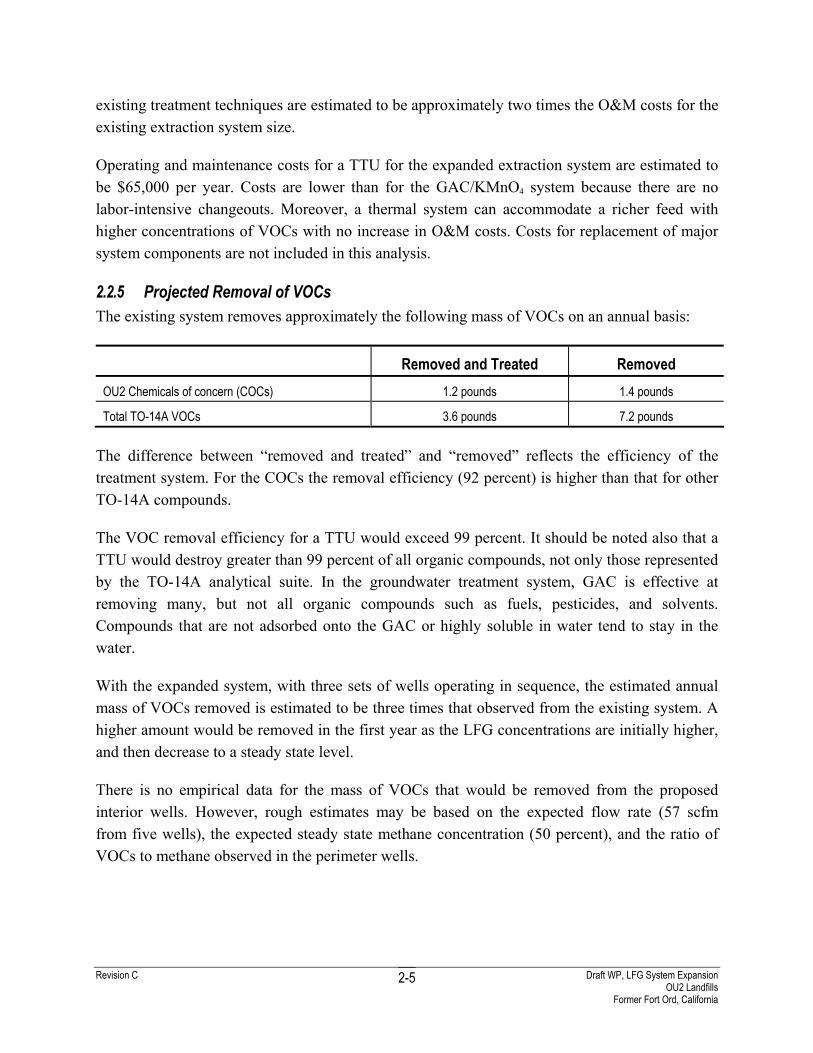
2.2.5 Projected Removal of VOCs The existing system removes approximately the following mass of VOCs on an annual basis:
Removed and Treated Removed OU2 Chemicals of concern (COCs) 1.2 pounds 1.4 pounds
Total TO-14A VOCs 3.6 pounds 7.2 pounds The difference between “removed and treated” and “removed” reflects the efficiency of the treatment system. For the COCs the removal efficiency (92 percent) is higher than that for other TO-14A compounds.
The VOC removal efficiency for a TTU would exceed 99 percent. It should be noted also that a TTU would destroy greater than 99 percent of all organic compounds, not only those represented by the TO-14A analytical suite. In the groundwater treatment system, GAC is effective at removing many, but not all organic compounds such as fuels, pesticides, and solvents. Compounds that are not adsorbed onto the GAC or highly soluble in water tend to stay in the water.
With the expanded system, with three sets of wells operating in sequence, the estimated annual mass of VOCs removed is estimated to be three times that observed from the existing system. A higher amount would be removed in the first year as the LFG concentrations are initially higher, and then decrease to a steady state level.
There is no empirical data for the mass of VOCs that would be removed from the proposed interior wells. However, rough estimates may be based on the expected flow rate (57 scfm from five wells), the expected steady state methane concentration (50 percent), and the ratio of VOCs to methane observed in the perimeter wells.
Revision C Draft WP, LFG System Expansion OU2 Landfills
Former Fort Ord, California
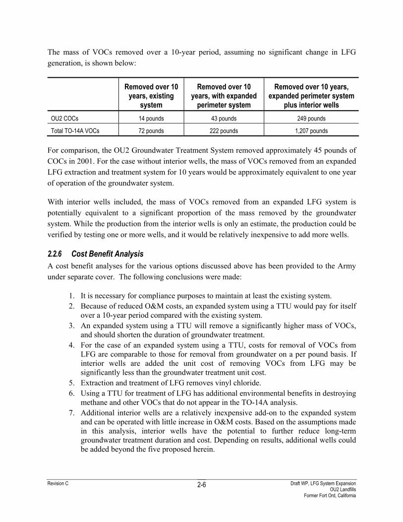
2-6
The mass of VOCs removed over a 10-year period, assuming no significant change in LFG generation, is shown below:
Removed over 10 years, existing
system
Removed over 10 years, with expanded
perimeter system
Removed over 10 years, expanded perimeter system
plus interior wells OU2 COCs 14 pounds 43 pounds 249 pounds
Total TO-14A VOCs 72 pounds 222 pounds 1,207 pounds For comparison, the OU2 Groundwater Treatment System removed approximately 45 pounds of COCs in 2001. For the case without interior wells, the mass of VOCs removed from an expanded LFG extraction and treatment system for 10 years would be approximately equivalent to one year of operation of the groundwater system.
With interior wells included, the mass of VOCs removed from an expanded LFG system is potentially equivalent to a significant proportion of the mass removed by the groundwater system. While the production from the interior wells is only an estimate, the production could be verified by testing one or more wells, and it would be relatively inexpensive to add more wells.
2.2.6 Cost Benefit Analysis A cost benefit analyses for the various options discussed above has been provided to the Army under separate cover. The following conclusions were made:
1. It is necessary for compliance purposes to maintain at least the existing system. 2. Because of reduced O&M costs, an expanded system using a TTU would pay for itself
over a 10-year period compared with the existing system. 3. An expanded system using a TTU will remove a significantly higher mass of VOCs,
and should shorten the duration of groundwater treatment. 4. For the case of an expanded system using a TTU, costs for removal of VOCs from
LFG are comparable to those for removal from groundwater on a per pound basis. If interior wells are added the unit cost of removing VOCs from LFG may be significantly less than the groundwater treatment unit cost.
5. Extraction and treatment of LFG removes vinyl chloride. 6. Using a TTU for treatment of LFG has additional environmental benefits in destroying
methane and other VOCs that do not appear in the TO-14A analysis. 7. Additional interior wells are a relatively inexpensive add-on to the expanded system
and can be operated with little increase in O&M costs. Based on the assumptions made in this analysis, interior wells have the potential to further reduce long-term groundwater treatment duration and cost. Depending on results, additional wells could be added beyond the five proposed herein.
Revision C Draft WP, LFG System Expansion OU2 Landfills
Former Fort Ord, California
3-1
3.0 Regulatory Requirements
This section presents the applicable regulatory requirements for LFG emissions at the landfill perimeter and the discharge of organic compounds to the atmosphere.
Based on our review, the applicable or relevant and appropriate requirements for permitting LFG and soil vapor collection and control at the OU2 Landfills include:
• Solid waste and water quality regulations contained in CCR Title 27 (CCR 27, formerly Title 14 CCR 17783.5)
• The air quality standards of the Monterey Bay Unified Air Pollution Control District (MBUAPCD)
• The groundwater protection requirements of the Monterey County Environmental Department of Health (MCDH)
3.1 California Integrated Waste Management Board Regulations CIWMB Regulations for Solid Waste Landfills, Title 27 CCR, Chapter 3, Article 6 - Gas Monitoring and Control at Active and Closed Disposal Sites (formerly Title 14 CCR, Chapter 3, Article 7.8 - California Public Resources Code, Division 30)
The modifications proposed herein are intended to address the applicable requirements for control of LFG migration from OU2 Landfills, and mitigating its impact on public health and the environment, as required in CCR Title 27, Environmental Protection, Division 2, Solid Waste.
The CIWMB regulation 27 CCR Section 20921 (formerly 14 CCR Section 17783) requires that methane concentrations do not exceed the LEL of 5 percent by volume [50,000 parts per million by volume (ppmv)] in soils at the landfill property boundary or an alternate boundary. Also, trace gases must be controlled to prevent adverse acute and chronic exposure to toxic air contaminants (TAC) and/or carcinogenic toxic air contaminants (CTAC).
3.2 Monterey Bay Unified Air Pollution Control District Regulations MBUAPCD Regulation II (New Sources) Rule 207 and Regulation X (Toxic Air Contaminants) Rule 1000
The Army has determined from discussions with MBUAPCD that these regulations will apply to LFG mitigation but they do not apply to the existing landfill.
Revision C Draft WP, LFG System Expansion OU2 Landfills
Former Fort Ord, California
3-2
3.2.1 Regulation II, Rule 207 The MBUAPCD regulates New Sources of excessive toxic compound emissions under the permitting requirements described in Rule 207, Review of New or Modified Sources. Under Rule 207, Best Available Control Technology (BACT) shall be required for any new or modified permit unit with a potential to emit over a stated level of specific VOCs or combustion by-products. These levels are summarized in Table 4.1.1 in Rule 207.
Due to their low gas generation rates and low VOC concentrations (based on the pilot study results;) the OU2 Landfills are not anticipated to produce toxic compound emission quantities exceeding the maximum emission thresholds stated in Rule 207. Thus, OU2 Landfills and the proposed emission control devices will be exempt from meeting the requirements for BACT stated in Rule 207.
The major compound of concern in the LFG that has a Rule 207 emission threshold is vinyl chloride. The Rule 207 threshold for vinyl chloride is 5.48 pounds per day (lbs/day). The anticipated throughput of vinyl chloride for the LFG extraction system (before treatment) is 0.085 lbs/day, far below the allowable maximum requiring BACT. The estimated worst case throughput of EPA Method TO-14A VOCs is 0.66 lbs/day (before treatment), compared to a Rule 207 maximum threshold of 150 lbs/day. The estimated vinyl chloride and VOC throughput were extrapolated from current estimated LFG extraction flows from existing facilities (Appendix B, Table 4B). Emissions of combustion process secondary pollutants (most commonly carbon monoxide, oxides of nitrogen and sulfur, and particulate matter), are also not anticipated to exceed the daily allowable mass emission rates stated in Rule 207.
3.2.2 Regulation X, Rule 1000 Because of the small size and anticipated low emissions of the landfill and treatment facilities, the permitting of this project will be primarily controlled by the requirements of MBUAPCD Rule 1000, Permit Guidelines and Requirements for Sources Emitting Toxic Air Contaminants. The LFG treatment system is a new or modified source that has the potential to emit very low levels of CTAC, or TAC. This subjects the emissions of the TTU to Rule 1000. A risk assessment was completed to demonstrate that the emissions from the proposed TTU will not cause a net increased cancer risk in excess of no more than 1 in 100,000 (or 1 x 10⁻⁵). The estimated cancer risk is 0.08 in 1,000,000 (1 x 10 -6) well below the level of concern. The proposed TTU also meets the requirements of using reasonable and best control technology to control CTACs and TACs. Detailed discussions and calculations are presented in Appendix C.

Revision C Draft WP, LFG System Expansion OU2 Landfills
Former Fort Ord, California
3-3
3.2.3 Standard Permit Requirements A recently issued MBUAPCD Permit to Operate for a LFG TTU of similar design, size, and purpose as the proposed treatment facility contained the following operating conditions:
• minimum destruction efficiency of total hydrocarbons (THC) shall be 98 percent by weight
• combustion temperature shall be maintained at a minimum of 1400°F within 30 minutes of any start-up
• the minimum combustion residence time shall be 0.6 seconds
• instrumentation shall continuously record combustion temperature during operation
• nitrogen oxide emissions shall not exceed 0.06 pound per million Btu (lb/MMBtu)
• carbon monoxide emissions shall not exceed 0.40 lb/MMBtu
• THC emissions shall not exceed 0.03 lb/MMBtu
• sulfur dioxide emissions shall not exceed 0.2 percent by volume (2,000 ppmv)
• inlet sulfur content shall not exceed 50 grains hydrogen sulfide per 100 cubic feet of gas
• instrumentation shall continuously record the amount of LFG flow to the flare during operation
• no air contaminant which is as dark or darker than Ringlemann 1 or equivalent 20 percent opacity shall be discharged for more than aggregate 3 minutes in any hour
• no emissions shall constitute a public nuisance
3.3 Federal Clean Air Act New Source Performance Standards Due to the small volume of waste, the OU2 Landfills are exempt from landfill emission control requirements under the federal New Source Performance Standards and Emission Guidelines [New Source Performance Standards (NSPS) and Emission Guidelines (EG), 40 Code of Federal Regulations (CFR) Part 60, Subparts WWW and Cc]. Thus the OU2 Landfills are also exempt from MBUAPCD Rule 437, Municipal Solid Waste Landfills, the local regulation implementing the federal landfill Emission Guidelines (40 CFR Part 60, Subpart Cc). Since the OU2 Landfills are exempt from NSPS/EG, the OU2 Landfills not considered a major source under federal Clean Air Act Amendment Title V, Operating Permits, unless there are other sources at Fort Ord requiring Major Facility Permits.
Revision C Draft WP, LFG System Expansion OU2 Landfills
Former Fort Ord, California
3-4
3.4 Monterey County Health Department - Well Drilling Permits The new LFG extraction wells are designed to intercept LFG and VOC migration to the groundwater table. The wells will be drilled along the perimeter road surrounding Area F. Each well will be constructed to either 22 or 32 feet below ground surface (bgs), and will be at least 60 feet above the high seasonal groundwater table. Interior extraction wells will be drilled to a maximum depth of 70 feet which is at least 20 feet above the high seasonal groundwater table. Permits will be obtained from the MCDH, Division of Environmental Health, Hazardous Materials Branch prior to fieldwork. One application will be submitted for each extraction well location.

Revision C Draft WP, LFG System Expansion OU2 Landfills
Former Fort Ord, California
4-1
4.0 Construction Work Plan, Extraction System
This section presents the construction requirements for the expansion of the LFG extraction system. The LFG system expansion consists of adding vertical extraction wells along the northern, western, southern perimeters of Area F and in the interior of Area F, into the undisturbed soil berms between the original excavated waste trenches. Operation of the existing treatment system will continue during expansion. Construction requirements are summarized below.
4.1 Extraction System The LFG extraction system expansion consists of adding vertical extraction wells along the northern, western and southern perimeter of Area F and in the interior of Area F. Drilling will start with the interior wells to facilitate performance of flow extraction testing (Section 4.1.2.2). Based on the successful performance of the pilot test system, where the spacing between extraction wells was 100 feet, the spacing between extraction wells in the system expansion is set at approximately 200 feet. Appendix D, Sheet 1 presents the site layout, the location of new LFG extraction wells, and new extraction piping. Sheets 6 and 7 present typical details for the extraction well construction.
4.1.1 Perimeter Extraction Wells Perimeter extraction wells will be constructed to meet the requirements of the system expansion for long-term system operation. Wells will be constructed with 4-inch (0.33 feet) diameter Schedule 40 PVC casing and screen. Each well will be constructed to either 22 or 32 feet bgs with the bottom 10 feet constructed with a 0.125 (1/8 inch)-slotted Schedule 40 PVC casing. The annulus surrounding the screen will be backfilled with 3/8-inch crushed or natural washed pea gravel per Specification Section 02521 (Appendix E). A CES-Landtec Accu-flo™ wellhead will be installed at each well in a protective concrete vault. To minimize air infiltration through the ground surface, a plastic sheet will be placed on the surface around the well, below each protective vault.
Appendix D, Sheets 7 and 8 presents the construction and installation details for the extraction well, wellhead, and vault. Specification Section 02521, included in Appendix E, presents the construction specification for perimeter extraction wells.
4.1.2 Interior Extraction Wells Interior extraction wells will be drilled into the undisturbed soil berms between the original excavated waste trenches. Well installation in soil reduces the potential risks of drilling through waste which is poorly defined, and may contain unknown hazardous materials. The sandy site
Revision C Draft WP, LFG System Expansion OU2 Landfills
Former Fort Ord, California
4-2
soils and geomembrane final cover should allow a substantial radius of influence for these interior wells, even though not installed in direct contact with waste.
Wells will be constructed with 6-inch (0.5 feet) diameter HDPE standard dimensional ratio 17 casing and screen. Each well will be constructed to 70 feet bgs. The screen, at the bottom 40 feet, will have 1/2-inch diameter holes with four holes per circumference at 90° and alternate rows staggered at 45°. The annulus surrounding the screen will be backfilled with 1-inch coarse gravel per Specification Section 02687 (Appendix E). A CES-Landtec Accu-flo™ wellhead will be installed at each well in a protective concrete vault. To minimize air infiltration through the ground surface, a plastic sheet will be placed on the surface around the well, below each protective vault.
Appendix D, Sheets 6 and 8 presents the construction and installation details for the extraction well, wellhead, and vault. Specification Section 02687, included in Appendix E, presents the construction specification for perimeter extraction wells.
4.1.2.1 Pre-Drilling Investigation Aerial photographs and topographic survey data, as well as visual observation of surface depressions/undulations will be used to select potential locations of interior wells. Geophysical surveys will also be conducted to confirm the location of undisturbed soil berms and waste trenches. For maximum definition, the geophysical surveys will consist of both electromagnetic (EM) and ground penetrating radar surveys (GPR). The EM surveys will consist of both frequency domain (EM-31) and time domain surveys (EM-61). Complete coverage over the field area will be achieved. The EM-31 will be used to identify non-metallic wastes and the EM-61 will be used to identify metallic wastes (Geonics LTD). It is understood that the area between trenches may contain shallower buried wastes and the trenches will contain the thick buried wastes. Shaw will attempt to delineate both of the areas during data processing. The GPR survey will be used to augment the EM surveys. Several GPR profiles will be conducted over anomalies identified in the EM data.
The EM data will be obtained simultaneously with GPS navigational data. Therefore, every data point will have associated California State Plane Coordinates. The data will be processed with a combination of Shaw in-house developed software and Oasis Montaj (GeoSoft).
Prior to drilling, each site will be potholed to a minimum depth of five feet bgs to confirm that the site is within the undisturbed soil berm and not the waste trench. After potholing, drilling will be advanced slowly and the cuttings carefully logged. If at any time during potholing and drilling, any evidence of waste is suspected or noted then potholing/drilling will be stopped and the drill site relocated.
Revision C Draft WP, LFG System Expansion OU2 Landfills
Former Fort Ord, California
4-3
4.1.2.2 Extraction Flow Testing After drilling, the header pipe from EW-31 through 34 will be immediately installed and temporarily connected to the existing header pipe (Appendix D, Sheet 1). After pipeline installation, flow extraction tests will be conducted to characterize the LFG production from the interior wells. The key data that are required to evaluate the effectiveness of using LFG as a fuel are sustainable LFG flow rate and methane concentration. During the field test, the LFG will be treated using the existing treatment system. Procedures and requirements for testing and/or establishing flow rates for extraction wells presented in Appendix G will be followed.
This information is needed prior to finalizing the design of the TTU (Section 2.1.2).
4.2 Collection Pipes and Valves Extraction wells to be installed along the northern, southern, and western edges of Area F will be connected to a common 6-inch HDPE header pipe. Interior extraction wells will be connected to a separate 6-inch HDPE header pipe. Lateral connections will be constructed of 2-inch flex hose, 2-inch HDPE, or 4-inch HDPE, depending on the distance between the header pipe and the extraction well. All lateral and header pipes will be constructed below grade a minimum of 12 inches above the geomembrane.
New header pipes and existing header pipes from the perimeter wells will be connected with valves to be installed within each pipe leg at the common manifold, and other locations, to control LFG flow. The extraction piping and valve layout is designed to allow flexibility for either alternating or concurrent operation of the three legs, with the north and west sides as one leg, the eastern side as a second leg, and the southern side as the third leg.
A control valve will also be installed at each extraction well connection. The valves will be constructed below grade and contained in valve boxes. Location of typical piping runs and valving are presented in Appendix D, Sheet 1. Details are presented in Sheet 9.
The new header pipe and laterals will be pressure tested to 5 pounds per square inch (psi) for 20 minutes. If there is a pressure drop, the leak will be isolated and repaired. Then the line(s) will be re-tested until all of the lines pass the pressure testing. The pressure testing will be conducted in accordance with the manufacturer’s recommendations and procedures.
Piping will be single wall and not double-contained. Double-contained pipe is not considered necessary because the piping will contain only small amounts of liquid under low pressure, the liquid would typically not be a hazardous material, and the system is installed above the footprint of the existing impacted groundwater plume. Also the specified HDPE pipe is strong and durable, and will be pressure tested for leakage before long-term operation.
Revision C Draft WP, LFG System Expansion OU2 Landfills
Former Fort Ord, California
4-4
In addition to the new extraction wells, piping previously installed to connect the treatment system to a LFG collector trench in Area E (Appendix D, Sheet 1) will be incorporated into the final extraction system. This collector pipe is intended to provide additional LFG, if needed or desired for future applications.
4.3 Extraction Well Vaults Extraction wells will be completed below grade, enclosed in 3 x 2 x 1.5-foot concrete vaults with locking aluminum covers. Construction details for the vaults are presented in Appendix D, Sheet 9. The extraction wells will be connected to the laterals with a CES-Landtec Accu-flo™ wellhead attached to each new extraction well.
4.4 Condensate Tank Installation Condensate resulting from LFG cooling in the piping system will be collected at topographic low points with three new condensate tanks. The condensate tanks consist of 325-gallon polyethylene tanks connected to the header piping at low points in the system. These tanks will be set into a concrete vault, which will act as a spill prevention system for the condensate tanks. The concrete vault will consist of a concrete drainpipe cut to fit, seated on a concrete base and sealed at the joints by a cement sealer. The condensate tanks will be constructed below ground surface to allow the condensate to gravity flow to the condensate tank. The existing condensate tanks will be upgraded to match the new system. Appendix D, Sheet 8 shows the typical construction of a condensate tank with secondary containment. The tanks will be connected to the header pipe by flexible hose.
4.5 Drilling of Extraction Wells This section presents a discussion on the permit requirements for extraction wells, drilling equipment decontamination, and handling of investigation derived waste. Permits for extraction wells will be obtained from the MCDH prior to fieldwork (Section 3.4).
4.5.1 Equipment Decontamination Tools and equipment used during drilling operations will be pressure washed using hot water prior to initial use and before departing the project site.
Between boreholes, tools and equipment that may be used during drilling will be cleaned of caked drill cuttings, soil, or other material using brushes and shovels. If gross contamination is encountered, tools and equipment will be pressure washed using hot water.
After cleaning and decontamination, tools and equipment that may be used during drilling operation must be kept clean and free of contaminants. Decontaminated equipment shall be kept off the ground by storing on clean metal racks (not wooden pallets) and/or wrapped in plastic.

Revision C Draft WP, LFG System Expansion OU2 Landfills
Former Fort Ord, California
4-5
Well materials, exclusive of sand pack, bentonite, and grout shall be decontaminated before placement in the borehole as described above. Following decontamination, all materials shall be placed on clean metal racks or clean plastic sheeting. If materials are not used immediately, they shall be wrapped or covered with clean plastic sheeting.
4.5.2 Investigation Derived Waste Wastes will be kept separate by type (i.e. soil cuttings will not be mixed with wastewater). Soil cuttings will be left at each borehole location. Because wells are to be drilled outside the landfill perimeter, soil cuttings and wash water should not be contaminated. Soil cuttings may be used at the OU2 Landfills for grading access roads or to fill potholes. Water generated during pressure washing will be contained in 55-gallon drums, and will either be used for dust control on the landfill cap or transported to the OU2 groundwater treatment plant. Other wastes (e.g. cement bags) will be disposed of as regular waste.
4.6 Environmental Protection Environmental impacts associated with drilling and construction activities are not anticipated. Requirements for dust control, erosion control, and security are presented in the following subsections.
4.6.1 Dust Control It is not anticipated that dust will be generated. Water trucks will be used to spray water in active construction areas, if noticeable dust is generated. If required, due to high winds, additional engineering measures will be implemented to control dust during drilling and construction activities.
4.6.2 Erosion Control Extraction well drilling is occurring primarily along the existing Area F perimeter road. It is anticipated that drilling and construction activities will require minimal disturbance of the vegetative cover and sensitive habitat. If required, the erosion control requirements presented in the OU2 Landfills O&M Plan (IT, 2000) will be implemented.
4.6.3 Security The landfill is enclosed by permanent fences to isolate and control access to the site. If permanent fences are removed to provide access to equipment during drilling and construction activities, temporary fences will be installed.

Revision C Draft WP, LFG System Expansion OU2 Landfills
Former Fort Ord, California
5-1
5.0 Construction Work Plan, Treatment System
This section presents the electrical and construction requirements for installation of the TTU. The basic TTU will arrive at the site on a custom prefabricated skid package, ready for connection to site utilities and the vapor source to be treated. The existing blower will be reused for the TTU. Operation of the existing treatment system will continue during expansion.
The proposed facility plan includes a 38 x 34-foot area enclosed in an 8-foot high chain link fence with wind screen and a 50 x 50-foot driveway/parking lot. Electrical and construction requirements are summarized below.
5.1 Subgrade and Concrete Pad Installation Prior to delivery of the prefabricated skid package, the site will be prepared using the following procedure:
• Excavate to a depth of approximately 1 foot 8 inches, compact and line with a fabric
• Place approximately 1 foot of Class II base rock compacted to 95 percent maximum dry density
• Install 6-mil vapor barrier polyethylene sheet between base rock and concrete
• Construct 11 x 26-foot concrete foundation pad, 8 inches thick using American Society of Testing Materials C150 Type 1 concrete with #4 rebar 12 inches on center each way (Appendix E, Specification 03300). Dimensions of the pad may change depending on the final TTU selected.
• After completion of the interior installations, construct chain link fencing with wind screen slats (Appendix E, Specification 02830).
Details of the facility plan and blower and flare skid foundation pad are presented in Appendix D, Sheets 2, 3, and 10.
5.2 Installation of Treatment System The treatment system will be delivered to the site in two pieces (Appendix D, Sheets 2, 3, and 10). Each piece will be placed onto the concrete pad using a crane. All pieces, including the blower, will be anchored into the concrete pad using specified anchor bolts or by means of brackets. Appendix E, Specification 11000 presents equipment description and construction.
LFG and condensate plumbing will be pressure tested to 5 psi for 20 minutes. Propane plumbing will be pressure tested to 100 psi for 20 minutes. If there is a detected pressure drop, the leak will be isolated and repaired. Then the plumbing will be re-tested until all sections pass the

Revision C Draft WP, LFG System Expansion OU2 Landfills
Former Fort Ord, California
5-2
pressure testing. The pressure testing will be conducted in accordance with the pipe manufacturer’s recommendations and procedures.
5.3 Electrical Installation The current electrical transformer [30 amperes (amps), 480 volt, 3-phase] will be left in place. A branch from the 3-phase primary will be extended from this existing main switch, to a second main breaker panel on the proposed treatment system skid control rack. An additional transformer (20 amps, 110 volt, single phase) will be included on the treatment system control rack to provide outlets for electrical equipment and light fixtures. Equipment will be protected with foundation grounding, as well as with multiple ground wires using ground rod boxes with copper grounding rods inside. Appendix D, Sheets 4 and 5, present the piping and instrumentation diagram and Sheet 11 presents the electrical details.

Revision C Draft WP, LFG System Expansion OU2 Landfills
Former Fort Ord, California
6-1
6.0 Start up Operations
The primary objectives of the start-up operations phase are:
• maximize the long-term equilibrium flow of LFG methane and VOCs from the extraction wells
• maximize fuel efficiency and emissions performance of the TTU
• maintain concentrations of all LFG compounds at compliance monitoring probes below regulatory standards
To achieve the above objectives, the following subtasks will be performed during the first two months of operation:
• operator training and shakedown of the treatment system to assure correct operation of all combustion controls and safety/alarm systems
• balancing of LFG extraction times, flows, and applied vacuums to maximize individual and total COC mass removal
• determination of optimum flow rates of extracted LFG, dilution air, and supplemental fuel to maximize COC mass treatment and/or cost-effectiveness
• demonstrate compliance with air district operating requirements
The above tasks are described in further detail, below.
6.1 Shakedown of the Treatment System 6.1.1 Manufacturer's Start-up Initial shakedown of the treatment system includes comprehensive on site inspection and operation by the factory technician and site-operator training. The site operator will confirm that a representative extracted gas stream is available from one or more of the extraction system legs, to feed the TTU during start-up/shakedown operation. Upon completion of equipment installation and external connections, the factory technician will arrive on site to:
• test all electrical power and control circuits
• start and test-operate the TTU over its full functional range
• test and assure correct operation of all combustion controls and safety/alarm systems

Revision C Draft WP, LFG System Expansion OU2 Landfills
Former Fort Ord, California
6-2
• confirm that equipment operation can meet all permit conditions for the emissions source test
• train the site operating personnel in basic operations and troubleshooting
6.1.2 Daily Equipment Inspection During the start-up phase, after initial shakedown, the site operator will visually inspect the treatment facility equipment and piping daily. The following items will be inspected each day, at approximately the same time:
• Blower Data
− Blower bearing temperature
− Blower bearing vibration
− Blower current draw (amps)
• Blower Inlet and Discharge Piping Instrumentation
− Inlet vacuum
− Inlet gas temperature
− Discharge pressure
− Discharge gas temperature
• Flow Recorder
− Instantaneous LFG and propane flow rate
− Totalized LFG and propane flow
− Propane tank pressure level
• Knock Out Pot
− Water level
− Differential pressure drop
• Oxygen Analyzer
− Oxygen concentration
• Dilution Air Blower Panel
− Operating speed

Revision C Draft WP, LFG System Expansion OU2 Landfills
Former Fort Ord, California
6-3
The site operator will immediately note and schedule all repair and maintenance items, including warranty work to be performed by the equipment manufacturer.
6.1.3 Weekly Equipment Inspection The following routine operational items shall be performed weekly:
• Change data recorder chart or download instrument memory storage
• Check calibration of the oxygen analyzer
• Check for correct operation of the trouble alarms and auto-dialer
6.2 Balance LFG Extraction Wells Balancing of the LFG extraction wells consists of the initial monitoring and adjustment of the LFG extraction wells during start-up to maximize the mass removal of methane and COCs. It is essentially a field extraction test for each set of new wells, to determine the optimum LFG well extraction flow rates. The main criteria of well balancing will be to determine the initial methane productivity of each well and each leg of the extraction well system, and subsequently to:
• reduce LFG flows from less productive wells
• increase LFG flows from more productive wells
• obtain a consistent flow from each system leg within the normal operating range of the treatment system
Each new leg of the wellfield system will be operated continuously for two weeks, during which the wells will be individually monitored and adjusted at least three times per week. The first week of operation will allow for purging of accumulated LFG in the soil pore volume. The second week of operation will allow an approximation of the sustainable long term methane productivity of each leg. If it is observed that equilibrium extraction flow rates cannot be clearly defined after two weeks of continuous operation, additional wellfield balancing time may be requested.
During the start-up phase, each of the four major legs of the wellfield will be isolated from the other three, using valves at the central header manifold located at the west end of Area F.
6.2.1 Procedures The performance of the LFG system will be monitored using field instruments at the blower inlet, the central header manifold, and the individual wells. Monitoring parameters include applied vacuum, gas flow rate, methane, oxygen, and carbon dioxide.
Revision C Draft WP, LFG System Expansion OU2 Landfills
Former Fort Ord, California
6-4
6.2.2 Instrumentation A GEM-500™ (CES-Landec) gas analyzer will be used for all field measurements, including total pressure, differential pressure, and LFG composition (methane, carbon dioxide, oxygen, and balance gas).
The GEM-500™ calibration will be verified daily, according to manufacturer’s recommendations as specified in the operation manual (Form 6-1). In brief, the calibration requires two calibration gas mixtures. One gas mixture is used to span oxygen and zero methane. The other is used to span methane, carbon dioxide, and zero oxygen. The operation manual for the GEM-500™ is provided in Appendix B of the OU2 Landfills O&M Plan (IT, 2000).
6.2.3 Daily Monitoring Requirements Monitor and record the following data at approximately the same time each day, at the thermal treatment facility inlet:
• Methane concentration
• Oxygen concentration
• Carbon dioxide concentration
• Nitrogen concentration (balance gas)
• Transmission pipe vacuum
• Instantaneous flow rate
• Totalized flow
If unexpected changes are noted in the recorded data from the previous days' monitoring data, individual wells should be monitored to locate the source of the data variation. Well flows and vacuum shall be adjusted as required, to continue progression toward an acceptable equilibrium extraction condition.
6.2.4 LFG Flow Adjustment During start-up monitoring, frequent adjustments may be made to the well vacuums to attain an acceptable equilibrium flow and methane concentration. Initial flow rates for perimeter wells should be approximately 150 percent of the equilibrium rates determined for the existing wells east of Area F (approximately 10-15 scfm). During start-up extraction, individual wells should be monitored at least three times per week.
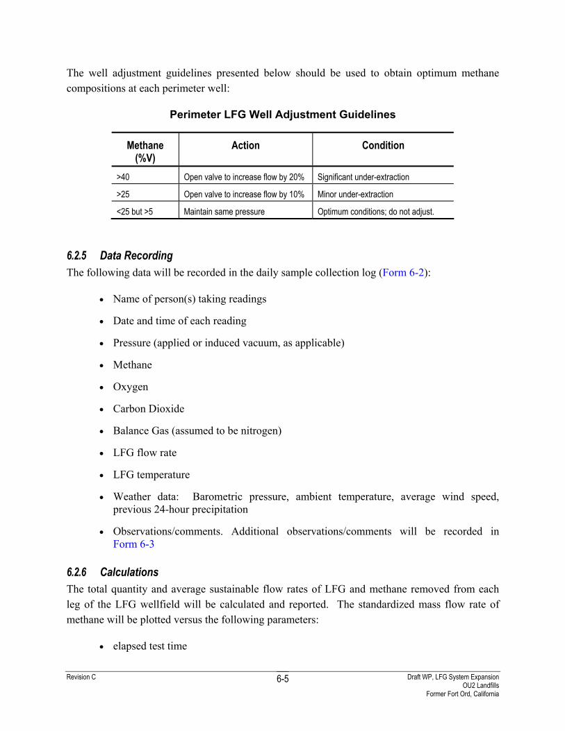
Revision C Draft WP, LFG System Expansion OU2 Landfills
Former Fort Ord, California
6-5
The well adjustment guidelines presented below should be used to obtain optimum methane compositions at each perimeter well:
Perimeter LFG Well Adjustment Guidelines
Methane (%V)
Action Condition
>40 Open valve to increase flow by 20% Significant under-extraction
>25 Open valve to increase flow by 10% Minor under-extraction
<25 but >5 Maintain same pressure Optimum conditions; do not adjust.
6.2.5 Data Recording The following data will be recorded in the daily sample collection log (Form 6-2):
• Name of person(s) taking readings
• Date and time of each reading
• Pressure (applied or induced vacuum, as applicable)
• Methane
• Oxygen
• Carbon Dioxide
• Balance Gas (assumed to be nitrogen)
• LFG flow rate
• LFG temperature
• Weather data: Barometric pressure, ambient temperature, average wind speed, previous 24-hour precipitation
• Observations/comments. Additional observations/comments will be recorded in Form 6-3
6.2.6 Calculations The total quantity and average sustainable flow rates of LFG and methane removed from each leg of the LFG wellfield will be calculated and reported. The standardized mass flow rate of methane will be plotted versus the following parameters:
• elapsed test time

Revision C Draft WP, LFG System Expansion OU2 Landfills
Former Fort Ord, California
6-6
• methane concentration
• total LFG flow
• applied system vacuum
The weekly rate and total quantity of VOCs removed from each leg of the LFG wells will be calculated and reported based on an annual VOC analysis of representative sample from the extraction system.
6.3 Optimize Treatment System Flow Rates The objective of this subtask is to determine the optimum flow rates of extracted LFG, dilution air, and supplemental fuel to maximize COC mass treatment while maintaining reasonable cost-effectiveness, within the following external constraints:
• available LFG extraction quantity, as determined during the initial well balancing task
• LFG methane concentration available for fueling the thermal unit
• design capacity of the treatment system
As the ranges of LFG flow and methane concentration available from the four extraction well legs are determined, a normal operating range for the thermal unit will be defined. Near the end of the start-up period, the appropriate propane and dilution air flow ranges will be established for maximum treatment efficiency, while operating within this normal target range. Alternative adjustments required for operating in potential LFG flow conditions outside the normal operating range will also be determined.
6.4 Demonstrate Air Quality Compliance Performance testing and routine monitoring will be conducted following requirements typically applied to landfill treatment systems of this size, within the MBUAPCD. Performance testing of the TTU shall be performed initially, to demonstrate compliance, and annually thereafter. The results of testing will be used to evaluate compliance of the TTU to the parameters and operating conditions presented in Appendix E, Section 11000 which are based on a recently issued MBUAPCD Permit to Operate for a LFG TTU of similar design, size, and purpose.
6.5 Decommissioning of Existing Treatment System The existing GAC/KMnO4 treatment system will be decommissioned after installation of the TTU has been completed. Equipment (e.g. blower) will be reused with the new treatment system.

Revision C Draft WP, LFG System Expansion OU2 Landfills
Former Fort Ord, California
6-7
During construction and installation of the new treatment system, operation of the existing treatment system will continue to maintain compliance (Section 1.4). Relocation of the existing treatment system, if required, will be conducted during regular shut down. Reconnection of the expanded extraction system to the TTU will be conducted during regular shut down.
Revision C Draft WP, LFG System Expansion OU2 Landfills
Former Fort Ord, California
7-1
7.0 Site Safety and Health Plan
Work activities will be performed utilizing safe work practices as detailed in the Site Safety and Health Plan (Revision 7), Fort Ord Remedial Action, Former Fort Ord, California (SSHP) (Shaw, 2003c). AHAs providing summary of the hazards anticipated during the LFG system expansion, and actions to be implemented to avoid and minimize the impact of these hazards, are presented in Appendix F.

Revision C Draft WP, LFG System Expansion OU2 Landfills
Former Fort Ord, California
8-1
8.0 Contractor Quality Control Plan
This Contractor Quality Control Plan has been developed in accordance with the requirements of the Program Contractor Quality Control Plan for TERC II (ICF Kaiser, 1998). A table showing the summary of project team quality control (QC) responsibilities is presented in Table 8-1.
8.1 Project Organization This section provides a brief description of the roles and responsibilities of personnel who will be involved with installation and testing of the expanded LFG extraction and treatment system. A project organization chart is presented in Figure 8-1.
8.1.1 Project Manager The Project Manager, Peter Kelsall, is responsible for the quality and cost and schedule performance of all project activities, including those performed by subcontractors. The Project Manager is the primary interface with the Army and regulatory agencies.
8.1.2 Project Engineer The Project Engineer, Andrew Wang P.E., is responsible for the design of the LFG extraction and treatment system and will provide technical direction for installation, testing and operations. Changes to the design or testing procedures will be reviewed and approved by the Project Engineer. The Project Engineer is responsible to the Project Manager and the Task Manager on project issues.
8.1.3 Task Manager The Task Manager, Jen Moser R. G., is responsible for day-to-day management of engineering, construction, operation, monitoring and testing activities including, but not limited to:
• Detailed planning and scheduling
• Managing Shaw resources and subcontractors
• Coordinating testing and monitoring activities
• Data compilation and reporting
• Tracking the project cost and schedule and implementing corrective measures when necessary
8.1.4 Contractor Quality Control System Manager The Contractor Quality Control System Manager (CQCSM), Tom Ghigliotto, supports the Task Manager in day-to-day operations; however, the CQCSM will report functionally to the TERC II
Revision C Draft WP, LFG System Expansion OU2 Landfills
Former Fort Ord, California
8-2
QC Supervisor, Michael Reed. The CQCSM has sufficient authority, including stop work authority; to ensure that all project site activities comply with approved work documents. This authority applies equally to all project activities, whether performed by Shaw or its subcontractors and suppliers.
The CQCSM will be responsible for planning and executing QC oversight of project operations and shall ensure compliance with specified QC requirements in project plans, procedures, and contract documents.
8.1.5 Certified Industrial Hygienist The TERC II Program Certified Industrial Hygienist (CIH), Dr. Rudy Von Burg, is responsible for the development, implementation, and oversight of the SSHP (Shaw, 2003c). The CIH will provide oversight during construction and sampling activities.
8.1.6 Site Safety and Health Officer The Site Safety and Health Officer (SSHO), Charles Luckie, is responsible for implementation of the SSHP and applicable corporate Health and Safety procedures. Specific responsibilities include developing AHAs and monitoring construction and sampling activities for compliance with the SSHP. The SSHO is responsible to the Task Manager in day-to-day operations, but reports functionally to the TERC II Program CIH, Dr. Rudy Von Burg.
8.1.7 Project Superintendent The Project Superintendent, Dan Nohrden, is responsible for overseeing construction activities performed at the site. Field activities may be conducted by qualified in-house staff or by subcontractors. The Project Superintendent reports to the Task Manager.
8.1.8 Project Subcontractors A subcontractor to be selected later will perform extraction well drilling and installation. Subcontracted work will be conducted in accordance with the requirements of the contract, subcontractor scopes of work.
8.2 Definable Features of Work The definable features of work are as follows:
• Drill and install extraction wells
• Install extraction system piping
• Conduct flow extraction test on interior wells (Appendix G)
• Install extraction well vaults

Revision C Draft WP, LFG System Expansion OU2 Landfills
Former Fort Ord, California
8-3
• Select and finalize TTU design based on results of interior well flow extraction test
• Install condensate collection tanks, including upgrades to existing condensate tanks
• Prepare treatment system site foundation and other utilities
• Install treatment system
• Connect extraction piping to the treatment system, including vent trench from Area E
• Start up operations
8.3 Deliverables Project deliverables for this project include the following:
Landfill Gas Expansion System Work Plan, including Contractor Quality Control Plan
• Modifications of the OU2 Landfills O&M Plan (IT, 2000) to include documentation of the system expansion and new treatment equipment
• Construction record drawings showing all permanently installed systems. These drawings and a narrative description of the construction will be issued as an addendum to the OU2 Landfills RACCR (Shaw, 2003b)
Revision C Draft WP, LFG System Expansion OU2 Landfills
Former Fort Ord, California
9-1
9.0 References
U.S. Department of the Army (Army), 1994, Final Record of Decision, Operable Unit 2, Fort Ord Landfills, Fort Ord, California
Army, 1996, Explanation of Significant Differences, Area A, Operable Unit Landfill, Fort Ord, California
Army, 1997, Explanation of Significant Differences, Consolidation of Remediation Waste in a Corrective Action Management Unit (CAMU), Operable Unit 2 Landfill, Fort Ord, California
ICF Kaiser, 1998, Program Contractor Quality Control Plan for Sacramento TERC II, U.S. Army Corps of Engineers Contract No. DACW05-96-D-0011, Oakland, CA
IT Corporation (IT), 1996, Remedial Action Work Plan, Operable Unit 2, Landfill Closure, Fort Ord, California
IT, 1999, Draft (Final) Remedial Action Confirmation Report, Area A, Operable Unit 2 Landfills, Former Fort Ord, California
IT, 2000, Post-Closure Operation and Maintenance Plan, Areas B through F, Operable Unit 2 Landfills Remedial Action, Fort Ord, California
IT, 2002a, Draft Final Landfill Gas Perimeter Probe Monitoring Report, June, September, December 2000 and May 2001, Operable Unit 2 Landfill, Former Fort Ord, California
IT, 2002b, Draft Final Landfill Gas Perimeter Probe Monitoring Report, 2001, Operable Unit 2 Landfill, Former Fort Ord, California
Shaw Environmental, Inc. (Shaw), 2003a, Draft Evaluation Report, Landfill Gas Pilot Test, Operable Unit 2 Landfills, Former Fort Ord, California
Shaw, 2003b, Draft Remedial Action Construction Completion Report, Operable Unit 2 Landfills, Areas A through F, Former Fort Ord, California
Shaw, 2003c, Site Safety and Health Plan (Revision 7), Fort Ord Remedial Action, Former Fort Ord, California
Shaw, 2004a, Draft Final Landfill Gas Perimeter Probe Monitoring Report, 2002, Operable Unit 2 Landfill, Former Fort Ord, California
Shaw, 2004b, Draft Landfill Gas Perimeter Probe Monitoring Report, 2003, Operable Unit 2 Landfills, Former Fort Ord, California
Shaw, 2004c, Draft Report, 2003 Ambient Air Monitoring and Human Health Risk Assessment, Operable Unit 2 Landfills, Former Fort Ord, California