
Fracturation hydraulique et stimulation hydrauliquey q
Francois Henri Cornet, Institut de Physique du Globe de Strasbourg
Principe de la fracturation hydraulique
ôl h l é éRôle du champ de contrainte sur la géométrie des grandes fractures hydrauliques
Stimulation hydraulique : l’exemple de Soultz/sous Forêts
Le question posée par l’exploitation des « gaz de shistes »
CFMR‐3 mai 2012 1

Hydraulic fracturingHydraulic fracturing• The stress field close to a cylindrical hole in an elastic
field is :
• If the borehole is parallel to a principal stress direction (Vertical) and a pressure is applied in the hole: σ (σ(Vertical) and a pressure is applied in the hole: σθθ = (σH+ σh ) – 2 (σH ‐ σh ) cos 2θ ‐ Pw, and rupture occurs for :
If th k h b l d d b d i l ti • Both hydraulic fracturing and thermal cracking are mode• If the rock has been cooled down by mud circulation, the hoop stress is : σθθ = ‐KΔT /E, where K is coefficient of thermal expansion, E is Young’s modulus and ΔT is the difference between far‐field and borehole temperature
• Correction for pore pressure effect (still debated)
Both hydraulic fracturing and thermal cracking are mode I fractures
CFMR‐3 mai 2012
Correction for pore pressure effect (still debated)
2

Generating en echelon fractures in inclined wellsGenerating en echelon fractures in inclined wells
ff t b h l f il• effects on borehole failure
Azimuth where
Zones where maximum stress component reach its maximum value
‐ Pw
+ Pw
minimum principal stress reaches its lowest value
its maximum value
TOH BOH TOH TOH BOH TOH
BO IF B0 IF BO IF B0 IF
Inclination of plane in
CFMR‐3 mai 2012
Inclination of plane in which shear stress is zero
3

CFMR‐3 mai 2012 4

CFMR‐3 mai 2012 5
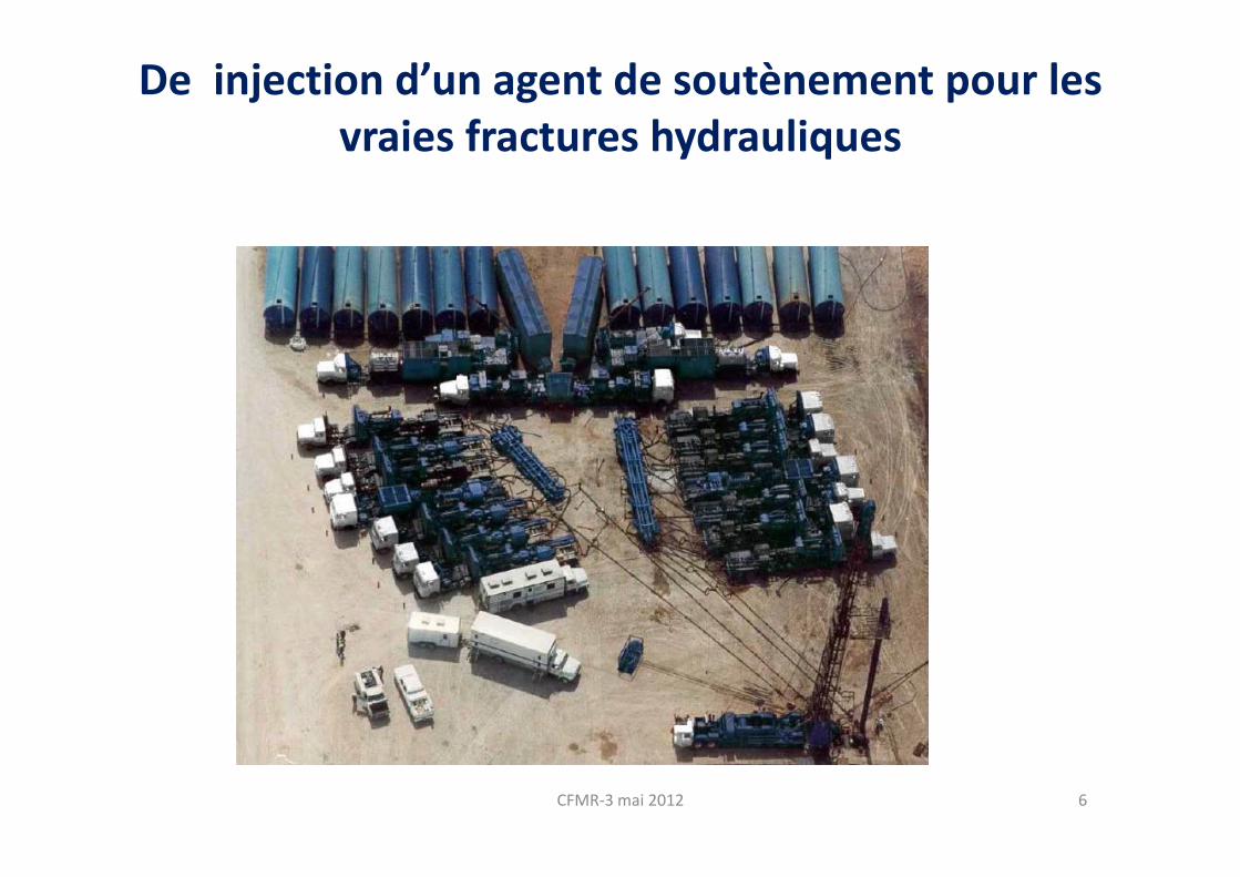
De injection d’un agent de soutènement pour les vraies fractures hydrauliquesvraies fractures hydrauliques
CFMR‐3 mai 2012 6
CFMR‐3 mai 2012 7

Influence de la contrainte principale minimum sur la géométrie des fractures
Fracturation hydraulique = Extension spatiale des fracturesFracturation hydraulique = Rupture de traction pure
Extension spatiale des fractures hydrauliques en terrain homogène
CFMR‐3 mai 2012 8

Cas des terrains sédimentaires (bassin de Paris)Cas des terrains sédimentaires (bassin de Paris)
CFMR‐3 mai 2012 9

Stimulation hydraulique sur le site expérimental de Soultz/forêts
CFMR‐3 mai 2012 10
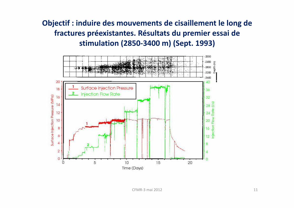
Objectif : induire des mouvements de cisaillement le long de fractures préexistantes Résultats du premier essai defractures préexistantes. Résultats du premier essai de
stimulation (2850‐3400 m) (Sept. 1993)
CFMR‐3 mai 2012 11
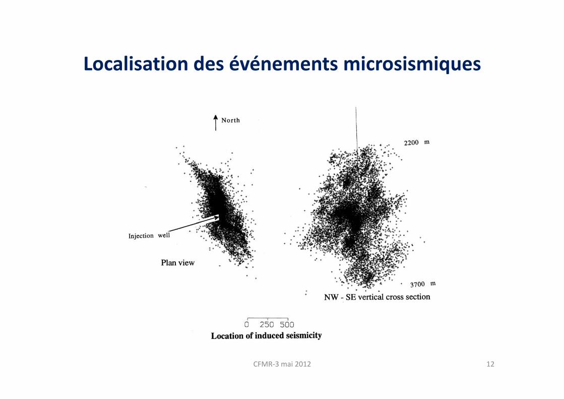
Localisation des événements microsismiquesLocalisation des événements microsismiques
CFMR‐3 mai 2012 12

Etude à différentes profondeurs de l’orientation du nuage
CFMR‐3 mai 2012 13
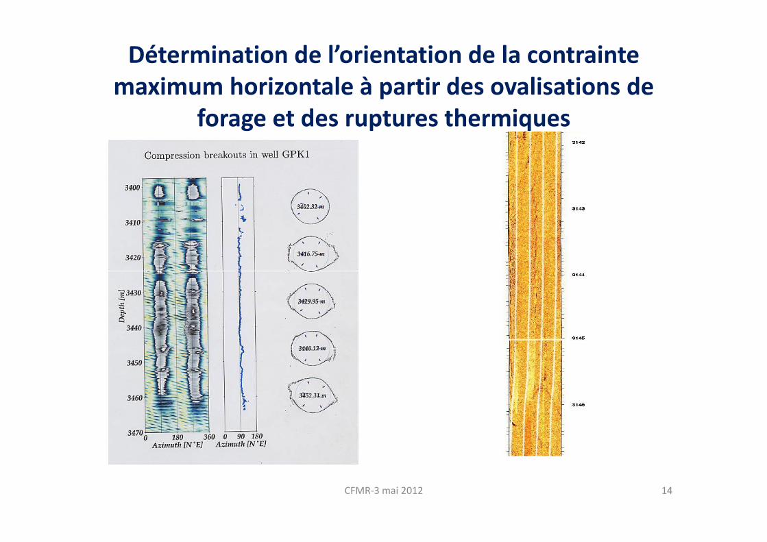
Détermination de l’orientation de la contrainte maximum horizontale à partir des ovalisations demaximum horizontale à partir des ovalisations de
forage et des ruptures thermiques
CFMR‐3 mai 2012 14

Caratérisation des variations d’orientation du nuage microsismique avec la profondeur
Depth Mean Mean dip Number ofDepth interval (m)l
Mean azimuth
Mean dip Number of events
2800 - 2900 N179°E 87° 329
2900 – 3000 N165°E 67° 402
3000 - 3200 N146°E 86° 416
CFMR‐3 mai 2012
1990 - 2200 N 147°E 87°
15

Variation des zones de d’injection en fonction de la pression d’injection
CFMR‐3 mai 2012 16

Le site de Soultz aujourd’hui
P t it ti f llPresent situation: four wells have been drilled.
All the wells have been Sedimentary coverStimulated in 1993 at 2850‐3600m
stimulated by large progressive hydraulic injections at different depths and different periods to increase their connectivity
y
crystalline basement (granite)
increase their connectivity.
Stimulated in 1995 and 1996 at 3200‐3800 m Stimulated in 2004 and
CFMR‐3 mai 2012 17
and in 2000 at 4400‐5000 mStimulated in 2004 and 2005 at 4479‐5000m
Stimulated in 2003 at 4487‐5100 m
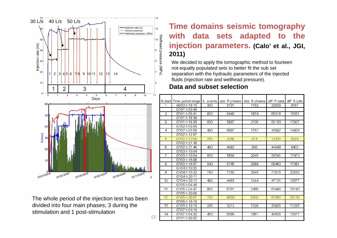
Time domains seismic tomographywith data sets adapted to the
30 L/s 40 L/s 50 L/s
with data sets adapted to theinjection parameters. (Calo’ et al., JGI,2011)We decided to apply the tomographic method to fourteen
Data and subset selection
not-equally populated sets to better fit the sub set separation with the hydraulic parameters of the injected fluids (injection rate and wellhead pressure).
The whole period of the injection test has been
CFMR‐3 mai 2012 18
The whole period of the injection test has been divided into four main phases; 3 during the stimulation and 1 post-stimulation

Set 1 Set 2 Set 3 Set 4 Set 5 Set 6
30 ls‐1 40 ls‐1
Set 7 Set 8 Set 9 Set 10 Set 11 Set 12
Seismicity re‐located with the 3D
50 ls‐1
yvelocity models.No internal structure observed during the stimulation (sets 1‐12). But the post‐injection seismicity (sets 13 and 14) reveals oriented
CFMR‐3 mai 2012 19
p j y ( )structures
Set 13 Set 14 Calò et al., JGI, 2011
Conclusion sur l’injection forcée j
O t t t d é l l’ lit d d l i d’i j ti• On note quatre types de réponse selon l’amplitude de la pression d’injection:
– Réponse élastique du système;
– Circulation forcée dans réseau de fractures existant avec déstabilisation locale dans les plans préexistants quand τ = tgø (n – P) + C; ø et C angle de frottement et cohésion ( 0?) de la fracture préexistante concernéefrottement et cohésion (=0?) de la fracture préexistante concernée.
– Création d’une nouvelle zone de rupture en cisaillement ( ) l d f d é dτ = tgø0 (n – P) + C0; ø0 angle de frottement interne du matériau; orientation de
la normale au plan de rupture à (/4 + ø0/2) de la direction de max; C0 cohésion de la roche saine;
– Développement d’une fracture hydraulique si Pinj ≥ min perpendiculaire à min .
20CFMR‐3 mai 2012
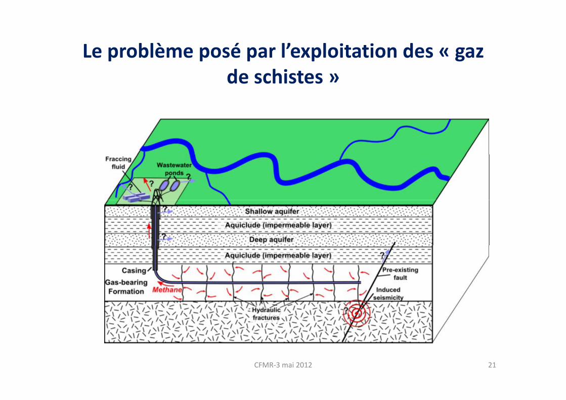
Le problème posé par l’exploitation des « gaz de schistes »
CFMR‐3 mai 2012 21


