castorone et fds2 - evolen.org · • with a unique fleet of pipelay vessels: all semisubmersible...
TRANSCRIPT
CastorOne et FDS2
Journées Annuelles 2011 des Hydrocarbures
1
Journées Annuelles 2011 des Hydrocarbures
Atelier 4Innovations maritimes : les nouveaux navires
CastorOne• SAIPEM operates the largest and most diversified offshore
construction fleet, for both conventional and deepwater pipelines
• With a unique fleet of pipelay vessels: all semisubmersible pipelay vessels Semac, Castoro 6 and Castoro 7 are SAIPEM
Why the CastorOne?
2
• With the CastorOne SAIPEM targets the large gas trunklines and oil export pipelines, in difficult environments, deepwater and/or arctic conditions.
• Typical projects:Jack Saint Malo & Big Foot Oil Export – GOM (awarded)Gazprom Shotkhman – Barents SeaGALSI (Algeria – Sardinia – Italy)Greece to ItalySouth Stream - Black Sea
Main Capabilities
DP3Ice Class
Pipe diameter 8” to 48” (60” with coating)Triple Joint 12 m or Double Joint 18 m
3
Triple Joint 12 m or Double Joint 18 m 6 or 7 working stations in Triple Joint
3 tensioners x 250 tons continuous pull750 tons A&R Winch
S-Lay and Steep S-LayJ-Lay

CastorOne
4

Maximum height of vessel fromBL (JLT folded)
67m
Length overall• 330 m (approx. without stinger)• 380 m (approx. with stinger stowed)
Width overall 39m
Depth 24m
Operating draught (excluding az.Thrusters)
from 8m to 10.6 m
• 750 mt Longitudinal
CastorOne CastorOne -- Main particularsMain particulars
5
Nominal Bollard Pull• 750 mt Longitudinal • 600 mt Lateral
Nominal transit speed 12.5 knots
Storage capacity pipes 20,000 mt
Accommodations capacitymaximum
702 persons
DP system - Total installedpower
Class 3- 8 x 8.4MW = 67.2MW
• operative sea state• pipe abandonment• operative stand-by
• max. 3.5 m Hs • from 3.5 m to 5m Hs • up to 8 m Hs, either with stinger in
the water or in rest position
Pipe Production CapabilitiesPipe Production Capabilities
Storage capacities Storage capacities
6
Storage capacities Storage capacities
TJ (tripleTJ (triple--joint) fabrication plantjoint) fabrication plant
Main firing lineMain firing line

Line Pipe Storage CapacitiesLine Pipe Storage Capacities
Single Joint Storage Area
Potside and Starboardside Prefabrication Workshop
Main Firing Line
7
Single Joint Storage Area
Double or Triple Joints Buffer and Cut Out Area
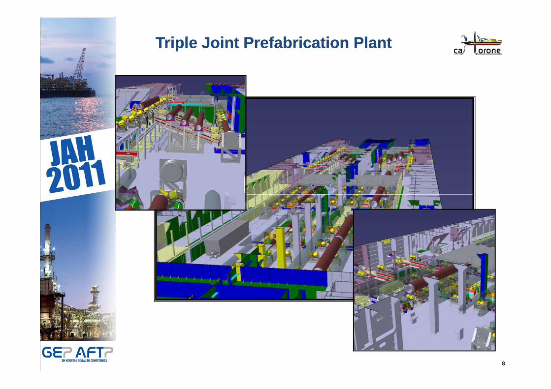
Triple Joint Prefabrication PlantTriple Joint Prefabrication Plant
8
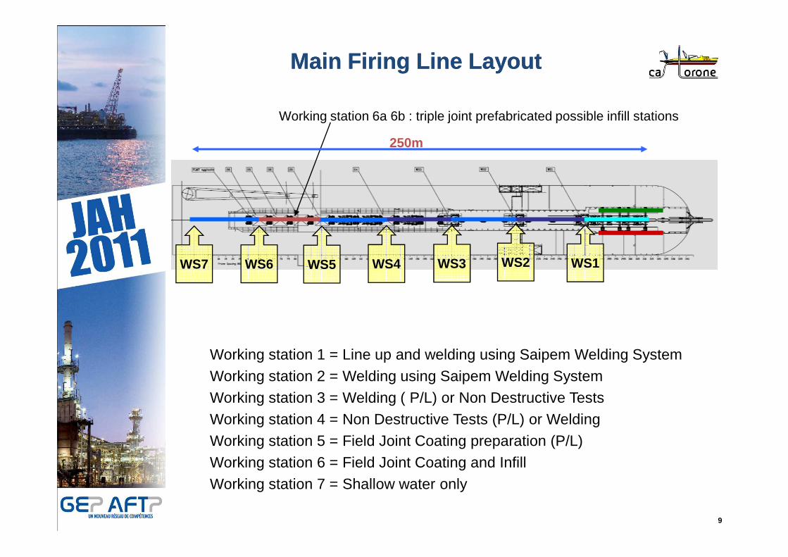
Main Firing Line LayoutMain Firing Line Layout
WS1WS2WS3WS4WS5WS6
Working station 6a 6b : triple joint prefabricated possible infill stations
WS7
250m
9
Working station 1 = Line up and welding using Saipem Welding SystemWorking station 2 = Welding using Saipem Welding System Working station 3 = Welding ( P/L) or Non Destructive Tests Working station 4 = Non Destructive Tests (P/L) or WeldingWorking station 5 = Field Joint Coating preparation (P/L)Working station 6 = Field Joint Coating and Infill Working station 7 = Shallow water only
Tensioners Tensioners
CastorOne Pipelaying EquipmentCastorOne Pipelaying Equipment
10
Stinger Stinger ILS InstallationILS Installation
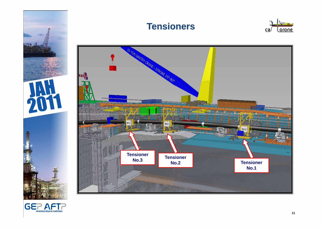
TensionersTensioners
11
Tensioner No.3 Tensioner
No.1
Tensioner No.2
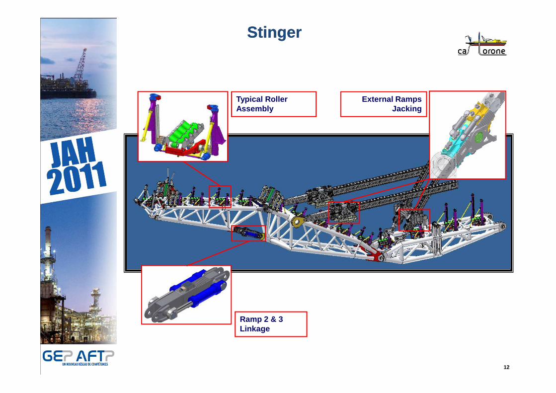
StingerStinger
External Ramps Jacking
Typical Roller Assembly
12
Ramp 2 & 3 Linkage

Stinger (Various Configurations)Stinger (Various Configurations)
7 Working Station – 300m Curvature Radius
7 Working Station – 130m Curvature Radius
Increasing WD
13
6 Working Station – 130m Curvature Radius6 Working Station – 110m Curvature Radius
Increasing WD
Increasing WD
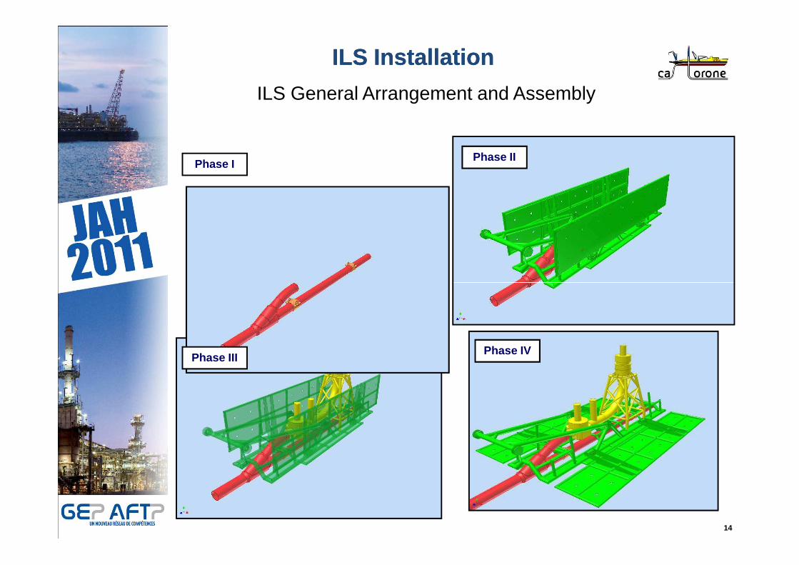
ILS InstallationILS Installation
ILS General Arrangement and Assembly
Phase IPhase II
14
Phase IIIPhase IV
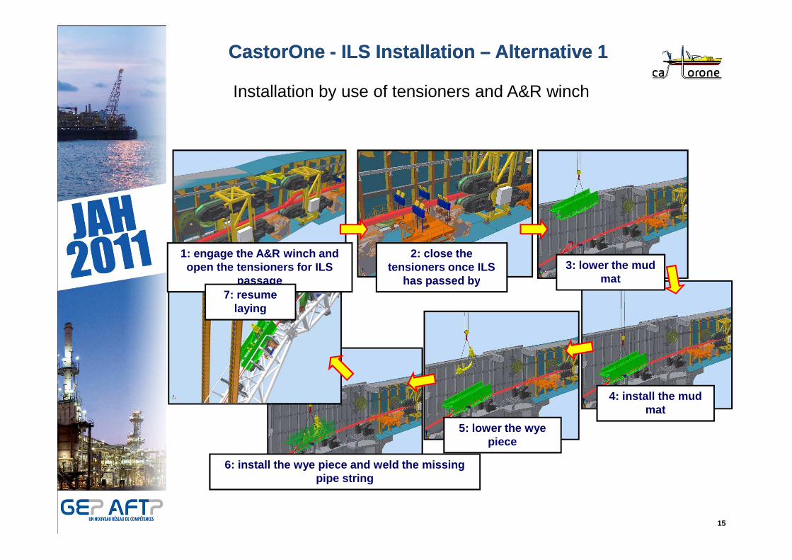
CastorOne CastorOne -- ILS Installation ILS Installation –– Alternative 1Alternative 1
Installation by use of tensioners and A&R winch
1: engage the A&R winch and open the tensioners for ILS
passage
2: close the tensioners once ILS
has passed by3: lower the mud
mat
15
6: install the wye piece and weld the missing pipe string
passage has passed by mat
4: install the mud mat
5: lower the wye piece
7: resume laying

ILS Installation ILS Installation –– Alternative 2Alternative 2
Installation by use of holding clamp
1: engage the A&R winch and open the
2: lay till the forged ring reaches the 3: engage the holding
16
winch and open the tensioners
ring reaches the holding clamp
3: engage the holding clamp
4: deploy the mud mat and complete the wye piece
installation
7: resume laying
5: fabricate the missing pipe string, close the tensioners and disengage
the holding clamp

J-Lay Tower for Triple Joints
JJ--Lay Tower capabilitiesLay Tower capabilities
Welding Station
17
FJC Station

JJ--Lay Tower characteristicsLay Tower characteristics
• Handling of 3Js, Two working stations enabling welding/AUT and
coating to be performed in parallel
• Use of friction clamps and safety clamp instead of tensioners
• Ability to cohabit with the S-lay system
18
• Ability to cohabit with the S-lay system
• Being mounted in the moon pool and Partially foldable (max height
67m)
• Fixed vertical laying angle
• Full weather vaning capacity
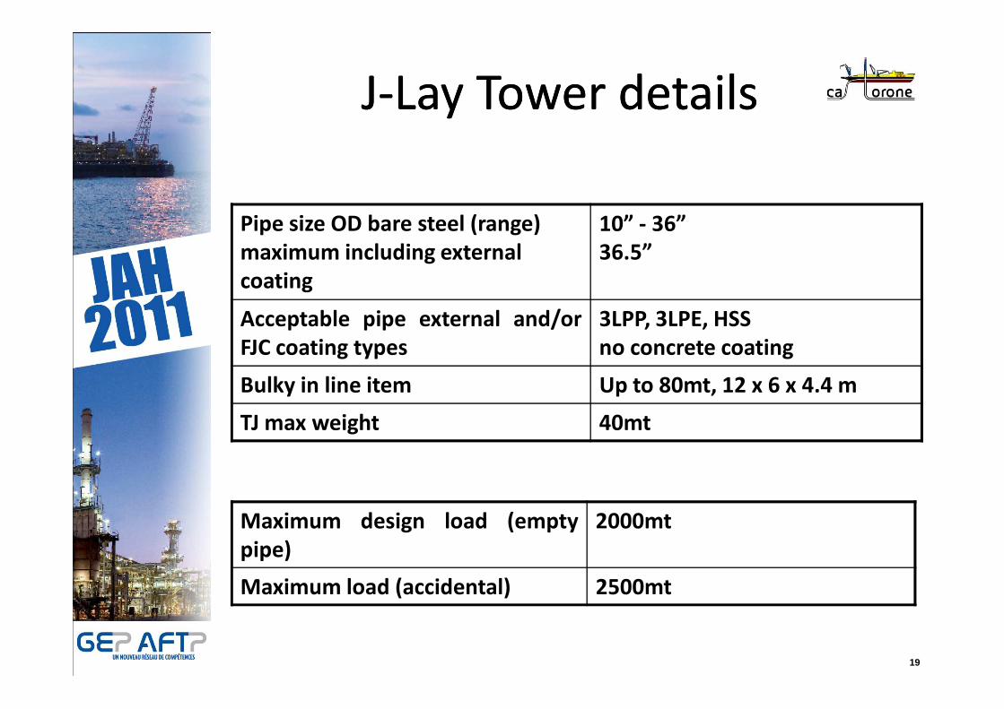
JJ--Lay Tower detailsLay Tower details
Pipe size OD bare steel (range)
maximum including external
coating
10” - 36”
36.5”
Acceptable pipe external and/or
FJC coating types
3LPP, 3LPE, HSS
no concrete coating
19
FJC coating types no concrete coating
Bulky in line item Up to 80mt, 12 x 6 x 4.4 m
TJ max weight 40mt
Maximum design load (empty
pipe)
2000mt
Maximum load (accidental) 2500mt

Castorone – Construction in Yantai Raffles
20
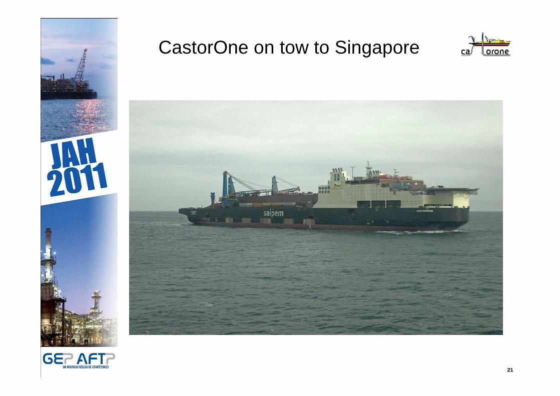
CastorOne on tow to Singapore
21

CastorOne at Keppel Shipyard
22
First Contracts
SAIPEM has already secured more than650 kms of pipelines (20 inch et 24 inch)to install with CASTORONE between
23
to install with CASTORONE between120m WD to 2200 m WD.
ENBRIDGEENBRIDGEBig Foot Oil ExportBig Foot Oil Export
CHEVRONCHEVRONJack & Saint MaloJack & Saint Malo
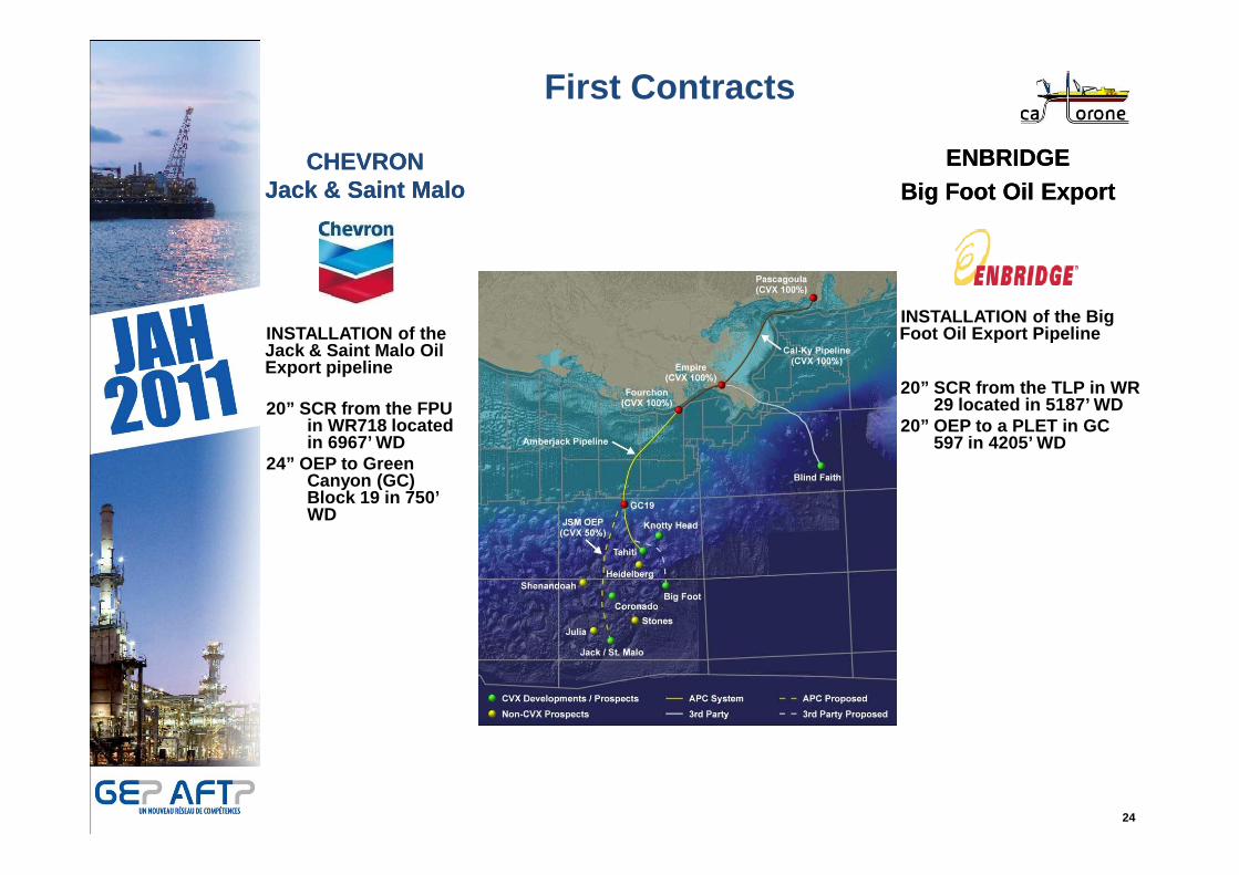
First Contracts
INSTALLATION of the Jack & Saint Malo Oil Export pipeline
20” SCR from the FPU in WR718 located in 6967’ WD
20” SCR from the TLP in WR 29 located in 5187’ WD
20” OEP to a PLET in GC 597 in 4205’ WD
INSTALLATION of the Big Foot Oil Export Pipeline
24
in 6967’ WD24” OEP to Green
Canyon (GC) Block 19 in 750’ WD
597 in 4205’ WD

Challenges & Features
CHEVRONCHEVRONJack & Saint MaloJack & Saint Malo
25
In-Line structures Installation
- 2DW in line valve (24’’)
- 2DW in line sled (20’’ branch and vertical connector
- 2SW in line valve (24’’)
Ultra Deep Water Max WD 7,020’ SCR Start-up / LaydownSCR welding in 5G2 Cable Crossings2 Pipeline Crossings
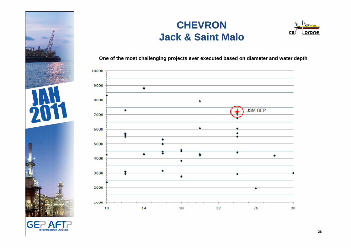
CHEVRONCHEVRONJack & Saint MaloJack & Saint Malo
One of the most challenging projects ever executed based on diameter and water depth
26

CHEVRONCHEVRONJack & Saint MaloJack & Saint Malo
S-Lay in 7,000 ft (2.100 m) Water Depth
27
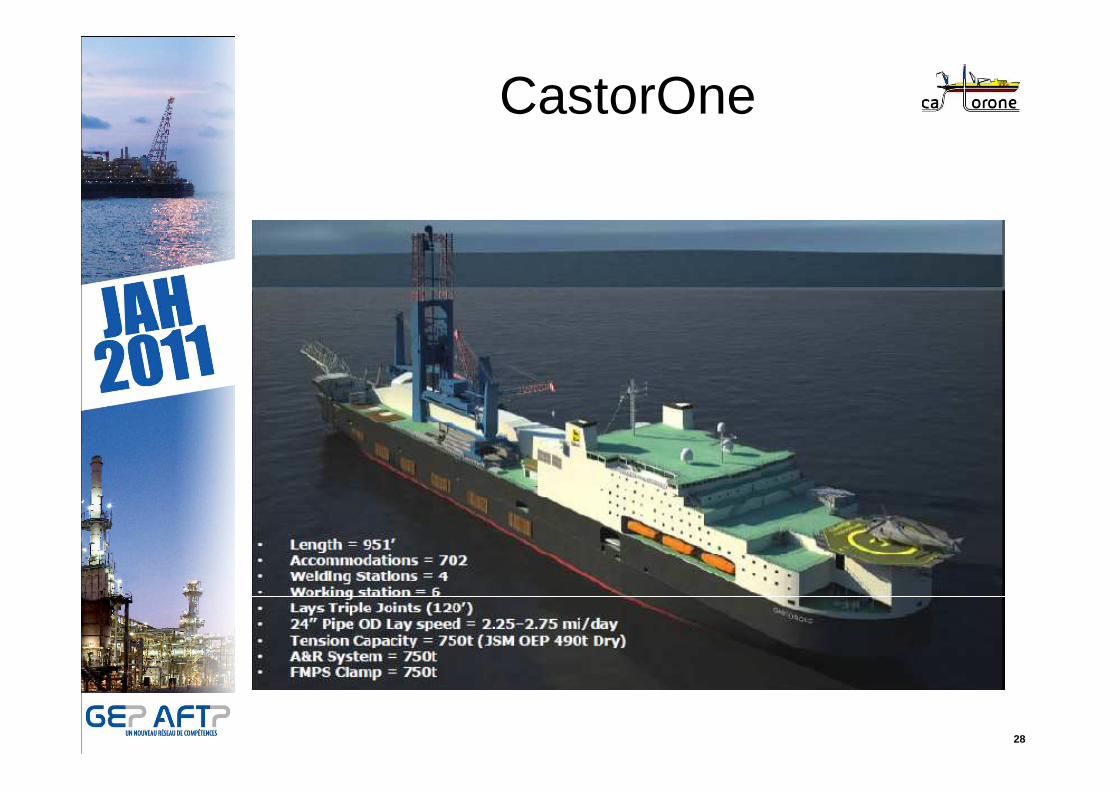
CastorOne
28
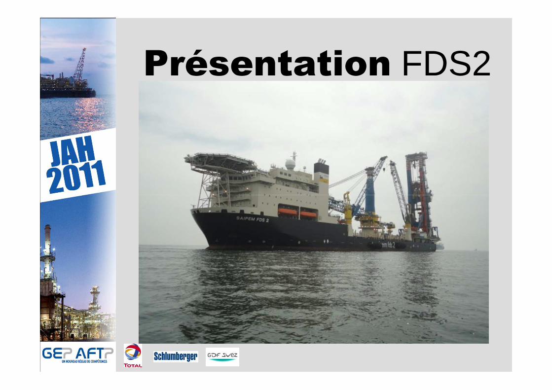
Présentation FDS2
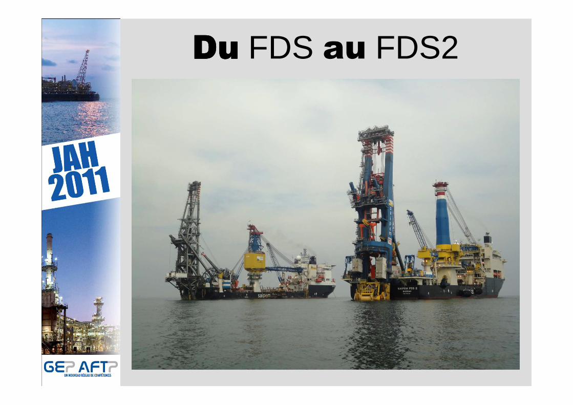
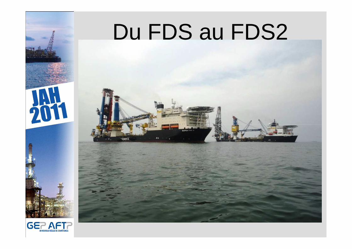
DuDuDuDu FDS au FDS2

Devant le succès du Saipem FDS depuis 10 ans, il a été décidé de construire, sur lemême principe, un bateau reprenant les qualités de ce bateau monocoque, multi rôlesà positionnement dynamique.
Ainsi est né le SAIPEM FDS2 qui a été baptisé en ma rs 2011.
Les principales différences visibles sont les suiva ntes:
FDS FDS2FDS FDS2
Dimensions 163 m x 30m x 7.4 m(ops) 183 m x 32.2 m x 8 m(ops)
Propulsions 4x 2200kW + 2x 4400KW 2x 5000KW +3x 5500K W
+ 2x 2000KW
Grue principale 600 MT 1000 MT
Pose de conduites 4 inch/ 22 inch 4 inch/ 36 inch
Tensions (flooded) 550 MT (600 MT) 1500 MT (2 000MT)
Treuil principal A/R 440 MT 750 MT
Personnel à bord 245 325
Du FDS au FDS2
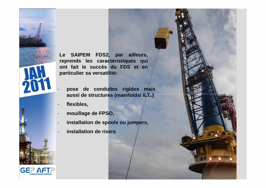
- pose de conduites rigides maisaussi de structures (manifolds/ ILT..)
Le SAIPEM FDS2, par ailleurs,reprends les caractéristiques quiont fait le succès du FDS et enparticulier sa versatilité:
aussi de structures (manifolds/ ILT..)
- flexibles,
- mouillage de FPSO,
- installation de spools ou jumpers,
- installation de risers

Le principe de pose de conduites rigides est similaire au FDS c’est-à-dire la préfabrication à bord de quadruples joints de 48 m e nvironet leur raboutage à la ligne.
Clamp
Fixe
Clamp
Mobile
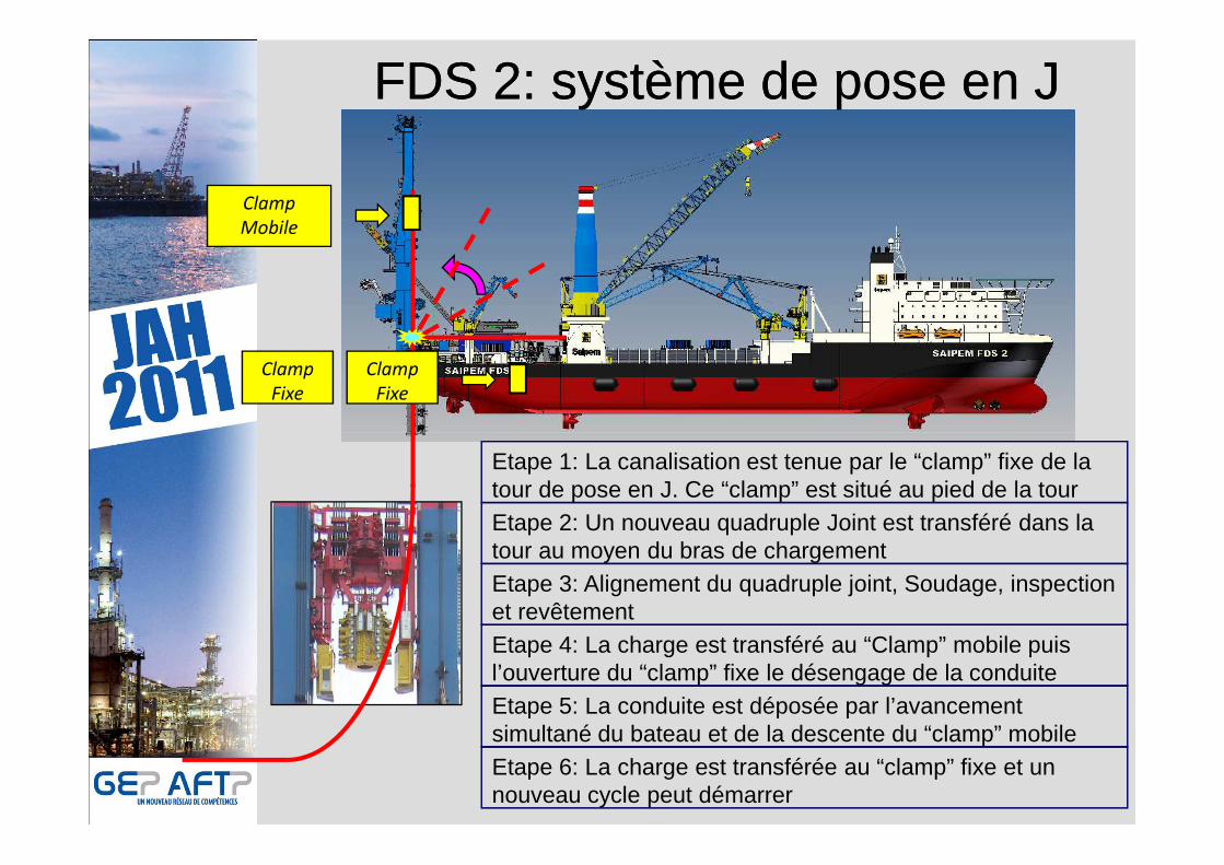
FDS 2: système de pose en JFDS 2: système de pose en J
Clamp
Fixe
Etape 1: La canalisation est tenue par le “clamp” fixe de la tour de pose en J. Ce “clamp” est situé au pied de la tourEtape 2: Un nouveau quadruple Joint est transféré dans la tour au moyen du bras de chargementEtape 3: Alignement du quadruple joint, Soudage, inspection et revêtementEtape 4: La charge est transféré au “Clamp” mobile puis l’ouverture du “clamp” fixe le désengage de la conduiteEtape 5: La conduite est déposée par l’avancement simultané du bateau et de la descente du “clamp” mobileEtape 6: La charge est transférée au “clamp” fixe et un nouveau cycle peut démarrer

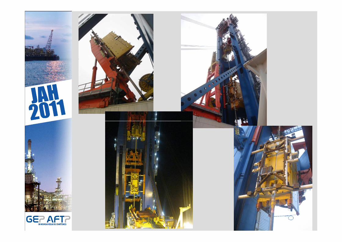
Chargement de Quadruple Joints
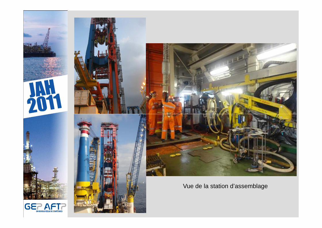
Vue de la station d’assemblage
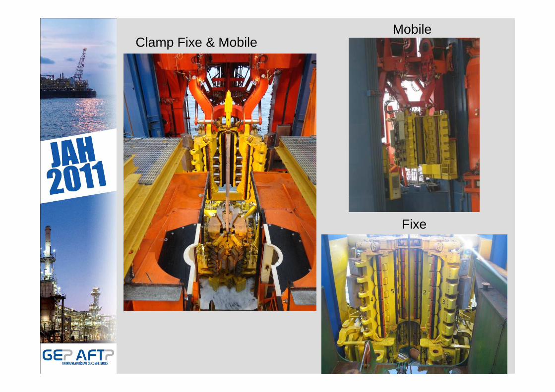
Clamp Fixe & MobileMobile
Fixe

Bulky item Installation

FDS 2:Pose de canalisation en SFDS 2:Pose de canalisation en S• Le FDS2 est d’ores et déja concu pour poser des can alisation en S • La structure du FDS2 comprend une rampe de pose cen trale• 2 tensionneurs de 90MT • 5 stations de travail double joint ou de 11 station simple joints• Le stinger est de type fixe maintenue par un systèm e à poulies
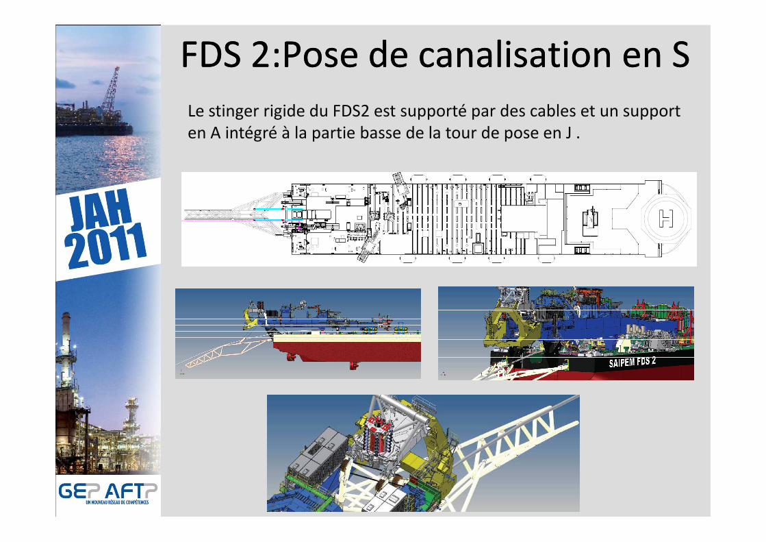
Le stinger rigide du FDS2 est supporté par des cables et un support
en A intégré à la partie basse de la tour de pose en J .
FDS 2:Pose de canalisation en SFDS 2:Pose de canalisation en S
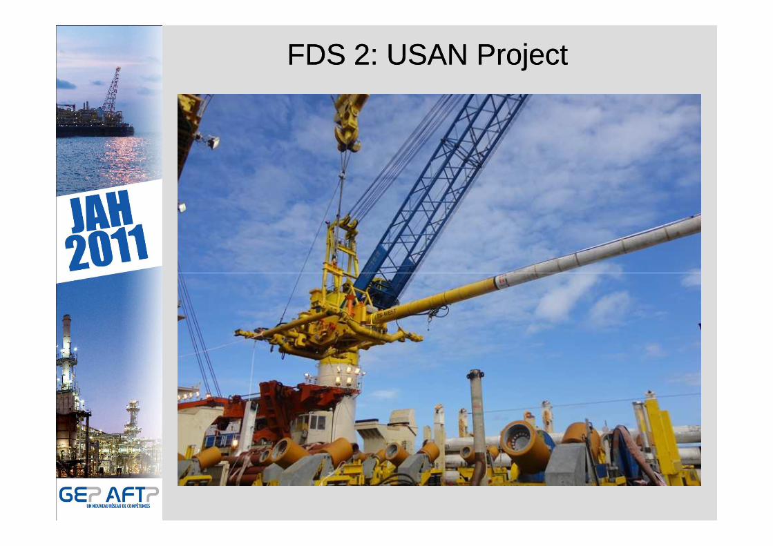
FDS 2: USAN ProjectFDS 2: USAN Project

FDS 2: USAN ProjectFDS 2: USAN Project
Le premier projet en cours de réalisation par le FD S 2 est USAN, dont le champ est situé à ~100kms des côtes du Nigeria à une profondeur d’eau d’environ 800 m.
Le développement du champ a principalement été effectué par le FDS, assisté de la SAIPEM 3000. Il comprend 23 puits de productions et 19 puits d’inje ction d’eau et de gaz tous connectés à un FPSO.d’eau et de gaz tous connectés à un FPSO.
Le FDS2 a fini de poser une ligne d’injection de ga z de 8’’ d’environ 10kms et est actuellement en train d’effe ctuer la pose de 2 lignes d’exportation d’huile de 22’’ ( 2 x ~2kms).
Le relevage et l’installation finale des OOL seront effectués par le FDS2 assisté de la SAIPEM 3000.