arcelormittal pv fr de
TRANSCRIPT
Profilés et Aciers Marchands Sections and Merchant Bars Profil- und StabstahlProgramme de Vente / Sales Programme / Verkaufsprogramm
Long Carbon Europe

© F
MG
B. G
ugge
nhei
m B
ilbao
Mus
eoa,
Bilb
ao. 2
00
7
1
Cher partenaire, Nous sommes heureux de vous présenter la nouvelle édition papier du programme de vente ArcelorMittal pour les profiles et aciers marchands.
Nous vous offrons la plus vaste gamme en termes de dimensions géométriques et de nuances d'acier. Vous trouverez ici, toute l'information relative a leurs propriétés, avantages et applications .
Comme nous menons une politique de développement continu de nos produits, ce catalogue sera soumis a des changements. C'est pourquoi nous vous invitons a consulter la version en ligne de notre catalogue sur www.arcelormittal.com/sections afin d'être informés de nos derniers développements..
En complément à ce catalogue, nos équipes commerciales et notre assistance technique sont à votre disposition pour répondre à vos questions :[email protected]
Nous vous souhaitons une bonne lecture!
Amit SenguptaArcelorMittal LCE Chief Marketing Officer
Arnaud Poupart-LafargeArcelorMittal LCE Chief Executive Officer
Dear Partner, We are delighted to present you the new paper edition of the ArcelorMittal sales programme for hot rolled sections and merchant bars.
We offer you the widest range of structural shape sizes and steel grades and you will find here comprehensive information about their properties as well as their advantages and applications.
Since we operate a policy of continuous product development, this product catalogue will be subject to changes . In order to remain up-to-date with our latest developments, we invite you to regularly consult our catalogue online at www.arcelormittal.com/sections.
In addition to this catalogue, our commercial teams and technical advisory are at your disposal to answer any question you may have:sections. [email protected]
We hope you enjoy reading our sales programme!
Sehr geehrte Partner, Wir freuen uns, Ihnen die neue Papierausgabe des ArcelorMittal Verkaufsprogamms fur Walzprofile und Stabstahl zu prasentieren. Wir bieten Ihnen die umfangreichste Produktpalette an, sowohl in Profilreihen als auch in Stahlgüten. Sie finden hier umfassende Informationen uber Eigenschaften, Vorteile und Anwendungen.
Da wir eine kontinuierliche Produktentwicklungspolitik betreiben, wird dieser Katalog Anderungen unterworfen sein. Um mit unseren letzten Entwicklungen auf dem Laufenden zu bleiben , laden wir Sie ein, regelmäßig unseren Katalog Online unter www.arcelormittal.com/sections zu konsultieren.
Zusätzlich zu diesem Katalog stehen Ihnen zur Beantwortung weiterer Fragen unser Vertrieb und Technische Beratung zur Verfügung:sections [email protected]
Wir wünschen Ihnen viel Vergnügen beim Lesen unseres Verkaufsprogramms!

Table des matières
7 Données commerciales
27 Nuances et qualités d’acier
63 Gamme de profilés
205 Données techniques
230 Nos agences
Table of contents
Inhalts-verzeichnis
7 Vertriebs-, Servicedaten 27 Stahlsorten und Sondergüten
63 Profilreihen
205 Technische Daten
230 Unsere Vertretungen
7 Commercial data 27 Steel grades and qualities
63 Section ranges
205 Technical Data
230 Our agencies
3

5
ArcelorMittal
ArcelorMittal est le numéro un mondial de la sidérurgie avec plus de 262 000 employés répartis dans 60 pays.
Une présence industrielle dans 20 pays nous permet d'être positionnés sur tous les marchés clés de l’acier qu’ils soient émergents ou matures.Notre groupe est aujourd’hui leader sur les tous les principaux marchés de l’acier, de la construction automobile au secteur du bâtiment et des appareils électroménagers à l’emballage. Nos efforts en matière de R&D ainsi que notre réseau de distribution sont parmi les facteurs clés de notre succès
Développement durable, qualité et leadership sont nos valeurs clés c’est pourquoi nous nous sommes engagés à œuvrer de façon responsable en ce qui concerne la santé, la sécurité et le bien-être. En prenant un rôle majeur dans les efforts de l'industrie pour développer des technologies sidérurgiques novatrices, nous démontrons notre intérêt dans la gestion durable de l’environnement.
Long Carbon Europe
Long Carbon Europe est l’unité stratégique produisant les produits longs au sein de 22 usines dans 10 pays d’Europe et Afrique du nord. L’offre de Long Carbon comprend profilés, aciers marchands, rails, pieux, fil machine, ronds à béton et profilés spéciaux. L’entreprise offre la gamme de produits la plus étendue tout en respectant les exigences techniques, qualitatives et environnementales les plus strictes.
Satisfaction client, performance et innovation sont nos objectifs, c’est pourquoi une assistance technique et des logiciels conviviaux sont mis gratuitement à disposition de nos partenaires afin de faciliter le prédimensionement de leur projets.
ArcelorMittal is the world's number one steel company, with over 262,000 employees in more than 60 countries.
An industrial presence in 20 countries exposes our company to all the key steel markets, from emerging to mature.Our Group is the leader in all major global markets, including automotive, construction, household appliances and packaging, with leading R&D and technology, as well as an outstanding distribution networks.
Through our core values of sustainability, quality and leadership, we commit to operating in a responsible way with respect to the health, safety and well-being. We are also committed to the sustainable management of the environment taking a leading role in the industry's efforts to develop breakthrough steelmaking technologies.
Long Carbon Europe
Long Carbon Europe is ArcelorMittal‘s business unit producing long products at 22 plants within 10 countries in Europe and North Africa. Long Carbon Europe’s offer covers Sections, Merchant bars, Rails, Piles, Bars Rods and Special Sections. The company offers the widest product range of its kind, meeting the strictest technical, quality and environmental requirements.
Customer satisfaction, performance and innovation are our priority objectives therefore technical assistance and user-friendly software are made available to our partners as a support in the design of their projects involving structural steel.
ArcelorMittal ist der weltweit führende Stahlhersteller mit einer Präsenz in mehr als 60 Ländern und Produktionsstätten in mehr als 20 Ländern. Als Marktführer in allen wichtigen Stahlmärkten, vom Automobil- über den Bausektor als auch Haushaltsgeräte
und Verpackungen beschäftigt die Gruppe 262.000 Mitarbeiter.
Operativ in vier Kontinenten tätig werden sämtliche industriellen Schlüsselmärkte, sowohl aufstrebende als auch voll entwickelte, durch hervorragende Vertriebsnetze abgedeckt.
Im Hinblick auf seine Grundwerte Nachhaltigkeit, Qualität und Führerschaft verpflichtet sich ArcelorMittal zu Verantwortung und Respekt gegenüber Gesundheit, Sicherheit und Wohlbefinden seiner Mitarbeiter. Ebenso verpflichtet sich das Unternehmen zu einem nachhaltigen Umgang mit der Umwelt. Es nimmt innerhalb der Branche bei den Bemühungen, richtungweisende Technologien in der Stahlproduktion zu entwickeln, eine führende Rolle ein und führt aktiv Forschung und Entwicklung von Technologien auf Basis von Stahl durch, die zum Kampf gegen den Klimawandel beitragen.
Long Carbon Europe
Long Carbon Europe ist einer der strategischen Geschäftsbereiche der ArcelorMittal-Gruppe und stellt Langprodukte in 22 Werken in 10 Ländern in Europa und Nordafrika her. Das Angebot von Long Carbon Europe besteht aus Walzträgern, Stabstahl, Pfählen, Schienen, Stäben, Spundwänden und Spezialprofilen.Long Carbon Europe vertreibt weltweit eine breite Produktpalette, die den strengsten technischen, qualitativen und ökologischen Kriterien entspricht.
Kundenzufriedenheit, Leistung und Innovation stehen dabei an erster Stelle. Damit unsere Kunden ihre Projekte wirtschaftlich und sicher realisieren können, stellen wir technische Beratung und benutzerfreundliche Bemessungshilfen zur Verfügung.

© a
sbl A
tom
ium
vzw
- M
arie
-Fra
nçoi
se P
lissa
rt

7
Données commerciales
Commercial data
8 Conditions de livraison
10 Support technique
11 Parachèvement
12 Recherche et développement
13 Développement durable
16 Logiciels de pré-dimensionnement
18 ACB - Poutrelle alvéolaire à ouver-tures circulaires
20 "AngelinaTM " - Pouterelle alvéolaire à ouvertures sinusoidales
22 Construction Slim-Floor
25 CoSFB - Nouvelle génération de poutrelles Slim-Floor
26 Profilés optimisés
8 Delivery conditions
10 Technical support
11 Finishing
12 Research and development
13 Sustainability
16 Structural Software for Pre-design
18 ACB - Castellated beam with circular openings
20 "AngelinaTM " - Castellated beam with sinusoidal openings
22 Slim-Floor Construction
25 CoSFB - New generation of slim-floor beams
26 Optimized Sections
8 Lieferbedingungen
10 Technische Beratung
11 Anarbeitung der Träger
12 Forschung und Entwicklung
13 Nachhaltigkeit
16 Vorbemessungssoftware
18 ACB - Lochstegträger mit runden Öffnungen
20 "AngelinaTM " - Lochstegträger mit sinusförmigen Öffungen
22 Die Slim-Floor Bauweise
25 CoSFB - Neue Generation von Slim-Floor Trägern
26 Optimierte Profile
7
Vertriebs- Servicedaten
Tolérances de laminageLes tolérances de laminage usuelles sur dimensions, forme, poids et longueur sont données au tableau 15-19. Certaines tolérances réduites sont possibles après accord.
Longueur maximaleLes longueurs maximales réalisables varient entre 15,5 m et 33 m suivant le profilé. Des longueurs supérieures sont uniquement livrables sur demande.
Tonnage minimalSauf spécification contraire dans les tableaux des profilés, le tonnage minimal de chaque poste de commande s’élève à 5 tonnes par profilé, qualité, longueur et destination.
Etat de surfaceL’état de surface normal des sections est conforme à EN10163-3: 2004, classe C, sous-classe 1.
Contrôle par ultrasonsLe contrôle par ultrasons est exécuté suivant accord et moyennant un supplément de prix. La procédure du contrôle est déterminée d’un commun accord entre le client et le producteur.
CertificationLe type de la certification doit être spécifié au moment de la commande.
Délais de livraisonLes délais de livraison sont à convenir avec notre représentation locale.
Conditions de livraison
Rolling tolerancesThe usual rolling tolerances on dimensions, shape, weight and length are given in table 15-19. Specific tolerances can be reduced after agreement.
Maximum length availableThe maximum length varies between 15,5 and 33 m depending on the shape. Greater lengths are available only upon request.
Minimum tonnageUnless otherwise indicated in the section tables, the minimum tonnage for any order- item is 5 tonnes per section, quality, length and destination.
Surface conditioningMaterial is delivered in standard ex-mill condition with surface quality in accordance with EN10163-3: 2004, class C, subclass 1.
Ultrasonic testingUltrasonic testing is carried out upon agreement at extra cost. The procedure for this test must be agreed between the purchaser and the manufacturer.
CertificationThe type of certification shall be specified at the time of order.
Terms of deliveryPlease contact our local representative.
Delivery conditions
WalztoleranzenDie üblichen Walztoleranzen auf Abmessungen, Form, Gewicht und Länge sind in der Tabelle 15-19 aufgezeigt. Spezifische Toleranzen können nach Absprache reduziert werden.
Maximale LieferlängeDie maximale Länge beträgt 15,5 m bis 33 m je nach Profil. Größere Längen können nur nach Absprache geliefert werden.
MindestbestellmengeFalls nicht anders in den Profiltabellen angegeben, beträgt die Mindestbestellmenge 5 Tonnen pro Profil, Stahlgüte, Länge und Bestimmungsort.
OberflächenbeschaffenheitIm Normalfall wird das Material hinsichtlich seiner Oberflächenbeschaffenheit in der Grundanforderung gemäß EN10163-3: 2004, Klasse C, Untergruppe 1 geliefert.
UltraschallprüfungenGesonderte Ultraschallprüfungen können gegen Aufpreis auf Anfrage vereinbart werden. Die Verfahrensweise für die Untersuchung muss zwischen dem Besteller und dem Hersteller vereinbart werden.
ZertifizierungDer Typ der Zertifizierung muss bei der Bestellung vereinbart werden.
LieferfristenBitte erkundigen Sie sich bei unserer örtlichen Niederlassung.
Liefer-bedingungen
9
Conditions générales de livraisonSauf spécifications contraires, les conditions générales de livraison sont conformes à EN10021: 2006. Un exemplaire du document est disponible sur demande ou sur le site Internet www.arcelormittal.com/sections.
Assurance QualitéLes usines produisant les profilés et aciers marchands de la division Commercial Sections d’ArcelorMittal sont certifiées ISO 9001.
Depuis le 1er septembre 2006, nous reprenons sur le document de contrôle le marquage CE ainsi que les autres informations en adéquation avec les exigences de la partie harmonisée -annexe ZA de l’EN 10025: 2004 pour tous les produits en nuances d’aciers suivant cette nouvelle norme européenne. Le marquage CE remplace tout marquage national européen ayant le même champ d’application.
Poutrelles sur mesureA partir de certaines séries de poutrelles standardisées, une gamme de profilés dérivés, les poutrelles laminées sur mesure, sont à la disposition des constructeurs. L’utilisateur a la possibilité de déterminer lui-même son profilé désiré et de le faire laminer sur mesure. Grâce à la technique de laminage universelle, la fabrication de poutrelles sur mesure devient rationnelle et économique. Le laminage de poutrelles sur mesure est soumis à une commande minimale de 500 tonnes par profilé et nuance.
General delivery conditionsIf not otherwise specified, general delivery conditions are in accordance with EN10021: 2006. The document is available upon request and can be found on the Internet site www.arcelormittal.com/sections.
Quality AssuranceThe mills producing the sections and merchant bars of the Commercial Sections division of ArcelorMittal are certified ISO 9001.
Since September 1, 2006, the CE mark and the other information required in the harmonized part 1 - annex ZA of EN 10025:2004 are shown in the inspection document for all our products that are delivered in steel grades according to this new European standard. The CE marking replaces any national European conformity marking having the same scope.
Tailor-made beamsWorking from the basis of specific standard beam ranges, we can offer the constructor a whole range of derived sections : tailor-made beams. The user can establish the steel section that is needed and have it rolled to measure. With our universal rolling technique, manufacture is both efficient and economic. The minimum order per tailor-made section and grade is 500 tonnes.
Allgemeine LieferbedingungenSofern keine gesonderte Vereinbarung vorliegt, gelten für die allgemeinen Lieferbedingungen die Angaben der EN10021: 2006. Ein Exemplar des Dokumentes ist auf Anfrage verfügbar und kann auf der Internetseite www.arcelormittal.com/sections eingesehen werden.
QualitätssicherungDie Walzwerke, die die Profile und den Stabstahl der Commercial Sections Division von ArcelorMittal herstellen, sind nach ISO 9001 zertifiziert.
Seit dem 1. September 2006 werden das CE- Zeichen sowie andere Informationen im Einklang mit dem harmonisierten Teil 1 – Anhang ZA der EN 10025:2004 für alle unsere Produkte in Stahlgüten nach dieser neuen europäischen Norm in der Prüfbescheinigung angegeben. Die CE-Kennzeichnung tritt an die Stelle anderer europäischer Konformitätskennzeichnungen mit dem gleichen Geltungsbereich.
Träger nach MaßAusgehend von bestimmten genormten Profilreihen kann eine ganze Serie von abgeleiteten Profilen angeboten werden: Träger nach Maß. Dem Verbraucher ist somit die Möglichkeit gegeben, selbst ein Profil zu entwerfen und es nach Maß walzen zu lassen. Durch das angewandte Universalverfahren bleibt der Vorteil der rationellen Herstellung und der Wirtschaftlichkeit dabei erhalten. Die Mindestbestellmenge beträgt 500 Tonnen pro Träger nach Maß und Güte.
A Long Carbon Europe, nous voulons faire plus que simplement vous offrir des aciers de construction. Nous souhaitons vous soutenir dans la conception et le développement de solutions innovantes pour tirer le meilleur parti de nos aciers.
Nous sommes heureux de vous proposer des conseils techniques gratuits ainsi que des réponses à vos questions sur l’utilisation des profilés et aciers marchands. Cette assistance technique va de la conception des éléments des structures, à la métallurgie et au soudage, en passant par les détails de la construction, la protection des surfaces et la sécurité incendie.
Nos experts vous soutiendront dans vos initiatives, où que vous vous trouviez dans le monde afin d’offrir des solutions sur-mesure vous permettant d’optimiser l’usage de nos produits.
Support technique
At Long Carbon Europe, we want to do more than simply provide structural products. We would like to help you in designing and developing innovative solutions to take the best advantage of our steel.
We are happy to provide free technical advice and to answer your questions about the use of sections and merchant bars. This technical advice covers the design of structural elements, construction details, surface protection, fire safety, metallurgy and welding.
Our specialists are ready to support your initiatives anywhere in the world and to provide tailor made services to help you get better result faster with our steel.
Technical support
Long Carbon Europe versteht sich als mehr als nur ein Profilstahlhersteller. Wir wollen Sie bei der Konzeption und Entwicklung innovativer Lösungen unterstützen, um die Stärken unserer Stähle bestmöglich auszunutzen.
Um die Verwendung unserer Produkte und Lösungen und sämtliche Fragen rund um den Einsatz von Profil- und Stabstahl zu beantworten, stellen wir Ihnen eine kostenlose technische Beratung zur Verfügung. Diese reicht vom Tragwerksentwurf und der Vordimensionierung über Oberflächen- und Brandschutz, Metallurgie bis hin zu Konstruktionsdetails und zur Schweißtechnik.
Unsere Spezialisten stehen Ihnen jederzeit zur Verfügung, um Sie bei Ihren Aktivitäten weltweit zu unterstützen und um die Anwendung unseren Produkte zu optimieren.
Technische Beratung
11
Pour compléter les possibilités techniques de nos partenaires, nous nous sommes dotés d’outils de parachèvement performants et offrons un large éventail de services, tels que :
l foragel oxycoupage l découpes en Tés l crantage l contrefléchagel cintrage l dressagel mise à longueur exacte par sciage à froidl soudage de connecteurs (goujons, etc) l grenaillagel traitements de surface
Parachèvement
As a complement to the technical capacities of our partners, we are equipped with high-performance finishing tools and offer a wide range of services, such as:
l drillingl flame cuttingl T cut-outsl notchingl camberingl curvingl straighteningl cold sawing to exact lengthl welding and fitting of studsl shot and sand blastingl surface treatment
Finishing
Wir halten verschiedene technische Einrichtungen für die Anarbeitung vor, um das Angebot zu optimieren. Unsere Möglichkeiten zur Anarbeitung umfassen folgende Bereiche:
l Bohrenl Brennschneidenl Zuschneiden auf T-Querschnittl Ausklinkenl Überhöhenl Biegenl Richtenl Kaltsägen auf exakte Längenl Aufschweißen von Kopfbolzendübelnl Strahlenl Oberflächenbehandlung
Anarbeitung der Träger
ArcelorMittal développe constamment des produits et solutions innovantes pour répondre aux besoins spécifiques du marché de la construction.
La sécurité incendie, le développement durable, les revêtements, la construction mixte et l’utilisation des Eurocodes font partie intégrante de notre stratégie.
Notre centre de recherche réalise également, en collaboration avec la direction des ventes et du marketing, des guides et logiciels d’utilisation des produits, et assure la diffusion de ses travaux en synergie avec les organismes techniques et de promotions européens, ainsi que des entreprises d’édition de logiciels dédiés à la construction, reconnues mondialement.
Consultez www.access-steel.com pour utiliser facilement les Eurocodes, ainsi que www.securewithsteel.com pour connaître le réseau européen de spécialistes en ingénierie incendie.
Recherche et développement
ArcelorMittal is constantly developing innovative products and solutions designed to satisfy the specific needs of the construction market.
Fire safety, sustainable development, coatings, composite construction and the use of the Eurocodes form an integral part of our strategy.
And our research centre, working with sales and marketing management, also produces product user guides and software, and takes care of the distribution of its output in synergy with European technical and promotional units, as well as globally recognized software publishers specialising in the construction industry.
Visit www.access-steel.com to learn how to use the Eurocodes with ease, and www.securewithsteel.com to find out about the European network of fire safety engineering specialists.
Research and development
ArcelorMittal entwickelt fortwährend innovative Produkte und Lösungen, um die besonderen Anforderungen des Bausektors erfüllen zu können.
Brandschutz, nachhaltige Entwicklung, Beschichtungen, Verbundbau und die Verwendung der Eurocodes sind ein wesentlicher Bestandteil unserer Strategie.
Unser Forschungzentrum erstellt zusammen mit der Vertriebs-und Marketing-Abteilung Handbücher und Software zur Anwendung der Produkte. Die Ergebnisse der Forschungsprojekte werden in Kooperation mit technischen Institutionen und europäischen Förderverbänden verbreitet, sowie in die Produkte weltweit bekannter Softwareunternehmen integriert, die Programme für die Baubranche entwickeln.
Besuchen Sie die Website www.access-steel.com, um die Eurocodes kennen zu lernen, und erfahren Sie mehr über das europäische Netzwerk der Spezialisten für Brandschutztechnik unter www.securewithsteel.com
Forschung und Entwicklung
13
L’Acier : un matériau écologique
Grâce à sa capacité à recouvrer ses propriétés originales même après plusieurs boucles de recyclage, l’acier est le matériau le plus recyclé au monde. Lorsqu’une construction en poutrelles laminées arrive en fin de vie, 99% des profilés peuvent être ensuite réutilisés ou recyclés. Ainsi pour le réemploi, la vie des poutres en acier peut être étendue à de nouvelles constructions ou rénovations. Pour le recyclage, 100% de la ferraille devient une matière première utilisée par la sidérurgie et contribue ainsi à une économie d’énergie allant de 65 à 95% par rapport à la filière minerais. Le réemploi et le recyclage permettent d’économiser les ressources naturelles et contribuent à un meilleur environnement.
Les Analyses du Cycle de Vie (ACV) des poutrelles en acier telles que la Déclaration Environnementale (EPD-BFS-2010111) se basent sur les données de World Steel Ass. et sur la méthode du « taux de recyclage en fin de vie » prenant en compte les bénéfices environnementaux du recyclage et de la réutilisation. En accord avec l’ISO 14025, ces ACV sont attestées par des organismes indépendants pour leurs conformités aux normes ISO 14040-44.
Solutions durables en poutrelles laminées
ArcelorMittal propose des solutions satisfaisant les aspects du développement durable requis par la plupart des systèmes de certification ou d’évaluation de la performance environnementale des bâtiments.
• Aspects écologiques de la durabilitéLe cycle de vie d’un bâtiment regroupe les phases de production des produits, de construction, d’utilisation et de fin de vie. La performance environnementale d’un bâtiment
Steel: an eco-friendly material.
Thanks to its ability to recover the original properties without loss of quality after melting makes steel the most recycled material in the world.In the built environment, 99% of the hot-rolled steel sections can be re-used or recycled at their end of life. Being flexible and adaptable, the functional life of steel sections can be extended in refurbished and new constructions. As 100% of the recovered scrap will be used as a raw material in the steel industry and thus provides between 65% and 95% energy savings compared to primary production, recycling process contributes to resources savings and a better environment.
Life Cycle Assessment (LCA) of steel sections such as the Environmental Product Declaration (EPD-BFS-2010111) based on Word Steel Association database are built on the most appropriate “End-of-Life recycling rate” methodology which takes into account the environmental benefits of the re-use and the recycling. As stated in ISO 14025, those LCA were reviewed by independent verifiers to confirm that all theses calculations are in line with the standard ISO 14040-44.
Sustainable hot-rolled steel solutions
ArcelorMittal has developed solutions which fulfill most of sustainable aspects needed by rating systems or by assessment of sustainable performance of Buildings. Most of those methods concern the 5 common sustainable goals:
• Environmental aspects of sustainabilityThe purpose of the environmental performance of buildings or products constituting the building is to get a quantitative evaluation of the different
Stahl: ein umweltfreundlicher Baustoff
Stahl ist der meistrecycelte Werkstoff der Welt. Dies verdankt er seiner Eigenschaft, seine Ausgangseigenschaften ohne Qualitätsverlust nach dem Schmelzen wiederzuerlangen. In bebautem Umfeld können 99% der warmgewalzten Stahlprofile wiederverwendet oder recycelt werden. Durch seine Flexibilität und Anpassungsfähigkeit kann die Lebensdauer von Walzstahlprofilen in Restaurationen und Neubauten verlängert werden. 100% von zurück gewonnenem Stahlschrott wird als Rohmaterial in der Stahlindustrie eingesetzt und ermöglicht so 65% bis 90% Energieeinsparung gegenüber der Primärproduktion. Dieser Recyclingprozess leistet somit einen wesentlichen Beitrag zur Ressourcenschonung und einer besseren Umwelt.Ökobilanzen (Life Cycle Assessment LCA) von Stahlprofilen wie zum Beispiel die Umwelt-Produktdeklaration (Environmental Product Declaration EPD-BFS-2010111), basieren auf den Daten der World Steel Association und wurden auf der gängigen “End-of-Life recycling rate”-Methode erarbeitet. In ihr wird auch der Umweltnutzen von Wiederverwendung und Recycling erfasst. Wie in ISO 14025 angegeben, werden diese Ökobilanzen (LCA) von unabhängigen Prüfern untersucht, um die Übereinstimmung der Berechnungen mit ISO 14040-44 zu bestätigen.
Nachhaltige Lösungen mit warmgewalzten Profilen
ArcelorMittal hat Lösungen entwickelt die die meisten Aspekte der Nachhaltigkeit erfüllen, welche in Rating-Systemen oder Beurteilungen der Effizienz in der Nachhaltig von Gebäuden benötigt werden.
• Ökologische Aspekte der NachhaltigkeitGegenstand der Nachhaltigkeitsbetrachtung von Gebäuden oder Bauteilen ist eine quantitative Beurteilung der verschiedenen Umwelteinflüsse, die während des gesamten
Développement durable
Sustainability
Nachhaltigkeit

environmental impacts generated during the whole life cycle. The life cycle describes the production, construction, use, end-of-life phases and also potential benefits of recycling and re-use. Therefore, ArcelorMittal has developed the AMECO tool that calculates Global Warming Potential and Primary Energy Consumption of steel and composite steel-concrete buildings and bridges. AMECO allows the architects and designers to perform an ecodesign by choosing by comparison the most ecological solutions.
• Economical aspects of sustainabilityHot-rolled sections are industrially produced to a high quality, in a full range of sizes and steel grades, including HISTAR. They allow architects and designers to easily fulfill the requirements of investors by combining high quality, functionality, aesthetics, low weight and short construction time. Slender structures can be designed which decrease construction height and foundation works leading to a further decrease of material, fabrication, transport and construction costs. The lifecycle costs prove the competitiveness and sustainability of steel and composite structures.
• Socio-cultural aspects of sustainability
Steel sections provide the user with transparent and lean structures combined with robustness and safety. Local inhabitants and their social environment remain clean in uncontaminated surroundings as steel in structures does not release any harmful substances into the environment.
• Technical aspects of sustainabilityStructures made of rolled beams have the advantage of being able to resist high level utilization. These robust construction solutions are adaptable to changes in use during service life without damage or loss of functionality.
Développement durable
Sustainability
Nachhaltigkeit
ou des produits le constituant est l’évaluation quantitative des différents impacts générés pendant tout le cycle de vie et aussi des bénéfices du recyclage et de la réutilisation des matériaux. Suivant ce schéma, le logiciel AMECO d’ArcelorMittal calcule les impacts Réchauffement Climatique et Consommation en Energie Primaire pour les structures en acier et mixtes de bâtiments et ponts. AMECO permet ainsi aux architectes et ingénieurs de concevoir écologiquement en choisissant les solutions les plus écologiques.
• Aspects économiques de la durabilitéLa production industrielle garantit un haut niveau de qualité sur une très large gamme de produits et nuances disponibles telles que la qualité HISTAR. L’acier, qui combine qualité, fonctionnalité et esthétique avec des modes de construction légers et rapides, permet aux architectes et aux concepteurs de répondre à toutes les exigences. Les structures élancées permettent une diminution de la hauteur de construction et des volumes de terrassement entrainant une diminution des couts de matériaux, de transport et de construction. Les coûts de cycle de vie prouvent la compétitivité et la durabilité des constructions en acier ou mixtes.
• Aspects socioculturels de la durabilité
Les ouvrages en acier constitués de profilés laminés à chaud offrent à l’utilisateur le moyen de concevoir des structures transparentes aux lignes allégées, robustes et sûres. L’environnement d’une structure en acier constitue un milieu sain car l’acier ne dégage pas de substances dangereuses. Il ne présente donc aucun danger pour la santé des êtres vivants.
• Aspects techniques de la durabilitéLes structures en acier sont capables de résister à de forts taux d’utilisation et possèdent l’avantage d’être adaptables aux possibles changements d’utilisation pendant leur service sans dommage ou perte de fonctionnalité.
Lebenszyklus entstehen. Der Lebenszyklus beschreibt Produktion, Ausführung, Nutzung, Rückbau und ebenso potentielle Nutzen aus Wiederverwendung und Recycling. Aus diesem Grund entwickelte ArcelorMittal die AMECO-Software. Diese berechnet das Treibhauspotential und den Primärenergieverbrauch von Stahl- und Stahlverbundgebäuden und Brücken. AMECO ermöglicht Architekten und Ingenieuren durch sogenanntes „Eco-Design“, ökologisch zu entwerfen.
• Ökonomische Aspekte der NachhaltigkeitWarmgewalzte Profile eröffnen den Architekten und Tragwerksplanern ungeahnte Möglichkeiten, um den Anforderungen der Investoren gerecht zu werden, indem hohe Qualität, Funktionalität, Ästhetik, leichte und schnelle Bauweise eine ganzheitliche Symbiose bilden. Der Entwurf schlanker und leichter Stahlkonstruktionen mit geringen Querschnittshöhen verringert die erforderlichen Erdarbeiten für Fundamente und führt zu geringeren Fassadenflächen sowie zu einem verminderten Heiz- oder Kühlvolumen durch geringere Bau- und Raumhöhen.Ausschreibungen, in denen die Lebenszykluskosten eingeschlossen sind, zeigen die ganzheitliche Konkurrenzfähigkeit von Lösungen bei Verwendung von Walzprofilen für Stahl- und Verbundkonstruktionen.
• Soziokulturelle Aspekte der NachhaltigkeitWarmgewalzte Profile bieten dem Anwender eine hohe Transparenz und Schlankheit des Bauwerks bei gleichzeitig hoher Tragfähigkeit und Tragsicherheit. Die Nutzer und deren gesellschaftliches Umfeld bewegen sich in einem baubiologisch reinen Umfeld, denn verbauter Stahl gibt keine gefährlichen Stoffe an die Umwelt ab und stellt somit keine Gesundheitsgefahr für Lebewesen dar.
• Technische Aspekte der NachhaltigkeitKonstruktionen aus Walzprofilen haben den Vorteil, dass sie hohen Belastungen standhalten können. Diese robusten Konstruktionen können flexibel an Nutzungsänderungen ohne Funktionalitätsverlust angepasst werden.
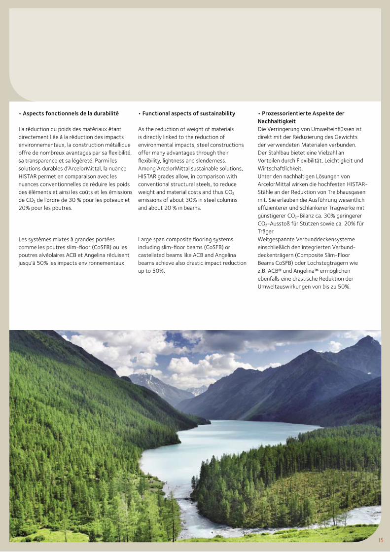
• Functional aspects of sustainability
As the reduction of weight of materials is directly linked to the reduction of environmental impacts, steel constructions offer many advantages through their flexibility, lightness and slenderness.Among ArcelorMittal sustainable solutions, HISTAR grades allow, in comparison with conventional structural steels, to reduce weight and material costs and thus CO2 emissions of about 30% in steel columns and about 20 % in beams.
Large span composite flooring systems including slim-floor beams (CoSFB) or castellated beams like ACB and Angelina beams achieve also drastic impact reduction up to 50%.
• Aspects fonctionnels de la durabilité
La réduction du poids des matériaux étant directement liée à la réduction des impacts environnementaux, la construction métallique offre de nombreux avantages par sa flexibilité, sa transparence et sa légèreté. Parmi les solutions durables d’ArcelorMittal, la nuance HISTAR permet en comparaison avec les nuances conventionnelles de réduire les poids des éléments et ainsi les coûts et les émissions de CO2 de l’ordre de 30 % pour les poteaux et 20% pour les poutres.
Les systèmes mixtes à grandes portées comme les poutres slim-floor (CoSFB) ou les poutres alvéolaires ACB et Angelina réduisent jusqu'à 50% les impacts environnementaux.
• Prozessorientierte Aspekte der NachhaltigkeitDie Verringerung von Umwelteinflüssen ist direkt mit der Reduzierung des Gewichts der verwendeten Materialen verbunden. Der Stahlbau bietet eine Vielzahl an Vorteilen durch Flexibilität, Leichtigkeit und Wirtschaftlichkeit.Unter den nachhaltigen Lösungen von ArcelorMittal wirken die hochfesten HISTAR-Stähle an der Reduktion von Treibhausgasen mit. Sie erlauben die Ausführung wesentlich effizienterer und schlankerer Tragwerke mit günstigerer CO2-Bilanz ca. 30% geringerer CO2-Ausstoß für Stützen sowie ca. 20% für Träger.Weitgespannte Verbunddeckensysteme einschließlich den integrierten Verbund-deckenträgern (Composite Slim-Floor Beams CoSFB) oder Lochstegträgern wie z.B. ACB® und Angelina™ ermöglichen ebenfalls eine drastische Reduktion der Umweltauswirkungen von bis zu 50%.
15
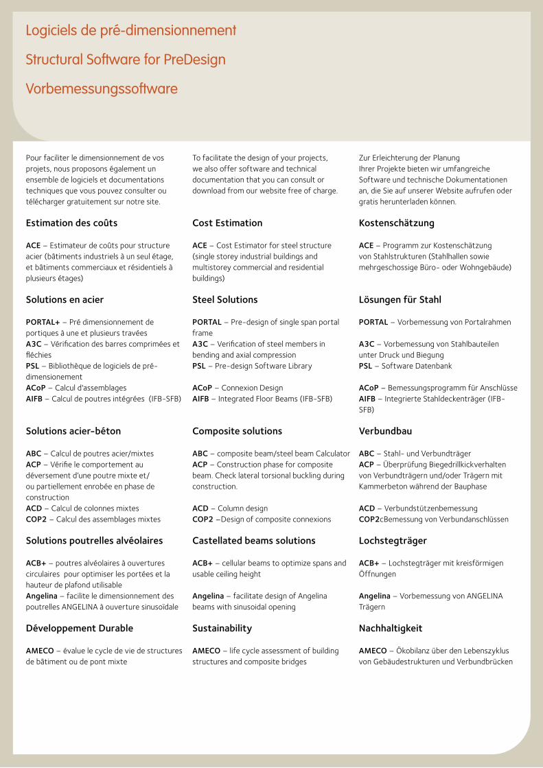
To facilitate the design of your projects, we also offer software and technical documentation that you can consult or download from our website free of charge.
Cost Estimation
ACE – Cost Estimator for steel structure (single storey industrial buildings and multistorey commercial and residential buildings)
Steel Solutions
PORTAL – Pre-design of single span portal frameA3C – Verification of steel members in bending and axial compressionPSL – Pre-design Software Library
ACoP – Connexion DesignAIFB – Integrated Floor Beams (IFB-SFB)
Composite solutions
ABC – composite beam/steel beam CalculatorACP – Construction phase for composite beam. Check lateral torsional buckling during construction.
ACD – Column designCOP2 –Design of composite connexions
Castellated beams solutions
ACB+ – cellular beams to optimize spans and usable ceiling height
Angelina – facilitate design of Angelina beams with sinusoidal opening
Sustainability
AMECO – life cycle assessment of building structures and composite bridges
Zur Erleichterung der PlanungIhrer Projekte bieten wir umfangreiche Software und technische Dokumentationen an, die Sie auf unserer Website aufrufen oder gratis herunterladen können.
Kostenschätzung
ACE – Programm zur Kostenschätzung von Stahlstrukturen (Stahlhallen sowie mehrgeschossige Büro- oder Wohngebäude)
Lösungen für Stahl
PORTAL – Vorbemessung von Portalrahmen
A3C – Vorbemessung von Stahlbauteilen unter Druck und BiegungPSL – Software Datenbank
ACoP – Bemessungsprogramm für AnschlüsseAIFB – Integrierte Stahldeckenträger (IFB-SFB)
Verbundbau
ABC – Stahl- und VerbundträgerACP – Überprüfung Biegedrillkickverhalten von Verbundträgern und/oder Trägern mit Kammerbeton während der Bauphase
ACD – VerbundstützenbemessungCOP2cBemessung von Verbundanschlüssen
Lochstegträger
ACB+ – Lochstegträger mit kreisförmigen Öffnungen
Angelina – Vorbemessung von ANGELINA Trägern
Nachhaltigkeit
AMECO – Ökobilanz über den Lebenszyklus von Gebäudestrukturen und Verbundbrücken
Pour faciliter le dimensionnement de vos projets, nous proposons également un ensemble de logiciels et documentations techniques que vous pouvez consulter ou télécharger gratuitement sur notre site.
Estimation des coûts
ACE – Estimateur de coûts pour structure acier (bâtiments industriels à un seul étage, et bâtiments commerciaux et résidentiels à plusieurs étages)
Solutions en acier
PORTAL+ – Pré dimensionnement de portiques à une et plusieurs travéesA3C – Vérification des barres comprimées et fléchiesPSL – Bibliothèque de logiciels de pré-dimensionementACoP – Calcul d'assemblagesAIFB – Calcul de poutres intégrées (IFB-SFB)
Solutions acier-béton
ABC – Calcul de poutres acier/mixtesACP – Vérifie le comportement au déversement d’une poutre mixte et/ou partiellement enrobée en phase de constructionACD – Calcul de colonnes mixtesCOP2 – Calcul des assemblages mixtes
Solutions poutrelles alvéolaires
ACB+ – poutres alvéolaires à ouvertures circulaires pour optimiser les portées et la hauteur de plafond utilisableAngelina – facilite le dimensionnement des poutrelles ANGELINA à ouverture sinusoïdale
Développement Durable
AMECO – évalue le cycle de vie de structures de bâtiment ou de pont mixte
Logiciels de pré-dimensionnement
Structural Software for PreDesign
Vorbemessungssoftware
17
Ponts
ACOBRI: Pré-dimensionnement des ponts mixtes – routes, rails et passerelles
Calcul au feu
AFCC - résistance au feu des colonnes mixtes AFCB – résistance au feu des poutres mixtes
Ozone – Température des gaz en cas d'incendie et température correspondante de l’acierLuca – guide de dimensionnement pour les halls industriels en situation d’incendieMACS+- Analyse au feu des dalles de planchers mixtes partiellement protégés
Sismique
INERD – système constructif en acier qui permet de renforcer les portiques en béton.
www.arcelormittal.com/sections
Bridges
ACOBRI: Predesign of composite bridges for roads, rails and pedestrians
Fire
AFCC - Fire resistance composite column
AFCB – Fire resistance composite beam
Ozone – Gas temperature in the event of fire and corresponding steel temperature
Luca – Design guide for industrial hall in fire conditionMACS+: Partially protected composite slabs at elevated temperatures
Seismic
INERD – reinforce concrete column with encased steel profile to avoid soft storey failure
Brücken
ACOBRI: Vorbemessung von Straßen-, Bahn- und Fußgängerbrücken in Verbundbauweise
Bemessung im Brandfall
AFCC - Verbundstützenbemessung im Brandfall (Stützen)AFCB – Verbundstützenbemessung im Brandfall (Träger)Ozone – Berechnung der Gastemperatur bei Feuer u der entsprechenden Stahltemperatur
Luca – Vorbemessung von Industriehallen im BrandfallMACS+: berechnet Verbunddecken im Brandfall unter Berücksichtigung der Scheibenwirkung der Decke
Erdbeben
INERD– Innovatives Stahlkonstruktionskonzept für ein duktiles Tragverhalten von erdbebenbeanspruchten Stahlbetonbauskeletten.
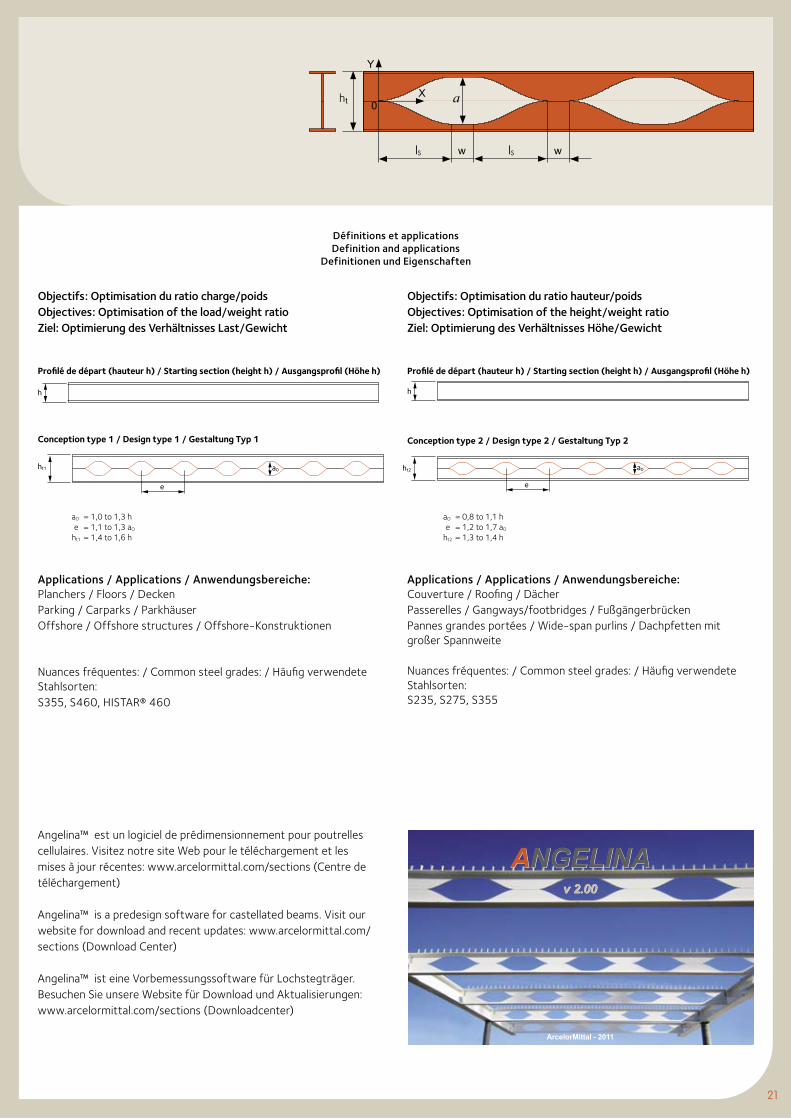
Objectifs: Optimisation du ratio hauteur/poidsObjectives: Optimisation of the height/weight ratioZiel: Optimierung des Verhältnisses Höhe/Gewicht
ACB - Poutrelle alvéolaire à ouvertures circulaires
ACB - Castellated beam with circular openings
ACB - Lochstegträger mit runden Öffnungen
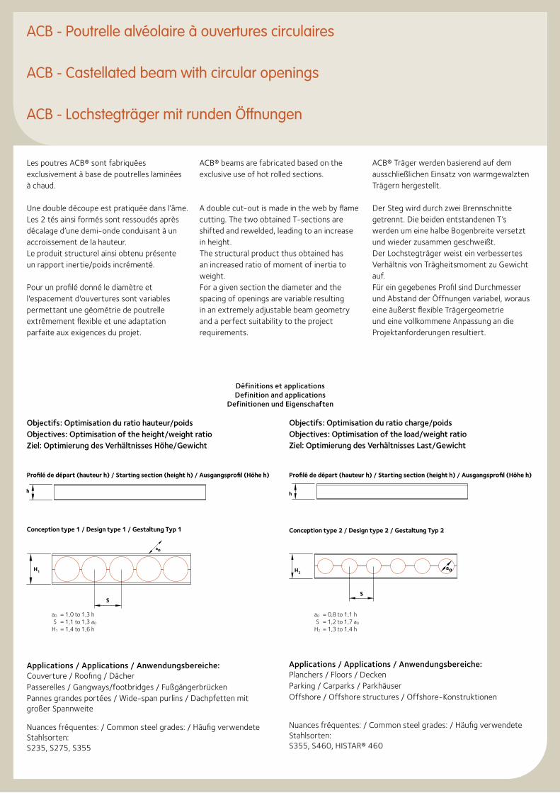
Les poutres ACB® sont fabriquées exclusivement à base de poutrelles laminées à chaud.
Une double découpe est pratiquée dans l’âme. Les 2 tés ainsi formés sont ressoudés après décalage d’une demi-onde conduisant à un accroissement de la hauteur.Le produit structurel ainsi obtenu présente un rapport inertie/poids incrémenté.
Pour un profilé donné le diamètre et l'espacement d'ouvertures sont variables permettant une géométrie de poutrelle extrêmement flexible et une adaptation parfaite aux exigences du projet.
ACB® beams are fabricated based on the exclusive use of hot rolled sections.
A double cut-out is made in the web by flame cutting. The two obtained T-sections are shifted and rewelded, leading to an increase in height.The structural product thus obtained has an increased ratio of moment of inertia to weight.For a given section the diameter and the spacing of openings are variable resulting in an extremely adjustable beam geometry and a perfect suitability to the project requirements.
ACB® Träger werden basierend auf dem ausschließlichen Einsatz von warmgewalzten Trägern hergestellt.
Der Steg wird durch zwei Brennschnitte getrennt. Die beiden entstandenen T’s werden um eine halbe Bogenbreite versetzt und wieder zusammen geschweißt.Der Lochstegträger weist ein verbessertes Verhältnis von Trägheitsmoment zu Gewicht auf.Für ein gegebenes Profil sind Durchmesser und Abstand der Öffnungen variabel, woraus eine äußerst flexible Trägergeometrie und eine vollkommene Anpassung an die Projektanforderungen resultiert.
Objectifs: Optimisation du ratio charge/poidsObjectives: Optimisation of the load/weight ratioZiel: Optimierung des Verhältnisses Last/Gewicht
Conception type 1 / Design type 1 / Gestaltung Typ 1 Conception type 2 / Design type 2 / Gestaltung Typ 2
aO = 1,0 to 1,3 h S = 1,1 to 1,3 aO
H1 = 1,4 to 1,6 h
aO = 0,8 to 1,1 h S = 1,2 to 1,7 aO
H2 = 1,3 to 1,4 h
Profilé de départ (hauteur h) / Starting section (height h) / Ausgangsprofil (Höhe h) Profilé de départ (hauteur h) / Starting section (height h) / Ausgangsprofil (Höhe h)
ao
S
H1
h h
S
H2ao
Définitions et applications Definition and applications
Definitionen und Eigenschaften
Applications / Applications / Anwendungsbereiche:Planchers / Floors / DeckenParking / Carparks / ParkhäuserOffshore / Offshore structures / Offshore-Konstruktionen
Nuances fréquentes: / Common steel grades: / Häufig verwendete Stahlsorten:S355, S460, HISTAR® 460
Applications / Applications / Anwendungsbereiche:Couverture / Roofing / DächerPasserelles / Gangways/footbridges / Fußgängerbrücken Pannes grandes portées / Wide-span purlins / Dachpfetten mit großer Spannweite
Nuances fréquentes: / Common steel grades: / Häufig verwendete Stahlsorten:S235, S275, S355
19
ACB+v 2.05
Web controls
ACB+v 2.05
Web controls
ArcelorMittal - 2011
Pour une description détaillée et plus d'informations consultez la Brochure technique ACB® Poutres Cellulaires (disponible pour téléchargement sous www.arcelormittal.com/sections (Bibliothèque)
For a detailed description and further information please consult the technical Brochure ACB® Cellular beams (available for download under www.arcelormittal.com/sections (Library)
Ausführliche Beschreibung und Informationen in der technischen Broschüre ACB® Lochstegräger (verfügbar zum Download unter www.arcelormittal.com/sections (Bibliothek)
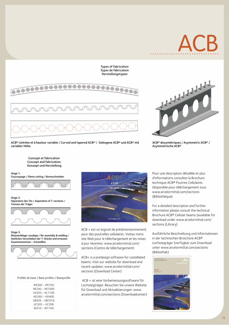
Stage 1:Oxycoupage / Flame cutting / Brennschneiden
Stage 2: Séparation des Tés / Separation of T-sections / Trennen der Träger
Stage 3: Réassemblage-soudage / Re-assembly & welding /Seitliches Verschieben der T-Stücke und erneutes Zusammensetzen - Schweißen
Concept et fabricationConcept and fabrication Konzept und Herstellung
Types of fabricationTypes de fabrication Herstellungstypen
ACB
Profilés de base / Base profiles / Basisprofile
IPE300 – IPE750HE240 – HE1000HL920 – HL1100HD260 – HD400UB305 – UB1016UC305 – UC356W310 – W1100
ACB® dissymétriques / Asymmetric ACB® / Asymmetrische ACB®
ACB® cintrées et à hauteur variable / Curved and tapered ACB® / Gebogene ACB® und ACB® mit variabler Höhe
ACB + est un logiciel de prédimensionnement pour des poutrelles cellulaires. Visitez notre site Web pour le téléchargement et les mises à jour récentes: www.arcelormittal.com/sections (Centre de téléchargement)
ACB+ is a predesign software for castellated beams. Visit our website for download and recent updates: www.arcelormittal.com/sections (Download Center)
ACB + ist eine Vorbemessungssoftware für Lochstegträger. Besuchen Sie unsere Website für Download und Aktualisierungen: www.arcelormittal.com/sections (Downloadcenter)
ACB®Cellular Beams
Long Carbon EuropeSections and Merchant Bars
«ANGELINATM» - Poutrelle alvéolaire à ouvertures sinusoidales
“ANGELINATM“ - Castellated beam with sinusoidal openings
„ANGELINATM“ - Lochstegträger mit sinusförmigen Öffnungen
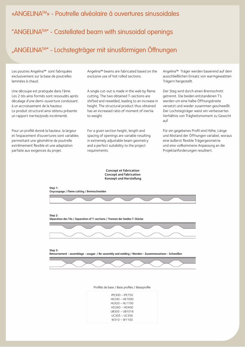
Les poutres Angelina™ sont fabriquées exclusivement sur la base de poutrelles laminées à chaud.
Une découpe est pratiquée dans l’âme. Les 2 tés ainsi formés sont ressoudés après décalage d’une demi-ouverture conduisant à un accroissement de la hauteur.Le produit structurel ainsi obtenu présente un rapport inertie/poids incrémenté.
Pour un profilé donné la hauteur, la largeur et l'espacement d'ouvertures sont variables permettant une géométrie de poutrelle extrêmement flexible et une adaptation parfaite aux exigences du projet.
Angelina™ beams are fabricated based on the exclusive use of hot rolled sections.
A single cut-out is made in the web by flame cutting. The two obtained T-sections are shifted and rewelded, leading to an increase in height. The structural product thus obtained has an increased ratio of moment of inertia to weight.
For a given section height, length and spacing of openings are variable resulting in extremely adjustable beam geometry and a perfect suitability to the project requirements.
Angelina™ Träger werden basierend auf dem ausschließlichen Einsatz von warmgewalzten Trägern hergestellt.
Der Steg wird durch einen Brennschnitt getrennt. Die beiden entstandenen T’s werden um eine halbe Öffnungsbreite versetzt und wieder zusammen geschweißt.Der Lochstegträger weist ein verbessertes Verhältnis von Trägheitsmoment zu Gewicht auf.
Für ein gegebenes Profil sind Höhe, Länge und Abstand der Öffnungen variabel, woraus eine äußerst flexible Trägergeometrie und eine vollkommene Anpassung an die Projektanforderungen resultiert.
Profilés de base / Base profiles / Basisprofile
IPE300 – IPE750HE240 – HE1000HL920 – HL1100HD260 – HD400UB305 – UB1016UC305 – UC356W310 – W1100
Concept et fabricationConcept and fabrication Konzept und Herstellung
Step 1:Oxycoupage / Flame cutting / Brennschneiden
Step 2:Séparation des Tés / Separation of T-sections / Trennen der beiden T-Stücke
Step 3: Retournement - assemblage - sougae / Re-assembly and welding / Wenden - Zusammensetzen - Schweißen
21
Angelina™ est un logiciel de prédimensionnement pour poutrelles cellulaires. Visitez notre site Web pour le téléchargement et les mises à jour récentes: www.arcelormittal.com/sections (Centre de téléchargement)
Angelina™ is a predesign software for castellated beams. Visit our website for download and recent updates: www.arcelormittal.com/sections (Download Center)
Angelina™ ist eine Vorbemessungssoftware für Lochstegträger. Besuchen Sie unsere Website für Download und Aktualisierungen: www.arcelormittal.com/sections (Downloadcenter)
ArcelorMittal - 2011
ANGELINAv 2.00
ANGELINAv 2.00
ww
0X
Y
a
lS lS
Définitions et applications Definition and applications
Definitionen und Eigenschaften
aO = 1,0 to 1,3 h e = 1,1 to 1,3 aO
ht1 = 1,4 to 1,6 h
aO = 0,8 to 1,1 h e = 1,2 to 1,7 aO
ht2 = 1,3 to 1,4 h
Objectifs: Optimisation du ratio hauteur/poids Objectives: Optimisation of the height/weight ratio Ziel: Optimierung des Verhältnisses Höhe/Gewicht
Objectifs: Optimisation du ratio charge/poids Objectives: Optimisation of the load/weight ratio Ziel: Optimierung des Verhältnisses Last/Gewicht
Conception type 1 / Design type 1 / Gestaltung Typ 1 Conception type 2 / Design type 2 / Gestaltung Typ 2
Profilé de départ (hauteur h) / Starting section (height h) / Ausgangsprofil (Höhe h) Profilé de départ (hauteur h) / Starting section (height h) / Ausgangsprofil (Höhe h)
Applications / Applications / Anwendungsbereiche:Planchers / Floors / DeckenParking / Carparks / ParkhäuserOffshore / Offshore structures / Offshore-Konstruktionen
Nuances fréquentes: / Common steel grades: / Häufig verwendete Stahlsorten:S355, S460, HISTAR® 460
Applications / Applications / Anwendungsbereiche:Couverture / Roofing / DächerPasserelles / Gangways/footbridges / Fußgängerbrücken Pannes grandes portées / Wide-span purlins / Dachpfetten mit großer Spannweite
Nuances fréquentes: / Common steel grades: / Häufig verwendete Stahlsorten:S235, S275, S355
h h
ht1
e
a0 ht2
e
a0
th
Construction Slim-Floor
Slim-Floor Construction
Die Slim-Floor Bauweise
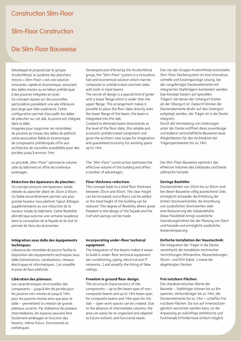
Développé et proposé par le groupe ArcelorMittal, le système des planchers minces « Slim-Floor » est une solution innovante, rapide et économique, associant des dalles mixtes ou en béton préfabriqué à des poutres intégrées en acier.Ce concept repose sur des poutrelles particulières possédant une aile inférieure plus large que l’aile supérieure. Cette configuration permet d’accueillir les dalles de plancher sur cet aile, la poutre est intégrée dans la dalle.Imaginée pour supprimer les retombées de poutres au niveau des dalles de plafond, cette association fiable et économique de composants préfabriqués offre aux architectes de nouvelles possibilités pour des portées jusqu’à environ 14m.
Le procédé „Slim-Floor“ optimise le volume utile du bâtiment et offre de nombreux avantages.
Réduction des épaisseurs de plancher: Ce concept procure une épaisseur totale réduite du plancher allant de 20cm à 40cm. Ce faible encombrement permet une plus grande hauteur sous plafond, l’ajout d’étages supplémentaires ou une réduction de la hauteur totale du bâtiment. Cette flexibilité altimétrique autorise une certaine souplesse dans la conception de la façade et du toit et permet de faire des économies.
Intégration sous dalle des équipements techniques: L’absence de retombée de poutre facilite la disposition des équipements techniques sous dalle (climatisation, canalisations, réseaux électriques et informatiques…) et simplifie la pose de faux plafonds.
Libération des plateaux: Les caractéristiques structurelles des composants – jusqu’à 8m de portée pour les poutres non-mixtes et jusqu’à 14m pour les poutres mixtes ainsi que pour la dalle – permettent la création de grands plateaux ouverts. Par d’absence de poteaux intermédiaires, les espaces peuvent être facilement aménagés en fonction des besoins, même futurs, fonctionnels et esthétiques.
Developed and offered by the ArcelorMittal group, the “Slim-Floor” system is a innovative, fast and economical solution which marries composite or prefabricated concrete slabs with built-in steel beams.The secret of design is a special kind of girder with a lower flange which is wider than the upper flange. This arrangement makes it possible to place the floor slabs directly onto the lower flange of the beam, the beam is integrated into the slab.Created to eliminate beam downstands at the level of the floor slabs, this reliable and economic prefabricated component unit gives the architect new scope for imagination and guaranteed economy for working spans up to 14m.
The “Slim-Floor” construction optimizes the effective volume of the building and offers a number of advantages.
Floor thickness reduction: This concept leads to a total floor thickness between 20cm and 40cm. The clear height can be increased, extra floors can be added or the total height of the building can be reduced. This degree of flexibility allows great freedom in the design of the façade and the roof and savings can be made.
Incorporating under-floor technical equipment: The integration of the beams makes it easier to build in under-floor technical equipment (air-conditioning, piping, electrical and IT networks…) and simplify the fitting of false ceilings.
Freedom in ground floor design: The structural characteristics of the components – up to 8m beam span of non-composite beams and up to 14m beam span for composite beams and 14m span for the slab – open work spaces can be created. Due to the absence of intermediate columns, the area can easily be re-organized and adapted to future esthetic and functional needs.
Das von der Gruppe ArcelorMittal entwickelte Slim-Floor Deckensystem ist eine innovative, schnelle und kostengünstige Lösung, bei der vorgefertigte Deckenelemente mit integrierten Stahlträgern kombiniert werden.Das Konzept basiert auf speziellen Trägern, bei denen der Untergurt breiter als der Obergurt ist. Dadurch können die Deckenelemente direkt auf den Untergurt aufgelegt werden, der Träger ist in die Decke integriert.Durch die Vermeidung von Unterzügen unter der Decke eröffnet diese zuverlässige und äußerst wirtschaftliche Bauweise neue Möglichkeiten für den Architekten bei Trägerspannweiten bis zu 14m.
Die Slim-Floor Bauweise optimiert das effektive Volumen des Gebäudes und bietet zahlreiche Vorteile.
Geringe Bauhöhe: Deckenstärken von 20cm bis zu 40cm sind bei dieser Bauweise völlig ausreichend. Dies ermöglicht entweder die Erhöhung der lichten Stockwerkshöhe, die Anordnung von zusätzlichen Stockwerken oder eine Reduzierung der Gebäudehöhe. Diese Flexibilität bringt zusätzliche Gestaltungsfreiheit bei der Planung von Dach und Fassade und ermöglicht zusätzliche Kosteneinsparung.
Einfache Installation der Haustechnik: Die Integration der Träger in die Decke vereinfacht die Installation technischer Vorrichtungen (Klimarohre, Wasserleitungen, Strom- und EDV Kabel…) sowie die abgehängter Decken.
Frei nutzbare Flächen: Die charakteristischen Werte der Bauteile – Stahlträger können bis zu 8m spannen, Verbundträger bis zu 14m, die Deckenelemente bis zu 14m – schaffen frei nutzbare Flächen. Da nun auf Innenstützen gänzlich verzichtet werden kann, ist die Anpassung an zukünftige ästhetische und funktionale Erfordernisse einfach möglich.
23
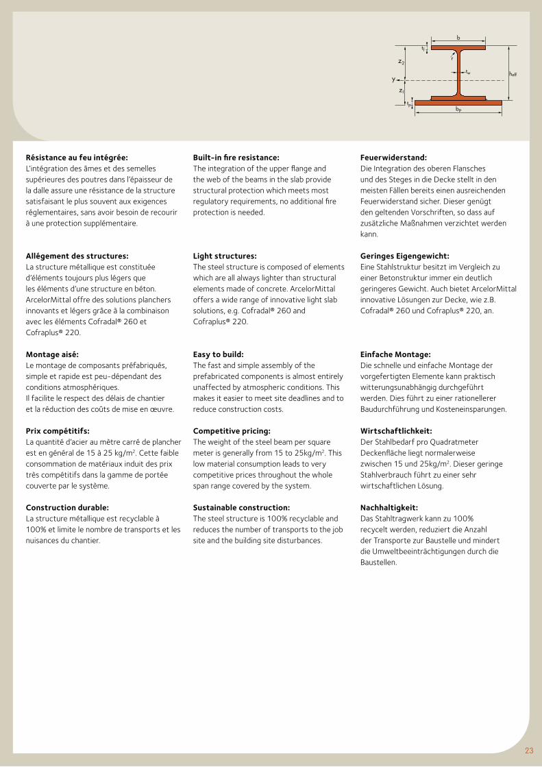
Résistance au feu intégrée: L’intégration des âmes et des semelles supérieures des poutres dans l’épaisseur de la dalle assure une résistance de la structure satisfaisant le plus souvent aux exigences réglementaires, sans avoir besoin de recourir à une protection supplémentaire.
Allégement des structures: La structure métallique est constituée d’éléments toujours plus légers que les éléments d’une structure en béton. ArcelorMittal offre des solutions planchers innovants et légers grâce à la combinaison avec les éléments Cofradal® 260 et Cofraplus® 220.
Montage aisé: Le montage de composants préfabriqués, simple et rapide est peu-dépendant des conditions atmosphériques. Il facilite le respect des délais de chantier et la réduction des coûts de mise en œuvre.
Prix compétitifs: La quantité d’acier au mètre carré de plancher est en général de 15 à 25 kg/m2. Cette faible consommation de matériaux induit des prix très compétitifs dans la gamme de portée couverte par le système.
Construction durable: La structure métallique est recyclable à 100% et limite le nombre de transports et les nuisances du chantier.
Built-in fire resistance: The integration of the upper flange and the web of the beams in the slab provide structural protection which meets most regulatory requirements, no additional fire protection is needed.
Light structures: The steel structure is composed of elements which are all always lighter than structural elements made of concrete. ArcelorMittal offers a wide range of innovative light slab solutions, e.g. Cofradal® 260 and Cofraplus® 220.
Easy to build: The fast and simple assembly of the prefabricated components is almost entirely unaffected by atmospheric conditions. This makes it easier to meet site deadlines and to reduce construction costs.
Competitive pricing: The weight of the steel beam per square meter is generally from 15 to 25kg/m2. This low material consumption leads to very competitive prices throughout the whole span range covered by the system.
Sustainable construction: The steel structure is 100% recyclable and reduces the number of transports to the job site and the building site disturbances.
Feuerwiderstand: Die Integration des oberen Flansches und des Steges in die Decke stellt in den meisten Fällen bereits einen ausreichenden Feuerwiderstand sicher. Dieser genügt den geltenden Vorschriften, so dass auf zusätzliche Maßnahmen verzichtet werden kann.
Geringes Eigengewicht: Eine Stahlstruktur besitzt im Vergleich zu einer Betonstruktur immer ein deutlich geringeres Gewicht. Auch bietet ArcelorMittal innovative Lösungen zur Decke, wie z.B. Cofradal® 260 und Cofraplus® 220, an.
Einfache Montage: Die schnelle und einfache Montage der vorgefertigten Elemente kann praktisch witterungsunabhängig durchgeführt werden. Dies führt zu einer rationellerer Baudurchführung und Kosteneinsparungen.
Wirtschaftlichkeit: Der Stahlbedarf pro Quadratmeter Deckenfläche liegt normalerweise zwischen 15 und 25kg/m2. Dieser geringe Stahlverbrauch führt zu einer sehr wirtschaftlichen Lösung.
Nachhaltigkeit: Das Stahltragwerk kann zu 100% recycelt werden, reduziert die Anzahl der Transporte zur Baustelle und mindert die Umweltbeeinträchtigungen durch die Baustellen.
tw
b
heff
bp
tf
pt
rz
z
y
2
1
Construction Slim-Floor (suite)
Slim-Floor Construction (continued)
Die Slim-Floor Bauweise (Fortsetzung)
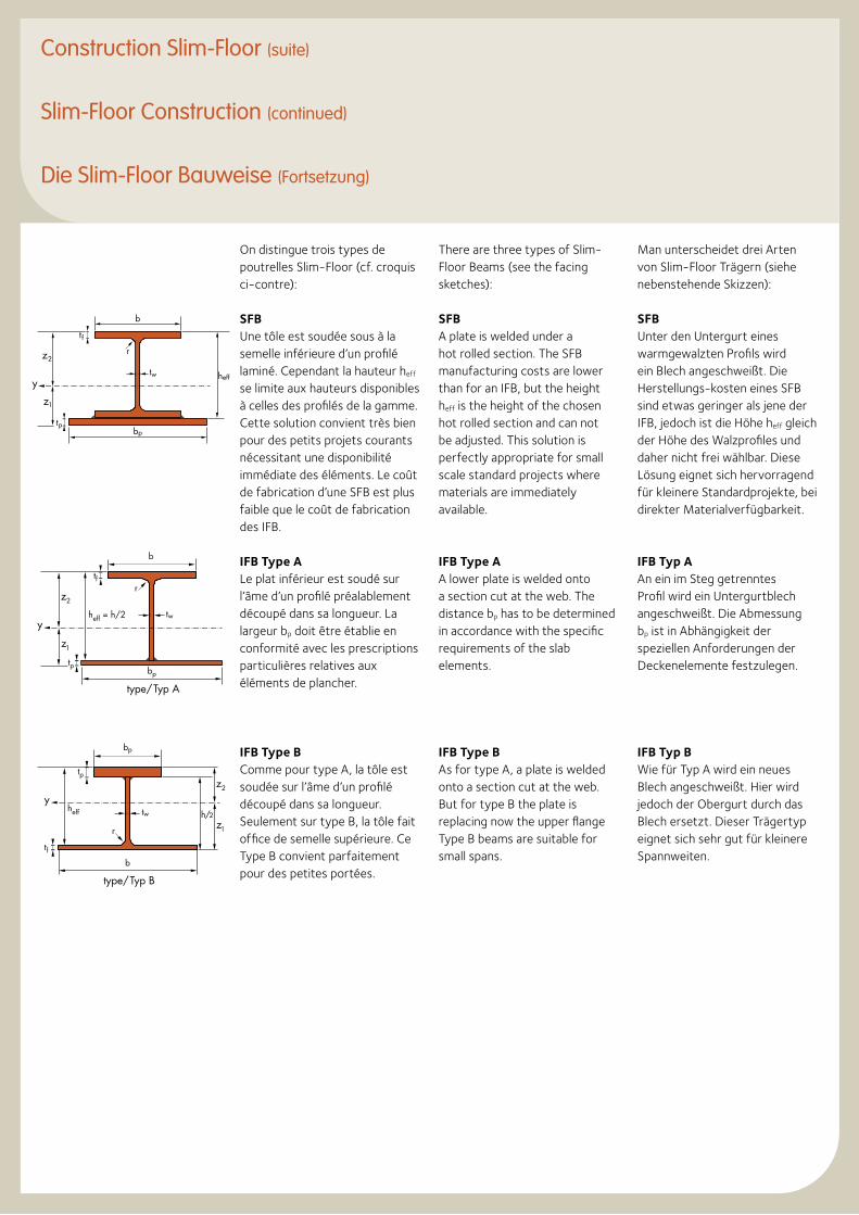
On distingue trois types de poutrelles Slim-Floor (cf. croquis ci-contre):
SFBUne tôle est soudée sous à la semelle inférieure d’un profilé laminé. Cependant la hauteur heff se limite aux hauteurs disponibles à celles des profilés de la gamme. Cette solution convient très bien pour des petits projets courants nécessitant une disponibilité immédiate des éléments. Le coût de fabrication d’une SFB est plus faible que le coût de fabrication des IFB.
IFB Type ALe plat inférieur est soudé sur l’âme d’un profilé préalablement découpé dans sa longueur. La largeur bp doit être établie en conformité avec les prescriptions particulières relatives aux éléments de plancher.
IFB Type BComme pour type A, la tôle est soudée sur l’âme d’un profilé découpé dans sa longueur. Seulement sur type B, la tôle fait office de semelle supérieure. Ce Type B convient parfaitement pour des petites portées.
There are three types of Slim-Floor Beams (see the facing sketches):
SFBA plate is welded under a hot rolled section. The SFB manufacturing costs are lower than for an IFB, but the height heff is the height of the chosen hot rolled section and can not be adjusted. This solution is perfectly appropriate for small scale standard projects where materials are immediately available.
IFB Type AA lower plate is welded onto a section cut at the web. The distance bp has to be determined in accordance with the specific requirements of the slab elements.
IFB Type BAs for type A, a plate is welded onto a section cut at the web. But for type B the plate is replacing now the upper flange Type B beams are suitable for small spans.
Man unterscheidet drei Arten von Slim-Floor Trägern (siehe nebenstehende Skizzen):
SFBUnter den Untergurt eines warmgewalzten Profils wird ein Blech angeschweißt. Die Herstellungs-kosten eines SFB sind etwas geringer als jene der IFB, jedoch ist die Höhe heff gleich der Höhe des Walzprofiles und daher nicht frei wählbar. Diese Lösung eignet sich hervorragend für kleinere Standardprojekte, bei direkter Materialverfügbarkeit.
IFB Typ AAn ein im Steg getrenntes Profil wird ein Untergurtblech angeschweißt. Die Abmessung bp ist in Abhängigkeit der speziellen Anforderungen der Deckenelemente festzulegen.
IFB Typ BWie für Typ A wird ein neues Blech angeschweißt. Hier wird jedoch der Obergurt durch das Blech ersetzt. Dieser Trägertyp eignet sich sehr gut für kleinere Spannweiten.
tw
b
heff
bp
tf
pt
rz
z
y
2
1
bp
tw
tp
tf
z2
z1
B pyT/epyt
h/2
b
r
heff
y
b
heff = h/2
bp
tp
tf
tw
rz2
z
y
1
A pyT/epyt
25
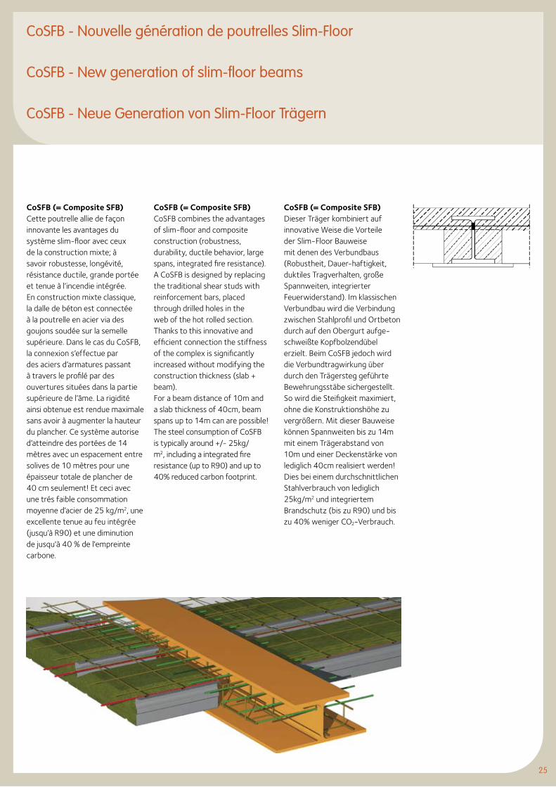
CoSFB (= Composite SFB)Cette poutrelle allie de façon innovante les avantages du système slim-floor avec ceux de la construction mixte; à savoir robustesse, longévité, résistance ductile, grande portée et tenue à l’incendie intégrée. En construction mixte classique, la dalle de béton est connectée à la poutrelle en acier via des goujons soudée sur la semelle supérieure. Dans le cas du CoSFB, la connexion s’effectue par des aciers d’armatures passant à travers le profilé par des ouvertures situées dans la partie supérieure de l’âme. La rigidité ainsi obtenue est rendue maximale sans avoir à augmenter la hauteur du plancher. Ce système autorise d’atteindre des portées de 14 mètres avec un espacement entre solives de 10 mètres pour une épaisseur totale de plancher de 40 cm seulement! Et ceci avec une trés faible consommation moyenne d’acier de 25 kg/m2, une excellente tenue au feu intégrée (jusqu’à R90) et une diminution de jusqu'à 40 % de l'empreinte carbone.
CoSFB (= Composite SFB)CoSFB combines the advantages of slim-floor and composite construction (robustness, durability, ductile behavior, large spans, integrated fire resistance). A CoSFB is designed by replacing the traditional shear studs with reinforcement bars, placed through drilled holes in the web of the hot rolled section. Thanks to this innovative and efficient connection the stiffness of the complex is significantly increased without modifying the construction thickness (slab + beam).For a beam distance of 10m and a slab thickness of 40cm, beam spans up to 14m can are possible!The steel consumption of CoSFB is typically around +/- 25kg/m2, including a integrated fire resistance (up to R90) and up to 40% reduced carbon footprint.
CoSFB (= Composite SFB)Dieser Träger kombiniert auf innovative Weise die Vorteile der Slim-Floor Bauweise mit denen des Verbundbaus (Robustheit, Dauer-haftigkeit, duktiles Tragverhalten, große Spannweiten, integrierter Feuerwiderstand). Im klassischen Verbundbau wird die Verbindung zwischen Stahlprofil und Ortbeton durch auf den Obergurt aufge-schweißte Kopfbolzendübel erzielt. Beim CoSFB jedoch wird die Verbundtragwirkung über durch den Trägersteg geführte Bewehrungsstäbe sichergestellt. So wird die Steifigkeit maximiert, ohne die Konstruktionshöhe zu vergrößern. Mit dieser Bauweise können Spannweiten bis zu 14m mit einem Trägerabstand von 10m und einer Deckenstärke von lediglich 40cm realisiert werden! Dies bei einem durchschnittlichen Stahlverbrauch von lediglich 25kg/m2 und integriertem Brandschutz (bis zu R90) und bis zu 40% weniger CO2-Verbrauch.
CoSFB - Nouvelle génération de poutrelles Slim-Floor
CoSFB - New generation of slim-floor beams
CoSFB - Neue Generation von Slim-Floor Trägern
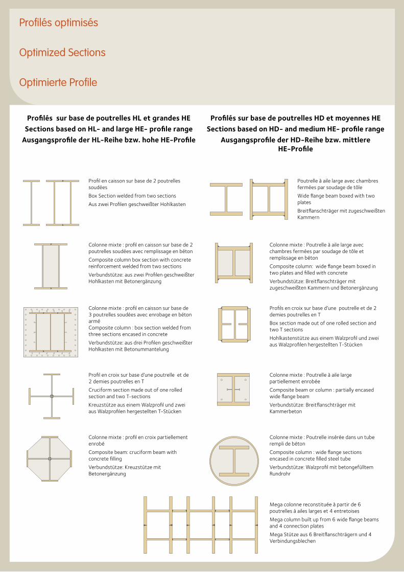
Profilés sur base de poutrelles HL et grandes HE
Sections based on HL- and large HE- profile range
Ausgangsprofile der HL-Reihe bzw. hohe HE-Profile
Profilés sur base de poutrelles HD et moyennes HE
Sections based on HD- and medium HE- profile range
Ausgangsprofile der HD-Reihe bzw. mittlere HE-Profile
Aus zwei Profilengeschweißter Hohlkasten
Kreuzstütze aus einem Walzprofil und zwei
aus Walzprofilen her-gestellten T-Stücken
Breitflansch-träger mit
zugeschweißten Kammern
Verbundstütze:Breitflanschträger mit
zugeschweißten Kammern und Betonergänzung
Hohlkastenstütze auseinem Walzprofil und zwei aus Walzprofilen herge-
stellten T-Stücken
Verbundstütze:Breitflanschträger mit Kammerbeton Verbundstütze:
Walzprofil mit betongefülltem
Rundrohr
Verbundstütze:Kreuzstütze mit Betonergänzung
Verbundstütze: aus zwei Profilengeschweißter Hohlkasten
mit Betonergänzung
Verbundstütze: aus dreiProfilen geschweißter
Hohlkasten mit Betonummantelung
Profil en caisson sur base de 2 poutrelles soudées
Box Section welded from two sections
Aus zwei Profilen geschweißter Hohlkasten
Aus zwei Profilengeschweißter Hohlkasten
Kreuzstütze aus einem Walzprofil und zwei
aus Walzprofilen her-gestellten T-Stücken
Breitflansch-träger mit
zugeschweißten Kammern
Verbundstütze:Breitflanschträger mit
zugeschweißten Kammern und Betonergänzung
Hohlkastenstütze auseinem Walzprofil und zwei aus Walzprofilen herge-
stellten T-Stücken
Verbundstütze:Breitflanschträger mit Kammerbeton Verbundstütze:
Walzprofil mit betongefülltem
Rundrohr
Verbundstütze:Kreuzstütze mit Betonergänzung
Verbundstütze: aus zwei Profilengeschweißter Hohlkasten
mit Betonergänzung
Verbundstütze: aus dreiProfilen geschweißter
Hohlkasten mit Betonummantelung
Poutrelle à aile large avec chambres fermées par soudage de tôle
Wide flange beam boxed with two plates
Breitflanschträger mit zugeschweißten Kammern
Aus zwei Profilengeschweißter Hohlkasten
Kreuzstütze aus einem Walzprofil und zwei
aus Walzprofilen her-gestellten T-Stücken
Breitflansch-träger mit
zugeschweißten Kammern
Verbundstütze:Breitflanschträger mit
zugeschweißten Kammern und Betonergänzung
Hohlkastenstütze auseinem Walzprofil und zwei aus Walzprofilen herge-
stellten T-Stücken
Verbundstütze:Breitflanschträger mit Kammerbeton Verbundstütze:
Walzprofil mit betongefülltem
Rundrohr
Verbundstütze:Kreuzstütze mit Betonergänzung
Verbundstütze: aus zwei Profilengeschweißter Hohlkasten
mit Betonergänzung
Verbundstütze: aus dreiProfilen geschweißter
Hohlkasten mit Betonummantelung
Colonne mixte : profil en caisson sur base de 2 poutrelles soudées avec remplissage en béton
Composite column box section with concrete reinforcement welded from two sections
Verbundstütze: aus zwei Profilen geschweißter Hohlkasten mit Betonergänzung
Aus zwei Profilengeschweißter Hohlkasten
Kreuzstütze aus einem Walzprofil und zwei
aus Walzprofilen her-gestellten T-Stücken
Breitflansch-träger mit
zugeschweißten Kammern
Verbundstütze:Breitflanschträger mit
zugeschweißten Kammern und Betonergänzung
Hohlkastenstütze auseinem Walzprofil und zwei aus Walzprofilen herge-
stellten T-Stücken
Verbundstütze:Breitflanschträger mit Kammerbeton Verbundstütze:
Walzprofil mit betongefülltem
Rundrohr
Verbundstütze:Kreuzstütze mit Betonergänzung
Verbundstütze: aus zwei Profilengeschweißter Hohlkasten
mit Betonergänzung
Verbundstütze: aus dreiProfilen geschweißter
Hohlkasten mit Betonummantelung
Colonne mixte : Poutrelle à aile large avec chambres fermées par soudage de tôle et remplissage en béton
Composite column: wide flange beam boxed in two plates and filled with concrete
Verbundstütze: Breitflanschträger mit zugeschweißten Kammern und Betonergänzung
Aus zwei Profilengeschweißter Hohlkasten
Kreuzstütze aus einem Walzprofil und zwei
aus Walzprofilen her-gestellten T-Stücken
Breitflansch-träger mit
zugeschweißten Kammern
Verbundstütze:Breitflanschträger mit
zugeschweißten Kammern und Betonergänzung
Hohlkastenstütze auseinem Walzprofil und zwei aus Walzprofilen herge-
stellten T-Stücken
Verbundstütze:Breitflanschträger mit Kammerbeton Verbundstütze:
Walzprofil mit betongefülltem
Rundrohr
Verbundstütze:Kreuzstütze mit Betonergänzung
Verbundstütze: aus zwei Profilengeschweißter Hohlkasten
mit Betonergänzung
Verbundstütze: aus dreiProfilen geschweißter
Hohlkasten mit Betonummantelung
Colonne mixte : profil en caisson sur base de 3 poutrelles soudées avec enrobage en béton arméComposite column : box section welded from three sections encased in concrete
Verbundstütze: aus drei Profilen geschweißterHohlkasten mit Betonummantelung
Aus zwei Profilengeschweißter Hohlkasten
Kreuzstütze aus einem Walzprofil und zwei
aus Walzprofilen her-gestellten T-Stücken
Breitflansch-träger mit
zugeschweißten Kammern
Verbundstütze:Breitflanschträger mit
zugeschweißten Kammern und Betonergänzung
Hohlkastenstütze auseinem Walzprofil und zwei aus Walzprofilen herge-
stellten T-Stücken
Verbundstütze:Breitflanschträger mit Kammerbeton Verbundstütze:
Walzprofil mit betongefülltem
Rundrohr
Verbundstütze:Kreuzstütze mit Betonergänzung
Verbundstütze: aus zwei Profilengeschweißter Hohlkasten
mit Betonergänzung
Verbundstütze: aus dreiProfilen geschweißter
Hohlkasten mit Betonummantelung
Profils en croix sur base d’une poutrelle et de 2 demies poutrelles en T
Box section made out of one rolled section and two T sections
Hohlkastenstütze aus einem Walzprofil und zweiaus Walzprofilen hergestellten T-StückenAus zwei Profilen
geschweißter Hohlkasten
Kreuzstütze aus einem Walzprofil und zwei
aus Walzprofilen her-gestellten T-Stücken
Breitflansch-träger mit
zugeschweißten Kammern
Verbundstütze:Breitflanschträger mit
zugeschweißten Kammern und Betonergänzung
Hohlkastenstütze auseinem Walzprofil und zwei aus Walzprofilen herge-
stellten T-Stücken
Verbundstütze:Breitflanschträger mit Kammerbeton Verbundstütze:
Walzprofil mit betongefülltem
Rundrohr
Verbundstütze:Kreuzstütze mit Betonergänzung
Verbundstütze: aus zwei Profilengeschweißter Hohlkasten
mit Betonergänzung
Verbundstütze: aus dreiProfilen geschweißter
Hohlkasten mit Betonummantelung
Profil en croix sur base d’une poutrelle et de 2 demies poutrelles en T
Cruciform section made out of one rolled section and two T-sections
Kreuzstütze aus einem Walzprofil und zwei aus Walzprofilen hergestellten T-Stücken
Aus zwei Profilengeschweißter Hohlkasten
Kreuzstütze aus einem Walzprofil und zwei
aus Walzprofilen her-gestellten T-Stücken
Breitflansch-träger mit
zugeschweißten Kammern
Verbundstütze:Breitflanschträger mit
zugeschweißten Kammern und Betonergänzung
Hohlkastenstütze auseinem Walzprofil und zwei aus Walzprofilen herge-
stellten T-Stücken
Verbundstütze:Breitflanschträger mit Kammerbeton Verbundstütze:
Walzprofil mit betongefülltem
Rundrohr
Verbundstütze:Kreuzstütze mit Betonergänzung
Verbundstütze: aus zwei Profilengeschweißter Hohlkasten
mit Betonergänzung
Verbundstütze: aus dreiProfilen geschweißter
Hohlkasten mit Betonummantelung
Colonne mixte : Poutrelle à aile large partiellement enrobée
Composite beam or column : partially encased wide flange beam
Verbundstütze: Breitflanschträger mit KammerbetonAus zwei Profilen
geschweißter Hohlkasten
Kreuzstütze aus einem Walzprofil und zwei
aus Walzprofilen her-gestellten T-Stücken
Breitflansch-träger mit
zugeschweißten Kammern
Verbundstütze:Breitflanschträger mit
zugeschweißten Kammern und Betonergänzung
Hohlkastenstütze auseinem Walzprofil und zwei aus Walzprofilen herge-
stellten T-Stücken
Verbundstütze:Breitflanschträger mit Kammerbeton Verbundstütze:
Walzprofil mit betongefülltem
Rundrohr
Verbundstütze:Kreuzstütze mit Betonergänzung
Verbundstütze: aus zwei Profilengeschweißter Hohlkasten
mit Betonergänzung
Verbundstütze: aus dreiProfilen geschweißter
Hohlkasten mit Betonummantelung
Colonne mixte : profil en croix partiellement enrobé
Composite beam: cruciform beam with concrete filling
Verbundstütze: Kreuzstütze mit Betonergänzung
Aus zwei Profilengeschweißter Hohlkasten
Kreuzstütze aus einem Walzprofil und zwei
aus Walzprofilen her-gestellten T-Stücken
Breitflansch-träger mit
zugeschweißten Kammern
Verbundstütze:Breitflanschträger mit
zugeschweißten Kammern und Betonergänzung
Hohlkastenstütze auseinem Walzprofil und zwei aus Walzprofilen herge-
stellten T-Stücken
Verbundstütze:Breitflanschträger mit Kammerbeton Verbundstütze:
Walzprofil mit betongefülltem
Rundrohr
Verbundstütze:Kreuzstütze mit Betonergänzung
Verbundstütze: aus zwei Profilengeschweißter Hohlkasten
mit Betonergänzung
Verbundstütze: aus dreiProfilen geschweißter
Hohlkasten mit Betonummantelung
Colonne mixte : Poutrelle insérée dans un tube rempli de béton
Composite column : wide flange sections encased in concrete filled steel tube
Verbundstütze: Walzprofil mit betongefülltem Rundrohr
Mega colonne reconstituée à partir de 6 poutrelles à ailes larges et 4 entretoises
Mega column built up from 6 wide flange beams and 4 connection plates
Mega Stütze aus 6 Breitflanschträgern und 4 Verbindungsblechen
Profilés optimisés
Optimized Sections
Optimierte Profile
Aus zwei Profilengeschweißter Hohlkasten
Kreuzstütze aus einem Walzprofil und zwei
aus Walzprofilen her-gestellten T-Stücken
Breitflansch-träger mit
zugeschweißten Kammern
Verbundstütze:Breitflanschträger mit
zugeschweißten Kammern und Betonergänzung
Hohlkastenstütze auseinem Walzprofil und zwei aus Walzprofilen herge-
stellten T-Stücken
Verbundstütze:Breitflanschträger mit Kammerbeton Verbundstütze:
Walzprofil mit betongefülltem
Rundrohr
Verbundstütze:Kreuzstütze mit Betonergänzung
Verbundstütze: aus zwei Profilengeschweißter Hohlkasten
mit Betonergänzung
Verbundstütze: aus dreiProfilen geschweißter
Hohlkasten mit Betonummantelung
27
Nuances et qualités d’acier
Steel grades and qualities
Stahlsorten und Sondergüten
28 Nuances et qualités d'acier
34 Arcorox® - Poutrelle en acier autopatinable
35 16 Mo3 - Acier allié pour températures d'utilisation élevées
37 1. Désignations usuelles des nuances d’acier de construction
38 2. Aciers de construction non alliés suivant norme européenne
40 3. Aciers de construction soudables à grains fins suivant norme européenne
42 4. Aciers pour trempe et revenu - aciers non alliés en haute qualité et aciers spéciaux non alliés
44 5. Aciers de marque HISTAR® et FRITENAR®
46 6. Aciers de construction soudables destinés à la fabrication de structures marines fixes suivant norme européenne
48 7. Aciers HISTAR® et FRITENAR® pour applications offshore
50 8. Aciers de construction à résistance améliorée à la corrosion atmosphérique suivant norme européenne et aciers de marques Arcorox®
52 9. Acier de construction soudable 16Mo3 avec caratéristiques spécifiées à températures élevée
54 10. Nuances d’acier suivant normes américaines
56 11. Nuances d’acier suivant normes russes
58 12. Nuances d’acier suivant normes japonaises
60 13. Tableaux de comparaison des nuances d’acier usuelles
62 14. Aciers pour cémentation - aciers spéciaux non alliés
28 Steelgrades and qualities
34 Arcorox® - Weathering steel grade
35 16Mo3 - Alloyed steel for elevated service temperatures
37 1. Usual structural steel grade designations
38 2. Non-alloy structural steels according to European standard
40 3. Weldable fine grain structural steels according to European standard
42 4. Steels for quenching and tempering - non-alloy quality steels and non-alloy
special steels
44 5. HISTAR® and FRITENAR® Trademark Steels
46 6. Weldable structural steels for fixed offshore structures according to
European standard
48 7. HISTAR® and FRITENAR® steel grades for offshore applications
50 8. Structural Steels with improved atmospheric corrosion resistance according to European standard and Arcorox® trademark steels
52 9. Weldable structural steel 16Mo3 with specified elevated temperature properties
54 10. Steel grades according to American standards
56 11. Steel grades according to Russian standards
58 12. Steel grades according to Japanese standards
60 13. Comparison tables of typical steel grades
62 14. Case hardening steels - non alloy special steels
28 Stahlsorten und Sondergüten
34 Arcorox® - Wetterfester Baustahl
35 16Mo3 - Legierter Stahl für erhöhte Einsatztemperaturen
37 1. Übliche Bezeichnungen der Baustahlgüten
38 2. Unlegierte Baustähle nach europäischer Norm
40 3. Schweißgeeignete Feinkornbaustähle nach europäischer Norm
42 4. Vergütungsstähle - unlegierte Qualitätsstähle und unlegierte Spezialstähle
44 5. HISTAR® und FRITENAR® Markenstähle
46 6. Schweißgeeignete Baustähle für feststehende Offshore-Konstruktionen nach europäischer Norm
48 7. HISTAR® und FRITENAR® Stahlgüten für Offshore- Anwendungen
50 8. Wetterfeste Baustähle nach europäischer Norm und Arcorox® Markenstahl
52 9. Schweißgeeigneter Baustahl 16Mo3 mit festgelegten Eigenschaften bei erhöhten Einsatztemperaturen
54 10. Stahlgüten nach amerikanischen Normen
56 11. Stahlgüten nach russischen Normen
58 12. Stahlgüten nach japanischen Normen
60 13. Vergleichstabellen der üblichen Stahlgüten
62 14. Einsatzstähle - unlegierte Spezialstähle
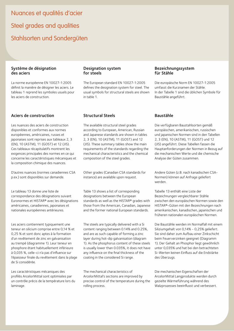
Nuances et qualités d’acier
Steel grades and qualities
Stahlsorten und Sondergüten
Système de désignation des aciers
La norme européenne EN 10027-1:2005 définit la manière de désigner les aciers. Le tableau 1 reprend les symboles usuels pour les aciers de construction.
Aciers de construction
Les nuances des aciers de construction disponibles et conformes aux normes européennes, américaines, russes et japonaises sont reprises aux tableaux 2, 3 (EN), 10 (ASTM), 11 (GOST) et 12 (JIS). Ces tableaux récapitulatifs montrent les exigences principales des normes en ce qui concerne les caractéristiques mécaniques et la composition chimique des nuances.
D’autres nuances (normes canadiennes CSA p.ex.) sont disponibles sur demande.
Le tableau 13 donne une liste de correspondance des désignations suivant Euronormes et HISTAR® avec les désignations américaines, canadiennes, japonaises et nationales européennes antérieures.
Les aciers contiennent typiquement une teneur en silicium comprise entre 0,14 % et 0,25 % et sont donc aptes à la formation d’un revêtement de zinc en galvanisation au trempé (diagramme 1). Leur teneur en phosphore étant habituellement inférieure à 0,035 %, celle-ci n’a pas d’influence sur l’épaisseur finale du revêtement dans la plage de Si considérée.
Les caractéristiques mécaniques des profilés ArcelorMittal sont optimisées par un contrôle précis de la température lors du laminage.
Designation system for steels
The European standard EN 10027-1:2005 defines the designation system for steel. The usual symbols for structural steels are shown in table 1.
Structural Steels
The available structural steel grades according to European, American, Russian and Japanese standards are shown in tables 2, 3 (EN), 10 (ASTM), 11 (GOST) and 12 (JIS). These summary tables show the main requirements of the standards regarding the mechanical characteristics and the chemical composition of the steel grades.
Other grades (Canadian CSA standards for instance) are available upon request.
Table 13 shows a list of corresponding designations between the European standards as well as the HISTAR® grades with those from the American, Canadian, Japanese and the former national European standards.
The steels are typically delivered with a Si content ranging between 0.14% and 0.25%, and are as such capable of forming a zinc layer during hot-dip galvanisation (diagram 1). As the phosphorus content of these steels is usually lower than 0.035%, it does not have any influence on the final thickness of the coating in the considered Si range.
The mechanical characteristics of ArcelorMittal’s sections are improved by precise control of the temperature during the rolling process.
Bezeichnungssystem für Stähle
Die europäische Norm EN 10027-1:2005 umfasst die Kurznamen der Stähle. In der Tabelle 1 sind die üblichen Symbole für Baustähle angeführt.
Baustähle
Die verfügbaren Baustahlsorten gemäß europäischen, amerikanischen, russischen und japanischen Normen sind in den Tabellen 2, 3 (EN), 10 (ASTM), 11 (GOST) und 12 (JIS) angeführt. Diese Tabellen fassen die Hauptanforderungen der Normen in Bezug auf die mechanischen Werte und die chemische Analyse der Güten zusammen.
Andere Güten (z.B. nach kanadischen CSA- Normen) können auf Anfrage geliefert werden.
Tabelle 13 enthält eine Liste der Bezeichnungen vergleichbarer Stähle zwischen den europäischen Normen sowie den HISTAR®-Güten mit den Bezeichnungen nach amerikanischen, kanadischen, japanischen und früheren nationalen europäischen Normen.
Die Baustähle werden im Normalfall mit einem Siliziumgehalt von 0,14% - 0,25% geliefert. Sie sind daher zum Aufbau einer Zinkschicht beim Feuerverzinken geeignet (Diagramm 1). Der Gehalt an Phosphor liegt gewöhnlich unter 0,035% und hat bei den betrachteten Si-Werten keinen Einfluss auf die Endstärke des Überzugs.
Die mechanischen Eigenschaften der ArcelorMittal Langprodukte werden durch gezielte Wärmeführung während des Walzprozesses beeinflusst und verbessert.
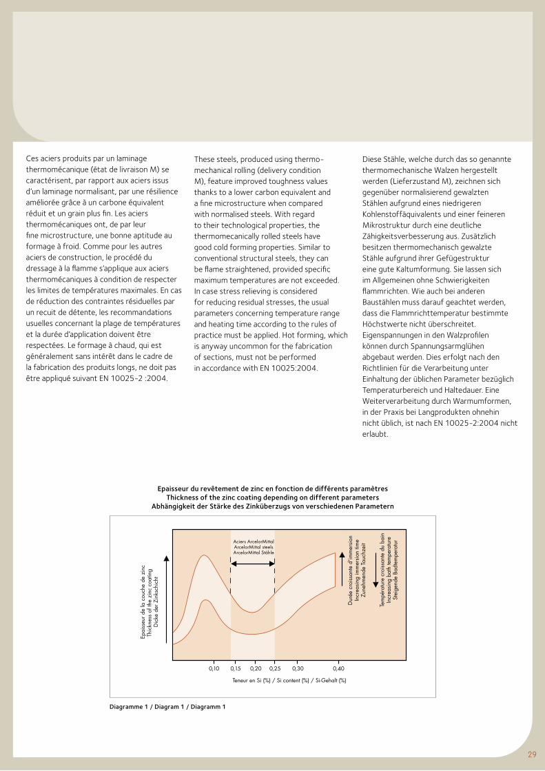
29
Ces aciers produits par un laminage thermomécanique (état de livraison M) se caractérisent, par rapport aux aciers issus d’un laminage normalisant, par une résilience améliorée grâce à un carbone équivalent réduit et un grain plus fin. Les aciers thermomécaniques ont, de par leur fine microstructure, une bonne aptitude au formage à froid. Comme pour les autres aciers de construction, le procédé du dressage à la flamme s’applique aux aciers thermomécaniques à condition de respecter les limites de températures maximales. En cas de réduction des contraintes résiduelles par un recuit de détente, les recommandations usuelles concernant la plage de températures et la durée d’application doivent être respectées. Le formage à chaud, qui est généralement sans intérêt dans le cadre de la fabrication des produits longs, ne doit pas être appliqué suivant EN 10025-2 :2004.
These steels, produced using thermo-mechanical rolling (delivery condition M), feature improved toughness values thanks to a lower carbon equivalent and a fine microstructure when compared with normalised steels. With regard to their technological properties, the thermomecanically rolled steels have good cold forming properties. Similar to conventional structural steels, they can be flame straightened, provided specific maximum temperatures are not exceeded. In case stress relieving is considered for reducing residual stresses, the usual parameters concerning temperature range and heating time according to the rules of practice must be applied. Hot forming, which is anyway uncommon for the fabrication of sections, must not be performed in accordance with EN 10025:2004.
Diese Stähle, welche durch das so genannte thermomechanische Walzen hergestellt werden (Lieferzustand M), zeichnen sich gegenüber normalisierend gewalzten Stählen aufgrund eines niedrigeren Kohlenstoffäquivalents und einer feineren Mikrostruktur durch eine deutliche Zähigkeitsverbesserung aus. Zusätzlich besitzen thermomechanisch gewalzte Stähle aufgrund ihrer Gefügestruktur eine gute Kaltumformung. Sie lassen sich im Allgemeinen ohne Schwierigkeiten flammrichten. Wie auch bei anderen Baustählen muss darauf geachtet werden, dass die Flammrichttemperatur bestimmte Höchstwerte nicht überschreitet. Eigenspannungen in den Walzprofilen können durch Spannungsarmglühen abgebaut werden. Dies erfolgt nach den Richtlinien für die Verarbeitung unter Einhaltung der üblichen Parameter bezüglich Temperaturbereich und Haltedauer. Eine Weiterverarbeitung durch Warmumformen, in der Praxis bei Langprodukten ohnehin nicht üblich, ist nach EN 10025-2:2004 nicht erlaubt.
Epaisseur du revêtement de zinc en fonction de différents paramètres Thickness of the zinc coating depending on different parameters
Abhängigkeit der Stärke des Zinküberzugs von verschiedenen Parametern
Diagramme 1 / Diagram 1 / Diagramm 1
epai
sseu
r de
la c
ouch
e de
zin
cTh
ickn
ess
of th
e zi
nc c
oatin
g D
icke
der
Zin
ksch
icht
Teneur en Si (%) / Si content (%) / Si-Gehalt (%)
Dur
ée c
rois
sant
e d'
imm
ersi
onIn
crea
sing
imm
ersi
on ti
me
Zune
hmen
de T
auch
zeit
Tem
péra
ture
cro
issa
nte
du b
ain
Incr
easi
ng b
ath
tem
pera
ture
Stei
gend
e Ba
dtem
pera
tur
0,10 0,20 0,250,15 0,30 0,40
Aciers ArcelorMittalArcelorMittal steelsArcelorMittal Stähle
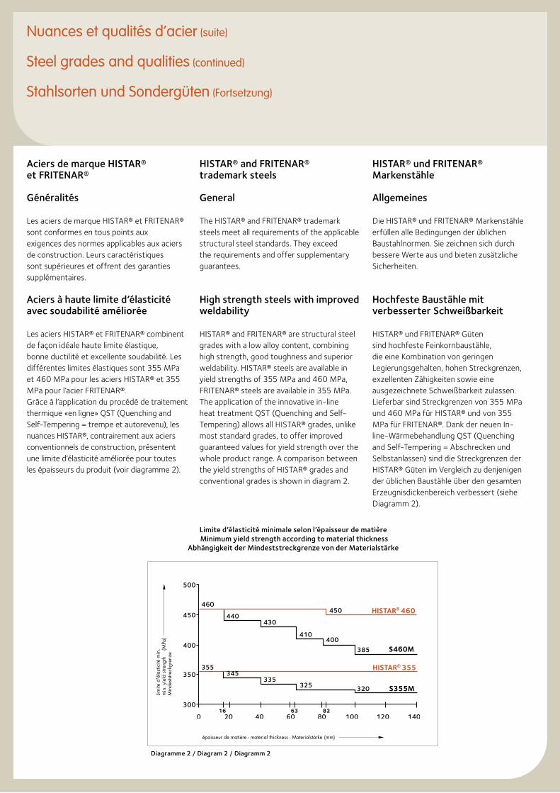
Aciers de marque HISTAR® et FRITENAR®
Généralités
Les aciers de marque HISTAR® et FRITENAR® sont conformes en tous points aux exigences des normes applicables aux aciers de construction. Leurs caractéristiques sont supérieures et offrent des garanties supplémentaires.
Aciers à haute limite d’élasticité avec soudabilité améliorée
Les aciers HISTAR® et FRITENAR® combinent de façon idéale haute limite élastique, bonne ductilité et excellente soudabilité. Les différentes limites élastiques sont 355 MPa et 460 MPa pour les aciers HISTAR® et 355 MPa pour l’acier FRITENAR®.Grâce à l’application du procédé de traitement thermique «en ligne» QST (Quenching and Self-Tempering = trempe et autorevenu), les nuances HISTAR®, contrairement aux aciers conventionnels de construction, présentent une limite d’élasticité améliorée pour toutes les épaisseurs du produit (voir diagramme 2).
HISTAR® and FRITENAR® trademark steels
General
The HISTAR® and FRITENAR® trademark steels meet all requirements of the applicable structural steel standards. They exceed the requirements and offer supplementary guarantees.
High strength steels with improved weldability
HISTAR® and FRITENAR® are structural steel grades with a low alloy content, combining high strength, good toughness and superior weldability. HISTAR® steels are available in yield strengths of 355 MPa and 460 MPa, FRITENAR® steels are available in 355 MPa.The application of the innovative in-line heat treatment QST (Quenching and Self-Tempering) allows all HISTAR® grades, unlike most standard grades, to offer improved guaranteed values for yield strength over the whole product range. A comparison between the yield strengths of HISTAR® grades and conventional grades is shown in diagram 2.
HISTAR® und FRITENAR® Markenstähle
Allgemeines
Die HISTAR® und FRITENAR® Markenstähle erfüllen alle Bedingungen der üblichen Baustahlnormen. Sie zeichnen sich durch bessere Werte aus und bieten zusätzliche Sicherheiten.
Hochfeste Baustähle mit verbesserter Schweißbarkeit
HISTAR® und FRITENAR® Güten sind hochfeste Feinkornbaustähle, die eine Kombination von geringen Legierungsgehalten, hohen Streckgrenzen, exzellenten Zähigkeiten sowie eine ausgezeichnete Schweißbarkeit zulassen. Lieferbar sind Streckgrenzen von 355 MPa und 460 MPa für HISTAR® und von 355 MPa für FRITENAR®. Dank der neuen In-line-Wärmebehandlung QST (Quenching and Self-Tempering = Abschrecken und Selbstanlassen) sind die Streckgrenzen der HISTAR® Güten im Vergleich zu denjenigen der üblichen Baustähle über den gesamten Erzeugnisdickenbereich verbessert (siehe Diagramm 2).
Nuances et qualités d’acier (suite)
Steel grades and qualities (continued)
Stahlsorten und Sondergüten (Fortsetzung)
épaisseur de matière - material thickness - Materialstärke (mm)
Limite
d'é
lasti
cité
min
.m
in. y
ield
stre
ngth
(
MPa
)M
inde
ststre
ckgr
enze
Diagramme 2 / Diagram 2 / Diagramm 2
Limite d’élasticité minimale selon l’épaisseur de matière Minimum yield strength according to material thickness
Abhängigkeit der Mindeststreckgrenze von der Materialstärke
31
Les nuances HISTAR® sont livrées suivant l’agreement technique Européen ETA-10/0156. Ils sont conforme aux spécifications de l’EN 10025-4 : 2004 pour les aciers soudables à grains fins.
Les nuances des aciers de marque HISTAR® et FRITENAR® sont reprises dans le tableau 5. Des renseignements techniques détaillés de ces nuances sont disponibles sur demande.
Les aciers contiennent habituellement une teneur en silicium comprise entre 0,14 % et 0,25 % et sont donc aptes à la formation d’un revêtement de zinc en galvanisation au trempé (diagramme 1). Leur teneur en phosphore étant habituellement inférieure à 0,035 %, celle-ci n’a pas d’influence sur l’épaisseur finale du revêtement dans la plage de Si considérée.
La nuance FRITENAR® est disponible sur demande. Les nuances HISTAR® sont disponibles uniquement pour les profilés marqués HI (pages 71 à 147).
Les aciers HISTAR® et FRITENAR® peuvent être oxycoupés et parachevés suivant une procédure identique à celle appliquée aux aciers de construction du même niveau de résistance. Grâce au bas carbone équivalent, il n’est pas nécessaire de procéder à un préchauffage afin d’éviter la fissuration lorsque la température du produit est >0°C.
Dans l’hypothèse du respect des règles générales de soudage, les aciers HISTAR® et FRITENAR® offrent une excellente aptitude au soudage manuel et automatique. Grâce aux faibles valeurs de carbone équivalent, il n’est généralement pas nécessaire de procéder au préchauffage, pourvu que l’apport en énergie se situe entre 10 et 60 kJ/cm, que la température du produit soit >0°C et que des électrodes à faible teneur en hydrogène soient utilisées.
HISTAR® steels are delivered in a thermo-mechanically rolled condition in accordance with the European Technical Approval ETA-10/0156. They comply with the requirements of the European standards EN 10025-4: 2004 for weldable fine grain structural steels.
Table 5 shows the characteristics of the available HISTAR® and FRITENAR® trademark steel grades. Detailed data of these steels are available upon request.
The steels are typically delivered with a Si content ranging between 0,14% and 0,25%, and are as such capable of forming a zinc layer during hot-dip galvanisation (diagram 1). As the phosphorus content of these steels is usually lower than 0,035%, it does not have any influence on the final thickness of the coating in the considered Si range.
The sections are available in the FRITENAR® grade upon agreement. For HISTAR® grades, only the sizes marked HI are available (pages 71 to 147).
HISTAR® and FRITENAR® steels can be cut with a torch and machined using the process normally applied to structural steel of the same level of strength. Due to the low carbon equivalent, preheating in order to prevent cracking is generally not necessary for product temperatures >0°C.
HISTAR® and FRITENAR® steels offer good weldability for manual and automatic processes, provided the general rules for welding are respected. Due to the low carbon equivalent values of these steels, preheating is not necessary within the range of heat inputs of 10-60 kJ/cm and for temperatures of the structure over 0°C, provided that low hydrogen consumables are used.
HISTAR® Stähle werden im thermo-mechanisch gewalzten Zustand nach ETA-10/0156 geliefert. Sie erfüllen die Anforderungen der europäischen Normen EN 10025-4: 2004 für schweißgeeignete Feinkornbaustähle.
In Tabelle 5 ist die Liste aller verfügbaren HISTAR® und FRITENAR® Markenstähle aufgeführt. Auf Nachfrage sind weitere Einzelheiten dieser Güten erhältlich.
Die Markenstähle werden im Normalfall mit einem Si-Gehalt von 0,14% - 0,25% geliefert. Sie sind daher zum Aufbau einer Zinkschicht beim Feuerverzinken geeignet (Diagramm 1). Der Gehalt an Phosphor liegt gewöhnlich unter 0,035% und hat bei den betrachteten Si-Werten keinen Einfluss auf die Endstärke des Überzugs.
Nur die in den Tabellen der Seiten 71 bis 147 mit Hl gekennzeichneten Profile sind in HISTAR® Güten lieferbar, während die FRITENAR® Güte auf Anfrage erhältlich ist.
Das thermische Trennen und die mechanische Bearbeitung von HISTAR® und FRITENAR® Güten können unter normalen Bedingungen genauso durchgeführt werden wie für vergleichbare Baustähle in dem jeweiligen Festigkeitsbereich. Ein Vorwärmen zur Vermeidung von Abkühlungsrissen ist, bedingt durch den geringen Gehalt an Legierungselementen, ab einer Verarbeitungstemperatur >0°C nicht erforderlich.
Unter Einhaltung der allgemeinen Regeln der Schweißtechnik bieten die HISTAR® und FRITENAR® Güten für alle manuellen und automatischen Schweißprozesse eine optimale Schweißbarkeit. Bedingt durch das niedrige Kohlenstoffäquivalent ist ein Vorwärmen bei Streckenenergien von 10-60 kJ/cm und bei Verarbeitungstemperaturen >0°C nicht erforderlich, vorausgesetzt es werden Schweißzusatzwerkstoffe mit niedrigem Wasserstoffgehalt verwendet.
Dans ces conditions les aciers HISTAR® 355 et FRITENAR® 355 peuvent être soudés sans préchauffage sur toute la gamme d’épaisseur. A l’identique des aciers de construction usuels, un séchage est recommandé avant d’effectuer le soudage à des températures ambiantes en dessous de 5°C ou si la pièce est humide.
En cas de recuit de détente des aciers HISTAR® et FRITENAR®, la température se situe entre 530°C et 580°C. La durée d’application recommandée est de 2 minutes par mm d’épaisseur sans qu’elle soit inférieure à 30 minutes ou supérieure à 90 minutes.
Lors d’opérations de dressage à la flamme de courte durée sur toute l’épaisseur du produit, il convient de ne pas dépasser une température de 650°C. Localement, une température jusqu’à 900°C est admissible en cas de dressage à la flamme en surface du produit uniquement.
Aciers pour applications offshore
Les nuances HISTAR® Offshore et FRITENAR* Offshore ont été développées spécialement pour les applications offshore. Comparées aux aciers de marque HISTAR® et FRITENAR®, les nuances offshore présentent des propriétés supplémentaires, dont notamment :• descaractéristiquesdedéformation
améliorées dans le sens de l’épaisseur en ce qui concerne la résistance à l’arrachement lamellaire (qualités Z) ;
• despropriétésderésiliencegarantiesdans le sens transversal ;
• unrapportmaximalentrelesvaleursde la limite élastique et de la résistance à la traction.
Les caractéristiques mécaniques et les compositions chimiques des nuances d’aciers offshore sont reprises aux tableaux 6 et 7. Le tableau récapitulatif 6 montre les exigences principales de la norme EN 10225: 2009 en ce qui concerne les caractéristiques mécaniques et la composition chimique des nuances.
Under these conditions, no preheating is required for welding HISTAR® 355 and FRITENAR® 355 steels over the whole thickness range. As for the usual structural steels, drying before welding is recommended for ambient temperatures below 5°C and when the surface is wet.
If stress relieving is required for HISTAR® and FRITENAR® steels, it is performed at temperatures between 530°C and 580°C. The recommended holding time is 2 minutes per mm product thickness, but not less than 30 minutes and not more than 90 minutes.
For a short reheating of the entire thickness of HISTAR® and FRITENAR® beams, the flame straightening temperature should not exceed 650°C. For local reheating of the surface only, a flame straightening temperature of up to 900°C is allowable.
Steel grades for offshore applications
HISTAR® Offshore and FRITENAR® Offshore are structural steel grades especially developed for offshore applications. In comparison with HISTAR® and FRITENAR® trademark steels, the grades for offshore applications offer the following additional features:• improvedthrough-thicknessdeforma-
tion properties with respect to the resistance to lamellar tearing (Z quali-ties);
• notchimpactpropertiesinthetrans-verse direction;
• maximumratiobetweenyieldstrength and tensile strength.
The available grades, their mechanical characteristics and chemical composition are shown in tables 6 and 7. The summary table 6 shows the main requirements of EN 10225: 2009 regarding the mechanical characteristics and the chemical composition of the steel grades.
Unter diesen Umständen können die HISTAR® 355 und FRITENAR® 355 Stähle ohne Vorwärmen über den gesamten Dickenbereich geschweißt werden. Wie für die üblichen Baustähle sollen Profile mit nasser Stahloberfläche und Temperaturen unter 5°C vor dem Schweißen getrocknet werden.
Für den Fall, dass Spannungsarmglühen erforderlich ist, erfolgt dieses bei den HISTAR® und FRITENAR® Güten bei Temperaturen zwischen 530°C und 580°C. Es wird empfohlen, die Haltezeit bei 2 Minuten pro mm Materialstärke anzusetzen. Die Gesamtdauer sollte jedoch mindestens 30 Minuten betragen und insgesamt 90 Minuten nicht überschreiten.
Bei einer kurzen durchgreifenden Erwärmung des Materials beim Flammrichten über die gesamte Erzeugnisdicke sollte die Temperatur unter 650°C liegen. Bei einer lokalen, punktuellen Oberflächenerwärmung des Bauteils sollte die Flammrichttemperatur 900°C nicht überschreiten.
Stahlgüten für Offshore-Anwendungen
Die HISTAR® Offshore- und FRITENAR® Offshore-Güten sind speziell für den Offshore-Bereich entwickelt worden. Im Vergleich zu den Markenstählen HISTAR® und FRITENAR® bieten die Offshore-Güten folgende zusätzlichen Eigenschaften:• GütenmitverbessertenVerformungs-
eigenschaften zur Verminderung der Terrassenbruchneigung bei Beanspruchung senkrecht zur Erzeugnisoberfläche (Z-Güten);
• KerbschlageigenschafteninQuerrich-tung;
• maximalesVerhältniszwischenStreck-grenze und Zugfestigkeit.
Die Tabellen 6 und 7 führen die verfügbaren Offshore-Güten sowie deren mechanische Eigenschaften und chemische Zusammensetzung auf. Die Tabelle 6 fasst die Hauptanforderungen der Norm EN 10225: 2009 in Bezug auf die mechanischen Werte und die chemische Analyse der Güten zusammen.
Nuances et qualités d’acier (suite)
Steel grades and qualities (continued)
Stahlsorten und Sondergüten (Fortsetzung)
33
Die HISTAR®- und FRITENAR® Offshore- Güten in Tabelle 7 stehen in vollem Einklang mit den Forderungen der EN 10225: 2009.
Auf Nachfrage sind weitere Einzelheiten dieser Offshore-Güten erhältlich.
Sondergüten
1. Wetterfeste Stähle nach EN 10025-5: 2004 (Tabelle 8) – Lieferbedingungen auf Anfrage.
2. Nach Vereinbarung können die Güten nach EN 10025-2: 2004 und EN 10025-4: 2004 mit verbesserten Verformungseigenschaften zur Verminderung der Terrassenbruch-neigung bei Beanspruchung senkrecht zur Erzeugnisoberfläche (Z-Güten) geliefert werden.
3. Stahlgüten gemäß Sonderspezifikation (chemische Zusammensetzung und mechanische Eigenschaften) sind lieferbar nach Vereinbarung und unter-liegen Mindestbestellmengen.
The HISTAR® and FRITENAR® Offshore grades in Table 7 are in compliance with EN 10225: 2009.
Detailed data on the HISTAR® Offshore and FRITENAR® Offshore steels are available upon request.
Special Steel Qualities
1. Weathering steels in accordance with EN 10025-5: 2004 (table 8) – delivery conditions upon request.
2. Steel grades in accordance with EN 10025-2: 2004 and EN 10025-4: 2004 are available upon request with improved through-thickness deformation properties with respect to the resistance to lamellar tearing (Z qualities).
3. Steel grades according to particular specifications (chemical composition and mechanical properties) are subject to prior approval and minimum ton-nages to be agreed upon.
Les aciers offshore HISTAR® et FRITENAR® du tableau 7 sont conformes aux spécifications de l’EN 10225: 2009.
Des renseignements techniques détaillés des nuances HISTAR® Offshore et FRITENAR® Offshore sont disponibles sur demande.
Qualités spéciales
1. Aciers patinables suivant EN 10025-5 : 2004 (tableau 8) - conditions de livraison sur demande.
2. Après accord, les nuances suivant EN 10025-2: 2004 et EN 10025-4: 2004 sont disponibles avec des caractéristiques de défor-mation améliorées dans le sens de l’épaisseur concernant la résistance à l’arrachement lamellaire (qualités Z).
3. Les aciers suivant spécifications particulières (composition chimique et propriétés mécaniques) sont disponi-bles sur demande et sont sujets à des tonnages minima à convenir.
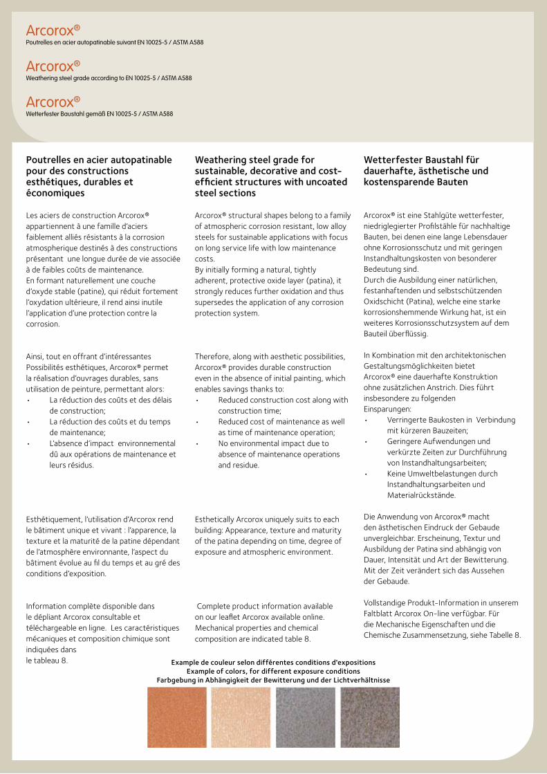
Poutrelles en acier autopatinable pour des constructions esthétiques, durables et économiques
Les aciers de construction Arcorox® appartiennent à une famille d’aciers faiblement alliés résistants à la corrosion atmospherique destinés à des constructions présentant une longue durée de vie associée à de faibles coûts de maintenance.En formant naturellement une couche d’oxyde stable (patine), qui réduit fortement l’oxydation ultérieure, il rend ainsi inutile l’application d’une protection contre la corrosion.
Ainsi, tout en offrant d’intéressantes Possibilités esthétiques, Arcorox® permet la réalisation d’ouvrages durables, sans utilisation de peinture, permettant alors:• Laréductiondescoûtsetdesdélais
de construction;• Laréductiondescoûtsetdutemps
de maintenance;• L’absenced’impactenvironnemental
dû aux opérations de maintenance et leurs résidus.
Esthétiquement, l’utilisation d’Arcorox rend le bâtiment unique et vivant : l’apparence, la texture et la maturité de la patine dépendant de l’atmosphère environnante, l’aspect du bâtiment évolue au fil du temps et au gré des conditions d’exposition.
Information complète disponible dans le dépliant Arcorox consultable et téléchargeable en ligne. Les caractéristiques mécaniques et composition chimique sont indiquées dans le tableau 8.
Weathering steel grade for sustainable, decorative and cost-efficient structures with uncoated steel sections
Arcorox® structural shapes belong to a family of atmospheric corrosion resistant, low alloy steels for sustainable applications with focus on long service life with low maintenance costs.By initially forming a natural, tightly adherent, protective oxide layer (patina), it strongly reduces further oxidation and thus supersedes the application of any corrosion protection system.
Therefore, along with aesthetic possibilities, Arcorox® provides durable construction even in the absence of initial painting, which enables savings thanks to:• Reducedconstructioncostalongwith
construction time;• Reducedcostofmaintenanceaswell
as time of maintenance operation;• Noenvironmentalimpactdueto
absence of maintenance operations and residue.
Esthetically Arcorox uniquely suits to each building: Appearance, texture and maturity of the patina depending on time, degree of exposure and atmospheric environment.
Complete product information available on our leaflet Arcorox available online. Mechanical properties and chemical composition are indicated table 8.
Wetterfester Baustahl für dauerhafte, ästhetische und kostensparende Bauten
Arcorox® ist eine Stahlgüte wetterfester, niedriglegierter Profilstähle für nachhaltige Bauten, bei denen eine lange Lebensdauer ohne Korrosionsschutz und mit geringen Instandhaltungskosten von besonderer Bedeutung sind.Durch die Ausbildung einer natürlichen, festanhaftenden und selbstschützenden Oxidschicht (Patina), welche eine starke korrosionshemmende Wirkung hat, ist ein weiteres Korrosionsschutzsystem auf dem Bauteil überflüssig.
In Kombination mit den architektonischen Gestaltungsmöglichkeiten bietet Arcorox® eine dauerhafte Konstruktion ohne zusätzlichen Anstrich. Dies führt insbesondere zu folgendenEinsparungen:• VerringerteBaukosteninVerbindung
mit kürzeren Bauzeiten;• GeringereAufwendungenund
verkürzte Zeiten zur Durchführung von Instandhaltungsarbeiten;
• KeineUmweltbelastungendurchInstandhaltungsarbeiten und Materialrückstände.
Die Anwendung von Arcorox® macht den ästhetischen Eindruck der Gebaude unvergleichbar. Erscheinung, Textur und Ausbildung der Patina sind abhängig von Dauer, Intensität und Art der Bewitterung. Mit der Zeit verändert sich das Aussehen der Gebaude.
Vollstandige Produkt-Information in unserem Faltblatt Arcorox On-line verfügbar. Für die Mechanische Eigenschaften und die Chemische Zusammensetzung, siehe Tabelle 8.
Arcorox®
Poutrelles en acier autopatinable suivant EN 10025-5 / ASTM A588
Arcorox® Weathering steel grade according to EN 10025-5 / ASTM A588
Arcorox®
Wetterfester Baustahl gemäß EN 10025-5 / ASTM A588
Example de couleur selon différentes conditions d'expositionsExample of colors, for different exposure conditions
Farbgebung in Abhängigkeit der Bewitterung und der Lichtverhältnisse
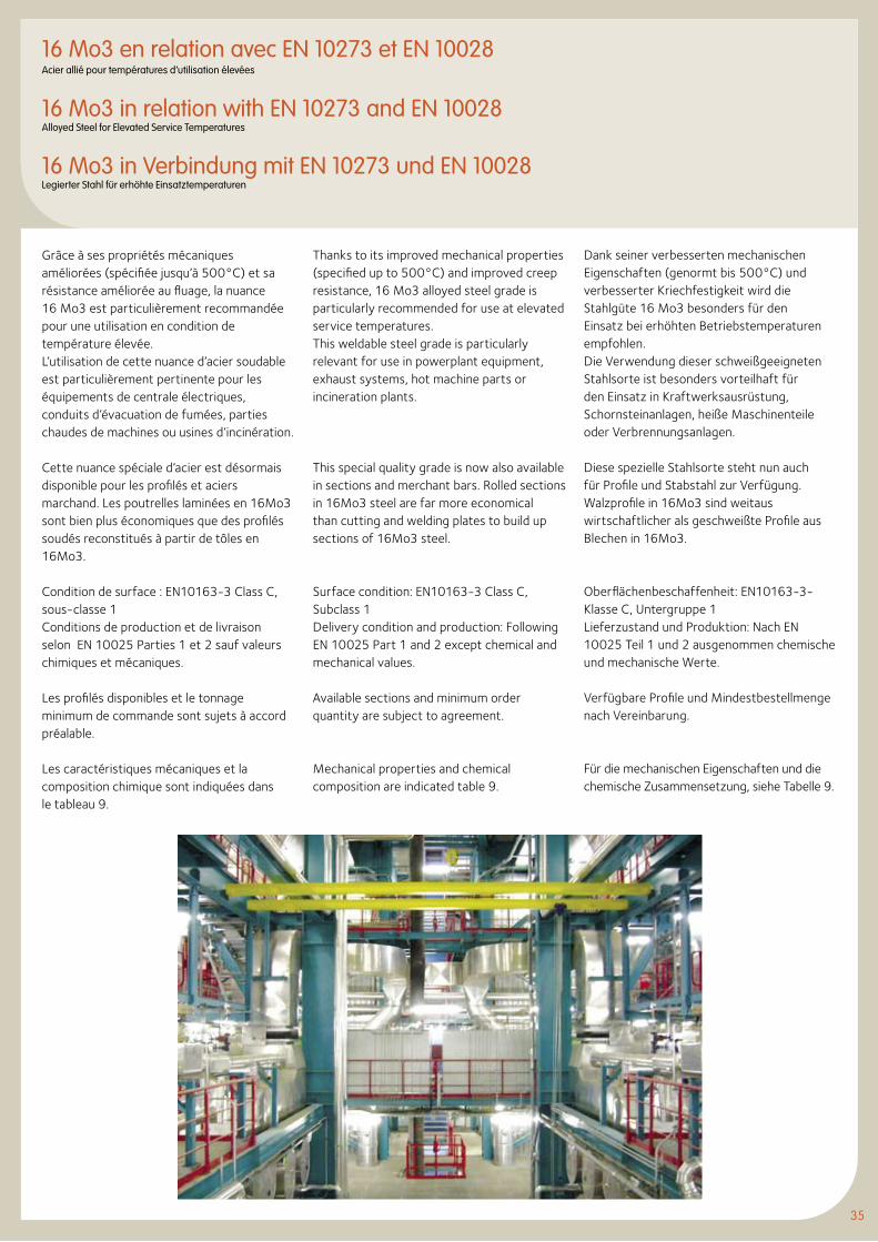
35
Grâce à ses propriétés mécaniques améliorées (spécifiée jusqu’à 500°C) et sa résistance améliorée au fluage, la nuance 16 Mo3 est particulièrement recommandée pour une utilisation en condition de température élevée.L’utilisation de cette nuance d’acier soudable est particulièrement pertinente pour les équipements de centrale électriques, conduits d’évacuation de fumées, parties chaudes de machines ou usines d’incinération.
Cette nuance spéciale d’acier est désormais disponible pour les profilés et aciers marchand. Les poutrelles laminées en 16Mo3 sont bien plus économiques que des profilés soudés reconstitués à partir de tôles en 16Mo3.
Condition de surface : EN10163-3 Class C, sous-classe 1Conditions de production et de livraison selon EN 10025 Parties 1 et 2 sauf valeurs chimiques et mécaniques.
Les profilés disponibles et le tonnage minimum de commande sont sujets à accord préalable.
Les caractéristiques mécaniques et la composition chimique sont indiquées dans le tableau 9.
Thanks to its improved mechanical properties (specified up to 500°C) and improved creep resistance, 16 Mo3 alloyed steel grade is particularly recommended for use at elevated service temperatures.This weldable steel grade is particularly relevant for use in powerplant equipment, exhaust systems, hot machine parts or incineration plants.
This special quality grade is now also available in sections and merchant bars. Rolled sections in 16Mo3 steel are far more economical than cutting and welding plates to build up sections of 16Mo3 steel.
Surface condition: EN10163-3 Class C, Subclass 1Delivery condition and production: Following EN 10025 Part 1 and 2 except chemical and mechanical values.
Available sections and minimum order quantity are subject to agreement.
Mechanical properties and chemical composition are indicated table 9.
Dank seiner verbesserten mechanischen Eigenschaften (genormt bis 500°C) und verbesserter Kriechfestigkeit wird die Stahlgüte 16 Mo3 besonders für den Einsatz bei erhöhten Betriebstemperaturen empfohlen.Die Verwendung dieser schweißgeeigneten Stahlsorte ist besonders vorteilhaft für den Einsatz in Kraftwerksausrüstung, Schornsteinanlagen, heiße Maschinenteile oder Verbrennungsanlagen.
Diese spezielle Stahlsorte steht nun auch für Profile und Stabstahl zur Verfügung. Walzprofile in 16Mo3 sind weitaus wirtschaftlicher als geschweißte Profile aus Blechen in 16Mo3.
Oberflächenbeschaffenheit: EN10163-3-Klasse C, Untergruppe 1Lieferzustand und Produktion: Nach EN 10025 Teil 1 und 2 ausgenommen chemische und mechanische Werte.
Verfügbare Profile und Mindestbestellmenge nach Vereinbarung.
Für die mechanischen Eigenschaften und die chemische Zusammensetzung, siehe Tabelle 9.
16 Mo3 en relation avec EN 10273 et EN 10028Acier allié pour températures d’utilisation élevées
16 Mo3 in relation with EN 10273 and EN 10028Alloyed Steel for Elevated Service Temperatures
16 Mo3 in Verbindung mit EN 10273 und EN 10028Legierter Stahl für erhöhte Einsatztemperaturen
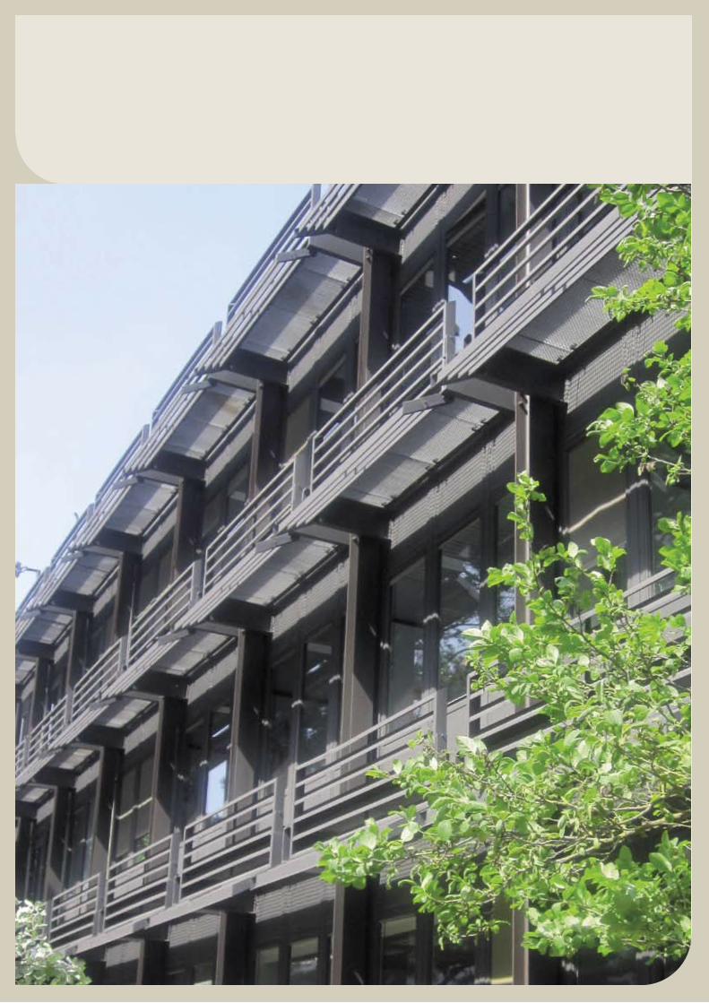
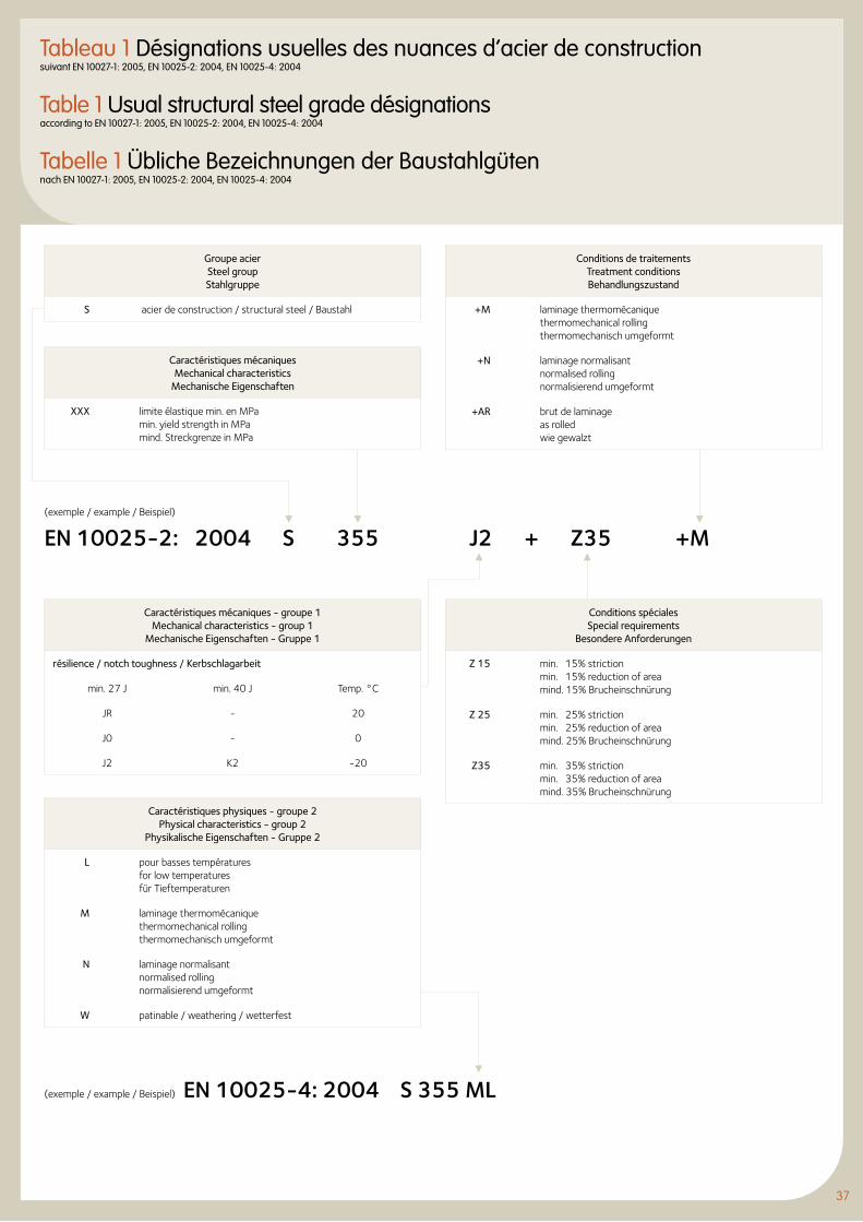
37
Tableau 1 Désignations usuelles des nuances d’acier de constructionsuivant EN 10027-1: 2005, EN 10025-2: 2004, EN 10025-4: 2004
Table 1 Usual structural steel grade désignations according to EN 10027-1: 2005, EN 10025-2: 2004, EN 10025-4: 2004
Tabelle 1 Übliche Bezeichnungen der Baustahlgüten nach EN 10027-1: 2005, EN 10025-2: 2004, EN 10025-4: 2004
Groupe acier Steel group Stahlgruppe
S acier de construction / structural steel / Baustahl
Caractéristiques mécaniques Mechanical characteristics
Mechanische Eigenschaften
XXX limite élastique min. en MPa min. yield strength in MPa mind. Streckgrenze in MPa
Conditions de traitements Treatment conditions Behandlungszustand
+M laminage thermomécanique thermomechanical rolling thermomechanisch umgeformt
+N laminage normalisant normalised rolling normalisierend umgeformt
+AR brut de laminage as rolledwie gewalzt
Caractéristiques mécaniques - groupe 1Mechanical characteristics - group 1
Mechanische Eigenschaften - Gruppe 1
résilience / notch toughness / Kerbschlagarbeit
min. 27 J min. 40 J Temp. °C
JR - 20
J0 - 0
J2 K2 -20
Caractéristiques physiques - groupe 2 Physical characteristics - group 2
Physikalische Eigenschaften - Gruppe 2
L pour basses températures for low temperatures für Tieftemperaturen
M laminage thermomécanique thermomechanical rolling thermomechanisch umgeformt
N laminage normalisant normalised rolling normalisierend umgeformt
W patinable / weathering / wetterfest
Conditions spéciales Special requirements
Besondere Anforderungen
Z 15 min. 15% striction min. 15% reduction of area mind. 15% Brucheinschnürung
Z 25 min. 25% striction min. 25% reduction of area mind. 25% Brucheinschnürung
Z35 min. 35% striction min. 35% reduction of area mind. 35% Brucheinschnürung
(exemple / example / Beispiel)
EN 10025-2: 2004 S 355 J2 + Z35 +M
(exemple / example / Beispiel) EN 10025-4: 2004 S 355 ML
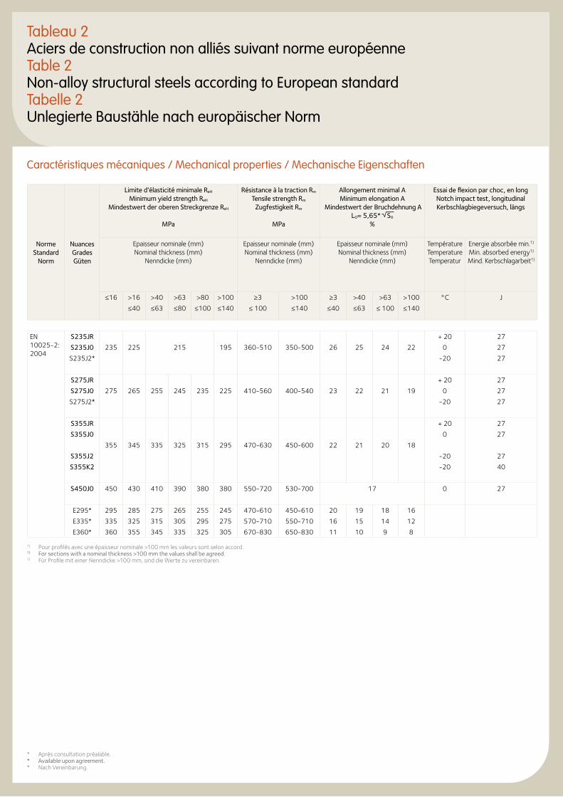
1) Pour profilés avec une épaisseur nominale >100 mm les valeurs sont selon accord.1) For sections with a nominal thickness >100 mm the values shall be agreed.1) Für Profile mit einer Nenndicke >100 mm, sind die Werte zu vereinbaren.
Tableau 2Aciers de construction non alliés suivant norme européenne Table 2Non-alloy structural steels according to European standardTabelle 2Unlegierte Baustähle nach europäischer Norm
Caractéristiques mécaniques / Mechanical properties / Mechanische Eigenschaften
Norme Standard
Norm
Nuances Grades Güten
Limite d’élasticité minimale ReH Minimum yield strength ReH
Mindestwert der oberen Streckgrenze ReH
MPa
Résistance à la traction Rm Tensile strength Rm
Zugfestigkeit Rm
MPa
Allongement minimal A Minimum elongation A
Mindestwert der Bruchdehnung A L0= 5,65* S0
%
Essai de flexion par choc, en long Notch impact test, longitudinal Kerbschlagbiegeversuch, längs
Epaisseur nominale (mm) Nominal thickness (mm)
Nenndicke (mm)
Epaisseur nominale (mm) Nominal thickness (mm)
Nenndicke (mm)
Epaisseur nominale (mm) Nominal thickness (mm)
Nenndicke (mm)
Température Temperature Temperatur
Energie absorbée min.1) Min. absorbed energy1) Mind. Kerbschlagarbeit1)
≤16 >16 >40 >63 >80 >100 ≥3 >100 ≥3 >40 >63 >100 °C J
≤40 ≤63 ≤80 ≤100 ≤140 ≤ 100 ≤140 ≤40 ≤63 ≤ 100 ≤140
EN 10025-2: 2004
S235JR + 20 27
S235J0 235 225 215 195 360-510 350-500 26 25 24 22 0 27
S235J2* -20 27
S275JR + 20 27
S275J0 275 265 255 245 235 225 410-560 400-540 23 22 21 19 0 27
S275J2* -20 27
S355JR + 20 27
S355J0 0 27
355 345 335 325 315 295 470-630 450-600 22 21 20 18
S355J2 -20 27
S355K2 -20 40
S450J0 450 430 410 390 380 380 550-720 530-700 17 0 27
E295* 295 285 275 265 255 245 470-610 450-610 20 19 18 16
E335* 335 325 315 305 295 275 570-710 550-710 16 15 14 12
E360* 360 355 345 335 325 305 670-830 650-830 11 10 9 8
* Après consultation préalable.* Available upon agreement.* Nach Vereinbarung.
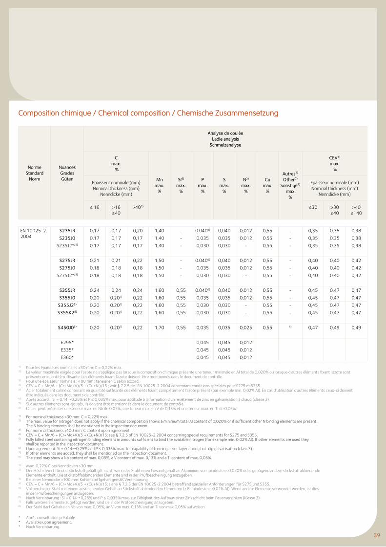
39
Composition chimique / Chemical composition / Chemische Zusammensetzung
Norme Standard
Norm
Nuances Grades Güten
Analyse de couléeLadle analysis
Schmelzanalyse
Cmax.
%
Mn max.
%
Si6) max.
%
P max.
%
S max.
%
N2) max.
%
Cu max.
%
Autres7) Other7)
Sonstige7) max.
%
CEV4)
max. %
Epaisseur nominale (mm) Nominal thickness (mm)
Nenndicke (mm)
Epaisseur nominale (mm) Nominal thickness (mm)
Nenndicke (mm)
≤ 16 >16≤40
>403) ≤30 >30≤40
>40≤140
EN 10025-2: 2004
S235JR 0,17 0,17 0,20 1,40 - 0.0406) 0,040 0,012 0,55 - 0,35 0,35 0,38
S235J0 0,17 0,17 0,17 1,40 - 0,035 0,035 0,012 0,55 - 0,35 0,35 0,38
S235J2*/5) 0,17 0,17 0,17 1,40 - 0,030 0,030 - 0,55 - 0,35 0,35 0,38
S275JR 0,21 0,21 0,22 1,50 - 0.0406) 0,040 0,012 0,55 - 0,40 0,40 0,42
S275J0 0,18 0,18 0,18 1,50 - 0,035 0,035 0,012 0,55 - 0,40 0,40 0,42
S275J2*/5) 0,18 0,18 0,18 1,50 - 0,030 0,030 - 0,55 - 0,40 0,40 0,42
S355JR 0,24 0,24 0,24 1,60 0,55 0.0406) 0,040 0,012 0,55 - 0,45 0,47 0,47
S355J0 0,20 0.201) 0,22 1,60 0,55 0,035 0,035 0,012 0,55 - 0,45 0,47 0,47
S355J25) 0,20 0.201) 0,22 1,60 0,55 0,030 0,030 - 0,55 - 0,45 0,47 0,47
S355K25) 0,20 0.201) 0,22 1,60 0,55 0,030 0,030 - 0,55 - 0,45 0,47 0,47
S450J05) 0,20 0.201) 0,22 1,70 0,55 0,035 0,035 0,025 0,55 8) 0,47 0,49 0,49
E295* 0,045 0,045 0,012
E335* 0,045 0,045 0,012
E360* 0,045 0,045 0,012
1) Pour les épaisseurs nominales >30 mm: C = 0,22% max.2) La valeur maximale exigée pour l’azote ne s’applique pas lorsque la composition chimique présente une teneur minimale en Al total de 0,020% ou lorsque d’autres éléments fixant l’azote sont
présents en quantité suffisante. Les éléments fixant l’azote doivent être mentionnés dans le document de contrôle.3) Pour une épaisseur nominale >100 mm : teneur en C selon accord.4) CEV = C + Mn/6 + (Cr+Mo+V)/5 + (Cu+Ni)/15 ; voir § 7.2.5 de l’EN 10025-2:2004 concernant conditions spéciales pour S275 et S355.5) Acier totalement calmé contenant en quantité suffisante des éléments fixant complètement l’azote présent (par exemple min. 0,02% Al). En cas d’utilisation d’autres éléments ceux-ci doivent
être indiqués dans les documents de contrôle.6) Après accord : Si = 0,14¦0,25% et P ≤ 0,035% max. pour aptitude à la formation d’un revêtement de zinc en galvanisation à chaud (classe 3).7) Si d’autres éléments sont ajoutés, ils doivent être mentionnés dans le document de contrôle. 8) L’acier peut présenter une teneur max. en Nb de 0,05%, une teneur max. en V de 0,13% et une teneur max. en Ti de 0,05%.
1) For nominal thickness >30 mm: C = 0,22% max.2) The max. value for nitrogen does not apply if the chemical composition shows a minimum total AI content of 0,020% or if sufficient other N binding elements are present.
The N binding elements shall be mentioned in the inspection document.3) For nominal thickness >100 mm: C content upon agreement.4) CEV = C + Mn/6 + (Cr+Mo+V)/5 + (Cu+Ni)/15; see § 7.2.5 of EN 10025-2:2004 concerning special requirements for S275 and S355.5) Fully killed steel containing nitrogen binding element in amounts sufficient to bind the available nitrogen (for example min. 0,02% AI). If other elements are used they
shall be reported in the inspection document.6) Upon agreement: Si = 0,14¦0,25% and P ≤ 0,035% max. for capability of forming a zinc layer during hot-dip galvanisation (class 3).7) If other elements are added, they shall be mentioned on the inspection document. 8) The steel may show a Nb content of max. 0,05%, a V content of max. 0,13% and a Ti content of max. 0,05%.
1) Max. 0,22% C bei Nenndicken >30 mm.2) Der Höchstwert für den Stickstoffgehalt gilt nicht, wenn der Stahl einen Gesamtgehalt an Aluminium von mindestens 0,020% oder genügend andere stickstoffabbindende
Elemente enthält. Die stickstoffabbindenden Elemente sind in der Prüfbescheinigung anzugeben.3) Bei einer Nenndicke >100 mm: Kohlenstoffgehalt gemäß Vereinbarung.4) CEV = C + Mn/6 + (Cr+Mo+V)/5 + (Cu+Ni)/15; siehe § 7.2.5 der EN 10025-2:2004 betreffend spezieller Anforderungen für S275 und S355.5) Vollberuhigter Stahl mit einem ausreichenden Gehalt an Stickstoff abbindenden Elementen (z.B. mindestens 0,02% AI). Wenn andere Elemente verwendet werden, ist dies
in den Prüfbeschenigungen anzugeben.6) Nach Vereinbarung : Si = 0,14¦0,25% und P ≤ 0,035% max. zur Fähigkeit des Aufbaus einer Zinkschicht beim Feuerverzinken (Klasse 3).7) Falls weitere Elemente zugefügt werden, sind sie in der Prüfbescheinigung anzugeben. 8) Der Stahl darf Gehalte an Nb von max. 0,05%, an V von max. 0,13% und an Ti von max 0,05% aufweisen
* Après consultation préalable.* Available upon agreement.* Nach Vereinbarung.
Norme Standard
Norm
Nuances Grades Güten
Limite d’élasticité minimale ReH Minimum yield strength ReH
Mindestwert der oberen Streckgrenze ReH
MPa
Résistance à la traction Rm Tensile strength Rm
Zugfestigkeit Rm
MPa
Allongement minimal A Minimum elongation A
Mindestwert der Bruchdehnung A L0= 5,65* S0
%
Essai de flexion par choc, en long Notch impact test, longitudinal Kerbschlagbiegeversuch, längs
Epaisseur nominale (mm) Nominal thickness (mm)
Nenndicke (mm)
Epaisseur nominale (mm) Nominal thickness (mm)
Nenndicke (mm)
Epaisseur nominale (mm) Nominal thickness (mm)
Nenndicke (mm)
Température Temperature Temperatur
Energie absorbée min.1) Min. absorbed energy1) Mind. Kerbschlagarbeit1)
≤16 >16 >40 >63 >80 >100 ≥3 >100 ≥3 >40 >63 >100 °C J
≤40 ≤63 ≤80 ≤100 ≤140 ≤ 100 ≤140 ≤40 ≤63 ≤ 100 ≤140
EN 10025-2: 2004
S235JR + 20 27
S235J0 235 225 215 195 360-510 350-500 26 25 24 22 0 27
S235J2* -20 27
S275JR + 20 27
S275J0 275 265 255 245 235 225 410-560 400-540 23 22 21 19 0 27
S275J2* -20 27
S355JR + 20 27
S355J0 0 27
355 345 335 325 315 295 470-630 450-600 22 21 20 18
S355J2 -20 27
S355K2 -20 40
S450J0 450 430 410 390 380 380 550-720 530-700 17 0 27
E295* 295 285 275 265 255 245 470-610 450-610 20 19 18 16
E335* 335 325 315 305 295 275 570-710 550-710 16 15 14 12
E360* 360 355 345 335 325 305 670-830 650-830 11 10 9 8
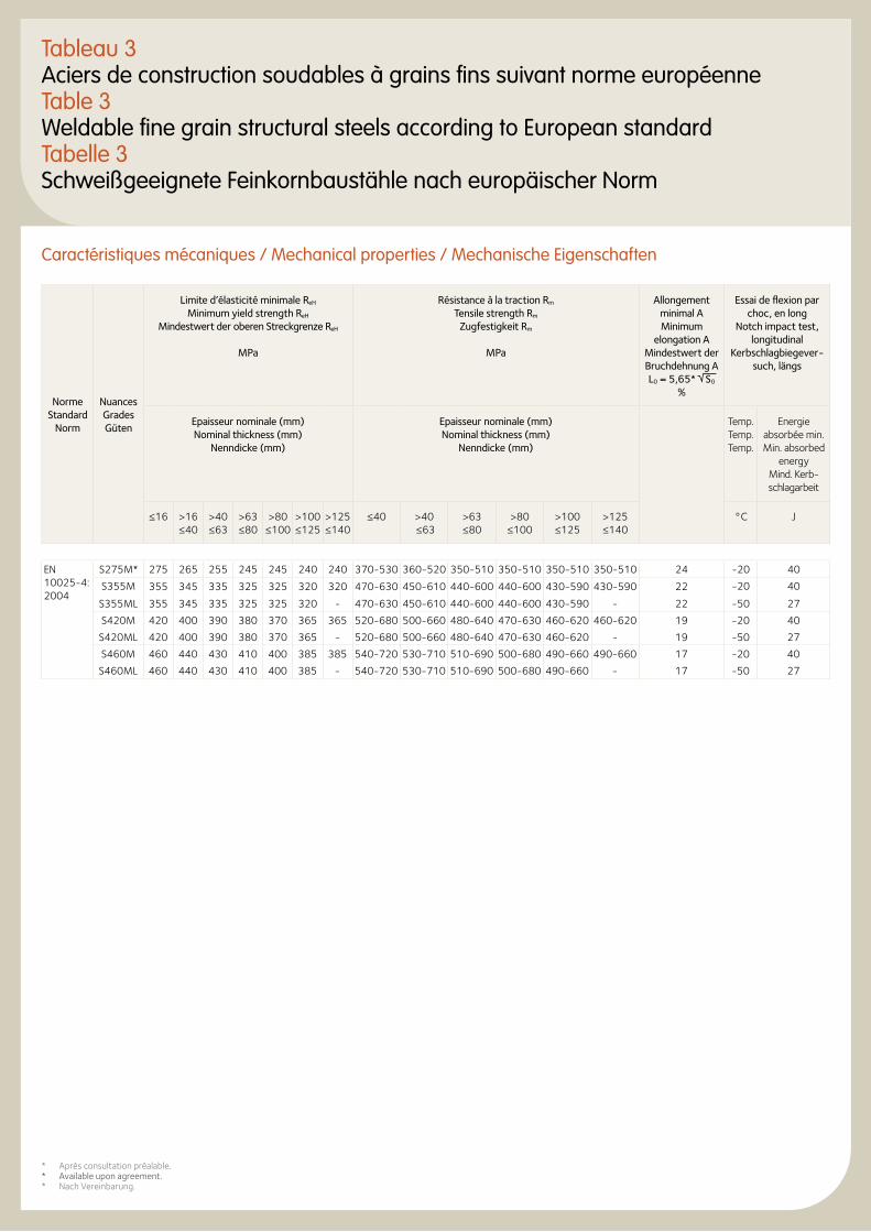
4141
Tableau 3Aciers de construction soudables à grains fins suivant norme européenneTable 3Weldable fine grain structural steels according to European standard Tabelle 3Schweißgeeignete Feinkornbaustähle nach europäischer Norm
Caractéristiques mécaniques / Mechanical properties / Mechanische Eigenschaften
Norme Standard
Norm
Nuances Grades Güten
Limite d’élasticité minimale ReH Minimum yield strength ReH
Mindestwert der oberen Streckgrenze ReH
MPa
Résistance à la traction Rm Tensile strength Rm
Zugfestigkeit Rm
MPa
Allongement minimal A Minimum
elongation A Mindestwert der Bruchdehnung A L0 = 5,65* S0
%
Essai de flexion par choc, en long
Notch impact test, longitudinal
Kerbschlagbiegever-such, längs
Epaisseur nominale (mm) Nominal thickness (mm)
Nenndicke (mm)
Epaisseur nominale (mm) Nominal thickness (mm)
Nenndicke (mm)
Temp. Temp. Temp.
Energie absorbée min. Min. absorbed
energy Mind. Kerb-schlagarbeit
≤16 >16 ≤40
>40 ≤63
>63 ≤80
>80 ≤100
>100 ≤125
>125 ≤140
≤40 >40 ≤63
>63 ≤80
>80 ≤100
>100 ≤125
>125 ≤140
°C J
EN 10025-4: 2004
S275M* 275 265 255 245 245 240 240 370-530 360-520 350-510 350-510 350-510 350-510 24 -20 40
S355M 355 345 335 325 325 320 320 470-630 450-610 440-600 440-600 430-590 430-590 22 -20 40
S355ML 355 345 335 325 325 320 - 470-630 450-610 440-600 440-600 430-590 - 22 -50 27
S420M 420 400 390 380 370 365 365 520-680 500-660 480-640 470-630 460-620 460-620 19 -20 40
S420ML 420 400 390 380 370 365 - 520-680 500-660 480-640 470-630 460-620 - 19 -50 27
S460M 460 440 430 410 400 385 385 540-720 530-710 510-690 500-680 490-660 490-660 17 -20 40
S460ML 460 440 430 410 400 385 - 540-720 530-710 510-690 500-680 490-660 - 17 -50 27
* Après consultation préalable.* Available upon agreement.* Nach Vereinbarung.
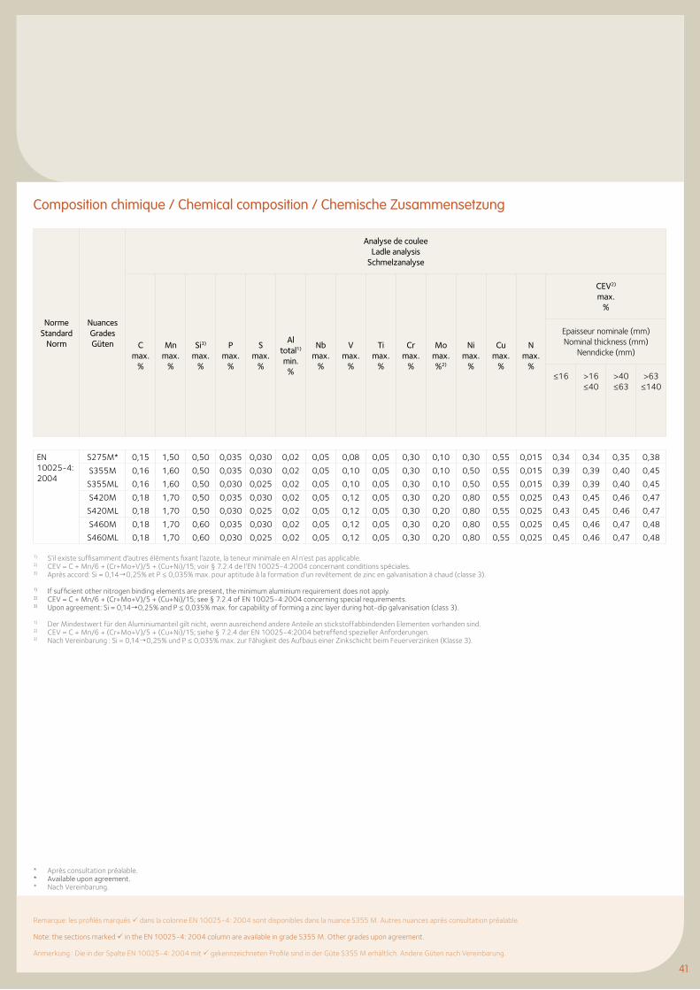
4141
Composition chimique / Chemical composition / Chemische Zusammensetzung
Norme Standard
Norm
Nuances Grades Güten
Analyse de coulee Ladle analysis
Schmelzanalyse
C max.
%
Mn max.
%
Si3) max.
%
P max.
%
S max.
%
Al total1) min.
%
Nb max.
%
V max.
%
Ti max.
%
Cr max.
%
Mo max. %2)
Ni max.
%
Cu max.
%
N max.
%
CEV2) max.
%
Epaisseur nominale (mm) Nominal thickness (mm)
Nenndicke (mm)
≤16 >16 ≤40
>40 ≤63
>63 ≤140
EN 10025-4: 2004
S275M* 0,15 1,50 0,50 0,035 0,030 0,02 0,05 0,08 0,05 0,30 0,10 0,30 0,55 0,015 0,34 0,34 0,35 0,38
S355M
S355ML
0,16
0,16
1,60
1,60
0,50
0,50
0,035
0,030
0,030
0,025
0,02
0,02
0,05
0,05
0,10
0,10
0,05
0,05
0,30
0,30
0,10
0,10
0,50
0,50
0,55
0,55
0,015
0,015
0,39
0,39
0,39
0,39
0,40
0,40
0,45
0,45
S420M
S420ML
0,18
0,18
1,70
1,70
0,50
0,50
0,035
0,030
0,030
0,025
0,02
0,02
0,05
0,05
0,12
0,12
0,05
0,05
0,30
0,30
0,20
0,20
0,80
0,80
0,55
0,55
0,025
0,025
0,43
0,43
0,45
0,45
0,46
0,46
0,47
0,47
S460M
S460ML
0,18
0,18
1,70
1,70
0,60
0,60
0,035
0,030
0,030
0,025
0,02
0,02
0,05
0,05
0,12
0,12
0,05
0,05
0,30
0,30
0,20
0,20
0,80
0,80
0,55
0,55
0,025
0,025
0,45
0,45
0,46
0,46
0,47
0,47
0,48
0,48
Remarque: les profilés marqués dans la colonne EN 10025-4: 2004 sont disponibles dans la nuance S355 M. Autres nuances après consultation préalable.
Note: the sections marked in the EN 10025-4: 2004 column are available in grade S355 M. Other grades upon agreement.
Anmerkung : Die in der Spalte EN 10025-4: 2004 mit gekennzeichneten Profile sind in der Güte S355 M erhältlich. Andere Güten nach Vereinbarung.
1) S’il existe suffisamment d'autres éléments fixant l’azote, la teneur minimale en Al n’est pas applicable.2) CEV = C + Mn/6 + (Cr+Mo+V)/5 + (Cu+Ni)/15; voir § 7.2.4 de l’EN 10025-4:2004 concernant conditions spéciales.3) Après accord: Si = 0,14¦0,25% et P ≤ 0,035% max. pour aptitude à la formation d’un revêtement de zinc en galvanisation à chaud (classe 3).
1) If sufficient other nitrogen binding elements are present, the minimum aluminium requirement does not apply.2) CEV = C + Mn/6 + (Cr+Mo+V)/5 + (Cu+Ni)/15; see § 7.2.4 of EN 10025-4:2004 concerning special requirements.3) Upon agreement: Si = 0,14¦0,25% and P ≤ 0,035% max. for capability of forming a zinc layer during hot-dip galvanisation (class 3).
1) Der Mindestwert für den Aluminiumanteil gilt nicht, wenn ausreichend andere Anteile an stickstoffabbindenden Elementen vorhanden sind.2) CEV = C + Mn/6 + (Cr+Mo+V)/5 + (Cu+Ni)/15; siehe § 7.2.4 der EN 10025-4:2004 betreffend spezieller Anforderungen.3) Nach Vereinbarung : Si = 0,14¦0,25% und P ≤ 0,035% max. zur Fähigkeit des Aufbaus einer Zinkschicht beim Feuerverzinken (Klasse 3).
* Après consultation préalable.* Available upon agreement.* Nach Vereinbarung.
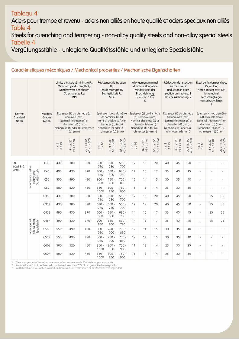
Tableau 4Aciers pour trempe et revenu - aciers non alliés en haute qualité et aciers speciaux non alliésTable 4Steels for quenching and tempering - non-alloy quality steels and non-alloy special steels Tabelle 4Vergütungsstähle - unlegierte Qualitätsstähle und unlegierte Spezialstähle
Norme Standard
Norm
Nuances Grades Güten
Limite d’élasticité minimale ReH Minimum yield strength ReH
Mindestwert der oberen Streckgrenze ReH
MPa
Résistance à la traction Rm
Tensile strength Rm Zugfestigkeit Rm
MPa
Allongement minimal Minimum elongation
Mindestwert der Bruchdehnung L0 = 5,65* S0
%
Réduction de la section en fracture, Z
Reduction in cross section on fracture, Z Brucheinschnürung. Z
Essai de flexion par choc, KV, en long
Notch impact test, KV, longitudinal
Kerbschlagbiege-versuch, KV, längs
J
Epaisseur (t) ou diamètre (d) nominale (mm)
Nominal thickness (t) or diameter (d) (mm)
Nenndicke (t) oder Durchmesser (d) (mm)
Epaisseur (t) ou diamètre (d) nominale (mm)
Nominal thickness (t) or diameter (d) (mm)
Nenndicke (t) oder Du-rchmesser (d) (mm)
Epaisseur (t) ou diamètre (d) nominale (mm)
Nominal thickness (t) or diameter (d) (mm)
Nenndicke (t) oder Du-rchmesser (d) (mm)
Epaisseur (t) ou diamètre (d) nominale (mm)
Nominal thickness (t) or diameter (d) (mm)
Nenndicke (t) oder Du-rchmesser (d) (mm)
Epaisseur (t) ou diamètre (d) nominale (mm)
Nominal thickness (t) or diameter (d) (mm)
Nenndicke (t) oder Du-rchmesser (d) (mm)
t ≤ 8
d
≤ 16
8 <
t ≤
20
16 <
d ≤
40
20 <
t ≤
60
40 <
d ≤
100
t ≤ 8
d
≤ 16
8 <
t ≤ 2
0
16 <
d ≤
40
20 <
t ≤
60
40
< d
≤ 1
00
t ≤ 8
d
≤ 16
8 <
t ≤
2016
< d
≤ 4
0
20 <
t ≤
60
40
< d
≤ 1
00
t ≤ 8
d
≤ 16
8 <
t ≤
20
16 <
d ≤
40
20 <
t ≤
60
40
< d
≤ 1
00
t ≤ 8
d
≤ 16
8 <
t ≤
20
16 <
d ≤
40
20 <
t ≤
60
40
< d
≤ 1
00
EN 10083-2: 2006
acie
r hau
te q
ualit
é qu
ality
ste
el
Qua
lität
ssta
hl
C35 430 380 320 630 - 780
600 - 750
550 - 700
17 19 20 40 45 50 - - -
C45 490 430 370 700 - 850
650 - 800
630 - 780
14 16 17 35 40 45 - - -
C55 550 490 420 800 - 950
750 - 900
700 - 850
12 14 15 30 35 40 - - -
C60 580 520 450 850 - 1000
800 - 950
750 - 900
11 13 14 25 30 35 - - -
acie
r spé
cial
sp
ecia
l ste
el
Spez
ials
tahl
C35E 430 380 320 630 - 780
600 - 750
550 - 700
17 19 20 40 45 50 - 35 35
C35R 430 380 320 630 - 780
600 - 750
550 - 700
17 19 20 40 45 50 - 35 35
C45E 490 430 370 700 - 850
650 - 800
630 - 780
14 16 17 35 40 45 - 25 25
C45R 490 430 370 700 - 850
650 - 800
630 - 780
14 16 17 35 40 45 - 25 25
C55E 550 490 420 800 - 950
750 - 900
700 - 850
12 14 15 30 35 40 - - -
C55R 550 490 420 800 - 950
750 - 900
700 - 850
12 14 15 30 35 40 - - -
C60E 580 520 450 850 - 1000
800 - 950
750 - 900
11 13 14 25 30 35 - - -
C60R 580 520 450 850 - 1000
800 - 950
750 - 900
11 13 14 25 30 35 - - -
1) Valeur moyenne de 3 essais sans aucune valeur en dessous de 70% de la moyenne garantie.1) Mean value of 3 tests with no individual value lower than 70% of the guaranteed average value.1) Mittelwert aus 3 Versuchen, wobei kein Einzelwert unterhalb von 70% des Mittelwertes liegen darf.
Caractéristiques mécaniques / Mechanical properties / Mechanische Eigenschaften
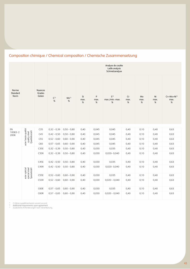
43
Norme Standard
Norm
Nuances Grades Güten
Analyse de coulée Ladle analysis
Schmelzanalyse
C1) %
Mn1) %
Si max.
%
P max.
%
S1) max./min.-max.
%
Cr max.
%
Mo max.
%
Ni max.
%
Cr+Mo+Ni1) max.
%
EN 10083-2: 2006
acie
r hau
te q
ualit
é qu
ality
ste
el
Qua
lität
ssta
hl
C35 0,32 - 0,39 0,50 - 0,80 0,40 0,045 0,045 0,40 0,10 0,40 0,63
C45 0,42 - 0,50 0,50 - 0,80 0,40 0,045 0,045 0,40 0,10 0,40 0,63
C55 0,52 - 0,60 0,60 - 0,90 0,40 0,045 0,045 0,40 0,10 0,40 0,63
C60 0,57 - 0,65 0,60 - 0,90 0,40 0,045 0,045 0,40 0,10 0,40 0,63
acie
r spé
cial
sp
ecia
l ste
el
Spez
ials
tahl
C35E 0,32 - 0,39 0,50 - 0,80 0,40 0,030 0,035 0,40 0,10 0,40 0,63
C35R 0,32 - 0,39 0,50 - 0,80 0,40 0,030 0,020- 0,040 0,40 0,10 0,40 0,63
C45E 0,42 - 0,50 0,50 - 0,80 0,40 0,030 0,035 0,40 0,10 0,40 0,63
C45R 0,42 - 0,50 0,50 - 0,80 0,40 0,030 0,020- 0,040 0,40 0,10 0,40 0,63
C55E 0,52 - 0,60 0,60 - 0,90 0,40 0,030 0,035 0,40 0,10 0,40 0,63
C55R 0,52 - 0,60 0,60 - 0,90 0,40 0,030 0,020 - 0,040 0,40 0,10 0,40 0,63
C60E 0,57 - 0,65 0,60 - 0,90 0,40 0,030 0,035 0,40 0,10 0,40 0,63
C60R 0,57 - 0,65 0,60 - 0,90 0,40 0,030 0,020 - 0,040 0,40 0,10 0,40 0,63
Composition chimique / Chemical composition / Chemische Zusammensetzung
1) Critères supplémentaires suivant accord.1) Additional requirements upon agreement.1) Zusätzliche Anforderungen nach Vereinbarung.
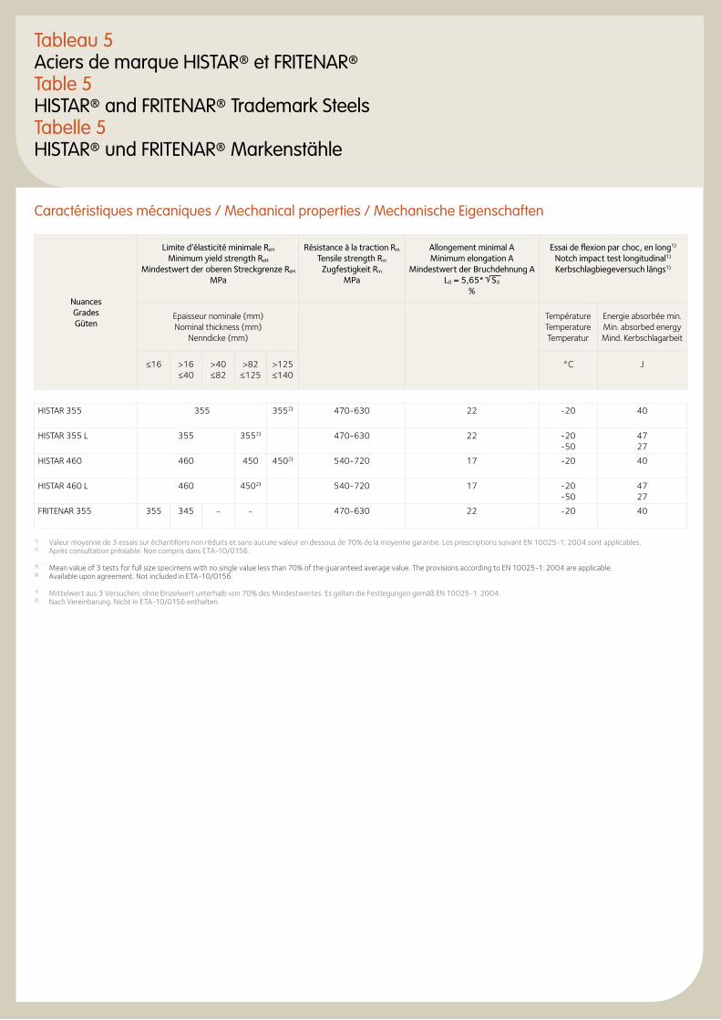
Tableau 5Aciers de marque HISTAR® et FRITENAR®Table 5HISTAR® and FRITENAR® Trademark SteelsTabelle 5HISTAR® und FRITENAR® Markenstähle
Caractéristiques mécaniques / Mechanical properties / Mechanische Eigenschaften
Nuances Grades Güten
Limite d’élasticité minimale ReH Minimum yield strength ReH
Mindestwert der oberen Streckgrenze ReH MPa
Résistance à la traction Rm Tensile strength Rm
Zugfestigkeit Rm MPa
Allongement minimal A Minimum elongation A
Mindestwert der Bruchdehnung A L0 = 5,65* S0
%
Essai de flexion par choc, en long1) Notch impact test longitudinal1) Kerbschlagbiegeversuch längs1)
Epaisseur nominale (mm) Nominal thickness (mm)
Nenndicke (mm)
Température Temperature Temperatur
Energie absorbée min. Min. absorbed energy Mind. Kerbschlagarbeit
≤16 >16 ≤40
>40 ≤82
>82 ≤125
>125 ≤140
°C J
HISTAR 355 355 3552) 470-630 22 -20 40
HISTAR 355 L 355 3552) 470-630 22 -20 -50
47 27
HISTAR 460 460 450 4502) 540-720 17 -20 40
HISTAR 460 L 460 4502) 540-720 17 -20 -50
47 27
FRITENAR 355 355 345 - - 470-630 22 -20 40
1) Valeur moyenne de 3 essais sur échantillons non réduits et sans aucune valeur en dessous de 70% de la moyenne garantie. Les prescriptions suivant EN 10025-1: 2004 sont applicables.2) Après consultation préalable. Non compris dans ETA-10/0156.
1) Mean value of 3 tests for full size specimens with no single value less than 70% of the guaranteed average value. The provisions according to EN 10025-1: 2004 are applicable.2) Available upon agreement. Not included in ETA-10/0156.
1) Mittelwert aus 3 Versuchen, ohne Einzelwert unterhalb von 70% des Mindestwertes. Es gelten die Festlegungen gemäß EN 10025-1: 2004.2) Nach Vereinbarung. Nicht in ETA-10/0156 enthalten.
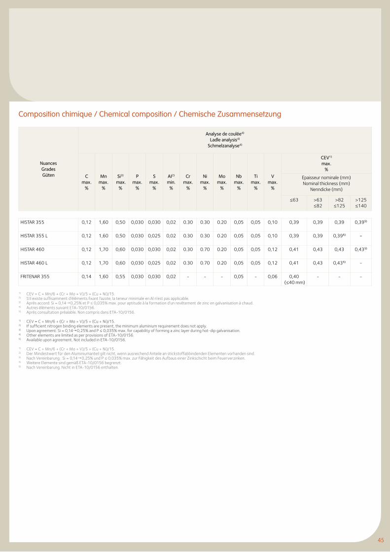
45
Composition chimique / Chemical composition / Chemische Zusammensetzung
Nuances Grades Güten
Analyse de coulée4)
Ladle analysis4) Schmelzanalyse4)
C max.
%
Mn max.
%
Si3) max.
%
P max.
%
S max.
%
AI2) min.
%
Crmax.
%
Nimax.
%
Momax.
%
Nb max.
%
Timax.
%
V max.
%
CEV1) max.
%
Epaisseur nominale (mm) Nominal thickness (mm)
Nenndicke (mm)
≤63 >63 ≤82
>82 ≤125
>125 ≤140
HISTAR 355 0,12 1,60 0,50 0,030 0,030 0,02 0.30 0.30 0.20 0,05 0,05 0,10 0,39 0,39 0,39 0,395)
HISTAR 355 L 0,12 1,60 0,50 0,030 0,025 0,02 0.30 0.30 0.20 0,05 0,05 0,10 0,39 0,39 0,395) -
HISTAR 460 0,12 1,70 0,60 0,030 0,030 0,02 0.30 0.70 0.20 0,05 0,05 0,12 0,41 0,43 0,43 0,435)
HISTAR 460 L 0,12 1,70 0,60 0,030 0,025 0,02 0.30 0.70 0.20 0,05 0,05 0,12 0,41 0,43 0,435) -
FRITENAR 355 0,14 1,60 0,55 0,030 0,030 0,02 - - - 0,05 - 0,06 0,40 (≤40 mm)
- - -
1) CEV = C + Mn/6 + (Cr + Mo + V)/5 + (Cu + Ni)/15.2) S’il existe suffisamment d’éléments fixant l’azote, la teneur minimale en Al n’est pas applicable.3) Après accord: Si = 0,14¦0,25% et P ≤ 0,035% max. pour aptitude à la formation d’un revêtement de zinc en galvanisation à chaud.4) Autres éléments suivant ETA-10/0156.5) Après consultation préalable. Non compris dans ETA-10/0156.
1) CEV = C + Mn/6 + (Cr + Mo + V)/5 + (Cu + Ni)/15.2) If sufficient nitrogen binding elements are present, the minimum aluminium requirement does not apply.3) Upon agreement: Si = 0,14¦0,25% and P ≤ 0,035% max. for capability of forming a zinc layer during hot-dip galvanisation.4) Other elements are limited as per provisions of ETA-10/0156.5) Available upon agreement. Not included in ETA-10/0156.
1) CEV = C + Mn/6 + (Cr + Mo + V)/5 + (Cu + Ni)/15.2) Der Mindestwert für den Aluminiumanteil gilt nicht, wenn ausreichend Anteile an stickstoffabbindenden Elementen vorhanden sind.3) Nach Vereinbarung : Si = 0,14¦0,25% und P ≤ 0,035% max. zur Fähigkeit des Aufbaus einer Zinkschicht beim Feuerverzinken.4) Weitere Elemente sind gemäß ETA-10/0156 begrenzt.5) Nach Vereinbarung. Nicht in ETA-10/0156 enthalten.
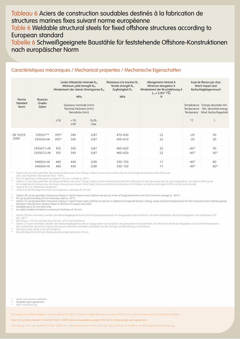
47
Tableau 6 Aciers de construction soudables destinés à la fabrication de structures marines fixes suivant norme européenne Table 6 Weldable structural steels for fixed offshore structures according to European standard Tabelle 6 Schweißgeeignete Baustähle für feststehende Offshore-Konstruktionen nach europäischer Norm
Caractéristiques mécaniques / Mechanical properties / Mechanische Eigenschaften
Norme Standard
Norm
Nuances Grades Güten
Limite d’élasticité minimale ReH Minimum yield strength ReH
Mindestwert der oberen Streckgrenze ReH
MPa
Résistance à la traction Rm Tensile strength Rm
Zugfestigkeit Rm
MPa
Allongement minimal A Minimum elongation A
Mindestwert der Bruchdehnung A L0 = 5,65* S0
%
Essai de flexion par choc Notch impact test
Kerbschlagbiegeversuch
Epaisseur nominale (mm) Nominal thickness (mm)
Nenndicke (mm)
Température Temperature Temperatur
Energie absorbée min. Min. absorbed energy Mind. Kerbschlagarbeit
≤16 >16 ≤40
Re/Rm max.
°C J
EN 10225: 2009
S355G15)*
S355G4+M
3554)
3554)
345
345
0,87
0,87
470-630
450-610
22
22
-20
-20
50
50
S355G11+M
S355G12+M
355
355
345
345
0,87
0,87
460-620
460-620
22
22
-402)
-402)
50
501)
S460G3+M
S460G4+M
460
460
440
440
0,90
0,90
530-720
530-720
17
17
-402)
-402)
60
603)
1) Option 26 peut être spécifiée: des essais de flexion par choc Charpy V dans le sens transversal au lieu du sens longitudinal doivent être effectués avec une moyenne minimale de 50J à -40°C.
2) Pour les épaisseurs inférieures ou égales à 25 mm: contrôle à -20°C.3) Option 27 peut être spécifiée: des essais de flexion par choc Charpy V dans le sens transversal doivent être effectués en plus des essais dans le sens longitudinal. Les valeurs d’énergie et
les températures d’essais pour les essais transversaux doivent faire l’objet d’un accord entre le producteur et l’acheteur au moment de l’appel d’offres et de la commande.4) Jusqu’à 25 mm d’épaisseur seulement.5) L'état brut de laminage est limité à une épaisseur maximale de 25 mm.
1) Option 26 can be specified: transverse Charpy V-notch impacts tests shall be carried out in lieu of longitudinal tests with 50J minimum average at -40°C.2) For up to and including 25 mm thickness, test at -20°C.3) Option 27 can be specified: transverse Charpy V-notch impact tests shall be carried out in addition to longitudinal tests. Energy values and test temperatures for the transverse tests shall be agreed
between manufacturer and purchaser at the time of enquiry and order.4) Available up to 25 mm thick only.5) As rolled condition limited to a maximum thickness of 25 mm.
1) Option 26 kann vereinbart werden: die Kerbschlagbiegeversuche sind an Querproben anstatt an Längsproben durchzuführen, mit einem Mittelwert der Kerbschlagarbeit von mindestens 50J bei -40°C.
2) Bei Dicken ≤ 25 mm sind die Versuche bei -20°C durchzuführen.3) Option 27 kann vereinbart werden: die Kerbschlagbiegeversuche an Längsproben sind zusätzlich an Querproben durchzuführen. Die Werte für die Kerbschlagarbeit und die Prüftemperaturen
der zusätzlichen Versuche in Querrichtung sind zwischen Hersteller und Käufer bei der Anfrage und Bestellung zu vereinbaren.4) Nur bis zu einer Dicke ≤ 25 mm erhältlich.5) Die lieferbare Dicke für den Walzzustand beträgt höchstens 25 mm.
Remarque: les profilés marqués dans la colonne EN 10225: 2009 sont disponibles dans la nuance S355 G4+M. Autres nuances après consultation préalable.
Note: the sections marked in the EN 10225: 2009 column are available in grade S355 G4+M. Other grades upon agreement.
Anmerkung : Die in der Spalte EN 10225: 2009 mit gekennzeichneten Profile sind in der Güte S355 G4+M erhältlich. Andere Güten nach Vereinbarung.
* Après consultation préalable.* Available upon agreement.* Nach Vereinbarung.
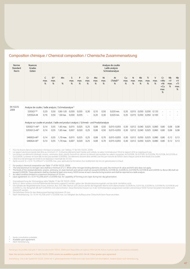
4747
Norme Standard
Norm
Nuances Grades Güten
Analyse de coulée Ladle analysis
Schmelzanalyse
C max.
%
Si5) max.
%
Mn
%
S max.
%
P max.
%
Cr max.
%
Mo max.
%
Ni max.
%
AI (Total)2)
%
Cu max.
%
N max.
%
Nb max.
%
Ti max.
%
V max.
%
Cr+Mo +Ni+Cu max.
%
Nb+V
max. %
Nb+V +Ti
max. %
EN 10225:2009
Analyse de coulée / ladle analysis / Schmelzanalyse1)
S355G14)*
S355G4+M
0,20
0,16
0,50
0,50
0,90-1,65
1,60 max.
0,030
0,030
0,035
0,035
0,30
-
0,10
0,20
0,50
0,30
0,020 min.
0,020 min.
0,35
0,35
0,015
0,015
0,050
0,050
0,030
0,050
0,120
0,100
-
-
-
-
-
-
Analyse sur coulée et produit / ladle and product analysis / Schmelz- und Produktanalyse
S355G11+M3)
S355G12+M3)
0,14
0,14
0,55
0,55
1,65 max.
1,65 max.
0,015
0,007
0,025
0,020
0,25
0,25
0,08
0,08
0,50
0,50
0,015-0,055
0,015-0,055
0,30
0,30
0,012
0,012
0,040
0,040
0,025
0,025
0,060
0,060
0,80
0,80
0,06
0,06
0,08
0,08
S460G3+M3)
S460G4+M3)
0,14
0,14
0,55
0,55
1,70 max.
1,70 max.
0,015
0,007
0,025
0,020
0,25
0,25
0,08
0,08
0,70
0,70
0,015-0,055
0,015-0,055
0,30
0,30
0,012
0,012
0,050
0,050
0,025
0,025
0,080
0,080
0,80
0,80
0,12
0,12
0,13
0,13
1) Pour les écarts dans la composition chimique sur produit, voir Tableau 17 de l’EN 10225: 2009.2) Le rapport aluminium/azote doit être au minimum 2:1. Si d’autres éléments liant l’azote sont utilisés, la valeur minimale pour l’Al et le rapport AI:N ne s’appliquent pas.3) Les teneurs en éléments résiduels: arsenic, antimoine, étain, plomb, bismuth et calcium ne doivent pas excéder les valeurs suivantes: As 0,030%, Sb 0,010%, Sn 0,020%, Pb 0,010%, Bi 0,010% et
Ca 0,005%. La teneur en bore (B) ne doit pas excéder 0,0005%. Ces éléments doivent être vérifiés une fois par tranche de 5000 t dans chaque usine et être dosés à la coulée.4) L’état brut de laminage est limité à une épaisseur maximale de 25 mm.5) Après accord: Si = 0,14¦0,25% et P ≤ 0,035% max. pour aptitude à la formation d’un revêtement de zinc en galvanisation à chaud.
1) For product chemical composition see Table 17 of EN 10225: 2009.2) The total aluminium to nitrogen ratio shall be a minimum of 2:1. When other nitrogen binding elements are used, the minimum AI value and AI:N ratio does not apply.3) The levels of the residual elements: arsenic, antimony, tin, lead, bismuth and calcium shall not exceed 0,030% As, 0,010% Sb, 0,020% Sn, 0,010% Pb, 0,010% Bi and 0,005% Ca. Boron (B) shall not
exceed 0,0005%. These elements shall be checked at least once every 5000 tonnes at each manufacturing location and shall be reported as a ladle analysis.4) As rolled condition limited to a maximum thickness of 25 mm.5) Upon agreement: Si = 0,14¦0,25% and P ≤ 0,035% max. for capability of forming a zinc layer during hot-dip galvanisation.
1) Grenzabweichung der Stückanalyse siehe Tabelle 17 der EN 10225: 2009.2) AI/N ≥2. Wenn andere stickstoffabbindende Elemente zugesetzt werden, gelten der Mindestaluminiumgehalt und das AI/N-Verhältnis nicht.3) Die Gehalte der Begleitelemente Arsen, Antimon, Bor, Zinn, Blei, Bismut und Calcium dürfen die folgenden Werte nicht überschreiten: 0,030% As, 0,010 Sb, 0,020% Sn, 0,010% Pb, 0,010% Bi und
0,005% Ca. Der Borgehalt (B) darf 0,0005% nicht überschreiten. Diese Elemente müssen nur in der Schmelzanalyse ausgewiesen werden und einmal je 5000 Tonnen bei jedem Herstellerwerk überprüft werden.
4) Die lieferbare Dicke für den Walzzustand beträgt höchstens 25 mm.5) Nach Vereinbarung : Si = 0,14¦0,25% und P ≤ 0,035% max. zur Fähigkeit des Aufbaus einer Zinkschicht beim Feuerverzinken.
Composition chimique / Chemical composition / Chemische Zusammensetzung
Remarque: les profilés marqués dans la colonne EN 10225: 2009 sont disponibles en nuance S355 G4+M. Autres nuances après consultation préalable.
Note: the sections marked in the EN 10225: 2009 column are available in grade S355 G4+M. Other grades upon agreement.
Anmerkung : Die in der Spalte EN 10225: 2009 mit gekennzeichneten Profile sind in der Güte S355 G4+M erhältlich. Andere Güten nach Vereinbarung.
* Après consultation préalable.* Available upon agreement.* Nach Vereinbarung.
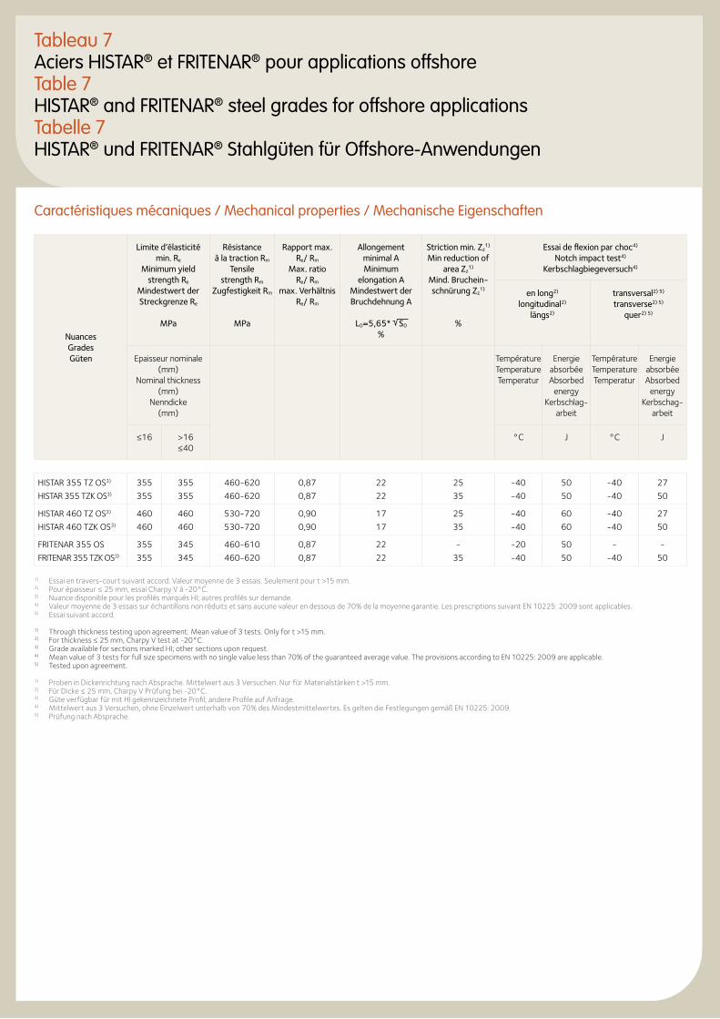
Tableau 7Aciers HISTAR® et FRITENAR® pour applications offshoreTable 7HISTAR® and FRITENAR® steel grades for offshore applicationsTabelle 7HISTAR® und FRITENAR® Stahlgüten für Offshore-Anwendungen
Caractéristiques mécaniques / Mechanical properties / Mechanische Eigenschaften
Nuances Grades Güten
Limite d’élasticité min. Re
Minimum yield strength Re
Mindestwert der Streckgrenze Re
MPa
Résistance à la traction Rm
Tensile strength Rm
Zugfestigkeit Rm
MPa
Rapport max. Re/ Rm
Max. ratio Re/ Rm
max. Verhältnis Re/ Rm
Allongement minimal A Minimum
elongation A Mindestwert der Bruchdehnung A
L0=5,65* S0
%
Striction min. Zz1)
Min reduction of area Zz
1) Mind. Bruchein-schnürung Zz
1)
%
Essai de flexion par choc4) Notch impact test4)
Kerbschlagbiegeversuch4)
en long2) longitudinal2)
längs2)
transversal2) 5) transverse2) 5)
quer2) 5)
Epaisseur nominale (mm)
Nominal thickness (mm)
Nenndicke (mm)
Température Temperature Temperatur
Energie absorbée Absorbed
energy Kerbschlag-
arbeit
Température Temperature Temperatur
Energie absorbée Absorbed
energy Kerbschag-
arbeit
≤16 >16 ≤40
°C J °C J
HISTAR 355 TZ OS3)
HISTAR 355 TZK OS3)
355
355
355
355
460-620
460-620
0,87
0,87
22
22
25
35
-40
-40
50
50
-40
-40
27
50
HISTAR 460 TZ OS3)
HISTAR 460 TZK OS3)
460
460
460
460
530-720
530-720
0,90
0,90
17
17
25
35
-40
-40
60
60
-40
-40
27
50
FRITENAR 355 OS
FRITENAR 355 TZK OS3)
355
355
345
345
460-610
460-620
0,87
0,87
22
22
-
35
-20
-40
50
50
-
-40
-
50
1) Essai en travers-court suivant accord. Valeur moyenne de 3 essais. Seulement pour t >15 mm.2) Pour épaisseur ≤ 25 mm, essai Charpy V à -20°C.3) Nuance disponible pour les profilés marqués HI; autres profilés sur demande.4) Valeur moyenne de 3 essais sur échantillons non réduits et sans aucune valeur en dessous de 70% de la moyenne garantie. Les prescriptions suivant EN 10225: 2009 sont applicables.5) Essai suivant accord.
1) Through thickness testing upon agreement. Mean value of 3 tests. Only for t >15 mm.2) For thickness ≤ 25 mm, Charpy V test at -20°C.3) Grade available for sections marked HI; other sections upon request.4) Mean value of 3 tests for full size specimens with no single value less than 70% of the guaranteed average value. The provisions according to EN 10225: 2009 are applicable.5) Tested upon agreement.
1) Proben in Dickenrichtung nach Absprache. Mittelwert aus 3 Versuchen. Nur für Materialstärken t >15 mm.2) Für Dicke ≤ 25 mm, Charpy V Prüfung bei -20°C.3) Güte verfügbar für mit Hl gekennzeichnete Profil; andere Profile auf Anfrage.4) Mittelwert aus 3 Versuchen, ohne Einzelwert unterhalb von 70% des Mindestmittelwertes. Es gelten die Festlegungen gemäß EN 10225: 2009.5) Prüfung nach Absprache.
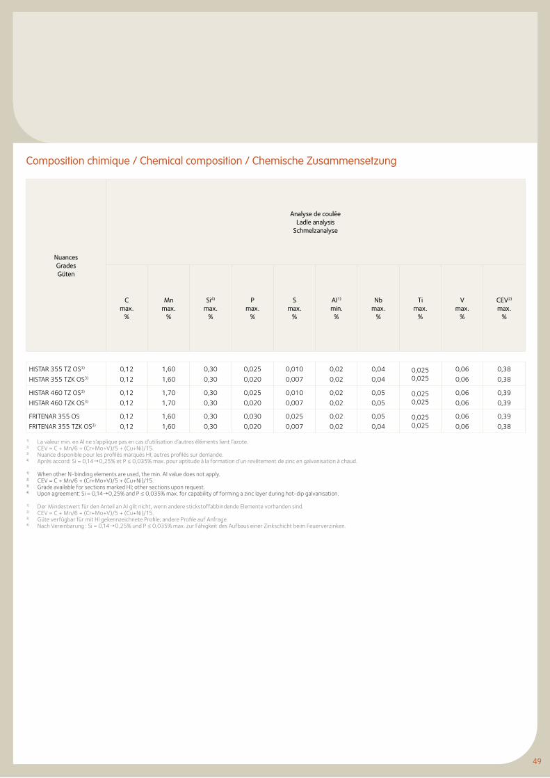
49
Composition chimique / Chemical composition / Chemische Zusammensetzung
1) La valeur min. en Al ne s’applique pas en cas d’utilisation d’autres éléments liant l’azote.2) CEV = C + Mn/6 + (Cr+Mo+V)/5 + (Cu+Ni)/15.3) Nuance disponible pour les profilés marqués HI; autres profilés sur demande.4) Après accord: Si = 0,14¦0,25% et P ≤ 0,035% max. pour aptitude à la formation d’un revêtement de zinc en galvanisation à chaud.
1) When other N-binding elements are used, the min. AI value does not apply.2) CEV = C + Mn/6 + (Cr+Mo+V)/5 + (Cu+Ni)/15.3) Grade available for sections marked HI; other sections upon request.4) Upon agreement: Si = 0,14¦0,25% and P ≤ 0,035% max. for capability of forming a zinc layer during hot-dip galvanisation.
1) Der Mindestwert für den Anteil an AI gilt nicht, wenn andere stickstoffabbindende Elemente vorhanden sind.2) CEV = C + Mn/6 + (Cr+Mo+V)/5 + (Cu+Ni)/15.3) Güte verfügbar für mit Hl gekennzeichnete Profile; andere Profile auf Anfrage.4) Nach Vereinbarung : Si = 0,14¦0,25% und P ≤ 0,035% max. zur Fähigkeit des Aufbaus einer Zinkschicht beim Feuerverzinken.
Nuances Grades Güten
Analyse de coulée Ladle analysis
Schmelzanalyse
C max.
%
Mn max.
%
Si4) max.
%
P max.
%
S max.
%
AI1) min.
%
Nb max.
%
Timax.
%
V max.
%
CEV2) max.
%
HISTAR 355 TZ OS3)
HISTAR 355 TZK OS3)
0,12
0,12
1,60
1,60
0,30
0,30
0,025
0,020
0,010
0,007
0,02
0,02
0,04
0,040,0250,025
0,06
0,06
0,38
0,38
HISTAR 460 TZ OS3)
HISTAR 460 TZK OS3)
0,12
0,12
1,70
1,70
0,30
0,30
0,025
0,020
0,010
0,007
0,02
0,02
0,05
0,050,0250,025
0,06
0,06
0,39
0,39
FRITENAR 355 OS
FRITENAR 355 TZK OS3)
0,12
0,12
1,60
1,60
0,30
0,30
0,030
0,020
0,025
0,007
0,02
0,02
0,05
0,040,0250,025
0,06
0,06
0,39
0,38
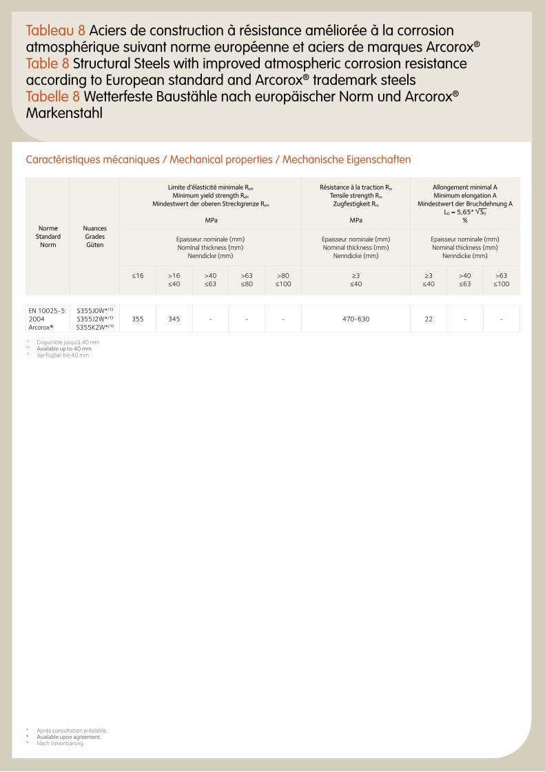
Tableau 8 Aciers de construction à résistance améliorée à la corrosion atmosphérique suivant norme européenne et aciers de marques Arcorox®
Table 8 Structural Steels with improved atmospheric corrosion resistance according to European standard and Arcorox® trademark steelsTabelle 8 Wetterfeste Baustähle nach europäischer Norm und Arcorox® Markenstahl
Caractéristiques mécaniques / Mechanical properties / Mechanische Eigenschaften
Norme Standard
Norm
Nuances Grades Güten
Limite d’élasticité minimale ReH Minimum yield strength ReH
Mindestwert der oberen Streckgrenze ReH
MPa
Résistance à la traction Rm Tensile strength Rm
Zugfestigkeit Rm
MPa
Allongement minimal A Minimum elongation A
Mindestwert der Bruchdehnung A LO = 5,65* S0
%
Epaisseur nominale (mm) Nominal thickness (mm)
Nenndicke (mm)
Epaisseur nominale (mm) Nominal thickness (mm)
Nenndicke (mm)
Epaisseur nominale (mm) Nominal thickness (mm)
Nenndicke (mm)
≤16 >16 ≤40
>40 ≤63
>63 ≤80
>80 ≤100
≥3 ≤40
≥3 ≤40
>40 ≤63
>63 ≤100
EN 10025-5: 2004Arcorox®
S355J0W*/1) S355J2W*/1) S355K2W*/1)
355 345 - - - 470-630 22 - -
1) Disponible jusqu’à 40 mm1) Available up to 40 mm1) Verfügbar bis 40 mm
* Après consultation préalable.* Available upon agreement.* Nach Vereinbarung.
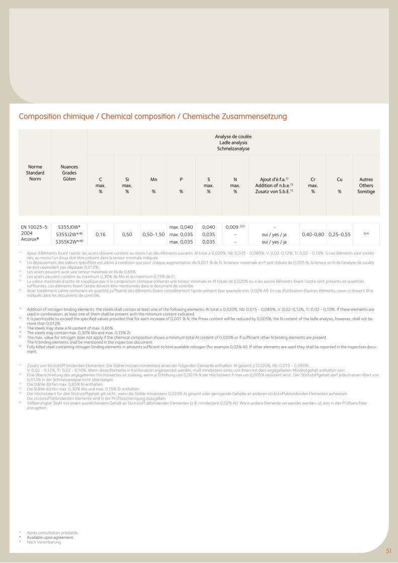
51
Norme Standard
Norm
Nuances Grades Güten
Analyse de coulée Ladle analysis
Schmelzanalyse
C max.
%
Si max.
%
Mn
%
P
%
S max.
%
N max.
%
Ajout d’é.f.a.1) Addition of n.b.e.1) Zusatz von S.b.E.1)
Cr max.
%
Cu
%
Autres Others
Sonstige
EN 10025-5: 2004Arcorox®
S355J0W*
S355J2W*/6)
S355K2W*/6)
0,16 0,50 0,50-1,50
max. 0,040
max. 0,035
max. 0,035
0,040
0,035
0,035
0,009 2)5)
-
-
-
oui / yes / ja
oui / yes / ja
0,40-0,80 0,25-0,55 3)4)
1) Ajout d’éléments fixant l’azote: les aciers doivent contenir au moins l’un des éléments suivants: Al total ≥ 0,020%, Nb: 0,015 - 0,060%, V: 0,02-0,12%, Ti: 0,02 - 0,10%. Si ces éléments sont combi-nés, au moins l’un d’eux doit être présent dans la teneur minimale indiquée.
2) Un dépassement des valeurs spécifiées est admis à condition que pour chaque augmentation de 0,001 % de N, la teneur maximale en P soit réduite de 0,005 %; la teneur en N de l’analyse de coulée ne doit cependant pas dépasser 0,012%.
3) Les aciers peuvent avoir une teneur maximale en Ni de 0,65%.4) Les aciers peuvent contenir au maximum 0,30% de Mo et au maximum 0,15% de Zr.5) La valeur maximale d’azote ne s’applique pas si la composition chimique présente une teneur minimale en Al totale de 0,020% ou si les autres éléments fixant l’azote sont présents en quantités
suffisantes. Les éléments fixant l’azote doivent être mentionnés dans le document de contrôle.6) Acier totalement calme contenant en quantité suffisante des éléments fixant complètement l'azote présent (par exemple min. 0,02% Al). En cas d'utilisation d'autres éléments, ceux-ci doivent être
indiqués dans les documents de contrôle.
1) Addition of nitrogen binding elements: the steels shall contain at least one of the following elements: AI total ≥ 0,020%, Nb: 0,015 - 0,060%, V: 0,02-0,12%, Ti: 0,02 - 0,10%. If these elements are used in combination, at least one of them shall be present with the minimum content indicated.
2) It is permissible to exceed the specified values provided that for each increase of 0,001 % N, the Pmax content will be reduced by 0,005%; the N content of the ladle analysis, however, shall not be more than 0,012%.
3) The steels may show a Ni content of max. 0,65%.4) The steels may contain max. 0,30% Mo and max. 0,15% Zr.5) The max. value for nitrogen does not apply if the chemical composition shows a minimum total AI content of 0,020% or if sufficient other N binding elements are present.
The N binding elements shall be mentioned in the inspection document.6) Fully killed steel containing nitrogen binding elements in amounts sufficient to bind available nitrogen (for example 0,02% Al). If other elements are used they shall be reported in the inspection docu-
ment.
1) Zusatz von Stickstoff bindenden Elementen: Die Stähle müssen mindestens eines der folgenden Elemente enthalten: AI gesamt ≥ 0,020%, Nb: 0,015 - 0,060% , V: 0,02 - 0,12%, Ti: 0,02 - 0,10%. Wenn diese Elemente in Kombination angewendet werden, muß mindestens eines von ihnen mit dem angegebenen Mindestgehalt enthalten sein.2) Eine Überschreitung des angegebenen Höchstwertes ist zulässig, wenn je Erhöhung von 0,001% N der Höchstwert P max um 0,005% reduziert wird.; Der Stickstoffgehalt darf jedoch einen Wert von
0,012% in der Schmelzanalyse nicht übersteigen.3) Die Stähle dürfen max. 0,65% Ni enthalten.4) Die Stähle dürfen max. 0,30% Mo und max. 0,15% Zr enthalten.5) Der Höchstwert für den Stickstoffgehalt gilt nicht, wenn die Stähle mindestens 0,020% AI gesamt oder genügende Gehalte an anderen stickstoffabbindenden Elementen aufweisen.
Die stickstoffabbindenden Elemente sind in der Prüfbescheinigung anzugeben.6) Vollberuhigter Stahl mit einem ausreichendem Gehalt an Stickstoff abbindenden Elementen (z.B. mindestens 0,02% Al). Wenn andere Elemente verwendet werden, ist dies in den Prüfberichten
anzugeben.
Composition chimique / Chemical composition / Chemische Zusammensetzung
* Après consultation préalable.* Available upon agreement.* Nach Vereinbarung.
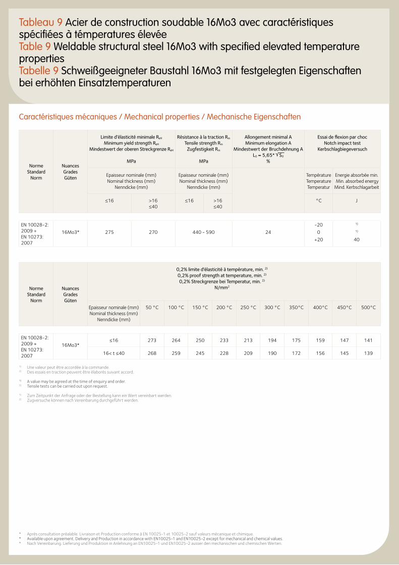
Tableau 9 Acier de construction soudable 16Mo3 avec caractéristiques spécifiées à témperatures élevéeTable 9 Weldable structural steel 16Mo3 with specified elevated temperature propertiesTabelle 9 Schweißgeeigneter Baustahl 16Mo3 mit festgelegten Eigenschaften bei erhöhten Einsatztemperaturen
Caractéristiques mécaniques / Mechanical properties / Mechanische Eigenschaften
Norme Standard
Norm
Nuances Grades Güten
Limite d’élasticité minimale ReH Minimum yield strength ReH
Mindestwert der oberen Streckgrenze ReH
MPa
Résistance à la traction Rm Tensile strength Rm
Zugfestigkeit Rm
MPa
Allongement minimal A Minimum elongation A
Mindestwert der Bruchdehnung A L0 = 5,65* S0
%
Essai de flexion par choc Notch impact test
Kerbschlagbiegeversuch
Epaisseur nominale (mm) Nominal thickness (mm)
Nenndicke (mm)
Epaisseur nominale (mm) Nominal thickness (mm)
Nenndicke (mm)
Température Temperature Temperatur
Energie absorbée min. Min. absorbed energy Mind. Kerbschlagarbeit
≤16 >16 ≤40
≤16 >16 ≤40
°C J
EN 10028-2: 2009 + EN 10273: 2007
16Mo3* 275 270 440 - 590 24
-20
0
+20
1) 1)
40
Norme Standard
Norm
Nuances Grades Güten
0,2% limite d'élasticité à température, min. 2)
0,2% proof strength at temperature, min. 2)
0,2% Streckgrenze bei Temperatur, min. 2)
N/mm2
Epaisseur nominale (mm) Nominal thickness (mm)
Nenndicke (mm)
50 °C 100 °C 150 °C 200 °C 250 °C 300 °C 350°C 400°C 450°C 500°C
EN 10028-2: 2009 + EN 10273: 2007
16Mo3*≤16 273 264 250 233 213 194 175 159 147 141
16< t ≤40 268 259 245 228 209 190 172 156 145 139
1) Une valeur peut être accordée à la commande.2) Des essais en traction peuvent être élaborés suivant accord. 1) A value may be agreed at the time of enquiry and order.2) Tensile tests can be carried out upon request. 1) Zum Zeitpunkt der Anfrage oder der Bestellung kann ein Wert vereinbart werden.2) Zugversuche können nach Vereinbarung durchgeführt werden.
* Après consultation préalable. Livraison et Production conforme à EN 10025-1 et 10025-2 sauf valeurs mécanique et chimique.* Available upon agreement. Delivery and Production in accordance with EN10025-1 and EN10025-2 except for mechanical and chemical values.* Nach Vereinbarung. Lieferung und Produktion in Anlehnung an EN10025-1 und EN10025-2 ausser den mechanischen und chemischen Werten.
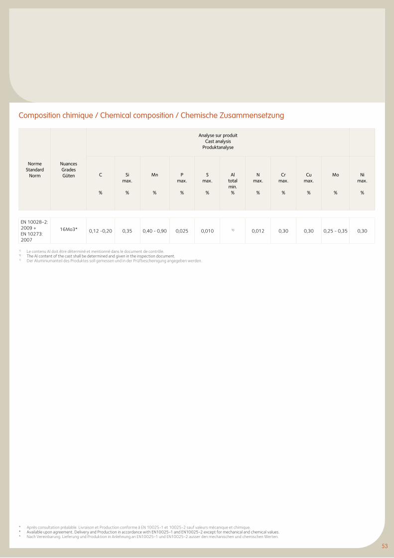
53
Norme Standard
Norm
Nuances Grades Güten
Analyse sur produitCast analysis
Produktanalyse
C
%
Si max.
%
Mn
%
P max.
%
S max.
%
Al totalmin.
%
N max.
%
Cr max.
%
Cu max.
%
Mo
%
Ni max.
%
EN 10028-2: 2009 + EN 10273: 2007
16Mo3* 0,12 -0,20 0,35 0,40 - 0,90 0,025 0,010 1) 0,012 0,30 0,30 0,25 - 0,35 0,30
Composition chimique / Chemical composition / Chemische Zusammensetzung
1) Le contenu Al doit être déterminé et mentionné dans le document de contrôle. 1) The Al content of the cast shall be determined and given in the inspection document. 1) Der Aluminiumanteil des Produktes soll gemessen und in der Prüfbescheinigung angegeben werden.
* Après consultation préalable. Livraison et Production conforme à EN 10025-1 et 10025-2 sauf valeurs mécanique et chimique.* Available upon agreement. Delivery and Production in accordance with EN10025-1 and EN10025-2 except for mechanical and chemical values.* Nach Vereinbarung. Lieferung und Produktion in Anlehnung an EN10025-1 und EN10025-2 ausser den mechanischen und chemischen Werten.
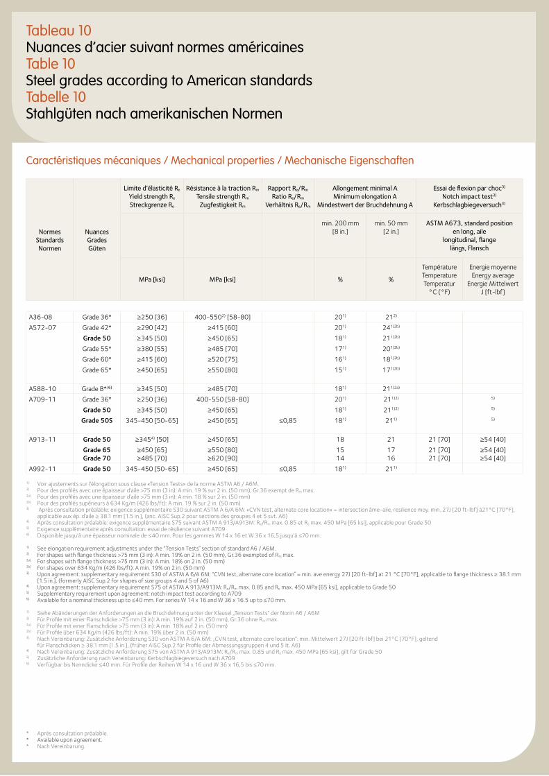
Tableau 10Nuances d’acier suivant normes américainesTable 10Steel grades according to American standardsTabelle 10Stahlgüten nach amerikanischen Normen
Caractéristiques mécaniques / Mechanical properties / Mechanische Eigenschaften
Normes Standards Normen
Nuances Grades Güten
Limite d’élasticité Re Yield strength Re Streckgrenze Re
Résistance à la traction Rm Tensile strength Rm
Zugfestigkeit Rm
Rapport Re/Rm Ratio Re/Rm
Verhältnis Re/Rm
Allongement minimal A Minimum elongation A
Mindestwert der Bruchdehnung A
Essai de flexion par choc3) Notch impact test3)
Kerbschlagbiegeversuch3)
min. 200 mm [8 in.]
min. 50 mm [2 in.]
ASTM A673, standard position en long, aile
longitudinal, flange längs, Flansch
MPa [ksi] MPa [ksi] % %
Température Temperature Temperatur
°C (°F)
Energie moyenne Energy average
Energie Mittelwert J [ft-lbf]
A36-08 Grade 36* ≥250 [36] 400-5502) [58-80] 201) 212)
A572-07 Grade 42* ≥290 [42] ≥415 [60] 201) 241)2b)
Grade 50 ≥345 [50] ≥450 [65] 181) 211)2b)
Grade 55* ≥380 [55] ≥485 [70] 171) 201)2b)
Grade 60* ≥415 [60] ≥520 [75] 161) 181)2b)
Grade 65* ≥450 [65] ≥550 [80] 151) 171)2b)
A588-10 Grade B*/6) ≥345 [50] ≥485 [70] 181) 211)2a)
A709-11 Grade 36* ≥250 [36] 400-550 [58-80] 201) 211)2) 5)
Grade 50 ≥345 [50] ≥450 [65] 181) 211)2) 5)
Grade 50S 345-450 [50-65] ≥450 [65] ≤0,85 181) 211) 5)
A913-11 Grade 50 ≥3454) [50] ≥450 [65] 18 21 21 [70] ≥54 [40]
Grade 65Grade 70
≥450 [65]≥485 [70]
≥550 [80] ≥620 [90]
1514
1716
21 [70]21 [70]
≥54 [40]≥54 [40]
A992-11 Grade 50 345-450 [50-65] ≥450 [65] ≤0,85 181) 211)
1) Voir ajustements sur l’élongation sous clause «Tension Tests» de la norme ASTM A6 / A6M.2) Pour des profilés avec une épaisseur d’aile >75 mm (3 in): A min. 19 % sur 2 in. (50 mm), Gr.36 exempt de Rm max.2a) Pour des profilés avec une épaisseur d’aile >75 mm (3 in): A min. 18 % sur 2 in. (50 mm)2b) Pour des profilés supèrieurs à 634 Kg/m (426 lbs/ft): A min. 19 % sur 2 in. (50 mm)3) Après consultation préalable: exigence supplémentaire S30 suivant ASTM A 6/A 6M: «CVN test, alternate core location» = intersection âme-aile, resilience moy. min. 27J [20 ft-lbf] à21°C [70°F],
applicable aux ép. d’aile ≥ 38.1 mm [1.5 in.], (anc. AISC Sup.2 pour sections des groupes 4 et 5 svt. A6)4) Après consultation préalable: exigence supplémentaire S75 suivant ASTM A 913/A913M: Re/Rm max. 0.85 et Re max. 450 MPa [65 ksi], applicable pour Grade 505) Exigence supplémentaire aprés consultation: essai de résilience suivant A7096) Disponible jusqu'à une épaisseur nominale de ≤40 mm. Pour les gammes W 14 x 16 et W 36 x 16,5 jusqu'à ≤70 mm.
1) See elongation requirement adjustments under the “Tension Tests˝ section of standard A6 / A6M.2) For shapes with flange thickness >75 mm (3 in): A min. 19% on 2 in. (50 mm), Gr.36 exempted of Rm max.2a) For shapes with flange thickness >75 mm (3 in): A min. 18% on 2 in. (50 mm)2b) For shapes over 634 Kg/m (426 lbs/ft): A min. 19% on 2 in. (50 mm)3) Upon agreement: supplementary requirement S30 of ASTM A 6/A 6M: “CVN test, alternate core location˝ = min. ave energy 27J [20 ft-lbf] at 21 °C [70°F], applicable to flange thickness ≥ 38.1 mm
[1.5 in.], (formerly AISC Sup.2 for shapes of size groups 4 and 5 of A6)4) Upon agreement: supplementary requirement S75 of ASTM A 913/A913M: Re/Rm max. 0.85 and Re max. 450 MPa [65 ksi], applicable to Grade 505) Supplementary requirement upon agreement: notch impact test according to A7096) Available for a nominal thickness up to ≤40 mm. For series W 14 x 16 and W 36 x 16.5 up to ≤70 mm.
1) Siehe Abänderungen der Anforderungen an die Bruchdehnung unter der Klausel „Tension Tests” der Norm A6 / A6M2) Für Profile mit einer Flanschdicke >75 mm (3 in): A min. 19% auf 2 in. (50 mm), Gr.36 ohne Rm max.2a) Für Profile mit einer Flanschdicke >75 mm (3 in): A min. 18% auf 2 in. (50 mm)2b) Für Profile über 634 Kg/m (426 lbs/ft): A min. 19% über 2 in. (50 mm)3) Nach Vereinbarung: Zusätzliche Anforderung S30 von ASTM A 6/A 6M: „CVN test, alternate core location”: min. Mittelwert 27J [20 ft-lbf] bei 21°C [70°F], geltend
für Flanschdicken ≥ 38.1 mm [l .5 in.], (früher AISC Sup.2 für Profile der Abmessungsgruppen 4 und 5 It. A6)4) Nach Vereinbarung: Zusätzliche Anforderung S75 von ASTM A 913/A913M: Re/Rm max. 0.85 und Re max. 450 MPa [65 ksi], gilt für Grade 505) Zusätzliche Anforderung nach Vereinbarung: Kerbschlagbiegeversuch nach A7096) Verfügbar bis Nenndicke ≤40 mm. Für Profile der Reihen W 14 x 16 und W 36 x 16,5 bis ≤70 mm.
* Après consultation préalable.* Available upon agreement.* Nach Vereinbarung.
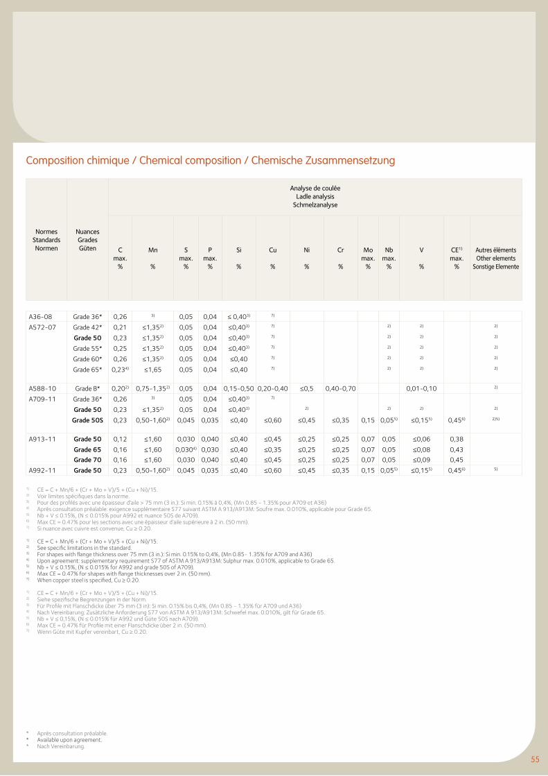
55
Composition chimique / Chemical composition / Chemische Zusammensetzung
Normes Standards Normen
Nuances Grades Güten
Analyse de coulée Ladle analysis
Schmelzanalyse
C max.
%
Mn
%
S max.
%
P max.
%
Si
%
Cu
%
Ni
%
Cr
%
Mo max.
%
Nb max.
%
V
%
CE1) max.
%
Autres éléments Other elements
Sonstige Elemente
A36-08 Grade 36* 0,26 3) 0,05 0,04 ≤ 0,403) 7)
A572-07 Grade 42* 0,21 ≤1,352) 0,05 0,04 ≤0,403) 7) 2) 2) 2)
Grade 50 0,23 ≤1,352) 0,05 0,04 ≤0,403) 7) 2) 2) 2)
Grade 55* 0,25 ≤1,352) 0,05 0,04 ≤0,403) 7) 2) 2) 2)
Grade 60* 0,26 ≤1,352) 0,05 0,04 ≤0,40 7) 2) 2) 2)
Grade 65* 0,234) ≤1,65 0,05 0,04 ≤0,40 7) 2) 2) 2)
A588-10 Grade B* 0,202) 0,75-1,352) 0,05 0,04 0,15-0,50 0,20-0,40 ≤0,5 0,40-0,70 0,01-0,10 2)
A709-11 Grade 36* 0,26 3) 0,05 0,04 ≤0,403) 7)
Grade 50 0,23 ≤1,352) 0,05 0,04 ≤0,403) 2) 2) 2) 2)
Grade 50S 0,23 0,50-1,602) 0,045 0,035 ≤0,40 ≤0,60 ≤0,45 ≤0,35 0,15 0,055) ≤0,155) 0,456) 2)5)
A913-11 Grade 50 0,12 ≤1,60 0,030 0,040 ≤0,40 ≤0,45 ≤0,25 ≤0,25 0,07 0,05 ≤0,06 0,38
Grade 65
Grade 70
0,16
0,16
≤1,60
≤1,60
0,0304)
0,030
0,030
0,040
≤0,40
≤0,40
≤0,35
≤0,45
≤0,25
≤0,25
≤0,25
≤0,25
0,07
0,07
0,05
0,05
≤0,08
≤0,09
0,43
0,45
A992-11 Grade 50 0,23 0,50-1,602) 0,045 0,035 ≤0,40 ≤0,60 ≤0,45 ≤0,35 0,15 0,055) ≤0,155) 0,456) 5)
1) CE = C + Mn/6 + (Cr + Mo + V)/5 + (Cu + Ni)/15.2) Voir limites spécifiques dans la norme.3) Pour des profilés avec une épaisseur d’aile > 75 mm (3 in.): Si min. 0.15% à 0,4%, (Mn 0.85 - 1.35% pour A709 et A36)4) Après consultation préalable: exigence supplémentaire S77 suivant ASTM A 913/A913M: Soufre max. 0.010%, applicable pour Grade 65.5) Nb + V ≤ 0.15%, (N ≤ 0.015% pour A992 et nuance 50S de A709).6) Max CE = 0.47% pour les sections avec une épaisseur d’aile supérieure à 2 in. (50 mm).7) Si nuance avec cuivre est convenue, Cu ≥ 0.20.
1) CE = C + Mn/6 + (Cr + Mo + V)/5 + (Cu + Ni)/15.2) See specific limitations in the standard.3) For shapes with flange thickness over 75 mm (3 in.): Si min. 0.15% to 0,4%, (Mn 0.85- 1.35% for A709 and A36)4) Upon agreement: supplementary requirement S77 of ASTM A 913/A913M: Sulphur max. 0.010%, applicable to Grade 65.5) Nb + V ≤ 0.15%, (N ≤ 0.015% for A992 and grade 50S of A709).6) Max CE = 0.47% for shapes with flange thicknesses over 2 in. (50 mm).7) When copper steel is specified, Cu ≥ 0.20.
1) CE = C + Mn/6 + (Cr + Mo + V)/5 + (Cu + Ni)/15.2) Siehe spezifische Begrenzungen in der Norm.3) Für Profile mit Flanschdicke über 75 mm (3 in): Si min. 0.15% bis 0,4%, (Mn 0.85 - 1.35% für A709 und A36)4) Nach Vereinbarung: Zusätzliche Anforderung S77 von ASTM A 913/A913M: Schwefel max. 0.010%, gilt für Grade 65.5) Nb + V ≤ 0,15%, (N ≤ 0.015% für A992 und Güte 50S nach A709).6) Max CE = 0.47% für Profile mit einer Flanschdicke über 2 in. (50 mm).7) Wenn Güte mit Kupfer vereinbart, Cu ≥ 0.20.
* Après consultation préalable.* Available upon agreement.* Nach Vereinbarung.
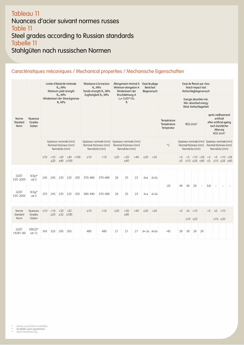
Tableau 11Nuances d’acier suivant normes russesTable 11Steel grades according to Russian standardsTabelle 11Stahlgüten nach russischen Normen
Caractéristiques mécaniques / Mechanical properties / Mechanische Eigenschaften
Norme Standard
Norm
Nuances Grades Güten
Limite d’élasticité minimale ReH, MPa
Minimum yield strength ReH, MPa
Mindestwert der Streckgrenze Re, MPa
Résistance à la traction Rm, MPa
Tensile strength Rm, MPaZugfestigkeit Rm, MPa
Allongement minimal AMinimum elongation A
Mindestwert der Bruchdehnung A
L0= 5,65*√S0
%
Essai de pliageBend test
Biegeversuch
Essai de flexion par chocNotch impact test
Kerbschlagbiegeversuch
Energie absorbée min. Min. absorbed energyMind. Kerbschlagarbeit
Température TempératureTemperatur
KCU J/cm2
après vieillissement artificiel
after artificial ageingnach künstlicher
AlterungKCU J/cm2
Epaisseur nominale (mm)Nominal thickness (mm)
Nenndicke (mm)
Epaisseur nominale (mm) Nominal thickness (mm)
Nenndicke (mm)
Epaisseur nominale (mm)Nominal thickness (mm)
Nenndicke (mm)°C
Epaisseur nominale (mm)Nominal thickness (mm)
Nenndicke (mm)
Epaisseur nominale (mm)Nominal thickness (mm)
Nenndicke (mm)
≤10 >10≤20
>20≤40
>40≤100
>100 ≤10 >10 ≤20 >20≤40
>40 ≤20 >20 >3≤5
>5≤10
>10≤26
>26≤40
>3≤5
>5≤10
>10≤26
>26≤40
GOST 535-2005
St3ps*cat 5
245 245 235 225 205 370-480 370-480 26 25 23 d=a d=2a
-20 49 49 29 - 9,8 - - -
GOST 535-2005
St3sp*cat 5
255 245 235 225 205 380-490 370-480 26 25 23 d=a d=2a
Norme Standard
Norm
Nuances Grades Güten
≤10 >10≤20
>20≤32
>32≤100
≤10 >10 ≤20 >20≤40
>40 ≤20 >20 <5 ≥5 >10 <5 ≥5 >10
≤10 ≤20 ≤10 ≤20
GOST 19281-89
09G2S*cat 12
345 325 295 265 480 480 21 21 21 d= 2a d=2a -40 39 39 29 29
* Après consultation préalable.* Available upon agreement.* Nach Vereinbarung.
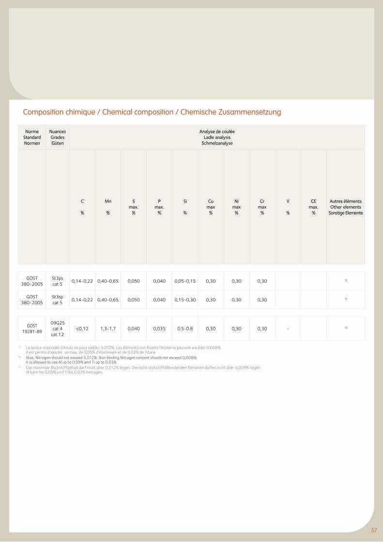
57
Norme StandardNormen
Nuances Grades Güten
Analyse de couléeLadle analysis
Schmelzanalyse
C
%
Mn
%
Smax.
%
Pmax.
%
Si
%
Cumax
%
Nimax
%
Crmax
%
V
%
CEmax.
%
Autres élémentsOther elements
Sonstige Elemente
GOST380-2005
St3pscat 5
0,14-0,22 0,40-0,65 0,050 0,040 0,05-0,15 0,30 0,30 0,30 1)
GOST380-2005
St3spcat 5
0,14-0,22 0,40-0,65 0,050 0,040 0,15-0,30 0,30 0,30 0,30 1)
GOST 19281-89
09G2Scat 4
cat 12≤0,12 1,3-1,7 0,040 0,035 0.5-0.8 0,30 0,30 0,30 - 1)
Composition chimique / Chemical composition / Chemische Zusammensetzung
1) La teneur maximale d’Azote ne peut exéder 0.012%. Les éléments non fixants l’Azote ne peuvent excéder 0,008%. Il est permis d’ajouter un max. de 0,05% d’Aluminium et de 0,03% de Titane
1) Max. Nitrogen should not exceed 0,012%. Non binding Nitrogen content should not exceed 0,008%. It is allowed to use Al up to 0,05% and Ti up to 0,03%.
1) Der maximale Stickstoffgehalt darf nicht über 0,012% liegen. Die nicht stickstoffabbindenden Elemente dürfen nicht über 0,008% liegen. Al kann bis 0,05% und Ti bis 0,03% betragen.
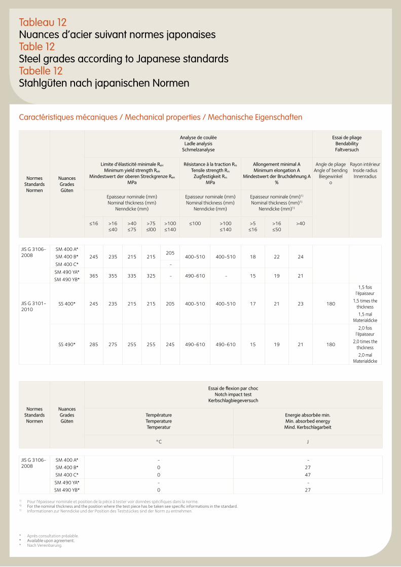
Tableau 12Nuances d’acier suivant normes japonaisesTable 12Steel grades according to Japanese standardsTabelle 12Stahlgüten nach japanischen Normen
Caractéristiques mécaniques / Mechanical properties / Mechanische Eigenschaften
Normes Standards Normen
Nuances Grades Güten
Analyse de coulée Ladle analysis
Schmelzanalyse
Essai de pliage Bendability Faltversuch
Limite d’élasticité minimale ReH Minimum yield strength ReH
Mindestwert der oberen Streckgrenze ReH MPa
Résistance à la traction Rm Tensile strength Rm
Zugfestigkeit Rm MPa
Allongement minimal A Minimum elongation A
Mindestwert der Bruchdehnung A %
Angle de pliage Angle of bending
Biegewinkelo
Rayon intérieur Inside radius Innenradius
Epaisseur nominale (mm) Nominal thickness (mm)
Nenndicke (mm)
Epaisseur nominale (mm) Nominal thickness (mm)
Nenndicke (mm)
Epaisseur nominale (mm)1) Nominal thickness (mm)1)
Nenndicke (mm)1)
≤16 >16 ≤40
>40 ≤75
>75 ≤l00
>100 ≤140
≤100 >100 ≤140
>5 ≤16
>16 ≤50
>40
JIS G 3106-2008
SM 400 A*
SM 400 B* 245 235 215 215205
400-510 400-510 18 22 24
SM 400 C* -
SM 490 YA*
SM 490 YB*365 355 335 325 - 490-610 - 15 19 21
JIS G 3101-2010
SS 400* 245 235 215 215 205 400-510 400-510 17 21 23 180
1,5 fois l’épaisseur
1,5 times the thickness
1,5 mal Materialdicke
SS 490* 285 275 255 255 245 490-610 490-610 15 19 21 180
2,0 fois l’épaisseur
2,0 times the thickness
2,0 mal Materialdicke
Normes Standards Normen
Nuances Grades Güten
Essai de flexion par choc Notch impact test
Kerbschlagbiegeversuch
Température Temperature Temperatur
Energie absorbée min. Min. absorbed energy Mind. Kerbschlagarbeit
°C J
JIS G 3106-2008
SM 400 A*
SM 400 B*
SM 400 C*
-
0
0
-
27
47
SM 490 YA*
SM 490 YB*
-
0
-
27
* Après consultation préalable.* Available upon agreement.* Nach Vereinbarung.
1) Pour l'épaisseur nominale et position de la pièce à tester voir données spécifiques dans la norme.1) For the nominal thickness and the position where the test piece has be taken see specific informations in the standard.1) Informationen zur Nenndicke und der Position des Teststückes sind der Norm zu entnehmen.
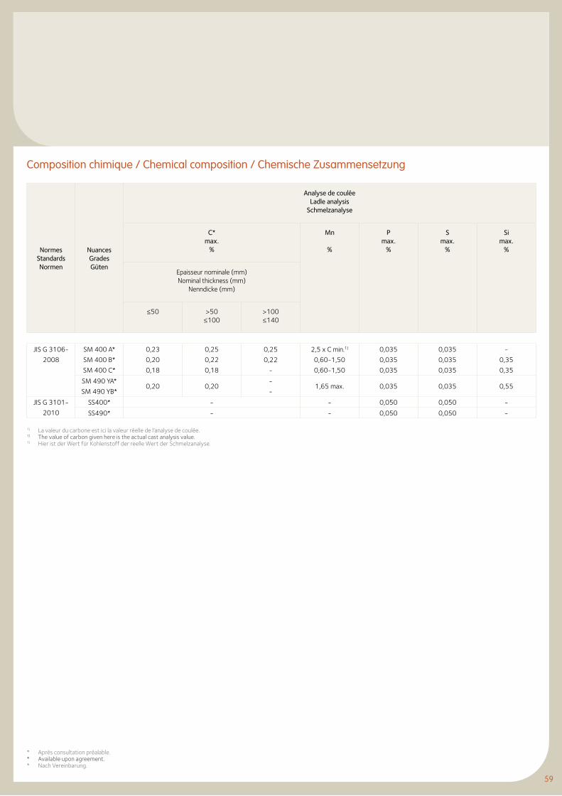
59
Composition chimique / Chemical composition / Chemische Zusammensetzung
Normes Standards Normen
Nuances Grades Güten
Analyse de coulée Ladle analysis
Schmelzanalyse
C* max.
%
Mn
%
P max.
%
S max.
%
Si max.
%
Epaisseur nominale (mm) Nominal thickness (mm)
Nenndicke (mm)
≤50 >50 ≤100
>100 ≤140
JIS G 3106-
2008
SM 400 A*
SM 400 B*
SM 400 C*
0,23
0,20
0,18
0,25
0,22
0,18
0,25
0,22
-
2,5 x C min.1)
0,60-1,50
0,60-1,50
0,035
0,035
0,035
0,035
0,035
0,035
-
0,35
0,35
SM 490 YA*
SM 490 YB*0,20 0,20
-
-1,65 max. 0,035 0,035 0,55
JIS G 3101-
2010
SS400* - - 0,050 0,050 -
SS490* - - 0,050 0,050 -
1) La valeur du carbone est ici la valeur réelle de l’analyse de coulée.1) The value of carbon given here is the actual cast analysis value.1) Hier ist der Wert für Kohlenstoff der reelle Wert der Schmelzanalyse.
* Après consultation préalable.* Available upon agreement.* Nach Vereinbarung.
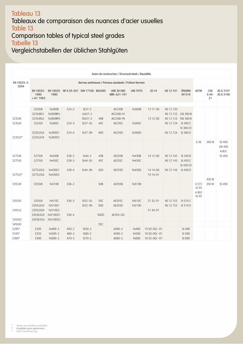
Tableau 13Tableaux de comparaison des nuances d’acier usuellesTable 13Comparison tables of typical steel gradesTabelle 13Vergleichstabellen der üblichen Stahlgüten
Aciers de construction / Structural steels / Baustähle
EN 10025-2: 2004
Normes antérieures / Previous standards / Frühere Normen
EN 10025: 1990
+ A1: 1993
EN 10025: 1990
NF A 35-501 DIN 17100 BS4360 UNE 36 080 NBN A21-101
UNI 7070 SS 14 NS 12 101 ÖNORM M1316
ASTM CSA G 40-
21
JIS G 3101 JIS G 3106
S235JR Fe360B E24-2 St37-2 AE235B Fe360B 13 11-00 NS 12 120
S235JRG1 Fe360BFU Ust37-2 AE235B-FU NS 12 122 USt 360 B
S235JR S235JRG2 Fe360BFN RSt37-2 40B AE235B-FN 13 12-00 NS 12 123 RSt 360 B
S235J0 S235J0 Fe360C E24-3 St37-3U 40C AE235C Fe360C NS 12 124 St 360 C
St 360 CE
S235J2G3 Fe360D1 E24-4 St37-3N 40D AE235D Fe360D NS 12 124 St 360 D
S235J2* S235J2G4 Fe360D2
A 36 260 W SS 400
SM 400
A/B/C
S275JR S275JR Fe430B E28-2 St44-2 43B AE255B Fe430B 14 12-00 NS 12 142 St 430 B SS 400
S275J0 S275J0 Fe430C E28-3 St44-3U 43C AE255C Fe430C NS 12 143 St 430 C
St 430 CE
S275J2G3 Fe430D1 E28-4 St44-3N 43D AE255D Fe430D 14 14-00 NS 12 143 St 430 D
S275J2* S275J2G4 Fe430D2 14 14-01
300 W
S355JR S355JR Fe510B E36-2 50B AE355B Fe510B A 572 Gr.50
350 W SS 490
A 992 Gr.50
S355J0 S355J0 Fe510C E36-3 St52-3U 50C AE355C Fe510C 21 32-01 NS 12 153 St 510 C
S355J2G3 Fe510D1 St52-3N 50D AE355D Fe510D NS 12 153 St 510 D
S355J2 S355J2G4 Fe510D2 21 34-01
S355K2G3 Fe510DD1 E36-4 50DD AE355-DD
S355K2 S355K2G4 Fe510DD2
S450J0 55C
E295* E295 Fe490-2 A50-2 St50-2 A490-2 Fe490 15 50-00/ -01 St 490
E335* E335 Fe590-2 A60-2 St60-2 A590-2 Fe590 16 50-00/ -01 St 590
E360* E360 Fe690-2 A70-2 St70-2 A690-2 Fe690 16 55-00/ -01 St 690
* Après consultation préalable.* Available upon agreement.* Nach Vereinbarung.
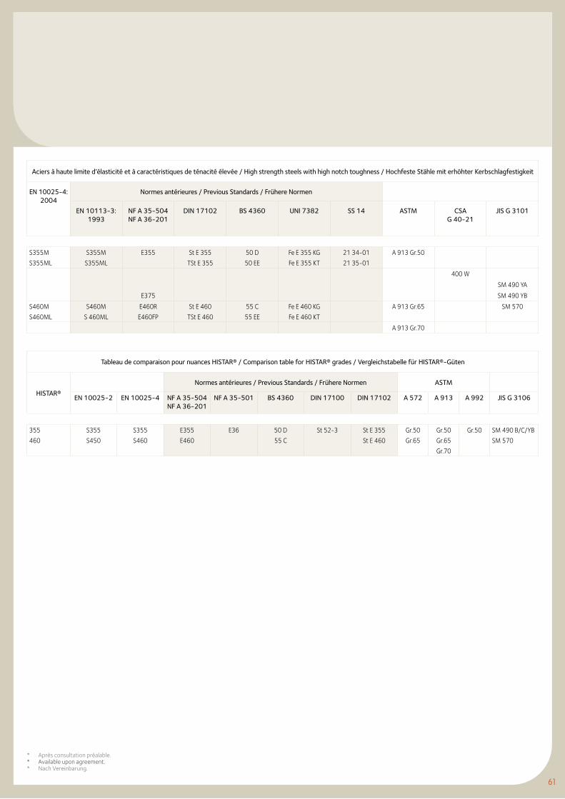
61
Aciers à haute limite d’élasticité et à caractéristiques de ténacité élevée / High strength steels with high notch toughness / Hochfeste Stähle mit erhöhter Kerbschlagfestigkeit
EN 10025-4: 2004
Normes antérieures / Previous Standards / Frühere Normen
EN 10113-3: 1993
NF A 35-504 NF A 36-201
DIN 17102 BS 4360 UNI 7382 SS 14 ASTM CSA G 40-21
JIS G 3101
S355M
S355ML
S355M
S355ML
E355 St E 355
TSt E 355
50 D
50 EE
Fe E 355 KG
Fe E 355 KT
21 34-01
21 35-01
A 913 Gr.50
400 W
SM 490 YA
E375 SM 490 YB
S460M
S460ML
S460M
S 460ML
E460R
E460FP
St E 460
TSt E 460
55 C
55 EE
Fe E 460 KG
Fe E 460 KT
A 913 Gr.65 SM 570
A 913 Gr.70
Tableau de comparaison pour nuances HISTAR® / Comparison table for HISTAR® grades / Vergleichstabelle für HISTAR®-Güten
HISTAR®
Normes antérieures / Previous Standards / Frühere Normen ASTM
EN 10025-2 EN 10025-4 NF A 35-504 NF A 36-201
NF A 35-501 BS 4360 DIN 17100 DIN 17102 A 572 A 913 A 992 JIS G 3106
355
460
S355
S450
S355
S460
E355
E460
E36 50 D
55 C
St 52-3 St E 355
St E 460
Gr.50
Gr.65
Gr.50
Gr.65
Gr.70
Gr.50 SM 490 B/C/YB
SM 570
* Après consultation préalable.* Available upon agreement.* Nach Vereinbarung.
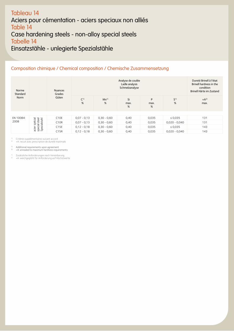
Tableau 14Aciers pour cémentation - aciers speciaux non alliésTable 14Case hardening steels - non-alloy special steels Tabelle 14Einsatzstähle - unlegierte Spezialstähle
Composition chimique / Chemical composition / Chemische Zusammensetzung
Norme Standard
Norm
Nuances Grades Güten
Analyse de coulée Ladle analysis
Schmelzanalyse
Dureté Brinell à l’état Brinell hardness in the
conditionBrinell Härte im Zustand
C1) %
Mn1) %
Si max.
%
P max.
%
S1) %
+A2) max.
EN 10084: 2008
acie
r spé
cial
sp
ecia
l ste
el
Spez
ials
tahl C10E 0,07 - 0,13 0,30 - 0,60 0,40 0,035 ≤ 0,035 131
C10R 0,07 - 0,13 0,30 - 0,60 0,40 0,035 0,020 - 0,040 131
C15E 0,12 - 0,18 0,30 - 0,60 0,40 0,035 ≤ 0,035 143
C15R 0,12 - 0,18 0,30 - 0,60 0,40 0,035 0,020 - 0,040 143
1) Critères supplémentaires suivant accord2) +A: recuit avec prescription de dureté maximale
1) Additional requirements upon agreement2) +A: annealed to maximum hardness requirements
1) Zusätzliche Anforderungen nach Vereinbarung2) +A: weichgeglüht für Anforderung auf Höchstwerte

Gammes de profilés
71 Profilés européens et aciers marchands
127 Profilés britanniques
149 Profilés américains
193 Profilés russes
199 Profilés japonais
Section ranges
Profil-reihen
71 European sections and merchant bars
127 British sections
149 American sections
193 Russian sections
199 Japanese sections
71 Europäische Profile und Stabstahl
127 Britische Profile
149 Amerikanische Profile
193 Russische Profile
199 Japanische Profile
63
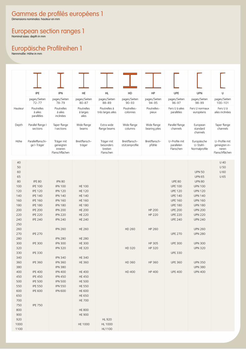
Gammes de profilés européens 1Dimensions nominales: hauteur en mm
European section ranges 1Nominal sizes: depth in mm
Europäische Profilreihen 1 Nennmaße: Höhe in mm
IPE IPN HE HL HD HP UPE UPN U
pages/Seiten 72-77
pages/Seiten 78-79
pages/Seiten80-87
pages/Seiten88-89
pages/Seiten 90-93
pages/Seiten 94-95
pages/Seiten 96-97
pages/Seiten 98-99
pages/Seiten100-101
Hauteur Poutrelles à ailes
parallèles
Poutrelles à ailes
inclinées
Poutrelles à larges
ailes
Poutrelles àtrès larges ailes
Poutrelles-colonnes
Poutrelles-pieux
Fers U à ailesparallèles
Fers U normaux européens
Fers U àailes inclinées
Depth Parallel flange I sections
Taper flange I sections
Wide flange beams
Extra wide flange beams
Wide flange columns
Wide flange bearing piles
Parallel flange channels
European standard channels
Taper flange channels
Höhe Parallelflanschi-ge l-Träger
Träger mit geneigten
inneren Flanschflächen
Breitflansch-träger
Träger mit besonders
breiten Flanschen
Breitflansch-stützenprofile
Breitflansch-pfähle
U-Profile mit parallelen Flanschen
Europäische U-Stahl-
Normalprofile
U-Profile mit geneigten in-
neren Flanschflächen
40 U 40
50 U 50
60 UPN 50 U 60
65 UPN 65 U 65
80 IPE 80 IPN 80 UPE 80 UPN 80
100 IPE 100 IPN 100 HE 100 UPE 100 UPN 100
120 IPE 120 IPN 120 HE 120 UPE 120 UPN 120
140 IPE 140 IPN 140 HE 140 UPE 140 UPN 140
160 IPE 160 IPN 160 HE 160 UPE 160 UPN 160
180 IPE 180 IPN 180 HE 180 UPE 180 UPN 180
200 IPE 200 IPN 200 HE 200 HP 200 UPE 200 UPN 200
220 IPE 220 IPN 220 HE 220 HP 220 UPE 220 UPN 220
240 IPE 240 IPN 240 HE 240 UPE 240 UPN 240
250
260 IPN 260 HE 260 HD 260 HP 260 UPN 260
270 IPE 270 UPE 270 UPN 280
280 IPN 280 HE 280
300 IPE 300 IPN 300 HE 300 HP 305 UPE 300 UPN 300
320 IPN 320 HE 320 HD 320 HP 320 UPN 320
330 IPE 330 UPE 330
340 IPN 340 HE 340
360 IPE 360 IPN 360 HE 360 HD 360 HP 360 UPE 360 UPN 350
380 IPN 380 UPN 380
400 IPE 400 IPN 400 HE 400 HD 400 HP 400 UPE 400 UPN 400
450 IPE 450 IPN 450 HE 450
500 IPE 500 IPN 500 HE 500
550 IPE 550 IPN 550 HE 550
600 IPE 600 IPN 600 HE 600
650 HE 650
700 HE 700
750 IPE 750
800 HE 800
900 HE 900
920 HL 920
1000 HE 1000 HL 1000
1100 HL1100
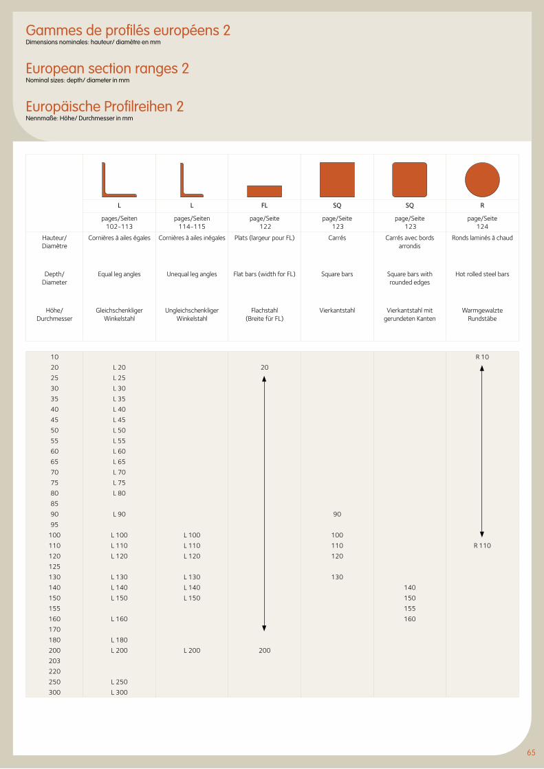
65
Gammes de profilés européens 2Dimensions nominales: hauteur/ diamètre en mm
European section ranges 2Nominal sizes: depth/ diameter in mm
Europäische Profilreihen 2Nennmaße: Höhe/ Durchmesser in mm
L L FL SQ SQ R
pages/Seiten102-113
pages/Seiten 114-115
page/Seite 122
page/Seite 123
page/Seite 123
page/Seite 124
Hauteur/ Diamètre
Cornières à ailes égales Cornières à ailes inégales Plats (largeur pour FL) Carrés Carrés avec bords arrondis
Ronds laminés à chaud
Depth/ Diameter
Equal leg angles Unequal leg angles Flat bars (width for FL) Square bars Square bars with rounded edges
Hot rolled steel bars
Höhe/ Durchmesser
Gleichschenkliger Winkelstahl
Ungleichschenkliger Winkelstahl
Flachstahl (Breite für FL)
Vierkantstahl Vierkantstahl mit gerundeten Kanten
Warmgewalzte Rundstäbe
10 R 10
20 L 20 20
25 L 25
30 L 30
35 L 35
40 L 40
45 L 45
50 L 50
55 L 55
60 L 60
65 L 65
70 L 70
75 L 75
80 L 80
85
90 L 90 90
95
100 L 100 L 100 100
110 L 110 L 110 110 R 110
120 L 120 L 120 120
125
130 L 130 L 130 130
140 L 140 L 140 140
150 L 150 L 150 150
155 155
160 L 160 160
170
180 L 180
200 L 200 L 200 200
203
220
250 L 250
300 L 300
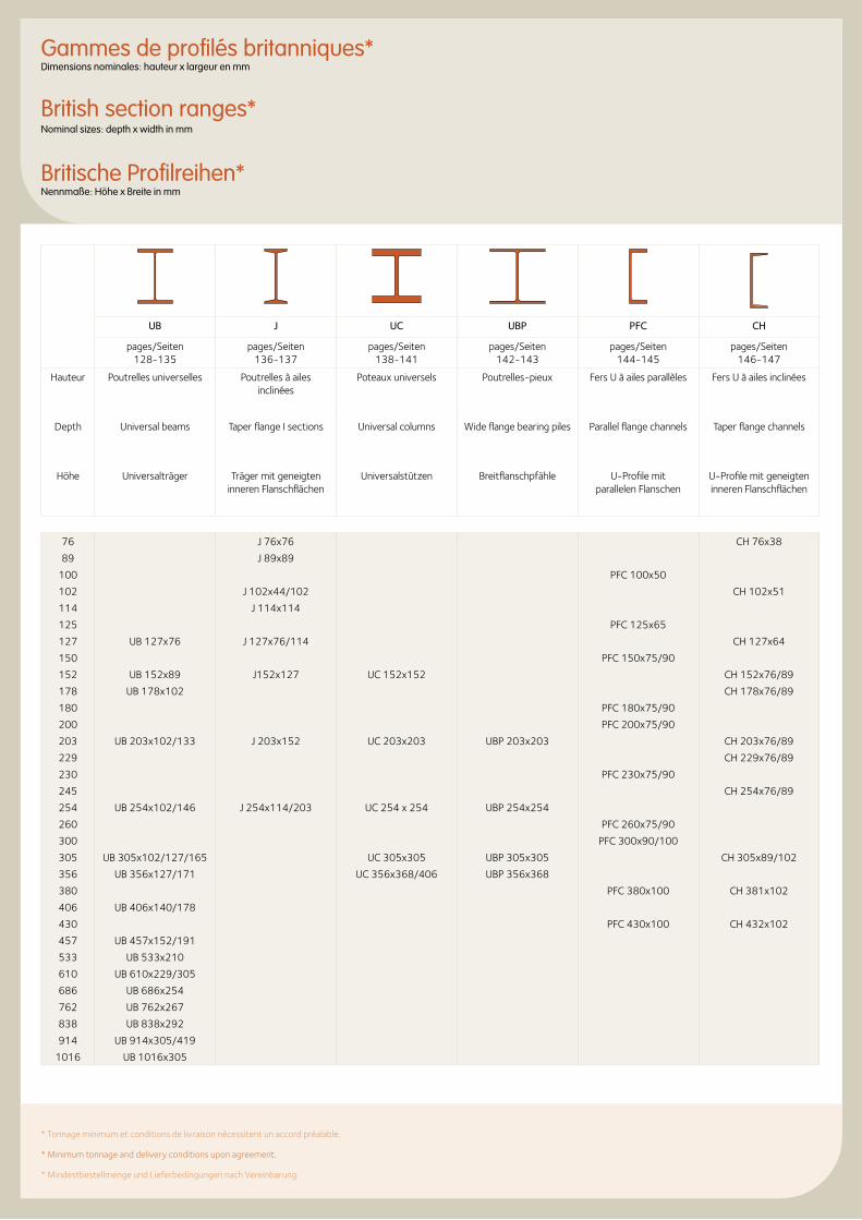
* Tonnage minimum et conditions de livraison nécessitent un accord préalable.
* Minimum tonnage and delivery conditions upon agreement.
* Mindestbestellmenge und Lieferbedingungen nach Vereinbarung.
Gammes de profilés britanniques*Dimensions nominales: hauteur x largeur en mm
British section ranges* Nominal sizes: depth x width in mm
Britische Profilreihen*Nennmaße: Höhe x Breite in mm
UB J UC UBP PFC CH
pages/Seiten 128-135
pages/Seiten 136-137
pages/Seiten 138-141
pages/Seiten 142-143
pages/Seiten 144-145
pages/Seiten 146-147
Hauteur Poutrelles universelles Poutrelles à ailes inclinées
Poteaux universels Poutrelles-pieux Fers U à ailes parallèles Fers U à ailes inclinées
Depth Universal beams Taper flange I sections Universal columns Wide flange bearing piles Parallel flange channels Taper flange channels
Höhe Universalträger Träger mit geneigten inneren Flanschflächen
Universalstützen Breitflanschpfähle U-Profile mit parallelen Flanschen
U-Profile mit geneigten inneren Flanschflächen
76 J 76x76 CH 76x38
89 J 89x89
100 PFC 100x50
102 J 102x44/102 CH 102x51
114 J 114x114
125 PFC 125x65
127 UB 127x76 J 127x76/114 CH 127x64
150 PFC 150x75/90
152 UB 152x89 J152x127 UC 152x152 CH 152x76/89
178 UB 178x102 CH 178x76/89
180 PFC 180x75/90
200 PFC 200x75/90
203 UB 203x102/133 J 203x152 UC 203x203 UBP 203x203 CH 203x76/89
229 CH 229x76/89
230 PFC 230x75/90
245 CH 254x76/89
254 UB 254x102/146 J 254x114/203 UC 254 x 254 UBP 254x254
260 PFC 260x75/90
300 PFC 300x90/100
305 UB 305x102/127/165 UC 305x305 UBP 305x305 CH 305x89/102
356 UB 356x127/171 UC 356x368/406 UBP 356x368
380 PFC 380x100 CH 381x102
406 UB 406x140/178
430 PFC 430x100 CH 432x102
457 UB 457x152/191
533 UB 533x210
610 UB 610x229/305
686 UB 686x254
762 UB 762x267
838 UB 838x292
914 UB 914x305/419
1016 UB 1016x305
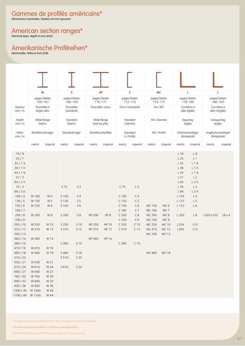
67
Gammes de profilés américains*Dimensions nominales: hauteur en mm (pouces)
American section ranges*Nominal sizes: depth in mm (inch)
Amerikanische Profilreihen*Nennmaße: Höhe in mm (Zoll)
W S HP C MC L L
pages/Seiten 150-167
pages/Seiten 168-169
pages/Seiten 170-171
pages/Seiten 172-173
pages/Seiten 174-177
pages/Seiten 178-185
pages/Seiten 186-187
Hauteur mm / in
Poutrelles à larges ailes
Poutrellesstandards
Poutrelles-pieux Fers U standards Fers MC Cornières à ailes égales
Cornières à ailes inégales
Depth mm / in
Wide flange beams
Standard Beams
Wide flange bearing piles
Standard channels
MC channels Equal leg angles
Unequal leg angles
Höhe mm / in
Breitflanschträger Standardträger Breitflanschpfähle Standard U-Profile
MC-Profile Gleichschenkliger Winkelstahl
UngleichschenkligerWinkelstahl
metric imperial metric imperial metric imperial metric imperial metric imperial metric imperial metric imperial
19 / ¾ L 19 L ¾
25 / 1 L 25 L 1
32 / 1 ¼ L 32 L 1 ¼
38 / 1 ½ L 38 L 1 ½
44 / 1 ¾ L 44 L 1 ¾
51 / 2 L 51 L 2
64 / 2 ½ L 64 L 2 ½
75 / 3 S 75 S 3 C 75 C 3 L 76 L 3
89 / 3 ½ L 89 L 3 ½
100 / 4 W 100 W 4 S 100 S 4 C 100 C 4 L 102 L 4
130 / 5 W 130 W 5 S 130 S 5 C 130 C 5 L 127 L 5
150 / 6 W 150 W 6 S 150 S 6 C 150 C 6 MC 150 MC 6 L 152 L 6
180 / 7 C 180 C 7 MC 180 MC 7
200 / 8 W 200 W 8 S 200 S 8 HP 200 HP 8 C 200 C 8 MC 200 MC 8 L 203 L 8 L203 x102 L8 x 4
230 / 9 C 230 C 9 MC 230 MC 9
250 / 10 W 250 W 10 S 250 S 10 HP 250 HP 10 C 250 C 10 MC 250 MC 10 L254 L10
310 / 12 W 310 W 12 S 310 S 12 HP 310 HP 12 C 310 C 12 MC 310 MC 12 L305 L12
330 / 13 MC 330 MC 13
360 / 14 W 360 W 14 HP 360 HP 14
380 / 15 S 380 S 15 C 380 C 15
410 / 16 W 410 W 16
460 / 18 W 460 W 18 S 460 S 18 MC 460 MC 18
510 / 20 S 510 S 20
530 / 21 W 530 W 21
610 / 24 W 610 W 24 S 610 S 24
690 / 27 W 690 W 27
760 / 30 W 760 W 30
840 / 33 W 840 W 33
920 / 36 W 920 W 36
1000 / 40 W 1000 W 40
1100 / 44 W 1100 W 44
* Tonnage minimum et conditions de livraison nécessitent un accord préalable. * Minimum tonnage and delivery conditions upon agreement. * Mindestbestellmenge und Lieferbedingungen nach Vereinbarung.
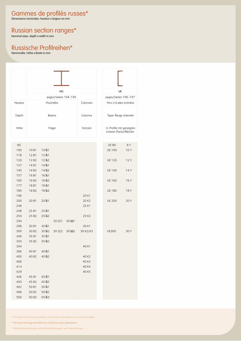
Gammes de profilés russes*Dimensions nominales: hauteur x largeur en mm
Russian section ranges*Nominal sizes: depth x width in mm
Russische Profilreihen*Nennmaße: Höhe x Breite in mm
* Tonnage minimum et conditions de livraison nécessitent un accord préalable. * Minimum tonnage and delivery conditions upon agreement. * Mindestbestellmenge und Lieferbedingungen nach Vereinbarung.
HG UE
pages/Seiten 194-195 pages/Seiten 196-197
Hauteur Poutrelles Colonnes Fers U à ailes inclinées
Depth Beams Columns Taper flange channels
Höhe Träger Stützen U-Profile mit geneigten inneren Flanschflächen
80 UE 80 8 Y
100 10 B1 10 Б1 UE 100 10 Y
118 12 B1 12 Б1
120 12 B2 12 Б2 UE 120 12 Y
137 14 B1 14 Б1
140 14 B2 14 Б2 UE 140 14 Y
157 16 B1 16 Б1
160 16 B2 16 Б2 UE 160 16 Y
177 18 B1 18 Б1
180 18 B2 18 Б2 UE 180 18 Y
196 20 K1
200 20 B1 20 Б1 20 K2 UE 200 20 Y
246 25 K1
248 25 B1 25 Б1
250 25 B2 25 Б2 25 K2
294 30 SZ1 30 Ш1
298 30 B1 30 Б1 30 K1
300 30 B2 30 Б2 30 SZ2 30 Ш2 30 K2/K3 UE300 30 Y
346 35 B1 35 Б1
350 35 B2 35 Б2
394 40 K1
396 40 B1 40 Б1
400 40 B2 40 Б2 40 K2
406 40 K3
414 40 K4
429 40 K5
446 45 B1 45 Б1
450 45 B2 45 Б2
492 50 B1 50 Б1
496 50 B2 50 Б2
500 50 B3 50 Б3
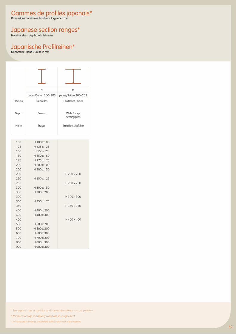
69
Gammes de profilés japonais*Dimensions nominales: hauteur x largeur en mm
Japanese section ranges*Nominal sizes: depth x width in mm
Japanische Profilreihen*Nennmaße: Höhe x Breite in mm
H H
pages/Seiten 200-203 pages/Seiten 200-203
Hauteur Poutrelles Poutrelles-pieux
Depth Beams Wide flange bearing piles
Höhe Träger Breitflanschpfähle
100 H 100 x 100
125 H 125 x 125
150 H 150 x 75
150 H 150 x 150
175 H 175 x 175
200 H 200 x 100
200 H 200 x 150
200 H 200 x 200
250 H 250 x 125
250 H 250 x 250
300 H 300 x 150
300 H 300 x 200
300 H 300 x 300
350 H 350 x 175
350 H 350 x 350
400 H 400 x 200
400 H 400 x 300
400 H 400 x 400
500 H 500 x 200
500 H 500 x 300
600 H 600 x 300
700 H 700 x 300
800 H 800 x 300
900 H 900 x 300
* Tonnage minimum et conditions de livraison nécessitent un accord préalable. * Minimum tonnage and delivery conditions upon agreement. * Mindestbestellmenge und Lieferbedingungen nach Vereinbarung.
© M
arc
Det
iffe
72 IPE Poutrelles I européennes
78 IPN Poutrelles normales européennes
80 HE Poutrelles européennes à larges ailes
88 HL Poutrelles européennes à très larges ailes
90 HD Poutrelles-poteaux à larges ailes
94 HP Poutrelles-pieux à larges ailes
96 UPE Fers U à ailes parallèles
98 UPN Fers U normaux européens
100 U Fers U à ailes inclinées
102 L Cornières à ailes égales
114 L Cornières à ailes inégales
116 L Dimensions de construction - cornières à ailes égales
121 L Dimensions de construction - cornières à ailes inégales
122 Fers plats + Larges plats
123 Carrés
124 Ronds laminés à chaud
72 IPE European I beams
78 IPN European standard beams
80 HE European wide flange beams
88 HL European extra wide flange beams
90 HD Wide flange columns
94 HP Wide flange bearing piles
96 UPE Channels with parallel flanges
98 UPN European standard channels
100 U Channels with taper flanges
102 L Equal leg angles
114 L Unequal leg angles
116 L Dimensions for detailing - equal leg angles
121 L Dimensions for detailing - unequal leg angles
122 Narrow flat bars + Flat bars
123 Square bars
124 Hot rolled round steel bars
72 IPE Europäische I-Profile
78 IPN Europäische Normalträger
80 HE Europäische Breitflanschträger
88 HL Europäische Träger mit besonders breiten Flanschen
90 HD Breitflansch-Stützenprofile
94 HP Breitflanschpfähle
96 UPE U-Profile mit parallelen Flanschen
98 UPN Europäische U-Stahl-Normalprofile
100 U-Profile mit geneigten inneren Flanschflächen
102 L Gleichschenkliger Winkelstahl
114 L Ungleichschenkliger Winkelstahl
116 L Konstruktionsmaße - gleichschenkliger Winkelstahl
121 L Konstruktionsmaße - ungleichschenkliger Winkelstahl
122 Flachstahl + Breitflachstahl
123 Vierkantstahl
124 Warmgewalzte Rundstäbe
Profilés européens et aciers marchands
European Sections and merchant bars
Europäische Profile und Stabstahl
71
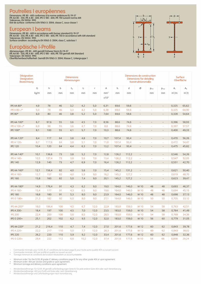
IPE AA 80* 4,9 78 46 3,2 4,2 5,0 6,31 69,6 59,6 - - - 0,325 65,62
IPEA80•/* 5,0 78 46 3,3 4,2 5,0 6,38 69,6 59,6 - - - 0,325 64,90
IPE 80* 6,0 80 46 3,8 5,2 5,0 7,64 69,6 59,6 - - - 0,328 54,64
IPE AA 100* 6,7 97,6 55 3,6 4,5 7,0 8,56 88,6 74,6 - - - 0,396 58,93
IPEA100•/* 6,9 98 55 3,6 4,7 7,0 8,8 88,6 74,6 - - - 0,397 57,57
IPE 100* 8,1 100 55 4,1 5,7 7,0 10,3 88,6 74,6 - - - 0,400 49,33
IPE AA 120* 8,4 117 64 3,8 4,8 7,0 10,7 107,4 93,4 - - - 0,470 56,26
IPEA120• 8,7 117,6 64 3,8 5,1 7,0 11,0 107,4 93,4 - - - 0,472 54,47
IPE 120 10,4 120 64 4,4 6,3 7,0 13,2 107,4 93,4 - - - 0,475 45,82
IPE AA 140* 10,1 136,6 73 3,8 5,2 7,0 12,8 126,2 112,2 - - - 0,546 54,26
IPEA140• 10,5 137,4 73 3,8 5,6 7,0 13,4 126,2 112,2 - - - 0,547 52,05
IPE 140 12,9 140 73 4,7 6,9 7,0 16,4 126,2 112,2 - - - 0,551 42,70
IPE AA 160* 12,1 156,4 82 4,0 5,6 7,0 15,4 145,2 131,2 - - - 0,621 50,40
IPEA160• 12,7 157 82 4,0 5,9 9,0 16,2 145,2 127,2 - - - 0,619 48,70
IPE 160 15,8 160 82 5,0 7,4 9,0 20,1 145,2 127,2 - - - 0,623 39,47
IPE AA 180* 14,9 176,4 91 4,3 6,2 9,0 19,0 164,0 146,0 M 10 48 48 0,693 46,37
IPEA180• 15,4 177 91 4,3 6,5 9,0 19,6 164,0 146,0 M 10 48 48 0,694 45,15
IPE 180 18,8 180 91 5,3 8,0 9,0 23,9 164,0 146,0 M 10 48 48 0,698 37,13
IPE O 180+ 21,3 182 92 6,0 9,0 9,0 27,1 164,0 146,0 M 10 50 50 0,705 33,12
IPE AA 200* 18,0 196,4 100 4,5 6,7 12,0 22,9 183,0 159,0 M 10 54 58 0,763 42,51
IPEA200• 18,4 197 100 4,5 7,0 12,0 23,5 183,0 159,0 M 10 54 58 0,764 41,49
IPE 200 22,4 200 100 5,6 8,5 12,0 28,5 183,0 159,0 M 10 54 58 0,768 34,36
IPE O 200+ 25,1 202 102 6,2 9,5 12,0 32,0 183,0 159,0 M 10 56 60 0,779 31,05
IPE AA 220* 21,2 216,4 110 4,7 7,4 12,0 27,0 201,6 177,6 M 12 60 62 0,843 39,78
IPEA220• 22,2 217 110 5,0 7,7 12,0 28,3 201,6 177,6 M 12 60 62 0,843 38,02
IPE 220 26,2 220 110 5,9 9,2 12,0 33,4 201,6 177,6 M 12 60 62 0,848 32,36
IPE O 220+ 29,4 222 112 6,6 10,2 12,0 37,4 201,6 177,6 M 10 58 66 0,858 29,24
• Commande minimale: pour S235 JR, cf. conditions de livraison page 8; pour toute autre qualité 40t ou suivant accord.+ Commande minimale: 40t par profilé et qualité ou suivant accord. * Tonnage minimum et conditions de livraison nécessitent un accord préalable.
• Minimum order: for the S235 JR grade cf. delivery conditions page 8; for any other grade 40t or upon agreement.+ Minimum order: 40t per section and grade or upon agreement.* Minimum tonnage and delivery conditions upon agreement. • Mindestbestellmenge: für S235 JR gemäß Lieferbedingungen Seite 8; für jede andere Güte 40t oder nach Vereinbarung.+ Mindestbestellmenge: 40t pro Profil und Güte oder nach Vereinbarung. * Mindestbestellmenge und Lieferbedingungen nach Vereinbarung.
Désignation Designation Bezeichnung
Dimensions Abmessungen
Dimensions de construction Dimensions for detailing
Konstruktionsmaße
Surface Oberfläche
G
kg/m
h b tw tf r A hi d Ø pmin pmax AL AG
mm mm mm mm mm mm2 mm mm mm mm m2/m m2/t
x102
Poutrelles I européennesDimensions: IPE 80 - 600 conformes à la norme antérieure EU 19-57 IPE AA 80 - 550, IPE A 80 - 600, IPE O 180 - 600, IPE 750 suivant norme AM Tolérances: EN 10034: 1993 Etat de surface: conforme à EN 10163-3: 2004, classe C, sous-classe 1
European I beamsDimensions: IPE 80 - 600 in accordance with former standard EU 19-57 IPE AA 80 - 550, IPE A 80 - 600, IPE O 180 - 600, IPE 750 in accordance with AM standard Tolerances: EN 10034: 1993 Surface condition: according to EN 10163-3: 2004, class C, subclass 1
Europäische I-ProfileAbmessungen: IPE 80 - 600 gemäß früherer Norm EU 19-57 IPE AA 80 - 550, IPE A 80 - 600, IPE O 180 - 600, IPE 750 gemäß AM Standard Toleranzen: EN 10034: 1993 Oberflächenbeschaffenheit: Gemäß EN 10163-3: 2004, Klasse C, Untergruppe 1
b
r
yy dh
tw
ss
zzt f
hi
p
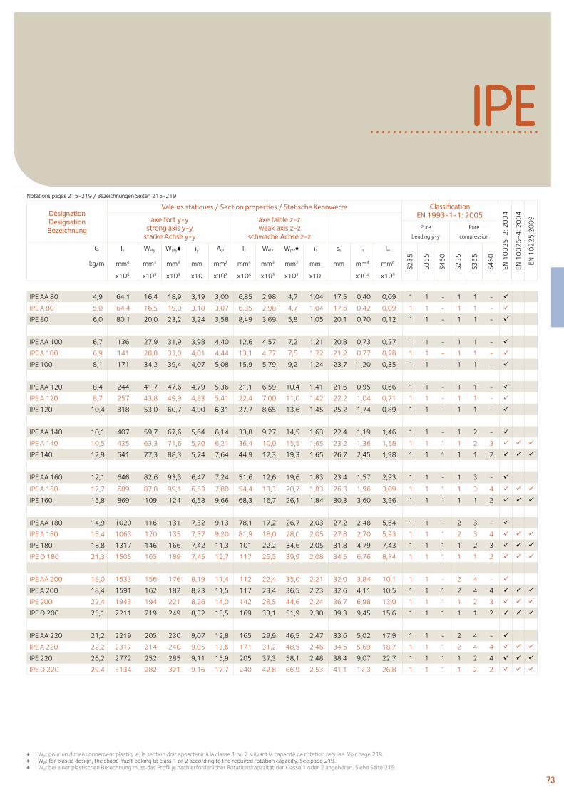
73
IPE
73
IPE AA 80 4,9 64,1 16,4 18,9 3,19 3,00 6,85 2,98 4,7 1,04 17,5 0,40 0,09 1 1 - 1 1 -
IPE A 80 5,0 64,4 16,5 19,0 3,18 3,07 6,85 2,98 4,7 1,04 17,6 0,42 0,09 1 1 - 1 1 -
IPE 80 6,0 80,1 20,0 23,2 3,24 3,58 8,49 3,69 5,8 1,05 20,1 0,70 0,12 1 1 - 1 1 -
IPE AA 100 6,7 136 27,9 31,9 3,98 4,40 12,6 4,57 7,2 1,21 20,8 0,73 0,27 1 1 - 1 1 -
IPE A 100 6,9 141 28,8 33,0 4,01 4,44 13,1 4,77 7,5 1,22 21,2 0,77 0,28 1 1 - 1 1 -
IPE 100 8,1 171 34,2 39,4 4,07 5,08 15,9 5,79 9,2 1,24 23,7 1,20 0,35 1 1 - 1 1 -
IPE AA 120 8,4 244 41,7 47,6 4,79 5,36 21,1 6,59 10,4 1,41 21,6 0,95 0,66 1 1 - 1 1 -
IPE A 120 8,7 257 43,8 49,9 4,83 5,41 22,4 7,00 11,0 1,42 22,2 1,04 0,71 1 1 - 1 1 -
IPE 120 10,4 318 53,0 60,7 4,90 6,31 27,7 8,65 13,6 1,45 25,2 1,74 0,89 1 1 - 1 1 -
IPE AA 140 10,1 407 59,7 67,6 5,64 6,14 33,8 9,27 14,5 1,63 22,4 1,19 1,46 1 1 - 1 2 -
IPE A 140 10,5 435 63,3 71,6 5,70 6,21 36,4 10,0 15,5 1,65 23,2 1,36 1,58 1 1 1 1 2 3
IPE 140 12,9 541 77,3 88,3 5,74 7,64 44,9 12,3 19,3 1,65 26,7 2,45 1,98 1 1 1 1 1 2
IPE AA 160 12,1 646 82,6 93,3 6,47 7,24 51,6 12,6 19,6 1,83 23,4 1,57 2,93 1 1 - 1 3 -
IPE A 160 12,7 689 87,8 99,1 6,53 7,80 54,4 13,3 20,7 1,83 26,3 1,96 3,09 1 1 1 1 3 4
IPE 160 15,8 869 109 124 6,58 9,66 68,3 16,7 26,1 1,84 30,3 3,60 3,96 1 1 1 1 1 2
IPE AA 180 14,9 1020 116 131 7,32 9,13 78,1 17,2 26,7 2,03 27,2 2,48 5,64 1 1 - 2 3 -
IPE A 180 15,4 1063 120 135 7,37 9,20 81,9 18,0 28,0 2,05 27,8 2,70 5,93 1 1 1 2 3 4
IPE 180 18,8 1317 146 166 7,42 11,3 101 22,2 34,6 2,05 31,8 4,79 7,43 1 1 1 1 2 3
IPE O 180 21,3 1505 165 189 7,45 12,7 117 25,5 39,9 2,08 34,5 6,76 8,74 1 1 1 1 1 2
IPE AA 200 18,0 1533 156 176 8,19 11,4 112 22,4 35,0 2,21 32,0 3,84 10,1 1 1 - 2 4 -
IPE A 200 18,4 1591 162 182 8,23 11,5 117 23,4 36,5 2,23 32,6 4,11 10,5 1 1 1 2 4 4
IPE 200 22,4 1943 194 221 8,26 14,0 142 28,5 44,6 2,24 36,7 6,98 13,0 1 1 1 1 2 3
IPE O 200 25,1 2211 219 249 8,32 15,5 169 33,1 51,9 2,30 39,3 9,45 15,6 1 1 1 1 1 2
IPE AA 220 21,2 2219 205 230 9,07 12,8 165 29,9 46,5 2,47 33,6 5,02 17,9 1 1 - 2 4 -
IPE A 220 22,2 2317 214 240 9,05 13,6 171 31,2 48,5 2,46 34,5 5,69 18,7 1 1 1 2 4 4
IPE 220 26,2 2772 252 285 9,11 15,9 205 37,3 58,1 2,48 38,4 9,07 22,7 1 1 1 1 2 4
IPE O 220 29,4 3134 282 321 9,16 17,7 240 42,8 66,9 2,53 41,1 12,3 26,8 1 1 1 1 2 2
IPE
Désignation Designation Bezeichnung
Valeurs statiques / Section properties / Statische Kennwerte Classification EN 1993-1-1: 2005
EN 1
00
25
-2: 2
00
4
EN 1
00
25
-4: 2
00
4
EN 1
02
25
:20
09axe fort y-y
strong axis y-y starke Achse y-y
axe faible z-z weak axis z-z
schwache Achse z-z Pure
bending y-y
Pure
compression
G
kg/m
Iy Wel.y Wpl.y♦ iy Avz Iz Wel.z Wpl.z♦ iz ss It Iw
S23
5
S35
5
S46
0
S23
5
S35
5
S46
0
mm4 mm3 mm3 mm mm2 mm4 mm3 mm3 mm mm mm4 mm6
x104 x103 x103 x10 x102 x104 x103 x103 x10 x104 x109
♦ Wpl: pour un dimensionnement plastique, la section doit appartenir à la classe 1 ou 2 suivant la capacité de rotation requise. Voir page 219.♦ Wpl: for plastic design, the shape must belong to class 1 or 2 according to the required rotation capacity. See page 219.♦ Wpl: bei einer plastischen Berechnung muss das Profil je nach erforderlicher Rotationskapazität der Klasse 1 oder 2 angehören. Siehe Seite 219.
Notations pages 215-219 / Bezeichnungen Seiten 215-219
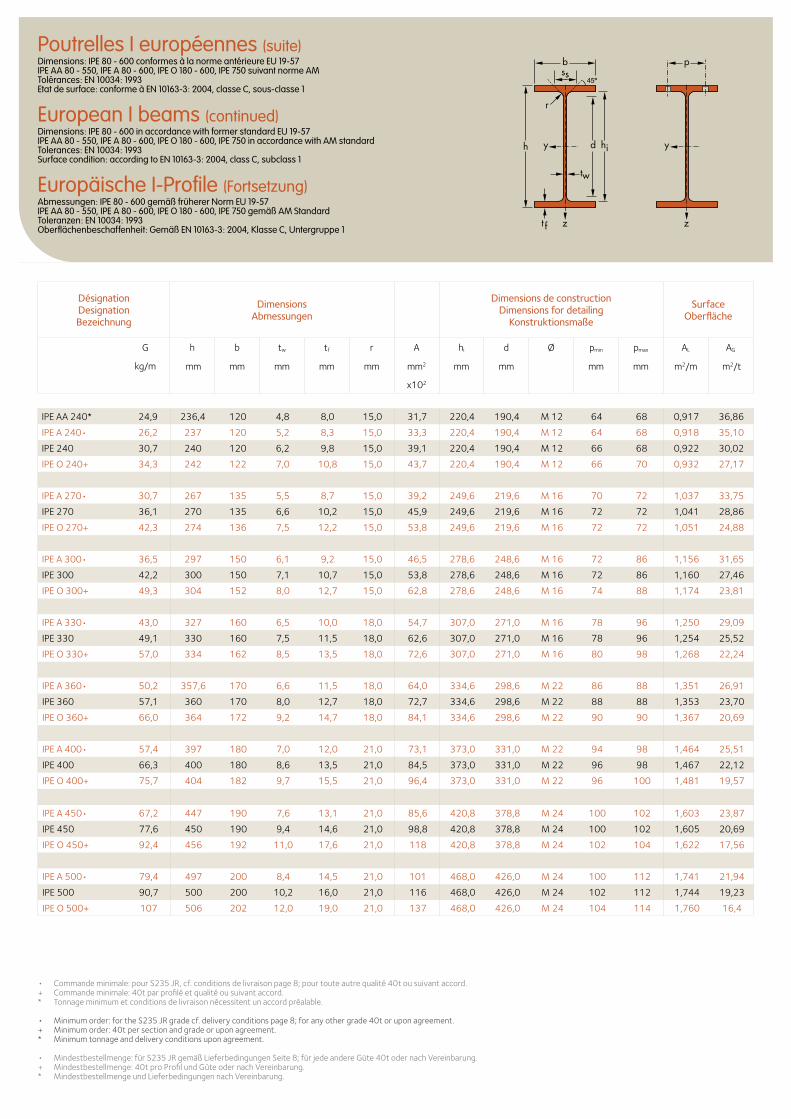
IPE AA 240* 24,9 236,4 120 4,8 8,0 15,0 31,7 220,4 190,4 M 12 64 68 0,917 36,86
IPEA240• 26,2 237 120 5,2 8,3 15,0 33,3 220,4 190,4 M 12 64 68 0,918 35,10
IPE 240 30,7 240 120 6,2 9,8 15,0 39,1 220,4 190,4 M 12 66 68 0,922 30,02
IPE O 240+ 34,3 242 122 7,0 10,8 15,0 43,7 220,4 190,4 M 12 66 70 0,932 27,17
IPEA270• 30,7 267 135 5,5 8,7 15,0 39,2 249,6 219,6 M 16 70 72 1,037 33,75
IPE 270 36,1 270 135 6,6 10,2 15,0 45,9 249,6 219,6 M 16 72 72 1,041 28,86
IPE O 270+ 42,3 274 136 7,5 12,2 15,0 53,8 249,6 219,6 M 16 72 72 1,051 24,88
IPEA300• 36,5 297 150 6,1 9,2 15,0 46,5 278,6 248,6 M 16 72 86 1,156 31,65
IPE 300 42,2 300 150 7,1 10,7 15,0 53,8 278,6 248,6 M 16 72 86 1,160 27,46
IPE O 300+ 49,3 304 152 8,0 12,7 15,0 62,8 278,6 248,6 M 16 74 88 1,174 23,81
IPEA330• 43,0 327 160 6,5 10,0 18,0 54,7 307,0 271,0 M 16 78 96 1,250 29,09
IPE 330 49,1 330 160 7,5 11,5 18,0 62,6 307,0 271,0 M 16 78 96 1,254 25,52
IPE O 330+ 57,0 334 162 8,5 13,5 18,0 72,6 307,0 271,0 M 16 80 98 1,268 22,24
IPEA360• 50,2 357,6 170 6,6 11,5 18,0 64,0 334,6 298,6 M 22 86 88 1,351 26,91
IPE 360 57,1 360 170 8,0 12,7 18,0 72,7 334,6 298,6 M 22 88 88 1,353 23,70
IPE O 360+ 66,0 364 172 9,2 14,7 18,0 84,1 334,6 298,6 M 22 90 90 1,367 20,69
IPEA400• 57,4 397 180 7,0 12,0 21,0 73,1 373,0 331,0 M 22 94 98 1,464 25,51
IPE 400 66,3 400 180 8,6 13,5 21,0 84,5 373,0 331,0 M 22 96 98 1,467 22,12
IPE O 400+ 75,7 404 182 9,7 15,5 21,0 96,4 373,0 331,0 M 22 96 100 1,481 19,57
IPEA450• 67,2 447 190 7,6 13,1 21,0 85,6 420,8 378,8 M 24 100 102 1,603 23,87
IPE 450 77,6 450 190 9,4 14,6 21,0 98,8 420,8 378,8 M 24 100 102 1,605 20,69
IPE O 450+ 92,4 456 192 11,0 17,6 21,0 118 420,8 378,8 M 24 102 104 1,622 17,56
IPEA500• 79,4 497 200 8,4 14,5 21,0 101 468,0 426,0 M 24 100 112 1,741 21,94
IPE 500 90,7 500 200 10,2 16,0 21,0 116 468,0 426,0 M 24 102 112 1,744 19,23
IPE O 500+ 107 506 202 12,0 19,0 21,0 137 468,0 426,0 M 24 104 114 1,760 16,4
Poutrelles I européennes (suite)Dimensions: IPE 80 - 600 conformes à la norme antérieure EU 19-57 IPE AA 80 - 550, IPE A 80 - 600, IPE O 180 - 600, IPE 750 suivant norme AM Tolérances: EN 10034: 1993 Etat de surface: conforme à EN 10163-3: 2004, classe C, sous-classe 1
European I beams (continued)Dimensions: IPE 80 - 600 in accordance with former standard EU 19-57 IPE AA 80 - 550, IPE A 80 - 600, IPE O 180 - 600, IPE 750 in accordance with AM standard Tolerances: EN 10034: 1993 Surface condition: according to EN 10163-3: 2004, class C, subclass 1
Europäische I-Profile (Fortsetzung)Abmessungen: IPE 80 - 600 gemäß früherer Norm EU 19-57 IPE AA 80 - 550, IPE A 80 - 600, IPE O 180 - 600, IPE 750 gemäß AM Standard Toleranzen: EN 10034: 1993 Oberflächenbeschaffenheit: Gemäß EN 10163-3: 2004, Klasse C, Untergruppe 1
b
r
yy dh
tw
ss
zzt f
hi
p
• Commande minimale: pour S235 JR, cf. conditions de livraison page 8; pour toute autre qualité 40t ou suivant accord.+ Commande minimale: 40t par profilé et qualité ou suivant accord. * Tonnage minimum et conditions de livraison nécessitent un accord préalable.
• Minimum order: for the S235 JR grade cf. delivery conditions page 8; for any other grade 40t or upon agreement.+ Minimum order: 40t per section and grade or upon agreement.* Minimum tonnage and delivery conditions upon agreement. • Mindestbestellmenge: für S235 JR gemäß Lieferbedingungen Seite 8; für jede andere Güte 40t oder nach Vereinbarung.+ Mindestbestellmenge: 40t pro Profil und Güte oder nach Vereinbarung. * Mindestbestellmenge und Lieferbedingungen nach Vereinbarung.
Désignation Designation Bezeichnung
Dimensions Abmessungen
Dimensions de construction Dimensions for detailing
Konstruktionsmaße
Surface Oberfläche
G
kg/m
h b tw tf r A hi d Ø pmin pmax AL AG
mm mm mm mm mm mm2 mm mm mm mm m2/m m2/t
x102
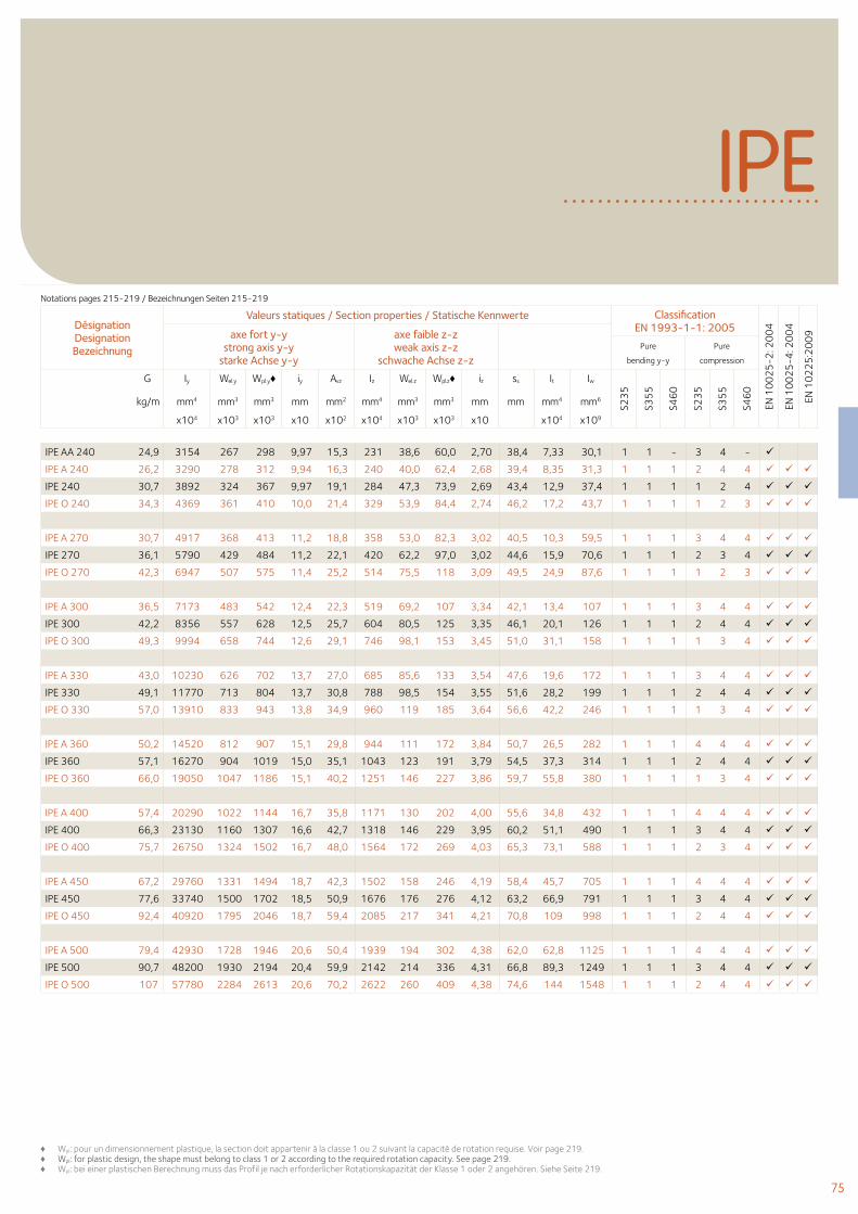
75
IPE
IPE AA 240 24,9 3154 267 298 9,97 15,3 231 38,6 60,0 2,70 38,4 7,33 30,1 1 1 - 3 4 -
IPE A 240 26,2 3290 278 312 9,94 16,3 240 40,0 62,4 2,68 39,4 8,35 31,3 1 1 1 2 4 4
IPE 240 30,7 3892 324 367 9,97 19,1 284 47,3 73,9 2,69 43,4 12,9 37,4 1 1 1 1 2 4
IPE O 240 34,3 4369 361 410 10,0 21,4 329 53,9 84,4 2,74 46,2 17,2 43,7 1 1 1 1 2 3
IPE A 270 30,7 4917 368 413 11,2 18,8 358 53,0 82,3 3,02 40,5 10,3 59,5 1 1 1 3 4 4
IPE 270 36,1 5790 429 484 11,2 22,1 420 62,2 97,0 3,02 44,6 15,9 70,6 1 1 1 2 3 4
IPE O 270 42,3 6947 507 575 11,4 25,2 514 75,5 118 3,09 49,5 24,9 87,6 1 1 1 1 2 3
IPE A 300 36,5 7173 483 542 12,4 22,3 519 69,2 107 3,34 42,1 13,4 107 1 1 1 3 4 4
IPE 300 42,2 8356 557 628 12,5 25,7 604 80,5 125 3,35 46,1 20,1 126 1 1 1 2 4 4
IPE O 300 49,3 9994 658 744 12,6 29,1 746 98,1 153 3,45 51,0 31,1 158 1 1 1 1 3 4
IPE A 330 43,0 10230 626 702 13,7 27,0 685 85,6 133 3,54 47,6 19,6 172 1 1 1 3 4 4
IPE 330 49,1 11770 713 804 13,7 30,8 788 98,5 154 3,55 51,6 28,2 199 1 1 1 2 4 4
IPE O 330 57,0 13910 833 943 13,8 34,9 960 119 185 3,64 56,6 42,2 246 1 1 1 1 3 4
IPE A 360 50,2 14520 812 907 15,1 29,8 944 111 172 3,84 50,7 26,5 282 1 1 1 4 4 4
IPE 360 57,1 16270 904 1019 15,0 35,1 1043 123 191 3,79 54,5 37,3 314 1 1 1 2 4 4
IPE O 360 66,0 19050 1047 1186 15,1 40,2 1251 146 227 3,86 59,7 55,8 380 1 1 1 1 3 4
IPE A 400 57,4 20290 1022 1144 16,7 35,8 1171 130 202 4,00 55,6 34,8 432 1 1 1 4 4 4
IPE 400 66,3 23130 1160 1307 16,6 42,7 1318 146 229 3,95 60,2 51,1 490 1 1 1 3 4 4
IPE O 400 75,7 26750 1324 1502 16,7 48,0 1564 172 269 4,03 65,3 73,1 588 1 1 1 2 3 4
IPE A 450 67,2 29760 1331 1494 18,7 42,3 1502 158 246 4,19 58,4 45,7 705 1 1 1 4 4 4
IPE 450 77,6 33740 1500 1702 18,5 50,9 1676 176 276 4,12 63,2 66,9 791 1 1 1 3 4 4
IPE O 450 92,4 40920 1795 2046 18,7 59,4 2085 217 341 4,21 70,8 109 998 1 1 1 2 4 4
IPE A 500 79,4 42930 1728 1946 20,6 50,4 1939 194 302 4,38 62,0 62,8 1125 1 1 1 4 4 4
IPE 500 90,7 48200 1930 2194 20,4 59,9 2142 214 336 4,31 66,8 89,3 1249 1 1 1 3 4 4
IPE O 500 107 57780 2284 2613 20,6 70,2 2622 260 409 4,38 74,6 144 1548 1 1 1 2 4 4
Désignation Designation Bezeichnung
Valeurs statiques / Section properties / Statische Kennwerte Classification EN 1993-1-1: 2005
EN 1
00
25
-2: 2
00
4
EN 1
00
25
-4: 2
00
4
EN 1
02
25
:20
09axe fort y-y
strong axis y-y starke Achse y-y
axe faible z-z weak axis z-z
schwache Achse z-z Pure
bending y-y
Pure
compression
G
kg/m
Iy Wel.y Wpl.y♦ iy Avz Iz Wel.z Wpl.z♦ iz ss It Iw
S23
5
S35
5
S46
0
S23
5
S35
5
S46
0
mm4 mm3 mm3 mm mm2 mm4 mm3 mm3 mm mm mm4 mm6
x104 x103 x103 x10 x102 x104 x103 x103 x10 x104 x109
♦ Wpl: pour un dimensionnement plastique, la section doit appartenir à la classe 1 ou 2 suivant la capacité de rotation requise. Voir page 219.♦ Wpl: for plastic design, the shape must belong to class 1 or 2 according to the required rotation capacity. See page 219.♦ Wpl: bei einer plastischen Berechnung muss das Profil je nach erforderlicher Rotationskapazität der Klasse 1 oder 2 angehören. Siehe Seite 219.
Notations pages 215-219 / Bezeichnungen Seiten 215-219
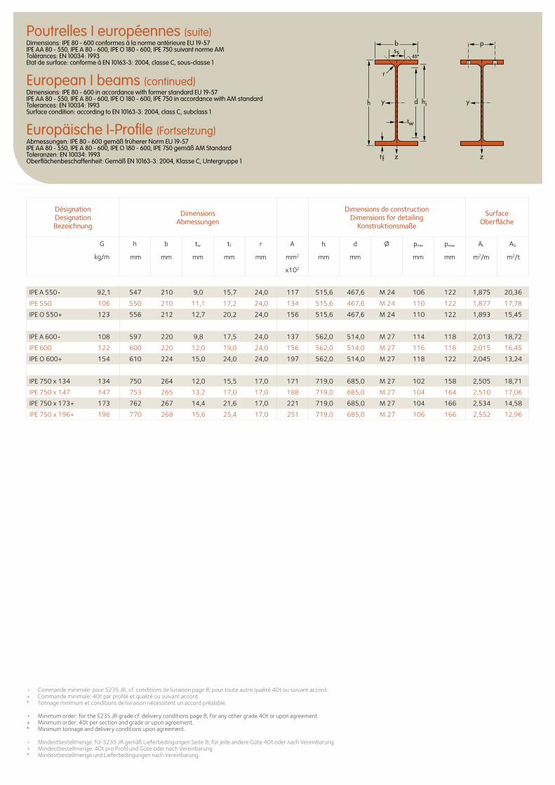
Désignation Designation Bezeichnung
Dimensions Abmessungen
Dimensions de construction Dimensions for detailing
Konstruktionsmaße
Surface Oberfläche
G
kg/m
h b tw tf r A hi d Ø pmin pmax AL AG
mm mm mm mm mm mm2 mm mm mm mm m2/m m2/t
x102
IPEA550• 92,1 547 210 9,0 15,7 24,0 117 515,6 467,6 M 24 106 122 1,875 20,36
IPE 550 106 550 210 11,1 17,2 24,0 134 515,6 467,6 M 24 110 122 1,877 17,78
IPE O 550+ 123 556 212 12,7 20,2 24,0 156 515,6 467,6 M 24 110 122 1,893 15,45
IPEA600• 108 597 220 9,8 17,5 24,0 137 562,0 514,0 M 27 114 118 2,013 18,72
IPE 600 122 600 220 12,0 19,0 24,0 156 562,0 514,0 M 27 116 118 2,015 16,45
IPE O 600+ 154 610 224 15,0 24,0 24,0 197 562,0 514,0 M 27 118 122 2,045 13,24
IPE 750 x 134 134 750 264 12,0 15,5 17,0 171 719,0 685,0 M 27 102 158 2,505 18,71
IPE 750 x 147 147 753 265 13,2 17,0 17,0 188 719,0 685,0 M 27 104 164 2,510 17,06
IPE 750 x 173+ 173 762 267 14,4 21,6 17,0 221 719,0 685,0 M 27 104 166 2,534 14,58
IPE 750 x 196+ 196 770 268 15,6 25,4 17,0 251 719,0 685,0 M 27 106 166 2,552 12,96
• Commande minimale: pour S235 JR, cf. conditions de livraison page 8; pour toute autre qualité 40t ou suivant accord.+ Commande minimale: 40t par profilé et qualité ou suivant accord. * Tonnage minimum et conditions de livraison nécessitent un accord préalable.
• Minimum order: for the S235 JR grade cf. delivery conditions page 8; for any other grade 40t or upon agreement.+ Minimum order: 40t per section and grade or upon agreement.* Minimum tonnage and delivery conditions upon agreement. • Mindestbestellmenge: für S235 JR gemäß Lieferbedingungen Seite 8; für jede andere Güte 40t oder nach Vereinbarung.+ Mindestbestellmenge: 40t pro Profil und Güte oder nach Vereinbarung. * Mindestbestellmenge und Lieferbedingungen nach Vereinbarung.
Poutrelles I européennes (suite)Dimensions: IPE 80 - 600 conformes à la norme antérieure EU 19-57 IPE AA 80 - 550, IPE A 80 - 600, IPE O 180 - 600, IPE 750 suivant norme AM Tolérances: EN 10034: 1993 Etat de surface: conforme à EN 10163-3: 2004, classe C, sous-classe 1
European I beams (continued)Dimensions: IPE 80 - 600 in accordance with former standard EU 19-57 IPE AA 80 - 550, IPE A 80 - 600, IPE O 180 - 600, IPE 750 in accordance with AM standard Tolerances: EN 10034: 1993 Surface condition: according to EN 10163-3: 2004, class C, subclass 1
Europäische I-Profile (Fortsetzung)Abmessungen: IPE 80 - 600 gemäß früherer Norm EU 19-57 IPE AA 80 - 550, IPE A 80 - 600, IPE O 180 - 600, IPE 750 gemäß AM Standard Toleranzen: EN 10034: 1993 Oberflächenbeschaffenheit: Gemäß EN 10163-3: 2004, Klasse C, Untergruppe 1
b
r
yy dh
tw
ss
zzt f
hi
p
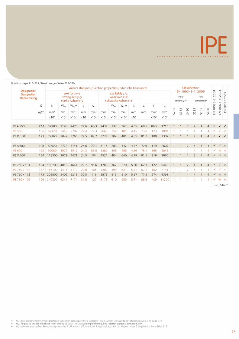
77
Désignation Designation Bezeichnung
Valeurs statiques / Section properties / Statische Kennwerte Classification EN 1993-1-1: 2005
EN 1
00
25
-2: 2
00
4
EN 1
00
25
-4: 2
00
4
EN 1
02
25
:20
09axe fort y-y
strong axis y-y starke Achse y-y
axe faible z-z weak axis z-z
schwache Achse z-z Pure
bending y-y
Pure
compression
G
kg/m
Iy Wel.y Wpl.y♦ iy Avz Iz Wel.z Wpl.z♦ iz ss It Iw
S23
5
S35
5
S46
0
S23
5
S35
5
S46
0
mm4 mm3 mm3 mm mm2 mm4 mm3 mm3 mm mm mm4 mm6
x104 x103 x103 x10 x102 x104 x103 x103 x10 x104 x109
IPE
IPE A 550 92,1 59980 2193 2475 22,6 60,3 2432 232 362 4,55 68,5 86,5 1710 1 1 2 4 4 4
IPE 550 106 67120 2440 2787 22,4 72,3 2668 254 401 4,45 73,6 123 1884 1 1 1 4 4 4
IPE O 550 123 79160 2847 3263 22,5 82,7 3224 304 481 4,55 81,2 188 2302 1 1 1 2 4 4
IPE A 600 108 82920 2778 3141 24,6 70,1 3116 283 442 4,77 72,9 119 2607 1 1 2 4 4 4
IPE 600 122 92080 3070 3512 24,3 83,8 3387 308 486 4,66 78,1 165 2846 1 1 1 4 4 4 HI HI
IPE O 600 154 118300 3879 4471 24,5 104 4521 404 640 4,79 91,1 318 3860 1 1 1 2 4 4 HI HI
IPE 750 x 134 134 150700 4018 4644 29,7 95,6 4788 362 570 5,30 62,3 122 6440 1 1 2 4 4 4
IPE 750 x 147 147 166100 4411 5110 29,8 105 5289 399 631 5,31 67,1 162 7141 1 1 2 4 4 4
IPE 750 x 173 173 205800 5402 6218 30,5 116 6873 515 810 5,57 77,5 274 9391 1 1 1 4 4 4 HI HI
IPE 750 x 196 196 240300 6241 7174 31,0 127 8175 610 959 5,71 86,3 409 11290 1 1 1 4 4 4 HI HI HI = HISTAR©
Notations pages 215-219 / Bezeichnungen Seiten 215-219
♦ Wpl: pour un dimensionnement plastique, la section doit appartenir à la classe 1 ou 2 suivant la capacité de rotation requise. Voir page 219.♦ Wpl: for plastic design, the shape must belong to class 1 or 2 according to the required rotation capacity. See page 219.♦ Wpl: bei einer plastischen Berechnung muss das Profil je nach erforderlicher Rotationskapazität der Klasse 1 oder 2 angehören. Siehe Seite 219.
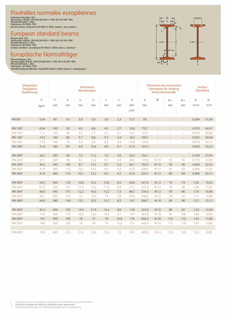
Désignation Designation Bezeichnung
Dimensions Abmessungen
Dimensions de construction Dimensions for detailing
Konstruktionsmaße
Surface Oberfläche
G
kg/m
h b tw tf r1 r2 A d Ø pmin pmax AL AG
mm mm mm mm mm mm mm2 mm mm mm m2/m m2/t
x102
* Tonnage minimum et conditions de livraison nécessitent un accord préalable.* Minimum tonnage and delivery conditions upon agreement.* Mindestbestellmenge und Lieferbedingungen nach Vereinbarung.
Poutrelles normales européennesInclinaison des ailes: 14% Dimensions: IPN 80 - IPN 550 DIN 1025-1: 1995, NF A 45-209: 1983 IPN 600 DIN 1025-1: 1963 Tolérances: EN 10024: 1995 Etat de surface: conforme à EN 10163-3: 2004, classe C, sous-classe 1
European standard beamsFlange slope: 14% Dimensions: IPN 80 - IPN 550 DIN 1025-1: 1995, NF A 45-209: 1983 IPN 600 DIN 1025-1: 1963 Tolerances: EN 10024: 1995 Surface condition: according to EN 10163-3: 2004, class C, subclass 1
Europäische NormalträgerFlanschneigung: 14% Abmessungen: IPN 80 - IPN 550 DIN 1025-1: 1995, NF A 45-209: 1983 IPN 600 DIN 1025-1: 1963 Toleranzen: EN 10024: 1995 Oberflächenbeschaffenheit: Gemäß EN 10163-3: 2004, Klasse C, Untergruppe 1
ssp
45o
d
twtf
h yy
zz
b
r1r2
b4
IPN 80* 5,94 80 42 3,9 5,9 3,9 2,3 7,57 59 - - - 0,304 51,09
IPN 100* 8,34 100 50 4,5 6,8 4,5 2,7 10,6 75,7 - - - 0,370 44,47
IPN 120* 11,1 120 58 5,1 7,7 5,1 3,1 14,2 92,4 - - - 0,439 39,38
IPN 140* 14,3 140 66 5,7 8,6 5,7 3,4 18,2 109,1 - - - 0,502 34,94
IPN 160* 17,9 160 74 6,3 9,5 6,3 3,8 22,8 125,8 - - - 0,575 32,13
IPN 180* 21,9 180 82 6,9 10,4 6,9 4,1 27,9 142,4 - - - 0,640 29,22
IPN 200* 26,2 200 90 7,5 11,3 7,5 4,5 33,4 159,1 - - - 0,709 27,04
IPN 220* 31,1 220 98 8,1 12,2 8,1 4,9 39,5 175,8 M 10 50 56 0,775 24,99
IPN 240* 36,2 240 106 8,7 13,1 8,7 5,2 46,1 192,5 M 10 54 60 0,844 23,32
IPN 260* 41,9 260 113 9,4 14,1 9,4 5,6 53,3 208,9 M 12 62 62 0,906 21,65
IPN 280* 47,9 280 119 10,1 15,2 10,1 6,1 61,0 225,1 M 12 68 68 0,966 20,17
IPN 300* 54,2 300 125 10,8 16,2 10,8 6,5 69,0 241,6 M 12 70 74 1,03 19,02
IPN 320* 61,0 320 131 11,5 17,3 11,5 6,9 77,7 257,9 M 12 70 80 1,09 17,87
IPN 340* 68,0 340 137 12,2 18,3 12,2 7,3 86,7 274,3 M 12 78 86 1,15 16,90
IPN 360* 76,1 360 143 13 19,5 13 7,8 97,0 290,2 M 12 78 92 1,21 15,89
IPN 380* 84,0 380 149 13,7 20,5 13,7 8,2 107 306,7 M 16 84 86 1,27 15,12
IPN 400* 92,4 400 155 14,4 21,6 14,4 8,6 118 322,9 M 16 86 92 1,33 14,36
IPN 450* 115 450 170 16,2 24,3 16,2 9,7 147 363,6 M 16 92 106 1,48 12,83
IPN 500* 141 500 185 18 27 18 10,8 179 404,3 M 20 102 110 1,63 11,60
IPN 550* 166 550 200 19 30 19 11,9 212 445,6 M 22 112 118 1,80 10,80
IPN 600* 199 600 215 21,6 32,4 21,6 13 254 485,8 M 24 126 128 1,92 9,89
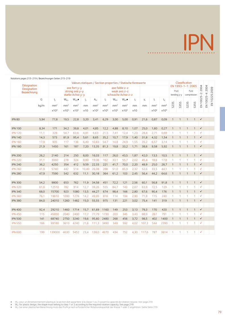
79
IPN
Désignation Designation Bezeichnung
Valeurs statiques / Section properties / Statische Kennwerte Classification EN 1993-1-1: 2005
EN 1
00
25
-2: 2
00
4
EN 1
00
25
-4: 2
00
4
EN 1
02
25
:20
09axe fort y-y
strong axis y-y starke Achse y-y
axe faible z-z weak axis z-z
schwache Achse z-z Pure
bending y-y
Pure
compression
G
kg/m
Iy Wel.y Wpl.y♦ iy Avz Iz Wel.z Wpl.z♦ iz ss It Iw
S23
5
S35
5
S23
5
S35
5
mm4 mm3 mm3 mm mm2 mm4 mm3 mm3 mm mm mm4 mm6
x104 x103 x103 x10 x102 x104 x103 x103 x10 x104 x109
IPN 80 5,94 77,8 19,5 22,8 3,20 3,41 6,29 3,00 5,00 0,91 21,6 0,87 0,09 1 1 1 1
IPN 100 8,34 171 34,2 39,8 4,01 4,85 12,2 4,88 8,10 1,07 25,0 1,60 0,27 1 1 1 1
IPN 120 11,1 328 54,7 63,6 4,81 6,63 21,5 7,41 12,4 1,23 28,4 2,71 0,69 1 1 1 1
IPN 140 14,3 573 81,9 95,4 5,61 8,65 35,2 10,7 17,9 1,40 31,8 4,32 1,54 1 1 1 1
IPN 160 17,9 935 117 136 6,40 10,83 54,7 14,8 24,9 1,55 35,2 6,57 3,14 1 1 1 1
IPN 180 21,9 1450 161 187 7,20 13,35 81,3 19,8 33,2 1,71 38,6 9,58 5,92 1 1 1 1
IPN 200 26,2 2140 214 250 8,00 16,03 117 26,0 43,5 1,87 42,0 13,5 10,5 1 1 1 1
IPN 220 31,1 3060 278 324 8,80 19,06 162 33,1 55,7 2,02 45,4 18,6 17,8 1 1 1 1
IPN 240 36,2 4250 354 412 9,59 22,33 221 41,7 70,0 2,20 48,9 25,0 28,7 1 1 1 1
IPN 260 41,9 5740 442 514 10,40 26,08 288 51,0 85,9 2,32 52,6 33,5 44,1 1 1 1 1
IPN 280 47,9 7590 542 632 11,1 30,18 364 61,2 103 2,45 56,4 44,2 64,6 1 1 1 1
IPN 300 54,2 9800 653 762 11,9 34,58 451 72,2 121 2,56 60,1 56,8 91,8 1 1 1 1
IPN 320 61,0 12510 782 914 12,7 39,26 555 84,7 143 2,67 63,9 72,5 129 1 1 1 1
IPN 340 68,0 15700 923 1080 13,5 44,27 674 98,4 166 2,80 67,6 90,4 176 1 1 1 1
IPN 360 76,1 19610 1090 1276 14,2 49,95 818 114 194 2,90 71,8 115 240 1 1 1 1
IPN 380 84,0 24010 1260 1482 15,0 55,55 975 131 221 3,02 75,4 141 319 1 1 1 1
IPN 400 92,4 29210 1460 1714 15,7 61,69 1160 149 253 3,13 79,3 170 420 1 1 1 1
IPN 450 115 45850 2040 2400 17,7 77,79 1730 203 345 3,43 88,9 267 791 1 1 1 1
IPN 500 141 68740 2750 3240 19,6 95,60 2480 268 456 3,72 98,5 402 1400 1 1 1 1
IPN 550 166 99180 3610 4240 21,6 111,3 3490 349 592 4,02 107,3 544 2390 1 1 1 1
IPN 600 199 139000 4630 5452 23,4 138,0 4670 434 752 4,30 117,6 787 3814 1 1 1 1
Notations pages 215-219 / Bezeichnungen Seiten 215-219
♦ Wpl: pour un dimensionnement plastique, la section doit appartenir à la classe 1 ou 2 suivant la capacité de rotation requise. Voir page 219.♦ Wpl: for plastic design, the shape must belong to class 1 or 2 according to the required rotation capacity. See page 219.♦ Wpl: bei einer plastischen Berechnung muss das Profil je nach erforderlicher Rotationskapazität der Klasse 1 oder 2 angehören. Siehe Seite 219.
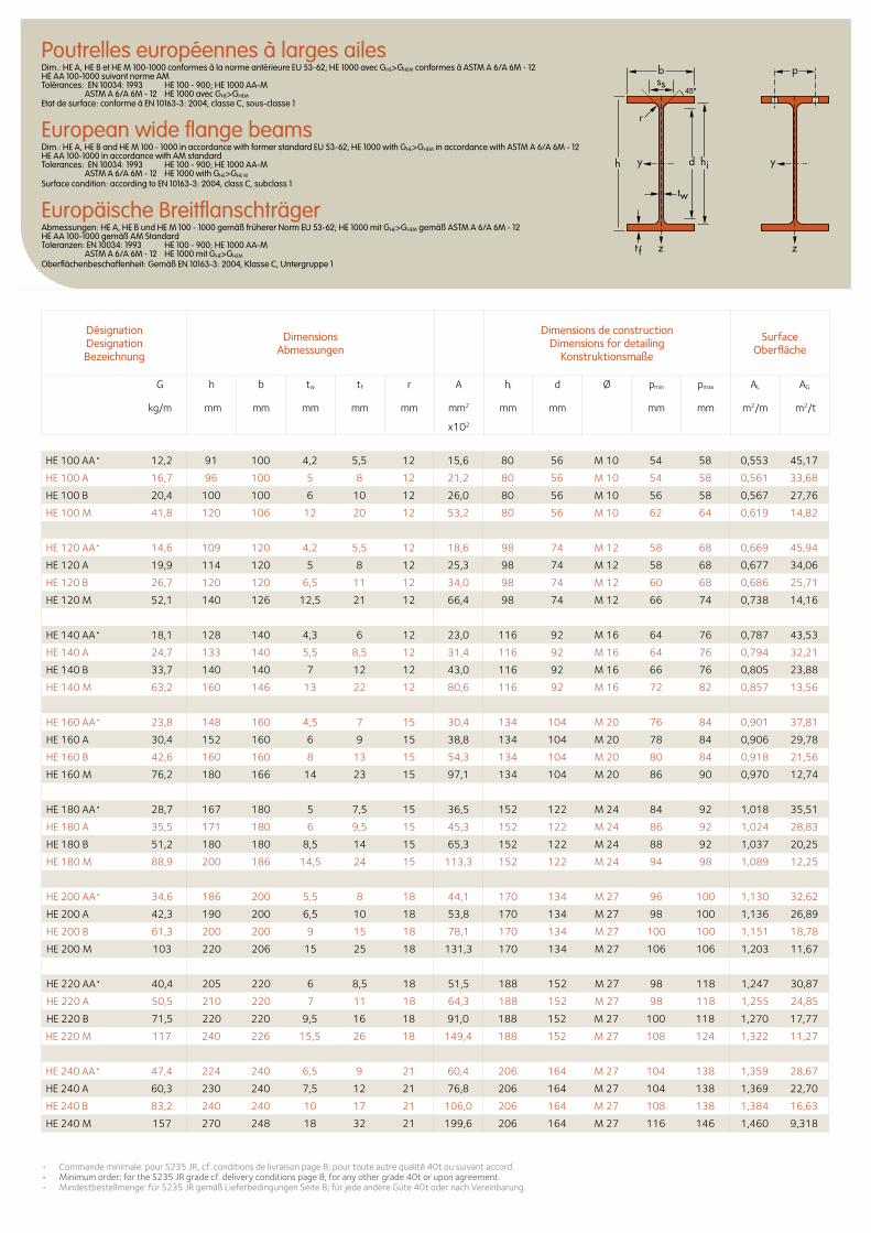
Désignation Designation Bezeichnung
Dimensions Abmessungen
Dimensions de construction Dimensions for detailing
Konstruktionsmaße
Surface Oberfläche
G
kg/m
h b tw tf r A hi d Ø pmin pmax AL AG
mm mm mm mm mm mm2 mm mm mm mm m2/m m2/t
x102
HE 100 AA• 12,2 91 100 4,2 5,5 12 15,6 80 56 M 10 54 58 0,553 45,17
HE 100 A 16,7 96 100 5 8 12 21,2 80 56 M 10 54 58 0,561 33,68
HE 100 B 20,4 100 100 6 10 12 26,0 80 56 M 10 56 58 0,567 27,76
HE 100 M 41,8 120 106 12 20 12 53,2 80 56 M 10 62 64 0,619 14,82
HE 120 AA• 14,6 109 120 4,2 5,5 12 18,6 98 74 M 12 58 68 0,669 45,94
HE 120 A 19,9 114 120 5 8 12 25,3 98 74 M 12 58 68 0,677 34,06
HE 120 B 26,7 120 120 6,5 11 12 34,0 98 74 M 12 60 68 0,686 25,71
HE 120 M 52,1 140 126 12,5 21 12 66,4 98 74 M 12 66 74 0,738 14,16
HE 140 AA• 18,1 128 140 4,3 6 12 23,0 116 92 M 16 64 76 0,787 43,53
HE 140 A 24,7 133 140 5,5 8,5 12 31,4 116 92 M 16 64 76 0,794 32,21
HE 140 B 33,7 140 140 7 12 12 43,0 116 92 M 16 66 76 0,805 23,88
HE 140 M 63,2 160 146 13 22 12 80,6 116 92 M 16 72 82 0,857 13,56
HE 160 AA• 23,8 148 160 4,5 7 15 30,4 134 104 M 20 76 84 0,901 37,81
HE 160 A 30,4 152 160 6 9 15 38,8 134 104 M 20 78 84 0,906 29,78
HE 160 B 42,6 160 160 8 13 15 54,3 134 104 M 20 80 84 0,918 21,56
HE 160 M 76,2 180 166 14 23 15 97,1 134 104 M 20 86 90 0,970 12,74
HE 180 AA• 28,7 167 180 5 7,5 15 36,5 152 122 M 24 84 92 1,018 35,51
HE 180 A 35,5 171 180 6 9,5 15 45,3 152 122 M 24 86 92 1,024 28,83
HE 180 B 51,2 180 180 8,5 14 15 65,3 152 122 M 24 88 92 1,037 20,25
HE 180 M 88,9 200 186 14,5 24 15 113,3 152 122 M 24 94 98 1,089 12,25
HE 200 AA• 34,6 186 200 5,5 8 18 44,1 170 134 M 27 96 100 1,130 32,62
HE 200 A 42,3 190 200 6,5 10 18 53,8 170 134 M 27 98 100 1,136 26,89
HE 200 B 61,3 200 200 9 15 18 78,1 170 134 M 27 100 100 1,151 18,78
HE 200 M 103 220 206 15 25 18 131,3 170 134 M 27 106 106 1,203 11,67
HE 220 AA• 40,4 205 220 6 8,5 18 51,5 188 152 M 27 98 118 1,247 30,87
HE 220 A 50,5 210 220 7 11 18 64,3 188 152 M 27 98 118 1,255 24,85
HE 220 B 71,5 220 220 9,5 16 18 91,0 188 152 M 27 100 118 1,270 17,77
HE 220 M 117 240 226 15,5 26 18 149,4 188 152 M 27 108 124 1,322 11,27
HE 240 AA• 47,4 224 240 6,5 9 21 60,4 206 164 M 27 104 138 1,359 28,67
HE 240 A 60,3 230 240 7,5 12 21 76,8 206 164 M 27 104 138 1,369 22,70
HE 240 B 83,2 240 240 10 17 21 106,0 206 164 M 27 108 138 1,384 16,63
HE 240 M 157 270 248 18 32 21 199,6 206 164 M 27 116 146 1,460 9,318
• Commandeminimale:pourS235JR,cf.conditionsdelivraisonpage8;pourtouteautrequalité40tousuivantaccord.• Minimumorder:fortheS235JRgradecf.deliveryconditionspage8;foranyothergrade40toruponagreement.• Mindestbestellmenge:fürS235JRgemäßLieferbedingungenSeite8;fürjedeandereGüte40todernachVereinbarung.
Poutrelles européennes à larges ailesDim.: HE A, HE B et HE M 100-1000 conformes à la norme antérieure EU 53-62; HE 1000 avec GHE>GHEM conformes à ASTM A 6/A 6M - 12 HE AA 100-1000 suivant norme AM Tolérances: EN 10034: 1993 HE 100 - 900; HE 1000 AA-M ASTM A 6/A 6M - 12 HE 1000 avec GHE>GHEM Etat de surface: conforme à EN 10163-3: 2004, classe C, sous-classe 1
European wide flange beamsDim.: HE A, HE B and HE M 100 - 1000 in accordance with former standard EU 53-62; HE 1000 with GHE>GHEM in accordance with ASTM A 6/A 6M - 12 HE AA 100-1000 in accordance with AM standard Tolerances: EN 10034: 1993 HE 100 - 900; HE 1000 AA-M ASTM A 6/A 6M - 12 HE 1000 with GHE>GHE M Surface condition: according to EN 10163-3: 2004, class C, subclass 1
Europäische BreitflanschträgerAbmessungen: HE A, HE B und HE M 100 - 1000 gemäß früherer Norm EU 53-62; HE 1000 mit GHE>GHEM gemäß ASTM A 6/A 6M - 12 HE AA 100-1000 gemäß AM Standard Toleranzen: EN 10034: 1993 HE 100 - 900; HE 1000 AA-M ASTM A 6/A 6M - 12 HE 1000 mit GHE>GHEM Oberflächenbeschaffenheit: Gemäß EN 10163-3: 2004, Klasse C, Untergruppe 1
b
r
yy d
tw
ss
zzt f
hi
p
h
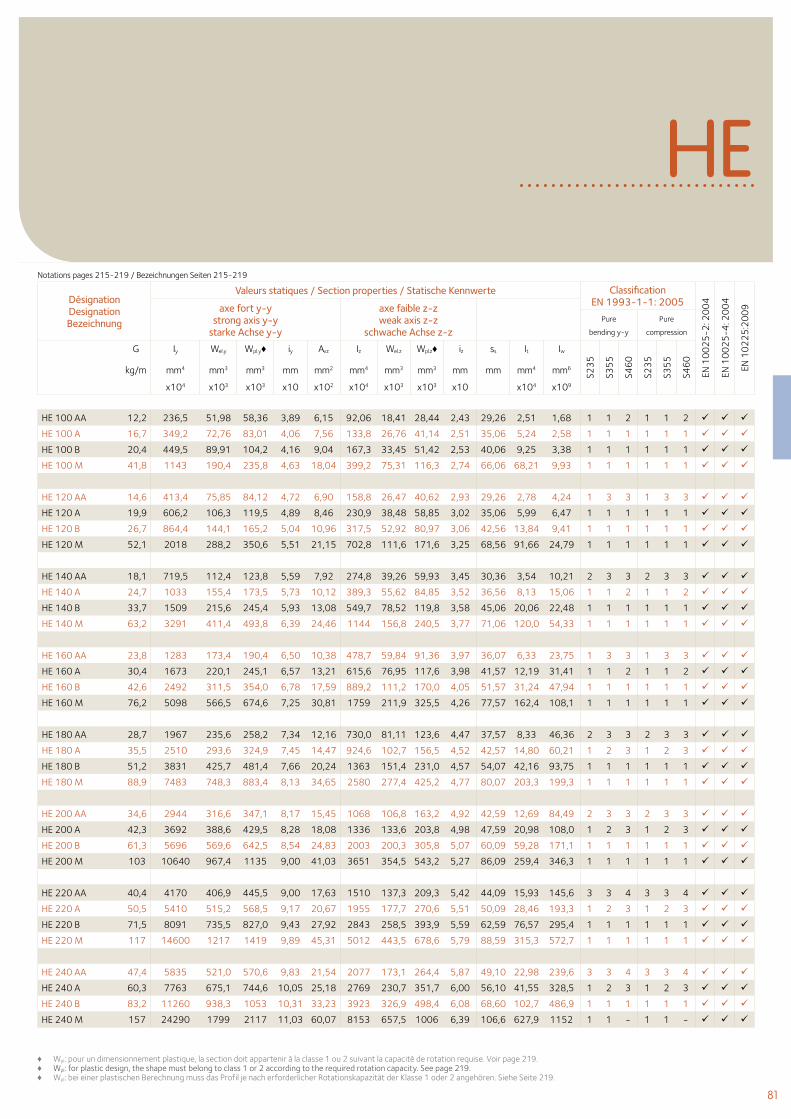
81
HE
HE 100 AA 12,2 236,5 51,98 58,36 3,89 6,15 92,06 18,41 28,44 2,43 29,26 2,51 1,68 1 1 2 1 1 2
HE 100 A 16,7 349,2 72,76 83,01 4,06 7,56 133,8 26,76 41,14 2,51 35,06 5,24 2,58 1 1 1 1 1 1
HE 100 B 20,4 449,5 89,91 104,2 4,16 9,04 167,3 33,45 51,42 2,53 40,06 9,25 3,38 1 1 1 1 1 1
HE 100 M 41,8 1143 190,4 235,8 4,63 18,04 399,2 75,31 116,3 2,74 66,06 68,21 9,93 1 1 1 1 1 1
HE 120 AA 14,6 413,4 75,85 84,12 4,72 6,90 158,8 26,47 40,62 2,93 29,26 2,78 4,24 1 3 3 1 3 3
HE 120 A 19,9 606,2 106,3 119,5 4,89 8,46 230,9 38,48 58,85 3,02 35,06 5,99 6,47 1 1 1 1 1 1
HE 120 B 26,7 864,4 144,1 165,2 5,04 10,96 317,5 52,92 80,97 3,06 42,56 13,84 9,41 1 1 1 1 1 1
HE 120 M 52,1 2018 288,2 350,6 5,51 21,15 702,8 111,6 171,6 3,25 68,56 91,66 24,79 1 1 1 1 1 1
HE 140 AA 18,1 719,5 112,4 123,8 5,59 7,92 274,8 39,26 59,93 3,45 30,36 3,54 10,21 2 3 3 2 3 3
HE 140 A 24,7 1033 155,4 173,5 5,73 10,12 389,3 55,62 84,85 3,52 36,56 8,13 15,06 1 1 2 1 1 2
HE 140 B 33,7 1509 215,6 245,4 5,93 13,08 549,7 78,52 119,8 3,58 45,06 20,06 22,48 1 1 1 1 1 1
HE 140 M 63,2 3291 411,4 493,8 6,39 24,46 1144 156,8 240,5 3,77 71,06 120,0 54,33 1 1 1 1 1 1
HE 160 AA 23,8 1283 173,4 190,4 6,50 10,38 478,7 59,84 91,36 3,97 36,07 6,33 23,75 1 3 3 1 3 3
HE 160 A 30,4 1673 220,1 245,1 6,57 13,21 615,6 76,95 117,6 3,98 41,57 12,19 31,41 1 1 2 1 1 2
HE 160 B 42,6 2492 311,5 354,0 6,78 17,59 889,2 111,2 170,0 4,05 51,57 31,24 47,94 1 1 1 1 1 1
HE 160 M 76,2 5098 566,5 674,6 7,25 30,81 1759 211,9 325,5 4,26 77,57 162,4 108,1 1 1 1 1 1 1
HE 180 AA 28,7 1967 235,6 258,2 7,34 12,16 730,0 81,11 123,6 4,47 37,57 8,33 46,36 2 3 3 2 3 3
HE 180 A 35,5 2510 293,6 324,9 7,45 14,47 924,6 102,7 156,5 4,52 42,57 14,80 60,21 1 2 3 1 2 3
HE 180 B 51,2 3831 425,7 481,4 7,66 20,24 1363 151,4 231,0 4,57 54,07 42,16 93,75 1 1 1 1 1 1
HE 180 M 88,9 7483 748,3 883,4 8,13 34,65 2580 277,4 425,2 4,77 80,07 203,3 199,3 1 1 1 1 1 1
HE 200 AA 34,6 2944 316,6 347,1 8,17 15,45 1068 106,8 163,2 4,92 42,59 12,69 84,49 2 3 3 2 3 3
HE 200 A 42,3 3692 388,6 429,5 8,28 18,08 1336 133,6 203,8 4,98 47,59 20,98 108,0 1 2 3 1 2 3
HE 200 B 61,3 5696 569,6 642,5 8,54 24,83 2003 200,3 305,8 5,07 60,09 59,28 171,1 1 1 1 1 1 1
HE 200 M 103 10640 967,4 1135 9,00 41,03 3651 354,5 543,2 5,27 86,09 259,4 346,3 1 1 1 1 1 1
HE 220 AA 40,4 4170 406,9 445,5 9,00 17,63 1510 137,3 209,3 5,42 44,09 15,93 145,6 3 3 4 3 3 4
HE 220 A 50,5 5410 515,2 568,5 9,17 20,67 1955 177,7 270,6 5,51 50,09 28,46 193,3 1 2 3 1 2 3
HE 220 B 71,5 8091 735,5 827,0 9,43 27,92 2843 258,5 393,9 5,59 62,59 76,57 295,4 1 1 1 1 1 1
HE 220 M 117 14600 1217 1419 9,89 45,31 5012 443,5 678,6 5,79 88,59 315,3 572,7 1 1 1 1 1 1
HE 240 AA 47,4 5835 521,0 570,6 9,83 21,54 2077 173,1 264,4 5,87 49,10 22,98 239,6 3 3 4 3 3 4
HE 240 A 60,3 7763 675,1 744,6 10,05 25,18 2769 230,7 351,7 6,00 56,10 41,55 328,5 1 2 3 1 2 3
HE 240 B 83,2 11260 938,3 1053 10,31 33,23 3923 326,9 498,4 6,08 68,60 102,7 486,9 1 1 1 1 1 1
HE 240 M 157 24290 1799 2117 11,03 60,07 8153 657,5 1006 6,39 106,6 627,9 1152 1 1 - 1 1 -
Désignation Designation Bezeichnung
Valeurs statiques / Section properties / Statische Kennwerte Classification EN 1993-1-1: 2005
EN 1
00
25
-2: 2
00
4
EN 1
00
25
-4: 2
00
4
EN 1
02
25
:20
09axe fort y-y
strong axis y-y starke Achse y-y
axe faible z-z weak axis z-z
schwache Achse z-z Pure
bending y-y
Pure
compression
G
kg/m
Iy Wel.y Wpl.y♦ iy Avz Iz Wel.z Wpl.z♦ iz ss It Iw
S23
5
S35
5
S46
0
S23
5
S35
5
S46
0
mm4 mm3 mm3 mm mm2 mm4 mm3 mm3 mm mm mm4 mm6
x104 x103 x103 x10 x102 x104 x103 x103 x10 x104 x109
Notations pages 215-219 / Bezeichnungen Seiten 215-219
♦ Wpl: pour un dimensionnement plastique, la section doit appartenir à la classe 1 ou 2 suivant la capacité de rotation requise. Voir page 219.♦ Wpl: for plastic design, the shape must belong to class 1 or 2 according to the required rotation capacity. See page 219.♦ Wpl: bei einer plastischen Berechnung muss das Profil je nach erforderlicher Rotationskapazität der Klasse 1 oder 2 angehören. Siehe Seite 219.
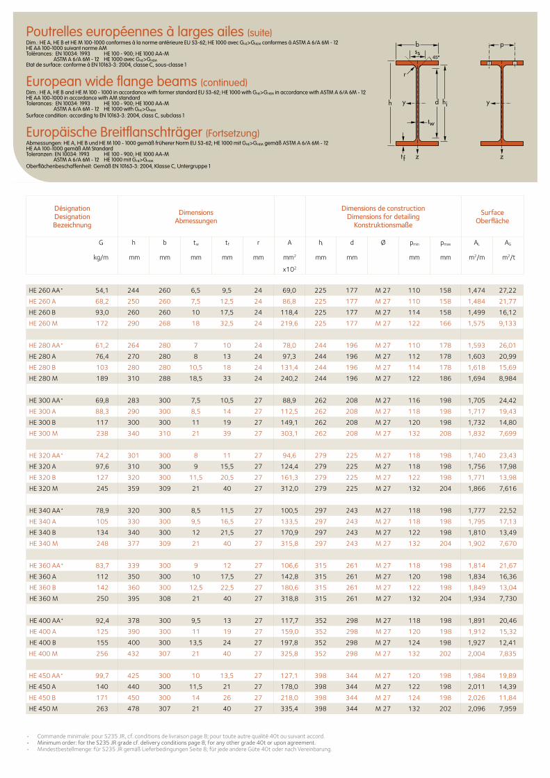
Désignation Designation Bezeichnung
Dimensions Abmessungen
Dimensions de construction Dimensions for detailing
Konstruktionsmaße
Surface Oberfläche
G
kg/m
h b tw tf r A hi d Ø pmin pmax AL AG
mm mm mm mm mm mm2 mm mm mm mm m2/m m2/t
x102
Poutrelles européennes à larges ailes (suite)Dim.: HE A, HE B et HE M 100-1000 conformes à la norme antérieure EU 53-62; HE 1000 avec GHE>GHEM conformes à ASTM A 6/A 6M - 12 HE AA 100-1000 suivant norme AM Tolérances: EN 10034: 1993 HE 100 - 900; HE 1000 AA-M ASTM A 6/A 6M - 12 HE 1000 avec GHE>GHEM Etat de surface: conforme à EN 10163-3: 2004, classe C, sous-classe 1
European wide flange beams (continued)Dim.: HE A, HE B and HE M 100 - 1000 in accordance with former standard EU 53-62; HE 1000 with GHE>GHEM in accordance with ASTM A 6/A 6M - 12 HE AA 100-1000 in accordance with AM standard Tolerances: EN 10034: 1993 HE 100 - 900; HE 1000 AA-M ASTM A 6/A 6M - 12 HE 1000 with GHE>GHEM Surface condition: according to EN 10163-3: 2004, class C, subclass 1
Europäische Breitflanschträger (Fortsetzung)Abmessungen: HE A, HE B und HE M 100 - 1000 gemäß früherer Norm EU 53-62; HE 1000 mit GHE>GHEM gemäß ASTM A 6/A 6M - 12 HE AA 100-1000 gemäß AM Standard Toleranzen: EN 10034: 1993 HE 100 - 900; HE 1000 AA-M ASTM A 6/A 6M - 12 HE 1000 mit GHE>GHEM Oberflächenbeschaffenheit: Gemäß EN 10163-3: 2004, Klasse C, Untergruppe 1
HE 260 AA• 54,1 244 260 6,5 9,5 24 69,0 225 177 M 27 110 158 1,474 27,22
HE 260 A 68,2 250 260 7,5 12,5 24 86,8 225 177 M 27 110 158 1,484 21,77
HE 260 B 93,0 260 260 10 17,5 24 118,4 225 177 M 27 114 158 1,499 16,12
HE 260 M 172 290 268 18 32,5 24 219,6 225 177 M 27 122 166 1,575 9,133
HE 280 AA• 61,2 264 280 7 10 24 78,0 244 196 M 27 110 178 1,593 26,01
HE 280 A 76,4 270 280 8 13 24 97,3 244 196 M 27 112 178 1,603 20,99
HE 280 B 103 280 280 10,5 18 24 131,4 244 196 M 27 114 178 1,618 15,69
HE 280 M 189 310 288 18,5 33 24 240,2 244 196 M 27 122 186 1,694 8,984
HE 300 AA• 69,8 283 300 7,5 10,5 27 88,9 262 208 M 27 116 198 1,705 24,42
HE 300 A 88,3 290 300 8,5 14 27 112,5 262 208 M 27 118 198 1,717 19,43
HE 300 B 117 300 300 11 19 27 149,1 262 208 M 27 120 198 1,732 14,80
HE 300 M 238 340 310 21 39 27 303,1 262 208 M 27 132 208 1,832 7,699
HE 320 AA• 74,2 301 300 8 11 27 94,6 279 225 M 27 118 198 1,740 23,43
HE 320 A 97,6 310 300 9 15,5 27 124,4 279 225 M 27 118 198 1,756 17,98
HE 320 B 127 320 300 11,5 20,5 27 161,3 279 225 M 27 122 198 1,771 13,98
HE 320 M 245 359 309 21 40 27 312,0 279 225 M 27 132 204 1,866 7,616
HE 340 AA• 78,9 320 300 8,5 11,5 27 100,5 297 243 M 27 118 198 1,777 22,52
HE 340 A 105 330 300 9,5 16,5 27 133,5 297 243 M 27 118 198 1,795 17,13
HE 340 B 134 340 300 12 21,5 27 170,9 297 243 M 27 122 198 1,810 13,49
HE 340 M 248 377 309 21 40 27 315,8 297 243 M 27 132 204 1,902 7,670
HE 360 AA• 83,7 339 300 9 12 27 106,6 315 261 M 27 118 198 1,814 21,67
HE 360 A 112 350 300 10 17,5 27 142,8 315 261 M 27 120 198 1,834 16,36
HE 360 B 142 360 300 12,5 22,5 27 180,6 315 261 M 27 122 198 1,849 13,04
HE 360 M 250 395 308 21 40 27 318,8 315 261 M 27 132 204 1,934 7,730
HE 400 AA• 92,4 378 300 9,5 13 27 117,7 352 298 M 27 118 198 1,891 20,46
HE 400 A 125 390 300 11 19 27 159,0 352 298 M 27 120 198 1,912 15,32
HE 400 B 155 400 300 13,5 24 27 197,8 352 298 M 27 124 198 1,927 12,41
HE 400 M 256 432 307 21 40 27 325,8 352 298 M 27 132 202 2,004 7,835
HE 450 AA• 99,7 425 300 10 13,5 27 127,1 398 344 M 27 120 198 1,984 19,89
HE 450 A 140 440 300 11,5 21 27 178,0 398 344 M 27 122 198 2,011 14,39
HE 450 B 171 450 300 14 26 27 218,0 398 344 M 27 124 198 2,026 11,84
HE 450 M 263 478 307 21 40 27 335,4 398 344 M 27 132 202 2,096 7,959
b
r
yy d
tw
ss
zzt f
hi
p
h
• Commandeminimale:pourS235JR,cf.conditionsdelivraisonpage8;pourtouteautrequalité40tousuivantaccord.• Minimumorder:fortheS235JRgradecf.deliveryconditionspage8;foranyothergrade40toruponagreement.• Mindestbestellmenge:fürS235JRgemäßLieferbedingungenSeite8;fürjedeandereGüte40todernachVereinbarung.
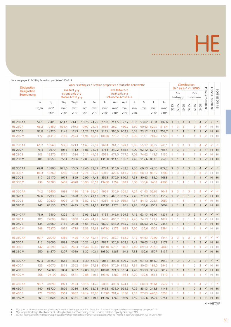
83
♦ Wpl: pour un dimensionnement plastique, la section doit appartenir à la classe 1 ou 2 suivant la capacité de rotation requise. Voir page 219.♦ Wpl: for plastic design, the shape must belong to class 1 or 2 according to the required rotation capacity. See page 219.♦ Wpl: bei einer plastischen Berechnung muss das Profil je nach erforderlicher Rotationskapazität der Klasse 1 oder 2 angehören. Siehe Seite 219.
HI = HISTAR©
HE
Désignation Designation Bezeichnung
Valeurs statiques / Section properties / Statische Kennwerte Classification EN 1993-1-1: 2005
EN 1
00
25
-2: 2
00
4
EN 1
00
25
-4: 2
00
4
EN 1
02
25
:20
09axe fort y-y
strong axis y-y starke Achse y-y
axe faible z-z weak axis z-z
schwache Achse z-z Pure
bending y-y
Pure
compression
G
kg/m
Iy Wel.y Wpl.y♦ iy Avz Iz Wel.z Wpl.z♦ iz ss It Iw
S23
5
S35
5
S46
0
S23
5
S35
5
S46
0
mm4 mm3 mm3 mm mm2 mm4 mm3 mm3 mm mm mm4 mm6
x104 x103 x103 x10 x102 x104 x103 x103 x10 x104 x109
HE 260 AA 54,1 7981 654,1 714,5 10,76 24,75 2788 214,5 327,7 6,36 53,62 30,31 382,6 3 3 4 3 3 4
HE 260 A 68,2 10450 836,4 919,8 10,97 28,76 3668 282,1 430,2 6,50 60,62 52,37 516,4 1 3 3 1 3 3 HI HI
HE 260 B 93,0 14920 1148 1283 11,22 37,59 5135 395,0 602,2 6,58 73,12 123,8 753,7 1 1 1 1 1 1 HI HI
HE 260 M 172 31310 2159 2524 11,94 66,89 10450 779,7 1192 6,90 111,1 719,0 1728 1 1 1 1 1 1 HI HI
HE 280 AA 61,2 10560 799,8 873,1 11,63 27,52 3664 261,7 399,4 6,85 55,12 36,22 590,1 3 3 4 3 3 4
HE 280 A 76,4 13670 1013 1112 11,86 31,74 4763 340,2 518,1 7,00 62,12 62,10 785,4 1 3 3 1 3 3 HI HI
HE 280 B 103 19270 1376 1534 12,11 41,09 6595 471,0 717,6 7,09 74,62 143,7 1130 1 1 1 1 1 1 HI HI
HE 280 M 189 39550 2551 2966 12,83 72,03 13160 914,1 1397 7,40 112,6 807,3 2520 1 1 1 1 1 1 HI HI
HE 300 AA 69,8 13800 975,6 1065 12,46 32,37 4734 315,6 482,3 7,30 60,13 49,35 877,2 3 3 4 3 3 4
HE 300 A 88,3 18260 1260 1383 12,74 37,28 6310 420,6 641,2 7,49 68,13 85,17 1200 1 3 3 1 3 3 HI HI
HE 300 B 117 25170 1678 1869 12,99 47,43 8563 570,9 870,1 7,58 80,63 185,0 1688 1 1 1 1 1 1 HI HI
HE 300 M 238 59200 3482 4078 13,98 90,53 19400 1252 1913 8,00 130,6 1408 4386 1 1 1 1 1 1 HI HI
HE 320 AA 74,2 16450 1093 1196 13,19 35,40 4959 330,6 505,7 7,24 61,63 55,87 1041 3 3 4 3 3 4
HE 320 A 97,6 22930 1479 1628 13,58 41,13 6985 465,7 709,7 7,49 71,63 108,0 1512 1 2 3 1 2 3 HI HI
HE 320 B 127 30820 1926 2149 13,82 51,77 9239 615,9 939,1 7,57 84,13 225,1 2069 1 1 1 1 1 1 HI HI
HE 320 M 245 68130 3796 4435 14,78 94,85 19710 1276 1951 7,95 132,6 1501 5004 1 1 1 1 1 1 HI HI
HE 340 AA 78,9 19550 1222 1341 13,95 38,69 5185 345,6 529,3 7,18 63,13 63,07 1231 3 3 4 3 3 4
HE 340 A 105 27690 1678 1850 14,40 44,95 7436 495,7 755,9 7,46 74,13 127,2 1824 1 1 3 1 1 3 HI HI
HE 340 B 134 36660 2156 2408 14,65 56,09 9690 646,0 985,7 7,53 86,63 257,2 2454 1 1 1 1 1 1 HI HI
HE 340 M 248 76370 4052 4718 15,55 98,63 19710 1276 1953 7,90 132,6 1506 5584 1 1 1 1 1 1 HI HI
HE 360 AA 83,7 23040 1359 1495 14,70 42,17 5410 360,7 553,0 7,12 64,63 70,99 1444 2 3 3 2 3 3
HE 360 A 112 33090 1891 2088 15,22 48,96 7887 525,8 802,3 7,43 76,63 148,8 2177 1 1 2 1 1 2 HI HI
HE 360 B 142 43190 2400 2683 15,46 60,60 10140 676,1 1032 7,49 89,13 292,5 2883 1 1 1 1 1 1 HI HI
HE 360 M 250 84870 4297 4989 16,32 102,4 19520 1268 1942 7,83 132,6 1507 6137 1 1 1 1 1 1 HI HI
HE 400 AA 92,4 31250 1654 1824 16,30 47,95 5861 390,8 599,7 7,06 67,13 84,69 1948 2 3 3 2 3 4
HE 400 A 125 45070 2311 2562 16,84 57,33 8564 570,9 872,9 7,34 80,63 189,0 2942 1 1 1 1 2 2 HI HI
HE 400 B 155 57680 2884 3232 17,08 69,98 10820 721,3 1104 7,40 93,13 355,7 3817 1 1 1 1 1 1 HI HI
HE 400 M 256 104100 4820 5571 17,88 110,2 19340 1260 1934 7,70 132,6 1515 7410 1 1 1 1 1 1 HI HI
HE 450 AA 99,7 41890 1971 2183 18,16 54,70 6088 405,8 624,4 6,92 68,63 95,61 2572 1 3 3 2 4 4
HE 450 A 140 63720 2896 3216 18,92 65,78 9465 631,0 965,5 7,29 85,13 243,8 4148 1 1 1 1 2 3 HI HI
HE 450 B 171 79890 3551 3982 19,14 79,66 11720 781,4 1198 7,33 97,63 440,5 5258 1 1 1 1 1 2 HI HI
HE 450 M 263 131500 5501 6331 19,80 119,8 19340 1260 1939 7,59 132,6 1529 9251 1 1 1 1 1 1 HI HI
Notations pages 215-219 / Bezeichnungen Seiten 215-219
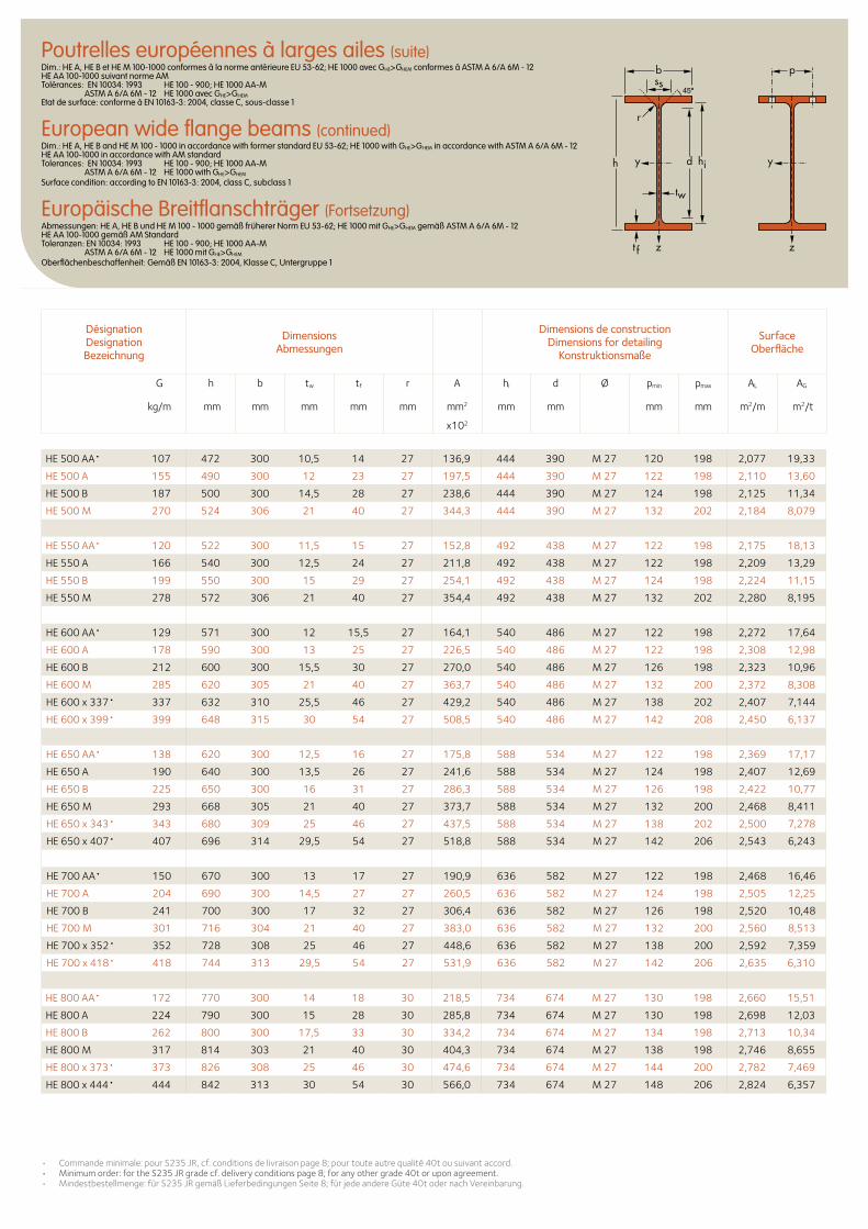
• Commandeminimale:pourS235JR,cf.conditionsdelivraisonpage8;pourtouteautrequalité40tousuivantaccord.• Minimumorder:fortheS235JRgradecf.deliveryconditionspage8;foranyothergrade40toruponagreement.• Mindestbestellmenge:fürS235JRgemäßLieferbedingungenSeite8;fürjedeandereGüte40todernachVereinbarung.
Désignation Designation Bezeichnung
Dimensions Abmessungen
Dimensions de construction Dimensions for detailing
Konstruktionsmaße
Surface Oberfläche
G
kg/m
h b tw tf r A hi d Ø pmin pmax AL AG
mm mm mm mm mm mm2 mm mm mm mm m2/m m2/t
x102
Poutrelles européennes à larges ailes (suite)Dim.: HE A, HE B et HE M 100-1000 conformes à la norme antérieure EU 53-62; HE 1000 avec GHE>GHEM conformes à ASTM A 6/A 6M - 12 HE AA 100-1000 suivant norme AM Tolérances: EN 10034: 1993 HE 100 - 900; HE 1000 AA-M ASTM A 6/A 6M - 12 HE 1000 avec GHE>GHEM Etat de surface: conforme à EN 10163-3: 2004, classe C, sous-classe 1
European wide flange beams (continued)Dim.: HE A, HE B and HE M 100 - 1000 in accordance with former standard EU 53-62; HE 1000 with GHE>GHEM in accordance with ASTM A 6/A 6M - 12 HE AA 100-1000 in accordance with AM standard Tolerances: EN 10034: 1993 HE 100 - 900; HE 1000 AA-M ASTM A 6/A 6M - 12 HE 1000 with GHE>GHEM Surface condition: according to EN 10163-3: 2004, class C, subclass 1
Europäische Breitflanschträger (Fortsetzung)Abmessungen: HE A, HE B und HE M 100 - 1000 gemäß früherer Norm EU 53-62; HE 1000 mit GHE>GHEM gemäß ASTM A 6/A 6M - 12 HE AA 100-1000 gemäß AM Standard Toleranzen: EN 10034: 1993 HE 100 - 900; HE 1000 AA-M ASTM A 6/A 6M - 12 HE 1000 mit GHE>GHEM Oberflächenbeschaffenheit: Gemäß EN 10163-3: 2004, Klasse C, Untergruppe 1
HE 500 AA• 107 472 300 10,5 14 27 136,9 444 390 M 27 120 198 2,077 19,33
HE 500 A 155 490 300 12 23 27 197,5 444 390 M 27 122 198 2,110 13,60
HE 500 B 187 500 300 14,5 28 27 238,6 444 390 M 27 124 198 2,125 11,34
HE 500 M 270 524 306 21 40 27 344,3 444 390 M 27 132 202 2,184 8,079
HE 550 AA• 120 522 300 11,5 15 27 152,8 492 438 M 27 122 198 2,175 18,13
HE 550 A 166 540 300 12,5 24 27 211,8 492 438 M 27 122 198 2,209 13,29
HE 550 B 199 550 300 15 29 27 254,1 492 438 M 27 124 198 2,224 11,15
HE 550 M 278 572 306 21 40 27 354,4 492 438 M 27 132 202 2,280 8,195
HE 600 AA• 129 571 300 12 15,5 27 164,1 540 486 M 27 122 198 2,272 17,64
HE 600 A 178 590 300 13 25 27 226,5 540 486 M 27 122 198 2,308 12,98
HE 600 B 212 600 300 15,5 30 27 270,0 540 486 M 27 126 198 2,323 10,96
HE 600 M 285 620 305 21 40 27 363,7 540 486 M 27 132 200 2,372 8,308
HE 600 x 337• 337 632 310 25,5 46 27 429,2 540 486 M 27 138 202 2,407 7,144
HE 600 x 399• 399 648 315 30 54 27 508,5 540 486 M 27 142 208 2,450 6,137
HE 650 AA• 138 620 300 12,5 16 27 175,8 588 534 M 27 122 198 2,369 17,17
HE 650 A 190 640 300 13,5 26 27 241,6 588 534 M 27 124 198 2,407 12,69
HE 650 B 225 650 300 16 31 27 286,3 588 534 M 27 126 198 2,422 10,77
HE 650 M 293 668 305 21 40 27 373,7 588 534 M 27 132 200 2,468 8,411
HE 650 x 343• 343 680 309 25 46 27 437,5 588 534 M 27 138 202 2,500 7,278
HE 650 x 407• 407 696 314 29,5 54 27 518,8 588 534 M 27 142 206 2,543 6,243
HE 700 AA• 150 670 300 13 17 27 190,9 636 582 M 27 122 198 2,468 16,46
HE 700 A 204 690 300 14,5 27 27 260,5 636 582 M 27 124 198 2,505 12,25
HE 700 B 241 700 300 17 32 27 306,4 636 582 M 27 126 198 2,520 10,48
HE 700 M 301 716 304 21 40 27 383,0 636 582 M 27 132 200 2,560 8,513
HE 700 x 352• 352 728 308 25 46 27 448,6 636 582 M 27 138 200 2,592 7,359
HE 700 x 418• 418 744 313 29,5 54 27 531,9 636 582 M 27 142 206 2,635 6,310
HE 800 AA• 172 770 300 14 18 30 218,5 734 674 M 27 130 198 2,660 15,51
HE 800 A 224 790 300 15 28 30 285,8 734 674 M 27 130 198 2,698 12,03
HE 800 B 262 800 300 17,5 33 30 334,2 734 674 M 27 134 198 2,713 10,34
HE 800 M 317 814 303 21 40 30 404,3 734 674 M 27 138 198 2,746 8,655
HE 800 x 373• 373 826 308 25 46 30 474,6 734 674 M 27 144 200 2,782 7,469
HE 800 x 444• 444 842 313 30 54 30 566,0 734 674 M 27 148 206 2,824 6,357
b
r
yy d
tw
ss
zzt f
hi
p
h
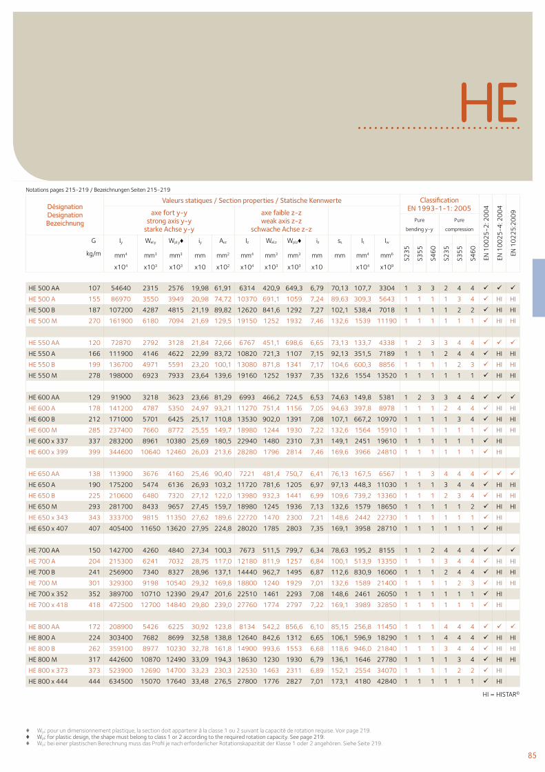
85
♦ Wpl: pour un dimensionnement plastique, la section doit appartenir à la classe 1 ou 2 suivant la capacité de rotation requise. Voir page 219.♦ Wpl: for plastic design, the shape must belong to class 1 or 2 according to the required rotation capacity. See page 219.♦ Wpl: bei einer plastischen Berechnung muss das Profil je nach erforderlicher Rotationskapazität der Klasse 1 oder 2 angehören. Siehe Seite 219.
HI = HISTAR©
HE
Désignation Designation Bezeichnung
Valeurs statiques / Section properties / Statische Kennwerte Classification EN 1993-1-1: 2005
EN 1
00
25
-2: 2
00
4
EN 1
00
25
-4: 2
00
4
EN 1
02
25
:20
09axe fort y-y
strong axis y-y starke Achse y-y
axe faible z-z weak axis z-z
schwache Achse z-z Pure
bending y-y
Pure
compression
G
kg/m
Iy Wel.y Wpl.y♦ iy Avz Iz Wel.z Wpl.z♦ iz ss It Iw
S23
5
S35
5
S46
0
S23
5
S35
5
S46
0
mm4 mm3 mm3 mm mm2 mm4 mm3 mm3 mm mm mm4 mm6
x104 x103 x103 x10 x102 x104 x103 x103 x10 x104 x109
HE 500 AA 107 54640 2315 2576 19,98 61,91 6314 420,9 649,3 6,79 70,13 107,7 3304 1 3 3 2 4 4
HE 500 A 155 86970 3550 3949 20,98 74,72 10370 691,1 1059 7,24 89,63 309,3 5643 1 1 1 1 3 4 HI HI
HE 500 B 187 107200 4287 4815 21,19 89,82 12620 841,6 1292 7,27 102,1 538,4 7018 1 1 1 1 2 2 HI HI
HE 500 M 270 161900 6180 7094 21,69 129,5 19150 1252 1932 7,46 132,6 1539 11190 1 1 1 1 1 1 HI HI
HE 550 AA 120 72870 2792 3128 21,84 72,66 6767 451,1 698,6 6,65 73,13 133,7 4338 1 2 3 3 4 4
HE 550 A 166 111900 4146 4622 22,99 83,72 10820 721,3 1107 7,15 92,13 351,5 7189 1 1 1 2 4 4 HI HI
HE 550 B 199 136700 4971 5591 23,20 100,1 13080 871,8 1341 7,17 104,6 600,3 8856 1 1 1 1 2 3 HI HI
HE 550 M 278 198000 6923 7933 23,64 139,6 19160 1252 1937 7,35 132,6 1554 13520 1 1 1 1 1 1 HI HI
HE 600 AA 129 91900 3218 3623 23,66 81,29 6993 466,2 724,5 6,53 74,63 149,8 5381 1 2 3 3 4 4
HE 600 A 178 141200 4787 5350 24,97 93,21 11270 751,4 1156 7,05 94,63 397,8 8978 1 1 1 2 4 4 HI HI
HE 600 B 212 171000 5701 6425 25,17 110,8 13530 902,0 1391 7,08 107,1 667,2 10970 1 1 1 1 3 4 HI HI
HE 600 M 285 237400 7660 8772 25,55 149,7 18980 1244 1930 7,22 132,6 1564 15910 1 1 1 1 1 1 HI HI
HE 600 x 337 337 283200 8961 10380 25,69 180,5 22940 1480 2310 7,31 149,1 2451 19610 1 1 1 1 1 1 HI
HE 600 x 399 399 344600 10640 12460 26,03 213,6 28280 1796 2814 7,46 169,6 3966 24810 1 1 1 1 1 1 HI
HE 650 AA 138 113900 3676 4160 25,46 90,40 7221 481,4 750,7 6,41 76,13 167,5 6567 1 1 3 4 4 4
HE 650 A 190 175200 5474 6136 26,93 103,2 11720 781,6 1205 6,97 97,13 448,3 11030 1 1 1 3 4 4 HI HI
HE 650 B 225 210600 6480 7320 27,12 122,0 13980 932,3 1441 6,99 109,6 739,2 13360 1 1 1 2 3 4 HI HI
HE 650 M 293 281700 8433 9657 27,45 159,7 18980 1245 1936 7,13 132,6 1579 18650 1 1 1 1 1 2 HI HI
HE 650 x 343 343 333700 9815 11350 27,62 189,6 22720 1470 2300 7,21 148,6 2442 22730 1 1 1 1 1 1 HI
HE 650 x 407 407 405400 11650 13620 27,95 224,8 28020 1785 2803 7,35 169,1 3958 28710 1 1 1 1 1 1 HI
HE 700 AA 150 142700 4260 4840 27,34 100,3 7673 511,5 799,7 6,34 78,63 195,2 8155 1 1 2 4 4 4
HE 700 A 204 215300 6241 7032 28,75 117,0 12180 811,9 1257 6,84 100,1 513,9 13350 1 1 1 3 4 4 HI HI
HE 700 B 241 256900 7340 8327 28,96 137,1 14440 962,7 1495 6,87 112,6 830,9 16060 1 1 1 2 4 4 HI HI
HE 700 M 301 329300 9198 10540 29,32 169,8 18800 1240 1929 7,01 132,6 1589 21400 1 1 1 1 2 3 HI HI
HE 700 x 352 352 389700 10710 12390 29,47 201,6 22510 1461 2293 7,08 148,6 2461 26050 1 1 1 1 1 1 HI
HE 700 x 418 418 472500 12700 14840 29,80 239,0 27760 1774 2797 7,22 169,1 3989 32850 1 1 1 1 1 1 HI
HE 800 AA 172 208900 5426 6225 30,92 123,8 8134 542,2 856,6 6,10 85,15 256,8 11450 1 1 1 4 4 4
HE 800 A 224 303400 7682 8699 32,58 138,8 12640 842,6 1312 6,65 106,1 596,9 18290 1 1 1 4 4 4 HI HI
HE 800 B 262 359100 8977 10230 32,78 161,8 14900 993,6 1553 6,68 118,6 946,0 21840 1 1 1 3 4 4 HI HI
HE 800 M 317 442600 10870 12490 33,09 194,3 18630 1230 1930 6,79 136,1 1646 27780 1 1 1 1 3 4 HI HI
HE 800 x 373 373 523900 12690 14700 33,23 230,3 22530 1463 2311 6,89 152,1 2554 34070 1 1 1 1 2 2 HI
HE 800 x 444 444 634500 15070 17640 33,48 276,5 27800 1776 2827 7,01 173,1 4180 42840 1 1 1 1 1 1 HI
Notations pages 215-219 / Bezeichnungen Seiten 215-219
HI = HISTAR©
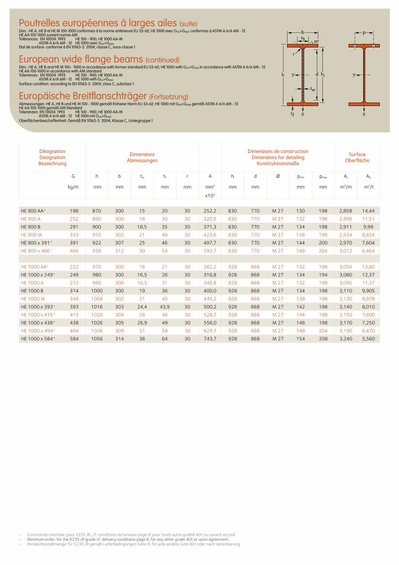
• Commandeminimale:pourS235JR,cf.conditionsdelivraisonpage8;pourtouteautrequalité40tousuivantaccord.• Minimumorder:fortheS235JRgradecf.deliveryconditionspage8;foranyothergrade40toruponagreement.• Mindestbestellmenge:fürS235JRgemäßLieferbedingungenSeite8;fürjedeandereGüte40todernachVereinbarung.
Désignation Designation Bezeichnung
Dimensions Abmessungen
Dimensions de construction Dimensions for detailing
Konstruktionsmaße
Surface Oberfläche
G
kg/m
h b tw tf r A hi d Ø pmin pmax AL AG
mm mm mm mm mm mm2 mm mm mm mm m2/m m2/t
x102
Poutrelles européennes à larges ailes (suite)Dim.: HE A, HE B et HE M 100-1000 conformes à la norme antérieure EU 53-62; HE 1000 avec GHE>GHEM conformes à ASTM A 6/A 6M - 12 HE AA 100-1000 suivant norme AM Tolérances: EN 10034: 1993 HE 100 - 900; HE 1000 AA-M ASTM A 6/A 6M - 12 HE 1000 avec GHE>GHEM Etat de surface: conforme à EN 10163-3: 2004, classe C, sous-classe 1
European wide flange beams (continued)Dim.: HE A, HE B and HE M 100 - 1000 in accordance with former standard EU 53-62; HE 1000 with GHE>GHEM in accordance with ASTM A 6/A 6M - 12 HE AA 100-1000 in accordance with AM standard Tolerances: EN 10034: 1993 HE 100 - 900; HE 1000 AA-M ASTM A 6/A 6M - 12 HE 1000 with GHE>GHEM Surface condition: according to EN 10163-3: 2004, class C, subclass 1
Europäische Breitflanschträger (Fortsetzung)Abmessungen: HE A, HE B und HE M 100 - 1000 gemäß früherer Norm EU 53-62; HE 1000 mit GHE>GHEM gemäß ASTM A 6/A 6M - 12 HE AA 100-1000 gemäß AM Standard Toleranzen: EN 10034: 1993 HE 100 - 900; HE 1000 AA-M ASTM A 6/A 6M - 12 HE 1000 mit GHE>GHEM Oberflächenbeschaffenheit: Gemäß EN 10163-3: 2004, Klasse C, Untergruppe 1
HE 900 AA• 198 870 300 15 20 30 252,2 830 770 M 27 130 198 2,858 14,44
HE 900 A 252 890 300 16 30 30 320,5 830 770 M 27 132 198 2,896 11,51
HE 900 B 291 900 300 18,5 35 30 371,3 830 770 M 27 134 198 2,911 9,99
HE 900 M 333 910 302 21 40 30 423,6 830 770 M 27 138 198 2,934 8,824
HE 900 x 391• 391 922 307 25 46 30 497,7 830 770 M 27 144 200 2,970 7,604
HE 900 x 466• 466 938 312 30 54 30 593,7 830 770 M 27 148 204 3,012 6,464
HE 1000 AA• 222 970 300 16 21 30 282,2 928 868 M 27 132 198 3,056 13,80
HE 1000 x 249• 249 980 300 16,5 26 30 316,8 928 868 M 27 134 194 3,080 12,37
HE 1000 A 272 990 300 16,5 31 30 346,8 928 868 M 27 132 198 3,095 11,37
HE 1000 B 314 1000 300 19 36 30 400,0 928 868 M 27 134 198 3,110 9,905
HE 1000 M 349 1008 302 21 40 30 444,2 928 868 M 27 138 198 3,130 8,978
HE 1000 x 393• 393 1016 303 24,4 43,9 30 500,2 928 868 M 27 142 198 3,140 8,010
HE 1000 x 415• 415 1020 304 26 46 30 528,7 928 868 M 27 144 198 3,150 7,600
HE 1000 x 438• 438 1026 305 26,9 49 30 556,0 928 868 M 27 146 198 3,170 7,250
HE 1000 x 494• 494 1036 309 31 54 30 629,1 928 868 M 27 148 204 3,190 6,470
HE 1000 x 584• 584 1056 314 36 64 30 743,7 928 868 M 27 154 208 3,240 5,560
b
r
yy d
tw
ss
zzt f
hi
p
h
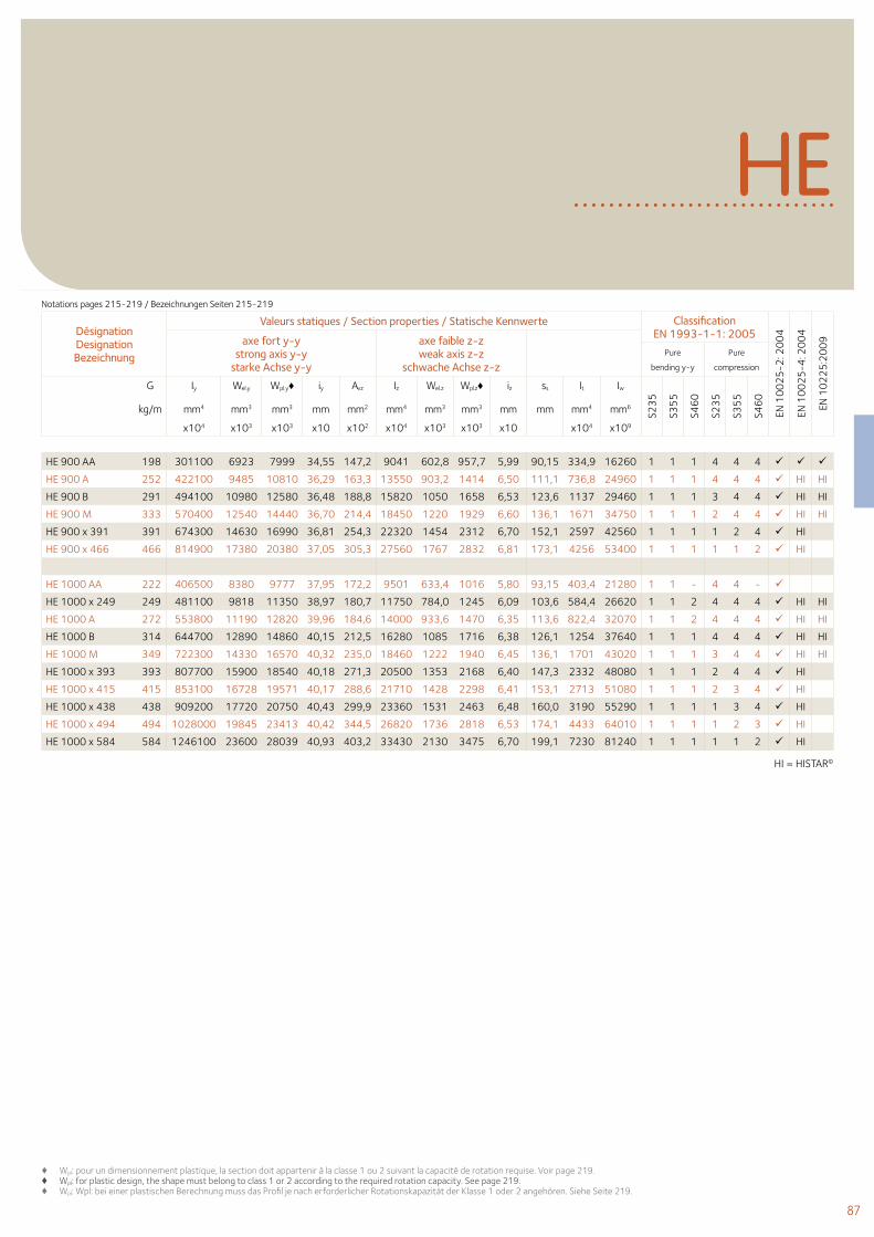
87
HI = HISTAR©
♦ Wpl: pour un dimensionnement plastique, la section doit appartenir à la classe 1 ou 2 suivant la capacité de rotation requise. Voir page 219.♦ Wpl: for plastic design, the shape must belong to class 1 or 2 according to the required rotation capacity. See page 219.♦ Wpl: Wpl: bei einer plastischen Berechnung muss das Profil je nach erforderlicher Rotationskapazität der Klasse 1 oder 2 angehören. Siehe Seite 219.
HE
Désignation Designation Bezeichnung
Valeurs statiques / Section properties / Statische Kennwerte Classification EN 1993-1-1: 2005
EN 1
00
25
-2: 2
00
4
EN 1
00
25
-4: 2
00
4
EN 1
02
25
:20
09axe fort y-y
strong axis y-y starke Achse y-y
axe faible z-z weak axis z-z
schwache Achse z-z Pure
bending y-y
Pure
compression
G
kg/m
Iy Wel.y Wpl.y♦ iy Avz Iz Wel.z Wpl.z♦ iz ss It Iw
S23
5
S35
5
S46
0
S23
5
S35
5
S46
0
mm4 mm3 mm3 mm mm2 mm4 mm3 mm3 mm mm mm4 mm6
x104 x103 x103 x10 x102 x104 x103 x103 x10 x104 x109
HE 900 AA 198 301100 6923 7999 34,55 147,2 9041 602,8 957,7 5,99 90,15 334,9 16260 1 1 1 4 4 4
HE 900 A 252 422100 9485 10810 36,29 163,3 13550 903,2 1414 6,50 111,1 736,8 24960 1 1 1 4 4 4 HI HI
HE 900 B 291 494100 10980 12580 36,48 188,8 15820 1050 1658 6,53 123,6 1137 29460 1 1 1 3 4 4 HI HI
HE 900 M 333 570400 12540 14440 36,70 214,4 18450 1220 1929 6,60 136,1 1671 34750 1 1 1 2 4 4 HI HI
HE 900 x 391 391 674300 14630 16990 36,81 254,3 22320 1454 2312 6,70 152,1 2597 42560 1 1 1 1 2 4 HI
HE 900 x 466 466 814900 17380 20380 37,05 305,3 27560 1767 2832 6,81 173,1 4256 53400 1 1 1 1 1 2 HI
HE 1000 AA 222 406500 8380 9777 37,95 172,2 9501 633,4 1016 5,80 93,15 403,4 21280 1 1 - 4 4 -
HE 1000 x 249 249 481100 9818 11350 38,97 180,7 11750 784,0 1245 6,09 103,6 584,4 26620 1 1 2 4 4 4 HI HI
HE 1000 A 272 553800 11190 12820 39,96 184,6 14000 933,6 1470 6,35 113,6 822,4 32070 1 1 2 4 4 4 HI HI
HE 1000 B 314 644700 12890 14860 40,15 212,5 16280 1085 1716 6,38 126,1 1254 37640 1 1 1 4 4 4 HI HI
HE 1000 M 349 722300 14330 16570 40,32 235,0 18460 1222 1940 6,45 136,1 1701 43020 1 1 1 3 4 4 HI HI
HE 1000 x 393 393 807700 15900 18540 40,18 271,3 20500 1353 2168 6,40 147,3 2332 48080 1 1 1 2 4 4 HI
HE 1000 x 415 415 853100 16728 19571 40,17 288,6 21710 1428 2298 6,41 153,1 2713 51080 1 1 1 2 3 4 HI
HE 1000 x 438 438 909200 17720 20750 40,43 299,9 23360 1531 2463 6,48 160,0 3190 55290 1 1 1 1 3 4 HI
HE 1000 x 494 494 1028000 19845 23413 40,42 344,5 26820 1736 2818 6,53 174,1 4433 64010 1 1 1 1 2 3 HI
HE 1000 x 584 584 1246100 23600 28039 40,93 403,2 33430 2130 3475 6,70 199,1 7230 81240 1 1 1 1 1 2 HI
Notations pages 215-219 / Bezeichnungen Seiten 215-219
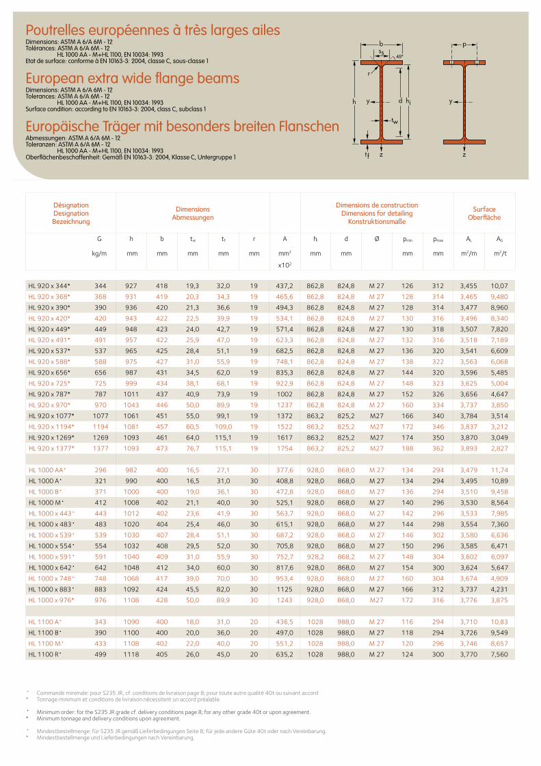
Poutrelles européennes à très larges ailesDimensions: ASTM A 6/A 6M - 12 Tolérances: ASTM A 6/A 6M - 12 HL 1000 AA - M+HL 1100, EN 10034: 1993 Etat de surface: conforme à EN 10163-3: 2004, classe C, sous-classe 1
European extra wide flange beamsDimensions: ASTM A 6/A 6M - 12 Tolerances: ASTM A 6/A 6M - 12 HL 1000 AA - M+HL 1100, EN 10034: 1993Surface condition: according to EN 10163-3: 2004, class C, subclass 1
Europäische Träger mit besonders breiten FlanschenAbmessungen: ASTM A 6/A 6M - 12 Toleranzen: ASTM A 6/A 6M - 12 HL 1000 AA - M+HL 1100, EN 10034: 1993 Oberflächenbeschaffenheit: Gemäß EN 10163-3: 2004, Klasse C, Untergruppe 1
b
r
yy dh
tw
ss
zzt f
hi
p
Désignation Designation Bezeichnung
Dimensions Abmessungen
Dimensions de construction Dimensions for detailing
Konstruktionsmaße
Surface Oberfläche
G
kg/m
h b tw tf r A hi d Ø pmin pmax AL AG
mm mm mm mm mm mm2 mm mm mm mm m2/m m2/t
x102
HL 920 x 344* 344 927 418 19,3 32,0 19 437,2 862,8 824,8 M 27 126 312 3,455 10,07
HL 920 x 368* 368 931 419 20,3 34,3 19 465,6 862,8 824,8 M 27 128 314 3,465 9,480
HL 920 x 390* 390 936 420 21,3 36,6 19 494,3 862,8 824,8 M 27 128 314 3,477 8,960
HL 920 x 420* 420 943 422 22,5 39,9 19 534,1 862,8 824,8 M 27 130 316 3,496 8,340
HL 920 x 449* 449 948 423 24,0 42,7 19 571,4 862,8 824,8 M 27 130 318 3,507 7,820
HL 920 x 491* 491 957 422 25,9 47,0 19 623,3 862,8 824,8 M 27 132 316 3,518 7,189
HL 920 x 537* 537 965 425 28,4 51,1 19 682,5 862,8 824,8 M 27 136 320 3,541 6,609
HL 920 x 588* 588 975 427 31,0 55,9 19 748,1 862,8 824,8 M 27 138 322 3,563 6,068
HL 920 x 656* 656 987 431 34,5 62,0 19 835,3 862,8 824,8 M 27 144 320 3,596 5,485
HL 920 x 725* 725 999 434 38,1 68,1 19 922,9 862,8 824,8 M 27 148 323 3,625 5,004
HL 920 x 787* 787 1011 437 40,9 73,9 19 1002 862,8 824,8 M 27 152 326 3,656 4,647
HL 920 x 970* 970 1043 446 50,0 89,9 19 1237 862,8 824,8 M 27 160 334 3,737 3,850
HL 920 x 1077* 1077 1061 451 55,0 99,1 19 1372 863,2 825,2 M27 166 340 3,784 3,514
HL 920 x 1194* 1194 1081 457 60,5 109,0 19 1522 863,2 825,2 M27 172 346 3,837 3,212
HL 920 x 1269* 1269 1093 461 64,0 115,1 19 1617 863,2 825,2 M27 174 350 3,870 3,049
HL 920 x 1377* 1377 1093 473 76,7 115,1 19 1754 863,2 825,2 M27 188 362 3,893 2,827
HL 1000 AA• 296 982 400 16,5 27,1 30 377,6 928,0 868,0 M 27 134 294 3,479 11,74
HL 1000 A• 321 990 400 16,5 31,0 30 408,8 928,0 868,0 M 27 134 294 3,495 10,89
HL 1000 B• 371 1000 400 19,0 36,1 30 472,8 928,0 868,0 M 27 136 294 3,510 9,458
HL 1000 M• 412 1008 402 21,1 40,0 30 525,1 928,0 868,0 M 27 140 296 3,530 8,564
HL 1000 x 443• 443 1012 402 23,6 41,9 30 563,7 928,0 868,0 M 27 142 296 3,533 7,985
HL 1000 x 483• 483 1020 404 25,4 46,0 30 615,1 928,0 868,0 M 27 144 298 3,554 7,360
HL 1000 x 539• 539 1030 407 28,4 51,1 30 687,2 928,0 868,0 M 27 146 302 3,580 6,636
HL 1000 x 554• 554 1032 408 29,5 52,0 30 705,8 928,0 868,0 M 27 150 296 3,585 6,471
HL 1000 x 591• 591 1040 409 31,0 55,9 30 752,7 928,2 868,2 M 27 148 304 3,602 6,097
HL 1000 x 642• 642 1048 412 34,0 60,0 30 817,6 928,0 868,0 M 27 154 300 3,624 5,647
HL 1000 x 748• 748 1068 417 39,0 70,0 30 953,4 928,0 868,0 M 27 160 304 3,674 4,909
HL 1000 x 883• 883 1092 424 45,5 82,0 30 1125 928,0 868,0 M 27 166 312 3,737 4,231
HL 1000 x 976* 976 1108 428 50,0 89,9 30 1243 928,0 868,0 M27 172 316 3,776 3,875
HL 1100 A• 343 1090 400 18,0 31,0 20 436,5 1028 988,0 M 27 116 294 3,710 10,83
HL 1100 B• 390 1100 400 20,0 36,0 20 497,0 1028 988,0 M 27 118 294 3,726 9,549
HL 1100 M• 433 1108 402 22,0 40,0 20 551,2 1028 988,0 M 27 120 296 3,746 8,657
HL 1100 R• 499 1118 405 26,0 45,0 20 635,2 1028 988,0 M 27 124 300 3,770 7,560
• Commande minimale: pour S235 JR, cf. conditions de livraison page 8; pour toute autre qualité 40t ou suivant accord* Tonnage minimum et conditions de livraison nécessitent un accord préalable.
• Minimum order: for the S235 JR grade cf. delivery conditions page 8; for any other grade 40t or upon agreement.* Minimum tonnage and delivery conditions upon agreement.
• Mindestbestellmenge: für S235 JR gemäß Lieferbedingungen Seite 8; für jede andere Güte 40t oder nach Vereinbarung.* Mindestbestellmenge und Lieferbedingungen nach Vereinbarung.
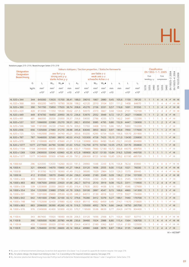
89
HL
Désignation Designation Bezeichnung
Valeurs statiques / Section properties / Statische Kennwerte Classification EN 1993-1-1: 2005
EN 1
00
25
-2: 2
00
4
EN 1
00
25
-4: 2
00
4
EN 1
02
25
:20
09axe fort y-y
strong axis y-y starke Achse y-y
axe faible z-z weak axis z-z
schwache Achse z-z Pure
bending y-y
Pure
compression
G
kg/m
Iy Wel.y Wpl.y♦ iy Avz Iz Wel.z Wpl.z♦ iz ss It Iw
S23
5
S35
5
S46
0
S23
5
S35
5
S46
0
mm4 mm3 mm3 mm mm2 mm4 mm3 mm3 mm mm mm4 mm6
x104 x103 x103 x10 x102 x104 x103 x103 x10 x104 x109
HL 920 x 344 344 645000 13920 15700 38,41 188,0 39010 1867 2880 9,45 105,6 1159 78120 1 1 1 4 4 4 HI HI
HL 920 x 368 368 692200 14870 16790 38,56 198,2 42120 2010 3104 9,51 111,2 1408 84670 1 1 1 3 4 4 HI HI
HL 920 x 390 390 741700 15850 17920 38,74 208,6 45270 2156 3331 9,57 116,8 1691 91550 1 1 1 3 4 4 HI HI
HL 920 x 420 420 813300 17250 19530 39,02 221,5 50070 2373 3667 9,68 124,6 2151 102100 1 1 1 2 4 4 HI HI
HL 920 x 449 449 874700 18450 20950 39,13 236,6 53970 2552 3949 9,72 131,7 2627 110600 1 1 1 2 4 4 HI
HL 920 x 491 491 966300 20200 23000 39,37 256,6 59000 2796 4335 9,73 142,2 3441 122200 1 1 1 1 3 4 HI
HL 920 x 537 537 1066000 22080 25270 39,51 282,1 65550 3085 4795 9,80 152,9 4447 136900 1 1 1 1 2 3 HI
HL 920 x 588 588 1181000 24230 27840 39,74 309,3 72760 3408 5310 9,86 165,1 5860 153200 1 1 1 1 1 2 HI
HL 920 x 656 656 1335000 27060 31270 39,98 345,8 83040 3853 6022 9,97 180,8 7950 177600 1 1 1 1 1 2 HI
HL 920 x 725 725 1492000 29880 34740 40,21 383,6 93200 4295 6734 10,05 196,6 10570 201900 1 1 1 1 1 1 HI
HL 920 x 787 787 1646000 32560 38010 40,53 414,5 103300 4728 7425 10,15 211,0 13430 226800 1 1 1 1 1 1 HI
HL 920 x 970 970 2100000 40270 47660 41,21 513,8 133900 6002 9490 10,40 252,1 24320 304000 1 1 1 1 1 1 HI
HL 920 x 1077 1077 2377000 44790 53390 41,63 570,0 152700 6773 10740 10,55 275,5 33170 350800 1 1 1 1 1 1 HI
HL 920 x 1194 1194 2694000 49830 59830 42,08 632,7 175000 7660 12180 10,72 300,8 44370 409700 1 1 1 1 1 1 HI
HL 920 x 1269 1269 2900000 53040 63960 42,35 672,9 189900 8237 13130 10,84 316,5 52500 449700 1 1 1 1 1 1 HI
HL 920 x 1377 1377 3034000 55500 67680 41,59 797,2 206300 8723 14160 10,85 329,2 61190 485700 1 1 1 1 1 1 HI
HL 1000 AA 296 620300 12630 14260 40,53 181,5 28960 1448 2243 8,76 105,8 762,6 65900 1 1 2 4 4 4 HI HI
HL 1000 A 321 696400 14070 15800 41,27 184,6 33120 1656 2555 9,00 113,6 1021 76030 1 1 2 4 4 4 HI HI
HL 1000 B 371 813700 16270 18360 41,49 212,5 38580 1929 2984 9,03 126,3 1575 89440 1 1 1 4 4 4 HI HI
HL 1000 M 412 910500 18070 20460 41,64 236,0 43400 2160 3349 9,09 136,2 2134 101500 1 1 1 3 4 4 HI HI
HL 1000 x 443 443 966500 19100 21780 41,41 261,8 45500 2264 3529 8,98 142,5 2545 106700 1 1 1 2 4 4 HI
HL 1000 x 483 483 1067000 20930 23920 41,66 282,7 50710 2510 3919 9,08 152,5 3311 119900 1 1 1 2 4 4 HI
HL 1000 x 539 539 1203000 23350 26820 41,83 316,4 57630 2832 4436 9,16 165,7 4546 137600 1 1 1 1 2 4 HI
HL 1000 x 554 554 1232000 23880 27500 41,79 328,0 59100 2897 4547 9,15 168,6 4860 141300 1 1 1 1 2 3 HI
HL 1000 x 591 591 1331000 25600 29530 42,05 346,3 64010 3130 4916 9,22 177,9 5927 154300 1 1 1 1 2 3 HI
HL 1000 x 642 642 1451000 27680 32100 42,12 379,6 70280 3412 5379 9,27 189,1 7440 170700 1 1 1 1 1 2 HI
HL 1000 x 748 748 1732000 32430 37880 42,62 438,9 85110 4082 6459 9,45 214,1 11670 210600 1 1 1 1 1 1 HI
HL 1000 x 883 883 2096000 38390 45260 43,16 516,5 105000 4952 7874 9,66 244,6 18750 265700 1 1 1 1 1 1 HI
HL 1000 x 976 976 2349000 42400 50300 43,50 570,7 118500 5538 8839 9,77 264,9 24770 304400 1 1 1 1 1 1 HI
HL 1100 A 343 867400 15920 18060 44,58 206,5 33120 1656 2568 8,71 103,4 1037 92710 1 1 2 4 4 4 HI HI
HL 1100 B 390 1005000 18280 20780 44,98 230,6 38480 1924 2988 8,80 115,4 1564 108700 1 1 1 4 4 4 HI HI
HL 1100 M 433 1126000 20320 23160 45,19 254,4 43410 2160 3362 8,87 125,4 2130 123500 1 1 1 4 4 4 HI HI
HL 1100 R 499 1294000 23150 26600 45,14 300,4 49980 2468 3870 8,87 139,4 3135 143400 1 1 1 2 4 4 HI
♦ Wpl: pour un dimensionnement plastique, la section doit appartenir à la classe 1 ou 2 suivant la capacité de rotation requise. Voir page 219.
♦ Wpl: for plastic design, the shape must belong to class 1 or 2 according to the required rotation capacity. See page 219.
♦ Wpl: bei einer plastischen Berechnung muss das Profil je nach erforderlicher Rotationskapazität der Klasse 1 oder 2 angehören. Siehe Seite 219.
HI = HISTAR©
Notations pages 215-219 / Bezeichnungen Seiten 215-219
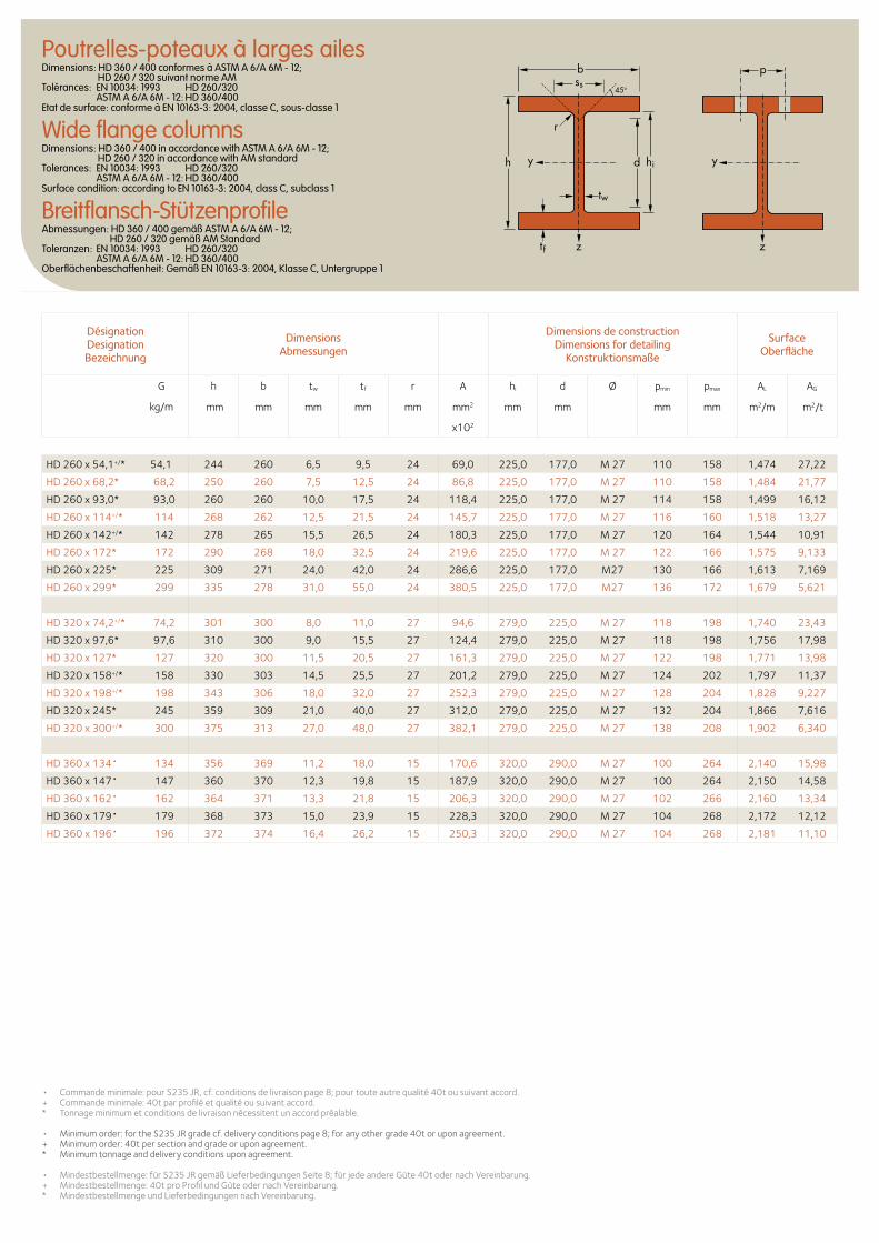
Désignation Designation Bezeichnung
Dimensions Abmessungen
Dimensions de construction Dimensions for detailing
Konstruktionsmaße
Surface Oberfläche
G
kg/m
h b tw tf r A hi d Ø pmin pmax AL AG
mm mm mm mm mm mm2 mm mm mm mm m2/m m2/t
x102
Poutrelles-poteaux à larges ailesDimensions: HD 360 / 400 conformes à ASTM A 6/A 6M - 12; HD 260 / 320 suivant norme AM Tolérances: EN 10034: 1993 HD 260/320 ASTM A 6/A 6M - 12: HD 360/400 Etat de surface: conforme à EN 10163-3: 2004, classe C, sous-classe 1
Wide flange columnsDimensions: HD 360 / 400 in accordance with ASTM A 6/A 6M - 12; HD 260 / 320 in accordance with AM standard Tolerances: EN 10034: 1993 HD 260/320 ASTM A 6/A 6M - 12: HD 360/400 Surface condition: according to EN 10163-3: 2004, class C, subclass 1
Breitflansch-StützenprofileAbmessungen: HD 360 / 400 gemäß ASTM A 6/A 6M - 12; HD 260 / 320 gemäß AM Standard Toleranzen: EN 10034: 1993 HD 260/320 ASTM A 6/A 6M - 12: HD 360/400 Oberflächenbeschaffenheit: Gemäß EN 10163-3: 2004, Klasse C, Untergruppe 1
d hi
tw
tf
h
r
b
yy
zz
pss
45o
HD 260 x 54,1+/* 54,1 244 260 6,5 9,5 24 69,0 225,0 177,0 M 27 110 158 1,474 27,22
HD 260 x 68,2* 68,2 250 260 7,5 12,5 24 86,8 225,0 177,0 M 27 110 158 1,484 21,77
HD 260 x 93,0* 93,0 260 260 10,0 17,5 24 118,4 225,0 177,0 M 27 114 158 1,499 16,12
HD 260 x 114+/* 114 268 262 12,5 21,5 24 145,7 225,0 177,0 M 27 116 160 1,518 13,27
HD 260 x 142+/* 142 278 265 15,5 26,5 24 180,3 225,0 177,0 M 27 120 164 1,544 10,91
HD 260 x 172* 172 290 268 18,0 32,5 24 219,6 225,0 177,0 M 27 122 166 1,575 9,133
HD 260 x 225* 225 309 271 24,0 42,0 24 286,6 225,0 177,0 M27 130 166 1,613 7,169
HD 260 x 299* 299 335 278 31,0 55,0 24 380,5 225,0 177,0 M27 136 172 1,679 5,621
HD 320 x 74,2+/* 74,2 301 300 8,0 11,0 27 94,6 279,0 225,0 M 27 118 198 1,740 23,43
HD 320 x 97,6* 97,6 310 300 9,0 15,5 27 124,4 279,0 225,0 M 27 118 198 1,756 17,98
HD 320 x 127* 127 320 300 11,5 20,5 27 161,3 279,0 225,0 M 27 122 198 1,771 13,98
HD 320 x 158+/* 158 330 303 14,5 25,5 27 201,2 279,0 225,0 M 27 124 202 1,797 11,37
HD 320 x 198+/* 198 343 306 18,0 32,0 27 252,3 279,0 225,0 M 27 128 204 1,828 9,227
HD 320 x 245* 245 359 309 21,0 40,0 27 312,0 279,0 225,0 M 27 132 204 1,866 7,616
HD 320 x 300+/* 300 375 313 27,0 48,0 27 382,1 279,0 225,0 M 27 138 208 1,902 6,340
HD 360 x 134• 134 356 369 11,2 18,0 15 170,6 320,0 290,0 M 27 100 264 2,140 15,98
HD 360 x 147• 147 360 370 12,3 19,8 15 187,9 320,0 290,0 M 27 100 264 2,150 14,58
HD 360 x 162• 162 364 371 13,3 21,8 15 206,3 320,0 290,0 M 27 102 266 2,160 13,34
HD 360 x 179• 179 368 373 15,0 23,9 15 228,3 320,0 290,0 M 27 104 268 2,172 12,12
HD 360 x 196• 196 372 374 16,4 26,2 15 250,3 320,0 290,0 M 27 104 268 2,181 11,10
• Commande minimale: pour S235 JR, cf. conditions de livraison page 8; pour toute autre qualité 40t ou suivant accord.+ Commande minimale: 40t par profilé et qualité ou suivant accord. * Tonnage minimum et conditions de livraison nécessitent un accord préalable.
• Minimum order: for the S235 JR grade cf. delivery conditions page 8; for any other grade 40t or upon agreement.+ Minimum order: 40t per section and grade or upon agreement.* Minimum tonnage and delivery conditions upon agreement. • Mindestbestellmenge: für S235 JR gemäß Lieferbedingungen Seite 8; für jede andere Güte 40t oder nach Vereinbarung.+ Mindestbestellmenge: 40t pro Profil und Güte oder nach Vereinbarung. * Mindestbestellmenge und Lieferbedingungen nach Vereinbarung.
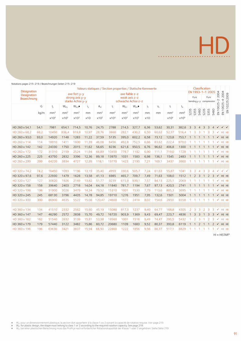
91
Désignation Designation Bezeichnung
Valeurs statiques / Section properties / Statische Kennwerte Classification EN 1993-1-1: 2005
EN 1
00
25
-2: 2
00
4
EN 1
00
25
-4: 2
00
4
EN 1
02
25
:20
09axe fort y-y
strong axis y-y starke Achse y-y
axe faible z-z weak axis z-z
schwache Achse z-z Pure
bending y-y
Pure
compression
G
kg/m
Iy Wel.y Wpl.y♦ iy Avz Iz Wel.z Wpl.z♦ iz ss It Iw
S23
5
S35
5
S46
0
S23
5
S35
5
S46
0
mm4 mm3 mm3 mm mm2 mm4 mm3 mm3 mm mm mm4 mm6
x104 x103 x103 x10 x102 x104 x103 x103 x10 x104 x109
HD
HD 260 x 54,1 54,1 7981 654,1 714,5 10,76 24,75 2788 214,5 327,7 6,36 53,62 30,31 382,6 3 3 4 3 3 4
HD 260 x 68,2 68,2 10450 836,4 919,8 10,97 28,76 3668 282,1 430,2 6,50 60,62 52,37 516,4 1 3 3 1 3 3 HI HI
HD 260 x 93,0 93,0 14920 1148 1283 11,22 37,59 5135 395,0 602,2 6,58 73,12 123,8 753,7 1 1 1 1 1 1 HI HI
HD 260 x 114 114 18910 1411 1600 11,39 46,08 6456 492,8 752,5 6,66 83,62 222,4 979,0 1 1 1 1 1 1 HI HI
HD 260 x 142 142 24330 1750 2015 11,62 56,65 8236 621,6 950,5 6,76 96,62 406,8 1300 1 1 1 1 1 1 HI HI
HD 260 x 172 172 31310 2159 2524 11,94 66,89 10450 779,7 1192 6,90 111,1 719,0 1728 1 1 1 1 1 1 HI HI
HD 260 x 225 225 43750 2832 3396 12,36 89,18 13970 1031 1583 6,98 136,1 1545 2483 1 1 1 1 1 1 HI HI
HD 260 x 299 299 64220 3834 4727 12,99 118,1 19770 1423 2190 7,21 169,1 3437 3860 1 1 1 1 1 1 HI HI
HD 320 x 74,2 74,2 16450 1093 1196 13,19 35,40 4959 330,6 505,7 7,24 61,63 55,87 1041 3 3 4 3 3 4
HD 320 x 97,6 97,6 22930 1479 1628 13,58 41,13 6985 465,7 709,7 7,49 71,63 108,0 1512 1 2 3 1 2 3 HI HI
HD 320 x 127 127 30820 1926 2149 13,82 51,77 9239 615,9 939,1 7,57 84,13 225,1 2069 1 1 1 1 1 1 HI HI
HD 320 x 158 158 39640 2403 2718 14,04 64,18 11840 781,7 1194 7,67 97,13 420,5 2741 1 1 1 1 1 1 HI HI
HD 320 x 198 198 51900 3026 3479 14,34 79,52 15310 1001 1530 7,79 113,6 805,3 3695 1 1 1 1 1 1 HI HI
HD 320 x 245 245 68130 3796 4435 14,78 94,85 19710 1276 1951 7,95 132,6 1501 5004 1 1 1 1 1 1 HI HI
HD 320 x 300 300 86900 4635 5522 15,08 120,47 24600 1572 2414 8,02 154,6 2650 6558 1 1 1 1 1 1 HI HI
HD 360 x 134 134 41510 2332 2562 15,60 45,19 15080 817,3 1237 9,40 64,77 168,8 4305 2 3 3 2 3 3 HI HI
HD 360 x 147 147 46290 2572 2838 15,70 49,72 16720 903,9 1369 9,43 69,47 223,7 4836 1 3 3 1 3 3 HI HI
HD 360 x 162 162 51540 2832 3139 15,81 53,98 18560 1001 1516 9,49 74,47 295,5 5432 1 2 3 1 2 3 HI HI
HD 360 x 179 179 57440 3122 3482 15,86 60,72 20680 1109 1683 9,52 80,37 393,8 6119 1 1 2 1 1 2 HI HI
HD 360 x 196 196 63630 3421 3837 15,94 66,50 22860 1222 1856 9,56 86,37 517,1 6829 1 1 1 1 1 1 HI HI
♦ Wpl: pour un dimensionnement plastique, la section doit appartenir à la classe 1 ou 2 suivant la capacité de rotation requise. Voir page 219.♦ Wpl: for plastic design, the shape must belong to class 1 or 2 according to the required rotation capacity. See page 219.♦ Wpl: bei einer plastischen Berechnung muss das Profil je nach erforderlicher Rotationskapazität der Klasse 1 oder 2 angehören. Siehe Seite 219.
HI = HISTAR©
Notations pages 215-219 / Bezeichnungen Seiten 215-219
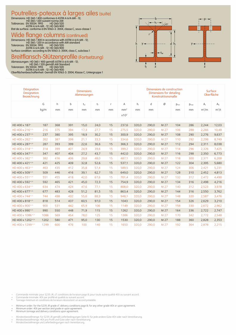
HD 400 x 187+ 187 368 391 15,0 24,0 15 237,6 320,0 290,0 M 27 104 286 2,244 12,03
HD 400 x 216•/+ 216 375 394 17,3 27,7 15 275,5 320,0 290,0 M 27 106 288 2,266 10,48
HD 400 x 237•/+ 237 380 395 18,9 30,2 15 300,9 320,0 290,0 M 27 108 290 2,276 9,637
HD 400 x 262•/+ 262 387 398 21,1 33,3 15 334,6 320,0 290,0 M 27 110 292 2,298 8,749
HD 400 x 287•/+ 287 393 399 22,6 36,6 15 366,3 320,0 290,0 M 27 112 294 2,311 8,038
HD 400 x 314•/+ 314 399 401 24,9 39,6 15 399,2 320,0 290,0 M 27 114 296 2,326 7,425
HD 400 x 347•/+ 347 407 404 27,2 43,7 15 442,0 320,0 290,0 M 27 116 298 2,350 6,773
HD 400 x 382•/+ 382 416 406 29,8 48,0 15 487,1 320,0 290,0 M 27 118 300 2,371 6,200
HD 400 x 421•/+ 421 425 409 32,8 52,6 15 537,1 320,0 290,0 M 27 122 304 2,395 5,680
HD 400 x 463•/+ 463 435 412 35,8 57,4 15 589,5 320,0 290,0 M 27 124 306 2,421 5,231
HD 400 x 509•/+ 509 446 416 39,1 62,7 15 649,0 320,0 290,0 M 27 128 310 2,452 4,813
HD 400 x 551•/+ 551 455 418 42,0 67,6 15 701,4 320,0 290,0 M 27 132 312 2,472 4,490
HD 400 x 592•/+ 592 465 421 45,0 72,3 15 754,9 320,0 290,0 M 27 134 316 2,498 4,216
HD 400 x 634•/+ 634 474 424 47,6 77,1 15 808,0 320,0 290,0 M 27 140 312 2,523 3,978
HD 400 x 677•/+ 677 483 428 51,2 81,5 15 863,4 320,0 290,0 M 27 144 316 2,550 3,762
HD 400 x 744•/+ 744 498 432 55,6 88,9 15 948,1 320,0 290,0 M 27 148 320 2,587 3,476
HD 400 x 818•/+ 818 514 437 60,5 97,0 15 1043 320,0 290,0 M 27 154 326 2,629 3,210
HD 400 x 900•/+ 900 531 442 65,9 106 15 1149 320,0 290,0 M 27 158 330 2,672 2,962
HD 400 x 990•/+ 990 550 448 71,9 115 15 1262 320,0 290,0 M 27 164 336 2,722 2,747
HD 400 x 1086•/+ 1086 569 454 78,0 125 15 1386 320,0 290,0 M 27 170 342 2,772 2,548
HD 400 x 1202•/+ 1202 580 471 95,0 130 15 1530 320,0 290,0 M 27 188 360 2,828 2,353
HD 400 x 1299•/+ 1299 600 476 100 140 15 1650 320,0 290,0 M 27 192 364 2,878 2,215
• Commande minimale: pour S235 JR, cf. conditions de livraison page 8; pour toute autre qualité 40t ou suivant accord.+ Commande minimale: 40t par profilé et qualité ou suivant accord. * Tonnage minimum et conditions de livraison nécessitent un accord préalable. • Minimum order: for the S235 JR grade cf. delivery conditions page 8; for any other grade 40t or upon agreement.+ Minimum order: 40t per section and grade or upon agreement.* Minimum tonnage and delivery conditions upon agreement. • Mindestbestellmenge: für S235 JR gemäß Lieferbedingungen Seite 8; für jede andere Güte 40t oder nach Vereinbarung.+ Mindestbestellmenge: 40t pro Profil und Güte oder nach Vereinbarung. * Mindestbestellmenge und Lieferbedingungen nach Vereinbarung.
Désignation Designation Bezeichnung
Dimensions Abmessungen
Dimensions de construction Dimensions for detailing
Konstruktionsmaße
Surface Oberfläche
G
kg/m
h b tw tf r A hi d Ø pmin pmax AL AG
mm mm mm mm mm mm2 mm mm mm mm m2/m m2/t
x102
d hi
tw
tf
h
r
b
yy
zz
pss
45o
Poutrelles-poteaux à larges ailes (suite)Dimensions: HD 360 / 400 conformes à ASTM A 6/A 6M - 12; HD 260 / 320 suivant norme AM Tolérances: EN 10034: 1993 HD 260/320 ASTM A 6/A 6M - 12: HD 360/400 Etat de surface: conforme à EN 10163-3: 2004, classe C, sous-classe 1
Wide flange columns (continued)Dimensions: HD 360 / 400 in accordance with ASTM A 6/A 6M - 12; HD 260 / 320 in accordance with AM standard Tolerances: EN 10034: 1993 HD 260/320 ASTM A 6/A 6M - 12: HD 360/400 Surface condition: according to EN 10163-3: 2004, class C, subclass 1
Breitflansch-Stützenprofile (Fortsetzung)Abmessungen: HD 360 / 400 gemäß ASTM A 6/A 6M - 12; HD 260 / 320 gemäß AM Standard Toleranzen: EN 10034: 1993 HD 260/320 ASTM A 6/A 6M - 12: HD 360/400 Oberflächenbeschaffenheit: Gemäß EN 10163-3: 2004, Klasse C, Untergruppe 1
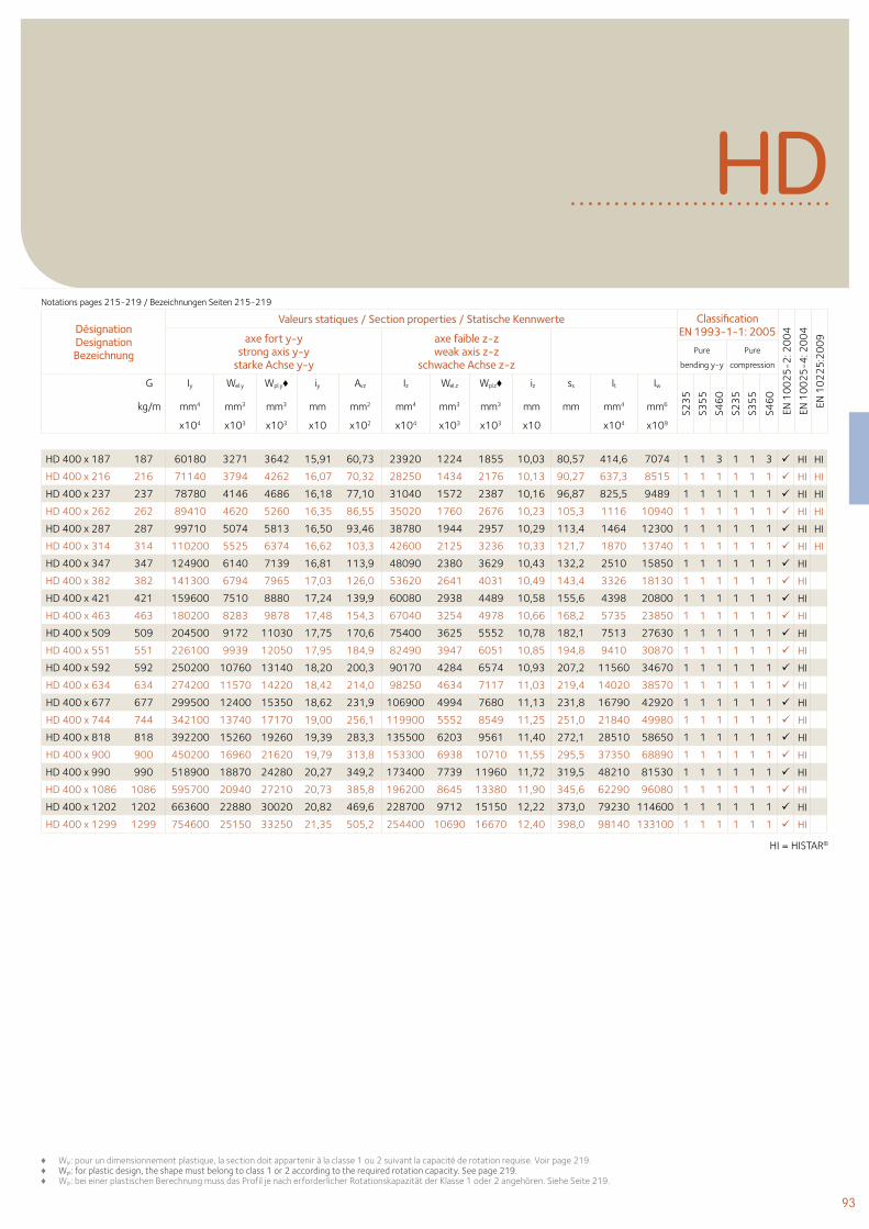
93
HD 400 x 187 187 60180 3271 3642 15,91 60,73 23920 1224 1855 10,03 80,57 414,6 7074 1 1 3 1 1 3 HI HI
HD 400 x 216 216 71140 3794 4262 16,07 70,32 28250 1434 2176 10,13 90,27 637,3 8515 1 1 1 1 1 1 HI HI
HD 400 x 237 237 78780 4146 4686 16,18 77,10 31040 1572 2387 10,16 96,87 825,5 9489 1 1 1 1 1 1 HI HI
HD 400 x 262 262 89410 4620 5260 16,35 86,55 35020 1760 2676 10,23 105,3 1116 10940 1 1 1 1 1 1 HI HI
HD 400 x 287 287 99710 5074 5813 16,50 93,46 38780 1944 2957 10,29 113,4 1464 12300 1 1 1 1 1 1 HI HI
HD 400 x 314 314 110200 5525 6374 16,62 103,3 42600 2125 3236 10,33 121,7 1870 13740 1 1 1 1 1 1 HI HI
HD 400 x 347 347 124900 6140 7139 16,81 113,9 48090 2380 3629 10,43 132,2 2510 15850 1 1 1 1 1 1 HI
HD 400 x 382 382 141300 6794 7965 17,03 126,0 53620 2641 4031 10,49 143,4 3326 18130 1 1 1 1 1 1 HI
HD 400 x 421 421 159600 7510 8880 17,24 139,9 60080 2938 4489 10,58 155,6 4398 20800 1 1 1 1 1 1 HI
HD 400 x 463 463 180200 8283 9878 17,48 154,3 67040 3254 4978 10,66 168,2 5735 23850 1 1 1 1 1 1 HI
HD 400 x 509 509 204500 9172 11030 17,75 170,6 75400 3625 5552 10,78 182,1 7513 27630 1 1 1 1 1 1 HI
HD 400 x 551 551 226100 9939 12050 17,95 184,9 82490 3947 6051 10,85 194,8 9410 30870 1 1 1 1 1 1 HI
HD 400 x 592 592 250200 10760 13140 18,20 200,3 90170 4284 6574 10,93 207,2 11560 34670 1 1 1 1 1 1 HI
HD 400 x 634 634 274200 11570 14220 18,42 214,0 98250 4634 7117 11,03 219,4 14020 38570 1 1 1 1 1 1 HI
HD 400 x 677 677 299500 12400 15350 18,62 231,9 106900 4994 7680 11,13 231,8 16790 42920 1 1 1 1 1 1 HI
HD 400 x 744 744 342100 13740 17170 19,00 256,1 119900 5552 8549 11,25 251,0 21840 49980 1 1 1 1 1 1 HI
HD 400 x 818 818 392200 15260 19260 19,39 283,3 135500 6203 9561 11,40 272,1 28510 58650 1 1 1 1 1 1 HI
HD 400 x 900 900 450200 16960 21620 19,79 313,8 153300 6938 10710 11,55 295,5 37350 68890 1 1 1 1 1 1 HI
HD 400 x 990 990 518900 18870 24280 20,27 349,2 173400 7739 11960 11,72 319,5 48210 81530 1 1 1 1 1 1 HI
HD 400 x 1086 1086 595700 20940 27210 20,73 385,8 196200 8645 13380 11,90 345,6 62290 96080 1 1 1 1 1 1 HI
HD 400 x 1202 1202 663600 22880 30020 20,82 469,6 228700 9712 15150 12,22 373,0 79230 114600 1 1 1 1 1 1 HI
HD 400 x 1299 1299 754600 25150 33250 21,35 505,2 254400 10690 16670 12,40 398,0 98140 133100 1 1 1 1 1 1 HI
♦ Wpl: pour un dimensionnement plastique, la section doit appartenir à la classe 1 ou 2 suivant la capacité de rotation requise. Voir page 219. ♦ Wpl: for plastic design, the shape must belong to class 1 or 2 according to the required rotation capacity. See page 219. ♦ Wpl: bei einer plastischen Berechnung muss das Profil je nach erforderlicher Rotationskapazität der Klasse 1 oder 2 angehören. Siehe Seite 219.
Désignation Designation Bezeichnung
Valeurs statiques / Section properties / Statische Kennwerte Classification EN 1993-1-1: 2005
EN 1
00
25
-2: 2
00
4
EN 1
00
25
-4: 2
00
4
EN 1
02
25
:20
09axe fort y-y
strong axis y-y starke Achse y-y
axe faible z-z weak axis z-z
schwache Achse z-z Pure
bending y-y
Pure
compression
G
kg/m
Iy Wel.y Wpl.y♦ iy Avz Iz Wel.z Wpl.z♦ iz ss It Iw
S23
5
S35
5
S46
0
S23
5
S35
5
S46
0
mm4 mm3 mm3 mm mm2 mm4 mm3 mm3 mm mm mm4 mm6
x104 x103 x103 x10 x102 x104 x103 x103 x10 x104 x109
HDNotations pages 215-219 / Bezeichnungen Seiten 215-219
HI = HISTAR©
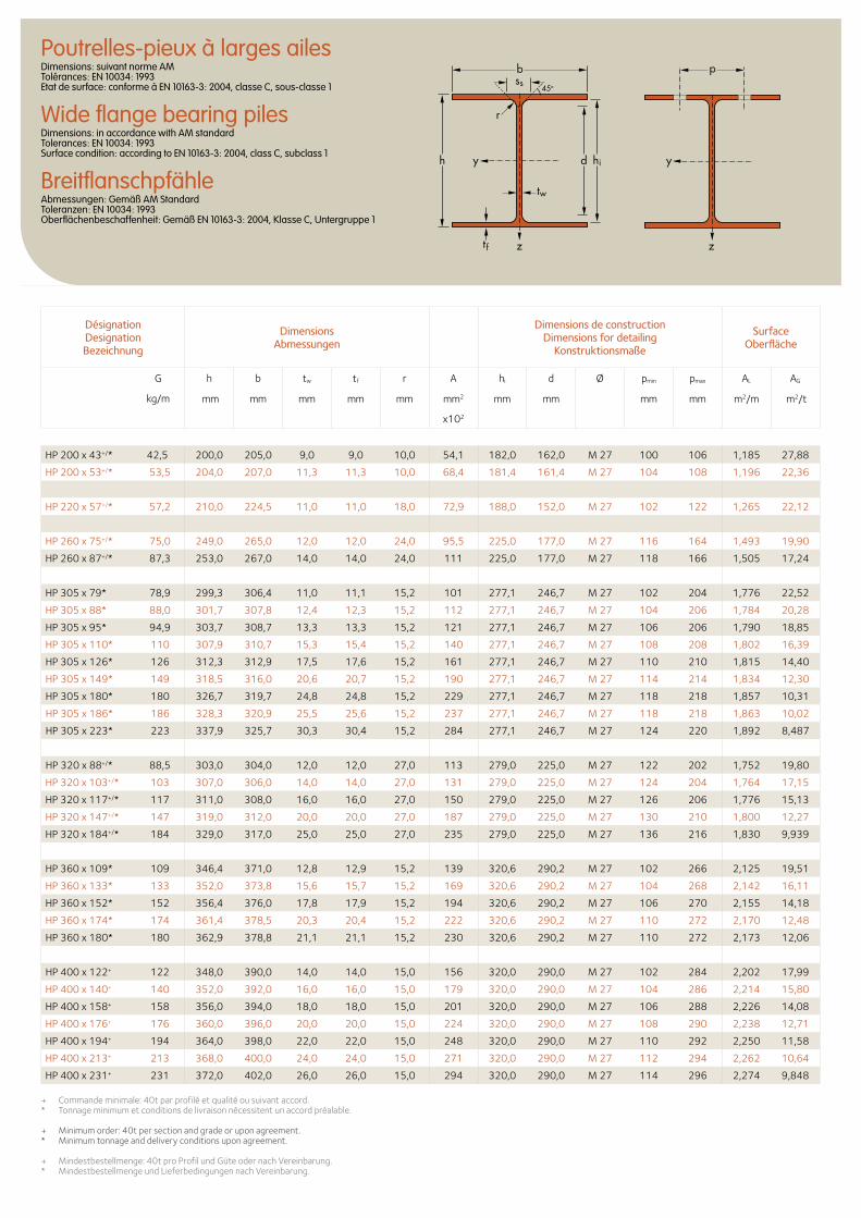
Désignation Designation Bezeichnung
Dimensions Abmessungen
Dimensions de construction Dimensions for detailing
Konstruktionsmaße
Surface Oberfläche
G
kg/m
h b tw tf r A hi d Ø pmin pmax AL AG
mm mm mm mm mm mm2 mm mm mm mm m2/m m2/t
x102
Poutrelles-pieux à larges ailesDimensions: suivant norme AM Tolérances: EN 10034: 1993 Etat de surface: conforme à EN 10163-3: 2004, classe C, sous-classe 1
Wide flange bearing pilesDimensions: in accordance with AM standard Tolerances: EN 10034: 1993 Surface condition: according to EN 10163-3: 2004, class C, subclass 1
BreitflanschpfähleAbmessungen: Gemäß AM Standard Toleranzen: EN 10034: 1993 Oberflächenbeschaffenheit: Gemäß EN 10163-3: 2004, Klasse C, Untergruppe 1
+ Commande minimale: 40t par profilé et qualité ou suivant accord. * Tonnage minimum et conditions de livraison nécessitent un accord préalable.
+ Minimum order: 40t per section and grade or upon agreement. * Minimum tonnage and delivery conditions upon agreement.
+ Mindestbestellmenge: 40t pro Profil und Güte oder nach Vereinbarung. * Mindestbestellmenge und Lieferbedingungen nach Vereinbarung.
d hi
tw
tf
yyh
zz
r
b pss
45o
HP 200 x 43+/* 42,5 200,0 205,0 9,0 9,0 10,0 54,1 182,0 162,0 M 27 100 106 1,185 27,88
HP 200 x 53+/* 53,5 204,0 207,0 11,3 11,3 10,0 68,4 181,4 161,4 M 27 104 108 1,196 22,36
HP 220 x 57+/* 57,2 210,0 224,5 11,0 11,0 18,0 72,9 188,0 152,0 M 27 102 122 1,265 22,12
HP 260 x 75+/* 75,0 249,0 265,0 12,0 12,0 24,0 95,5 225,0 177,0 M 27 116 164 1,493 19,90
HP 260 x 87+/* 87,3 253,0 267,0 14,0 14,0 24,0 111 225,0 177,0 M 27 118 166 1,505 17,24
HP 305 x 79* 78,9 299,3 306,4 11,0 11,1 15,2 101 277,1 246,7 M 27 102 204 1,776 22,52
HP 305 x 88* 88,0 301,7 307,8 12,4 12,3 15,2 112 277,1 246,7 M 27 104 206 1,784 20,28
HP 305 x 95* 94,9 303,7 308,7 13,3 13,3 15,2 121 277,1 246,7 M 27 106 206 1,790 18,85
HP 305 x 110* 110 307,9 310,7 15,3 15,4 15,2 140 277,1 246,7 M 27 108 208 1,802 16,39
HP 305 x 126* 126 312,3 312,9 17,5 17,6 15,2 161 277,1 246,7 M 27 110 210 1,815 14,40
HP 305 x 149* 149 318,5 316,0 20,6 20,7 15,2 190 277,1 246,7 M 27 114 214 1,834 12,30
HP 305 x 180* 180 326,7 319,7 24,8 24,8 15,2 229 277,1 246,7 M 27 118 218 1,857 10,31
HP 305 x 186* 186 328,3 320,9 25,5 25,6 15,2 237 277,1 246,7 M 27 118 218 1,863 10,02
HP 305 x 223* 223 337,9 325,7 30,3 30,4 15,2 284 277,1 246,7 M 27 124 220 1,892 8,487
HP 320 x 88+/* 88,5 303,0 304,0 12,0 12,0 27,0 113 279,0 225,0 M 27 122 202 1,752 19,80
HP 320 x 103+/* 103 307,0 306,0 14,0 14,0 27,0 131 279,0 225,0 M 27 124 204 1,764 17,15
HP 320 x 117+/* 117 311,0 308,0 16,0 16,0 27,0 150 279,0 225,0 M 27 126 206 1,776 15,13
HP 320 x 147+/* 147 319,0 312,0 20,0 20,0 27,0 187 279,0 225,0 M 27 130 210 1,800 12,27
HP 320 x 184+/* 184 329,0 317,0 25,0 25,0 27,0 235 279,0 225,0 M 27 136 216 1,830 9,939
HP 360 x 109* 109 346,4 371,0 12,8 12,9 15,2 139 320,6 290,2 M 27 102 266 2,125 19,51
HP 360 x 133* 133 352,0 373,8 15,6 15,7 15,2 169 320,6 290,2 M 27 104 268 2,142 16,11
HP 360 x 152* 152 356,4 376,0 17,8 17,9 15,2 194 320,6 290,2 M 27 106 270 2,155 14,18
HP 360 x 174* 174 361,4 378,5 20,3 20,4 15,2 222 320,6 290,2 M 27 110 272 2,170 12,48
HP 360 x 180* 180 362,9 378,8 21,1 21,1 15,2 230 320,6 290,2 M 27 110 272 2,173 12,06
HP 400 x 122+ 122 348,0 390,0 14,0 14,0 15,0 156 320,0 290,0 M 27 102 284 2,202 17,99
HP 400 x 140+ 140 352,0 392,0 16,0 16,0 15,0 179 320,0 290,0 M 27 104 286 2,214 15,80
HP 400 x 158+ 158 356,0 394,0 18,0 18,0 15,0 201 320,0 290,0 M 27 106 288 2,226 14,08
HP 400 x 176+ 176 360,0 396,0 20,0 20,0 15,0 224 320,0 290,0 M 27 108 290 2,238 12,71
HP 400 x 194+ 194 364,0 398,0 22,0 22,0 15,0 248 320,0 290,0 M 27 110 292 2,250 11,58
HP 400 x 213+ 213 368,0 400,0 24,0 24,0 15,0 271 320,0 290,0 M 27 112 294 2,262 10,64
HP 400 x 231+ 231 372,0 402,0 26,0 26,0 15,0 294 320,0 290,0 M 27 114 296 2,274 9,848
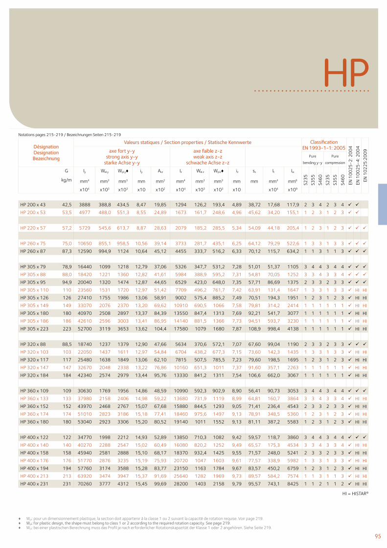
95
Désignation Designation Bezeichnung
Valeurs statiques / Section properties / Statische Kennwerte Classification EN 1993-1-1: 2005
EN 1
00
25
-2: 2
00
4
EN 1
00
25
-4: 2
00
4
EN 1
02
25
:20
09axe fort y-y
strong axis y-y starke Achse y-y
axe faible z-z weak axis z-z
schwache Achse z-z Pure
bending y-y
Pure
compression
G
kg/m
Iy Wel.y Wpl.y♦ iy Avz Iz Wel.z Wpl.z♦ iz ss It Iw
S23
5
S35
5
S46
0
S23
5
S35
5
S46
0
mm4 mm3 mm3 mm mm2 mm4 mm3 mm3 mm mm mm4 mm6
x104 x103 x103 x10 x102 x104 x103 x103 x10 x104 x109
HP
HP 200 x 43 42,5 3888 388,8 434,5 8,47 19,85 1294 126,2 193,4 4,89 38,72 17,68 117,9 2 3 4 2 3 4
HP 200 x 53 53,5 4977 488,0 551,3 8,55 24,89 1673 161,7 248,6 4,96 45,62 34,20 155,1 1 2 3 1 2 3
HP 220 x 57 57,2 5729 545,6 613,7 8,87 28,63 2079 185,2 285,5 5,34 54,09 44,18 205,4 1 2 3 1 2 3
HP 260 x 75 75,0 10650 855,1 958,5 10,56 39,14 3733 281,7 435,1 6,25 64,12 79,29 522,6 1 3 3 1 3 3
HP 260 x 87 87,3 12590 994,9 1124 10,64 45,12 4455 333,7 516,2 6,33 70,12 115,7 634,2 1 1 3 1 1 3
HP 305 x 79 78,9 16440 1099 1218 12,79 37,06 5326 347,7 531,2 7,28 51,01 51,37 1105 3 4 4 3 4 4
HP 305 x 88 88,0 18420 1221 1360 12,82 41,61 5984 388,9 595,2 7,31 54,81 70,05 1252 3 3 4 3 3 4
HP 305 x 95 94,9 20040 1320 1474 12,87 44,65 6529 423,0 648,0 7,35 57,71 86,69 1375 2 3 3 2 3 3
HP 305 x 110 110 23560 1531 1720 12,97 51,42 7709 496,2 761,7 7,42 63,91 131,4 1647 1 3 3 1 3 3 HI HI
HP 305 x 126 126 27410 1755 1986 13,06 58,91 9002 575,4 885,2 7,49 70,51 194,3 1951 1 2 3 1 2 3 HI HI
HP 305 x 149 149 33070 2076 2370 13,20 69,62 10910 690,5 1066 7,58 79,81 314,2 2414 1 1 1 1 1 1 HI HI
HP 305 x 180 180 40970 2508 2897 13,37 84,39 13550 847,4 1313 7,69 92,21 541,7 3077 1 1 1 1 1 1 HI HI
HP 305 x 186 186 42610 2596 3003 13,41 86,95 14140 881,5 1366 7,73 94,51 593,7 3230 1 1 1 1 1 1 HI HI
HP 305 x 223 223 52700 3119 3653 13,62 104,4 17580 1079 1680 7,87 108,9 998,4 4138 1 1 1 1 1 1 HI HI
HP 320 x 88 88,5 18740 1237 1379 12,90 47,66 5634 370,6 572,1 7,07 67,60 99,04 1190 2 3 3 2 3 3
HP 320 x 103 103 22050 1437 1611 12,97 54,84 6704 438,2 677,3 7,15 73,60 142,3 1435 1 3 3 1 3 3 HI HI
HP 320 x 117 117 25480 1638 1849 13,06 62,10 7815 507,5 785,5 7,23 79,60 198,5 1695 1 2 3 1 2 3 HI HI
HP 320 x 147 147 32670 2048 2338 13,22 76,86 10160 651,3 1011 7,37 91,60 357,1 2263 1 1 1 1 1 1 HI HI
HP 320 x 184 184 42340 2574 2979 13,44 95,76 13330 841,2 1311 7,54 106,6 662,0 3067 1 1 1 1 1 1 HI HI
HP 360 x 109 109 30630 1769 1956 14,86 48,59 10990 592,3 902,9 8,90 56,41 90,73 3053 3 4 4 3 4 4
HP 360 x 133 133 37980 2158 2406 14,98 59,22 13680 731,9 1119 8,99 64,81 160,7 3864 3 3 4 3 3 4 HI HI
HP 360 x 152 152 43970 2468 2767 15,07 67,68 15880 844,5 1293 9,05 71,41 236,4 4543 2 3 3 2 3 3 HI HI
HP 360 x 174 174 51010 2823 3186 15,18 77,41 18460 975,6 1497 9,13 78,91 348,5 5360 1 2 3 1 2 3 HI HI
HP 360 x 180 180 53040 2923 3306 15,20 80,52 19140 1011 1552 9,13 81,11 387,2 5583 1 2 3 1 2 3 HI HI
HP 400 x 122 122 34770 1998 2212 14,93 52,89 13850 710,3 1082 9,42 59,57 118,7 3860 3 4 4 3 4 4
HP 400 x 140 140 40270 2288 2547 15,02 60,49 16080 820,2 1252 9,49 65,57 175,3 4534 3 3 4 3 3 4 HI HI
HP 400 x 158 158 45940 2581 2888 15,10 68,17 18370 932,4 1425 9,55 71,57 248,0 5241 2 3 3 2 3 3 HI HI
HP 400 x 176 176 51770 2876 3235 15,19 75,93 20720 1047 1603 9,61 77,57 338,9 5982 1 3 3 1 3 3 HI HI
HP 400 x 194 194 57760 3174 3588 15,28 83,77 23150 1163 1784 9,67 83,57 450,2 6759 1 2 3 1 2 3 HI HI
HP 400 x 213 213 63920 3474 3947 15,37 91,69 25640 1282 1969 9,73 89,57 584,2 7574 1 1 3 1 1 3 HI HI
HP 400 x 231 231 70260 3777 4312 15,45 99,69 28200 1403 2158 9,79 95,57 743,1 8425 1 1 2 1 1 2 HI HI
♦ Wpl: pour un dimensionnement plastique, la section doit appartenir à la classe 1 ou 2 suivant la capacité de rotation requise. Voir page 219.♦ Wpl: for plastic design, the shape must belong to class 1 or 2 according to the required rotation capacity. See page 219.♦ Wpl: bei einer plastischen Berechnung muss das Profil je nach erforderlicher Rotationskapazität der Klasse 1 oder 2 angehören. Siehe Seite 219.
Notations pages 215-219 / Bezeichnungen Seiten 215-219
HI = HISTAR©
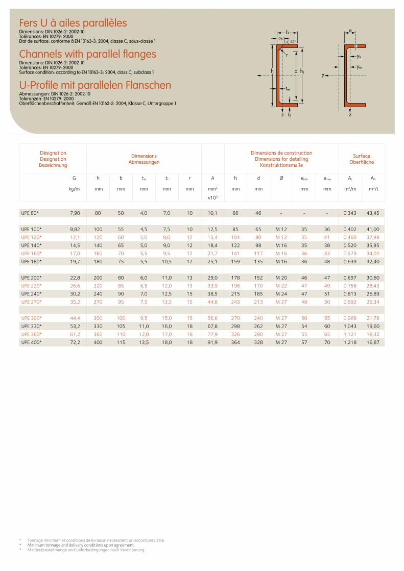
Fers U à ailes parallèlesDimensions: DIN 1026-2: 2002-10 Tolérances: EN 10279: 2000 Etat de surface: conforme à EN 10163-3: 2004, classe C, sous-classe 1
Channels with parallel flangesDimensions: DIN 1026-2: 2002-10 Tolerances: EN 10279: 2000 Surface condition: according to EN 10163-3: 2004, class C, subclass 1
U-Profile mit parallelen FlanschenAbmessungen: DIN 1026-2: 2002-10 Toleranzen: EN 10279: 2000 Oberflächenbeschaffenheit: Gemäß EN 10163-3: 2004, Klasse C, Untergruppe 1
Désignation Designation Bezeichnung
Dimensions Abmessungen
Dimensions de construction Dimensions for detailing
Konstruktionsmaße
Surface Oberfläche
G
kg/m
h b tw tf r A hi d Ø emin emax AL AG
mm mm mm mm mm mm2 mm mm mm mm m2/m m2/t
x102
ys
ess
ym
45o
d hi
tw
tf
h y
zz
r
b
UPE 80* 7,90 80 50 4,0 7,0 10 10,1 66 46 - - - 0,343 43,45
UPE 100* 9,82 100 55 4,5 7,5 10 12,5 85 65 M 12 35 36 0,402 41,00
UPE 120* 12,1 120 60 5,0 8,0 12 15,4 104 80 M 12 35 41 0,460 37,98
UPE 140* 14,5 140 65 5,0 9,0 12 18,4 122 98 M 16 35 38 0,520 35,95
UPE 160* 17,0 160 70 5,5 9,5 12 21,7 141 117 M 16 36 43 0,579 34,01
UPE 180* 19,7 180 75 5,5 10,5 12 25,1 159 135 M 16 36 48 0,639 32,40
UPE 200* 22,8 200 80 6,0 11,0 13 29,0 178 152 M 20 46 47 0,697 30,60
UPE 220* 26,6 220 85 6,5 12,0 13 33,9 196 170 M 22 47 49 0,756 28,43
UPE 240* 30,2 240 90 7,0 12,5 15 38,5 215 185 M 24 47 51 0,813 26,89
UPE 270* 35,2 270 95 7,5 13,5 15 44,8 243 213 M 27 48 50 0,892 25,34
UPE 300* 44,4 300 100 9,5 15,0 15 56,6 270 240 M 27 50 55 0,968 21,78
UPE 330* 53,2 330 105 11,0 16,0 18 67,8 298 262 M 27 54 60 1,043 19,60
UPE 360* 61,2 360 110 12,0 17,0 18 77,9 326 290 M 27 55 65 1,121 18,32
UPE 400* 72,2 400 115 13,5 18,0 18 91,9 364 328 M 27 57 70 1,218 16,87
* Tonnage minimum et conditions de livraison nécessitent un accord préalable.* Minimum tonnage and delivery conditions upon agreement.* Mindestbestellmenge und Lieferbedingungen nach Vereinbarung.
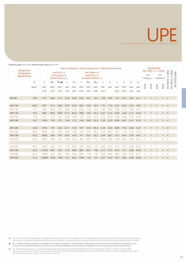
97
UPE
Désignation Designation Bezeichnung
Valeurs statiques / Section properties / Statische Kennwerte Classification EN 1993-1-1: 2005
EN 1
00
25
-2: 2
00
4
EN 1
00
25
-4: 2
00
4
EN 1
02
25
:20
09axe fort y-y
strong axis y-y starke Achse y-y
axe faible z-z weak axis z-z
schwache Achse z-z Pure
bending y-y
Pure
compression
G
kg/m
Iy Wel.y Wpl.y■ iy Avz Iz Wel.z Wpl.z′ iz ss It Iw ys ym
S23
5
S35
5
S23
5
S35
5
mm4 mm3 mm3 mm mm2 mm4 mm3 mm3 mm mm mm4 mm6 mm mm
x104 x103 x103 x10 x102 x104 x103 x103 x10 x104 x109 x10 x10
UPE 80 7,90 107 26,8 31,2 3,26 4,05 25,5 8,0 14,3 1,59 16,9 1,47 0,22 1,82 3,71 1 1 1 1
UPE 100 9,82 207 41,4 48,0 4,07 5,34 38,3 10,6 19,3 1,75 17,9 2,01 0,53 1,91 3,93 1 1 1 1
UPE 120 12,1 364 60,6 70,3 4,86 7,18 55,5 13,8 25,3 1,90 20,0 2,90 1,12 1,98 4,12 1 1 1 1
UPE 140 14,5 600 85,6 98,8 5,71 8,25 78,8 18,2 33,2 2,07 21,0 4,05 2,20 2,17 4,54 1 1 1 1
UPE 160 17,0 911 114 132 6,48 10,0 107 22,6 41,5 2,22 22,0 5,20 3,96 2,27 4,76 1 1 1 1
UPE 180 19,7 1350 150 173 7,34 11,2 144 28,6 52,3 2,39 23,0 6,99 6,81 2,47 5,19 1 1 1 1
UPE 200 22,8 1910 191 220 8,11 13,5 187 34,5 63,3 2,54 24,6 8,89 11,0 2,56 5,41 1 1 1 1
UPE 220 26,6 2680 244 281 8,90 15,8 247 42,5 78,2 2,70 26,1 12,1 17,6 2,70 5,70 1 1 1 1
UPE 240 30,2 3600 300 347 9,67 18,8 311 50,1 92,2 2,84 28,3 15,1 26,4 2,79 5,91 1 1 1 1
UPE 270 35,2 5250 389 451 10,8 22,2 401 60,7 112 2,99 29,8 19,9 43,6 2,89 6,14 1 1 1 2
UPE 300 44,4 7820 522 613 11,8 30,3 538 75,6 137 3,08 33,3 31,5 72,7 2,89 6,03 1 1 1 1
UPE 330 53,2 11010 667 792 12,7 38,8 681 89,7 156 3,17 37,5 45,2 112 2,90 6,00 1 1 1 1
UPE 360 61,2 14830 824 982 13,8 45,6 844 105 178 3,29 39,5 58,5 166 2,97 6,12 1 1 1 1
UPE 400 72,2 20980 1050 1260 15,1 56,2 1045 123 191 3,37 42,0 79,1 259 2,98 6,06 1 1 1 1
■ Wpl,y est calculé selon l’hypothèse d’un diagramme de contraintes bi-rectangulaire et n’est applicable que si deux ou plusieurs fers U sont associés de facon à constituer une section doublement symétrique pour laquelle un moment de flexion agissant dans le plan du centre de gravité n’engendre pas de torsion.
■ Wpl,y is determined assuming a bi-rectangular stress block distribution. Thus, the given value applies only if two or more channels are combined in such a way to form a double symmetric cross-section so that the bending moment acting in the plane of the centre of gravity will not lead to torsion.
■ Für die Berechnung von Wpl,y wurde eine doppelrechteckige Spannungsverteilung angenommen. Der angegebene Wert ist daher nur anwendbar, wenn zwei oder mehr U-Profile so miteinander kombiniert sind, dass sie einen doppelsymmetrischen Querschnitt bilden, womit ein Biegemoment, das in der Schwerpunktebene angreift, keine Torsion hervorruft.
Notations pages 215-219 / Bezeichnungen Seiten 215-219
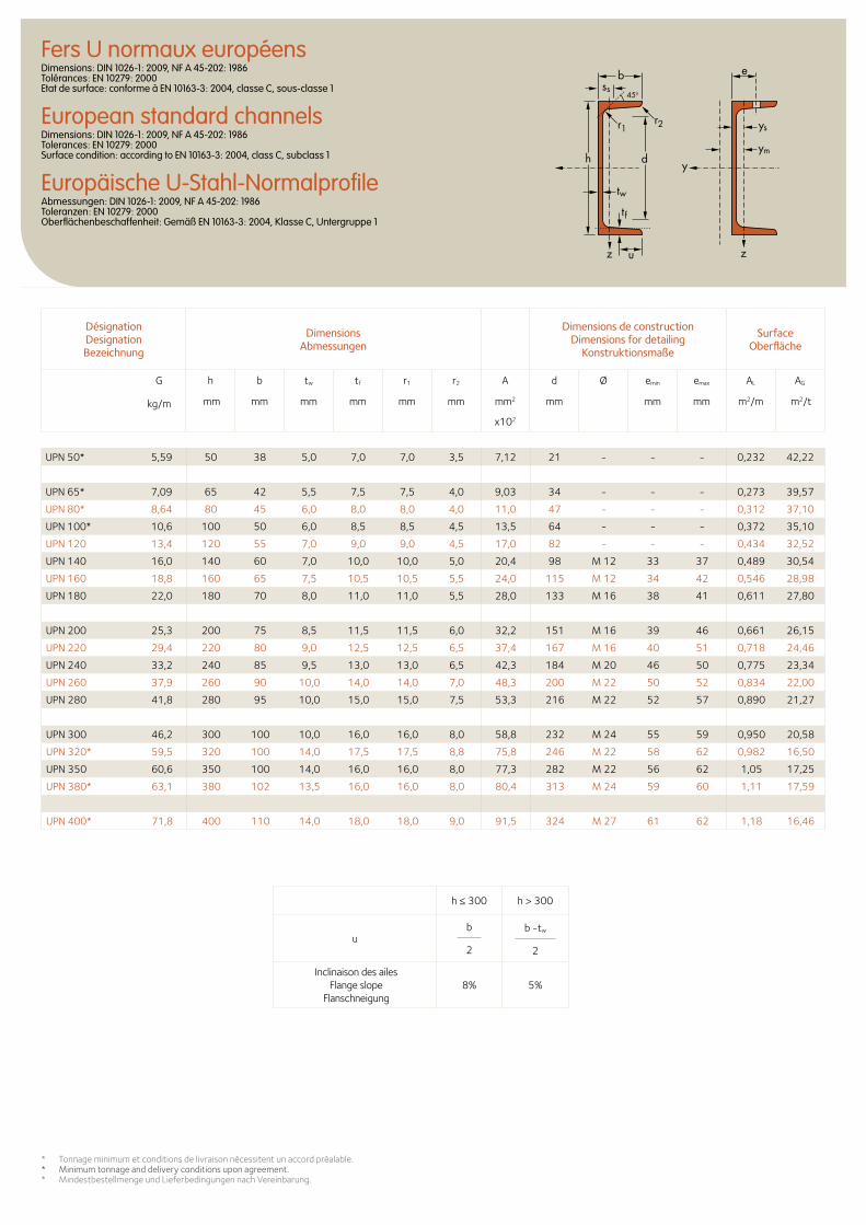
Fers U normaux européensDimensions: DIN 1026-1: 2009, NF A 45-202: 1986 Tolérances: EN 10279: 2000 Etat de surface: conforme à EN 10163-3: 2004, classe C, sous-classe 1
European standard channelsDimensions: DIN 1026-1: 2009, NF A 45-202: 1986 Tolerances: EN 10279: 2000 Surface condition: according to EN 10163-3: 2004, class C, subclass 1
Europäische U-Stahl-NormalprofileAbmessungen: DIN 1026-1: 2009, NF A 45-202: 1986 Toleranzen: EN 10279: 2000 Oberflächenbeschaffenheit: Gemäß EN 10163-3: 2004, Klasse C, Untergruppe 1
* Tonnage minimum et conditions de livraison nécessitent un accord préalable.* Minimum tonnage and delivery conditions upon agreement.* Mindestbestellmenge und Lieferbedingungen nach Vereinbarung.
ys
ess
ym
y
z z
45o
d
tw
tf
h
r1
b
r2
u
Désignation Designation Bezeichnung
Dimensions Abmessungen
Dimensions de construction Dimensions for detailing
Konstruktionsmaße
Surface Oberfläche
G
kg/m
h b tw tf r1 r2 A d Ø emin emax AL AG
mm mm mm mm mm mm mm2 mm mm mm m2/m m2/t
x102
UPN 50* 5,59 50 38 5,0 7,0 7,0 3,5 7,12 21 - - - 0,232 42,22
UPN 65* 7,09 65 42 5,5 7,5 7,5 4,0 9,03 34 - - - 0,273 39,57
UPN 80* 8,64 80 45 6,0 8,0 8,0 4,0 11,0 47 - - - 0,312 37,10
UPN 100* 10,6 100 50 6,0 8,5 8,5 4,5 13,5 64 - - - 0,372 35,10
UPN 120 13,4 120 55 7,0 9,0 9,0 4,5 17,0 82 - - - 0,434 32,52
UPN 140 16,0 140 60 7,0 10,0 10,0 5,0 20,4 98 M 12 33 37 0,489 30,54
UPN 160 18,8 160 65 7,5 10,5 10,5 5,5 24,0 115 M 12 34 42 0,546 28,98
UPN 180 22,0 180 70 8,0 11,0 11,0 5,5 28,0 133 M 16 38 41 0,611 27,80
UPN 200 25,3 200 75 8,5 11,5 11,5 6,0 32,2 151 M 16 39 46 0,661 26,15
UPN 220 29,4 220 80 9,0 12,5 12,5 6,5 37,4 167 M 16 40 51 0,718 24,46
UPN 240 33,2 240 85 9,5 13,0 13,0 6,5 42,3 184 M 20 46 50 0,775 23,34
UPN 260 37,9 260 90 10,0 14,0 14,0 7,0 48,3 200 M 22 50 52 0,834 22,00
UPN 280 41,8 280 95 10,0 15,0 15,0 7,5 53,3 216 M 22 52 57 0,890 21,27
UPN 300 46,2 300 100 10,0 16,0 16,0 8,0 58,8 232 M 24 55 59 0,950 20,58
UPN 320* 59,5 320 100 14,0 17,5 17,5 8,8 75,8 246 M 22 58 62 0,982 16,50
UPN 350 60,6 350 100 14,0 16,0 16,0 8,0 77,3 282 M 22 56 62 1,05 17,25
UPN 380* 63,1 380 102 13,5 16,0 16,0 8,0 80,4 313 M 24 59 60 1,11 17,59
UPN 400* 71,8 400 110 14,0 18,0 18,0 9,0 91,5 324 M 27 61 62 1,18 16,46
h ≤ 300 h > 300
ub
2
b -tw
2
Inclinaison des ailes Flange slope
Flanschneigung8% 5%
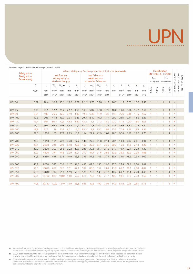
99
UPN
■ Wpl,y est calculé selon l’hypothèse d’un diagramme de contraintes bi-rectangulaire et n’est applicable que si deux ou plusieurs fers U sont associés de facon à constituer une section doublement symétrique pour laquelle un moment de flexion agissant dans le plan du centre de gravité n’engendre pas de torsion.
■ Wpl,y is determined assuming a bi-rectangular stress block distribution. Thus, the given value applies only if two or more channels are combined in such a way to form a double symmetric cross-section so that the bending moment acting in the plane of the centre of gravity will not lead to torsion.
■ Für die Berechnung von Wpl,y wurde eine doppelrechteckige Spannungsverteilung angenommen. Der angegebene Wert ist daher nur anwendbar, wenn zwei oder mehr U-Profile so miteinander kombiniert sind, dass sie einen doppelsymmetrischen Querschnitt bilden, womit ein Biegemoment, das in der Schwerpunktebene angreift, keine Torsion hervorruft.
Désignation Designation Bezeichnung
Valeurs statiques / Section properties / Statische Kennwerte Classification EN 1993-1-1: 2005
EN 1
00
25
-2: 2
00
4
EN 1
00
25
-4: 2
00
4
EN 1
02
25
:20
09axe fort y-y
strong axis y-y starke Achse y-y
axe faible z-z weak axis z-z
schwache Achse z-z Pure
bending y-y
Pure
compression
G
kg/m
Iy Wel.y Wpl.y■ iy Avz Iz Wel.z Wpl.z′ iz ss It Iw ys ym
S23
5
S35
5
S23
5
S35
5
mm4 mm3 mm3 mm mm2 mm4 mm3 mm3 mm mm mm4 mm6 mm mm
x104 x103 x103 x10 x102 x104 x103 x103 x10 x104 x109 x10 x10
UPN 50 5,59 26,4 10,6 13,1 1,92 2,77 9,12 3,75 6,78 1,13 16,7 1,12 0,03 1,37 2,47 1 1 1 1
UPN 65 7,09 57,5 17,7 21,7 2,52 3,68 14,1 5,07 9,38 1,25 18,0 1,61 0,08 1,42 2,60 1 1 1 1
UPN 80 8,64 106 26,5 32,3 3,10 4,90 19,4 6,36 11,9 1,33 19,4 2,20 0,18 1,45 2,67 1 1 1 1
UPN 100 10,6 206 41,2 49,0 3,91 6,46 29,3 8,49 16,2 1,47 20,3 2,81 0,41 1,55 2,93 1 1 1 1
UPN 120 13,4 364 60,7 72,6 4,62 8,80 43,2 11,1 21,2 1,59 22,2 4,15 0,90 1,60 3,03 1 1 1 1
UPN 140 16,0 605 86,4 103 5,45 10,4 62,7 14,8 28,3 1,75 23,9 5,68 1,80 1,75 3,37 1 1 1 1
UPN 160 18,8 925 116 138 6,21 12,6 85,3 18,3 35,2 1,89 25,3 7,39 3,26 1,84 3,56 1 1 1 1
UPN 180 22,0 1350 150 179 6,95 15,1 114 22,4 42,9 2,02 26,7 9,55 5,57 1,92 3,75 1 1 1 1
UPN 200 25,3 1910 191 228 7,70 17,7 148 27,0 51,8 2,14 28,1 11,9 9,07 2,01 3,94 1 1 1 1
UPN 220 29,4 2690 245 292 8,48 20,6 197 33,6 64,1 2,30 30,3 16,0 14,6 2,14 4,20 1 1 1 1
UPN 240 33,2 3600 300 358 9,22 23,7 248 39,6 75,7 2,42 31,7 19,7 22,1 2,23 4,39 1 1 1 1
UPN 260 37,9 4820 371 442 9,99 27,1 317 47,7 91,6 2,56 33,9 25,5 33,3 2,36 4,66 1 1 1 1
UPN 280 41,8 6280 448 532 10,9 29,3 399 57,2 109 2,74 35,6 31,0 48,5 2,53 5,02 1 1 1 1
UPN 300 46,2 8030 535 632 11,7 31,8 495 67,8 130 2,90 37,3 37,4 69,1 2,70 5,41 1 1 1 1
UPN 320 59,5 10870 679 826 12,1 47,1 597 80,6 152 2,81 43,0 66,7 96,1 2,60 4,82 1 1 1 1
UPN 350 60,6 12840 734 918 12,9 50,8 570 75,0 143 2,72 40,7 61,2 114 2,40 4,45 1 1 1 1
UPN 380 63,1 15760 829 1010 14,0 53,2 615 78,7 148 2,77 40,3 59,1 146 2,38 4,58 1 1 1 1
UPN 400 71,8 20350 1020 1240 14,9 58,6 846 102 190 3,04 44,0 81,6 221 2,65 5,11 1 1 1 1
Notations pages 215-219 / Bezeichnungen Seiten 215-219
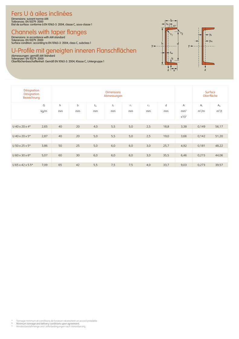
Fers U à ailes inclinéesDimensions: suivant norme AM Tolérances: EN 10279: 2000 Etat de surface: conforme à EN 10163-3: 2004, classe C, sous-classe 1
Channels with taper flangesDimensions: in accordance with AM standard Tolerances: EN 10279: 2000 Surface condition: according to EN 10163-3: 2004, class C, subclass 1
U-Profile mit geneigten inneren FlanschflächenAbmessungen: gemäß AM Standard Toleranzen: EN 10279: 2000 Oberflächenbeschaffenheit: Gemäß EN 10163-3: 2004, Klasse C, Untergruppe 1
* Tonnage minimum et conditions de livraison nécessitent un accord préalable.* Minimum tonnage and delivery conditions upon agreement.* Mindestbestellmenge und Lieferbedingungen nach Vereinbarung.
Désignation Designation Bezeichnung
Dimensions Abmessungen
Surface Oberfläche
G h b tw tf r1 r2 d A AL AG
kg/m mm mm mm mm mm mm mm mm2 m2/m m2/t
x102
ys
ss
ym
y
z z
y
45o
d
tw
tf
h
r1
b
r2
u
U 40 x 20 x 4* 2,65 40 20 4,0 5,5 5,0 2,5 18,8 3,38 0,149 56,17
U 40 x 20 x 5* 2,87 40 20 5,0 5,5 5,0 2,5 19,0 3,66 0,142 51,20
U 50 x 25 x 5* 3,86 50 25 5,0 6,0 6,0 3,0 25,7 4,92 0,181 48,22
U 60 x 30 x 6* 5,07 60 30 6,0 6,0 6,0 3,0 35,5 6,46 0,215 44,06
U 65 x 42 x 5.5* 7,09 65 42 5,5 7,5 7,5 4,0 33,7 9,03 0,273 39,57
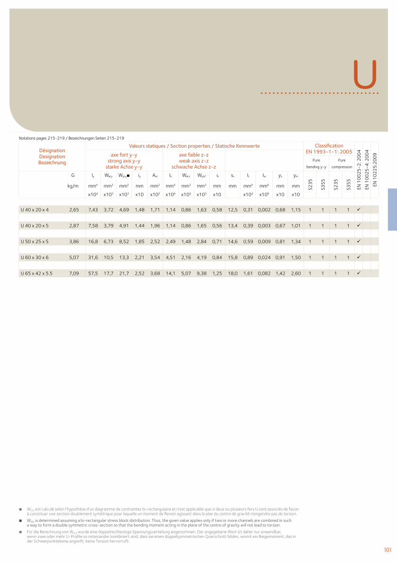
101
U
■ Wpl,y est calculé selon l’hypothèse d’un diagramme de contraintes bi-rectangulaire et n’est applicable que si deux ou plusieurs fers U sont associés de facon à constituer une section doublement symétrique pour laquelle un moment de flexion agissant dans le plan du centre de gravité n’engendre pas de torsion.
■ Wpl,y is determined assuming a bi-rectangular stress block distribution. Thus, the given value applies only if two or more channels are combined in such a way to form a double symmetric cross-section so that the bending moment acting in the plane of the centre of gravity will not lead to torsion.
■ Für die Berechnung von Wpl,y wurde eine doppelrechteckige Spannungsverteilung angenommen. Der angegebene Wert ist daher nur anwendbar, wenn zwei oder mehr U-Profile so miteinander kombiniert sind, dass sie einen doppelsymmetrischen Querschnitt bilden, womit ein Biegemoment, das in der Schwerpunktebene angreift, keine Torsion hervorruft.
Désignation Designation Bezeichnung
Valeurs statiques / Section properties / Statische Kennwerte Classification EN 1993-1-1: 2005
EN 1
00
25
-2: 2
00
4
EN 1
00
25
-4: 2
00
4
EN 1
02
25
:20
09axe fort y-y
strong axis y-y starke Achse y-y
axe faible z-z weak axis z-z
schwache Achse z-z Pure
bending y-y
Pure
compression
G Iy Wel.y Wpl.y■ iy Avz Iz Wel.z Wpl.z′ iz ss It Iw ys ym
S23
5
S35
5
S23
5
S35
5
kg/m mm4 mm3 mm3 mm mm2 mm4 mm3 mm3 mm mm mm4 mm6 mm mm
x104 x103 x103 x10 x102 x104 x103 x103 x10 x104 x109 x10 x10
U 40 x 20 x 4 2,65 7,43 3,72 4,69 1,48 1,71 1,14 0,86 1,63 0,58 12,5 0,31 0,002 0,68 1,15 1 1 1 1
U 40 x 20 x 5 2,87 7,58 3,79 4,91 1,44 1,96 1,14 0,86 1,65 0,56 13,4 0,39 0,003 0,67 1,01 1 1 1 1
U 50 x 25 x 5 3,86 16,8 6,73 8,52 1,85 2,52 2,49 1,48 2,84 0,71 14,6 0,59 0,009 0,81 1,34 1 1 1 1
U 60 x 30 x 6 5,07 31,6 10,5 13,3 2,21 3,54 4,51 2,16 4,19 0,84 15,8 0,89 0,024 0,91 1,50 1 1 1 1
U 65 x 42 x 5.5 7,09 57,5 17,7 21,7 2,52 3,68 14,1 5,07 9,38 1,25 18,0 1,61 0,082 1,42 2,60 1 1 1 1
Notations pages 215-219 / Bezeichnungen Seiten 215-219
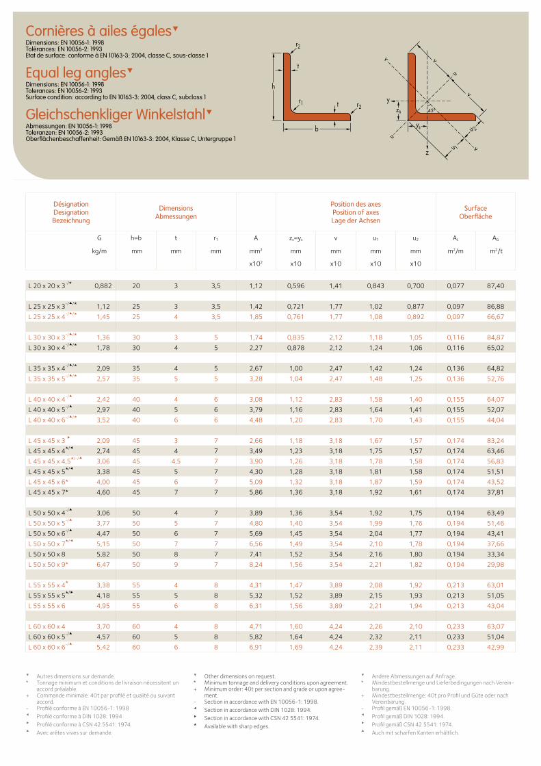
Cornières à ailes égalesDimensions: EN 10056-1: 1998 Tolérances: EN 10056-2: 1993 Etat de surface: conforme à EN 10163-3: 2004, classe C, sous-classe 1
Equal leg anglesDimensions: EN 10056-1: 1998 Tolerances: EN 10056-2: 1993 Surface condition: according to EN 10163-3: 2004, class C, subclass 1
Gleichschenkliger WinkelstahlAbmessungen: EN 10056-1: 1998 Toleranzen: EN 10056-2: 1993 Oberflächenbeschaffenheit: Gemäß EN 10163-3: 2004, Klasse C, Untergruppe 1
Désignation Designation Bezeichnung
Dimensions Abmessungen
Position des axesPosition of axesLage der Achsen
Surface Oberfläche
G h=b t r1 A zs=ys v u1 u2 AL AG
kg/m mm mm mm mm2 mm mm mm mm m2/m m2/t
x102 x10 x10 x10 x10
zs
ys
y
z
u
uu 1
u 2
v
v
v
v
t
t
h
b
r1 r2
r2
45o
L 20 x 20 x 3-/* 0,882 20 3 3,5 1,12 0,596 1,41 0,843 0,700 0,077 87,40
L 25 x 25 x 3-//* 1,12 25 3 3,5 1,42 0,721 1,77 1,02 0,877 0,097 86,88
L 25 x 25 x 4-//* 1,45 25 4 3,5 1,85 0,761 1,77 1,08 0,892 0,097 66,67
L 30 x 30 x 3-//* 1,36 30 3 5 1,74 0,835 2,12 1,18 1,05 0,116 84,87
L 30 x 30 x 4-//* 1,78 30 4 5 2,27 0,878 2,12 1,24 1,06 0,116 65,02
L 35 x 35 x 4-//* 2,09 35 4 5 2,67 1,00 2,47 1,42 1,24 0,136 64,82
L 35 x 35 x 5-//* 2,57 35 5 5 3,28 1,04 2,47 1,48 1,25 0,136 52,76
L 40 x 40 x 4-/
2,42 40 4 6 3,08 1,12 2,83 1,58 1,40 0,155 64,07
L 40 x 40 x 5-/
2,97 40 5 6 3,79 1,16 2,83 1,64 1,41 0,155 52,07
L 40 x 40 x 6-//* 3,52 40 6 6 4,48 1,20 2,83 1,70 1,43 0,155 44,04
L 45 x 45 x 3
2,09 45 3 7 2,66 1,18 3,18 1,67 1,57 0,174 83,24
L 45 x 45 x 4*/2,74 45 4 7 3,49 1,23 3,18 1,75 1,57 0,174 63,46
L 45 x 45 x 4,5*/-/3,06 45 4,5 7 3,90 1,26 3,18 1,78 1,58 0,174 56,83
L 45 x 45 x 5*/3,38 45 5 7 4,30 1,28 3,18 1,81 1,58 0,174 51,51
L 45 x 45 x 6* 4,00 45 6 7 5,09 1,32 3,18 1,87 1,59 0,174 43,52
L 45 x 45 x 7* 4,60 45 7 7 5,86 1,36 3,18 1,92 1,61 0,174 37,81
L 50 x 50 x 4-/
3,06 50 4 7 3,89 1,36 3,54 1,92 1,75 0,194 63,49
L 50 x 50 x 5-/
3,77 50 5 7 4,80 1,40 3,54 1,99 1,76 0,194 51,46
L 50 x 50 x 6-/
4,47 50 6 7 5,69 1,45 3,54 2,04 1,77 0,194 43,41
L 50 x 50 x 7*/5,15 50 7 7 6,56 1,49 3,54 2,10 1,78 0,194 37,66
L 50 x 50 x 8 5,82 50 8 7 7,41 1,52 3,54 2,16 1,80 0,194 33,34
L 50 x 50 x 9* 6,47 50 9 7 8,24 1,56 3,54 2,21 1,82 0,194 29,98
L 55 x 55 x 4* 3,38 55 4 8 4,31 1,47 3,89 2,08 1,92 0,213 63,01
L 55 x 55 x 5*/4,18 55 5 8 5,32 1,52 3,89 2,15 1,93 0,213 51,05
L 55 x 55 x 6 4,95 55 6 8 6,31 1,56 3,89 2,21 1,94 0,213 43,04
L 60 x 60 x 4 3,70 60 4 8 4,71 1,60 4,24 2,26 2,10 0,233 63,07
L 60 x 60 x 5-/
4,57 60 5 8 5,82 1,64 4,24 2,32 2,11 0,233 51,04
L 60 x 60 x 6-/
5,42 60 6 8 6,91 1,69 4,24 2,39 2,11 0,233 42,99
Autres dimensions sur demande. * Tonnage minimum et conditions de livraison nécessitent un
accord préalable.+ Commande minimale: 40t par profilé et qualité ou suivant
accord.- Profilé conforme à EN 10056-1: 1998Profilé conforme à DIN 1028: 1994Profilé conforme à CSN 42 5541: 1974.Avec arêtes vives sur demande.
Other dimensions on request. * Minimum tonnage and delivery conditions upon agreement.+ Minimum order: 40t per section and grade or upon agree-
ment.- Section in accordance with EN 10056-1: 1998. Section in accordance with DIN 1028: 1994. Section in accordance with CSN 42 5541: 1974. Available with sharp edges.
Andere Abmessungen auf Anfrage. * Mindestbestellmenge und Lieferbedingungen nach Verein-
barung.+ Mindestbestellmenge: 40t pro Profil und Güte oder nach
Vereinbarung.- Profil gemäß EN 10056-1: 1998. Profil gemäß DIN 1028: 1994. Profil gemäß CSN 42 5541: 1974. Auch mit scharfen Kanten erhältlich.
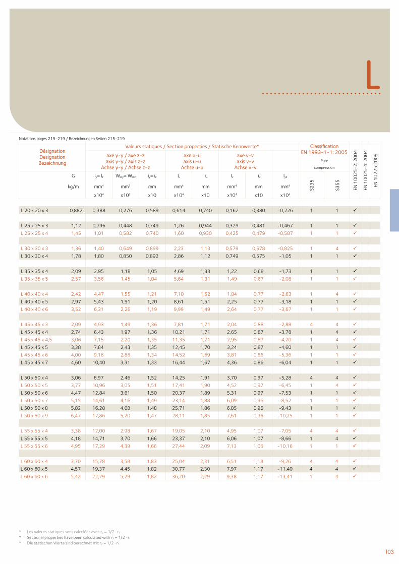
103
L
Désignation Designation Bezeichnung
Valeurs statiques / Section properties / Statische Kennwerte* Classification EN 1993-1-1: 2005
EN 1
00
25
-2: 2
00
4
EN 1
00
25
-4: 2
00
4
EN 1
02
25
:20
09axe y-y / axe z-z
axis y-y / axis z-zAchse y-y / Achse z-z
axe u-uaxis u-u
Achse u-u
axe v-vaxis v-v
Achse v-vPure
compression
G ly= lz Wel.y= Wel.z iy= iz Iu iu Iv iv lyz
S23
5
S35
5
kg/m mm4 mm3 mm mm4 mm mm4 mm mm4
x104 x103 x10 x104 x10 x104 x10 x104
Notations pages 215-219 / Bezeichnungen Seiten 215-219
L 20 x 20 x 3 0,882 0,388 0,276 0,589 0,614 0,740 0,162 0,380 -0,226 1 1
L 25 x 25 x 3 1,12 0,796 0,448 0,749 1,26 0,944 0,329 0,481 -0,467 1 1
L 25 x 25 x 4 1,45 1,01 0,582 0,740 1,60 0,930 0,425 0,479 -0,587 1 1
L 30 x 30 x 3 1,36 1,40 0,649 0,899 2,23 1,13 0,579 0,578 -0,825 1 4
L 30 x 30 x 4 1,78 1,80 0,850 0,892 2,86 1,12 0,749 0,575 -1,05 1 1
L 35 x 35 x 4 2,09 2,95 1,18 1,05 4,69 1,33 1,22 0,68 -1,73 1 1
L 35 x 35 x 5 2,57 3,56 1,45 1,04 5,64 1,31 1,49 0,67 -2,08 1 1
L 40 x 40 x 4 2,42 4,47 1,55 1,21 7,10 1,52 1,84 0,77 -2,63 1 4
L 40 x 40 x 5 2,97 5,43 1,91 1,20 8,61 1,51 2,25 0,77 -3,18 1 1
L 40 x 40 x 6 3,52 6,31 2,26 1,19 9,99 1,49 2,64 0,77 -3,67 1 1
L 45 x 45 x 3 2,09 4,93 1,49 1,36 7,81 1,71 2,04 0,88 -2,88 4 4
L 45 x 45 x 4 2,74 6,43 1,97 1,36 10,21 1,71 2,65 0,87 -3,78 1 4
L 45 x 45 x 4,5 3,06 7,15 2,20 1,35 11,35 1,71 2,95 0,87 -4,20 1 4
L 45 x 45 x 5 3,38 7,84 2,43 1,35 12,45 1,70 3,24 0,87 -4,60 1 1
L 45 x 45 x 6 4,00 9,16 2,88 1,34 14,52 1,69 3,81 0,86 -5,36 1 1
L 45 x 45 x 7 4,60 10,40 3,31 1,33 16,44 1,67 4,36 0,86 -6,04 1 1
L 50 x 50 x 4 3,06 8,97 2,46 1,52 14,25 1,91 3,70 0,97 -5,28 4 4
L 50 x 50 x 5 3,77 10,96 3,05 1,51 17,41 1,90 4,52 0,97 -6,45 1 4
L 50 x 50 x 6 4,47 12,84 3,61 1,50 20,37 1,89 5,31 0,97 -7,53 1 1
L 50 x 50 x 7 5,15 14,61 4,16 1,49 23,14 1,88 6,09 0,96 -8,52 1 1
L 50 x 50 x 8 5,82 16,28 4,68 1,48 25,71 1,86 6,85 0,96 -9,43 1 1
L 50 x 50 x 9 6,47 17,86 5,20 1,47 28,11 1,85 7,61 0,96 -10,25 1 1
L 55 x 55 x 4 3,38 12,00 2,98 1,67 19,05 2,10 4,95 1,07 -7,05 4 4
L 55 x 55 x 5 4,18 14,71 3,70 1,66 23,37 2,10 6,06 1,07 -8,66 1 4
L 55 x 55 x 6 4,95 17,29 4,39 1,66 27,44 2,09 7,13 1,06 -10,16 1 1
L 60 x 60 x 4 3,70 15,78 3,58 1,83 25,04 2,31 6,51 1,18 -9,26 4 4
L 60 x 60 x 5 4,57 19,37 4,45 1,82 30,77 2,30 7,97 1,17 -11,40 4 4
L 60 x 60 x 6 5,42 22,79 5,29 1,82 36,20 2,29 9,38 1,17 -13,41 1 4
* Les valeurs statiques sont calculées avec r2 = 1/2 . r1
* Sectional properties have been calculated with r2 = 1/2 . r1
* Die statischen Werte sind berechnet mit r2 = 1/2 . r1
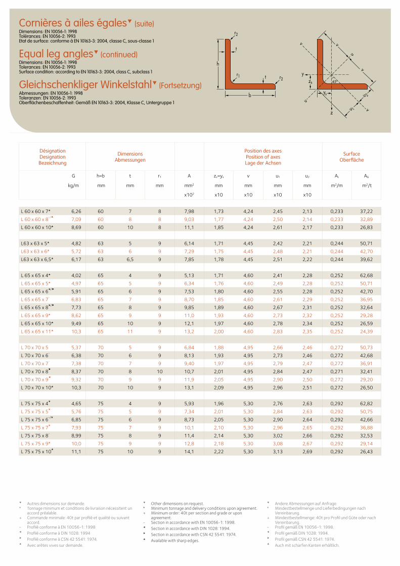
Cornières à ailes égales (suite)Dimensions: EN 10056-1: 1998 Tolérances: EN 10056-2: 1993 Etat de surface: conforme à EN 10163-3: 2004, classe C, sous-classe 1
Equal leg angles (continued)Dimensions: EN 10056-1: 1998 Tolerances: EN 10056-2: 1993 Surface condition: according to EN 10163-3: 2004, class C, subclass 1
Gleichschenkliger Winkelstahl (Fortsetzung)Abmessungen: EN 10056-1: 1998 Toleranzen: EN 10056-2: 1993 Oberflächenbeschaffenheit: Gemäß EN 10163-3: 2004, Klasse C, Untergruppe 1
zs
ys
y
z
u
uu 1
u 2
v
v
v
v
t
t
h
b
r1 r2
r2
45o
L 60 x 60 x 7* 6,26 60 7 8 7,98 1,73 4,24 2,45 2,13 0,233 37,22
L 60 x 60 x 8-/
7,09 60 8 8 9,03 1,77 4,24 2,50 2,14 0,233 32,89
L 60 x 60 x 10* 8,69 60 10 8 11,1 1,85 4,24 2,61 2,17 0,233 26,83
L63 x 63 x 5* 4,82 63 5 9 6,14 1,71 4,45 2,42 2,21 0,244 50,71
L63 x 63 x 6* 5,72 63 6 9 7,29 1,75 4,45 2,48 2,21 0,244 42,70
L63 x 63 x 6,5* 6,17 63 6,5 9 7,85 1,78 4,45 2,51 2,22 0,244 39,62
L 65 x 65 x 4* 4,02 65 4 9 5,13 1,71 4,60 2,41 2,28 0,252 62,68
L 65 x 65 x 5* 4,97 65 5 9 6,34 1,76 4,60 2,49 2,28 0,252 50,71
L 65 x 65 x 6*/5,91 65 6 9 7,53 1,80 4,60 2,55 2,28 0,252 42,70
L 65 x 65 x 7-
6,83 65 7 9 8,70 1,85 4,60 2,61 2,29 0,252 36,95
L 65 x 65 x 8*/7,73 65 8 9 9,85 1,89 4,60 2,67 2,31 0,252 32,64
L 65 x 65 x 9* 8,62 65 9 9 11,0 1,93 4,60 2,73 2,32 0,252 29,28
L 65 x 65 x 10* 9,49 65 10 9 12,1 1,97 4,60 2,78 2,34 0,252 26,59
L 65 x 65 x 11* 10,3 65 11 9 13,2 2,00 4,60 2,83 2,35 0,252 24,39
L 70 x 70 x 5 5,37 70 5 9 6,84 1,88 4,95 2,66 2,46 0,272 50,73
L 70 x 70 x 6-
6,38 70 6 9 8,13 1,93 4,95 2,73 2,46 0,272 42,68
L 70 x 70 x 7-
7,38 70 7 9 9,40 1,97 4,95 2,79 2,47 0,272 36,91
L 70 x 70 x 8
8,37 70 8 10 10,7 2,01 4,95 2,84 2,47 0,271 32,41
L 70 x 70 x 9
9,32 70 9 9 11,9 2,05 4,95 2,90 2,50 0,272 29,20
L 70 x 70 x 10* 10,3 70 10 9 13,1 2,09 4,95 2,96 2,51 0,272 26,50
L 75 x 75 x 4* 4,65 75 4 9 5,93 1,96 5,30 2,76 2,63 0,292 62,82
L 75 x 75 x 5* 5,76 75 5 9 7,34 2,01 5,30 2,84 2,63 0,292 50,75
L 75 x 75 x 6-/* 6,85 75 6 9 8,73 2,05 5,30 2,90 2,64 0,292 42,66
L 75 x 75 x 7* 7,93 75 7 9 10,1 2,10 5,30 2,96 2,65 0,292 36,88
L 75 x 75 x 8-
8,99 75 8 9 11,4 2,14 5,30 3,02 2,66 0,292 32,53
L 75 x 75 x 9* 10,0 75 9 9 12,8 2,18 5,30 3,08 2,67 0,292 29,14
L 75 x 75 x 10* 11,1 75 10 9 14,1 2,22 5,30 3,13 2,69 0,292 26,43
Désignation Designation Bezeichnung
Dimensions Abmessungen
Position des axesPosition of axesLage der Achsen
Surface Oberfläche
G h=b t r1 A zs=ys v u1 u2 AL AG
kg/m mm mm mm mm2 mm mm mm mm m2/m m2/t
x102 x10 x10 x10 x10
Autres dimensions sur demande. * Tonnage minimum et conditions de livraison nécessitent un
accord préalable.+ Commande minimale: 40t par profilé et qualité ou suivant
accord.- Profilé conforme à EN 10056-1: 1998Profilé conforme à DIN 1028: 1994Profilé conforme à CSN 42 5541: 1974.Avec arêtes vives sur demande.
Other dimensions on request. * Minimum tonnage and delivery conditions upon agreement.+ Minimum order: 40t per section and grade or upon
agreement.- Section in accordance with EN 10056-1: 1998. Section in accordance with DIN 1028: 1994. Section in accordance with CSN 42 5541: 1974. Available with sharp edges.
Andere Abmessungen auf Anfrage. * Mindestbestellmenge und Lieferbedingungen nach
Vereinbarung.+ Mindestbestellmenge: 40t pro Profil und Güte oder nach
Vereinbarung.- Profil gemäß EN 10056-1: 1998. Profil gemäß DIN 1028: 1994. Profil gemäß CSN 42 5541: 1974. Auch mit scharfen Kanten erhältlich.
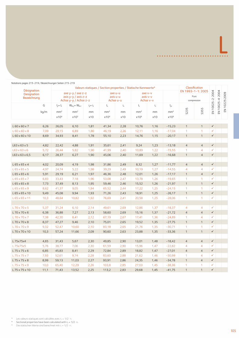
105
L
Désignation Designation Bezeichnung
Valeurs statiques / Section properties / Statische Kennwerte* Classification EN 1993-1-1: 2005
EN 1
00
25
-2: 2
00
4
EN 1
00
25
-4: 2
00
4
EN 1
02
25
:20
09axe y-y / axe z-z
axis y-y / axis z-zAchse y-y / Achse z-z
axe u-uaxis u-u
Achse u-u
axe v-vaxis v-v
Achse v-vPure
compression
G ly= lz Wel.y= Wel.z iy= iz Iu iu Iv iv lyz
S23
5
S35
5
kg/m mm4 mm3 mm mm4 mm mm4 mm mm4
x104 x103 x10 x104 x10 x104 x10 x104
Notations pages 215-219 / Bezeichnungen Seiten 215-219
L 60 x 60 x 7 6,26 26,05 6,10 1,81 41,34 2,28 10,76 1,16 -15,23 1 1
L 60 x 60 x 8 7,09 29,15 6,89 1,80 46,19 2,26 12,11 1,16 -17,04 1 1
L 60 x 60 x 10 8,69 34,93 8,41 1,78 55,10 2,23 14,76 1,15 -20,17 1 1
L63 x 63 x 5 4,82 22,42 4,88 1,91 35,61 2,41 9,24 1,23 -13,18 4 4
L63 x 63 x 6 5,72 26,44 5,82 1,90 41,99 2,40 10,89 1,22 -15,55 1 4
L63 x 63 x 6,5 6,17 28,37 6,27 1,90 45,06 2,40 11,69 1,22 -16,68 1 4
L 65 x 65 x 4 4,02 20,09 4,19 1,98 31,86 2,49 8,32 1,27 -11,77 4 4
L 65 x 65 x 5 4,97 24,74 5,22 1,98 39,29 2,49 10,19 1,27 -14,55 4 4
L 65 x 65 x 6 5,91 29,19 6,21 1,97 46,36 2,48 12,01 1,26 -17,17 1 4
L 65 x 65 x 7 6,83 33,43 7,18 1,96 53,08 2,47 13,78 1,26 -19,65 1 1
L 65 x 65 x 8 7,73 37,49 8,13 1,95 59,46 2,46 15,52 1,26 -21,97 1 1
L 65 x 65 x 9 8,62 41,37 9,05 1,94 65,52 2,44 17,22 1,25 -24,15 1 1
L 65 x 65 x 10 9,49 45,08 9,94 1,93 71,26 2,43 18,91 1,25 -26,17 1 1
L 65 x 65 x 11 10,3 48,64 10,82 1,92 76,69 2,41 20,58 1,25 -28,06 1 1
L 70 x 70 x 5 5,37 31,24 6,10 2,14 49,61 2,69 12,86 1,37 -18,37 4 4
L 70 x 70 x 6 6,38 36,88 7,27 2,13 58,60 2,69 15,16 1,37 -21,72 4 4
L 70 x 70 x 7 7,38 42,30 8,41 2,12 67,19 2,67 17,41 1,36 -24,89 1 4
L 70 x 70 x 8 8,37 47,27 9,46 2,10 75,01 2,65 19,52 1,35 -27,75 1 1
L 70 x 70 x 9 9,32 52,47 10,60 2,10 83,18 2,65 21,76 1,35 -30,71 1 1
L 70 x 70 x 10 10,3 57,24 11,66 2,09 90,60 2,63 23,88 1,35 -33,36 1 1
L 75x75x4 4,65 31,43 5,67 2,30 49,85 2,90 13,01 1,48 -18,42 4 4
L 75x75x5 5,76 38,77 7,06 2,30 61,59 2,90 15,96 1,47 -22,82 4 4
L 75 x 75 x 6 6,85 45,83 8,41 2,29 72,84 2,89 18,82 1,47 -27,01 4 4
L 75 x 75 x 7 7,93 52,61 9,74 2,28 83,60 2,88 21,62 1,46 -30,99 1 4
L 75 x 75 x 8 8,99 59,13 11,03 2,27 93,91 2,86 24,35 1,46 -34,78 1 4
L 75 x 75 x 9 10,0 65,40 12,29 2,26 103,8 2,85 27,03 1,45 -38,36 1 1
L 75 x 75 x 10 11,1 71,43 13,52 2,25 113,2 2,83 29,68 1,45 -41,75 1 1
* Les valeurs statiques sont calculées avec r2 = 1/2 . r1
* Sectional properties have been calculated with r2 = 1/2 . r1
* Die statischen Werte sind berechnet mit r2 = 1/2 . r1
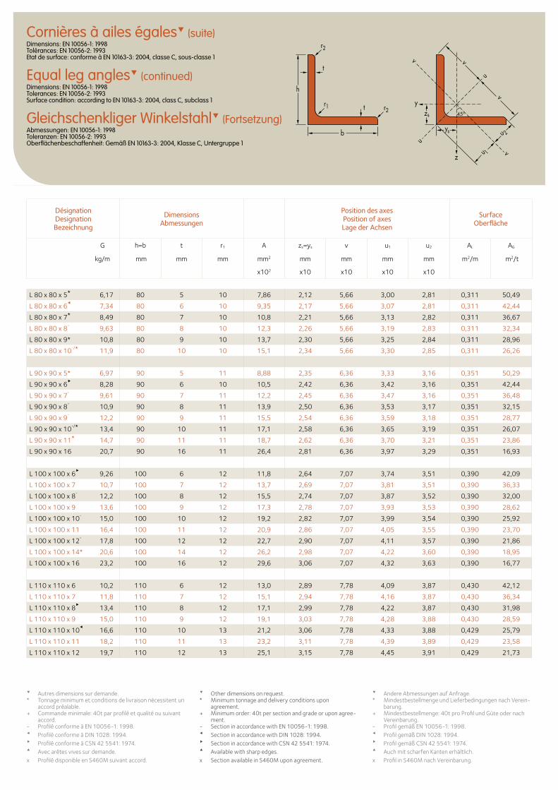
Cornières à ailes égales (suite)Dimensions: EN 10056-1: 1998 Tolérances: EN 10056-2: 1993 Etat de surface: conforme à EN 10163-3: 2004, classe C, sous-classe 1
Equal leg angles (continued)Dimensions: EN 10056-1: 1998 Tolerances: EN 10056-2: 1993 Surface condition: according to EN 10163-3: 2004, class C, subclass 1
Gleichschenkliger Winkelstahl (Fortsetzung)Abmessungen: EN 10056-1: 1998 Toleranzen: EN 10056-2: 1993 Oberflächenbeschaffenheit: Gemäß EN 10163-3: 2004, Klasse C, Untergruppe 1
zs
ys
y
z
u
uu 1
u 2
v
v
v
v
t
t
h
b
r1 r2
r2
45o
L 80 x 80 x 5* 6,17 80 5 10 7,86 2,12 5,66 3,00 2,81 0,311 50,49
L 80 x 80 x 6
7,34 80 6 10 9,35 2,17 5,66 3,07 2,81 0,311 42,44
L 80 x 80 x 7* 8,49 80 7 10 10,8 2,21 5,66 3,13 2,82 0,311 36,67
L 80 x 80 x 8-
9,63 80 8 10 12,3 2,26 5,66 3,19 2,83 0,311 32,34
L 80 x 80 x 9* 10,8 80 9 10 13,7 2,30 5,66 3,25 2,84 0,311 28,96
L 80 x 80 x 10-/* 11,9 80 10 10 15,1 2,34 5,66 3,30 2,85 0,311 26,26
L 90 x 90 x 5* 6,97 90 5 11 8,88 2,35 6,36 3,33 3,16 0,351 50,29
L 90 x 90 x 6
8,28 90 6 10 10,5 2,42 6,36 3,42 3,16 0,351 42,44
L 90 x 90 x 7-
9,61 90 7 11 12,2 2,45 6,36 3,47 3,16 0,351 36,48
L 90 x 90 x 8-
10,9 90 8 11 13,9 2,50 6,36 3,53 3,17 0,351 32,15
L 90 x 90 x 9-
12,2 90 9 11 15,5 2,54 6,36 3,59 3,18 0,351 28,77
L 90 x 90 x 10-/* 13,4 90 10 11 17,1 2,58 6,36 3,65 3,19 0,351 26,07
L 90 x 90 x 11* 14,7 90 11 11 18,7 2,62 6,36 3,70 3,21 0,351 23,86
L 90 x 90 x 16 20,7 90 16 11 26,4 2,81 6,36 3,97 3,29 0,351 16,93
L 100 x 100 x 6
9,26 100 6 12 11,8 2,64 7,07 3,74 3,51 0,390 42,09
L 100 x 100 x 7 10,7 100 7 12 13,7 2,69 7,07 3,81 3,51 0,390 36,33
L 100 x 100 x 8-
12,2 100 8 12 15,5 2,74 7,07 3,87 3,52 0,390 32,00
L 100 x 100 x 9 13,6 100 9 12 17,3 2,78 7,07 3,93 3,53 0,390 28,62
L 100 x 100 x 10-
15,0 100 10 12 19,2 2,82 7,07 3,99 3,54 0,390 25,92
L 100 x 100 x 11 16,4 100 11 12 20,9 2,86 7,07 4,05 3,55 0,390 23,70
L 100 x 100 x 12-
17,8 100 12 12 22,7 2,90 7,07 4,11 3,57 0,390 21,86
L 100 x 100 x 14* 20,6 100 14 12 26,2 2,98 7,07 4,22 3,60 0,390 18,95
L 100 x 100 x 16 23,2 100 16 12 29,6 3,06 7,07 4,32 3,63 0,390 16,77
L 110 x 110 x 6 10,2 110 6 12 13,0 2,89 7,78 4,09 3,87 0,430 42,12
L 110 x 110 x 7 11,8 110 7 12 15,1 2,94 7,78 4,16 3,87 0,430 36,34
L 110 x 110 x 8
13,4 110 8 12 17,1 2,99 7,78 4,22 3,87 0,430 31,98
L 110 x 110 x 9 15,0 110 9 12 19,1 3,03 7,78 4,28 3,88 0,430 28,59
L 110 x 110 x 10
16,6 110 10 13 21,2 3,06 7,78 4,33 3,88 0,429 25,79
L 110 x 110 x 11 18,2 110 11 13 23,2 3,11 7,78 4,39 3,89 0,429 23,58
L 110 x 110 x 12 19,7 110 12 13 25,1 3,15 7,78 4,45 3,91 0,429 21,73
Désignation Designation Bezeichnung
Dimensions Abmessungen
Position des axesPosition of axesLage der Achsen
Surface Oberfläche
G h=b t r1 A zs=ys v u1 u2 AL AG
kg/m mm mm mm mm2 mm mm mm mm m2/m m2/t
x102 x10 x10 x10 x10
Autres dimensions sur demande. * Tonnage minimum et conditions de livraison nécessitent un
accord préalable.+ Commande minimale: 40t par profilé et qualité ou suivant
accord.- Profilé conforme à EN 10056-1: 1998.Profilé conforme à DIN 1028: 1994.Profilé conforme à CSN 42 5541: 1974.Avec arêtes vives sur demande.x Profilé disponible en S460M suivant accord.
Other dimensions on request. * Minimum tonnage and delivery conditions upon
agreement.+ Minimum order: 40t per section and grade or upon agree-
ment.- Section in accordance with EN 10056-1: 1998. Section in accordance with DIN 1028: 1994. Section in accordance with CSN 42 5541: 1974. Available with sharp edges.x Section available in S460M upon agreement.
Andere Abmessungen auf Anfrage. * Mindestbestellmenge und Lieferbedingungen nach Verein-
barung.+ Mindestbestellmenge: 40t pro Profil und Güte oder nach
Vereinbarung.- Profil gemäß EN 10056-1: 1998. Profil gemäß DIN 1028: 1994. Profil gemäß CSN 42 5541: 1974. Auch mit scharfen Kanten erhältlich.x Profil in S460M nach Vereinbarung.
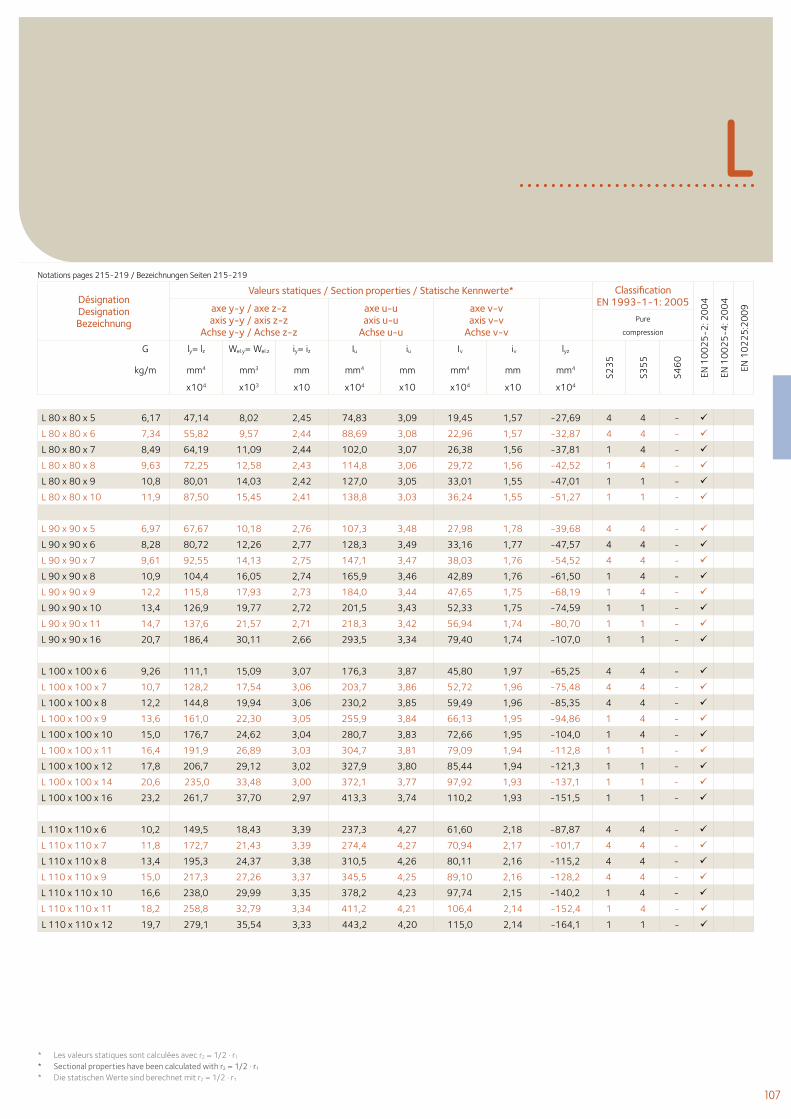
107
L
Désignation Designation Bezeichnung
Valeurs statiques / Section properties / Statische Kennwerte* Classification EN 1993-1-1: 2005
EN 1
00
25
-2: 2
00
4
EN 1
00
25
-4: 2
00
4
EN 1
02
25
:20
09axe y-y / axe z-z
axis y-y / axis z-zAchse y-y / Achse z-z
axe u-uaxis u-u
Achse u-u
axe v-vaxis v-v
Achse v-vPure
compression
G ly= lz Wel.y= Wel.z iy= iz Iu iu Iv iv lyz
S23
5
S35
5
S46
0
kg/m mm4 mm3 mm mm4 mm mm4 mm mm4
x104 x103 x10 x104 x10 x104 x10 x104
Notations pages 215-219 / Bezeichnungen Seiten 215-219
L 80 x 80 x 5 6,17 47,14 8,02 2,45 74,83 3,09 19,45 1,57 -27,69 4 4 -
L 80 x 80 x 6 7,34 55,82 9,57 2,44 88,69 3,08 22,96 1,57 -32,87 4 4 -
L 80 x 80 x 7 8,49 64,19 11,09 2,44 102,0 3,07 26,38 1,56 -37,81 1 4 -
L 80 x 80 x 8 9,63 72,25 12,58 2,43 114,8 3,06 29,72 1,56 -42,52 1 4 -
L 80 x 80 x 9 10,8 80,01 14,03 2,42 127,0 3,05 33,01 1,55 -47,01 1 1 -
L 80 x 80 x 10 11,9 87,50 15,45 2,41 138,8 3,03 36,24 1,55 -51,27 1 1 -
L 90 x 90 x 5 6,97 67,67 10,18 2,76 107,3 3,48 27,98 1,78 -39,68 4 4 -
L 90 x 90 x 6 8,28 80,72 12,26 2,77 128,3 3,49 33,16 1,77 -47,57 4 4 -
L 90 x 90 x 7 9,61 92,55 14,13 2,75 147,1 3,47 38,03 1,76 -54,52 4 4 -
L 90 x 90 x 8 10,9 104,4 16,05 2,74 165,9 3,46 42,89 1,76 -61,50 1 4 -
L 90 x 90 x 9 12,2 115,8 17,93 2,73 184,0 3,44 47,65 1,75 -68,19 1 4 -
L 90 x 90 x 10 13,4 126,9 19,77 2,72 201,5 3,43 52,33 1,75 -74,59 1 1 -
L 90 x 90 x 11 14,7 137,6 21,57 2,71 218,3 3,42 56,94 1,74 -80,70 1 1 -
L 90 x 90 x 16 20,7 186,4 30,11 2,66 293,5 3,34 79,40 1,74 -107,0 1 1 -
L 100 x 100 x 6 9,26 111,1 15,09 3,07 176,3 3,87 45,80 1,97 -65,25 4 4 -
L 100 x 100 x 7 10,7 128,2 17,54 3,06 203,7 3,86 52,72 1,96 -75,48 4 4 -
L 100 x 100 x 8 12,2 144,8 19,94 3,06 230,2 3,85 59,49 1,96 -85,35 4 4 -
L 100 x 100 x 9 13,6 161,0 22,30 3,05 255,9 3,84 66,13 1,95 -94,86 1 4 -
L 100 x 100 x 10 15,0 176,7 24,62 3,04 280,7 3,83 72,66 1,95 -104,0 1 4 -
L 100 x 100 x 11 16,4 191,9 26,89 3,03 304,7 3,81 79,09 1,94 -112,8 1 1 -
L 100 x 100 x 12 17,8 206,7 29,12 3,02 327,9 3,80 85,44 1,94 -121,3 1 1 -
L 100 x 100 x 14 20,6 235,0 33,48 3,00 372,1 3,77 97,92 1,93 -137,1 1 1 -
L 100 x 100 x 16 23,2 261,7 37,70 2,97 413,3 3,74 110,2 1,93 -151,5 1 1 -
L 110 x 110 x 6 10,2 149,5 18,43 3,39 237,3 4,27 61,60 2,18 -87,87 4 4 -
L 110 x 110 x 7 11,8 172,7 21,43 3,39 274,4 4,27 70,94 2,17 -101,7 4 4 -
L 110 x 110 x 8 13,4 195,3 24,37 3,38 310,5 4,26 80,11 2,16 -115,2 4 4 -
L 110 x 110 x 9 15,0 217,3 27,26 3,37 345,5 4,25 89,10 2,16 -128,2 4 4 -
L 110 x 110 x 10 16,6 238,0 29,99 3,35 378,2 4,23 97,74 2,15 -140,2 1 4 -
L 110 x 110 x 11 18,2 258,8 32,79 3,34 411,2 4,21 106,4 2,14 -152,4 1 4 -
L 110 x 110 x 12 19,7 279,1 35,54 3,33 443,2 4,20 115,0 2,14 -164,1 1 1 -
* Les valeurs statiques sont calculées avec r2 = 1/2 . r1
* Sectional properties have been calculated with r2 = 1/2 . r1
* Die statischen Werte sind berechnet mit r2 = 1/2 . r1
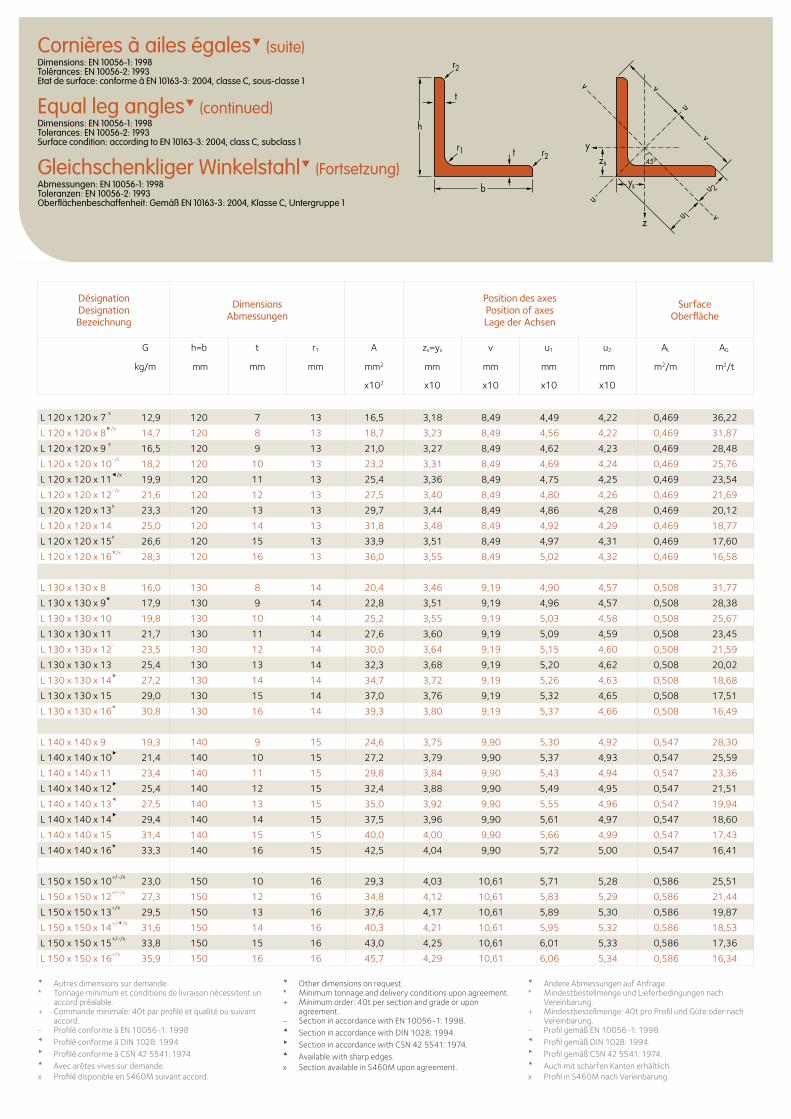
Cornières à ailes égales (suite)Dimensions: EN 10056-1: 1998 Tolérances: EN 10056-2: 1993 Etat de surface: conforme à EN 10163-3: 2004, classe C, sous-classe 1
Equal leg angles (continued)Dimensions: EN 10056-1: 1998 Tolerances: EN 10056-2: 1993 Surface condition: according to EN 10163-3: 2004, class C, subclass 1
Gleichschenkliger Winkelstahl (Fortsetzung)Abmessungen: EN 10056-1: 1998 Toleranzen: EN 10056-2: 1993 Oberflächenbeschaffenheit: Gemäß EN 10163-3: 2004, Klasse C, Untergruppe 1
zs
ys
y
z
u
uu 1
u 2
v
v
v
v
t
t
h
b
r1 r2
r2
45o
L 120 x 120 x 7 x
12,9 120 7 13 16,5 3,18 8,49 4,49 4,22 0,469 36,22
L 120 x 120 x 8/x
14,7 120 8 13 18,7 3,23 8,49 4,56 4,22 0,469 31,87
L 120 x 120 x 9 x
16,5 120 9 13 21,0 3,27 8,49 4,62 4,23 0,469 28,48
L 120 x 120 x 10-/x
18,2 120 10 13 23,2 3,31 8,49 4,69 4,24 0,469 25,76
L 120 x 120 x 11/x
19,9 120 11 13 25,4 3,36 8,49 4,75 4,25 0,469 23,54
L 120 x 120 x 12-/x
21,6 120 12 13 27,5 3,40 8,49 4,80 4,26 0,469 21,69
L 120 x 120 x 13x
23,3 120 13 13 29,7 3,44 8,49 4,86 4,28 0,469 20,12
L 120 x 120 x 14 25,0 120 14 13 31,8 3,48 8,49 4,92 4,29 0,469 18,77
L 120 x 120 x 15x
26,6 120 15 13 33,9 3,51 8,49 4,97 4,31 0,469 17,60
L 120 x 120 x 16*/x28,3 120 16 13 36,0 3,55 8,49 5,02 4,32 0,469 16,58
L 130 x 130 x 8 16,0 130 8 14 20,4 3,46 9,19 4,90 4,57 0,508 31,77
L 130 x 130 x 9* 17,9 130 9 14 22,8 3,51 9,19 4,96 4,57 0,508 28,38
L 130 x 130 x 10 19,8 130 10 14 25,2 3,55 9,19 5,03 4,58 0,508 25,67
L 130 x 130 x 11 21,7 130 11 14 27,6 3,60 9,19 5,09 4,59 0,508 23,45
L 130 x 130 x 12-
23,5 130 12 14 30,0 3,64 9,19 5,15 4,60 0,508 21,59
L 130 x 130 x 13 25,4 130 13 14 32,3 3,68 9,19 5,20 4,62 0,508 20,02
L 130 x 130 x 14
27,2 130 14 14 34,7 3,72 9,19 5,26 4,63 0,508 18,68
L 130 x 130 x 15 29,0 130 15 14 37,0 3,76 9,19 5,32 4,65 0,508 17,51
L 130 x 130 x 16* 30,8 130 16 14 39,3 3,80 9,19 5,37 4,66 0,508 16,49
L 140 x 140 x 9 19,3 140 9 15 24,6 3,75 9,90 5,30 4,92 0,547 28,30
L 140 x 140 x 10
21,4 140 10 15 27,2 3,79 9,90 5,37 4,93 0,547 25,59
L 140 x 140 x 11 23,4 140 11 15 29,8 3,84 9,90 5,43 4,94 0,547 23,36
L 140 x 140 x 12
25,4 140 12 15 32,4 3,88 9,90 5,49 4,95 0,547 21,51
L 140 x 140 x 13
27,5 140 13 15 35,0 3,92 9,90 5,55 4,96 0,547 19,94
L 140 x 140 x 14
29,4 140 14 15 37,5 3,96 9,90 5,61 4,97 0,547 18,60
L 140 x 140 x 15 31,4 140 15 15 40,0 4,00 9,90 5,66 4,99 0,547 17,43
L 140 x 140 x 16* 33,3 140 16 15 42,5 4,04 9,90 5,72 5,00 0,547 16,41
L 150 x 150 x 10+/-/x
23,0 150 10 16 29,3 4,03 10,61 5,71 5,28 0,586 25,51
L 150 x 150 x 12+/-/x
27,3 150 12 16 34,8 4,12 10,61 5,83 5,29 0,586 21,44
L 150 x 150 x 13+/x
29,5 150 13 16 37,6 4,17 10,61 5,89 5,30 0,586 19,87
L 150 x 150 x 14+//x
31,6 150 14 16 40,3 4,21 10,61 5,95 5,32 0,586 18,53
L 150 x 150 x 15+/-/x
33,8 150 15 16 43,0 4,25 10,61 6,01 5,33 0,586 17,36
L 150 x 150 x 16+/x
35,9 150 16 16 45,7 4,29 10,61 6,06 5,34 0,586 16,34
Désignation Designation Bezeichnung
Dimensions Abmessungen
Position des axesPosition of axesLage der Achsen
Surface Oberfläche
G h=b t r1 A zs=ys v u1 u2 AL AG
kg/m mm mm mm mm2 mm mm mm mm m2/m m2/t
x102 x10 x10 x10 x10
Autres dimensions sur demande. * Tonnage minimum et conditions de livraison nécessitent un
accord préalable.+ Commande minimale: 40t par profilé et qualité ou suivant
accord.- Profilé conforme à EN 10056-1: 1998Profilé conforme à DIN 1028: 1994Profilé conforme à CSN 42 5541: 1974Avec arêtes vives sur demande.x Profilé disponible en S460M suivant accord.
Other dimensions on request. * Minimum tonnage and delivery conditions upon agreement.+ Minimum order: 40t per section and grade or upon
agreement.- Section in accordance with EN 10056-1: 1998. Section in accordance with DIN 1028: 1994. Section in accordance with CSN 42 5541: 1974. Available with sharp edges.x Section available in S460M upon agreement.
Andere Abmessungen auf Anfrage. * Mindestbestellmenge und Lieferbedingungen nach
Vereinbarung.+ Mindestbestellmenge: 40t pro Profil und Güte oder nach
Vereinbarung.- Profil gemäß EN 10056-1: 1998. Profil gemäß DIN 1028: 1994. Profil gemäß CSN 42 5541: 1974. Auch mit scharfen Kanten erhältlich.x Profil in S460M nach Vereinbarung.
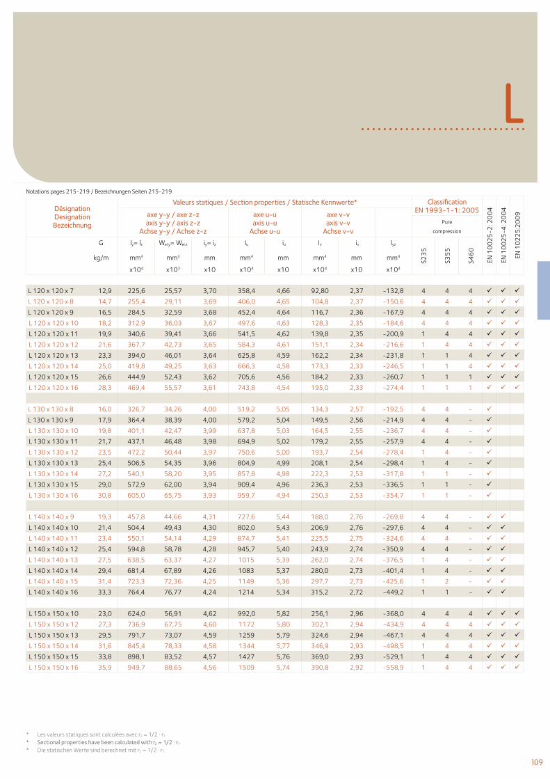
109
LNotations pages 215-219 / Bezeichnungen Seiten 215-219
Désignation Designation Bezeichnung
Valeurs statiques / Section properties / Statische Kennwerte* Classification EN 1993-1-1: 2005
EN 1
00
25
-2: 2
00
4
EN 1
00
25
-4: 2
00
4
EN 1
02
25
:20
09axe y-y / axe z-z
axis y-y / axis z-zAchse y-y / Achse z-z
axe u-uaxis u-u
Achse u-u
axe v-vaxis v-v
Achse v-vPure
compression
G ly= lz Wel.y= Wel.z iy= iz Iu iu Iv iv lyz
S23
5
S35
5
S46
0
kg/m mm4 mm3 mm mm4 mm mm4 mm mm4
x104 x103 x10 x104 x10 x104 x10 x104
* Les valeurs statiques sont calculées avec r2 = 1/2 . r1
* Sectional properties have been calculated with r2 = 1/2 . r1
* Die statischen Werte sind berechnet mit r2 = 1/2 . r1
L 120 x 120 x 7 12,9 225,6 25,57 3,70 358,4 4,66 92,80 2,37 -132,8 4 4 4
L 120 x 120 x 8 14,7 255,4 29,11 3,69 406,0 4,65 104,8 2,37 -150,6 4 4 4
L 120 x 120 x 9 16,5 284,5 32,59 3,68 452,4 4,64 116,7 2,36 -167,9 4 4 4
L 120 x 120 x 10 18,2 312,9 36,03 3,67 497,6 4,63 128,3 2,35 -184,6 4 4 4
L 120 x 120 x 11 19,9 340,6 39,41 3,66 541,5 4,62 139,8 2,35 -200,9 1 4 4
L 120 x 120 x 12 21,6 367,7 42,73 3,65 584,3 4,61 151,1 2,34 -216,6 1 4 4
L 120 x 120 x 13 23,3 394,0 46,01 3,64 625,8 4,59 162,2 2,34 -231,8 1 1 4
L 120 x 120 x 14 25,0 419,8 49,25 3,63 666,3 4,58 173,3 2,33 -246,5 1 1 4
L 120 x 120 x 15 26,6 444,9 52,43 3,62 705,6 4,56 184,2 2,33 -260,7 1 1 1
L 120 x 120 x 16 28,3 469,4 55,57 3,61 743,8 4,54 195,0 2,33 -274,4 1 1 1
L 130 x 130 x 8 16,0 326,7 34,26 4,00 519,2 5,05 134,3 2,57 -192,5 4 4 -
L 130 x 130 x 9 17,9 364,4 38,39 4,00 579,2 5,04 149,5 2,56 -214,9 4 4 -
L 130 x 130 x 10 19,8 401,1 42,47 3,99 637,8 5,03 164,5 2,55 -236,7 4 4 -
L 130 x 130 x 11 21,7 437,1 46,48 3,98 694,9 5,02 179,2 2,55 -257,9 4 4 -
L 130 x 130 x 12 23,5 472,2 50,44 3,97 750,6 5,00 193,7 2,54 -278,4 1 4 -
L 130 x 130 x 13 25,4 506,5 54,35 3,96 804,9 4,99 208,1 2,54 -298,4 1 4 -
L 130 x 130 x 14 27,2 540,1 58,20 3,95 857,8 4,98 222,3 2,53 -317,8 1 1 -
L 130 x 130 x 15 29,0 572,9 62,00 3,94 909,4 4,96 236,3 2,53 -336,5 1 1 -
L 130 x 130 x 16 30,8 605,0 65,75 3,93 959,7 4,94 250,3 2,53 -354,7 1 1 -
L 140 x 140 x 9 19,3 457,8 44,66 4,31 727,6 5,44 188,0 2,76 -269,8 4 4 -
L 140 x 140 x 10 21,4 504,4 49,43 4,30 802,0 5,43 206,9 2,76 -297,6 4 4 -
L 140 x 140 x 11 23,4 550,1 54,14 4,29 874,7 5,41 225,5 2,75 -324,6 4 4 -
L 140 x 140 x 12 25,4 594,8 58,78 4,28 945,7 5,40 243,9 2,74 -350,9 4 4 -
L 140 x 140 x 13 27,5 638,5 63,37 4,27 1015 5,39 262,0 2,74 -376,5 1 4 -
L 140 x 140 x 14 29,4 681,4 67,89 4,26 1083 5,37 280,0 2,73 -401,4 1 4 -
L 140 x 140 x 15 31,4 723,3 72,36 4,25 1149 5,36 297,7 2,73 -425,6 1 2 -
L 140 x 140 x 16 33,3 764,4 76,77 4,24 1214 5,34 315,2 2,72 -449,2 1 1 -
L 150 x 150 x 10 23,0 624,0 56,91 4,62 992,0 5,82 256,1 2,96 -368,0 4 4 4
L 150 x 150 x 12 27,3 736,9 67,75 4,60 1172 5,80 302,1 2,94 -434,9 4 4 4
L 150 x 150 x 13 29,5 791,7 73,07 4,59 1259 5,79 324,6 2,94 -467,1 4 4 4
L 150 x 150 x 14 31,6 845,4 78,33 4,58 1344 5,77 346,9 2,93 -498,5 1 4 4
L 150 x 150 x 15 33,8 898,1 83,52 4,57 1427 5,76 369,0 2,93 -529,1 1 4 4
L 150 x 150 x 16 35,9 949,7 88,65 4,56 1509 5,74 390,8 2,92 -558,9 1 4 4
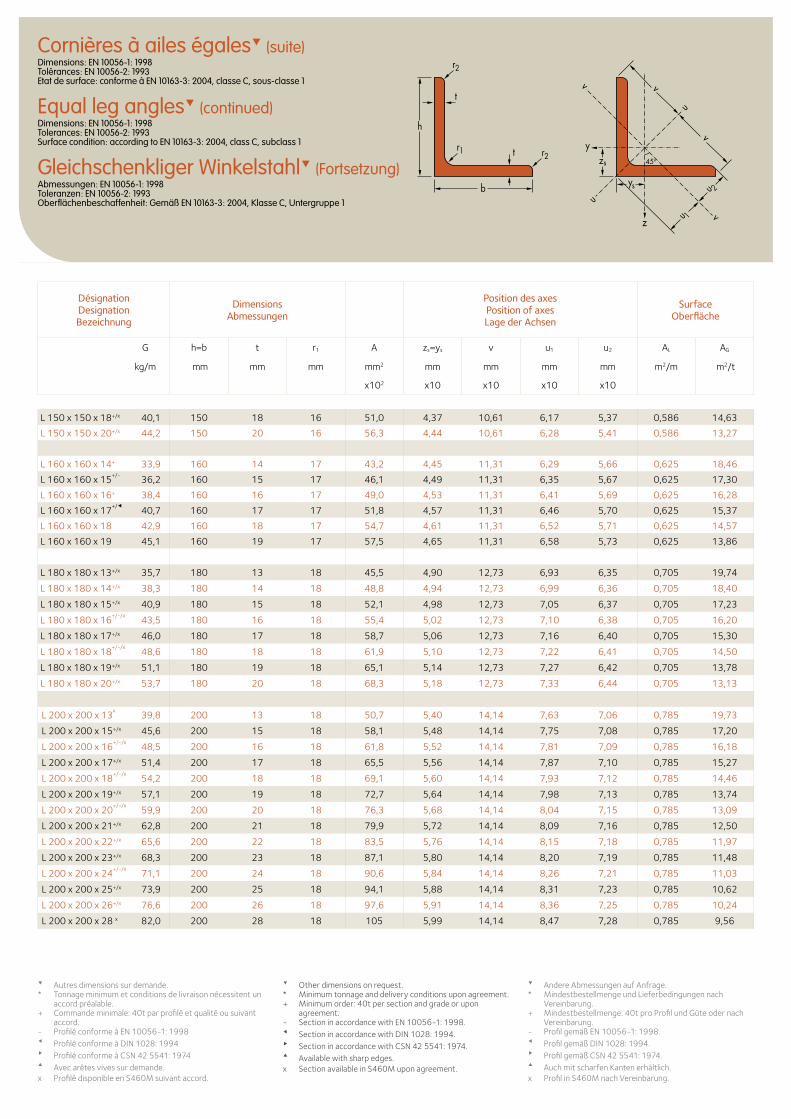
Cornières à ailes égales (suite)Dimensions: EN 10056-1: 1998 Tolérances: EN 10056-2: 1993 Etat de surface: conforme à EN 10163-3: 2004, classe C, sous-classe 1
Equal leg angles (continued)Dimensions: EN 10056-1: 1998 Tolerances: EN 10056-2: 1993 Surface condition: according to EN 10163-3: 2004, class C, subclass 1
Gleichschenkliger Winkelstahl (Fortsetzung)Abmessungen: EN 10056-1: 1998 Toleranzen: EN 10056-2: 1993 Oberflächenbeschaffenheit: Gemäß EN 10163-3: 2004, Klasse C, Untergruppe 1
zs
ys
y
z
u
uu 1
u 2
v
v
v
v
t
t
h
b
r1 r2
r2
45o
Désignation Designation Bezeichnung
Dimensions Abmessungen
Position des axesPosition of axesLage der Achsen
Surface Oberfläche
G h=b t r1 A zs=ys v u1 u2 AL AG
kg/m mm mm mm mm2 mm mm mm mm m2/m m2/t
x102 x10 x10 x10 x10
Autres dimensions sur demande. * Tonnage minimum et conditions de livraison nécessitent un
accord préalable.+ Commande minimale: 40t par profilé et qualité ou suivant
accord.- Profilé conforme à EN 10056-1: 1998Profilé conforme à DIN 1028: 1994Profilé conforme à CSN 42 5541: 1974Avec arêtes vives sur demande.x Profilé disponible en S460M suivant accord.
Other dimensions on request. * Minimum tonnage and delivery conditions upon agreement.+ Minimum order: 40t per section and grade or upon
agreement.- Section in accordance with EN 10056-1: 1998. Section in accordance with DIN 1028: 1994. Section in accordance with CSN 42 5541: 1974. Available with sharp edges.x Section available in S460M upon agreement.
Andere Abmessungen auf Anfrage. * Mindestbestellmenge und Lieferbedingungen nach
Vereinbarung.+ Mindestbestellmenge: 40t pro Profil und Güte oder nach
Vereinbarung.- Profil gemäß EN 10056-1: 1998. Profil gemäß DIN 1028: 1994. Profil gemäß CSN 42 5541: 1974. Auch mit scharfen Kanten erhältlich.x Profil in S460M nach Vereinbarung.
L 150 x 150 x 18+/x 40,1 150 18 16 51,0 4,37 10,61 6,17 5,37 0,586 14,63
L 150 x 150 x 20+/x 44,2 150 20 16 56,3 4,44 10,61 6,28 5,41 0,586 13,27
L 160 x 160 x 14+ 33,9 160 14 17 43,2 4,45 11,31 6,29 5,66 0,625 18,46
L 160 x 160 x 15+/-
36,2 160 15 17 46,1 4,49 11,31 6,35 5,67 0,625 17,30
L 160 x 160 x 16+ 38,4 160 16 17 49,0 4,53 11,31 6,41 5,69 0,625 16,28
L 160 x 160 x 17+/
40,7 160 17 17 51,8 4,57 11,31 6,46 5,70 0,625 15,37
L 160 x 160 x 18 42,9 160 18 17 54,7 4,61 11,31 6,52 5,71 0,625 14,57
L 160 x 160 x 19 45,1 160 19 17 57,5 4,65 11,31 6,58 5,73 0,625 13,86
L 180 x 180 x 13+/x 35,7 180 13 18 45,5 4,90 12,73 6,93 6,35 0,705 19,74
L 180 x 180 x 14+/x 38,3 180 14 18 48,8 4,94 12,73 6,99 6,36 0,705 18,40
L 180 x 180 x 15+/x 40,9 180 15 18 52,1 4,98 12,73 7,05 6,37 0,705 17,23
L 180 x 180 x 16+/-/x
43,5 180 16 18 55,4 5,02 12,73 7,10 6,38 0,705 16,20
L 180 x 180 x 17+/x 46,0 180 17 18 58,7 5,06 12,73 7,16 6,40 0,705 15,30
L 180 x 180 x 18+/-/x
48,6 180 18 18 61,9 5,10 12,73 7,22 6,41 0,705 14,50
L 180 x 180 x 19+/x 51,1 180 19 18 65,1 5,14 12,73 7,27 6,42 0,705 13,78
L 180 x 180 x 20+/x 53,7 180 20 18 68,3 5,18 12,73 7,33 6,44 0,705 13,13
L 200 x 200 x 13x
39,8 200 13 18 50,7 5,40 14,14 7,63 7,06 0,785 19,73
L 200 x 200 x 15+/x 45,6 200 15 18 58,1 5,48 14,14 7,75 7,08 0,785 17,20
L 200 x 200 x 16+/-/x
48,5 200 16 18 61,8 5,52 14,14 7,81 7,09 0,785 16,18
L 200 x 200 x 17+/x 51,4 200 17 18 65,5 5,56 14,14 7,87 7,10 0,785 15,27
L 200 x 200 x 18+/-/x
54,2 200 18 18 69,1 5,60 14,14 7,93 7,12 0,785 14,46
L 200 x 200 x 19+/x 57,1 200 19 18 72,7 5,64 14,14 7,98 7,13 0,785 13,74
L 200 x 200 x 20+/-/x
59,9 200 20 18 76,3 5,68 14,14 8,04 7,15 0,785 13,09
L 200 x 200 x 21+/x 62,8 200 21 18 79,9 5,72 14,14 8,09 7,16 0,785 12,50
L 200 x 200 x 22+/x 65,6 200 22 18 83,5 5,76 14,14 8,15 7,18 0,785 11,97
L 200 x 200 x 23+/x 68,3 200 23 18 87,1 5,80 14,14 8,20 7,19 0,785 11,48
L 200 x 200 x 24+/-/x
71,1 200 24 18 90,6 5,84 14,14 8,26 7,21 0,785 11,03
L 200 x 200 x 25+/x 73,9 200 25 18 94,1 5,88 14,14 8,31 7,23 0,785 10,62
L 200 x 200 x 26+/x 76,6 200 26 18 97,6 5,91 14,14 8,36 7,25 0,785 10,24
L 200 x 200 x 28 x 82,0 200 28 18 105 5,99 14,14 8,47 7,28 0,785 9,56
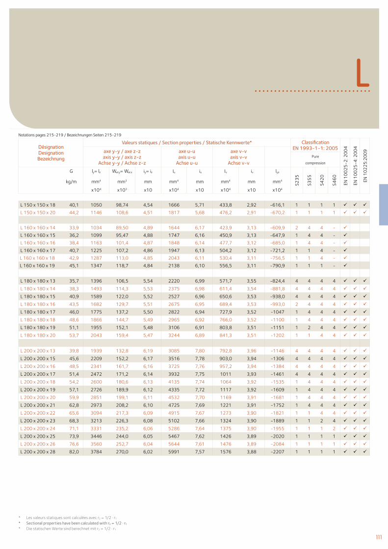
111
LNotations pages 215-219 / Bezeichnungen Seiten 215-219
Désignation Designation Bezeichnung
Valeurs statiques / Section properties / Statische Kennwerte* Classification EN 1993-1-1: 2005
EN 1
00
25
-2: 2
00
4
EN 1
00
25
-4: 2
00
4
EN 1
02
25
:20
09axe y-y / axe z-z
axis y-y / axis z-zAchse y-y / Achse z-z
axe u-uaxis u-u
Achse u-u
axe v-vaxis v-v
Achse v-vPure
compression
G ly= lz Wel.y= Wel.z iy= iz Iu iu Iv iv lyz
S23
5
S35
5
S42
0
S46
0
kg/m mm4 mm3 mm mm4 mm mm4 mm mm4
x104 x103 x10 x104 x10 x104 x10 x104
L 150 x 150 x 18 40,1 1050 98,74 4,54 1666 5,71 433,8 2,92 -616,1 1 1 1 1
L 150 x 150 x 20 44,2 1146 108,6 4,51 1817 5,68 476,2 2,91 -670,2 1 1 1 1
L 160 x 160 x 14 33,9 1034 89,50 4,89 1644 6,17 423,9 3,13 -609,9 2 4 4 -
L 160 x 160 x 15 36,2 1099 95,47 4,88 1747 6,16 450,9 3,13 -647,9 1 4 4 -
L 160 x 160 x 16 38,4 1163 101,4 4,87 1848 6,14 477,7 3,12 -685,0 1 4 4 -
L 160 x 160 x 17 40,7 1225 107,2 4,86 1947 6,13 504,2 3,12 -721,2 1 1 4 -
L 160 x 160 x 18 42,9 1287 113,0 4,85 2043 6,11 530,4 3,11 -756,5 1 1 4 -
L 160 x 160 x 19 45,1 1347 118,7 4,84 2138 6,10 556,5 3,11 -790,9 1 1 1 -
L 180 x 180 x 13 35,7 1396 106,5 5,54 2220 6,99 571,7 3,55 -824,4 4 4 4 4
L 180 x 180 x 14 38,3 1493 114,3 5,53 2375 6,98 611,4 3,54 -881,8 4 4 4 4
L 180 x 180 x 15 40,9 1589 122,0 5,52 2527 6,96 650,6 3,53 -938,0 4 4 4 4
L 180 x 180 x 16 43,5 1682 129,7 5,51 2675 6,95 689,4 3,53 -993,0 2 4 4 4
L 180 x 180 x 17 46,0 1775 137,2 5,50 2822 6,94 727,9 3,52 -1047 1 4 4 4
L 180 x 180 x 18 48,6 1866 144,7 5,49 2965 6,92 766,0 3,52 -1100 1 4 4 4
L 180 x 180 x 19 51,1 1955 152,1 5,48 3106 6,91 803,8 3,51 -1151 1 2 4 4
L 180 x 180 x 20 53,7 2043 159,4 5,47 3244 6,89 841,3 3,51 -1202 1 1 4 4
L 200 x 200 x 13 39,8 1939 132,8 6,19 3085 7,80 792,8 3,96 -1146 4 4 4 4
L 200 x 200 x 15 45,6 2209 152,2 6,17 3516 7,78 903,0 3,94 -1306 4 4 4 4
L 200 x 200 x 16 48,5 2341 161,7 6,16 3725 7,76 957,2 3,94 -1384 4 4 4 4
L 200 x 200 x 17 51,4 2472 171,2 6,14 3932 7,75 1011 3,93 -1461 4 4 4 4
L 200 x 200 x 18 54,2 2600 180,6 6,13 4135 7,74 1064 3,92 -1535 1 4 4 4
L 200 x 200 x 19 57,1 2726 189,9 6,12 4335 7,72 1117 3,92 -1609 1 4 4 4
L 200 x 200 x 20 59,9 2851 199,1 6,11 4532 7,70 1169 3,91 -1681 1 4 4 4
L 200 x 200 x 21 62,8 2973 208,2 6,10 4725 7,69 1221 3,91 -1752 1 4 4 4
L 200 x 200 x 22 65,6 3094 217,3 6,09 4915 7,67 1273 3,90 -1821 1 1 4 4
L 200 x 200 x 23 68,3 3213 226,3 6,08 5102 7,66 1324 3,90 -1889 1 1 2 4
L 200 x 200 x 24 71,1 3331 235,2 6,06 5286 7,64 1375 3,90 -1955 1 1 1 2
L 200 x 200 x 25 73,9 3446 244,0 6,05 5467 7,62 1426 3,89 -2020 1 1 1 1
L 200 x 200 x 26 76,6 3560 252,7 6,04 5644 7,61 1476 3,89 -2084 1 1 1 1
L 200 x 200 x 28 82,0 3784 270,0 6,02 5991 7,57 1576 3,88 -2207 1 1 1 1
* Les valeurs statiques sont calculées avec r2 = 1/2 . r1
* Sectional properties have been calculated with r2 = 1/2 . r1
* Die statischen Werte sind berechnet mit r2 = 1/2 . r1
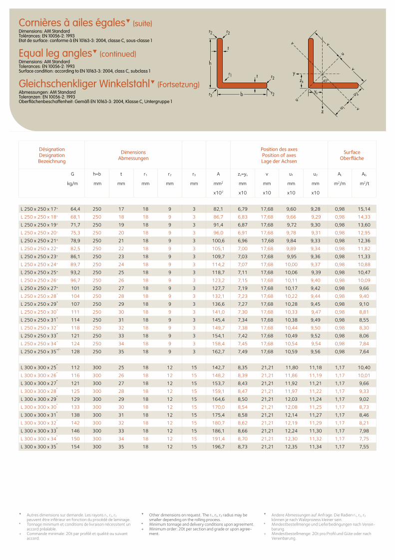
Cornières à ailes égales (suite)Dimensions: AM Standard Tolérances: EN 10056-2: 1993 Etat de surface: conforme à EN 10163-3: 2004, classe C, sous-classe 1
Equal leg angles (continued)Dimensions: AM Standard Tolerances: EN 10056-2: 1993 Surface condition: according to EN 10163-3: 2004, class C, subclass 1
Gleichschenkliger Winkelstahl (Fortsetzung)Abmessungen: AM Standard Toleranzen: EN 10056-2: 1993 Oberflächenbeschaffenheit: Gemäß EN 10163-3: 2004, Klasse C, Untergruppe 1
Désignation Designation Bezeichnung
Dimensions Abmessungen
Position des axesPosition of axesLage der Achsen
Surface Oberfläche
G h=b t r1 r2 r3 A zs=ys v u1 u2 AL AG
kg/m mm mm mm mm mm mm2 mm mm mm mm m2/m m2/t
x102 x10 x10 x10 x10
Autres dimensions sur demande. Les rayons r1, r2, r3 peuvent être inférieur en fonction du procédé de laminage.
* Tonnage minimum et conditions de livraison nécessitent un accord préalable.
+ Commande minimale: 20t par profilé et qualité ou suivant accord.
Other dimensions on request. The r1, r2, r3 radius may be smaller depending on the rolling process.
* Minimum tonnage and delivery conditions upon agreement.+ Minimum order: 20t per section and grade or upon agree-
ment.
Andere Abmessungen auf Anfrage. Die Radien r1, r2, r3 können je nach Walzprozess kleiner sein.
* Mindestbestellmenge und Lieferbedingungen nach Verein-barung.
+ Mindestbestellmenge: 20t pro Profil und Güte oder nach Vereinbarung.
L 250 x 250 x 17+ 64,4 250 17 18 9 3 82,1 6,79 17,68 9,60 9,28 0,98 15,14
L 250 x 250 x 18+ 68,1 250 18 18 9 3 86,7 6,83 17,68 9,66 9,29 0,98 14,33
L 250 x 250 x 19+ 71,7 250 19 18 9 3 91,4 6,87 17,68 9,72 9,30 0,98 13,60
L 250 x 250 x 20+ 75,3 250 20 18 9 3 96,0 6,91 17,68 9,78 9,31 0,98 12,95
L 250 x 250 x 21+ 78,9 250 21 18 9 3 100,6 6,96 17,68 9,84 9,33 0,98 12,36
L 250 x 250 x 22+ 82,5 250 22 18 9 3 105,1 7,00 17,68 9,89 9,34 0,98 11,82
L 250 x 250 x 23+ 86,1 250 23 18 9 3 109,7 7,03 17,68 9,95 9,36 0,98 11,33
L 250 x 250 x 24+ 89,7 250 24 18 9 3 114,2 7,07 17,68 10,00 9,37 0,98 10,88
L 250 x 250 x 25+ 93,2 250 25 18 9 3 118,7 7,11 17,68 10,06 9,39 0,98 10,47
L 250 x 250 x 26+ 96,7 250 26 18 9 3 123,2 7,15 17,68 10,11 9,40 0,98 10,09
L 250 x 250 x 27+ 101 250 27 18 9 3 127,7 7,19 17,68 10,17 9,42 0,98 9,66
L 250 x 250 x 28+
104 250 28 18 9 3 132,1 7,23 17,68 10,22 9,44 0,98 9,40
L 250 x 250 x 29+
107 250 29 18 9 3 136,6 7,27 17,68 10,28 9,45 0,98 9,10
L 250 x 250 x 30+
111 250 30 18 9 3 141,0 7,30 17,68 10,33 9,47 0,98 8,81
L 250 x 250 x 31+
114 250 31 18 9 3 145,4 7,34 17,68 10,38 9,49 0,98 8,55
L 250 x 250 x 32+
118 250 32 18 9 3 149,7 7,38 17,68 10,44 9,50 0,98 8,30
L 250 x 250 x 33+
121 250 33 18 9 3 154,1 7,42 17,68 10,49 9,52 0,98 8,06
L 250 x 250 x 34+
124 250 34 18 9 3 158,4 7,45 17,68 10,54 9,54 0,98 7,84
L 250 x 250 x 35+/-
128 250 35 18 9 3 162,7 7,49 17,68 10,59 9,56 0,98 7,64
L 300 x 300 x 25*
112 300 25 18 12 15 142,7 8,35 21,21 11,80 11,18 1,17 10,40
L 300 x 300 x 26*
116 300 26 18 12 15 148,2 8,39 21,21 11,86 11,19 1,17 10,01
L 300 x 300 x 27*
121 300 27 18 12 15 153,7 8,43 21,21 11,92 11,21 1,17 9,66
L 300 x 300 x 28*
125 300 28 18 12 15 159,1 8,47 21,21 11,97 11,22 1,17 9,33
L 300 x 300 x 29*
129 300 29 18 12 15 164,6 8,50 21,21 12,03 11,24 1,17 9,02
L 300 x 300 x 30*
133 300 30 18 12 15 170,0 8,54 21,21 12,08 11,25 1,17 8,73
L 300 x 300 x 31*
138 300 31 18 12 15 175,4 8,58 21,21 12,14 11,27 1,17 8,46
L 300 x 300 x 32*
142 300 32 18 12 15 180,7 8,62 21,21 12,19 11,29 1,17 8,21
L 300 x 300 x 33*
146 300 33 18 12 15 186,1 8,66 21,21 12,24 11,30 1,17 7,98
L 300 x 300 x 34*
150 300 34 18 12 15 191,4 8,70 21,21 12,30 11,32 1,17 7,75
L 300 x 300 x 35*
154 300 35 18 12 15 196,7 8,73 21,21 12,35 11,34 1,17 7,55
zs
ys
y
z
u
uu 1
u 2
v
v
v
v
t
t
h
b
r1 r2
r2
r2r2
45o
r3
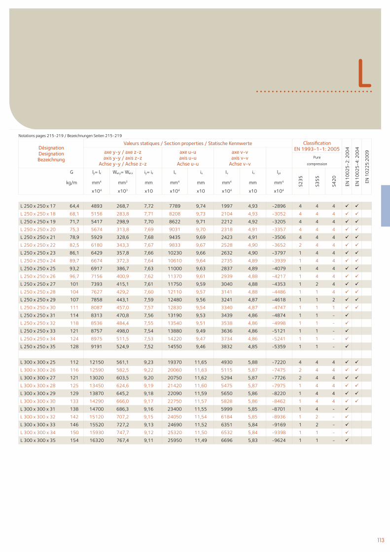
113
LNotations pages 215-219 / Bezeichnungen Seiten 215-219
Désignation Designation Bezeichnung
Valeurs statiques / Section properties / Statische Kennwerte Classification EN 1993-1-1: 2005
EN 1
00
25
-2: 2
00
4
EN 1
00
25
-4: 2
00
4
EN 1
02
25
:20
09axe y-y / axe z-z
axis y-y / axis z-zAchse y-y / Achse z-z
axe u-uaxis u-u
Achse u-u
axe v-vaxis v-v
Achse v-vPure
compression
G ly= lz Wel.y= Wel.z iy= iz Iu iu Iv iv lyz
S23
5
S35
5
S42
0
kg/m mm4 mm3 mm mm4 mm mm4 mm mm4
x104 x103 x10 x104 x10 x104 x10 x104
L 250 x 250 x 17 64,4 4893 268,7 7,72 7789 9,74 1997 4,93 -2896 4 4 4
L 250 x 250 x 18 68,1 5156 283,8 7,71 8208 9,73 2104 4,93 -3052 4 4 4
L 250 x 250 x 19 71,7 5417 298,9 7,70 8622 9,71 2212 4,92 -3205 4 4 4
L 250 x 250 x 20 75,3 5674 313,8 7,69 9031 9,70 2318 4,91 -3357 4 4 4
L 250 x 250 x 21 78,9 5929 328,6 7,68 9435 9,69 2423 4,91 -3506 4 4 4
L 250 x 250 x 22 82,5 6180 343,3 7,67 9833 9,67 2528 4,90 -3652 2 4 4
L 250 x 250 x 23 86,1 6429 357,8 7,66 10230 9,66 2632 4,90 -3797 1 4 4
L 250 x 250 x 24 89,7 6674 372,3 7,64 10610 9,64 2735 4,89 -3939 1 4 4
L 250 x 250 x 25 93,2 6917 386,7 7,63 11000 9,63 2837 4,89 -4079 1 4 4
L 250 x 250 x 26 96,7 7156 400,9 7,62 11370 9,61 2939 4,88 -4217 1 4 4
L 250 x 250 x 27 101 7393 415,1 7,61 11750 9,59 3040 4,88 -4353 1 2 4
L 250 x 250 x 28 104 7627 429,2 7,60 12110 9,57 3141 4,88 -4486 1 1 4
L 250 x 250 x 29 107 7858 443,1 7,59 12480 9,56 3241 4,87 -4618 1 1 2
L 250 x 250 x 30 111 8087 457,0 7,57 12830 9,54 3340 4,87 -4747 1 1 1
L 250 x 250 x 31 114 8313 470,8 7,56 13190 9,53 3439 4,86 -4874 1 1 -
L 250 x 250 x 32 118 8536 484,4 7,55 13540 9,51 3538 4,86 -4998 1 1 -
L 250 x 250 x 33 121 8757 498,0 7,54 13880 9,49 3636 4,86 -5121 1 1 -
L 250 x 250 x 34 124 8975 511,5 7,53 14220 9,47 3734 4,86 -5241 1 1 -
L 250 x 250 x 35 128 9191 524,9 7,52 14550 9,46 3832 4,85 -5359 1 1 -
L 300 x 300 x 25 112 12150 561,1 9,23 19370 11,65 4930 5,88 -7220 4 4 4
L 300 x 300 x 26 116 12590 582,5 9,22 20060 11,63 5115 5,87 -7475 2 4 4
L 300 x 300 x 27 121 13020 603,5 9,20 20750 11,62 5294 5,87 -7726 2 4 4
L 300 x 300 x 28 125 13450 624,6 9,19 21420 11,60 5475 5,87 -7975 1 4 4
L 300 x 300 x 29 129 13870 645,2 9,18 22090 11,59 5650 5,86 -8220 1 4 4
L 300 x 300 x 30 133 14290 666,0 9,17 22750 11,57 5828 5,86 -8462 1 4 4
L 300 x 300 x 31 138 14700 686,3 9,16 23400 11,55 5999 5,85 -8701 1 4 -
L 300 x 300 x 32 142 15120 707,2 9,15 24050 11,54 6184 5,85 -8936 1 2 -
L 300 x 300 x 33 146 15520 727,2 9,13 24690 11,52 6351 5,84 -9169 1 2 -
L 300 x 300 x 34 150 15930 747,7 9,12 25320 11,50 6532 5,84 -9398 1 1 -
L 300 x 300 x 35 154 16320 767,4 9,11 25950 11,49 6696 5,83 -9624 1 1 -
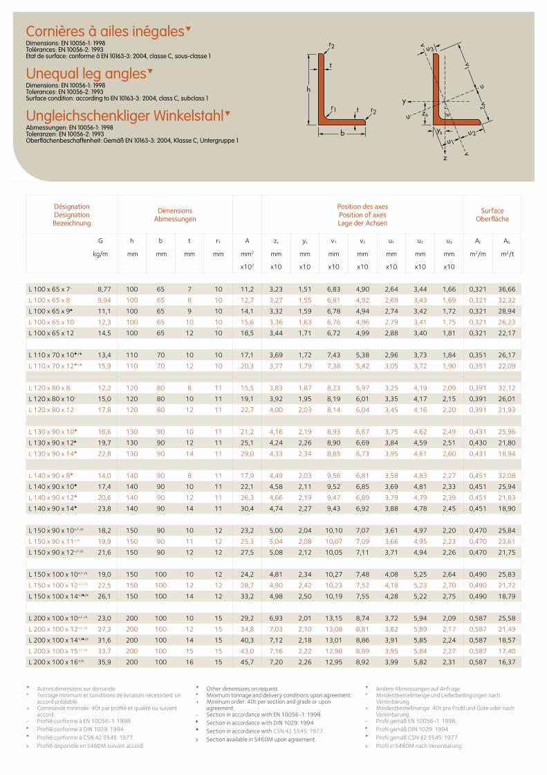
Cornières à ailes inégalesDimensions: EN 10056-1: 1998 Tolérances: EN 10056-2: 1993 Etat de surface: conforme à EN 10163-3: 2004, classe C, sous-classe 1
Unequal leg anglesDimensions: EN 10056-1: 1998 Tolerances: EN 10056-2: 1993 Surface condition: according to EN 10163-3: 2004, class C, subclass 1
Ungleichschenkliger WinkelstahlAbmessungen: EN 10056-1: 1998 Toleranzen: EN 10056-2: 1993 Oberflächenbeschaffenheit: Gemäß EN 10163-3: 2004, Klasse C, Untergruppe 1
Désignation Designation Bezeichnung
Dimensions Abmessungen
Position des axesPosition of axesLage der Achsen
Surface Oberfläche
G h b t r1 A zs ys v1 v2 u1 u2 u3 AL AG
kg/m mm mm mm mm mm2 mm mm mm mm mm mm mm m2/m m2/t
x102 x10 x10 x10 x10 x10 x10 x10
Autres dimensions sur demande.* Tonnage minimum et conditions de livraison nécessitent un
accord préalable.+ Commande minimale: 40t par profilé et qualité ou suivant
accord.- Profilé conforme à EN 10056-1: 1998♣ Profilé conforme à DIN 1029: 1994Profilé conforme à CSN 42 5545: 1977.x Profilé disponible en S460M suivant accord.
Other dimensions on request. * Minimum tonnage and delivery conditions upon agreement.+ Minimum order: 40t per section and grade or upon
agreement.- Section in accordance with EN 10056-1: 1998.♣ Section in accordance with DIN 1029: 1994 Section in accordance with CSN 42 5545: 1977.x Section available in S460M upon agreement.
Andere Abmessungen auf Anfrage. * Mindestbestellmenge und Lieferbedingungen nach
Vereinbarung.+ Mindestbestellmenge: 40t pro Profil und Güte oder nach
Vereinbarung.- Profil gemäß EN 10056-1: 1998.♣ Profil gemäß DIN 1029: 1994 Profil gemäß CSN 42 5545: 1977.x Profil in S460M nach Vereinbarung.
zs
z
y
u
u
ys
u1
u2
u3
v2
v
v
v1t
t
h
b
r1
r2
r2
L 100 x 65 x 7- 8,77 100 65 7 10 11,2 3,23 1,51 6,83 4,90 2,64 3,44 1,66 0,321 36,66
L 100 x 65 x 8- 9,94 100 65 8 10 12,7 3,27 1,55 6,81 4,92 2,69 3,43 1,69 0,321 32,32
L 100 x 65 x 9♣ 11,1 100 65 9 10 14,1 3,32 1,59 6,78 4,94 2,74 3,42 1,72 0,321 28,94
L 100 x 65 x 10- 12,3 100 65 10 10 15,6 3,36 1,63 6,76 4,96 2,79 3,41 1,75 0,321 26,23
L 100 x 65 x 12 14,5 100 65 12 10 18,5 3,44 1,71 6,72 4,99 2,88 3,40 1,81 0,321 22,17
L 110 x 70 x 10/* 13,4 110 70 10 10 17,1 3,69 1,72 7,43 5,38 2,96 3,73 1,84 0,351 26,17
L 110 x 70 x 12/* 15,9 110 70 12 10 20,3 3,77 1,79 7,38 5,42 3,05 3,72 1,90 0,351 22,09
L 120 x 80 x 8- 12,2 120 80 8 11 15,5 3,83 1,87 8,23 5,97 3,25 4,19 2,09 0,391 32,12
L 120 x 80 x 10- 15,0 120 80 10 11 19,1 3,92 1,95 8,19 6,01 3,35 4,17 2,15 0,391 26,01
L 120 x 80 x 12- 17,8 120 80 12 11 22,7 4,00 2,03 8,14 6,04 3,45 4,16 2,20 0,391 21,93
L 130 x 90 x 10 16,6 130 90 10 11 21,2 4,16 2,19 8,93 6,67 3,75 4,62 2,49 0,431 25,96
L 130 x 90 x 12♣ 19,7 130 90 12 11 25,1 4,24 2,26 8,90 6,69 3,84 4,59 2,51 0,430 21,80
L 130 x 90 x 14 22,8 130 90 14 11 29,0 4,33 2,34 8,85 6,73 3,95 4,61 2,60 0,431 18,94
L 140 x 90 x 8 14,0 140 90 8 11 17,9 4,49 2,03 9,56 6,81 3,58 4,83 2,27 0,451 32,08
L 140 x 90 x 10 17,4 140 90 10 11 22,1 4,58 2,11 9,52 6,85 3,69 4,81 2,33 0,451 25,94
L 140 x 90 x 12 20,6 140 90 12 11 26,3 4,66 2,19 9,47 6,89 3,79 4,79 2,39 0,451 21,83
L 140 x 90 x 14 23,8 140 90 14 11 30,4 4,74 2,27 9,43 6,92 3,88 4,78 2,45 0,451 18,90
L 150 x 90 x 10+/-/x 18,2 150 90 10 12 23,2 5,00 2,04 10,10 7,07 3,61 4,97 2,20 0,470 25,84
L 150 x 90 x 11+/x 19,9 150 90 11 12 25,3 5,04 2,08 10,07 7,09 3,66 4,95 2,23 0,470 23,61
L 150 x 90 x 12+/-/x 21,6 150 90 12 12 27,5 5,08 2,12 10,05 7,11 3,71 4,94 2,26 0,470 21,75
L 150 x 100 x 10+/-/x 19,0 150 100 10 12 24,2 4,81 2,34 10,27 7,48 4,08 5,25 2,64 0,490 25,83
L 150 x 100 x 12+/-/x 22,5 150 100 12 12 28,7 4,90 2,42 10,23 7,52 4,18 5,23 2,70 0,490 21,72
L 150 x 100 x 14+/♣/x 26,1 150 100 14 12 33,2 4,98 2,50 10,19 7,55 4,28 5,22 2,75 0,490 18,79
L 200 x 100 x 10+/-/x 23,0 200 100 10 15 29,2 6,93 2,01 13,15 8,74 3,72 5,94 2,09 0,587 25,58
L 200 x 100 x 12+/-/x 27,3 200 100 12 15 34,8 7,03 2,10 13,08 8,81 3,82 5,89 2,17 0,587 21,49
L 200 x 100 x 14+/♣/x 31,6 200 100 14 15 40,3 7,12 2,18 13,01 8,86 3,91 5,85 2,24 0,587 18,57
L 200 x 100 x 15+/-/x 33,7 200 100 15 15 43,0 7,16 2,22 12,98 8,89 3,95 5,84 2,27 0,587 17,40
L 200 x 100 x 16+/x 35,9 200 100 16 15 45,7 7,20 2,26 12,95 8,92 3,99 5,82 2,31 0,587 16,37
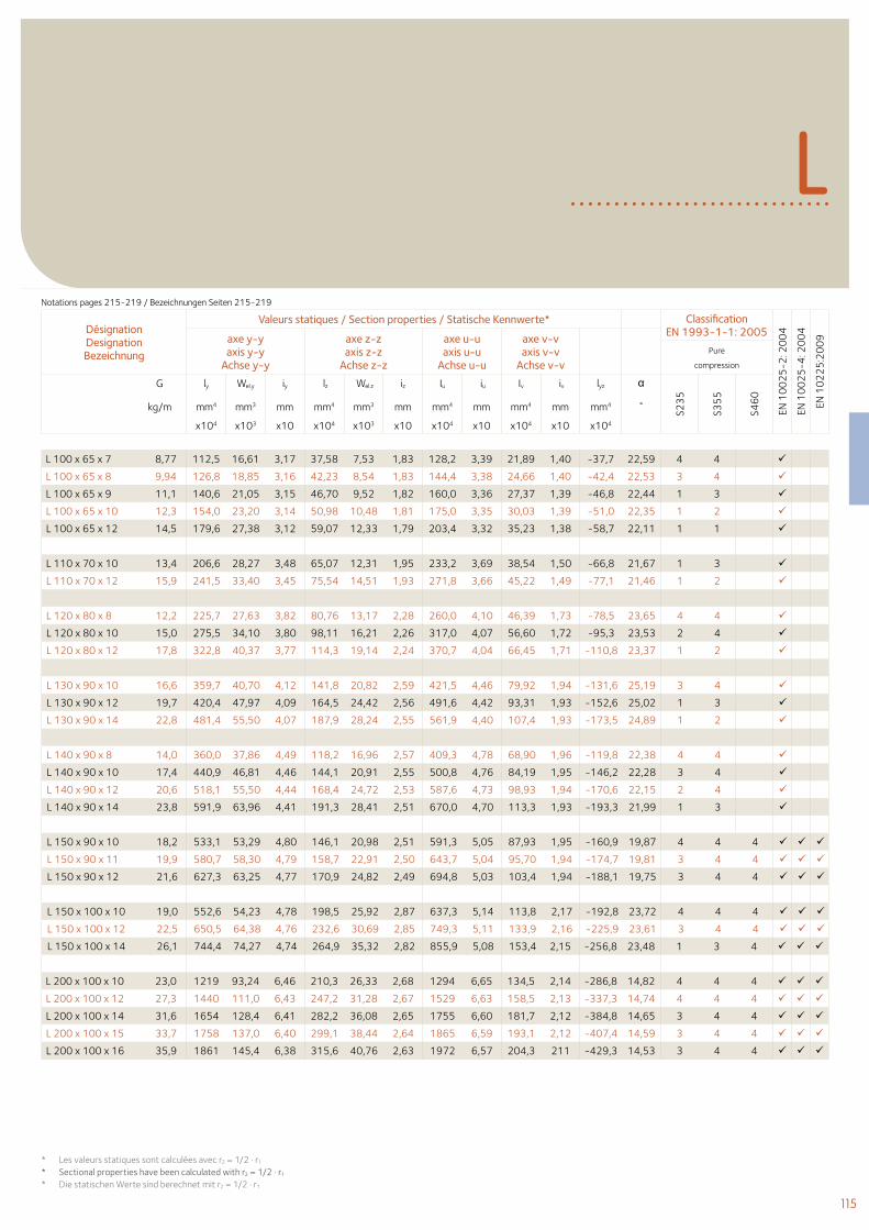
115
L
Désignation Designation Bezeichnung
Valeurs statiques / Section properties / Statische Kennwerte* Classification EN 1993-1-1: 2005
EN 1
00
25
-2: 2
00
4
EN 1
00
25
-4: 2
00
4
EN 1
02
25
:20
09axe y-y
axis y-yAchse y-y
axe z-zaxis z-z
Achse z-z
axe u-uaxis u-u
Achse u-u
axe v-vaxis v-v
Achse v-vPure
compression
G ly Wel.y iy lz Wel.z iz Iu iu Iv iv lyz α
S23
5
S35
5
S46
0
kg/m mm4 mm3 mm mm4 mm3 mm mm4 mm mm4 mm mm4 ˚
x104 x103 x10 x104 x103 x10 x104 x10 x104 x10 x104
L 100 x 65 x 7 8,77 112,5 16,61 3,17 37,58 7,53 1,83 128,2 3,39 21,89 1,40 -37,7 22,59 4 4
L 100 x 65 x 8 9,94 126,8 18,85 3,16 42,23 8,54 1,83 144,4 3,38 24,66 1,40 -42,4 22,53 3 4
L 100 x 65 x 9 11,1 140,6 21,05 3,15 46,70 9,52 1,82 160,0 3,36 27,37 1,39 -46,8 22,44 1 3
L 100 x 65 x 10 12,3 154,0 23,20 3,14 50,98 10,48 1,81 175,0 3,35 30,03 1,39 -51,0 22,35 1 2
L 100 x 65 x 12 14,5 179,6 27,38 3,12 59,07 12,33 1,79 203,4 3,32 35,23 1,38 -58,7 22,11 1 1
L 110 x 70 x 10 13,4 206,6 28,27 3,48 65,07 12,31 1,95 233,2 3,69 38,54 1,50 -66,8 21,67 1 3
L 110 x 70 x 12 15,9 241,5 33,40 3,45 75,54 14,51 1,93 271,8 3,66 45,22 1,49 -77,1 21,46 1 2
L 120 x 80 x 8 12,2 225,7 27,63 3,82 80,76 13,17 2,28 260,0 4,10 46,39 1,73 -78,5 23,65 4 4
L 120 x 80 x 10 15,0 275,5 34,10 3,80 98,11 16,21 2,26 317,0 4,07 56,60 1,72 -95,3 23,53 2 4
L 120 x 80 x 12 17,8 322,8 40,37 3,77 114,3 19,14 2,24 370,7 4,04 66,45 1,71 -110,8 23,37 1 2
L 130 x 90 x 10 16,6 359,7 40,70 4,12 141,8 20,82 2,59 421,5 4,46 79,92 1,94 -131,6 25,19 3 4
L 130 x 90 x 12 19,7 420,4 47,97 4,09 164,5 24,42 2,56 491,6 4,42 93,31 1,93 -152,6 25,02 1 3
L 130 x 90 x 14 22,8 481,4 55,50 4,07 187,9 28,24 2,55 561,9 4,40 107,4 1,93 -173,5 24,89 1 2
L 140 x 90 x 8 14,0 360,0 37,86 4,49 118,2 16,96 2,57 409,3 4,78 68,90 1,96 -119,8 22,38 4 4
L 140 x 90 x 10 17,4 440,9 46,81 4,46 144,1 20,91 2,55 500,8 4,76 84,19 1,95 -146,2 22,28 3 4
L 140 x 90 x 12 20,6 518,1 55,50 4,44 168,4 24,72 2,53 587,6 4,73 98,93 1,94 -170,6 22,15 2 4
L 140 x 90 x 14 23,8 591,9 63,96 4,41 191,3 28,41 2,51 670,0 4,70 113,3 1,93 -193,3 21,99 1 3
L 150 x 90 x 10 18,2 533,1 53,29 4,80 146,1 20,98 2,51 591,3 5,05 87,93 1,95 -160,9 19,87 4 4 4
L 150 x 90 x 11 19,9 580,7 58,30 4,79 158,7 22,91 2,50 643,7 5,04 95,70 1,94 -174,7 19,81 3 4 4
L 150 x 90 x 12 21,6 627,3 63,25 4,77 170,9 24,82 2,49 694,8 5,03 103,4 1,94 -188,1 19,75 3 4 4
L 150 x 100 x 10 19,0 552,6 54,23 4,78 198,5 25,92 2,87 637,3 5,14 113,8 2,17 -192,8 23,72 4 4 4
L 150 x 100 x 12 22,5 650,5 64,38 4,76 232,6 30,69 2,85 749,3 5,11 133,9 2,16 -225,9 23,61 3 4 4
L 150 x 100 x 14 26,1 744,4 74,27 4,74 264,9 35,32 2,82 855,9 5,08 153,4 2,15 -256,8 23,48 1 3 4
L 200 x 100 x 10 23,0 1219 93,24 6,46 210,3 26,33 2,68 1294 6,65 134,5 2,14 -286,8 14,82 4 4 4
L 200 x 100 x 12 27,3 1440 111,0 6,43 247,2 31,28 2,67 1529 6,63 158,5 2,13 -337,3 14,74 4 4 4
L 200 x 100 x 14 31,6 1654 128,4 6,41 282,2 36,08 2,65 1755 6,60 181,7 2,12 -384,8 14,65 3 4 4
L 200 x 100 x 15 33,7 1758 137,0 6,40 299,1 38,44 2,64 1865 6,59 193,1 2,12 -407,4 14,59 3 4 4
L 200 x 100 x 16 35,9 1861 145,4 6,38 315,6 40,76 2,63 1972 6,57 204,3 211 -429,3 14,53 3 4 4
Notations pages 215-219 / Bezeichnungen Seiten 215-219
* Les valeurs statiques sont calculées avec r2 = 1/2 . r1
* Sectional properties have been calculated with r2 = 1/2 . r1
* Die statischen Werte sind berechnet mit r2 = 1/2 . r1
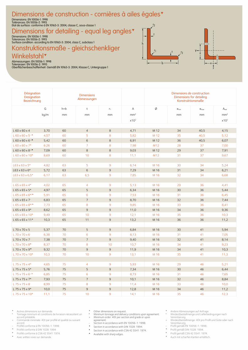
Désignation Designation Bezeichnung
Dimensions Abmessungen
Dimensions de construction Dimensions for detailing
Konstruktionsmaße
G h=b t r1 A Ø emin emax Anet
kg/m mm mm mm mm2 mm mm mm2
x102 x102
Dimensions de construction - cornières à ailes égalesDimensions: EN 10056-1: 1998 Tolérances: EN 10056-2: 1993 Etat de surface: conforme à EN 10163-3: 2004, classe C, sous-classe 1
Dimensions for detailing - equal leg anglesDimensions: EN 10056-1: 1998 Tolerances: EN 10056-2: 1993 Surface condition: according to EN 10163-3: 2004, class C, subclass 1
Konstruktionsmaße - gleichschenkliger WinkelstahlAbmessungen: EN 10056-1: 1998 Toleranzen: EN 10056-2: 1993 Oberflächenbeschaffenheit: Gemäß EN 10163-3: 2004, Klasse C, Untergruppe 1
Autres dimensions sur demande.* Tonnage minimum et conditions de livraison nécessitent un
accord préalable.+ Commande minimale: 40t par profilé et qualité ou suivant
accord.- Profilé conforme à EN 10056-1: 1998Profilé conforme à DIN 1028: 1994Profilé conforme à CSN 42 5541: 1974.Avec arêtes vives sur demande.
Other dimensions on request. * Minimum tonnage and delivery conditions upon agreement.+ Minimum order: 40t per section and grade or upon
agreement.- Section in accordance with EN 10056-1: 1998. Section in accordance with DIN 1028: 1994. Section in accordance with CSN 42 5541: 1974. Available with sharp edges.
Andere Abmessungen auf Anfrage. * Mindestbestellmenge und Lieferbedingungen nach
Vereinbarung.+ Mindestbestellmenge: 40t pro Profil und Güte oder nach
Vereinbarung.- Profil gemäß EN 10056-1: 1998. Profil gemäß DIN 1028: 1994. Profil gemäß CSN 42 5541: 1974. Auch mit scharfen Kanten erhältlich.
e
e
t
t
h
b
r1 r2
r2
L 60 x 60 x 4 3,70 60 4 8 4,71 M 12 34 40,5 4,15
L 60 x 60 x 5-/ 4,57 60 5 8 5,82 M 12 35 40,5 5,12
L 60 x 60 x 6-/ 5,42 60 6 8 6,91 M 12 36 40,5 6,07
L 60 x 60 x 7* 6.26 60 7 8 7,98 M12 28 37 7,00
L 60 x 60 x 8-/ 7,09 60 8 8 9,03 M 12 29 37 7,91
L 60 x 60 x 10* 8,69 60 10 8 11,1 M12 31 37 9,67
L63 x 63 x 5* 4,82 63 5 9 6,14 M 16 30 34 5,24
L63 x 63 x 6* 5,72 63 6 9 7,29 M 16 31 34 6,21
L63 x 63 x 6,5* 6,17 63 6,5 9 7,85 M 16 32 34 6,68
L 65 x 65 x 4* 4,02 65 4 9 5,13 M 16 29 36 4,41
L 65 x 65 x 5* 4,97 65 5 9 6,34 M 16 30 36 5,44
L 65 x 65 x 6*/ 5,91 65 6 9 7,53 M 16 31 36 6,45
L 65 x 65 x 7- 6,83 65 7 9 8,70 M 16 32 36 7,44
L 65 x 65 x 8*/ 7,73 65 8 9 9,85 M 16 33 36 8,41
L 65 x 65 x 9* 8,62 65 9 9 11,0 M 16 34 36 9,36
L 65 x 65 x 10* 9,49 65 10 9 12,1 M 16 35 36 10,3
L 65 x 65 x 11* 10,3 65 11 9 13,2 M 16 36 36 11,2
L 70 x 70 x 5 5,37 70 5 9 6,84 M 16 30 41 5,94
L 70 x 70 x 6- 6,38 70 6 9 8,13 M 16 31 41 7,05
L 70 x 70 x 7- 7,38 70 7 9 9,40 M 16 32 41 8,14
L 70 x 70 x 8 8,37 70 8 10 10,7 M 16 34 41 9,23
L 70 x 70 x 9 9,32 70 9 9 11,9 M 16 34 41 10,3
L 70 x 70 x 10* 10,3 70 10 9 13,1 M 16 35 41 11,3
L 75 x 75 x 4* 4,65 75 4 9 5,93 M 16 29 46 5,21
L 75 x 75 x 5* 5,76 75 5 9 7,34 M 16 30 46 6,44
L 75 x 75 x 6-/* 6,85 75 6 9 8,73 M 16 31 46 7,65
L 75 x 75 x 7* 7,93 75 7 9 10,1 M 16 32 46 8,84
L 75 x 75 x 8- 8,99 75 8 9 11,4 M 16 33 46 10,0
L 75 x 75 x 9* 10,0 75 9 9 12,8 M 16 34 46 11,2
L 75 x 75 x 10* 11,1 75 10 9 14,1 M 16 35 46 12,3
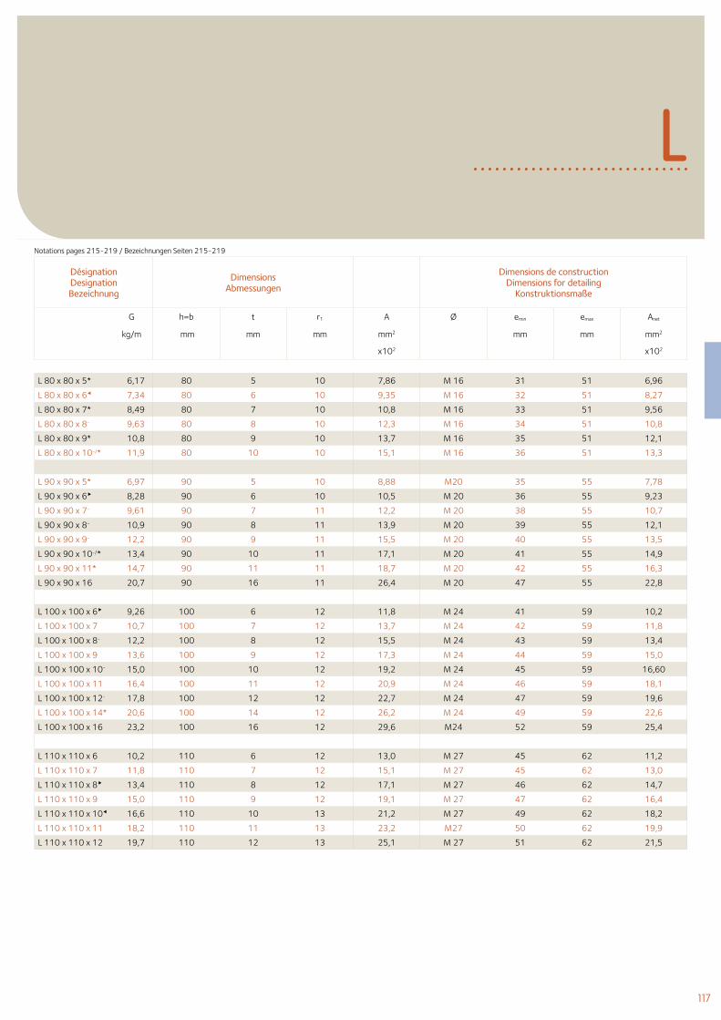
117
L
Désignation Designation Bezeichnung
Dimensions Abmessungen
Dimensions de construction Dimensions for detailing
Konstruktionsmaße
G h=b t r1 A Ø emin emax Anet
kg/m mm mm mm mm2 mm mm mm2
x102 x102
Notations pages 215-219 / Bezeichnungen Seiten 215-219
L 80 x 80 x 5* 6,17 80 5 10 7,86 M 16 31 51 6,96
L 80 x 80 x 6 7,34 80 6 10 9,35 M 16 32 51 8,27
L 80 x 80 x 7* 8,49 80 7 10 10,8 M 16 33 51 9,56
L 80 x 80 x 8- 9,63 80 8 10 12,3 M 16 34 51 10,8
L 80 x 80 x 9* 10,8 80 9 10 13,7 M 16 35 51 12,1
L 80 x 80 x 10-/* 11,9 80 10 10 15,1 M 16 36 51 13,3
L 90 x 90 x 5* 6,97 90 5 10 8,88 M20 35 55 7,78
L 90 x 90 x 6 8,28 90 6 10 10,5 M 20 36 55 9,23
L 90 x 90 x 7- 9,61 90 7 11 12,2 M 20 38 55 10,7
L 90 x 90 x 8- 10,9 90 8 11 13,9 M 20 39 55 12,1
L 90 x 90 x 9- 12,2 90 9 11 15,5 M 20 40 55 13,5
L 90 x 90 x 10-/* 13,4 90 10 11 17,1 M 20 41 55 14,9
L 90 x 90 x 11* 14,7 90 11 11 18,7 M 20 42 55 16,3
L 90 x 90 x 16 20,7 90 16 11 26,4 M 20 47 55 22,8
L 100 x 100 x 6 9,26 100 6 12 11,8 M 24 41 59 10,2
L 100 x 100 x 7 10,7 100 7 12 13,7 M 24 42 59 11,8
L 100 x 100 x 8- 12,2 100 8 12 15,5 M 24 43 59 13,4
L 100 x 100 x 9 13,6 100 9 12 17,3 M 24 44 59 15,0
L 100 x 100 x 10- 15,0 100 10 12 19,2 M 24 45 59 16,60
L 100 x 100 x 11 16,4 100 11 12 20,9 M 24 46 59 18,1
L 100 x 100 x 12- 17,8 100 12 12 22,7 M 24 47 59 19,6
L 100 x 100 x 14* 20,6 100 14 12 26,2 M 24 49 59 22,6
L 100 x 100 x 16 23,2 100 16 12 29,6 M24 52 59 25,4
L 110 x 110 x 6 10,2 110 6 12 13,0 M 27 45 62 11,2
L 110 x 110 x 7 11,8 110 7 12 15,1 M 27 45 62 13,0
L 110 x 110 x 8 13,4 110 8 12 17,1 M 27 46 62 14,7
L 110 x 110 x 9 15,0 110 9 12 19,1 M 27 47 62 16,4
L 110 x 110 x 10 16,6 110 10 13 21,2 M 27 49 62 18,2
L 110 x 110 x 11 18,2 110 11 13 23,2 M27 50 62 19,9
L 110 x 110 x 12 19,7 110 12 13 25,1 M 27 51 62 21,5
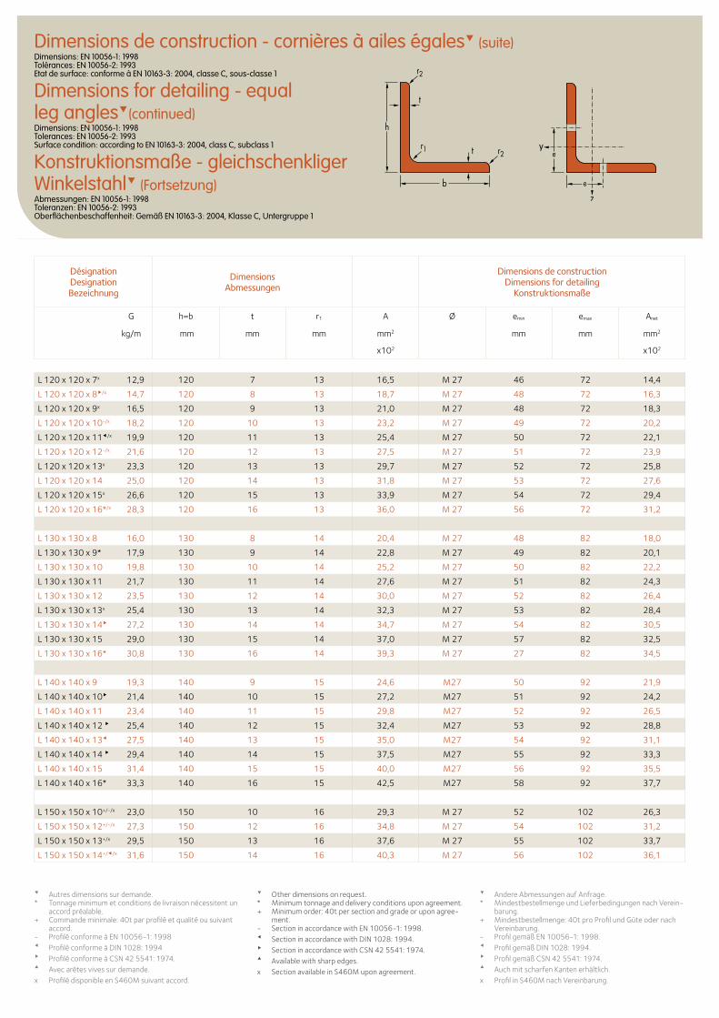
Désignation Designation Bezeichnung
Dimensions Abmessungen
Dimensions de construction Dimensions for detailing
Konstruktionsmaße
G h=b t r1 A Ø emin emax Anet
kg/m mm mm mm mm2 mm mm mm2
x102 x102
Dimensions de construction - cornières à ailes égales (suite)Dimensions: EN 10056-1: 1998 Tolérances: EN 10056-2: 1993 Etat de surface: conforme à EN 10163-3: 2004, classe C, sous-classe 1
Dimensions for detailing - equal leg angles(continued)Dimensions: EN 10056-1: 1998 Tolerances: EN 10056-2: 1993 Surface condition: according to EN 10163-3: 2004, class C, subclass 1
Konstruktionsmaße - gleichschenkliger Winkelstahl (Fortsetzung)Abmessungen: EN 10056-1: 1998 Toleranzen: EN 10056-2: 1993 Oberflächenbeschaffenheit: Gemäß EN 10163-3: 2004, Klasse C, Untergruppe 1
e
e
t
t
h
b
r1 r2
r2
Autres dimensions sur demande.* Tonnage minimum et conditions de livraison nécessitent un
accord préalable.+ Commande minimale: 40t par profilé et qualité ou suivant
accord.- Profilé conforme à EN 10056-1: 1998Profilé conforme à DIN 1028: 1994Profilé conforme à CSN 42 5541: 1974.Avec arêtes vives sur demande.x Profilé disponible en S460M suivant accord.
Other dimensions on request. * Minimum tonnage and delivery conditions upon agreement.+ Minimum order: 40t per section and grade or upon agree-
ment.- Section in accordance with EN 10056-1: 1998. Section in accordance with DIN 1028: 1994. Section in accordance with CSN 42 5541: 1974. Available with sharp edges.x Section available in S460M upon agreement.
Andere Abmessungen auf Anfrage. * Mindestbestellmenge und Lieferbedingungen nach Verein-
barung.+ Mindestbestellmenge: 40t pro Profil und Güte oder nach
Vereinbarung.- Profil gemäß EN 10056-1: 1998. Profil gemäß DIN 1028: 1994. Profil gemäß CSN 42 5541: 1974. Auch mit scharfen Kanten erhältlich.x Profil in S460M nach Vereinbarung.
L 120 x 120 x 7x 12,9 120 7 13 16,5 M 27 46 72 14,4
L 120 x 120 x 8/x 14,7 120 8 13 18,7 M 27 48 72 16,3
L 120 x 120 x 9x 16,5 120 9 13 21,0 M 27 48 72 18,3
L 120 x 120 x 10-/x 18,2 120 10 13 23,2 M 27 49 72 20,2
L 120 x 120 x 11/x 19,9 120 11 13 25,4 M 27 50 72 22,1
L 120 x 120 x 12-/x 21,6 120 12 13 27,5 M 27 51 72 23,9
L 120 x 120 x 13x 23,3 120 13 13 29,7 M 27 52 72 25,8
L 120 x 120 x 14 25,0 120 14 13 31,8 M 27 53 72 27,6
L 120 x 120 x 15x 26,6 120 15 13 33,9 M 27 54 72 29,4
L 120 x 120 x 16*/x 28,3 120 16 13 36,0 M 27 56 72 31,2
L 130 x 130 x 8 16,0 130 8 14 20,4 M 27 48 82 18,0
L 130 x 130 x 9* 17,9 130 9 14 22,8 M 27 49 82 20,1
L 130 x 130 x 10 19,8 130 10 14 25,2 M 27 50 82 22,2
L 130 x 130 x 11 21,7 130 11 14 27,6 M 27 51 82 24,3
L 130 x 130 x 12 23,5 130 12 14 30,0 M 27 52 82 26,4
L 130 x 130 x 13x 25,4 130 13 14 32,3 M 27 53 82 28,4
L 130 x 130 x 14 27,2 130 14 14 34,7 M 27 54 82 30,5
L 130 x 130 x 15 29,0 130 15 14 37,0 M 27 57 82 32,5
L 130 x 130 x 16* 30,8 130 16 14 39,3 M 27 27 82 34,5
L 140 x 140 x 9 19,3 140 9 15 24,6 M27 50 92 21,9
L 140 x 140 x 10 21,4 140 10 15 27,2 M27 51 92 24,2
L 140 x 140 x 11 23,4 140 11 15 29,8 M27 52 92 26,5
L 140 x 140 x 12 25,4 140 12 15 32,4 M27 53 92 28,8
L 140 x 140 x 13 27,5 140 13 15 35,0 M27 54 92 31,1
L 140 x 140 x 14 29,4 140 14 15 37,5 M27 55 92 33,3
L 140 x 140 x 15 31,4 140 15 15 40,0 M27 56 92 35,5
L 140 x 140 x 16* 33,3 140 16 15 42,5 M27 58 92 37,7
L 150 x 150 x 10+/-/x 23,0 150 10 16 29,3 M 27 52 102 26,3
L 150 x 150 x 12+/-/x 27,3 150 12 16 34,8 M 27 54 102 31,2
L 150 x 150 x 13+/x 29,5 150 13 16 37,6 M 27 55 102 33,7
L 150 x 150 x 14+//x 31,6 150 14 16 40,3 M 27 56 102 36,1
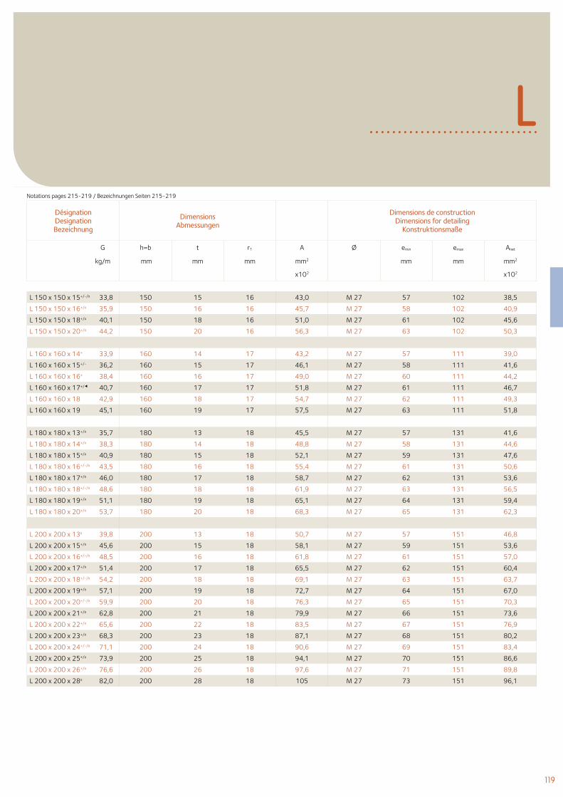
119
L
Désignation Designation Bezeichnung
Dimensions Abmessungen
Dimensions de construction Dimensions for detailing
Konstruktionsmaße
G h=b t r1 A Ø emin emax Anet
kg/m mm mm mm mm2 mm mm mm2
x102 x102
Notations pages 215-219 / Bezeichnungen Seiten 215-219
L 150 x 150 x 15+/-/x 33,8 150 15 16 43,0 M 27 57 102 38,5
L 150 x 150 x 16+/x 35,9 150 16 16 45,7 M 27 58 102 40,9
L 150 x 150 x 18+/x 40,1 150 18 16 51,0 M 27 61 102 45,6
L 150 x 150 x 20+/x 44,2 150 20 16 56,3 M 27 63 102 50,3
L 160 x 160 x 14+ 33,9 160 14 17 43,2 M 27 57 111 39,0
L 160 x 160 x 15+/- 36,2 160 15 17 46,1 M 27 58 111 41,6
L 160 x 160 x 16+ 38,4 160 16 17 49,0 M 27 60 111 44,2
L 160 x 160 x 17+/ 40,7 160 17 17 51,8 M 27 61 111 46,7
L 160 x 160 x 18 42,9 160 18 17 54,7 M 27 62 111 49,3
L 160 x 160 x 19 45,1 160 19 17 57,5 M 27 63 111 51,8
L 180 x 180 x 13+/x 35,7 180 13 18 45,5 M 27 57 131 41,6
L 180 x 180 x 14+/x 38,3 180 14 18 48,8 M 27 58 131 44,6
L 180 x 180 x 15+/x 40,9 180 15 18 52,1 M 27 59 131 47,6
L 180 x 180 x 16+/-/x 43,5 180 16 18 55,4 M 27 61 131 50,6
L 180 x 180 x 17+/x 46,0 180 17 18 58,7 M 27 62 131 53,6
L 180 x 180 x 18+/-/x 48,6 180 18 18 61,9 M 27 63 131 56,5
L 180 x 180 x 19+/x 51,1 180 19 18 65,1 M 27 64 131 59,4
L 180 x 180 x 20+/x 53,7 180 20 18 68,3 M 27 65 131 62,3
L 200 x 200 x 13x 39,8 200 13 18 50,7 M 27 57 151 46,8
L 200 x 200 x 15+/x 45,6 200 15 18 58,1 M 27 59 151 53,6
L 200 x 200 x 16+/-/x 48,5 200 16 18 61,8 M 27 61 151 57,0
L 200 x 200 x 17+/x 51,4 200 17 18 65,5 M 27 62 151 60,4
L 200 x 200 x 18+/-/x 54,2 200 18 18 69,1 M 27 63 151 63,7
L 200 x 200 x 19+/x 57,1 200 19 18 72,7 M 27 64 151 67,0
L 200 x 200 x 20+/-/x 59,9 200 20 18 76,3 M 27 65 151 70,3
L 200 x 200 x 21+/x 62,8 200 21 18 79,9 M 27 66 151 73,6
L 200 x 200 x 22+/x 65,6 200 22 18 83,5 M 27 67 151 76,9
L 200 x 200 x 23+/x 68,3 200 23 18 87,1 M 27 68 151 80,2
L 200 x 200 x 24+/-/x 71,1 200 24 18 90,6 M 27 69 151 83,4
L 200 x 200 x 25+/x 73,9 200 25 18 94,1 M 27 70 151 86,6
L 200 x 200 x 26+/x 76,6 200 26 18 97,6 M 27 71 151 89,8
L 200 x 200 x 28x 82,0 200 28 18 105 M 27 73 151 96,1
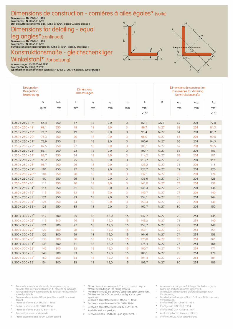
Dimensions de construction - cornières à ailes égales (suite)Dimensions: EN 10056-1: 1998 Tolérances: EN 10056-2: 1993 Etat de surface: conforme à EN 10163-3: 2004, classe C, sous-classe 1
Dimensions for detailing - equal leg angles(continued)Dimensions: EN 10056-1: 1998 Tolerances: EN 10056-2: 1993 Surface condition: according to EN 10163-3: 2004, class C, subclass 1
Konstruktionsmaße - gleichschenkliger Winkelstahl (Fortsetzung)Abmessungen: EN 10056-1: 1998 Toleranzen: EN 10056-2: 1993 Oberflächenbeschaffenheit: Gemäß EN 10163-3: 2004, Klasse C, Untergruppe 1
Désignation Designation Bezeichnung
Dimensions Abmessungen
Dimensions de construction Dimensions for detailing
Konstruktionsmaße
G h=b t r1 r2 r3 A Ø emin emax Anet
kg/m mm mm mm mm mm mm2 mm mm mm2
x102 x102
Autres dimensions sur demande. Les rayons r1, r2, r3 peuvent être inférieur en fonction du procédé de laminage.
* Tonnage minimum et conditions de livraison nécessitent un accord préalable.
+ Commande minimale: 40t par profilé et qualité ou suivant accord.
- Profilé conforme à EN 10056-1: 1998Profilé conforme à DIN 1028: 1994Profilé conforme à CSN 42 5541: 1974.Avec arêtes vives sur demande.x Profilé disponible en S460M suivant accord.
Other dimensions on request. The r1, r2, r3 radius may be smaller depending on the rolling process.
* Minimum tonnage and delivery conditions upon agreement.+ Minimum order: 40t per section and grade or upon
agreement.- Section in accordance with EN 10056-1: 1998. Section in accordance with DIN 1028: 1994. Section in accordance with CSN 42 5541: 1974. Available with sharp edges.x Section available in S460M upon agreement.
Andere Abmessungen auf Anfrage. Die Radien r1, r2, r3 können je nach Walzprozess kleiner sein.
* Mindestbestellmenge und Lieferbedingungen nach Vereinbarung.
+ Mindestbestellmenge: 40t pro Profil und Güte oder nach Vereinbarung.
- Profil gemäß EN 10056-1: 1998. Profil gemäß DIN 1028: 1994. Profil gemäß CSN 42 5541: 1974. Auch mit scharfen Kanten erhältlich.x Profil in S460M nach Vereinbarung.
L 250 x 250 x 17* 64,4 250 17 18 9,0 3 82,1 M27 62 201 77,0
L 250 x 250 x 18* 68,1 250 18 18 9,0 3 86,7 M 27 63 201 81,3
L 250 x 250 x 19* 71,7 250 19 18 9,0 3 91,4 M 27 64 201 85,7
L 250 x 250 x 20* 75,3 250 20 18 9,0 3 96,0 M 27 65 201 90,0
L 250 x 250 x 21* 78,9 250 21 18 9,0 3 100,6 M 27 66 201 94,3
L 250 x 250 x 22* 82,5 250 22 18 9,0 3 105,1 M 27 67 201 98,5
L 250 x 250 x 23* 86,1 250 23 18 9,0 3 109,7 M 27 68 201 103
L 250 x 250 x 24* 89,7 250 24 18 9,0 3 114,2 M 27 69 201 107
L 250 x 250 x 25* 93,2 250 25 18 9,0 3 118,7 M 27 70 201 111
L 250 x 250 x 26* 96,7 250 26 18 9,0 3 123,2 M 27 71 201 115
L 250 x 250 x 27* 101 250 27 18 9,0 3 127,7 M 27 72 201 120
L 250 x 250 x 28*/- 104 250 28 18 9,0 3 137,1 M 27 73 201 124
L 250 x 250 x 29* 107 250 29 18 9,0 3 136,6 M 27 74 201 128
L 250 x 250 x 30* 111 250 30 18 9,0 3 141,0 M 27 75 201 132
L 250 x 250 x 31* 114 250 31 18 9,0 3 145,4 M 27 76 201 136
L 250 x 250 x 32* 118 250 32 18 9,0 3 149,7 M 27 77 201 140
L 250 x 250 x 33* 121 250 33 18 9,0 3 154,1 M 27 78 201 144
L 250 x 250 x 34* 124 250 34 18 9,0 3 158,4 M 27 79 201 148
L 250 x 250 x 35*/- 128 250 35 18 9,0 3 162,7 M 27 80 201 152
L 300 x 300 x 25* 112 300 25 18 12,0 15 142,7 M 27 70 251 135
L 300 x 300 x 26* 116 300 26 18 12,0 15 148,2 M 27 71 251 140
L 300 x 300 x 27* 121 300 27 18 12,0 15 153,7 M 27 72 251 146
L 300 x 300 x 28* 125 300 28 18 12,0 15 159,1 M 27 73 251 151
L 300 x 300 x 29* 129 300 29 18 12,0 15 164,6 M 27 74 251 156
L 300 x 300 x 30* 133 300 30 18 12,0 15 170,0 M 27 75 251 161
L 300 x 300 x 31* 138 300 31 18 12,0 15 175,4 M 27 76 251 166
L 300 x 300 x 32* 142 300 32 18 12,0 15 180,7 M 27 77 251 171
L 300 x 300 x 33* 146 300 33 18 12,0 15 186,1 M 27 78 251 176
L 300 x 300 x 34* 150 300 34 18 12,0 15 191,4 M 27 79 251 181
L 300 x 300 x 35* 154 300 35 18 12,0 15 196,7 M 27 80 251 186
zs
ys
y
z
u
uu 1
u 2
v
v
v
v
t
t
h
b
r1 r2
r2
r2r2
45o
r3
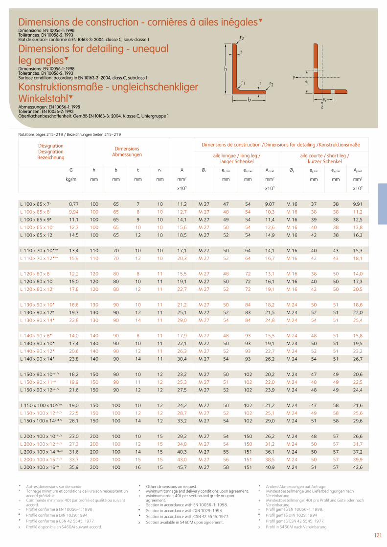
121
Dimensions de construction - cornières à ailes inégalesDimensions: EN 10056-1: 1998 Tolérances: EN 10056-2: 1993 Etat de surface: conforme à EN 10163-3: 2004, classe C, sous-classe 1
Dimensions for detailing - unequal leg anglesDimensions: EN 10056-1: 1998 Tolerances: EN 10056-2: 1993 Surface condition: according to EN 10163-3: 2004, class C, subclass 1
Konstruktionsmaße - ungleichschenkliger WinkelstahlAbmessungen: EN 10056-1: 1998 Toleranzen: EN 10056-2: 1993 Oberflächenbeschaffenheit: Gemäß EN 10163-3: 2004, Klasse C, Untergruppe 1
Désignation Designation Bezeichnung
Dimensions Abmessungen
Dimensions de construction /Dimensions for detailing /Konstruktionsmaße
aile longue / long leg / langer Schenkel
aile courte / short leg / kurzer Schenkel
G h b t r1 A Øz ez,min ez,max Az,net Øy ey,min ey,max Ay,net
kg/m mm mm mm mm mm2 mm mm mm2 mm mm mm2
x102 x102 x102
L 100 x 65 x 7- 8,77 100 65 7 10 11,2 M 27 47 54 9,07 M 16 37 38 9,91
L 100 x 65 x 8- 9,94 100 65 8 10 12,7 M 27 48 54 10,3 M 16 38 38 11,2
L 100 x 65 x 9♣ 11,1 100 65 9 10 14,1 M 27 49 54 11,4 M 16 39 38 12,5
L 100 x 65 x 10- 12,3 100 65 10 10 15,6 M 27 50 54 12,6 M 16 40 38 13,8
L 100 x 65 x 12 14,5 100 65 12 10 18,5 M 27 52 54 14,9 M 16 42 38 16,3
L 110 x 70 x 10/* 13,4 110 70 10 10 17,1 M 27 50 64 14,1 M 16 40 43 15,3
L 110 x 70 x 12/* 15,9 110 70 12 10 20,3 M 27 52 64 16,7 M 16 42 43 18,1
L 120 x 80 x 8- 12,2 120 80 8 11 15,5 M 27 48 72 13,1 M 16 38 50 14,0
L 120 x 80 x 10- 15,0 120 80 10 11 19,1 M 27 50 72 16,1 M 16 40 50 17,3
L 120 x 80 x 12- 17,8 120 80 12 11 22,7 M 27 52 72 19,1 M 16 42 50 20,5
L 130 x 90 x 10 16,6 130 90 10 11 21,2 M 27 50 84 18,2 M 24 50 51 18,6
L 130 x 90 x 12♣ 19,7 130 90 12 11 25,1 M 27 52 83 21,5 M 24 52 51 22,0
L 130 x 90 x 14 22,8 130 90 14 11 29,0 M 27 54 84 24,8 M 24 54 51 25,4
L 140 x 90 x 8 14,0 140 90 8 11 17,9 M 27 48 93 15,5 M 24 48 51 15,8
L 140 x 90 x 10 17,4 140 90 10 11 22,1 M 27 50 93 19,1 M 24 50 51 19,5
L 140 x 90 x 12 20,6 140 90 12 11 26,3 M 27 52 93 22,7 M 24 52 51 23,2
L 140 x 90 x 14 23,8 140 90 14 11 30,4 M 27 54 93 26,2 M 24 54 51 26,7
L 150 x 90 x 10+/-/x 18,2 150 90 10 12 23,2 M 27 50 102 20,2 M 24 47 49 20,6
L 150 x 90 x 11+/x 19,9 150 90 11 12 25,3 M 27 51 102 22,0 M 24 48 49 22,5
L 150 x 90 x 12+/-/x 21,6 150 90 12 12 27,5 M 27 52 102 23,9 M 24 48 49 24,4
L 150 x 100 x 10+/-/x 19,0 150 100 10 12 24,2 M 27 50 102 21,2 M 24 47 58 21,6
L 150 x 100 x 12+/-/x 22,5 150 100 12 12 28,7 M 27 52 102 25,1 M 24 49 58 25,6
L 150 x 100 x 14+/♣/x 26,1 150 100 14 12 33,2 M 27 54 102 29,0 M 24 51 58 29,6
L 200 x 100 x 10+/-/x 23,0 200 100 10 15 29,2 M 27 54 150 26,2 M 24 48 57 26,6
L 200 x 100 x 12+/-/x 27,3 200 100 12 15 34,8 M 27 54 150 31,2 M 24 50 57 31,7
L 200 x 100 x 14+/♣/x 31,6 200 100 14 15 40,3 M 27 55 151 36,1 M 24 50 57 37,2
L 200 x 100 x 15+/-/x 33,7 200 100 15 15 43,0 M 27 56 151 38,5 M 24 50 57 39,9
L 200 x 100 x 16+/x 35,9 200 100 16 15 45,7 M 27 58 151 40,9 M 24 51 57 42,6
Autres dimensions sur demande.* Tonnage minimum et conditions de livraison nécessitent un
accord préalable.+ Commande minimale: 40t par profilé et qualité ou suivant
accord.- Profilé conforme à EN 10056-1: 1998♣ Profilé conforme à DIN 1029: 1994Profilé conforme à CSN 42 5545: 1977.x Profilé disponible en S460M suivant accord.
Other dimensions on request. * Minimum tonnage and delivery conditions upon agreement.+ Minimum order: 40t per section and grade or upon
agreement.- Section in accordance with EN 10056-1: 1998.♣ Section in accordance with DIN 1029: 1994 Section in accordance with CSN 42 5545: 1977.x Section available in S460M upon agreement.
Andere Abmessungen auf Anfrage. * Mindestbestellmenge und Lieferbedingungen nach
Vereinbarung.+ Mindestbestellmenge: 40t pro Profil und Güte oder nach
Vereinbarung.- Profil gemäß EN 10056-1: 1998.♣ Profil gemäß DIN 1029: 1994 Profil gemäß CSN 42 5545: 1977.x Profil in S460M nach Vereinbarung.
t
t
h
b
r1
r2
r2ez
ey
Notations pages 215-219 / Bezeichnungen Seiten 215-219
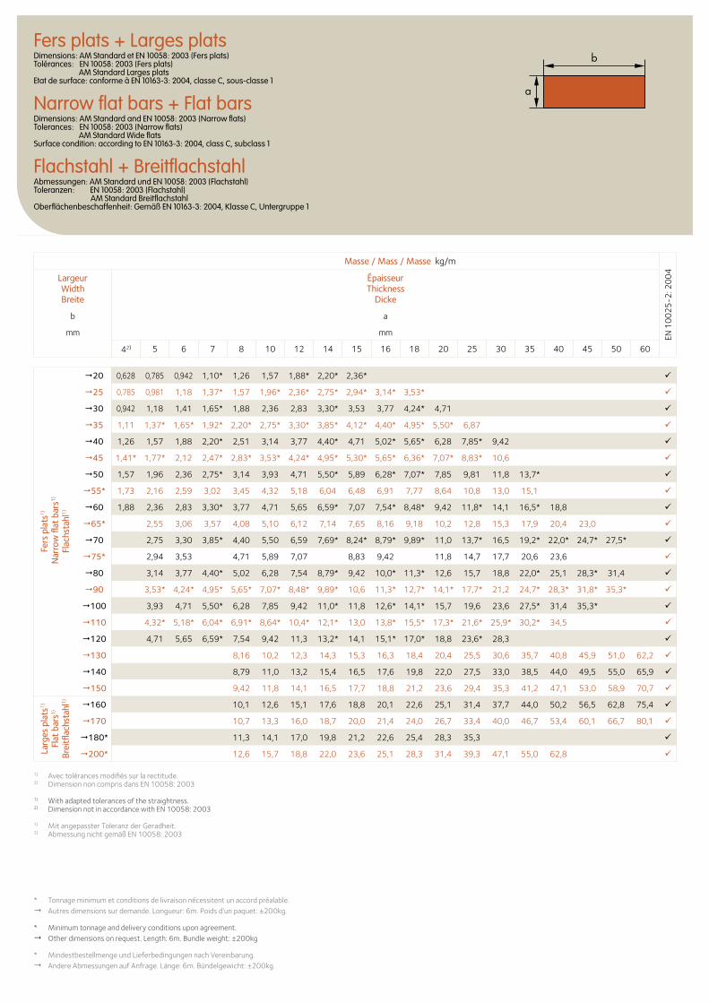
Fers plats + Larges platsDimensions: AM Standard et EN 10058: 2003 (Fers plats) Tolérances: EN 10058: 2003 (Fers plats) AM Standard Larges plats Etat de surface: conforme à EN 10163-3: 2004, classe C, sous-classe 1
Narrow flat bars + Flat barsDimensions: AM Standard and EN 10058: 2003 (Narrow flats) Tolerances: EN 10058: 2003 (Narrow flats) AM Standard Wide flats Surface condition: according to EN 10163-3: 2004, class C, subclass 1
Flachstahl + BreitflachstahlAbmessungen: AM Standard und EN 10058: 2003 (Flachstahl) Toleranzen: EN 10058: 2003 (Flachstahl) AM Standard Breitflachstahl Oberflächenbeschaffenheit: Gemäß EN 10163-3: 2004, Klasse C, Untergruppe 1
b
a
Masse / Mass / Masse kg/m
EN 1
00
25
-2: 2
00
4
LargeurWidthBreite
ÉpaisseurThickness
Dicke
b a
mm mm
42) 5 6 7 8 10 12 14 15 16 18 20 25 30 35 40 45 50 60
Fers
pla
ts1)
Nar
row
flat
bar
s1)
Flac
hsta
hl1)
20 0,628 0,785 0,942 1,10* 1,26 1,57 1,88* 2,20* 2,36*
25 0,785 0,981 1,18 1,37* 1,57 1,96* 2,36* 2,75* 2,94* 3,14* 3,53*
30 0,942 1,18 1,41 1,65* 1,88 2,36 2,83 3,30* 3,53 3,77 4,24* 4,71
35 1,11 1,37* 1,65* 1,92* 2,20* 2,75* 3,30* 3,85* 4,12* 4,40* 4,95* 5,50* 6,87
40 1,26 1,57 1,88 2,20* 2,51 3,14 3,77 4,40* 4,71 5,02* 5,65* 6,28 7,85* 9,42
45 1,41* 1,77* 2,12 2,47* 2,83* 3,53* 4,24* 4,95* 5,30* 5,65* 6,36* 7,07* 8,83* 10,6
50 1,57 1,96 2,36 2,75* 3,14 3,93 4,71 5,50* 5,89 6,28* 7,07* 7,85 9,81 11,8 13,7*
55* 1,73 2,16 2,59 3,02 3,45 4,32 5,18 6,04 6,48 6,91 7,77 8,64 10,8 13,0 15,1
60 1,88 2,36 2,83 3,30* 3,77 4,71 5,65 6,59* 7,07 7,54* 8,48* 9,42 11,8* 14,1 16,5* 18,8
65* 2,55 3,06 3,57 4,08 5,10 6,12 7,14 7,65 8,16 9,18 10,2 12,8 15,3 17,9 20,4 23,0
70 2,75 3,30 3,85* 4,40 5,50 6,59 7,69* 8,24* 8,79* 9,89* 11,0 13,7* 16,5 19,2* 22,0* 24,7* 27,5*
75* 2,94 3,53 4,71 5,89 7,07 8,83 9,42 11,8 14,7 17,7 20,6 23,6
80 3,14 3,77 4,40* 5,02 6,28 7,54 8,79* 9,42 10,0* 11,3* 12,6 15,7 18,8 22,0* 25,1 28,3* 31,4
90 3,53* 4,24* 4,95* 5,65* 7,07* 8,48* 9,89* 10,6 11,3* 12,7* 14,1* 17,7* 21,2 24,7* 28,3* 31,8* 35,3*
100 3,93 4,71 5,50* 6,28 7,85 9,42 11,0* 11,8 12,6* 14,1* 15,7 19,6 23,6 27,5* 31,4 35,3*
110 4,32* 5,18* 6,04* 6,91* 8,64* 10,4* 12,1* 13,0 13,8* 15,5* 17,3* 21,6* 25,9* 30,2* 34,5
120 4,71 5,65 6,59* 7,54 9,42 11,3 13,2* 14,1 15,1* 17,0* 18,8 23,6* 28,3
130 8,16 10,2 12,3 14,3 15,3 16,3 18,4 20,4 25,5 30,6 35,7 40,8 45,9 51,0 62,2
140 8,79 11,0 13,2 15,4 16,5 17,6 19,8 22,0 27,5 33,0 38,5 44,0 49,5 55,0 65,9
150 9,42 11,8 14,1 16,5 17,7 18,8 21,2 23,6 29,4 35,3 41,2 47,1 53,0 58,9 70,7
Larg
es p
lats
1)
Flat
bar
s1)
Brei
tflac
hsta
hl1) 160 10,1 12,6 15,1 17,6 18,8 20,1 22,6 25,1 31,4 37,7 44,0 50,2 56,5 62,8 75,4
170 10,7 13,3 16,0 18,7 20,0 21,4 24,0 26,7 33,4 40,0 46,7 53,4 60,1 66,7 80,1
180* 11,3 14,1 17,0 19,8 21,2 22,6 25,4 28,3 35,3
200* 12,6 15,7 18,8 22,0 23,6 25,1 28,3 31,4 39,3 47,1 55,0 62,8
* Tonnage minimum et conditions de livraison nécessitent un accord préalable.Autres dimensions sur demande. Longueur: 6m. Poids d’un paquet: ±200kg.
* Minimum tonnage and delivery conditions upon agreement. Other dimensions on request. Length: 6m. Bundle weight: ±200kg
* Mindestbestellmenge und Lieferbedingungen nach Vereinbarung.Andere Abmessungen auf Anfrage. Länge: 6m. Bündelgewicht: ±200kg.
1) Avec tolérances modifiés sur la rectitude.2) Dimension non compris dans EN 10058: 2003
1) With adapted tolerances of the straightness.2) Dimension not in accordance with EN 10058: 2003
1) Mit angepasster Toleranz der Geradheit.2) Abmessung nicht gemäß EN 10058: 2003
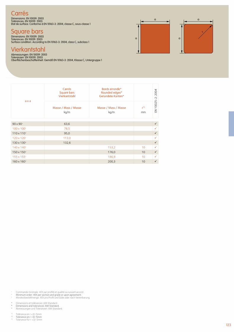
123
CarrésDimensions: EN 10059: 2003 Tolérances: EN 10059: 2003 Etat de surface: Conforme à EN 10163-3: 2004, classe C, sous-classe 1
Square barsDimensions: EN 10059: 2003 Tolerances: EN 10059: 2003 Surface condition: According to EN 10163-3: 2004, class C, subclass 1
VierkantstahlAbmessungen: EN 10059: 2003 Toleranzen: EN 10059: 2003 Oberflächenbeschaffenheit: Gemäß EN 10163-3: 2004, Klasse C, Untergruppe 1
a
a
a x a
CarrésSquare bars
Vierkantstahl
Bords arrondis*Rounded edges*
Gerundete Kanten*
EN 1
00
25
-2: 2
00
4
Masse / Mass / Massekg/m
Masse / Mass / Massekg/m
r1)
mm
90 x 90+ 63,6
100 x 100+ 78,5
110 x 110+ 95,0
120 x 120+ 113,0
130 x 130+ 132,6
140 x 140+ 153,2 10
150 x 150+ 176,0 10
155 x 155+ 186,9 10
160 x 160+ 200,3 10
+ Commande minimale: 40t par profilé et qualité ou suivant accord.+ Minimum order: 40t per section and grade or upon agreement.+ Mindestbestellmenge: 40t pro Profil und Güte oder nach Vereinbarung.
* Dimensions et tolérances: AM Standard.* Dimensions and tolerances: AM Standard.* Abmessungen und Toleranzen: AM Standard.
1) Tolérance en r +3/-5mm1) Tolerance on r +3/-5mm1) Tolerance für r +3/-5mm
a
a
r
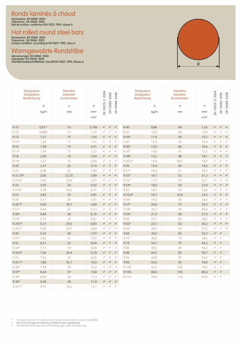
Ronds laminés à chaudDimensions: EN 10060: 2003 Tolérances: EN 10060: 2003 Etat de surface: conforme à EN 10221: 1995, classe A
Hot rolled round steel barsDimensions: EN 10060: 2003 Tolerances: EN 10060: 2003 Surface condition: according to EN 10221: 1995, class A
Warmgewalzte RundstäbeAbmessungen: EN 10060: 2003 Toleranzen: EN 10060: 2003 Oberflächenbeschaffenheit: Gemäß EN 10221: 1995, Klasse A
Désignation Designation Bezeichnung
DiamètreDiameter
Durchmesser
EN 1
00
25
-2: 2
00
4
EN 1
00
83
: 20
06
EN 1
00
84
: 20
08
G d A
kg/m mm mm2
x102
R 10 0,617 10 0,785
R 12 0,888 12 1,13
R 14 1,21 14 1,54
R 15* 1,39 15 1,77
R 16 1,58 16 2,01
R 17* 1,78 17 2,27
R 18 2,00 18 2,54
R 19* 2,23 19 2,84
R 20 2,47 20 3,14
R 22 2,98 22 3,80
R 22.25* 3,05 22,25 3,89
R 23.6* 3,43 23,6 4,37
R 24 3,55 24 4,52
R 24.5* 3,70 24,5 4,71
R 25 3,85 25 4,91
R 26 4,17 26 5,31
R 26.7* 4,40 26,7 5,60
R 27* 4,49 27 5,73
R 28* 4,83 28 6,16
R 29* 5,19 29 6,61
R 29.5* 5,37 29,5 6,83
R 29.7* 5,44 29,7 6,93
R 30 5,55 30 7,07
R 31* 5,92 31 7,55
R 32 6,31 32 8,04
R 34* 7,13 34 9,08
R 34.4* 7,30 34,4 9,29
R 35 7,55 35 9,62
R 35.7* 7,86 35,7 10,0
R 36* 7,99 36 10,2
R 37* 8,44 37 10,8
R 38* 8,90 38 11,3
R 39* 9,38 39 11,9
R 39.2* 9,47 39,2 12,1
* Tonnage minimum et conditions de livraison nécessitent un accord préalable.* Minimum tonnage and delivery conditions upon agreement.* Mindestbestellmenge und Lieferbedingungen nach Vereinbarung.
Désignation Designation Bezeichnung
DiamètreDiameter
Durchmesser
EN 1
00
25
-2: 2
00
4
EN 1
00
83
: 20
06
EN 1
00
84
: 20
08
G d A
kg/m mm mm2
x102
R 40 9,86 40 12,6
R 42 10,9 42 13,9
R 44* 11,9 44 15,2
R 45 12,5 45 15,9
R 46* 13,0 46 16,6
R 47* 13,6 47 17,3
R 48* 14,2 48 18,1
R 49.2* 14,9 49,2 19,0
R 50 15,4 50 19,6
R 51* 16,0 51 20,4
R 52* 16,7 52 21,2
R 53* 17,3 53 22,1
R 54* 18,0 54 22,9
R 55 18,7 55 23,8
R 55.8* 19,2 55,8 24,5
R 56* 19,3 56 24,6
R 57* 20,0 57 25,5
R 58* 20,7 58 26,4
R 59* 21,5 59 27,3
R 60 22,2 60 28,3
R 62* 23,7 62 30,2
R 63* 24,5 63 31,2
R 65 26,0 65 33,2
R 70 30,2 70 38,5
R 75 34,7 75 44,2
R 80 39,5 80 50,3
R 85 44,5 85 56,7
R 90 49,9 90 63,6
R 95 55,6 95 70,9
R 100 61,7 100 78,5
R 105 68,0 105 86,6
R 110 74,6 110 95,0
b
125125
© C
onfe
rdo
© P
hoto
Luc
Boe
gly
- A
rchi
tect
es C
laud
e Va
scon
i et
Jean
Pet
it
127
© P
hoto
Luc
Boe
gly
- A
rchi
tect
es C
laud
e Va
scon
i et
Jean
Pet
it
128 UB Poutrelles universelles britanniques
136 J Poutrelles normales britanniques
138 UC Poteaux universels britanniques
142 UBP Poutrelles-pieux britanniques à larges ailes
144 PFC Fers U britanniques à ailes parallèles
146 CH Fers U britanniques à ailes inclinées
128 UB British universal beams
136 J British joists with taper flanges
138 UC British universal columns
142 UBP British universal bearing piles with wide flanges
144 PFC British parallel flange channels
146 CH British channels with taper flanges
128 UB Britische Universalträger
136 J Britische Normalträger
138 UC Britische Universalstützen
142 UBP Britische Breitflanschpfähle
144 PFC Britische U-Profile mit parallelen Flanschen
146 CH Britische U-Profile mit geneigten inneren Flanschflächen
Profilés britanniques British Sections Britische Profile
127
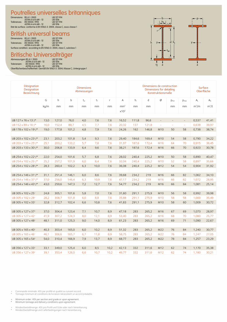
b
r
yy dh
tw
ss
zzt f
hi
pPoutrelles universelles britanniquesDimensions: BS 4-1: 2005 UB 127-914 ASTM A 6/A 6M - 12 UB 1016 Tolérances: EN 10034: 1993 UB 127-914 ASTM A 6/A 6M - 12 UB 1016 Etat de surface: conforme à EN 10163-3: 2004, classe C, sous-classe 1
British universal beamsDimensions: BS 4-1: 2005 UB 127-914 ASTM A 6/A 6M - 12 UB 1016 Tolerances: EN 10034: 1993 UB 127-914 ASTM A 6/A 6M - 12 UB 1016 Surface condition: according to EN 10163-3: 2004, class C, subclass 1
Britische UniversalträgerAbmessungen:BS 4-1: 2005 UB 127-914 ASTM A 6/A 6M - 12 UB 1016 Toleranzen: EN 10034: 1993 UB 127-914 ASTM A 6/A 6M - 12 UB 1016 Oberflächenbeschaffenheit: Gemäß EN 10163-3: 2004, Klasse C, Untergruppe 1
Désignation Designation Bezeichnung
Dimensions Abmessungen
Dimensions de construction Dimensions for detailing
Konstruktionsmaße
Surface Oberfläche
G
kg/m
h b tw tf r A hi d Ø pmin pmax AL AG
mm mm mm mm mm mm2 mm mm mm mm m2/m m2/t
x102
+ Commande minimale: 40t par profilé et qualité ou suivant accord.* Tonnage minimum et conditions de livraison nécessitent un accord préalable.
+ Minimum order: 40t per section and grade or upon agreement.* Minimum tonnage and delivery conditions upon agreement.
+ Mindestbestellmenge: 40t pro Profil und Güte oder nach Vereinbarung.* Mindestbestellmenge und Lieferbedingungen nach Vereinbarung.
UB 127 x 76 x 13+/* 13,0 127,0 76,0 4,0 7,6 7,6 16,52 111,8 96,6 - - - 0,537 41,41
UB 152 x 89 x 16+/* 16,0 152,4 88,7 4,5 7,7 7,6 20,32 137 121,8 - - - 0,638 39,97
UB 178 x 102 x 19+/* 19,0 177,8 101,2 4,8 7,9 7,6 24,26 162 146,8 M10 50 58 0,738 38,74
UB 203 x 102 x 23+/* 23,1 203,2 101,8 5,4 9,3 7,6 29,40 184,6 169,4 M10 54 58 0,790 34,22
UB 203 x 133 x 25+/* 25,1 203,2 133,2 5,7 7,8 7,6 31,97 187,6 172,4 M16 64 70 0,915 36,45
UB 203 x 133 x 30+/* 30,0 206,8 133,9 6,4 9,6 7,6 38,21 187,6 172,4 M16 66 70 0,923 30,78
UB 254 x 102 x 22+/* 22,0 254,0 101,6 5,7 6,8 7,6 28,02 240,4 225,2 M10 50 58 0,890 40,47
UB 254 x 102 x 25+/* 25,2 257,2 101,9 6,0 8,4 7,6 32,04 240,4 225,2 M10 52 58 0,897 35,66
UB 254 x 102 x 28+/* 28,3 260,4 102,2 6,3 10,0 7,6 36,08 240,4 225,2 M12 54 54 0,904 31,92
UB 254 x 146 x 31+/* 31,1 251,4 146,1 6,0 8,6 7,6 39,68 234,2 219 M16 66 82 1,062 34,10
UB 254 x 146 x 37+/* 37,0 256,0 146,4 6,3 10,9 7,6 47,17 234,2 219 M16 66 82 1,072 28,95
UB 254 x 146 x 43+/* 43,0 259,6 147,3 7,2 12,7 7,6 54,77 234,2 219 M16 66 84 1,081 25,14
UB 305 x 102 x 25+ 24,8 305,1 101,6 5,8 7,0 7,6 31,60 291,1 275,9 M10 56 58 0,992 39,98
UB 305 x 102 x 28+ 28,2 308,7 101,8 6,0 8,8 7,6 35,88 291,1 275,9 M10 58 58 1,000 35,49
UB 305 x 102 x 33+ 32,8 312,7 102,4 6,6 10,8 7,6 41,83 291,1 275,9 M10 58 60 1,009 30,72
UB 305 x 127 x 37+ 37,0 304,4 123,4 7,1 10,7 8,9 47,18 283 265,2 M16 67 69 1,073 28,97
UB 305 x 127 x 42+ 41,9 307,2 124,3 8,0 12,1 8,9 53,40 283 265,2 M16 68 70 1,080 25,77
UB 305 x 127 x 48+ 48,1 311,0 125,3 9,0 14,0 8,9 61,23 283 265,2 M16 69 71 1,090 22,67
UB 305 x 165 x 40+ 40,3 303,4 165,0 6,0 10,2 8,9 51,32 283 265,2 M22 76 84 1,240 30,77
UB 305 x 165 x 46+ 46,1 306,6 165,7 6,7 11,8 8,9 58,75 283 265,2 M22 76 84 1,247 27,05
UB 305 x 165 x 54+ 54,0 310,4 166,9 7,9 13,7 8,9 68,77 283 265,2 M22 78 84 1,257 23,29
UB 356 x 127 x 33+ 33,1 349,0 125,4 6,0 8,5 10,2 42,13 332 311,6 M12 62 74 1,170 35,38
UB 356 x 127 x 39+ 39,1 353,4 126,0 6,6 10,7 10,2 49,77 332 311,6 M12 62 74 1,180 30,21
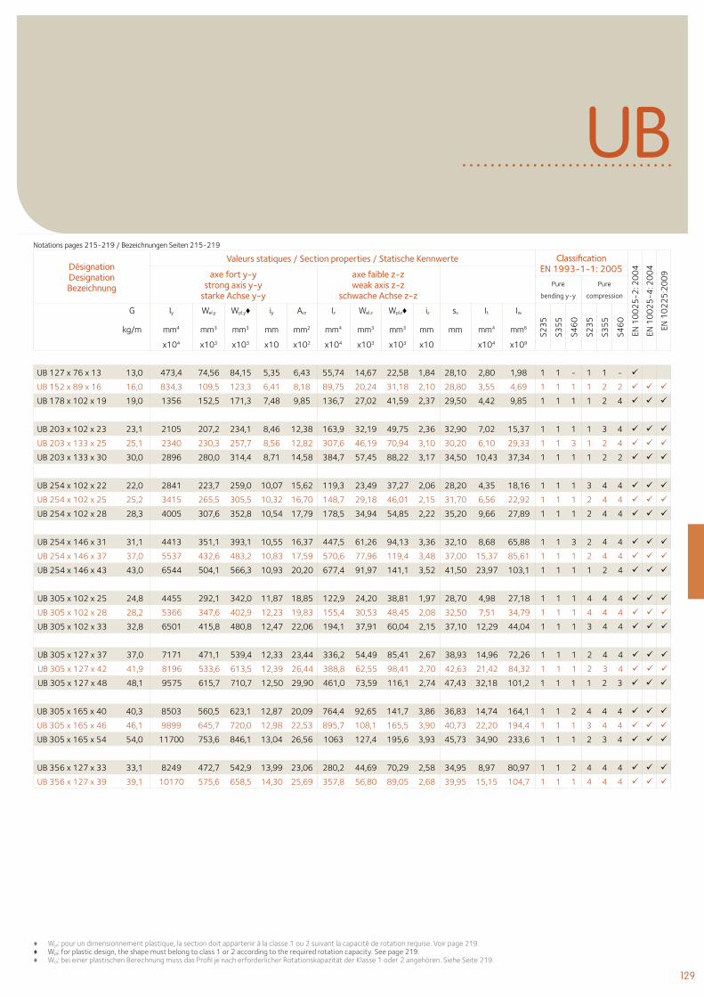
129
UB
Désignation Designation Bezeichnung
Valeurs statiques / Section properties / Statische Kennwerte Classification EN 1993-1-1: 2005
EN 1
00
25
-2: 2
00
4
EN 1
00
25
-4: 2
00
4
EN 1
02
25
:20
09axe fort y-y
strong axis y-y starke Achse y-y
axe faible z-z weak axis z-z
schwache Achse z-z Pure
bending y-y
Pure
compression
G
kg/m
Iy Wel.y Wpl.y♦ iy Avz Iz Wel.z Wpl.z♦ iz ss It Iw
S23
5
S35
5
S46
0
S23
5
S35
5
S46
0
mm4 mm3 mm3 mm mm2 mm4 mm3 mm3 mm mm mm4 mm6
x104 x103 x103 x10 x102 x104 x103 x103 x10 x104 x109
♦ Wpl: pour un dimensionnement plastique, la section doit appartenir à la classe 1 ou 2 suivant la capacité de rotation requise. Voir page 219.♦ Wpl: for plastic design, the shape must belong to class 1 or 2 according to the required rotation capacity. See page 219.♦ Wpl: bei einer plastischen Berechnung muss das Profil je nach erforderlicher Rotationskapazität der Klasse 1 oder 2 angehören. Siehe Seite 219.
UB 127 x 76 x 13 13,0 473,4 74,56 84,15 5,35 6,43 55,74 14,67 22,58 1,84 28,10 2,80 1,98 1 1 - 1 1 -
UB 152 x 89 x 16 16,0 834,3 109,5 123,3 6,41 8,18 89,75 20,24 31,18 2,10 28,80 3,55 4,69 1 1 1 1 2 2
UB 178 x 102 x 19 19,0 1356 152,5 171,3 7,48 9,85 136,7 27,02 41,59 2,37 29,50 4,42 9,85 1 1 1 1 2 4
UB 203 x 102 x 23 23,1 2105 207,2 234,1 8,46 12,38 163,9 32,19 49,75 2,36 32,90 7,02 15,37 1 1 1 1 3 4
UB 203 x 133 x 25 25,1 2340 230,3 257,7 8,56 12,82 307,6 46,19 70,94 3,10 30,20 6,10 29,33 1 1 3 1 2 4
UB 203 x 133 x 30 30,0 2896 280,0 314,4 8,71 14,58 384,7 57,45 88,22 3,17 34,50 10,43 37,34 1 1 1 1 2 2
UB 254 x 102 x 22 22,0 2841 223,7 259,0 10,07 15,62 119,3 23,49 37,27 2,06 28,20 4,35 18,16 1 1 1 3 4 4
UB 254 x 102 x 25 25,2 3415 265,5 305,5 10,32 16,70 148,7 29,18 46,01 2,15 31,70 6,56 22,92 1 1 1 2 4 4
UB 254 x 102 x 28 28,3 4005 307,6 352,8 10,54 17,79 178,5 34,94 54,85 2,22 35,20 9,66 27,89 1 1 1 2 4 4
UB 254 x 146 x 31 31,1 4413 351,1 393,1 10,55 16,37 447,5 61,26 94,13 3,36 32,10 8,68 65,88 1 1 3 2 4 4
UB 254 x 146 x 37 37,0 5537 432,6 483,2 10,83 17,59 570,6 77,96 119,4 3,48 37,00 15,37 85,61 1 1 1 2 4 4
UB 254 x 146 x 43 43,0 6544 504,1 566,3 10,93 20,20 677,4 91,97 141,1 3,52 41,50 23,97 103,1 1 1 1 1 2 4
UB 305 x 102 x 25 24,8 4455 292,1 342,0 11,87 18,85 122,9 24,20 38,81 1,97 28,70 4,98 27,18 1 1 1 4 4 4
UB 305 x 102 x 28 28,2 5366 347,6 402,9 12,23 19,83 155,4 30,53 48,45 2,08 32,50 7,51 34,79 1 1 1 4 4 4
UB 305 x 102 x 33 32,8 6501 415,8 480,8 12,47 22,06 194,1 37,91 60,04 2,15 37,10 12,29 44,04 1 1 1 3 4 4
UB 305 x 127 x 37 37,0 7171 471,1 539,4 12,33 23,44 336,2 54,49 85,41 2,67 38,93 14,96 72,26 1 1 1 2 4 4
UB 305 x 127 x 42 41,9 8196 533,6 613,5 12,39 26,44 388,8 62,55 98,41 2,70 42,63 21,42 84,32 1 1 1 2 3 4
UB 305 x 127 x 48 48,1 9575 615,7 710,7 12,50 29,90 461,0 73,59 116,1 2,74 47,43 32,18 101,2 1 1 1 1 2 3
UB 305 x 165 x 40 40,3 8503 560,5 623,1 12,87 20,09 764,4 92,65 141,7 3,86 36,83 14,74 164,1 1 1 2 4 4 4
UB 305 x 165 x 46 46,1 9899 645,7 720,0 12,98 22,53 895,7 108,1 165,5 3,90 40,73 22,20 194,4 1 1 1 3 4 4
UB 305 x 165 x 54 54,0 11700 753,6 846,1 13,04 26,56 1063 127,4 195,6 3,93 45,73 34,90 233,6 1 1 1 2 3 4
UB 356 x 127 x 33 33,1 8249 472,7 542,9 13,99 23,06 280,2 44,69 70,29 2,58 34,95 8,97 80,97 1 1 2 4 4 4
UB 356 x 127 x 39 39,1 10170 575,6 658,5 14,30 25,69 357,8 56,80 89,05 2,68 39,95 15,15 104,7 1 1 1 4 4 4
Notations pages 215-219 / Bezeichnungen Seiten 215-219
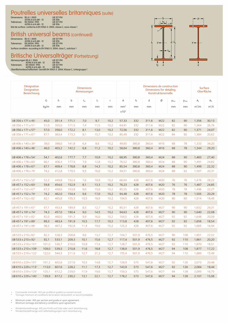
b
r
yy dh
tw
ss
zzt f
hi
pPoutrelles universelles britanniques (suite)Dimensions: BS 4-1: 2005 UB 127-914 ASTM A 6/A 6M - 12 UB 1016 Tolérances: EN 10034: 1993 UB 127-914 ASTM A 6/A 6M - 12 UB 1016 Etat de surface: conforme à EN 10163-3: 2004, classe C, sous-classe 1
British universal beams (continued)Dimensions: BS 4-1: 2005 UB 127-914 ASTM A 6/A 6M - 12 UB 1016 Tolerances: EN 10034: 1993 UB 127-914 ASTM A 6/A 6M - 12 UB 1016 Surface condition: according to EN 10163-3: 2004, class C, subclass 1
Britische Universalträger (Fortsetzung)Abmessungen:BS 4-1: 2005 UB 127-914 ASTM A 6/A 6M - 12 UB 1016 Toleranzen: EN 10034: 1993 UB 127-914 ASTM A 6/A 6M - 12 UB 1016 Oberflächenbeschaffenheit: Gemäß EN 10163-3: 2004, Klasse C, Untergruppe 1
Désignation Designation Bezeichnung
Dimensions Abmessungen
Dimensions de construction Dimensions for detailing
Konstruktionsmaße
Surface Oberfläche
G
kg/m
h b tw tf r A hi d Ø pmin pmax AL AG
mm mm mm mm mm mm2 mm mm mm mm m2/m m2/t
x102
UB 356 x 171 x 45+ 45,0 351,4 171,1 7,0 9,7 10,2 57,33 332 311,6 M22 82 90 1,356 30,13
UB 356 x 171 x 51+ 51,0 355,0 171,5 7,4 11,5 10,2 64,91 332 311,6 M22 82 90 1,364 26,76
UB 356 x 171 x 57+ 57,0 358,0 172,2 8,1 13,0 10,2 72,56 332 311,6 M22 82 90 1,371 24,07
UB 356 x 171 x 67+ 67,1 363,4 173,2 9,1 15,7 10,2 85,49 332 311,6 M22 84 92 1,384 20,62
UB 406 x 140 x 39+ 39,0 398,0 141,8 6,4 8,6 10,2 49,65 380,8 360,4 M16 68 78 1,333 34,20
UB 406 x 140 x 46+ 46,0 403,2 142,2 6,8 11,2 10,2 58,64 380,8 360,4 M16 68 78 1,344 29,20
UB 406 x 178 x 54+ 54,1 402,6 177,7 7,7 10,9 10,2 68,95 380,8 360,4 M24 88 90 1,483 27,40
UB 406 x 178 x 60+ 60,1 406,4 177,9 7,9 12,8 10,2 76,52 380,8 360,4 M24 88 90 1,491 24,82
UB 406 x 178 x 67+ 67,1 409,4 178,8 8,8 14,3 10,2 85,54 380,8 360,4 M24 88 90 1,499 22,32
UB 406 x 178 x 74+ 74,2 412,8 179,5 9,5 16,0 10,2 94,51 380,8 360,4 M24 88 92 1,507 20,31
UB 457 x 152 x 52+ 52,3 449,8 152,4 7,6 10,9 10,2 66,64 428 407,6 M20 76 76 1,476 28,22
UB 457 x 152 x 60+ 59,8 454,6 152,9 8,1 13,3 10,2 76,23 428 407,6 M20 76 76 1,487 24,85
UB 457 x 152 x 67+ 67,2 458,0 153,8 9,0 15,0 10,2 85,55 428 407,6 M20 78 78 1,496 22,27
UB 457 x 152 x 74+ 74,2 462,0 154,4 9,6 17,0 10,2 94,48 428 407,6 M20 78 78 1,505 20,29
UB 457 x 152 x 82+ 82,1 465,8 155,3 10,5 18,9 10,2 104,5 428 407,6 M20 80 80 1,514 18,45
UB 457 x 191 x 67+ 67,1 453,4 189,9 8,5 12,7 10,2 85,51 428 407,6 M27 90 90 1,632 24,31
UB 457 x 191 x 74+ 74,3 457,0 190,4 9,0 14,5 10,2 94,63 428 407,6 M27 90 90 1,640 22,08
UB 457 x 191 x 82+ 82,0 460,0 191,3 9,9 16,0 10,2 104,5 428 407,6 M27 92 92 1,648 20,09
UB 457 x 191 x 89+ 89,3 463,4 191,9 10,5 17,7 10,2 113,8 428 407,6 M27 92 92 1,656 18,54
UB 457 x 191 x 98+ 98,3 467,2 192,8 11,4 19,6 10,2 125,3 428 407,6 M27 92 92 1,665 16,94
UB 533 x 210 x 82+ 82,2 528,3 208,8 9,6 13,2 12,7 104,7 501,9 476,5 M27 90 108 1,851 22,52
UB 533 x 210 x 92+ 92,1 533,1 209,3 10,1 15,6 12,7 117,4 501,9 476,5 M27 92 110 1,861 20,20
UB 533 x 210 x 101+ 101,0 536,7 210,0 10,8 17,4 12,7 128,7 501,9 476,5 M27 92 110 1,870 18,51
UB 533 x 210 x 109+ 109,0 539,5 210,8 11,6 18,8 12,7 138,9 501,9 476,5 M27 94 108 1,877 17,22
UB 533 x 210 x 122+ 122,0 544,5 211,9 12,7 21,3 12,7 155,4 501,9 476,5 M27 94 110 1,889 15,49
UB 610 x 229 x 101+ 101,2 602,6 227,6 10,5 14,8 12,7 128,9 573 547,6 M27 92 126 2,073 20,48
UB 610 x 229 x 113+ 113,0 607,6 228,2 11,1 17,3 12,7 143,9 573 547,6 M27 92 126 2,084 18,44
UB 610 x 229 x 125+ 125,1 612,2 229,0 11,9 19,6 12,7 159,3 573 547,6 M27 94 128 2,095 16,75
UB 610 x 229 x 140+ 139,9 617,2 230,2 13,1 22,1 12,7 178,2 573 547,6 M27 94 128 2,107 15,06
+ Commande minimale: 40t par profilé et qualité ou suivant accord.* Tonnage minimum et conditions de livraison nécessitent un accord préalable.
+ Minimum order: 40t per section and grade or upon agreement.* Minimum tonnage and delivery conditions upon agreement.
+ Mindestbestellmenge: 40t pro Profil und Güte oder nach Vereinbarung.* Mindestbestellmenge und Lieferbedingungen nach Vereinbarung.
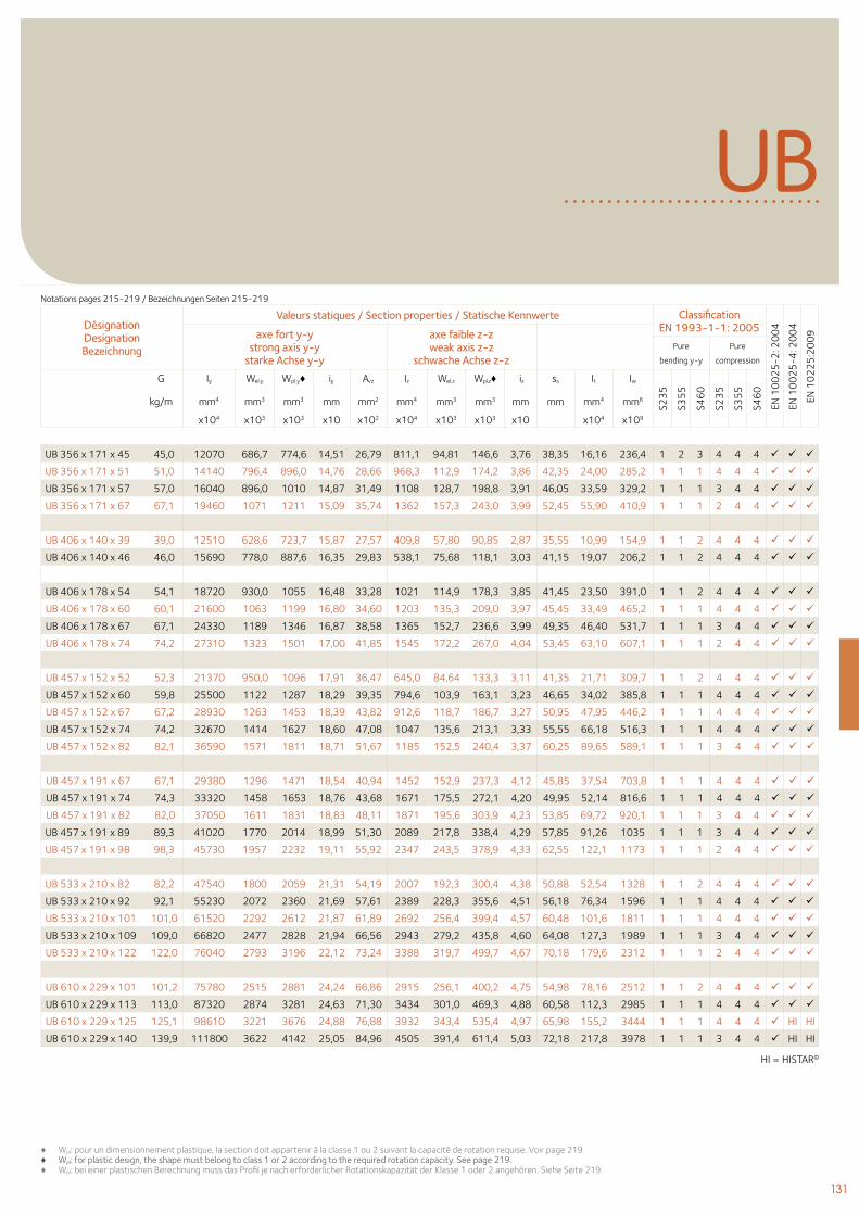
131
UB
Désignation Designation Bezeichnung
Valeurs statiques / Section properties / Statische Kennwerte Classification EN 1993-1-1: 2005
EN 1
00
25
-2: 2
00
4
EN 1
00
25
-4: 2
00
4
EN 1
02
25
:20
09axe fort y-y
strong axis y-y starke Achse y-y
axe faible z-z weak axis z-z
schwache Achse z-z Pure
bending y-y
Pure
compression
G
kg/m
Iy Wel.y Wpl.y♦ iy Avz Iz Wel.z Wpl.z♦ iz ss It Iw
S23
5
S35
5
S46
0
S23
5
S35
5
S46
0
mm4 mm3 mm3 mm mm2 mm4 mm3 mm3 mm mm mm4 mm6
x104 x103 x103 x10 x102 x104 x103 x103 x10 x104 x109
UB 356 x 171 x 45 45,0 12070 686,7 774,6 14,51 26,79 811,1 94,81 146,6 3,76 38,35 16,16 236,4 1 2 3 4 4 4
UB 356 x 171 x 51 51,0 14140 796,4 896,0 14,76 28,66 968,3 112,9 174,2 3,86 42,35 24,00 285,2 1 1 1 4 4 4
UB 356 x 171 x 57 57,0 16040 896,0 1010 14,87 31,49 1108 128,7 198,8 3,91 46,05 33,59 329,2 1 1 1 3 4 4
UB 356 x 171 x 67 67,1 19460 1071 1211 15,09 35,74 1362 157,3 243,0 3,99 52,45 55,90 410,9 1 1 1 2 4 4
UB 406 x 140 x 39 39,0 12510 628,6 723,7 15,87 27,57 409,8 57,80 90,85 2,87 35,55 10,99 154,9 1 1 2 4 4 4
UB 406 x 140 x 46 46,0 15690 778,0 887,6 16,35 29,83 538,1 75,68 118,1 3,03 41,15 19,07 206,2 1 1 2 4 4 4
UB 406 x 178 x 54 54,1 18720 930,0 1055 16,48 33,28 1021 114,9 178,3 3,85 41,45 23,50 391,0 1 1 2 4 4 4
UB 406 x 178 x 60 60,1 21600 1063 1199 16,80 34,60 1203 135,3 209,0 3,97 45,45 33,49 465,2 1 1 1 4 4 4
UB 406 x 178 x 67 67,1 24330 1189 1346 16,87 38,58 1365 152,7 236,6 3,99 49,35 46,40 531,7 1 1 1 3 4 4
UB 406 x 178 x 74 74,2 27310 1323 1501 17,00 41,85 1545 172,2 267,0 4,04 53,45 63,10 607,1 1 1 1 2 4 4
UB 457 x 152 x 52 52,3 21370 950,0 1096 17,91 36,47 645,0 84,64 133,3 3,11 41,35 21,71 309,7 1 1 2 4 4 4
UB 457 x 152 x 60 59,8 25500 1122 1287 18,29 39,35 794,6 103,9 163,1 3,23 46,65 34,02 385,8 1 1 1 4 4 4
UB 457 x 152 x 67 67,2 28930 1263 1453 18,39 43,82 912,6 118,7 186,7 3,27 50,95 47,95 446,2 1 1 1 4 4 4
UB 457 x 152 x 74 74,2 32670 1414 1627 18,60 47,08 1047 135,6 213,1 3,33 55,55 66,18 516,3 1 1 1 4 4 4
UB 457 x 152 x 82 82,1 36590 1571 1811 18,71 51,67 1185 152,5 240,4 3,37 60,25 89,65 589,1 1 1 1 3 4 4
UB 457 x 191 x 67 67,1 29380 1296 1471 18,54 40,94 1452 152,9 237,3 4,12 45,85 37,54 703,8 1 1 1 4 4 4
UB 457 x 191 x 74 74,3 33320 1458 1653 18,76 43,68 1671 175,5 272,1 4,20 49,95 52,14 816,6 1 1 1 4 4 4
UB 457 x 191 x 82 82,0 37050 1611 1831 18,83 48,11 1871 195,6 303,9 4,23 53,85 69,72 920,1 1 1 1 3 4 4
UB 457 x 191 x 89 89,3 41020 1770 2014 18,99 51,30 2089 217,8 338,4 4,29 57,85 91,26 1035 1 1 1 3 4 4
UB 457 x 191 x 98 98,3 45730 1957 2232 19,11 55,92 2347 243,5 378,9 4,33 62,55 122,1 1173 1 1 1 2 4 4
UB 533 x 210 x 82 82,2 47540 1800 2059 21,31 54,19 2007 192,3 300,4 4,38 50,88 52,54 1328 1 1 2 4 4 4
UB 533 x 210 x 92 92,1 55230 2072 2360 21,69 57,61 2389 228,3 355,6 4,51 56,18 76,34 1596 1 1 1 4 4 4
UB 533 x 210 x 101 101,0 61520 2292 2612 21,87 61,89 2692 256,4 399,4 4,57 60,48 101,6 1811 1 1 1 4 4 4
UB 533 x 210 x 109 109,0 66820 2477 2828 21,94 66,56 2943 279,2 435,8 4,60 64,08 127,3 1989 1 1 1 3 4 4
UB 533 x 210 x 122 122,0 76040 2793 3196 22,12 73,24 3388 319,7 499,7 4,67 70,18 179,6 2312 1 1 1 2 4 4
UB 610 x 229 x 101 101,2 75780 2515 2881 24,24 66,86 2915 256,1 400,2 4,75 54,98 78,16 2512 1 1 2 4 4 4
UB 610 x 229 x 113 113,0 87320 2874 3281 24,63 71,30 3434 301,0 469,3 4,88 60,58 112,3 2985 1 1 1 4 4 4
UB 610 x 229 x 125 125,1 98610 3221 3676 24,88 76,88 3932 343,4 535,4 4,97 65,98 155,2 3444 1 1 1 4 4 4 HI HI
UB 610 x 229 x 140 139,9 111800 3622 4142 25,05 84,96 4505 391,4 611,4 5,03 72,18 217,8 3978 1 1 1 3 4 4 HI HI
♦ Wpl: pour un dimensionnement plastique, la section doit appartenir à la classe 1 ou 2 suivant la capacité de rotation requise. Voir page 219.♦ Wpl: for plastic design, the shape must belong to class 1 or 2 according to the required rotation capacity. See page 219.♦ Wpl: bei einer plastischen Berechnung muss das Profil je nach erforderlicher Rotationskapazität der Klasse 1 oder 2 angehören. Siehe Seite 219.
Notations pages 215-219 / Bezeichnungen Seiten 215-219
HI = HISTAR©
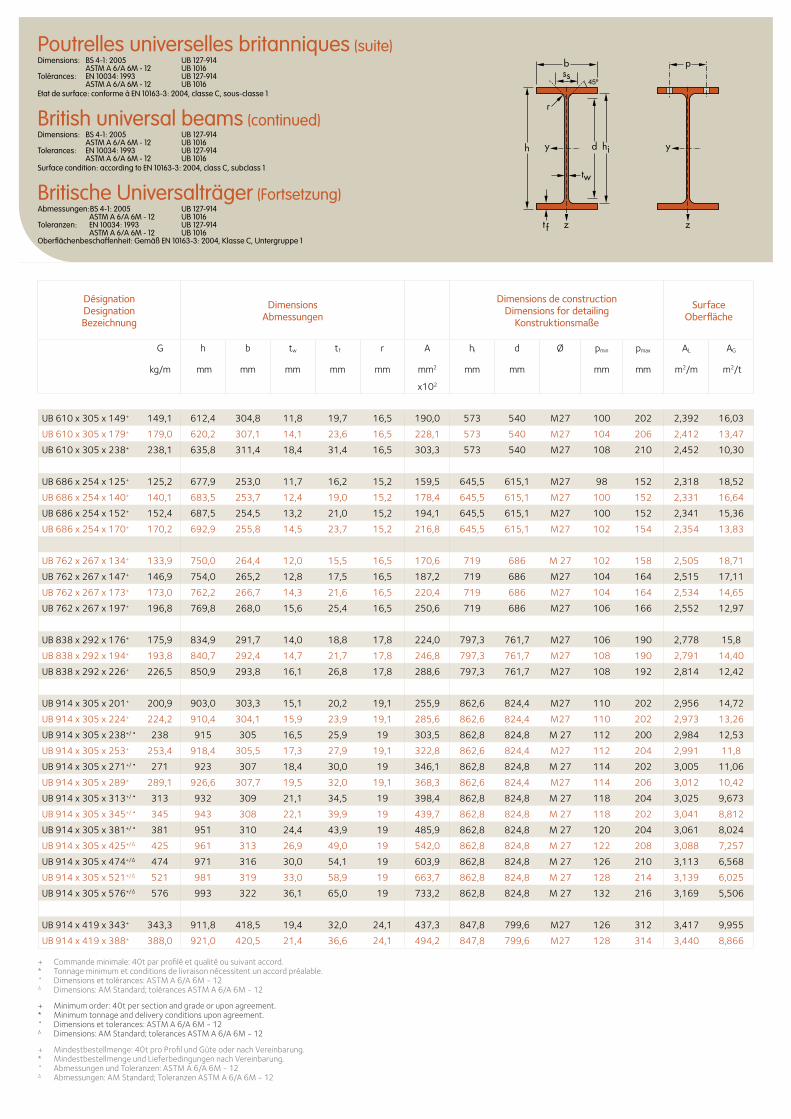
b
r
yy dh
tw
ss
zzt f
hi
pPoutrelles universelles britanniques (suite)Dimensions: BS 4-1: 2005 UB 127-914 ASTM A 6/A 6M - 12 UB 1016 Tolérances: EN 10034: 1993 UB 127-914 ASTM A 6/A 6M - 12 UB 1016 Etat de surface: conforme à EN 10163-3: 2004, classe C, sous-classe 1
British universal beams (continued)Dimensions: BS 4-1: 2005 UB 127-914 ASTM A 6/A 6M - 12 UB 1016 Tolerances: EN 10034: 1993 UB 127-914 ASTM A 6/A 6M - 12 UB 1016 Surface condition: according to EN 10163-3: 2004, class C, subclass 1
Britische Universalträger (Fortsetzung)Abmessungen:BS 4-1: 2005 UB 127-914 ASTM A 6/A 6M - 12 UB 1016 Toleranzen: EN 10034: 1993 UB 127-914 ASTM A 6/A 6M - 12 UB 1016 Oberflächenbeschaffenheit: Gemäß EN 10163-3: 2004, Klasse C, Untergruppe 1
Désignation Designation Bezeichnung
Dimensions Abmessungen
Dimensions de construction Dimensions for detailing
Konstruktionsmaße
Surface Oberfläche
G
kg/m
h b tw tf r A hi d Ø pmin pmax AL AG
mm mm mm mm mm mm2 mm mm mm mm m2/m m2/t
x102
UB 610 x 305 x 149+ 149,1 612,4 304,8 11,8 19,7 16,5 190,0 573 540 M27 100 202 2,392 16,03
UB 610 x 305 x 179+ 179,0 620,2 307,1 14,1 23,6 16,5 228,1 573 540 M27 104 206 2,412 13,47
UB 610 x 305 x 238+ 238,1 635,8 311,4 18,4 31,4 16,5 303,3 573 540 M27 108 210 2,452 10,30
UB 686 x 254 x 125+ 125,2 677,9 253,0 11,7 16,2 15,2 159,5 645,5 615,1 M27 98 152 2,318 18,52
UB 686 x 254 x 140+ 140,1 683,5 253,7 12,4 19,0 15,2 178,4 645,5 615,1 M27 100 152 2,331 16,64
UB 686 x 254 x 152+ 152,4 687,5 254,5 13,2 21,0 15,2 194,1 645,5 615,1 M27 100 152 2,341 15,36
UB 686 x 254 x 170+ 170,2 692,9 255,8 14,5 23,7 15,2 216,8 645,5 615,1 M27 102 154 2,354 13,83
UB 762 x 267 x 134+ 133,9 750,0 264,4 12,0 15,5 16,5 170,6 719 686 M 27 102 158 2,505 18,71
UB 762 x 267 x 147+ 146,9 754,0 265,2 12,8 17,5 16,5 187,2 719 686 M27 104 164 2,515 17,11
UB 762 x 267 x 173+ 173,0 762,2 266,7 14,3 21,6 16,5 220,4 719 686 M27 104 164 2,534 14,65
UB 762 x 267 x 197+ 196,8 769,8 268,0 15,6 25,4 16,5 250,6 719 686 M27 106 166 2,552 12,97
UB 838 x 292 x 176+ 175,9 834,9 291,7 14,0 18,8 17,8 224,0 797,3 761,7 M27 106 190 2,778 15,8
UB 838 x 292 x 194+ 193,8 840,7 292,4 14,7 21,7 17,8 246,8 797,3 761,7 M27 108 190 2,791 14,40
UB 838 x 292 x 226+ 226,5 850,9 293,8 16,1 26,8 17,8 288,6 797,3 761,7 M27 108 192 2,814 12,42
UB 914 x 305 x 201+ 200,9 903,0 303,3 15,1 20,2 19,1 255,9 862,6 824,4 M27 110 202 2,956 14,72
UB 914 x 305 x 224+ 224,2 910,4 304,1 15,9 23,9 19,1 285,6 862,6 824,4 M27 110 202 2,973 13,26
UB 914 x 305 x 238+/• 238 915 305 16,5 25,9 19 303,5 862,8 824,8 M 27 112 200 2,984 12,53
UB 914 x 305 x 253+ 253,4 918,4 305,5 17,3 27,9 19,1 322,8 862,6 824,4 M27 112 204 2,991 11,8
UB 914 x 305 x 271+/• 271 923 307 18,4 30,0 19 346,1 862,8 824,8 M 27 114 202 3,005 11,06
UB 914 x 305 x 289+ 289,1 926,6 307,7 19,5 32,0 19,1 368,3 862,6 824,4 M27 114 206 3,012 10,42
UB 914 x 305 x 313+/• 313 932 309 21,1 34,5 19 398,4 862,8 824,8 M 27 118 204 3,025 9,673
UB 914 x 305 x 345+/• 345 943 308 22,1 39,9 19 439,7 862,8 824,8 M 27 118 202 3,041 8,812
UB 914 x 305 x 381+/• 381 951 310 24,4 43,9 19 485,9 862,8 824,8 M 27 120 204 3,061 8,024
UB 914 x 305 x 425+/∆ 425 961 313 26,9 49,0 19 542,0 862,8 824,8 M 27 122 208 3,088 7,257
UB 914 x 305 x 474+/∆ 474 971 316 30,0 54,1 19 603,9 862,8 824,8 M 27 126 210 3,113 6,568
UB 914 x 305 x 521+/∆ 521 981 319 33,0 58,9 19 663,7 862,8 824,8 M 27 128 214 3,139 6,025
UB 914 x 305 x 576+/∆ 576 993 322 36,1 65,0 19 733,2 862,8 824,8 M 27 132 216 3,169 5,506
UB 914 x 419 x 343+ 343,3 911,8 418,5 19,4 32,0 24,1 437,3 847,8 799,6 M27 126 312 3,417 9,955
UB 914 x 419 x 388+ 388,0 921,0 420,5 21,4 36,6 24,1 494,2 847,8 799,6 M27 128 314 3,440 8,866
+ Commande minimale: 40t par profilé et qualité ou suivant accord.* Tonnage minimum et conditions de livraison nécessitent un accord préalable.• Dimensions et tolérances: ASTM A 6/A 6M - 12∆ Dimensions: AM Standard; tolérances ASTM A 6/A 6M - 12
+ Minimum order: 40t per section and grade or upon agreement.* Minimum tonnage and delivery conditions upon agreement.• Dimensions et tolerances: ASTM A 6/A 6M - 12∆ Dimensions: AM Standard; tolerances ASTM A 6/A 6M - 12
+ Mindestbestellmenge: 40t pro Profil und Güte oder nach Vereinbarung.* Mindestbestellmenge und Lieferbedingungen nach Vereinbarung.• Abmessungen und Toleranzen: ASTM A 6/A 6M - 12∆ Abmessungen: AM Standard; Toleranzen ASTM A 6/A 6M - 12
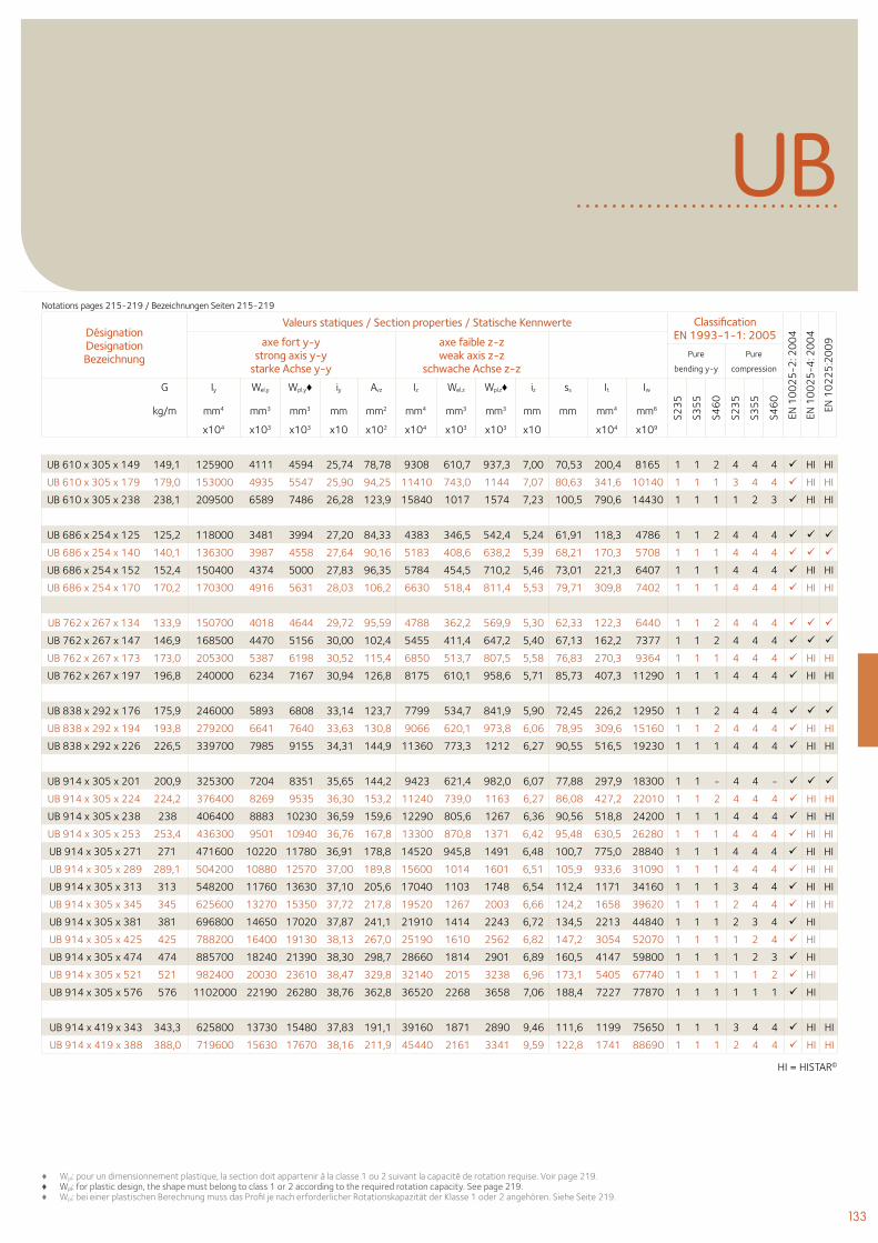
133
UB
Désignation Designation Bezeichnung
Valeurs statiques / Section properties / Statische Kennwerte Classification EN 1993-1-1: 2005
EN 1
00
25
-2: 2
00
4
EN 1
00
25
-4: 2
00
4
EN 1
02
25
:20
09axe fort y-y
strong axis y-y starke Achse y-y
axe faible z-z weak axis z-z
schwache Achse z-z Pure
bending y-y
Pure
compression
G
kg/m
Iy Wel.y Wpl.y♦ iy Avz Iz Wel.z Wpl.z♦ iz ss It Iw
S23
5
S35
5
S46
0
S23
5
S35
5
S46
0
mm4 mm3 mm3 mm mm2 mm4 mm3 mm3 mm mm mm4 mm6
x104 x103 x103 x10 x102 x104 x103 x103 x10 x104 x109
UB 610 x 305 x 149 149,1 125900 4111 4594 25,74 78,78 9308 610,7 937,3 7,00 70,53 200,4 8165 1 1 2 4 4 4 HI HI
UB 610 x 305 x 179 179,0 153000 4935 5547 25,90 94,25 11410 743,0 1144 7,07 80,63 341,6 10140 1 1 1 3 4 4 HI HI
UB 610 x 305 x 238 238,1 209500 6589 7486 26,28 123,9 15840 1017 1574 7,23 100,5 790,6 14430 1 1 1 1 2 3 HI HI
UB 686 x 254 x 125 125,2 118000 3481 3994 27,20 84,33 4383 346,5 542,4 5,24 61,91 118,3 4786 1 1 2 4 4 4
UB 686 x 254 x 140 140,1 136300 3987 4558 27,64 90,16 5183 408,6 638,2 5,39 68,21 170,3 5708 1 1 1 4 4 4
UB 686 x 254 x 152 152,4 150400 4374 5000 27,83 96,35 5784 454,5 710,2 5,46 73,01 221,3 6407 1 1 1 4 4 4 HI HI
UB 686 x 254 x 170 170,2 170300 4916 5631 28,03 106,2 6630 518,4 811,4 5,53 79,71 309,8 7402 1 1 1 4 4 4 HI HI
UB 762 x 267 x 134 133,9 150700 4018 4644 29,72 95,59 4788 362,2 569,9 5,30 62,33 122,3 6440 1 1 2 4 4 4
UB 762 x 267 x 147 146,9 168500 4470 5156 30,00 102,4 5455 411,4 647,2 5,40 67,13 162,2 7377 1 1 2 4 4 4
UB 762 x 267 x 173 173,0 205300 5387 6198 30,52 115,4 6850 513,7 807,5 5,58 76,83 270,3 9364 1 1 1 4 4 4 HI HI
UB 762 x 267 x 197 196,8 240000 6234 7167 30,94 126,8 8175 610,1 958,6 5,71 85,73 407,3 11290 1 1 1 4 4 4 HI HI
UB 838 x 292 x 176 175,9 246000 5893 6808 33,14 123,7 7799 534,7 841,9 5,90 72,45 226,2 12950 1 1 2 4 4 4
UB 838 x 292 x 194 193,8 279200 6641 7640 33,63 130,8 9066 620,1 973,8 6,06 78,95 309,6 15160 1 1 2 4 4 4 HI HI
UB 838 x 292 x 226 226,5 339700 7985 9155 34,31 144,9 11360 773,3 1212 6,27 90,55 516,5 19230 1 1 1 4 4 4 HI HI
UB 914 x 305 x 201 200,9 325300 7204 8351 35,65 144,2 9423 621,4 982,0 6,07 77,88 297,9 18300 1 1 - 4 4 -
UB 914 x 305 x 224 224,2 376400 8269 9535 36,30 153,2 11240 739,0 1163 6,27 86,08 427,2 22010 1 1 2 4 4 4 HI HI
UB 914 x 305 x 238 238 406400 8883 10230 36,59 159,6 12290 805,6 1267 6,36 90,56 518,8 24200 1 1 1 4 4 4 HI HI
UB 914 x 305 x 253 253,4 436300 9501 10940 36,76 167,8 13300 870,8 1371 6,42 95,48 630,5 26280 1 1 1 4 4 4 HI HI
UB 914 x 305 x 271 271 471600 10220 11780 36,91 178,8 14520 945,8 1491 6,48 100,7 775,0 28840 1 1 1 4 4 4 HI HI
UB 914 x 305 x 289 289,1 504200 10880 12570 37,00 189,8 15600 1014 1601 6,51 105,9 933,6 31090 1 1 1 4 4 4 HI HI
UB 914 x 305 x 313 313 548200 11760 13630 37,10 205,6 17040 1103 1748 6,54 112,4 1171 34160 1 1 1 3 4 4 HI HI
UB 914 x 305 x 345 345 625600 13270 15350 37,72 217,8 19520 1267 2003 6,66 124,2 1658 39620 1 1 1 2 4 4 HI HI
UB 914 x 305 x 381 381 696800 14650 17020 37,87 241,1 21910 1414 2243 6,72 134,5 2213 44840 1 1 1 2 3 4 HI
UB 914 x 305 x 425 425 788200 16400 19130 38,13 267,0 25190 1610 2562 6,82 147,2 3054 52070 1 1 1 1 2 4 HI
UB 914 x 305 x 474 474 885700 18240 21390 38,30 298,7 28660 1814 2901 6,89 160,5 4147 59800 1 1 1 1 2 3 HI
UB 914 x 305 x 521 521 982400 20030 23610 38,47 329,8 32140 2015 3238 6,96 173,1 5405 67740 1 1 1 1 1 2 HI
UB 914 x 305 x 576 576 1102000 22190 26280 38,76 362,8 36520 2268 3658 7,06 188,4 7227 77870 1 1 1 1 1 1 HI
UB 914 x 419 x 343 343,3 625800 13730 15480 37,83 191,1 39160 1871 2890 9,46 111,6 1199 75650 1 1 1 3 4 4 HI HI
UB 914 x 419 x 388 388,0 719600 15630 17670 38,16 211,9 45440 2161 3341 9,59 122,8 1741 88690 1 1 1 2 4 4 HI HI
♦ Wpl: pour un dimensionnement plastique, la section doit appartenir à la classe 1 ou 2 suivant la capacité de rotation requise. Voir page 219.♦ Wpl: for plastic design, the shape must belong to class 1 or 2 according to the required rotation capacity. See page 219.♦ Wpl: bei einer plastischen Berechnung muss das Profil je nach erforderlicher Rotationskapazität der Klasse 1 oder 2 angehören. Siehe Seite 219.
Notations pages 215-219 / Bezeichnungen Seiten 215-219
HI = HISTAR©
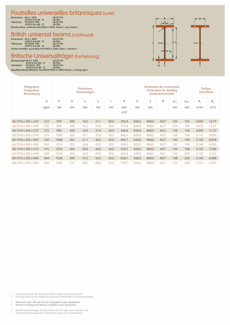
b
r
yy dh
tw
ss
zzt f
hi
p
Désignation Designation Bezeichnung
Dimensions Abmessungen
Dimensions de construction Dimensions for detailing
Konstruktionsmaße
Surface Oberfläche
G
kg/m
h b tw tf r A hi d Ø pmin pmax AL AG
mm mm mm mm mm mm2 mm mm mm mm m2/m m2/t
x102
+ Commande minimale: 40t par profilé et qualité ou suivant accord.* Tonnage minimum et conditions de livraison nécessitent un accord préalable.
+ Minimum order: 40t per section and grade or upon agreement.* Minimum tonnage and delivery conditions upon agreement.
+ Mindestbestellmenge: 40t pro Profil und Güte oder nach Vereinbarung.* Mindestbestellmenge und Lieferbedingungen nach Vereinbarung.
UB 1016 x 305 x 222+ 222 970 300 16,0 21,1 30,0 282,8 928,0 868,0 M27 134 194 3,056 13,77
UB 1016 x 305 x 249+ 249 980 300 16,5 26,0 30,0 316,8 928,0 868,0 M27 134 194 3,075 12,37
UB 1016 x 305 x 272+ 272 990 300 16,5 31,0 30,0 346,8 928,0 868,0 M27 134 194 3,095 11,37
UB 1016 x 305 x 314+ 314 1000 300 19,1 35,9 30,0 400,4 928,0 868,0 M27 136 194 3,110 9,895
UB 1016 x 305 x 350+ 350 1008 302 21,1 40,0 30,0 445,1 928,0 868,0 M27 140 196 3,130 8,958
UB 1016 x 305 x 393+ 393 1016 303 24,4 43,9 30,0 500,2 928,0 868,0 M27 142 198 3,144 8,006
UB 1016 x 305 x 415+ 415 1020 304 26,0 46,0 30,0 528,7 928,0 868,0 M27 144 198 3,152 7,596
UB 1016 x 305 x 438+ 438 1026 305 26,9 49,0 30,0 556,3 928,0 868,0 M27 146 200 3,167 7,252
UB 1016 x 305 x 494+ 494 1036 309 31,0 54,0 30,0 629,1 928,0 868,0 M27 148 204 3,194 6,468
UB 1016 x 305 x 584+ 584 1056 314 36,0 64,0 30,0 743,7 928,0 868,0 M27 154 208 3,244 5,557
Poutrelles universelles britanniques (suite)Dimensions: BS 4-1: 2005 UB 127-914 ASTM A 6/A 6M - 12 UB 1016 Tolérances: EN 10034: 1993 UB 127-914 ASTM A 6/A 6M - 12 UB 1016 Etat de surface: conforme à EN 10163-3: 2004, classe C, sous-classe 1
British universal beams (continued)Dimensions: BS 4-1: 2005 UB 127-914 ASTM A 6/A 6M - 12 UB 1016 Tolerances: EN 10034: 1993 UB 127-914 ASTM A 6/A 6M - 12 UB 1016 Surface condition: according to EN 10163-3: 2004, class C, subclass 1
Britische Universalträger (Fortsetzung)Abmessungen:BS 4-1: 2005 UB 127-914 ASTM A 6/A 6M - 12 UB 1016 Toleranzen: EN 10034: 1993 UB 127-914 ASTM A 6/A 6M - 12 UB 1016 Oberflächenbeschaffenheit: Gemäß EN 10163-3: 2004, Klasse C, Untergruppe 1
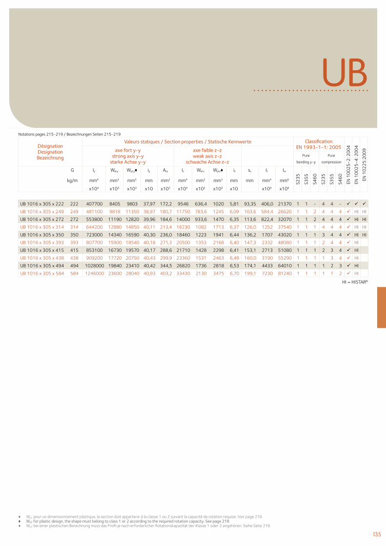
135
UB
Désignation Designation Bezeichnung
Valeurs statiques / Section properties / Statische Kennwerte Classification EN 1993-1-1: 2005
EN 1
00
25
-2: 2
00
4
EN 1
00
25
-4: 2
00
4
EN 1
02
25
:20
09axe fort y-y
strong axis y-y starke Achse y-y
axe faible z-z weak axis z-z
schwache Achse z-z Pure
bending y-y
Pure
compression
G
kg/m
Iy Wel.y Wpl.y♦ iy Avz Iz Wel.z Wpl.z♦ iz ss It Iw
S23
5
S35
5
S46
0
S23
5
S35
5
S46
0
mm4 mm3 mm3 mm mm2 mm4 mm3 mm3 mm mm mm4 mm6
x104 x103 x103 x10 x102 x104 x103 x103 x10 x104 x109
♦ Wpl: pour un dimensionnement plastique, la section doit appartenir à la classe 1 ou 2 suivant la capacité de rotation requise. Voir page 219.♦ Wpl: for plastic design, the shape must belong to class 1 or 2 according to the required rotation capacity. See page 219.♦ Wpl: bei einer plastischen Berechnung muss das Profil je nach erforderlicher Rotationskapazität der Klasse 1 oder 2 angehören. Siehe Seite 219.
Notations pages 215-219 / Bezeichnungen Seiten 215-219
UB 1016 x 305 x 222 222 407700 8405 9803 37,97 172,2 9546 636,4 1020 5,81 93,35 406,0 21370 1 1 - 4 4 -
UB 1016 x 305 x 249 249 481100 9818 11350 38,97 180,7 11750 783,6 1245 6,09 103,6 584,4 26620 1 1 2 4 4 4 HI HI
UB 1016 x 305 x 272 272 553800 11190 12820 39,96 184,6 14000 933,6 1470 6,35 113,6 822,4 32070 1 1 2 4 4 4 HI HI
UB 1016 x 305 x 314 314 644200 12880 14850 40,11 213,4 16230 1082 1713 6,37 126,0 1252 37540 1 1 1 4 4 4 HI HI
UB 1016 x 305 x 350 350 723000 14340 16590 40,30 236,0 18460 1223 1941 6,44 136,2 1707 43020 1 1 1 3 4 4 HI HI
UB 1016 x 305 x 393 393 807700 15900 18540 40,18 271,3 20500 1353 2168 6,40 147,3 2332 48080 1 1 1 2 4 4 HI
UB 1016 x 305 x 415 415 853100 16730 19570 40,17 288,6 21710 1428 2298 6,41 153,1 2713 51080 1 1 1 2 3 4 HI
UB 1016 x 305 x 438 438 909200 17720 20750 40,43 299,9 23360 1531 2463 6,48 160,0 3190 55290 1 1 1 1 3 4 HI
UB 1016 x 305 x 494 494 1028000 19840 23410 40,42 344,5 26820 1736 2818 6,53 174,1 4433 64010 1 1 1 1 2 3 HI
UB 1016 x 305 x 584 584 1246000 23600 28040 40,93 403,2 33430 2130 3475 6,70 199,1 7230 81240 1 1 1 1 1 2 HI
HI = HISTAR©
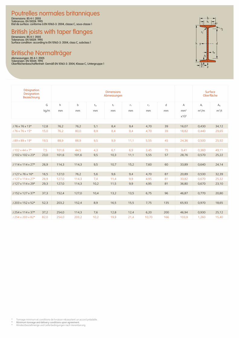
Désignation Designation Bezeichnung
Dimensions Abmessungen
Surface Oberfläche
G
kg/m
h b tw tf r1 r2 d A AL AG
mm mm mm mm mm mm mm mm2 m2/m m2/t
x102
Poutrelles normales britanniquesDimensions: BS 4-1: 2005 Tolérances: EN 10024: 1995 Etat de surface: conforme à EN 10163-3: 2004, classe C, sous-classe 1
British joists with taper flangesDimensions: BS 4-1: 2005 Tolerances: EN 10024: 1995 Surface condition: according to EN 10163-3: 2004, class C, subclass 1
Britische NormalträgerAbmessungen: BS 4-1: 2005 Toleranzen: EN 10024: 1995 Oberflächenbeschaffenheit: Gemäß EN 10163-3: 2004, Klasse C, Untergruppe 1
ss45o
d
twtf
h y
z
b
r1r2
b4
J 76 x 76 x 13* 12,8 76,2 76,2 5,1 8,4 9,4 4,70 39 16,07 0,430 34,12
J 76 x 76 x 15* 15,0 76,2 80,0 8,9 8,4 9,4 4,70 39 18,82 0,440 29,65
J 89 x 89 x 19* 19,5 88,9 88,9 9,5 9,9 11,1 5,55 45 24,36 0,500 25,92
J 102 x 44 x 7* 7,5 101,6 44,5 4,3 6,1 6,9 3,45 75 9,41 0,360 49,11
J 102 x 102 x 23* 23,0 101,6 101,6 9,5 10,3 11,1 5,55 57 28,76 0,570 25,22
J 114 x 114 x 27* 26,9 114,3 114,3 9,5 10,7 15,2 7,60 60 33,89 0,640 24,14
J 127 x 76 x 16* 16,5 127,0 76,2 5,6 9,6 9,4 4,70 87 20,89 0,530 32,39
J 127 x 114 x 27* 26,9 127,0 114,3 7,4 11,4 9,9 4,95 81 33,82 0,670 25,32
J 127 x 114 x 29* 29,3 127,0 114,3 10,2 11,5 9,9 4,95 81 36,80 0,670 23,10
J 152 x 127 x 37* 37,3 152,4 127,0 10,4 13,2 13,5 6,75 96 46,87 0,770 20,80
J 203 x 152 x 52* 52,3 203,2 152,4 8,9 16,5 15,5 7,75 135 65,93 0,970 18,65
J 254 x 114 x 37* 37,2 254,0 114,3 7,6 12,8 12,4 6,20 200 46,94 0,930 25,12
J 254 x 203 x 82* 82,0 254,0 203,2 10,2 19,9 21,4 10,70 166 103,9 1,260 15,40
* Tonnage minimum et conditions de livraison nécessitent un accord préalable.* Minimum tonnage and delivery conditions upon agreement.* Mindestbestellmenge und Lieferbedingungen nach Vereinbarung.
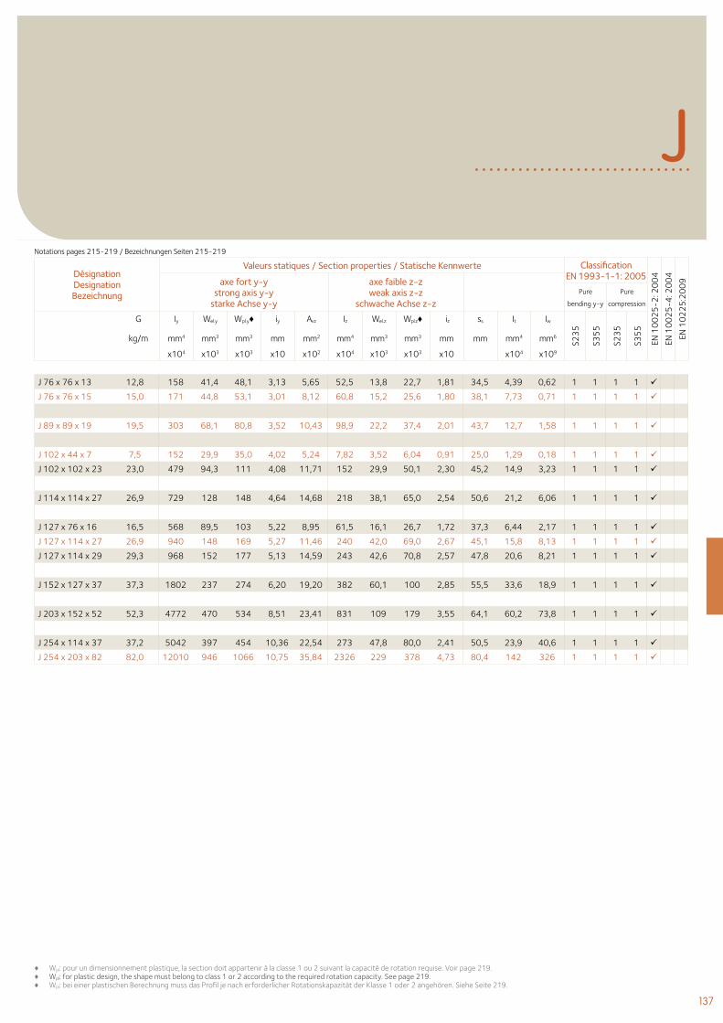
137
Désignation Designation Bezeichnung
Valeurs statiques / Section properties / Statische Kennwerte Classification EN 1993-1-1: 2005
EN 1
00
25
-2: 2
00
4
EN 1
00
25
-4: 2
00
4
EN 1
02
25
:20
09axe fort y-y
strong axis y-y starke Achse y-y
axe faible z-z weak axis z-z
schwache Achse z-z Pure
bending y-y
Pure
compression
G
kg/m
Iy Wel.y Wpl.y♦ iy Avz Iz Wel.z Wpl.z♦ iz ss It Iw
S23
5
S35
5
S23
5
S35
5
mm4 mm3 mm3 mm mm2 mm4 mm3 mm3 mm mm mm4 mm6
x104 x103 x103 x10 x102 x104 x103 x103 x10 x104 x109
J
♦ Wpl: pour un dimensionnement plastique, la section doit appartenir à la classe 1 ou 2 suivant la capacité de rotation requise. Voir page 219.♦ Wpl: for plastic design, the shape must belong to class 1 or 2 according to the required rotation capacity. See page 219. ♦ Wpl: bei einer plastischen Berechnung muss das Profil je nach erforderlicher Rotationskapazität der Klasse 1 oder 2 angehören. Siehe Seite 219.
J 76 x 76 x 13 12,8 158 41,4 48,1 3,13 5,65 52,5 13,8 22,7 1,81 34,5 4,39 0,62 1 1 1 1
J 76 x 76 x 15 15,0 171 44,8 53,1 3,01 8,12 60,8 15,2 25,6 1,80 38,1 7,73 0,71 1 1 1 1
J 89 x 89 x 19 19,5 303 68,1 80,8 3,52 10,43 98,9 22,2 37,4 2,01 43,7 12,7 1,58 1 1 1 1
J 102 x 44 x 7 7,5 152 29,9 35,0 4,02 5,24 7,82 3,52 6,04 0,91 25,0 1,29 0,18 1 1 1 1
J 102 x 102 x 23 23,0 479 94,3 111 4,08 11,71 152 29,9 50,1 2,30 45,2 14,9 3,23 1 1 1 1
J 114 x 114 x 27 26,9 729 128 148 4,64 14,68 218 38,1 65,0 2,54 50,6 21,2 6,06 1 1 1 1
J 127 x 76 x 16 16,5 568 89,5 103 5,22 8,95 61,5 16,1 26,7 1,72 37,3 6,44 2,17 1 1 1 1
J 127 x 114 x 27 26,9 940 148 169 5,27 11,46 240 42,0 69,0 2,67 45,1 15,8 8,13 1 1 1 1
J 127 x 114 x 29 29,3 968 152 177 5,13 14,59 243 42,6 70,8 2,57 47,8 20,6 8,21 1 1 1 1
J 152 x 127 x 37 37,3 1802 237 274 6,20 19,20 382 60,1 100 2,85 55,5 33,6 18,9 1 1 1 1
J 203 x 152 x 52 52,3 4772 470 534 8,51 23,41 831 109 179 3,55 64,1 60,2 73,8 1 1 1 1
J 254 x 114 x 37 37,2 5042 397 454 10,36 22,54 273 47,8 80,0 2,41 50,5 23,9 40,6 1 1 1 1
J 254 x 203 x 82 82,0 12010 946 1066 10,75 35,84 2326 229 378 4,73 80,4 142 326 1 1 1 1
Notations pages 215-219 / Bezeichnungen Seiten 215-219
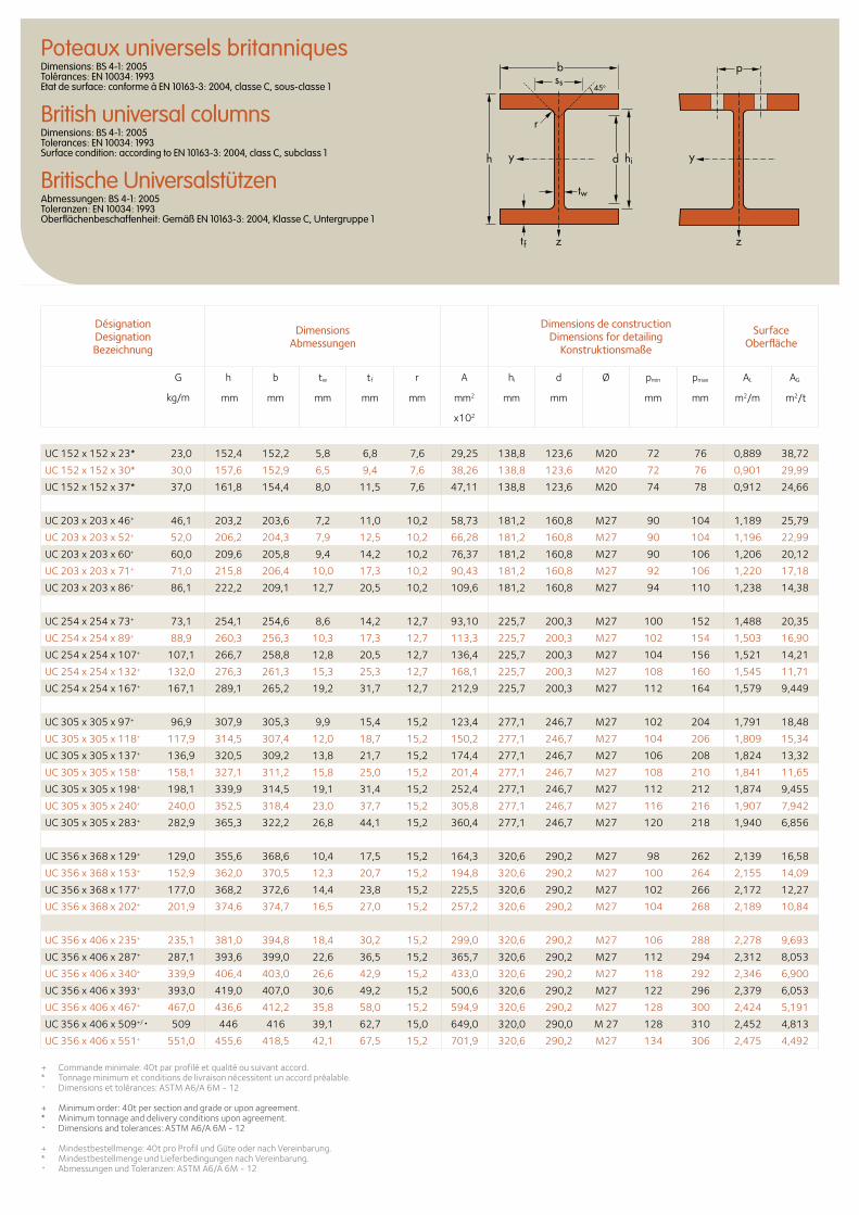
Désignation Designation Bezeichnung
Dimensions Abmessungen
Dimensions de construction Dimensions for detailing
Konstruktionsmaße
Surface Oberfläche
G
kg/m
h b tw tf r A hi d Ø pmin pmax AL AG
mm mm mm mm mm mm2 mm mm mm mm m2/m m2/t
x102
Poteaux universels britanniquesDimensions: BS 4-1: 2005 Tolérances: EN 10034: 1993 Etat de surface: conforme à EN 10163-3: 2004, classe C, sous-classe 1
British universal columnsDimensions: BS 4-1: 2005 Tolerances: EN 10034: 1993 Surface condition: according to EN 10163-3: 2004, class C, subclass 1
Britische UniversalstützenAbmessungen: BS 4-1: 2005 Toleranzen: EN 10034: 1993 Oberflächenbeschaffenheit: Gemäß EN 10163-3: 2004, Klasse C, Untergruppe 1
+ Commande minimale: 40t par profilé et qualité ou suivant accord. * Tonnage minimum et conditions de livraison nécessitent un accord préalable.• Dimensions et tolérances: ASTM A6/A 6M - 12
+ Minimum order: 40t per section and grade or upon agreement. * Minimum tonnage and delivery conditions upon agreement.• Dimensions and tolerances: ASTM A6/A 6M - 12
+ Mindestbestellmenge: 40t pro Profil und Güte oder nach Vereinbarung. * Mindestbestellmenge und Lieferbedingungen nach Vereinbarung. • Abmessungen und Toleranzen: ASTM A6/A 6M - 12
d hi
tw
tf
h
r
b
yy
zz
pss
45o
UC 152 x 152 x 23* 23,0 152,4 152,2 5,8 6,8 7,6 29,25 138,8 123,6 M20 72 76 0,889 38,72
UC 152 x 152 x 30* 30,0 157,6 152,9 6,5 9,4 7,6 38,26 138,8 123,6 M20 72 76 0,901 29,99
UC 152 x 152 x 37* 37,0 161,8 154,4 8,0 11,5 7,6 47,11 138,8 123,6 M20 74 78 0,912 24,66
UC 203 x 203 x 46+ 46,1 203,2 203,6 7,2 11,0 10,2 58,73 181,2 160,8 M27 90 104 1,189 25,79
UC 203 x 203 x 52+ 52,0 206,2 204,3 7,9 12,5 10,2 66,28 181,2 160,8 M27 90 104 1,196 22,99
UC 203 x 203 x 60+ 60,0 209,6 205,8 9,4 14,2 10,2 76,37 181,2 160,8 M27 90 106 1,206 20,12
UC 203 x 203 x 71+ 71,0 215,8 206,4 10,0 17,3 10,2 90,43 181,2 160,8 M27 92 106 1,220 17,18
UC 203 x 203 x 86+ 86,1 222,2 209,1 12,7 20,5 10,2 109,6 181,2 160,8 M27 94 110 1,238 14,38
UC 254 x 254 x 73+ 73,1 254,1 254,6 8,6 14,2 12,7 93,10 225,7 200,3 M27 100 152 1,488 20,35
UC 254 x 254 x 89+ 88,9 260,3 256,3 10,3 17,3 12,7 113,3 225,7 200,3 M27 102 154 1,503 16,90
UC 254 x 254 x 107+ 107,1 266,7 258,8 12,8 20,5 12,7 136,4 225,7 200,3 M27 104 156 1,521 14,21
UC 254 x 254 x 132+ 132,0 276,3 261,3 15,3 25,3 12,7 168,1 225,7 200,3 M27 108 160 1,545 11,71
UC 254 x 254 x 167+ 167,1 289,1 265,2 19,2 31,7 12,7 212,9 225,7 200,3 M27 112 164 1,579 9,449
UC 305 x 305 x 97+ 96,9 307,9 305,3 9,9 15,4 15,2 123,4 277,1 246,7 M27 102 204 1,791 18,48
UC 305 x 305 x 118+ 117,9 314,5 307,4 12,0 18,7 15,2 150,2 277,1 246,7 M27 104 206 1,809 15,34
UC 305 x 305 x 137+ 136,9 320,5 309,2 13,8 21,7 15,2 174,4 277,1 246,7 M27 106 208 1,824 13,32
UC 305 x 305 x 158+ 158,1 327,1 311,2 15,8 25,0 15,2 201,4 277,1 246,7 M27 108 210 1,841 11,65
UC 305 x 305 x 198+ 198,1 339,9 314,5 19,1 31,4 15,2 252,4 277,1 246,7 M27 112 212 1,874 9,455
UC 305 x 305 x 240+ 240,0 352,5 318,4 23,0 37,7 15,2 305,8 277,1 246,7 M27 116 216 1,907 7,942
UC 305 x 305 x 283+ 282,9 365,3 322,2 26,8 44,1 15,2 360,4 277,1 246,7 M27 120 218 1,940 6,856
UC 356 x 368 x 129+ 129,0 355,6 368,6 10,4 17,5 15,2 164,3 320,6 290,2 M27 98 262 2,139 16,58
UC 356 x 368 x 153+ 152,9 362,0 370,5 12,3 20,7 15,2 194,8 320,6 290,2 M27 100 264 2,155 14,09
UC 356 x 368 x 177+ 177,0 368,2 372,6 14,4 23,8 15,2 225,5 320,6 290,2 M27 102 266 2,172 12,27
UC 356 x 368 x 202+ 201,9 374,6 374,7 16,5 27,0 15,2 257,2 320,6 290,2 M27 104 268 2,189 10,84
UC 356 x 406 x 235+ 235,1 381,0 394,8 18,4 30,2 15,2 299,0 320,6 290,2 M27 106 288 2,278 9,693
UC 356 x 406 x 287+ 287,1 393,6 399,0 22,6 36,5 15,2 365,7 320,6 290,2 M27 112 294 2,312 8,053
UC 356 x 406 x 340+ 339,9 406,4 403,0 26,6 42,9 15,2 433,0 320,6 290,2 M27 118 292 2,346 6,900
UC 356 x 406 x 393+ 393,0 419,0 407,0 30,6 49,2 15,2 500,6 320,6 290,2 M27 122 296 2,379 6,053
UC 356 x 406 x 467+ 467,0 436,6 412,2 35,8 58,0 15,2 594,9 320,6 290,2 M27 128 300 2,424 5,191
UC 356 x 406 x 509+/• 509 446 416 39,1 62,7 15,0 649,0 320,0 290,0 M 27 128 310 2,452 4,813
UC 356 x 406 x 551+ 551,0 455,6 418,5 42,1 67,5 15,2 701,9 320,6 290,2 M27 134 306 2,475 4,492
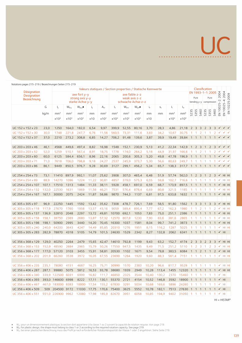
139
♦ Wpl: pour un dimensionnement plastique, la section doit appartenir à la classe 1 ou 2 suivant la capacité de rotation requise. Voir page 219. ♦ Wpl: for plastic design, the shape must belong to class 1 or 2 according to the required rotation capacity. See page 219. ♦ Wpl: bei einer plastischen Berechnung muss das Profil je nach erforderlicher Rotationskapazität der Klasse 1 oder 2 angehören. Siehe Seite 219.
Désignation Designation Bezeichnung
Valeurs statiques / Section properties / Statische Kennwerte Classification EN 1993-1-1: 2005
EN 1
00
25
-2: 2
00
4
EN 1
00
25
-4: 2
00
4
EN 1
02
25
:20
09axe fort y-y
strong axis y-y starke Achse y-y
axe faible z-z weak axis z-z
schwache Achse z-z Pure
bending y-y
Pure
compression
G
kg/m
Iy Wel.y Wpl.y♦ iy Avz Iz Wel.z Wpl.z♦ iz ss It Iw
S23
5
S35
5
S46
0
S23
5
S35
5
S46
0
mm4 mm3 mm3 mm mm2 mm4 mm3 mm3 mm mm mm4 mm6
x104 x103 x103 x10 x102 x104 x103 x103 x10 x104 x109
UC
HI = HISTAR©
UC 152 x 152 x 23 23,0 1250 164,0 182,0 6,54 9,97 399,9 52,55 80,16 3,70 28,3 4,86 21,18 2 3 3 2 3 3
UC 152 x 152 x 30 30,0 1748 221,8 247,7 6,76 11,56 560,5 73,31 111,6 3,83 34,2 10,67 30,75 1 1 2 1 1 2
UC 152 x 152 x 37 37,0 2210 273,2 308,8 6,85 14,27 706,2 91,48 139,6 3,87 39,9 19,49 39,84 1 1 1 1 1 1
UC 203 x 203 x 46 46,1 4568 449,6 497,4 8,82 16,98 1548 152,1 230,9 5,13 41,2 22,34 142,9 1 2 3 1 2 3
UC 203 x 203 x 52 52,0 5259 510,1 567,4 8,91 18,75 1778 174,0 264,2 5,18 44,9 31,97 166,6 1 1 2 1 1 2
UC 203 x 203 x 60 60,0 6125 584,4 656,1 8,96 22,16 2065 200,6 305,3 5,20 49,8 47,78 196,9 1 1 1 1 1 1
UC 203 x 203 x 71 71,0 7618 706,0 798,8 9,18 24,27 2537 245,9 373,7 5,30 56,6 80,63 249,7 1 1 1 1 1 1
UC 203 x 203 x 86 86,1 9449 850,5 976,7 9,28 30,69 3127 299,1 456,2 5,34 65,7 138,3 317,7 1 1 1 1 1 1
UC 254 x 254 x 73 73,1 11410 897,9 992,1 11,07 25,62 3908 307,0 465,4 6,48 51,9 57,74 562,0 1 2 3 1 2 3 HI HI
UC 254 x 254 x 89 88,9 14270 1096 1224 11,22 30,81 4857 379,0 575,3 6,55 59,8 102,7 716,6 1 1 1 1 1 1 HI HI
UC 254 x 254 x 107 107,1 17510 1313 1484 11,33 38,11 5928 458,1 697,0 6,59 68,7 173,9 897,5 1 1 1 1 1 1 HI HI
UC 254 x 254 x 132 132,0 22530 1631 1869 11,58 46,21 7531 576,4 878,4 6,69 80,8 321,5 1185 1 1 1 1 1 1 HI HI
UC 254 x 254 x 167 167,1 30000 2075 2424 11,87 58,86 9870 744,3 1137 6,81 97,5 633,8 1632 1 1 1 1 1 1 HI HI
UC 305 x 305 x 97 96,9 22250 1445 1592 13,42 35,62 7308 478,7 726,1 7,69 58,5 91,80 1562 1 3 3 1 3 3 HI HI
UC 305 x 305 x 118 117,9 27670 1760 1958 13,57 43,16 9059 589,4 895,4 7,77 67,2 162,3 1980 1 1 2 1 1 2 HI HI
UC 305 x 305 x 137 136,9 32810 2048 2297 13,72 49,81 10700 692,1 1053 7,83 75,0 251,1 2386 1 1 1 1 1 1 HI HI
UC 305 x 305 x 158 158,1 38750 2369 2680 13,87 57,32 12570 807,8 1230 7,90 83,6 381,6 2865 1 1 1 1 1 1 HI HI
UC 305 x 305 x 198 198,1 50900 2995 3440 14,20 70,45 16300 1037 1581 8,04 99,7 741,2 3873 1 1 1 1 1 1 HI HI
UC 305 x 305 x 240 240,0 64200 3643 4247 14,49 85,85 20310 1276 1951 8,15 116,2 1287 5025 1 1 1 1 1 1 HI HI
UC 305 x 305 x 283 282,9 78870 4318 5105 14,79 101,5 24630 1529 2342 8,27 132,8 2062 6341 1 1 1 1 1 1 HI
UC 356 x 368 x 129 129,0 40250 2264 2479 15,65 42,47 14610 792,8 1199 9,43 63,2 152,7 4174 2 3 3 2 3 3 HI HI
UC 356 x 368 x 153 152,9 48590 2684 2965 15,79 50,26 17550 947,5 1435 9,49 71,5 251,2 5110 1 2 3 1 2 3 HI HI
UC 356 x 368 x 177 177,0 57120 3103 3455 15,91 58,81 20530 1102 1671 9,54 79,8 383,5 6084 1 1 2 1 1 2 HI HI
UC 356 x 368 x 202 201,9 66260 3538 3972 16,05 67,55 23690 1264 1920 9,60 88,3 561,4 7151 1 1 1 1 1 1 HI HI
UC 356 x 406 x 235 235,1 79080 4151 4687 16,25 75,71 30990 1570 2383 10,20 96,6 817,7 9529 1 1 1 1 1 1 HI HI
UC 356 x 406 x 287 287,1 99880 5075 5812 16,53 93,78 38680 1939 2949 10,28 113,4 1455 12320 1 1 1 1 1 1 HI HI
UC 356 x 406 x 340 339,9 122500 6031 6999 16,82 111,7 46850 2325 3544 10,40 130,2 2370 15460 1 1 1 1 1 1 HI
UC 356 x 406 x 393 393,0 146600 6998 8222 17,11 130,1 55370 2721 4154 10,52 146,8 3592 18900 1 1 1 1 1 1 HI
UC 356 x 406 x 467 467,0 183000 8383 10000 17,54 155,2 67830 3291 5034 10,68 169,6 5896 24260 1 1 1 1 1 1 HI
UC 356 x 406 x 509 509 204500 9172 11030 17,75 170,6 75400 3625 5552 10,78 182,1 7513 27630 1 1 1 1 1 1 HI
UC 356 x 406 x 551 551,0 226900 9962 12080 17,98 185,9 82670 3951 6058 10,85 194,9 9402 31050 1 1 1 1 1 1 HI
Notations pages 215-219 / Bezeichnungen Seiten 215-219
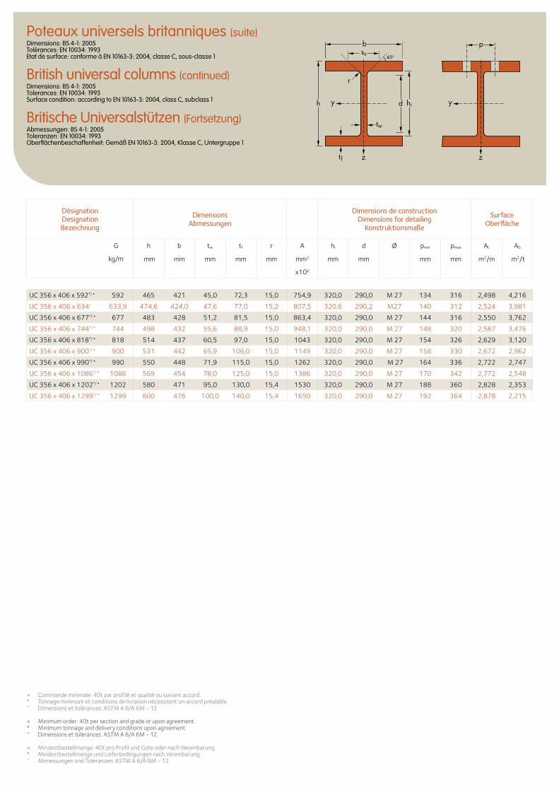
Désignation Designation Bezeichnung
Dimensions Abmessungen
Dimensions de construction Dimensions for detailing
Konstruktionsmaße
Surface Oberfläche
G
kg/m
h b tw tf r A hi d Ø pmin pmax AL AG
mm mm mm mm mm mm2 mm mm mm mm m2/m m2/t
x102
Poteaux universels britanniques (suite)Dimensions: BS 4-1: 2005 Tolérances: EN 10034: 1993 Etat de surface: conforme à EN 10163-3: 2004, classe C, sous-classe 1
British universal columns (continued)Dimensions: BS 4-1: 2005 Tolerances: EN 10034: 1993 Surface condition: according to EN 10163-3: 2004, class C, subclass 1
Britische Universalstützen (Fortsetzung)Abmessungen: BS 4-1: 2005 Toleranzen: EN 10034: 1993 Oberflächenbeschaffenheit: Gemäß EN 10163-3: 2004, Klasse C, Untergruppe 1
+ Commande minimale: 40t par profilé et qualité ou suivant accord. * Tonnage minimum et conditions de livraison nécessitent un accord préalable.• Dimensions et tolérances: ASTM A 6/A 6M - 12
+ Minimum order: 40t per section and grade or upon agreement. * Minimum tonnage and delivery conditions upon agreement.• Dimensions et tolerances: ASTM A 6/A 6M - 12
+ Mindestbestellmenge: 40t pro Profil und Güte oder nach Vereinbarung. * Mindestbestellmenge und Lieferbedingungen nach Vereinbarung.• Abmessungen und Toleranzen: ASTM A 6/A 6M - 12
d hi
tw
tf
h
r
b
yy
zz
pss
45o
UC 356 x 406 x 592*/• 592 465 421 45,0 72,3 15,0 754,9 320,0 290,0 M 27 134 316 2,498 4,216
UC 356 x 406 x 634+ 633,9 474,6 424,0 47,6 77,0 15,2 807,5 320,6 290,2 M27 140 312 2,524 3,981
UC 356 x 406 x 677*/• 677 483 428 51,2 81,5 15,0 863,4 320,0 290,0 M 27 144 316 2,550 3,762
UC 356 x 406 x 744*/• 744 498 432 55,6 88,9 15,0 948,1 320,0 290,0 M 27 148 320 2,587 3,476
UC 356 x 406 x 818*/• 818 514 437 60,5 97,0 15,0 1043 320,0 290,0 M 27 154 326 2,629 3,120
UC 356 x 406 x 900*/• 900 531 442 65,9 106,0 15,0 1149 320,0 290,0 M 27 158 330 2,672 2,962
UC 356 x 406 x 990*/• 990 550 448 71,9 115,0 15,0 1262 320,0 290,0 M 27 164 336 2,722 2,747
UC 356 x 406 x 1086*/• 1086 569 454 78,0 125,0 15,0 1386 320,0 290,0 M 27 170 342 2,772 2,548
UC 356 x 406 x 1202*/• 1202 580 471 95,0 130,0 15,4 1530 320,0 290,0 M 27 188 360 2,828 2,353
UC 356 x 406 x 1299*/• 1299 600 476 100,0 140,0 15,4 1650 320,0 290,0 M 27 192 364 2,878 2,215
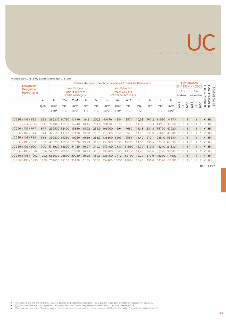
141
♦ Wpl: pour un dimensionnement plastique, la section doit appartenir à la classe 1 ou 2 suivant la capacité de rotation requise. Voir page 219. ♦ Wpl: for plastic design, the shape must belong to class 1 or 2 according to the required rotation capacity. See page 219. ♦ Wpl: bei einer plastischen Berechnung muss das Profil je nach erforderlicher Rotationskapazität der Klasse 1 oder 2 angehören. Siehe Seite 219.
Désignation Designation Bezeichnung
Valeurs statiques / Section properties / Statische Kennwerte Classification EN 1993-1-1: 2005
EN 1
00
25
-2: 2
00
4
EN 1
00
25
-4: 2
00
4
EN 1
02
25
:20
09axe fort y-y
strong axis y-y starke Achse y-y
axe faible z-z weak axis z-z
schwache Achse z-z Pure
bending y-y
Pure
compression
G
kg/m
Iy Wel.y Wpl.y♦ iy Avz Iz Wel.z Wpl.z♦ iz ss It Iw
S23
5
S35
5
S46
0
S23
5
S35
5
S46
0
mm4 mm3 mm3 mm mm2 mm4 mm3 mm3 mm mm mm4 mm6
x104 x103 x103 x10 x102 x104 x103 x103 x10 x104 x109
UCNotations pages 215-219 / Bezeichnungen Seiten 215-219
UC 356 x 406 x 592 592 250200 10760 13140 18,2 200,3 90170 4284 6574 10,93 207,2 11560 34670 1 1 1 1 1 1 HI
UC 356 x 406 x 634 633,9 274800 11580 14240 18,45 214,6 98130 4629 7108 11,02 219,4 13990 38660 1 1 1 1 1 1 HI
UC 356 x 406 x 677 677 299500 12400 15350 18,62 231,9 106900 4994 7680 11,13 231,8 16790 42920 1 1 1 1 1 1 HI
UC 356 x 406 x 744 744 342100 13740 17170 19,00 256,1 119900 5552 8549 11,25 251,0 21840 49980 1 1 1 1 1 1 HI
UC 356 x 406 x 818 818 392200 15260 19260 19,39 283,3 135500 6203 9561 11,40 272,1 28510 58650 1 1 1 1 1 1 HI
UC 356 x 406 x 900 900 450200 16960 21620 19,79 313,8 153300 6938 10710 11,55 295,5 37350 68890 1 1 1 1 1 1 HI
UC 356 x 406 x 990 990 518900 18870 24280 20,27 349,2 173400 7739 11960 11,72 319,5 48210 81530 1 1 1 1 1 1 HI
UC 356 x 406 x 1086 1086 595700 20940 27210 20,73 385,8 196200 8645 13380 11,90 345,6 62290 96080 1 1 1 1 1 1 HI
UC 356 x 406 x 1202 1202 663600 22880 30020 20,82 469,6 228700 9712 15150 12,22 373,0 79230 114600 1 1 1 1 1 1 HI
UC 356 x 406 x 1299 1299 754600 25150 33250 21,35 505,2 254400 10690 16670 12,40 398,0 98140 133100 1 1 1 1 1 1 HI
HI = HISTAR©
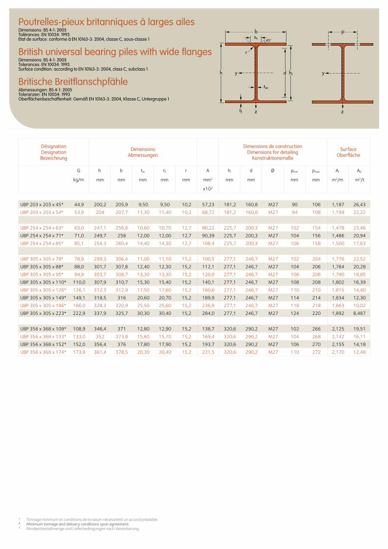
Désignation Designation Bezeichnung
Dimensions Abmessungen
Dimensions de construction Dimensions for detailing
Konstruktionsmaße
Surface Oberfläche
G
kg/m
h b tw tf r A hi d Ø pmin pmax AL AG
mm mm mm mm mm mm2 mm mm mm mm m2/m m2/t
x102
Poutrelles-pieux britanniques à larges ailesDimensions: BS 4-1: 2005 Tolérances: EN 10034: 1993 Etat de surface: conforme à EN 10163-3: 2004, classe C, sous-classe 1
British universal bearing piles with wide flangesDimensions: BS 4-1: 2005 Tolerances: EN 10034: 1993 Surface condition: according to EN 10163-3: 2004, class C, subclass 1
Britische BreitflanschpfähleAbmessungen: BS 4-1: 2005 Toleranzen: EN 10034: 1993 Oberflächenbeschaffenheit: Gemäß EN 10163-3: 2004, Klasse C, Untergruppe 1
d hi
tw
tf
yyh
zz
r
b pss
45o
UBP 203 x 203 x 45* 44,9 200,2 205,9 9,50 9,50 10,2 57,23 181,2 160,8 M27 90 106 1,187 26,43
UBP 203 x 203 x 54* 53,9 204 207,7 11,30 11,40 10,2 68,72 181,2 160,8 M27 94 108 1,199 22,22
UBP 254 x 254 x 63* 63,0 247,1 256,6 10,60 10,70 12,7 80,22 225,7 200,3 M27 102 154 1,478 23,46
UBP 254 x 254 x 71* 71,0 249,7 258 12,00 12,00 12,7 90,39 225,7 200,3 M27 104 156 1,486 20,94
UBP 254 x 254 x 85* 85,1 254,3 260,4 14,40 14,30 12,7 108,4 225,7 200,3 M27 106 158 1,500 17,63
UBP 305 x 305 x 79* 78,9 299,3 306,4 11,00 11,10 15,2 100,5 277,1 246,7 M27 102 204 1,776 22,52
UBP 305 x 305 x 88* 88,0 301,7 307,8 12,40 12,30 15,2 112,1 277,1 246,7 M27 104 206 1,784 20,28
UBP 305 x 305 x 95* 94,9 303,7 308,7 13,30 13,30 15,2 120,9 277,1 246,7 M27 106 206 1,790 18,85
UBP 305 x 305 x 110* 110,0 307,9 310,7 15,30 15,40 15,2 140,1 277,1 246,7 M27 108 208 1,802 16,39
UBP 305 x 305 x 126* 126,1 312,3 312,9 17,50 17,60 15,2 160,6 277,1 246,7 M27 110 210 1,815 14,40
UBP 305 x 305 x 149* 149,1 318,5 316 20,60 20,70 15,2 189,9 277,1 246,7 M27 114 214 1,834 12,30
UBP 305 x 305 x 186* 186,0 328,3 320,9 25,50 25,60 15,2 236,9 277,1 246,7 M27 118 218 1,863 10,02
UBP 305 x 305 x 223* 222,9 337,9 325,7 30,30 30,40 15,2 284,0 277,1 246,7 M27 124 220 1,892 8,487
UBP 356 x 368 x 109* 108,9 346,4 371 12,80 12,90 15,2 138,7 320,6 290,2 M27 102 266 2,125 19,51
UBP 356 x 368 x 133* 133,0 352 373,8 15,60 15,70 15,2 169,4 320,6 290,2 M27 104 268 2,142 16,11
UBP 356 x 368 x 152* 152,0 356,4 376 17,80 17,90 15,2 193,7 320,6 290,2 M27 106 270 2,155 14,18
UBP 356 x 368 x 174* 173,9 361,4 378,5 20,30 20,40 15,2 221,5 320,6 290,2 M27 110 272 2,170 12,48
* Tonnage minimum et conditions de livraison nécessitent un accord préalable.* Minimum tonnage and delivery conditions upon agreement. * Mindestbestellmenge und Lieferbedingungen nach Vereinbarung.
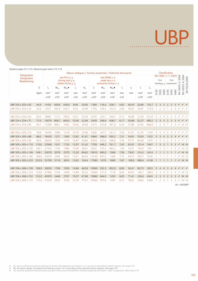
143
Désignation Designation Bezeichnung
Valeurs statiques / Section properties / Statische Kennwerte Classification EN 1993-1-1: 2005
EN 1
00
25
-2: 2
00
4
EN 1
00
25
-4: 2
00
4
EN 1
02
25
:20
09axe fort y-y
strong axis y-y starke Achse y-y
axe faible z-z weak axis z-z
schwache Achse z-z Pure
bending y-y
Pure
compression
G
kg/m
Iy Wel.y Wpl.y♦ iy Avz Iz Wel.z Wpl.z♦ iz ss It Iw
S23
5
S35
5
S46
0
S23
5
S35
5
S46
0
mm4 mm3 mm3 mm mm2 mm4 mm3 mm3 mm mm mm4 mm6
x104 x103 x103 x10 x102 x104 x103 x103 x10 x104 x109
UBP
HI = HISTAR©
UBP 203 x 203 x 45 44,9 4100 409,6 458,9 8,46 20,95 1384 134,4 206,1 4,92 40,45 20,80 125,7 2 3 3 2 3 3
UBP 203 x 203 x 54 53,9 5027 492,8 556,7 8,55 24,98 1705 164,2 252,4 4,98 46,05 34,97 157,9 1 2 3 1 2 3
UBP 254 x 254 x 63 63,0 8860 717,2 799,3 10,51 29,16 3016 235,1 359,7 6,13 46,88 37,20 421,0 3 3 4 3 3 4
UBP 254 x 254 x 71 71,0 10070 806,7 904,0 10,56 32,96 3439 266,6 408,7 6,17 50,88 52,27 485,2 2 3 3 2 3 3
UBP 254 x 254 x 85 85,1 12280 966,1 1092 10,65 39,58 4215 323,8 497,9 6,24 57,88 87,82 606,0 1 2 3 1 2 3 HI HI
UBP 305 x 305 x 79 78,9 16440 1099 1218 12,79 37,06 5326 347,7 531,2 7,28 51,01 51,37 1105 3 4 4 3 4 4
UBP 305 x 305 x 88 88,0 18420 1221 1360 12,82 41,61 5984 388,9 595,2 7,31 54,81 70,05 1252 3 3 4 3 3 4
UBP 305 x 305 x 95 94,9 20040 1320 1474 12,87 44,65 6529 423,0 648,0 7,35 57,71 86,69 1375 2 3 3 2 3 3
UBP 305 x 305 x 110 110,0 23560 1531 1720 12,97 51,42 7709 496,2 761,7 7,42 63,91 131,4 1647 1 3 3 1 3 3 HI HI
UBP 305 x 305 x 126 126,1 27410 1755 1986 13,06 58,91 9002 575,4 885,2 7,49 70,51 194,3 1951 1 2 3 1 2 3 HI HI
UBP 305 x 305 x 149 149,1 33070 2076 2370 13,20 69,62 10910 690,5 1066 7,58 79,81 314,2 2414 1 1 1 1 1 1 HI HI
UBP 305 x 305 x 186 186,0 42610 2596 3003 13,41 86,95 14140 881,5 1366 7,73 94,51 593,7 3230 1 1 1 1 1 1 HI HI
UBP 305 x 305 x 223 222,9 52700 3119 3653 13,62 104,4 17580 1079 1680 7,87 108,9 998,4 4138 1 1 1 1 1 1 HI HI
UBP 356 x 368 x 109 108,9 30630 1769 1956 14,86 48,59 10990 592,3 902,9 8,90 56,41 90,73 3053 3 4 4 3 4 4
UBP 356 x 368 x 133 133,0 37980 2158 2406 14,98 59,22 13680 731,9 1119 8,99 64,81 160,7 3864 3 3 4 3 3 4 HI HI
UBP 356 x 368 x 152 152,0 43970 2468 2767 15,07 67,68 15880 844,5 1293 9,05 71,41 236,4 4543 2 3 3 2 3 3 HI HI
UBP 356 x 368 x 174 173,9 51010 2823 3186 15,18 77,41 18460 975,6 1497 9,13 78,91 348,5 5360 1 2 3 1 2 3 HI HI
♦ Wpl: pour un dimensionnement plastique, la section doit appartenir à la classe 1 ou 2 suivant la capacité de rotation requise. Voir page 219. ♦ Wpl: for plastic design, the shape must belong to class 1 or 2 according to the required rotation capacity. See page 219. ♦ Wpl: bei einer plastischen Berechnung muss das Profil je nach erforderlicher Rotationskapazität der Klasse 1 oder 2 angehören. Siehe Seite 219.
Notations pages 215-219 / Bezeichnungen Seiten 215-219
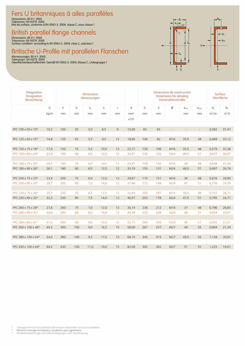
Désignation Designation Bezeichnung
Dimensions Abmessungen
Dimensions de construction Dimensions for detailing
Konstruktionsmaße
Surface Oberfläche
G
kg/m
h b tw tf r A hi d Ø emin emax AL AG
mm mm mm mm mm mm2 mm mm mm mm m2/m m2/t
x102
Fers U britanniques à ailes parallèlesDimensions: BS 4-1: 2005 Tolérances: EN 10279: 2000 Etat de surface: conforme à EN 10163-3: 2004, classe C, sous-classe 1
British parallel flange channelsDimensions: BS 4-1: 2005 Tolerances: EN 10279: 2000 Surface condition: according to EN 10163-3: 2004, class C, subclass 1
Britische U-Profile mit parallelen FlanschenAbmessungen: BS 4-1: 2005 Toleranzen: EN 10279: 2000 Oberflächenbeschaffenheit: Gemäß EN 10163-3: 2004, Klasse C, Untergruppe 1
ys
ess
ym
45o
d hi
tw
tf
h y
zz
r
b
PFC 100 x 50 x 10* 10,2 100 50 5,0 8,5 9 13,00 83 65 - - - 0,382 37,47
PFC 125 x 65 x 15* 14,8 125 65 5,5 9,5 12 18,80 106 82 M16 35,5 38 0,489 33,12
PFC 150 x 75 x 18* 17,9 150 75 5,5 10,0 12 22,77 130 106 M16 35,5 48 0,579 32,38
PFC 150 x 90 x 24* 23,9 150 90 6,5 12,0 12 30,41 126 102 M24 46,5 51 0,637 26,67
PFC 180 x 75 x 20* 20,3 180 75 6,0 10,5 12 25,91 159 135 M16 36 48 0,638 31,36
PFC 180 x 90 x 26* 26,1 180 90 6,5 12,5 12 33,19 155 131 M24 46,5 51 0,697 26,74
PFC 200 x 75 x 23* 23,4 200 75 6,0 12,5 12 29,87 175 151 M16 36 48 0,678 28,90
PFC 200 x 90 x 30* 29,7 200 90 7,0 14,0 12 37,86 172 148 M24 47 51 0,736 24,76
PFC 230 x 75 x 26* 25,7 230 75 6,5 12,5 12 32,69 205 181 M16 36,5 48 0,737 28,71
PFC 230 x 90 x 32* 32,2 230 90 7,5 14,0 12 40,97 202 178 M24 47,5 51 0,795 24,71
PFC 260 x 75 x 28* 27,6 260 75 7,0 12,0 12 35,14 236 212 M16 37 48 0,796 28,85
PFC 260 x 90 x 35* 34,8 260 90 8,0 14,0 12 44,38 232 208 M24 48 51 0,854 24,51
PFC 300 x 90 x 41* 41,4 300 90 9,0 15,5 12 52,73 269 245 M24 49 51 0,932 22,51
PFC 300 x 100 x 46* 45,5 300 100 9,0 16,5 15 58,00 267 237 M27 49 55 0,969 21,29
PFC 380 x 100 x 54* 54,0 380 100 9,5 17,5 15 68,74 345 315 M27 49,5 55 1,128 20,91
PFC 430 x 100 x 64* 64,4 430 100 11,0 19,0 15 82,09 392 362 M27 51 55 1,225 19,01
* Tonnage minimum et conditions de livraison nécessitent un accord préalable.* Minimum tonnage and delivery conditions upon agreement. * Mindestbestellmenge und Lieferbedingungen nach Vereinbarung.
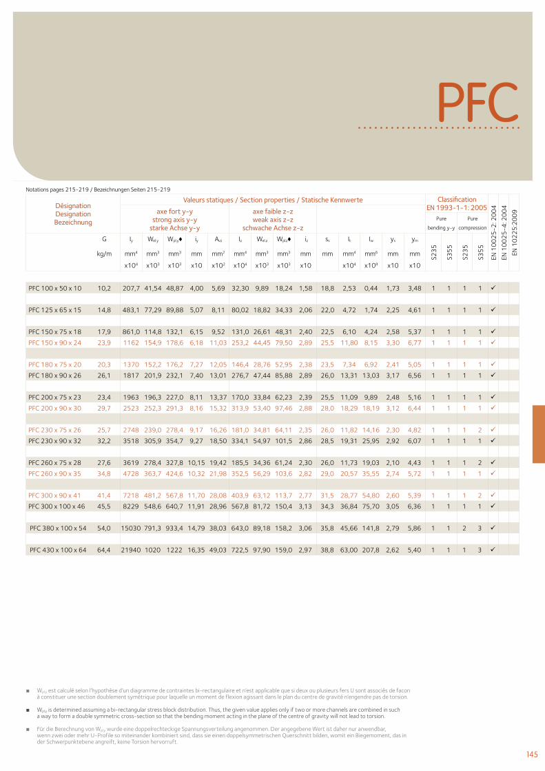
145
PFC
Désignation Designation Bezeichnung
Valeurs statiques / Section properties / Statische Kennwerte Classification EN 1993-1-1: 2005
EN 1
00
25
-2: 2
00
4
EN 1
00
25
-4: 2
00
4
EN 1
02
25
:20
09axe fort y-y
strong axis y-y starke Achse y-y
axe faible z-z weak axis z-z
schwache Achse z-z Pure
bending y-y
Pure
compression
G Iy Wel.y Wpl.y♦ iy Avz Iz Wel.z Wpl.z♦ iz ss It Iw ys ym
S23
5
S35
5
S23
5
S35
5
kg/m mm4 mm3 mm3 mm mm2 mm4 mm3 mm3 mm mm mm4 mm6 mm mm
x104 x103 x103 x10 x102 x104 x103 x103 x10 x104 x109 x10 x10
PFC 100 x 50 x 10 10,2 207,7 41,54 48,87 4,00 5,69 32,30 9,89 18,24 1,58 18,8 2,53 0,44 1,73 3,48 1 1 1 1
PFC 125 x 65 x 15 14,8 483,1 77,29 89,88 5,07 8,11 80,02 18,82 34,33 2,06 22,0 4,72 1,74 2,25 4,61 1 1 1 1
PFC 150 x 75 x 18 17,9 861,0 114,8 132,1 6,15 9,52 131,0 26,61 48,31 2,40 22,5 6,10 4,24 2,58 5,37 1 1 1 1
PFC 150 x 90 x 24 23,9 1162 154,9 178,6 6,18 11,03 253,2 44,45 79,50 2,89 25,5 11,80 8,15 3,30 6,77 1 1 1 1
PFC 180 x 75 x 20 20,3 1370 152,2 176,2 7,27 12,05 146,4 28,76 52,95 2,38 23,5 7,34 6,92 2,41 5,05 1 1 1 1
PFC 180 x 90 x 26 26,1 1817 201,9 232,1 7,40 13,01 276,7 47,44 85,88 2,89 26,0 13,31 13,03 3,17 6,56 1 1 1 1
PFC 200 x 75 x 23 23,4 1963 196,3 227,0 8,11 13,37 170,0 33,84 62,23 2,39 25,5 11,09 9,89 2,48 5,16 1 1 1 1
PFC 200 x 90 x 30 29,7 2523 252,3 291,3 8,16 15,32 313,9 53,40 97,46 2,88 28,0 18,29 18,19 3,12 6,44 1 1 1 1
PFC 230 x 75 x 26 25,7 2748 239,0 278,4 9,17 16,26 181,0 34,81 64,11 2,35 26,0 11,82 14,16 2,30 4,82 1 1 1 2
PFC 230 x 90 x 32 32,2 3518 305,9 354,7 9,27 18,50 334,1 54,97 101,5 2,86 28,5 19,31 25,95 2,92 6,07 1 1 1 1
PFC 260 x 75 x 28 27,6 3619 278,4 327,8 10,15 19,42 185,5 34,36 61,24 2,30 26,0 11,73 19,03 2,10 4,43 1 1 1 2
PFC 260 x 90 x 35 34,8 4728 363,7 424,6 10,32 21,98 352,5 56,29 103,6 2,82 29,0 20,57 35,55 2,74 5,72 1 1 1 1
PFC 300 x 90 x 41 41,4 7218 481,2 567,8 11,70 28,08 403,9 63,12 113,7 2,77 31,5 28,77 54,80 2,60 5,39 1 1 1 2
PFC 300 x 100 x 46 45,5 8229 548,6 640,7 11,91 28,96 567,8 81,72 150,4 3,13 34,3 36,84 75,70 3,05 6,36 1 1 1 1
PFC 380 x 100 x 54 54,0 15030 791,3 933,4 14,79 38,03 643,0 89,18 158,2 3,06 35,8 45,66 141,8 2,79 5,86 1 1 2 3
PFC 430 x 100 x 64 64,4 21940 1020 1222 16,35 49,03 722,5 97,90 159,0 2,97 38,8 63,00 207,8 2,62 5,40 1 1 1 3
■ Wpl.y est calculé selon l’hypothèse d’un diagramme de contraintes bi-rectangulaire et n’est applicable que si deux ou plusieurs fers U sont associés de facon à constituer une section doublement symétrique pour laquelle un moment de flexion agissant dans le plan du centre de gravité n’engendre pas de torsion.
■ Wpl.y is determined assuming a bi-rectangular stress block distribution. Thus, the given value applies only if two or more channels are combined in such a way to form a double symmetric cross-section so that the bending moment acting in the plane of the centre of gravity will not lead to torsion.
■ Für die Berechnung von Wpl.y wurde eine doppelrechteckige Spannungsverteilung angenommen. Der angegebene Wert ist daher nur anwendbar, wenn zwei oder mehr U-Profile so miteinander kombiniert sind, dass sie einen doppelsymmetrischen Querschnitt bilden, womit ein Biegemoment, das in der Schwerpunktebene angreift, keine Torsion hervorruft.
Notations pages 215-219 / Bezeichnungen Seiten 215-219
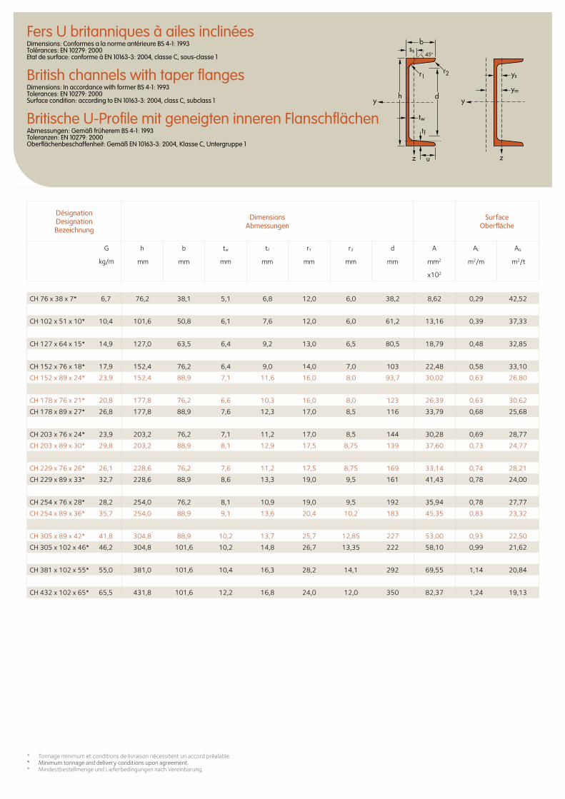
Désignation Designation Bezeichnung
Dimensions Abmessungen
Surface Oberfläche
G
kg/m
h b tw tf r1 r2 d A AL AG
mm mm mm mm mm mm mm mm2 m2/m m2/t
x102
Fers U britanniques à ailes inclinéesDimensions: Conformes a la norme antérieure BS 4-1: 1993 Tolérances: EN 10279: 2000 Etat de surface: conforme à EN 10163-3: 2004, classe C, sous-classe 1
British channels with taper flangesDimensions: In accordance with former BS 4-1: 1993 Tolerances: EN 10279: 2000 Surface condition: according to EN 10163-3: 2004, class C, subclass 1
Britische U-Profile mit geneigten inneren FlanschflächenAbmessungen: Gemäß früherem BS 4-1: 1993 Toleranzen: EN 10279: 2000 Oberflächenbeschaffenheit: Gemäß EN 10163-3: 2004, Klasse C, Untergruppe 1
* Tonnage minimum et conditions de livraison nécessitent un accord préalable.* Minimum tonnage and delivery conditions upon agreement.* Mindestbestellmenge und Lieferbedingungen nach Vereinbarung.
CH 76 x 38 x 7* 6,7 76,2 38,1 5,1 6,8 12,0 6,0 38,2 8,62 0,29 42,52
CH 102 x 51 x 10* 10,4 101,6 50,8 6,1 7,6 12,0 6,0 61,2 13,16 0,39 37,33
CH 127 x 64 x 15* 14,9 127,0 63,5 6,4 9,2 13,0 6,5 80,5 18,79 0,48 32,85
CH 152 x 76 x 18* 17,9 152,4 76,2 6,4 9,0 14,0 7,0 103 22,48 0,58 33,10
CH 152 x 89 x 24* 23,9 152,4 88,9 7,1 11,6 16,0 8,0 93,7 30,02 0,63 26,80
CH 178 x 76 x 21* 20,8 177,8 76,2 6,6 10,3 16,0 8,0 123 26,39 0,63 30,62
CH 178 x 89 x 27* 26,8 177,8 88,9 7,6 12,3 17,0 8,5 116 33,79 0,68 25,68
CH 203 x 76 x 24* 23,9 203,2 76,2 7,1 11,2 17,0 8,5 144 30,28 0,69 28,77
CH 203 x 89 x 30* 29,8 203,2 88,9 8,1 12,9 17,5 8,75 139 37,60 0,73 24,77
CH 229 x 76 x 26* 26,1 228,6 76,2 7,6 11,2 17,5 8,75 169 33,14 0,74 28,21
CH 229 x 89 x 33* 32,7 228,6 88,9 8,6 13,3 19,0 9,5 161 41,43 0,78 24,00
CH 254 x 76 x 28* 28,2 254,0 76,2 8,1 10,9 19,0 9,5 192 35,94 0,78 27,77
CH 254 x 89 x 36* 35,7 254,0 88,9 9,1 13,6 20,4 10,2 183 45,35 0,83 23,32
CH 305 x 89 x 42* 41,8 304,8 88,9 10,2 13,7 25,7 12,85 227 53,00 0,93 22,50
CH 305 x 102 x 46* 46,2 304,8 101,6 10,2 14,8 26,7 13,35 222 58,10 0,99 21,62
CH 381 x 102 x 55* 55,0 381,0 101,6 10,4 16,3 28,2 14,1 292 69,55 1,14 20,84
CH 432 x 102 x 65* 65,5 431,8 101,6 12,2 16,8 24,0 12,0 350 82,37 1,24 19,13
ys
ss
ym
y
z z
45o
d
tw
tf
h
r1
b
r2
u
y
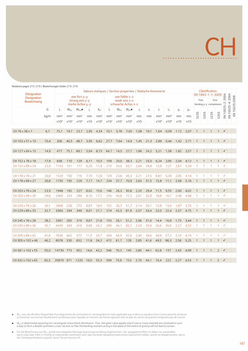
147
Désignation Designation Bezeichnung
Valeurs statiques / Section properties / Statische Kennwerte Classification EN 1993-1-1: 2005
EN 1
00
25
-2: 2
00
4
EN 1
00
25
-4: 2
00
4
EN 1
02
25
:20
09axe fort y-y
strong axis y-y starke Achse y-y
axe faible z-z weak axis z-z
schwache Achse z-z Pure
bending y-y
Pure
compression
G
kg/m
Iy Wel.y Wpl.y♦ iy Avz Iz Wel.z Wpl.z♦ iz ss It Iw ys ym
S23
5
S35
5
S23
5
S35
5
mm4 mm3 mm3 mm mm2 mm4 mm3 mm3 mm mm mm4 mm6 mm mm
x104 x103 x103 x10 x102 x104 x103 x103 x10 x104 x109 x10 x10
CH
CH 76 x 38 x 7 6,7 75,1 19,7 23,7 2,95 4,34 10,1 3,78 7,50 1,08 19,1 1,64 0,09 1,12 2,07 1 1 1 1
CH 102 x 51 x 10 10,4 206 40,5 48,7 3,95 6,62 27,7 7,64 14,9 1,45 21,3 2,89 0,44 1,42 2,71 1 1 1 1
CH 127 x 64 x 15 14,9 477 75,1 89,1 5,04 8,73 64,7 14,5 27,7 1,86 24,2 5,21 1,58 1,82 3,57 1 1 1 1
CH 152 x 76 x 18 17,9 838 110 129 6,11 10,5 109 20,0 38,3 2,21 25,0 6,24 3,95 2,04 4,12 1 1 1 1
CH 152 x 89 x 24 23,9 1154 151 177 6,20 11,9 210 34,5 63,7 2,64 29,8 12,9 7,21 2,67 5,34 1 1 1 1
CH 178 x 76 x 21 20,8 1329 150 176 7,10 12,8 129 23,6 45,3 2,21 27,5 8,87 6,39 2,05 4,14 1 1 1 1
CH 178 x 89 x 27 26,8 1735 195 229 7,17 14,7 234 37,7 70,9 2,63 31,5 15,8 11,1 2,58 5,16 1 1 1 1
CH 203 x 76 x 24 23,9 1948 192 227 8,02 15,6 146 26,3 50,8 2,20 29,4 11,5 9,55 2,00 4,02 1 1 1 1
CH 203 x 89 x 30 29,8 2469 243 286 8,10 17,7 256 40,6 77,2 2,61 32,8 18,8 16,1 2,48 4,98 1 1 1 1
CH 229 x 76 x 26 26,1 2608 228 272 8,87 18,5 152 26,7 51,7 2,14 30,1 12,8 13,0 1,87 3,76 1 1 1 1
CH 229 x 89 x 33 32,7 3364 294 349 9,01 21,1 274 42,5 81,9 2,57 34,4 22,0 22,4 2,37 4,75 1 1 1 1
CH 245 x 76 x 28 28,2 3361 265 319 9,67 21,8 153 26,1 51,2 2,06 31,0 14,4 16,9 1,73 3,44 1 1 1 1
CH 245 x 89 x 36 35,7 4435 349 416 9,89 24,7 289 44,1 85,2 2,53 35,9 25,6 30,0 2,27 4,52 1 1 1 1
CH 305 x 89 x 42 41,8 7036 462 572 11,5 33,7 304 44,5 92,9 2,40 39,6 39,9 57,2 2,10 4,19 1 1 1 1
CH 305 x 102 x 46 46,2 8078 530 652 11,8 34,2 472 61,7 128 2,85 41,6 49,5 86,3 2,56 5,25 1 1 1 1
CH 381 x 102 x 55 55,0 14730 773 952 14,6 43,2 546 70,3 145 2,80 44,1 62,8 157 2,43 4,99 1 1 1 2
CH 432 x 102 x 65 65,5 20970 971 1220 16,0 55,3 599 75,6 153 2,70 44,1 74,4 222 2,27 4,53 1 1 1 2
■ Wpl.y est calculé selon l’hypothèse d’un diagramme de contraintes bi-rectangulaire et n’est applicable que si deux ou plusieurs fers U sont associés de facon à constituer une section doublement symétrique pour laquelle un moment de flexion agissant dans le plan du centre de gravité n’engendre pas de torsion.
■ Wpl.y is determined assuming a bi-rectangular stress block distribution. Thus, the given value applies only if two or more channels are combined in such a way to form a double symmetric cross-section so that the bending moment acting in the plane of the centre of gravity will not lead to torsion.
■ Für die Berechnung von Wpl.y wurde eine doppelrechteckige Spannungsverteilung angenommen. Der angegebene Wert ist daher nur anwendbar, wenn zwei oder mehr U-Profile so miteinander kombiniert sind, dass sie einen doppelsymmetrischen Querschnitt bilden, womit ein Biegemoment, das in der Schwerpunktebene angreift, keine Torsion hervorruft.
Notations pages 215-219 / Bezeichnungen Seiten 215-219
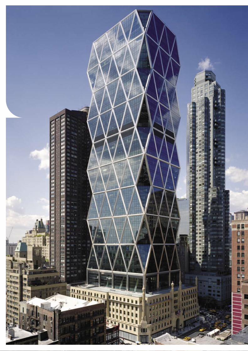
© C
huck
Cho
i - A
rchi
tect
: Fos
ter
& P
artn
ers
- H
ears
t To
wer
, N
YC

© C
huck
Cho
i - A
rchi
tect
: Fos
ter
& P
artn
ers
- H
ears
t To
wer
, N
YC
150 W Poutrelles américaines à larges ailes
168 S Poutrelles américaines standard
170 HP Poutrelles-pieux américaines à larges ailes
172 C Fers U normaux américains
174 MC Fers U américains
178 L Cornières américaines à ailes égales
186 L Cornières américaines à ailes inégales
188 L Dimensions de construction - Cornières américaines à ailes égales
191 L Dimensions de construction - Cornières américaines à ailes inégales
150 W American wide flange beams
168 S American standard beams
170 HP American wide flange bearing piles
172 C American standard channels
174 MC American channels
178 L American equal leg angles
186 L American unequal leg angles
188 L Dimensions for detailing - American equal leg angles
191 L Dimensions for detailing - American unequal leg angles
150 W Amerikanische Breitflanschträger
168 S Amerikanische Standardträger
170 HP Amerikanische Breitflanschpfähle
172 C Amerikanische U-Stahl- Normalprofile
174 MC Amerikanische U-Stahl-Profile
178 L Amerikanischer gleichschenkliger Winkelstahl
186 L Amerikanischer ungleichschenkliger Winkelstahl
188 L Konstruktionsmaße - Amerikanischer gleichschenkliger Winkelstahl
191 L Konstruktionsmaße - Amerikanischer ungleichschenkliger Winkelstahl
Profilés américains American Sections Amerikanische Profile
149
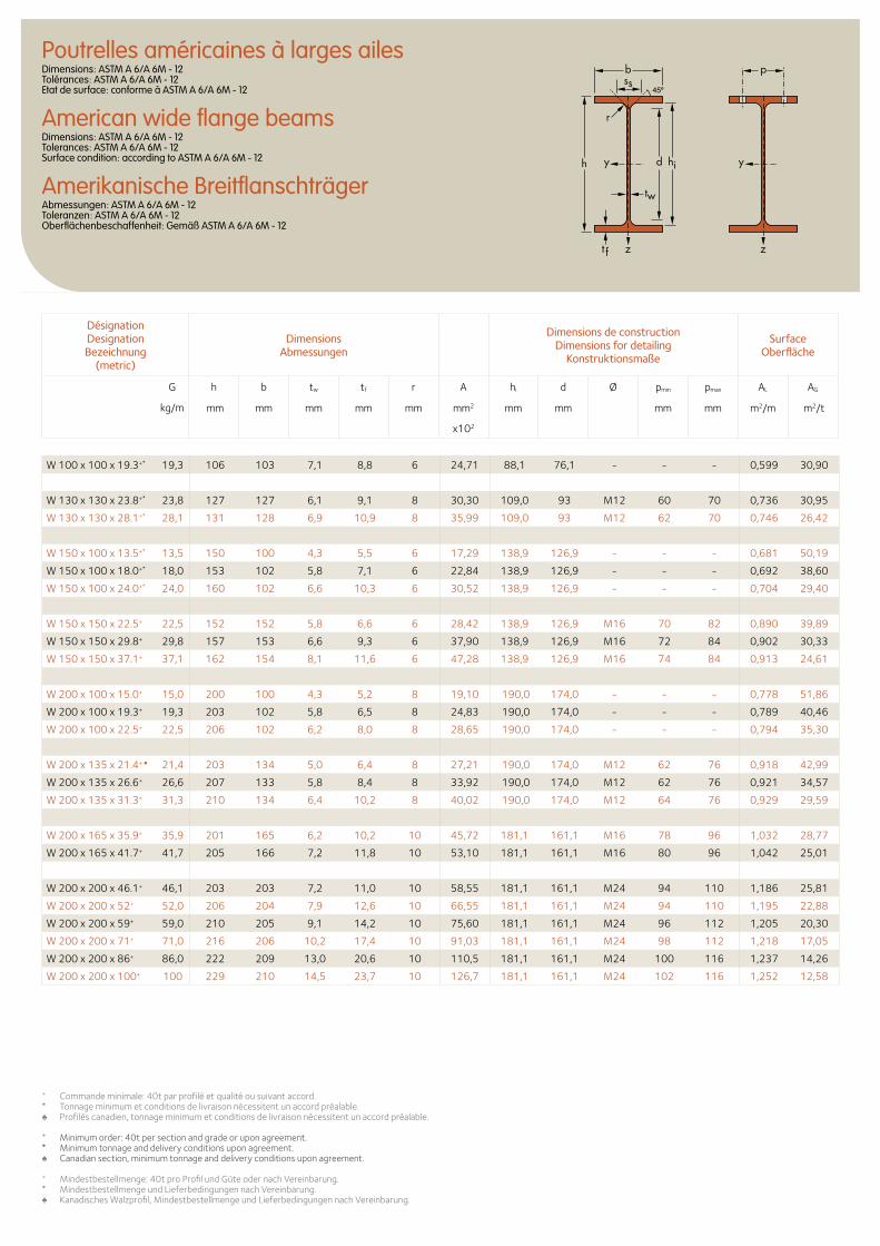
Poutrelles américaines à larges ailesDimensions: ASTM A 6/A 6M - 12 Tolérances: ASTM A 6/A 6M - 12 Etat de surface: conforme à ASTM A 6/A 6M - 12
American wide flange beamsDimensions: ASTM A 6/A 6M - 12 Tolerances: ASTM A 6/A 6M - 12 Surface condition: according to ASTM A 6/A 6M - 12
Amerikanische BreitflanschträgerAbmessungen: ASTM A 6/A 6M - 12 Toleranzen: ASTM A 6/A 6M - 12 Oberflächenbeschaffenheit: Gemäß ASTM A 6/A 6M - 12
Désignation Designation Bezeichnung
(metric)
Dimensions Abmessungen
Dimensions de construction Dimensions for detailing
Konstruktionsmaße
Surface Oberfläche
G
kg/m
h b tw tf r A hi d Ø pmin pmax AL AG
mm mm mm mm mm mm2 mm mm mm mm m2/m m2/t
x102
b
r
yy dh
tw
ss
zzt f
hi
p
W 100 x 100 x 19.3+* 19,3 106 103 7,1 8,8 6 24,71 88,1 76,1 - - - 0,599 30,90
W 130 x 130 x 23.8+* 23,8 127 127 6,1 9,1 8 30,30 109,0 93 M12 60 70 0,736 30,95
W 130 x 130 x 28.1+* 28,1 131 128 6,9 10,9 8 35,99 109,0 93 M12 62 70 0,746 26,42
W 150 x 100 x 13.5+* 13,5 150 100 4,3 5,5 6 17,29 138,9 126,9 - - - 0,681 50,19
W 150 x 100 x 18.0+* 18,0 153 102 5,8 7,1 6 22,84 138,9 126,9 - - - 0,692 38,60
W 150 x 100 x 24.0+* 24,0 160 102 6,6 10,3 6 30,52 138,9 126,9 - - - 0,704 29,40
W 150 x 150 x 22.5+ 22,5 152 152 5,8 6,6 6 28,42 138,9 126,9 M16 70 82 0,890 39,89
W 150 x 150 x 29.8+ 29,8 157 153 6,6 9,3 6 37,90 138,9 126,9 M16 72 84 0,902 30,33
W 150 x 150 x 37.1+ 37,1 162 154 8,1 11,6 6 47,28 138,9 126,9 M16 74 84 0,913 24,61
W 200 x 100 x 15.0+ 15,0 200 100 4,3 5,2 8 19,10 190,0 174,0 - - - 0,778 51,86
W 200 x 100 x 19.3+ 19,3 203 102 5,8 6,5 8 24,83 190,0 174,0 - - - 0,789 40,46
W 200 x 100 x 22.5+ 22,5 206 102 6,2 8,0 8 28,65 190,0 174,0 - - - 0,794 35,30
W 200 x 135 x 21.4+ ♠ 21,4 203 134 5,0 6,4 8 27,21 190,0 174,0 M12 62 76 0,918 42,99
W 200 x 135 x 26.6+ 26,6 207 133 5,8 8,4 8 33,92 190,0 174,0 M12 62 76 0,921 34,57
W 200 x 135 x 31.3+ 31,3 210 134 6,4 10,2 8 40,02 190,0 174,0 M12 64 76 0,929 29,59
W 200 x 165 x 35.9+ 35,9 201 165 6,2 10,2 10 45,72 181,1 161,1 M16 78 96 1,032 28,77
W 200 x 165 x 41.7+ 41,7 205 166 7,2 11,8 10 53,10 181,1 161,1 M16 80 96 1,042 25,01
W 200 x 200 x 46.1+ 46,1 203 203 7,2 11,0 10 58,55 181,1 161,1 M24 94 110 1,186 25,81
W 200 x 200 x 52+ 52,0 206 204 7,9 12,6 10 66,55 181,1 161,1 M24 94 110 1,195 22,88
W 200 x 200 x 59+ 59,0 210 205 9,1 14,2 10 75,60 181,1 161,1 M24 96 112 1,205 20,30
W 200 x 200 x 71+ 71,0 216 206 10,2 17,4 10 91,03 181,1 161,1 M24 98 112 1,218 17,05
W 200 x 200 x 86+ 86,0 222 209 13,0 20,6 10 110,5 181,1 161,1 M24 100 116 1,237 14,26
W 200 x 200 x 100+ 100 229 210 14,5 23,7 10 126,7 181,1 161,1 M24 102 116 1,252 12,58
+ Commande minimale: 40t par profilé et qualité ou suivant accord. * Tonnage minimum et conditions de livraison nécessitent un accord préalable.♠ Profilés canadien, tonnage minimum et conditions de livraison nécessitent un accord préalable.
+ Minimum order: 40t per section and grade or upon agreement.* Minimum tonnage and delivery conditions upon agreement.♠ Canadian section, minimum tonnage and delivery conditions upon agreement.
+ Mindestbestellmenge: 40t pro Profil und Güte oder nach Vereinbarung.* Mindestbestellmenge und Lieferbedingungen nach Vereinbarung.♠ Kanadisches Walzprofil, Mindestbestellmenge und Lieferbedingungen nach Vereinbarung.
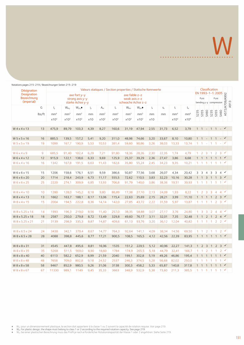
151
W
♦ Wpl: pour un dimensionnement plastique, la section doit appartenir à la classe 1 ou 2 suivant la capacité de rotation requise. Voir page 219.♦ Wpl: for plastic design, the shape must belong to class 1 or 2 according to the required rotation capacity. See page 219. ♦ Wpl: bei einer plastischen Berechnung muss das Profil je nach erforderlicher Rotationskapazität der Klasse 1 oder 2 angehören. Siehe Seite 219.
W 4 x 4 x 13 13 475,9 89,79 103,3 4,39 8,27 160,6 31,19 47,94 2,55 31,73 6,52 3,79 1 1 - 1 1 -
W 5 x 5 x 16 16 885,5 139,5 157,2 5,41 9,20 311,0 48,98 74,66 3,20 33,67 8,10 10,80 1 1 - 1 1 -
W 5 x 5 x 19 19 1099 167,7 190,9 5,53 10,53 381,4 59,60 90,86 3,26 38,03 13,33 13,74 1 1 - 1 1 -
W 6 x 4 x 9 9 685,5 91,40 102,4 6,29 7,21 91,80 18,36 28,26 2,30 22,35 1,74 4,79 1 2 3 1 2 3
W 6 x 4 x 12 12 915,9 122,1 138,6 6,33 9,69 125,9 25,37 39,29 2,36 27,47 3,86 6,68 1 1 1 1 1 1
W 6 x 4 x 16 16 1342 167,8 191,5 6,63 11,43 182,6 35,80 55,24 2,45 34,23 9,35 10,21 1 1 1 1 1 1
W 6 x 6 x 15 15 1206 158,6 176,1 6,51 9,59 386,6 50,87 77,56 3,68 26,07 4,34 20,42 3 3 4 3 3 4
W 6 x 6 x 20 20 1714 218,4 243,9 6,73 11,17 555,5 72,62 110,5 3,83 32,23 10,16 30,28 1 1 3 1 1 3
W 6 x 6 x 25 25 2220 274,1 309,9 6,85 13,93 706,8 91,79 140,0 3,86 38,36 19,51 39,93 1 1 1 1 1 1
W 8 x 4 x 10 10 1280 128,0 145,2 8,18 9,80 86,89 17,38 27,10 2,13 24,09 1,93 8,22 1 2 3 3 4 4
W 8 x 4 x 13 13 1662 163,7 188,1 8,17 13,06 115,4 22,63 35,69 2,15 28,21 3,99 11,10 1 1 1 1 2 3
W 8 x 4 x 15 15 2004 194,5 222,8 8,36 14,14 142,0 27,85 43,72 2,22 31,59 5,97 13,87 1 1 1 1 2 3
W 8 x 5.25 x 14 14 1993 196,3 219,0 8,56 11,40 257,0 38,35 58,88 3,07 27,17 3,76 24,80 1 3 3 2 4 4
W 8 x 5.25 x 18 18 2587 250,0 279,8 8,72 13,49 329,8 49,60 76,17 3,11 32,01 7,35 32,48 1 1 2 1 2 4
W 8 x 5.25 x 21 21 3139 298,9 335,3 8,87 14,87 409,6 61,13 93,76 3,20 36,12 12,04 40,82 1 1 1 1 2 2
W 8 x 6.5 x 24 24 3438 342,1 379,4 8,67 14,77 764,3 92,64 141,1 4,09 38,34 14,56 69,50 1 1 2 1 1 2
W 8 x 6.5 x 28 28 4088 398,8 445,6 8,77 17,21 900,5 108,5 165,5 4,12 42,56 22,39 83,95 1 1 1 1 1 1
W 8 x 8 x 31 31 4545 447,8 495,6 8,81 16,96 1535 151,2 229,5 5,12 40,96 22,27 141,3 1 2 3 1 2 3
W 8 x 8 x 35 35 5268 511,5 569,0 8,90 18,60 1784 174,9 265,5 5,18 44,79 32,41 166,7 1 1 2 1 1 2
W 8 x 8 x 40 40 6113 582,2 652,9 8,99 21,59 2040 199,1 302,8 5,19 49,26 46,86 195,4 1 1 1 1 1 1
W 8 x 8 x 48 48 7658 709,0 802,8 9,18 24,52 2537 246,3 374,5 5,28 56,68 82,02 250,0 1 1 1 1 1 1
W 8 x 8 x 58 58 9467 852,9 980,5 9,26 31,06 3138 300,3 458,2 5,33 65,87 140,8 317,8 1 1 1 1 1 1
W 8 x 8 x 67 67 11330 989,1 1149 9,45 35,33 3663 348,9 532,9 5,38 73,60 211,3 385,5 1 1 1 1 1 1
Désignation Designation Bezeichnung
(imperial)
Valeurs statiques / Section properties / Statische Kennwerte Classification EN 1993-1-1: 2005
A57
2/A
70
9/A
99
2
A91
3
axe fort y-y strong axis y-y
starke Achse y-y
axe faible z-z weak axis z-z
schwache Achse z-z Pure
bending y-y
Pure
compression
G Iy Wel.y Wpl.y♦ iy Avz Iz Wel.z Wpl.z♦ iz ss It Iw
S23
5
S35
5
S46
0
S23
5
S35
5
S46
0
lbs/ft mm4 mm3 mm3 mm mm2 mm4 mm3 mm3 mm mm mm4 mm6
x104 x103 x103 x10 x102 x104 x103 x103 x10 x104 x109
Notations pages 215-219 / Bezeichnungen Seiten 215-219
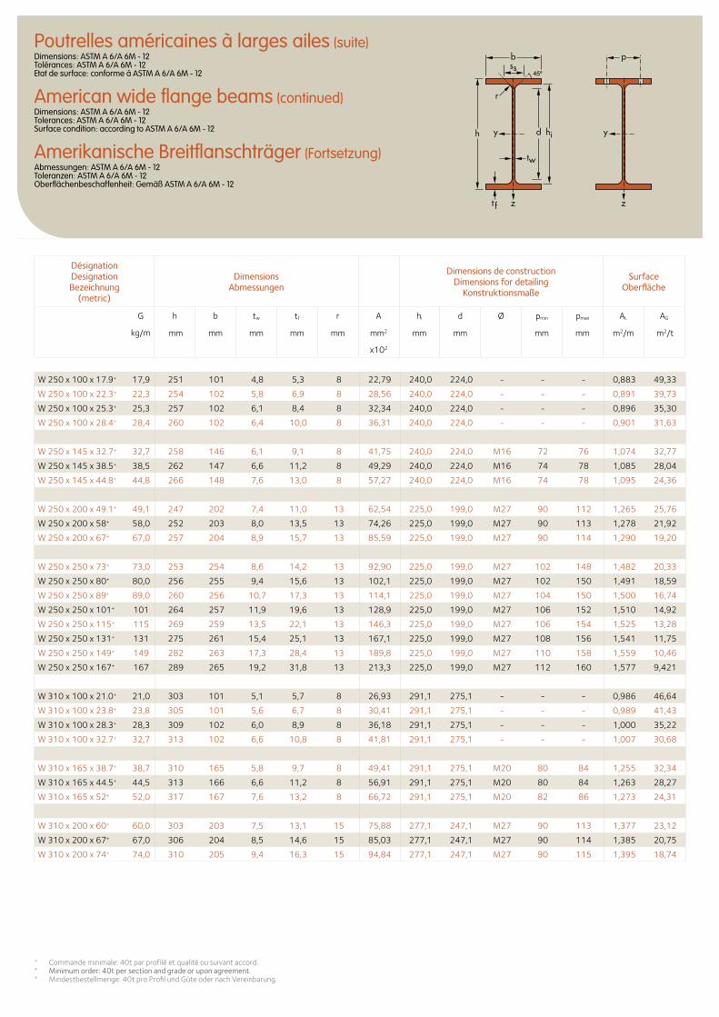
W 250 x 100 x 17.9+ 17,9 251 101 4,8 5,3 8 22,79 240,0 224,0 - - - 0,883 49,33
W 250 x 100 x 22.3+ 22,3 254 102 5,8 6,9 8 28,56 240,0 224,0 - - - 0,891 39,73
W 250 x 100 x 25.3+ 25,3 257 102 6,1 8,4 8 32,34 240,0 224,0 - - - 0,896 35,30
W 250 x 100 x 28.4+ 28,4 260 102 6,4 10,0 8 36,31 240,0 224,0 - - - 0,901 31,63
W 250 x 145 x 32.7+ 32,7 258 146 6,1 9,1 8 41,75 240,0 224,0 M16 72 76 1,074 32,77
W 250 x 145 x 38.5+ 38,5 262 147 6,6 11,2 8 49,29 240,0 224,0 M16 74 78 1,085 28,04
W 250 x 145 x 44.8+ 44,8 266 148 7,6 13,0 8 57,27 240,0 224,0 M16 74 78 1,095 24,36
W 250 x 200 x 49.1+ 49,1 247 202 7,4 11,0 13 62,54 225,0 199,0 M27 90 112 1,265 25,76
W 250 x 200 x 58+ 58,0 252 203 8,0 13,5 13 74,26 225,0 199,0 M27 90 113 1,278 21,92
W 250 x 200 x 67+ 67,0 257 204 8,9 15,7 13 85,59 225,0 199,0 M27 90 114 1,290 19,20
W 250 x 250 x 73+ 73,0 253 254 8,6 14,2 13 92,90 225,0 199,0 M27 102 148 1,482 20,33
W 250 x 250 x 80+ 80,0 256 255 9,4 15,6 13 102,1 225,0 199,0 M27 102 150 1,491 18,59
W 250 x 250 x 89+ 89,0 260 256 10,7 17,3 13 114,1 225,0 199,0 M27 104 150 1,500 16,74
W 250 x 250 x 101+ 101 264 257 11,9 19,6 13 128,9 225,0 199,0 M27 106 152 1,510 14,92
W 250 x 250 x 115+ 115 269 259 13,5 22,1 13 146,3 225,0 199,0 M27 106 154 1,525 13,28
W 250 x 250 x 131+ 131 275 261 15,4 25,1 13 167,1 225,0 199,0 M27 108 156 1,541 11,75
W 250 x 250 x 149+ 149 282 263 17,3 28,4 13 189,8 225,0 199,0 M27 110 158 1,559 10,46
W 250 x 250 x 167+ 167 289 265 19,2 31,8 13 213,3 225,0 199,0 M27 112 160 1,577 9,421
W 310 x 100 x 21.0+ 21,0 303 101 5,1 5,7 8 26,93 291,1 275,1 - - - 0,986 46,64
W 310 x 100 x 23.8+ 23,8 305 101 5,6 6,7 8 30,41 291,1 275,1 - - - 0,989 41,43
W 310 x 100 x 28.3+ 28,3 309 102 6,0 8,9 8 36,18 291,1 275,1 - - - 1,000 35,22
W 310 x 100 x 32.7+ 32,7 313 102 6,6 10,8 8 41,81 291,1 275,1 - - - 1,007 30,68
W 310 x 165 x 38.7+ 38,7 310 165 5,8 9,7 8 49,41 291,1 275,1 M20 80 84 1,255 32,34
W 310 x 165 x 44.5+ 44,5 313 166 6,6 11,2 8 56,91 291,1 275,1 M20 80 84 1,263 28,27
W 310 x 165 x 52+ 52,0 317 167 7,6 13,2 8 66,72 291,1 275,1 M20 82 86 1,273 24,31
W 310 x 200 x 60+ 60,0 303 203 7,5 13,1 15 75,88 277,1 247,1 M27 90 113 1,377 23,12
W 310 x 200 x 67+ 67,0 306 204 8,5 14,6 15 85,03 277,1 247,1 M27 90 114 1,385 20,75
W 310 x 200 x 74+ 74,0 310 205 9,4 16,3 15 94,84 277,1 247,1 M27 90 115 1,395 18,74
+ Commande minimale: 40t par profilé et qualité ou suivant accord. + Minimum order: 40t per section and grade or upon agreement.+ Mindestbestellmenge: 40t pro Profil und Güte oder nach Vereinbarung.
Poutrelles américaines à larges ailes (suite)Dimensions: ASTM A 6/A 6M - 12 Tolérances: ASTM A 6/A 6M - 12 Etat de surface: conforme à ASTM A 6/A 6M - 12
American wide flange beams (continued)Dimensions: ASTM A 6/A 6M - 12 Tolerances: ASTM A 6/A 6M - 12 Surface condition: according to ASTM A 6/A 6M - 12
Amerikanische Breitflanschträger (Fortsetzung)Abmessungen: ASTM A 6/A 6M - 12 Toleranzen: ASTM A 6/A 6M - 12 Oberflächenbeschaffenheit: Gemäß ASTM A 6/A 6M - 12
Désignation Designation Bezeichnung
(metric)
Dimensions Abmessungen
Dimensions de construction Dimensions for detailing
Konstruktionsmaße
Surface Oberfläche
G
kg/m
h b tw tf r A hi d Ø pmin pmax AL AG
mm mm mm mm mm mm2 mm mm mm mm m2/m m2/t
x102
b
r
yy dh
tw
ss
zzt f
hi
p
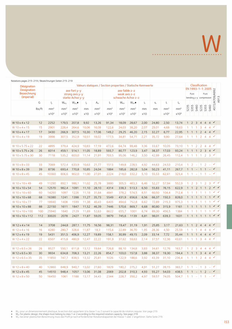
153
W 10 x 4 x 12 12 2252 179,5 207,8 9,92 13,26 91,34 18,09 28,67 2,00 24,80 2,50 13,74 1 2 3 4 4 4
W 10 x 4 x 15 15 2901 228,4 264,6 10,06 16,08 122,6 24,03 38,20 2,07 29,01 4,68 18,63 1 1 1 3 4 4
W 10 x 4 x 17 17 3430 266,9 307,5 10,30 17,06 149,2 29,25 46,20 2,15 32,27 6,77 22,95 1 1 1 2 4 4
W 10 x 4 x 19 19 3998 307,5 352,9 10,51 18,02 177,5 34,81 54,71 2,21 35,72 9,80 27,64 1 1 1 2 4 4
W 10 x 5.75 x 22 22 4895 379,4 424,9 10,83 17,19 472,6 64,74 99,48 3,36 33,67 10,05 73,10 1 1 2 2 4 4
W 10 x 5.75 x 26 26 6014 459,1 514,1 11,05 18,89 593,7 80,77 123,9 3,47 38,37 17,03 93,24 1 1 1 2 3 4
W 10 x 5.75 x 30 30 7118 535,2 603,0 11,14 21,91 703,5 95,06 146,2 3,50 42,99 26,45 112,4 1 1 1 1 2 3
W 10 x 8 x 33 33 7069 572,4 633,9 10,63 21,77 1513 149,8 228,5 4,92 44,63 24,53 210,4 1 2 - 1 2 -
W 10 x 8 x 39 39 8736 693,4 770,8 10,85 24,04 1884 185,6 282,8 5,04 50,23 41,11 267,7 1 1 - 1 1 -
W 10 x 8 x 45 45 10360 806,6 902,0 11,00 27,01 2224 218,0 332,2 5,10 55,53 62,61 323,4 1 1 - 1 1 -
W 10 x 10 x 49 49 11290 892,1 986,1 11,02 25,78 3880 305,5 463,3 6,46 52,27 57,94 552,9 1 2 3 1 2 3
W 10 x 10 x 54 54 12570 982,4 1091 11,10 28,10 4314 338,3 513,3 6,50 55,83 76,15 622,9 1 1 2 1 1 2
W 10 x 10 x 60 60 14260 1097 1226 11,18 31,84 4841 378,2 574,5 6,51 60,50 104,4 712,4 1 1 1 1 1 1
W 10 x 10 x 68 68 16380 1241 1398 11,27 35,73 5549 431,9 656,6 6,56 66,37 150,3 828,0 1 1 1 1 1 1
W 10 x 10 x 77 77 18940 1408 1599 11,38 40,43 6405 494,6 752,8 6,62 72,89 215,3 975,3 1 1 1 1 1 1
W 10 x 10 x 88 88 22150 1611 1847 11,52 46,39 7446 570,6 869,7 6,68 80,80 315,9 1161 1 1 1 1 1 1
W 10 x 10 x 100 100 25940 1840 2129 11,69 52,63 8622 655,7 1001 6,74 89,30 456,5 1384 1 1 1 1 1 1
W 10 x 10 x 112 112 30020 2078 2427 11,87 59,05 9879 745,6 1139 6,81 98,01 639,3 1631 1 1 1 1 1 1
W 12 x 4 x 14 14 3708 244,8 287,1 11,75 16,56 98,31 19,47 31,19 1,91 25,85 3,17 21,63 1 1 2 4 4 4
W 12 x 4 x 16 16 4280 280,7 328,6 11,87 18,3 115,6 22,89 36,70 1,95 28,36 4,50 25,59 1 1 1 4 4 4
W 12 x 4 x 19 19 5431 351,5 406,9 12,27 19,89 158,1 30,99 49,15 2,09 33,14 7,72 35,44 1 1 1 4 4 4
W 12 x 4 x 22 22 6507 415,8 480,9 12,47 22,22 191,9 37,62 59,63 2,14 37,57 12,36 43,61 1 1 1 3 4 4
W 12 x 6.5 x 26 26 8527 550,1 611,8 13,12 19,64 726,8 88,10 134,8 3,83 34,61 12,76 163,7 1 2 3 4 4 4
W 12 x 6.5 x 30 30 9934 634,8 708,3 13,21 22,26 854,7 103,0 157,8 3,88 38,37 19,30 194,4 1 1 1 3 4 4
W 12 x 6.5 x 35 35 11850 747,7 838,5 13,32 25,81 1026 122,9 188,6 3,92 43,39 31,10 236,4 1 1 1 2 4 4
W 12 x 8 x 40 40 12860 848,9 940,7 13,02 27,60 1829 180,2 275,2 4,91 51,27 39,15 383,7 1 1 - 1 3 -
W 12 x 8 x 45 45 14510 948,4 1057 13,06 31,08 2069 202,8 310,3 4,93 55,27 54,03 438,5 1 1 - 1 2 -
W 12 x 8 x 50 50 16450 1061 1188 13,17 34,43 2344 228,7 350,2 4,97 59,57 74,05 504,7 1 1 - 1 1 -
♦ Wpl: pour un dimensionnement plastique, la section doit appartenir à la classe 1 ou 2 suivant la capacité de rotation requise. Voir page 219.♦ Wpl: for plastic design, the shape must belong to class 1 or 2 according to the required rotation capacity. See page 219. ♦ Wpl: bei einer plastischen Berechnung muss das Profil je nach erforderlicher Rotationskapazität der Klasse 1 oder 2 angehören. Siehe Seite 219.
WDésignation Designation Bezeichnung
(imperial)
Valeurs statiques / Section properties / Statische Kennwerte Classification EN 1993-1-1: 2005
A57
2/A
70
9/A
99
2
A91
3
axe fort y-y strong axis y-y
starke Achse y-y
axe faible z-z weak axis z-z
schwache Achse z-z Pure
bending y-y
Pure
compression
G Iy Wel.y Wpl.y♦ iy Avz Iz Wel.z Wpl.z♦ iz ss It Iw
S23
5
S35
5
S46
0
S23
5
S35
5
S46
0
lbs/ft mm4 mm3 mm3 mm mm2 mm4 mm3 mm3 mm mm mm4 mm6
x104 x103 x103 x10 x102 x104 x103 x103 x10 x104 x109
Notations pages 215-219 / Bezeichnungen Seiten 215-219
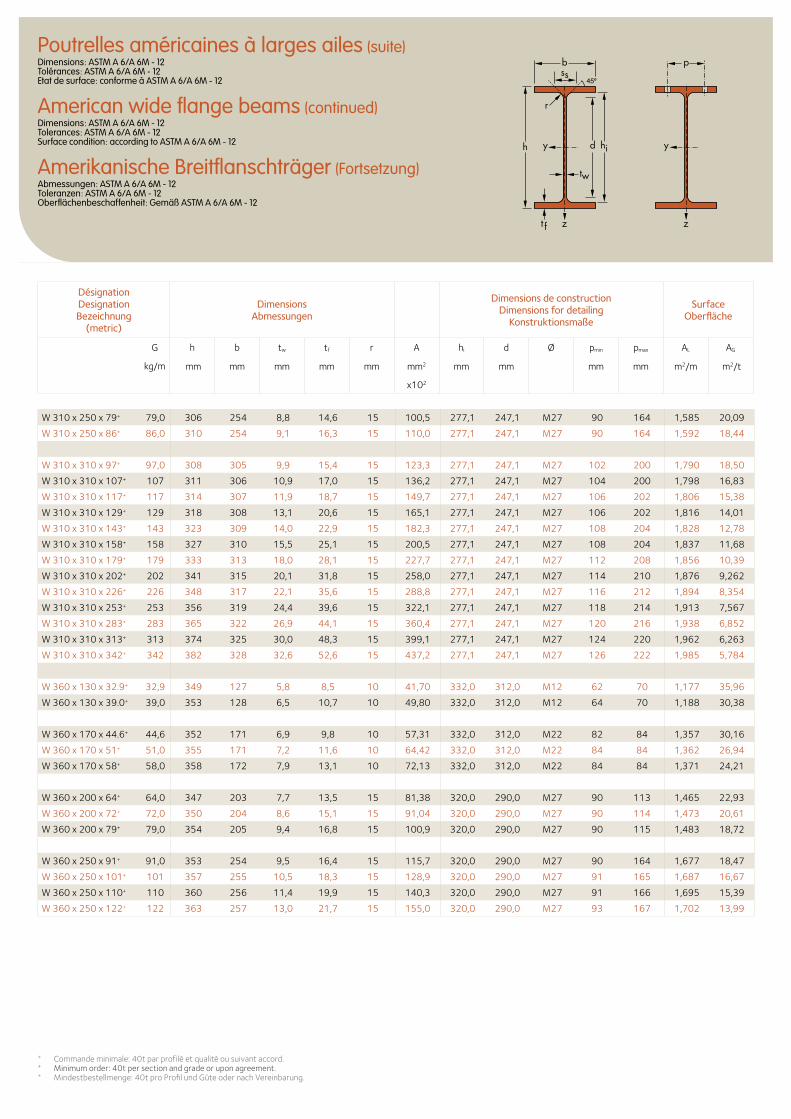
+ Commande minimale: 40t par profilé et qualité ou suivant accord. + Minimum order: 40t per section and grade or upon agreement.+ Mindestbestellmenge: 40t pro Profil und Güte oder nach Vereinbarung.
Désignation Designation Bezeichnung
(metric)
Dimensions Abmessungen
Dimensions de construction Dimensions for detailing
Konstruktionsmaße
Surface Oberfläche
G
kg/m
h b tw tf r A hi d Ø pmin pmax AL AG
mm mm mm mm mm mm2 mm mm mm mm m2/m m2/t
x102
b
r
yy dh
tw
ss
zzt f
hi
p
W 310 x 250 x 79+ 79,0 306 254 8,8 14,6 15 100,5 277,1 247,1 M27 90 164 1,585 20,09
W 310 x 250 x 86+ 86,0 310 254 9,1 16,3 15 110,0 277,1 247,1 M27 90 164 1,592 18,44
W 310 x 310 x 97+ 97,0 308 305 9,9 15,4 15 123,3 277,1 247,1 M27 102 200 1,790 18,50
W 310 x 310 x 107+ 107 311 306 10,9 17,0 15 136,2 277,1 247,1 M27 104 200 1,798 16,83
W 310 x 310 x 117+ 117 314 307 11,9 18,7 15 149,7 277,1 247,1 M27 106 202 1,806 15,38
W 310 x 310 x 129+ 129 318 308 13,1 20,6 15 165,1 277,1 247,1 M27 106 202 1,816 14,01
W 310 x 310 x 143+ 143 323 309 14,0 22,9 15 182,3 277,1 247,1 M27 108 204 1,828 12,78
W 310 x 310 x 158+ 158 327 310 15,5 25,1 15 200,5 277,1 247,1 M27 108 204 1,837 11,68
W 310 x 310 x 179+ 179 333 313 18,0 28,1 15 227,7 277,1 247,1 M27 112 208 1,856 10,39
W 310 x 310 x 202+ 202 341 315 20,1 31,8 15 258,0 277,1 247,1 M27 114 210 1,876 9,262
W 310 x 310 x 226+ 226 348 317 22,1 35,6 15 288,8 277,1 247,1 M27 116 212 1,894 8,354
W 310 x 310 x 253+ 253 356 319 24,4 39,6 15 322,1 277,1 247,1 M27 118 214 1,913 7,567
W 310 x 310 x 283+ 283 365 322 26,9 44,1 15 360,4 277,1 247,1 M27 120 216 1,938 6,852
W 310 x 310 x 313+ 313 374 325 30,0 48,3 15 399,1 277,1 247,1 M27 124 220 1,962 6,263
W 310 x 310 x 342+ 342 382 328 32,6 52,6 15 437,2 277,1 247,1 M27 126 222 1,985 5,784
W 360 x 130 x 32.9+ 32,9 349 127 5,8 8,5 10 41,70 332,0 312,0 M12 62 70 1,177 35,96
W 360 x 130 x 39.0+ 39,0 353 128 6,5 10,7 10 49,80 332,0 312,0 M12 64 70 1,188 30,38
W 360 x 170 x 44.6+ 44,6 352 171 6,9 9,8 10 57,31 332,0 312,0 M22 82 84 1,357 30,16
W 360 x 170 x 51+ 51,0 355 171 7,2 11,6 10 64,42 332,0 312,0 M22 84 84 1,362 26,94
W 360 x 170 x 58+ 58,0 358 172 7,9 13,1 10 72,13 332,0 312,0 M22 84 84 1,371 24,21
W 360 x 200 x 64+ 64,0 347 203 7,7 13,5 15 81,38 320,0 290,0 M27 90 113 1,465 22,93
W 360 x 200 x 72+ 72,0 350 204 8,6 15,1 15 91,04 320,0 290,0 M27 90 114 1,473 20,61
W 360 x 200 x 79+ 79,0 354 205 9,4 16,8 15 100,9 320,0 290,0 M27 90 115 1,483 18,72
W 360 x 250 x 91+ 91,0 353 254 9,5 16,4 15 115,7 320,0 290,0 M27 90 164 1,677 18,47
W 360 x 250 x 101+ 101 357 255 10,5 18,3 15 128,9 320,0 290,0 M27 91 165 1,687 16,67
W 360 x 250 x 110+ 110 360 256 11,4 19,9 15 140,3 320,0 290,0 M27 91 166 1,695 15,39
W 360 x 250 x 122+ 122 363 257 13,0 21,7 15 155,0 320,0 290,0 M27 93 167 1,702 13,99
Poutrelles américaines à larges ailes (suite)Dimensions: ASTM A 6/A 6M - 12 Tolérances: ASTM A 6/A 6M - 12 Etat de surface: conforme à ASTM A 6/A 6M - 12
American wide flange beams (continued)Dimensions: ASTM A 6/A 6M - 12 Tolerances: ASTM A 6/A 6M - 12 Surface condition: according to ASTM A 6/A 6M - 12
Amerikanische Breitflanschträger (Fortsetzung)Abmessungen: ASTM A 6/A 6M - 12 Toleranzen: ASTM A 6/A 6M - 12 Oberflächenbeschaffenheit: Gemäß ASTM A 6/A 6M - 12
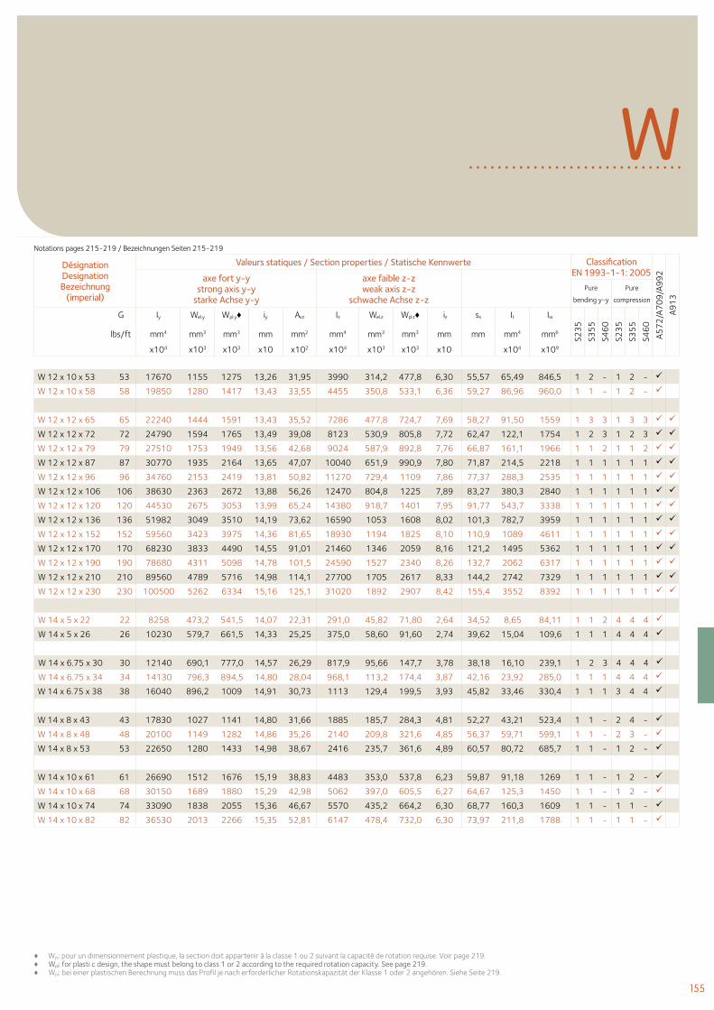
155
♦ Wpl: pour un dimensionnement plastique, la section doit appartenir à la classe 1 ou 2 suivant la capacité de rotation requise. Voir page 219.♦ Wpl: for plasti c design, the shape must belong to class 1 or 2 according to the required rotation capacity. See page 219. ♦ Wpl: bei einer plastischen Berechnung muss das Profil je nach erforderlicher Rotationskapazität der Klasse 1 oder 2 angehören. Siehe Seite 219.
WDésignation Designation Bezeichnung
(imperial)
Valeurs statiques / Section properties / Statische Kennwerte Classification EN 1993-1-1: 2005
A57
2/A
70
9/A
99
2
A91
3
axe fort y-y strong axis y-y
starke Achse y-y
axe faible z-z weak axis z-z
schwache Achse z-z Pure
bending y-y
Pure
compression
G Iy Wel.y Wpl.y♦ iy Avz Iz Wel.z Wpl.z♦ iz ss It Iw
S23
5
S35
5
S46
0
S23
5
S35
5
S46
0
lbs/ft mm4 mm3 mm3 mm mm2 mm4 mm3 mm3 mm mm mm4 mm6
x104 x103 x103 x10 x102 x104 x103 x103 x10 x104 x109
W 12 x 10 x 53 53 17670 1155 1275 13,26 31,95 3990 314,2 477,8 6,30 55,57 65,49 846,5 1 2 - 1 2 -
W 12 x 10 x 58 58 19850 1280 1417 13,43 33,55 4455 350,8 533,1 6,36 59,27 86,96 960,0 1 1 - 1 2 -
W 12 x 12 x 65 65 22240 1444 1591 13,43 35,52 7286 477,8 724,7 7,69 58,27 91,50 1559 1 3 3 1 3 3
W 12 x 12 x 72 72 24790 1594 1765 13,49 39,08 8123 530,9 805,8 7,72 62,47 122,1 1754 1 2 3 1 2 3
W 12 x 12 x 79 79 27510 1753 1949 13,56 42,68 9024 587,9 892,8 7,76 66,87 161,1 1966 1 1 2 1 1 2
W 12 x 12 x 87 87 30770 1935 2164 13,65 47,07 10040 651,9 990,9 7,80 71,87 214,5 2218 1 1 1 1 1 1
W 12 x 12 x 96 96 34760 2153 2419 13,81 50,82 11270 729,4 1109 7,86 77,37 288,3 2535 1 1 1 1 1 1
W 12 x 12 x 106 106 38630 2363 2672 13,88 56,26 12470 804,8 1225 7,89 83,27 380,3 2840 1 1 1 1 1 1
W 12 x 12 x 120 120 44530 2675 3053 13,99 65,24 14380 918,7 1401 7,95 91,77 543,7 3338 1 1 1 1 1 1
W 12 x 12 x 136 136 51982 3049 3510 14,19 73,62 16590 1053 1608 8,02 101,3 782,7 3959 1 1 1 1 1 1
W 12 x 12 x 152 152 59560 3423 3975 14,36 81,65 18930 1194 1825 8,10 110,9 1089 4611 1 1 1 1 1 1
W 12 x 12 x 170 170 68230 3833 4490 14,55 91,01 21460 1346 2059 8,16 121,2 1495 5362 1 1 1 1 1 1
W 12 x 12 x 190 190 78680 4311 5098 14,78 101,5 24590 1527 2340 8,26 132,7 2062 6317 1 1 1 1 1 1
W 12 x 12 x 210 210 89560 4789 5716 14,98 114,1 27700 1705 2617 8,33 144,2 2742 7329 1 1 1 1 1 1
W 12 x 12 x 230 230 100500 5262 6334 15,16 125,1 31020 1892 2907 8,42 155,4 3552 8392 1 1 1 1 1 1
W 14 x 5 x 22 22 8258 473,2 541,5 14,07 22,31 291,0 45,82 71,80 2,64 34,52 8,65 84,11 1 1 2 4 4 4
W 14 x 5 x 26 26 10230 579,7 661,5 14,33 25,25 375,0 58,60 91,60 2,74 39,62 15,04 109,6 1 1 1 4 4 4
W 14 x 6.75 x 30 30 12140 690,1 777,0 14,57 26,29 817,9 95,66 147,7 3,78 38,18 16,10 239,1 1 2 3 4 4 4
W 14 x 6.75 x 34 34 14130 796,3 894,5 14,80 28,04 968,1 113,2 174,4 3,87 42,16 23,92 285,0 1 1 1 4 4 4
W 14 x 6.75 x 38 38 16040 896,2 1009 14,91 30,73 1113 129,4 199,5 3,93 45,82 33,46 330,4 1 1 1 3 4 4
W 14 x 8 x 43 43 17830 1027 1141 14,80 31,66 1885 185,7 284,3 4,81 52,27 43,21 523,4 1 1 - 2 4 -
W 14 x 8 x 48 48 20100 1149 1282 14,86 35,26 2140 209,8 321,6 4,85 56,37 59,71 599,1 1 1 - 2 3 -
W 14 x 8 x 53 53 22650 1280 1433 14,98 38,67 2416 235,7 361,6 4,89 60,57 80,72 685,7 1 1 - 1 2 -
W 14 x 10 x 61 61 26690 1512 1676 15,19 38,83 4483 353,0 537,8 6,23 59,87 91,18 1269 1 1 - 1 2 -
W 14 x 10 x 68 68 30150 1689 1880 15,29 42,98 5062 397,0 605,5 6,27 64,67 125,3 1450 1 1 - 1 2 -
W 14 x 10 x 74 74 33090 1838 2055 15,36 46,67 5570 435,2 664,2 6,30 68,77 160,3 1609 1 1 - 1 1 -
W 14 x 10 x 82 82 36530 2013 2266 15,35 52,81 6147 478,4 732,0 6,30 73,97 211,8 1788 1 1 - 1 1 -
Notations pages 215-219 / Bezeichnungen Seiten 215-219
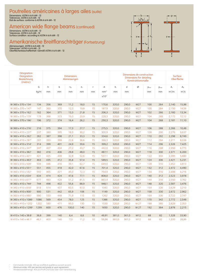
Désignation Designation Bezeichnung
(metric)
Dimensions Abmessungen
Dimensions de construction Dimensions for detailing
Konstruktionsmaße
Surface Oberfläche
G
kg/m
h b tw tf r A hi d Ø pmin pmax AL AG
mm mm mm mm mm mm2 mm mm mm mm m2/m m2/t
x102
b
r
yy dh
tw
ss
zzt f
hi
p
W 360 x 370 x 134+ 134 356 369 11,2 18,0 15 170,6 320,0 290,0 M27 100 264 2,140 15,98
W 360 x 370 x 147+ 147 360 370 12,3 19,8 15 187,9 320,0 290,0 M27 100 264 2,150 14,58
W 360 x 370 x 162+ 162 364 371 13,3 21,8 15 206,3 320,0 290,0 M27 102 266 2,160 13,34
W 360 x 370 x 179+ 179 368 373 15,0 23,9 15 228,3 320,0 290,0 M27 104 268 2,172 12,12
W 360 x 370 x 196+ 196 372 374 16,4 26,2 15 250,3 320,0 290,0 M27 104 268 2,181 11,10
W 360 x 410 x 216+ 216 375 394 17,3 27,7 15 275,5 320,0 290,0 M27 106 288 2,266 10,48
W 360 x 410 x 237+ 237 380 395 18,9 30,2 15 300,9 320,0 290,0 M27 108 290 2,276 9,637
W 360 x 410 x 262+ 262 387 398 21,1 33,3 15 334,6 320,0 290,0 M27 110 292 2,298 8,749
W 360 x 410 x 287+ 287 393 399 22,6 36,6 15 366,3 320,0 290,0 M27 112 294 2,311 8,038
W 360 x 410 x 314+ 314 399 401 24,9 39,6 15 399,2 320,0 290,0 M27 114 296 2,326 7,425
W 360 x 410 x 347+ 347 407 404 27,2 43,7 15 442,0 320,0 290,0 M27 116 298 2,350 6,773
W 360 x 410 x 382+ 382 416 406 29,8 48,0 15 487,1 320,0 290,0 M27 118 300 2,371 6,200
W 360 x 410 x 421+ 421 425 409 32,8 52,6 15 537,1 320,0 290,0 M27 122 304 2,395 5,680
W 360 x 410 x 463+ 463 435 412 35,8 57,4 15 589,5 320,0 290,0 M27 124 306 2,421 5,231
W 360 x 410 x 509+ 509 446 416 39,1 62,7 15 649,0 320,0 290,0 M27 128 310 2,452 4,813
W 360 x 410 x 551+ 551 455 418 42,0 67,6 15 701,4 320,0 290,0 M27 132 312 2,472 4,490
W 360 x 410 x 592+ 592 465 421 45,0 72,3 15 754,9 320,0 290,0 M27 134 316 2,498 4,216
W 360 x 410 x 634+ 634 474 424 47,6 77,1 15 808,0 320,0 290,0 M27 140 312 2,523 3,978
W 360 x 410 x 677+ 677 483 428 51,2 81,5 15 863,4 320,0 290,0 M27 144 316 2,550 3,762
W 360 x 410 x 744+ 744 498 432 55,6 88,9 15 948,1 320,0 290,0 M27 148 320 2,587 3,476
W 360 x 410 x 818+ 818 514 437 60,5 97,0 15 1043 320,0 290,0 M27 154 326 2,629 3,210
W 360 x 410 x 900+ 900 531 442 65,9 106 15 1149 320,0 290,0 M27 158 330 2,672 2,962
W 360 x 410 x 990+ 990 550 448 71,9 115 15 1262 320,0 290,0 M27 164 336 2,722 2,747
W 360 x 410 x 1086+ 1086 569 454 78,0 125 15 1386 320,0 290,0 M27 170 342 2,772 2,548
W 360 x 410 x 1202+ 1202 580 471 95,0 130 15 1530 320,0 290,0 M 27 188 360 2,828 2,353
W 360 x 410 x 1299+ 1299 600 476 100,0 140 15 1650 320,0 290,0 M 27 192 364 2,878 2,215
W 410 x 140 x 38.8+ 38,8 399 140 6,4 8,8 10 49,91 381,0 361,0 M12 68 82 1,328 33,90
W 410 x 140 x 46.1+ 46,1 403 140 7,0 11,2 10 58,86 381,0 361,0 M12 68 82 1,335 28,89
+ Commande minimale: 40t par profilé et qualité ou suivant accord.+ Minimum order: 40t per section and grade or upon agreement.+ Mindestbestellmenge: 40t pro Profil und Güte oder nach Vereinbarung.
Poutrelles américaines à larges ailes (suite)Dimensions: ASTM A 6/A 6M - 12 Tolérances: ASTM A 6/A 6M - 12 Etat de surface: conforme à ASTM A 6/A 6M - 12
American wide flange beams (continued)Dimensions: ASTM A 6/A 6M - 12 Tolerances: ASTM A 6/A 6M - 12 Surface condition: according to ASTM A 6/A 6M - 12
Amerikanische Breitflanschträger (Fortsetzung)Abmessungen: ASTM A 6/A 6M - 12 Toleranzen: ASTM A 6/A 6M - 12 Oberflächenbeschaffenheit: Gemäß ASTM A 6/A 6M - 12
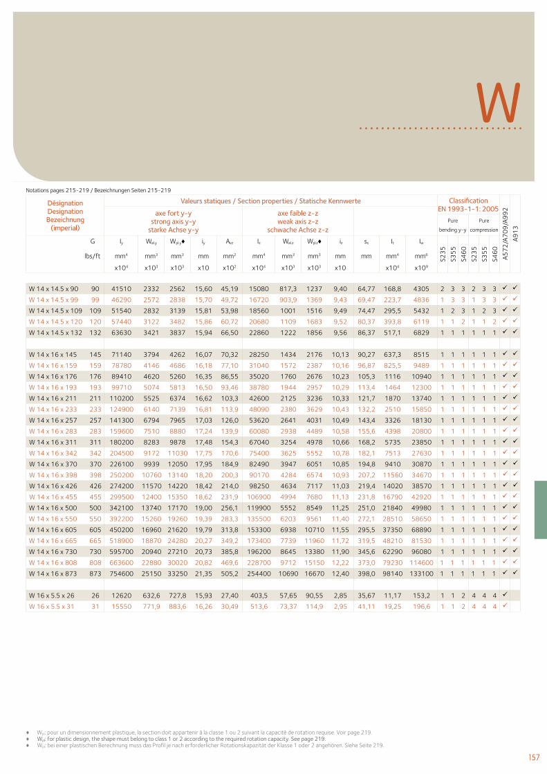
157
♦ Wpl: pour un dimensionnement plastique, la section doit appartenir à la classe 1 ou 2 suivant la capacité de rotation requise. Voir page 219.♦ Wpl: for plastic design, the shape must belong to class 1 or 2 according to the required rotation capacity. See page 219. ♦ Wpl: bei einer plastischen Berechnung muss das Profil je nach erforderlicher Rotationskapazität der Klasse 1 oder 2 angehören. Siehe Seite 219.
WDésignation Designation Bezeichnung
(imperial)
Valeurs statiques / Section properties / Statische Kennwerte Classification EN 1993-1-1: 2005
A57
2/A
70
9/A
99
2
A91
3
axe fort y-y strong axis y-y
starke Achse y-y
axe faible z-z weak axis z-z
schwache Achse z-z Pure
bending y-y
Pure
compression
G Iy Wel.y Wpl.y♦ iy Avz Iz Wel.z Wpl.z♦ iz ss It Iw
S23
5
S35
5
S46
0
S23
5
S35
5
S46
0
lbs/ft mm4 mm3 mm3 mm mm2 mm4 mm3 mm3 mm mm mm4 mm6
x104 x103 x103 x10 x102 x104 x103 x103 x10 x104 x109
W 14 x 14.5 x 90 90 41510 2332 2562 15,60 45,19 15080 817,3 1237 9,40 64,77 168,8 4305 2 3 3 2 3 3
W 14 x 14.5 x 99 99 46290 2572 2838 15,70 49,72 16720 903,9 1369 9,43 69,47 223,7 4836 1 3 3 1 3 3
W 14 x 14.5 x 109 109 51540 2832 3139 15,81 53,98 18560 1001 1516 9,49 74,47 295,5 5432 1 2 3 1 2 3
W 14 x 14.5 x 120 120 57440 3122 3482 15,86 60,72 20680 1109 1683 9,52 80,37 393,8 6119 1 1 2 1 1 2
W 14 x 14.5 x 132 132 63630 3421 3837 15,94 66,50 22860 1222 1856 9,56 86,37 517,1 6829 1 1 1 1 1 1
W 14 x 16 x 145 145 71140 3794 4262 16,07 70,32 28250 1434 2176 10,13 90,27 637,3 8515 1 1 1 1 1 1
W 14 x 16 x 159 159 78780 4146 4686 16,18 77,10 31040 1572 2387 10,16 96,87 825,5 9489 1 1 1 1 1 1
W 14 x 16 x 176 176 89410 4620 5260 16,35 86,55 35020 1760 2676 10,23 105,3 1116 10940 1 1 1 1 1 1
W 14 x 16 x 193 193 99710 5074 5813 16,50 93,46 38780 1944 2957 10,29 113,4 1464 12300 1 1 1 1 1 1
W 14 x 16 x 211 211 110200 5525 6374 16,62 103,3 42600 2125 3236 10,33 121,7 1870 13740 1 1 1 1 1 1
W 14 x 16 x 233 233 124900 6140 7139 16,81 113,9 48090 2380 3629 10,43 132,2 2510 15850 1 1 1 1 1 1
W 14 x 16 x 257 257 141300 6794 7965 17,03 126,0 53620 2641 4031 10,49 143,4 3326 18130 1 1 1 1 1 1
W 14 x 16 x 283 283 159600 7510 8880 17,24 139,9 60080 2938 4489 10,58 155,6 4398 20800 1 1 1 1 1 1
W 14 x 16 x 311 311 180200 8283 9878 17,48 154,3 67040 3254 4978 10,66 168,2 5735 23850 1 1 1 1 1 1
W 14 x 16 x 342 342 204500 9172 11030 17,75 170,6 75400 3625 5552 10,78 182,1 7513 27630 1 1 1 1 1 1
W 14 x 16 x 370 370 226100 9939 12050 17,95 184,9 82490 3947 6051 10,85 194,8 9410 30870 1 1 1 1 1 1
W 14 x 16 x 398 398 250200 10760 13140 18,20 200,3 90170 4284 6574 10,93 207,2 11560 34670 1 1 1 1 1 1
W 14 x 16 x 426 426 274200 11570 14220 18,42 214,0 98250 4634 7117 11,03 219,4 14020 38570 1 1 1 1 1 1
W 14 x 16 x 455 455 299500 12400 15350 18,62 231,9 106900 4994 7680 11,13 231,8 16790 42920 1 1 1 1 1 1
W 14 x 16 x 500 500 342100 13740 17170 19,00 256,1 119900 5552 8549 11,25 251,0 21840 49980 1 1 1 1 1 1
W 14 x 16 x 550 550 392200 15260 19260 19,39 283,3 135500 6203 9561 11,40 272,1 28510 58650 1 1 1 1 1 1
W 14 x 16 x 605 605 450200 16960 21620 19,79 313,8 153300 6938 10710 11,55 295,5 37350 68890 1 1 1 1 1 1
W 14 x 16 x 665 665 518900 18870 24280 20,27 349,2 173400 7739 11960 11,72 319,5 48210 81530 1 1 1 1 1 1
W 14 x 16 x 730 730 595700 20940 27210 20,73 385,8 196200 8645 13380 11,90 345,6 62290 96080 1 1 1 1 1 1
W 14 x 16 x 808 808 663600 22880 30020 20,82 469,6 228700 9712 15150 12,22 373,0 79230 114600 1 1 1 1 1 1
W 14 x 16 x 873 873 754600 25150 33250 21,35 505,2 254400 10690 16670 12,40 398,0 98140 133100 1 1 1 1 1 1
W 16 x 5.5 x 26 26 12620 632,6 727,8 15,93 27,40 403,5 57,65 90,55 2,85 35,67 11,17 153,2 1 1 2 4 4 4
W 16 x 5.5 x 31 31 15550 771,9 883,6 16,26 30,49 513,6 73,37 114,9 2,95 41,11 19,25 196,6 1 1 2 4 4 4
Notations pages 215-219 / Bezeichnungen Seiten 215-219
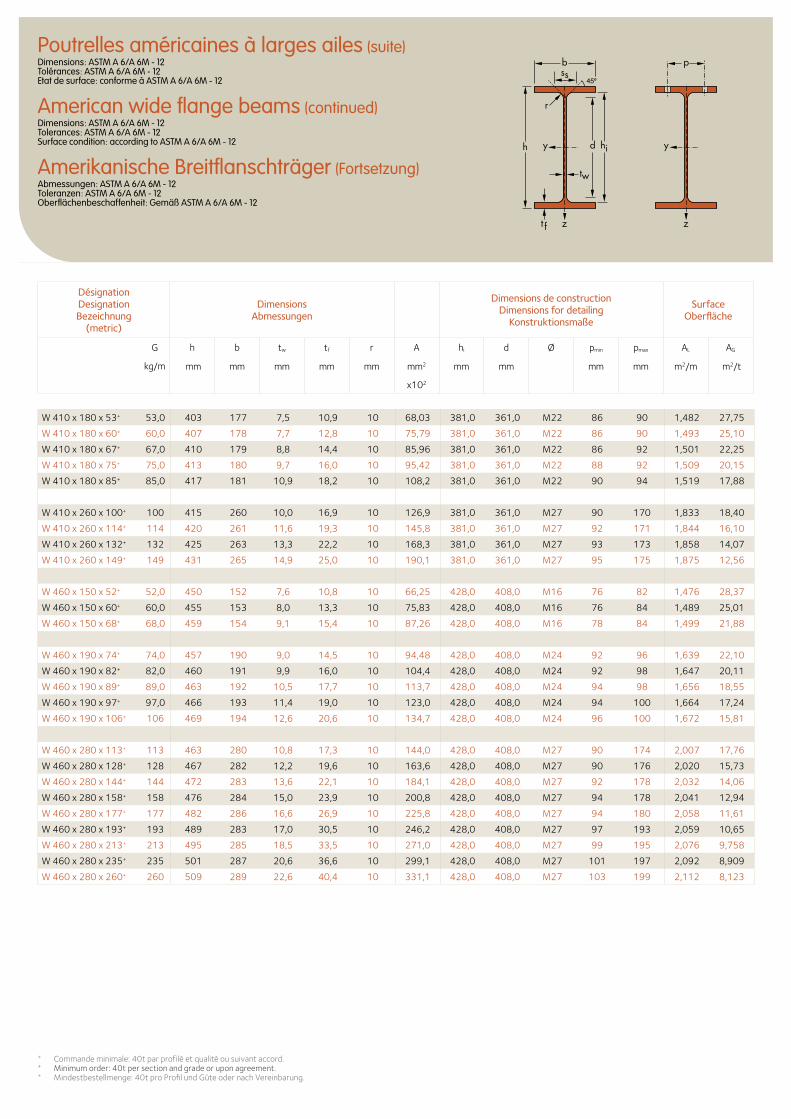
Désignation Designation Bezeichnung
(metric)
Dimensions Abmessungen
Dimensions de construction Dimensions for detailing
Konstruktionsmaße
Surface Oberfläche
G
kg/m
h b tw tf r A hi d Ø pmin pmax AL AG
mm mm mm mm mm mm2 mm mm mm mm m2/m m2/t
x102
b
r
yy dh
tw
ss
zzt f
hi
p
W 410 x 180 x 53+ 53,0 403 177 7,5 10,9 10 68,03 381,0 361,0 M22 86 90 1,482 27,75
W 410 x 180 x 60+ 60,0 407 178 7,7 12,8 10 75,79 381,0 361,0 M22 86 90 1,493 25,10
W 410 x 180 x 67+ 67,0 410 179 8,8 14,4 10 85,96 381,0 361,0 M22 86 92 1,501 22,25
W 410 x 180 x 75+ 75,0 413 180 9,7 16,0 10 95,42 381,0 361,0 M22 88 92 1,509 20,15
W 410 x 180 x 85+ 85,0 417 181 10,9 18,2 10 108,2 381,0 361,0 M22 90 94 1,519 17,88
W 410 x 260 x 100+ 100 415 260 10,0 16,9 10 126,9 381,0 361,0 M27 90 170 1,833 18,40
W 410 x 260 x 114+ 114 420 261 11,6 19,3 10 145,8 381,0 361,0 M27 92 171 1,844 16,10
W 410 x 260 x 132+ 132 425 263 13,3 22,2 10 168,3 381,0 361,0 M27 93 173 1,858 14,07
W 410 x 260 x 149+ 149 431 265 14,9 25,0 10 190,1 381,0 361,0 M27 95 175 1,875 12,56
W 460 x 150 x 52+ 52,0 450 152 7,6 10,8 10 66,25 428,0 408,0 M16 76 82 1,476 28,37
W 460 x 150 x 60+ 60,0 455 153 8,0 13,3 10 75,83 428,0 408,0 M16 76 84 1,489 25,01
W 460 x 150 x 68+ 68,0 459 154 9,1 15,4 10 87,26 428,0 408,0 M16 78 84 1,499 21,88
W 460 x 190 x 74+ 74,0 457 190 9,0 14,5 10 94,48 428,0 408,0 M24 92 96 1,639 22,10
W 460 x 190 x 82+ 82,0 460 191 9,9 16,0 10 104,4 428,0 408,0 M24 92 98 1,647 20,11
W 460 x 190 x 89+ 89,0 463 192 10,5 17,7 10 113,7 428,0 408,0 M24 94 98 1,656 18,55
W 460 x 190 x 97+ 97,0 466 193 11,4 19,0 10 123,0 428,0 408,0 M24 94 100 1,664 17,24
W 460 x 190 x 106+ 106 469 194 12,6 20,6 10 134,7 428,0 408,0 M24 96 100 1,672 15,81
W 460 x 280 x 113+ 113 463 280 10,8 17,3 10 144,0 428,0 408,0 M27 90 174 2,007 17,76
W 460 x 280 x 128+ 128 467 282 12,2 19,6 10 163,6 428,0 408,0 M27 90 176 2,020 15,73
W 460 x 280 x 144+ 144 472 283 13,6 22,1 10 184,1 428,0 408,0 M27 92 178 2,032 14,06
W 460 x 280 x 158+ 158 476 284 15,0 23,9 10 200,8 428,0 408,0 M27 94 178 2,041 12,94
W 460 x 280 x 177+ 177 482 286 16,6 26,9 10 225,8 428,0 408,0 M27 94 180 2,058 11,61
W 460 x 280 x 193+ 193 489 283 17,0 30,5 10 246,2 428,0 408,0 M27 97 193 2,059 10,65
W 460 x 280 x 213+ 213 495 285 18,5 33,5 10 271,0 428,0 408,0 M27 99 195 2,076 9,758
W 460 x 280 x 235+ 235 501 287 20,6 36,6 10 299,1 428,0 408,0 M27 101 197 2,092 8,909
W 460 x 280 x 260+ 260 509 289 22,6 40,4 10 331,1 428,0 408,0 M27 103 199 2,112 8,123
+ Commande minimale: 40t par profilé et qualité ou suivant accord. + Minimum order: 40t per section and grade or upon agreement.+ Mindestbestellmenge: 40t pro Profil und Güte oder nach Vereinbarung.
Poutrelles américaines à larges ailes (suite)Dimensions: ASTM A 6/A 6M - 12 Tolérances: ASTM A 6/A 6M - 12 Etat de surface: conforme à ASTM A 6/A 6M - 12
American wide flange beams (continued)Dimensions: ASTM A 6/A 6M - 12 Tolerances: ASTM A 6/A 6M - 12 Surface condition: according to ASTM A 6/A 6M - 12
Amerikanische Breitflanschträger (Fortsetzung)Abmessungen: ASTM A 6/A 6M - 12 Toleranzen: ASTM A 6/A 6M - 12 Oberflächenbeschaffenheit: Gemäß ASTM A 6/A 6M - 12
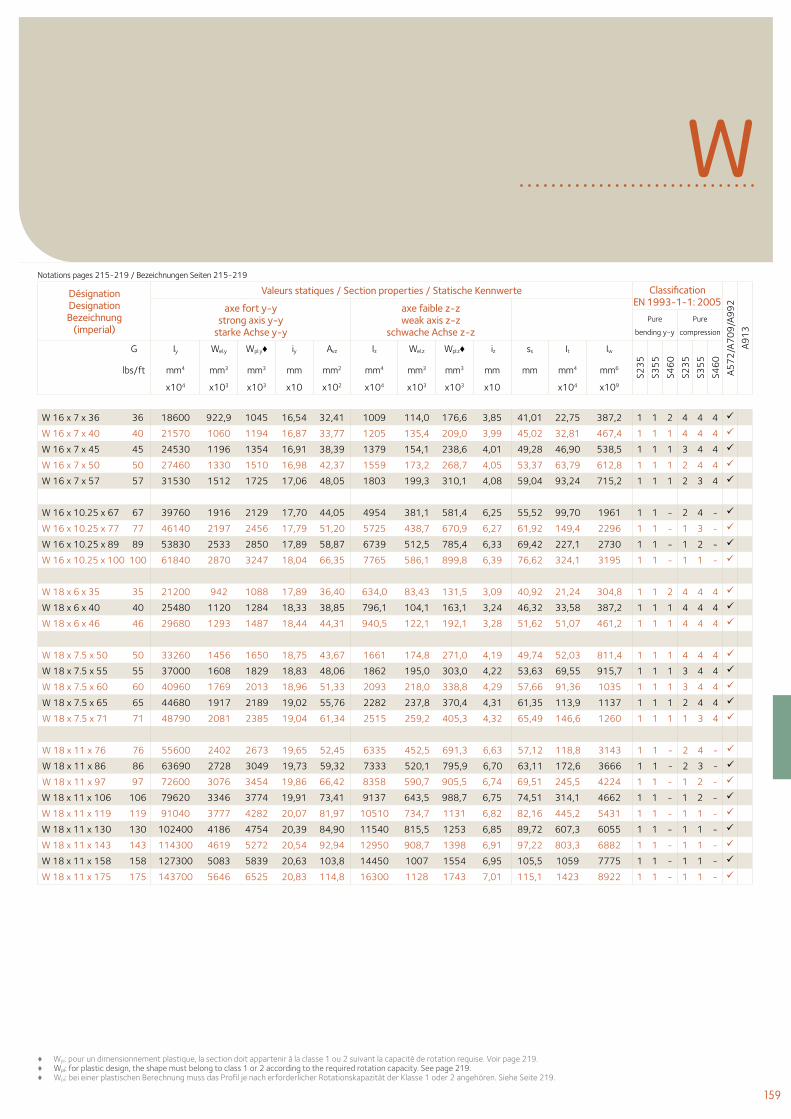
159
♦ Wpl: pour un dimensionnement plastique, la section doit appartenir à la classe 1 ou 2 suivant la capacité de rotation requise. Voir page 219.♦ Wpl: for plastic design, the shape must belong to class 1 or 2 according to the required rotation capacity. See page 219. ♦ Wpl: bei einer plastischen Berechnung muss das Profil je nach erforderlicher Rotationskapazität der Klasse 1 oder 2 angehören. Siehe Seite 219.
WDésignation Designation Bezeichnung
(imperial)
Valeurs statiques / Section properties / Statische Kennwerte Classification EN 1993-1-1: 2005
A57
2/A
70
9/A
99
2
A91
3
axe fort y-y strong axis y-y
starke Achse y-y
axe faible z-z weak axis z-z
schwache Achse z-z Pure
bending y-y
Pure
compression
G Iy Wel.y Wpl.y♦ iy Avz Iz Wel.z Wpl.z♦ iz ss It Iw
S23
5
S35
5
S46
0
S23
5
S35
5
S46
0
lbs/ft mm4 mm3 mm3 mm mm2 mm4 mm3 mm3 mm mm mm4 mm6
x104 x103 x103 x10 x102 x104 x103 x103 x10 x104 x109
W 16 x 7 x 36 36 18600 922,9 1045 16,54 32,41 1009 114,0 176,6 3,85 41,01 22,75 387,2 1 1 2 4 4 4
W 16 x 7 x 40 40 21570 1060 1194 16,87 33,77 1205 135,4 209,0 3,99 45,02 32,81 467,4 1 1 1 4 4 4
W 16 x 7 x 45 45 24530 1196 1354 16,91 38,39 1379 154,1 238,6 4,01 49,28 46,90 538,5 1 1 1 3 4 4
W 16 x 7 x 50 50 27460 1330 1510 16,98 42,37 1559 173,2 268,7 4,05 53,37 63,79 612,8 1 1 1 2 4 4
W 16 x 7 x 57 57 31530 1512 1725 17,06 48,05 1803 199,3 310,1 4,08 59,04 93,24 715,2 1 1 1 2 3 4
W 16 x 10.25 x 67 67 39760 1916 2129 17,70 44,05 4954 381,1 581,4 6,25 55,52 99,70 1961 1 1 - 2 4 -
W 16 x 10.25 x 77 77 46140 2197 2456 17,79 51,20 5725 438,7 670,9 6,27 61,92 149,4 2296 1 1 - 1 3 -
W 16 x 10.25 x 89 89 53830 2533 2850 17,89 58,87 6739 512,5 785,4 6,33 69,42 227,1 2730 1 1 - 1 2 -
W 16 x 10.25 x 100 100 61840 2870 3247 18,04 66,35 7765 586,1 899,8 6,39 76,62 324,1 3195 1 1 - 1 1 -
W 18 x 6 x 35 35 21200 942 1088 17,89 36,40 634,0 83,43 131,5 3,09 40,92 21,24 304,8 1 1 2 4 4 4
W 18 x 6 x 40 40 25480 1120 1284 18,33 38,85 796,1 104,1 163,1 3,24 46,32 33,58 387,2 1 1 1 4 4 4
W 18 x 6 x 46 46 29680 1293 1487 18,44 44,31 940,5 122,1 192,1 3,28 51,62 51,07 461,2 1 1 1 4 4 4
W 18 x 7.5 x 50 50 33260 1456 1650 18,75 43,67 1661 174,8 271,0 4,19 49,74 52,03 811,4 1 1 1 4 4 4
W 18 x 7.5 x 55 55 37000 1608 1829 18,83 48,06 1862 195,0 303,0 4,22 53,63 69,55 915,7 1 1 1 3 4 4
W 18 x 7.5 x 60 60 40960 1769 2013 18,96 51,33 2093 218,0 338,8 4,29 57,66 91,36 1035 1 1 1 3 4 4
W 18 x 7.5 x 65 65 44680 1917 2189 19,02 55,76 2282 237,8 370,4 4,31 61,35 113,9 1137 1 1 1 2 4 4
W 18 x 7.5 x 71 71 48790 2081 2385 19,04 61,34 2515 259,2 405,3 4,32 65,49 146,6 1260 1 1 1 1 3 4
W 18 x 11 x 76 76 55600 2402 2673 19,65 52,45 6335 452,5 691,3 6,63 57,12 118,8 3143 1 1 - 2 4 -
W 18 x 11 x 86 86 63690 2728 3049 19,73 59,32 7333 520,1 795,9 6,70 63,11 172,6 3666 1 1 - 2 3 -
W 18 x 11 x 97 97 72600 3076 3454 19,86 66,42 8358 590,7 905,5 6,74 69,51 245,5 4224 1 1 - 1 2 -
W 18 x 11 x 106 106 79620 3346 3774 19,91 73,41 9137 643,5 988,7 6,75 74,51 314,1 4662 1 1 - 1 2 -
W 18 x 11 x 119 119 91040 3777 4282 20,07 81,97 10510 734,7 1131 6,82 82,16 445,2 5431 1 1 - 1 1 -
W 18 x 11 x 130 130 102400 4186 4754 20,39 84,90 11540 815,5 1253 6,85 89,72 607,3 6055 1 1 - 1 1 -
W 18 x 11 x 143 143 114300 4619 5272 20,54 92,94 12950 908,7 1398 6,91 97,22 803,3 6882 1 1 - 1 1 -
W 18 x 11 x 158 158 127300 5083 5839 20,63 103,8 14450 1007 1554 6,95 105,5 1059 7775 1 1 - 1 1 -
W 18 x 11 x 175 175 143700 5646 6525 20,83 114,8 16300 1128 1743 7,01 115,1 1423 8922 1 1 - 1 1 -
Notations pages 215-219 / Bezeichnungen Seiten 215-219
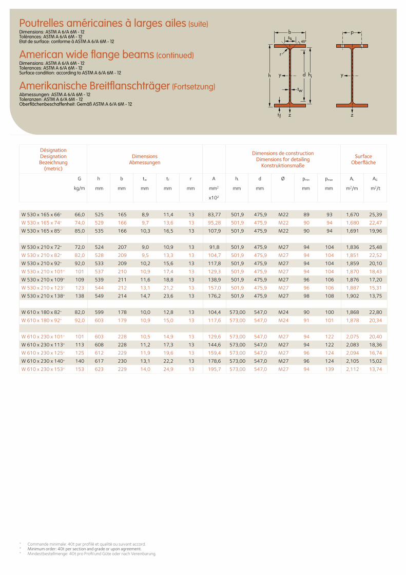
Désignation Designation Bezeichnung
(metric)
Dimensions Abmessungen
Dimensions de construction Dimensions for detailing
Konstruktionsmaße
Surface Oberfläche
G
kg/m
h b tw tf r A hi d Ø pmin pmax AL AG
mm mm mm mm mm mm2 mm mm mm mm m2/m m2/t
x102
b
r
yy dh
tw
ss
zzt f
hi
p
W 530 x 165 x 66+ 66,0 525 165 8,9 11,4 13 83,77 501,9 475,9 M22 89 93 1,670 25,39
W 530 x 165 x 74+ 74,0 529 166 9,7 13,6 13 95,28 501,9 475,9 M22 90 94 1,680 22,47
W 530 x 165 x 85+ 85,0 535 166 10,3 16,5 13 107,9 501,9 475,9 M22 90 94 1,691 19,96
W 530 x 210 x 72+ 72,0 524 207 9,0 10,9 13 91,8 501,9 475,9 M27 94 104 1,836 25,48
W 530 x 210 x 82+ 82,0 528 209 9,5 13,3 13 104,7 501,9 475,9 M27 94 104 1,851 22,52
W 530 x 210 x 92+ 92,0 533 209 10,2 15,6 13 117,8 501,9 475,9 M27 94 104 1,859 20,10
W 530 x 210 x 101+ 101 537 210 10,9 17,4 13 129,3 501,9 475,9 M27 94 104 1,870 18,43
W 530 x 210 x 109+ 109 539 211 11,6 18,8 13 138,9 501,9 475,9 M27 96 106 1,876 17,20
W 530 x 210 x 123+ 123 544 212 13,1 21,2 13 157,0 501,9 475,9 M27 96 106 1,887 15,31
W 530 x 210 x 138+ 138 549 214 14,7 23,6 13 176,2 501,9 475,9 M27 98 108 1,902 13,75
W 610 x 180 x 82+ 82,0 599 178 10,0 12,8 13 104,4 573,00 547,0 M24 90 100 1,868 22,80
W 610 x 180 x 92+ 92,0 603 179 10,9 15,0 13 117,6 573,00 547,0 M24 91 101 1,878 20,34
W 610 x 230 x 101+ 101 603 228 10,5 14,9 13 129,6 573,00 547,0 M27 94 122 2,075 20,40
W 610 x 230 x 113+ 113 608 228 11,2 17,3 13 144,6 573,00 547,0 M27 94 122 2,083 18,36
W 610 x 230 x 125+ 125 612 229 11,9 19,6 13 159,4 573,00 547,0 M27 96 124 2,094 16,74
W 610 x 230 x 140+ 140 617 230 13,1 22,2 13 178,6 573,00 547,0 M27 96 124 2,105 15,02
W 610 x 230 x 153+ 153 623 229 14,0 24,9 13 195,7 573,00 547,0 M27 94 139 2,112 13,74
+ Commande minimale: 40t par profilé et qualité ou suivant accord. + Minimum order: 40t per section and grade or upon agreement.+ Mindestbestellmenge: 40t pro Profil und Güte oder nach Vereinbarung.
Poutrelles américaines à larges ailes (suite)Dimensions: ASTM A 6/A 6M - 12 Tolérances: ASTM A 6/A 6M - 12 Etat de surface: conforme à ASTM A 6/A 6M - 12
American wide flange beams (continued)Dimensions: ASTM A 6/A 6M - 12 Tolerances: ASTM A 6/A 6M - 12 Surface condition: according to ASTM A 6/A 6M - 12
Amerikanische Breitflanschträger (Fortsetzung)Abmessungen: ASTM A 6/A 6M - 12 Toleranzen: ASTM A 6/A 6M - 12 Oberflächenbeschaffenheit: Gemäß ASTM A 6/A 6M - 12
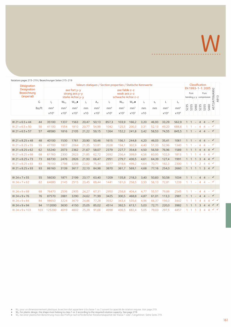
161
♦ Wpl: pour un dimensionnement plastique, la section doit appartenir à la classe 1 ou 2 suivant la capacité de rotation requise. Voir page 219.♦ Wpl: for plastic design, the shape must belong to class 1 or 2 according to the required rotation capacity. See page 219. ♦ Wpl: bei einer plastischen Berechnung muss das Profil je nach erforderlicher Rotationskapazität der Klasse 1 oder 2 angehören. Siehe Seite 219.
WDésignation Designation Bezeichnung
(imperial)
Valeurs statiques / Section properties / Statische Kennwerte Classification EN 1993-1-1: 2005
A57
2/A
70
9/A
99
2
A91
3
axe fort y-y strong axis y-y
starke Achse y-y
axe faible z-z weak axis z-z
schwache Achse z-z Pure
bending y-y
Pure
compression
G Iy Wel.y Wpl.y♦ iy Avz Iz Wel.z Wpl.z♦ iz ss It Iw
S23
5
S35
5
S46
0
S23
5
S35
5
S46
0
lbs/ft mm4 mm3 mm3 mm mm2 mm4 mm3 mm3 mm mm mm4 mm6
x104 x103 x103 x10 x102 x104 x103 x103 x10 x104 x109
W 21 x 6.5 x 44 44 35100 1337 1563 20,47 50,13 857,3 103,9 166,2 3,20 46,93 33,29 562,9 1 1 - 4 4 -
W 21 x 6.5 x 50 50 41100 1554 1810 20,77 54,98 1042 125,5 200,3 3,31 52,13 49,20 688,6 1 1 - 4 4 -
W 21 x 6.5 x 57 57 48580 1816 2105 21,22 59,15 1264 152,2 241,8 3,42 58,53 74,55 845,5 1 1 - 4 4 -
W 21 x 8.25 x 48 48 40100 1530 1761 20,90 50,46 1615 156,1 244,8 4,20 46,03 35,41 1061 1 1 - 4 4 -
W 21 x 8.25 x 55 55 47700 1807 2064 21,35 53,81 2028 194,1 302,9 4,40 51,33 52,96 1340 1 1 - 4 4 -
W 21 x 8.25 x 62 62 55240 2073 2362 21,67 58,07 2379 227,7 354,8 4,50 56,59 76,96 1589 1 1 1 4 4 4
W 21 x 8.25 x 68 68 61760 2300 2623 21,85 62,72 2692 256,4 399,9 4,56 60,95 102,9 1813 1 1 1 4 4 4
W 21 x 8.25 x 73 73 66730 2476 2826 21,93 66,47 2951 279,7 436,5 4,61 64,39 127,4 1991 1 1 1 3 4 4
W 21 x 8.25 x 83 83 76100 2798 3208 22,02 75,34 3377 318,6 499,2 4,64 70,71 182,3 2300 1 1 1 2 4 4
W 21 x 8.25 x 93 93 86160 3139 3617 22,10 84,98 3870 361,7 569,1 4,68 77,16 254,0 2660 1 1 1 1 3 4
W 24 x 7 x 55 55 56030 1871 2199 23,17 63,40 1209 135,8 218,3 3,40 50,83 50,58 1034 1 1 - 4 4 -
W 24 x 7 x 62 62 64680 2145 2515 23,45 69,44 1441 161,0 258,5 3,50 56,13 72,81 1239 1 1 - 4 4 -
W 24 x 9 x 68 68 76470 2536 2905 24,27 67,31 2950 258,8 404,4 4,77 55,57 79,88 2545 1 1 - 4 4 -
W 24 x 9 x 76 76 87570 2881 3290 24,62 71,99 3425 300,5 468,8 4,87 61,01 113,3 2981 1 1 - 4 4 -
W 24 x 9 x 84 84 98650 3224 3679 24,86 77,28 3932 343,4 535,6 4,96 66,37 156,0 3442 1 1 1 4 4 4
W 24 x 9 x 94 94 112000 3630 4150 25,05 85,02 4514 392,5 613,1 5,03 72,71 220,0 3982 1 1 1 3 4 4
W 24 x 9 x 103 103 125200 4019 4602 25,29 91,66 4998 436,5 682,4 5,05 79,03 297,5 4457 1 1 1 3 4 4
Notations pages 215-219 / Bezeichnungen Seiten 215-219
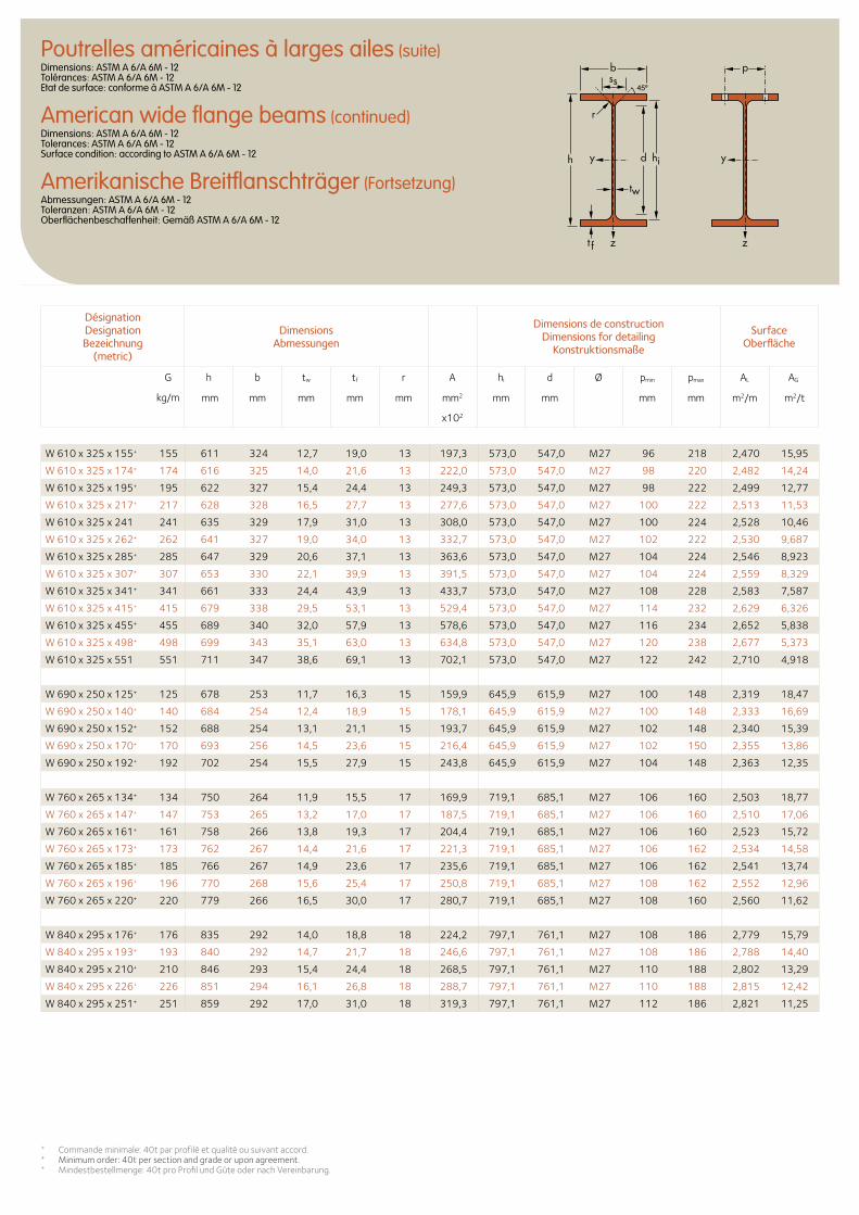
Désignation Designation Bezeichnung
(metric)
Dimensions Abmessungen
Dimensions de construction Dimensions for detailing
Konstruktionsmaße
Surface Oberfläche
G
kg/m
h b tw tf r A hi d Ø pmin pmax AL AG
mm mm mm mm mm mm2 mm mm mm mm m2/m m2/t
x102
b
r
yy dh
tw
ss
zzt f
hi
p
W 610 x 325 x 155+ 155 611 324 12,7 19,0 13 197,3 573,0 547,0 M27 96 218 2,470 15,95
W 610 x 325 x 174+ 174 616 325 14,0 21,6 13 222,0 573,0 547,0 M27 98 220 2,482 14,24
W 610 x 325 x 195+ 195 622 327 15,4 24,4 13 249,3 573,0 547,0 M27 98 222 2,499 12,77
W 610 x 325 x 217+ 217 628 328 16,5 27,7 13 277,6 573,0 547,0 M27 100 222 2,513 11,53
W 610 x 325 x 241 241 635 329 17,9 31,0 13 308,0 573,0 547,0 M27 100 224 2,528 10,46
W 610 x 325 x 262+ 262 641 327 19,0 34,0 13 332,7 573,0 547,0 M27 102 222 2,530 9,687
W 610 x 325 x 285+ 285 647 329 20,6 37,1 13 363,6 573,0 547,0 M27 104 224 2,546 8,923
W 610 x 325 x 307+ 307 653 330 22,1 39,9 13 391,5 573,0 547,0 M27 104 224 2,559 8,329
W 610 x 325 x 341+ 341 661 333 24,4 43,9 13 433,7 573,0 547,0 M27 108 228 2,583 7,587
W 610 x 325 x 415+ 415 679 338 29,5 53,1 13 529,4 573,0 547,0 M27 114 232 2,629 6,326
W 610 x 325 x 455+ 455 689 340 32,0 57,9 13 578,6 573,0 547,0 M27 116 234 2,652 5,838
W 610 x 325 x 498+ 498 699 343 35,1 63,0 13 634,8 573,0 547,0 M27 120 238 2,677 5,373
W 610 x 325 x 551 551 711 347 38,6 69,1 13 702,1 573,0 547,0 M27 122 242 2,710 4,918
W 690 x 250 x 125+ 125 678 253 11,7 16,3 15 159,9 645,9 615,9 M27 100 148 2,319 18,47
W 690 x 250 x 140+ 140 684 254 12,4 18,9 15 178,1 645,9 615,9 M27 100 148 2,333 16,69
W 690 x 250 x 152+ 152 688 254 13,1 21,1 15 193,7 645,9 615,9 M27 102 148 2,340 15,39
W 690 x 250 x 170+ 170 693 256 14,5 23,6 15 216,4 645,9 615,9 M27 102 150 2,355 13,86
W 690 x 250 x 192+ 192 702 254 15,5 27,9 15 243,8 645,9 615,9 M27 104 148 2,363 12,35
W 760 x 265 x 134+ 134 750 264 11,9 15,5 17 169,9 719,1 685,1 M27 106 160 2,503 18,77
W 760 x 265 x 147+ 147 753 265 13,2 17,0 17 187,5 719,1 685,1 M27 106 160 2,510 17,06
W 760 x 265 x 161+ 161 758 266 13,8 19,3 17 204,4 719,1 685,1 M27 106 160 2,523 15,72
W 760 x 265 x 173+ 173 762 267 14,4 21,6 17 221,3 719,1 685,1 M27 106 162 2,534 14,58
W 760 x 265 x 185+ 185 766 267 14,9 23,6 17 235,6 719,1 685,1 M27 106 162 2,541 13,74
W 760 x 265 x 196+ 196 770 268 15,6 25,4 17 250,8 719,1 685,1 M27 108 162 2,552 12,96
W 760 x 265 x 220+ 220 779 266 16,5 30,0 17 280,7 719,1 685,1 M27 108 160 2,560 11,62
W 840 x 295 x 176+ 176 835 292 14,0 18,8 18 224,2 797,1 761,1 M27 108 186 2,779 15,79
W 840 x 295 x 193+ 193 840 292 14,7 21,7 18 246,6 797,1 761,1 M27 108 186 2,788 14,40
W 840 x 295 x 210+ 210 846 293 15,4 24,4 18 268,5 797,1 761,1 M27 110 188 2,802 13,29
W 840 x 295 x 226+ 226 851 294 16,1 26,8 18 288,7 797,1 761,1 M27 110 188 2,815 12,42
W 840 x 295 x 251+ 251 859 292 17,0 31,0 18 319,3 797,1 761,1 M27 112 186 2,821 11,25
+ Commande minimale: 40t par profilé et qualité ou suivant accord. + Minimum order: 40t per section and grade or upon agreement.+ Mindestbestellmenge: 40t pro Profil und Güte oder nach Vereinbarung.
Poutrelles américaines à larges ailes (suite)Dimensions: ASTM A 6/A 6M - 12 Tolérances: ASTM A 6/A 6M - 12 Etat de surface: conforme à ASTM A 6/A 6M - 12
American wide flange beams (continued)Dimensions: ASTM A 6/A 6M - 12 Tolerances: ASTM A 6/A 6M - 12 Surface condition: according to ASTM A 6/A 6M - 12
Amerikanische Breitflanschträger (Fortsetzung)Abmessungen: ASTM A 6/A 6M - 12 Toleranzen: ASTM A 6/A 6M - 12 Oberflächenbeschaffenheit: Gemäß ASTM A 6/A 6M - 12
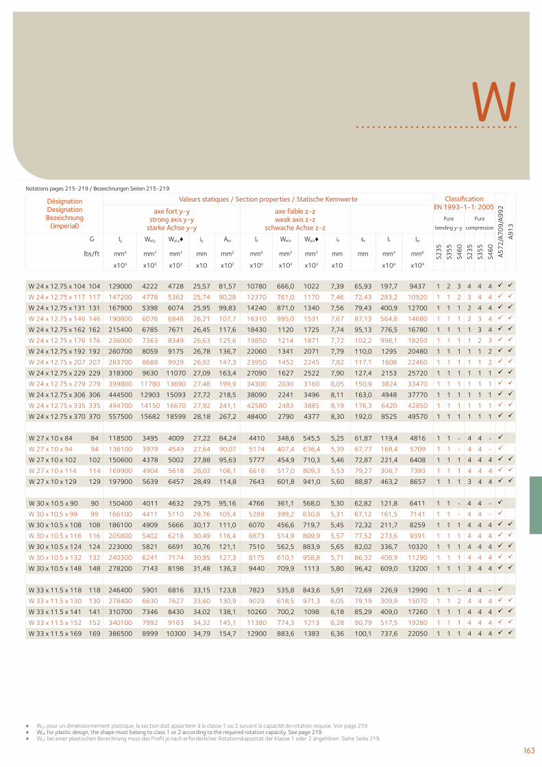
163
♦ Wpl: pour un dimensionnement plastique, la section doit appartenir à la classe 1 ou 2 suivant la capacité de rotation requise. Voir page 219.♦ Wpl: for plastic design, the shape must belong to class 1 or 2 according to the required rotation capacity. See page 219. ♦ Wpl: bei einer plastischen Berechnung muss das Profil je nach erforderlicher Rotationskapazität der Klasse 1 oder 2 angehören. Siehe Seite 219.
WDésignation Designation Bezeichnung
(imperial)
Valeurs statiques / Section properties / Statische Kennwerte Classification EN 1993-1-1: 2005
A57
2/A
70
9/A
99
2
A91
3
axe fort y-y strong axis y-y
starke Achse y-y
axe faible z-z weak axis z-z
schwache Achse z-z Pure
bending y-y
Pure
compression
G Iy Wel.y Wpl.y♦ iy Avz Iz Wel.z Wpl.z♦ iz ss It Iw
S23
5
S35
5
S46
0
S23
5
S35
5
S46
0
lbs/ft mm4 mm3 mm3 mm mm2 mm4 mm3 mm3 mm mm mm4 mm6
x104 x103 x103 x10 x102 x104 x103 x103 x10 x104 x109
W 24 x 12.75 x 104 104 129000 4222 4728 25,57 81,57 10780 666,0 1022 7,39 65,93 197,7 9437 1 2 3 4 4 4
W 24 x 12.75 x 117 117 147200 4778 5362 25,74 90,28 12370 761,0 1170 7,46 72,43 283,2 10920 1 1 2 3 4 4
W 24 x 12.75 x 131 131 167900 5398 6074 25,95 99,83 14240 871,0 1340 7,56 79,43 400,9 12700 1 1 1 2 4 4
W 24 x 12.75 x 146 146 190800 6076 6848 26,21 107,7 16310 995,0 1531 7,67 87,13 564,6 14680 1 1 1 2 3 4
W 24 x 12.75 x 162 162 215400 6785 7671 26,45 117,6 18430 1120 1725 7,74 95,13 776,5 16780 1 1 1 1 3 4
W 24 x 12.75 x 176 176 236000 7363 8349 26,63 125,6 19850 1214 1871 7,72 102,2 998,1 18250 1 1 1 1 2 3
W 24 x 12.75 x 192 192 260700 8059 9175 26,78 136,7 22060 1341 2071 7,79 110,0 1295 20480 1 1 1 1 1 2
W 24 x 12.75 x 207 207 283700 8688 9929 26,92 147,3 23950 1452 2245 7,82 117,1 1608 22460 1 1 1 1 1 2
W 24 x 12.75 x 229 229 318300 9630 11070 27,09 163,4 27090 1627 2522 7,90 127,4 2153 25720 1 1 1 1 1 1
W 24 x 12.75 x 279 279 399800 11780 13690 27,48 199,9 34300 2030 3160 8,05 150,9 3824 33470 1 1 1 1 1 1
W 24 x 12.75 x 306 306 444500 12903 15093 27,72 218,5 38090 2241 3496 8,11 163,0 4948 37770 1 1 1 1 1 1
W 24 x 12.75 x 335 335 494700 14150 16670 27,92 241,1 42580 2483 3885 8,19 176,3 6420 42850 1 1 1 1 1 1
W 24 x 12.75 x 370 370 557500 15682 18599 28,18 267,2 48400 2790 4377 8,30 192,0 8525 49570 1 1 1 1 1 1
W 27 x 10 x 84 84 118500 3495 4009 27,22 84,24 4410 348,6 545,5 5,25 61,87 119,4 4816 1 1 - 4 4 -
W 27 x 10 x 94 94 136100 3979 4549 27,64 90,07 5174 407,4 636,4 5,39 67,77 168,4 5709 1 1 - 4 4 -
W 27 x 10 x 102 102 150600 4378 5002 27,88 95,63 5777 454,9 710,3 5,46 72,87 221,4 6408 1 1 1 4 4 4
W 27 x 10 x 114 114 169900 4904 5618 28,02 106,1 6618 517,0 809,3 5,53 79,27 306,7 7393 1 1 1 4 4 4
W 27 x 10 x 129 129 197900 5639 6457 28,49 114,8 7643 601,8 941,0 5,60 88,87 463,2 8657 1 1 1 3 4 4
W 30 x 10.5 x 90 90 150400 4011 4632 29,75 95,16 4766 361,1 568,0 5,30 62,82 121,8 6411 1 1 - 4 4 -
W 30 x 10.5 x 99 99 166100 4411 5110 29,76 105,4 5289 399,2 630,8 5,31 67,12 161,5 7141 1 1 - 4 4 -
W 30 x 10.5 x 108 108 186100 4909 5666 30,17 111,0 6070 456,6 719,7 5,45 72,32 211,7 8259 1 1 1 4 4 4
W 30 x 10.5 x 116 116 205800 5402 6218 30,49 116,4 6873 514,9 809,9 5,57 77,52 273,6 9391 1 1 1 4 4 4
W 30 x 10.5 x 124 124 223000 5821 6691 30,76 121,1 7510 562,5 883,9 5,65 82,02 336,7 10320 1 1 1 4 4 4
W 30 x 10.5 x 132 132 240300 6241 7174 30,95 127,3 8175 610,1 958,8 5,71 86,32 408,9 11290 1 1 1 4 4 4
W 30 x 10.5 x 148 148 278200 7143 8198 31,48 136,3 9440 709,9 1113 5,80 96,42 609,0 13200 1 1 1 3 4 4
W 33 x 11.5 x 118 118 246400 5901 6816 33,15 123,8 7823 535,8 843,6 5,91 72,69 226,9 12990 1 1 - 4 4 -
W 33 x 11.5 x 130 130 278400 6630 7627 33,60 130,9 9029 618,5 971,3 6,05 79,19 309,9 15070 1 1 2 4 4 4
W 33 x 11.5 x 141 141 310700 7346 8430 34,02 138,1 10260 700,2 1098 6,18 85,29 409,0 17260 1 1 1 4 4 4
W 33 x 11.5 x 152 152 340100 7992 9163 34,32 145,1 11380 774,3 1213 6,28 90,79 517,5 19280 1 1 1 4 4 4
W 33 x 11.5 x 169 169 386500 8999 10300 34,79 154,7 12900 883,6 1383 6,36 100,1 737,6 22050 1 1 1 4 4 4
Notations pages 215-219 / Bezeichnungen Seiten 215-219
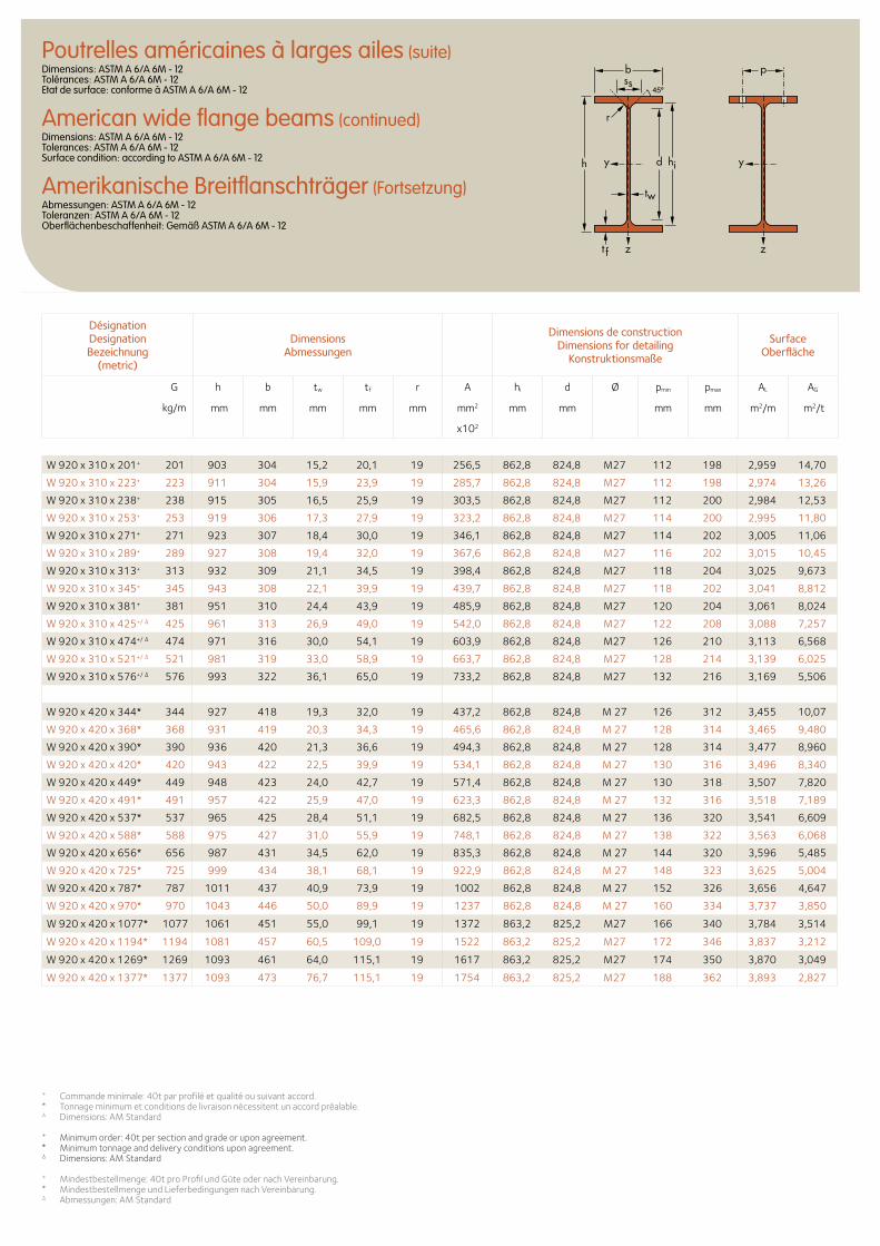
+ Commande minimale: 40t par profilé et qualité ou suivant accord. * Tonnage minimum et conditions de livraison nécessitent un accord préalable.∆ Dimensions: AM Standard
+ Minimum order: 40t per section and grade or upon agreement.* Minimum tonnage and delivery conditions upon agreement.∆ Dimensions: AM Standard
+ Mindestbestellmenge: 40t pro Profil und Güte oder nach Vereinbarung.* Mindestbestellmenge und Lieferbedingungen nach Vereinbarung.∆ Abmessungen: AM Standard
Désignation Designation Bezeichnung
(metric)
Dimensions Abmessungen
Dimensions de construction Dimensions for detailing
Konstruktionsmaße
Surface Oberfläche
G
kg/m
h b tw tf r A hi d Ø pmin pmax AL AG
mm mm mm mm mm mm2 mm mm mm mm m2/m m2/t
x102
b
r
yy dh
tw
ss
zzt f
hi
p
W 920 x 310 x 201+ 201 903 304 15,2 20,1 19 256,5 862,8 824,8 M27 112 198 2,959 14,70
W 920 x 310 x 223+ 223 911 304 15,9 23,9 19 285,7 862,8 824,8 M27 112 198 2,974 13,26
W 920 x 310 x 238+ 238 915 305 16,5 25,9 19 303,5 862,8 824,8 M27 112 200 2,984 12,53
W 920 x 310 x 253+ 253 919 306 17,3 27,9 19 323,2 862,8 824,8 M27 114 200 2,995 11,80
W 920 x 310 x 271+ 271 923 307 18,4 30,0 19 346,1 862,8 824,8 M27 114 202 3,005 11,06
W 920 x 310 x 289+ 289 927 308 19,4 32,0 19 367,6 862,8 824,8 M27 116 202 3,015 10,45
W 920 x 310 x 313+ 313 932 309 21,1 34,5 19 398,4 862,8 824,8 M27 118 204 3,025 9,673
W 920 x 310 x 345+ 345 943 308 22,1 39,9 19 439,7 862,8 824,8 M27 118 202 3,041 8,812
W 920 x 310 x 381+ 381 951 310 24,4 43,9 19 485,9 862,8 824,8 M27 120 204 3,061 8,024
W 920 x 310 x 425+/ ∆ 425 961 313 26,9 49,0 19 542,0 862,8 824,8 M27 122 208 3,088 7,257
W 920 x 310 x 474+/ ∆ 474 971 316 30,0 54,1 19 603,9 862,8 824,8 M27 126 210 3,113 6,568
W 920 x 310 x 521+/ ∆ 521 981 319 33,0 58,9 19 663,7 862,8 824,8 M27 128 214 3,139 6,025
W 920 x 310 x 576+/ ∆ 576 993 322 36,1 65,0 19 733,2 862,8 824,8 M27 132 216 3,169 5,506
W 920 x 420 x 344* 344 927 418 19,3 32,0 19 437,2 862,8 824,8 M 27 126 312 3,455 10,07
W 920 x 420 x 368* 368 931 419 20,3 34,3 19 465,6 862,8 824,8 M 27 128 314 3,465 9,480
W 920 x 420 x 390* 390 936 420 21,3 36,6 19 494,3 862,8 824,8 M 27 128 314 3,477 8,960
W 920 x 420 x 420* 420 943 422 22,5 39,9 19 534,1 862,8 824,8 M 27 130 316 3,496 8,340
W 920 x 420 x 449* 449 948 423 24,0 42,7 19 571,4 862,8 824,8 M 27 130 318 3,507 7,820
W 920 x 420 x 491* 491 957 422 25,9 47,0 19 623,3 862,8 824,8 M 27 132 316 3,518 7,189
W 920 x 420 x 537* 537 965 425 28,4 51,1 19 682,5 862,8 824,8 M 27 136 320 3,541 6,609
W 920 x 420 x 588* 588 975 427 31,0 55,9 19 748,1 862,8 824,8 M 27 138 322 3,563 6,068
W 920 x 420 x 656* 656 987 431 34,5 62,0 19 835,3 862,8 824,8 M 27 144 320 3,596 5,485
W 920 x 420 x 725* 725 999 434 38,1 68,1 19 922,9 862,8 824,8 M 27 148 323 3,625 5,004
W 920 x 420 x 787* 787 1011 437 40,9 73,9 19 1002 862,8 824,8 M 27 152 326 3,656 4,647
W 920 x 420 x 970* 970 1043 446 50,0 89,9 19 1237 862,8 824,8 M 27 160 334 3,737 3,850
W 920 x 420 x 1077* 1077 1061 451 55,0 99,1 19 1372 863,2 825,2 M27 166 340 3,784 3,514
W 920 x 420 x 1194* 1194 1081 457 60,5 109,0 19 1522 863,2 825,2 M27 172 346 3,837 3,212
W 920 x 420 x 1269* 1269 1093 461 64,0 115,1 19 1617 863,2 825,2 M27 174 350 3,870 3,049
W 920 x 420 x 1377* 1377 1093 473 76,7 115,1 19 1754 863,2 825,2 M27 188 362 3,893 2,827
Poutrelles américaines à larges ailes (suite)Dimensions: ASTM A 6/A 6M - 12 Tolérances: ASTM A 6/A 6M - 12 Etat de surface: conforme à ASTM A 6/A 6M - 12
American wide flange beams (continued)Dimensions: ASTM A 6/A 6M - 12 Tolerances: ASTM A 6/A 6M - 12 Surface condition: according to ASTM A 6/A 6M - 12
Amerikanische Breitflanschträger (Fortsetzung)Abmessungen: ASTM A 6/A 6M - 12 Toleranzen: ASTM A 6/A 6M - 12 Oberflächenbeschaffenheit: Gemäß ASTM A 6/A 6M - 12
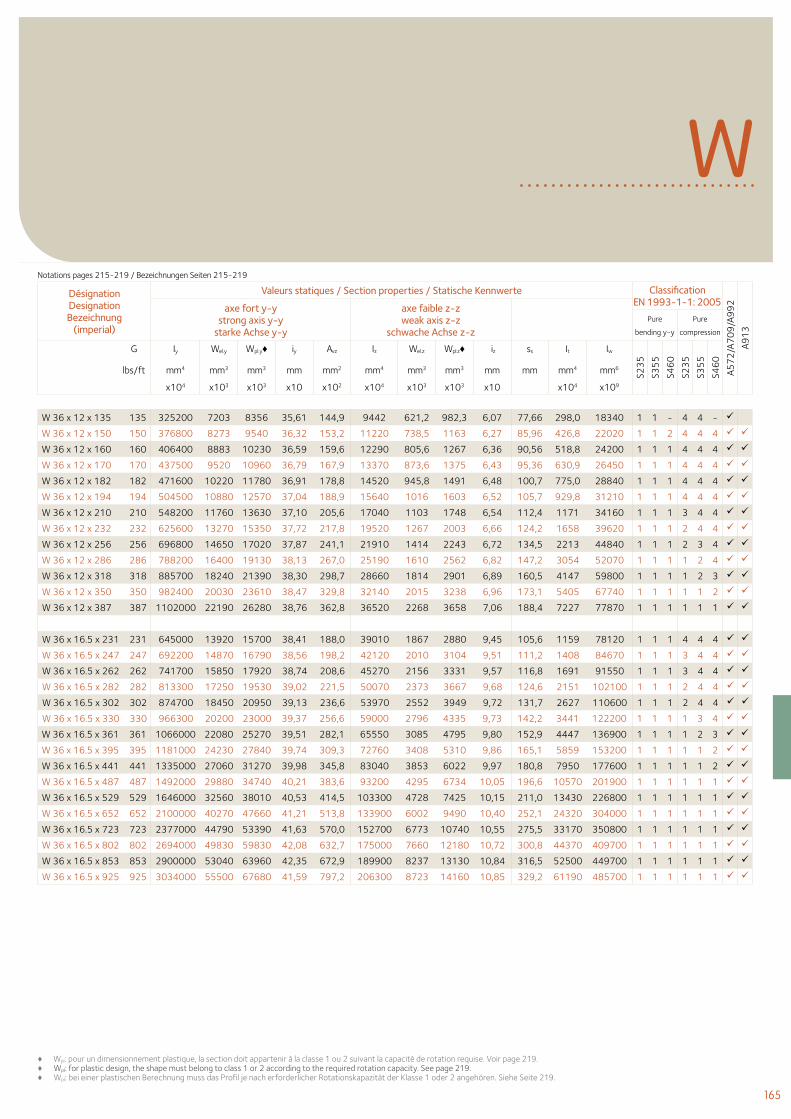
165
♦ Wpl: pour un dimensionnement plastique, la section doit appartenir à la classe 1 ou 2 suivant la capacité de rotation requise. Voir page 219.♦ Wpl: for plastic design, the shape must belong to class 1 or 2 according to the required rotation capacity. See page 219. ♦ Wpl: bei einer plastischen Berechnung muss das Profil je nach erforderlicher Rotationskapazität der Klasse 1 oder 2 angehören. Siehe Seite 219.
WDésignation Designation Bezeichnung
(imperial)
Valeurs statiques / Section properties / Statische Kennwerte Classification EN 1993-1-1: 2005
A57
2/A
70
9/A
99
2
A91
3
axe fort y-y strong axis y-y
starke Achse y-y
axe faible z-z weak axis z-z
schwache Achse z-z Pure
bending y-y
Pure
compression
G Iy Wel.y Wpl.y♦ iy Avz Iz Wel.z Wpl.z♦ iz ss It Iw
S23
5
S35
5
S46
0
S23
5
S35
5
S46
0
lbs/ft mm4 mm3 mm3 mm mm2 mm4 mm3 mm3 mm mm mm4 mm6
x104 x103 x103 x10 x102 x104 x103 x103 x10 x104 x109
W 36 x 12 x 135 135 325200 7203 8356 35,61 144,9 9442 621,2 982,3 6,07 77,66 298,0 18340 1 1 - 4 4 -
W 36 x 12 x 150 150 376800 8273 9540 36,32 153,2 11220 738,5 1163 6,27 85,96 426,8 22020 1 1 2 4 4 4
W 36 x 12 x 160 160 406400 8883 10230 36,59 159,6 12290 805,6 1267 6,36 90,56 518,8 24200 1 1 1 4 4 4
W 36 x 12 x 170 170 437500 9520 10960 36,79 167,9 13370 873,6 1375 6,43 95,36 630,9 26450 1 1 1 4 4 4
W 36 x 12 x 182 182 471600 10220 11780 36,91 178,8 14520 945,8 1491 6,48 100,7 775,0 28840 1 1 1 4 4 4
W 36 x 12 x 194 194 504500 10880 12570 37,04 188,9 15640 1016 1603 6,52 105,7 929,8 31210 1 1 1 4 4 4
W 36 x 12 x 210 210 548200 11760 13630 37,10 205,6 17040 1103 1748 6,54 112,4 1171 34160 1 1 1 3 4 4
W 36 x 12 x 232 232 625600 13270 15350 37,72 217,8 19520 1267 2003 6,66 124,2 1658 39620 1 1 1 2 4 4
W 36 x 12 x 256 256 696800 14650 17020 37,87 241,1 21910 1414 2243 6,72 134,5 2213 44840 1 1 1 2 3 4
W 36 x 12 x 286 286 788200 16400 19130 38,13 267,0 25190 1610 2562 6,82 147,2 3054 52070 1 1 1 1 2 4
W 36 x 12 x 318 318 885700 18240 21390 38,30 298,7 28660 1814 2901 6,89 160,5 4147 59800 1 1 1 1 2 3
W 36 x 12 x 350 350 982400 20030 23610 38,47 329,8 32140 2015 3238 6,96 173,1 5405 67740 1 1 1 1 1 2
W 36 x 12 x 387 387 1102000 22190 26280 38,76 362,8 36520 2268 3658 7,06 188,4 7227 77870 1 1 1 1 1 1
W 36 x 16.5 x 231 231 645000 13920 15700 38,41 188,0 39010 1867 2880 9,45 105,6 1159 78120 1 1 1 4 4 4
W 36 x 16.5 x 247 247 692200 14870 16790 38,56 198,2 42120 2010 3104 9,51 111,2 1408 84670 1 1 1 3 4 4
W 36 x 16.5 x 262 262 741700 15850 17920 38,74 208,6 45270 2156 3331 9,57 116,8 1691 91550 1 1 1 3 4 4
W 36 x 16.5 x 282 282 813300 17250 19530 39,02 221,5 50070 2373 3667 9,68 124,6 2151 102100 1 1 1 2 4 4
W 36 x 16.5 x 302 302 874700 18450 20950 39,13 236,6 53970 2552 3949 9,72 131,7 2627 110600 1 1 1 2 4 4
W 36 x 16.5 x 330 330 966300 20200 23000 39,37 256,6 59000 2796 4335 9,73 142,2 3441 122200 1 1 1 1 3 4
W 36 x 16.5 x 361 361 1066000 22080 25270 39,51 282,1 65550 3085 4795 9,80 152,9 4447 136900 1 1 1 1 2 3
W 36 x 16.5 x 395 395 1181000 24230 27840 39,74 309,3 72760 3408 5310 9,86 165,1 5859 153200 1 1 1 1 1 2
W 36 x 16.5 x 441 441 1335000 27060 31270 39,98 345,8 83040 3853 6022 9,97 180,8 7950 177600 1 1 1 1 1 2
W 36 x 16.5 x 487 487 1492000 29880 34740 40,21 383,6 93200 4295 6734 10,05 196,6 10570 201900 1 1 1 1 1 1
W 36 x 16.5 x 529 529 1646000 32560 38010 40,53 414,5 103300 4728 7425 10,15 211,0 13430 226800 1 1 1 1 1 1
W 36 x 16.5 x 652 652 2100000 40270 47660 41,21 513,8 133900 6002 9490 10,40 252,1 24320 304000 1 1 1 1 1 1
W 36 x 16.5 x 723 723 2377000 44790 53390 41,63 570,0 152700 6773 10740 10,55 275,5 33170 350800 1 1 1 1 1 1
W 36 x 16.5 x 802 802 2694000 49830 59830 42,08 632,7 175000 7660 12180 10,72 300,8 44370 409700 1 1 1 1 1 1
W 36 x 16.5 x 853 853 2900000 53040 63960 42,35 672,9 189900 8237 13130 10,84 316,5 52500 449700 1 1 1 1 1 1
W 36 x 16.5 x 925 925 3034000 55500 67680 41,59 797,2 206300 8723 14160 10,85 329,2 61190 485700 1 1 1 1 1 1
Notations pages 215-219 / Bezeichnungen Seiten 215-219
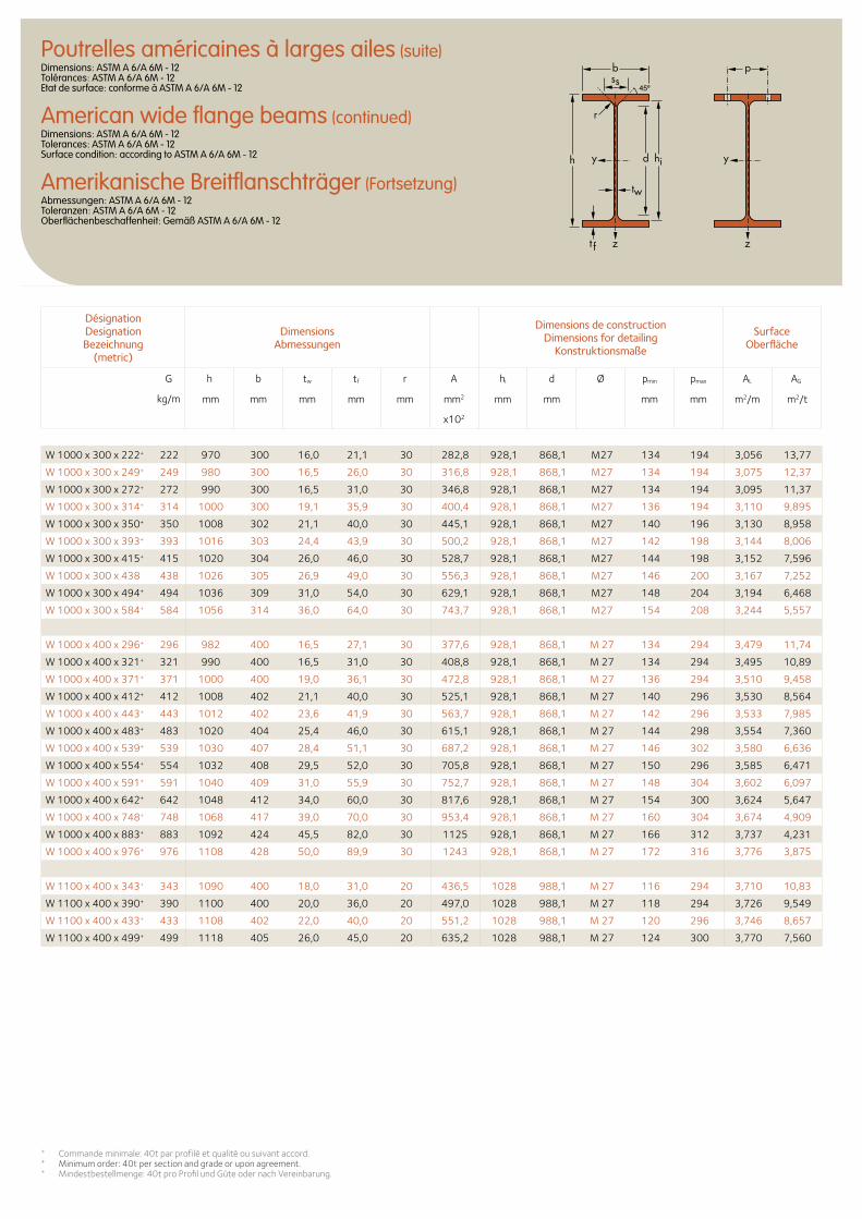
+ Commande minimale: 40t par profilé et qualité ou suivant accord. + Minimum order: 40t per section and grade or upon agreement.+ Mindestbestellmenge: 40t pro Profil und Güte oder nach Vereinbarung.
Désignation Designation Bezeichnung
(metric)
Dimensions Abmessungen
Dimensions de construction Dimensions for detailing
Konstruktionsmaße
Surface Oberfläche
G
kg/m
h b tw tf r A hi d Ø pmin pmax AL AG
mm mm mm mm mm mm2 mm mm mm mm m2/m m2/t
x102
b
r
yy dh
tw
ss
zzt f
hi
p
W 1000 x 300 x 222+ 222 970 300 16,0 21,1 30 282,8 928,1 868,1 M27 134 194 3,056 13,77
W 1000 x 300 x 249+ 249 980 300 16,5 26,0 30 316,8 928,1 868,1 M27 134 194 3,075 12,37
W 1000 x 300 x 272+ 272 990 300 16,5 31,0 30 346,8 928,1 868,1 M27 134 194 3,095 11,37
W 1000 x 300 x 314+ 314 1000 300 19,1 35,9 30 400,4 928,1 868,1 M27 136 194 3,110 9,895
W 1000 x 300 x 350+ 350 1008 302 21,1 40,0 30 445,1 928,1 868,1 M27 140 196 3,130 8,958
W 1000 x 300 x 393+ 393 1016 303 24,4 43,9 30 500,2 928,1 868,1 M27 142 198 3,144 8,006
W 1000 x 300 x 415+ 415 1020 304 26,0 46,0 30 528,7 928,1 868,1 M27 144 198 3,152 7,596
W 1000 x 300 x 438 438 1026 305 26,9 49,0 30 556,3 928,1 868,1 M27 146 200 3,167 7,252
W 1000 x 300 x 494+ 494 1036 309 31,0 54,0 30 629,1 928,1 868,1 M27 148 204 3,194 6,468
W 1000 x 300 x 584+ 584 1056 314 36,0 64,0 30 743,7 928,1 868,1 M27 154 208 3,244 5,557
W 1000 x 400 x 296+ 296 982 400 16,5 27,1 30 377,6 928,1 868,1 M 27 134 294 3,479 11,74
W 1000 x 400 x 321+ 321 990 400 16,5 31,0 30 408,8 928,1 868,1 M 27 134 294 3,495 10,89
W 1000 x 400 x 371+ 371 1000 400 19,0 36,1 30 472,8 928,1 868,1 M 27 136 294 3,510 9,458
W 1000 x 400 x 412+ 412 1008 402 21,1 40,0 30 525,1 928,1 868,1 M 27 140 296 3,530 8,564
W 1000 x 400 x 443+ 443 1012 402 23,6 41,9 30 563,7 928,1 868,1 M 27 142 296 3,533 7,985
W 1000 x 400 x 483+ 483 1020 404 25,4 46,0 30 615,1 928,1 868,1 M 27 144 298 3,554 7,360
W 1000 x 400 x 539+ 539 1030 407 28,4 51,1 30 687,2 928,1 868,1 M 27 146 302 3,580 6,636
W 1000 x 400 x 554+ 554 1032 408 29,5 52,0 30 705,8 928,1 868,1 M 27 150 296 3,585 6,471
W 1000 x 400 x 591+ 591 1040 409 31,0 55,9 30 752,7 928,1 868,1 M 27 148 304 3,602 6,097
W 1000 x 400 x 642+ 642 1048 412 34,0 60,0 30 817,6 928,1 868,1 M 27 154 300 3,624 5,647
W 1000 x 400 x 748+ 748 1068 417 39,0 70,0 30 953,4 928,1 868,1 M 27 160 304 3,674 4,909
W 1000 x 400 x 883+ 883 1092 424 45,5 82,0 30 1125 928,1 868,1 M 27 166 312 3,737 4,231
W 1000 x 400 x 976+ 976 1108 428 50,0 89,9 30 1243 928,1 868,1 M 27 172 316 3,776 3,875
W 1100 x 400 x 343+ 343 1090 400 18,0 31,0 20 436,5 1028 988,1 M 27 116 294 3,710 10,83
W 1100 x 400 x 390+ 390 1100 400 20,0 36,0 20 497,0 1028 988,1 M 27 118 294 3,726 9,549
W 1100 x 400 x 433+ 433 1108 402 22,0 40,0 20 551,2 1028 988,1 M 27 120 296 3,746 8,657
W 1100 x 400 x 499+ 499 1118 405 26,0 45,0 20 635,2 1028 988,1 M 27 124 300 3,770 7,560
Poutrelles américaines à larges ailes (suite)Dimensions: ASTM A 6/A 6M - 12 Tolérances: ASTM A 6/A 6M - 12 Etat de surface: conforme à ASTM A 6/A 6M - 12
American wide flange beams (continued)Dimensions: ASTM A 6/A 6M - 12 Tolerances: ASTM A 6/A 6M - 12 Surface condition: according to ASTM A 6/A 6M - 12
Amerikanische Breitflanschträger (Fortsetzung)Abmessungen: ASTM A 6/A 6M - 12 Toleranzen: ASTM A 6/A 6M - 12 Oberflächenbeschaffenheit: Gemäß ASTM A 6/A 6M - 12
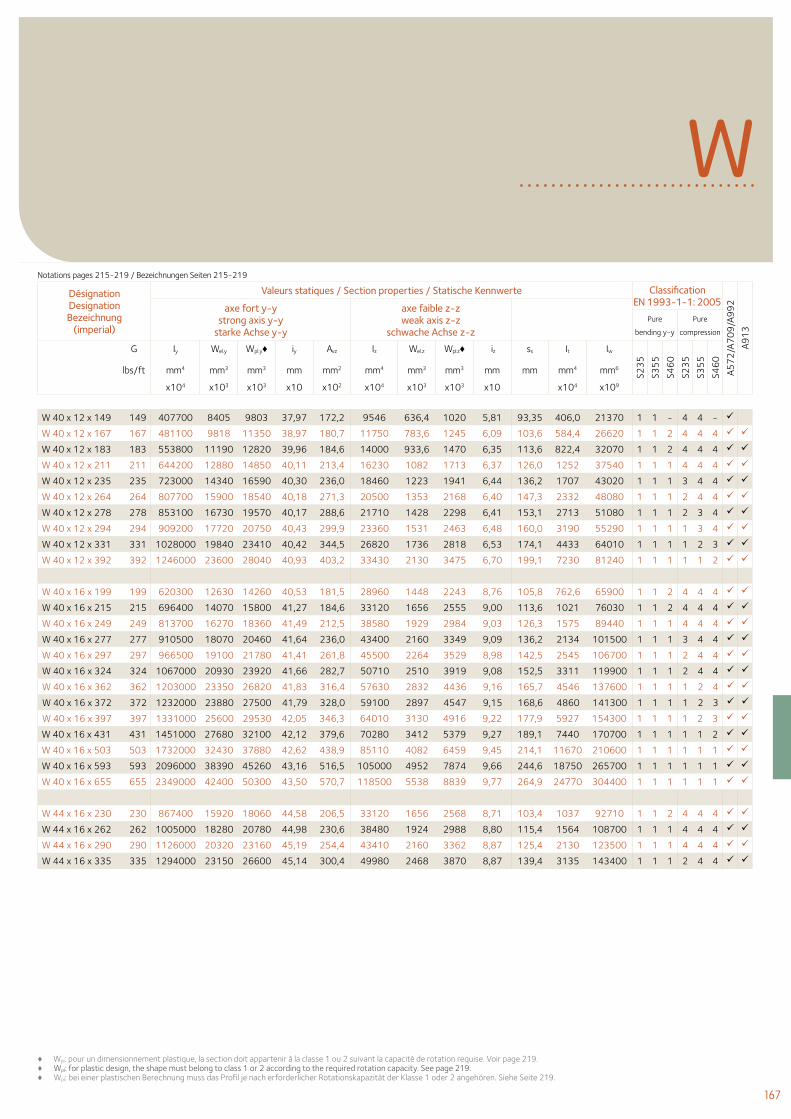
167
♦ Wpl: pour un dimensionnement plastique, la section doit appartenir à la classe 1 ou 2 suivant la capacité de rotation requise. Voir page 219.♦ Wpl: for plastic design, the shape must belong to class 1 or 2 according to the required rotation capacity. See page 219. ♦ Wpl: bei einer plastischen Berechnung muss das Profil je nach erforderlicher Rotationskapazität der Klasse 1 oder 2 angehören. Siehe Seite 219.
WDésignation Designation Bezeichnung
(imperial)
Valeurs statiques / Section properties / Statische Kennwerte Classification EN 1993-1-1: 2005
A57
2/A
70
9/A
99
2
A91
3
axe fort y-y strong axis y-y
starke Achse y-y
axe faible z-z weak axis z-z
schwache Achse z-z Pure
bending y-y
Pure
compression
G Iy Wel.y Wpl.y♦ iy Avz Iz Wel.z Wpl.z♦ iz ss It Iw
S23
5
S35
5
S46
0
S23
5
S35
5
S46
0
lbs/ft mm4 mm3 mm3 mm mm2 mm4 mm3 mm3 mm mm mm4 mm6
x104 x103 x103 x10 x102 x104 x103 x103 x10 x104 x109
W 40 x 12 x 149 149 407700 8405 9803 37,97 172,2 9546 636,4 1020 5,81 93,35 406,0 21370 1 1 - 4 4 -
W 40 x 12 x 167 167 481100 9818 11350 38,97 180,7 11750 783,6 1245 6,09 103,6 584,4 26620 1 1 2 4 4 4
W 40 x 12 x 183 183 553800 11190 12820 39,96 184,6 14000 933,6 1470 6,35 113,6 822,4 32070 1 1 2 4 4 4
W 40 x 12 x 211 211 644200 12880 14850 40,11 213,4 16230 1082 1713 6,37 126,0 1252 37540 1 1 1 4 4 4
W 40 x 12 x 235 235 723000 14340 16590 40,30 236,0 18460 1223 1941 6,44 136,2 1707 43020 1 1 1 3 4 4
W 40 x 12 x 264 264 807700 15900 18540 40,18 271,3 20500 1353 2168 6,40 147,3 2332 48080 1 1 1 2 4 4
W 40 x 12 x 278 278 853100 16730 19570 40,17 288,6 21710 1428 2298 6,41 153,1 2713 51080 1 1 1 2 3 4
W 40 x 12 x 294 294 909200 17720 20750 40,43 299,9 23360 1531 2463 6,48 160,0 3190 55290 1 1 1 1 3 4
W 40 x 12 x 331 331 1028000 19840 23410 40,42 344,5 26820 1736 2818 6,53 174,1 4433 64010 1 1 1 1 2 3
W 40 x 12 x 392 392 1246000 23600 28040 40,93 403,2 33430 2130 3475 6,70 199,1 7230 81240 1 1 1 1 1 2
W 40 x 16 x 199 199 620300 12630 14260 40,53 181,5 28960 1448 2243 8,76 105,8 762,6 65900 1 1 2 4 4 4
W 40 x 16 x 215 215 696400 14070 15800 41,27 184,6 33120 1656 2555 9,00 113,6 1021 76030 1 1 2 4 4 4
W 40 x 16 x 249 249 813700 16270 18360 41,49 212,5 38580 1929 2984 9,03 126,3 1575 89440 1 1 1 4 4 4
W 40 x 16 x 277 277 910500 18070 20460 41,64 236,0 43400 2160 3349 9,09 136,2 2134 101500 1 1 1 3 4 4
W 40 x 16 x 297 297 966500 19100 21780 41,41 261,8 45500 2264 3529 8,98 142,5 2545 106700 1 1 1 2 4 4
W 40 x 16 x 324 324 1067000 20930 23920 41,66 282,7 50710 2510 3919 9,08 152,5 3311 119900 1 1 1 2 4 4
W 40 x 16 x 362 362 1203000 23350 26820 41,83 316,4 57630 2832 4436 9,16 165,7 4546 137600 1 1 1 1 2 4
W 40 x 16 x 372 372 1232000 23880 27500 41,79 328,0 59100 2897 4547 9,15 168,6 4860 141300 1 1 1 1 2 3
W 40 x 16 x 397 397 1331000 25600 29530 42,05 346,3 64010 3130 4916 9,22 177,9 5927 154300 1 1 1 1 2 3
W 40 x 16 x 431 431 1451000 27680 32100 42,12 379,6 70280 3412 5379 9,27 189,1 7440 170700 1 1 1 1 1 2
W 40 x 16 x 503 503 1732000 32430 37880 42,62 438,9 85110 4082 6459 9,45 214,1 11670 210600 1 1 1 1 1 1
W 40 x 16 x 593 593 2096000 38390 45260 43,16 516,5 105000 4952 7874 9,66 244,6 18750 265700 1 1 1 1 1 1
W 40 x 16 x 655 655 2349000 42400 50300 43,50 570,7 118500 5538 8839 9,77 264,9 24770 304400 1 1 1 1 1 1
W 44 x 16 x 230 230 867400 15920 18060 44,58 206,5 33120 1656 2568 8,71 103,4 1037 92710 1 1 2 4 4 4
W 44 x 16 x 262 262 1005000 18280 20780 44,98 230,6 38480 1924 2988 8,80 115,4 1564 108700 1 1 1 4 4 4
W 44 x 16 x 290 290 1126000 20320 23160 45,19 254,4 43410 2160 3362 8,87 125,4 2130 123500 1 1 1 4 4 4
W 44 x 16 x 335 335 1294000 23150 26600 45,14 300,4 49980 2468 3870 8,87 139,4 3135 143400 1 1 1 2 4 4
Notations pages 215-219 / Bezeichnungen Seiten 215-219
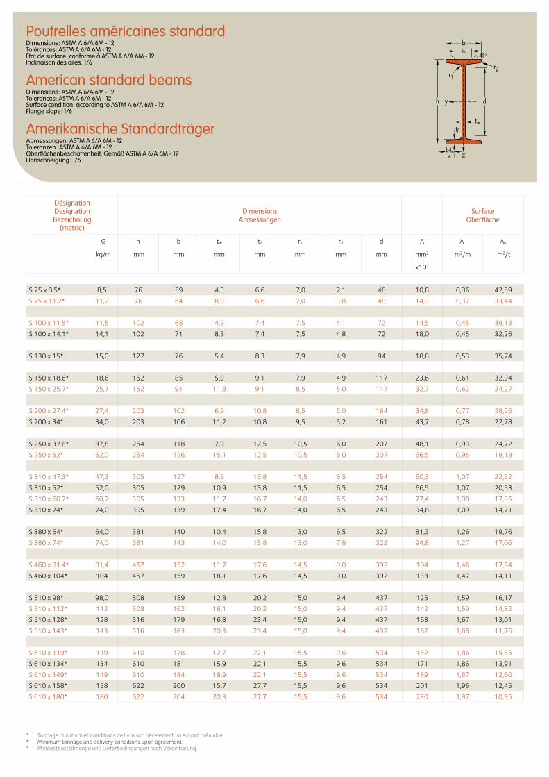
S 75 x 8.5* 8,5 76 59 4,3 6,6 7,0 2,1 48 10,8 0,36 42,59
S 75 x 11.2* 11,2 76 64 8,9 6,6 7,0 3,8 48 14,3 0,37 33,44
S 100 x 11.5* 11,5 102 68 4,9 7,4 7,5 4,1 72 14,5 0,45 39,13
S 100 x 14.1* 14,1 102 71 8,3 7,4 7,5 4,8 72 18,0 0,45 32,26
S 130 x 15* 15,0 127 76 5,4 8,3 7,9 4,9 94 18,8 0,53 35,74
S 150 x 18.6* 18,6 152 85 5,9 9,1 7,9 4,9 117 23,6 0,61 32,94
S 150 x 25.7* 25,7 152 91 11,8 9,1 8,5 5,0 117 32,7 0,62 24,27
S 200 x 27.4* 27,4 203 102 6,9 10,8 8,5 5,0 164 34,8 0,77 28,26
S 200 x 34* 34,0 203 106 11,2 10,8 9,5 5,2 161 43,7 0,78 22,78
S 250 x 37.8* 37,8 254 118 7,9 12,5 10,5 6,0 207 48,1 0,93 24,72
S 250 x 52* 52,0 254 126 15,1 12,5 10,5 6,0 207 66,5 0,95 18,18
S 310 x 47.3* 47,3 305 127 8,9 13,8 11,5 6,5 254 60,3 1,07 22,52
S 310 x 52* 52,0 305 129 10,9 13,8 11,5 6,5 254 66,5 1,07 20,53
S 310 x 60.7* 60,7 305 133 11,7 16,7 14,0 6,5 243 77,4 1,08 17,85
S 310 x 74* 74,0 305 139 17,4 16,7 14,0 6,5 243 94,8 1,09 14,71
S 380 x 64* 64,0 381 140 10,4 15,8 13,0 6,5 322 81,3 1,26 19,76
S 380 x 74* 74,0 381 143 14,0 15,8 13,0 7,8 322 94,8 1,27 17,06
S 460 x 81.4* 81,4 457 152 11,7 17,6 14,5 9,0 392 104 1,46 17,94
S 460 x 104* 104 457 159 18,1 17,6 14,5 9,0 392 133 1,47 14,11
S 510 x 98* 98,0 508 159 12,8 20,2 15,0 9,4 437 125 1,59 16,17
S 510 x 112* 112 508 162 16,1 20,2 15,0 9,4 437 142 1,59 14,32
S 510 x 128* 128 516 179 16,8 23,4 15,0 9,4 437 163 1,67 13,01
S 510 x 143* 143 516 183 20,3 23,4 15,0 9,4 437 182 1,68 11,76
S 610 x 119* 119 610 178 12,7 22,1 15,5 9,6 534 152 1,86 15,65
S 610 x 134* 134 610 181 15,9 22,1 15,5 9,6 534 171 1,86 13,91
S 610 x 149* 149 610 184 18,9 22,1 15,5 9,6 534 189 1,87 12,60
S 610 x 158* 158 622 200 15,7 27,7 15,5 9,6 534 201 1,96 12,45
S 610 x 180* 180 622 204 20,3 27,7 15,5 9,6 534 230 1,97 10,95
Poutrelles américaines standardDimensions: ASTM A 6/A 6M - 12 Tolérances: ASTM A 6/A 6M - 12 Etat de surface: conforme à ASTM A 6/A 6M - 12 Inclinaison des ailes: 1/6
American standard beamsDimensions: ASTM A 6/A 6M - 12 Tolerances: ASTM A 6/A 6M - 12 Surface condition: according to ASTM A 6/A 6M - 12 Flange slope: 1/6
Amerikanische StandardträgerAbmessungen: ASTM A 6/A 6M - 12 Toleranzen: ASTM A 6/A 6M - 12 Oberflächenbeschaffenheit: Gemäß ASTM A 6/A 6M - 12 Flanschneigung: 1/6
Désignation Designation Bezeichnung
(metric)
Dimensions Abmessungen
Surface Oberfläche
G
kg/m
h b tw tf r1 r2 d A AL AG
mm mm mm mm mm mm mm mm2 m2/m m2/t
x102
ss45o
d
twtf
h y
z
b
r1r2
b-tw4
* Tonnage minimum et conditions de livraison nécessitent un accord préalable.* Minimum tonnage and delivery conditions upon agreement.* Mindestbestellmenge und Lieferbedingungen nach Vereinbarung.
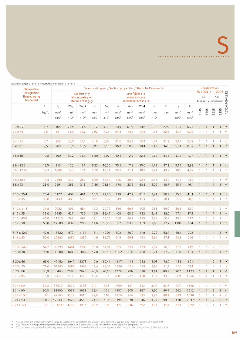
169
S 3 x 5.7 5,7 105 27,5 31,5 3,12 4,19 18,9 6,39 10,6 1,32 27,9 1,93 0,23 1 1 1 1
S 3 x 7.5 7,5 121 31,9 38,2 2,92 7,23 24,3 7,59 13,6 1,31 32,6 4,97 0,29 1 1 1 1
S 4 x 7.7 7,7 255 50,0 57,1 4,18 6,07 31,6 9,28 15,9 1,47 31,3 3,17 0,72 1 1 1 1
S 4 x 9.5 9,5 283 55,5 65,5 3,97 9,16 36,3 10,2 18,4 1,42 34,6 5,91 0,82 1 1 1 1
S 5 x 10 10,0 509 80,2 91,4 5,20 8,07 49,2 12,9 22,3 1,62 34,5 4,92 1,77 1 1 1 1
S 6 x 12.5 12,5 913 120 137 6,22 10,20 75,5 17,8 30,6 1,79 37,3 7,14 3,92 1 1 1 1
S 6 x 17.25 17,3 1089 143 171 5,78 18,54 95,9 21,1 38,9 1,71 43,7 18,5 4,87 1 1 1 1
S 8 x 18.4 18,4 2390 236 268 8,29 15,46 156 30,5 52,4 2,11 43,6 14,1 14,5 1 1 1 1
S 8 x 23 23,0 2691 265 313 7,86 23,84 178 33,6 60,5 2,02 48,7 25,4 16,4 1 1 1 1
S 10 x 25.4 25,4 5127 404 461 10,3 22,30 279 47,2 81,3 2,41 50,9 25,8 41,1 1 1 1 1
S 10 x 35 35,0 6139 483 579 9,61 39,22 349 55,5 103 2,29 58,1 61,2 50,6 1 1 1 1
S 12 x 31.8 31,8 9082 596 684 12,3 29,77 386 60,8 105 2,53 56,0 38,5 82,9 1 1 1 2
S 12 x 35 35,0 9555 627 730 12,0 35,47 408 63,2 112 2,48 58,0 47,4 87,1 1 1 1 1
S 12 x 40.8 40,8 11310 742 862 12,1 39,25 560 84,2 145 2,69 66,9 75,6 117 1 1 1 1
S 12 x 50 50,0 12680 832 996 11,6 55,25 652 93,9 169 2,63 72,7 130,0 134 1 1 1 1
S 15 x 42.9 42,9 18620 977 1131 15,1 42,91 602 86,0 149 2,72 63,7 66,1 202 1 1 1 3
S 15 x 50 50,0 20180 1059 1257 14,6 55,79 645 90,3 164 2,61 67,3 94,5 216 1 1 1 1
S 18 x 54.7 54,7 33390 1461 1703 18,0 57,51 855 113 199 2,87 70,8 102 419 1 1 2 3
S 18 x 70 70,0 38580 1689 2042 17,0 85,10 1002 126 238 2,74 77,2 190 483 1 1 1 1
S 20 x 66 66,0 49450 1947 2275 19,9 69,41 1147 144 253 3,03 78,0 153 691 1 1 2 3
S 20 x 75 75,0 52980 2086 2485 19,4 85,23 1226 151 274 2,94 81,2 200 734 1 1 1 2
S 20 x 86 86,0 65480 2540 2990 20,0 90,18 1929 216 378 3,44 89,7 287 1173 1 1 1 1
S 20 x 96 96,0 69620 2700 3228 19,6 107 2081 227 410 3,39 93,2 369 1256 1 1 1 1
S 24 x 80 80,0 87530 2872 3336 24,1 82,5 1750 197 342 3,40 83,7 207 1528 1 1 4 4
S 24 x 90 90,0 93500 3067 3631 23,4 101 1857 205 367 3,30 86,9 262 1612 1 1 2 3
S 24 x 100 100 99160 3253 3910 22,9 118 1970 214 393 3,23 89,9 333 1698 1 1 1 2
S 24 x 106 106 122300 3929 4560 24,7 103 3195 320 546 3,99 99,5 428 2837 1 1 2 3
S 24 x 121 121 131200 4217 4996 23,9 129 3427 336 592 3,87 104 553 3022 1 1 1 1
SDésignation Designation Bezeichnung
(imperial)
Valeurs statiques / Section properties / Statische Kennwerte Classification EN 1993-1-1: 2005
A57
2/A
70
9/A
99
2axe fort y-y strong axis y-y
starke Achse y-y
axe faible z-z weak axis z-z
schwache Achse z-z Pure
bending y-y
Pure
compression
G Iy Wel.y Wpl.y♦ iy Avz Iz Wel.z Wpl.z♦ iz ss It Iw
S23
5
S35
5
S23
5
S35
5
lbs/ft mm4 mm3 mm3 mm mm2 mm4 mm3 mm3 mm mm mm4 mm6
x104 x103 x103 x10 x102 x104 x103 x103 x10 x104 x109
♦ Wpl: pour un dimensionnement plastique, la section doit appartenir à la classe 1 ou 2 suivant la capacité de rotation requise. Voir page 219.♦ Wpl: for plastic design, the shape must belong to class 1 or 2 according to the required rotation capacity. See page 219. ♦ Wpl: bei einer plastischen Berechnung muss das Profil je nach erforderlicher Rotationskapazität der Klasse 1 oder 2 angehören. Siehe Seite 219.
Notations pages 215-219 / Bezeichnungen Seiten 215-219
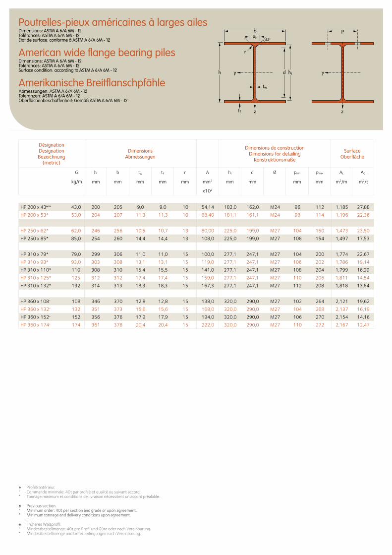
Poutrelles-pieux américaines à larges ailesDimensions: ASTM A 6/A 6M - 12 Tolérances: ASTM A 6/A 6M - 12 Etat de surface: conforme à ASTM A 6/A 6M - 12
American wide flange bearing pilesDimensions: ASTM A 6/A 6M - 12 Tolerances: ASTM A 6/A 6M - 12 Surface condition: according to ASTM A 6/A 6M - 12
Amerikanische BreitflanschpfähleAbmessungen: ASTM A 6/A 6M - 12 Toleranzen: ASTM A 6/A 6M - 12 Oberflächenbeschaffenheit: Gemäß ASTM A 6/A 6M - 12
d hi
tw
tf
yyh
zz
r
b pss
45o
Désignation Designation Bezeichnung
(metric)
Dimensions Abmessungen
Dimensions de construction Dimensions for detailing
Konstruktionsmaße
Surface Oberfläche
G
kg/m
h b tw tf r A hI d Ø pmin pmax AL AG
mm mm mm mm mm mm2 mm mm mm mm m2/m m2/t
x102
HP 200 x 43♠/* 43,0 200 205 9,0 9,0 10 54,14 182,0 162,0 M24 96 112 1,185 27,88
HP 200 x 53* 53,0 204 207 11,3 11,3 10 68,40 181,1 161,1 M24 98 114 1,196 22,36
HP 250 x 62* 62,0 246 256 10,5 10,7 13 80,00 225,0 199,0 M27 104 150 1,473 23,50
HP 250 x 85* 85,0 254 260 14,4 14,4 13 108,0 225,0 199,0 M27 108 154 1,497 17,53
HP 310 x 79* 79,0 299 306 11,0 11,0 15 100,0 277,1 247,1 M27 104 200 1,774 22,67
HP 310 x 93* 93,0 303 308 13,1 13,1 15 119,0 277,1 247,1 M27 106 202 1,786 19,14
HP 310 x 110* 110 308 310 15,4 15,5 15 141,0 277,1 247,1 M27 108 204 1,799 16,29
HP 310 x 125* 125 312 312 17,4 17,4 15 159,0 277,1 247,1 M27 110 206 1,811 14,54
HP 310 x 132* 132 314 313 18,3 18,3 15 167,3 277,1 247,1 M27 112 208 1,818 13,84
HP 360 x 108+ 108 346 370 12,8 12,8 15 138,0 320,0 290,0 M27 102 264 2,121 19,62
HP 360 x 132+ 132 351 373 15,6 15,6 15 168,0 320,0 290,0 M27 104 268 2,137 16,19
HP 360 x 152+ 152 356 376 17,9 17,9 15 194,0 320,0 290,0 M27 106 270 2,154 14,16
HP 360 x 174+ 174 361 378 20,4 20,4 15 222,0 320,0 290,0 M27 110 272 2,167 12,47
♠ Profilé antérieur.+ Commande minimale: 40t par profilé et qualité ou suivant accord.* Tonnage minimum et conditions de livraison nécessitent un accord préalable.
♠ Previous section.+ Minimum order: 40t per section and grade or upon agreement.* Minimum tonnage and delivery conditions upon agreement.
♠ Früheres Walzprofil.+ Mindestbestellmenge: 40t pro Profil und Güte oder nach Vereinbarung.* Mindestbestellmenge und Lieferbedingungen nach Vereinbarung.
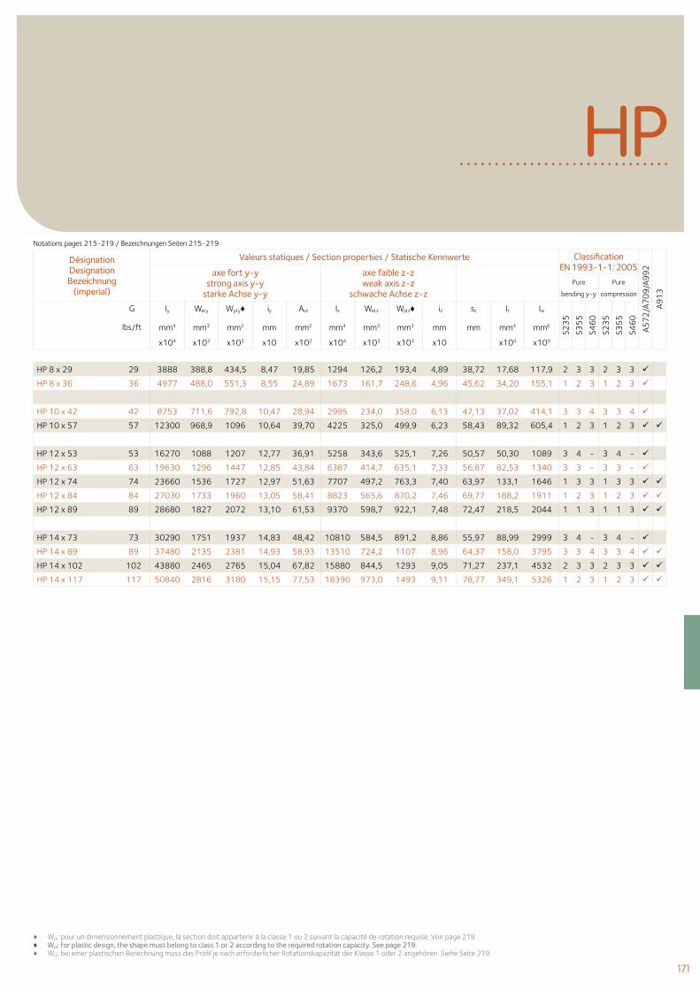
171
HP
HP 8 x 29 29 3888 388,8 434,5 8,47 19,85 1294 126,2 193,4 4,89 38,72 17,68 117,9 2 3 3 2 3 3
HP 8 x 36 36 4977 488,0 551,3 8,55 24,89 1673 161,7 248,6 4,96 45,62 34,20 155,1 1 2 3 1 2 3
HP 10 x 42 42 8753 711,6 792,8 10,47 28,94 2995 234,0 358,0 6,13 47,13 37,02 414,1 3 3 4 3 3 4
HP 10 x 57 57 12300 968,9 1096 10,64 39,70 4225 325,0 499,9 6,23 58,43 89,32 605,4 1 2 3 1 2 3
HP 12 x 53 53 16270 1088 1207 12,77 36,91 5258 343,6 525,1 7,26 50,57 50,30 1089 3 4 - 3 4 -
HP 12 x 63 63 19630 1296 1447 12,85 43,84 6387 414,7 635,1 7,33 56,87 82,53 1340 3 3 - 3 3 -
HP 12 x 74 74 23660 1536 1727 12,97 51,63 7707 497,2 763,3 7,40 63,97 133,1 1646 1 3 3 1 3 3
HP 12 x 84 84 27030 1733 1960 13,05 58,41 8823 565,6 870,2 7,46 69,77 188,2 1911 1 2 3 1 2 3
HP 12 x 89 89 28680 1827 2072 13,10 61,53 9370 598,7 922,1 7,48 72,47 218,5 2044 1 1 3 1 1 3
HP 14 x 73 73 30290 1751 1937 14,83 48,42 10810 584,5 891,2 8,86 55,97 88,99 2999 3 4 - 3 4 -
HP 14 x 89 89 37480 2135 2381 14,93 58,93 13510 724,2 1107 8,96 64,37 158,0 3795 3 3 4 3 3 4
HP 14 x 102 102 43880 2465 2765 15,04 67,82 15880 844,5 1293 9,05 71,27 237,1 4532 2 3 3 2 3 3
HP 14 x 117 117 50840 2816 3180 15,15 77,53 18390 973,0 1493 9,11 78,77 349,1 5326 1 2 3 1 2 3
Désignation Designation Bezeichnung
(imperial)
Valeurs statiques / Section properties / Statische Kennwerte Classification EN 1993-1-1: 2005
A57
2/A
70
9/A
99
2
A91
3
axe fort y-y strong axis y-y
starke Achse y-y
axe faible z-z weak axis z-z
schwache Achse z-z Pure
bending y-y
Pure
compression
G Iy Wel.y Wpl.y♦ iy Avz Iz Wel.z Wpl.z♦ iz ss It Iw
S23
5
S35
5
S46
0
S23
5
S35
5
S46
0
lbs/ft mm4 mm3 mm3 mm mm2 mm4 mm3 mm3 mm mm mm4 mm6
x104 x103 x103 x10 x102 x104 x103 x103 x10 x104 x109
♦ Wpl: pour un dimensionnement plastique, la section doit appartenir à la classe 1 ou 2 suivant la capacité de rotation requise. Voir page 219.♦ Wpl: for plastic design, the shape must belong to class 1 or 2 according to the required rotation capacity. See page 219. ♦ Wpl: bei einer plastischen Berechnung muss das Profil je nach erforderlicher Rotationskapazität der Klasse 1 oder 2 angehören. Siehe Seite 219.
Notations pages 215-219 / Bezeichnungen Seiten 215-219
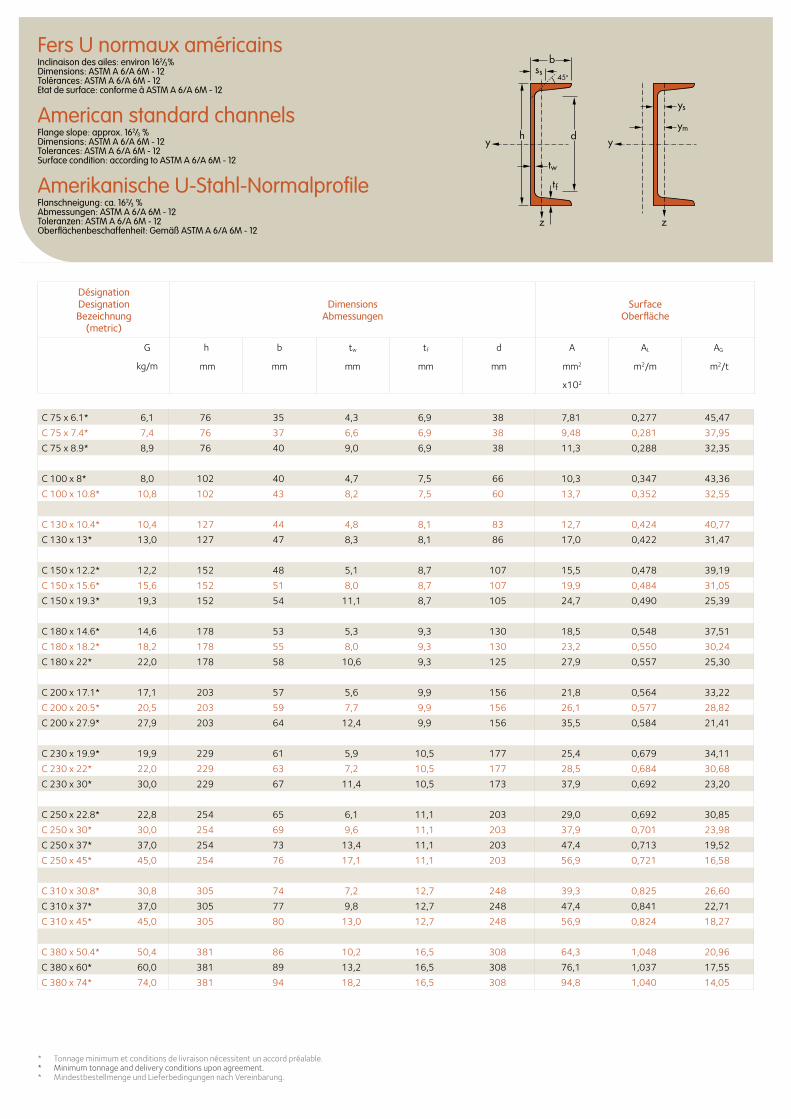
Fers U normaux américainsInclinaison des ailes: environ 162/3% Dimensions: ASTM A 6/A 6M - 12 Tolérances: ASTM A 6/A 6M - 12 Etat de surface: conforme à ASTM A 6/A 6M - 12
American standard channelsFlange slope: approx. 162/3 % Dimensions: ASTM A 6/A 6M - 12 Tolerances: ASTM A 6/A 6M - 12 Surface condition: according to ASTM A 6/A 6M - 12
Amerikanische U-Stahl-NormalprofileFlanschneigung: ca. 162/3 % Abmessungen: ASTM A 6/A 6M - 12 Toleranzen: ASTM A 6/A 6M - 12 Oberflächenbeschaffenheit: Gemäß ASTM A 6/A 6M - 12
C 75 x 6.1* 6,1 76 35 4,3 6,9 38 7,81 0,277 45,47
C 75 x 7.4* 7,4 76 37 6,6 6,9 38 9,48 0,281 37,95
C 75 x 8.9* 8,9 76 40 9,0 6,9 38 11,3 0,288 32,35
C 100 x 8* 8,0 102 40 4,7 7,5 66 10,3 0,347 43,36
C 100 x 10.8* 10,8 102 43 8,2 7,5 60 13,7 0,352 32,55
C 130 x 10.4* 10,4 127 44 4,8 8,1 83 12,7 0,424 40,77
C 130 x 13* 13,0 127 47 8,3 8,1 86 17,0 0,422 31,47
C 150 x 12.2* 12,2 152 48 5,1 8,7 107 15,5 0,478 39,19
C 150 x 15.6* 15,6 152 51 8,0 8,7 107 19,9 0,484 31,05
C 150 x 19.3* 19,3 152 54 11,1 8,7 105 24,7 0,490 25,39
C 180 x 14.6* 14,6 178 53 5,3 9,3 130 18,5 0,548 37,51
C 180 x 18.2* 18,2 178 55 8,0 9,3 130 23,2 0,550 30,24
C 180 x 22* 22,0 178 58 10,6 9,3 125 27,9 0,557 25,30
C 200 x 17.1* 17,1 203 57 5,6 9,9 156 21,8 0,564 33,22
C 200 x 20.5* 20,5 203 59 7,7 9,9 156 26,1 0,577 28,82
C 200 x 27.9* 27,9 203 64 12,4 9,9 156 35,5 0,584 21,41
C 230 x 19.9* 19,9 229 61 5,9 10,5 177 25,4 0,679 34,11
C 230 x 22* 22,0 229 63 7,2 10,5 177 28,5 0,684 30,68
C 230 x 30* 30,0 229 67 11,4 10,5 173 37,9 0,692 23,20
C 250 x 22.8* 22,8 254 65 6,1 11,1 203 29,0 0,692 30,85
C 250 x 30* 30,0 254 69 9,6 11,1 203 37,9 0,701 23,98
C 250 x 37* 37,0 254 73 13,4 11,1 203 47,4 0,713 19,52
C 250 x 45* 45,0 254 76 17,1 11,1 203 56,9 0,721 16,58
C 310 x 30.8* 30,8 305 74 7,2 12,7 248 39,3 0,825 26,60
C 310 x 37* 37,0 305 77 9,8 12,7 248 47,4 0,841 22,71
C 310 x 45* 45,0 305 80 13,0 12,7 248 56,9 0,824 18,27
C 380 x 50.4* 50,4 381 86 10,2 16,5 308 64,3 1,048 20,96
C 380 x 60* 60,0 381 89 13,2 16,5 308 76,1 1,037 17,55
C 380 x 74* 74,0 381 94 18,2 16,5 308 94,8 1,040 14,05
ys
ss
ymdy y
zz
tw
tf
h
b
45o
Désignation Designation Bezeichnung
(metric)
Dimensions Abmessungen
Surface Oberfläche
G
kg/m
h b tw tf d A AL AG
mm mm mm mm mm mm2 m2/m m2/t
x102
* Tonnage minimum et conditions de livraison nécessitent un accord préalable.* Minimum tonnage and delivery conditions upon agreement.* Mindestbestellmenge und Lieferbedingungen nach Vereinbarung.
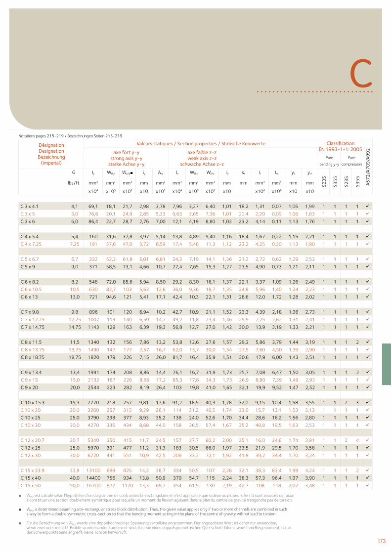
173
CDésignation Designation Bezeichnung
(imperial)
Valeurs statiques / Section properties / Statische Kennwerte Classification EN 1993-1-1: 2005
A57
2/A
70
9/A
99
2axe fort y-y strong axis y-y
starke Achse y-y
axe faible z-z weak axis z-z
schwache Achse z-z Pure
bending y-y
Pure
compression
G Iy Wel.y Wpl.y■ iy Avz Iz Wel.z Wpl.z iz ss It Iw ys ym
S23
5
S35
5
S23
5
S35
5
lbs/ft mm4 mm3 mm3 mm mm2 mm4 mm3 mm3 mm mm mm4 mm6 mm mm
x104 x103 x103 x10 x102 x104 x103 x103 x10 x104 x109 x10 x10
C 3 x 4.1 4,1 69,1 18,1 21,7 2,98 3,78 7,96 3,27 6,40 1,01 18,2 1,31 0,07 1,06 1,99 1 1 1 1
C 3 x 5 5,0 76,6 20,1 24,9 2,85 5,33 9,63 3,65 7,36 1,01 20,4 2,20 0,09 1,06 1,83 1 1 1 1
C 3 x 6 6,0 86,4 22,7 28,7 2,76 7,00 12,1 4,19 8,80 1,03 23,2 4,14 0,11 1,13 1,76 1 1 1 1
C 4 x 5.4 5,4 160 31,6 37,8 3,97 5,14 13,8 4,89 9,40 1,16 18,4 1,67 0,22 1,15 2,21 1 1 1 1
C 4 x 7.25 7,25 191 37,6 47,0 3,72 8,59 17,4 5,48 11,3 1,12 23,2 4,25 0,30 1,13 1,90 1 1 1 1
C 5 x 6.7 6,7 332 52,3 61,8 5,01 6,81 24,3 7,19 14,1 1,36 21,2 2,72 0,62 1,29 2,53 1 1 1 1
C 5 x 9 9,0 371 58,5 73,1 4,66 10,7 27,4 7,65 15,3 1,27 23,5 4,90 0,73 1,21 2,11 1 1 1 1
C 6 x 8.2 8,2 548 72,0 85,6 5,94 8,50 29,2 8,30 16,1 1,37 22,1 3,37 1,09 1,26 2,49 1 1 1 1
C 6 x 10.5 10,5 630 82,7 103 5,63 12,6 36,0 9,36 18,7 1,35 24,8 5,96 1,40 1,24 2,23 1 1 1 1
C 6 x 13 13,0 721 94,6 121 5,41 17,1 42,4 10,3 22,1 1,31 28,6 12,0 1,72 1,28 2,02 1 1 1 1
C 7 x 9.8 9,8 896 101 120 6,94 10,2 42,7 10,9 21,1 1,52 23,3 4,39 2,18 1,36 2,73 1 1 1 1
C 7 x 12.25 12,25 1007 113 140 6,59 14,7 49,2 11,8 23,4 1,46 25,9 7,25 2,62 1,31 2,41 1 1 1 1
C 7 x 14.75 14,75 1143 129 163 6,39 19,3 56,8 12,7 27,0 1,42 30,0 13,9 3,19 1,33 2,21 1 1 1 1
C 8 x 11.5 11,5 1340 132 156 7,86 13,2 53,8 12,6 27,6 1,57 29,3 5,86 3,79 1,44 3,19 1 1 1 2
C 8 x 13.75 13,75 1490 147 177 7,57 16,7 62,0 13,7 30,0 1,54 27,5 7,60 4,50 1,39 2,90 1 1 1 1
C 8 x 18.75 18,75 1820 179 226 7,15 26,0 81,7 16,4 35,9 1,51 30,6 17,9 6,00 1,43 2,51 1 1 1 1
C 9 x 13.4 13,4 1991 174 208 8,86 14,4 76,1 16,7 31,9 1,73 25,7 7,08 6,47 1,50 3,05 1 1 1 2
C 9 x 15 15,0 2132 187 226 8,66 17,2 85,3 17,8 34,3 1,73 26,9 8,80 7,39 1,49 2,93 1 1 1 1
C 9 x 20 20,0 2544 223 282 8,19 26,4 103 19,8 41,0 1,65 32,1 19,9 9,52 1,47 2,52 1 1 1 1
C 10 x 15.3 15,3 2770 218 257 9,81 17,6 91,2 18,5 40,3 1,78 32,0 9,15 10,4 1,58 3,55 1 1 2 3
C 10 x 20 20,0 3260 257 315 9,29 26,1 114 21,2 46,5 1,74 33,6 15,7 13,1 1,53 3,13 1 1 1 1
C 10 x 25 25,0 3790 298 377 8,93 35,2 138 24,0 52,6 1,70 34,4 28,6 16,2 1,56 2,80 1 1 1 1
C 10 x 30 30,0 4270 336 434 8,68 44,0 158 26,5 57,4 1,67 35,2 48,8 19,5 1,63 2,53 1 1 1 1
C 12 x 20.7 20,7 5340 350 415 11,7 24,5 157 27,7 60,2 2,00 35,1 16,0 24,8 1,74 3,91 1 1 2 4
C 12 x 25 25,0 5970 391 477 11,2 31,3 183 30,5 66,0 1,97 33,5 21,9 29,5 1,70 3,58 1 1 1 1
C 12 x 30 30,0 6720 441 551 10,9 42,5 209 33,2 72,1 1,92 41,8 39,2 34,4 1,70 3,24 1 1 1 1
C 15 x 33.9 33,9 13100 688 825 14,3 38,7 334 50,5 107 2,28 32,1 38,3 83,4 1,99 4,24 1 1 1 2
C 15 x 40 40,0 14400 756 934 13,8 50,9 379 54,7 115 2,24 38,3 57,3 96,4 1,97 3,90 1 1 1 1
C 15 x 50 50,0 16700 877 1120 13,3 69,7 454 61,5 130 2,19 42,7 108 118 2,02 3,48 1 1 1 1
■ Wpl,y est calculé selon l’hypothèse d’un diagramme de contraintes bi-rectangulaire et n’est applicable que si deux ou plusieurs fers U sont associés de facon à constituer une section doublement symétrique pour laquelle un moment de flexion agissant dans le plan du centre de gravité n’engendre pas de torsion.
■ Wpl,y is determined assuming a bi-rectangular stress block distribution. Thus, the given value applies only if two or more channels are combined in such a way to form a double symmetric cross-section so that the bending moment acting in the plane of the centre of gravity will not lead to torsion.
■ Für die Berechnung von Wpl,y wurde eine doppelrechteckige Spannungsverteilung angenommen. Der angegebene Wert ist daher nur anwendbar, wenn zwei oder mehr U-Profile so miteinander kombiniert sind, dass sie einen doppelsymmetrischen Querschnitt bilden, womit ein Biegemoment, das in der Schwerpunktebene angreift, keine Torsion hervorruft.
Notations pages 215-219 / Bezeichnungen Seiten 215-219
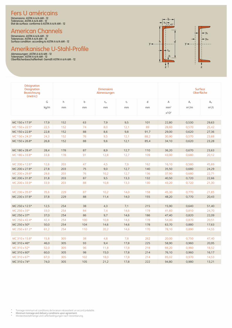
Fers U américainsDimensions: ASTM A 6/A 6M - 12 Tolérances: ASTM A 6/A 6M - 12 Etat de surface: conforme à ASTM A 6/A 6M - 12
American ChannelsDimensions: ASTM A 6/A 6M - 12 Tolerances: ASTM A 6/A 6M - 12 Surface condition: according to ASTM A 6/A 6M - 12
Amerikanische U-Stahl-ProfileAbmessungen: ASTM A 6/A 6M - 12 Toleranzen: ASTM A 6/A 6M - 12 Oberflächenbeschaffenheit: Gemäß ASTM A 6/A 6M - 12
Désignation Designation Bezeichnung
(metric)
Dimensions Abmessungen
Surface Oberfläche
G
kg/m
h b tw tf d A AL AG
mm mm mm mm mm mm2 m2/m m2/t
x102
* Tonnage minimum et conditions de livraison nécessitent un accord préalable.* Minimum tonnage and delivery conditions upon agreement.* Mindestbestellmenge und Lieferbedingungen nach Vereinbarung.
MC 150 x 17.9* 17,9 152 63 7,9 9,5 101 22,80 0,530 29,63
MC 150 x 22.5* 22,5 152 74 8,0 12,1 89 28,60 0,570 25,42
MC 150 x 22.8* 22,8 152 88 8,6 9,8 91,7 29,00 0,620 27,36
MC 150 x 24.3* 24,3 152 76 9,5 12,1 88,2 30,90 0,570 23,68
MC 150 x 26.8* 26,8 152 88 9,6 12,1 85,4 34,10 0,620 23,28
MC 180 x 28.4* 28,4 178 87 8,9 12,7 110 36,20 0,670 23,63
MC 180 x 33.8* 33,8 178 91 12,8 12,7 109 43,00 0,680 20,12
MC 200 x 12.6* 12,6 203 47 4,5 7,9 162 16,10 0,580 45,69
MC 200 x 27.8* 27,8 203 75 9,0 12,7 140 35,50 0,680 24,29
MC 200 x 29.8* 29,8 203 76 10,2 12,7 136 37,90 0,680 22,71
MC 200 x 31.8* 31,8 203 87 9,5 13,3 132 40,50 0,720 22,66
MC 200 x 33.9* 33,9 203 88 10,8 13,3 130 43,20 0,720 21,30
MC 230 x 35.6* 35,6 229 87 10,2 14,0 158 45,30 0,770 21,65
MC 230 x 37.8* 37,8 229 88 11,4 14,0 155 48,20 0,770 20,43
MC 250 x 12.5* 12,5 254 38 4,3 7,1 215 15,90 0,640 51,40
MC 250 x 33* 33,0 254 84 7,4 14,6 179 41,60 0,810 24,70
MC 250 x 37* 37,0 254 86 9,7 14,6 186 47,40 0,820 22,09
MC 250 x 42.4* 42,4 254 100 10,8 14,6 178 54,00 0,870 20,51
MC 250 x 50* 50,0 254 104 14,6 14,6 178 63,70 0,880 17,63
MC 250 x 61.2* 61,2 254 110 20,2 14,6 170 78,10 0,890 14,55
MC 310 x 15.8* 15,8 305 38 4,8 7,8 262 20,00 0,750 47,40
MC 310 x 46* 46,0 305 93 9,4 17,8 225 58,90 0,960 20,95
MC 310 x 52* 52,0 305 96 11,8 17,8 218 66,20 0,960 18,52
MC 310 x 60* 60,0 305 98 15,0 17,8 214 76,10 0,960 16,17
MC 310 x 67* 67,0 305 102 18,0 17,8 214 85,02 0,970 14,53
MC 310 x 74* 74,0 305 105 21,2 17,8 222 94,80 0,980 13,21
ys
ss
ymdy y
zz
tw
tf
h
b
45o
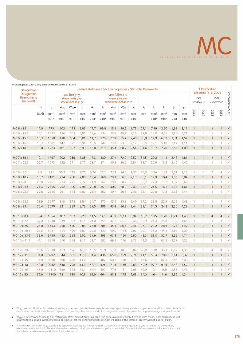
175
MC
■ Wpl.y: est calculé selon l’hypothèse d’un diagramme de contraintes bi-rectangulaire et n’est applicable que si deux ou plusieurs fers U sont associés de facon à constituer une section doublement symétrique pour laquelle un moment de flexion agissant dans le plan du centre de gravité n’engendre pas de torsion.
■Wpl.y: is determined assuming a bi-rectangular stress block distribution. Thus, the given value applies only if two or more channels are combined in such a way to form a double symmetric cross-section so that the bending moment acting in the plane of the centre of gravity will not lead to torsion.
■ Für die Berechnung von Wpl.y wurde eine doppelrechteckige Spannungsverteilung angenommen. Der angegebene Wert ist daher nur anwendbar, wenn zwei oder mehr U-Profile so miteinander kombiniert sind, dass sie einen doppelsymmetrischen Querschnitt bilden, womit ein Biegemoment, das in der Schwerpunktebene angreift, keine Torsion hervorruft.
Désignation Designation Bezeichnung
(imperial)
Valeurs statiques / Section properties / Statische Kennwerte Classification EN 1993-1-1: 2005
A57
2/A
70
9/A
99
2axe fort y-y strong axis y-y
starke Achse y-y
axe faible z-z weak axis z-z
schwache Achse z-z Pure
bending y-y
Pure
compression
G Iy Wel.y Wpl.y■ iy Avz Iz Wel.z Wpl.z iz ss It Iw ys ym
S23
5
S35
5
S23
5
S35
5
lbs/ft mm4 mm3 mm3 mm mm2 mm4 mm3 mm3 mm mm mm4 mm6 mm mm
x104 x103 x103 x10 x102 x104 x103 x103 x10 x104 x109 x10 x10
MC 6 x 12 12,0 773 102 123 5,83 12,7 69,8 15,1 29,6 1,75 27,1 7,89 2,60 1,63 3,11 1 1 1 1
MC 6 x 15.1 15,1 1033 136 162 6,01 13,4 134 25,8 49,7 2,16 31,8 14,0 4,66 2,18 4,21 1 1 1 1
MC 6 x 15.3 15,3 1050 138 164 6,01 14,2 178 27,9 55,2 2,48 30,8 12,9 6,58 2,31 4,54 1 1 1 1
MC 6 x 16.3 16,3 1081 142 171 5,91 15,5 147 27,2 53,3 2,17 33,5 17,1 5,18 2,17 4,11 1 1 1 1
MC 6 x 18 18,0 1223 161 192 5,99 15,8 219 35,4 68,7 2,54 34,6 19,7 7,70 2,53 4,88 1 1 1 1
MC 7 x 19.1 19,1 1797 202 239 7,05 17,3 230 37,4 72,2 2,52 34,5 20,2 11,2 2,46 4,81 1 1 1 1
MC 7 x 22.7 22,7 1973 222 271 6,77 23,7 271 40,8 80,9 2,51 38,7 32,9 13,6 2,42 4,47 1 1 1 1
MC 8 x 8.5 8,5 971 95,7 115 7,77 9,74 27,1 7,53 14,5 1,30 20,0 2,54 1,89 1,07 2,19 1 1 2 4
MC 8 x 18.7 18,7 2171 214 258 7,83 19,4 160 29,3 56,8 2,13 33,1 17,9 10,4 1,99 3,84 1 1 1 1
MC 8 x 20 20,0 2261 223 271 7,72 21,9 167 29,8 58,7 2,10 35,2 22,3 11,2 1,97 3,69 1 1 1 1
MC 8 x 21.4 21,4 2555 252 300 7,94 20,8 251 40,0 78,0 2,49 36,1 24,5 16,2 2,36 4,61 1 1 1 1
MC 8 x 22.8 22,8 2645 261 314 7,83 23,4 262 40,7 80,3 2,46 38,1 29,8 17,3 2,33 4,44 1 1 1 1
MC 9 x 23.9 23,9 3547 310 373 8,84 24,7 275 43,2 83,8 2,46 37,2 28,8 22,9 2,29 4,43 1 1 1 1
MC 9 x 25.4 25,4 3670 321 389 8,73 27,5 286 43,9 86,3 2,44 39,1 34,5 24,2 2,26 4,28 1 1 1 1
MC 10 x 8.4 8,4 1354 107 132 9,20 11,5 14,1 4,59 9,14 0,94 18,7 1,95 1,70 0,71 1,40 1 1 4 4
MC 10 x 22 22,0 4310 339 397 10,1 21,0 255 42,2 81,3 2,46 35,9 24,4 25,8 2,30 4,65 1 1 1 1
MC 10 x 25 25,0 4543 358 430 9,81 25,8 285 45,3 86,5 2,46 36,1 28,2 28,9 2,25 4,42 1 1 1 1
MC 10 x 28.5 28,5 5257 414 496 9,87 29,0 433 59,0 114 2,83 39,7 38,2 44,5 2,58 5,09 1 1 1 1
MC 10 x 33.6 33,6 5750 453 558 9,52 37,9 498 63,8 126 2,80 43,3 58,0 52,7 2,55 4,74 1 1 1 1
MC 10 x 41.1 41,1 6550 516 654 9,17 51,7 582 69,2 146 2,73 51,0 124 65,2 2,59 4,32 1 1 1 1
MC 12 x 10.6 10,6 2338 153 196 10,8 15,5 15,9 5,08 10,8 0,89 20,9 3,20 3,22 0,69 1,30 1 1 4 4
MC 12 x 31 31,0 8292 544 661 12,0 31,4 436 65,0 129 2,74 41,1 53,4 70,6 2,61 5,32 1 1 1 1
MC 12 x 35 35,0 8998 590 726 11,7 39,1 487 68,7 138 2,71 45,6 70,1 82,1 2,55 5,00 1 1 1 1
MC 12 x 40 40,0 9732 638 798 11,3 48,7 526 71,5 146 2,63 49,9 97,7 91,5 2,48 4,57 1 1 1 1
MC 12 x 45 45,0 10510 689 873 11,1 57,4 597 77,5 161 2,65 52,9 131 105 2,53 4,41 1 1 1 1
MC 12 x 50 50,0 11140 731 939 10,9 65,9 664 83,5 175 2,65 54,0 164 116 2,59 4,24 1 1 1 1
Notations pages 215-219 / Bezeichnungen Seiten 215-219
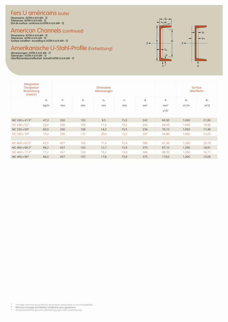
ys
ss
ymdy y
zz
tw
tf
h
b
45o
Fers U américains (suite)Dimensions: ASTM A 6/A 6M - 12 Tolérances: ASTM A 6/A 6M - 12 Etat de surface: conforme à ASTM A 6/A 6M - 12
American Channels (continued)Dimensions: ASTM A 6/A 6M - 12 Tolerances: ASTM A 6/A 6M - 12 Surface condition: according to ASTM A 6/A 6M - 12
Amerikanische U-Stahl-Profile (Fortsetzung)Abmessungen: ASTM A 6/A 6M - 12 Toleranzen: ASTM A 6/A 6M - 12 Oberflächenbeschaffenheit: Gemäß ASTM A 6/A 6M - 12
* Tonnage minimum et conditions de livraison nécessitent un accord préalable.* Minimum tonnage and delivery conditions upon agreement.* Mindestbestellmenge und Lieferbedingungen nach Vereinbarung.
MC 330 x 47.3* 47,3 330 102 9,5 15,5 242 60,30 1,040 21,95
MC 330 x 52* 52,0 330 103 11,4 15,5 242 66,40 1,040 19,96
MC 330 x 60* 60,0 330 106 14,2 15,5 236 76,10 1,050 17,48
MC 330 x 74* 74,0 330 112 20,0 15,5 247 94,80 1,060 14,29
MC 460 x 63.5* 63,5 457 100 11,4 15,9 366 81,30 1,280 20,18
MC 460 x 68.2* 68,2 457 102 12,7 15,9 370 87,10 1,290 18,91
MC 460 x 77.2* 77,2 457 104 15,2 15,9 366 98,70 1,290 16,71
MC 460 x 86* 86,0 457 107 17,8 15,9 375 110,0 1,300 15,09
Désignation Designation Bezeichnung
(metric)
Dimensions Abmessungen
Surface Oberfläche
G
kg/m
h b tw tf d A AL AG
mm mm mm mm mm mm2 m2/m m2/t
x102
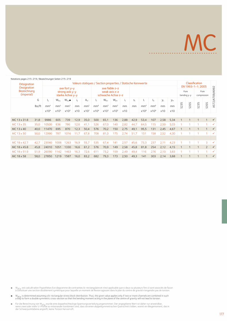
177
MC
MC 13 x 31.8 31,8 9986 605 739 12,9 35,0 500 65,1 136 2,88 42,9 53,4 107 2,58 5,34 1 1 1 1
MC 13 x 35 35,0 10500 636 786 12,6 41,1 526 67,0 140 2,82 44,7 64,5 115 2,50 5,03 1 1 1 1
MC 13 x 40 40,0 11470 695 870 12,3 50,4 576 70,2 150 2,75 49,1 95,5 131 2,45 4,67 1 1 1 1
MC 13 x 50 50,0 12990 787 1016 11,7 67,8 708 81,0 175 2,74 51,7 151 158 2,52 4,30 1 1 1 1
MC 18 x 42.7 42,7 23040 1008 1263 16,9 55,7 535 67,4 141 2,57 45,6 73,3 237 2,11 4,23 1 1 1 3
MC 18 x 45.8 45,8 24010 1051 1330 16,6 61,2 576 70,9 149 2,58 45,8 81,8 254 2,12 4,15 1 1 1 2
MC 18 x 51.9 51,9 26090 1142 1463 16,3 72,6 611 73,2 159 2,49 49,4 116 276 2,10 3,83 1 1 1 1
MC 18 x 58 58,0 27850 1219 1587 16,0 83,2 682 79,3 173 2,50 49,3 141 303 2,14 3,68 1 1 1 1
■ Wpl.y: est calculé selon l’hypothèse d’un diagramme de contraintes bi-rectangulaire et n’est applicable que si deux ou plusieurs fers U sont associés de facon à constituer une section doublement symétrique pour laquelle un moment de flexion agissant dans le plan du centre de gravité n’engendre pas de torsion.
■Wpl.y: is determined assuming a bi-rectangular stress block distribution. Thus, the given value applies only if two or more channels are combined in such a way to form a double symmetric cross-section so that the bending moment acting in the plane of the centre of gravity will not lead to torsion.
■ Für die Berechnung von Wpl.y wurde eine doppelrechteckige Spannungsverteilung angenommen. Der angegebene Wert ist daher nur anwendbar, wenn zwei oder mehr U-Profile so miteinander kombiniert sind, dass sie einen doppelsymmetrischen Querschnitt bilden, womit ein Biegemoment, das in der Schwerpunktebene angreift, keine Torsion hervorruft.
Désignation Designation Bezeichnung
(imperial)
Valeurs statiques / Section properties / Statische Kennwerte Classification EN 1993-1-1: 2005
A57
2/A
70
9/A
99
2axe fort y-y strong axis y-y
starke Achse y-y
axe faible z-z weak axis z-z
schwache Achse z-z Pure
bending y-y
Pure
compression
G Iy Wel.y Wpl.y■ iy Avz Iz Wel.z Wpl.z iz ss It Iw ys ym
S23
5
S35
5
S23
5
S35
5
lbs/ft mm4 mm3 mm3 mm mm2 mm4 mm3 mm3 mm mm mm4 mm6 mm mm
x104 x103 x103 x10 x102 x104 x103 x103 x10 x104 x109 x10 x10
Notations pages 215-219 / Bezeichnungen Seiten 215-219
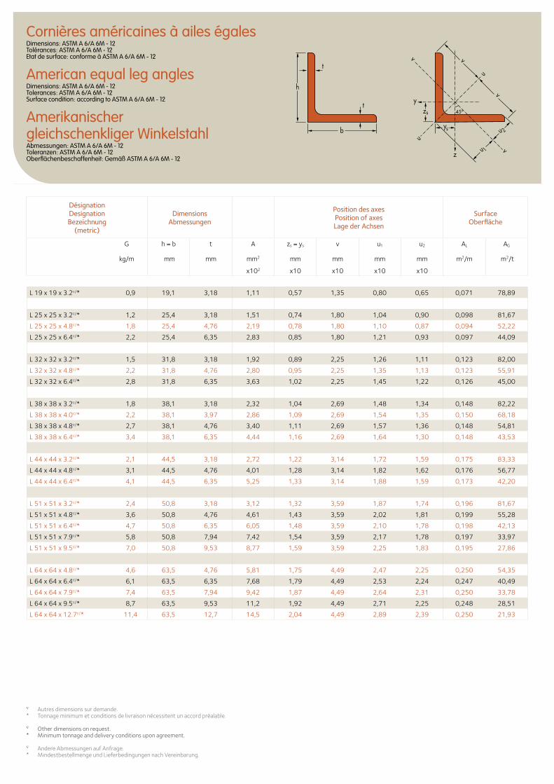
Cornières américaines à ailes égalesDimensions: ASTM A 6/A 6M - 12 Tolérances: ASTM A 6/A 6M - 12 Etat de surface: conforme à ASTM A 6/A 6M - 12
American equal leg anglesDimensions: ASTM A 6/A 6M - 12 Tolerances: ASTM A 6/A 6M - 12 Surface condition: according to ASTM A 6/A 6M - 12
Amerikanischer gleichschenkliger WinkelstahlAbmessungen: ASTM A 6/A 6M - 12 Toleranzen: ASTM A 6/A 6M - 12 Oberflächenbeschaffenheit: Gemäß ASTM A 6/A 6M - 12
zs
ys
y
z
u
u
u 1
u 2
v
v
v
v
t
t
h
b
45o
L 19 x 19 x 3.2∇/* 0,9 19,1 3,18 1,11 0,57 1,35 0,80 0,65 0,071 78,89
L 25 x 25 x 3.2∇/* 1,2 25,4 3,18 1,51 0,74 1,80 1,04 0,90 0,098 81,67
L 25 x 25 x 4.8∇/* 1,8 25,4 4,76 2,19 0,78 1,80 1,10 0,87 0,094 52,22
L 25 x 25 x 6.4∇/* 2,2 25,4 6,35 2,83 0,85 1,80 1,21 0,93 0,097 44,09
L 32 x 32 x 3.2∇/* 1,5 31,8 3,18 1,92 0,89 2,25 1,26 1,11 0,123 82,00
L 32 x 32 x 4.8∇/* 2,2 31,8 4,76 2,80 0,95 2,25 1,35 1,13 0,123 55,91
L 32 x 32 x 6.4∇/* 2,8 31,8 6,35 3,63 1,02 2,25 1,45 1,22 0,126 45,00
L 38 x 38 x 3.2∇/* 1,8 38,1 3,18 2,32 1,04 2,69 1,48 1,34 0,148 82,22
L 38 x 38 x 4.0∇/* 2,2 38,1 3,97 2,86 1,09 2,69 1,54 1,35 0,150 68,18
L 38 x 38 x 4.8∇/* 2,7 38,1 4,76 3,40 1,11 2,69 1,57 1,36 0,148 54,81
L 38 x 38 x 6.4∇/* 3,4 38,1 6,35 4,44 1,16 2,69 1,64 1,30 0,148 43,53
L 44 x 44 x 3.2∇/* 2,1 44,5 3,18 2,72 1,22 3,14 1,72 1,59 0,175 83,33
L 44 x 44 x 4.8∇/* 3,1 44,5 4,76 4,01 1,28 3,14 1,82 1,62 0,176 56,77
L 44 x 44 x 6.4∇/* 4,1 44,5 6,35 5,25 1,33 3,14 1,88 1,59 0,173 42,20
L 51 x 51 x 3.2∇/* 2,4 50,8 3,18 3,12 1,32 3,59 1,87 1,74 0,196 81,67
L 51 x 51 x 4.8∇/* 3,6 50,8 4,76 4,61 1,43 3,59 2,02 1,81 0,199 55,28
L 51 x 51 x 6.4∇/* 4,7 50,8 6,35 6,05 1,48 3,59 2,10 1,78 0,198 42,13
L 51 x 51 x 7.9∇/* 5,8 50,8 7,94 7,42 1,54 3,59 2,17 1,78 0,197 33,97
L 51 x 51 x 9.5∇/* 7,0 50,8 9,53 8,77 1,59 3,59 2,25 1,83 0,195 27,86
L 64 x 64 x 4.8∇/* 4,6 63,5 4,76 5,81 1,75 4,49 2,47 2,25 0,250 54,35
L 64 x 64 x 6.4∇/* 6,1 63,5 6,35 7,68 1,79 4,49 2,53 2,24 0,247 40,49
L 64 x 64 x 7.9∇/* 7,4 63,5 7,94 9,42 1,87 4,49 2,64 2,31 0,250 33,78
L 64 x 64 x 9.5∇/* 8,7 63,5 9,53 11,2 1,92 4,49 2,71 2,25 0,248 28,51
L 64 x 64 x 12.7∇/* 11,4 63,5 12,7 14,5 2,04 4,49 2,89 2,39 0,250 21,93
∇ Autres dimensions sur demande.* Tonnage minimum et conditions de livraison nécessitent un accord préalable.
∇ Other dimensions on request.* Minimum tonnage and delivery conditions upon agreement.
∇ Andere Abmessungen auf Anfrage.* Mindestbestellmenge und Lieferbedingungen nach Vereinbarung.
DésignationDesignationBezeichnung
(metric)
Dimensions Abmessungen
Position des axesPosition of axesLage der Achsen
Surface Oberfläche
G
kg/m
h = b t A zs = ys v u1 u2 AL AG
mm mm mm2 mm mm mm mm m2/m m2/t
x102 x10 x10 x10 x10
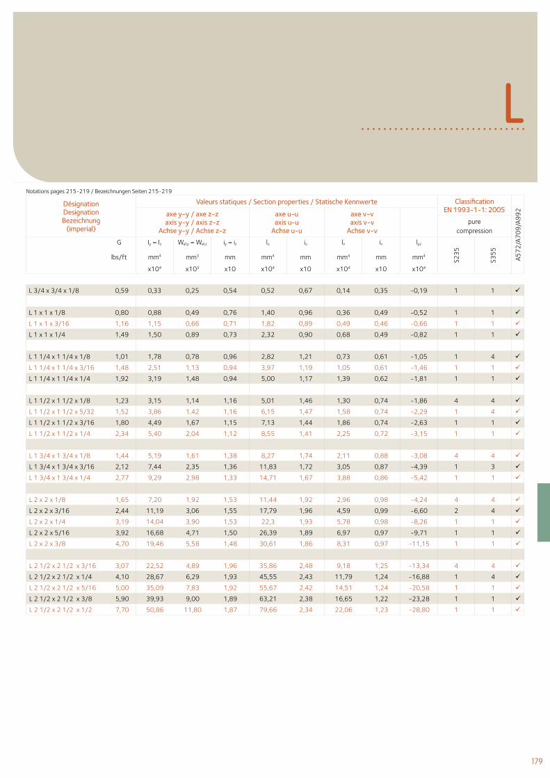
179
L
L 3/4 x 3/4 x 1/8 0,59 0,33 0,25 0,54 0,52 0,67 0,14 0,35 -0,19 1 1
L 1 x 1 x 1/8 0,80 0,88 0,49 0,76 1,40 0,96 0,36 0,49 -0,52 1 1
L 1 x 1 x 3/16 1,16 1,15 0,66 0,71 1,82 0,89 0,49 0,46 -0,66 1 1
L 1 x 1 x 1/4 1,49 1,50 0,89 0,73 2,32 0,90 0,68 0,49 -0,82 1 1
L 1 1/4 x 1 1/4 x 1/8 1,01 1,78 0,78 0,96 2,82 1,21 0,73 0,61 -1,05 1 4
L 1 1/4 x 1 1/4 x 3/16 1,48 2,51 1,13 0,94 3,97 1,19 1,05 0,61 -1,46 1 1
L 1 1/4 x 1 1/4 x 1/4 1,92 3,19 1,48 0,94 5,00 1,17 1,39 0,62 -1,81 1 1
L 1 1/2 x 1 1/2 x 1/8 1,23 3,15 1,14 1,16 5,01 1,46 1,30 0,74 -1,86 4 4
L 1 1/2 x 1 1/2 x 5/32 1,52 3,86 1,42 1,16 6,15 1,47 1,58 0,74 -2,29 1 4
L 1 1/2 x 1 1/2 x 3/16 1,80 4,49 1,67 1,15 7,13 1,44 1,86 0,74 -2,63 1 1
L 1 1/2 x 1 1/2 x 1/4 2,34 5,40 2,04 1,12 8,55 1,41 2,25 0,72 -3,15 1 1
L 1 3/4 x 1 3/4 x 1/8 1,44 5,19 1,61 1,38 8,27 1,74 2,11 0,88 -3,08 4 4
L 1 3/4 x 1 3/4 x 3/16 2,12 7,44 2,35 1,36 11,83 1,72 3,05 0,87 -4,39 1 3
L 1 3/4 x 1 3/4 x 1/4 2,77 9,29 2,98 1,33 14,71 1,67 3,88 0,86 -5,42 1 1
L 2 x 2 x 1/8 1,65 7,20 1,92 1,53 11,44 1,92 2,96 0,98 -4,24 4 4
L 2 x 2 x 3/16 2,44 11,19 3,06 1,55 17,79 1,96 4,59 0,99 -6,60 2 4
L 2 x 2 x 1/4 3,19 14,04 3,90 1,53 22,3 1,93 5,78 0,98 -8,26 1 1
L 2 x 2 x 5/16 3,92 16,68 4,71 1,50 26,39 1,89 6,97 0,97 -9,71 1 1
L 2 x 2 x 3/8 4,70 19,46 5,58 1,48 30,61 1,86 8,31 0,97 -11,15 1 1
L 2 1/2 x 2 1/2 x 3/16 3,07 22,52 4,89 1,96 35,86 2,48 9,18 1,25 -13,34 4 4
L 2 1/2 x 2 1/2 x 1/4 4,10 28,67 6,29 1,93 45,55 2,43 11,79 1,24 -16,88 1 4
L 2 1/2 x 2 1/2 x 5/16 5,00 35,09 7,83 1,92 55,67 2,42 14,51 1,24 -20,58 1 1
L 2 1/2 x 2 1/2 x 3/8 5,90 39,93 9,00 1,89 63,21 2,38 16,65 1,22 -23,28 1 1
L 2 1/2 x 2 1/2 x 1/2 7,70 50,86 11,80 1,87 79,66 2,34 22,06 1,23 -28,80 1 1
Désignation Designation Bezeichnung
(imperial)
Valeurs statiques / Section properties / Statische Kennwerte Classification EN 1993-1-1: 2005
A57
2/A
70
9/A
99
2axe y-y / axe z-zaxis y-y / axis z-z
Achse y-y / Achse z-z
axe u-uaxis u-u
Achse u-u
axe v-vaxis v-v
Achse v-vpure
compression
G Iy = Iz Wel.y = Wel.z iy = iz lu iu lv iv lyz
S23
5
S35
5
lbs/ft mm4 mm3 mm mm4 mm mm4 mm mm4
x104 x103 x10 x104 x10 x104 x10 x104
Notations pages 215-219 / Bezeichnungen Seiten 215-219
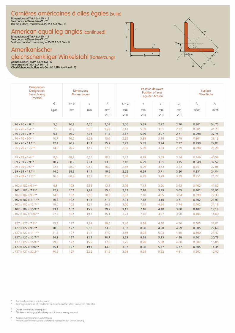
Cornières américaines à ailes égales (suite)Dimensions: ASTM A 6/A 6M - 12 Tolérances: ASTM A 6/A 6M - 12 Etat de surface: conforme à ASTM A 6/A 6M - 12
American equal leg angles (continued)Dimensions: ASTM A 6/A 6M - 12 Tolerances: ASTM A 6/A 6M - 12 Surface condition: according to ASTM A 6/A 6M - 12
Amerikanischer gleichschenkliger Winkelstahl (Fortsetzung)Abmessungen: ASTM A 6/A 6M - 12 Toleranzen: ASTM A 6/A 6M - 12 Oberflächenbeschaffenheit: Gemäß ASTM A 6/A 6M - 12
zs
ys
y
z
u
u
u 1
u 2
v
v
v
v
t
t
h
b
45o
L 76 x 76 x 4.8∇/* 5,5 76,2 4,76 7,03 2,06 5,39 2,92 2,70 0,301 54,73
L 76 x 76 x 6.4∇/* 7,3 76,2 6,35 9,29 2,13 5,39 3,01 2,72 0,301 41,23
L 76 x 76 x 7.9∇/* 9,1 76,2 7,94 11,5 2,17 5,39 3,07 2,71 0,298 32,75
L 76 x 76 x 9.5∇/* 10,7 76,2 9,53 13,6 2,25 5,39 3,18 2,78 0,301 28,13
L 76 x 76 x 11.1∇/* 12,4 76,2 11,1 15,7 2,29 5,39 3,24 2,77 0,298 24,03
L 76 x 76 x 12.7∇/* 14,0 76,2 12,7 17,7 2,35 5,39 3,33 2,79 0,298 21,29
L 89 x 89 x 6.4∇/* 8,6 88,9 6,35 10,9 2,42 6,29 3,43 3,14 0,349 40,58
L 89 x 89 x 7.9∇/* 10,7 88,9 7,94 13,5 2,48 6,29 3,51 3,15 0,348 32,52
L 89 x 89 x 9.5∇/* 12,6 88,9 9,53 16,0 2,56 6,29 3,63 3,23 0,351 27,86
L 89 x 89 x 11.1∇/* 14,6 88,9 11,1 18,5 2,62 6,29 3,71 3,26 0,351 24,04
L 89 x 89 x 12.7∇/* 16,5 88,9 12,7 21,0 2,68 6,29 3,79 3,29 0,351 21,27
L 102 x 102 x 6.4∇/* 9,8 102 6,35 12,5 2,76 7,18 3,90 3,63 0,402 41,02
L 102 x 102 x 7.9∇/* 12,2 102 7,94 15,5 2,82 7,18 3,99 3,65 0,402 32,95
L 102 x 102 x 9.5∇/* 14,6 102 9,53 18,5 2,87 7,18 4,05 3,64 0,399 27,33
L 102 x 102 x 11.1∇/* 16,8 102 11,1 21,4 2,94 7,18 4,16 3,71 0,402 23,93
L 102 x 102 x 12.7∇/* 19,0 102 12,7 24,2 3,00 7,18 4,24 3,74 0,402 21,16
L 102 x 102 x 15.9∇/* 23,4 102 15,9 29,7 3,11 7,18 4,40 3,80 0,402 17,18
L 102 x 102 x 19.0∇/* 27,5 102 19,1 35,1 3,23 7,18 4,57 3,90 0,404 14,69
L 127 x 127 x 7.9∇/* 15,3 127 7,94 19,6 3,46 8,98 4,90 4,56 0,505 33,01
L 127 x 127 x 9.5∇/* 18,3 127 9,53 23,3 3,52 8,98 4,98 4,59 0,505 27,60
L 127 x 127 x 11.1∇/* 21,3 127 11,1 27,0 3,56 8,98 5,03 4,55 0,500 23,47
L 127 x 127 x 12.7∇/* 24,1 127 12,7 30,7 3,63 8,98 5,13 4,58 0,501 20,79
L 127 x 127 x 15.9∇/* 29,8 127 15,9 37,8 3,75 8,98 5,30 4,68 0,502 16,85
L 127 x 127 x 19.0∇/* 35,1 127 19,1 44,8 3,87 8,98 5,47 4,77 0,505 14,35
L 127 x 127 x 22.2∇/* 40,5 127 22,2 51,5 3,98 8,98 5,62 4,81 0,503 12,42
DésignationDesignationBezeichnung
(metric)
Dimensions Abmessungen
Position des axesPosition of axesLage der Achsen
Surface Oberfläche
G
kg/m
h = b t A zs = ys v u1 u2 AL AG
mm mm mm2 mm mm mm mm m2/m m2/t
x102 x10 x10 x10 x10
∇ Autres dimensions sur demande.* Tonnage minimum et conditions de livraison nécessitent un accord préalable.
∇ Other dimensions on request.* Minimum tonnage and delivery conditions upon agreement.
∇ Andere Abmessungen auf Anfrage.* Mindestbestellmenge und Lieferbedingungen nach Vereinbarung.
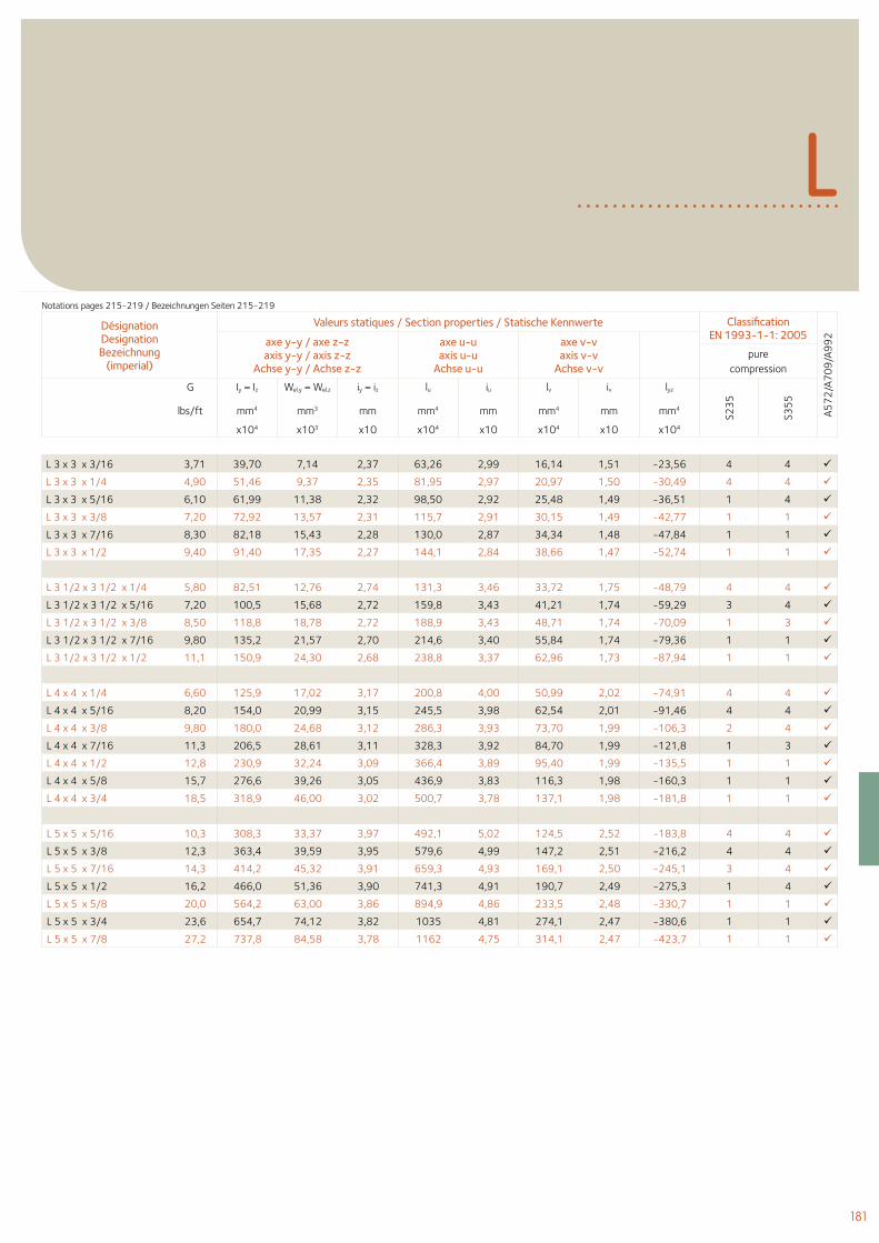
181
L
L 3 x 3 x 3/16 3,71 39,70 7,14 2,37 63,26 2,99 16,14 1,51 -23,56 4 4
L 3 x 3 x 1/4 4,90 51,46 9,37 2,35 81,95 2,97 20,97 1,50 -30,49 4 4
L 3 x 3 x 5/16 6,10 61,99 11,38 2,32 98,50 2,92 25,48 1,49 -36,51 1 4
L 3 x 3 x 3/8 7,20 72,92 13,57 2,31 115,7 2,91 30,15 1,49 -42,77 1 1
L 3 x 3 x 7/16 8,30 82,18 15,43 2,28 130,0 2,87 34,34 1,48 -47,84 1 1
L 3 x 3 x 1/2 9,40 91,40 17,35 2,27 144,1 2,84 38,66 1,47 -52,74 1 1
L 3 1/2 x 3 1/2 x 1/4 5,80 82,51 12,76 2,74 131,3 3,46 33,72 1,75 -48,79 4 4
L 3 1/2 x 3 1/2 x 5/16 7,20 100,5 15,68 2,72 159,8 3,43 41,21 1,74 -59,29 3 4
L 3 1/2 x 3 1/2 x 3/8 8,50 118,8 18,78 2,72 188,9 3,43 48,71 1,74 -70,09 1 3
L 3 1/2 x 3 1/2 x 7/16 9,80 135,2 21,57 2,70 214,6 3,40 55,84 1,74 -79,36 1 1
L 3 1/2 x 3 1/2 x 1/2 11,1 150,9 24,30 2,68 238,8 3,37 62,96 1,73 -87,94 1 1
L 4 x 4 x 1/4 6,60 125,9 17,02 3,17 200,8 4,00 50,99 2,02 -74,91 4 4
L 4 x 4 x 5/16 8,20 154,0 20,99 3,15 245,5 3,98 62,54 2,01 -91,46 4 4
L 4 x 4 x 3/8 9,80 180,0 24,68 3,12 286,3 3,93 73,70 1,99 -106,3 2 4
L 4 x 4 x 7/16 11,3 206,5 28,61 3,11 328,3 3,92 84,70 1,99 -121,8 1 3
L 4 x 4 x 1/2 12,8 230,9 32,24 3,09 366,4 3,89 95,40 1,99 -135,5 1 1
L 4 x 4 x 5/8 15,7 276,6 39,26 3,05 436,9 3,83 116,3 1,98 -160,3 1 1
L 4 x 4 x 3/4 18,5 318,9 46,00 3,02 500,7 3,78 137,1 1,98 -181,8 1 1
L 5 x 5 x 5/16 10,3 308,3 33,37 3,97 492,1 5,02 124,5 2,52 -183,8 4 4
L 5 x 5 x 3/8 12,3 363,4 39,59 3,95 579,6 4,99 147,2 2,51 -216,2 4 4
L 5 x 5 x 7/16 14,3 414,2 45,32 3,91 659,3 4,93 169,1 2,50 -245,1 3 4
L 5 x 5 x 1/2 16,2 466,0 51,36 3,90 741,3 4,91 190,7 2,49 -275,3 1 4
L 5 x 5 x 5/8 20,0 564,2 63,00 3,86 894,9 4,86 233,5 2,48 -330,7 1 1
L 5 x 5 x 3/4 23,6 654,7 74,12 3,82 1035 4,81 274,1 2,47 -380,6 1 1
L 5 x 5 x 7/8 27,2 737,8 84,58 3,78 1162 4,75 314,1 2,47 -423,7 1 1
Désignation Designation Bezeichnung
(imperial)
Valeurs statiques / Section properties / Statische Kennwerte Classification EN 1993-1-1: 2005
A57
2/A
70
9/A
99
2axe y-y / axe z-zaxis y-y / axis z-z
Achse y-y / Achse z-z
axe u-uaxis u-u
Achse u-u
axe v-vaxis v-v
Achse v-vpure
compression
G Iy = Iz Wel.y = Wel.z iy = iz lu iu lv iv lyz
S23
5
S35
5
lbs/ft mm4 mm3 mm mm4 mm mm4 mm mm4
x104 x103 x10 x104 x10 x104 x10 x104
Notations pages 215-219 / Bezeichnungen Seiten 215-219
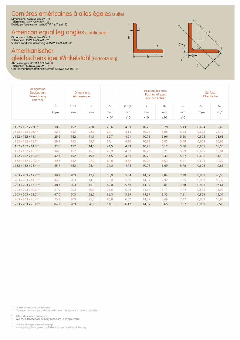
zs
ys
y
z
u
u
u 1
u 2
v
v
v
v
t
t
h
b
45o
L 152 x 152 x 7.9∇/* 18,5 152 7,94 23,6 4,09 10,78 5,78 5,43 0,604 32,65
L 152 x 152 x 9.5∇/* 22,2 152 9,53 28,1 4,14 10,78 5,85 5,43 0,602 27,12
L 152 x 152 x 11.1∇/* 25,6 152 11,1 32,7 4,21 10,78 5,96 5,50 0,605 23,63
L 152 x 152 x 12.7∇/* 29,2 152 12,7 37,1 4,26 10,78 6,03 5,48 0,603 20,65
L 152 x 152 x 14.3∇/* 32,6 152 14,3 41,5 4,33 10,78 6,12 5,56 0,605 18,56
L 152 x 152 x 15.9∇/* 36,0 152 15,9 45,9 4,39 10,78 6,21 5,59 0,605 16,81
L 152 x 152 x 19.0∇/* 42,7 152 19,1 54,5 4,51 10,78 6,37 5,67 0,606 14,19
L 152 x 152 x 22.2∇/* 49,3 152 22,2 62,8 4,62 10,78 6,53 5,71 0,605 12,27
L 152 x 152 x 25.4∇/* 55,7 152 25,4 71,0 4,73 10,78 6,69 5,78 0,605 10,86
L 203 x 203 x 12.7∇/* 39,3 203 12,7 50,0 5,54 14,37 7,84 7,30 0,808 20,56
L 203 x 203 x 14.3∇/* 44,0 203 14,3 56,0 5,60 14,37 7,92 7,35 0,809 18,39
L 203 x 203 x 15.9∇/* 48,7 203 15,9 62,0 5,66 14,37 8,01 7,38 0,809 16,61
L 203 x 203 x 19.0∇/* 57,9 203 19,1 73,6 5,78 14,37 8,17 7,44 0,809 13,97
L 203 x 203 x 22.2∇/* 67,0 203 22,2 85,0 5,89 14,37 8,33 7,51 0,809 12,07
L 203 x 203 x 25.4∇/* 75,9 203 25,4 96,8 6,00 14,37 8,49 7,47 0,807 10,63
L 203 x 203 x 28.6∇/* 84,7 203 28,6 108 6,12 14,37 8,65 7,57 0,808 9,54
DésignationDesignationBezeichnung
(metric)
Dimensions Abmessungen
Position des axesPosition of axesLage der Achsen
Surface Oberfläche
G
kg/m
h = b t A zs = ys v u1 u2 AL AG
mm mm mm2 mm mm mm mm m2/m m2/t
x102 x10 x10 x10 x10
∇ Autres dimensions sur demande.* Tonnage minimum et conditions de livraison nécessitent un accord préalable.
∇ Other dimensions on request.* Minimum tonnage and delivery conditions upon agreement.
∇ Andere Abmessungen auf Anfrage.* Mindestbestellmenge und Lieferbedingungen nach Vereinbarung.
Cornières américaines à ailes égales (suite)Dimensions: ASTM A 6/A 6M - 12 Tolérances: ASTM A 6/A 6M - 12 Etat de surface: conforme à ASTM A 6/A 6M - 12
American equal leg angles (continued)Dimensions: ASTM A 6/A 6M - 12 Tolerances: ASTM A 6/A 6M - 12 Surface condition: according to ASTM A 6/A 6M - 12
Amerikanischer gleichschenkliger Winkelstahl (Fortsetzung)Abmessungen: ASTM A 6/A 6M - 12 Toleranzen: ASTM A 6/A 6M - 12 Oberflächenbeschaffenheit: Gemäß ASTM A 6/A 6M - 12
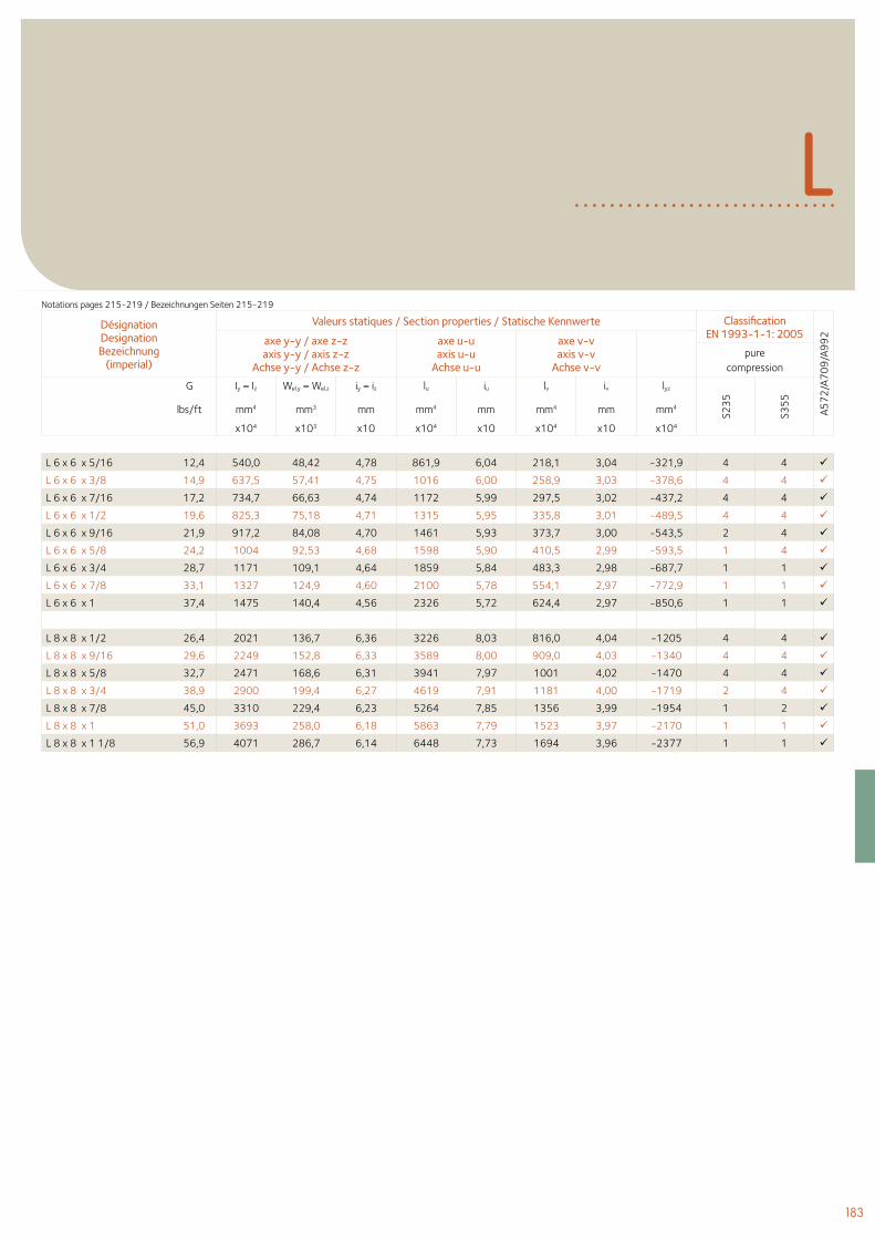
183
L
L 6 x 6 x 5/16 12,4 540,0 48,42 4,78 861,9 6,04 218,1 3,04 -321,9 4 4
L 6 x 6 x 3/8 14,9 637,5 57,41 4,75 1016 6,00 258,9 3,03 -378,6 4 4
L 6 x 6 x 7/16 17,2 734,7 66,63 4,74 1172 5,99 297,5 3,02 -437,2 4 4
L 6 x 6 x 1/2 19,6 825,3 75,18 4,71 1315 5,95 335,8 3,01 -489,5 4 4
L 6 x 6 x 9/16 21,9 917,2 84,08 4,70 1461 5,93 373,7 3,00 -543,5 2 4
L 6 x 6 x 5/8 24,2 1004 92,53 4,68 1598 5,90 410,5 2,99 -593,5 1 4
L 6 x 6 x 3/4 28,7 1171 109,1 4,64 1859 5,84 483,3 2,98 -687,7 1 1
L 6 x 6 x 7/8 33,1 1327 124,9 4,60 2100 5,78 554,1 2,97 -772,9 1 1
L 6 x 6 x 1 37,4 1475 140,4 4,56 2326 5,72 624,4 2,97 -850,6 1 1
L 8 x 8 x 1/2 26,4 2021 136,7 6,36 3226 8,03 816,0 4,04 -1205 4 4
L 8 x 8 x 9/16 29,6 2249 152,8 6,33 3589 8,00 909,0 4,03 -1340 4 4
L 8 x 8 x 5/8 32,7 2471 168,6 6,31 3941 7,97 1001 4,02 -1470 4 4
L 8 x 8 x 3/4 38,9 2900 199,4 6,27 4619 7,91 1181 4,00 -1719 2 4
L 8 x 8 x 7/8 45,0 3310 229,4 6,23 5264 7,85 1356 3,99 -1954 1 2
L 8 x 8 x 1 51,0 3693 258,0 6,18 5863 7,79 1523 3,97 -2170 1 1
L 8 x 8 x 1 1/8 56,9 4071 286,7 6,14 6448 7,73 1694 3,96 -2377 1 1
Désignation Designation Bezeichnung
(imperial)
Valeurs statiques / Section properties / Statische Kennwerte Classification EN 1993-1-1: 2005
A57
2/A
70
9/A
99
2axe y-y / axe z-zaxis y-y / axis z-z
Achse y-y / Achse z-z
axe u-uaxis u-u
Achse u-u
axe v-vaxis v-v
Achse v-vpure
compression
G Iy = Iz Wel.y = Wel.z iy = iz lu iu lv iv lyz
S23
5
S35
5
lbs/ft mm4 mm3 mm mm4 mm mm4 mm mm4
x104 x103 x10 x104 x10 x104 x10 x104
Notations pages 215-219 / Bezeichnungen Seiten 215-219
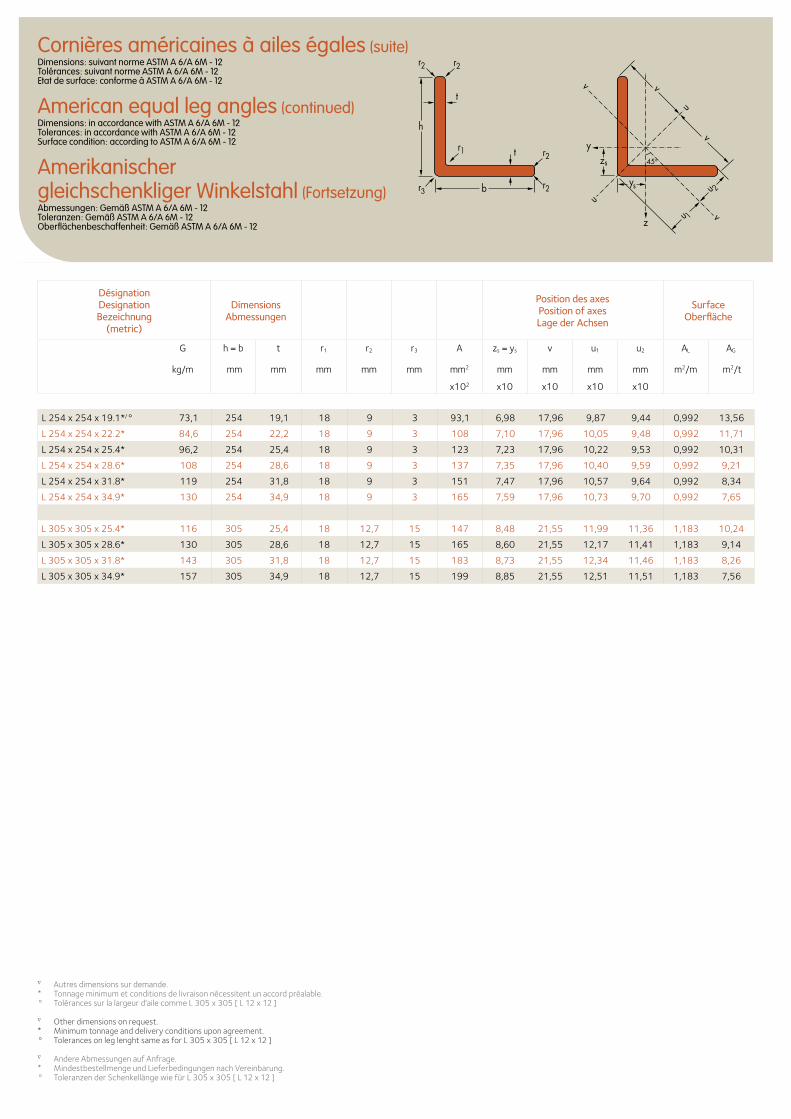
Cornières américaines à ailes égales (suite)Dimensions: suivant norme ASTM A 6/A 6M - 12 Tolérances: suivant norme ASTM A 6/A 6M - 12 Etat de surface: conforme à ASTM A 6/A 6M - 12
American equal leg angles (continued)Dimensions: in accordance with ASTM A 6/A 6M - 12 Tolerances: in accordance with ASTM A 6/A 6M - 12 Surface condition: according to ASTM A 6/A 6M - 12
Amerikanischer gleichschenkliger Winkelstahl (Fortsetzung)Abmessungen: Gemäß ASTM A 6/A 6M - 12 Toleranzen: Gemäß ASTM A 6/A 6M - 12 Oberflächenbeschaffenheit: Gemäß ASTM A 6/A 6M - 12
L 254 x 254 x 19.1*/° 73,1 254 19,1 18 9 3 93,1 6,98 17,96 9,87 9,44 0,992 13,56
L 254 x 254 x 22.2* 84,6 254 22,2 18 9 3 108 7,10 17,96 10,05 9,48 0,992 11,71
L 254 x 254 x 25.4* 96,2 254 25,4 18 9 3 123 7,23 17,96 10,22 9,53 0,992 10,31
L 254 x 254 x 28.6* 108 254 28,6 18 9 3 137 7,35 17,96 10,40 9,59 0,992 9,21
L 254 x 254 x 31.8* 119 254 31,8 18 9 3 151 7,47 17,96 10,57 9,64 0,992 8,34
L 254 x 254 x 34.9* 130 254 34,9 18 9 3 165 7,59 17,96 10,73 9,70 0,992 7,65
L 305 x 305 x 25.4* 116 305 25,4 18 12,7 15 147 8,48 21,55 11,99 11,36 1,183 10,24
L 305 x 305 x 28.6* 130 305 28,6 18 12,7 15 165 8,60 21,55 12,17 11,41 1,183 9,14
L 305 x 305 x 31.8* 143 305 31,8 18 12,7 15 183 8,73 21,55 12,34 11,46 1,183 8,26
L 305 x 305 x 34.9* 157 305 34,9 18 12,7 15 199 8,85 21,55 12,51 11,51 1,183 7,56
DésignationDesignationBezeichnung
(metric)
Dimensions Abmessungen
Position des axesPosition of axesLage der Achsen
Surface Oberfläche
G
kg/m
h = b t r1 r2 r3 A zs = ys v u1 u2 AL AG
mm mm mm mm mm mm2 mm mm mm mm m2/m m2/t
x102 x10 x10 x10 x10
∇ Autres dimensions sur demande.* Tonnage minimum et conditions de livraison nécessitent un accord préalable.° Tolérances sur la largeur d'aile comme L 305 x 305 [ L 12 x 12 ]
∇ Other dimensions on request.* Minimum tonnage and delivery conditions upon agreement.° Tolerances on leg lenght same as for L 305 x 305 [ L 12 x 12 ]
∇ Andere Abmessungen auf Anfrage.* Mindestbestellmenge und Lieferbedingungen nach Vereinbarung.° Toleranzen der Schenkellänge wie für L 305 x 305 [ L 12 x 12 ]
zs
ys
y
z
u
uu 1
u 2
v
v
v
v
t
t
h
b
r1 r2
r2
r2r2
45o
r3
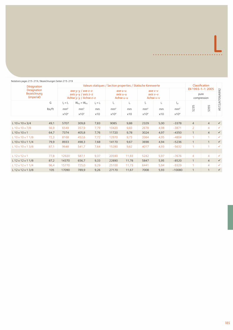
185
L
L 10 x 10 x 3/4 49,1 5707 309,8 7,83 9085 9,88 2329 5,00 -3378 4 4
L 10 x 10 x 7/8 56,9 6549 357,9 7,79 10420 9,83 2678 4,98 -3871 2 4
L 10 x 10 x 1 64,7 7374 405,8 7,76 11720 9,78 3024 4,97 -4350 1 4
L 10 x 10 x 1 1/8 72,3 8168 452,6 7,72 12970 9,73 3364 4,95 -4804 1 1
L 10 x 10 x 1 1/4 79,9 8933 498,3 7,68 14170 9,67 3698 4,94 -5236 1 1
L 10 x 10 x 1 3/8 87,1 9648 541,7 7,64 15280 9,62 4017 4,93 -5632 1 1
L 12 x 12 x 1 77,8 12920 587,1 9,37 20590 11,83 5242 5,97 -7676 4 4
L 12 x 12 x 1 1/8 87,2 14370 656,7 9,33 22890 11,78 5847 5,95 -8520 1 4
L 12 x 12 x 1 1/4 96,4 15770 725,0 9,29 25100 11,73 6441 5,94 -9329 1 4
L 12 x 12 x 1 3/8 105 17090 789,9 9,26 27170 11,67 7008 5,93 -10080 1 1
Désignation Designation Bezeichnung
(imperial)
Valeurs statiques / Section properties / Statische Kennwerte Classification EN 1993-1-1: 2005
A57
2/A
70
9/A
99
2axe y-y / axe z-zaxis y-y / axis z-z
Achse y-y / Achse z-z
axe u-uaxis u-u
Achse u-u
axe v-vaxis v-v
Achse v-vpure
compression
G Iy = Iz Wel.y = Wel.z iy = iz lu iu lv iv lyz
S23
5
S35
5
lbs/ft mm4 mm3 mm mm4 mm mm4 mm mm4
x104 x103 x10 x104 x10 x104 x10 x104
Notations pages 215-219 / Bezeichnungen Seiten 215-219
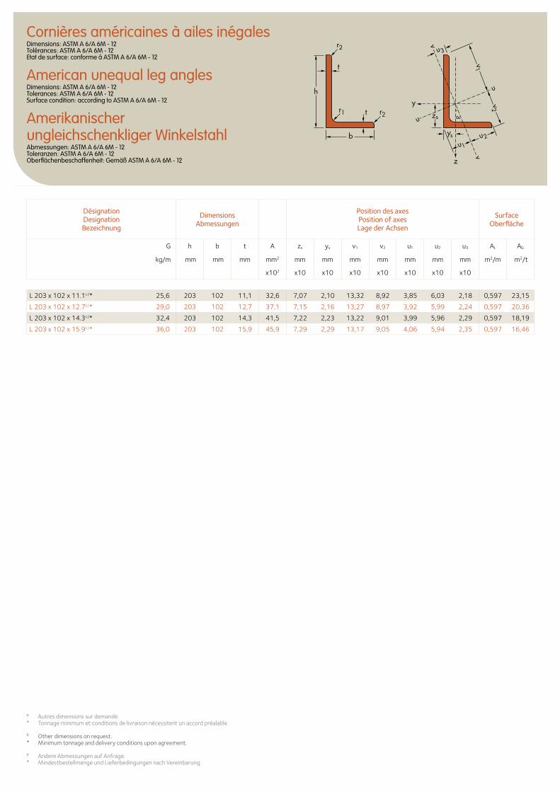
Cornières américaines à ailes inégalesDimensions: ASTM A 6/A 6M - 12 Tolérances: ASTM A 6/A 6M - 12 Etat de surface: conforme à ASTM A 6/A 6M - 12
American unequal leg anglesDimensions: ASTM A 6/A 6M - 12 Tolerances: ASTM A 6/A 6M - 12 Surface condition: according to ASTM A 6/A 6M - 12
Amerikanischer ungleichschenkliger WinkelstahlAbmessungen: ASTM A 6/A 6M - 12 Toleranzen: ASTM A 6/A 6M - 12 Oberflächenbeschaffenheit: Gemäß ASTM A 6/A 6M - 12
zs
z
y
u
u
ys
u1
u2
u3
v2
v
v
v1t
t
h
b
r1
r2
r2
Désignation Designation Bezeichnung
Dimensions Abmessungen
Position des axesPosition of axesLage der Achsen
Surface Oberfläche
G h b t A zs ys v1 v2 u1 u2 u3 AL AG
kg/m mm mm mm mm2 mm mm mm mm mm mm mm m2/m m2/t
x102 x10 x10 x10 x10 x10 x10 x10
L 203 x 102 x 11.1∇/* 25,6 203 102 11,1 32,6 7,07 2,10 13,32 8,92 3,85 6,03 2,18 0,597 23,15
L 203 x 102 x 12.7∇/* 29,0 203 102 12,7 37,1 7,15 2,16 13,27 8,97 3,92 5,99 2,24 0,597 20,36
L 203 x 102 x 14.3∇/* 32,4 203 102 14,3 41,5 7,22 2,23 13,22 9,01 3,99 5,96 2,29 0,597 18,19
L 203 x 102 x 15.9∇/* 36,0 203 102 15,9 45,9 7,29 2,29 13,17 9,05 4,06 5,94 2,35 0,597 16,46
∇ Autres dimensions sur demande.* Tonnage minimum et conditions de livraison nécessitent un accord préalable.
∇ Other dimensions on request.* Minimum tonnage and delivery conditions upon agreement.
∇ Andere Abmessungen auf Anfrage.* Mindestbestellmenge und Lieferbedingungen nach Vereinbarung.
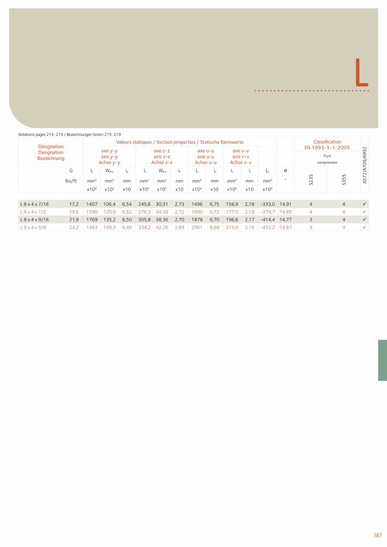
187
L
Désignation Designation Bezeichnung
Valeurs statiques / Section properties / Statische Kennwerte Classification EN 1993-1-1: 2005
A57
2/A
70
9/A
99
2axe y-yaxis y-y
Achse y-y
axe z-zaxis z-z
Achse z-z
axe u-uaxis u-u
Achse u-u
axe v-vaxis v-v
Achse v-vPure
compression
G ly Wel.y iy lz Wel.z iz Iu iu Iv iv lyz α
S23
5
S35
5
lbs/ft mm4 mm3 mm mm4 mm3 mm mm4 mm mm4 mm mm4 ˚
x104 x103 x10 x104 x103 x10 x104 x10 x104 x10 x104
L 8 x 4 x 7/16 17,2 1407 106,4 6,54 245,6 30,31 2,73 1496 6,75 156,9 2,18 -333,0 14,91 4 4
L 8 x 4 x 1/2 19,6 1590 120,9 6,52 276,3 34,38 2,72 1690 6,72 177,0 2,18 -374,7 14,85 4 4
L 8 x 4 x 9/16 21,9 1769 135,2 6,50 305,8 38,36 2,70 1878 6,70 196,6 2,17 -414,4 14,77 3 4
L 8 x 4 x 5/8 24,2 1943 149,3 6,48 334,2 42,26 2,69 2061 6,68 215,8 2,16 -452,2 14,67 3 4
Notations pages 215-219 / Bezeichnungen Seiten 215-219
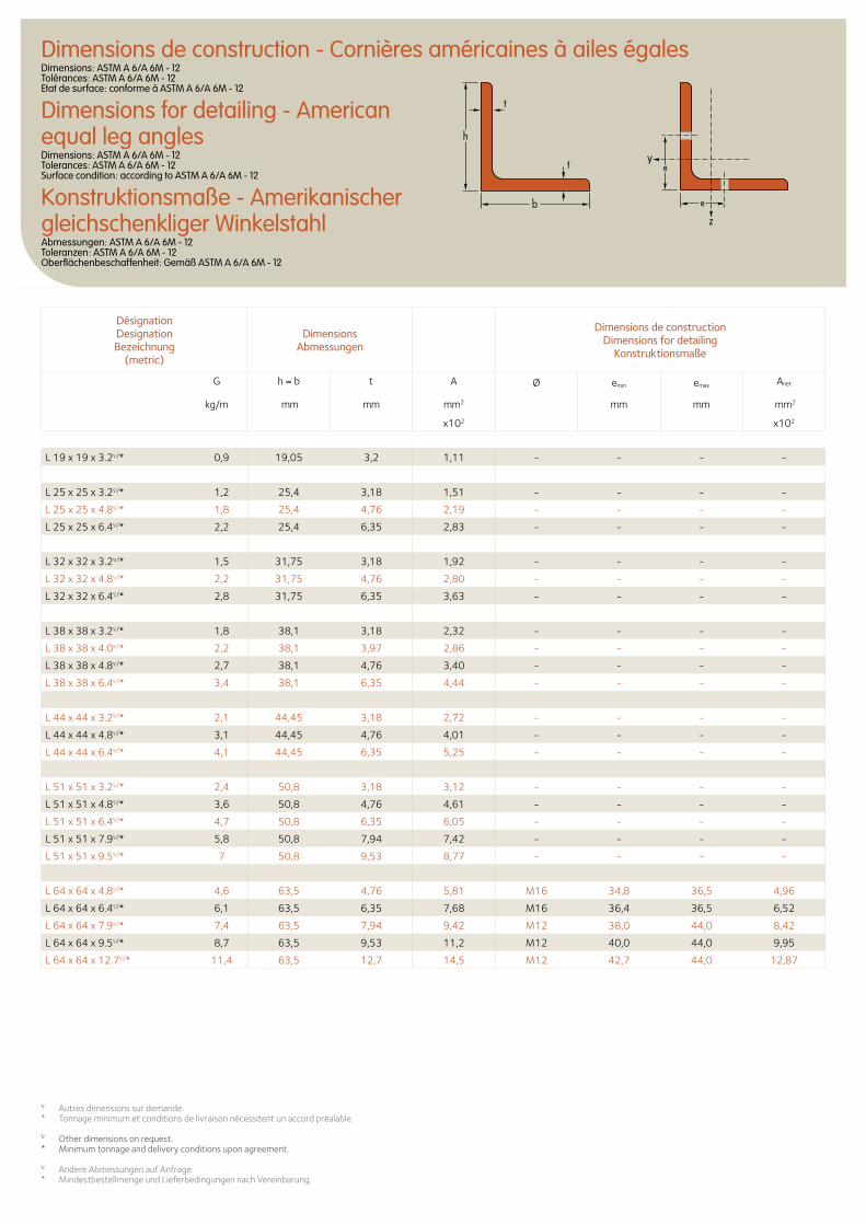
t
t
h
b
e
e
L 19 x 19 x 3.2∇/* 0,9 19,05 3,2 1,11 - - - -
L 25 x 25 x 3.2∇/* 1,2 25,4 3,18 1,51 - - - -
L 25 x 25 x 4.8∇/* 1,8 25,4 4,76 2,19 - - - -
L 25 x 25 x 6.4∇/* 2,2 25,4 6,35 2,83 - - - -
L 32 x 32 x 3.2∇/* 1,5 31,75 3,18 1,92 - - - -
L 32 x 32 x 4.8∇/* 2,2 31,75 4,76 2,80 - - - -
L 32 x 32 x 6.4∇/* 2,8 31,75 6,35 3,63 - - - -
L 38 x 38 x 3.2∇/* 1,8 38,1 3,18 2,32 - - - -
L 38 x 38 x 4.0∇/* 2,2 38,1 3,97 2,86 - - - -
L 38 x 38 x 4.8∇/* 2,7 38,1 4,76 3,40 - - - -
L 38 x 38 x 6.4∇/* 3,4 38,1 6,35 4,44 - - - -
L 44 x 44 x 3.2∇/* 2,1 44,45 3,18 2,72 - - - -
L 44 x 44 x 4.8∇/* 3,1 44,45 4,76 4,01 - - - -
L 44 x 44 x 6.4∇/* 4,1 44,45 6,35 5,25 - - - -
L 51 x 51 x 3.2∇/* 2,4 50,8 3,18 3,12 - - - -
L 51 x 51 x 4.8∇/* 3,6 50,8 4,76 4,61 - - - -
L 51 x 51 x 6.4∇/* 4,7 50,8 6,35 6,05 - - - -
L 51 x 51 x 7.9∇/* 5,8 50,8 7,94 7,42 - - - -
L 51 x 51 x 9.5∇/* 7 50,8 9,53 8,77 - - - -
L 64 x 64 x 4.8∇/* 4,6 63,5 4,76 5,81 M16 34,8 36,5 4,96
L 64 x 64 x 6.4∇/* 6,1 63,5 6,35 7,68 M16 36,4 36,5 6,52
L 64 x 64 x 7.9∇/* 7,4 63,5 7,94 9,42 M12 38,0 44,0 8,42
L 64 x 64 x 9.5∇/* 8,7 63,5 9,53 11,2 M12 40,0 44,0 9,95
L 64 x 64 x 12.7∇/* 11,4 63,5 12,7 14,5 M12 42,7 44,0 12,87
∇ Autres dimensions sur demande.* Tonnage minimum et conditions de livraison nécessitent un accord préalable.
∇ Other dimensions on request.* Minimum tonnage and delivery conditions upon agreement.
∇ Andere Abmessungen auf Anfrage.* Mindestbestellmenge und Lieferbedingungen nach Vereinbarung.
DésignationDesignationBezeichnung
(metric)
Dimensions Abmessungen
Dimensions de constructionDimensions for detailing
Konstruktionsmaße
G
kg/m
h = b t A Ø emin emax Anet
mm mm mm2 mm mm mm2
x102 x102
Dimensions de construction - Cornières américaines à ailes égalesDimensions: ASTM A 6/A 6M - 12 Tolérances: ASTM A 6/A 6M - 12 Etat de surface: conforme à ASTM A 6/A 6M - 12
Dimensions for detailing - American equal leg anglesDimensions: ASTM A 6/A 6M - 12 Tolerances: ASTM A 6/A 6M - 12 Surface condition: according to ASTM A 6/A 6M - 12
Konstruktionsmaße - Amerikanischer gleichschenkliger WinkelstahlAbmessungen: ASTM A 6/A 6M - 12 Toleranzen: ASTM A 6/A 6M - 12 Oberflächenbeschaffenheit: Gemäß ASTM A 6/A 6M - 12
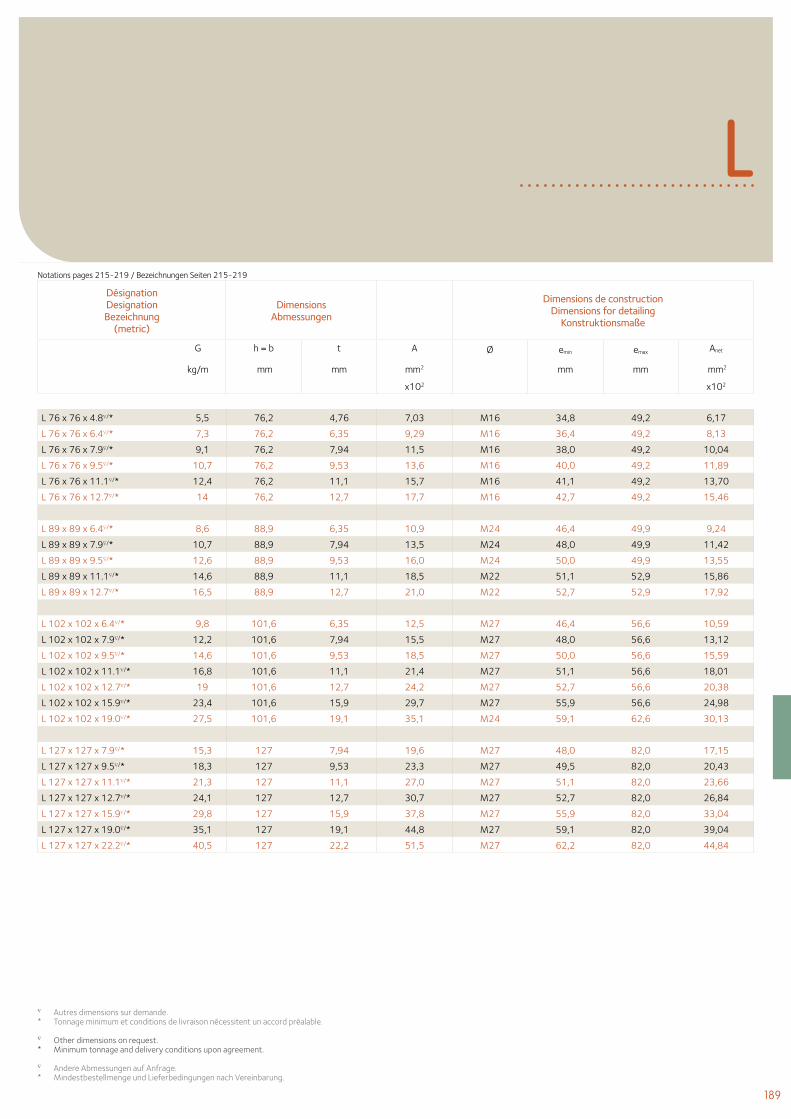
189
L
L 76 x 76 x 4.8∇/* 5,5 76,2 4,76 7,03 M16 34,8 49,2 6,17
L 76 x 76 x 6.4∇/* 7,3 76,2 6,35 9,29 M16 36,4 49,2 8,13
L 76 x 76 x 7.9∇/* 9,1 76,2 7,94 11,5 M16 38,0 49,2 10,04
L 76 x 76 x 9.5∇/* 10,7 76,2 9,53 13,6 M16 40,0 49,2 11,89
L 76 x 76 x 11.1∇/* 12,4 76,2 11,1 15,7 M16 41,1 49,2 13,70
L 76 x 76 x 12.7∇/* 14 76,2 12,7 17,7 M16 42,7 49,2 15,46
L 89 x 89 x 6.4∇/* 8,6 88,9 6,35 10,9 M24 46,4 49,9 9,24
L 89 x 89 x 7.9∇/* 10,7 88,9 7,94 13,5 M24 48,0 49,9 11,42
L 89 x 89 x 9.5∇/* 12,6 88,9 9,53 16,0 M24 50,0 49,9 13,55
L 89 x 89 x 11.1∇/* 14,6 88,9 11,1 18,5 M22 51,1 52,9 15,86
L 89 x 89 x 12.7∇/* 16,5 88,9 12,7 21,0 M22 52,7 52,9 17,92
L 102 x 102 x 6.4∇/* 9,8 101,6 6,35 12,5 M27 46,4 56,6 10,59
L 102 x 102 x 7.9∇/* 12,2 101,6 7,94 15,5 M27 48,0 56,6 13,12
L 102 x 102 x 9.5∇/* 14,6 101,6 9,53 18,5 M27 50,0 56,6 15,59
L 102 x 102 x 11.1∇/* 16,8 101,6 11,1 21,4 M27 51,1 56,6 18,01
L 102 x 102 x 12.7∇/* 19 101,6 12,7 24,2 M27 52,7 56,6 20,38
L 102 x 102 x 15.9∇/* 23,4 101,6 15,9 29,7 M27 55,9 56,6 24,98
L 102 x 102 x 19.0∇/* 27,5 101,6 19,1 35,1 M24 59,1 62,6 30,13
L 127 x 127 x 7.9∇/* 15,3 127 7,94 19,6 M27 48,0 82,0 17,15
L 127 x 127 x 9.5∇/* 18,3 127 9,53 23,3 M27 49,5 82,0 20,43
L 127 x 127 x 11.1∇/* 21,3 127 11,1 27,0 M27 51,1 82,0 23,66
L 127 x 127 x 12.7∇/* 24,1 127 12,7 30,7 M27 52,7 82,0 26,84
L 127 x 127 x 15.9∇/* 29,8 127 15,9 37,8 M27 55,9 82,0 33,04
L 127 x 127 x 19.0∇/* 35,1 127 19,1 44,8 M27 59,1 82,0 39,04
L 127 x 127 x 22.2∇/* 40,5 127 22,2 51,5 M27 62,2 82,0 44,84
∇ Autres dimensions sur demande.* Tonnage minimum et conditions de livraison nécessitent un accord préalable.
∇ Other dimensions on request.* Minimum tonnage and delivery conditions upon agreement.
∇ Andere Abmessungen auf Anfrage.* Mindestbestellmenge und Lieferbedingungen nach Vereinbarung.
DésignationDesignationBezeichnung
(metric)
Dimensions Abmessungen
Dimensions de constructionDimensions for detailing
Konstruktionsmaße
G
kg/m
h = b t A Ø emin emax Anet
mm mm mm2 mm mm mm2
x102 x102
Notations pages 215-219 / Bezeichnungen Seiten 215-219
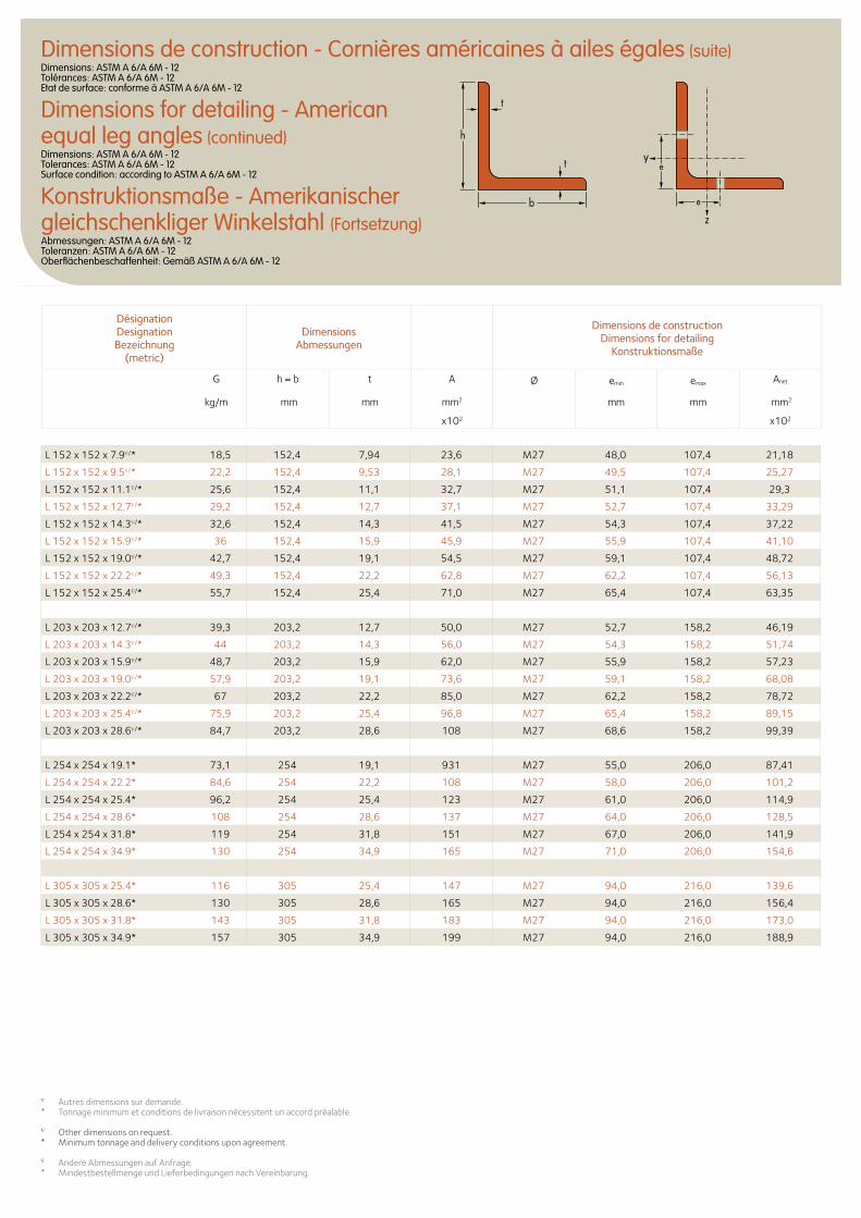
t
t
h
b
e
e
L 152 x 152 x 7.9∇/* 18,5 152,4 7,94 23,6 M27 48,0 107,4 21,18
L 152 x 152 x 9.5∇/* 22,2 152,4 9,53 28,1 M27 49,5 107,4 25,27
L 152 x 152 x 11.1∇/* 25,6 152,4 11,1 32,7 M27 51,1 107,4 29,3
L 152 x 152 x 12.7∇/* 29,2 152,4 12,7 37,1 M27 52,7 107,4 33,29
L 152 x 152 x 14.3∇/* 32,6 152,4 14,3 41,5 M27 54,3 107,4 37,22
L 152 x 152 x 15.9∇/* 36 152,4 15,9 45,9 M27 55,9 107,4 41,10
L 152 x 152 x 19.0∇/* 42,7 152,4 19,1 54,5 M27 59,1 107,4 48,72
L 152 x 152 x 22.2∇/* 49,3 152,4 22,2 62,8 M27 62,2 107,4 56,13
L 152 x 152 x 25.4∇/* 55,7 152,4 25,4 71,0 M27 65,4 107,4 63,35
L 203 x 203 x 12.7∇/* 39,3 203,2 12,7 50,0 M27 52,7 158,2 46,19
L 203 x 203 x 14.3∇/* 44 203,2 14,3 56,0 M27 54,3 158,2 51,74
L 203 x 203 x 15.9∇/* 48,7 203,2 15,9 62,0 M27 55,9 158,2 57,23
L 203 x 203 x 19.0∇/* 57,9 203,2 19,1 73,6 M27 59,1 158,2 68,08
L 203 x 203 x 22.2∇/* 67 203,2 22,2 85,0 M27 62,2 158,2 78,72
L 203 x 203 x 25.4∇/* 75,9 203,2 25,4 96,8 M27 65,4 158,2 89,15
L 203 x 203 x 28.6∇/* 84,7 203,2 28,6 108 M27 68,6 158,2 99,39
L 254 x 254 x 19.1* 73,1 254 19,1 931 M27 55,0 206,0 87,41
L 254 x 254 x 22.2* 84,6 254 22,2 108 M27 58,0 206,0 101,2
L 254 x 254 x 25.4* 96,2 254 25,4 123 M27 61,0 206,0 114,9
L 254 x 254 x 28.6* 108 254 28,6 137 M27 64,0 206,0 128,5
L 254 x 254 x 31.8* 119 254 31,8 151 M27 67,0 206,0 141,9
L 254 x 254 x 34.9* 130 254 34,9 165 M27 71,0 206,0 154,6
L 305 x 305 x 25.4* 116 305 25,4 147 M27 94,0 216,0 139,6
L 305 x 305 x 28.6* 130 305 28,6 165 M27 94,0 216,0 156,4
L 305 x 305 x 31.8* 143 305 31,8 183 M27 94,0 216,0 173,0
L 305 x 305 x 34.9* 157 305 34,9 199 M27 94,0 216,0 188,9
DésignationDesignationBezeichnung
(metric)
Dimensions Abmessungen
Dimensions de constructionDimensions for detailing
Konstruktionsmaße
G
kg/m
h = b t A Ø emin emax Anet
mm mm mm2 mm mm mm2
x102 x102
∇ Autres dimensions sur demande.* Tonnage minimum et conditions de livraison nécessitent un accord préalable.
∇ Other dimensions on request.* Minimum tonnage and delivery conditions upon agreement.
∇ Andere Abmessungen auf Anfrage.* Mindestbestellmenge und Lieferbedingungen nach Vereinbarung.
Dimensions de construction - Cornières américaines à ailes égales (suite)Dimensions: ASTM A 6/A 6M - 12 Tolérances: ASTM A 6/A 6M - 12 Etat de surface: conforme à ASTM A 6/A 6M - 12
Dimensions for detailing - American equal leg angles (continued)Dimensions: ASTM A 6/A 6M - 12 Tolerances: ASTM A 6/A 6M - 12 Surface condition: according to ASTM A 6/A 6M - 12
Konstruktionsmaße - Amerikanischer gleichschenkliger Winkelstahl (Fortsetzung)Abmessungen: ASTM A 6/A 6M - 12 Toleranzen: ASTM A 6/A 6M - 12 Oberflächenbeschaffenheit: Gemäß ASTM A 6/A 6M - 12
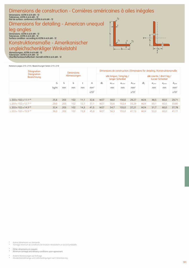
191
Désignation Designation Bezeichnung
Dimensions Abmessungen
Dimensions de construction /Dimensions for detailing /Konstruktionsmaße
aile longue / long leg / langer Schenkel
aile courte / short leg / kurzer Schenkel
G h b t A Øz ez,min ez,max Az,net Øy ey,min ey,max Ay,net
kg/m mm mm mm mm2 mm mm mm2 mm mm mm2
x102 x102 x102
L 203 x 102 x 11.1∇/* 25,6 203 102 11,1 32,6 M27 58,0 150,0 29,27 M24 48,5 60,0 29,71
L 203 x 102 x 12.7∇/* 29,0 203 102 12,7 37,1 M27 55,6 152,4 33,29 M24 50,1 60,0 33,80
L 203 x 102 x 14.3∇/* 32,4 203 102 14,3 41,5 M27 54,7 155,0 37,21 M24 51,7 60,0 37,78
L 203 x 102 x 15.9∇/* 36,0 203 102 15,9 45,9 M27 56,3 155,0 41,13 M24 53,3 60,0 41,77
∇ Autres dimensions sur demande.* Tonnage minimum et conditions de livraison nécessitent un accord préalable.
∇ Other dimensions on request.* Minimum tonnage and delivery conditions upon agreement.
∇ Andere Abmessungen auf Anfrage.* Mindestbestellmenge und Lieferbedingungen nach Vereinbarung.
Dimensions de construction - Cornières américaines à ailes inégalesDimensions: ASTM A 6/A 6M - 12 Tolérances: ASTM A 6/A 6M - 12 Etat de surface: conforme à ASTM A 6/A 6M - 12
Dimensions for detailing - American unequal leg anglesDimensions: ASTM A 6/A 6M - 12 Tolerances: ASTM A 6/A 6M - 12 Surface condition: according to ASTM A 6/A 6M - 12
Konstruktionsmaße - Amerikanischer ungleichschenkliger WinkelstahlAbmessungen: ASTM A 6/A 6M - 12 Toleranzen: ASTM A 6/A 6M - 12 Oberflächenbeschaffenheit: Gemäß ASTM A 6/A 6M - 12
t
t
h
b
r1
r2
r2ez
ey
Notations pages 215-219 / Bezeichnungen Seiten 215-219
© P
hoto
Luc
Boe
gly
- A
rchi
tect
es C
laud
e Va
scon
i et
Jean
Pet
it
© P
hoto
Luc
Boe
gly
- A
rchi
tect
es C
laud
e Va
scon
i et
Jean
Pet
it
194 Poutrelles russes laminées à chaud
196 Fers U à ailes inclinées
194 Russian hot rolled beams
196 Channels with taper flanges
194 Russische Walzträger
196 U-Profile mit geneigten inneren Flanschflächen
Profilés russes Russian sections Russische Profile
193
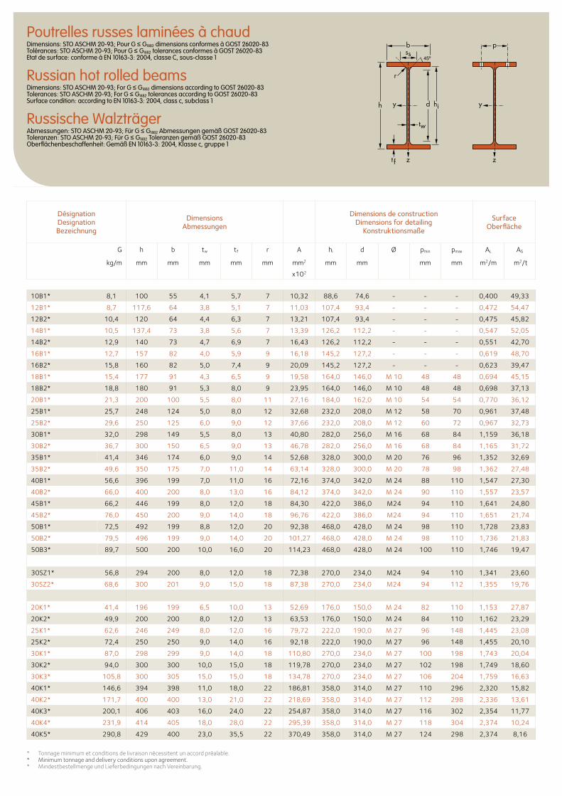
Poutrelles russes laminées à chaudDimensions: STO ASCHM 20-93; Pour G ≤ G18B2 dimensions conformes à GOST 26020-83 Tolérances: STO ASCHM 20-93; Pour G ≤ G18B2 tolerances conformes à GOST 26020-83 Etat de surface: conforme à EN 10163-3: 2004, classe C, sous-classe 1
Russian hot rolled beamsDimensions: STO ASCHM 20-93; For G ≤ G18B2 dimensions according to GOST 26020-83 Tolerances: STO ASCHM 20-93; For G ≤ G18B2 tolerances according to GOST 26020-83 Surface condition: according to EN 10163-3: 2004, class c, subclass 1
Russische WalzträgerAbmessungen: STO ASCHM 20-93; Für G ≤ G18B2 Abmessungen gemäß GOST 26020-83 Toleranzen: STO ASCHM 20-93; Für G ≤ G18B2 Toleranzen gemäß GOST 26020-83 Oberflächenbeschaffenheit: Gemäß EN 10163-3: 2004, Klasse c, gruppe 1
DésignationDesignationBezeichnung
DimensionsAbmessungen
Dimensions de constructionDimensions for detailing
Konstruktionsmaße
SurfaceOberfläche
G h b tw tf r A hi d Ø pmin pmax AL AG
kg/m mm mm mm mm mm mm2 mm mm mm mm m2/m m2/t
x102
10B1* 8,1 100 55 4,1 5,7 7 10,32 88,6 74,6 - - - 0,400 49,33
12B1* 8,7 117,6 64 3,8 5,1 7 11,03 107,4 93,4 - - - 0,472 54,47
12B2* 10,4 120 64 4,4 6,3 7 13,21 107,4 93,4 - - - 0,475 45,82
14B1* 10,5 137,4 73 3,8 5,6 7 13,39 126,2 112,2 - - - 0,547 52,05
14B2* 12,9 140 73 4,7 6,9 7 16,43 126,2 112,2 - - - 0,551 42,70
16B1* 12,7 157 82 4,0 5,9 9 16,18 145,2 127,2 - - - 0,619 48,70
16B2* 15,8 160 82 5,0 7,4 9 20,09 145,2 127,2 - - - 0,623 39,47
18B1* 15,4 177 91 4,3 6,5 9 19,58 164,0 146,0 M 10 48 48 0,694 45,15
18B2* 18,8 180 91 5,3 8,0 9 23,95 164,0 146,0 M 10 48 48 0,698 37,13
20B1* 21,3 200 100 5,5 8,0 11 27,16 184,0 162,0 M 10 54 54 0,770 36,12
25B1* 25,7 248 124 5,0 8,0 12 32,68 232,0 208,0 M 12 58 70 0,961 37,48
25B2* 29,6 250 125 6,0 9,0 12 37,66 232,0 208,0 M 12 60 72 0,967 32,73
30B1* 32,0 298 149 5,5 8,0 13 40,80 282,0 256,0 M 16 68 84 1,159 36,18
30B2* 36,7 300 150 6,5 9,0 13 46,78 282,0 256,0 M 16 68 84 1,165 31,72
35B1* 41,4 346 174 6,0 9,0 14 52,68 328,0 300,0 M 20 76 96 1,352 32,69
35B2* 49,6 350 175 7,0 11,0 14 63,14 328,0 300,0 M 20 78 98 1,362 27,48
40B1* 56,6 396 199 7,0 11,0 16 72,16 374,0 342,0 M 24 88 110 1,547 27,30
40B2* 66,0 400 200 8,0 13,0 16 84,12 374,0 342,0 M 24 90 110 1,557 23,57
45B1* 66,2 446 199 8,0 12,0 18 84,30 422,0 386,0 M24 94 110 1,641 24,80
45B2* 76,0 450 200 9,0 14,0 18 96,76 422,0 386,0 M24 94 110 1,651 21,74
50B1* 72,5 492 199 8,8 12,0 20 92,38 468,0 428,0 M 24 98 110 1,728 23,83
50B2* 79,5 496 199 9,0 14,0 20 101,27 468,0 428,0 M 24 98 110 1,736 21,83
50B3* 89,7 500 200 10,0 16,0 20 114,23 468,0 428,0 M 24 100 110 1,746 19,47
30SZ1* 56,8 294 200 8,0 12,0 18 72,38 270,0 234,0 M24 94 110 1,341 23,60
30SZ2* 68,6 300 201 9,0 15,0 18 87,38 270,0 234,0 M24 94 112 1,355 19,76
20K1* 41,4 196 199 6,5 10,0 13 52,69 176,0 150,0 M 24 82 110 1,153 27,87
20K2* 49,9 200 200 8,0 12,0 13 63,53 176,0 150,0 M 24 84 110 1,162 23,29
25K1* 62,6 246 249 8,0 12,0 16 79,72 222,0 190,0 M 27 96 148 1,445 23,08
25K2* 72,4 250 250 9,0 14,0 16 92,18 222,0 190,0 M 27 96 148 1,455 20,10
30K1* 87,0 298 299 9,0 14,0 18 110,80 270,0 234,0 M 27 100 198 1,743 20,04
30K2* 94,0 300 300 10,0 15,0 18 119,78 270,0 234,0 M 27 102 198 1,749 18,60
30K3* 105,8 300 305 15,0 15,0 18 134,78 270,0 234,0 M 27 106 204 1,759 16,63
40K1* 146,6 394 398 11,0 18,0 22 186,81 358,0 314,0 M 27 110 296 2,320 15,82
40K2* 171,7 400 400 13,0 21,0 22 218,69 358,0 314,0 M 27 112 298 2,336 13,61
40K3* 200,1 406 403 16,0 24,0 22 254,87 358,0 314,0 M 27 116 302 2,354 11,77
40K4* 231,9 414 405 18,0 28,0 22 295,39 358,0 314,0 M 27 118 304 2,374 10,24
40K5* 290,8 429 400 23,0 35,5 22 370,49 358,0 314,0 M 27 124 298 2,374 8,16
* Tonnage minimum et conditions de livraison nécessitent un accord préalable.* Minimum tonnage and delivery conditions upon agreement.* Mindestbestellmenge und Lieferbedingungen nach Vereinbarung.
b
r
yy dh
tw
ss
zzt f
hi
p
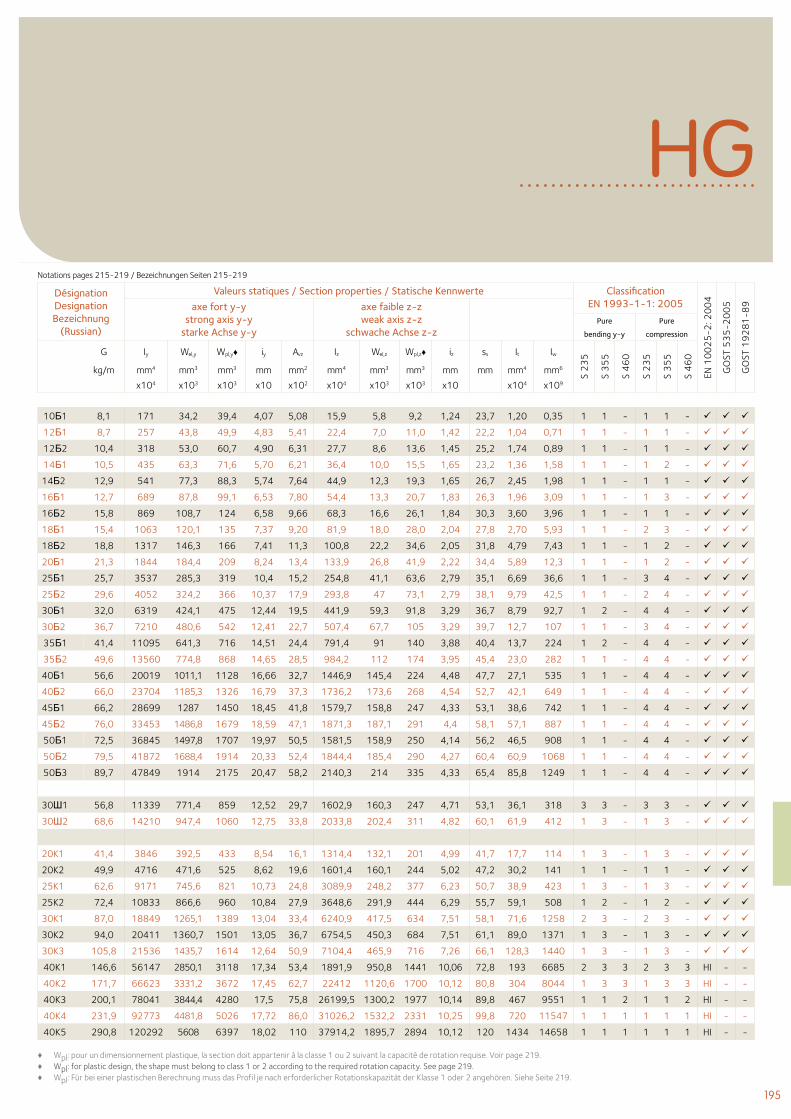
195
DésignationDesignationBezeichnung
(Russian)
Valeurs statiques / Section properties / Statische Kennwerte ClassificationEN 1993-1-1: 2005
EN 1
00
25
-2: 2
00
4
GO
ST 5
35
-20
05
GO
ST 1
92
81
-89axe fort y-y
strong axis y-ystarke Achse y-y
axe faible z-zweak axis z-z
schwache Achse z-zPure
bending y-y
Pure
compression
G Iy Wel,y Wpl,y♦ iy Avz Iz Wel,z Wpl,z♦ iz ss It Iw
S 2
35
S 3
55
S 4
60
S 2
35
S 3
55
S 4
60
kg/m mm4 mm3 mm3 mm mm2 mm4 mm3 mm3 mm mm mm4 mm6
x104 x103 x103 x10 x102 x104 x103 x103 x10 x104 x109
10Б1 8,1 171 34,2 39,4 4,07 5,08 15,9 5,8 9,2 1,24 23,7 1,20 0,35 1 1 - 1 1 -
12Б1 8,7 257 43,8 49,9 4,83 5,41 22,4 7,0 11,0 1,42 22,2 1,04 0,71 1 1 - 1 1 -
12Б2 10,4 318 53,0 60,7 4,90 6,31 27,7 8,6 13,6 1,45 25,2 1,74 0,89 1 1 - 1 1 -
14Б1 10,5 435 63,3 71,6 5,70 6,21 36,4 10,0 15,5 1,65 23,2 1,36 1,58 1 1 - 1 2 -
14Б2 12,9 541 77,3 88,3 5,74 7,64 44,9 12,3 19,3 1,65 26,7 2,45 1,98 1 1 - 1 1 -
16Б1 12,7 689 87,8 99,1 6,53 7,80 54,4 13,3 20,7 1,83 26,3 1,96 3,09 1 1 - 1 3 -
16Б2 15,8 869 108,7 124 6,58 9,66 68,3 16,6 26,1 1,84 30,3 3,60 3,96 1 1 - 1 1 -
18Б1 15,4 1063 120,1 135 7,37 9,20 81,9 18,0 28,0 2,04 27,8 2,70 5,93 1 1 - 2 3 -
18Б2 18,8 1317 146,3 166 7,41 11,3 100,8 22,2 34,6 2,05 31,8 4,79 7,43 1 1 - 1 2 -
20Б1 21,3 1844 184,4 209 8,24 13,4 133,9 26,8 41,9 2,22 34,4 5,89 12,3 1 1 - 1 2 -
25Б1 25,7 3537 285,3 319 10,4 15,2 254,8 41,1 63,6 2,79 35,1 6,69 36,6 1 1 - 3 4 -
25Б2 29,6 4052 324,2 366 10,37 17,9 293,8 47 73,1 2,79 38,1 9,79 42,5 1 1 - 2 4 -
30Б1 32,0 6319 424,1 475 12,44 19,5 441,9 59,3 91,8 3,29 36,7 8,79 92,7 1 2 - 4 4 -
30Б2 36,7 7210 480,6 542 12,41 22,7 507,4 67,7 105 3,29 39,7 12,7 107 1 1 - 3 4 -
35Б1 41,4 11095 641,3 716 14,51 24,4 791,4 91 140 3,88 40,4 13,7 224 1 2 - 4 4 -
35Б2 49,6 13560 774,8 868 14,65 28,5 984,2 112 174 3,95 45,4 23,0 282 1 1 - 4 4 -
40Б1 56,6 20019 1011,1 1128 16,66 32,7 1446,9 145,4 224 4,48 47,7 27,1 535 1 1 - 4 4 -
40Б2 66,0 23704 1185,3 1326 16,79 37,3 1736,2 173,6 268 4,54 52,7 42,1 649 1 1 - 4 4 -
45Б1 66,2 28699 1287 1450 18,45 41,8 1579,7 158,8 247 4,33 53,1 38,6 742 1 1 - 4 4 -
45Б2 76,0 33453 1486,8 1679 18,59 47,1 1871,3 187,1 291 4,4 58,1 57,1 887 1 1 - 4 4 -
50Б1 72,5 36845 1497,8 1707 19,97 50,5 1581,5 158,9 250 4,14 56,2 46,5 908 1 1 - 4 4 -
50Б2 79,5 41872 1688,4 1914 20,33 52,4 1844,4 185,4 290 4,27 60,4 60,9 1068 1 1 - 4 4 -
50Б3 89,7 47849 1914 2175 20,47 58,2 2140,3 214 335 4,33 65,4 85,8 1249 1 1 - 4 4 -
30Ш1 56,8 11339 771,4 859 12,52 29,7 1602,9 160,3 247 4,71 53,1 36,1 318 3 3 - 3 3 -
30Ш2 68,6 14210 947,4 1060 12,75 33,8 2033,8 202,4 311 4,82 60,1 61,9 412 1 3 - 1 3 -
20K1 41,4 3846 392,5 433 8,54 16,1 1314,4 132,1 201 4,99 41,7 17,7 114 1 3 - 1 3 -
20K2 49,9 4716 471,6 525 8,62 19,6 1601,4 160,1 244 5,02 47,2 30,2 141 1 1 - 1 1 -
25K1 62,6 9171 745,6 821 10,73 24,8 3089,9 248,2 377 6,23 50,7 38,9 423 1 3 - 1 3 -
25K2 72,4 10833 866,6 960 10,84 27,9 3648,6 291,9 444 6,29 55,7 59,1 508 1 2 - 1 2 -
30K1 87,0 18849 1265,1 1389 13,04 33,4 6240,9 417,5 634 7,51 58,1 71,6 1258 2 3 - 2 3 -
30K2 94,0 20411 1360,7 1501 13,05 36,7 6754,5 450,3 684 7,51 61,1 89,0 1371 1 3 - 1 3 -
30K3 105,8 21536 1435,7 1614 12,64 50,9 7104,4 465,9 716 7,26 66,1 128,3 1440 1 3 - 1 3 -
40K1 146,6 56147 2850,1 3118 17,34 53,4 1891,9 950,8 1441 10,06 72,8 193 6685 2 3 3 2 3 3 HI - -
40K2 171,7 66623 3331,2 3672 17,45 62,7 22412 1120,6 1700 10,12 80,8 304 8044 1 3 3 1 3 3 HI - -
40K3 200,1 78041 3844,4 4280 17,5 75,8 26199,5 1300,2 1977 10,14 89,8 467 9551 1 1 2 1 1 2 HI - -
40K4 231,9 92773 4481,8 5026 17,72 86,0 31026,2 1532,2 2331 10,25 99,8 720 11547 1 1 1 1 1 1 HI - -
40K5 290,8 120292 5608 6397 18,02 110 37914,2 1895,7 2894 10,12 120 1434 14658 1 1 1 1 1 1 HI - -
♦ Wpl: pour un dimensionnement plastique, la section doit appartenir à la classe 1 ou 2 suivant la capacité de rotation requise. Voir page 219.♦ Wpl: for plastic design, the shape must belong to class 1 or 2 according to the required rotation capacity. See page 219.♦ Wpl: Für bei einer plastischen Berechnung muss das Profil je nach erforderlicher Rotationskapazität der Klasse 1 oder 2 angehören. Siehe Seite 219.
HGNotations pages 215-219 / Bezeichnungen Seiten 215-219
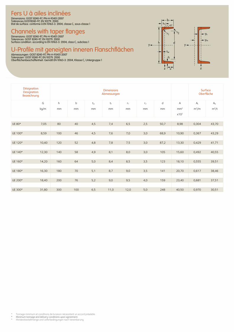
Fers U à ailes inclinéesDimensions: GOST 8240-97, PN-H-93451:2007 Tolérances GOST8240-97, EN 10279: 2000 Etat de surface: conforme à EN 10163-3: 2004, classe C, sous-classe 1
Channels with taper flangesDimensions: GOST 8240-97, PN-H-93451:2007 Tolerances: GOST 8240-97, EN 10279: 2000 Surface condition: according to EN 10163-3: 2004, class C, subclass 1
U-Profile mit geneigten inneren FlanschflächenAbmessungen: GOST 8240-97, PN-H-93451:2007 Toleranzen: GOST 8240-97, EN 10279: 2000 Oberflächenbeschaffenheit: Gemäß EN 10163-3: 2004, Klasse C, Untergruppe 1
* Tonnage minimum et conditions de livraison nécessitent un accord préalable.* Minimum tonnage and delivery conditions upon agreement.* Mindestbestellmenge und Lieferbedingungen nach Vereinbarung.
Désignation Designation Bezeichnung
Dimensions Abmessungen
Surface Oberfläche
G h b tw tf r1 r2 d A AL AG
kg/m mm mm mm mm mm mm mm mm2 m2/m m2/t
x102
ys
ss
ym
y
z z
y
45o
d
tw
tf
h
r1
b
r2
u
UE 80* 7,05 80 40 4,5 7,4 6,5 2,5 50,7 8,98 0,304 43,70
UE 100* 8,59 100 46 4,5 7,6 7,0 3,0 68,9 10,90 0,367 43,29
UE 120* 10,40 120 52 4,8 7,8 7,5 3,0 87,2 13,30 0,429 41,71
UE 140* 12,30 140 58 4,9 8,1 8,0 3,0 105 15,60 0,492 40,55
UE 160* 14,20 160 64 5,0 8,4 8,5 3,5 123 18,10 0,555 39,51
UE 180* 16,30 180 70 5,1 8,7 9,0 3,5 141 20,70 0,617 38,46
UE 200* 18,40 200 76 5,2 9,0 9,5 4,0 159 23,40 0,681 37,51
UE 300* 31,80 300 100 6,5 11,0 12,0 5,0 248 40,50 0,970 30,51
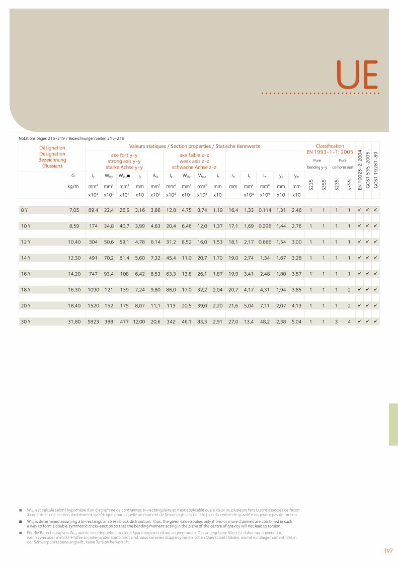
197
UE
■ Wpl,y est calculé selon l’hypothèse d’un diagramme de contraintes bi-rectangulaire et n’est applicable que si deux ou plusieurs fers U sont associés de facon à constituer une section doublement symétrique pour laquelle un moment de flexion agissant dans le plan du centre de gravité n’engendre pas de torsion.
■ Wpl,y is determined assuming a bi-rectangular stress block distribution. Thus, the given value applies only if two or more channels are combined in such a way to form a double symmetric cross-section so that the bending moment acting in the plane of the centre of gravity will not lead to torsion.
■ Für die Berechnung von Wpl,y wurde eine doppelrechteckige Spannungsverteilung angenommen. Der angegebene Wert ist daher nur anwendbar, wenn zwei oder mehr U-Profile so miteinander kombiniert sind, dass sie einen doppelsymmetrischen Querschnitt bilden, womit ein Biegemoment, das in der Schwerpunktebene angreift, keine Torsion hervorruft.
Désignation Designation Bezeichnung
(Russian)
Valeurs statiques / Section properties / Statische Kennwerte Classification EN 1993-1-1: 2005
EN 1
00
25
-2: 2
00
4
GO
ST 5
35
-20
05
GO
ST 1
92
81
-89axe fort y-y
strong axis y-y starke Achse y-y
axe faible z-z weak axis z-z
schwache Achse z-z Pure
bending y-y
Pure
compression
G Iy Wel.y Wpl.y■ iy Avz Iz Wel.z Wpl.z iz ss It Iw ys ym
S23
5
S35
5
S23
5
S35
5
kg/m mm4 mm3 mm3 mm mm2 mm4 mm3 mm3 mm mm mm4 mm6 mm mm
x104 x103 x103 x10 x102 x104 x103 x103 x10 x104 x109 x10 x10
8 Y 7,05 89,4 22,4 26,5 3,16 3,86 12,8 4,75 8,74 1,19 16,4 1,33 0,114 1,31 2,46 1 1 1 1
10 Y 8,59 174 34,8 40,7 3,99 4,83 20,4 6,46 12,0 1,37 17,1 1,69 0,296 1,44 2,76 1 1 1 1
12 Y 10,40 304 50,6 59,1 4,78 6,14 31,2 8,52 16,0 1,53 18,1 2,17 0,666 1,54 3,00 1 1 1 1
14 Y 12,30 491 70,2 81,4 5,60 7,32 45,4 11,0 20,7 1,70 19,0 2,74 1,34 1,67 3,28 1 1 1 1
16 Y 14,20 747 93,4 108 6,42 8,53 63,3 13,8 26,1 1,87 19,9 3,41 2,48 1,80 3,57 1 1 1 1
18 Y 16,30 1090 121 139 7,24 9,80 86,0 17,0 32,2 2,04 20,7 4,17 4,31 1,94 3,85 1 1 1 2
20 Y 18,40 1520 152 175 8,07 11,1 113 20,5 39,0 2,20 21,6 5,04 7,11 2,07 4,13 1 1 1 2
30 Y 31,80 5823 388 477 12,00 20,6 342 46,1 83,3 2,91 27,0 13,4 48,2 2,38 5,04 1 1 3 4
Notations pages 215-219 / Bezeichnungen Seiten 215-219

200 Sections H japonaises 200 Japanese H sections 200 Japanische H-Profile
Profilés japonais Japanese sections Japanische Profile
199
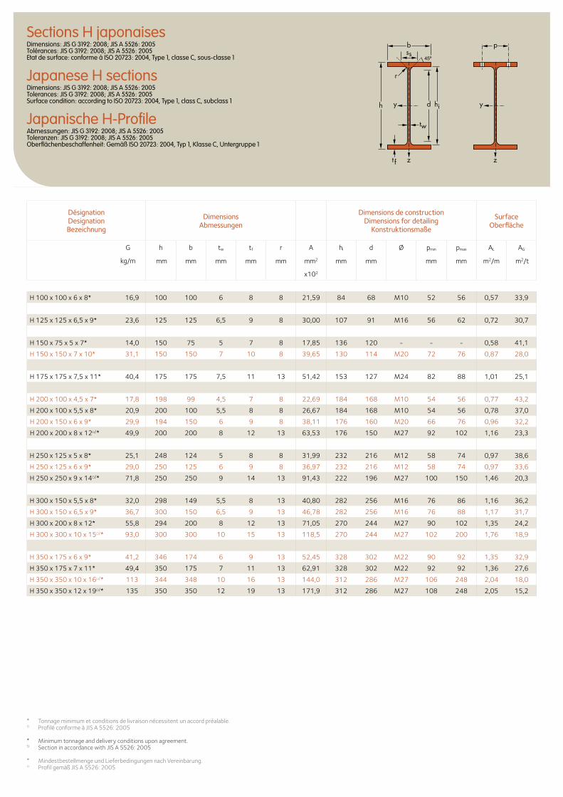
b
r
yy dh
tw
ss
zzt f
hi
pSections H japonaisesDimensions: JIS G 3192: 2008; JIS A 5526: 2005 Tolérances: JIS G 3192: 2008; JIS A 5526: 2005 Etat de surface: conforme à ISO 20723: 2004, Type 1, classe C, sous-classe 1
Japanese H sectionsDimensions: JIS G 3192: 2008; JIS A 5526: 2005 Tolerances: JIS G 3192: 2008; JIS A 5526: 2005 Surface condition: according to ISO 20723: 2004, Type 1, class C, subclass 1
Japanische H-ProfileAbmessungen: JIS G 3192: 2008; JIS A 5526: 2005 Toleranzen: JIS G 3192: 2008; JIS A 5526: 2005 Oberflächenbeschaffenheit: Gemäß ISO 20723: 2004, Typ 1, Klasse C, Untergruppe 1
H 100 x 100 x 6 x 8* 16,9 100 100 6 8 8 21,59 84 68 M10 52 56 0,57 33,9
H 125 x 125 x 6,5 x 9* 23,6 125 125 6,5 9 8 30,00 107 91 M16 56 62 0,72 30,7
H 150 x 75 x 5 x 7* 14,0 150 75 5 7 8 17,85 136 120 - - - 0,58 41,1
H 150 x 150 x 7 x 10* 31,1 150 150 7 10 8 39,65 130 114 M20 72 76 0,87 28,0
H 175 x 175 x 7,5 x 11* 40,4 175 175 7,5 11 13 51,42 153 127 M24 82 88 1,01 25,1
H 200 x 100 x 4,5 x 7* 17,8 198 99 4,5 7 8 22,69 184 168 M10 54 56 0,77 43,2
H 200 x 100 x 5,5 x 8* 20,9 200 100 5,5 8 8 26,67 184 168 M10 54 56 0,78 37,0
H 200 x 150 x 6 x 9* 29,9 194 150 6 9 8 38,11 176 160 M20 66 76 0,96 32,2
H 200 x 200 x 8 x 12□/* 49,9 200 200 8 12 13 63,53 176 150 M27 92 102 1,16 23,3
H 250 x 125 x 5 x 8* 25,1 248 124 5 8 8 31,99 232 216 M12 58 74 0,97 38,6
H 250 x 125 x 6 x 9* 29,0 250 125 6 9 8 36,97 232 216 M12 58 74 0,97 33,6
H 250 x 250 x 9 x 14□/* 71,8 250 250 9 14 13 91,43 222 196 M27 100 150 1,46 20,3
H 300 x 150 x 5,5 x 8* 32,0 298 149 5,5 8 13 40,80 282 256 M16 76 86 1,16 36,2
H 300 x 150 x 6,5 x 9* 36,7 300 150 6,5 9 13 46,78 282 256 M16 76 88 1,17 31,7
H 300 x 200 x 8 x 12* 55,8 294 200 8 12 13 71,05 270 244 M27 90 102 1,35 24,2
H 300 x 300 x 10 x 15□/* 93,0 300 300 10 15 13 118,5 270 244 M27 102 200 1,76 18,9
H 350 x 175 x 6 x 9* 41,2 346 174 6 9 13 52,45 328 302 M22 90 92 1,35 32,9
H 350 x 175 x 7 x 11* 49,4 350 175 7 11 13 62,91 328 302 M22 92 92 1,36 27,6
H 350 x 350 x 10 x 16□/* 113 344 348 10 16 13 144,0 312 286 M27 106 248 2,04 18,0
H 350 x 350 x 12 x 19□/* 135 350 350 12 19 13 171,9 312 286 M27 108 248 2,05 15,2
Désignation Designation Bezeichnung
Dimensions Abmessungen
Dimensions de construction Dimensions for detailing
Konstruktionsmaße
Surface Oberfläche
G
kg/m
h b tw tf r A hi d Ø pmin pmax AL AG
mm mm mm mm mm mm2 mm mm mm mm m2/m m2/t
x102
* Tonnage minimum et conditions de livraison nécessitent un accord préalable.□ Profilé conforme à JIS A 5526: 2005
* Minimum tonnage and delivery conditions upon agreement.□ Section in accordance with JIS A 5526: 2005
* Mindestbestellmenge und Lieferbedingungen nach Vereinbarung.□ Profil gemäß JIS A 5526: 2005
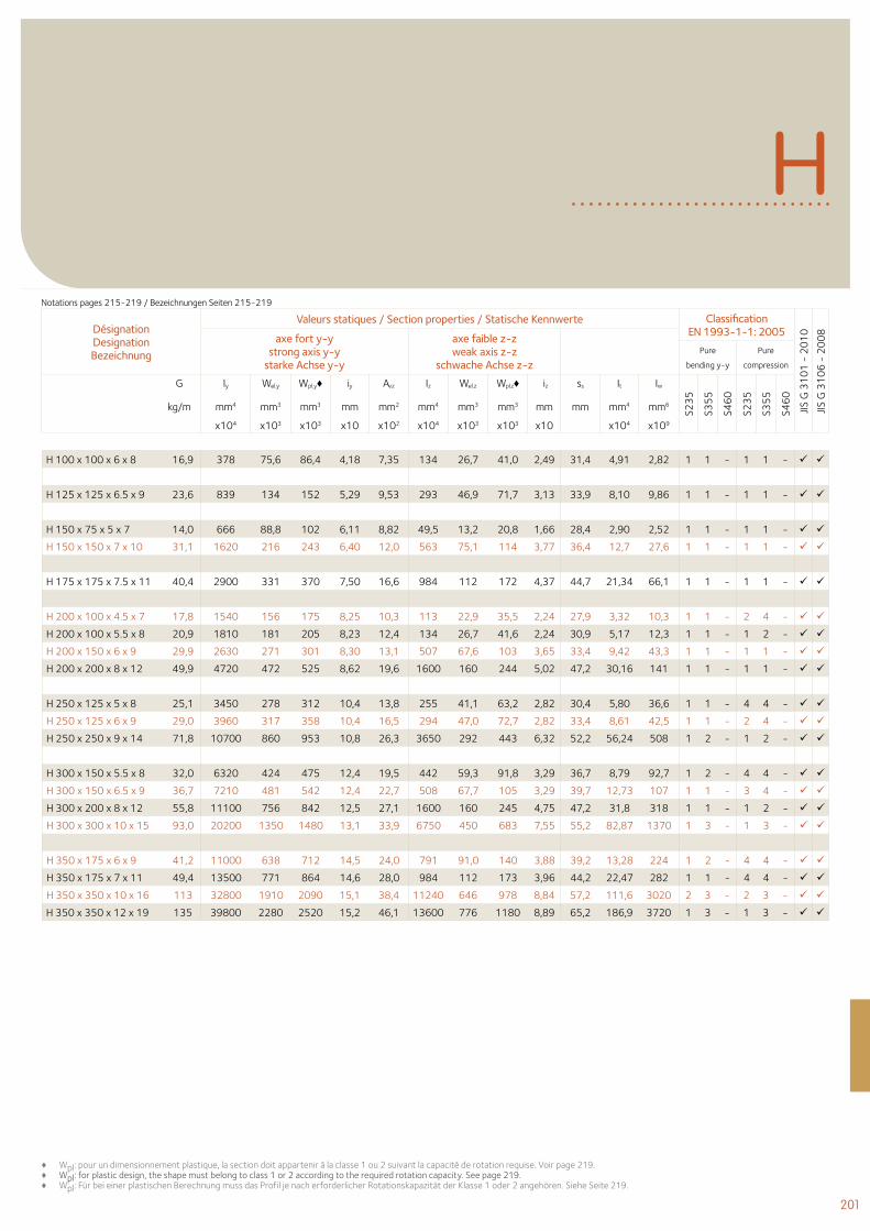
201
Désignation Designation Bezeichnung
Valeurs statiques / Section properties / Statische Kennwerte Classification EN 1993-1-1: 2005
JIS G
31
01
- 2
01
0
JIS G
31
06
- 2
00
8
axe fort y-y strong axis y-y
starke Achse y-y
axe faible z-z weak axis z-z
schwache Achse z-z Pure
bending y-y
Pure
compression
G Iy Wel.y Wpl.y♦ iy Avz Iz Wel.z Wpl.z♦ iz ss It Iw
S23
5
S35
5
S46
0
S23
5
S35
5
S46
0
kg/m mm4 mm3 mm3 mm mm2 mm4 mm3 mm3 mm mm mm4 mm6
x104 x103 x103 x10 x102 x104 x103 x103 x10 x104 x109
H
H 100 x 100 x 6 x 8 16,9 378 75,6 86,4 4,18 7,35 134 26,7 41,0 2,49 31,4 4,91 2,82 1 1 - 1 1 -
H 125 x 125 x 6.5 x 9 23,6 839 134 152 5,29 9,53 293 46,9 71,7 3,13 33,9 8,10 9,86 1 1 - 1 1 -
H 150 x 75 x 5 x 7 14,0 666 88,8 102 6,11 8,82 49,5 13,2 20,8 1,66 28,4 2,90 2,52 1 1 - 1 1 -
H 150 x 150 x 7 x 10 31,1 1620 216 243 6,40 12,0 563 75,1 114 3,77 36,4 12,7 27,6 1 1 - 1 1 -
H 175 x 175 x 7.5 x 11 40,4 2900 331 370 7,50 16,6 984 112 172 4,37 44,7 21,34 66,1 1 1 - 1 1 -
H 200 x 100 x 4.5 x 7 17,8 1540 156 175 8,25 10,3 113 22,9 35,5 2,24 27,9 3,32 10,3 1 1 - 2 4 -
H 200 x 100 x 5.5 x 8 20,9 1810 181 205 8,23 12,4 134 26,7 41,6 2,24 30,9 5,17 12,3 1 1 - 1 2 -
H 200 x 150 x 6 x 9 29,9 2630 271 301 8,30 13,1 507 67,6 103 3,65 33,4 9,42 43,3 1 1 - 1 1 -
H 200 x 200 x 8 x 12 49,9 4720 472 525 8,62 19,6 1600 160 244 5,02 47,2 30,16 141 1 1 - 1 1 -
H 250 x 125 x 5 x 8 25,1 3450 278 312 10,4 13,8 255 41,1 63,2 2,82 30,4 5,80 36,6 1 1 - 4 4 -
H 250 x 125 x 6 x 9 29,0 3960 317 358 10,4 16,5 294 47,0 72,7 2,82 33,4 8,61 42,5 1 1 - 2 4 -
H 250 x 250 x 9 x 14 71,8 10700 860 953 10,8 26,3 3650 292 443 6,32 52,2 56,24 508 1 2 - 1 2 -
H 300 x 150 x 5.5 x 8 32,0 6320 424 475 12,4 19,5 442 59,3 91,8 3,29 36,7 8,79 92,7 1 2 - 4 4 -
H 300 x 150 x 6.5 x 9 36,7 7210 481 542 12,4 22,7 508 67,7 105 3,29 39,7 12,73 107 1 1 - 3 4 -
H 300 x 200 x 8 x 12 55,8 11100 756 842 12,5 27,1 1600 160 245 4,75 47,2 31,8 318 1 1 - 1 2 -
H 300 x 300 x 10 x 15 93,0 20200 1350 1480 13,1 33,9 6750 450 683 7,55 55,2 82,87 1370 1 3 - 1 3 -
H 350 x 175 x 6 x 9 41,2 11000 638 712 14,5 24,0 791 91,0 140 3,88 39,2 13,28 224 1 2 - 4 4 -
H 350 x 175 x 7 x 11 49,4 13500 771 864 14,6 28,0 984 112 173 3,96 44,2 22,47 282 1 1 - 4 4 -
H 350 x 350 x 10 x 16 113 32800 1910 2090 15,1 38,4 11240 646 978 8,84 57,2 111,6 3020 2 3 - 2 3 -
H 350 x 350 x 12 x 19 135 39800 2280 2520 15,2 46,1 13600 776 1180 8,89 65,2 186,9 3720 1 3 - 1 3 -
♦ Wpl: pour un dimensionnement plastique, la section doit appartenir à la classe 1 ou 2 suivant la capacité de rotation requise. Voir page 219.♦ Wpl: for plastic design, the shape must belong to class 1 or 2 according to the required rotation capacity. See page 219.♦ Wpl: Für bei einer plastischen Berechnung muss das Profil je nach erforderlicher Rotationskapazität der Klasse 1 oder 2 angehören. Siehe Seite 219.
Notations pages 215-219 / Bezeichnungen Seiten 215-219
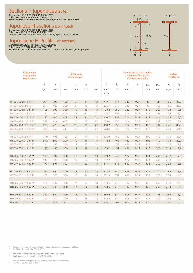
b
r
yy dh
tw
ss
zzt f
hi
pSections H japonaises (suite)Dimensions: JIS G 3192: 2008; JIS A 5526: 2005 Tolérances: JIS G 3192: 2008; JIS A 5526: 2005 Etat de surface: conforme à ISO 20723: 2004, Type 1, classe C, sous-classe 1
Japanese H sections (continued)Dimensions: JIS G 3192: 2008; JIS A 5526: 2005 Tolerances: JIS G 3192: 2008; JIS A 5526: 2005 Surface condition: according to ISO 20723: 2004, Type 1, class C, subclass 1
Japanische H-Profile (Fortsetzung)Abmessungen: JIS G 3192: 2008; JIS A 5526: 2005 Toleranzen: JIS G 3192: 2008; JIS A 5526: 2005 Oberflächenbeschaffenheit: Gemäß ISO 20723: 2004, Typ 1, Klasse C, Untergruppe 1
H 400 x 200 x 7 x 11* 56,1 396 199 7 11 13 71,41 374 348 M27 90 98 1,55 27,7
H 400 x 200 x 8 x 13* 65,4 400 200 8 13 13 83,37 374 348 M27 90 100 1,56 23,9
H 400 x 300 x 10 x 16* 105 390 300 10 16 13 133,2 358 332 M27 110 200 1,94 18,5
H 400 x 400 x 13 x 21□/* 172 400 400 13 21 22 218,7 358 314 M27 114 298 2,34 13,6
H 400 x 400 x 21 x 21□/* 197 400 408 21 21 22 250,7 358 314 M27 122 306 2,35 12,0
H 400 x 400 x 18 x 28□/* 232 414 405 18 28 22 295,4 358 314 M27 118 302 2,37 10,2
H 400 x 400 x 20 x 35□/* 283 428 407 20 35 22 360,7 358 314 M27 120 304 2,41 8,50
H 400 x 400 x 30 x 50□/* 415 458 417 30 50 22 528,6 358 314 M27 130 316 2,49 5,99
H 500 x 200 x 9 x 14* 77,9 496 199 9 14 13 99,29 468 442 M24 100 110 1,75 22,4
H 500 x 200 x 10 x 16* 88,2 500 200 10 16 13 112,2 468 442 M24 102 112 1,76 20,0
H 500 x 300 x 11 x 15* 111 482 300 11 15 13 141,2 452 426 M27 118 200 2,12 19,1
H 500 x 300 x 11 x 18* 125 488 300 11 18 13 159,2 452 426 M27 118 200 2,13 17,1
H 600 x 300 x 12 x 17* 133 582 300 12 17 13 169,2 548 522 M27 124 200 2,32 17,5
H 600 x 300 x 12 x 20* 147 588 300 12 20 13 187,2 548 522 M27 124 200 2,33 15,9
H 600 x 300 x 14 x 23* 170 594 302 14 23 13 217,1 548 522 M27 126 202 2,35 13,8
H 700 x 300 x 13 x 20* 163 692 300 13 20 18 207,5 652 616 M27 124 200 2,53 15,5
H 700 x 300 x 13 x 24* 182 700 300 13 24 18 231,5 652 616 M27 124 200 2,54 14,0
H 800 x 300 x 14 x 22* 188 792 300 14 22 18 239,5 748 712 M27 126 200 2,73 14,5
H 800 x 300 x 14 x 26* 207 800 300 14 26 18 263,5 748 712 M27 126 200 2,74 13,3
H 900 x 300 x 15 x 23* 210 890 299 15 23 18 266,9 844 808 M27 126 198 2,92 13,9
H 900 x 300 x 16 x 28* 240 900 300 16 28 18 305,8 844 808 M27 128 200 2,94 12,2
H 900 x 300 x 18 x 34* 283 912 302 18 34 18 360,1 844 808 M27 130 202 2,97 10,5
Désignation Designation Bezeichnung
Dimensions Abmessungen
Dimensions de construction Dimensions for detailing
Konstruktionsmaße
Surface Oberfläche
G
kg/m
h b tw tf r A hi d Ø pmin pmax AL AG
mm mm mm mm mm mm2 mm mm mm mm m2/m m2/t
x102
* Tonnage minimum et conditions de livraison nécessitent un accord préalable.□ Profilé conforme à JIS A 5526: 2005
* Minimum tonnage and delivery conditions upon agreement.□ Section in accordance with JIS A 5526: 2005
* Mindestbestellmenge und Lieferbedingungen nach Vereinbarung.□ Profil gemäß JIS A 5526: 2005
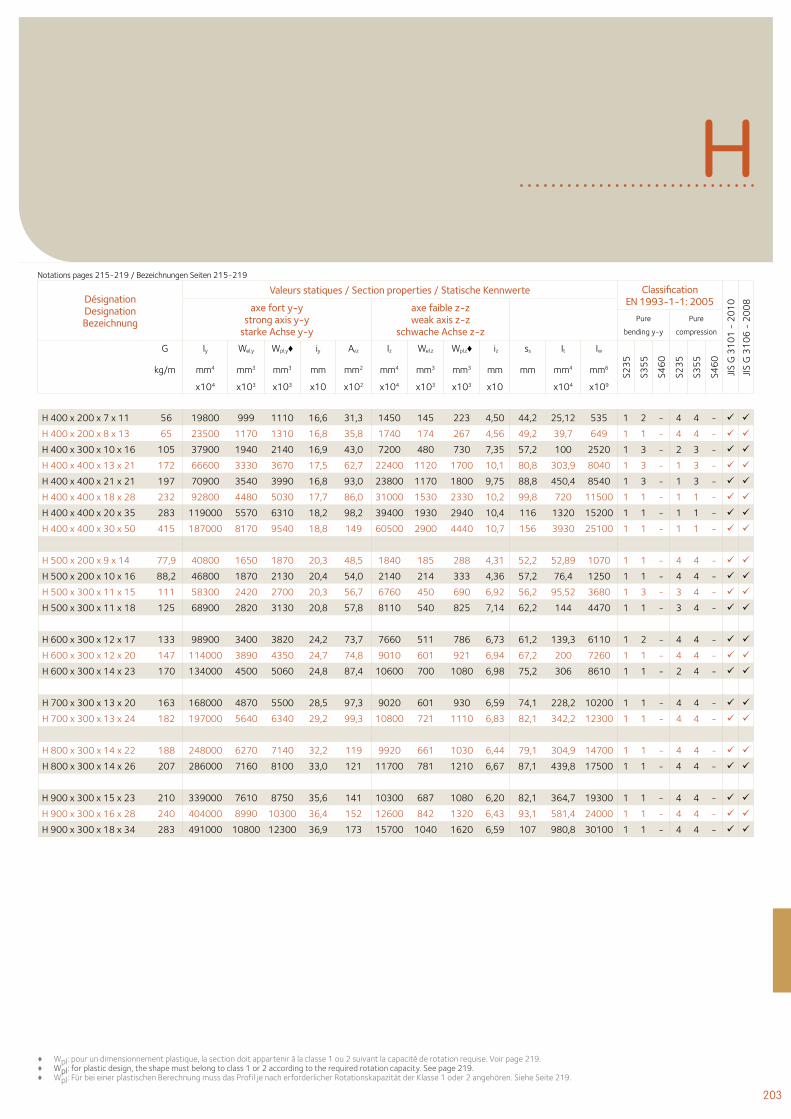
203
H
H 400 x 200 x 7 x 11 56 19800 999 1110 16,6 31,3 1450 145 223 4,50 44,2 25,12 535 1 2 - 4 4 -
H 400 x 200 x 8 x 13 65 23500 1170 1310 16,8 35,8 1740 174 267 4,56 49,2 39,7 649 1 1 - 4 4 -
H 400 x 300 x 10 x 16 105 37900 1940 2140 16,9 43,0 7200 480 730 7,35 57,2 100 2520 1 3 - 2 3 -
H 400 x 400 x 13 x 21 172 66600 3330 3670 17,5 62,7 22400 1120 1700 10,1 80,8 303,9 8040 1 3 - 1 3 -
H 400 x 400 x 21 x 21 197 70900 3540 3990 16,8 93,0 23800 1170 1800 9,75 88,8 450,4 8540 1 3 - 1 3 -
H 400 x 400 x 18 x 28 232 92800 4480 5030 17,7 86,0 31000 1530 2330 10,2 99,8 720 11500 1 1 - 1 1 -
H 400 x 400 x 20 x 35 283 119000 5570 6310 18,2 98,2 39400 1930 2940 10,4 116 1320 15200 1 1 - 1 1 -
H 400 x 400 x 30 x 50 415 187000 8170 9540 18,8 149 60500 2900 4440 10,7 156 3930 25100 1 1 - 1 1 -
H 500 x 200 x 9 x 14 77,9 40800 1650 1870 20,3 48,5 1840 185 288 4,31 52,2 52,89 1070 1 1 - 4 4 -
H 500 x 200 x 10 x 16 88,2 46800 1870 2130 20,4 54,0 2140 214 333 4,36 57,2 76,4 1250 1 1 - 4 4 -
H 500 x 300 x 11 x 15 111 58300 2420 2700 20,3 56,7 6760 450 690 6,92 56,2 95,52 3680 1 3 - 3 4 -
H 500 x 300 x 11 x 18 125 68900 2820 3130 20,8 57,8 8110 540 825 7,14 62,2 144 4470 1 1 - 3 4 -
H 600 x 300 x 12 x 17 133 98900 3400 3820 24,2 73,7 7660 511 786 6,73 61,2 139,3 6110 1 2 - 4 4 -
H 600 x 300 x 12 x 20 147 114000 3890 4350 24,7 74,8 9010 601 921 6,94 67,2 200 7260 1 1 - 4 4 -
H 600 x 300 x 14 x 23 170 134000 4500 5060 24,8 87,4 10600 700 1080 6,98 75,2 306 8610 1 1 - 2 4 -
H 700 x 300 x 13 x 20 163 168000 4870 5500 28,5 97,3 9020 601 930 6,59 74,1 228,2 10200 1 1 - 4 4 -
H 700 x 300 x 13 x 24 182 197000 5640 6340 29,2 99,3 10800 721 1110 6,83 82,1 342,2 12300 1 1 - 4 4 -
H 800 x 300 x 14 x 22 188 248000 6270 7140 32,2 119 9920 661 1030 6,44 79,1 304,9 14700 1 1 - 4 4 -
H 800 x 300 x 14 x 26 207 286000 7160 8100 33,0 121 11700 781 1210 6,67 87,1 439,8 17500 1 1 - 4 4 -
H 900 x 300 x 15 x 23 210 339000 7610 8750 35,6 141 10300 687 1080 6,20 82,1 364,7 19300 1 1 - 4 4 -
H 900 x 300 x 16 x 28 240 404000 8990 10300 36,4 152 12600 842 1320 6,43 93,1 581,4 24000 1 1 - 4 4 -
H 900 x 300 x 18 x 34 283 491000 10800 12300 36,9 173 15700 1040 1620 6,59 107 980,8 30100 1 1 - 4 4 -
♦ Wpl: pour un dimensionnement plastique, la section doit appartenir à la classe 1 ou 2 suivant la capacité de rotation requise. Voir page 219.♦ Wpl: for plastic design, the shape must belong to class 1 or 2 according to the required rotation capacity. See page 219.♦ Wpl: Für bei einer plastischen Berechnung muss das Profil je nach erforderlicher Rotationskapazität der Klasse 1 oder 2 angehören. Siehe Seite 219.
Désignation Designation Bezeichnung
Valeurs statiques / Section properties / Statische Kennwerte Classification EN 1993-1-1: 2005
JIS G
31
01
- 2
01
0
JIS G
31
06
- 2
00
8
axe fort y-y strong axis y-y
starke Achse y-y
axe faible z-z weak axis z-z
schwache Achse z-z Pure
bending y-y
Pure
compression
G Iy Wel.y Wpl.y♦ iy Avz Iz Wel.z Wpl.z♦ iz ss It Iw
S23
5
S35
5
S46
0
S23
5
S35
5
S46
0
kg/m mm4 mm3 mm3 mm mm2 mm4 mm3 mm3 mm mm mm4 mm6
x104 x103 x103 x10 x102 x104 x103 x103 x10 x104 x109
Notations pages 215-219 / Bezeichnungen Seiten 215-219

Données techniques
Technical data
Technische Daten
206 Facteurs de massivité
215 Notations et formules
219 Classification des sections transversales
220 Tolérances de laminage220 15. Poutrelles222 16. Poutrelles alvéolaires224 17. Profilés225 18. Cornières à ailes égales et
inégales226 19. Aciers marchands
227 Table de conversion
228 Propriétés de l’acier de construction
206 Section factors (fire resistance)
215 Notations and formulae
219 Classification of cross-sections
220 Rolling tolerances 220 15. Beams222 16. Castellated beams224 17. Channels & joists225 18. Equal and unequal leg angles
226 19. Merchant bars
227 Conversion table
228 Material coefficients of structural steel
206 Profilfaktoren (Feuerwiderstand)
215 Bezeichnungen und Formeln
219 Einstufung in Querschnitts- klassen 220 Walztoleranzen 220 15. Träger 222 16. Lochstegträger 224 17. Formstahl 225 18. Gleich- und ungleichschenkliger
Winkelstahl226 19. Stabstahl
227 Umrechnungstabelle
228 Werkstoffkennwerte von Baustahl
205
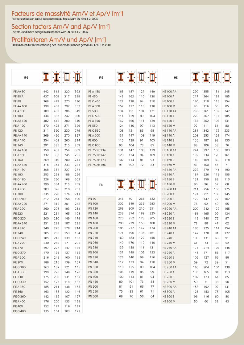
Facteurs de massivité Am/V et Ap/V [m-1]Facteurs utilisés en calcul de résistance au feu suivant EN 1993-1-2: 2005
Section factors Am/V and Ap/V [m-1]Factors used in fire design in accordance with EN 1993-1-2: 2005
Profilfaktoren Am/V und Ap/V [m-1]Profilfaktoren für die Berechnung des Feuerwiderstandes gemäß EN 1993-1-2: 2005
IPE
IPE AA 80 442 515 320 393
IPE 80 A 437 509 317 389
IPE 80 369 429 270 330
IPE AA 100 398 463 292 357
IPE A 100 389 452 286 349
IPE 100 334 387 247 300
IPE AA 120 382 442 280 340
IPE A 120 370 428 271 329
IPE 120 311 360 230 279
IPE AA 140 369 426 270 327
IPE A 140 354 409 260 314
IPE 140 291 335 215 259
IPE AA 160 350 403 256 309
IPE A 160 332 382 245 295
IPE 160 269 310 200 241
IPE AA 180 316 364 233 281
IPE A 180 308 354 227 274
IPE 180 253 291 188 226
IPE O 180 226 260 168 202
IPE AA 200 290 334 215 259
IPE A 200 283 326 210 253
IPE 200 235 270 176 211
IPE O 200 212 244 158 190
IPE AA 220 271 312 201 242
IPE A 220 260 298 193 231
IPE 220 221 254 165 198
IPE O 220 200 230 149 179
IPE AA 240 251 289 187 225
IPE A 240 240 276 178 214
IPE 240 205 236 153 184
IPE O 240 185 213 139 167
IPE A 270 230 265 171 205
IPE 270 197 227 147 176
IPE O 270 170 195 127 152
IPE A 300 216 248 160 192
IPE 300 188 216 139 167
IPE O 300 163 187 121 145
IPE A 330 199 228 149 178
IPE 330 175 200 131 157
IPE O 330 152 175 114 137
IPE A 360 185 211 138 165
IPE 360 163 186 122 146
IPE O 360 142 162 107 127
IPE A 400 176 200 133 158
IPE 400 152 174 116 137
IPE O 400 135 154 103 122
IPE
IPE A 450 165 187 127 149
IPE 450 143 162 110 130
IPE O 450 122 138 94 110
IPE A 500 152 172 118 138
IPE 500 134 151 104 121
IPE O 500 114 129 89 104
IPE A 550 142 160 111 129
IPE 550 124 140 97 113
IPE O 550 108 121 85 98
IPE A 600 131 147 103 119
IPE 600 115 129 91 105
IPE O 600 93 104 73 85
IPE 750 x 134 131 147 103 119
IPE 750 x 147 120 134 94 109
IPE 750 x 173 102 114 81 93
IPE 750 x 196 91 102 72 83
IPN
IPN 80 346 401 266 322
IPN 100 302 349 236 283
IPN 120 268 309 210 251
IPN 140 238 274 189 225
IPN 160 220 252 173 205
IPN 180 200 229 158 188
IPN 200 185 212 147 174
IPN 220 171 196 136 161
IPN 240 160 183 127 150
IPN 260 149 170 119 140
IPN 280 139 158 111 131
IPN 300 131 149 105 123
IPN 320 123 140 99 116
IPN 340 117 133 94 110
IPN 360 110 125 89 104
IPN 380 105 119 85 99
IPN 400 100 113 81 94
IPN 450 89 101 73 84
IPN 500 81 91 66 77
IPN 550 75 85 61 71
IPN 600 68 76 56 64
HE
HE 100 AA 290 355 181 245
HE 100 A 217 264 138 185
HE 100 B 180 218 115 154
HE 100 M 96 116 65 85
HE 120 AA 296 361 182 247
HE 120 A 220 267 137 185
HE 120 B 167 202 106 141
HE 120 M 92 111 61 80
HE 140 AA 281 342 172 233
HE 140 A 208 253 129 174
HE 140 B 155 187 98 130
HE 140 M 88 106 58 76
HE 160 AA 244 297 150 203
HE 160 A 192 234 120 161
HE 160 B 140 169 88 118
HE 160 M 83 100 54 71
HE 180 AA 229 279 141 190
HE 180 A 187 226 115 155
HE 180 B 131 159 83 110
HE 180 M 80 96 52 68
HE 200 AA 211 256 130 175
HE 200 A 174 211 108 145
HE 200 B 122 147 77 102
HE 200 M 76 92 49 65
HE 220 AA 200 242 122 165
HE 220 A 161 195 99 134
HE 220 B 115 140 72 97
HE 220 M 73 88 47 62
HE 240 AA 185 225 114 154
HE 240 A 147 178 91 122
HE 240 B 108 131 68 91
HE 240 M 61 73 39 52
HE 260 AA 176 214 108 146
HE 260 A 141 171 88 117
HE 260 B 105 127 66 88
HE 260 M 59 72 39 51
HE 280 AA 168 204 104 139
HE 280 A 136 165 84 113
HE 280 B 102 123 64 85
HE 280 M 59 71 38 50
HE 300 AA 158 192 97 131
HE 300 A 126 153 78 105
HE 300 B 96 116 60 80
HE 300 M 50 60 33 43
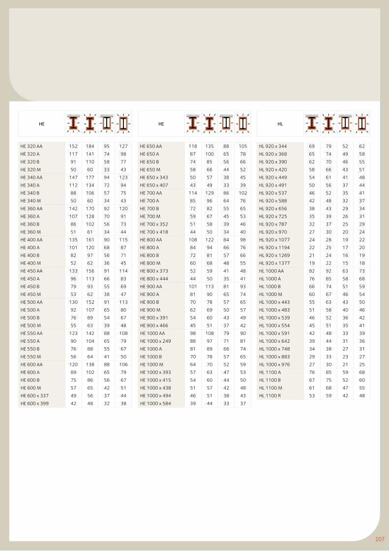
207
HE
HE 320 AA 152 184 95 127
HE 320 A 117 141 74 98
HE 320 B 91 110 58 77
HE 320 M 50 60 33 43
HE 340 AA 147 177 94 123
HE 340 A 112 134 72 94
HE 340 B 88 106 57 75
HE 340 M 50 60 34 43
HE 360 AA 142 170 92 120
HE 360 A 107 128 70 91
HE 360 B 86 102 56 73
HE 360 M 51 61 34 44
HE 400 AA 135 161 90 115
HE 400 A 101 120 68 87
HE 400 B 82 97 56 71
HE 400 M 52 62 36 45
HE 450 AA 133 156 91 114
HE 450 A 96 113 66 83
HE 450 B 79 93 55 69
HE 450 M 53 62 38 47
HE 500 AA 130 152 91 113
HE 500 A 92 107 65 80
HE 500 B 76 89 54 67
HE 500 M 55 63 39 48
HE 550 AA 123 142 88 108
HE 550 A 90 104 65 79
HE 550 B 76 88 55 67
HE 550 M 56 64 41 50
HE 600 AA 120 138 88 106
HE 600 A 89 102 65 79
HE 600 B 75 86 56 67
HE 600 M 57 65 42 51
HE 600 x 337 49 56 37 44
HE 600 x 399 42 48 32 38
HE
HE 650 AA 118 135 88 105
HE 650 A 87 100 65 78
HE 650 B 74 85 56 66
HE 650 M 58 66 44 52
HE 650 x 343 50 57 38 45
HE 650 x 407 43 49 33 39
HE 700 AA 114 129 86 102
HE 700 A 85 96 64 76
HE 700 B 72 82 55 65
HE 700 M 59 67 45 53
HE 700 x 352 51 58 39 46
HE 700 x 418 44 50 34 40
HE 800 AA 108 122 84 98
HE 800 A 84 94 66 76
HE 800 B 72 81 57 66
HE 800 M 60 68 48 55
HE 800 x 373 52 59 41 48
HE 800 x 444 44 50 35 41
HE 900 AA 101 113 81 93
HE 900 A 81 90 65 74
HE 900 B 70 78 57 65
HE 900 M 62 69 50 57
HE 900 x 391 54 60 43 49
HE 900 x 466 45 51 37 42
HE 1000 AA 98 108 79 90
HE 1000 x 249 88 97 71 81
HE 1000 A 81 89 66 74
HE 1000 B 70 78 57 65
HE 1000 M 64 70 52 59
HE 1000 x 393 57 63 47 53
HE 1000 x 415 54 60 44 50
HE 1000 x 438 51 57 42 48
HE 1000 x 494 46 51 38 43
HE 1000 x 584 39 44 33 37
HL
HL 920 x 344 69 79 52 62
HL 920 x 368 65 74 49 58
HL 920 x 390 62 70 46 55
HL 920 x 420 58 66 43 51
HL 920 x 449 54 61 41 48
HL 920 x 491 50 56 37 44
HL 920 x 537 46 52 35 41
HL 920 x 588 42 48 32 37
HL 920 x 656 38 43 29 34
HL 920 x 725 35 39 26 31
HL 920 x 787 32 37 25 29
HL 920 x 970 27 30 20 24
HL 920 x 1077 24 28 19 22
HL 920 x 1194 22 25 17 20
HL 920 x 1269 21 24 16 19
HL 920 x 1377 19 22 15 18
HL 1000 AA 82 92 63 73
HL 1000 A 76 85 58 68
HL 1000 B 66 74 51 59
HL 1000 M 60 67 46 54
HL 1000 x 443 55 63 43 50
HL 1000 x 483 51 58 40 46
HL 1000 x 539 46 52 36 42
HL 1000 x 554 45 51 35 41
HL 1000 x 591 42 48 33 39
HL 1000 x 642 39 44 31 36
HL 1000 x 748 34 38 27 31
HL 1000 x 883 29 33 23 27
HL 1000 x 976 27 30 21 25
HL 1100 A 76 85 59 68
HL 1100 B 67 75 52 60
HL 1100 M 61 68 47 55
HL 1100 R 53 59 42 48
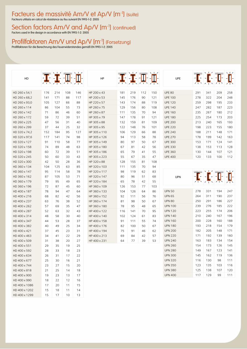
Facteurs de massivité Am/V et Ap/V [m-1] (suite)Facteurs utilisés en calcul de résistance au feu suivant EN 1993-1-2: 2005
Section factors Am/V and Ap/V [m-1] (continued)Factors used in fire design in accordance with EN 1993-1-2: 2005
Profilfaktoren Am/V und Ap/V [m-1] (Forsetzung)Profilfaktoren für die Berechnung des Feuerwiderstandes gemäß EN 1993-1-2: 2005
UPE
UPE 80 291 341 209 258
UPE 100 278 322 204 248
UPE 120 259 298 195 233
UPE 140 247 282 187 223
UPE 160 235 267 180 212
UPE 180 225 254 173 203
UPE 200 213 240 165 193
UPE 220 198 223 155 180
UPE 240 188 211 148 171
UPE 270 178 199 142 163
UPE 300 153 171 124 141
UPE 330 138 153 113 128
UPE 360 130 144 107 121
UPE 400 120 133 100 112
UPN
UPN 50 278 331 194 247
UPN 65 264 311 190 237
UPN 80 250 291 186 227
UPN 100 239 276 185 222
UPN 120 223 255 174 206
UPN 140 210 240 167 196
UPN 160 200 228 160 188
UPN 180 193 218 154 179
UPN 200 182 205 148 171
UPN 220 171 192 139 160
UPN 240 163 183 134 154
UPN 260 154 173 126 145
UPN 280 149 167 123 141
UPN 300 145 162 119 136
UPN 320 116 130 98 111
UPN 350 123 135 103 116
UPN 380 125 138 107 120
UPN 400 117 129 99 111
HD
HD 260 x 54,1 176 214 108 146
HD 260 x 68,2 141 171 88 117
HD 260 x 93,0 105 127 66 88
HD 260 x 114 86 104 55 73
HD 260 x 142 71 86 46 60
HD 260 x 172 59 72 39 51
HD 260 x 225 47 56 31 40
HD 260 x 299 37 44 25 32
HD 320 x 74,2 152 184 95 127
HD 320 x 97,6 117 141 74 98
HD 320 x 127 91 110 58 77
HD 320 x 158 74 89 48 63
HD 320 x 198 60 72 39 51
HD 320 x 245 50 60 33 43
HD 320 x 300 42 50 28 36
HD 360 x 134 104 125 63 85
HD 360 x 147 95 114 58 78
HD 360 x 162 87 105 53 71
HD 360 x 179 79 95 49 65
HD 360 x 196 72 87 45 60
HD 400 x 187 78 94 47 64
HD 400 x 216 68 82 42 56
HD 400 x 237 63 76 38 52
HD 400 x 262 57 69 35 47
HD 400 x 287 52 63 32 43
HD 400 x 314 48 58 30 40
HD 400 x 347 44 53 28 37
HD 400 x 382 40 49 25 34
HD 400 x 421 37 45 23 31
HD 400 x 463 34 41 22 29
HD 400 x 509 31 38 20 27
HD 400 x 551 29 35 19 25
HD 400 x 592 28 33 18 23
HD 400 x 634 26 31 17 22
HD 400 x 677 25 30 16 21
HD 400 x 744 23 27 15 20
HD 400 x 818 21 25 14 18
HD 400 x 900 19 23 13 17
HD 400 x 990 18 22 12 16
HD 400 x 1086 17 20 11 15
HD 400 x 1202 15 18 11 14
HD 400 x 1299 15 17 10 13
HP
HP 200 x 43 181 219 112 150
HP 200 x 53 145 176 90 121
HP 220 x 57 143 174 88 119
HP 260 x 75 129 156 80 108
HP 260 x 87 111 135 70 94
HP 305 x 79 147 178 91 121
HP 305 x 88 132 159 81 109
HP 305 x 95 122 148 76 101
HP 305 x 110 106 129 66 88
HP 305 x 126 94 113 58 78
HP 305 x 149 80 97 50 67
HP 305 x 180 67 81 42 56
HP 305 x 186 65 79 41 55
HP 305 x 223 55 67 35 47
HP 320 x 88 128 155 81 108
HP 320 x 103 111 135 70 94
HP 320 x 117 98 119 62 83
HP 320 x 147 80 96 51 68
HP 320 x 184 65 78 42 55
HP 360 x 109 126 153 77 103
HP 360 x 133 104 126 64 86
HP 360 x 152 92 111 56 76
HP 360 x 174 81 98 50 67
HP 360 x 180 78 95 48 65
HP 400 x 122 116 141 70 95
HP 400 x 140 102 124 61 83
HP 400 x 158 91 111 55 74
HP 400 x 176 82 100 50 67
HP 400 x 194 75 91 46 62
HP 400 x 213 69 84 42 57
HP 400 x 231 64 77 39 53
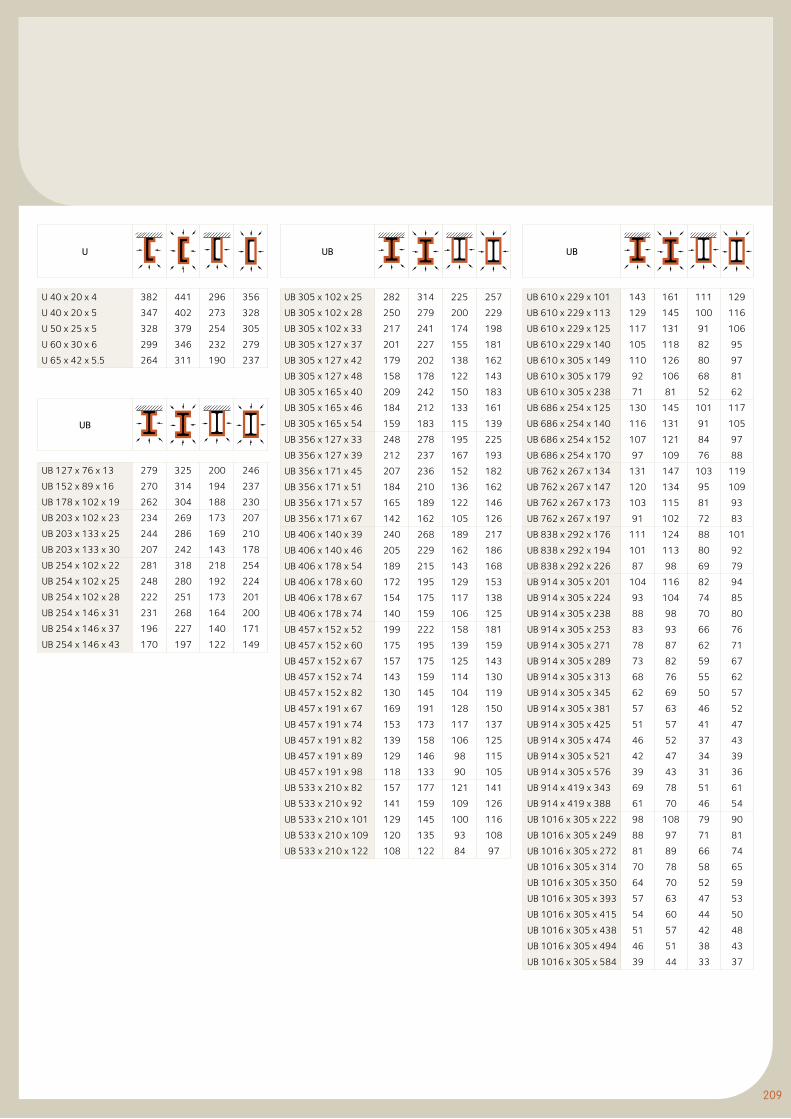
209
UB
UB 610 x 229 x 101 143 161 111 129
UB 610 x 229 x 113 129 145 100 116
UB 610 x 229 x 125 117 131 91 106
UB 610 x 229 x 140 105 118 82 95
UB 610 x 305 x 149 110 126 80 97
UB 610 x 305 x 179 92 106 68 81
UB 610 x 305 x 238 71 81 52 62
UB 686 x 254 x 125 130 145 101 117
UB 686 x 254 x 140 116 131 91 105
UB 686 x 254 x 152 107 121 84 97
UB 686 x 254 x 170 97 109 76 88
UB 762 x 267 x 134 131 147 103 119
UB 762 x 267 x 147 120 134 95 109
UB 762 x 267 x 173 103 115 81 93
UB 762 x 267 x 197 91 102 72 83
UB 838 x 292 x 176 111 124 88 101
UB 838 x 292 x 194 101 113 80 92
UB 838 x 292 x 226 87 98 69 79
UB 914 x 305 x 201 104 116 82 94
UB 914 x 305 x 224 93 104 74 85
UB 914 x 305 x 238 88 98 70 80
UB 914 x 305 x 253 83 93 66 76
UB 914 x 305 x 271 78 87 62 71
UB 914 x 305 x 289 73 82 59 67
UB 914 x 305 x 313 68 76 55 62
UB 914 x 305 x 345 62 69 50 57
UB 914 x 305 x 381 57 63 46 52
UB 914 x 305 x 425 51 57 41 47
UB 914 x 305 x 474 46 52 37 43
UB 914 x 305 x 521 42 47 34 39
UB 914 x 305 x 576 39 43 31 36
UB 914 x 419 x 343 69 78 51 61
UB 914 x 419 x 388 61 70 46 54
UB 1016 x 305 x 222 98 108 79 90
UB 1016 x 305 x 249 88 97 71 81
UB 1016 x 305 x 272 81 89 66 74
UB 1016 x 305 x 314 70 78 58 65
UB 1016 x 305 x 350 64 70 52 59
UB 1016 x 305 x 393 57 63 47 53
UB 1016 x 305 x 415 54 60 44 50
UB 1016 x 305 x 438 51 57 42 48
UB 1016 x 305 x 494 46 51 38 43
UB 1016 x 305 x 584 39 44 33 37
U
U 40 x 20 x 4 382 441 296 356
U 40 x 20 x 5 347 402 273 328
U 50 x 25 x 5 328 379 254 305
U 60 x 30 x 6 299 346 232 279
U 65 x 42 x 5.5 264 311 190 237
UB
UB 127 x 76 x 13 279 325 200 246
UB 152 x 89 x 16 270 314 194 237
UB 178 x 102 x 19 262 304 188 230
UB 203 x 102 x 23 234 269 173 207
UB 203 x 133 x 25 244 286 169 210
UB 203 x 133 x 30 207 242 143 178
UB 254 x 102 x 22 281 318 218 254
UB 254 x 102 x 25 248 280 192 224
UB 254 x 102 x 28 222 251 173 201
UB 254 x 146 x 31 231 268 164 200
UB 254 x 146 x 37 196 227 140 171
UB 254 x 146 x 43 170 197 122 149
UB
UB 305 x 102 x 25 282 314 225 257
UB 305 x 102 x 28 250 279 200 229
UB 305 x 102 x 33 217 241 174 198
UB 305 x 127 x 37 201 227 155 181
UB 305 x 127 x 42 179 202 138 162
UB 305 x 127 x 48 158 178 122 143
UB 305 x 165 x 40 209 242 150 183
UB 305 x 165 x 46 184 212 133 161
UB 305 x 165 x 54 159 183 115 139
UB 356 x 127 x 33 248 278 195 225
UB 356 x 127 x 39 212 237 167 193
UB 356 x 171 x 45 207 236 152 182
UB 356 x 171 x 51 184 210 136 162
UB 356 x 171 x 57 165 189 122 146
UB 356 x 171 x 67 142 162 105 126
UB 406 x 140 x 39 240 268 189 217
UB 406 x 140 x 46 205 229 162 186
UB 406 x 178 x 54 189 215 143 168
UB 406 x 178 x 60 172 195 129 153
UB 406 x 178 x 67 154 175 117 138
UB 406 x 178 x 74 140 159 106 125
UB 457 x 152 x 52 199 222 158 181
UB 457 x 152 x 60 175 195 139 159
UB 457 x 152 x 67 157 175 125 143
UB 457 x 152 x 74 143 159 114 130
UB 457 x 152 x 82 130 145 104 119
UB 457 x 191 x 67 169 191 128 150
UB 457 x 191 x 74 153 173 117 137
UB 457 x 191 x 82 139 158 106 125
UB 457 x 191 x 89 129 146 98 115
UB 457 x 191 x 98 118 133 90 105
UB 533 x 210 x 82 157 177 121 141
UB 533 x 210 x 92 141 159 109 126
UB 533 x 210 x 101 129 145 100 116
UB 533 x 210 x 109 120 135 93 108
UB 533 x 210 x 122 108 122 84 97
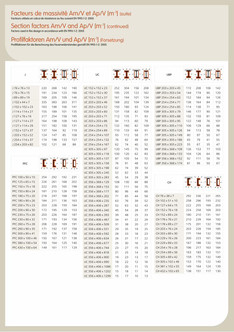
UBP
UBP 203 x 203 x 45 172 208 106 142
UBP 203 x 203 x 54 144 174 90 120
UBP 254 x 254 x 63 152 184 94 126
UBP 254 x 254 x 71 136 164 84 112
UBP 254 x 254 x 85 114 138 71 95
UBP 305 x 305 x 79 146 177 90 121
UBP 305 x 305 x 88 132 159 81 109
UBP 305 x 305 x 95 122 148 76 101
UBP 305 x 305 x 110 106 129 66 88
UBP 305 x 305 x 126 94 113 58 78
UBP 305 x 305 x 149 80 97 50 67
UBP 305 x 305 x 186 65 79 41 55
UBP 305 x 305 x 223 55 67 35 47
UBP 356 x 368 x 109 126 153 77 103
UBP 356 x 368 x 133 104 126 64 86
UBP 356 x 368 x 152 92 111 56 76
UBP 356 x 368 x 174 81 98 50 67
CH
CH 76 x 38 x 7 292 336 221 265
CH 102 x 51 x 10 258 296 193 232
CH 127 x 64 x 15 222 255 169 203
CH 152 x 76 x 18 224 258 169 203
CH 152 x 89 x 24 180 210 131 161
CH 178 x 76 x 21 210 239 164 192
CH 178 x 89 x 27 175 201 132 158
CH 203 x 76 x 24 203 228 159 185
CH 203 x 89 x 30 171 194 132 155
CH 229 x 76 x 26 200 223 161 184
CH 229 x 89 x 33 167 188 132 153
CH 254 x 76 x 28 196 217 163 184
CH 254 x 89 x 36 163 183 132 151
CH 305 x 89 x 42 159 175 132 149
CH 305 x 102 x 46 153 170 122 140
CH 381 x 102 x 55 149 164 124 139
CH 432 x 102 x 65 138 151 117 130
J
J 76 x 76 x 13 220 268 142 190
J 76 x 76 x 15 191 234 123 166
J 89 x 89 x 19 169 205 109 146
J 102 x 44 x 7 335 383 263 311
J 102 x 102 x 23 163 198 106 141
J 114 x 114 x 27 155 189 101 135
J 127 x 76 x 16 217 254 158 195
J 127 x 114 x 27 164 198 109 143
J 127 x 114 x 29 151 182 100 131
J 152 x 127 x 37 137 164 92 119
J 203 x 152 x 52 124 147 85 108
J 254 x 114 x 37 174 198 133 157
J 254 x 203 x 82 102 121 68 88
PFC
PFC 100 x 50 x 10 254 292 192 231
PFC 125 x 65 x 15 226 261 168 202
PFC 150 x 75 x 18 222 255 165 198
PFC 150 x 90 x 24 181 210 128 158
PFC 180 x 75 x 20 218 247 168 197
PFC 180 x 90 x 26 184 211 136 163
PFC 200 x 75 x 23 203 228 159 184
PFC 200 x 90 x 30 172 195 129 153
PFC 230 x 75 x 26 203 226 164 187
PFC 230 x 90 x 32 171 193 134 156
PFC 260 x 75 x 28 206 228 169 191
PFC 260 x 90 x 35 171 192 137 158
PFC 300 x 90 x 41 159 176 131 148
PFC 300 x 100 x 46 150 167 121 138
PFC 380 x 100 x 54 150 164 125 140
PFC 430 x 100 x 64 149 161 117 129
UC
UC 152 x 152 x 23 252 304 156 208
UC 152 x 152 x 30 195 235 122 162
UC 152 x 152 x 37 161 194 101 134
UC 203 x 203 x 46 168 202 104 139
UC 203 x 203 x 52 150 180 93 124
UC 203 x 203 x 60 131 158 82 109
UC 203 x 203 x 71 112 135 71 93
UC 203 x 203 x 86 94 113 60 79
UC 254 x 254 x 73 132 160 82 109
UC 254 x 254 x 89 110 133 69 91
UC 254 x 254 x 107 93 112 58 77
UC 254 x 254 x 132 76 92 48 64
UC 254 x 254 x 167 62 74 40 52
UC 305 x 305 x 97 120 145 75 99
UC 305 x 305 x 118 100 120 62 83
UC 305 x 305 x 137 87 105 54 72
UC 305 x 305 x 158 76 91 48 63
UC 305 x 305 x 198 62 74 39 52
UC 305 x 305 x 240 52 62 33 44
UC 305 x 305 x 283 45 54 29 38
UC 356 x 368 x 129 108 130 66 88
UC 356 x 368 x 153 92 111 56 75
UC 356 x 368 x 177 80 96 49 66
UC 356 x 368 x 202 71 85 44 58
UC 356 x 406 x 235 63 76 39 52
UC 356 x 406 x 287 52 63 32 43
UC 356 x 406 x 340 45 54 28 37
UC 356 x 406 x 393 39 48 25 33
UC 356 x 406 x 467 34 41 22 29
UC 356 x 406 x 509 31 38 20 27
UC 356 x 406 x 551 29 35 19 25
UC 356 x 406 x 592 28 33 18 23
UC 356 x 406 x 634 26 31 17 22
UC 356 x 406 x 677 25 30 16 21
UC 356 x 406 x 744 23 27 15 20
UC 356 x 406 x 818 21 25 14 18
UC 356 x 406 x 900 19 23 13 17
UC 356 x 406 x 990 18 22 12 16
UC 356 x 406 x 1086 17 20 11 15
UC 356 x 406 x 1202 15 18 11 14
UC 356 x 406 x 1299 15 17 10 13
Facteurs de massivité Am/V et Ap/V [m-1] (suite)Facteurs utilisés en calcul de résistance au feu suivant EN 1993-1-2: 2005
Section factors Am/V and Ap/V [m-1] (continued)Factors used in fire design in accordance with EN 1993-1-2: 2005
Profilfaktoren Am/V und Ap/V [m-1] (Forsetzung)Profilfaktoren für die Berechnung des Feuerwiderstandes gemäß EN 1993-1-2: 2005
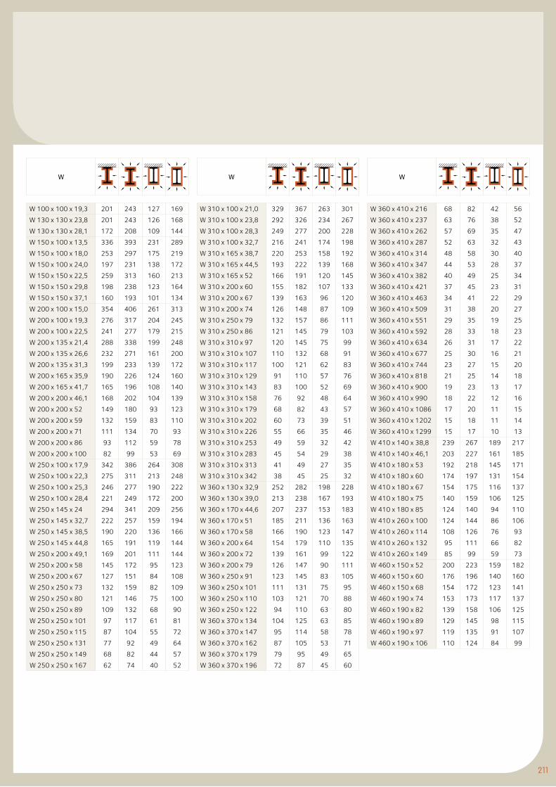
211
W
W 360 x 410 x 216 68 82 42 56
W 360 x 410 x 237 63 76 38 52
W 360 x 410 x 262 57 69 35 47
W 360 x 410 x 287 52 63 32 43
W 360 x 410 x 314 48 58 30 40
W 360 x 410 x 347 44 53 28 37
W 360 x 410 x 382 40 49 25 34
W 360 x 410 x 421 37 45 23 31
W 360 x 410 x 463 34 41 22 29
W 360 x 410 x 509 31 38 20 27
W 360 x 410 x 551 29 35 19 25
W 360 x 410 x 592 28 33 18 23
W 360 x 410 x 634 26 31 17 22
W 360 x 410 x 677 25 30 16 21
W 360 x 410 x 744 23 27 15 20
W 360 x 410 x 818 21 25 14 18
W 360 x 410 x 900 19 23 13 17
W 360 x 410 x 990 18 22 12 16
W 360 x 410 x 1086 17 20 11 15
W 360 x 410 x 1202 15 18 11 14
W 360 x 410 x 1299 15 17 10 13
W 410 x 140 x 38,8 239 267 189 217
W 410 x 140 x 46,1 203 227 161 185
W 410 x 180 x 53 192 218 145 171
W 410 x 180 x 60 174 197 131 154
W 410 x 180 x 67 154 175 116 137
W 410 x 180 x 75 140 159 106 125
W 410 x 180 x 85 124 140 94 110
W 410 x 260 x 100 124 144 86 106
W 410 x 260 x 114 108 126 76 93
W 410 x 260 x 132 95 111 66 82
W 410 x 260 x 149 85 99 59 73
W 460 x 150 x 52 200 223 159 182
W 460 x 150 x 60 176 196 140 160
W 460 x 150 x 68 154 172 123 141
W 460 x 190 x 74 153 173 117 137
W 460 x 190 x 82 139 158 106 125
W 460 x 190 x 89 129 145 98 115
W 460 x 190 x 97 119 135 91 107
W 460 x 190 x 106 110 124 84 99
W
W 100 x 100 x 19,3 201 243 127 169
W 130 x 130 x 23,8 201 243 126 168
W 130 x 130 x 28,1 172 208 109 144
W 150 x 100 x 13,5 336 393 231 289
W 150 x 100 x 18,0 253 297 175 219
W 150 x 100 x 24,0 197 231 138 172
W 150 x 150 x 22,5 259 313 160 213
W 150 x 150 x 29,8 198 238 123 164
W 150 x 150 x 37,1 160 193 101 134
W 200 x 100 x 15,0 354 406 261 313
W 200 x 100 x 19,3 276 317 204 245
W 200 x 100 x 22,5 241 277 179 215
W 200 x 135 x 21,4 288 338 199 248
W 200 x 135 x 26,6 232 271 161 200
W 200 x 135 x 31,3 199 233 139 172
W 200 x 165 x 35,9 190 226 124 160
W 200 x 165 x 41,7 165 196 108 140
W 200 x 200 x 46,1 168 202 104 139
W 200 x 200 x 52 149 180 93 123
W 200 x 200 x 59 132 159 83 110
W 200 x 200 x 71 111 134 70 93
W 200 x 200 x 86 93 112 59 78
W 200 x 200 x 100 82 99 53 69
W 250 x 100 x 17,9 342 386 264 308
W 250 x 100 x 22,3 275 311 213 248
W 250 x 100 x 25,3 246 277 190 222
W 250 x 100 x 28,4 221 249 172 200
W 250 x 145 x 24 294 341 209 256
W 250 x 145 x 32,7 222 257 159 194
W 250 x 145 x 38,5 190 220 136 166
W 250 x 145 x 44,8 165 191 119 144
W 250 x 200 x 49,1 169 201 111 144
W 250 x 200 x 58 145 172 95 123
W 250 x 200 x 67 127 151 84 108
W 250 x 250 x 73 132 159 82 109
W 250 x 250 x 80 121 146 75 100
W 250 x 250 x 89 109 132 68 90
W 250 x 250 x 101 97 117 61 81
W 250 x 250 x 115 87 104 55 72
W 250 x 250 x 131 77 92 49 64
W 250 x 250 x 149 68 82 44 57
W 250 x 250 x 167 62 74 40 52
W
W 310 x 100 x 21,0 329 367 263 301
W 310 x 100 x 23,8 292 326 234 267
W 310 x 100 x 28,3 249 277 200 228
W 310 x 100 x 32,7 216 241 174 198
W 310 x 165 x 38,7 220 253 158 192
W 310 x 165 x 44,5 193 222 139 168
W 310 x 165 x 52 166 191 120 145
W 310 x 200 x 60 155 182 107 133
W 310 x 200 x 67 139 163 96 120
W 310 x 200 x 74 126 148 87 109
W 310 x 250 x 79 132 157 86 111
W 310 x 250 x 86 121 145 79 103
W 310 x 310 x 97 120 145 75 99
W 310 x 310 x 107 110 132 68 91
W 310 x 310 x 117 100 121 62 83
W 310 x 310 x 129 91 110 57 76
W 310 x 310 x 143 83 100 52 69
W 310 x 310 x 158 76 92 48 64
W 310 x 310 x 179 68 82 43 57
W 310 x 310 x 202 60 73 39 51
W 310 x 310 x 226 55 66 35 46
W 310 x 310 x 253 49 59 32 42
W 310 x 310 x 283 45 54 29 38
W 310 x 310 x 313 41 49 27 35
W 310 x 310 x 342 38 45 25 32
W 360 x 130 x 32,9 252 282 198 228
W 360 x 130 x 39,0 213 238 167 193
W 360 x 170 x 44,6 207 237 153 183
W 360 x 170 x 51 185 211 136 163
W 360 x 170 x 58 166 190 123 147
W 360 x 200 x 64 154 179 110 135
W 360 x 200 x 72 139 161 99 122
W 360 x 200 x 79 126 147 90 111
W 360 x 250 x 91 123 145 83 105
W 360 x 250 x 101 111 131 75 95
W 360 x 250 x 110 103 121 70 88
W 360 x 250 x 122 94 110 63 80
W 360 x 370 x 134 104 125 63 85
W 360 x 370 x 147 95 114 58 78
W 360 x 370 x 162 87 105 53 71
W 360 x 370 x 179 79 95 49 65
W 360 x 370 x 196 72 87 45 60
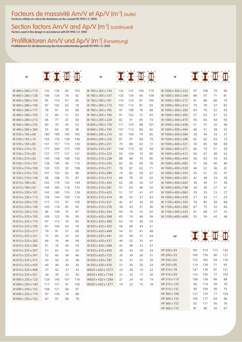
W
W 1000 x 300 x 222 97 108 79 90
W 1000 x 300 x 249 88 97 71 81
W 1000 x 300 x 272 81 89 66 74
W 1000 x 300 x 314 70 78 57 65
W 1000 x 300 x 350 64 70 52 59
W 1000 x 300 x 393 57 63 47 53
W 1000 x 300 x 415 54 60 44 50
W 1000 x 300 x 438 51 57 42 48
W 1000 x 300 x 494 46 51 38 43
W 1000 x 300 x 584 39 44 33 37
W 1000 x 400 x 296 82 92 63 73
W 1000 x 400 x 321 76 85 58 68
W 1000 x 400 x 371 66 74 51 59
W 1000 x 400 x 412 60 67 46 54
W 1000 x 400 x 443 56 63 43 50
W 1000 x 400 x 483 51 58 40 46
W 1000 x 400 x 539 46 52 36 42
W 1000 x 400 x 554 45 51 35 41
W 1000 x 400 x 591 42 48 33 38
W 1000 x 400 x 642 39 44 31 36
W 1000 x 400 x 748 34 39 27 31
W 1000 x 400 x 883 29 33 23 27
W 1000 x 400 x 976 27 30 21 25
W 1100 x 400 x 343 76 85 59 68
W 1100 x 400 x 390 67 75 52 60
W 1100 x 400 x 433 61 68 47 55
W 1100 x 400 x 499 53 59 42 48
HP
HP 200 x 43 181 219 112 150
HP 200 x 53 145 176 90 121
HP 250 x 62 152 185 94 126
HP 250 x 85 114 138 71 95
HP 310 x 79 147 178 91 121
HP 310 x 93 124 150 77 103
HP 310 x 110 106 128 66 88
HP 310 x 125 94 114 59 79
HP 310 x 132 90 109 56 75
HP 360 x 108 127 154 77 104
HP 360 x 132 105 127 64 86
HP 360 x 152 92 111 56 76
HP 360 x 174 81 98 50 67
W
W 460 x 280 x 113 120 139 84 103
W 460 x 280 x 128 106 124 74 92
W 460 x 280 x 144 95 110 67 82
W 460 x 280 x 158 87 102 62 76
W 460 x 280 x 177 78 91 55 68
W 460 x 280 x 193 72 84 51 63
W 460 x 280 x 213 66 77 47 58
W 460 x 280 x 235 60 70 43 53
W 460 x 280 x 260 55 64 39 48
W 530 x 165 x 66 180 199 145 165
W 530 x 165 x 74 159 176 128 146
W 530 x 165 x 85 141 157 115 130
W 530 x 210 x 72 177 200 137 159
W 530 x 210 x 82 157 177 121 141
W 530 x 210 x 92 140 158 108 126
W 530 x 210 x 101 128 145 99 115
W 530 x 210 x 109 120 135 93 108
W 530 x 210 x 123 107 120 83 96
W 530 x 210 x 138 96 108 74 87
W 610 x 180 x 82 162 179 132 149
W 610 x 180 x 92 145 160 118 133
W 610 x 230 x 101 142 160 110 128
W 610 x 230 x 113 128 144 100 116
W 610 x 230 x 125 117 131 91 105
W 610 x 230 x 140 105 118 82 95
W 610 x 230 x 153 96 108 75 87
W 610 x 325 x 155 109 125 78 95
W 610 x 325 x 174 97 112 70 85
W 610 x 325 x 195 87 100 63 76
W 610 x 325 x 217 79 91 57 69
W 610 x 325 x 241 73 83 53 64
W 610 x 325 x 262 66 76 48 58
W 610 x 325 x 285 61 70 45 54
W 610 x 325 x 307 57 65 42 50
W 610 x 325 x 341 52 60 38 46
W 610 x 325 x 415 43 50 32 38
W 610 x 325 x 455 40 46 30 36
W 610 x 325 x 498 37 42 27 33
W 610 x 325 x 551 34 39 25 30
W 690 x 250 x 125 129 145 101 116
W 690 x 250 x 140 117 131 91 105
W 690 x 250 x 152 108 121 84 97
W 690 x 250 x 170 97 109 76 88
W 690 x 250 x 192 87 97 68 78
W
W 760 x 265 x 134 132 147 104 119
W 760 x 265 x 147 120 134 94 109
W 760 x 265 x 161 110 123 87 100
W 760 x 265 x 173 102 114 81 93
W 760 x 265 x 185 97 108 76 88
W 760 x 265 x 196 91 102 72 83
W 760 x 265 x 220 82 91 65 74
W 840 x 295 x 176 111 124 88 101
W 840 x 295 x 193 101 113 80 92
W 840 x 295 x 210 93 104 74 85
W 840 x 295 x 226 87 97 69 79
W 840 x 295 x 251 79 88 63 72
W 920 x 310 x 201 104 115 82 94
W 920 x 310 x 223 93 104 74 85
W 920 x 310 x 238 88 98 70 80
W 920 x 310 x 253 83 93 66 76
W 920 x 310 x 271 78 87 62 71
W 920 x 310 x 289 74 82 59 67
W 920 x 310 x 313 68 76 55 62
W 920 x 310 x 345 62 69 50 57
W 920 x 310 x 381 57 63 46 52
W 920 x 310 x 425 51 57 41 47
W 920 x 310 x 474 46 52 37 43
W 920 x 310 x 521 42 47 34 39
W 920 x 310 x 576 39 43 31 36
W 920 x 420 x 344 69 79 52 62
W 920 x 420 x 368 65 74 49 58
W 920 x 420 x 390 62 70 46 55
W 920 x 420 x 420 58 66 43 51
W 920 x 420 x 449 54 61 41 48
W 920 x 420 x 491 50 56 37 44
W 920 x 420 x 537 46 52 35 41
W 920 x 420 x 588 42 48 32 37
W 920 x 420 x 656 38 43 29 34
W 920 x 420 x 725 35 39 26 31
W 920 x 420 x 787 32 37 25 29
W 920 x 420 x 970 27 30 20 24
W920 x 420 x 1077 24 28 19 22
W920 x 420 x 1194 22 25 17 20
W920 x 420 x 1269 21 24 16 19
W920 x 420 x 1377 19 22 15 18
Facteurs de massivité Am/V et Ap/V [m-1] (suite)Facteurs utilisés en calcul de résistance au feu suivant EN 1993-1-2: 2005
Section factors Am/V and Ap/V [m-1] (continued)Factors used in fire design in accordance with EN 1993-1-2: 2005
Profilfaktoren Am/V und Ap/V [m-1] (Forsetzung)Profilfaktoren für die Berechnung des Feuerwiderstandes gemäß EN 1993-1-2: 2005
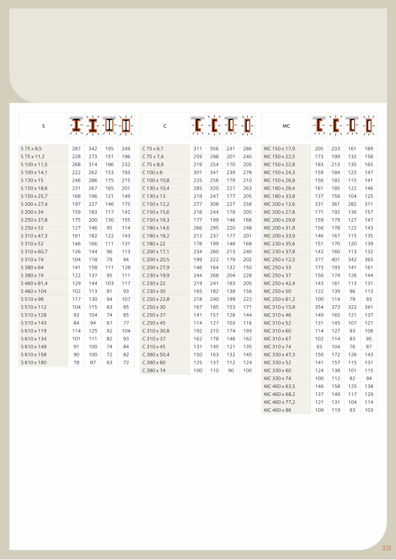
213
MC
MC 150 x 17,9 205 233 161 189
MC 150 x 22,5 173 199 132 158
MC 150 x 22,8 183 213 135 165
MC 150 x 24,3 159 184 123 147
MC 150 x 26,8 156 182 115 141
MC 180 x 28,4 161 185 122 146
MC 180 x 33,8 137 158 104 125
MC 200 x 12,6 331 361 282 311
MC 200 x 27,8 171 192 136 157
MC 200 x 29,8 159 179 127 147
MC 200 x 31,8 156 178 122 143
MC 200 x 33,9 146 167 115 135
MC 230 x 35,6 151 170 120 139
MC 230 x 37,8 142 160 113 132
MC 250 x 12,5 377 401 342 365
MC 250 x 33 173 193 141 161
MC 250 x 37 156 174 126 144
MC 250 x 42,4 143 161 113 131
MC 250 x 50 122 139 96 113
MC 250 x 61,2 100 114 79 93
MC 310 x 15,8 354 373 322 341
MC 310 x 46 149 165 121 137
MC 310 x 52 131 145 107 121
MC 310 x 60 114 127 93 106
MC 310 x 67 102 114 83 95
MC 310 x 74 93 104 76 87
MC 330 x 47,3 156 172 126 143
MC 330 x 52 141 157 115 131
MC 330 x 60 124 138 101 115
MC 330 x 74 100 112 82 94
MC 460 x 63,5 146 158 125 138
MC 460 x 68,2 137 149 117 129
MC 460 x 77,2 121 131 104 114
MC 460 x 86 109 119 93 103
S
S 75 x 8,5 287 342 195 249
S 75 x 11,2 228 273 151 196
S 100 x 11,5 268 314 186 232
S 100 x 14,1 222 262 153 193
S 130 x 15 246 286 175 215
S 150 x 18,6 231 267 165 201
S 150 x 25,7 168 196 121 149
S 200 x 27,4 197 227 146 175
S 200 x 34 159 183 117 142
S 250 x 37,8 175 200 130 155
S 250 x 52 127 146 95 114
S 310 x 47,3 161 182 122 143
S 310 x 52 146 166 111 131
S 310 x 60,7 126 144 96 113
S 310 x 74 104 118 79 94
S 380 x 64 141 158 111 128
S 380 x 74 122 137 95 111
S 460 x 81,4 129 144 103 117
S 460 x 104 102 113 81 93
S 510 x 98 117 130 94 107
S 510 x 112 104 115 83 95
S 510 x 128 93 104 74 85
S 510 x 143 84 94 67 77
S 610 x 119 114 125 92 104
S 610 x 134 101 111 82 93
S 610 x 149 91 100 74 84
S 610 x 158 90 100 72 82
S 610 x 180 78 87 63 72
C
C 75 x 6,1 311 356 241 286
C 75 x 7,4 259 298 201 240
C 75 x 8,9 219 254 170 205
C 100 x 8 301 341 239 278
C 100 x 10,8 225 256 179 210
C 130 x 10,4 285 320 227 263
C 130 x 13 219 247 177 205
C 150 x 12,2 277 308 227 258
C 150 x 15,6 218 244 179 205
C 150 x 19,3 177 199 146 168
C 180 x 14,6 266 295 220 248
C 180 x 18,2 213 237 177 201
C 180 x 22 178 199 148 168
C 200 x 17,1 234 260 213 240
C 200 x 20,5 199 222 179 202
C 200 x 27,9 146 164 132 150
C 230 x 19,9 244 268 204 228
C 230 x 22 219 241 183 205
C 230 x 30 165 182 138 156
C 250 x 22,8 218 240 199 222
C 250 x 30 167 185 153 171
C 250 x 37 141 157 128 144
C 250 x 45 114 127 103 116
C 310 x 30,8 192 210 174 193
C 310 x 37 162 178 146 162
C 310 x 45 131 145 121 135
C 380 x 50,4 150 163 132 145
C 380 x 60 125 137 112 124
C 380 x 74 100 110 90 100
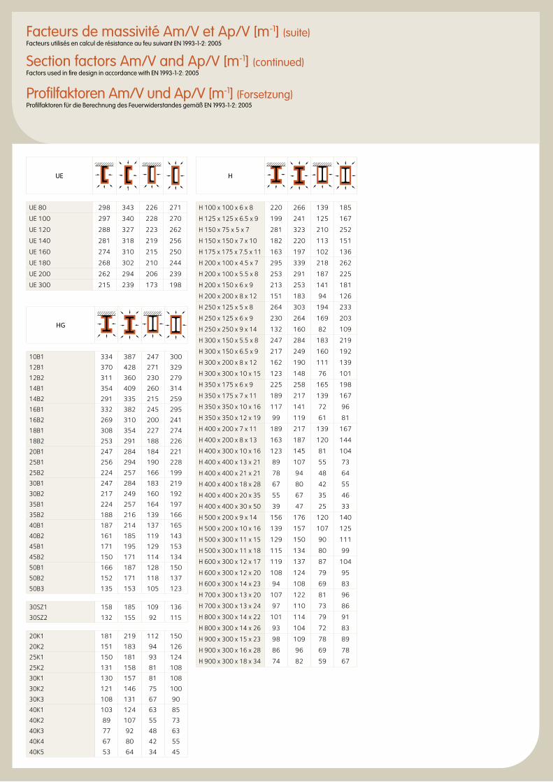
H
H 100 x 100 x 6 x 8 220 266 139 185
H 125 x 125 x 6.5 x 9 199 241 125 167
H 150 x 75 x 5 x 7 281 323 210 252
H 150 x 150 x 7 x 10 182 220 113 151
H 175 x 175 x 7.5 x 11 163 197 102 136
H 200 x 100 x 4.5 x 7 295 339 218 262
H 200 x 100 x 5.5 x 8 253 291 187 225
H 200 x 150 x 6 x 9 213 253 141 181
H 200 x 200 x 8 x 12 151 183 94 126
H 250 x 125 x 5 x 8 264 303 194 233
H 250 x 125 x 6 x 9 230 264 169 203
H 250 x 250 x 9 x 14 132 160 82 109
H 300 x 150 x 5.5 x 8 247 284 183 219
H 300 x 150 x 6.5 x 9 217 249 160 192
H 300 x 200 x 8 x 12 162 190 111 139
H 300 x 300 x 10 x 15 123 148 76 101
H 350 x 175 x 6 x 9 225 258 165 198
H 350 x 175 x 7 x 11 189 217 139 167
H 350 x 350 x 10 x 16 117 141 72 96
H 350 x 350 x 12 x 19 99 119 61 81
H 400 x 200 x 7 x 11 189 217 139 167
H 400 x 200 x 8 x 13 163 187 120 144
H 400 x 300 x 10 x 16 123 145 81 104
H 400 x 400 x 13 x 21 89 107 55 73
H 400 x 400 x 21 x 21 78 94 48 64
H 400 x 400 x 18 x 28 67 80 42 55
H 400 x 400 x 20 x 35 55 67 35 46
H 400 x 400 x 30 x 50 39 47 25 33
H 500 x 200 x 9 x 14 156 176 120 140
H 500 x 200 x 10 x 16 139 157 107 125
H 500 x 300 x 11 x 15 129 150 90 111
H 500 x 300 x 11 x 18 115 134 80 99
H 600 x 300 x 12 x 17 119 137 87 104
H 600 x 300 x 12 x 20 108 124 79 95
H 600 x 300 x 14 x 23 94 108 69 83
H 700 x 300 x 13 x 20 107 122 81 96
H 700 x 300 x 13 x 24 97 110 73 86
H 800 x 300 x 14 x 22 101 114 79 91
H 800 x 300 x 14 x 26 93 104 72 83
H 900 x 300 x 15 x 23 98 109 78 89
H 900 x 300 x 16 x 28 86 96 69 78
H 900 x 300 x 18 x 34 74 82 59 67
HG
10B1 334 387 247 300
12B1 370 428 271 329
12B2 311 360 230 279
14B1 354 409 260 314
14B2 291 335 215 259
16B1 332 382 245 295
16B2 269 310 200 241
18B1 308 354 227 274
18B2 253 291 188 226
20B1 247 284 184 221
25B1 256 294 190 228
25B2 224 257 166 199
30B1 247 284 183 219
30B2 217 249 160 192
35B1 224 257 164 197
35B2 188 216 139 166
40B1 187 214 137 165
40B2 161 185 119 143
45B1 171 195 129 153
45B2 150 171 114 134
50B1 166 187 128 150
50B2 152 171 118 137
50B3 135 153 105 123
30SZ1 158 185 109 136
30SZ2 132 155 92 115
20K1 181 219 112 150
20K2 151 183 94 126
25K1 150 181 93 124
25K2 131 158 81 108
30K1 130 157 81 108
30K2 121 146 75 100
30K3 108 131 67 90
40K1 103 124 63 85
40K2 89 107 55 73
40K3 77 92 48 63
40K4 67 80 42 55
40K5 53 64 34 45
Facteurs de massivité Am/V et Ap/V [m-1] (suite)Facteurs utilisés en calcul de résistance au feu suivant EN 1993-1-2: 2005
Section factors Am/V and Ap/V [m-1] (continued)Factors used in fire design in accordance with EN 1993-1-2: 2005
Profilfaktoren Am/V und Ap/V [m-1] (Forsetzung)Profilfaktoren für die Berechnung des Feuerwiderstandes gemäß EN 1993-1-2: 2005
UE
UE 80 298 343 226 271
UE 100 297 340 228 270
UE 120 288 327 223 262
UE 140 281 318 219 256
UE 160 274 310 215 250
UE 180 268 302 210 244
UE 200 262 294 206 239
UE 300 215 239 173 198
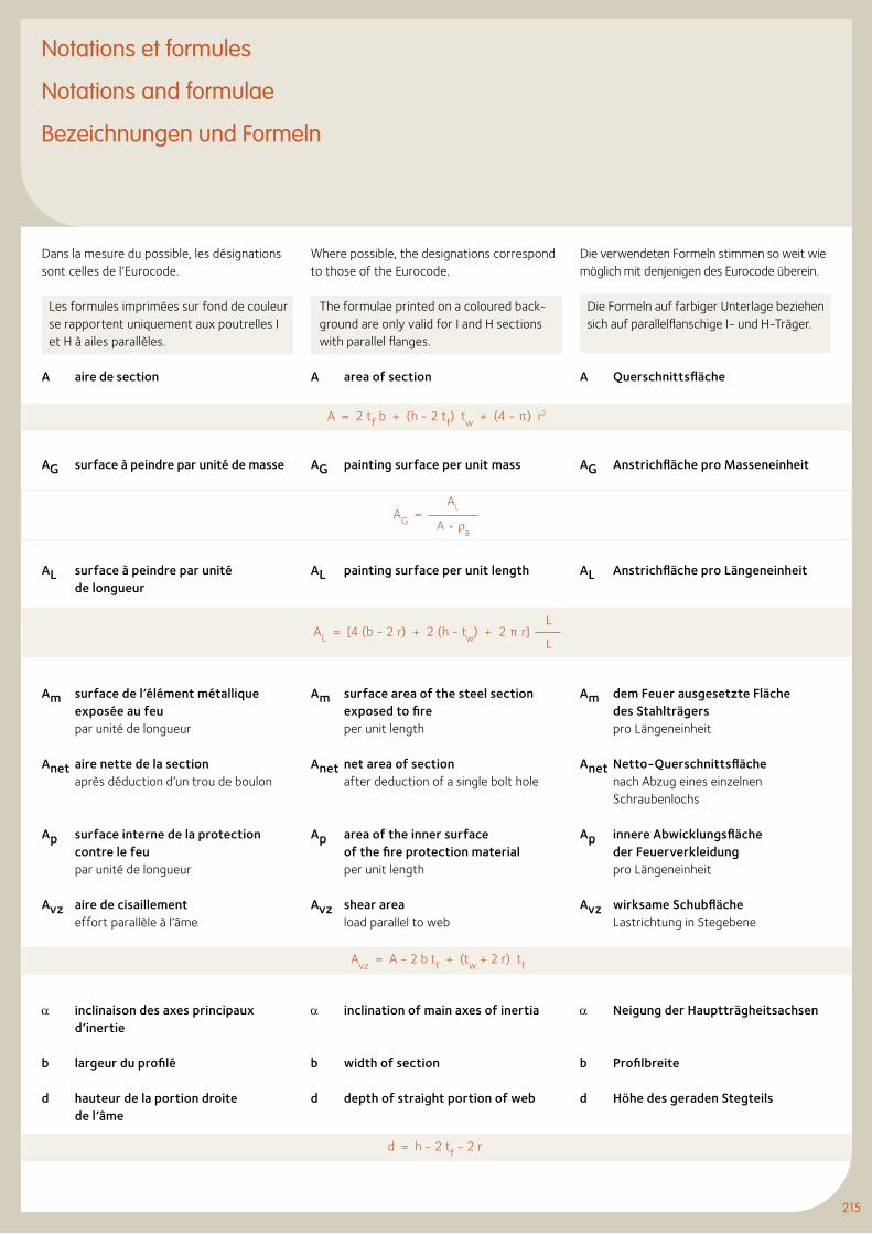
215
Notations et formules
Notations and formulae
Bezeichnungen und Formeln
Dans la mesure du possible, les désignations sont celles de l’Eurocode.
Les formules imprimées sur fond de couleur se rapportent uniquement aux poutrelles I et H à ailes parallèles.
A aire de section
AG surface à peindre par unité de masse
AL surface à peindre par unité de longueur
Am surface de l’élément métallique exposée au feu par unité de longueur
Anet aire nette de la section après déduction d’un trou de boulon
Ap surface interne de la protection contre le feu par unité de longueur
Avz aire de cisaillement effort parallèle à l’âme
α inclinaison des axes principaux d’inertie
b largeur du profilé
d hauteur de la portion droite de l’âme
Where possible, the designations correspond to those of the Eurocode.
The formulae printed on a coloured back-ground are only valid for I and H sections with parallel flanges.
A area of section
AG painting surface per unit mass
AL painting surface per unit length
Am surface area of the steel section exposed to fire per unit length
Anet net area of section after deduction of a single bolt hole
Ap area of the inner surface of the fire protection material per unit length
Avz shear area load parallel to web
α inclination of main axes of inertia
b width of section
d depth of straight portion of web
Die verwendeten Formeln stimmen so weit wie möglich mit denjenigen des Eurocode überein.
Die Formeln auf farbiger Unterlage beziehen sich auf parallelflanschige I- und H-Träger.
A Querschnittsfläche
AG Anstrichfläche pro Masseneinheit
AL Anstrichfläche pro Längeneinheit
Am dem Feuer ausgesetzte Fläche des Stahlträgers pro Längeneinheit
Anet Netto-Querschnittsfläche nach Abzug eines einzelnen Schraubenlochs
Ap innere Abwicklungsfläche der Feuerverkleidung pro Längeneinheit
Avz wirksame Schubfläche Lastrichtung in Stegebene
α Neigung der Hauptträgheitsachsen
b Profilbreite
d Höhe des geraden Stegteils
215
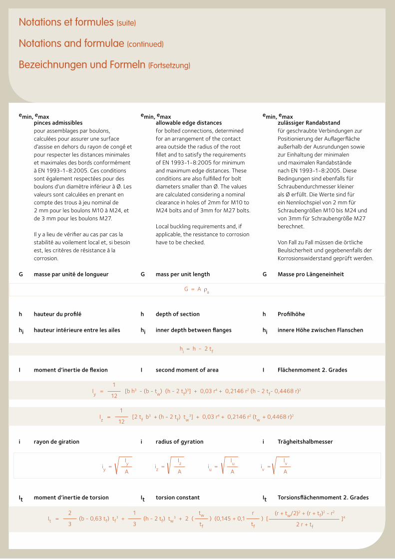
emin, emax pinces admissibles
pour assemblages par boulons, calculées pour assurer une surface d’assise en dehors du rayon de congé et pour respecter les distances minimales et maximales des bords conformément à EN 1993-1-8:2005. Ces conditions sont également respectées pour des boulons d’un diamètre inférieur à Ø. Les valeurs sont calculées en prenant en compte des trous à jeu nominal de 2 mm pour les boulons M10 à M24, et de 3 mm pour les boulons M27.
Il y a lieu de vérifier au cas par cas la stabilité au voilement local et, si besoin est, les critères de résistance à la corrosion.
G masse par unité de longueur
h hauteur du profilé
hi hauteur intérieure entre les ailes
I moment d’inertie de flexion
i rayon de giration
It moment d’inertie de torsion
emin, emaxallowable edge distances for bolted connections, determined for an arrangement of the contact area outside the radius of the root fillet and to satisfy the requirements of EN 1993-1-8:2005 for minimum and maximum edge distances. These conditions are also fulfilled for bolt diameters smaller than Ø. The values are calculated considering a nominal clearance in holes of 2mm for M10 to M24 bolts and of 3mm for M27 bolts.
Local buckling requirements and, if applicable, the resistance to corrosion have to be checked.
G mass per unit length
h depth of section
hi inner depth between flanges
I second moment of area
i radius of gyration
It torsion constant
emin, emax zulässiger Randabstand
für geschraubte Verbindungen zur Positionierung der Auflagerfläche außerhalb der Ausrundungen sowie zur Einhaltung der minimalen und maximalen Randabstände nach EN 1993-1-8:2005. Diese Bedingungen sind ebenfalls für Schraubendurchmesser kleiner als Ø erfüllt. Die Werte sind für ein Nennlochspiel von 2 mm für Schraubengrößen M10 bis M24 und von 3mm für Schraubengröße M27 berechnet.
Von Fall zu Fall müssen die örtliche Beulsicherheit und gegebenenfalls der Korrosionswiderstand geprüft werden.
G Masse pro Längeneinheit
h Profilhöhe
hi innere Höhe zwischen Flanschen
I Flächenmoment 2. Grades
i Trägheitshalbmesser
It Torsionsflächenmoment 2. Grades
Notations et formules (suite)
Notations and formulae (continued)
Bezeichnungen und Formeln (Fortsetzung)
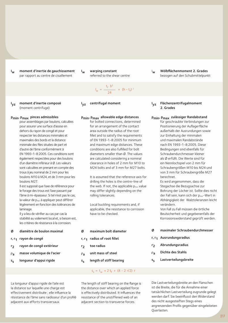
217
Iw moment d’inertie de gauchissement par rapport au centre de cisaillement
Iyz moment d’inertie composé (moment centrifuge)
pmin, pmax pinces admissibles pour assemblages par boulons, calculées pour assurer une surface d’assise en dehors du rayon de congé et pour respecter les distances minimales et maximales des bords et la distance minimale des files situées de part et d’autre de l’âme conformément à EN 1993-1-8:2005. Ces conditions sont également respectées pour des boulons d’un diamètre inférieur à Ø. Les valeurs sont calculées en prenant en compte des trous à jeu nominal de 2 mm pour les boulons M10 à M24, et de 3 mm pour les boulons M27.Il est supposé que l’axe de référence pour le forage des trous est l’axe passant par l’âme à mi-épaisseur. Si tel n’est pas le cas, la valeur de pmin à appliquer peut différer légèrement en fonction des tolérances de laminage. Il y a lieu de vérifier au cas par cas la stabilité au voilement local et, si besoin est, les critères de résistance à la corrosion.
Ø diamètre de boulon maximal
r, r1 rayon de congé
r2 rayon de congé extérieur
ρa masse volumique de l’acier
ss longueur d’appui rigide
La longueur d’appui rigide de l’aile est la distance sur laquelle une charge est effectivement distribuée ; elle influence la résistance de l’âme sans raidisseur d’un profilé adjacent aux efforts transversaux.
Iw warping constant referred to the shear centre
Iyz centrifugal moment
pmin, pmax allowable edge distancesfor bolted connections, determined for an arrangement of the contact area outside the radius of the root fillet and to satisfy the requirements of EN 1993-1-8:2005 for minimum and maximum edge distances. These conditions are also fulfilled for bolt diameters smaller than Ø. The values are calculated considering a nominal clearance in holes of 2 mm for M10 to M24 bolts and of 3 mm for M27 bolts.
It is assumed that the reference axis for drilling the holes is the centre-line of the web. If not, the applicable pmin value may differ slightly depending on the rolling tolerances.
Local buckling requirements and, if applicable, the resistance to corrosion have to be checked.
Ø maximum bolt diameter
r, r1 radius of root fillet
r2 toe radius
ρa unit mass of steel
ss length of stiff bearing
The length of stiff bearing on the flange is the distance over which an applied force is effectively distributed. It influences the resistance of the unstiffened web of an adjacent section to transverse forces.
Iw Wölbflächenmoment 2. Grades bezogen auf den Schubmittelpunkt
Iyz Flächenzentrifugalmoment 2. Grades
pmin, pmax zulässiger Randabstand für geschraubte Verbindungen zur Positionierung der Auflagerfläche außerhalb der Ausrundungen sowie zur Einhaltung der minimalen und maximalen Randabstände nach EN 1993-1-8:2005. Diese Bedingungen sind ebenfalls für Schraubendurchmesser kleiner als Ø erfüllt. Die Werte sind für ein Nennlochspiel von 2 mm für Schraubengrößen M10 bis M24 und von 3 mm für Schraubengröße M27 berechnet.Es wird angenommen, dass die Stegachse die Bezugsachse zur Bohrung der Löcher ist. Sollte dies nicht der Fall sein, kann sich der pmin-Wert in Abhängigkeit der Walztoleranzen leicht verändern. Von Fall zu Fall müssen die örtliche Beulsicherheit und gegebenenfalls der Korrosionswiderstand geprüft werden.
Ø maximaler Schraubendurchmesser
r, r1 Ausrundungsradius
r2 Abrundungsradius
ρa Dichte des Stahls
ss Lastverteilungsbreite
Die Lastverteilungsbreite an den Flanschen ist die Breite, die für die Annahme einer tatsächlichen Lastverteilung zugrunde gelegt werden darf. Sie beeinflusst den Widerstand des nicht ausgesteiften Stegs eines angrenzenden Profils gegenüber eingeleiteten Querlasten.
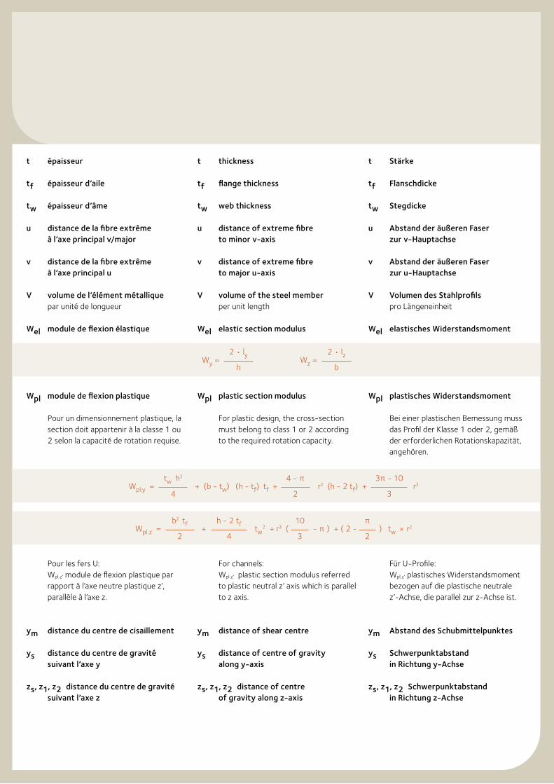
t épaisseur
tf épaisseur d’aile
tw épaisseur d’âme
u distance de la fibre extrême à l’axe principal v/major
v distance de la fibre extrême à l’axe principal u
V volume de l’élément métallique par unité de longueur
Wel module de flexion élastique
Wpl module de flexion plastique
Pour un dimensionnement plastique, la section doit appartenir à la classe 1 ou 2 selon la capacité de rotation requise.
Pour les fers U:Wpl.z’ module de flexion plastique par rapport à l’axe neutre plastique z’, parallèle à l’axe z.
ym distance du centre de cisaillement
ys distance du centre de gravité suivant l’axe y
zs, z1, z2 distance du centre de gravité suivant l’axe z
t thickness
tf flange thickness
tw web thickness
u distance of extreme fibre to minor v-axis
v distance of extreme fibre to major u-axis
V volume of the steel member per unit length
Wel elastic section modulus
Wpl plastic section modulus
For plastic design, the cross-section must belong to class 1 or 2 according to the required rotation capacity.
For channels:Wpl.z’ plastic section modulus referred to plastic neutral z’ axis which is parallel to z axis.
ym distance of shear centre
ys distance of centre of gravity along y-axis
zs, z1, z2 distance of centre of gravity along z-axis
t Stärke
tf Flanschdicke
tw Stegdicke
u Abstand der äußeren Faser zur v-Hauptachse
v Abstand der äußeren Faser zur u-Hauptachse
V Volumen des Stahlprofils pro Längeneinheit
Wel elastisches Widerstandsmoment
Wpl plastisches Widerstandsmoment
Bei einer plastischen Bemessung muss das Profil der Klasse 1 oder 2, gemäß der erforderlichen Rotationskapazität, angehören.
Für U-Profile:Wpl.z’ plastisches Widerstandsmoment bezogen auf die plastische neutrale z’-Achse, die parallel zur z-Achse ist.
ym Abstand des Schubmittelpunktes
ys Schwerpunktabstand in Richtung y-Achse
zs, z1, z2 Schwerpunktabstand in Richtung z-Achse
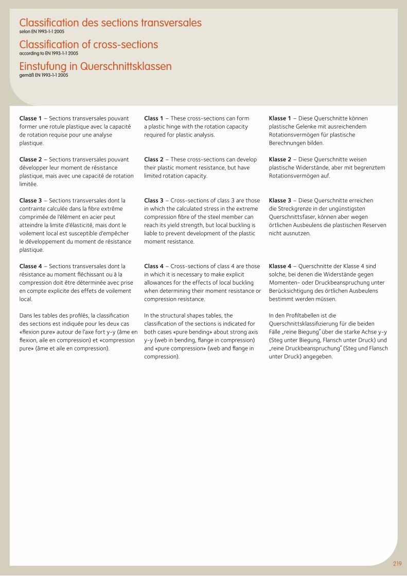
219
Classification des sections transversalesselon EN 1993-1-1 2005
Classification of cross-sections according to EN 1993-1-1 2005
Einstufung in Querschnittsklassengemäß EN 1993-1-1 2005
Classe 1 – Sections transversales pouvant former une rotule plastique avec la capacité de rotation requise pour une analyse plastique.
Classe 2 – Sections transversales pouvant développer leur moment de résistance plastique, mais avec une capacité de rotation limitée.
Classe 3 – Sections transversales dont la contrainte calculée dans la fibre extrême comprimée de l’élément en acier peut atteindre la limite d’élasticité, mais dont le voilement local est susceptible d’empêcher le développement du moment de résistance plastique.
Classe 4 – Sections transversales dont la résistance au moment fléchissant ou à la compression doit être déterminée avec prise en compte explicite des effets de voilement local.
Dans les tables des profilés, la classification des sections est indiquée pour les deux cas «flexion pure» autour de l’axe fort y-y (âme en flexion, aile en compression) et «compression pure» (âme et aile en compression).
Class 1 – These cross-sections can form a plastic hinge with the rotation capacity required for plastic analysis.
Class 2 – These cross-sections can develop their plastic moment resistance, but have limited rotation capacity.
Class 3 – Cross-sections of class 3 are those in which the calculated stress in the extreme compression fibre of the steel member can reach its yield strength, but local buckling is liable to prevent development of the plastic moment resistance.
Class 4 – Cross-sections of class 4 are those in which it is necessary to make explicit allowances for the effects of local buckling when determining their moment resistance or compression resistance.
In the structural shapes tables, the classification of the sections is indicated for both cases «pure bending» about strong axis y-y (web in bending, flange in compression) and «pure compression» (web and flange in compression).
Klasse 1 – Diese Querschnitte können plastische Gelenke mit ausreichendem Rotationsvermögen für plastische Berechnungen bilden.
Klasse 2 – Diese Querschnitte weisen plastische Widerstände, aber mit begrenztem Rotationsvermögen auf.
Klasse 3 – Diese Querschnitte erreichen die Streckgrenze in der ungünstigsten Querschnittsfaser, können aber wegen örtlichen Ausbeulens die plastischen Reserven nicht ausnutzen.
Klasse 4 – Querschnitte der Klasse 4 sind solche, bei denen die Widerstände gegen Momenten- oder Druckbeanspruchung unter Berücksichtigung des örtlichen Ausbeulens bestimmt werden müssen.
In den Profiltabellen ist die Querschnittsklassifizierung für die beiden Fälle „reine Biegung˝ über die starke Achse y-y (Steg unter Biegung, Flansch unter Druck) und „reine Druckbeanspruchung˝ (Steg und Flansch unter Druck) angegeben.
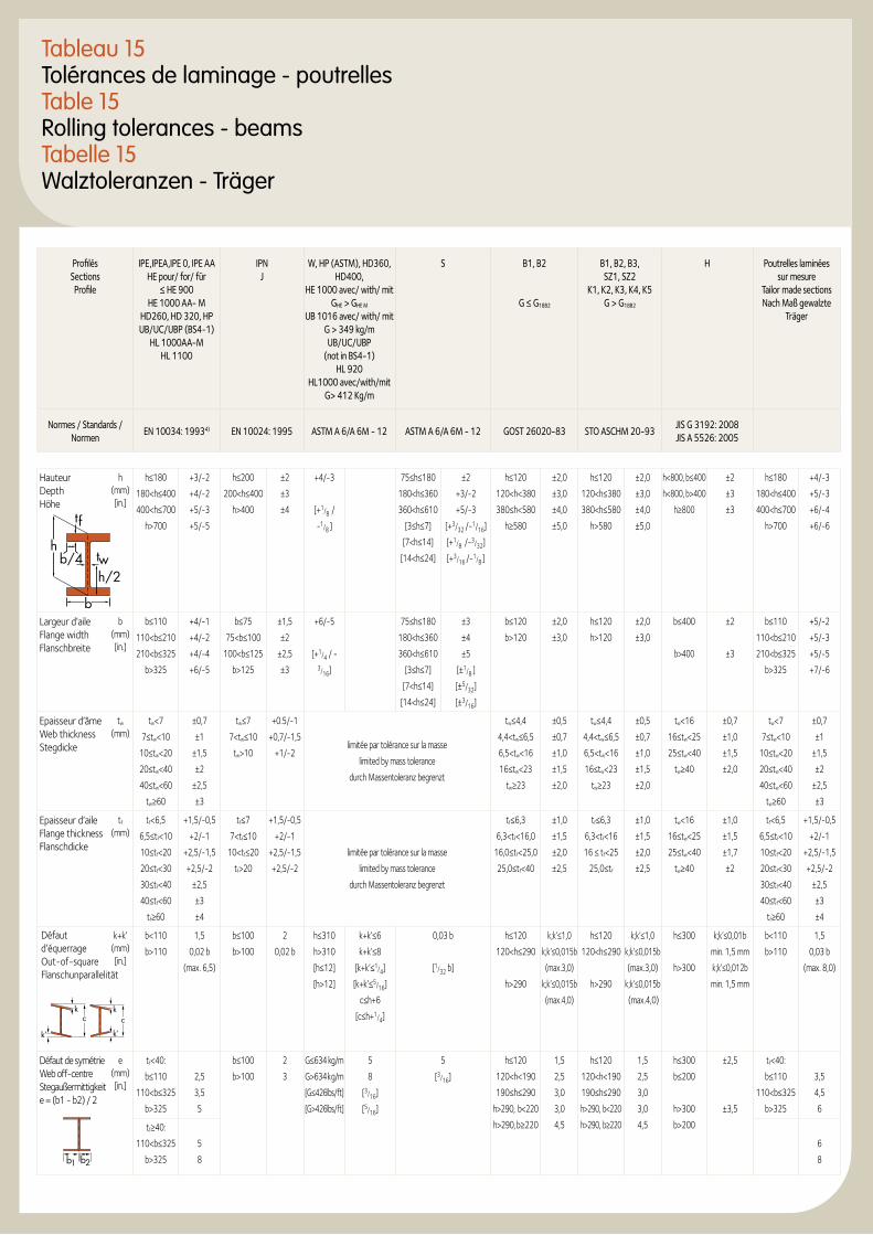
Tableau 15Tolérances de laminage - poutrellesTable 15Rolling tolerances - beamsTabelle 15Walztoleranzen - Träger
Profilés Sections Profile
IPE,IPEA,IPE 0, IPE AA HE pour/ for/ für
≤ HE 900 HE 1000 AA- M
HD260, HD 320, HP UB/UC/UBP (BS4-1)
HL 1000AA-MHL 1100
IPN J
W, HP (ASTM), HD360, HD400,
HE 1000 avec/ with/ mit GHE > GHE M
UB 1016 avec/ with/ mit G > 349 kg/m UB/UC/UBP
(not in BS4-1)HL 920
HL1000 avec/with/mit G> 412 Kg/m
S B1, B2
G ≤ G18B2
B1, B2, B3, SZ1, SZ2
K1, K2, K3, K4, K5G > G18B2
H Poutrelles laminées sur mesure
Tailor made sections Nach Maß gewalzte
Träger
Normes / Standards / Normen
EN 10034: 19934) EN 10024: 1995 ASTM A 6/A 6M - 12 ASTM A 6/A 6M - 12 GOST 26020-83 STO ASCHM 20-93 JIS G 3192: 2008 JIS A 5526: 2005
Hauteur Depth Höhe
h (mm) [in.]
h≤180
180<h≤400
400<h≤700
h>700
+3/-2
+4/-2
+5/-3
+5/-5
h≤200
200<h≤400
h>400
±2
±3
±4
+4/-3
[+1/8 /
-1/8 ]
75≤h≤180
180<h≤360
360<h≤610
[3≤h≤7]
[7<h≤14]
[14<h≤24]
±2
+3/-2
+5/-3
[+3/32 /-1/16]
[+1/8 /-3/32]
[+3/16 /-1/8 ]
h≤120
120<h<380
380≤h<580
h≥580
±2,0
±3,0
±4,0
±5,0
h≤120
120<h≤380
380<h≤580
h>580
±2,0
±3,0
±4,0
±5,0
h<800, b≤400
h<800, b>400
h≥800
±2
±3
±3
h≤180
180<h≤400
400<h≤700
h>700
+4/-3
+5/-3
+6/-4
+6/-6
Largeur d’aile Flange width Flanschbreite
b (mm) [in.]
b≤110
110<b≤210
210<b≤325
b>325
+4/-1
+4/-2
+4/-4
+6/-5
b≤75
75<b≤100
100<b≤125
b>125
±1,5
±2
±2,5
±3
+6/-5
[+1/4 / - 3/16]
75≤h≤180
180<h≤360
360<h≤610
[3≤h≤7]
[7<h≤14]
[14<h≤24]
±3
±4
±5
[±1/8 ]
[±5/32]
[±3/16]
b≤120
b>120
±2,0
±3,0
h≤120
h>120
±2,0
±3,0
b≤400
b>400
±2
±3
b≤110
110<b≤210
210<b≤325
b>325
+5/-2
+5/-3
+5/-5
+7/-6
Epaisseur d’âme Web thickness Stegdicke
tw (mm)
tw<7
7≤tw<10
10≤tw<20
20≤tw<40
40≤tw<60
tw≥60
±0,7
±1
±1,5
±2
±2,5
±3
tw≤7
7<tw≤10
tw>10
+0.5/-1
+0,7/-1,5
+1/-2limitée par tolérance sur la masse
limited by mass tolerance
durch Massentoleranz begrenzt
tw≤4,4
4,4<tw≤6,5
6,5<tw<16
16≤tw<23
tw≥23
±0,5
±0,7
±1,0
±1,5
±2,0
tw≤4,4
4,4<tw≤6,5
6,5<tw<16
16≤tw<23
tw≥23
±0,5
±0,7
±1,0
±1,5
±2,0
tw<16
16≤tw<25
25≤tw<40
tw≥40
±0,7
±1,0
±1,5
±2,0
tw<7
7≤tw<10
10≤tw<20
20≤tw<40
40≤tw<60
tw≥60
±0,7
±1
±1,5
±2
±2,5
±3
Epaisseur d’aile Flange thickness Flanschdicke
tf (mm)
tf<6,5
6,5≤tf<10
10≤tf<20
20≤tf<30
30≤tf<40
40≤tf<60
tf≥60
+1,5/-0,5
+2/-1
+2,5/-1,5
+2,5/-2
±2,5
±3
±4
tf≤7
7<tf≤10
10<tf≤20
tf>20
+1,5/-0,5
+2/-1
+2,5/-1,5
+2,5/-2
limitée par tolérance sur la masse
limited by mass tolerance
durch Massentoleranz begrenzt
tf≤6,3
6,3<tf<16,0
16,0≤tf<25,0
25,0≤tf<40
±1,0
±1,5
±2,0
±2,5
tf≤6,3
6,3<tf<16
16 ≤ tf<25
25,0≤tf
±1,0
±1,5
±2,0
±2,5
tw<16
16≤tw<25
25≤tw<40
tw≥40
±1,0
±1,5
±1,7
±2
tf<6,5
6,5≤tf<10
10≤tf<20
20≤tf<30
30≤tf<40
40≤tf<60
tf≥60
+1,5/-0,5
+2/-1
+2,5/-1,5
+2,5/-2
±2,5
±3
±4
k+k’ (mm) [in.]
b<110
b>110
1,5
0,02 b
(max. 6,5)
b≤100
b>100
2
0,02 b
h≤310
h>310
[h≤12]
[h>12]
k+k’≤6
k+k’≤8
[k+k’≤1/4]
[k+k’≤5/16]
c≤h+6
[c≤h+1/4]
0,03 b
[1/32 b]
h≤120
120<h≤290
h>290
k;k’≤1,0
k;k’≤0,015b
(max.3,0)
k;k’≤0,015b
(max.4,0)
h≤120
120<h≤290
h>290
k;k’≤1,0
k;k’≤0,015b
(max.3,0)
k;k’≤0,015b
(max.4,0)
h≤300
h>300
k;k’≤0,01b
min. 1,5 mm
k;k’≤0,012b
min. 1,5 mm
b<110
b>110
1,5
0,03 b
(max. 8,0)
Défaut de symétrie Web off-centre Stegaußermittigkeit e = (b1 - b2) / 2
e (mm) [in.]
tf<40:
b≤110
110<b≤325
b>325
2,5
3,5
5
b≤100
b>100
2
3
G≤634 kg/m
G>634kg/m
[G≤426lbs/ft]
[G>426lbs/ft]
5
8
[3/16]
[5/16]
5
[3/16]
h≤120
120<h<190
190≤h≤290
h>290, b<220
h>290, b≥220
1,5
2,5
3,0
3,0
4,5
h≤120
120<h<190
190≤h≤290
h>290, b<220
h>290, b≥220
1,5
2,5
3,0
3,0
4,5
h≤300
b≤200
h>300
b>200
±2,5
±3,5
tf<40:
b≤110
110<b≤325
b>325
3,5
4,5
6
tf≥40:
110<b≤325
b>325
5
8
6
8b1 b2
tf
tb/4h/2w
h
b
kc
k’
kc
k’
Défaut d’équerrage Out-of-square Flanschunparallelität
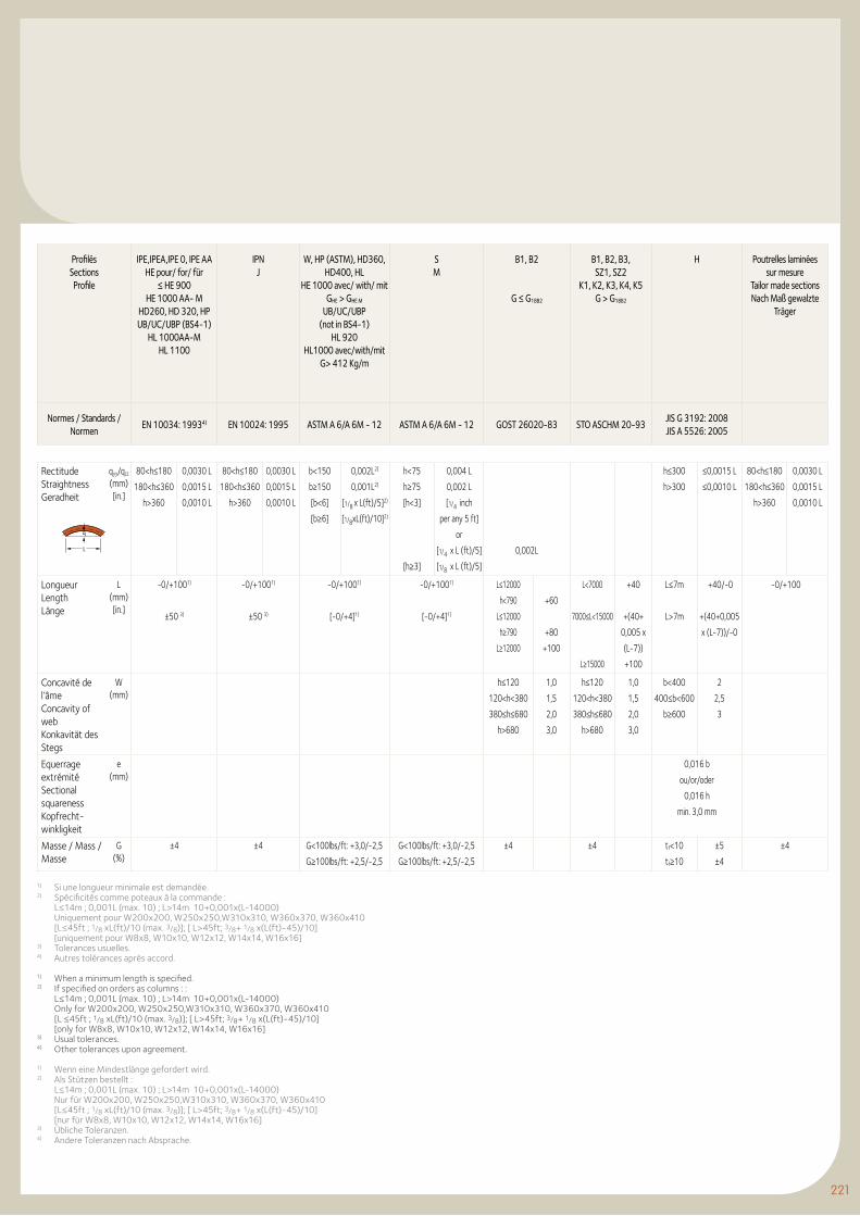
221
Rectitude Straightness Geradheit
qyy/qzz (mm) [in.]
80<h≤180
180<h≤360
h>360
0,0030 L
0,0015 L
0,0010 L
80<h≤180
180<h≤360
h>360
0,0030 L
0,0015 L
0,0010 L
b<150
b≥150
[b<6]
[b≥6]
0,002L2)
0,001L2)
[1/8 x L(ft)/5]2)
[1/8xL(ft)/10]2)
h<75
h≥75
[h<3]
[h≥3]
0,004 L
0,002 L
[1/4 inch
per any 5 ft]
or
[1/4 x L (ft)/5]
[1/8 x L (ft)/5]
0,002L
h≤300
h>300
≤0,0015 L
≤0,0010 L
80<h≤180
180<h≤360
h>360
0,0030 L
0,0015 L
0,0010 L
Longueur Length Länge
L (mm) [in.]
-0/+1001)
±50 3)
-0/+1001)
±50 3)
-0/+1001)
[-0/+4]1)
-0/+1001)
[-0/+4]1)
L≤12000
h<790
L≤12000
h≥790
L≥12000
+60
+80
+100
L<7000
7000≤L<15000
L≥15000
+40
+(40+
0,005 x
(L-7))
+100
L≤7m
L>7m
+40/-0
+(40+0,005
x (L-7))/-0
-0/+100
Concavité de l’âme Concavity of web Konkavität des Stegs
W (mm)
h≤120
120<h<380
380≤h≤680
h>680
1,0
1,5
2,0
3,0
h≤120
120<h<380
380≤h≤680
h>680
1,0
1,5
2,0
3,0
b<400
400≤b<600
b≥600
2
2,5
3
Equerrage extrémité Sectional squareness Kopfrecht-winkligkeit
e (mm)
0,016 b
ou/or/oder
0,016 h
min. 3,0 mm
Masse / Mass / Masse
G (%)
±4 ±4 G<100lbs/ft: +3,0/-2,5
G≥100lbs/ft: +2,5/-2,5
G<100lbs/ft: +3,0/-2,5
G≥100lbs/ft: +2,5/-2,5
±4 ±4 tf<10
tf≥10
±5
±4
±4
q
L
Profilés Sections Profile
IPE,IPEA,IPE 0, IPE AA HE pour/ for/ für
≤ HE 900 HE 1000 AA- M
HD260, HD 320, HP UB/UC/UBP (BS4-1)
HL 1000AA-MHL 1100
IPN J
W, HP (ASTM), HD360, HD400, HL
HE 1000 avec/ with/ mit GHE > GHE M
UB/UC/UBP (not in BS4-1)
HL 920HL1000 avec/with/mit
G> 412 Kg/m
S M
B1, B2
G ≤ G18B2
B1, B2, B3,SZ1, SZ2
K1, K2, K3, K4, K5G > G18B2
H Poutrelles laminées sur mesure
Tailor made sections Nach Maß gewalzte
Träger
Normes / Standards / Normen
EN 10034: 19934) EN 10024: 1995 ASTM A 6/A 6M - 12 ASTM A 6/A 6M - 12 GOST 26020-83 STO ASCHM 20-93 JIS G 3192: 2008 JIS A 5526: 2005
1) Si une longueur minimale est demandée.2) Spécificités comme poteaux à la commande : L≤14m ; 0,001L (max. 10) ; L>14m 10+0,001x(L-14000) Uniquement pour W200x200, W250x250,W310x310, W360x370, W360x410 [L≤45ft ; 1/8 xL(ft)/10 (max. 3/8)]; [ L>45ft; 3/8+ 1/8 x(L(ft)-45)/10] [uniquement pour W8x8, W10x10, W12x12, W14x14, W16x16]3) Tolerances usuelles.4) Autres tolérances après accord.
1) When a minimum length is specified.2) If specified on orders as columns : : L≤14m ; 0,001L (max. 10) ; L>14m 10+0,001x(L-14000) Only for W200x200, W250x250,W310x310, W360x370, W360x410 [L ≤45ft ; 1/8 xL(ft)/10 (max. 3/8)]; [ L>45ft; 3/8+ 1/8 x(L(ft)-45)/10] [only for W8x8, W10x10, W12x12, W14x14, W16x16]3) Usual tolerances.4) Other tolerances upon agreement.
1) Wenn eine Mindestlänge gefordert wird.2) Als Stützen bestellt : L≤14m ; 0,001L (max. 10) ; L>14m 10+0,001x(L-14000) Nur für W200x200, W250x250,W310x310, W360x370, W360x410 [L≤45ft ; 1/8 xL(ft)/10 (max. 3/8)]; [ L>45ft; 3/8+ 1/8 x(L(ft)-45)/10] [nur für W8x8, W10x10, W12x12, W14x14, W16x16]3) Übliche Toleranzen.4) Andere Toleranzen nach Absprache.
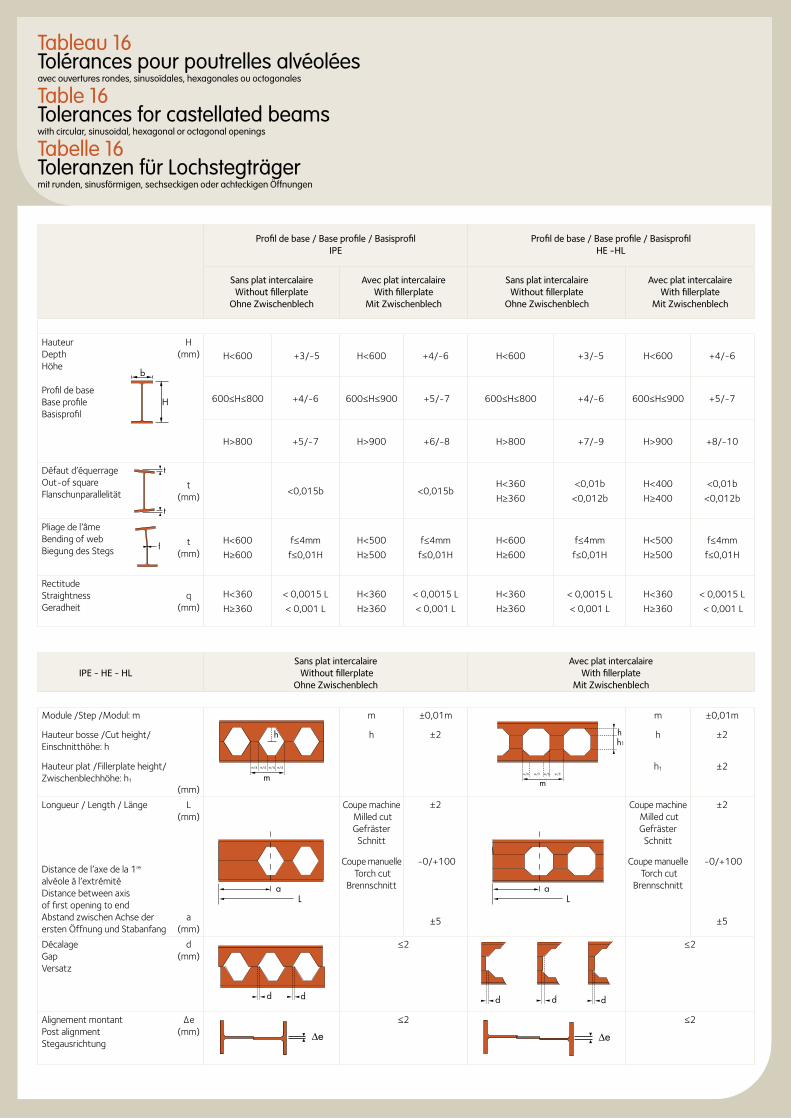
Profil de base / Base profile / Basisprofil IPE
Profil de base / Base profile / Basisprofil HE -HL
Sans plat intercalaire Without fillerplate
Ohne Zwischenblech
Avec plat intercalaire With fillerplate
Mit Zwischenblech
Sans plat intercalaire Without fillerplate
Ohne Zwischenblech
Avec plat intercalaire With fillerplate
Mit Zwischenblech
Hauteur Depth Höhe Profil de base Base profile Basisprofil
H(mm) H<600 +3/-5 H<600 +4/-6 H<600 +3/-5 H<600 +4/-6
600≤H≤800 +4/-6 600≤H≤900 +5/-7 600≤H≤800 +4/-6 600≤H≤900 +5/-7
H>800 +5/-7 H>900 +6/-8 H>800 +7/-9 H>900 +8/-10
Défaut d’équerrage Out-of square Flanschunparallelität
t(mm)
<0,015b <0,015bH<360
H≥360
<0,01b
<0,012b
H<400
H≥400
<0,01b
<0,012b
Pliage de l’âme Bending of web Biegung des Stegs
t(mm)
H<600
H≥600
f≤4mm
f≤0,01H
H<500
H≥500
f≤4mm
f≤0,01H
H<600
H≥600
f≤4mm
f≤0,01H
H<500
H≥500
f≤4mm
f≤0,01H
Rectitude Straightness Geradheit
q(mm)
H<360
H≥360
< 0,0015 L
< 0,001 L
H<360
H≥360
< 0,0015 L
< 0,001 L
H<360
H≥360
< 0,0015 L
< 0,001 L
H<360
H≥360
< 0,0015 L
< 0,001 L
IPE - HE - HLSans plat intercalaire Without fillerplate
Ohne Zwischenblech
Avec plat intercalaire With fillerplate
Mit Zwischenblech
Module /Step /Modul: m
mm/4 m/4 m/4 m/4
h
m ±0,01m
mm/6 m/3 m/6 m/3
hh1
m ±0,01m
Hauteur bosse /Cut height/ Einschnitthöhe: h
h ±2 h ±2
Hauteur plat /Fillerplate height/ Zwischenblechhöhe: h1
(mm)
h1 ±2
Longueur / Length / Länge L (mm)
Coupe machine Milled cut Gefräster
Schnitt
±2 Coupe machine Milled cut Gefräster
Schnitt
±2
Distance de l’axe de la 1re alvéole à l’extrémité Distance between axis of first opening to end Abstand zwischen Achse der ersten Öffnung und Stabanfang
a (mm)
Coupe manuelle Torch cut
Brennschnitt
-0/+100
±5
Coupe manuelle Torch cut
Brennschnitt
-0/+100
±5
Décalage Gap Versatz
d (mm)
d d
≤2
d dd
≤2
Alignement montant Post alignment Stegausrichtung
∆e (mm) ∆e
≤2
∆e
≤2
t
t
f
Tableau 16 Tolérances pour poutrelles alvéolées avec ouvertures rondes, sinusoïdales, hexagonales ou octogonales
Table 16 Tolerances for castellated beams with circular, sinusoidal, hexagonal or octagonal openings
Tabelle 16 Toleranzen für Lochstegträger mit runden, sinusförmigen, sechseckigen oder achteckigen Öffnungen
H
b
aL
aL
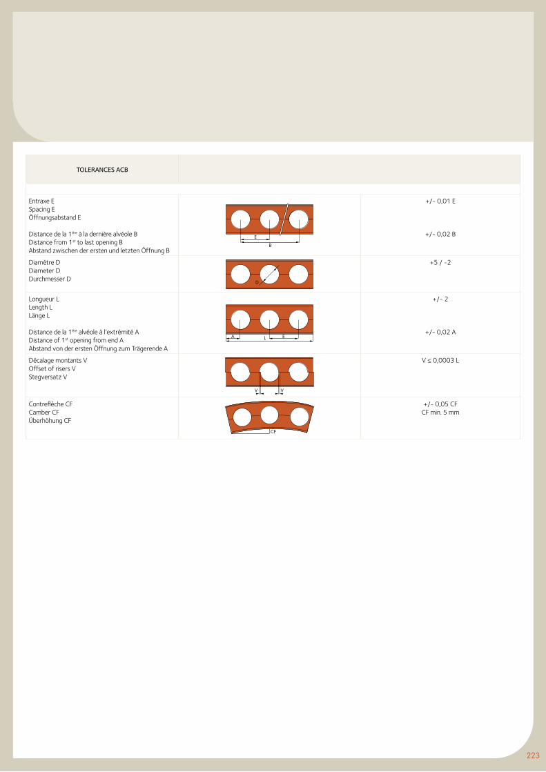
223
TOLERANCES ACB
Entraxe ESpacing EÖffnungsabstand E
Distance de la 1ère à la dernière alvéole BDistance from 1st to last opening BAbstand zwischen der ersten und letzten Öffnung B
e
B
+/- 0,01 E
+/- 0,02 B
Diamètre DDiameter DDurchmesser D D
+5 / -2
Longueur LLength LLänge L
Distance de la 1ère alvéole à l’extrémité ADistance of 1st opening from end AAbstand von der ersten Öffnung zum Trägerende A
eLA
+/- 2
+/- 0,02 A
Décalage montants VOffset of risers VStegversatz V
V V
V ≤ 0,0003 L
Contreflèche CFCamber CFÜberhöhung CF
CF
+/- 0,05 CFCF min. 5 mm
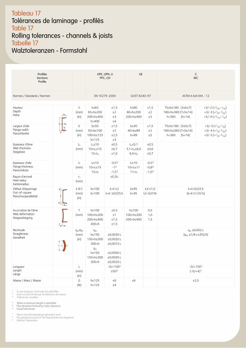
Tableau 17Tolérances de laminage - profilésTable 17Rolling tolerances - channels & joistsTabelle 17Walztoleranzen - Formstahl
Profilés Sections Profile
UPE, UPN, U PFC, CH
UE C MC
Normes / Standards / Normen EN 10279: 2000 GOST 8240-97 ASTM A 6/A 6M - 12
Hauteur Depth Höhe b
ht f
tw
r3
h
(mm)
[in]
h≤65
65<h≤200
200<h≤400
h>400
±1,5
±2
±3
±4
h≤80
80<h≤200
200<h≤400
±1,5
±2
±3
75≤h≤180 [3≤h≤7]
180<h≤360 [7<h≤14]
h>360 [h>14]
+3/-2 [+3/32 /-1/16 ]
+3/-3 [+1/8 /-3/32 ]
+5/-4 [+3/16 /-1/8 ]
Largeur d’aile Flange width Flanschbreite
b
(mm)
[in]
b≤50
50<b≤100
100<b≤125
b>125
±1,5
±2
±2,5
±3
b≤40
40<b≤89
b>89
±1,5
±2
±3
75≤h≤180 [3≤h≤7]
180<h≤360 [7<h≤14]
h>360 [h>14]
+3/-3 [+1/8 /-1/8 ]
+3/-4 [+1/8 /-5/32 ]
+3/-5 [+1/8 /-3/16 ]
Epaisseur d’âme Web thickness Stegdicke
tw
(mm)
tw≤10
10<tw≤15
15<tw
±0,5
±0,7
±1,0
tw≤5,1
5,1<tw≤6,0
6,0<tw
±0,5
±0,6
±0,7
Epaisseur d’aile Flange thickness Flanschdicke
tf
(mm)
tf≤10
10<tf≤15
15<tf
-0,52)
-12)
-1,52)
tf≤10
10<tf≤11
11<tf
-0,52)
-0,82)
-1,02)
Rayon d’arrondi Heel radius Kantenradius
r3
(mm)
≤0,3tf
Défaut d’équerrage Out-of-square Flanschunparallelität h
k’
k
b
k (k’)
(mm)
[in]
b≤100
b>100
k+k’≤2
k+k’ ≤0,025 b
b≤95
b>95
k;k’≤1,0
k;k’ ≤0,015b
k+k’≤0,03 b
[k+k’≤1/32 b]
Incurvation de l’âme Web deformation Stegausbiegung
f
f
(mm)
h≤100
100<h≤200
200<h≤400
400<h
±0,5
±1
±1,5
±1,5
h≤100
100<h≤200
200<h≤400
0,5
1,0
1,5
Rectitude Straightness Geradheit
qL
qyy/qzz
(mm)
[in]
qyy
h≤150
150<h≤300
300<h
qzz
h≤150
150<h≤300
300<h
±0,0030 L
±0,0020 L
±0,0015 L
±0,0050 L
±0,0030 L
±0,0020 L
qyy ≤0,002 L
[qyy ≤1/8 x L(ft)/5]
Longueur Length Länge
L
(mm)
[in]
-0/+1001)
±503)
-0/+1001)
[-0/+4]1)
Masse / Mass / Masse G
(%)
h≤125
h>125
±6
±4
±6 ±2,5
1) Si une longueur minimale est spécifiée.2) Ecart en plus limité par la tolérance de masse.3) Tolérances usuelles.
1) When a minimum length is specified.2) Plus deviation limited by mass tolerance.3) Usual tolerances.
1) Wenn eine Mindestlänge gefordert wird.2) Plusabweichung durch die Massentoleranz begrenzt.3) Übliche Toleranzen.
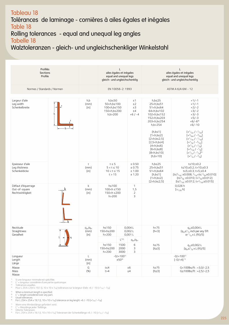
225
Tableau 18Tolérances de laminage - cornières à ailes égales et inégalesTable 18Rolling tolerances - equal and unequal leg anglesTabelle 18Walztoleranzen - gleich- und ungleichschenkliger Winkelstahl
Profilés Sections Profile
Lailes égales et inégalesequal and unequal legs
gleich- und ungleichschenklig
Lailes égales et inégalesequal and unequal legs
gleich- und ungleichschenklig
Normes / Standards / Normen EN 10056-2: 1993 ASTM A 6/A 6M - 12
Largeur d’aileLeg widthSchenkelbreite
t
t
h
b
h,b (mm) [in]
h,b≤50 50<h,b≤100
100<h,b≤150 150<h,b≤200
h,b>200
±1 ±2 ±3 ±4
+6 / -4
h,b≤2525<h,b≤5151<h,b≤64
64<h,b≤102102<h,b≤152152<h,b≤203203<h,b≤254
h,b>254
[h,b≤1][1<h,b≤2]
[2<h,b≤2,5][2,5<h,b≤4][4<h,b≤6][6<h,b≤8]
[8<h,b≤10][h,b>10]
+1/-1+1/-1+2/-2+3/-2+3/-3+5/-3
+6/-64)
+6/-10
[+1/32 / -1/32][+3/64 / -3/64][+1/16 / -1/16][+1/8 / -3/32][+1/8 / -1/8][+3/16 / -1/8][+1/4 / -1/4]4)
[+1/4 / -3/8]
Epaisseur d’aileLeg thicknessSchenkeldicke
t (mm)[in]
t ≤ 55 < t ≤ 10
10 < t ≤ 15t > 15
± 0.50± 0.75± 1.00± 1.20
h,b≤2525<h,b≤5151<h,b≤64
[h,b≤1][1<h,b≤2]
[2<h,b≤2,5]
t≤10;±0.2t≤10;±0.2; t>10;±0.3
t≤5;±0.3; t>5;±0.4[t≤3/16; ±0.008; 3/16<t≤ 3/8;±0.010]
[t≤3/8; ±0.010; t>3/8;±0.012][t≤3/16; ±0.012; t>3/16;±0.015]
Défaut d’équerrage Out-of-square Rechtwinkligkeit
k
k
k (mm) [in]
h≤100 100<h ≤150 150<h ≤200
h>200
1 1,5 23
0,026 h [3/128 h]
Rectitude Straightness Geradheit
qL
qyy/qzz (mm) [in]
h≤150 150<h≤200
h>200
0,004 L 0,002 L0,001 L
h<75 [h<3]
h≥75 [h≥3]
qyy≤0,004 L [qyy≤1/4 inch per any 5ft
or 1/4 x L (ft)/5]
qyy≤0,002 L [qyy≤1/8 x L (ft)/5]
L’’2) qyy/qzz
h≤150 150<h≤200
h>200
1500 20003000
6 33
Longueur Length Länge
L (mm) [in]
-0/+1001)
±503)
-0/+1001) [-0/+4] 1)
Masse Mass Masse
G (%)
t≤4 t>4
±6 ±4
h≥75 [h≥3]
G<100lbs/ft : +3,0/-2,5G≥100lbs/ft : +2,5/-2,5
1) Si une longueur minimale est spécifiée.2) L’’ = longueur considérée d’une partie quelconque.3) Tolérances usuelles.4) Pour L 254 x 254 x 19,1 [L 10 x 10 x 3/4] tolérances sur la largeur d'aile +6 / -10 [+1/4 / -3/8]1) When a minimum length is specified.2) L’’ = length considered over any part.3) Usual tolerances.4) For L 254 x 254 x 19,1 [L 10 x 10 x 3/4] tolerance on leg lenght +6 / -10 [+1/4 / -3/8]1) Wenn eine Mindestlänge gefordert wird.2) L’’ = Messlänge jeder Teillänge.3) Übliche Toleranzen.4) Für L 254 x 254 x 19,1 [L 10 x 10 x 3/4] Toleranzen der Schenkellänge +6 / -10 [+1/4 / -3/8]
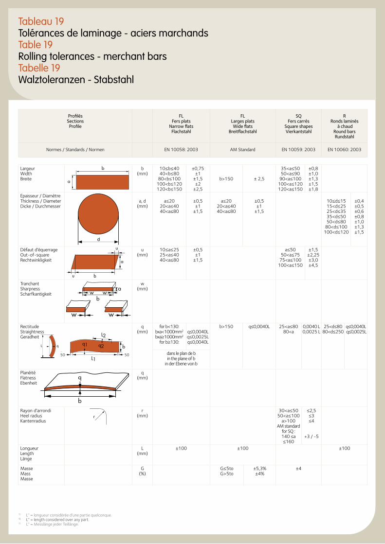
Profilés Sections Profile
FL Fers plats
Narrow flats Flachstahl
FL Larges plats Wide flats
Breitflachstahl
SQ Fers carrés
Square shapes Vierkantstahl
R Ronds laminés
à chaud Round bars Rundstahl
Normes / Standards / Normen EN 10058: 2003 AM Standard EN 10059: 2003 EN 10060: 2003
LargeurWidthBreite
b
a
b(mm)
10≤b≤4040<b≤80
80<b≤100100<b≤120120<b≤150
±0,75±1
±1,5±2
±2,5
b>150 ± 2,5
35<a≤5050<a≤90
90<a≤100100<a≤120120<a≤150
±0,8±1,0±1,3±1,5±1,8
Epaisseur / DiamètreThickness / DiameterDicke / Durchmesser
b
a, d(mm)
a≤2020<a≤4040<a≤80
±0,5±1
±1,5
a≤2020<a≤4040<a≤80
±0,5±1
±1,5
10≤d≤1515<d≤2525<d≤3535<d≤5050<d≤80
80<d≤100100<d≤120
±0,4±0,5±0,6±0,8±1,0±1,3±1,5
Défaut d’équerrageOut-of-squareRechtwinkligkeit
u
u b
a
u(mm)
10≤a≤2525<a≤4040<a≤80
±0,5±1
±1,5
a≤5050<a≤75
75<a≤100100<a≤150
±1,5±2,25±3,0±4,5
Tranchant Sharpness Scharfkantigkeit w w
b
a
ww
w (mm)
Rectitude Straightness Geradheit
q (mm)
for b<130:bxa<1000mm2 bxa≥1000mm2
for b≥130:
q≤0,0040Lq≤0,0025Lq≤0,0040L
b>150 q≤0,0040L 25<a≤8080<a
0,0040 L0,0025 L
25<d≤8080<d≤250
q≤0,0040L q≤0,0025L
dans le plan de b in the plane of b
in der Ebene von b
Planéité Flatness Ebenheit
q (mm)
Rayon d’arrondi Heel radius Kantenradius
rr
(mm)30<a≤50
50<a≤100 a>100
AM standard for SQ : 140 ≤a ≤160
≤2,5 ≤3 ≤4
+3 / -5
Longueur Length Länge
L (mm)
±100 ±100 ±100
Masse Mass Masse
G (%)
G≤5toG>5to
±5,3%±4%
±4
Tableau 19Tolérances de laminage - aciers marchandsTable 19Rolling tolerances - merchant barsTabelle 19Walztoleranzen - Stabstahl
b
q
L1
L2
b5◊5◊
q1 q2qL
50 50
1) L’’ = longueur considérée d’une partie quelconque.1) L’’ = length considered over any part.1) L’’ = Messlänge jeder Teillänge.
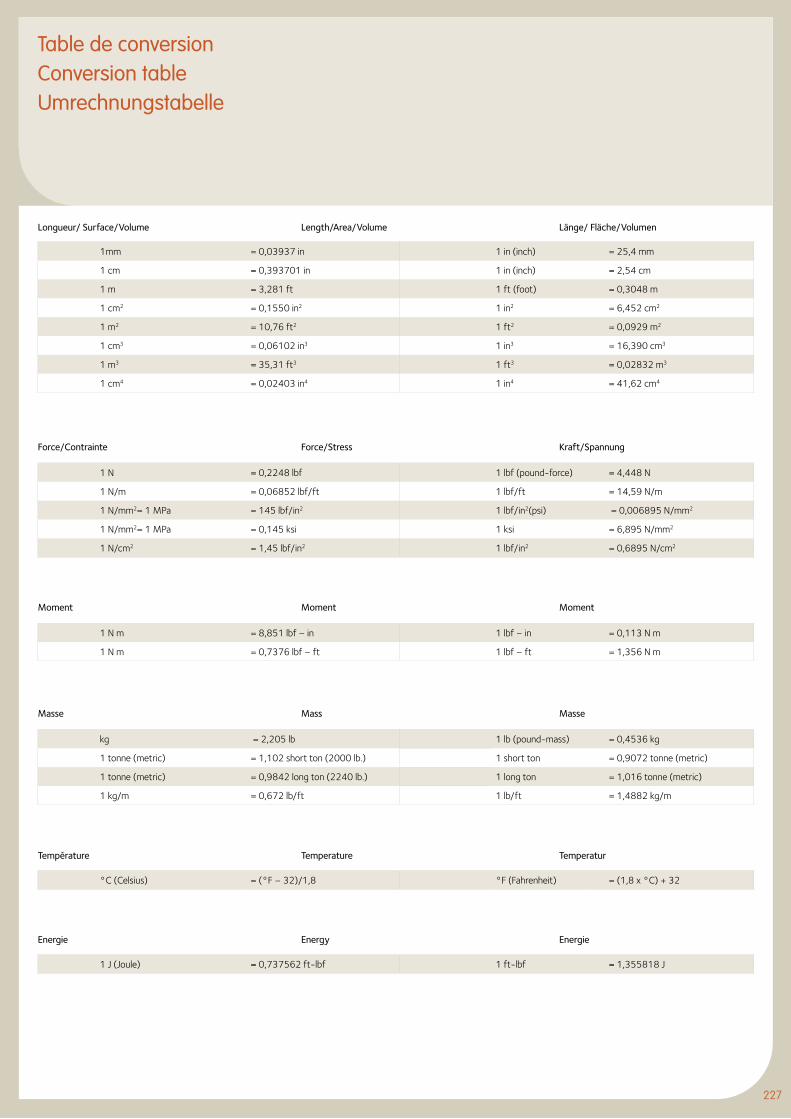
227
Table de conversionConversion tableUmrechnungstabelle
1mm = 0,03937 in 1 in (inch) = 25,4 mm
1 cm = 0,393701 in 1 in (inch) = 2,54 cm
1 m = 3,281 ft 1 ft (foot) = 0,3048 m
1 cm2 = 0,1550 in2 1 in2 = 6,452 cm2
1 m2 = 10,76 ft2 1 ft2 = 0,0929 m2
1 cm3 = 0,06102 in3 1 in3 = 16,390 cm3
1 m3 = 35,31 ft3 1 ft3 = 0,02832 m3
1 cm4 = 0,02403 in4 1 in4 = 41,62 cm4
Longueur/ Surface/Volume Length/Area/Volume Länge/ Fläche/Volumen
1 N = 0,2248 lbf 1 lbf (pound-force) = 4,448 N
1 N/m = 0,06852 lbf/ft 1 lbf/ft = 14,59 N/m
1 N/mm2= 1 MPa = 145 lbf/in2 1 lbf/in2(psi) = 0,006895 N/mm2
1 N/mm2= 1 MPa = 0,145 ksi 1 ksi = 6,895 N/mm2
1 N/cm2 = 1,45 lbf/in2 1 lbf/in2 = 0,6895 N/cm2
Force/Contrainte Force/Stress Kraft/Spannung
1 N m = 8,851 lbf – in 1 lbf – in = 0,113 N m
1 N m = 0,7376 lbf – ft 1 lbf – ft = 1,356 N m
Moment Moment Moment
kg = 2,205 lb 1 lb (pound-mass) = 0,4536 kg
1 tonne (metric) = 1,102 short ton (2000 lb.) 1 short ton = 0,9072 tonne (metric)
1 tonne (metric) = 0,9842 long ton (2240 lb.) 1 long ton = 1,016 tonne (metric)
1 kg/m = 0,672 lb/ft 1 lb/ft = 1,4882 kg/m
Masse Mass Masse
°C (Celsius) = (°F – 32)/1,8 °F (Fahrenheit) = (1,8 x °C) + 32
Température Temperature Temperatur
1 J (Joule) = 0,737562 ft-lbf 1 ft-lbf = 1,355818 J
Energie Energy Energie
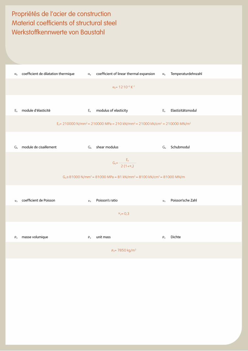
Propriétés de l’acier de constructionMaterial coefficients of structural steelWerkstoffkennwerte von Baustahl
a coefficient de dilatation thermique a coefficient of linear thermal expansion a Temperaturdehnzahl
a= 12.10-6 K-1
Ea module d’élasticité Ea modulus of elasticity Ea Elastizitätsmodul
Ea= 210000 N/mm2 = 210000 MPa = 210 kN/mm2 = 21000 kN/cm2 = 210000 MN/m2
Ga module de cisaillement Ga shear modulus Ga Schubmodul
Ga ≅ 81000 N/mm2 = 81000 MPa = 81 kN/mm2 = 8100 kN/cm2 = 81000 MN/m
a coefficient de Poisson a Poisson’s ratio a Poisson’sche Zahl
a= 0,3
a masse volumique a unit mass a Dichte
a= 7850 kg/m3
Ga=Ea
2 (1+ a)

229

Siège socialHeadquartersHauptgeschäftssitz
LUXEMBOURGArcelorMittalCommercial Sections66, rue de LuxembourgL 4221 Esch sur AlzetteLUXEMBOURGT : +352 5313 3010F : +352 5313 [email protected]
SPAINArcelorMittalComercial Perfiles España S.L.Ctr. Toledo. Km. 9,200E 28021 MadridSPAINT : +34 91 797 23 00F : +34 91 505 02 57
Nos agencesOur agenciesUnsere Vertretungen
ARCELORMITTAL COMMERCIAL SECTIONS
Agences commercialesSales agenciesVerkaufsagenturen
AUSTRIAArcelorMittalCommercial Sections Austria GmbHVogelweiderstraße 66A 5020 SalzburgAUSTRIAT : +43 662 88 67 44F : +43 662 88 67 44 [email protected]
BELGIUM + THE NETHERLANDSArcelorMittalCommercial Sections Benelux B.VEemhavenweg 70Postbus 55052NL 3008 EB RotterdamT : +31 10 487 03 44 (direct)F : +31 10 487 03 [email protected]
BOSNIA HERZEGOWINAArcelorMittal ZenicaBulevar kralja Tvrtka, no. 1772000 ZenicaBOSNIA HERZEGOWINAT : +384 32 467 268F : +384 32 467 065
BULGARIAArcelorMittal Commercial Long Bulgaria 2, Nikolay Hayton, ent C, apt C61113 SofiaBULGARIAT : +359 287 09 028F : +359 287 05 [email protected]
CZECH REPUBLICArcelorMittal Commercial Long Czech s.r.o.Vratimovska 68970702 Ostrava KunciceCZECH REPUBLICT : +420 59 568 6040F : +420 59 568 5025
DENMARKArcelorMittalCommercial Long Denmark A/SIslands Brygge, 43DK 2300 CopenhagenDENMARKT : +45 33 74 17 11F : +45 33 13 10 [email protected]
ESTONIAArcelorMittal Commercial BalticsTatari 610116 TalinESTONIAT : +372 64 14 338F : +372 6414 383erik [email protected]
FINLANDArcelorMittalCommercial Long Finland OYYrjönkatu 9A3FIN 00120 HelsinkiFINLANDT : +358 9 74 222 400F : +358 9 74 222 [email protected]
FRANCEArcelorMittalCommercial Sections France S.A.6, rue André CampraF 93212 La Plaine Saint-Denis CedexFRANCET : +33 1 71 92 00 00F : +33 1 71 92 17 [email protected]
Domaine de Pelus4, rue Graham BellF 33700 MerignacFRANCET : +33 5 57 92 09 10F : +33 5 57 92 61 [email protected]
231
GREECE AND CYPRUSArcelor MittalCommercial FCSE Greece Ltd.Zeppou 51GR 16675 Glyfada AthensGREECET : +30 210 960 42 79F : +30 210 965 25 [email protected]
GERMANYArcelorMittalCommercial Long Deutschland GmbHSubbelrather Straße 13P.O. Box 10 12 04D 50452 KölnGERMANYT : +49 221 572 90F : +49 221 572 92 [email protected]
Augustenstraße 7D 70178 StuttgartGERMANYT: +49 711 489 80 0F: +49 711 489 80 [email protected]
ICELANDGudmundur Arason EHFSkútuvogur 4IS 104 ReykjavikICELANDT : +354 568 6844F : +354 568 [email protected]
ITALYArcelorMittalCommercial Sections Italia SrlStrada Torino 43 c/oEuropalace CenterI 10043 Orbassano (TO)ITALYT : +39 011 906 3931F : +39 011 903 [email protected]
NORWAYArcelorMittalCommercial Long Norway A/SArbinsgate 2,N 0253 OsloPostboks 2667 Solli,N 0203 OsloNORWAYT : +47 22 83 78 20F : +47 22 83 78 [email protected]
POLANDArcelorMittalCommercial Long PolandAl. Pilsudskiego 9241 308 Dabrawa GomiczaPOLANDT : +48 32 776 67 27F : +48 32 776 70 [email protected]
ROMANIAArcelorMittalCommercial Long Romania S.R.L.7 9 Intrarea Tudor Stefan2nd Floor, AP. 4Sector 1, 011 655 BucharestROMANIAT : +40 31 405 47 93F : +40 21 231 71 [email protected]
SWEDENArcelorMittalCommercial Long Sweden A.B.Birger Jarlsgatan 41 AS 111 45 StockholmSWEDENT : +46 8 534 80 94 0F : +46 8 611 61 [email protected]
SWITZERLANDArcelorMittalCommercial Sections Schweiz AGInnere Margarethenstrasse 7CH 4051 BaselSWITZERLANDT : +41 61 227 77 77F : +41 61 227 77 [email protected]
UNITED KINGDOMArcelorMittalCommercial Long UK LtdArcelor House4 Prince’s Way SolihullWest Midlands B91 3ALUNITED KINGDOMT : +44 121 705 84 44F : +44 121 703 05 [email protected]
69 High Street, RayleighEssex S56 7EJUNITED KINGDOMT : +44 126 877 90 56F : +44 126 877 84 [email protected]
Siège socialHeadquartersHauptgeschäftssitz
LUXEMBOURGArcelorMittal InternationalLuxembourg19, avenue de la LibertéL 2930 LuxembourgG.D. of LUXEMBOURGT : +352 4792 1F : +352 49 07 [email protected]
ARCELORMITTAL INTERNATIONAL
AFRICAArcelorMittal InternationalAfricaDouar Chtaiba, Route 107 Zenata MohammediaMOROCCOT : +212 522 75 1692F : +212 522 75 17 43 l 75 17 [email protected]
AZERBAIJANArcelorMittal International AzerbaijanAGA Center, 13th Floor55, Khojali AvenueRoom No 13/5AZ-1025 BakuAzerbaijanT: +90 212 317 4948F: +90 212 317 [email protected]
BRAZILArcelorMittal InternationalBrasilAlameda Santos 700, 13° andarCEP 01418 100 SPSAO PAOLOBRAZILT : +55 11 36 38 69 04F : +55 11 36 38 69 [email protected]
CANADAArcelorMittal InternationalCanada5500 North Service Road, 7th FloorL7L 6W6 BURLINGTONONTARIOCANADAT : +1 905 634 1400F : +1 905-634 [email protected]
CHILEArcelorMittal InternationalChileSan Pio X N° 2460 Of. 705.Providencia/SantiagoT : +56 2 233 96 94F : +56 2 233 26 [email protected]
CHINA (People’s Republic of)ArcelorMittal InternationalShanghaiUnit A2 13F Time Square,500 Zhangyang RoadPudong, Shanghai 200122P.R. CHINAT : +86 21 58368200F : +86 21 [email protected]
ArcelorMittal InternationalBeijingFortune Plaza Office Tower A, Room 38017 Dongsanhuan Zhong Lu Chaoyang District100020 BeijingP.R. CHINAT : +86 10 65309633F : +86 10 [email protected]
ArcelorMittal InternationalUrumqui8F China Development Bank towerFountain Plaza, No 333 Zhang Shang RoadUrumqui, XinJiangP.R. CHINAT : +86 991 23396 02F : +86 991 23396 [email protected]
COLOMBIAArcelorMittal InternationalColombiaCalle 90 N° 12 45 Of. 605Bogotá, COLOMBIAT : +57 1 623 40 22F : +57 1 610 01 [email protected]
ECUADORArcelorMittal InternationalEcuadorAv. Pampite S/N y ChimborazoCentro Comercial La Esquina, Oficina 3CumbayáQuito,ECUADORT : + 593 2 289 2162 / 2163 / 2164F : +593 2 289 [email protected]
233
EGYPTArcelorMittal InternationalEgyptUnit 1 Building no. 15Road no. 25411728 DiglaMaadi CairoEGYPTMob : + 201 000 90 [email protected]
INDIAArcelorMittal InternationalMumbai403, ‘A’ Wing, Delphi,Hiranandani Business Park,PowaiMumbai 40 0076INDIAT : +91 22 424 895 00F : +91 22 670 295 [email protected]
ArcelorMittal InternationalIndia (Automotive)6th Floor, M6, Uppal Plaza (Near Apollo Hospital)Jasola Community Center, JasolaNew Delhi 110044, INDIAT : +91 11 46759415 I 011 46759437F : +91 11 [email protected]
KOREAArcelorMittal InternationalKoreaB 613 Kolon Tripolis 1, Gumgok dongBundang gu, Sungnam cityKyunggi do, Post Code 463804KOREAT : +82 31 715 3242F : +82 31 715 [email protected]
MEXICOArcelorMittal InternationalMexico Calle Privada de los Industriales 110 A8° Piso Desp. 801 802Col. Industrial Benito JuárezQuerétaro, Qro. 76100,MEXICOT : +52 442 218 6872F : +52 442 218 [email protected]
NIGERIAArcelorMital Projects Nigeria1B Adebayo Doherty StreetOff Admiralty Way, Lekki Ph1,Lagos NigeriaT +234 1 277 [email protected]
PAKISTANArcelorMittal InternationalPakistanLiaison OfficeSuit 304, 3rd floorSiddiq Trade CenterMain Boulevard GurbergLahorePakistanT +92 42 3578 1605-06F +92 42 3253 [email protected]
PERUArcelorMittal InternationalPeruCalle Miguel Dasso 134Oficina 301Lima 27PERUT : +51 1 421 43 64F : +51 1 422 33 [email protected]
RUSSIAArcelorMittal InternationalMoscowBolshaya Ordynka Street 44, building 4119 017 MoscowRUSSIAT : +7 495 721 15 51F : +7 495 721 15 [email protected]
SENEGALArcelorMittal International SenegalAvenue Cheikh Anta DiopImmeuble SAPHIRB.P. 25 377 Dakar-FannSenegalT +221 77 529 13 90F +221 33 859 76 [email protected]
SINGAPOREArcelorMittal InternationalSingapore08 01 Anson House72, Anson Road079911 Singapore, SINGAPORET : +65 67339033F : +65 [email protected]
SOUTH AFRICAArcelorMittal InternationalSouth AfricaThe Place, 1Sandton Drive,Sandhurst, Sandton, 2196REPUBLIC OF SOUTH AFRICAT : +27 11 268 2561/2F : +27 11 268 [email protected]
TAIWANArcelorMittal InternationalTaiwan8F A3; n°502 Jiou Ru 1st Rd.;San Min Dist., Kaohsiung,TAIWAN ROCT : +886 7 390 04 25F : +886 7 390 04 [email protected]
TURKEYArcelorMittal InternationalÇelik Dis Ticaret A.S.Nispetiye Caddesi,Ozden Is MerkeziN014/4 LeventT 34330 IstanbulTURKEYT : +90 212 317 49 00F : +90 212 283 76 [email protected]
UNITED ARAB EMIRATESArcelorMittal InternationalFZEJAFZA LOB 15Office 525, 5th FloorJebel Ali Free ZonePO Box 262098Dubai,UNITED ARAB EMIRATEST : +971 4 881 1662F : +971 4 881 [email protected]
UNITED STATES OF AMERICAArcelorMittal InternationalNorth America1 South Dearborn, 13th floorChicago, IL, 60603,USAT : +1 312 899 3500F : +1 312 899 [email protected]
UKRAINEArcelorMittal InternationalUkraine20 Velzka Zhytomirska Str.10250 Kiev, UKRAINET : +38 044 201 4912 / 4913 / 4914F : +38 044 201 [email protected]
VENEZUELAArcelorMittal InternationalVenezuelaEdificio Keope, Avenida Vera Cruz, Piso 4, Oficina 45 ALas Mercedes/Caracas 1060 A,VENEZUELAT . +58 212 993 46 35 / 993 81 01 / 991 41 97F : + 58 212 992 13 [email protected]
VIETNAMArcelorMittal InternationalD35, 40 Ba Huyen Thanh Quan, Ward 6,Dist. 3, Ho Chi Minh City,VIETNAMT : + 84 8 9307248F : + 84 8 [email protected]

235
En dépit du soin apporté à la confection de la présente brochure, nous vous informons qu’ArcelorMittal ne peut en aucun cas être tenu responsable des erreurs éventuelles qu’elle pourrait contenir ni des dommages susceptibles de résulter d’une interprétation erronée de son contenu.
Although every care has been taken during the production of this brochure, we regret that we cannot accept any liability in respect of any incorrect information it may contain or any damages which may arise through the misinterpretation of its contents.
Obschon diese Broschüre mit der größtmöglichen Sorgfalt erstellt wurde, weisen wir darauf hin, dass wir keinerlei Haftung übernehmen in Bezug auf eventuell enthaltene Fehlinformationen oder für Schäden, die durch eine fehlerhafte Interpretation des Inhaltes entstehen können.

Notes / Notizen

237
Notes / Notizen

Notes / Notizen

239
Notes / Notizen

Notes / Notizen

ArcelorMittal Commercial Sections
66, rue de LuxembourgL-4221 Esch-sur-AlzetteLUXEMBOURGTel. + 352 5313 3010Fax + 352 5313 2799
www.arcelormittal.com/sections
Vers
ion
20
12
-1