aorc-cigre technical meetingapplication of real-time phasor domain simulation for wide area...
TRANSCRIPT
Application of Real-time Phasor Domain Simulation for
Wide Area Protection in Large-Scale Power Systems
Nik Sofizan Nik Yusuf
Transmission Division
Tenaga Nasional Berhad
Malaysia
AORC-CIGRE TECHNICAL MEETING16th to 21st August 2015
The Magellan Sutera Resort, Kota Kinabalu, Sabah, MALAYSIA
Pow
er S
yste
mP
he
no
me
na
Tim
e R
ange
of
WA
MPA
CC
on
tro
l Act
ion
s
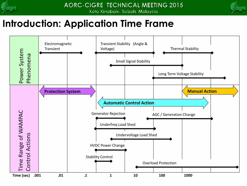
Electromagnetic Transient
Transient Stability (Angle & Voltage)
Small Signal Stability
Long Term Voltage Stability
Thermal Stability
Protection System
Automatic Control Action
Manual Action
Underfreq Load Shed
Generator Rejection
HVDC Power Change
Undervoltage Load Shed
Stability Control
Overload Protection
AGC / Generation Change
Time (sec) .001 .01 .1 1 10 100 1000
Introduction: Application Time Frame
Highlights
• Real Time Power System Simulator
• Features and Capability
• Example Hardware in Loop Testing
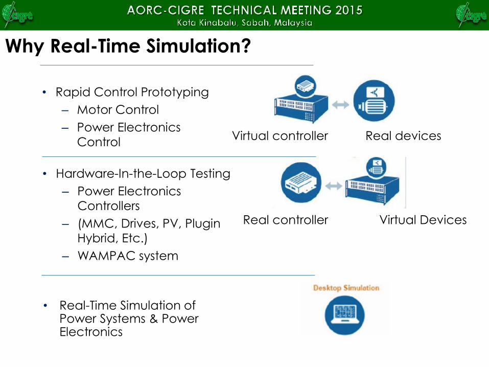
Why Real-Time Simulation?
Virtual controller Real devices
• Rapid Control Prototyping
– Motor Control
– Power Electronics
Control
Real controller Virtual Devices
• Hardware-In-the-Loop Testing
– Power Electronics
Controllers
– (MMC, Drives, PV, Plugin
Hybrid, Etc.)
– WAMPAC system
• Real-Time Simulation of Power Systems & Power Electronics
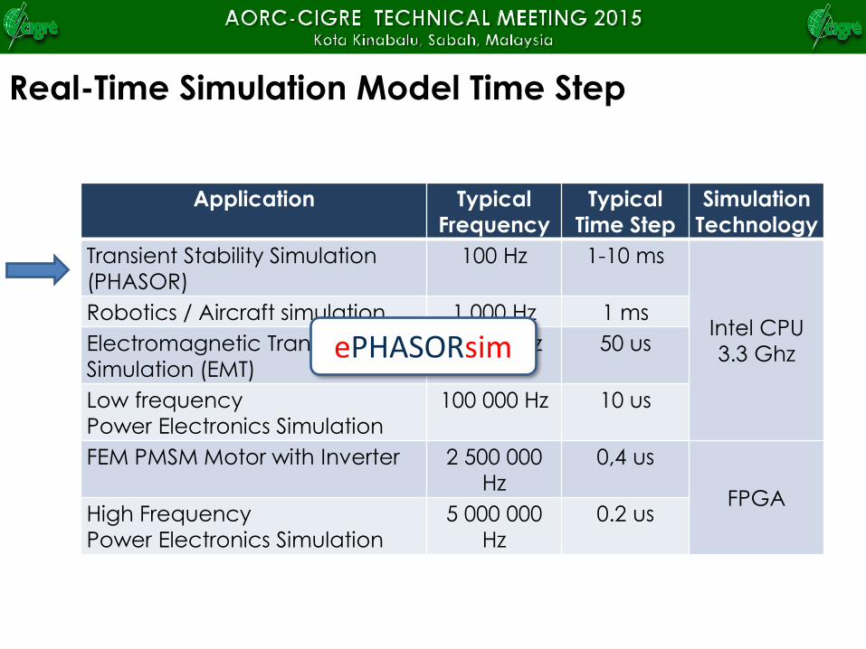
Real-Time Simulation Model Time Step
Application Typical
Frequency
Typical
Time Step
Simulation
Technology
Transient Stability Simulation
(PHASOR)
100 Hz 1-10 ms
Intel CPU
3.3 Ghz
Robotics / Aircraft simulation 1 000 Hz 1 ms
Electromagnetic Transients
Simulation (EMT)
20 000 Hz 50 us
Low frequency
Power Electronics Simulation
100 000 Hz 10 us
FEM PMSM Motor with Inverter 2 500 000
Hz
0,4 us
FPGAHigh Frequency
Power Electronics Simulation
5 000 000
Hz
0.2 us
ePHASORsim
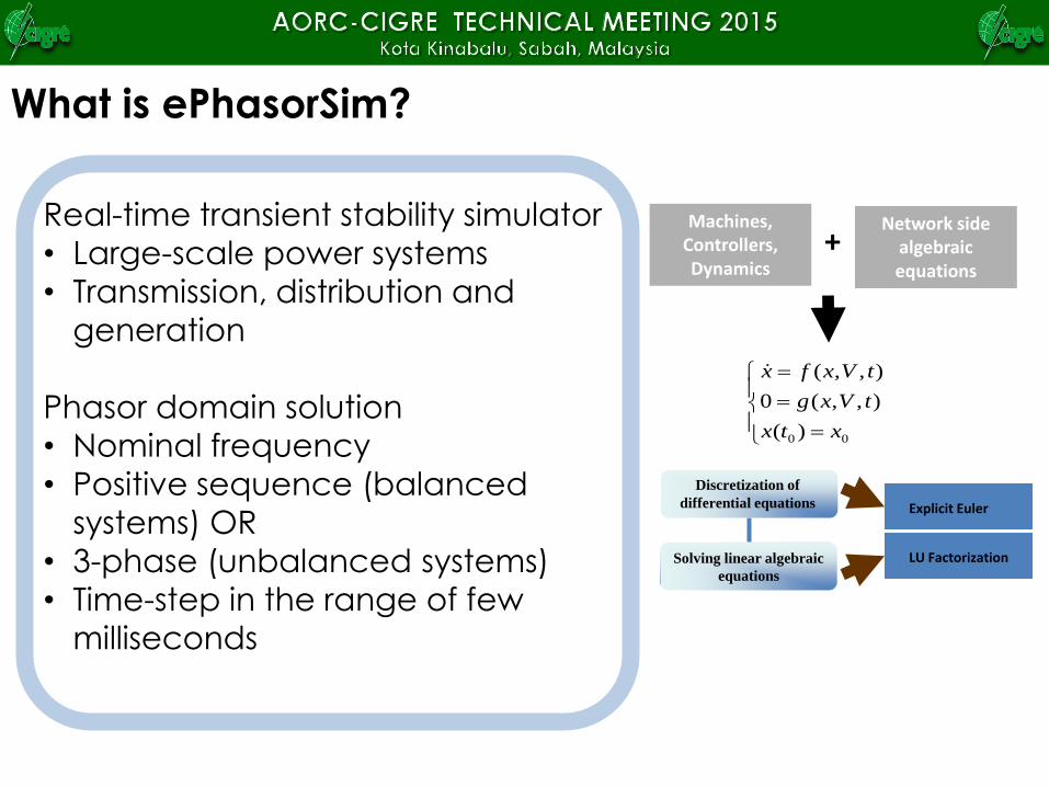
Real-time transient stability simulator
• Large-scale power systems
• Transmission, distribution and
generation
Phasor domain solution
• Nominal frequency
• Positive sequence (balanced
systems) OR
• 3-phase (unbalanced systems)
• Time-step in the range of few
milliseconds
00 )(
),,(0
),,(
xtx
tVxg
tVxfx
Machines, Controllers, Dynamics
Network side algebraic equations
+
Discretization of
differential equations
Solving linear algebraic
equations
Explicit Euler
LU Factorization
What is ePhasorSim?
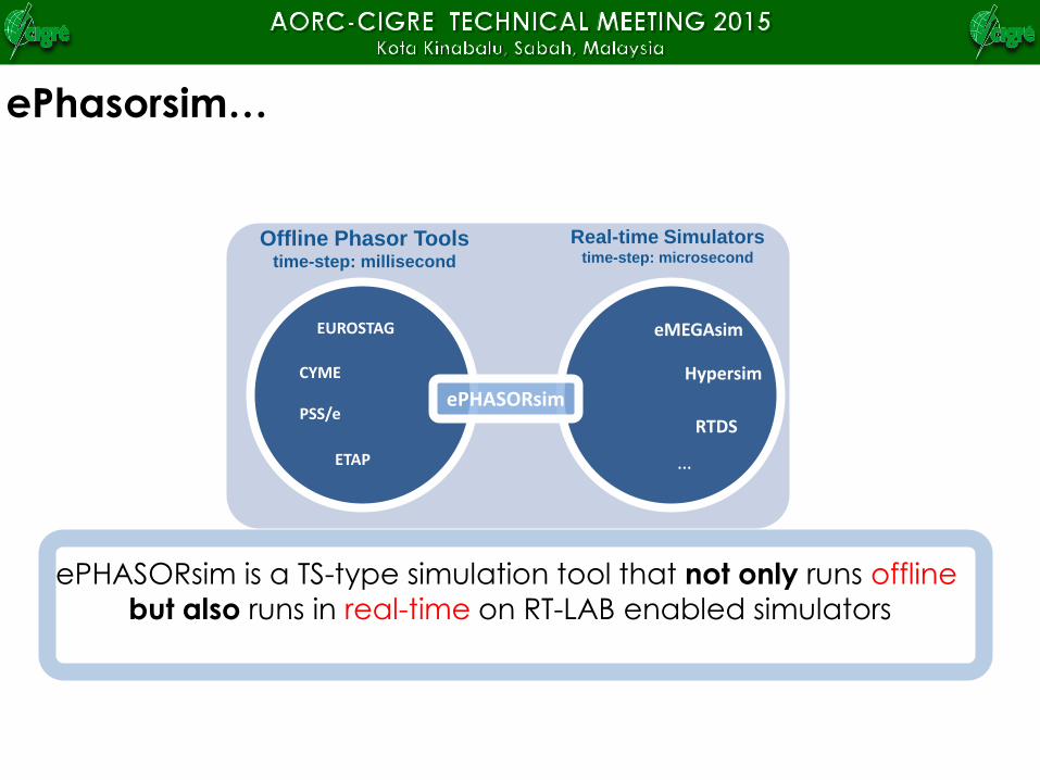
Offline Phasor Tools time-step: millisecond
PSS/e
ETAP
EUROSTAG
CYME
Real-time Simulatorstime-step: microsecond
eMEGAsim
Hypersim
RTDS
…
ePHASORsim
ePhasorsim…
ePHASORsim is a TS-type simulation tool that not only runs offline
but also runs in real-time on RT-LAB enabled simulators
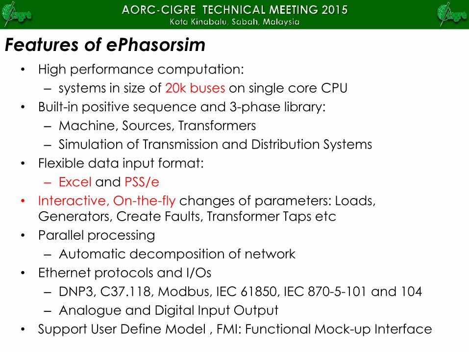
• High performance computation:
– systems in size of 20k buses on single core CPU
• Built-in positive sequence and 3-phase library:
– Machine, Sources, Transformers
– Simulation of Transmission and Distribution Systems
• Flexible data input format:
– Excel and PSS/e
• Interactive, On-the-fly changes of parameters: Loads,
Generators, Create Faults, Transformer Taps etc
• Parallel processing
– Automatic decomposition of network
• Ethernet protocols and I/Os
– DNP3, C37.118, Modbus, IEC 61850, IEC 870-5-101 and 104
– Analogue and Digital Input Output
• Support User Define Model , FMI: Functional Mock-up Interface
Features of ePhasorsim
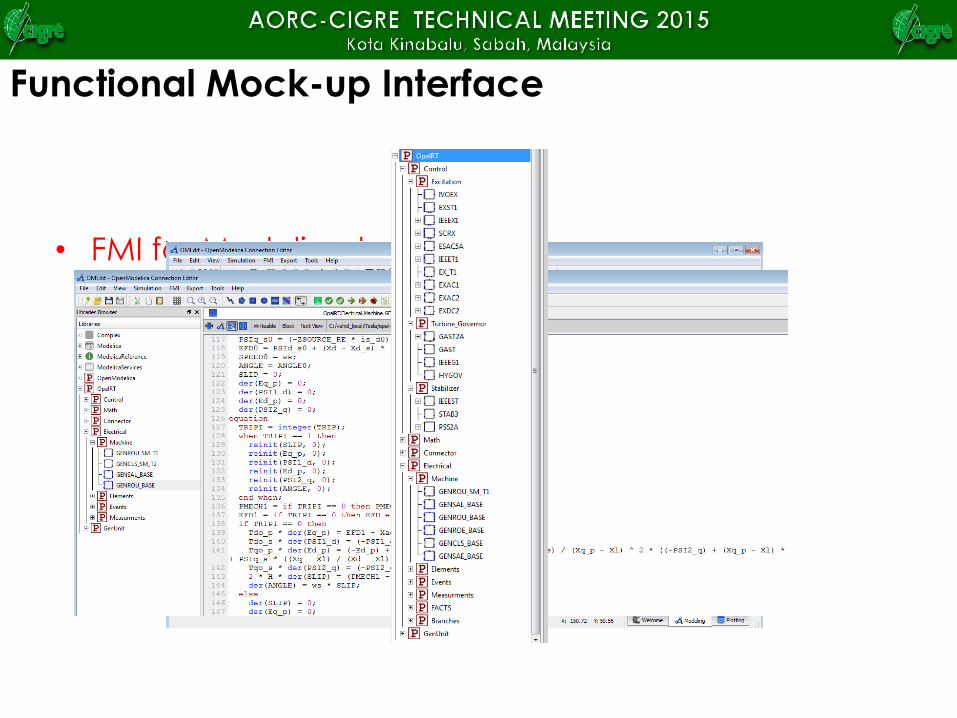
• FMI for Modelica based FMUs
– FMU generation for both Windows
and Linux OS
– FMI is compatible with
OpenModelica: an open source
Modelica tool
– A library of models are developed
based on PSS/e components
Functional Mock-up Interface
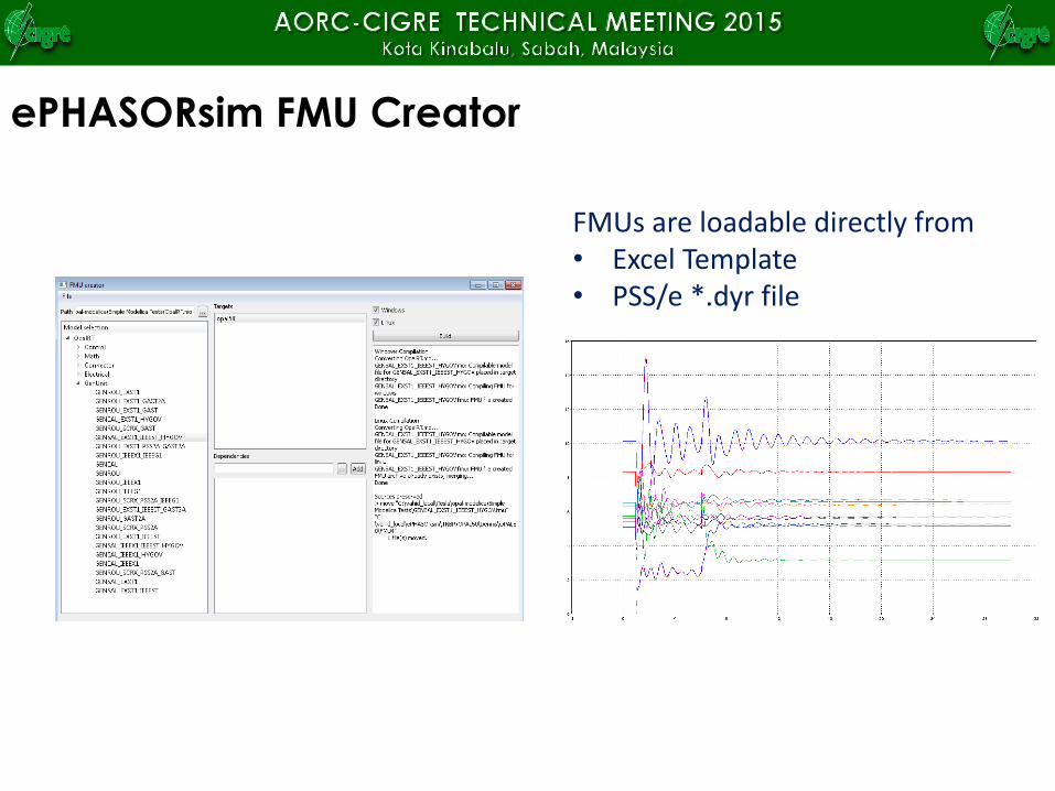
ePHASORsim FMU Creator
FMUs are loadable directly from• Excel Template • PSS/e *.dyr file
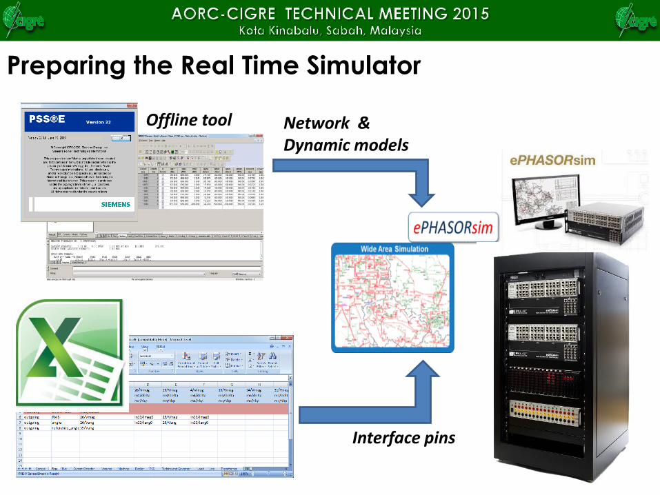
Preparing the Real Time Simulator
Interface pins
Network & Dynamic models
Offline tool
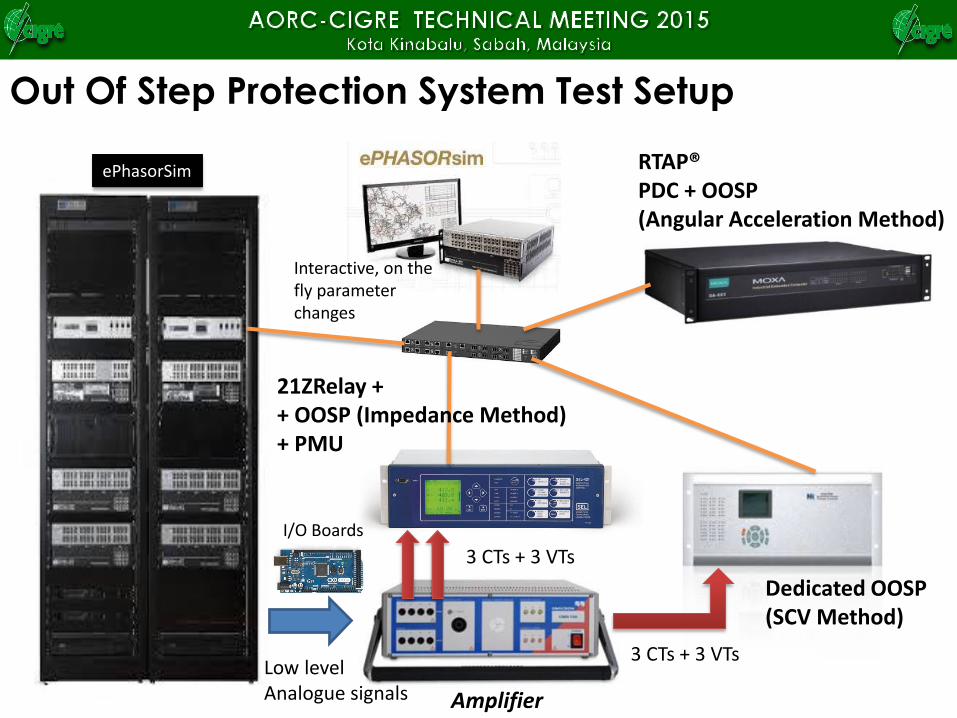
Out Of Step Protection System Test Setup
Amplifier
3 CTs + 3 VTs
Low levelAnalogue signals
ePhasorSim RTAP®PDC + OOSP(Angular Acceleration Method)
Dedicated OOSP(SCV Method)
3 CTs + 3 VTs
21ZRelay + + OOSP (Impedance Method)+ PMU
Interactive, on the fly parameter changes
I/O Boards
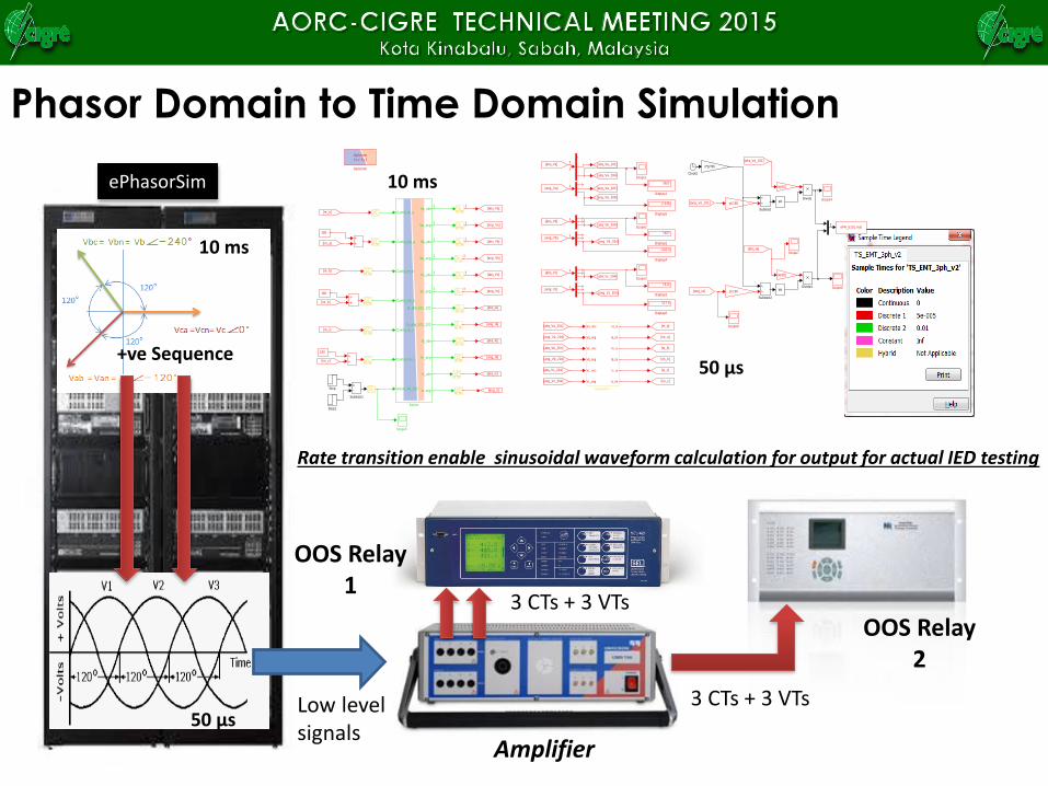
Phasor Domain to Time Domain Simulation
Amplifier
3 CTs + 3 VTs
Low levelsignals
3 CTs + 3 VTs50 μs
+ve Sequence
10 ms
OOS Relay1
OOS Relay2
Rate transition enable sinusoidal waveform calculation for output for actual IED testing
sin
sin
ePH_b101.mat
To File
Subtract2
Subtract1
Subtract
Va_rms
Va_ang
Vb_rms
Vb_ang
Vc_rms
Vc_ang
Ia_re
Ia_im
Ib_re
Ib_im
Ic_re
Ic_im
Subsystem
Step1
Step
Va_abs
Va_ang
Vb_abs
Vb_ang
Vc_abs
Vc_ang
Ia_abs_101_102
Ia_ang_101_102
Ib_abs
Ib_ang
Ic_abs
Ic_ang
CurrInj_re_a
CurrInj_im_a
CurrInj_re_b
CurrInj_im_b
CurrInj_re_c
CurrInj_im_c
Active_Flt_102
Solver
Scope8
Scope7
Scope6
Scope5
Scope4
Scope3
Scope2
Scope1
Copy
1/z
1/z
1/z
1/z
1/z
1/z
ZOH
ZOH
ZOH
ZOH
ZOH
1/z
ZOH
ZOHCopy
Copy
Copy
1/z
OpComm
Ts = Ts_f
OpComm
[abs_Va_204]
[abs_Vb_204]
[ang_Vc]
[ang_Vb]
[ang_Va]
[abs_Vc]
[abs_Vb]
[ang_Ib]
[abs_Ib]
[ang_Ia]
[abs_Ia]
[abs_Va_101]
[ang_Va_101]
[im_c]
[abs_Va]
[ang_Ic]
[abs_Ic][re_c]
[im_b]
[re_b]
[im_a]
[re_a]
[abs_Vc_204]
[ang_Va_204]
[ang_Vc_204]
[ang_Vb_204]
sqrt(2)
2*pi*60
sqrt(2)
pi/180
pi/180
[ang_Vb_204]
[ang_Va_204]
[abs_Vb_204]
[ang_Vc]
[abs_Vc]
[ang_Vb]
[im_c]
[re_c]
[abs_Vb]
[ang_Ia]
[ang_Va]
[abs_Ia]
[ang_Va_101]
[abs_Va_101]
[im_b]
[re_b]
[ang_Vc_204]
[im_a]
[re_a]
[abs_Va_204]
[abs_Vc_204]
[abs_Va]
Divide1
Divide
117.6
Display6
-2.449
Display5
-122.3
Display4
7412
Display3
7407
Display2
7407
Display1
180
180
180
Clock1
3
3
3
3
3
3
3
3
3
3
3
3
3
3
3
3
3
3
3
2
ePhasorSim 10 ms
50 μs
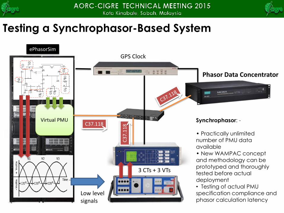
Testing a Synchrophasor-Based System
3 CTs + 3 VTs
Low levelsignals
Phasor Data Concentrator
C37.118C
37
.11
8Virtual PMU Synchrophasor: -
• Practically unlimited number of PMU data available• New WAMPAC concept and methodology can be prototyped and thoroughly tested before actual deployment• Testing of actual PMU specification compliance and phasor calculation latency
ePhasorSim
GPS Clock
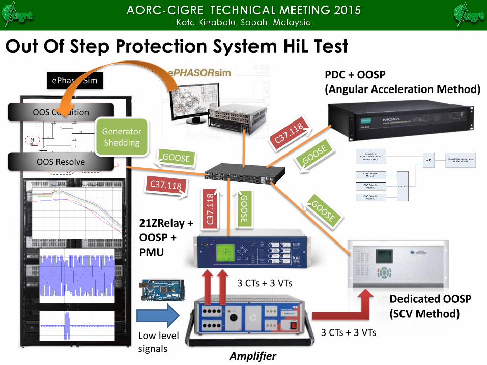
Out Of Step Protection System HiL Test
Amplifier
21ZRelay + OOSP + PMU
3 CTs + 3 VTs
Low levelsignals
ePhasorSimPDC + OOSP(Angular Acceleration Method)
Dedicated OOSP(SCV Method)
GO
OSE
3 CTs + 3 VTs
C3
7.1
18
0 0.5 1 1.5-1.5
-1
-0.5
0
0.5
1
1.5x 10
4
Time (s)
Vo
lta
ge
(V
)
0 0.5 1 1.5-1
-0.8
-0.6
-0.4
-0.2
0
0.2
0.4
0.6
0.8
1x 10
4
Time (s)
Cur
rent
(A)
9 9.5 10 10.5 11 11.5 12 12.5 13 13.5 14
-250
-200
-150
-100
-50
0
50
100
Time (s)
An
gle
(D
eg
.)
Generator Rotor Angle After Out-Of-Step Control
OOS Condition
OOS Resolve
Generator Shedding
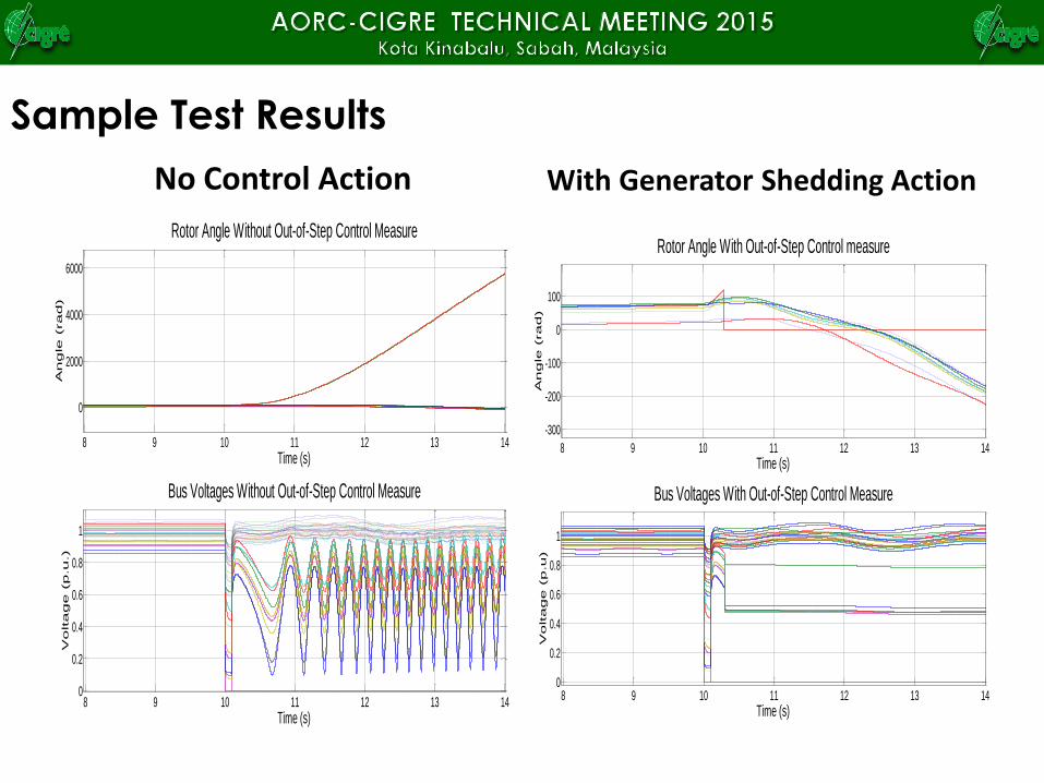
Sample Test Results
No Control Action With Generator Shedding Action
8 9 10 11 12 13 14
0
2000
4000
6000
Time (s)
An
gle
(ra
d)
Rotor Angle Without Out-of-Step Control Measure
8 9 10 11 12 13 140
0.2
0.4
0.6
0.8
1
Time (s)
Vo
lta
ge
(p
.u
.)
Bus Voltages Without Out-of-Step Control Measure
8 9 10 11 12 13 14
-300
-200
-100
0
100
Time (s)
An
gle
(ra
d)
Rotor Angle With Out-of-Step Control measure
8 9 10 11 12 13 140
0.2
0.4
0.6
0.8
1
Time (s)
Vo
lta
ge
(p
.u
)
Bus Voltages With Out-of-Step Control Measure
Summary
• Enable comprehensive functional and performance
testing of WAMPAC under controlled environment
be actual deployment
– Entire grid model can be included
– Various grid conditions, loads and generation
patterns
– Testing scenarios not possible in actual system
test
• Operator training on newly develop WAMPAC
applications
• Rapid prototyping of new concepts or ideas
• Increase collaboration between utility and
universities
Summary
• Continuous improvement and tuning of the models
shall be carried out to ensure the simulation results
are as close as possible to actual grid
– Every time when grid disturbance occurs
– Using data from PMU-Based dynamic recorder
– Perform model and model parameters validation