année : 9 faculté: sciences de l’ingéniorat département...
TRANSCRIPT
Année : 1029
Faculté: Sciences de l’ingéniorat
Département: Génie mécanique
MEMOIRE
Présenté en vue de l’obtention du diplôme de : MASTER
Intitulé
Domaine : Sciences et Technologie
Filière : Génie mécanique
Spécialité : Construction mécanique
Par :
BELABEND Selma
Directeurs de mémoire :
KHELIF.R. Pr UNIVERSITE BADJI MOKHTAR ANNABA ALGERIE
PAUNOIU.V Pr UNIVERSITE DUNAREA DE JOS GALATI – ROUMANIE
BADJI MOKHTAR- ANNABA UNIVERSITY
UNIVERSITE BADJI MOKHTAR ANNABA
عنابـة-جامعة باجي مختار
Maintenance Based on Simulation of
Static Structural Analysis for
Bearings Behaviour
1
About the Algerian National Laboratory in Maintenance
Education
For Algerian economy, Africa's fourth economy, to be able to compete successfully both at
national and international levels, production systems and equipment must perform at much
better levels. Requirements for increased product quality, reduced throughput time and
enhanced operating effectiveness within a rapidly changing customer demand environment
continue to demand a high maintenance performance. Unfortunately, few companies in Algeria
address the significant synergies of knowledge and skills in maintenance and maintenance
operations. Currently, there are no any maintenance programmes at academic level while
training in maintenance is isolated being performed solely in few large companies.
Today, the universities are further stressed by huge classes, overstressed infrastructures,
inadequate and unskilled supervisors, insufficient and old equipment, and a lack of up-to-date
educational and scientific materials. Vocational education suffers from problems with the
language of instruction, poor teaching, haphazard job placement (lack of systematization), lack
of industrial linkages, and lack of flexibility. These problems produce graduates with
inadequate skills in unwanted areas and the inability to adapt. Investing in education and
training in maintenance engineering and management at all professional levels, engineers,
managers and technical personnel in various industries, will boost the Algerian economic
competitiveness and will create thousands of new jobs in universities, training centres, and for
engineers, managers and technicians in all economic sectors. Youth, men and women, will find
a rewarded carrier path and professional satisfaction in Algerian economic sector.
The Algerian National Laboratory in Maintenance Education, ANL-MEd, has the mission to
create the next generation educated workforce in industry. There are two major driving forces
for the ANL-MEd project proposal: i) Matching the educational and training programmes at
universities to the needs of industry and generally of the Algerian economy, for creation of new
jobs. ii) Creation of a strong coalition between university - industry - governmental
organizations for long-term collaboration in education, training and research, for revitalization
of Algerian economy and in particular of Algerian industry.
ANL-MEd assembles for 36 months a consortium with 14 partners with unique combination of
skills and expertise. The consortium, coordinated by USTHB, has a hierarchical structure that
ensures an efficient communication and cooperation. Four European universities with solid
competence in maintenance engineering and management will contribute to development of
teaching material and training students, teacher, trainers and industry staff. The four Algerian
universities will collaborate with EU partners and the Algerian industrial partners to develop
and implement the specialization and training programmes, and to create the ANL-ORG, the
national laboratory which will coordinates all activities related to maintenance education. The
key factor for implementation of the project objectives is the active collaboration between
academic and industrial partners. Therefore, important resources have been allocated for
creating a harmonious working environment – ANL-ORG – with activities for creating synergies between project partners and stakeholders. This will contribute to strengthening the
active cooperation between university and industry, as well between Algeria and EU. The
project activities are distributed in 7 work packages according to a detailed work plan that

adequately structures the efforts into manageable work packages with clear responsibilities and
objectives. For improved effectiveness in the project for organization of implementation, the
partners are grouped in three clusters: ANL-EDUC – cluster for education, ANL-VET – cluster
for vocational education and training and ANL-ORG for organization of the ANL, coordinating
the resources for integration, communication and exploitation.

II
Avec tout respect et amour je dédie ce modeste travail
À mes chers parents,
À mon mes sœurs Yasmine et Meriem,
À mon défunt Professeur Madame Boubsil Wassila puisse dieu l'accueillir dans son paradis et dans
son infinie miséricorde,
À tous mes amis en Souvenir des plus beaux instants qu'on a passés ensemble Aussi bien à tous ceux
qui m'ont aidé Merci
Selma,

III
Acknowledgements
This work was supported by a grant of the European Commission thought Erasmus + program,
code 586035-EPP-1-2017-1-DZ-EPPKA2-CBHE-JP. The information and views set out in this
publication are those of the authors and do not necessarily reflect the official opinion of the
European Union. Neither the European Union institutions and bodies nor any person acting on
their behalf may be held responsible for the use which may be made of the information
contained therein.
I would first like to thank my thesis advisor Professor Viorel PAUNOIU, head of Department
of Manufacturing Engineering from Faculty of Engineering, “Dunarea de Jos” University of
Galati, ROMANIA. The door to Professor Viorel PAUNOIU office was always open whenever
I ran into a trouble spot or had a question about my research or writing. He consistently allowed
this paper to be my own work, but steered me in the right the direction whenever he thought I
needed it as well as to all members of the ERASMUS + ANL MED project for these last 5
months in ROMANIA.
I would also like to acknowledge Professor Rabia KHELIF from the Department of Mechanical
Engineering, Faculty of Engineering, University Badji Mokhtar Annaba ALGERIA as the
second reader of this thesis, and I am gratefully indebted to his for his very valuable comments
on this thesis.
I am also hugely appreciative to Professor Nacereddine ZEGHIB from the Department of
Mechanical Engineering, Faculty of Engineering, University Badji Mokhtar Annaba
ALGERIA, and constant encouragement during the various phases of our project work and this
last 5 years at the university.
Finally, I must express my very profound gratitude to my parents and my sisters Yasmine and
Meriem BELABEND, and to my partner and colleagues for providing me with unfailing
support and continuous encouragement throughout my years of study and through the process
of researching and writing this thesis and a special thanks to my college and best friend Youcef.
This accomplishment would not have been possible without them. Thank you.
Selma,
IV
Abstract
Ball and roller bearings, commonly known as bearings, are commonly used machine elements.
The first chapter describes the types of bearing their classification and mode the choice of
bearings as well as their maintenance; the second chapter describes the defects present in the
bearing. The bearing failure can occur for various reasons, their possible causes as well as the
modes of inspection of their defects according to the standards and using the Non-Destructive
Control. Accurate determination of the cause of a bearing failure is essential to formulate
appropriate recommendations for its elimination. Simple and widely applied.
The third chapter, which is the heart of this dissertation, presents the simulation of ball bearings
using 3D simulation software: SOLIDWORKS ANSYS and MESYS calculation software. The
analysis of finite elements by contact, stress, deformation, penetration, sliding distance, etc..
ANSYS gives a good impression for the analysis of contacts, which, using ANSYS and
MESYS, based on the drawing of the model under SOLIDWORKS. Based on the state of
nonlinear contact has been researched and analysed and those following different configuration
to see what gives optimal results.
For the maintenance part: given in the last and fourth chapter
Total Productive Maintenance (TPM) is an innovative Japanese concept. Total Productive
Maintenance (TPM) concepts have been accepted by many organizations around the world.
This part aims at giving the first evaluation for the implementation of a policy of total
productive maintenance in the TPM rolling bearing industry
Keywords : Bearing , Inspection , Modelling , Simulation ; ANSYS , SOLIDWORKS , FEM ,
Bearing Behaviours , Static Load , Hertzian Contact .
V
Résumé
Les roulements à billes et à rouleaux, généralement appelés roulements, sont des éléments de
machine couramment utilisés. Le premier chapitre décrit les types de roulement leurs
classification et mode le choix des roulements ainsi que leur maintenance ; le second chapitre
décrit les défauts présent dans les roulements, La défaillance du roulement peut survenir pour
diverses raisons .Leur causes possible ainsi que les modes d'inspection de leurs défauts suivant
les standard et en utilisant les Contrôle Non-Destructive. La détermination précise de la cause
d'une défaillance d'un roulement est indispensable pour formuler les recommandations
appropriées en vue de son élimination. Simple et largement appliquée.
Le troisième chapitre qui est le cœur de cette dissertation présente la simulation des roulements
à bille en utilisant les logiciels de simulation 3D : SOLIDWORKS ANSYS et logiciel de calcul
MESYS. L'analyse des éléments finis par le contact, les contraintes, la déformation, la
pénétration, la distance de glissement, etc. ANSYS donne une bonne impression pour l'analyse
des contacts, qui, utilisant ANSYS, basé sur le dessin du modèle sous SOLIDWORKS. Basé
sur l'état de contact non linéaire a été recherché et analysé et ceux suivant différente
configuration à fin de voir la quel donne des résultats optimaux.
Pour la partie maintenance : donné dans le dernier et quatrième chapitre
La maintenance productive totale (TPM) est un concept japonais novateur, Les concepts de
maintenance productive totale (TPM) ont été acceptés par de nombreuses organisations à
travers le monde .Cette partie vise à donner la première évaluation pour l'implémentation d'une
politique de Totale maintenance productive dans l'industrie du roulement du TPM dans le
roulement
Mots clés : Simulation, Modélisation, Méthode Des Eléments Finis, Roulement à billes,
ANSYS, MESYS, Pression de Hertz.

VI
خصـــــمل تستخدم مدحرجات الكريات واألسطوانة ، والمعروفة باسم المحامل ، في عناصر الماكينة. يصف الفصل األول أنواع تحمل
التصنيف ووضع اختيار المحامل وكذلك صيانتها ؛ يصف الفصل الثاني العيوب الموجودة في المحامل ، يمكن أن يحدث
طرق فحص عيوبها وفقًا للمعايير وباستخدام التحكم غير المدمر. تحديد عطل محمل ألسباب مختلفة .أسبابها المحتملة وكذلك
دقيق لسبب فشل تحمل أمر ضروري لصياغة توصيات مناسبة و بسيطة وتطبيقها على نطاق واسع للقضاء عليه.
د: برنامج حسابيقدم الفصل الثالث الذي يمثل جوهر هذه الرسالة محاكاة الكرات باستخدام برنامج محاكاة ثالثي األبعا
SOLIDWORKS ANSYS وMESYS ، تحليل العناصر المحددة عن طريق االتصال ، واإلجهاد ، والتشوه .
طريقة ANSYS ( انطباًعا جيدًا لتحليل جهات االتصال ، باستخدام ANSYSواالختراق ، ومسافة االنزالق ، إلخ. يعطي
. بناًء على حالة االتصال غير الخطي تم بحثه SOLIDWORKS، استنادًا إلى رسم النموذج تحت )العناصر المحددة
وتحليله وتلك التي تتبع التكوينات المختلفة لمعرفة النتائج المثلى.
األخير والرابع لجزء الصيانة: الواردة في الفصل
TPM ( هو مفهوم ياباني مبتكر ، وقد تم قبول مفاهيم الصيانة اإلنتاجية الشاملةTPMمن قبل العد ) يد من المؤسسات في
المتداول TPMجميع أنحاء العالم. يهدف هذا الجزء إلى إعطاء التقييم األول لتنفيذ سياسة الصيانة التكميلية المنتجة في العالم.
صناعة الحاملة
.، ضغط هيرتز ANSYS ،MESYSالنمذجة ، طريقة العناصر المحددة ، كروي ، المحاكاة،الكلمات المفتاحية:
Maintenance Based on Simulation of Static Structural Analysis for Bearings Behaviour
Selma BELABEND
VII
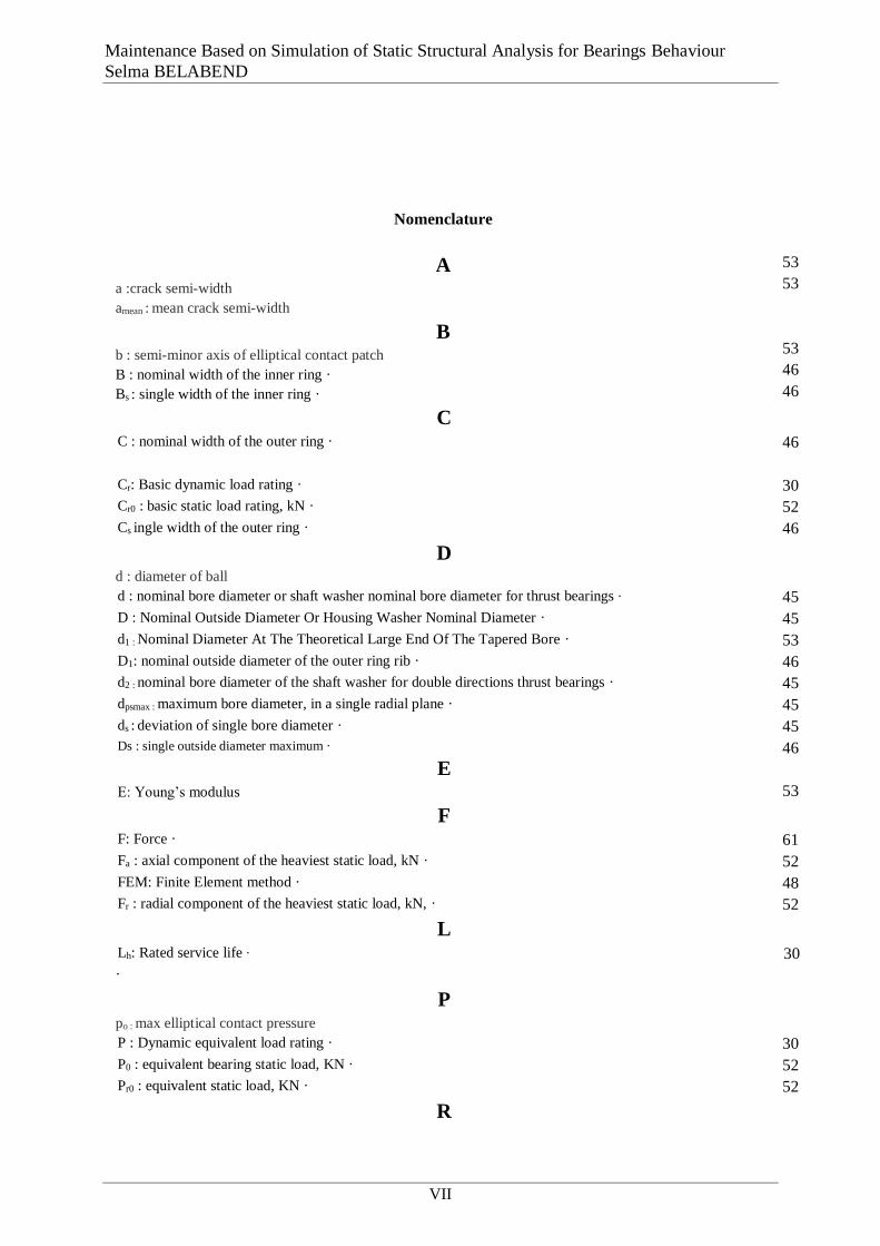
Nomenclature
A a :crack semi-width
amean : mean crack semi-width
B b : semi-minor axis of elliptical contact patch
B : nominal width of the inner ring ·
Bs : single width of the inner ring ·
53
53
53
46
46
C
C : nominal width of the outer ring · 46
Cr: Basic dynamic load rating · 30
Cr0 : basic static load rating, kN · 52
Cs ingle width of the outer ring · 46
D d : diameter of ball
d : nominal bore diameter or shaft washer nominal bore diameter for thrust bearings · 45
D : Nominal Outside Diameter Or Housing Washer Nominal Diameter · 45
d1 : Nominal Diameter At The Theoretical Large End Of The Tapered Bore · 53
D1: nominal outside diameter of the outer ring rib · 46
d2 : nominal bore diameter of the shaft washer for double directions thrust bearings · 45
dpsmax : maximum bore diameter, in a single radial plane · 45
ds : deviation of single bore diameter · 45
Ds : single outside diameter maximum ·
E E: Young’s modulus
46
53
F
F: Force · 61
Fa : axial component of the heaviest static load, kN · 52
FEM: Finite Element method · 48
Fr : radial component of the heaviest static load, kN, · 52
L
Lh: Rated service life · 30
·
P po : max elliptical contact pressure
P : Dynamic equivalent load rating · 30
P0 : equivalent bearing static load, KN · 52
Pr0 : equivalent static load, KN · 52
R
VIII
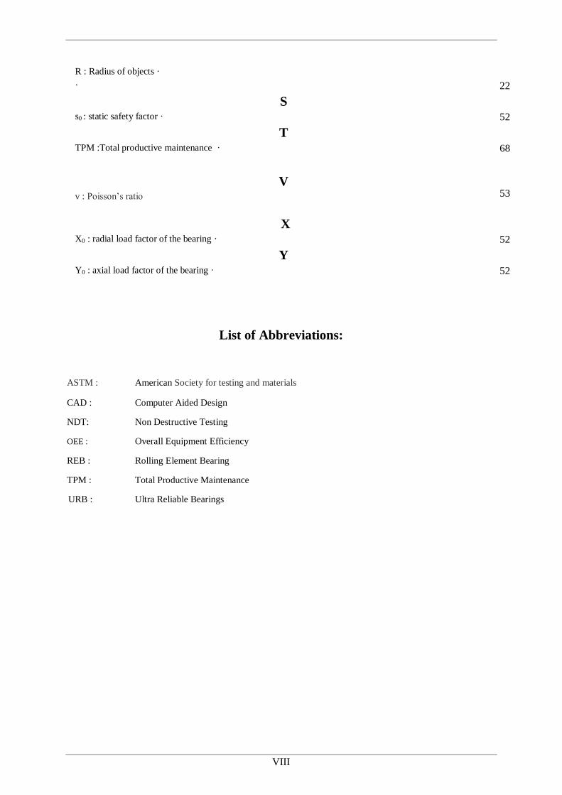
R : Radius of objects ·
· 22
S
s0 : static safety factor · 52
T
TPM :Total productive maintenance · 68
V v : Poisson’s ratio
53
X
X0 : radial load factor of the bearing · 52
Y
Y0 : axial load factor of the bearing ·
52
List of Abbreviations:
ASTM : American Society for testing and materials
CAD : Computer Aided Design
NDT: Non Destructive Testing
OEE : Overall Equipment Efficiency
REB : Rolling Element Bearing
TPM : Total Productive Maintenance
URB : Ultra Reliable Bearings
IX
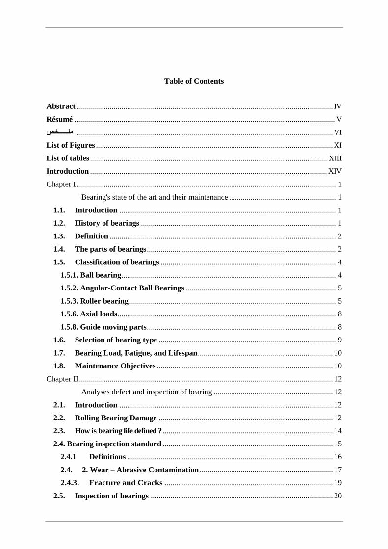
Table of Contents
Abstract ................................................................................................................................... IV
Résumé ..................................................................................................................................... V
ملــــــخص ................................................................................................................................... VI
List of Figures ......................................................................................................................... XI
List of tables ......................................................................................................................... XIII
Introduction ......................................................................................................................... XIV
Chapter I ..................................................................................................................................... 1
Chapitre 1 Bearing's state of the art and their maintenance ....................................................... 1
1.1. Introduction ............................................................................................................... 1
1.2. History of bearings .................................................................................................... 1
1.3. Definition .................................................................................................................... 2
1.4. The parts of bearings ................................................................................................. 2
1.5. Classification of bearings .......................................................................................... 4
1.5.1. Ball bearing .............................................................................................................. 4
1.5.2. Angular-Contact Ball Bearings ............................................................................. 5
1.5.3. Roller bearing .......................................................................................................... 5
1.5.6. Axial loads ................................................................................................................ 8
1.5.8. Guide moving parts ................................................................................................. 8
1.6. Selection of bearing type ........................................................................................... 9
1.7. Bearing Load, Fatigue, and Lifespan ..................................................................... 10
1.8. Maintenance Objectives .......................................................................................... 10
Chapter II.................................................................................................................................. 12
Chapitre 2 Analyses defect and inspection of bearing ............................................................. 12
2.1. Introduction ............................................................................................................. 12
2.2. Rolling Bearing Damage ......................................................................................... 12
2.3. How is bearing life defined ? ....................................................................................... 14
2.4. Bearing inspection standard ....................................................................................... 15
2.4.1 Definitions ......................................................................................................... 16
2.4. 2. Wear – Abrasive Contamination .................................................................... 17
2.4.3. Fracture and Cracks ...................................................................................... 19
2.5. Inspection of bearings ............................................................................................. 20
Tables of Contents, Figures and Tables
X
2.5.1. Visual inspection ................................................................................................... 21
2.5.2. Surface quality control ..................................................................................... 22
2.5.3. Macro-structure inspection ............................................................................. 23
2.5.5. Chemical composition analysis ....................................................................... 25
2.5.6. Mechanical properties determination ............................................................ 25
2.6. Conclusion ................................................................................................................ 26
Chapter III ................................................................................................................................ 27
Chapitre 3 Modelling and Simulation of Bearings.......................................................................
3.1. Introduction ................................................................................................................. 27
3.2. Structural dimensions of the bearings used as research objects ............................. 28
3.2.1. Geometry ............................................................................................................... 28
3.2.1. Materials ................................................................................................................ 29
3.3. CAD and FE-model ..................................................................................................... 30
A. First configuration ................................................................................................... 34
B. Second configuration .................................................................................................. 38
C. Analytical calculation ................................................................................................ 42
D. MESYS result ............................................................................................................. 45
E. Comparsaison with the result on MESYS ............................................................. 46
3.4. Discussion and conclusion ........................................................................................... 46
Chapter IV ................................................................................................................................ 48
Chapitre 4 First Step for the Implementation of TPM in the Bearing Industry ....................... 48
4.1. Introduction ................................................................................................................. 48
4.2. Presentation of industry .............................................................................................. 48
4.2.1. Generalities ............................................................................................................ 48
4.2.2. History .................................................................................................................... 49
4.3. Total productive maintenance .................................................................................... 49
4.3.1. History of total productive maintenance ............................................................ 49
4.3.2. Developmental stages of TPM .............................................................................. 49
4.3.3. Definition ............................................................................................................... 51
4.4. Implementing TPM principles ................................................................................... 55
4.4.1. 5S - A Base of TPM .............................................................................................. 56
4.5. Action plan ................................................................................................................... 58
Conclusion ........................................................................................................................... 58
Chapter V ................................................................................................................................. 60
General conclusion ................................................................................................................. 60

Maintenance Based on Simulation of Static Structural Analysis for Bearings Behaviour
Selma BELABEND
XI
References ................................................................................................................................ 61
List of Figures
Fig 1 University “Dunarea de Jos” of Galati ......................................................................... XV
Fig 2 The Faculty of Engineering ......................................................................................... XVI
Fig.1.1 History of bearing [3] .................................................................................................... 1
Fig.1.2 Rotating system with bearings [4]. ............................................................................... 2
Fig.1.3 The parts of bearings [8] ................................................................................................ 3
Fig.1.4 the parts of ball bearings [9] ......................................................................................... 3
Fig.1.5 Ball bearing [11] ............................................................................................................ 4
Fig.1.6 Bearing contact angle [14] ............................................................................................. 5
Fig.1.7 Straight roller bearing [11] ............................................................................................ 6
Fig.1.8 Roller bearings [11] ...................................................................................................... 6
Fig.1.9 Bearings Load [3] .......................................................................................................... 7
Fig.1.10 Radial load [4] ............................................................................................................. 7
Fig.1.11 Thrust load [4] ............................................................................................................. 7
Fig.1.12 Angular load [4] ........................................................................................................... 7
Fig.1.13 Radial load [4] ............................................................................................................ 8
Fig.1.14 Thrust load [4] ............................................................................................................ 8
Fig.1.15 Angular load [4] .......................................................................................................... 8
Fig.1.16 Rolling elements for ball and roller bearings [19] ....................................................... 9
Fig.2.1 The progression of surface rolling contact fatigue [31] ............................................... 13
Fig.2.2 The progression of surface rolling contact fatigue [31] ............................................... 13
Fig.2.3 The progression of surface rolling contact fatigue [31] ............................................... 13
Fig.2.4 The progression of surface rolling contact fatigue [31] ............................................... 13
Fig.2.5 ISO 15243 Bearing damage classification [36]. .......................................................... 15
Fig.2.6 Outer ring of cylindrical roller bearing ........................................................................ 17
Fig.2.7 Outer ring of double row angular contact ball bearing (rub unit bearing). .................. 17
Fig.2.8 Initial subsurface spalling in a deep groove ball bearing............................................. 18
Fig.2.9 Advanced subsurface spalling in a tapered roller bearing ........................................... 18
Fig.2.12 Micro cracks forming a “fish-scale” appearance [40] ............................................... 18
Fig.2.12 Microspalls [40] ......................................................................................................... 18
Fig2.12 Heavy grey stained areas (Scale 1,25:1) [40] ............................................................. 18
Fig.2.13 Subsurface micro crack with the “butterfly phenomenon” (white etched area) (Scale
500:1) [40] ................................................................................................................................ 19
Fig.2.14 Fracture [41] .............................................................................................................. 19
Fig.2.15 Crack [41] .................................................................................................................. 19
Fig.2.16 Fracture of inner ring [93] ......................................................................................... 20
Fig.2.17 Inner ring of spherical roller [93] bearing ................................................................. 20
Fig.2.18 Discoloration [43] ...................................................................................................... 20
Fig.2.19 Rust [43] .................................................................................................................... 20

Tables of Contents, Figures and Tables
XII
Fig.2.20 bearing part [4]........................................................................................................... 21
Fig.2.21 Visual inspection [44] ................................................................................................ 22
Fig.2.22 Dimensional and geometrical control [44] ................................................................ 22
Fig.2.23 Surface control [90] ................................................................................................... 22
Fig.2.24 Surface quality control [44] ....................................................................................... 23
Fig 2.25 Liquid Penetrant testing [106] ................................................................................... 23
Fig 2.26 Liquid Penetrant Testing [98] .................................................................................... 23
Fig.2.27 Magnetic particle testing [85] .................................................................................... 24
Fig.2.28 [92] ............................................................................................................................. 24
Fig.2.29 Eddy current test method according to the standard ISO 21968 [99]. ....................... 24
Fig.2.30 Macro-structure inspection [44]................................................................................. 25
Fig.2.31 Chemical composition analysis [17] .......................................................................... 25
Fig.2.32 Mechanical properties determination [44] ................................................................. 25
Fig.2.33 Micro-structure inspection [44] ................................................................................. 25
Fig.3.1 Methodology ................................................................................................................ 28
Fig.3.2 Technical drawing of ball bearings [51] ...................................................................... 29
Fig.3.3 Radial ball bearings [51] .............................................................................................. 29
Fig.3.4 CAD Bearing ............................................................................................................... 31
Fig.3.5 Sketch Inner Ring ........................................................................................................ 32
Fig.3.6 Inner ring CAD ............................................................................................................ 32
Fig.3.7 Cage CAD .................................................................................................................... 32
Fig.3.8 Sketch Outer Ring ........................................................................................................ 32
Fig.3.9 Outer ring CAD ........................................................................................................... 32
Fig.3.10 Balls CAD .................................................................................................................. 32
Fig.3.11 Bearing Exploded view 3D ........................................................................................ 32
Fig.3.12 Assembly on SolidWorks .......................................................................................... 32
Fig.3.13 Assembled bearing CAD model SolidWorks ............................................................ 33
Fig.3.14 Geometry on ANSYS ................................................................................................ 33
Fig.3.15 Define material to each parts ..................................................................................... 33
Fig.3.16 Adding materials data on ANSYS Engineering Data ................................................ 33
Fig.3.17 Connection balls/cage ................................................................................................ 34
Fig.3.18 shows the meshing of the ball bearing ....................................................................... 34
Fig.3.19 Boundary condition first case .................................................................................... 36
Fig.3.20 Boundary condition second case................................................................................ 36
Fig.3.22 Total deformation case 1 [87] ................................................................................... 37
Fig.3.22 Equivalent stress of Von Mises case 1 [87] .............................................................. 37
Fig 3.24 Total deformation case 1 [87] .................................................................................... 37
Fig 3.24 Equivalent stress of Von Mises case 2 [87] .............................................................. 37
Fig.3.25 Meshing second configuration ................................................................................... 38
Fig.3.26 First and second case second configuration boundary conditions ............................. 39
Fig.3.27 Contact Rings/Balls ................................................................................................... 39
Fig.3.29 Total deformation second configuration case 1 ......................................................... 40
Fig.3.29 Equivalent stress second configuration case 1 ........................................................... 40
Fig.3.30 Result first case : Pressure contact (Balls/Rings) ...................................................... 40
Fig.3.32 Total deformation second configuration case 2 ......................................................... 41
Fig.3.32 Equivalent stress second configuration case 2 ........................................................... 41
Fig.3.33 Result second case : Pressure contact (Balls/Rings) .................................................. 41
Maintenance Based on Simulation of Static Structural Analysis for Bearings Behaviour
Selma BELABEND
XIII
Fig.3.34 Contact between 2 spheres [62] [63] ........................................................................ 42
Fig.3.35 Input the bearing properties on MESYS .................................................................... 45
Fig.3.36 Contact stress MESYS position of the balls .............................................................. 45
Fig.3.37 Bearing and load distribution on MESYS ................................................................. 45
Fig.3.38 MESYS Result ........................................................................................................... 46
Fig.4.1 URB [51] ..................................................................................................................... 48
Fig.4.2 The traditional TPM model consists of a 5S and eight supporting activities [80] . .... 52
Fig.4.3 Relationship between TPM and lean manufacturing philosophy [70] ........................ 53
Fig.4.4 THE 5S [authors] ......................................................................................................... 57
List of tables
Table 2.1 Bearing damage ISO classification ......................................................................... 16
Table 2.2 Wear ........................................................................................................................ 17
Table 3.1 Geometry ................................................................................................................. 28
Table 3.2 Geometrical properties [51] ..................................................................................... 29
Table 3.3 : Material ................................................................................................................. 30
Table 3.4 Value of static safety factor [51] ............................................................................. 35
Table 3.5 Result details for the first configuration first case ................................................... 37
Table 3.6 Details of the result Von-Mises for the first configuration second case ................ 37
Table 3.7 Detail of the result first case second configuration ................................................. 40
Table 3.8 Details of pressure first case .................................................................................... 40
Table 3.9 Details of the result of the second configuration second case ................................. 41
Table 3.10 Details of pressure first case .................................................................................. 41
Table 3.11 Input Data (bearing geometry and parameters) ..................................................... 44
Table 3.12 The analytical results ............................................................................................. 44
Table 3.13 Comparison between the results ............................................................................ 46
Table 4.1 Developmental stages .............................................................................................. 50
Table 4.2 TPM TOOLS [79] .................................................................................................. 54
Table 4.3 SIX BIG LOSSES [14] ............................................................................................ 55
Table 4.4 Questionnaire ........................................................................................................... 55
XIV
Introduction
Rolling bearings allow for the transfer of forces between the moving and fixed parts of the
mechanical system, and are designed to minimize friction arising from power and energy
transfer. Due to their multiple use, increasing emphasis is placed on their development and
improvement, because, in many cases the bearings do not provide the required durability
according to the calculation values. There may be more then a reason, for example, overload,
load lower than required, inadequate lubrication, ineffective sealing, inadequate over fitting, or
impact load on the bearing that leads to permanent deformation in the form of imprints in the
bearing ring path . This very latest case of damage is becoming more and more frequent, that’s
why it is necessary to look after the problem in order to examine the given load conditions,
using FEM method and to obtain optimal results for further research, and apply modifications
in bearings in order to decrease the impact damage with the intention of eliminating it.
Researchers continue with the intensive development and research in field of bearings with
purpose to investigate new theory of bearing aspects, solving significant parameters and values
of rolling bearings in order to ensure maximum quality and accurate prediction.
And because every employee at levels in the organization is concerned about the maintenance,
the quality and efficiency of their equipment, the concepts of Total Productive Maintenance
(TPM) have been accepted in many organizations across the world. The main aim of TPM
implementation is to reduce the six big losses that are equipment failures or breakdown losses,
setup and adjustment losses.
XV
General Presentation of the University “Dunarea de Jos” of
Galati
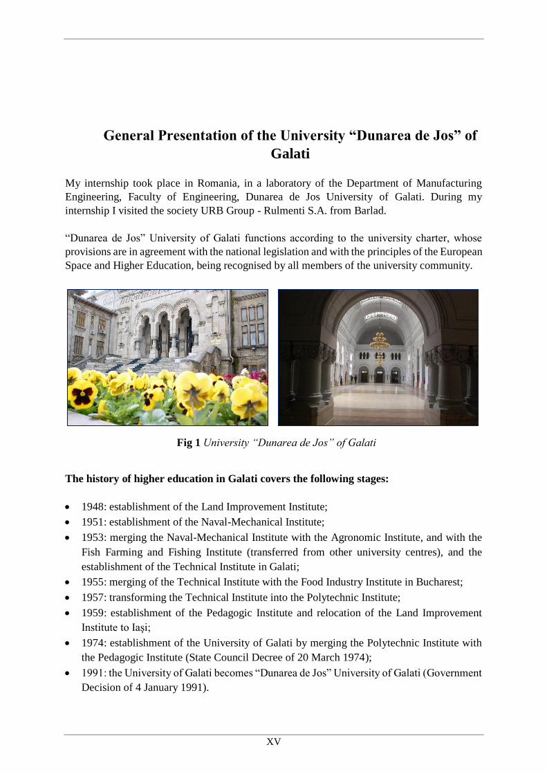
My internship took place in Romania, in a laboratory of the Department of Manufacturing
Engineering, Faculty of Engineering, Dunarea de Jos University of Galati. During my
internship I visited the society URB Group - Rulmenti S.A. from Barlad.
“Dunarea de Jos” University of Galati functions according to the university charter, whose
provisions are in agreement with the national legislation and with the principles of the European
Space and Higher Education, being recognised by all members of the university community.
The history of higher education in Galati covers the following stages:
1948: establishment of the Land Improvement Institute;
1951: establishment of the Naval-Mechanical Institute;
1953: merging the Naval-Mechanical Institute with the Agronomic Institute, and with the
Fish Farming and Fishing Institute (transferred from other university centres), and the
establishment of the Technical Institute in Galati;
1955: merging of the Technical Institute with the Food Industry Institute in Bucharest;
1957: transforming the Technical Institute into the Polytechnic Institute;
1959: establishment of the Pedagogic Institute and relocation of the Land Improvement
Institute to Iaşi;
1974: establishment of the University of Galati by merging the Polytechnic Institute with
the Pedagogic Institute (State Council Decree of 20 March 1974);
1991: the University of Galati becomes “Dunarea de Jos” University of Galati (Government
Decision of 4 January 1991).
Fig 1 University “Dunarea de Jos” of Galati

XVI
In the structure of the above mentioned institutes, there were a series of study programmes that
were unique in the country: Naval Constructions, Harbours and Ship Exploitation, Food
Industry, Fish Farming Technology, Cooling Devices – which meant that an important creation
process on elaborating educational curricula and syllabi, lectures, laboratory equipment etc.,
presently being used in other university centres around the country, was fully the work of the
academics in Galati higher education.
The academic community of “Dunarea de Jos” University of Galati is composed of the
following:
12.500 students
1000 teaching staff
14 faculties
67 Bachelor Study Programmes
52 Master study Programmes
3 Doctoral Schools
13 Doctoral Study Programmes
230 doctoral students
More than 2500 international students
“Dunarea de Jos” University of Galati has concluded more than 100 partnership agreements
with universities from 34 countries.
Faculty of Engineering
The Faculty of Engineering is a strong branch of “Dunarea de Jos” University of Galati through
its academic offer, the quality of the teaching staff and modern teaching and research spaces.
Studies are focused towards national and international subjects, increase contentment of the
students and employees, promoting values during the development process of the human
resources, multidisciplinary cooperation in all segments of teaching and scientific research
activities.
Fig 2 The Faculty of Engineering
XVII
Motivation and objectives of the work
The motivation to do this work comes from the large importance of bearings, as they are widely
used in rotating machinery to support rotating shafts. The major cause of machinery
breakdowns is bearing failure, and that last comes from the repeated high stressing on the
contacts between the rolling element and the raceway eventually causes fatigue damage. In
addition to this, the main reason for bearing failures is an improper handling-and-mounting
procedure, corrosion, wear and manufacturing defects.
However, and based on the motivation above, the main objectives of the dissertation thesis are
the following:
Describes the types of bearing, their classification, the choice of bearings as well as their
maintenance;
Analyse the possible causes of bearing failures, the modes of inspection using
destructive and Non-Destructive Control (according to the standards).
Analyse the rolling ball bearing using the finite element stress or displacement
behaviour and the pressure contact of rolling ball bearing.
Analyse of the pressure contact of rolling ball bearing using the methodology of Hertz
theory and equations based on specific ball bearing parameter and with the result of
MESYS software.
Make a comparison between the three results obtained from the analyse of pressure
contact:
o FEM analysis;
o The methodology of Hertz theory;
o MESYS software calculus.
Analysing the ball bearing behaviours with different configuration of bounding
condition and meshing in order to see the dependence of the number of elements and
nodes;
Evaluate the bearing industry in order to implement the Total Productive Maintenance
like a first initiation step.
Establish a plan of action for the implementation of the 5S in the bearing industry based
on the evaluation and results obtained.

1
Chapter I
Chapitre 1 Bearing's state of the art and their maintenance
1.1.Introduction
Ball and roller bearings, generically called rolling bearings, are commonly used machine
elements. They are employed to permit rotary motion of, or about, shafts in simple commercial
devices such as bicycles, roller skates, and electric motors. They are also used in complex
engineering mechanisms such as aircraft gas turbines, rolling mills, dental drills, gyroscopes,
and power transmissions. [2]
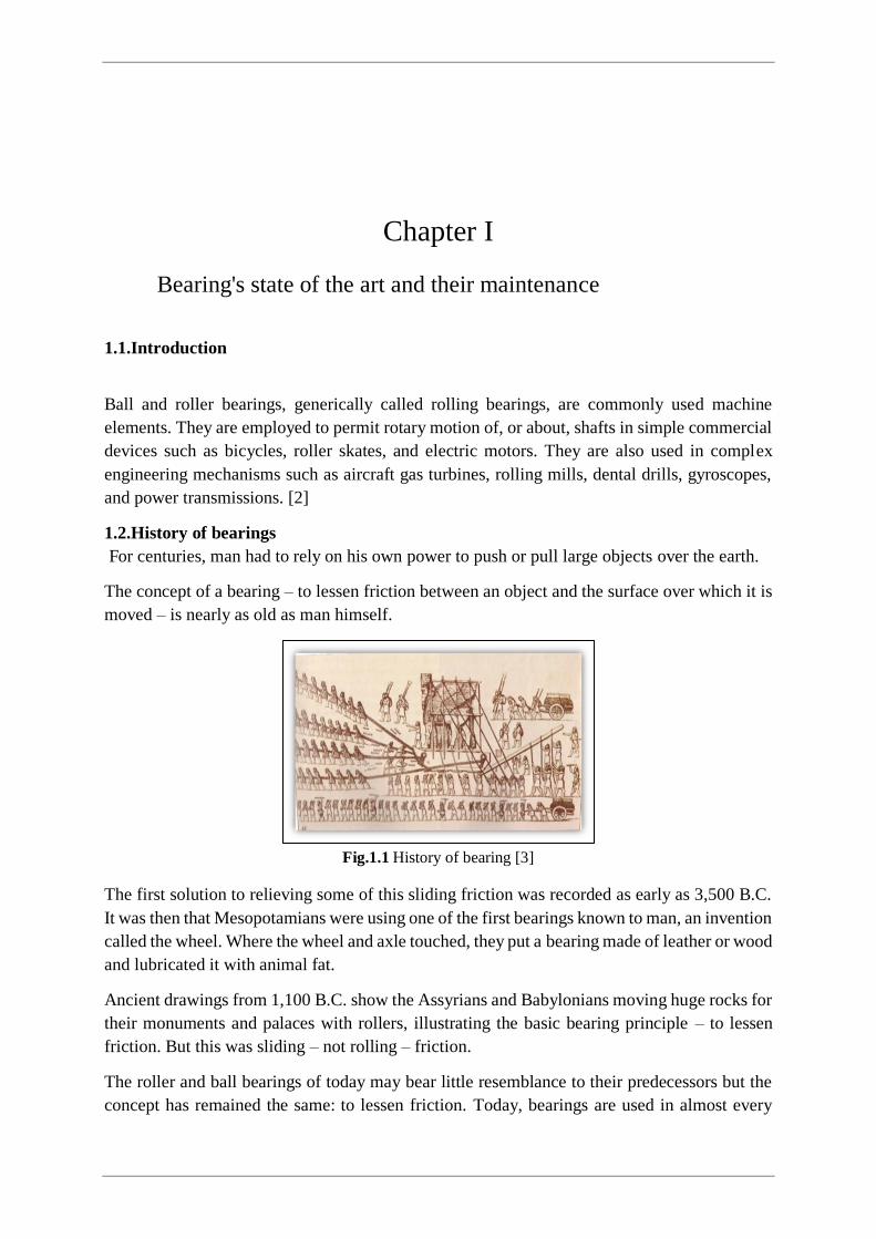
1.2.History of bearings
For centuries, man had to rely on his own power to push or pull large objects over the earth.
The concept of a bearing – to lessen friction between an object and the surface over which it is
moved – is nearly as old as man himself.
Fig.1.1 History of bearing [3]
The first solution to relieving some of this sliding friction was recorded as early as 3,500 B.C.
It was then that Mesopotamians were using one of the first bearings known to man, an invention
called the wheel. Where the wheel and axle touched, they put a bearing made of leather or wood
and lubricated it with animal fat.
Ancient drawings from 1,100 B.C. show the Assyrians and Babylonians moving huge rocks for
their monuments and palaces with rollers, illustrating the basic bearing principle – to lessen
friction. But this was sliding – not rolling – friction.
The roller and ball bearings of today may bear little resemblance to their predecessors but the
concept has remained the same: to lessen friction. Today, bearings are used in almost every

Maintenance Based on Simulation of Static Structural Analysis for Bearings Behaviour
Selma BELABEND
2
imaginable application, such as roller skates and bicycles, where two surfaces are turning or
moving against each other. They are used in thousands of ways, from the minute internal
workings of a clock to large turbine engines in a ship [4].
1.3.Definition
Rolling bearing is the key component of rotating machinery, whose running state has an
important effect on the healthy condition of rotating machinery equipment [5].
A bearing is a support or guide that locates one machine component with respect to others in
such a way that prescribed relative motion can occur while the forces associated with machine
operation are transmitted smoothly and efficiently [5].
A wide range of bearings has been developed; some involve rolling motion, sliding motion, and
both rolling and sliding motions. Lubrication of a bearing is frequently used to reduce friction
and, therefore, the wear and power absorbed by the bearing, as well as to remove heat. This
ensures the operation of the bearing assembly at temperatures compatible with the materials
and lubricant used [6].
Bearings can be classified in several ways: according to the basic mode of operation (rubbing,
hydrodynamic, hydrostatic, or rolling element), according to the direction and nature of the
applied load (thrust or journal), or according to geometric form (tapered land, stepped parallel
surface, or tilting pad). There is much to be said for classification according to the basic mode
of operation, with subdivisions to account for different geometric forms and loading conditions
[5].
Rolling element bearings are widely used in rotating machinery to support rotating shafts, and
the major cause of machinery breakdowns is bearing failure. Hence, it is necessary to detect
bearing faults at an early stage. Rolling element bearings usually consist of an inner race, an
outer race, several rollers and a cage. When the surface of one of these components develops a
localised fault, the impacts generated excite the resonant frequencies of the bearing and adjacent
components, and induce a modulating phenomenon.
1.4.The parts of bearings
The parts of a bearing a bearing’s smooth performance is assured by a combination of basic
working part Fig.1.3 :
Fig.1.2 Rotating system with bearings [4].
Chapter I Bearing’s State of The Art And Their Maintenance
3
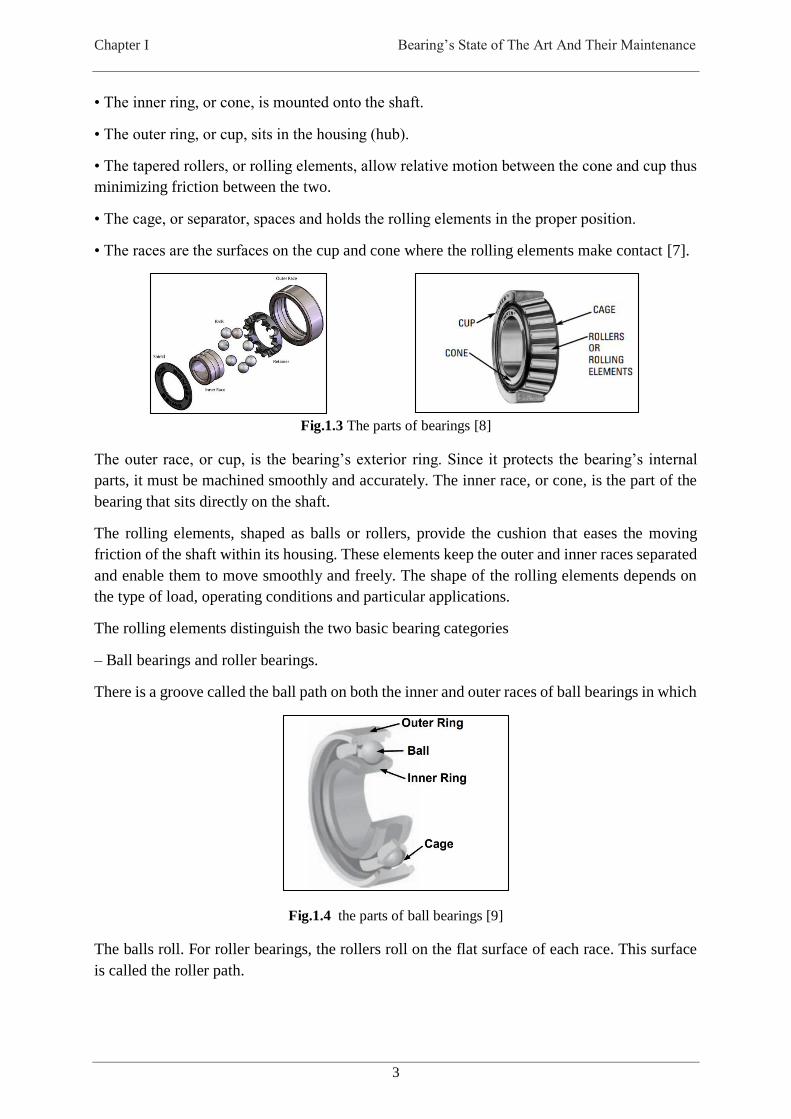
• The inner ring, or cone, is mounted onto the shaft.
• The outer ring, or cup, sits in the housing (hub).
• The tapered rollers, or rolling elements, allow relative motion between the cone and cup thus
minimizing friction between the two.
• The cage, or separator, spaces and holds the rolling elements in the proper position.
• The races are the surfaces on the cup and cone where the rolling elements make contact [7].
Fig.1.3 The parts of bearings [8]
The outer race, or cup, is the bearing’s exterior ring. Since it protects the bearing’s internal
parts, it must be machined smoothly and accurately. The inner race, or cone, is the part of the
bearing that sits directly on the shaft.
The rolling elements, shaped as balls or rollers, provide the cushion that eases the moving
friction of the shaft within its housing. These elements keep the outer and inner races separated
and enable them to move smoothly and freely. The shape of the rolling elements depends on
the type of load, operating conditions and particular applications.
The rolling elements distinguish the two basic bearing categories
– Ball bearings and roller bearings.
There is a groove called the ball path on both the inner and outer races of ball bearings in which
Fig.1.4 the parts of ball bearings [9]
The balls roll. For roller bearings, the rollers roll on the flat surface of each race. This surface
is called the roller path.
Maintenance Based on Simulation of Static Structural Analysis for Bearings Behaviour
Selma BELABEND
4
Finally, the separator is a metal retainer that holds the balls or rollers. Positioned between the
inner and outer races, the separator keeps the rolling elements evenly spaced [4].
Rolling bearings fall into two main classifications: ball bearings and roller bearings. Balls
geometrically contact the raceway surfaces of the inner and outer rings at “points,” while the
contact surface of rollers is a “line” contact. Rollers come in four basic geometric styles:
cylindrical, needle, tapered and spherical.
Rolling bearings can further be classified according to the direction in which the load is applied:
radial, thrust, or a combination of both. While the rolling elements and the bearing rings take
any load applied to the bearings (at the contact point between the rolling elements and raceway
surfaces), the retainer takes no direct load. It only serves to hold the rolling elements at equal
distances from each other, forcing the rolling elements to enter the load zones and prevent them
from falling out [9].
1.5.Classification of bearings
Bearings can also be classified according to their geometry related to the relative motion of
elements in machinery. Examples are journal, plane-slider, and spherical bearings. A journal
bearing, also referred to as a sleeve bearing, is widely used in machinery for rotating shafts. It
consists of a bushing (sleeve) supported by a housing, which can be part of the frame of a
machine. The shaft (journal) rotates inside the bore of the sleeve. There is a small clearance
between the inner diameter of the sleeve and the journal, to allow for free rotation.
In contrast, a plane-slider bearing is used mostly for linear motion, such as the slides in machine
tools. A bearing can also be classified as a radial bearing or a thrust bearing, depending on
whether the bearing load is in the radial or axial direction, respectively, of the shaft [10].
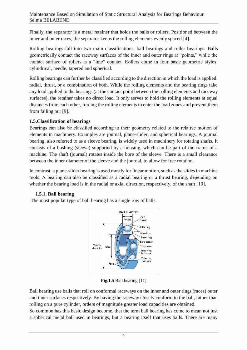
1.5.1. Ball bearing
The most popular type of ball bearing has a single row of balls.
Fig.1.5 Ball bearing [11]
Ball bearing use balls that roll on conformal raceways on the inner and outer rings (races) outer
and inner surfaces respectively. By having the raceway closely conform to the ball, rather than
rolling on a pure cylinder, orders of magnitude greater load capacities are obtained.
So common has this basic design become, that the term ball bearing has come to mean not just
a spherical metal ball used in bearings, but a bearing itself that uses balls. There are many
Chapter I Bearing’s State of The Art And Their Maintenance
5
different types of ball bearings, but in general, when the term ball bearing is used, it is usually
referred to a deep-groove radial bearing, which is sometimes called a Conrad bearing after
Robert Conrad who invented its means of manufacture. Ball bearings are extremely common
because they can handle both radial and thrust loads. In these bearings a ball provides rolling
function. They are low friction high speed bearings meant for light to medium loading.
Ball bearings generally are used for lower cost, lower load, or higher precision applications.
They are normally being used in light and general machine applications. They are commonly
found in fans, roller blades, wheel bearings, and under hood applications on cars etc [12].
In addition to the single row design, there also are double row, angular contact and ball thrust
bearings.
1.5.2. Angular-Contact Ball Bearings
Angular-contact ball bearings can be regarded as a variation of deep-groove ball bearings.
Unlike deep groove bearings, an angular-contact bearing has at least one race ring that has only
one side shoulder. Angular-contact ball bearings are capable of carrying an appreciable thrust
load in one direction with or without a radial load. Because an angular-contact bearing must
have a thrust load acting on it, no endplay (lateral movement) exists within the bearing. The
line that
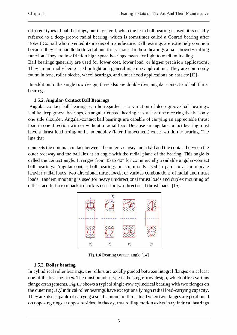
connects the nominal contact between the inner raceway and a ball and the contact between the
outer raceway and the ball lies at an angle with the radial plane of the bearing. This angle is
called the contact angle. It ranges from 15 to 40° for commercially available angular-contact
ball bearings. Angular-contact ball bearings are commonly used in pairs to accommodate
heavier radial loads, two directional thrust loads, or various combinations of radial and thrust
loads. Tandem mounting is used for heavy unidirectional thrust loads and duplex mounting of
either face-to-face or back-to-back is used for two-directional thrust loads. [15].
Fig.1.6 Bearing contact angle [14]
1.5.3. Roller bearing
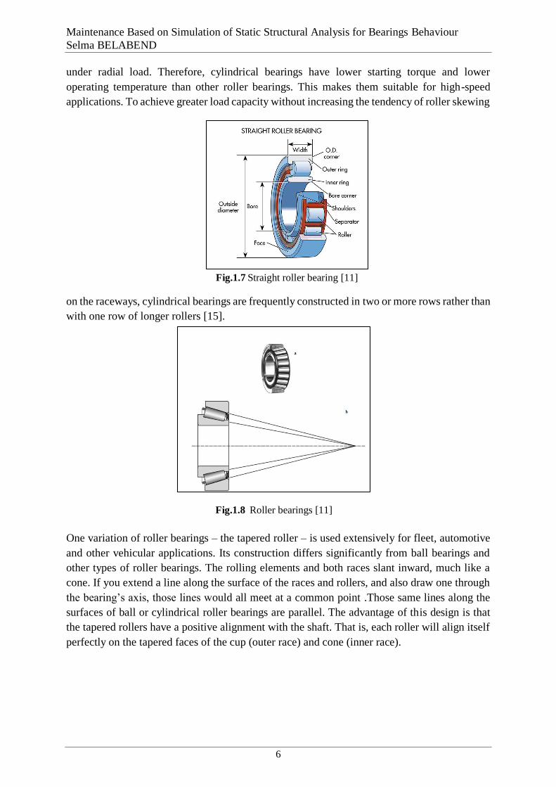
In cylindrical roller bearings, the rollers are axially guided between integral flanges on at least
one of the bearing rings. The most popular type is the single-row design, which offers various
flange arrangements. Fig.1.7 shows a typical single-row cylindrical bearing with two flanges on
the outer ring. Cylindrical roller bearings have exceptionally high radial load-carrying capacity.
They are also capable of carrying a small amount of thrust load when two flanges are positioned
on opposing rings at opposite sides. In theory, true rolling motion exists in cylindrical bearings
Maintenance Based on Simulation of Static Structural Analysis for Bearings Behaviour
Selma BELABEND
6
under radial load. Therefore, cylindrical bearings have lower starting torque and lower
operating temperature than other roller bearings. This makes them suitable for high-speed
applications. To achieve greater load capacity without increasing the tendency of roller skewing
on the raceways, cylindrical bearings are frequently constructed in two or more rows rather than
with one row of longer rollers [15].
One variation of roller bearings – the tapered roller – is used extensively for fleet, automotive
and other vehicular applications. Its construction differs significantly from ball bearings and
other types of roller bearings. The rolling elements and both races slant inward, much like a
cone. If you extend a line along the surface of the races and rollers, and also draw one through
the bearing’s axis, those lines would all meet at a common point .Those same lines along the
surfaces of ball or cylindrical roller bearings are parallel. The advantage of this design is that
the tapered rollers have a positive alignment with the shaft. That is, each roller will align itself
perfectly on the tapered faces of the cup (outer race) and cone (inner race).
Fig.1.7 Straight roller bearing [11]
Fig.1.8 Roller bearings [11]
Chapter I Bearing’s State of The Art And Their Maintenance
7
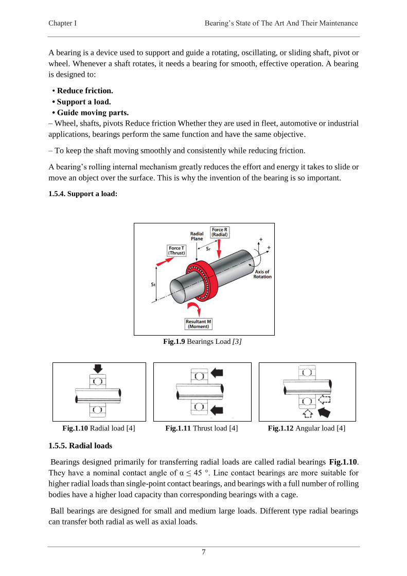
A bearing is a device used to support and guide a rotating, oscillating, or sliding shaft, pivot or
wheel. Whenever a shaft rotates, it needs a bearing for smooth, effective operation. A bearing
is designed to:
• Reduce friction.
• Support a load.
• Guide moving parts.
– Wheel, shafts, pivots Reduce friction Whether they are used in fleet, automotive or industrial
applications, bearings perform the same function and have the same objective.
– To keep the shaft moving smoothly and consistently while reducing friction.
A bearing’s rolling internal mechanism greatly reduces the effort and energy it takes to slide or
move an object over the surface. This is why the invention of the bearing is so important.
1.5.4. Support a load:
1.5.5. Radial loads
Bearings designed primarily for transferring radial loads are called radial bearings Fig.1.10.
They have a nominal contact angle of α ≤ 45 °. Line contact bearings are more suitable for
higher radial loads than single-point contact bearings, and bearings with a full number of rolling
bodies have a higher load capacity than corresponding bearings with a cage.
Ball bearings are designed for small and medium large loads. Different type radial bearings
can transfer both radial as well as axial loads.
Fig.1.10 Radial load [4]
Fig.1.11 Thrust load [4]
Fig.1.12 Angular load [4]
Fig.1.9 Bearings Load [3]

Maintenance Based on Simulation of Static Structural Analysis for Bearings Behaviour
Selma BELABEND
8
1.5.6. Axial loads
Bearings designed mainly for axial loads (thrust ball bearings) have a contact angle α>45°.
Combined loads are composed of simultaneously acting radial and axial loads.
Axial load capacity of a bearing depends on the angle of contact. The larger the angle, the larger
the axial load bearing capacity of the bearing. Larger axial clearance in single row ball bearings
increases their load bearing capacity. Single and double row angular contact ball bearings or
tapered roller bearings are best for capturing combined loads. Fig.1.12
Combined loads can also be borne by double row spherical roller bearings, thrust ball angular-
contact bearings, and to a limited extent, also spherical roller thrust bearings. Self-aligning ball
bearings [16].
The word “radial” means in the direction of a radius: moving from the circumference inward,
or the centre outward.
In this case it moves from the outside in. A radial load pushes down, from the outer race inward
to the balls, cage and inner race at the centre of the bearing.
The load is at right angles (90º) to the shaft on which it is being supported.
Thrust” means a pressure or pushing force exerted by one part against a touching part. Pressure
is exerted sideways, pushing the shaft either right or left. This shaft movement then pushes the
inner race of the bearing in the same sideways direction. The line of pressure, that is, the load,
runs parallel to the shaft Fig.1.11.
An “angular” load is actually a combination of radial and thrust loads. As the load moves at an
angle toward the shaft, it pushes against the corner of the inner race.
Pressure is transmitted diagonally, through the corner of the race, cage and rolling elements, to
the opposite corner of the outer race
1.5.8. Guide moving parts
The third function, to guide moving parts, is a result of the other two functions. By supporting
a load while reducing friction, a bearing guides shaft operation. It assists the movement of
crucial shafts, wheels and pivots [4] .
Without a bearing, the rotating part could not continue operating on a smooth, constant basis ;
Plain bearings rely on either rubbing contact between the bearing surfaces or pressure to
separate the two surfaces. The pressure required can be induced in a lubricant by the movement
of one component relative to another or by the external supply of the lubricant under the
Fig.1.13 Radial load [4]
Fig.1.14 Thrust load [4]
Fig.1.15 Angular load [4]

Chapter I Bearing’s State of The Art And Their Maintenance
9
required pressure. Plain bearings are also available from specialist bearing suppliers. In
principle, they can be significantly less expensive than rolling element bearings because they
involve fewer moving components.
1.6. Selection of bearing type
REB1 designs have evolved into numerous bearing types displaying geometrical characteristics
that make them more or less appropriate depending on the application.
The selection of an appropriate bearing for a given task, however, is an involved activity, which
needs to take into account, among other factors: [6]
Overall bearing arrangements in the mechanical system and possible combinations
Magnitudes and directions of the applied loads
Desired rotational speeds
Desired lifetime based on static and dynamic load capacities
Available space and acceptable weight
Mounting and dismounting constraint
Stiffness, accuracy, internal clearance and misalignment constraints
Overall environment, lubrication, temperature and possible contamination
Costs [17].
Design is a creative process for finding a solution to a particular problem. Can be explained in
many ways, can be interpreted in many ways.
For example, it may be desirable to produce:
The cheapest design
The easiest to build with available materials
The most reliable
The one that takes up the smallest space
The one that is lightest in weight.
The best from any of a whole variety of possible standpoints
The task of the designer is not so clear-cut, because he or she has chosen a reasonable
compromise between these various requirements and then one of the possible designs
that could meet this compromise [18].
Fig.1.16 Rolling elements for ball and roller bearings [19]
1 Rolling Element Bearing

Maintenance Based on Simulation of Static Structural Analysis for Bearings Behaviour
Selma BELABEND
10
1.7.Bearing Load, Fatigue, and Lifespan
Rolling fatigue is a material failure caused by the application of repeated stresses to a small
volume of material. It is a unique failure type. It is essentially a process of seeking out the
weakest point at which the first failure will occur. We can surmise that on a microscale there
will be a wide dispersion in material strength or resistance to fatigue because of
inhomogeneity’s in the material. Because bearing materials are complex alloys, we would not
expect them to be homogeneous or equally resistant to failure at all points. Therefore the
fatigue process can be expected to be one in which a group of supposedly identical specimens
exhibit wide variations in failure time when stressed in the same way. For this reason it is
necessary to treat the fatigue process statistically.
Maintenance of bearings
Since failures in engineering structures can lead to severe economic loss, its health monitoring
is very essential particularly in aerospace, civil, marine and other structures to avoid premature
failures. Precise incipient structural damage identification and its location is of great interest to
many researchers [20].
In rotating machinery, early fault detection of the rolling elements, i.e. bearing and gear faults
has been gaining importance in recent years because of its detrimental influence on the
reliability of equipment. Different techniques have been developed for monitoring and
diagnosis of rolling element bearings [21].
The bearing may also become unserviceable because of seizing, breakage, wear, false
brinelling, corrosion, etc. These problems are caused by improper selection or handling of the
bearing. The problems are avoidable by correct selection, proper handling and maintenance,
and are distinguished from the fatigue life of the bearing. However, breakdowns due to
improper application, bearing design, and maintenance are more frequent than flaking due to
rolling fatigue in the field [22].
Ball and roller bearings have three components that typically experience damage. They are the
rolling element, inner race, and outer race. The signature produced varies according to the
damaged component and whether or not the impact location is in a loaded zone of the bearing.
A defect present on a rotating component produces periodic pulses that depend on the load
characteristic of the system, with the largest pulses originating in the peak of a loaded zone. A
defect on a stationary race in a loaded zone is intuitively easiest to detect, with a pulse of
constant frequency (assuming constant rotational velocity) and higher magnitude.
Most difficulties posed in bearing initial fault detection stem from the presence of a variety of
noises and the wide spectrum of a bearing defect signal. Therefore, the success of bearing fault
detection methods usually depends on increasing a bearing defect signal-to-noise ratio.
Identification and quantification of key signal features dictating the condition of the element is
then the main priority [23].
1.8. Maintenance Objectives

Chapter I Bearing’s State of The Art And Their Maintenance
11
Maintenance is vital for the process industry .this fact was recognised and raised with the
development of the Japanese’s industry. The strengthening, year by year, of maintenance
management in the process industry occurred for different reasons. In the industry, production
relies heavily on the plant itself, so that the most of the factors like productivity, quality, safety,
pollution, and production costs depend on the condition of the plant. Also most of the industry
production is of the continuous, integrated type, so plant and equipment problems generate
enormous financial losses.
The primary objectives of maintenance are:
• To extend equipment life.
• To keep the plant and equipment in the optimal condition for production or service and secure
maximum return on the investment.
• To constantly maintain the ability to cope with emergencies.
• To assure safety [24].
Traditional maintenance operations by observing the variations and/ or trends of some
condition-monitoring indices is usually time consuming and not always reliable when multiple
features (techniques) are applied for fault diagnostics, particularly as the data are noise affected
[25] [26].
Detection of the fault and its severity are two important steps or features of a condition
monitoring system. Lifetime of a machine component is determined by the severity of the fault.
It is crucial, especially in critical systems, where continual operation is generally indispensable.
The bearing defects can be either distributed or local type or combination of both. The
distributed defects can be due to surface roughness, waviness, misaligned races, and off size
rolling elements [27].
Localized defects are developed in the raceways, rollers and cage of a bearing. The periodic
impacts occur at ball passing frequency (characteristic defect frequencies), which can be
estimated from the bearing geometry and the rotational speed. The vibration signal is not
sensitive to the incipient defects in the bearings; sometimes the defect frequencies are not
observable, because the impulses generated by the defects are masked or distorted by the noise
generated by other parts of the equipment. To overcome this problem, many researchers to
detect bearing local faults implement advanced signal processing techniques [20].
How well – and how long – a bearing wears also depends on maintenance. This includes:
• Inspection of the bearing, shaft, and housing for damage;
• Double checking the mounting and assembly;
• Re-lubrication at suggested intervals;
• Making adjustments as necessary; and
• Cleaning the bearing [4].

12
Chapter II
Chapitre 2 Analyses defect and inspection of bearing
2.1. Introduction
Rolling element bearings are among the most common components to be found in industrial
rotation machinery. They are found in industries from agriculture to aerospace, in equipment
as diverse as paper mill rollers to The Space shuttle Main Engine Turbo machinery. There has
been much written on the subject of bearing vibration monitoring over the last twenty-five
years. This chapter attempts to summarise the underlying science of rolling element bearings
across these diverse application from the point of view of machine condition monitoring using
vibration analysis. The key factors, which are addressed in this chapter, include the underlying
science of bearing vibration, bearing life, vibration measurement, signal processing techniques
and prognosis of bearing failure [28].
It has been considered that if a rolling bearing in service is properly lubricated, properly aligned,
kept free of abrasives, moisture, and corrosive reagents, and properly loaded, then all causes of
damage are eliminated save one, material fatigue.
Historically, rolling bearing theory postulated that no rotating bearing can give unlimited
service, because of the probability of fatigue of the surfaces in rolling contact. The stresses
repeatedly acting on these surfaces can be extremely high as compared to other stresses acting
on engineering structures [29].
2.2. Rolling Bearing Damage
Rolling bearing damage is generally detected by unusual operational behaviour of the bearing
arrangement. Uneven running and uncommon running noise usually indicate flaked running
surfaces due to material fatigue or an alteration of the radial clearance due to wear. High friction
i.e. resistance to smooth running, can indicate detrimental preload, poor lubrication or damaged
rolling contact surfaces. Higher than normal temperatures are a sign of an increase in friction.
Breakdown of the lubrication may be responsible for a sudden rise in operating temperature
occurring without a change in the operating conditions.
In the case of machine tools, wear and other bearing damage are evidenced by the deterioration
in quality of the work pieces.
These operational characteristics of a damaged bearing can be exploited to monitor the bearing
arrangement, perhaps using temperature and vibration measuring instruments. At the first signs
of premature bearing damage, the causes and effects should be analysed so that steps to avoid
Chapter II Analyses defect and inspection of bearing
13
further damage can be taken. To this end, it is often necessary to dismount and examine the
bearing.
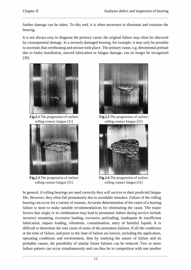
It is not always easy to diagnose the primary cause; the original failure may often be obscured
by consequential damage. In a severely damaged bearing, for example, it may only be possible
to ascertain that overheating and seizure took place. The primary cause, e.g. detrimental preload
due to faulty installation, starved lubrication or fatigue damage, can no longer be recognized
[30].
Fig.2.1 The progression of surface
rolling contact fatigue [31]
Fig.2.2 The progression of surface
rolling contact fatigue [31]
Fig.2.3 The progression of surface
rolling contact fatigue [31]
Fig.2.4 The progression of surface
rolling contact fatigue [31]
In general, if rolling bearings are used correctly they will survive to their predicted fatigue
life. However, they often fail prematurely due to avoidable mistakes. Failure of the rolling
bearing can occur for a variety of reasons. Accurate determination of the cause of a bearing
failure is must to make suitable recommendations for eliminating the cause. The major
factors that singly or in combination may lead to premature failure during service include
incorrect mounting, excessive loading, excessive preloading, inadequate & insufficient
lubrication, impact loading, vibrations, contamination, entry of harmful liquids. It is
difficult to determine the root cause of some of the premature failures. If all the conditions
at the time of failure, and prior to the time of failure are known, including the application,
operating conditions and environment, then by studying the nature of failure and its
probable causes, the possibility of similar future failures can be reduced. Two or more
failure pattern can occur simultaneously and can thus be in competition with one another
Maintenance Based on Simulation of Static Structural Analysis for Bearings Behaviour
Selma BELABEND
14
to reduce the bearing life. Also a pattern of failure that is active for one period in the life
of a bearing can lead to or can even be followed by another failure mechanism, which then
cause premature failure. Thus in some instances, a single failure pattern will be visible and
in other indications of several failure pattern will be evident, making exact determination
of root cause difficult. So when more than one bearing failure pattern has been occurred,
proper analysis depends on careful examination of failed components [32].
Severe vibrations of bearing can even cause the entire system to function incorrectly, result
in downtime of the system and economic loss to the customer. Vibration signature analysis
of machine components is a commonly used fault-detection technique employed in rotor-
bearing systems. There are two critical states in the condition monitoring of machine
components: the first is the detection of the fault and the second is the determination of
severity of the fault, that is, the lifetime of the machine component [33].
Even when bearings are being used under ideal conditions, failures of bearings are caused by
deterioration of the material due to rolling fatigue. Generally, the service life of bearings is
expressed either as a period of time or as the total number of rotations before the occurrence of
failures in the inner ring, outer ring or rolling element because of rolling fatigue, due to repeated
stress.(section 2.3 page14 ) Rolling bearings sometimes fracture earlier than expected. The
following causes should be considered;
1. Inappropriate use of bearings
2. Faulty installation or improper processing
3. Improper lubricant, lubrication method or sealing device
4. Inappropriate speed and operating temperature
5. Contamination by foreign matter during installation
6. Abnormally heavy load [34].
2.3.How is bearing life defined ?
Generally, a rolling bearing cannot rotate forever. Unless operating conditions are ideal and the
fatigue load limit is not reached, eventually material fatigue will occur.
Fatigue is the result of shear stresses cyclically appearing immediately below the load-carrying
surface. After a time these stresses cause cracks which gradually, extend up to the surface. The
fatigue failure of metals is the well-known type of failure that occurs after the repetition of
several cycles - from a few to millions - of stresses applied to the specimen, or to the component.
The simplest fatigue failure everyone can obtain can be produced by the repeated bending of,
say, a paper clip, made of soft steel: after some reversed cycles (often only five to ten are
enough), it will break in two parts (and one must be careful, because they can be very warm)
[35].
As the rolling elements pass over the cracks fragments of material break away and this is known
as flaking or spelling. The flaking progressively increases in ex- tent and eventually makes the
bearing unserviceable.
The life of a rolling bearing is defined as the number of revolutions the bearing can perform
before incipient flaking occurs. This does not mean to say that the bearing cannot be used
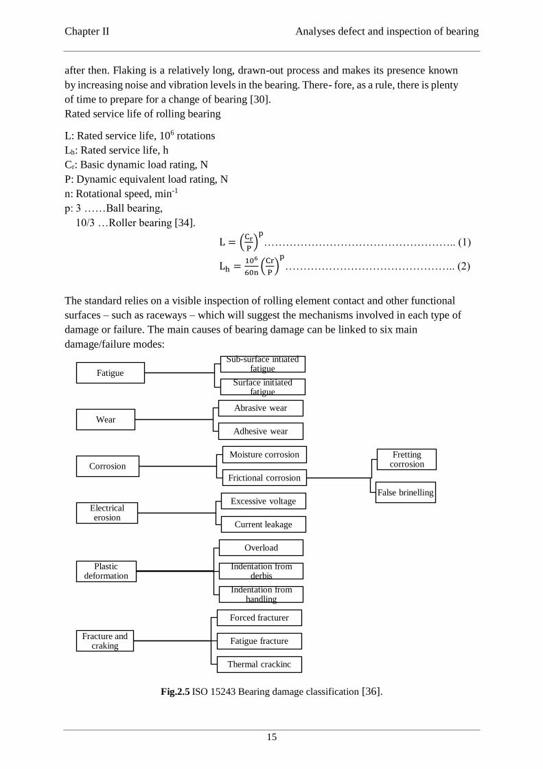
Chapter II Analyses defect and inspection of bearing
15
after then. Flaking is a relatively long, drawn-out process and makes its presence known
by increasing noise and vibration levels in the bearing. There- fore, as a rule, there is plenty
of time to prepare for a change of bearing [30].
Rated service life of rolling bearing
L: Rated service life, 106 rotations
Lh: Rated service life, h
Cr: Basic dynamic load rating, N
P: Dynamic equivalent load rating, N
n: Rotational speed, min-1
p: 3 ……Ball bearing,
10/3 …Roller bearing [34].
L = (Cr
P)
p
…………………………………………….. (1)
Lh =106
60n(
Cr
P)
p
……………………………………….. (2)
2.4. Bearing inspection standard
The standard relies on a visible inspection of rolling element contact and other functional
surfaces – such as raceways – which will suggest the mechanisms involved in each type of
damage or failure. The main causes of bearing damage can be linked to six main
damage/failure modes:
Fig.2.5 ISO 15243 Bearing damage classification [36].
Fatigue
Sub-surface intiated fatigue
Surface initiated fatigue
Wear
Abrasive wear
Adhesive wear
Corrosion
Moisture corrosion
Frictional corrosion
Fretting corrosion
False brinelling
Electrical erosion
Excessive voltage
Current leakage
Plastic deformation
Overload
Indentation from derbis
Indentation from handling
Fracture and craking
Forced fracturer
Fatigue fracture
Thermal crackinc
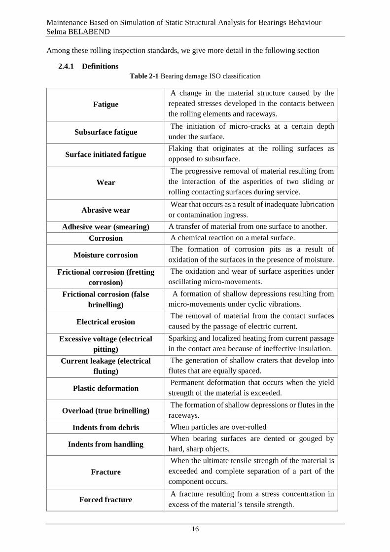
Maintenance Based on Simulation of Static Structural Analysis for Bearings Behaviour
Selma BELABEND
16
Among these rolling inspection standards, we give more detail in the following section
2.4.1 Definitions
Table 2-1 Bearing damage ISO classification
Fatigue
A change in the material structure caused by the
repeated stresses developed in the contacts between
the rolling elements and raceways.
Subsurface fatigue The initiation of micro-cracks at a certain depth
under the surface.
Surface initiated fatigue Flaking that originates at the rolling surfaces as
opposed to subsurface.
Wear
The progressive removal of material resulting from
the interaction of the asperities of two sliding or
rolling contacting surfaces during service.
Abrasive wear Wear that occurs as a result of inadequate lubrication
or contamination ingress.
Adhesive wear (smearing) A transfer of material from one surface to another.
Corrosion A chemical reaction on a metal surface.
Moisture corrosion The formation of corrosion pits as a result of
oxidation of the surfaces in the presence of moisture.
Frictional corrosion (fretting
corrosion)
The oxidation and wear of surface asperities under
oscillating micro-movements.
Frictional corrosion (false
brinelling)
A formation of shallow depressions resulting from
micro-movements under cyclic vibrations.
Electrical erosion The removal of material from the contact surfaces
caused by the passage of electric current.
Excessive voltage (electrical
pitting)
Sparking and localized heating from current passage
in the contact area because of ineffective insulation.
Current leakage (electrical
fluting)
The generation of shallow craters that develop into
flutes that are equally spaced.
Plastic deformation Permanent deformation that occurs when the yield
strength of the material is exceeded.
Overload (true brinelling) The formation of shallow depressions or flutes in the
raceways.
Indents from debris When particles are over-rolled
Indents from handling When bearing surfaces are dented or gouged by
hard, sharp objects.
Fracture
When the ultimate tensile strength of the material is
exceeded and complete separation of a part of the
component occurs.
Forced fracture A fracture resulting from a stress concentration in
excess of the material’s tensile strength.
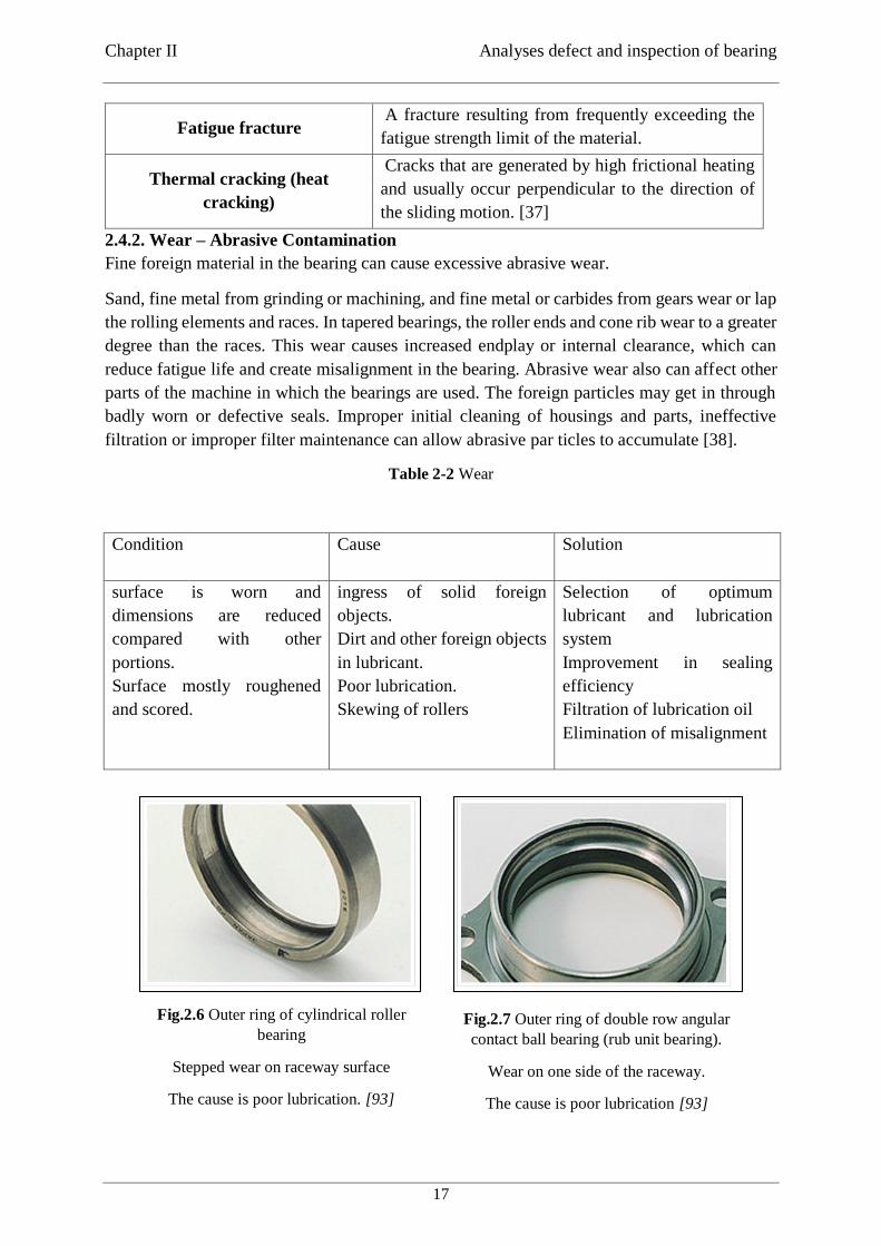
Chapter II Analyses defect and inspection of bearing
17
Fatigue fracture A fracture resulting from frequently exceeding the
fatigue strength limit of the material.
Thermal cracking (heat
cracking)
Cracks that are generated by high frictional heating
and usually occur perpendicular to the direction of
the sliding motion. [37]
2.4.2. Wear – Abrasive Contamination
Fine foreign material in the bearing can cause excessive abrasive wear.
Sand, fine metal from grinding or machining, and fine metal or carbides from gears wear or lap
the rolling elements and races. In tapered bearings, the roller ends and cone rib wear to a greater
degree than the races. This wear causes increased endplay or internal clearance, which can
reduce fatigue life and create misalignment in the bearing. Abrasive wear also can affect other
parts of the machine in which the bearings are used. The foreign particles may get in through
badly worn or defective seals. Improper initial cleaning of housings and parts, ineffective
filtration or improper filter maintenance can allow abrasive par ticles to accumulate [38].
Table 2-2 Wear
Condition Cause
Solution
surface is worn and
dimensions are reduced
compared with other
portions.
Surface mostly roughened
and scored.
ingress of solid foreign
objects.
Dirt and other foreign objects
in lubricant.
Poor lubrication.
Skewing of rollers
Selection of optimum
lubricant and lubrication
system
Improvement in sealing
efficiency
Filtration of lubrication oil
Elimination of misalignment
Fig.2.6 Outer ring of cylindrical roller
bearing
Stepped wear on raceway surface
The cause is poor lubrication. [93]
Fig.2.7 Outer ring of double row angular
contact ball bearing (rub unit bearing).
Wear on one side of the raceway.
The cause is poor lubrication [93]
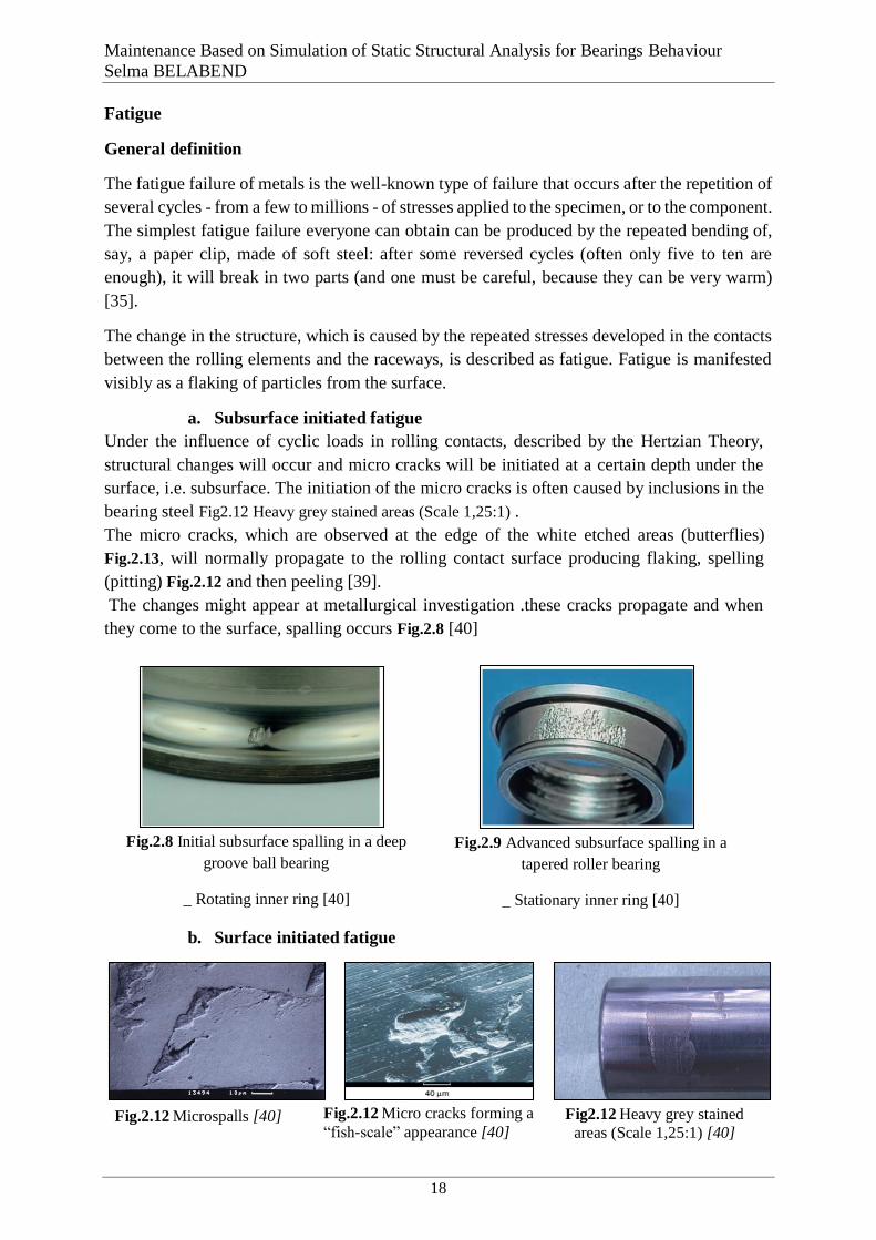
Maintenance Based on Simulation of Static Structural Analysis for Bearings Behaviour
Selma BELABEND
18
Fatigue
General definition
The fatigue failure of metals is the well-known type of failure that occurs after the repetition of
several cycles - from a few to millions - of stresses applied to the specimen, or to the component.
The simplest fatigue failure everyone can obtain can be produced by the repeated bending of,
say, a paper clip, made of soft steel: after some reversed cycles (often only five to ten are
enough), it will break in two parts (and one must be careful, because they can be very warm)
[35].
The change in the structure, which is caused by the repeated stresses developed in the contacts
between the rolling elements and the raceways, is described as fatigue. Fatigue is manifested
visibly as a flaking of particles from the surface.
a. Subsurface initiated fatigue
Under the influence of cyclic loads in rolling contacts, described by the Hertzian Theory,
structural changes will occur and micro cracks will be initiated at a certain depth under the
surface, i.e. subsurface. The initiation of the micro cracks is often caused by inclusions in the
bearing steel Fig2.12 Heavy grey stained areas (Scale 1,25:1) .
The micro cracks, which are observed at the edge of the white etched areas (butterflies)
Fig.2.13, will normally propagate to the rolling contact surface producing flaking, spelling
(pitting) Fig.2.12 and then peeling [39].
The changes might appear at metallurgical investigation .these cracks propagate and when
they come to the surface, spalling occurs Fig.2.8 [40]
Fig.2.8 Initial subsurface spalling in a deep
groove ball bearing
_ Rotating inner ring [40]
Fig.2.9 Advanced subsurface spalling in a
tapered roller bearing
_ Stationary inner ring [40]
b. Surface initiated fatigue
Fig.2.12 Micro cracks forming a
“fish-scale” appearance [40]
Fig.2.12 Microspalls [40] Fig2.12 Heavy grey stained
areas (Scale 1,25:1) [40]
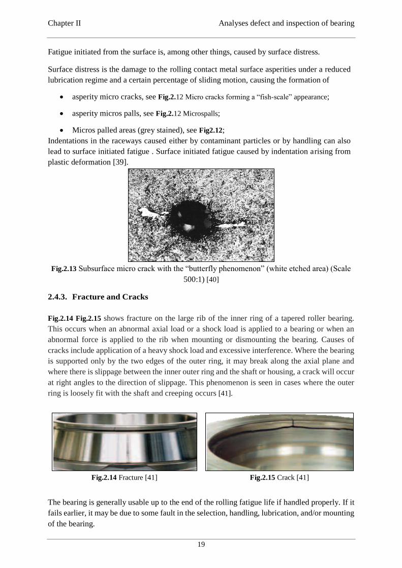
Chapter II Analyses defect and inspection of bearing
19
Fatigue initiated from the surface is, among other things, caused by surface distress.
Surface distress is the damage to the rolling contact metal surface asperities under a reduced
lubrication regime and a certain percentage of sliding motion, causing the formation of
asperity micro cracks, see Fig.2.12 Micro cracks forming a “fish-scale” appearance;
asperity micros palls, see Fig.2.12 Microspalls;
Micros palled areas (grey stained), see Fig2.12;
Indentations in the raceways caused either by contaminant particles or by handling can also
lead to surface initiated fatigue . Surface initiated fatigue caused by indentation arising from
plastic deformation [39].
Fig.2.13 Subsurface micro crack with the “butterfly phenomenon” (white etched area) (Scale
500:1) [40]
2.4.3. Fracture and Cracks
Fig.2.14 Fig.2.15 shows fracture on the large rib of the inner ring of a tapered roller bearing.
This occurs when an abnormal axial load or a shock load is applied to a bearing or when an
abnormal force is applied to the rib when mounting or dismounting the bearing. Causes of
cracks include application of a heavy shock load and excessive interference. Where the bearing
is supported only by the two edges of the outer ring, it may break along the axial plane and
where there is slippage between the inner outer ring and the shaft or housing, a crack will occur
at right angles to the direction of slippage. This phenomenon is seen in cases where the outer
ring is loosely fit with the shaft and creeping occurs [41].
Fig.2.14 Fracture [41]
Fig.2.15 Crack [41]
The bearing is generally usable up to the end of the rolling fatigue life if handled properly. If it
fails earlier, it may be due to some fault in the selection, handling, lubrication, and/or mounting
of the bearing.
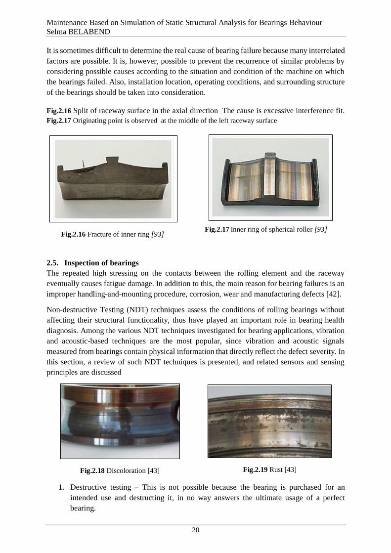
Maintenance Based on Simulation of Static Structural Analysis for Bearings Behaviour
Selma BELABEND
20
It is sometimes difficult to determine the real cause of bearing failure because many interrelated
factors are possible. It is, however, possible to prevent the recurrence of similar problems by
considering possible causes according to the situation and condition of the machine on which
the bearings failed. Also, installation location, operating conditions, and surrounding structure
of the bearings should be taken into consideration.
Fig.2.16 Split of raceway surface in the axial direction The cause is excessive interference fit.
Fig.2.17 Originating point is observed at the middle of the left raceway surface
2.5. Inspection of bearings
The repeated high stressing on the contacts between the rolling element and the raceway
eventually causes fatigue damage. In addition to this, the main reason for bearing failures is an
improper handling-and-mounting procedure, corrosion, wear and manufacturing defects [42].
Non-destructive Testing (NDT) techniques assess the conditions of rolling bearings without
affecting their structural functionality, thus have played an important role in bearing health
diagnosis. Among the various NDT techniques investigated for bearing applications, vibration
and acoustic-based techniques are the most popular, since vibration and acoustic signals
measured from bearings contain physical information that directly reflect the defect severity. In
this section, a review of such NDT techniques is presented, and related sensors and sensing
principles are discussed
Fig.2.18 Discoloration [43]
Fig.2.19 Rust [43]
1. Destructive testing – This is not possible because the bearing is purchased for an
intended use and destructing it, in no way answers the ultimate usage of a perfect
bearing.
Fig.2.17 Inner ring of spherical roller [93]
bearing Fig.2.16 Fracture of inner ring [93]
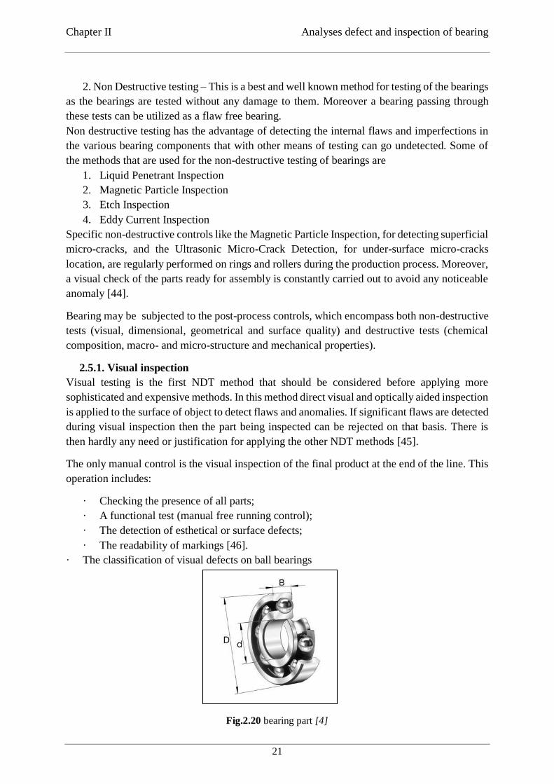
Chapter II Analyses defect and inspection of bearing
21
2. Non Destructive testing – This is a best and well known method for testing of the bearings
as the bearings are tested without any damage to them. Moreover a bearing passing through
these tests can be utilized as a flaw free bearing.
Non destructive testing has the advantage of detecting the internal flaws and imperfections in
the various bearing components that with other means of testing can go undetected. Some of
the methods that are used for the non-destructive testing of bearings are
1. Liquid Penetrant Inspection
2. Magnetic Particle Inspection
3. Etch Inspection
4. Eddy Current Inspection
Specific non-destructive controls like the Magnetic Particle Inspection, for detecting superficial
micro-cracks, and the Ultrasonic Micro-Crack Detection, for under-surface micro-cracks
location, are regularly performed on rings and rollers during the production process. Moreover,
a visual check of the parts ready for assembly is constantly carried out to avoid any noticeable
anomaly [44].
Bearing may be subjected to the post-process controls, which encompass both non-destructive
tests (visual, dimensional, geometrical and surface quality) and destructive tests (chemical
composition, macro- and micro-structure and mechanical properties).
2.5.1. Visual inspection
Visual testing is the first NDT method that should be considered before applying more
sophisticated and expensive methods. In this method direct visual and optically aided inspection
is applied to the surface of object to detect flaws and anomalies. If significant flaws are detected
during visual inspection then the part being inspected can be rejected on that basis. There is
then hardly any need or justification for applying the other NDT methods [45].
The only manual control is the visual inspection of the final product at the end of the line. This
operation includes:
· Checking the presence of all parts;
· A functional test (manual free running control);
· The detection of esthetical or surface defects;
· The readability of markings [46].
· The classification of visual defects on ball bearings
Fig.2.20 bearing part [4]
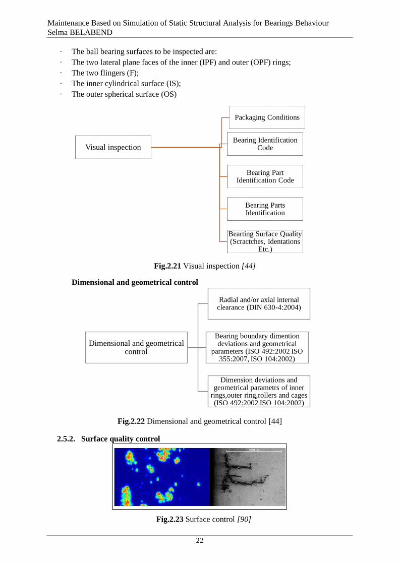
Maintenance Based on Simulation of Static Structural Analysis for Bearings Behaviour
Selma BELABEND
22
· The ball bearing surfaces to be inspected are:
· The two lateral plane faces of the inner (IPF) and outer (OPF) rings;
· The two flingers (F);
· The inner cylindrical surface (IS);
· The outer spherical surface (OS)
Dimensional and geometrical control
Fig.2.22 Dimensional and geometrical control [44]
2.5.2. Surface quality control
Visual inspection
Packaging Conditions
Bearing Identification Code
Bearing Part Identification Code
Bearing Parts Identification
Bearting Surface Quality (Scractches, Identations
Etc.)
Dimensional and geometrical control
Radial and/or axial internal clearance (DIN 630-4:2004)
Bearing boundary dimention deviations and geometrical
parameters (ISO 492:2002 ISO 355:2007, ISO 104:2002)
Dimension deviations and geometrical parametrs of inner
rings,outer ring,rollers and cages (ISO 492:2002 ISO 104:2002)
Fig.2.23 Surface control [90]
Fig.2.21 Visual inspection [44]
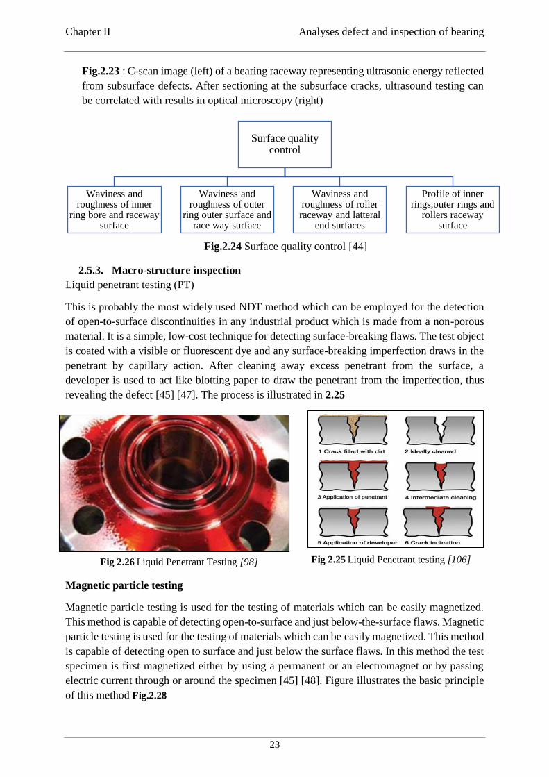
Chapter II Analyses defect and inspection of bearing
23
Fig.2.23 : C-scan image (left) of a bearing raceway representing ultrasonic energy reflected
from subsurface defects. After sectioning at the subsurface cracks, ultrasound testing can
be correlated with results in optical microscopy (right)
Fig.2.24 Surface quality control [44]
2.5.3. Macro-structure inspection
Liquid penetrant testing (PT)
This is probably the most widely used NDT method which can be employed for the detection
of open-to-surface discontinuities in any industrial product which is made from a non-porous
material. It is a simple, low-cost technique for detecting surface-breaking flaws. The test object
is coated with a visible or fluorescent dye and any surface-breaking imperfection draws in the
penetrant by capillary action. After cleaning away excess penetrant from the surface, a
developer is used to act like blotting paper to draw the penetrant from the imperfection, thus
revealing the defect [45] [47]. The process is illustrated in 2.25
Magnetic particle testing
Magnetic particle testing is used for the testing of materials which can be easily magnetized.
This method is capable of detecting open-to-surface and just below-the-surface flaws. Magnetic
particle testing is used for the testing of materials which can be easily magnetized. This method
is capable of detecting open to surface and just below the surface flaws. In this method the test
specimen is first magnetized either by using a permanent or an electromagnet or by passing
electric current through or around the specimen [45] [48]. Figure illustrates the basic principle
of this method Fig.2.28
Surface quality control
Waviness and roughness of inner
ring bore and raceway surface
Waviness and roughness of outer
ring outer surface and race way surface
Waviness and roughness of roller raceway and latteral
end surfaces
Profile of inner rings,outer rings and
rollers raceway surface
Fig 2.26 Liquid Penetrant Testing [98] Fig 2.25 Liquid Penetrant testing [106]

Maintenance Based on Simulation of Static Structural Analysis for Bearings Behaviour
Selma BELABEND
24
Eddy current
Eddy current testing is employed for the detection and measurement of defects such as cracks,
porosity, blowholes, inclusions, overlaps, shrinkages and soft spots in a wide variety of test
specimens in solid cylindrical, hollow cylindrical or other complex shapes. Corrosion and
cracking due to stress corrosion can also be detected. Changes in electrical conductivity and
permeability can be measured which in turn have a bearing upon the material properties such
as hardness, homogeneity, degree of heat treatment, existence of internal stresses,
decarburization, diffusion, alloy composition, presence of impurities, etc.
Thickness measurements can be made on metallic plates, foils, sheets, strips, tubes and
cylinders. Eddy current testing technology, which is based on the electromagnetic induction
theory, set up the rolling bearing roller in the alternating magnetic field, and then there will be
induced current in the roller, that is eddy current. The function of this eddy current magnetic
field produced by itself in the roller is to change strength of original magnetic field, then
inducing the diversification of coil voltage and impedance [45] [49].
Fig.2.28 [92] Fig.2.27 Magnetic particle testing [85]
Fig.2.29 Eddy current test method according to the standard ISO 21968 [99].

Chapter II Analyses defect and inspection of bearing
25
2.5.4. Macro-structure inspection
2.5.5. Chemical composition analysis
Fig.2.31 Chemical composition analysis [17]
2.5.6. Mechanical properties determination
2.5.7. Micro-structure inspection
Fig.2.33 Micro-structure inspection [44]
Bearings that have been in service or endurance-tested in a test rig may be examined by various
NDT methods. This is to provide more insight into the root cause of bearing failure and bearing
Micro-structure inspection
Non-metallic inclusion (thin and heavy series)
of inner rings. outer rings and rollers (ISO
4967:1998 (E))
Carbide size, networks, streaks and segregation rate
of inner rings,outer rings and rollers (ISO 5949:1983)
Decarbonisation layer of inner rings,outer
rings and rollers (ISO3887 2003)
Carbunizing layer of inner
rings,outer rings and
rollers (ISO 2639:2002
Mechanical properties determination
Rockwell C hardness of inner rings ,outer rings and rollers(ball) (ISO
6506-1:2005)
Fig.2.32 Mechanical properties determination [44]
Fig.2.30 Macro-structure inspection [44]
Macro-structure inspection
Blue fracture test for macro-inclusions of inner
rings, outer rings and rollers (ISO 3763-1976)
Porosity of inner rings outer rings and rollers (ASTM E 340-00:2006)
Forged rollers material flow lines pattern
Superficial macro-cracks detection of inner rings. outer rings and rollers.
Chemical composition analysisChemical composition of inner
rings, outer rings, rollers and cages (ISO 683 :17 1999

Maintenance Based on Simulation of Static Structural Analysis for Bearings Behaviour
Selma BELABEND
26
degradation mechanisms or, in the case of bearing remanufacturing inspection, to check for
subsurface damage and see if the bearing component is fit for further service.
2.6. Conclusion
The bearing is an element with a very important role and dominates the performance of some
machines and process equipment. If one of the bearings fails, the damage can be minimal. On
the other hand, bearing failure on a transportation device can have severe consequences. Every
bearing becomes unserviceable after a certain operating time, even if it is installed correctly
and operated properly. To prevent unnecessary bearing failure, a regular inspection must be
carried out.
When bearing failure is found, even if it is insignificant, it is important to investigate the
phenomenon to determine the causes. At this time, not only the bearing but also the shaft,
housing, and lubricant used with the bearing should be comprehensively investigated, together
with the bearing. To judge the causes of failure, sufficient knowledge and experience in
bearings and lubricants and a good understanding of the characteristics of the equipment are
necessary. In addition, consideration of the installation conditions and operational process of
the bearing is required.

27
Chapter III
Chapitre 3 Modelling and Simulation of Bearings
3.1. Introduction
FEM analysis is very efficient method for achieving stresses at different loading condition
according to forces and boundary conditions applied to the component from the static analysis.
The use of numerical method such as Finite Element Method now a day commonly used to
gives detail information about structure or component.
Bearings are an important mechanical components that help in maintaining the liner and
rotational movements of a machine. To ensure a long operational life of bearings it is necessary
to predict the load which are supposed to carry. In the case of stationary bearings, low
oscillations, working at low speeds, or when taking large short shocks during rotation, loading
is considered to be static.
Thus, in-service safety is determined by the magnitude of the deformations at the runway rolling
paths. This work aims to simulate and model the behaviour of the ball bearings under a static
loading with a comparison of two variants of the application of load, axial and radial. We also
considered two types of constraints.
The analysis is performed using the finite element method.
This work aims at analysing the behaviour of the ball bearings under a static load, for this fact
the simulation and modelling by finite element in order to study behaviour and make
comparisons. This work has two study variants in two different configuration and comparing
the result with analytical result
ANSYS is commonly used and enjoyed by an extended use in the structural areas, for analysis.
ANSYS it consists of three main phases : Pre-processing, conducting or importing of the solid
model system that are to be analysed, solid meshing design in finite elements, implementation
of conditions and loads at the limit, Processing, numeric solving of the characteristic equations
behaviour of the system and getting the solution. Post-processing, viewing the results in order
to analyses system reaction and identification of areas with critical applications.
The purpose of the study was to collect data's using two different software's and after to compare
them with mathematical results. Using the ANSYS in this purpose it was able to analyses the
design of the structure of the ball bearing in detail [50].
The first case: apply the load on the inner ring and fix the outer ring.
The second case: apply the load on the outer ring and define the inner ring as a fixed support.
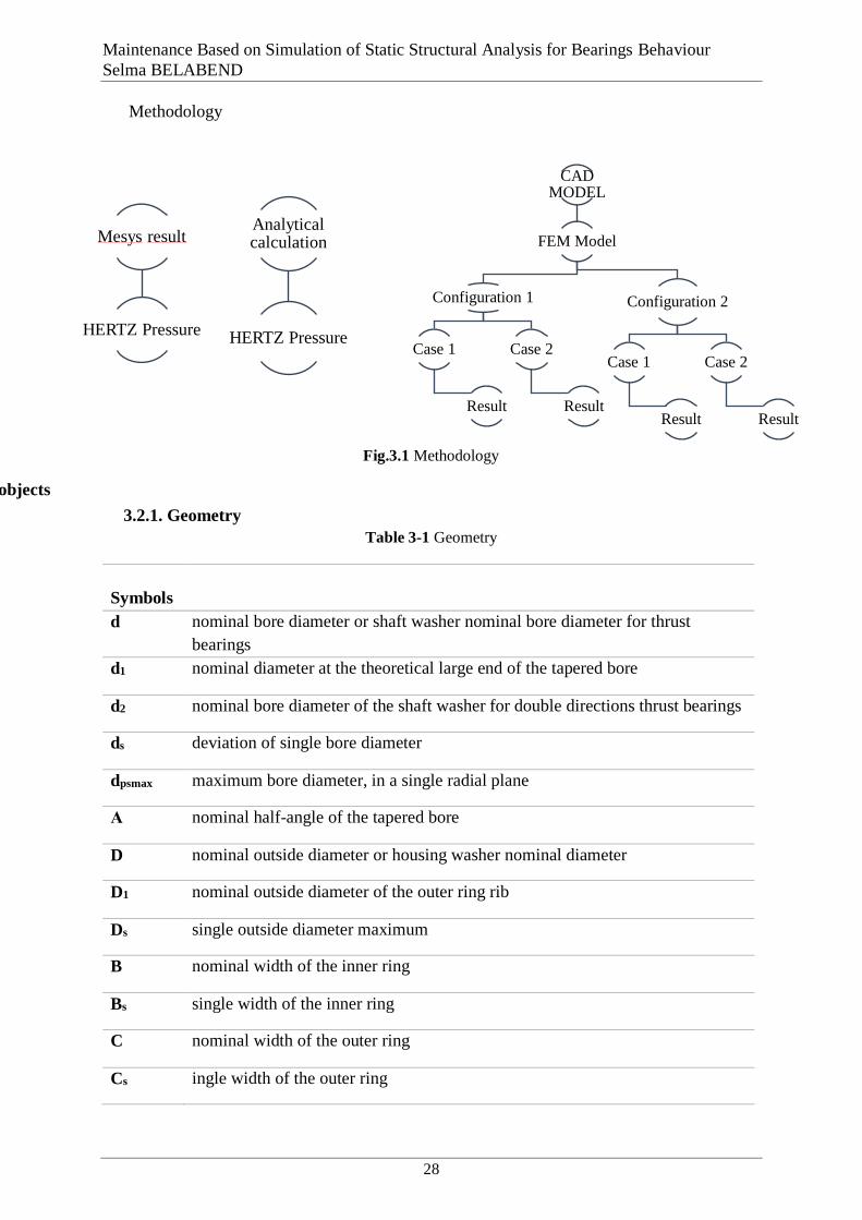
Maintenance Based on Simulation of Static Structural Analysis for Bearings Behaviour
Selma BELABEND
28
Methodology
3.2. Structural dimensions of the bearings used as research objects
3.2.1. Geometry
Table 3-1 Geometry
Symbols
d nominal bore diameter or shaft washer nominal bore diameter for thrust
bearings
d1 nominal diameter at the theoretical large end of the tapered bore
d2 nominal bore diameter of the shaft washer for double directions thrust bearings
ds deviation of single bore diameter
dpsmax maximum bore diameter, in a single radial plane
Α nominal half-angle of the tapered bore
D nominal outside diameter or housing washer nominal diameter
D1 nominal outside diameter of the outer ring rib
Ds single outside diameter maximum
B nominal width of the inner ring
Bs single width of the inner ring
C nominal width of the outer ring
Cs ingle width of the outer ring
CAD MODEL
FEM Model
Configuration 1
Case 1
Result
Case 2
Result
Configuration 2
Case 1
Result
Case 2
Result
Mesys result
HERTZ Pressure
Analyticalcalculation
HERTZ Pressure
Fig.3.1 Methodology
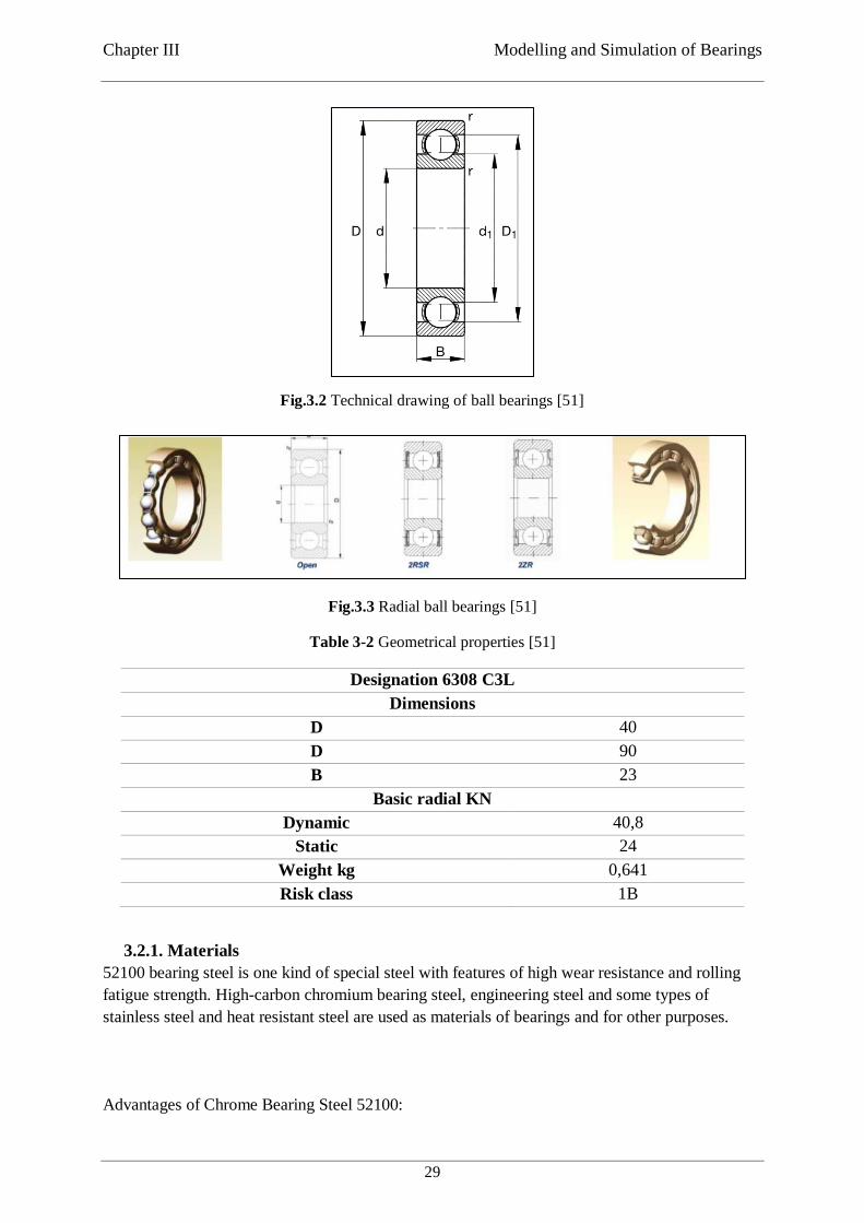
Chapter III Modelling and Simulation of Bearings
29
Fig.3.3 Radial ball bearings [51]
Table 3-2 Geometrical properties [51]
Designation 6308 C3L
Dimensions
D 40
D 90
B 23
Basic radial KN
Dynamic 40,8
Static 24
Weight kg 0,641
Risk class 1B
3.2.1. Materials
52100 bearing steel is one kind of special steel with features of high wear resistance and rolling
fatigue strength. High-carbon chromium bearing steel, engineering steel and some types of
stainless steel and heat resistant steel are used as materials of bearings and for other purposes.
Advantages of Chrome Bearing Steel 52100:
Fig.3.2 Technical drawing of ball bearings [51]
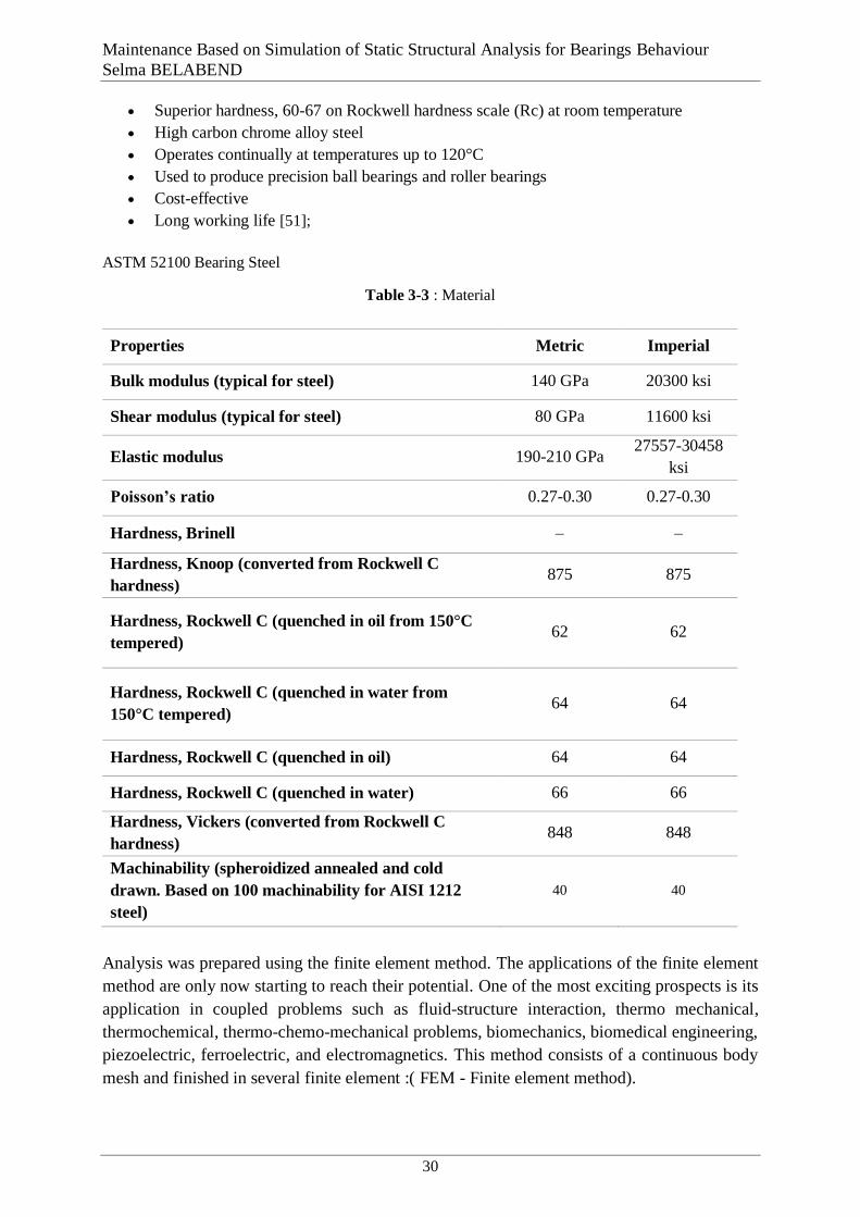
Maintenance Based on Simulation of Static Structural Analysis for Bearings Behaviour
Selma BELABEND
30
Superior hardness, 60-67 on Rockwell hardness scale (Rc) at room temperature
High carbon chrome alloy steel
Operates continually at temperatures up to 120°C
Used to produce precision ball bearings and roller bearings
Cost-effective
Long working life [51];
ASTM 52100 Bearing Steel
Table 3-3 : Material
Properties Metric Imperial
Bulk modulus (typical for steel) 140 GPa 20300 ksi
Shear modulus (typical for steel) 80 GPa 11600 ksi
Elastic modulus 190-210 GPa 27557-30458
ksi
Poisson’s ratio 0.27-0.30 0.27-0.30
Hardness, Brinell – –
Hardness, Knoop (converted from Rockwell C
hardness) 875 875
Hardness, Rockwell C (quenched in oil from 150°C
tempered) 62 62
Hardness, Rockwell C (quenched in water from
150°C tempered) 64 64
Hardness, Rockwell C (quenched in oil) 64 64
Hardness, Rockwell C (quenched in water) 66 66
Hardness, Vickers (converted from Rockwell C
hardness) 848 848
Machinability (spheroidized annealed and cold
drawn. Based on 100 machinability for AISI 1212
steel)
40 40
3.3. CAD and FE-model
Analysis was prepared using the finite element method. The applications of the finite element
method are only now starting to reach their potential. One of the most exciting prospects is its
application in coupled problems such as fluid-structure interaction, thermo mechanical,
thermochemical, thermo-chemo-mechanical problems, biomechanics, biomedical engineering,
piezoelectric, ferroelectric, and electromagnetics. This method consists of a continuous body
mesh and finished in several finite element :( FEM - Finite element method).
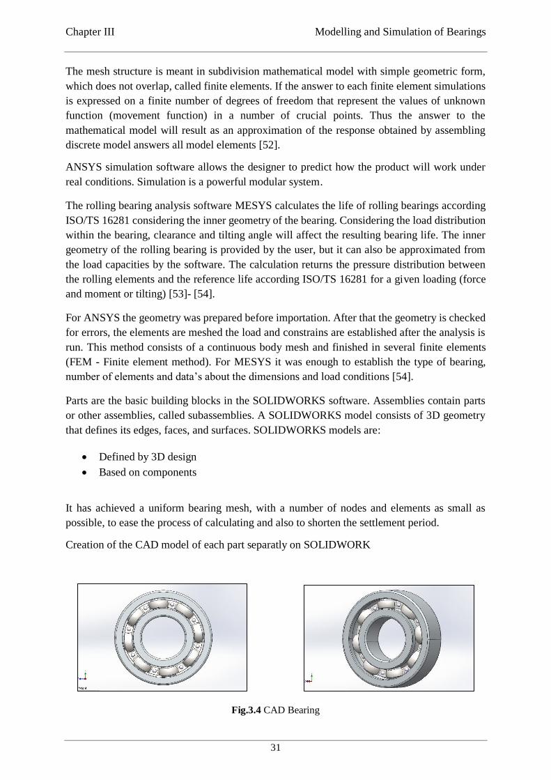
Chapter III Modelling and Simulation of Bearings
31
The mesh structure is meant in subdivision mathematical model with simple geometric form,
which does not overlap, called finite elements. If the answer to each finite element simulations
is expressed on a finite number of degrees of freedom that represent the values of unknown
function (movement function) in a number of crucial points. Thus the answer to the
mathematical model will result as an approximation of the response obtained by assembling
discrete model answers all model elements [52].
ANSYS simulation software allows the designer to predict how the product will work under
real conditions. Simulation is a powerful modular system.
The rolling bearing analysis software MESYS calculates the life of rolling bearings according
ISO/TS 16281 considering the inner geometry of the bearing. Considering the load distribution
within the bearing, clearance and tilting angle will affect the resulting bearing life. The inner
geometry of the rolling bearing is provided by the user, but it can also be approximated from
the load capacities by the software. The calculation returns the pressure distribution between
the rolling elements and the reference life according ISO/TS 16281 for a given loading (force
and moment or tilting) [53]- [54].
For ANSYS the geometry was prepared before importation. After that the geometry is checked
for errors, the elements are meshed the load and constrains are established after the analysis is
run. This method consists of a continuous body mesh and finished in several finite elements
(FEM - Finite element method). For MESYS it was enough to establish the type of bearing,
number of elements and data’s about the dimensions and load conditions [54].
Parts are the basic building blocks in the SOLIDWORKS software. Assemblies contain parts
or other assemblies, called subassemblies. A SOLIDWORKS model consists of 3D geometry
that defines its edges, faces, and surfaces. SOLIDWORKS models are:
Defined by 3D design
Based on components
It has achieved a uniform bearing mesh, with a number of nodes and elements as small as
possible, to ease the process of calculating and also to shorten the settlement period.
Creation of the CAD model of each part separatly on SOLIDWORK
Fig.3.4 CAD Bearing
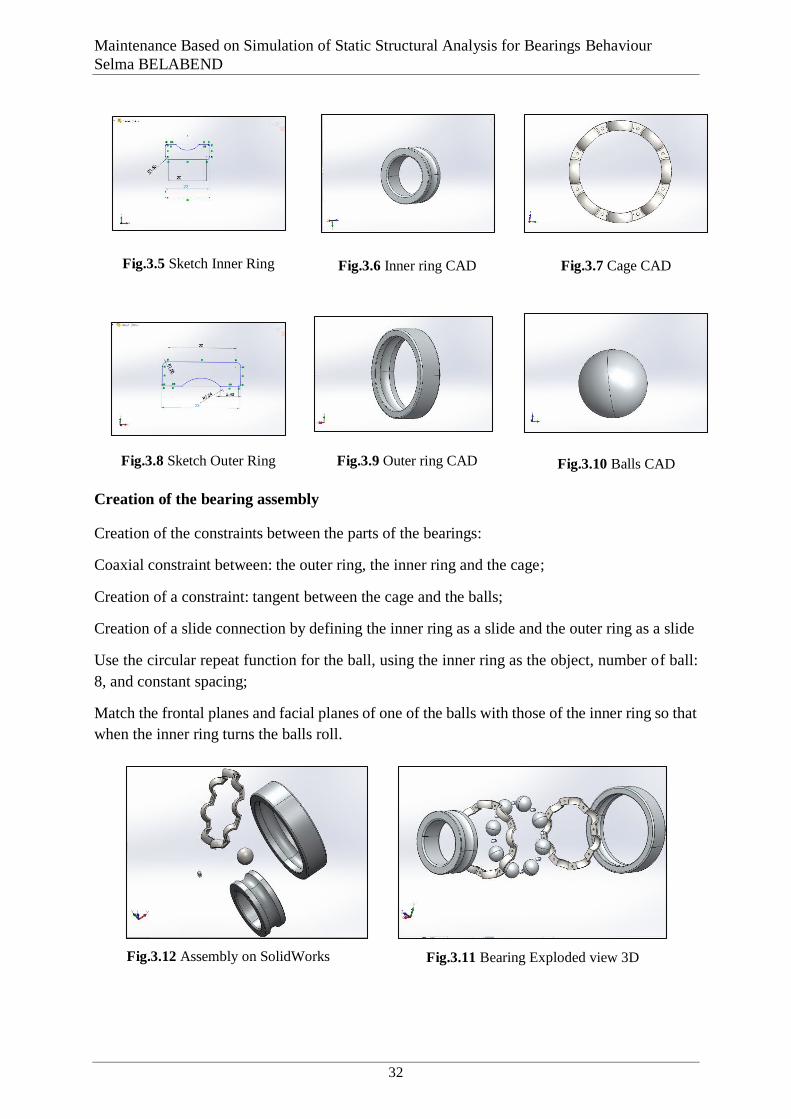
Maintenance Based on Simulation of Static Structural Analysis for Bearings Behaviour
Selma BELABEND
32
Fig.3.11 Bearing Exploded view 3D
Fig.3.5 Sketch Inner Ring
Fig.3.6 Inner ring CAD
Fig.3.7 Cage CAD
Fig.3.8 Sketch Outer Ring
Fig.3.9 Outer ring CAD
Fig.3.10 Balls CAD
Creation of the bearing assembly
Creation of the constraints between the parts of the bearings:
Coaxial constraint between: the outer ring, the inner ring and the cage;
Creation of a constraint: tangent between the cage and the balls;
Creation of a slide connection by defining the inner ring as a slide and the outer ring as a slide
Use the circular repeat function for the ball, using the inner ring as the object, number of ball:
8, and constant spacing;
Match the frontal planes and facial planes of one of the balls with those of the inner ring so that
when the inner ring turns the balls roll.
Fig.3.12 Assembly on SolidWorks

Chapter III Modelling and Simulation of Bearings
33
Fig.3.13 Assembled bearing CAD model SolidWorks
CAD (* .SLDASM. format) model are imported into the ANSYS WORKBENCH software.
Fig.3.14 Geometry on ANSYS
In the geometry section assign to each piece its material;
For both rings and balls the material being: ASTM 52100 Bearing Steel; not found in the
ANSYS 2019 R1 academic database, in the section engineering data we need to define the name
and the properties of the materials including: physical properties, teeth, properties linear elastic
... etc
Fig.3.15 Define material to each parts Fig.3.16 Adding materials data on
ANSYS Engineering Data
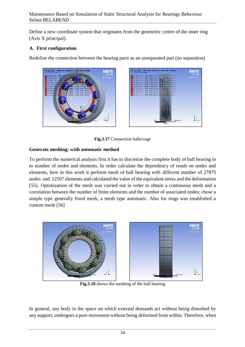
Maintenance Based on Simulation of Static Structural Analysis for Bearings Behaviour
Selma BELABEND
34
Define a new coordinate system that originates from the geometric centre of the inner ring
(Axis X principal).
A. First configuration
Redefine the connection between the bearing parts as an unseparated part (no separation)
Fig.3.17 Connection balls/cage
Generate meshing: with automatic method
To perform the numerical analysis first it has to discretize the complete body of ball bearing in
to number of nodes and elements. In order calculate the dependency of result on nodes and
elements, here in this work it perform mesh of ball bearing with different number of 27875
nodes and 12507 elements and calculated the value of the equivalent stress and the deformation
[55]. Optimization of the mesh was carried out in order to obtain a continuous mesh and a
correlation between the number of finite elements and the number of associated nodes; chose a
simple type generally fixed mesh, a mesh type automatic. Also for rings was established a
custom mesh [56]
Fig.3.18 shows the meshing of the ball bearing
A.1. The solicitation first configuration
In general, any body in the space on which external demands act without being disturbed by
any support, undergoes a pure movement without being deformed from within. Therefore, when
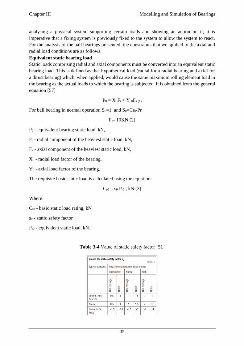
Chapter III Modelling and Simulation of Bearings
35
analysing a physical system supporting certain loads and showing an action on it, it is
imperative that a fixing system is previously fixed to the system to allow the system to react.
For the analysis of the ball bearings presented, the constraints that we applied to the axial and
radial load conditions are as follows:
Equivalent static bearing load
Static loads comprising radial and axial components must be converted into an equivalent static
bearing load. This is defined as that hypothetical load (radial for a radial bearing and axial for
a thrust bearing) which, when applied, would cause the same maximum rolling element load in
the bearing as the actual loads to which the bearing is subjected. It is obtained from the general
equation [57]
P0 = X0Fr + Y 0Fa (1)
For ball bearing in normal operation S0=1 and S0=Cr0/Pr0
Po= 10KN (2)
P0 - equivalent bearing static load, kN,
Fr - radial component of the heaviest static load, kN,
Fa - axial component of the heaviest static load, kN,
X0 - radial load factor of the bearing,
Y0 - axial load factor of the bearing.
The requisite basic static load is calculated using the equation:
Cr0 = s0 Pr0 , kN (3)
Where:
Cr0 - basic static load rating, kN
s0 - static safety factor
Pr0 - equivalent static load, kN.
Table 3-4 Value of static safety factor [51]
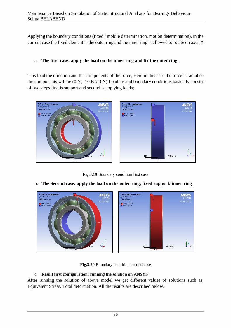
Maintenance Based on Simulation of Static Structural Analysis for Bearings Behaviour
Selma BELABEND
36
A.2. Boundary Condition first configuration
Applying the boundary conditions (fixed / mobile determination, motion determination), in the
current case the fixed element is the outer ring and the inner ring is allowed to rotate on axes X
a. The first case: apply the load on the inner ring and fix the outer ring,
This load the direction and the components of the force, Here in this case the force is radial so
the components will be (0 N; -10 KN; 0N) Loading and boundary conditions basically consist
of two steps first is support and second is applying loads;
Fig.3.19 Boundary condition first case
b. The Second case: apply the load on the outer ring; fixed support: inner ring
Fig.3.20 Boundary condition second case
c. Result first configuration: running the solution on ANSYS
After running the solution of above model we get different values of solutions such as,
Equivalent Stress, Total deformation. All the results are described below.
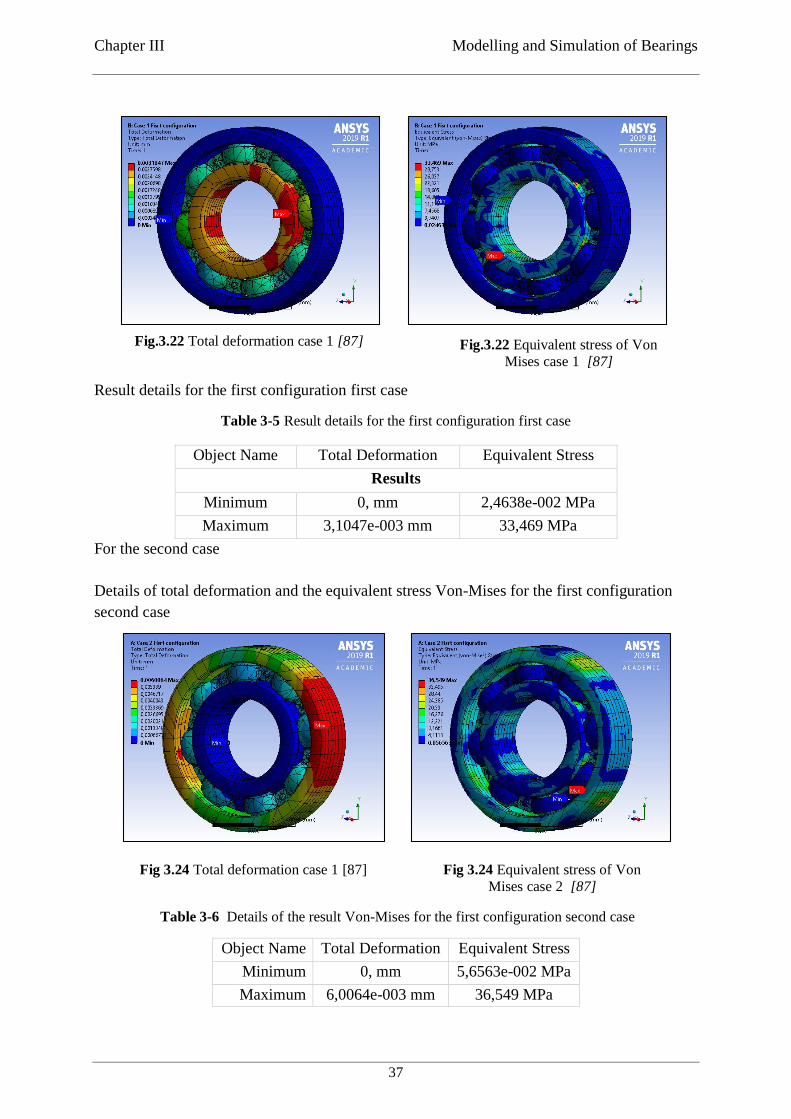
Chapter III Modelling and Simulation of Bearings
37
Result details for the first configuration first case
Table 3-5 Result details for the first configuration first case
Object Name Total Deformation Equivalent Stress
Results
Minimum 0, mm 2,4638e-002 MPa
Maximum 3,1047e-003 mm 33,469 MPa
For the second case
Details of total deformation and the equivalent stress Von-Mises for the first configuration
second case
Table 3-6 Details of the result Von-Mises for the first configuration second case
Object Name Total Deformation Equivalent Stress
Minimum 0, mm 5,6563e-002 MPa
Maximum 6,0064e-003 mm 36,549 MPa
Fig.3.22 Total deformation case 1 [87] Fig.3.22 Equivalent stress of Von
Mises case 1 [87]
Fig 3.24 Total deformation case 1 [87] Fig 3.24 Equivalent stress of Von
Mises case 2 [87]
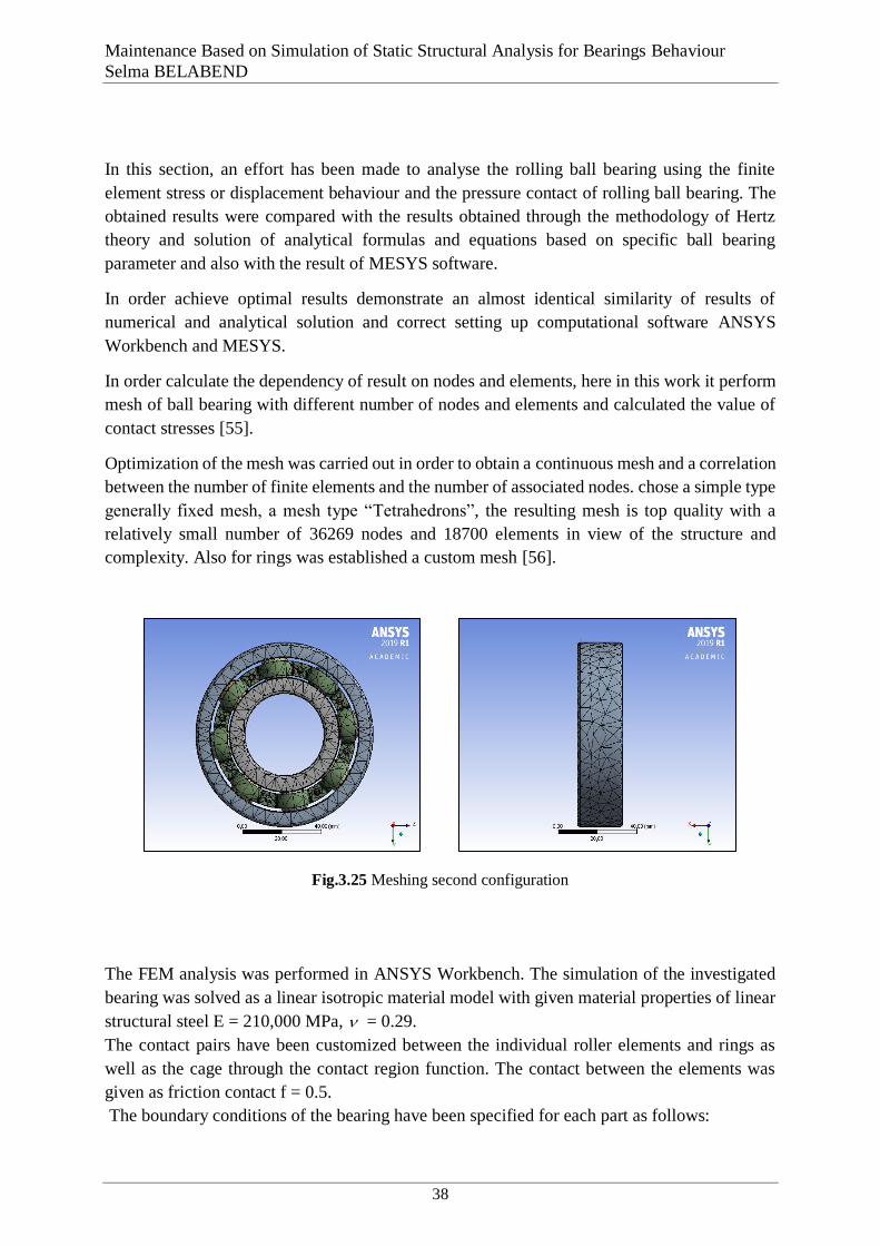
Maintenance Based on Simulation of Static Structural Analysis for Bearings Behaviour
Selma BELABEND
38
B. Second configuration
In this section, an effort has been made to analyse the rolling ball bearing using the finite
element stress or displacement behaviour and the pressure contact of rolling ball bearing. The
obtained results were compared with the results obtained through the methodology of Hertz
theory and solution of analytical formulas and equations based on specific ball bearing
parameter and also with the result of MESYS software.
In order achieve optimal results demonstrate an almost identical similarity of results of
numerical and analytical solution and correct setting up computational software ANSYS
Workbench and MESYS.
In order calculate the dependency of result on nodes and elements, here in this work it perform
mesh of ball bearing with different number of nodes and elements and calculated the value of
contact stresses [55].
Optimization of the mesh was carried out in order to obtain a continuous mesh and a correlation
between the number of finite elements and the number of associated nodes. chose a simple type
generally fixed mesh, a mesh type “Tetrahedrons”, the resulting mesh is top quality with a
relatively small number of 36269 nodes and 18700 elements in view of the structure and
complexity. Also for rings was established a custom mesh [56].
Fig.3.25 Meshing second configuration
B.1. Boundary Condition second configuration
The FEM analysis was performed in ANSYS Workbench. The simulation of the investigated
bearing was solved as a linear isotropic material model with given material properties of linear
structural steel E = 210,000 MPa, = 0.29.
The contact pairs have been customized between the individual roller elements and rings as
well as the cage through the contact region function. The contact between the elements was
given as friction contact f = 0.5.
The boundary conditions of the bearing have been specified for each part as follows:
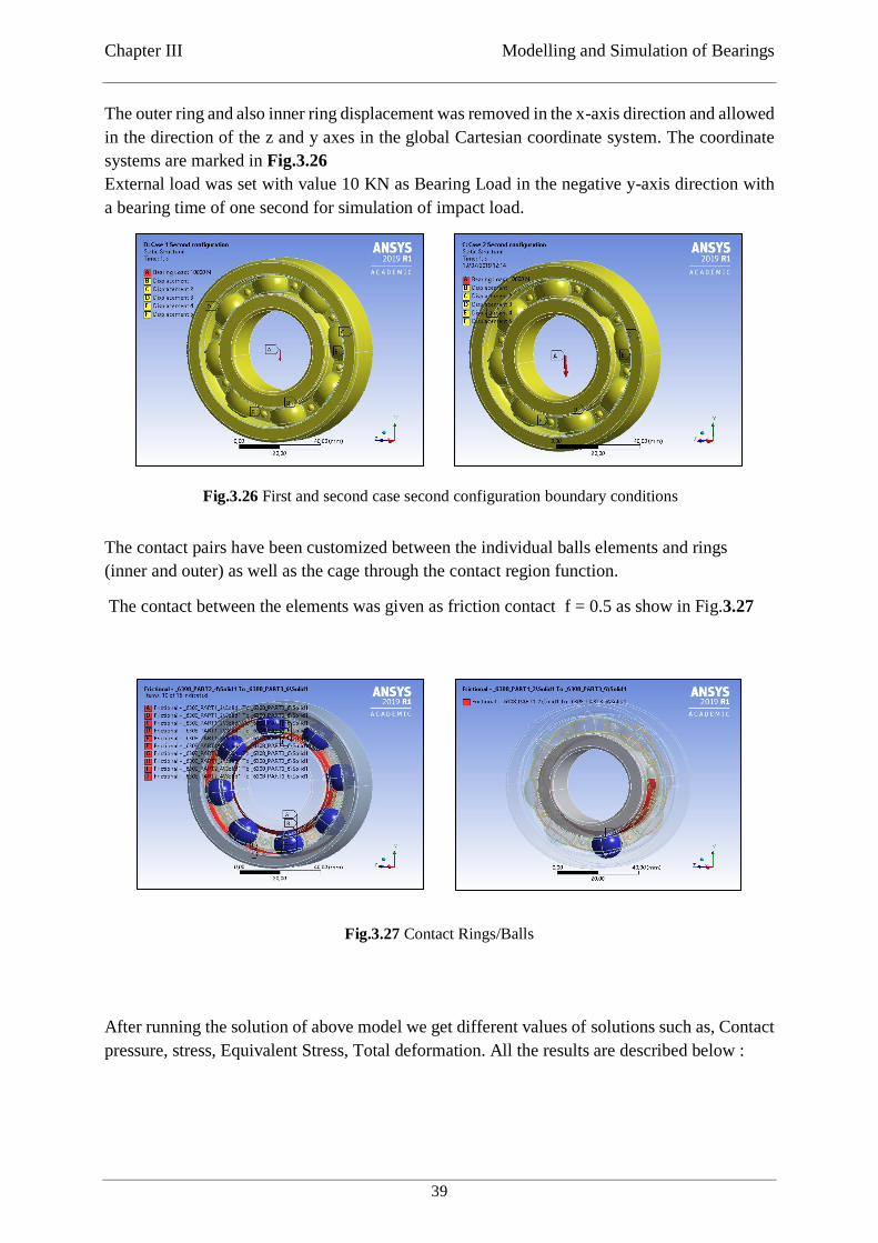
Chapter III Modelling and Simulation of Bearings
39
The outer ring and also inner ring displacement was removed in the x-axis direction and allowed
in the direction of the z and y axes in the global Cartesian coordinate system. The coordinate
systems are marked in Fig.3.26
External load was set with value 10 KN as Bearing Load in the negative y-axis direction with
a bearing time of one second for simulation of impact load.
The contact pairs have been customized between the individual balls elements and rings
(inner and outer) as well as the cage through the contact region function.
The contact between the elements was given as friction contact f = 0.5 as show in Fig.3.27
Fig.3.27 Contact Rings/Balls
Result configurations
After running the solution of above model we get different values of solutions such as, Contact
pressure, stress, Equivalent Stress, Total deformation. All the results are described below :
Fig.3.26 First and second case second configuration boundary conditions
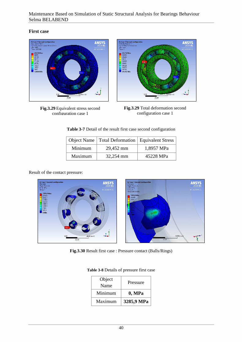
Maintenance Based on Simulation of Static Structural Analysis for Bearings Behaviour
Selma BELABEND
40
First case
Table 3-7 Detail of the result first case second configuration
Object Name Total Deformation Equivalent Stress
Minimum 29,452 mm 1,8957 MPa
Maximum 32,254 mm 45228 MPa
Result of the contact pressure:
Fig.3.30 Result first case : Pressure contact (Balls/Rings)
Table 3-8 Details of pressure first case
Object
Name Pressure
Minimum 0, MPa
Maximum 3285,9 MPa
Fig.3.29 Total deformation second
configuration case 1 Fig.3.29 Equivalent stress second
configuration case 1
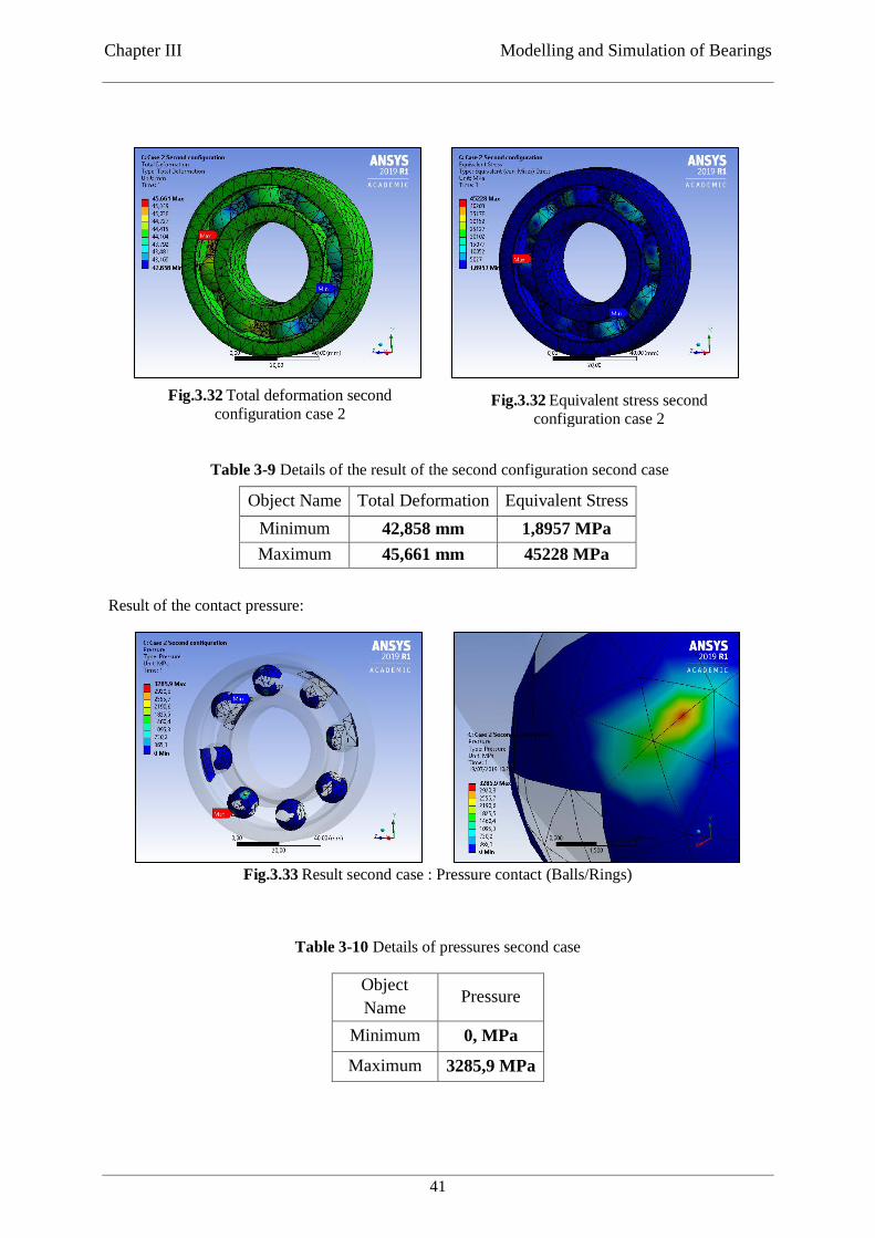
Chapter III Modelling and Simulation of Bearings
41
Second case
Table 3-9 Details of the result of the second configuration second case
Result of the contact pressure:
Fig.3.33 Result second case : Pressure contact (Balls/Rings)
Table 3-10 Details of pressures second case
Object
Name Pressure
Minimum 0, MPa
Maximum 3285,9 MPa
Object Name Total Deformation Equivalent Stress
Minimum 42,858 mm 1,8957 MPa
Maximum 45,661 mm 45228 MPa
Fig.3.32 Total deformation second
configuration case 2 Fig.3.32 Equivalent stress second
configuration case 2

Maintenance Based on Simulation of Static Structural Analysis for Bearings Behaviour
Selma BELABEND
42
C. Analytical calculation
In the elastic area, it is possible to calculate the contact pressure and the resulting deformation
at the contact points of the rolling elements and orbits by means of Hertz theory. Concerning to
the contact of the volume elastic bodies.
The general conclusions of this theory are based on three main assumptions.
1. The material of the bodies to be touched must be homogeneous and isotropic.
2. Only normal stress, not shear, can be transmitted in the contact area.
3. The proportional limit of the material must not be exceeded, that is, there can be no
plastic deformation [58] [59].
The contact area of the point contact of the load between the two curved bodies in point contact
is generally elliptical (
Fig.3.34). The elliptical contact surface for two components with identical
elastic modulus E and Poisson constant is defined according to Hertz theory with respect to the
main axis.
When the rolling ball bearing works, it is usually that more than one rolling ball bears the load.
The condition is complex between rollers and rings.
When the load is 0, contact area is a point, i.e., point-contact. When the load increases in
running, the bearing inner ring, outer ring and rolling elements bring forth plastic deformation
in the contact area, so the point contact becomes face-contact. Furthermore, contact area
gradually becomes ellipse, and generates residual stress [60] [61].
Fig.3.34 Contact between 2 spheres [62] [63]
The contact parameters, such as the place, size, shape of contact area, as well as the contact
pressure and friction force distribution, will be variable with the loads changing. These facts
are typical boundary conditions for nonlinear problems. When any two curved bodies of
different radii of curvature are brought into contact they will initially touch at either a point or
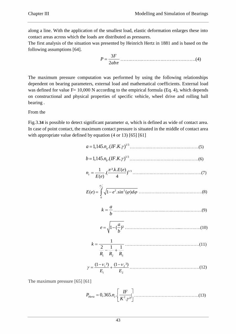
Chapter III Modelling and Simulation of Bearings
43
along a line. With the application of the smallest load, elastic deformation enlarges these into
contact areas across which the loads are distributed as pressures.
The first analysis of the situation was presented by Heinrich Hertz in 1881 and is based on the
following assumptions [64].
3
2
FP
ab …….…….…….…….…….…….…….(4)
The maximum pressure computation was performed by using the following relationships
dependent on bearing parameters, external load and mathematical coefficients. External load
was defined for value F= 10,000 N according to the empirical formula (Eq. 4), which depends
on constructional and physical properties of specific vehicle, wheel drive and rolling ball
bearing .
From the
Fig.3.34 is possible to detect significant parameter 𝑎, which is defined as wide of contact area.
In case of point contact, the maximum contact pressure is situated in the middle of contact area
with appropriate value defined by equation (4 or 13) [65] [61]
1/31,145. .( . . )aa n IF K …….…….…….…….…….…….…….(5)
1/31,145. .( . . )bb n IF K …….…….…….…….…….…….…….(6)
1/31 ². . ( ).( )
( ) 4c
k E en
E e
…….…….…….…….…….…….…….(7)
22 2
0
( ) 1 .sin ( )E e e d
…….…….……….…….…….…….(8)
a
kb
…….…….…….……….….…….….…….……….(9)
1 ( )²a
eb
………………………………...……….….(10)
1 2 3
1
2 1 1k
R R R
……………………………………………(11)
1 2
1 2
(1 ²) (1 ²)
E E
…………………………………………(12)
The maximum pressure [65] [61]
20,365. .
. ²Hertz c
IFP n
K
…………………………..………….(13)
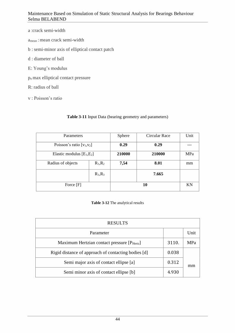
Maintenance Based on Simulation of Static Structural Analysis for Bearings Behaviour
Selma BELABEND
44
a :crack semi-width
amean : mean crack semi-width
b : semi-minor axis of elliptical contact patch
d : diameter of ball
E: Young’s modulus
po max elliptical contact pressure
R: radius of ball
v : Poisson’s ratio
Table 3-11 Input Data (bearing geometry and parameters)
Parameters Sphere Circular Race Unit
Poisson’s ratio [v1,v2] 0.29 0.29 ---
Elastic modulus [E1,E2] 210000 210000 MPa
Radius of objects R1,R2 7,54 8.01 mm
R1,R3 7.665
Force [F] 10 KN
Table 3-12 The analytical results
RESULTS
Parameter Unit
Maximum Hertzian contact pressure [PHertz] 3110. MPa
Rigid distance of approach of contacting bodies [d] 0.038
mm Semi major axis of contact ellipse [a] 0.312
Semi minor axis of contact ellipse [b] 4.930
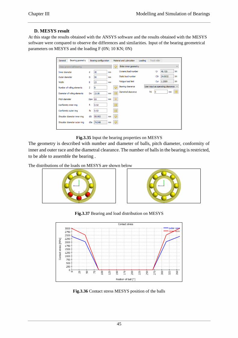
Chapter III Modelling and Simulation of Bearings
45
D. MESYS result
At this stage the results obtained with the ANSYS software and the results obtained with the MESYS
software were compared to observe the differences and similarities. Input of the bearing geometrical
parameters on MESYS and the loading F (0N; 10 KN; 0N)
The geometry is described with number and diameter of balls, pitch diameter, conformity of
inner and outer race and the diametral clearance. The number of balls in the bearing is restricted,
to be able to assemble the bearing .
The distributions of the loads on MESYS are shown below
Fig.3.37 Bearing and load distribution on MESYS
Fig.3.35 Input the bearing properties on MESYS
Fig.3.36 Contact stress MESYS position of the balls
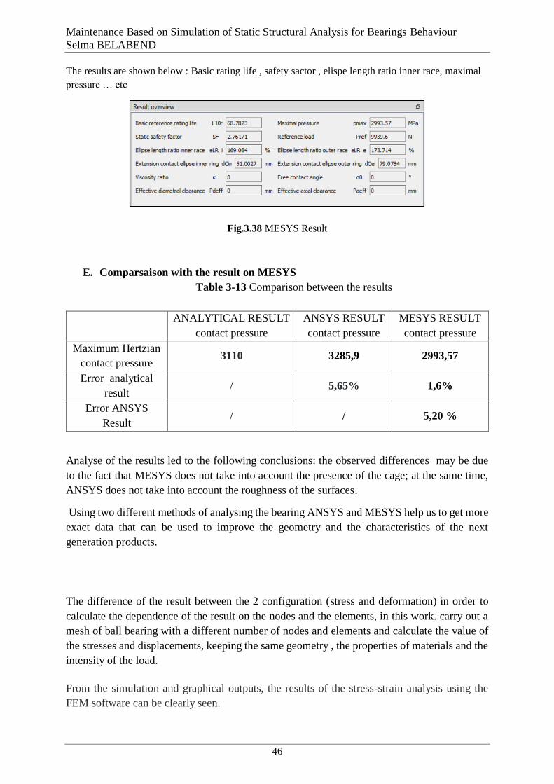
Maintenance Based on Simulation of Static Structural Analysis for Bearings Behaviour
Selma BELABEND
46
The results are shown below : Basic rating life , safety sactor , elispe length ratio inner race, maximal
pressure … etc
E. Comparsaison with the result on MESYS
Table 3-13 Comparison between the results
Analyse of the results led to the following conclusions: the observed differences may be due
to the fact that MESYS does not take into account the presence of the cage; at the same time,
ANSYS does not take into account the roughness of the surfaces,
Using two different methods of analysing the bearing ANSYS and MESYS help us to get more
exact data that can be used to improve the geometry and the characteristics of the next
generation products.
3.4. Discussion and conclusion
The difference of the result between the 2 configuration (stress and deformation) in order to
calculate the dependence of the result on the nodes and the elements, in this work. carry out a
mesh of ball bearing with a different number of nodes and elements and calculate the value of
the stresses and displacements, keeping the same geometry , the properties of materials and the
intensity of the load.
From the simulation and graphical outputs, the results of the stress-strain analysis using the
FEM software can be clearly seen.
ANALYTICAL RESULT
contact pressure
ANSYS RESULT
contact pressure
MESYS RESULT
contact pressure
Maximum Hertzian
contact pressure 3110 3285,9 2993,57
Error analytical
result / 5,65% 1,6%
Error ANSYS
Result / / 5,20 %
Fig.3.38 MESYS Result
Chapter III Modelling and Simulation of Bearings
47
The results obtained by mesys and Ansys were then compared to the analytical results obtained
using the Hertz theory methodology, which leads to the conclusion that the configuration of the
boundary conditions of the simulation given in the ANSYS Workbench calculation software is
acceptable. to the fact that the errors are less than 6%.
48
Chapter IV
Chapitre 4 First Step for the Implementation of TPM in the Bearing
Industry
4.1. Introduction
Total productive maintenance (TPM) is a pioneering Japanese concept, the term total
productive maintenance which was accredited to Nippondenso, a company that created parts
for Toyota. Seiichi Nakajima is considered as the father of TPM because of his plentiful
contributions of TPM [66]. The concepts of Total Productive Maintenance (TPM) have been
accepted in many organizations across the world. (TPM) is a scientific company- wide approach
in which every employee at levels in the organization is concerned about the maintenance, the
quality and efficiency of their equipment [67].
Overall Equipment Efficiency (OEE) is used as the measure of success of TPM implementation.
The main aim of TPM implementation is to reduce six big losses that are equipment failures or
breakdown losses, setup and adjustment losses, idling and minor stoppage losses, reduce speed
losses, defect in process losses and reduce yield losses [68] in all possible area of the industries
including top level management to floor workers.
4.2. Presentation of industry
4.2.1. Generalities
Rulmenti S.A., Barlad is a bearing manufacturing company located in Romania. The main
shareholder is BERA Holding from Turkey.
The company acts with approximately 1400 employees. Main activities are design,
production, sales and service of different types of bearings.
Fig.4.1 URB [51]
Chapter IV First Step for the Implementation of TPM in the Bearing Industry
49
4.2.2. History
In 1953, the company started to produce bearings. A continuous improvement process was
developed through the actual design, production and control facilities. Numerous changes were
implemented in order to raise the life expectancy, loading capacity and operating precision of
the bearings.
They include the respect for clients and the satisfaction of their needs among their fundamental
principles. Therefore, they tried to respond better to the market requirements by offering,
besides the bearings with standardized shapes and sizes, a large range of non-standardized
bearings, specific to various utilization.
Tooling department is a competent business partner ready to offer advice, to help and solve
problems. They have their own production capacity and can process parts and pieces under
customer’s orders.
RULMENTI S.A. BARLAD is a worldwide supplier of bearings and services in the rolling
bearing business. The Company is among the biggest producers of rolling bearings from Europe
and is known in the world market more than 65 years.
Today RULMENTI SA produces and distributes under URB brand a full range of bearings
including Radial Ball Bearings, Cylindrical Roller Bearings, Spherical Roller Bearings, Thrust
Ball Bearings, Thrust Cylindrical Roller Bearings, Tapered Roller Bearings all well known for
their precision and reliability. All bearings are produced in accordance with the standards of
International Organization of Standardization (ISO) and DIN standards.
RULMENTI SA is close to the customers through the wide distributor network in more than
40 countries, e.g. Romania, Germany, UK, Italy, Benelux, France, Spain, Ireland, Greece,
Poland, Bulgaria, Serbia, Ukraine, Turkey, USA, South Africa, Brazil, Egypt, India, Korea,
Taiwan, Thailand, Singapore, Vietnam, U.A.E. and other country [69].
4.3. Total productive maintenance
4.3.1. History of total productive maintenance
After Second World War Japanese industries realized that, industries cannot produce good
quality products with the help of poor maintenance system of equipment and it cannot stay in
this competitive global market. For effective maintenance system, Japanese companies adopted
U.S.A. based preventive maintenance policy in 1951 [70] .
Total productive maintenance (TPM) is a Japanese philosophy, which they imported after
1951.M/s Nippon Denso Co. Ltd japan, a supplier of M/s Toyota Motor Company, in the year
1971, firstly introduced TPM concept. “Total productive maintenance is an innovative concept
to maintenance that eliminates break downs, optimizes equipment effectiveness and promotes
autonomous maintenance technique by operators through day to day activities involving total
workforce” [71].
4.3.2. Developmental stages of TPM
Preventive maintenance was introduced in the 1950’s, with productive maintenance becoming
well established during the 1960’s. The development of TPM began in the 1970’s. The period
prior to 1950 can be referred to as the “breakdown maintenance” period [72].
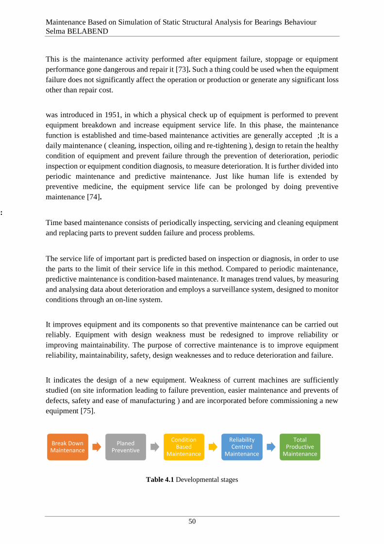
Maintenance Based on Simulation of Static Structural Analysis for Bearings Behaviour
Selma BELABEND
50
1. Breakdown maintenance :
This is the maintenance activity performed after equipment failure, stoppage or equipment
performance gone dangerous and repair it [73]. Such a thing could be used when the equipment
failure does not significantly affect the operation or production or generate any significant loss
other than repair cost.
2. Preventive maintenance ( 1951 )
was introduced in 1951, in which a physical check up of equipment is performed to prevent
equipment breakdown and increase equipment service life. In this phase, the maintenance
function is established and time-based maintenance activities are generally accepted ;It is a
daily maintenance ( cleaning, inspection, oiling and re-tightening ), design to retain the healthy
condition of equipment and prevent failure through the prevention of deterioration, periodic
inspection or equipment condition diagnosis, to measure deterioration. It is further divided into
periodic maintenance and predictive maintenance. Just like human life is extended by
preventive medicine, the equipment service life can be prolonged by doing preventive
maintenance [74].
2a. Periodic maintenance (Time based maintenance - TBM):
Time based maintenance consists of periodically inspecting, servicing and cleaning equipment
and replacing parts to prevent sudden failure and process problems.
2b. Predictive maintenance:
The service life of important part is predicted based on inspection or diagnosis, in order to use
the parts to the limit of their service life in this method. Compared to periodic maintenance,
predictive maintenance is condition-based maintenance. It manages trend values, by measuring
and analysing data about deterioration and employs a surveillance system, designed to monitor
conditions through an on-line system.
3. Corrective maintenance (1957)
It improves equipment and its components so that preventive maintenance can be carried out
reliably. Equipment with design weakness must be redesigned to improve reliability or
improving maintainability. The purpose of corrective maintenance is to improve equipment
reliability, maintainability, safety, design weaknesses and to reduce deterioration and failure.
4. Maintenance prevention (1960)
It indicates the design of a new equipment. Weakness of current machines are sufficiently
studied (on site information leading to failure prevention, easier maintenance and prevents of
defects, safety and ease of manufacturing ) and are incorporated before commissioning a new
equipment [75].
Table 4.1 Developmental stages
Break Down Maintenance
Planed Preventive
Condition Based
Maintenance
Reliability Centred
Maintenance
Total Productive
Maintenance
Chapter IV First Step for the Implementation of TPM in the Bearing Industry
51
4.3.3. Definition
A complete definition of TPM includes the following five elements:
1. TPM aims to maximize equipment effectiveness (overall effectiveness).
2. TPM establishes a thorough system of PM for the equipment’s entire life span.
3. Various departments (engineering, operations, and maintenance) implement TPM.
4. TPM involves every single employee, from top management to workers on the floor.
5. TPM is based on the promotion of PM through motivation management: autonomous
small group activities.
The word “total” in “total productive maintenance” has three meanings that describe the
principal features of TPM:
1. Total effectiveness (referred to in point 1 above) indicates TPM’s pursuit of economic
efficiency or profitability.
2. Total maintenance system (point 2) includes maintenance prevention (MP and
maintainability improvement (MI) as well as preventive maintenance.
3. Total participation of all employees ( point 3,4 and 5) includes autonomous maintenance
by the operators through small group activities [72].
TPM (Total Productive Maintenance) is a holistic approach to equipment maintenance that
strives to achieve perfect production:
No Breakdowns
No Small Stops or Slow Running
No Defects
In addition it values a safe working environment:
No Accidents
TPM emphasizes proactive and preventative maintenance to maximize the operational
efficiency of equipment. It blurs the distinction between the roles of production and
maintenance by placing a strong emphasis on empowering operators to help maintain their
equipment.
The implementation of a TPM program creates a shared responsibility for equipment that
encourages greater involvement by plant floor workers. In the right environment this can be
very effective in improving productivity (increasing up time, reducing cycle times, and
eliminating defects).
Total means improve overall effectiveness of plants, employees and renovate overall plant
effectiveness by involving all employees from bottom to top management,
Productive means to produce defect free products with take care of the safety,
Maintenance means to increase the lifecycle of product or production system. Total productive
maintenance is interfering between men and machine.
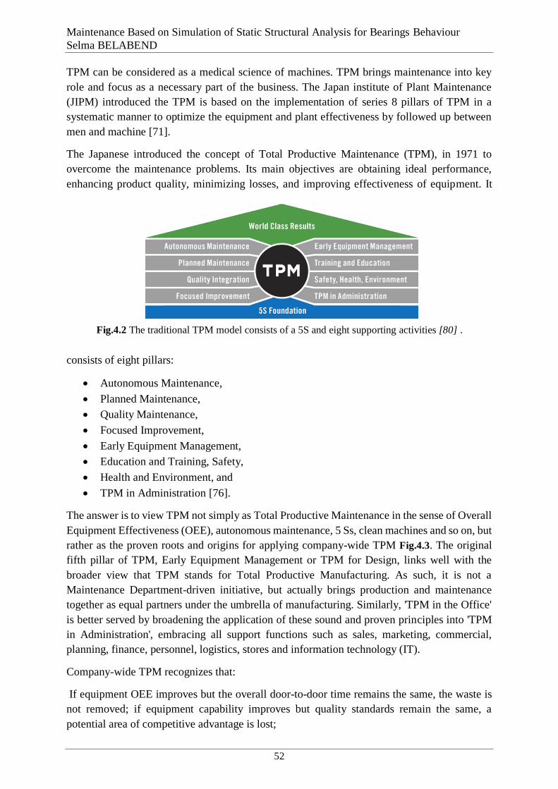
Maintenance Based on Simulation of Static Structural Analysis for Bearings Behaviour
Selma BELABEND
52
TPM can be considered as a medical science of machines. TPM brings maintenance into key
role and focus as a necessary part of the business. The Japan institute of Plant Maintenance
(JIPM) introduced the TPM is based on the implementation of series 8 pillars of TPM in a
systematic manner to optimize the equipment and plant effectiveness by followed up between
men and machine [71].
The Japanese introduced the concept of Total Productive Maintenance (TPM), in 1971 to
overcome the maintenance problems. Its main objectives are obtaining ideal performance,
enhancing product quality, minimizing losses, and improving effectiveness of equipment. It
consists of eight pillars:
Autonomous Maintenance,
Planned Maintenance,
Quality Maintenance,
Focused Improvement,
Early Equipment Management,
Education and Training, Safety,
Health and Environment, and
TPM in Administration [76].
The answer is to view TPM not simply as Total Productive Maintenance in the sense of Overall
Equipment Effectiveness (OEE), autonomous maintenance, 5 Ss, clean machines and so on, but
rather as the proven roots and origins for applying company-wide TPM Fig.4.3. The original
fifth pillar of TPM, Early Equipment Management or TPM for Design, links well with the
broader view that TPM stands for Total Productive Manufacturing. As such, it is not a
Maintenance Department-driven initiative, but actually brings production and maintenance
together as equal partners under the umbrella of manufacturing. Similarly, 'TPM in the Office'
is better served by broadening the application of these sound and proven principles into 'TPM
in Administration', embracing all support functions such as sales, marketing, commercial,
planning, finance, personnel, logistics, stores and information technology (IT).
Company-wide TPM recognizes that:
If equipment OEE improves but the overall door-to-door time remains the same, the waste is
not removed; if equipment capability improves but quality standards remain the same, a
potential area of competitive advantage is lost;
Fig.4.2 The traditional TPM model consists of a 5S and eight supporting activities [80] .

Chapter IV First Step for the Implementation of TPM in the Bearing Industry
53
If knowledge gained about the process does not produce higher rates of return on investment,
the organization is not making the best use of its capabilities;
If capability is increased but this is not met by generation of new business, an opportunity to
reduce unit costs is lost.
Tools of TPM
A variety of tools is often used to help the deployment of activities through TPM programs
based on these pillars.
Among the tools used by TPM to analyse and solve equipment and process related problems
are Pareto Analysis, Statistical Process Control (SPC – control charts, etc), problem solving
techniques like brainstorming, cause and effect diagrams and 5M Approach, visual control like
OPLs, Poka-Yoke Systems, Autonomous Maintenance, Continuous Improvement, 5S. Setup
Time Reduction, Waste Minimization, Bottleneck Analysis, Recognition and Reward Program
and Simulation [77].
The main objectives of TPM implementations is to reduce occurrence of unforeseen machine
breakdowns that interrupt production and lead to losses [78].
OEE = Availability (A) × Performance (P) × Rate of Quality (Q)
A. Availability is the proportion of time available for which a machine runs or production
purposes. When a process is stopped, it’s creating a cost with no associated value . Availability
is the ratio of Operating time and Loading time.
Availability (A) = [(Loading time-Downtime) ÷ Loading time] × 100
B. Performance is the results of activities on an organization over given period of time. A
Performance score of 100% means when the process is running as fast as possible.
Performance Rate= [(Standard cycle time × Product unit processed) ÷ Operating time] ×
100
Fig.4.3 Relationship between TPM and lean manufacturing philosophy [70]

Maintenance Based on Simulation of Static Structural Analysis for Bearings Behaviour
Selma BELABEND
54
C. Quality (Q) is percentage of good parts out of total produced parts. A quality score of
100% means there is no defect.
Quality Rate= [(Product unit processed –Defect Units) ÷Product unit processed] ×100
[79] .
Table 4.2 TPM TOOLS [79]
Component TPM Goal Type of productivity Loss
Availability No Stops
Availability takes into account Availability Loss, which
includes all events that stop planned production for an
appreciable length of time (typically several minutes or
longer). Examples include Unplanned Stops (such as
breakdowns and other down events) and Planned Stops (such
as changeovers).
Performance
No Small
Stops or
Slow
Running
Performance takes into account Performance Loss, which
includes all factors that cause production to operate at less
than the maximum possible speed when running. Examples
include both Slow Cycles, and Small Stops.
Quality No Defects
Quality takes into account Quality Loss, which factors out
manufactured pieces that do not meet quality standards,
including pieces that require rework. Examples include
Production Rejects and Reduced Yield on startup.
OEE Perfect
Production
OEE takes into account all losses (Availability Loss,
Performance Loss, and Quality Loss), resulting in a measure
of truly productive manufacturing time [80].
Six Big Losses
One of the major goals of TPM and OEE is to reduce or eliminate what are called the six big
losses which they are the most common causes of efficiency loss in manufacturing. The link of
the losses and the effectiveness in TPM is defined in terms of both the quality of the product
and the equipment availability. Any operation time may face losses and these losses can be
visible like scrap, changeovers and breakdowns or invisibles such as the slow running, the
frequent adjustment to maintain the production within tolerance, Nakajima summarised the loss
in a six big losses [81].
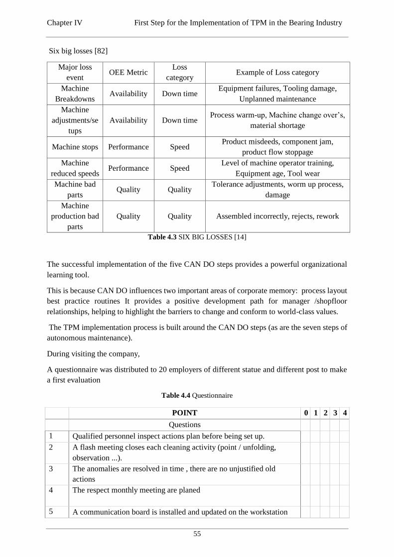
Chapter IV First Step for the Implementation of TPM in the Bearing Industry
55
Six big losses [82]
Major loss
event OEE Metric
Loss
category Example of Loss category
Machine
Breakdowns Availability Down time
Equipment failures, Tooling damage,
Unplanned maintenance
Machine
adjustments/se
tups
Availability Down time Process warm-up, Machine change over’s,
material shortage
Machine stops Performance Speed Product misdeeds, component jam,
product flow stoppage
Machine
reduced speeds Performance Speed
Level of machine operator training,
Equipment age, Tool wear
Machine bad
parts Quality Quality
Tolerance adjustments, worm up process,
damage
Machine
production bad
parts
Quality Quality Assembled incorrectly, rejects, rework
Table 4.3 SIX BIG LOSSES [14]
4.4. Implementing TPM principles
The successful implementation of the five CAN DO steps provides a powerful organizational
learning tool.
This is because CAN DO influences two important areas of corporate memory: process layout
best practice routines It provides a positive development path for manager /shopfloor
relationships, helping to highlight the barriers to change and conform to world-class values.
The TPM implementation process is built around the CAN DO steps (as are the seven steps of
autonomous maintenance).
During visiting the company,
A questionnaire was distributed to 20 employers of different statue and different post to make
a first evaluation
Table 4.4 Questionnaire
POINT 0 1 2 3 4
Questions
1 Qualified personnel inspect actions plan before being set up.
2 A flash meeting closes each cleaning activity (point / unfolding,
observation ...).
3 The anomalies are resolved in time , there are no unjustified old
actions
4 The respect monthly meeting are planed
5 A communication board is installed and updated on the workstation
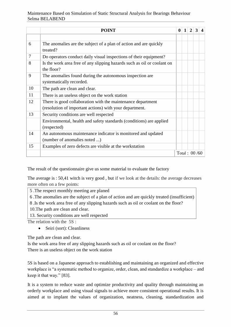
Maintenance Based on Simulation of Static Structural Analysis for Bearings Behaviour
Selma BELABEND
56
POINT 0 1 2 3 4
6 The anomalies are the subject of a plan of action and are quickly
treated?
7 Do operators conduct daily visual inspections of their equipment?
8 Is the work area free of any slipping hazards such as oil or coolant on
the floor?
9 The anomalies found during the autonomous inspection are
systematically recorded.
10 The path are clean and clear.
11 There is an useless object on the work station
12 There is good collaboration with the maintenance department
(resolution of important actions) with your department.
13 Security conditions are well respected
Environmental, health and safety standards (conditions) are applied
(respected)
14 An autonomous maintenance indicator is monitored and updated
(number of anomalies noted ...)
15 Examples of zero defects are visible at the workstation
Total : 00 /60
The result of the questionnaire give us some material to evaluate the factory
The average is : 50,41 witch is very good , but if we look at the details: the average decreases
more often on a few points:
5 .The respect monthly meeting are planed
6 .The anomalies are the subject of a plan of action and are quickly treated (insufficient)
8 .Is the work area free of any slipping hazards such as oil or coolant on the floor?
10.The path are clean and clear.
13. Security conditions are well respected
The relation with the 5S :
Seiri (sort): Cleanliness
The path are clean and clear.
Is the work area free of any slipping hazards such as oil or coolant on the floor?
There is an useless object on the work station
4.4.1. 5S - A Base of TPM
5S is based on a Japanese approach to establishing and maintaining an organized and effective
workplace is “a systematic method to organize, order, clean, and standardize a workplace – and
keep it that way.” [83].
It is a system to reduce waste and optimize productivity and quality through maintaining an
orderly workplace and using visual signals to achieve more consistent operational results. It is
aimed at to implant the values of organization, neatness, cleaning, standardization and

Chapter IV First Step for the Implementation of TPM in the Bearing Industry
57
discipline into the workplace in its existing configuration. In the daily work of a company,
routines that maintain organization and orderliness are essential to a smooth and efficient flow
of activities. Sort, the first S, focuses on eliminating unnecessary items from the workplace that
are not needed for current production operations. Set in order focuses on creating efficient and
effective storage methods to arrange items, so that they are easy to use, and to. 5S is considered
to be the first lean method implemented by firms. The description of the steps of 5S is given
below
Seiri (sort): Remove all items from the workplace that are not needed for current production
operations or for records. Unnecessary material at the work place can lead to errors and defects.
Seiton (set in order): Arrange and label needed items so that they are easy to locate and use.
Seiso (shine): Clean floors, equipment, and work stations, this step also includes identifying
and preventing the sources of contamination or dirt.
Seiketsu (standardize): Adopt methods and practices to maintain Sort, Set in Order, and Shine
on an ongoing and continuously improving manner.
Shitsuke (sustain): Make 5S standard practice [73].
Fig.4.4 THE 5S [authors]
In English-speaking countries an alternative way of expressing the 5 Ss is the more easily
remembered CAN DO of
Cleanliness
Arrangement
Neatness
Discipline
Order
The philosophy is exactly the same, however:
1. Get rid of everything and anything unnecessary.
2. Put what you do want in its right place so that it is to hand.
5S
Seiri
Seiton
SeisoSeiketsu
Shitsuke

Maintenance Based on Simulation of Static Structural Analysis for Bearings Behaviour
Selma BELABEND
58
3. Keep it clean and tidy at all times, recognizing that cleanliness is neatness (a clear
mind/attitude), is spotting deterioration (through inspection), is putting things right before
they become catastrophes, is pride in the workplace, giving self-esteem.
4. Pass on that discipline and order to your colleagues so that we all strive for a dust-free and
dirt-free plant.
The CAN DO approach, therefore, is to look at the production facility and clean the workshop
and its plant and machinery as it has never been cleaned before, whilst at the same time casting
a ruthlessly critical eye at everything in the workplace. Nothing must be allowed to remain
anywhere on the shopfloor unless it is directly relevant to the current production process. Good
housekeeping thereafter becomes everyone’s responsibility and a way of life.
The cleaning process involves the operators of machines and plant. As they clean, they will get
to know their machines better; they will gradually develop their own ability to see or detect
weaknesses and deterioration such as oil leaks, vibration, loose fastenings and unusual noise.
As time goes on, they will be able to perform essential, front-line asset care and some minor
maintenance tasks within the limits of their own skills. The process will take place in complete
co-operation with maintenance people, who will be freed to apply their technical skills where
needed. With the attitude to cleanliness and good housekeeping understood, we can move on to
explain the main principles on which TPM is founded [84].
4.5. Action plan
Step1 Preparing the site: Take note of the process, use the guide and its annexes to prepare all
the necessary equipment. Set up the activity table and prepare the communication / training
materials for the staff.
Step 2 The big storage room: Remove from the workstation all that is useless, to repair or to
put away somewhere.
Step 3 The upgrade: Processing labels, and set up the cleaning kit. Preparation and realization
of the DAY 5S. Treatment of anomaly observations and improvement ideas from the 5S day.
Step 4 Assignment: Define the ideal layout of the workstation and perform temporary floor
marking with colored tape. Also identify all locations: tools, consumables, working documents
etc ...
Step 5 Maintaining the established standard: Write cleaning ranges, establish a daily, weekly
and monthly schedule.
Step 6 Analyse and remove sources of soiling. Facilitate access to clean, drive, adjust:
transparency, speed of disassembly.
Step 7 Sustainability: Set up maintenance audits to avoid drifting. Take stock of the site and
record the lessons (+/-).
Finalize the action plan. Develop maintenance tools (self-maintenance ranges)
Conclusion
This treats information, collation, equipment, understanding and maintenance as things that are
necessary, compared to sources of contamination, human error and hidden losses as

Chapter IV First Step for the Implementation of TPM in the Bearing Industry
59
unnecessary items. Having decided what is necessary, work processes can then be
formalized/refined. One of the outcomes of implementing best practice in this way is that many
tasks can be simplified such that the most appropriate person can carry them out.
This releases specialist maintenance or production personnel to concentrate on optimization of
plant and equipment, providing the gateway to ‘better than’ new performance. The stepwise
implementation philosophy of the TPM principles is set out below. Continuous improvement
in OEE The initial process of cleaning and establishing order leads to discovering abnormalities,
and progresses through four steps:
1. Discover equipment abnormalities.
2. Treat abnormalities and extend focus to supply chain losses.
3. Set optimal equipment conditions to deliver future customer expectations.
4. Maintain optimal equipment conditions during delegation of routine.
The objective of this process is to move progressively towards a situation where all production
plant is always available when needed and operating as closely as possible to 100 per cent
effectiveness. Achieving this goal will certainly not come easily and may take years. The basic
concept is one of continuous improvement: ’What is good enough today will not be good
enough tomorrow’ [84].
60
Chapter V
General conclusion
The bearings industry began to use remarkable technological advancement to improve products
quality. Optimization of standard construction, improving the calculation and testing methods
including the Finite Element Method have provided high quality product with low cost.
Since failures in engineering products especially in rotating machinery, early fault detection of
the rolling elements as bearings can lead to severe economic loss because of its detrimental
influence on the reliability of equipment, its health monitoring is very essential particularly in
aerospace, civil, marine and other structures to avoid premature failures. Precise incipient
structural damage identification and its location is of great interest to many researchers.
Different techniques have been developed for monitoring and diagnosis of rolling element
bearings
Simulation is a powerful modular system that uses numerical software and allow the engineer
to predict the behaviour of the structure under its working conditions. By using ANSYS to
numerically simulate and analyse on stress and strain during deep groove ball bearing contacts,
the finite element solutions were got, which had good consistency with the Hertzian theory
solutions. The contact analysis of finite element method can easily and intuitively get the strain
values. Which can efficiently understands the parts running information, such as contact
penetration, contact-sliding distance, and so on. Those will provide reference and evidence for
strength Analysis, life-design and structural optimum about complex bearing.
Concerning the total productive maintenance: The crux of the above literature review is that, in
order to improve the 5S Japanese approach, in otherwise the CAN DO approach, a systematic
and methodological step is required and that is implementing pillars of TPM. It is thus
observed, that TPM forms the basis of OEE (Overall Equipment Efficiency) implement, in all
industries and more research work are always useful to optimize the method, to improve
productivity. The three parameters of OEE viz Availability, Performance and Quality rate needs
to be taken special care off, and their improvement, directly contributed to improve OEE of
concern machine, or entire manufacturing unit.

Maintenance Based on Simulation of Static Structural Analysis for Bearings Behaviours
BELABEND Selma
61
References
[1] ***, “"DUNAREA DE JOS" UNIVERSITY OF GALATI,” [Online]. Available:
https://erris.gov.ro. [Accessed June 2019].
[2] T. A. HARRIS, Rolling bearing analysis, New York USA: Wiley-Interscience Publication,
2001.
[3] Team BC in Bearing Corporation , “The History of Bearings,” 8 June 2017. [Online].
Available: http://www.bearingcorporation.com/the-history-of-bearings/. [Accessed 1 April
2019].
[4] SKF, Pole Position Bearing self study guide, USA, 2008.
[5] S. R. S. B. O. J. Bernard J. Hamrock, Fundamentals of Fluid Film Lubrication, The Ohio
State University: National Aeronautics and Space Administration Office of Management
Scientific and technical Information Program, 1991.
[6] P. R.N.Childs, Mechanical Design Engineering Handbook, 2014.
[7] TIMKEN Company, “BEARING DIMENSION CATALOG,” 1999.
[8] G. A. POWELL, “MAINTAINING YOUR BONES® BEARINGS,” BONES® BEARINGS,
[Online]. Available: https://bonesbearings.com/support/maintenance/#. [Accessed 04 April
2019].
[9] NTN, BALL AND ROLLER BEARINGS GATALOG A-1000-XI, usa, 2009.
[10] I. Marcel Dekker, Bearing Design in Machinery: Engineering Tribology and Lubrication,
THE UNITED STATES OF AMERICA New York, 2003.
[11] C. Gonzalez, “machine design the difference between bearings,” 26 August 2015. [Online].
Available: https://www.machinedesign.com/whats-difference-between/what-s-difference-
between-bearings-1. [Accessed 27 March 2019].
[12] spatguru, “Bearing Basic and types of bearings,” 19 jul 2014. [Online]. Available:
http://ispatguru.com/bearing-basics-and-types-of-bearings/.
[13] X. A. T. T. C. C. A. Moyer, Rolling Element Bearings, The Timken Company CRC Press
LLC, 2001.
[14] I. DELHI, “BEARINGS,” 03 DECEMBER 2013. [Online]. Available:
https://nptel.ac.in/courses/116102012/127. [Accessed 1 April 2019].
[15] ZKL GROUP, “Selecting type of bearing,” 2012. [Online]. Available: http://www.zkl.cz/.
[Accessed 29 03 2019].
Maintenance Based on Simulation of Static Structural Analysis for Bearings Behaviour
Selma BELABEND
62
[16] A. R. D. Crehu, Tribological analysis of White Etching Crack (WEC) failures in rolling
element bearings, Lyon: INSA, 2014.
[17] D. D. M. G. C. T. D. Berthe, Tribological Design of Machine Elements, Lyon: ELSEVIER,
1989.
[18] P. E. L. H. K. W. Johannes Brändlein, Ball and Roller Bearings: Theory, Design and
Application, New York: John Wiley & Sons, 1999.
[19] Rao and Ch. Ratnam, “A Comparative Experimental Study on Identification of Defect
Severity in Rolling Element Bearings using Acoustic Emission and vibration Analysis,”
Tribology in industry, pp. 176-185 177, 2015.
[20] N. Tandon and A. Choudhury, “'A review of Vibration and Acoustic measurement methods
for the detection of defects in rolling element bearings',,” Tribol. Int.,, pp. vol. 32, no.8, pp.
469-80, , 1999.
[21] NTN, Care and Maintenance of Bearings CAT.No.3017-II/E], USA.
[22] J. SHIROISHI, S. L. Y. LI and S. a. K. T. DANYLUK, “Vibration analysis for Bearing outer
race condition diagnostics.,” Journal of the Brazilian Society of Mechanical Sciences, pp. v.
21, n. 3, p. 484-492, 1999.
[23] Suzuki T., New direction for TPM, Massachusetts, 1992.
[24] W. W. F. G. I.E.E.E. Jie Liu, “An enhanced diagnostic scheme for bearing condition
monitoring,,” IEEE Trans. Instrum. Meas., no. 309–321, 2010.
[25] Q. Z. Q. Miao, “Planetary gearbox vibration signal characteristics analysis and fault
diagnosis,” Shock. Vib, 2015.
[26] S. D. c. ,. X. C. a. ,. C. L. a. ,. R.-V. S. d. ,. H. Q. Zhiqiang Chen, “Deep neural networks-
based rolling bearing fault diagnosis,” Microelectronics Reliability, p. 327–333, 2017.
[27] I. Howard, A Review of Rolling Element Bearing Vibration "Detection,Diagnosis and
Prognosis, Melbourne Victoria Australia: Aeronautical and Maritime Research Laboratory
Airframes and Engines Division, 1994.
[28] T. A. a. K. M. Harris, Essential Concepts of Bearing Technology, New York: Taylor &
Francis Group, LLC., 2006.
[29] SKF, Bearing failures and their causes, ENGLAND, 1994.
[30] SKF, Bearing investigation Extract from the Railway technical handbook,, 1999.
[31] N. Bearing, Technical catalog, Jaipur India, July 2005.
[32] M. G. Q. C. Gerval JP, “Behaviour modelling and vibration analysis applied to predictive
maintenance: different approaches leading to the same conclusion.,” OCEANS, 94. ‘Oceans
engineering for today’s technology and tomorrow’s preservation’ , 1994.
[33] Koyo, Ball & Roller Bearings: Failure, Causes and Counter measures, JTEKT corporation.
[34] I. V. P. Ky Dang Van, HIGH-CYCLE METAL FATIGUE FROM THEORY TO
APPLICATIONS, Springer-Verlag Wien GmbH, 1999.

Maintenance Based on Simulation of Static Structural Analysis for Bearings Behaviours
BELABEND Selma
63
[35] P. I. Informer, “Identifying The Causes Of Bearing Damage and Failure,” 4 December 2017.
[Online]. Available: https://www.processindustryinformer.com/editorial/identifying-causes-
bearing-damage-failure/. [Accessed 8 April 2019].
[36] SKF, Bearing Installation and Maintenance Guide, 2012.
[37] Timken , Bearing Damage Analysis with Lubrication Reference Guide, The Timken
Company, 2015.
[38] ***I. 15243:2004(E), INTERNATIONAL STANDARD Rolling bearings Damage and
failures terms, characteristics and causes, 2004.
[39] ***ISO 15243, International standard Rolling bearings Damage and failures,Terms,
charecteristics and causes, 2017.
[40] NSK, Handling Instructions for bearing.
[41] D. R. CELIN, “CRACKS IN A ROLLER-BEARING,” METALURGIJA, vol. 1, no. 47, pp.
69-72, 2008.
[42] ***, “Bearing inspection,” 2014 May 20. [Online]. Available:
https://www.techtransfer.com/blog/bearing-inspections/. [Accessed 2019 May 20].
[43] RKB, RKB Multi-level control system for rolling bearing, technological bearings.
[44] Non-destructive Testing: A Guidebook for Industrial Management and Quality Control
Personnel, VIENNA, : INTERNATIONAL ATOMIC ENERGY AGENCY, , 1999.
[45] G. T. M. S. M. Lanzetta, “The Process Control in Manufacturing: Inspection of Ball
Bearings,” in PRogress in Innovative Manufacturing Engineering, Pisa,Italy, 2001.
[46] The British Institute of Non-Destructive Testing, “Carrying out NDT and CM,” [Online].
Available: https://www.bindt.org/careers/careers-information/Carrying-out-NDT-and-CM/.
[Accessed 21 May 2019].
[47] INTERNATIONAL ATOMIC ENERGY AGENCY, Liquid Penetrant and Magnetic Particle
Testing at Level 2 Training Guidelines in Non-destructive Testing Techniques,
INTERNATIONAL ATOMIC ENERGY AGENCY, 2000.
[48] J. Y. ,. H. Huinan Wanga, “Current Status and Prospect of Roller Bearing Surface Defect
Detection,” Elsevier Ltd, p. 4331 – 4336, 2011.
[49] O. L. ,. A. B. Alin Marian Pușcașu, “Study regarding the structural response of standard
cylindrical roller bearings using ANSYS and MESYS,” in MATEC Web of Conferences 178,
05012, 2018.
[50] Bearings, URB Ultra Reliable, General catalog, Barlad: urb group companies , 2017.
[51] B. Z. ,. K. Semih TAŞKAYA, “INVESTIGATION OF THE FORCE AND MOMENT
EFFECTS OF ST 37 AND ST 70 ROOF,” Middle East Journal of Science, vol. 1, no. 4, pp.
23-35, 2018.
Maintenance Based on Simulation of Static Structural Analysis for Bearings Behaviour
Selma BELABEND
64
[52] T. Q. Z. K. L. J. Z. Yongqi, “Analysis of Stress and Strain of the Rolling Bearing by FEA
method,” in International Conference on Applied Physics and Industrial Engineering
Physics., 2012.
[53] I. 281, “International Standard, Rolling Bearings – dynamic load rating and rating life,,”
2007.
[54] U. J. Monu Jasoriya, “Analysis on Effects of Different Materials used to Manufacture Deep
Groove Ball Bearing,” International Journal for Research in Applied Science & Engineering
Technology (IJRASET) ISSN: 2321-9653, vol. 6 , no. 287-297, 2018.
[55] C. L. Y. P. N. H. Marek Bucki, “Jacobian-based repair method for finite element meshes,”
Engineering with Computers, Springer Verlag, pp. 285-297, 2011.
[56] SKF, “Loads,” SKF, [Online]. Available: https://www.skf.com/ph/products/bearings-units-
housings/engineered-products/insocoat-bearings/loads/index.html. [Accessed 06 June 2019].
[57] .. ,. P.K. Gupta, “Computer graphics modeling of rolling bearing dynamics,” in Presented at
the STLE Annual Meeting,, Pittsburg,Pennsylvania, 1994.
[58] *. A. S. V. D. M. S. Peter Šulka, “Comparison of analytical and numerical solution of bearing
contact analysis,” in MATEC Web of Conferences, Slovak Republic, 2018.
[59] A. B. Jones, “A general theory for elastically constrained ball and radial bearings under
arbitrary load and speed conditions.,” no. pp309-320, (1960).
[60] D. A. N. R. AKKUDASU CHENNAKESAVULU, “Structural Analysis of Ball Bearings in
ANSYS,” JSETR, pp. 7086-7090, 2015.
[61] A. F. Pascal GUAY, “BALL BEARING STIFFNESS.A NEW APPROACH OFFERING
ANALYTICAL EXPRESSIONS,” ReserchGate, September 2015.
[62] ***, “HERTZ CONTACT – UNIVERSAL POINT,” [Online]. Available:
https://www.janssenprecisionengineering.com/page/hertz-contact-universal-point/. [Accessed
July 2019].
[63] M. S. M. Ž. A. ,. V. Dekys, “Structural optimization by finite element method.,” 2005.
[64] A. S. V. D. M. S. Peter Šulka, “Static structural analysis of rolling ball bearing,” in EDP
Sciences., 2018.
[65] S.Nakajima, Introduction to Total Productive Maintenance, Portland, OR, : Productivity
Press, , 1988 .
[66] M. ,. M.S.Rahman, “Implementation of Total Productive Maintenance(TPM) to Enhance
Overall Equipment Efficiency in Jute Industry – a Case Study,” International Journal of
Innovative Science and Research Technology, vol. 3, no. -2456-2165 , pp. 582-587, 4, April
2018 .
[67] I. A. a. J. Khamba, “Total productive maintenance:literature review and directions,”
International Journal of Quality &Reliability Management, vol. 25, no. 7, pp. 709-756, 2008.
[68] GROUP, URB, “Our history,” URB, [Online]. Available: https://www.urbgroup.com/our-
history/. [Accessed 2019 April 11].
Maintenance Based on Simulation of Static Structural Analysis for Bearings Behaviours
BELABEND Selma
65
[69] D. A. A. J. Tamer H. Haddad, “The Applicability of Total Productive Maintenance for
Healthcare Facilities: an Implementation Methodology,” International Journal of Business,
Humanities and Technology , vol. 2, no. 2, pp. 148-155, March 2012 .
[70] D. N. Gandhi and V. Deshpande, “A REVIEW OF TPM TO IMPLEMENT OEE
TECHNIQUE IN MANUFACTURING,” INDUSTRIAL ENGINEERING JOURNAL, vol.
Vol. XI , no. No. 6, June - 2018.
[71] N. Seiichi, Total Productive Maintenance, Tokyo: Productivity press, 1984.
[72] A. K. S. e. al., International Journal of Engineering Science and Technology (IJES) ISSN :
0975-5462 Vol. 4 No.03 , March 2012.
[73] Emerald Group Publishing Limited, “Total productive maintenance (TPM) implementation
practice,” vol. Vol. 5, no. No. 3, 2014, 2014.
[74] “The Plant Maintenance Resource Center,” 2019. [Online]. Available: http://www.plant-
maintenance.com. [Accessed 29 March 2019].
[75] E.Sivaselvam and S. Gajendran, “Improvement of Overall Equipment Effectiveness In a
Plastic,” IOSR Journal of Mechanical and Civil Engineering (IOSR-JMCE), no. PP 12-16,
2014 .
[76] R. S. a. H. M. Jostes, Total productive maintenance and its link to total quality management.,
1994.
[77] A.Gosavi, “ “A risk-sensitive approach to total productive maintenance”,” Automatic, vol. 8,
no. 42, pp. 1321-1330, 2006.
[78] P. &. R. G. B. Dal, “Overall equipment effectiveness as a measure for operational
improvement: A practical analysis,” International Journal of Operations & Production
Management,, vol. 20, no. 12, pp. 1488-1502, 2015.
[79] leanproduction, “TPM (Total Productive Maintenance),” [Online]. Available:
https://www.leanproduction.com/tpm.html. [Accessed 2019 April 2].
[80] O. T. R.Almeanazel, “Total Productive Maintenance Review and Overall Equipment
Effectiveness Measurement,” Jordan Journal of Mechanical and Industrial Engineering, Vols.
Volume 4, , no. Number 4, September 2010 .
[81] E. .. S. Gajendran, “Improvement of Overall Equipment Effectiveness In a Plastic Injection
Moulding Industry,” IOSR Journal of Mechanical and Civil Engineering (IOSR-JMCE),
2014.
[82] I. Productivity, 5S for TPM - Supporting and Maintaining Total Productive Maintenance:
Participant Guide, Portland, OR, 1999.
[83] P. W. a. D. McCarthy, “TPM - A Route to World-Class Performance,” 2001.
[84] A. Zolfaghari, “Reliability and sensitivity of magnetic particle nondestructive testing in
detecting the surface cracks of welded components,” in Scientific Figure on ResearchGate.
[85] R. X. G. a. S. Sheng, NONDESTRUCTIVE TESTING FOR BEARING CONDITION
MONITORING AND HEALTH DIAGNOSIS.
Maintenance Based on Simulation of Static Structural Analysis for Bearings Behaviour
Selma BELABEND
66
[86] V. P. R. K. Selma BELABEND, “SIMULATION OF BALL BEARING BEHAVIOURS
UNDER STATIC LOADING,” in Scientific Conference of Doctoral Schools SCDS-UDJG
Perspectives and challenges in doctoral research , Galati, 2019.
[87] P. W. a. D. McCarthy, 2001.
[88] J. Lucas, “Welding Procedure Specification’s (WPS),” UTI Corporation.
[89] S. S. N.-D. T. G. T. D. JONAS HALLBÄCK, “NON-DESTRUCTIVE TESTING AT SKF,”
Friday 31 March 2017. [Online]. Available: http://evolution.skf.com/non-destructive-testing-
at-skf/. [Accessed 21 May 2019].
[90] K. D. IOANNIS VASSILEIOU PAPADOPOULOS, HIGH-CYCLE METAL FATIGUE,
Springer-Verlag Wien GmbH, 1999.
[91] indiamart, “Inspection & Testing Engineers,” [Online]. Available:
https://www.indiamart.com/proddetail/coil-magnetic-particle-testing-9723010030.html.
[Accessed 12 May 2019].
[92] N. Global, “Wear,” [Online]. Available:
https://www.ntnglobal.com/en/products/care/damage/wear-out.html. [Accessed 2019 May
14].
[93] V. G. B. S. Aleksandar Vencl, Fault tree analysis of most common rolling bearing, IOP
Conference Series: Materials Science and Engineering, 2017.
[94] X. Ai and C. A. Moyer, Rolling Element Bearings, CRC Press LCC, 2001.
[95] FAG, Rolling Bearing Failure, Australia : Pty Ltd, 2005.
[96] SKF, Railway technical handbook Drive systems: traction motor and gearbox bearings,
sensors, condition monitoring and services, 2012.
[97] NSK , “Maintenance and repairs,” [Online]. Available:
http://www.nsk.com/services/maintenancerepairs/index.html. [Accessed 2019 May 10].
[98] NFW Inspection Company , “Liquid Penetrant Testing,” [Online]. Available:
http://www.nfw-ndt.co.uk/index.php/services/liquid-penetrant-testing-dye-pen. [Accessed 21
May 2019].
[99] helmut fischer, “Eddy Current Method, phase-sensitive,” [Online]. Available:
http://www.helmut-fischer.ch/en/switzerland/knowledge/methods/coating-thickness-
measurement/eddy-current-method-phase-sensitive/. [Accessed 21 May 2019].
[100] AWS Comitee on Piping and Tubing, “D10 Committee on Piping and Tubing,” [Online].
Available: https://www.aws.org/standards/committee/d10-committee-on-piping-and-tubing.
[Accessed 2 June 2019].
[101] astmsteel, “bearing steel,” [Online]. Available: http://www.astmsteel.com/product/52100-
bearing-steel-aisi/. [Accessed 19 April 2019].
[102] kaydon bearings, “Bearing load scenarios,” [Online]. Available:
https://www.kaydonbearings.com/typesACX.htm. [Accessed 26 March 2019].
Maintenance Based on Simulation of Static Structural Analysis for Bearings Behaviours
BELABEND Selma
67
[103] SKF, “5 most common causes of bearing failures in electric motors and what to do about
them,” 22 Febraury 2017. [Online]. Available: https://www.skf.com/group/news-and-
media/news-search/2017-01-22-
5_most_common_causes_of_bearing_failures_in_electric_motors_and_what_to_do_about_th
em.html. [Accessed 8 April 2019].
[104] X. A. C. A. Moyer, Xiaolan Ai, The Timken Company, 2001.
[105] E. A. C. Tina Kanti Agustiady, Total productive maintenance : strategies and implementation
guide, New york USA: CRC Press, 2016.
[106] ***, “NDTT,” [Online]. Available:
http://www.ndttechnologies.com/products/penetrant_testing.html.