analysis of copper/fluoropolymer film fl-cm, soit seulement de 5% plus élevée que l'argent....
TRANSCRIPT
ANALYSIS OF COPPER/FLUOROPOLYMER FILM SYSTEMS FOR
Avni ALPTEKIN
DÉPARTEMENT DE GÉNIE PHYSIQUE
ÉCOLE POLYTECHNIQUE DE MONTRÉAL
MÉMOIRE PRÉsENTÉ EN WE DE L'OBTENTION
DU DIPLÔME DE &TRISE ÈS SCIENCES APPLIQUÉES
(GÉNIE PHYSIQUE)
AVRIL 2998
O Avni ALPTE'EUN, 1998

National Library of Canada
Bibliothèque nationale du Canada
Acquisitions and Acquisitions et Bibliographie Services senrices bibliographiques
395 Wellington Street 395, nie Wellington Ottawa ON K1A O N 4 Ottawa ON KfA ON4 Canada Canada
The author has granted a non- L'auteur a accorde une licence non exclusive licence allowing the exclusive permettant à la National Library of Canada to Bibliothèque nationale du Canada de reproduce, loan, distribute or sell reproduire, prêter, distribuer ou copies of this thesis in microfonn, vendre des copies de cette thèse sous paper or electronic formats. la forme de microfiche/fïlm, de
reproduction sur papier ou sur format électronique.
The author retains ownership of the L'auteur conserve la propriété du copyright in this thesis. Neither the droit d'auteur qui protège cette thèse. thesis nor substantial extracts fkom it Ni la thèse ni des extraits substantiels may be prïnted or otherwise de celle-ci ne doivent être imprimés reproduced without the author's ou autrement reproduits sans son pemission. autorisation-
Ce mémoire intitulé:
ANALYSIS OF COPPERlFLUOROPOLYMER FILM SYSTEMS FOR
Présenté par: ALPTEKIN. Ami
en vue de l'obtention du diplôme de: Maîtrise ès sciences a~pliauées
a été dûment accepté par le jury d'examen constitué de:
M WERTHEIMER, Michael, PbD., président
M. MARTINU. Ludvik Ph.D., membre et directeur de recherche
M. SACHER. Edward PhB., membre et codirecteur de recherche
M. MEUNIER Michel, Ph-D., membre

Je veux tout d'abord remercier sincèrement mon directeur et mon codirecteur de
recherche, M. L. Martinu et M. E. Sacher. Ils m'ont donné tout le support scientifique et
moral nécessaire pour compléter mon projet de recherche.
Je voudrais également remercier M. M. Meunier et M. PVL R Wertheimer
d'avoir accepté d'être membres du jury. J'espère qu'ils trouveront la lecture de ce
mémoire intéressante.
Je me dois de remercier M. D. Poitras pour m'avoir aidé a corriger le texte de ce
mémoire, M. G. Jalbert, Mme. S. Poulin, M. G. Czerernuszkin, M. G. Cerny, Mme. J.
Sapieha pour leur aide technique et pour leurs conseils et discussions, et M. M
DiRemo pour m'avoir appris l'ABC de caractérisation FTIR des couches minces.
J'apprécie également toutes les aides morales et scientifiques de mes amis au
Laboratoire de Procédés Plasmas.

The main objective of this project was to test different copper/fluoropolymer
combinations as potential candidates for multilevel intercomects. The low permittivity
dielectric films studied involve plasma polymerized fluorocarbons, sputtered
tluoropolymers and the cornmercially available Teflon AF1600. These different
fluoropolymer materials are compared according to their fabrication process, dielectric
properties over a large frequency range, their thermal stability, and compatibility with
the metallization process.
Dielectric properties, namely the pemittivity and the dissipation factor, were
obtained over a wide frequency range (102-106 Eh) for metal-insulator-meta1 (MM)
structures which were temperature-cycled (25OC-250°C) under vacuum. The effect of
temperature cycling on the dielectric properties was examined in order to elucidate the
thermal stability and to eliminate the effect of components such as low molecular
weight species, residual solvent and atrnospheric contaminants. M e r annealuig under
vacuum at 200 O C , al1 fluoropolymer f ihs showed a relative permittivity and
dissipation factor below 2.0 and 0.001, respectively. The dielectric properties were
related to the presence of fiee radicals and dipoles (C=O) determined by photoacoustic
FTR. The compatibility of fluoropolymers with the rnetallization process was analyzed
by evaluating the adhesion of copper to fluoropolymers exposed to various types of heat
treatments. It was found that the adhesion of copper to fluoropolymers was enhanced by
preannealing in the atrnosphere before copper deposition, and by poçtannealing in
vacuum a k r copper deposition. The enhancement of adhesion was related to the
presence of osygen-containing groups on the surface, also determined by photoacoustic

FTIR. Diffwion of copper into the polymer was revealed by X-ray photoelectron
spectroscopy measurements, and it also helped to increase the copper/fluoropolymer
adhesion. Suitability of fluoropolymers for the application in multiIeveI intercomect
structures is discussed.

Le premier objectif de ce projet a été d'étudier fa combinaison du cuivre et des
fluoropolymères en tant que candidats potentiels pour les interconnexions
multicouches. Les objectifs spécifiques ont été de comparer des fluoropolyrnères
fabriqués selon différents procédés du dépôt (fluorocarbures plasma polymerisés,
fluoropolymères pulvérisés et le Téflon AF1600), a leurs propriétés diélectriques sur
une large gamme de fréquences, à leur stabilité thermique, et à leur compatibilité avec
les procédés de métallisation.
Les propnétés diélectriques, telles que la permittivité et le facteur de perte, ont
été obtenues à travers une large gamme de frèquences (10~-106 Hz) pour les structures
du type "métal-isolant-métal" (MIM) chauffées (25OC-250°C) sous vide. L'effet du
cyclage thermique a été examiné afin de comprendre la stabilité thermique et
d'éliminer les effets des fragments a faible masse moléculaire, le solvant résiduel et les
contaminants atmosphériques. Nous avons obtenu des couches de fluoropolymères
ayant des permittivités moins de 2.0 et facteurs de perte moins de 0.00 1 après chauffage
sous vide à 200 OC. Nous avons aussi évalué les propnétés diélectriques dans la gamme
de fréquence jusqu'à 1015 Hz. Les propriétés diélectriques sont reliées à la présence des
radicaw libres et de dipoles (C=O), mis en évidence par la spectroscopie
photoacoustique FTIR. La compatibilité des fluoropolymères avec le processus de
métallisation a été examinée en évaluant I'adhérence du cuivre sur les fluoropolyrnères
exposés à difErents types de traitements thermiques. L'adhérence du cuiwe sur les
fluoropolymères a été améliorée par le pré-chauffage (avant le dépôt du cuivre) et le
post-chauffage (après le dépôt du cuivre). L'augmentation de I'adhérence a été reliée a

la présence de groupes chimiques de surface contenant de l'oxygène, tel que mis en
évidence par la spectroscopie photoacoustique FTIR. La diffusion du cuivre dans les
polymères a été observée par I'XPS. Cette difision a contribué à l'augmentation de
l'adhérence du cuivre sur les fluoropolyrnères. Nous avons étudié la possibilité de
I'utilisation des fl uoropolymères dans les interconnexions multicouches.

LONG RÉsUMÉ EN FRANCAIS
L' utilisation prospective de semiconducteurs composés dans les technologies
d'integntion à trés grande échelle (ULSI) et giga-échelle (GSI) requiert une réduction
des délais de transmission d'un signal sur les multicouches des dispositifs qui sont
faites de couches alternatives de lignes de métal et d'isolant polymérique. Le temps de
délai de la transmission est le produit de la résistance des interconnexions métalliques
et de la capacitance de l'isolant; il est réduit par une diminution de la résistance des
lignes métalliques et de la permittivité de l'isolant polymérique.
11 y a des raisons importantes pour choisir le cuivre comme métal pour les
interconnexions et les fluoropolymères comme isolant: le cuivre a une résistivité de
1.67 fl-cm, soit seulement de 5% plus élevée que l'argent. Les fluoropolymères ont
les plus basses permittivités parmi les polymères, leurs facteur de perte et d'absorptivité
de l'eau sont basses, et ils ont une résistance chimique excellente, en plus d'of3kir une
bonne résistance thermique. Cependant, un problème subsiste: le cuivre n'adhère pas
suffisamment aux fluoropolymères. En considérant les hautes temptratures associées
aux étapes de fabrication, ainsi que le chauffage de Joule relié à l'utilisation des
dispositifs, les problèmes de l'adhérence deviennent encore plus importants; les
contraintes thermiques peuvent résulter en une perte d'adhérence à l'interface si les
liaisons chimiques n'y sont pas sufisamment fortes.

Ces problèmes nous ont poussés a étudier l'interphase créée lors du dépôt de cuivre sur
différents fluoropolymères. Nous avons déterminé I'adhérence du cuivre déposé et les
propriétés diélectriques des fluoropolyrnères situés entre deuv couches de cuivre en
fonction du traitement thermique. Nous avons aussi déterminé les types de groupes
chimiques sur les surfaces des fluoropolymères par la spectroscopie infrarouge
photoacoustique, et nous avons suivi la diffusion du cuivre dans le fluoropolymère par
l'XE'S-
Nous avons étudié ois types de film fiuoropolymère: le Téflon pulvérisé (SP),
les fluorocarbones plasma polyrnerisés (PP) et le Teflon AF1600 déposé par tournette.
Les films pulvérisés et plasma polymérisés ont été préparés dans un système de plasma
rf (13.56 MHz). Une cible de PTFE conventionnel a été placée sur l'électrode rf et
pulvérisée en utilisant un plasma Ar ou CFq. Les films PP ont été obtenus à partir des
monomères C2F3H ou C2Fq. Les substrats utilisés ont été le silicium et le verre, et
l'épaisseur des couches était typiquement de 1 pm. La solution Teflon AF1600 6%
provenant de DuPont a été diluée avec du solvent Sigma Fluorinert FC-77 et déposée
par tournette.
Le cuivre à haute pureté a été déposé soit par évaporation, en utilisant le
chauffage résistif, ou par pulvérisation avec un système planaire DC utilisant un
magnétron et l'Ar. L76paisseur du cuivre était d'environ 200 nm, déterminée par
profilornéaie.
Pour améliorer la stabilité et l'adhérence des films, les échantillons ont été
traités thermiquement sous une variété des conditions, soient le préchauffage (avant le

dépôt du cuivre) et le postchauffage (après le dépôt du cuivre). Le préchauffage a été
fait sous atmosphère ambiente ou sous vide. Le postchauffage a été fait sous vide
seulement, pour éviter l'oxydation du cuivre. Tous les traitements thermiques ont été
fait à 200 OC pendant 30 min.
En plus du traitement thennique, le Téflon Ml600 fait l'objet de traitements de
surface par plasma dans certains cas. Ces traitements ont été effectués dans la même
chambre de plasma en utilisant le N2, I'Ar et l'air sur un substrat mis à la masse. Un
échantillon non traité de Téflon AF1600 issu de la même gaufne a été conservé pour
fins de comparaison. Tous ces échantillons ont été métallisés avec le cuivre par
évaporation.
Pour s'assurer que les propriétés diélectriques sont reproductibles et stables, les
structures cuivre/ff uoropolymère ont subit un cycle thermique sous vide. La capacitance
2 6 et les pertes diélectriques ont été déterminées à des fréquences entre 10 et 10 Hz.
Nous avons aussi évalué les valeurs de permittivité en haute fréquence par des mesures
optiques dans la gamme du visible.
L'adhérence a été mesurée par la technique microrayure et par pelage standard.
Pour la microrayure, une pointe hémisphérique a été déplacée sur la surface avec une
vitesse constante et une charge augmentant linéairement; la charge critique à laquelle
les premiers défauts sont apparus a été déduite par une observation par microscope
optique. Le test de pelage a été fait en utilisant un ruban adhésif 3M de type 600. Le
ruban a été placé sur l'échantillon et un rouleau de poids de 2 kg a été roule sur le ruban

deux fois; immédiatement aprés, le ruban a été tiré perpendiculairement de la surface et
le pourcentage de cuivre qui a resté sur la surface a été estimé.
Les spectres infrarouges ont été pris en mode de transmission dans un
spectromètre équipé avec une cellule infrarouge photoacoustique.
L'analyse XPS a été faite avec la radiation de Mg I& (1253.6 eV). Des
balayages de survol ont été utilisés pour obtenir les concentrations élémentaires pour
différents angles de sortie par rapport a la normale (perpendiculaire), qui sont utilisées
pour évaluer la diffision du cuivre dans les films après les traitements thermiques. Les
survok de surface par XPS, dans la gamme de 0-1000 eV, ont été obtenus pour les
fluoropolyrnères metalliséç, en utilisant Les angles de 0' (perpendiculaire) et de 35'
pour indiquer les profils de concentration de cuivre. Ces mesures ont été répétées pour
plusieurs étapes des chauffages à différentes températures.
L'évolution de la contrainte thermique en fonction de la température a été
évaluée pour les fluoropolymeres metallisés et non métallisés en utilisant le système
commercial sous atmosphère de N2.
Nous avons mesuré la tension de surface pour les films de fluoropolymère
chauEés sous atmosphère ambiente. Ceci a été accompli en utilisant un goniomètre a
l'angle de contact et de petites gouttes de 6 différents liquides. La méthode de Kaelble
d donne les composantes dispersives (y ) et polaires (yP) de tension de surface.
La permittivité est d'environ 2.5 pour les matériaux tels-que-déposés, et tombe
au dessous de 2.0 après un chauffage sous vide à 200 OC durant 30 min. Cet effet peut
être relié à la stabilisation de la microstructure des couches qui initiallement
contiennent des radicaux libres (couches déposeés par plasma) et du solvant retenu
(Téflon AF1600). Le chauffage est accompagné par I'émission des espèces à faible
masse moléculaire.
Après chauffage, le spectre diélectrique ne montrait aucune particularité
spécifique dans la gamme de températures utilisées. L'augmentation de tan6 avec la
température indique une augmentation de la perte diélectrique. Pour le Téflon AF1600
également, les valeurs de permittivité K diminuent avec une augmentation de la
température. Nous avons comgé la courbe K (T) en considérant l'expansion thermique
de l'aire et de l'épaisseur du condensateur et en utilisant Le coefficient d'expansion
thermique donné par le manufacturier. Cependant, cette approche ne change pas l'allure
de ta courbe considérablement.
Les résultats de microrayure et de pelage indiquent que le préchauffage dans
I'atmosphère ambiante peut contribuer de manière significative a l'augmentation de
l'adhérence du cuivre sur les Buoropolymères PP et SP. Ceci peut être dû aux réactions
avec l'air des radicaux libres, qui sont produits pendant le dépôt par plasma. Les sites
qui contiennent 1'o.xygène sont disponibles pour la réaction avec le cuivre. Cependant,
pour le TéfI on AF 1600, ceci n'est pas le cas: - ce polymère n'ayant pas de radicaux
libres, l'adhérence du cuivre est faible et ne s'améliore pas par préchauffage
atmosphérique. Les résultats montrent aussi que le postchauffage contribue à
l'adhirence, dû, probablement à la diffusion du cuivre dans les fluoropolymères (voir

plus loin). En général, le cuivre pulvérisé adhère mieux que ie cuivre évaporé, tel qu'
indiqué par une charge critique plus élevée. Cet effet est relié aux énergies plus élevées
associées à la pulvérisation. Après un postchauffage sous vide, I'adhérence améliore
encore plus: aucune couche de cuivre pulvérisée ne montre de perte de l'adhérence
après le test de pelage.
L'adhérence du cuivre évaporé sur le Téflon AF1600 s'améliore encore plus par
le traitements de surface par plasma Typiquement, la charge critique augmente de
25%.
Les spectres infrarouges photoacoustiques qui ont leur origine dans la région
près de la surface montrent un pic intense à environ 1200 cm-' pour les films PP et SP,
dû à un mode de vibration des groupes CFn. L'auîre grand pic à environ 1700 c m 1 peut
être expliqué par la présence de groupes carbonyles (C=O), qui sont le résultat de
réactions des radicaux libres avec I'oxygène atmosphérique. Une absorption a environ
3400 c m 1 est due à la présence de groupes -OH qui résultent de la réaction des
radicaux libres avec les vapeurs d'eau. Pour le Téflon AF1600, les pics caractéristiques
à 1250 cm", 1150 cm" et 980 cm-' sont, respectivement, dûs aux modes de vibrations
longitudinales de CF2, le composant de dioxole fluorine, et aux vibrations de CF;. Les
spectres infrarouges de la surface des fl uoropolymères PP et SP sont plus riches en pics
des contaminants, particulièrement -OH, en comparaison avec ceux de leur volume,
alors que pour Téflon AF1600, les spectres de surface et de volume sont similaires.
Ceci confirme la réaction des radicaux libres, crées durant la fabrication avec Ies
composantes de l'air et l'introduction de nouvauv groupes polaires. Nous expliquons la

plus forte adhérence observée sur les fluoropolymères PP et SP comme étant la cause
de la formation de liaisons chimiques à 1' interphase métal-polymère.
Les changements observés avec l'analyse XPS indiquent que la diffusion du
cuivre augmente avec une augmentation de la température. Il est aussi évident que la
diffusion de cuivre dans le Téflon AF1600 est plus marquée que dans les
fluoropolymeres déposés par plasma.
Pour les films de Buoropolymères PP et SP non métallisés, les changements
irréversibles de la contrainte thermique ont été observés pendant le premier cycle
thermique. Pour les PP(C2Fq) et le SP Téflon (Ar), la contrainte thermique est
initialement très basse (-O m a ) ; le PP(CzF4) acquiert une contrainte en tension quand
ta température dépasse 100 OC et est stable et reproductible pendant les cycles suivants
de chauffage et de refroidissement. Le SP Téflon acquiert une contrainte compressive
quand il est chauffé. Ces effets peuvent être reliés au processus de dépôt qui utilise les
particules aux plus hautes énergies cinétiques, et à la présence d'Ar qui peut être
incorporé dans les films. Le Téflon MI600 subit une contrainte négative (compressive)
jusqu'à 200 OC. Cependant, quand il est chauffé encore plus, à 350 OC, il se produit des
changements substantiels vers des valeun plus compressives, similaire au
comportement de SP Téflon. Après les mesures initiales de contrainte des échantillons
fluoropolymères, les échantillons ont été couverts de couches de cuivre évaporé (-200
nm). Nous avons observé que le cuivre contribue à une contrainte en tension qui se
stabilise après le chauffage initial.

Les composantes dispersives et polaires des tensions de surface et leur somme
ont été tracées en fonction de la charge critique pour les différents £luoropolymeres.
Evidemment, les deux composantes de la tension de surface augmentent avec une
augmentation de la charge critique. Ceci suggére la contribution des deux composantes,
polaire et dispersive, à l'adhérence du cuivre sur les fi uoropolyrnères.
Dans ce travail, nous avons étudié le dépôt de cuivre sur des fluoropolymères,
en utilisant une approche de caractérisation multitechnique. Nous avons montré que les
trois matériaux, les fluorocarbones polymérisés par plasma, le Téflon pulvérisé et le
Téflon AF1600 déposé par tournette, possèdent des permittivité sous 2.0 à travers une
2 large gamme de fréquences (10 HZ-1014 Hz) quand ils sont chauffés à 200 OC sous
vide. Le cuivre adhère bien aux films déposés par plasma, un effet qui est relié à la
présence de groupes contenant de l'oxygène près de la surface chimiquement active.
L'adhérence sur le Téflon Ml600 et les autres polymères peut être améliorée encore
plus par postchauffage, qui à son tour, favorise la difision de cuivre dans les
polymères.

TABLE OF CONTENTS
PAGE
DEDICACE ................................................................................................. .,. ................. iv
REMERCIEMENTS ........................................................................................................ v
AB STRACT- ................................................................................................................... vi
, . . - RESUME.. .................................................................................................................. ..viri
LONG RÉsUh/lÉ EN FRANÇAIS .................................................................................. ..x
..- TABLE OF CONTEXTS ........................................................................................... . , ~ L I
LIST OF FIGURE S.. .................................................................................................... xxi
LIST OF TABLES ............. ,. ....................................................................................... . .
PUBLICATIONS. ............................................................................. m i I
CHAPTER 1- INTRODUCTION ................................................................................ -1
C W T E R 2- CHARACTERISTICS OF FILM MATERLAES CONSlDERED
FOR MULTILEVEL NTERCOINNECTS.. .............................................. .9
2.1. STRUCTURE AND DIELECTRJC PROPERTES OF
FLUOROPOLYMER FILMS ................................................................. 9
2- 1.1 CONVENTIONAL FLUOROPOLYMERS .................................. 1 1
........................ 2.1 -2 PLASMA-DEPOSITED FLUOROPOLYMERS -1 7
PAGE
2.1.3 SHORT COMlPARISON BETWEEN THE PLASMA
DEPOSITED AND CONVENTIONAL
FLUOROPOLYMERS ............................................................... 2 7
...................................................... 2.2. PROPERTES OF COPPER FILMS 30
2.3 ADHESION OF METALS TO FLUOROPOLYMERS ......................... 35
2.3.1 MECHANISMS OF ADHESION ............................................. -35
2.3.2 EVALUATION OF ADHESION ........... .... ............................. 38
2 -3 -3 M-ETAL-FLUOROPOLYMER INTERFACES ........................ -44
............... CHAPTER 3- EXPERIMENTAL METHODOLOGY.. ,,.. .......... -51
3.1 FABRICATION OF FLUOROPOLYMER FILMS ...................O........... -51
3.1.1 PLASMA DEPOSITION ........................................................... -51.
3 ........................................................................ . 3 1 2 SPIN COATING 52
3 -2 FABRICATION OF COPPER FILMS ................................................. -53
3.3 CHARACTERIZATION OF FILM MATERLALS .............................. -55
3 3 . 1 DELECTRIC MEASUIPEMENTS ......................................... -55
3 3
zi 3.2 ADHESION MEASUREMENTS ............................................ -58
C I ? -9 J... STRESSMEASUREMENTS ................................................... 62
3.3.4 CHEMICAL CI-IAEWCTERIZATICN OF THE SURFACES
............................................................ AND ENTERFACES -64
3 3 . 5 THICKNESS MEASUREMENTS ......................................... -67
PAGE
C W T E R 4- IQESULTS AND DISCUSSION ...................................................... -68
4.1 DIELECTRIC PROPERTIES OF FLUOROPOLYMER FILMS .......... -68
4.1.1 THERMAL HISTORY ............................................................... 68
4.1.2 FREQUENCY DEPENDENCE OF THE DELECTRIC
PROPERTIES .......................................................................... 76
4.2 ADHESION OF COPPER TO FLUOROPOLYMERS .......................... 77
................... 4.2.1 MICROSCRATCH AND PEEL TEST ANALYSIS 77
4.2.2 XPS PROFILE ANALY SIS ............ .-. ..................................... 85
4.2.3 FTIR ANALY SIS ....................................................................... -87
4.2.4 SURFACE TENSION MEASUREMENTS ....................... -89
4.2-5 OBSERVATION OF THE FLUOROPOLYMER SURFACES BY
SEM AND AFM ....................................................... 91
4.2.5 MEASUREMENTS OF STRESS ............................................. -93
CHAPTER 5- CONCLUSIONS .......................................................................... ,... .. -98
REFERENCES ............................................................................................................. 1 04

LIST OF FIGURES
........................................................................................................................ Figure 2.1: 10
Relations hip between tan6 and temperature at constant frequency.
........................................................................................................................ Figure 2.2: 12
Teflon AF: A family of Amorphous Fluoroplastics with Tg ranging fiom 80°C to 300°C.
Figure 2.3:. ...................................................................................................................... -13
Chernical structure of Teflon AF 1600 repeat unit.
Figure 2.4:. ....................................................................................................................... 15
Refiactive index vs. Composition for PDDKFE Copolymers.
Figure 2.5: ........................................................................................................................ 16
Film Thiclcness vs. Spin Speed for Teflon AF 1600 solutions diluted in Sigma Fluorinen
FC-75 and spun onto glass.
PAGE
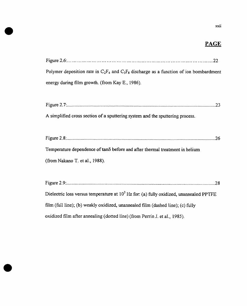
Figure 2.6:. ....................................................................................... -22
Polymer deposition rate in C2F4 and C3F8 discharge as a function of ion bornbardment
energy during film growth. (firom Kay E., 1986).
Figure 2.7:.. .................-....................................................................................................
A sirnplified cross section of a s p u t t e ~ g system and the sputtering process.
Figure 2. 8: ........................................................................................................................ 26
Temperature dependence of tan6 before and afier thermal treatment in heliurn
(fiom Nakano T. et al., 1988).
Figure 2.9: ........................................................................................................................ 28
Dielectnc loss versus temperature at 10' Hz for: (a) fully oxidized, unamealed PPTE
film (full line); (b) weakly oxidized, unannealed film (dashed line); (c) N l y
oxidized film after amealing (dotted line) (from Perrin J. et al., 1985).

PAGE
Figure 2.1 O:.. ............... .,,, .......................................................................................... -40
Calculated stress distribution during the scratching procedure (frorn Hamilton, G. M.
and Goodman, L. E., 1966).
Figure 2.11: .......................................................................................................-.-.--......... 41
Illusiration of the scratch test.
3 Figure 2.12 : ........................................................................................ -42
Cross-hatch peel test.
+ ............................................................... Figure 2.13: ,. Various simple peel tests (fiom Hardy A., 1963).
Figure 2.14: .........................................................................................................---.-....-.. -45
Illustration of a structured interface region (frorn Liston, E. M. et al., 1993)
...................................................................................................................... Figure 2.15: 47
XPS C( 1s) and O( 1 s) spectra of Tefion AF (fiom Shi M. K. et al., 1995).

PAGE
Figure 2.16: ...................................................................................................................... 48
XPS C(1s) and F(1s) spectra of PPFC before and after Cu deposition (corn Shi M. K. et
al., 1995).
Figure 2.17: ................................................................................................................... ..SO
Effect of treatment gas in microwave plasma on the critical load, Lc, of 200 nrn thick
evaporated copper films, and on the mean surface roughness ( R M S ) of as-treated
Teflon PFA surfaces (from Klemberg-Sapieha, J. E., 1997).
Figure 3.1 : ............................................... ..... ............................................................ -52
Plasma systern used in our laboratory.
Figure 3.2: ........................................................................................................................ 57
The experimental set-up and metal-insulator-metal (MM) sample structure used in Our
experiments.
3 1 Figure J -3 :... ..................................................................................................................... 60
A summary of possible failure modes observed after the scratching (fiom Bumen P. J.
and Rickerby D. S. , 1987).

PAGE
9 ..................................................................................................................... Figure 3 . 4 ~ . -6 1
SEM picture showhg the point at which Lc is typically measured.
........................................................................................................................ Figure 3.5: 63
Schematics of the fl exus laser scanning mechanism. (fiorn Courtesy of 1. Blech, Flexus
Corp., Sunnyvale, CA).
Figure 3.6: ........................................................................................................................ 65
Schematic diagram of photoacoustic ceIl (from R T. Graf et al., 1987).
Figure 4.1: .................. ... .............................................................................................. 72
Effect of cycling on the dielectric constant of Ar-sputtered Teflon.
....................................................................................................................... Figure 4.2:. 72
Effect of cycling on the dissipation factor of Ar-sputtered Teflon.
Figure 4.3: ........................................~..........................................................~-....--.----. ------73
Dielectric constant vs temperature for a vacuum annealed Teflon AF 1600.

PAGE
........................................................................................................................ Figure 4.4: 73
Dissipation factor vs temperature for a vacuum annealed Teflon AF16OO.
....................................................................................................................... Figure 4.5 :. 74
Dielectric constant vs temperature for a vacuum amealed PP(C2F4).
.................................................................................... Figure 4.6:. ............... ... .. ... -74
Dissipation factor vs temperature for a vacuum annealed PP(C2F4).
..................................................................................................................... Figure 4.7:. -75
Dielectric constant vs temperature for a vacuum annealed CF4 sputtered Teflon.
............................................................................................. Figure 4.8: ............... .... ..75
Dissipation factor vs temperature for a vacuum annealed CF4 sputtered Teflon.
..................................................................................................................... Figure 4.9: ..-y6
Dielectric constant as a function of fiequency at room temperature for unannealed and
amealed fiuoropoiyrners in vacuum.

PAGE
...................................................................................................................... Figure 4.10: 77
Dissipation factor as a function of frequency at room temperature for annealed
fluoropolymen in vacuum (It must be ernphasized that near 10" Hz there are two
different log f(&) values: 14.6 and 15.8 obtained for two frequencies corresponding to
a wavelength of 450 and 650 nm).
Figure 4.1 1 :... ................................ ..... ............................................................................. ..79
MST and peel test results for copper deposited on fluoropolymers.
...................................................................................................................... Figure 4.12 80
The effect of plasma surface treatment on the adhesion of evaporated copper ont0
Teflon AF 1600.
Figure 4-13: ................................................................................................................... -81
Delaminations of evaporated Cu from the atmosphere preannealed Teflon AF 1600. The
critical load was around 0.05 N.
...................................................................................................................... Figure 4.14: 82
Delaminahons of evaporated copper frorn Teflon AF1600 observed with more detail.

PAGE
Figure 4-15:.. .................................................................................................................... 83
Sequence of pictures seen with the reflection mode of an opticai microscope. Bare
PP(C2F3H) on glass amealed in the atmosphere and analyzed using the scratch tester
(Magnification: 550x, tip size:0.8 mm, range of load: 0-3 N, loading rate: 1 N/min,
speed of tip: 5 d m i n ) .
..................................................................................................................... Figure 4.16:. 84
Sequence of pictures seen with the transmission mode of an opticai microscope.
PP(C2F3H) film sputtered with Cu. The sample was not postannealed. (Magnification :
550x, tip size: 0.8 mm, range of load: 0-3 N, loading rate: 1N/min, speed of tip: 5
d m i n ) .
Figure 4.17: ..................................................................................................................... 86
Atornic concentration of copper as a function of mealing temperature at 0' and 35'
take-off angles from normal obtained by XPS.
Figure 4.18: ...................................................................................................................... 87
PA signal for fluoropolymers.

PAGE
Figure 4.19: ...................................................................................................................... 89
Contamination peaks (CHn) of two Teflon AF1600 samples. SarnpIe A was kept in
laboratory atmosphere for some time whereas sample B (kept in a dessicator) was
inserted within seconds into the FTIR spectrometer.
.................................................................................................................... Figure 4-20:.. 90
Surface Tension as a function of critical load for atmosphere-annealed fluoropolymers
(in the order of increasing critical load: Teflon AF1600, PP(C2F4), SP Teflon (CF4), SP
Teflon (Ar), PP(C2F3H)) .
Figure 4.21: ...................................................................................................................... 92
Cauliflower-Iike surface structure of PP(C2F3H) observed under SEM-
Figure 4.32: ................................................................................................................... -.-92
Cauliflower-Iike surface structure of PP(C2F3H) observed under AFM.
Figure 4.23 :... ................................................................................................................... 93
The smooth surfaces of PP(C2F4) under SEM. We have intentionaIIy focused on a dust
particle to make the observed features evident.

PAGE
Figure 4.24:. .............----.---S.-* ............................................................... .--. --- ---. . --- ---96
Stress as a function of temperature for bue fluoropolymer films.
Figure 4.25: ............. .... ... .... .... ...... .... .. .................. ... ..... ................... ...... .. ... ......... . .... ... ... 96
Stress as a function of temperature for copper evaporated fluoropolymer films.

LIST OF TABLES
PAGE
Table 1-1: ..................................................~........................................................................ 4
Possible candidates for low resistivity metal.
Table 1.2: ........................................................................................................................... 6
Candidates for low permittivity dielecîric.
Table 2.1: ................................................................................................................. 14
Typical property data for Teflon AF (Grades 1600 and 2400).
Table 2.2: ...................................................................................................................... ..3 1
Cornparison of electromigration parameters for bulk materials (from Murarka, S. P. and
Hymes, S., 1995).
................................................................. Table 2.3 :
Properties of possible interlayer metals (fiom Murarka,
.....................
S. P. and Kymes,
........................................................................................................................ Table 2.4: J J
Relative adiabatic temperature rise due to Joule heating in various metals and their
thermal conductivities (from Murarka, S. P. and Hymes, S., 1995).
................ 32
S., 1995).
* C I

PUBLICATIONS
This work has contributed to the following papers and conference presentations:
"Mechanical and Dielectnc Properties of Low Permittivity Dielectnc Materials", A.
ALPTEKIN, G. CZEREMUSZKIN, L. MARTINLT, M. MEUNIER, E. SACHER and M,
DIRENZO, MRS Symposium Proceedings, Vol. 443 (1997) 79-84.
"Dielectric and Mechanical Pro perties of CopperiFluoro polymer Film Stnict~res'~, A.
ALPTEKINy E. SACHER, G. CZEREMUSZKIN, L. MARTINU and M DIRENZO,
Electrochemical Society Meeting, Abstract, Vol 97(1), 1997.
"The Deposition of Copper onto Teflon AF1600: An XPS Cornparison of Vapor
Deposition and Spuîtering", D. POPOWCI, J. E. KLEMBERG-SAPIEHA, G.
CZEREMUSZKIN, A. ALPTEKIN, L. MARTINU, M- MEUNIER, E. SACKER
Metallized Plastics V, 1997, edited by K. Mittal.
"Thermal Stability of Low Permittivity Fluoropolymer Dielectrics", G.
CZEREMUSZKIN, L. MPJiTINü, A. ALPTEKN, D. POPOVICI, M. MEUNIER and
E. SACHER, Electrochemical Society Meeting, Abstract, Vol. 97( 1 ), 1997.

CHAPTER 1
INTRODUCTION
Continuing advances in the fields of VLSI (Very Large Scale Integration) and
ULSI (Ultra Large Scaie Integration), and the conrinuing developments of smaller and
smaller devices introduced new concems about the existing rnetallization schemes for
gates, interconnections, ohrnic contacts as well as the reliability of the commonly used
alurninum conductors. Any metallization scheme used with integrated circuits should
satis& several important requirements, such as (Murarka S. P. et ai., 1993):
Low resistivity
Easy to form and etch
Stability in oxidizing environments
Mechanical stability, good adhesion and low stress
Surface smoothness
Stability throughout processing as well as during subsequent operation
No contamination of devices, wafers and working apparatus
Good long-term device characteristics
Low electromig-ration even at high currents and high operating frequencies
Hish thermal conductivity to insure heat dissipation

The signal transmission delay tirne, T=RC, is of critical importance for the
multilayer devices that are comected to each other and to other devices via the metal
intercomection lines. These multilayer devices consist of alternating Iayers of metal
and dielectric. R and C stand, respectively, for the resistance of these intercomection
lines, and the capacitance of the dielectnc between them. A low RC value will resuit in
a faster signal transmission speed of the device. At less than 1 micron feature sizes, the
interconnect delay becornes very significant. In order to reduce the RC time constant,
one may use lower resistivity metals and shorter metal conductor connections, as well
as lower pemittivity dielectrics (Murarka, S. P. et al., 1993). Low permittivity
dielectric materials have a small amount of polar groups and their dissipation factors
are small. Low dissipation factors are desirable for low power losses (Ku, C. C. and
Liepins, R-, 1987).
\ si CoSiz
SOURCE AND DRAIN
Fig. 1.1: Illustration of a multilevel interconnect scheme
Low resistance of the interconnections and contacts plays othrr important roles

as well: it generates less heat and has a Iower electromigration-induced atomic flu.
The importance of this is obvious if one considers that future current densities are
expected to be at least an order of magnitude higher than today's.
There have been several candidates among the metals, as well as among the
dielectrics which seem to satisQ most of the above requirements. However, to comply
wi-th al1 of them is not an easy task at all. Each possible candidate has its own
advantages and disadvantages. Among the metal candidates are W, Al, Ag, Au, Ta, Ti,
Mg, Be, Mo and Cu. The cornparison in Table 1.1 clearly shows that Cu is one of the
most promising materials.

Table 1.1 : Possible candidates for low resistivity metal.
Thermal
conductivity
(W/cm)
Melting point
at atmospheric
pressure (OC)
Deposition
Sputtering Evaporation
Sputtering Evaporation
Sputtering Evaporation
SputîeRng Evaporation
S puttering Evaporation
Cu has a lower resistivity than al1 other metals except Ag. If we take into consideration
the higher melting point of Cu in cornparison with Ag, an important factor responsible
for low diffûsivity of Cu at a given temperature cornpared to Ag, we can conclude that
Cu is preferable. The high thermal conductivity of Cu is another positive property that
helps lowering the effective temperature nse in copper interconnections.

Let us consider the possible low permittivity dielectric candidates. Arnong the
materials of interest are the ffuoropolymers, fluorinated polyimides, polyimide
nanofoams, parylenes, porous silica, fluonnated Sioz, aerogels, morphous diamond-
like carbon, .... etc. Fluoropolymers have several superior properties compared to other
dielectrics. Table 1.2 summarizes the characteristics of some low permittivity dielectric
candidates. It is evident that only the aerogels and porous silica have a lower
permitiivity than the fluoropolymers. Ail the oîher dielectrics have substantially higher
permittivities. Even though existing data on bulk aerogels confirm that they meet
property requirements suc h as thermal stability, moisture absorption, and compatibility
with conductors, they possess a diminished strength as compared to dense materials
(Hrubesh L. W., 1995). Strength is important for film processing and subsequent device
processing (rnetallization, etching, etc) (Smith D. M. et al., 1995). Parylenes, some
having relatively low pemittivities compared to other candidates, are prone to metal
diffusion, and the diffusion coefficient is comparable to polyirnides. In addition,
parylenes do not adhere well to underlying surfaces, and the metals deposited on
parylene have weak adhesion (Dabral S. et al., 1995).

Table 1.2: Candidates for low permittivity dielectric.
1 Polyimide siloxane [l]
1 Porous silica [3]
References:
([Il Gutmann, R. J. et al., 1995)
(121 Sullivan, J. P.et al., 1996)
([3] Rosario, A. G., 1996)
([4] Ting, C. H- et al., 1995)
( [ 5 ] This work)
De position technique
Spin-on
Vapor phase
Vapor phase
Spin on
PECVD
Spin-on, PECVD, sputtering Spin on
Thermal 1

The general objective of our work was to test copper and fluoropolymers as
potential candidates for multilevel intercomects. Our specific objectives were to
compare different Buoropulymea according to their fabrication process, dielectric
properties over a large kequency range, thermal stability and their compatibility with
the metallization process.
In the present work, we used several types of fabrication processes to obtain and
compare different types of fluoropolymers. Fluoropolymer films were obtained using
s pin-coating, plasma polymerization and s puttering. Co pper was either sputtered or
evaporated. These are deposition techniques that c m easily be incorporated in the
rnanufacturing processes presently used.
The dielectric properties, which are the permittivity and the dissipation factor,
were evaluated over large frequency (10' Hi- 106 Hz) and temperature (25 OC-200 OC)
ranges. The purpose of thermal cycling of the multilayer structures was to eliminate
polar species incorporated in the films and thus to obtain reproducibly stable films. In
addition to this, it gave us the oppominity to determine the temperature range over
which these structures are stable. The stability of the copper-fluoropolymer interface is
determined largely by the cornpatibility of the metallization process with the
fluoropoIymer films.
To understand the interface and bulk-related phenornena, as well as to interpret
the possible problems, experiments were conducted to evaluate the adhesion, stress,
diffusion, release of gases, as well as surface and bulk chemical properties, using

various methods such as PA FTR, contact angle goniometry, W S and mass
spectrometry. In Chapter 5, we suinman-ze Our findings on the suitability of
fluoropolymers and copper for multilevel interco~ects .

CHARACTEIRISTICS OF FILM MATERIALS CONSDEFCED FOR MULTILEVEL INTERCOPWECTS
2.1. STRUCTURE) AND DELECTRIC PROPERTES OF FLUOROPOLYMEII FILMS
In this chapter, first the phenornena of relaxation and dielectric Ioss will be
shortly described for polymers in general. Next, conventional and plasma-deposited
fluoropolymers are described and a short cornparison is made. The discussion involves
the structures and the dielectric properties as they are described in the literature. The
discussion on the part of the conventional fluoropolymers includes Teflon AF1600.
Fundamental pnnciples of plasma processes and the polymerization mechanism are
given as part of the discussion on plasma-deposited fiuoropolyrners.
Polyrners exhibit in generai more than one region of dielectric Ioss (Ioss tangent)
due to different motions of their segments (Ku C. C., Liepins R., 1987). Tangent of the
dielectnc loss angle is the ratio of the loss current to the charging current in a
condenser, and it is expressed as:
IOSS current E" tan6 = -- -
charging current ' E'
Here, E' is the real part of the dielectric constant (permittivity), and E" is the imagina.
part of the dielectric constant.

For arnorphous polyrners at least two regions are observed, and for crystalline poIymers
loss regions may arise fiom four regions. The glass-rubber transition Tg, indicating a
transition from the glassy state to a rubbery state, gives rise to a major dispersion for
both arnorphous and crystalline polymers. Short range motions such as side-group
rotations or local mode motions Lead to smaller dispersions (loss regions). These usually
take place in !k low-temperature range. Another source of dispersions is phase
transformation.
One can label the various peaks using Greek letters: the highest temperature
process is always a, with the remaining peaks being labelled in order of decreasing
temperature. Therefore, analysis of dielectric spectra provides information about the
structural characteristics of polymers.
TaRERAnJRE
Figure 2.1: Relationship between tan6 and temperature at constant frequency. (frorn Ku
C. C., Liepins R., 1987).
An important issue in our work is to achieve low values for the dielectric loss
and the permittivi- (E' or K). This involves both chemical and physical aspects. The
chemical aspect is concerned with the synthesis of molecules that lead to shon
relaxation times and thus low tan6 values. The physical aspect of achirving low values

I l
for the dielectric loss involves the effects of plasticization, molecular weight and
morphology. For low-eequency (<lktIz) dielectric losses, the dc and ac conductivities
are very sensitive to small amounts of moisture and impurities. This makes the
dielectric properties very sensitive to local inhomogeneities and structural defects thar
introduce additional dipoles into the polymer. As a conclusion we can Say that the
elirnination of impurities and structural heterogeneities is of utmost importance in order
to achieve low tanô. The requirements leading to Iow dielectric losses in polymers can
be summarized as follows (Ku C. C., Liepins R., 1987):
(1) Prevention of short branch formation during the synthesis as well as during
subsequent processing.
(2) Prevention of unsaturation to avoid oxidation.
(3) Prevention of oxidation during spthesis as well as during processing. Carbonyl
groups can contribute significantly to the dielectric loss.
(4) One might choose plasticizers with polarities Iower than that of the polymer itself.
( 5 ) Elimination of impurities and structural irregularities by improving the synthesis
and processing conditions.
In the following, we examine and compare conventional fluoropolymers and plasma
polymerized fluorocarbons (PPFC) by refemng to earlier published work.
2.1.1 CONVEXTIONAL FLUOROPOLk3ERS
In this section, conventional fluoropolymers will be discussed in general and

12
Teflon AF1600 wiIl be deaIt with in more detail,
Conventionaliy polymenzed fluorocarbons, such as tetrafluoroethylene, are
lcnown to form a highly ordered structure. This couid be explained to be due to the
arrangement of oligomers (Nakano T. et al., 1988). The films are espected to have a
more ordered structure when the substrate temperature during polyrrterization is high.
Since the molecular motion occurs easily in the as-polymerized film, the degree of
order of the film will increase if the tilm is heated afier polyrnerization. On the
contrary, plasma irradiation during deposition crosslinks the film.
"TEF'L,ON AF' is a member of a family of amorphous copolymers based on 2'2-
bistrifluoromethyl-4,5-difhoro- 1,3-dioxole (PDD) with tetrafluoroethylene (Buck W.
K, Resnick P. R, 1993). CopoIymers of PDD with TFE are commercially available
fiorn Du Pont. Figure 2.2 shows the chernical structure of TFE and PDD copolymers,
and Figure 2.3 shows the structure of Teflon AF 1600.
TFE PDD
Figure 2.2: Teflon AF: A farnily of Amorphous
Fluoroplastics with Tg ranging from 80 "-300 OC.

c - c - a!*-9- \ 1-Î-"- 1 \
Figure 2.3: Chemical structure of Teflon AF 1600 repeat unit.
TEFL,ON AF polymers have the Iowest dielecîric constants (table 1.2 shows about 1.9 at
roorn temperature) of any known solid polymer (Starkweather H. et al., 1991),
extremely low refiactive indices (Chow R et al., 1994 and Lowry, J. H. et al., 1992),
high gas pemeability, and low thermal conductivities. These copolymers are soluble at
roorn temperature in several fluorocarbon solvents. Properties may be vaned by
changing molecular weight and comonomer ratio. A sumrnary of the properties given by
the manufacturer is shown in table 2.1.
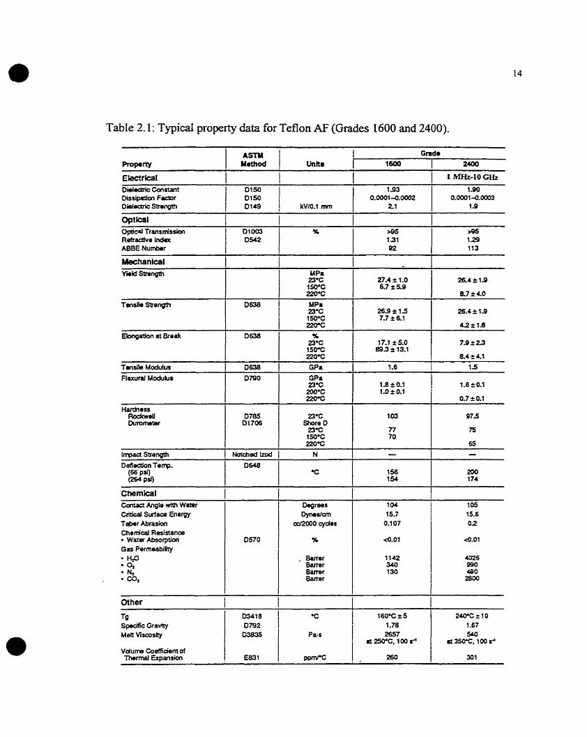
Table 2.1: Typical propexiy data for Teflon AF (Grades 1600 and 2400).
. -
~léctrica~ I I I 1 1 --IO GHZ Diilecrric Constant 193 1.90 Dissipatfori F e r 0.00014Oa02 0.0001-0.00(M DielocPic Sùongm
--
CirnGa~ Canas Angle mth Wutsr CririGal Sutfaoe Enrrgy Tabar Abrasiaci Cherncal Resistanœ
Warar Absorption Gar Permeability H P
O, rJ,
. C O ,
15.7 15.6
a92000 cydes 0.1 07
- &mer Bener Barrer Baner
cher 1 Tg 0341 8 Spaak Graviry 0792 Men Vitcoshy 03835
2 W C 2 1 0
Pa. s 2657 SLO
I d 2!5OaC, 100 r' P 350%. 100 r'

15
Figure 2.4 shows the variation of refractive index as a function of PDD/TFE copolymer
composition.
O 20 40 ô0 80 100 FDD, mol%
Figure 2.4: Refractive Index vs. Composition for PDDlITE Copolyrners (fioom Buck W.
EL, Resnick P. R., 1993).
There is a variety of solution processing methods due to the room temperature
solubility of Teflon AF in perfluorocarbon solvents. In order to obtain thin to ultra-thin,
uniform thickness coatings on flat substrates one can spin-deposit the dissolved
TEFLON AF. From Figure 2.5 one can get an idea about the dependence of film
thickness on spin speed and on the concentration of solution.

1 Spin Speed, rpm
Figure 2.5: Film Thickness vs. Spin Speed for Teflon AF 1600 solutions diluted in
Sigma Fluorinert FC-75 and spun ont0 g l a s .
Mrared spectra of a Teflon AF 1600 film were compared to that of conventional
PTFE (Polytetrafluoroethylene) (Nason T. C. et al., 1992). The most significant
difference of Teflon AF from PTFE was the strong peak at -980 cm", indicative of CF3
vibrations (more discussion will be provided in section 4.2.3). This peak is very weak
for thin films of ordhary Tefion. The strong presence of CF3 in Teflon AF films
supports the contention that the dioxole monomer is not unduly discriminated against
repoiyrnerïzation of scission fragments. Also the peaks at 1100, 1245, 1270 and
13 l~crn-' were present ody in Teflon AF and cm be attributed to the fluorinated
dioxole component.

Teflon AF was proposed for several applications including high performance
optical coatings such as anti-reflective (AR) and high reflector (HR) coatings (Chow R.
et al., 1994). The bulk properties of this pertluorinated arnorphous polymer show a hi&
transmiitance range from 200 nm to 2000 nm, and a low refractive indes of about 1.29.
It \vas showm that Teflon AF2400 can be thermalIy evaporated (Nason T. C. et al.,
1992) as a corrosion bamer for extra-terrestial equipment (Grieser J. et al., I W O j, and
as an insulator for submicron electronic devices (Hiraoka H., Lazare S., 1990).
2.1.2 PLASMA-DEPOSPTED FLUOROPOLYMERS
Before proceeding to our work, it wouid be appropriate to mention the basics of
a plasma, in our case more appropriately the cccold" Iow-pressure plasma. A plasma can
be defined as a partially ionized gas, with equal nurnber densities of positive and
negative charge camers, in which the charged particles are "free" and possess
collective behavior. A plasma thus consists of neutrals, ions, radicals, excited species,
electrons and the accompanying UV radiation. In a !ow pressure, high frequency
discharge, the heavy particles are essentially at arnbient ternperature (0.075 eV), while
the electrons with higher kinetic energies (up to tens of eV) are capable of breaking
bonds and causing further ionization. This is necessary to sustain the discharge. These
reactive species c m thus undergo eeither homogeneous (gas-phase) or heterogeneous
reactions (with a solid surface in contact with the plasma). These takr place near
ambient temperature and, therefore, plasma processes are well suited for the deposition

18
of temperature sensitive polymer films and substrates that are coated with these. Plasma
processes can be used for basically three types of applications: the deposition of thin
films, etching and surface modification. PIasma polymerization can make flawless thin
films particularly useful in the electronic device industry. Because of the fact that
commercial applications of low pressure plasma processes for deposition and surface
modification are relatively new in cornparison to etching, the industry is changing its
classical serniconductor processuig schemes cautiously and gradually towards new
alternatives. These th*n films can be obtained either by the plasma-polymerization of a
monorner gas or by the sputtering of a conventional polymer target The second
important effect is surface modification. The above-mentioned energetic particles and
photons in the plasma interact with the polymer surface. In plasmas which do not lead
to thin film deposition, four general effects can be observed: (i) surface cleaning, (ii)
ablation or etching, (iii) crosslinking or branching and (iv) modification of surface
chemical structure (Liston E. M. et al., 1993).
The discussion of this section includes fluoropolymer films obtained fiom
plasma polymerization of a monomer, and fluoropolymer films that are sputîered frorn
their conventional bulk target. In the case of fluorocarbons both methods result in
qualitatively similar chemical and physical properties (Tibbiît J. M. et al., 1975).
Plasma polfrnenzation is a good method to make nearly flawless thin films and
therefore it has been considered promising in a variety of areas such as
rnicroelectronics, optoelectronics, optics, biomedical industxy,. . . etc. Plasma
polymerization can be used to deposit thin films from monorners which are v e n

difficult to polymerize by conventional methods (Nakano T. et al., 1988). The
individual reactions involved in the process of polymer formation in a glow discharse
are very cornplex.
EarIier studies involving X-ray photoelectron spectroscopy ( X P S ) (Rice D. W.,
O'Kane D. F-, 1976; Clark D. T. et al., 1979) and nuclear magnetic resonance (NMR)
(Dilks A., Kaplan S., 1982), have shown that plasma-polymerized fluorocarbons are
highiy cross-linked with some unsaturated carbon groups in contrat to their
conventional counterparts. During plasma deposition, many electrons, ions and photons
with enough energy bombard the film and fieeze the structure in the disordered state.
Therefore, the subsequent thermal treatment rarely increases the degree of order. IR
absorption spectra of plasma-polymerked fluorocarbon films show the presence of
C=O groups that appear upon exposure to air (Giegengack H., Hinze D., 1971; Alptekin
A., et al., 1997). This is attributed to the reaction of free radicals (dangiing bonds),
created during the plasma-deposition process, with the atmospheric oxygen.
The stnicture and properties of plasma-polymeriled films depend on feed
composition and parameters of the plasma environment, such as power, pressure and
monorner flow rate (Chen R and SiIverstein M. S., 1996). F/C ratios of 1.33, 1.55 and
1.71 were found for plasma-polymerized octafi uorocyclobutane (PPOFCB) prepared
under various fabrication'conditions (Amyot N. et al., 1992). It was suggested that
plasma-polymerized films with low F/C ratio are more highly crosslinked compared to
films with high FIC ratios. Since crosslinking is known to contribute ro enhanced
electrical conductivity, this could help explain their observed high tan6 values (Amyot

N. et aI., 1992).
n e gIow discharge polymerization of fluorinetontainhg compounds is very
sensitive to the conditions of polyrnen'zation. in order to obtain polymers from fluorine-
containing compounds, it is very important to use a relatively low discharge power in
cornparison to other polymers (Yasuda H., 1978). High discharge power leads to
ablation by detaching the fluorine. Thus one can not easily produce polymer films with
a high fluorine content by using high discharge powers. Etching in fluorocarbon
plasmas makes the plasma polymerization a complex phenomenon (Yasuda H., 1985)
(d'Agoçtin0 R et al., 1990). Therefore it is helpful to employ techniques that suppress
the etching effect of the detached fluorine, such as the addition of a small amount of H2
(Winters FI. F. et ai., 1977) or hydrogen-produchg compounds (Mogab C. J., 1977). It
was observed for fluorocarbons wiîh a high F/C ratio (F/C>2.0), the predominant
process is etching, while for fluorocarbons with a low FIC ratio (F/Ce.O),
polymerization is a dominant process (Kay E. et al., 1980).
To illustrate plasma polymerization mechanism more clearly, one may show
some examples. Electron induced monorner fragmentation and ionization takes place
when a fluorocarbon monomer is introduced into a plasma system. Fra=mentation
products produced depend on monomers being used (Ka? E. and Dilks A., 1981).
Various ions and radicals will also be formed. It was shown that in the case of saturated
monomer injection, the rate of polyrnerization on a substrate is proportional to the rats
of arrivai of unsawated species of the homologous series: (CF?), (Kay E. and Dilks A.,
198 1). The kinrtic energy and number of ions bornbarding the growing poi~ner surface

also influences the rate of polymerizatioo and the structure of the polymer (Kay E. and
Dilks A, 198 1). The following surface reactions compete on al1 surfaces in contact with
the fI uorocarbon plasma (Kay E., 1986):
When an unsaturated monomer such as tetrafluoroethylene (CF2)2 is introduced
into the plasma, then polymerization (reaction (a)) dominates because of the abundance
of polymer precursors (CF2)2 and energetic ions. Physical sputtering (reaction (c)) will
dominate the deposition process if ion energies are very hi& (c=10-5000 eV).
When a saturated monomer such as CjF8 is introduced into the plasma, electron-
impact induced fragmentation results in CF2, F and ions (primarily C F , ~ (Kay E.,
1986). Figure 2.6 shows that in a C3F8 plasma, the polymer deposition rate decreases
with increasing ion energy. At hi& enough energies removal of electrode material
(metal) takes over. This suggests that as the ion energy increases, reactions (b), (c) and

22
(d) become more dominant. At the grounded substrate electrode surface reaction (a)
dominates.
Vol- Appliad to Su- (voiu)
Figure 2.6: Polymer deposition rate in CzF4 and C3F8 discharge as a fiinction of ion
bombardment energy during film growth. (fiom Kay E., 1986)
Dilution of the plasma with inert gases such as Ar can lead tu a less significant
polyrnerization, but an enhanced physical sputtering of electrode material due to Ar+.
Therefore, one can control the ratio of metal sputtered atoms arriving at the substrate
fiom the powered metal target electrode to the polymer precursor species CFl amving
at the grounded substrate (Kay E. and Hecq M. J., 1984).
Fluoropolyrner films can also be sputtered fkom their conventional bulk target.
Figure 2.7 illusirates a simplified cross section of a sputtenng system and the spuîtenng
process,

Vacuum
Pressure 10-200 mTorr
Power supply (dc, ac, rf)
Target e / O Ejected
Atoms ~ r " .1
(fragments) Substrate 7-
- - - - - Cathode
Substrate holder Polarized or not
Vacuum Pumps
Glow Discharge
- - - - - Anode
1 Substrate
Bombardment of the Thin Film Negative Ions
Secondary Electrons Neutra1 Atoms and Fragments
Figure 2.7: A sirnplified cross section of a sputtering system and the spunering process.
Typically, the target (simply a plate of the material to be deposited) is comected
to a negative voltage supply (dc or rf-induced), the substrates are attached to the
substrate holder that faces the target The holder may be grounded, floating, bbiased,

heated, cooled or some combination of these. A gas such as Ar is introduced into the
evacuated chamber in order to provide a medium in which a glow discharge c m be
initiated and rnaintained. When the glow discharge is started, positive ions are
accelerated by the electric field toward the target. These positive ions transfer their
mornentum to the mainly neutral target atoms and thus remove them. These atoms
condense on the substrate into thin films. It should be noted that any material object
irnrnersed in a glow discharge acquires a negative potential with respect to its
surroundings and, therefore, can be considered as a sputtering target. This depends on
the plasma potential and the sputtering yield. Other particles such as secondas.
electrons, ions, desorbed gases, x-rays and photons are also produced at the target. The
negative particles (electrons and negative ions) are accelerated towards the substrate
platform and bombard the growing film ( Vossen J. L., Kern W., 1978). Al1 of these
particles produced during the sputtering process influence the film p w t h .
The sputtering yield is defined as:
Nunber of Particles Eiected fiom Target Sputtering Yield = (2-2)
Number of Incident Ions
There is a threshold for sputtering approxirnately equal to the heat of sublimation. The
energy range of ions used in sputtenng processes is about 10-5000 eV. Generally
speaking, the yield increases with incident ion energy and therefore m a s of the incident
ion ( Vossen J. L., Kern W., 1978).
Fluorocarbon
properties. Typically,
polymers deposited by plasma exhibit
the permittivities are between 1.8-2.2, and
25
interesting dielectnc
the dissipation factors
in the order oF0.001-0.0001 (Alptekin, A- et al., 1996). The amount of fluorine in the
film depends on the deposition temperature among many other parameters. The F/C
(fluonne to carbon) ratio falls and the pedttivity increases with increasing deposition
temperature (Mountsier T. W., Kurnar D., 1996). The plasma assisted deposition of
fluorocarbon films fiom hexafluoropropylene (C3F6) and hydrogen showed F/C ratios of
1.1-1.2 at 20 O C and 0.73-0.74 at 400 OC. Since the permittivity rises wîth increasing
temperature due to thermal motions, a permittivity of 1.9 was observed at 20 OC, and
this value increased to 2.4 at 400 OC (Mountsier T. W., Kumar D., 1996).
In order to show the importance of the deposition conditions during plasma
polyrnerization and the thermal treatments on the dielectric properties of fluorocarbon
films, it would be worth mentioning the results of some experirnents performed with
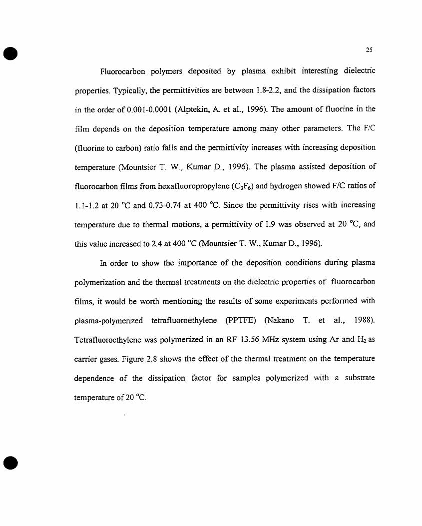
plasma-polyrnerized tetrafluoroethylene (PPTFE) (Nakano T. et al., 1988).
Tetrafluoroethylene was polymerized in an RF 13.56 MHz system using Ar and Hl as
carrier gases. Figure 2.8 shows the effect of the thermal treatment on the temperature
dependence of the dissipation factor for samples polymerized with a substrate
temperature of 20 OC.

F=l (kHz) Spu ttered H2:15(mI STP min) O Electrode
o0 O.
D O O O O ~ ~ oO
8 O* O
$oO a s poIyrnerized 0 O
O O
Substrate Temp. 20 O c Oo*o
u a
af ter thermal treatment
t
O150 -100 -50 O 50 100 150 1 1 P Y 1 1
Temperature ("C)
Figure 2.8: Temperature dependence of tan6 before and after thermal treatment in
helium (fiom Nakano T. et al., f 988).
The dissipation factor is decreased by the thermal treatment, indicatinç the decrease in
the number of fiee radicals in the film (Nakano T. et al., 1985) and the Ioss of Iow
molecular weight species and water vapor. The as-polymerized film was unstable and
the measured value fluctuated depending on how the sample was stored. It was also
shown that the flow rate of the carrier gas, substrate temperature, measurement
frequency and the method of electrode deposition of the metal-insulator-meta1 (MIM)
had important effects on the temperature dependence of the dissipation factor (Nakano
T. et al., 1985).
An expenment performed with plasma-polyrnerized CF3C1 (Martinu L. et al.,
1986) showed that, after cooling the specirnen in vacuum below -50°C and successive
heating, a reproducibIe maximum in tan6 near 80 O C , similar to figure 2.8 was observed.
In the second cycle this peak disappeared and tan6 decreased substantiaily, giving a
reproducible curve. When the sample was exposed to the atmosphere and the
measurement repeated, the onginal curve with the peak near 80 OC was obtained, an
effect that can be attnbuted to the desorption of water vapor during heating.
Ln the following we examine and compare conventional Buoropolymers and
plasma deposited Buoropolymers by refemng to the earlier published work.
2.1.3 SHORT COMFAIUSON BETWEEN THE PLASMA DEPOSITED FLUOROPOLMMERS AND CONVENTIONAL, FLUOROPOLYMERS
In order to illustrate typical dielectric behavior of plasma polymerized
Buorocarbon films, the l a s tangent versus temperature is s h o w in Figure 2.9 for a
plasma-polymerized PTEE film.

Figure 2.9: Dielectric loss venus temperature at 103 Hz for. (a) a fully oxidized,
unannealed PPTFE film (full Iine); (b) a weakly oxidized, unanneded film (dashed
line); (c) the fully oxidized film afier annealing (dotîed line) (Perrin J. et al., 1985).
In the latter scan, measurements are limited up to 170 OC where the conductivity effects
appeared, due to short circuits at film fractures created by annealing during the first
scan. In spite of several unsuccessfül attempts this probfern was not solved (From Perrin
J. et al., 1985). As observed from the dielectnc loss spectra, at least four relaxation
peaks are present in the film and are denoted as a, fi, R ,, az. As a general point we can
state that the plasma-polymerized fluorocarbons are highly cross-linked with some
unsaturated carbon groups, in contrast to their conventional counterparts. This makes
them susceptible to oxidation upon exposure to air. The -5 and f i2 relaxations obsemed

in figure 2.9 were attributed to the motion of tertiary carbon structures such as cross-
link sites (Tibbitt I. M. et al., 1976). It was suggested that these relaxations are
associated with irreversib le structurai, and possibly chemical, rearrangement of the
polymer. The reversible relaxation taking place at around 70 OC disappears upon
annealing. This is probably due to the curing effect consisting of physical and chemical
rearrangernents of the polymer segments which in tum result in a higher degree of
cross-linking and a denser structure. It was hypothesized that the pairing (reaction) of
neighbonng unsaturated groups could lead to this cross-linking. The existence of such
reversible relaxations is common for other plasma-polymerized materials as well
(Monta S. et al., 1976). The y relaxation is due to C=O groups introduced in the film
upon oxidation (Heîzier U., Kay E., 1978). This type of relaxations were observed for
other plasma polymerized monomers, such as C2F3Cl (Martinu L. et a1.,1986). In the
case of conventional fluoropolymers, these y relaxations are due to the ordered
structure. The R relaxation in the 160-180 OC temperature region is ascribed to the
glass-rubber transition of PTFE (Perrin J. et al., 1985).
An important difference between plasma polymerized fluoropolymers and
conventional fluoropolyrners is based on the stoichiometry of the deposited films. Films
deposited using plasma polymenzation possess some remaining impurity materials.
Therefore, the deposited films are not stoichiometric. Laser ablation method using an
UV laser beam was reported to produce stoichiometric films of P T E (Blanchet G. B.,
Isrnat S., 1993). Generally, films prepared by rf sputtering are found to bc fluorine
deficient. (Blanchet G. B., Ismat S., 1993). For a PTFE target used in magnetron rf
spuîtering, an F/C ratio of 0.7 was found in the erosion track and a ratio of 1.3 in the
center of the target (Biederman H, et al., 1997)-
2.2. PROPERTEES OF COPPER FILMS
There has been a large effort over the past several years in the investigation of
copper for use as an interco~ection metal that would replace the currently used
aluminum. The reason for this effort was maidy related to the lower resistivity (1.67
@-cm vs. 2.7 pQ-cm for Al) and higher electromigration resistance which is several
orders of magnitude higher than Al. Besides these, copper has other positive aspects
that support its use in silicon integrated circuits: For example corrosion resistance,
ductility or formability and mechanicd strength (Young's rnodulus=12.98x10⁷ ~/crn'),
relatively high melting point (1085 OC at atmospheric pressure) among usable electical
conductors and its hi& thermal (3.98 W/cm) and electrical conductivities (0.60 a- 'cm-'). Copper is a near-noble metal and is chernically active rnostly in the presence of
oxidizing agents. We c m Say that copper is not altered by dry air (Murarka S. P., Hymes
S., 1995). If one neglects the grain-boundary contribution to atomic difision, one can
express the atomic flux due to electromigration in the single crystal or large-grained
crystal as:
- - N D z 'qj J a m x u k T
Here, N, D, Z*q, q, j, o, k, and T are the atomic density, atomic diffusivity, effective
charge on the moving atom, electronic charge, current density, electncal conductivity,

Boltzmann's constant, and temperature in K, respectively. Some of the most
conductive metals are compared in Table 2.2 with respect to their electromigration
parameters:
Table 2.2: Cornparison of electromigration parameters for bulk materials (from
Murarka S. P. and Hyrnes S., 1995).
Difluslon pararneters
Copper has acceptor levels in the middle of the silicon band gap, at 0.24,0.37, and 0.52
eV with respect to the valence edge and, therefore, can act as a recombination-
generation center for charge carriers. Thuç it can diffuse in Silicon and degrade the
semiconductor devices. This was the reason it was avoided in silicon-based integrated
circuits in the pst. However, today the processing temperatures of copper have dropped
from 1000-1300 OC to less than 900 O C and the postmetal processing temperatures fiom
the 400-700 O C range d o m to less than 450 O C . These are todays reasons for
considering copper intercomect technology for multilevel devices.
As mentioned earlier, the main purpose of this work is to achieve Iower RC time

constants in order to increase the speed of integrated circuits. This RC delay time, T,
can be expressed as (Mmka S. P., Hymes S., 1995):
Here, p, tM, L, and tm are the resistivity, thickness, length of the intercormection
and interlayer dielectnc (ILD) permittivity and thickness. For a given thickness of the
metal and the ILD, the RC depends on p, L and EU. Table 2.3 shows the properties of
possible interlayer metais:
Table 2.3: Properties of possible interlayer metds (fiorn Murarka S. P. and Hymes S.,
Property
Resistivity (pR-cm) - Young's modulus x 10' N/cm2 TCR x 1WK Thermal conductivity (W/crn) CTE x 106/~& M Pt ("C) Specific heat capacity ( J k g K) Corrosion in air Adhesion to SiO, Deposition
Sputteflng Evaporation EVD
Etching Dry Wet
Delay (pslmm) ThermaisFess per degree for films on Si I ( 102 N/&c)
Cu
1.67 12-98 4.3 3.98 17 1085 386 Poor Poor
J J J
? C 2.3 2.5
Ag
1.59 8.27 4.1 4.25 19.1 962 234 Poor Poor
J J ?
? J
2.2 1.9
Au
2.35 7.85 4 3.1 5 14.2 1064 132 ExceIlen t Poor
J J ?
? J
3.2 1.2
Al
2.66 7.06 4.5 2.38 23.5 660 917 Good Good
J J
J ('1
J / Y
3.7 2.1
W
5.65 4 1.1 4.8 1.74 4.5 3387 138 Good Poor
J J J
J J
7.8 0.8
Note: Delay = RC = 34.5 R, (ps/mm) for 1-mm-length conductor on 1 -pm thick 50,.

OnIy Ag has a resistivity Iower than Cu; unforhrnately, it is prone to higher
electromigration than Cu. The resistivity is not ody important to decrease the RC delay
but also to reduce the heat generation The temperature rise in an adiabatic environment
where no heat is absorbed or dissipated can be expressed as:
Here, j is the current density, g the density, and C the specific kat capacity of the
intercomection material. Table 2.4 compares the adiabatic temperature rise for
different candidate metals:
Table 2.4: Relative adiabatic temperature rise due to Joule heating in various rnetds
and their themai conductivities (firom M m k a S. P. and Hymes S., 1995).
In thin film applications, the thichess of the copper layer is also of critical importance.
An increase in resistivity is observed due to surface and grain boundary scattering. The
relative values of the electron mean free path in copper and the thickness or grain size

detemine the contribution to the higher resistivity values that are sometimes observed.
To avoid this kind of effect, one has to deposit films with thicknesses or grain sizes
larger than the mean fiee path of the electrons in copper. Resistivity might be increased
by crystal defects as well. This problern can be overcome by amealing which leads to
an increase in grain size and, therefore, a relative decrease in grain boundary area. This
will lead to the elimination of defects. In the case of sputtering, the sputtering gas might
be trappeci, and its presence wouid cause a higher resistivity.
It is ciear that the lowest temperature rise due to Joule heating is for copper
which has also the second highest thermal conductivity only about 7% lower than that
of Ag, which has the highest thermal conductivity among the metds. These make it
clear that less heat will be generated if copper is used and thus the devices will work
more efficientiy. Furthemore, heat related problems will be of less concem by the
proper use of copper.
Copper has superior mechanical properties compared to aiurninum. Table 2.3
gives some of these properties. Young's modulus, yield strength, and ultimate tende
strength of copper at 300 K are 1 . 3 ~ IO', 6.9x10³, and 2 . 2 1 ~ 10' ~ / c m ' , respectively.
These values are multipies of those for Al (Murarka S. P., Hymes S. W., 1995). Due to
this high Young's modulus, stress effects mi& be of importance for copper films.
Stress cornpetes with adhesion strength and can cause adhesive failure of the metal
frorn the dielectric substrate. The specific subject of stress ivill be discussed later.

2.3 ADEXESION OF LMETALS TO FLUOROPOLYMERS
Adhesion is one of the most important reliability problems. The Amencan
Society for Testing and Materials (ASTMJ defines adhesion as: 'The state in which two
surfaces are kept together by the forces at the interface which can be the valence forces
or the interlocking forces or both" (Good, R. J., 1975.) When an adhesive failure
occurs, the metal layers no longer adhere weIl to the dielectric substrate such as
fluoropolymer. Therefore, one has to consider the issue of adhesion in rnatenals
selection and processing. In a multilevel device, due to the different thermal constraints
such as different thermal expansion coefficients of the metai layers and the dielectric,
stress effects rnight be cumulative and may very well lead to failure. Even though they
limit the device performance to some extent and lead to higher cost of production,
adhesion promoters may be effective. In an ideal case, the adhesion promoter c m also
act as a di fkion barrier between the metal layer and the dielectric. These adhesion
promoters can be metals (for example Ti or Ta) as weU as alloys (for example TiTa
alloy) of some metals. Instead of depositing a thin layer of such a metal or rnetal alloy ,
one can pretreat the surface in order to promote adhesion. This treatment can be done
using plasma, laser or simply themally. These issues will be discussed below.
2.3.1 MXCBAIWSMS OF ADEESION
It would be appropriate to look at the various forces of rnolecular attraction
before mentioning the theones of adhesion There are two main groups of forces of

36
moIecular attraction: chemical and physical bonds. (Allen K. W., 1963.) A chemical
bond is characterized by some kind of çharing of particles such as electrons which is the
resdt of a chemical reaction whereas a physical bond is the result of an interaction of
particles due to their electric and magnetic fields.
Chernical bonds can be categorized as:
(1) Ionic bonds due to Coulombic electrostatic forces between oppositely charged ions
derived from elements of widely different electronegativities.
(2) Covalent electron pair bonds due to exchange forces between elements of similar
electronegativities.
(3) Metallic bonding through the sharing of electrons in an electron gas which occurs
for the least electronegative elements.
Physical bonds fa11 into the following categories:
(1) Keesom dipole-dipole forces (orientation effect) - molecules with permanent dipole
moments will have a mutual attraction and will cause a mutual alignment.
(2) Debye dipole-molecule forces (induction effect) - a molecule with a permanent
dipole moment will induce a dipole in a neighboring molecule by polarization.
(3) London molecule-molecule forces (dispersion eEect) - general interaction between
any two molecules or atoms in close proxirnity, irrespective of their permanent dipoles.
If averaged over a period of time, moIecules may have a zero dipole moment due to the
symmetnc electron distribution function. However, there will be instantaneous dipoles
arising from the motion of the electrons, which will lead to induced dipotes in phase. At

larger distances, about 200 A, the London dispersion forces are reduced by the
electromagnetic retardation. In addition, when molecules approach each other vexy
closely a repulsion occurs between their electron clouds as they overlap.
To suwnarize, the total cohesion in any material will be the result of any
primary chemical forces which are involved, Keesom orientation and Debye induction
forces if there are any permanent dipoles, London dispersion forces in al1 cases,
diminished by retardation at larger distances and repulsion forces important at short
distances.
There are various theories of adhesion (Raevskii R.G., 1973) (Allen K. W.,
1969.): chemical bonding theory, adsorption or weding theory, electrostatic, diffusion,
weak boundary layer, mechanical and rheologiçal. According to Fowkes, the acid-base
interactions at the film-substrate interface are also v e v important for the adhesion.
Different models explaining adhesion are summarized in several reviews (Mitta1 K. L.,
1976) (Sharpe L. R, 1993)
According to the chemical bonding theory, it is essential to have chemical
reactions between the materials in order to achieve good bonding. This theory can be
applied well to polymers. It postdates the existence of covalent bonding at the interface
as was described above within the subject of molecular interactions. The efficiency of
such bonding depends on the number of interfacial bonds and the chain lengths, in the
case of polymers.
Wetting has been proven to be a necessary but not sufficient condition for good
adhesion. It was observed that some adhesives showed good spreadability (Le. makes

contact angles close to zero) but did not adhere well (Iyengar Y. and Erickson D. E.,
1967).
Electrostatic theory resembles the film-substrate system to a planar capacitor
with plates carrying opposite charges (Deryagin, B. V. and Krotova, N. A., 1948).
According to the d i f i i on theory of adhesion developed mainly by Voyutskii
(Voyutskii, S. S., 1963) adhesion arises through the interdifision of the adlierent and
the adhesive. It has been principally applied tu joints involving polymeric materials.
Sometimes it is a one-way diffusion of adhesive molecules and sometimes a two-way
d i f i i o n of both the adhesive and adherend molecuies (interfaciai mixing). In either
case there is no more a clear-cut boundary, but rather an interfacial layer ("interphase")
representing a gradual transition from polymer to its substrate.
According to the mechanical interiocking theory, the adhesive has to enter into
the pores and irregularities of the materials. The microgeometry of the interface
explains adhesion.
The rheological theory relates adhesion to mechanical properîies and stress
distribution at the film-substrate interface.
There are several techniques uîilized for estimating the strength of adhesion of
thin films deposited on substrates. None of these techniques can be accepted as perfect.
Al1 of them have some kind of problem related to the performance of the test and
inrerpretation of the results. This is the reason why one usually mes to evaluate

adhesion by using more than one technique at a time. Thus one can compare the results
of the different techniques and corne to more rneaningful conclusions. There are two
fiindamental difficulties that Iimit the rneasurement of adhesion: 1) the surface
irregularities that can be at atomic dimensions do not permit an ideal contact between
the two solid surfaces, 2) there are no easy ways to directly measure interfacial atomic
bond strengths (Ohring M., 1992). There exist mainly three types of tests to evaluate
adhesion: (i) tensile-type test, (ii) shear-type test, and (iii) scratch test. A review of
various testing methods c m be found in Iiterature (Valli J., 1986) (Steinmann P. A. and
Kintermann H. E., 1989) (Martinu L., 19%).
(i) The direct pull-off test is in the most straightforward way related to the
adhesion force, FA, which is equal to the force applied perpendicularly to the contact
area. Tested specimen has to be glued or soldered to the tested coating. If
contamination of the interface has to be avoided, contact-Iess methods such as the
acceleration test or the pulsed laser test have to be used. The acceleration test consists
of a cylinder, ont0 which the sample is mounted and which is rotated at a very high
speed in order to delaminate the coating with the effect of the centrifuga1 force. In the
case of pulsed laser test, a shock wave due to a laser pulse fiom the back of the
substrate causes the coating delamination.
(ii) n i e simplest shear-type test is the adhesive tape peel test. This test usually
provides just a qualitative measure of adhesion. If the percentage of the peeled film is
evaluated, a semiquantitative analysis can be made. An estimation of the adhesion force
can be obtained by rneasuring the peel force as a function of angle and extrapolating the

plot to zero angle. The units of peel force are N/m, i.e. the force applied to a given
width of the tape, and it does not have the saine dimensions as WmZ of FA.
(iii) The scratch test provides qualitative and quantitative information about
adhesion. The principle is to drive a stylus of known radius, Rs, over a film under
increasing vertical load (see Figure 2.1 1). During scratching, stresses induced due to
indentation and fiction combine, and contribute to the total compressive and t ende
stresses in fiont of the stylus and at its trailing edge, as shown in Figure 2.10. As a
consequence, the film starts to delarninate.
Figure 2.10: Calculated stress distribution during the scratching procedure (from
Hamilton G. M. and Goodman L. E., 1966).

Direction of \ The Scratch 1 *Motion of the \
Figure 2.1 1: Illustration of the scratch test.
The criticai load Lc M is determined as a Ioad when the film starts to
delaminate from the intetface. Once the scratching is completed, one c m anaiyze the
film adhesion by the following methods (MST Micro-Scratch-Tester, User's Manual,
Version: 1.0):
Acoustic emission detection
Frictional force measurement
Penetration depth measurement
Optical observation (through the attached microscope)
According to the type of film and substrate and their thicknesses as well as the
experimental parameters one or several of these methods are more informative in
cornparison to the others.
The Lc is a semiquantitative measure of adhesion, which can be theoretically
correIated with the adhesion force (M. Ohring, 1992):

42
F ~ = K K ~ ~ / x R : (2-6)
where the magnitude of coefficient K depends on the model details (K can range fiom
0.2 to 1), Hv is the Vickers hardness of the film, and Rs is the radius of the stylus tip.
According to the model of Bull and Rickerby (Bull S. J. and Rickerby D. S.,
19901, three contributions to the stress responsible for the coating delamination are
related to the work of adhesion, WA- These three contributions are: elastic-plastic
indentation stress, intemal stress and tangentid fiction stress. The work of adhesion is
then expressed as:
Here, d is the coating thickness, E the elastic modulus of the coating, and w is the
scratch width at Lc.
The ease of application and low cost make the adhesive tape peel test very
popular. However, to rnake a more comparative analysis and detemine the modes of
failure, one can use the scratch test The peel test is widely regarded as qualitative. This
is not completely tme. To make a comparative study, the peel test and the scratch test
c m both be used and the results can be compared Semiquantitative information can be
obtained from peel test by using differently graded adhesives or by evaluating the
percentage of the area of the peeled film, such as in the cross-hatch pattern s h o w in
figure 2.12.

-- .
Figure 2.12: Cross-hatch peel test
A consistent procedure has to be adopted in applying the peel test. The type of
tape, the weight of roller to be rolled over the tape, the speed and angle at which the
tape is peeled and the temperature are some of the factors that have influence on the
outcome. Peel test can be applied in several ways, as is s h o w in Figure 2.13 (Hardy A.
e
+ f
Shearing cyIWders or Napkirn ring test
Figure 2.13: Various simple peel tests (from Hardy A-, 1963).
2.3.3 METAL-FLUOROPOLYMER INTERFACES
An interface is a region where there is a steep gradient in the local properties of
the system. This gradient might be in properties such as chemical composition, as when
two immiscible phases are in molecular or atomic contact; or it might be a gradient in
structure, such as the interface between two phases which have the sarne chemical
composition, but are different in density or arrangement of atorns or molecules. The
gradient across the interface is in properiies such as elastic modulus, Poisson's ratio,
refractive index ,... etc (Good, R. J., 1975.).
Here, we are concemed with the copper-fluoropolymer interface. Fluoropolymer
surfaces are inert, possess very low surface energy and contain constituents of weak
boundary layers, such as &H,-containing groups on the surface (Shi M K et al., 1995).
Therefore, films deposited onto fluoropolyrners do not suficiently wet or react
chemicaily with the surface. These can partly explain the reason behind the weak
adhesion of copper to fluoropolymers.
The notion of a structured interfacial region is important to illustrate the profile
of a film substrate system such as that of copper and fluoropolymer. Figure 2.11 shows
the interface structure between the adhenng layer and polymer substrate.
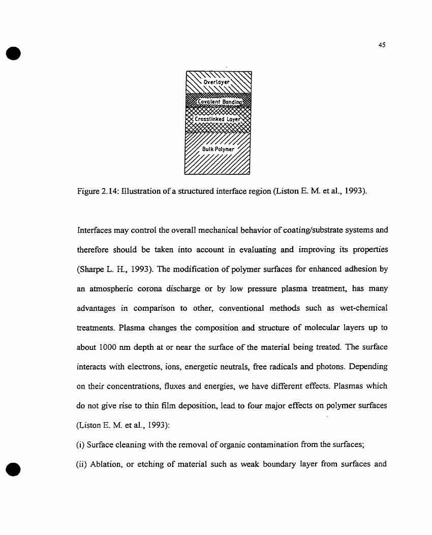
Figure 2.14: Illustration of a structured interface region (Liston E. M- et al., 1993).
Interfaces rnay control the overall mechanical behavior of coating/substrate systems and
therefore should be taken into account in evaluating and improving its properties
(Sharpe L. K, 1993). The modification of polymer surfaces for enhanced adhesion by
an atmospheric corona discharge or by low pressure plasma treatrnent, has many
advantages in cornparison to other, conventional methods such as wet-chernical
treatments. Plasma changes the composition and structure of molecular Iayers up to
about 1000 nm depth at or near the surface of the material being treated. The surface
interacts with electrons, ions, energetic neutrals, fkee radicals and photons. Depending
on their concentrations, fluxes and energies, we have different effects. Plasmas which
do not give rise to thin film deposition, lead to four major effects on polyrner surfaces
(Liston E. M. et al., 2993):
(i) Surface cleaning with the removal of organic contamination from the surfaces;
(ii) Ablation, or etching of material such as weak boundary layer fiom surfaces and

increasing the sürface area.
(iii) crosslinking or branching of near-surface molecules to cohesively strengthen the
surface layer.
(iv) modification of surface-chernical stnicture during plasma treatment and afier re-
exposure of the materials to air. This resdts in the reaction of fiee radicals with
atmospheric oxygen or water vapor.
An XPS experiment performed to study the interaction of Cu with untreated and
das rna- î rea ted surface of Teflon AF shows the importance of covalent bonds on the
adhesion of Cu to fluoropolymers (Shi M. K et al., 1995). As can be seen fiom Fig
2.15, after Cu evaporation, new features at around 285 and 531 eV in the C(1s) and
O(1s) spectra of the X P S analysis may be identifie& (Shi M. K. et al., 1994). The
feature around 285 eV in the C(1s) peak may contain cornponents from the formation of
C-C and Cu-O-C bonds, and the feahire around 53 1 eV in the O(ls) peak may be due to
Cu-N-C- structures (Shi M. K. et al., 1994).

Bind ing Energy . [ e ~ 1
Figure 2.15: XPS C(1 s) and 0(1 s) spectra of Teflon AF (fiom Shi M. K. et al., 1995).
Another XPS analysis was performed for the plasma-polymerized
trifluoroethylene (C2F3H) (Shi M. K et al., 1995) (Figure 2.16). The C(1s) envelope
shows the presence of C-C (C-H), CF, CF2 and CF3 groups @'Àgostino R., 1990). After
Cu evaporation, the peak at 286 shifted to a lower binding energy at around 285.5 eV,
which may indicate Cu-O-C bond formation (Shi M. K. et al., 1995), and the F(ls)
spectmm was changed by an additional peak at around 687.5 eV, due to -F.

Binding Energy [eV1
Figure 2.16: WS C(ls) and F(ls) spectra of PPFC before and after Cu deposition (fiorn
Shi M. K. et al., 2995).
These observations f?om the XPS experiments suggest that Cu-OC and Cu-N-C bonds
may be responsible for superior copper adhesion to NrpIasma-treated fluoropolymers.
As mentioned earlier, the highest energies of interaction are associated with covalent
bonding (200-800 kVmole). Plasma surface treatments involving other gases such as
0 2 , HZ, 02+H2 and Nz+H2 also improve the adhesion of copper to fluoropolymers (Shi
M. K et al., 1995; Liston E. M. et al,, 1993).
Literature involving plasma surface treatments gives insight into the
contribution of various factors to the copper-fluoropolymer adhesion (Liston E. M. et
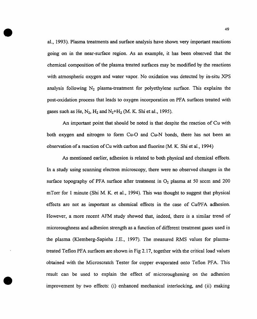
al., 1993). Plasma treatments and surface analysis have shown very important reactions
going on in the near-surface region. As an example, it has been observed that the
chernical composition of the plasma treated surfaces may be modified by the reactions
with atmosphenc oxygen and water vapor. No oxidation was detected by in-situ X P S
analysis following N2 plasma-treatment for polyethylene surface. This explains the
post-oxidation process that leads to oxygen incorporation on PFA surfaces treated with
gases such as He, Nt, Hz and Nz+Hz (M. K Shi et al., 1995).
An important point that should be noted is that despite the reaction of Cu with
both oxygen and nitrogen to fom Cu-O and Cu-N bonds, there has not been an
observation of a reaction of Cu with carbon and fluorine (M. K. Shi et aI., 1994)
As rnentioned earlier, adhesion is related to both physicd and chemical effects.
In a study using scanning electron microscopy, there were no observed changes in the
surface topography of PFA surface after treatment in O2 plasma at 50 sccm and 200
mTorr for 1 minute (Shi M. K. et al., 1994). This was thought to suggest that physical
effects are not as important as chemical effects in the case of CulPFA adhesion
However, a more recent AFM study showed that, indeed, there is a similar trend of
microroughness and adhesion strength as a function of different treatment gases used in
the plasma (Klemberg-Sapieha LE., 1997). The measured RMS values for plasma-
treated Teflon PFA surfaces are shown in Fig 2.17, together with the cntical load values
obtained with the Microscratch Tester for copper evaporated ont0 Tefion PFA. This
result can be used to explain the effect of microroughening on the adhesion
improvernent by two effects: (i) enhanced mechanical interlocking, and (ii) making

50
more surface area availabie for chernical bonding It is believed that these two
mechanisms, together with surface mechanical stabilization by crosslinking, contribute
to enhanced film adhesion found for plasma-treated polymer surfaces.
1 a-s m
Treatment gas
Figure 2.17: Effcct of treatment gas in microwave plasma on the cntical load, Lc, of
200 nrn thick evaporated copper films, and on the mean surface roughness (RMS) of as-
treated Teflon PFA surfaces (from Klemberg-Sapieha J.E., 1997).

CHAPTER ILI
EXlPERPMENTAL METHODOLOGY
3.1 FABRICATION OF FLUOROPOLYiMER FILMS
The fluoropolymer sarnples we evaluated in this study include plasma-
polyrnenzed (PP) C2F4 and C2F3H, sputtered (SP) Teflon PTFE, and spin-deposited
(SD) Teflon AF1600. We chose these fluoropolymers due to their availability or the
compatibility of their deposition methods with the presently used technologies.
3.1.1 PLASMA DEPOSITION
The plasma system used in our laboratory is shown in Figure 3.1. Both the
sputtering and the plasma polymerization of fluorocarbon were performed in an RF
plasma system operating at 13.56 MKz and at a pressure of 20-40 mTorr, as measured
by an MKS Baratron pressure gauge. The chamber was evacuated using turbomolecular
or diffision pumps. The distance between the RF and the grounded electrodes was 2.2
cm and the electrodes were 8.4 cm in diameter. In the case of SP films, a disc of 3 mm
thick conventional P T E was placed on the RF electrode, and glass or silicon substrates
were placed on the grounded electrode; Ar and CF4 gases were used at a 80w rate of 10
sccm measured by MKS flowmeten, and the RF power was about 150 W, as indicated
by the power source. For PP films, C2F3H or C2F4 monomers were used at the same
flow as for sputteting but with an W power of about 20 W. The Si or glass substrates

were placed on the grounded substrate holder. A11 Buoropolymer films in this study
were about 1 jm in thickness (see section 2 - 3 3 for the measurement of film thickness)
unless otherwise mentioned. This was so for al1 samples prepared for various
characterization techniques. The shapes of substrates however were different, as will be
specifically described as part of the analysis technique that was used.
RF:
1 . grounded electrode - - substrate Rolder
Figure 3.1: Plasma system used in our laboratory.
3.1.2 S P N COA4ThVG
For our experiments, TEFLON AF1600 solution was diluted in Fluorinert Sigma
FC-77, to obtain a 6% solution, and spin-deposited. First, a 2 inch wafer was placed
firmly onto the Teflon holder of the instrument using a pump. Before applying the

Iiquid polymer solution, the wafer was rotated at the highest speeds for some time to be
well centered. A large pipette was filled with 1.2 ml of the solution and this was poured
rnanually onto the center of the wafer. Immediately thereafier the spin coater was
tumed on at a speed of 6200 rprn for 20 seconds. The fluoropolyrner films were about 1
p m thick The standard curing procedure consisted of two steps. The first step was to
anneal the coated substrates at 170 OC for 15 minutes, and the second step \vas an
annealing at 330 O C for 15 minutes. This procedure however did not assure uniform
film thickness in some cases; in those cases the Teflon AF16OO was washed from the
wafer and the deposition process was repeated. Three small scratches were made on the
films, one at the center of the wafer, and the other two on the sides. Using a DEKTAK
profilorneter as descnbed in section 3.3.5, the thickness was evaluated at these points
and statistical averages were taken.
3.2. FABRICATION OF COPPER FILMS
Copper was deposited using either evaporation or sputtering. Copper thickness
was about 200 nm in both cases as measured by placing a clean microscope slide
among the experimental samples and using profilometry as described above. Since the
sticking coefficients are different for glass and fluoropolymer, the copper thicknesses
were also evaluated using the differences in thickness of metallized and unmetallized
fluoropolymer films. The results were close to those obtained from bare microscope
slides for a copper thickness of 200 nm. The principles of profilometry are described in

section 3.3.5.
For our experiments, hi&-purity copper (99.999 %) was thermally evaporated
fiom a filament at a pressure of around loJ Torr rneasured by a Penning gauge. the
filament to substrate distance being 30 cm. The chamber was evacuated prirnarily by a
mechanical pump, afier which pumping was switched to a diffusion pump. In our
expenments we chose a resistive coil type of filament in order to avoid overheating of
fluoropolymer substrates. The coil was aligned horizontally and pieces of copper were
clarnped on it. We placed the samptes in close pro.ximity to each other in order to
achieve similar thicknesses for the films.
In our expenments, we used a plana disc shaped cathode (which served as the
sputtering source) parallel to an anode surface (grounded, served as the substrate
holder).
Copper was sputtered, using a DC planar magnetron at a pressure of 10 mTorr of Ar as
meaçured by an MKS Baratron gauge, a flow rate of 6 sccrn as measured by an MKS
flowmeter, a current of 0.5 A and a negative target bias of 355 V. The chamber was
evacuated using a turbomolecular purnp. The parallel dix-shaped cathode was 8 cm in
diameter and the distance between the cathode and the anode was about 7 cm.
To avoid possible problems that rnight have occurred due to the high power
dissipation, the cathode was cooled with a high flow of water.

For the dielectric rneasurements, copper electrodes (about 200 nm thick) were
evaporated on both sides of the fluoropolymer (Ipm thick) to form metal-insulator-
metal structures (see Fig. 3.2). The effective areas of the electrodes were squares
of 3x3 mm dimensions achieved by using a mask The multilayer structure was
fabncated on standard microscope giass slides of 2x2 cm dimensions. The 200 nrn
thickness of copper is larger than the mean fiee path of electrons, thus surface effects
should not be of concem and conductivity is sufficiently hi& (p-1.67 @-cm). The
samples were placed and M y clamped on a copper plate of 5x5 cm dimensions that
was attached on top of a square-shaped cerarnic heater. Thermal cycling was performed
inside a grounded metal chamber kepî at 10" Ton. The dielectric behavior was
stabilized by annealing at 200°C for 30 minutes. The heating rate was approximately
2OC/min and was controlled manuaIly using an adjustable power source. The
temperature was rneasured using a very thin thennocouple installed on the substrate
holder, its tip touching the sample surface in order to measure the temperature with
higher precision. We found that there exists a temperature gradient between the interior
of the heater and the sample surface (AT=70 OC when Ta00 OC on the sample surface).
The annealing removed low molecular weight fragments and caused the fiee radicals to
react in the case of PP and SP polymers and removed residual solvent in the case of

56
(SD) Teflon AF1600. In addition to these, water was desorbed. These results will be
discussed later in this work. Atmospheric contaminants were removed in al1 cases. The
thermal cycling was found necessary to obtain reproducibly stable dielectric properties.
Dielectric measurernents were performed using an HP 4274A rnulti-frequency
LCR meter, at fiequencies ranging fiom 100 Hz to 100 kHz. Experiments have shown
that direct mechanical contact of the sample electrodes and the LCR multifiequency
meter gives the best results with almost no noise at elevated temperatures. Previous
attempts with a conductive paste (silver paste) caused noise at temperatures above the
room temperature. In order to reduce the additional, unwanted capacitive effects, a pair
of BNC coaxial cables were used to connect the sample chamber to the measuring
apparatus.
The permimvity at high fiequency in the visible range (-1015 Hz) was evaluated
from the refiactive index, obtained using a Perkin Elmer U V M S N R Lambda 19
spectrometer which measured the optical transmission and reflection. By changing
thickness and refiactive index iteratively, a minimum error function (difference
between simulated and measured transmission and reflection) was found. Using
different dispersion curves describing the continuity of the optical constants over a
certain wavelength range, the refiactive index was found at the wavelengîhs of 450 and
750 nm. The dielectnc constant was obtained by squaring the refiactive index. The
Sellrneier formula (Tatian B., 1984) was used in our caIculations:

Here n(k) is the refiactive index at wavelength A, A, and Bj are constants detemiined by
the fitting process.
Thermocouple inserted into
ont0 ceramic heater
Microscope siide used as sampie substrate for electrical measurements
AND T I E M e E R A r n CQNTROLLER
Chamber evacuated by a mechanicd pump
Figure 3.2: The expenmental set-up and metal-insulator-metal (Mbf) sample s t m c t u e
used in our experirnents.
Copper Electrodes
.---. - - - - - - n e - - - - - - - - . - - - - Tm Fluoropolymer
- * - - - - - - - * * - - - - - - - - * - - - * - - - .
T 2 cm Glass
b
Substrate
. . Film
. . . . . . . . . * . . . - . . ' t i
3 m m i A 2 c m -:
4 &
Holder
I - . . . .
4 7

3.3.2 ADEESION MEASUIREMENTS
The microscratch tester (MST CSEM Switzerland) and type 600 3M Scotch
Tape peel test were used to measure adhesion. The main reason for choosing these
techniques was their ease of use in evaluating various types of samples. in addition to
these, the possibility of making quantitative, semiquantitative and qualitative analyses
with the microscratch tester made it an attractive instrument to be used in order to make
a comparative analysis of differently treated fluoropolymer samples.
When using the MST, a linearly increasing force, over the range of 0-3 N, was
applied to a 0.8 mm hemispherical diamond tip moving across the surface at a speed of
5 m m h i n at a loading rate of 1 N/rnin. The scratches were analyzed, using both optical
microscopy and SEM, to determine the critical load necessary to delaminate copper
O from the polymer substrate. In our case, where a 2000 A copper film is deposited on a
I pm fluoropolyrner, it is easier to evaluate adhesion by optical observation. The reason
for this is the fact that the dope of friction force vesus normal force does not change
significantly when copper starts delaminating. The acoustic emission was not sensitive
enough at the point of first copper delamination In al1 measurernents the critical load
was usually obtained from 5 scratches on each sample.
Several samples were analyzed for each different treatment condition. The films
to be analyzed with the microscratch tester were deposited on 2x2 cm glass slides. Ir
was observed that srnall irregularities (such as dust particles oriçinating from the air)

entering between the stylus tip and the film surface dong the path of the scratch could
mislead the experimenter by delarninaîing the film. Therefore critical load values
largely deviating from the average were omitted. Generally, small scale plastic
deformations or delaminations gradually turn to more extensive, large scale
delaminations as the normal force increases. The possible failure modes are
summarized in Figure 3.3. However, one should keep in mind that these modes are just
simpiifications of the observed results. The actual observations are more wmplex and,
sometimes, a combination of several of these modes occurs at the same the . Therefore,
it is up to the experimenter to define a reasonable critical load Figure 3.4, obtained
with SEM, shows the point at which L, was typically measured.
An important problem to be solved is to distinguish the delamination of Cu
films at the Cu/fluoropolyrner interface from the delamination of fluoropolymer films at
the fluoropolyrner/substrate interface. Generally, the former occurs first and the latter is
observed at higher load values. To dari@ this problem, we observed the scratches under
optical microscopes operating in reflection and transmission modes. The microscope
operating in the transmission mode of polarized light makes it possible to see whether a
fluoropolymer film rernains on the glas subsnate, which would imply that copper
delaminates from the fluoropolymer. In case the fluoropolymer film remains adherîng
but copper is removed the color is light green. If the polyrner is dehminated, the color
will turn to light blue, indicative of the presence of bare glass substrate.

Failure modes in the scratch test
Terstlle cracking
L3+
Figure 3.3: A summary of possible failure modes observed afier the scratching ( h m
Bumett P. J. and =ckerby D. S., 1987)

Figure 3.4: SEM picture showing the point at which L, is typically measured.
Type 600 3M Scotch Tape was used to perform the peel test, to provide
additional information about adhesion. Samples were prepared by depositing a
fluoropolymer film (-1pm thick) on 2x2 and 2x4 glass microscope slides, followed by
copper deposition
(-200nm thick). The tape was placed pnt ly over the sample and a 2 kg roller was
rolled twice over it. Irnmediately thereafter, the tape was peeled fiom the surface
perpendicularly and the percentage of remaining copper was estimated by dividing the
area into segments and counting the number of segments retaining the copper.
3.3.3. STRESS ;MEASURE&lENTS
Film stress was measured as a function of temperature for both bare and

metallized fluoropolymers, using the Tencor flx-301 Flexus system under &
atmosphere. The possibility of meamring film stresses as a function of temperature in a
N2 atmosphere made this instrument particularly attractive for our copper-metallized
samples, since copper oxidation had to be avoided The films were deposited on 2 inch
Si (100) wafers, the thickness of polymer and copper being about 1 pm and 200 nrn,
respectively. The principle is based on the evaluation of changes in the radius of
curvature of the substrate resulting fiom film deposition %y measuring this defornation
one can fmd the strain and thereby the stress using the Stoney equation:
(3 -2)
Here, E and v are Young's rnodulus and Poisson's ratio of the substrate, respectively. D
and t are the thickness of the substrate and film. The substrate radius before, RI, and
after, R2, film deposition will give the effective radius defined as:
R=(RI -R2)/RIR2 (3.3)
It should be noted that we considered only the elastic constants of the substrate and
therefore this equation is valid oniy when t«D. There exist several different methods
to mesure the radii. Our Flexus system uses a scanning beam technique: A rnovable
assembly of solid state lasers, mirrors, and a position-sensitive detector. The angle of
reflection, 0, is measured as a function of distance x travelled along the substrate. The
derivative of the angle 0 with respect to the distance will give the radius. In other
words:

R=dWdu
The schematics of the Flexus apparatus utilized is shown in Fig 3.5-
Laser Beam
1
Figure 3.5: Schematics of the flexus laser scanning mechanism (Flexus Corp.,
Sunnyvale, CA).
The Flexus system can be employed to anatyze the stress-temperature behaviour.
Resistive coils heat the sample uniformly in a N2 atmosphere. However, it should be
noted that in these in-situ stress versus temperature measurements, the Young's
modulus and other elastic constants of the Si substrate are assumed to be temperature-
independent because they show only a very small temperature dependence: elastic
constants decreasing with increasing temperature (Flexus Corp., Sunnyvale, CA).

3.3.4. CIB[EMICAL CHARACTERIZATION OF THE SURFACES
AND INTERFACES
a) FTIR: The chemical structure of the films and interfaces was also evaluated:
FTIR spectra were obtained in transmission (volume) and photoacousticaI1y (surface)
on a MATTSON RS-1 FTIR spectrometer using an MTEC mode1 300 photoacoustic
sample attachment. Fluoropolymer samples were prepared using glas and Si substrates.
Photoacoustic spectroscopy (PAS) works on the pnnciple that modulated IR radiation
stn'king the surface of the sample is absorbed in the first thermal difision length,
converted to heat, which changes the pressure of the coupling gas in the photoacoustic
cell. A standing sound wave develops and is detected by a microphone. Only those
frequencies that are absorbed will Iead to the development of sound waves. In other
words, in PAS sound waves are being used to detect uifiared absorption fiequencies.
Due to its suitability for the nondestructive characterization of fluoropolymers, we used
this technique. PAS can be applied to analyze the near surface region, down to several
hundred angstrorns (DiRemo M et al., 1995). The surface regions of fluoropolymers
were analyzed with PAS in order to determine differences in surface chemical structure.
The question that also had to be answered was which chemical groups may
contribute to the adhesion of copper to fiuoropolymers. Using transmission, one can
obtain information about the intenor of the material. Fi_mire 3.6 shows a photoacoustic
cell:

S a m p l e
Infrared Beam f = 2vv
v = movable m i r r o r velociry
- v = IR f r e q u e n c y
Y k M i c r o p h o n e
Figure 3.6: Schematic diagram of photoacoustic cell (fkom Graf R T. et al.,
1987).
b) X P S : XPS spectra were obtained using a VG ESCALAB MKII instrument
with Mg K, radiation (1253.6 eV), operated at 12 kV and 20 mA. These conditions
were used to minimize the degradation of the fluoropolpers due to the X-rays which
affected the entire surfaces of the samples. The following procedure was used for this
experiment: newly deposited fluoropolymer sarnples were carried inside a dessicator
and introduced into the preparation chamber of the XPS system. They were covered
with a few monolayen of evaporated copper. Since no quartz crystal microbalance was
used, the copper thicknesses were different for different fluoropolymer samples.
Immediately thereafter the samples were transferred to the anaiysis charnber for the first

evaluation before heating. Survey spectra of metallized fluoropolymers, as a function of
heat treatment, gave details on Cu d i f i i o n This was accomplished by successively
heating the rnetallized samples inside the preparation chamber and then tramferring
them back to the analysis charnber for survey scans. Photoelectrons were collected at
take-off angles of 35', 70' and 90' with respect to the sample plane. Since these
photoelectrons originate from a depth approxirnately a distance of 3Asin0, where h and
0 are rnean free path and take-off angle, respectively, varying depths up to 3h could be
probed. The analyzed surface area was 2x3 m.&. Peak areas were evaluated; by taking
into consideration the elemental sensitivity factors, quantitative analysis gave us the
concentration profiles of various elements, inciuding copper. Thus, it was possible to
obtain depth profiles of the elements after diEerent annealing ternperatures. In our case,
following the evaporation of copper, the heat treatments were performed in-situ at 25,
100, 150,200 and 250 O C for 10 min intervals.
c) Contact angle goniometry: Surface tension, for atmosphere-annealed bare
fluoropolymer films on glas, was obtained using contact angle goniometry and
applying small drops of 6 different liquids. KaeIble3s method (Kaelble D. H- et ai.,
1974) gives the dispersive (yd) and polar (p) components of the surface tension. Small
drops of predetermined liquids were applied to the polymer surface and the changing
contact angle was recorded every 20 second over a pied of about two minutes. The
values of undisturbed contact angle 8 were evahated from an extrapolation of al1 data
to zero time. The cos 0 and the work of adhesion (W,) were calculated. Using the value

67
of W,, a least squares fit was made and the dispersive and polar components of surface
tension were detennined,
3.3-5- T r n C r n S S MEAStJRErnNTS
Thicknesses of fluoropolymer and metal films were eval .uated using
profilometry (DEKTAK). This was accomplished by making several scratches on
different locations of the films using a razor blade. Thereafter the stylus was moved
perpendicularly to the scratches and the thickness was evaluated from the step profile.
Statistical averages were obtained korn several positions. The accuracy of this test
instrument is within 10%-
In order to evaluate the changes in thickness after annealing, we used
profilometry and thennomechanical analysis (TMA) in sorne cases. The principle of
TMA is based on the measurement of the reIative change in film thickness with respect
to its original value during annealing in N2 atmosphere. A free-standing piece of film
was placed in between the flat, cylinder-shaped tips of a few mm diameter and a very
low load (1 mg) was applied on the tips to press the film. Free-standing Teflon AFI600
was obtained by dipping a piece of Tefion AF1600-coated Si wafer into water and
peeling off a small piece of the film. Free-standing plasma deposited films were
obtained by peeling pieces fiom the rf powered electrode. The films were then heated at
a rate of 2 OC/min to the required temperatures (usually 200 OC), and the changes in
thichesses were recorded,
CHAPTER IV
RESULTS AND DISCUSSION
4.1 DIELECTRFC PROPERTES OF FLUOROPOLYMER FILMS
Ln this chapter, the experimental results obtained for MIM (metal-insulator-
metal) structures will be presented. These results include both permittivity and
dissipation factor as a function of temperature and frequency. With the exception of
PP(C2F3H), which short-circuited above room temperature, a11 other fluoropolymers
showed permittivity values below 1.9 and dissipation factors in the order of 10-~-10'' at
room temperature and at frequencies 1-100 subsequent to vacuum annealing. It
wîll be s h o m below that the deposition parameters for PP(C2F3K) led to gas phase
reactions which, in tuni, resulted in non-uniforrn films with cauliflower-like surfaces,
very prone to copper diffusion and short-circuiting. It should also be rnentioned that a
decrease in fluoropolymer thickness of about 20 % was rneasured after 30 minutes of
annealing. This was taken into consideration in the calculations.
The dielectric properties of polymers depend to a large extent on their thermal
history. For this reason the sandwich structures were thermally cycIed and the dieiectric
spectra observed. Another reason for thermal cycling was to evaluate thermal stability
of these Cu/fluoropolyrner rnultilevel structures. It was seen that the values of

permittivity and dissipation factor were significantly greater pnor to amealing, and they
reached lower values with increasing numbers of thermal cycles, before reaching their
stable values. The noise observed during the first heating disappeared once the samples
were suficiently heated and stabilized: Very sable properties were rneasured for films
afier annealing at 200 OC for 30 minutes in vacuum (see Figures 4. L and 4.2). Annealing
led to the desorption of water vapor, low molecular weight species and a reduction of
fiee radicals. Mass spectroscopie analyses hrther indicated that the annealing process
at higher temperatures was accompanied by the loss of low molecular weight species in
the case of the SP and PP fluoropolymers, and by the Ioss of solvent retained in the
Tefion AF1600 films (G. Czerernuszkin et aI., 1997). When stabilized samples were
exposed to air, the permittivity values increased slightly but they returned to their
former values upon evacuation.
The dielectric behavior of the fluoropolymer films is M e r documented with
the effect of temperature on dielectric constant (K) and dissipation factor (tan 6) (see
Figure 4.1 and Figure 4.2). M e r annealing, the dependence curves were found to be
featureless in the given temperature range. The K values were found to decrease with
rising temperature. The dissipation factors, on the other hand, experienced a sharp
increase starting at around 100 OC and suggested the presence of a relaxation peak
above 200 OC (see Figure 4.2). This peak shifted to higher temperature values as the
frequency increased. The spectra were similar for different samples of the same kind of
Buoropolymer. Furthemore, there were only minor differences from one kind of

fluoropolymer to another, evaluated in this work. These observations are consistent
with earlier publications indicating that the dissipation factor varies as a function of
temperature in a similar way for different plasma-deposited fluoropolymers (Martinu et
al., 1986). The dielectric behaviour of fluoropolymer films was explained in section
2.1.3. Figures 4.3 to 4.8 surnmarize the plots of dielectric constant and dissipation
factor as a function of temperature for the fluoropolymers we investigated.
The dielectric behavior of Teflon AF1600 (see Figure 4.3 and Figure 4.4) is
similar to results obtained earlier. Here too, the K values were found to decrease with
rising temperature. It was expected that the permittivity would increase with increasing
temperature, as is fomd for many other polyrners. We corrected the K(T) c w e ,
considering thermal expansion of the capacitor area and of the thickness, using a linear
thermal expansion coefficient of 74 pp& (Starkweather H. et al., 1991). This
approach, however, did not change the temperature dependence significantly. The K(T)
cuve agrees well with the Clausius-Mossotti equation.
The reproducibility of the spectra gave us an understanding of thermal stability.
Up to about 200°c, stability is maintained, but beyond 200 OC the spectra showed
features such as large deviations from the general trend. niese deviations can be
explained as due to the dimision of copper into the polymers and, eventually,
shortcircuiting (diffusion of copper into fluoropolyiners will be discussed) and an
increased DC conductivity. These deviations were manifested as substantial increases in
dissipation factors by orders of magnitude, observed for al1 samples. Once such

deviations were observed, it was no longer possible to obtain the former dielectric
constant and dissipation factor values fiom these samples.

- - --
Effect of Cyclfng on the Dlelectrlc Constant of Ar Sputtered Teflon
j -K (20 kHz) Third C-le - K (20 kHz) ~ i rs r IR h r r 200%;
j r K iZO kHz) Fust Cycle
Fi,pe 4.1 : Effect of cycling on the dielectric constant of Ar-sputtered
Teflon.
Effect of Cycling on the Dissipation Factor for Ar Sputtered Tenon
Figure 4.2: Effect of cycling on the dissipation factor of Ar-sputtered
Teflon.
0 0 1 + ! 1
o.me .. I - O (20 kHz) F i r i t Cycle 1 - O GO kHz) Sacone Cycle 1 - O (20 Mir) ThirdCydo ; - O (20 tnq A%r in h i t t o a t ! ' 0 0 0 4 -
0002 -

Figure 4.3: Dielectric constant vs temperature for a vacuum anneded~eflon AF1600.
Temperature 6)
Figure 4.4: Dissipation factor vs temperature for a vacuum annealed Teflon AF1600.

1.8
1.78
1.76
1.74
1.72
1 -7
1.68
O 5 0 1 0 0 150 200
Temperature CC)
Figure 4.5: Dielectric constant vs temperature for a vacuum annealed PP(C2F4).
Figure 4.6: Dissipation factor vs temperature for a vacuum annealed PP(C2F4).

1 KHz
2 KHz
4 KHz 10 KHz
20 KHz
40 K M A00 KHz
Figure constant for a vacuum sputtered
50 100 150 O
Temperature (C)
Figure 4.8: Dissipation factor vs temperature for a vacuum annealed CF4 sputtered
Tef on.
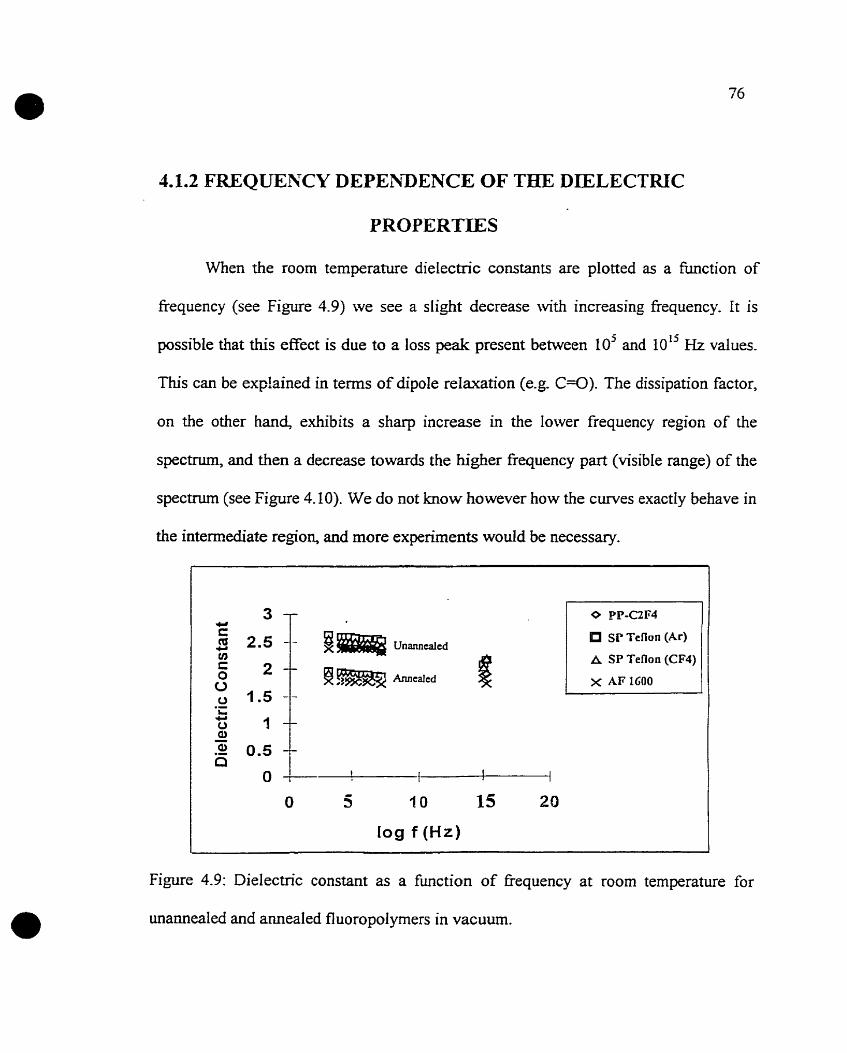
1.1.2 FREQUENCY DEPEhIDENCE OF THE DIELECTRIC
PIROPERTIES
When the room temperature dielectric constants are plotted as a function of
frequency (see Figure 4.9) we see a slight decrease with increasing frequency. It is
possible that this effect is due to a loss peak present between 10' and 10" Hz values.
This c m be exp!ained in terms of dipole relaxation (e-g. C=O). The dissipation factor,
on the other hand, exhibits a sharp increase in the lower frequency region of the
spectnim, and then a decrease towards the higher fiequency part (visible range) of the
spectrum (see Figure 4.10). We do not know however how the curves exactly behave in
the intermediate region, and more experiments wodd be necessary.
log f (Hz)
Sr Teflon (Ar)
A SP Tenon (CF4)
Figure 4.9: Dielectric constant as a function of frequency at room temperature for
unamealed and ameaied fluoropolymers in vacuum.

log f (Hz) -- -
Figure 4.10: Dissipation factor as a fünction of frequency at room temperature for
annealed fluoropolymers in vacuum (It rnust be emphasized that near 10'' fi there are
two different log f (Hi) values: 14.6 and 15.8 obtained for two frequencies
conesponding to a wavelength of 450 and 650 nm).
4.2 ADIiIESION OF COPPER TO FLUOROPOEYPMERS
4.2.1 MICROSCRATCH AND PEEL TEST ANALYSE
Figure 4.11 shows the microscratch and peel test results for samples exposed to
various heat treatments. The abbreviations 'atm' and 'vac' indicate, respectively,
annealing under the ahnosphere or in vacuum. Al1 these treatments were performed at
200 OC for 30 min. The results show that premealing in atmosphere signîficant1y
increases adhesion for the PP and SP fiuoropolymer sarnples. It is believed that Gee
radicals produced dunng the plasma deposition are thermally activated during
pretreatment to react with air to produce chernical groups ( G O ) capable of reaction
with copper. As was confirmed earlier using XPS analysis on plasma treated
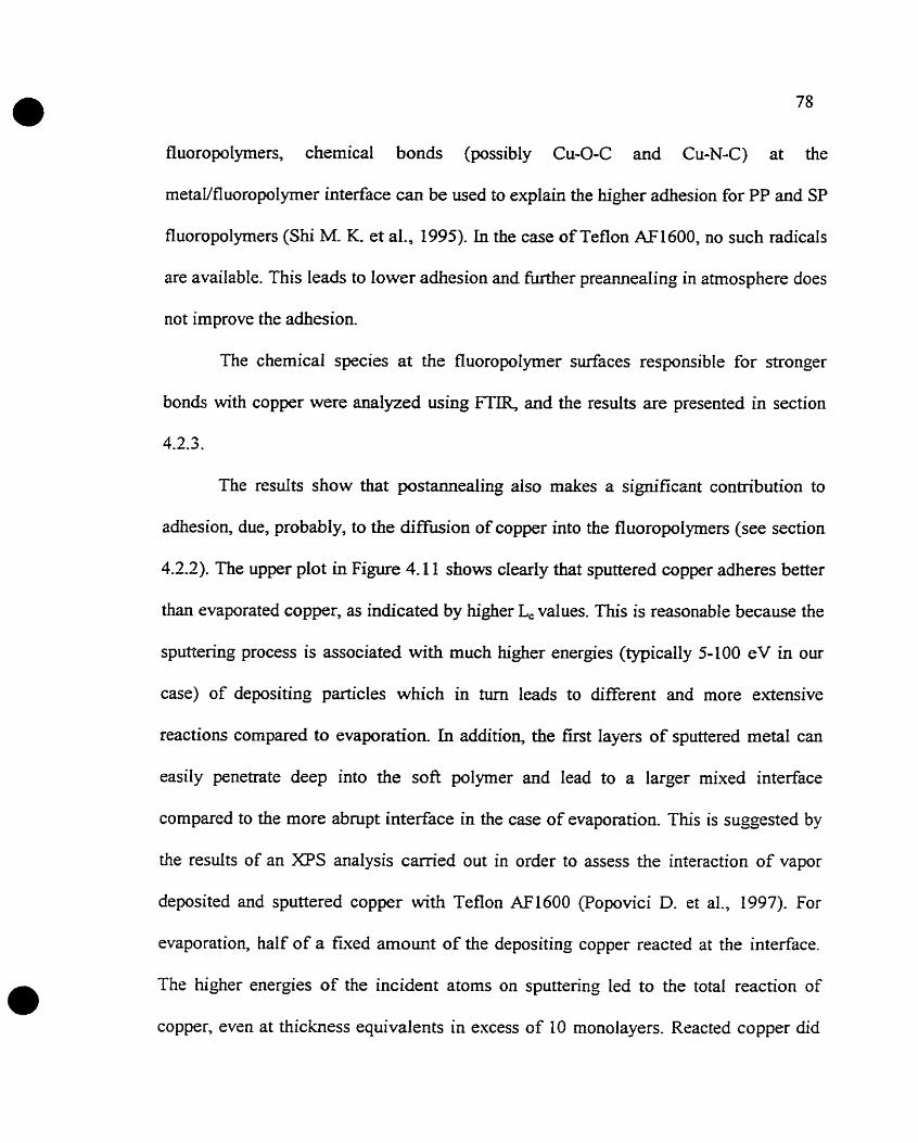
fluoropolyrners, chemical bonds (possibly Cu-O-C and Cu-N-C) at the
metaVfluoropoIymer interface can be wed to explain the higher adhesion for PP and SP
fluoropolymers (Shi M. K et al,, 1995). In the case of Teflon AF1600, no such radicals
are available. This leads to lower adhesion and further preannealing in atmosphere does
not improve the adhesion.
The chemical species at the fluoropolymer surfaces responsible for stronger
bonds with copper were analyzed using FTIR, and the results are presented in section
4.2.3.
The resuits show that postannealing also makes a significant contribution to
adhesion, due, probably, to the diffusion of copper into the fluoropolymers (see section
4.2.2). The upper plot in Figure 4.11 shows clearly that sputtered copper adheres better
than evapurated copper, as indicated by higher L, values. This is reasonable because the
sputtenng process is associated with much higher energies (typically 5-100 eV in our
case) of depositing particles which in tum leads to different and more extensive
reactions compared to evaporation. In addition, the first layers of sputtered metal can
easily penetmte deep into the soft polymer and lead to a larger mixed interface
compared to the more abrupt interface in the case of evaporatioe This is suggested by
the resuits of an X P S analysis carried out in order to mess the interaction of vapor
deposited and sputtered copper with Teflon AF1600 (Popovici D. et al., 1997). For
evaporation, half of a fmed amount of the depositing copper reacted at the interface.
The higher energies of the incident atoms on sputtenng Ied to the total reaction of
copper, even at thickness equivalents in excess of 10 monolayers. Reacted copper did
79
not remain accumulated at the Teflon surface but, rather, was uniformly distributed
throughout the observation depth (Popovici D. et al., 1997).
2-5 T hlicroscratch Test / Sputtered Copper
l- Microscratch Test / Evapora ted Copper
Peel Test1 Evaporated Copper , 1 0 0 T
PP SP Teflon PP Teflon (HCIF3) (Ar) (CFA) (C2F4) .IF 1600
Figure 4.1 1 : iMST and peel test results for copper deposited on
fluoropolymers.

The experiments performed to determine the effect of plasma surface eeatment
on the adhesion of evaporated copper onto Teflon AF1600 showed that NI, Ar and air
plasma treatrnents show only minute increases in critical force values for the set of
parameters used in this work. The critical forces obtained were around 0.15 N for the
non plasma-treated reference sarnple and close to 0.2 N for the plasma-treated samples,
as is shown in Figure 4.12:
Microscratch Tes t I Evaporated C o p p e t
Refemnce NZ ttsatsd Ar tmated air treatsd
Plasma Surface Trertment
Figure 4.13: The effect of plasma surface treatment on the adhesion of evaporated
copper onto Teflon AF 1600.
These experiments do not represent a thorough study of plasma pretreatment on the
Teflon AF l6OO/Cu system, but rather a preliminary attempt.

The copper delaminations starting at a veq- low criticaI force value can be
obsenied in Figure 4.13 seen by SEM. Here, the copper film cracks in fiont of the
stylus under the effect of mainly compressive stresses. On the sides of the scratch we
can identi- the chipping off of the copper film from the Teflon M l 6 0 0 surface.
Figure 4.13: Delaminations of evaporated Cu from the atmosphere-preamealed Teflon
AF1600. The critical Ioad was around 0.05 N.
Fipure 4.14 shows the scratch patterns with a higher magnification. It is possible to
distinguish the copper delaminations from the fluoropolymer and the fluoropdymer
delaminations from the glass or Si substrate. The latter occurs at much higher forces
cornparcd to the former. In the upper right corner of the picture, wve can identify, by its
irregular surface and gray color, the Teflon MI600 that Iost its copper coating during

the scratching procedure. Between isolated areas of copper we can distinguish the
cracks in the pal-mer, appearing as dark holes.
Figure 4.14: Delaminations of evaporated copper fiom Teflon AF 1600 observed with
more detail.
To confirm this. we analyzed unmetallized fluoropolymer films deposited on glas
slides using the microscratch test (MST). [t was observed that no complete
delarninations of the fluoropolymer from the glass occurred and the o d y failure modes
showing cracks and partial delaminations occurred at higher Ioad values. Even at the
end of the scratch we sel cracks and an irreguiar surface which identifies the presence

of the fluoropotymer on the glass substrate. Figure 4.15 is a scratch with pictures
showing a sequentially increasing Ioad.
Figure 4-15: Sequence of pictures seen with the reflection mode of an optical
microscope. Bare PP(CLFjH) on g la s amealed in the atmosphere and analyzed using
the scratch tester (Magnification: 550x, tip size:0.8 mm, range of load: 0-3 N, loading
rate: 1 N/min, sperd of tip: 5 d m i n ) .

The sequence of pictures seen in Figure 4.16 illustrates the gradua1 development
of failures observed under the transmission mode of an optical microscope. It should be
noted that the light green color seen on the substrate after the first delaminations
indicates the presence of the fl uoropolymer whereas, at later stages, the color tums to
light blue and matches that of an uncoated glas slide.
Figure 4.16: Sequence of pictures seen with the transmission mode of an optical
microscope. PP(C2F3H) film sputtered wîth Cu. The sample was not postannealed.
(Magification : 5 5 0 ~ ~ tip size: 0.8 mm, range of load: 0-3 N, loading rate: lN/rnin,
speed of tip: 5 mdmin).

We showed that the adhesion of copper onto fluoropolymers can be enhanced
using thermal annealing techniques. Annealing can improve adhesion and, at the same
time, stabilize the dielectric properties of these films. Therefore, it would be worth
considering thermal cycling of these films at some stage of their manufachiring process.
When postamealed, the samples showed an improvement in adhesion strength. Our
interpretation of this result was based on an XPS profile analysis we conducted in order
to observe possible diffusion phenornena taking place as metallized samples were
postannealed In other words, the diffusion of the first layers of depositing copper into
the polymer can lead to a stronger interface and result in beîter adhesion due to
"mechanical interlocking".

Figure 4.17: Atomic concentration of copper as a function
of annealing temperature at O0 and 35' take-off angles frorn
normal obtained by XPS.
Figure 4.17 shows the plot of this experiment. Atomic profiles of copper indicate that,
with increasing temperatures, the diffusion of copper towards the intenor regions of the
film is enhanced. Therefore, we observe a decrease of copper concentration at 0' and
35" takesff angles in the near surface regions as the sample is amealed at higher
temperatures. This decrease copper concentration higher for the Teflon
compared to the plasma-deposited samples. This difference may be explained to be due
to the noncrosslinked structure of Teflon AF1600 in contrast to the denser, crosslinked
plasma deposited polymers. in this figure we do not include the 70" take-off angle data
because, they do not necessarily fo1Iow the general trend. This observation may be due

to the very shallow depth probed at this take-off angle, which may be affected by the
irradiation damage caused by x-rays. In an earlier study, F and O losses were observed
even at low doses of x-ray irradiation @. Popovici et al., 1997).
42.3 FTIR ANALYSIS
Photoacoustic spectra onginating from near-surface region are s h o w in Figure 4.18.
- 3: SP Taon (CF,) on Si - 4: PP (C,F,H) on Si
Figure 4.18: PA signal for fluoropolymers.
The PP and SP films reveal a broad peak around 1200 cm", which is mostly due to the
stretching of CF, groups (Shi M. K. et al., 1994) (Giegengack H. and Hinze D., 1971)
(Martinu L., 1986). The peak around 1700 cm-' may be the confirmation of the
presence of carbonyl (C=O) groups, as a resuit of the reaction of the film fiee radicals

with the atmospheric oxygen upon exposure to the ambient (Shi M K. et al., 1994)
(Sacher E., 1994) (Martinu L., 1986). As a result, active sites containing oxygen are
available for reaction with copper (Alptekin A. et al., 1997). We explain the higher
adhesion observed for PP and SP fluoropolymers to be due to the formation of chernical
bonds at the metal-polymer interface (Shi M. K. et al., 1995). The weak absorption
around 3400 cm-' is due to -OH groups, present either because of the reaction of free
radicals with water, or the bonding of water to the ether linkages in Teflon AF1600. In
the case of Tefion AF1600, the characteristic peaks observed are due to CF2 stretching
(1250 cm-'), the C-O-C stretching of the fluorinated dioxole component (1 150 cri?),
and CF3 vibrations (980 cm-') (Nason T. C. et al., 1992). In al1 cases, there remained
some residual C G in the rneasuring cornpartment which gives rise to a peak around
2400 cm-', unrelated to the film structure.
We also observed that, in the case of Teflon AF1600, the CH, contamination
peak can be significantly reduced in size upon evacuation whereas in the case of
plasma-deposited fluoropoiymers, this cannot be achieved. It is this inert nature of
Teflon AF1600 that suggests the need for an enhancement of adhesion. Figure 4.19
shows the photoacoustic spectra of two Tefl on AF1600 samples, one of which was kept
in a dessicator under vacuum and, within a few seconds, inserted into the FTIR
spectrorneter, whereas the other was kept in the laboratory atmosphere for some time
before analysis. Evidently, the latter sample exhibitted a more pronounced CH. and OH
peak. It is h o w n that CH, generally ieads to poor adhesion because the C-H bonds are
not attacked by adsorbed metal (Chen T. C. S., Mukhopadhyay S. M., 1995).

Wavenumbers
Figure 4.19: Contamination peaks (CH.) of two Teflon AF 1600 samples. Sarnple A was
kept in Iaboratory atrnosphere for some time whereas sample B (kept in a dessicator)
was inserted within seconds into the FTIR spectrometer.
4.2.4 SURFACE TENSION MEASUIRE-mNTS
The dispersive and polar components of the surface tension, as well as their
sum, are ploîted in figure 4.20 as a f ic t ion of critical load, obtained for different
fluoropoIymers. It is evident that both components of surface tension increase with

increasing critical ioad. This suggests the contribution of both polar and dispersive
forces to the adhesion of copper onto fluoropolymers. Mittal has discussed several
examples in his review (Mittal K. L., 1975), noting that the adhesion strength is
maximized when the surface tensions of the two components have similar magnitudes.
This may be due to a minimization of the interfacial tension, which is inversely
proportional to adhesion strength (Sel1 P. J. and Neumann A. W., 1966). Adhesion is
govemed by different rnechanisms in difEerent cases however, and therefore no
definitive staternents should be made.
- Linear (Total S w k e Tension ) i - Linear (Dispefshe
Surlace Tension )
Figure 4.20: Surface Tension as a function of critical load for
atmosphere-amealed fluoropolymers (in the order of increa-
sing critical load: Tefl on AF 1600, PP(C2FJ), SP Teflon (CF4),
SP Teflon (Ar), PP(C2F3H)).
4.2.5 OBSERVATION OF TFiE FLUOROPOLYMER SURFACES
BY SEM AMI AFM
Figures 4.2 1 to 4.23 show the surfaces of PP(C2F3H) and PP(C2F4) observed
under SEM and AFM It appears that the deposition parameters Iead to a gas phase
reaction in the case of PP(C2F3H) which, in turn, results in a cauliflower-like surface
structure. When c~smooth-appearing" regions of the cauliflower-like surface were
observed with higher magnification, it became evident îhat those regions were not
smooth. In the case of PP(C2F4), as the picture shows, the surfaces were smooth. We
have intentionally foc& on a dust particle to make the observed features evident.
Obviously Figure 4.2 1 shows a rougher surface compared to Figure 4.23. Rougher
surface indicates more porosity, more tendency to "short-circuit", which explains the
problems associated with the dielectric measurements mentioned in section 4.1.

Figure 4.2 1: Caulifiower-like surface structure of PP(C2F3H) observed under SEM.
L ~ p r n 0 m'
Figure 1.22: Cauliflowver-like surthce structure of PP(C2F3H) observed under MM.

. - - - - - -
Figure 4.23: The smooth surfaces of PP(C2F4) under SEM- We have intentionally
focused on a dus? particle to make the observed features evident.
4.2.5 MICASUREMENT OF STRESS
The evofution of film stress as a function of temperature is shown in Figures
4.24 and 4.25 for bare and metallized fluoropolymer films. The starting point of the
experiments are indicated with linle errows showing the increase of temperature, and
the end points of the experirnents are indicated with little cross signs. It should also be
noted that at the maximum point of each temperature cycle the sarnples were kept at a
constant temperature for 30 minutes. During the first heating cycles, irrevenible
changes in the stress of bare PP and SP fluoropo~mer films were observed. In the case

of SP Teflon (Ar) and PP(C2F4) the stress is initially very low (-O m a ) . When the
temperature is increased, the stress values become tensile above 100 OC for PP(C2F4)
and reproducibly stable in subsequent thermal cycles. A Ioss or desorption of low
molecular weight species can be the cause of this obserqed behavior. The SP Teflon
(Ar) develops a compressive stress when heated, suggesting film densification, and it,
too, reaches reproducibly stable values in the following cycles. These reproducibly
stable stresses for bare SP Teflon (Ar) can be seen between -100 MPa and -150 MPa
values. The two lines in this region were obtained for successive thermal cycles, with
the more compressive values corresponding to the latter cycle.
We anaiyzed two Teflon AF1600 samples. Sample 1 was put into the charnber
immediately after deposition without any annealing prior to the experiment (Le. no
curing at 170 OC and 330 O C ) . Sample 2, however, was annealed in vacuum at 170 OC
for 15 minutes and at 330 O C for another 15 minutes and then anaiyzed as recommended
in the procedure. Teflon AF1600 shows a compressive stress which appears to be quite
stable up to 200 OC, but it becornes more compressive when heated to 350 OC. At this
high temperature, both samples (samples 1 and 2) of the Teflon AF1600 are probably
releasing their solvent Fluonnert 77, degrading and therefore losing weight
(Czeremuszkin G. et al., 1997). It should be noted fkom figure 4.24 that the Teflon
Ml600 was cyled to 200 OC several times and no such significant changes in stress
were observed,
When the samples were rnetallized afier thermal cycling, a tensile contribution
to the overall stress was observed in al1 cases. Metallization contributed about 30 MPa

of stress in the case of PP(C2F4), PP(C2F3H), SP Teflon (Ar), and about 200 MPa in the
case of Teflon AF1600. Except in the case of Teflon AFL600, the stress did not
appreciably change upon further thermal cycling- These mal1 changes can be explained
in terms of the stress relaxations at the copper/fluoropolymer interface. The high
temperature annealing (350 OC) of Teflon AF1600 probably continues to degrade the
polymer and, at the same tirne, enhances diffisioa
The general conclusion about stress measurements would be that stress effects
do not seem to be very high in copper/fluoropolymer film structures. We believe that
these values observed wouid not lead to a stress-related failure in two layer films such
as ours, involving copper and fluoropolymers. The reason for our belief is mainly due to
the observation that no failure such as cracking was observed for the copper evaporated
fluoropolymer samples when they were removed from the stress testing flexus system.
Ody sputtered copper samples showed cracks when they were annealed. However, we
did not analyze their stresses. In addition, stress values can be reproducibly stabilized
after suflicient thermal cycling, another indication of a film that is appearently £tee of
stress-related failure.

/ -PP-C2F4 ! !
; -a-- S P Teflo n (Ar)
+PP-C2F3H
: +AF 1600 (Sarnpie 1) .
' +AF 1600 (Sample 2) : !
I
! I - I
Figure 4.24: Stress as a function of ternperature for b u e fluoropolymer films.
! i !
! + SP Teflon (Ar) i i : I
I I
i - I ! i + PP-C2F3H
I a '
l . . / P O - : I I
13 I
i -AF 1600 1 1
, ! U J (Sample 1) : i m - 5 0 - i al 3
j *-100 -
i -150
Temperature (k) - - - - - - -- - - - - - - -
Figure 4.25: Stress as a function of ternperature for copper evaporated fluoropolymer
films.

This analysis of stress involved two layers only. In order to obtain more
comprehensive information about stresses and to better know whether copper and
fluoropotyrner are reliable as possible multilevel interconnect materials, one should
extend the study of stress to multilayer structures.

CHAPTER V:
SUMMARY AND CONCLUSIONS
The general objective of this work was to evaluate copper and fl uoropolymers as
potential candidates for multilevel intercomects. This objective was, in general, met to
a large extent: It was shown that multilevel structures of the f o m metai-insulator-metal
(MIA4) exhibit promising dielectric and mechanical properties at temperatures and
fiequemies close to those they could be used at in the future. The specific objectives of
this project were, in generd, met by cornparing different fluoropolymers according to
their fabrication process, dielectric properties, thermal stability and compatibility with
the rnetallization process.
We studied the dielectric properîies, i.e. dielectric constant and dissipation
factor, of metal-insdator-metal (MIM) sandwich stnictures over the temperature range
from 25 "C to 200 O C , and fiequency range from 100 Hz to 100 kHi, as well as at 10"
Hz. With the exception of plasma-polymerized C2F3H, which frequently showed
behavior indicating short-circuiting, the fluoropolymers we studied show dielectric
constants of less than 1.9 and dissipation factors around 105-104 in the temperature
range in which they would be used. The deposition parameters for plasma-polymerized
C2F3H led to gas phase reactions which, in turn, resulted in non-uniform films with
cauliflower-like surfaces prone to copper difision and short-circuiting The

fl uoropolymers studied show stable behavior afier thermal cycling when isolated from
the open atmosphere. These effects of vacuum heating were related to the reaction of
fiee radicals, removal of low molecular weight species in the case of PP and SP
polymers, and to the rernoval of residual solvent in the case of Teflon AF1600. In
addition, unbound atmosphetic contaminants were removed in al1 cases.
The dielectric constant shows a decrease with increasing temperature. A volume
correction of the dielectric constant for Teflon AF1600, considering thermal expansion,
does not make a significant change to its dielectic properiies. The dissipation factor
starts to increase sharply beyond 100 O C , a temperature above which these matenals
will be use& suggesting a loss and dc conduction to be present above 200 OC. The
dielectric constant at room temperature shows a very slow decrease with increasing
fiequency. Plots for the dissipation factor show a sharp increase in the lower frequency
region and a decrease for hi& frequencies in the optical range near I O L 5 Hz. The region
in between may possess a maximum, the overall shape of the plot suggesting a dipolar
loss. This can be explained in terms of dipole relaxation (e-g. C e ) .
The samples of temperature cycling showed reproducibly stable dielectric
properties to a maximum temperature of about 200 "C. The problem however remains
that today's technology requires, during manufacturing, stability up to about 400 OC.
Thermal stability issues thus seem to be the limiting factor for the immediate
application of Cdfl uoropolymer combinations. However, this problem will eventually
be solved as processing temperatures are expected to decrease in the future (Gutmam
R. J. et al., 1995).

The problems associated with thermal stability cm be grouped into bvo main
classes. The first class includes the intrinsic properties of the matenals, i-e. the
temperatures which the polymer itself can withstand without continuously losing weight
and/or degrading. The second class is associated with the interactions of the polymers
with Cu, such as copper diffusion into fluoropolymers. The first class of problems
definitely necessitates the use of suitable temperatures and there is not much to be done
except to explore methods aimed at decreasing the processhg temperatures. However,
the second class of problems can be more readily solved by preventing migration of
copper atoms deep into the polymer, by using possible diffusion barriers such as T a ,
Ti, Ta. With minimum copper interconnect feature sizes of 0.25 pm or Iower, only thin,
high resistivity materials such as these cm be considered as diffusion barriers, in order
to keep the total intercomect resistance low (Gutmann R J. et al., 1995).
niroughout our study we analyzed the effects of two types of annealing
procedures. The fust type was preanneahg and it was perfomed in open atmosphere
or in vacuum pnor to metallization of the fluoropolymers. The second type,
postannealing, was performed in vacuum after the Buoropolymers were metallized with
copper. Al1 these were done at 200 OC for 30 minutes. It was observed that evaporated
copper adhered poorly to plasma deposited polymers unless the samples were
preannealed in the open atmosphere and postannealed in vacuum. The adhesion of
copper was worst in the case of Teflon AF1600 and did not show a si,gificant
improvement after preamealing the fluoropolytner. Plasma surface treatments in &, Ar
and air improved the adhesion of copper to Teflon AF1600 fiom a critical load value of

0.15 to 0.20 N, an observed increase of about 33 %. A more significant improvement
for this polymer was achieved upon postannealing at 200 OC for 30 minutes which
increased the critical load to about 0.3 N. Sputtered copper however adhered better,
gïving critical loads between 0.5-1 N without postannealing, and values above 1.0 N
after postamealing. These values are higher than those obtained for evaporated copper
which were less than 0.7 N even after postannealing for a11 polymers investigated in this
work
Infrared spectroscopy was used in an effort to understand the observed adhesion
properties. The surface sensitive photoacoustic spectra revealed significantly larger
C=û and -OH peaks at 1750 cm-' and 3400 cm-', respectively, for the plasma-deposited
fluoropolymers compared to Teflon AF1600, as a result of the reaction of fiee radicds,
produced on plasma deposition, with air. As a result, active sites containing oxygen are
available for reaction with copper. We interpret the higher adhesion found for PP and
SP fluoropolymers by the formation of chernical bonds (prob~ibly Cu-O-C and Cu-N-C)
at the metal-polymer interface observed in an earlier work in this laboratory.
Results showed that stress values associated with metallized polymer films do
not indicate an important problern for adhesion and reliability. We qualiQ the stress
values obtained as noderate. There were irreversibIe changes in stress during first
heating cycles. More stable stress values were obtained after temperature cycling the
samples. It was observed in the case of Teflon AH600 that, when ameaied, the major
changes in stress towards more compressive values took place at high temperatura,
similar to the behavior of SP Teflon. The sputtered Teflon became compressive afier
heating. This was explained to be due to film densification. The plasma polymerized
C2F4 showed stress values which, on amealing, became more tensile. The plasma
polymerized C2FPH showed a similar trend, i.e. a small increase towards more tensile
stress. These observations were related to the loss of low rnolecular weight species.
Surface energy values obtained for atmosphere preannealed fiuoropolyrner films
were found between 12x10" and 27x1 O" ~/crn'. When these values were plotted as a
fimction of critical Ioad, measured for the same fluoropolyrners after the same themal
treatments, it was observed that both the dispenive and polar components of surface
tension increased linearly with increasing critical load. This may suggest that both of
these components contribute to the adhesion of copper to fluoropolymers .
In summary, our work contributed the following:
1. This work once more confirmed the reproducibility of resuits for similar types
of fluoropolymers. There is an agreement of our results with those obtained earlier for
plasma-deposited polytetrafluoroethylene (ETFE), plasma-polyrnerized tluorocarbons
and Teflon AF1600. This is important because even though the deposition systems and
conditions are somewhat different from one Iaboratory to the other, similar
fluoropolymer f i h s with low permittivity and dissipation factor can be obtained.
2. This study involved various techniques in order to analyse
copper/fluoroplymer film systems, providing thus a complementary and consistent
assessment of the film characteristics.
3. This work is original and it was not previously perforrned with the materials
investigated The heat treatments OF fluoropolymers before and after metallization, and

the cornparison of adhesion constitute an example of originality.
In conclusion, fluoropolymer films showing low dielectric constants and
dissipation factors can be obtained by various deposition techniques. It is possible to
enhance the adhesion of copper onto ff uoropolymers. There rernain, however, problems
to be solved One of them is copper diffusion into fluoropolymers which may cause
short-circuiting which leads to lower reliability especially at higher temperatures. Some
ways to accomplish this could be to use aû appropriate diffusion banier between metal
and Buoropolymer or to investigate the effect of surface treatments of fluoropolymers
on copper diffusion. Another open question is how the fiuoropolymer adheres to
copper. This must definitely be investigated, because, in our work, we only looked at
the adhesion of copper onto fluoropolymers. We used metai-insulator-meta1 film
structures which consisted of three films only. In order to have a better understanding of
the reliabilities of these materials, this study should be extended to rnuiîilayers. This
would be closer to the real situation of multilayer structures used in rnicroelectronics.

ALLEN, K. W., in Aspects of Adhesion, Vol. 5, ALNER D. J., Ed., CRC Press,
Cleveland, Ohio, 1969.
ALLEN, K. W., Proceedings of the conference held at Northampton College of
Advanced Technology, EC 1 on 2 1 and 22 March, 1963.
ALPTEKIN, A., SACHER, E-, CZEREMUSZKIN, G., MARTINU, L., Presented at the
Electrochemical Soc. Meeting, Montréal, May 1997.
AMYOT, N., KLEMBERG-SAPIEHA, J. E., WERTHEIMER., M R, IEEE
Transactions on Electrical Insulation, 27, (1992) 1 10 1-1 107.
BERNETT, M- K., ZISMAN, W. A., J. Coll. Interface Sci., 28, (1968) 243.
BEDERMAN, H., BILKOVA, P., JEZEK, J., HLIDEK, P., SLAVINSKA, D., Journal
of Non-CrystalIine Solids, 2 1 8, (1 997) 44-49.
BLANCKET, G. B. and ISMAT S., Appl. Phys. Lett., a (1993) 1026.
BUCK, W. H. and RESNKK, P. R, Paper Presented at the 1 8 3 ~ Meeting of the
Electrochemical Society, Honolulu, HI, May 17, 1993.
BULL, S. J. and RICKERBY D. S., Surface and Coating Technol., 0, (1990) 149.
BURNETT, P. J. and RICKERBY, D. S., Thin Solid Films, 154, (1987) 403.
CHAUG, YS. and ADAMS, R, J. Vac. Sci. Technol., (1993) 2269.
CHEN, R and SLVERSTEIN, M. S., Journal of Polymer Science: Part A : Polymer
Chemisw, 34.207-216 (1996).
CHEN, T. C. S. and MUKHOPADHYAY, S. M, J. Appl. Phys., (1995) 5422-5426.
CHOW, R-, LOOMS, G. E., SPRAGGE, M. K, L N S E Y , E. F., RAINER, F., WARD,
R- L., KOZLOWSKI, M. R., SPIE vol. 2253, (1994),512-520.
CLARK, D. T., DILKS, A. and SHUTTLEWORTH, D., Polymer Surfaces, D. T.
CLARK and W. J. FEAST, eds. (Wiley, London, 1979).

1 O6
CZEREMUSZKIN, G., MARTINU, L., ALPTEKDJ, A., POPOVICI, D., and SACHER,
E., Electrochemical Society Meeting Abstract Vol. 97(1), 1997.
DABRAL, S., ZHANG, X-, WANG, B-, YANG, G. R, LU, T. M, MCDONALD, J. F.,
Proceedings of the MRS 1995 Fall Meeting, Volume 38J 205-2 15.
D' AGOSTINO, R., ed., Plasma Deposition, Treatment and Etching of Polymers,
Academic Press, New York, 1990.
D' AGOSTINO, R., CRAMAROSSA, F., FRACASSI, F., and IUUZZI, F., in Plasma
Deposition, Treatment, and Etching of Pofymers, D'AGOSTCNO R, Ed, Academic,
New York, 1990, p. 95.
DERYAGN, B. V., et KROTOVA, N. A., DokIady Akad. Nauk S.S.S.R.,61. (1 948)
843-849.
DILKS, A. and KAPLAN, S., Proc. Electrochern. Soc. 82-6 (1982), Proc. 3*
Symposium Plasma Process, Denver, Colorado, 198 1.
DIRENZO, M., ELLIS, T. H., SACHER, E- and STANGEL, L, Prog. Surf. Sci., 50.-
(1995) 407.

GERENSER, L. J., J. Vac. Sci. Technol. A., 6, (1988) 2897.
GIEGENGACK, H. and HINZE, D., Phys. Statu Solid, A8.513 (1971).
GOOD, R J., Polym. Sci. Technol. A, 9- (1975) 107-127.
GRAF, R T., KOENIG, J. L. and ISHDA, K, Fourier Transfomi Mared
Characterization of Polymers, ISKIDA K, Polymer Science and Tec hnology, vol.%
(1987).
GRIESER, J., SWISHER, R, PHIPPS, J., PELLEYMOUNTER, D., HILDRETK, E.,
"Next generation thermal control coatings," in Optical Surfaces Resistant to Severe
EnWonments, ed. S. MUSIKANT, SPIE vol. 1330, (1990) 1 1 1-1 18.
GUTMANN, R J., CHOW, T.P., LAKSHMINARAYANAN, S., PRICE, D. T.,
STEIGERWALD, LM., YOU, L., MllRARKq S.P., Thin Solid Films, 270, (1995)
472-479.
HIRAOKA, H. and LAZARE, S., Appl. Surface Science, 40, (1990) 342.

108
HRUBESH, L. W., Proceedings of the MRS 1995 Fall Meeting, Volume 381,267-272.
HRUBESH, L. W. and RESNICK, P. R., paper presented at the 1 8 3 ~ Meeting of the
Electrochemical Society, Honolulu, HI, May 17, 1993.
HARDY, A., Proceedings of the conference held at Northampton College of Advanced
Technology, ECI on 21 and 22 March, 1963.
HETZLER, U. and KAY, E., J. Appl. Phys. 49, (1978) 56 17.
rYENGAR, Y . and ERICKSON, D. E., J. Appl. Polymer Sci., 'l, (1967) 23 11.
KAY, E., 2. Phys. D - Atoms, Molecules and Chsters, 2, (1986) 251-262.
KAY, E., COBURN, J., DILKS, A., in 94 Topics in Current Chemistry, edited by
VEPREK, S. and VENCTGUPALAN, M., 1980 Sp~ger-Verlag.
KAY, E., DELKS, A., J. Vac. Sci. Technol., 18. (1981) 1.
KAY, E., D U S , A, Thin SoIid Films, 78. (1981) 309.

KAY, E., HECQ, M., J. Appl. Phys., 55, (1984) 370.
KAELBLE, D. H., DYNES, P. J., and CIRLIN, E. H., J. Adhesion, & (1974) 23.
KLEMBERG-SAPIEHA, J. E., In Plasma Treatments and Deposition of Polymers,
D'AGOSTINO R., Ed., Kiuwer Academic Publishers, Dordrecht, The Nederlands,
1997.
KU, C. C. and LIEPINS, R., Electrical Properties of Polymers (Macmillan, New York,
1987).
LISTON, E. M., MARTINU, L. and WERTHEIMER, M. R., J. Adhesion Sci. Teclmol-,
7 (1993) 1091. a
LOWRY, J. H., MENDLOWITZ, J. S., and SUBIWMANUN, N. S., In ccOptical
characteristics of Teflon AF fluoroplastic materials", Optical Engineering., a (1992)
1982.
MARTINLT, L., Thin Solid Films, 140, L1986) 307.
MARTINU, L., BIEDERMAN, H. and NEDBAL, J., Thin Solid Films, 136, (1 986) 1 1-

MARTINU, L., In "Plasma Treatments and Deposition of Polymers", R.
D7AGOSTIN0, Ed., Kluwer Acadernic Publishers, Dordrecht, The Nederlands 1997.
=AL, K- L., J. Vac. Sei. Technol., 13. (1976) 19.
MlTTAL, K. L., J. Adhesion Sci. Technol., 9, (1975) 129.
MOGAB, C . J., J. Electrochem. Soc., 124,1262 (1977).
MORITA, S., SAUER, G., IEDA, M., in c'PIasma Chemistry of Polymers" (M.
DE- New York, 1976) p. 133.
MOUNTSIER, T. W., KU= D. Proceedings of the MRS 1996 Fall Meeting,
Symposium H, December 2-6 Boston
MST Micro-Scratch-Tester, User' s Manual, Version: 1 .O.
MURARKA, S. P., GUTMANN R J., KALOYEROS, A, E., LANFORD, W. A., Thin
Solid Films, 236, (1 993,257.
I I I
MURARKA, S. P. and HYMES, S. W., Crit Rev. Solid St Mater. Sci., 20, (1995) 87-
124.
NAKANO, T., FUKUYAMA, M., and OtW, Y., Japanese Journal of Applied Physics,
Vol. N0.6, June, 1988, pp. 1042-1046.
NAKANO, T., KASAMA, Y., OtW, Y. and YAHAGI, K.: Ipn. J. Appl. Phys., 24-
(1985) 83.
NASON, T. C., MOORE, J. A. and LU, T. M., Appl. Phys. Lett., 60, (1992) 1866.
OHRING, M., Chapter 9 in The Materials Science of Thin Films, Academic Press, New
York 1992.
PERRIN, J., SIEMENS, R. L., KAY, E., Solid State Phys., 4792. (1985) 50801.
POPOVICI, D., KLEMBERG-SAPIEHA, J. E., CZEREMUSZKIN, G., ALPTEKIN, A-,
MARTINU, L., MEUMER, M., SACHER, E., Metallized Plastics V., MITTAL K.,
Ed., 1997.
POPOVICI, D., KLEMBERG-SAPIEHA, J- E., SACHER, E., MEUNIER., M.,
MARTINU, L., J. Vac. Sci. Technot., submitîed.

RAEVSKII, R. G., J. Adhesion, 5, (1973) 203.
EUCE, D. W. and O'KANE, D. F., J. Electroochem. Soc. 123,1308 (1976).
ROSARIO, A. G., Proceedings of the MRS 1996 Fail Meeting, Symposium H-
SACHER, E., Prog. Surf. Sci., o, (1994) 273.
SHARPE, L. K, Chapter 1, pp.1-20 in Interfacial Interactions in Polymenc
Composites, AKOVALI G, Ed., NATO-AS1 Series E: Applied Sciences 230, Kluwer,
Dordrecht, 1993.
SHI, M. K., SELMANI, A, MARTINU, L., SACHER, E., WERTHEIMER, MR and
YELON, A., J. Adhesion Sei. Technol., 8, (1 994) 1 129.
SHI, M. K., MARTINU,
YELON, A., Surface and
L., SACHER, E., SELMAM, A., WERTHEIMER, M- R. and
Interface Analysis, a (1 995) 99- 104.
SHI, M. K., KLEMBERG-SAPIEHA, J. E., CZEREMUSZKIN, G., MARTINU, L. and
SACHER, E., Proc. ht. Symp. on Plasma Chemistry ISPC 12, Minneapolis, MN,
August 1995, p.5 1.

SMITH, D. M., ANDERSON, J., CHO, C. C., JOHNSTON, G. P., JENG, S. P.,
Proceedings of the MRS 1995 Fa11 Meeting, Volume 381.261-266.
STARKWEATHER, H., AVAKIAN, P., MATHESON, R, FONTANELLA, J. and
WINTERSGILL, M., MacromoIecules, 24. (1 99 1) 3853.
STEINRlANN, P. A. and -, H E., J. Vac. Sci. Technol. (1989)
SULLIVAN, J. P., DENISON, D. R, SEAGER, C. K, NEWCOMER, P. P., APBELT,
C. A, ALBERT G. B., Proceedings of the MRS 1996 FdI Meeting, Symposium K
TATIAN, B., Applied Optics, (1 984) 4477-4485.
TIBBITT, J. U, SHEN, M and BELL, A. T., Thin Solid Films LA3 (1975).
TIBBITT, J. M., BELL, A T. and SHEN, M., Plasma Chemistry of Polymers
- @EKKER, M, New York, 1976).
TING, C . H., SEIDEL, T. E., Proceedings of the MRS 1995 Fa11 Meeting, Volume 3 8 1.

V a L i , L, J. Vac. Sci. Technol., A4. (1986) 3007.
VOSSEN, J. L., KERN, W. (1978), Thin Film Processes, Academic Press, San Diego,
CA, USA,
VOYüTSKII, S. S., Autohesion and Adhesion of High Polymers, p. 138, inter-science,
1963.
WAITS, R K (1 978), Thin Film Processes, Academic Press, San Diego, CA, USA.
WINTERS, H, F., COBUIW, J. W., and KAY, E., Electrochem. Soc. Extend. Abstr.
NO. 77-2, (1977) 393.
YASUDA, H. and HSU, T., Surf Sci., 232 (1978).
YASUDA, H. in Thin Film Processes, edited by JOHN L. VOSSEN and WERNER
KERN, 1978 Acadernic Press Inc.
YASUDA, Ky Plasma polymerization, Academic, New York, 1985.

IMAGE EVALUATION TEST TARGET (QA-3)
APPLIED - lN1AGE. lnc = 1653 East Main Street - -. - - Rochester. NY 14609 USA -- -- - A Phone: 7161482-0300 -- -- - - Fa: 716/288-5989
O 1993. Applied Image. Inc.. All Righls Reserved